Embed Size (px)
Citation preview

Three- Span Continuous Horizontally Curved Composite Steel TUB Girder Bridge
WIZARD, ANALYSIS AND DESIGN
1
Bridging Your Innovations to Realities
2
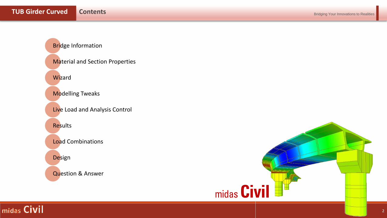
TUB Girder Curved Contents
Bridge Information
Material and Section Properties
Wizard
Modelling Tweaks
Live Load and Analysis Control
Results
Load Combinations
Design
Question & Answer

Bridging Your Innovations to Realities
4
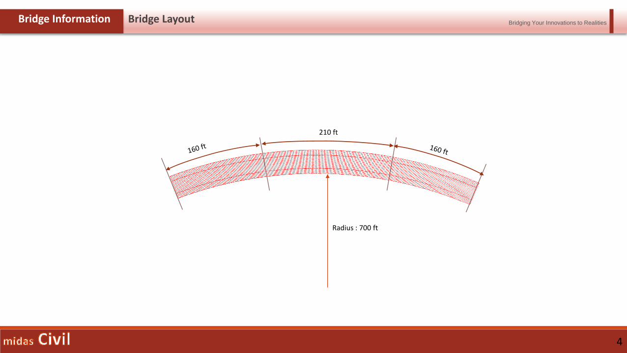
Bridge Information Bridge Layout
210 ft
Radius : 700 ft
Bridging Your Innovations to Realities
5
Bridge Information Material Properties And Loadings Considered
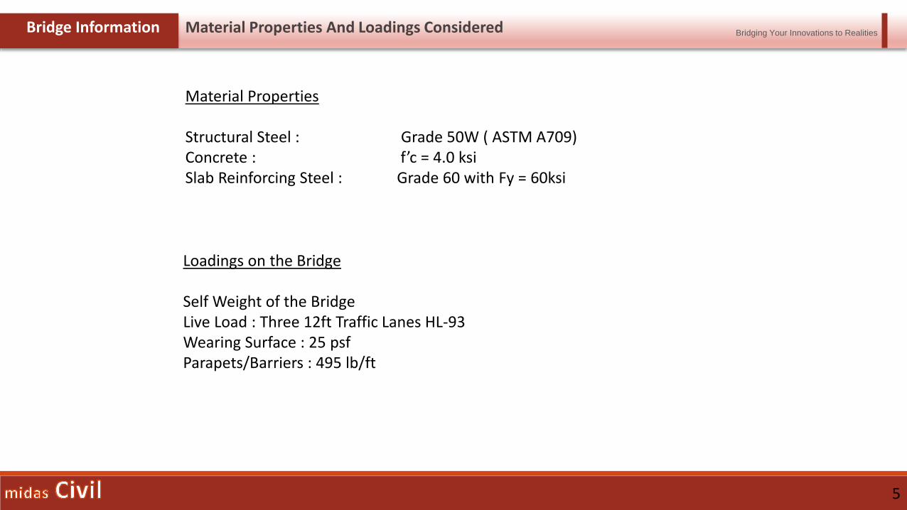
Material Properties
Structural Steel : Grade 50W ( ASTM A709)Concrete : f’c = 4.0 ksiSlab Reinforcing Steel : Grade 60 with Fy = 60ksi
Loadings on the Bridge
Self Weight of the BridgeLive Load : Three 12ft Traffic Lanes HL-93Wearing Surface : 25 psfParapets/Barriers : 495 lb/ft
Bridging Your Innovations to Realities
6
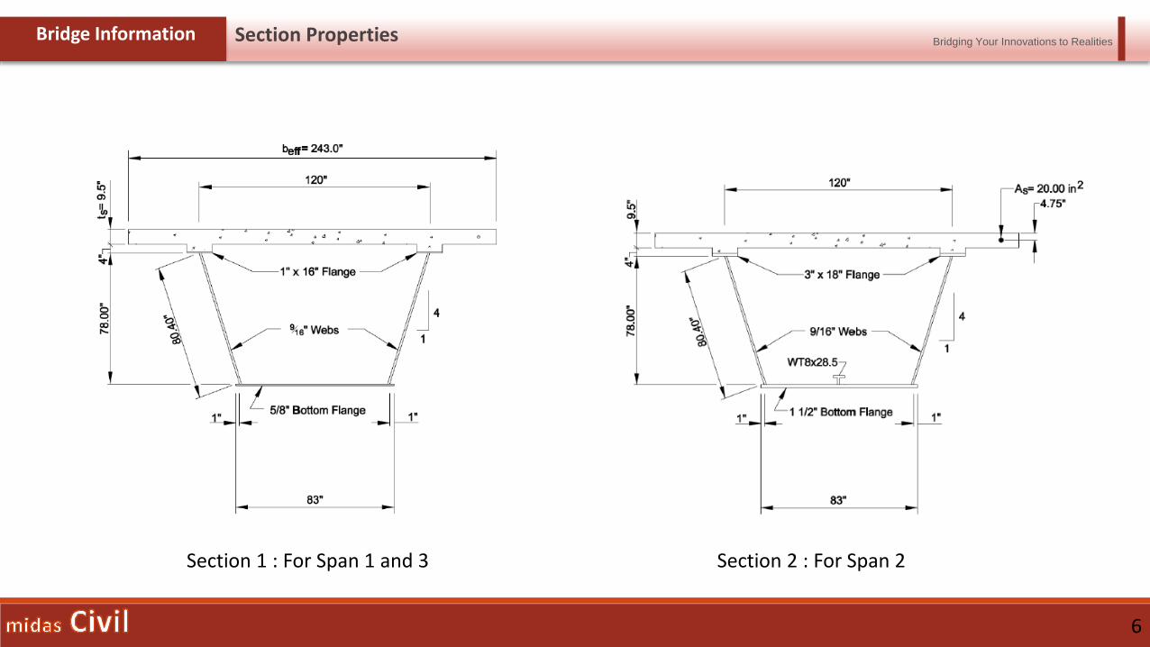
Bridge Information Section Properties
Section 1 : For Span 1 and 3 Section 2 : For Span 2
Bridging Your Innovations to Realities
7
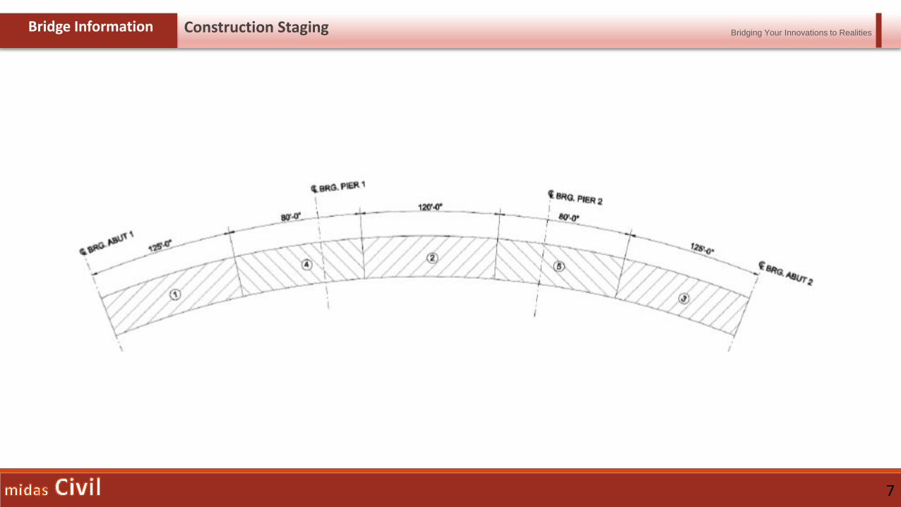
Bridge Information Construction Staging

Bridging Your Innovations to Realities
9
Properties Material Properties
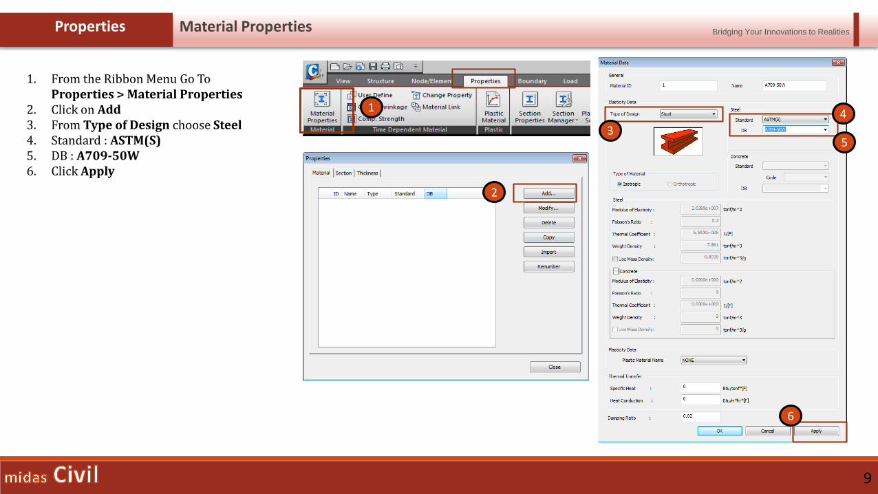
1. From the Ribbon Menu Go ToProperties > Material Properties
2. Click on Add3. From Type of Design choose Steel4. Standard : ASTM(S)5. DB : A709-50W6. Click Apply
2
3
4
5
6
1
Bridging Your Innovations to Realities
10
Properties Material Properties
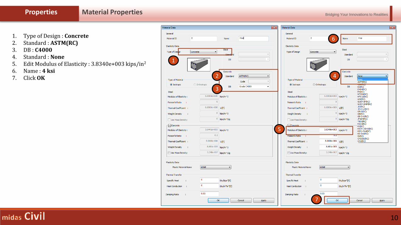
1. Type of Design : Concrete2. Standard : ASTM(RC)3. DB : C40004. Standard : None5. Edit Modulus of Elasticity : 3.8340e+003 kips/in2
6. Name : 4 ksi7. Click OK
1
2
3
4
5
6
7
Bridging Your Innovations to Realities
11
Properties Section Properties
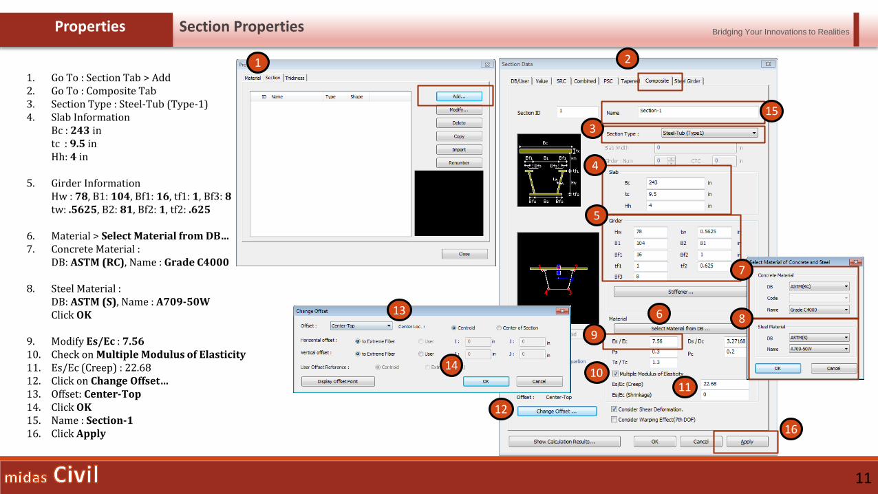
1. Go To : Section Tab > Add2. Go To : Composite Tab3. Section Type : Steel-Tub (Type-1)4. Slab Information
Bc : 243 in tc : 9.5 inHh: 4 in
5. Girder InformationHw : 78, B1: 104, Bf1: 16, tf1: 1, Bf3: 8tw: .5625, B2: 81, Bf2: 1, tf2: .625
6. Material > Select Material from DB…7. Concrete Material :
DB: ASTM (RC), Name : Grade C4000
8. Steel Material :DB: ASTM (S), Name : A709-50WClick OK
9. Modify Es/Ec : 7.5610. Check on Multiple Modulus of Elasticity11. Es/Ec (Creep) : 22.6812. Click on Change Offset…13. Offset: Center-Top14. Click OK15. Name : Section-116. Click Apply
1
3
4
5
6
7
8
9
1011
13
12
14
15
16
2

Bridging Your Innovations to Realities
12
Properties Section Properties
1. Name : Section-2
2. Girder InformationHw : 78, B1: 104, Bf1: 18, tf1: 3, Bf3: 9tw: .5625, B2: 81, Bf2: 1, tf2: 1.5
3. Click on Stiffener…4. Name: WT8x255. Type : Tee6. H: 8.13, B: 7.07, tw: 0.38, tf: 0.637. Click Add8. Give NBottom as 19. Check on C10. d(in) : 41.511. Click OK12. Click Apply
1
6
7
8
9
10
11
2
3
4
5
12
Bridging Your Innovations to Realities
13
Properties Section Properties
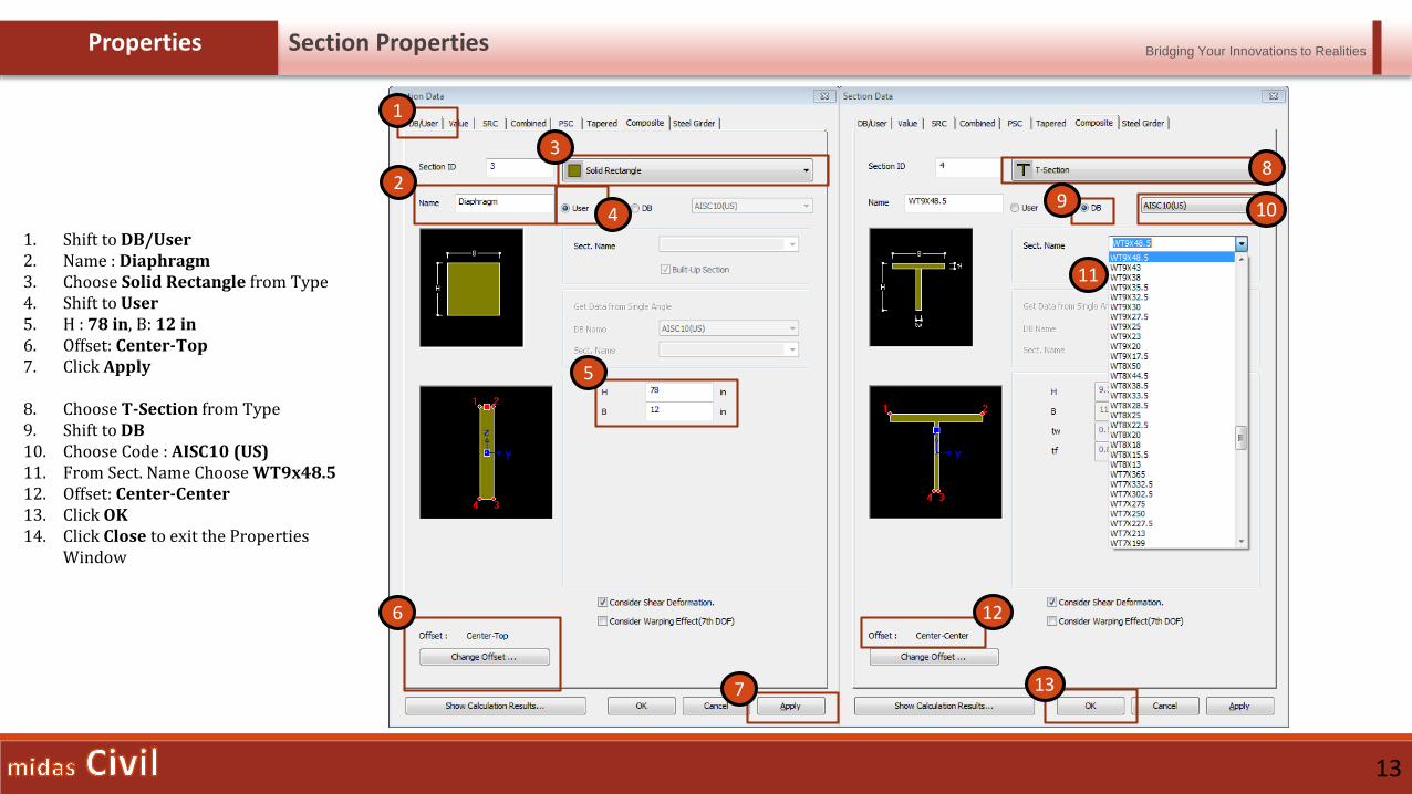
1. Shift to DB/User2. Name : Diaphragm3. Choose Solid Rectangle from Type4. Shift to User5. H : 78 in, B: 12 in6. Offset: Center-Top7. Click Apply
8. Choose T-Section from Type9. Shift to DB10. Choose Code : AISC10 (US)11. From Sect. Name Choose WT9x48.512. Offset: Center-Center13. Click OK14. Click Close to exit the Properties
Window
6
7
8
10
11
2
3
4
5
1
9
12
13

Bridging Your Innovations to Realities
15
Wizard Layout
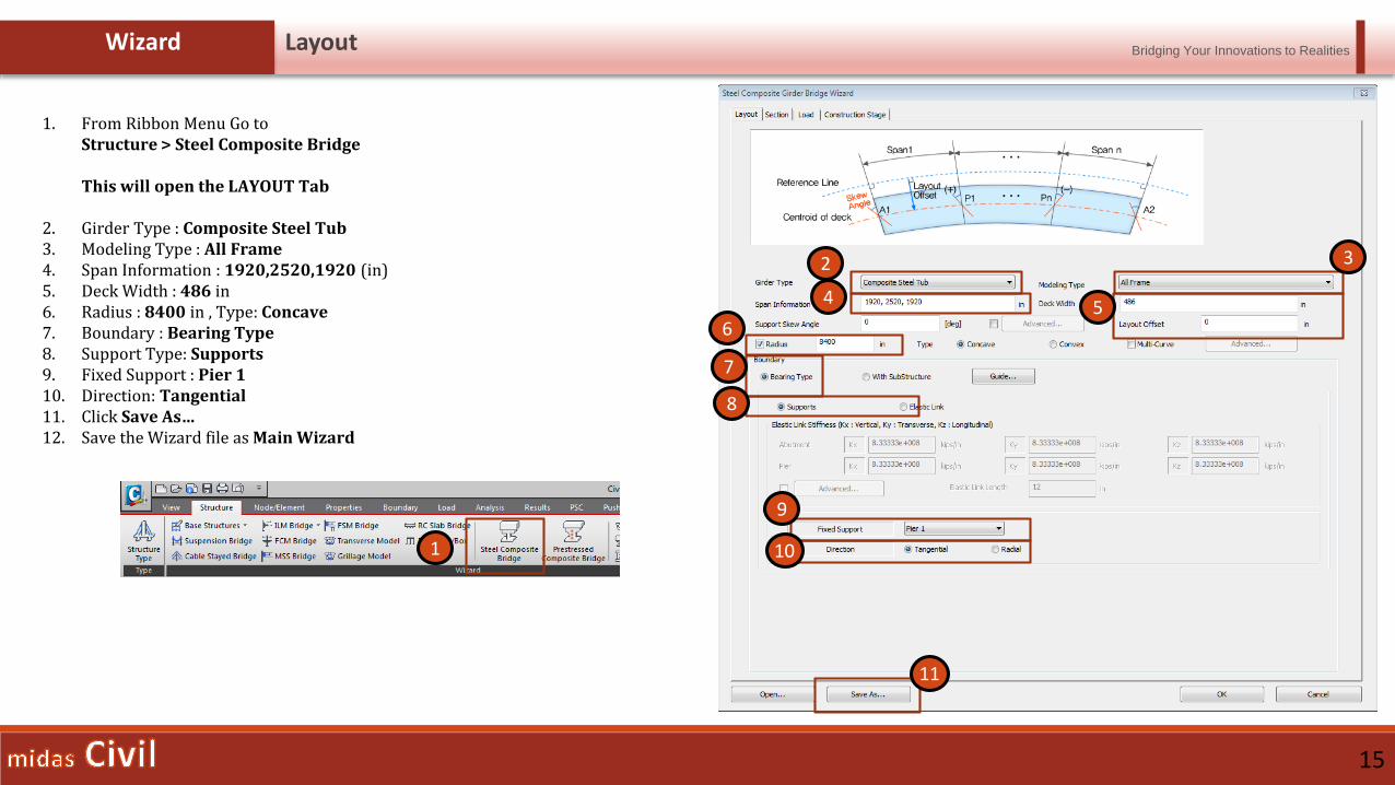
1. From Ribbon Menu Go to Structure > Steel Composite Bridge
This will open the LAYOUT Tab
2. Girder Type : Composite Steel Tub3. Modeling Type : All Frame4. Span Information : 1920,2520,1920 (in)5. Deck Width : 486 in6. Radius : 8400 in , Type: Concave7. Boundary : Bearing Type8. Support Type: Supports9. Fixed Support : Pier 110. Direction: Tangential11. Click Save As…12. Save the Wizard file as Main Wizard
1
3
45
6
7
8
2
9
10
11
Bridging Your Innovations to Realities
16
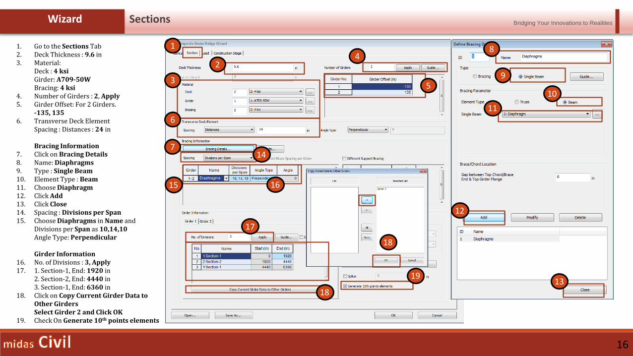
Wizard Sections
1. Go to the Sections Tab2. Deck Thickness : 9.6 in3. Material:
Deck : 4 ksiGirder: A709-50WBracing: 4 ksi
4. Number of Girders : 2, Apply5. Girder Offset: For 2 Girders.
-135, 1356. Transverse Deck Element
Spacing : Distances : 24 in
Bracing Information7. Click on Bracing Details8. Name: Diaphragms9. Type : Single Beam10. Element Type : Beam11. Choose Diaphragm12. Click Add13. Click Close14. Spacing : Divisions per Span15. Choose Diaphragms in Name and
Divisions per Span as 10,14,10Angle Type: Perpendicular
Girder Information16. No. of Divisions : 3, Apply17. 1. Section-1, End: 1920 in
2. Section-2, End: 4440 in3. Section-1, End: 6360 in
18. Click on Copy Current Girder Data to Other Girders Select Girder 2 and Click OK
19. Check On Generate 10th points elements
1
6
7
2
3
4
5
8
9
10
11
12
14
15
17
1913
16
18
18
Bridging Your Innovations to Realities
17
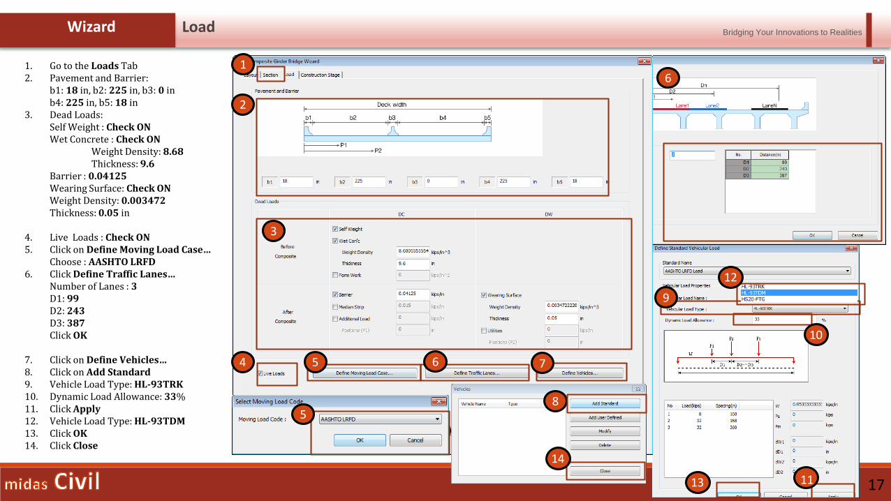
Wizard Load
1. Go to the Loads Tab2. Pavement and Barrier:
b1: 18 in, b2: 225 in, b3: 0 inb4: 225 in, b5: 18 in
3. Dead Loads:Self Weight : Check ONWet Concrete : Check ON
Weight Density: 8.68Thickness: 9.6
Barrier : 0.04125Wearing Surface: Check ONWeight Density: 0.003472Thickness: 0.05 in
4. Live Loads : Check ON5. Click on Define Moving Load Case…
Choose : AASHTO LRFD6. Click Define Traffic Lanes…
Number of Lanes : 3D1: 99D2: 243D3: 387Click OK
7. Click on Define Vehicles…8. Click on Add Standard9. Vehicle Load Type: HL-93TRK10. Dynamic Load Allowance: 33%11. Click Apply12. Vehicle Load Type: HL-93TDM13. Click OK14. Click Close
1
2
3
4
8
10
13
14
18
5
5
6
6
7
9
11
12
14
Bridging Your Innovations to Realities
18
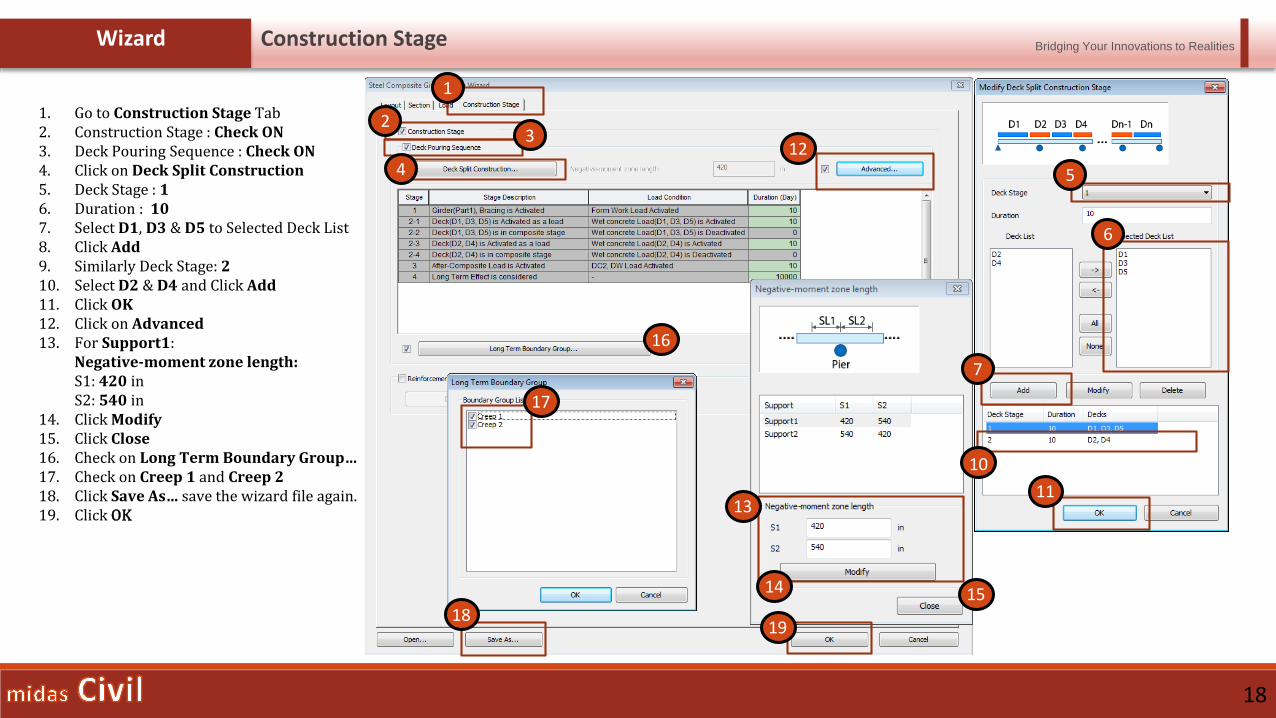
Wizard Construction Stage
1. Go to Construction Stage Tab2. Construction Stage : Check ON3. Deck Pouring Sequence : Check ON4. Click on Deck Split Construction5. Deck Stage : 16. Duration : 107. Select D1, D3 & D5 to Selected Deck List8. Click Add9. Similarly Deck Stage: 210. Select D2 & D4 and Click Add11. Click OK12. Click on Advanced13. For Support1:
Negative-moment zone length:S1: 420 inS2: 540 in
14. Click Modify15. Click Close16. Check on Long Term Boundary Group…17. Check on Creep 1 and Creep 218. Click Save As… save the wizard file again.19. Click OK
6
7
10
11
1
23
4 5
12
13
14 15
16
17
1819
Bridging Your Innovations to Realities
19
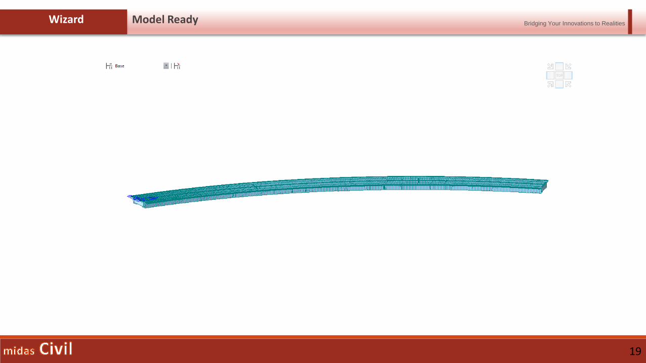
Wizard Model Ready

Bridging Your Innovations to Realities
21
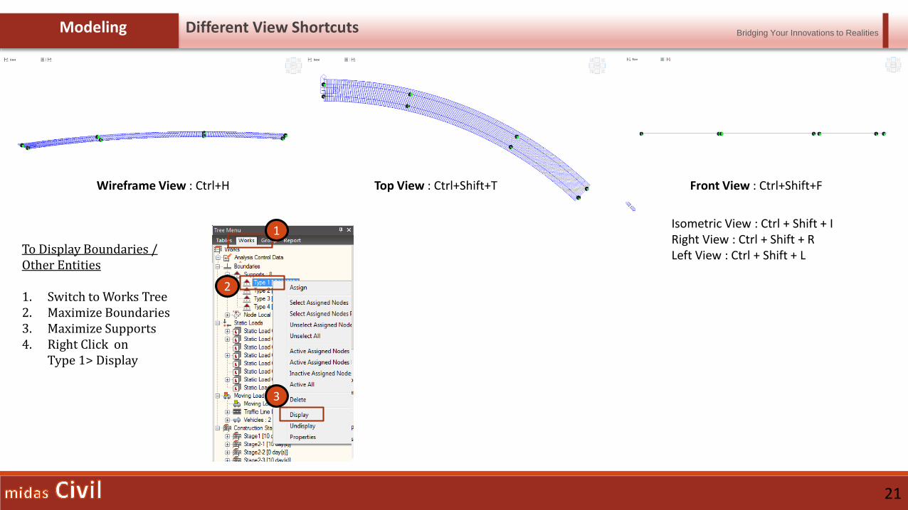
Modeling Different View Shortcuts
Wireframe View : Ctrl+H Top View : Ctrl+Shift+T Front View : Ctrl+Shift+F
Isometric View : Ctrl + Shift + IRight View : Ctrl + Shift + RLeft View : Ctrl + Shift + LTo Display Boundaries /
Other Entities
1. Switch to Works Tree2. Maximize Boundaries3. Maximize Supports4. Right Click on
Type 1> Display
1
2
3
Bridging Your Innovations to Realities
22
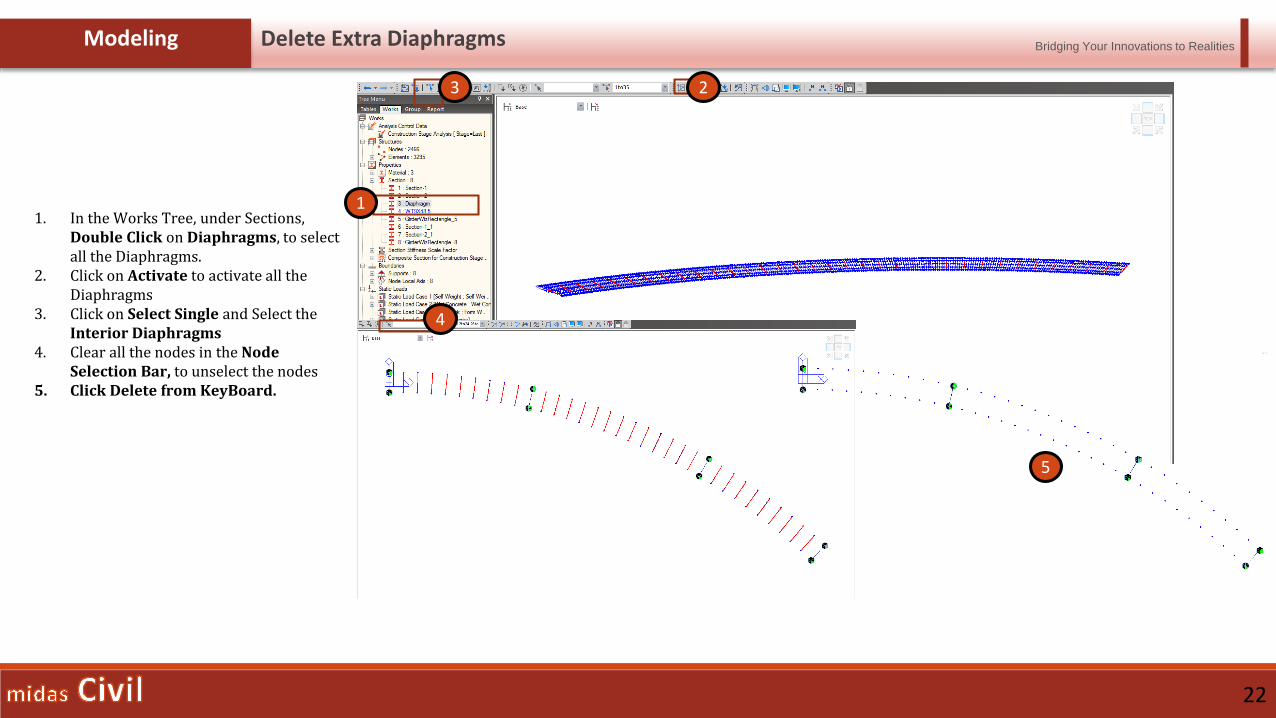
Modeling Delete Extra Diaphragms
1. In the Works Tree, under Sections,Double Click on Diaphragms, to select all the Diaphragms.
2. Click on Activate to activate all the Diaphragms
3. Click on Select Single and Select theInterior Diaphragms
4. Clear all the nodes in the Node Selection Bar, to unselect the nodes
5. Click Delete from KeyBoard.
1
2
5
3
4
Bridging Your Innovations to Realities
23
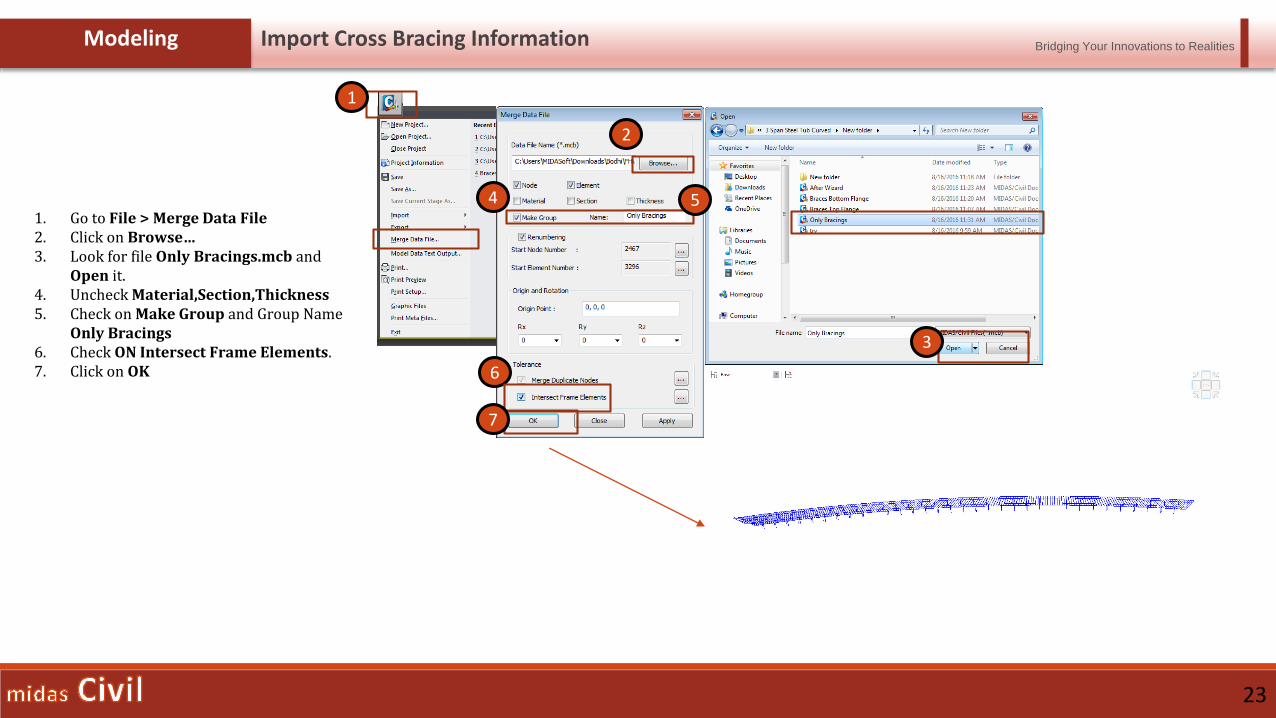
Modeling Import Cross Bracing Information
1. Go to File > Merge Data File2. Click on Browse…3. Look for file Only Bracings.mcb and
Open it.4. Uncheck Material,Section,Thickness5. Check on Make Group and Group Name
Only Bracings6. Check ON Intersect Frame Elements.7. Click on OK
1
2
3
5
6
7
4
Bridging Your Innovations to Realities
24
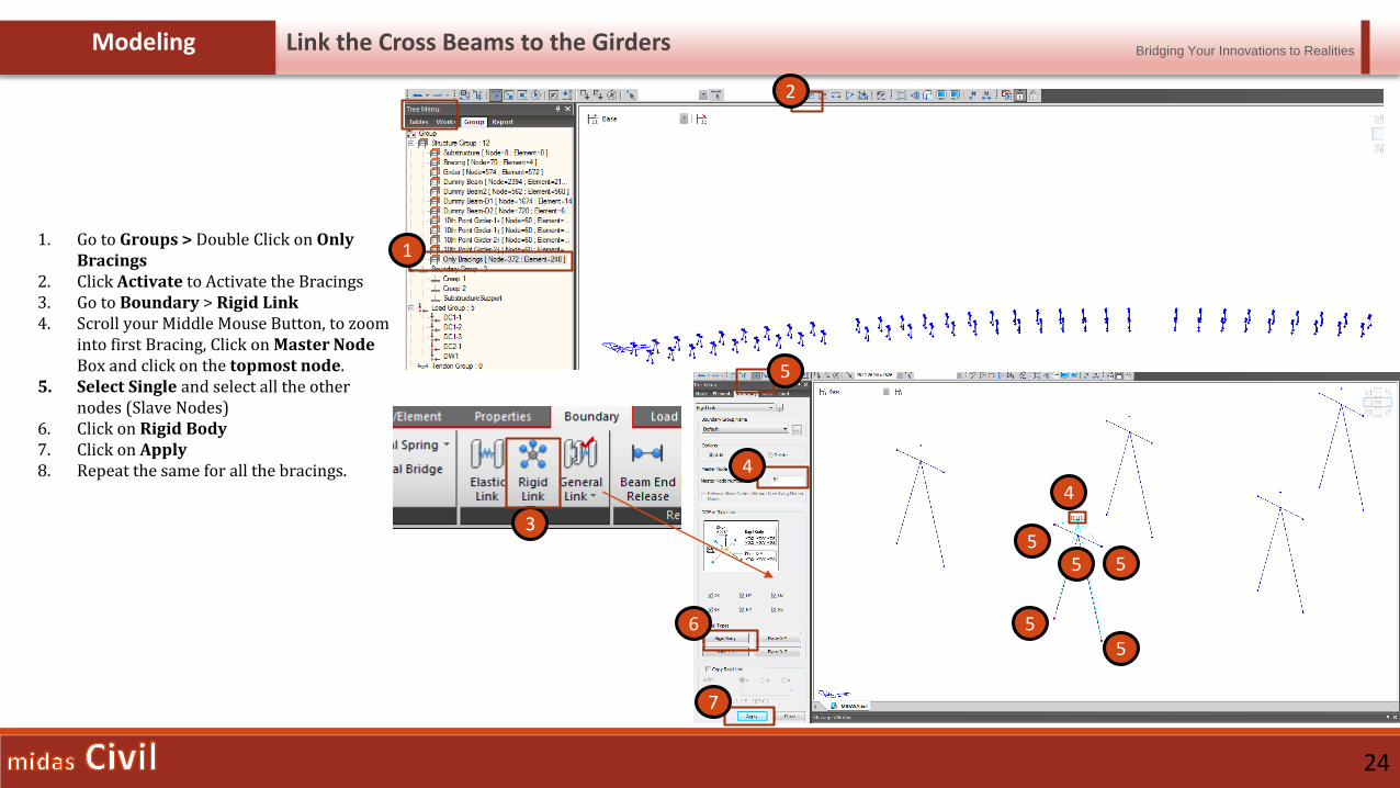
Modeling Link the Cross Beams to the Girders
1. Go to Groups > Double Click on Only Bracings
2. Click Activate to Activate the Bracings3. Go to Boundary > Rigid Link4. Scroll your Middle Mouse Button, to zoom
into first Bracing, Click on Master Node Box and click on the topmost node.
5. Select Single and select all the other nodes (Slave Nodes)
6. Click on Rigid Body7. Click on Apply8. Repeat the same for all the bracings.
1
2
3
6
7
4
4
5
55
55
5
Bridging Your Innovations to Realities
25
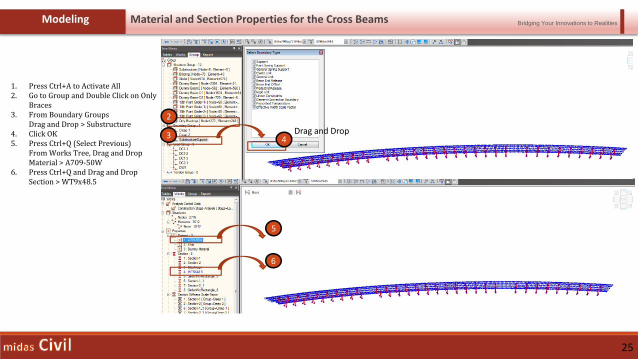
Modeling Material and Section Properties for the Cross Beams
1. Press Ctrl+A to Activate All2. Go to Group and Double Click on Only
Braces3. From Boundary Groups
Drag and Drop > Substructure4. Click OK5. Press Ctrl+Q (Select Previous)
From Works Tree, Drag and DropMaterial > A709-50W
6. Press Ctrl+Q and Drag and DropSection > WT9x48.5
2
3
5
6
4Drag and Drop
Bridging Your Innovations to Realities
26
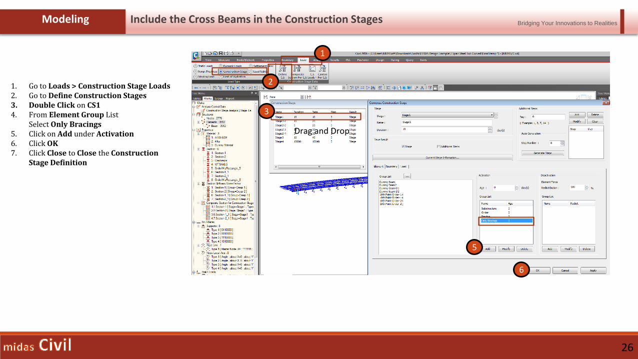
Modeling Include the Cross Beams in the Construction Stages
1. Go to Loads > Construction Stage Loads2. Go to Define Construction Stages3. Double Click on CS14. From Element Group List
Select Only Bracings5. Click on Add under Activation6. Click OK7. Click Close to Close the Construction
Stage Definition
2
3
5
6
Drag and Drop
1
Bridging Your Innovations to Realities
27
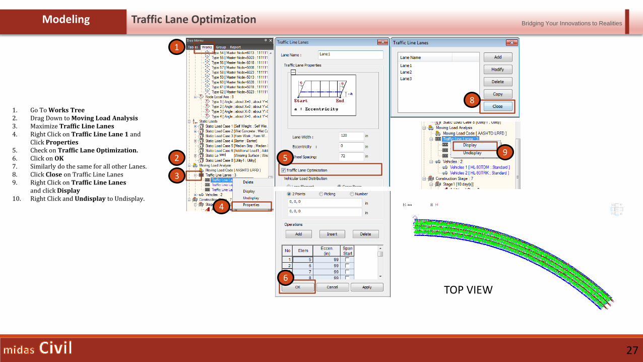
Modeling Traffic Lane Optimization
1. Go To Works Tree2. Drag Down to Moving Load Analysis3. Maximize Traffic Line Lanes4. Right Click on Traffic Line Lane 1 and
Click Properties5. Check on Traffic Lane Optimization.6. Click on OK7. Similarly do the same for all other Lanes.8. Click Close on Traffic Line Lanes9. Right Click on Traffic Line Lanes
and click Display10. Right Click and Undisplay to Undisplay.
1
2
3
4
95
6
8
TOP VIEW
Bridging Your Innovations to Realities
28
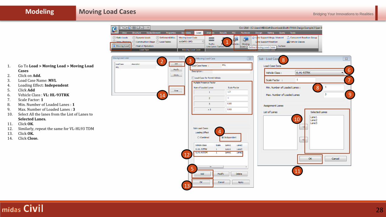
Modeling Moving Load Cases
1. Go To Load > Moving Load > Moving Load Cases
2. Click on Add.3. Load Case Name: MVL4. Loading Effect: Independent5. Click Add6. Vehicle Class : VL: HL-93TRK7. Scale Factor: 18. Min. Number of Loaded Lanes : 19. Max. Number of Loaded Lanes : 310. Select All the lanes from the List of Lanes to
Selected Lanes.11. Click OK.12. Similarly, repeat the same for VL-HL93 TDM13. Click OK.14. Click Close.
1
2
8
83
4
5
6
7
9
10
11
12
13
14
Bridging Your Innovations to Realities
29
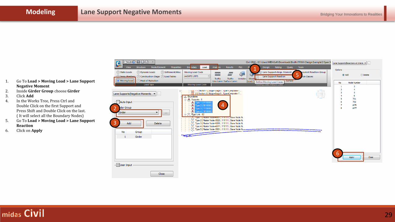
Modeling Lane Support Negative Moments
1. Go To Load > Moving Load > Lane Support Negative Moment
2. Inside Girder Group choose Girder3. Click Add4. In the Works Tree, Press Ctrl and
Double Click on the first Support andPress Shift and Double Click on the last.( It will select all the Boundary Nodes)
5. Go To Load > Moving Load > Lane Support Reaction
6. Click on Apply
1
2
3
4
6
5

Bridging Your Innovations to Realities
31
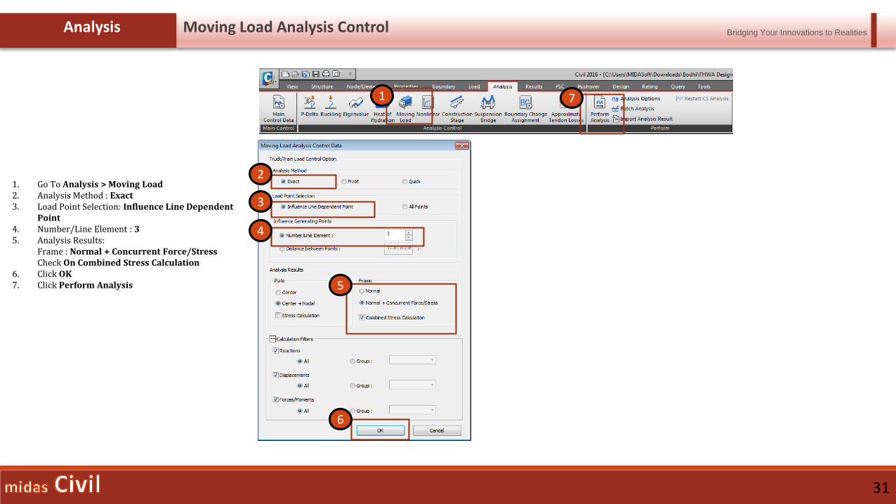
Analysis Moving Load Analysis Control
1. Go To Analysis > Moving Load2. Analysis Method : Exact3. Load Point Selection: Influence Line Dependent
Point4. Number/Line Element : 35. Analysis Results:
Frame : Normal + Concurrent Force/StressCheck On Combined Stress Calculation
6. Click OK7. Click Perform Analysis
1
2
3
4
6
5
7

For further queries and doubts write a mail to : [email protected]
Please join for the upcoming webinars