Embed Size (px)
Citation preview
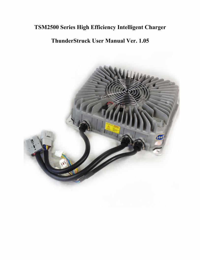
TSM2500 Series High Efficiency Intelligent Charger
ThunderStruck User Manual Ver. 1.05
Table Of Contents
I. Product Overview
II. Safety
III. Preventing Leakage and Fire
1.Correct use of Breakers, Sockets and Cables
2. Correct Use of Input Connections
3. Charging Environment Requirements
IV. Regular Maintenance
V. Technical Specifications
VI. Parts List
VII. LED Charge Light Information
VIII. Appearance and Installation Dimensions
IX. Connections and Wiring
X. Faults & Solutions
I Product Overview
The TSM2500 series high efficiency intelligent charger is designed to charge traction
batteries of electric vehicles. This series of products adopt the most advanced technologies such
as LLC resonant, active power factor correction, microcomputer measurement and control,
digital adjusting, and extremely water resistant technology. Its features include: wide input
voltage range, high input power factor that significantly reduces the input current as well as heat
generated from the input cable, and Low harmonic current that reduces interference to other
electric equipment. Full range soft switching is used to achieve high conversion efficiency and
very little electromagnetic interference. The charger is designed according to IP66 protection
grade and is highly water resistant. It is also small in size, lightweight, quiet, beautiful, simple to
install and of course easy operation and maintenance.
The charger uses microcomputer measurements and control technology, the embedded
CPU can accurately detect battery voltage and charge current.
The charger has temperature compensation functions, as well as automatic shut down
after being fully charged. Reverse battery connection protection as well as output short circuit
protection, AC input under voltage protection, and overheating protection . These functions help
to ensure safe and reliable use.
II Safety
1. Please do not disassemble the charger; this may cause electric shock or other injuries.
2. If the charger needs to be connected to an AC power supply with extension cables, please
make sure that the extension cable can withstand the maximum input current (GB 2.5mm2
copper core cable is recommended to be used), and limit the extension cable length within 10m.
3. Don’t place the charger where it can get wet, this may cause damage to the charger as
well as electric shock to the operator.
4. The charger’s DC output plug should be connected reliably to the socket, if they are
damaged or loose, please replace them immediately, otherwise it will cause overheating in the
plug position, and can even cause fire.
5. If the charger produces any abnormal sound or smell while on, please unplug the
power immediately and contact the service department. Do not attempt to open the charger case.
6. Make sure that all air vents are unobstructed to prevent charger overheating. Do not place
the charger near a heat source; the charger should be left with enough space to ensure proper
ventilation.
7. Please disconnect the charger's AC input power if you need to move it.
8. Make sure that AC power supply voltage matches chargers’ input voltage. For inquiries,
please contact your supplier or local power Supply Corporation.
9. Battery voltage and the nominal voltage of the charger must be matched or it
could damage both the charger and the batteries.
10. To avoid damage to the charger’s cables, do not pull, twist or shake the cables or the
connection terminals. If the cable is worn, please replace it immediately.
III Preventing Leakage and Fire
1. Correct use of Breakers, Sockets and Cables
1. Use copper core cables with flame-retardant jackets. The cables’ core diameter must be at
least 2.5mm in diameter.
2. Prevent plugs, sockets from coming in contact with water.
Note: According to statistics, 80% of electric car fires occur during charging. The main reasons
for this include insufficient core diameter, size of cables, poor quality plugs and sockets, poor
contact of plugs and sockets, poor flame-retardant sheath or shells of breakers, plugs and sockets
and so on.
2. Correct Use of Input Connections
Make sure that the plug is clean, undamaged and free of dirt before charging.
3. Charging Environment Requirements
Have it be spacious and away from flammable materials. Avoid mounting/placing the charging
plugs, charging cables or the charger itself on car cabs, synthetic seats and other flammable
objects.
4. Lithium Safety
A lithium battery pack should have a battery management system to ensure safe charging. A
battery pack with no BMS can be a very dangerous thing. We are not responsible for damage to
batteries due to using a charger with no BMS.
Most prismatic lithium batteries should be contained in a manner that prevents them from
swelling during charging and discharging. Consult your battery manufacturer’s recommendation
for the best way to package your cells.
IV Regular Maintenance
1. Check the J1772 Socket regularly for corrosion or other conduction inhibitors. Poor contact
may result in overheating and burning inside the socket, which although unlikely could cause
fire.
2. Make sure to use a charger that has a dedicated breaker and wire running to it.
3. Make sure that the charger’s shell and cooling fan are free of debris and dirt.
V Technical Specifications
Rated input voltage: 220VAC 50/60Hz
Input voltage range: 85~265VAC (Note: When the Input voltage is lower than 185VAC, the
output power will be limited to 1.5KW)
Power Factor: ≥ 0.99 @ 220VAC input, full power output;
Total Harmonic Current: ≤ 5% @ 220VAC input, full power output;
Nominal output voltage: 144V
Maxim output voltage: 180V
Rated output current: 15A
Voltage regulation accuracy: ≤ 0.5%
Current regulation accuracy: ≤ 2%
Conversion efficiency: ≥ 95% @ 220VAC input, full power output
Protection class: IP66
Audible Noise: ≤ 40dB
Seismic rating: Designed according to IEC60335-2-29-2004-Part.21
Working temperature: -25~55°C (Note: models whose output power greater than 2KW
Storage temperature: - 40~80°C
Recognition certificates: CE SGS will ensure 2KW output at 60°C. )
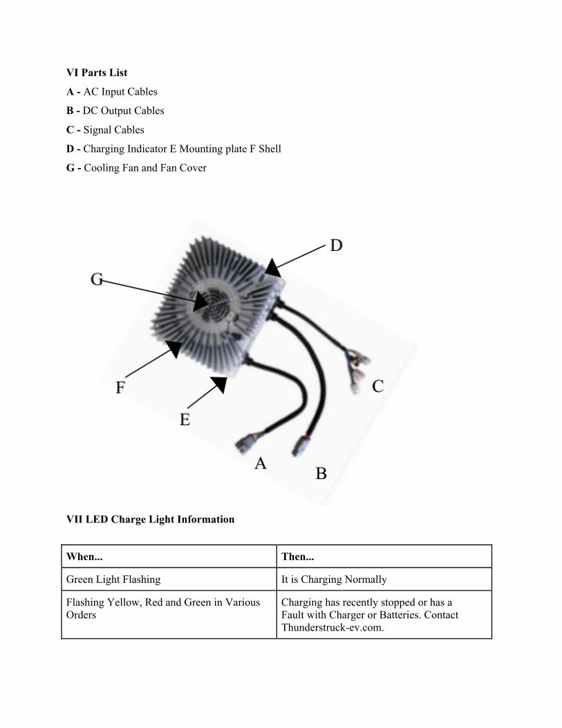
VI Parts List
A - AC Input Cables
B - DC Output Cables
C - Signal Cables
D - Charging Indicator E Mounting plate F Shell
G - Cooling Fan and Fan Cover
VII LED Charge Light Information
When... Then...
Green Light Flashing It is Charging Normally
Flashing Yellow, Red and Green in Various Orders
Charging has recently stopped or has a Fault with Charger or Batteries. Contact Thunderstruck-ev.com.
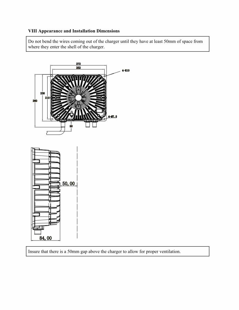
VIII Appearance and Installation Dimensions
Do not bend the wires coming out of the charger until they have at least 50mm of space from where they enter the shell of the charger.
Insure that there is a 50mm gap above the charger to allow for proper ventilation.
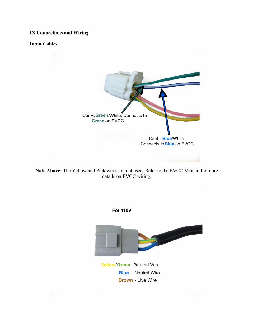
IX Connections and Wiring
Input Cables
Note Above: The Yellow and Pink wires are not used, Refer to the EVCC Manual for more details on EVCC wiring.
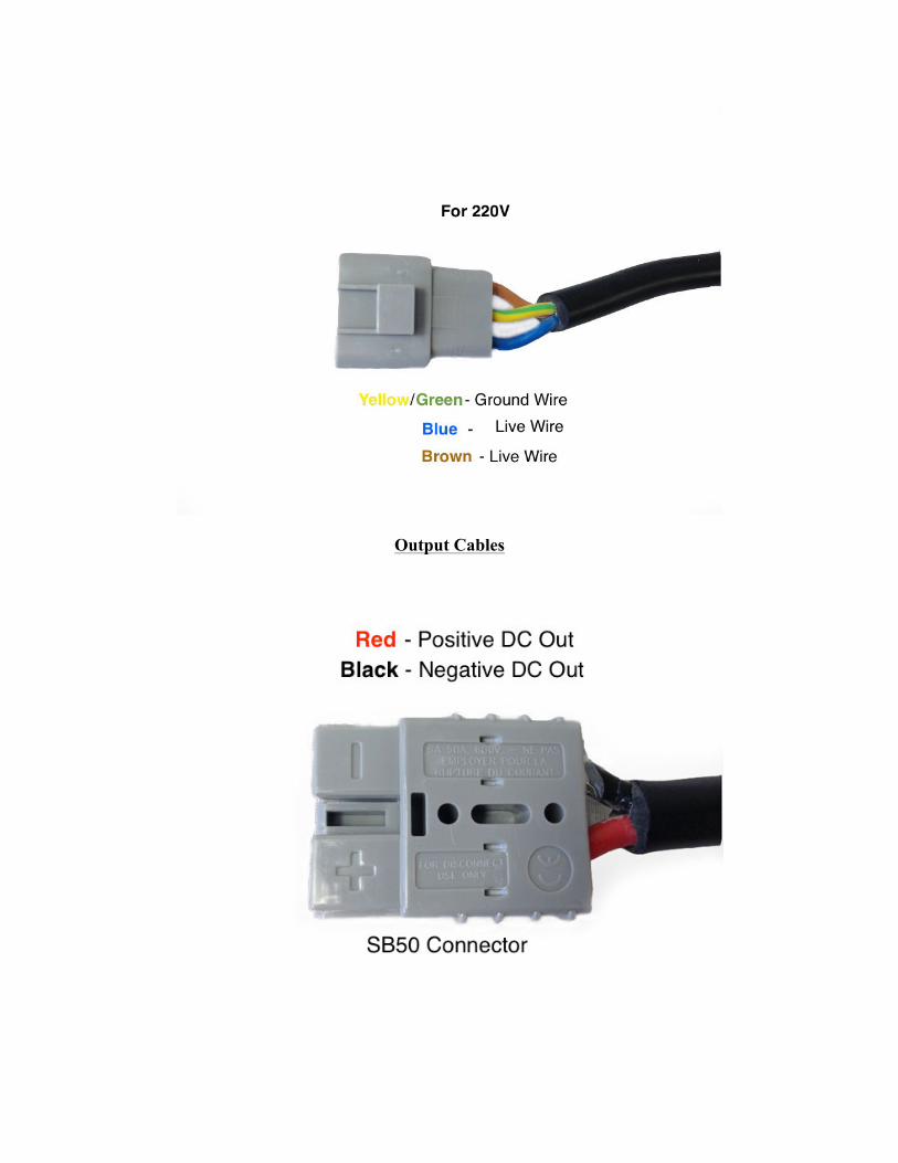
Output Cables
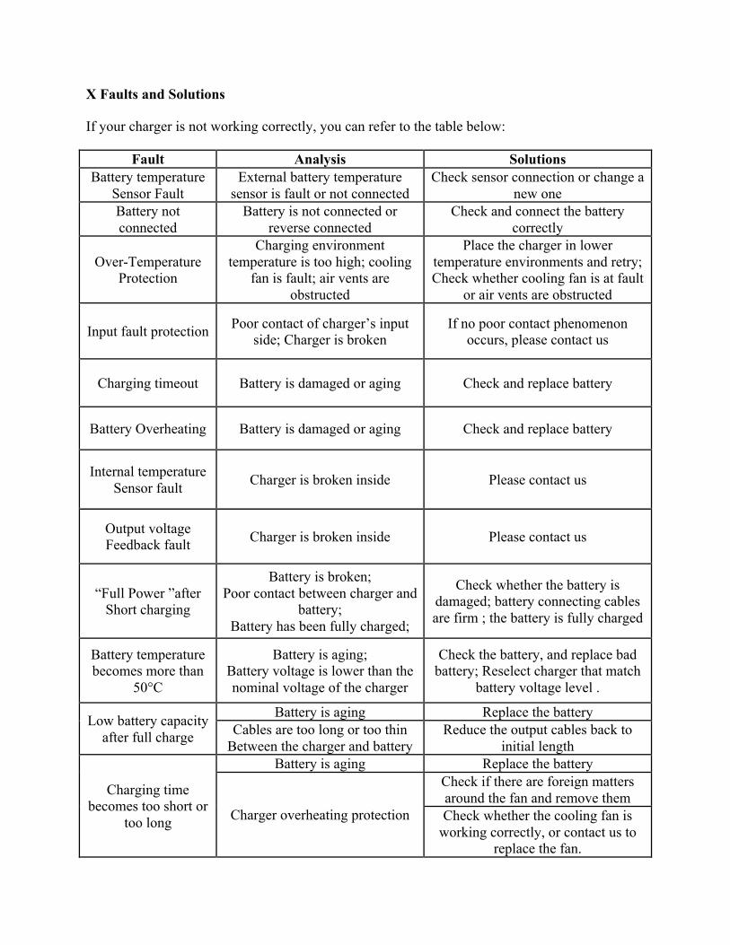
X Faults and Solutions
If your charger is not working correctly, you can refer to the table below:
Fault Analysis Solutions Battery temperature
Sensor Fault External battery temperature
sensor is fault or not connected Check sensor connection or change a
new one Battery not connected
Battery is not connected or reverse connected
Check and connect the battery correctly
Over-Temperature Protection
Charging environment temperature is too high; cooling
fan is fault; air vents are obstructed
Place the charger in lower temperature environments and retry; Check whether cooling fan is at fault
or air vents are obstructed
Input fault protection Poor contact of charger’s input side; Charger is broken
If no poor contact phenomenon occurs, please contact us
Charging timeout Battery is damaged or aging Check and replace battery
Battery Overheating Battery is damaged or aging Check and replace battery
Internal temperature Sensor fault Charger is broken inside Please contact us
Output voltage Feedback fault Charger is broken inside Please contact us
“Full Power ”after Short charging
Battery is broken; Poor contact between charger and
battery; Battery has been fully charged;
Check whether the battery is damaged; battery connecting cables are firm ; the battery is fully charged
Battery temperature becomes more than
50°C
Battery is aging; Battery voltage is lower than the nominal voltage of the charger
Check the battery, and replace bad battery; Reselect charger that match
battery voltage level .
Low battery capacity after full charge
Battery is aging Replace the battery Cables are too long or too thin
Between the charger and battery Reduce the output cables back to
initial length
Charging time becomes too short or
too long
Battery is aging Replace the battery
Charger overheating protection
Check if there are foreign matters around the fan and remove them Check whether the cooling fan is
working correctly, or contact us to replace the fan.
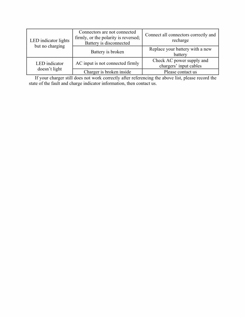
LED indicator lights but no charging
Connectors are not connected firmly, or the polarity is reversed;
Battery is disconnected
Connect all connectors correctly and recharge
Battery is broken Replace your battery with a new battery
LED indicator doesn’t light
AC input is not connected firmly Check AC power supply and chargers’ input cables
Charger is broken inside Please contact us If your charger still does not work correctly after referencing the above list, please record the
state of the fault and charge indicator information, then contact us.