Embed Size (px)
Citation preview
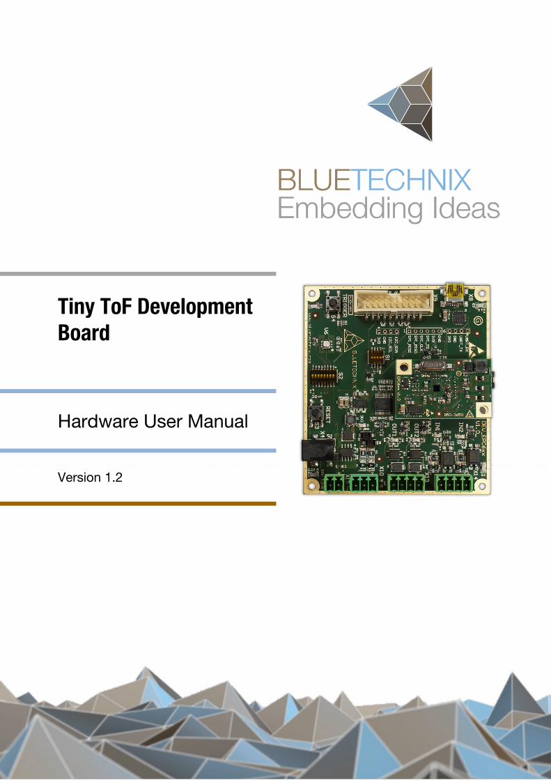
Tiny ToF Development Board
Hardware User Manual
Version 1.2
Contact
Bluetechnix
Waidhausenstraße 3/19
A-1140 Vienna
AUSTRIA
http://www.bluetechnix.com
Date: 2014-07-14
© Bluetechnix 2014
Table of Contents
1 General Information .......................................................................................................................... 6
1.1 Symbols Used ........................................................................................................................... 6
1.2 Certification ............................................................................................................................... 6
2 Introduction ...................................................................................................................................... 7
2.1 Overview ................................................................................................................................... 7
2.2 Key Features ............................................................................................................................. 7
2.2.1 Active components ............................................................................................................ 8
3 General Description .......................................................................................................................... 9
3.1 Functional Description .............................................................................................................. 9
3.1.1 EPC6xx ToF Module connector (p).................................................................................... 9
3.1.2 Power Supply (k, l) ............................................................................................................. 9
3.1.3 JTAG (d) ........................................................................................................................... 10
3.1.4 USB/UART (b) .................................................................................................................. 10
3.1.5 Reset Button (j) ................................................................................................................ 10
3.1.6 Trigger Button (g) ............................................................................................................. 10
3.1.7 Dual Color LED (h) ........................................................................................................... 10
3.1.8 GPIOs (o, n) ...................................................................................................................... 10
3.1.9 SPI (c) ............................................................................................................................... 11
3.1.10 I2C (e) ............................................................................................................................... 11
3.1.11 Modulation (ModLight) Interface (r) ................................................................................. 11
3.1.12 RS-232/RS-485 (m).......................................................................................................... 11
3.1.13 Configuration Switch 1 (f) ................................................................................................ 11
3.1.14 Configuration Switch 2 (i) ................................................................................................. 12
4 Specifications ................................................................................................................................. 13
4.1 Electrical Specifications .......................................................................................................... 13
4.1.1 Operating Conditions ....................................................................................................... 13
4.1.2 Absolute Maximum Ratings ............................................................................................. 13
4.1.3 ESD Sensitivity ................................................................................................................. 13
5 Connector Description ................................................................................................................... 14
5.1 EPC6xx ToF Module connector .............................................................................................. 14
6 Mechanical Outline ......................................................................................................................... 15
6.1 Top View ................................................................................................................................. 15
7 Support ........................................................................................................................................... 16
7.1 General Support ...................................................................................................................... 16
8 Ordering Information ...................................................................................................................... 17
9 Product History .............................................................................................................................. 18
© Bluetechnix 2014
9.1 Version Information ................................................................................................................. 18
9.1.1 Tiny ToF Development Board .......................................................................................... 18
9.2 Anomalies ................................................................................................................................ 18
10 Document Revision History ........................................................................................................ 19
11 List of Abbreviations ................................................................................................................... 20
A List of Figures and Tables .............................................................................................................. 21
© Bluetechnix 2014
© Bluetechnix 2014 All Rights Reserved. The information herein is given to describe certain components and shall not be considered as a guarantee of characteristics.
Terms of delivery and rights of technical change reserved.
We hereby disclaim any warranties, including but not limited to warranties of non-infringement, regarding circuits, descriptions and charts stated herein.
Bluetechnix makes and you receive no warranties or conditions, express, implied, statutory or in any communication with you. Bluetechnix specifically disclaims any implied warranty of merchantability or fitness for a particular purpose.
Bluetechnix takes no liability for any damages and errors causing of the usage of this board. The user of this board is responsible by himself for the functionality of his application. He is allowed to use the board only if he has the qualification. More information is found in the General Terms and Conditions (AGB).
Information
For further information on technology, delivery terms and conditions and prices please contact Bluetechnix (http://www.bluetechnix.com).
Warning
Due to technical requirements components may contain dangerous substances.
© Bluetechnix 2014
Hardware User Manual – Tiny ToF Development Board Last change: 14 July 2014 Version 1.2
1 General Information
This guide applies to the Tiny ToF Development Board from Bluetechnix GmbH. Follow this guide chapter by chapter to set up and understand your product.
The document applies to the X-Grade product.
1.1 Symbols Used
This guide makes use of a few symbols and conventions:
Warning
Indicates a situation which, if not avoided, could result in minor or moderate injury and/or property damage or damage to the device.
Caution
Indicates a situation which, if not avoided, may result in minor damage to the device, in malfunction of the device or in data loss.
Note
Notes provide information on special issues related to the device or provide information that will make operation of the device easier.
Procedures
A procedure always starts with a headline 1. The number indicates the step number of a certain procedure you are expected to
follow. Steps are numbered sequentially. This sign indicates an expected result of your action.
References
This symbol indicates a cross reference to a different chapter of this manual or to an external document.
1.2 Certification
X-Grade Version
X-Grade version of the products are not intended for sale and have therefore no certifications. The user is responsible for a correct usage in order with federal laws.
© Bluetechnix 2014 Page 6 | 21
Hardware User Manual – Tiny ToF Development Board Last change: 14 July 2014 Version 1.2
2 Introduction
2.1 Overview
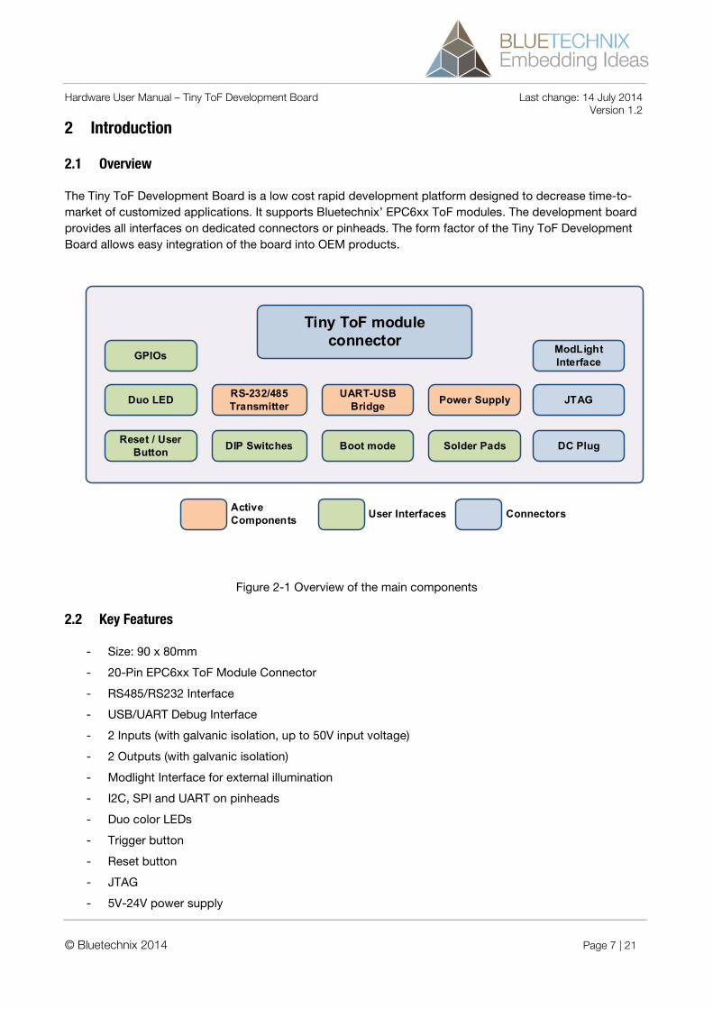
The Tiny ToF Development Board is a low cost rapid development platform designed to decrease time-to-market of customized applications. It supports Bluetechnix’ EPC6xx ToF modules. The development board provides all interfaces on dedicated connectors or pinheads. The form factor of the Tiny ToF Development Board allows easy integration of the board into OEM products.
DC Plug
Duo LED
Reset / User Button
Tiny ToF module connector
UART-USB Bridge Power Supply
Active Components User Interfaces Connectors
DIP Switches Boot mode
RS-232/485 Transmitter
Solder Pads
ModLight Interface
JTAG
GPIOs
Figure 2-1 Overview of the main components
2.2 Key Features
- Size: 90 x 80mm
- 20-Pin EPC6xx ToF Module Connector
- RS485/RS232 Interface
- USB/UART Debug Interface
- 2 Inputs (with galvanic isolation, up to 50V input voltage)
- 2 Outputs (with galvanic isolation)
- Modlight Interface for external illumination
- I2C, SPI and UART on pinheads
- Duo color LEDs
- Trigger button
- Reset button
- JTAG
- 5V-24V power supply
© Bluetechnix 2014 Page 7 | 21
Hardware User Manual – Tiny ToF Development Board Last change: 14 July 2014 Version 1.2
2.2.1 Active components
- USB/UART Bridge (CP2102)
- RS-232/RS-485 Transceiver (ISL3330)
- StepDown Converter (MPM3620)
© Bluetechnix 2014 Page 8 | 21
Hardware User Manual – Tiny ToF Development Board Last change: 14 July 2014 Version 1.2
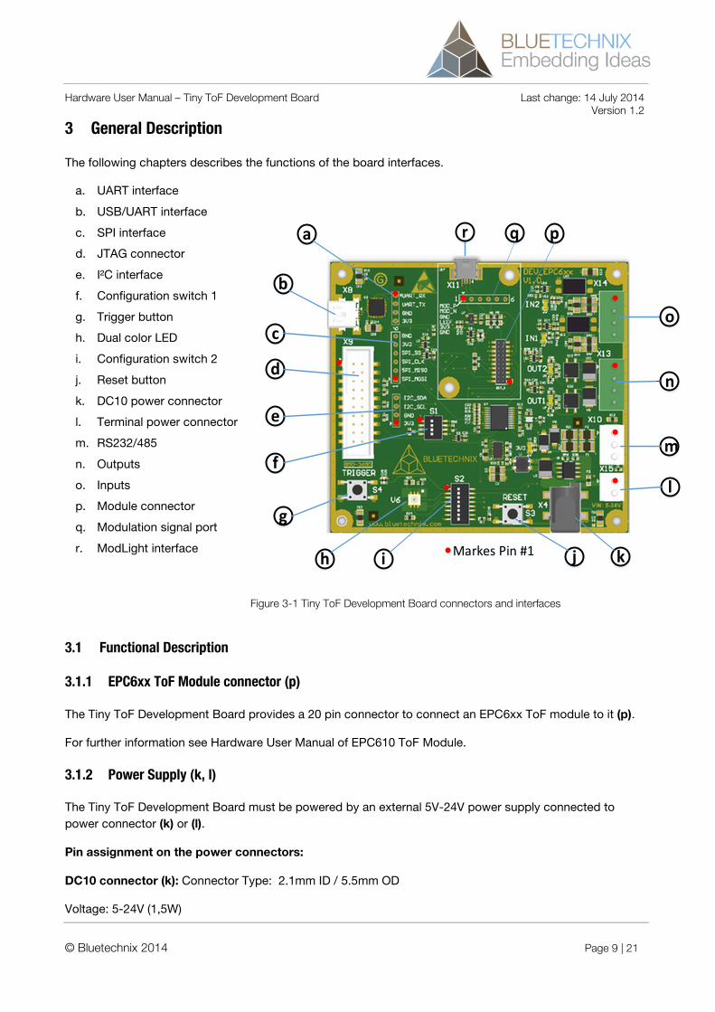
3 General Description
The following chapters describes the functions of the board interfaces.
a. UART interface
b. USB/UART interface
c. SPI interface
d. JTAG connector
e. I²C interface
f. Configuration switch 1
g. Trigger button
h. Dual color LED
i. Configuration switch 2
j. Reset button
k. DC10 power connector
l. Terminal power connector
m. RS232/485
n. Outputs
o. Inputs
p. Module connector
q. Modulation signal port
r. ModLight interface
Markes Pin #1
b
c
d
a
e
f
g
h j k
l
m
n
i
o
pqr
Figure 3-1 Tiny ToF Development Board connectors and interfaces
3.1 Functional Description
3.1.1 EPC6xx ToF Module connector (p)
The Tiny ToF Development Board provides a 20 pin connector to connect an EPC6xx ToF module to it (p).
For further information see Hardware User Manual of EPC610 ToF Module.
3.1.2 Power Supply (k, l)
The Tiny ToF Development Board must be powered by an external 5V-24V power supply connected to power connector (k) or (l).
Pin assignment on the power connectors:
DC10 connector (k): Connector Type: 2.1mm ID / 5.5mm OD
Voltage: 5-24V (1,5W)
© Bluetechnix 2014 Page 9 | 21
Hardware User Manual – Tiny ToF Development Board Last change: 14 July 2014 Version 1.2 Polarity:
Terminal connector (l): Pin #1: +5V-24V, Pin#2: GND
3.1.3 JTAG (d)
A standard ARM JTAG connector (20 pins, 2.54mm pitch) (d) is available for processor debugging.
3.1.4 USB/UART (b)
An EPC6xx ToF module UART is routed through a USB/UART bridge (CP2102 Silicon Labs) to the connector (b). The same UART is also available on pinheads (a).
Note
Switch 8 of DIP switch (i) must be in OFF position.
3.1.5 Reset Button (j)
The Tiny ToF Development Board provides a reset button (j) to reset the EPC6xx ToF module.
3.1.6 Trigger Button (g)
The Tiny ToF Development Board provides a trigger button (g) which is connected to pin 14 of the EPC6xx ToF module connector.
Note
Switch 1 of DIP switch (i) must be in ON position.
3.1.7 Dual Color LED (h)
The Dual Color LED (h) is connected to the pins 6 and 12 of the module connector and can be used for status signaling.
Note
Switches 6 and 7 of DIP switch (i) must be in ON position.
3.1.8 GPIOs (o, n)
Two galvanic isolated inputs (o) and two galvanic isolated outputs (n) are available on the Tiny ToF Development Board. The current status of the GPIOs are shown by Status LEDs (IN1, IN2, OUT1, OUT2).
Note
Switches 6, 7 and 8 of DIP switch (i) must be in OFF position.
© Bluetechnix 2014 Page 10 | 21
Hardware User Manual – Tiny ToF Development Board Last change: 14 July 2014 Version 1.2
Warning
Do not exceed the maximum allowed voltages and currents. (see 4.1.1)
3.1.9 SPI (c)
The SPI interface of the EPC6xx ToF module is available on pinheads (c).
3.1.10 I2C (e)
The I2C interface of the EPC6xx ToF module is available on pinheads (e).
3.1.11 Modulation (ModLight) Interface (r)
For connection of an external IR light source, a Modulation light signal connector is available on the Tiny ToF Development Board. The same signals are also available on pinheads (q).
Note
Resistors R4 and R9 must be depopulated and resistors R1 and R6 must be populated (0R, 0402). The used EPC6xx ToF module must be configured for external illumination. (For further information see Hardware User Manuel of EPC610 ToF Module).
Note
Keep the connection between the ModLight interface and the external IR light source as short as possible.
3.1.12 RS-232/RS-485 (m)
A RS-232/485 interface is available on the Tiny ToF Development Board.
Note
Switch 8 of DIP switch (i) must be in ON position. Switch 3 of DIP switch (f) must be in ON position. Switch 2 of DIP switch (f) switches between RS-232 (OFF) and RS-285 (ON).
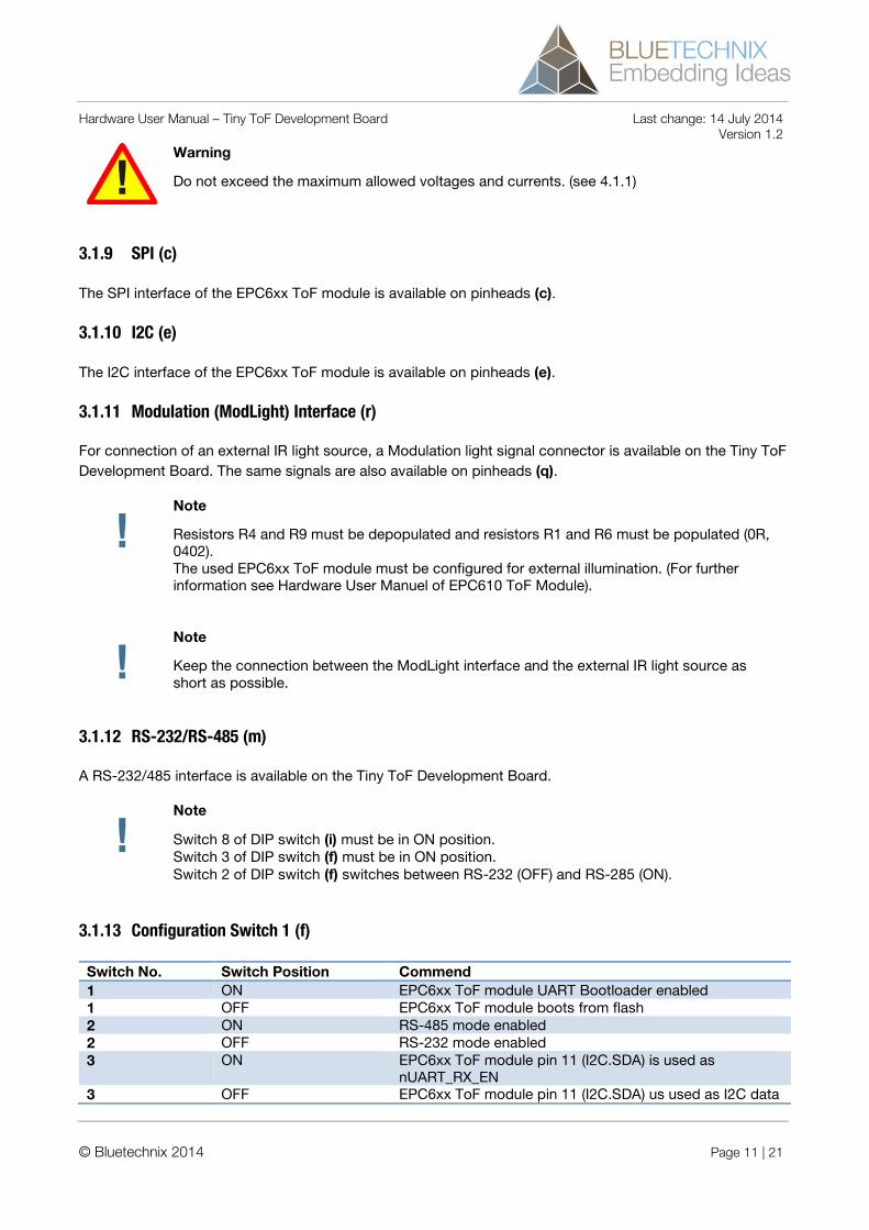
3.1.13 Configuration Switch 1 (f)
Switch No. Switch Position Commend 1 ON EPC6xx ToF module UART Bootloader enabled 1 OFF EPC6xx ToF module boots from flash 2 ON RS-485 mode enabled 2 OFF RS-232 mode enabled 3 ON EPC6xx ToF module pin 11 (I2C.SDA) is used as
nUART_RX_EN 3 OFF EPC6xx ToF module pin 11 (I2C.SDA) us used as I2C data
© Bluetechnix 2014 Page 11 | 21
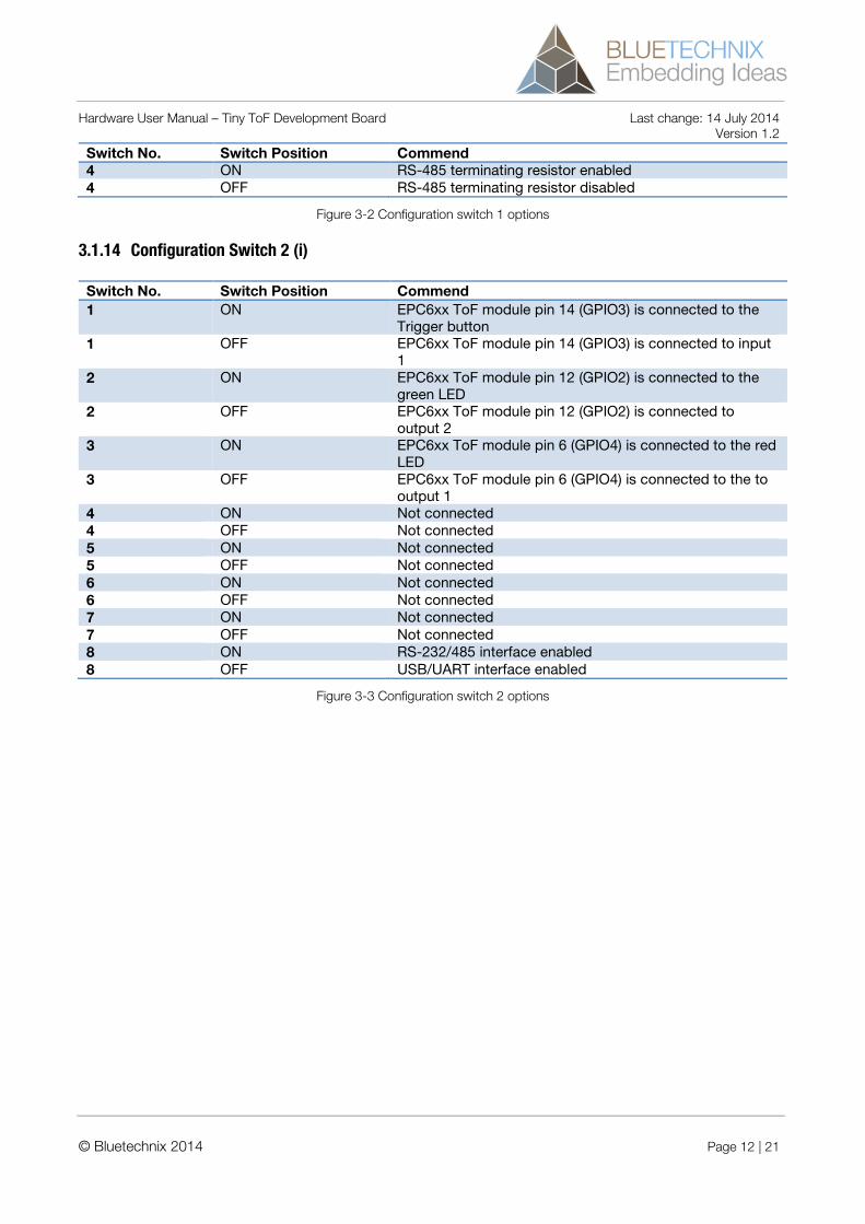
Hardware User Manual – Tiny ToF Development Board Last change: 14 July 2014 Version 1.2 Switch No. Switch Position Commend 4 ON RS-485 terminating resistor enabled 4 OFF RS-485 terminating resistor disabled
Figure 3-2 Configuration switch 1 options
3.1.14 Configuration Switch 2 (i)
Switch No. Switch Position Commend 1 ON EPC6xx ToF module pin 14 (GPIO3) is connected to the
Trigger button 1 OFF EPC6xx ToF module pin 14 (GPIO3) is connected to input
1 2 ON EPC6xx ToF module pin 12 (GPIO2) is connected to the
green LED 2 OFF EPC6xx ToF module pin 12 (GPIO2) is connected to
output 2 3 ON EPC6xx ToF module pin 6 (GPIO4) is connected to the red
LED 3 OFF EPC6xx ToF module pin 6 (GPIO4) is connected to the to
output 1 4 ON Not connected 4 OFF Not connected 5 ON Not connected 5 OFF Not connected 6 ON Not connected 6 OFF Not connected 7 ON Not connected 7 OFF Not connected 8 ON RS-232/485 interface enabled 8 OFF USB/UART interface enabled
Figure 3-3 Configuration switch 2 options
© Bluetechnix 2014 Page 12 | 21
Hardware User Manual – Tiny ToF Development Board Last change: 14 July 2014 Version 1.2
4 Specifications
4.1 Electrical Specifications
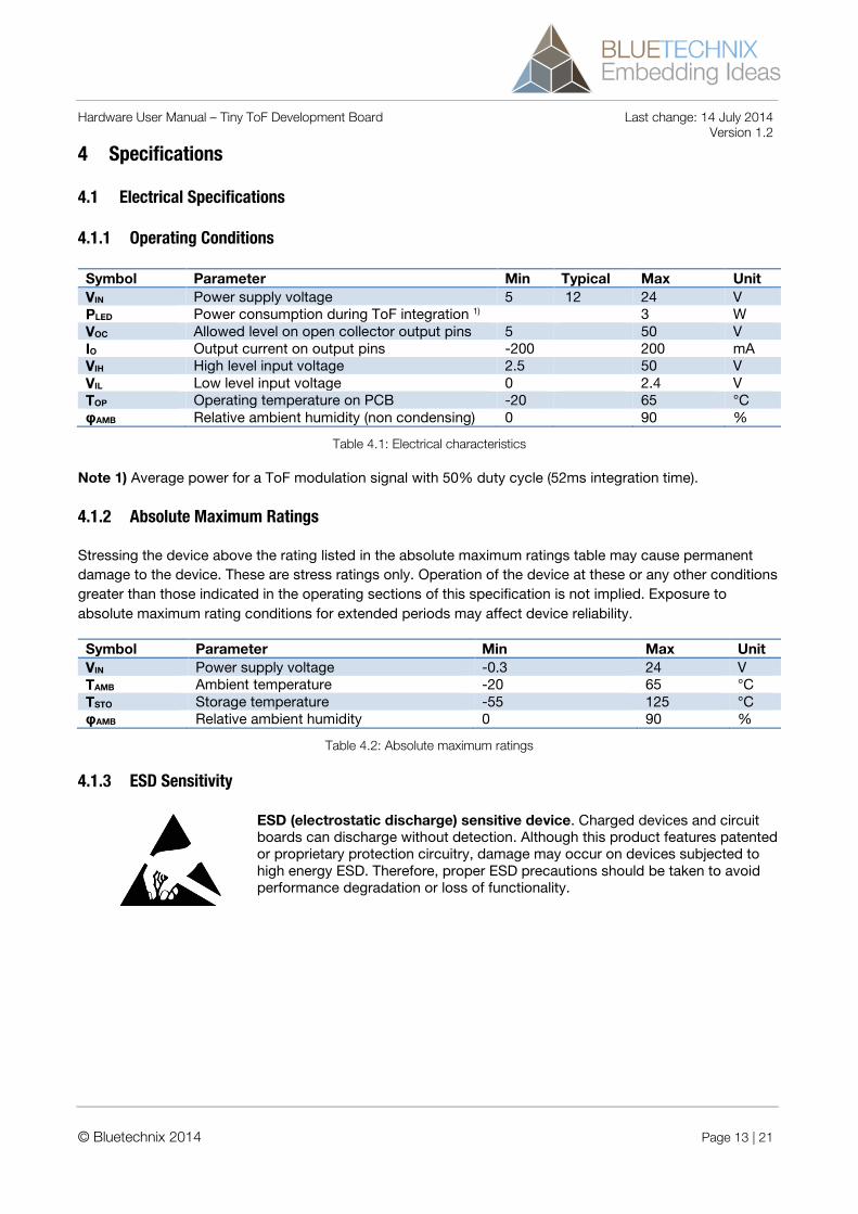
4.1.1 Operating Conditions
Symbol Parameter Min Typical Max Unit VIN Power supply voltage 5 12 24 V PLED Power consumption during ToF integration 1) 3 W VOC Allowed level on open collector output pins 5 50 V IO Output current on output pins -200 200 mA VIH High level input voltage 2.5 50 V VIL Low level input voltage 0 2.4 V TOP Operating temperature on PCB -20 65 °C φAMB Relative ambient humidity (non condensing) 0 90 %
Table 4.1: Electrical characteristics
Note 1) Average power for a ToF modulation signal with 50% duty cycle (52ms integration time).
4.1.2 Absolute Maximum Ratings
Stressing the device above the rating listed in the absolute maximum ratings table may cause permanent damage to the device. These are stress ratings only. Operation of the device at these or any other conditions greater than those indicated in the operating sections of this specification is not implied. Exposure to absolute maximum rating conditions for extended periods may affect device reliability.
Symbol Parameter Min Max Unit VIN Power supply voltage -0.3 24 V TAMB Ambient temperature -20 65 °C TSTO Storage temperature -55 125 °C φAMB Relative ambient humidity 0 90 %
Table 4.2: Absolute maximum ratings
4.1.3 ESD Sensitivity
ESD (electrostatic discharge) sensitive device. Charged devices and circuit boards can discharge without detection. Although this product features patented or proprietary protection circuitry, damage may occur on devices subjected to high energy ESD. Therefore, proper ESD precautions should be taken to avoid performance degradation or loss of functionality.
© Bluetechnix 2014 Page 13 | 21
Hardware User Manual – Tiny ToF Development Board Last change: 14 July 2014 Version 1.2
5 Connector Description
5.1 EPC6xx ToF Module connector
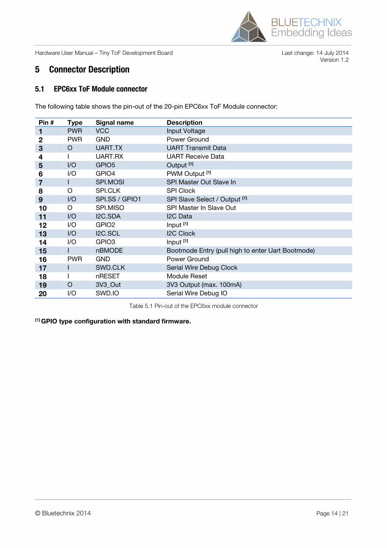
The following table shows the pin-out of the 20-pin EPC6xx ToF Module connector:
Pin # Type Signal name Description 1 PWR VCC Input Voltage 2 PWR GND Power Ground 3 O UART.TX UART Transmit Data 4 I UART.RX UART Receive Data 5 I/O GPIO5 Output [1] 6 I/O GPIO4 PWM Output [1]
7 I SPI.MOSI SPI Master Out Slave In 8 O SPI.CLK SPI Clock 9 I/O SPI.SS / GPIO1 SPI Slave Select / Output [1] 10 O SPI.MISO SPI Master In Slave Out 11 I/O I2C.SDA I2C Data 12 I/O GPIO2 Input [1] 13 I/O I2C.SCL I2C Clock 14 I/O GPIO3 Input [1] 15 I nBMODE Bootmode Entry (pull high to enter Uart Bootmode) 16 PWR GND Power Ground 17 I SWD.CLK Serial Wire Debug Clock 18 I nRESET Module Reset 19 O 3V3_Out 3V3 Output (max. 100mA) 20 I/O SWD.IO Serial Wire Debug IO
Table 5.1 Pin-out of the EPC6xx module connector
[1] GPIO type configuration with standard firmware.
© Bluetechnix 2014 Page 14 | 21
Hardware User Manual – Tiny ToF Development Board Last change: 14 July 2014 Version 1.2
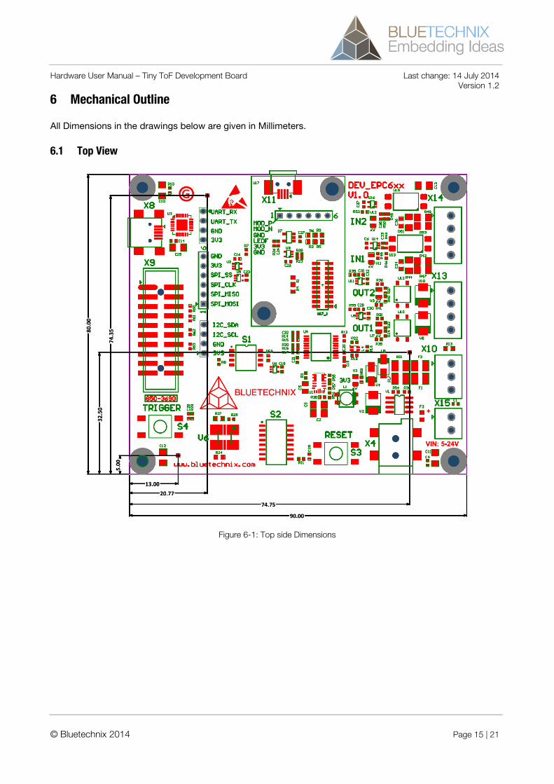
6 Mechanical Outline
All Dimensions in the drawings below are given in Millimeters.
6.1 Top View
Figure 6-1: Top side Dimensions
© Bluetechnix 2014 Page 15 | 21
Hardware User Manual – Tiny ToF Development Board Last change: 14 July 2014 Version 1.2
7 Support
7.1 General Support
General support for products can be found at Bluetechnix’ support site http://support.bluetechnix.at
© Bluetechnix 2014 Page 16 | 21
Hardware User Manual – Tiny ToF Development Board Last change: 14 July 2014 Version 1.2
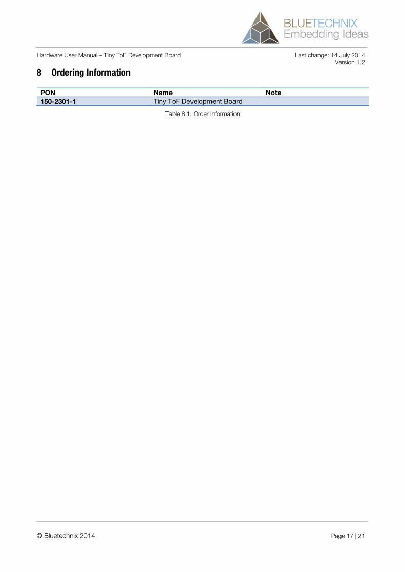
8 Ordering Information
PON Name Note 150-2301-1 Tiny ToF Development Board
Table 8.1: Order Information
© Bluetechnix 2014 Page 17 | 21
Hardware User Manual – Tiny ToF Development Board Last change: 14 July 2014 Version 1.2
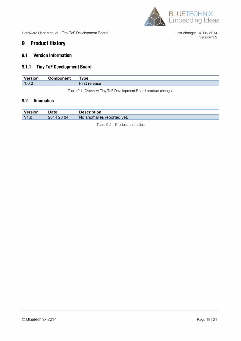
9 Product History
9.1 Version Information
9.1.1 Tiny ToF Development Board
Version Component Type 1.0.0 First release
Table 9.1: Overview Tiny ToF Development Board product changes
9.2 Anomalies
Version Date Description V1.0 2014 23 04 No anomalies reported yet.
Table 9.2 – Product anomalies
© Bluetechnix 2014 Page 18 | 21
Hardware User Manual – Tiny ToF Development Board Last change: 14 July 2014 Version 1.2
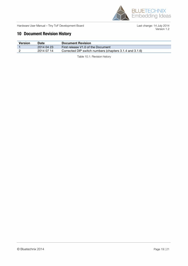
10 Document Revision History
Version Date Document Revision 1 2014 04 23 First release V1.0 of the Document 2 2014 07 14 Corrected DIP switch numbers (chapters 3.1.4 and 3.1.6)
Table 10.1: Revision history
© Bluetechnix 2014 Page 19 | 21
Hardware User Manual – Tiny ToF Development Board Last change: 14 July 2014 Version 1.2
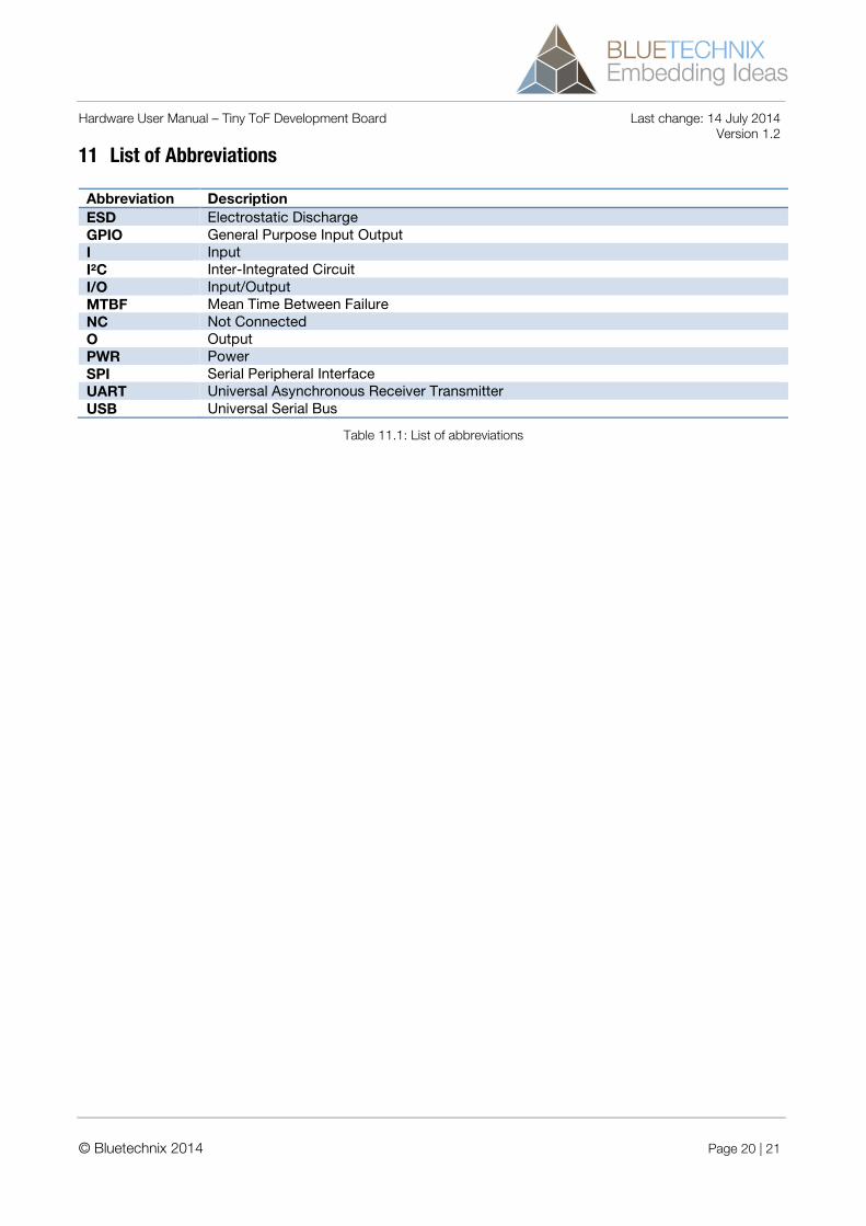
11 List of Abbreviations
Abbreviation Description ESD Electrostatic Discharge GPIO General Purpose Input Output I Input I²C Inter-Integrated Circuit I/O Input/Output MTBF Mean Time Between Failure NC Not Connected O Output PWR Power SPI Serial Peripheral Interface UART Universal Asynchronous Receiver Transmitter USB Universal Serial Bus
Table 11.1: List of abbreviations
© Bluetechnix 2014 Page 20 | 21
Hardware User Manual – Tiny ToF Development Board Last change: 14 July 2014 Version 1.2
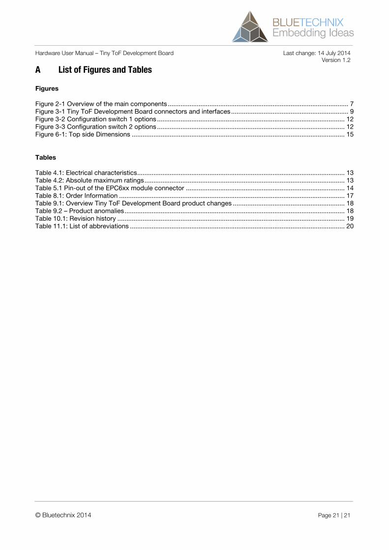
A List of Figures and Tables
Figures
Figure 2-1 Overview of the main components .................................................................................................... 7 Figure 3-1 Tiny ToF Development Board connectors and interfaces ................................................................. 9 Figure 3-2 Configuration switch 1 options ........................................................................................................ 12 Figure 3-3 Configuration switch 2 options ........................................................................................................ 12 Figure 6-1: Top side Dimensions ...................................................................................................................... 15
Tables
Table 4.1: Electrical characteristics ................................................................................................................... 13 Table 4.2: Absolute maximum ratings ............................................................................................................... 13 Table 5.1 Pin-out of the EPC6xx module connector ........................................................................................ 14 Table 8.1: Order Information ............................................................................................................................. 17 Table 9.1: Overview Tiny ToF Development Board product changes .............................................................. 18 Table 9.2 – Product anomalies .......................................................................................................................... 18 Table 10.1: Revision history .............................................................................................................................. 19 Table 11.1: List of abbreviations ....................................................................................................................... 20
© Bluetechnix 2014 Page 21 | 21