Embed Size (px)
Citation preview
TM 9-1300-251-20&PTECHNICAL MANUAL
MAINTENANCE MANUAL(INCLUDING REPAIR PARTS AND SPECIAL TOOLS LISTS)
UNIT
ARTILLERY AMMUNITIONFOR
GUNS, HOWITZERS, MORTARS,RECOILLESS RIFLES,
AND40MM GRENADE LAUNCHERS
SUPERSEDURE NOTICE - This manual supersedes TM 9-1300-251-20&P, 11 May 1994, including all changes.
DISTRIBUTION STATEMENT A - Approved for public release; distribution is unlimited.
HEADQUARTERS, DEPARTMENT OF THE ARMY
12 FEBRUARY 2003
TM 9-1300-251-20&PC6
CHANGE ) HEADQUARTERS) DEPARTMENT OF THE ARMY
NO. 6 ) WASHINGTON, DC, 11 February 2010
Unit Maintenance Manual(Including Repair Parts and Special Tools List)
Artillery Ammunitionfor
Guns, Howitzers, Mortars, Recoilless Rifles,and 40mm Grenade Launchers
DISTRIBUTION STATEMENT A - Approved for public release; distribution is unlimited.
TM 9-1300-251-20&P, 12 February 2003, is changed as follows:
1. File this change sheet in front of the publication for reference purposes.2. Remove old pages and insert new pages as indicated below.3. New or changed material is indicated by a vertical bar in the outer margin of the page.
Remove Pages Insert Pages
A and B A and B2-11 and 2-12 2-11 and 2-12F-3 and F-4 F-3 and F-4
DISTRIBUTION: To be distributed in accordance with the initial distribution number (IDN) 400301 requirements for TM 9-1300-251-20&P.
1004806
By Order of the Secretary of the Army:
GEORGE W. CASEY, JR. General, United States Army
Chief of StaffOfficial:
JOYCE E. MORROW Administrative Assistant to the
Secretary of the Army
CHANGE ) HEADQUARTERS) DEPARTMENT OF THE ARMY
NO. 5 ) WASHINGTON, DC, 20 JUNE 2008
Unit Maintenance Manual(Including Repair Parts and Special Tools List)
Artillery Ammunitionfor
Guns, Howitzers, Mortars, Recoilless Rifles,and 40mm Grenade Launchers
DISTRIBUTION STATEMENT A - Approved for public release; distribution is unlimited.
TM 9-1300-251-20&P, 12 February 2003, is changed as follows:
1. File this change sheet in front of the publication for reference purposes.2. Remove old pages and insert new pages as indicated below.3. New or changed material is indicated by a vertical bar in the outer margin of the page.
Remove Pages Insert Pages
A and B A and Bi and ii i and ii1-1 and 1-2 1-1 and 1-22-21 thru 2-26 2-21 thru 2-26A-1 and A-2 A-1 and A-2B-25 and B-26 B-25 and B-26E-9 thru E-12 E-9 thru E-12F-3 thru F-6 F-3 thru F-6F-9 thru F-12 F-9 thru F-12
DISTRIBUTION: To be distributed in accordance with the initial distribution number 400301 requirements for TM 9-1300-251-20&P.
0815103
By Order of the Secretary of the Army:
GEORGE W. CASEY, JR. General, United States Army
Chief of StaffOfficial:
JOYCE E. MORROW Administrative Assistant to the
Secretary of the Army
TM 9-1300-251-20&PC5
TM 9-1300-251-20&PC4
CHANGE ) HEADQUARTERS) DEPARTMENT OF THE ARMY
NO. 4 ) WASHINGTON, DC, 01 September 2006
Unit Maintenance Manual(Including Repair Parts and Special Tools List)
Artillery Ammunitionfor
Guns, Howitzers, Mortars, Recoilless Rifles,and 40mm Grenade Launchers
DISTRIBUTION STATEMENT A - Approved for public release; distribution is unlimited.
TM 9-1300-251-20&P, 12 February 2003, is changed as follows:
1. File this change sheet in front of the publication for reference purposes.2. Remove old pages and insert new pages as indicated below.3. New or changed material is indicated by a vertical bar in the outer margin of the page.4. Added or revised illustrations are indicated by a vertical bar adjacent to the illustration identification number.
Remove Pages Insert Pages
A and B A and Biii and iv iii and iv2-7 and 2-8 2-7 and 2-82-31 thru 2-34 2-31 thru 2-343-43 and 3-44 3-43 and 3-443-44.1 and 3-44.2 3-44.1 and 3-44.2E-5 thru E-8 E-5 thru E-8E-11 and E-12 E-11 and E-12F-9 thru F-12 F-9 thru F-12DA Form 2028-2 DA Form 2028
DISTRIBUTION: To be distributed in accordance with the initial distribution number 400301 requirements for TM 9-1300-251-20&P.
0613701
CHANGE ) HEADQUARTERS) DEPARTMENT OF THE ARMY
NO. 3 ) WASHINGTON, DC, 20 January 2005
Unit Maintenance Manual(Including Repair Parts and Special Tools List)
Artillery Ammunitionfor
Guns, Howitzers, Mortars, Recoilless Rifles,and 40mm Grenade Launchers
DISTRIBUTION STATEMENT A - Approved for public release; distribution is unlimited.
TM 9-1300-251-20&P, 12 February 2003, is changed as follows:
1. File this change sheet in front of the publication for reference purposes.2. Remove old pages and insert new pages as indicated below.3. New or changed material is indicated by a vertical bar in the outer margin of the page.4. Added or revised illustrations are indicated by a vertical bar adjacent to the illustration identification number.
Remove Pages Insert Pages
A and B A and Bi thru iv i thru iv2-3 and 2-4 2-3 and 2-42-7 and 2-8 2-7 and 2-83-13 and 3-14 3-13 and 3-143-43 and 3-44 3-43 and 3-44None 3-44.1 and 3-44.23-45 and 3-46 3-45 and 3-46E-3 thru E-6 E-3 thru E-6F-9 and F-10 F-9 and F-10F-15 and F-16 F-15 and F-16
DISTRIBUTION: To be distributed in accordance with the initial distribution number 400301 requirements for TM 9-1300-251-20&P.
0435705
TM 9-1300-251-20&PC3
CHANGE ) HEADQUARTERS) DEPARTMENT OF THE ARMY
NO. 2 ) WASHINGTON, DC, 18 May 2004
Unit Maintenance Manual(Including Repair Parts and Special Tools List)
Artillery Ammunitionfor
Guns, Howitzers, Mortars, Recoilless Rifles,and 40mm Grenade Launchers
DISTRIBUTION STATEMENT A - Approved for public release; distribution is unlimited.
TM 9-1300-251-20&P, 12 February 2003, is changed as follows:
1. File this change sheet in front of the publication for reference purposes.2. Remove old pages and insert new pages as indicated below.3. New or changed material is indicated by a vertical bar in the outer margin of the page.
Remove Pages Insert Pages
A and B A and Bi and ii i and ii2-11 and 2-12 2-11 and 2-12E-3 and E-4 E-3 and E-4F-3 and F-4 F-3 and F-4
DISTRIBUTION: To be distributed in accordance with the initial distribution number 400301 requirements for TM 9-1300-251-20&P.
0411402
TM 9-1300-251-20&PC2
CHANGE ) HEADQUARTERS) DEPARTMENT OF THE ARMY
NO. 1 ) WASHINGTON, DC, 17 October 2003
Unit Maintenance Manual(Including Repair Parts and Special Tools List)
Artillery Ammunitionfor
Guns, Howitzers, Mortars, Recoilless Rifles,and 40mm Grenade Launchers
DISTRIBUTION STATEMENT A - Approved for public release; distribution is unlimited.
TM 9-1300-251-20&P, 12 February 2003, is changed as follows:
1. File this change sheet in front of the publication for reference purposes.2. Remove old pages and insert new pages as indicated below.3. New or changed material is indicated by a vertical bar in the outer margin of the page.4. Added or revised appendixes are indicated by a vertical bar adjacent to the appendix title.
Remove Pages Insert Pages
A and B A and B2-17 and 2-18 2-17 and 2-182-21 and 2-22 2-21 and 2-222-25 and 2-26 2-25 and 2-26E-5 thru E-10 E-5 thru E-10F-3 thru F-6 F-3 thru F-6F-9 and F-10 F-9 and F-10
DISTRIBUTION: To be distributed in accordance with the initial distribution number 400301 requirements for TM 9-1300-251-20&P.
0326001
TM 9-1300-251-20&PC1
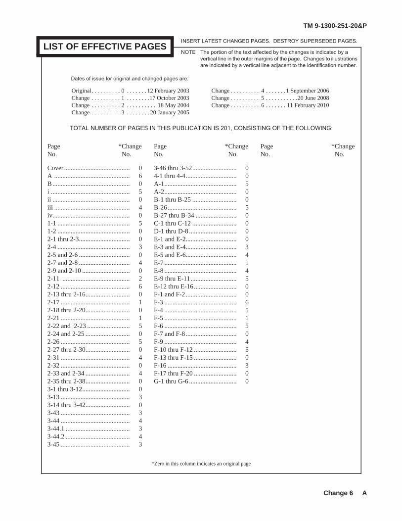
TM 9-1300-251-20&P
Change 6 A
*Zero in this column indicates an original page
LIST OF EFFECTIVE PAGESNOTE The portion of the text affected by the changes is indicated by a
vertical line in the outer margins of the page. Changes to illustrations are indicated by a vertical line adjacent to the identification number.
INSERT LATEST CHANGED PAGES. DESTROY SUPERSEDED PAGES.
Dates of issue for original and changed pages are:
TOTAL NUMBER OF PAGES IN THIS PUBLICATION IS 201, CONSISTING OF THE FOLLOWING:
Page *Change Page *Change Page *ChangeNo. No. No. No. No. No.
Original. . . . . . . . . . 0 . . . . . . . 12 February 2003 Change . . . . . . . . . . 4 . . . . . . . 1 September 2006Change . . . . . . . . . . 1 . . . . . . . .17 October 2003 Change . . . . . . . . . . 5 . . . . . . . . . . .20 June 2008Change . . . . . . . . . . 2 . . . . . . . . . . 18 May 2004 Change . . . . . . . . . . 6 . . . . . . . 11 February 2010Change . . . . . . . . . . 3 . . . . . . . . 20 January 2005
Cover ........................................ 0A .............................................. 6B ............................................... 0i ................................................ 5ii ............................................... 0iii .............................................. 4iv............................................... 01-1 ............................................ 51-2 ............................................ 02-1 thru 2-3............................... 02-4 ............................................ 32-5 and 2-6 ............................... 02-7 and 2-8 ............................... 42-9 and 2-10 ............................. 02-11 ......................................... 22-12 .......................................... 62-13 thru 2-16........................... 02-17 .......................................... 12-18 thru 2-20........................... 02-21 .......................................... 12-22 and 2-23 .......................... 52-24 and 2-25 ........................... 02-26 .......................................... 52-27 thru 2-30........................... 02-31 .......................................... 42-32 .......................................... 02-33 and 2-34 ........................... 42-35 thru 2-38........................... 03-1 thru 3-12............................. 03-13 .......................................... 33-14 thru 3-42........................... 03-43 .......................................... 33-44 .......................................... 43-44.1 ....................................... 33-44.2 ....................................... 43-45 .......................................... 3
3-46 thru 3-52........................... 04-1 thru 4-4............................... 0A-1............................................ 5A-2............................................ 0B-1 thru B-25 ........................... 0B-26.......................................... 5B-27 thru B-34 ......................... 0C-1 thru C-12 ........................... 0D-1 thru D-8 ............................. 0E-1 and E-2............................... 0E-3 and E-4............................... 3E-5 and E-6............................... 4E-7 ............................................ 1E-8 ............................................ 4E-9 thru E-11............................ 5 E-12 thru E-16.......................... 0F-1 and F-2 ............................... 0F-3 ............................................ 6F-4 ............................................ 5F-5 ............................................ 1F-6 ............................................ 5F-7 and F-8 ............................... 0F-9 ............................................ 4F-10 thru F-12 .......................... 5F-13 thru F-15 .......................... 0F-16 .......................................... 3F-17 thru F-20 .......................... 0G-1 thru G-6 ............................. 0

TM 9-1300-251-20&P
B
THIS PAGE INTENTIONALLY LEFT BLANK
TM 9-1300-251-20&P
i
TECHNICAL MANUAL HEADQUARTERSDEPARTMENT OF THE ARMY
No. 9-1300-251-20&P Washington, DC, 12 February 2003
Unit Maintenance Manual(Including Repair Parts and Special Tools List)
Artillery Ammunitionfor
Guns, Howitzers, Mortars, Recoilless Rifles,and 40mm Grenade Launchers
REPORTING ERRORS AND RECOMMENDING IMPROVEMENTS
You can help improve this manual. If you find any mistakes or if you know of a way to improve theprocedures, please let us know. Mail your letter or DA Form 2028 (Recommended Changes to Publicationsand Blank Forms) located in the back of this manual directly to Logistics Research and EngineeringDirectorate (AMSRD-AAR-EIL-LS), U.S. Army RDECOM, Armament Research, Development andEngineering Center, Picatinny Arsenal, NJ 07806-5000. You may also send in your recommended changesvia electronic mail or by fax. Our e-mail address is [email protected]. Our fax number isDSN 880-4633, Commercial (973) 724-4633. A reply will be furnished to you.
Page
CHAPTER 1 INTRODUCTION . . . . . . . . . . . . . . . . . . . . . . . . . . . . . . . . . . . . . . . . . . . . . . . . . . . . . . . . . . . . . . 1-1Section I General . . . . . . . . . . . . . . . . . . . . . . . . . . . . . . . . . . . . . . . . . . . . . . . . . . . . . . . . . . . . . . . . . . . . . 1-1
1.1 Scope . . . . . . . . . . . . . . . . . . . . . . . . . . . . . . . . . . . . . . . . . . . . . . . . . . . . . . . . . . . . . . . . . 1-11.2 Forms, Records and Reports . . . . . . . . . . . . . . . . . . . . . . . . . . . . . . . . . . . . . . . . . . . . . . . 1-11.3 Destruction of Ammunition to Prevent Enemy Use. . . . . . . . . . . . . . . . . . . . . . . . . . . . . . 1-1
Section II Description and Data . . . . . . . . . . . . . . . . . . . . . . . . . . . . . . . . . . . . . . . . . . . . . . . . . . . . . . . . . . 1-11.4 General . . . . . . . . . . . . . . . . . . . . . . . . . . . . . . . . . . . . . . . . . . . . . . . . . . . . . . . . . . . . . . . . 1-1
Section III Safety, Care, and Handling . . . . . . . . . . . . . . . . . . . . . . . . . . . . . . . . . . . . . . . . . . . . . . . . . . . . . . 1-21.5 Safety . . . . . . . . . . . . . . . . . . . . . . . . . . . . . . . . . . . . . . . . . . . . . . . . . . . . . . . . . . . . . . . . . 1-21.6 Care and Handling . . . . . . . . . . . . . . . . . . . . . . . . . . . . . . . . . . . . . . . . . . . . . . . . . . . . . . . 1-2
CHAPTER 2 DESCRIPTION AND DATA . . . . . . . . . . . . . . . . . . . . . . . . . . . . . . . . . . . . . . . . . . . . . . . . . . . . . 2-1Section I General . . . . . . . . . . . . . . . . . . . . . . . . . . . . . . . . . . . . . . . . . . . . . . . . . . . . . . . . . . . . . . . . . . . . . 2-1
2.1 Types of Complete Rounds . . . . . . . . . . . . . . . . . . . . . . . . . . . . . . . . . . . . . . . . . . . . . . . . 2-12.2 Identification . . . . . . . . . . . . . . . . . . . . . . . . . . . . . . . . . . . . . . . . . . . . . . . . . . . . . . . . . . . 2-1
Section II Fixed Ammunition for Guns, Recoilless Rifles, and Grenade Launchers . . . . . . . . . . . . . . . . . . 2-22.3 Description . . . . . . . . . . . . . . . . . . . . . . . . . . . . . . . . . . . . . . . . . . . . . . . . . . . . . . . . . . . . . 2-22.4 Data . . . . . . . . . . . . . . . . . . . . . . . . . . . . . . . . . . . . . . . . . . . . . . . . . . . . . . . . . . . . . . . . . . 2-2
Section III Fixed Ammunition for 152mm Gun-Launchers . . . . . . . . . . . . . . . . . . . . . . . . . . . . . . . . . . . . . . 2-142.5 Description . . . . . . . . . . . . . . . . . . . . . . . . . . . . . . . . . . . . . . . . . . . . . . . . . . . . . . . . . . . . . 2-142.6 Data . . . . . . . . . . . . . . . . . . . . . . . . . . . . . . . . . . . . . . . . . . . . . . . . . . . . . . . . . . . . . . . . . . 2-14
Section IV Semifixed Ammunition. . . . . . . . . . . . . . . . . . . . . . . . . . . . . . . . . . . . . . . . . . . . . . . . . . . . . . . . . 2-162.7 Description . . . . . . . . . . . . . . . . . . . . . . . . . . . . . . . . . . . . . . . . . . . . . . . . . . . . . . . . . . . . . 2-162.8 Data . . . . . . . . . . . . . . . . . . . . . . . . . . . . . . . . . . . . . . . . . . . . . . . . . . . . . . . . . . . . . . . . . . 2-16
Section V Semifixed Ammunition for Mortars . . . . . . . . . . . . . . . . . . . . . . . . . . . . . . . . . . . . . . . . . . . . . . . 2-202.9 Description . . . . . . . . . . . . . . . . . . . . . . . . . . . . . . . . . . . . . . . . . . . . . . . . . . . . . . . . . . . . . 2-202.10 Data . . . . . . . . . . . . . . . . . . . . . . . . . . . . . . . . . . . . . . . . . . . . . . . . . . . . . . . . . . . . . . . . . 2-20
Change 5
TM 9-1300-251-20&P
ii
Page
CHAPTER 2 DESCRIPTION AND DATA - ContinuedSection VI Separate-Loading Ammunition. . . . . . . . . . . . . . . . . . . . . . . . . . . . . . . . . . . . . . . . . . . . . . . . . . . 2-27
2.11 Description . . . . . . . . . . . . . . . . . . . . . . . . . . . . . . . . . . . . . . . . . . . . . . . . . . . . . . . . . . . . 2-272.12 Data . . . . . . . . . . . . . . . . . . . . . . . . . . . . . . . . . . . . . . . . . . . . . . . . . . . . . . . . . . . . . . . . . 2-27
Section VII Fuzes . . . . . . . . . . . . . . . . . . . . . . . . . . . . . . . . . . . . . . . . . . . . . . . . . . . . . . . . . . . . . . . . . . . . . . . 2-362.13 Description . . . . . . . . . . . . . . . . . . . . . . . . . . . . . . . . . . . . . . . . . . . . . . . . . . . . . . . . . . . . 2-362.14 Data . . . . . . . . . . . . . . . . . . . . . . . . . . . . . . . . . . . . . . . . . . . . . . . . . . . . . . . . . . . . . . . . . 2-36
CHAPTER 3 MAINTENANCE INSTRUCTIONS. . . . . . . . . . . . . . . . . . . . . . . . . . . . . . . . . . . . . . . . . . . . . . . . 3-1Section I Inspection Upon Receipt of Materiel . . . . . . . . . . . . . . . . . . . . . . . . . . . . . . . . . . . . . . . . . . . . . . 3-1
3.1 General . . . . . . . . . . . . . . . . . . . . . . . . . . . . . . . . . . . . . . . . . . . . . . . . . . . . . . . . . . . . . . . . 3-13.2 Precautions . . . . . . . . . . . . . . . . . . . . . . . . . . . . . . . . . . . . . . . . . . . . . . . . . . . . . . . . . . . . . 3-13.3 Unpacking Procedures . . . . . . . . . . . . . . . . . . . . . . . . . . . . . . . . . . . . . . . . . . . . . . . . . . . . 3-1
Section II Special Tools and Equipment . . . . . . . . . . . . . . . . . . . . . . . . . . . . . . . . . . . . . . . . . . . . . . . . . . . . 3-143.4 Common Tools and Equipment . . . . . . . . . . . . . . . . . . . . . . . . . . . . . . . . . . . . . . . . . . . . . 3-143.5 Repair Parts and Special Tools. . . . . . . . . . . . . . . . . . . . . . . . . . . . . . . . . . . . . . . . . . . . . . 3-14
Section III Maintenance Instructions . . . . . . . . . . . . . . . . . . . . . . . . . . . . . . . . . . . . . . . . . . . . . . . . . . . . . . . 3-143.6 General . . . . . . . . . . . . . . . . . . . . . . . . . . . . . . . . . . . . . . . . . . . . . . . . . . . . . . . . . . . . . . . . 3-143.7 Expendable Materials . . . . . . . . . . . . . . . . . . . . . . . . . . . . . . . . . . . . . . . . . . . . . . . . . . . . . 3-143.8 Inspection of Packaging . . . . . . . . . . . . . . . . . . . . . . . . . . . . . . . . . . . . . . . . . . . . . . . . . . . 3-143.9 Inspection of Ammunition . . . . . . . . . . . . . . . . . . . . . . . . . . . . . . . . . . . . . . . . . . . . . . . . . 3-193.10 Cleaning, Touchup, and Marking of Ammunition. . . . . . . . . . . . . . . . . . . . . . . . . . . . . . 3-273.11 Maintenance of Packaging Hardware . . . . . . . . . . . . . . . . . . . . . . . . . . . . . . . . . . . . . . . 3-303.12 Maintenance of Packaging Containers and Materials . . . . . . . . . . . . . . . . . . . . . . . . . . . 3-303.13 Marking of Packaging Materials . . . . . . . . . . . . . . . . . . . . . . . . . . . . . . . . . . . . . . . . . . . 3-323.14 Nose Fuze Removal and Installation . . . . . . . . . . . . . . . . . . . . . . . . . . . . . . . . . . . . . . . . 3-333.15 Loading 40mm Charger Clips . . . . . . . . . . . . . . . . . . . . . . . . . . . . . . . . . . . . . . . . . . . . . 3-343.16 Repacking Procedures . . . . . . . . . . . . . . . . . . . . . . . . . . . . . . . . . . . . . . . . . . . . . . . . . . . 3-353.17 Painting and Marking of Boxes with Light Loads . . . . . . . . . . . . . . . . . . . . . . . . . . . . . . 3-473.18 Replacement of Switches for M823 Copperhead Training Projectile. . . . . . . . . . . . . . . 3-473.19 Replacement of Projectile Ogive (Nose Cone) for M823 Copperhead Training Projectile . . . . . . . . . . . . . . . . . . . . . . . . . . . . . . . . . . . . . . . . . . . . . . . . . . . . . . . . . . . . 3-493.20 Replacement of Obturator and/or Base for M823 Copperhead Training Projectile . . . . 3-493.21 Moving of Projectile, M712 (Copperhead) Pallet Within the Battalion Area . . . . . . . . . 3-503.22 Handling Equipment for Projectile . . . . . . . . . . . . . . . . . . . . . . . . . . . . . . . . . . . . . . . . . 3-51
CHAPTER 4 SHIPMENT/MOVEMENT AND STORAGE. . . . . . . . . . . . . . . . . . . . . . . . . . . . . . . . . . . . . . . . . 4-1Section I Shipment/Movement. . . . . . . . . . . . . . . . . . . . . . . . . . . . . . . . . . . . . . . . . . . . . . . . . . . . . . . . . . . 4-1
4.1 Precautions . . . . . . . . . . . . . . . . . . . . . . . . . . . . . . . . . . . . . . . . . . . . . . . . . . . . . . . . . . . . . 4-14.2 Transportation . . . . . . . . . . . . . . . . . . . . . . . . . . . . . . . . . . . . . . . . . . . . . . . . . . . . . . . . . . 4-1
Section II Storage . . . . . . . . . . . . . . . . . . . . . . . . . . . . . . . . . . . . . . . . . . . . . . . . . . . . . . . . . . . . . . . . . . . . . 4-14.3 Precautions . . . . . . . . . . . . . . . . . . . . . . . . . . . . . . . . . . . . . . . . . . . . . . . . . . . . . . . . . . . . . 4-14.4 Storage Data . . . . . . . . . . . . . . . . . . . . . . . . . . . . . . . . . . . . . . . . . . . . . . . . . . . . . . . . . . . . 4-14.5 Procedures . . . . . . . . . . . . . . . . . . . . . . . . . . . . . . . . . . . . . . . . . . . . . . . . . . . . . . . . . . . . . 4-2
APPENDIX A REFERENCES. . . . . . . . . . . . . . . . . . . . . . . . . . . . . . . . . . . . . . . . . . . . . . . . . . . . . . . . . . . . . . . . . A-1APPENDIX B MAINTENANCE ALLOCATION CHART (MAC). . . . . . . . . . . . . . . . . . . . . . . . . . . . . . . . . . . . B-1APPENDIX C REPAIR PARTS AND SPECIAL TOOLS LIST (RPSTL). . . . . . . . . . . . . . . . . . . . . . . . . . . . . . . C-1APPENDIX D EXPENDABLE AND DURABLE ITEMS LIST . . . . . . . . . . . . . . . . . . . . . . . . . . . . . . . . . . . . . . D-1APPENDIX E PACKING MATERIALS, ACCESSORIES, AND TOOLS . . . . . . . . . . . . . . . . . . . . . . . . . . . . . . E-1APPENDIX F PACKING, MARKING AND STORAGE . . . . . . . . . . . . . . . . . . . . . . . . . . . . . . . . . . . . . . . . . . . F-1APPENDIX G SPECIAL HANDLING EQUIPMENT FOR AMMUNITION . . . . . . . . . . . . . . . . . . . . . . . . . . . . G-1
TM 9-1300-251-20&P
iii
LIST OF ILLUSTRATIONS
Number Title Page
2-1 Typical Rounds of Fixed Ammunition . . . . . . . . . . . . . . . . . . . . . . . . . . . . . . . . . . . . . . . . . . . . . . . . 2-22-2 Typical Round of 152mm Ammunition. . . . . . . . . . . . . . . . . . . . . . . . . . . . . . . . . . . . . . . . . . . . . . . . 2-142-3 Typical Round of Semifixed Ammunition for Howitzers . . . . . . . . . . . . . . . . . . . . . . . . . . . . . . . . . . 2-162-4 Plastic Nose Plug . . . . . . . . . . . . . . . . . . . . . . . . . . . . . . . . . . . . . . . . . . . . . . . . . . . . . . . . . . . . . . . . . 2-162-5 Typical Rounds of Mortar Ammunition . . . . . . . . . . . . . . . . . . . . . . . . . . . . . . . . . . . . . . . . . . . . . . . 2-202-6 Typical Round of Separate-Loading Ammunition. . . . . . . . . . . . . . . . . . . . . . . . . . . . . . . . . . . . . . . . 2-272-7 M712 Projectile (Copperhead) Arrangement of Components . . . . . . . . . . . . . . . . . . . . . . . . . . . . . . . 2-283-1 Typical Wirebound Box. . . . . . . . . . . . . . . . . . . . . . . . . . . . . . . . . . . . . . . . . . . . . . . . . . . . . . . . . . . . 3-23-2 Sallee Closer . . . . . . . . . . . . . . . . . . . . . . . . . . . . . . . . . . . . . . . . . . . . . . . . . . . . . . . . . . . . . . . . . . . . 3-33-3 Typical Wood Boxes . . . . . . . . . . . . . . . . . . . . . . . . . . . . . . . . . . . . . . . . . . . . . . . . . . . . . . . . . . . . . . 3-33-4 Typical Metal Containers. . . . . . . . . . . . . . . . . . . . . . . . . . . . . . . . . . . . . . . . . . . . . . . . . . . . . . . . . . . 3-43-5 Typical Projectile Grommets . . . . . . . . . . . . . . . . . . . . . . . . . . . . . . . . . . . . . . . . . . . . . . . . . . . . . . . . 3-53-6 Typical Metal Boxes . . . . . . . . . . . . . . . . . . . . . . . . . . . . . . . . . . . . . . . . . . . . . . . . . . . . . . . . . . . . . . 3-63-7 Typical Fiber Containers . . . . . . . . . . . . . . . . . . . . . . . . . . . . . . . . . . . . . . . . . . . . . . . . . . . . . . . . . . . 3-73-8 Fuzes Packed in M2A1 Metal Box . . . . . . . . . . . . . . . . . . . . . . . . . . . . . . . . . . . . . . . . . . . . . . . . . . . 3-83-9 Ammunition Metal Container . . . . . . . . . . . . . . . . . . . . . . . . . . . . . . . . . . . . . . . . . . . . . . . . . . . . . . . 3-93-10 Metal Container (PA 64) for 152mm Ammunition . . . . . . . . . . . . . . . . . . . . . . . . . . . . . . . . . . . . . . . 3-93-11 Metal Container for Copperhead Projectiles . . . . . . . . . . . . . . . . . . . . . . . . . . . . . . . . . . . . . . . . . . . . 3-103-12 Preload Bands and Lifting Straps. . . . . . . . . . . . . . . . . . . . . . . . . . . . . . . . . . . . . . . . . . . . . . . . . . . . . 3-113-13 Metal Container for Cartridge APDS-T, DM13B1 (GE). . . . . . . . . . . . . . . . . . . . . . . . . . . . . . . . . . . 3-123-14 Projectile Rust and Deterioration. . . . . . . . . . . . . . . . . . . . . . . . . . . . . . . . . . . . . . . . . . . . . . . . . . . . . 3-193-15 Rotating Band Damage . . . . . . . . . . . . . . . . . . . . . . . . . . . . . . . . . . . . . . . . . . . . . . . . . . . . . . . . . . . . 3-203-16 Proper Supplementary Charge Position . . . . . . . . . . . . . . . . . . . . . . . . . . . . . . . . . . . . . . . . . . . . . . . . 3-203-17 Corrosion in Fuze Well and on Supplementary Charge . . . . . . . . . . . . . . . . . . . . . . . . . . . . . . . . . . . 3-203-18 Corrosion on Primers and Cartridge Case . . . . . . . . . . . . . . . . . . . . . . . . . . . . . . . . . . . . . . . . . . . . . . 3-213-19 Cleaning Rust and Corrosion from Fuze Well and Projectile Body . . . . . . . . . . . . . . . . . . . . . . . . . . 3-273-20 Using Spray Paint for Touchup . . . . . . . . . . . . . . . . . . . . . . . . . . . . . . . . . . . . . . . . . . . . . . . . . . . . . . 3-293-21 Markings on Metal Container for 105mm . . . . . . . . . . . . . . . . . . . . . . . . . . . . . . . . . . . . . . . . . . . . . . 3-323-22 Loading 40mm Cartridges in Charger Clips . . . . . . . . . . . . . . . . . . . . . . . . . . . . . . . . . . . . . . . . . . . . 3-353-23 Packing Wirebound Boxes. . . . . . . . . . . . . . . . . . . . . . . . . . . . . . . . . . . . . . . . . . . . . . . . . . . . . . . . . . 3-393-24 Closing Wirebound Box. . . . . . . . . . . . . . . . . . . . . . . . . . . . . . . . . . . . . . . . . . . . . . . . . . . . . . . . . . . . 3-403-25 Pallet for Copperhead Projectiles. . . . . . . . . . . . . . . . . . . . . . . . . . . . . . . . . . . . . . . . . . . . . . . . . . . . . 3-433-25a Metal Container for Cartridge, 105mm: HEP-T, M393A3 and Cartridge, 105mm: TP-T,
M467A1 . . . . . . . . . . . . . . . . . . . . . . . . . . . . . . . . . . . . . . . . . . . . . . . . . . . . . . . . . . . . . . . . . . . . . . 3-433-25b Metal Container for Cartridge, 105mm: Canister, M1040 . . . . . . . . . . . . . . . . . . . . . . . . . . . . . . . . . 3-443-26 Metal Container for Cartridge, 120mm: HEAT-MP-T, M830 and Cartridge, 120mm: TP-T,
M831 Series . . . . . . . . . . . . . . . . . . . . . . . . . . . . . . . . . . . . . . . . . . . . . . . . . . . . . . . . . . . . . . . . . . . 3-44.13-27 Metal Container for Cartridge, 120mm: APFSDS-T, M829/M829A1/M829A2 and
Cartridge, 120mm: TPCSDS-T, M865 . . . . . . . . . . . . . . . . . . . . . . . . . . . . . . . . . . . . . . . . . . . . . . 3-44.13-28 IM Metal Container for Cartridge, 120mm: APFSDS-T, M829A3 . . . . . . . . . . . . . . . . . . . . . . . . . . 3-44.23-29 Metal Container for Cartridge, 120mm: HEAT-MP-T, M830A1 and HE-OR-T, M908 . . . . . . . . . . 3-44.23-29a Metal Container for Cartridge, 120mm: Canister, M1028 . . . . . . . . . . . . . . . . . . . . . . . . . . . . . . . . . 3-44.23-29b Metal Container for Cartridge, 120mm: TPMP-T, XM1002 . . . . . . . . . . . . . . . . . . . . . . . . . . . . . . . 3-453-30 Location of Code and Time Switch Assembly . . . . . . . . . . . . . . . . . . . . . . . . . . . . . . . . . . . . . . . . . . 3-473-31 Switch Assembly . . . . . . . . . . . . . . . . . . . . . . . . . . . . . . . . . . . . . . . . . . . . . . . . . . . . . . . . . . . . . . . . . 3-483-32 Lifting Sling for Use on Projectile M712 (Copperhead) Pallet End Loop Configuration. . . . . . . . . . 3-503-33 Sling Configuration . . . . . . . . . . . . . . . . . . . . . . . . . . . . . . . . . . . . . . . . . . . . . . . . . . . . . . . . . . . . . . . 3-51
Change 4
TM 9-1300-251-20&P
iv
LIST OF TABLES
Number Title Page
2-1 Army-Authorized Ammunition for Guns (35mm through 165mm) . . . . . . . . . . . . . . . . . . . . . . . . . . 2-32-2 Army-Authorized Ammunition for Recoilless Rifles (90mm and 106mm) . . . . . . . . . . . . . . . . . . . . 2-92-3 Army-Authorized Ammunition for Grenade Launchers (40mm Only). . . . . . . . . . . . . . . . . . . . . . . . 2-102-4 Army-Authorized Ammunition for 152mm Gun Launchers . . . . . . . . . . . . . . . . . . . . . . . . . . . . . . . . 2-152-5 Army-Authorized Ammunition for Howitzers (105mm Only) . . . . . . . . . . . . . . . . . . . . . . . . . . . . . . 2-172-6 Army-Authorized Ammunition for Mortars (60mm through 120mm) . . . . . . . . . . . . . . . . . . . . . . . . 2-212-7 Army-Authorized Projectiles and Propelling Charges for Guns (175mm Only). . . . . . . . . . . . . . . . . 2-292-8 Army-Authorized Projectiles and Propelling Charges for Howitzers (155mm and 8-Inch) . . . . . . . . 2-302-9 Miscellaneous Components for Separate-Loading Ammunition. . . . . . . . . . . . . . . . . . . . . . . . . . . . . 2-352-10 Point Detonating and Point Detonating, Concrete Piercing Fuze Data . . . . . . . . . . . . . . . . . . . . . . . . 2-362-11 Mechanical Time, Mechanical Time and Superquick, and Time Fuze Data . . . . . . . . . . . . . . . . . . . . 2-372-12 Proximity Fuze Data . . . . . . . . . . . . . . . . . . . . . . . . . . . . . . . . . . . . . . . . . . . . . . . . . . . . . . . . . . . . . . 2-372-13 Inert and Dummy Fuze Data . . . . . . . . . . . . . . . . . . . . . . . . . . . . . . . . . . . . . . . . . . . . . . . . . . . . . . . . 2-382-14 Packaging Material for Copperhead . . . . . . . . . . . . . . . . . . . . . . . . . . . . . . . . . . . . . . . . . . . . . . . . . . 2-383-1 Inspection Criteria for Packaging . . . . . . . . . . . . . . . . . . . . . . . . . . . . . . . . . . . . . . . . . . . . . . . . . . . . 3-153-2 Inspection Criteria for Ammunition. . . . . . . . . . . . . . . . . . . . . . . . . . . . . . . . . . . . . . . . . . . . . . . . . . . 3-224-1 Quantity-Distance Data for Field Storage Categories A, B, and D . . . . . . . . . . . . . . . . . . . . . . . . . . . 4-24-2 Quantity-Distance Data for Field Storage Category C . . . . . . . . . . . . . . . . . . . . . . . . . . . . . . . . . . . . 4-3
TM 9-1300-251-20&P
Change 5 1-1
CHAPTER 1INTRODUCTION
SECTION I GENERAL
NOTE
No maintenance is authorized below depotlevel for munitions filled with lethal agents.
1.1 SCOPE.
1.1.1 These instructions are for use by unit maintenancepersonnel. They apply to artillery ammunition ranging incalibers from 37 millimeters through 8 inches. Artilleryammunition, as it is defined in this manual, includes conven-tional and Improved Conventional Munitions for guns, how-itzers, mortars, recoilless rifles and 40mm grenadelaunchers.
1.1.2 Operating instructions are contained in the appro-priate weapon's manual.
1.1.3 Military Specification format for TMs requires thatthe Organizational Maintenance level TMs contain the com-plete Maintenance Allocation Chart (MAC).
1.1.4 Higher levels are to perform any maintenanceauthorized at a lower level (unless specifically stated other-wise) and to utilize any tools authorized for the maintenanceoperation.
1.1.5 The format requires that the available repair partsbe authorized in the RPSTL for the lowest maintenance levelthat can perform the operation.
1.1.6 The format requires separate appendices for toolsand expendable supplies.
1.1.7 For data sheet information on the items in this man-ual, refer to TM 43-0001-28.
1.2 FORMS, RECORDS AND REPORTS.
Department of the Army maintenance forms and reportingprocedures are prescribed in DA PAM 750-8 (The ArmyMaintenance Management System (TAMMS) UsersManual). Accidents involving injury to personnel or damageto materiel will be reported on DA Form 285 (U.S. ArmyAccident Report) in accordance with AR 385-10 (The ArmySafety Program). Explosive ammunition malfunctions willbe reported in accordance with AR 75-1 (MalfunctionsInvolving Ammunition and Explosives).
1.3 DESTRUCTION OF AMMUNITION TO PRE-VENT ENEMY USE.
Destruction of artillery munitions when subject to capture orabandonment will be undertaken by the user only when, injudgment of the unit commander concerned, such action isnecessary in accordance with orders of, or policy establishedby, the Army commander. (Refer to TM 43-0002-33.)
SECTION II DESCRIPTION AND DATA
1.4 GENERAL.
For description and data, see chapter 2.
TM 9-1300-251-20&P
1-2 Change 5
SECTION III SAFETY, CARE, AND HANDLING
1.5 SAFETY.
1.5.1 Observe all safety regulations, local standing oper-ating procedures and precautions generally applicable toammunition. Safety rules peculiar to artillery ammunitionare discussed below.
1.5.1.1 Fuzes contain extremely sensitive explosives andmust be handled carefully at all times.
1.5.1.2 Disassembly of explosive components withoutspecific authorization is prohibited.
1.5.1.3 Electrically primed ammunition must be handledvery carefully when out of its packaging in work areas.Operators handling such ammunition must wear gloves, con-ductive safety shoes and the work area must be equippedwith conductive floors or mats. Refer to AR 385-10 (TheArmy Safety Program) and DA PAM 385-64 (Ammunitionand Explosive Safety Standards) for complete precautions.
1.5.1.4 Never attempt to clean the electric primer of thecartridge by any metal object or tool.
1.6 CARE AND HANDLING.
1.6.1 Do not drop, drag, throw, tumble or otherwise strikeboxes containing explosive components.
1.6.2 Store ammunition in a dry, well ventilated place,protected from the direct rays of the sun and other sources ofexcessive heat.
1.6.3 Protect ammunition from mud, sand, moisture,frost, snow, ice, dirt, oil, grease and other foreign matter.
1.6.4 Handle unpacked ammunition carefully to preventdamage to projectile, primer, cartridge case, rotating bandand fuzes.
1.6.5 Observe storage procedures outlined in chapter 4.
TM 9-1300-251-20&P
2-1
CHAPTER 2DESCRIPTION AND DATA
SECTION I GENERAL
2.1 TYPES OF COMPLETE ROUNDS.
A complete round of ammunition consists of all the compo-nents required to fire a weapon once. Artillery ammunitioncomprises several different types (fixed, semifixed, and sep-arate loading) designed for ease in handling and loading.The descriptive material in this chapter and the MaintenanceAllocation Charts in appendix B are organized to reflectthese classifications. Because of their unique maintenancerequirements, 152mm ammunition, 155mm Copperheadrounds, mortar rounds and fuzes are covered separately.
2.2 IDENTIFICATION.
2.2.1 Markings. Ammunition is identified by markingson the packaging container, on the item proper, and/or onindividual components. These markings include, as appro-priate, National Stock Number (NSN), Department ofDefense Identification Code (DODIC), caliber and type ofweapon, type and model of projectile/cartridge, weight zonemarkings, ammunition lot number and loader's symbol, func-tional markings, characteristics, and other appropriate infor-mation. Ammunition is painted to protect it fromdeterioration. Specific colors are painted on the ammunitionas a secondary means of identification.
2.2.2 Color Coding. Ammunition is color coded to iden-tify its functioning or content. (For example, high explosive-loaded items are painted olive drab and marked with yellowlettering.) Color coding standards have been altered over theyears, one reason being to achieve international standardiza-tion. This has resulted in more than one version of an item inthe field; e.g., in the case of inert, practice, and training itemsthere are three distinct generations in the field. The oldest,designated "inert," was painted black. The black color wasalso used on inert sections (projectiles) of fixed artilleryrounds which had live, loaded cartridge cases. The secondgeneration designated "training," or "practice," was paintedblue. Training items are completely inert and practice itemsmay or may not contain explosive sections such as propellantcharges or spotting charges. Practice items containing suchexplosive sections are indicated by an olive drab band. Thenewest generation merely has the inert training items paintedbronze, while practice items are blue or blue with a brown oryellow stripe.
TM 9-1300-251-20&P
2-2
SECTION II FIXED AMMUNITION FOR GUNS, RECOILLESS RIFLES,AND GRENADE LAUNCHERS
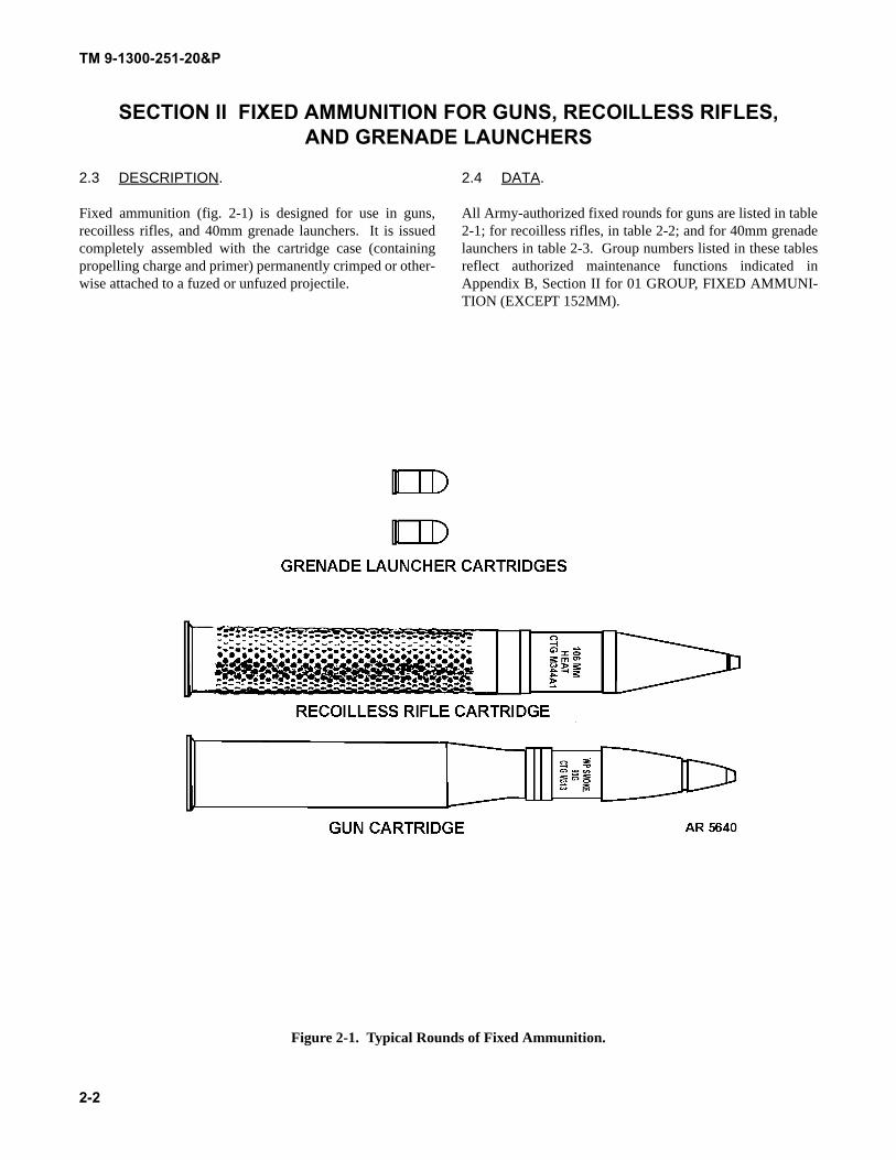
2.3 DESCRIPTION.
Fixed ammunition (fig. 2-1) is designed for use in guns,recoilless rifles, and 40mm grenade launchers. It is issuedcompletely assembled with the cartridge case (containingpropelling charge and primer) permanently crimped or other-wise attached to a fuzed or unfuzed projectile.
2.4 DATA.
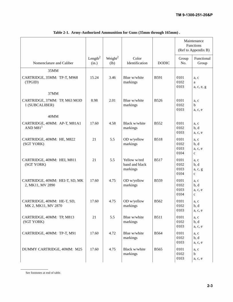
All Army-authorized fixed rounds for guns are listed in table2-1; for recoilless rifles, in table 2-2; and for 40mm grenadelaunchers in table 2-3. Group numbers listed in these tablesreflect authorized maintenance functions indicated inAppendix B, Section II for 01 GROUP, FIXED AMMUNI-TION (EXCEPT 152MM).
Figure 2-1. Typical Rounds of Fixed Ammunition.
TM 9-1300-251-20&P
2-3
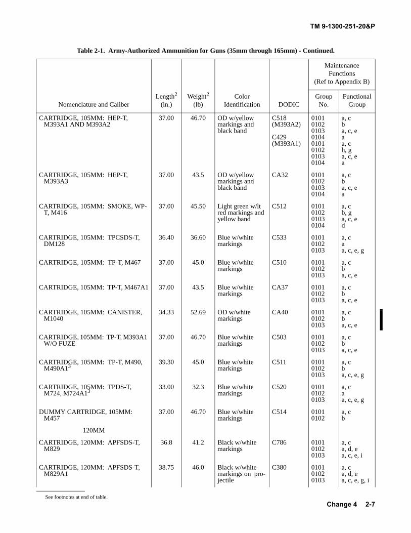
Table 2-1. Army-Authorized Ammunition for Guns (35mm through 165mm) .
Nomenclature and CaliberLength2
(in.)Weight2
(lb)Color
Identification DODIC
Maintenance Functions
(Ref to Appendix B)
Group No.
Functional Group
35MM
CARTRIDGE, 35MM: TP-T, M968 (TPGID)
15.24 3.46 Blue w/white markings
B591 010101020103
a, caa, c, e, g
37MM
CARTRIDGE, 37MM: TP, M63 MOD 1 (SUBCALIBER)
8.98 2.01 Blue w/white markings
B526 010101020103
a, cba, c, e
40MM
CARTRIDGE, 40MM: AP-T, M81A1 AND M811
17.60 4.58 Black w/white markings
B552 010101020103
a, cb, da, c, e
CARTRIDGE, 40MM: HE, M822 (SGT YORK)
21 5.5 OD w/yellow markings
B518 0101010201030104
a, cb, da, c, ec
CARTRIDGE, 40MM: HEI, M811 (SGT YORK)
21 5.5 Yellow w/red band and black markings
B517 0101010201030104
a, cb, da, c, gc
CARTRIDGE, 40MM: HEI-T, SD, MK 2, MK11, MV 2890
17.60 4.75 OD w/yellow markings
B559 0101010201030104
a, cb, da, c, ec
CARTRIDGE, 40MM: HE-T, SD, MK 2, MK11, MV 2870
17.60 4.75 OD w/yellow markings
B562 010101020103
a, cb, da, c, e
CARTRIDGE, 40MM: TP, M813 (SGT YORK)
21 5.5 Blue w/white markings
B511 010101020103
a, cb, da, c, e
CARTRIDGE, 40MM: TP-T, M91 17.60 4.72 Blue w/white markings
B564 010101020103
a, cb, da, c, e
DUMMY CARTRIDGE, 40MM: M25 17.60 4.75 Black w/white markings
B565 010101020103
a, cba, c, e
See footnotes at end of table.
TM 9-1300-251-20&P
2-4
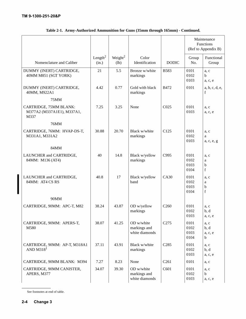
DUMMY (INERT) CARTRIDGE, 40MM M851 (SGT YORK)
21 5.5 Bronze w/white markings
B583 010101020103
a, cba, c, e
DUMMY (INERT) CARTRIDGE, 40MM, M922A1
4.42 0.77 Gold with black markings
B472 0101 a, b, c, d, e, f
75MM
CARTRIDGE, 75MM BLANK: M377A2 (M337A1E1), M337A1, M337
7.25 3.25 None C025 01010103
a, ca, c, e
76MM
CARTRIDGE, 76MM: HVAP-DS-T, M331A1, M331A2
30.88 20.70 Black w/white markings
C125 010101020103
a, caa, c, e, g
84MM
LAUNCHER and CARTRIDGE, 84MM: M136 (AT4)
40 14.8 Black w/yellow markings
C995 0101010201030104
a, cabf
LAUNCHER and CARTRIDGE, 84MM: AT4 CS RS
40.8 17 Black w/yellow band
CA30 0101010201030104
a, cabf
90MM
CARTRIDGE, 90MM: APC-T, M82 38.24 43.87 OD w/yellow markings
C260 010101020103
a, cb, da, c, e
CARTRIDGE, 90MM: APERS-T, M580
38.07 41.25 OD w/white markings and white diamonds
C275 0101010201030104
a, cb, da, c, eb
CARTRIDGE, 90MM: AP-T, M318A1 AND M3181
37.11 43.91 Black w/white markings
C285 010101020103
a, cb, da, c, e
CARTRIDGE, 90MM BLANK: M394 7.27 8.23 None C261 0101 a, c
CARTRIDGE, 90MM CANISTER, APERS, M377
34.07 39.30 OD w/white markings and white diamonds
C601 010101020103
a, cba, c, e
Table 2-1. Army-Authorized Ammunition for Guns (35mm through 165mm) - Continued.
Nomenclature and CaliberLength2
(in.)Weight2
(lb)Color
Identification DODIC
Maintenance Functions
(Ref to Appendix B)
Group No.
Functional Group
See footnotes at end of table.
Change 3
TM 9-1300-251-20&P
2-5
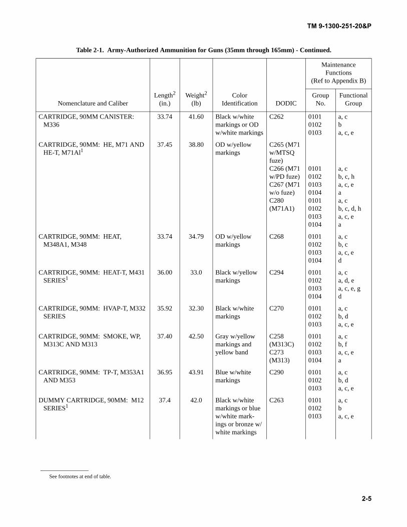
CARTRIDGE, 90MM CANISTER: M336
33.74 41.60 Black w/white markings or OD w/white markings
C262 010101020103
a, cba, c, e
CARTRIDGE, 90MM: HE, M71 AND HE-T, M71Al1
37.45 38.80 OD w/yellow markings
C265 (M71 w/MTSQ fuze)C266 (M71 w/PD fuze)C267 (M71 w/o fuze)C280 (M71A1)
01010102010301040101010201030104
a, cb, c, ha, c, eaa, cb, c, d, ha, c, ea
CARTRIDGE, 90MM: HEAT, M348A1, M348
33.74 34.79 OD w/yellow markings
C268 0101010201030104
a, cb, ca, c, ed
CARTRIDGE, 90MM: HEAT-T, M431 SERIES1
36.00 33.0 Black w/yellow markings
C294 0101010201030104
a, ca, d, ea, c, e, gd
CARTRIDGE, 90MM: HVAP-T, M332 SERIES
35.92 32.30 Black w/white markings
C270 010101020103
a, cb, da, c, e
CARTRIDGE, 90MM: SMOKE, WP, M313C AND M313
37.40 42.50 Gray w/yellow markings and yellow band
C258(M313C)C273(M313)
0101010201030104
a, cb, fa, c, ea
CARTRIDGE, 90MM: TP-T, M353A1 AND M353
36.95 43.91 Blue w/white markings
C290 010101020103
a, cb, da, c, e
DUMMY CARTRIDGE, 90MM: M12 SERIES1
37.4 42.0 Black w/white markings or blue w/white mark-ings or bronze w/white markings
C263 010101020103
a, cba, c, e
Table 2-1. Army-Authorized Ammunition for Guns (35mm through 165mm) - Continued.
Nomenclature and CaliberLength2
(in.)Weight2
(lb)Color
Identification DODIC
Maintenance Functions
(Ref to Appendix B)
Group No.
Functional Group
See footnotes at end of table.
TM 9-1300-251-20&P
2-6
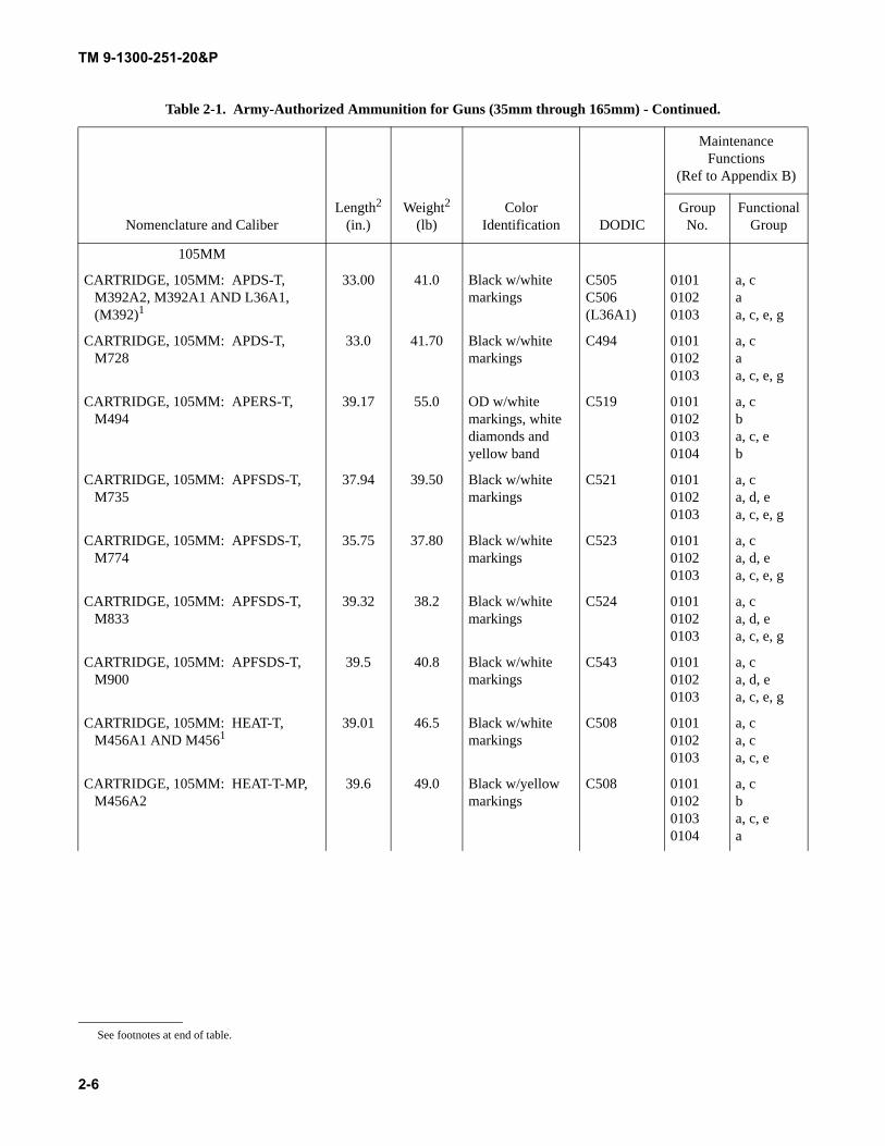
105MM
CARTRIDGE, 105MM: APDS-T, M392A2, M392A1 AND L36A1, (M392)1
33.00 41.0 Black w/white markings
C505C506(L36A1)
010101020103
a, caa, c, e, g
CARTRIDGE, 105MM: APDS-T, M728
33.0 41.70 Black w/white markings
C494 010101020103
a, caa, c, e, g
CARTRIDGE, 105MM: APERS-T, M494
39.17 55.0 OD w/white markings, white diamonds and yellow band
C519 0101010201030104
a, cba, c, eb
CARTRIDGE, 105MM: APFSDS-T, M735
37.94 39.50 Black w/white markings
C521 010101020103
a, ca, d, ea, c, e, g
CARTRIDGE, 105MM: APFSDS-T, M774
35.75 37.80 Black w/white markings
C523 010101020103
a, ca, d, ea, c, e, g
CARTRIDGE, 105MM: APFSDS-T, M833
39.32 38.2 Black w/white markings
C524 010101020103
a, ca, d, ea, c, e, g
CARTRIDGE, 105MM: APFSDS-T, M900
39.5 40.8 Black w/white markings
C543 010101020103
a, ca, d, ea, c, e, g
CARTRIDGE, 105MM: HEAT-T, M456A1 AND M4561
39.01 46.5 Black w/white markings
C508 010101020103
a, ca, ca, c, e
CARTRIDGE, 105MM: HEAT-T-MP, M456A2
39.6 49.0 Black w/yellow markings
C508 0101010201030104
a, cba, c, ea
Table 2-1. Army-Authorized Ammunition for Guns (35mm through 165mm) - Continued.
Nomenclature and CaliberLength2
(in.)Weight2
(lb)Color
Identification DODIC
Maintenance Functions
(Ref to Appendix B)
Group No.
Functional Group
See footnotes at end of table.
TM 9-1300-251-20&P
2-7
CARTRIDGE, 105MM: HEP-T, M393A1 AND M393A2
37.00 46.70 OD w/yellow markings and black band
C518(M393A2)
C429(M393A1)
01010102010301040101010201030104
a, cba, c, eaa, ch, ga, c, ea
CARTRIDGE, 105MM: HEP-T, M393A3
37.00 43.5 OD w/yellow markings and black band
CA32 0101010201030104
a, cba, c, ea
CARTRIDGE, 105MM: SMOKE, WP-T, M416
37.00 45.50 Light green w/lt red markings and yellow band
C512 0101010201030104
a, cb, ga, c, ed
CARTRIDGE, 105MM: TPCSDS-T, DM128
36.40 36.60 Blue w/white markings
C533 010101020103
a, caa, c, e, g
CARTRIDGE, 105MM: TP-T, M467 37.00 45.0 Blue w/white markings
C510 010101020103
a, cba, c, e
CARTRIDGE, 105MM: TP-T, M467A1 37.00 43.5 Blue w/white markings
CA37 010101020103
a, cba, c, e
CARTRIDGE, 105MM: CANISTER, M1040
34.33 52.69 OD w/white markings
CA40 010101020103
a, cba, c, e
CARTRIDGE, 105MM: TP-T, M393A1 W/O FUZE
37.00 46.70 Blue w/white markings
C503 010101020103
a, cba, c, e
CARTRIDGE, 105MM: TP-T, M490, M490A13
39.30 45.0 Blue w/white markings
C511 010101020103
a, cba, c, e, g
CARTRIDGE, 105MM: TPDS-T, M724, M724A13
33.00 32.3 Blue w/white markings
C520 010101020103
a, caa, c, e, g
DUMMY CARTRIDGE, 105MM: M457
37.00 46.70 Blue w/white markings
C514 01010102
a, cb
120MM
CARTRIDGE, 120MM: APFSDS-T, M829
36.8 41.2 Black w/white markings
C786 010101020103
a, ca, d, ea, c, e, i
CARTRIDGE, 120MM: APFSDS-T, M829A1
38.75 46.0 Black w/white markings on pro-jectile
C380 010101020103
a, ca, d, ea, c, e, g, i
Table 2-1. Army-Authorized Ammunition for Guns (35mm through 165mm) - Continued.
Nomenclature and CaliberLength2
(in.)Weight2
(lb)Color
Identification DODIC
Maintenance Functions
(Ref to Appendix B)
Group No.
Functional Group
See footnotes at end of table.Change 4
TM 9-1300-251-20&P
2-8
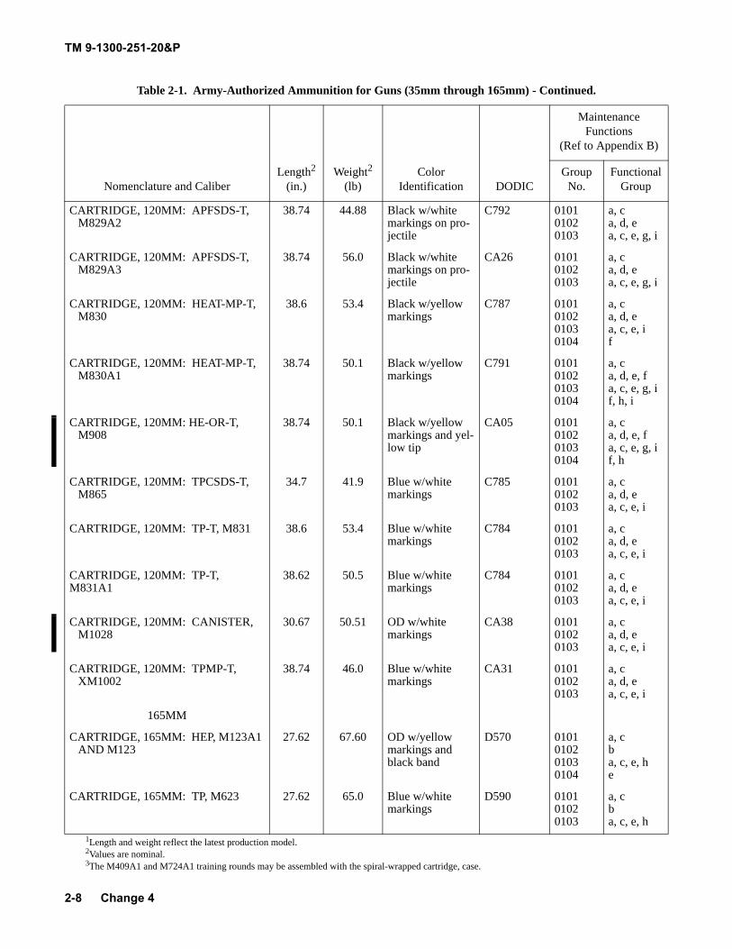
CARTRIDGE, 120MM: APFSDS-T, M829A2
38.74 44.88 Black w/white markings on pro-jectile
C792 010101020103
a, ca, d, ea, c, e, g, i
CARTRIDGE, 120MM: APFSDS-T, M829A3
38.74 56.0 Black w/white markings on pro-jectile
CA26 010101020103
a, ca, d, ea, c, e, g, i
CARTRIDGE, 120MM: HEAT-MP-T, M830
38.6 53.4 Black w/yellow markings
C787 0101010201030104
a, ca, d, ea, c, e, if
CARTRIDGE, 120MM: HEAT-MP-T, M830A1
38.74 50.1 Black w/yellow markings
C791 0101010201030104
a, ca, d, e, fa, c, e, g, if, h, i
CARTRIDGE, 120MM: HE-OR-T, M908
38.74 50.1 Black w/yellow markings and yel-low tip
CA05 0101010201030104
a, ca, d, e, fa, c, e, g, if, h
CARTRIDGE, 120MM: TPCSDS-T, M865
34.7 41.9 Blue w/white markings
C785 010101020103
a, ca, d, ea, c, e, i
CARTRIDGE, 120MM: TP-T, M831 38.6 53.4 Blue w/white markings
C784 010101020103
a, ca, d, ea, c, e, i
CARTRIDGE, 120MM: TP-T, M831A1
38.62 50.5 Blue w/white markings
C784 010101020103
a, ca, d, ea, c, e, i
CARTRIDGE, 120MM: CANISTER, M1028
30.67 50.51 OD w/white markings
CA38 010101020103
a, ca, d, ea, c, e, i
CARTRIDGE, 120MM: TPMP-T, XM1002
38.74 46.0 Blue w/white markings
CA31 010101020103
a, ca, d, ea, c, e, i
165MM
CARTRIDGE, 165MM: HEP, M123A1 AND M123
27.62 67.60 OD w/yellow markings and black band
D570 0101010201030104
a, cba, c, e, he
CARTRIDGE, 165MM: TP, M623 27.62 65.0 Blue w/white markings
D590 010101020103
a, cba, c, e, h
1Length and weight reflect the latest production model.2Values are nominal.3The M409A1 and M724A1 training rounds may be assembled with the spiral-wrapped cartridge, case.
Table 2-1. Army-Authorized Ammunition for Guns (35mm through 165mm) - Continued.
Nomenclature and CaliberLength2
(in.)Weight2
(lb)Color
Identification DODIC
Maintenance Functions
(Ref to Appendix B)
Group No.
Functional Group
Change 4
TM 9-1300-251-20&P
2-9
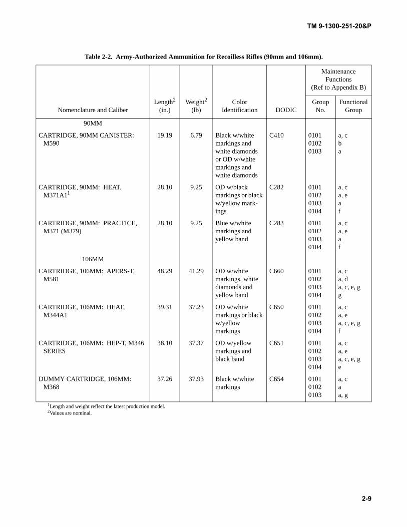
Table 2-2. Army-Authorized Ammunition for Recoilless Rifles (90mm and 106mm).
Nomenclature and CaliberLength2
(in.)Weight2
(lb)Color
Identification DODIC
Maintenance Functions
(Ref to Appendix B)
Group No.
Functional Group
90MM
CARTRIDGE, 90MM CANISTER: M590
19.19 6.79 Black w/white markings and white diamonds or OD w/white markings and white diamonds
C410 010101020103
a, cba
CARTRIDGE, 90MM: HEAT, M371A11
28.10 9.25 OD w/black markings or black w/yellow mark-ings
C282 0101010201030104
a, ca, eaf
CARTRIDGE, 90MM: PRACTICE, M371 (M379)
28.10 9.25 Blue w/white markings and yellow band
C283 0101010201030104
a, ca, eaf
106MM
CARTRIDGE, 106MM: APERS-T, M581
48.29 41.29 OD w/white markings, white diamonds and yellow band
C660 0101010201030104
a, ca, da, c, e, gg
CARTRIDGE, 106MM: HEAT, M344A1
39.31 37.23 OD w/white markings or black w/yellow markings
C650 0101010201030104
a, ca, ea, c, e, gf
CARTRIDGE, 106MM: HEP-T, M346 SERIES
38.10 37.37 OD w/yellow markings and black band
C651 0101010201030104
a, ca, ea, c, e, ge
DUMMY CARTRIDGE, 106MM: M368
37.26 37.93 Black w/white markings
C654 010101020103
a, caa, g
1Length and weight reflect the latest production model.2Values are nominal.
TM 9-1300-251-20&P
2-10
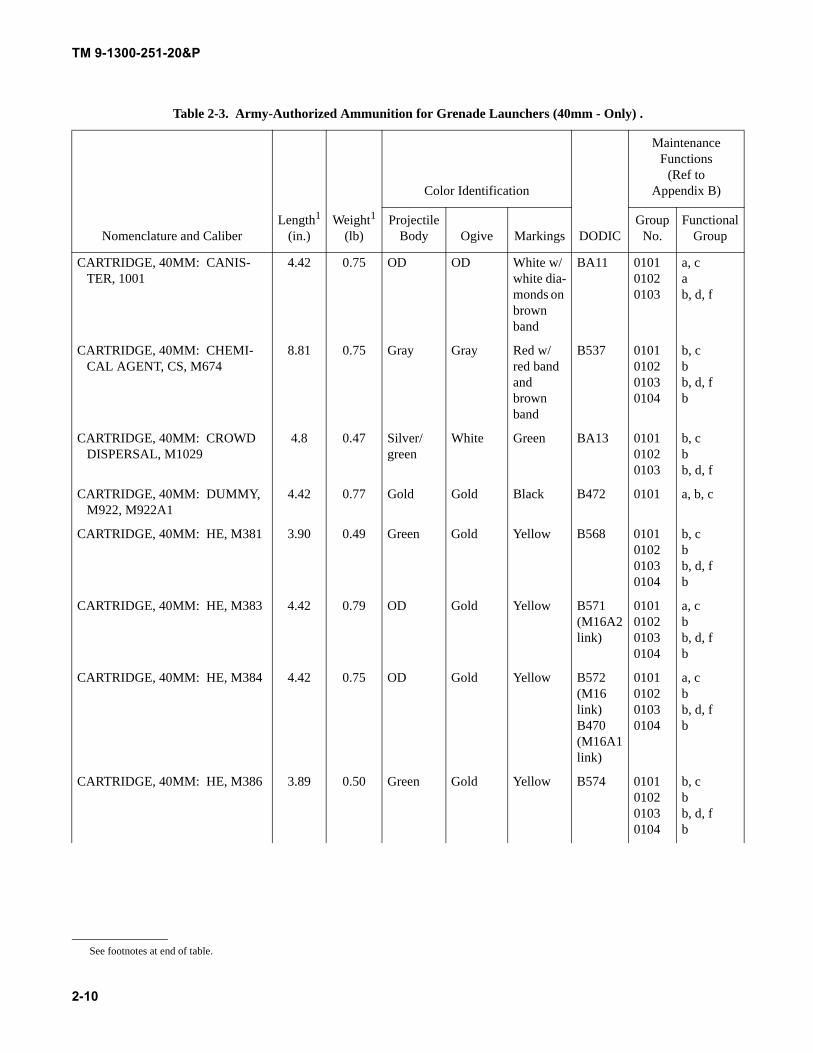
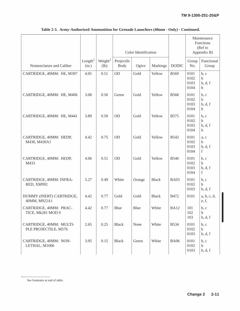
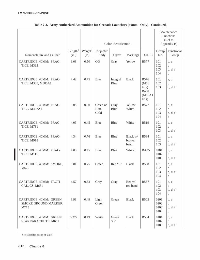
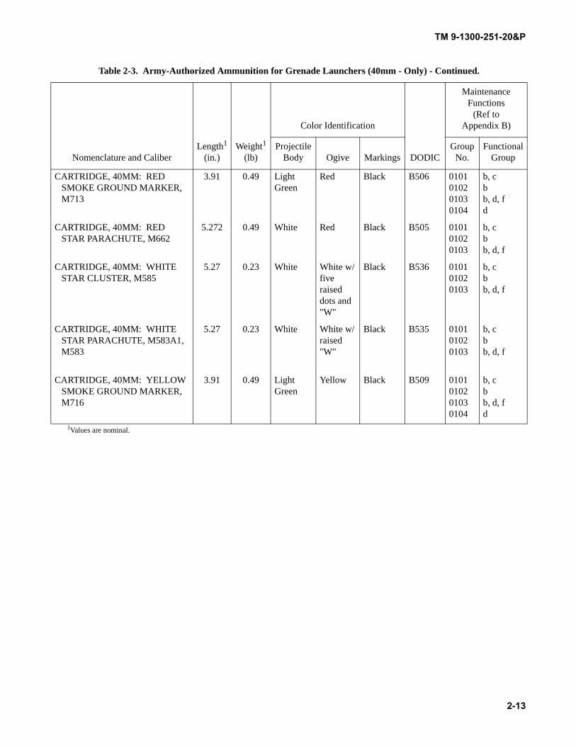
Table 2-3. Army-Authorized Ammunition for Grenade Launchers (40mm - Only) .
Nomenclature and CaliberLength1
(in.)Weight1
(lb)
Color Identification
DODIC
Maintenance Functions
(Ref toAppendix B)
Projectile Body Ogive Markings
Group No.
Functional Group
CARTRIDGE, 40MM: CANIS-TER, 1001
4.42 0.75 OD OD White w/white dia-monds on brown band
BA11 010101020103
a, cab, d, f
CARTRIDGE, 40MM: CHEMI-CAL AGENT, CS, M674
8.81 0.75 Gray Gray Red w/red band and brown band
B537 0101010201030104
b, cbb, d, fb
CARTRIDGE, 40MM: CROWD DISPERSAL, M1029
4.8 0.47 Silver/green
White Green BA13 010101020103
b, cbb, d, f
CARTRIDGE, 40MM: DUMMY, M922, M922A1
4.42 0.77 Gold Gold Black B472 0101 a, b, c
CARTRIDGE, 40MM: HE, M381 3.90 0.49 Green Gold Yellow B568 0101010201030104
b, cbb, d, fb
CARTRIDGE, 40MM: HE, M383 4.42 0.79 OD Gold Yellow B571(M16A2link)
0101010201030104
a, cbb, d, fb
CARTRIDGE, 40MM: HE, M384 4.42 0.75 OD Gold Yellow B572(M16link)B470(M16A1link)
0101010201030104
a, cbb, d, fb
CARTRIDGE, 40MM: HE, M386 3.89 0.50 Green Gold Yellow B574 0101010201030104
b, cbb, d, fb
See footnotes at end of table.
TM 9-1300-251-20&P
2-11
CARTRIDGE, 40MM: HE, M397 4.05 0.51 OD Gold Yellow B569 0101010201030104
b, cbb, d, fb
CARTRIDGE, 40MM: HE, M406 3.08 0.50 Green Gold Yellow B568 0101010201030104
b, cbb, d, fb
CARTRIDGE, 40MM: HE, M441 3.89 0.50 OD Gold Yellow B575 0101010201030104
b, cbb, d, fb
CARTRIDGE, 40MM: HEDP, M430, M430A1
4.42 0.75 OD Gold Yellow B542 0101010201030104
a, cbb, d, ff
CARTRIDGE, 40MM: HEDP, M433
4.06 0.51 OD Gold Yellow B546 0101010201030104
b, cbb, d, ff
CARTRIDGE, 40MM: INFRA-RED, XM992
5.27 0.49 White Orange Black BA03 010101020103
b, cbb, d, f
DUMMY (INERT) CARTRIDGE, 40MM, M922A1
4.42 0.77 Gold Gold Black B472 0101 a, b, c, d, e, f,
CARTRIDGE, 40MM: PRAC-TICE, Mk281 MOD 0
4.42 0.77 Blue Blue White BA12 101102103
b, cbb, d, f
CARTRIDGE, 40MM: MULTI-PLE PROJECTILE, M576
2.65 0.25 Black None White B534 010101020103
b, cbb, d, f
CARTRIDGE, 40MM: NON-LETHAL, M1006
3.95 0.15 Black Green White BA06 010101020103
b, cbb, d, f
Table 2-3. Army-Authorized Ammunition for Grenade Launchers (40mm - Only) - Continued.
Nomenclature and CaliberLength1
(in.)Weight1
(lb)
Color Identification
DODIC
Maintenance Functions
(Ref toAppendix B)
ProjectileBody Ogive Markings
Group No.
Functional Group
See footnotes at end of table.
Change 2
TM 9-1300-251-20&P
2-12
CARTRIDGE, 40MM: PRAC-TICE, M382
3.08 0.50 OD Gray Yellow B577 101102103104
b, cbb, d, fb
CARTRIDGE, 40MM: PRAC-TICE, M385, M385A1
4.42 0.75 Blue Integral Blue
Black B576 (M16link) B480 (M16A1 link)
101102103
a, cbb, d, f
CARTRIDGE, 40MM: PRAC-TICE, M407A1
3.08 0.50 Green or Blue Gold
GrayBlue
Yellow White
B577 101102103104
b, cbb, d, fb
CARTRIDGE, 40MM: PRAC-TICE, M781
4.05 0.45 Blue Blue White B519 101102103
b, cbb, d, f
CARTRIDGE, 40MM: PRAC-TICE, M918
4.34 0.76 Blue Blue Black w/brown band
B584 101102103
b, cbb, d, f
CARTRIDGE, 40MM: PRAC-TICE, M1110
4.05 0.45 Blue Blue White BA35 010101020103
b, cbb, d, f
CARTRIDGE, 40MM: SMOKE, M675
8.81 0.75 Green Red “R” Black B538 101102103104
b, cbb, d, fb
CARTRIDGE, 40MM: TACTI-CAL, CS, M651
4.57 0.63 Gray Gray Red w/red band
B567 101102103104
b, cbb, d, fb
CARTRIDGE, 40MM: GREEN SMOKE GROUND MARKER, M715
3.91 0.49 Light Green
Green Black B503 0101010201030104
b, cbb, d, fd
CARTRIDGE, 40MM: GREEN STAR PARACHUTE, M661
5.272 0.49 White Green "G"
Black B504 010101020103
b, cbb, d, f
Table 2-3. Army-Authorized Ammunition for Grenade Launchers (40mm - Only) - Continued.
Nomenclature and CaliberLength1
(in.)Weight1
(lb)
Color Identification
DODIC
Maintenance Functions
(Ref toAppendix B)
ProjectileBody Ogive Markings
Group No.
Functional Group
See footnotes at end of table.
Change 6
TM 9-1300-251-20&P
2-13
CARTRIDGE, 40MM: RED SMOKE GROUND MARKER, M713
3.91 0.49 Light Green
Red Black B506 0101010201030104
b, cbb, d, fd
CARTRIDGE, 40MM: RED STAR PARACHUTE, M662
5.272 0.49 White Red Black B505 010101020103
b, cbb, d, f
CARTRIDGE, 40MM: WHITE STAR CLUSTER, M585
5.27 0.23 White White w/five raised dots and "W"
Black B536 010101020103
b, cbb, d, f
CARTRIDGE, 40MM: WHITE STAR PARACHUTE, M583A1, M583
5.27 0.23 White White w/raised "W"
Black B535 010101020103
b, cbb, d, f
CARTRIDGE, 40MM: YELLOW SMOKE GROUND MARKER, M716
3.91 0.49 Light Green
Yellow Black B509 0101010201030104
b, cbb, d, fd
1Values are nominal.
Table 2-3. Army-Authorized Ammunition for Grenade Launchers (40mm - Only) - Continued.
Nomenclature and CaliberLength1
(in.)Weight1
(lb)
Color Identification
DODIC
Maintenance Functions
(Ref toAppendix B)
Projectile Body Ogive Markings
Group No.
Functional Group
TM 9-1300-251-20&P
2-14
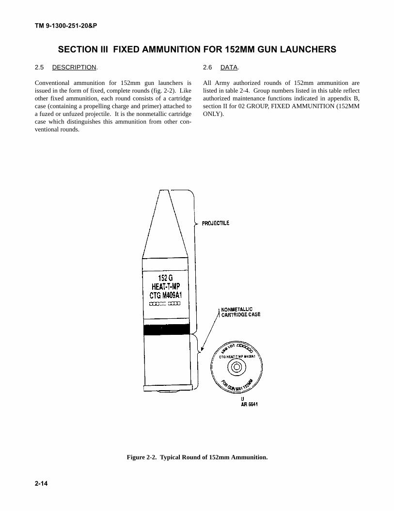
SECTION III FIXED AMMUNITION FOR 152MM GUN LAUNCHERS
2.5 DESCRIPTION.
Conventional ammunition for 152mm gun launchers isissued in the form of fixed, complete rounds (fig. 2-2). Likeother fixed ammunition, each round consists of a cartridgecase (containing a propelling charge and primer) attached toa fuzed or unfuzed projectile. It is the nonmetallic cartridgecase which distinguishes this ammunition from other con-ventional rounds.
2.6 DATA.
All Army authorized rounds of 152mm ammunition arelisted in table 2-4. Group numbers listed in this table reflectauthorized maintenance functions indicated in appendix B,section II for 02 GROUP, FIXED AMMUNITION (152MMONLY).
Figure 2-2. Typical Round of 152mm Ammunition.
TM 9-1300-251-20&P
2-15
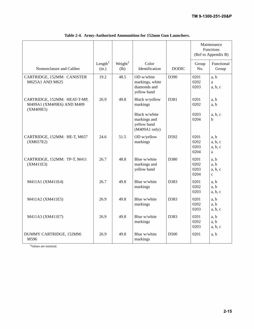
Table 2-4. Army-Authorized Ammunition for 152mm Gun Launchers.
Nomenclature and CaliberLength1
(in.)Weight1
(lb)Color
Identification DODIC
Maintenance Functions
(Ref to Appendix B)
Group No.
Functional Group
CARTRIDGE, 152MM: CANISTER M625A1 AND M625
19.2 48.5 OD w/white markings, white diamonds and yellow band
D390 020102020203
a, baa, b, c
CARTRIDGE, 152MM: HEAT-T-MP, M409A1 (XM409E6) AND M409 (XM409E5)
26.9 49.8 Black w/yellow markings
Black w/white markings and yellow band (M409A1 only)
D381 02010202
02030204
a, ba, b
a, b, cb
CARTRIDGE, 152MM: HE-T, M657 (XM657E2)
24.6 51.5 OD w/yellow markings
D592 0201020202030204
a, ba, b, ca, b, ca
CARTRIDGE, 152MM: TP-T, M411 (XM411E3)
26.7 48.8 Blue w/white markings and yellow band
D380 0201020202030204
a, ba, ba, b, cc
M411A1 (XM411E4) 26.7 49.8 Blue w/white markings
D383 020102020203
a, ba, ba, b, c
M411A2 (XM411E5) 26.9 49.8 Blue w/white markings
D383 020102020203
a, ba, ba, b, c
M411A3 (XM411E7) 26.9 49.8 Blue w/white markings
D383 020102020203
a, ba, ba, b, c
DUMMY CARTRIDGE, 152MM: M596
26.9 49.8 Blue w/white markings
D500 0201 a, b
1Values are nominal.
TM 9-1300-251-20&P
2-16
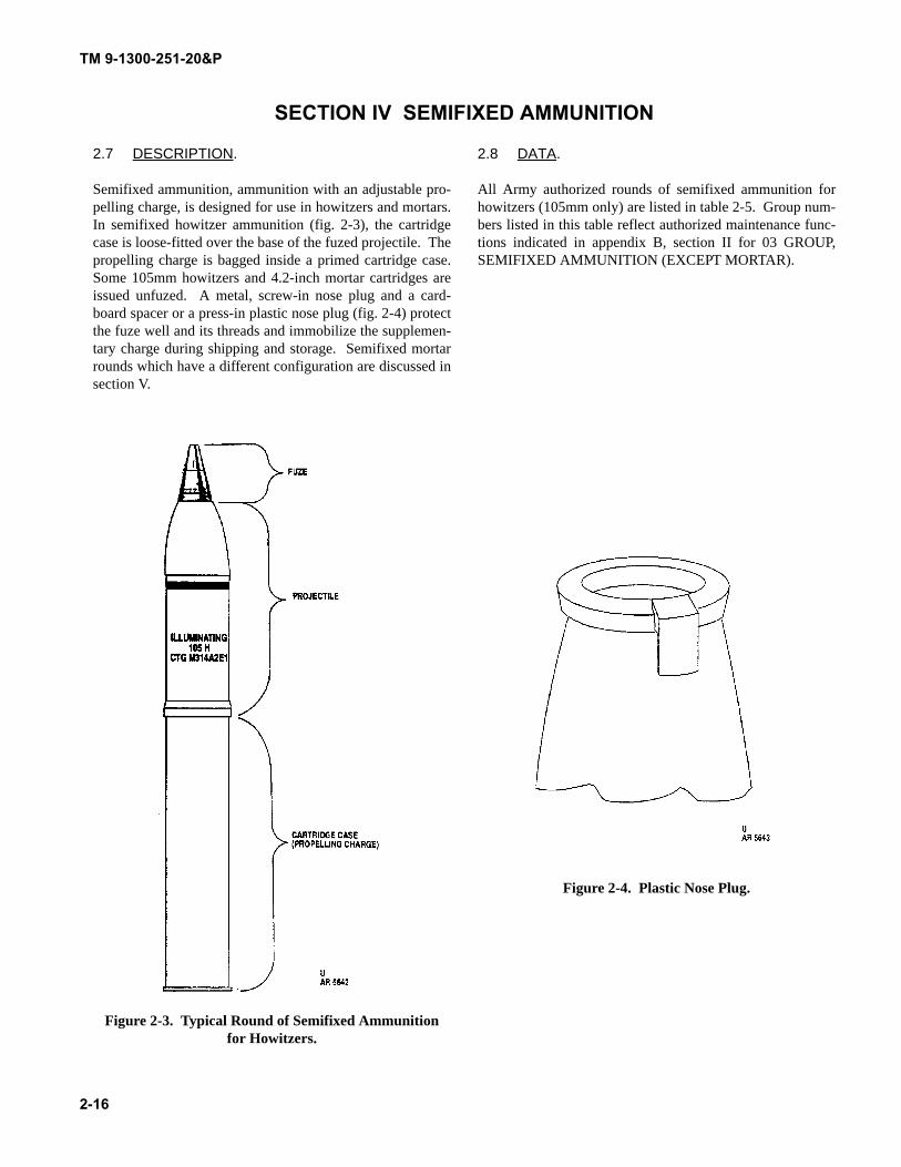
SECTION IV SEMIFIXED AMMUNITION
2.7 DESCRIPTION.
Semifixed ammunition, ammunition with an adjustable pro-pelling charge, is designed for use in howitzers and mortars.In semifixed howitzer ammunition (fig. 2-3), the cartridgecase is loose-fitted over the base of the fuzed projectile. Thepropelling charge is bagged inside a primed cartridge case.Some 105mm howitzers and 4.2-inch mortar cartridges areissued unfuzed. A metal, screw-in nose plug and a card-board spacer or a press-in plastic nose plug (fig. 2-4) protectthe fuze well and its threads and immobilize the supplemen-tary charge during shipping and storage. Semifixed mortarrounds which have a different configuration are discussed insection V.
Figure 2-3. Typical Round of Semifixed Ammunition for Howitzers.
2.8 DATA.
All Army authorized rounds of semifixed ammunition forhowitzers (105mm only) are listed in table 2-5. Group num-bers listed in this table reflect authorized maintenance func-tions indicated in appendix B, section II for 03 GROUP,SEMIFIXED AMMUNITION (EXCEPT MORTAR).
Figure 2-4. Plastic Nose Plug.
TM 9-1300-251-20&P
2-17
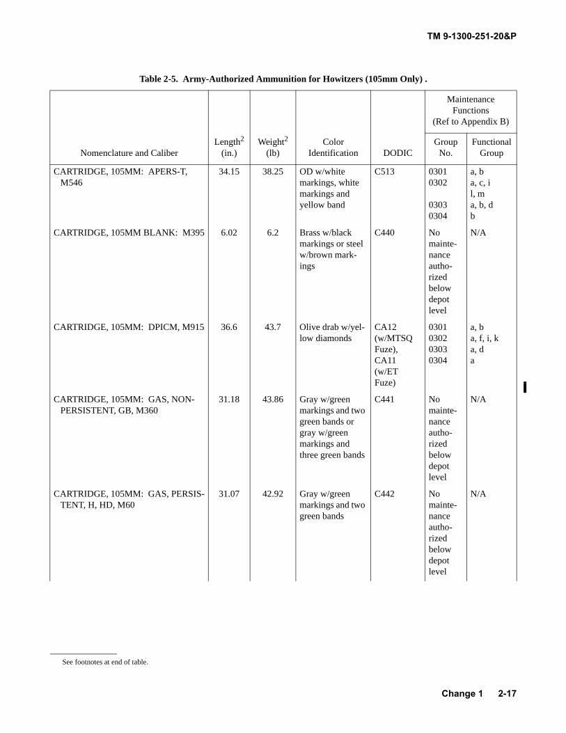
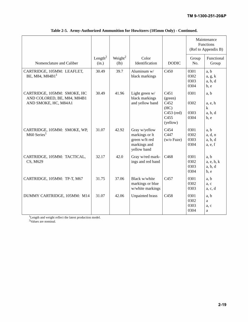
Table 2-5. Army-Authorized Ammunition for Howitzers (105mm Only) .
Nomenclature and CaliberLength2
(in.)Weight2
(lb)Color
Identification DODIC
Maintenance Functions
(Ref to Appendix B)
Group No.
Functional Group
CARTRIDGE, 105MM: APERS-T, M546
34.15 38.25 OD w/white markings, white markings and yellow band
C513 03010302
03030304
a, ba, c, il, ma, b, db
CARTRIDGE, 105MM BLANK: M395 6.02 6.2 Brass w/black markings or steel w/brown mark-ings
C440 No mainte-nance autho-rized below depot level
N/A
CARTRIDGE, 105MM: DPICM, M915 36.6 43.7 Olive drab w/yel-low diamonds
CA12 (w/MTSQ Fuze),CA11 (w/ET Fuze)
0301030203030304
a, ba, f, i, ka, da
CARTRIDGE, 105MM: GAS, NON-PERSISTENT, GB, M360
31.18 43.86 Gray w/green markings and two green bands or gray w/green markings and three green bands
C441 No mainte-nance autho-rized below depot level
N/A
CARTRIDGE, 105MM: GAS, PERSIS-TENT, H, HD, M60
31.07 42.92 Gray w/green markings and two green bands
C442 No mainte-nance autho-rized below depot level
N/A
See footnotes at end of table.
Change 1
TM 9-1300-251-20&P
2-18
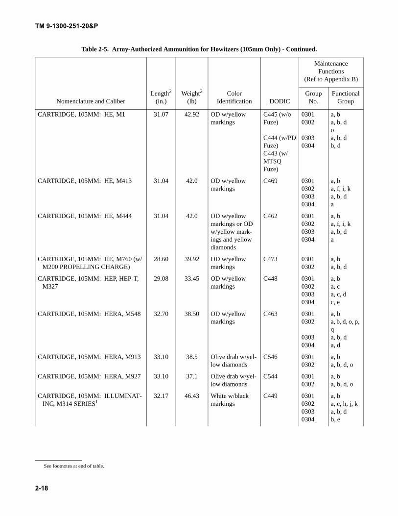
CARTRIDGE, 105MM: HE, M1 31.07 42.92 OD w/yellow markings
C445 (w/oFuze)
C444 (w/PDFuze)C443 (w/MTSQ Fuze)
03010302
03030304
a, ba, b, doa, b, db, d
CARTRIDGE, 105MM: HE, M413 31.04 42.0 OD w/yellow markings
C469 0301030203030304
a, ba, f, i, ka, b, da
CARTRIDGE, 105MM: HE, M444 31.04 42.0 OD w/yellow markings or OD w/yellow mark-ings and yellow diamonds
C462 0301030203030304
a, ba, f, i, ka, b, da
CARTRIDGE, 105MM: HE, M760 (w/M200 PROPELLING CHARGE)
28.60 39.92 OD w/yellow markings
C473 03010302
a, ba, b, d
CARTRIDGE, 105MM: HEP, HEP-T, M327
29.08 33.45 OD w/yellow markings
C448 0301030203030304
a, ba, ca, c, dc, e
CARTRIDGE, 105MM: HERA, M548 32.70 38.50 OD w/yellow markings
C463 03010302
03030304
a, ba, b, d, o, p, qa, b, da, d
CARTRIDGE, 105MM: HERA, M913 33.10 38.5 Olive drab w/yel-low diamonds
C546 03010302
a, ba, b, d, o
CARTRIDGE, 105MM: HERA, M927 33.10 37.1 Olive drab w/yel-low diamonds
C544 03010302
a, ba, b, d, o
CARTRIDGE, 105MM: ILLUMINAT-ING, M314 SERIES1
32.17 46.43 White w/black markings
C449 0301030203030304
a, ba, e, h, j, ka, b, db, e
Table 2-5. Army-Authorized Ammunition for Howitzers (105mm Only) - Continued.
Nomenclature and CaliberLength2
(in.)Weight2
(lb)Color
Identification DODIC
Maintenance Functions
(Ref to Appendix B)
Group No.
Functional Group
See footnotes at end of table.
TM 9-1300-251-20&P
2-19
CARTRIDGE, 105MM: LEAFLET, BE, M84, M84B11
30.49 39.7 Aluminum w/black markings
C450 0301030203030304
a, ba, g, ka, b, db, e
CARTRIDGE, 105MM: SMOKE, HC AND COLORED, BE, M84, M84B1 AND SMOKE, HC, M84A1
30.49 41.96 Light green w/black markings and yellow band
C451 (green)C452 (HC)C453 (red)C455 (yellow)
0301
0302
03030304
a, b
a, e, hka, b, db, e
CARTRIDGE, 105MM: SMOKE, WP, M60 Series1
31.07 42.92 Gray w/yellow markings or lt green w/lt red markings and yellow band
C454C447 (w/o Fuze)
0301030203030304
a, ba, d, na, b, da, e, f
CARTRIDGE, 105MM: TACTICAL, CS, M629
32.17 42.0 Gray w/red mark-ings and red band
C468 0301030203030304
a, ba, e, h, ka, b, db, e
CARTRIDGE, 105MM: TP-T, M67 31.75 37.06 Black w/white markings or blue w/white markings
C457 030103020303
a, ba, ca, c, d
DUMMY CARTRIDGE, 105MM: M14 31.07 42.06 Unpainted brass C458 0301030203030304
a, baa, ca
1Length and weight reflect the latest production model.2Values are nominal.
Table 2-5. Army-Authorized Ammunition for Howitzers (105mm Only) - Continued.
Nomenclature and CaliberLength2
(in.)Weight2
(lb)Color
Identification DODIC
Maintenance Functions
(Ref to Appendix B)
Group No.
Functional Group
TM 9-1300-251-20&P
2-20
SECTION V SEMIFIXED AMMUNITION FOR MORTARS
2.9 DESCRIPTION.
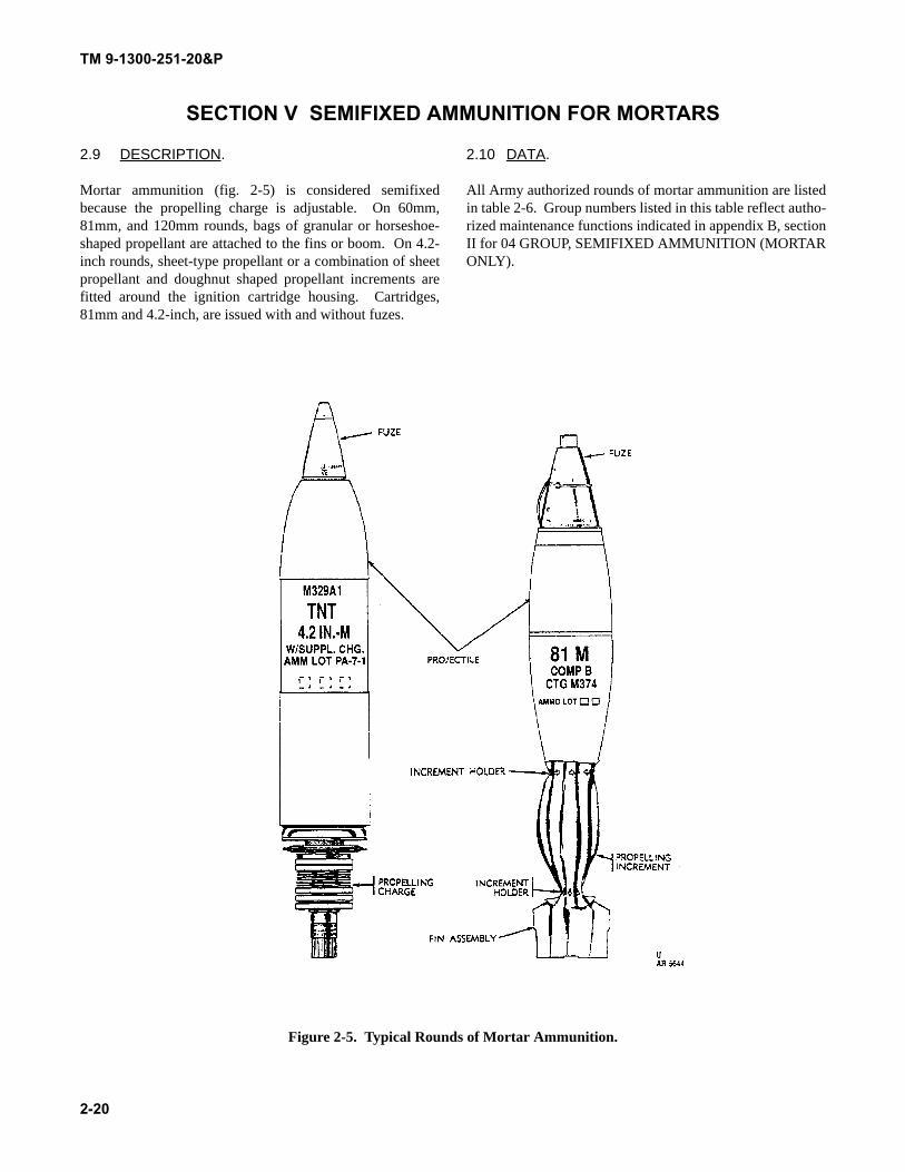
Mortar ammunition (fig. 2-5) is considered semifixedbecause the propelling charge is adjustable. On 60mm,81mm, and 120mm rounds, bags of granular or horseshoe-shaped propellant are attached to the fins or boom. On 4.2-inch rounds, sheet-type propellant or a combination of sheetpropellant and doughnut shaped propellant increments arefitted around the ignition cartridge housing. Cartridges,81mm and 4.2-inch, are issued with and without fuzes.
2.10 DATA.
All Army authorized rounds of mortar ammunition are listedin table 2-6. Group numbers listed in this table reflect autho-rized maintenance functions indicated in appendix B, sectionII for 04 GROUP, SEMIFIXED AMMUNITION (MORTARONLY).
Figure 2-5. Typical Rounds of Mortar Ammunition.
TM 9-1300-251-20&P
2-21
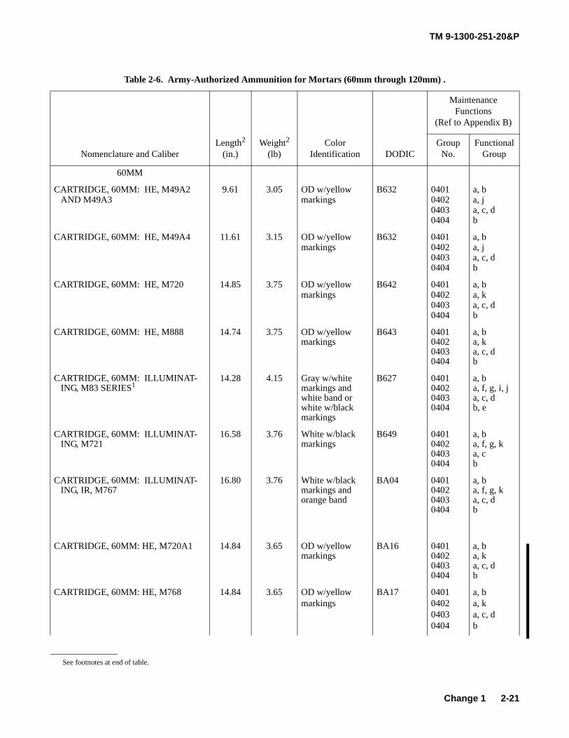
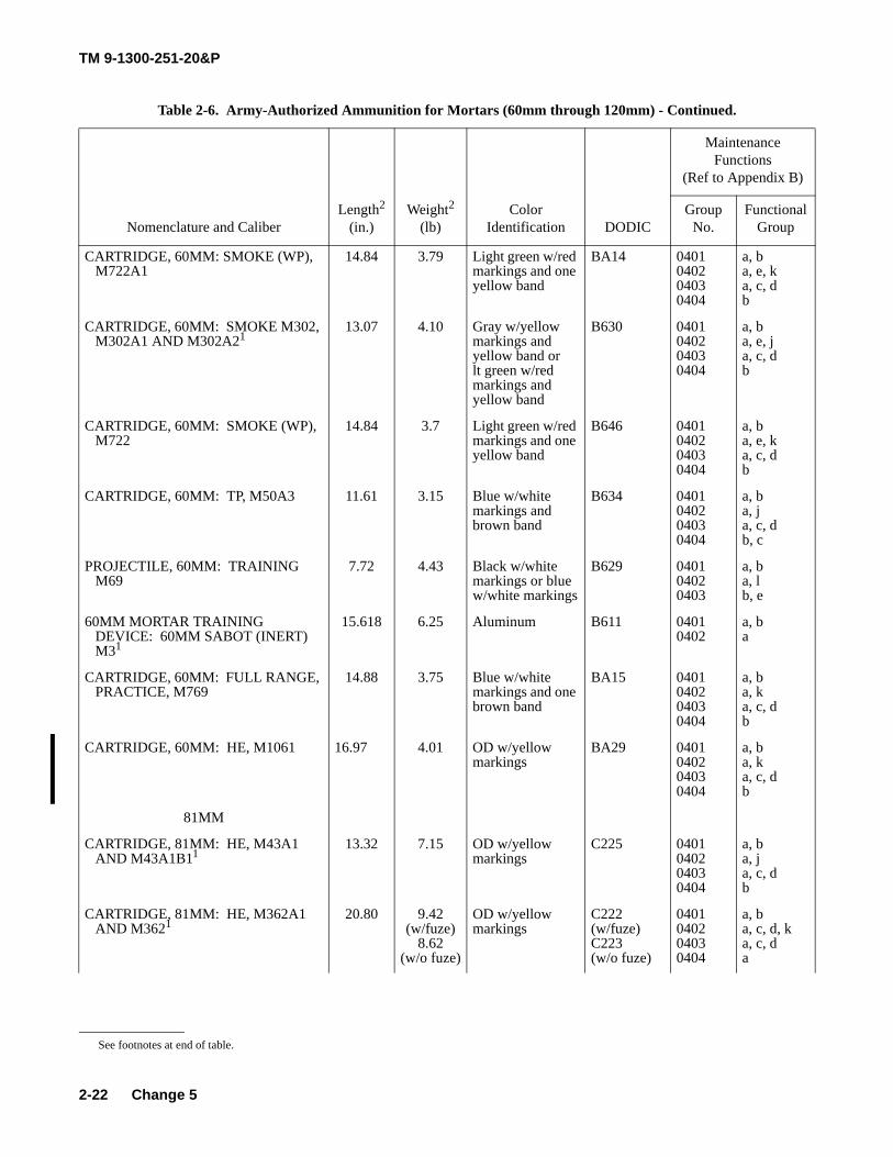
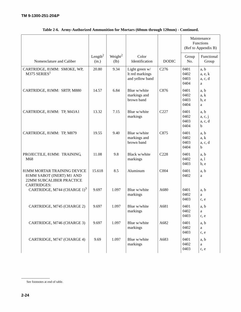
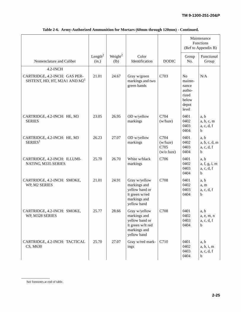
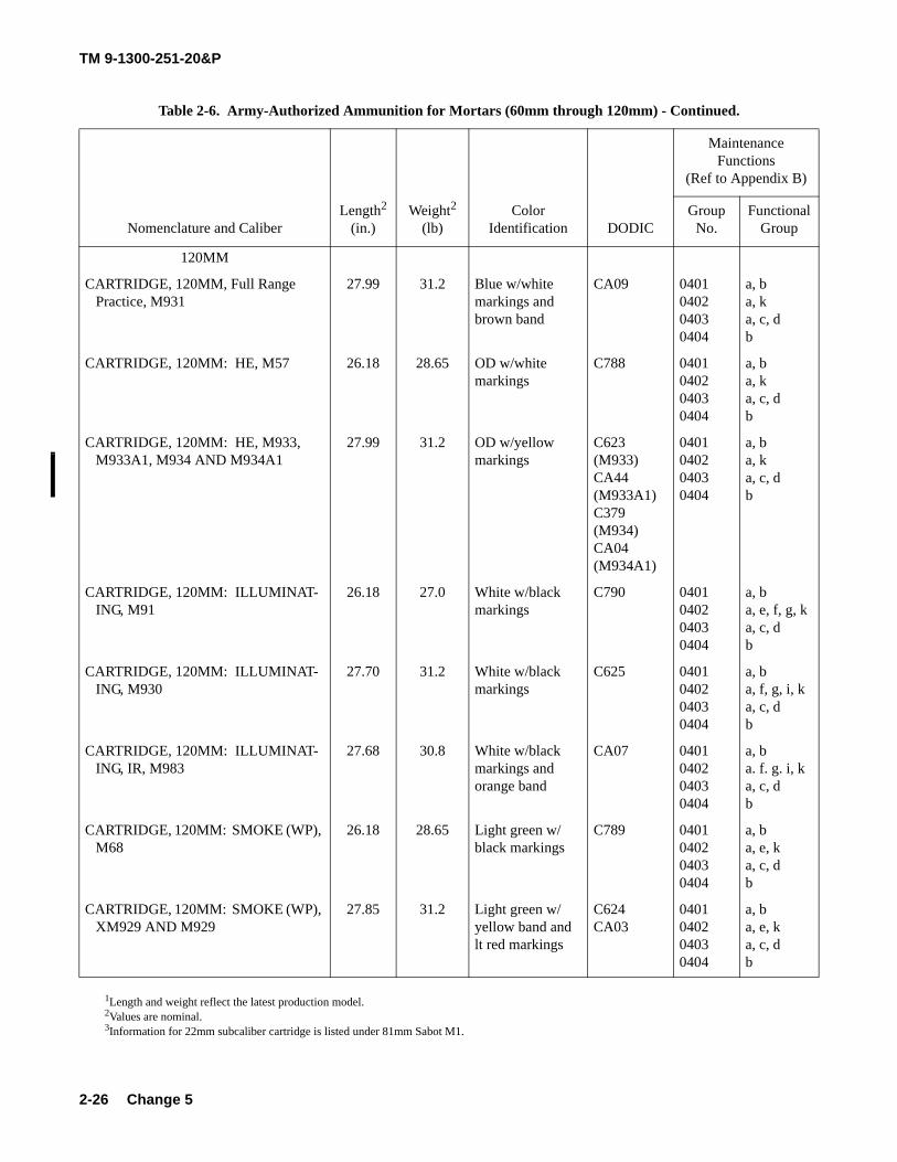
Table 2-6. Army-Authorized Ammunition for Mortars (60mm through 120mm) .
Nomenclature and CaliberLength2
(in.)Weight2
(lb)Color
Identification DODIC
Maintenance Functions
(Ref to Appendix B)
Group No.
Functional Group
60MM
CARTRIDGE, 60MM: HE, M49A2 AND M49A3
9.61 3.05 OD w/yellow markings
B632 0401040204030404
a, ba, ja, c, db
CARTRIDGE, 60MM: HE, M49A4 11.61 3.15 OD w/yellow markings
B632 0401040204030404
a, ba, ja, c, db
CARTRIDGE, 60MM: HE, M720 14.85 3.75 OD w/yellow markings
B642 0401040204030404
a, ba, ka, c, db
CARTRIDGE, 60MM: HE, M888 14.74 3.75 OD w/yellow markings
B643 0401040204030404
a, ba, ka, c, db
CARTRIDGE, 60MM: ILLUMINAT-ING, M83 SERIES1
14.28 4.15 Gray w/white markings and white band or white w/black markings
B627 0401040204030404
a, ba, f, g, i, ja, c, db, e
CARTRIDGE, 60MM: ILLUMINAT-ING, M721
16.58 3.76 White w/black markings
B649 0401040204030404
a, ba, f, g, ka, cb
CARTRIDGE, 60MM: ILLUMINAT-ING, IR, M767
16.80 3.76 White w/black markings and orange band
BA04 0401040204030404
a, ba, f, g, ka, c, db
CARTRIDGE, 60MM: HE, M720A1 14.84 3.65 OD w/yellow markings
BA16 0401040204030404
a, ba, ka, c, db
CARTRIDGE, 60MM: HE, M768 14.84 3.65 OD w/yellow markings
BA17 0401040204030404
a, ba, ka, c, db
See footnotes at end of table.
Change 1
TM 9-1300-251-20&P
2-22
CARTRIDGE, 60MM: SMOKE (WP), M722A1
14.84 3.79 Light green w/red markings and one yellow band
BA14 0401040204030404
a, ba, e, ka, c, db
CARTRIDGE, 60MM: SMOKE M302, M302A1 AND M302A21
13.07 4.10 Gray w/yellow markings and yellow band or lt green w/red markings and yellow band
B630 0401040204030404
a, ba, e, ja, c, db
CARTRIDGE, 60MM: SMOKE (WP), M722
14.84 3.7 Light green w/red markings and one yellow band
B646 0401040204030404
a, ba, e, ka, c, db
CARTRIDGE, 60MM: TP, M50A3 11.61 3.15 Blue w/white markings and brown band
B634 0401040204030404
a, ba, ja, c, db, c
PROJECTILE, 60MM: TRAINING M69
7.72 4.43 Black w/white markings or blue w/white markings
B629 040104020403
a, ba, lb, e
60MM MORTAR TRAINING DEVICE: 60MM SABOT (INERT) M31
15.618 6.25 Aluminum B611 04010402
a, ba
CARTRIDGE, 60MM: FULL RANGE, PRACTICE, M769
14.88 3.75 Blue w/white markings and one brown band
BA15 0401040204030404
a, ba, ka, c, db
CARTRIDGE, 60MM: HE, M1061 16.97 4.01 OD w/yellow markings
BA29 0401040204030404
a, ba, ka, c, db
81MM
CARTRIDGE, 81MM: HE, M43A1 AND M43A1B11
13.32 7.15 OD w/yellow markings
C225 0401040204030404
a, ba, ja, c, db
CARTRIDGE, 81MM: HE, M362A1 AND M3621
20.80 9.42(w/fuze)
8.62(w/o fuze)
OD w/yellow markings
C222(w/fuze)C223(w/o fuze)
0401040204030404
a, ba, c, d, ka, c, da
Table 2-6. Army-Authorized Ammunition for Mortars (60mm through 120mm) - Continued.
Nomenclature and CaliberLength2
(in.)Weight2
(lb)Color
Identification DODIC
Maintenance Functions
(Ref to Appendix B)
Group No.
Functional Group
See footnotes at end of table.
Change 5
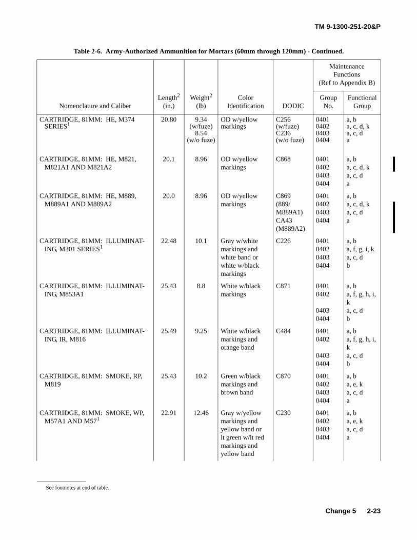
TM 9-1300-251-20&P
2-23
CARTRIDGE, 81MM: HE, M374 SERIES1
20.80 9.34(w/fuze)
8.54(w/o fuze)
OD w/yellow markings
C256(w/fuze)C236(w/o fuze)
0401040204030404
a, ba, c, d, ka, c, da
CARTRIDGE, 81MM: HE, M821, M821A1 AND M821A2
20.1 8.96 OD w/yellow markings
C868 0401040204030404
a, ba, c, d, ka, c, da
CARTRIDGE, 81MM: HE, M889, M889A1 AND M889A2
20.0 8.96 OD w/yellow markings
C869(889/M889A1)CA43(M889A2)
0401040204030404
a, ba, c, d, ka, c, da
CARTRIDGE, 81MM: ILLUMINAT-ING, M301 SERIES1
22.48 10.1 Gray w/white markings and white band or white w/black markings
C226 0401040204030404
a, ba, f, g, i, ka, c, db
CARTRIDGE, 81MM: ILLUMINAT-ING, M853A1
25.43 8.8 White w/black markings
C871 04010402
04030404
a, ba, f, g, h, i, ka, c, db
CARTRIDGE, 81MM: ILLUMINAT-ING, IR, M816
25.49 9.25 White w/black markings and orange band
C484 04010402
04030404
a, ba, f, g, h, i, ka, c, db
CARTRIDGE, 81MM: SMOKE, RP, M819
25.43 10.2 Green w/black markings and brown band
C870 0401040204030404
a, ba, e, ka, c, da
CARTRIDGE, 81MM: SMOKE, WP, M57A1 AND M571
22.91 12.46 Gray w/yellow markings and yellow band or lt green w/lt red markings and yellow band
C230 0401040204030404
a, ba, e, ka, c, da
Table 2-6. Army-Authorized Ammunition for Mortars (60mm through 120mm) - Continued.
Nomenclature and CaliberLength2
(in.)Weight2
(lb)Color
Identification DODIC
Maintenance Functions
(Ref to Appendix B)
Group No.
Functional Group
See footnotes at end of table.
Change 5
TM 9-1300-251-20&P
2-24
CARTRIDGE, 81MM: SMOKE, WP, M375 SERIES1
20.80 9.34 Light green w/lt red markings and yellow band
C276 0401040204030404
a, ba, e, ka, c, da
CARTRIDGE, 81MM: SRTP, M880 14.57 6.84 Blue w/white markings and brown band
C876 0401040204030404
a, ba, kb, ea
CARTRIDGE, 81MM: TP, M43A1 13.32 7.15 Blue w/white markings
C227 0401040204030404
a, ba, c, ja, c, db
CARTRIDGE, 81MM: TP, M879 19.55 9.40 Blue w/white markings and brown band
C875 0401040204030404
a, ba, ka, c, db
PROJECTILE, 81MM: TRAINING, M68
11.08 9.8 Black w/white markings
C228 040104020403
a, ba, lb, e
81MM MORTAR TRAINING DEVICE 81MM SABOT (INERT) M1 AND 22MM SUBCALIBER PRACTICE CARTRIDGES: CARTRIDGE, M744 (CHARGE 1)3
15.618
9.697
8.5
1.097
Aluminum
Blue w/white markings
C004
A680
04010402
040104020403
a, ba
a, bac, e
CARTRIDGE, M745 (CHARGE 2) 9.697 1.097 Blue w/white markings
A681 040104020403
a, bac, e
CARTRIDGE, M746 (CHARGE 3) 9.697 1.097 Blue w/white markings
A682 040104020403
a, bac, e
CARTRIDGE, M747 (CHARGE 4) 9.69 1.097 Blue w/white markings
A683 040104020403
a, bac, e
Table 2-6. Army-Authorized Ammunition for Mortars (60mm through 120mm) - Continued.
Nomenclature and CaliberLength2
(in.)Weight2
(lb)Color
Identification DODIC
Maintenance Functions
(Ref to Appendix B)
Group No.
Functional Group
See footnotes at end of table.
TM 9-1300-251-20&P
2-25
4.2-INCH
CARTRIDGE, 4.2-INCH: GAS PER-SISTENT, HD, HT, M2A1 AND M21
21.01 24.67 Gray w/green markings and two green bands
C703 No mainte-nance autho-rized below depot level
N/A
CARTRIDGE, 4.2-INCH: HE, M3 SERIES
23.05 26.95 OD w/yellow markings
C704(w/fuze)
0401040204030404
a, ba, b, c, ma, c, d, fb
CARTRIDGE, 4.2-INCH: HE, M3 SERIES1
26.23 27.07 OD w/yellow markings
C704(w/fuze)C705(w/o fuze)
0401040204030404
a, ba, b, c, d, ma, c, d, fb
CARTRIDGE, 4.2-INCH: ILLUMI-NATING, M335 SERIES
25.70 26.70 White w/black markings
C706 0401040204030404
a, ba, f, g, i, ma, c, d, fb
CARTRIDGE, 4.2-INCH: SMOKE, WP, M2 SERIES
21.01 24.91 Gray w/yellow markings and yellow band or lt green w/red markings and yellow band
C708 0401040204030404
a, ba, ma, c, d, fb
CARTRIDGE, 4.2-INCH: SMOKE, WP, M328 SERIES
25.77 28.66 Gray w/yellow markings and yellow band or lt green w/lt red markings and yellow band
C708 0401040204030404
a, ba, e, m, na, c, d, fb
CARTRIDGE, 4.2-INCH: TACTICAL CS, M630
25.70 27.07 Gray w/red mark-ings
C710 0401040204030404
a, ba, h, i, ma, c, d, fb
Table 2-6. Army-Authorized Ammunition for Mortars (60mm through 120mm) - Continued.
Nomenclature and CaliberLength2
(in.)Weight2
(lb)Color
Identification DODIC
Maintenance Functions
(Ref to Appendix B)
Group No.
Functional Group
See footnotes at end of table.
TM 9-1300-251-20&P
2-26
120MM
CARTRIDGE, 120MM, Full Range Practice, M931
27.99 31.2 Blue w/white markings and brown band
CA09 0401040204030404
a, ba, ka, c, db
CARTRIDGE, 120MM: HE, M57 26.18 28.65 OD w/white markings
C788 0401040204030404
a, ba, ka, c, db
CARTRIDGE, 120MM: HE, M933, M933A1, M934 AND M934A1
27.99 31.2 OD w/yellow markings
C623 (M933)CA44(M933A1)C379 (M934)CA04 (M934A1)
0401040204030404
a, ba, ka, c, db
CARTRIDGE, 120MM: ILLUMINAT-ING, M91
26.18 27.0 White w/black markings
C790 0401040204030404
a, ba, e, f, g, ka, c, db
CARTRIDGE, 120MM: ILLUMINAT-ING, M930
27.70 31.2 White w/black markings
C625 0401040204030404
a, ba, f, g, i, ka, c, db
CARTRIDGE, 120MM: ILLUMINAT-ING, IR, M983
27.68 30.8 White w/black markings and orange band
CA07 0401040204030404
a, ba. f. g. i, ka, c, db
CARTRIDGE, 120MM: SMOKE (WP), M68
26.18 28.65 Light green w/black markings
C789 0401040204030404
a, ba, e, ka, c, db
CARTRIDGE, 120MM: SMOKE (WP), XM929 AND M929
27.85 31.2 Light green w/yellow band and lt red markings
C624CA03
0401040204030404
a, ba, e, ka, c, db
1Length and weight reflect the latest production model.2Values are nominal.3Information for 22mm subcaliber cartridge is listed under 81mm Sabot M1.
Table 2-6. Army-Authorized Ammunition for Mortars (60mm through 120mm) - Continued.
Nomenclature and CaliberLength2
(in.)Weight2
(lb)Color
Identification DODIC
Maintenance Functions
(Ref to Appendix B)
Group No.
Functional Group
Change 5
TM 9-1300-251-20&P
2-27
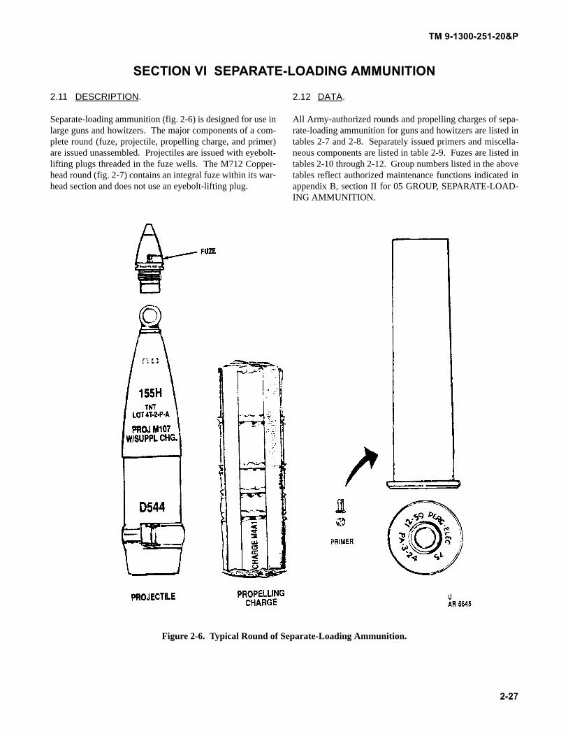
SECTION VI SEPARATE-LOADING AMMUNITION
2.11 DESCRIPTION.
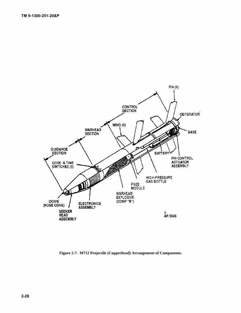
Separate-loading ammunition (fig. 2-6) is designed for use inlarge guns and howitzers. The major components of a com-plete round (fuze, projectile, propelling charge, and primer)are issued unassembled. Projectiles are issued with eyebolt-lifting plugs threaded in the fuze wells. The M712 Copper-head round (fig. 2-7) contains an integral fuze within its war-head section and does not use an eyebolt-lifting plug.
2.12 DATA.
All Army-authorized rounds and propelling charges of sepa-rate-loading ammunition for guns and howitzers are listed intables 2-7 and 2-8. Separately issued primers and miscella-neous components are listed in table 2-9. Fuzes are listed intables 2-10 through 2-12. Group numbers listed in the abovetables reflect authorized maintenance functions indicated inappendix B, section II for 05 GROUP, SEPARATE-LOAD-ING AMMUNITION.
Figure 2-6. Typical Round of Separate-Loading Ammunition.
TM 9-1300-251-20&P
2-28
Figure 2-7. M712 Projectile (Copperhead) Arrangement of Components.
TM 9-1300-251-20&P
2-29
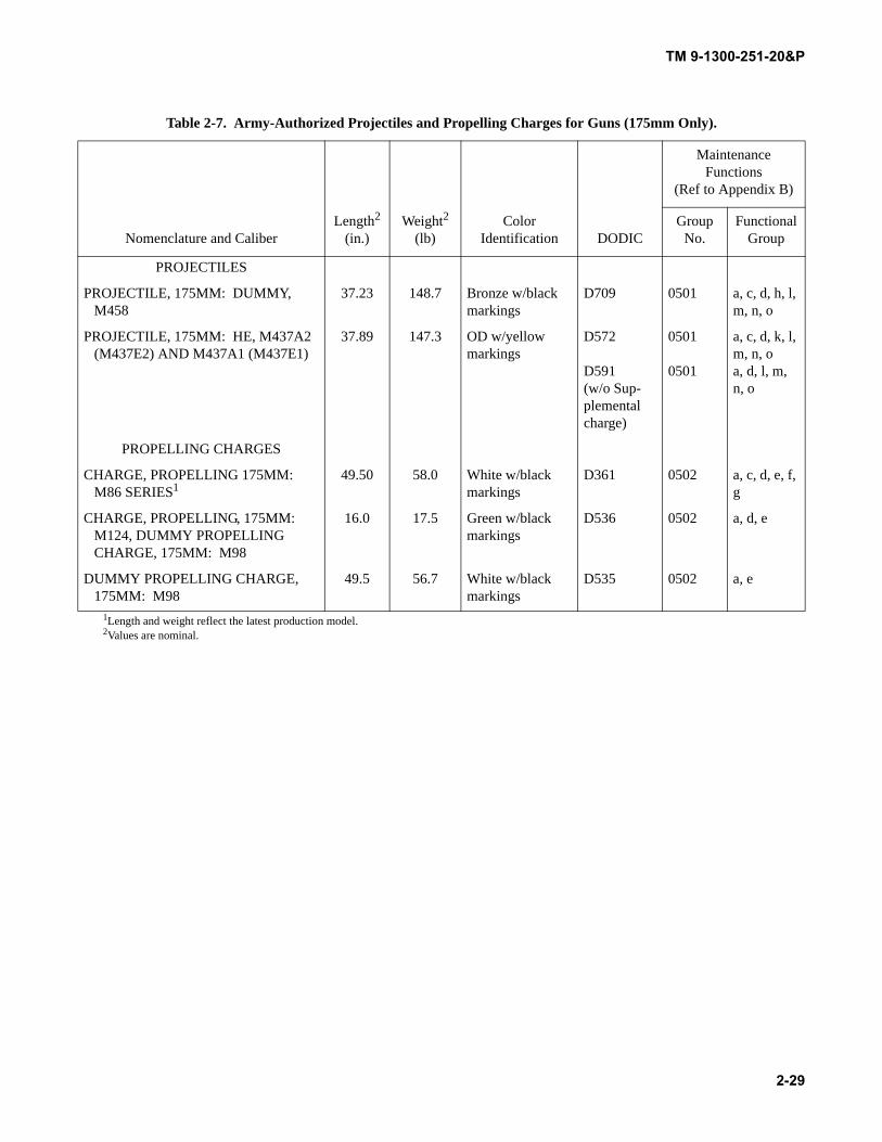
Table 2-7. Army-Authorized Projectiles and Propelling Charges for Guns (175mm Only).
Nomenclature and CaliberLength2
(in.)Weight2
(lb)Color
Identification DODIC
Maintenance Functions
(Ref to Appendix B)
Group No.
Functional Group
PROJECTILES
PROJECTILE, 175MM: DUMMY, M458
37.23 148.7 Bronze w/black markings
D709 0501 a, c, d, h, l, m, n, o
PROJECTILE, 175MM: HE, M437A2 (M437E2) AND M437A1 (M437E1)
37.89 147.3 OD w/yellow markings
D572
D591(w/o Sup-plemental charge)
0501
0501
a, c, d, k, l, m, n, oa, d, l, m, n, o
PROPELLING CHARGES
CHARGE, PROPELLING 175MM: M86 SERIES1
49.50 58.0 White w/black markings
D361 0502 a, c, d, e, f, g
CHARGE, PROPELLING, 175MM: M124, DUMMY PROPELLING CHARGE, 175MM: M98
16.0 17.5 Green w/black markings
D536 0502 a, d, e
DUMMY PROPELLING CHARGE, 175MM: M98
49.5 56.7 White w/black markings
D535 0502 a, e
1Length and weight reflect the latest production model.2Values are nominal.
TM 9-1300-251-20&P
2-30
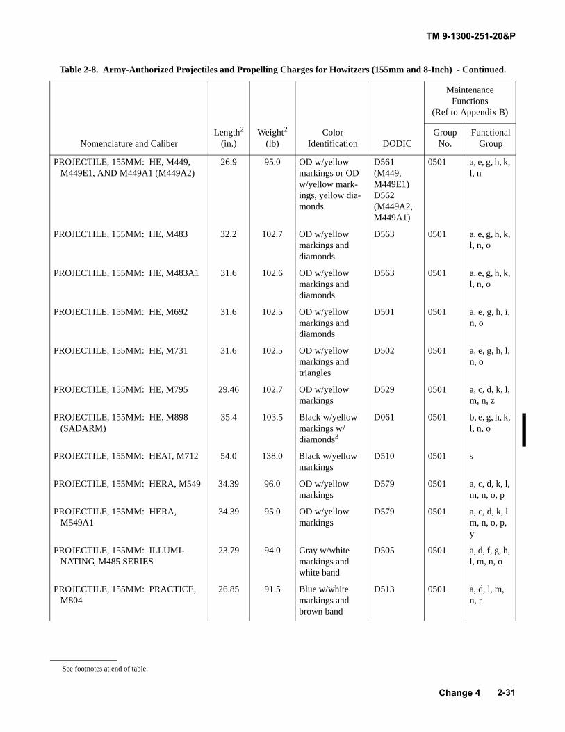
Table 2-8. Army-Authorized Projectiles and Propelling Charges for Howitzers (155mm and 8-Inch) .
Nomenclature and CaliberLength2
(in.)Weight2
(lb)Color
Identification DODIC
Maintenance Functions
(Ref to Appendix B)
Group No.
Functional Group
155MM PROJECTILES
DUMMY PROJECTILE, 155MM: M7 27.56 95.0 Black w/red and brass
D553 0501 a
PROJECTILE, 155MM: AT, M718 AND M741 (RAAM)
33.8 103.0 OD w/yellow markings and triangles
D503 (M718)D509 (M741)
0501 a, e, h, l, m, n, o
PROJECTILE, 155MM: EXTENDED RANGE, DP, M864
31.6 102.6 OD w/yellow markings and diamonds
D864 0501 a, e, h, k, l, n, o, w
PROJECTILE, 155MM: GAS, NON-PERSISTENT, GB VX, M121A1 AND M121
27.59 99.70 Gray w/green markings and two green bands or gray w/green markings, three green bands and one yellow band
D542(GB)
No mainte-nance autho-rized below depot level
N/A
PROJECTILE, 155MM: GAS, PER-SISTENT, H, HD, M110
26.78 98.5 Gray w/green markings and two green bands
D543 No mainte-nance autho-rized below depot level
N/A
PROJECTILE, 155MM: GB2, M687 31.6 93.0 Gray w/dark green markings and yellow band
D594 0501 a, d, l, m, n, o, s, t
PROJECTILE, 155MM: HE, M107 27.57 96.25 OD w/yellow markings
D544(w/supple-mentary charge)D571(w/o supple-mentary charge)
0501 a, c, d, k, l, m, n
See footnotes at end of table.
TM 9-1300-251-20&P
2-31
PROJECTILE, 155MM: HE, M449, M449E1, AND M449A1 (M449A2)
26.9 95.0 OD w/yellow markings or OD w/yellow mark-ings, yellow dia-monds
D561(M449,M449E1)D562(M449A2,M449A1)
0501 a, e, g, h, k, l, n
PROJECTILE, 155MM: HE, M483 32.2 102.7 OD w/yellow markings and diamonds
D563 0501 a, e, g, h, k, l, n, o
PROJECTILE, 155MM: HE, M483A1 31.6 102.6 OD w/yellow markings and diamonds
D563 0501 a, e, g, h, k, l, n, o
PROJECTILE, 155MM: HE, M692 31.6 102.5 OD w/yellow markings and diamonds
D501 0501 a, e, g, h, i, n, o
PROJECTILE, 155MM: HE, M731 31.6 102.5 OD w/yellow markings and triangles
D502 0501 a, e, g, h, l, n, o
PROJECTILE, 155MM: HE, M795 29.46 102.7 OD w/yellow markings
D529 0501 a, c, d, k, l, m, n, z
PROJECTILE, 155MM: HE, M898 (SADARM)
35.4 103.5 Black w/yellow markings w/diamonds3
D061 0501 b, e, g, h, k, l, n, o
PROJECTILE, 155MM: HEAT, M712 54.0 138.0 Black w/yellow markings
D510 0501 s
PROJECTILE, 155MM: HERA, M549 34.39 96.0 OD w/yellow markings
D579 0501 a, c, d, k, l, m, n, o, p
PROJECTILE, 155MM: HERA, M549A1
34.39 95.0 OD w/yellow markings
D579 0501 a, c, d, k, l m, n, o, p, y
PROJECTILE, 155MM: ILLUMI-NATING, M485 SERIES
23.79 94.0 Gray w/white markings and white band
D505 0501 a, d, f, g, h, l, m, n, o
PROJECTILE, 155MM: PRACTICE, M804
26.85 91.5 Blue w/white markings and brown band
D513 0501 a, d, l, m, n, r
Table 2-8. Army-Authorized Projectiles and Propelling Charges for Howitzers (155mm and 8-Inch) - Continued.
Nomenclature and CaliberLength2
(in.)Weight2
(lb)Color
Identification DODIC
Maintenance Functions
(Ref to Appendix B)
Group No.
Functional Group
See footnotes at end of table.
Change 4
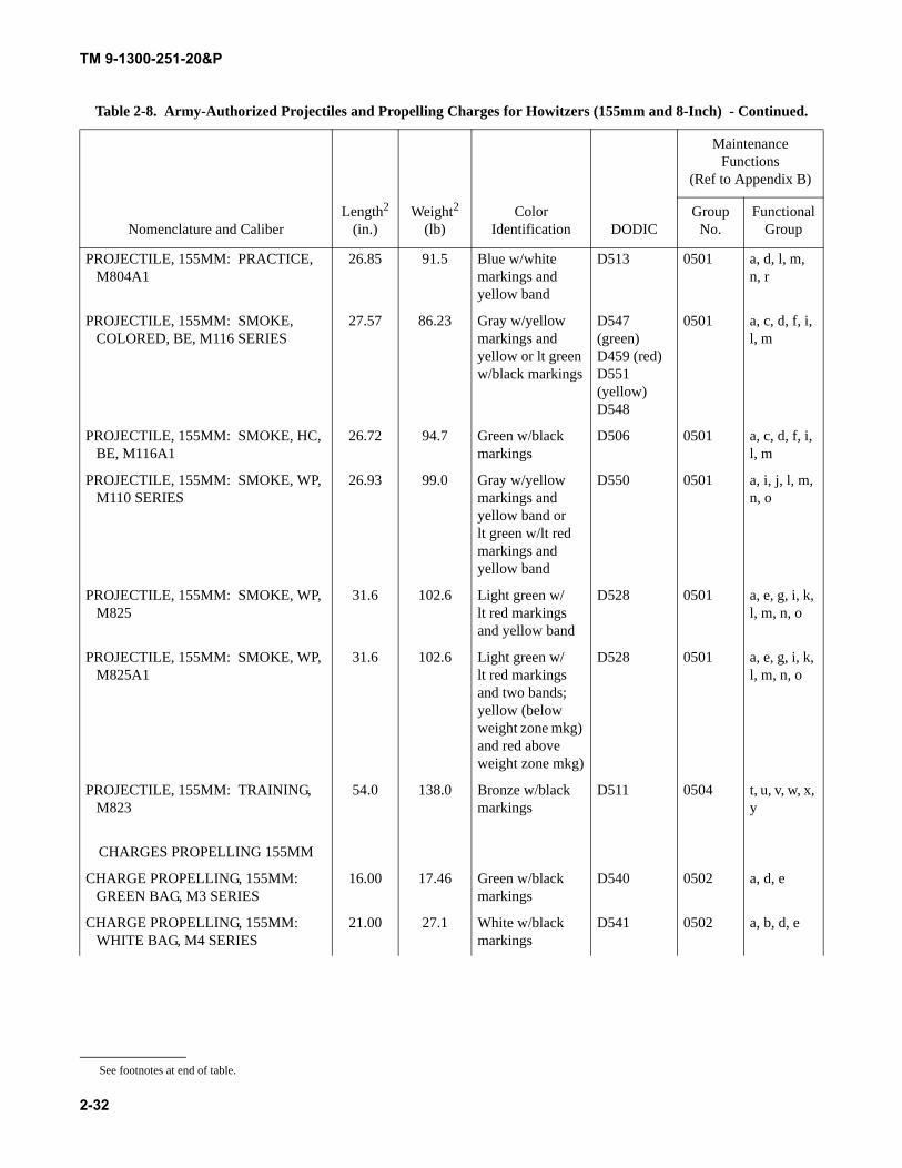
TM 9-1300-251-20&P
2-32
PROJECTILE, 155MM: PRACTICE, M804A1
26.85 91.5 Blue w/white markings and yellow band
D513 0501 a, d, l, m, n, r
PROJECTILE, 155MM: SMOKE, COLORED, BE, M116 SERIES
27.57 86.23 Gray w/yellow markings and yellow or lt green w/black markings
D547 (green)D459 (red)D551(yellow)D548
0501 a, c, d, f, i, l, m
PROJECTILE, 155MM: SMOKE, HC, BE, M116A1
26.72 94.7 Green w/black markings
D506 0501 a, c, d, f, i, l, m
PROJECTILE, 155MM: SMOKE, WP, M110 SERIES
26.93 99.0 Gray w/yellow markings and yellow band or lt green w/lt red markings and yellow band
D550 0501 a, i, j, l, m, n, o
PROJECTILE, 155MM: SMOKE, WP, M825
31.6 102.6 Light green w/lt red markings and yellow band
D528 0501 a, e, g, i, k, l, m, n, o
PROJECTILE, 155MM: SMOKE, WP, M825A1
31.6 102.6 Light green w/lt red markings and two bands; yellow (below weight zone mkg) and red above weight zone mkg)
D528 0501 a, e, g, i, k, l, m, n, o
PROJECTILE, 155MM: TRAINING, M823
54.0 138.0 Bronze w/black markings
D511 0504 t, u, v, w, x, y
CHARGES PROPELLING 155MM
CHARGE PROPELLING, 155MM: GREEN BAG, M3 SERIES
16.00 17.46 Green w/black markings
D540 0502 a, d, e
CHARGE PROPELLING, 155MM: WHITE BAG, M4 SERIES
21.00 27.1 White w/black markings
D541 0502 a, b, d, e
Table 2-8. Army-Authorized Projectiles and Propelling Charges for Howitzers (155mm and 8-Inch) - Continued.
Nomenclature and CaliberLength2
(in.)Weight2
(lb)Color
Identification DODIC
Maintenance Functions
(Ref to Appendix B)
Group No.
Functional Group
See footnotes at end of table.
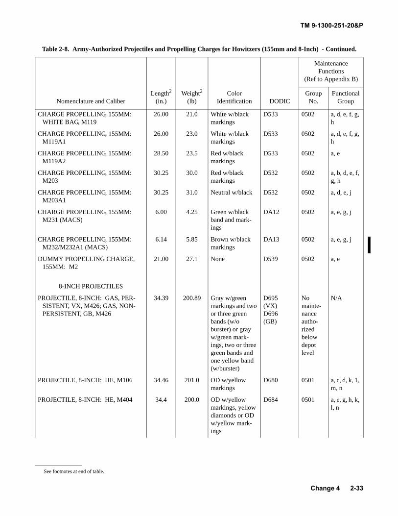
TM 9-1300-251-20&P
2-33
CHARGE PROPELLING, 155MM: WHITE BAG, M119
26.00 21.0 White w/black markings
D533 0502 a, d, e, f, g, h
CHARGE PROPELLING, 155MM: M119A1
26.00 23.0 White w/black markings
D533 0502 a, d, e, f, g, h
CHARGE PROPELLING, 155MM: M119A2
28.50 23.5 Red w/black markings
D533 0502 a, e
CHARGE PROPELLING, 155MM: M203
30.25 30.0 Red w/black markings
D532 0502 a, b, d, e, f, g, h
CHARGE PROPELLING, 155MM: M203A1
30.25 31.0 Neutral w/black D532 0502 a, d, e, j
CHARGE PROPELLING, 155MM: M231 (MACS)
6.00 4.25 Green w/black band and mark-ings
DA12 0502 a, e, g, j
CHARGE PROPELLING, 155MM: M232/M232A1 (MACS)
6.14 5.85 Brown w/black markings
DA13 0502 a, e, g, j
DUMMY PROPELLING CHARGE, 155MM: M2
21.00 27.1 None D539 0502 a, e
8-INCH PROJECTILES
PROJECTILE, 8-INCH: GAS, PER-SISTENT, VX, M426; GAS, NON-PERSISTENT, GB, M426
34.39 200.89 Gray w/green markings and two or three green bands (w/o burster) or gray w/green mark-ings, two or three green bands and one yellow band (w/burster)
D695(VX)D696(GB)
No mainte-nance autho-rized below depot level
N/A
PROJECTILE, 8-INCH: HE, M106 34.46 201.0 OD w/yellow markings
D680 0501 a, c, d, k, 1, m, n
PROJECTILE, 8-INCH: HE, M404 34.4 200.0 OD w/yellow markings, yellow diamonds or OD w/yellow mark-ings
D684 0501 a, e, g, h, k, l, n
Table 2-8. Army-Authorized Projectiles and Propelling Charges for Howitzers (155mm and 8-Inch) - Continued.
Nomenclature and CaliberLength2
(in.)Weight2
(lb)Color
Identification DODIC
Maintenance Functions
(Ref to Appendix B)
Group No.
Functional Group
See footnotes at end of table.
Change 4
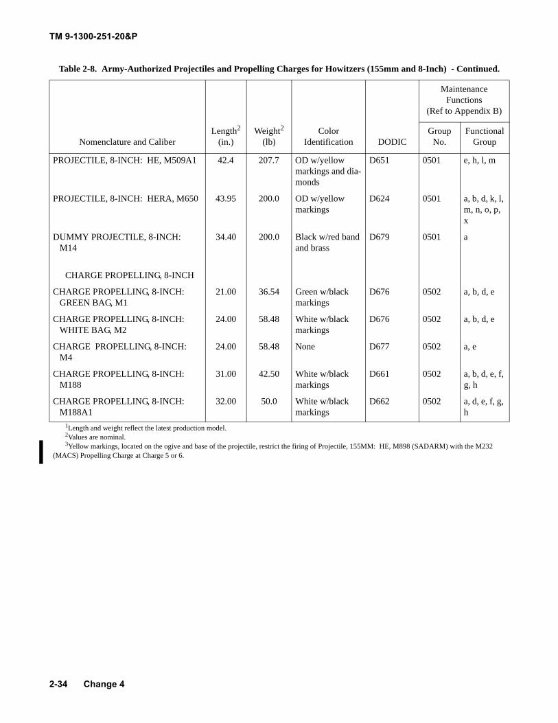
TM 9-1300-251-20&P
2-34
PROJECTILE, 8-INCH: HE, M509A1 42.4 207.7 OD w/yellow markings and dia-monds
D651 0501 e, h, l, m
PROJECTILE, 8-INCH: HERA, M650 43.95 200.0 OD w/yellow markings
D624 0501 a, b, d, k, l, m, n, o, p, x
DUMMY PROJECTILE, 8-INCH: M14
34.40 200.0 Black w/red band and brass
D679 0501 a
CHARGE PROPELLING, 8-INCH
CHARGE PROPELLING, 8-INCH: GREEN BAG, M1
21.00 36.54 Green w/black markings
D676 0502 a, b, d, e
CHARGE PROPELLING, 8-INCH: WHITE BAG, M2
24.00 58.48 White w/black markings
D676 0502 a, b, d, e
CHARGE PROPELLING, 8-INCH: M4
24.00 58.48 None D677 0502 a, e
CHARGE PROPELLING, 8-INCH: M188
31.00 42.50 White w/black markings
D661 0502 a, b, d, e, f, g, h
CHARGE PROPELLING, 8-INCH: M188A1
32.00 50.0 White w/black markings
D662 0502 a, d, e, f, g, h
1Length and weight reflect the latest production model.2Values are nominal.3Yellow markings, located on the ogive and base of the projectile, restrict the firing of Projectile, 155MM: HE, M898 (SADARM) with the M232
(MACS) Propelling Charge at Charge 5 or 6.
Table 2-8. Army-Authorized Projectiles and Propelling Charges for Howitzers (155mm and 8-Inch) - Continued.
Nomenclature and CaliberLength2
(in.)Weight2
(lb)Color
Identification DODIC
Maintenance Functions
(Ref to Appendix B)
Group No.
Functional Group
Change 4
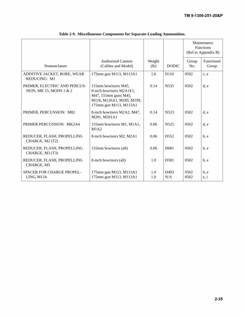
TM 9-1300-251-20&P
2-35
Table 2-9. Miscellaneous Components for Separate-Loading Ammunition.
NomenclatureAuthorized Cannon (Caliber and Model)
Weight (lb) DODIC
Maintenance Functions
(Ref to Appendix B)
Group No.
Functional Group
ADDITIVE JACKET, BORE, WEAR REDUCING: M1
175mm gun M113, M113A1 1.6 D110 0502 c, e
PRIMER, ELECTRIC AND PERCUS-SION, MK 15, MODS 1 & 2
115mm howitzers M45, 8-inch howitzers M2A1E1, M47, 155mm guns M45, M126, M126A1, M185, M199, 175mm gun M113, M113A1
0.14 N535 0502 d, e
PRIMER, PERCUSSION: M82 8-inch howitzers M2A2, M47, M201, M201A1
0.14 N523 0502 d, e
PRIMER PERCUSSION: MK2A4 155mm howitzers M1, M1A1, M1A2
0.06 N525 0502 d, e
REDUCER, FLASH, PROPELLING CHARGE, M2 (T2)
8-inch howitzers M2, M2A1 0.06 D552 0502 b, e
REDUCER, FLASH, PROPELLING CHARGE, M3 (T3)
155mm howitzers (all) 0.06 D681 0502 b, e
REDUCER, FLASH, PROPELLING CHARGE, M5
8-inch howitzers (all) 1.0 D581 0502 b, e
SPACER FOR CHARGE PROPEL-LING, M124
175mm gun M113, M113A1175mm gun M113, M113A1
1.01.0
D493N/A
05020502
b, ee, i
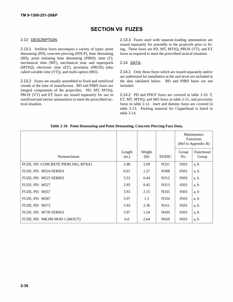
TM 9-1300-251-20&P
2-36
SECTION VII FUZES
2.13 DESCRIPTION.
2.13.1 Artillery fuzes encompass a variety of types: pointdetonating (PD), concrete piercing (PDCP), base detonating(BD), point initiating base detonating (PIBD), time (T),mechanical time (MT), mechanical time and superquick(MTSQ), electronic time (ET), proximity (PROX) (alsocalled variable time (VT)), and multi-option (MO).
2.13.2 Fuzes are usually assembled to fixed and semifixedrounds at the time of manufacture. BD and PIBD fuzes areintegral components of the projectiles. PD, MT, MTSQ,PROX (VT) and ET fuzes are issued separately for use insemifixed and mortar ammunition to meet the prescribed tac-tical situation.
2.13.3 Fuzes used with separate-loading ammunition areissued separately for assembly to the projectile prior to fir-ing. These fuzes are PD, MT, MTSQ, PROX (VT), and ETfuzes as required to meet the prescribed tactical situation.
2.14 DATA.
2.14.1 Only those fuzes which are issued separately and/orare authorized for installation at the unit level are included inthe data tabulated below. BD and PIBD fuzes are notincluded.
2.14.2 PD and PDCP fuzes are covered in table 2-10, T,ET, MT, MTSQ, and MO fuzes in table 2-11, and proximityfuzes in table 2-12. Inert and dummy fuzes are covered intable 2-13. Packing material for Copperhead is listed intable 2-14.
Table 2-10. Point Detonating and Point Detonating, Concrete Piercing Fuze Data.
NomenclatureLength
(in.)Weight
(lb) DODIC
Maintenance Functions
(Ref to Appendix B)
Group No.
Functional Group
FUZE, PD: CONCRETE PIERCING, M78A1 3.48 2.09 N331 0503 a, b
FUZE, PD: M524 SERIES 6.01 1.27 N308 0503 a, b
FUZE, PD: M525 SERIES 3.53 0.44 N312 0503 a, b
FUZE, PD: M527 2.95 0.45 N313 0503 a, b
FUZE, PD: M557 5.93 2.15 N335 0503 a, b
FUZE, PD: M567 5.97 1.3 N334 0503 a, b
FUZE, PD: M572 5.93 2.30 N311 0503 a, b
FUZE, PD: M739 SERIES 5.97 1.54 N430 0503 a, b
FUZE, PD: MK399 MOD 1 (MOUT) 6.0 2.64 N659 0503 a, b
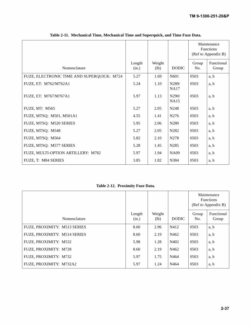
TM 9-1300-251-20&P
2-37
Table 2-11. Mechanical Time, Mechanical Time and Superquick, and Time Fuze Data.
NomenclatureLength
(in.)Weight
(lb) DODIC
Maintenance Functions
(Ref to Appendix B)
Group No.
Functional Group
FUZE, ELECTRONIC TIME AND SUPERQUICK: M724 5.27 1.69 N601 0503 a, b
FUZE, ET: M762/M762A1 5.24 1.10 N289/NA17
0503 a, b
FUZE, ET: M767/M767A1 5.97 1.13 N290/NA15
0503 a, b
FUZE, MT: M565 5.27 2.05 N248 0503 a, b
FUZE, MTSQ: M501, M501A1 4.55 1.41 N276 0503 a, b
FUZE, MTSQ: M520 SERIES 5.95 2.06 N280 0503 a, b
FUZE, MTSQ: M548 5.27 2.05 N282 0503 a, b
FUZE, MTSQ: M564 5.82 2.10 N278 0503 a, b
FUZE, MTSQ: M577 SERIES 5.28 1.45 N285 0503 a, b
FUZE, MULTI-OPTION ARTILLERY: M782 5.97 1.94 NA09 0503 a, b
FUZE, T: M84 SERIES 3.85 1.82 N384 0503 a, b
Table 2-12. Proximity Fuze Data.
NomenclatureLength
(in.)Weight
(lb) DODIC
Maintenance Functions
(Ref to Appendix B)
Group No.
Functional Group
FUZE, PROXIMITY: M513 SERIES 8.60 2.96 N412 0503 a, b
FUZE, PROXIMITY: M514 SERIES 8.60 2.19 N462 0503 a, b
FUZE, PROXIMITY: M532 5.98 1.28 N402 0503 a, b
FUZE, PROXIMITY: M728 8.60 2.19 N462 0503 a, b
FUZE, PROXIMITY: M732 5.97 1.75 N464 0503 a, b
FUZE, PROXIMITY: M732A2 5.97 1.24 N464 0503 a, b
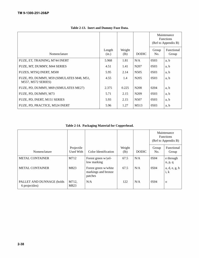
TM 9-1300-251-20&P
2-38
Table 2-13. Inert and Dummy Fuze Data.
NomenclatureLength
(in.)Weight
(lb) DODIC
Maintenance Functions
(Ref to Appendix B)
Group No.
Functional Group
FUZE, ET, TRAINING, M744 INERT 5.968 1.81 N/A 0503 a, b
FUZE, MT, DUMMY, M44 SERIES 4.51 1.41 N207 0503 a, b
FUZES, MTSQ INERT, M500 5.95 2.14 N505 0503 a, b
FUZE, PD, DUMMY, M59 (SIMULATES M48, M51, M557, M572 SERIES)
4.55 1.4 N205 0503 a, b
FUZE, PD, DUMMY, M69 (SIMULATES ME27) 2.375 0.225 N208 0204 a, b
FUZE, PD, DUMMY, M73 5.71 2.15 N209 0503 a, b
FUZE, PD, INERT, M151 SERIES 5.93 2.15 N507 0503 a, b
FUZE, PD, PRACTICE, M524 INERT 5.96 1.27 M513 0503 a, b
Table 2-14. Packaging Material for Copperhead.
NomenclatureProjectile Used With Color Identification
Weight (lb) DODIC
Maintenance Functions
(Ref to Appendix B)
Group No.
Functional Group
METAL CONTAINER M712 Forest green w/yel-low marking
67.5 N/A 0504 e throughn, p, q
METAL CONTAINER M823 Forest green w/white markings and bronze patches
67.5 N/A 0504 a, d, e, g, hi, k
PALLET AND DUNNAGE (holds 6 projectiles)
M712,M823
N/A 122 N/A 0504 o
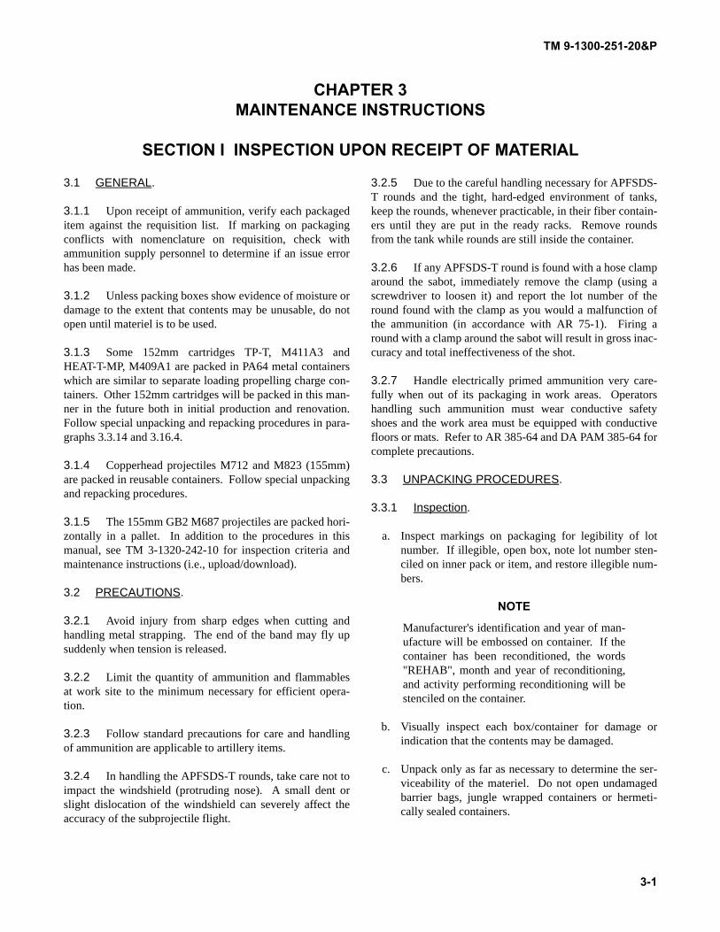
TM 9-1300-251-20&P
CHAPTER 3MAINTENANCE INSTRUCTIONS
SECTION I INSPECTION UPON RECEIPT OF MATERIAL
3.1 GENERAL.
3.1.1 Upon receipt of ammunition, verify each packageditem against the requisition list. If marking on packagingconflicts with nomenclature on requisition, check withammunition supply personnel to determine if an issue errorhas been made.
3.1.2 Unless packing boxes show evidence of moisture ordamage to the extent that contents may be unusable, do notopen until materiel is to be used.
3.1.3 Some 152mm cartridges TP-T, M411A3 andHEAT-T-MP, M409A1 are packed in PA64 metal containerswhich are similar to separate loading propelling charge con-tainers. Other 152mm cartridges will be packed in this man-ner in the future both in initial production and renovation.Follow special unpacking and repacking procedures in para-graphs 3.3.14 and 3.16.4.
3.1.4 Copperhead projectiles M712 and M823 (155mm)are packed in reusable containers. Follow special unpackingand repacking procedures.
3.1.5 The 155mm GB2 M687 projectiles are packed hori-zontally in a pallet. In addition to the procedures in thismanual, see TM 3-1320-242-10 for inspection criteria andmaintenance instructions (i.e., upload/download).
3.2 PRECAUTIONS.
3.2.1 Avoid injury from sharp edges when cutting andhandling metal strapping. The end of the band may fly upsuddenly when tension is released.
3.2.2 Limit the quantity of ammunition and flammablesat work site to the minimum necessary for efficient opera-tion.
3.2.3 Follow standard precautions for care and handlingof ammunition are applicable to artillery items.
3.2.4 In handling the APFSDS-T rounds, take care not toimpact the windshield (protruding nose). A small dent orslight dislocation of the windshield can severely affect theaccuracy of the subprojectile flight.
3.2.5 Due to the careful handling necessary for APFSDS-T rounds and the tight, hard-edged environment of tanks,keep the rounds, whenever practicable, in their fiber contain-ers until they are put in the ready racks. Remove roundsfrom the tank while rounds are still inside the container.
3.2.6 If any APFSDS-T round is found with a hose clamparound the sabot, immediately remove the clamp (using ascrewdriver to loosen it) and report the lot number of theround found with the clamp as you would a malfunction ofthe ammunition (in accordance with AR 75-1). Firing around with a clamp around the sabot will result in gross inac-curacy and total ineffectiveness of the shot.
3.2.7 Handle electrically primed ammunition very care-fully when out of its packaging in work areas. Operatorshandling such ammunition must wear conductive safetyshoes and the work area must be equipped with conductivefloors or mats. Refer to AR 385-64 and DA PAM 385-64 forcomplete precautions.
3.3 UNPACKING PROCEDURES.
3.3.1 Inspection.
a. Inspect markings on packaging for legibility of lotnumber. If illegible, open box, note lot number sten-ciled on inner pack or item, and restore illegible num-bers.
NOTE
Manufacturer's identification and year of man-ufacture will be embossed on container. If thecontainer has been reconditioned, the words"REHAB", month and year of reconditioning,and activity performing reconditioning will bestenciled on the container.
b. Visually inspect each box/container for damage orindication that the contents may be damaged.
c. Unpack only as far as necessary to determine the ser-viceability of the materiel. Do not open undamagedbarrier bags, jungle wrapped containers or hermeti-cally sealed containers.
3-1
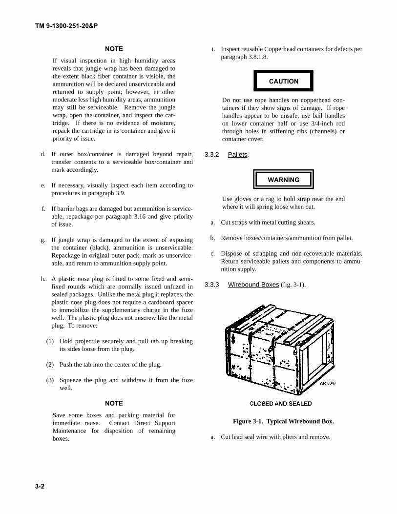
TM 9-1300-251-20&P
NOTE
If visual inspection in high humidity areasreveals that jungle wrap has been damaged tothe extent black fiber container is visible, theammunition will be declared unserviceable andreturned to supply point; however, in othermoderate less high humidity areas, ammunitionmay still be serviceable. Remove the junglewrap, open the container, and inspect the car-tridge. If there is no evidence of moisture,repack the cartridge in its container and give itpriority of issue.
d. If outer box/container is damaged beyond repair,transfer contents to a serviceable box/container andmark accordingly.
e. If necessary, visually inspect each item according toprocedures in paragraph 3.9.
f. If barrier bags are damaged but ammunition is service-able, repackage per paragraph 3.16 and give priorityof issue.
g. If jungle wrap is damaged to the extent of exposingthe container (black), ammunition is unserviceable.Repackage in original outer pack, mark as unservice-able, and return to ammunition supply point.
h. A plastic nose plug is fitted to some fixed and semi-fixed rounds which are normally issued unfuzed insealed packages. Unlike the metal plug it replaces, theplastic nose plug does not require a cardboard spacerto immobilize the supplementary charge in the fuzewell. The plastic plug does not unscrew like the metalplug. To remove:
(1) Hold projectile securely and pull tab up breakingits sides loose from the plug.
(2) Push the tab into the center of the plug.
(3) Squeeze the plug and withdraw it from the fuzewell.
NOTE
Save some boxes and packing material forimmediate reuse. Contact Direct SupportMaintenance for disposition of remainingboxes.
i. Inspect reusable Copperhead containers for defects perparagraph 3.8.1.8.
CAUTION
Do not use rope handles on copperhead con-tainers if they show signs of damage. If ropehandles appear to be unsafe, use bail handleson lower container half or use 3/4-inch rodthrough holes in stiffening ribs (channels) orcontainer cover.
3.3.2 Pallets.
WARNING
Use gloves or a rag to hold strap near the endwhere it will spring loose when cut.
a. Cut straps with metal cutting shears.
b. Remove boxes/containers/ammunition from pallet.
c. Dispose of strapping and non-recoverable materials.Return serviceable pallets and components to ammu-nition supply.
3.3.3 Wirebound Boxes (fig. 3-1).
Figure 3-1. Typical Wirebound Box.
a. Cut lead seal wire with pliers and remove.
3-2
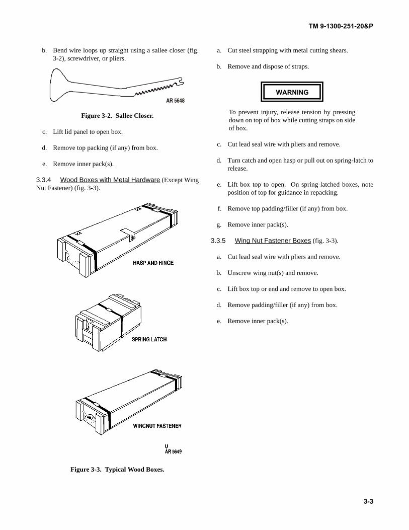
TM 9-1300-251-20&P
b. Bend wire loops up straight using a sallee closer (fig.3-2), screwdriver, or pliers.
Figure 3-2. Sallee Closer.
c. Lift lid panel to open box.
d. Remove top packing (if any) from box.
e. Remove inner pack(s).
3.3.4 Wood Boxes with Metal Hardware (Except WingNut Fastener) (fig. 3-3).
Figure 3-3. Typical Wood Boxes.
a. Cut steel strapping with metal cutting shears.
b. Remove and dispose of straps.
WARNING
To prevent injury, release tension by pressingdown on top of box while cutting straps on sideof box.
c. Cut lead seal wire with pliers and remove.
d. Turn catch and open hasp or pull out on spring-latch torelease.
e. Lift box top to open. On spring-latched boxes, noteposition of top for guidance in repacking.
f. Remove top padding/filler (if any) from box.
g. Remove inner pack(s).
3.3.5 Wing Nut Fastener Boxes (fig. 3-3).
a. Cut lead seal wire with pliers and remove.
b. Unscrew wing nut(s) and remove.
c. Lift box top or end and remove to open box.
d. Remove padding/filler (if any) from box.
e. Remove inner pack(s).
3-3
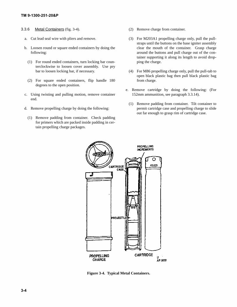
TM 9-1300-251-20&P
3.3.6 Metal Containers (fig. 3-4).
a. Cut lead seal wire with pliers and remove.
b. Loosen round or square ended containers by doing thefollowing:
(1) For round ended containers, turn locking bar coun-terclockwise to loosen cover assembly. Use prybar to loosen locking bar, if necessary.
(2) For square ended containers, flip handle 180degrees to the open position.
c. Using twisting and pulling motion, remove containerend.
d. Remove propelling charge by doing the following:
(1) Remove padding from container. Check paddingfor primers which are packed inside padding in cer-tain propelling charge packages.
(2) Remove charge from container.
(3) For M203A1 propelling charge only, pull the pull-straps until the buttons on the base igniter assemblyclear the mouth of the container. Grasp chargearound the buttons and pull charge out of the con-tainer supporting it along its length to avoid drop-ping the charge.
(4) For M86 propelling charge only, pull the pull-tab toopen black plastic bag then pull black plastic bagfrom charge.
e. Remove cartridge by doing the following: (For152mm ammunition, see paragraph 3.3.14).
(1) Remove padding from container. Tilt container topermit cartridge case and propelling charge to slideout far enough to grasp rim of cartridge case.
Figure 3-4. Typical Metal Containers.
3-4
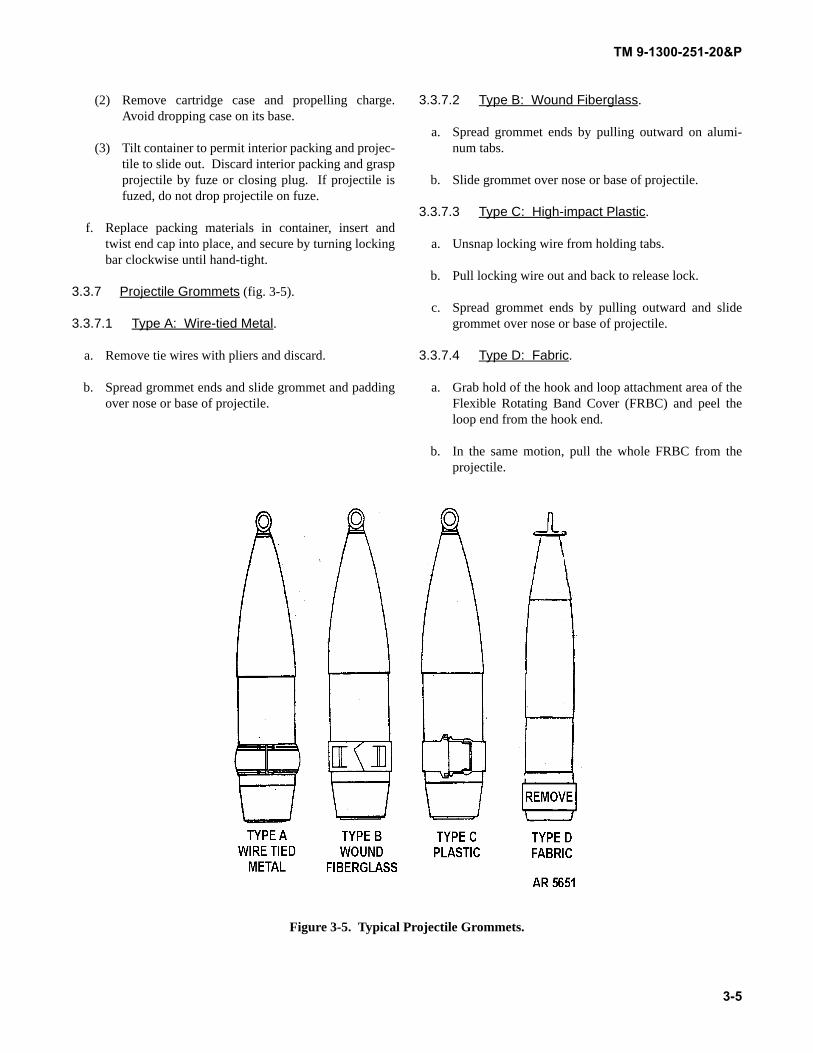
TM 9-1300-251-20&P
(2) Remove cartridge case and propelling charge.Avoid dropping case on its base.
(3) Tilt container to permit interior packing and projec-tile to slide out. Discard interior packing and graspprojectile by fuze or closing plug. If projectile isfuzed, do not drop projectile on fuze.
f. Replace packing materials in container, insert andtwist end cap into place, and secure by turning lockingbar clockwise until hand-tight.
3.3.7 Projectile Grommets (fig. 3-5).
3.3.7.1 Type A: Wire-tied Metal.
a. Remove tie wires with pliers and discard.
b. Spread grommet ends and slide grommet and paddingover nose or base of projectile.
3.3.7.2 Type B: Wound Fiberglass.
a. Spread grommet ends by pulling outward on alumi-num tabs.
b. Slide grommet over nose or base of projectile.
3.3.7.3 Type C: High-impact Plastic.
a. Unsnap locking wire from holding tabs.
b. Pull locking wire out and back to release lock.
c. Spread grommet ends by pulling outward and slidegrommet over nose or base of projectile.
3.3.7.4 Type D: Fabric.
a. Grab hold of the hook and loop attachment area of theFlexible Rotating Band Cover (FRBC) and peel theloop end from the hook end.
b. In the same motion, pull the whole FRBC from theprojectile.
Figure 3-5. Typical Projectile Grommets.
3-5
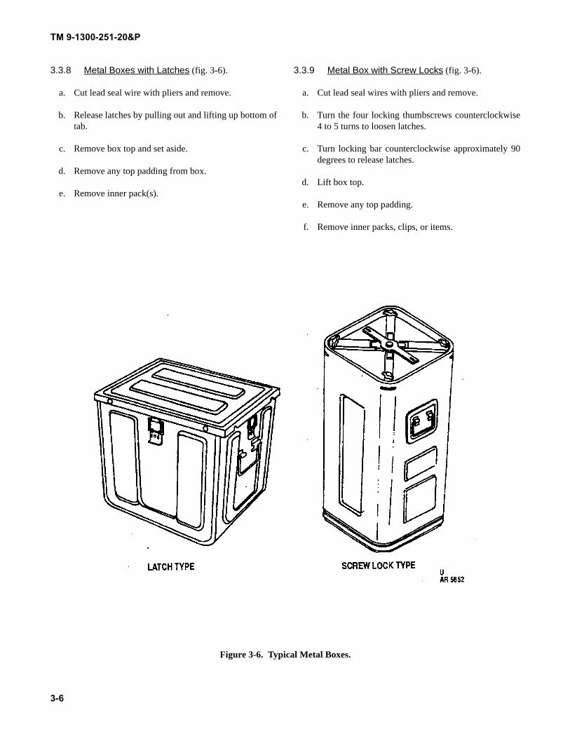
TM 9-1300-251-20&P
3.3.8 Metal Boxes with Latches (fig. 3-6).
a. Cut lead seal wire with pliers and remove.
b. Release latches by pulling out and lifting up bottom oftab.
c. Remove box top and set aside.
d. Remove any top padding from box.
e. Remove inner pack(s).
3.3.9 Metal Box with Screw Locks (fig. 3-6).
a. Cut lead seal wires with pliers and remove.
b. Turn the four locking thumbscrews counterclockwise4 to 5 turns to loosen latches.
c. Turn locking bar counterclockwise approximately 90degrees to release latches.
d. Lift box top.
e. Remove any top padding.
f. Remove inner packs, clips, or items.
Figure 3-6. Typical Metal Boxes.
3-6
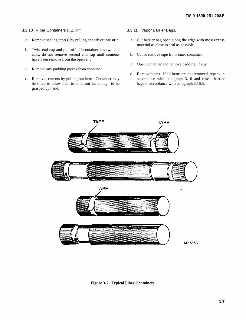
TM 9-1300-251-20&P
3.3.10 Fiber Containers (fig. 3-7).
a. Remove sealing tape(s) by pulling end tab or tear strip.
b. Twist end cap and pull off. If container has two endcaps, do not remove second end cap until contentshave been remove from the open end.
c. Remove any padding pieces from container.
d. Remove contents by pulling out item. Container maybe tilted to allow item to slide out far enough to begrasped by hand.
3.3.11 Vapor Barrier Bags.
a. Cut barrier bag open along the edge with most excessmaterial as close to seal as possible.
b. Cut or remove tape from inner container.
c. Open container and remove padding, if any.
d. Remove items. If all items are not removed, repack inaccordance with paragraph 3.16 and reseal barrierbags in accordance with paragraph 3.16.5.
Figure 3-7. Typical Fiber Containers.
3-7
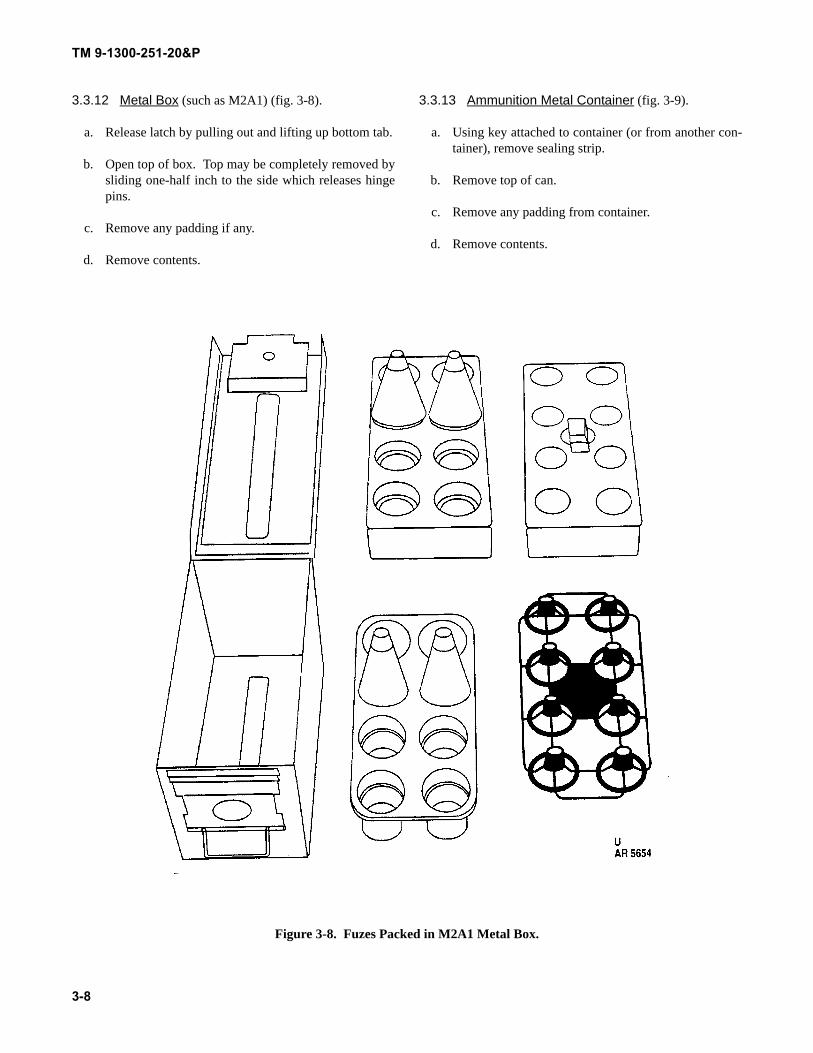
TM 9-1300-251-20&P
3.3.12 Metal Box (such as M2A1) (fig. 3-8).
a. Release latch by pulling out and lifting up bottom tab.
b. Open top of box. Top may be completely removed bysliding one-half inch to the side which releases hingepins.
c. Remove any padding if any.
d. Remove contents.
3.3.13 Ammunition Metal Container (fig. 3-9).
a. Using key attached to container (or from another con-tainer), remove sealing strip.
b. Remove top of can.
c. Remove any padding from container.
d. Remove contents.
Figure 3-8. Fuzes Packed in M2A1 Metal Box.
3-8
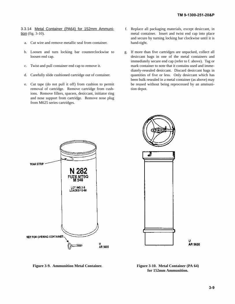
TM 9-1300-251-20&P
3.3.14 Metal Container (PA64) for 152mm Ammuni-tion (fig. 3-10).
a. Cut wire and remove metallic seal from container.
b. Loosen and turn locking bar counterclockwise toloosen end cap.
c. Twist and pull container end cap to remove it.
d. Carefully slide cushioned cartridge out of container.
e. Cut tape (do not pull it off) from cushion to permitremoval of cartridge. Remove cartridge from cush-ions. Remove fillers, spacers, desiccant, initiator ringand nose support from cartridge. Remove nose plugfrom M625 series cartridges.
Figure 3-9. Ammunition Metal Container.
f. Replace all packaging materials, except desiccant, inmetal container. Insert and twist end cap into placeand secure by turning locking bar clockwise until it ishand-tight.
g. If more than five cartridges are unpacked, collect alldesiccant bags in one of the metal containers andimmediately secure end cap (refer to f. above). Tag ormark container to note that it contains used and imme-diately-resealed desiccant. Discard desiccant bags inquantities of five or less. Only desiccant which hasbeen bulk resealed in a metal container (as above) maybe reused without being reprocessed by an ammuni-tion depot.
Figure 3-10. Metal Container (PA 64) for 152mm Ammunition.
3-9
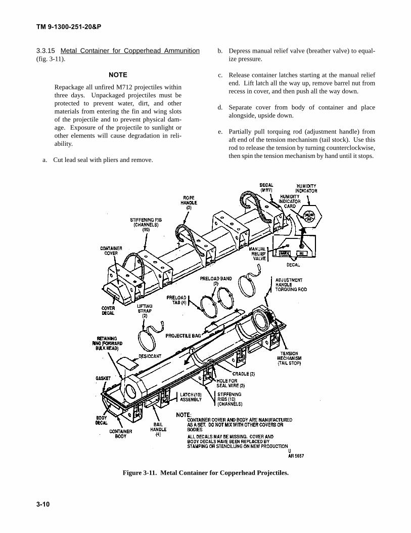
TM 9-1300-251-20&P
3.3.15 Metal Container for Copperhead Ammunition(fig. 3-11).
NOTE
Repackage all unfired M712 projectiles withinthree days. Unpackaged projectiles must beprotected to prevent water, dirt, and othermaterials from entering the fin and wing slotsof the projectile and to prevent physical dam-age. Exposure of the projectile to sunlight orother elements will cause degradation in reli-ability.
a. Cut lead seal with pliers and remove.
b. Depress manual relief valve (breather valve) to equal-ize pressure.
c. Release container latches starting at the manual reliefend. Lift latch all the way up, remove barrel nut fromrecess in cover, and then push all the way down.
d. Separate cover from body of container and placealongside, upside down.
e. Partially pull torquing rod (adjustment handle) fromaft end of the tension mechanism (tail stock). Use thisrod to release the tension by turning counterclockwise,then spin the tension mechanism by hand until it stops.
Figure 3-11. Metal Container for Copperhead Projectiles.
3-10
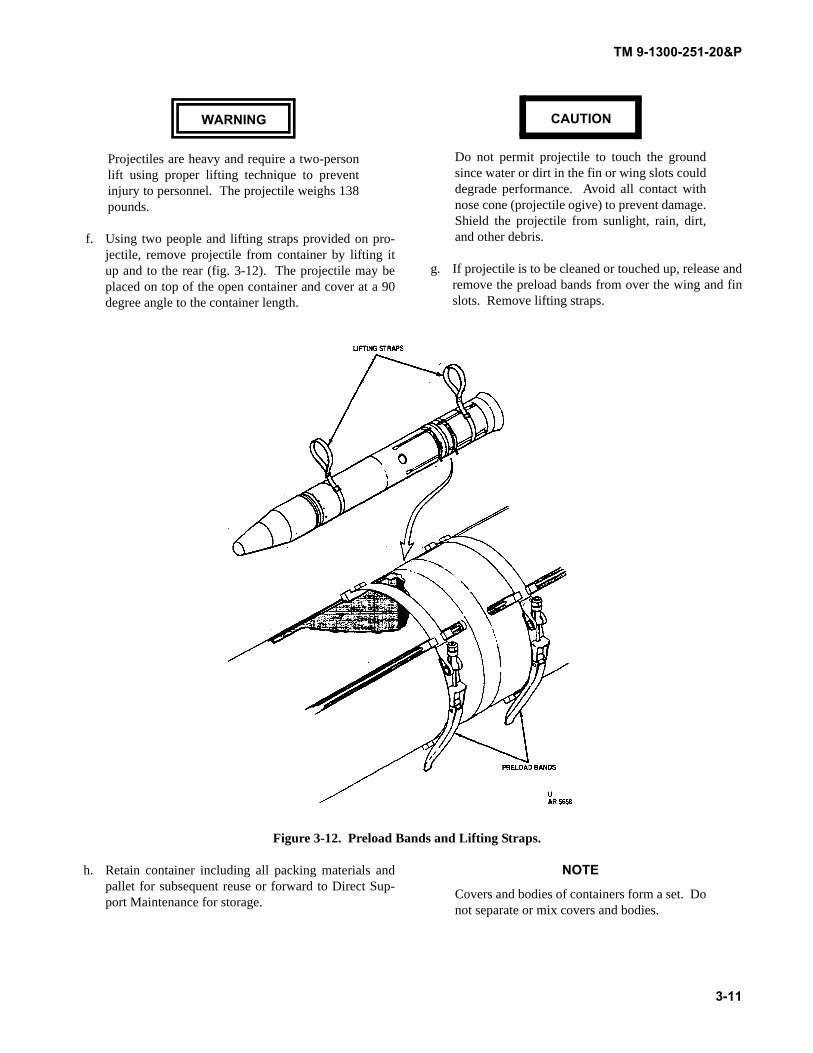
TM 9-1300-251-20&P
WARNING
Projectiles are heavy and require a two-personlift using proper lifting technique to preventinjury to personnel. The projectile weighs 138pounds.
f. Using two people and lifting straps provided on pro-jectile, remove projectile from container by lifting itup and to the rear (fig. 3-12). The projectile may beplaced on top of the open container and cover at a 90degree angle to the container length.
CAUTION
Do not permit projectile to touch the groundsince water or dirt in the fin or wing slots coulddegrade performance. Avoid all contact withnose cone (projectile ogive) to prevent damage.Shield the projectile from sunlight, rain, dirt,and other debris.
g. If projectile is to be cleaned or touched up, release andremove the preload bands from over the wing and finslots. Remove lifting straps.
Figure 3-12. Preload Bands and Lifting Straps.
h. Retain container including all packing materials andpallet for subsequent reuse or forward to Direct Sup-port Maintenance for storage.
NOTE
Covers and bodies of containers form a set. Donot separate or mix covers and bodies.
3-11
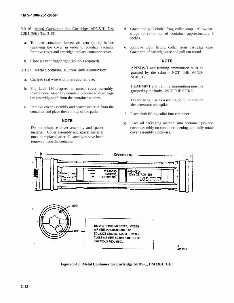
TM 9-1300-251-20&P
3.3.16 Metal Container for Cartridge APDS-T, DM13B1 (GE) (fig. 3-13).
a. To open container, loosen air vent (knob) beforeremoving the cover in order to equalize vacuum.Remove cover and cartridge; replace container cover.
b. Close air vent finger tight (no tools required).
3.3.17 Metal Container, 105mm Tank Ammunition.
a. Cut lead seal wire with pliers and remove.
b. Flip latch 180 degrees to unseal cover assembly.Rotate cover assembly counterclockwise to disengagethe assembly shaft from the container notches.
c. Remove cover assembly and spacer material from thecontainer and place them on top of the pallet.
NOTE
Do not misplace cover assembly and spacermaterial. Cover assembly and spacer materialmust be replaced after all cartridges have beenremoved from the container.
d. Grasp and pull cloth lifting collar strap. Allow car-tridge to come out of container approximately 8inches.
e. Remove cloth lifting collar from cartridge case.Grasp rim of cartridge case and pull out round.
NOTE
APFSDS-T and training ammunition must begrasped by the sabot - NOT THE WIND-SHIELD.
HEAT-MP-T and training ammunition must begrasped by the body - NOT THE SPIKE.
Do not bang, use as a resting point, or step onthe penetrator and spike.
f. Place cloth lifting collar into container.
g. Place all packaging material into container, positioncover assembly on container opening, and fully rotatecover assembly clockwise.
Figure 3-13. Metal Container for Cartridge APDS-T, DM13B1 (GE).
3-12
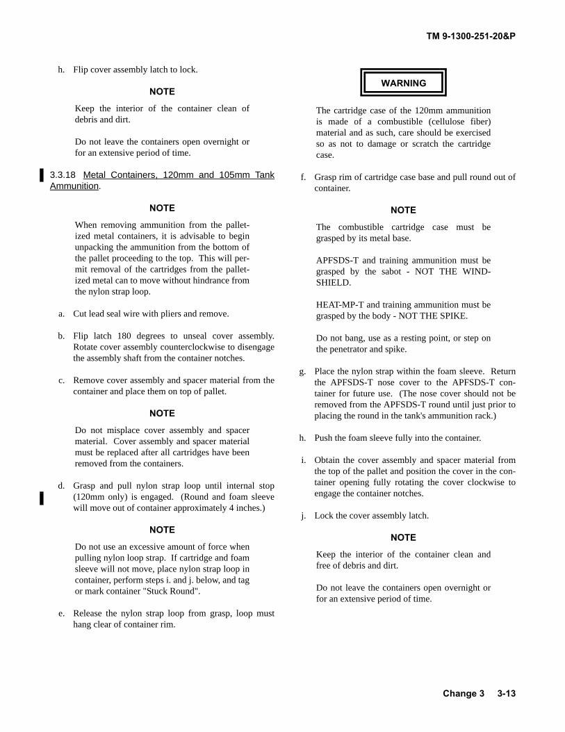
TM 9-1300-251-20&P
h. Flip cover assembly latch to lock.
NOTE
Keep the interior of the container clean ofdebris and dirt.
Do not leave the containers open overnight orfor an extensive period of time.
3.3.18 Metal Containers, 120mm and 105mm TankAmmunition.
NOTE
When removing ammunition from the pallet-ized metal containers, it is advisable to beginunpacking the ammunition from the bottom ofthe pallet proceeding to the top. This will per-mit removal of the cartridges from the pallet-ized metal can to move without hindrance fromthe nylon strap loop.
a. Cut lead seal wire with pliers and remove.
b. Flip latch 180 degrees to unseal cover assembly.Rotate cover assembly counterclockwise to disengagethe assembly shaft from the container notches.
c. Remove cover assembly and spacer material from thecontainer and place them on top of pallet.
NOTE
Do not misplace cover assembly and spacermaterial. Cover assembly and spacer materialmust be replaced after all cartridges have beenremoved from the containers.
d. Grasp and pull nylon strap loop until internal stop(120mm only) is engaged. (Round and foam sleevewill move out of container approximately 4 inches.)
NOTE
Do not use an excessive amount of force whenpulling nylon loop strap. If cartridge and foamsleeve will not move, place nylon strap loop incontainer, perform steps i. and j. below, and tagor mark container "Stuck Round".
e. Release the nylon strap loop from grasp, loop musthang clear of container rim.
WARNING
The cartridge case of the 120mm ammunitionis made of a combustible (cellulose fiber)material and as such, care should be exercisedso as not to damage or scratch the cartridgecase.
f. Grasp rim of cartridge case base and pull round out ofcontainer.
NOTE
The combustible cartridge case must begrasped by its metal base.
APFSDS-T and training ammunition must begrasped by the sabot - NOT THE WIND-SHIELD.
HEAT-MP-T and training ammunition must begrasped by the body - NOT THE SPIKE.
Do not bang, use as a resting point, or step onthe penetrator and spike.
g. Place the nylon strap within the foam sleeve. Returnthe APFSDS-T nose cover to the APFSDS-T con-tainer for future use. (The nose cover should not beremoved from the APFSDS-T round until just prior toplacing the round in the tank's ammunition rack.)
h. Push the foam sleeve fully into the container.
i. Obtain the cover assembly and spacer material fromthe top of the pallet and position the cover in the con-tainer opening fully rotating the cover clockwise toengage the container notches.
j. Lock the cover assembly latch.
NOTE
Keep the interior of the container clean andfree of debris and dirt.
Do not leave the containers open overnight orfor an extensive period of time.
Change 3 3-13
TM 9-1300-251-20&P
SECTION II SPECIAL TOOLS AND EQUIPMENT
3.4 COMMON TOOLS AND EQUIPMENT.
Standard and commonly used tools and equipment havinggeneral application to this ammunition are authorized forissue by tables of organization and equipment (TOE).
3.5 REPAIR PARTS AND SPECIAL TOOLS.
Repair parts and special tools required at organizational levelare listed in appendix C.
SECTION III MAINTENANCE INSTRUCTIONS
3.6 GENERAL.
3.6.1 Maintenance at the organizational level is per-formed by designated personnel in using units. Its purpose isto prevent further deterioration of ammunition which hasbeen exposed to rough handling or adverse weather condi-tions. Direct support units may be called upon to providetechnical assistance and packaging materials.
3.6.2 Responsibilities for maintenance are limited tothose functions specified in appendix B, Maintenance Allo-cation Chart (MAC). Only maintenance operations forwhich procedures are given in this manual or in the weaponoperator's manual are authorized.
3.6.3 Maintenance shall be performed at least 90 feetfrom any ammunition magazine or storage shelter.
3.6.4 Ammunition is to be removed from packagingbefore performing maintenance on packaging materialsexcept when just re-marking outer packing or restrapping.
3.7 EXPENDABLE MATERIALS.
3.7.1 Touchup painting must be done using the correctpaint color and correct paint specification. Paint, cleaningcompounds, and other expendable materials authorized foruse by organizational maintenance personnel are listed inappendix D.
3.7.2 Expendable materials should be requisitionedthrough normal channels on an as-required basis.
3.8 INSPECTION OF PACKAGING.
If receipt inspection or storage inspection of packagingreveals damage or deterioration to the extent that serviceabil-ity of the ammunition is questionable, unpack ammunition
(using procedures in paragraph 3.3) and visually inspectinner packs and/or items. Unpack only as far as necessary todetermine serviceability.
3.8.1 Packaging Defects. Specific inspection criteriaand identification of defects (as acceptable, reparable, orirreparable) are outlined in table 3-1. The most commonlyencountered packaging defects are listed below.
3.8.1.1 Outer container (boxes) damaged, weathered, orrotted to the extent contents are not protected.
3.8.1.2 Inner container damaged to the extent contentsare not protected or cannot be readily removed.
3.8.1.3 Container cap or closure insecure to the extentcontents are not protected.
3.8.1.4 Inner container wet (except metal), rusted, moldy,or mildewed.
3.8.1.5 Hardware or banding loose, missing, broken, orineffective.
3.8.1.6 Handle or cleat missing or broken.
3.8.1.7 Contents loose to the extent item may be dam-aged in handling.
3.8.1.8 (Copperhead container) Cracks or holes in thecontainer; humidity readings 40% or over; unsafe rope han-dles, lifting straps or projectile preload bands missing orunserviceable.
3-14
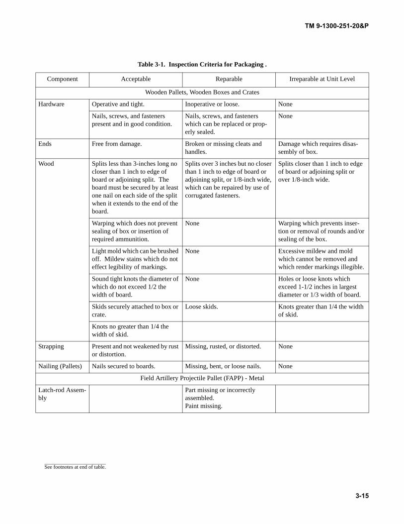
TM 9-1300-251-20&P
Table 3-1. Inspection Criteria for Packaging .
Component Acceptable Reparable Irreparable at Unit Level
Wooden Pallets, Wooden Boxes and Crates
Hardware Operative and tight. Inoperative or loose. None
Nails, screws, and fasteners present and in good condition.
Nails, screws, and fasteners which can be replaced or prop-erly sealed.
None
Ends Free from damage. Broken or missing cleats and handles.
Damage which requires disas-sembly of box.
Wood Splits less than 3-inches long no closer than 1 inch to edge of board or adjoining split. The board must be secured by at least one nail on each side of the split when it extends to the end of the board.
Splits over 3 inches but no closer than 1 inch to edge of board or adjoining split, or 1/8-inch wide, which can be repaired by use of corrugated fasteners.
Splits closer than 1 inch to edge of board or adjoining split or over 1/8-inch wide.
Warping which does not prevent sealing of box or insertion of required ammunition.
None Warping which prevents inser-tion or removal of rounds and/or sealing of the box.
Light mold which can be brushed off. Mildew stains which do not effect legibility of markings.
None Excessive mildew and mold which cannot be removed and which render markings illegible.
Sound tight knots the diameter of which do not exceed 1/2 the width of board.
None Holes or loose knots which exceed 1-1/2 inches in largest diameter or 1/3 width of board.
Skids securely attached to box or crate.
Loose skids. Knots greater than 1/4 the width of skid.
Knots no greater than 1/4 the width of skid.
Strapping Present and not weakened by rust or distortion.
Missing, rusted, or distorted. None
Nailing (Pallets) Nails secured to boards. Missing, bent, or loose nails. None
Field Artillery Projectile Pallet (FAPP) - Metal
Latch-rod Assem-bly
Part missing or incorrectly assembled. Paint missing.
See footnotes at end of table.
3-15
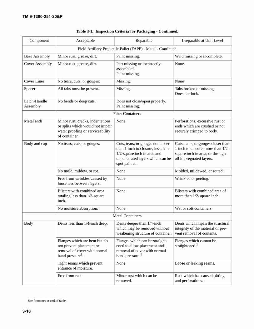
TM 9-1300-251-20&P
Field Artillery Projectile Pallet (FAPP) - Metal - Continued
Base Assembly Minor rust, grease, dirt. Paint missing. Weld missing or incomplete.
Cover Assembly Minor rust, grease, dirt. Part missing or incorrectly assembled. Paint missing.
None
Cover Liner No tears, cuts, or gouges. Missing. None
Spacer All tabs must be present. Missing. Tabs broken or missing. Does not lock.
Latch-Handle Assembly
No bends or deep cuts. Does not close/open properly. Paint missing.
Fiber Containers
Metal ends Minor rust, cracks, indentations or splits which would not impair water proofing or serviceability of container.
None Perforations, excessive rust or ends which are crushed or not securely crimped to body.
Body and cap No tears, cuts, or gouges. Cuts, tears, or gouges not closer than 1 inch to closure, less than 1/2-square inch in area and unpenetrated layers which can be spot painted.
Cuts, tears, or gouges closer than 1 inch to closure, more than 1/2- square inch in area, or through all impregnated layers.
No mold, mildew, or rot. None Molded, mildewed, or rotted.
Free from wrinkles caused by looseness between layers.
None Wrinkled or peeling.
Blisters with combined area totaling less than 1/2-square inch.
None Blisters with combined area of more than 1/2-square inch.
No moisture absorption. None Wet or soft containers.
Metal Containers
Body Dents less than 1/4-inch deep. Dents deeper than 1/4-inch which may be removed without weakening structure of container.
Dents which impair the structural integrity of the material or pre-vent removal of contents.
Flanges which are bent but do not prevent placement or removal of cover with normal hand pressure1.
Flanges which can be straight-ened to allow placement and removal of cover with normal hand pressure.1
Flanges which cannot be straightened.1
Tight seams which prevent entrance of moisture.
None Loose or leaking seams.
Free from rust. Minor rust which can be removed.
Rust which has caused pitting and perforations.
Table 3-1. Inspection Criteria for Packaging - Continued.
Component Acceptable Reparable Irreparable at Unit Level
See footnotes at end of table.
3-16
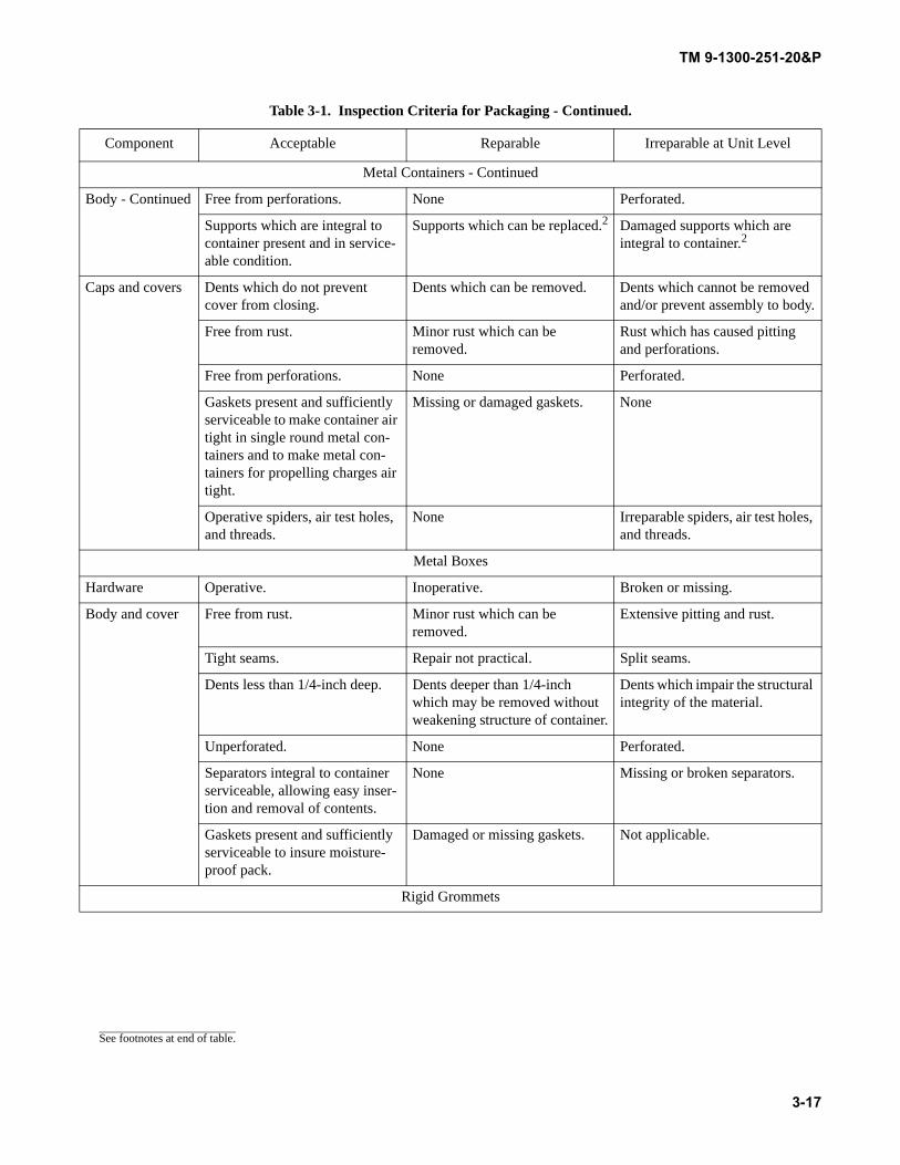
TM 9-1300-251-20&P
Metal Containers - Continued
Body - Continued Free from perforations. None Perforated.
Supports which are integral to container present and in service-able condition.
Supports which can be replaced.2 Damaged supports which are integral to container.2
Caps and covers Dents which do not prevent cover from closing.
Dents which can be removed. Dents which cannot be removed and/or prevent assembly to body.
Free from rust. Minor rust which can be removed.
Rust which has caused pitting and perforations.
Free from perforations. None Perforated.
Gaskets present and sufficiently serviceable to make container air tight in single round metal con-tainers and to make metal con-tainers for propelling charges air tight.
Missing or damaged gaskets. None
Operative spiders, air test holes, and threads.
None Irreparable spiders, air test holes, and threads.
Metal Boxes
Hardware Operative. Inoperative. Broken or missing.
Body and cover Free from rust. Minor rust which can be removed.
Extensive pitting and rust.
Tight seams. Repair not practical. Split seams.
Dents less than 1/4-inch deep. Dents deeper than 1/4-inch which may be removed without weakening structure of container.
Dents which impair the structural integrity of the material.
Unperforated. None Perforated.
Separators integral to container serviceable, allowing easy inser-tion and removal of contents.
None Missing or broken separators.
Gaskets present and sufficiently serviceable to insure moisture-proof pack.
Damaged or missing gaskets. Not applicable.
Rigid Grommets
Table 3-1. Inspection Criteria for Packaging - Continued.
Component Acceptable Reparable Irreparable at Unit Level
See footnotes at end of table.
3-17
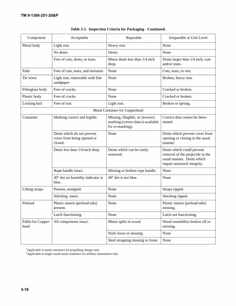
TM 9-1300-251-20&P
1Applicable to metal containers for propelling charges only.2Applicable to single round metal containers for artillery ammunition only.
Metal body Light rust. Heavy rust. None
No dents. Dents. None
Free of cuts, dents, or tears. Minor dents less than 1/4 inch deep.
Dents larger than 1/4 inch, cuts and/or tears.
Pads Free of cuts, tears, and moisture. None Cuts, tears, or wet.
Tie wires Light rust, removable with fine sandpaper.
None Broken, heavy rust.
Fiberglass body Free of cracks. None Cracked or broken.
Plastic body Free of cracks. None Cracked or broken.
Locking bail Free of rust. Light rust. Broken or sprung.
Metal Container for Copperhead
Container Marking correct and legible. Missing, illegible, or incorrect marking (correct data is available for re-marking).
Correct data cannot be deter-mined.
Dents which do not prevent cover from being opened or closed.
None Dents which prevent cover from opening or closing in the usual manner.
Dents less than 1/4-inch deep. Dents which can be easily removed.
Dents which could prevent removal of the projectile in the usual manner. Dents which impair structural integrity.
Rope handle intact. Missing or broken rope handle. None
40° dot on humidity indicator is blue.
40° dot is not blue. None
Lifting straps Present, unripped. None Straps ripped.
Stitching intact. None Stitching ripped.
Preload Plastic inserts (preload tabs) present.
None Plastic inserts (preload tabs) missing.
Latch functioning. None Latch not functioning.
Pallet for Copper-head
All components intact. Minor splits in wood. Wood assemblies broken off or missing.
Nails loose or missing. None
Steel strapping missing or loose. None
Table 3-1. Inspection Criteria for Packaging - Continued.
Component Acceptable Reparable Irreparable at Unit Level
3-18
TM 9-1300-251-20&P
3.8.2 Corrective Action.
3.8.2.1 Replace unserviceable containers using proce-dures in paragraph 3.6.
3.8.2.2 Repair broken or damaged pallets and boxesusing procedures in paragraph 3.12.
3.8.2.3 Tighten or replace hardware or banding usingprocedures in paragraph 3.11.
3.8.2.4 Replace unserviceable grommets using proce-dures in paragraph 3.16.11.
3.8.2.5 Forward Copperhead containers irreparable atunit level to Depot. Perform minor maintenance as indicatedin paragraph 3.12.6.
3.8.2.6 Forward unserviceable Copperhead pallets toDirect Support Maintenance. Forward serviceable pallets toDirect Support Maintenance for storage.
3.9 INSPECTION OF AMMUNITION.
3.9.1 Materiel Defects. Specific defects (identified asacceptable, reparable, or irreparable) and inspection criteriaare outlined in table 3-2. The most commonly encounteredtypes of materiel defects are listed and illustrated below.
3.9.1.1 Peeling, blistered, or scratched protective coatingon painted surfaces.
3.9.1.2 Projectile rust and deterioration (fig. 3-14).
Figure 3-14. Projectile Rust and Deterioration.
3-19
TM 9-1300-251-20&P
3.9.1.3 Rotating band damage (fig. 3-15).
3.9.1.4 Supplementary charge missing or showing feltpad (fig. 3-16). Supplementary charge pad is not oversized(see drawing 8797090, Rev U or later).
3.9.1.5 Corroded supplementary charge and/or fuze wellliner (fig. 3-17).
3.9.1.6 Exudation of explosive filler in fuze well (para-graph 3.10).
3.9.1.7 Missing or damaged obturator band. Damageincludes a crack, cut, or gouge extending across entire widthof band.
3.9.1.8 Loose obturator band - the band will not remainin groove.
Figure 3-15. Rotating Band Damage.
Figure 3-16. Proper Supplementary Charge Position.
Figure 3-17. Corrosion in Fuze Well and on Supplementary Charge.
3-20
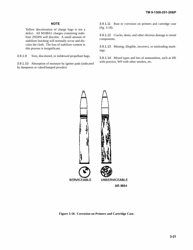
TM 9-1300-251-20&P
NOTE
Yellow discoloration of charge bags is not adefect. All M188A1 charges containing stabi-lizer 2NDPA will discolor. A small amount ofstabilizer leaching will normally occur and dis-color the cloth. The loss of stabilizer content inthis process is insignificant.
3.9.1.9 Torn, discolored, or mildewed propellant bags.
3.9.1.10 Absorption of moisture by igniter pads (indicatedby dampness or caked/lumped powder).
3.9.1.11 Rust or corrosion on primers and cartridge case(fig. 3-18).
3.9.1.12 Cracks, dents, and other obvious damage to metalcomponents.
3.9.1.13 Missing, illegible, incorrect, or misleading mark-ings.
3.9.1.14 Mixed types and lots of ammunition, such as HEwith practice, WP with other smokes, etc.
Figure 3-18. Corrosion on Primers and Cartridge Case.
3-21
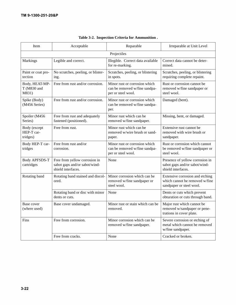
TM 9-1300-251-20&P
Table 3-2. Inspection Criteria for Ammunition .
Item Acceptable Reparable Irreparable at Unit Level
Projectiles
Markings Legible and correct. Illegible. Correct data available for re-marking.
Correct data cannot be deter-mined.
Paint or coat pro-tection
No scratches, peeling, or blister-ing.
Scratches, peeling, or blistering in spots.
Scratches, peeling, or blistering requiring complete repaint.
Body, HEAT-MP-T (M830 and M831)
Free from rust and/or corrosion. Minor rust or corrosion which can be removed w/fine sandpa-per or steel wool.
Rust or corrosion cannot be removed w/fine sandpaper or steel wool.
Spike (Body)(M456 Series)
Free from rust and/or corrosion. Minor rust or corrosion which can be removed w/fine sandpa-per.
Damaged (bent).
Spoiler (M456 Series)
Free from rust and adequately fastened (positioned).
Minor rust which can be removed w/fine sandpaper.
Missing, bent, or damaged.
Body (except HEP-T car-tridges)
Free from rust. Minor rust which can be removed w/wire brush or sand-paper.
Extensive rust cannot be removed with wire brush or sandpaper.
Body HEP-T car-tridges
Free from rust and/orcorrosion.
Minor rust or corrosion which can be removed w/fine sandpa-per or steel wool.
Rust or corrosion which cannot be removed w/fine sandpaper or steel wool.
Body APFSDS-T cartridges
Free from yellow corrosion in sabot gaps and/or sabot/wind-shield interfaces.
None Presence of yellow corrosion in sabot gaps and/or sabot/wind-shield interfaces.
Rotating band Rotating band stained and discol-ored.
Minor corrosion which can be removed w/fine sandpaper or steel wool.
Extensive corrosion and etching which cannot be removed w/fine sandpaper or steel wool.
Rotating band or disc with minor dents or cuts.
None Dents or cuts which prevent obturation or cuts through band.
Base cover (where used)
Base cover undamaged. Minor rust or stain which can be removed.
Major rust which cannot be removed w/sandpaper or pene-trations in cover plate.
Fins Free from corrosion. Minor corrosion which can be removed w/fine sandpaper.
Severe corrosion or etching of metal which cannot be removed w/fine sandpaper.
Free from cracks. None Cracked or broken.
3-22
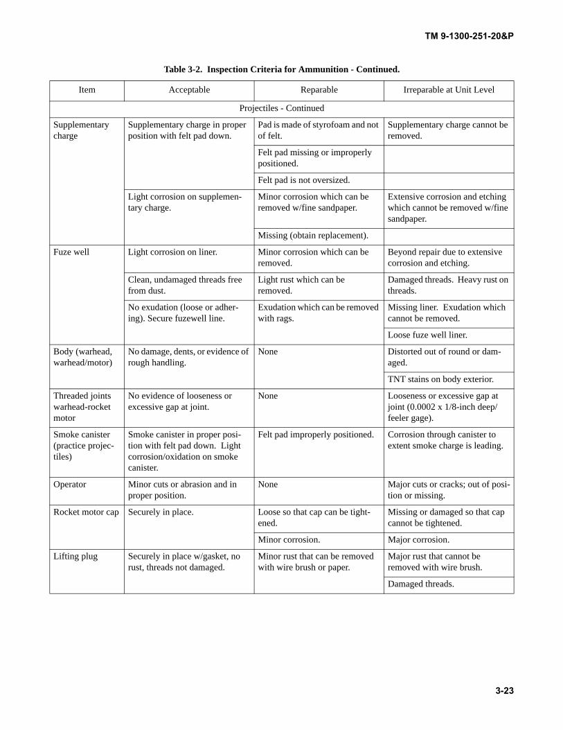
TM 9-1300-251-20&P
Projectiles - Continued
Supplementary charge
Supplementary charge in proper position with felt pad down.
Pad is made of styrofoam and not of felt.
Supplementary charge cannot be removed.
Felt pad missing or improperly positioned.
Felt pad is not oversized.
Light corrosion on supplemen-tary charge.
Minor corrosion which can be removed w/fine sandpaper.
Extensive corrosion and etching which cannot be removed w/fine sandpaper.
Missing (obtain replacement).
Fuze well Light corrosion on liner. Minor corrosion which can be removed.
Beyond repair due to extensive corrosion and etching.
Clean, undamaged threads free from dust.
Light rust which can be removed.
Damaged threads. Heavy rust on threads.
No exudation (loose or adher-ing). Secure fuzewell line.
Exudation which can be removed with rags.
Missing liner. Exudation which cannot be removed.
Loose fuze well liner.
Body (warhead, warhead/motor)
No damage, dents, or evidence of rough handling.
None Distorted out of round or dam-aged.
TNT stains on body exterior.
Threaded joints warhead-rocket motor
No evidence of looseness or excessive gap at joint.
None Looseness or excessive gap at joint (0.0002 x 1/8-inch deep/feeler gage).
Smoke canister (practice projec-tiles)
Smoke canister in proper posi-tion with felt pad down. Light corrosion/oxidation on smoke canister.
Felt pad improperly positioned. Corrosion through canister to extent smoke charge is leading.
Operator Minor cuts or abrasion and in proper position.
None Major cuts or cracks; out of posi-tion or missing.
Rocket motor cap Securely in place. Loose so that cap can be tight-ened.
Missing or damaged so that cap cannot be tightened.
Minor corrosion. Major corrosion.
Lifting plug Securely in place w/gasket, no rust, threads not damaged.
Minor rust that can be removed with wire brush or paper.
Major rust that cannot be removed with wire brush.
Damaged threads.
Table 3-2. Inspection Criteria for Ammunition - Continued.
Item Acceptable Reparable Irreparable at Unit Level
3-23
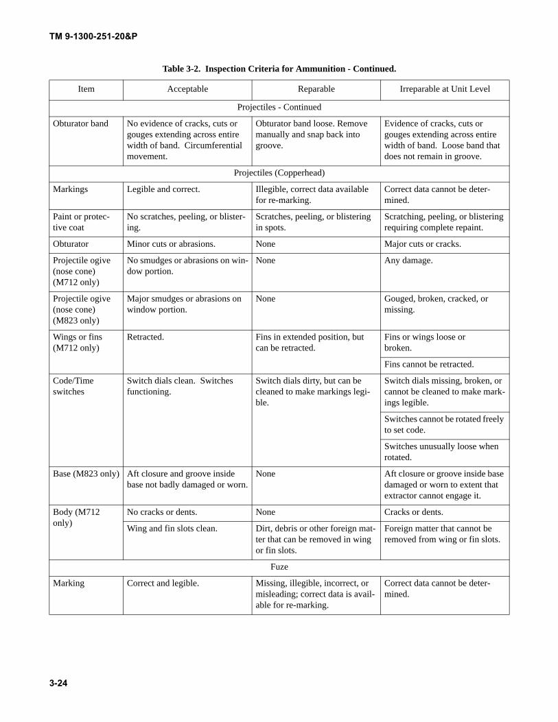
TM 9-1300-251-20&P
Projectiles - Continued
Obturator band No evidence of cracks, cuts or gouges extending across entire width of band. Circumferential movement.
Obturator band loose. Remove manually and snap back into groove.
Evidence of cracks, cuts or gouges extending across entire width of band. Loose band that does not remain in groove.
Projectiles (Copperhead)
Markings Legible and correct. Illegible, correct data available for re-marking.
Correct data cannot be deter-mined.
Paint or protec-tive coat
No scratches, peeling, or blister-ing.
Scratches, peeling, or blistering in spots.
Scratching, peeling, or blistering requiring complete repaint.
Obturator Minor cuts or abrasions. None Major cuts or cracks.
Projectile ogive (nose cone) (M712 only)
No smudges or abrasions on win-dow portion.
None Any damage.
Projectile ogive (nose cone) (M823 only)
Major smudges or abrasions on window portion.
None Gouged, broken, cracked, or missing.
Wings or fins (M712 only)
Retracted. Fins in extended position, but can be retracted.
Fins or wings loose orbroken.
Fins cannot be retracted.
Code/Time switches
Switch dials clean. Switches functioning.
Switch dials dirty, but can be cleaned to make markings legi-ble.
Switch dials missing, broken, or cannot be cleaned to make mark-ings legible.
Switches cannot be rotated freely to set code.
Switches unusually loose when rotated.
Base (M823 only) Aft closure and groove inside base not badly damaged or worn.
None Aft closure or groove inside base damaged or worn to extent that extractor cannot engage it.
Body (M712 only)
No cracks or dents. None Cracks or dents.
Wing and fin slots clean. Dirt, debris or other foreign mat-ter that can be removed in wing or fin slots.
Foreign matter that cannot be removed from wing or fin slots.
Fuze
Marking Correct and legible. Missing, illegible, incorrect, or misleading; correct data is avail-able for re-marking.
Correct data cannot be deter-mined.
Table 3-2. Inspection Criteria for Ammunition - Continued.
Item Acceptable Reparable Irreparable at Unit Level
3-24
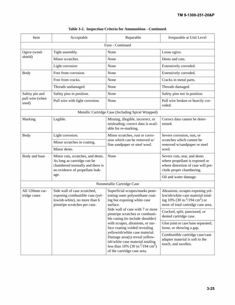
TM 9-1300-251-20&P
Fuze - Continued
Ogive (wind-shield)
Tight assembly. None Loose ogive.
Minor scratches. None Dents and cuts.
Light corrosion None Extensively corroded.
Body Free from corrosion. None Extensively corroded.
Free from cracks. None Cracks in metal parts.
Threads undamaged. None Threads damaged.
Safety pin and pull wire (when used)
Safety pins in position. None Safety pins not in position.
Pull wire with light corrosion. None Pull wire broken or heavily cor-roded.
Metallic Cartridge Case (Including Spiral Wrapped)
Marking Legible. Missing, illegible, incorrect, or misleading; correct data is avail-able for re-marking.
Correct data cannot be deter-mined.
Body Light corrosion. Minor scratches, rust or corro-sion which can be removed w/fine sandpaper or steel wool.
Severe corrosion, rust, or scratches which cannot be removed w/sandpaper or steel wool.
Minor scratches in coating.
Minor dents.
Body and base Minor cuts, scratches, and dents. As long as cartridge can be chambered normally and there is no evidence of propellant leak-age.
None Severe cuts, tear, and dents where propellant is exposed or where distortion of case will pre-clude proper chambering.
Oil and water damage.
Nonmetallic Cartridge Case
All 120mm car-tridge cases
Side wall of case scratched, exposing combustible case (yel-lowish-white), no more than 6 pinstripe scratches per case.
Superficial scrapes/marks pene-trating outer polyurethane coat-ing but exposing white case surface.Side wall of case with 7 or more pinstripe scratches or combusti-ble casing (to include shoulder) with scrapes, abrasions, or sur-face coating voided revealing yellowish/white case material. Damage area(s) reveal yellow-ish/white case material totaling less than 10% (30 in.2/194 cm2) of the cartridge case area.
Abrasions, scrapes exposing yel-lowish/white case material total-ing 10% (30 in.2/194 cm2) or more of total cartridge case area.
Cracked, split, punctured, or dented cartridge case.
Glue joint or case base separated, loose, or showing a gap.
Combustible cartridge case/case adapter material is soft to the touch, and swollen.
Table 3-2. Inspection Criteria for Ammunition - Continued.
Item Acceptable Reparable Irreparable at Unit Level
3-25
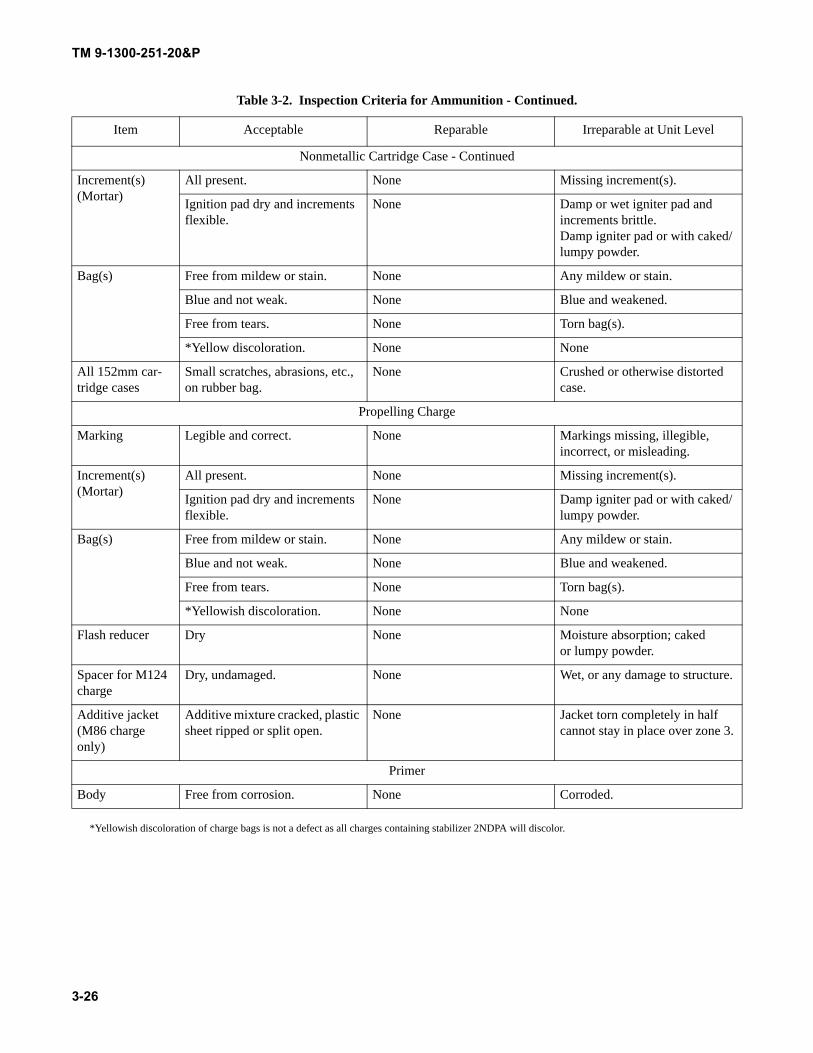
TM 9-1300-251-20&P
*Yellowish discoloration of charge bags is not a defect as all charges containing stabilizer 2NDPA will discolor.
Nonmetallic Cartridge Case - Continued
Increment(s) (Mortar)
All present. None Missing increment(s).
Ignition pad dry and increments flexible.
None Damp or wet igniter pad and increments brittle.Damp igniter pad or with caked/lumpy powder.
Bag(s) Free from mildew or stain. None Any mildew or stain.
Blue and not weak. None Blue and weakened.
Free from tears. None Torn bag(s).
*Yellow discoloration. None None
All 152mm car-tridge cases
Small scratches, abrasions, etc., on rubber bag.
None Crushed or otherwise distorted case.
Propelling Charge
Marking Legible and correct. None Markings missing, illegible, incorrect, or misleading.
Increment(s) (Mortar)
All present. None Missing increment(s).
Ignition pad dry and increments flexible.
None Damp igniter pad or with caked/lumpy powder.
Bag(s) Free from mildew or stain. None Any mildew or stain.
Blue and not weak. None Blue and weakened.
Free from tears. None Torn bag(s).
*Yellowish discoloration. None None
Flash reducer Dry None Moisture absorption; cakedor lumpy powder.
Spacer for M124 charge
Dry, undamaged. None Wet, or any damage to structure.
Additive jacket (M86 charge only)
Additive mixture cracked, plastic sheet ripped or split open.
None Jacket torn completely in half cannot stay in place over zone 3.
Primer
Body Free from corrosion. None Corroded.
Table 3-2. Inspection Criteria for Ammunition - Continued.
Item Acceptable Reparable Irreparable at Unit Level
3-26
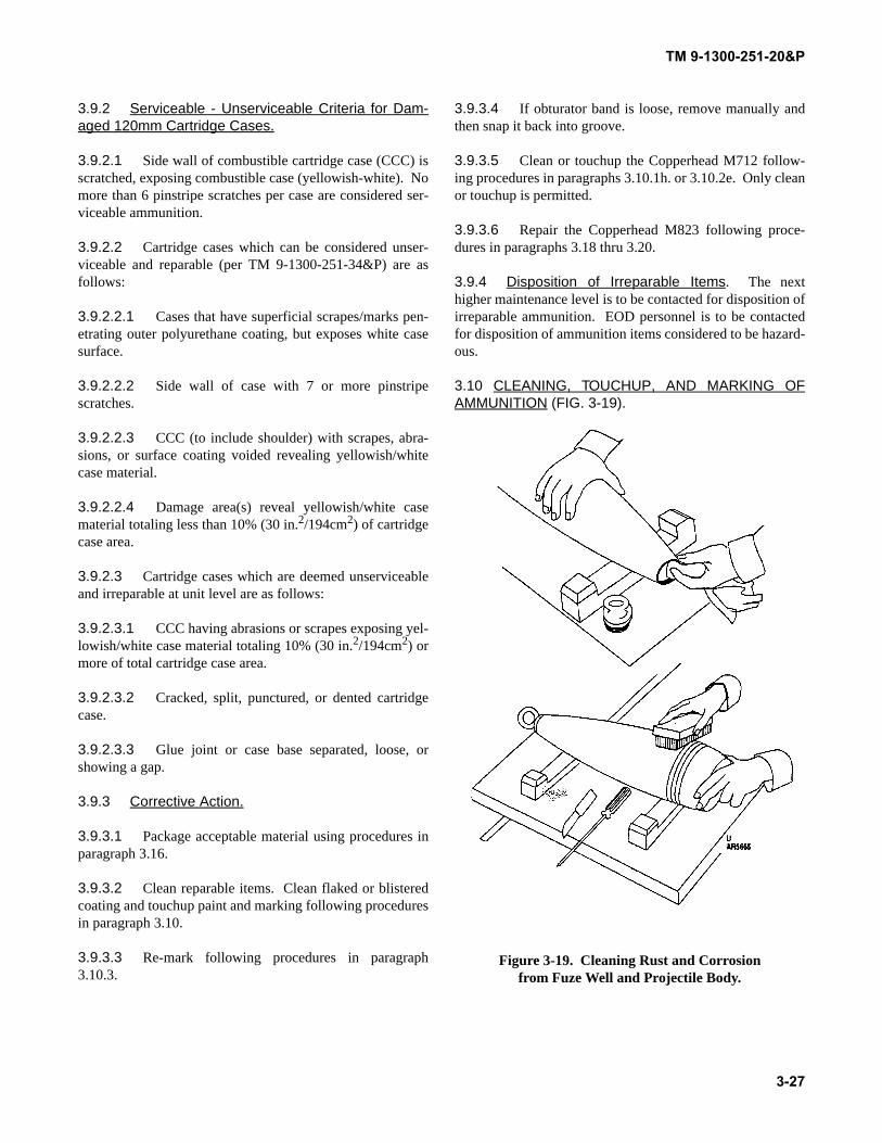
TM 9-1300-251-20&P
3.9.2 Serviceable - Unserviceable Criteria for Dam-aged 120mm Cartridge Cases.
3.9.2.1 Side wall of combustible cartridge case (CCC) isscratched, exposing combustible case (yellowish-white). Nomore than 6 pinstripe scratches per case are considered ser-viceable ammunition.
3.9.2.2 Cartridge cases which can be considered unser-viceable and reparable (per TM 9-1300-251-34&P) are asfollows:
3.9.2.2.1 Cases that have superficial scrapes/marks pen-etrating outer polyurethane coating, but exposes white casesurface.
3.9.2.2.2 Side wall of case with 7 or more pinstripescratches.
3.9.2.2.3 CCC (to include shoulder) with scrapes, abra-sions, or surface coating voided revealing yellowish/whitecase material.
3.9.2.2.4 Damage area(s) reveal yellowish/white casematerial totaling less than 10% (30 in.2/194cm2) of cartridgecase area.
3.9.2.3 Cartridge cases which are deemed unserviceableand irreparable at unit level are as follows:
3.9.2.3.1 CCC having abrasions or scrapes exposing yel-lowish/white case material totaling 10% (30 in.2/194cm2) ormore of total cartridge case area.
3.9.2.3.2 Cracked, split, punctured, or dented cartridgecase.
3.9.2.3.3 Glue joint or case base separated, loose, orshowing a gap.
3.9.3 Corrective Action.
3.9.3.1 Package acceptable material using procedures inparagraph 3.16.
3.9.3.2 Clean reparable items. Clean flaked or blisteredcoating and touchup paint and marking following proceduresin paragraph 3.10.
3.9.3.3 Re-mark following procedures in paragraph3.10.3.
3.9.3.4 If obturator band is loose, remove manually andthen snap it back into groove.
3.9.3.5 Clean or touchup the Copperhead M712 follow-ing procedures in paragraphs 3.10.1h. or 3.10.2e. Only cleanor touchup is permitted.
3.9.3.6 Repair the Copperhead M823 following proce-dures in paragraphs 3.18 thru 3.20.
3.9.4 Disposition of Irreparable Items. The nexthigher maintenance level is to be contacted for disposition ofirreparable ammunition. EOD personnel is to be contactedfor disposition of ammunition items considered to be hazard-ous.
3.10 CLEANING, TOUCHUP, AND MARKING OFAMMUNITION (FIG. 3-19).
Figure 3-19. Cleaning Rust and Corrosion from Fuze Well and Projectile Body.
3-27
TM 9-1300-251-20&P
WARNING
Primers shall be cleaned only with rags dippedin alcohol or acetone. Primers shall be coveredwith fiber container cap during cleaning, tou-chup, and marking of ammunition.
NOTE
To the extent allowed by the available facili-ties, the safety criteria for handling and mainte-nance of ammunition given in AR 385-64 andDA Pam 385-64 must be followed.
3.10.1 Cleaning.
NOTE
Rags shall be sorted in non-combustible self-closing containers. Wastes or used rags shallbe placed in water filled containers. Areas willbe well ventilated where solvents and paintsare used.
a. Remove dirt, mud, and other foreign material usingrags or brushes. Use rags dampened with alcohol oracetone to remove grease.
b. Using nonferrous brush, remove flaked, chipped, blis-tered, or peeling paint.
c. Remove rust using nonferrous brush or sandpaper.
WARNING
Fuze cavity liner must be in place prior tocleaning fuze well or threads.
d. Prior to cleaning fuze well and threads, thoroughlyinspect fuze well for explosive filler exudation aroundthe top of the fuze liner. Remove exudation beforeundertaking any other cleaning operation such ascleaning threads. Remove exudation using acetonedampened rag wrapped around a wooden stick. (Ragshould be tied around end of stick to make a swab.)Swab the area around the top of the fuze well linerseveral times using fresh pieces of rag dampened withacetone until exudation is removed. Then clean fuzewell threads with small stainless steel brush and ragsdampened with alcohol or acetone.
CAUTION
Do not clean the projectiles, especially theplastic components, with any cleaning solutionother than soap and water or alcohol. Cleaningagents, paint thinners, acetone, and similaragents will damage the plastic components.
NOTE
Use of Corrosive Removing Compound (CRC)will not be permitted on main tank gun ammu-nition unless authorization is granted by theNational Maintenance Point (NMP), HQ,AMCCOM, ATTN: NMSOS, SND, RockIsland, IL 61299-6000.
CRC is for use only on bare aluminum/copperbased metal ammunition components.
Do not partially or completely submergeammunition items into solutions containingCRC or any other form of cleaning agent.
Do not allow CRC solution or any other agentto enter the cartridge case via cartridge case/projectile interface area.
e. Clean corrosion from aluminum or copper-based met-als by first, brushing with a nonsparking brush andthen removing residue by wiping effected area with arag dampened sparingly with an approved corrosivecleaning compound.
f. Inspect cleansed item for cracks or other damage ordeterioration.
g. Allow solvent-cleaned surfaces to dry thoroughlybefore painting.
h. Clean Copperhead projectiles with a solution of soapand water or alcohol.
NOTE
To prevent chips, rust particles, cleaning solu-tions, and other foreign matter from enteringthe wing and fin slots on the M712 projectile(or from getting under the loose fitting obtura-tor and the code-time switches) use maskingtape, rags, or other material.
3-28
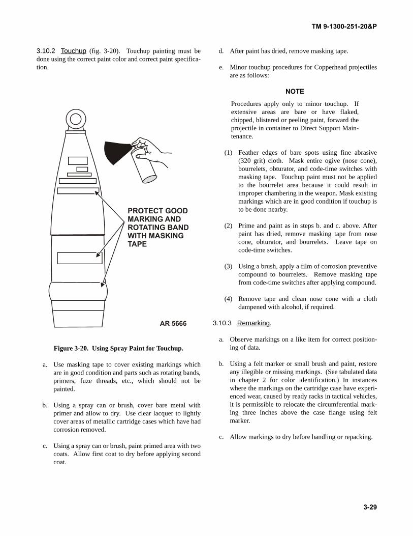
TM 9-1300-251-20&P
3.10.2 Touchup (fig. 3-20). Touchup painting must bedone using the correct paint color and correct paint specifica-tion.
Figure 3-20. Using Spray Paint for Touchup.
a. Use masking tape to cover existing markings whichare in good condition and parts such as rotating bands,primers, fuze threads, etc., which should not bepainted.
b. Using a spray can or brush, cover bare metal withprimer and allow to dry. Use clear lacquer to lightlycover areas of metallic cartridge cases which have hadcorrosion removed.
c. Using a spray can or brush, paint primed area with twocoats. Allow first coat to dry before applying secondcoat.
d. After paint has dried, remove masking tape.
e. Minor touchup procedures for Copperhead projectilesare as follows:
NOTE
Procedures apply only to minor touchup. Ifextensive areas are bare or have flaked,chipped, blistered or peeling paint, forward theprojectile in container to Direct Support Main-tenance.
(1) Feather edges of bare spots using fine abrasive(320 grit) cloth. Mask entire ogive (nose cone),bourrelets, obturator, and code-time switches withmasking tape. Touchup paint must not be appliedto the bourrelet area because it could result inimproper chambering in the weapon. Mask existingmarkings which are in good condition if touchup isto be done nearby.
(2) Prime and paint as in steps b. and c. above. Afterpaint has dried, remove masking tape from nosecone, obturator, and bourrelets. Leave tape oncode-time switches.
(3) Using a brush, apply a film of corrosion preventivecompound to bourrelets. Remove masking tapefrom code-time switches after applying compound.
(4) Remove tape and clean nose cone with a clothdampened with alcohol, if required.
3.10.3 Remarking.
a. Observe markings on a like item for correct position-ing of data.
b. Using a felt marker or small brush and paint, restoreany illegible or missing markings. (See tabulated datain chapter 2 for color identification.) In instanceswhere the markings on the cartridge case have experi-enced wear, caused by ready racks in tactical vehicles,it is permissible to relocate the circumferential mark-ing three inches above the case flange using feltmarker.
c. Allow markings to dry before handling or repacking.
3-29

TM 9-1300-251-20&P
3.11 MAINTENANCE OF PACKAGING HARDWARE.
3.11.1 Repair of Damaged Hardware. Hardware whichhas been damaged to the point that it is inoperable is usuallyirreparable; however, minor damage can usually be correctedby straightening, as follows:
a. Using pliers, carefully bend damaged item until itsconfiguration is the same as the serviceable item.
b. Test repaired hardware for proper functioning.
3.11.2 Replacement of Irreparable Hardware. Hard-ware which cannot be repaired can be replaced with a ser-viceable item cannibalized from an unserviceable containeras follows:
a. Using a screwdriver, remove unserviceable hardware.
b. Attempt to reinstall serviceable hardware in existingholes. Secure with screws.
c. If screws are missing or cannot be tightened in exist-ing holes, follow procedures below.
(1) Replace missing screws with others obtained froman unserviceable box.
(2) If screws cannot be tightened, move hardware(with box top in place) to a different location wherescrews can be secured. If necessary, carve notch toaccommodate hinge pin.
(3) Mark location for attaching screws and removehardware.
(4) Drive and remove a small nail at each location toprovide a pilot hole.
(5) Place hardware and screws in position and secure.
3.11.3 Removing Rust or Corrosion from Hardware.
a. Remove rust and corrosion from hardware by firstbrushing with a wire brush.
b. Cover with primer or paint.
3.11.4 Replacing Broken, Loose, or DeterioratedStrapping.
a. Cut pieces of 5/8-inch banding of sufficient length togo around box plus about 6 to 8 inches.
b. Position strap(s) under box.
c. Insert one strap end into strap stretcher so that strap isheld firmly by stretcher with about 3 inches of strapprotruding.
d. Place clip over strap end.
e. Thread loose end of strap through clip and intostretcher head.
f. Tighten strap by repeated movement of ratchet leveruntil edges begin to cut into box.
g. Using banding crimper, crimp clip in two places.
h. Release locking pawl on stretcher and slide stretcherout.
i. Cut off excess strapping.
j. Repeat steps c. thru i. above for each strap.
3.12 MAINTENANCE OF PACKAGING CONTAIN-ERS AND MATERIALS.
3.12.1 Repair of Cracks and Splits in Wood.
a. Hold board tight so that the crack or split is closed.
b. Hammer corrugated fasteners into wood at 4- to 6-inch intervals. Fastener should be centered acrosscrack.
3.12.2 Repair of Broken Cleats or Wood Handles.
a. Remove broken cleat with claw hammer or pry bar.
b. Remove serviceable cleat with claw hammer or prybar from an otherwise unserviceable box.
c. Position serviceable cleat on box and secure with 3 to5 small nails.
d. Bend nails over inside of box with hammer.
3-30
TM 9-1300-251-20&P
3.12.3 Repair of Rope or Strap Handles.
a. Remove cleats holding handle with claw hammer orpry bar.
b. Remove serviceable handle from an otherwise unser-viceable box by removing the holding cleats with clawhammer or pry bar.
NOTE
Do not remove nails or staples attaching handleto cleats.
c. Position serviceable handle and cleats and attach tobox with 3 to 5 nails in each cleat.
d. Bend nails over inside of box with hammer.
3.12.4 Painting of Wood Boxes. Normally, used boxeswill not be painted except to obliterate previous markings orto indicate less than full pack (see paragraph 3.17).
3.12.5 Painting of Metal Boxes.
a. Remove dirt, mud, and other foreign material fromboxes using wire brush and/or rags dipped in deter-gent-water solution. Use rags dipped in alcohol toremove grease.
b. Using wire brush, remove flaked, chipped, blistered,or peeling paint.
c. Remove rust and corrosion using a wire brush andsandpaper or rags and corrosion removing compound.
d. Allow cleaned surfaces to dry thoroughly beforepainting.
e. Cover existing markings, if applicable, with maskingtape.
f. Using spray can or brush, cover bare metal withprimer and allow to dry.
g. Using spray can or brush, paint primed area with twocoats, Allow first coat to dry before applying second.
h. Remove masking tape, where applied.
i. Mark box as required following procedures in para-graph 3.13.
3.12.6 Touchup of Copperhead Container (fig. 3-11).
a. Remove dirt, mud, and other foreign material usingrags or brushes. Use rags dampened with alcohol oracetone to remove grease.
WARNING
Acetone is extremely flammable; keep awayfrom heat, sparks, and open flames. Keep con-tainer closed. Use adequate ventilation andavoid prolonged or repeated contact with theskin. The vapor is heavier than air and maytravel considerable distance to a source of igni-tion and flashback. Acetone can react vigor-ously with oxidizing materials.
CAUTION
Container reconditioning operations shall notbe performed in the same area where Copper-head M712 Projectiles are exposed.
b. Using nonferrous brush or 220 grit abrasive cloth,remove flaked, chipped, blistered or peeling paint, andaluminum corrosion.
c. Inspect cleaned item for cracks and other damage ordeterioration.
d. Allow cleaned surfaces to dry thoroughly beforepainting.
e. Mask existing nearby markings that are in good condi-tion with masking tape. Mask the humidity indicator,warning labels, rope carrying handles, and latches thatmust remain unpainted.
f. Using a spray can or brush, cover bare metal withprimer coat TT-P1757. Allow primer to dry.
g. Using a spray can or brush, paint primed area with twocoats of olive drab paint MIL-E-52891. Allow firstcoat to dry before applying second coat.
h. Remove masking tape.
i. Mark container per procedures in paragraph 3.13.3,and refer to TM 9-1300-251-34&P, if required.
3-31
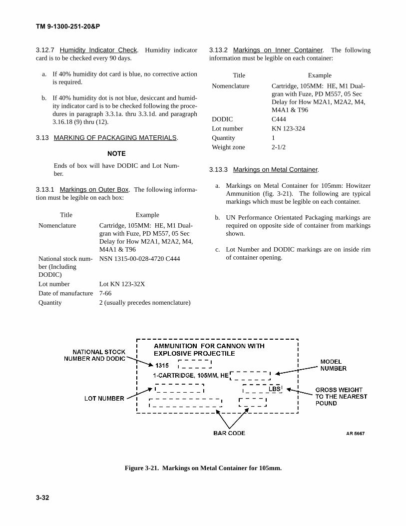
TM 9-1300-251-20&P
3.12.7 Humidity Indicator Check. Humidity indicatorcard is to be checked every 90 days.
a. If 40% humidity dot card is blue, no corrective actionis required.
b. If 40% humidity dot is not blue, desiccant and humid-ity indicator card is to be checked following the proce-dures in paragraph 3.3.1a. thru 3.3.1d. and paragraph3.16.18 (9) thru (12).
3.13 MARKING OF PACKAGING MATERIALS.
NOTE
Ends of box will have DODIC and Lot Num-ber.
3.13.1 Markings on Outer Box. The following informa-tion must be legible on each box:
3.13.2 Markings on Inner Container. The followinginformation must be legible on each container:
3.13.3 Markings on Metal Container.
a. Markings on Metal Container for 105mm: HowitzerAmmunition (fig. 3-21). The following are typicalmarkings which must be legible on each container.
b. UN Performance Orientated Packaging markings arerequired on opposite side of container from markingsshown.
c. Lot Number and DODIC markings are on inside rimof container opening.
Figure 3-21. Markings on Metal Container for 105mm.
Title ExampleNomenclature Cartridge, 105MM: HE, M1 Dual-
gran with Fuze, PD M557, 05 Sec Delay for How M2A1, M2A2, M4, M4A1 & T96
National stock num-ber (Including DODIC)
NSN 1315-00-028-4720 C444
Lot number Lot KN 123-32XDate of manufacture 7-66Quantity 2 (usually precedes nomenclature)
Title ExampleNomenclature Cartridge, 105MM: HE, M1 Dual-
gran with Fuze, PD M557, 05 Sec Delay for How M2A1, M2A2, M4, M4A1 & T96
DODIC C444Lot number KN 123-324Quantity 1Weight zone 2-1/2
3-32
TM 9-1300-251-20&P
3.13.4 Restoration of Markings.
a. Carefully observe information and location of mark-ings on packaging of like item.
b. Using waterproof ink marker, china marking pencil orsmall brush and paint, restore markings which arefaded, obliterated during cleaning, or painted over.
c. Check markings for accuracy and allow to dry.
d. Repack ammunition following procedures in para-graph 3.16.
3.14 NOSE FUZE REMOVAL AND INSTALLATION.
3.14.1 Removal of Nose Fuzes.
a. Place fuze wrench M18 on fuze so that edges ofwrench solidly engage wrench slots on fuze.
b. Holding projectile firmly, (use strap wrench, if avail-able) turn wrench counterclockwise to loosen fuze.
c. Remove fuze by hand.
d. For fuzes with separate booster, use fuze wrench toloosen and unscrew booster (applies to M78 seriesfuzes only).
e. Install new fuze in accordance with 3.14.2 below.
f. Package fuzes removed following procedures in para-graph 3.16.
3.14.2 Installation of Fuzes with Attached Booster.
a. Assure fuze and fuze well threads are clean andundamaged (use dry rag to wipe off, if necessary).
b. Assuring that threads engage properly, screw fuzeclockwise into nose of projectile until fuze shoulderseats flush on nose of projectile.
c. Engage M18 fuze wrench in fuze slots and unscrewfuze one-quarter turn.
NOTE
Reject any fuze or projectile which will notallow proper seating of the fuze.
d. Holding projectile firmly (using strap wrench if avail-able) tighten fuze into nose of projectile with onesharp stroke of the wrench.
3.14.3 Installation of Fuzes with Separate Boosters.
a. Screw booster in fuze well clockwise assuring thatthreads are properly engaged.
b. Place fuze wrench so that edges of wrench engageslots on booster.
c. Holding projectile firmly, (using strap wrench, ifavailable) turn wrench clockwise to tighten booster.
d. Install fuze following procedures in 13.4.2 above.
3.14.4 Installation of Lifting Plugs.
a. Assure lifting plug gasket is in place, intact, and clean.Assure plug threads are undamaged and clean. Assurefuze well threads are clean. Wipe off gasket and/orthreads with dry rag, as necessary.
b. Thread plug into fuze well and screw it in clockwiseuntil hand-tight against nose of projectile.
c. Unscrew plug a quarter-turn.
d. While holding projectile securely, (use a strap wrench,if available) insert a bar or handle of fuze wrenchthrough loop in lifting plug and tighten plug with onesmooth, easy stroke. One easy stroke is sufficient;over-tightening can damage gasket which, in turn,could allow moisture damage to fuze well area.
3-33
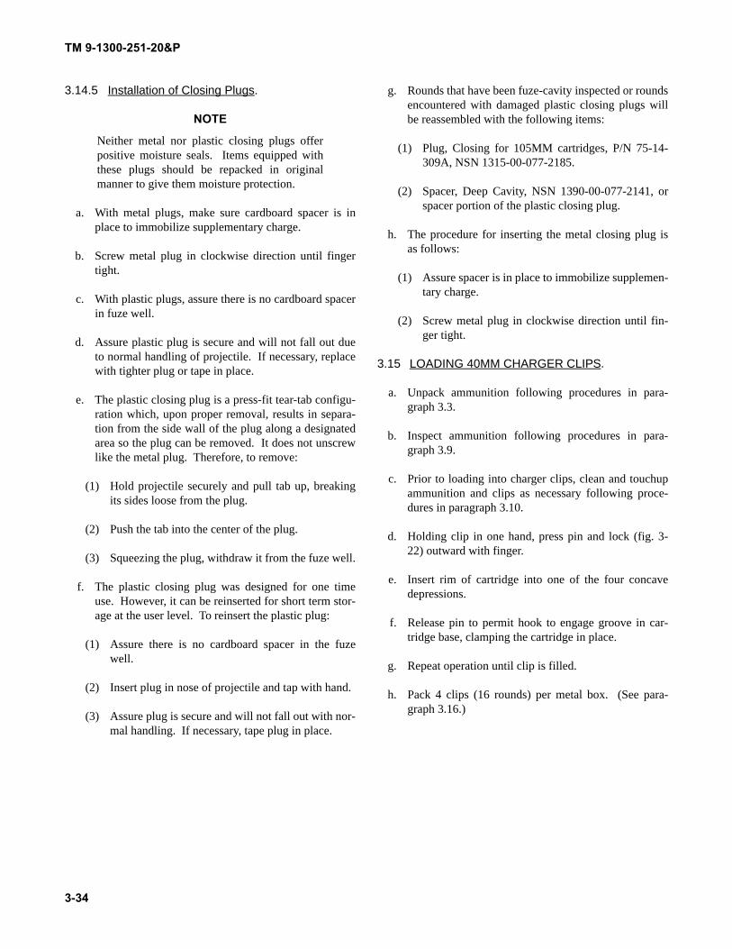
TM 9-1300-251-20&P
3.14.5 Installation of Closing Plugs.
NOTE
Neither metal nor plastic closing plugs offerpositive moisture seals. Items equipped withthese plugs should be repacked in originalmanner to give them moisture protection.
a. With metal plugs, make sure cardboard spacer is inplace to immobilize supplementary charge.
b. Screw metal plug in clockwise direction until fingertight.
c. With plastic plugs, assure there is no cardboard spacerin fuze well.
d. Assure plastic plug is secure and will not fall out dueto normal handling of projectile. If necessary, replacewith tighter plug or tape in place.
e. The plastic closing plug is a press-fit tear-tab configu-ration which, upon proper removal, results in separa-tion from the side wall of the plug along a designatedarea so the plug can be removed. It does not unscrewlike the metal plug. Therefore, to remove:
(1) Hold projectile securely and pull tab up, breakingits sides loose from the plug.
(2) Push the tab into the center of the plug.
(3) Squeezing the plug, withdraw it from the fuze well.
f. The plastic closing plug was designed for one timeuse. However, it can be reinserted for short term stor-age at the user level. To reinsert the plastic plug:
(1) Assure there is no cardboard spacer in the fuzewell.
(2) Insert plug in nose of projectile and tap with hand.
(3) Assure plug is secure and will not fall out with nor-mal handling. If necessary, tape plug in place.
g. Rounds that have been fuze-cavity inspected or roundsencountered with damaged plastic closing plugs willbe reassembled with the following items:
(1) Plug, Closing for 105MM cartridges, P/N 75-14-309A, NSN 1315-00-077-2185.
(2) Spacer, Deep Cavity, NSN 1390-00-077-2141, orspacer portion of the plastic closing plug.
h. The procedure for inserting the metal closing plug isas follows:
(1) Assure spacer is in place to immobilize supplemen-tary charge.
(2) Screw metal plug in clockwise direction until fin-ger tight.
3.15 LOADING 40MM CHARGER CLIPS.
a. Unpack ammunition following procedures in para-graph 3.3.
b. Inspect ammunition following procedures in para-graph 3.9.
c. Prior to loading into charger clips, clean and touchupammunition and clips as necessary following proce-dures in paragraph 3.10.
d. Holding clip in one hand, press pin and lock (fig. 3-22) outward with finger.
e. Insert rim of cartridge into one of the four concavedepressions.
f. Release pin to permit hook to engage groove in car-tridge base, clamping the cartridge in place.
g. Repeat operation until clip is filled.
h. Pack 4 clips (16 rounds) per metal box. (See para-graph 3.16.)
3-34
TM 9-1300-251-20&P
Figure 3-22. Loading 40mm Cartridges in Charger Clips.
3.16 REPACKING PROCEDURES.
NOTE
Boxes and packaging materials are normallyavailable for reuse after ammunition is fired. Ifnot available in using organization, requisitionrequired items.
Refer to appendix C (Repair Parts and SpecialTools List) for most recent packaging informa-tion and appendix F for packing and markingdata.
3.16.1 General.
3.16.1.1 Always repack ammunition in serviceable pack-aging containers.
3.16.1.2 Select packaging components from those for sim-ilar ammunition items.
3.16.1.3 Use filler pads as required for a tight pack.
3.16.1.4 Re-mark package as necessary to assure propermarkings.
3.16.1.5 Assure that neoprene or elastomeric barrier bag ispresent, properly positioned, and undamaged before repack-ing 152mm ammunition.
3.16.2 Metal Container.
a. Place item in container so that it is firmly seated infiller materials.
b. Cover any sensitive parts such as primers with pad-ding.
3-35
TM 9-1300-251-20&P
c. Place top on container.
d. Seal with plastic filament tape or black nylon tape bywrapping joint in a double layer and folding edgesover top.
3.16.3 Metal Box (M2A1, etc.).
a. Inspect gasket on top of box to assure a good seal.
b. Place lower filler materials into box.
c. Insert item(s) in space(s) provided.
d. Add other filler materials as required.
e. If top has been completely removed, line up hingeslots on top with hinge pins on box and slide top ontobox.
f. Close top firmly.
g. Place short end of locking lever under lock lip.
h. Push down and in on locking lever until it snapsagainst box.
3.16.4 Metal Container (PA64) for 152mm Ammuni-tion.
a. Replace protective neoprene or elastomeric bag overcartridge case, if previously removed.
b. If fresh desiccant bags or desiccant bags which havebeen resealed as per paragraph 3.3.14g. are available,secure desiccant bag to projectile nose in originalmanner.
c. Replace nose plug on M625 series cartridges.
d. Fit nose support to cartridge and place cartridge in halfcushion cavity.
e. Place initiator ring between base of cartridge andcushion.
f. Insert forward spacer between nose support and cush-ion.
g. Place inner fillers between forward spacer, asrequired, to provide a tight pack.
h. Place remaining cushion half over cartridge.
i. Secure cushion halves together with one completewrap of any available tape six to seven inches fromeach end. Be sure tape is long enough to overlap itselfand form a pull tab of approximately 3-inch length.Form tab by folding free end of tape back on itself,adhesive to adhesive.
j. Place cushioned cartridge into metal container, noseend first. Cushion and container are both marked toassure proper orientation.
k. Use end fillers as required to provide a tight packwhen end cap is secured.
l. Insert and twist end cap into place. Secure cap end byturning locking bar clockwise until it is handtight.Secure locking bar with a piece of scrap wire.
3.16.5 Vapor-Barrier Bag.
a. Place protective materials around sensitive parts(primer, etc.) of item.
b. Place the item(s) into paperboard box.
c. Close paperboard box and seal with tape.
d. Insert box in barrier bag.
e. Exhaust air from bag, fold edges over and seal withtape.
3.16.6 Wax-Dipped Container (Jungle-Wrap).
NOTE
Wax-dipped outer wrap may be discarded afterit has been opened. Inner fiber containers maybe repacked to safely ship mortar cartridges todepot. Any jungle wrapped mortar cartridgeswhose packaging has been opened is consid-ered compromised to moisture degradation andmust be used immediately or shipped to depotfor renovation.
a. Replace the packing stop ("horseshow" ring or full-cylinder ring), if used, in fuze or nose plug slots.
b. Holding container at a slight angle (30° to 60°), insertitem, nose first, into container and seat firmly.
3-36
TM 9-1300-251-20&P
c. Place padding over end of item. Secure with tape ifnecessary.
d. Slide on end cap.
e. Seal end cap with a double layer of black plastic fila-ment-reinforced tape.
3.16.7 Single End Fiber Container.
a. Replace packing stop, if used, in fuze or nose plugslots.
b. Holding container at a slight angle (30° to 60°), insertitem, projectile end first, into the container and seatfirmly.
c. Place padding on item as required. Secure with tape ifnecessary.
d. Slide on end cap.
e. Seal end cap by covering joint with two layers ofblack plastic filament-reinforced tape.
3.16.8 Double-End Fiber Container.
a. Determine which end of container should contain pro-jectile.
b. Replace packing stop, if used, in fuze or nose plugslots.
c. Holding container at a slight angle (30° to 60°), insertprojectile, nose first, into container and seat firmly.
d. Use filler material if necessary and slide on first endcap.
e. Place felt or other padding in second end cap.
f. Place cartridge case, base first, in second end cap sothat primer is protected by padding material.
g. Insert cardboard cup over propellant charge.
h. Slide fiber container over cartridge case and seat inend cap.
i. Seal end caps with two layers of black plastic fila-ment-reinforced tape over joints.
3.16.9 Metal Box with Screw Locks.
a. Inspect gasket in top of box to assure good seal.
b. Place filler material in bottom of box as necessary.
c. Place inner pack(s) in box.
d. Place padding or filler material over inner pack(s).
e. Position top on box.
f. Turn locking bar clockwise to tighten latches.
g. Turn the four locking thumbscrews clockwise to locklatches.
h. Secure locking bar and thumbscrews with wire.
3.16.10 Metal Box with Latches.
a. Inspect gasket in top of box to assure good seal.
b. Place filler material in bottom of box as necessary.
c. Place inner pack(s) in box. Use filler material orempty containers when box is not full.
d. Place padding or filler material over inner pack(s).
e. Position top on box.
f. Snap latches shut to secure top.
g. Secure latches with wire.
3.16.11 Projectile Grommet.
3.16.11.1 Type A: Wire-tied Metal.
a. Place padding inside grommet.
b. Spread grommet ends and slide grommet and paddingover projectile rotating band.
c. Secure grommet with wire ties through holes pro-vided. Tighten wires with pliers and cut off excess.
3-37
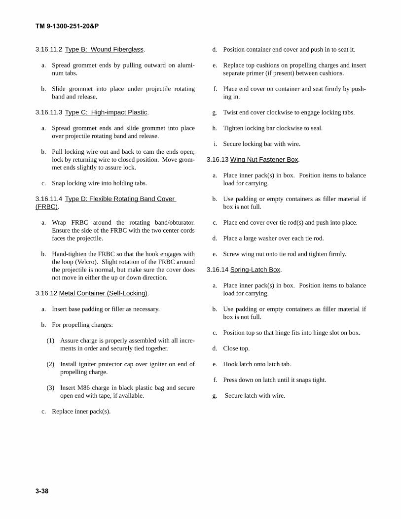
TM 9-1300-251-20&P
3.16.11.2 Type B: Wound Fiberglass.
a. Spread grommet ends by pulling outward on alumi-num tabs.
b. Slide grommet into place under projectile rotatingband and release.
3.16.11.3 Type C: High-impact Plastic.
a. Spread grommet ends and slide grommet into placeover projectile rotating band and release.
b. Pull locking wire out and back to cam the ends open;lock by returning wire to closed position. Move grom-met ends slightly to assure lock.
c. Snap locking wire into holding tabs.
3.16.11.4 Type D: Flexible Rotating Band Cover (FRBC).
a. Wrap FRBC around the rotating band/obturator.Ensure the side of the FRBC with the two center cordsfaces the projectile.
b. Hand-tighten the FRBC so that the hook engages withthe loop (Velcro). Slight rotation of the FRBC aroundthe projectile is normal, but make sure the cover doesnot move in either the up or down direction.
3.16.12 Metal Container (Self-Locking).
a. Insert base padding or filler as necessary.
b. For propelling charges:
(1) Assure charge is properly assembled with all incre-ments in order and securely tied together.
(2) Install igniter protector cap over igniter on end ofpropelling charge.
(3) Insert M86 charge in black plastic bag and secureopen end with tape, if available.
c. Replace inner pack(s).
d. Position container end cover and push in to seat it.
e. Replace top cushions on propelling charges and insertseparate primer (if present) between cushions.
f. Place end cover on container and seat firmly by push-ing in.
g. Twist end cover clockwise to engage locking tabs.
h. Tighten locking bar clockwise to seal.
i. Secure locking bar with wire.
3.16.13 Wing Nut Fastener Box.
a. Place inner pack(s) in box. Position items to balanceload for carrying.
b. Use padding or empty containers as filler material ifbox is not full.
c. Place end cover over tie rod(s) and push into place.
d. Place a large washer over each tie rod.
e. Screw wing nut onto tie rod and tighten firmly.
3.16.14 Spring-Latch Box.
a. Place inner pack(s) in box. Position items to balanceload for carrying.
b. Use padding or empty containers as filler material ifbox is not full.
c. Position top so that hinge fits into hinge slot on box.
d. Close top.
e. Hook latch onto latch tab.
f. Press down on latch until it snaps tight.
g. Secure latch with wire.
3-38
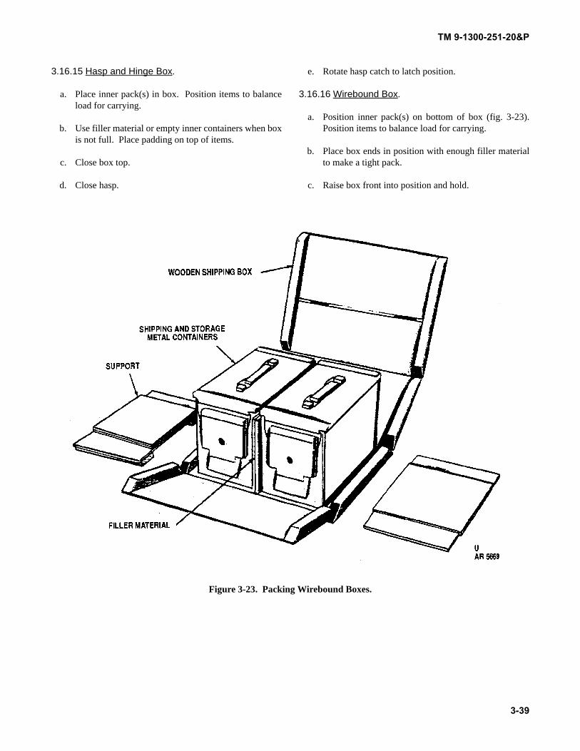
TM 9-1300-251-20&P
3.16.15 Hasp and Hinge Box.
a. Place inner pack(s) in box. Position items to balanceload for carrying.
b. Use filler material or empty inner containers when boxis not full. Place padding on top of items.
c. Close box top.
d. Close hasp.
e. Rotate hasp catch to latch position.
3.16.16 Wirebound Box.
a. Position inner pack(s) on bottom of box (fig. 3-23).Position items to balance load for carrying.
b. Place box ends in position with enough filler materialto make a tight pack.
c. Raise box front into position and hold.
Figure 3-23. Packing Wirebound Boxes.
3-39
TM 9-1300-251-20&P
d. Raise box back into position and hold.
e. Close top, being careful to fit wire loops on top overwire loops on front.
f. Bend wire loops flat against box using a sallee closer(fig. 3-24).
3.16.17 Pallet (Wooden).
a. Arrange boxes, containers, projectiles, etc., on palletin the same configuration as the original load, if possi-ble. Distribute load for balance.
b. Place separators between rows of metal tube contain-ers.
Figure 3-24. Closing Wirebound Box.
3-40
TM 9-1300-251-20&P
c. Place top (projectile pallet) in position.
d. Cut 1-1/4-inch banding pieces about two feet longerthan pallet girth.
e. Position straps under upper part of pallet bottom.
f. Position wood strips under straps to protect ammuni-tion packaging.
g. Insert one strap end from rear into strap stretcher sothat strap is held firmly by stretcher and about 4 to 6inches of strap protrudes.
h. Place clip over strap end.
i. Thread loose end of that strap through clip and intostretcher head.
j. Tighten strap by repeated movement of ratchet leveruntil edges begin to cut into wood.
k. Using banding crimper, crimp clip in two places.
l. Release locking pawl on stretcher and slide stretcherout.
m. Cut off excess strapping.
n. Repeat steps g. thru m. above, for each strap.
3.16.18 Field Artillery Projectile Pallet (FAPP).
a. Attach the latch rod assembly to the pallet base assem-bly. Assure that the rod length is the correct one forthe type of projectile.
b. Insert spacers into the pallet base assembly and lockthem into the base holes using the tabs.
c. Insert the cover liner into the pallet cover assemblylifting plug cup. For lifting plugs with narrow flange,use cover support drawing, 9369960.
d. Load projectiles onto pallet starting from the center.Minimum partial load is two projectiles.
e. Place pallet top on the projectiles and leave handles inthe open position.
f. Move the latch rod so that the top nut of the rod sits inthe trunnion of the handle.
g. Close the pallet cover by pushing the handles downinto the lock position.
h. Add metallic seal around the two handles.
3.16.19 Metal Container Copperhead (fig. 3-11).
a. Receive temporarily repackaged projectile from firingbattery. Check for white stripe and numeral on bodyof container at the end below the humidity indicatorand manual relief valve. White stripe marking indi-cates projectile was previously repackaged. If stripeand numeral are there, conceal markings by paintingover with forest green paint.
b. Check tag on container indicating amount of timeprojectile was removed from container. When 30 daysor more, forward container with projectile to DirectSupport Maintenance. When under 30 days, repack-age following steps (1) thru (13) below.
(1) Open container and remove projectile, as pre-scribed in paragraph 3.3.15.
(2) Remove loose dirt, paint chips, rust, and other for-eign matter from interior of container cover andlower half. Goggles or eye shields should be worn.
(3) Check flange gasket. If missing or damaged, for-ward container with projectile to depot for replace-ment of flange gasket.
(4) Using a soft dry cloth, wipe window of projectileogive (nose cone). Dampen cloth with isopropylalcohol to remove smudges, if necessary.
(5) Clean, touchup, or re-mark projectile as required.On M823 training projectile, replace ogive (nosecone), obturator, or code-time switches, if required.
(6) To replace projectile into container, reinstall wingand fin preload bands, making sure each of the fourpreload tabs on each of the bands securely engagesfin/wings.
3-41
TM 9-1300-251-20&P
WARNING
Projectiles are heavy and require a two-personlift using proper lifting technique to preventinjury to personnel. The projectile weighs 138pounds.
CAUTION
Do not permit projectile to touch the ground.Avoid all contact of ogive to prevent damage.
(7) Using two people and lifting straps, lift projectileup and position it over the container.
(8) Carefully lower projectile, guiding the ogive intothe retaining ring (forward bulkhead) first; gentlylower projectile into place on the two cradles.Tighten tension mechanism handtight. Do notovertighten the tension mechanism, as this coulddamage the nose cone or torquing rod.
(9) Check internal components of container for com-pleteness and replace missing items.
(10) Remove desiccant and replace with fresh supply.
(11) Assuring inside cradles are aligned, carefullyswing container cover back onto the body.
(12) Close container latches in pairs starting at the endopposite the humidity indicator. Lift up latch han-dle, place T-bolt in cover recess, and push down onhandle to close.
(13) Check humidity indicator. If 40 percent humiditysector on indicator card is blue, proceed to step(14). If not blue, open container and change desic-cant and humidity indicator card as follows:
(a) Using slip-joint pliers, unscrew humidity indica-tor from container, turning counterclockwise.
(b) Use 1/2-inch socket screw key (Allen wrench) ortorque wrench with 1/2-inch drive to unscrewplug from inside of humidity indicator, turningcounterclockwise.
(c) Remove preformed packing from inside ofhumidity indicator.
(d) Remove used indicator card. Insert new indica-tor card.
(e) Reinstall preformed packing inside humidityindicator.
NOTE
If preformed packing is not reusable, returncontainer, with projectile, to depot for replace-ment.
(f) Reinstall plug on inside of humidity indicatorusing a 1/2-inch socket head key. Turn keyclockwise until handtight.
(g) Reinstall humidity indicator into threaded hole inthe container using slip-joint pliers. Tighten byturning clockwise until handtight.
(h) After a 120 hour period, observe humidity indi-cator card. If the 40 percent humidity sector isnot blue, open container, change card and desic-cant again, then close container. If after a second120-hour period the sector is not blue, take pro-jectile out, put projectile in a different container,and re-mark container. Tools used in replace-ment of humidity indicator card are available inTool Kit, Artillery, Mechanics: Ordnance.
(14) Check rope handles and replace, if necessary, asfollows:
(a) Fabricate replacement handles by cutting a 24-inch length of rope, T-R-605, from bulk stock.Wrap both ends of handles with tape, A-A-52080. The wrapped area shall not be longerthan 1-1/2 inches.
(b) Pass both ends of new rope handle through holesin container stiffening rib using another ropehandle as a guide.
(c) Tie a single overhand knot on each end of therope handle.
(d) Pull firmly on rope to set knots. Assure handle isproperly secured.
3-42
TM 9-1300-251-20&P
3.16.20 Pallet for Copperhead Clamshell Container(fig.3-25).
a. Arrange container (dunnage sections and wood-fillerassemblies, if used) on pallet in the same configura-tion as the original load, if possible.
b. Place six dunnage assemblies in place.
c. Cut 3/4-inch wide banding pieces approximately 11-feet long. Banding pieces must be at least 6 incheslonger than pallet girth. As an alternate, use 5/8-inchor 1-1/4-inch banding.
d. Follow procedures in paragraphs 3.16.17e. thru3.16.17n.
e. Staple straps to pallet assembly.
3.16.21 Metal Container, 105mm Tank Ammunition(figs. 3-25a and 3-25b.
NOTE
Repack HEP-T, TP-T, or canister ammunitioninto their respective containers.
a. Flip latch 180 degrees to unseal cover assembly. Pal-let for Copperhead Projectiles.
b. Rotate cover assembly counterclockwise to disengagethe assembly shaft from container notches.
Figure 3-25. Pallet for Copperhead Projectiles.
Figure 3-25a. Metal Container for Cartridge, 105mm: HEP-T, M393A3 and Cartridge, 105mm: TP-T, M467A1.
Change 3 3-43
TM 9-1300-251-20&P
Figure 3-25b. Metal Container for Cartridge, 105mm: Canister, M1040.
NOTE
Do not misplace cover assembly and spacermaterial. Cover assembly and spacer materialmust be replaced after the cartridge has beenplaced in container.
c. Remove cover assembly and spacer material fromcontainer and place them on top of pallet.
d. Remove cloth lifting collar from container.
e. Visually inspect (use flashlight) interior of containerfor debris. If debris is present, remove by usingbroom handle, shovel handle, etc. (If container is notpalletized, face open end of container downward untildebris falls out.) If debris cannot be removed fromcontainer, place cloth lifting collar, foam, and card-
board cover spacer into container. Place and securecover assembly to container, and tag or mark the con-tainer "Debris".
f. Insert cartridge (nose first) approximately three quar-ters into container.
g. Obtain and secure cloth lifting collar to cartridge casebase.
h. Obtain cover assembly and spacer material from topof pallet. Perform trial fit of cover and spacer materialon container. Add foam and/or cardboard spacermaterial into container until cover does not readilylatch. Remove cover and remove the thinnest spacerin the container. Replace cover assembly and locklatch.
3-44 Change 4
TM 9-1300-251-20&P
3.16.22 Metal Container, 120mm Tank Ammunition(figs. 3-26 thru 3-29).
NOTE
When placing 120mm ammunition into pallet-ized containers, it is advisable to begin packingfrom the top of the pallet down. This will per-mit packing of the cartridges on the pallet with-out hindrance from the nylon strap loops.
Repack HEAT ammunition in HEAT contain-ers and APFSDS in APFSDS containers. Theinterior foam liners differ for each type ofammunition.
a. Flip latch 180 degrees to unseal cover assembly.
b. Rotate cover assembly counterclockwise to disengageassembly shaft from container notches.
c. Remove cover assembly and spacer material fromcontainer and place them on top of pallet.
Figure 3-26. Metal Container for Cartridge, 120mm: HEAT-MP-T, M830 and Cartridge, 120mm: TP-T, M831 Series.
Figure 3-27. Metal Container for Cartridge, 120mm: APFSDS-T, M829/M829A1/M829A2 andCartridge, 120mm: TPCSDS-T, M865.
Change 3 3-44.1
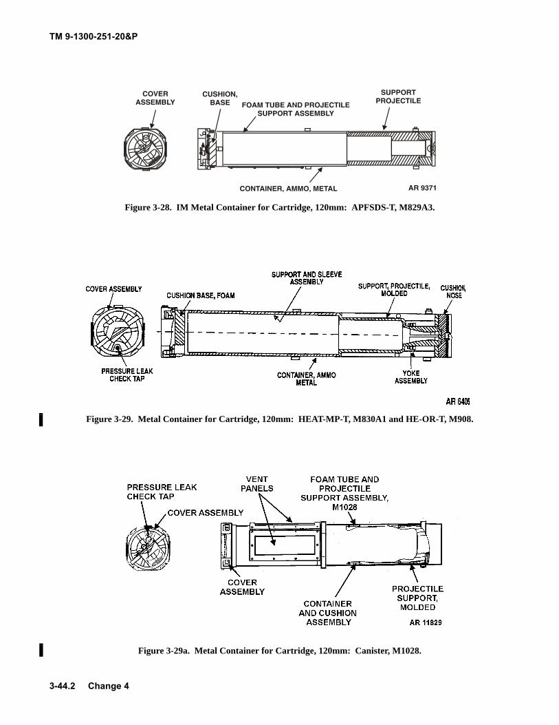
TM 9-1300-251-20&P
Figure 3-28. IM Metal Container for Cartridge, 120mm: APFSDS-T, M829A3.
Figure 3-29. Metal Container for Cartridge, 120mm: HEAT-MP-T, M830A1 and HE-OR-T, M908.
Figure 3-29a. Metal Container for Cartridge, 120mm: Canister, M1028.
3-44.2 Change 4
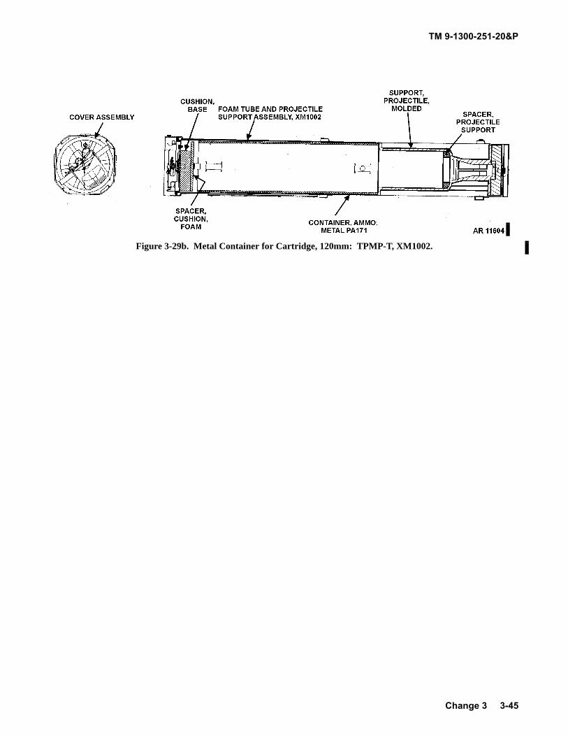
TM 9-1300-251-20&P
Figure 3-29b. Metal Container for Cartridge, 120mm: TPMP-T, XM1002.
Change 3 3-45
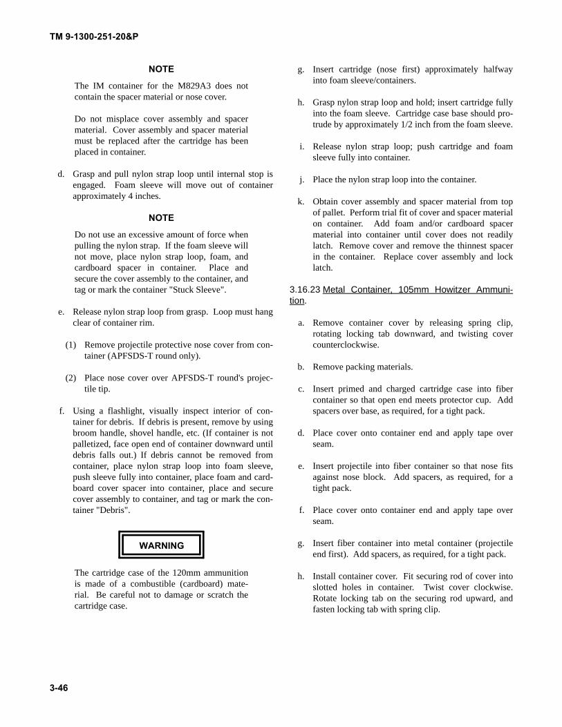
TM 9-1300-251-20&P
NOTE
The IM container for the M829A3 does notcontain the spacer material or nose cover.
Do not misplace cover assembly and spacermaterial. Cover assembly and spacer materialmust be replaced after the cartridge has beenplaced in container.
d. Grasp and pull nylon strap loop until internal stop isengaged. Foam sleeve will move out of containerapproximately 4 inches.
NOTE
Do not use an excessive amount of force whenpulling the nylon strap. If the foam sleeve willnot move, place nylon strap loop, foam, andcardboard spacer in container. Place andsecure the cover assembly to the container, andtag or mark the container "Stuck Sleeve".
e. Release nylon strap loop from grasp. Loop must hangclear of container rim.
(1) Remove projectile protective nose cover from con-tainer (APFSDS-T round only).
(2) Place nose cover over APFSDS-T round's projec-tile tip.
f. Using a flashlight, visually inspect interior of con-tainer for debris. If debris is present, remove by usingbroom handle, shovel handle, etc. (If container is notpalletized, face open end of container downward untildebris falls out.) If debris cannot be removed fromcontainer, place nylon strap loop into foam sleeve,push sleeve fully into container, place foam and card-board cover spacer into container, place and securecover assembly to container, and tag or mark the con-tainer "Debris".
WARNING
The cartridge case of the 120mm ammunitionis made of a combustible (cardboard) mate-rial. Be careful not to damage or scratch thecartridge case.
g. Insert cartridge (nose first) approximately halfwayinto foam sleeve/containers.
h. Grasp nylon strap loop and hold; insert cartridge fullyinto the foam sleeve. Cartridge case base should pro-trude by approximately 1/2 inch from the foam sleeve.
i. Release nylon strap loop; push cartridge and foamsleeve fully into container.
j. Place the nylon strap loop into the container.
k. Obtain cover assembly and spacer material from topof pallet. Perform trial fit of cover and spacer materialon container. Add foam and/or cardboard spacermaterial into container until cover does not readilylatch. Remove cover and remove the thinnest spacerin the container. Replace cover assembly and locklatch.
3.16.23 Metal Container, 105mm Howitzer Ammuni-tion.
a. Remove container cover by releasing spring clip,rotating locking tab downward, and twisting covercounterclockwise.
b. Remove packing materials.
c. Insert primed and charged cartridge case into fibercontainer so that open end meets protector cup. Addspacers over base, as required, for a tight pack.
d. Place cover onto container end and apply tape overseam.
e. Insert projectile into fiber container so that nose fitsagainst nose block. Add spacers, as required, for atight pack.
f. Place cover onto container end and apply tape overseam.
g. Insert fiber container into metal container (projectileend first). Add spacers, as required, for a tight pack.
h. Install container cover. Fit securing rod of cover intoslotted holes in container. Twist cover clockwise.Rotate locking tab on the securing rod upward, andfasten locking tab with spring clip.
3-46
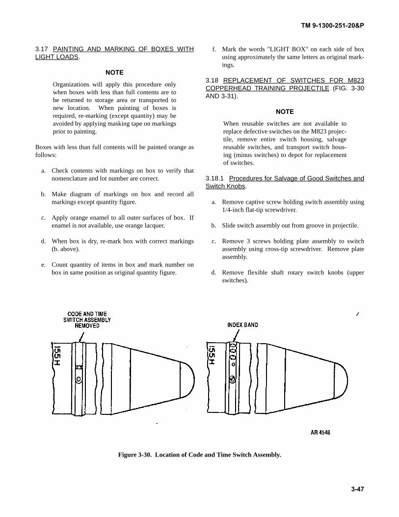
TM 9-1300-251-20&P
3.17 PAINTING AND MARKING OF BOXES WITHLIGHT LOADS.
NOTE
Organizations will apply this procedure onlywhen boxes with less than full contents are tobe returned to storage area or transported tonew location. When painting of boxes isrequired, re-marking (except quantity) may beavoided by applying masking tape on markingsprior to painting.
Boxes with less than full contents will be painted orange asfollows:
a. Check contents with markings on box to verify thatnomenclature and lot number are correct.
b. Make diagram of markings on box and record allmarkings except quantity figure.
c. Apply orange enamel to all outer surfaces of box. Ifenamel is not available, use orange lacquer.
d. When box is dry, re-mark box with correct markings(b. above).
e. Count quantity of items in box and mark number onbox in same position as original quantity figure.
f. Mark the words "LIGHT BOX" on each side of boxusing approximately the same letters as original mark-ings.
3.18 REPLACEMENT OF SWITCHES FOR M823COPPERHEAD TRAINING PROJECTILE (FIG. 3-30AND 3-31).
NOTE
When reusable switches are not available toreplace defective switches on the M823 projec-tile, remove entire switch housing, salvagereusable switches, and transport switch hous-ing (minus switches) to depot for replacementof switches.
3.18.1 Procedures for Salvage of Good Switches andSwitch Knobs.
a. Remove captive screw holding switch assembly using1/4-inch flat-tip screwdriver.
b. Slide switch assembly out from groove in projectile.
c. Remove 3 screws holding plate assembly to switchassembly using cross-tip screwdriver. Remove plateassembly.
d. Remove flexible shaft rotary switch knobs (upperswitches).
Figure 3-30. Location of Code and Time Switch Assembly.
3-47
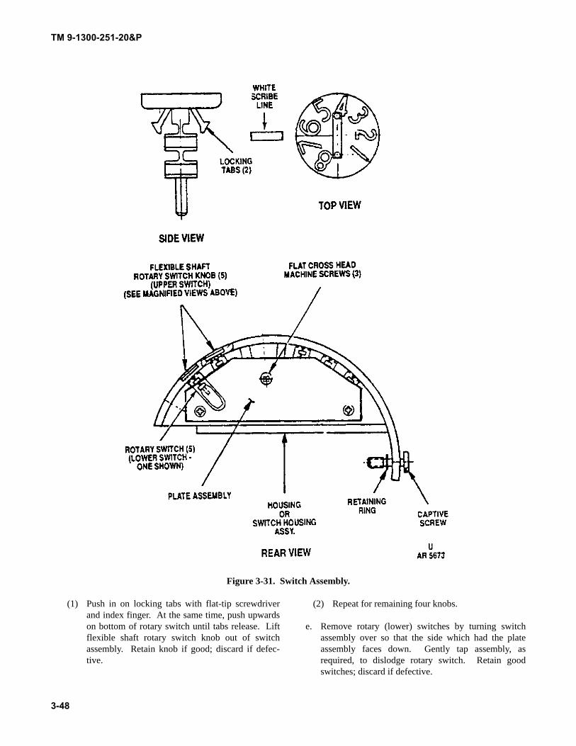
TM 9-1300-251-20&P
Figure 3-31. Switch Assembly.
(1) Push in on locking tabs with flat-tip screwdriverand index finger. At the same time, push upwardson bottom of rotary switch until tabs release. Liftflexible shaft rotary switch knob out of switchassembly. Retain knob if good; discard if defec-tive.
(2) Repeat for remaining four knobs.
e. Remove rotary (lower) switches by turning switchassembly over so that the side which had the plateassembly faces down. Gently tap assembly, asrequired, to dislodge rotary switch. Retain goodswitches; discard if defective.
3-48
TM 9-1300-251-20&P
f. Re-attach plate assembly to switch assembly usingcross-tip screwdriver to reinsert screws.
g. Forward switch assembly (minus switches) to Annis-ton Army Depot for switch replacement. Retain goodswitches and knobs to repair other M823 projectiles.
3.18.2 Procedure for Replacement of DefectiveSwitches and Knobs when Spares are available.
a. Remove plate assembly from switch assembly follow-ing procedures in 3.18.1a. thru 3.18.1c. above.
b. Remove any defective flexible shaft rotary switchknobs following procedures in 3.18.1d. above.Replace with good knobs previously removed fromanother switch assembly.
c. Remove any defective rotary switches following pro-cedures in 3.18.1e. above. Replace with good rotaryswitches previously removed from another switchassembly.
d. Re-attach plate assembly to switch assembly usingcross-tip screwdriver.
e. Slide switch assembly back into groove in projectile.
f. Replace captive screw to hold switch assembly in pro-jectile using 1/4-inch flat-tip screwdriver.
g. If switch assembly is found to be unserviceable, for-ward to depot for replacement. Tag or mark containerto note that it contains projectile without switchassembly. Set tagged container aside until replace-ment assembly is available.
3.19 REPLACEMENT OF PROJECTILE OGIVE(NOSE CONE) FOR M823 COPPERHEAD TRAININGPROJECTILE.
a. Place projectile on a dry, clean, flat surface.
b. Using two people, one person holds the projectile withboth hands to prevent it from turning while the secondperson removes the damaged nose cone by turning itcounterclockwise by hand. If nose cone cannot beremoved by hand, a strap wrench may be used.
c. Install new nose cone by turning it clockwise into thenose of the projectile. Ensure that threads engageproperly.
3.20 REPLACEMENT OF OBTURATOR AND/ORBASE FOR M823 COPPERHEAD TRAINING PRO-JECTILE.
a. Place projectile on side, then place on wooden saddlesor other support.
b. Using two people, one person holds the projectile withboth hands to prevent it from turning while the secondperson uses an extractor drive ratchet (or other ratchetwith a 3/4-inch square drive) to engage the opening inthe center bottom of the base. Turn ratchet counter-clockwise to unscrew base from projectile.
c. Remove obturator from base.
d. If obturator is being replaced, install replacementobturator onto base, making sure the higher part ofobturator is toward the rear.
e. If base is being replaced, re-install obturator on newbase making sure the higher part of obturator is towardthe rear.
f. Using extractor drive ratchet or other ratchet with 3/4-inch square drive, screw base back onto projectile,turning clockwise until handtight.
3-49
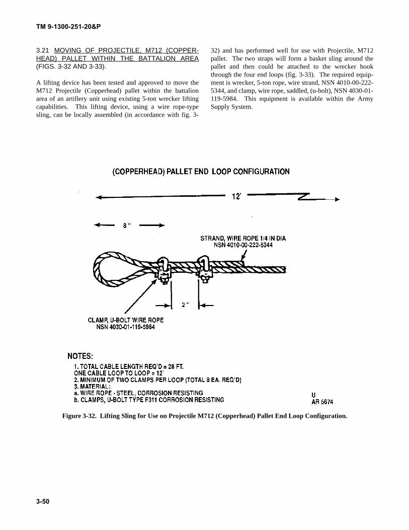
TM 9-1300-251-20&P
3.21 MOVING OF PROJECTILE, M712 (COPPER-HEAD) PALLET WITHIN THE BATTALION AREA(FIGS. 3-32 AND 3-33).
A lifting device has been tested and approved to move theM712 Projectile (Copperhead) pallet within the battalionarea of an artillery unit using existing 5-ton wrecker liftingcapabilities. This lifting device, using a wire rope-typesling, can be locally assembled (in accordance with fig. 3-
32) and has performed well for use with Projectile, M712pallet. The two straps will form a basket sling around thepallet and then could be attached to the wrecker hookthrough the four end loops (fig. 3-33). The required equip-ment is wrecker, 5-ton rope, wire strand, NSN 4010-00-222-5344, and clamp, wire rope, saddled, (u-bolt), NSN 4030-01-119-5984. This equipment is available within the ArmySupply System.
Figure 3-32. Lifting Sling for Use on Projectile M712 (Copperhead) Pallet End Loop Configuration.
3-50
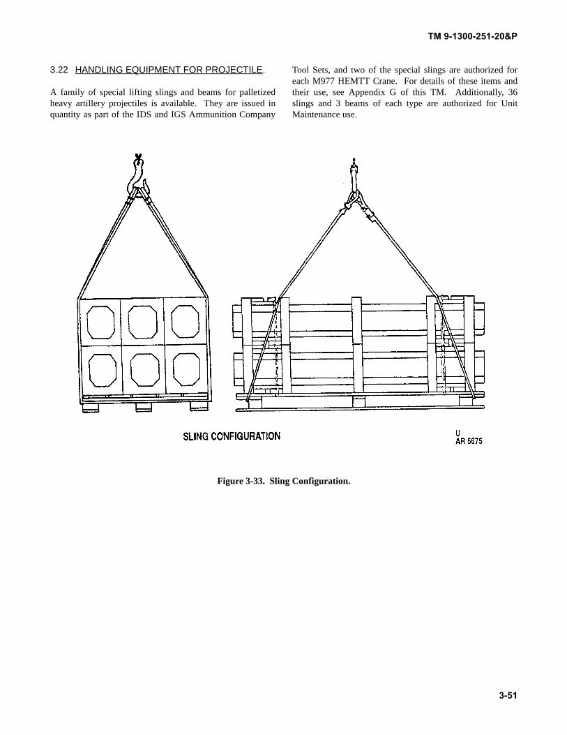
TM 9-1300-251-20&P
3.22 HANDLING EQUIPMENT FOR PROJECTILE.
A family of special lifting slings and beams for palletizedheavy artillery projectiles is available. They are issued inquantity as part of the IDS and IGS Ammunition Company
Tool Sets, and two of the special slings are authorized foreach M977 HEMTT Crane. For details of these items andtheir use, see Appendix G of this TM. Additionally, 36slings and 3 beams of each type are authorized for UnitMaintenance use.
Figure 3-33. Sling Configuration.
3-51

TM 9-1300-251-20&P
THIS PAGE INTENTIONALLY LEFT BLANK
3-52
TM 9-1300-251-20&P
4-1
CHAPTER 4SHIPMENT/MOVEMENT AND STORAGE
SECTION I SHIPMENT/MOVEMENT
4.1 PRECAUTIONS.
Damaged, contaminated or otherwise degraded material maybe dangerous and/or its usefulness may be impaired.
4.2 TRANSPORTATION.
WARNING
Do not roll, drop, throw, or subject ammunitionto rough handling.
4.2.1 Block and brace ammunition packages being trans-ported in trucks, jeeps and other tactical vehicles. (Blockingand bracing must be adequate to withstand sudden stops andstarts, as well as off road operations.)
4.2.2 Stack ammunition in a manner which preventsshifting.
4.2.3 Assure packaging provides adequate protection forammunition during transportation.
NOTE
Certain NATO nation's munitions are, byagreement, interoperable in training. At theconclusion of any training exercise, any ammu-nition drawn from a NATO nation should bereturned to the troops of the NATO nation fromwhom it was obtained. However, it is possiblethat some NATO nation munitions may beturned into a US Army ASP. For that reason,the following is included in this note: AnyNATO munitions received at an ASP shall bereturned to troops of the appropriate NATOnation.
SECTION II STORAGE
4.3 PRECAUTIONS.
4.3.1 Select storage site carefully to avoid exposure topower lines and electric cables.
4.3.2 Assure that exposure to radio frequency (RF) ener-gies and electromagnetic radiation is kept to a minimum instorage areas.
4.3.3 Do not store ammunition adjacent to reservoirs,water mains, or sewer lines.
4.3.4 Select level, well drained sites free from readilyignitable and flammable materials.
4.3.5 Do not store ammunition under trees or adjacent totowers or other structures that attract lightening.
4.3.6 Provide nonflammable or fire-resistant overheadcovers (e.g., tarpaulin) for all ammunition. Maintain over-head air space of approximately 18 inches between cover
and ammunition. Keep cover at least 6 inches from stack onends and at sides to permit circulation of air.
4.3.7 Store or transport ammunition containing whitephosphorus with projectiles in a vertical position.
4.4 STORAGE DATA.
4.4.1 Field Storage Categories.
4.4.1.1 General. Storage categories are the primarygroups into which ammunition is segregated for storage inthe field. The groupings are based on consideration of thedesirability of storing components of complete rounds inadjacent stacks and on consideration of the hazards of propa-gation of explosion, range of fragments, spread of fires, andchemical contamination. Safety procedures covering storageare based on the following factors:
4.4.1.1.1 Items having comparable storage risks aregrouped together in the same category.
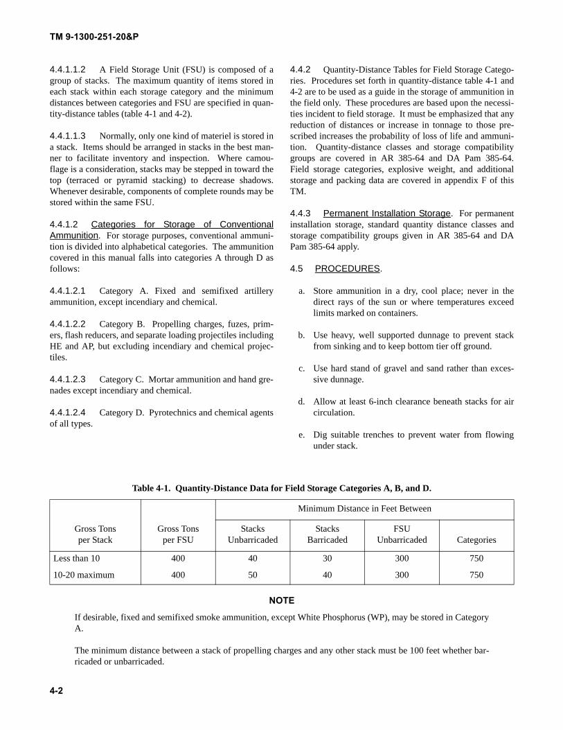
TM 9-1300-251-20&P
4-2
4.4.1.1.2 A Field Storage Unit (FSU) is composed of agroup of stacks. The maximum quantity of items stored ineach stack within each storage category and the minimumdistances between categories and FSU are specified in quan-tity-distance tables (table 4-1 and 4-2).
4.4.1.1.3 Normally, only one kind of materiel is stored ina stack. Items should be arranged in stacks in the best man-ner to facilitate inventory and inspection. Where camou-flage is a consideration, stacks may be stepped in toward thetop (terraced or pyramid stacking) to decrease shadows.Whenever desirable, components of complete rounds may bestored within the same FSU.
4.4.1.2 Categories for Storage of ConventionalAmmunition. For storage purposes, conventional ammuni-tion is divided into alphabetical categories. The ammunitioncovered in this manual falls into categories A through D asfollows:
4.4.1.2.1 Category A. Fixed and semifixed artilleryammunition, except incendiary and chemical.
4.4.1.2.2 Category B. Propelling charges, fuzes, prim-ers, flash reducers, and separate loading projectiles includingHE and AP, but excluding incendiary and chemical projec-tiles.
4.4.1.2.3 Category C. Mortar ammunition and hand gre-nades except incendiary and chemical.
4.4.1.2.4 Category D. Pyrotechnics and chemical agentsof all types.
4.4.2 Quantity-Distance Tables for Field Storage Catego-ries. Procedures set forth in quantity-distance table 4-1 and4-2 are to be used as a guide in the storage of ammunition inthe field only. These procedures are based upon the necessi-ties incident to field storage. It must be emphasized that anyreduction of distances or increase in tonnage to those pre-scribed increases the probability of loss of life and ammuni-tion. Quantity-distance classes and storage compatibilitygroups are covered in AR 385-64 and DA Pam 385-64.Field storage categories, explosive weight, and additionalstorage and packing data are covered in appendix F of thisTM.
4.4.3 Permanent Installation Storage. For permanentinstallation storage, standard quantity distance classes andstorage compatibility groups given in AR 385-64 and DAPam 385-64 apply.
4.5 PROCEDURES.
a. Store ammunition in a dry, cool place; never in thedirect rays of the sun or where temperatures exceedlimits marked on containers.
b. Use heavy, well supported dunnage to prevent stackfrom sinking and to keep bottom tier off ground.
c. Use hard stand of gravel and sand rather than exces-sive dunnage.
d. Allow at least 6-inch clearance beneath stacks for aircirculation.
e. Dig suitable trenches to prevent water from flowingunder stack.
NOTE
If desirable, fixed and semifixed smoke ammunition, except White Phosphorus (WP), may be stored in CategoryA.
The minimum distance between a stack of propelling charges and any other stack must be 100 feet whether bar-ricaded or unbarricaded.
Table 4-1. Quantity-Distance Data for Field Storage Categories A, B, and D.
Gross Tons per Stack
Gross Tons per FSU
Minimum Distance in Feet Between
Stacks Unbarricaded
Stacks Barricaded
FSU Unbarricaded Categories
Less than 10 400 40 30 300 750
10-20 maximum 400 50 40 300 750
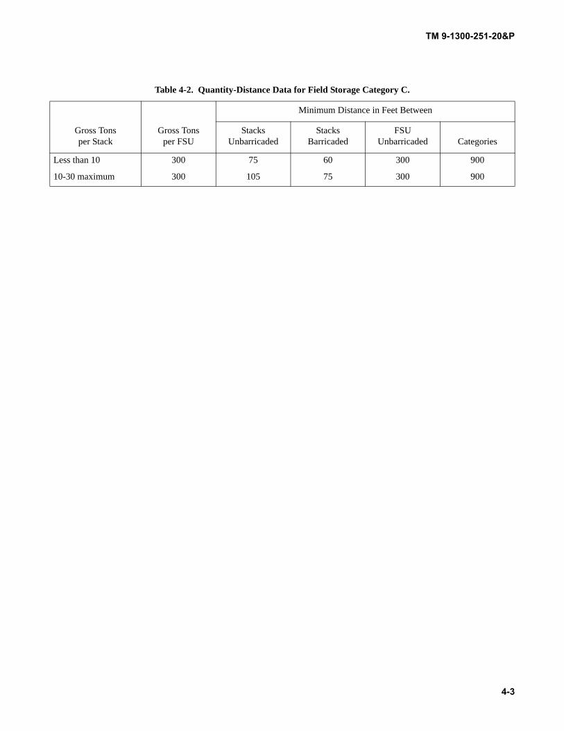
TM 9-1300-251-20&P
4-3
Table 4-2. Quantity-Distance Data for Field Storage Category C.
Gross Tons per Stack
Gross Tons per FSU
Minimum Distance in Feet Between
Stacks Unbarricaded
Stacks Barricaded
FSU Unbarricaded Categories
Less than 10 300 75 60 300 900
10-30 maximum 300 105 75 300 900

TM 9-1300-251-20&P
4-4
THIS PAGE INTENTIONALLY LEFT BLANK

TM 9-1300-251-20&P
Change 5 A-1
APPENDIX AREFERENCES
A.1 SCOPE.
This appendix lists all Army regulations, field manuals, forms, pamphlets, supply bulletins, supply catalogs, technical bulle-tins, technical manuals, and miscellaneous publications referenced in this manual. The publication index (DA Pam 25-30)should be consulted frequently for latest changes or revisions of references given in this appendix and for new publicationsrelating to the material covered in this manual.
A.2 ARMY REGULATIONS.
Malfunctions Involving Ammunition and Explosives .............................................................. AR 75-1
The Army Safety Program ........................................................................................................ AR 385-10
A.3 FORMS.
U.S. Army Accident Report ...................................................................................................... DA Form 285
Recommended Changes to Equipment Technical Publications ................................................ DA Form 2028
Ammunition Condition Report.................................................................................................. DA Form 2415
Transportation Discrepancy Report (TDR) ............................................................................... DD Form 361
A.4 PAMPHLETS.
Consolidated Index of Army Publications and Blank Forms.................................................... DA Pam 25-30
Ammunition and Explosives Safety Standards ......................................................................... DA Pam 385-64
The Army Maintenance Management System (TAMMS) Users Manual ................................ DA Pam 750-8
A.5 TECHNICAL BULLETINS.
Munitions Restricted or Suspended........................................................................................... TB 9-1300-385
A.6 TECHNICAL MANUALS.
Operator’s Manual for Projectile, 155MM: GB2, M687 .......................................................... TM 3-1320-242-10
Organizational and Direct Support Maintenance Manual (Including RPSTL) for Extractor Assembly (For Projectile, 155-MM: M712 Cannon-Launched Guided Projectile and M823 Training Projectile).................................................................................................................... TM 9-1025-212-23&P
Direct Support and General Support Maintenance Manual (Including RPSTL) for Artillery Ammunition for Guns, Howitzers, Mortars, Recoilless Rifles, and 40MM Grenade Launchers .................................................................................................................................. TM 9-1300-251-34&P
A.6 TECHNICAL MANUALS – Continued.

TM 9-1300-251-20&P
A-2
Army Ammunition Data Sheets for Artillery Ammunition: Guns, Howitzers, Mortars, Recoilless Rifles, Grenade Launchers and Artillery Fuzes....................................................... TM 43-0001-28
Destruction of Conventional Ammunition and Improved Conventional Munitions (ICM) to Prevent Enemy Use ................................................................................................................... TM 43-0002-33
TM 9-1300-251-20&P
B-1
APPENDIX BMAINTENANCE ALLOCATION CHART (MAC)
SECTION I INTRODUCTION
B.1 THE ARMY MAINTENANCE SYSTEM MAC.
B.1.1 This introduction provides a general explanation ofall maintenance and repair functions authorized at variousmaintenance levels under the standard Army MaintenanceSystem concept.
B.1.2 The MAC designates overall authority and respon-sibility for the performance of maintenance functions on theidentified end item or component. The application of themaintenance functions to the end item or component shall beconsistent with the capacities and capabilities of the desig-nated maintenance levels, which are shown on the MAC incolumn (4) as:
Unit - includes two subcolumns, C (operator/crew) and O (unit) maintenance.
Direct Support - includes an F subcolumn.
General Support - includes an H subcolumn.
Depot - includes a D subcolumn.
B.1.3 The tools and test equipment requirements (imme-diately following the MAC) list the tools and test equipment(both special tools and common tool sets) required for eachmaintenance function as referenced from the MAC.
B.1.4 The remarks (immediately following the tools andtest equipment requirements) contain supplemental instruc-tions and explanatory notes for a particular maintenancefunction.
B.2 MAINTENANCE FUNCTIONS.
Maintenance functions are limited to and defined as follows:
B.2.1 Inspect. To determine the serviceability of an itemby comparing its physical, mechanical, and/or electricalcharacteristics with established standards through examina-tion (e.g., by sight, sound, or feel). This includes scheduledinspection and gagings and evaluation of cannon tubes.
B.2.2 Test. To verify serviceability by measuring themechanical, pneumatic, hydraulic, or electrical characteris-tics of an item and comparing those characteristics with pre-scribed standards on a scheduled basis, i.e., load testing oflift devices and hydrostatic testing of pressure hoses.
B.2.3 Service. Operations required periodically to keepan item in proper operating condition; e.g., to clean (includesdecontaminate, when required), to preserve, to drain, topaint, or to replenish fuel, lubricants, chemical fluids, orgases. This includes scheduled exercising and purging ofrecoil mechanisms.
B.2.4 Adjust. To maintain or regulate, within prescribedlimits, by bringing into proper position, or by setting theoperating characteristics to specified parameters.
B.2.5 Align. To adjust specified variable elements of anitem to bring about optimum or desired performance.
B.2.6 Calibrate. To determine and cause corrections tobe made or to be adjusted on instruments of test, measuring,and diagnostic equipment used in precision measurement.Consists of comparisons of two instruments, one of which isa certified standard of known accuracy, to detect and adjustany discrepancy in the accuracy of the instrument beingcompared.
B.2.7 Remove/Install. To remove and install the sameitem when required to perform service or other maintenancefunctions. Install may be the act of emplacing, seating, orfixing into position a spare, repair part, or module (compo-nent or assembly) in a manner to allow the proper function-ing of an equipment or system.
B.2.8 Replace. To remove an unserviceable item andinstall a serviceable counterpart in its place. “Replace” isauthorized by the MAC and assigned maintenance level isshown as the third position code of the Source, Maintenanceand Recoverability (SMR) code.
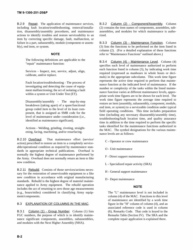
TM 9-1300-251-20&P
B-2
B.2.9 Repair. The application of maintenance services,including fault location/troubleshooting, removal/installa-tion, disassembly/assembly procedures, and maintenanceactions to identify troubles and restore serviceability to anitem by correcting specific damage, fault, malfunction, orfailure in a part, subassembly, module (component or assem-bly), end item, or system.
NOTE
The following definitions are applicable to the"repair" maintenance function:
Services - Inspect, test, service, adjust, align,calibrate, and/or replace.
Fault location/troubleshooting - The process ofinvestigating and detecting the cause of equip-ment malfunctioning; the act of isolating a faultwithin a system or Unit Under Test (ET).
Disassembly/assembly - The step-by-stepbreakdown (taking apart) of a spare/functionalgroup coded item to the level of its least com-ponent, that is assigned as SMR code for thelevel of maintenance under consideration (i.e.,identified as maintenance significant).
Actions - Welding, grinding, riveting, straight-ening, facing, machining, and/or resurfacing.
B.2.10 Overhaul. That maintenance effort (service/action) prescribed to restore an item to a completely service-able/operational condition as required by maintenance stan-dards in appropriate technical publications. Overhaul isnormally the highest degree of maintenance performed bythe Army. Overhaul does not normally return an item to likenew condition.
B.2.11 Rebuild. Consists of those services/actions neces-sary for the restoration of unserviceable equipment to a likenew condition in accordance with original manufacturingstandards. Rebuild is the highest degree of materiel mainte-nance applied to Army equipment. The rebuild operationincludes the act of returning to zero those age measurements(e.g., hours/miles) considered in classifying Army equip-ment/components.
B.3 EXPLANATION OF COLUMNS IN THE MAC.
B.3.1 Column (1) - Group Number. Column (1) listsFGC numbers, the purpose of which is to identify mainte-nance significant components, assemblies, subassemblies,and modules with the Next Higher Assembly (NHA).
B.3.2 Column (2) - Component/Assembly. Column(2) contains the item names of components, assemblies, sub-assemblies, and modules for which maintenance is autho-rized.
B.3.3 Column (3) - Maintenance Function. Column(3) lists the functions to be performed on the item listed incolumn (2). (For a detailed explanation of these functionsrefer to "Maintenance Functions" outlined above.)
B.3.4 Column (4) - Maintenance Level. Column (4)specifies each level of maintenance authorized to performeach function listed in column (3), by indicating work timerequired (expressed as manhours in whole hours or deci-mals) in the appropriate subcolumn. This work time figurerepresents the active time required to perform that mainte-nance function at the indicated level of maintenance. If thenumber or complexity of the tasks within the listed mainte-nance function varies at different maintenance levels, appro-priate work time figures are to be shown for each level. Thework time figure represents the average time required torestore an item (assembly, subassembly, component, module,end item, or system) to a serviceable condition under typicalfield operating conditions. This time includes preparationtime (including any necessary disassembly/assembly time),troubleshooting/fault location time, and quality assurancetime in addition to the time required to perform the specifictasks identified for the maintenance functions authorized inthe MAC. The symbol designations for the various mainte-nance levels are as follows:
C - Operator or crew maintenance
O - Unit maintenance
F - Direct support maintenance
L - Specialized repair activity (SRA)
H - General support maintenance
D - Depot maintenance
NOTE
The "L" maintenance level is not included incolumn (4) of the MAC. Functions to this levelof maintenance are identified by a work timefigure in the "H" column of column (4), and anassociated reference code is used in column(6), Remarks Code. That code is keyed to theRemarks Table (Section IV). The SRA and thecomplete repair application is explained there.
TM 9-1300-251-20&P
B-3
B.3.5 Column (5) - Tools and Equipment ReferenceCode. Column (5) specifies, by code, those common toolsets (not individual tools), common Test, Measurement andDiagnostic Equipment (TMDE), and special tools, specialTMDE and special support equipment required to performthe designated function. Codes are keyed to the entries inthe tools and test equipment table.
B.3.6 Column (6) - Remarks Code. When applicable,this column contains a letter code, in alphabetical order,which is keyed to the Remarks Table entries. (See SectionIV.)
B.4 EXPLANATION OF COLUMNS IN SECTION III,TOOLS AND TEST EQUIPMENT.
B.4.1 Tool or Test Equipment Reference Code. Thetool or test equipment reference code correlates with a codeused in column (5) of the MAC.
B.4.2 Maintenance Level. The lowest level of mainte-nance authorized to use the tool or test equipment.
B.4.3 Nomenclature. Name or identification of the toolor test equipment.
B.4.4 National Stock Number. The NSN of the tool ortest equipment.
B.4.5 Tool Number. The manufacturer’s part number,model number, or type number.
B.5 EXPLANATION OF COLUMNS IN SECTION IV,REMARKS TABLE.
B.5.1 Remarks Code. The code recorded in column (6)of the MAC.
B.5.2 Remarks. This column lists information pertinentto the maintenance function being performed as indicated inthe MAC.
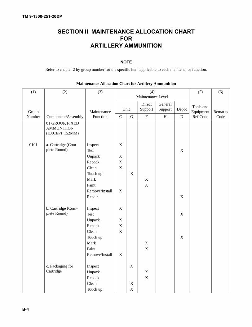
TM 9-1300-251-20&P
B-4
SECTION II MAINTENANCE ALLOCATION CHARTFOR
ARTILLERY AMMUNITION
NOTE
Refer to chapter 2 by group number for the specific item applicable to each maintenance function.
Maintenance Allocation Chart for Artillery Ammunition
(1) (2) (3) (4)Maintenance Level
(5) (6)
Group Number Component/Assembly
Maintenance Function
Tools and Equipment Ref Code
Remarks Code
UnitDirect
SupportGeneral Support Depot
C O F H D01 GROUP, FIXED AMMUNITION (EXCEPT 152MM)
0101 a. Cartridge (Com-plete Round)
Inspect XTest XUnpack XRepack XClean XTouch up XMark XPaint XRemove/Install XRepair X
b. Cartridge (Com-plete Round)
Inspect XTest XUnpack XRepack XClean XTouch up XMark XPaint XRemove/Install X
c. Packaging for Cartridge
Inspect XUnpack XRepack XClean XTouch up X
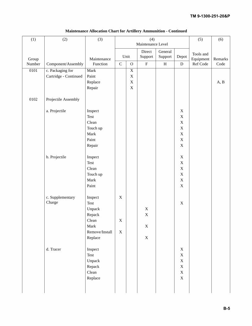
TM 9-1300-251-20&P
B-5
0101 c. Packaging for Mark XCartridge - Continued Paint X
Replace X A, BRepair X
0102 Projectile Assembly
a. Projectile Inspect XTest XClean XTouch up XMark XPaint XRepair X
b. Projectile Inspect XTest XClean XTouch up XMark XPaint X
c. Supplementary Charge
Inspect XTest XUnpack XRepack XClean XMark XRemove/Install XReplace X
d. Tracer Inspect XTest XUnpack XRepack XClean XReplace X
Maintenance Allocation Chart for Artillery Ammunition - Continued
(1) (2) (3) (4)Maintenance Level
(5) (6)
Group Number Component/Assembly
Maintenance Function
Tools and Equipment Ref Code
Remarks Code
UnitDirect
SupportGeneral Support Depot
C O F H D
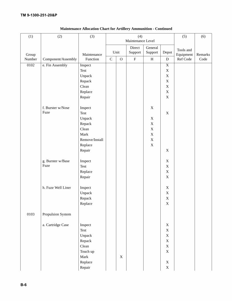
TM 9-1300-251-20&P
B-6
0102 e. Fin Assembly Inspect XTest XUnpack XRepack XClean XReplace XRepair X
f. Burster w/Nose Fuze
Inspect XTest XUnpack XRepack XClean XMark XRemove/Install XReplace XRepair X
g. Burster w/Base Fuze
Inspect XTest XReplace XRepair X
h. Fuze Well Liner Inspect XUnpack XRepack XReplace X
0103 Propulsion System
a. Cartridge Case Inspect XTest XUnpack XRepack XClean XTouch up XMark XReplace XRepair X
Maintenance Allocation Chart for Artillery Ammunition - Continued
(1) (2) (3) (4)Maintenance Level
(5) (6)
Group Number Component/Assembly
Maintenance Function
Tools and Equipment Ref Code
Remarks Code
UnitDirect
SupportGeneral Support Depot
C O F H D
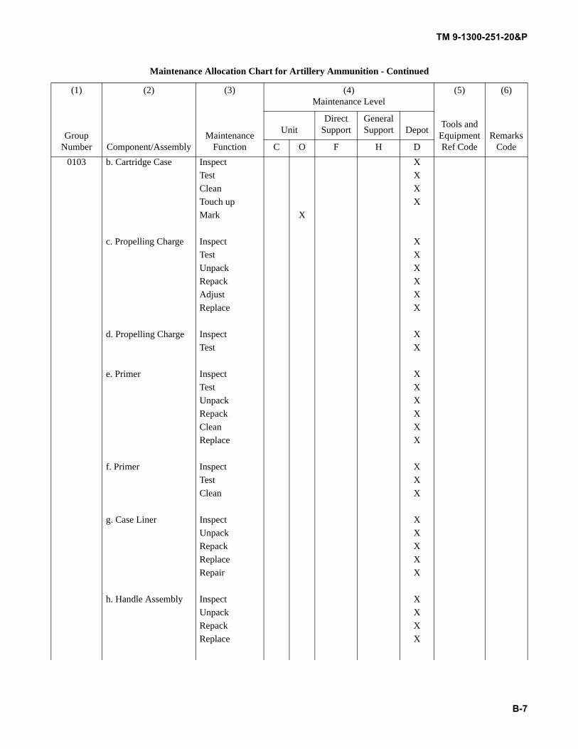
TM 9-1300-251-20&P
B-7
0103 b. Cartridge Case Inspect XTest XClean XTouch up XMark X
c. Propelling Charge Inspect XTest XUnpack XRepack XAdjust XReplace X
d. Propelling Charge Inspect XTest X
e. Primer Inspect XTest XUnpack XRepack XClean XReplace X
f. Primer Inspect XTest XClean X
g. Case Liner Inspect XUnpack XRepack XReplace XRepair X
h. Handle Assembly Inspect XUnpack XRepack XReplace X
Maintenance Allocation Chart for Artillery Ammunition - Continued
(1) (2) (3) (4)Maintenance Level
(5) (6)
Group Number Component/Assembly
Maintenance Function
Tools and Equipment Ref Code
Remarks Code
UnitDirect
SupportGeneral Support Depot
C O F H D
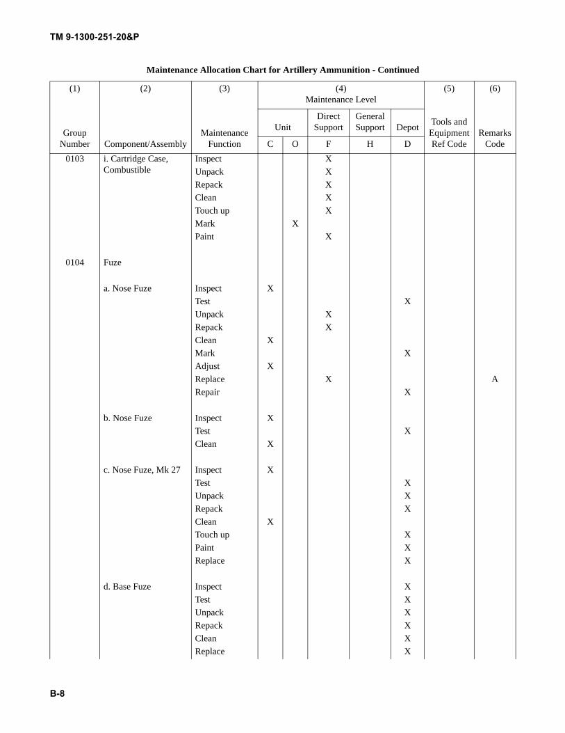
TM 9-1300-251-20&P
B-8
0103 i. Cartridge Case, Combustible
Inspect XUnpack XRepack XClean XTouch up XMark XPaint X
0104 Fuze
a. Nose Fuze Inspect XTest XUnpack XRepack XClean XMark XAdjust XReplace X ARepair X
b. Nose Fuze Inspect XTest XClean X
c. Nose Fuze, Mk 27 Inspect XTest XUnpack XRepack XClean XTouch up XPaint XReplace X
d. Base Fuze Inspect XTest XUnpack XRepack XClean XReplace X
Maintenance Allocation Chart for Artillery Ammunition - Continued
(1) (2) (3) (4)Maintenance Level
(5) (6)
Group Number Component/Assembly
Maintenance Function
Tools and Equipment Ref Code
Remarks Code
UnitDirect
SupportGeneral Support Depot
C O F H D
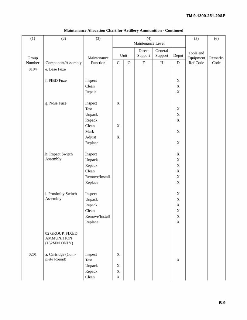
TM 9-1300-251-20&P
B-9
0104 e. Base Fuze
f. PIBD Fuze Inspect XClean XRepair X
g. Nose Fuze Inspect XTest XUnpack XRepack XClean XMark XAdjust XReplace X
h. Impact Switch Assembly
Inspect XUnpack XRepack XClean XRemove/Install XReplace X
i. Proximity Switch Assembly
Inspect XUnpack XRepack XClean XRemove/Install XReplace X
02 GROUP, FIXED AMMUNITION (152MM ONLY)
0201 a. Cartridge (Com-plete Round)
Inspect XTest XUnpack XRepack XClean X
Maintenance Allocation Chart for Artillery Ammunition - Continued
(1) (2) (3) (4)Maintenance Level
(5) (6)
Group Number Component/Assembly
Maintenance Function
Tools and Equipment Ref Code
Remarks Code
UnitDirect
SupportGeneral Support Depot
C O F H D
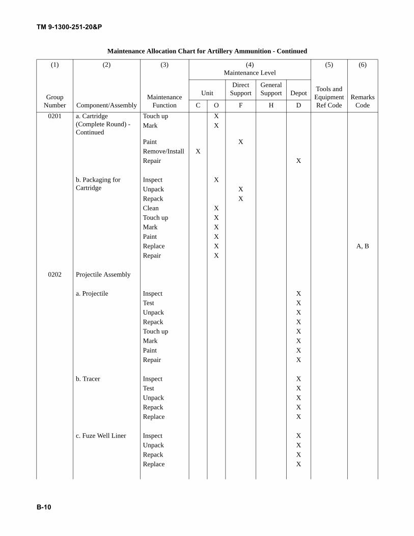
TM 9-1300-251-20&P
B-10
0201 a. Cartridge (Complete Round) - Continued
Touch up XMark X
Paint XRemove/Install XRepair X
b. Packaging for Cartridge
Inspect XUnpack XRepack XClean XTouch up XMark XPaint XReplace X A, BRepair X
0202 Projectile Assembly
a. Projectile Inspect XTest XUnpack XRepack XTouch up XMark XPaint XRepair X
b. Tracer Inspect XTest XUnpack XRepack XReplace X
c. Fuze Well Liner Inspect XUnpack XRepack XReplace X
Maintenance Allocation Chart for Artillery Ammunition - Continued
(1) (2) (3) (4)Maintenance Level
(5) (6)
Group Number Component/Assembly
Maintenance Function
Tools and Equipment Ref Code
Remarks Code
UnitDirect
SupportGeneral Support Depot
C O F H D
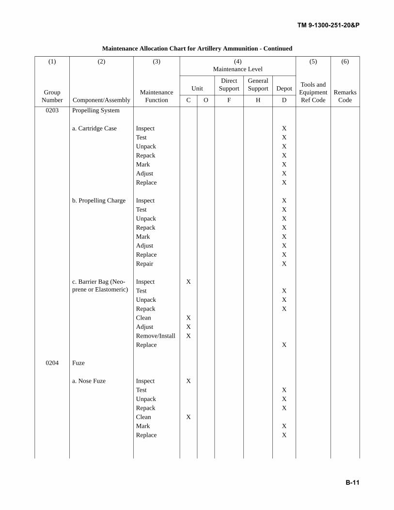
TM 9-1300-251-20&P
B-11
0203 Propelling System
a. Cartridge Case Inspect XTest XUnpack XRepack XMark XAdjust XReplace X
b. Propelling Charge Inspect XTest XUnpack XRepack XMark XAdjust XReplace XRepair X
c. Barrier Bag (Neo-prene or Elastomeric)
Inspect XTest XUnpack XRepack XClean XAdjust XRemove/Install XReplace X
0204 Fuze
a. Nose Fuze Inspect XTest XUnpack XRepack XClean XMark XReplace X
Maintenance Allocation Chart for Artillery Ammunition - Continued
(1) (2) (3) (4)Maintenance Level
(5) (6)
Group Number Component/Assembly
Maintenance Function
Tools and Equipment Ref Code
Remarks Code
UnitDirect
SupportGeneral Support Depot
C O F H D
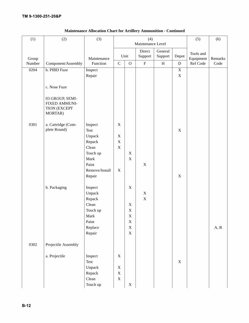
TM 9-1300-251-20&P
B-12
0204 b. PIBD Fuze Inspect XRepair X
c. Nose Fuze
03 GROUP, SEMI-FIXED AMMUNI-TION (EXCEPT MORTAR)
0301 a. Cartridge (Com-plete Round)
Inspect XTest XUnpack XRepack XClean XTouch up XMark XPaint XRemove/Install XRepair X
b. Packaging Inspect XUnpack XRepack XClean XTouch up XMark XPaint XReplace X A, BRepair X
0302 Projectile Assembly
a. Projectile Inspect XTest XUnpack XRepack XClean XTouch up X
Maintenance Allocation Chart for Artillery Ammunition - Continued
(1) (2) (3) (4)Maintenance Level
(5) (6)
Group Number Component/Assembly
Maintenance Function
Tools and Equipment Ref Code
Remarks Code
UnitDirect
SupportGeneral Support Depot
C O F H D
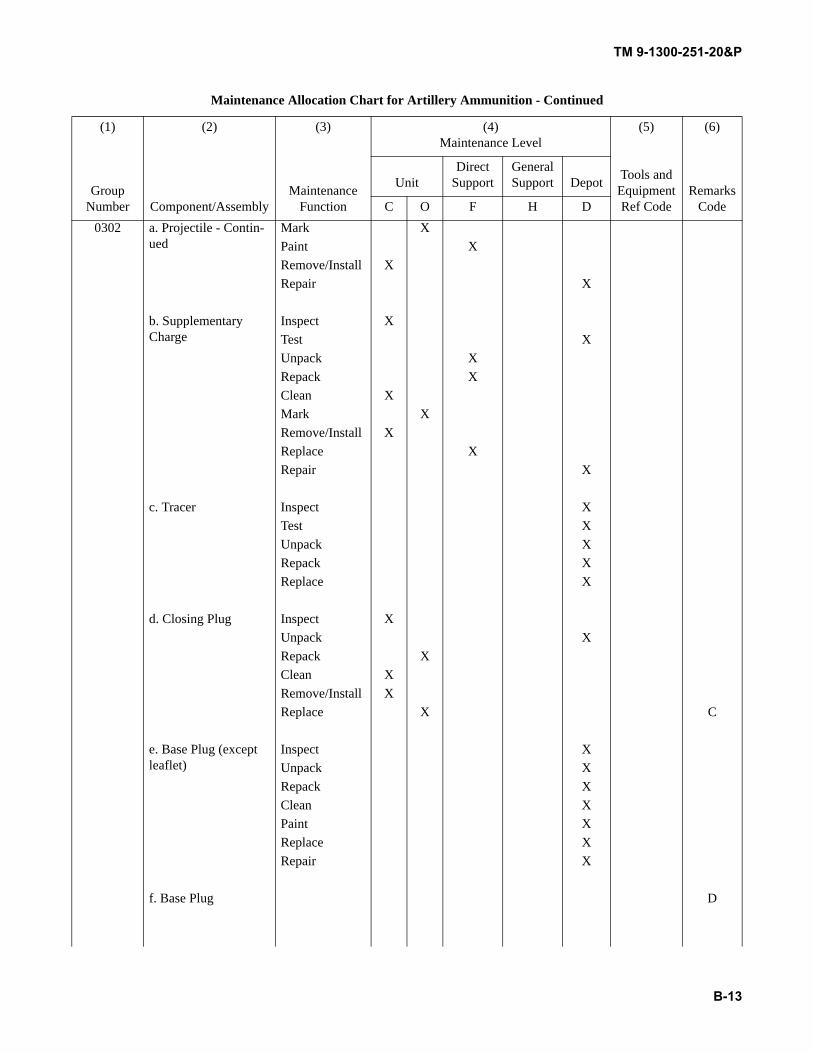
TM 9-1300-251-20&P
B-13
0302 a. Projectile - Contin-ued
Mark XPaint XRemove/Install XRepair X
b. Supplementary Charge
Inspect XTest XUnpack XRepack XClean XMark XRemove/Install XReplace XRepair X
c. Tracer Inspect XTest XUnpack XRepack XReplace X
d. Closing Plug Inspect XUnpack XRepack XClean XRemove/Install XReplace X C
e. Base Plug (except leaflet)
Inspect XUnpack XRepack XClean XPaint XReplace XRepair X
f. Base Plug D
Maintenance Allocation Chart for Artillery Ammunition - Continued
(1) (2) (3) (4)Maintenance Level
(5) (6)
Group Number Component/Assembly
Maintenance Function
Tools and Equipment Ref Code
Remarks Code
UnitDirect
SupportGeneral Support Depot
C O F H D
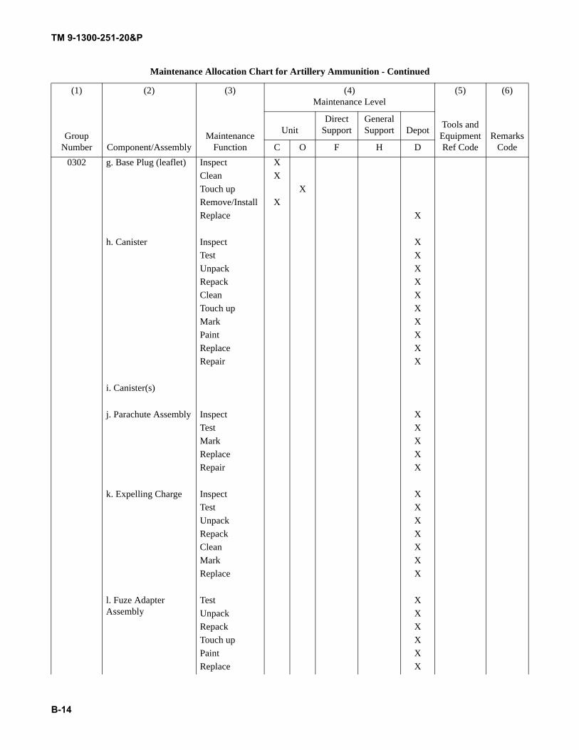
TM 9-1300-251-20&P
B-14
0302 g. Base Plug (leaflet) Inspect XClean XTouch up XRemove/Install XReplace X
h. Canister Inspect XTest XUnpack XRepack XClean XTouch up XMark XPaint XReplace XRepair X
i. Canister(s)
j. Parachute Assembly Inspect XTest XMark XReplace XRepair X
k. Expelling Charge Inspect XTest XUnpack XRepack XClean XMark XReplace X
l. Fuze Adapter Assembly
Test XUnpack XRepack XTouch up XPaint XReplace X
Maintenance Allocation Chart for Artillery Ammunition - Continued
(1) (2) (3) (4)Maintenance Level
(5) (6)
Group Number Component/Assembly
Maintenance Function
Tools and Equipment Ref Code
Remarks Code
UnitDirect
SupportGeneral Support Depot
C O F H D
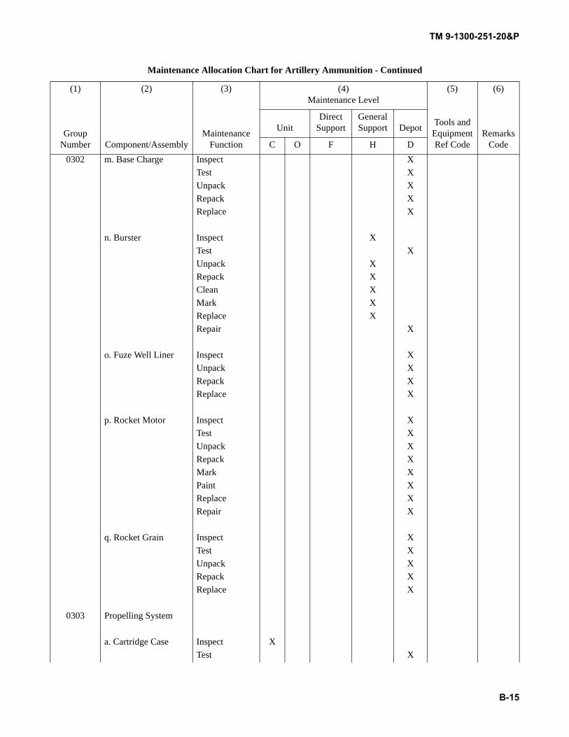
TM 9-1300-251-20&P
B-15
0302 m. Base Charge Inspect XTest XUnpack XRepack XReplace X
n. Burster Inspect XTest XUnpack XRepack XClean XMark XReplace XRepair X
o. Fuze Well Liner Inspect XUnpack XRepack XReplace X
p. Rocket Motor Inspect XTest XUnpack XRepack XMark XPaint XReplace XRepair X
q. Rocket Grain Inspect XTest XUnpack XRepack XReplace X
0303 Propelling System
a. Cartridge Case Inspect XTest X
Maintenance Allocation Chart for Artillery Ammunition - Continued
(1) (2) (3) (4)Maintenance Level
(5) (6)
Group Number Component/Assembly
Maintenance Function
Tools and Equipment Ref Code
Remarks Code
UnitDirect
SupportGeneral Support Depot
C O F H D
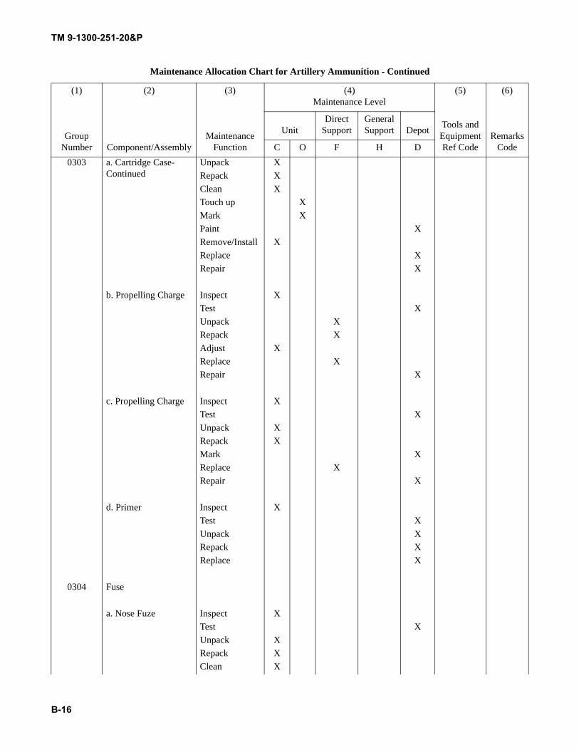
TM 9-1300-251-20&P
B-16
0303 a. Cartridge Case- Continued
Unpack XRepack XClean XTouch up XMark XPaint XRemove/Install XReplace XRepair X
b. Propelling Charge Inspect XTest XUnpack XRepack XAdjust XReplace XRepair X
c. Propelling Charge Inspect XTest XUnpack XRepack XMark XReplace XRepair X
d. Primer Inspect XTest XUnpack XRepack XReplace X
0304 Fuse
a. Nose Fuze Inspect XTest XUnpack XRepack XClean X
Maintenance Allocation Chart for Artillery Ammunition - Continued
(1) (2) (3) (4)Maintenance Level
(5) (6)
Group Number Component/Assembly
Maintenance Function
Tools and Equipment Ref Code
Remarks Code
UnitDirect
SupportGeneral Support Depot
C O F H D
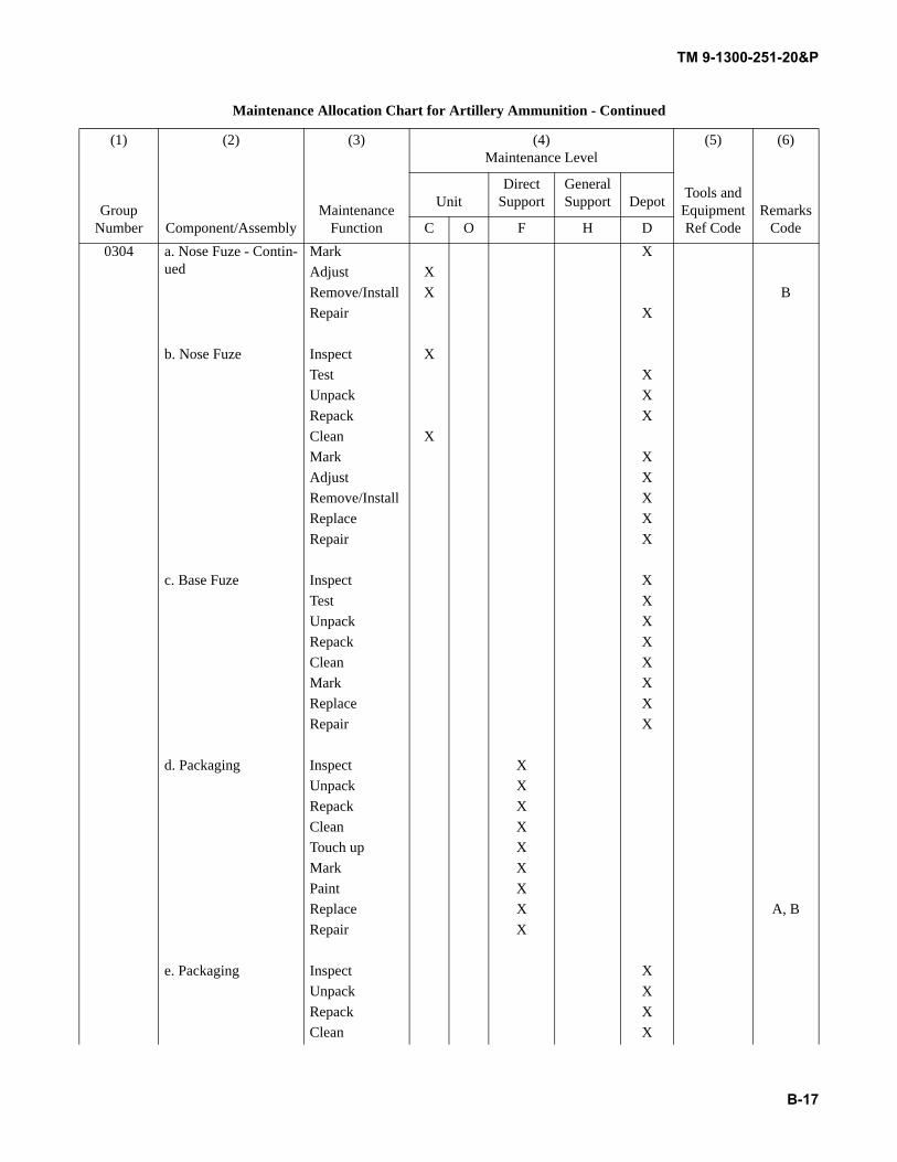
TM 9-1300-251-20&P
B-17
0304 a. Nose Fuze - Contin-ued
Mark XAdjust XRemove/Install X BRepair X
b. Nose Fuze Inspect XTest XUnpack XRepack XClean XMark XAdjust XRemove/Install XReplace XRepair X
c. Base Fuze Inspect XTest XUnpack XRepack XClean XMark XReplace XRepair X
d. Packaging Inspect XUnpack XRepack XClean XTouch up XMark XPaint XReplace X A, BRepair X
e. Packaging Inspect XUnpack XRepack XClean X
Maintenance Allocation Chart for Artillery Ammunition - Continued
(1) (2) (3) (4)Maintenance Level
(5) (6)
Group Number Component/Assembly
Maintenance Function
Tools and Equipment Ref Code
Remarks Code
UnitDirect
SupportGeneral Support Depot
C O F H D

TM 9-1300-251-20&P
B-18
0304 e. Packaging - Contin-ued
Touch up XMark XPaint XReplace XRepair X
f. Nose Fuze, PD, M557
Inspect XTest XUnpack XRepack XClean XTouch up XMark XReplace XRepair X
04 GROUP, SEMI-FIXED AMMUNI-TION (MORTAR ONLY)
0401 a. Cartridge (Com-plete Round)
Inspect XTest XUnpack XRepack XClean XTouch up XMark X
b. Packaging Material Inspect XUnpack XRepack XClean XTouch up XMark XPaint XAdjust XRemove/Install XRepair X
Maintenance Allocation Chart for Artillery Ammunition - Continued
(1) (2) (3) (4)Maintenance Level
(5) (6)
Group Number Component/Assembly
Maintenance Function
Tools and Equipment Ref Code
Remarks Code
UnitDirect
SupportGeneral Support Depot
C O F H D
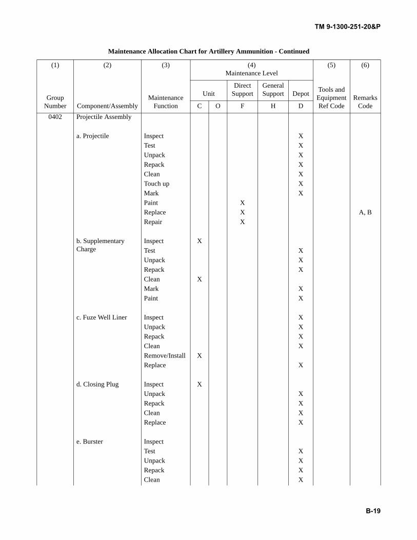
TM 9-1300-251-20&P
B-19
0402 Projectile Assembly
a. Projectile Inspect XTest XUnpack XRepack XClean XTouch up XMark XPaint XReplace X A, BRepair X
b. Supplementary Charge
Inspect XTest XUnpack XRepack XClean XMark XPaint X
c. Fuze Well Liner Inspect XUnpack XRepack XClean XRemove/Install XReplace X
d. Closing Plug Inspect XUnpack XRepack XClean XReplace X
e. Burster InspectTest XUnpack XRepack XClean X
Maintenance Allocation Chart for Artillery Ammunition - Continued
(1) (2) (3) (4)Maintenance Level
(5) (6)
Group Number Component/Assembly
Maintenance Function
Tools and Equipment Ref Code
Remarks Code
UnitDirect
SupportGeneral Support Depot
C O F H D
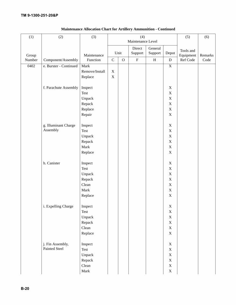
TM 9-1300-251-20&P
B-20
0402 e. Burster - Continued Mark XRemove/Install XReplace X
f. Parachute Assembly Inspect XTest XUnpack XRepack XReplace XRepair X
g. Illuminant Charge Assembly
Inspect XTest XUnpack XRepack XMark XReplace X
h. Canister Inspect XTest XUnpack XRepack XClean XMark XReplace X
i. Expelling Charge Inspect XTest XUnpack XRepack XClean XReplace X
j. Fin Assembly, Painted Steel
Inspect XTest XUnpack XRepack XClean XMark X
Maintenance Allocation Chart for Artillery Ammunition - Continued
(1) (2) (3) (4)Maintenance Level
(5) (6)
Group Number Component/Assembly
Maintenance Function
Tools and Equipment Ref Code
Remarks Code
UnitDirect
SupportGeneral Support Depot
C O F H D
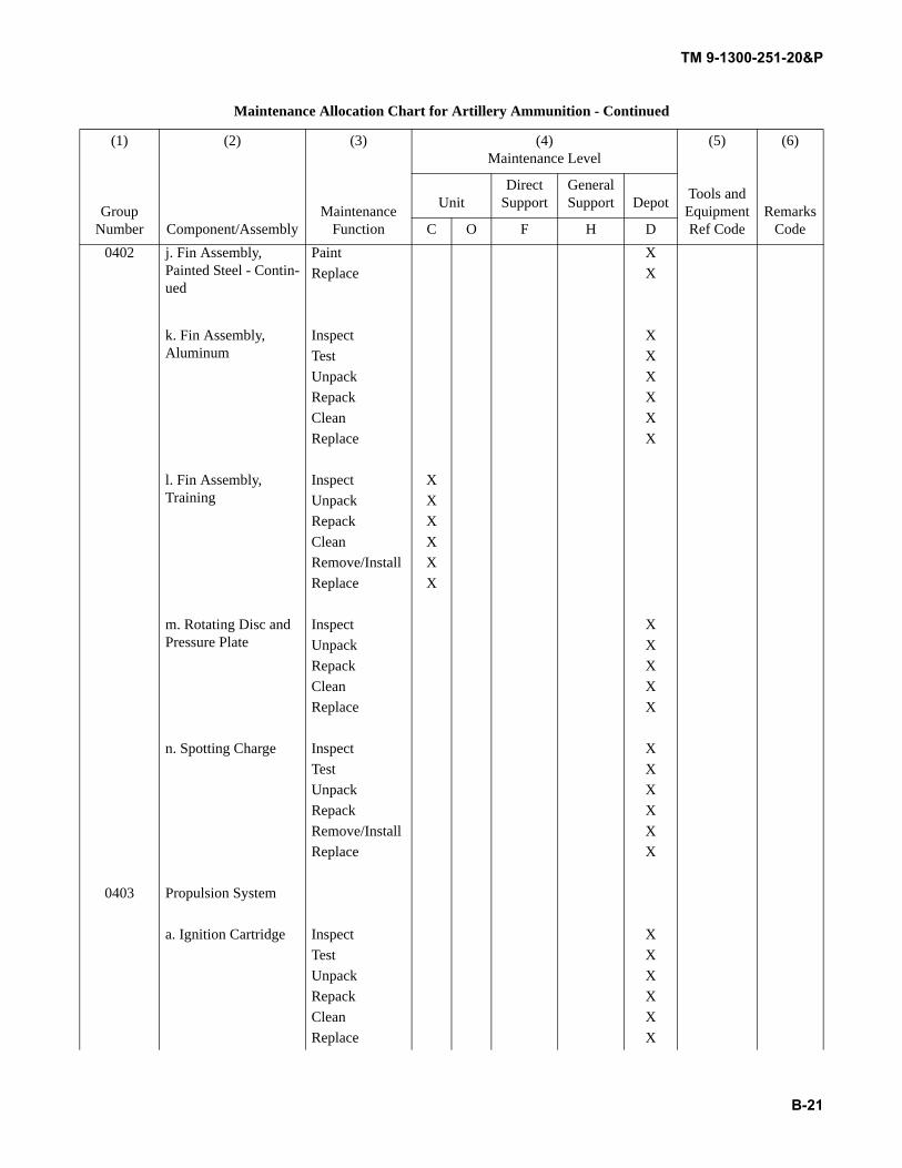
TM 9-1300-251-20&P
B-21
0402 j. Fin Assembly, Painted Steel - Contin-ued
Paint XReplace X
k. Fin Assembly, Aluminum
Inspect XTest XUnpack XRepack XClean XReplace X
l. Fin Assembly, Training
Inspect XUnpack XRepack XClean XRemove/Install XReplace X
m. Rotating Disc and Pressure Plate
Inspect XUnpack XRepack XClean XReplace X
n. Spotting Charge Inspect XTest XUnpack XRepack XRemove/Install XReplace X
0403 Propulsion System
a. Ignition Cartridge Inspect XTest XUnpack XRepack XClean XReplace X
Maintenance Allocation Chart for Artillery Ammunition - Continued
(1) (2) (3) (4)Maintenance Level
(5) (6)
Group Number Component/Assembly
Maintenance Function
Tools and Equipment Ref Code
Remarks Code
UnitDirect
SupportGeneral Support Depot
C O F H D
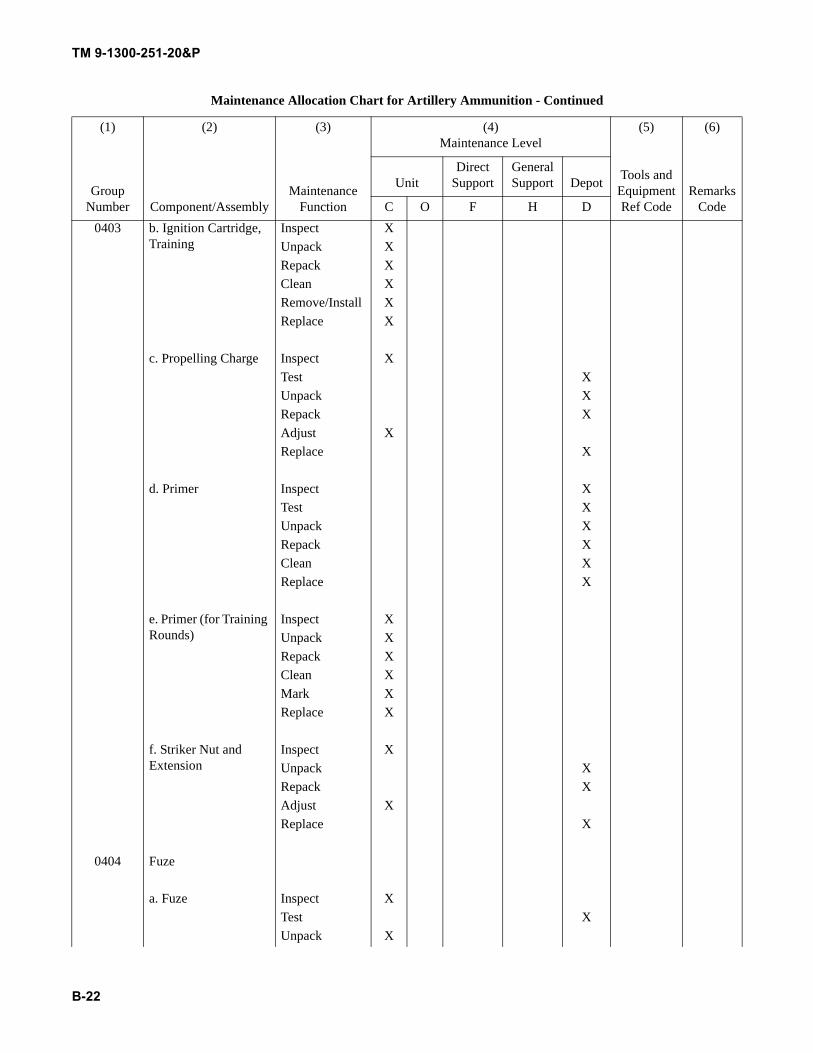
TM 9-1300-251-20&P
B-22
0403 b. Ignition Cartridge, Training
Inspect XUnpack XRepack XClean XRemove/Install XReplace X
c. Propelling Charge Inspect XTest XUnpack XRepack XAdjust XReplace X
d. Primer Inspect XTest XUnpack XRepack XClean XReplace X
e. Primer (for Training Rounds)
Inspect XUnpack XRepack XClean XMark XReplace X
f. Striker Nut and Extension
Inspect XUnpack XRepack XAdjust XReplace X
0404 Fuze
a. Fuze Inspect XTest XUnpack X
Maintenance Allocation Chart for Artillery Ammunition - Continued
(1) (2) (3) (4)Maintenance Level
(5) (6)
Group Number Component/Assembly
Maintenance Function
Tools and Equipment Ref Code
Remarks Code
UnitDirect
SupportGeneral Support Depot
C O F H D
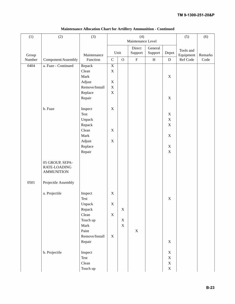
TM 9-1300-251-20&P
B-23
0404 a. Fuze - Continued Repack XClean XMark XAdjust XRemove/Install XReplace XRepair X
b. Fuze Inspect XTest XUnpack XRepack XClean XMark XAdjust XReplace XRepair X
05 GROUP, SEPA-RATE-LOADING AMMUNITION
0501 Projectile Assembly
a. Projectile Inspect XTest XUnpack XRepack XClean XTouch up XMark XPaint XRemove/Install XRepair X
b. Projectile Inspect XTest XClean XTouch up X
Maintenance Allocation Chart for Artillery Ammunition - Continued
(1) (2) (3) (4)Maintenance Level
(5) (6)
Group Number Component/Assembly
Maintenance Function
Tools and Equipment Ref Code
Remarks Code
UnitDirect
SupportGeneral Support Depot
C O F H D
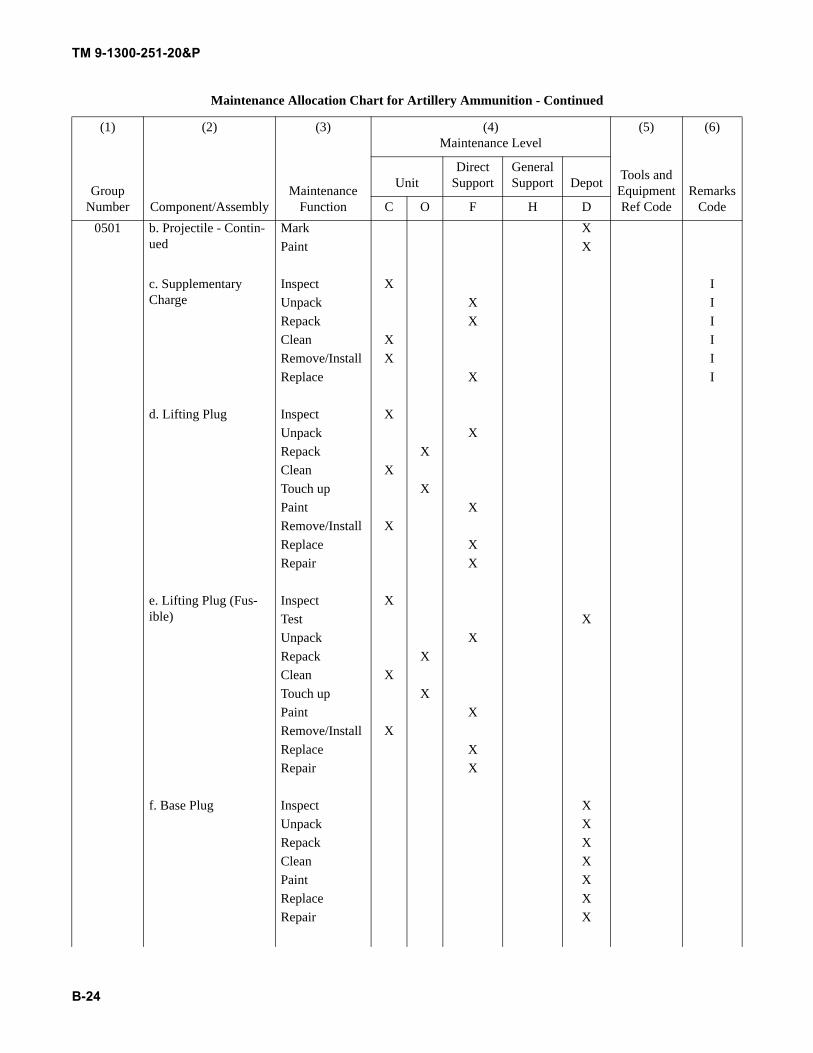
TM 9-1300-251-20&P
B-24
0501 b. Projectile - Contin-ued
Mark XPaint X
c. Supplementary Charge
Inspect X IUnpack X IRepack X IClean X IRemove/Install X IReplace X I
d. Lifting Plug Inspect XUnpack XRepack XClean XTouch up XPaint XRemove/Install XReplace XRepair X
e. Lifting Plug (Fus-ible)
Inspect XTest XUnpack XRepack XClean XTouch up XPaint XRemove/Install XReplace XRepair X
f. Base Plug Inspect XUnpack XRepack XClean XPaint XReplace XRepair X
Maintenance Allocation Chart for Artillery Ammunition - Continued
(1) (2) (3) (4)Maintenance Level
(5) (6)
Group Number Component/Assembly
Maintenance Function
Tools and Equipment Ref Code
Remarks Code
UnitDirect
SupportGeneral Support Depot
C O F H D
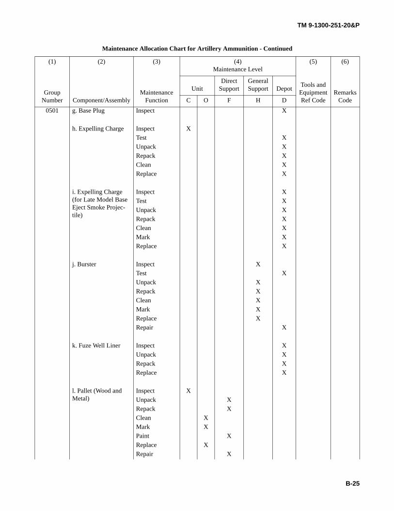
TM 9-1300-251-20&P
B-25
0501 g. Base Plug Inspect X
h. Expelling Charge Inspect XTest XUnpack XRepack XClean XReplace X
i. Expelling Charge (for Late Model Base Eject Smoke Projec-tile)
Inspect XTest XUnpack XRepack XClean XMark XReplace X
j. Burster Inspect XTest XUnpack XRepack XClean XMark XReplace XRepair X
k. Fuze Well Liner Inspect XUnpack XRepack XReplace X
l. Pallet (Wood and Metal)
Inspect XUnpack XRepack XClean XMark XPaint XReplace XRepair X
Maintenance Allocation Chart for Artillery Ammunition - Continued
(1) (2) (3) (4)Maintenance Level
(5) (6)
Group Number Component/Assembly
Maintenance Function
Tools and Equipment Ref Code
Remarks Code
UnitDirect
SupportGeneral Support Depot
C O F H D
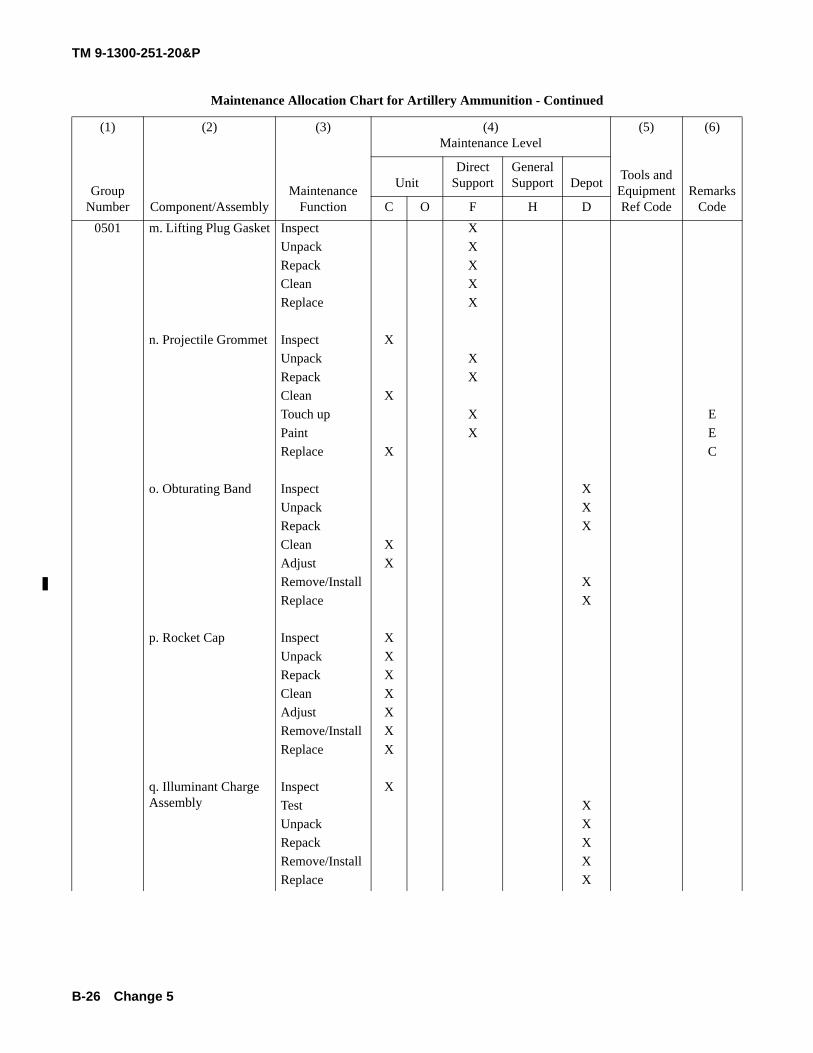
TM 9-1300-251-20&P
B-26
0501 m. Lifting Plug Gasket Inspect XUnpack XRepack XClean XReplace X
n. Projectile Grommet Inspect XUnpack XRepack XClean XTouch up X EPaint X EReplace X C
o. Obturating Band Inspect XUnpack XRepack XClean XAdjust XRemove/Install XReplace X
p. Rocket Cap Inspect XUnpack XRepack XClean XAdjust XRemove/Install XReplace X
q. Illuminant Charge Assembly
Inspect XTest XUnpack XRepack XRemove/Install XReplace X
Maintenance Allocation Chart for Artillery Ammunition - Continued
(1) (2) (3) (4)Maintenance Level
(5) (6)
Group Number Component/Assembly
Maintenance Function
Tools and Equipment Ref Code
Remarks Code
UnitDirect
SupportGeneral Support Depot
C O F H D
Change 5
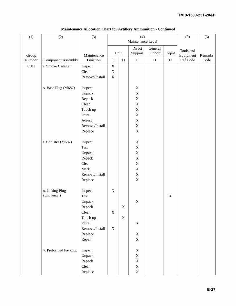
TM 9-1300-251-20&P
B-27
0501 r. Smoke Canister Inspect XClean XRemove/Install X
s. Base Plug (M687) Inspect XUnpack XRepack XClean XTouch up XPaint XAdjust XRemove/Install XReplace X
t. Canister (M687) Inspect XTest XUnpack XRepack XClean XMark XRemove/Install XReplace X
u. Lifting Plug (Universal)
Inspect XTest XUnpack XRepack XClean XTouch up XPaint XRemove/Install XReplace XRepair X
v. Preformed Packing Inspect XUnpack XRepack XClean XReplace X
Maintenance Allocation Chart for Artillery Ammunition - Continued
(1) (2) (3) (4)Maintenance Level
(5) (6)
Group Number Component/Assembly
Maintenance Function
Tools and Equipment Ref Code
Remarks Code
UnitDirect
SupportGeneral Support Depot
C O F H D
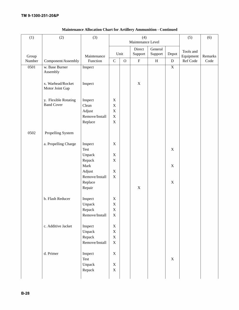
TM 9-1300-251-20&P
B-28
0501 w. Base Burner Assembly
Inspect X
x. Warhead/Rocket Motor Joint Gap
Inspect X
y. Flexible Rotating Band Cover
Inspect XClean XAdjust XRemove/Install XReplace X
0502 Propelling System
a. Propelling Charge Inspect XTest XUnpack XRepack XMark XAdjust XRemove/Install XReplace XRepair X
b. Flash Reducer Inspect XUnpack XRepack XRemove/Install X
c. Additive Jacket Inspect XUnpack XRepack XRemove/Install X
d. Primer Inspect XTest XUnpack XRepack X
Maintenance Allocation Chart for Artillery Ammunition - Continued
(1) (2) (3) (4)Maintenance Level
(5) (6)
Group Number Component/Assembly
Maintenance Function
Tools and Equipment Ref Code
Remarks Code
UnitDirect
SupportGeneral Support Depot
C O F H D
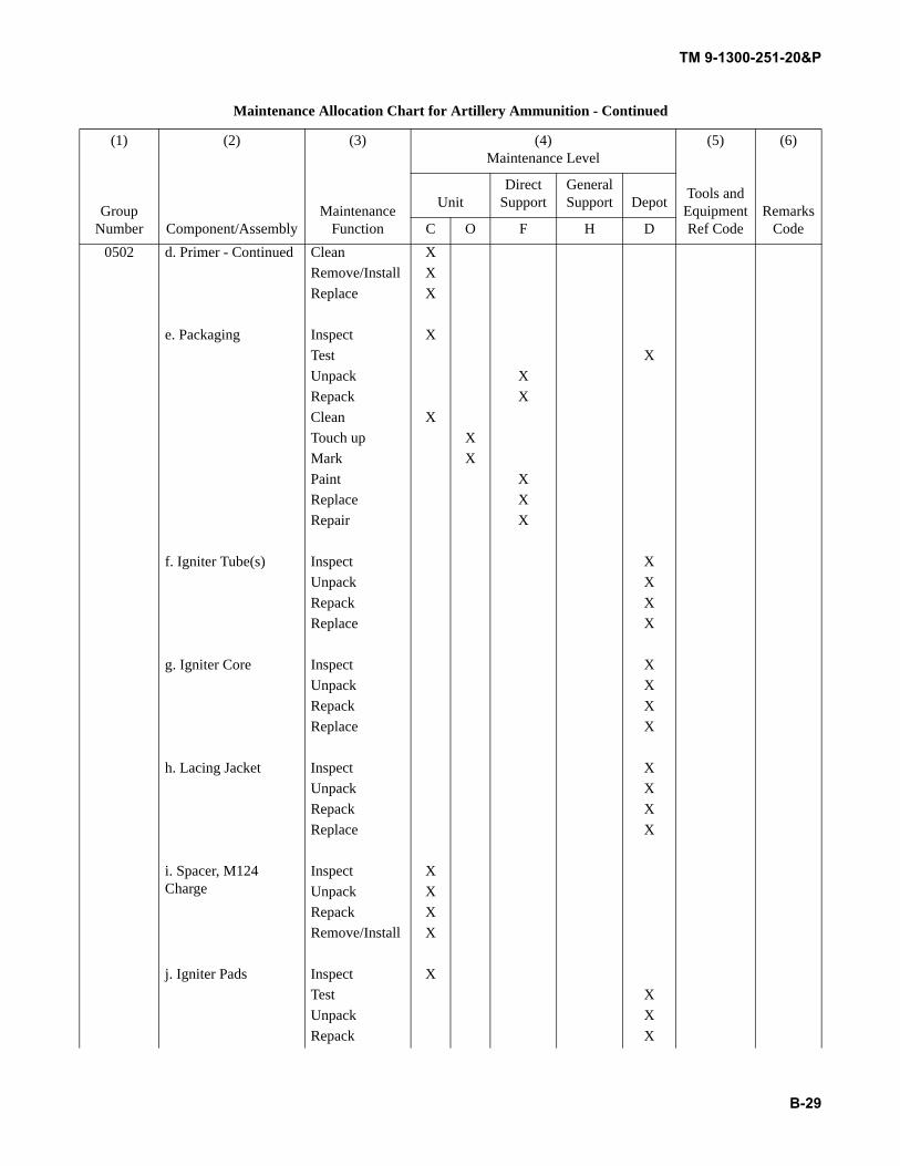
TM 9-1300-251-20&P
B-29
0502 d. Primer - Continued Clean XRemove/Install XReplace X
e. Packaging Inspect XTest XUnpack XRepack XClean XTouch up XMark XPaint XReplace XRepair X
f. Igniter Tube(s) Inspect XUnpack XRepack XReplace X
g. Igniter Core Inspect XUnpack XRepack XReplace X
h. Lacing Jacket Inspect XUnpack XRepack XReplace X
i. Spacer, M124 Charge
Inspect XUnpack XRepack XRemove/Install X
j. Igniter Pads Inspect XTest XUnpack XRepack X
Maintenance Allocation Chart for Artillery Ammunition - Continued
(1) (2) (3) (4)Maintenance Level
(5) (6)
Group Number Component/Assembly
Maintenance Function
Tools and Equipment Ref Code
Remarks Code
UnitDirect
SupportGeneral Support Depot
C O F H D
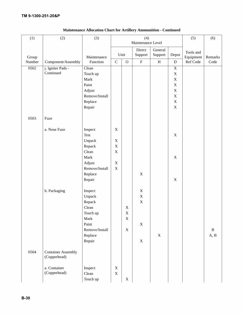
TM 9-1300-251-20&P
B-30
0502 j. Igniter Pads - Continued
Clean XTouch up XMark XPaint XAdjust XRemove/Install XReplace XRepair X
0503 Fuze
a. Nose Fuze Inspect XTest XUnpack XRepack XClean XMark XAdjust XRemove/Install XReplace XRepair X
b. Packaging Inspect XUnpack XRepack XClean XTouch up XMark XPaint XRemove/Install X BReplace X A, BRepair X
0504 Container Assembly (Copperhead)
a. Container (Copperhead)
Inspect XClean XTouch up X
Maintenance Allocation Chart for Artillery Ammunition - Continued
(1) (2) (3) (4)Maintenance Level
(5) (6)
Group Number Component/Assembly
Maintenance Function
Tools and Equipment Ref Code
Remarks Code
UnitDirect
SupportGeneral Support Depot
C O F H D
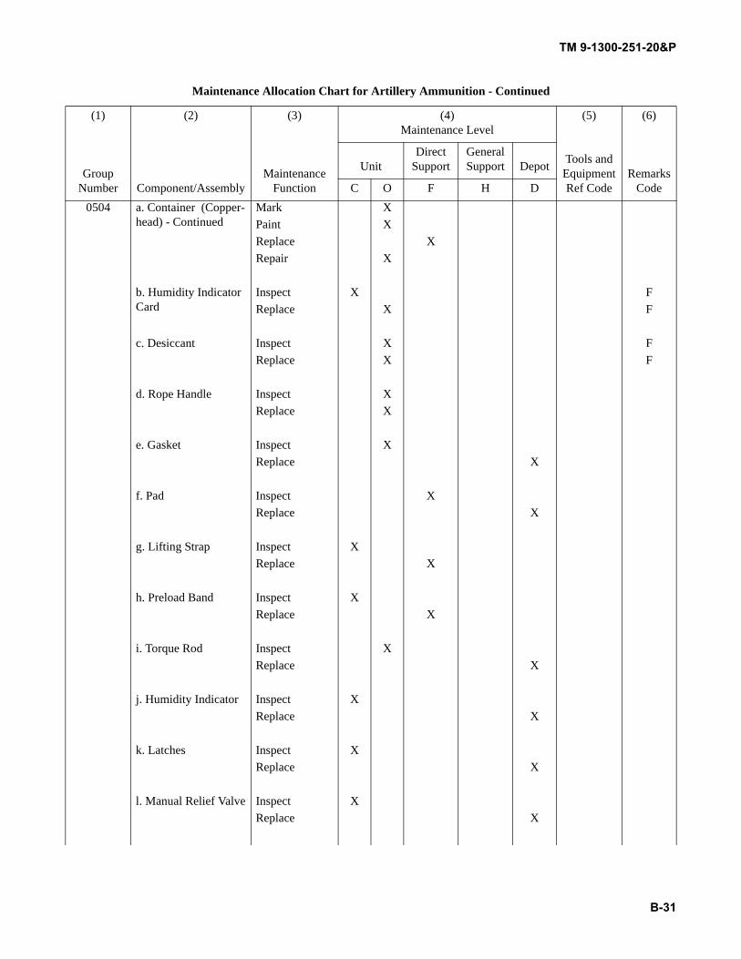
TM 9-1300-251-20&P
B-31
0504 a. Container (Copper-head) - Continued
Mark XPaint XReplace XRepair X
b. Humidity Indicator Card
Inspect X FReplace X F
c. Desiccant Inspect X FReplace X F
d. Rope Handle Inspect XReplace X
e. Gasket Inspect XReplace X
f. Pad Inspect XReplace X
g. Lifting Strap Inspect XReplace X
h. Preload Band Inspect XReplace X
i. Torque Rod Inspect XReplace X
j. Humidity Indicator Inspect XReplace X
k. Latches Inspect XReplace X
l. Manual Relief Valve Inspect XReplace X
Maintenance Allocation Chart for Artillery Ammunition - Continued
(1) (2) (3) (4)Maintenance Level
(5) (6)
Group Number Component/Assembly
Maintenance Function
Tools and Equipment Ref Code
Remarks Code
UnitDirect
SupportGeneral Support Depot
C O F H D
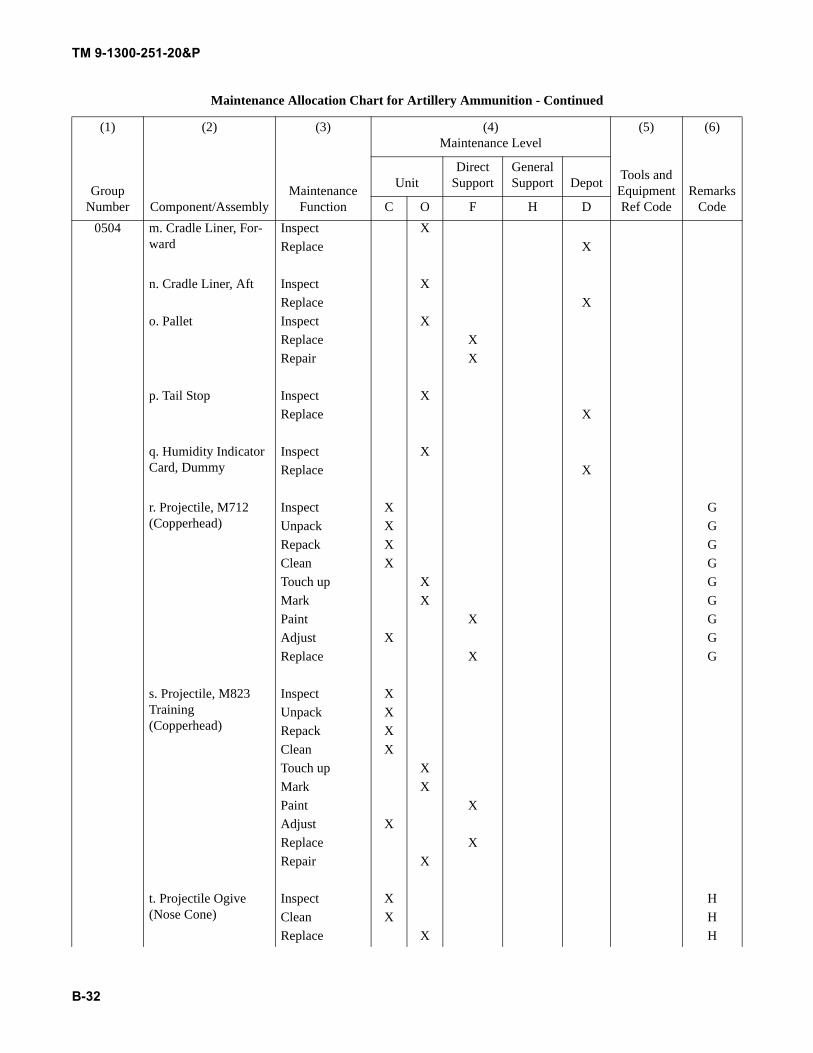
TM 9-1300-251-20&P
B-32
0504 m. Cradle Liner, For-ward
Inspect XReplace X
n. Cradle Liner, Aft Inspect XReplace X
o. Pallet Inspect XReplace XRepair X
p. Tail Stop Inspect XReplace X
q. Humidity Indicator Card, Dummy
Inspect XReplace X
r. Projectile, M712 (Copperhead)
Inspect X GUnpack X GRepack X GClean X GTouch up X GMark X GPaint X GAdjust X GReplace X G
s. Projectile, M823 Training (Copperhead)
Inspect XUnpack XRepack XClean XTouch up XMark XPaint XAdjust XReplace XRepair X
t. Projectile Ogive (Nose Cone)
Inspect X HClean X HReplace X H
Maintenance Allocation Chart for Artillery Ammunition - Continued
(1) (2) (3) (4)Maintenance Level
(5) (6)
Group Number Component/Assembly
Maintenance Function
Tools and Equipment Ref Code
Remarks Code
UnitDirect
SupportGeneral Support Depot
C O F H D
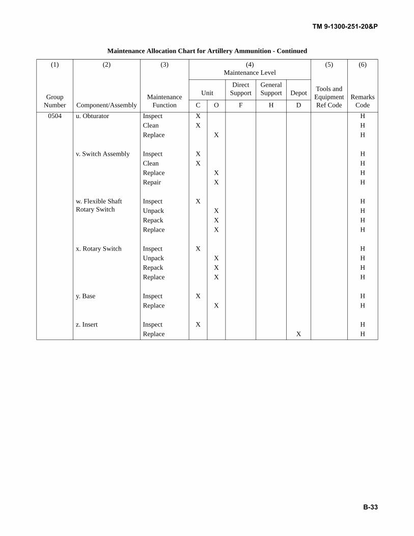
TM 9-1300-251-20&P
B-33
0504 u. Obturator Inspect X HClean X HReplace X H
v. Switch Assembly Inspect X HClean X HReplace X HRepair X H
w. Flexible Shaft Rotary Switch
Inspect X HUnpack X HRepack X HReplace X H
x. Rotary Switch Inspect X HUnpack X HRepack X HReplace X H
y. Base Inspect X HReplace X H
z. Insert Inspect X HReplace X H
Maintenance Allocation Chart for Artillery Ammunition - Continued
(1) (2) (3) (4)Maintenance Level
(5) (6)
Group Number Component/Assembly
Maintenance Function
Tools and Equipment Ref Code
Remarks Code
UnitDirect
SupportGeneral Support Depot
C O F H D
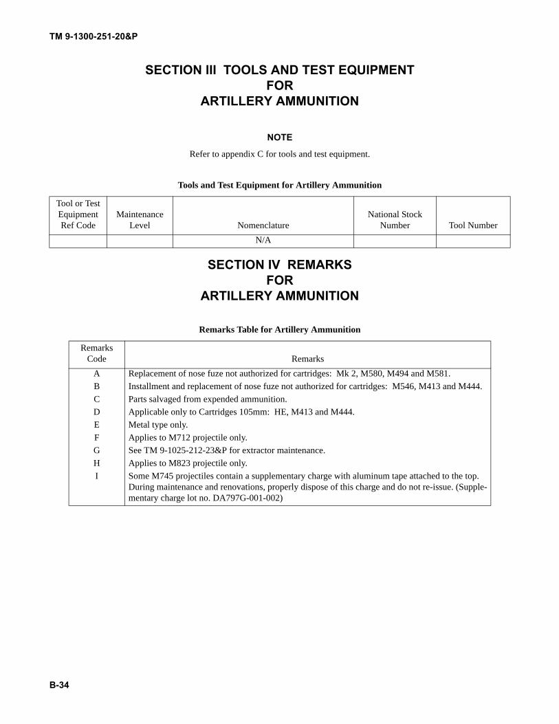
TM 9-1300-251-20&P
B-34
SECTION III TOOLS AND TEST EQUIPMENTFOR
ARTILLERY AMMUNITION
NOTE
Refer to appendix C for tools and test equipment.
SECTION IV REMARKSFOR
ARTILLERY AMMUNITION
Tools and Test Equipment for Artillery Ammunition
Tool or Test Equipment Ref Code
Maintenance Level Nomenclature
National Stock Number Tool Number
N/A
Remarks Table for Artillery Ammunition
Remarks Code Remarks
A Replacement of nose fuze not authorized for cartridges: Mk 2, M580, M494 and M581.B Installment and replacement of nose fuze not authorized for cartridges: M546, M413 and M444.C Parts salvaged from expended ammunition.D Applicable only to Cartridges 105mm: HE, M413 and M444.E Metal type only.F Applies to M712 projectile only.G See TM 9-1025-212-23&P for extractor maintenance.H Applies to M823 projectile only.I Some M745 projectiles contain a supplementary charge with aluminum tape attached to the top.
During maintenance and renovations, properly dispose of this charge and do not re-issue. (Supple-mentary charge lot no. DA797G-001-002)
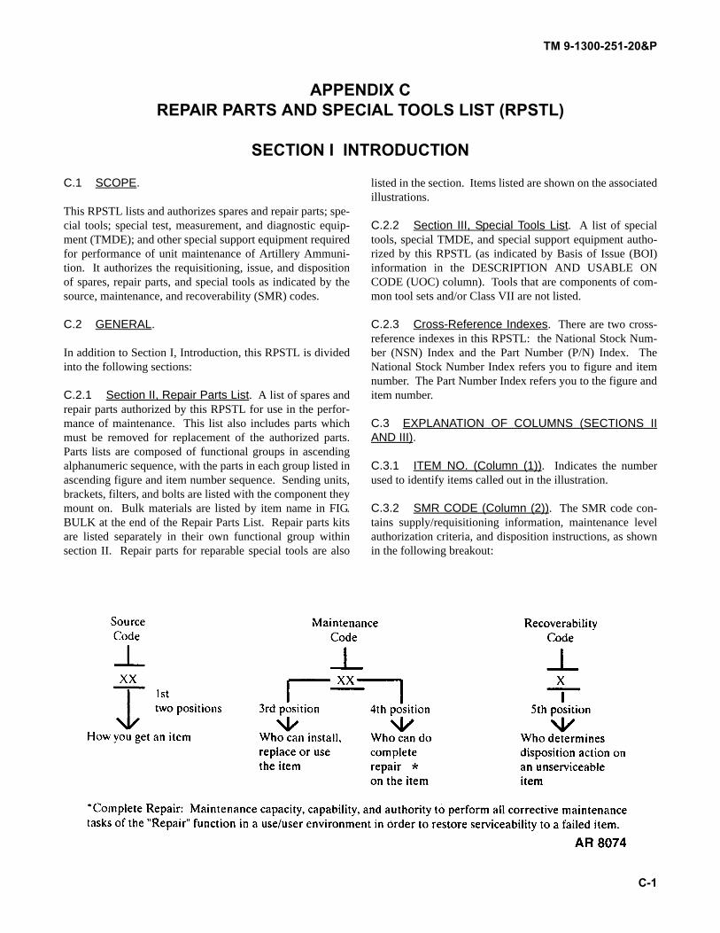
TM 9-1300-251-20&P
C-1
APPENDIX CREPAIR PARTS AND SPECIAL TOOLS LIST (RPSTL)
SECTION I INTRODUCTION
C.1 SCOPE.
This RPSTL lists and authorizes spares and repair parts; spe-cial tools; special test, measurement, and diagnostic equip-ment (TMDE); and other special support equipment requiredfor performance of unit maintenance of Artillery Ammuni-tion. It authorizes the requisitioning, issue, and dispositionof spares, repair parts, and special tools as indicated by thesource, maintenance, and recoverability (SMR) codes.
C.2 GENERAL.
In addition to Section I, Introduction, this RPSTL is dividedinto the following sections:
C.2.1 Section II, Repair Parts List. A list of spares andrepair parts authorized by this RPSTL for use in the perfor-mance of maintenance. This list also includes parts whichmust be removed for replacement of the authorized parts.Parts lists are composed of functional groups in ascendingalphanumeric sequence, with the parts in each group listed inascending figure and item number sequence. Sending units,brackets, filters, and bolts are listed with the component theymount on. Bulk materials are listed by item name in FIG.BULK at the end of the Repair Parts List. Repair parts kitsare listed separately in their own functional group withinsection II. Repair parts for reparable special tools are also
listed in the section. Items listed are shown on the associatedillustrations.
C.2.2 Section III, Special Tools List. A list of specialtools, special TMDE, and special support equipment autho-rized by this RPSTL (as indicated by Basis of Issue (BOI)information in the DESCRIPTION AND USABLE ONCODE (UOC) column). Tools that are components of com-mon tool sets and/or Class VII are not listed.
C.2.3 Cross-Reference Indexes. There are two cross-reference indexes in this RPSTL: the National Stock Num-ber (NSN) Index and the Part Number (P/N) Index. TheNational Stock Number Index refers you to figure and itemnumber. The Part Number Index refers you to the figure anditem number.
C.3 EXPLANATION OF COLUMNS (SECTIONS IIAND III).
C.3.1 ITEM NO. (Column (1)). Indicates the numberused to identify items called out in the illustration.
C.3.2 SMR CODE (Column (2)). The SMR code con-tains supply/requisitioning information, maintenance levelauthorization criteria, and disposition instructions, as shownin the following breakout:
TM 9-1300-251-20&P
C-2
C.3.2.1 Source Code. The source code tells you howyou get an item needed for maintenance, repair, or overhaulof an end item/equipment. Explanations of source codes fol-low:
NOTE
Cannibalization or controlled exchange, whenauthorized, may be used as a source of supplyfor items with the above source codes, exceptfor those source coded “XA” or those aircraftsupport items restricted by requirements of AR750-1.
C.3.2.2 Maintenance Code. Maintenance codes tellyou the level(s) of maintenance authorized to use and repairsupport items. The maintenance codes are entered in thethird and fourth positions of the SMR code as follows:
C.3.2.2.1 Third Position. The maintenance code enteredin the third position tells you the lowest maintenance levelauthorized to remove, replace, and use an item. The mainte-nance code entered in the third position will indicate authori-zation to the following levels of maintenance.
Source Code Application/Explanation
PAPBPCPDPEPFPG
Stock items; use the applicable NSN to requisition/request items with these source codes. They are autho-rized to the level indicated by the code entered in the 3rd position of the SMR code.
NOTE
Items coded PC aresubject to deteriora-tion.
KDKFKB
Items with these codes are not to be requested/requisitioned individu-ally. They are part of a kit which is authorized to the maintenance level indicated in the 3rd position of the SMR code. The complete kit must be requisitioned and applied.
MO-Made at unit/AVUM level
MF-Made at DS/AVIM level
MH-Made at GS level
ML-Made at SRAMD-Made at
depot
Items with these codes are not to be requisitioned/requested individu-ally. They must be made from bulk material which is identified by the P/N in the DESCRIPTION AND USABLE ON CODE (UOC) col-umn and listed in the bulk material group work package of the RPSTL. If the item is authorized to you by the 3rd position code of the SMR code, but the source code indicates it is made at higher level, order the item from the higher level of mainte-nance.
AO-Assembled by unit/AVUM level
AF-Assembled by DS/AVIM level
AH-Assembled by GS level
AL-Assembled by SRA
AD-Assembled by depot
Items with these codes are not to be requested/requisitioned individu-ally. The parts that make up the assembled item must be requisi-tioned or fabricated and assembled at the level of maintenance indicated by the source code. If the 3rd posi-tion of the SMR code authorizes you to replace the item, but the source code indicates the item is assembled at a higher level, order the item from the higher level of maintenance.
XA Do not requisition an “XA” coded item. Order the next higher assem-bly. (Refer to NOTE below.)
XB If an item is not available from sal-vage, order it using the CAGEC and P/N.
XC Installation drawings, diagrams, instruction sheets, field service drawings; identified by manufac-turer’s P/N.
XD Item is not stocked. Order an XD-coded item through normal supply channels using the CAGEC and P/N given, if no NSN is available.
MaintenanceCode Application/Explanation
C - Crew or operator maintenance done within unit/AVUM maintenance.
O - Unit level/AVUM maintenance can remove, replace, and use the item.
F - Direct support/AVIM maintenance can remove, replace, and use the item.
H - General support maintenance can remove, replace, and use the item.
L - Specialized repair activity can remove, replace, and use the item.
D - Depot can remove, replace, and use the item.
Source Code Application/Explanation
TM 9-1300-251-20&P
C-3
C.3.2.2.2 Fourth Position. The maintenance codeentered in the fourth position tells you whether or not theitem is to be repaired and identifies the lowest maintenancelevel with the capability to do complete repair (perform allauthorized repair functions).
NOTE
Some limited repair may be done on the item ata lower level of maintenance, if authorized bythe Maintenance Allocation Chart (MAC) andSMR codes.
C.3.2.3 Recoverability Code. Recoverability codes areassigned to items to indicate the disposition action on unser-viceable items. The recoverability code is shown in the fifthposition of the SMR code as follows:
C.3.3 NSN (Column (3)). The NSN for the item is listedin this column.
C.3.4 CAGEC (Column (4)). The Commercial andGovernment Entity Code (CAGEC) is a five-digit codewhich is used to identify the manufacturer, distributor, orGovernment agency/activity that supplies the item.
C.3.5 PART NUMBER (Column (5)). Indicates the pri-mary number used by the manufacturer (individual, com-pany, firm, corporation, or Government activity), whichcontrols the design and characteristics of the item by meansof its engineering drawings, specifications, standards, andinspection requirements to identify an item or range of items.
NOTE
When you use an NSN to requisition an item,the item you receive may have a different P/Nfrom the number listed.
C.3.6 DESCRIPTION AND USABLE ON CODE(UOC) (Column (6)). This column includes the followinginformation:
C.3.6.1 The federal item name, and when required a min-imum description to identify the item.
C.3.6.2 P/Ns of bulk materials are referenced in this col-umn in the line entry to be manufactured or fabricated.
MaintenanceCode Application/Explanation
O - Unit/AVUM is the lowest level that can do complete repair of the item.
F - Direct support/AVIM is the lowest level that can do complete repair of the item.
H - General support is the lowest level that can do complete repair of the item.
L - Specialized repair activity is the lowest level that can do complete repair of the item.
D - Depot is the lowest level that can do complete repair of the item.
Z - Nonreparable. No repair is authorized.B - No repair is authorized. No parts or spe-
cial tools are authorized for maintenance of “B” coded item. However, the item may be reconditioned by adjusting, lubri-cating, etc., at the user level.
RecoverabilityCode Application/Explanation
Z - Nonreparable item. When unserviceable, condemn and dispose of the item at the level of maintenance shown in the third position of the SMR code.
O - Reparable item. When uneconomically reparable, condemn and dispose of the item at the unit level.
F - Reparable item. When uneconomically reparable, condemn and dispose of the item at the direct support level.
H - Reparable item. When uneconomically repairable, condemn and dispose of the item at the general support level.
D - Reparable item. When beyond lower level repair capability, return to depot. Condemnation and disposal of item are not authorized below depot level.
L - Reparable item. Condemnation and dis-posal not authorized below Specialized Repair Activity (SRA).
A - Item requires special handling or con-demnation procedures because of spe-cific reasons (such as precious metal content, high dollar value, critical mate-rial, or hazardous material). Refer to appropriate manuals/directives for spe-cific instructions.
RecoverabilityCode Application/Explanation
TM 9-1300-251-20&P
C-4
C.3.6.3 Hardness Critical Item (HCI). A support itemthat provides the equipment with special protection fromelectromagnetic pulse (EMP) damage during a nuclearattack.
C.3.6.4 The statement END OF FIGURE appears justbelow the last item description in column (6) for a given fig-ure in both section II and section III.
C.3.7 QTY (Column (7)). The QTY (quantity per figure)column indicates the quantity of the item used in the break-out shown on the illustration/figure, which is prepared for afunctional group, subfunctional group, or an assembly. A“V” appearing in this column instead of a quantity indicatesthat the quantity is variable and quantity may change fromapplication to application.
C.4 EXPLANATION OF CROSS-REFERENCEINDEXES (SECTION IV).
C.4.1 National Stock Number (NSN) Index.
C.4.1.1 STOCK NUMBER Column. This column liststhe NSN in the National Item Identification Number (NIIN)sequence. The NIIN consists of the last nine digits of theNSN.
C.4.1.2 FIG. Column. This column lists the number ofthe figure where the item is identified/located. The figuresare in numerical order in sections II and III.
C.4.1.3 ITEM Column. The item number identifies theitem associated with the figure listed in the adjacent FIG.column. This item is also identified by the NSN listed on thesame line.
C.4.2 Part Number (P/N) Index. P/Ns in this index arelisted in ascending alphanumeric sequence (vertical arrange-ment of letter and number combinations which places thefirst letter or digit of each group in order “A” through “Z,”followed by the numbers “0” through “9” and each followingletter or digit in like order).
C.4.2.1 PART NUMBER Column. Indicates the P/Nassigned to the item.
C.4.2.2 FIG. Column. This column lists the number ofthe figure where the item is identified/located in sections IIand III.
C.4.2.3 ITEM Column. The item number is the numberassigned to the item as it appears in the figure referenced inthe adjacent figure number column.
C.5 SPECIAL INFORMATION.
C.5.1 UOC. The UOC appears in the lower left corner ofthe Description Column heading. Usable on codes areshown as “UOC: ...” in the Description Column (justifiedleft) on the first line under the applicable item/nomenclature.Uncoded items are applicable to all models. Identification ofthe UOCs used in the RPSTL are:
C.5.2 Index Numbers. Items which have the wordBULK in the figure column will have an index numbershown in the item number column. This index number is across-reference between the NSN / P/N index and the bulkmaterial list in section II.
C.5.3 Illustrations List. The illustrations in this RPSTLcontain unit authorized items. Illustrations published in TM9-1300-251-34&P that contain unit authorized items alsoappear in this RPSTL. The tabular list in section II containsonly those parts coded “O” in the third position of the SMRcode, therefore, there may be a break in the item numbersequence.
C.6 HOW TO LOCATE REPAIR PARTS.
C.6.1 When NSNs or P/Ns are Not Known.
C.6.1.1 First. Using the table of contents, determine theassembly group to which the item belongs. This is necessarysince figures are prepared for assembly groups and subas-sembly groups, and lists are divided into the same groups.
C.6.1.2 Second. Find the figure covering the functionalgroup or subfunctional group to which the item belongs.
C.6.1.3 Third. Identify the item on the figure and notethe number(s).
C.6.1.4 Fourth. Look in the repair parts list for the figure
NSN (e.g., 5385-01-574-1476)
NIIN
When using this column to locate an item, ignore the first four digits of the NSN. How-ever, the complete NSN should be used when ordering items by stock number.
Code Used On
CHA Projectile, 155mm: M823
BK9 Projectile, 155mm: M549
TM 9-1300-251-20&P
C-5
and item numbers. The NSNs and part numbers are on thesame line as the associated item numbers.
C.6.2 When NSN is Known.
C.6.2.1 First. If you have the NSN, look in the STOCKNUMBER column of the NSN index list. The NSN isarranged in NIIN sequence. Note the figure and item num-ber next to the NSN.
C.6.2.2 Second. Turn to the figure and locate the itemnumber. Verify that the item is the one you are looking for.
C.6.3 When P/N is Known.
C.6.3.1 First. If you have the P/N and not the NSN, lookin the PART NUMBER column of the P/N index. Identifythe figure and item number.
C.6.3.2 Second. Look up the item on the figure in theapplicable repair parts list.
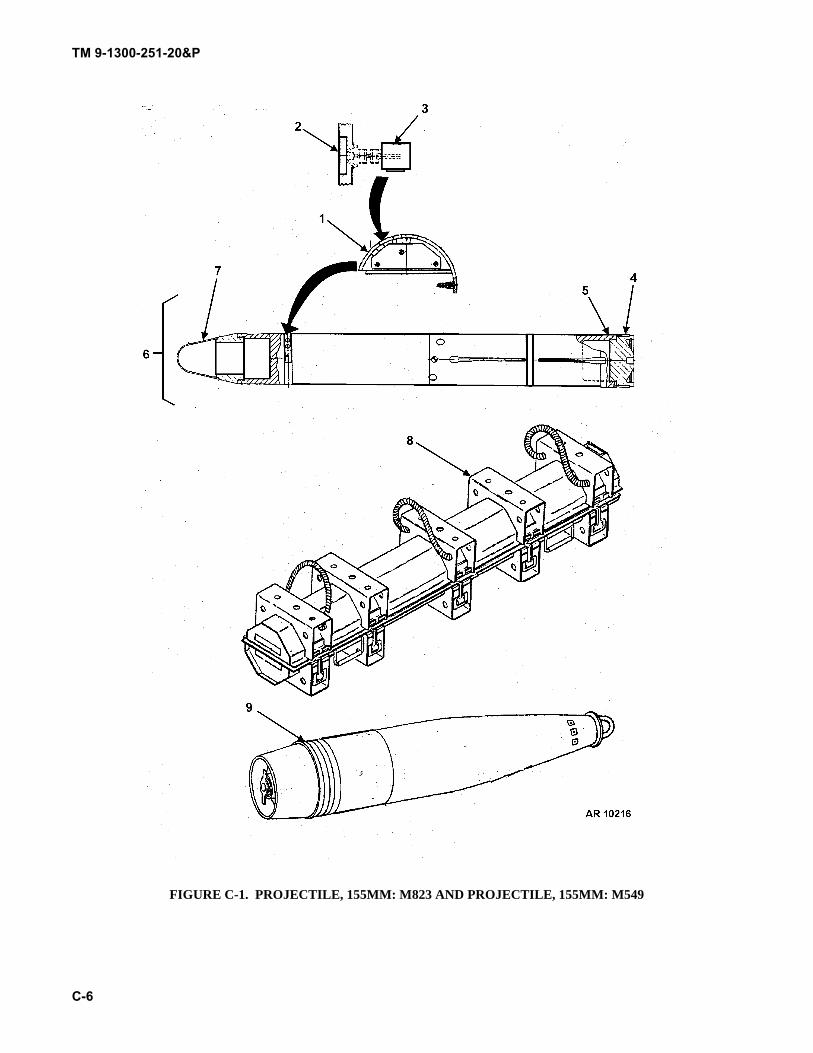
TM 9-1300-251-20&P
C-6
FIGURE C-1. PROJECTILE, 155MM: M823 AND PROJECTILE, 155MM: M549
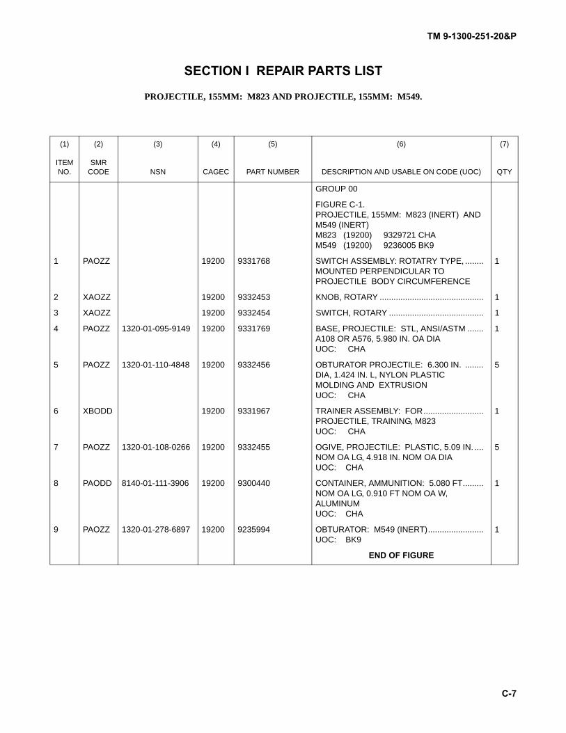
TM 9-1300-251-20&P
C-7
SECTION I REPAIR PARTS LIST
PROJECTILE, 155MM: M823 AND PROJECTILE, 155MM: M549.
(1) (2) (3) (4) (5) (6) (7)
ITEM NO.
SMR CODE NSN CAGEC PART NUMBER DESCRIPTION AND USABLE ON CODE (UOC) QTY
GROUP 00
FIGURE C-1. PROJECTILE, 155MM: M823 (INERT) AND M549 (INERT)M823 (19200) 9329721 CHAM549 (19200) 9236005 BK9
1 PAOZZ 19200 9331768 SWITCH ASSEMBLY: ROTATRY TYPE, ........ MOUNTED PERPENDICULAR TO PROJECTILE BODY CIRCUMFERENCE
1
2 XAOZZ 19200 9332453 KNOB, ROTARY ............................................. 1
3 XAOZZ 19200 9332454 SWITCH, ROTARY ......................................... 1
4 PAOZZ 1320-01-095-9149 19200 9331769 BASE, PROJECTILE: STL, ANSI/ASTM .......A108 OR A576, 5.980 IN. OA DIAUOC: CHA
1
5 PAOZZ 1320-01-110-4848 19200 9332456 OBTURATOR PROJECTILE: 6.300 IN. ........DIA, 1.424 IN. L, NYLON PLASTIC MOLDING AND EXTRUSIONUOC: CHA
5
6 XBODD 19200 9331967 TRAINER ASSEMBLY: FOR..........................PROJECTILE, TRAINING, M823UOC: CHA
1
7 PAOZZ 1320-01-108-0266 19200 9332455 OGIVE, PROJECTILE: PLASTIC, 5.09 IN. ....NOM OA LG, 4.918 IN. NOM OA DIAUOC: CHA
5
8 PAODD 8140-01-111-3906 19200 9300440 CONTAINER, AMMUNITION: 5.080 FT.........NOM OA LG, 0.910 FT NOM OA W, ALUMINUMUOC: CHA
1
9 PAOZZ 1320-01-278-6897 19200 9235994 OBTURATOR: M549 (INERT)........................UOC: BK9
1
END OF FIGURE
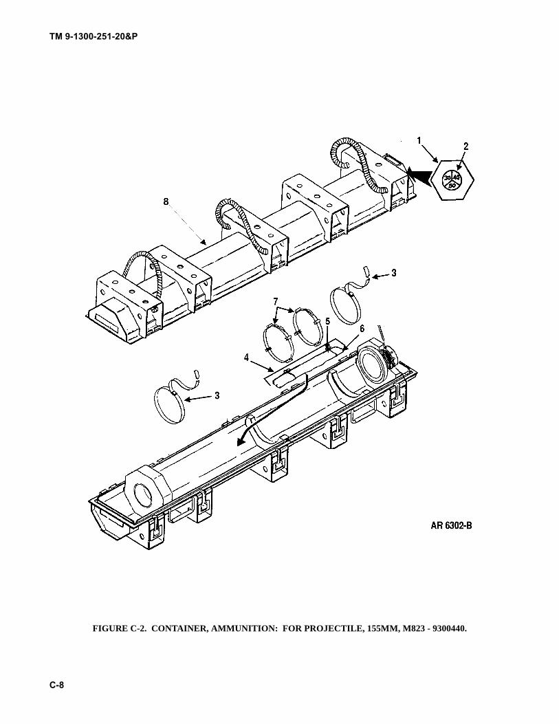
TM 9-1300-251-20&P
C-8
FIGURE C-2. CONTAINER, AMMUNITION: FOR PROJECTILE, 155MM, M823 - 9300440.
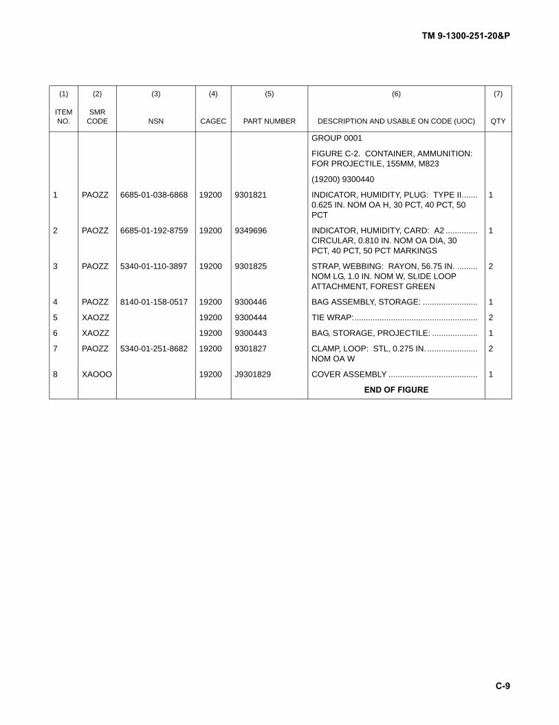
TM 9-1300-251-20&P
C-9
(1) (2) (3) (4) (5) (6) (7)
ITEM NO.
SMR CODE NSN CAGEC PART NUMBER DESCRIPTION AND USABLE ON CODE (UOC) QTY
GROUP 0001
FIGURE C-2. CONTAINER, AMMUNITION: FOR PROJECTILE, 155MM, M823
(19200) 9300440
1 PAOZZ 6685-01-038-6868 19200 9301821 INDICATOR, HUMIDITY, PLUG: TYPE II.......0.625 IN. NOM OA H, 30 PCT, 40 PCT, 50 PCT
1
2 PAOZZ 6685-01-192-8759 19200 9349696 INDICATOR, HUMIDITY, CARD: A2 ..............CIRCULAR, 0.810 IN. NOM OA DIA, 30 PCT, 40 PCT, 50 PCT MARKINGS
1
3 PAOZZ 5340-01-110-3897 19200 9301825 STRAP, WEBBING: RAYON, 56.75 IN. .........NOM LG, 1.0 IN. NOM W, SLIDE LOOP ATTACHMENT, FOREST GREEN
2
4 PAOZZ 8140-01-158-0517 19200 9300446 BAG ASSEMBLY, STORAGE: ........................ 1
5 XAOZZ 19200 9300444 TIE WRAP:...................................................... 2
6 XAOZZ 19200 9300443 BAG, STORAGE, PROJECTILE: .................... 1
7 PAOZZ 5340-01-251-8682 19200 9301827 CLAMP, LOOP: STL, 0.275 IN. ...................... NOM OA W
2
8 XAOOO 19200 J9301829 COVER ASSEMBLY ....................................... 1
END OF FIGURE

TM 9-1300-251-20&P
C-10
SECTION I SPECIAL TOOLS LIST
Not applicable.
TM 9-1300-251-20&P
C-11
SECTION I CROSS-REFERENCE INDEXES
NATIONAL STOCK NUMBER INDEX
STOCK NUMBER FIG. ITEM6685-01-038-6868 C-2 11320-01-095-9149 C-1 41320-01-108-0266 C-1 75340-01-110-3897 C-2 31320-01-110-4848 C-1 5
8140-01-111-3906 C-1 86685-01-192-8759 C-2 25340-01-251-8682 C-2 71320-01-278-6897 C-1 9
STOCK NUMBER FIG. ITEM
TM 9-1300-251-20&P
C-12
PART NUMBER INDEX
PART NUMBER FIG. ITEM9235994 C-1 99300440 C-1 89300443 C-2 69300444 C-2 59300446 C-2 49301821 C-2 19301825 C-2 39301827 C-2 79301829 C-2 8
9331768 C-1 19331769 C-1 49331967 C-1 69332453 C-1 29332454 C-1 39332455 C-1 79332456 C-1 59349696 C-2 2
PART NUMBER FIG. ITEM
TM 9-1300-251-20&P
D-1
APPENDIX DEXPENDABLE AND DURABLE ITEMS LIST
SECTION I INTRODUCTION
D.1 SCOPE.
This appendix lists expendable and durable items you willneed to operate and maintain the Artillery Ammunition forGuns, Howitzers, Mortars, Recoilless Rifles, and 40mm Gre-nade Launchers. This listing is for information purposesonly and is not authority to requisition the listed items.These items are authorized to you by CTA 50-970, Expend-able/Durable Items (Except: Medical, Class V, Repair Partsand Heraldic Items).
D.2 EXPLANATION OF COLUMNS.
D.2.1 Column (1) - Item Number. This number isassigned to the entry in the listing for reference whenrequired.
D.2.2 Column (2) - Level. This column identifies thelowest level of maintenance that requires the listed item.
C - Operator/CrewO - Unit MaintenanceF - Direct Support MaintenanceH - General Support Maintenance
D.2.3 Column (3) - National Stock Number. This is thenational stock number assigned to the item; use it to requestor requisition the item.
D.2.4 Column (4) - Description. Indicates the federalitem name and, if required, a description to identify the item.The last line for each item indicates the Commercial andGovernment Entity Code (CAGEC) in parentheses followedby the part number.
D.2.5 Column (5) - Unit of Measure (U/M)/Unit ofIssue (U/I). This measure is expressed by a two-characteralphabetical abbreviation (e.g., EA, IN, PR). If the unit ofmeasure differs from the unit of issue as shown in the ArmyMaster Data File (AMDF), requisition the lowest unit ofissue that will satisfy your requirements.
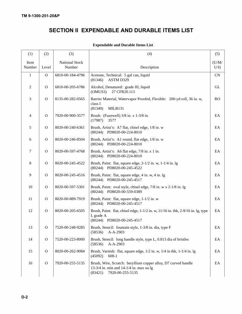
TM 9-1300-251-20&P
D-2
SECTION II EXPENDABLE AND DURABLE ITEMS LIST
Expendable and Durable Items List
(1) (2) (3) (4) (5)
Item Number Level
National Stock Number Description
(U/M/U/I)
1 O 6810-00-184-4796 Acetone, Technical: 5 gal can, liquid(81346) ASTM D329
CN
2 O 6810-00-205-6786 Alcohol, Denatured: grade III, liquid(OMUS3) 27 CFR20.113
GL
3 O 8135-00-282-0565 Barrier Material, Watervapor Proofed, Flexible: 200-yd roll, 36 in. w, class I(81349) MILB131
RO
4 O 7920-00-900-3577 Brush: (Fuzewell) 3/8 in. x 1-3/8 in.(17987) 3577
EA
5 O 8020-00-240-6361 Brush, Artist’s: A7 flat, chisel edge, 1/8 in. w(80244) PD8020-00-224-8010
EA
6 O 8020-00-246-8504 Brush, Artist’s: A1 round, flat edge, 1/8 in. w(80244) PD8020-00-224-8010
EA
7 O 8020-00-597-4768 Brush, Artist’s: A6 flat edge, 7/8 in. x 1 in.(80244) PD8020-00-224-8010
EA
8 O 8020-00-245-4522 Brush, Paint: flat, square edge, 2-1/2 in. w, 1-1/4 in. lg(80244) PD8020-00-245-4522
EA
9 O 8020-00-245-4516 Brush, Paint: flat, square edge, 4 in. w, 4 in. lg(80244) PD8020-00-245-4517
EA
10 O 8020-00-597-5301 Brush, Paint: oval style, chisel edge, 7/8 in. w x 2-1/8 in. lg(80244) PD8020-00-559-0389
EA
11 O 8020-00-889-7919 Brush, Paint: flat, square edge, 1-1/2 in. w(80244) PD8020-00-245-4517
EA
12 O 8020-00-205-6505 Brush, Paint: flat, chisel edge, 1-1/2 in. w, 11/16 in. thk, 2-9/16 in. lg, type I, grade A(80244) PD8020-00-245-4517
EA
13 O 7520-00-248-9285 Brush, Stencil: fountain style, 1-3/8 in. dia, type F(58536) A-A-2903
EA
14 O 7520-00-223-8000 Brush, Stencil: long handle style, type L, 0.813 dia of bristles(58536) A-A-2903
EA
15 O 8020-00-262-9084 Brush, Varnish: flat, square edge, 1/2 in. w, 1/4 in thk, 1-1/4 in. lg(45092) 608-1
EA
16 O 7920-00-255-5135 Brush, Wire, Scratch: beryllium copper alloy, D7 curved handle13-3/4 in. min and 14-1/4 in. max oa lg(83421) 7920-00-255-5135
EA
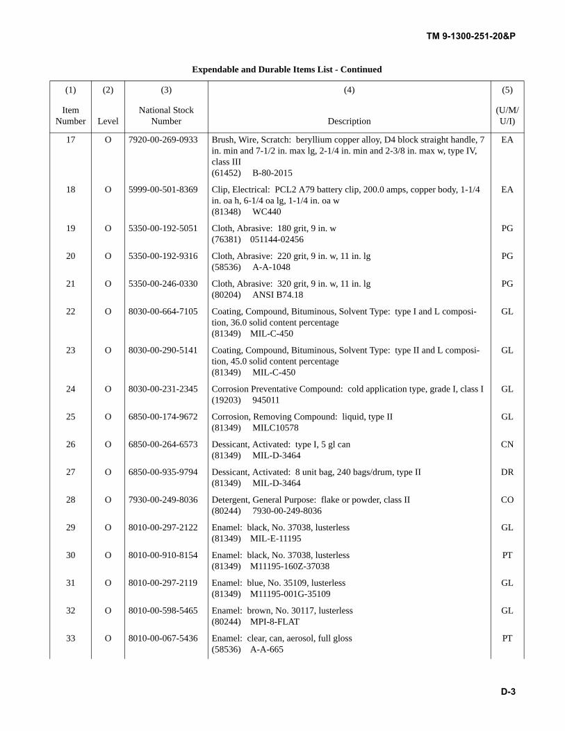
TM 9-1300-251-20&P
D-3
17 O 7920-00-269-0933 Brush, Wire, Scratch: beryllium copper alloy, D4 block straight handle, 7 in. min and 7-1/2 in. max lg, 2-1/4 in. min and 2-3/8 in. max w, type IV, class III(61452) B-80-2015
EA
18 O 5999-00-501-8369 Clip, Electrical: PCL2 A79 battery clip, 200.0 amps, copper body, 1-1/4 in. oa h, 6-1/4 oa lg, 1-1/4 in. oa w(81348) WC440
EA
19 O 5350-00-192-5051 Cloth, Abrasive: 180 grit, 9 in. w(76381) 051144-02456
PG
20 O 5350-00-192-9316 Cloth, Abrasive: 220 grit, 9 in. w, 11 in. lg(58536) A-A-1048
PG
21 O 5350-00-246-0330 Cloth, Abrasive: 320 grit, 9 in. w, 11 in. lg(80204) ANSI B74.18
PG
22 O 8030-00-664-7105 Coating, Compound, Bituminous, Solvent Type: type I and L composi-tion, 36.0 solid content percentage(81349) MIL-C-450
GL
23 O 8030-00-290-5141 Coating, Compound, Bituminous, Solvent Type: type II and L composi-tion, 45.0 solid content percentage(81349) MIL-C-450
GL
24 O 8030-00-231-2345 Corrosion Preventative Compound: cold application type, grade I, class I(19203) 945011
GL
25 O 6850-00-174-9672 Corrosion, Removing Compound: liquid, type II(81349) MILC10578
GL
26 O 6850-00-264-6573 Dessicant, Activated: type I, 5 gl can(81349) MIL-D-3464
CN
27 O 6850-00-935-9794 Dessicant, Activated: 8 unit bag, 240 bags/drum, type II(81349) MIL-D-3464
DR
28 O 7930-00-249-8036 Detergent, General Purpose: flake or powder, class II(80244) 7930-00-249-8036
CO
29 O 8010-00-297-2122 Enamel: black, No. 37038, lusterless(81349) MIL-E-11195
GL
30 O 8010-00-910-8154 Enamel: black, No. 37038, lusterless(81349) M11195-160Z-37038
PT
31 O 8010-00-297-2119 Enamel: blue, No. 35109, lusterless(81349) M11195-001G-35109
GL
32 O 8010-00-598-5465 Enamel: brown, No. 30117, lusterless(80244) MPI-8-FLAT
GL
33 O 8010-00-067-5436 Enamel: clear, can, aerosol, full gloss(58536) A-A-665
PT
Expendable and Durable Items List - Continued
(1) (2) (3) (4) (5)
Item Number Level
National Stock Number Description
(U/M/U/I)
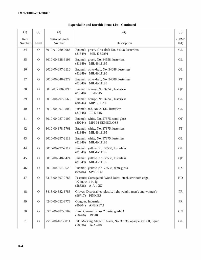
TM 9-1300-251-20&P
D-4
34 O 8010-01-260-9066 Enamel: green, olive drab No. 34008, lusterless(81349) MIL-E-52891
GL
35 O 8010-00-828-3193 Enamel: green, No. 34558, lusterless(81349) MIL-E-11195
GL
36 O 8010-00-297-2116 Enamel: olive drab, No. 34088, lusterless(81349) MIL-E-11195
GL
37 O 8010-00-848-9272 Enamel: olive drab, No. 34088, lusterless(81349) MIL-E-11195
PT
38 O 8010-01-088-0096 Enamel: orange, No. 32246, lusterless(81348) TT-E-515
QT
39 O 8010-00-297-0563 Enamel: orange, No. 32246, lusterless(80244) MIP 8-FLAT
GL
40 O 8010-00-297-0809 Enamel: red, No. 31136, lusterless(81348) TT-E-515
GL
41 O 8010-00-087-0107 Enamel: white, No. 27875, semi-gloss(80244) MPI 94-SEMIGLOSS
QT
42 O 8010-00-878-5761 Enamel: white, No. 37875, lusterless(81349) MIL-E-11195
PT
43 O 8010-00-297-2111 Enamel: white, No. 37875, lusterless(81349) MIL-E-11195
GL
44 O 8010-00-297-2112 Enamel: yellow, No. 33538, lusterless(81349) MIL-E-11195
GL
45 O 8010-00-848-6424 Enamel: yellow, No. 33538, lusterless(81349) MIL-E-11195
QT
46 O 8010-00-851-5525 Enamel: yellow, No. 23538, semi-gloss(09786) SW101-43
BX
47 O 5315-00-597-9766 Fastener, Corrugated, Wood Joint: steel, sawtooth edge, 1/2 in. w, 1 in. lg(58536) A-A-1957
HD
48 O 8415-00-682-6786 Gloves, Disposable: plastic, light weight, men’s and women’s(96717) PINKIES
PR
49 O 4240-00-052-3776 Goggles, Industrial:(80204) ANSIZ87.1
PR
50 O 8520-00-782-3509 Hand Cleaner: class 2 paste, grade A(10266) DD10
CN
51 O 7510-00-161-0811 Ink, Marking, Stencil: black, No. 37038, opaque, type II, liquid(58536) A-A-208
GL
Expendable and Durable Items List - Continued
(1) (2) (3) (4) (5)
Item Number Level
National Stock Number Description
(U/M/U/I)
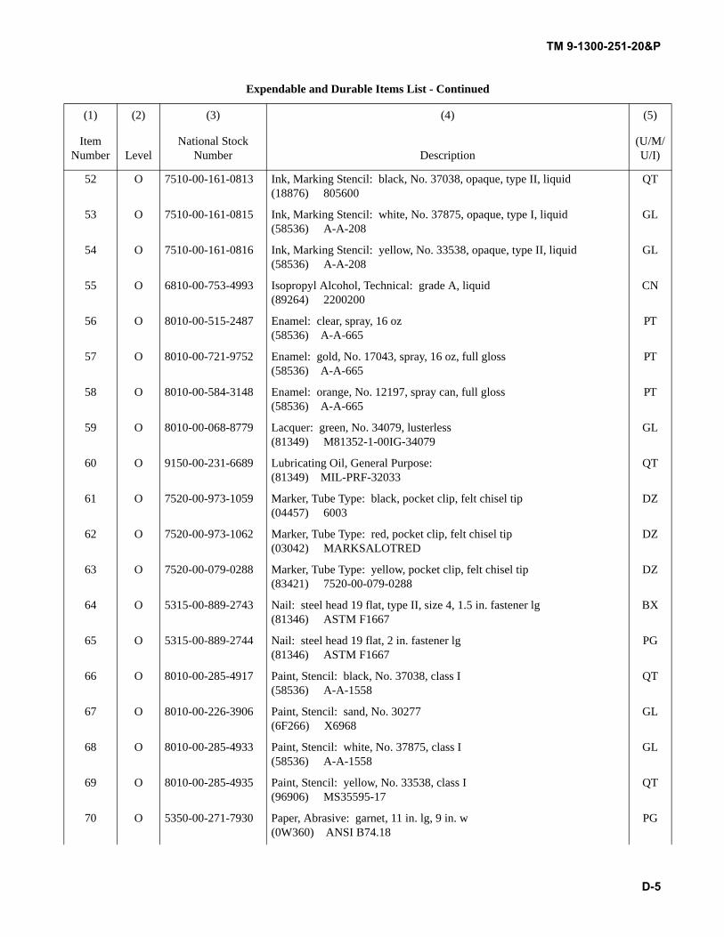
TM 9-1300-251-20&P
D-5
52 O 7510-00-161-0813 Ink, Marking Stencil: black, No. 37038, opaque, type II, liquid(18876) 805600
QT
53 O 7510-00-161-0815 Ink, Marking Stencil: white, No. 37875, opaque, type I, liquid(58536) A-A-208
GL
54 O 7510-00-161-0816 Ink, Marking Stencil: yellow, No. 33538, opaque, type II, liquid(58536) A-A-208
GL
55 O 6810-00-753-4993 Isopropyl Alcohol, Technical: grade A, liquid(89264) 2200200
CN
56 O 8010-00-515-2487 Enamel: clear, spray, 16 oz(58536) A-A-665
PT
57 O 8010-00-721-9752 Enamel: gold, No. 17043, spray, 16 oz, full gloss(58536) A-A-665
PT
58 O 8010-00-584-3148 Enamel: orange, No. 12197, spray can, full gloss(58536) A-A-665
PT
59 O 8010-00-068-8779 Lacquer: green, No. 34079, lusterless(81349) M81352-1-00IG-34079
GL
60 O 9150-00-231-6689 Lubricating Oil, General Purpose:(81349) MIL-PRF-32033
QT
61 O 7520-00-973-1059 Marker, Tube Type: black, pocket clip, felt chisel tip(04457) 6003
DZ
62 O 7520-00-973-1062 Marker, Tube Type: red, pocket clip, felt chisel tip(03042) MARKSALOTRED
DZ
63 O 7520-00-079-0288 Marker, Tube Type: yellow, pocket clip, felt chisel tip(83421) 7520-00-079-0288
DZ
64 O 5315-00-889-2743 Nail: steel head 19 flat, type II, size 4, 1.5 in. fastener lg(81346) ASTM F1667
BX
65 O 5315-00-889-2744 Nail: steel head 19 flat, 2 in. fastener lg(81346) ASTM F1667
PG
66 O 8010-00-285-4917 Paint, Stencil: black, No. 37038, class I(58536) A-A-1558
QT
67 O 8010-00-226-3906 Paint, Stencil: sand, No. 30277(6F266) X6968
GL
68 O 8010-00-285-4933 Paint, Stencil: white, No. 37875, class I(58536) A-A-1558
GL
69 O 8010-00-285-4935 Paint, Stencil: yellow, No. 33538, class I(96906) MS35595-17
QT
70 O 5350-00-271-7930 Paper, Abrasive: garnet, 11 in. lg, 9 in. w(0W360) ANSI B74.18
PG
Expendable and Durable Items List - Continued
(1) (2) (3) (4) (5)
Item Number Level
National Stock Number Description
(U/M/U/I)
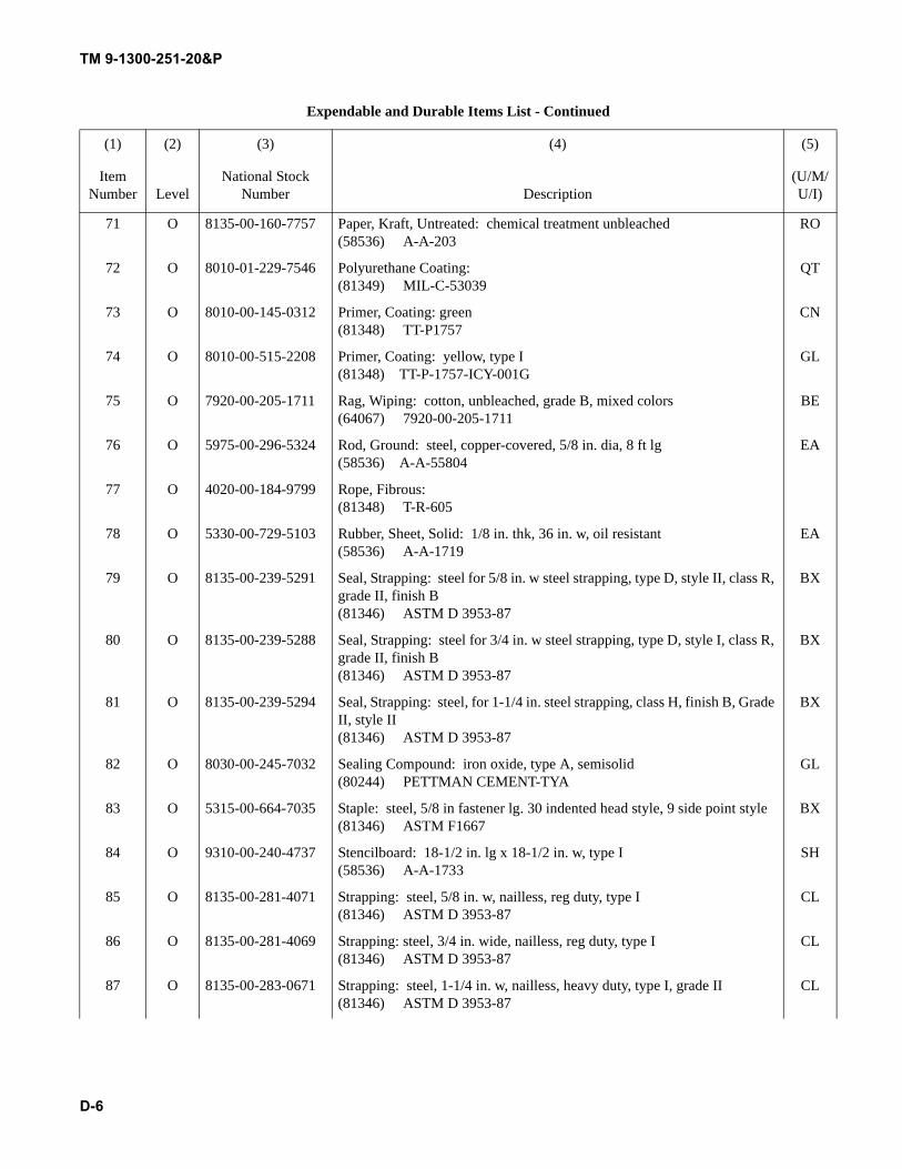
TM 9-1300-251-20&P
D-6
71 O 8135-00-160-7757 Paper, Kraft, Untreated: chemical treatment unbleached(58536) A-A-203
RO
72 O 8010-01-229-7546 Polyurethane Coating:(81349) MIL-C-53039
QT
73 O 8010-00-145-0312 Primer, Coating: green(81348) TT-P1757
CN
74 O 8010-00-515-2208 Primer, Coating: yellow, type I(81348) TT-P-1757-ICY-001G
GL
75 O 7920-00-205-1711 Rag, Wiping: cotton, unbleached, grade B, mixed colors(64067) 7920-00-205-1711
BE
76 O 5975-00-296-5324 Rod, Ground: steel, copper-covered, 5/8 in. dia, 8 ft lg(58536) A-A-55804
EA
77 O 4020-00-184-9799 Rope, Fibrous:(81348) T-R-605
78 O 5330-00-729-5103 Rubber, Sheet, Solid: 1/8 in. thk, 36 in. w, oil resistant(58536) A-A-1719
EA
79 O 8135-00-239-5291 Seal, Strapping: steel for 5/8 in. w steel strapping, type D, style II, class R, grade II, finish B(81346) ASTM D 3953-87
BX
80 O 8135-00-239-5288 Seal, Strapping: steel for 3/4 in. w steel strapping, type D, style I, class R, grade II, finish B(81346) ASTM D 3953-87
BX
81 O 8135-00-239-5294 Seal, Strapping: steel, for 1-1/4 in. steel strapping, class H, finish B, Grade II, style II(81346) ASTM D 3953-87
BX
82 O 8030-00-245-7032 Sealing Compound: iron oxide, type A, semisolid(80244) PETTMAN CEMENT-TYA
GL
83 O 5315-00-664-7035 Staple: steel, 5/8 in fastener lg. 30 indented head style, 9 side point style(81346) ASTM F1667
BX
84 O 9310-00-240-4737 Stencilboard: 18-1/2 in. lg x 18-1/2 in. w, type I(58536) A-A-1733
SH
85 O 8135-00-281-4071 Strapping: steel, 5/8 in. w, nailless, reg duty, type I(81346) ASTM D 3953-87
CL
86 O 8135-00-281-4069 Strapping: steel, 3/4 in. wide, nailless, reg duty, type I(81346) ASTM D 3953-87
CL
87 O 8135-00-283-0671 Strapping: steel, 1-1/4 in. w, nailless, heavy duty, type I, grade II(81346) ASTM D 3953-87
CL
Expendable and Durable Items List - Continued
(1) (2) (3) (4) (5)
Item Number Level
National Stock Number Description
(U/M/U/I)
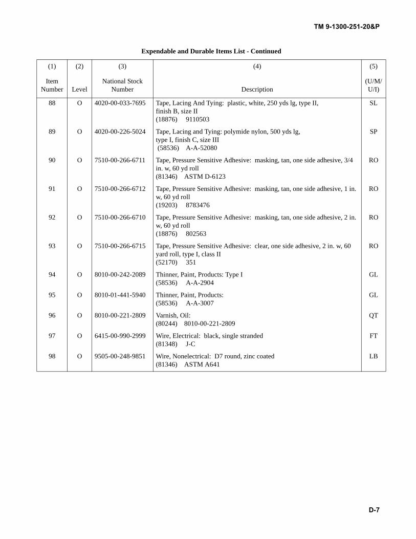
TM 9-1300-251-20&P
D-7
88 O 4020-00-033-7695 Tape, Lacing And Tying: plastic, white, 250 yds lg, type II, finish B, size II(18876) 9110503
SL
89 O 4020-00-226-5024 Tape, Lacing and Tying: polymide nylon, 500 yds lg, type I, finish C, size III (58536) A-A-52080
SP
90 O 7510-00-266-6711 Tape, Pressure Sensitive Adhesive: masking, tan, one side adhesive, 3/4 in. w, 60 yd roll(81346) ASTM D-6123
RO
91 O 7510-00-266-6712 Tape, Pressure Sensitive Adhesive: masking, tan, one side adhesive, 1 in. w, 60 yd roll(19203) 8783476
RO
92 O 7510-00-266-6710 Tape, Pressure Sensitive Adhesive: masking, tan, one side adhesive, 2 in. w, 60 yd roll(18876) 802563
RO
93 O 7510-00-266-6715 Tape, Pressure Sensitive Adhesive: clear, one side adhesive, 2 in. w, 60 yard roll, type I, class II(52170) 351
RO
94 O 8010-00-242-2089 Thinner, Paint, Products: Type I(58536) A-A-2904
GL
95 O 8010-01-441-5940 Thinner, Paint, Products: (58536) A-A-3007
GL
96 O 8010-00-221-2809 Varnish, Oil:(80244) 8010-00-221-2809
QT
97 O 6415-00-990-2999 Wire, Electrical: black, single stranded(81348) J-C
FT
98 O 9505-00-248-9851 Wire, Nonelectrical: D7 round, zinc coated(81346) ASTM A641
LB
Expendable and Durable Items List - Continued
(1) (2) (3) (4) (5)
Item Number Level
National Stock Number Description
(U/M/U/I)

TM 9-1300-251-20&P
D-8
THIS PAGE INTENTIONALLY LEFT BLANK
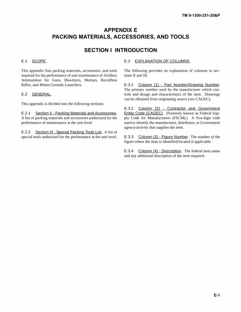
TM 9-1300-251-20&P
E-1
APPENDIX EPACKING MATERIALS, ACCESSORIES, AND TOOLS
SECTION I INTRODUCTION
E.1 SCOPE.
This appendix lists packing materials, accessories, and toolsrequired for the performance of unit maintenance of ArtilleryAmmunition for Guns, Howitzers, Mortars, RecoillessRifles, and 40mm Grenade Launchers.
E.2 GENERAL.
This appendix is divided into the following sections:
E.2.1 Section II - Packing Materials and Accessories.A list of packing materials and accessories authorized for theperformance of maintenance at the unit level.
E.2.2 Section III - Special Packing Tools List. A list ofspecial tools authorized for the performance at the unit level.
E.3 EXPLANATION OF COLUMNS.
The following provides an explanation of columns in sec-tions II and III.
E.3.1 Column (1) - Part Number/Drawing Number.The primary number used by the manufacturer which con-trols and design and characteristics of the item. Drawingscan be obtained from originating source (see CAGEC).
E.3.2 Column (2) - Contractor and GovernmentEntity Code (CAGEC). (Formerly known as Federal Sup-ply Code for Manufacturers (FSCM).) A five-digit codeused to identify the manufacturer, distributor, or Governmentagency/activity that supplies the item.
E.3.3 Column (3) - Figure Number. The number of thefigure where the item is identified/located if applicable.
E.3.4 Column (4) - Description. The federal item nameand any additional description of the item required.
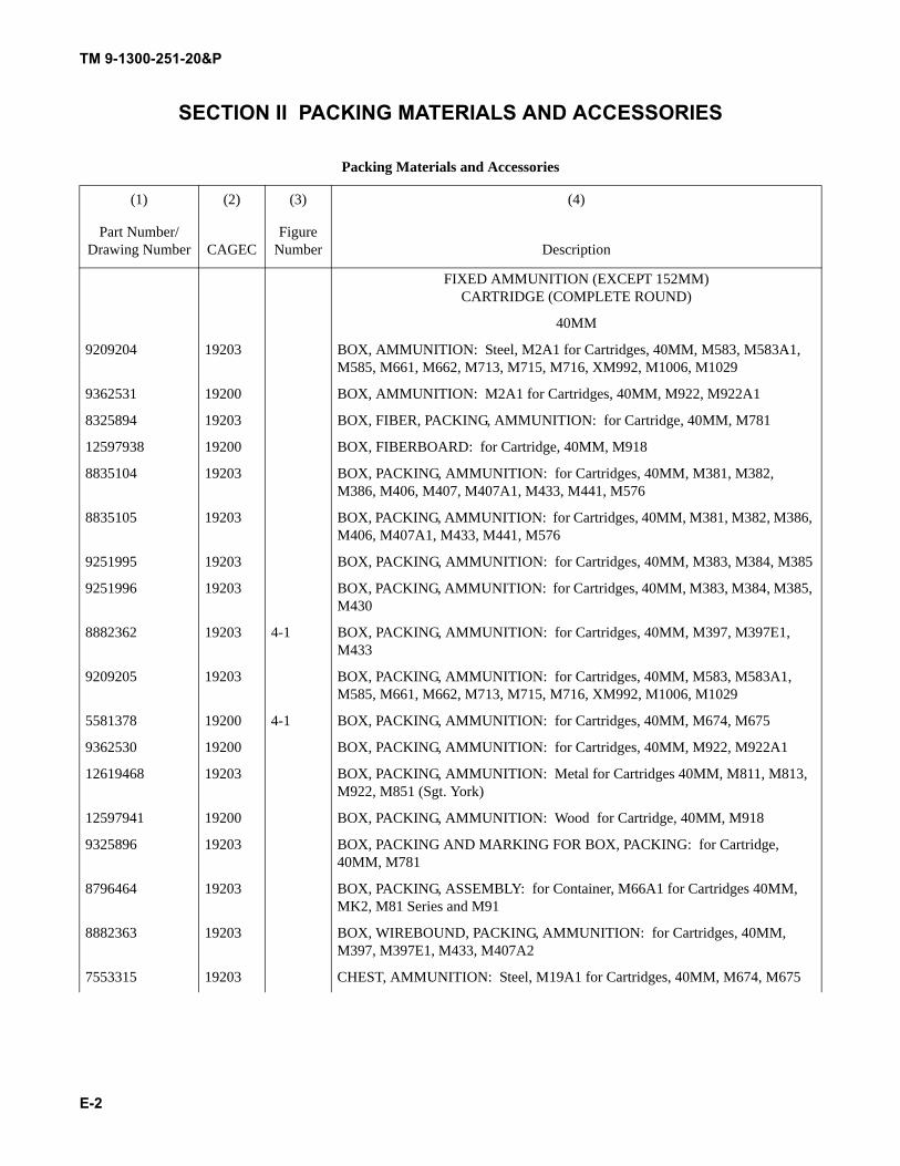
TM 9-1300-251-20&P
E-2
SECTION II PACKING MATERIALS AND ACCESSORIES
Packing Materials and Accessories
(1) (2) (3) (4)
Part Number/Drawing Number CAGEC
Figure Number Description
FIXED AMMUNITION (EXCEPT 152MM) CARTRIDGE (COMPLETE ROUND)
40MM
9209204 19203 BOX, AMMUNITION: Steel, M2A1 for Cartridges, 40MM, M583, M583A1, M585, M661, M662, M713, M715, M716, XM992, M1006, M1029
9362531 19200 BOX, AMMUNITION: M2A1 for Cartridges, 40MM, M922, M922A1
8325894 19203 BOX, FIBER, PACKING, AMMUNITION: for Cartridge, 40MM, M781
12597938 19200 BOX, FIBERBOARD: for Cartridge, 40MM, M918
8835104 19203 BOX, PACKING, AMMUNITION: for Cartridges, 40MM, M381, M382, M386, M406, M407, M407A1, M433, M441, M576
8835105 19203 BOX, PACKING, AMMUNITION: for Cartridges, 40MM, M381, M382, M386, M406, M407A1, M433, M441, M576
9251995 19203 BOX, PACKING, AMMUNITION: for Cartridges, 40MM, M383, M384, M385
9251996 19203 BOX, PACKING, AMMUNITION: for Cartridges, 40MM, M383, M384, M385, M430
8882362 19203 4-1 BOX, PACKING, AMMUNITION: for Cartridges, 40MM, M397, M397E1, M433
9209205 19203 BOX, PACKING, AMMUNITION: for Cartridges, 40MM, M583, M583A1, M585, M661, M662, M713, M715, M716, XM992, M1006, M1029
5581378 19200 4-1 BOX, PACKING, AMMUNITION: for Cartridges, 40MM, M674, M675
9362530 19200 BOX, PACKING, AMMUNITION: for Cartridges, 40MM, M922, M922A1
12619468 19203 BOX, PACKING, AMMUNITION: Metal for Cartridges 40MM, M811, M813, M922, M851 (Sgt. York)
12597941 19200 BOX, PACKING, AMMUNITION: Wood for Cartridge, 40MM, M918
9325896 19203 BOX, PACKING AND MARKING FOR BOX, PACKING: for Cartridge, 40MM, M781
8796464 19203 BOX, PACKING, ASSEMBLY: for Container, M66A1 for Cartridges 40MM, MK2, M81 Series and M91
8882363 19203 BOX, WIREBOUND, PACKING, AMMUNITION: for Cartridges, 40MM, M397, M397E1, M433, M407A2
7553315 19203 CHEST, AMMUNITION: Steel, M19A1 for Cartridges, 40MM, M674, M675
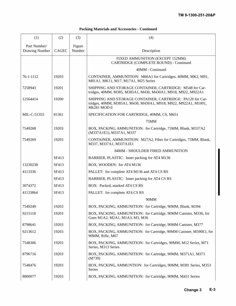
TM 9-1300-251-20&P
E-3
FIXED AMMUNITION (EXCEPT 152MM) CARTRIDGE (COMPLETE ROUND) - Continued
40MM - Continued
76-1-1112 19203 CONTAINER, AMMUNITION: M66A1 for Cartridges, 40MM, MK2, M91, M81A1, MK11, M17, M17A1, M25 Series
7258943 19201 SHIPPING AND STORAGE CONTAINER, CARTRIDGE: M548 for Car-tridges, 40MM, M385, M385A1, M430, M430A1, M918, M922, M922A1
12564414 19200 SHIPPING AND STORAGE CONTAINER, CARTRIDGE: PA120 for Car-tridges, 40MM, M385A1, M430, M430A1, M918, M922, M922A1, M1001, Mk281 MOD 0
MIL-C-51355 81361 SPECIFICATION FOR CARTRIDGE, 40MM, CS, M651
75MM
7549268 19203 BOX, PACKING, AMMUNITION: for Cartridge, 75MM, Blank, M337A2 (M337A1E1), M337A1, M337
7549269 19203 CONTAINER, AMMUNITION: M27A2, Fiber for Cartridges, 75MM, Blank, M337, M337A1, M337A1E1
84MM - SHOULDER FIRED AMMUNITION
SF413 BARRIER, PLASTIC: Inner packing for AT4 M136
13230238 SF413 BOX, WOODEN: for AT4 M136
4113336 SF413 PALLET: for complete AT4 M136 and AT4 CS RS
SF413 BARRIER, PLASTIC: Inner packing for AT4 CS RS
3074372 SF413 BOX: Packed, marked AT4 CS RS
41133864 SF413 PALLET: for complete AT4 CS RS
90MM
7549249 19203 BOX, PACKING, AMMUNITION: for Cartridge, 90MM, Blank, M394
9215118 19203 BOX, PACKING, AMMUNITION: for Cartridge, 90MM Canister, M336, for Guns M1A2, M2A1, M1A3, M3, M36
8798641 19203 BOX, PACKING, AMMUNITION: for Cartridge, 90MM Canister, M377
9213612 19203 BOX, PACKING, AMMUNITION: for Cartridge, 90MM Canister, M590E1, for 90MM, Rifle, M67
7548306 19203 BOX, PACKING, AMMUNITION: for Cartridges, 90MM, M12 Series, M71 Series, M313 Series
8796716 19203 BOX, PACKING, AMMUNITION: for Cartridge, 90MM, M371A1, M371 (M739)
7548476 19203 BOX, PACKING, AMMUNTION: for Cartridges, 90MM, M381 Series, M353 Series
8800077 19203 BOX, PACKING, AMMUNITION: for Cartridge, 90MM, M431 Series
Packing Materials and Accessories - Continued
(1) (2) (3) (4)
Part Number/Drawing Number CAGEC
Figure Number Description
Change 3
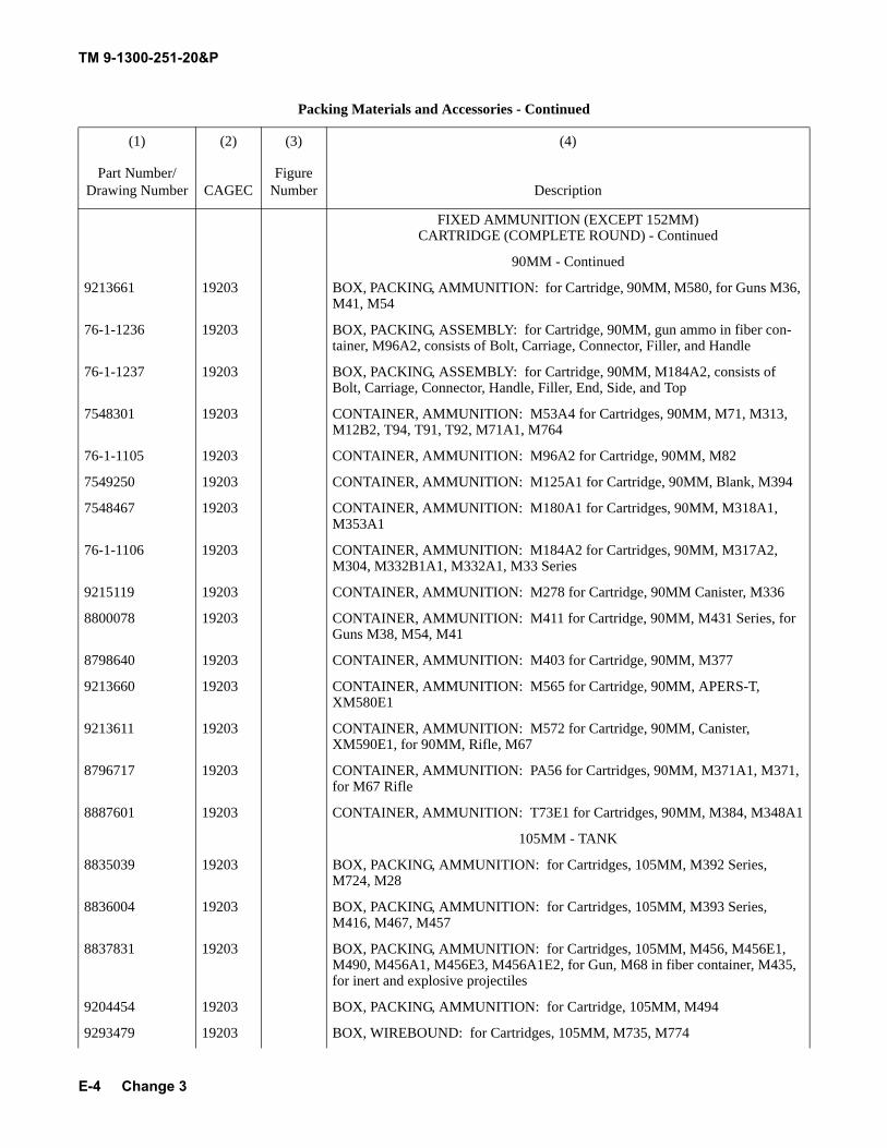
TM 9-1300-251-20&P
E-4
FIXED AMMUNITION (EXCEPT 152MM) CARTRIDGE (COMPLETE ROUND) - Continued
90MM - Continued
9213661 19203 BOX, PACKING, AMMUNITION: for Cartridge, 90MM, M580, for Guns M36, M41, M54
76-1-1236 19203 BOX, PACKING, ASSEMBLY: for Cartridge, 90MM, gun ammo in fiber con-tainer, M96A2, consists of Bolt, Carriage, Connector, Filler, and Handle
76-1-1237 19203 BOX, PACKING, ASSEMBLY: for Cartridge, 90MM, M184A2, consists of Bolt, Carriage, Connector, Handle, Filler, End, Side, and Top
7548301 19203 CONTAINER, AMMUNITION: M53A4 for Cartridges, 90MM, M71, M313, M12B2, T94, T91, T92, M71A1, M764
76-1-1105 19203 CONTAINER, AMMUNITION: M96A2 for Cartridge, 90MM, M82
7549250 19203 CONTAINER, AMMUNITION: M125A1 for Cartridge, 90MM, Blank, M394
7548467 19203 CONTAINER, AMMUNITION: M180A1 for Cartridges, 90MM, M318A1, M353A1
76-1-1106 19203 CONTAINER, AMMUNITION: M184A2 for Cartridges, 90MM, M317A2, M304, M332B1A1, M332A1, M33 Series
9215119 19203 CONTAINER, AMMUNITION: M278 for Cartridge, 90MM Canister, M336
8800078 19203 CONTAINER, AMMUNITION: M411 for Cartridge, 90MM, M431 Series, for Guns M38, M54, M41
8798640 19203 CONTAINER, AMMUNITION: M403 for Cartridge, 90MM, M377
9213660 19203 CONTAINER, AMMUNITION: M565 for Cartridge, 90MM, APERS-T, XM580E1
9213611 19203 CONTAINER, AMMUNITION: M572 for Cartridge, 90MM, Canister, XM590E1, for 90MM, Rifle, M67
8796717 19203 CONTAINER, AMMUNITION: PA56 for Cartridges, 90MM, M371A1, M371, for M67 Rifle
8887601 19203 CONTAINER, AMMUNITION: T73E1 for Cartridges, 90MM, M384, M348A1
105MM - TANK
8835039 19203 BOX, PACKING, AMMUNITION: for Cartridges, 105MM, M392 Series, M724, M28
8836004 19203 BOX, PACKING, AMMUNITION: for Cartridges, 105MM, M393 Series, M416, M467, M457
8837831 19203 BOX, PACKING, AMMUNITION: for Cartridges, 105MM, M456, M456E1, M490, M456A1, M456E3, M456A1E2, for Gun, M68 in fiber container, M435, for inert and explosive projectiles
9204454 19203 BOX, PACKING, AMMUNITION: for Cartridge, 105MM, M494
9293479 19203 BOX, WIREBOUND: for Cartridges, 105MM, M735, M774
Packing Materials and Accessories - Continued
(1) (2) (3) (4)
Part Number/Drawing Number CAGEC
Figure Number Description
Change 3
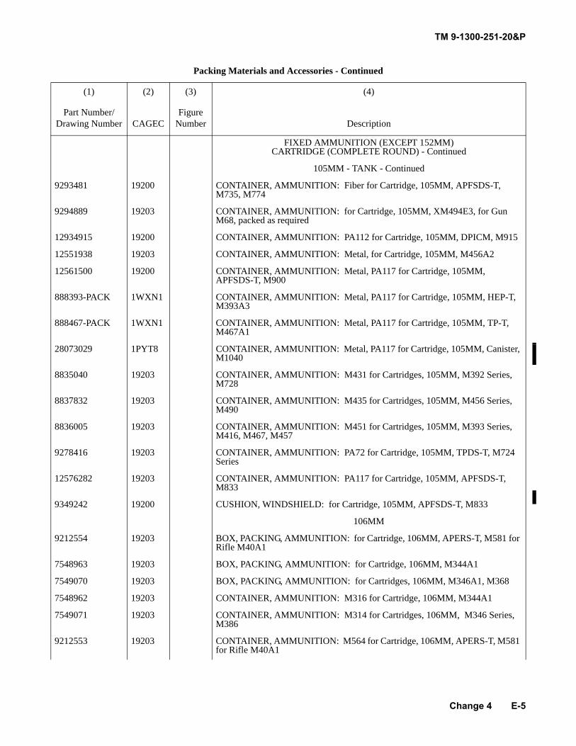
TM 9-1300-251-20&P
E-5
FIXED AMMUNITION (EXCEPT 152MM) CARTRIDGE (COMPLETE ROUND) - Continued
105MM - TANK - Continued
9293481 19200 CONTAINER, AMMUNITION: Fiber for Cartridge, 105MM, APFSDS-T, M735, M774
9294889 19203 CONTAINER, AMMUNITION: for Cartridge, 105MM, XM494E3, for Gun M68, packed as required
12934915 19200 CONTAINER, AMMUNITION: PA112 for Cartridge, 105MM, DPICM, M915
12551938 19203 CONTAINER, AMMUNITION: Metal, for Cartridge, 105MM, M456A2
12561500 19200 CONTAINER, AMMUNITION: Metal, PA117 for Cartridge, 105MM, APFSDS-T, M900
888393-PACK 1WXN1 CONTAINER, AMMUNITION: Metal, PA117 for Cartridge, 105MM, HEP-T, M393A3
888467-PACK 1WXN1 CONTAINER, AMMUNITION: Metal, PA117 for Cartridge, 105MM, TP-T, M467A1
28073029 1PYT8 CONTAINER, AMMUNITION: Metal, PA117 for Cartridge, 105MM, Canister, M1040
8835040 19203 CONTAINER, AMMUNITION: M431 for Cartridges, 105MM, M392 Series, M728
8837832 19203 CONTAINER, AMMUNITION: M435 for Cartridges, 105MM, M456 Series, M490
8836005 19203 CONTAINER, AMMUNITION: M451 for Cartridges, 105MM, M393 Series, M416, M467, M457
9278416 19203 CONTAINER, AMMUNITION: PA72 for Cartridge, 105MM, TPDS-T, M724 Series
12576282 19203 CONTAINER, AMMUNITION: PA117 for Cartridge, 105MM, APFSDS-T, M833
9349242 19200 CUSHION, WINDSHIELD: for Cartridge, 105MM, APFSDS-T, M833
106MM
9212554 19203 BOX, PACKING, AMMUNITION: for Cartridge, 106MM, APERS-T, M581 for Rifle M40A1
7548963 19203 BOX, PACKING, AMMUNITION: for Cartridge, 106MM, M344A1
7549070 19203 BOX, PACKING, AMMUNITION: for Cartridges, 106MM, M346A1, M368
7548962 19203 CONTAINER, AMMUNITION: M316 for Cartridge, 106MM, M344A1
7549071 19203 CONTAINER, AMMUNITION: M314 for Cartridges, 106MM, M346 Series, M386
9212553 19203 CONTAINER, AMMUNITION: M564 for Cartridge, 106MM, APERS-T, M581 for Rifle M40A1
Packing Materials and Accessories - Continued
(1) (2) (3) (4)
Part Number/Drawing Number CAGEC
Figure Number Description
Change 4
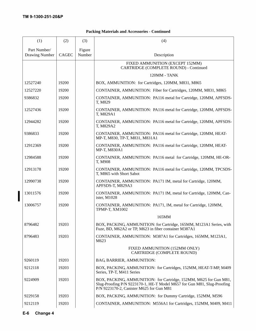
TM 9-1300-251-20&P
E-6
FIXED AMMUNITION (EXCEPT 152MM) CARTRIDGE (COMPLETE ROUND) - Continued
120MM - TANK
12527240 19200 BOX, AMMUNITION: for Cartridges, 120MM, M831, M865
12527220 19200 CONTAINER, AMMUNITION: Fiber for Cartridges, 120MM, M831, M865
9386832 19200 CONTAINER, AMMUNITION: PA116 metal for Cartridge, 120MM, APFSDS-T, M829
12527436 19200 CONTAINER, AMMUNITION: PA116 metal for Cartridge, 120MM, APFSDS-T, M829A1
12944282 19200 CONTAINER, AMMUNITION: PA116 metal for Cartridge, 120MM, APFSDS-T, M829A2
9386833 19200 CONTAINER, AMMUNITION: PA116 metal for Cartridge, 120MM, HEAT-MP-T, M830, TP-T, M831, M831A1
12912369 19200 CONTAINER, AMMUNITION: PA116 metal for Cartridge, 120MM, HEAT-MP-T, M830A1
12984588 19200 CONTAINER, AMMUNITION: PA116 metal for Cartridge, 120MM, HE-OR-T, M908
12913178 19200 CONTAINER, AMMUNITION: PA116 metal for Cartridge, 120MM, TPCSDS-T, M865 with Short Sabot
12990738 19200 CONTAINER, AMMUNITION: PA171 IM, metal for Cartridge, 120MM, APFSDS-T, M829A3
13011576 19200 CONTAINER, AMMUNITION: PA171 IM, metal for Cartridge, 120MM, Can-ister, M1028
13006757 19200 CONTAINER, AMMUNITION: PA171, IM, metal for Cartridge, 120MM, TPMP-T, XM1002
165MM
8796482 19203 BOX, PACKING, AMMUNITION: for Cartridge, 165MM, M123A1 Series, with Fuze, BD, M62A2 or TP, M623 in fiber container M387A1
8796483 19203 CONTAINER, AMMUNITION: M387A1 for Cartridges, 165MM, M123A1, M623
FIXED AMMUNITION (152MM ONLY) CARTRIDGE (COMPLETE ROUND)
9260119 19203 BAG, BARRIER, AMMUNITION:
9212118 19203 BOX, PACKING, AMMUNITION: for Cartridges, 152MM, HEAT-T-MP, M409 Series, TP-T, M411 Series
9224909 19203 BOX, PACKING, AMMUNITION: for Cartridge, 152MM, M625 for Gun M81, Slug-Proofing P/N 9223170-1, HE-T Model M657 for Gun M81, Slug-Proofing P/N 9223170-2, Canister M625 for Gun M81
9229158 19203 BOX, PACKING, AMMUNITION: for Dummy Cartridge, 152MM, M596
9212119 19203 CONTAINER, AMMUNITION: M556A1 for Cartridges, 152MM, M409, M411
Packing Materials and Accessories - Continued
(1) (2) (3) (4)
Part Number/Drawing Number CAGEC
Figure Number Description
Change 4
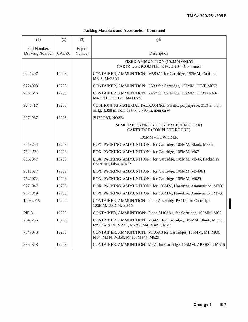
TM 9-1300-251-20&P
E-7
FIXED AMMUNITION (152MM ONLY) CARTRIDGE (COMPLETE ROUND) - Continued
9221407 19203 CONTAINER, AMMUNITION: M580A1 for Cartridge, 152MM, Canister, M625, M625A1
9224908 19203 CONTAINER, AMMUNITION: PA33 for Cartridge, 152MM, HE-T, M657
9261646 19203 CONTAINER, AMMUNITION: PA57 for Cartridge, 152MM, HEAT-T-MP, M409A1 and TP-T, M411A3
9248417 19203 CUSHIONING MATERIAL PACKAGING: Plastic, polystyrene, 31.9 in. nom oa lg, 4.398 in. nom oa thk, 8.796 in. nom oa w
9271067 19203 SUPPORT, NOSE:
SEMIFIXED AMMUNITION (EXCEPT MORTAR) CARTRIDGE (COMPLETE ROUND)
105MM - HOWITZER
7549254 19203 BOX, PACKING, AMMUNITION: for Cartridge, 105MM, Blank, M395
76-1-530 19203 BOX, PACKING, AMMUNITION: for Cartridge, 105MM, M67
8862347 19203 BOX, PACKING, AMMUNITION: for Cartridge, 105MM, M546, Packed in Container, Fiber, M472
9213637 19203 BOX, PACKING, AMMUNITION: for Cartridge, 105MM, M548E1
7549072 19203 BOX, PACKING, AMMUNITION: for Cartridge, 105MM, M629
9271047 19203 BOX, PACKING, AMMUNITION: for 105MM, Howitzer, Ammunition, M760
9271849 19203 BOX, PACKING, AMMUNITION: for 105MM, Howitzer, Ammunition, M760
12934915 19200 CONTAINER, AMMUNITION: Fiber Assembly, PA112, for Cartridge, 105MM, DPICM, M915
PIF-81 19203 CONTAINER, AMMUNITION: Fiber, M108A1, for Cartridge, 105MM, M67
7549255 19203 CONTAINER, AMMUNITION: M34A1 for Cartridge, 105MM, Blank, M395, for Howitzers, M2A1, M2A2, M4, M4A1, M49
7549073 19203 CONTAINER, AMMUNITION: M105A3 for Cartridges, 105MM, M1, M60, M84, M314, M360, M413, M444, M629
8862348 19203 CONTAINER, AMMUNITION: M472 for Cartridge, 105MM, APERS-T, M546
Packing Materials and Accessories - Continued
(1) (2) (3) (4)
Part Number/Drawing Number CAGEC
Figure Number Description
Change 1
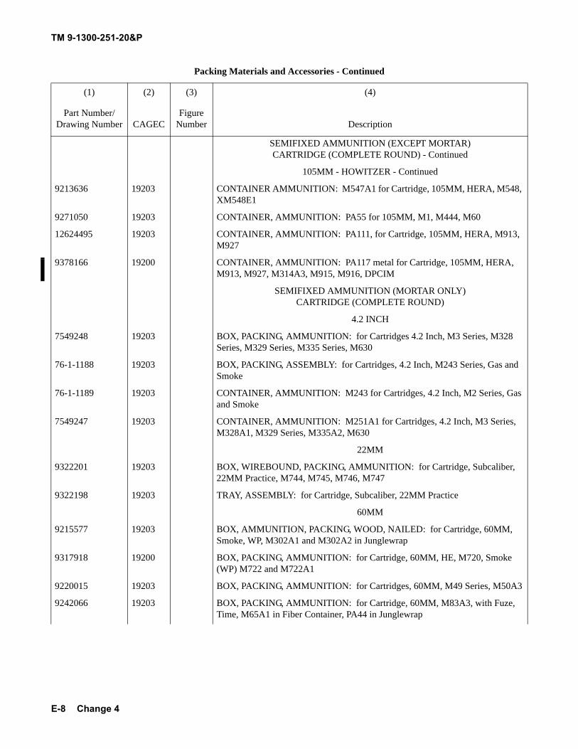
TM 9-1300-251-20&P
E-8
SEMIFIXED AMMUNITION (EXCEPT MORTAR) CARTRIDGE (COMPLETE ROUND) - Continued
105MM - HOWITZER - Continued
9213636 19203 CONTAINER AMMUNITION: M547A1 for Cartridge, 105MM, HERA, M548, XM548E1
9271050 19203 CONTAINER, AMMUNITION: PA55 for 105MM, M1, M444, M60
12624495 19203 CONTAINER, AMMUNITION: PA111, for Cartridge, 105MM, HERA, M913, M927
9378166 19200 CONTAINER, AMMUNITION: PA117 metal for Cartridge, 105MM, HERA, M913, M927, M314A3, M915, M916, DPCIM
SEMIFIXED AMMUNITION (MORTAR ONLY) CARTRIDGE (COMPLETE ROUND)
4.2 INCH
7549248 19203 BOX, PACKING, AMMUNITION: for Cartridges 4.2 Inch, M3 Series, M328 Series, M329 Series, M335 Series, M630
76-1-1188 19203 BOX, PACKING, ASSEMBLY: for Cartridges, 4.2 Inch, M243 Series, Gas and Smoke
76-1-1189 19203 CONTAINER, AMMUNITION: M243 for Cartridges, 4.2 Inch, M2 Series, Gas and Smoke
7549247 19203 CONTAINER, AMMUNITION: M251A1 for Cartridges, 4.2 Inch, M3 Series, M328A1, M329 Series, M335A2, M630
22MM
9322201 19203 BOX, WIREBOUND, PACKING, AMMUNITION: for Cartridge, Subcaliber, 22MM Practice, M744, M745, M746, M747
9322198 19203 TRAY, ASSEMBLY: for Cartridge, Subcaliber, 22MM Practice
60MM
9215577 19203 BOX, AMMUNITION, PACKING, WOOD, NAILED: for Cartridge, 60MM, Smoke, WP, M302A1 and M302A2 in Junglewrap
9317918 19200 BOX, PACKING, AMMUNITION: for Cartridge, 60MM, HE, M720, Smoke (WP) M722 and M722A1
9220015 19203 BOX, PACKING, AMMUNITION: for Cartridges, 60MM, M49 Series, M50A3
9242066 19203 BOX, PACKING, AMMUNITION: for Cartridge, 60MM, M83A3, with Fuze, Time, M65A1 in Fiber Container, PA44 in Junglewrap
Packing Materials and Accessories - Continued
(1) (2) (3) (4)
Part Number/Drawing Number CAGEC
Figure Number Description
Change 4
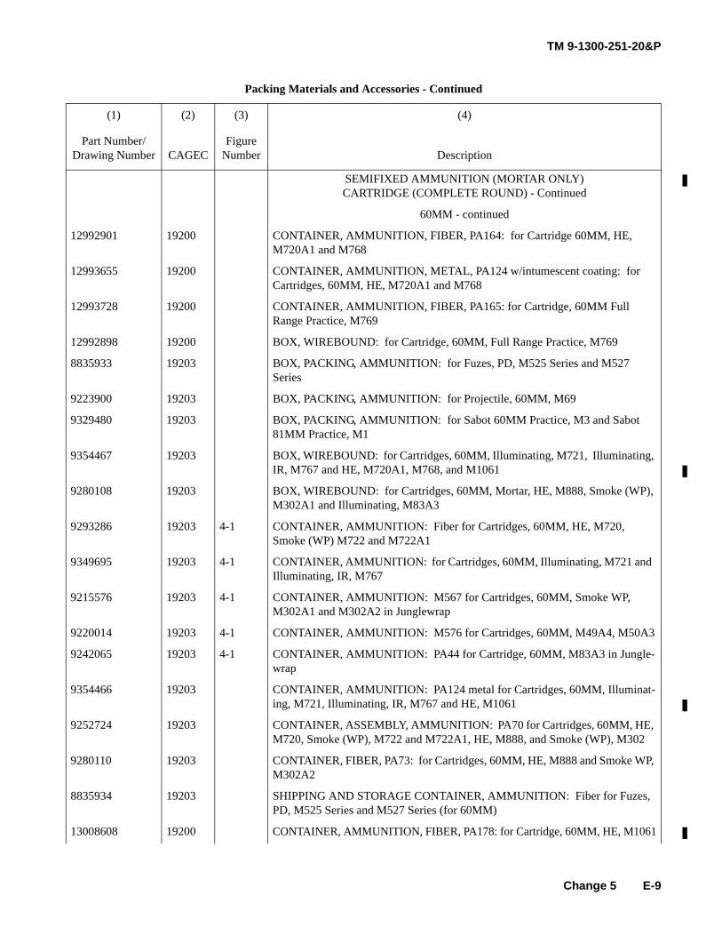
TM 9-1300-251-20&P
E-9
SEMIFIXED AMMUNITION (MORTAR ONLY) CARTRIDGE (COMPLETE ROUND) - Continued
60MM - continued
12992901 19200 CONTAINER, AMMUNITION, FIBER, PA164: for Cartridge 60MM, HE, M720A1 and M768
12993655 19200 CONTAINER, AMMUNITION, METAL, PA124 w/intumescent coating: for Cartridges, 60MM, HE, M720A1 and M768
12993728 19200 CONTAINER, AMMUNITION, FIBER, PA165: for Cartridge, 60MM Full Range Practice, M769
12992898 19200 BOX, WIREBOUND: for Cartridge, 60MM, Full Range Practice, M769
8835933 19203 BOX, PACKING, AMMUNITION: for Fuzes, PD, M525 Series and M527 Series
9223900 19203 BOX, PACKING, AMMUNITION: for Projectile, 60MM, M69
9329480 19203 BOX, PACKING, AMMUNITION: for Sabot 60MM Practice, M3 and Sabot 81MM Practice, M1
9354467 19203 BOX, WIREBOUND: for Cartridges, 60MM, Illuminating, M721, Illuminating, IR, M767 and HE, M720A1, M768, and M1061
9280108 19203 BOX, WIREBOUND: for Cartridges, 60MM, Mortar, HE, M888, Smoke (WP), M302A1 and Illuminating, M83A3
9293286 19203 4-1 CONTAINER, AMMUNITION: Fiber for Cartridges, 60MM, HE, M720, Smoke (WP) M722 and M722A1
9349695 19203 4-1 CONTAINER, AMMUNITION: for Cartridges, 60MM, Illuminating, M721 and Illuminating, IR, M767
9215576 19203 4-1 CONTAINER, AMMUNITION: M567 for Cartridges, 60MM, Smoke WP, M302A1 and M302A2 in Junglewrap
9220014 19203 4-1 CONTAINER, AMMUNITION: M576 for Cartridges, 60MM, M49A4, M50A3
9242065 19203 4-1 CONTAINER, AMMUNITION: PA44 for Cartridge, 60MM, M83A3 in Jungle-wrap
9354466 19203 CONTAINER, AMMUNITION: PA124 metal for Cartridges, 60MM, Illuminat-ing, M721, Illuminating, IR, M767 and HE, M1061
9252724 19203 CONTAINER, ASSEMBLY, AMMUNITION: PA70 for Cartridges, 60MM, HE, M720, Smoke (WP), M722 and M722A1, HE, M888, and Smoke (WP), M302
9280110 19203 CONTAINER, FIBER, PA73: for Cartridges, 60MM, HE, M888 and Smoke WP, M302A2
8835934 19203 SHIPPING AND STORAGE CONTAINER, AMMUNITION: Fiber for Fuzes, PD, M525 Series and M527 Series (for 60MM)
13008608 19200 CONTAINER, AMMUNITION, FIBER, PA178: for Cartridge, 60MM, HE, M1061
Packing Materials and Accessories - Continued
(1) (2) (3) (4)
Part Number/Drawing Number CAGEC
Figure Number Description
Change 5
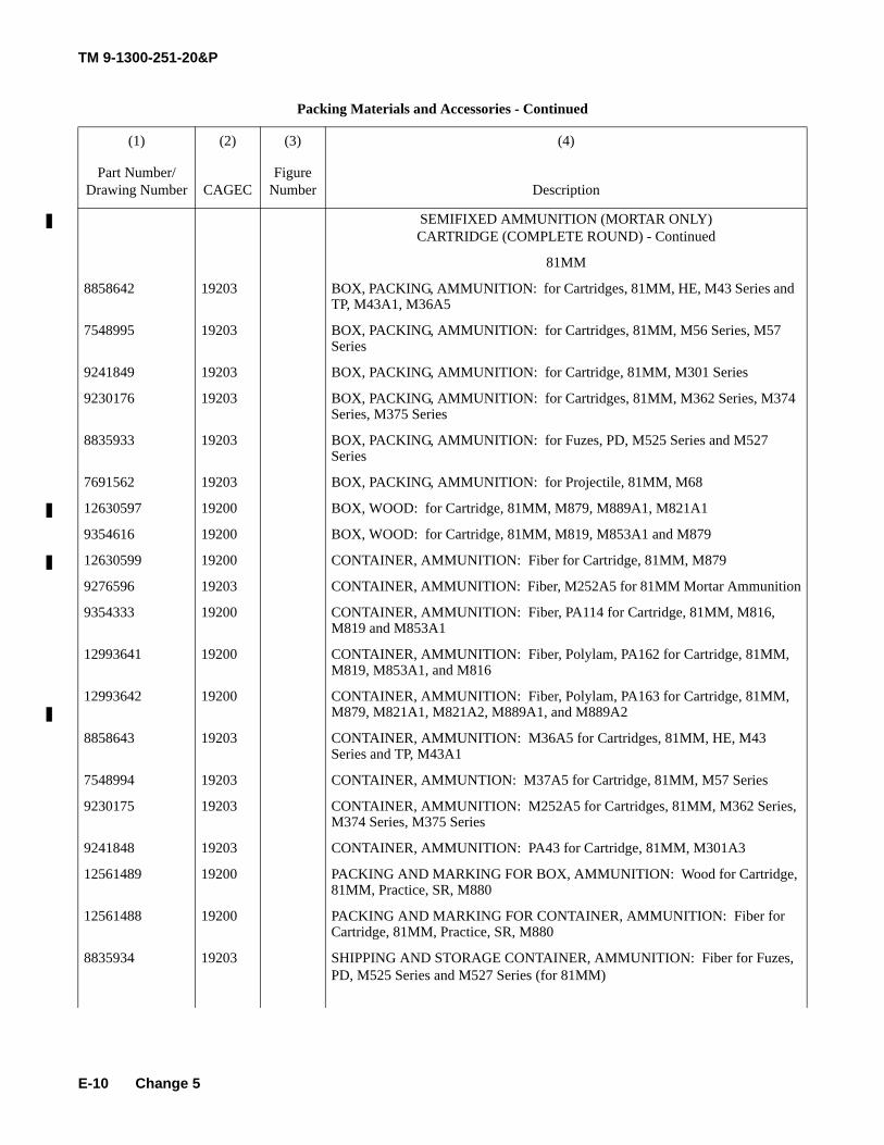
TM 9-1300-251-20&P
E-10
SEMIFIXED AMMUNITION (MORTAR ONLY) CARTRIDGE (COMPLETE ROUND) - Continued
81MM
8858642 19203 BOX, PACKING, AMMUNITION: for Cartridges, 81MM, HE, M43 Series and TP, M43A1, M36A5
7548995 19203 BOX, PACKING, AMMUNITION: for Cartridges, 81MM, M56 Series, M57 Series
9241849 19203 BOX, PACKING, AMMUNITION: for Cartridge, 81MM, M301 Series
9230176 19203 BOX, PACKING, AMMUNITION: for Cartridges, 81MM, M362 Series, M374 Series, M375 Series
8835933 19203 BOX, PACKING, AMMUNITION: for Fuzes, PD, M525 Series and M527 Series
7691562 19203 BOX, PACKING, AMMUNITION: for Projectile, 81MM, M68
12630597 19200 BOX, WOOD: for Cartridge, 81MM, M879, M889A1, M821A1
9354616 19200 BOX, WOOD: for Cartridge, 81MM, M819, M853A1 and M879
12630599 19200 CONTAINER, AMMUNITION: Fiber for Cartridge, 81MM, M879
9276596 19203 CONTAINER, AMMUNITION: Fiber, M252A5 for 81MM Mortar Ammunition
9354333 19200 CONTAINER, AMMUNITION: Fiber, PA114 for Cartridge, 81MM, M816, M819 and M853A1
12993641 19200 CONTAINER, AMMUNITION: Fiber, Polylam, PA162 for Cartridge, 81MM, M819, M853A1, and M816
12993642 19200 CONTAINER, AMMUNITION: Fiber, Polylam, PA163 for Cartridge, 81MM, M879, M821A1, M821A2, M889A1, and M889A2
8858643 19203 CONTAINER, AMMUNITION: M36A5 for Cartridges, 81MM, HE, M43 Series and TP, M43A1
7548994 19203 CONTAINER, AMMUNTION: M37A5 for Cartridge, 81MM, M57 Series
9230175 19203 CONTAINER, AMMUNITION: M252A5 for Cartridges, 81MM, M362 Series, M374 Series, M375 Series
9241848 19203 CONTAINER, AMMUNITION: PA43 for Cartridge, 81MM, M301A3
12561489 19200 PACKING AND MARKING FOR BOX, AMMUNITION: Wood for Cartridge, 81MM, Practice, SR, M880
12561488 19200 PACKING AND MARKING FOR CONTAINER, AMMUNITION: Fiber for Cartridge, 81MM, Practice, SR, M880
8835934 19203 SHIPPING AND STORAGE CONTAINER, AMMUNITION: Fiber for Fuzes, PD, M525 Series and M527 Series (for 81MM)
Packing Materials and Accessories - Continued
(1) (2) (3) (4)
Part Number/Drawing Number CAGEC
Figure Number Description
Change 5
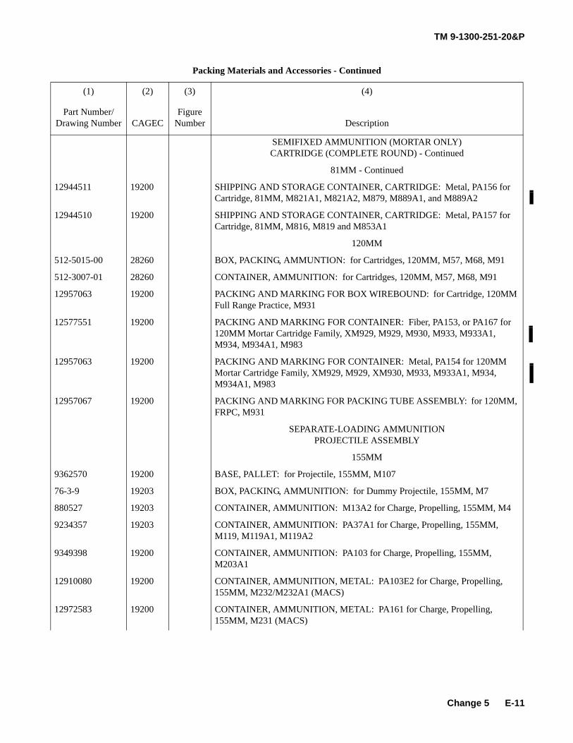
TM 9-1300-251-20&P
E-11
SEMIFIXED AMMUNITION (MORTAR ONLY) CARTRIDGE (COMPLETE ROUND) - Continued
81MM - Continued
12944511 19200 SHIPPING AND STORAGE CONTAINER, CARTRIDGE: Metal, PA156 for Cartridge, 81MM, M821A1, M821A2, M879, M889A1, and M889A2
12944510 19200 SHIPPING AND STORAGE CONTAINER, CARTRIDGE: Metal, PA157 for Cartridge, 81MM, M816, M819 and M853A1
120MM
512-5015-00 28260 BOX, PACKING, AMMUNTION: for Cartridges, 120MM, M57, M68, M91
512-3007-01 28260 CONTAINER, AMMUNITION: for Cartridges, 120MM, M57, M68, M91
12957063 19200 PACKING AND MARKING FOR BOX WIREBOUND: for Cartridge, 120MM Full Range Practice, M931
12577551 19200 PACKING AND MARKING FOR CONTAINER: Fiber, PA153, or PA167 for 120MM Mortar Cartridge Family, XM929, M929, M930, M933, M933A1, M934, M934A1, M983
12957063 19200 PACKING AND MARKING FOR CONTAINER: Metal, PA154 for 120MM Mortar Cartridge Family, XM929, M929, XM930, M933, M933A1, M934, M934A1, M983
12957067 19200 PACKING AND MARKING FOR PACKING TUBE ASSEMBLY: for 120MM, FRPC, M931
SEPARATE-LOADING AMMUNITION PROJECTILE ASSEMBLY
155MM
9362570 19200 BASE, PALLET: for Projectile, 155MM, M107
76-3-9 19203 BOX, PACKING, AMMUNITION: for Dummy Projectile, 155MM, M7
880527 19203 CONTAINER, AMMUNITION: M13A2 for Charge, Propelling, 155MM, M4
9234357 19203 CONTAINER, AMMUNITION: PA37A1 for Charge, Propelling, 155MM, M119, M119A1, M119A2
9349398 19200 CONTAINER, AMMUNITION: PA103 for Charge, Propelling, 155MM, M203A1
12910080 19200 CONTAINER, AMMUNITION, METAL: PA103E2 for Charge, Propelling, 155MM, M232/M232A1 (MACS)
12972583 19200 CONTAINER, AMMUNITION, METAL: PA161 for Charge, Propelling, 155MM, M231 (MACS)
Packing Materials and Accessories - Continued
(1) (2) (3) (4)
Part Number/Drawing Number CAGEC
Figure Number Description
Change 5
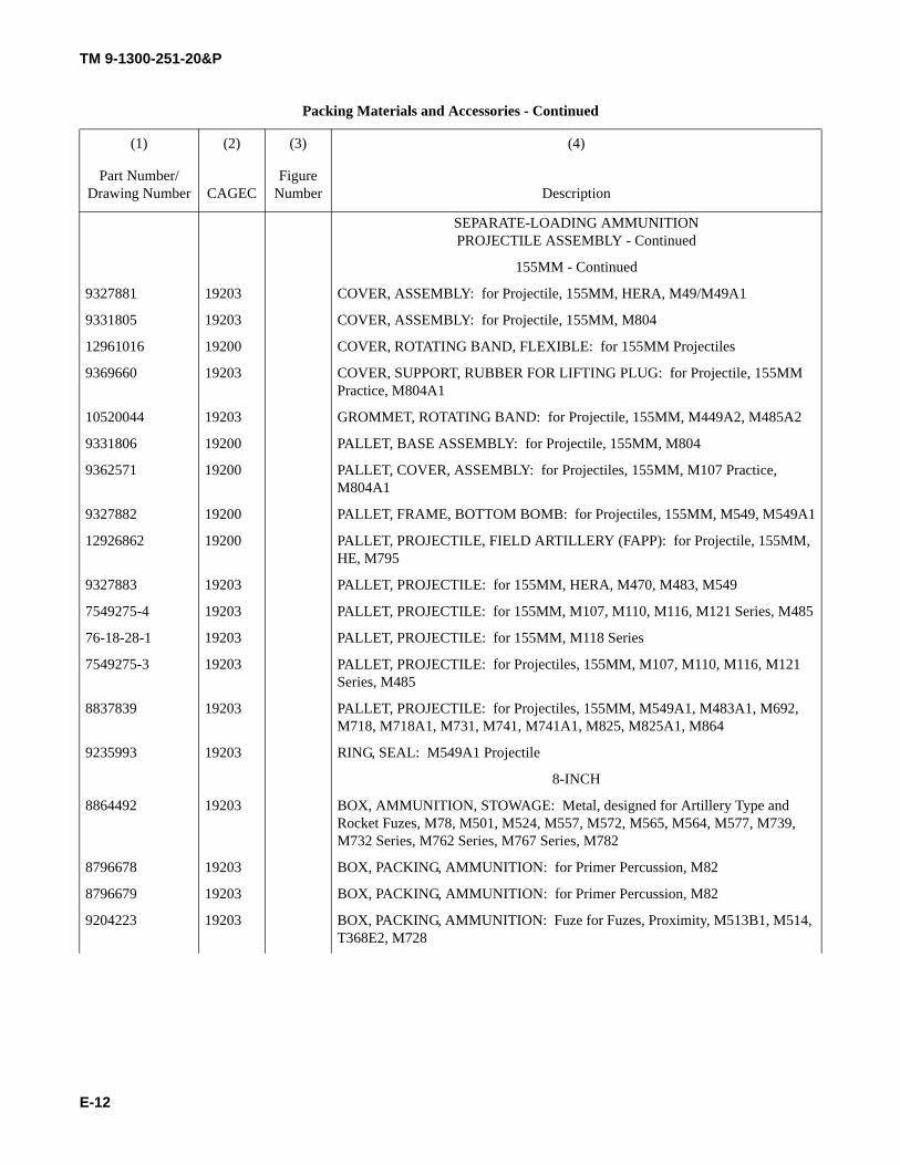
TM 9-1300-251-20&P
E-12
SEPARATE-LOADING AMMUNITION PROJECTILE ASSEMBLY - Continued
155MM - Continued
9327881 19203 COVER, ASSEMBLY: for Projectile, 155MM, HERA, M49/M49A1
9331805 19203 COVER, ASSEMBLY: for Projectile, 155MM, M804
12961016 19200 COVER, ROTATING BAND, FLEXIBLE: for 155MM Projectiles
9369660 19203 COVER, SUPPORT, RUBBER FOR LIFTING PLUG: for Projectile, 155MM Practice, M804A1
10520044 19203 GROMMET, ROTATING BAND: for Projectile, 155MM, M449A2, M485A2
9331806 19200 PALLET, BASE ASSEMBLY: for Projectile, 155MM, M804
9362571 19200 PALLET, COVER, ASSEMBLY: for Projectiles, 155MM, M107 Practice, M804A1
9327882 19200 PALLET, FRAME, BOTTOM BOMB: for Projectiles, 155MM, M549, M549A1
12926862 19200 PALLET, PROJECTILE, FIELD ARTILLERY (FAPP): for Projectile, 155MM, HE, M795
9327883 19203 PALLET, PROJECTILE: for 155MM, HERA, M470, M483, M549
7549275-4 19203 PALLET, PROJECTILE: for 155MM, M107, M110, M116, M121 Series, M485
76-18-28-1 19203 PALLET, PROJECTILE: for 155MM, M118 Series
7549275-3 19203 PALLET, PROJECTILE: for Projectiles, 155MM, M107, M110, M116, M121 Series, M485
8837839 19203 PALLET, PROJECTILE: for Projectiles, 155MM, M549A1, M483A1, M692, M718, M718A1, M731, M741, M741A1, M825, M825A1, M864
9235993 19203 RING, SEAL: M549A1 Projectile
8-INCH
8864492 19203 BOX, AMMUNITION, STOWAGE: Metal, designed for Artillery Type and Rocket Fuzes, M78, M501, M524, M557, M572, M565, M564, M577, M739, M732 Series, M762 Series, M767 Series, M782
8796678 19203 BOX, PACKING, AMMUNITION: for Primer Percussion, M82
8796679 19203 BOX, PACKING, AMMUNITION: for Primer Percussion, M82
9204223 19203 BOX, PACKING, AMMUNITION: Fuze for Fuzes, Proximity, M513B1, M514, T368E2, M728
Packing Materials and Accessories - Continued
(1) (2) (3) (4)
Part Number/Drawing Number CAGEC
Figure Number Description
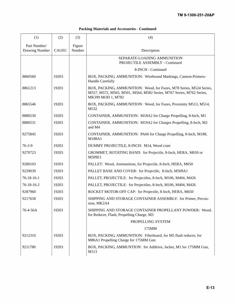
TM 9-1300-251-20&P
E-13
SEPARATE-LOADING AMMUNITION PROJECTILE ASSEMBLY - Continued
8-INCH - Continued
8860560 19203 BOX, PACKING, AMMUNITION: Wirebound Markings, Cannon-Primers- Handle Carefully
8861213 19203 BOX, PACKING, AMMUNITION: Wood, for Fuzes, M78 Series, M524 Series, M557, M572, M565, M501, M564, M582 Series, M767 Series, M762 Series, MK399 MOD 1, M782
8865546 19203 BOX, PACKING, AMMUNITION: Wood, for Fuzes, Proximity M513, M514, M532
8880530 19203 CONTAINER, AMMUNITION: M18A2 for Charge Propelling, 8-Inch, M1
8880531 19203 CONTAINER, AMMUNITION: M19A2 for Charges Propelling, 8-Inch, M2 and M4
9275845 19203 CONTAINER, AMMUNITION: PA66 for Charge Propelling, 8-Inch, M188, M188A1
76-3-9 19203 DUMMY PROJECTILE, 8-INCH: M14, Wood crate
9270723 19203 GROMMET, ROTATING BAND: for Projectile, 8-Inch, HERA, M650 or M509E1
9280103 19203 PALLET: Wood, Ammunition, for Projectile, 8-Inch, HERA, M650
9229039 19203 PALLET BASE AND COVER: for Projectile, 8-Inch, M509A1
76-18-16-1 19203 PALLET, PROJECTILE: for Projectiles, 8-Inch, M106, M404, M426
76-18-16-2 19203 PALLET, PROJECTILE: for Projectiles, 8-Inch, M106, M404, M426
9287960 19203 ROCKET MOTOR-OFF CAP: for Projectile, 8-Inch, HERA, M650
9217658 19203 SHIPPING AND STORAGE CONTAINER ASSEMBLY: for Primer, Percus-sion, MK2A4
76-4-56A 19203 SHIPPING AND STORAGE CONTAINER PROPELLANT POWDER: Wood, for Reducer, Flash, Propelling Charge, M3
PROPELLING SYSTEM
175MM
9212310 19203 BOX, PACKING, AMMUNITION: Fiberboard, for M5 flash reducer, for M86A1 Propelling Charge for 175MM Gun
9211780 19203 BOX, PACKING, AMMUNTION: for Additive, Jacket, M1 for 175MM Gun, M113
Packing Materials and Accessories - Continued
(1) (2) (3) (4)
Part Number/Drawing Number CAGEC
Figure Number Description
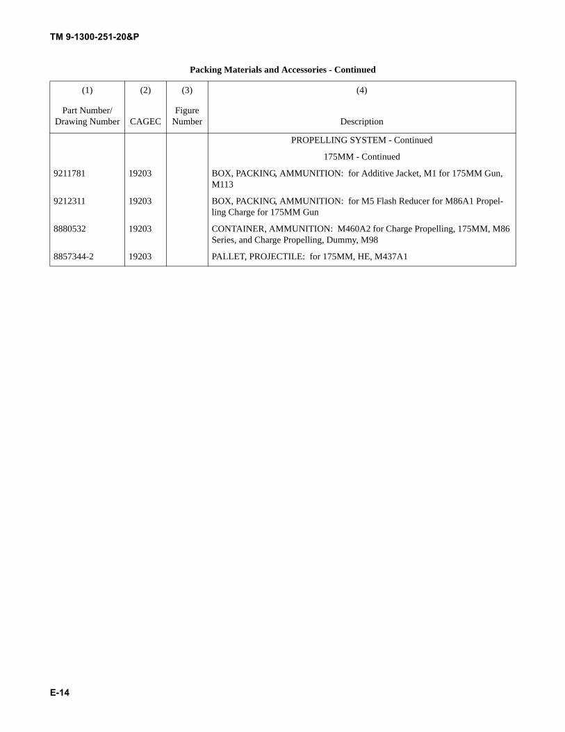
TM 9-1300-251-20&P
E-14
PROPELLING SYSTEM - Continued
175MM - Continued
9211781 19203 BOX, PACKING, AMMUNITION: for Additive Jacket, M1 for 175MM Gun, M113
9212311 19203 BOX, PACKING, AMMUNITION: for M5 Flash Reducer for M86A1 Propel-ling Charge for 175MM Gun
8880532 19203 CONTAINER, AMMUNITION: M460A2 for Charge Propelling, 175MM, M86 Series, and Charge Propelling, Dummy, M98
8857344-2 19203 PALLET, PROJECTILE: for 175MM, HE, M437A1
Packing Materials and Accessories - Continued
(1) (2) (3) (4)
Part Number/Drawing Number CAGEC
Figure Number Description

TM 9-1300-251-20&P
E-15
SECTION III SPECIAL PACKING TOOLS LIST
Not applicable.

TM 9-1300-251-20&P
E-16
THIS PAGE INTENTIONALLY LEFT BLANK
TM 9-1300-251-20&P
F-1
APPENDIX FPACKING, MARKING AND STORAGE
SECTION I INTRODUCTION
F.1 SCOPE.
This appendix contains information required by organiza-tional level of maintenance for repacking of artillery muni-tions.
F.2 EXPLANATION OF COLUMNS.
F.2.1 Column (1) - Item. The nomenclature of themunition.
F.2.2 Column (2) - Outer Pack. The type of package.
F.2.3 Column (3) - Inner Pack. The type of pack.
F.2.4 Column (4) - Number Items in Package. Thequantity of munitions in the outer pack.
F.2.5 Column (5) - Number Items per Inner Pack.The quantity of munitions in the inner pack.
F.2.6 Column (6) - Total Weight (lb). The total weightof the outer and inner pack and contents.
F.2.7 Column (7) - Total Explosive Weight (lb). Thetotal weight of explosives of the packaged munitions.
F.2.8 Column (8) - Cube. The result of the length, mul-tiplied by the width, multiplied by height of the outer pack.
F.3 Column (9) - Field Storage Category. The primarygroups into which ammunition is segregated for storage inthe field.
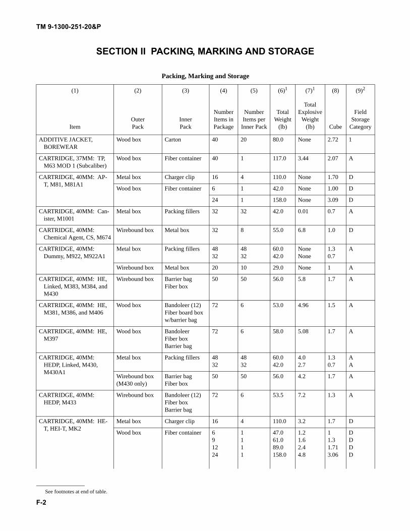
TM 9-1300-251-20&P
F-2
SECTION II PACKING, MARKING AND STORAGE
Packing, Marking and Storage
(1) (2) (3) (4) (5) (6)1 (7)1 (8) (9)2
ItemOuter Pack
Inner Pack
Number Items in Package
Number Items per
Inner Pack
Total Weight
(lb)
Total Explosive
Weight (lb) Cube
Field Storage
Category
ADDITIVE JACKET, BOREWEAR
Wood box Carton 40 20 80.0 None 2.72 1
CARTRIDGE, 37MM: TP, M63 MOD 1 (Subcaliber)
Wood box Fiber container 40 1 117.0 3.44 2.07 A
CARTRIDGE, 40MM: AP-T, M81, M81A1
Metal box Charger clip 16 4 110.0 None 1.70 D
Wood box Fiber container 6 1 42.0 None 1.00 D
24 1 158.0 None 3.09 D
CARTRIDGE, 40MM: Can-ister, M1001
Metal box Packing fillers 32 32 42.0 0.01 0.7 A
CARTRIDGE, 40MM: Chemical Agent, CS, M674
Wirebound box Metal box 32 8 55.0 6.8 1.0 D
CARTRIDGE, 40MM: Dummy, M922, M922A1
Metal box Packing fillers 4832
4832
60.042.0
NoneNone
1.30.7
A
Wirebound box Metal box 20 10 29.0 None 1 A
CARTRIDGE, 40MM: HE, Linked, M383, M384, and M430
Wirebound box Barrier bagFiber box
50 50 56.0 5.8 1.7 A
CARTRIDGE, 40MM: HE, M381, M386, and M406
Wood box Bandoleer (12)Fiber board box w/barrier bag
72 6 53.0 4.96 1.5 A
CARTRIDGE, 40MM: HE, M397
Wood box BandoleerFiber boxBarrier bag
72 6 58.0 5.08 1.7 A
CARTRIDGE, 40MM: HEDP, Linked, M430, M430A1
Metal box Packing fillers 4832
4832
60.042.0
4.02.7
1.30.7
AA
Wirebound box (M430 only)
Barrier bagFiber box
50 50 56.0 4.2 1.7 A
CARTRIDGE, 40MM: HEDP, M433
Wirebound box Bandoleer (12)Fiber boxBarrier bag
72 6 53.5 7.2 1.3 A
CARTRIDGE, 40MM: HE-T, HEI-T, MK2
Metal box Charger clip 16 4 110.0 3.2 1.7 D
Wood box Fiber container 691224
1111
47.061.089.0158.0
1.21.62.44.8
11.31.713.06
DDDD
See footnotes at end of table.
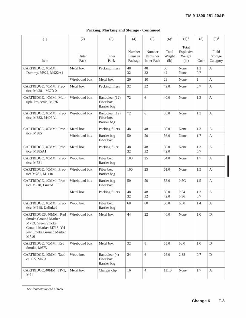
TM 9-1300-251-20&P
F-3
CARTRIDGE, 40MM: Dummy, M922, M922A1
Metal box Packing fillers 4832
4832
6042
NoneNone
1.30.7
A
Wirebound box Metal box 20 10 29 None 1 A
CARTRIDGE, 40MM: Prac-tice, Mk281 MOD 0
Metal box Packing fillers 32 32 42.0 None 0.7 A
CARTRIDGE, 40MM: Mul-tiple Projectile, M576
Wirebound box Bandoleer (12)Fiber boxBarrier bag
72 6 40.0 None 1.3 A
CARTRIDGE, 40MM: Prac-tice, M382, M407A1
Wirebound box Bandoleer (12)Fiber boxBarrier bag
72 6 53.0 None 1.3 A
CARTRIDGE, 40MM: Prac-tice, M385
Metal box Packing fillers 48 48 60.0 None 1.3 A
Wirebound box Barrier bagFiber box
50 50 56.0 None 1.7 A
CARTRIDGE, 40MM: Prac-tice, M385A1
Metal box Packing filler 4832
4832
60.042.0
None 1.30.7
A
CARTRIDGE, 40MM: Prac-tice, M781
Wood box Fiber boxBarrier bag
100 25 64.0 None 1.7 A
CARTRIDGE, 40MM: Prac-tice M781, M1110
Wirebound box Fiber boxBarrier bag
100 25 61.0 None 1.5 A
CARTRIDGE, 40MM: Prac-tice M918, Linked
Wirebound box Barrier bagFiber box
50 50 53.0 0.5G 1.5 A
Metal box Packing fillers 4832
4832
60.042.0
0.540.36
1.30.7
A
CARTRIDGE, 40MM: Prac-tice, M918, Unlinked
Wood box Fiber boxBarrier bag
60 60 66.0 68.0 1.4 A
CARTRIDGES, 40MM: Red Smoke Ground Marker M713, Green Smoke Ground Marker M715, Yel-low Smoke Ground Marker M716
Wirebound box Metal box 44 22 46.0 None 1.0 D
CARTRIDGE, 40MM: Red Smoke, M675
Wirebound box Metal box 32 8 55.0 68.0 1.0 D
CARTRIDGE, 40MM: Tacti-cal CS, M651
Wood box Bandoleer (4)Fiber boxBarrier bag
24 6 26.0 2.88 0.7 D
CARTRIDGE, 40MM: TP-T, M91
Metal box Charger clip 16 4 111.0 None 1.7 A
Packing, Marking and Storage - Continued
(1) (2) (3) (4) (5) (6)1 (7)1 (8) (9)2
ItemOuter Pack
Inner Pack
NumberItems in Package
NumberItems per
Inner Pack
Total Weight
(lb)
Total Explosive
Weight (lb) Cube
Field Storage
Category
See footnotes at end of table.
Change 6
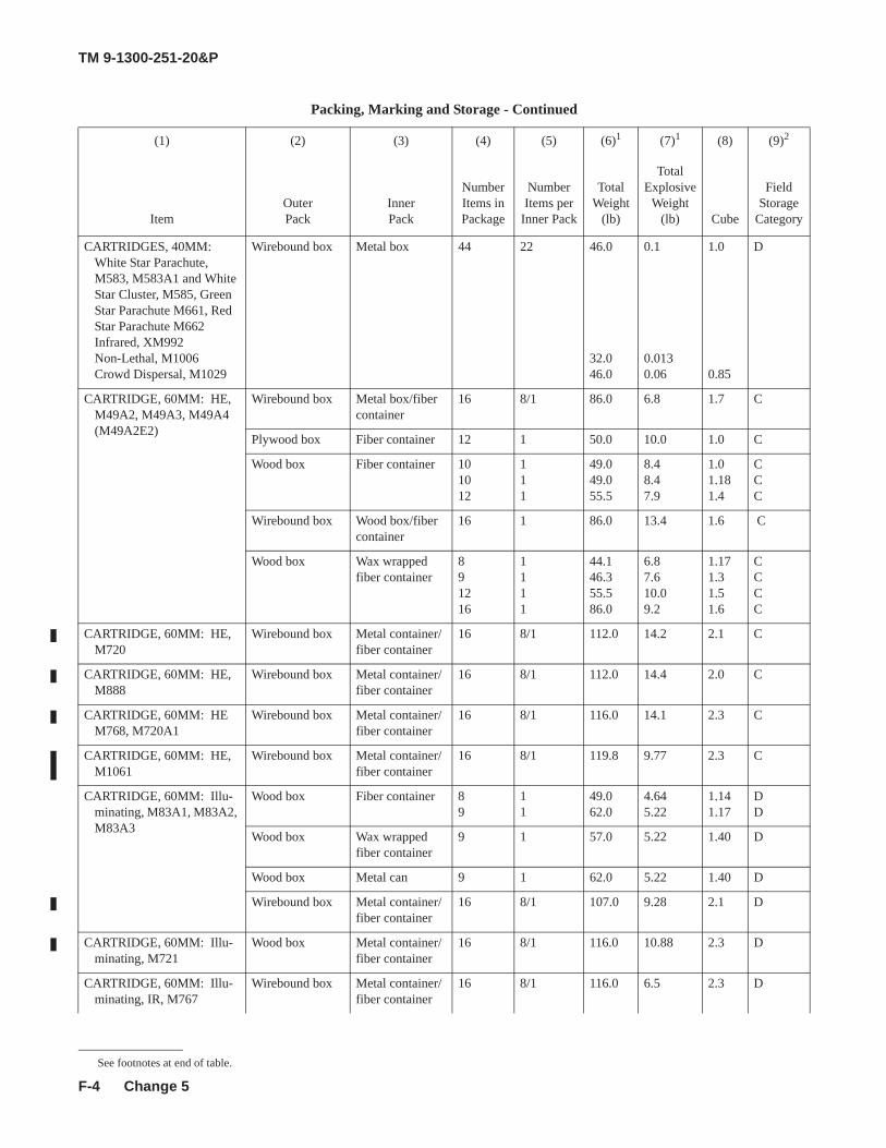
TM 9-1300-251-20&P
F-4
CARTRIDGES, 40MM: White Star Parachute, M583, M583A1 and White Star Cluster, M585, Green Star Parachute M661, Red Star Parachute M662Infrared, XM992Non-Lethal, M1006Crowd Dispersal, M1029
Wirebound box Metal box 44 22 46.0
32.046.0
0.1
0.0130.06
1.0
0.85
D
CARTRIDGE, 60MM: HE, M49A2, M49A3, M49A4 (M49A2E2)
Wirebound box Metal box/fiber container
16 8/1 86.0 6.8 1.7 C
Plywood box Fiber container 12 1 50.0 10.0 1.0 C
Wood box Fiber container 101012
111
49.049.055.5
8.48.47.9
1.01.181.4
CCC
Wirebound box Wood box/fiber container
16 1 86.0 13.4 1.6 C
Wood box Wax wrapped fiber container
891216
1111
44.146.355.586.0
6.87.610.09.2
1.171.31.51.6
CCCC
CARTRIDGE, 60MM: HE, M720
Wirebound box Metal container/fiber container
16 8/1 112.0 14.2 2.1 C
CARTRIDGE, 60MM: HE, M888
Wirebound box Metal container/fiber container
16 8/1 112.0 14.4 2.0 C
CARTRIDGE, 60MM: HE M768, M720A1
Wirebound box Metal container/fiber container
16 8/1 116.0 14.1 2.3 C
CARTRIDGE, 60MM: HE, M1061
Wirebound box Metal container/fiber container
16 8/1 119.8 9.77 2.3 C
CARTRIDGE, 60MM: Illu-minating, M83A1, M83A2, M83A3
Wood box Fiber container 89
11
49.062.0
4.645.22
1.141.17
DD
Wood box Wax wrapped fiber container
9 1 57.0 5.22 1.40 D
Wood box Metal can 9 1 62.0 5.22 1.40 D
Wirebound box Metal container/fiber container
16 8/1 107.0 9.28 2.1 D
CARTRIDGE, 60MM: Illu-minating, M721
Wood box Metal container/fiber container
16 8/1 116.0 10.88 2.3 D
CARTRIDGE, 60MM: Illu-minating, IR, M767
Wirebound box Metal container/fiber container
16 8/1 116.0 6.5 2.3 D
Packing, Marking and Storage - Continued
(1) (2) (3) (4) (5) (6)1 (7)1 (8) (9)2
ItemOuter Pack
Inner Pack
NumberItems in Package
NumberItems per
Inner Pack
Total Weight
(lb)
Total Explosive
Weight (lb) Cube
Field Storage
Category
See footnotes at end of table.
Change 5
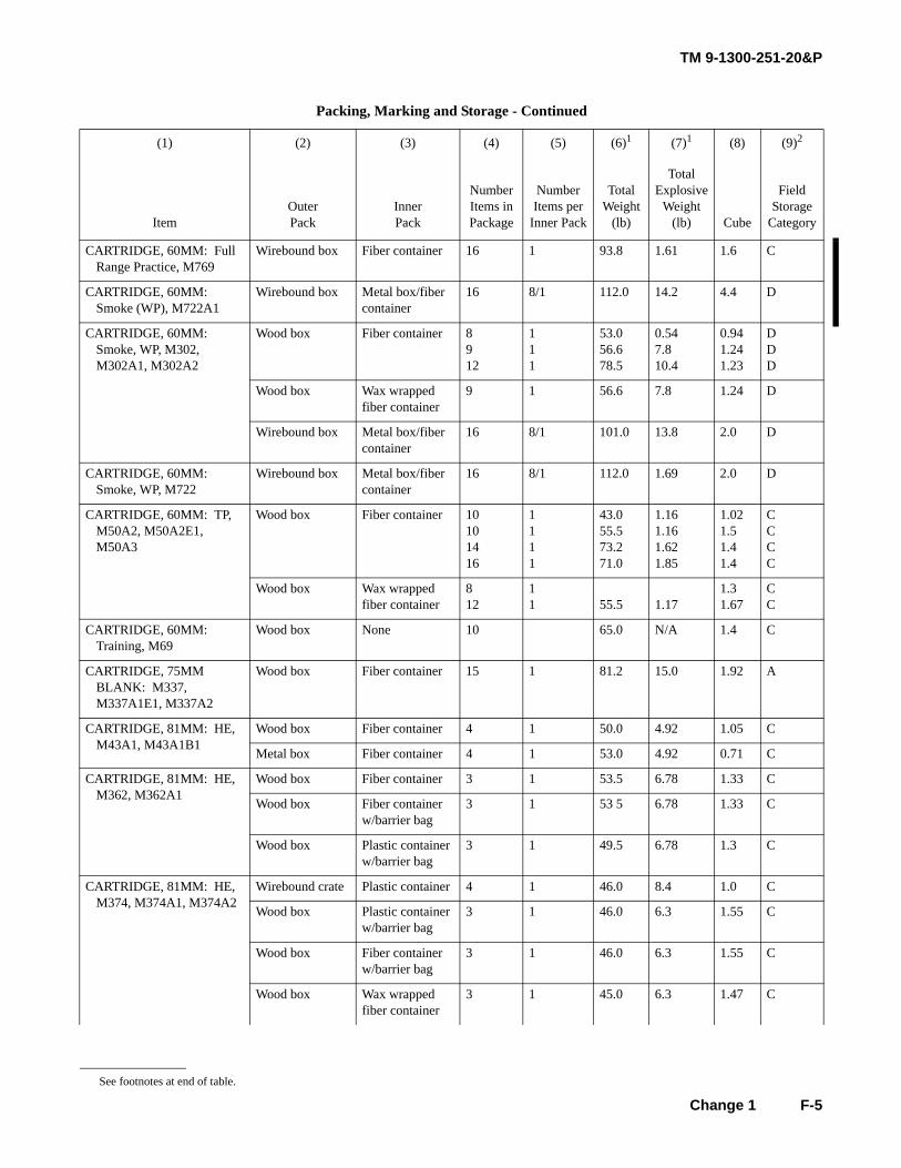
TM 9-1300-251-20&P
F-5
CARTRIDGE, 60MM: Full Range Practice, M769
Wirebound box Fiber container 16 1 93.8 1.61 1.6 C
CARTRIDGE, 60MM: Smoke (WP), M722A1
Wirebound box Metal box/fiber container
16 8/1 112.0 14.2 4.4 D
CARTRIDGE, 60MM: Smoke, WP, M302, M302A1, M302A2
Wood box Fiber container 8912
111
53.056.678.5
0.547.810.4
0.941.241.23
DDD
Wood box Wax wrapped fiber container
9 1 56.6 7.8 1.24 D
Wirebound box Metal box/fiber container
16 8/1 101.0 13.8 2.0 D
CARTRIDGE, 60MM: Smoke, WP, M722
Wirebound box Metal box/fiber container
16 8/1 112.0 1.69 2.0 D
CARTRIDGE, 60MM: TP, M50A2, M50A2E1, M50A3
Wood box Fiber container 10101416
1111
43.055.573.271.0
1.161.161.621.85
1.021.51.41.4
CCCC
Wood box Wax wrapped fiber container
812
11 55.5 1.17
1.31.67
CC
CARTRIDGE, 60MM: Training, M69
Wood box None 10 65.0 N/A 1.4 C
CARTRIDGE, 75MM BLANK: M337, M337A1E1, M337A2
Wood box Fiber container 15 1 81.2 15.0 1.92 A
CARTRIDGE, 81MM: HE, M43A1, M43A1B1
Wood box Fiber container 4 1 50.0 4.92 1.05 C
Metal box Fiber container 4 1 53.0 4.92 0.71 C
CARTRIDGE, 81MM: HE, M362, M362A1
Wood box Fiber container 3 1 53.5 6.78 1.33 C
Wood box Fiber container w/barrier bag
3 1 53 5 6.78 1.33 C
Wood box Plastic container w/barrier bag
3 1 49.5 6.78 1.3 C
CARTRIDGE, 81MM: HE, M374, M374A1, M374A2
Wirebound crate Plastic container 4 1 46.0 8.4 1.0 C
Wood box Plastic container w/barrier bag
3 1 46.0 6.3 1.55 C
Wood box Fiber container w/barrier bag
3 1 46.0 6.3 1.55 C
Wood box Wax wrapped fiber container
3 1 45.0 6.3 1.47 C
Packing, Marking and Storage - Continued
(1) (2) (3) (4) (5) (6)1 (7)1 (8) (9)2
ItemOuter Pack
Inner Pack
Number Items in Package
Number Items per
Inner Pack
Total Weight
(lb)
Total Explosive
Weight (lb) Cube
Field Storage
Category
See footnotes at end of table.
Change 1
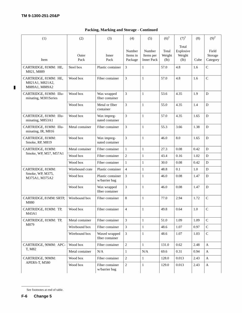
TM 9-1300-251-20&P
F-6
CARTRIDGE, 81MM: HE, M821, M889
Steel box Plastic container 3 1 57.0 4.8 1.6 C
CARTRIDGE, 81MM: HE, M821A1, M821A2, M889A1, M889A2
Wood box Fiber container 3 1 57.0 4.8 1.6 C
CARTRIDGE, 81MM: Illu-minating, M301Series
Wood box Wax wrapped fiber container
3 1 53.6 4.35 1.9 D
Wood box Metal or fiber container
3 1 55.0 4.35 1.4 D
CARTRIDGE, 81MM: Illu-minating, M853A1
Wood box Wax impreg-nated container
3 1 57.0 4.35 1.65 D
CARTRIDGE, 81MM: Illu-minating, IR, M816
Metal container Fiber container 3 1 55.3 3.66 1.38 D
CARTRIDGE, 81MM: Smoke, RP, M819
Wood box Wax impreg-nated container
3 1 46.0 8.0 1.65 D
CARTRIDGE, 81MM: Smoke, WP, M57, M57A1
Metal container Fiber container 1 1 27.3 0.08 0.42 D
Wood box Fiber container 2 1 43.4 0.16 1.02 D
Wood box Fiber container 1 1 30.0 0.08 0.42 D
CARTRIDGE, 81MM: Smoke, WP, M375, M375A1, M375A2
Wirebound crate Plastic container 4 1 48.8 0.1 1.0 D
Wood box Plastic container w/barrier bag
3 1 46.0 0.08 1.47 D
Wood box Wax wrapped fiber container
3 1 46.0 0.08 1.47 D
CARTRIDGE, 81MM: SRTP, M880
Wirebound box Fiber container 8 1 77.0 2.94 1.72 C
CARTRIDGE, 81MM: TP, M43A1
Wood box Fiber container 4 1 49.8 0.64 1.0 C
CARTRIDGE, 81MM: TP, M879
Metal container Fiber container 3 1 51.0 1.09 1.09 C
Wirebound box Fiber container 3 1 48.6 1.07 0.97 C
Wirebound box Waxed wrapped fiber container
3 1 48.6 1.07 1.03 C
CARTRIDGE, 90MM: APC-T, M82
Wood box Fiber container 2 1 131.0 0.62 2.48 A
Metal container N/A 1 N/A 69.6 0.31 0.94 A
CARTRIDGE, 90MM: APERS-T, M580
Wood box Fiber container 2 1 128.0 0.013 2.43 A
Wood box Fiber container w/barrier bag
2 1 129.0 0.013 2.43 A
Packing, Marking and Storage - Continued
(1) (2) (3) (4) (5) (6)1 (7)1 (8) (9)2
ItemOuter Pack
Inner Pack
Number Items in Package
Number Items per
Inner Pack
Total Weight
(lb)
Total Explosive
Weight (lb) Cube
Field Storage
Category
See footnotes at end of table.
Change 5
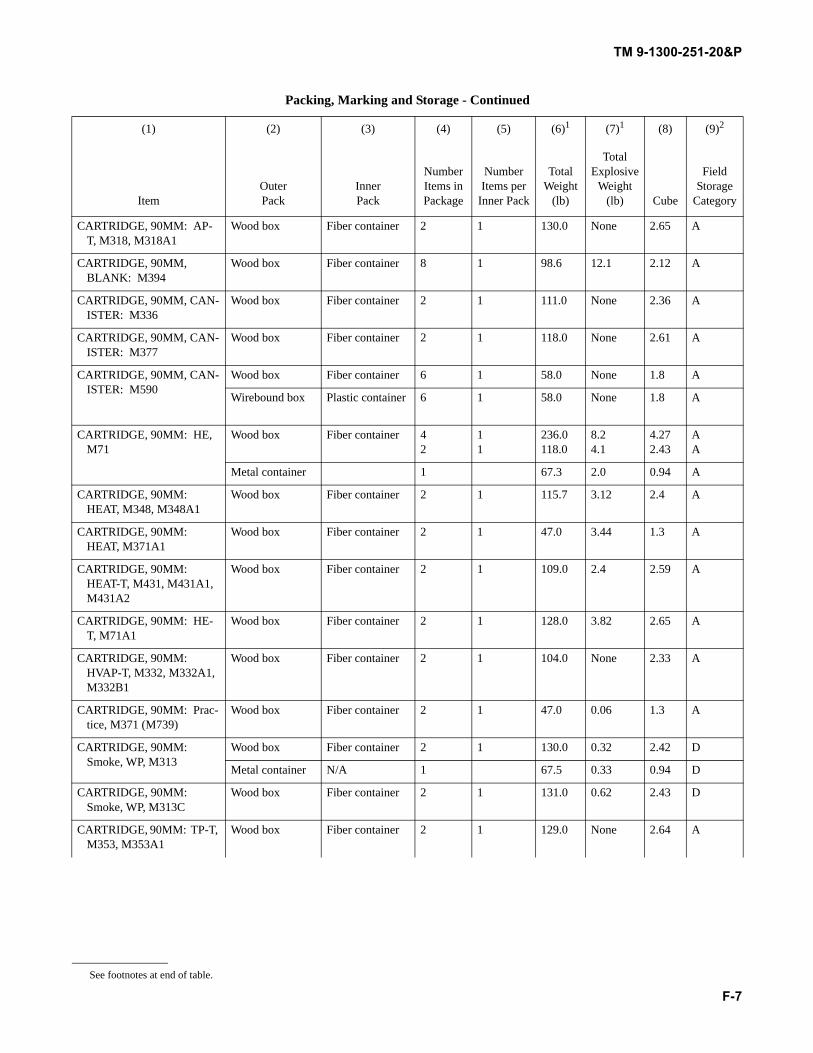
TM 9-1300-251-20&P
F-7
CARTRIDGE, 90MM: AP-T, M318, M318A1
Wood box Fiber container 2 1 130.0 None 2.65 A
CARTRIDGE, 90MM, BLANK: M394
Wood box Fiber container 8 1 98.6 12.1 2.12 A
CARTRIDGE, 90MM, CAN-ISTER: M336
Wood box Fiber container 2 1 111.0 None 2.36 A
CARTRIDGE, 90MM, CAN-ISTER: M377
Wood box Fiber container 2 1 118.0 None 2.61 A
CARTRIDGE, 90MM, CAN-ISTER: M590
Wood box Fiber container 6 1 58.0 None 1.8 A
Wirebound box Plastic container 6 1 58.0 None 1.8 A
CARTRIDGE, 90MM: HE, M71
Wood box Fiber container 42
11
236.0118.0
8.24.1
4.272.43
AA
Metal container 1 67.3 2.0 0.94 A
CARTRIDGE, 90MM: HEAT, M348, M348A1
Wood box Fiber container 2 1 115.7 3.12 2.4 A
CARTRIDGE, 90MM: HEAT, M371A1
Wood box Fiber container 2 1 47.0 3.44 1.3 A
CARTRIDGE, 90MM: HEAT-T, M431, M431A1, M431A2
Wood box Fiber container 2 1 109.0 2.4 2.59 A
CARTRIDGE, 90MM: HE-T, M71A1
Wood box Fiber container 2 1 128.0 3.82 2.65 A
CARTRIDGE, 90MM: HVAP-T, M332, M332A1, M332B1
Wood box Fiber container 2 1 104.0 None 2.33 A
CARTRIDGE, 90MM: Prac-tice, M371 (M739)
Wood box Fiber container 2 1 47.0 0.06 1.3 A
CARTRIDGE, 90MM: Smoke, WP, M313
Wood box Fiber container 2 1 130.0 0.32 2.42 D
Metal container N/A 1 67.5 0.33 0.94 D
CARTRIDGE, 90MM: Smoke, WP, M313C
Wood box Fiber container 2 1 131.0 0.62 2.43 D
CARTRIDGE, 90MM: TP-T, M353, M353A1
Wood box Fiber container 2 1 129.0 None 2.64 A
Packing, Marking and Storage - Continued
(1) (2) (3) (4) (5) (6)1 (7)1 (8) (9)2
ItemOuter Pack
Inner Pack
Number Items in Package
Number Items per
Inner Pack
Total Weight
(lb)
Total Explosive
Weight (lb) Cube
Field Storage
Category
See footnotes at end of table.
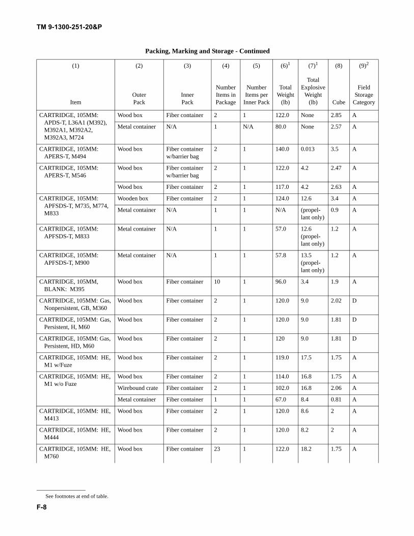
TM 9-1300-251-20&P
F-8
CARTRIDGE, 105MM: APDS-T, L36A1 (M392), M392A1, M392A2, M392A3, M724
Wood box Fiber container 2 1 122.0 None 2.85 A
Metal container N/A 1 N/A 80.0 None 2.57 A
CARTRIDGE, 105MM: APERS-T, M494
Wood box Fiber container w/barrier bag
2 1 140.0 0.013 3.5 A
CARTRIDGE, 105MM: APERS-T, M546
Wood box Fiber container w/barrier bag
2 1 122.0 4.2 2.47 A
Wood box Fiber container 2 1 117.0 4.2 2.63 A
CARTRIDGE, 105MM: APFSDS-T, M735, M774, M833
Wooden box Fiber container 2 1 124.0 12.6 3.4 A
Metal container N/A 1 1 N/A (propel-lant only)
0.9 A
CARTRIDGE, 105MM: APFSDS-T, M833
Metal container N/A 1 1 57.0 12.6(propel-lant only)
1.2 A
CARTRIDGE, 105MM: APFSDS-T, M900
Metal container N/A 1 1 57.8 13.5(propel-lant only)
1.2 A
CARTRIDGE, 105MM, BLANK: M395
Wood box Fiber container 10 1 96.0 3.4 1.9 A
CARTRIDGE, 105MM: Gas, Nonpersistent, GB, M360
Wood box Fiber container 2 1 120.0 9.0 2.02 D
CARTRIDGE, 105MM: Gas, Persistent, H, M60
Wood box Fiber container 2 1 120.0 9.0 1.81 D
CARTRIDGE, 105MM: Gas, Persistent, HD, M60
Wood box Fiber container 2 1 120 9.0 1.81 D
CARTRIDGE, 105MM: HE, M1 w/Fuze
Wood box Fiber container 2 1 119.0 17.5 1.75 A
CARTRIDGE, 105MM: HE, M1 w/o Fuze
Wood box Fiber container 2 1 114.0 16.8 1.75 A
Wirebound crate Fiber container 2 1 102.0 16.8 2.06 A
Metal container Fiber container 1 1 67.0 8.4 0.81 A
CARTRIDGE, 105MM: HE, M413
Wood box Fiber container 2 1 120.0 8.6 2 A
CARTRIDGE, 105MM: HE, M444
Wood box Fiber container 2 1 120.0 8.2 2 A
CARTRIDGE, 105MM: HE, M760
Wood box Fiber container 23 1 122.0 18.2 1.75 A
Packing, Marking and Storage - Continued
(1) (2) (3) (4) (5) (6)1 (7)1 (8) (9)2
ItemOuter Pack
Inner Pack
Number Items in Package
Number Items per
Inner Pack
Total Weight
(lb)
Total Explosive
Weight (lb) Cube
Field Storage
Category
See footnotes at end of table.
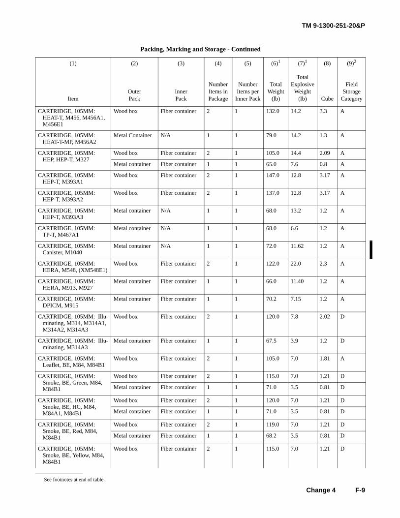
TM 9-1300-251-20&P
F-9
CARTRIDGE, 105MM: HEAT-T, M456, M456A1, M456E1
Wood box Fiber container 2 1 132.0 14.2 3.3 A
CARTRIDGE, 105MM: HEAT-T-MP, M456A2
Metal Container N/A 1 1 79.0 14.2 1.3 A
CARTRIDGE, 105MM: HEP, HEP-T, M327
Wood box Fiber container 2 1 105.0 14.4 2.09 A
Metal container Fiber container 1 1 65.0 7.6 0.8 A
CARTRIDGE, 105MM: HEP-T, M393A1
Wood box Fiber container 2 1 147.0 12.8 3.17 A
CARTRIDGE, 105MM: HEP-T, M393A2
Wood box Fiber container 2 1 137.0 12.8 3.17 A
CARTRIDGE, 105MM: HEP-T, M393A3
Metal container N/A 1 1 68.0 13.2 1.2 A
CARTRIDGE, 105MM: TP-T, M467A1
Metal container N/A 1 1 68.0 6.6 1.2 A
CARTRIDGE, 105MM: Canister, M1040
Metal container N/A 1 1 72.0 11.62 1.2 A
CARTRIDGE, 105MM: HERA, M548, (XM548E1)
Wood box Fiber container 2 1 122.0 22.0 2.3 A
CARTRIDGE, 105MM: HERA, M913, M927
Metal container Fiber container 1 1 66.0 11.40 1.2 A
CARTRIDGE, 105MM: DPICM, M915
Metal container Fiber container 1 1 70.2 7.15 1.2 A
CARTRIDGE, 105MM: Illu-minating, M314, M314A1, M314A2, M314A3
Wood box Fiber container 2 1 120.0 7.8 2.02 D
CARTRIDGE, 105MM: Illu-minating, M314A3
Metal container Fiber container 1 1 67.5 3.9 1.2 D
CARTRIDGE, 105MM: Leaflet, BE, M84, M84B1
Wood box Fiber container 2 1 105.0 7.0 1.81 A
CARTRIDGE, 105MM: Smoke, BE, Green, M84, M84B1
Wood box Fiber container 2 1 115.0 7.0 1.21 D
Metal container Fiber container 1 1 71.0 3.5 0.81 D
CARTRIDGE, 105MM: Smoke, BE, HC, M84, M84A1, M84B1
Wood box Fiber container 2 1 120.0 7.0 1.21 D
Metal container Fiber container 1 1 71.0 3.5 0.81 D
CARTRIDGE, 105MM: Smoke, BE, Red, M84, M84B1
Wood box Fiber container 2 1 119.0 7.0 1.21 D
Metal container Fiber container 1 1 68.2 3.5 0.81 D
CARTRIDGE, 105MM: Smoke, BE, Yellow, M84, M84B1
Wood box Fiber container 2 1 115.0 7.0 1.21 D
Packing, Marking and Storage - Continued
(1) (2) (3) (4) (5) (6)1 (7)1 (8) (9)2
ItemOuter Pack
Inner Pack
Number Items in Package
Number Items per
Inner Pack
Total Weight
(lb)
Total Explosive
Weight (lb) Cube
Field Storage
Category
See footnotes at end of table.
Change 4
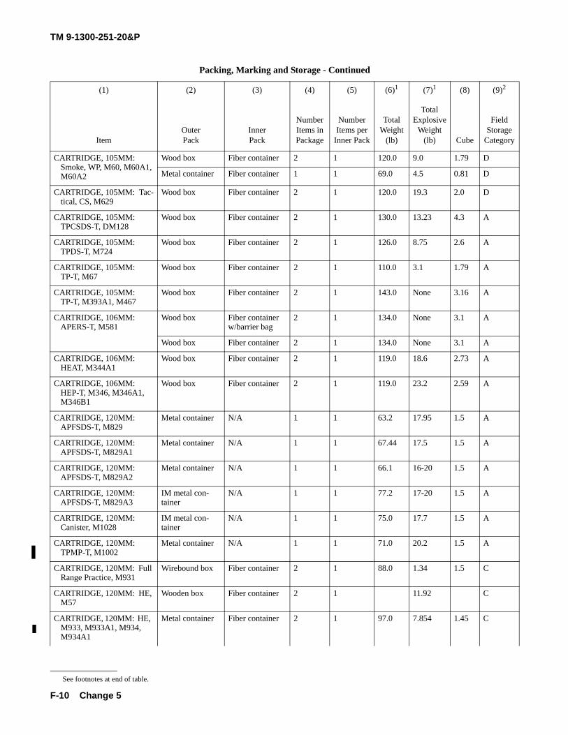
TM 9-1300-251-20&P
F-10
CARTRIDGE, 105MM: Smoke, WP, M60, M60A1, M60A2
Wood box Fiber container 2 1 120.0 9.0 1.79 D
Metal container Fiber container 1 1 69.0 4.5 0.81 D
CARTRIDGE, 105MM: Tac-tical, CS, M629
Wood box Fiber container 2 1 120.0 19.3 2.0 D
CARTRIDGE, 105MM: TPCSDS-T, DM128
Wood box Fiber container 2 1 130.0 13.23 4.3 A
CARTRIDGE, 105MM: TPDS-T, M724
Wood box Fiber container 2 1 126.0 8.75 2.6 A
CARTRIDGE, 105MM: TP-T, M67
Wood box Fiber container 2 1 110.0 3.1 1.79 A
CARTRIDGE, 105MM: TP-T, M393A1, M467
Wood box Fiber container 2 1 143.0 None 3.16 A
CARTRIDGE, 106MM: APERS-T, M581
Wood box Fiber container w/barrier bag
2 1 134.0 None 3.1 A
Wood box Fiber container 2 1 134.0 None 3.1 A
CARTRIDGE, 106MM: HEAT, M344A1
Wood box Fiber container 2 1 119.0 18.6 2.73 A
CARTRIDGE, 106MM: HEP-T, M346, M346A1, M346B1
Wood box Fiber container 2 1 119.0 23.2 2.59 A
CARTRIDGE, 120MM: APFSDS-T, M829
Metal container N/A 1 1 63.2 17.95 1.5 A
CARTRIDGE, 120MM: APFSDS-T, M829A1
Metal container N/A 1 1 67.44 17.5 1.5 A
CARTRIDGE, 120MM: APFSDS-T, M829A2
Metal container N/A 1 1 66.1 16-20 1.5 A
CARTRIDGE, 120MM: APFSDS-T, M829A3
IM metal con-tainer
N/A 1 1 77.2 17-20 1.5 A
CARTRIDGE, 120MM: Canister, M1028
IM metal con-tainer
N/A 1 1 75.0 17.7 1.5 A
CARTRIDGE, 120MM: TPMP-T, M1002
Metal container N/A 1 1 71.0 20.2 1.5 A
CARTRIDGE, 120MM: Full Range Practice, M931
Wirebound box Fiber container 2 1 88.0 1.34 1.5 C
CARTRIDGE, 120MM: HE, M57
Wooden box Fiber container 2 1 11.92 C
CARTRIDGE, 120MM: HE, M933, M933A1, M934, M934A1
Metal container Fiber container 2 1 97.0 7.854 1.45 C
Packing, Marking and Storage - Continued
(1) (2) (3) (4) (5) (6)1 (7)1 (8) (9)2
ItemOuter Pack
Inner Pack
Number Items in Package
Number Items per
Inner Pack
Total Weight
(lb)
Total Explosive
Weight (lb) Cube
Field Storage
Category
See footnotes at end of table.
Change 5
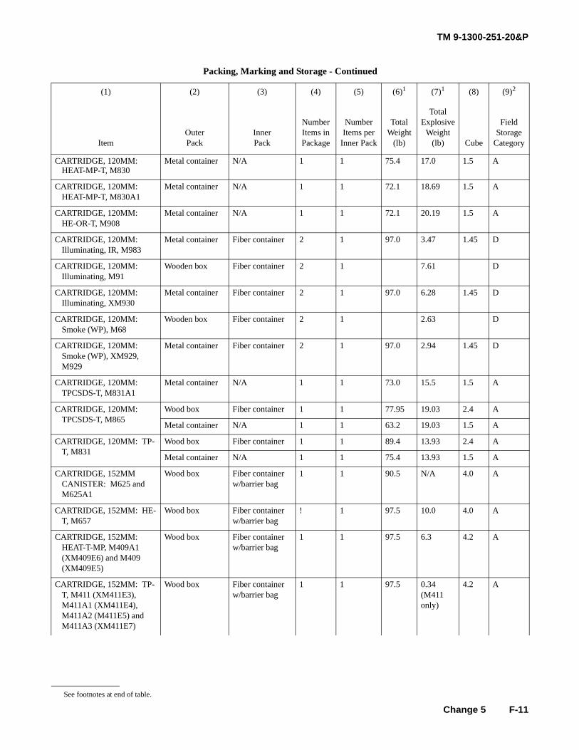
TM 9-1300-251-20&P
F-11
CARTRIDGE, 120MM: HEAT-MP-T, M830
Metal container N/A 1 1 75.4 17.0 1.5 A
CARTRIDGE, 120MM: HEAT-MP-T, M830A1
Metal container N/A 1 1 72.1 18.69 1.5 A
CARTRIDGE, 120MM:HE-OR-T, M908
Metal container N/A 1 1 72.1 20.19 1.5 A
CARTRIDGE, 120MM:Illuminating, IR, M983
Metal container Fiber container 2 1 97.0 3.47 1.45 D
CARTRIDGE, 120MM:Illuminating, M91
Wooden box Fiber container 2 1 7.61 D
CARTRIDGE, 120MM:Illuminating, XM930
Metal container Fiber container 2 1 97.0 6.28 1.45 D
CARTRIDGE, 120MM: Smoke (WP), M68
Wooden box Fiber container 2 1 2.63 D
CARTRIDGE, 120MM: Smoke (WP), XM929, M929
Metal container Fiber container 2 1 97.0 2.94 1.45 D
CARTRIDGE, 120MM: TPCSDS-T, M831A1
Metal container N/A 1 1 73.0 15.5 1.5 A
CARTRIDGE, 120MM: TPCSDS-T, M865
Wood box Fiber container 1 1 77.95 19.03 2.4 A
Metal container N/A 1 1 63.2 19.03 1.5 A
CARTRIDGE, 120MM: TP-T, M831
Wood box Fiber container 1 1 89.4 13.93 2.4 A
Metal container N/A 1 1 75.4 13.93 1.5 A
CARTRIDGE, 152MM CANISTER: M625 and M625A1
Wood box Fiber container w/barrier bag
1 1 90.5 N/A 4.0 A
CARTRIDGE, 152MM: HE-T, M657
Wood box Fiber container w/barrier bag
! 1 97.5 10.0 4.0 A
CARTRIDGE, 152MM: HEAT-T-MP, M409A1 (XM409E6) and M409 (XM409E5)
Wood box Fiber container w/barrier bag
1 1 97.5 6.3 4.2 A
CARTRIDGE, 152MM: TP-T, M411 (XM411E3), M411A1 (XM411E4), M411A2 (M411E5) and M411A3 (XM411E7)
Wood box Fiber container w/barrier bag
1 1 97.5 0.34(M411 only)
4.2 A
Packing, Marking and Storage - Continued
(1) (2) (3) (4) (5) (6)1 (7)1 (8) (9)2
ItemOuter Pack
Inner Pack
Number Items in Package
Number Items per
Inner Pack
Total Weight
(lb)
Total Explosive
Weight (lb) Cube
Field Storage
Category
See footnotes at end of table.
Change 5
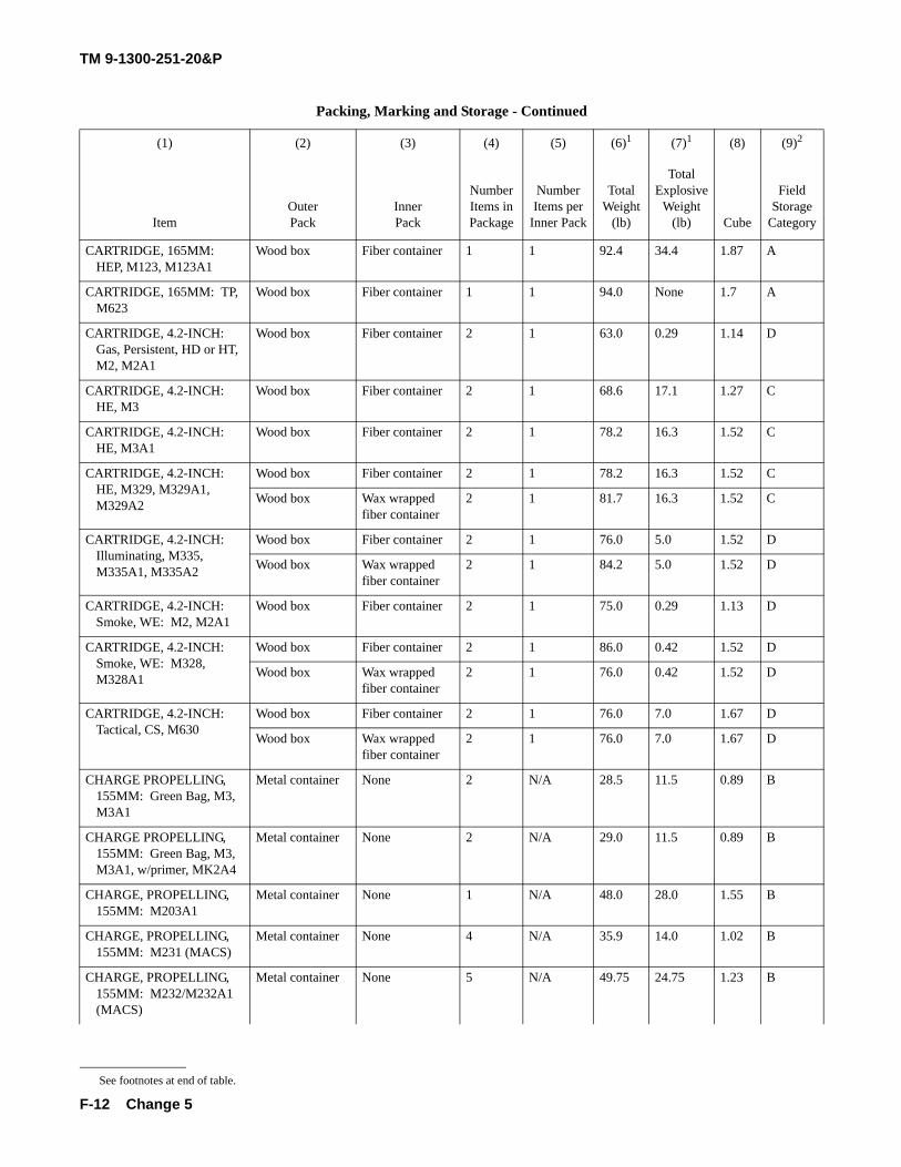
TM 9-1300-251-20&P
F-12
CARTRIDGE, 165MM: HEP, M123, M123A1
Wood box Fiber container 1 1 92.4 34.4 1.87 A
CARTRIDGE, 165MM: TP, M623
Wood box Fiber container 1 1 94.0 None 1.7 A
CARTRIDGE, 4.2-INCH: Gas, Persistent, HD or HT, M2, M2A1
Wood box Fiber container 2 1 63.0 0.29 1.14 D
CARTRIDGE, 4.2-INCH: HE, M3
Wood box Fiber container 2 1 68.6 17.1 1.27 C
CARTRIDGE, 4.2-INCH: HE, M3A1
Wood box Fiber container 2 1 78.2 16.3 1.52 C
CARTRIDGE, 4.2-INCH: HE, M329, M329A1, M329A2
Wood box Fiber container 2 1 78.2 16.3 1.52 C
Wood box Wax wrapped fiber container
2 1 81.7 16.3 1.52 C
CARTRIDGE, 4.2-INCH: Illuminating, M335, M335A1, M335A2
Wood box Fiber container 2 1 76.0 5.0 1.52 D
Wood box Wax wrapped fiber container
2 1 84.2 5.0 1.52 D
CARTRIDGE, 4.2-INCH: Smoke, WE: M2, M2A1
Wood box Fiber container 2 1 75.0 0.29 1.13 D
CARTRIDGE, 4.2-INCH: Smoke, WE: M328, M328A1
Wood box Fiber container 2 1 86.0 0.42 1.52 D
Wood box Wax wrapped fiber container
2 1 76.0 0.42 1.52 D
CARTRIDGE, 4.2-INCH: Tactical, CS, M630
Wood box Fiber container 2 1 76.0 7.0 1.67 D
Wood box Wax wrapped fiber container
2 1 76.0 7.0 1.67 D
CHARGE PROPELLING, 155MM: Green Bag, M3, M3A1
Metal container None 2 N/A 28.5 11.5 0.89 B
CHARGE PROPELLING, 155MM: Green Bag, M3, M3A1, w/primer, MK2A4
Metal container None 2 N/A 29.0 11.5 0.89 B
CHARGE, PROPELLING, 155MM: M203A1
Metal container None 1 N/A 48.0 28.0 1.55 B
CHARGE, PROPELLING, 155MM: M231 (MACS)
Metal container None 4 N/A 35.9 14.0 1.02 B
CHARGE, PROPELLING, 155MM: M232/M232A1 (MACS)
Metal container None 5 N/A 49.75 24.75 1.23 B
Packing, Marking and Storage - Continued
(1) (2) (3) (4) (5) (6)1 (7)1 (8) (9)2
ItemOuter Pack
Inner Pack
Number Items in Package
Number Items per
Inner Pack
Total Weight
(lb)
Total Explosive
Weight (lb) Cube
Field Storage
Category
See footnotes at end of table.
Change 5
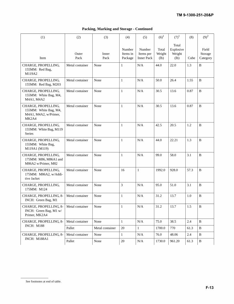
TM 9-1300-251-20&P
F-13
CHARGE, PROPELLING, 155MM: Red Bag, M119A2
Metal container None 1 N/A 44.0 22.0 1.3 B
CHARGE, PROPELLING, 155MM: Red Bag, M203
Metal container None 1 N/A 50.0 26.4 1.55 B
CHARGE, PROPELLING, 155MM: White Bag, M4, M4A1, M4A2
Metal container None 1 N/A 30.5 13.6 0.87 B
CHARGE, PROPELLING, 155MM: White Bag, M4, M4A1, M4A2, w/Primer, MK2A4
Metal container None 1 N/A 30.5 13.6 0.87 B
CHARGE, PROPELLING, 155MM: White Bag, M119 Series
Metal container None 1 N/A 42.5 20.5 1.2 B
CHARGE, PROPELLING, 155MM: White Bag, M119A1 (M119)
Metal container None 1 N/A 44.0 22.21 1.3 B
CHARGE, PROPELLING, 175MM: M86, M86A1 and M86A2 w/Primer, M82
Metal container None 1 N/A 99.0 58.0 3.1 B
CHARGE, PROPELLING, 175MM: M86A2, w/Addi-tive Jacket
Metal container None 16 1 1992.0 928.0 57.3 B
CHARGE, PROPELLING, 175MM: M124
Metal container None 3 N/A 95.0 51.0 3.1 B
CHARGE, PROPELLING, 8-INCH: Green Bag, M1
Metal container None 1 N/A 31.2 13.7 1.0 B
CHARGE, PROPELLING, 8-INCH: Green Bag, M1 w/Primer, MK2A4
Metal container None 1 N/A 31.2 13.7 1.5 B
CHARGE, PROPELLING, 8-INCH: M188
Metal container None 1 N/A 75.0 38.5 2.4 B
Pallet Metal container 20 1 1700.0 770 61.3 B
CHARGE, PROPELLING, 8-INCH: M188A1
Metal container None 1 N/A 76.0 48.06 2.4 B
Pallet None 20 N/A 1730.0 961.20 61.3 B
Packing, Marking and Storage - Continued
(1) (2) (3) (4) (5) (6)1 (7)1 (8) (9)2
ItemOuter Pack
Inner Pack
Number Items in Package
Number Items per
Inner Pack
Total Weight
(lb)
Total Explosive
Weight (lb) Cube
Field Storage
Category
See footnotes at end of table.
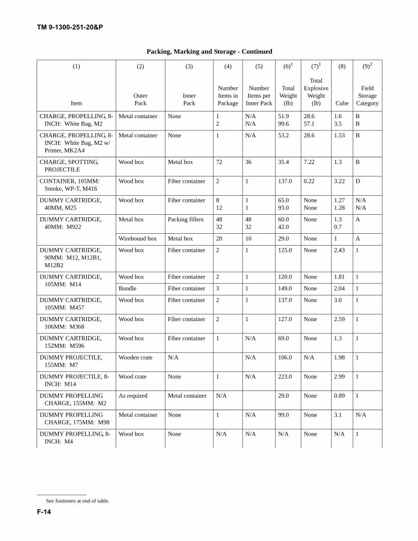
TM 9-1300-251-20&P
F-14
CHARGE, PROPELLING, 8-INCH: White Bag, M2
Metal container None 12
N/AN/A
51.999.6
28.657.1
1.63.5
BB
CHARGE, PROPELLING, 8-INCH: White Bag, M2 w/Primer, MK2A4
Metal container None 1 N/A 53.2 28.6 1.53 B
CHARGE, SPOTTING, PROJECTILE
Wood box Metal box 72 36 35.4 7.22 1.3 B
CONTAINER, 105MM: Smoke, WP-T, M416
Wood box Fiber container 2 1 137.0 0.22 3.22 D
DUMMY CARTRIDGE, 40MM, M25
Wood box Fiber container 812
11
65.093.0
NoneNone
1.271.28
N/AN/A
DUMMY CARTRIDGE, 40MM: M922
Metal box Packing fillers 4832
4832
60.042.0
None 1.30.7
A
Wirebound box Metal box 20 10 29.0 None 1 A
DUMMY CARTRIDGE, 90MM: M12, M12B1, M12B2
Wood box Fiber container 2 1 125.0 None 2.43 1
DUMMY CARTRIDGE, 105MM: M14
Wood box Fiber container 2 1 120.0 None 1.81 1
Bundle Fiber container 3 1 149.0 None 2.04 1
DUMMY CARTRIDGE, 105MM: M457
Wood box Fiber container 2 1 137.0 None 3.0 1
DUMMY CARTRIDGE, 106MM: M368
Wood box Fiber container 2 1 127.0 None 2.59 1
DUMMY CARTRIDGE, 152MM: M596
Wood box Fiber container 1 N/A 69.0 None 1.3 1
DUMMY PROJECTILE, 155MM: M7
Wooden crate N/A N/A 106.0 N/A 1.98 1
DUMMY PROJECTILE, 8-INCH: M14
Wood crate None 1 N/A 223.0 None 2.99 1
DUMMY PROPELLING CHARGE, 155MM: M2
As required Metal container N/A 29.0 None 0.89 1
DUMMY PROPELLING CHARGE, 175MM: M98
Metal container None 1 N/A 99.0 None 3.1 N/A
DUMMY PROPELLING, 8-INCH: M4
Wood box None N/A N/A N/A None N/A 1
Packing, Marking and Storage - Continued
(1) (2) (3) (4) (5) (6)1 (7)1 (8) (9)2
ItemOuter Pack
Inner Pack
Number Items in Package
Number Items per
Inner Pack
Total Weight
(lb)
Total Explosive
Weight (lb) Cube
Field Storage
Category
See footnotes at end of table.
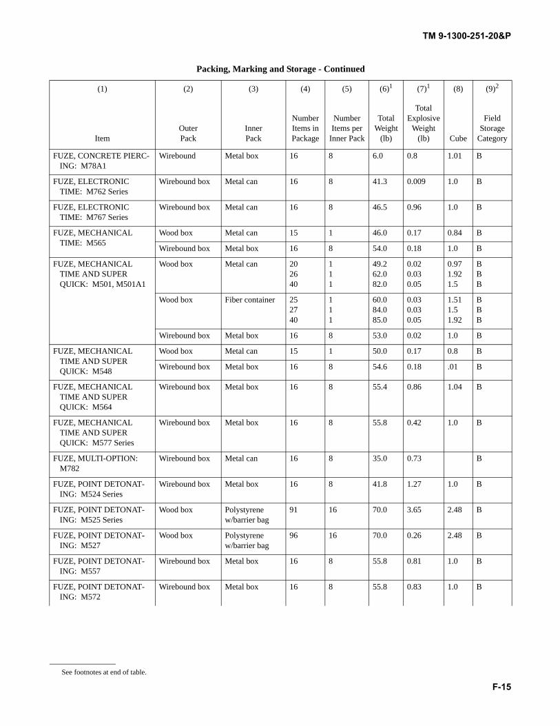
TM 9-1300-251-20&P
F-15
FUZE, CONCRETE PIERC-ING: M78A1
Wirebound Metal box 16 8 6.0 0.8 1.01 B
FUZE, ELECTRONIC TIME: M762 Series
Wirebound box Metal can 16 8 41.3 0.009 1.0 B
FUZE, ELECTRONIC TIME: M767 Series
Wirebound box Metal can 16 8 46.5 0.96 1.0 B
FUZE, MECHANICAL TIME: M565
Wood box Metal can 15 1 46.0 0.17 0.84 B
Wirebound box Metal box 16 8 54.0 0.18 1.0 B
FUZE, MECHANICAL TIME AND SUPER QUICK: M501, M501A1
Wood box Metal can 202640
111
49.262.082.0
0.020.030.05
0.971.921.5
BBB
Wood box Fiber container 252740
111
60.084.085.0
0.030.030.05
1.511.51.92
BBB
Wirebound box Metal box 16 8 53.0 0.02 1.0 B
FUZE, MECHANICAL TIME AND SUPER QUICK: M548
Wood box Metal can 15 1 50.0 0.17 0.8 B
Wirebound box Metal box 16 8 54.6 0.18 .01 B
FUZE, MECHANICAL TIME AND SUPER QUICK: M564
Wirebound box Metal box 16 8 55.4 0.86 1.04 B
FUZE, MECHANICAL TIME AND SUPER QUICK: M577 Series
Wirebound box Metal box 16 8 55.8 0.42 1.0 B
FUZE, MULTI-OPTION: M782
Wirebound box Metal can 16 8 35.0 0.73 B
FUZE, POINT DETONAT-ING: M524 Series
Wirebound box Metal box 16 8 41.8 1.27 1.0 B
FUZE, POINT DETONAT-ING: M525 Series
Wood box Polystyrene w/barrier bag
91 16 70.0 3.65 2.48 B
FUZE, POINT DETONAT-ING: M527
Wood box Polystyrene w/barrier bag
96 16 70.0 0.26 2.48 B
FUZE, POINT DETONAT-ING: M557
Wirebound box Metal box 16 8 55.8 0.81 1.0 B
FUZE, POINT DETONAT-ING: M572
Wirebound box Metal box 16 8 55.8 0.83 1.0 B
Packing, Marking and Storage - Continued
(1) (2) (3) (4) (5) (6)1 (7)1 (8) (9)2
ItemOuter Pack
Inner Pack
Number Items in Package
Number Items per
Inner Pack
Total Weight
(lb)
Total Explosive
Weight (lb) Cube
Field Storage
Category
See footnotes at end of table.
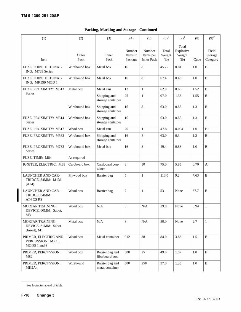
TM 9-1300-251-20&P
F-16
FUZE, POINT DETONAT-ING: M739 Series
Wirebound box Metal box 16 8 45.72 0.81 1.0 B
FUZE, POINT DETONAT-ING: MK399 MOD 1
Wirebound box Metal box 16 8 67.4 0.43 1.0 B
FUZE, PROXIMITY: M513 Series
Metal box Metal can 12 1 62.0 0.66 1.52 B
Shipping and storage container
25 1 97.0 1.38 1.55 B
Wirebound box Shipping and storage container
16 8 63.0 0.88 1.31 B
FUZE, PROXIMITY: M514 Series
Wirebound box Shipping and storage container
16 63.0 0.88 1.31 B
FUZE, PROXIMITY: M517 Wood box Metal can 20 1 47.8 0.004 1.0 B
FUZE, PROXIMITY: M532 Wirebound box Shipping and storage container
16 8 63.0 0.3 1.3 B
FUZE, PROXIMITY: M732 Series
Wirebound box Metal box 16 8 49.4 0.88 1.0 B
FUZE, TIME: M84 As required
IGNITER, ELECTRIC: M63 Cardboard box Cardboard con-tainer
9 50 75.0 5.85 0.70 A
LAUNCHER AND CAR-TRIDGE, 84MM: M136 (AT4)
Plywood box Barrier bag 5 1 113.0 9.2 7.63 E
LAUNCHER AND CAR-TRIDGE, 84MM:AT4 CS RS
Wood box Barrier bag 2 1 53 None 37.7 E
MORTAR TRAINING DEVICE, 60MM: Sabot, M3
Wood box N/A 3 N/A 39.0 None 0.94 1
MORTAR TRAINING DEVICE, 81MM: Sabot (Insert), M1
Metal box N/A 3 N/A 50.0 None 2.7 1
PRIMER, ELECTRIC AND PERCUSSION: MK15, MODS 1 and 3
Wood box Metal container 912 38 84.0 3.83 1.51 B
PRIMER, PERCUSSION: M82
Wood box Barrier bag and fiberboard box
500 25 49.0 1.57 1.8 B
PRIMER, PERCUSSION: MK2A4
Wirebound Barrier bag and metal container
500 250 37.0 1.35 1.0 B
Packing, Marking and Storage - Continued
(1) (2) (3) (4) (5) (6)1 (7)1 (8) (9)2
ItemOuter Pack
Inner Pack
Number Items in Package
Number Items per
Inner Pack
Total Weight
(lb)
Total Explosive
Weight (lb) Cube
Field Storage
Category
See footnotes at end of table.
Change 3PIN: 072718-003
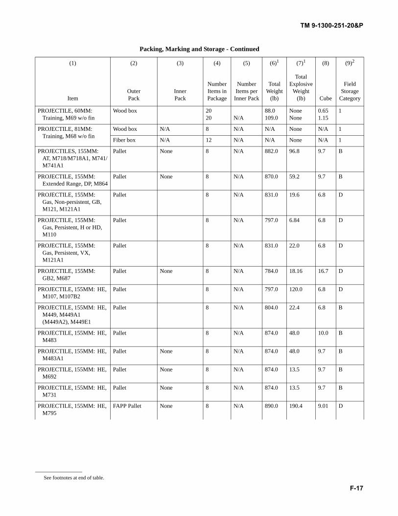
TM 9-1300-251-20&P
F-17
PROJECTILE, 60MM: Training, M69 w/o fin
Wood box 2020 N/A
88.0109.0
NoneNone
0.651.15
1
PROJECTILE, 81MM: Training, M68 w/o fin
Wood box N/A 8 N/A N/A None N/A 1
Fiber box N/A 12 N/A N/A None N/A 1
PROJECTILES, 155MM: AT, M718/M718A1, M741/M741A1
Pallet None 8 N/A 882.0 96.8 9.7 B
PROJECTILE, 155MM: Extended Range, DP, M864
Pallet None 8 N/A 870.0 59.2 9.7 B
PROJECTILE, 155MM: Gas, Non-persistent, GB, M121, M121A1
Pallet 8 N/A 831.0 19.6 6.8 D
PROJECTILE, 155MM: Gas, Persistent, H or HD, M110
Pallet 8 N/A 797.0 6.84 6.8 D
PROJECTILE, 155MM: Gas, Persistent, VX, M121A1
Pallet 8 N/A 831.0 22.0 6.8 D
PROJECTILE, 155MM: GB2, M687
Pallet None 8 N/A 784.0 18.16 16.7 D
PROJECTILE, 155MM: HE, M107, M107B2
Pallet 8 N/A 797.0 120.0 6.8 D
PROJECTILE, 155MM: HE, M449, M449A1 (M449A2), M449E1
Pallet 8 N/A 804.0 22.4 6.8 B
PROJECTILE, 155MM: HE, M483
Pallet 8 N/A 874.0 48.0 10.0 B
PROJECTILE, 155MM: HE, M483A1
Pallet None 8 N/A 874.0 48.0 9.7 B
PROJECTILE, 155MM: HE, M692
Pallet None 8 N/A 874.0 13.5 9.7 B
PROJECTILE, 155MM: HE, M731
Pallet None 8 N/A 874.0 13.5 9.7 B
PROJECTILE, 155MM: HE, M795
FAPP Pallet None 8 N/A 890.0 190.4 9.01 D
Packing, Marking and Storage - Continued
(1) (2) (3) (4) (5) (6)1 (7)1 (8) (9)2
ItemOuter Pack
Inner Pack
Number Items in Package
Number Items per
Inner Pack
Total Weight
(lb)
Total Explosive
Weight (lb) Cube
Field Storage
Category
See footnotes at end of table.
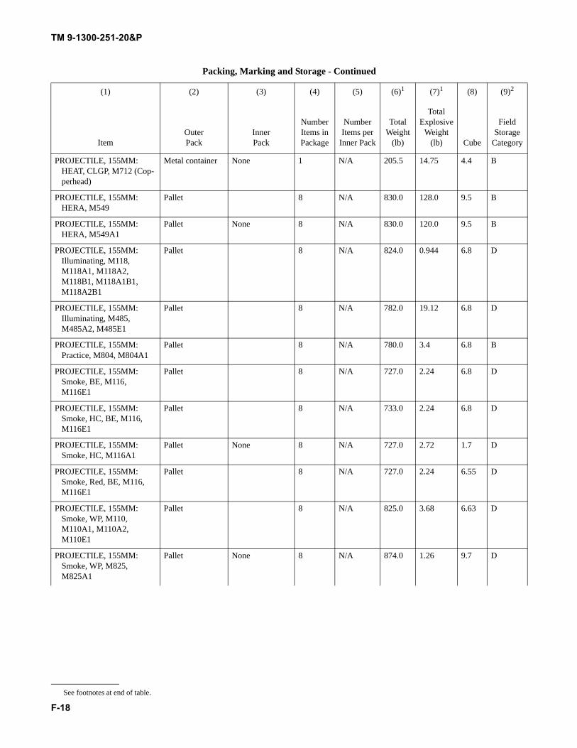
TM 9-1300-251-20&P
F-18
PROJECTILE, 155MM: HEAT, CLGP, M712 (Cop-perhead)
Metal container None 1 N/A 205.5 14.75 4.4 B
PROJECTILE, 155MM: HERA, M549
Pallet 8 N/A 830.0 128.0 9.5 B
PROJECTILE, 155MM: HERA, M549A1
Pallet None 8 N/A 830.0 120.0 9.5 B
PROJECTILE, 155MM: Illuminating, M118, M118A1, M118A2, M118B1, M118A1B1, M118A2B1
Pallet 8 N/A 824.0 0.944 6.8 D
PROJECTILE, 155MM: Illuminating, M485, M485A2, M485E1
Pallet 8 N/A 782.0 19.12 6.8 D
PROJECTILE, 155MM: Practice, M804, M804A1
Pallet 8 N/A 780.0 3.4 6.8 B
PROJECTILE, 155MM: Smoke, BE, M116, M116E1
Pallet 8 N/A 727.0 2.24 6.8 D
PROJECTILE, 155MM: Smoke, HC, BE, M116, M116E1
Pallet 8 N/A 733.0 2.24 6.8 D
PROJECTILE, 155MM: Smoke, HC, M116A1
Pallet None 8 N/A 727.0 2.72 1.7 D
PROJECTILE, 155MM: Smoke, Red, BE, M116, M116E1
Pallet 8 N/A 727.0 2.24 6.55 D
PROJECTILE, 155MM: Smoke, WP, M110, M110A1, M110A2, M110E1
Pallet 8 N/A 825.0 3.68 6.63 D
PROJECTILE, 155MM: Smoke, WP, M825, M825A1
Pallet None 8 N/A 874.0 1.26 9.7 D
Packing, Marking and Storage - Continued
(1) (2) (3) (4) (5) (6)1 (7)1 (8) (9)2
ItemOuter Pack
Inner Pack
Number Items in Package
Number Items per
Inner Pack
Total Weight
(lb)
Total Explosive
Weight (lb) Cube
Field Storage
Category
See footnotes at end of table.
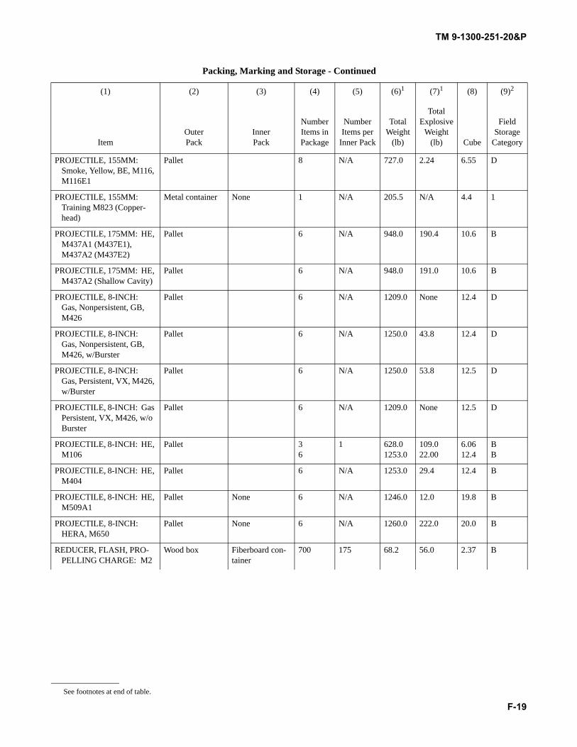
TM 9-1300-251-20&P
F-19
PROJECTILE, 155MM: Smoke, Yellow, BE, M116, M116E1
Pallet 8 N/A 727.0 2.24 6.55 D
PROJECTILE, 155MM: Training M823 (Copper-head)
Metal container None 1 N/A 205.5 N/A 4.4 1
PROJECTILE, 175MM: HE, M437A1 (M437E1), M437A2 (M437E2)
Pallet 6 N/A 948.0 190.4 10.6 B
PROJECTILE, 175MM: HE, M437A2 (Shallow Cavity)
Pallet 6 N/A 948.0 191.0 10.6 B
PROJECTILE, 8-INCH: Gas, Nonpersistent, GB, M426
Pallet 6 N/A 1209.0 None 12.4 D
PROJECTILE, 8-INCH: Gas, Nonpersistent, GB, M426, w/Burster
Pallet 6 N/A 1250.0 43.8 12.4 D
PROJECTILE, 8-INCH: Gas, Persistent, VX, M426, w/Burster
Pallet 6 N/A 1250.0 53.8 12.5 D
PROJECTILE, 8-INCH: Gas Persistent, VX, M426, w/o Burster
Pallet 6 N/A 1209.0 None 12.5 D
PROJECTILE, 8-INCH: HE, M106
Pallet 36
1 628.01253.0
109.022.00
6.0612.4
BB
PROJECTILE, 8-INCH: HE, M404
Pallet 6 N/A 1253.0 29.4 12.4 B
PROJECTILE, 8-INCH: HE, M509A1
Pallet None 6 N/A 1246.0 12.0 19.8 B
PROJECTILE, 8-INCH: HERA, M650
Pallet None 6 N/A 1260.0 222.0 20.0 B
REDUCER, FLASH, PRO-PELLING CHARGE: M2
Wood box Fiberboard con-tainer
700 175 68.2 56.0 2.37 B
Packing, Marking and Storage - Continued
(1) (2) (3) (4) (5) (6)1 (7)1 (8) (9)2
ItemOuter Pack
Inner Pack
Number Items in Package
Number Items per
Inner Pack
Total Weight
(lb)
Total Explosive
Weight (lb) Cube
Field Storage
Category
See footnotes at end of table.
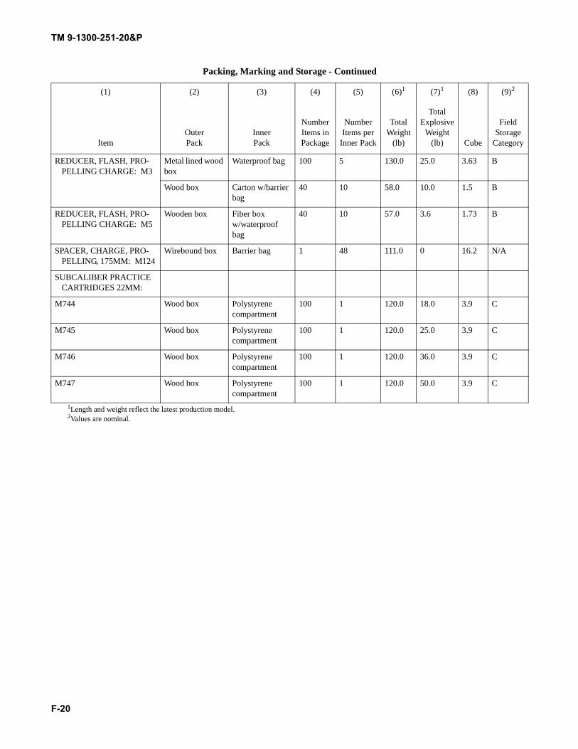
TM 9-1300-251-20&P
F-20
REDUCER, FLASH, PRO-PELLING CHARGE: M3
Metal lined wood box
Waterproof bag 100 5 130.0 25.0 3.63 B
Wood box Carton w/barrier bag
40 10 58.0 10.0 1.5 B
REDUCER, FLASH, PRO-PELLING CHARGE: M5
Wooden box Fiber box w/waterproof bag
40 10 57.0 3.6 1.73 B
SPACER, CHARGE, PRO-PELLING, 175MM: M124
Wirebound box Barrier bag 1 48 111.0 0 16.2 N/A
SUBCALIBER PRACTICE CARTRIDGES 22MM:
M744 Wood box Polystyrene compartment
100 1 120.0 18.0 3.9 C
M745 Wood box Polystyrene compartment
100 1 120.0 25.0 3.9 C
M746 Wood box Polystyrene compartment
100 1 120.0 36.0 3.9 C
M747 Wood box Polystyrene compartment
100 1 120.0 50.0 3.9 C
1Length and weight reflect the latest production model.2Values are nominal.
Packing, Marking and Storage - Continued
(1) (2) (3) (4) (5) (6)1 (7)1 (8) (9)2
ItemOuter Pack
Inner Pack
Number Items in Package
Number Items per
Inner Pack
Total Weight
(lb)
Total Explosive
Weight (lb) Cube
Field Storage
Category
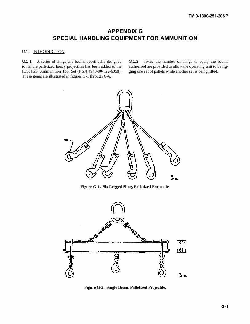
TM 9-1300-251-20&P
G-1
APPENDIX GSPECIAL HANDLING EQUIPMENT FOR AMMUNITION
G.1 INTRODUCTION.
G.1.1 A series of slings and beams specifically designedto handle palletized heavy projectiles has been added to theIDS, IGS, Ammunition Tool Set (NSN 4940-00-322-6058).These items are illustrated in figures G-1 through G-6.
G.1.2 Twice the number of slings to equip the beamsauthorized are provided to allow the operating unit to be rig-ging one set of pallets while another set is being lifted.
Figure G-1. Six Legged Sling, Palletized Projectile.
Figure G-2. Single Beam, Palletized Projectile.
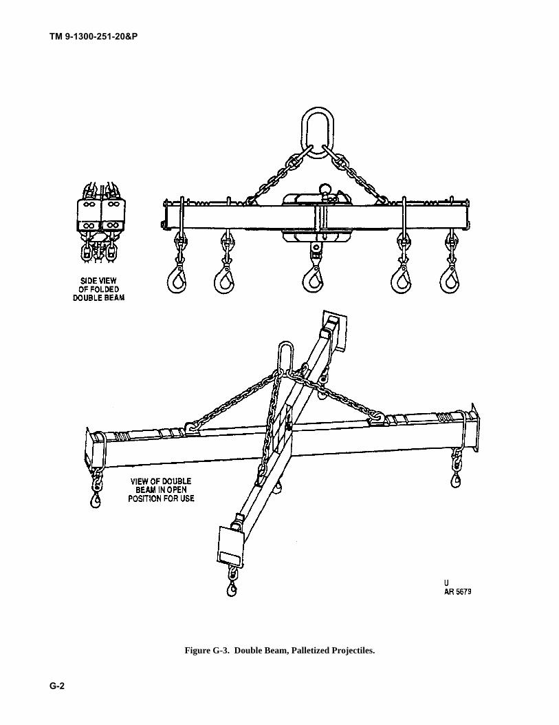
TM 9-1300-251-20&P
G-2
Figure G-3. Double Beam, Palletized Projectiles.
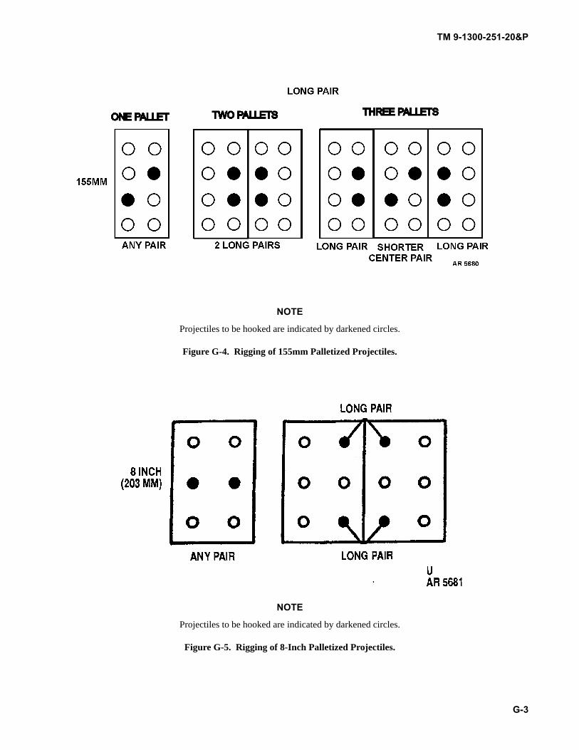
TM 9-1300-251-20&P
G-3
NOTE
Projectiles to be hooked are indicated by darkened circles.
Figure G-4. Rigging of 155mm Palletized Projectiles.
NOTE
Projectiles to be hooked are indicated by darkened circles.
Figure G-5. Rigging of 8-Inch Palletized Projectiles.
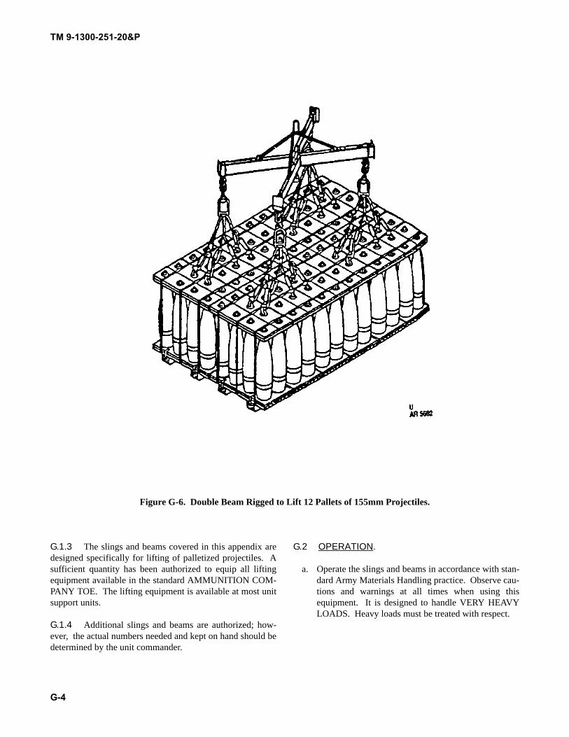
TM 9-1300-251-20&P
G-4
Figure G-6. Double Beam Rigged to Lift 12 Pallets of 155mm Projectiles.
G.1.3 The slings and beams covered in this appendix aredesigned specifically for lifting of palletized projectiles. Asufficient quantity has been authorized to equip all liftingequipment available in the standard AMMUNITION COM-PANY TOE. The lifting equipment is available at most unitsupport units.
G.1.4 Additional slings and beams are authorized; how-ever, the actual numbers needed and kept on hand should bedetermined by the unit commander.
G.2 OPERATION.
a. Operate the slings and beams in accordance with stan-dard Army Materials Handling practice. Observe cau-tions and warnings at all times when using thisequipment. It is designed to handle VERY HEAVYLOADS. Heavy loads must be treated with respect.
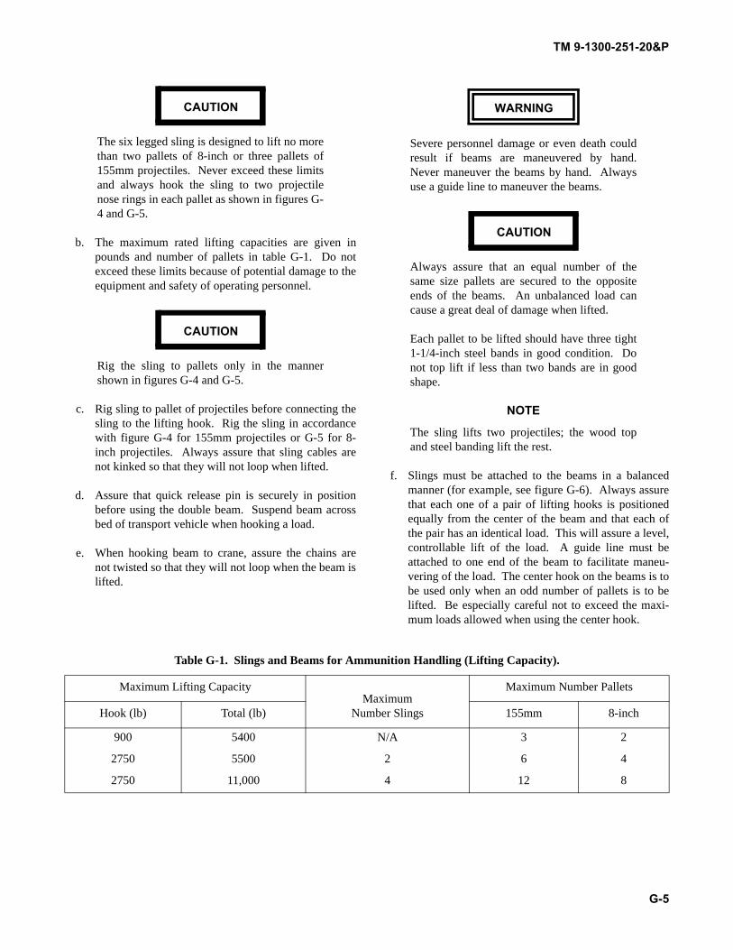
TM 9-1300-251-20&P
G-5
CAUTION
The six legged sling is designed to lift no morethan two pallets of 8-inch or three pallets of155mm projectiles. Never exceed these limitsand always hook the sling to two projectilenose rings in each pallet as shown in figures G-4 and G-5.
b. The maximum rated lifting capacities are given inpounds and number of pallets in table G-1. Do notexceed these limits because of potential damage to theequipment and safety of operating personnel.
CAUTION
Rig the sling to pallets only in the mannershown in figures G-4 and G-5.
c. Rig sling to pallet of projectiles before connecting thesling to the lifting hook. Rig the sling in accordancewith figure G-4 for 155mm projectiles or G-5 for 8-inch projectiles. Always assure that sling cables arenot kinked so that they will not loop when lifted.
d. Assure that quick release pin is securely in positionbefore using the double beam. Suspend beam acrossbed of transport vehicle when hooking a load.
e. When hooking beam to crane, assure the chains arenot twisted so that they will not loop when the beam islifted.
WARNING
Severe personnel damage or even death couldresult if beams are maneuvered by hand.Never maneuver the beams by hand. Alwaysuse a guide line to maneuver the beams.
CAUTION
Always assure that an equal number of thesame size pallets are secured to the oppositeends of the beams. An unbalanced load cancause a great deal of damage when lifted.
Each pallet to be lifted should have three tight1-1/4-inch steel bands in good condition. Donot top lift if less than two bands are in goodshape.
NOTE
The sling lifts two projectiles; the wood topand steel banding lift the rest.
f. Slings must be attached to the beams in a balancedmanner (for example, see figure G-6). Always assurethat each one of a pair of lifting hooks is positionedequally from the center of the beam and that each ofthe pair has an identical load. This will assure a level,controllable lift of the load. A guide line must beattached to one end of the beam to facilitate maneu-vering of the load. The center hook on the beams is tobe used only when an odd number of pallets is to belifted. Be especially careful not to exceed the maxi-mum loads allowed when using the center hook.
Table G-1. Slings and Beams for Ammunition Handling (Lifting Capacity).
Maximum Lifting CapacityMaximum
Number Slings
Maximum Number Pallets
Hook (lb) Total (lb) 155mm 8-inch
900 5400 N/A 3 2
2750 5500 2 6 4
2750 11,000 4 12 8
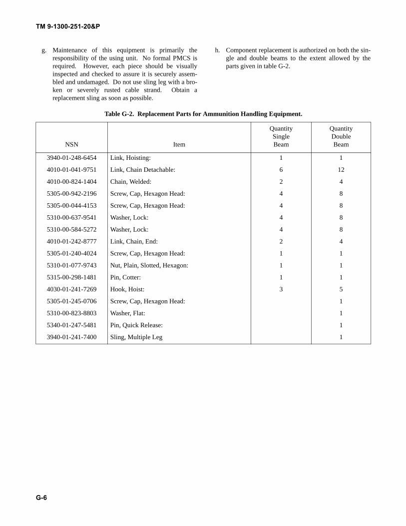
TM 9-1300-251-20&P
G-6
g. Maintenance of this equipment is primarily theresponsibility of the using unit. No formal PMCS isrequired. However, each piece should be visuallyinspected and checked to assure it is securely assem-bled and undamaged. Do not use sling leg with a bro-ken or severely rusted cable strand. Obtain areplacement sling as soon as possible.
h. Component replacement is authorized on both the sin-gle and double beams to the extent allowed by theparts given in table G-2.
Table G-2. Replacement Parts for Ammunition Handling Equipment.
NSN Item
QuantitySingleBeam
QuantityDoubleBeam
3940-01-248-6454 Link, Hoisting: 1 1
4010-01-041-9751 Link, Chain Detachable: 6 12
4010-00-824-1404 Chain, Welded: 2 4
5305-00-942-2196 Screw, Cap, Hexagon Head: 4 8
5305-00-044-4153 Screw, Cap, Hexagon Head: 4 8
5310-00-637-9541 Washer, Lock: 4 8
5310-00-584-5272 Washer, Lock: 4 8
4010-01-242-8777 Link, Chain, End: 2 4
5305-01-240-4024 Screw, Cap, Hexagon Head: 1 1
5310-01-077-9743 Nut, Plain, Slotted, Hexagon: 1 1
5315-00-298-1481 Pin, Cotter: 1 1
4030-01-241-7269 Hook, Hoist: 3 5
5305-01-245-0706 Screw, Cap, Hexagon Head: 1
5310-00-823-8803 Washer, Flat: 1
5340-01-247-5481 Pin, Quick Release: 1
3940-01-241-7400 Sling, Multiple Leg 1
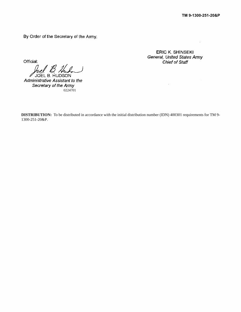
DISTRIBUTION: To be distributed in accordance with the initial distribution number (IDN) 400301 requirements for TM 9-1300-251-20&P.
0224701
TM 9-1300-251-20&P

TM 9-1300-251-20&P 18 Jun 99 SOF Demo Kit, M303
2-3 Add “LOCKWASHER” to the illustration.Reason: Missing from illustration.
1-2 Change “Rock Island, IL 61201” to read “Aberdeen Proving Ground, MD 21010”.Reason: Wrong Address.
SAMPLE
1.2.41
2 2-6

This Page Intentionally Left Blank

LRED (AMSRD-AAR-AIL-LS)
Picatinny Arsenal, NJ 07806-5000U.S. Army RDECOM, ARDEC
TM 9-1300-251-20&P
Artillery Ammo for Guns,Howitzers, Mortars, Recoilless Rifles,and 40mm Grenade Launchers12 Feb 03

LRED (AMSRD-AAR-AIL-LS)
Picatinny Arsenal, NJ 07806-5000U.S. Army RDECOM, ARDEC
LRED (AMSRD-AAR-AIL-LS)
Picatinny Arsenal, NJ 07806-5000U.S. Army RDECOM, ARDEC
TM 9-1300-251-20&P
Artillery Ammo for Guns,Howitzers, Mortars, Recoilless Rifles,and 40mm Grenade Launchers12 Feb 03

LRED (AMSRD-AAR-AIL-LS)
Picatinny Arsenal, NJ 07806-5000U.S. Army RDECOM, ARDEC

LRED (AMSRD-AAR-AIL-LS)
Picatinny Arsenal, NJ 07806-5000U.S. Army RDECOM, ARDEC
TM 9-1300-251-20&P
Artillery Ammo for Guns,Howitzers, Mortars, Recoilless Rifles,and 40mm Grenade Launchers12 Feb 03
LRED (AMSRD-AAR-AIL-LS)
Picatinny Arsenal, NJ 07806-5000U.S. Army RDECOM, ARDEC


PIN: 072718-000

This fine document...
Was brought to you by me:
Liberated Manuals -- free army and government manuals
Why do I do it? I am tired of sleazy CD-ROM sellers, who take publicly available information, slap “watermarks” and other junk on it, and sell it. Those masters of search engine manipulation make sure that their sites that sell free information, come up first in search engines. They did not create it... They did not even scan it... Why should they get your money? Why are not letting you give those free manuals to your friends?
I am setting this document FREE. This document was made by the US Government and is NOT protected by Copyright. Feel free to share, republish, sell and so on.
I am not asking you for donations, fees or handouts. If you can, please provide a link to liberatedmanuals.com, so that free manuals come up first in search engines:
<A HREF=http://www.liberatedmanuals.com/>Free Military and Government Manuals</A>
– SincerelyIgor Chudovhttp://igor.chudov.com/
– Chicago Machinery Movers