Embed Size (px)
Citation preview

UNCLASSIFIED
AD NUMBER
CLASSIFICATION CHANGESTO:FROM:
LIMITATION CHANGESTO:
FROM:
AUTHORITY
THIS PAGE IS UNCLASSIFIED
AD332404
UNCLASSIFIED
CONFIDENTIAL
Approved for public release; distribution isunlimited.
Controlling DoD Organization: Army BiologicalLabs, Fort Detrick, Frederick, MD.
OSD/WHS ltr dtd 1 Aug 2013; OSD/WHS ltr dtd 1Aug 2013
' .•
, ,.
- ---.". --~- ··----~ ... ....-,.-·~ l. --~:;;: . ··:-~
{•:: ----------~-------~-------~---------~-------------- ~-----------~------~----------- ----------------------- ------------------------ -- ------------------,. .... + .-=-~----
Office of the Secretary ofDefenseS\)l'G§J'S'Z.. Chief, ROD, ESD, WHS +-Date:/ZTl/lrZfJ/.? Authority: EO 13526 DeclassifY: 'J. Deny in Full: __ _ Declassify in Part: __ _ Reason: MDR: /......,L..--~M--_...,.2_../-r.l.{,.....,,7=-----
Page determined to be Unclassified Reviewed Chief, ROO, WHS lAW EO 131!i2~, St4tion 3.5 Oato; \ q JU_. ze> l3
:~;
. . i
-~
•
,'
ARMED SERVICES TECHNICAL INFORMATION AGENCY ARLINGTON HALL STATION ARLINGTON I 2, VIRGIN lA
\
~ Page detennl"ed to be Uoc~osifl 1
J Reviewed Chief, ROD, WHS 1 ·,
_______ .. ____________________ IAW..E0..1J62Uegtl0n_3..5__ + ---- ----- ---.. Date: JUL 1 9 3JII J
Nal'ICI: When gove.mment or ether d.rawinas, speci:f'ication• or other data are uaed for any purpose other than in connection vi th a detini tel.y related sovernment procurement operation, the u. s. Govel'!UIIellt thereby incurs no respond bill ty1 nor &JlY obligation whatsoeve·rJ and the i"act that the Government J1JB.'3 have fo1'SII1J.ated1 turnished1 or in an;t way supplied the said drawings, specitioations, or other data is not to be regarded by implication or other·iise as 1n a:cry lllallner licensill8 the holder or any otber person or corporation, or conveyiJlg any rishts or permission to manufacture, use or sell any patented invention that may in arJ¥ way be related thereto.
!
DECLASSIFI!O IN FULL , Authority: EO 13S26 Chief. ReCOI"ds & Declass Dlv, WHS Date: JUL 1 9 2013
·~
Page -..,ined to be u- ~ . Reviewed Chief, RDD, WHS ~~ lAW EO 13626, Section 3.5
~ ---~-~----~-~--------~------~---0'1'!--------- --;-----------Oat&T-•-r-g--201-------------------------- -N CE. .
S DOCUMENT CONTAINS INFORMA
NG THE NATIONAL DEFE OF
ING OF THE E LAWS 1 TITLE 18,
and 794. THE
S IN ANY .MANNER
I ~
i.f . '
--· -----~----------..........
l l j
S'PP'E 1W 23
a am !&L!S!E&
SEVENTH QUARTERLY PROOUSS REPORT
ON
DlSS!'.MINATlON OF SOLID AND LIQUID BW AGENTS
(Unclauiiied Title) -·----- -.. ~ .. ._._..""",..,... - ---~-
.lior Period December 4, 1961 -March 4, 196Z Contract No. DA·lB-064-CML-2745
U. S. Army Biolo1ic:a.l Laboratories 1 : ll!: 1
.
Prepared for: fl.
Fort Detrielr.. Maryland 1
Report No: a300 Project No: 82408 Date: June az. 1962
S11bmitted by:
Approved by:
Reaearch and Development Z003 Eaat Hennepin Avenue Minneapolta U. Minnesota
dP"NR'm'h
1:
0. R. Wnitn.a.h Project Manager
DECLASSIFIED IN FULL Authority: EO 13526 Chief, Records & Declass Div, WHS Date:
JUL 19 2013
I, ;
-_ -----------r-rc------------------------------------------------, .
Page determined to be Unclassified Reviewed Chief, ROD. WHS
-----~---tAW EO 13626, 8eetleA 3.5
FOREWORD Date: JUl 19 8
I
f
r r
Staff Members of the Research and Development Departments who have participated in directina and performing thia work include Mr. S. P. Jonu, Jr. I Mr. a. Whitnah, Mr. M. Sandgren, Mr. A. Anderton, Dr. v. w. Greene, Dr. J. Park, ~41'. R. Lindquist, Mr. J. McGillicuddy, Mr. J, Upton, Mr. W. L. Torgeson, Mr. J. Nash, Mr. S. Steinberg, Mr. P. Stroom, Mr. A. McFarland, Mr. G. Mor£itt, Mr. L, Graf, Mr. I. Hall, Mr. G. Bec:lc, Mr. J. Walters, Mr. A. T. Bauman, Mr. T, Petereon, Mr. C. Lanon, Mr. D. Harrington, Mr. R. Ackroyd, Mr. D. Kedl, Mr, B. Schmidt, Mr. Q, Lundy, Mr. 'R. Dahlberg, Mr·. 4l.. Barrett, Mr. 0, Durigan. Mr. A. Kydd, Mr. E. Knutson. Mr. G. Leiter, Mr. N. Konopliv, Mr. J. Unga, and Miaa M. Johnson.
,... W8i1111!l0& :a Lids zqsO!L 1!D &t WI eiW264 t<lt tpl"rM 'a the PM'el wMc.
ii
r
I '
---··--···--- 1~--
(
I ~ j
I J·
I I I I I I f r
I I
~ I I
I r I
•NIIIINM1IM a
_ -----·-- --~--~----Oeet.ASSifJ!f).JN.P\JIJ.-·-- ---- -~------·----· --Authority: EO 13526 Chief, Record$ & Declass Olv, WHS
AB:3TllACT Date: JUl 19 Ill
Tht. Seventh Quarterly Report pruenta the reaultl of continued work on a large number ol technical aapects of B W di .. emination.
P1-ogreu on the theoretical and experimental 1tudiea o£ powder mechanics is reported. Several new experimental techniques a.re die· cuued and more complete analyaea of the previouely obtained experimental data are aiven.
The design and fabrication of a new aeroaol chamber, equipped with light-scattering instrumentation it deacribed. Thh chamber will permit atudie• o! aerosol atability. The aerosol generation and sampling apparatu11 are dieeuaeed.
Studiee of the viability of~ and !J.• in the bulk and aero1ol forma, are presented. These are investigations o! the effects of elevated temperature and additlvea.
Wind tunnel atudie• of diuemination and deagalomera.tion are dis· cussed. The reeulte of further atudiea of amall-ecale agglomer&tea and &
description of a new high-flow-rate diueminator model are given.
New experimental work on metering and conveyini dry powdera is described and da.ta are given on the performance ol a !ull-•cale laboratory feeding model.
Progreu in completing the wind tunnel and auociated apparatua for installation at Fort Detrick is reported.
Design studies coverinJ several fea•:urea of the dry-asent airborne disseminator are deacribed.
The results of computer atudies dealing with the line -aource diu em ina.· tion of. the agent UL- I are given.
The 1tatus of work on the deaign and fabrication o£ a liquid-agent &irborne diueminator ia reported, and many detailed aepeete of the deaign are presented,
iii
WIMBIIfttJ[ 1
.J •J
I
I I \ I I I
I
;1
DECLASSIFIED IN FULL
I COtiFIIIICiilr Authority: eo 13526
_ Chief, Records & Declass Dlv WHS Date: •
JUL 19 JnS -------t---- ----------------------------=-=-----
~
1 i
-t
i f
f
:{
~
f
Section
1.
z.
3,
••
TABU OF CONTENTS
Title
lNTRODUCTION
THEORETICAL AND EXPERIMENTAL STUDIES OJ'
THE MECHANICS OF DRY POWDERS
z. 1 2. 1. l
2. 1. 2 z.z z. z. l 2. z. z 2., 2. 3 2..3 z. 3. 1 z. 3. z z. 3. 3 2..4
Development o£ Experimental Appara.t\11 Appar&tu• for Determining Compactlon Characteristic• of Dry Powders Triaxial Shear Apparatus Related Experimental Studies Residual Shear Strength of Compacted Powders
Wall Friction Phenomena. Compaction Characteristics o£ Powders Bulk Tenlile Strength of Powden Apparatus and Technique Dl.scuuion of Experimental Results Future Work Mathematical Analysis of the Piston-Cylinder
T .. L
AEROSOL STUDIES
3. 1 3, z 3. z. 1 3. 2.. z 3. 3 3.-4 3. 5
Main Chamber Optical Light -Scattering Detection System Monochromatic Light Source Photomultiplier Detection System Powder Dispersing System The Aeroeol Samplini Syetem Future Work
VIABILITY STUDIES
4. 1 4.a 4. l
Viability o! Dry AeroaolJ o£ ~and Sm Eflect of Cab -0-Sil on ViabifitY -Toxic Effec o£ Buna. Rubber on ~
iv
CPN"PIN"'L
Pa1e
1-1
Z-1 Z·l
Z-Z Z-8 Z-8 ~-10 2-11 2-16 2.-18 2-22 Z-26 Z-27
3-l
3-1 3-l l-1 3-4 3-7 3-10 3-16
4-1
4-1 4-7 4-10
,,-
~
t ----------·'"
I ~ I
I l J j
J
I I I J
f f .f :t
f f .>
r
TABLE OF CONTENTS (Continued)
Section Title Page
5. DISSEMINATION AND DEAOOLOMERATION STUDIES S-1
6.
7.
8.
9.
5. 1 5. 2
5.3
General Sm Diaeemination - Small-Scale Asalomerate Study Deeian of High Flow Rate Diuemtnato:r Mod~l (OMI ~3) and Related Equipment
EXPERIMENTS WITH THE FULL-SCALE FEEDER FOR COMPACTED DRY AGENT SIMULANT MATERIALS
6. 1 6.2 6. 3 6.4
Introduction General Procedure Driving Torque Determinations Motivating Gaa and Talc Discharge Rate Meuuremente
APPARATUS FOR DISSEMINATION EXPERIMENTS AT FORT DETRICK
DESIGN STUDIES ON A DRY ·AGENT DISSEMINATION SYSTEM
8. 1 a.z 8. 3 8.4
The External Configuration o£ the Store The Rotary Actuator The Power Generator Gaa Storaae Veaael and Flow Regulatin& Sy•tem
SYSTEMS STUDY
v
MD'I'IIN I lid"
,
5-l 5-l
5-5
6-1
8-1
8-1 8-Z 8-4 B-4
9-1
t !
t t IJ t i I
DECLASSIFI!O IN FULL Authority: EO 13526 Chief, Records & Declass Dlv WHS Date: '
~---------------·-- t=-- ----------------- --------------·-·-----·· ----- -------- ---~---- - ________________ JliLli 201-------------
l r (
I
r r r r r •
Section
10.
11.
u.
TABLE OF CONTEN1·S (Continued}
Title
PROGRESS ON THE LIQUID DISSJCMINATINO STORE
10. 1 lO,l lO.l. 1 IO.l.l l o. ~. 3 10. z ... 10. z. 5 10. z. 6 10. z. 7 10. 3
Work on Design and Fabrication Disseminator Description and Information Structure Generator Nose Section Contenta Plumbing Auembly Fluid Handling System Operation Boom A• sembly Actuator Asaen.IJly Structural Te ating
SUMMARY AND CONCLUSIONS
REFERENCES
vi
'Ot'VR'N•at
Pa&e
10~1
10~1 10-6 10-6 10-8 10-9 10-10 10-10 10-13 10-13 10-14
ll-1
1 z~t
t
I
t
i {
f -I
r I
DECLASSIFIED IN FULL Authority: EO 13526 Chief, Records & Declass DIY, WHS Date: ---------·---- ·-------·-------------- ----- ----·--------·----·- ------·--tftft-Ht .m----------------
Figure
2.. 1
z.z 2.3
LIST OF ILLUSTRATIONS
Title
Apparatus for Measurement of Compaction Characteristics of Powders
Triaxial Shear Strength Apparatua
No Title
2. 4 No Title
2.5
2.6
2..7
z. a
2..9
2.. 10
2. 11
Z.lZ
2.. 13
z.u
No Title
Shear Characteriatic• of Talc using Direct Shear Technique
Frictional Reaieta.nce for Surface!! in Contact with Talc Powder
Compaction StreBe aa a Function of Powder Specific Volume
Compaction Energy as a Function of Powder Specific Volume ·
Elastic Modul11s '!!as a Function of Specific Volume !or Several P·.,wdere
Laboratory Setup for Measurement of Bulk Tensile Stren1th of Compreued Powders
Apparatu11 for Measurement oi Bulk Tensile Strength of Compreued Powders
Column Segment Crou -Section
Bulk Tensile Strength of Zinc Cadmium Sulfide (Curves A and B)
2. 15 Bulk Tensile Strength oi Zinc Cadmium Sulfide (Curve C)
2. 16 Compreseion of a Column of Powder
z. 17 Bulk Tent~~ile Strensth 110' 11 aa a Function ot Distance "L" from tho Compressive Force
vH
n(QftiiR'D ....
Page
a-3
Z-5
2.-6
2-6
2.-7
2.~9
2.-lZ
2.-14
2.-15
2.-17
2.-19
2-20
Z-2.1
2.-2.3
2.-24
2.-2.5
2.-2.5
..
l J
I
r f l ~ •rtPIIINIIM DEOlASSIJI!O IN I'ULL i 1 Authority: eo 13526 t . Chief, Recotda & Declass Dlv. WHS ----- 1 c---------··--------·----------.. ---.. --·"----····---... -·-------......... --------Date: JUt lf 2013 ...... ---------
r (
L 1
r
Figure
2.18
2.19
3. 1
3.2
3.3
3.4
3.5
3.6
3.7
3.8
3.9
3. 10
4. 1
4.2
4. 3
4.4
5. 1
5.2
LIST OF ILLUSTRATIONS (Continued)
Title
Bulk Tensile Strength "00" Immediately Below Compres aive Piston ae a Function of Total Plug Length. L 1
Notation £or Pieton-Cylindu Analysis
Aerophilometer
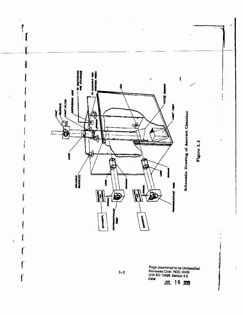
Schematic Drawini o£ Aeroeol Chamber
Pe%'cent Transmiuion o£ 117-60 Filter over a Range ot Wavelengths
Response of IP21 Phototube over a Rante of Wave • lengths
Overall Response o£ System
Schematic Diagram of Powder Ditperaing Apparatus
Sketch o£ Filter and Holder Immerud in an Aero1ol
Sampling with a Needle Immersed in an Aerosol
Schematic Diagram o! Aerosol Samplina Apparatua lnlide Chamber
Schematic Diagram of Aerosol Sampling Syltem Control Manifold and a Samplina Probe
Viability oi Sm and ~ Aerosola at Elevated Air Stream Temperature
Thermal Death 'Time Parameters of Sm and h Aeroeoh -
Effect of Cab-0-Sil on Viability of~ Aero1ola
Toxic Effect o£ Rubber
Model !or Statistical Analysis
Percentaie of Particles {by number) i.n ~Aerosol
viii
....,ft&INIIIL
Page
Z-Z6
2-28
3-2.
3-3
3-5
3-8
3·9
3-ll
3·12.
3-14
3-15
4-l
4-8
4-11
5-3
S-6
f•
(
(
l
f
I
(
f (
I r r 1
r
Figure
5.3
5.4
UST OF ILLUSTRATIONS (Continued)
Title
· Mechani•m• for Preparing Simulated Sm Sample (Fill) for Dissemination -
Hiih Flow Rate Diueminator Model (QMI-3) !or Wind Tunnel Application
S. 5 Disseminator Model and Related Equipment Mounted on Wind Tunnel
6. 1 Schematic Diagram o£ Teat Arrangement uaed with Experimental Feeder for Compacted Powder•
6. 2
6. 3
6.4
6.5
6.6
9. 1
1 o. l
1 o. z 1 o. 3
10.4
1 o. 5
Test Arrangement uaed with Experimental Feeder for Compacted Powders
Test Room used for Experimental Work with Dry Powder Materials
Thread Cleaner Scheme to Remove Powder from Screw
Discharge Rate Curve• for Series "A" Teats using Talc in the Experimental Dry Agent Feeder
Dilcharge Rate Curves for Series "B" Teets uaing Talc in the Experimental Dry Ag~nt Feed"r
Flow Rate veraus Downwind Distance for 11Average11
Weather Condition• - Agent UL-Z
Flow Rate veraua Downwind Distance !or "Good" Weather Conditions - Agent UL·Z
External View o£ Liquid BW Agent Diaseminator Showing Ram-Air Turbine Installation
Fluid Handling Syatem
View of Liquid Diaeemin&ting Store with Aft Section Removed to Show Installation of Fluid Handling System
Boom and Actuator Syatem
Plumbing Schematic
ix
"Qt!!'l lit I IX£
Page
5-8
5-9
.5-11
6-3
6-4
6-6
6-8
6-14
6-15
9-Z
9·3
1 0-Z
10-3
10-4
10-5
10-lZ
f l
J
I_ I
r l (
l
' ~
t f t
f (
r
Table
4. 1
4. 2
4. 3
4.4
4.5
6. 1
DECLA!SIIJI!O IN FUU. CCtiiiiiMIM ~~."';>rrty: Eo 13526
.,,.,, R8COfda & "'--• Oete: ~ass Dlv, WHS
--------··---------------Jot J 9 201 .
LJST OF TABLES
Title Pase
Viability of Dry Aerosols of ~ at Various Exposures 4-3 j J
(~from Lot No. X-lZ, aeroaolbed with DeVi!biu
1 generator • S 1 trials)
Viability of Dry Aerosols of Sm at Various :S:xpoaures 4-5 (Sm !rom Pool 17, aerosolizecrby explolion - 35 trri'la)
EHect of Cab-0-SU Coating on Sh.ort Term Viability 4-9 of Sm -Influence of 1% Cab-0-SU on Viability Dry Aerosol of 4-9 ~Exposed to Elevated Air Temperatures
Effect o£ Rubber on Sm Suepenaions 4-10
Teat Results uains Compacted Talc in Experimental 6-13 Feeder
X
L n l l {
{
f f j
f J
t
r r· !
&OMIPWPII DECLASSIFIED IN FULL Authority: EO 13526 Chief, Records & Declass Dlv WHS Date: JUl J 9 201 '
SEVENTH QUARTERLY PROGRESS REPORT ON
DISSEMINATION OF SOLID AND LIQUID BW AGENTS
I. INTRODUCTION
This is the Seventh Quarterly Progress Repol't on Contract Number
DA-18-064-CML-2.745 which is a program of reeearch on the dheemination
o! solid and liquid BW agentlll.
During thia reporting period, Phase IV of the program was initiated,
which provides £or a 2Z-month continuation of the contract. The scope of
work under Phase IV includes:
1) Continuation of theoretical analyses and experimental in· vestigations of the parameters which influence the behavior of finely-divided materials.
2) Continuation of studies of method• for uni£orm metering, conveying, dissemination and dcagglomeration of dry finely-divided materials.
3) Continuation of desi;n studies and preparation of a detailed design of a dry-agent di.uemi.nation system capable of disseminating dry powders at a practical and effective rate.
4) Fabrication a.nd testing of dry-aient line-source expet'imental hardware,
5) Preparation of f!.nal drawing• and specifica.tiun1 of the dry· agent dissemination system.
6) Preparation of an operating and instruction manual for thb equipment.
This report cover a proareae on studiea covered by Items ( l) through
( 3) above a a well a. work which wa1 initiated under Phases 11 and lllof the
project. Work on Items (4), (5) and (6) above is .scheduled for a later put
of the program.
l-1
MULIDINIL&
l 1
'
-':~-
I
l l
--'
r [
----~- r------
1 I (
I I I I I I ,f
r f r r t
r
Page determined to be Unclassified Reviewed Chief, ROO, WHS lAW EO 131al, ltotlon 3.6 Oatt: 9
-------·---~-------------------------- JULJj _ _l0)3__ _________ . _-
~. THEORETICAL AND EXPERIMENTAL STUDIES OJ' THE MECHANICS
OF DRY POWDERS
Studiea o£ the mechanical properties and behavior of dry powder• were
continued durina the period covered by this report. The major effort during
thia period wa.a devoted to deaignint and !a.bricatin& improved apparatus for
measuring •igniflcant mechanical properties of dry powdera. Recently ob·
tained experimental ruulta relatin& to powder 11hear strength and wall
friction phenomena are presented. Alao included is an analytical study of
the stress distribution in a powder subjected to compaction in a platen
cylinder device.
z. 1 Development of Experimental Appa.ra.tua
Two types of experimental apparatua have been designed and fabricated
during the paat ~hree-month period: 1) an improved device for measurement
of the energy required to compact a powder to a given density atate, and
Z) a triaxial shear teat device. The triaxial apparatus should enable a more
precise measurement of the shear strenath of a powder than waa pouible
with the direct shear apparatus uaed in earlier teats. lt h hoped that testa
ca.rried out with theu devices will furnish baaie information required for
an undeutandina o£ the behavior of dry powders. At the same time, such
apparatus may prove useful in developing characterization teat• for powders.
Z. 1. 1 Ap;,aratua for Determining Compaction Characteriatica of Dry Pow era
Experimental results reported ea.rliu ln the current study proal'am
have indicated how the bulk denlity of a powder depend• on the energy in
veated in compacting the powderl, The apparatus uaed in these experiments
waa subject to 11everal limitationt, however. The moat serioua problem
encountered with thia apparatus waa a lack of a~enaltivity in meaeuring the
Z-1
I ~ 1 I
I ~
:1 J j ..
, ' u
[
I l
f r f '!
r
Page determined to be Unclassified Reviewed Chief, ROO, WHS lAW EO 13&26, hotlon 3,5
Oate: JUl 19 101
deformation of the powder sample. Thi1 precluded an accurate meaaure
rnent of the elaatic p:ropertie s of compacted powdera. Alao, it wae not
po .. il>l• to apply hi1h cumpaction atreuee to the aample beeau .. of excel•
aive elaetic deformation of the compactio11 device.
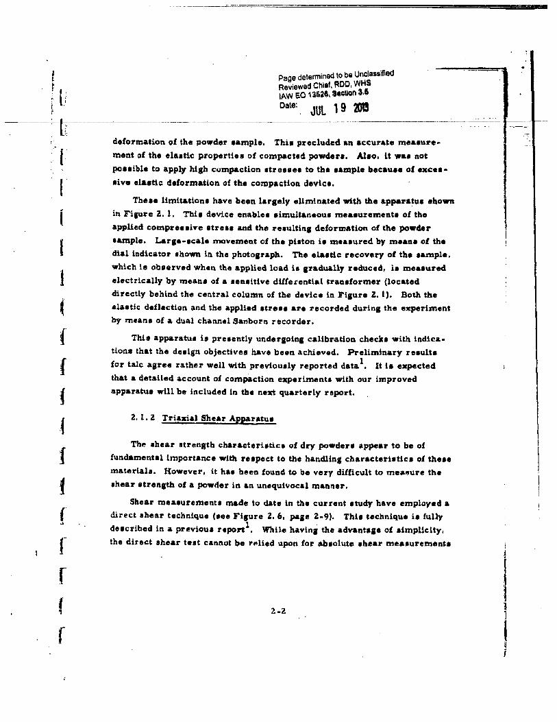
Thue limit&dona have been largely eliminated with the appal'&tue ebown
in .Fi1ure 2., 1. Thie device enablu aimu1taneoua meaaurementl of the applied compres aive 1treu and the reaultina deformation of the powder eample. Lar1•·•cale movement of the phton ie measured by mean• of the dial indicator ahown in the photo1raph. The ela1t1c recovery of the •ample.
which ia obaerved when the applied load ia aradually reduced, ia meuured electrically by meana of a un1itive dtl!e.rential trauformer (located directly behind the central column of the device in .Fiaure z. 1 ). Both the elaatic de.flec::tion and the applied atress are recorded durin& the experiment by means of a dual channel Sanborl'l recorder.
Thie apparatua il pruently undersoinl calibratioo check• with indicationa that the duign objectivee have been achieved. Preliminary reaulta
for talc agree rather well with previoualy reported data 1• It t• expected that a detailed account of compaction experimenta with our improved apparatus will be included in the next quarterly report.
2. 1. Z Triaxial Shear App&ratue
The •hear •tren&th char&cteriatica of dry powdere appear to be of
fundamental importance with rupect to the handlint characteristic• of the•• materiala, However, it haa been found to be very difficult to mea,ure the
•hear etrenath of a powder in an unequivocal manner,
Shear measunmenu made to date in the current atudy have employed a direct shear technique (eee Fisure Z. 6, paJe Z-9). Thi1 technique ie fully
ducribed in a previoue report1• While havinl the advanta1e o1 eimplic:Uy, the direct shear teat cannot be 1'~lied upon for ab•olute •hear meaaurementa
2-Z
l
! 1
! ;
Page determined to be Unclassified Reviewed Chief, ROO, WI'IS lAW EO 13528, Section 3.5 Date:
JUL 19 LOl3
2-3
Ol
"' <II
"' lJ 8. ... 0 ., (J .... .. 10 .... "' 1.) .. I) <'4 ,.. ~ (.)
d 0 ... ..... v a e 0 (.) .... 0 .. I! ~ a ~~
"' ::1 IJI 11 Ill
~
"' 0 ..... ,. ::l ... ·~ ,.. " 0.
~
\
ri ~
"' ::1 b.O .... to.
Page detennined to be Unclassified Reviewed Chief, ROO, WHS lAW EO 13526, Stotlon 3,5
Date: JUl 1 9 3J1S ---------,------------------------------------------------------------------------------------------------------------------ -----------------------
I
I
r
{
t
f
I \
f f f f I
f
since the material being tested in con•trained in an indeterminate manner
by the apparatus. This con1tra.int is likely to be evidenced as a.n apparent
increase in shear atrenath of the material.
The tria:xi&l teat m~thod, which ha• abo beell described in an earlier
report2., ia ba1ed upon controllii!.J the atreues applied to the sample durint
the 1hear test. The .sheal· resistance of the powder can then be found from
the known applied ltre .. ee as deac:ribed aubeequently.
A prototype triaxial test device has been developed in order to apply this
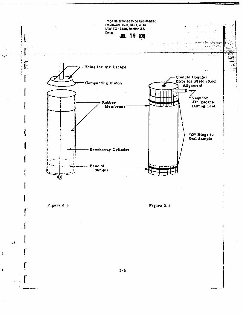
teat technique in dry powder research. The device, shown in Figure z. a, will be ua~d in the following way:
The sample is compacted in a thin rubber membranfl which is used to
seal the sample during the teat. As can be seen from Figure z. 3, the teat
sample ha.e the form oi. a. right circular cylinder, with a cylindrical fitting
placed at each end. The end fittings insure that the axial streuu applied
to the sample are properly distributed and also facilitate aealin1 of the tam
pie. A vent is provided in the top fitting to avoid entrapment of air due to
compreuion of the sample (Figure Z. 4). The aample is placed in the teat
device aa thown in Figure i!. 2, and the chamber is preuurized. An axial
load is then gradually applied to the sample until shearing oecure. The
axial force il meaeured by means of strain ga1ea mounted inside the cham
ber. Failure ia detected by mean1 of a aenaitive linear potentiometer which
indicates the motion of the loading pilton By feedtna both the potentio
meter and strain aaae outputl to a dual channel recorder. a dmultaneous
recording of data ia pouible.
The shear characteri1tics are found by conducting triaxial tuta at
several chamber preuures and conatructing a. Mohr stres• circle at each
load condition. Two •tress circlet, corresponding to the chamber pres
•urea Pz and p 21
• are shown in Figure Z. S. The point• Ci'2. and (1"'2.1 on the
diasram represent lateral stresses applied to the eample; thus, we have 1 1 l G"'z = Pz and O""z = Pz • The pointl C1j and CT'i are the axial 1treu ..
Z-4
1
Page detennined to be Unclassified Reviewed Chief, ROD, WHS lAW EO 13628, Section 3.5
Data: JUl 19 g
Figure Z. Z Triaxial Shf!ar Strength Apparatus
G -5
2709
!, - ~
Page determined to be Unclassified Reviewed Chief, ROD, WHS lAW EO 13528, Stctlon 3.5
Oatt: JUt 19 IJI ----- .
_.. ---~h--- ---------·----------·-------------·--·--·------· ····-·-··--------· --·--·--· ;,,. '· r. ...
r;
~ I~ '· . t: . ~-
I I
' (
f I
I I r ~
r r r
''··-·-
Compactins Pilton
.._ ____ Rubber
Membrane ------4
-+-4---- Breakaw&y Cylinder
Conical Counter __ ...,..'--__ Bore for Piaton Rod
Alignment ':""o----r""l"f -'--n zl).t for
Air Escape D1uin1 Teat
"011 Rins• to Sraal Sample
Fisure 2. 4
Z-6 _]
~:1 . ~-
..~
I I !
i' ..
~-
t~ t I I I
' I
t r r r f r r 1
r
.! \
Page determined to be Unclassified Reviewed Chief, ROO, WHS lAW so 13525, 11ot1on 3.5 ~---~-=- · Dato: JUl 1 9 g ' ':_~--,::~~ .
-----·app~;:::-:.~~mp-1-e.-Il-th_e_a_pplle:~::-;.::~~ .. ~~:·;;.;Z:"_::~· :-;\ where A ia the cron -uetional area of the aample.
Retidual Shear Stungth.
I
c1i
Compressi'le Stress, o-
Fiaure 2. 5
In the general cate, the ahear strensth characterhtie i1 defined by the envelope of a aeries of 1treea circlea. The intercept of the ehear strenath charaeterhtic curve at 0"" • 0 is of particular intereat since this yields the residual shear strength of the compacted power aample, i.e., the atrensth of the powder undel" zero load.
Pl'eliminary testt With this apparatus have revealed several problema connected with sealing the eample to prevent infiltration uf high-preuure air from the preature chamber. At the preaent time, thi1 problem and eeveral other minor di!ficultiea have been cleared up and it ia expected th&t
routine shear testa with thlt triaxial thear apparatua can now be undertaken.
Experimental reeulta obtained with tho triaxial appara.tua will be com~
pared with ahear characteristic: a obtained from direct shear tests. H. as expected, these methoda yield different reaulta, a critical evaluation of both
Z-7
J
[
r f I
I I t
f
f r r
... _ .... -·;
Page determined to be Unclassified Reviewed Chief, ROD, WHS lAW eo 13528. Stctlon 3.5 Date: JUl. l g !JB
-----..0.·----:--~,fw~~~~-.. -~--.r.---~- ..... ..,....._.-:7•.
.. ,~-teat methode will be neceuary. Aa mentioned earlier, it appears l~ly that the direct shear tut will yield a hiaher ahear ruiat..nce than the tri· axial teat becaue of conatrainte applied to the powder aample in the clired shear teat. Another point of difference between thue teat methoda ia in the compaction proceu. or more apecifically, in the way atreaut are applied to produce sample compaction in each ca. a e. A 1eneral clitcue aion of the •• mattere will be de£erred until experimental data are available from testa of identical powder a&mplea by both technique a.
Z. Z Related Exp.rimental Stucliee
A number of experimenU were carried out durin1 the paat quarterly period for the purpote of providina intiaht into the atatic behavior of dry
powders. The retulta of these testa are preaented below. Alao, previously reported results ol compaction atudiea 1 have been reviewed and are preaented he:reift in a different and more meanina!ul form.
Z. 2. 1 Reaidual Shear Strenatb of Compacted Powden
• The residual shear atrenath of talc powder waa investigated by uling
the direct shear apparatut described in an earlier report1• Theae te•t• were conducted in the usual manner, with one important change. Prior to application of a tan1ential ehearina force to the upper ahear disk (see Flaure 2. 6), the aample wa. compacted by application of a compre81ive streu ~· Thit atreu waa then reduced to the value a;, and the •hearlna 11treu, ~c required to •hear the ea.mple wat determined. A eeriu of teat• of thia type were carried out o.ver a ranse of ~ompaction at:reuea o-c: while keeping O""r fixed, The reaulte of tbeee teet• are shown in Figure Z. 6 for
3 :z 3 z O"r = 4. 2 x 10 dynes/em and a;. = 8. 2 x 10 dynea/cm • Each data point shown in the figure ia the a.verage of 5 or more runa. The maximum deviation from the mean value• wae within ,:t5 percent.
Z-8
- -· ... ""' ........... ·~---· ,.-~ ... --
..
l I t
I I
·,. ..
'it~~~ G =E.s_IC .... m•· CD 0 ~0. eCD c.. _. c ii)
c: &'!o3 ,...~:!:r
- • Q)
- p;-o. a. CDI ~o
~OCT ~ !: . Q)
til !-» ~ §= .,en~
: ~
"'-~:-·~-
N • ~
-·- I
6.0
0
. ..., - I - - 1 - I -1 - - - -"
- -
·:~"l' -( .-~ i r 1 .:
· !';~ 1, r : "{:
.1'~
i~: ~-J~; ... ... ,. I·
·,·j •'.
·.·
F"fA Rough Circular Disk
(Dia. 4. 57 em) '.
Shea.r Strenath uncJer;:1:d ·I
Rough Surface
T
~
-~ 2.0
Symbol
X 0
z <rr (dyne•/cm )
4. Z X 103
8. Z X 103
Reeidual Shear Strength
~ ' -.__ X -~~
-4 ~ ~ x 10 (dyneal.o:m )
4.0 6.0 8.0 Fisure ~. 6 Shear Cha.l'a.cteristi'• of Talc u•lol Direct Shear TechDique
.; lr'.
··i l
1.. ·I
~~H i ; ' ;~ ~ :. . :~: :' r
!- '
i·l:rJ , : I J, •1: ; 1j: :
:&f:·iJ.
' L. --::.
I•. ! '.:tl l I I
i..i". 'iT
:;:i:f.~,·· ,'. ~·' -· ~~~,); ·t:•: .: !'' ' II jY i:~ !, ... ,.•; . ., •.
. f~1l-~~ !:::: ~- ~;; ! ~ ~ • : ;
./ . ·~ '~} •I. J• ~ j .!• ,,.,. , . ! : 1ft!,. ~/j·l: '1! .' I • ·I ------- .._,._
:! :~i~(;:;t;l ~I :.\t ·10.,"~ :,
) J I .I .1 lj-; : ... i .,.;'I ',·: ' . --· ·-·~--.. ------ f. :···1 :r.Tit. I" .. 1 I 41 t ;;. :.~ v~ '! ~- ;.
,: : :! ,~1,;lr::;·~J : , .·~: ·~-~ · · ..... ·· ·t,, I •. ;,J i 11 • .•. '~"
-,r:1 h1• • ; • 1 · . ~·~: . :".:.:.~,;
l'
r
Page determined to be Unclassified Reviewed Chief, ROO, WHS lAW EO 13526, hotiOn 3.5 Data:
JUL 19 201
Tbe shear strength of the powder waa found to incre&ae with the com·
paction atreu r:r in accordance with the power relationship: 't ,. constant 044 c 4 c
x cr. ' for cr ~ 10 • The residual ahear 1treagth of the cotnpacted pow-c c der ean be estimated by subtractini the shear stress corresponding to the
compreuive etreu err from the mea•ured values. The resulting ahear
atr-enath characteristics shown in Figure z. 6 were determined in this manner.
It ia apparent that the residual shear strength of the powder is dependent to
some extent on the compreuive streaa (Tr maintained during shearing of the
sample. Although then experiments and the interpretation given above may
not be conclusive, the trend exhibited in Fiaure 2. 6 is of considerable in·
terut.
Compa1'ina the shear strength of talc under load with the ruidual ahear
strength of the compacted powder. it il apparent that the ralative effect of
compaction on shear strength decreaae1 with increasing compressive
at:reue1.
A decilive teat of thil conclusion will be pouible by using the triaxial
te1t apparatus deacribed in the precedina section of thia report. It will of
courae be neceuary to teat a. number of powdera ln thia manner in order to
draw general concluaiona aa to the behavior of dry powders.
~. z. Z Wall Friction Phenomena
In many practical 1ituation1, it ia neceasary to underatancl the nature
of the mechanical interaction between a powder and a aolid aurfa.ce. ln
particular, the friction angle or coefficient of friction for a 1urface expoeed
to a powder t. of importance in the compaction of a. powder l.n piaton
cylindu devices.
Accordingly. an experimental investigation of wall friction has been
undertaken, u1ing easentially the t\ame a.pparatua employed for direct shear
meaaurementa. In these te.ta, the rough disk u~ually employed in the
shear teat• is replaced by a geometrically similar disk, one face of which
Z-10
l J
i '!
' j ·~
! ., i .;
r
I
if
f f f
Page detennined to be Unclassified Reviewed Chief, ROO, WHS lAW EO 13526, Section 3.5 Date:
JUL 19 201
has beea prepared for the friction test. This face ia placed in contact with
the powder and, from this point·on, the teat is carried out in exactly the
same manner a.a the direct ahea.r teat.
Friction teats of this type ha.ve been pedormed for several ma.teriah of
'll&ryina surface roughness in contact with talc powder. Results of these e.x•
perimenta are plotted in Fiaure 2. 7. Three type• ol surfacu were investi
gated: stainless steel, aluminum alloy and aluminum covered with an epoxy
resin yielding a smooth, gloaay surface. From Figure Z. 7 it can be aeen
that the frictional resistance is euentially proportional to normal stress lor
each surface tested. Furthermore, a substantial variation in friction angle
was o~aerved for the different surfaces, ransinj from 8 = 35. s• for an un
polilhed stainleu steel surface (10 to U mic:roinchea nominal surface rough
ness) to a. minimum of 9 = 30" lor a poliahed aluminum surface (6 to 8 micro
inches a. r. ), These friction anglu are substantially below the shear angle·
for talc powder (- = 40•).
Further tesu of this type are planned for the immediate future. It ia of
particular interest and importance !or theoretical aa well aa practical rea·
son• to determine the influence of surface roughness on the friction angle.
Mean• fur minimizing wall friction are also of practical importance.
2. Z. 3 Compaction Characterietica of Powders
Data from compa.c:tion experiments reported in a previous report1 have
been re .examined during the current report period and subjected to further
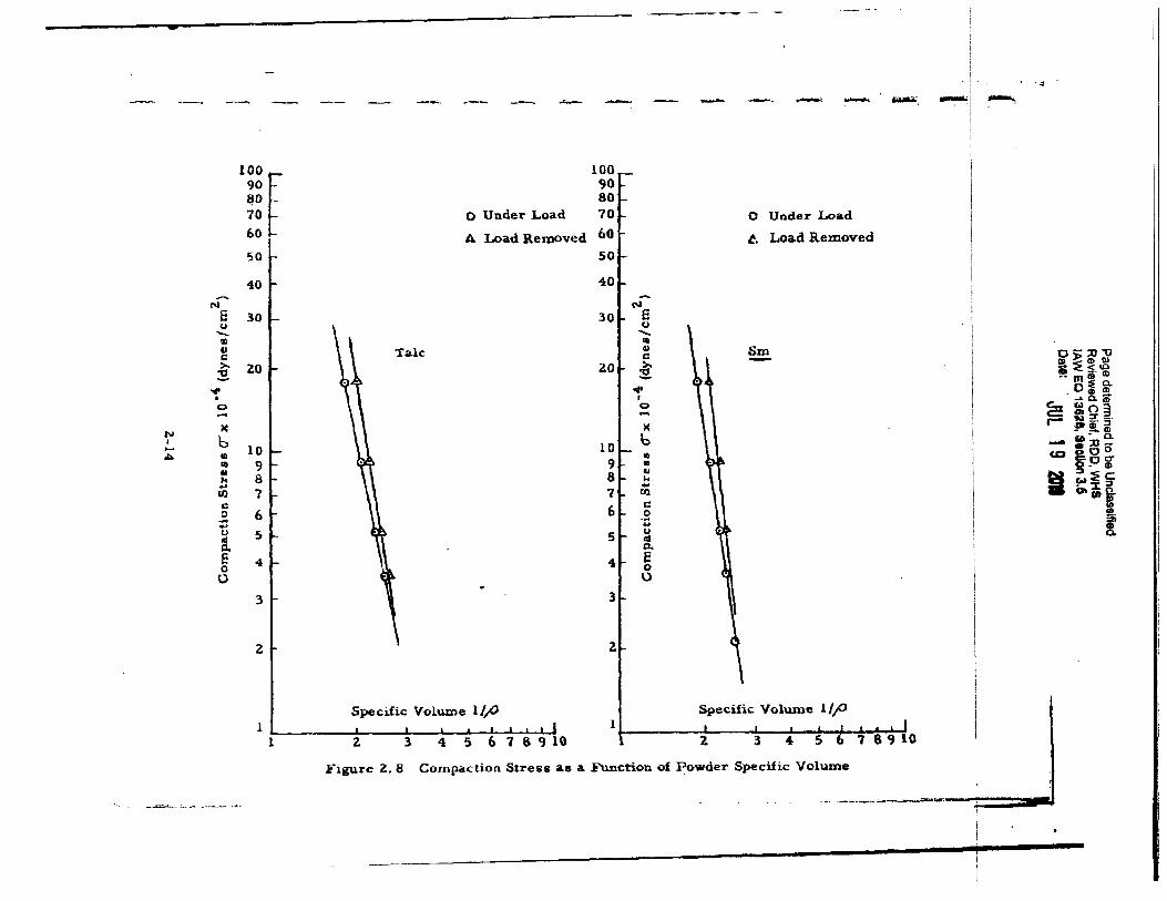
analyai•. Theee results are presented in FiJUres z. 8, z. 9 and Z. 10 •hawing
respectively the compaction stre .. , compaction energy and equivalent elastic
moduli as a function of denaity for talc and~ powders.
2-11
I
I .
Page determined to be Unclassified RevieY~ed Chief, ROD, WHS lAW EO 13~6. Section 3.5 Date: JUl l g D
Z. Z. 3. 1 Streu Required for Compaction of a D\'y Powder
The compre .. ive 1treu required to achieve a given powder c!enaity in a
piston-cylinder compaction device {aee Reference 1) ia plotted aa a function
of the specific volume in Figure 2. 8. Two curve• are shown for each
material: 1) the c:ompreuive stres1 required to obtain the denaity undu
loaded conditions, and .Z) the stress required to obtain the density after re•
moval of the load; i.e., after allowance is made for elastic recovery of the
powder.
2. Z. 3 • .Z Eneru R.eq,uired for Compaction
The energy per 1ram required for compaction of a powder to a &iven
density is shown in Figure 2. 9. When allowance is made for elastic re
covery of the powder a ahift in the eneray and density of the aample oc:cura
as indicated in the figure. It ia of intereat to observe that Figure Z. 9 indi
cate. that the elastic energy ttored in the powder is proportional to the total
energy at a aiven denttty for the conditione of thete experiment• •
.Z. Z. 3. 3 Effective Elastic Moduli for Dry Powdera
I11 order to deecribe the elaatic properties of a powder, we may define
att equivale11t elaatic modulue of the form:
E '" (Z-1)
where:
rr .. the applied atreu
h8
= the compressed depth of the powder .ample
Ax = the me~a1ured elaatic recovery after removal of the load
Z-13
- - - -. IOl 100
90 90 ~0 - 80 70 0 Under Load 70~ 0 Under Load
60 A Load Removed 60 t. Load Removed 50 50
40 40
N N s 30 30 a CJ u ..._ ....... Ill Ill
" 4) Sm c d -
~ ~0 2.0 ~ .... ""' • ' 0 0 - -
N IC X
6 b t 10 ..... 10
"" CD • • 9 9 • II II ,.. 8 8 "' .... .... Ul 7 7 Ul c 6 s::: 0 6 .9 -.... u u s 5 u I'll cd c. (1.
E 4 4 a 0 0 0 0 .
3 3
2 2.
Specific Volw::ne 1/;0 Specific Volume 1/jO
1 L-------~----~--~~--~~~~ 1 2. 3 45·--l l 1 l 4 ~ ~ ~ 8 9 io
Figure Z. 8 Compaction Stress as a. Function of Powder Specific Volume
' . ' _, -, ··~
o-:::o-o I» > (!) Q)
a =E s.~ •• mIll o=:a. -_..&;.
2: ~03 r- ~ ;r. ::r !II'~ CD a· a.
- .:::o-CD &Co o~g
~~ ~ :Ec f-Ix:. oocntt
= • 5!i !.
~.:......._ ... ···~· .4o --- ---·----........... -~....-:. ! sr'
~-----------------1
,__.._ - - _.. - -I .-100 :r-103
90 80
70 60
50
40
30 1 1\ 1\ I
'0 l- e bll ...... lD bll
"' Cl
>-
~~~"0
N
bl
1 "' .... w
.
Iii w
U\ ti
.. m~~ o~o.
6 c \
.::.. .... ~!!t
0
c:: ~olD
....
r- ~:::r3
5 ...
!» iD ::r
u
"'
...... f .. -.tD
Q,
~ :;;oo.
41- e
c.o ooo :1:
0
B gP2"
u \ 0 Under Lo•d
!o':E~
l X
o-ijn
Lo4ld Removed
Qj"
= 3i !
2
Specific Volume l/p Specific Vohune 1//)
I I I I I I I I I I I I I I I I I I I I I I ; I' 1 1 z 3 4 - , - - - ·- - - - . -
Figure Z. 9 Compa.ctioo. Eo.ergy as a Futlction of Powder Specific Volume
-· -·- -~ .. ...,.;,.;.:.,_ ~-..~-~ -I .. ·---·- -----r..;: •. I •
----------1
Page determined to be Unclassified Reviewed Chief, ROD, WHS lAW EO 13526, Section 3.5 Date:
JUl 19 201
---------------·-c------------------- ------------------------------------- ------------------------------------------
I l I
. t
\
The equivalent ela•tic modulus is plotted u a function of specific vol~ in
Figure l. 10 for talc, !!!!_and •ac::charin. It is apparent from the fi!JUI'e that
the elaetic properties of the three powders are remarubly aimilar, at lea•t
under the conditions of these teats.
Further studies of the els.atic properties of powders will be carried aut
with the more sensitive compaction apparatus discuueci in Section z. 1. 1.
a. 3 Bulk Tensile Strenstb of Powdera
A veuatile new apparatus for the determination of the bulk tensile
atrenath of a column of compreued powder baa been duiJnecl and perfected.
The apparatu• permits the bulk ten•ile strenath measurement to be made as
a function of 1) bulk density, Z) distance from compressive force application·
to !ra~_tu:t_~ pla~e, and J) total column length. ln addition to this, we should
by proper extrapolation of data bom 2.) and l) be a.ble to obtain a value for
the bulk tenaile atrenatb of a compreued powder which la dependent only
upon the physical propertiee of the compreued powder and on the maanitude
of the c:ompreeaivc force applied and therefore indep~ndent of the 1eometry
of the a.ppattatua. Thia ahould provide an absolute method Cor the c:ompartaon
of the bulk teauile 1trength of various c:ompreaaed powder e.
Theoretically the bulk ten1ile atrenith of a c:ompreued powder ia an
exponential function of the dilt&Dce from the compreuive pilton to the
fracture plane 3.
where:
(]"' "' bulk tenaile atrength of !1 column of compreased powder at dhtance L from the piston
(Z-Z)
07, = bulk tenaile strength of comprened powder immediately below the piston
2-16
..
l .i
I l.
10
9
8
7
6
5
4
3
2
Page determined to be Unclassified Reviewed Chief, ROO, WHS lAW eO 13628. section 3.5 Oatt: JUt 1 9 201
0
Legend
®~
X Saccharin
B. Talc
z 3 4 Specific Volume 1/P
Figure Z. 10 Elastic Modulu• lr as a Function of Specific Volume for Several Powders
Z-17
I
l ( 1 i
r
I
Page determined to be Unclassified Reviewed Chief, ROD. WHS lAW EO 13526, Sdon 3.5
Date: JUL 1 9 201
---~---------------- ---------------------------- ---------------~---------------------- ----------r k • constant :l L • distance from piaton to fracture plane
An. experimental apparatua muat therefore be capable of frac:turin1 the • colurnn of c:ompreued powder at several dilferent diatancet !rom the pbton applying the com pre uive force. An apparatua has been duigned and perfected to accomplish thia.
~. 3. 1 Apparatus and Technique
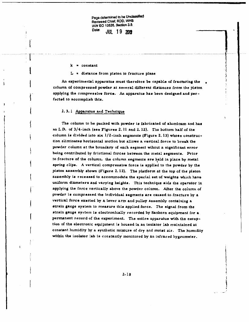
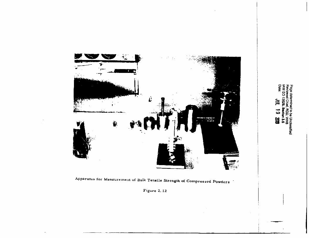
The column to be packed with powder it fabricated of aluminum a.nd baa
an I.P. o! 3/4~inch (see Fl1ure1 Z.ll and Z.lZ). The bottom half of the column ia divided into 1ix 1/Z-inch 1egmcnta (Figure Z. 13) whose conatruc:tion eliminate• horizontal motion but allows a vertical force to break the powder column at the boundary of each sesment wihout a significant error
being contributed by frictional forcea between the metal aegmenta. Prior to fracture of the column. the column ugmenta are held in place by metal
\
aprinJ clipa. A vertical compreuive force i• applied to the powder by the piaton auembly shown (Figure Z. 1 Z). The platform at the top of the piaton auembly ie receued to accommodate the special set of weighta which have unilorm diameter• and varyinJ heiaht•. Thia technique aide the oparator in applying the force vertically above the powder column. After the column of powder is compresaed the individual eegment1 are caused to fracture by a
vertical force exerted by a lever arm a.nd pulley auembly c:ont&ininll a atrain gause system to meaaure thit applied force. The signal from the strain gauge syBtem ia electronically recorded by Sanborn equipment for a permanent record of the experiment, The entire apparatus with. the exception o£ the electronic equipment b hou•ed in a11 isolator lab maintained at conat&nt humidity by a 1ynthetic mi~ure of dry ~nd moist a.ir. The huml·dity within the i1olator lab is constantly monitored by an infr&ud hygrometer.
.
I
I \
1 i • i }
1 .
~-···· ·-
Page determined to be Unclassified Reviewed Chief, ROD. WHS lAW EO 13526. Section 3.6 Date: JUL 19 101S
~-"",:
i
I'
. ~1:
,- . rttFz ; : ·- "'
.;
IJ
''· t·~,. . ~
1-.i:.
...
.. , k,
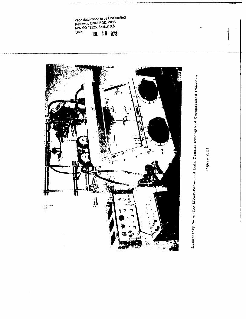
Apparatus for Measurement of Bulk Tensile Strength of Compressed Powders
Figure 2. 12
~)>::0"0 s-:E~IJ) •• _.<0 m<!!(!) o~g.
e_ (;)!it c:::: 01 () 3 r- ~~:;-*'--Ill - t! ::0 a. c.o~oo
~ !~~ Cl a. i}i 5
jj)
I
-
(
f {
f f f f f J J r
Page detennined to be Unclassified Reviewed Chief, ROD, WHS lAW EO 13526, Section 3.5 Date:
JUt 19 m
..
Figure 2. 13 Column Segment Crou -.Section
In experiment• conducted 10 far zinc cadmium aulCide haa bun used aa
a. teat powder. Althoup itt tensile etrenath ia comparatively low it b known
to Jive reproducible results for thia type of phyaic:&l mea.aurement3.
ln a typic&l experiment the powder il preconditioned in the iaolator lab
at the dealred humidity (15.,. in thie caae) for at leaat 48 houre. The column
il then .filled by aiftina the powder throu1h a glau powder funnel fitted with
a fine muh acreen to a .. ure uniform packin1 of the powdu. The pleton
auembly la then clamped into poaition and the vertical fol'ce ia applied.
Durinl early experimentation it waa found neceuary to clamp the entire
column ri1idly prior to e.pplication of the compreuive force aince the in·
dividual aegment cla.mpa were not etron1 enough to prevent bendina of the
c:olumn and thue c&uee partial fracture of the compacted powder prior to
meaeurement of the tenaile atren1th. After compre .. ion, the pilton aaeem
bly and upper fillin1 tube are carefully removed. A "lift cap" aaaembly de
•ilned to clamp firmly to the top of each eegment ia lhted into place and
2-Z 1
I l
I i I
J ~
i 1· r .-.
Page detennined to be Unclassified Reviewed Chief, ROD, WHS lAW EO 13526, Section 3.5
Date: JUL 1 9 2DI
! . ··-·--·-·····---···-·-------·-·----· ----i, r-------------·-·-- ---··----------------·-··----·-----------· ··--·--·-------~~ r r I I I I I I l I f (
.-1 ~
r
connected co the lift a .. embly. By turninl a crank in the lift asaembly the
column i• fractured at the bottom of each ae1ment alter it it undamped.
The tec.stle force ia recorded by the atrain aauae auembly.
Z. 3. a Diacunion of Experimental Reaulta
The primary purpoee ift this preliminary ut of experiment• waa to
check the reliability of the equipment and apparatue, Aa shown in F\;uru
2. 14 and a. lS, the tensile strength data follow the exponential relationehip
quite well. It ia believed that the scatter of points at lara• value• of L c:an
be diminished by refinement of technique. It 1hould be noted that the data
indicate a dependence o! tenaile strength upon lenath of time of. c:ompal'i1on,
When the weight• were allowed to compre81 the powder overni11ht (16 houra)
a aipUicant change in ~occurred. Thh phenomenon will have to be es
plored further, but for the purpose of comparing one powder with another it
may be found eJCiledient to a11ree upon a •tand&rd time of compression.
Aa each UJment of powder 11 broken, its weiaht can alao be recorded
10 that we c:a.n alao follow the c:han1e ln bullt ten1ile •trengtb with bulk den
tity.
In our measurements we are actually mea1urint the tenaile atrensth at
the fracture point at a distance "L" from the pilton (Figure z. 16). We then
plot the tensile atrength "cr" vereue L at 1hown in Fiaure 2. 17.
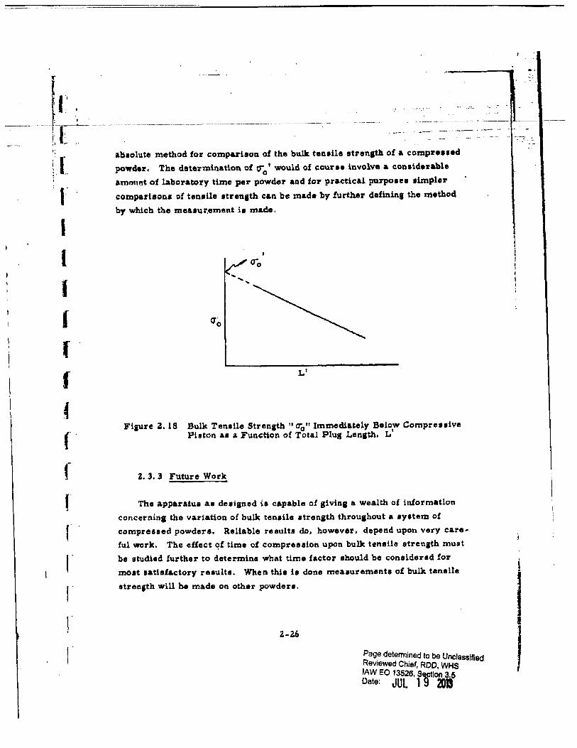
By extrapolation to L • 0 we obtain 0""0
, the bulk tensile atrenJth of the
powder at the surface of the piaton. Thit a.uumea that ~ ia independent of
"L", the total plua length. Recent experiment• indicate that thil ia probably
not the caae. The design of thit apparatul ia such that we can allo vary the I .
value of L (total plu1 length). Thus by plotting L' versus c:J0
and extrapolatina
to L' • 0, u shown in Fiaure Z. 18, we would obtain a value rr 1 for the bulk 0
teneile atren&th of the powder which ia dependent only upon the physical pro-
pertiu of the powder and tho maanitude of the compreasive f.orc:e applied
but independent of. the geometry of the a.ppa.ratua. This should provide an
"r,!!!r •• -::-·
I I r I I f I f f r I f f
, I
f I
f"' I Cl ....
30
zo
P.age determined to be Ul'lclassifiecl Reviewed Chief, ROO, WHS lAW EO 13528, itotion 3.6 Date: JUL 1 9 201
..
~---~-..... ; ... v..:..__.. --+-~..:.. . ..a. . ..i.r-:.-. :·~.-. ,;;C --~--':-- ~·.:··~-.---.-{=-;~i .. _~~:;,;.;:'\;~ ~=--.. ____ , .:·· ,o.;._~::.-~-:::-:----~·-:-=--··: .. J_~ .. --· ... ---- -----. . ----- ~ :_-.. :..,Li..;::~~-:~'·~-~- .. :-...:··,...
~-----~---~----~--:.--~---·~--_______: __ :_~·~--·.....:._..:. __ ~ ____ _::__..::...__:__~---=---------·-_:__·--- . ,,, ··- ,j - -
-~-~-~. : .... :--:-::??:~:~:~~ ·~~
Curve A - 1/Z hour compreuion
Curve B - 1 hour compreaaion
L (em)
0
' t i l ! .
I
~
~
:,;_~
-·..:-..;.. :._ '.:'!.:... ~.-.
1~ ______ ._ ______ ~ ______ _. ________ ._ ______ ~--------~------~
t
J
0 1 z 3 4 s 6
Figure 2.14 Bulk Tensile Strength of Zinc: Ca.dmium Sulfide {Curvu A and B)
Z-Z3
7
1"1 I 0 ...
( H N e
I (,J -QfJ
~
r ~
b
r i 41
"' ... Ill
t 41
:;:1 QfJ a u
r E-t
~ r r r r I
1 I r 0
r • I
r
I 1
fl1ge determined to be \Jnclassified Reviewed Ch.ief, ROO, WHS lAW EO 13626, Se.ctlon 3.5 .
Date: JUl 1 9 3)1 ··~·-· -~~--..-·· .. ......
. . . . _, - -~-. . .. - . -:-r-.. - ... ~~-~.~'"'""~-~--·~;:4JI~P ... t ···'·-'· ;.._ ~'!~~~..::::::~~~ ....
··-:--:-. - .. _>..:..::..·."-.: ·C:~~'·,. '"-L~-~~::~.:::. .. ~-;~: . :__-~~-~-~-"--L~~---~~---:~ .. ~-:- -~~.,-:~~-:'~ _;; ~ ~~~ ~'"~-"-
~~=:-~~·::•:·:::·'~·~J~~ ;:~~ ~ -- --=~
···-~.-~.:-
Curve C - 16 hour compreuion
•
•
• •
; ;
L (em} j
I I I I I z l 4 ! 6 7 I Figure 2. 1! Bulk Tensile Strenith of Zinc Cadmium Sulfide
I (Curv• C) I Z·Z4
J
I•
I r r I I I f
1
I f
I ,-r r I
r
--- .. ~~==========~~~~~------------
r
J -r----"' '--r I 1------+---'f"-Fracture Plane
L•
Figure 2., 16 Comprenl.on of a Column of Powder
L--
Fiaure 2. 17 Bulle Ten1ile Strength "a"" &I a. FuncUon of Diatance 11 L11 from the Compreseive Force
2-25
Page determined to be Unclassified Reviewed Chief, ROO, WHS lAW EO 13628, Section 3,1
Date: JUL 1 9 J)l
• .... --M---.·•, • .... . ~· ~ .··- ~
l 1
,
)
' I
I J
-· ~ . ;;
_11, '~---~--~~-~-~~--~--- ----~-~-~------------------------~------~----~-~---~--- ~-}L--· t·· : _____ .. -- ·--~·- ..
---~ ti .- .. ,.
~·- [. I
r I l I I J r 4
f f r r I"
abaolute method for comparieon of the bulk ten1ile atren1th of a compreued
powder. The determination of c;0
1 would of course involve a ~onaiduable
amm1nt of laboratory time per powder aad for practical purposu timpler
compati•on.s of tenaile atrenJth can be made by further definina the method
by which tho moaaur,ement is made.
I
<ro
Ls
Fiaure z. 18 aulk Tenaile Stren.th II O"'o It Immediately Below Compreuive Pieton a.a a Function of Total Plug Lenath, L1
z. l. l Future Work
The apparatua aa deaigned i• capable of giving a wealth of information
c:oncernina the variation o£ bulk tenaile atronath throuahout a 1y1tem of
compreued powders. Reliable results do, however, depead upon very care
ful work. The effect Q,f time of compreeaion upon bulk tensile strenath muat
be studied further to determine what time factor should be considered for
moat a&tialactory result a. When thia is done me&aurementa of bulk tensile
atrensth will be made on other powdeu.
Z-26
Pag~ determined to be Unclassified Reviewed Chief, ROD, WHS lAW EO 13526, S~ion 3,5 Date: JUL 1 ~ 201
I I
I ,· . t ' , : f t------------1L ·~-----------------------------
- • I• •
l --
1'
L [
1
\
I l r
r ~
r
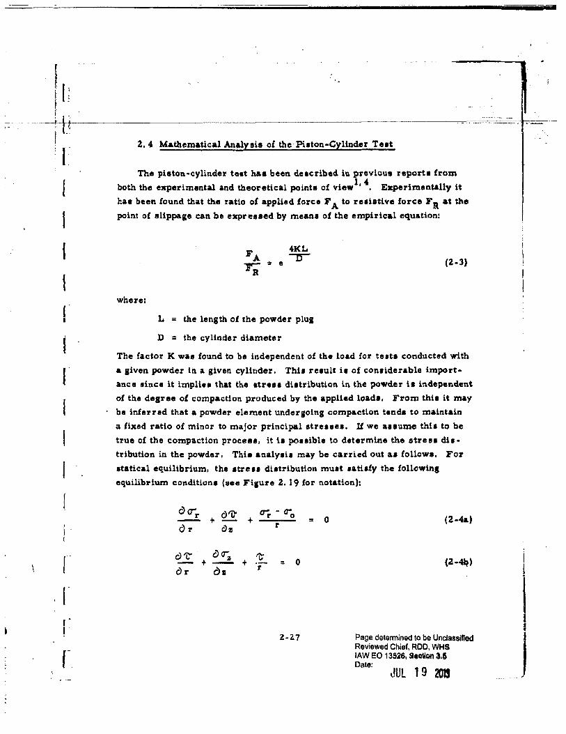
2. 4 Mathematical Analysis o£ the Pilton-Cylinder Teat
The piston-cylinder test haa been deaeribed in pTevioua nporta fTom
both the experimental and theoretical points of view1• 4. Experimentally it
has been found that the ratio of applied Ioree FA to resistive force F R at the
point of slippage can be expreued by means of the empirical equation:
where:
L =
4KL = e ...,-
the length of che powder plUI
D = the cylinder diameter
(2-3)
The factor K wae found to be independent of the load for teats conducted with
a given powder in a given cylinder. Thi1 result it of con1iderable import
ance aince it impU .. that the atreu di.ttribution in the powder is independent
of the degree of compaction produced by the applied loadl, From thit it may
be inferred that a powder element undergoing compaction tends to maintain
a lixed ratio of minor to major principal etreaaea. U we auume thia to be
true of the compaction proceae, it is pouible to determine the streu dh
tribution in the powder. This analysis ma.y be carried out as followa, For
etatieal equilibrium, the atreu diatribution mutt tatitfy the !ollowins
equilibrium condition• (aee FiJUre 2.. 19 for notation):
c) CT"'r +
c)l'j}' +
Or Clz
c)'C" t c)~
+ or c:h
err - o-o r
't" 0 = r
Z-2.7
= 0 (2--4&)
Page determined to be Unclassified Reviewed Chief, ROO, WHS lAW EO 13526, Station 3.6 Date:
JUl 19 201S
.. -----
I
l
I J
•
t i I.
...
I l I I l I I
I I ('
r r I
r I
,.-I
r
IL
+z
:
I r(~z
I
r
I r-
'
---r
\ \
'•
Detail of Powder Element showins Notation for Streuee
Figure z. 19 Notation for Piston-Cylinder Analysia
Z-Z8
Page determined to be Unclassified Reviewed Chief, ROO, WHS lAW EO 13526, Sectlon3.5 Date: JUL 1 9 Dl
··•
j
I I
J
t tr ----l-~--------------------------------------~---'--'---~
f l i: t ~
! I 1/
L
I I I l r
U the 1hear atreaa il emaU, we may &IIUl'Jle that:
= c (Z-5)
where ; 11 the shear a.ngle of the powder. The meaning of thi• auumption
can be •een by referring to Figure 2. 19. In the atrest plane, it we impon
the condition that 't' i• small relative to the diUerence in prin.cipa.l atreuea
«7'i - ~· it i1 apparent that a; a <T'e .!: OZ and O"'z • C7j, Furthermore, if
shearinc is imminent, we must have 0"'1,1 Oj • C or ~/ u;. ~ C.
With these aasumpti.ons, the above equations become:
(:Z.-6a)
OO'"'r + £! 0 - =
Or clz (Z-6b)
c) l r"C") ~ 0"' 21 + r - = 0
Or oz {Z-6e}
Thia ay1tem of equation• can be eolved l.n a straiaht!orward manner, yieldina
the following expruaionl for the streuea:
F e K i' (]"" = R
z -z. ir-R""2-t-(Q.)-l + '-'·· r
{
00 ,..., 2n- :Z.n }
~ z.Zn {n 1 )! (Z-7a)
a ... n. F ., :Z.n + 1 } (Z·7b)
Page detennined to be Unclassified Reviewed Chief, ROD, WHS lAW EO 13626, Section 3.5 Date: JUL 1 9 g
l
I I
,,, i
r-~-------r
, : r -I
r I I
I I
I r I r r f
r
.. ·'
·~·--
---------------------------~c----~-----~
where:
K =a~
a.Z = 4)'2. c CX) a. Zn
f(a) = 1 + l: 2" 12n + Z) z2n. (n ! )Z 1
:a - l' z = L' r ;::: r
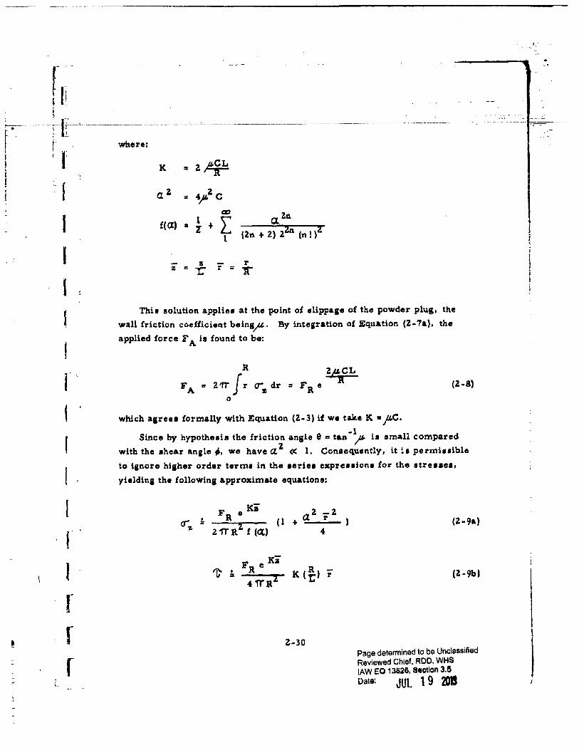
Thil solution applies at the point of 1lippage o£ the powder plug, the
wall friction coeilicient beins_p. By integration of Equation (Z-7a), the
applied force FA is found to be:
o-z dr = T ll e
Zp.CL R (Z-8)
which a1reu !ormally with Equation (Z-3) if we take K =pC. -1
Since by hypothesis the friction angle 9 = tan )I' ia small compared
with the shear angle;, we have a.Z « 1. Conse(iuently, it ia permiuible
to ignore hisher order term• in the uriu expressions £or the stresses,
yieldin& the following approximate equations:
F e IG' R
a z _z + r
4
K (~) r
~-30
(Z-9&}
Page determined to be Unclassified Reviewed Chief, ROD, WHS lAW EO 13626, Section 3.5
Date: JUL 1 9 201
---------li--1-J'----------------------------------------------------------------------------------;---·---------~--~c::-~-t-------
(
I
,. I
r f" f
Aa an example, il~ = 0. Z5 and - : 40•, we obtain C :a 0, .116 and aZ a 0. 054. The variation of f1"_ over a cron -aec:tion of the powder slut i• given by the z term:
Thua, the axial atre .. h&a a maximum variation of about 1. -1 pe1een.t over the croat• .. ction. On the other hand the ahearins atrett increaaet linearly from zero on the axit to the value:
(2-10)
at the wall.
The above analytb leada to concluliont which ia no way conflict with experimental reaultt for the pieton-cylindor contiguration, Thb lendt a degJ"ee of auppo:rt to the principal &llumption on which the analyail wae baaed: that compaction of a dry powder occurs under condition• ol imminent shear.
Z-31 Page determined to be Unclassified Reviewed Chief, ROD, WHS lAW EO 13526, Section 3.5
Date: cJUl 1 9 2013 I
, I· (i_· ~
----· ~-----------------------------
l 3, AmOSOL S'l'UDIES
(
I t I I l
t
r
The desiaa aad labricatioa ol an a.erophilometer, a li.aht-scattel'~rll in
etrumented aeroeol chamber, for use in atudyittl the eettlina propertiee of
aeroaol• is almoat complete. A photograph and schematic drawin1 of thh
device in ita pruent state are pruented in Flgurea 3. 1 and 3.1 reapectively.
The aerophilometer conai1ta of: I) a main chamber, Z) an optic&! li1ht·
sc&ttednJ detection ayatem, 3) a powder diaperainl ayatem, and 4) an aero
sol aampling eyatem.
3.1 Main Chamber
The main chamber, constructed of aheet aluminum, ha.• an internal
dimenlion of one cubic meter. The sides of the chamber are joined by
riveta and sealed with epoxy resin. The door (one entire aide o£ the cham·
ber) h connected on one edge by means of a hinge to the chamber. The
door clo1ea against a Dor-tite gasket and ia locked by Unk-loc.k faateners.
At the right lower corner of the chamber il a 4-ineb fan blade. The
motor !or the tan blade is located outlide the chamber and haa Us ah&ft pro
jecting into the chamber through a Teflon aeal.
3. ~ Optical Liaht ·Scattering Detection System
The optical light-seatterinl detection system it shown as part of the
aerosol chamber (aerophilometer) aa depicted· in Fiaure 3. Z. This system
con1ilts of a monochromatic light source and two sensitive phc.tomultiplier
detection eyatema.
3. Z. 1 Monochromatic :Cight Source
The lamp is a General Electric projection lamp. In order to avoid
fluctuation• in the light, power is suppli•d from a Soreneon regulator a.nd
the lamp voltage i1 controlled by an autotransformer. In addition. the lamp
circuitry is such that the lamp cannot be turned on: unleu ita coolin1 blower
is operatina.
3-1 Page determined to be Unclassified Reviewed Chief, ROO, WHS lAW EO 13&26, S•otion 3.5 Oatet
JUt 19 a1D
r
I I
-------------------------------------
--------------------·-- -------------·
Page determined to be Unclassified Reviewed Chief, ROO, WHS lAW EO 13526, 9eotlon 3.6 Date:
tJ'Ul 19 201
• f .. ;r
{
' (
f f f ,
f
I •
r (
I
l-3
...
J .... i 0 .. N ~ .
1"'1
'S u k
·l ~
t Q
1 I ~
"" JJ
f
Page determined to be Unclassified Reviewed Chief, ROD, WHS lAW EO 13526, S•ction 3.5
Oate: JUl 19 2013
]
j
J J
' J
,. t ~
:[
iF h ;r I• ~.;
{
l I t I. I I I I I I I f f f f f
A cone of liaht from the la.mp ia admitted into the lena housing through
a 0. 5-inch aperture. Midway between thil aperture and the lena is a baffle
With a. l. ZS ·inch aperture. The ae two baffiea limit the amount of light
reaching the lena. To reduce the amount of undesirable light the lena hout
ing i1 ~lack anodized.
A 5 em diameter len• with a focal length of about 19 em is placed auch
that the image of the l111.mp !llaments is at the floor of the main chamber of
the aerophUometer in a light trap. The light trap ia an open-end polyhedron
made of sheet aluminum. The angle8 of the polyhedron are chosen such that
the specularly reflected Ught undergoes many reflections before re-entering
the chamber, The inaide o! the trap ia painted black to inaure a large
amount of absorption at each reflection of the light.
Positioned between the lena and the main chamber is a Corning glaa1
light filter f7 -60. This filter transmits only light within narrow banda of
wavelengths. Figut-e 3. 3 gives the percent tranaml.asion over a range of
wavelengths for this filter. An optical flat glau window uala the main
chamber from the lens houaing.
3. 2. 2 Photomultiplier Detection Syatern
There are two complete identical photomultiplier detection ayatema.
Both are placed in the center of one aide of the chamber perpendicular to
the lisht beam. One ia l/3 of the diatance down the aide from the top of t..'-:e
chamber and the other ia 2/3 of the dhtance down.
The photomultiplier tube• uud in thia apparatu1 are RCA type lPZl.
These tubes have a projected sensitive area of 5/1611 x 15/1611• In order to
ma.ke a well-delined aperture for the sensitive area and attempt to reduce
the pauibility of extraneous light reaching this area, the tubea except for
the sensitive area have been completely masked with black tape. There
aponae of phototube lPZl is given in Figure 3. 4 over a range of wavelengths.
3-4 Page determined to be Unclassified Reviewed Chief, ROD, WHS lAW eo 13528, Section 3.5
Oate: JUL 1 9 2013
1 l 'j
j
J
•-'-
I[! '~":~::::::: + b------ ------------------ ------------------- ---------------~--------__::_: _____ ~~-_ -~-~-'-'---_=-==...__= t --
--'_:'~
"
l (
cs 0 .... Ill Ill
·a t al g ... ..
30 E-1
( ~ 41
20 lJ
"' 41
{ Pt 10
J 0 ·0
{
{
f -~
f r f r r il
r
o. 1
Corning #7 -60 Filter
0,2 0.3 0.4 o.s o. 7 0, 8
Wavelenath (microns)
Figure 3. 3 Percent Tranaminion of f7 -60 Filter over a Range of Wavelen1tha
3-5 Page determined to be Unclassified Reviewed Chief, ROO, WHS lAW EO 1312&, ieatiM 3.6 Date\ JUl 19 201!
-,;:_
J
;_.
l I
' t (
I f r r r r ' r
100
t -- ---------------~---.... ~- ' I
~
Wavelength (microns)
Figure 3. 4 Ruponu ol IP~l Phototube over a Range of Wavelengthll
3-6 Page determined to be Unclassified Reviewed Chief, ROD. WHS lAW EO 13526. Section 3.S
Date: JUl 1 9 ZOI
.. ,-.·
r
r r
' I
I I I
r I
. . .-..:-- .... __ :-·~ .. ~~-:;::.::-:~--~-=-""""":·"-·~
ln. order to reduce extran.eoua light aourcee, the photo~ult!plier tube
houtina• aod photomultiplier lena houalnga are bl&c:k in color. Aa in the
ca .. of the Hsht aourc:o lena houaina. the chamber is ae&lecl from the photo
tube lena houeing by an Oj)tical fla.t slau window.
The phototube leneea, which are aimilar to the light source letu, are
poaitioned such that the imaae plane of the phototube aperture ia in the cen
ter of the light beam. Tbia image dimenaion ia 4-1/Z cm x 1-1/2. em. Thua,
only particle• within a rectangularly ahaped volume (whoae width ie deter
mined by the light beam and height ia 1-1/Z em) are capable of acatterinJ
Ught into the phototube. Each of the two phototubea receivu equal amounta
of light fiux. Therefol'e. if each volume contains the •ame number and lise
of particlea, each will acatter the a&me amount of li1ht into the phototubea.
Each photomultiplier tub• il connected to an Aminco photomultiplier
mic:rophotometer which iR turn il connected to a Brown recorder. The
microphotometer il a power supply for the tube, a coutroller-. a signal
amplifier, and & meter, while the Brown recorder give• a contin.uoua re
cord of the output alanala fl'om the microphotometer.
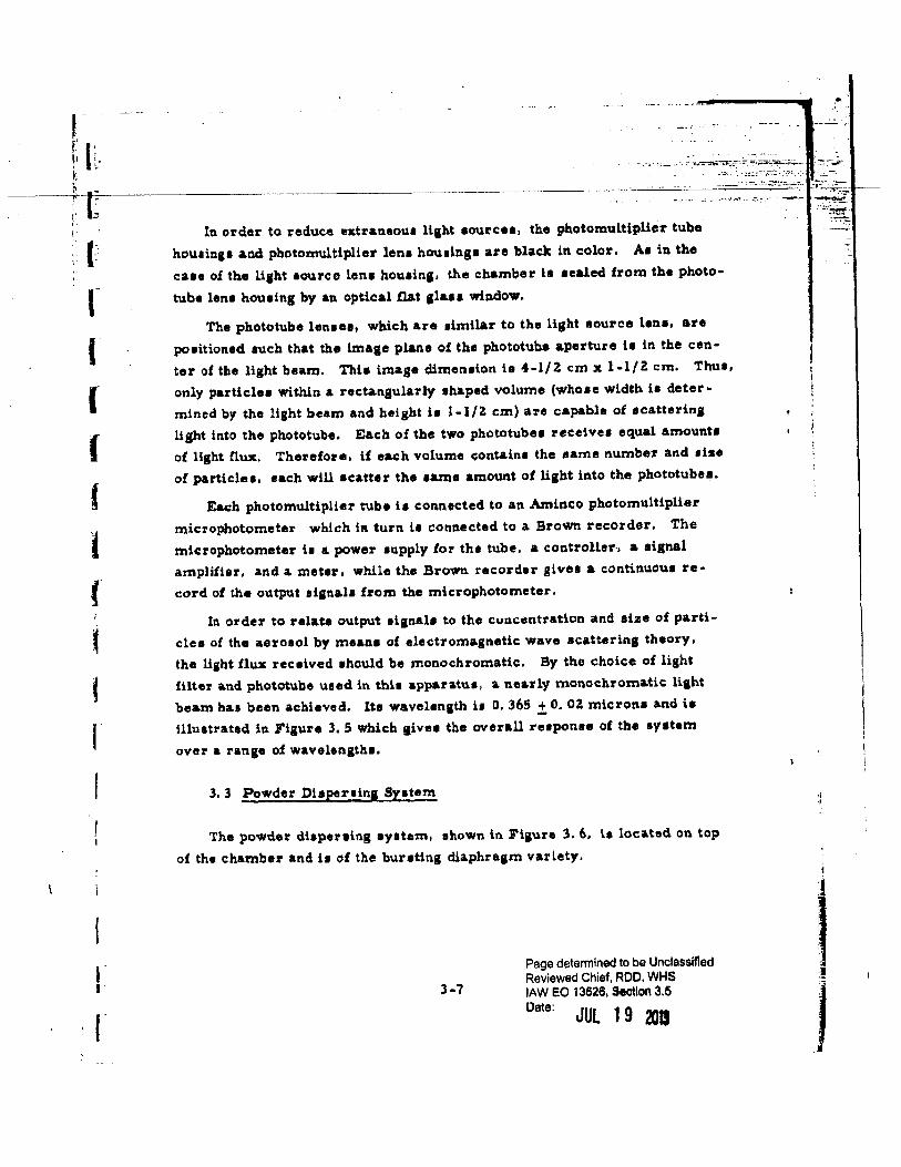
In order to relate output aianal• to the cuncentration and size of parti
cles o£ the aerosol by me ana of electromagnetic wave acattering theory,
the Uaht flux received should be monochromatic. By the choice of light
filter and phototube uaed in thia apparatua, & nearly monochroma.tic liaht
beam haa been achieved. lte wavelenath is 0. 365 .± 0. OZ micron• and il
illustrated in Figure 3, 5 which 11ivea the overall reaponae of the system
over a range of wavelengtha.
3, 3 Powder Diaperling Syatem
The powder diaperoaing ayetem, ahown in Fiaure l. 6, i.e loc&ted on top
of the chamber and it of the b\1ratin1 dia.phraam variety.
3-7
Page determined to be Unclassified Reviewed Chief, ROD. WHS lAW EO 13526, Section 3.5
Date: JUL 1 9 201J
I j
.·.: .. :::.:::...;.;;·-1...,......:~~~·-:.'!,:-.= •• ;.;..;:;.'::1' -
---~~--:. ..... ·-- ._- .-=~-
-~----~---- -- ~--·~--~-~~-~~ .. -.. ~~-.. -.-- .. ....,.,._.,_....,..~..,,_,..,...,,~~:1: jiL J&:a4Da ·. ..----l· n-·--~--------···-~----·-·-·--·---.. -----·----·
r ,=. !' !~
I I f
I
I l t
r f f r f I' r
30
20
10
0 o. 1
o. 365 + o. 02
...
o. z 0,3 0,4 o. 5 0.6 0.7 o. 8
Wavelength (microns)
Flaure 3. 5 .ov~rall ruponse o£ Syatem
3-8
Page determined to be Unclassified Reviewed Chief, ROO, WH: lAW EO 13&2&, seotlon3.
Datet JUl 1 9 2013
1 l !
!
I I j
I
.u
I l
l I t
I
r
I r
Piston Ringa (Teflon 110 11 Rini•)
Piston Auembly
/Housing
Diaphragm
~ -~-;~-::-~~:---:-~-;·;.._._-; r:=<r.-.;:;.._ ...,. ""•-
............ -.-.:;:~~·- . .,...,
' ' J'igure 3. 6 Schematic: Df.agram of Powder Diapei'IJing Apparatua
I 3-9
Page determined to be Unclassified Reviewed Chief, ROD, WHS lAW EO 13526, Section 3.5
Date: JUl l 9 2013
J
J
I
•,
-· .-.-~ -~--··,.-
--~-~-. ----------- --~- --- ~--------~--- ---~----------------------~~~ 4~t .~~
The cycle of operation of the dt.aperaina unit is aa follows: Firat, the
housing ia removed from the mounting flange which is permanently aealsd
to the top of the cha111ber and a diaphragm ia in1talled. Next the hauling il
reaec:ured and the cap. which alao carriea the phton auembly, il removed.
Thil permits loading of the powder. The cap ia then replaced. Dry nitro•
a en, the cliape:rainl IILB, ia metered in throuJ&h a needle valve and the J&•
preuure b monitored by a. gauge. When the diaperaina gae baa reached the
desired preuure, dry nitrogen is then diverted to the drivinl g&l inlet by
means of a togale valve. The drivinJ gas pushes the piston downward,
simultaneously cloein& the diaper sing gas inlet and puncturiag the diaphrasm.
With a proper combination of diaperainagaa preuure and diaphragm
material, it is believed that the diaphragm will rupture cleanly and the pow
der will be efficiently dispersed. Bem;b tuting oi the unit, however, ia in
ita ea.rly stagu; further experimentation will be neceua.ry to find the suit
able combination.
3. 4 The Aeroaol Samplinl System
An aeroeol sampling eyetem baa been installed in the chamber. This
will enable "spot checka11 of the aerosol by direct sampling. This data may
then be correlated to the data !rom the liab.t scattering system, which con•
tinuously monitore the aeroaol condition.
The direct eamplina of the aerosol b ac:compliehed by drawing an
aero1ol apecimen through a filter, The filter uaed is the Millipo:re 13 mm
diameter Type AA, which haa an 0. 8-mlcron pore size. Design conaidera•
tioru for the aampling ayatem center around the filter. Theee conaidera
tlon• will be cliacuued prior to preaentlna the 1ampltni ayetem aa a whole.
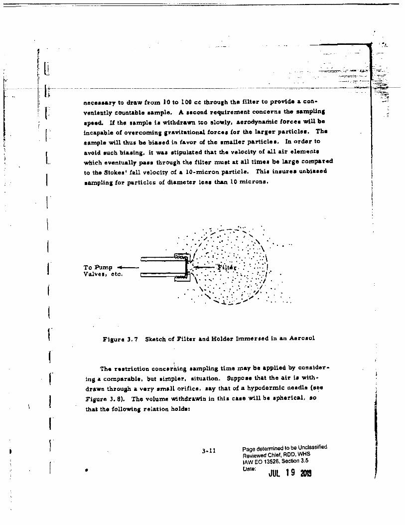
Fiaure 3. 7 shows a filter and ita holder immeued in an aeroaol. When
the apprgpriate valve i1 opene:i, for a period of time the pllrnp draws the air
contained in the volume roughly indicated by the da1hed line tbroullh the fil·
ter. It haa been estimated that for typical aerosol densities lt will be
3-10 Page determined to be Unclassified Reviewed Chief, ROD, WHS lAW EO 13526, Stotlon 3.5 Date:
Jut 19 m
I i
I j
, : l li ~.- \'. --~-----r ~r----~---------------------------------- ________ :__ _____ . --
t- .. ~ J; necessary to draw from 10 to 100 cc throu&h the filter to provide a con•
1 1; r l ;
,_.
L
I t
t
r I r J
r r !
r
venlently couatable aample. A aecond requirement concern• the aampllnJ
apeed. U the aample il withdrawn too slowly, aerodynamic: forcet will 1Je
incapable of overcoming anvttational forcu for the laraer particle.. The
sample will thu1 be biased ill favor of the amaUer particles. In order to
avoid auch biatlng, it waa stipulated that the velocity of all air elementa
which eventually pau throuah the !Uter muat at all t1me1 be large compared
to the Stokea' fall velocity of a 10-micron particle. Thia inaurea unbiased
aamplin& for particlcG: of diameter le .. than 10 micron1.
Figure 3. 7 Sketch o! Filter and Holder Immersed in an Aerosol
I
The natriction concerning sampling time may be applied by consider·
ing a comparable, but airnpler, aituation. Suppo•e that the air i• with
drawn. thl'ough a very small orifice, say that of a hypodermic needle (s~e
Fijure 3. 8). The volume withdr&win in thia case will be •pherical, ao
that the followin1 relation hold•:
3-11
•
Page determined to be Unclassified Reviewed Chief, ROD. WHS lAW EO 13526. Section 3.5 Uate: JUL 19 •
.:· ........ : ... -.:. .... - ·- -· . .. _..-.... ..._ _,.___,_ ---,:.:...:
H----~~-~ ~-~~ -::~~~
·-·-:-:"--!
' J
I I
l-:- . f' r l I I
' I I I I I I r i
r r c J •
r
---- - --- ----
..• , ... - • .,-.... ___ !!!" __ ..... ._. __ ,_~ ---·
where:
J'lgure 3. 8 Samplins with a Needle Irnmereed in an Aerosol
v (r)
f = the £low rate thruuiJh the ori£ice
·-~·;::;_:;.·~ .. ~·-:-~.1~~ - ..... ~.-~· .... :-
-.. -...::::.;..._..~ .. ' .... _._~ ..
v(r) = the veloc:ity o£ an element of air located a. distance r from the orifice.
Further, the aampled volume V is given by
v • £t • !f a3
where:
t = the sampling time
R • the racliua o£ the region sampled.
Now, since we nee'd con•tder r S R, it may be noted that
3-ll
Page determined to be Unclassified Reviewed Chief, ROO, WHS lAW EO 13526, Section 3.5 f.Jate:
JUl 19 20J!
l . i
! i
.~.- -··-
-~.;:--
.'{~~
i
I \
' I
I
n r [
l l I I
I
r r r
r
v(r) • f 41T r:a
f • v{l\.) 41rR~
lmpodna the condition
v(R) >> 0. 35 em/sec
which ls the Stokes' fall velocity of 10-rnicron particle, it is seen that
but
v(R) » a
0, 35 em/ sec • 41TR
ftz = lV 2./l ... (tlr}
so that the condition is
£» 3V 1./l
0.35cm/tec x 41T x Cw> ·
Since alto V /f = t tbexoe \1 the condition
t « v 3V 'l.}j
0, 35 em/sec X 41T X ( 4lf")
on t. For V.:: 10 cm3
then conditions imply f » 8 cm3/sec and t « 1, 3
sec while lor V • 100 cm3, there reault1 l » 37 cm3/nc t <<. Z. 7 eec.
It ahould be noted that increaaina the sampled volume V increatel both
the lower limit on. f and the upper limit on t.
Page determined to be Unclassified
Reviewed Chief, ROO, WHS
lAW EO 13526, Section 3.5
Uatl\ JUl 1 9 2013
I
J
L· ---·----. -r---·-------··-- ----- .. ------------------------------- ------------r------
I I I
r
r
The actual sampling situation, of course. i• more nearly th•d depictecl
in Figure J. 7. Further etudy will probably ehow that the relation between v
and f, thoush more complicated than the one analysed for Fisure 3. 8 will
result in leu stringent conclition• on ! and t.
The filter .ayatsm in~talled in the aerophUometer utilises a. 3/S~inch
dia.meter portion of the filter disk. The Millipore Co. published curve•
show that the prenure differential required to produce a !low of 8 cm3/sec
is about 3 em Hg. while for 37 cm 3/aec the requirement is about 18 em Hi•
Both conditions are eaaily attainable.
The aeroaol samplins system comprise• eight filter holders auapencled
in the aeroeol cha.mber by four probes. Theae probes are located in the
chamber as ahown in Figure 3. 9. The filter holder• form the eight corners
of a cube of ed1e length 3l em. This cube is centrally located within the
chamber.
Fiaure 3. 9
33 em --33 cr;0
Schematic Diagram of Aeroaol Sampling Apparatus In•ide Chamber •
3-14 Page determined to be Unclassified
Reviewed Chief, ROD, WHS lAW eo 13526, Section 3.5
Uatt: JUL 1 9 2013
1 I i I
I ! t
'
I.
J.
I
I r
Each of the four probes is separately controlled, which eanbles sam
plea to be dra.wn at !our different time. in the history of a liven aerosol.
The control manifold for the aamplins system is shown schematically
(only one of the probu h shown) in Fipre 3. 10.
Solenoid Valve-
\ t f To Other Probes
U U ~ /Meterini Valve l
To __... J ~- Bleed Exhaust Pump L._fl ~
' j ~To Manometer \Solenoid Va.lve Meterini Vaive 1
-Inlet Tube
-Inlet Tube
Figure 3. 10 Schematic DiaJram of Aerosol Sampling System Control Manifold and a. Sampling Probe
This system operatu aa follows: The four solenoid valve. on the probes
are hormally clo1ed, while that on the bleed il normally open; the wiring is
such that actuating any one of the four probe sol"noida actuate. the bleed
solenoid. With one o! the probe solenoids open, Metering Valve 1 ia
3-15 Page determined to be Unclassified Reviewed Chief, ROO, WHS lAW EO 13&2&, S90tlon 3.6 Uate:
JUL 19 2D1S
l
l I
L
I r l I I
(
r r ' r
'---~------------------------------
adjusted to give the desired flow &I indicated by the manometer, After the
probe solenoid i8 closed (which action also re ·opens the bleed aolenoid)
Metering Valve 2 is adjuated to reproduce the preaeure drop on the m&no•
metet'. Thus, the manifold ia continuously run at the ne11ative pre11ure
(with respect to a.tmoapheric) which c:orreaponda to the de1ired flow rate.
Thia, to11ether with the fact that the manifold piping maku up the bulk of the
sampling system volume, in1ure1 minimum respon1e time of the system.
The .filter holden are so constructed that they may be easily removed
from the probe inlet tubes. Thi• enables carrying of the filter holder -
filter unit to a microscope for examination without disturbing the filter.
3. 5 Future Work
A1 previously stated, the tabrication of the aerosol chamber described
above h nearly complete, Preliminary teats. though few in number to date,
have indicated that duign eatimatu are luffic:lently clou to reality aa to
require no major modif'icattona of the varioua systems.
The work of. the first few week• of the next reportin.a period will be con
cerned with determining optimum oper&ting conditione nec:eaea.ry to produce
a well diaperaed aero$ol, The variable. primarily under 1tudy will oe dis
persing gae preeaure, diaphra1m material, and amount of initial fan stir·
ring.
The main objective after detail• o! operation are worked out ia investi
gation of factors &!.fectini the settlina rate of aeroaola. Thill eseentially is
a •tudy o£ agglomeration rate• of pa.rticlu in the aerosol. Factou to be
studied Will ln.clude, but neceuarily be limited to:
1) Concenb•ation of aerosol
Z) Particle size and type
3) Charge chara.c:teriatlca of particle• and environment
4) Wate% vapor content of particle
3-16
Page detennined to be Unclassified Reviewed Chief, ROD, WHS lAW EO 13528, Section 3.5 Uatt:
JUL 19 201
1
l I !
l I
I l
J f f f I
f
~
f
f <I f
5) Relative humidity of environment
6) Turbulent and tranquil aettlina
Aerosol turbulence may be an important factor in agglomeration o£
aerosol particles. In view o£ the low Stokes' fall velocity of a typical parti·
cle (0. 7 mm/aec for a 5 -micron diameter particle}, a truly tranq,uU settlina
condition is difficult to achieve in practice. Because of thie fact, the use of
two separate phototube scanning unita la highly advantageoue. While detail•
of individual light-scattering curvea are related to aerosol condition• in a
complicated way, the relative behavior of two such curves ia more eaeHy
understood.
3-17 Page determined to be Unclassified Reviewed Chief, ROD, WHS lAW EO 13626, Sacnion 3.5
Uatt: JUL 1 9 2013
.I
j
j
. { .
l (
i ...
f I l
f f
f
4. VIABILITY STUDIES
In previous reports data were presented on the viability of wet and dry
aerosol• o£ S. marc:ucens and B. globigii after exposure to & aeriee of
temparaturea rangins from 75'C to uo•c for periods up to 1. 68 seconds.
During the preaent reporting period, the same apparatus and techniques
wue employed to extend this study over a wider temperature range (up to
2oo•c). The data were then used to calculate the thermal-death-time para
meters which are characteristic for these systems.
Preliminary studies were undertaken to evaluate the effect which coat
ing ~with Cab-0-Sil (an amorphous silica composed of 1 S to 20 millimicron
particles) had on the viability of the system, its culturing properties and its
susceptibility to elevated air streams •
The appa't'ent toxic influence of the buna rubber liquid-store liner on
proli!erating and resting cella was investigated and was !ound to be a bac
teriostatic rather than a bactericidal effect.
4. 1 Viability o£ Dry Aerosols of Bi and Sm
Until the present reporting period, no effect of beat on the viability of
~aerosols could be observed. At the higher temperature• studied during
this pel'iod, however, a significant diminution in viability waa demonstrated.
These observations are summarized ln. Table 4. 1 and are plotted in Ft1ure
4.1. Expoaure at temperatures up to 150 detrees £or 1. 68 seconds and 175
degrees for 0. S seconds manifested no observable effect. More severe
treatments. either at increased temperature~ or for more extended periods
markedly &f!ected viability. Since the apparatus used in these ~Jtudiea was
not designed to 11tudy expoeurea greater than 20o•c for l, &8 seconds, l.t was
impouible to extend these observations further. However, examination of
the few reliable points obtained indicates that the characteriatic of thermal
death for .!s spores after dry aerotolization would not differ markedly from
4-1 Page detennined to be Unclassified Reviewed Chief, ROD, WHS lAW EO 13528, Seotlon 3,5 [.late:
JUL 19 1013
l ~
i j I l !
I ' ~ ~ 1
I ;
1
f
I: -----·-
I 100. 0 l ]
l l :l
t 10, 0 I
4 j
1. 0
f "" r.o ...
t 0 > • Sm l. 68 aec ... > o Sm 0. 5 sec k o. 1 ~ A~ 1. 68 sec
I ..... A~ 0. !5 0 sec
lie 0
I ~
I o. 01
f f 0,001
f f 0,0001 j
so 75 100 1a! 150 175 ~00
' f Temperature °C
Figure 4, 1 Viability of Sm &nd ~Aerosols at 1
r Elevated Ai~ream cmpc rature :; t
~ 4-Z Page detennined to be Unclassified I f Reviewed Chief, ROD. WHS
lAW EO 13626, section 3.5 I
Uete: JUL 19 2013 f
t f (
i f f f f r
r
those of ~aerosols. In each c:a.ae, apparently, the destruction il retarded
l.n the initial phau, then becomes accelerated until logarithmic death occurs.
The major difference between !J and ~ ie the critical expoeure at which
thermal effect becomes apparent.
Table 4. 1 Viability of Dry Aeroaob of !J at VaJ'ious Exposures (~from Lot No. X-U, a.ero11olized with DeVilbiu generator - Sl triala)
Exposure Time (sec) Average Corrected Temperature (Calculated at Viability (Gfo) Viability* (~)
(•c) Room Temperature) (Experimental) (Calculated)
Room Temp. 1. 68 100 100 1Z5 1. 68 100 100 150 1. 68 100 100 175 1. 68 14.Z 16.5 zoo 1. 68 0.63 0,77 J75 0. s 94. 0 lOO zoo 0. s 54.5 67.0
• Values corrected for differences in sample volumes from heated and controllega due to variation in flow ratu at different temperature~.
During this study period it was pouible to obaerve the logarithmic
thermal death of aerotolized §!!!.through aeveral ordere of maanitude, Pre·
vioua reporta, which included data only up to 13o•c for 1. 68 second• did not
illustrate the true shape of the destruction curve. The results reported in
Table 4. ~ a.nd Figure 4. z. on the other hand, are high •igni!icant. lt is
evident that at the le., severe exposures, the death rates resemble those
obtained for multicellular organiams. Thil type of curve is always ob
tained with clumped cella where all member• of the clump muat be killed
before it !aile to form a. colony5 . Since the aerosolized ~ and ~ sus pen•
aion• probably exist in the form of multicellular c:lumpa, these experimental
4-3 Page determined to be Unclassified Reviewed Chief, ROO, WHS lAW EO 13628, Section 3.5
Uett: JUl 1 9 3)13
,,
1 I I I
I I l .
' ~----·-·--·---- -------~-~-----·- ----~--,--------·----------- ·--·-·-- ·---· -~-------
{•
l I l l {
~ (
(
f f f f ,f
f
f f r I
r
z.o
-u Q) .. Q)
.§ f-o 'S 1:10 Q ~
o. 1 70
Sm 90~ - ~99.0%
~50.0~
Sm 99. 9"
80 90 100 110 lZO 130 140 150 loO 170 180 190 200
Temperature •c
Figure 4, 2 Thermal Death Time Parameters of Sm and~ Aeroaola
Page determined to be Unclassified Reviewed Chief, ROO, WHS lAW EO 13526, Section 3.5
Uate: JUl 1 9 201! I ,
I I.
l l
,. •
curve• aaree well with the theory, This phenomenon, however, could not
be ob1ervecl (and waa not previously observed) unlea• the ob1ervationa were
extended over a wide range of lethal expo1urea such aa per!ormed in this
study.
Tabla 4. 2 Viability of Dry Aero1ola of Sm at Various Exposures (~from Pool 17, a.ero•ollziCJ"l,y explotion - 35 trial a)
Temperature Expoaure Time Averaae ViabUity, % Corrected Viability, ~· ('C) (sec) (Experimental) (Calculated)
75 1, 12 71. 0 71. 0 1. 68 55.0 55.0
100 0.5 99.0 100.0 l. lZ 61. z 64. 0 1. 68 43.6 46.0
125 0.5 54.7 59.0 1. 12 33.3 36. 0 1.68 6, 1 6. 4
150 0.5 7.Z 7.9 1. 68 0.25 0.275
175 0.5 o. 03Z 0,035 1.68 o. 00024 0.00026
*Values corrected fo1· dulerence1 in sample volume !rom heated and con• trollega due to variation in flow rates at different temperatures.
Figure 4. 1 alao illustrates the variation that may be expected ln results
lor any given exposure, a.nd the need for multifold replication of trials in
order to gain valid paint• for the plot of thermal destruction curves. It
appeara that significance should be a.acribed only to differences which vary
by an order of ma.gnitude or more.
4-5 Page detennined to be Unclassified Reviewed Chief, ROD, WHS lAW EO 13528, S•ction 3.5
tJete: JUl 1 9 2013
I ! i '
I
, t.
, I ~-----0--tt-----·---------------------·--·--·--------------·- ·-----------------------·----------·---·-------------·
(
I I f .
I (
I I-
I I
During this phase o£ the study several pouible sources of error auo
cia.ted with our techniques were considered. Aside from the norm&l experi
mental error which could occur, it was recosnized that the two following
corrections might have to be applied because of the vuiation in !low rate
through the heated leg o£ the apparatus at elevated temperatures:
1) correction for sample volume difference .Crom heated and unheated leg during simultaneous sampling for identical time period
Z) correction for actual exposure time which would differ from the theor ... tical one calculated for room temperature
The first correction wa1 made on the bash o£ observed flow rate mea
surements for each individual run and is included in the tabulated data. The
second correction can be calculatl'ld as follows:
where:
Troom
:: Tobserved
Froom temp
F obaerved ' tcalculated
tactual
Troom
Tobserved
F room temp
Fobaerved
tcalculated
= the time exposure time in seconds
= absolute temp in control leg
= abaolute temp in heated leg
= flow rate through control leg = 0, 43 dm
= !low rate through heated leg
= expoaure time calculated for control leg between oriain and sampler
These correctiona were included in the data plotted in Figure 4. 2. which
repreaent the thermal death time parameteu !or the syatem under study.
4-6 Page determined to be Unclassified Reviewed Chief, ROO, WHS lAW EO 13628, Section 3.5
Uate: JUL 1 9 2013
l !
~ , I
-------~ --~-----~-~-·---·-·-·-·-· -·-----~---------·----- ----------·-- ·-- ----------- -------~-- ----~-~--------~-----------·--- --------------------~-- .. -------------------~--------------------------·-·---lr I I
r I
t•
'
The values in Figure 4. Z are calculated £rom the experimental value a
obtained and are characteriatic "Z" value curvet from which interpolation•
can be confidently made for the timet and temperatures shown. Euentia.lly
thia chart permits the prediction of the level of destruction which would be
expected at any expo•ure Within the range shown.
4:. Z Effect of Cab -0-Sil on Viability
Preliminary experiments were performed to determine the ef1ect of
Cab-0-Sil on the viability of~ and~ powder•, under storage and elevated
air atream conditiona.
To determine any inhibitory effects, Cab-0-Sil waa incorporated into
nutrient agar in concentration• ranging from 0. 1 to 5. 0 percent. Both .!!~
and Sm arew on these media with no sian of inherent inhibition. Cab·O-Sil
waa then mixed with ~powder in concentration• of 0. 1 and 1. 0 percaLlt.
The dry mixtures were refrigerated and samples were taken at interval•
!or culturina. The teet results are shown in Table 4. 3 and indicate that no
demonstrable bactericidal effects occur during short term storage periodt
under these conditions.
Mixtures of Cab-0-Sil a.nd ~were aerosolized into the elevated tem·
perature air atream apparatus and viability wa1 measured by previously
described techniques a.t 125, 150 and 175 degreea. The results of theae
triall are tabulated in Table 4. 4 and plotted in Figure 4. 3 tosether with the averaged data for pure powders of Sm at the same exposures. There
appears to be a. very 1light protective effect exerted by Cab-0-Sil; however,
too few triala have been performed at thia date to lend any aigniiicance to
the obaerved deflections. It can be concluded, nevertheleu, that Cab-0-Sil
doce not exert any deleterioua influence on the viability of ~during growth,
short tf!rm atorage, a.nd upon aerosolization.
4-7 Page determined to be Unclassified Reviewed Chief, ROD. WHS lAW EO 13526, Section 3.6 uate~ JUL 1 9 2013
I j
I j
t I.
r I I· l
f
f t r r
f
-TJt. -IIJ
"-0
~ k
~ '3 ~ 0 o-l
100.0
10. 0
1.0
0. 1 0,5 sec: Cab·O·Sil
0.5 sec No Cab·O-Sil
o. 01
o. 001
1. 68 aec Cab-0-Sil
1. 68 aec: No Cab-0-Sil:
0.0001~------~----------~--------------~----------------ll5
Fiiure 4. 3
150 175
Temperature •c
Effect of Cab-0-Sil on Viability of~ Aerosols
4-8 Page determined to be Unclassified Reviewed Chief, ROD, WHS lAW EO 13526, iaQ\lgn 3.6
uattt JUL l 9 2013
l
I .; 1 ~
l l
r l I t I {
f
~
f ~
~·
f f f
r r f r
Table• 4. 3 Eflec:t of Cab·O-SU Coating on Short Term Viability of ~
Storage Period (Days)
0
0
3
s
!o Cab-0-SU
1. 0 0.1
1.0 o. 1
1.0 0. 1 1.0 o. 1
Diluent
" II
II
II
II
II
'I' ween ZO ( 0, 1 o/t) Tween 20 (0. 1%)
Viable Count per gm x 10-10
8,0
5.0 •• 0
4. 8 3. 6
3.4 6, 7 4. 8 3.7
Table 4. 4 Influence o! 1% Cab-0-Sil on Viability of Dry Aero•ol of~ Exposed to Elevated Air Temperatures
Temperature ("C)
150
175
Time (sec)
0. 5 1. 68
0 . .5 1, 68
o. 5 l. 68
4-9
Average Viability, % Control Ca.b-0-Sil
54.7 84.0 6. 1 16. 6
7.Z 7. 3 0.25 o. 25
0.03Z. o. 090 o. 00024 0,0006
Page determined to be Unclassified Reviewed Chief, ROD. WHS lAW eo 13526, Section 3.5
Uate: JUl 1 9 Z013
l
l 1
1
I .I
I I l·
l
~ .
'
r .
I
4. 3 Toxic E!!ect of Buna Rubber on Sm
Several stripe of cured, sterile buna rubber (Stoner Rubber Co.) were
embedded into nutrient agar plates, and overlajd with a. thin layer of clear
a.11a.r, Streak inoculations were made on the overlay of~· h• a mold
euapendon and an actinomycete. The results are diagrammed in Fi11u:re
4. 4. In each case, growth waa markedly inhibited in the vicinity of the
rubber, indicating the presence of some soluble, dif!ulible toxic agent.
Triplicate suspenaiona of~ in tryptose phosphate buffer were pre
pared and refrigerated. Square sections of sterile rubber were placed in
two of the flaska, and the third flaek was retained aa a control. Aliquota
were taken at Z4-hour intervals a.nd viability of the~ was determined by
plating. The results, shown In Table 4. 5, indicated that the rubber did not
exert a bactericidal effect and that ita toxic principle was euentially bac
teriostatic.
Table 4. 5 Effect of Rubber on ~Suspensions
Storage Period (hours)
0 24 48 96
uo 144 168
No Rubber
2.9 2, 3 2. 3 2.0 1.3 1.6 0.8
Viable Count per cml X 1 o·4 ~ z Rubber (25 em ) Rubber (l en;· }
4-10
0.9 1.2 1.3 0.6 1.5 o. 9 o. 7
1, 5 1. 1 1.6 o. 5 1. z 1.3 0. 7
Page determined to be Unclassified Reviewed Chief, ROO, WHS lAW EO 13526, Section 3.5
[)ate: JUl 1 9 2013
'l
I ', l
j )
I 1 I
l \
' I
.!
f f
r
R\tbber Strip
---Ag&r
Aspetgillu• ~·
Sm -Streptomycu !f:
Figure 4. 4 Toxic Effect of Rubber
4-11 Page determined to be Unclassified Reviewed Chief, ROD, WHS lAW EO 13626, Section 3.5
Uate: JUL 1 9 R
l ~ ]
I. ------- ·-··------------··· --·~~- ---~-------~~------ ---~----·-----" -- --------~------·-·--~·----~-------
1 r I I I f f I I I f f f f f r "
r
S. DISSEMINATION AND DEAGGLOME.RATION STUDlES
S.l General
The dearee o£ deagglomeration during disaemination of ~ in the wind
tunnel was further studied. during thia period by making an analytical eatima
tion oi the effect of filtration on determinations of small-scale agglomeration
in the 1 to 20-micron range. In th11 previous report it waa stated our data
repre1ented the upper limit on the degree of deagglomeration, !Iince all
apparent agglomerate~, viewed under a light microscope, were counted even
though some of them resulted !rom filtration proc .. 1 employed in aamplins
the aerosol. This study shows that a aiani!icant percentage oi the apparent
agglomeration may be due to filtration.
Considerable effort during this period was devoted to the design, fabri
cation and development of a new diuemination model capable of a 30 lb/min
powder flow rate, similar to the full-acale diueminator currently being de
aigned. Apparatus used for preparation a£ the powder samples were also
constructed. These included a compaction device and a mechanical deag
glomeratar for reducins the resu.ltini dugs o! material to small aiilome r
ates and ba~tic particle•. Th11 equipment will be utilized in wind tunnel tuts
both in our labora.tory a.nd in !orthcomina experiments in the Fort Detrick
la.rge aerosol sphere.
5. 2 Sm Diuemination -Small-Scale Asalomerate Study
ln ouzo previous work, apparent agglomerates present in the aeroaol in
the small-scale range, 1 to ZO microns, were collected on Millipore filters
and counted under a light microscope. The statistical analyais which follow•
was conducted to eatimate the quantity of agglomerates formed by filtration.
Due to the complexity of the problem, it is neceuary to assume that
the particles are uniform in size. By definition, an agglomerate ia formed
5-l
Page determined to be Unclaaaltled Reviewed Chief, ROO. WHS lAW eo 13626, Section 3.5
Uate: JUL 1 9 2013
I I ., f
. t· . .. :.-· ~--"--·---~----·--•-• ----·~-----·--··-~·e--~----------- --- --- --------------------------------
(: ,.
I l
I l
·r
r r r
du!'ins filtl'ation if one or more particles fall within one diameter of the
center of a particle which already rona upon th@ filter. Fiaure S. l depict•
thil situation where:
At • total filter area ~bserved under the micro1cope
z A
1 "' fT Dp = projected filter area
Dp • particle liiameter
The filtration effect ie dependent on the projected area of the particle•
in the aerosol. Therefore, the particle dimen.ton uaed in the c&lc::ulation is
the mean diameter with reapeet to the surface. ddined from the particle
lise diatribution by:
where:
D ~ ,. p
n = number of particles in any interval (i)
N = total particles in diltribution
The value of this term waa obtained for the ~ sa.mple diueminated in the
te ata.
Pohaoll 11 law c::an be used to predict the probability of two or more
aeparate particles .lalllnJ on the filter within the area A • The law ia valid I
lor caaea with a large number of va.riabl .. and a amall probability, both of
which are satiahed in thi• a.nalys1a.
In general, Poiuon •a law states that the prob.ability of findina any
number (x) of bade partices in the area A1
is
P(x) = -m x e m x!
5-~
(5-l)
Page determined to be Unclassified Reviewed Chief, ROD. WHS lAW EO 13526, Section 3.5
Uate: JUL 1 9 2.013
l I .1
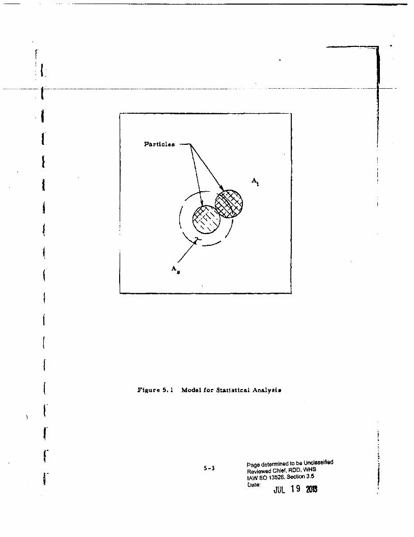
f L
I I I I
i I '
(
i t
(
{
(
r f
Particles
At
A •
Fi~ure 5. I Model lor Statiatlc:a.l Analysh
5-3 Page determined to be Unclassified Reviewed Chief, ROD. WHS lAW EO 13526, Section 3.5 Uate:
JUL 19 201
·-
l
I t r
(
{'
r (
I ~
where m is the mean number of parti<:lu in all area• (A ) 8
m • (S-Z)
where n • total number of particles oburved.
Since the sum of the probabilitiea of all pouible valuca (x) must equal
one, the probability of finding two or more particle• in A1 il
P (Z or mon) = 1 • P(o) • P(l) (S-3)
Thus,
P (Z or more) = 1 - e-m (5-4)
or
P (Z or more) :: 1 - e-m (1 + m) (5-5)
The expected number of agglomerate& (a) on the obaerved area of the
filter due to !iltration ia aimply:
[ ~.] E(a) • ~- P (Z or more) (5-6)
In analysing the experimental data preunted in the previous report,
the surface mean diameter of the aeroaol particle diltribut1on wa• calcu
lated and the following reeulta were obtained6.
5-4
Page determined to be Unclassified Reviewed Chief, ROD. WHS lAW EO 13526, Section 3.5 Ottt:
JUL 19 201S
I I
I ! !

~ { -----T --~~--- --------------
1 (
I
i l
r 1
r •• I
r
A • I. 96 x 10·7 cm2
" m = 0. 075 particles/area (A
11)
Thus:
P (Z or more) = 26. 7 x 10·4
and
E(a.) = 40 agglomerate•
The percentages o! particulate materia.l in the aerosol which formed
apparent agglomerates and thoae estimated to be formed durina filtration
are shown in Figure S. Z. The computation ahowe that filtration does have
a ligniflcant eflect l)n our data analysis: at lew bulk density (0, 33 gm/ cc)
about 57 percent of the apparent agalomerate• present may be attributed to
filtration, whereas at bulk density (0. 65 gm/cc) this value ia 31 percent.
lt should be noted that the expected agglomeration due to filtration is
directly proportional to the particle size. Therefore, data preunted in the
laat report in the 5 to 20-micron range are i.n!luenced more by filtration
than thoae ln the 1 to 5 -micron range.
3. 3 Duisn of High Flow Rate Diueminator Model (GMI-3) and Related !qulpmont
Experim~ntal work on the diuemination of~ in the wind tunnel up to
the present time baa provided a baeic underatanding Qf the aerodynamic
break-up procea 1 and characteriltica of both mechanical and pneumatic
diueminatora. At this time, it ia deeirable to inveadgate more specifically,
parameters that are being considered in the deaign and development of the
prototype unit. Therefore, a new model diueminator baa been deaigned
and fabricated to accompliah thh objective.
5-5
Page determined to be Unclassified Reviewed Chief, ROD, WHS lAW E.O 13626, S•ctlon 3.6
oatt: JUL 1 9 2013
I I I
I I I I
J
.I I ~ I ..
-------- ····----·--·-----······-----------··-···---·----------·-··-------··---------------------···
I {
... 4.)
.0
~ ~ ~ u u ... &: Gil ~ .... 1'1 ... u
~ .... tiO
~
0
0.3 0.4
0
0
Apparent Agalomera.tes Observed in ~ to 20-Micron Range
Apparent Agglomerates Cauaed by Filtration Effect
0.5 0.6 Bulk Density (gm/ cc:)
Figuu 5. Z Porcenta1e of Particles (by number) in~ Aerosol
0.7
(which conaitt of apparent agjlomeratee in the 1 to 20-micron range as compared to apparent agalomerates caused by filtration effect (wind tunnel Mac:h number o. 5)
5-6
Page determined to be Unclassified Reviewed Chief, ROD. WHS lAW EO 13S26, StGUOn 3.5
uate: JUl 1 9 2013
r I (
(
I (
(
( ,. (
I
The prototype unit will utilize a mechanical mechamam lo partially
break up the larie compacted sluga of material into small agglomerate•
and basic p&E'ticlea. The rnater1al will form a bed ill the diuemina.tor
which will be traneported from the unit into the atmoaphere by a gas.
To limulate the complete proceaa, equipment baa been constructed for
compacting the powder in the density ra.n;e 0. 40 t'-' 0. 65 gm/cc and •hearing
the slugs. Figure 5. 3 shows the devicea, Compa.ction ia accomplished by
ueing a low friction pia.ton and dead weiahte. Mechanical break-up ia
achieved by rotating andadvancing the compacted slugs into a single blade
with a cuttin.ll depth of 0. 050 ineb.
Modele udng a purely pneumatic; mechanism for tran1porting material
into the wind tunnel were inveatigatecl for this new eyatem. However, it was
found difficult to disseminate one gram of material in 0, OQ.f second, re
quired for a 30 lb/min flow rate. Thus, a mechanical piaton concept was
employed as shown in Figure 5. 4. The tran1port mechanism in this case
doea not tend to break up the material prior to itlf entry into the tunnel,
whereas in the case of gae transport, there is partial reduction of agslo
meratea. Therefore, deagglomer&tion data obtained with the model 1hould
be on the conservative aide - performance o£ the prototype should be slightly
better.
The system utilizes compreued gaa to actuate the piston. In compari
son with the previously uaed spring eyatem, thia method provides 1reater
llexibility for varying the ejection velocity and aimpliliu the loading opera
tion. For this high speed ejection process it is neceuary to apply the
actuating force to the piston rapidly. This ia achieved by retaining the
pilton with an electromagnet and pressurizing the air chamber to 12 paia.
The phton ill released when the circuit to the coil ia opened.
For a 3Cl lb/min flow rate the orifice diameter is 0, 394 inehu anci the
ejection velocity ilf 33. 5 ft/ aec,
Page determined to be Unclassified Reviewed Chief, RDD. WHS lAW EO 13526, Section 3.5 Uate: JUL 1 9 2013
J
;.
[ ~ .•
~ _t__ ___ _
t t f t I
I I , t . . '
' I
I t 1
I
(a) <J ur11pactor
Mechanisms !or Prt~pal'i~,g i'>illllll:~kd Sr.1_ Sample (Fill) for Diueminatton
Page determined to be Unclassified Reviewed Chief, ROD, WHS lAW EO 13526, Section 3.5
Uate: JUL 1 9 2013
p '
{
(
(
~
J ;I
I I I I I I I f I J f
Wind Tunnel
Micro -Switch
!:lectromagnet
Figure 5. 4
'Powder Sa.mple
Air Chamber
High Flow Rate Diueminator Model (GMI ·3) for Wind Tunnel Applicatton
5-9 Page determined to be Unclassified Reviewed Chief, ROD, WHS lAW eo 13526, Section 3.5
Uate: JUl 1 9 2013 I I
. r r l I r
I (
(
I I
. f
r r r I ..
r
valve which il connected to a miero-awitch ill such a way that the coil cir•
cuit il opened whel\ the slider ia pull1d open •
The complete apparatua nt•qp il 1how11 in Figure 5. 5 where the model
ia mounted to the wind tunnel. Related equipment include. a power 1upply
coneilting of two, 6·volt dry cella and a regulator and preuure gauge.
At the present time the appa.ratu1 ha.1 been tested for operational
characterbttca. In the immediate future, experiment. will be conducted to
determine the de;ree of deagglomeration dul"i.ng diuemina.tion of~· The
aame analysis techniquea aa were diacusaed in our previou1 report will be
uaed in thi• work. Also, during thi1 next pniod the unit will be uaed in
viability recovery teata at Fort Detrick in the 40-foot teat aphere.
5-10
Page determined to be Unclassified Reviewed Chief, ROD. WHS lAW EO 13526. Section 3.5
Oate: JUt l 9 201
J
l I i
l
i
l ' J
Page determined to be Unclassified Reviewed Chief, ROD. WHS lAW EO 13&28, S•c\lon 3.6
uato: JUL 19 201
i t
~ II GQMIIAIMIII,. OECLASSif'II!O IN I'ULL i_· .1 Authority: eo 13526 ~ Chief, Records & Oeclass Olv, WHS E • Date:
~. ------t-u------------··-----------------------------------""JUCTr20J! ----------e
I
' ,,
r f " J
r
6. EXPE.Rl.MENTS WITH THE FULL-SCAl..E FEEDER FOR COMPACTED DRY AQENT SIMULANT MATERIALS
6. 1 Introduction
A full-scale device for disaggregating and feeding compacted powder 7 materials waa described in the sixth quarterly progl'ess report . This de·
vice embodies the euential design features proposed for u .. in an airborne
store capable o! disseminating dry BW agent materials which are carried
aboard the store in a compacted state. The main objectiv .. o£ the experi
ment. with the full-scale feeder are to demonstrate the feasibility of the
propoaed deaign concept8 and to obtain data required for the design and
fabrication of a disseminator suitable for flight testing.
Perhaps the two most important queations relative to the proposed de
sign concept have been:
1) Will the force required to translate the compacted powder down the cylinder be low enough to allow a practical drive ayatem?
Z) Will the amount of gaa required to motivate the diaaggregated powder be low enough to permit storing sufficient gas a.board the store?
The desired objective ia to have a driving torque which does not exceed
Z500~tnch-pounde and a gas consumption which does not exceed approxi
mately 3 percent by weight of the agent material.
During the reporting period covered by this document, it was demon
atrated that both the torque and gae requirements are low enough to con ..
aider the deeign feasible in thete regards.
The experiments which are being reported have alao served to provide
qualitative information relative to items such as: the size of dilcharse
opening required, the effectivenea a of the cutters in shaving off and break·
ing up the compacted powder, gaa preuurea required for proper operation
of the feeder, uniformity of powder flow rate, and other behavior char
acterhtics of the !eeder and the compacted dry talc. In general, the
6-1
•aurtOIMtAl"
l ; +-il! j . r
I' :
r ~
• i
! ~
!
J
·.~
r , r 1
"lUll'S: 1! DEC~SSIFIED IN FULL ., • Authonty: EO 13526 ~·~
Chief, Records & Declass Div, WHS .. ·'£. ·------------------····-·-·-····-~Date. ·----~-----·- <
JUL 19 D! .. ,; performance of the experimental feeder haa been very encouraging and indi
cations are that the proposed concept for disseminating compa.cted dry agent
materi&la ia quite feaaible. Even though the r81ulta obtained thu1 far are
somewhat preliminary in nature, it ia believed that the following diacu .. ion•
will prove to be o£ value to thou following the progreu of work .on the dil
aemination of dry agent materials.
6. Z General Procedure
The procedure employed in the experimental work is to load and com
pact the powder mate7'i&l into the feeder and then to mount the unit in a teat
stand where the powder can be collected and weighed a.s the feeder is driven
by a variable speed drive. As the feeder is operated, several operational
characterietica such as driving speed, driving torque, time to discharge a
given quantity of powder, aa• flow rate, gas pressure inside feeder, and
gas preseure at the supply regulator are observed an~ recorded.
A schematic diagram of the arrangement used in the experiments il
presented ln Figure 6. 1. A photograph of the actual equipment ia shown in
Figure 6. 2. In thie picture the feeder is shown in the teet stand and con
nected to the drive unit. The gas manometera and !low meter are mounted
on the cart so that they can be readily disconnected and moved out of the
way during the loading operation.
The torque required to drive the feeder ie mea•ured two ways. When
the drive ecrew ia rotated manually a torque wrench bused, When the
power drive is used. torque ie determined by meaeuring the reaction torque
on the drive unit. The drive unit is mounted on two bearinge in line with
the axis of the feeder and restrained by a dynamometer. The force regia
tered on the dynamometer is multiplied by the lever arm to obtain the
torque.
Since relatively low preuuree are employed in the gas system beyond
the regulator, llimple manometer tubet are used to measure presaures.
6-Z
t81411DI:Cilallca i 1
....._, ,....., ~
0' I w
"~~l,:..;_;.;.JI!~!----··~-.;.a... ..
---·---- -" ~-
I '··:n.~·····""t'W-......'~i-·---..-·~·-
··•"-t .--.., .......... - - - .._. - ~ .........., -_, ,_ I .j ,.--
/
~
.14 ~ ~ ll_. lill Air In ----.....=====~~: Flow Meter 1-ij
Restrictor
Regula.tor I ~ b:=
' Manometers
Variable -Speed Drive
Figure 6. l
-- ----' -nr--w
Collecting Drum
0
JI R
0
Platform ScAle
Feeder
Schematic Diagram of Teat Arrangement used with Expedmental Feeder fox- Compacted Powde:ra
I
~0>0 ::rc m ii:fo ~g_!j;:
!:u~m
c... m-e: I o ·:!! r-. _m
lgowO
-;1[ ~~~ ~, ~ F
I<
I~ lw
I ~--=<j I·' :; ',( .,'I
,ll"ltr• ~~~~ .... _'1,_~.!~~->--' J I ",
I
Figure 6. 2
-- ------·--·------
Test Arrangement used with Experimental Feeder for Compacted Powders
~~~~1il I·· • :fo
~ i!i • I Jo:!! 4 .......... "' c.q -&:0
~ llti ~~ I •
Is li I
---- I I
I I
It SQW'P'"P'b DECLASSIFIED IN FULL Authority: EO 13526 Chief, Records & Declass Dlv, WHS~ .... Date: ,. tl NWe ~
--~-~~ v-~- ~~--~~-----~~-~-----------~----~~-----~--~- --------- JUL -1--il-~QIN---~~~a-~---
. r I r ..
I
' _.
\
{
f r
The amount of gas being uaed i8 meaaured with a variable-area type
!low meter placed· in the eupply line between the prusure reaulator and the
!eeder. The r .. trlctor ia used to control the amount of air Ilowina into the
!eeder .
"Mbtron Vapor" talc produced by the Sierra Talc lr Clay Co., haa
been used in all of the experiments thua far. Thia material haa a maximum
particle size of 8 microns, a mean diameter of 1. 03 microna, and a 1pecific
aravity of 2. 75. The p&rticlea have a plate-like shape, Talc i1 being uaed
in the preliminary work becauae with talc it is not neceuary to operate
with low humidity conditions in the teat area and there ia no explosion
hazard. However, it la important that face maaka be worn by personnel to
prevent inhalation of the material.
The talc il loaded into the feeder by separating the cylinder at the cen
ter eection and standing each half on end. The piaton h moved to the fully
retracted podtion at bottom of the cylinder. Talc is loaded into the cylin
der a.nd compacted in increments to obtain a uniform density throughout.
Denlity is calculated from the weight of talc required to fill the known
volume within the feeder. The denaity obtained waa 0. 44 grams per cc in
the first loading and 0, 46 gramt per cc in the second loading. The feeder
wa• loaded with 438 lba of talc in the !irst loading and 443 lb• ln. the ucond.
The experimental work i1 being conducted in a special test room fabri
cated for the purpoeee of confinins powder materials to a specific area and
ol subsequently providing a means of operating under controlled humidity
conditions. The room is shown ln Figure 6, 3. It ha• a floor 9 by 1 S feet
and ia 11 feet 8 inches hiah. The teet room ia Cabricated from rigid plastic
fibre glass aheeLs secured to a structural aluminum framework with epoxy
resin to obta1n an air-tight enclosure, There is an air lock to minimize
influx of unconditioned air u pereonnel pa.as through the doot'way. The
current work haa been conducted with the door open and ueing a blower to
pull air through the rooM and out through a filter before discharging it to
6-5
CAt'"llrt"att a
! I l
I I
'
1 ~~~ q .I
DECLASSIFIED IN FULL :1 iiA!'Wiiil:III W:re Authority: EO 13526
Chief, Records & Declass Olv, WHS
------- ------- - -------------- ------------------------ ---- ------ _______ Qti_~~-Jut:---l9-201t-----------------
I f
6-6
oM tdBLQifkbC
// ~
~~ \ Chtef. Records & QeciHt,.Oiv, WHS . :.::" . Date: JUl 1 9 D . . ·l -" - --··r··rr----------------·-···-·-··---·--·-·-------·--·-···-··-·-· ----.. ---···---·--·-----. --··------------------ ~-~=~
r , :: ::~d:;. =~:::,:::.~: :.~::.·:::::·:.::.~::~~ty .:::~" .. ·· J The d""er haa not been installed. . I. -T
All electrical equipment installed in the test room is explosion prool.
r l
r
6. 3 P_tiving Torque Determination•
While operatina the feeder to discharge the first load of talc, a con
siderable portion of the operating time was devoted to studying the driving
torque problem. Belore proceeding with power·driven operation o£ the
loaded feeder, the drive screw was turned manually with a torque wrench.
Two important observations were made. Firat, the pistons moved approxi
mately lilix inches alona the cylinder before the other end of the powder alug
started moving into t!1e diaaggregator cutter•. Second, as tlut feed a crew
waa rotated the required torque gradually increa.sed until a value ol 250ft·
lbs was exce~ded. Since the desired torque objective o£ ZOO ft-lbs had been
exceeded, steps were taken to reduce the torque before proceeding with the
power operation.
The cylinder was opened at the ends and the pistona were removed
without disturbing the powder. It was oh1.1erved thnt the talc being forced
out of the threads of the drive screw wa1 highly compacted and appeared to
be locking the piaton nut to the drive screw. In addition, the oil was coming
out o£ the bronze Oilite material of the nut and mixing with the talc to form
a hard gummy residue in the threads.
The thread friction was reduced by changing to a free -machining brau
material for the piston nuts and by incorporating a thread cleanout feature
in the nut, as shown in Figure 6. 4, This nut is constructed eo that powder
material in the •crew thread is removed at the front face of the nut and
directed throuah a radial paa aagewa.y to the rear face of the piston where it
falla into the cylinder behind the piston.
6-7
••uciiDIMIIE•
J i
j :j I
<1' I co
-~; .... .:.:.:.~ ----·;.~.--- ..........
---'-
--/ ---
L~lot in Face o£ Nut
\
........
"'
~ . ·--
Cover Plate
~ ...... ,......_. ....--..
I I
···--............... ~~PI!--~e:w."'t':n,,
--~~--
- Direction of Motion
Piston Nut
Screw
NtiHIIIJHIIIIIlll/JIIIIIIJIUlllllili~IIIII - --
Compacted Powder
-Path of Powder Scraped from Thread
(Half Size)
00>0 !a:r.cm !l!!!,::fO
• 0 r;:u::L:J>
c:...~~~ c:: m-r- 0:!! _..m -gowO
(Q~~~ ~I» c -~ F ~
Figure 6. 4 Thread Cleaner Scheme to Remove Powder from Screw ~
·- . ...__..,. 'll• , f.. PI~.~~
r;
,I ·.1. ,.·,, ," ..,'·.: • . • • •,) '[Jtilt4!.·~ .. ~-~~-tU•~"t~; •.•. ~·.!! .,• . . 1
After modifying the piaton nuta the torque required to drive the feeder
was approximately 200 ft-lbl indicating that the modification reduced the
threa.d friction by a little more than 50 ft-lbs. No attempt wa.a made to ob-
tain a torque reading for thread friction independent o£ other forcea con
tributing to the overall driving torque requirement.
Having achieved a sufficiently low driving torque value it was poaaible
to proceed with power-driven operation of the feeder, In operating the
feeder, the material was discharged in a eeriea of short runs of one to two
minutes duration. It was observed that the torque required to start the
feeder after each shut·down waa excessive because the talc waa bearing
against the disaggregator disc• at the center of the cylinder. By rotating
the disaggregator back and forth manually. it wa.e posaiblct to clear the
powder back to the cutting plane (approximately 3/lZ inches from the disc
in the first teat series). When this waa done the torque reduced to an
acceptably low value of ZOO ft-lba or leu. It waa noted that eomething was
cauaini the compacted powder to expand when the feeder was stopped at th.e
end of a run.
As a consequence of the series oi runs with the first load o£ talc it was
learned that the following factors can contribute to the torque load which
must 'be overcome by the drive unit:
1) force required to translate the powder slug down the cylinder - approxiinately 180 ft-lba.
Z) torque required to rotate the dhaggregator dhca if the powaer beau against the diacs - variable depending upon bearing preuure: calculated to be 86 ft-lbe for a pressure of 0. 5 psi.
3) torque required to stir powder in the center section alter it has been shaved off by the cutters - calculated to be approximately 2 ft-lbs.
4) torque to rotate the feeder when empty (friction from bearinga, acrew-threada, piston rubbing on cylinder, diaaggregator rubbing on cylinder)- approximately 15 !t-lba.
5) torque from powder being forced out of feed screw aad resisting travel of the nut - approximately 50 ft-lba.
6-9
,,fiJI'IIPINI' n 1.1
:1
'
CON"D'W' 0 I
DECLA!SIFI!O IN FULL Authority: EO 13526 Chief, Records & Declass Dlv, WHS Date: JUl 19 D_ __________ _
With the above knowledge o! factors contributing to torctue it waa easy
to ue why the total torque initially exceeded the desired ZOO ft·lbt objec •
tive and why it waa necu aary to take action directed at reducing torque
where i)osaible. The thread clean-out feature incorporated in the piston
nut wt\ich eliminated torque Item ( S) has already been described. Correc ~
tive action taken to lower other torque items is diacusted below.
The force required to trantlate the powder tlug down the cylinder,
Item { 1) above, waa reduced by allowing the compacted powder to expand
radially after compaction thua eliminating sidewall forces of powder
asainst the cylinder. Thh waa accompliahed by lining the cylinder with
at1•ip1 of 1/8-inc:h thick aluminum before loading and compacting the pow·
der i11 the cylinder. Theae stripe were then removed to form a radial
clearance apace all around the elua of powder. When the cylinder wa1
poai.tioned horizontally it waa observed that the space created in thh man~
ner wa.1 .more than adeq_ua.te to relieve compaction stresses and that the
powder was not contacting the cylinder wall on the upper aide.
An attempt wa• made to reduce the torque resulting from powder bear
ina againat the disaggregator discs by mounting the cutters on the outer
surfaces (toward compacted powder) of the discs, This placed the cutting
plane approximately l3/3Z inches away £rom the disc. This arrangement
provided additional apace !or the powder to expand and contributed to a re•
duction in the required driving torctue. However. subsequent teats demon•
strated that thia was not the complete solution to the powder expansion
problem and that further torque reductions should be po .. ible if the powder
expansion can be minimized.
The torque required to rotate the diaaggregator was reduced by mount·
in& rollers en the perimeter of the disca which support the cuttera.
The succeu of theu measures in reducing torque was demonatratcd in
the urie• of te•ts made with the aecond loading. The torque was only 3!5
£t-lba during the first teat of this series when the feeder wu full o£ pown~r.
By the end of the second tut run the torque had increased to 150 ft·lbe.
During the reat o( the ?'uru the torque ranged from 100 to 160 ft·lbs.
6-10
IJltilbiAflif1
r
.. i 'i DECLASSIFIED IN FULL J
Authority: EO 13526 J·.• Chief. Records & Declass Olv, WHS ,. ~-
~ Date: 1 9 2013 .·~ ------··---·-·--··--·----···--·----··-·-··------"'.:"-~---··-··-···-·-··--------·--···-···-\-- ;t-··-
The loading procedure employing removable stripe to create a radial
expanaion spa.ce for the powder also eliminated the initial delay in powder
feeding. In the preceding discuuions o! the results without uaing remov
able stripe during loading, it was pointed. out that the piaton moved approxi
mately six inc:hee before the central end of the alug of material started
feedin1 into the cutters. When the powder was allowed to expand radially
after compaction, the piston pushed the powder slug into the cutters without
noticeable initial compreuion of the slug.
6. 4 Motivatins Oaa and Talc Discharge Rate Mea1urements
In the proposed design of the dry agent diueminator a gas stored aboard
the diueminator will be employed to move the powder from the center sec
tion of the unit out into the slip stream. As the compacted agent matedal
is shaved off by the diaaggregator cutters, it is mixed with gas and flaws
out through the discharge opening. The powder flow rate will be controlled
by the rate at which compacted powder is fed into the rotatins disaggregator,
Even though the gas and discharge opening is not used to meter the agent
material, the size of the opening, the rate of gas £low and tho gas pressure
within the cylinder muet be adequate to insure that the material is carried
out of the center section as it is disaggregated. Material muat not accumu
late in the center aection. However, the space and weight allowed !or ga1
storage is limited and, consequently, the gas must be used sparingly if the
diuemination concept is to prove i'easible. An objective of no more than 3
percent by weight of the agent material was established. Experiments have
demonstrated that this condition can be achieved.
In the experiments being discussed here, air ha.• been uaed to move the
powder fror..1 the diaaggregator section of the feeder through the diacharge
opening into the drum where it is c:ollected and weighed. Eventually dry
nitrogen will be used for this purpose, However. plant air i• leas expen
sive and more convenient to uae than nitrogen and is quite adequate £or the
initial experiments. By the time the experimental work progresses to the
6-11
•t•PIDENI lif'
-.;,
J
(
I l
stage wh~re it becomes neceuary to use dry nitrogen, it is expected that
teat techniques will have been developed to the extent that gas wastase will
be a minimum.
Much of the talc: discharged in the two series of testa being reported on
wa.a expended while working on the torque problem and developing suitable
operating procedures. However, six runs provided good powder and g&a
Oow rate d&ta a.nd these results are summarized Ln Table 6. 1. The two
moat significant accomplishments evidenced by the tabulated results are:
1} Powder flow rate& of 30 lbe per min were achieved and exceeded,
a} The powder was discharged succea afully with a ga1 quantity aa low as 0. 8 percent by weight of powder.
These favorable powder and gas flows were obtained with auita.bly low gas
preuures within the feeder.
The diameter of the dischal'ge opening waa 0. 375 inches on Runs A-3
and A-4 and 0. 500 inches on the others. On Run A-4 the conditions werp
such that the talc did not discharge as fast as it was being fed through the
diaaggregator. As a eonaequence the center section filled with talc and the
feeder jammed. When the discharge opening waa increased to 0, SOO inches
in Run A-5 it was posaible to feed talc at a high"r rate ( 35 lbs per min
compared to Z8 lbs per min) while uaing a lower air preuure in the feeder
(2.1 em Hg compared to 36 em Hg) than waa required with the 0. 375-inch
opening. The Hmitins condition• result1ng in jamming were not obtained
with the a. 500-inch opening during these testa.
For the "A" series of runs the air pressure in the feeder is only 2 or
3 em Hg below the supply preuure set by the regulator, whereas in the
"B" rune the feeder preuure is from 6 to 2.5 em Hg below the supply pres
sure. This difference in the two series of runs is explained by the pre
sence of a flow restrictor between the regulator and the feeder on runs B--4,
B-5 and B-6. This restrtctor is used to provide a control over the amount
of air entering the feeder. Without the reatrictor the air flow is dependent
upon the amount of powder being discharged. The powder tends to choke off
the iiir.
6-12 ,.,, ...... 1 !J '· ~
i l
' 1
r: if ~.. ( '. DECLASSIFI!O IN FULL
' 4QtiiiiiNiiJit" Authority: EO 13526 t l - Chief, Records & DeclaS$ Dlv, WHS a Date: . r. Jut:-l-t-a--------- f- _r--------------·---------------·----·-------·------- ... ------------
i I ' • ~
~
I
I (
(
f
{ 3
Table 6. 1 Teat Results Uaing Compacted Talc: in Experimental Feeder
Run Talc Flow Air Flow Air-Ta~c Air Preuure, em. Hs. Diacharge No, lba/mi11 lbs/min Ratio Supply Feedel' Diam., rnchea
A-3 28.0 0.425 o. 015 38 36 o. 375 A·4 30.3 0.359 o. 012 3Z 29 o. 375 A-5 35.0 0.296 0.008 Z3 21 0.500
B-4 27.5 O.ZZl 0.008 zo 14 0,500 B-5 34.0 o. 418 o.ou 44.5 19 0,500 B-6 34.0 o. 403 0.012 41 22 a. 500
~ 1. Average density o£ compacted talc in feeder wu 0. 44 gm per cc: in
the series "A11 runs and 0. 46 gm per cc in the series "B" rune.
2. On Run A-4 the center section filled up with talc because it waa not discharging fast enough.
The curves in Figures 6. 5 and 6. 6 are preaented to ahow the uni£ormity
oC powder flow observed during the teat•. With the exception o£ teat Run
B-6, the time wa1 recorded at 10 lb interval• a• the powder accumulated in
the collection drum. Five-pound intervala were used on Run B-6. The
pointl have very little scatter from the straight line which was drawn
throuah the pointa for the purpoae o£ determining the flow rates for the
various runs.
6-13
... GNPIDINfiAt "
·~
1 _._-· :!_ ______ ,
_,
' ; l 'l
,,
~ l
l {
Ill
1 g a..
1 ~
j v • ...
Q
~ E-t
70
60
so
40
30
zo
10
o~~~~------------------~----------------0 zo 40 60 80 100 lZO Time, Seconds
Fiaure 6. 5 Diacharae R&te Curves !or Series "A11 Testa ueing Talc in the Experimental Dry Aaent Feeder
6-14
ti8NPIIIIftiM
···"'
f t I l All& .. ,a&nn... DECLASSIII'II!O IN F\ULL i ! •• • IKIII M Authority: EO 13526\ f - g::~· ReoorcJs & Declass Dlv, WHS --- tw . ----------------------- --------------------------------~----------Jttt-n--.,--------------
1 ;
r I
I· -3 d ::t 0 Ill
.a ~ =o 1-t
! ~ I) 14 .... ~ u
.-4 Ill ~
50
40
30 Runs B-5 and B-6
zo
10
0 2.0 40 60 80 100
Time, Second•
Figure 6. o Discharge Rate Curves for Series 11 B11 Testa using Talc in the Experiment&! Dry Agent Feeder
o-1s ~ ............ . I
f i l DECLASSII'I!O IN FULL
l l GO""Ditlll'lar Authority: eo 13526 Chief, Records & Declass Olv, WHS Date: --... T t~--- -- ------------------------- ----- ------------ ------ JUt--l-9----!}}!--- -- -- ------
' {t 7. APPARATUS FOR DISSEMINATION EXPERIMENTS AT FORT DETRICK
! I
..
i
Durina this reporting period. the wind tunnel apparatu1 and disumina
tion teat fixture wore completed in prepara.tion for shipment to Fort Detrick.
The dissemination test fixture was used at General Mills, Inc. in a uries
of experiment. in the wind tunnel in our laboratories. Thia unit and the
ex:pP.rimental work with it is discuued in Section 6 ol this report. The
wind tunnel design and fabrication were completed, incorporatini the features
outlined in our Sixth Quarterly Proareu Report9. The main components
included:
1) A nozzle and teet section
2) A atilling chamber
3) A heat exchanger
4) Three air-storage tanks
51 Five oil-free, two-stage reciprocating air compressors
The installation of this equipment in the' Fort Detrick facility and the
dissemination experiments conducted with thie apparatus will be covered in
the next quarterly progreu report.
7-1
•aiCPibi:C I Iiiii I
... ;
PI
~ DECLASSII'I!O IN FULL Authority: EO 13528 Chief, Records & Declass Dlv, WHS ~ u
I ,i 1-t---------------Date: JUL 1 9 20D
, t (t t t
f I
(.
j
8. DESIGN STUDIES ON A DRY-AGENT DISSEMINATION SYSTEM
During thh reporting period, considerable progress was made on
deaign •tudiu covering the dry-agent diuemination ayatem.
The initial concept of this external aircraft store wae set forth in our
Fifth Quarterly Progress Report 8 • The main features of this dissemina
tor concept are: 1) an aerodynamically-shaped outer store ttructul'e with
Z) a cylindrically-shaped inner aaent container which holds two compacted
slugs of dry agent; 3) a. ram-air turbine which furnishes power to 4) a
rotary actuator which drivea S) a piston feeding system, and 6) a rotating
diaaigresator which removes powder from the advancini slugs and utilizes,
for conveying purposes, compressed gas £rom 7) a self -contained gaa
atoraae veuel.
In our Sixth Quarterly Progress Report 10, we reported the results of
preliminary experimental work on a laboratory model o£ the center section
of the dis seminate;,r which includes the piston feeding system and rotating
disagareaatol'. Additillnal experimental evaluation of this laboratory model
ia diacuased in Section 6 of this report. This feeding concept hal been very
auccea8ful in providing a uniform powder feed rate, as outlined in the above
mentioned diac:ua a ions,
We have also given attention to several of the other principal con•
ponenta o£ the airborne dry-agent disseminator and have eatabHahed •orne
o£ the characteristics of these as discussed below.
8. 1 The External Configuration of the Store
As a result of atudiea of store shapes, we recommended two alternatives
to Fort Detrick. One of these waa the Douglas store configuration which was
used fot the liquid-agent db aerninator fabricated under this contract, and
the other waa a smaller store (ll. 12 inches in diameter by 180 inches in
length) which waa originally used (or a. 150-gallon fuel tank on the Qrumma.n
8-l
... Af&ZL£ J

I
I 1
F9F-6, F9F-6P, F9F-7, F9F-8, and F9F-8B aircraft. Alter review of
this question of the size of the store, including diac:uuiona with re;vre
aentaiivee of the Air Force and Navy, the Fort Detrick staff asked us to
proceed with the design on the basis of the amallar store. This decision
was influenced by aevflral considerations including target size and com
patibility of the store with operational and obaoleacent aircraft,
Aa currently enviaioned, it will be po1aible to provide a cylindrical
agent container in the center section of this store which will have a di
ameter of 16. 5 inchea and a length o£ approximately 80 inc:hea. With com
pacted dry agent, the payload will be approximately 350 pounds.
8. Z The Rotary Actuator
The feeding mechanism in this diueminator concept must be driven at
relatively low rotational speeds. It ia also desirable that several speeds
be available, thereby providing a. selection of the agent diesemination rate.
A preliminary design study has been conducted on this rotary actuator be
cause it is important to establish the feasibility of providing a suitably
compact and lightweight drive unit before detailed design of th~ store is
initiated,
The principal requirements which were used as a basis for this pre
liminary design study are lbted below:
1) Output Speeds - 8, 12, 16, Z4 and 32. rpm in either direction.
Z) Output Torque - 2., 500 inch-pounds in either direction at the above speeds.
3) Maximum Allowable Overhung Shaft Load - 1. 500 pounds.
4) Maximum Allowable Inward Thrust Load on Shaft -2, 000 pounds.
5) Maximum Allowable Outward Thrust Load on Shaft -Z, 000 pounds.
8-Z
& LUI !ISh I IIUif" ' I
J
f I DECLASSIPII!O IN I'ULL f U' Authority: EO 13526
I t•llfllltMIJL m Chief. Records & Declass Otv.WHS . . - ~~19m .. · .... -I H- -------·--···--·--·-·----~-----·-··-----·---~-···-----~--·--·~-··---- ----,-~- ~-~
! l i ! t ·.
( .
6)
7)
8)
9)
Duty Cycle - Continuous Cor periods up to 1/Z·hour.
Lifo - 200 hours.
Operating Altitude -Sea level to 15, 000 feet.
1 0) Acceleration - 1 0 g 111 in any direction.
11) Vibration - 5 to 500 cps at 0. 036-tnch double amplitude or !. 1 0 g whichever il the lower value.
lZ) Input Electrical Characteristics - 400 cycle, ZOO volt, 3 phase, AC.
13) Connectors - Water -tight connector at cable entrance to actuator housing.
The actuator unit for this application will conaiat o£ an AC aircraft
motor, a variable speed-reducing a.uembly and a fixed speed-reducing
assembly. The motor will be a 4-pole moto1', which has a nominal speed
o£ 12, 000 rpm at 400 cyclea. The use of a relatively high-speed motor
makes the actuator more compact and reduces the weisht. The a.nalysia
shows that the motor will have a rating of approximately 2 horsepower.
The variable speed-reducing auembly will be duigned so that the motor
pinion gQar can be meshed with any one o£ five idler gears by rotating a
supporting sleeve. The fixed speed-reducing auembly consists of a three
stage planetary gear package having an overall reduction ratio of 433. 5 to 1.
A comprehensive analysil of the gear performance hal been made
which shows that the required life o£ 200 hours is feasible under the condi·
tions of this deeign. The physical dimensions of the actuator unit, u cur
rently envisioned, are an overall length of approximately Z4 inches and a
maximum diameter of approximately 8 inchea. Depending on the final
selection of the motor, the physical shape will vary somewhat. A pre
liminary weight analysis haa been made which indicatelt that the complete
actuator unit should weigh approximately 65 poundA, including the electri
cal motor.
8-3 , ....... , .... ..
I I !.
8. 3 The Power Generator
Baaed on the above analysis, it is anticipated tlul.t the motor power
input requirement will 'be appro~mately Z ldlowatte. The ram-air turbine
(General Moton, Allison Divilion) uaed on the liquid di1eeminator has a
rating of 4. S kva. Si.nce thi• unit h&l adequate power and il relatively
small and lightweight, we plant to incorporate it into the dry-agent db
aeminator design.
8. 4 G&l Storage Vea sel and Flow Regulating 8y1tem
Experimental investigations usins the laboratory model of the feeding
system have shown that successful operation can be achieved uaing talc
powder. when the ratio of air flow to power flow (on a masa basis) h
approximately 0. 01 to 0. OZ. In our prelimit'lary studies of the pressure•
veuel requirements in thiS airborne dia semination syatem, we have set the
air (or nitrogen) storage requirement at 3 percent of the maximum payload
(350 pounds) or 10. S pounds of gas.
Since volume thould be minimized, we have bated our calculations on
a storage pressure of 3000 psi. At this pressure, the required quantity uf
a.ir will occupy a volume of approximately 0. 7 et3 , which is definitely com
patible with the apace available in the store. It appears that the most utis
!a.ctory 1hape will be a conical center section with (essentially) hemilpheri
cal ends.
With rupect to materiall, tanks of this type are available in glau
fiber, 1teel and other alloys. Due to the major importance of 1a!ety in a
system of the type under coneideration here, we recommend the use of a
steel tank. It ia believed that inspection of glaea -fiber reinforced plastic
pressure vessels b not as well developed as procedures for steel tanks.
The preliminary estimate for the weight of a suitable steel tank ia 40 pound1.
Two manufacturers of these tanl<.s are Tavco and Kidde.
8-4
I II IIZB 2
i r r
Initial studies o£ the fiow-resulatinll system indicate that the moat
suitable technique for providin1 aeveral levele o! constant (but aelect.a'ble)
flow rate ia to opera:te the ayatem with a critical orUice in the line to the
disaggre11atin1 section and an adjuatable preuure resulator upatream of
this orifice. Experiment• with tlte (ull-tcale laboratory f .. dina model
have confirmed this opinion. It has been found that this mode of operation
h superior to method• where the flow is controlled in response to the pru
sure in the center section.
Additional work on the proper sequencing of control functions is
planned in the future.
8-5
lllQMIIQIN'V ..
DECLASSIFI!O IN FULL Authority: EO 13526 Chief. Records & ~claani'lv, WHS Date: JUL 19
_..,,_., __ . . . ·~-· ·-.. ?~~
~ .. ISICfllllll&i a . ~ 11
, . £ OECLASSIFII!O IN FULL ---------t~u;----------------------------------------------------~A~u~~~~~r~N,~.je~o~1~ss~2~er------------------~~~-~---: _ . f
0Chief. Records & Declass Dlv, WHS l
i ate: JUL 1 9 2013 _, II ( 9. SYSTEMS SfrUDY 1 t I! In our Sixth Quarterly Proireu Report
11, we pruented the results o£
computer studiu of the problem of line-source diuemination of two solid
a1ent1 LE and N. The variable decay-rate model was used to determine
J the agent !low rate (versus downwind tra.vel) required to deliver a. minimum
r of the ro50 dose to the area covered.
Durina this reportina period, the same type of computer &n•lY sia haa
been conducted for the agent UL-Z. However, in this case, information a.s
to the dependence of decay-rate on time wae not available ao that a fixed
decay-rate assumption was necessary.
The equati~>ns of the model were proiJr&rnmf'ld on the Bendix G-15 com
puter and the results a.re preunted in Figures 9. 1 and 9. Z. The following
values for the various paramctora were uaed:
1) Biological decay rate {conatant): 4. 5~ min -l.
Z} Concentration- to-in!ective-doae ratio, c/IDso: 1. 36xlo13 lb- 1.
3} Height of the aircraft, h: 200 feet.
4) Efficiency of diuemination, E: ZO~.
5) E£1iciency of particle retention, Er: 33%.
61 Speed of the aircraft, v: 546 mph.
It will be noted from Figures 9. 1 and 9. Z that, over the ranae of down
wind diatancu investigated, tho flow rates are well below the maximum
delivery rate (30 to 60 lb/min) which ia planned for the dry-agent diuemina
tor. It may also be uen that the Influence of we&ther condition• i1 im
portant, although it is laaa pronounced than in the case of the a1ent N, dis·
cuaaed in Reference ll. This is tra.ceaule to the diiference in decay rate,
the a1ent N having a lower decay rate.
9-l
:A8fiJIUINIIAL 1
- -
-o ' N
00)>0 ~~gg; .. ;g.~
<:-. (1)8~~ c:: m.- a.o::!!
"'~m ...... 00 wO u::. o~z
(j)Q),.
~ ~ c t3 ~ F
0 ~
~ (I)
~ .... E ...... .a -.i .. ., ~
1t 0 ....
Cat
L-·-··----··
~0
15
10
5
0 5 10
Figure 9. 1
-·
15 zo zs }0
Downwind Distance in Miles
. .,. .... , t·
I I i
-.·-··~-~ ... ,~"'r~~ .~ ·~ c::.-= I ~
35
Flow Rate versus Downwind Distance for ''Avera.ge11
Weather Conditione - Agent UL-Z I ;
t··
----- '!u
.. -- • . t •. ;; f'TJ:.:) .•.. , .... ';, ..... ;~ i~~,\~~~~1:~,.,,,.+
;t.O
15
C! ... s -,D .....
-.Q
G 10 I 1M ....
~ ~ 0 ..... ...
5
0 5 10
Figure'}. 2.
-------------·
-I
., ~.-- ........ ~~ ...... ~.~~ ...... ~a. I -9r::::
! I
I I i I
I
!
I '
001' 0 ~~ ~ .. ~ .~
<D .. ~ c.. 81!1-
_l_ _ ___ l____ I ~ it-~il -~Qo ~ 15 20 25 30
Downwind Diatance, )4ilea
Flow Rate veraua Downwind Distance for uaood" Weather Conditions - Agent UL-Z
35 ~ (!
I IF ~I ~I (I) I
I ~ i (I
'I ]1.'. II
..;.. -~·~.;:.r-nreercol''" 'TllZ n era
fl : •• , • ?! ·:··h
~ C t ~ I
' I ~· t-~• ~ ~.
-u·~ .. •·- ... ~~IJJ!i'/1•\;"l,;.
• w•~~·· __... -• '•• ~·:""- ;;-
~ ~ -~
~ U GIIJIIMtl&. ... -=.-=-~ ____ . _ ~-i -. .. . -~ T li------~----~ --- -----~-~-~-~----------~------~ ---~----~-~-_..==;:;
t ,-' . f . t •.
r •
J" I ,. I
10, PR.OGRE.CJS ON THE UQUID DISSEMINATINO STOllE
Phase II of this contract ln~l11dea the design and fabrication of a liquid
BW agent diaaeminating atol'e. The confiauration and general charac:terhM 12
tics of thia unit are described in our Fifth Quarterly Pl'ogreaa Report
Additional work toward completion of this taak wa• covered in our Sixth
Quarterly Progress Report13 which outlined progress on deliin of the tank
assembly, fluid handUna system, electrical system and the boom anemb1y,
and reported the status of the orders for purchased parts,
10, 1 Work on De sip and Fabrication
During this reporting period, work on this liquid agent disseminating
store progressed so that the unit was completed to the point where success
ful laboratory-functional testing a.nd demonatra.tion was accomplished,
Figure 10. 1 il an external view of the di!lseminator, showing the ram-a.ir
turbine mounted on the nose o£ th., unit.
One o£ the principal areas of work during this periond was on the de"
tailed utn•.i.an. fabrication and teetina of the fluid handling •yatem.
Figure 10. Z showr the plu1nbing a.uembly and Figure 10. 3 is a view of the
store with the aft section removed to show the completed in•tallation.
Another important ae aembly is the boom and actuator system whieh is
ahown ln i'lgure 10, 4. The twin·boom auembly ia mounted in the aft-end
of the store. These boom"' contain the slit-type nozzles through which the
agent is diecharged into the slipstream. The actuator ia an electrically
driven unit which it capable of extending or retracting the booma.
During this reporting period. the electrical components were a.lao pro•
curred and {where neceuary) specially fabricated and installed in thea atore.
The mechanical and electrical aspects of the liquid agent diueminating
atoro ara diaGuued in more detail in the section which follows.
10-1
CQIIIIAIMIIII a
DECLAS$11'1!0 IN FULL Authority: EO 13526 Chief, Records & Declass Dlv, WHS Date:
JUL 19 2013
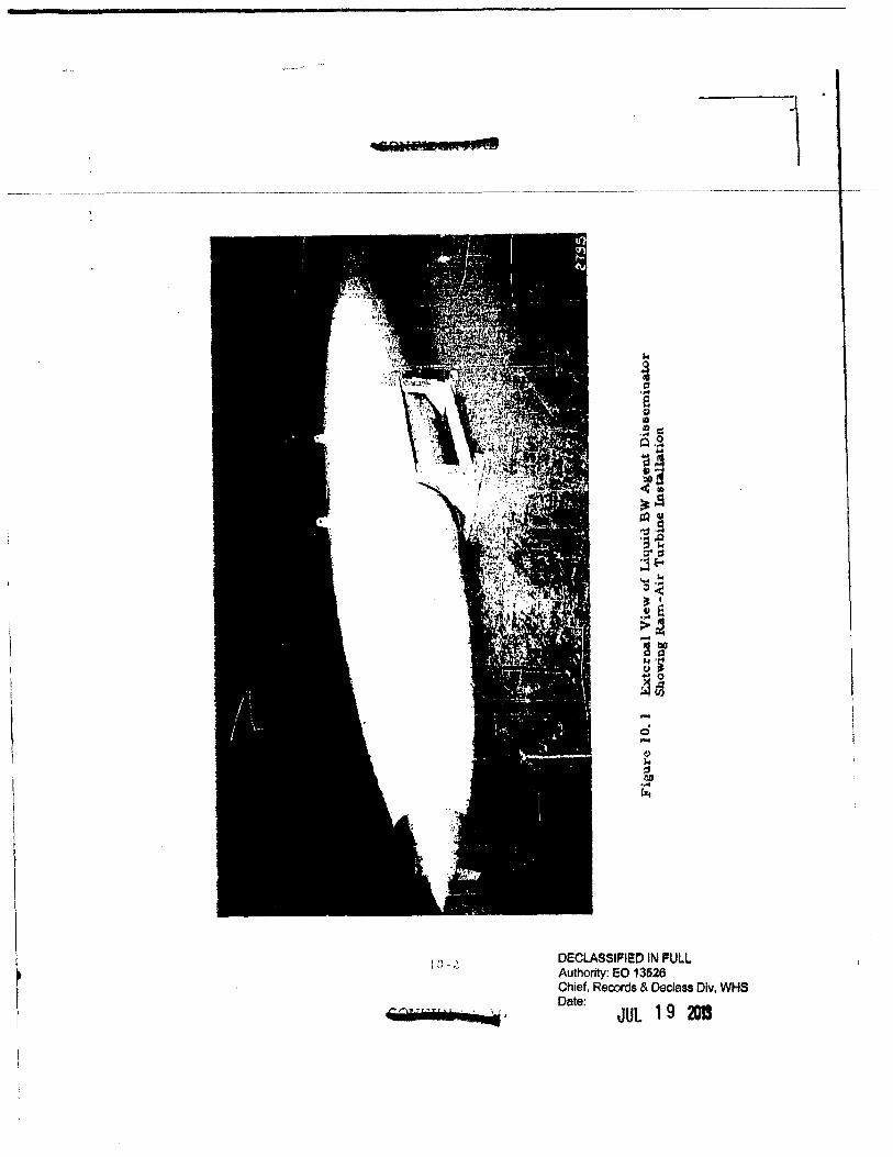
I
I I
\
I f I
~ I
'·"" ' l \I-,_.
€6JITiil± · · ~·
,. i " .... e 41 :0 .~ ~ ~.~
~.a " .... ~! ~,g &QU 'tl .s ·a -e :r:t j£-4 ~ .~ 0< iJ I
.~ e >~ -~~ ~·; .. 0
~GJ ... 0 -~ N ::1 OD .... ~
DECLASSIFI!O IN PULL Authority: EO 13526 Chief. Records & Declass Dlv, WHS Date:
JUL 19 •
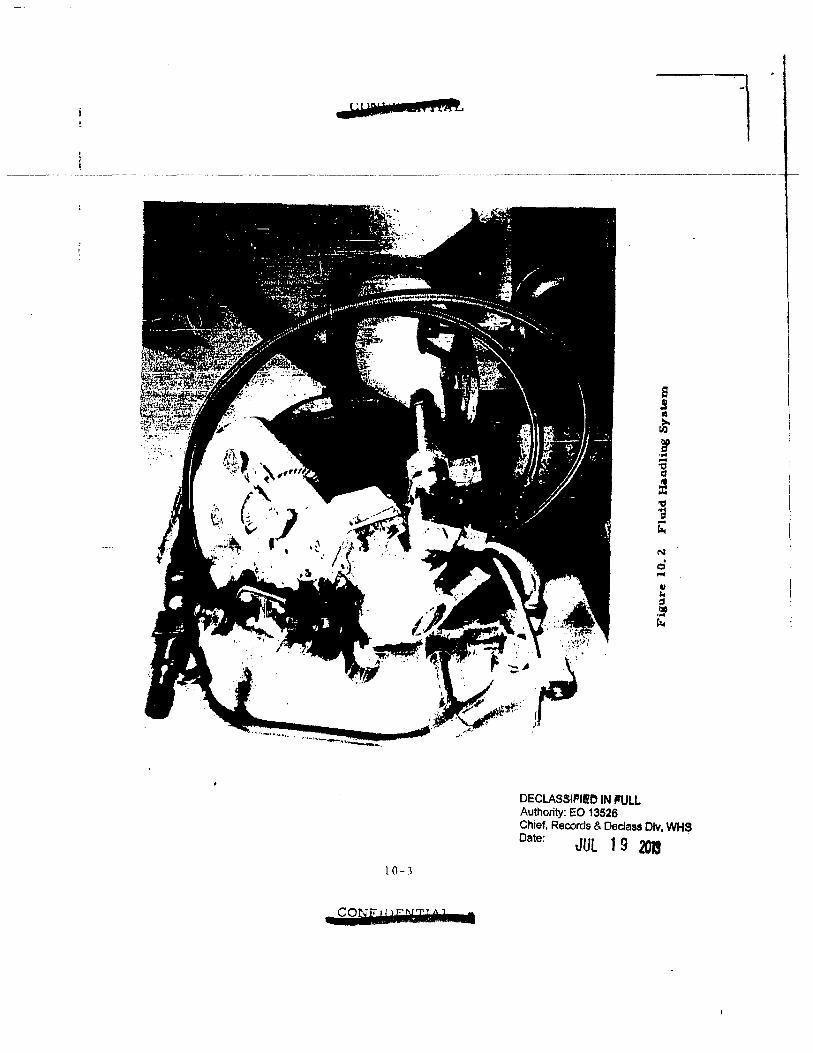
:::zlci 1 mo r n HM:.
10-J
• COrf[' I lailikUr •
DECLASSIFII!O IN ~fULL Authority: EO 13526
N . 0 ...
Chief, Records & Declass Dlv, WHS Date: JUl 1 9 2013 .
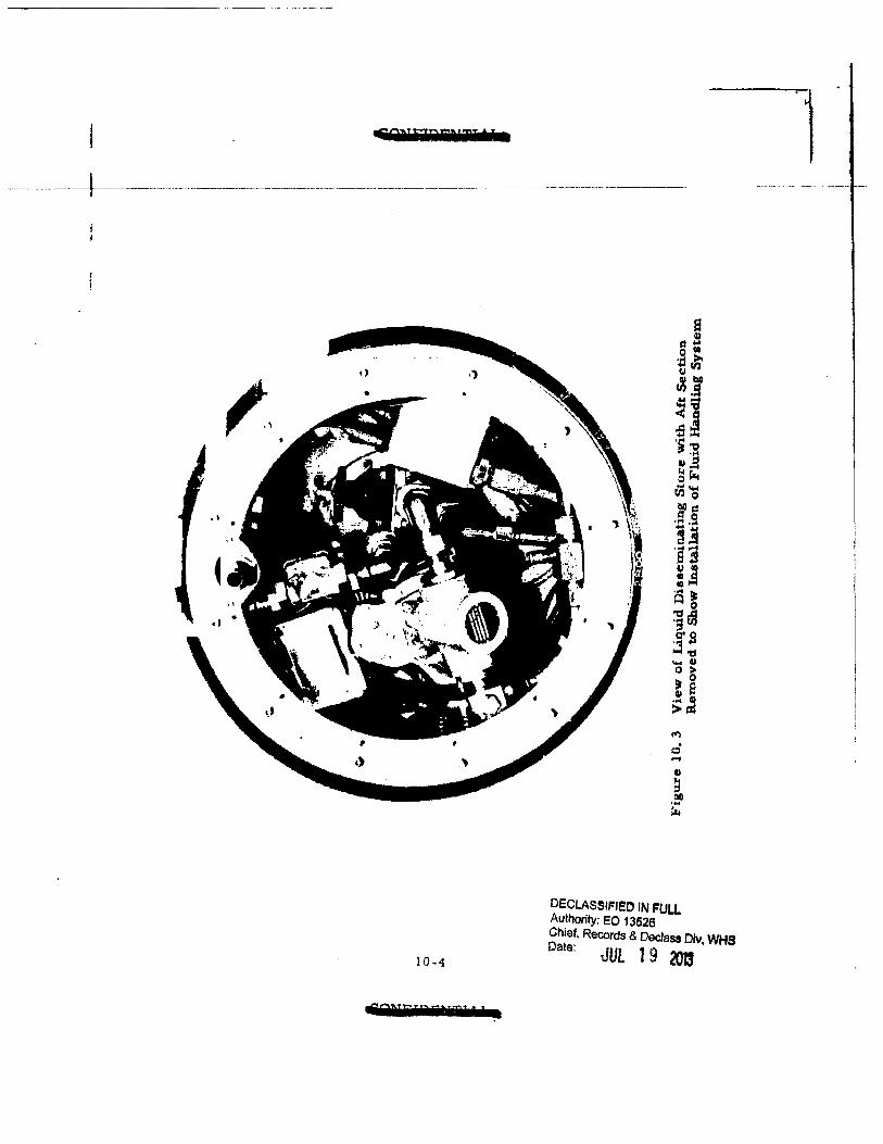
-&QD'flii:liil 'fa
,, •
10-4
49NFT?i!ITJ 7 I ;a
t"' . 0 ...
DECLASSIFIED IN FULL Authority: EO 13526 Chief. Records & Declass Olv, WHS Date: JUL 1 9 2013
i \
f----.-·-·---··--·--·--··{---·-·--·---·--·-·------------------ . ··-· I '
I
10-~
. l Authority: EO 13528
~~!~~· Records & DeT~~ wt-1~---------·- _ J.JGI.t:I.---·-·JUL ., "'"' l
~·· ('
·----~:- tT---· :r J
r
I
l
I
t
I
f ' r
OECLASSIPIEO IN I'ULL Authority: EO 13526 Chief, Records & Oeclass Dlv, WHS Date: dilL 1 9 201! --··----·· t----4--
·.d!
10. Z E!!!!minator Description and Information
The aeneral cha.racteristice of the dieseminator a.re lbted below:
Length: 2Z7 inchee Maximum Diameter: Z6. ! inches Loaded Weight: 2075 pound• Empty Weight: 575 pounds Capacity: 180 gallons Discharae Rate: 18. 7!S gallon• per minute at 70 psig Aerodynamic Cotlfigura.tion: Ooualas store Mounting Provisions: Standal"d luge on 30-inch centers.
Details of the structure, .the generator, the note section content•, the
plumbins aasembly, the fluid handling aystem operation, the boom asaembly
and t"te actuator auembly are given in the paragraphs which follow.
1 0. 2. 1 Structure
The structure conaiata of three major aeparable uctlone: the noee,
the centeJ' section and the taU section. In all o! theee eec:tion•• the skin ia
a major structural element for which the material it 6061-T6 aluminum.
For the nose and tail uetions the thickneu of the Aluminum ie 0. 071 inch
and for the middle 3 feet o! the center section it ia 0. 080 inch. At the separa
tion stations between the three separable sections, rings are welded to the
skin. These rings provide the flanges through which the section• are joined
by bolts. Other structul'al rin1s extending around the inner circumference
of the tank are used for supporting components within the ta.nk. The joining
and structural rings are alao made out o£ 6061-T6 aluminum. All parte of
the structure are o£ welded construction except for the door fra:rn••· the
bulkheads and rin111 uaed for mounting componenh, and the wells in the tail
of the tank into which the booma retract. The•• parta are riveted in place.
In mora detail, the nose section which ends at the rea.r mounting sur·
face of the air turbine generator has a spun aluminum akin, a forward
mounting ring to which the air turbine generator ill attached, a rear joining
rin& and an access door.
10-6 ........... 'I l
~
l
:·:'\
l: t8tlfi.IRIOAf DECLASSIFI!O IN I'Ull Authority: EO 13526 Chief, Records & Declass Dlv, WHS -· -·---+-n----····------·--·-----·---------·
~ ~ .
Date:
r
I ~
l
I
I r I
Tho center section conailts of a akin, the front joining ring and bulkbead aa one integral part, the inner tank mountina rillJ located toward the rttar of the center section, the rear joinillJ ring at the extreme rear u! the tank, two aec:eu doors. and Weld backup :ringe. The akin for the center section coneieu of three major sections welded together, one coneiatina originally of a nat aluminum sheet rolled into a cylindrical shape and welded alon1 a longitudinal element and two made from flat aluminum sheet fol'mcd and welded into the !ruatrum of a cone. Thea,, two sections, having the shape of the fruatrum of a cone, were then fo1•med into the final complex oiihape by the use of pot diu, The term complex here is used to describe a surface in which none of the elements are straight Hnee. All the inertial loadinr and air loading applied to the tank h transmitted to the pylon of the transporting aircraft through a central atructure. Major elements of the central structure are the strongback, the ma:.in support rings, and the attachment lugs that extend outward from the tank on the upper aide. The strongbac:k is an aluminum casting of Z20-T4 aluminum extending approximately from lug to lug and being about 14 inches wide. The two main support rings a.re bolted to the atrongback and extend around the inner circumference of the tank, Each rinfl is made in. two pieces joined at the bottom of the tank by an expansion turnbuckle that ia used to force the ring outward into tight contact with the tank. The material used for these rina• is 4130 steel, heat -treated to a tensile 1trength of 170, 000 to 190, 000 pound• per square inch. The luga are made of 4340 chrome, nickle, molybdenum ateel. heat-treated to a tensile strength of 180, 000 to ZOO, 000 pounds per square inch. The skin and structure (exclusive of inner tank) ha.ve a weight of about 285 pounds.
The center section also contains the inner tank which ia supported by being foamed·ill .. place and alao being held by screws !utening it at the rear to the mounting ring riveted to the outer tank akin. In addition to serving aa an inaulation the foam joins the outer aluminum akin and the inne2' tank together into a laminated atrucb.lre of great strength. Material for the inner tan.k is plastic -impregnated, filament -wound ffberJl&u built
10-7 ...........
......... DEeLASSIJi'I!O IN I'ULL Authority: EO 13526
f t ; !' I
Chief, Records & Declass Dlv WHS Date: JUt 1 9 3JI' .. ~
----~+~---·-·- ---------·----··· -- ----------- ------------------·------------ ------- -----··-·--- ----·- --·-[ I '
l up into wall• of l/10-inch thic::knue. This material waa selected becau•e
of ita resistance to C01'rOI!Iion and itfll light weight. The weight of the it-.ner
( tank ia 12.0 pound•.
The foamed-in-place inlulation is a proprietary product called H!TCO
I
I
f f f ·:1
r
made by the H. I. Thompson Fiberalau Co, It baa a deru~ity of 2. pounds.
pel' cubic foot, a.nd a. K value of 0, 14 BTU per hour per square foot p"'r de·
gree Fahrenheit per inch uf thickneas. The compreeaive strenJth is 4~
pound• per square inch a.t 160°F, and it will withstand 300'F. The thick
neu of the foam insulation ia not uniform but varies from 1-3/8-inch to
1·5/8-inch. It was installed through holes drilled in the outer akin and
these holes are filled with smoothing compound number 5-3000 called
Organiceram ma.de ln Anaheim, California.
Immediatel.y to the rear of the inner tank, but within the limits of the
center section, ia an inaulated compartment about 12 inches long. Thia
compartment ia insulated with about 5/8-inch o£ foamed-in-placed insula
tion to protect the plumbing from freeaina. A removable circular cover
covere the rear opening to thia compartment. The two doo:ra providing
access to thle compartment are alao insulated. Two pad-type hea.ting ele •
menta thermostatically controlled supply 90 watts.
The unin.sulated tail section consist a of a apun aluminum akin, the for •
ward joining ring, two actuator auembly mounting ring• riveted to the akin
and one accea a door. lt alao contains the boom wa.lla into which the boom•
rt~tract.
10. 2. 2 Generator
The generator ia manufactured by the Alliaon Diviaion of General
Motore. It baa the following characteristics:
t) Output 4. 5 kva at 0. 75 power factor
Z) The current: 115/200 volt 400 cps 3 phase wye
10-8
I i I
l .. _J
ll F DECLASSIFI!O IN FUll ! 't_l_ Authority: EO 13526
Chief, ReCOrds & DElcla Dlv · ,, Date: · ss • WHS _ r . JUL 19_ .-_ -~t+r--~----------·---------·--------······-···--------·-------------- 201------------------,
I 3) Speed control is by a mechanical governor that &djuata the 1
. propeller blade pitch. f
I I
I I I
r
' f r ' r
4)
S)
6)
7)
The speed range is from 11, 500 to u. 900 rpm over a spe~d range 300/650 knots true air speed, at 500 !t altitude.
It usee a solid state voltage regulator separately packaaed in a box about 4 x 4 x 3 inches.
Weight is 43 pounds.
lt has a maximum drag of 1 00 pounds.
10. 2. 3 Nose Section Contents
Mounted on the forward end o£ the center section but actually located in the noec section are some electrical acceuuries and supports. The functions performed are: voltage regulation, switching for operation on ground power or generator power, and ovedoad protection. The voltage regulator con.ailte of solid state circuitry that regulates the voltage of the air turbine generator through regulation of the field excitation. Thle regulator il built by Alli•on. Three connector• al'e provided: one !or connection to the power output ot the generator, one for connection to the generator for voltaae regulation, and one for connection to the ground power supply. The connec• tor for connection to the ground power supply is very large in comparison to the aise of the connector for connection to the gener&tor output. The rea•on for ita large aize is that it muat mate with the standard around pnwer supply socket.· A circuit breaker ie included for protection of the ayatem and the power supplies. One relay b provided to automatically connect the active power supply to the ey etem. In the normal poeition thb relay connects the generator output to the diueminator circuita. When ground power is supplied, the relay acta automatically to disconnect the air turbine generator from the system and in1tead connect the around power supply to the system. Alao, whenever voltage is not being aupplied by the ground power supply the contact• in the ground power supply connector a.ro disconnected from the diueminator circuits, Another relay ia used to control the supply of power
·-~
DECLASSIPIIO JN FULL SGIM"P8111jL Authority: EO 1362~
Chief, Records & Declass Dlv, WHS I \
------- -~ 1-i-·----·--·-·-------· ········-------········ - t It
Date: g ·-··--------· . ---------------------------- ___ J11L_l ___ 2013._ ___ .. -------------
l
I I I
' I
,.
to the system in accordance with the position of & switch on the control
panel located in the cockpit, All of the electric:al COlTiponenta diacussed so
far (except for the air turbine generator) are mounted on a dishpan shaped
mount attached to the !o1'ward end of the center taction. The relayo nnd
circuit breakers are mounted inside of thie mount and the voltage regulator
is mounted on the outtidc a.a shown. 'l'he dust cap covers the circuit
breaker reset button.
10. Z. 4 Plumbing Auembly
The plumbing auembly il located l.n the apace of the aft insulated compartment. Much of the support for the plumbing assembly is provided by the inner tank cover which is made ouL of Type 304 etainlesa steel. This
cover not only support• the plumbing auembly but al1o provide• a seal for retaining the contents of the tank. A ridge on this cover fits into a groove
o£ the mner filament-wound tank and the aea.l i• provided by an 110 11 ring fitted into tho groove. To the rear of the cover plate is the fluid control and
plumbing a.ssembly. The functions performed by the equipment hero include filling, venting, pumping. pressure relief, by-pass and flow sensing. Fill· ing and venting are accomplished through the two flexible tubes. The flexible
tubin& ia Aero AQuip Type 666. It consists of a teflon inner tube, a woven
stainlua ac:eel jacket, and a neoprene dip coat. The pump is a 1. 5 horsepower u.nil (motor pump) made by Lcn.rARomec and it il a. vane type having
a capacity of 18, 75 gallon• per minute at a pump outlet prea•ure of 70
pounda per square inch gauge. The weight of the pump ia U. 9 pounds.
The preuure drop from pump outlet to far end of boom is 3S psi. Pressure drop along boom does not exceed 1/'l. psi,
10. Z. 5 Fluid Handling Syatem Operation
The primary function of the fluid handling system is to tranafer under
preuure the liquid from the store to the disseminating boom8. To accomplish tnils task aatisfa.ctorily the £luid handling system must also provide
1 o. 1 0
! I
\
l i I
I ..• .....J
~·
~ DECLASSIPI!O IN PULL I I' Authority: EO 13526 ( ' •uuaa .... _ Chief. Records & Declass Dlv, WHS · •· Date: _ -, ------+ n-~-- ---------------------------------------------------- JlJL___l9 m ______________________ --~~; ~ ~
for controlllnJ the flow of fluid, recirculating or mixing the fluid, filling
I I
I" l
r ,. !
r
the tank with fluid and prt:>vide adequate mean• to allow decontamination, of the tank. Figure 10.5 shows a schematic o£ the plumbing ayatem.
Followihl is a brief description of the function of the component• in the system. As a .. tatting point it ia assumed that all th"ree manual valves are in the Cull open positions aa they would be for an airborne operation. The system will be in one of three statu while airborne. They are: STATIC (pump shut off), RECIRCULATE, or DISSEMINATE. Sequence functions have been neglected.
In the STATIC mode solenoid valves 4, 5, and 6 are closed. The f'luid ta thus confined by check valve 8, •olenoid valve Sand check valve 7.
In the RECIRCULATE mode solenoid valve 4 is opened and the pump started. The fluid is thua drawn from the tank and pumped through the plumbing system back into the tank at a 18 gpm rate. Solenoid valve 5 re • mains closed thua preventing £low ol fluid into the booms. Solenoid 6 re• mainf closed thus backing up check valve 7 and preventing any lou of fluid through the vent line. Under normal conditions the relief valve also t'emaina eland but if, due to lome malfunction, the !low of fluid in the recirculate line is restricted with a conseque-nt rise in pressure, the relief valve opens and allows fluid to !low into the tank through the vent line.
In the DISSEMINATE mode aolenoid valve 4 remains closed while sole • noid valves 5 and 6 are opened, the pump il started and fluid flows through solenoid valve 5 into the boom a.uembly and is diuem1nated, Aa the fluid flow• out of the tanlc a negative pressure h created within the tank. Thu1, Iince 10lenoid valve 6 ia open the prelll!lure differential c&uaes check valve 7 to open allowing flow of air into the tank. The relief valve again ia nor· mally closed and function• only when the flow i1 rutric:ted cauling rilel in fluid preuure beyond the preset relief preuure.
10-11
cog 22ULIIIIF
.. _...-..._.,
Tank
-0 I -N
Drain Plus
- ..
Air Fillet'
Manual Valve
Line Di~>charge
Recirculate Line
-- -
,_....._.,........ Check Valve
Figure 10. 5 Plumbing Schematic
I - •.,;··n.-:;-· o:;:"l'·j• ··-:.;-':"'-~-,.."" .. ,-"tit
-· - ~-I
"-Plus
Di11cha.rge
~
'-.Plus iOO>O I!! :r. s. m
l !l!~g~ i :u~(/) i ~n;!!!
~ a.o:!! (II_.IQ s;>owCJ
+~~z <f'iOI~
i J I=
I~ 10
I "'1i
·'
... ht-L"~ ·. ~I
I
I I l
t f
r f f
This is a welded auembly consisting of the two booma, their £airinga,
the shaft and the boom arm. The boom a are made of 17 -7· preciplt&tioo h&rdened stainleu ateel one-inch in diameter and 35 inches long. l!:&ch boom ha.• two rowa of orifices diametrically opposed and each row has 13
orifices. Each orif1ce i1 located in a flat apot milled on the boom. Knife edges uaed for cutting glau filament tape cover. applied over the boom wells are welded to the booms. Fairins• made of the s&me metal aa the boorna are welded to the booms to provide greater strength to resist bending
cauaeci by aerodynamic drag. The boom• and the tube• traaulmitting the fluid to the boom shaft in the tail compartment are coated with Electrofilm. The Electrofilm consilta of four layers: an i.nsulatin& ~.:o!lting applied to the surface of the boom or other pazot to be heated, the conductive coating applied to the insulating surface, another inaulating coating, and finally on the outlide a white ceramic coating. 1140 watts are supplied to each boom. A thermostat located in tho fairint of each boom controls the electric cur
rent supplied to the Electrofilm by on-off control. The boom abaft has machined journal aurfacu at each ettd. Cams located on the boom arm actuate microswitchea for making the indicator lights. on the cockpit control panel, tell whether the boom is extended or retracted. The aerodynamic
drag h about lZ psi or about 750 pounda total for the two booms.
10. ~.7 Actuator Auembly
The actuator (made by AiResearch) haa a normal push-pull of ~400 pounds, (clutch slips at 3, 000 pounds) wei1ha 15.6 pounds, extenda the boom in approximately 20 seconds and retracts it in the same length o£ time. The
actuator operates on three phase curr"11t. The boom a.c:tuator !Support atructure consists of two mountin11 platet joined by a structure of round bars.
The rear mounting plate and the bara are of type 30• 1tainlea1 steel and they are welded into one a.a.sen1bly. The !ront plate is of lllumittum and is
10-13
4111 a :sa: e: i2L a
j
i
J
' ~=-~ - - .
' t: lt ~ ·.. - -: -:;--~-;:_~· . l ! ~ . ··-.-·" -- _.,.,.~ - f - --;..."';"~...,·--~~- ~
~--1 tl-~--~---------~--~------------------------------ -. _----.-~------~- ,~;~;: ~&, . ~ 1 t atta.cb.ed to the ba.ra by meana of ac:rewa. Plates welded to the bar• near ;
f [ the front mounting plate are equipped with Oilite bronze bearings in which 1 f the boom shaft i• free to turn. -
1
1 I 0. 3 Structural To lt\!!1 j ~
t . J 1
r
r
Durina thb reportin& period, structural testa were performed on the
liquid a1ent diueminating store. Theae tests included a 1tatic atructural -~ teat, aloah and vibration testa and ejection testa. All of the teats were
auccenfully passed. The results of theee teats &re being analyzed further
and are beina uaed in preparina a structural report on the store. Thia
teatlna proir&m will be covered in detail in another report.
10-14
-iiM!IlE
DECLASSIFIED IN FULL Authority: EO 1352B Chief, Records & Declass Dl WHS Date: v,
JUL 19 20D
I I I
f
I I f
,. ' r
11. SUMMARY AND CONCLUSIONS
Dul'ing this reporting period, important progrea • was made in many areas of the program, as summarized below in the order the topics appear in the body of thia report.
To support the theoretical atudiea of powder mechanics, two types o! experimental appara.tua have been dosiaaed and fabricated. These are: 1) au improved device !or measurement of_ the energy of compaction, and Z) a triaxial shear teat device, Further 1tudy has been given to the shear at:t-ength data obtained with the direct-shear apparatus, with the result that. the residual shear strength (after the compreuive load has been removed) has been recoanized as an important parameter. Additional data were obtained relative to the wall friction of powder against various surfaces, showing that the friction angles were in several caaes aubatantially below the shear angle for the powder. The data from earlier compaction experiment• have been re-examined and the equivalent elastic modulus ha.a been determined (for three powders} ae a function o£ specific volume. A new technique for mea1urement of bulk tensile strength of compreued powder I hae been developed and it appears that this property of the powder can be isolated without dependence on the geometry of the system. A mathematical a.nalyli• of the piaton·cylinder friction test ha.a been made which supports the belief that the r.ompaction of a. dry powder occurs under condition• of imminent ahear (Section 2.),
The deai1n and fabrication of au aerophilometer, a light-scatterin1 instrumented aerosol chamber wa• euentially completed during thia period. To permit experimente on aerosol stability in thia chamber, a bureting· diaphragm type powder·dhpersing apparatus is bt~ing developed, a11 well as a filter sampling system for obtaining confirming dau {Section 3).
The etudiee of the viability of ~and ~ aerosols were continued, Meaeurementa of the effect of heated airstreams were extended up to ZOO •c to provide data for calculation of the thermal-death-time parameters.
11-1
DECLASSIFIED IN FULL Authority: EO 13526 Chief, Records & Declass Dlv WHS Date: JUL 19 2013 '
,.
I I f
' t J
' I
r f
~;_.::- .. ~ -:..:..o.;;.,.;,:-;:;....~~~~~·..;_" ·.· •. ·.""-:~- -~-,._.:;: .....:_::"'-~.!.':
~---------------·-- ----~------------- ----- --------~.::.c::.:.::...:.:::... ,-,.,;~~·
Preliminary atudiea were undertaken to evaluate the effect which coating ~with Ca.b-0-Sil baa en tho viability. of tho system. ita culturing proper-tiea and the susceptibility to heated au·etrea.ma. No lou of viability waa indicated when the ~was stored undel' refrigeration for short periods under these conditions. In the elevated temperatul'e expertmentt. the a.ddition of the Cab-0-Sil did not exert any deleterioua influence on the viability. Pu•uible toxic: e££ec:ta of buna. rubber (a sample of the liner in the liquid a.aent diaaell'linator) on~ were atuclied experimentally. The re'aulta indi· cate that the rubber did not exert a bactericidal effect and that its toxic pr1nc:iple wa.a euentially bacterioatat1c (Section 4);
The wind tunnel atudiea of dissemination and deagglomeration were continued. Attention waa focused during thia period on a study of amalltcale agglomerate• in the 1 to ZO-micron range. An analyaie revealed that previouely reported eatimat.,s of deagglomeration efficiency are conservative, due to the probability of forming agglomeratu during the filtration proceu. Durina this reporting period, a new hish-flow-ra.te diuemination teat fixture wae developed, which employe a pneumatically driven piaton feeding system which will aive inetantaneoua ma .. flow ratea of 30 to 40 p~unda per minute when charged with approximately one gram of powder. Auxiliary apparatue for preparing the sample {in a. manner which eimulatee the procoaaea in the airborne dry-agent dia aeminator) hat a.leo been de. veloped (Section S).
The experimental work on metering and conveying finely-divided dry solid• h&• been continued, u•ing the !ull-•cale l&boratory model !eedin11 sy•tem. Meaeurenumta of the air flow required in the pneumatic conveying •Y•tem a.nd the torque and power required to drive the machine have beP.n made. Aleo, the genera.l operation of the machine hat been obaerved, with very 1ucceu!Ul performance being achieved (Section 6).
The detlsn and fabrication of the winci tunnel and as sociatecl apparatus waa completed in preparation !or installation in the Fort Detrick Teat Sphere Facility (Section 7;.
11-~
DECLASSIFI!O IN I'ULL Authority: EO 13526 Chtef.Records & Dec!ass Dlv WHS Date: JUl 1 9 20l3 •
.... :::
i :; if
' J
J
'·' r[
I
I: r I
, I
. I
I I I
f
'
r I
' r
Design atudiu were made, dealing with several importact aapectl o! the new dry-agent airbo:rne disseminator. Recommendation• on the overall size and confiauration were submitted to Fort Detrick and the ae features were eatablithed. A de~ailed analysts of the rotary actuator required to drive the inter~l mechaniltn wa.a made. The characteristics of the gaa storage and flow regulating ayetem were studied (Section 8),
The computer studies on line-source dissemination were extended to include the agent UL-Z. 'I'he flow rates required under difierent wea.ther conditions were determined (Section 9).
Work on design and {abrica.tion of the airborne liquid agent diueminator prosreeeed very well during this period. The unit was completed to the point where it wa1 aucc::eesfully functionally teet~d in the labor&t()ry. ·rhl.~
unit wae (at a later period) al10 eucceu!ully !light-tested at the Naval Ail' Teat Station ilt Patuxent River, Maryland (Section 10).
11-3
DECLASSIFIED IN I'ULL Authority: EO 13526 Chief, Records & Declass Olv, WHS Date: JUL 1 9 2013
... •''
~ •• ~ '!:'- .- .. --· •.• /".;.... -1 ~
=··«""'··;
~
i ~ j t •
J
t. t
l: t 11 \
I 1.
' r t
t
r
l
f
. d to be Unclassified Page determt~e WHS Reviewed Chtef, RD~. 3 5 lAW EO :13526. sectton . Date: l '\)\fL.:"Jc \3
12. REFERENCES
1) Oeneral Mille, Inc. El~ctronica Div. Report no. Z249. Diaaeminati011 of solid and liquid BW agents {U), by 0. R. Whitnah et al, Contract DA-l8·064-CML-Z745. 5th Quart. Prot• .Report (Nov. 30, 1961). Confidential.
a) ----. Report no. ~2.00. Diuemination of aolid and liquid BW aaent• (U). by G. R. Whitnah et al. Contract DA-18-064-CML-Z745. 3rd Quart. Prog. Report (:May 15, 1961). Confidential. (AD 323, S98),
3)
4)
5)
6)
7)
S)
9)
1 0)
11)
••••• Report• no, 2112 and Zl48. Fundament&! ttudiu of the ditpeUi· bility of powdered materiab, by J. H. Naeh et al. Contract DA-18-108· 405-CM.L-824. I.t and 2nd Quart. Prog. Report• (Sept. 26, 1960 and Dec. 31. 1?60). (AD Z43, 607 and AD Z49, 913).
-.- -. Repol't no. 2216. DiUClminatioa of solid and liquid :BW aaenU (U), by Q. R. Whitnah et al. Contrac1 DA·l8·064·CML·Z745. 4th Quart. Pros . .Report (Aus. 10, 1961 ). Confidential. (AD 325, z.t7),
Wyse, 0. Chemical factors a£fectins growth and death. ln Bacterial physiology, ed. by C. H. Werkman and P. W. WUaon. N:""t., Academic Preu. 1951. pp. 17B-al3.
General Mills, tnt. Electronicl Div. Report no. Z2.64. Dinem\n~&tton of aolid and liquid BW a1ent• (U), by Q, R. Whltnah. Contract DA·IIl· 064-CML-2745. 6th Quart. Prog. Report (Feb. 23, 19U). pp. !·10 ttJ 5 .JZ. Confidential.
Ibid. pp. 6-L to 6-11.
-- .. -. Report no. U-49, op. cit., pp. 33-46.
...... Report no. U64, op. cit,, pp • 7·1 to 7•4,
·---. Report no. 2ZU, op. cit., pp. 6·1 to 6·1 0.
Ibid. pp. 9·1 to CJ.u. 1~) ----. Report no, ZlZ!!. nl.uemination of solid and lhl•lld BW •1•nt• tU). by 0. R. Whitnah et al. (Oct. 13, 1960). Cgntract DA·U·06··CWL• '745. Jlt QtJ&rt. Prog. Report (Oc:t. 13, 1960), pp. 5?··~8. Secut, (AD JZ-4, 746),
13) ·-··· Rep<)rt no. 2264. op. cit., pp. 8·1 to 8-!.
lZ-1
_ .. ';
I
I I
DEPARTMENT OF DEFENSE WASHINGTON HEADQUARTERS SERVICES
1 1 55 DEFENSE PENTAGON WASHINGTON, DC 20301-1155
MEMORANDUM FOR DEFENSE TECHNICAL INFORMATION CENTER (ATTN: WILLIAM B. BUSH)
8725 JOHN l KINGMAN ROAD, STE 0944 FT. BELVIOR, VA 22060-6218
SUBJECT: OSDMDRCases 12-M-3144through 12-M-3156
AUG 1 2013
At the request of , we have conducted a Mandatory Declassification
Review of the documents in the above referenced cases on the attached Compact Disc (CD)
under the provisions of Executive Order 13526, section 3.5, for public release. We have
declassified the documents in full. We have attached a copy of our response to the requester. If
you have any questions, please contact Ms. Luz Ortiz by phone at 571-372-0478 or by e-mail at
[email protected], [email protected], or [email protected].
Robert Storer Chief, Records and Declassification Division
Attachments: 1. MDR request w/ document list 2. OSD response letter 3. CD (U)

..
April 26, 2012
Department of Defense Directorate for Freedom of Information and Security Review Room2C757 1155 Defense Pentagon Washington, D.C. 20301-1155
Sir:
I am requesting under the Mandatory Declassification Review provisions of Executive Order 13291, copies of the following documents. I have tried several times to acquire them through DTIC, but the sites stated they are not available.
I am conducting research into the previous methods used to disseminate biological agents. Many source I use to have access to have been deleted from the internet. On numerous occasions I have been informed that formerly classified information that was declassified, have now become classified again (since 911). My attempts to locate such Executive Orders, regulations, laws, or other changes to this question have not successful nor revealed a specific source. As such I would appreciate any infonnation you can shed on this question.
Documents requested.
AD 348405, Dissemination of Solid and Liquid BW (Biological Warfare)Agents Quarterly l2..-M-3 \~ Progress Report Number 14, 4 Sept - 4 Dec 1963, G. R. Whitnah, February 1964, General Mills Report number 2512, General Mills, Inc., Minneapolis, MN, Contract number DA 18064 CML 2745,lOl.pages. Prepared for U.S. Anny Biological Laboratories, Fort Detrick, Maryland. Approved by S.P. Jones, Director of Aerospace Research at General Mills. Project No. 82408. General Mills Aerospace Research Division, 2295 Walnut Street, St. Paul 13,Minnesota. AD 3467 51, Dissemination of Solid and Liquid B W (Biological Warfare) Agents, Quarterly !l-Af- 31 'f)" Progress Report Number 12, March 4- June 4, 1963, G. R. Whitnah, July 1963, General Mills Report number 2411, General Mills, Inc., Minneapolis, MN, Contract number DA 18064 CML 2745. 184 pages. Approved by S.P. Jones, Director of Aerospace Research at General Mills. Project No. 82408. General Mills Aerospace Research Division, 2295 Walnut Street, St. Paul13, Minnesota. AD 346750, Dissemination of Solid and Liquid BW (Biological Warfare) Agents, Quarterly ll-AA~31'1(, Progress Report Number 13, 4 June- 4 Sept 1962, G.R. Whitnah, October 1963, General Mills
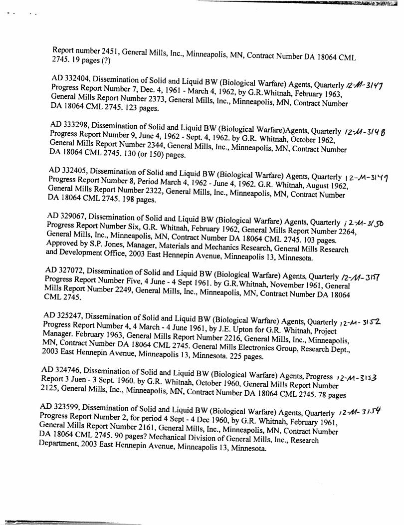
Report number 2451, General Mills, Inc., Minneapolis, MN, Contract Number DA 18064 CML 2745. 19 pages(?)
AD 332404, Dissemination of Solid and Liquid BW (Biological Warfare) Agents, Quarterly 12.-~-31'11 Progress Report Number 7, Dec. 4, 1961 - March 4, 1962, by G.R. Whitnah, February 1963, General Mills Report Number 2373, General Mills, Inc., Minneapolis, MN, Contract Number DA 18064 CML 2745. 123 pages.
AD 333298, Dissemination of Solid and Liquid BW (Biological Warfare)Agents, Quarterly tz-.JA-5/C/ 8 Progress Report Number 9, June 4, 1962 - Sept. 4, 1962. by G.R. Whitnah, October 1962, General Mills Report Number 2344, General Mills, Inc., Minneapolis, MN, Contract Number DA 18064 CML 2745. 130 (or 150) pages.
AD 332405, Dissemination of Solid and Liquid BW (Biological Warfare) Agents, Quarterly 1 ~-.M-31'-f? Progress Report Number 8, Period March 4, 1962 - June 4, 1962. G.R. Whitnah, August 1962, General Mills Report Number 2322, General Mills, Inc., Minneapolis, MN, Contract Number DA 18064 CML 2745. 198 pages.
AD 329067, Dissemination of Solid and Liquid BW (Biological Warfare) Agents, Quarterly 12--M- Jl J'l> Progress Report Number Six, G.R. Whitnah, February 1962, General Mills Report Number 2264, General Mills, Inc., Minneapolis, MN, Contract Number DA 18064 CML 2745. 103 pages. Approved by S.P. Jones, Manager, Materials and Mechanics Research, General Mills Research and Development Office, 2003 East Hennepin Avenue, Minneapolis 13, Minnesota.
AD 327072, Dissemination of Solid and Liquid BW (Biological Warfare) Agents, Quarterly /2-M-Jf'f{ Progress Report Number Five, 4 June- 4 Sept 1961. by G.R.Whitnah, November 1961, General Mills Report Number 2249, General Mills, Inc., Minneapolis, MN, Contract Number DA 18064 CML2745.
AD 325247, Dissemination of Solid and Liquid BW (Biological Warfare) Agents, Quarterly ,z.-M- ll a Progress Report Number 4, 4 March- 4 June 1961, by J.E. Upton for G.R. Whitnah, Project Manager. February 1963, General Mills Report Number 2216, General Mills, Inc., Minneapolis, MN, Contract Number DA 18064 CML 2745. General Mills Electronics Group, Research Dept., 2003 East Hennepin Avenue, Minneapolis 13, Minnesota. 225 pages.
AD 324746, Dissemination of Solid and Liquid BW (Biological Warfare) Agents, Progress 12-.M- ~11.3 Report 3 Juen - 3 Sept. 1960. by G.R. Whitnah, October 1960, General Mills Report Number 2125, General Mills, Inc., Minneapolis, MN, Contract Number DA 18064 CML 2745. 78 pages AD 323599, Dissemination of Solid and Liquid BW (Biological Warfare) Agents, Quarterly 12-M- "'JI.r'l Progress Report Nwnber 2, for period 4 Sept- 4 Dec 1960, by G.R. Whitnah, February 1961, General Mills Report Number 2161, General Mills, Inc., Minneapolis, MN, Contract Number DA 18064 CML 2745. 90 pages? Mechanical Division of General Mills, Inc., Research Departmen~ 2003 East Hennepin Avenue, Minneapolis 13, Minnesota.
AD 323598, Dissemination of Solid and Liquid BW (Biological Warfare) Agents, Quarterly 12-.#- 31 rsProgress Report, for period 4 Dec. 1960-4 March 1961, by G.R. Whitnah, May 1961, General Mills Report Number 2200, General Mills, Inc., Minneapolis, MN, Contract Number DA 18064 CML 2745. 95 pages.
AD 337635, Dissemination of Solid and Liquid BW (Biological Warfare) Agents, Quarterly 12-/H-315'(, Progress Report No. 10, period Sept. 4, 1962 - Dec. 4, 1962. G.R. Whitnah, Project Manager, Approved by S.P. Jones, Aerospace Research, February 1963.247 pages.
Sincerely