Embed Size (px)
Citation preview
8/8/2019 Topography for Field Artillery
http://slidepdf.com/reader/full/topography-for-field-artillery 1/272
'TOPOGRAPHYtor Field Artillery
Departmc!'t of Tactics
Document No.2
1922
This document replaces
Documents 51, 40a, 37b, and 51a.
published
Under the Direction of
THE CHIEF OF FIELD ARTILLERY
by the
TIlE FIELD ARTILLEHY SCHOOL
FORT SILL, OKLAHOMA
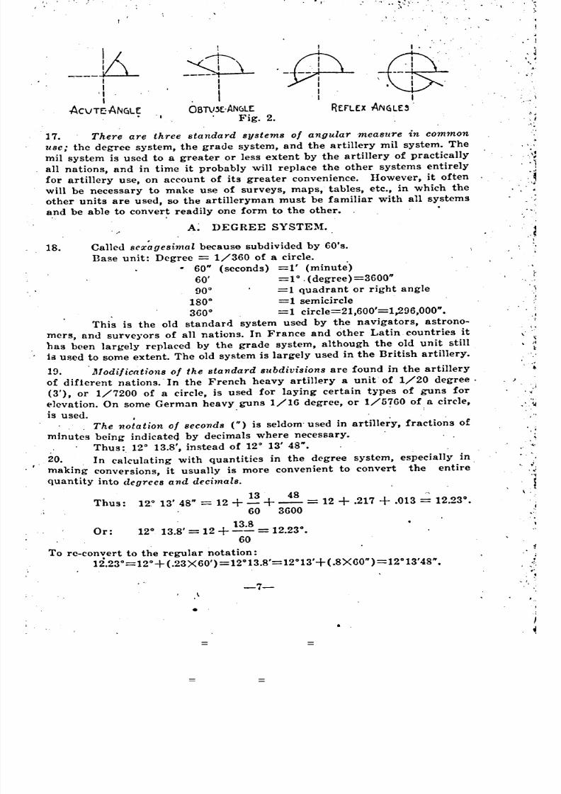
I
8/8/2019 Topography for Field Artillery
http://slidepdf.com/reader/full/topography-for-field-artillery 2/272
. Linear measure
. A. .Metric system
B. Conversion between English and metric system'Angular measure
A. Degree system
B. Grade system
C. Mil systemD. Conversion in angular measure
E. Expression of angles by tangents
Table showing accuracy of tangent calculation of angular'values •
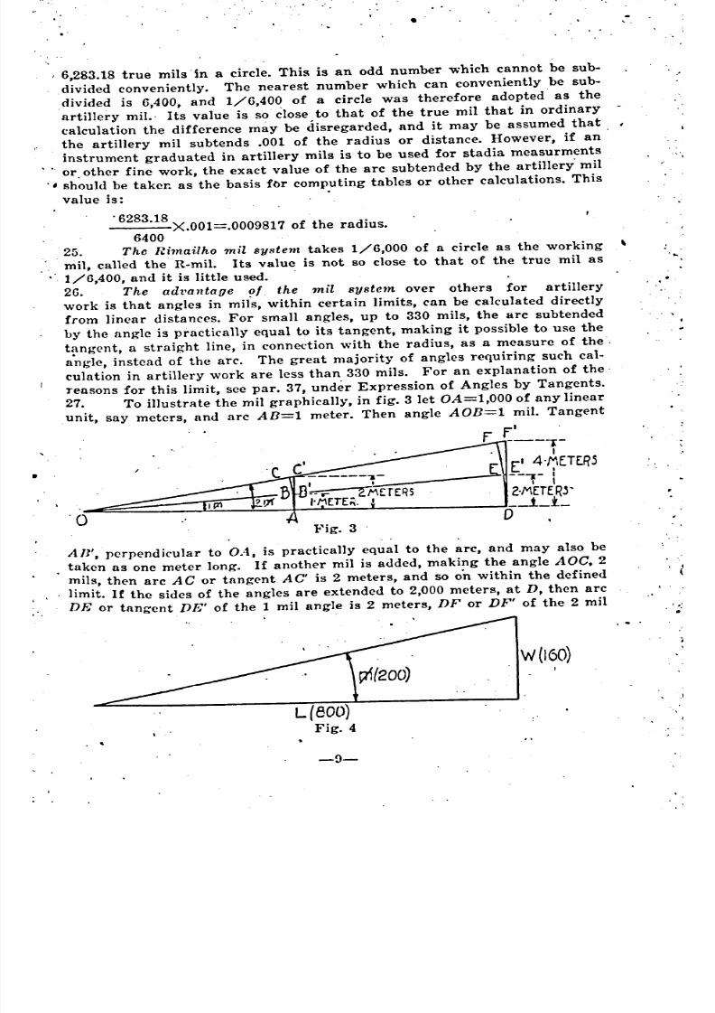
F. Gradients
G. Per cent
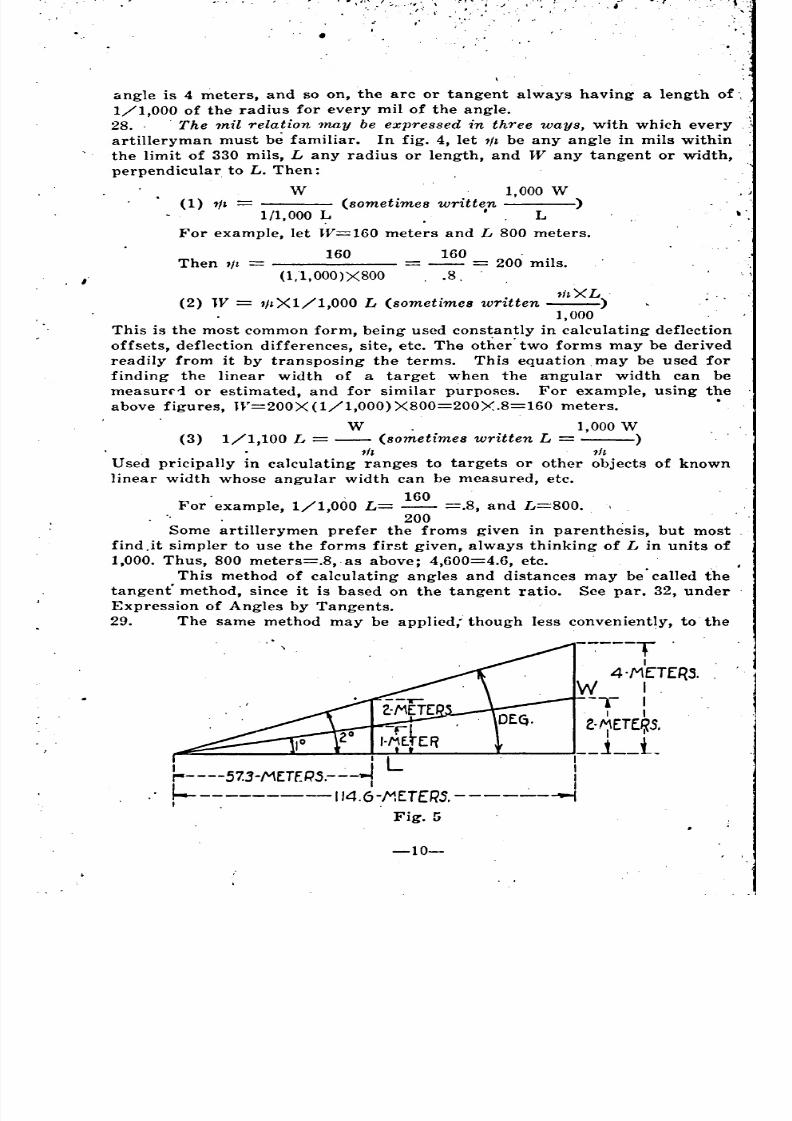
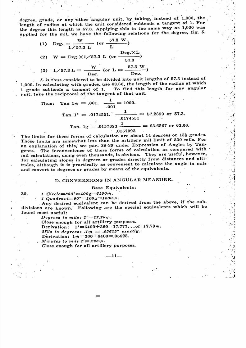
H. COJ:lversions in tangents and angular measureMeasuring instruments
A. Scales
Metric measuring scaleTriangular scale -"_
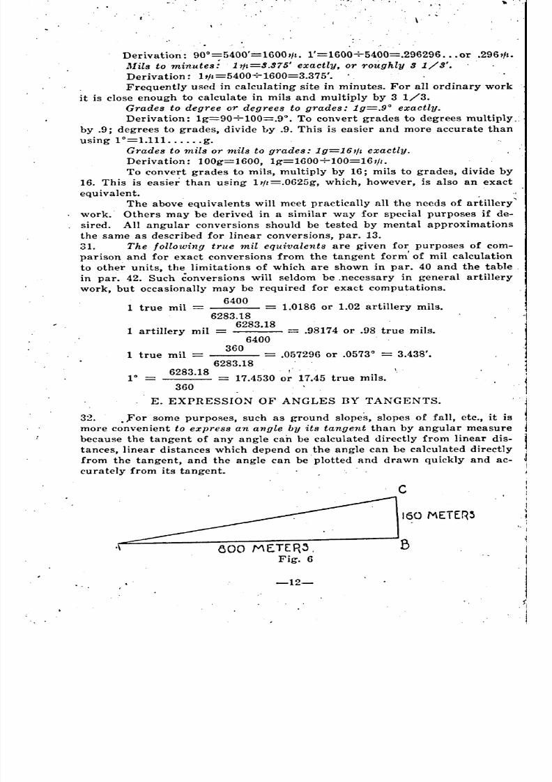
Tapes and chains
Testing of edges :.. -:B. Protractors
C. Em~rgency devices .
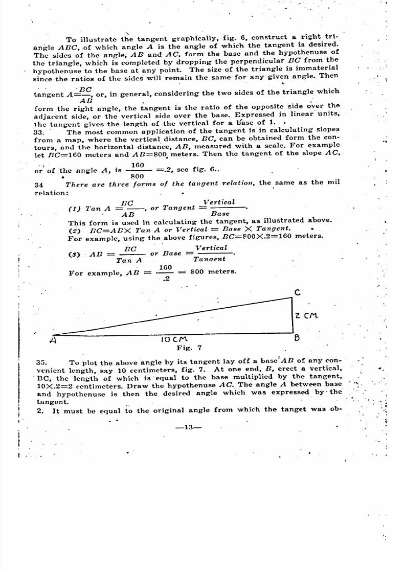
CHAPTER I.
CHAPTER II.
CHAPTER III
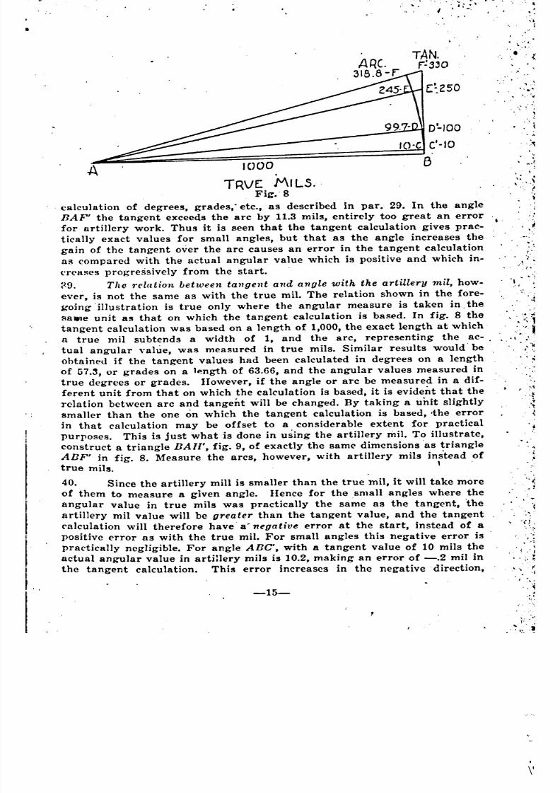
TABLE OF CONTENTS.
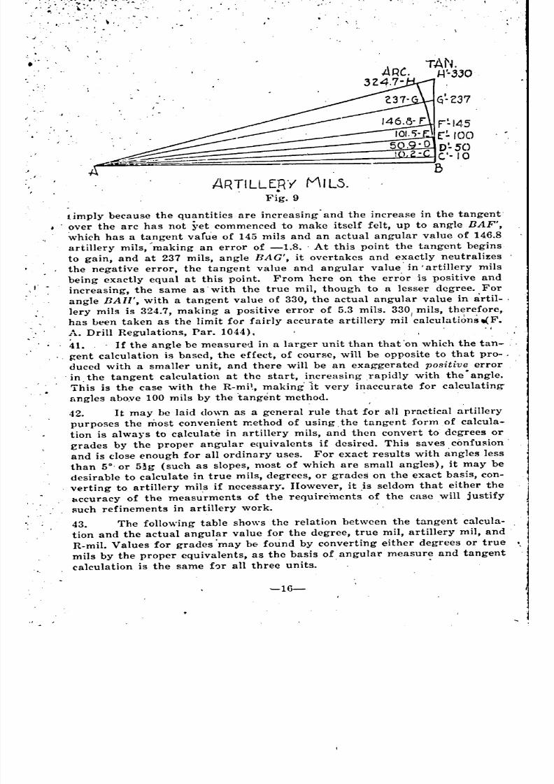
. Introduction.
Distance And Direction.
Maps And Scales
Par. 1-5
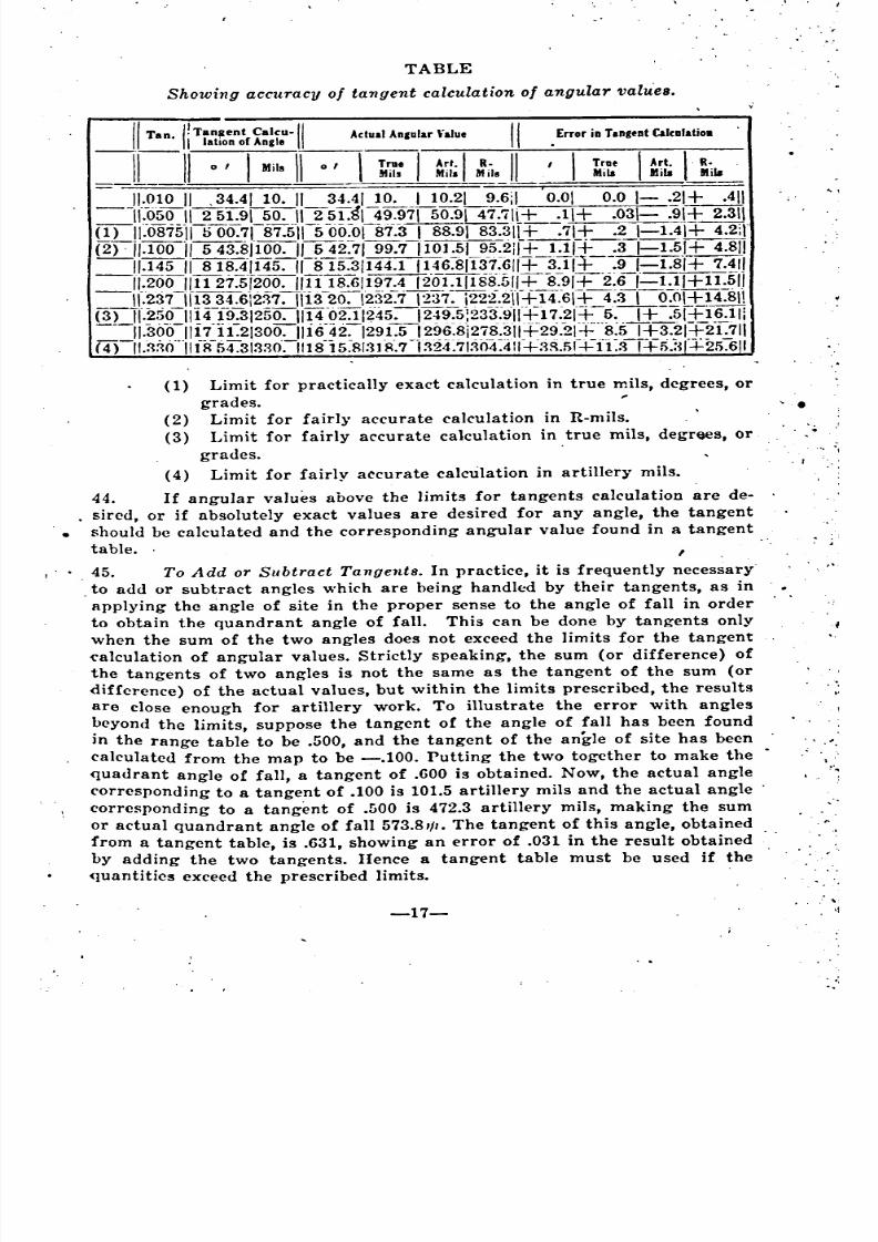
6-63
,8-14
8-9
10-14
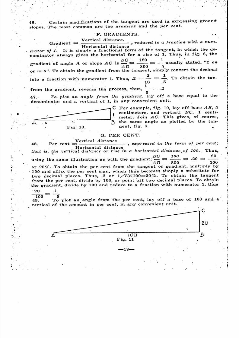
15-53
18-20
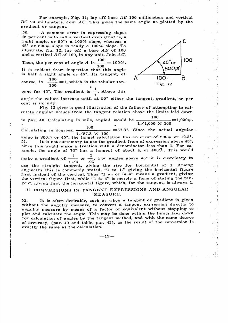
21-22
23-29.
30-31
32-45
42
46-47
48-51
52-53
54-75
54-59
55
. 55
57
5860-62
63
The elements of a mapA. Definition . ,B. Classes of maps
C. Map making and map reading1. Map making• 2. ~1ap reading
D. Ground relations
1. Distance2. Direction
3. ,AI ti tude
4. Map essentials J
64-74
64
65
66-68
67
68
69-74
70
71
72
74
_ ~ _
------------_
-----------------------------------------
------------------------------------------
---------------------~--------------------~-
------------------------
------------------------
_ _ _
------------_
_ ---------------------------------
' _ _
.
---------------~--------------------~-----
~ _ ---------------------------
_ _
_ ~------------------------------- _
_ _

8/8/2019 Topography for Field Artillery
http://slidepdf.com/reader/full/topography-for-field-artillery 3/272
, ,...... :.
',t
I •. ....
75-83
75
76-83
7778
79-83
84-118
84
85-91
85-86
85
86
87-9188
89-91
92-94 .
95-118
96-99
100-118
100-118
106-109
110,111-118
Distances and scales --------------"7--------~-------------------- .A. Definitions ----------------------------.
B. Scales
1. Representative fraction2., ''lords and figures -------:..---------------------------
3. Graphical scale
~Iap scale problems
A. Classes of problemsB. Simple rules and map scale calculations
1. ~lap to ground --.---------------------------------a. By R. F.
By words and figures scales -------------..:.--------
2: Ground to map '_.a. By R. F. _
b. By words and figures scales
C. Scale conversions
D. Types of graphical scales
1. Construction of reading scales
2. \Vorking scales
a. Strike scalesb. Mounted working scales
c. Interchange of graphical scales
d. Working scale graphs ...
CHAPTER IV. l\Ieasurements Of Slopes And Elevation 119-133
Discussion 119-120
A. Instruments used 120
B. Units in which slopes are expressed -----------------.:..-- 121-1271. Degrees anll minutes 122
2. l\lils ':..___________ 123
3. rercentages 1244. Gradients 125
5. Tangents 126
Type problem 127
C. Slope scale ~_ 128-133
1. Construction of slope scale 129-131
a. For American map .:. -:_ 129
b. For metric map 130-131 .
Degree slope scale ..:.____________ 130
Mil slope scale 131
2 Use of slope ~cale 132-133_
a. in contouring 132
b. In reading slopes .. 133
IIow sho\vnA. Bench ~ai'ks, hachures, and contours
1. Definitions .l
CHAPTER V. , E.levation And Ground 11'orms 13.1.141
134
135-140
135-138
-II--"
\
------------
------------------------------------------------
---------------------------
' -----------------------------------
-------------------------------------------
----------------------------------------------------
_ --- --------
-------------------
------------------------------------
-----------------------------
--------------------
----------------------- ------------
---------------------------------------------------------
-----------------
---------- --------------
----------~-~-------------~--~------------------~-------------------
~ _
8/8/2019 Topography for Field Artillery
http://slidepdf.com/reader/full/topography-for-field-artillery 4/272
, I,
.0\
; .,
, .
a. Bench ~rk --:~-----~--------~---------------b. Hachures
c. Contours2. Vertical interval
3. Critical points --:---------------------------------n. ,Logical contouring ----------:--------------------------
CHAPTER VI. Instruments Used In Topographic Operations.
135
136
137.139 .
140
141
142~173
.J• ,.1. .
. ,
I.
Description and use 142-173
A. Aiming circles .:.. .:.. :. 142
, n. Battery commander telescopes :.._____________________ 143C. Transit ~____________________________ 144
D. Prismatic compass ..:__________________________ 145 •
E. Peigne' compass ~_:...___________________ 146-150
1. To read bearings 147
2. To plot this direction with the compass 148
3. To plot the direction with a protractor _' 1494. To measure a slope :... 150
F. Plane table ~______________________ 151-152
1. To level the plane table .. . 152G. Alidades 153-161
1. Triangular alidades 153
2. Sighting alidades -' ~_ '154
3. Leveling alidade 155
a. To measure a gradient '_________ 155
b. Laying off directions .:..________ 155
4. Telescopic alidade :. 156-161.
a. To measure distance with the stadia 158b. Horizontal distance 159-161
II. Abney level ~___________________ 162-163
'To use Abney level '______________________________ 163-164
1. Gravity clinometer ... ~________________ 165
J. Levels 166'K. Slope board 167-168
L. Sito-goniometer 169-172 \
1. To measure site and find the minimum range ----.:.--- 170-171a. Site 170
b. Minimum range :.__________ 171
2. To measure angles and deflections .:.._______ 172M. Protractors '_________________________________ 173
• ,.
.
Defi niti on s
Methods of orientation .:. .:.~
A. By a declinated table
1. With a declinatoT unattached
2. With a declinator attached --:..-------------------------
CHAPTER VII. Orientation '174-183
174
175-183
176-177
176
177, .
,
-II 1 - .. .
~,
"
. , , '
------------------------------------
--------------------------------------
------------------------------------
{
"
=-
------------------------------
. ,
'"
,,
"
--------------
_ ---------------------------------
----------------------
'
• t
8/8/2019 Topography for Field Artillery
http://slidepdf.com/reader/full/topography-for-field-artillery 5/272
,Defini tion -----------------.---------------------------------A. Kinds of traverses .:... ...: •
B. Instruments used :
C. ~ethods of traverse :..
1. Fore sight-back sight method -_--------------------2. Needle traverse' , :..
3., Angle traverse
D. ~feasurernents.
1. Pacing
2. Chaining or taping
3. Stadia readingsE. Special case :. ---------------..:-----.,
F .. Errors in traversing ------,..--------------------------
By a known line:....:---------------.:.:-------------~-----
1. 'Vhen the, plane table is on a station over one of the
known points of a given line ---------..:-------------
2. 'Vhen the plane table is somewhere on the line joining
, two points of known location .:. . ----:..-----
3. By angle traverse ----------------------:..----------
4. When known point on given line' cannot be occupied
5. By resection
'
184-194
184
184
185
186-188
186
187
188
189-192
190
.191192
,193,
194
.
178-183 .. I~
178 :l',
179180. ,'~
181-183
183
-"I
.~
, .
I
, .
\
.
Traverses.
'B.
~;, .~ .• ,~ •• I- I .'
.....
CHAPTER VIII.
A,
,........ :...
'.~ .\ c'
.'.0
.Definition . _.:. . :._..: .:. .:.A. Purpose
B. Accuracy
C. The operation
To locate a point by intersection -----------~---------_:_---'------
Definit ion
Conditions which must be fulfilled if accurate results are to beexpected
~lethod8 of resection
A. Transparent paper method
, B.. Two point method -:..----------------------------------
1. Using a known line ---------~------~--.:.-------.:.---
2. Using the declinator --------------.:.--:..------------
C. .Three point method -------------:..---:..-----------------Triangle of error
1. Operator's posi.tion jnside triangle I
2. Operator's station outside triangle --..:---------:..-----,
a. By inverse triangle method ----------------:..----D. 'Back azimuth method :.. :..
E. Italian resection
;
CHAPTER IX.
CHAPTER X.
Intersection.
Resection.
."
195-198 .~
,
195
196
197
,198 ',
198
199-213 ,.
..199
1
, 200
201-213
201-203
204-205
204205, .
206-208
207-208
207
208
208
209
210-213
-IV-
--- __ ~ ~ _
~ ~ ~ _ __ _
_ _ _
--------------------------------
~----------------------------------
' --------------------------------------
',
'
"
'
-
"
o ". ~.. • ~' •
• - ....... ~ ~ ~
..' 4
•
,
~__ ~ __ _ ~ _
__~ _ ----------------------------------------
-------------------------------
_ ~ ~ _
----------------------------
~ _
~ _ ~ _
"
' ~
8/8/2019 Topography for Field Artillery
http://slidepdf.com/reader/full/topography-for-field-artillery 6/272
.-...., .
I '.-',j
, ..., .';
.,w. .• i,
. :r~ ... ""', ",'
'f'
.. ; ....
,
,
'.
1. The process2. The proof, --_-------------..,;-------------------- •
211-212
213
Position and area sketches ----------------------------'-------
A. Characteristics
B. Technique1. Whole to part method :- _' .
2. Determination of critical points
3. Information to be included ---------'---------..:.:..--
4. 'Conventional signs .----------.:..-----------'-~------5. Title .:-6. Border
7. 'Lettering •'Road sketches
A. Characteristicsn. Technique
1. ~fethod oy'sketchin~2. Lateral limits to be considered
3. Information to be in~luded
Characterist ics ,Types of sketches ~---------------.
E8sen ti al s
A. IdentificationB. Information
C. Drawing'
1. Perspective
a. Parallel horizontal lines ------------------.:.-----,
b. Parallel vertical linesc. Parallel lines not horizontal
2. Consecutive crest lines ---------------:.-------
3. Broken lines
4. Ground slope arid form
5. Shading6. Conventional signs
~Jethod of procedure
A. I~quipment ~_
n. Identification and orientation ---------------:..-----::---- •C. Analysis of the fecto~ -----~--~---.:..-------..:.--..:-----~-
D. Selection of reference point and horizontal control
E. Vertical control
F. Drawing in framework. A comparison of methods
1. First method ...
2. Second method _----------------------~-----------
~'
'.
'.
'I"<
: '. I
.~
,I:,-, .'
.'
:.
230-284
230-233
234-236
237-258
238
239-240
241-258
244-247
245
246'
247.
248-249,',250
,251-252 ....
253-254
255-258
259-283
'260
261-264t
265
266-268
269-270
271-274
272
273-274
214-229
214-229
214
215-223
215
216
217
218-220,.
221 ,
'222
223
224-229
224-225
226-229
.226-227 .
228
229
-v-
Ske~ching
Panoramic Sketches.
'.
CHAPTER XlI.
CHAPTER XI.
'I'
J',
'I •••
i'
. ""J
. , . ' t .. ' • " ,
--------------------------------------
-----------------------------------
----------------------------------------
--------------------
__ _ _
- _ -------------------------------------
--------------------
--------~--------------~------
--------------------
------------------------
----------------------------
~__ ---------------------------~----
---------------------------------_ _
__~ _
---------------------~----------------------
--------------------------------------
----------------------------
-----------------------------------~~----------------------------------
~ ~ _
------
----------------------------------~---
------
----------- ------------------------
) t .
'., ~
., I ~
. ~.,'
'
~~'.
" \
'
'
'
'
"
8/8/2019 Topography for Field Artillery
http://slidepdf.com/reader/full/topography-for-field-artillery 7/272
G. Filling in ----.:..---------~----------------.:..-------------
H. Designation of targets and important points
I. SubsketchesMap and panoramic sketch -'---~---.:..---------------------------..
Definitions ----------------------------------.'Visibility
A. Similar triangles ---------------------.:..--..:.---~---------
B. With elastic band --------~-------------~---..:.-----~---
C. 'Angle of site --------------------------------..:---------D. Graphic method ..:. ..:
E. Visibility charts _----------------------- .... Defilade
A. Angle of site
.. , 1. Measured from enemy O. P. ----------'--------------
2.' Measured from covering crest -----------r-..:--------B. o. Profiles.
'C. Trble of defilade ---------------'----------------------D. Type problems
1. First problem ------------------'------------------
2. Second problem
3. Third problem
..,,,,
.1-
l
275-276 ~l'
277-281
282-283
284
285-301
285
286-292
287
288
289
290
291-292
, 293-301
294-295
294
295 I
296
297 ..
298-301
299
300 ')
301.
.......
Visibility And Defilade.'HAPTER XIII.-
, .o'. , ....
't
302-304 'r-
305-312 .
306
307-309307308
309
310-312
310
311
312
313-327
313314
315-316
317-326
318-322
323-324
325-326
325
326
327
, ,
CHAPTER XIV. l\linimu~ Elevation, Minimum Range And Dead'Space ," ...rGeneral •
.Determination of minimum elevation and range
A. Steps of calculation -..:
B. Effect of Ground Forms ------------.:..-----------------
1. Level Terrain --~--------~---------~:.---------------
2.' Irregular Terrain -----------------'-----~----------
3. Effect of Slopes
'9~ Type PloblemsExample 1
. Example 2
Example 3
Determination of Dead Space -----:----------------------------
\ . Limit of dead space 4_
• Determination of grazing point
Type Problems ------------------:.----.:.'----.,.-------
, Calculation Method 'with Special Chart ------.'.------------------
Preparation of chart
. lJse of chart ---------------------------~-.--------
Type Problems ------------------~--------------'--Example 6
Example 7 ~_,
Dead Space Charts --~-------------------------.:..-----~--------
-:.' .
'."
-VI-
------------
----------------------------------------
--------------- _
- ~ _ ------------- _
""" _
_ - ~ ~ _
-----------------------------------
----------~-------------------------
. ..~ '. J
"
, ~
.
"
'
" _
-----------------
---------------------------------
----------~----------~------------
----------------------------~---------- _ _ _
' ~ ~-------------------
-------------------------------
_ ~
8/8/2019 Topography for Field Artillery
http://slidepdf.com/reader/full/topography-for-field-artillery 8/272
, •
.
Definition
Kinds of projection
A. Mercator's projection .-:------------.:..-------------------
B. Polyhedral projection
C. Conic projection
D. Polyhedral projection
E. Donne projection -------------------:.-----------------
F. Lambert projection ----------------------------------:..
Origin
Coordinates
A. Coordinates of originn. Complete coordinates \
C. Reduced hectometric coordinates
1; Error introduced
D. Plotting points
Convergence of tneredians
Y-Azimuth
CHAPTER XV.
CHAPTER XVI. I
Map Projections.
The Lambert Grid.
328-335
328
329-335
329
330331 ,
332
333
334-335.336-348
336
337-:344
338,339 ..
340-342
341
343-344
345-347
348
CHAPTER XVII. U~e Of Grid In Map Reading And Map Firing.
Advantages of the grid -------------------------~---------:--
A. Method of plotting a p:>int
1. When ruler graduations are longer than the distance
between grid:; -----------.:---------------------
2. When the ruler graduations are too small
n. Method of reading the coordinates of a point :.-----------
1. When the rule is correctly scaled ---------:..-~-------
2. When the scale is too large
3. When the scale is too small
4.' With the right angled ruleC. Plotting directions
1. By Y-azimuth -----------------:..------------------
2. Dy coordinates
a. By auxiliary points'
b. By similar triangles .:.-------------------------
c. Dy reduced similar triangles
d. By reversing direction
D. Detertnination of range and Y-azimuth by coordinates :..--
1. Range by square root
2. Di rection
Eo To locate on the ground a point the coordinates of whichare given
CHAPTER XVIII.
General
The Compass.
----------------------------------------------------
-\ '11-
349-367
349-367350-351
350
351
352-355
352
353
:354
355
356-362
356
357-362
359
360
'361
362
363-365
363
364-365
366-367
368-383 ... ,
368
'., ..
'
,
_ --------------------------------~----------
---------------------------------
-------------------------------------
---------------------------------
' _ _
------------------------------------------------------------------
-----------------~-----
----------------------------------
---------------------------------------
~-----------------------~-----------
---------------------------------------------
' "
'
,
----------------------------
---
-----------
-------~----------------
------------------------
------------------------------------------------------------
-----------------------------------
----------------------------
-----------~--------
' -------------------------
------------------------------
_ ~ ~ _
'
8/8/2019 Topography for Field Artillery
http://slidepdf.com/reader/full/topography-for-field-artillery 9/272
,"
~orthAzimuth
~Iagnetic bearing
):-azimuthDeclinationA. Magnetic declination
1. Magnetic variations _.:. ,
2. Use of isogonic chart
n. Compass declination . ..:
.CHAPTER XIX. Laying Guns With A Declinated Instrument.
Using prismatic compass
A. To determine the compass bearing of a target
Off-set method
n. Laying guns with bearing determined
1. Using compass as, aiming point
Using aiming circle or prismatic compass and magic number method
of laying (See Chapter XX). .
CHAPTER XX. Laying The Guns On Dase Line.
Steps' performed in occupation of a sector ---------'-------------
Establishment of base piece on base line -------,;,.---------------- .A. Drill regulation methorl
B. Using topographical methods
Classes of topographical methods
First class. Plane of sight through points located by
coordinatesSecond class. Plane of sight determined by an
established direction
i., Direct ~rientation
a. Using plane table --------------------:...-b. Using aiming circle ------------------.:..
2. Orientation by means of an orienting line
a. Advantages of an orienting line -----.:.--
b. Steps to be performed ----------------.:.
1. Determination of base angle
II. Laying on base line with aimingcircle
First case
Second case
Method ~o. 1.
III. Laying on base line using a planetable
CHAPTER XXI. Topo~raphical Operations In Occupation Of A
Dattery Sector. 418-432
I,
General
, , Gun position
-VIII-
418
419-423
------------------------------------------------------~ _ --------------------~-----~------~-------
-------------------------------------------------------- ---------------------------------------_
' _ _ _
_ -~--------
----- ---------------------------------
------------------
------------------
-------------------------------
--------------------------
----------------------
-----------------------------------
----------------------------
-------------------------
---
-------
_ -------
~ _ -----------------
_
----- _ --------------------~----------------------------
'

8/8/2019 Topography for Field Artillery
http://slidepdf.com/reader/full/topography-for-field-artillery 10/272
\
. "erre!'trial observation '-
Comparison of method3
. A. When coordinates of. gun position can be read directly frommap
n. Wnen gun position cannot be identified on map
1. Using geodetic point2. By resection .:.
3. By an orienting pointBase point or target '-.:.
A. When base point may not be determined .from map
,B. Determination of direction to target or base pointAiming point
. A. Determining direction to aiming point ------:..----------- .
. n. The orienting line ------_-----------------------------
1. Two types of orienting line2. Typical case
I' CHAPTEI~ XXII. Locating Targets.
419
420-423
421
422 •
423
424-425 , t
424.')
425/to
426-432
426
427-432 ,
428-430
431-432 ',,':
{
'I:
433-439
433
434-439
APPENDIX.
Praeticibifity of slopes ---------------"---------------------
Practicable depths of fords ..Strength of ice :
Length of pace on slopes
Appt'ndix J. Slopes. 440-443
440
442
442
443
Appt'ndix II.
Appt'ndix ]11.
Table Of 1\atural Functions:
Circclar Measure.
.444
445-446
Definitions and diagrams ..:
Conve~sion tables
A. Mils in terms of degrees and tangents ------.--------
B. Degrees in terms of mils and tangents
Classes of records
A. ~Iaps and charts1. Battle maps of sector
2. Charts
a. The firing chart ..
'
'
,
. -
.~
.
;"
445-446445
446
447-449-
450
451-486
451-468
487-506
487-506
488-501
488
489-501
489.490
Maps And Records.
Reduction Of Stadia ]~eadings.
Azimuth Of Polaris.•
I>efi~itions and Diagrams.
A ppendix VII.
Appendix IV.
. Appendix V.
Appendix VI.
-IX-
. ,
_ _
~-----------------------
--------
-----------------~-----------_
-----~------------------------_
------
------~ _
------------------------~ _
4
'
- ------------------------------~ _
----------------------------------"
'"
-- _
_
-------------
_ ---------------------------------
------------------------
~---------------------------
------ -------------------
.
." _
8/8/2019 Topography for Field Artillery
http://slidepdf.com/reader/full/topography-for-field-artillery 11/272
...
. .
b. Range and deflection fan
c. Position chart -'---------------------------rd. Auxiliary position . --------
e. General system of communication -------.:..--f. Chart of visible and'invisible areas ----------g. Chart of dead space
h. Combined charts
B. Written records
a. B. C. data book
b. Ammunition record ------------------------c. Ta~get sheet
-x-
-1491
492
493
494495
496-497
498-501
502-506
502
503
504
-~----------------
_ _
~ _ ----------------~----------
' _

8/8/2019 Topography for Field Artillery
http://slidepdf.com/reader/full/topography-for-field-artillery 12/272
TOPOGRAPHY FOR FIELD ARTILLERYCHAPTER I. '. "i
INTRODUCTION
nll~OR'rANC~ OF TOPOGRAPHY TO FIELD ARTILLERY ,OFFICERS.
1 . Topography, in general, is "the exact and scientific delineation and
description in minute detail of any' place or region" (Webster's New Inter-
national Dictionary). Military topography delineates and describes all the
physical features of military importance of a place o'r region. The science
is used by every branch of the service in the disposition and maneuvering
of its forces,. both combat and non-combatant .. Topography is especially
important in the' artillery, where it is used not only for maneuvering and
other general purposes, but for the preparation and conduct of fire. For
this purpose a high degree of accuracy is essential, requiring exact methods
not usually necessary in ordinary work.
2. The extensive use of topography in conneCtion with artillery firing
is a development of the late European 'Var. Batteries frequently remained
for long periods of time in fixed positions, making it possible to study theterrain thoroughly and to locate positions and objectives on maps accu-
rately and in great detail. By means of topographical measurements on map
and ground, very accurate data for opening fire could be prepared, and
the first shots dropped close to the target, reducing the labor of adjust-
ment to a minimum, saving much valuable time and ammunition, and gain-
ing an immeasurable advantage by surprising the enemy with a sudden and
effective fire. The advantage of this was especially apparent in crowded
sectors where many batteries were firing at the same time. Unless a battery
could place its first shots close to the target it was difficult for the observer
to distinguish them from those of other batteries. Another important use
l topographical method~ was found in the designation and identification
.of targets for observation, both aerial and terrestrial.
Thus firing with 'data obtained from the map came to be used rather
fr('quently. Even in rapid advances to new positions, much firing was done
em known enemy positions from the map alene, as it was sometimes impos-
..ible to secure observation in the broken and fireswept zones over which
tr.e advance was made. Of course, adjustment always was secured when-
l'ver possible by aerial or terrestrial observation, but with accurate mapsl;nd calibrated guns, fire with considerable effect could be deliveretl almost
immediately on the occupation of a new position, without w~iting for ob-
FoE'rvation. The value of this procedure in harassing a retreating enemy or
. In surprising him at any time is very grea,t.
3, It is by no means to bp. und~rstood that topographical methods of
• preparation and conduct of fire have supplanted the more rapid, but less
. accurate, methods given in Drill and Service Regulations for Field Artillery.
-1-
•
.
I
I ~
.
-
"
' .
8/8/2019 Topography for Field Artillery
http://slidepdf.com/reader/full/topography-for-field-artillery 13/272
,. .
These methods always will be required in rapid operations at various"
atages during the combat. Wheri) no accurate maps are available terrestrial
observation or open warfare methods must be used. However when oP-..~rations are continued for any length of time in the same territory, surveys
..hotild be made and maps prepared for firing purposes. A good artillery
t'ommander should understand the application of all methods, and take the
fullest advantage of every opportunity to improve the effectiveness of his
fire. To this end a thorough knowledge of topography is essential.
4. Topographical information is recorded chiefly in graphical form,
supplemented by written or printed explanations and reports. TopographicaT
records include maps and position charts, roads and area sketches, pano-
ramic sketches, road and reconnaissance reports, visibility and dead spacecharts, and any other. forms of records which may be necessary to furnish
the required information. The essentials of a good topographical record of.
any kind are: .
First, it must contain all possible information of military value for
the purpose which it is designed to serve, considering first the most im- .
porta nt, and omitting irrelevant matters which cause confusion.
Second, it must be accurate to the degree required for its purpose •.
Third, it must be clear and legible, presenting its information in such
form that it can be readily understood and used.In conveying the desired information on maps and sketches, the to-
pographer or cartographer very largely makes use of a system of conven-
tional signs, which, in reality, are graphs of the thing represented. These
conventional signs are much the same in all services. See Chapter XI.
5. An officer need not be an expert surveyor, draftsman, or artist in order
to make use of topography. The methods used are comparatively simple,
and much of the work can be, and commonly is, done by trained enlisted men.
'Vhere extensive surveys are required they are made by the engineers. . In
training for topography, the practical value of the work should be constantlyemphasized, every step' should be illustrated with practical examples, and'
no subject should be left until its ~pplication is thoroughly understood.
Note:-Where the term artillery.is used in this text it is understood'
that field artillery is meant.
, .
8/8/2019 Topography for Field Artillery
http://slidepdf.com/reader/full/topography-for-field-artillery 14/272
I • .,~ ,
.,,'
': ..
r .......
.'
, -I,'
..-\ "'.,.'
\ ~"
, .
,~J
;',
. \
".'.
,':,
-3-
./;'>1LI~EAR :\IEASURE. \:r:~
; ,,)-
8. The metric Bystem of linear measure is now used by the artillery of, ", ,'..
practically all nations, including the United States. However, our old ma-
teril is graduated in yards, and many of our maps', manuals, tables, and ", :;''.-'',, ',':,,!
'
,,' ",i'. 'I'
I';" '.'
CHAPTER II.
DISTANCE AND DIRECfION
MEASURE~IENT AND SYSTE:\IS OF MEASURE.
<6. The artillery topographer must be thoroughly familiar with the
-different system's of linear and angular measure used in field artillery, and
must be able to make accurate measurements. Detailed methods will be dis-
cussed later.'7. One of the aims of artillery topography is to save the waste re-
..suIting from inaccurate methods. Hence accuracy should be striven for in
811 work, and every effort made to eliminate sources of error. However, it
is useless to carry either measurements or calculations to a greater degree
of refinement than is required for the use for which the results are intended.
For example, it is possible from an accurate map to calculate site to
minute or a fraction of a mi~. If an accurate quadrant is to be used for
laying the gun, one graduated to minutes o!' fractions of mils, such close cal.
culation is desirable. lIo',vever, with ordinary materiel graduated only to
,even mils, it is useless to calculate closer than the nearest mil. Nor in any
case, is it worth while to calculate closer than the least setting of, the range
scale, or ,quadrant of the particular gun being used. Exceptions to this
may arise where several small calculations are to be combined, the total of
the fractions if taken together making an appreciable amount, but it is a
waste of time to carry a calculation to several decimal places which cannot
be used, especially if there is a possible error .in any of the measurements
on which the calculation is based., The result of a calculation is never more
accurate than the least accurate factor which enters into it.
Again, in measuring ranges on a map, a skilled man can measure
with a good scale to the nearest meter, or even to fractions of a meter OD
large scale maps. But if the map itself is inaccurate, due to .faulty printing,
E'hrinkage, etc., such close measurement would be needless. On the other
hand, in performing resections or other surveying operations on a plane
table with an accurate grid, a high degree of accuracy is possible, and every
measurement should be made with'the greatest care in order to make the
total error of the operations as small as possible.
Each operation should be studied to determine what degree of ac-
(uracy is required, always bearing in mind, first, the use for which the re-sult of the operation is intended, and second, the possibilities of the instru-
ment~ with which the operation is performed.
" ..
,
' '
"
, "
).
\ ,.
, .,.,"
r "
' 1I,
~ ........
'
'
'
~
8/8/2019 Topography for Field Artillery
http://slidepdf.com/reader/full/topography-for-field-artillery 15/272
't••
I
other documents to which the artilleryman must refer use the old English
units of measure. Hence it is necessary not only to know the metric system,
but to be able to convert. r2adiIy, one system into another. It is' assumed
.that the old English system already is well known, so it will not be treatedin detail.
A. METRIC SYSTEM.
. Abbreviations
Latin
prefixes
*Milli-
*Centi-
Deci-
=
=
1~1000 or .001
1~100. or ..Ot.
1~10 or . ~1
mm.
em;
dm.
*:Meter = 1, Base Unit. M. (or m.)
Dm.
Hm.
Kin.Mm.
10 times
100 times
1000 times
10000 times=
=
=Greek
prefixes
1
Deka-
Hecto-
*Kilo-
Myria-
*Units in most common use.
NO"e that the abbrevations of the units larger than the meter
are :apitalized, while small letters are used for the smaller units. The #
standard abreviations for meter is a small "m", but in artillery work a cap-
. ital "M" should be used to distinguish it from the sign ."1/:" for mil.
9. Care should be taken to distinguish the Greek prefix "deka", 10
times, from the Latin "ded';, (pronounced "desi"), 1~10. "Deka" is .some-
times spell~d "deca" (but' pronounced "deka"), especially in France, so the
only certain means of distinction is in the "a" and the "i" and in the pro-
nunciation. These prefixes are used m~re frequently in the grade system of
angular mp.asure than in linear measure.
n. COXVEnSIOX BETWEEN EKGLISH AND l\IETIUC SYSTI~l\IS •.
10. Ease Eqult'alellt: 1 meter = 39.37 inches (practically exact) ..
This is' the 'most. important equivalent to remember, as any conver-
sion can be mE-dethrough it (reducing English distances to inches and met-
ric distances to meters) and any other, desired equivalent can be derived
from it.
11. The length of the standard in'ternational meter has been fixed
with great precision, but the authorities differ slightly as to its equivalent
10 English measure. The above value of 39.37 inches is the legal standard
. equivalent for the United States, by act of Congress, July 28, 1866. The
officir.l British Board of Trade equivalent is 39.370113 inches. Other values
have been determined by different scientists, some larger and some smaller
, than 39.37, but the variation between them is very slight. 39.37 is so close to
the average that it may be accepted as a practically exact equivalent •. It
.. differs from the English standard by only .000113 inch, or a ratio of about
1 unit in 350,000. which is negligible except for the most delicate scientific
measurements.
-4-
.
'
8/8/2019 Topography for Field Artillery
http://slidepdf.com/reader/full/topography-for-field-artillery 16/272
,I.,'" I
.
Note: The standard meter is 1/10,000,000 of the quadrant of the,
,-earth measured along a meridian..
12 Following are other useful equivalents derived from the base equi~-
,alent.
Centimeters to inches: 1 em. = 39.37 in.This is practically exact, being simply 1/100 of the base equivalent.
Inches to centimeters: 1 in. 2.5~ em.
i-raetically exact. Derivation: 1 M. 100 em. 39.37 in.
! in.= 100-+3!).37=2.540005 em.,' or 2.54 within a negligible error.
Meters to yards: 1 M. = 1.09~ yds:
• ,Sufficiently accurate for all artillery purposes. Error amounts to about
, +.00039 yd., or a ra'tio of 1 in 2800 M or 3.6 in 10,000, negligible for artil-
.1ery work. If closer results are desired use 1.0936.
Derivation: 1 M.= 39.37 in. 1 yd. 36 in.1M. 39.37 -;- 36 1.093611 or 1.094 yds.
Yards to meters: 1 yd. .91~ M.
Sufficiently accurate for all artillery purposes. Error amounts to about
-.0004 M., or a ratio of 1 in 2500 M or 4 in 10,000, negligible for artillery
work. If closer results are desired, use .914i.
Derivation: 1 yd. 36 -7- 39.37 .9144018 or .914 M..
Meters to feet: 1 M. = 3.28 ft.
Sufficiently accurate for all artillery purposes. Error amounts to about ,
-.00083 ft., or a ratio of 1 in 4,000 M or 2.5 in 10,000, negligible for artil-'lery work. If closer results are desired, use. 3.2808.
Derivation: 1 ft. 12 in. 1 M. 39.37 -7- 12 3.28083 or 3.28 ft.
Feet to meters: 1 ft. = .305 M.Sufficiently accurate for all artillery purposes. Error amounts to about
+ .0002 M., or a ratio of 1 in 5,UOOM or 2 in 10,000, negligible for artillery ~"
work .• If closer results are desired, use .3048.
Derivation: 1 ft. 12 -+ 39.37 .304800 or .305 M.
13. The foregoing abbreviated values are the' same as those published
as standards for general use by the U. S. Bureau of Standards.Mistakes in making conversions can be avoided by checking all re-
sults by inspection, first deciding which factor to use, and then obtaining an
approximate result by a quick mental calculation.
. For example, in converting yards to meters, the result in meters will
be smaller, because it will take fewer meters to reach the same distance (a
meter being longer than a yard). lIenee use the' smaner equivalent, .914, not
1.094. One of the most common mistakes is in taking the wrong equivalent.
From this equivalent it appears that the result in meters should be about
9/10 of (or1/10 less than) the amount in yards. Thus, .1000 yds.X.914
=914 M., which checks with the approximation.
Again, in converting inches to centimeters, the result will be larger,
because it will take more centimeters to reach the same distance. Hence
use the larger equivalent, 2.54, not .3937. From this equivalent it appears
that the result in centimeteJ;'s should be about 2 1/2 times the amount in
inches. Thus, 2 in.X2.54=5.08 em., which checks with the approximation
U. In order to cultivate facility in thinking and estimating distances in
-~-
•
,
, .
. ".
,
'
= = =
= = = =
= = '
= = =
= =
"
'
-
\ .
"
" '""
"
8/8/2019 Topography for Field Artillery
http://slidepdf.com/reader/full/topography-for-field-artillery 17/272
./,. .
metric units, it is convenient to bear in mind the following approximate'
rela tions. I
1 meter about 40 inches, which is 4 inches, or' ab~ut 1/10
greater than a yard.
Hence distance in meters is about 1/10 les8 than distance in yards,
(since it will take fewer meters to reach the same distance). To get meters
,'. . from yards, 8ubtract 1/10.
Conversely, distance in yards is about 1/10 greater than distance in
meters. To get yards from meters, add 1/10,
.1 centimeter = about 4/10 inch. .
10 centimeters (1 decimeter) about 4 inches.
1 inch = about 2~ centimeters, or 25 millimeters.
1 foot about 30 centimeters, or 3 decimeters ..1 millimeter = about 2/3 of a sixteenth of an inch.
1 kilometer = about 5/8 mile.
The above equivalents are close enough for rough approximations,
such as estimating distances in open warfare, but for all exact topograph-
ical work the standard equivalents should be used.
ANG ULAR l\IEAS URE
15 An angle is measured by the incl~ded arc of a ci-/cle, the center of
which is at the vertex of the angle. It is immaterial how large the circle
is or how long the sides of the angle are, because angular measure is not
a measure of distance or area, but is an expression of the proportion be-
tween the part of the circle included within the angle and the whole circle.
This proportion remains the same for any given angle, whatever the size of
the circle.
16. By dividing the circle into a convenient number of equal parts, a
system' of angular measure is obtained. This is sometimes called circular
measure, as it is used to measure the relative size of arcs of circles as well
'as angles.' The artilleryman is more concerned with angles than with arcs,
so the term angular measure is preferable ..
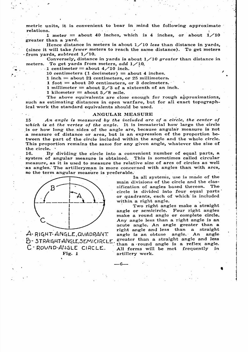
In all systems, use is made of the
main divisions of the circle and the clas-
sification of angles based thereon. The
circle is divided into four equal parts'
or quadrants, each of which'is included
within a right angle. I
. Two right angles make a straight
angle or scmicircl~. Four right anglesmake a round angle or complete circle.
C Any angle less than a right angle is an
acute angle. An angle greater than a
. right angle and less than a straight
A- RI~HT.ANGLE,QVADRANT angle is an obtuse angle.' An angle
B . .5TRAI(iliT-ANGLE ,sEMICIRCLE. greater than a strai~ht angle and less, , than a' round angle IS a reflex angle.
C. ROVfJD.AfJGL[ CIRCLE. All forms will be met frequently in
Fig. 1 artillery work.
-6- ,
~
=
'
= =
' -
8/8/2019 Topography for Field Artillery
http://slidepdf.com/reader/full/topography-for-field-artillery 18/272
\
'~
,':'
'.'
,...
,'!
,,...
'j,
. \.,
I.
'$1"-'-\ I
• I
IREF'LEX ANGLE~
._~
I
I
A~ DEGREE SYSTEM.
I
-~II
IOBTV.5E:.ANCJl(
Fig. 2.
'/
17. There are three standard systems of angular measure in common
use; the degree system, the grade system, and the artillery mil system. The
mil system is used to a greater or less extent by the artillery of practically
all nations, and in time it probably will replace the other systems entirely
for artillery use, on account of its greater convenience. However, it often
will be necessary to make use of surveys, maps, tables, etc., in which the
other units are used, so the artilleryman must be familiar with all systems
and be able to conver~ readily one form to the other.
-7-
18. Called sex~gesimal because subdivided by 60's.
Base unit: Degree 1/360 of a circle.
• 60" (seconds) =1' (minute'>
60/ =1 ,(degree)=3600"
90° =1 quadrant or right angle
180° =1 semicircle
360° =1 circle=21,600'=1,296,OOO".
This is the old standard system used by the navigators, astrono-
mers, and surve:rors of all nations. In France and other Latin. countries it
has been largely replaced by the grade system, although the old unit still
19 used to some extent. The old system is largely used in the British artillery.
19. Modifications of the standard subdivisions are found in the artillery
of difterent nations.' In the French heavy artillery a unit' of 1/20 degree.
(3'), or 1/7200 of a circle, is used for laying certain types of guns for
elevation. On some German heavy guns 1/16 degree, or 1/5760 of a circle,
is used. .
The notation of seconds (,,) is seldom' used in artille~y, fractio~s of
minutes being indicated by decimals where necessary.
Thus:, 12° 13.8/, instead of 12° 13' 48".
/' 20. In calculating with quantities in the degree system, especially in
making conversions, it usually is more convenient to convert the entire'
quantity into degrcc8 and decimals.
13 48Thus: 12° 13/ 48" 12 +- +-- 12 + .217 + .013 = 12.23°.60 3600
, 13.8Or: 12° 13.8/ 12+-- 12.23°.
60
To re-convert to the regular notation:
12.23°=12°+ (.23X60/) =12°13.8'=12°13'+(.8XGO")=12° 13'48".
.
•
'
<
.
"
"
'
"
' '
~
"
= °
"
= = = =
,
8/8/2019 Topography for Field Artillery
http://slidepdf.com/reader/full/topography-for-field-artillery 19/272
,
\'
The advantage of the other systems, using decimal subdivisions, is
obvious.'
B.' GRADE SYSTEM .
.21. Called centesimal because subdivided by 100's.
Base unit: Grade =1/100 of a quadrant or 1/400 of a circle.
(Sometimes spelled, "grad").
100'" ~seconds) P (minute)
100" 1 g. (grade) 10,000' '\
100g , 1 quadrant
200g 1 semicircle
400g 1 circle 40,000r-=4,000,000"')
The signs for centesimal minutes and seconds are inclined back-
ward to distinguish them from the sexagesimal notations.
Any expression in this system may be handled as a decimal simply
by putting a decimal point in place of the, sign "g". Thus: 3g95i' 30r~-=3.958g.
It must be remembered, however, that the subdivisions are by hundredths, ,
not tenths. lIenee if the figure for either minutes or seconds" is less than
10, a cipher must be put in front of it before pointing off. For this reason .
a cipher should always be put in front of a single minute or second digit
even'in the regular notation. Thus: 3g4> j"'=3.0407g, and sh'ould therefore
be written 3g04) 07"). . I
This is the standard system used by French navigators, astronomers,
and surveyors, although they stH make use of the old degree system to
some extent.
22... The following modifications of the standard system are 'used in the
French artillery:
To indicate wind direction:
1 dekagrade (or decagrade) 10 grades (Abbreviation Dg.)
10 dekagrades 1 quadrant.
40 dekagrades 1 circle.For laying certain types of heavy gun.'J:
1 decigrade 1/10 grade=10> (abbreviation dg.)
1000 decigrades 1 circle.
4000 decigrades 1 circle.
Note carefully the distinction between the spelling and abbreviations
of the two units. I •
('
C. MIL SYSTEM. I
Base unit: Mil=1/6,400 of a circle. Abbreviation "1/L".
1,600'/1=1 quadrant.
3,2001IL=1 semicircle.
6,400'/1=1 circle.
There are no subdivisions of the mil. Fractions or decimals are used j'
where required.
24. The size of the mil unit was determined by taking the angle which
subtends an arc 1/1,000 of the radius. The angle whose arc is equal to the
radius is called a radian. A true mil is therefore 1/1,000 of a r~dian. In
a complete circle there are 2 .". =6.28318, radians. There are, therefore
:l3.
-8-
. ,
o
'
= = = = = = =
0
' =
= =
= = '
= 0'0
'
8/8/2019 Topography for Field Artillery
http://slidepdf.com/reader/full/topography-for-field-artillery 20/272
•
, 6,283.18 true mils'in a circle. This is an odd number which cannot be sub-
divided conveniently. The nearest number which can conveniently be sub-
divided is 6,400, and 1/6,400 of a circle was therefore adopted as the
artillery mil.. Its value is so close to that of the true mil that in ordinary
calculation the difference may be disregarded, and it may be assumed that t
the artillery mil subtends .001 of the radius or distance. However, if an
instrument graduated in artillery mils is to be used for stadia measurments
or, other fine work, the exact value of the arc subtended by the artillery' mil
., should be taker. as the basis fbr computing tables or other calculations. This
value is: .
•
I
.628318--'-X.00l=.0009817 of the radius.
6400
25. The Rimailho mil 8ystem takes 1/6,000 of a circle as the workingmil, called the R-mil. Its value is not so close to that of the true mil as
. 1/6,400, and it is little used.
26. The advantage <}f the mil system over others for artillery
work is that angles in mils, within certain limits, can be calculated directly
from linear distances. For small angles, up to 330 mils, the arc 5ubtended
by the angle is practically equal to its tangent, making it possible to use the
tangent, a straight line, in connection with the radius, as a measure of the.
a'ngle, instead of the arc. The great majority of angles requiring such cal-
culation in artillery work are less than 330 mils. For an explanation of the'
reasons for this limit, see par. 37, under Expression of Angles by Tangents.
27. To illustrate the mil graphically, in fig. 3 let OA=l,OOO of any linear
unit, say meters, and arc AB=l meter. Then angle AOB=l mil. Tangent
r ~~-""I~
. I
1: l=~-,;~'~,[TER51
,.METER'"_J._t_
'0 0Fig. 3
AU', perpendicular to 0.1, is practically equal to the arc, and may also be
taken as one meter long. If another mil is added, making the angle AOC, 2
mils, then arc AC or tangent AC' is 2 meters, and 50 on within the defined
limit. If the sides of the angles are extended to 2,000 meters, at D, then arc
DE or tangent DE' of the 1 mil angle is 2 meters, DF or DF' of the 2 mil
W{l60)
L(800)Fig. 4
, ,
-9-
..
';:1
"
'
'
'
,
'
.
8/8/2019 Topography for Field Artillery
http://slidepdf.com/reader/full/topography-for-field-artillery 21/272
•
, ...., .
,. .I
, .•.• I'.'; ..
."f . . ".:
angle is 4 meters, and so on, the arc or tangent always having a length of',
1/1,000 of the radius for every mil of the angle.
28., . The mil relation may be expressed in three ways, with which every
artilleryman must be familiar. In fig. 4, let 1/£be any angle in mils within
the limit of 330 mils, L any radius or length, and W any tangent or width,
perpendicular to L. Then:
W 1,000 W
(1) 1ft -l/-I-,O-O-O-L-.sometimes writte,n --L--)
For example, let W=160 meters and L 800 meters.
160 160.
Then1f t
200 mils.(l,l,000)X800 ..8.
. 1hXL.(2) lV 1/£Xl/1,000 L (sometimes wr'Ltten ---)
1,000
This is the most common form, being used constantly in calculating deflection
offsets, deflection differences, site, etc. The other'two forms may be derived
readily from it by transposing the terms. This equation. may be used for
finding the linear width of a target when the angular width can be
measurri or estimated, and for similar purposes. For example, using the
above figures, lV=200X (1/1,000) X800=200X.8=160 meters. •
W. 1,000 W
(3) 1/1,100 L (sometimes written L ---)1/£ 11£
Used pricipally in calculating ranges to targets or other objects of known
linear width whose angular width can be measured, etc.
. . 160For example, 1/1,000 L= =.8, and 1,,=800.
200Some artillerymen prefer the froms given in parenthesis, but most
find.it simpler to use the forms first given, always thinking of L in units of
1,000. Thus, 800 meters=.8,as above; 4,600=4.6, etc.
This method of calculating angles and distances may be' called the
tangent' method, since it is based on the tangent ratio. See par. 32, under
Expression of Angles by Tangents.
29. The same method may be applied;' though less conveniently, to the
Fig. 5
-10-
J
,.
~ • ~ "
=
=
------- =
-- =
=
= -- =
--
•
8/8/2019 Topography for Field Artillery
http://slidepdf.com/reader/full/topography-for-field-artillery 22/272
l
.0
degree, grade, or any 'other' angular unit, by taking, instead of '1,000, the ..
length of radius at which the unit considered' subtends a tangent of 1. For
the degree this length is 57.3. Applying this in the same way as 1,000 was
applied for the mil, we have the following relations for the. degree, fig. 5.
(1) Deg. = _'V__ (or 57.3 'V )1/57.3 L L
-11-
D. CONVERSIONS IN ANGULAR MEASURE.
Deg.XL
(2) \V = Deg.X1/57.3 L (or ---)57.3
\V 57.3 'V(3) . 1/57.3 L = -- (or L = ---)
De~ De~
L is thus considered to be divided into unit lengths of 57.3 instead of
1,000. In calculating with grades, use 63.66, the length of the radius at which
1 grade 8ubtends a tangent of 1. To find this length for any angular
\lnit, take the reciprocal of the tangent of that unit.<.,'.'
,
I
, .t.' '.
(
r,".;.'
;
.,.
" ,'l:,.
'.:\.
..• ••
Tan 17/' .001. 1000..001
Tan 1° .0174551.'
rhus:
1___ 57.2899 or 57.3.
.0174551
1Tan. Ig = .0157093 = 63.6567 or 63.66.
. .0157093
The limits for these forms of calculation are about 14 degrees or 15~ grades.
These limits are somewhat less than the artillery mil limit of 330 mils. For
an explanation of this; see par. 38-39 under Expression of Angles by Tan-
gents. The inconvenience of these forms of calculation as compared with .
mil calculations, using even thousands, is obvious. They are useful, however,
for calculating slopes in degrees or grades directly from distances and alti-'
tUdes, although it is 'practically as convenient to calculate the angle in mils.
and' convert to degrees or grades by means of the equivalents.
Base Equ~valents:
30. 1 Circle=3600=400g=61,007/1.
1 Quadrant=90o=100g=1600l/l.
. Any desired equivalent can be derived from the above, if the sub-
divisions are known,' Following are the special equivalents which will be
found most useful:
Degrees to mils: r=17.7S,/,.Close enough for all artillery purposes.
Derivation: 1°=6400+360=17.777 .•. or 17.781/'.
Mlj[s to degrees: .1,/. .05625° exactly.
Derivation: 17/1=360+6400=.05625.
Minutes to mils 1'=:=.296'/1.
Close enough for all artillery purposes.
. -.• II
.
~
"
.
" \
,.
"
' = -- = = 0 =
---
=
8/8/2019 Topography for Field Artillery
http://slidepdf.com/reader/full/topography-for-field-artillery 23/272
Derivation: 900=5400'=1600,!t, 1'=1600+5400=,296296 .•. or .29611:.
Mils to minutes: 1*=3.375' exactly, or roughly 9 1/9 '.
Derivation: 1,/:=5400+1600=3.375'.
Frequently used in calculating site in minutes. For all ordinary work
it is close enough to calculate in mils and multiply by 3 1/3.
Grades to degree or degrees to grades: 19=.9° exactly.
Derivation: Ig=90+100=.9°. To convert grades to degrees multiply ..
by .9; degrees to grades, divide Ly .9. This is easier and more accurate than
using 1°=1.111. ..... g.
Grades to mils or mils to grades: 19=161/: exactly.
Derivation: 100g=1600, Ig=1600+100=161/z.
To convert grades to mils, multiply by 16; mils to grades, divide by
16. This is easier than using 11/1=.0625g, which, however, is also an exact
equivalent.
The above' equivalents will meet practically all the needs of artillery
work.' Others may be derived in a similar way for special purposes if de-
sired. All angular conversions should be tested by mental approximations
the same as described for linear conversions, par. 13.
31. The following true mil equivalents are given for purposes of com-
parison and for exact conversions from the tangent form' of mil calculation
to other units, the limitations of which are shown in par. 40 and the table,
in par. 42. Such conversions wiU seldom be .necessary in general artillery
work, but occasionally may be required for exact computations.
64001 true mil 1.0186 or 1.02 artillery mils.
6283.186283.18
1 artillery mil .98174 or .98 true mils.6400
360 0'
1 true mil .057296 or .0573 3.438 •6283.18
6283.181 17.4530 or 17.45 true mils.
360
E. EXPRESSIO~ OF ANGLES BY TANGENTS.
32. . ,For some purposes, such as ground slopes, slopes of fall, etc., it is
more convenient to express an angle by its tangent than by angular measure
because the tangent of any angle can be calculated directly from linear dis-
tances, linear distances which depend on the angle can be calculated directly
from the tangent, and the angle can be plotted Rnd drawn quickly and ac-
curately from its tangent.
C
160 METER~
.\ ~OO METER~. B.Fig. 6
. -12-
"
~
= ---- = = ---- =
= --- = = "
° = ---- =
'
8/8/2019 Topography for Field Artillery
http://slidepdf.com/reader/full/topography-for-field-artillery 24/272
"o illustrate the tangent graphically, fig. 6, construct a right tri- .
angle ABC, .of which angle A is the angle of which the tangent is desired.'
The sides of the angle, A B and A C, form the base and the hypothenuse of
the triangle, which is completed by dropping the perpendicular Be from the
hypothenuse to the base at any point. The size of the triangle is immaterialsince the ratios of the sides will remain the same for any given angle. Then
ta~gent A.;IJC, or, in general, consid~ring the two Sid~Sof the ~riangle which
ABform the right angle, the tangent is the ratio of the opposite side o'ver the
adjacent side, or the vertical side over the base. Expressed in linear units,
t he tangent gives the length of the vertical for a l1ase of 1. •
33.' The most common application of the tangent is in calculating'slopes
from a map, where the vertical distance, BC, can be obtained form the con-
tours, and the horizontal distance, AB, measured with a scale. For example
let nC=160 meters and AB=800. meters. Then the tangent of the slope AC"
'\ 160or of the angle A, is =.2, see fig. 6..
800
34 There are three forms of the tangent relation, the same as the mil
relation:
EC Vertical(1) Tan A = --, or Tangent = ---
AB BaseThis form is uscd in calculating the tangent, as illustrated above.
(2) nC=AEX Tan A or Vertical Base X Tangent.
For example, using the above figures, BC=800X.2=160 meters~
BC Vertical(9) , AB = --- or Base = ----
Tan A Tanaent
For example, AB160
, .2800 meters.
C
~ eM.
A IOCM. BFig. 7
3:3. To plot the above angle by its tangent layoff a base' AB of any con-
venient length, say 10 centimcters, fig. 7. At one end, B, erect a vertical,
.Be, the length of which is' cqual to the base multiplied by the tangent,
10X.2=2 ('cntimeters. Draw the hypothenuse AC. The angle A between base "',
and hypothcnuse is then the desired angle which was expressed by' the
tungent. •
2. It must be equal to the original angle from which the tanget was ob-
-13-
•
'. ,
;
---
'
=
=--=
'
I ~ ~
" ':

8/8/2019 Topography for Field Artillery
http://slidepdf.com/reader/full/topography-for-field-artillery 25/272
',I I'
tained because the tangent ratio of the sides of the plotted triangle, ...:., has10
been made the same as the ratio of the corresponding sides of the original160
triangle, , making the triangles similar and the corresponding angles
800,
equal. An angle of any size can be' expressed by its tangent and plotted in
this way without the use of the 'protractor.
36. The similarity between the calculation of the tangent and the cal-
culation of mils, degrees, or grades, as described in par. 29, is apparent. The
160
tangent in the illustration, fig. 6, was =.2. The calculated angle in800
'I' 160 'I X h ) . 160ml s IS =200 ml s (1,000, t e tangent ; In degrees,(1/1,OOO)X800 (1/57.3) X800
=11.460 (57.3 X the tangent); in grades, 160 -12.73g (63.66X the. (l/63.66)X800
tangent). The calculation in each case is based on the tangent ratio, simply
introducing the proper factor to convert the tangent ratio into angular units.
37. A Comparison. The reason why the calculation of the angular valuebased on the tangent ratio is limited to small angles, while the tanget it-
self may be used for any angle, is that the angular value is to be used in.
an entirely different way from the tangent value. The angular value ob-
tained .from the calculation is to be used like any other angular measure,
with instruments graduated in a circle, while the tangent value is' to be
used, either in calculation or plotting, as a' ratio between straight lines, in
the same way as it was originally calculated. Angular measure is repre-
sented by the arc of a circle. The tangent is represented by a straight line
tangent to' the arc. The tangent form of calculations can be used forangular measure only within the limits where the tangent is practically
equal to the arc. This is true only for: small angles. As the angle increases
the tangent becomes longer than the arc and cannot be used to represent
angular measure.
38 . To illustrate graphically the relation between the tangent v~lue and
the actual angular value of an angle, construct a right triangle ABF', fig. 8,'
with base AB=l,OOO and vertical BF'=330, divided into smaller triangles as
shown. Then, since the base is 1,000, arc BF and its divisions give the actual
angular measure, and tangent BF' and its divisions the tangent value, in true
mils, of the corresponding angles at A. In angle BAC' the arc Be and tan-
gent Be' are practically equal, both having a length of 10, so the angularj
measure is practically the same as the tangent value, 10 mils. Of course in
reality the tangent is slightly longer than the arc, but the difference for
such a small angle is negligible. In angle BAD' the tangent BD' has gained
perceptibly over the arc BD, but the difference is still slight, only .3 true:
mil. But when angle BAE' is reached, with a tangent value of 250 mils, the
tangent BE' is 5 mils ahead of the arc BE. This, therefore, must be taken'
as the limit for' using the tangent calculation of tru~ mils, or the similar
-14-
~' '" •
--
--
----- -----
'
i
'
8/8/2019 Topography for Field Artillery
http://slidepdf.com/reader/full/topography-for-field-artillery 26/272
.
.
• '.ti
., .', "tt.,'
, ,..
.,'
'; ,~
':~
'l
, ","'"
.....
..\
I~
.,'
,,:~'
'.",:\:',. ,"4
(:250
D~'OO
C'.IO
eI ).c
A1000
TRVE MILS.,Fig.'S
calculation of degrees, grades; etc., as described in par. 29. In the angle
RAF' the tangent exceeds the arc by 11.3 mils, entirely too great an error .'
for artillery work. Thus it is seen that the tangent calculation gives prac-
tically exact values for small angles, but that as the angle increases the
gain of the tangent over the arc causes an error in the tangent calculation
as compared with the actual angular value which is positive and which in-
(TeaSeS progressively from the start.
:~9. The relation between tangent and angle with the artillery mil, how-
ever, is not the same as with the true mil. The relation shown in the fore-going 'illustration is true only where the angular measure is taken in, the
saltte unit as that on which the tangent calculation is based. In fig. 8 the
tangent calculation was based on a length of 1,000, the exact length at which
a true mil subtends a width of 1, and the arc, representing the ac-,
tual angular value, was measured in true mils. Similar results would' be
obtained if the tangent values had been calculated in degrees on a length
of 57.3, or grades on a l~ngth of 63.66, and the angular values measured in
true degrees or grades. However, if the angle or arc be measured in a dif-
ferent unit from that on which the calculation is based, it is evident that the
relation between arc and tangent will be changed. By taking a unit slightly
smaller than the one on which the tangent calculation is based, ,the error
in that calculation may be offset to a considerable extent for practical
purposes. This is just what is done in using the artillery mil. To illustrate,
construct a triangle BAli', fig. 9, of exactly the same dimensions 'as triangle
AllF' in fig. 8. Measure the arcs, however, with artillery mils ins'tead of
true mils.
40. Since the artillery mill is smaller than the true mil, it will take more
of them to measure a given angle. Hence for the small angles where theangular value in true mils was practically the same as the tangent, 'the
artillery mil value will be greater than the tangent value, and the tangent
ralculation will therefore have' a' negative error at the start, instead of a
positive error as with the true mil. For small angles this negative error is
practically negligible. For angle ABC', with a tangent value of 10 mils the
actual angular value in arWJery mils is 10.2,making an error of -.2 mil in
the tangent calculation. This error increases in the negative direction,
-15-
, 'd .',,:,:..:
. '~
I ...
• I
.\fl. ,.
'~
',I
l:~:
,,'1
'"
,
"
'
" "' ~ t
'~';'
, ..
"
' '
~' '~
~_
. \'
8/8/2019 Topography for Field Artillery
http://slidepdf.com/reader/full/topography-for-field-artillery 27/272
,,:. \'
\
•
I
, .
/.\RTILLE]il MI L5.Fig. 9
£imply because the quantities are increasing" and the increase in the tangent'
f over the arc has not yet commenced to make itself felt, up to angle BAF',
''fhich has a tangent vafue of 145 mils and an actual angular value of 146.8
artillery mils, 'making an error of -1.8. At this point the tangent begins
to gain, and at 237 mils, angle BAG', it overtakes and exactly neutralizes
the negative error, the tangent value and angular value' in' artillery mils
being exactly equal at this point. From here on the error is positive and
increasing, the same as' with the true mil, though to a lesser degree. For
angle BAIl', with a tangent value of 330, the actual angular value in artil- .
lery mils is 324.7, making a positive error of 5.3 mils. 330 mils, therefore"
has been taken as the limit for fairly accurate artillery mil'calculations.(F.
A. Drill Regulations, Par. 1044).
41. . If the angle be measured in a larger unit than that 'on which the tan- ,
gent calculation is based, the effect, of course, will be opposite to that pro- ,
duced with a smaller unit, and there will be an exaggerated positive error
, in, the tangent calculation at the start, increasing rapidly with the. angle.This is the case with the R-mi1 making' it very inaccurate for calculating-
£Ingles abo,Ve 100 mils by the tangent method.
42. It may be laid down as a general rule that for all practical artillery
purposes the most convenient reethod of using, the tangent form of calcula-
tion is always to calculate in artillery mils, and then convert to degrees or
grades by the proper angular equivalents if desired. This saves confusion'
and is close enough for all ordinary uses. For exact results with angles less
than 5°, or 5~g (such as slopes, most of which are small angles), it may be
desirable to calculate in true mils, degrees, or grades on the exact basis, con-
verting to artillery mil,S if necessary. However, it ,is seldom that either the
llccuracy of the measurments of the requirements of the case will justify
such refinements in artillery work.
43. The following table shows the relation between the tangent calcula-
tion and the actual angular value for the degree, true mil, artillery mil, and
R-mil. Values for grades 'may be found by converting either degrees or true
mils by the proper equivalents, as the basis of angular measure and tangent
calculation is the same f')r all three units. .
-16-
-
"
'
'
'
"
'
8/8/2019 Topography for Field Artillery
http://slidepdf.com/reader/full/topography-for-field-artillery 28/272
J
TABLE
Showing accuracy of tangent calculation of angular values.
II Tan. I!Tanllent calc:u-llI lallon of Angle
-II-II 01 I MilSll 01
Actual Angular Value II
\ ~7i: I ~:~~:ii. II
Error in Tangent Calc:nlatioa
1 I True I Art. 1 R.Mila Mila Mill
. I
, .1) Limit for practically exact calculation in true mils, degrees, or
grades.
(2) Limit for fairly accurate calculation in R-mils.
(3) Limit for fairly accurate calculation in true mils, degrQes, or
grades.
(4) Limit for fairly accurate calculation in artiller~' mils.
44. If angular values above the limits for tangents calculation are de-
. sired, or if absolutely exact values are desired for any angle, the tangent
should be calculated and the corresponding angular value found in a tangent
table. ,I '. 45. To Add or Subtract Tangents. In practice, it is frequently necessary'
,to add or subtract angles which are being handl~d by their tangents, as in
applying the angle of site in the proper sense to the angle of fall in order
to obtain the quandrant angle of fall. This can be done by tangents onlywhen the sum of the two angles does not exceed the limits for the tangent
{'alculation of angular values. Strictly speaking, the sum (or difference) of
the tangents of two angles is not the same as the tangent of the sum (or
difference) of the actual values, but within the limits prescribed, the results
are close enough for artillery work. To illustrate the error with angles
beyond the limits, suppose the tangent of the angle of fall has been found
in the range table to be .500, and the tangent of the angle of site has been
calculated from the map to be ~.100. Putting the two together to make the .
quadrant angle of fall, a tangent of .600 is obtained. Now, the actual anglecorresponding to a tangent of .100 is 101.5 artillery mils and the actual angle .
corresponding to a tangent of .500 is 472.3 artillery mils, making the sum
or actual quandrant angle of fall 573.81/1. The tangent of this angle, obtained
from a tangent table, is .631, showing an error of .031 in the result obtained
by adding the two tangents. lienee a tangent table must be used if the
quantities exceed the prescribed limits.
-17-
,
,
'
8/8/2019 Topography for Field Artillery
http://slidepdf.com/reader/full/topography-for-field-artillery 29/272
, ,, -, - . ...
.• . I
,',
'.,
46. Certain modifications of the tangent are used in expressing ground
~lopes. The most common are the gradient and the per cent.
Fig. 10.
G. PER CENT.
P. Vertical distance
48. er cent = --------, expressed in the form of per cent;. Horizontal distance
that is, the vertical distance or rise in a horizontal distance, of 100., Thus,
. h 'II ,', Be 160 20u~mg t e same I us~ratlOn as WIth the gradIent; = -- = .20 = --
An 800 100or 20'7c. To obtain the per cent from the tangent or gradient, multiply by
I 100 and affL'{ the per cent sign, which thus becomes simply a substitute for
two decimal places. Thus, .2 or 1/5XIOO=20%. To obtain the tangent
from the per cent, divide by 100~ or point 'off two decimal places. To obtain
the gradient, divide by 100 and reduce to a fraction with numerator 1, thus
20 1
100 549. To plot an angle from the per cent, layoff a base of 100 and a
yertical of the amo~nt in per cent, in any convenient unit., . . . . 'C
ZO
A 100. BFig. 11 .
-18-
•
. . .. , ,-
-
.
" -
-
8/8/2019 Topography for Field Artillery
http://slidepdf.com/reader/full/topography-for-field-artillery 30/272
For example, Fig. 11: layoff base AB 100 millimeters and vertical
Be 20 millimeters. Join AC. Thi3 gives the same angle as plotted by the
gradient or tangent.
,
,
100
c
Fig. 12A
50. A common error in expressing slopes
in per cent is to call a vertical drop (that is, a
right angle, or ~OO) a 100% slope, whereas a
450 or 8001/~ slope is really a 100% slope. To
illustrate, fig. 12, layoff a base AB of 100
and n vertical BC of 100, in any unit. Join AC,
100Then, the per cent of angle A is = 100%.
100
that this angle
Its tangent, of
It is evident from inspection
i8 half n right angle or 45°.
. 100 ..course, IS =1, whIch IS the tabular tan-100 •
gent for 45°. The gradient is ~. Above this1
ang-Ie the values increase until at ~OO either the tangent, gradient, or per
cent is infinity.
Fig. 12 gives a good illustration of the fallacy of attempting to cal-
culate angular values from the tangent relation above the limits laid down
100
in I'ar. 40. Calculating in mils, angleA would be ----------1,0001/1.1/1,000 X 100
100Calculating in dcgrees, =57.3°. Since the actual angular_
1/57.3 X 100value is 8001l~ or 45°, the tanget calculation has an ('fror of 2001/~ or 12.3°.
£)1. It is not customary to use the gradient from of expression above 450,
sincc this would make a fraction with a denominator less than 1. For ex-
ample, the angle of 76° has a tangent of about 4, or 400~,. This would
k. 1 1 .. .
ma c a gradient of or -. For angles above 45° It IS customary to
1/4 .25use the straight tangent, giving the rise for horizontal of 1. Among
('ngin<>ers this is commonly stated, "1 to 4." giving the horizontal figure
first instead of the vertical. Thus "Ion or in 4" means a gradient, givin~
the wrtical figure first, while "1 to 4" is merely a form of stating the tan-
~cnt, giving first the horizontal figure, which, for the tangent, is always 1.
H. CONVERSIONS IN TANGEXT EXPRESSIONS AND ANGULAR
MEASURE.
FJ2. It is often desirable, such as when a tangent or gradient is given
without the angular measure, to convert a tangent expression directly to
ang-ulnr measure b;r means of a factor or equivalent without stopping to
plot and calculate the angle. This may be done within the limits laid down
for calculation of angles by the tangent method, and with the same degree
of accurac~', (par. 40 and table, par. 43), as the result of the conyersion is
exactly the same as the calculation.
-19-
I
,
--
--
------
--
_
8/8/2019 Topography for Field Artillery
http://slidepdf.com/reader/full/topography-for-field-artillery 31/272
-20-
Ta~gent or gradient to' mils: multiply by 1,000.'
Tangent or gradient to degrees: multiply by 57.3.
Tangent or gradient to grades: multiply by 63.66.
For example, Tangent .2X1,000=2001/1.
. Tangent .2X57.3=11.46°=1l °27.6'.Tangent .2X63.66=12.732~=12~73.' '20,~~"
. In each case the factor or equivalent "is the distance at which the
angular unit considered subtends a tangent of 1; that is, the factor' is the .
reciprocal of the tangent, the same as the factor used in calculating angles
from the tangent ratio, par. 39.
Per cent to mils: multiply by 10 (1%=101/t).
Per cent to degrees: multiply by .573 (1%=.573°).
Per cent to grades: multiply by .6366 (1%=.6366g).
The factors for per cent are simply 1=100 of those for the tangent
or gradient since per cent is 100 times tangent or gradient.
It is also often desired to find the tangent of a given angle for calcu-
lation or plotting. This may be done without a tangent table by means of
the following factors or equivalents, within the prescribed limits.
. .Mils to tangent:' multiply by .001 (the tangent of 1 mil) or point
off three places. For example, 2001/tX.001=.2, tangent.
Mils to gradient: set up a fraction with the given number of mils in
,the numerator and 1,000 in the denominator. Divide through by the num-erator to reduce numerator to 1. This is the same as multiplying by .001
and then converting the result in~o gradient form.
.. 200 1. 2 1For example, 200,/t= , gradient. Or 200,/tX.001=-=.2=- -.
. 1,000 5 10 5
Degrees to tangent: multiply by .0175 (the tangent of 1°).
For example, 2°X.0175=.035, tangent.
DegrOf:s to gradient: set up a fraction with the given number of
degrees in the numerator and 57.3 in the denominator. Divide through bythe numerator to reduce the numerator to 1. This is the same as multiplying
by .0175 and then converting the result into gradient form.
2 1 35 1For example, 2°= , gradient. Or 2°X.0175=.035=-- --.
57,3 28,6 . l,OOO 28.6
Grades to tangent: multiply by .0157 (the tangent of Ig).
Grades to gradient: same as with degrees, except that 63.66 is used,
instead of 57.3.
Mils to per cent: multiply by 1/10, or point off 1 place (11/1=.1%)._
Degrees to per cent: multiply by 1.75 (1°=1.75%).
Grades to per cent: multiply by 1.57 (111=1.57%).
These factors are simply 100 times those for converting to the tan-
gent, sin'ce the per cent is.100 times the tangent.I
53. For angles above the prescribed limits for calculation, a tangent
table must be used for all these operations. If a table is available it should
be u~ed for all angles, as it is more accurate and more convenient than cal- 'culating.
- -- = - =
__ = __ =
8/8/2019 Topography for Field Artillery
http://slidepdf.com/reader/full/topography-for-field-artillery 32/272
MEASUIU~G I!\STRUME~TS
A. SCALES.
U4. All measuring instruments used for exact topographical work should
be the best available, I?ade by reliable manufacturers. No instrument, even
a government standard issue, should be used without being tested.
Scales, rules, or alidade~ may be of wood, metal, celluloid, or. other
durable composition. P~per scales (except graphical scales drawn on maps)
are not' satisfactory,' as they ar~ subject to expansion and contraction from'
moisture. .
55. ,,1 metric measuring scale for artillery work should be 25 or 30 centi.
meters long, and should have two edges, one graduated to millimeters, the
other to half-millimeters. If the scale has only one edge it should be grad-
uated to half-millimeters. An English scale should be a foot long, graduated
on one edge to tenths, on the other to fiftieths of an inch. If it has only one
edge it should show both tenths and fiftieths. An ordinary engineer's (not
, urthitcct's) scale has these graduations. A triangular Bcale is a good form,
since it can be used as an alidade, but it i3 harder to straighten when warped
than a flat scale, and it is seldom that more than two edges will be used
for measuring. A flat scale with folding sights makes a better all-around
instrument and is easier to carrr.
SQ. Bvery measuring Bcale not' known to be standard should be tested
by ('omparing it with a known standard. 'Vooden or metal scales made by
reliable manufacturers may usually be accepted as accurate. All other
scales should be tested by comparison with a good wooden or metal scale.-
~7. Tapes or chains for g~ound measuring should be either all metal or
fabric with wires woven in lengthwise (usually called metallic tapes). Every'
woven tape, and every all-metal tape or chain not known to be standard,
should be compared with some known standard. Any errors discovered
,should be corrected by marks on the tape or by making allowances in measur.
ing. In long measurements where great accuracy is required it is necessary
to allow for stretching, sagging, and expansion or contraction due to heat.
Artillerymen, however, will seldom be concerned with these corrections, as
extensive'surveying usually will be done by engineers. Instructions for mak-
ing 81.1chmeasurements, if desired, may be found in any good engineer's or ,
surveyor's manual.
lJ8. ,Every edge which is to be used for drawing straight lines or for
sightin'g should be tested by sighting along it or by laying it along' an already
tested straight edge or plane surface (as a piece of plate glass or mirror
which gives true reflections). An edge may also be tested by drawing a
line along it with a sharp pencil, then reversing the edge along the other
sille of the Emmeline. If straight it will coincide with all parts of the line.
'A scale may be slightly crooked and still be good for measuring, though it
cannot be used for drawing straight lines. 'Vooden scales are likely to be-
come warped and metal celluloid scales to become bent, so they should be
, handled carefully and tested occasionally even after passing the first test •.
50. The line of sight of an alidade, whether defined by sight or by a
,. f
-
. ,
'.~'J
,
-21-
-'
'
.
..
_
'
8/8/2019 Topography for Field Artillery
http://slidepdf.com/reader/full/topography-for-field-artillery 33/272
straight edge should be tested to see whether is is parallel with the draw-
ing edge. This may be done as follows. Lay the alidade on a piece of paper
fixed on a plane or other flat surface, and sight on some sharp, well-defined
point at least 2,000 meters distant. Draw a fine line with a sharp pencil
along the drawing edge. Examine the line after' it is drawn to see that it
follows the edge exactly, and verify the sighting on the distant point. Re-
verse the alidade, placing the drawing edge carefully along the other side
of the same line. Then, if the line of sight is parallel with the drawing
edge it will again strike the point first sighted on. The process should be
repeated two or three times to make sure of the test. Comparative errors in
angles between lines drawn in any particular operation may be avoided
by placing the alidade so that the line of sight and the drawing edge are
always in the same relative positions, but errors in. orientation; that is, the
relation of lines on the map to corresponding lines on the ground, cannot be
so avoided. Hence if the alidade is inaccurate and cannot be adjusted it
should be discarded for sighting purposes.
B. PROTRACTORS.
60. An acC'urate protractor i; harder to get than an accurate scale. A ;
transpuent celluloid or composition protractor is the most useful type for.
artillery work, though metal protractors are usually more accurate. A pro-
tractor should be as large as can conveniently be used, with a radius of at
least 10 centimeters. A mil protractor should,be graduated to a least reading
of 10 mils, or 5 mils with a large protractor, and a degree protractor to
half, third, or quarter degree, (30', 20', or 15'), depending on the size of
the protractor,' Closer readings are made by eye, if necessary, Circulal'
protractors are sometimes used, but the semicircular type with a linear
measuring scale on the straight edge is better for general use, The sub-
divisions should be numbered clockwise. In a semicircular protractor there
should be an outer row of figur('~, from 0 to 3200~/£ or 1800, for use in the
first semicircle, and an inner row, from 3200,/1 to 6400,/1, or 1800 to 3600 for .
use in the second semicircle, with the protractor reversed.
61. To test a protractor, draw two lines with a tested straight edge in-
tersection at about their centers at right angles, each line slightly longer
than the diameter of the protractor. The lines should be very careful!y
drawn and all the right angles tested with the standard right angle form or
with a scale or compass, Then lay the protractor over the lines so that the
center of the protractor is exactly over the interse<=tion of the lines and the 0and 32001/1 or 1800 marks are on one of the lines. The 1600~/1 or 900 mark
should be on the other line (also the 4800'/1 or 2700 mark with a circular
protractor), If the marks on the protractor do not fall exactly over the
proper lines, it ir.dicates either that the center hole of the protractor is not
at the true center, which is the most common error, or that the grad-
uations are inaccurate. A slight inaccuracy in the position of the center hole.
may be corrected by enlarging the hole so as to make its center coincide
with the true center, If the error is greater than the diameter of the hole,
a new hole should be drilled at the true center, made very small at
~22-
'
8/8/2019 Topography for Field Artillery
http://slidepdf.com/reader/full/topography-for-field-artillery 34/272
first, then tested, and enlarged as desired. A needle broken off at its largest
part, ground flat, then pointed, and fitted with a sealing wax or wooden
handle, makes a good drill. If the new hole runs into the old, the old one
fhould be filled with a hard waterproof cement, such as china cement. If the
, protractor has lines running to the center, these- should be changed, ifI.ecessary, so as to intersect exactly at the true center. Before a point is
l'ccepted as the true center, it should be tested by the middle points and
C)uarter points of the quadrants, the same as above described for the main
quadrant points. Having completed the test, using one of the intersecting
lines as the origin, turn the paper by a full quadrant and repeat the test,
using the other line as the origin, so that any possible inaccuracy in the
drawing of the lines may be detected. The results should be the same using
either line.
G2. While testing the center it may be discovered that some of the grad-
uations are irregular. In that case the center should be located so as to give
correct readings for the greatest possible number of points, especially the
quadrant point and the principal subdivisions. Having established the center,
the accuracy of. the graduations should' be tested as follows. Center the
protractor over the intersection of the two test lines, with 0 on one of
the lines and note whether the other main quadrant points coincide exacf;hr
with the other lines. Then shift the protractor by one of the main suI-
divisions, such as 100'fl or 100, keeping it centered carefully, and note
wht:'ther the corresponding points in all four quadrants coincide with theirproper lines. Continue until the main subdivisions have been tested in this
way. This is usually a sufficient test, as it is unlikely that correspondin~
points in two different quadrants will both have an error in the same direc-
tion. . Another check is' to measure the main subdivisions. along
the edge with a good scale to see whether they are uniform. This, however,
is not an absolute test, because the edge of a protractor may be irregular
and still measure angles accurately, and such a test could not be used with a
rectangular protractor.
C. EMERGENCY DEVICES.
G3. Other Device8. Every artilleryman should know the length of his
shoe, his exact height, and the exact distance between some well defined
lines or marks on his hands, for use -in improvising measuring devices in
rase he should be without a scale. Marks usually can be found on the palm .
or inside the fingers which will give an even number of centimeters or inches.
The measurement should be made with the hand held perfectly :flat without
straining. When needed for use the measurement may be taken from the
hand by marks on the edge of a stick ~r piece of paper. Such measurements,
of courRe, arc not exact, but a fair degree of accuracy can be attained. It is
convenient also to know the span of the fingers, but this is a very rough
method of measuring on account of the difficulty in stretching the fingers
uniformly at different times. The hand and fingers .should of course, be
calibrated for measuring angles in mils, as described in Artillery Drill
Hegu lations.
-23-
.".J,,
.,!-:
....,
...... -:.
. I, "."
I
.~
.
.':
. :;.;.~
. > \
.....
'~
"I' "'~
','
:'.
.
.'
.
.......
-
-
8/8/2019 Topography for Field Artillery
http://slidepdf.com/reader/full/topography-for-field-artillery 35/272
CHAPTER III.
lUAPS AND SCALES.
TIlE ELEl\lENTS OF A l\IAP.
A. DEFINITION.
64. A map is a representation (usually on a flat surface), of the surface
of the earth, or some portion of it, sho'wing the relative size and position,'
according to some given scale or projection, of the parts represented (Web-
ster's New International Dictionary).
B. CLASSES OF MAPS.. ,
65. The map is the most important record of topographical information,
Military Maps may be divided into two general classes, a('('.~Tding to their
ll~es: first, strategical and tactical maps, including staff maps, road and
area sketches, and all other kinds of maps and sketches prepared in advance
or made through reconnaissance for use in the disposition and maneuvering'
of troops; second, technical maps, including artillery battle maps, firing
~harts, plane table sketches, etc., used in the preparation and conduct of artil-
lery fire. Every military map should represent the features of the region.
which it covers with the degree of completeness and accuracy required for its.
use, omitting unimportant details.
C. MAP MAKING AND MAP READING.
66. A thorough knowledge of maps is an essential part of the training
of every artillery officer, and, to some extent, of non-commissioned officers
and other especially trained soldiers. Applied knowledge of maps falls into
... t~o parts, map making and map reading.
(1) Map Making.,
67. For artillerymen there are two phases of map making: first, map;
. . making of an elementary sort, including the making of road, position, and
area sketches, to be used in the conduct of marches and the selection and
occupation of camp sites and artillery position's generally; (all officers, non-
commissioned officers, scouts, and other soldiers employed in reconnaissance-
must be able to make sketches of this kind); second, map making for pur-
poses of exact location and orientation, to be used in the location of gun
positions and targets and in the preparation and conduct of ~ire. All of-'_
ficers concerned with the preparation and conduct of fire must be skilled in .
this kind of map making to the extent required by their particular duties,
and every artillery officer should have at least a general understanding of
the method~ used. Certain non-commissioned 'officers and other soldiers
emplo~'ed in the preparation and observation of fire, such as instrument
sergeants and instrument operators, ~lso should be trained in this work.-'
(2) Map Heading.
(8. Map reading also may be divided into parts, corresponding to the two
general classes of maps: first, strategical and tactical map reading; second,
technical map reading. Eyery artillerman must be able to read intelli-
~.ently all maps which he may be called on to use. A knowledge of map
. making is a yaluable aid to map reading, and at least an elementary' train-
-2.1-
8/8/2019 Topography for Field Artillery
http://slidepdf.com/reader/full/topography-for-field-artillery 36/272
ing in map making is desirable for every Olie who is required to. use maps,
t;ven though he seldom may be called on to make them.
D. GROUND RELATIONS.
(:9. The foundation of every map is a representation of the ground. Other
features of military importance are then added as required. Every pointen the ground has three relations with reference to every other point: dis-'
tance, direction, and altitude. (The term elevation is sometimes used instead
of altitude, but in artillery this should be confined to gun elevation to avoid
confusion.)
(1) Distance.
70. The distance between points as represented on a map is the horizon-
tal distance'.
...•
I
(2) Direction.
71. The direction of one point from another is the horizontal angle be-
tween an established line of known direction and a line joining the two
J:oints.
(3) Altitude.
72. The altitude of a point is its distance vertically above an establi!hed
J<.nownhorizontal plane. Altitude may also be express'ed as the vertical angle
between a horizontal plane and a line poining the two points. Between a
gun and its target this is called the site.
73. By means of these three relations the exact position of every point
{In the ground and the relation of all points to each other, both horizontally
llnu vertically, can be shown on a map. Ground forms are shown by the
altitulles of critical point.:;, supplemented by graphical devices such as contours
or hachures, see pars. 136, 137, Ch. V.' Commercial maps usually show only
the horizontal relations, distance and direction, but for most military pur- ,
po~es it is necessary to show also altitudes and ground forms.
(4) ~Iap Essentials.
74. The essentials of a military map may be summoned up as follows:
1. It must show distances according to a given scale.2. It must show directions with reference to some established line
,of known direction, such as true north, magnetic north, or grid north, or
sometimes, on small local sketches, simply a line between two known points,
1:10 that the direction between points can be determined from the map, and
~o that the map can be oriented with respect to the ground, see par. 179, 179,
Ch. VII.
3. It must show altitudes and ground forms to the extent re-
quired for its use, giving altitudes above an established horizontal datum
plane, usually sea level.. J)JSTAXCES AXn SCALES.
A. DEFINITIONS.
75. Distances are represented on maps by scales, usually conforming to'
a regular system in which the scale is varied to suit the purpose of the
. map.
-25-
,
:.,' .
.
, ,,
,
.J
I , '
"
"
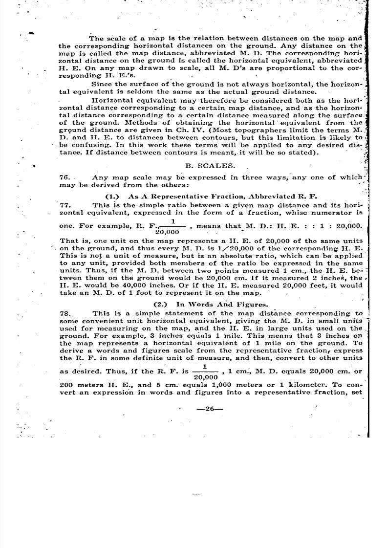
8/8/2019 Topography for Field Artillery
http://slidepdf.com/reader/full/topography-for-field-artillery 37/272
", ... ..
B. SCALES.
76. . Any map scale may be expressed in three ways, anyone of which}
may be derived from the others:
(1.) As A I~epresentath.e I.'raction, Abbreviated n~F.77. This is the simple ratio between a given map distance and its hori.
zontal equivalent, expressed in the form of a fraction, whisc numerator is
1one. For example, R. F.,--- , means that. M. D.: II. E. : : 1 : 20,000.
20,000
That is, one unit on the map represents a II. E. of 20,000 of the same units
'. on the ground, and thus every :M. D. is 1/20,000 of the corresponding II. E.
This is no~ a unit of measure, but is an absolute ratio, which can be applied .
to any unit, provided both members of the ratio be expressed in the sameunits. Thus, if the :M. D. between two points measured 1 em., the II. E. be';
tween them on the ground would be 20,000 em. If it measured 2 inches, the r
II. E. would be 40,000 inches. Or if the II. E. measured 20,000 feet, it would
take an 1\1. D. of 1 foot to represent it on the map.
(2.) In 'Vord8 And Figures.
78.. This is a simple statement of the map dist~nce corresponding to
some convenient unit horizontal equivalent, giving the M. D. in small units
used for measuring on the map, and the II. E. in large units used on the".ground. For example,. 3 inches eqllals 1 mile. This means that 3 inches on
the map represents a horizontal equivalent of 1 mile on the ground. To
derive a words and figures scale from the representative fraction, express
the R. F. in some definite unit of measure, and then, convert to other units
. 1 , . .as desired. Thus, if the R. F. is , 1 em., M. D. equals 20,000 em. or
20,000
200 meters II. E., and 5 em. equals 1,000 meters or 1 kilometer. To con.
vert an expressio'n in words and figures into a representative fraction, set
-26-
_ .
~
---
8/8/2019 Topography for Field Artillery
http://slidepdf.com/reader/full/topography-for-field-artillery 38/272
\'P a fraction with the given 1\1. D. in the numerator and the corresponding
n. E. in the denominator, converted into the same units as the M. D. Divide
hoth members by the numerator to reduce the fraction to a numerator of
1. The result is the R. F. Taking the first example above, 1 mil=63,360
. h . 3 1InC es, hence the R. F. IS = --- .63,360 21,120
(3.) By A Graphical Scale.
70. This is simply a rule or a line drawn on the map itself with divi-
sions marked showing the horizontal equivalents corresponding to the map
distances between the divisions of the scale. The length of any desired
graphical scale may be determined either from the R. F. or the words and
figures scale, as will be shown. The main divisions of the scale should be
large, for measuring the even portion of long distances, with an extra divi-sion to the left of the 0 subdivided for measuring the odd portion of any
distance down to the last reading of the scale, fig. 13.
MIL(-'
0I
Mf:Tf:R'500 0 500 1000 1500 ZOCO zsoo
'!I'''' , I I I I I
+n
Fig. 13.
80. In measuring between two points, the scale is placed so that the left
hand point is opposite the center of the subdivided portion to the left of the
n, and is then shifted, if necessary, to bring the nearest even mark on the
r.lain scale to the right-hand point. To illustrate, using the meter scale in
fig. 13, place the scale first with the middle or 250 meter point of the sub-
divided part opposite A, then shift to bring the even 1,000 meter point to n,r1aking the distance 1,150 meters.
81. A graphical scale may be made on a separate straight-edge or on the
map itself. Every map should have a graphical scale. The advantage of this
is that if the map expands or contracts accordiingto the moisture in the air,
or if it is enlarged or reduced photographically, the scale goes with it. To
use the scale, take it off on the edge of a piece of'paper or a ruler and apply
to the map, or mark the map distance on the edge of the paper and place it
against the scale. The latter is a convenient method in measuring crooked
(1.'stances, as roads.
82. Where a map bears a graphical Bcale, but the R. F. is unknown, the
n. F. may be determined as follows: Measure the 1\1. D. length of the graphi-
(al srale, or any convenient eVE'nportion of it. Set up a fraction with the
measured 1\1. D. in the numerator and the corresponding II. E. from the
scale in the denominator, converted into the same units as the 1\L D. Divide
looth members by the numerator to reduce to a numerator of 1. The result is
the R. F.
For example, suppose that a photographica1- reduction of a map has
a graphical scale for 5,000 meters which was reduced with the map, with a
-27-
•
",
.. ,
.-.1.
,i..,
.'
, ..
---
~
~
.
8/8/2019 Topography for Field Artillery
http://slidepdf.com/reader/full/topography-for-field-artillery 39/272
legend showing that the R. F. of the original may was _1 • The scale
20,000
measures 12.5 em. long, 5,000 meters=500,000 em. Then the new i.1. F.
12.5 1 .. .___ = --- , showmg that the map was reduced one-haIr in linear
500,000 . 40,000
dimensions.
E3. When a map bears no scale of any kind, its scale may be determined
by a comparison of measurements between known points on map and ground.
With any convenient scale measure the 1\1:. D. between two points on the
map. Measure the distance between the corresponding points on the ground
reducing it to the II. E. if it is not so actually (see par. 78). This gives at
once a "words and fig'Ures" scale, which can be converted into any units de.
sired. The R. F. can now be found from this as described under, "words and
~gures scale", in par. 78. The points selected shoulJ be such that the hori ••
70ntal distance between them can be measured, and should be as far apart
as conveniently can be reached. The process should be repeated with other
points in different directions, if possible, in order to verify the scale.
For example, suppose the distance between points A and n measureS \
17 mm. on the map, and the horizontal distance between the corresponding'
points on the ground measures 340 meters. Then, the words and figureS
~cale of the map is 17 mm.=340 meters, or 1 mm.=20 meters. 20 meters:::::. 1
20,000 mm. so the R. F. IS ---.
20,000
:\I.\P SCALS PROBLEl\lS. jA. CLASSES OF PROBLEMS.
84. Map scale problems fall into two classes: map to ground (M. D. to
H. E.), and ground to map (II. E. to M. D.). An example of the first class
is in determining- the II. E. for a 1\1. D. measured on the map with an
ordinary scale. A n example of the second class is in determining the M. D.to layoff on a map or sketch for a certain II. Eo measured on the ground,
or in determining the length of a graphical scale to read a certain number'
of units of H. E. In either case the calculation is a simple one of converting'
distances by meanse of the R. F. or the words and figures scale. .l:
B. SIMPLE RULE;S FOR MAP SCALE CALCULATIONS.
(1.) Map To Ground.
85. (a) By the R. P. (1) Multiply M. D. in map measure units by the
denominator of the R. F. The product is the II. E. in the same units. (2)
Convert this II. E. into any desired ground measure units.Example: On a sta~dard American map, the scale of which is 3
inches=1 mile, R. F. , the M. D. from point A to point [J
.21,120 .measures 5.08 centimeters. What is the II. Eo from A to n. in yards? .
Solution: (1) 5.08X21,1~0=107,28!>.G em., II. E.
(2) 107,28!>.Gcm.+2.5.1=42,240 in.
42,240+36=1,173.3 yards, ans .
•or: 107,28!>.Gcm.=1072.8!>G meters.
1072.8!>6Xl.0!)36=1,173.3 yards, ans.
-28-
__ iS
_
.
= ---
8/8/2019 Topography for Field Artillery
http://slidepdf.com/reader/full/topography-for-field-artillery 40/272
8G. (b) fly the 1Vordg and figures scale. (1) Find number of ground
measure (II. E.) units represented by 1 map measure unit. (2) Multiply this
by the M. D.
Example: same as under par. 85.
Solution: (1) 3 inches=l mile=1760 ~'ards.
3 inche£=3X2.54=7.62 em.Therefore 1 em.= 1760+7 .6~=230.97 yards.
(2) 5.08 cm.=5.08X230.97=1173.3 )Tards, ans.
Or the II. E. represented by 1 map measure unit may be found from
the R. F.:1 em. on map=21,120 em. on ground.
21,120 em.=211.2 meters.
211.2X1.0936=230.97 )'ards
Therefore 1 em. 1\1. D.=230.97 yards II. E.
This method of finding the II. E. value of 1 map measure unit is
Rimply to express the R. F. in the given map measure units, and convert the,
lI<"nominator into the desired grcund measure units.
Complete the solution as above.
The above example might be worked through in inches instead of
«('ntimeters hy converting the M. D. into inches at the start:
(1) 5.08 cm.+2.54=2 inches, M. D.
3 inches=1 mile=17GO yards.
Therefore 1 inch=1760+3=586.67 yards.
(2) 2 inches=2X586.67=1173.3 }'ards, ans.
Or, obtaining the value in II. E. of 1 map measure unit from the R.}'.
1. inch on map=21,120 inches on ground.
21,120~-36=586.G7 }Tards.
Therefore 1 inch M. D.=586.G7 yards II. E.
Complete the solution as above.
(2.) Ground To 1\lap.
87. Grouucl to map, or II. E. to ~I. D. problems, are simply the reverse
of map to ground, or 1\1. D. to II. E. problems.~8. (u) fly the R. F. (1) Convert the given II. E. into map measure
units. (2) Divide by the denominator of the R. F. The result is the desired
:\1. 1>.
Example: The II. E. from point A to point B on the ground is 1,000
meters. How many inches M. D. must be laid of! to represent this distance
(.n a standard American map, the scale of which is 6 inches= I mile, R. F.
1---?, Or, as a graphical scale problem, what will be the length in inches
10,GGO .
cf a graphical scale of 1,000 meters for this map? .Solution: (1) 1,000 metersX39.3i=39,370 inches.
(2) 39,370+10,560=3.7 inches, ans.
89. (b) By the 'Words and ligures scale. (1) Find number of ground
m<.>asure (II. E.) units represented by 1 map measure unit, the same as in
map to ground problems. (2) Divide this into the II. E. in the same ground
measure units.
8/8/2019 Topography for Field Artillery
http://slidepdf.com/reader/full/topography-for-field-artillery 41/272
Example: Same as under par. 100.
Solution: (1) 6 inches=l mile=1760 yards
1 inch=1760--;-6=293.3 )'ards.
293.3 yardsX.9144=268.2 meters.
Or from the R. F.: 1 inch on map=10,560 inches on.
ground.
10,5GOinches--;-39.37=268.2 meters.
Therefore 1 inch M. D.=268.2 meters II. E.
(2) 1,000--;-268.2=3.7 inches, ans.
90. From the above illustrations, it is evident that any map scale
probl~m can be solved either by means of the U. F. or the "words and
figures" scale. For most purposes the R. F. is simpler, as it uses the.
absolute ratio between map and II. E., and be applied directly to any units of
measure. However, in reading maps with an ordinary measuring scale, the .
, words and figures scale is useful to get the II. E. value of the measured M.
D.'s. The measuring scale becomes a sort of graphical scale when the II. E.
value of one of its units has been determined, though this may not be in a
convenient even amount. Thus, with American maps, as in the above ex-
amples, an inch always equals an odd number of yards II. E. The metric
system, with the corresponding maps having representative fractions in
even thousands, has a great advantag-e over the English system in this. 1
respect. For example, .on a map the R. F. of which is ---, 1 em. M. D.20,000
=20,000 em. II. E.=200 meters II. E. The centimeter scale then becomes
practically a graphical scale, on which each centimeter represents 200
meters, each millimeter 20 meters, and each half-millimeter 10 meters. \Vith
such maps any metric scale may be used as a reading scale, and most
problems can be solved mentally.
91. A convenient rule to remember when using the metric system on any
maps is that 1 millimeter of 1\1. D. equals a II. E. in meters 1/1,000 of the
denominator of the R. F. (because 1 millimeter equals 1/1,000 of a meter).
1 1Thus, on a --- map, 1 millimeter=20 meters; on a --- map, 1
20,000 21,120
1millimeter=21.12 meters; on a --- map, 1 millimeter=80 meters; on a
80,000
__ 1_ map, 1 millimeter=40 mders; etc ..
40,000
C. SCALE CONVERSIONS.
92. The 1\1. D. length of a graphical scale reading in certain units, as
yards, being given, it is sometimes desirable to be able to determine the
length for a similar scale reading in other units, as meters, directly from
the first scale, without calculating through the R. F. or the words and
figures scale. This is the case when the map has a graphical scale but the
R. F. is unknown, as when a map is enlarged or reduced photographically.
Proceed as follows:
93. On the given graphical scale measure with any convenient measuring
-30-
'
8/8/2019 Topography for Field Artillery
http://slidepdf.com/reader/full/topography-for-field-artillery 42/272
OG.
culated
figures
.
scale, the M. D. length of a convenient number, say 1,000, of the ground
measure units in which the scale reads. Multiply this M. D. by the ratio
between the length of one of the ground measure units of the desired scale .
and the length of one of the ground measure units of the given scale: The
result is the M. D. length of the desired scale, reading the same number
of new units, that is, 1,000, as was taken of the old. The new scale may
then be laid off on the map or made up as a separate scale.
For example, a map is found with a 1,000 yard graphical scale
which measures 3.4 inches. How many inches should be laid off for a 1,000
meter scale for the same map? Any :M.• D. is proportional to the II. E. which
it represents. lIenee the M. D. for a 1,000 meter scale )s to the :M. D. for a
1,000 yard scale as 1,000 meters is 'to 1,000 yards, or as 1 meter is to 1 yard,
or as 1.0036 is to 1 (par. 12). Therefore the :M. D. for the t,OOO meter
Rcale will be l.On6X3.4 in.=3.7 in. (This is the same as was obtained by the
complete calculation'in the example under par. 89.04. The distinction between the conversion of map ~cales a~d the con-
"ersion of ordinary linear' distances from one unit to another should be
noted. In converting map scales, the M. D. representing a given number of
one ground unit is multiplied by the inverse ratio between the units to find
the M. D. corresponding to the'same number of the second ground unit. In
ordinary conversions of linear di~tances the given distance in one unit is mul-
t;plied by the direct ratio between the units to find how many of the second
unit it will take to cover the Bame distance. Thus, distance in yards is to
<1istance in meters as 1 ~'ard is to 1 meter, or as .9144 is to 1, and 1,000 }'ardsX.0144=914.4 meters, using the direct ratio. In the first case the distance
corresponding to a fixed number of units is sought, and the inverse ratio of .
yards to meters or 1.0936 is used; in the second case the number of units
in a fixed distance. In either case mistakes in using the wrong ratio or
equivalent may be avoided by thinking whether the results should be larger
or smaller than the given figure, and gross errors in calculation may be
avoided by making a quick mental approximation of the result.
D. TYPES OF GRAPHICAL SCALES .
. 95. Graphical scales may be divided into two classes, working scales for
map making and reading scales for map reading. Some scales may be used
for both. Stride scales or mounted timing scales are workiing scales. They
cannot be used conveniently as reading scales because they are not graduated
in any standard unit of ground measure. To read a distance with them it
would be necessary to convert e\'ery measurement into standard units by the
prope'r equivalent. A mile scale is purely a reading scale. It cannot be used
conveniently as a working scale because it is impracticable to measure
distances on the ground in miles. A yard or meter scale is both a'l'eading
and a working scale, because it reads in standard units with which measure-
ments can be made on the ground.
(t.) Construction Of Reading Scalt~8.
If no graphical scale is available, horizontal equivalents may be cal-
from map distances, and conversely, from the R. F. or words and
scale. However, if any considerable amount of measuring is to be
-31-
1
: .
',. ....
',~ ...
'jO .
.':
~
<
~-
~ ..
'
'"
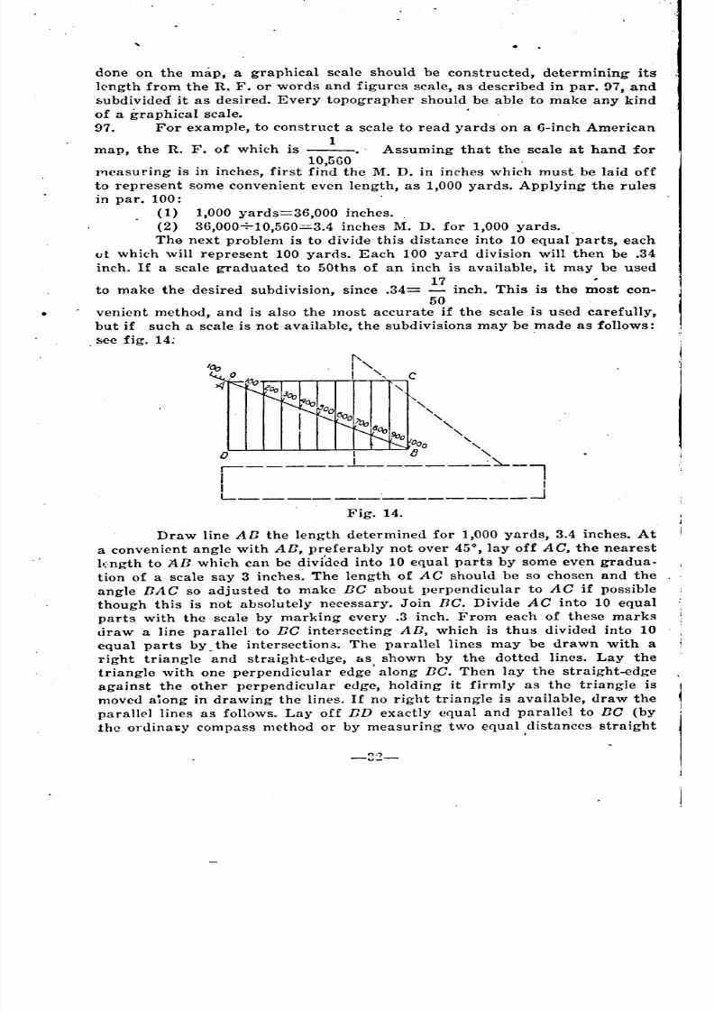
8/8/2019 Topography for Field Artillery
http://slidepdf.com/reader/full/topography-for-field-artillery 43/272
done on the map, a graphical scale should be constructed, determining its
lc'ngth from the R. F. or words and figures scale, as described in par. 97, and
subdivided it as desired. Every topographer should be able to make any kind
of a graphical scale. .
97. For example, to construct a scale to read yards on a 6-inch American
map, the R. F. of which is 1_., Assuming that the scale at hand for
10,560lYleasuring is in inches, first find the M. D. in inches which must be laid off
to represent some convenient even length, as 1,000 yards. Applying the rules
in par. 100:
(1) 1,000 yards=36,000 inches.
(2) 36,000+10,560=3.4 inches M. D. for 1,000 yards.
The next problem is to divide this distance into 10 equal' parts, eacho[ which will represent 100 yarrls. Each 100 yard division will then be .34
inch. If a scale graduated to 50ths of an inch is available, it may be used
17to make the desired subdivision, since .34= inch. This is the most con-
50venient method, and is also the most accurate if the scale is used carefully,
but if such a scale is not available, the subdivisions may be made as follows:
, see fig. 14; ,
I"I
" ,'\.
"",o I
.------l-----~~-l
I IL -.J
Fig. 14.
Draw line AB the length determined for 1,000 yards, 3.4 inches. At
a convenient angle with AB, preferably not over 450 layoff AC, the nearest
lEngth to AB which can be divi'dcd into 10 equal parts by some even gradua-
tion of a scale say 3 inches~ The length of AC should be so chosen and the
angle BAC so adjusted to make BC about perpendicular to AC if possible
though this is not absolutely necessary. Join BC. Divide AC into 10 equal
parts with the scale by marking every .3 inch. From each of these marks
draw a line parallel to BC intersecting AB, which is thus divided into 10
equal parts by the intersection.:!. The parallel lines may be drawn with a
l'ight triangle and straight-edge, &s shown by the dotted lines. Lay the
triangle with one perpendicular edge' along BC. Then lay the straight-edge
against the other perpendicular edge, holding it firmly as the triangle is
moved aiong in drawing the lines. If no right triangle is available, draw the
parallel lines as follows. Layoff ED exactly equal and parallel to BC (by
the ordinal:y compass method or by measuring two equal ,distances straight
""u_-
__
-
~ "
~ "
,
_
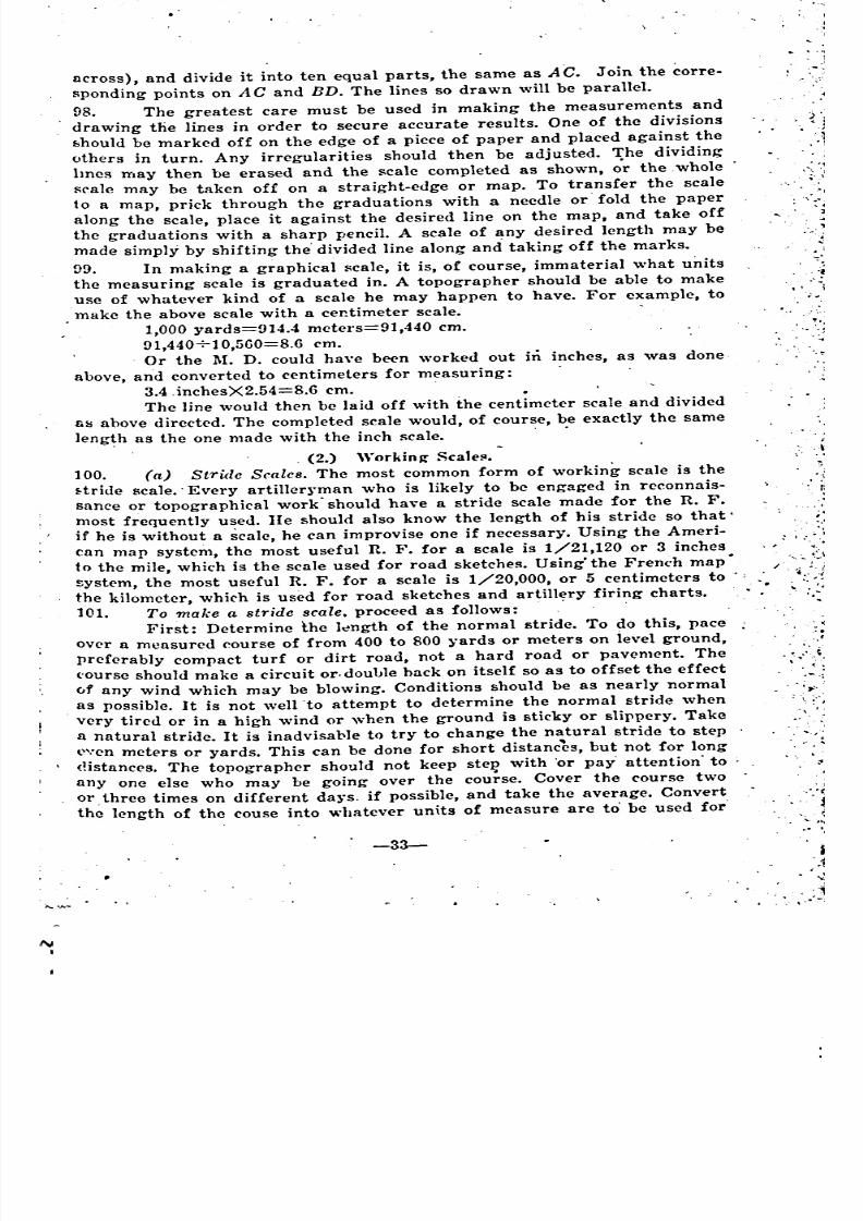
8/8/2019 Topography for Field Artillery
http://slidepdf.com/reader/full/topography-for-field-artillery 44/272
j
'.
.
....
~..... ,'--'
: ":"
... -',:.'
-33-
across), and divide it into ten equal parts, the same as AC. Join the corree
sponding points on A C and BD. The lines so drawn will be parallel.
98. The greatest care must be used in making the measurements and
drawing the lines in order to secure accurate results. One of the divisions
8hould be marked off on the edge of a piece of paper and placed against theothers in turn. Any irregularities should then be adjusted. rr:he dividing
lmes may then be erased and the scale completed as shown, or the, whole
srale may be taken off on a straight-edge or map. To transfer the scale
to a map, prick through the graduations with a needle or' fold the paper
along the scale, place it against the desired line on the map, and take off
the graduations with a sharp pencil. A scale of any desired length may be
made simply by shifting the' divided line along and taking off the marks.
!>9. In making a graphical scale, it is, of course, immaterial what units
the measuring scale is graduated in. A topographer should be able to makeuse of whatever kind of a scale he may happen to have. For example, to
make the above scale with a cer.timeter scale.
1,000 yards=914.4 metel's=91,440 em.
91,440710,5GO=8.6 em.
Or the M. D. could haye been worked out hi inches, as was done,
above, and converted to centimeters for measuring:
3.4.inchesX2.54=8.6 em.
The line would then be laid off with the centimeter scale and divided
fiS above directed. The completed scale would, of course, be exactly the sameleng~h as the one made with the inch scale.
,(2.) "'orkin~ Scale!!.
100. (a) Strule Scales. The most common form of working scale is the ,
f:tride scale.' Every artiller~'man who is likely to be engaged in reconnaise
sance or topographical work" should have a stride scale made for the R. F.
most frequently used. lie should also know the length of his stride so that'
if he is without a scale, he can improvise one if necessary. Using the Ameri- : I :.~
can map system, the most useful R. F. for a scale is 1/21,120 or 3 inches •
to the mile, which is the scale used for road sketches. Using'the French map.~ystem, the most useful R. F. for a scale is 1/20,000, or 5 centimeters to :.:. I
the kilometer, whiC'h is used for road sketches and artillery firing charts. .' '.'
101. To make a stride scale, proceed as follows: ,'.
First: Determine the It:!ngth of the normal stride. To do this, pace Jover a measured course of from 400 to 800 }'ards or meters on ievel ground,:':!
preferably compact turf or dirt road, not a hard road or pavement. The .
('ourse should make a circuit or. double hack on itself so as to offset the effect . <....i'
of any wind which may be blowing. Conditions should be as nearly normal
as possible. It is not well to attempt to determine the normal stride when
, very tired or in a high wind or when the ground is sticky or slippery. Take
a natural stride. It is inadvisa1'le to try to change the natural stride to step
l""cn meters or yards. This can be done for short distanc~s, but not for long
<Hstances. The topographer should not keep steI? with 'or pay' attention' to
anyone else who may be going over the course. Cover the course two
or, threo times on different da~'s. if possible, and take the average. Convert
the length of the couse into whatever units of measure are to' be used for'
:'
\
'
'
" ~':
' '...
'"~
~\~
,~.::
8/8/2019 Topography for Field Artillery
http://slidepdf.com/reader/full/topography-for-field-artillery 45/272
r-.
laying off the scale (inches or rentimeters), and divide this by the average
number of strides taken to cover the course. The result is the length of one
average stride. It is close enough to determine the stride to the nearest inch
'Or the nearest even centimeter, as this will be well within the probable error'Of striding and measuring with the scale.
102. Having determined the normal stride on level ground and made up
the scale accordingly, allowances can be made in using the scale for slopes,
for rough, sandy, or muddy ground, for wind, for the physical condition of
the person, etc. Ability to make these allowances 'comes with experience.
The table in Ch. VIII gives the average allowances to be made for slopes.
However, anyone with much sketching to do should take advantage of every
opportunity to determine his own aIIowances under. different conditions, pac-
ing measured courses both up and down hill, with and against the wind, pac-
ingthe regular course when tired, etc., marking on his scale the allowances
thus determined. After the length of the scale has once been determined, it
should be tested occasionally to see whether it has changed especially on mov-
ing to a different climate, terrain, or altitude.
103. Second: Multiply the length of one normal stride by the total num-
ber of strides desired for the scale, as 500 or 1000. This gives the length of the
scale nn the ground in the units in which the stride was determined, (inches or
centimeters). Multiply this by the desired R. F. The result is the length of
the scale, which may be laid <lff and subdivided as directed in par. 97.
Mark on the scale the name of the maker, the length of stride, and the R. F.
104. For example, to make a stride scale of 1,000 strides with an R. F. of
J/20,000:
Suppose a 500 meter course has been covered three times, in 255,
25!), and 262 strides, respectively, making an average of 258.7 or 25!) strides .
..Assume that the scale is to be laid off with a centimeter rule. Then th~ length
of the stride will be determined in centimeters. Length of the whole course iS
j500X100=50,000 em. Length of one stride is 50,000+259=193 em. Take the
-r,earesteven number, 194 em. The scale is to cover 1000 strides. 1000X194
=194,000 em., length of 1,000 ~trides on the ground. 1/20,000X194,000=
9.7 em., length of scale. Layoff the scale and mark it: Lt. John Smith. Stride
:94 em. R. F. 1/20,000.
105. It is immaterial what unit of measures are used in determining the
length of the scale, whether yards or meters, inches or centimeters, because
the absolute length of the stride is the same, no matter what units it is
measured in, and the length of the scale is determined from the length ofthe stride by "the R. F. In the above problem, if an inch scale it to be used
for laying off the stride scale, convert the length of the course, 500 meters,
into inches instead of centimeters and find the length of 1 stride in inches.
The length of the scale will then be determined in inches. Or work the
problem through i~ centimeters and convert the final result, 9.7 em., into
inches. A course measured in yards might be used instead of a meter course.
In any case the absolute l;ngth of the stride and of the stride scale would
be the same. It should be impressed on men learning the subject that the
'scale when completed is a working scale of strides only, having no relation
-3~-
~
'
.
,
8/8/2019 Topography for Field Artillery
http://slidepdf.com/reader/full/topography-for-field-artillery 46/272
to the system of measure by which it was determined. It cannot be used as
a general reading scale except by converting the strides into some standard
units of measure, nor can it be used as a working scale by anyone having a
different length of stride.
106. (b) Mounted lVorking Scales. For mounted sketching, a timing scale
is most convenient. A stride scale can be made for a horse the same as for
I.l person, and is somewhat more accurate than a timing scale. How-
ever, a timing scale is easier to use, and gives as close results as are usually
required for mounted sketching. ,
1(17. , To make a mounted timing Bcale proceed as follows: ,
First: Find the average distance covered in 1 minute by the horse at
the desired gait under normal c:onditions. To obtain good results, the horse
must have a uniform gait. An ordinary trot is the best gaid for generalwork. Take the horse over a measured course, say 2,000 meters or 2,000
yards, noting the time carefully. Cover' the course two or three times on
<.Jifferent days if possible, and take the average time. Divide this into the
length of the course, giving the average distance per minute~
The course should be the same kind of ground as will, ordinarily be
('overed in actual work, usually a dirt road. The horse should be warmed up
but not tired, and other conditions should be as nearly normal as possible.
Tests' under other conditions should be made later and allowances determined,the same as described for stride scales (par. 102). It is especially imporfant
to determine the difference between traveling light and with packed saddle.
'The scale should be made on th'e time taken with the load usually carried.
.and allowances made when carrying other loads. Separate scales may be
l:lad<,:lfor the different gaits, or the ratios between the gaits may be de-
termined, and the trotting scale used for all gaits, multiplying by the proper
l'atio. For example, the walk is usually about half as fast as the trot, 50
when walking, take half as much distance on the scale as when trotting.
108. Second: Convert the aVE:rage distance per minute into the units ofmeasure (inches or centimeters) which are to be used to layoff the scale.
Multiply this by the desired R. F. The result is the length of the scale for
1 minute. Layoff enough of these to make a scale of convenient length,
say 5 or 10 minutes, with an extra division at the left subdivided to halves,
quarters, and twelfths (5 second intervals). Mark on the scale the name or
number of the horse, the name of the rider, the load carried, the gait, the
!'lIte of speed per minute, and the R. F.
For example to make a trotting scale, carrying packed saddle, R. F.
1/20,000. Say the horse covers 2,000 meters trotting in an average time,
taken from three trials, of 10 min. 15 sec .. or 10.25, min. The average dis-
tance per minute is 2,000+10.25=195 meters. Suppose the scale is to be
measured in centimeters. 195 M.=19,500 em. 1/20,OOOX19,500=.975 em.
length of scale for 1 minute. Take ten minutes, or 9.75 em. for the full
length of the gcale. Lay this off, divide it into ten equal parts, and layoff
.an extra division at the left 8ubdivided into twelfths as above directed. Mark
-35-
. :\""'j,'"
.
',,\ ....
"
,
":
"
"
8/8/2019 Topography for Field Artillery
http://slidepdf.com/reader/full/topography-for-field-artillery 47/272
I.
'. f'
.'
",
, ,
the scale: Horse, Bob, No. 278. Lt. John Smith, rider. Packed saddle. Trot
195 :M. per min. R. F. 1/20,000.
109. Using standard American map scales, an ordinary inch scale divided.
into eigths of an inch can be used as a trotting time scale for the average
horse. The average horse trots a mile in 8 minutes. Then if the scale of
the map is 1 inch to the mile, 1/8 inch will represent 1 minute. For other
nap scales take as many as eights of an inch per minuts 'as there are inches
per mile in the scale. Thus, for a sketch on a scale of 3 inches to the mile,
take 3/8 inch per minute. For a walking scale, take. sixteenths of an inch,
as the average horse walks a mile in 16 minutes.
110. . (c) , Interchange of Graphical Scales. Any graphical scale, reading,
or working, made with a given R. F., can be used with any other R. F.'by correcting the readings by the ratio between the original R. F. of the
scale and' the desired R. F. This' can be done very conveniently where the
R. F .'s run in even proportions, as in the American and French standard
'gystem.
For example, to use a 1/20,000 stride scale for a 1/2,000 sketch, as
will frequently be required: The' ratio of the original R. F. to the desired
R. F. is 1:10. Hence consider &11the figures on the scale as if multiplied
by 1/10. Thus, if a distance is covered in 80 strides, it will 'take 800 stride.
divisions on the scale to l'epresent the 80 strides on the sketch.The procedure is similar with reading scales. For example, to use a
1 . I
readmg scale on a 1/21,120 map. The ratio o~ the original R. F. of
10,560
, the scale to the R. F. of the map is 2:1. lienee consider all figures on the
scale as if doubled. Thus, if the scale shows 100 yards between two points,
the distance on the map will be 200 yards.
111. (d) n'orking Scale Gra1)hs. 'Vhere a number of men are to make
working scales of the same kind, the labor of calculating the length of each8cale seperately can be saved by preparing a graph. This can be done for
. any. kind of scale, mounted or dismounted.
112. For example, to make a graph for a set of stride scales of 1,000
strides, with an R. F. of 1/20,000, fig. 15. '
First: Determine the length of the longest scale and the shortest
scale \vhich will probably' be required. .
Say the longest stride is 200 cm. Then the length of the longest
scale will be: 200XI000X1/20,000=10 cm.
Say the shortest stride, is 140 cm. Then the length of the sh~rtestscale will be: 140XI000Xl/20,000=7 cm.
113. Second: Calculate the number of different scales, according to the
l.:nits of measure used, between the longest and the shortest. If the strides
are measured in centimeters, take the scales every other centimeter; that is,
on the even numbers. If measured in inches, take the scales every inch.
This will be close enough, well within the probable errors of measurement,
dc. In this example, the difference between the longest and the shortest
scales is 200--140=60 em., making 30 double-centimeters or even numbered
divisions, see Fig. 15.
-36-
, "
___ '
' ''
-
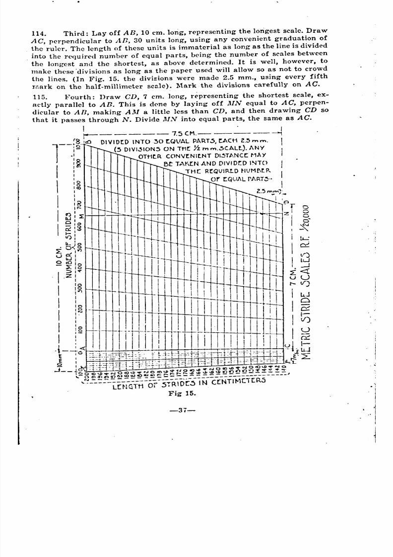
8/8/2019 Topography for Field Artillery
http://slidepdf.com/reader/full/topography-for-field-artillery 48/272
Fig 15.
-3i-
I
II
Z.'5mm"l' '.1-
'--''-'o0'
,~u....:
if)
Lw
J
_
~
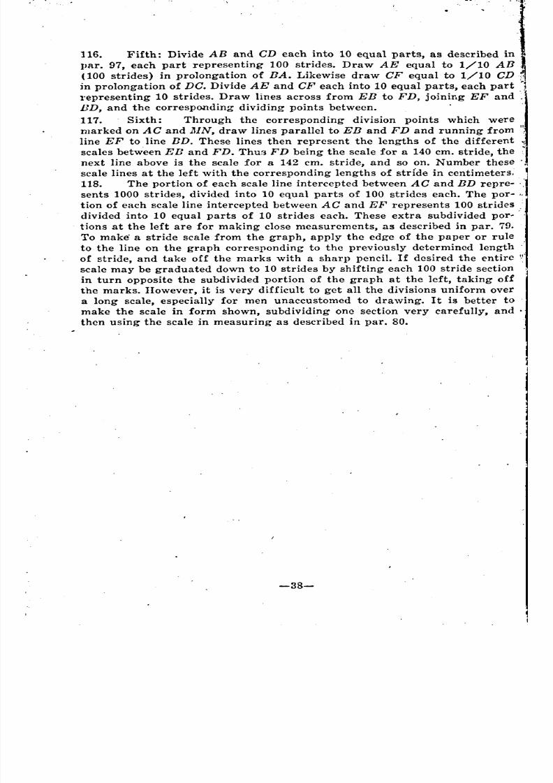
8/8/2019 Topography for Field Artillery
http://slidepdf.com/reader/full/topography-for-field-artillery 49/272
116. Fifth: Divide AB and CD each into 10 equal parts, as described in
IJar. 97, each part representing 100 strides. Draw AE equal to 1/10 All
(100 strides) in prolongation of llA. Likewise draw CF equal to 1/10 CD,-
in prolongation of DC. Divide AE and CF each into 10 equal parts, each part '1l'epresenting 10 strides. Draw lines across from EE to FD, joining EF and
BD, and the corresponding dividing points between.
117. Sixth: Through the corresponding division points which were
marked on AC and },IN, draw lines parallel to EB and FD and running from
line EF to line ED. These lines then represent the lengths of the different
scales betw'een EB and FD. Thu~; FD being the scale for a 140 em. stride, the
next line above is the scale for a 142 em. stride, and so on. Number these'
scale lines at the left with the corresponding lengths of stride in centimeters.
118. The portion of each scale line intercepted between AC and BD repre. '.'
sents 1000 strides, divided into 10 equal parts of 100 strides each. The por.
tion of each scale line intercepted between AC and EF represents 100 strides.
divided into 10 equal parts of 10 strides each. These extra subdivided por- .
tions at the left are for making close measurements, as described in par. 79.
To make a stride scale from the graph, apply the edge of the paper or rule
to the line on the graph corresponding to the previously determined length
of stride, and take off the marks with a sharp pencil. If desired the entire
scale may be graduated down to 10 strides by shifting each 100 stride section
in turn opposite the subdivided portion of the graph at the left, taking of!the marks. However, it is very difficult to get all the divisions uniform over
a long scale, especially for men unaccustomed to drawing. It is better to
make the scale in form shown, subdividing one section very carefully, and.
then using the scale in measuring as described in par. 80.
-38-
"
"
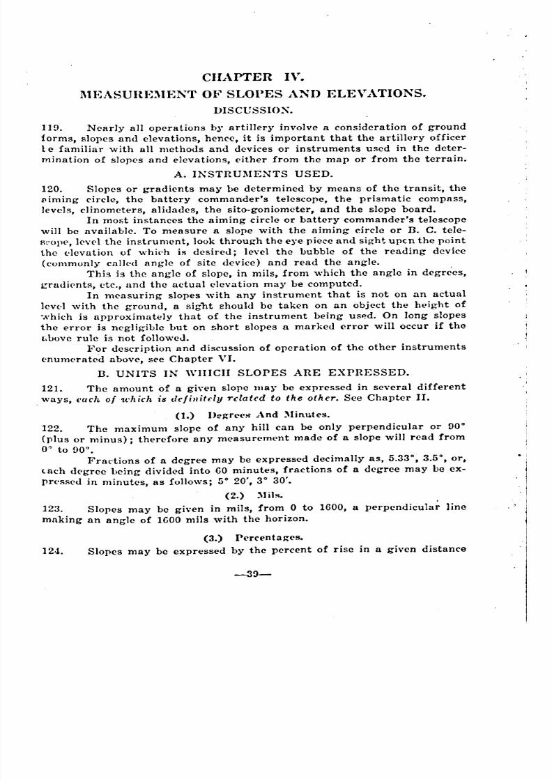
8/8/2019 Topography for Field Artillery
http://slidepdf.com/reader/full/topography-for-field-artillery 50/272
CHAPTER IV.
l\1EASUHE:\IEJ\T OF SLOPES A~n ELEVATIOJ\S.DISCUSSIOX.
119. Nearly all operations b)" artillery involve a consideration of ground
forms, slopes and elevations, hence, it is important that the artillery officer
1e familiar with all methods and devices or instruments used in the deter-
mination of slopes and elevations, (lither from the map or from the terrain.
A. INSTRUMENTS USED.
120. Slopes or gradients may be determined by means of the transit, thellImmg circle, the battery commander's telescope, the prismatic compass,
levels, clinometers, alidades, the sito-goniometer, and the slope board.
In most instances the aiming circle or battery commander's telescope
will be available. To measure a slope with the aiming circle or D. C. tele-
H~'OlW, 1('n1 the instrument, look through the e~"epiere and sight; upcn the point
the l'levation of whi('h is desired; level the bubble of the reading device
(commonly call(.<J angle of site device) and read the angle.
This is the angle of slope, in mils, from which the angle in degrees,
grlldj('nts, etc., and the actual elevation may be computed.In measuring slopes with any instrument that is not on an actual
levl'1 with the ground, a sight should be taken on an object the height of
-.vhich is approximately that of the instrument being USf?d. On long slopes
the error is negligible but on short slopes a marked error will occur if the
(,bove rule is not followeJ.
For description and discussion of operation of the other instruments
l'numcrated above, see Chapter VI.
n. UNITS IN WHICH SLOPES ARE EXPRESSED.
121. The amount of a given slope JlIa~' be expressed in several different
.ways, each of 1t'hich i8 definitely related to the other. See Chapter II.
(1.) I>e~rl'(,S"And )linutes.
122. The maximum slope of any hill can be only perpendicular or 90°
(plus or ~linus); therefore any measurement made of a slope will read from
o~ to 900•
Fra(.tions of a degree may be expressed decimally as, 5.330, 3.50
, or,
l8Ch dl'gree being divided into GO minutes, fractions of a degree may be ex-
prl'ssed in minutes, as follows; 5° 20', 3° 30'.
(2.) )li1s.
123. Slopes may be given in mils, from 0 to 1600, a perpendicular line
making an angle of 1GOO mils with the horizon.
(3.) Percenta~('s.
124. Slopes may be expressed by the percent of rise in a given distance
-39-
8/8/2019 Topography for Field Artillery
http://slidepdf.com/reader/full/topography-for-field-artillery 51/272
-40-
Qn the ground, i. e. the number of feet rise for each 100 ft. of horizontal
distance.
To find the percent of slope; divide the rise by the horizontal dis-
tance. For example, assume a rise of 5 feet in a horizontal distance of 100
feet. Dividing 5 by 100, the quotient is .05 or a 5% slope.
(4.) Gradients.
125. A slope may be indicated by the relation between the rise and the
horizontal distance such as a rise of 5 feet in 100 feet. This expressed as 5
on 100 or 5/100, or 1 on 20, the numerator usually being taken as unity.
~uch an expression is spoken of as the gradient of the slope.
(5.) Tangents.
126. The relation between the side opposite to the side adjacent to an an-gle of a right angled triangle, is the tangent relation of that angle.
Given the horizontal distance and' the degree of slope, look in the
table of tangents for the tangent of that slope and multiply it by the hori-
zontal distance. The result will be the height of the perpendicular of the
right triangle.
For Complete Conversion Tables see Appt'ndix III.
127. Typical Problern: Assume that with a slope board, or other slope
mea~uring device, the slope of a given hill has been determined to be 4°. It
il': desired -to change this into mils, percent, gradient, or. tangent values.
Refering to Appendix III the following values are found; (For a discussion
of values see Chapter II).
1°=17.78 mils or 1.75% and 1%= a gradient of 1/100 hence the
equations:
4X17.78=71.12 or 4°=71.12 mils.
4X 1.75= 7.00 or 4°=7%.
l%=gradient 1/100 then 7%=7Xl/IOO or a gradient of 7/100=1
on 14.28 or 4°=gradient of 1 on 14.28. From the tables, 4°=a tangent of
.06993.
Assume now that the point to which the slope has been read was
the top of a cliff, to the base of. which, it is possible to measure or pace .
off the horizontal distance. The height of the cliff is desired. .
Assumed horizontal distance=400 (60 inch) strides, GO in.=5 feet.
Then 400 strides=400X5 or 2,000 feet.
From Appendix III the tangent of 4°=.OG003. (The horizontal dis-
tance times the tangent gives the altitude of a right triangle). Therefore
2000XO.06993=130.86 or the height of the cliff in feet.
C. SLOPE SCALES.
128. A slope scale is a scale by which the slope between the contours may
be refld or which can be used in map making for locating the relative posi-
tions or distances between contours.
For American or other maps where the V. I. is directly proportional
to the scale of the map, a slope scale may be constructed that is applicable
to all such maps irrespective of the scale; i. e. if .65 in. is the M. D. between
contours for a 1° slope on a map, the scale of which is 3 inches to the mile, .
.
8/8/2019 Topography for Field Artillery
http://slidepdf.com/reader/full/topography-for-field-artillery 52/272
with u V. I. of 20 feet; it follows naturally that .65 in. is the 1\1. D. for a
10 slope on u map, the scale of which is 6 inches to the mile, with a V. I. of
10 feet, etc.
(1.) Construction Of Slope Scale.
12!). (a.) For American maps. To ascertain the M. D. between contours
\\ hen the degn\e of slope is known, the following formula applies:
. R. F.XV. I. (in feet)XG881\1. n. hctwcen contours:..:-:;-------------
Number of de(!'rees of sloDe(il-'H ht.ing- the numlwr of inches horizontal distance necessary to give a rise
of 1 foot on a 10 uC'gree slope.
l'roo! : .
10 slope=l ft. rise in 57.3 feet (or G88 inches) horizontal distance.
For G in. map 10
slope=10 ft. rise (the vertical distance between con-tours) 'in 573. ft. horizontal di5tance. But 6 in.=l mi1c. Then G in.=52~0
ft.~ alHI 573 ft.=G73/il280 of G in.=.G;, inch=:\1. D. betw('en countours for 10
fo;lope.
Similarly it may he. ~hown that the 1'1. n. for a 1 0 ~Iope with the
1 in., 3 in. and the 12 in. maps i~ .65 in.
For small ang-les it is npproximately true that the amount of rise
('ompan'<1 to the horizontal distance keeps pace with the degree of the ang-le.
Thus if a horizontal distance of 573 feet is required to g-ivc a rise of 10
f(.(.t on a 10
slopt', a similar rise would be f('cur('d in half that distance on a2° 'slope.
Or if .Gr>in. is the map distance between contours on the American
maps of 10 slope, thcn the map distance between contours will be half .65
m, or .325 in., for a 2° slope.
Solutions for various degrees of slope for American maps give the
following:
.(if) inch M. D. (between contours) for 10 slope,
.:~~;, inch M. n. for 2~ slope,
.22 inch 1\1. D. for 3° 810pc,
.1G inch M. D. for 4° slopc,
.13 inch 1\1. D. for 5° slope.
Draw a line subdivided into the abo\'e units (use a ruler dividcd into
d<>cimal parts of an inch, if possiblc, for accuracy). This scule pasted on a
trillng-ulnr ruler or aliJade can be used in contouring and will prove of yalue,
('spt\('ially in road sketches.
130. ([).) For metric maps. To construct a deg-ree slope scale for the
1/20,000 map with a [) metcr contour interval proceed as follows:
For a 10 ~lope a rise of 1 meter is equivalent to a horizontal dis-tnnee or 57.3 meters. A rise of [) meters (the distance between contours) will
he (.quivalent to a horizontal distance of 5X57.3l\1=28G.5:\1=28G50cm. On a
J /20,000 scale, 2~G50 cm. on the ground corre!'ponds to 1.4325 em. on the
mnp.
131. To ('onstruct a slope (lO,jl slope) for the 1/20,000 map with a 5
ruder contour interval proc('ed as follows:
For a 10,!1 slope a rise of 5:\1 corre~ponds to a horizontal distance of
-41-
"
8/8/2019 Topography for Field Artillery
http://slidepdf.com/reader/full/topography-for-field-artillery 53/272
, ~.
... .
f ;':', "~~.~ ".to;',;
:~ . '.
, :
>,
.i.:
." i.
500M. On the 1/20,000 map, Imm.=201VL Therefore a distance of 500M on
the ground corresponds to 500+20=25mm. on the map.
A 20/ll slope would have a M. D. between contours of half the above,
or 12.5 mm., and a 100/lt slope would require a M. D. of 1/10 or 2.5mm.
(2.) Use Of Slope Scale.
J32. (a) In Contouring: Only when a slope is absolutely uniform can a
~lope scale be used for plotting contours accurately; However it can be used
with sufficient accuracy' for all practical purposes of the military sketcher.
Assume that in making a road sketch a slope of 3° is measured from
the base of a hill to its crest, but by observation it is seen that the slope at ,
the base is gradual, and the slope towards the crest is steeper. Then by
measuring the number of times the interval for a 3° slope will go into thedistance as laid off on the map representing the hill, the number of contourS
crossing the road for the distance will be known. If, in this manner, it is
found that 8 contours will cross the road, the total distance is divided ipto
8 parts, intervals near the base of the hill being wider than those near the'
top after which the contours are drawn through the points of division.
If the slope is uniform the contours will be equally spaced.
133. (b.) In reading slopes: Place the slope scale on the map near the
slo!J~ which it is desired to measure. Move the scale around until one of the
,divisions on the scale corresponds to the M. D. between 2 adjacent con.
tours and so on with the next contours until the slope has been measured J'
for the distance de~ired. This gives the slope between adjacent contours only.'
, To get the slope between several con~ours the total of the slopes
measured may be averaged, thus getting the average slope of any given
ground; or the slope between the top and bottom of the hill may be read
and ~vepaied. This should be done only where the difference in slopes be.
tween contours does not exceed 1 or 2 degrees.
• Avetages should be taken only for plus or minus slopes, never for'both combined.
-42-
- '
~
'
~
'
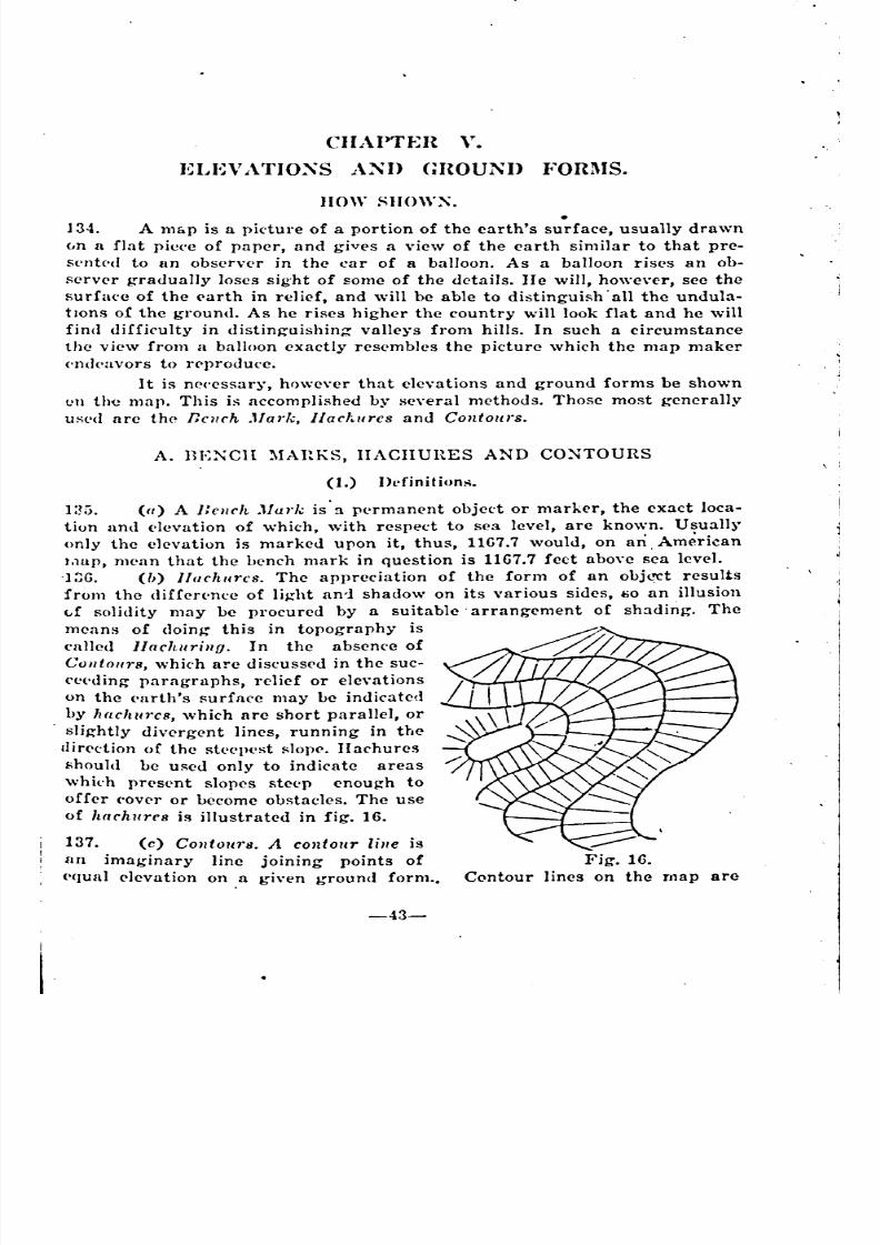
8/8/2019 Topography for Field Artillery
http://slidepdf.com/reader/full/topography-for-field-artillery 54/272
CHAPTEn Y.
ELEVATIO:\S A~n GHOUNI> I"ORl\IS.
1I0W SIlOW~. .134. A map is a picture of a portion of the earth's surface, usually drawn
(,n a flat piece of paper, and gives a view of the earth similar to that pre-
Sl'n1('d to an observer in the car of a balloon. As a balloon rises an ob-
server gradually loses sight of some of the details. He will, however, see the
surfa('c of the E'arth in relicf, and will be able to distinguish' all the undula-
tIOns of the ground. As he rises higher the country will look flat and he will
fin(l difficulty in distingouishin~ valleys from hills. In such a circumstance
the view from a balloon exactly res('mbles the picture which the map maker
('n<!('(lvors to r<.>produce.
It is n('('essary, hr)\\,evcr that elevations and ground forms be shown
el l the map. This is accomplished by several methods. Those most generally
w,;('d are the ECllch .1101'1,;,lIarhurcs and Contours.
A. BENCH ~IAltKS, IIACIIURES A~D CO~TOURS
----ig. 16.
Contour lines on the map are
(1.) Ih'finitions.
1:!5. (a) A Delich .1Iurk is' a p('rmanent object or marker, the cxact loca-
tion and ('lcvation of which, with respect to sea level, are known. Usually
only the elevation is marked upon it, thus, llG7.7 would, on an. American
1,1Up,mean that the hench mark in question is 1167.7 feet above sea level.
.] ;jG. (lJ) I!arhurcs, The appreciation of the form of an obj<."Ct results
from the diffen'nee of light awl shadow on its various sides, ~o an illusion
",f solidity may be procured by a suitable arrangocment of shading. Themeans of doing this in topography is
ealled l/achuriIlU. In the absenee of
CO/ltou1'8, which are diseusscd in the suc-
ce('dingo paragraphs, relief or elevations
on the ('l1rth's surface may be indicated
by h(£chu1'c8, which are short parallel, or
. slightly divergent lines, running in the
l1ir<>ction of the st<'cpest !'lop<.>.IIachures
should be u!';eu only to indicate areaswhkh pres('nt slopes ste('p cnou~h to
offer ('over or become obstacles. The use
of Iwrhur(,8 is illustrated in fig. 16.
137. (c) Confow's. A contour line is
an imaginary line joining points of
('(lual elevation on a gi\'en ground form .•
-43-
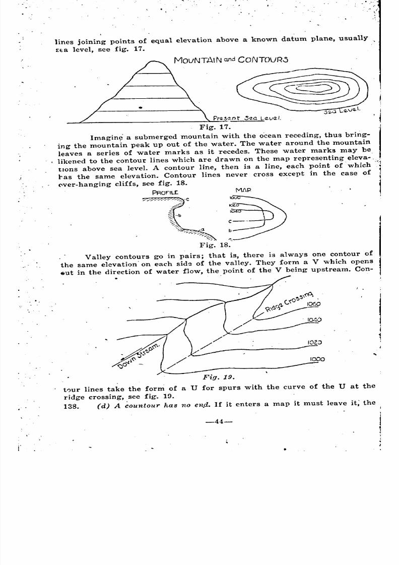
8/8/2019 Topography for Field Artillery
http://slidepdf.com/reader/full/topography-for-field-artillery 55/272
.. (
lines joining points of equal eleyation above a known datum plane, usually
Ela level, see fig. 17.
MovNTAI Nand CoNTOVR0
Pra.S9,nt' .5'2.Q La-va. I.
Fig. 17.
Imagin~ a submerged mountain with the o'cean receding, thus bring.ing the mountain peak up out of the water. The water around the mountain
leaves a series of water marks as it recedes. These water marks may be
likened to the contour lines which are drawn on the map representing eleva.
tlOnS above sea level. A contour line, then is a line, each point of which
ras the same elevation. Contour lines never. cross except in the case of
<'ver-hanging cliffs, see fig. 18.
PROflL£ MAP
to ~~\~~~ :~--. ' . ..../"% ".
Fig. 18.
Valley contours go in pairs; that is, there is always one contour of
the same elevation' on each side of the valley. They form a V which opens
~ut in the direction of water flow, the point of the V being upstream. Con.
.
"COO
Fig. 19.
t0ur lines take the form of a U for spurs with the curve of the U at the
ridge crossing, see fig. 19.
138. (d) A countour has no en,d. If it enters a map it must leave it; the
-44-
-
/
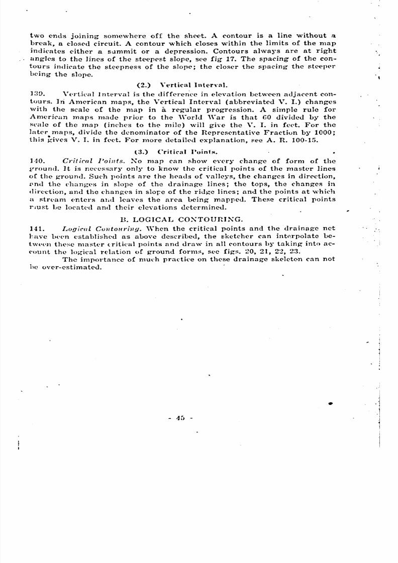
8/8/2019 Topography for Field Artillery
http://slidepdf.com/reader/full/topography-for-field-artillery 56/272
two ends joining somewhere off the sheet. A contour is a line without a
break, a dosed circuit. A contour which closes within the limits of the map
indicates either a sllmmit or a depression. Contours alwa~'s are at right
lmgles to the Jines of the steepe'st slope, see fig 17. The spacing of the con-
tours indicate the steepness of the slope; the closer the spacing the steeperbeing the slope.
(2.) Yt'rtical Inlen-at.
130. \'('rUeal Interval is the differerlee in elevation between adjacent con-
tours. Iri American maps, the Vertical Interval (abbreviated V. 1.) changes
with the scale of the map in a regular progression. A simple rule for
American maps made prior to the "'orld "'ar is that GO divided by the
seale of the map (inches to the mile) will give the V. 1. in fee't. For the
later maps, divide the denominator of the Representative Fraction b~T 1000;
thig g'ives V. 1. in feet. For more detailed explanation, ~ee A. R. 100-15.
(3.) Critical P()inl~.
1.10. Critical ]'oil1ts. :\0 map can show e\'ery change of form of the
g-roun<l. 1t is necessary only to know the critical points of the master lines
or the g'round. Su(.h points are the heads of valleys, the changes in direction,
l'nd the chang-es in slope of the drainage lines; the tops, the changes in
direction, and the changes in slore of the ridge lines; and the points at which
a sin'am ('niers awl leaves the area being mapped. These critical points
rmst IJe locat('d an<l their clev3tions determineJ.
B. LOGICAL COXTOURIKG.
141. Logical COl/touring. When the critical points and the drainag'e net
1:I1ve },l'('n established as above described, the sketcher can intl~rpolate be-
tWl'l'll th(\sc mast('r critical points and draw in all contours hy taking into fiC-
('ount the log-ical felation of ground forms, see figs. 20, 21, 2~, 23.
The importance of mUl'h practi('e on these drainage skeleton can not
he over-estimated.
•
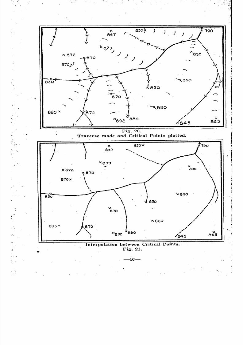
8/8/2019 Topography for Field Artillery
http://slidepdf.com/reader/full/topography-for-field-artillery 57/272
",
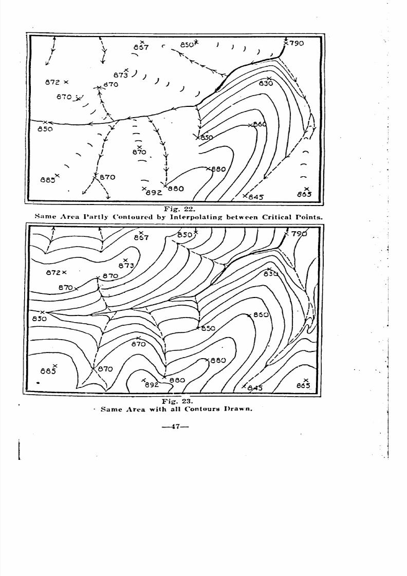
8/8/2019 Topography for Field Artillery
http://slidepdf.com/reader/full/topography-for-field-artillery 58/272
)))
x867
87~) )
~d70
870y t./
.I \."/
87Z x
-v.'" /t
" , x
'" f870
'" I
88'j'X "-870
I xII \ 805
..J-
Fig, 22.Same An'a Partl), ('ontour('d b)' Intt'rpolalin~ behH't'n Critical Points.
Fig. 23.
Same Art>a with all Contours Drawn.
-47-
~
~
'

8/8/2019 Topography for Field Artillery
http://slidepdf.com/reader/full/topography-for-field-artillery 59/272
t42.
143.
144.
145.
14G.
CHAPTEU VI.INSTUUl\1ENTS USED IN TOPOGUAPlIIC OPERATIONS.
DESCRIPTION A~D USE.
A. AIMING CIRCLE-See Hand Book.
B. BATTERY COl\ll\'lANDER TELESCOPES-See Hand Book.
C. TRANSIT-See Engineer Manual.
D. PRISMATIC COMPASS-See Hand Book.
E. PEIGNE' COMPASS.The Piegne' compass is used for topographical reconnaissance. It
allows the topographer to measure bearings and slopes. The distances arc
measured by stride or steel tape.
The Peigne' compass comprises a box in the bottom of which a grad~
uated dial is set. The magnetic m~cdlc swings on a pivot standing in the
center of the box. It may be' damped by means of a lever and a milled
lnob. The line of sight is defined by a slit sight and two wires extended in
the slot of the lid. InsiJe of the lid a mirror is inlaid.
One side of the box is beveled and engraved with a millimeter scale.A plummet rotating on the pivot of the needle gives the slopes in mils.
(1) To I{ead Bearings.
147. The lid is kept npen by means of the slit sight. The sketcher hold~-
the compass in his left hand, using his right index finger to release or clamp
the needle as needed. The point is sighted and the image of both needles and
graduated dial are observed in the mirror. By means of the lever, the,
sketcher may check the vibrations of the needle. He then screws the milled.
hrlob with his right thumb. The bearing may then be read. It is better to
Jepeat the operations two or three times and take the mean of the readings:!
(2) To Plot This Din'ction With The Compass. j148. On a sheet of drawing paper attached to a board draw a few parallel
lines in the direction of magnetic north (these lin~s making an ang'le with~
true north equal to the declination of the compass) near the point represent:;1
ing the place at which the bearing was read. Lay the box, entirely opened,:
(,n the table and pivot the bevel about the station point until the axis of thc1
I.eeelle is parallel to these lines. Draw a ray along the bevel. This ra:}
Il'presents the ~lirection as obtained with the ('ompass. .
(3) To Plot The Din'dion With A Protractor. i149. Use a protractor the graduations of which are the same as those oli
the dial. Layoff a line through the station point in the direction of maw~
netic north. Rotate the protractor about the station point until its zero linet
loincides with the line on the paper representing magnetic north. Mar~ of!
a point on the paper that will coincide with the angle as read from the com,':
rass. Connect this point and station point. This gives the line of knowll
direction. I
-
~
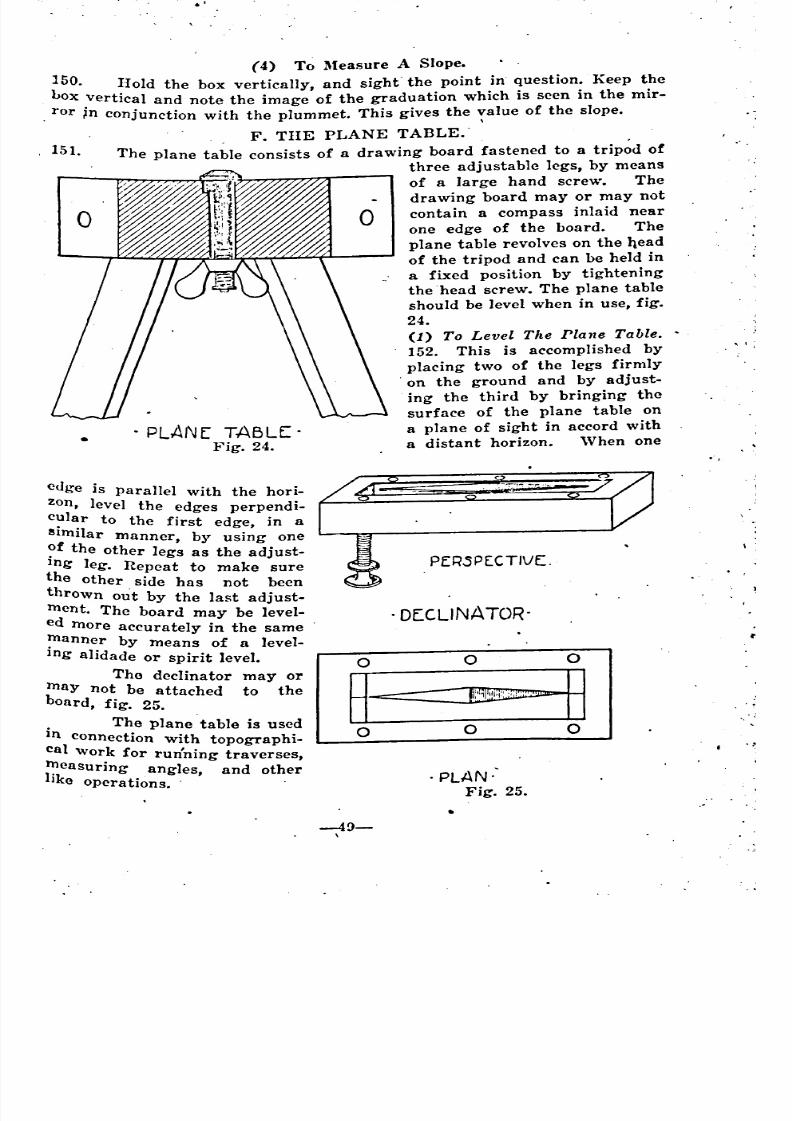
8/8/2019 Topography for Field Artillery
http://slidepdf.com/reader/full/topography-for-field-artillery 60/272
. ,-
,I
,0,
o
. PLANE: TABLE:.Fig. 24.
o
(4) To Measure A Slope.
~50. ~Iold the box vertically, and sight" the point in question. Keep the
ox .vertIcal and note the image of the graduation which is seen in the mir-
for ~n conjunction with the plummet. This gives the ~alue of the slope.
F. TilE PLANE TABLE.-The plane table consists of a drawing board fastened to a trip~d of
three adjustable legs, by means
of a large hand screw. The
drawing board mayor may not
contain a compass inlaid near
one edge of the board. The
plane table revolves on the qead
of the tripod and can be held in
a fixed position by tighteningthe head screw. The plane table
should be level when in use, fig.
24.
(1) To Level The Plane Table .•
152. This is accomplished by
placing two of the legs firmly
on the ground and by adjust-
ing the third by bringing the
surface of the plane table on
a plane of sight in accord with
a distant horizon. When one
, 151.
edge is parallel with the hori-
zon, level the edges perpendi-
c?lar to the first edge in aelm'lI ar manner, by using one
?f the other legs as the adjust-
Ing leg. Repeat to make sure
the other side has not been
thrown out by the last adjust-
ment. The board may be level-
ed more accurately in the same
~anner by means of a level-
Ing alidade or spirit level.
Tho declinator mayormay not be attached to theboard, fig. 25.
. The plane table is used
In connection with topographi-
cal work for run'ning traversesme . '. asurmg angles, and otherlIke operations.
P ER.S PEe T IVE:.
.OECLINATOR-
o 0 0
~----3o 0 0
. PLAN"Fig. 25.
,
-49-,
. o
0
o
'

8/8/2019 Topography for Field Artillery
http://slidepdf.com/reader/full/topography-for-field-artillery 61/272
:,
G. ALIDADES.
(1) Triangular Alidade.
153. The triangular alidade is a box wood rule which has a triangular
~rossection. All three edges of the alidade must be parallel to one another.In using this alidade one lower edge is placed along the line drawn, or to be;.
drawn, while the sighting is done along the top edge. ,'I
(2) The Sighting Alidadt>.
154. The sighting alidade or F. A. plotting scale is a flat ruler about
~5 centimeters long with two beveled edges. One edge is calibrated in milli-.
J(,eters and the other graduated to a 1/20,000 scale. On the face are placed '!two folding up-rights, one at each end, so that the line of sight passing
through the slits in each one is parallel to the edges of the scale. This alidade :can be used only for laying off directions and plotting points. In laying off'
directions either edge is placed along the line drawn, or to he drawn, and
the sighting is done by lining in the object with the line of sight passing
through the up-rights. The slit with the crosshair should be placed farther
from the eye.
(3) The Leveling Alidade.
155. The leveling alidade, sfJmetimes called a French alidade, ma~r be ..
used in laying off directions, plotting points, and measuring gradients, fig.::
-----_. ---- . -- -- _.- •._-- .- _._- -
If
ALlOAO[. :1Fig. 26. j
26. It consists of a ruler 20 to 25 centimeters in length on which are sup~
ported a level and 2 hinged standards. It al~() contains two eccentrics for
leveling the alidade. The rear standard contains three eye holes. The front /
standard forms an open frame including a horse hair sight. One side of the.!frame bears a graduation numbered upwards, the other side hears a grad"'l
uation numbered downwards. Each graduation consists of 40 divisions, ench..
division being equal to 1/100 part of the distance between the two stan'~dards, or 10 mils. I
.t,I
I
I
~
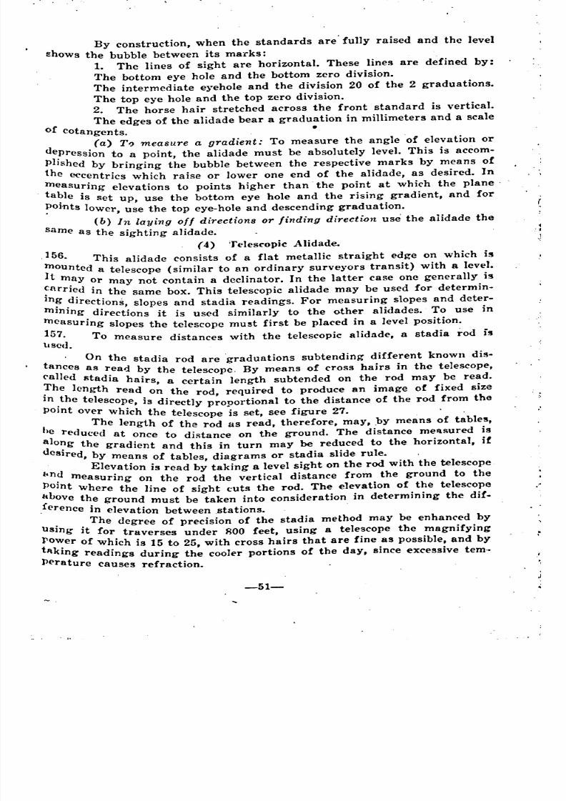
8/8/2019 Topography for Field Artillery
http://slidepdf.com/reader/full/topography-for-field-artillery 62/272
By construction, when the standards are' fully raised and the level
shows the bubble between its ma1"ks:
1. The lines of sight are horizontal. These lines are defined by:
The bottom eye hole and the bottom zero division.
The intermediate e}Oeholeand the division 20 of the 2 graduations.
The top eye hole and the top zero division.
2. The horse hair stretched across the front standard is vertical.
The edges of the alidade bear a graduation in millimeters and a scale
of cotangents. .•
(a) TIJ measure a gradient: To measure the angle of elevation or
depression to a point, the alidade must be absolutely level. This is accom-
phshed by bringing the bubble between the respective marks by means of
the eccentrics which raise or lower one end of the alidade, as desired. In
measuring elevations to points higher than the point at which the plane'ta?le is set up, use the bottom eye hole and the rising gradient, and for
~OJi1ts lower, use the top eye-hole and descending graduation.
(b) In laying off directions or finding direction use the alidade the
same as the sighting alidade. .
(4) T(']es("opic Alidade.
,156. This alidade consists of a flat metallic straight edge on which is
~ountcd a telescope (similar to an ordinary surveyors transit) with a level.
t m.ay or may not contain a dec1inator. In the latter case onc generally is
~nrTl~d in the same box. This telescopic alidade may be used for determin-
In?, .dlrections, slopes and stadia readings. For measuring slopes and deter-
mlnlng directions it is used similarly to the other alidades. To use in
measuring slopes the telescope mu~t first be placed in a level position.
157. To measure distances with the telescopic alidade, a stadia rod is
llsed.
t On the stadia rod are graduations subtending different known dis-
anl]ces as read by the telescope. By means of cross hairs in the telescope,
('a ed stadia h . . dTh I aIrs, a certam length subtended on the rod may be rea .. e ength read on the rod required to produce an image of fixed size
In .the telescope, is directly p;ooortional to the distance of the rod from the
POlnt over which the telescope .is set, see figure 27. .
t The length of the rod as read, therefore, may, .by means of table~,
)~ reduced at once to distance on the ground. The distance mellsured is
O?g the gradient and this in turn may be reduced to the horizontal, if
cSlred, by means of tables, diagrams or stadia slide rule.
Elevation is read by taking a level sight on the rod with the telescope
bn~ measuring on the rod the vertical distance from the ground to the
POlnt Where the line of sight cuts the rod. The elevation of the telescope
~Love the ground must be taken into consideration in determining the dif-
, erence in elevation between .stations.
The degree of precision of the stadia method may be enhanced by
Using it for traverses under ROO feet, using a telescope the magnifying
rov:er of which is 15 to 25, with cross hairs that are fine as possible, and by
tl\kmg readings during the cooler portions of the day, since excessive tern ..
Perature causes refraction.
-51-
I~
~
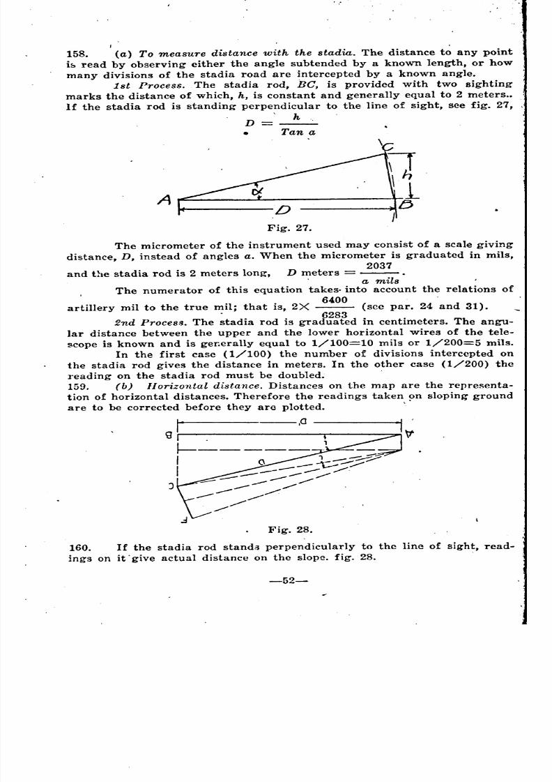
8/8/2019 Topography for Field Artillery
http://slidepdf.com/reader/full/topography-for-field-artillery 63/272
158. (a) To measure distance with the stadia. The distance to any point
i~ read by observing either the angle subtended by a known length, or how
many divisions of the stadia road are intercepted by a known angle.
1st Process .. The stadia rod, Be, is provided with two sighting
marks the distance of which, h, is constant and generally equal to 2 meters ..
If the stadia rod is standing perpendicular to the line of sight, see fig. 27, ,
hD---• Tan a
A
Fig. 27.
The micrometer of the instrument used may consist of a scale giving
distance, D, instead of angles a. When the micrometer is graduated in mils,
2037
and the stadia rod is 2 meters long, D meters .a mils
, The numerator of this equation takes. into account the relations of
. . 6400 (artillery mil to the true mIl; that IS, 2X see par. 24 and 31).
. 62832nd ProceS!l. The stadia rod is graduated in centimeters. The angu-
lar distance between the upper and the lower horizontal wires of the tele-
scope is known and is generally equal to 1/100=10 mils or 1/200=5 mils.
In the first case (1/100) the number of divisions intercepted on
the stadia rod gives the distance in meters. In the other case (1/200) thereading on the stadia rod must be doubled.
159. (b) Horizontal distance. Distances on the map are the representa-
tion of horizontal distances. Therefore the readings taken ~n sloping ground
are to be corrected before they arc plotted. \
J
__---_0 ,0
Fig. 28.
160. If the stadia rod stand'3 perpendicularly to the line of sight, read-ings on it give actual distance on the slope. fig. 28.
= ---
0
--- _
- _
0
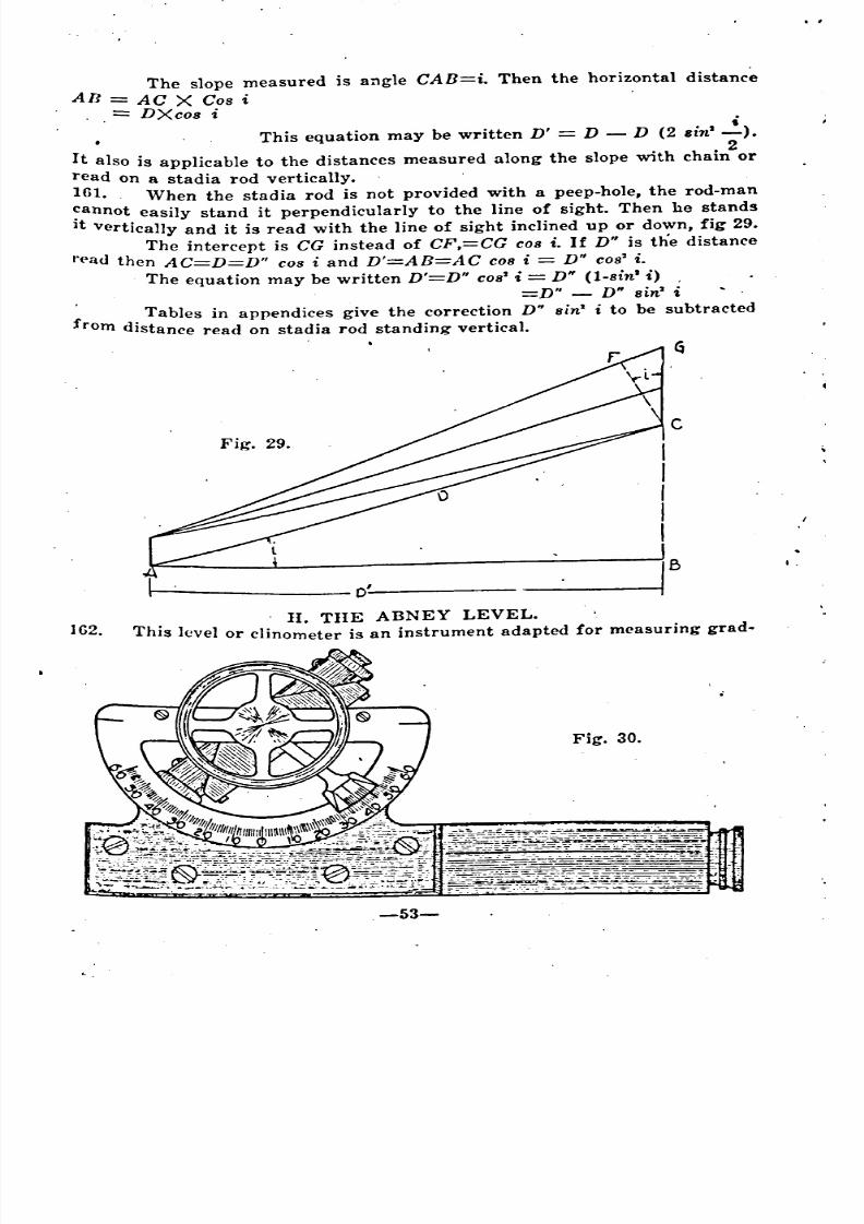
8/8/2019 Topography for Field Artillery
http://slidepdf.com/reader/full/topography-for-field-artillery 64/272
The slope measured is angle CAB=i. Then the horizontal distance
An AC X Cos i
.= DXcos ii
• This equation may be written D' = D D (2 Bin' -).
2It also is applicable to the distances measured along the slope with chain or
read on a stadia rod vertically.
161. When the stadia rod is not provided with a peep-hole, the rod-man
~annot easily stand it perpendicularly to the line of sight. Then he stand!
lt vertically and it is read with the line of sight inclined up or down, fig 29.
The intercept is CG instead of CF,=CG cos i. If D" is the distance
"<>authen A C=D=D" cos i and D'=A n=A C cos i = D" cos' i.
The equation may be written D'=D" cos' i = D" (l-sin'i) ,
=D" D" sin' i
f Tables in appendices give the correction D" sin' i to be subtracted
rom uistance read on stadia rod standing vertical.
---------0'------- -------'"
I.
IG2.
11. TilE ABNEY LEVEL.
This level or clinometer is an instrument adapted for measuring grad-
Fig. 30.
.-53-
= -
-
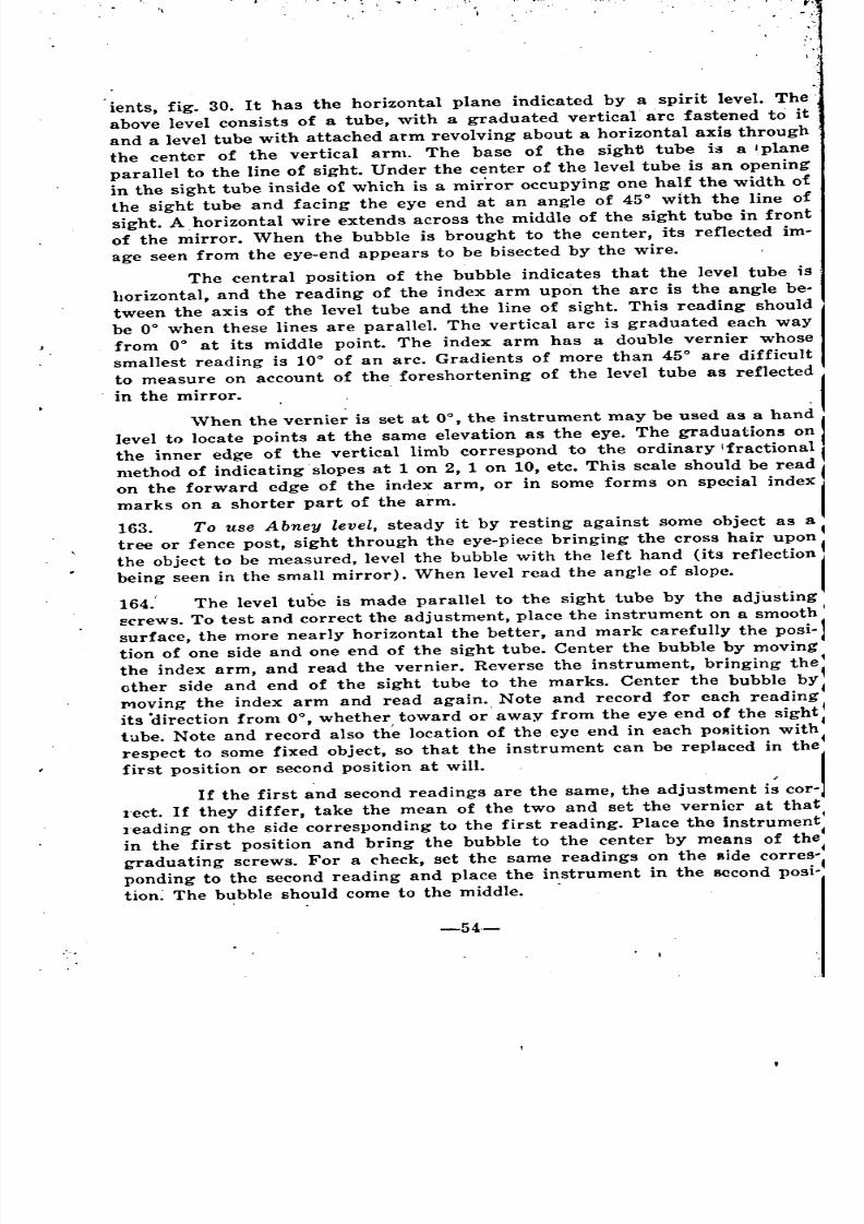
8/8/2019 Topography for Field Artillery
http://slidepdf.com/reader/full/topography-for-field-artillery 65/272
ients, fig. 30. It has the horizontal plane indicated by a spirit level. The
above level consists of a tube, with a graduated vertical. arc fastened to it
and a level tube with attached arm revolving about a horizontal axis through
the center of the vertical arm. The base of the sight tube is a 'plane
parallel to the line of sight. Under the center of the level tubeis an opening
in the sight tube inside of which is a mirror occupying one half the width of
the sight tube and facing the eye end at an angle of 45° wIth the line of
sight. A horizontal wire extends across the middle of the sight tube in front
of the mirror. When the bubble is brought to the center, its reflected im~
age seen from the eye-end appears to be bisected by the wire.
The central position of the bubble indicates that the level tube is
horizontal, and the reading of the index arm upon the arc is the angle be-
tween the axis of the level tube and the line of sight. This reading should
be 0° when these lines are parallel. The vertical arc is graduated each way
from 0° at its middle point. The index arm has a double vernier whose
smallest reading is 10° of an arc. Gradients of more than 45° are difficult
to measure on account of the foreshortening of the level tube as reflected
in the mirror.
'Vhen the vernier is set at 0°, the instrument may be used as a hand
level to locate points at the same elevation as the eye. The graduation~ on
the inner edge of the vertical limb correspond to the ordinary Ifractional
method of indicating slopes at 1 on 2, 1 on 10, etc. This scale should be read
on the forward edge of the index arm, or in some forms on special index
marks on a shorter part of the arm.
163. To use Abney level, steady it by resting against some object as a
tree or fence post, sight through the eye-piece bringing the cross hair upon
the o.bject to be measured, level the bubble with the left hand (its reflection
being seen in the small mirror). When level read the angle of slope.
164.' The level tube is made parallel to the sight tube by the adjusting
l:;crews. To test and correct the adjustment, place the instrument on a smooth
surface, the more nearly horizontal the better, and mark carefully the posi~
tion of one side and one end of the sight tube. Center the bubble by moving
the index arm, and read the vernier. Reverse the instrument, bringing thel
other side and end of the sight tube to the marks. Center the bubble by
J'YIovingthe index arm and read again. Note and record for each reading
its .direction from 0°, whether, toward or' away from the eye end of the sighttube. Note and record also the location of the eye end in each pORition with
respect to some fixed object, so that the instrument can. be replaced in the
first position or second position at will.,
If the first and second readings are the same, the adjustment is cor~
l'ect. If they differ, take the mean of the two and set the vernier at that
l'eading on the side corresponding to the first reading. Place the instrument~
in the first position and bring the bubble to the center by means of the
graduating screws. For a check, set the same readings on the side corres~ponding to the second reading and place the instrument in the second posi-
tion; The bubble should come to the middle. .
'
' '
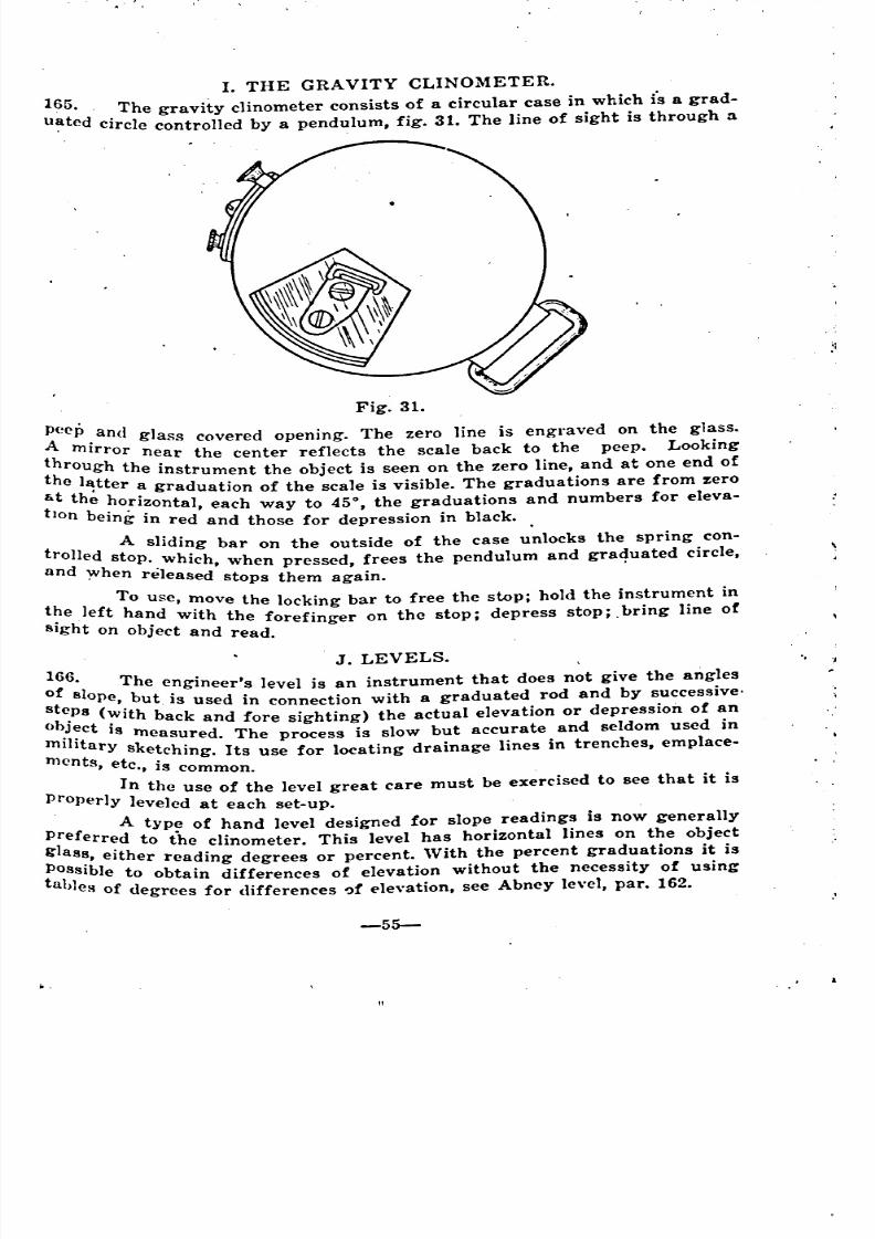
8/8/2019 Topography for Field Artillery
http://slidepdf.com/reader/full/topography-for-field-artillery 66/272
1. THE GRAVITY CLINOMETER.
165.. The gravity clinometer consists of a circular case in which fs a grad-
u~ted circle controlled by a pendulum, fig. 31. The line of sight is through :1
Fig. 31.
~~CP ,and glass covered opening. The zero line is engraved on the glass.
th mIrror near the center reflects the scale back to the peep. Looking
th rolugh the instrument the object is seen on the zero line, and at one end of
r.t eth~tter graduation of the scale is visible. The graduations are from zero
te horIzontal, each way to 45°, the graduations and numbers for eleva-
Ion b .. ,emg m red and those for depression in black.
t 11 A sliding bar on the outside of the case u~locks the spring con-
rOded stop. which, when pressed, frees the pendulum and graduated circle,
an when r 'I d', e ease stops them agam.
th I f To use, ~ove the locking bar to free the stop; hold the instrument in
, e
h
. e t ha~d wIth the forefinger on the stop; depress stoP;. bring line of
BIg t on obJect and read.
J. LEVELS.
1~6'1 The engineer's level is an instrument that does n~t give the angles
~t 8 ope, but is used in connection with a graduated rod and by successive'
}e.P8 (~ith back and fore sighting) the actual elevation or depression of an
o )Ject 18 .'I ' measured. The process is slow but accurate and seldom used In
mI Itary sk t h' I I' . t h Ic mg. ts use for locatmg dramage mes In renc es, emp ace-
mcnts, etc., is common.
. In the use of the level great care must be ex~rcised to see that it is
properly leveled at each set-up.
A type of hand level designed for slope readings is now generally
P~eferred to the clinometer. This level has horizontal lines on the object
go a8~, either reading degrees or percent. With the percent graduations it is
i~SsIble to obtain differences of elevation without the necessity of using
a >les of degrees for differences I)f elevation, see Abney level, par. 162.
-55-
\
~
'
"
"
"
8/8/2019 Topography for Field Artillery
http://slidepdf.com/reader/full/topography-for-field-artillery 67/272
, ,
. K. SLOPE BOARD.
167. The determination of gradients by the plummet line is quicker alldmpler, but less precise than with the clinometer, though exact enough :fO~<:rdinary purposes. If a line of sight be taken along the edge of a board alii
a line drawn perpendicular to' the sighting edge, this ~ine when the board ~'
Fig. 32.
held in a ver,tical plane, will make the f;ame angle with the plumb line th
the sighting edge makes with the horizontal; or in other words, will indicgl
the slope, fig. 32. ":JThe scale may be constructed by drawing an arc with the center
the intersection of the perpendicular and the sighting edge. 'From the pet
. pendicular layoff each way on the are, chords equal in length to 1/51
c.f the radius. It is convenient to take a radius of 5.73 inches or 5~
~cant, when the chords will be 1/10 of an inch, or to use a radius of 7 3/inches, when the chords will be 1/8 of an inch. :
, Short radial lines drawn at the ends of the chords form a graduati,
in degrees. The scale may be drawn on the lower edge of the board by pt
longing the radial lines. The plumb line is suspended so that when the Si
mg edge is horizontal it coincides with the zero line on the board.
!68. In use, the board is held so that the plumb line swings freely b
very close to the board. The sighting edge is directed to the object and wh
the line is steady the board is quickly. tilted so that the line draws acro;
the edge. The board is then turned in5:~orizontal position or nearly so, "
'
"
inCh
gl
l
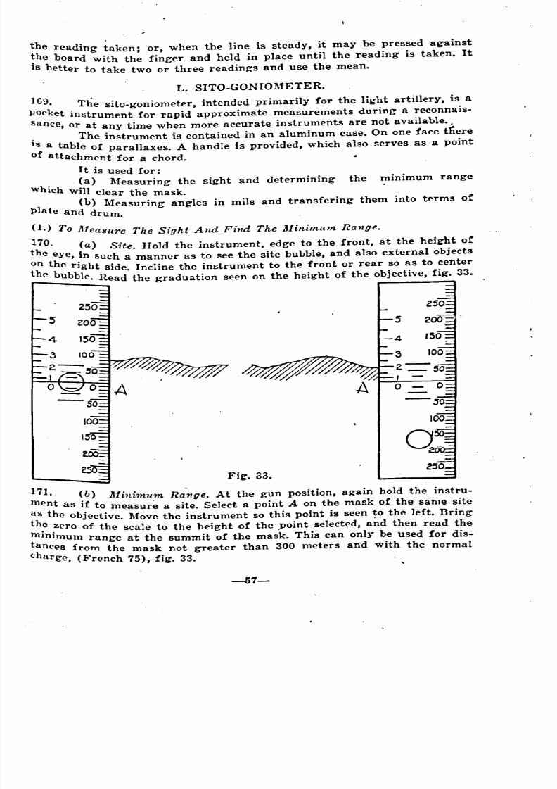
8/8/2019 Topography for Field Artillery
http://slidepdf.com/reader/full/topography-for-field-artillery 68/272
the reading taken; or, when the line is steady, it may be pressed against
~he board with the finger and held in place until the reading is taken. It
IS. better to take two or three readings and use the mean.
L. SITO-GONIOMETER.
169. The sito-goniometer, intended primarily for the light artillery, is a
pocket instrument for rapid approximate measurements during a reconnais-
sance, or at any time when more accurate instruments are not available ..
. The instrument is contained in an aluminum case. On one face tnere
1~ a table of parallaxes. A handle is provided, which also serves as a point
o attachment for a chord. •
It is used for:
(a) Measuring the sight and determining the minimum range
which will clear the mask.
1 (b) Measuring angles in mils and transfering them into terms of
p ate and drum. .
(1.) To Measure The Sight And Find The Minimum Range.
;~O. ~a) Site. Hold the instrument, edge to the front, at the height of
e eye, In such a manner as to see the site bubble, and also external objects
the right side. Incline the iristrument to the front or rear so as to center
e bubble. Read the graduation seen on the height of the objective, fig. 33.
171.. (b) Minimum Ra"-nge. At the gun position, again hold the instru-
ment as if to measure a site. Select a point A on the mask of the same site
:~ the objective. Move the instrument so this point is seen ~o the left. Bring
: .zero of the scale to the height of the point selected, and then read the
~Inlmum range at the summit of the mask. This can on!}. be used for dig-
~n('es from the mask not greater than 300 meters and with the normal
(. nrge, (French 75), fig. 33.
-57-
~~
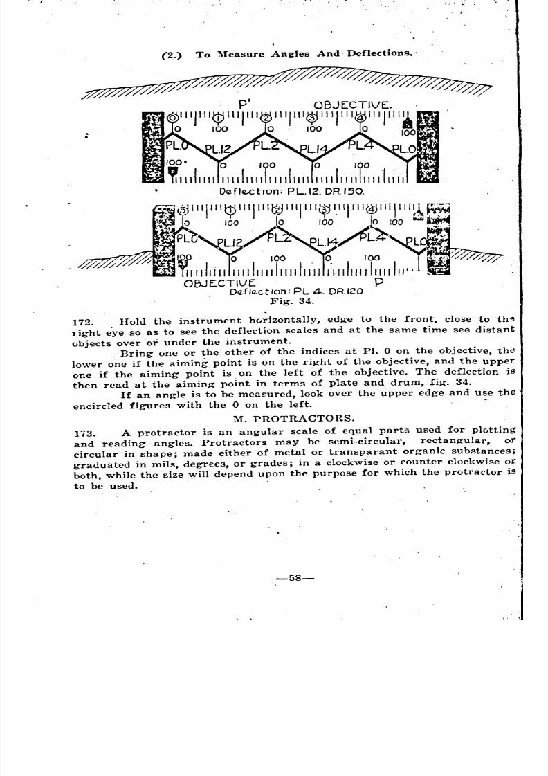
8/8/2019 Topography for Field Artillery
http://slidepdf.com/reader/full/topography-for-field-artillery 69/272
(2.) To Measure Angles And. Deflections ..
172. Hold the instrument horizontally, edge to the front, close to th:3
1ight eye so as to see the deflection scales and at the same time see distant
objects over or under the instrument.
Bring one or the other of the indices at PI. 0 on the objective, the
lower o~e if the aiming point is on the right of the objective, and the upperone if the aiming point is on the left of the objective. The deflection is
then read at the aiming point in terms of plate and drum, fig. 34.
If an angle is to be measured, look over the upper edge and use the
encircled figures with the 0 on the left.
M. PROTRACTORS.
173. A protractor is an angular scale of equal parts used for plotting
and reading angles. Protractors may be semi-circular, rectangular, or
circular in shape; made either of metal or transparant organic substances;graduated in mils, degrees, or grades; in a clockwi.se or counter clockwise or
both, while the size will depend upon the purpose for which the protractor is
to be used. .
8/8/2019 Topography for Field Artillery
http://slidepdf.com/reader/full/topography-for-field-artillery 70/272
175.
CHAPTER VII.ORIENTATION.
DEFINITIONS.
174. A plane table or map is said to be oriented whe~ all the directions
~:l the map correspond to the respective directions on the ground; i. e., when
.rUe north on the map points to true north, etc. It is evident, therefore, that
: plane table is oriented when all the lines on the board are parallel to the
re~pe.ctive lines on the ground and points 'on each line are in the same
e atlve positions as on the ground.('0 A plane table is said to be declinatcd when the declination of the
brtnpass needle is known and recorded, so that when the compass needle is
OUght opposite its index, the table becomes oriented.
o . An instrument is said to be oriented when the zero is on true north
r the Y-north depending on which is used as an origin.
( An instrument is said to be declinated when the declination of the
iOtnpass needle is known and recorded, so that when the declination constant
b'i se~ off and the needle is brought opposite its index, the instrument will
e onented.
METHODS OF ORIENTATION.
There are two general methods of orientation; viz.
First. By ,means of a'declinated instrument, or plane table, and,
not b Second. By means of a line of known direction, which mayor may
e established in advance.
A. BY A DECLINATED TABLE.
t (1.) With Declinator Unattached.
P76. ,Draw a line on the board making an angle with true north in the
o~ofe.r d~rection equal to the declination of the compass. Place the declinator
phis hne and rotate the board so that the compass needle coincides or is
tl~rallel to this line. Lock the board and verify by repeating the same opera.
On.
1 (2.) 'Vith Declinator Attached.
t 77. 'Place the map or gridded sheet upon the plane table so that the
prue north line makes an angle with the zero line of the declinator which is
()qual to the compass declination. Rotate the board until the compass needle is
Pposite its index. Lock the board. Verify by repeating.
i Note: For a discussion of the process of orienting with a declinated
n,strument, see Chapter XX.
( B. BY A KNOWN LINE.1.) When The Plane Table h On A Station Over One Of The I\:nown
178 Points Of a Given Line.r' Let the capital letters designate the points on the ground that are
ePresented respectively by the same small letters on the map or plane table ..Assume A to be the point on the ground at which the plane table is.
'
'
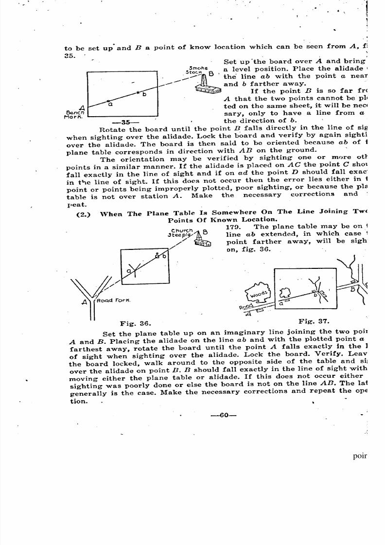
8/8/2019 Topography for Field Artillery
http://slidepdf.com/reader/full/topography-for-field-artillery 71/272
.. . .
ABenchMarK.
to be set up' and B a point of know location which can be seen from A, fi
35. .. , '
Set up 'the board over A and bring's~::c.~f\e a level position. Place the alidade
. .. the' line ab with the point a near'
.-'-- ':.",-, and b farther away.
. If the point B is so far fro
A that the two points cannot bepl<
ted on the same sheet, it will be
sary, only to have a line from a
-35- the direction of b.
Rotate the board until the point B falls directly in the line of sig
when sighting over the alidade. Lock the board and verify by again sightil
over the alidade. The board is then said to be oriented because ab of
plane table corresponds in direction with An on the ground.
The orientation may be verified by sighting one or more ot
points in a similar manner. If the alidade is placed onAC the point C sho
fall exactly in the line of sight and if on ad the point D should fall
in t"le line of sight. If this does not occur then the error lies either in
point or points being improperly plotted, poor sighting, or because the pI
table is not over station A. Make the necessary corrections and
I,eat.
(2.) When The Plane Table Is Somewhere On The Line Joining Tw
Points Of Known Location.
179. The plane table may be on
line ab extended, in which caset
point farther away, will be
on, fig. 36.
Fig. 36. Fig. 37.
Set the plane table up on an imaginary line joining the two
A and B. Placing the alidade on the line ab and with the plotted point a
farthest away, rotate the board until the point A falls exactly in the
of sight when sighting over the alidade. Lock the board. Verify. Leavl
the board locked, walk around to the opposite side of the table and si
over the alidade on point B. B should fall exactly in the line of sight withl
moving either the plane table or alidade. If this does not occur either
sighting was poorly done or else the board is not on the line An. The lat
generally is the case. Make the necessary corrections and repeat the op
tion.
\
' __-~ '
.
nec
exac
sigh
poir
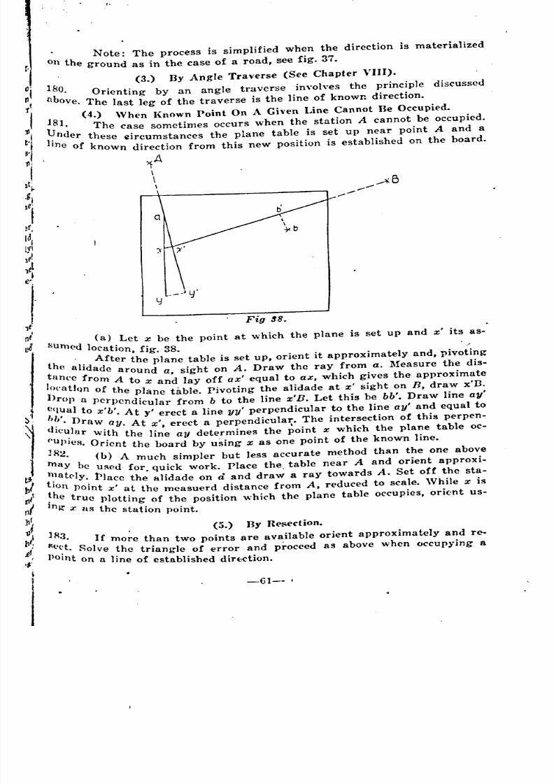
8/8/2019 Topography for Field Artillery
http://slidepdf.com/reader/full/topography-for-field-artillery 72/272
. Note: The process is simplified when the direction is materialized
on the ground as in the case of a road, see fig. 37.
(3.) By Angle Traverse (See Chapter VIII).
180. Orienting by an angle traverse involves the principle discussed
llbove. The last leg of the traverse is the line of known direction.
J8 (4.) When Known point On A Given Line Cannot Be Occupied.
U 1. The case sometimes occurs when the station A cannot be occupied.
I' nder these 4lircumstances the plane table is set up near point A and a
Ine of known direction from this new position is established on the board.
~A\
\\
Fig :l8.
su (a) Let x be the point at which the plane is set up and x' its as-
med location, fig. 38. .'
th, '1' After the plane table is set up, orient it approximately and, pivoting
t
ea rldade around a, sight on A. Draw the ray from a. Measure the dis-
an('e ro A0' tf m to x and lay off ax' equal to ax, which gives the approximate
n(a 1m of the plane table. pivoting the alidade at x' sight on fl, draw x'D.
e fO})1 a perpendicular from b to the line x'B. Let this be bb'. Draw line ay'
qua to x'b' At ., d' 1 h 1" 1,1' D . y erect a lme yy perpen ICU ar to t e me ay and equa to
d
,), 1 raw ay. At x', erect a perpendicular. The intersection of this perpen-
leu ar 'th' WI the line ay determines the point x which the plane table oc-
U}>Jcs. Orient the board by using x as one point of the known line.
lR2' (b) A much simpler but less accurate method than the one above
n ay be used for. quick work. Place the table near A and orient approxi-t,lately. Place the alidade on d and dra~ a ray towards A. Set off the sta-
t~n point x' at the measuerd distance from A, reduced to scale. While x is
i e true plotting of the position which the plane table occupies, orie:nt us-
nR' x as the station point.
lR (5.) By Resection •
., 3. If more than two points are available orient approximately and re-
Oc(,t S 1 h . ..' • 0 ve t e tTlangle of error and proceed as above when OCcup),jng a
lOlnt on a line of established dirE:Ction.
-61--
' ' '
'
8/8/2019 Topography for Field Artillery
http://slidepdf.com/reader/full/topography-for-field-artillery 73/272
~; • 'W" i""
,
CHAPTER VIII.
TRAVERSES.
DEFINITIONS •
. . -.184. ,A Traverse is the process of determining a route for, representation
(,n a map or sketch by actually proceeding over it, making the necessarymeasurements on the 'ground.
A. KINDS OF TRAVERSE.
Tra~erses are of two kinds, open and closed. A closed tra~erse' is one
which returns on the starting point or ends by passing through a known
point. An open or unclosed traverse fulfils neither of these requirements.
For the sake of 'an accurate check, a closed traverse should always be made
in any topographical work i~volving traverses, see fig. 39. I
UNCLOSE:D TRAVf.f1~f: .
A~
. c I
d
" XUnkown POint.
.A
CLO~E:D TRAVER-,E,s.,
b
Fig. 39.
. , I
B. INSTRUMENTS USED. I
185. Instruments 'U8ed in 'T-raversing ~re either a declinated instr~ment
or plane table. The declinated 'instrument may be used either in a needle
or angle traver8e described below, or in an ordinary survey., The plane
table is the usual method of recording traverses on a, map or sketch,
in which event a working scale is used to layoff on the table the distances
measured on the, ground. ,
C. METHODS OF TRAVERSE.
(1.) The Foresight.Back~ight Method.'
186. Methods 01 Traversing include the foresight-backsight meth'od,
needle traverse and 'angle traver8e. The foresight-backsight method is des~"
cribed as follows: Set up plane table at A,' the starting point. Cla'mp th~,
board and plot A on the sheef. Call the plotted point a. Pivot the alidadeat a until the ~cond station, n, is, sighted. Draw a ~ight r~~ ~he fU~1length
"
, , /
t
.
l
8/8/2019 Topography for Field Artillery
http://slidepdf.com/reader/full/topography-for-field-artillery 74/272
of the alidade, fig. 40.' Pick up the plane table and pace the distance be-
tween A and B in the dIrection of the ray already drawn. Arrived at B
layoff, on the ray already drawn, the distance ab corresponding to the
distance AB. Orient the board by laying the alidade on the ray ab and turn-
ing the board until A is sighted over the alidade, fig. 41. Clamp the board.
'
-----KC
Fig. 41.
"11TABL[.oN. B
II
f-AFig. 40.
for:esighton 8
rB
/ I'TABLLOVERAI
mTABLrOv[R.C
Pivot the alidade about b until the 3rd station C is sighted over the alidade.
Draw a light ray be, etc., proceeding by this method until the entire traverse
is completed, see figure 42.
(2) Needle Traverse.
187. ..1, Needle Traverse may be made in
order to save time over the fore sight-back
sight method. Alternate stations may be BY.-._
occupied and sights taken with a dec1inated
instrument, to stations not occupied. A
rodman may be used at the unoccupied
stations (in case these stations have no
sharply defined point to which sights may
be taken. First read the bearing from the
,first occupied station to the unoccupied
station; measure the distance; thence pro- \
,ceed to the second occupied station, mea- \
suring that distance. Plot the position of \
the unoccupied station from the direct~on Fig. 42. ,~ D
and distance first measured. Set up at the second station and read the
hearing to the unoccupied station. Draw a ray through the unoccupied sta-
tion with the bearing last read, plus or minus 3200ljl (back azimuth), and
on this ray plot the second occupied station at the measured distance.
(3.) Angle Traverse.
188.' A ngle Traverses sometimes are of value when it is desired merely
to orient at another point and the matter of distance is not important. In
such a case the orientation of the first known point is merely carried for-
Ward to the other known point.To do this, set up the table or instrument at the first point, A, and
-63-
, -
, ')
;
.' '
.
'"
--
'
-
,

8/8/2019 Topography for Field Artillery
http://slidepdf.com/reader/full/topography-for-field-artillery 75/272
tJrient. Take a shot at a second point, B, and draw the direction ab, on the
table, as in the case of any other traverse, fig. 40.
Proceed to the second station, B, and set up the bo~rd. Do not pause
to measure the distance. At B orient by a back sight on the line just drawn.
~ight on a third station, C, and draw line in this direction across the lineab. Proceed to C and repeat the operation.
Continue until the desired point is reached. The point will be reach-
ed with an oriented board which is what is desired.
In this operation, as in other traverses, the number of legs must be
lImited, otherwise the ~umulative error will be so great that the orientationrnnnot be accepted.
D. MEASUREMENTS.
180. Traverse. Distances p~ssed over may be determined by the stride of
man or horse, by the time taken by a rated horse, by the revolutions of ?'wheel, by chain or tape, and by stadia. Distances not' passed over may be
determined by estimation, by stadia, or by intersection.
(1.) Pacing.
190. Accurate measurWlent by pacing depends on the skill of the operator
In maintaining a uniforr •• length of pace, or of stride (a stride equals two
paces), on the care taken in determining the length of his pace, and theaccuracy with which the working scale is made and used.
Good pacing should not be in error by more than 3% on distances
up to 600 yards. On long traverses it is better to use an~ther method in order
to avoid a large error. It will be noticed that strides always are shorter
on sloping ground both going up and down grade than on horizontal grou~d.
This is due to the fact that the effort of moving upward shortens th: strIde
While in moving downward the operator checks himself, thus shortenmg the
stride. The length of the stride, moreover, is not the same when moving up
a given slope as when moving downward on the same slope.
The following table applies for an op-er~tor taking 100 paces up or
down slopes of 5 degrees and greater. The table indicates the number of
paces to layoff with the working scale for any given slope. On slopes less
than 5 degrees, and for distances on such slopes not greater than 200 yards,
J:O calculation is necessary and ground distances may be taken as the base.
In most instances errors resulting from this procedure are 'compensating.
5°
-~'P- ' I~~~.~
-----\,._-100 ;
PACES,9(J.4'\ 95.6
10° I 15° 20°-----l'~ ,I DOW:-.l 1. ~p I~ _P :D?~_~
78.7 91.5 i 69.3 87.4 58.81 80.8
25° 30°,-- _.
LP 'DOWN UP DOWN
4-9~~1-;~;-35.8 51.4 ,
TABLE OF PACES.
The above takes in;o c~nsideration both the slope of the ground and
the difference in the length of pace due to the slope. See Appendix 1. When
pacing count the number of paces between stations ,apply the working scale,
nnd layoff the proper length of the traverse on the map.
--- ---- ------- " ,.,
1 J
8/8/2019 Topography for Field Artillery
http://slidepdf.com/reader/full/topography-for-field-artillery 76/272
(2.) Chaining Or Taping.
:191. Having set up at a given station and .having oriented the board or
plane table, take a sight to the next station and draw a ray along the alidade
"'hile thus sighted. Send out chain or tape men who will measure the dis-
tance between stations. Keep these man lined in:by sighting over the alidade.
Apply the Representative Fraction of the map in question and layoff the
proper length of the leg of the traverse on the map. For very accurate work
the expansion or contraction of the steel chain or tape, tue' to the temparat-
ure, and its sag, are calculated and the measurement thus corrected.
~3.) Stadia Readings •.
192. This is a rapid method of obtaining measurement of distances es-
pecially over rough terrain where the pace, chain, or tape methods are likelyto cause large errors. The apparatus consists' of a transit or telescopic
alidade and a stadia rod operated by an assistant, see Ch. VI.
E. SPECIAL CASE.
193. When l'-"irstStation Cannot Be Occupied. (See fi'g. 43).
Fig. 43
Set up and level the plane table at B, a point not necessarily known,
but from which the point C is visible. Orient with a compass and plot the
Point a, the point (represented on the ground by A) which cannot be oc-Cupied. Sight on A. Through a draw ray am. Pivot the alidade on a and sight
the point C. Draw this ray ao. Pace or otherwise measure the distance B-C.
This distance, laid off to scale on the ray ao, gives point o. Move to C. set
up, level and orient the table with compass as before. Through a draw an
tOward C. From 0 draw. a line parallel to am. This intersects an at the de-
sired point c, the station last occupied, thereby giving the map distance ac
Which was what was desired.
I'
-65-
"
-

8/8/2019 Topography for Field Artillery
http://slidepdf.com/reader/full/topography-for-field-artillery 77/272
F. ERRORS IN TRAVERSING.
194. ~'he rermissible error in traversing is 5% of the entire Je~lgtit of the
traverse. This limit applies only to the ordinary traverse. No such amount
. of error is permitted in surveys. In making a closed traverse there probablywill be an error of closure. Fi.~re 44 indicates the method of correcting
this error for a closed traverse which returns on the starting point. The
procedure is the ~ame for a traverse closing on any known point.
o
l-I
// ....
/
/
/I
/........//
I"..../!'-.....
/
/1. .. . . .. ..
B/.........
A__//
/
8~---\\
7/-//
6~--\
\
5\-:.-
(ORR(CTING [RROR Or CLO,5VR[
ORIGINAL'TRAvERSE.CORRECTED' TRAV[RSE.
Fig.,44.
roint A' should be at A, but due to errors in traversing does not so P~i)t
On a straight line O-A laYoff from 0 in succession, the lengths of the
(;ourses A.1, 1-2, 2-3, etc. From the end of this line lay off, perpen~icular
to A-O, the line A-B equal to the error in closure, A-A'. Connect Band O.
Now from each Succeeding station on the line O-A, draw a line parallel tothe line A-B.
Referring to the traverse, draw through each plotted station, a line
parallel to the final closure lin(' A'.A. On each such line layoff its respec-
tive offset length, as determined ahove, giving new positions for each st~t.ion.
Connect these new stations and the traverse is adjusted .. Erase the or~gmaltraverse from the sheet.
~
-
-----
8/8/2019 Topography for Field Artillery
http://slidepdf.com/reader/full/topography-for-field-artillery 78/272
CHAPTER IX.
INTERSECTION.
DEFINITION.
195. Intersection is tha.t topographical operation by which a point on the
ground is located on the map by the intersection of rays, from two or more
l\n~'Yn points drawn in the direction of the unknown point.
A. PURPOSE.
196. Intersection is used to determine a point without occupying it, and
often is the only method which can thus be employed. It may be used to
lOcate a point behind the enemy's lines, a tree on the opposite side of a
~tream, a mountain peak in the distance, etc.
The method may also. be used to check up the accuracy in angles
and distances of a traverse, in the following manner: Before starting,
select an object on the ground that can be seen from at least three places
along the route to be followed, preferably at the "set-up" stations. While
making the traverse, after orienting the board, draw rays toward the select-
ed Point from known positions. The three or more rays should intersect at
One Point, if th~ work is correct.
B. ACCURACY.
l~7. Accuracy may be expected when the angles between at least two
of the rays is not less than 500 mils; nor more than 2700 mils, as the bad
x~/ "-/ "-
// "-/ \
/ "-//
/.//
//
//
\
\
"\\
Fig. 45.
~ffect of erratic sighting becomes smaller and smaller as the angles at the
Intersection of the rays approach right angles.
-67-
: I,
~
-
'
8/8/2019 Topography for Field Artillery
http://slidepdf.com/reader/full/topography-for-field-artillery 79/272
".c. THE OPERATION •.
To Locate A Point By Intersection.
198. A and B are two known points, accurately located on the map (or .
grid). It is desired to locate a third point, C, a church steeple, which can
he seen from both A and B. Process: Occupy A, and orient board accurately.
With a on the map (or grid) as a pivot sight on C on the ground, and.
through a draw a rayon the map toward C on the ground. Occupy B, orient
:-oard, a~d with b on the map as a pivot, perform the sa~e operation. The
mtersectIon c of the two rays will be the location of the pomt C on the map ..
If there is a third point' of known location on the' map, the location' of c
can be checked by repeating the operation at D on the ground. The three
lays should meet at one point. If they form a triangle, an error has been
made in sighting, orienting the board, or in plotting the location of A, B,or D.
8/8/2019 Topography for Field Artillery
http://slidepdf.com/reader/full/topography-for-field-artillery 80/272
CHAPTER X.
RESECTION.
DEFINITION.
199. Resection is that topographical process (the reverse of intersection)
by which a point of the map, corresponding to the sketcher's position on the
ground, is located by the intersection of rays drawn from points on the
ground through corresponding points on the map, after the map has beenoriented. .
CONDITIONS WHICH MUST BE FULFILLED IF ACCURATE RESULTS
ARE TO BE EXPECTED.
200. 1. , Known points must be plotted accurately.
2. Points chosen must be so located that the angles of intersection
of any of the rays drawn from them must be more than 500~t and less tban
27001;lt: also so that the points selected and the point sought should not
lie on the circumference of the same circle. .
3. The plane table must be level.
4. All rays should' be drawn on the same side of the alidade.
5. Lines should be fine and drawn with a hard pencil.6. Sighting should be accurate. After a ray is drawn it should be
checked by resighting. , . .
7.. Allowable error. The. error in the location of the point sought
mUst not exceed one millimeter of the true position no matter what scale
of map is used. Thus, on a 1 to 20,000 map this error would not be greater
than '20 meters, on a 1 to 10,000, this error would not be greater than 10
meters, and on a 1 to 5,000 map, this error would not be greater than 5meters. .
:METHODS OF RESECTION.
A. TRANSPARENT PAPER METHOD.
201. The operator is at point P which he wishes to determine on the map
~r grid. Points a, b, and c, exactly located on the map or grid, are visible
rom this position. The plane table is set up and leveled. A piece of trans-
pa,rent paper is fastened to the board which is locked fast without being
oriented. A needle is struck in the center of the sheet. This represents p.
t With the needle as a pivot, A, B, and C on the ground are sighted in
urn, rays .being drawn toward each. The rays are labeled. The transpar-~~t. sheet is then taken from the board and placed over the map or the grid.
th IS next moved about until the rays drawn toward A passes through a on
T~ map, while that to B passes through b, and that to C passes through c.
th e hole in the paper made by the needle, now is over the point p which is
th~ map representatio? of the point P on the ground. By pricking through
IS hole the point is recorded on the map.
-G9-
. ,
',
'
,
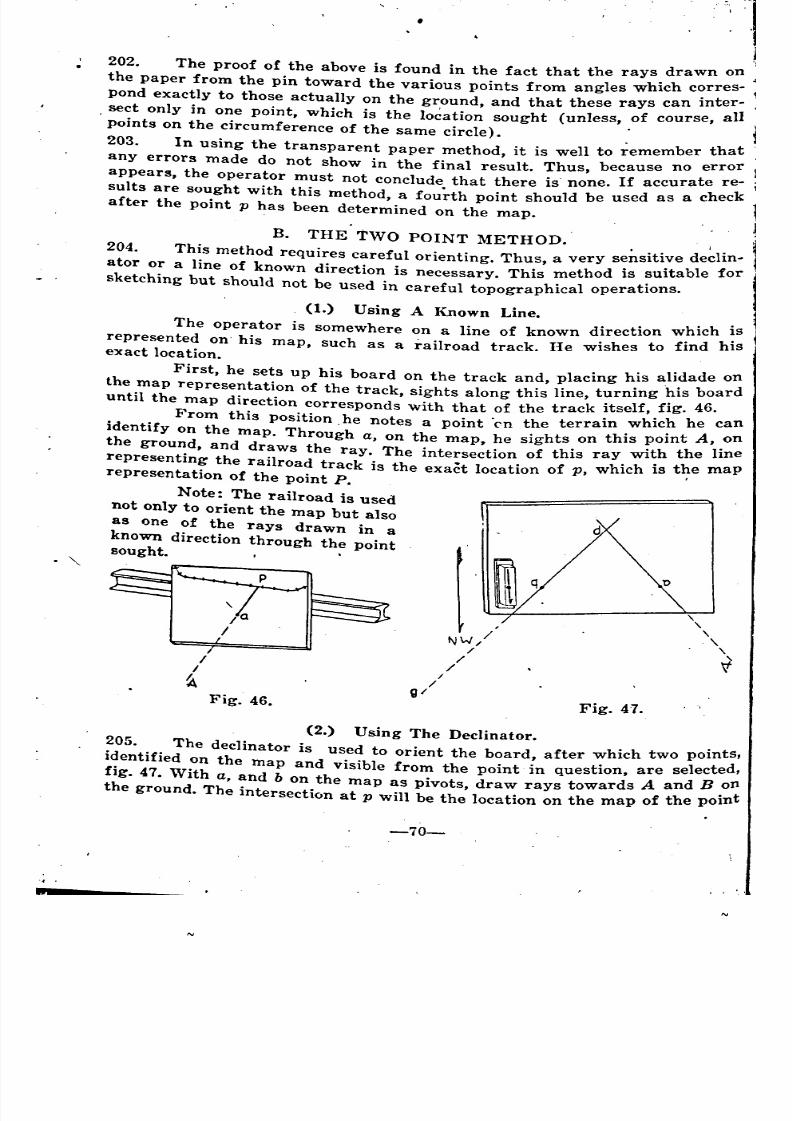
8/8/2019 Topography for Field Artillery
http://slidepdf.com/reader/full/topography-for-field-artillery 81/272
'202. The proof of the above is found in the fact that the rays drawn on -
the paper from the pin toward the various points from angles which c~rres-
pond exactly to those actually on the ground, and that these rays can mter-
. sect only in one point, which is the location sought (unless, of course, all J.
points on the circumference of the same circle). .
203. In using the transparent paper method, it is well to ~emember that
any errors made do not show in the final result. Thus, because no error
appears, the operator must not conclude that there is' none. If accurate re-
sults are sought with this method, a fou~th point should be used as a check
after the point p has been determined on the map.
B. THE TWO POINT METHOD.
204. This method requires careful orienting. Thus, a very se~sitive declin-
ator or a line of known direction is necessary. This method is suitable for
sketching but should not be used in careful topographical operations.
\
\
\
\\
Fig. 47.Fig. 46.
I/
(1.) Using A Known Line.
The operator is somewhere on a line of known direction which is
represented on his map, such as a railroad track. He wishes to find hisexact location.
First, he sets up his board on the track and, placing his alidade on
the map representation of the track, sights along this line, turning ~is boarduntil the map direction corresponds with that of the track itself, fIg. 46.
From this position. he notes a point 'en the terrain which he can
identify on the map. Through a, on the map, he sights on this point A, .on
the ground, and draws the ray. The intersection of this ray with the lme
representing the railroad track is the exact location of p, which is t~e maprepresentation of the point P.
Note: The railroad is used
not only to orient the map but also
as one of the rays drawn in aknown direction through the pointsought. I •
~.
. "
(2.) Using The Declinator.
205. The declinator is used to orient the board after which two points,
identified on the map and visible from the point in question, are selected,
fig. 47. With a, andbon the map as pivots, draw rays towards
Aand
B.on
the ground. The intersection at p will be the location on the map of the pomt
i
~ ~
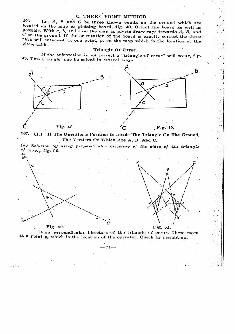
8/8/2019 Topography for Field Artillery
http://slidepdf.com/reader/full/topography-for-field-artillery 82/272
C. THREE POINT METHOD.
206. Let A, Band C be three known points on the ground which are
located on the map or plotting board, fig. 48. Orient the board as well as
Possible. With a, b, and c on the map as pivots draw rays towards A, B, and
C on the ground. If the orientation of the board is exactly correct the three.
rayS will intersect at one point, p, on the map which is the location of theplane table.
Triangle Of Error •
. If the orientation is not c.orrect a Htriangle 'of error" will occur, fig.
49. This triangle'may be solved in several ways. .
,'.,
.' .
I
I
II .
C Fig. 48
.B
----
. I,I/
I
Ie • Fig. 49.
. :
c
I
I
../
.1
.
207. (t.) If The Operator's Position Is Inside The Triangle On The Ground,
The Vertices Of \Vhich Are A, B, And C.
(a) Solution by using perpendicular bisectors of the sides of the triangle
of error, fig. 50.~.\
\.0
/II
y /
'~¥~~~Z~/ \ \.\
lj '
./Fig. 50.. Fig. 5L
Draw perpendicular bisectors of the triangle of error. These meet
at a point p, which is the location of the operator. Check by resighting.
-71-
\ .
I
~'
{
~
~
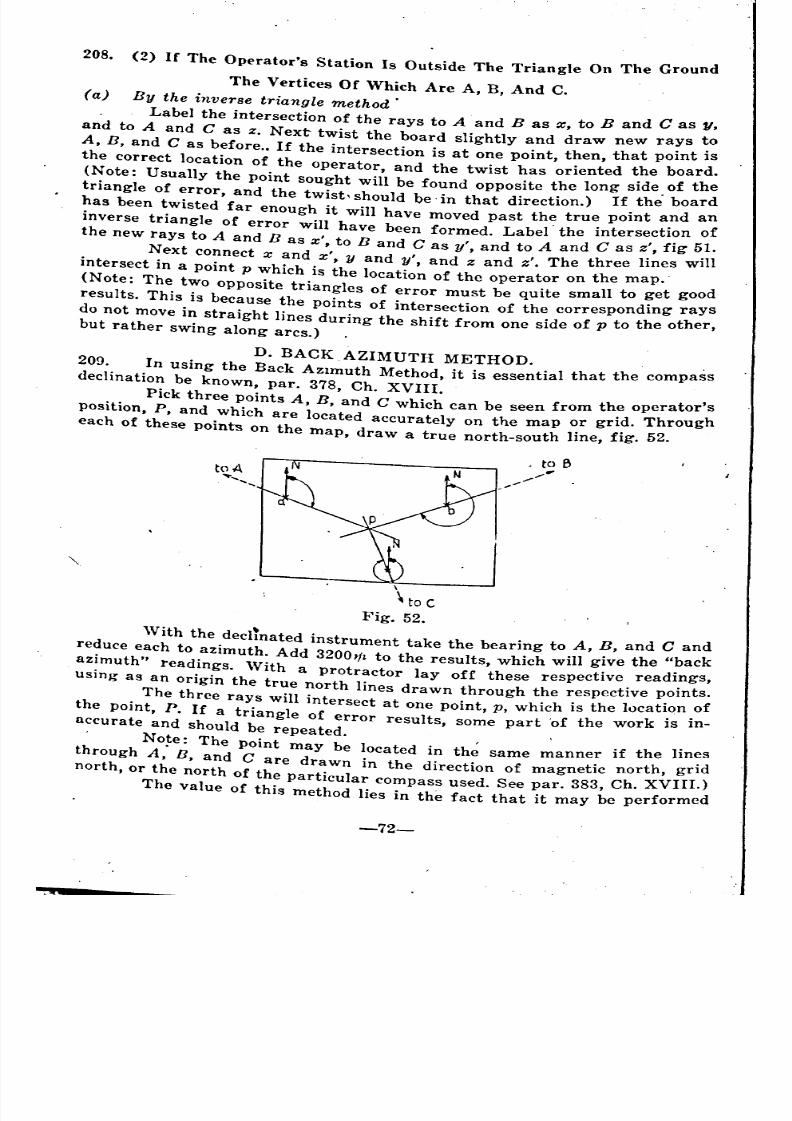
8/8/2019 Topography for Field Artillery
http://slidepdf.com/reader/full/topography-for-field-artillery 83/272
208. (2) If The Operator's Station Is Outside The Triangle On The Ground
The Vertices Of 'Vhich Are A, B, And C.
(a) By the inverse triangle method'
. Label the intersection of the rays to A and B as x, to Band C as 1/,
and to A and C as z. Next twist the board slightly and draw new rays to
A, B, and C as before .. If the intersection is at one point, then, that point is
the correct location of the operator, and the twist has oriented the board.
(Note: Usually the point sought will be found opposite the long side. of the
triangle of error, and the twist'should be' in that direction.) If the board
has been twisted far enough it will have moved past the true point and an
inverse triangle of error will have been formed. Label'the intersection of
the new rays to A and B as x', to nand Cas y', and to A and C as z', fig 5.1.
Next connect x and x', y and y', and z and z'. The three lines wIllintersect in a point p which' is the location of the operator on the map.'
(Note: The two opposite triangles of error must be quite small to get good
results. This is because the points of intersection of the corresponding rays
do not move in straight lines during the shift from one side of p to the other,bu t ra ther swing along arcs.)
D. BACK AZIMUTH METHOD. ,
209. In using the Back AZl~uth Method, it is essential that the compassdeclination be known, par. 378, Ch. XVIII.
Pick three points A, n, and C which can be seen from the operator's
position, P, and which are located accurately on the map or grid. Through
each of these points on the map, draw a true north-south line, fig. 52.
toA.....
.........
\
\ to C
Fig. 52.
With the decl!nated instrument take the bearing to A, n, and C and
reduce each to azimuth. Add 32001f~ to the results, which will give the "backazimuth" readings. With a protractor laYoff these respective readings,
using as an origin the true north lines drawn through the respective points .
. The three rays will intersect at one point, p, which is the lucatiqn .of
the pomt, P. If a triangle of error results, some part 'of the work is In-
accurate and should be repeated. ,
. No~e: The Point may be located in th~ same manner if the lines
through A, B, and C are drawn in the direction of magnetic north, grid
north, or the north of the particular compass used. See par. 383, Ch. XVIII.)
The value of this method lies in the fact that it may be performed
'
~
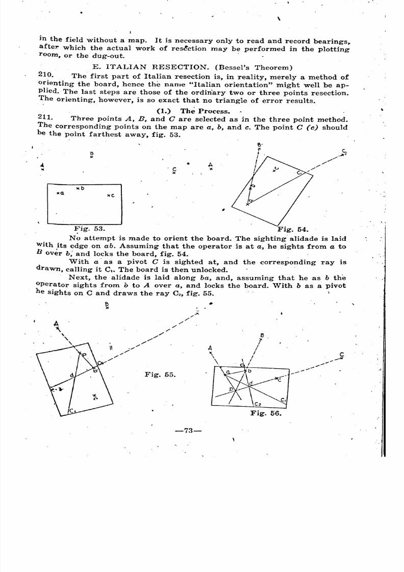
8/8/2019 Topography for Field Artillery
http://slidepdf.com/reader/full/topography-for-field-artillery 84/272
\
I
in the field without a map. It is necessary only to read and record bearings,.
after. which the actual work of res~ction may be performed in the plotting
room, or the dug-out. .
'C)(
xC
l:l)(
)Co.
E. ITALIAN RESECTION. (Bessel's Theorem)
210. The first part of Italian resection is, in reality, merely a method of
orienting the board, hence the name "Italian orientation" might well be ap-
plied. The last steps are those of the ordin'ary two or three points resection.
The orienting, however, is so exact that no triangle of error results.
(1.) The Process.
211. Three points A, B, and C are selected as in the three point method.
The corresponding points on the map are a, b, and c. The point C (c) should
be the point farthest away, fig. 53.
e.?'-,I
II
!
Fig. 53. Fig. 54.
No attempt is made to orient the board. The sighting alidade is laid
with its edge on ab. Assuming that the operator is at a, he sights from a to
B over b; and locks the board, fig. 54. . .
With a' as a pivot C is sighted at, and the corresponding ray is
drawn, calling it CloThe board is then unlocked.
N ext, the alidade is laid along ba, and, assuming that he as b the
operator sights from b to A over a, and locks the board. With b as a pivot
he sights on C and draws the ray C2, fig. 55. \
e)C
A'\,\\
Fig. 55.
Fig. 56.
-73-
,
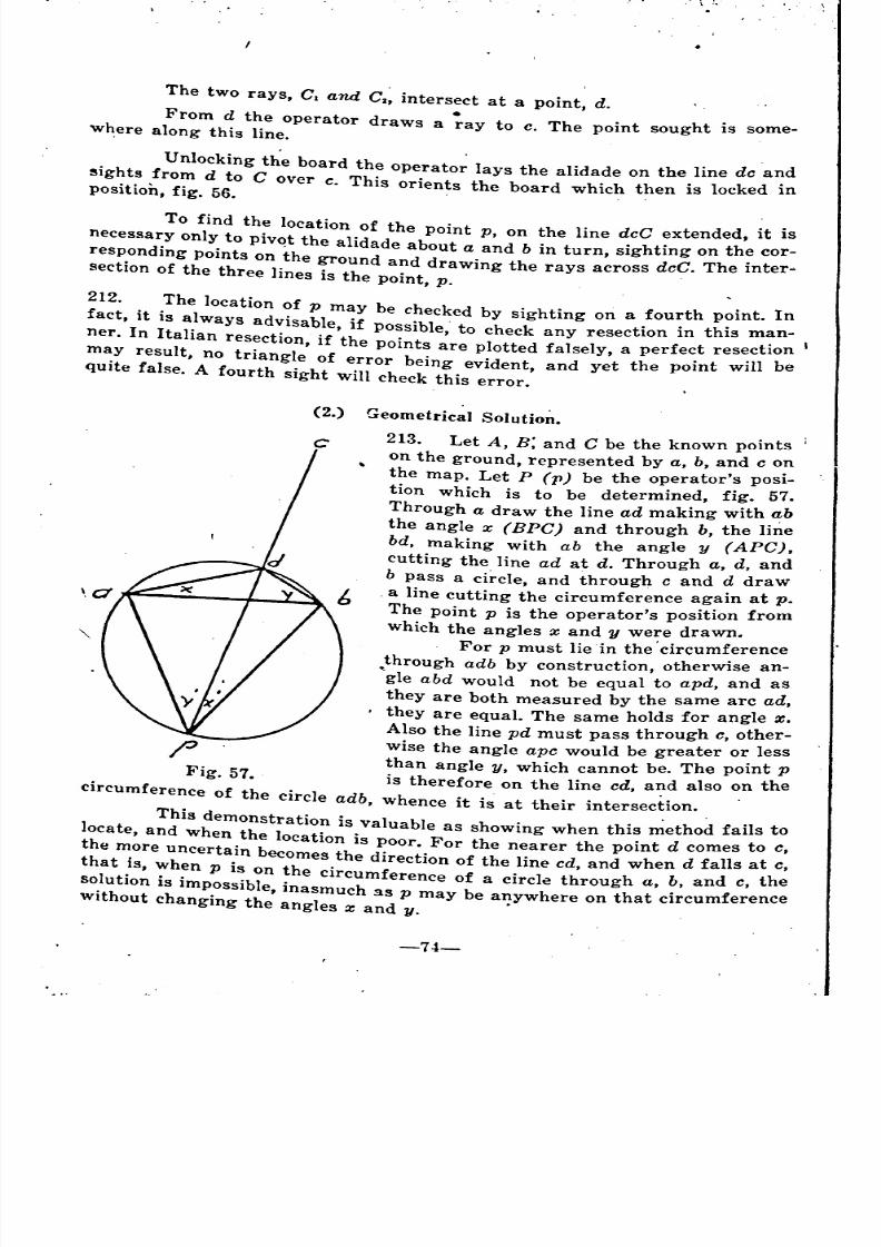
8/8/2019 Topography for Field Artillery
http://slidepdf.com/reader/full/topography-for-field-artillery 85/272
The two rays, C1 and C2~ intersect at a point, d.
From d the operator draws a ;ay to c. The point sought is some-w~ere along this line.
Unlocking the board the operato~ lays the alidade on the line de and
~ights from d to Cover c. This orients the board which then is locked inposition, fig. 56.
To find the location of the point p, on the line dcC extended, it is
necessary only to piv~t the alidade about a and b in turn, sighting on the cor-
responding points on the ground and draWing the rays across deC. The inter-section of the three lines is the point, p.
212. The location of p may be checked by sighting on a fourth point. In
fact, it is always advisable, if possible' to check any resection in this man-
ner. In Italian resection, if the points ~re plotted falsely, a perfect resection I
may result, no triangle of error being evident, and yet the point will be
quite false. A fourth sight will check this error.
c
(2.) Geometrical Solutio~.
213. Let A, B; and C be the known points i
on the ground, represented by a, b, and c o~the map. Let P (1') be the operator's POSI-
tion which is to be determined, fig. 57.
Through a draw the line ad making with ab
the angle x (BPC) and through b, the line
bd, making with ab the angle y (A PC) ,
cutting the line ad at d. Through a, d, and
b pass a circle and through c and d draw, . t. a line cutting the circumference agam a p.
The point p is the operator's position from
which the angles x and y were drawn.
. For p must lie in the 'circumference
through adb by construction, otherwise an-
"gle abd would not be equal to apd, and as
they are both measured by the same arc ad,
. they are equal. The same holds for angle x.
Also the line pd must pass through c, other-wise the angle ape would be greater or less
than angle y, which cannot be. The point p
Fig. 57. is therefore on the line cd, and also on the
circumference of the circle adb, whence it is at their intersection.
This demonstration is valuable as showing when this ~ethod fails to
locate, and when the location is poor. For the nearer the point d comes to c,
the more uncertain becomes the direction of the line cd and when d falls at c,
that is, When p is on the circumference of a circle through a, b, and c, thesolution is impossible, inasmuch 3S p may be anywhere on that circumferencewithout changing the angles z and 1/.' ,
_
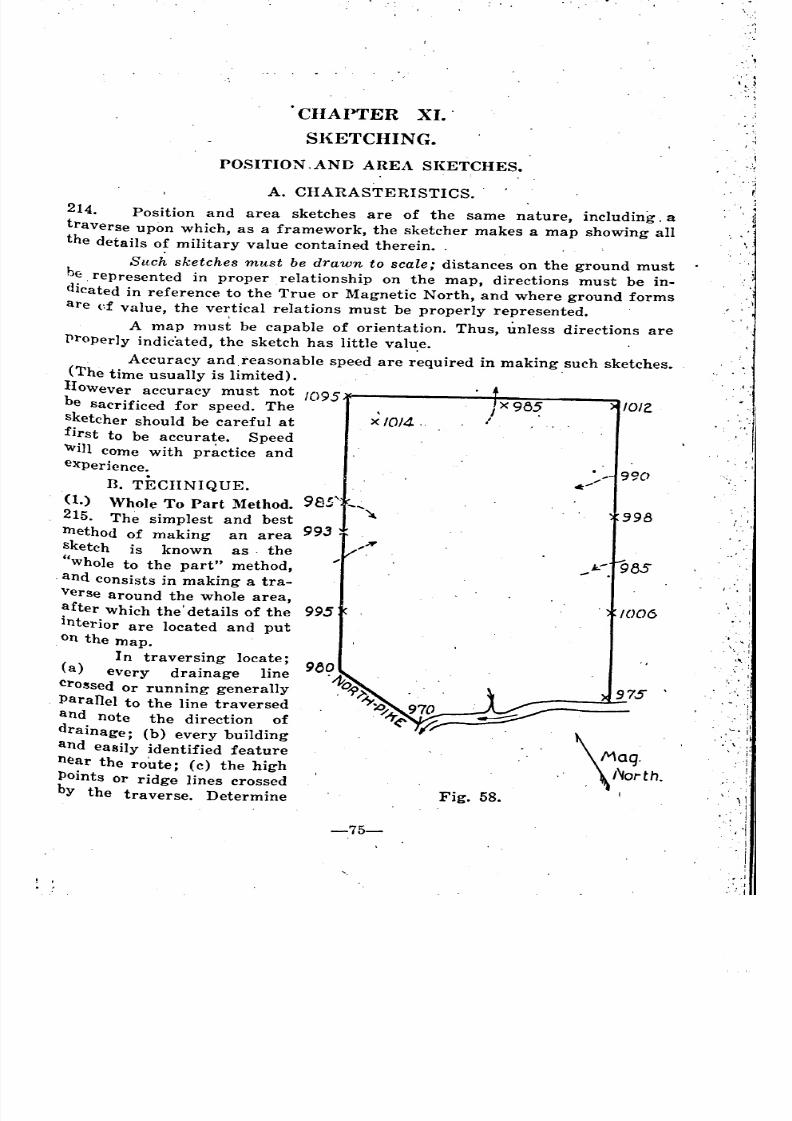
8/8/2019 Topography for Field Artillery
http://slidepdf.com/reader/full/topography-for-field-artillery 86/272
CHAPTER XI.'
Sl{ETCHING.
POSITION .AND AREA SI{ETCHES.
A. CHARASTERISTICS.
.. '1
I .• I
/' .
,(,
,'-. i!,
-. \ .'
/O/l.
.998
990
1006
985
975
J<:"... .
\ Maq.
,\1'Iorth.I
I X98~l
Fig. 58.
,
x 10/4,
995
993
214. Position and area sketches are of the same nature, including, a
traverse upon which, as a framework, the sketcher makes a map showing all
the details of military value contained therein. ,
Such sketches must be drawn to scale; distances on the ground must
b~ ,represented in proper relationship on the map, directions must be in-dicated in reference to the True or Magnetic North, and where ground forms
are d value, the vertical relations must be properly represented.
A map must be capable of orientation. Thus, unless directions are
properly indicated, the sketch has little valu.e.
, Accuracy and,reasonable speed are required in making such sketches.
(The time usually is limited).
However accuracy must not 1095be sacrificed for speed. The
sketcher should be careful at
first to be accurate. Speed
"'in come with pr~ctice and
experience.
D. TECHNIQUE.
(1.) Whole To Part Method.
215. The simplest and best
lnethod of making an area
sketch is known as, the
"whole to the part" method,
, and consists in making a tra-
Verse around the whole area,
after which the'details of the
interior are located and put
on the map.
In traversing locate;
(a) every drainage line
crO!sed or running generally
Paranel to the line traversed
and note the direction of
drainage; (b) every building
and easily identified feature
n~ar the route' (c) the high
Points or ridg~ lines crossed
by the traverse. Determine
,,'
-75-
'
.
"
\ ,- J ~
'
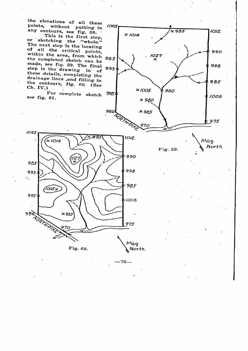
8/8/2019 Topography for Field Artillery
http://slidepdf.com/reader/full/topography-for-field-artillery 87/272
\ Mag.
. \ NorthFig. 59.
."/'X9B5/OJ!.
1/* 9901027X
998
lOll
\ Mag
\Notth.Fig. 60.
the elevations of all these
points, without putting in 1095
any contours, see fig. 58. I X 1014
This is the first step,
or . sketching the "whole."The next step is the' locating
of all the critical points,
within the area, from which 985
the completed sketch can be
ma~e, see fig. 59. The final 993
step is the drawing in of
these details, completing the
drainage lines ,and filling in
the contours, fig. 60. (See
Ch. IV.) mFor complete sketch
see fig. 61.
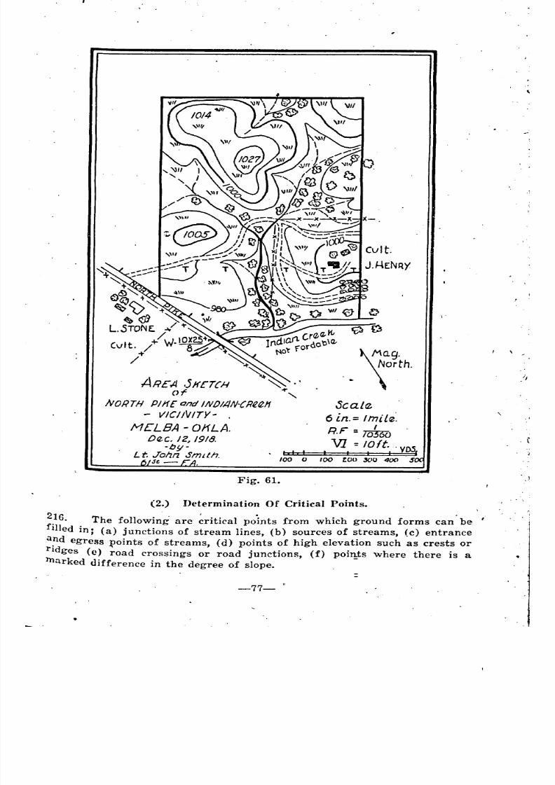
8/8/2019 Topography for Field Artillery
http://slidepdf.com/reader/full/topography-for-field-artillery 88/272
,100
Fig. 61.
~~g.
'. \orth.
Scalrt
6 in.="nil~:R.F 1t&oVi loft.. VD S
, , I I I (
() tOO too ,xl() 400 $
il
.
':
(2.) Determination Of Critical Points.
2.16. The following are ~riti('al points from which ground forms can' be
fIlled in; (a) junctions of stream lines, (b) sources of streams, (c) entrance
a?d egress ~oints of streams, (d) points of high elevation such as crests or
rIdges (e) road crossings or road junctions, (f) points where there is a
hlarked <1ifference in the degree of slope.
-77-
,
= =
"
'
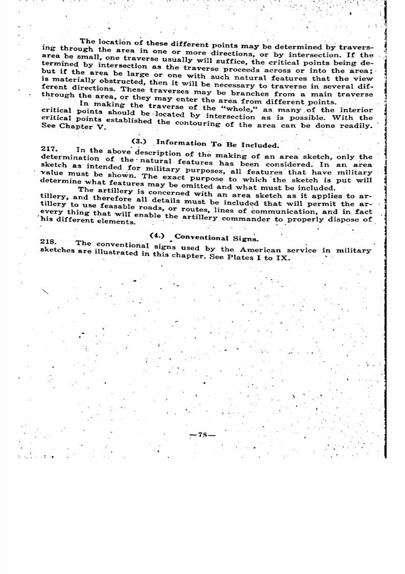
8/8/2019 Topography for Field Artillery
http://slidepdf.com/reader/full/topography-for-field-artillery 89/272
T
The location of these different points may be determined by travers- ,
ing through the area in one or more directions, or by intersection. If the
area be small, one traverse usually will suffice, the critical points being de-
termined by intersection as the traverse proceeds across or into the area;'
but if the area be large or one with such natural features that the view
is materially obstructed, then it will be necessary to traverse in several dif-
ferent directions. These traverses may be branches from a main traverse
through the area, or they may enter the area from different points. .
. [n making the traverse of the "whole," as many.'of the interior
critical points should be -located by intersection as is possible. With the
critical points established the contouring of the area can be done readily.See Chapter V. .
(3.) .Information To Be Included.
217. In the above'description of the makin~ of an area sketch, only ~he .
determination of the' natural. features has been considered. In an area
sketch. as intended for military purposes, all features' that have milita:yvalue must be shown. The exact purpose to which the sketch is put Will
determine what features may be omitted and what must be included.
The artillery is concerned with an area sketch as it applies to ar-
tillery, and therefore all details must be included that will permit the ar-
tillery to Use feasable roads, or routes, lines of communication, and in fact
every thing that wilI enable the artillery commander to properly dispose of.his different elements. '. , . .
(4.) Conventional Sign~.
218. The conventional si~s used by the American service in military
sketches are illustrated in this chapter. See Plates I to IX.
~ •
-
I
-
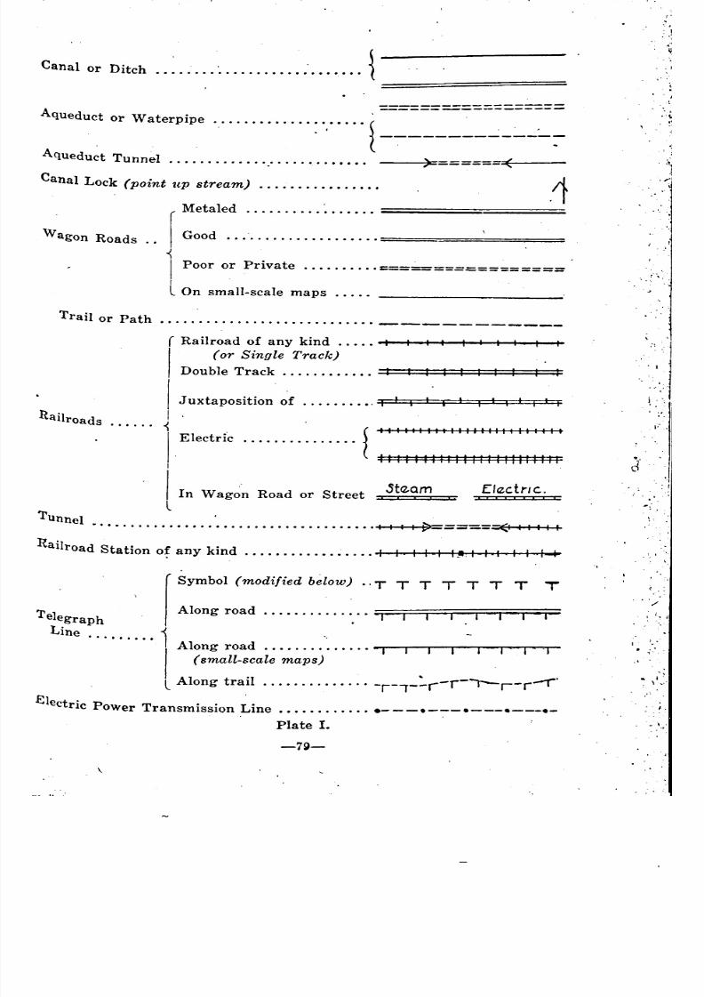
8/8/2019 Topography for Field Artillery
http://slidepdf.com/reader/full/topography-for-field-artillery 90/272
Canal or Ditch .• :.: :
Aqueduct or Waterpipe :.,' {
Aqueduct Tunnel ......................•.•. )= ==,~-(,-
',:,"
.~
,.'.
.1
Wagon Roads
Canal Lock (point up stream) .....•..••....••
r
Metaled .
Good ======================
I Poor or Private ~==~============I
L On small-scale maps .....
I
,,'
i,
I'
l~' I
.!I
-,
............................ -----------rail or Path
nailroads
( Railroad of any kind ..... 1 I I I I I
I
(or Single Track)
Double Track =*==*=*=*=*=+=*==*==~;;:
I Juxtaposition of I I I I I
I
i {I I I I I I I I I 1 I , I I I I I I II I I 1 I
IElectri'c .
IIII1I11111111I11111111I
ISta.am L/rletrlC..
In Wagon Road or Street ==X:::::I;;C' ':x====:Z;:LTunnel •.........................•.......... I I I I -(I I 1 I 1 I
:Railroad Station o~ any kind ..........•..•... I I I I I._ I , I I I 1-+
f
Symbol (modified below) .. T T T T T T T T
T I Along road .
e egraphLine
....•..•• I Along road.............. 'J
I (small-~cale maps) • .
L Along traIl -r-,--,-r I--r-r-r
Electric Power Transmission Line ............• ---.--:--e---e---._Plate I.
-7\)-
• I'
, I,,'
,
~ ========
~~-:=-~:~~= __
-.
:
~,,
~
~
"
'
~
~ _
"
"
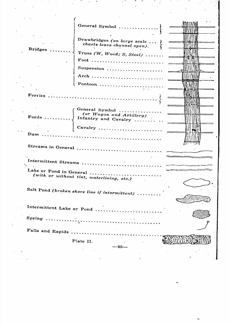
8/8/2019 Topography for Field Artillery
http://slidepdf.com/reader/full/topography-for-field-artillery 91/272
I ;.
(
I General Sym1x>1 1I I
I Drawbridges (on large scale ... tI chart. leave ~h~nnel QP~n). r
.•...... Truss (W, Wood; S, Steel) ..
I Foot .Ii Suspension .
I Arch ......•....................
l Pontoon .
(........................................ )
rGeneral Symbol .(or Wagon and Artillery) .
. . .'. . . . . . . Infantry and Cavalry ..
1 Cavalr}' .
.............................................
Bridges
Ferries
Fords
Dam
Streams in General. . . . . . . . . . . . . . . . . . . . . . . . . . . . . . ..
-Intermittent Streams ............................•.
"" .
Lake or Pond in General .
(with or without tint, 'waterlining, etc.)
Salt Pond (broken shore line if intermittent) ........•
Intermittent Lake or Pond ......•..................
Spring ..•........................................
Falls and Rapids
_.- .. .-- ...._-----
~
~ ~
" --
~
~
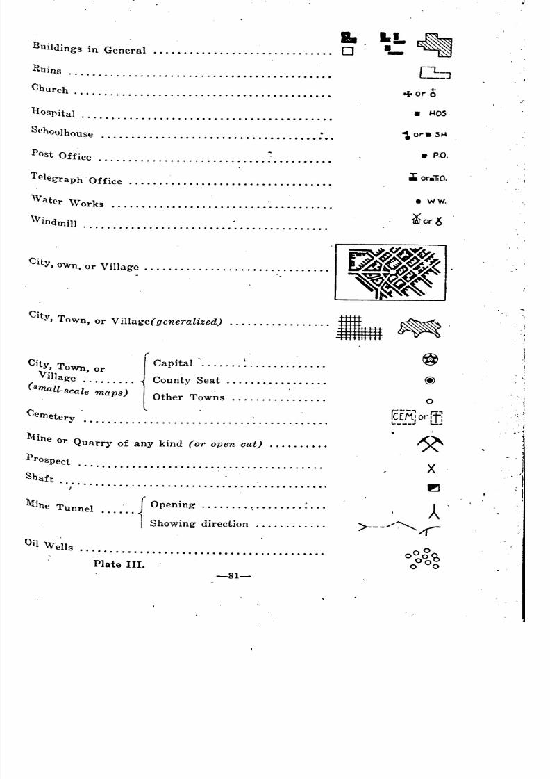
8/8/2019 Topography for Field Artillery
http://slidepdf.com/reader/full/topography-for-field-artillery 92/272
•uildings in General ....•.......................•• 0
RUins••••• I •••••••••••••• I •••••••••••••••••••••••
Church .......................................•..•
I-Iospital .........................................•
Schoolhouse ...................••..••.•••••••••• : ••
Post Off' .Ice .•..........••...••.•.....•••••••.•••••
Telegraph' Office ................................••
'Vater Works .......•..•
\V indn:dll .........................................•
I.!.•-
+or 6• HOS.
• P.O.
• WW.
.
City, Town, or
Village .
(small-scale m.aps)
City, own, or Village ..............................•
City To V'll ( l' d), wn, or I age genera l.ze .......••........
r
l'apital .
County Seat .
Other Towns .
. L •Cerneter .
y ...•...............•.•..........•.....•..
Mine Or Q f k' d ( t)uarry 0 any In or open cu .
Prospect.
Shaft
.. , .
1fine Tunn I . (Opening : .e •..... i
Showing direction .
o
ICfAiorifl.. ] u ..
X
f!I
•• II •••••••••••••••••••••••••••••••••••••
Plate III.
-81-
~
'
' ~
'
'"
'
'
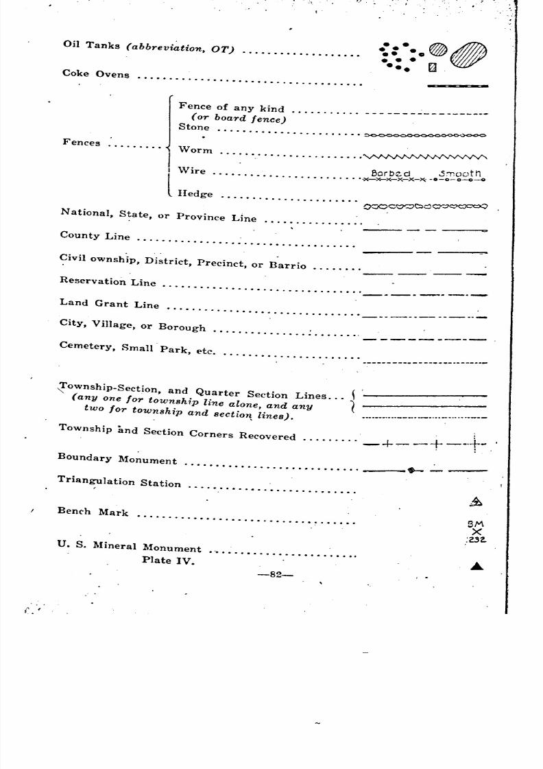
8/8/2019 Topography for Field Artillery
http://slidepdf.com/reader/full/topography-for-field-artillery 93/272
>. ,
, .
Oil Tanks (abbreviation, OT) .
Coke Ovens .
-::••o~A••• ••• t:a.
FencesjFe~c: ;:a:;Yfe~;e~
Stone
......... Worm
I . .Barbed S"'ooth
I \Vire ~-x-x-x-x-~-.-o-o-o-o
lHedge =="',,=
County Line .
Civil ownship, District, Precinct, or Barrio
Reservation Line _._.~._._
Land Grant Line...............................
City, Village, or Borough .
Cemetery, Small Park, etc • • .• ...
........... _- _ _--
( ,[ownship-Section. and Quarter Section Lines ... 1
(anyone for township line alone, and any (
two for township and 8ectio~ lines).
Township and Section Corners Recovered .......•.
_+~ _+ __+_.'Boundary Monument •.•••••.•.•••.••.•.•.••••••. ... _-:--
Triangulation Station ..........•................
Bench Mark ...........................• .
u. S. Mineral Monument ._•....•......•........•.
8MX
:Z.32.
.
------------------
~ ~
_
__ _ '
~
_
~
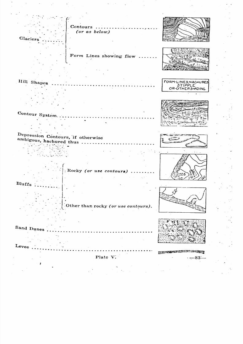
8/8/2019 Topography for Field Artillery
http://slidepdf.com/reader/full/topography-for-field-artillery 94/272
. "",'" .~v
.f CO;::":: b;l~;")"""""""""Glaciers....... . . .1-I
'l'Form Lines showing flow .
IIill Shap(.s . rORM-UN ES.1-jACHUR£.SSTJPPl.[OR'OTHER-"HADIN~.
Contour System .. L •••••••••••••••••••••••••••••••••
Depressio"n 'Con~ours, 'if otherwise
ambigous, hachured thus .
L --'
('~I:Rocky (or use contoura) .
/.I
• L ."••• L.. I"
, I.
:' :l:'Other than rocky (or use contours).
Bluffs
Sand Dunes •• " . . • . . . . . . . . • . . . . . . . . . • .. .. .. . .. .. • . flil~ltLevee ....••.... ".: •....•.....•.•...•...••••...••••.
Plate V:
~,\WII\'III\II¥IIJHI~~'I"\'IIl\'!.'!/Jlliunm::
,-83~
~
"
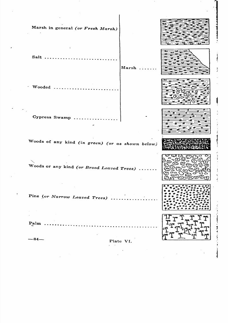
8/8/2019 Topography for Field Artillery
http://slidepdf.com/reader/full/topography-for-field-artillery 95/272
Marsh .
Salt .
. Wooded ...........•.............
.................
...........................................
Cypress Swamp
Palm
Marsh in general (or Fresh Marsh)
Pine Jor Narrow Leaved Trees) •.....•...........
Woods or any kind (or Brood Leaved Trees)
Woods of any kind (in green) (or as shown below)
~
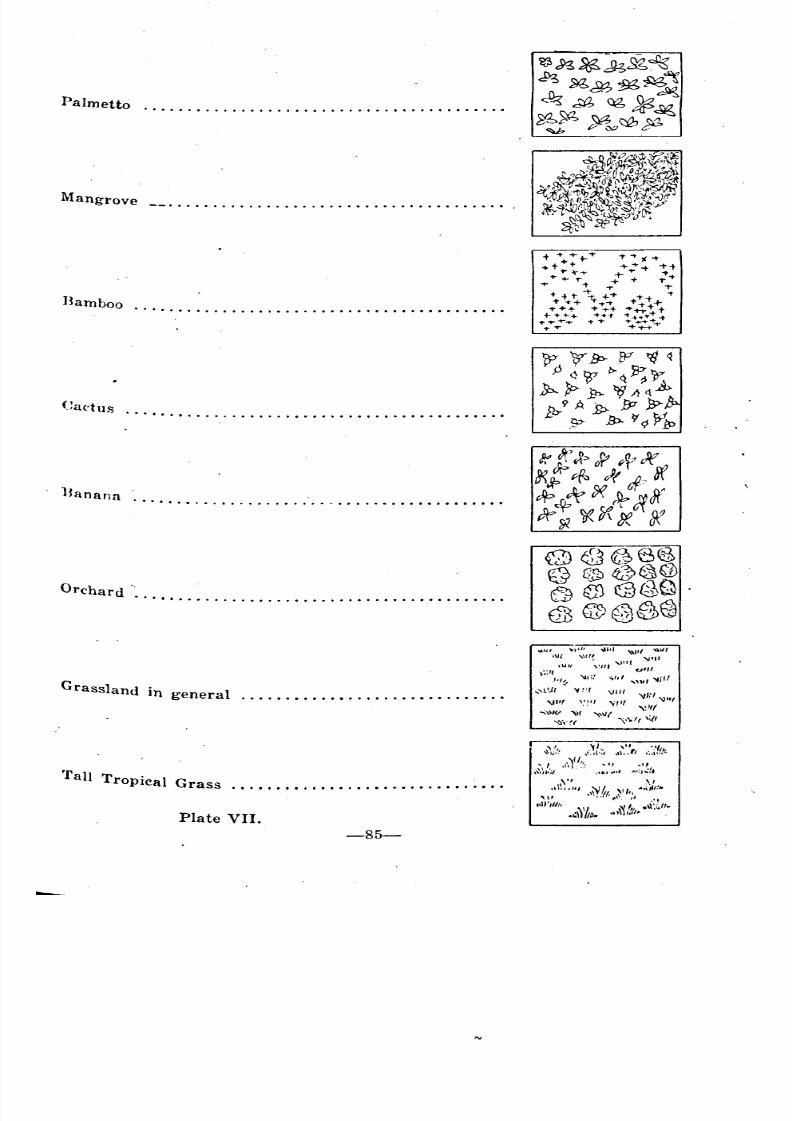
8/8/2019 Topography for Field Artillery
http://slidepdf.com/reader/full/topography-for-field-artillery 96/272
Palmetto
Orchard .... .•••••••••••••••••••••••••• II ••••• II II
Mangrove
...... ................................. .
••••••••• ', •••••••••••••• II •••••••• II •••• II
• II ••• II •••••• II
Bamboo
Cuetus
Banana
Grasslan .d III general
Plate VII.
'rull Tropical Grass . . . . . ... . . . ... ............ . ...
-85-
0 •
••••• II .. "
~
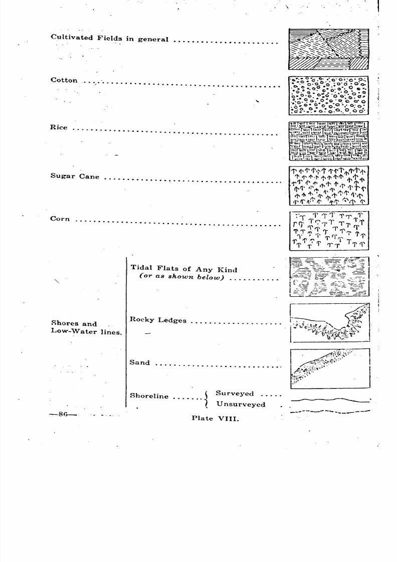
8/8/2019 Topography for Field Artillery
http://slidepdf.com/reader/full/topography-for-field-artillery 97/272
Sand .
.
,
I-
~i'l"~
j
7''''' 'f11'1'''(' l'I 1'r.- T 1'1'rr.' ;1' T1'fT\~"''1' 1'1' 'I
'l' .. 'r ' l' rl' l' 'r1'TITl' 'i'~m I T'f\~'l' f I 'IT I
Surveyed .....
Unsurveyed
Shoreline {
~hores and
Low-Water lines.
Tidal Flats of Any Kind
(or as shown below) .
Cultivated Fields in general .••.•.••.•••••••••••..•
Cotton .. ',' ..•....••.......•....•.....•...•..••••.
Sugar Cane ..•..•••..•..• .••.••....•.•..•...••...
Corn ..........•..••••...•..•...•...•.........•••.
Rice .......•...•..••......•...•.....•....•.......
,
"
-
-
~ '"
' '
~
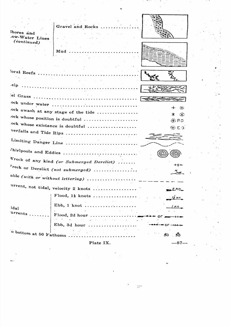
8/8/2019 Topography for Field Artillery
http://slidepdf.com/reader/full/topography-for-field-artillery 98/272
Mud .
Gravel ~nd Rocks .
:oral Reefs .
+ .$
* ::~(f; P. D
l~l1~:<c4iiE1........................................
.............................................
:el Grass
.elp
ihores and
'OW-Water Lines( continued)
,ock under water .
.ock awash at any stage of the tide .
~ockwhose position is doubtful .
,ock whose existance is doubtful .
Vreck of any kind (or Submerged Derelict) .
'reck or Der,elict (not submerged) .........•......•
able (with or'Without lettering) .......•...........
verfalls and Tide Rips
Limiting Da~ger Line
hirlpools and Eddies
.............. ,
.............. '. : ,
urrent, not tidal, velocity 2 knots .
Flood, 1 knots _'.. ,
idal
u rren ts .
Ebb, 1 knot .
Flood, 2d hour or • ., II.
Ebb, 3d hour .
o bottom at 50 l<'athoms .
Plate IX. -87-
_
~ ~
~ ~
' ' _---
8/8/2019 Topography for Field Artillery
http://slidepdf.com/reader/full/topography-for-field-artillery 99/272
219. In practical sketching, if it is more difficult, or requires more time
to make the conventional sign than it does to write what is meant, the ex-
perienced sketcher will write the description. A sketch is made primarily
to convey information. If what is meant to be conveyed is not clear the sketch,
is of no use. Again, if it takes a commander too long to read a sketch h~
will blame the sketcher, and as his time probably will be limited he may not. be,
able to take time to read it. It is well to remember that the sketch is bemE"
made to be read; that the convenience of the reader is sought, not that of th~
sketcher; and that is useless to put a mark on the sketch unless that mar~has a meaning which the reader will understand.
It is desirable that the conventional' signs shall picture what they
represent as nearly as possible, so as to be easily interpreted; that they he
simple in construction, so that they may be made rapidly; that they do nottake too much space on the sketch; and that they be so clear as to be readilyunderstood and not be mistaken one for another. .
220. The adaption of the convenional signs to the size and scale of the'
map is accomplished, in part by varying the boldness of the pen stroke, and
in part by wider spacing of them. The strokes never must be so small as,
to render the signs illegible and never larger than can be made easily with.
a medium pen. The object is to produce a reSUlt, which, While distinct
to conventional meaning, shall not be so heavy in general tone as to catcb.the eYe, or, What is more important in military maps, to obscure any ad"
ditions which may be made. Topographical signs should bee perfectly clear
twhen looked for, but not obtrusive. .
. Practice in rapid work has developed many short cuts in making CO""
ventional signs. These convey the same information as the standard signs,
I'ut with fewer pencil marks, and probably greater clearness;
It should be noted that the cross marks on a railroad, the signs in',
dicaling the different kinds of fences, the marks along a road indicating atelepraph line, and the T representing a telegraph line across country, should
not be put close together. This is done principally for the sake of clearness/~.although a great deal of time is saved by it. It is, however, an excellent rule,
never to put a mark on a Sketch, no matter how small, that is not necessary.
A culvert or bridge, less than 10 feet long, (road length) should be
n'presented by two V'S at right angles to the road with the point of the V'.~
opposite each other. Dimensions need not then be given as in a larger
bridge, but the material and the condition, if poor, should be noted: "Bric1(,Poor," or "Wood, bad." . .
Roads are conventional signs, but where Possible should be drawn to
8cale. The road lines should stand out clearly and distinctly with no lin,gS
or other conventional signs crossing the roads. Fence and telegraph syrl1-
bols are placed on the road lines. A hedge fence may be represented ..'._
drawing II's across one of the road lines at the same intervals as the fen C
signs. Fence or hedge signs are the only marks which ever sho~1d appe:between the road lines.
Stone and Wood fences, may be indicated quickly in sketching .writing in "Stone" or "Wood" along a line drawn to represent the fenc
'
as.
.1
" .
'
8/8/2019 Topography for Field Artillery
http://slidepdf.com/reader/full/topography-for-field-artillery 100/272
or if along.a road, on the road line, with marks indicating the limits of the
stone or wood fence. A marginal note is simplest and easiest.
Signs for single trees are dra\\'1l oblong or roughly circular in shape.
They should be spaced sufficiently so as to blue print readily. It is not
necessary to show individual trees. The sign indicates trees in that locality.<?ften it is better to draw a ragged border about the timbered area and
Write, "Wooded" therein.
Houses are represented by blocks which are made square and large
~nough to be set in the roads at the scale being used. Black blocks indicate
stone, brick, or concrete houses; and hollow blocks represent frame houses.
A row of houses occupying a certain distance along a road need not be in-
dicated individually, but house signs covering the scale distance occupied by
them should be shown.
In order to proportion the signs to the scale used, it is convenient to
hlake the lines that go on or along a road, of the same length as the width
of the road. This refers to such signs as those for telegraph llnes, barbed
wire, cuts, fills, bridges and culverts.' .
. A dry watercourse should be indicated by a broken line, which should
be wavy so as not to be mistaken for the trail sign; the latter being a broken
~traight line. If there is a small town along the road, it is not advisable
In a road sketch to show the individual streets, alleys and houses.' A town
sign covering the area of the town, and its name, is sufficient.
Where a conventional sign or written words can not be put in at the
Dlace desired without excessive crowding, write a (1) at that place and in-
sert the description in a marginal note opposite a (1) on the margin. Carry
~hese marginal notes by serial numbers. On a road sketch start them at the
ottom of the margin and run up. On other sketches start at the top of the
l)aper and number them down.
Break contour lines on each side of a road, or of a conventional sign,
Or of an abbreviation (as a description of a bridge).
. It sho~ld be remembered that a sketch, when finished, should be readyfor blue printing without tracing; therefore all signs should be destinct
enough for this purpose. All lines should be firm and clear cut.
(5.) Title.
221. Every finished sketch should have a descriptive title setting forth;
(a) the character of the sketch, (b) its locality, (c) the sketcher's name and
rank, (d) its date, (e) its linear scale, its contour interval and its datum
Plane, fig. 62.
Titles should be adapted in size and boldness to the size and import-ance of the sheet. They should be divided into lines following mainly the sub-
diVisions given above. The middle letter of each line should fall on a line
drawn vertically through the middle of the space alloted to the title. Lines
~hoUldbe alternately long and short. All items of the title should be weighted
oth by size of letter and the space between adjoining items so as to em-
PhaSize their relative importance. See sample title, Fig. 62.
t' Sometimes the magnetic north direction is indicated in the title sec-
Ion but usually it is found in the body of the map. .
-89-
8/8/2019 Topography for Field Artillery
http://slidepdf.com/reader/full/topography-for-field-artillery 101/272
'(6.) Border.
222. The sketch or drawing sh~uld be enclo'sed in a I'ect~ngle, pref~r~bl
with its ~ides N. and S, and E. W.. The .bo~der consis'ts of two para1l4
Jines, the inner one medium fine, the ~ute~' one medi~m heavy, with a spac
between them equal to th~. heavy line, see fig. 61~ .
POS/770N 8KETCH
MarOLD POST -rORTS/LL O)(LA
ByJOhn Doe" SgrBrry 'F "'/YFA.
12rebi:E.
RF~y2oooo V/~20Fl'
Yord3~Of.w f ( "1' 1 '1 :r '7 -r Ip
Fig. 62.
(7.) Lettering.
223. All lettering on ~Pposit.e sketches should be w~itten so as to read, fro
the south edge. In place sketches the lettering should be so located as
be read from the sketcher's position with the sketch oriented. In outpo
sketches the lettering is read facing toward the enemy. In road sketche
jhe lettering should be made so that it may be read by anyone followmg tll
route of the sketcher, with the sketch oriented.. . .. As a rule names and figures relating to points on the map are ma
parallel to one side. Names and figure~ relating to extended features,.
large areas, are disposed along the feature', or across the area, in straigllor curved lines.
Ornamental lettering should be avoided. A good general I'ule to folIo
is to use inclined letters for all names and words on the map which relates
water and upright letters for these which do not. In case the sketcher is n
expert in both upright and inclined letters, it is netter to. use the inc1in,
letters entirely. The type of inclined letter to be used is the Reinhardt lette:,
which is uniformly used by engineers through out our country fo~ gener,'lettering. See fig. 62 and Plate X.
~ ~
'

8/8/2019 Topography for Field Artillery
http://slidepdf.com/reader/full/topography-for-field-artillery 102/272
, •
LETTERING
Names of natural land features, vertical lettering;Names of natural water features, slanting lettering.
Thiclfness, of letter 1/7 of height.
Slope of letter :1 parts of base to 8 of height.
'AUTHORIZED ABBREVIATIONS
, A. Arroyo L. S. S. Life Saving Station.abut.
Abutment L. H.Lighthouse
A. Arch Long. Longitude
b~ Brick Mt. Mountain
B. S. Blacksmith Shop Mts. Mountains
bot. Bottom N. North
llr. Branch n.'f. Not fordable
br. Bridge p. Pier
C. Cape pk. Plank
... cern. Cemetery P. O. Post Office
con. Concrete Pt. Point
cov. Covered q. p. Queen-post
Cr. Creek R. River
cuI. Culvert R H. Roundhouse
D. S. Drug Store RR . Railroad
E. East S. South
Est. Estuary s. Steel
f. Fordable S. H. School House
Ft. Fort S. M. Saw mill
G. S. General Store Sta. Station
. giro Girder st. Stone
G. M. Grist Mill str. Stream
i. Iron T. G. Toll Gate
I. Island Tres. Trestle
Jc. Junction tr. Truss
k.p. King-post W. T. Water Tank
L. Lake W.,W. Waterworks
Lat. Latitude W. West
Ldg. Landing W.' Wood
Plate X.
-91-
l I
'
'
8/8/2019 Topography for Field Artillery
http://slidepdf.com/reader/full/topography-for-field-artillery 103/272
ROAD" SKETCHES.
A. CHARACTERISTICS.
224. Road sketches differ from area sketches in that they show the na
tural and military features on and in the immediate vicinity of the road only.They consist of simple traverse~ that follow the direction taken by the road
In drawing road sketches speed must be acquired as they should be
made at a rate of 2~ miles an hour if dismounted, or 3 to 5 miles if mounted.
225. Road sketches commonly are made. on a scale of 1/20,000. The sket-
cher should familiarize himself with a few of the common and frequently
used units of measure so that he will not have to apply his scale in locating
every detail on the map. He should, with practice, learn the graphical repre-
sentations of 100 and 200 yds., and the M. D. (between contours), for-la, 30,
and 5° slopes. He should practice estimating the degrees of slope of va~ied
terrain, checking against the reading of an accurate instrument. In this way
the sketcher can locate accurately and speed;ly the position of buildings,
streams, railroads, etc. on the map. He also will be able to give a better ideaof slopes of the adjoining terrain.
B. TECHNIQUE.
(1.) Method Of Sketching.
226. The sketcher must provide himself with the following: sketchingboard, alidade (or triangular ruler), slope measuring instrument (or slope-
board), pencils' and erasers, compass, working and slope scales. These latter
two scales should be pasted on the alidade for convenience. The board may be
mounted upon a tripod (becoming a plane-table) if desired.
227. Proceed to the place of beginning, and set up the plane table, or, ifusing a board, set it on a fence post, stonp., or on the ground. Place the
board so the general direction to be taken will correspond with the long side
of the board. Place the compass on the board and draw a line, in one cornet
of the paper, parallel to the needle. Mark this line to indicate the magnetic
north. This mark or arrow can then be used for orientation.
Having indicated the magnetic north, place a dot on the paper torepresent the point of beginning. Insert a needle in this dot. Place the
alidade against the needle and in the direction of tnwerse. Sight along the
edge of the alidade toward the point at which the next set-up will be made,
using the needle as a pivot, and swing the alidade until it is in direct line
with the direction to be taken (without disturbing the original position of
the board). Steady the alidade and draw a light ray in the new direction,
fig. 63. Measure the slope to the new point. Note all features in the vicinity.
Place them on the sketch and tr.en porceed to the new point just sighted.
Again set up the plane table. Measure off, on the ray just drawn, the
distance just traversed, orient the board by backsighting or with compasS.
Place the needle in the new point, -swing the alidade in the new direction tobe taken, and proceed as from the beginning.
Continue until the entire road distance has been covered, using the
same methods. Check the orientat~on frequently with the compass.At each new set-up, after the first, all the data observed, noted or
measured, "'ill be indicated on the sketch; and contours will be. drawn in
8/8/2019 Topography for Field Artillery
http://slidepdf.com/reader/full/topography-for-field-artillery 104/272
Where they cross the road, as well as in the vicinity of the road. Especial
attention must be given to noting all details that have military value.
Maq.\
l'iortht
[ /'
I!l/~'
~.WOOd',
\'~."" 0
L~~t'\ill
ROAD StrETCH fj SJVICINITY Or W.vON£S a 0
Jca/eJ" 'mila
Fig. 63.
o
t Time must not be wasted in actually pacing dist~nces to buildings off
he road or in measuring the distance between them. Nor must time be.
~Pent in measuring the exact size of cultivated fields, nor the distance that
Hre d .d" ams,. telephone or telegraph lines are from the roa . EstImate these
lstances and locate their positions approximately.
t .' Points of importance, such as hills, villages, etc. will be located by in-
~rsection as the traverse proceeds. If their location is beyond the limits
o the sketch their direction will be indicated. . .
A more rapid method of making a road sketch is to run the traverse
entirely with the compass needle. In all sketches the needle should be used
as a check to prevent gross errors or orientation.
-93-
=
8/8/2019 Topography for Field Artillery
http://slidepdf.com/reader/full/topography-for-field-artillery 105/272
(2.) Lateral Limits To' Be Considered. .
228. The lateral limits of a road sketch are; perforce, limited to what can'
be seen readily from the road. The limits usually considered are 400 yardon each side.
The lateral limits extend beyond this only when the additional infofmation has a military value, and then the salient points are drawn in, th
intervening details being. omitted in. whole or in part.
(3.) Information To Be Included.
229. A road sketch should be so complete that the military commande
can see at a glance all features of value. He must be able to tell the kind 0
road; its slope. and particability for his troops; if the road is fenced;
flanked by cultivated fields and if.tbey are fenced, also the type of fence; If
lhere are Woods near the road, or other cover and concealment; if hills
h.igh point~ of observation ~re visible; if there is cover so that in~antr~ can
jire effectively on troops on the road (effective range 600 yds.) If artIllery
positions are within view (this may include up to several miles); if there are
lines of communication, villages, buildings, water for men and animals along
the route; if the ground is level on both sides of the road; the location and,.
type of buildings. In short aU. information of military value must be sho\\:l
ln a road sketch. Minor and unimportant details should be omitted to aVOIdconfusion and to save time.
~ or

8/8/2019 Topography for Field Artillery
http://slidepdf.com/reader/full/topography-for-field-artillery 106/272
, ,
CHAPTER XII. ::
PANORAM'ic" SKETCHES., CHARACTERISTICS.
'., ,:
;, l
",I., :.••
.. :.
,. ;.
230. A panoramic sketch is' not a land-scape sketch. It has been 'called'
a vertical map, but it is more than a map. In addition it is a military.retord'
containing information of value to the higher commander; and' also- data for
Use by the officer conducting 'fire.: ;; . I •• ; :" ,'", ',:
231. Ever'y' 'artili~ry "officer is famiiiar with the' term ':'Re~~~mai~'s~n~~(
and Occupation, of, a ,Position":' Customarily ;,ho~ever ,~"th~.o'fffcer: thinks.' ofthe reconnaissance and occupation of a position chiefly, with',respe~t, to~'his',
own position, whereas it,: is just as important that he reconnoiter: ~n~:(fani-'
iliarize himself, with the enemy.position, (in'the sense that' he. secure'
the same information that the e'nemy has). This l~st is absolutely 'necessary' if '
the officer is to make, an intelligent estimate of the situation .. Irifact it is' a
fundamental of military operations that he, who would outguess the enemy"
must place himself, in ,the enemy's. position 'and, reason from ,the same prem-
ises adopted by the enemy. Hence, the need of the reconaissance of th~
enemy's position, so far, as is possible from a distance ..The absentee occupa-
tion of the enemy position may be accomplished by systematic observation of
the hostile terrain and of the enemy's movements, and by the careful record-
ing of the data thus obtained. Here it is that the panoramic sketch plays its
, part, the sketch being part of the attempt to occupy the enemy's position.
232. The meaning of the above may be illustrated better by citing a simple,
instance at certain field maneuvers. In the middle distance, as seen, from
the friendly O. P., was a ridge. Beyond the first ridge was a second one con."
taining a notch, appearing about, on a level with the top of the first ridge,
see fig.64. At a certain hour the offi~er in charge' of the O. P. noted the
second ridge, but the
..
-95':"'"
,'-
' "
" '"
'
'
'
8/8/2019 Topography for Field Artillery
http://slidepdf.com/reader/full/topography-for-field-artillery 107/272
glimpse was so brief and the visibility so poor that he could not determine
the direction of the movement. A study of the map indicated that there
were suitable battery positions for the enemy both in front and behind the
second ridge. He noted the appearance. of the fleeting target on the sketch
but was unable to record any definite data for the target. Shortly afterward
the heads and shoulders of two men were noted on the hill to the left of
the notch and the officer concluded that the enemy observation post was to
be located on that height. As yet he had nothing to indicate the batteryposition.
Sometime later in the morning the observer saw a dismounted man
proceed up the hill to the right of the notch. He drew the line' of travel on
the sketch from the point of first appearance to the point where the ridge
was crossed, and noted the time. Immediately afterward a horseman came
in sight more to the right and rode in a diagonal direction up the same hill.The facts were again noted on the sketch. Then, taking his map, the ob-
server plotted the lines of travel of the horseman and the dismounted soldier
and prolonged them u~til then intersected in the valley in front of the
second ridge. The observer reasoned that the intersection of these two
lines was the battery position of the enemy. Accordingly he prepared a
sketch showing the enemy position, and O. P., which, with the panoramic
sketch, was furnished his commanding officer. The observer was credited
with a solution of the problem, for the enemy battery was located as he had
reasoned, and zone fire' in the area indicated would, undoubtedly, havesilenced the enemy guns.
233. . As just indicated the function of the panoramic sketch is to supple-
ment the topographical map, to aid in the identification of objects on the
map, to furnish information of the situation within the enemy lines, and
also to provide data for the artillery. So detailed and exact should this in-
formation be that the battery commander may rely on the sketch and openfire without using any other data.
TYPES OF SKETCHES.
234. The panoramic sketch may be made in a few minutes by one of the
scouts in warfare of movement; or it may be made by a scout or other ob-
server from a permanent observation post, in warfare of position, in which
case an abundance of time will he available. Whoever makes the sketch must
Lear in mind that the sketch is to be used by another person, either by the
higher commander in his study of the sector or by the battery commander
in his conduct of fire; hence certain fundamentals as to identification, infor-
mation and technique must be observed. .
235. The tYPe of ketch that is to be made will depend upon the time
{'lement. In so called "open warfare", time is likely to be the all im-
.portant element, since the sketch must be available by the timp. the battery
commander is ready to open fire; hence rapid methods of calibration of the
paper with regard to the landscape will be employed. In warfare of position
the sketcher will use instruments in making measurements of all deflections
and of all angles of site and will, accurately, place the points'so measured
on the paper, according to some adopted horizontal and vertical scale. SuchII. sk:t:-h will be almost photographic in its exactness.
""
"
8/8/2019 Topography for Field Artillery
http://slidepdf.com/reader/full/topography-for-field-artillery 108/272
I
• I
ESSENTIALS.
236. . The French make a distinction between the sketch made deliberately
with exact instruments and covering all of the terrain visible from a given
O. P., and the sketch made by the scout during the reconnaissance of a posi-
tion. The former is called the panorama. The latter is known as the per-
spective sketch. The American service makes no such distinction in momen-clature, for there really is no distinction, one sketch grading into the other
according to the time' employed on it. The blank sheets furnished the
8ketcher by the field artillery, iig. 65, may be used for either type of
sketch. These sheets contain a series of parallel vertical lines and a series
of parallel horizontal lines. By adopting a certain scale for the space be-
, tween the vertical lines; e. g., 100 mils, it will be possible to make a series
of sketches all to one scale, which, when pasted together end to end, will
give the sketcher a complete panorama. On the other hand the lines on the
Paper lend themselves to the more hurried methods of calibration as will be
explained later.
237. What are the essentials of a good panoram.ic sketch? There are two
Which stand out with particular prominence; first, clearness of identifica-
tion; second, information furnished. Accuracy is another essential. Draw-
ing ranks last in the list.
A. IDENTIFICATION.
238. As to the matter of identification, the sketcher must remember that,
if the person using his sketch cannot identify the terrain respresented, then
his work is valueless. Hence the sketcher must neglect nothing that will
add to the ease of identification. Of course the horizon line is likely to be,
the greatest aid to identification of the sector and hence should not be omitted
although the objects thereon may be far out of artillery range. Ohjects in
the mid-distance and fore-ground also should be included when they will aid
in this step although they may have no particular military value. Lastly
the data to be entered at the bottom of the page, showing the place wherethe sketch was made and indicating the orientation, are essential to the iden-
tification of the sector.
B. INFORMATION.
239. Of course'the object of the sketch is to convey information. Hence,':" ,
although the sketch may be a work of art; and although the one who picks
it up may have no difficulty in identifying he sector; if that sketch does not
contain military information, and, in particular: information of use to the
artillery officer, the sketch is valueless and the sketcher might better not
have waisted his time on it. . . .
240. That the in/orm.ation furnished should be accurate is self evident
<Jtherwise the sketch loses much of its value.
C. DRAWING.
241. .. While drawing is not so important as'some other things in sketching,'
the officer must remember certain fundamentals. First, the sketch must be
..clear to the point of bareness. That is, the important features must be em-
phasized at the expense of the' unimportant: In other words the sketch be-
-97-
_
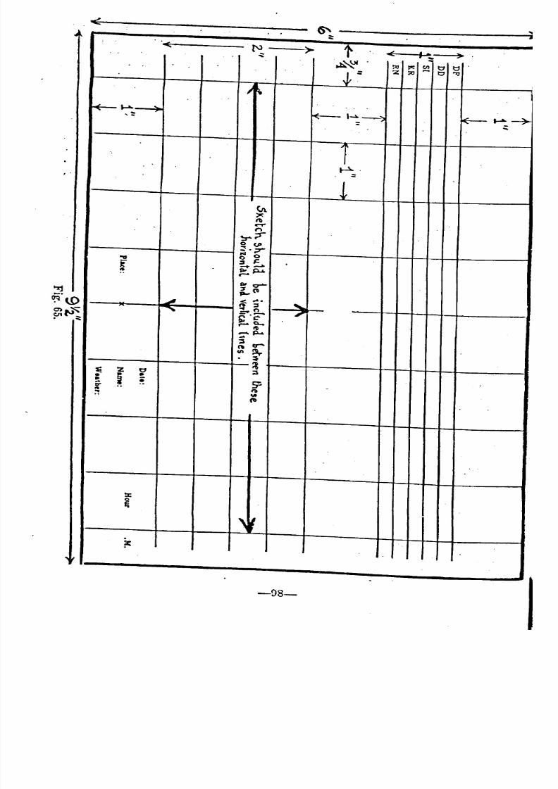
8/8/2019 Topography for Field Artillery
http://slidepdf.com/reader/full/topography-for-field-artillery 109/272
<
.
.~:O:CIlt1tj'
Z t1 ...,
I
-!>8-
1~.::
1
I
~ ~~
~ -.
8/8/2019 Topography for Field Artillery
http://slidepdf.com/reader/full/topography-for-field-artillery 110/272
-Comesa~caricature of the landscape. Hence it is just as important to know
What to leave out as it is what to 'put in. Whatever is done the sketcher
must not attempt to show the 'sector by a mass of shading such as would
b'i! employed by the ordinary sketcher. Such a procedure will hide essential
details rather than emphasize them. The fewer lines that can be used to
Convey the desired idea, the better it is.
242. However, the subject of drawing need not prove troublesome. Any
man who can handle a pencil well enough to make a map or area sketch can
, make a satisfactory panoramic sketch,. regardless of whether or not he has
any of the instinct of an artist. More often than not he will make a more
, valuable sketch that the trained artist because he. will not be tempted to
make a pretty picture and so hide military information.
~43. Since the sketch must enable the user to identify the sector quickl~',
'It should convey to the eye a rough picture of the terrain as it actually is
seen. To secure this ~icture few technical' devices should be employed.
(1.) Perspective System of Parallel Lines.
, 244. First of these technical devices is the principle of perspective. This
is a means of making use of the fact that distance to the eye is indicated
by the angle which an object of given height subtends at the eye. The
greater the distance the smaller the angle and hence the smaller the object
appears to the eye. Thus a row of objects of 'a given height extending into
the distance apparently will grow. smaller as the distance becomes greater
Until they finally vanish into a point on the horizon: In order to get theSame effect of distance or depth in a sketch,' the following principles of
Perspective should be applied.
245. (a) Any sy stem of para llel horizontal lines in a plane not parallel
to the plane of the observer, tends to come together or vanish at a point on
the horizon, called 'the vanishing point .. Such a system of lines is shown in
fig. 66. The lines" of the house which are parallel and which fulfill the con-
ditions enumerated, if prolonged, will meet in vanishing points, VP1 and VP2,
on the horizon. .
Perhaps the commonest example of vanishing of parallel lines to tobe found in the track of a railroad, a line of telegraph poles or the sides of a
road, as indicated in fig. 67.
246. (b) Any system of vertical parallel lines no matter in what plane,
will rem,ain parallel. In fig. 66 all vertical parallel lines remain parallel.
247. (c) A ny system of parallel lines not horizontal, in a plane not par-
allel to the plane of the observer, vanish in a point above or below the
horizon. In fig 68 the'lines joining the top and bottom of the picket fence
form the system of parallel lines fulfilling the above conditions. The section
.of the. fence All, is inclined downward and hence would vanish at VP 2• below
the horizon. The section Be, being inclined 'Upward, vanishes at VP 1 above the
horizon. . ,
(2). Consecutive Crest Lines.
24ft The effect of distance can be given in a mechanical way by varying
the weight of line. Since objects seen' close at hand are large and clear
and decrease in size and ciearness as. they recede from the observer, this
principle must be applied to sketching~ The nearest features must be the
~
,
'
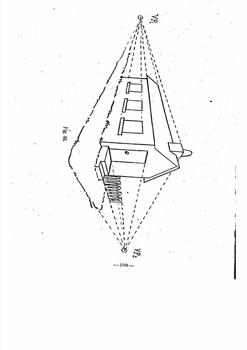
8/8/2019 Topography for Field Artillery
http://slidepdf.com/reader/full/topography-for-field-artillery 111/272
"~ <""l',i ~", \
/1, I' t
II, ':
/ 'II,
) II II
I
t/ll\\
Jill "
/ I I "
I I I I "I \\
,\
rlb' ,\/
J "/ / I~ \
rlO \,\
.\
~ ~ ~
~
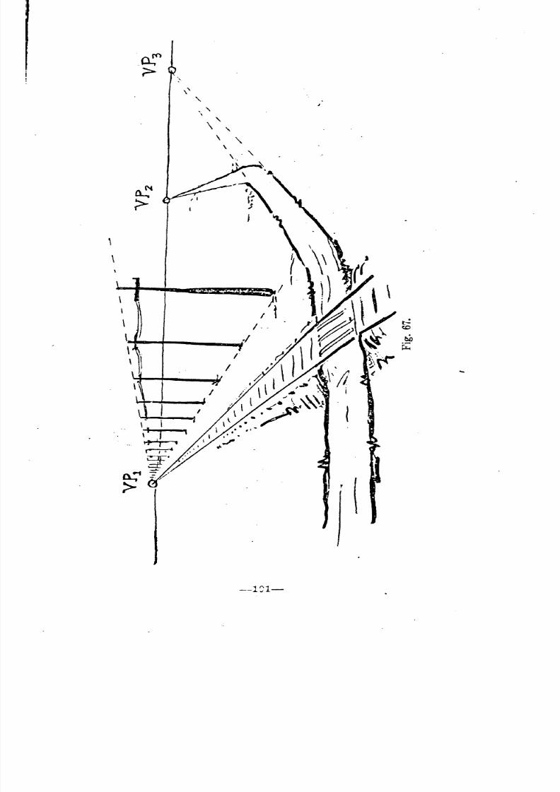
8/8/2019 Topography for Field Artillery
http://slidepdf.com/reader/full/topography-for-field-artillery 112/272
,\
--1~1-
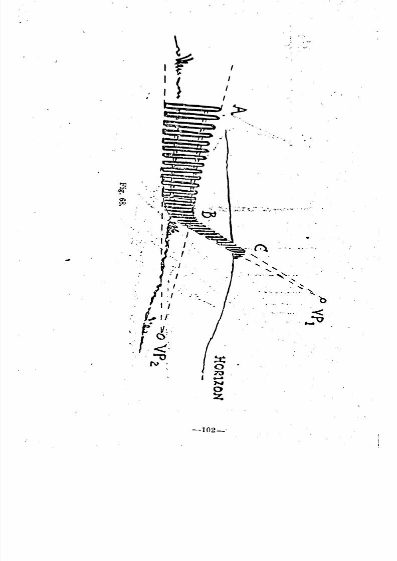
8/8/2019 Topography for Field Artillery
http://slidepdf.com/reader/full/topography-for-field-artillery 113/272
I ~ I
, : ,/~.?.
i
b- .. ...
~..... ,
~
~
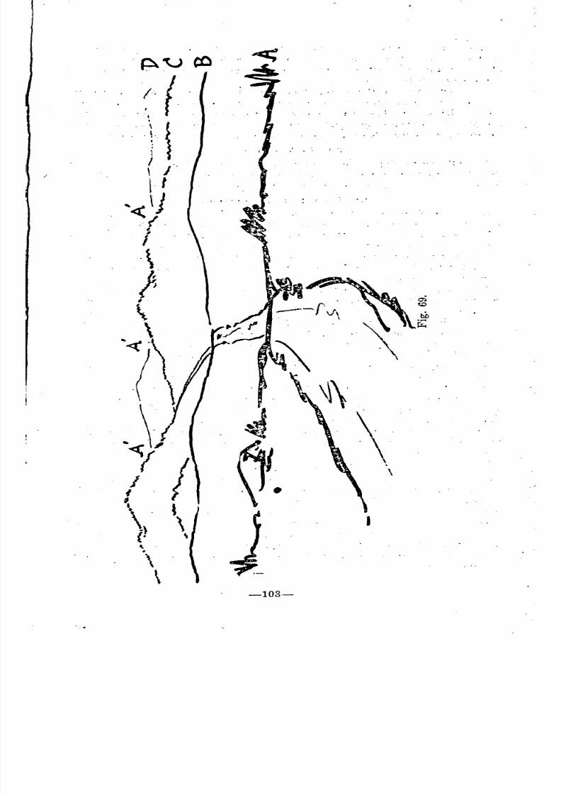
8/8/2019 Topography for Field Artillery
http://slidepdf.com/reader/full/topography-for-field-artillery 114/272
. .
\
. ",
, .,' I
\
\-103-
~'
.
8/8/2019 Topography for Field Artillery
http://slidepdf.com/reader/full/topography-for-field-artillery 115/272
largest and the heaviest of line, while they should become smaller and
lighter of line until the sky line is reached, which must be the faintest of all.
249. Figure 69 illustrates this principle. The successive crests recede fromthe observer in the order A, B, C, D.
The crest A therefore, should 'be the heaviest' line, and the lines
should decrease in intensity to the borizon D, wbich should be the faintest
line in the sketch. Tbe road, following tbis principle and the principle of
perspective, decreases in weight and tends to vanish in a point during its
Successive meanders. No lines should be so faint as to be indistinguishable.
(3.) Broken Lines.
250. By refraining from actually joining intersecting crest lines, as A',
fig. 69, a further technical means is employed of giving effect of depth
to the sketch. This gives the effect of haze found on distant slopes.
(4.) Ground Slopes And Form.
251. One of ihe fundamental requirements of a good sketch being clear-
ness, it is essential that all useless details be omitted. On the other hand
the general slopes and configurations of the ground are of military im-
portance and the question arises as to how to show this ground form with
out detracting from the clearness of the sketch. This is effected by using
the natural and artificial features that exist on the ground, drawn to con-form to the principles ~f perspective.
252. In figure 70 the position and shape of the road indicates a rise overthe crest in the foreground, a gentle dO\Vllward slope to the turn, and finally
a gradual rise to the crest, Where it disapuears. The telegraph line brings
out the same facts as does the line of single trees. The featnres represented
are of military importance and therefore must be shown, but, by means of
these features the configuration of the ground' also is indicated without
introducing useless lines or detracting from the clearness of the drawing.
In the same way the form of the hills is brought 'out by a few lines flowing
in the direction of the .lope. In the case of the Wooded hill the lines are short
and irregular, representing the tops of trees, while in the bare hill tbe
lines are smoother. The necessity for showing the form of these hills arises
primarily for easy identification and from the fact that targets, reference
Points, etc., may be located in a particnlar position on the hills which can
be indicated only from their.' relation to the ground conformation. If the
drawing of a wooded hill is diffiCUlt, smooth lines may be uscd and the hilllabeled, "Wooded."
~,
(5.) Shading.
253. The tendency of the average sketcher, upon completion of his sketch,
is to attempt to add to the general artistic effect by introdUcing shading of
various descriptions. This course cannot be too strongly criticised, for the
only result accomplished is to detract seriously from the dearness of the
work. It should be borne in mind that the panoramic sketch is not a land-
scape draWing, but is a skeleton chart, devoid of everything of no military
value, in which clearness is one of the prime essentials sought. Therefore,
unless the sketcher is thoroughly familiar with shading and its use, it ShOUld.be eliminated. ,
--104--
'
'
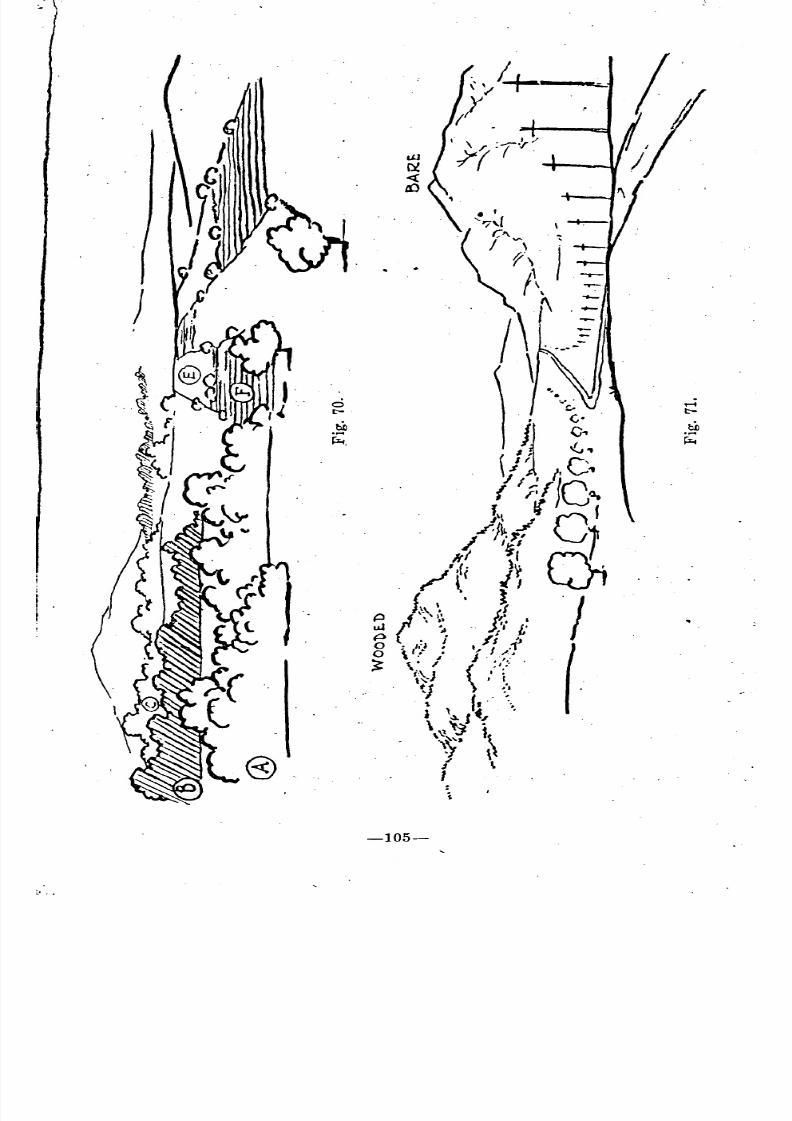
8/8/2019 Topography for Field Artillery
http://slidepdf.com/reader/full/topography-for-field-artillery 116/272
-105-
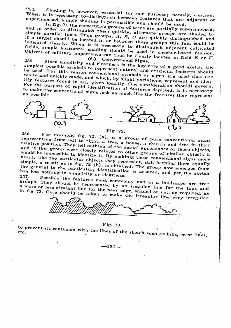
8/8/2019 Topography for Field Artillery
http://slidepdf.com/reader/full/topography-for-field-artillery 117/272
254. Shading is, however, essential for one purpose; namely, contrast.
When it is necessary to. distinguish between features that are adjacent or
superimposed, simple shading is permissible and should be used. .
. In fig. 71 the consecutive groups of trees are partially superimposed;
and in order, to distinguish them quickly, alternate groups are shaded by
simple parallel lines. Thus groups, A, B, C are quickly distinguished and
if a target should be located in or between these groupS this fact could be
indicated clearly. When it is necessary to distinguish adjacent cultivated
fields, simple horizontal shading should be used in checker-board fashion.
Objects of military importance can thus be clearly.located in field E or F.
(6.) Conventional Signs:' .
255. Since simplicity and clearness is the key-note o~ a good sketch, the
simplest possible symbols to represent natural and artificial' features should
be used. For' this reason conventional symbols' or, signs are used that are
easily and quickly made, and which, by slight variations, represent and iden-tify features found in any given locality. One consideration shouldl govern.
For the purpose of rapid identification of features depicted, it is necessary
to make the conventional signs look as much like the features they representas possible.
Fig. 72.,
256. For example, fig. 72, (a), is a group of pure conventional signs
representing from left to right, a tree, a house, a church and tree in their
relative position. They tell nothing of the actual appearance of those objects,
and if this group were closely related to other groups of similar objects it
would be impossible to identify it. By makinig these conventional signs more
nearly like the particular objects they represent, still keeping'them equally
simple, a result as in fig. 72 (b), is obtained. The group now emerges from
the general to the particular; identification is assured; ,and yet the sketchhas lost nothing in simplicity or clearness. ,
257. Possibly the features most commonly met in a lands~ape are tree
groups. They should be represented by an iregular line for tbe lops and
a more or less straight line for the near edge, shaded or not, as required, as
in fig 73. Care should be taken to make the irregular line' very irregular.
Fig. 73.
to prevent its confusion with the lines of the sketch such as h.iI!s. crest li~es.etc. "
-1013_
'
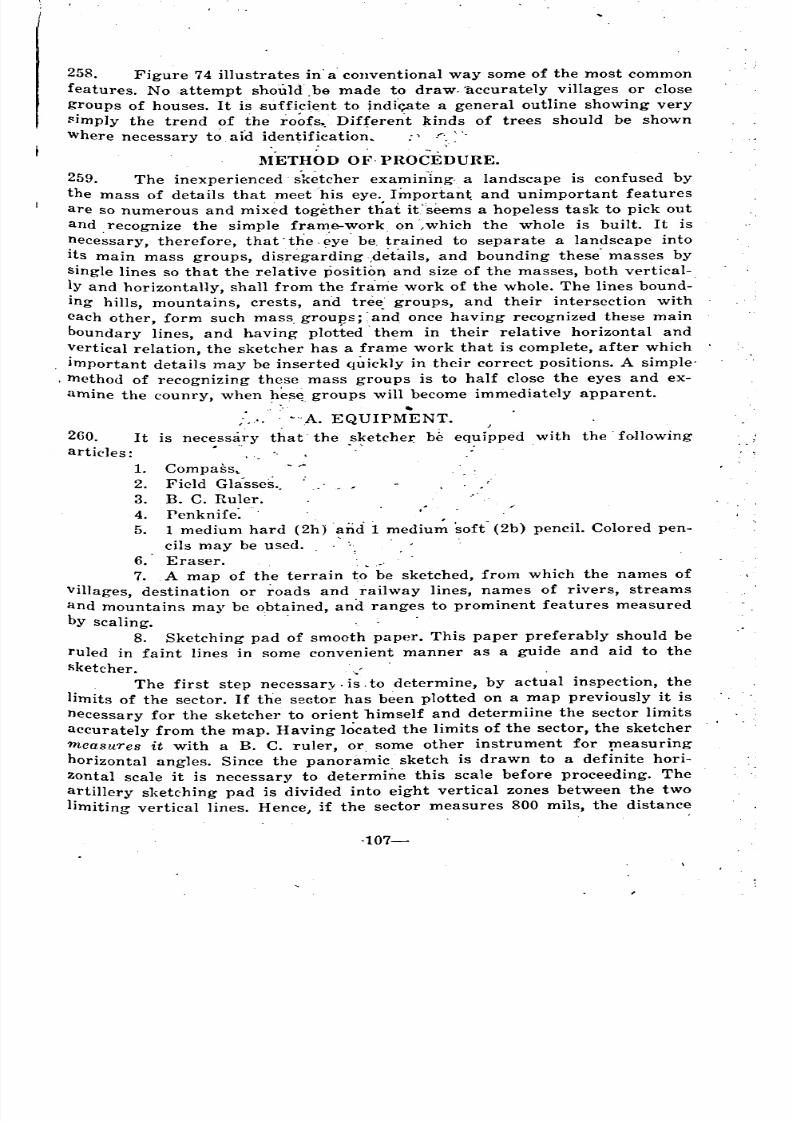
8/8/2019 Topography for Field Artillery
http://slidepdf.com/reader/full/topography-for-field-artillery 118/272
260. It
articles:
1.
2.
3.
4.
5.
258. Figure 74 illustrates in' a' conventional way some of the most common
features. No attempt shoul<f,ba made to draw, 'accurately villages or close
groups of houses. It is ~;uffici~nt to indf<;ate a general outline showing very
~imply the trend of the roofs. Different kinds of trees should be shown
Where necessary to aid identifi~atio~, :' "".:'". .
METHOD OF. PROCEDURE.
259. The inexperienced' sketcher examining, a landscape is confused by
the mass of details that meet his eye. Important and unimportant features
are so numerous and mixed together that it"seems a hopeless task to pick out
and recognize the simple frame-work on ,which the whole is built. It is
nece~sary, therefore, that' the. ~ye' be, trained to separate a landscape into
its main mass groups, disrE~ga~ding,details, and bounding these' masses by
single lines so that the relative position and size of the masses, both vertical-ly and horizontally, shall from the frame work of the whole. The lines bound-'
ing hills, mountains, crests, an'd tree groups, and their intersection with
each other, form such mass grou:gs;' aiId once having recognized these main
boundary lines, and having plotted' them in their relative horizontal and
vertical relation, the sketcher has a frame work that is complete, after which
important details may be inserted quickly in their correct positions. A simple-
. method of recognizing these mass groups is to half close the eyes and ex-
amine the counry, when h~s~ groups will become immediately apparent.
. .,.... .'A. EQUIPMENT.
is nec:ss~ry that' the .s~etcher. be equipped with the' following
Compass ..
Field Gla'sses.,
B. C. Ruler.
Penknife:
1 medium hard (2h)anci i mediu~ soft" (2b) pencil. Colored pen-
cils may be used.
6. Eraser. ,
7. A map of the terrain to be sketched, from which the names of
villages, destination or roads and railway lines, names of rivers, streams
and mountains may be obtained, and ranges to prominent features measured
by scaling. ,
8. Sketching pad of smooth paper. This paper preferably should be
ruled in faint lines in some convenient manner as a guide and aid to the
~ketcher. '~
The first step necessary. is, to determine, by actual inspection, the
limits of the sector. If the sector has b~en plotted on a map previously it is
necessary for the sketcher to orient himself and determiine the sector limits
accurately from the map. Having located the limits of the sector, the sketcher
measures it with a B. C. ruler, or some other instrument for ~easuring
horizontal angles. Since the panoramic sketch is drawn to a definite hori-
zontal scale it is necessary to determine this scale before proceeding. The
artillery sketching pad is divided into eight vertical zones between the two
limiting vertical lines. Hence, if the sector measures 800 mils, the distance
.107-
, .
'
" "
'
"
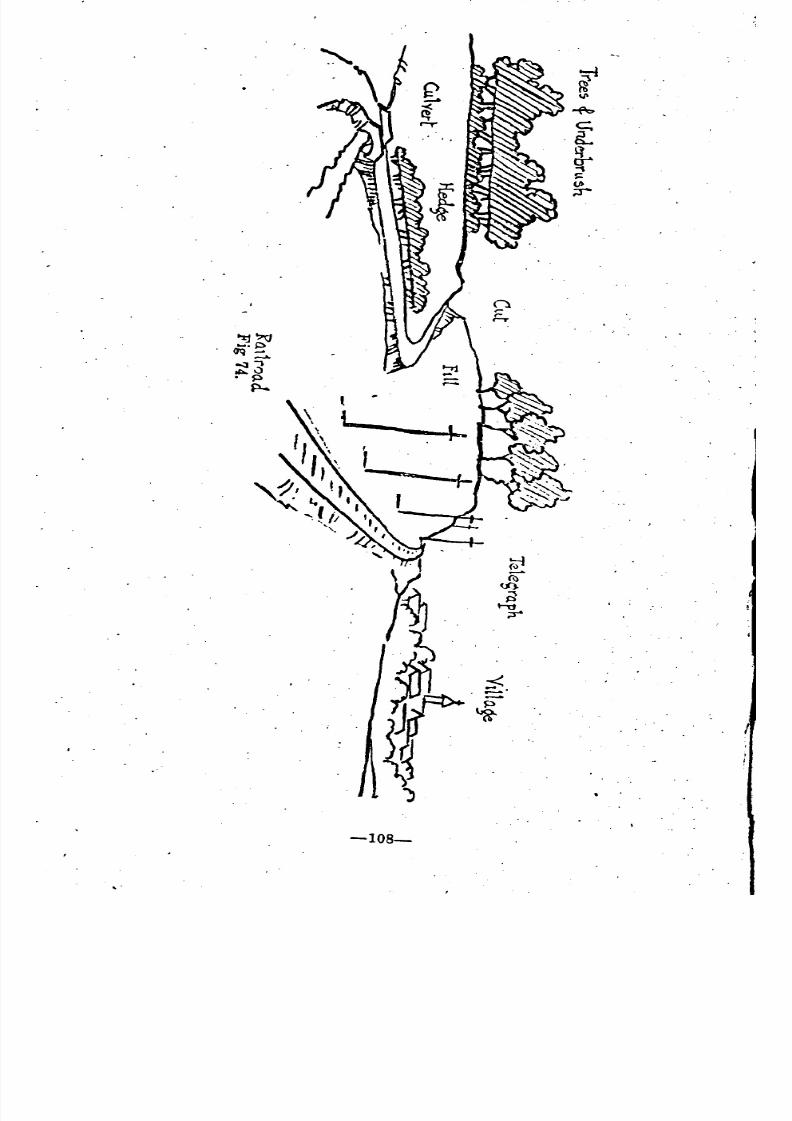
8/8/2019 Topography for Field Artillery
http://slidepdf.com/reader/full/topography-for-field-artillery 119/272
"
-108-
.
8/8/2019 Topography for Field Artillery
http://slidepdf.com/reader/full/topography-for-field-artillery 120/272
between any two adjacent vertical lines, will represent 100 mils; if the sector
is 400 mils, the distance between adjacent vertical lines will represent 50
lllils, etc. For a pad ruled in any similar convenient manner the scale of
'the sketch may be determined.
B. IDENTIFICATION OF THE SKETCHER'S POSITION AND THE
ORIENTATION OF THE SKETCH.
261. It is essential that this be done immediately, for the important rea-
son that unless this information is shown, the sketch' is of slight value to
anyone else attempting to use it.
Casualties among sketchers and observers are frequent and it should
be mandatory on all sketchers to complete th~se data,' as soon as the sector
to be sketched has been determined. The sketch thus becomes valuable at
once to others as soon as any military information appears on it, and in-('reases in value jn proportion to the completeness and accuracy of. this in-
formation.
262. Just as a map must, in order to make it of any value, have indicated
upon it the points of. the compass, so must a panoramic sketch have some
indication of direction. In the latter case this indication is only an approx-
imation and serves more for identification of the country than a correct
designation of direction.
263. An examination of fig. 65 will show that, at the bottom of the sketch,
and opposite the word, "Place", there is a cross mark o'n' the center verticalruled line. It is'through this mark that the arrow indicating the magnetic
north is drawn. Its direction is determined in the following mam1er.
As shown in fig. 75 turn the sketching pad into a horizontal posi-
tion. Sight along any vertical line at or near the center until this line, if pro-
longed, will pass through the exact point on the landscape through which
it passes in the sketch. The sketch is 'now oriented.
Holding the pad in this position place a compass on it and allow the
needle to come to rest.
Through the cross-mark on the center vertical line draw an arrow
parallel to the compass needle. Note, in the spaces indicated, the place from
'Which the sketch is made, the name of the sketcher, date, weather, as re-
{Jards 'visibility, and the hour of the day.
264. This last is important as the visibility changes from day to day and
from hour to hour, hence, unless indicated, an officer who was using a sketch
of a particular sector might imagine that he was in the wrong area unless
he knew that the conditions of visibility had changed. If time permits a
sketcher may choose the hour of the day when the visibility is best for the
area before him. Thus the early morning is best for a sector to the east
While shadows of late afternoon will serve to bring out successive ridges in
an area to the west.
C. ANALYSIS OF THE SECTOR.
265. Before proceeding further, examine the sector with and without glas-
Ses. The ground should be studied in an effort to get a clear mental picture
of its formation and to separate it into its fundamental mass groups; the
foreground mass or defilading screen, successive crests, the background or
-109-
\ ..
'
"

8/8/2019 Topography for Field Artillery
http://slidepdf.com/reader/full/topography-for-field-artillery 121/272
..... .
-110-
"
8/8/2019 Topography for Field Artillery
http://slidepdf.com/reader/full/topography-for-field-artillery 122/272
orizon. Glasses often will disclose crests, hollows, etc., capable of hiding
argets which otherwise might be overlooked. A little study will separate
he important from the unimportant details and the sketcher then is ready
o proceed, along definitely through-out lines, to conform to the object of the~keteh
, ;. SELECTI~N OF REFERENCE POINT AND HORIZONTAL
CONTROL.
~26: In order to ~ake the hori~ontal scale of practical value,'an origin of
i oflzontal measurement must be selected from the terrain and must be plot-
;ed and indicated on the sketch. A, sketch without a clearly indicated re-
~~rence point is more ,useless than a map without means of indicating direc-
I Ion. The reference point maY'i>r may not be in the sector included by the
~ketch. It should pre~erably, if possible, be in the sector, but owing to the
act .that the reference point must be a distinct, easily identified point, it isossible' that a given sector may be devoid of any point that could fulfill
t~ese conditions. In this case such a point should be selected as close to
,either limit, of the sector' as possible and an arrow should be drawn im-
mediately above the sketch pointing in the direction of this reference point,
~n.d should be so labeled. The point selected should further be described
rlefly as, "Reference point, lone pine tree on sky line", etc. Under normal
Conditions a suitable point can be chosen in the sector and indicated directly
on the Sketch. Since it is the origin of horizontal measurements, its angular
~esignation will be zero, a fact which further identifies it.67. In the selection of a reference point, the following considerations
;hoUld govern: (a) it should be easily seen and identified even under un-
avorable conditions of visibility, hence,' not too far away (as a distant
'lllountain_peak on the horizon); (b) it should be of such a character that it
cannot be entirely destroyed by artillery fire. ',.
<l' Owing to the prevalence of conditions of poor visibility, especially
urlng the winter months, in western Europe, the most suitable reference
~oints during the late war were found in the middle listance, and preferably,
f~atures of the terrain, such as; a small hill of distinctive shape, a well-de-
t lne? cross-roads or road fork, the point, where a road crossed a crest, or
the Intersection of a stream with a road or railroad, etc. These were found
o satisfy all conditions better than houses, towers, chimneys, trees or dis-
tant mountains. .' , .
268. By means of the plotted reference point and the vertical guide lines,
a ,baSis of horizontal control is established. By actually measuring with the
mI~ ruler the horizontal deflection of important points from the reference
POInt, these points may be plotted horizontally on the sketch in their true
I'elation.
In fig. 76 the farm is 200,mils from the reference point; the inter-
section of crests, A,' is 1l0inils, the peak, C, is 300 mils, etc.
E. VERTICAL CONTROL.
269. Vertical control, while not so important as the horizontal must be
~?nsi<lered by the sketcher if he would avoid distortion. Thus, unless some
lIne of vertical control is adopted a sketcher often will enlarge the vertical
-111-
' '
~
" '
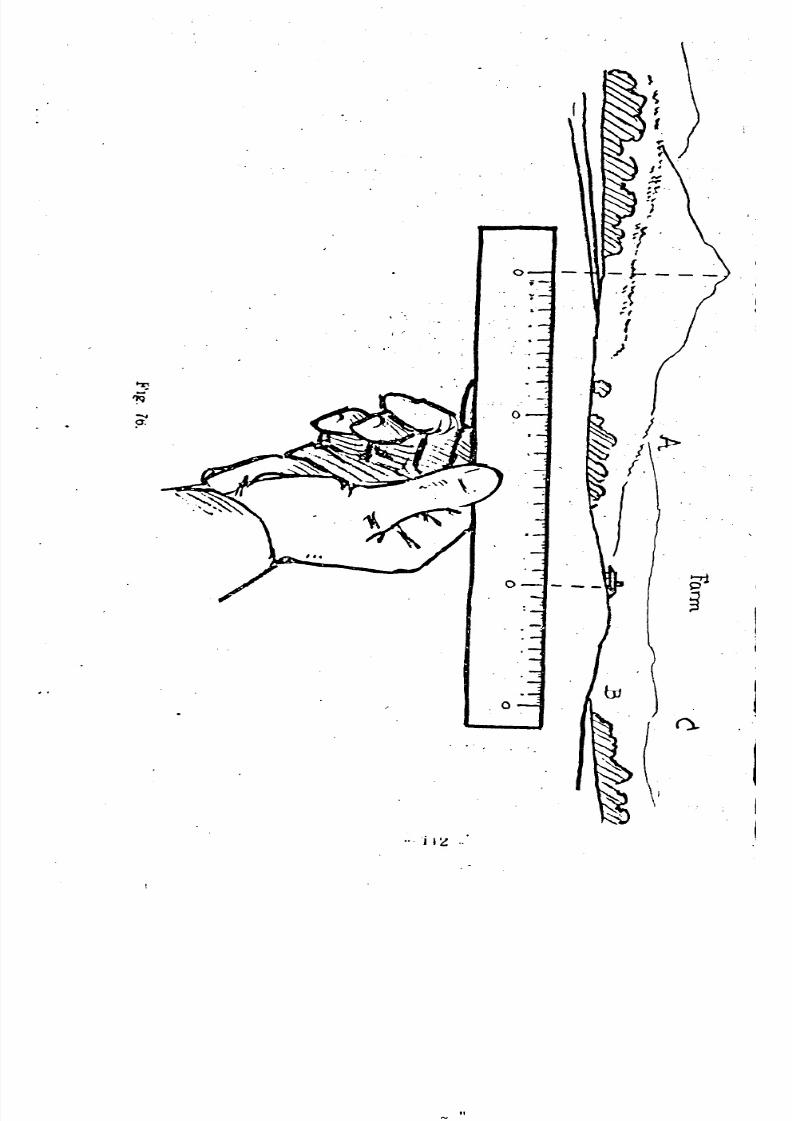
8/8/2019 Topography for Field Artillery
http://slidepdf.com/reader/full/topography-for-field-artillery 123/272
". j I ~ "
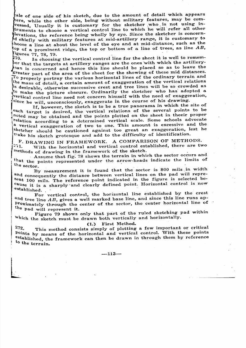
8/8/2019 Topography for Field Artillery
http://slidepdf.com/reader/full/topography-for-field-artillery 124/272
ale of one side of his sketch, due to the amount of detail which appears
ere, while the other side, being without military features, may be com-
ressed, Usually it is customary for the sketcher ,who. is not using in-
,truments to choose a vertical control line to which he will'refer all other
l.leva~ions,he referenc~ being wholly by eye. Since the sketcher is concern-
, d chIefly with military features at mid-artillery range, it is customary to
'hoose a line at about the level of the eye and at mid-distance, such as the
l~pf a prominent ridge, the top or bottom of a line of trees, as line AB,
Igures 77, 78, 79. . .
70. In choosing the vertical control line for the sheet it is well to remem-
er t~at the targets at artillery ranges are the ones with which the artillery-
flan IS concerned and' hence this line should be placed so as to leave the
:..greater part of the area of the sheet for the showing of these mid distances.
ro properly portray the various horizontal lines of the ordinar. y terrain and
~hemass of detail, a certain amount of exaggeration of the vertical relationss desirable, otherwise successive crest and tree lines will be so crowded as
:llto make the pictur~ obscure. Ordinarily the sketcher who has' adopted a
Iv:rtical control line need not concern himself with the need of exaggeration,
SIncehe will, unconsciously, exaggerate in the course of his drawing.
If, however, the sketch is to be a true panorama in which the site of
tach target is desired, the vertical relations of the several points to be
1noted may be obtained and the points plotted on the sheet in theeir proper
'I. relation according to a determined vertical scale. Some schools advocate
a vertical exaggeration of two to one. This amount is excessive and thesketcher should be cautioned against too great an exaggeration, lest he
Il:'ake his sketch grotesque an? add to the difficulty of identification.
c •• F. DRAWING IN FRAMEWORK. A COMPARISON OF METHODS.
, ./l.'Vith the horizontal and vertical control established, there are two
methods of drawing in the framework of the sketch. .
1h Assume that fig: 78 shows the terrain in which the sector occurs and
"hat the points represented. under the arrow-heads indicate the limits of
e sector. . .
By measurement it is found that the'sector is 800 mils ,in width
and consequently the distance between vertical lines on the pad will repre-
Sent 100 mils. The reference point indicated in the figure is selected be-
cause it is a sharply'and clearly defined point. Horizontal control is now
'established. , .
For vertical control, the horizontal line established by the crest
and tree line AB, gives a well marked base line, and since this line runs ap-
i~OXimatelY through the center of the sector, the center horizontal line of
e Pad will represent it.. Figure 79 shows only that. part of the ruled' sketching pad within
WhIch the sketch must be drawn both vertically and horizontally.
27 (1.) First Method.
~. This method consists simply of plotting a few important or critical
POInts by means of the horizontal and vertical control. 'Vith these points
~tab1ished, the framework can then be drawn in through them by reference
the terrain.
-113-
'
~
' ~
'
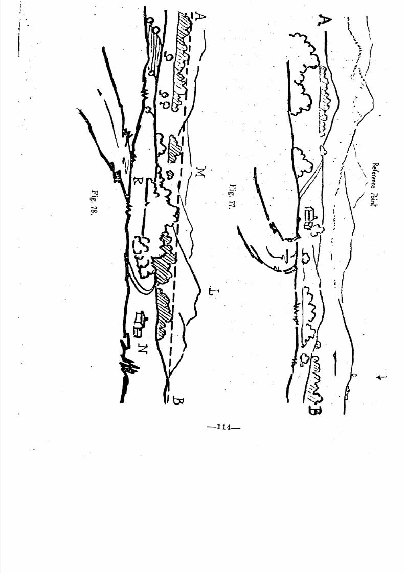
8/8/2019 Topography for Field Artillery
http://slidepdf.com/reader/full/topography-for-field-artillery 125/272
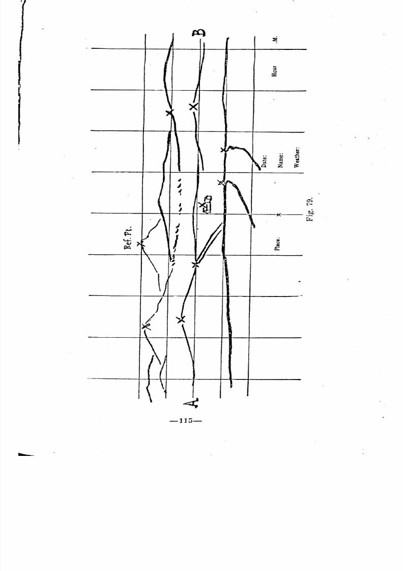
8/8/2019 Topography for Field Artillery
http://slidepdf.com/reader/full/topography-for-field-artillery 126/272
-]15-

8/8/2019 Topography for Field Artillery
http://slidepdf.com/reader/full/topography-for-field-artillery 127/272
-116-
Since the reference point is slightly to the left of the center of the.
sector it is plotted slightly to the left of the center of the sketch, and at
such height above the line AB as the eye estimates it. to be above the
imaginary line AS in the sector. This Point must be plotted first. By mea
Surement the chimney of the house is found to be 100 mils to the right 0
the reference point. It is also slightly below the imaginary line AS, fig. 78
Using the pre-determined scale of the sketch, measure off 100 mils to the
right of the plotted reference point, and, moving vertically. downward below
the line AS, plot in the location of the chimney such a distance below this
line as to be relatively correct, fig. 79.' In a similar manner, enough critical,
points are plotted to the right and left of the reference point to. establish
the framework of the sketch. A few such points are indicated.in fig. 91
by crosses. Typical critical Points are crests of hills, intersections of crests,
houses, limiting points of roads, limits of tree groups, etc. Through these
plotted points draw the outline of the terrain. , , ,
This method is the most accurate but is slow on account of the con-stant necessity of identifYing the plotted points with the points in the terrainthey actually represent. .,
. .(2.) Second Method ..
273. By holding the sketching pad vertically in front of the eye and look-,
ing ove: the top of the pad at the landscape, and at the same time moving
the pad, to or from the eye, a point will be reached at which the two
. limiting vertical ::nes of the pad will intersect, if prolonged" the corresponde
. ing limits of the sector. Figure 80 shows the pad in this position for the
landscape and sector shown in fig. 78. Holding' th~ pad here' the' sketcher
draws in lightly, in the one inch space at the extreme top of the sheet, the,
sky line and as many other important points. as possible, comparing the
outline'directly with the country as he glances over, the top of the pad.!,
This procedure automatically locates the framework horizontally. When,
completed, the pad is lOwered into a comfortable horizontal position and the.
framework so drawn is carried' down into its proper position on the sheet,'especial attention being given to locating the framework correctly by means,of the vertical control. '. ". .
,This method is much more rapid than the other and after 'a little:practice equally accurate result. can be obtained with it. It has the advan-
tage of eliminating constant identification of plotted points with correspond-ing grounds Points, and the consequent loss of time.' ..
274. The frame work drawn by either method should be done lightly with'
. a hard pencil. If time permits it can be gone over later and corrected where,.
nceSsary. More attention can then be paid to characteristic shapes and for-"
mations, and to relative vertical relations:. The principles of perspectivealso should be applied., , . ',' , . , , i.
.N otel: By using a sheet of transpar~nt celluloid, the same sizeas the sketching pad blank, ruled in the Same manner as the blank and,
a.ttached at rig?t angles to the pad, the sketcher may calibrate his sketc?, J!sImply by looking through the celluloid, and nOting on which line or m
which space each feature falls. It is a simple matter, then, to sketch 'these.
features in the same areas on the paper. ", ,",.:'. -. '. . . ;
' '
'" -
'
' " "
~ ' '
'
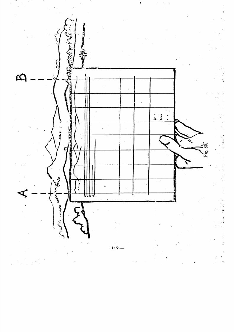
8/8/2019 Topography for Field Artillery
http://slidepdf.com/reader/full/topography-for-field-artillery 128/272
.
.11'1_
.' J
.
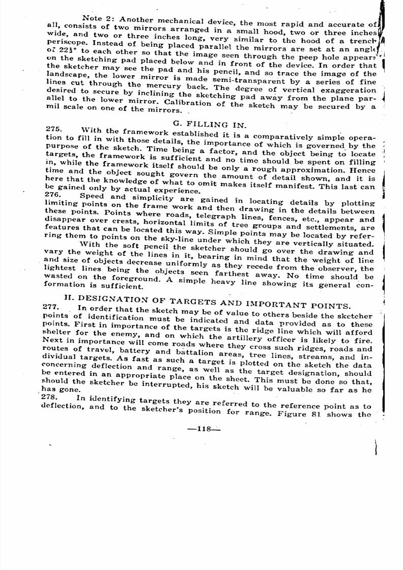
8/8/2019 Topography for Field Artillery
http://slidepdf.com/reader/full/topography-for-field-artillery 129/272
Note 2: Another mechanical device, the most rapid and accurate of
all, consists of two mirrors arranged in a small hood, two or three inches r~
wide, and two or three inches long, very similar to the hood of a trencr
periscope. Instead of being placed parallel the mirrors are set at an angh
or 22~O to each other so that the image seen through the peep hole appearf-
1
on the sketching pad placed below and in front of the device. In order that
the sketcher may see the pad and his pencil, and so trace the image of the
landscape, the lower mirror is made semi-transparent by a series of fine .
lines cut through the mercury back. The degree of vertical exaggeration
desired to secure by inclining the sketching pad away from the plane par-
allel to the lower mirror. Calibration of the sketch may be secured by amil scale on one of the mirrors.
G. FILLING IN.
275. With the framework established it is a comparatively simple opera-tion to fill in with those details, the importance of which is governed by tbej.
purpose of the sketch. Time being a factor, and the object being to locate
targets, the framework is sufficient and no time should be spent on filling j'.
in, while the framework itself should be only a rough approximation. Hence
time and the object sought govern the amount of detail shown, and it is
here that the knowledge of wbat to omit makes itself manifest. This last canbe gained only by actual experience.
276. Speed and simplicity are gained in locating details by plotting
limiting points on the frame work and then drawing in the details between
these points. Points where roads, telegraph lines, fences, etc., appear and
disappear over crests, horizontal limits of tree groups and settlements, are
features that can be located this way. Simple points may be located by refer-
ring them to points on the sky-line under which they are vertically situated.
With the soft pencil the sketcher should go over the drawing and
vary the weight of the lines in it, bearing in mind that the weight of line
. and size of objects decrease uniformly as they recede from the .observer, the
lightest lines being the objects seen farthest away. No time should bewasted on the foreground. A simple heavy line showing its general con-formation is sufficient.
II. DESIGNATION OF TARGETS AND IMPORTANT POINTS.
277. In order that the sketch may be of value to others beside the sketcher
points. of identification must be indicated and data provided as to these
points. First in importance of the targets is the ridge line which will afford
shelter for the enemy, and on which the artillery officer is likely to fire.
Next in importance will come roads Where they cross such ridges, roads and
routes of travel, battery and battalion areas, tree lines, streams, and in-
dividual targets. As fast as such a target is plotted on the sketch the data
concerning deflection and range, as well as the target designation, should
be entered in an appropriate place on the sheet. This must be done so that,
should the Sketcher be interrupted, his sketch will be valuable so far as hehas gone.
2i8. In identifying targets they are referred to the reference point as to
deflection, and to the sketcher's position for range. Figure 81 shows the
-118-:"
_
'
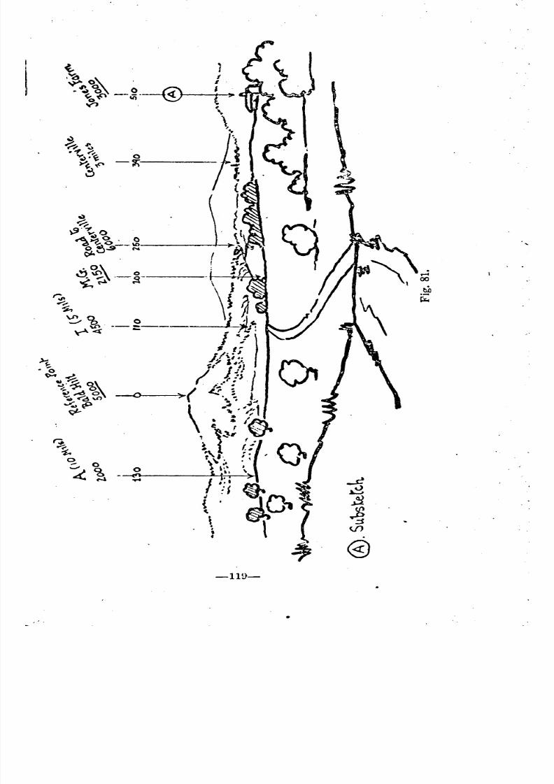
8/8/2019 Topography for Field Artillery
http://slidepdf.com/reader/full/topography-for-field-artillery 130/272
8/8/2019 Topography for Field Artillery
http://slidepdf.com/reader/full/topography-for-field-artillery 131/272
method of accomplishing this. Vertical lines' are drawn from the top of t
sheet and terminate in an arrow head in the exact point on the sketch whe
the point in question is located on the ground. Directly at the top of t
line the description of the point so located is written diagonally, so that
can be read with the sketch held in a normal position. Conventional si! '
for targets should not be used. They serve only to add unecessary de
to the sketch and destroy clearness. Since, in the artillery, the right of t
target is the point on which firing data are computed, the vertical line sho?
indicate the loeation of the right of the target, and if further identificatl ;
is necessary, its width in mils may be indicated. This would mean then, tli
lhe arrow-head locates the right of the target, and that the target exte~to the left of this point so many mils. '.
279. Simplicity in designation' of targets can be accomplished by usjil;
definitely understood abbreviations; e. g., "I" for infantry deployed, "A" rartillery in position, etc. The reference point always should be indicated
such and may further be given its correct name if known. For quick iden
fication the line to this point may be made' heavy or doubled. Accordir
to the jUdgement of the sketcher and the purpose of the sketch, any inforIl1I
tion may be shown, such as names of hills, mountains, farms, villages, de
tination of roads and railroads, location of bridges, trestles, culverts, et
The sketcher is governed only by consideration of the relative military iportance of the poirt:s shown or omitted. I
280. On the artillery sketch, directly under the description of the indicat
point or object, should be shown its range. The range is either estimate
or measured. If the latter, it is unde~'lined. By reference to fig. 65 it
~een that at the top of the sheet. are five horizontal zones marked at t
left, DE', DD, Sf, KR, alld .nN. These zones are solely for firing data a
these data are filled in before and corrected after firing. The firing dat '.
referring to any particular target, should be written across the vertical Iidesignating the target, and be in the correct zone. j
It is evident, therefore, that a third range Occurs. This ran~e, aft
aclual firing and correction, is the gun range to that particular point. Hen
on the complete sketch there will be shown estimated ranges, measur;,:
ranges determined by instruments, or from the map, and gun ranges d~termined by actual firing.
281. Immediately below the five horizontal zones for recording firing
data, fig. 65 is a one-inch Space before reaching the upper horizontal limit
of the sketch proper. This space is used solely for rec:>rding angular deflection)The deflection in mils of the particular point indicated, right or left of the
reference point, is placed directly on the vertical reference line, as indicated
in fjg. 81. The' deflection of the reference point is, of course, zero, which
further identifies this point. With a reference point within the sketch, de-
fl~tions will increase to the right and left of it. 'Vith the reference P()j[Wllhout the sketch, deflections will increase throughout the sketch to t~ .
left or right, depending on where the reference Point is, to the right or ~el •
of the sector. Deflections are habitually indicated to th~ nearest multlp
of five, as no closer measurement is possible with a mil ruler.
.
.
;
.
"
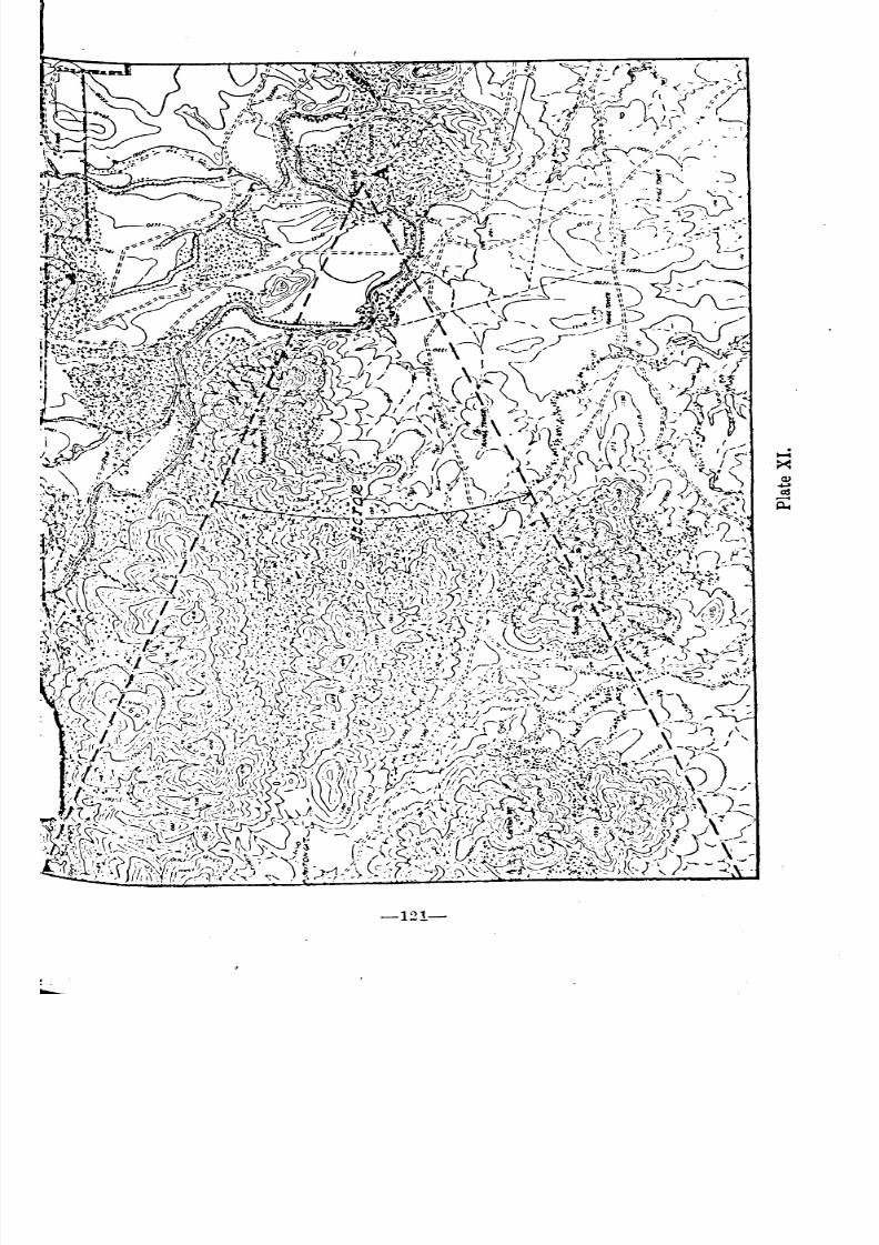
8/8/2019 Topography for Field Artillery
http://slidepdf.com/reader/full/topography-for-field-artillery 132/272
-121-
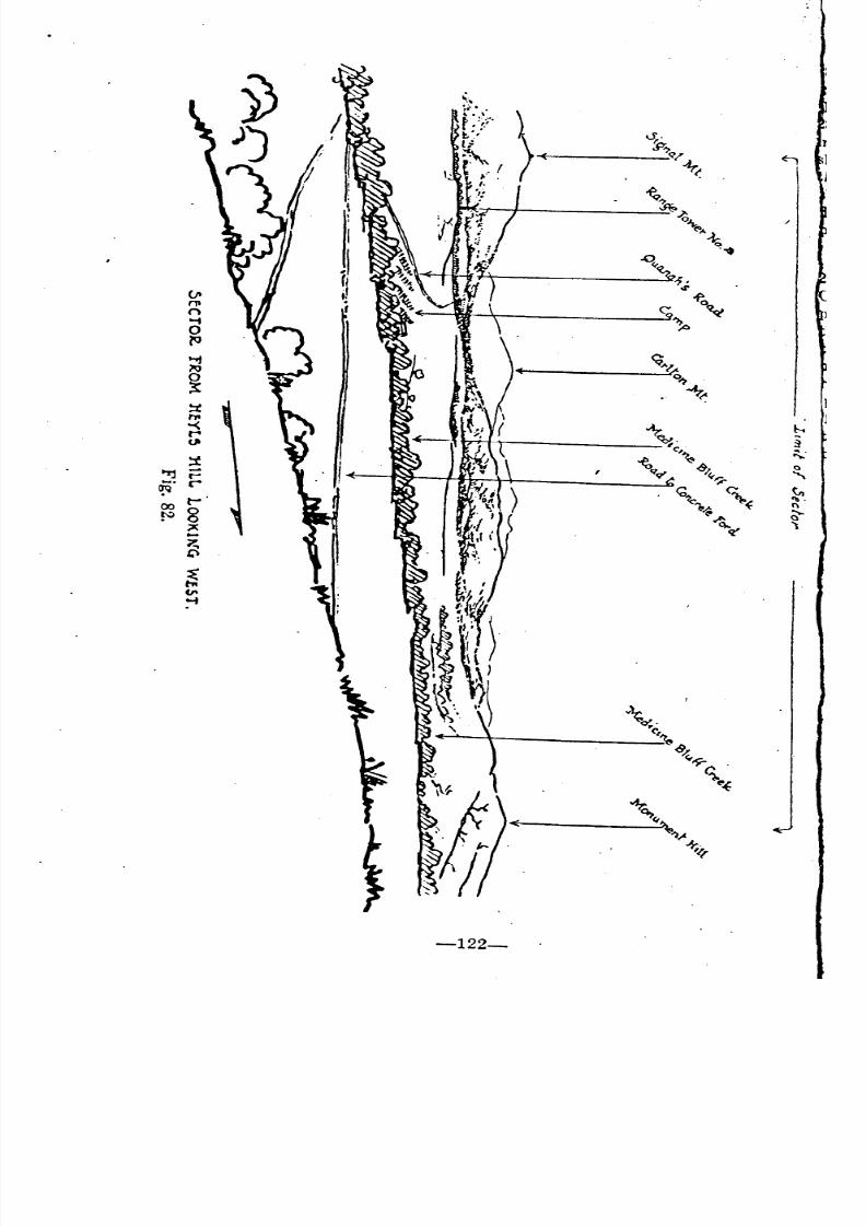
8/8/2019 Topography for Field Artillery
http://slidepdf.com/reader/full/topography-for-field-artillery 133/272
8/8/2019 Topography for Field Artillery
http://slidepdf.com/reader/full/topography-for-field-artillery 134/272
, I. SUBSKETCHES.
:82. In certain cases the sketcher may wish to show the terrain sur-
~Unding any particular point in more det~il than is possible on the ma.in
'8etch. This may be done by means of a subsketch, see A, fig. 8l.
, 3. In conclusion the sketcher must remember that he is busied in mak-
~g a map, a military record which is to be used by others. Therefore he
h?uld ask himself constantly the question, "What value has this sketch at
'hIS moment to another person"? With this question before him the sketcher
I ould be able to resist the temptation to draw unessentials, and so put,
,own only data of value, recording such items in turn according to their im-
ortance.,
MAP AND PAI\ORAi\HC SI{ETCH.
~84.. Plate Xl is a section of the military reservation of Fort Sill, Okla.
n It is marked a sector to be sketched from a given point, A. Fig. 82 is the
:noramic sketch made of this sector from the desired point. A study of
:he map and an examination of the sketch will show the comparison between
.e two and also will indicate the immense value of a sketch for showing
...vw the ('ountry actually looks from the customary point of view. No matter
ow great the topographer's knowledge or ability to read a map, it is im-
~~.ssible for him to get an accurate men.tal picture of the countr~ si~pl>:
." un a study of the map. The sketch brIdges the chasm between Imagma-
:101\
and1
C'ality; and with both at hand, intelligent and exact action may:l(: planned e':en though the country is entirely new and strange.
-123-
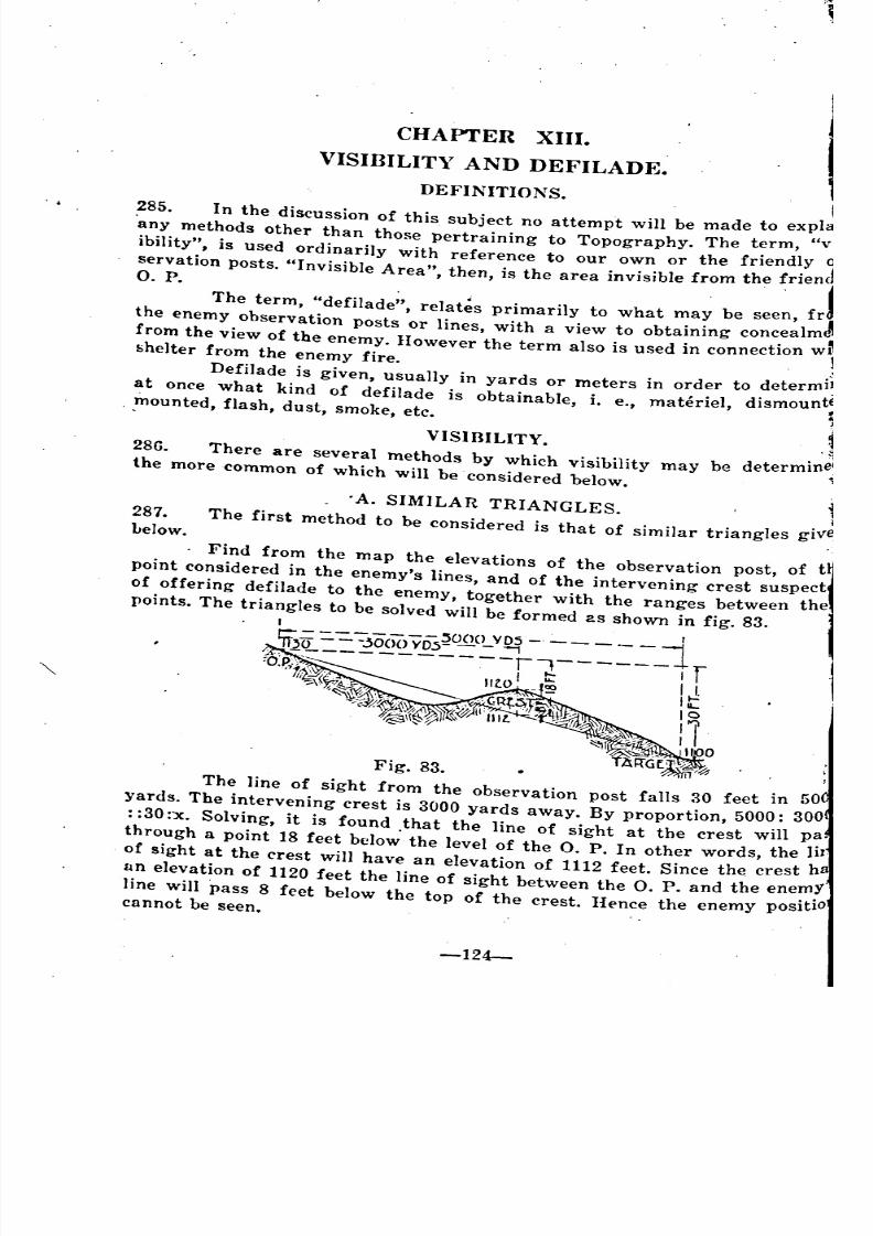
8/8/2019 Topography for Field Artillery
http://slidepdf.com/reader/full/topography-for-field-artillery 135/272
287.
Lelow.
CHAPTER XIII.
VISIBILITY AND DEFILADE.
DEFINITIONS .
. • 285. In the discussion of this subject no attempt will be made to expl~
'any methods other than tho,", pertraining to Topography. The term, "vi
ibility", is used ordinarily with reference to our own or the friendly q
servation posts. "Invisible Area" the.n is the area invisible from theo. P. . , .'
The term, "defilade", relat~s primarily to what may be seen, fr
the enemy observation posts or lines, with a view to obtaining conc.ealm ffrom the view of the enemy. However the term also is used in conneclIon w~shelter from the enemy fire. . ,]
Defilade is given, usually in yards or meters in order to determI~
at once what kind of defilade is obtainable, i. e., materiel, dismount~. mounted, flash, dust, smoke, etc.
.
VISIBILITY. .286. There are several methods by which visibility may be determine(the more common of which will be considered below.
.A. SIMILAR TRIANGLES.
The first method to be considered is that of similar triangles give
Find from the map the elevations of the observation post, of t
point considered in the enemy'S lines, and of the intervening crest suspect
the
Fig. 83.
The line of sight from the observation post falls 30 feet in 50
}.ards. The intervening crest is 3000 yards away. By proportion, 5000: 300
: :30 :x. Solving, it is found that the line of sight at the crest will pa
through a point 18 feet below" the level of the O. P. In other words, the Iir.
of sight at the crest will have an elevation of 1112 feet. Since the crest h
un elevation of 1120 feet the line of sight between the O. P. and the enemY
line will pass 8 feet below the top of the crest. Hence the enemy positiocannot be seen.
friencJ'
~
-
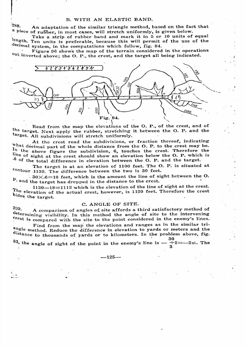
8/8/2019 Topography for Field Artillery
http://slidepdf.com/reader/full/topography-for-field-artillery 136/272
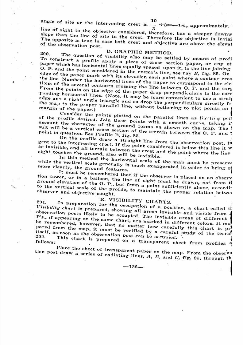
8/8/2019 Topography for Field Artillery
http://slidepdf.com/reader/full/topography-for-field-artillery 137/272
10 . 1"angle of site or the intervening crest is +3=-11/t, approXImate y.
3line of sight to the objective considered, therefore, has a. ste~pe~ d?w~,,:.
slope than the line of site to the crest. Therefore the obJectIve IS mVIS
The opposite is true'in case both crest and objective are above the elevatof the observation post.
D. GRAPHIC METHOD.
290. The question of visibility also may be settled by means of proff
To construct a profile apply a piece of cross section paper, or any ot
paper which has horizontal lines equally spaced upon it, to the line joining'
O. P. and the point considered in the enemy's line, see ray B, fig. 85. On
edge of the paper mark with its elevation each point where a contour cros
ihe line. Number the horizontal lines of the paper to correspond to the ele'thus of the several contours crossing .the line between O. P. and the targ
From the points on the edge of the paper drop perpendiculars to the corr,
'ronding horizontal lines. (Note. It may be more convenient to use a straiji
<:dge an', a right angle triangle and so drop the perpendiculars directly fr(
the ma) to the p! ~per parallel line, without bothering to plot points onmargin ')[ the paper.)
Consider th2 points plotted on the parallel lines as Ii'11',tir';~ pr,i,
of the p,ofile desireu. Join these points with a smooth ('ur'/e, takin6" i!'
account the character of the ground forms as shown on the map. The fsuIt will be a vertical cross section of the terrain between the O. P. and tpoint in question. See Profile B, fig. 85.
On the profile draw a straight line from the observation' post, ta
gent to the intervening crest. If the point considered is below this line it VI
l,e invisible, and all terrain between the crest and the point where the line'sight tOllches the ground, also will be invisible. •
In this method the horizontal scale of the map must be preserve
While the vertical scale generally is much exaggerated in order to bringmore clearly, the ground features. ,
It must be remembered that if the observer is placed on an 'obser~:
tion tower, or in a balloon, the line of sight must be drawn, not from
ground elevation of the O. P., but from a point SUfficiently above, accordilj
to th.e vertical scale of the profile, to maintain the proper relation bctwe1Observer and objective sought. ,
, .'E. VISIBILITY CHARTS.
2!H. In preparation for the occupation of a position, a chart called tb
Vi8ibilit~ chart is ~repared, showin~ all area~ i~visibIe and visib~e from
observatIOn posts lIkely to be occupIed. The mVIsIble areas of dIfferent
P's., if appearing on the same chart, are marked in different colors. It mu
be remembered, however, that no matter how carefully this chart Is Pl~
~ared from the map, it must be verified b~ a careful .stndy of the terra~Itself, as soon as the observation post can be occupied.
292. This chart is prepared on a transparent sheet from profilesfollows: .
Place the sheet of transparent paper on the map. From the observ81
tion post draw a series of radiating lines, A, B, and C, fig. 83, through thj
-
o' " t
'
'
8/8/2019 Topography for Field Artillery
http://slidepdf.com/reader/full/topography-for-field-artillery 138/272
....
1000
bil
\ .
transfer the points to the chart. After marking all the ra}1S on the map in
,this manner an irregular area or areas will be indicated by the dots. See
Points x', y', and z' of ray A, and x"~ Y",'and z" of ray C. Connect these dots
.
,',1
,..;
"
"
~
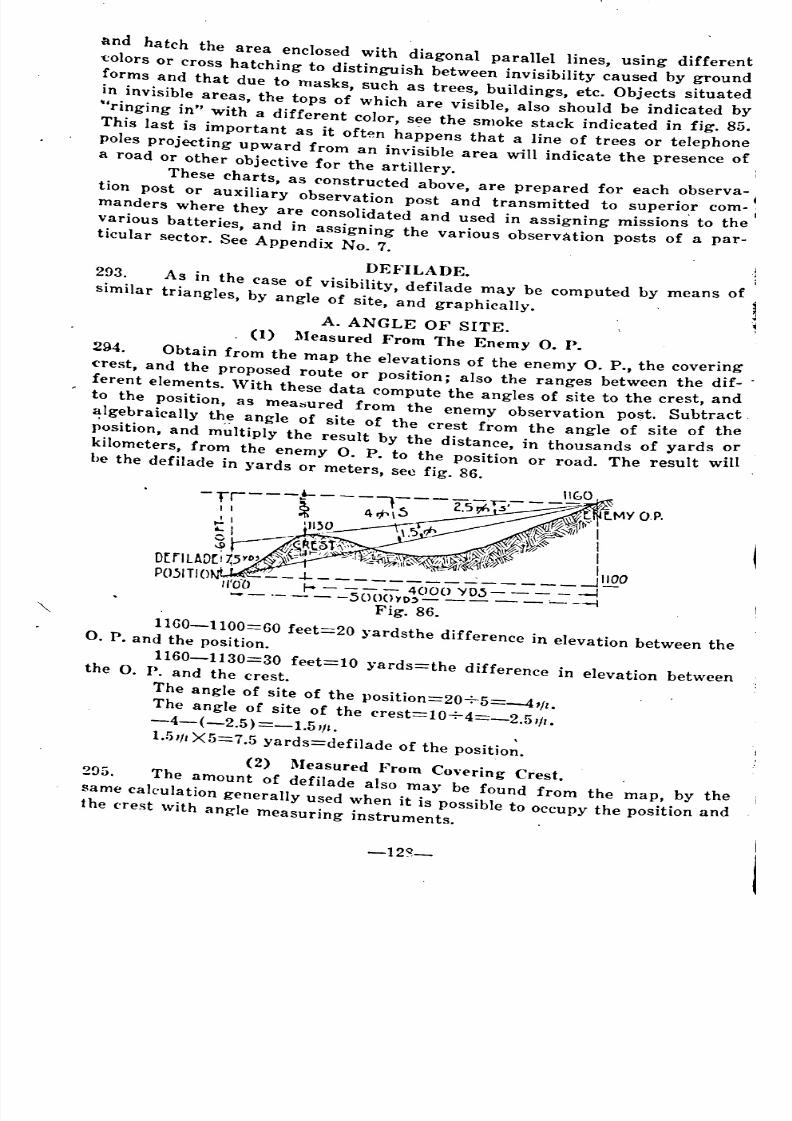
8/8/2019 Topography for Field Artillery
http://slidepdf.com/reader/full/topography-for-field-artillery 139/272
:lnd hatch the area enclosed with diagonal parallel lines, using different
'Colors or cross hatching to distinguish between invisibility caused by ground
forms and that due to masks, such as trees, buildings, etc. Objects situated
in invisible areas, the tops of which are visible, also should be indicated by
"ringing in" with a different color, see the smoke stack indicated in fig. 85.
This last is important as it often happens that a line of trees or telephonepoles projecting Upward from an invisible area will indicate the presence ofa road or other objective for the artillery.
These charts, as constructed above, are prepared for each observa-
tion post or auxiliary observation post and transmitted to superi~r com-
manders where they are consolidated and used in assigning missions to the
various batteries, and in assigning the various observation posts. of a par-ticular sector. See Appendix No.7.
DEFILADE.2?3.. A~ in the case of visibility, defilade may be computed by means of j
SimIlar tnangles, by angle of site, and graphically. .
.A. ANGLE OF SITE. \
, (I) Measured From The Enemy O. P.
294. Obtain from the map the elevations of the enemy O. P., the covering
crest, and the proposed route or position; also the ranges between the dif-
ferent elements. With these data compute the angles of site to the crest, and
to the position, as mea:sured from the enemy observation post. Subtractalgebraically the angle of site of the crest from the angle of site of the
position, and multiply the result by the distance, in thousands of yards or
kilometers, from the enemy O. P. to the position or road. The result willhe the defilade in yards or meters, see fig. 86.
lIf,O-tr---t--~~-;---2.5~. ~ tMYOP.
I I "Ii '/"\ ~iJf\l"..,!,t '11~~')f/l ,f:t:.~~1 I
~I .... \, ,,-,IF Ir-~,~R(~t~:, ,'or ,~,;!'~it~ ID(F1lAD(i7;5YO~ ,;~~liJh! ;--I:,::\;W;!"~~ ,,~~!~~Z; '1100
P05ITIO ---1- -j_1/'00 f-4 4(100 YD~-
._- -.50()()yo~- '---4
Fig. 86.
1160-1100=60 feet=20 ~.ardsthe difference in elevation between theO. P. and the position.
1160-1130=30 feet=10 ~.ards=the difference in elevation between
the O. P. and the crest.
The angle of site of the Position=20+5=-41!1.
The angle of site of the crest=10+4=_2.51!1.-4-(-2.5)=-1.5111. ,
l.!illl X5=7.5 yards=defilade of the position.
(2) Measured From Covering Crest.
295. The amount of defilade also may be found from the map, by the
same caltulation generally used when it is possible to occupy the position and
the ('fest with angle measuring instruments. ,
-12~_
'
~ -~ ,
_ - -- - __
- - - - - - -
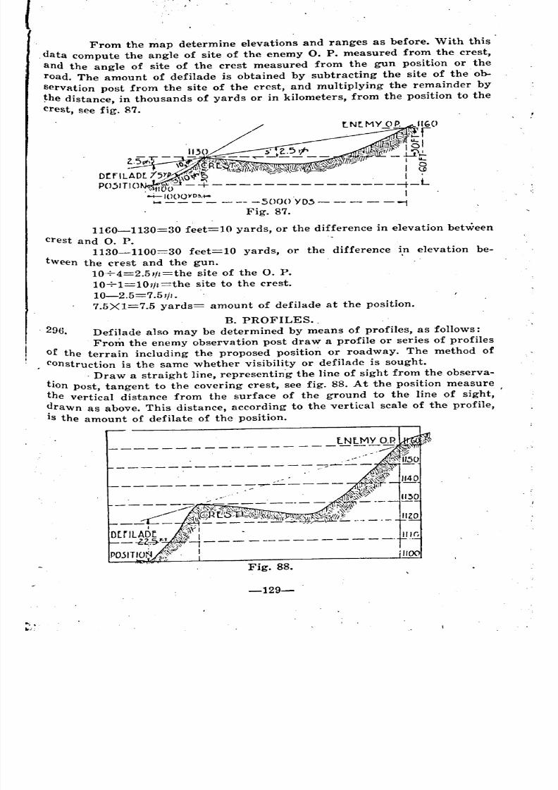
8/8/2019 Topography for Field Artillery
http://slidepdf.com/reader/full/topography-for-field-artillery 140/272
From the map determine elevations and ranges as before. With this
data compute the angle of site of the enemy O. P. measured from the crest,
and the angle of site of the crest measured from the gun position or the
road. The amount of defilade is obtained by subtracting the site of the. ob-
servation post from the site of the crest, and multiplying the remainder by
~he distance, in thousands of yards or in kilometers, from the position to the
crest, see fig. 87.
1160-1130=30 feet=lO yards, or the difference in elevation between
crest and O. P.
1130-1100=30 feet=10 yards, or the difference in elevation be-
tween the crest and the gun.
10-7-4=2.51/t=the site of the O. P.
10-7-1=10,/t=the site to the crest.
10-2.5=7.5//1. .
7.5X1=7.5 yards= amount of defilade at the position.
B. PROFILES ..
. 296. Defilade also may be determined by means of profiles, as follows:
From the enemy observation post draw a profile or series of profiles
of the terrain including the proposed position or roadway. The method of
construction is the same whether visibility or defilade is sought .
. Draw a straight line, representin.g the line of sight from the observa-tion post, tangent to the covering crest, see fig. 88. At the position measure
the vertical distance from the surface of the ground to the line of sight, ,
?rawn as above. This distance, according to the vertical scale of the profile,
IS the amount of defilate of the position.
1140
1130
IlZO
II If,
Fig. 88.
-129-
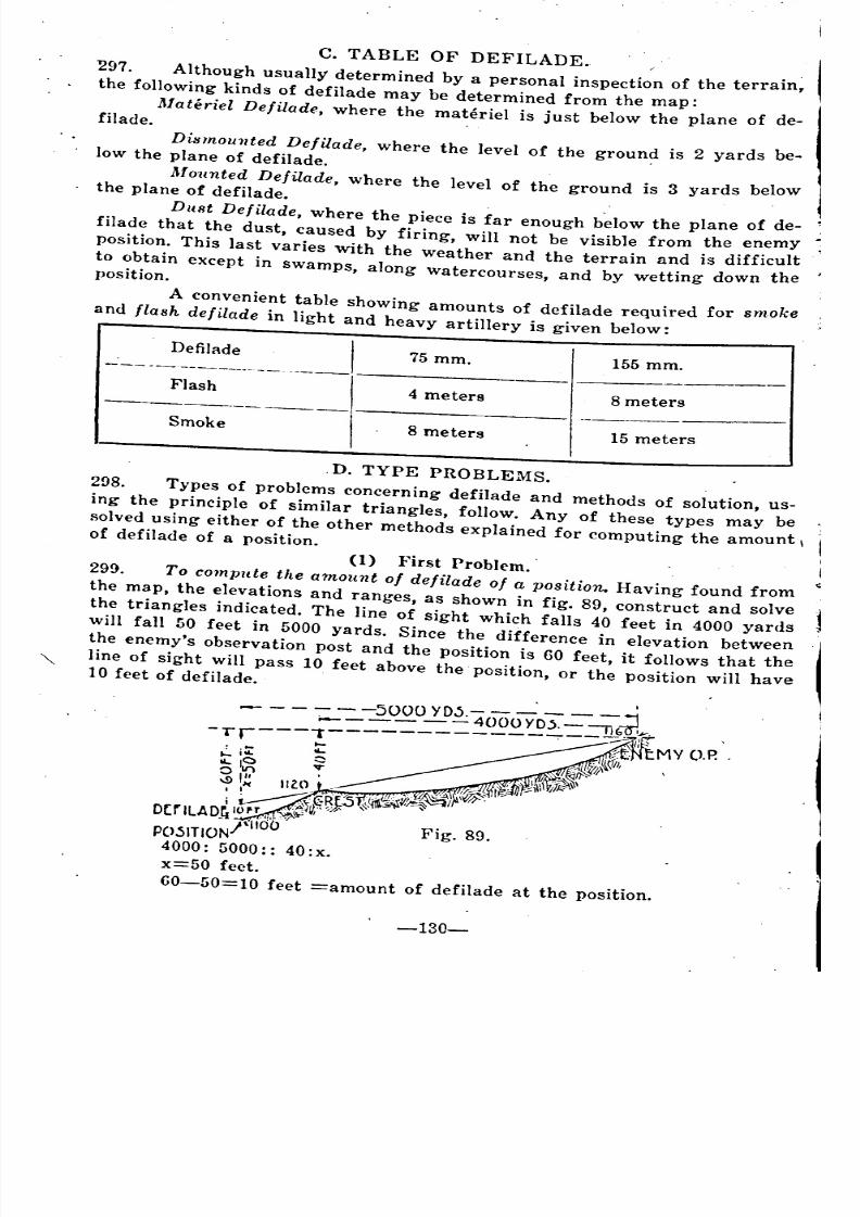
8/8/2019 Topography for Field Artillery
http://slidepdf.com/reader/full/topography-for-field-artillery 141/272
Defilade I75mm.
155 mm.-:_- --~~~sh ---.---. -----,
--4 meters
8 meters-------- -----,----Smoke
I8 meters
15 meters
c. TABLE OF DEFILADE.
297. Although usually determined by a personal inspection of the terrain,
the following kinds of defilade may be determined from the map:
Materiel Defilade, where the materiel is just below the plane of de-filade.
Dismounted Defilade, where the level of the ground is 2 yards be-low the plane of defilade. .
Mounted Defilade, where the level of the ground is 3 yards belowthe plane of defilade.
Dust Defilade, where the piece is far enough b~low the plane of de-
filade that the dust, caused by firing, will not be visible from the enemy
position. This last varies with the weather and the terrain and is difficult
to obtain except in swamps, along watercourses, and by wetting down theposition.
A convenient table showing amounts of defilade required for smokeand flash defilade in light and heavy artillery is given below:
.D. TYPE PROBLEMS.
2!:l8. Types of problems concerning defilade and methods of solution, us-
ing the principle of similar triangles, follow. Any of these types may be .
solved using either of the other methods explained for computing the amount \of defilade of a position.
(I) }~irst PrOblem.
299. To compute the amount of defilade of a position. Having found fromthe map. the elevations and ranges, as shown in fig. 89, eonstruct and solve l
the triangles indicated. The line of sight which falls 40 feet in 4000 yards
will fall 50 feet in 5000 yards. Since the difference in elevation between
the enemy's observation post and the position is 60 feet, it follows that the
line of sight will pass 10 feet above the' position, or the position will have10 feet of defilade.
j 1.
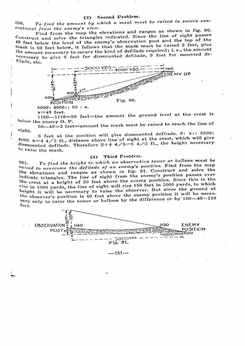
8/8/2019 Topography for Field Artillery
http://slidepdf.com/reader/full/topography-for-field-artillery 142/272
-r--= =--r-=~~~D~~~~(l -:=;ri'~OMY OP
I ~ . "W~' .t'
u.. <to 'N1/C .. .--- "v
'f M 'l-~~ . ._____ ,~@\h/
I IIIO~ '''/\:.:1\''/''.
1100. :/' ,.~ .:'llr' 7. . ~C 'r'(',qi(T=,;}d:'-;,'I>
ptt f 'ON'''' Fig. 90.
5000: 4000:: 60 : x.
x=48 feet.b 1160-1110=50 feet=the amount the ground level at the crest is
clow the enemy O. P.50-48=2 feet=amount the mask must be raised to reach the line of
'(2) Second Problem.
300. To find the amount by which a mask must be 'raised to secure con-
Cealment from the enemy's view.Find from the map the elevations and ranges as shown in fig. 90.
Construct and solve the triangles indicated. Since the line of sight passes
48 feet below the level of the enemy's observation post and the top of the
Inask is 50 feet below, it follows that the mask must be raised 2 feet, plus
the amount necessary to secure the kind of defilade required; i. e., the amount
nf:cessary to give 6 feet for dismounted defilade, 9 feet for mounted de-
Ilade, etc.
sight.
40 6 feet at th~ position will "gi~e dj~mounted defilade. 6.: x::. 50~0:
'do00. x=4 4/5 ft., dIstance above lme of sIght at the crest, WhIChWIll gIVe
t Isrnounted defilade. Therefore 2+4 4/5=6 4/5 ft., the height necessary
o raise the mask.
(3) Third Problem.
301. To find the height to which an observation tower or balloon must be
raised to ovei'come the defilade of an enemy's position. Find from the map
~he elevations and ranges as shown in fig. 91. Construct and solve the
Indicate triangles. The line of sight from the enemy's position passes over
t~e crest at a height of 30 feet above the enemy position. Since this is the
flse in 1000 yards, the line of sight will rise 150 feet in 5000 yards, to which
height it will be necessary to raise the observer. But since the ground at
the observer's position is 40 feet above the enemy position it will be neces-
Sary only to raise the tower or balloon by the difference or by'150-40=110
feet. .'
-131-
~~ - -
~ ~ . ~ ~
'
8/8/2019 Topography for Field Artillery
http://slidepdf.com/reader/full/topography-for-field-artillery 143/272
/
/
1000: 5000:: 30: x.
X=150 feet. -.'
150-40=110 feet=height balloon or tower must be raised above theround.
-132-
;
'
"
8/8/2019 Topography for Field Artillery
http://slidepdf.com/reader/full/topography-for-field-artillery 144/272
CHAPTER XIV.
MINIlUUM ELEVATION; MINIMUM RANGEAND DEAD SPACE.
GENERAL.
~02. . Mlinirnum elevation is the least quadrant angle of elevation at
which the trajectory will clear the covering mass or mask. It is a range
~cale or quadrant setting on the gun.
Minirnum range is the actual range to the point of fall for the
~inimum elevation. It is a measurement on rnap or g'round of the shortlimit of fire.
Dead space is ground which cannot be reached by fire. It is caused
by: first, the covering mass or mask immediately in front of the battery
~\Vhich also fixes the minimum elevation); second, obstructions beyond the
Immediate cover which may protect the enemy from artillery fire.
The first class of dead space begins at the crest of the immediate
COver, under the ascending branch of the trajectory, and extends to the
lninimum range. Its limits are determined,' in connection with minimum
E:levation and range. The second class of dead space is usually under the
descending branch of the trajectory, and must be -determined separately.
303. Accurate information as to minimum elevation, minimum range, and
dead space is of the highest importance to the artilleryman. The executive
and gunner must know the minimum elevation at which they may lay the
gun~, but need not know the minimum range, except so far as the term
"range" may be applied to the range scale setting. The battery commander
must know both the minimum range and the minimum elevation, because he
must know both the short limits of fire on the ground and the elevations tobe given the guns for targets at those limits. Higher commanders must
I know the minimum ranges and the boundaries of all other dead areas for
reference in assigning targets to batteries.
In an open warfare situation, the minimum elevation and range are
determined immediately on occupation of a position by measurements made
On the ground (F. A. Drill Regulations Par. 1168-1176; Art. Firing, Par.
56-58). Dead space of the first class is determined in connection with the
Process. Dead space of the second class cannot be determined without a map,
Unless the ranges, elevations, and slopes of protected enemy terrain are
accurately known from previous reconnaissance.
In a stabilized situation, as soon as the location of the guns has been
determined, and often' before the actual occupation of the position, all this
information is determined from the map, and tables and charts are pre-
Dared showing it in detail, for the use of the various commanders.
304. Every fixed obstruction of any considerable size which may stop
Or divert the passage of a projectile or cause it to explode is taken into con-
Sideration in determining minimum elevation" minimum range, and dead
-133-
8/8/2019 Topography for Field Artillery
http://slidepdf.com/reader/full/topography-for-field-artillery 145/272
~pace. Thus trees and buildings may be obstructions, as well as hills and
ridges. Tables and charts should show the nature of the obstruction by
notation or by some graphical device. It is assumed to be ground unlessotherwise noted.
A. STEPS Of' CALCULATION ..
HETEIUIINATIOX OF l\1II\"BIUl\fELEVATION AND RANGE.
305. In a stabilized situation a table should be prepared showing the
minimum elevation for each gun for at least every 200 mils of the sector
from the right limit to the left limit. If the covering crest is very irregular,
closer intervals must be taken. Minimum range is determined at the same
time. It may be recorded in special columns in the minimum elevation table
or in a separate table, and it will also be plotted on the dead space chart.
Separate tables must be made for each different projectile, charge, and fuso
wherever there is an appreciable difference in the trajectory.
The object of any calculation of minimum elevation and range is,first, to find the minimum elevation to clear the crest, and then to find a
point on the ground be~Yond, such that' the quadrant elevation required to
strike it is equal to the minimum elevation. This is the actual point of fall
for the minimum elevation. Methods differ in their details, but all are based,
!'ubstantially on the above principles. The following is the usual procedure. ~,
range.
306. 1. Determine th" minimum elevation in angular measure (mils or
degrees and minutes, etc.) to clear the crest as follows: Find from the
range table the elevation for the range to the crest, and add to this the
f;ite of the crest, calculated from the map. This is the quadrant elevation
for the crest. If the guns are close to the ('rest (within 300 yards with
the French 75, n~rmal charge), the drop in the trajectory is negligible, and
the site may be taken as the minimum elevation. The minimum elevation
Ehould be recorded in the table in angular measure as calculated, and the
corresponding range Betting (not map range), in yards or meters should alsobe entered if a range scale is used on the guns.
2. Find from the range table the map range corresponding to the
minimum elevation. This gives the range to the horizontal point of fall,
whert> the projectile would strike if the ground were level with the guns.Call this the first trial range.
3. Find from the map the altitude of the ground at the first trial
If it is the same as the altitude of the guns, the trial range is the J"
actual minimum range. (Example 1.)
If it is higher than the guns, the actual minimum range is short ofthe' first trial range. (Example 2.)
If it is lower than the guns, the actual minimum range is beyond thefirst trial range.
4. Where the altitude of the ground at the first trial range has
been found to be different from that of the guns, a further calculation is
necessary to determine the actual minimum range. In such calculations two _
things must be taken into consideration: first, the general altitude of the..
ground .t first trial range; second, the form of the ground, whether level'l
j.'
-
'"
8/8/2019 Topography for Field Artillery
http://slidepdf.com/reader/full/topography-for-field-artillery 146/272
uniformly sloping, or irregular. The methods of calculating under different
circumstances will now be taken up in detail.
B. EFFECT OF GROUND FORMS.
(1) Level Terrain.
307. With the ground at first trial range level, or approximately so, (al-
titude either higher or lower than guns) find the actual minimum range as
follows:On the map select a second trial point, the range to which is de-
termined by subtracting algebraically the site of the first trial point from the
minimum elevation, and taking from the range table the map range corres-
ponding to the resultant elevation. The second trial point is the minimum
range if the quadrant elevation to hit this point is equal to the minimum
elevation. (Example 2).If it is not equal to the minimum elevation find the difference be-
tween the two elevations and make a further range change in the proper
<lirection equal. to the range value of this difference. The second range
change wiII usually give the actual minimum range, but it should be tested
by its quadrant elevation, and a still further change made if necessary. .
(2) Irregular Terrain.
308. With the ground at first trial l'ange sloping or irregular, (the gen-
eral average altitude being either higher or lower than guns) the actualminimum range cannot be found by a range change corresponding to the val-
ue of the site, because the site of the ground at the new range would not be
the same as at the first trial range where the site was calculated. The
quadrant elevation of any point depends on two things, range and site. Both
are changed when the l'ange is changed on irregular or sloping ground.
lienee the effect of both must be taken into consideration in calculations on
such ground. Proceed as follows. Example 3: .
Make a l'ange change of some convenient even amount, say 50 or 100
yards, in the proper direction. Call this new range the second trial range.
Calculate the quadrant elevation to hit the ground at this range. If it is equal
to the minimum elevation, accept the range as the actual minimum range.
If the quadrant elevatio~ to hit the second trial point differs from'
the minimum elevation, the actual minimum range will be found between the
first and second trial points when the quadrant elevation of these points
differs from the minimum elevation in an opposite sense. (See (e) Example
3).When they differ f'rom the minimum elevation in the same sense, the
actual minimum range will lie beyond the second trial point in the direction
first trial point-second trial point. (See (d) Example 3).
It is rarely possible that the quadrant elevation of the first or even
the second or. third trial point will be exactly equal to'the minimum elevation, .
therefore if one trial point is short (over) of the minimum range select an-
other trial point at some convenient range change, say 50 or 100 yards, that is
lover (short) the minimum range. By narrowing the bracket thus obtained,
the point of fall for the minimum elevation may be determined as accurately
as is desired. (Example 3):
-135-
8/8/2019 Topography for Field Artillery
http://slidepdf.com/reader/full/topography-for-field-artillery 147/272
7.4 'II
40 'It
The degree of refinement to which calculations should be carried
depends on the accuracy of the map, the accuracy of the measurements and
the least setting of the guns. For practical purposes within 25 ~!ards is con-sidered sUfficiently accurate.
(3) Effect Of Slopes.
309. In making range changes on slopes, it should always be remembered
that if the ground at the point of fall slopes upward from the guns (opposite
to the trajectory), a smaller range change will be required to make up fi
given difference in elevation than if the ground is level, because the change
in site effects the elevation in the same sense as the range change. Thas is
an Upward slope works with the range change in changing the quadrant
(.levation. If the ground slopes downward from the guns at the point of
fall (in the same direction as the trajectory), a greater range change will
be required than if the ground is level, because the change in site affects
the elevation in the opposite sense from the range change. That is, a down-ward slope works against the range change in changing the quadrant ele-
vation. These statements are true whether the general altitude of the ground
is higher or lower than the guns, and whether the range change is madeforward or backward.
Type Problems.
310. Following are typical examples of minimum elevation andI'ange calculations.
Example 1.
Point of Fall on Level 'Vith Guns.
75mm. gun, H. E. Shell. MK. IV, Fuse MK. III (Long),
Range to crest 500 yards. Altitude of guns at muzzle, 400 feet.Altitude of crest 460 feet.
(a) Elevation for range of crest, 500 yds.
(from range table)
60 20Site of crest = 20 yds.
3 5
Minimum elevation (quadrant elevation of crest) 47.4 111
(b) Corresponding horizontal range (from range table
by interpolation) 2423 yds.
Layoff this range on the map. It is seen that the ground
at the point of fall has an altitude of 400 feet, the same as the
guns. The actual minimum range is therefore 2423 yards.
Example 2.
311. Point of fall on level ground higher (lower) than guns.
Other data same as example 1.
(a) Minimum elevation, same as example 1, 4i.4 'II
(b) Corresponding horizontal range, 1st trial range, 2423 yds.
(c) From the map altitude of the ground at the first
trial range is seen to be 430 feet, or ten yards above the guns.
S. h' . 10Ite at t IS pomt =+4.1 'II.
2.42
-136-
-
'"
-
8/8/2019 Topography for Field Artillery
http://slidepdf.com/reader/full/topography-for-field-artillery 148/272
47.4 'f£ (minimum elevation) minus 4.1 * (Site of First trial
Point) 43.3 1fr
(d) Corresponding horizontal range 2265 yds.
~, Layoff this second trial range on the map. This is minImUm
range if the quadrant elevation to hit the ground at this point is equal to
47.4 m, (the minimum elevation). If it differs from the minimum elevation,
proceed as in example 3.
Example 3.
312. Point of fall on irreg'lllar terrain, the average altitude of which
differs from that of the guns.
Other data same as example l.
(a) l\1inimum elevation; same as example. 1. 47.4 1ft-(b) Corresponding horizontal range, 1st trial range, 2423 yds.
(c) From the map the altitude of the ground at the first trial range
is seen to be 430 feet, or ten yards above the guns. Therefore the quadrant
elevation of the first trial point is greater than the minimum elevation and
the actual minimum range will be short of the first trial range.
(d) Let us try a point 100 yds short.
Elevation for range 2323 yds (2423-100) = 44.8 1ft
From the map the site of the ground at the second trialrange is found to be = 3.5 'fe
= 42.2 1fl
= 4 'fl
Quadrant elevation to hit ground at second trial range, 48.3 1/1
As 48.3 is greater than the minimum elevation it is possible to hit the
second trial point, and the actual minimum range will be found short of the
second trial point.(e) Try a third trial range 100 yds less than the second.
Elevation for range 2223
Site of ground at third trial range
== 43.5 1ft
4.1 *
Quadrant elevation to hit ground at third trial range = 46.2 'fl
As this is less than the minimum elevation it is not possible to hit
the ground at the third trial range, and a fourth trial range must be
selected at a greater range than the third.
(f) Try 50 yards more.
Elevation for range 2273
Site of ground at fourth trial range
Quadrant elevation to hit ground at fourth trial range = 47.6 1!1
As this is greater than the minimum elevation it is possible to hit the
Rround at the fourth trial range. Therefore the actual minimum range must
lie somewhere between' 2223 yds., and 2273 yds. Take the middle of the
bracket and call 2248 yds., the minimum range. In this case the difference
between the actual minimum range and the assumed minimum range of 2248
yards cannot exceed 25 yards, which is accurate enough for all practical
. Purposes. A greater degree' of refinement may be obtained by narrowing
the bracket to 25 yards, or smaller if desired.
~137-
=
.
8/8/2019 Topography for Field Artillery
http://slidepdf.com/reader/full/topography-for-field-artillery 149/272
Determination of Dead Space.
313. Dead Space of the second class, under the descending branch of the
trajectory, begins at the point at or near the top of the obstruction where
the slope of the ground first commences to be steeper than the slope of the
fall. This is called the grazing point, where the projectile will just graze
and go over. The dead space extends to the point of fall of the projectile on
the ground below. Every point beyond the grazing point, the quadrant eleva-
tion of which is less than the quadrant elevation of the grazing point isdead space. (See (b) Example 4).
Determination of the Grazing Point.
314. To determine' the grazing point, select on the' map a trial grazing
point, at or beyond the top of the obstruction, where the steepest part of the
slope begins. Calculate the quadrant elevation of this trial grazing point.
The test whether this is the grazing point, calculate the quadrantelevation of points both short and over the first trial point. The actual graz-
ing point is the point which requires the greatest quadrant elevation for
the projectile to clear. The distance that the other trial points arc selected
from the first trial point depends on the slope of the ground in the vicinityof the first trial point.
When the slope is steep, the trial point may be taken every 50 yards,on a gradual slope 100 or 200 yards. . .
Having obtained a bracket on the grazing point, that is when a point jof greater quadrant elevation has been enclosed by two trial points of less ,
<juadrant elevation, one short of and one beyond the point of greater elE!va-,
tion, the actual grazing point may be located r..s accurately as is desired bynarrowing the bracket, (See (d) Example ,4).
Type PrOblem.
315. The fOllowing is a typical example of locating the grazing point.
Example 4.
75 mm gun, H. E. Shell. MK. IV, Fuse MK III (Long), Range to first trial
grazing point 3000 yard3. Altitude of guns at muzzle, 400 feet. Altitude of
first triaI grazing point 445 feet. (The highest point on the crest in ques-tion).
(a) Elevation for range of first trial point, 3000 yds., (from
range table) 64.2 1/t
Site of crest at first point,45 15
:: 15 ~"ds. 5 1ft3 3
Quadrant Elevation of first' trial graze point :: 69.2 1/t
(b) Select a second trial grazing point 100 yards beyond the first.
From the map the altittude of the ground at this point is found to be '415eet.
-138-
- - _
8/8/2019 Topography for Field Artillery
http://slidepdf.com/reader/full/topography-for-field-artillery 150/272
Elevation for range of second tr"ial point, 3100 yards = 67.2 1il
Site of crest at second trial point,
15 5'- = 5 yds.
3 . . . 3.1 1.6 1/l.Quadrant Elevation of second trial grazing point. = 68.8 1/1
As this is .5 * less than the quadrant elevation of the first trial point, it is
impossible to hit the ground at the second trial point, therefore the second
trial point is in dead space, and is not a grazing point.
(c) Select a third trial grazing point halfway between the first and
! second. Altitude of the ground at this point is found to be 440 feet.
Elevation for range of trial point, 3050 yards 65.7 1/1
Site of crest at 3rd trial point,40 . 13.3_ == 13.3 yds. == 4.3 1it
3 2.05
Quadrant Elevation of third trial grazing point . = 70.0 1/1
As this is greater than the' quadrant elevation of the first trial
Point, the first. trial point. is not a grazing point, as it is possible for a
projectile to pass over it and hit the third trial point.
(d) Test the quadrant elevation of points 25 yds., short and 25 yds.,over the third trial point. A point 25 yds. over is found to have a quadrant
elevation of 69 1/1. A point 25 yds., short has a quadrant elevation of 70.4 1/1.
Therefore the actual graze point is located 25 yards' short of the
third trial point. If greater accuracy is desired this bracket of 25 yards may
be narrowed.
316. The far limit of dead space of the second class is found in exactly
the same manner as is the minimum range to clear the mass or mask im-
mediately in front of the battery. In Example 4 (d) above dead space of the ~,
second class begins at the grazing point and extends to a point on the ground
beyond, such that the quadrant elevation required to strjke this point is equal
to the minimum elevation to clear the crest, which in this case is the quadrant
elevation of the grazing point or 70.4 mils.
Calculation Method 'Vith Special Chart.
. 317. The work of calculating the minimum elevation, grazing point, and
minimum range may be greatly simplified and much time and labor savedby the use of a special chart. By means of this chart it is possible' to read
directly the quadrant elevation required to hit a point when the map range
and difference in altitude between the gun and point are known. Also the map
range may be found corresponding to any quadrant elevation.
318. To prepare such chart proceed as follows:
On a piece of 'cross' section paper rule two vertical lines about eight
inches apart. The exact distance between these lines is not important, four
inches or more may be used, but the farther the lines are apart the closerthe chart may be interpolated.
-
=
= --
-
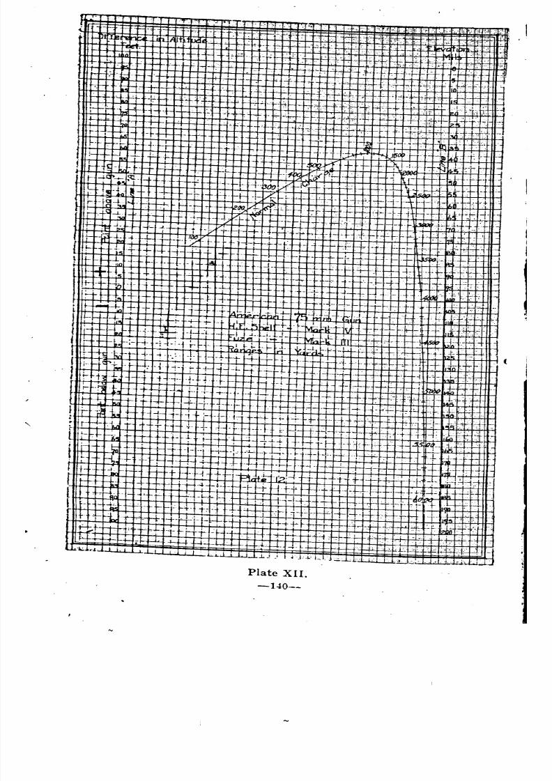
8/8/2019 Topography for Field Artillery
http://slidepdf.com/reader/full/topography-for-field-artillery 151/272
f.
-.-.
-'f, . _. ..
-'-;.~+--
I....~ i-
II
II
i.5
I
+-
..•-,:-
.1,
-, 1:- .,.-
.t- 12 -
-;-1--''1---- '.f1--. -:-!-
,'f- I .~'I ~,
r 'l~'1-- ~jJi;,11 -L LJi.- p
-+ r ,1 -t'-.: + ';;i1 -++1---+ -t !~'- I.:IT -' .-+~"1- L-. .::::-!-
I') 'f 'r.<
',-~Hc +-<+:.. 'r:>iJij,
'r .:+- "-,'! .•
'L~L .... ".'1":
:.. t- ~ , , .. I- --I-i-
t ~--'''.I-l;;, f- +- + ,+ - - ~'f-- I-Y -~'lirJ..
J-i- --+........ r-l-- ~i-- r-+- .;.. -h-(~f~ +- . ~-'v1 ~R'- I~~_
I iP~ -1 ...... +-.+ 1+I=";I"rJ-- +. ~-H-I'1t;;~lL in
I i- rL .. ;- ---t- .: ~il- H-~~j".,~ , . hr.::' : t:~. +. -t-' r
I t r~ 'k, 1- -t. + j-.1 rt +H-- l' rt Lt ._ .j_
f f- lit'~ ,--1-.-.~ -1- -t-H- --~f-t i++. -t- rf ~i-
,'t-- tit, H+~ ..+ ~ -t- +H -'H'I-'f-
I r-'~'~~ +~H+ f.-',i. --t- .t--+ H+ ,+[r +-) -f' ~+._ f +---f-f-' .+- -+ _
!i- ~. 1- + -f ;- + i:- t-- '+ i- +., __b'
I' --, i.t 1'- t + H- T- -+ + + i Ij- ,;,j_ ,I~ ... h
l!- rt:. t-.i t t j ....+ -+- f- __ .
i j-!;;; 4-. I -1- .. t- ;- -l-- '-~f-r -; .. ..L. k .•
t.. f.-t..- : ; l+'-!-i+.4 -t - '.I-j
I f- r 'H- t~-+H + E1t1t~12:t +r j,; II.~ -~-'- -~H.H++H ~, _
~ - -ir r- :tl -+- ,-r-~- :-t+f -+1-1+ I
r t- -t T +Ji:.t "': +1++-- +t'1"1,..+ --H+H- I : +++~:
! :) J" !--i-++ -+ '7-~H-- -t-H----8'. :'t.-
F--t-+- -t- t- -, J •.q_~: -n + f4-,,'L.rl' "I I ~4'L- b.L ..i.J I I .;:-J--.L' 1,,1,
Plate XII.
-140--
~
~-
' -
1
~ - --
~
I
---
~
--
1
-- . ~~ -
-~-
--
~ __
J •.
--
~ -I __ _
~ ~
j ~
8/8/2019 Topography for Field Artillery
http://slidepdf.com/reader/full/topography-for-field-artillery 152/272
8/8/2019 Topography for Field Artillery
http://slidepdf.com/reader/full/topography-for-field-artillery 153/272
Use of the Chart.
323. The main advantage of the chart lies in the fact that it is
Possible to read directly the quadrant elevation necessary to hit or clear any
Point when its map range and elevation are known without the necessity
of calculating the site, or taking the elevation from the range table.'
324. To find the quadrant elevatio'n of any point:
Take from the map the range and difference in altitude between the
. gun and the point in question. Place a straight edge on the chart in such a
manner that it will pass through the Points corresponding to this range and
difference in altitude. When the straight edge cuts Line "B" will be foundthe desired quadrant elevation.
Example VI.
325. To find the quadrant elevation of a point.
Range to crest 500 yards. Altitude of guns 400 feet. Altitude of<-rest 460 feet. The crest is therefore 60 feet above the guns.
Place a straight edge through plus 60 on line "A", and through 500
on range curve, and read 47+ mils Where the straight edge cuts line B.
This is the Same result as was obtained in Example 1 by calculating tbe siteand taking the elevation from the range table.
Example VII.
326. Given the minimum elevation to determine the mInImum range.
Point of fall on irregular terrain. Other data same as example l.
(a) To determine f.rst trial range place straight edge through 47.4
mils on line "B", and through zero on line "A", and on range curve read2425 yards.
(b) From the map, the altitude of the l:rround at this range (2423
Yds.) is seen to he 430 feet or 30 feet above the guns. Therefore the actualminimum range will be short of the first trial range.
(c) Try a point 100 yards short.
From the map the elevation of the ground at this point is foundo be 424 feet.
Place straight edge through plus 24 on line "A" and 2325 on rangecurve and read 48.5 mils on line "B".
(d) Proceed as in example 3 until the minimum range has beenlocated I1S aCcurately as is desired.
B. DEAD SPACE CHARTS.
327. The prohlem in determining dead space is to find the grazing point
and the point of fan, near and far limits, along several rays drawn on
the map from the gun Position, through each obstruction. The first ray is
drawn through the steepest slope of a ridge or through the highest point of
a vertical obstruction, such as trees or bUildings, and the limits of the dead
Space are determined and marked on this ray. Other rays are then drawn
successively on either side of the first, and the dead space is determined for
each, until a ray is found on each side where there is no dead space. The
more irregular the ground, the closer must be the rays. Some slopes will
require rays every ten mils; some only every hundred. The corresponding
points marked on the different rays are. then connected with a smooth
-142-
'"
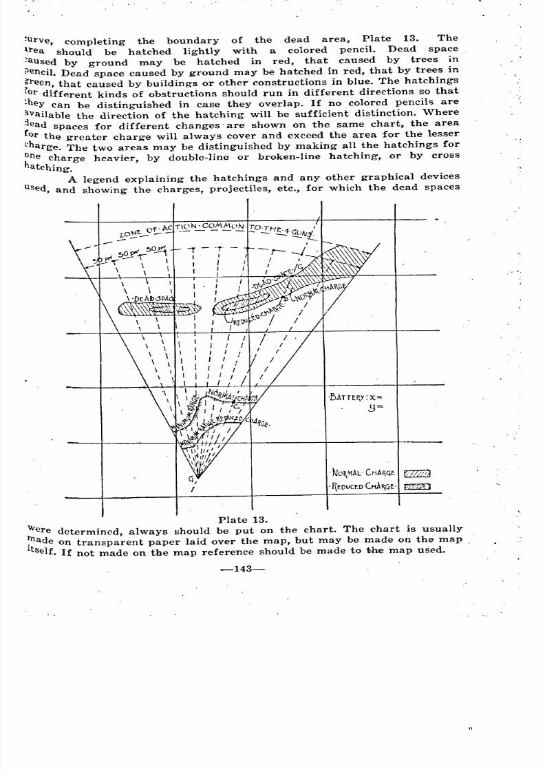
8/8/2019 Topography for Field Artillery
http://slidepdf.com/reader/full/topography-for-field-artillery 154/272
~urve, completing the boundary of the dead area, Plate 13. The
irea should be hatched lightly with a colored pencil. Dead space
~aused by ground may be hatched in red, that caused by trees in
Penci1.Dead space caused by ground may be hatched in red, that by trees in
freen, that caused by buildings or other constructions in blue. The hatchings
or diff~rent kinds of obstructions should run in different directions so that
they. can be distinguished in case they overlap. If no colored pencils are
~vailable the direction of the hatching will be sufficient distinction. \Vhere
ead spaces for different changes are shown on the same chart, the area
or the greater charge will always cover and exceed the area for the lesser
eharge. The two areas may be distinguished by making all the hatchings for
~ne charge heavier, by double-line or broken-line hatching, or by cross
atching.
A legend explaining the hatchings and any other graphical devices
sed, and showing the charges, p'rojectiles, etc., for which the dead spaces
.1)ATH~Y:X=
. NOP\MAL' CHMGE. tz2Z8
. ~r:DV(tD(tiAI\CjE' WillD
Plate 13.
'Were determined, always should be put on the chart. The chart is usually
~ade on transparent paper laid over the map, but may be made on the map
• Self. If not made on the map reference should be made to the map used.
-143-
~=
"
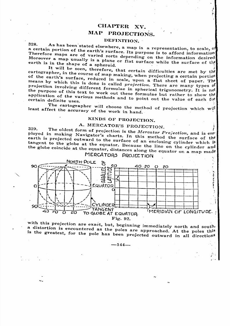
8/8/2019 Topography for Field Artillery
http://slidepdf.com/reader/full/topography-for-field-artillery 155/272
CHAPTER XV •
.MAP PROJECTIONS.
DEFI:\'ITIO~.
328. As has been' stated elsewhere, a map is a representation, to scale, 0
a certain portion of the earth's ~urface. Its purpose is to afford information
Therefore maps are of varied sorts depending on the information desired
Moreover a map usua'lly is a plane or flat surface while the surface of th!earth is in the shape of a spheroid. i
It will be seen, therefore, that certain difficulties are met by thecartographer, in the course of map making, when projecting a certain portio
Jlof the earth's surface, reduced in scale, upon a 'flat sheet of paper. The
means by which this is done is called projection. There are many types of
projection involving different formulae in spherical trigonometry. It is not
the purpose of this text to work out these formulae but rather to show the
application of the various methods and to point out the value of each forcertain definite uses. ,
The cartographer will choose the method of projection which willleast affect the accuracy of the work in hand'.
KI~DS OF PROJECTION.
A. MERCATOR'S PROJECTION. f
329. The oldest form of projectio~ is the Mercator Projection, and is em'
plo)'ed in making Navigator's charts. In this method the surface of the
earth is projected outward to the surface of an -enclosing cylinder which is
tangent to the 'globe at the eqnator. Because the line on the cylinder and
the globe coincide at the equator, distances along the equator on a map made
MERCATOR-S pgOJEITION
40 cO 0 ZO,
,~
R.c
-- I
'" I11'17':.
I I)
I
II/
/, I /
"" ,,--, ""'-- CYUNOC.... ~",-, ....::.... _... .,TA}-{~E:NT MER.DIAN Of LCNq TVDE. !
TO qLOBE: AT EQVATOR.
Fig. 92.
with this projection are exact, but, beginning i~mediately north and sout?,
a distortion is encountered as the poles are approached. At the poles thIS
is the greatest, for the pole has been projected outward in all directionS
'
~ ~ -
~-
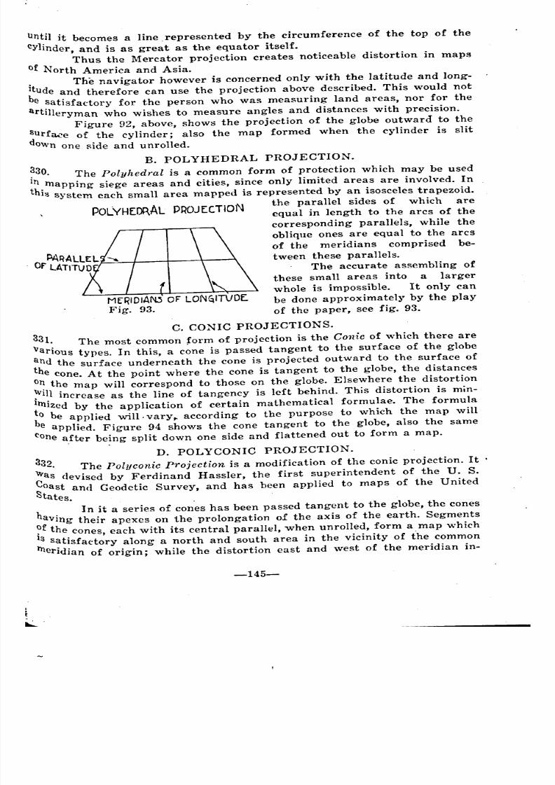
8/8/2019 Topography for Field Artillery
http://slidepdf.com/reader/full/topography-for-field-artillery 156/272
Until it becomes a line, represented by the circumference of the top of the
cYlinder, and is as great as the equator itself.
Thus the Mercator projection creates noticeable distortion in maps
of North America and Asia.. The navigator however is concerned only with the latitude and long-
~tude and therefore can use the projection above described. This would note satisfactory for the person who was measuring land areas, nor for the
artilleryman who wishes to measure angles and distances with precision.
Figure 92, above, shows the projection of the globe outward to the
~urf~e of the cylinder; also the map formed when the cylinder is slit
OWnone side and unrolled.
POLYHEIl\AL PROJECTiON
M[RIDIAN.S OF lON~ITVDE.
Fig. 93.
B. POLYHEDRAL PROJECTION.
~30. The Polyhedral is a common form of protection which may be used
In mapping siege areas and cities, since only limited areas are involved. Inthis system each small area mapped is represented by an isosceles trapezoid.
the parallel sides of which are
equal in length to the arcs of the
corresponding parallels, while the
oblique ones are equal to the arcs
of the meridians comprised be-
tween these parallels.
The accurate assembling of
these small areas into a largerwhole is impossible. It only can
be done approximately by the play
of the paper, see fig. 93.
C. CONIC PROJECTIONS.
331. The most common form of projection is the Conic of which there are
various types. In this, a cone is passed tangent to the surface of the globe
and t.he surface underneath the cone is projected outward to the surface of
the cone. At the point where the cone is tangent to the globe, the distanceso~ the map will correspond to those on the globe. Elsewhere the distortion
:"111increase as the line of tangency is left behind. This distortion is min-
Imized by the application of certain mathematical formulae. The formula
~o be applied will.vary,. according to the purpose to which the map will
e applied. Figure 94 shows the cone tangent to the globe, also the same
cone a,fter being split down one side and flattened out to form a map.
D. POLYCONIC PROJECTION.
332. The Polyconic Projection is a modification of the conic projection. It .~as devised by Ferdinand Hassler, the first superintendent of the U. S.
Oast and Geodetic Survey, and has been applied to maps of the United
.;)tates.
h. In it a series of cones has been passed tangent to the globe, the cones
aVIng their apexes on the prolongation of the axis of the earth. Segments
?f the cones, each with its central parallel, when unrolled, form a map which
IS satisfactory along a north and south area in the vicinity of the common
tneridian of origin; while the distortion east and west of the meridian in-
-145-
~ '
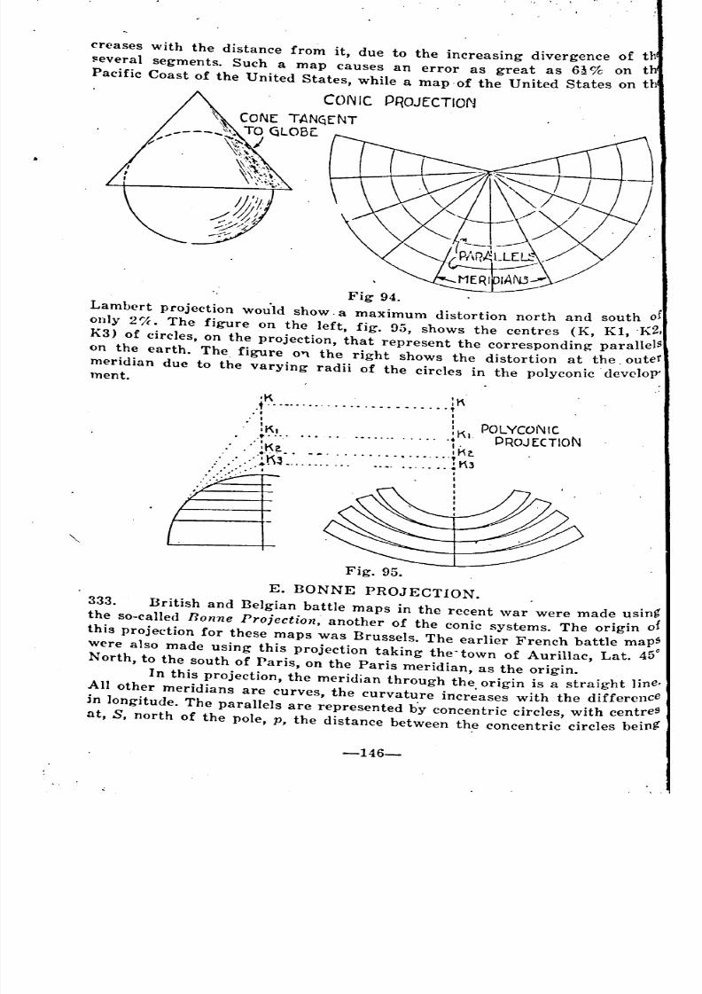
8/8/2019 Topography for Field Artillery
http://slidepdf.com/reader/full/topography-for-field-artillery 157/272
creases with the distance from it, due to the increasing divergence of th
~everal segments. Such a map causes an error as great as 6~% on t
Pacific Coast of the United States, while a map 'of the United States on th
PROJECTION
Fig 94.
Lambert projection wou"ld show. a maximum distortion north and south of
only 2'!c. The figure on the left, fig. 95, shows the centres (K, KI, 'K2,
K3) of circles, on the projection, that represent the corresponding parallels
on the earth. The figure 0"'\ the right shows the distortion at the, outermeridian due to the varying radii of the circles in the polyconic develop'ment.
POlYCO!\JIC
PROJ EeTION
'K :K..t " " .. " " "~. I I
• I I
. oK. 'K.
• I
I
Fig. 95.
E. BONNE PROJECTION.
333. British and Belgian battle maps in the recent war were made using
the so-called Bonne Projection, another of the conic systems. The origin of
this projection for these maps was Brussels. The earlier French battle maps
were also made using this projection taking the'town of Aurillac, Lat. 450
North, to the south of Paris, on the Paris meridian, as the origin.
In this projection, the meridian through the origin is a straight line.
All other meridians are curves, the curvature incr~ases with the difference
in longitude. The parallels are represented b'y concentric circles, with centreSat, S, north of the pole, p, the distance between th.e concentric circles being'
o
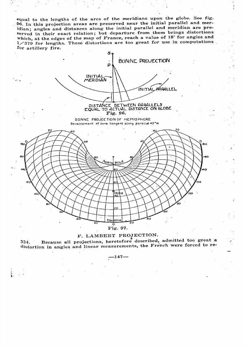
8/8/2019 Topography for Field Artillery
http://slidepdf.com/reader/full/topography-for-field-artillery 158/272
equal to the lengths of the arcs of the. meridians upon the globe. See fig.
96. In this projection areas are preserved near the initial parallel and mer-
idian; angles and distances along the initial parallel and meridian are pre-
served in their exact relation; but departure from them brings distortions
which, at the edges of the map of France, reach a value of 18' for angles and
1/379 for lengths. These distortions are too great for use in computations
for artillery fire.
s
BONNE PROJECTIONp
/' .
DISTANCE: BETWEEN pARALLEL"(QUAL TO ACTL'AL DI,srANCE oN qLOBE
Fig. 96.
BONNE: PROJ[CTION Of HEMISPHERE
O(lvG.lopment of cone taM<;)ent o.l"n9 pa.ralla.{4SoN
.'
F. LAMBERT PROJECTION.
334. Because all projections, heretofor: described, admitted too great a I'
distortion in angles and linear measurements, the French were forced to re-
-147-
-
.
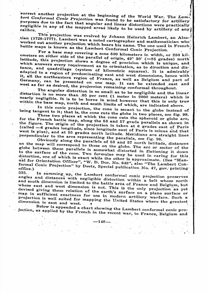
8/8/2019 Topography for Field Artillery
http://slidepdf.com/reader/full/topography-for-field-artillery 159/272
IJ.. t
'surrect another projection at the beginning of the World War. The Lam.~
bert Conformal Conic Projection was found to be satisfactory for artillery.
purposes due to the fact that angular and linear distortions were practically,
negligible in any of the mapped areas likely to be used by artillery of any Icalibre. ", ... i
This projection was evolved by JOhann Heinrich Lambert, an Alsa- f',tian' (1728-1777). Lambert was a noted cartographer and mathematician who:
worked out another projection which bears his name. The one used in French ~<
battle J1'1apsis known as the Lambert Conformal Conic Projection. •
For a base map covering a zone 500 kilometers in wtdth, or 250 kiI-,
ometers on either side of the parallel of origin, 490 30' (=55 grades) north
latitude, this projection shows a degree of precision which is unique, and,
which answers every requirement as to orientation, as to direction and dis-;
tance, and quadrillage (system of kilometric squares). It is admirably'
adapted to a region of predominating east and west dimensions, hence with;
it, all the northeastern region of France, as well as Belgium and part of
Germany, can be presented on one map. It can be extended ,east and
west as far as desired, the projeceion remaining conformal throughout.
The angular distortion is so small as to be negligible and the linear
distortion is no more than .05 per cent (1 meter in 2000 meters) which is
nearly negligible. It is to be borne in mind however that this is only true'
within the base map, north and south limits of which, are indicated above.
. In this conic projection, the cone is secant to the globe instead of
being tangent to it; that is, the cone cuts the globe in two places, see fig. 98~
These two places at which the cone cuts the spheroid or globe are,
for the French battle map, along the 53 and 57 grace parallels as shown in
the figure. The O1'igin of the projection is taken at 6 grades east of Paris
(called -6 grades longitude, since longitude east of Paris is minus and that
west is plus), and at 55 grades north latitude. Meridians are straight lines
,perpendicular to the arcs representing the parallels, see fig. 98.
Obviously along the parallels of 53 and 57 north latitude, distances
on the map will correspond to those on the globe. The arc or sector of the
globe between these parallels is somewhat distorted in flattening it down
to the surface of the cone" Two formulae may be used in caring for this;
distortion, one ,of which is exact while the other is approximate. (See "Man- .
u'al for Orientation Officer", "W. D. Doc. No. 648", also "The Lambert Con-
formal Conic Projection" by Deetz, Special publication No. 47, gOY:printingoffice.) .
335. , In summing up, the L~mbert conformal conic projection preserves
angle3 and distance; with negHgible distortion within a belt whose north'
and south dimension is limited to the battle area of France and Belgium, but
whose east and west dimension is not. This is the only projection "as yet.
devised giving these relation of the earth's surface on a plane surface or
map in sufficient exactness for use in modern artillery warfare. Such a
projection is well suited for' mapping the United States where the greatest.dimension is east and west. .
Below is appended a chart showing the Lambert conformal conic pro-jection, .a~ applied by the French in the recent war, to France, Belgium and
'
~
'
'
~
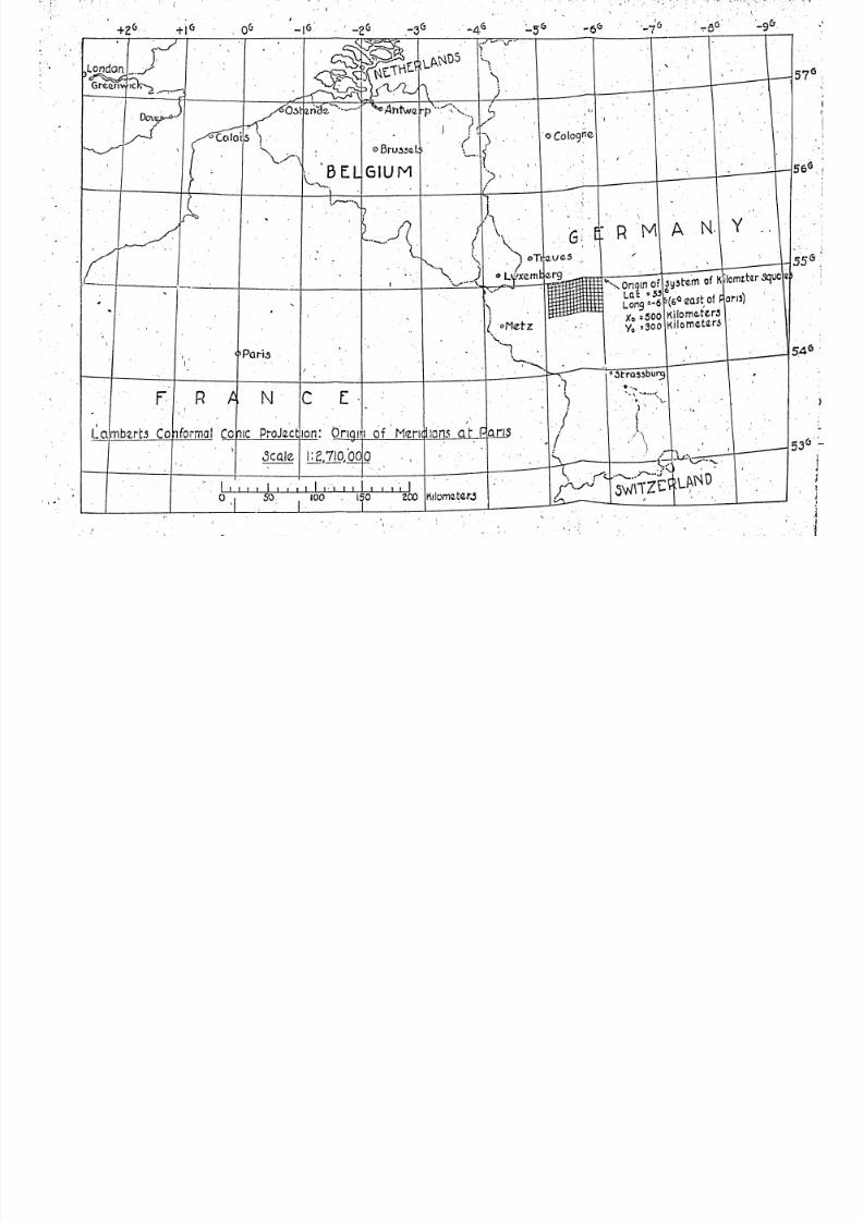
8/8/2019 Topography for Field Artillery
http://slidepdf.com/reader/full/topography-for-field-artillery 160/272
8/8/2019 Topography for Field Artillery
http://slidepdf.com/reader/full/topography-for-field-artillery 161/272
rj German) •. See Plate XIV. It will be noted that a portion of the grid sys-
.~ tem is also shown near its origin (which coincides with the origin 'of the pro-
.:1 jection). In the (.hart the grid is not shown to scale, the lines being ap-;
LAM5ERT'.s CONfORMALCONIC PROJECTION.
Fig. 98.
proximately 4 kilometers apart in place of 1 kilometer.
This grid system is discussed in Chapter XVI.
-149-
~
8/8/2019 Topography for Field Artillery
http://slidepdf.com/reader/full/topography-for-field-artillery 162/272
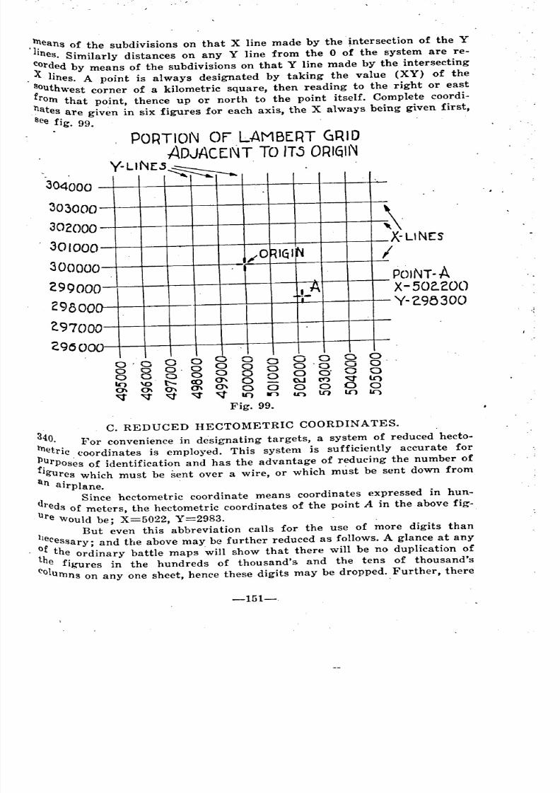
8/8/2019 Topography for Field Artillery
http://slidepdf.com/reader/full/topography-for-field-artillery 163/272
.~eans of the subdivisions on that X line made by the intersection of the Y
Ines. Similarly distances on any Y line from the 0 of the system are re-
~r~ed by means of the subdivisions on that Y line made by the intersecting
. lInes. A point is always designated by taking the value (XY) of the
~outhwest corner of a kilometric square, then reading to the right or east
rorn that point, thence up or north to the point itself. Complete coordi-nates are given in six figures for each axis, the X always being given first,
See fig. 99.
..
~.
X-LINES
I
POINT-AX-50,,200
Y-2.95300
0'000o 0' C 0
~g(3~U")
to lO It')
PORTION Of LAMBERT GRID
ADJACENT TO lTj ORIGIN
Y-L'NE.s~
0
0
0
0,0RIGI N
00
00 A
a .~-00
00-
. - '""0 ,.... 0 0 0 0
30400
30300
30200
30100
3000
2990
2980
?'970
2960
g g a0" 0 0
0' 0 0
V" lC) 10
Fig. 99.
C. REDUCED HECTOMETRIC COORDINATES.
~O . For convenience in designating targets, a system of reduced hecto-
etric . coordinates is employed. This system is sufficiently accurate for
~~rposes of identification and has the advantage of reducing the number of
19ures which must be sent over a wire, or which must be sent down from
an airplane.
d Since heetometric coordinate means coordinates expressed in hun-ureds of meters, the heetometric coordinates of the point A in the above fig-
re 'Would be; X=5022, Y=2983. --1 But even this abbreviation calls for the use of more digits than
I;Cessary; and the above may be further reduced as follows. A glance at any
~heth~ ordinary battle maps will show that there will be no duplication of
1 fIgures in the hundreds of thousand's and the tens of thousand's
(,'0 urnns on anyone sheet, hence these digits may be dropped. Further, there
-151-
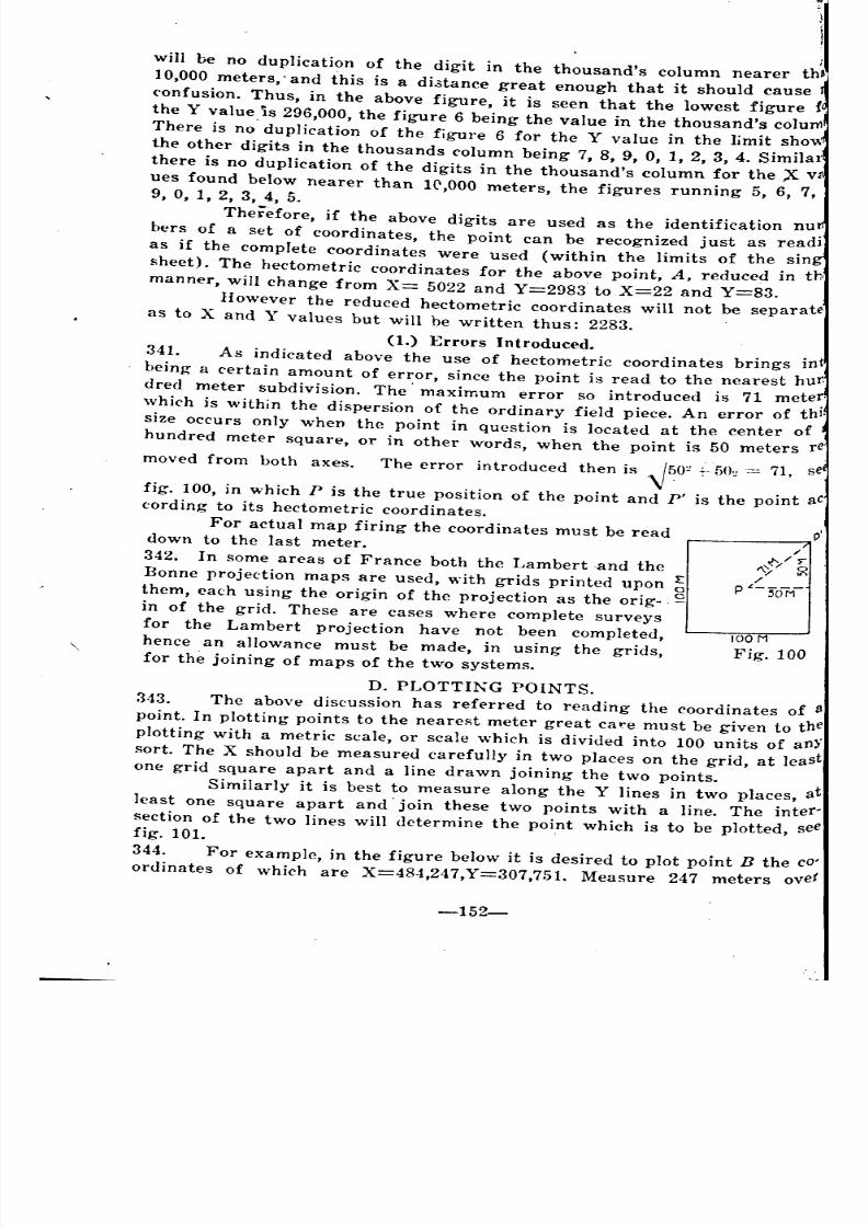
8/8/2019 Topography for Field Artillery
http://slidepdf.com/reader/full/topography-for-field-artillery 164/272
100
Fig. 100
will be no duplication of the digit in the thousand's column nearer th'
10,000 meters,' and this is a di3tance great enough that it should cause
('onfusion. Thus, in the above figure, it is seen that the lowest figure {
the Y value.is 296,000, the figure 6 being the value in the thousand's colum
There is no duplication of the figure 6 for the Y value in the limit shov.1
the other digits in the thousands column being 7, 8, 9, 0, 1, 2, 3, 4. Similar
there is no duplication of the digits in the thousand's column for the X w
ues found below nearer than 10,000 meters, the figures running 5, 6, 7,9, 0, 1, 2, 3, 4, 5.
Therefore, if the above digits are used as the identification nUll
bers of a set of coordinates, the point can be recognized just as readi
as if the complete coordinates were used (within the limits of the sing
sheet). The hectometric coordinates for the above point, A, reduced in th
manner, will change from X= 5022 and Y=2983. to X=22 and Y=83.
However the reduced hectometric coordinates will not be separate-
as to X and Y values but will be written thus: 2283.
(1.) Errors Introduced.
341. As indicated above the use of hectometric coordinates brings int
being a certain amount of error, since the point is read to the nearest hur.
dred meter subdivision. The' maximum error so introduced is 71 meter.
which is within the dispersion of the ordinary field piece. An error of thi.
size Occurs only when the point in question is located at the center of l
hundred meter square, or in other words, when the point is 50 meters re
moved from both axes. The error introduced then is ~50~ +-f>O~:= 71, se
fig. 100, in which P is the true position of the point and P' is the point aCcording to its hectometric coordinates.
For actual map firing the coordinates must be readdown to the last meter.
342. In some areas of France both the Lambert and the
Bonne projection maps are used, with grids printed upon
them, each using the origin of the projection as the orig- C
in of the grid. These are cases where complete surveys
for the Lambert projection have not been completed,
hence an allowance must be made, in using the grids,
for the joining of maps of the two systems.
D. PLOTTING POINTS.
343. The above discussion has referred to reading the coordinates of 8
point. In plotting points to the nearest meter great care must be given to the
plotting with a metric scale, or scale which is divided into 100 units of anYsort. The X should be measured carefully in two places on the grid, at least
one grid square apart and a line drawn joining the two points.
Similarly it is best to measure along the Y lines in two places, at
least one square apart and' join these two points with a line. The inter-
section of the two lines will determine the point which is to be plotted, seefig. 101. .
344. For example, in the figure below it is desired to plot point B the CO'
ordinates of which are X=484,247,Y=307,751. Measure 247 meters ove!
-152-
~
~
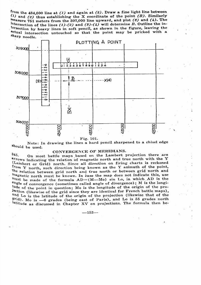
8/8/2019 Topography for Field Artillery
http://slidepdf.com/reader/full/topography-for-field-artillery 165/272
trom the 484,000 line at (1) and agai~ at (2). Draw a fine light line between
(1) and (2) thus establishing the X coordinate of the point (B). Similarly
~easure 751 meters from the 307,000 line upward, and plot (~) and (~). The
~ntersection of the lines (1)-(2) and (3)-(~) will determine B. Outline the in-
. ersection by heavy lines in soft pencil, as shown in the figure, leaving the
:~tual intersection untouched so that the point may be pricked with' a
~rp needle. .
PLOTTING A POINT
308000Q-
0\
(3) ._~ ..
.a..,
....._! J2.. ._. - _. - ... - ..X(4)I
306000
8C")
co'\t
ogIr)
co"\t
Fig. 101.
h Note: In drawing the lines a hard pencil sharpened to a chisel edge
B ould be used.
3 CONVERGENCE OF MEIUDIANS.
45. On most battle maps based on the Lambert projection there are
al'l'~Ws indicating the relation ~f magnetic north and true north with the Y
iLambert or Grid) north. Since all direction on firing charts is reckoned
t~orn Y north, such direction being known as the Y azimuth of the point,
e relation between grid north and true north or between grid north and
1l1agnetic north must be known. In case the map does not indicate this, use
1l1ust be made of the formula AD=(M-Mo) sin Lo, in which AD is the
:ng1e of convergence (sometimes called angle of divergence); M is the longi-
.ude of the point in question; Mo is the longitude of the origin of the pro-
Jection (likewise of the grid since they are identical for French battle maps),
an? Lo is the latitude of the origin of the projection (likewise that of the
. ~rl~). Mo is -6 grades (being east of Paris), and Lo is 55 grades north
atItude as discussed in Chapter XV on projections. The formula then be-
-153-
~

8/8/2019 Topography for Field Artillery
http://slidepdf.com/reader/full/topography-for-field-artillery 166/272
tomes, Angles of Convergence= (M-(-6» sin 55 grades. The sine of 6
grades is .76. The formula in its final form, then is AD=(M+6) . 76, whi(
~hould be noted in all artillery field notebooks. A simple discussion of an
a figure showing this relation between true north and grid north, as aboexpressed, is appropriate here.
346. By a theorem of spherical trigonometry, the qivergence of the me}dians from the north pole to the equator is a function of the sine of Uangle of latitude.
Fig. 102.
PARALLEL
'- Of ~5.9'\
, ANGLE.5 OFCONVER<qtNa1\
90"=100.9'
rQVATOR
For example, in the left hand part of
fig. 102 are shown two meridians converging at
the poles. Figure 103 portrays a development
of these same meridians showing that the an-
gIe between them is greatest at the pole. At the
pole the angle of latitude is 90° or 100 grades
(see right hand portion of fig. 102) and the
sine of 100 grades=l, its greatest value.However at the equator the meridians
are parallel. At the equator the angle of lati-
tude is 0 and the sine of this angle is O. Hence
the meridians, being parallel, form no angle.
The amount of the angles formed by meridians
may thus be seen to be a function of the sine
of the latitude at any given parallel, such as 55
grades, the one used in the formula.
347. The divergence of the true north andgrid north is identical with that for meridians,
since the Y axis coincides with the meridian of
origin. This divergence, then, is the measure of
some definite angle; that is, the angle between DEVr.LOPMf.NT OF
the meridian of origin (-6 grades), and the Tt-IRE.E. MtRID/AN.:>
point in question, M. Fig. 103.
Assume for example, that the point on the map in q'lestion is 3 grades
-154-
-
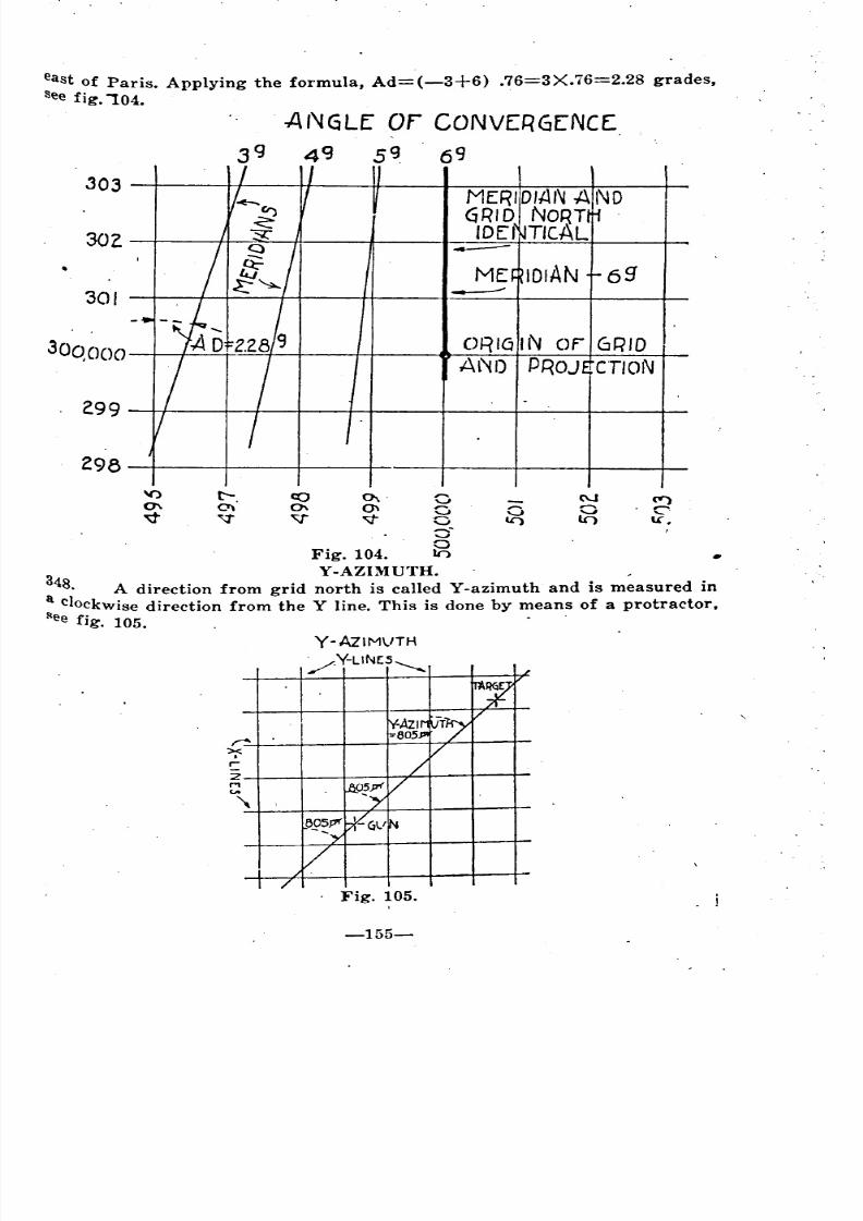
8/8/2019 Topography for Field Artillery
http://slidepdf.com/reader/full/topography-for-field-artillery 167/272
east of Paris. Applying the formula, Ad=(-3+6) .76=3X.76=2.28 grades,
See fig. '"104.
ANGLE" or CONVER6[NCE
39 4«3 5~ 69
303
30,
301
30qooo
299
ME:
---ORIGIN OF' GRID
AND PROJ eTloN
298
•
('t')
C-\A.
I
--.Jooa-
Fig. 104.
3 Y-AZIMUTH. ,
48, A direction from grid north is called Y-azimuth and is measured in
a clockwise direction from the Y line. This is done by means of a protractor,!lee fjg, 105.
Y-AzIMVTH
/Y-LlN(S~
Fig. 105.
-155-
I
~
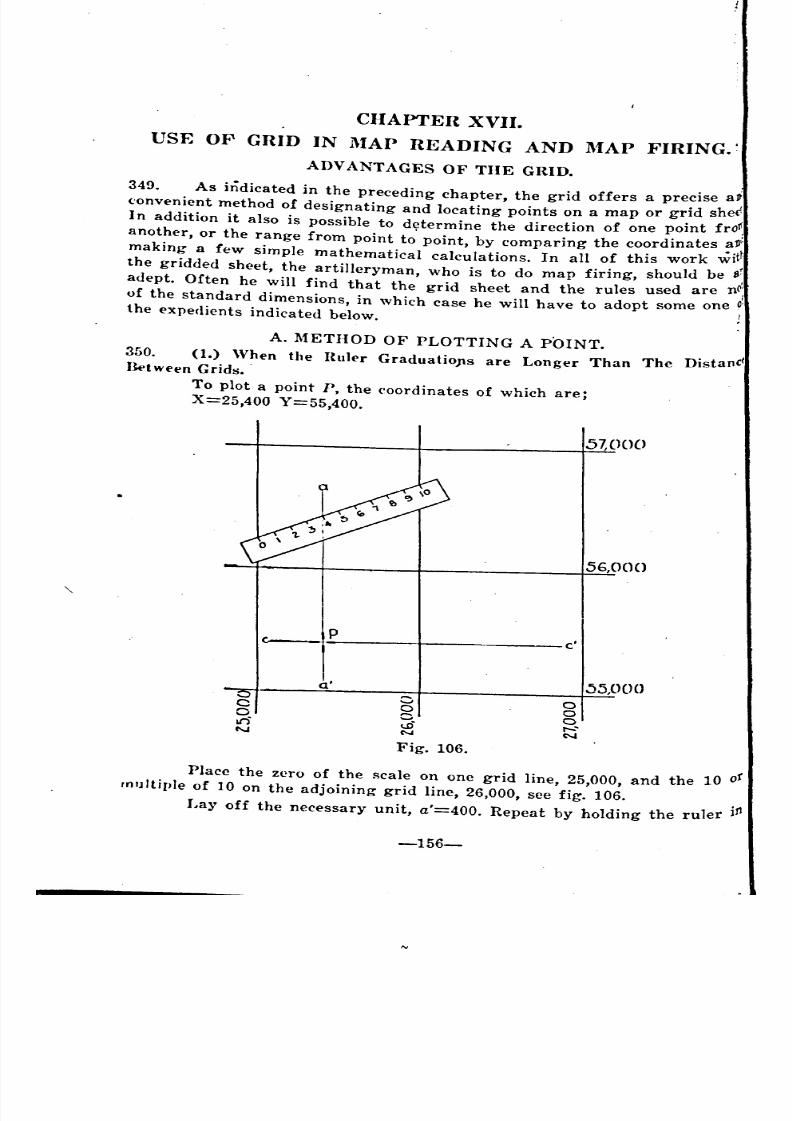
8/8/2019 Topography for Field Artillery
http://slidepdf.com/reader/full/topography-for-field-artillery 168/272
CHAPTER XVII.
USE OF GRID IN l\IAP READING AND l\fAP FIRING.'
ADVANTAGES OF THE GRID.
349. As indicated in the preceding chapter, the grid offers a precise at
('onvenient method of designating and locating points on a map or grid shec!
I n addition it also is possible to determine the direction of one point froP
another, or the range from point to' point by comparing the coordinates all':, .'tlaking a few simple mathematical calculations. In all of this work WI
the gridded sheet, the artilleryman, who is to do map firing, should be 1I~
adept. Often he will find that the grid sheet and the rules used are nC;of the standard dimensions, in which case he will have to adopt some one 0'
the expedients indicated below. ;
A. METHOD OF PLOTTING A POINT.
350. (1.) When the Huler Graduatio)ls are Longer Than The DistanC/Ilt>tWt't'n Grids •.
To plot a point P, the coordinates of which are;
X=25,400 Y=55,400.
57,000
56,000
pc'
a' :)5,000
C 0 a0
~' af")
r-'...,C'-'
N
Fig. 106.
Place the zero of the scale on one grid line, 25,000, and the 10 of
multiple of 10 on the adjoining grid line, 26,000, see fig. 106.
Layoff the necessary unit, a'=400. Repeat by holding the ruler j!1
-156-
,
~
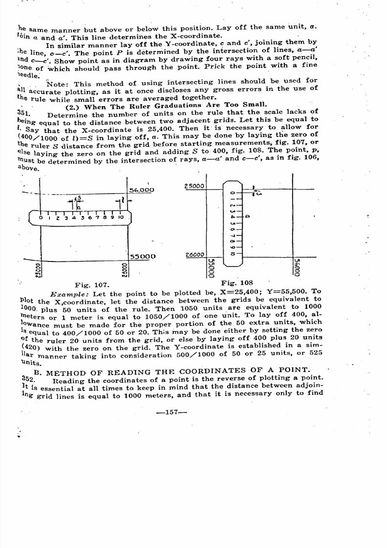
8/8/2019 Topography for Field Artillery
http://slidepdf.com/reader/full/topography-for-field-artillery 169/272
same manner but above or below this position. Layoff the same unit, a.
0ln a and a'. This line determines the X-coordinate.
lh . In similar manner lay of~ the Y -coordinate, and c', joining them by
e hne, (}-c'. The point P is determined by the intersection of lines, a-a'
~ndc-e'. Show point as in diagram by drawing four rays with a soft pencil,
~one of which should pass through the point. Prick the point with a fine1eedle:
'1" Note: This method of using intersecting lines should be used for
~l accurate plotting, as it at once discloses any gross errors in the use of
e rule while small errors are averaged together.
3 '(2.) When The Ruler Graduations Are Too Small.
5~. Determine the number of units on the rule that the scale lacks of
l.elng equal to the distan.ce bet~een two adjace~t ~rids. Let this be equal to
Say that the X-coordmate IS 25,400. Then It' IS necessary to allow for
400/1000 of l)=S in laying off, a. This may be done by laying the zero ofhe ruler S distance from the grid before starting measurements, fig. 107, or
else laying the zero on the grid and adding S to 400, fig. 108. The point, p,
l11ustbe determined by the intersection of rays, a-a' and c-c', as in fig. 106,
abOve.
25000
ooo'0N
55000 2.6000lJIVIo
g
o
UIG"-o
oo
Fig. 107. Fig. 108
III Example: Let the point to be plotted be, X=25,400; Y=55,500. To
loot the X,coordinate, let the distance between the grids be equivalent to
00, plus 50 units of the rule. Then 1050 units are equivalent to 1000
~eters or 1 meter is equal to 1050/1000 of one unit. To layoff 400, al-
.owance must be made for the proper portion of the 50 extra units, which
18 equal to 400/1000 of 50 or 20. This may be done either by setting the zero
~f the ruler 20 units from the grid, or else by laying off 400 plus 20 units'1420) with the zero on the grid. The Y-coordinate is established in a sim-
1 ar manner taking into consid<!ration 500/1000 of 50 or 25 units, or 525
'\lnits.
3 B. METHOD OF READ1NG THE COORDINATES OF A POINT.
152. Reading the coordinates of a point is the reverse of plotting a point.
it is essential at all times to keep in mind that the distance between adjoin-
ng grid lines is equal to 1000 meters, and that it is necessary only to find
-157-
~~ ~
'
8/8/2019 Topography for Field Artillery
http://slidepdf.com/reader/full/topography-for-field-artillery 170/272
f;ome means to interpolate or divide this distance up in the required numberd equal parts.
(1.) When The Rule Is Correctly Scaled.
Lay the zero of the ruler on the grid line and read the units to thl
point. Add these units to the thousands of the grid. For instance, the grid
line on which the zero is laid is marked 35,000, and the number of units to tbl
point from the grid line is equal to 475. Then that complete coordinate woulC
be equal to 35,475. The same applies for the reading of the other coordinate.
(N ote: When the grid is used to 10 times .the scale for which it was
originally intended, then the distance between grid Iines=lOO' meters. ThiS
('ase often arises when using a 1/20,000 grid for a 1/2,000 chart. Mallethe proper allowance in this case).
(2.) \Vhen the Scale Is Too Larg-e.
353. Bring the edge of the ruler opposite the point and at the same tinleturn it so that the 0 and 10 coincide with their respective grids. Read the
number of units and add to the thousands of the grid. If the ruler is toO
mu('h oblique, care must be used to get the exact value, see fig. 106.
(3.) When The Scale Is Too Small.
354. Determine the number' of units on the rule that is equal to the dif,
ference in length between the rule and the distance between grid lines. Let
this distance equal 1, see fig. 108. 1000+1= total number of units betweel1
grids. Let m= the units read from the grid to the point. Then the truCdistance, el, may be expressed as follows: d= [m-;-(lOOO+l)] 1000. Add the
value "d" to the thousands of the grid to the left and this will give one of
the ('omplete coordinates. The other coordin'lte is obtained in a simila1manner.
Bxample: Assume the point "P" lies between the grid lines 25,000
and 26,000; that the distance between the grids is equal to 1000 units of tM
rule +50 units. In other words, there are 1050' units of the rule betweeTl
adjacent grid lines. These 1050 units are equivalent to 1000 meters. As-
sume that from the grid line of 25,000 to the point there are 420 units. Then
420. .the distance in meters would be equal to -X1000, which is equal to 400.
' 1050
Therefore the X-coordinate =25,400. The other coordinate is obtained ina like manner.
(4.) With Hight Angled Rule.
355. A more rapid method for plotting and reading coordinates i5 indicated
in fig. 109. The right angled ruler enables one to read both coordinates at
one operation, but does not give as exact results as the operations des-tribed above.
This method is close enough for reading and plotting abbreviated
hectometric coordinates, also for preparing firing data in some types of maPfiring.
C. PLOTTING DIRECTIONS.
(1.) By Y-Azinwth.
356. The Y-azimuth of a line is the angular distance measured clockwise
-158-
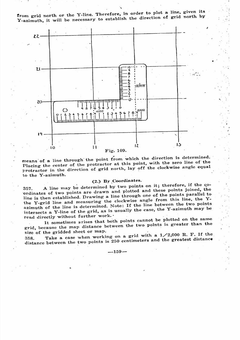
8/8/2019 Topography for Field Artillery
http://slidepdf.com/reader/full/topography-for-field-artillery 171/272
from grid north or the Y-line. Therefore, in order to plot a line, given its .
Y-azimuth, it will be necessary to establish the direction of grid north by
Il.
Fig. 109.
means' of a line through'the point f~om ~hich the direction is determined.
Placing the center of the protractor at this point, with the zero line of. the
protractor in the direction of grid north, layoff the clockwise angle equal
to the Y-azimuth. .
tl
w
19
\0
()
II
=-10 .. ;-
II :6 I
7 I
I
5 I':-- <} :io.OOO,
l.I ,
0- ••..I.I
Il I~
,"':
. ,'-'.
,
(2.) By Coordinates.
357. A line may b~ determined by two points on it; therefore, if the <:,0-
.ordinates of two points are drawn and plotted and these points joined, the
line is then established. Drawing a line through one of the points parallel to
the Y-grid line and measuring the clockwise angle from this line, the Y-
azimuth of the line is determined. Note: If the line between the two points
intersects a Y-line of the grid, ~s is usually the case, the Y-azimuth may beread directly without further work ..
It sometimes ~rises that both points cannot be plotted on the same
grid, because the map distance between the two points is greater than the
size of the gl'idded sheet or map.
358. Take a case when working on a grid with a 1/2,000 R. F. If the
distance between the two points is 250 centimeters and the greatest distance
-159-
~
~
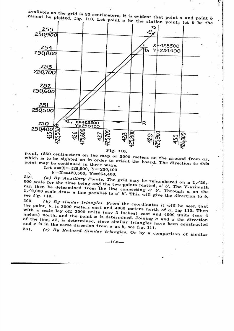
8/8/2019 Topography for Field Artillery
http://slidepdf.com/reader/full/topography-for-field-artillery 172/272
available on tbe grid i. 30 centimeter., it i. evident tbat point a and point b •
.cannot be plotted, fig. 110. Let point a be the station point; let b be the
254-
Z5qao
2.532.5(J,700
Z52.l5C>,GOO
2.51
25Q500
R
o 0
COo'... « )
In ' It'''
Fig. 110.
point, (250 centimeters on the map or 5000 meters on the ground from a),
which is to be sighted on in order to orieOnt the board. The direction to thispoint ma~' be continued in three ways.
Let a=X=425,500, Y=250,400.
'\. b=X=428,500, Y=254,400.
559. (a) By Auxiliary Points. The grid may be renumbered on a 1/20,-
000 scale for the time being and the two points plotted, a' b'. The V-azimuth
can then be determined from the line connecting a' b'. Through a on the
1/2,000 scale draw a line parallel to a' b'. This will give the direction to 0,see fig. 110.
360. (b) By similar triangles. From'the coordinates it will be seen that
the point, b, is 3000 meters east and 4000 meters north of a, fig 110. Then
with a scale laYoff 3000 units (say 3 inches) east and 4000 units (say 4inches) north, and the point x is determined. Joining a and x the direction
of the line, ab, is determined, since similar triangles have been constructedand x is in the same direction from a as b, see fig. 111.
361. (c) By Reduced Similar triangles. Or by a comparison of similar
-1GO-
~~ ~
~ ~-
~ ~
°
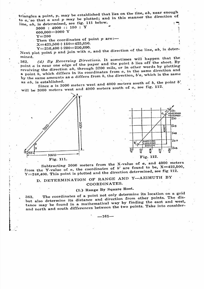
8/8/2019 Topography for Field Artillery
http://slidepdf.com/reader/full/topography-for-field-artillery 173/272
triangles a point, p, may be established that lies on th~ line, ab, near enough
to a,' so that a and p may be plotted; and in this manner the direction of
line, ab, is determined, see fig. 111 below.
3000 : 4000:: 150 : Y ,
600,000=3000 Y 1Y=200Then the coordinates of point pare:-
X=425,500+ 150=425,650.
Y=250,400+200=250,600.Next plot point p and join with a, and the direction of the line, ab, is deter-
mined. .
.362. (d) By Reversing Directions. It sometimes will happen that the
point a is near one edge of the paper and the point b lies off the sheet. By
revolving the direction ab, through 3200 mils,. or in other words by plotting
a point b, which differs in its coordinates from a, in the same direction andby the same amounts as a differs from b, the direction, b'a, which is the same
as ab, is established.Since a is 3000 meters west and 4000 meters south of b, the point b'.
will be 3000 meters west and 4000 meters south of a, see fig. 112.
8
13000-----.,
Fig. 111.Fig. 112.
SubtracUng 3000 meters from the X-value of a, and 4000 meters
from the Y-value of a, the coordinates of b' are found to be, X=422,500,
Y=246,400. This point is plotted and the direction determined, see fig 112.
D. DETERMINATION OF RANGE AND Y-AZIMUTH BYCOORDINATES.
(1.) Range By. Square Root.
363. The coordinates of a point not only determine its location on a grid
.but also determine its distance and direction from other points. The dis-
tance may be found in a mathematical way by finding the east and 'west,
and north and south differences between the two points. Take into consider-
-161-
~
~
~---
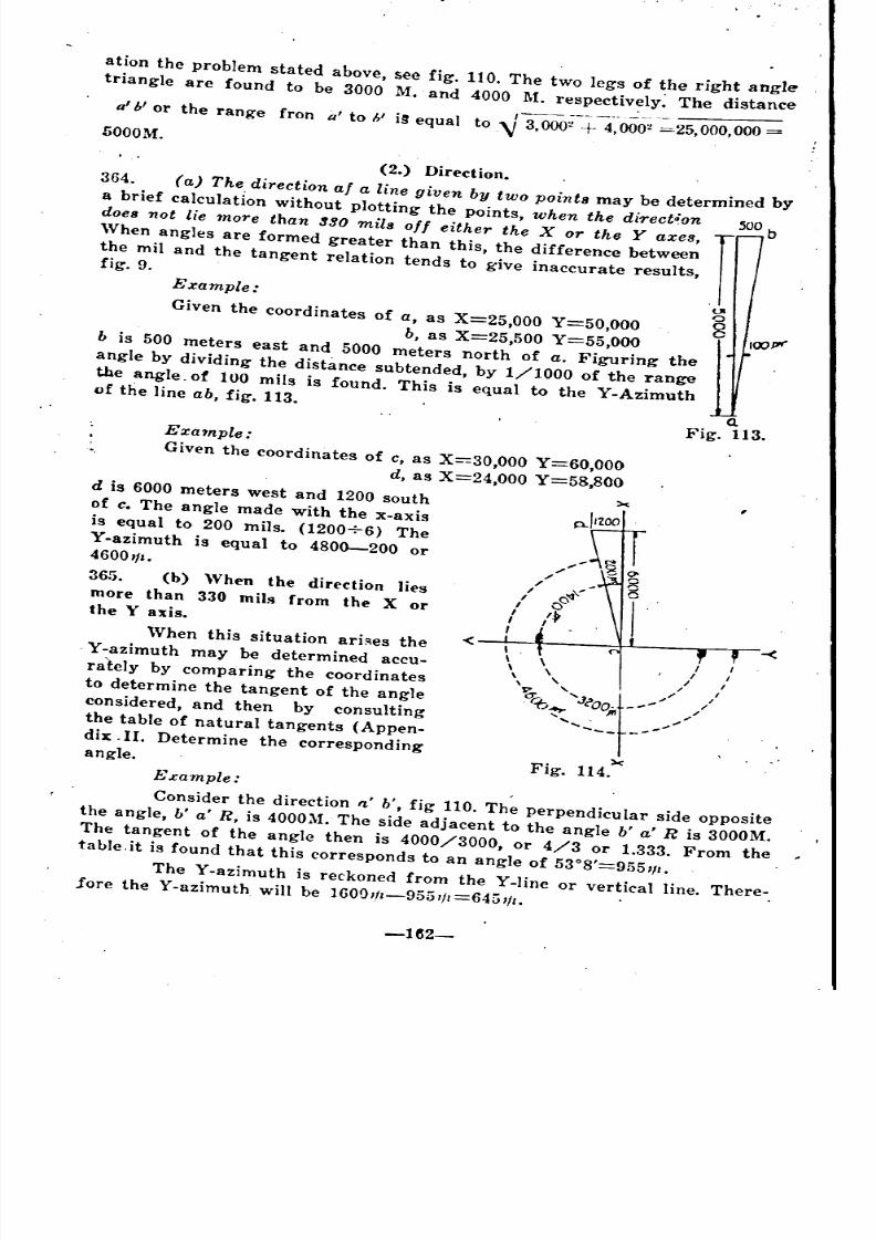
8/8/2019 Topography for Field Artillery
http://slidepdf.com/reader/full/topography-for-field-artillery 174/272
ation the problem stated above, see fig. 110. The two legs of the right angle
triangle are found to be 3000 M. and 4000 M. respectively The distance
a'ii or the range fron a' to 1/ i~ equal to.-V 3~;-+ 4~-OOO~===25,000,000SOOOM.
(2.) Direction.
364. (a) The direction at a line given by two points may be determined by
a brief calculation without plotting the points, when the direct;on
does not lie more than 390 mils off either the X or the Y axes,
'Vhen angles are formed greater than this, the difference between
the mil and the tangent relation tends to give inaccurate results,fig. 9.
Example:
Given the coordinates of a, as X=25,000 Y=50,OOO
b, as X=25,500 Y=55,OOOb is 500 meters east and 5000 meters north of a. Figuring the
angle by dividing the distance subtended, by 1/1000 of the range
the angle. of 100 mils is found. This is equal to the Y-Azimuthof the line ab, fig. 113.
Q.
Fig. 113.
I .
, \ , I
\ \ , I ,
\, / I
'I" '.... ,,/ /
~ J?oo.t--,.,,,, /~ ","
'...... ...,"........
xFig. 114.
Example:
Given the coordinates of c, as X=30,000 Y=60,000
d, as X=24,OOO Y=58,800d is 6000 meters west and 1200 south
of c. The angle made with the x-axis A-I,ZOOis equal to 200 mils. (1200+6) The
Y-azimuth is equal to 4800-200 or4600'1'.
365. (b) When the direction lies
more than 330 mils from the X orthe Y axis.
When this situation ari~es the
. Y-azimuth may be determined accu-
rately by comparing the coordinates
to determine the tangent of the angle
considered, and then by consulting
the table of natural tangents (Appen-
dix . II. Determine the corresponding
angle.
Example:
Consider the direction ft ' b', fig 110. The perpendicular side opposite
the angle, b' a' R, is 4000M. The side adjacent to the angle b' a' R is 3000M.
The tangent of the angle then is 4000/3000, or 4/3 or 1.333. From the
table.it is found that this corresponds to an angle of 53°8'=955111.
The Y-azimuth is reckoned from the Y-line or vertical line. There-lore the Y-azimuth will be 16001/1-9551/1=6451/1.
-1~2-
~ =
~ - ---
~
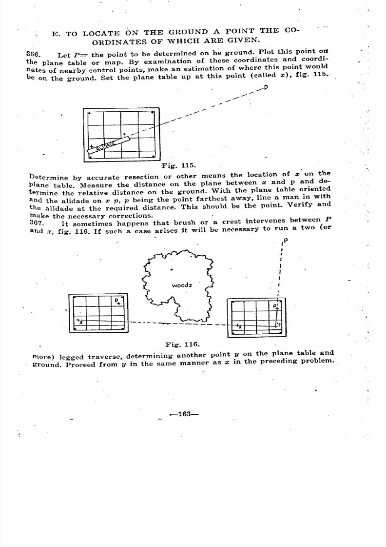
8/8/2019 Topography for Field Artillery
http://slidepdf.com/reader/full/topography-for-field-artillery 175/272
E. TO LOCATE ON THE GROUND A POINT THE CO.
ORDINATES OF WHICH ARE GIVEN.
~66. Let p= the point to be determined on h~ ground. Plot this point 011
the plane table or map. By examination of these coordinates and coordi.
nates of nearby control points, make an estimation of where this point would
be on the ground. Set the plane table up at this point (called x), fig. 115.-
/p....-'"....-
;"
Fig. 115.
Determine by accurate resection or other means the location of x on the
plane table. Measure the distance on the plane between x and p and de.
termine the relative distance on the ground. With the plane table oriented
and the alidade on x p, p being the point farthest away, line a man in with
the alidade at the required distance. This should be the point. Verify and
make the necessary corrections.367. It sometimes happens that brush or a crest intervenes between P
and x, fig. 116. If such a case arises it will be necessary to run a two (or
,P(
-I
I
I
I
,I
,~------ - .~. .~
-------~
Fig. 116.
more) legged traverse, determining another point y on the plane table and
ground. Proceed from y in the same manner as x in the preceding problem.
-163-
~ ~
8/8/2019 Topography for Field Artillery
http://slidepdf.com/reader/full/topography-for-field-artillery 176/272
CHAPTER XVIII.
THE COMPASS.
GENERAL.
f,
'-'i!368. In modern artillery practice the compass needle plays an important.,
part since it affords a convenient and reawnably accurate method of deter-
mining directions, of making traverses, of intersection, resection, and if lay- ,
ing guns for direction. Other things being equal the longer the needle the.
greater the accuracy of the direction determined. Even with a long needle
some sort of sighting device and some method of reading the subdivisions.'.j
of the angle set off is needed, in order to do satisfactory work, hence the
prismatic compass, the aiming circle or similar instruments only, can beused with a satisfactory degree of accuracy.
NOI{TH.
369. Because the artilleryman is dealing with three different norths-
True North, Magnetic North and Grid North (Lambert or Y-north)' it is-
convenient to designate horizontal angles measured from these various direc.tions by different names.
370. Azimuth. Thus in this. publication the horizontal angle, measured
dockwise from true north around to a given direction will be spoken of as .the azimuth of that direction.
371. The Magnetic bearing or bearing of a given direction will be used to-
designate the horizontal angle measured clockwise from magnetic north.
372. The Y-Azimuth of a direction is the horizontal angle measuredclockwise from Y-north or Grid north. .
Note: Actually Azimuth is any angle measured horizontally in a
clockwise direction from a given vertical plane. In some engineering man-uals and in the air ~ervice, the term is used to designate the horizontal
angle measured from magnetic north, the same angle which, in this text,will be termed bearing.
Bearing on the other hand in some texts is confined entirely to mea.
surements within a certain quadrant as "North North East" and alwayssu('h bearings are less than 90 degrees.
DECLINATION.
A. MAGNETIC DECLINATION.
373. The north magnetic pole is situated south of the north pole and in
the western hemisphere. Therefore the magnetic meridians and the true
meridians generally do not coincide. Magnetic Declination is the angle at
any given point between these two meridians or between true north andmagnetic north. .
Since the compass needle points toward the magnetic pole it is evi-
de.nt -that, except at a few localities it will not point toward the north pole.
-164-
.
i
-
"
_
8/8/2019 Topography for Field Artillery
http://slidepdf.com/reader/full/topography-for-field-artillery 177/272
.At certain parts of the earth's surface it will point east of the true no~th
giving an easterly declination and at others it will point west giving a west-
tlrly declination.
374. In America there is a westerly declination in the eastern part of the
Continent and an easterly declination in the western part of the continent.
The amount of declination varies with the locality. The amount of declina~, tion may be determined from an isogonic chart, such as that included in this
chapter, plate XII, which, for the epoch noted, gives, by curved lines con-
?ecting points of equal declinations, the approximate declination for points
ln the area represented.
. . Note: "Isogonic, of, pertaining to, or noting equal angles." Hence
lsogonic lines are imaginary lines joining points on the earth's surface at
'Which the-magnetic declination from the true north is the same.
At no 'point is the magnetic declination a constant. It is subject to
a number of different variations.
(1.) Magnetic Variations.
375. There are innumerable variations in the lines of magnetic force of
the earth very few of which can be computed. Following are the more im-
Portant variations to which the compass needle is subject. Of these, the
first two only, usually are considered.
(a) The daily variation, consisting of a swing from the. extreme
easterly position at about 8 :00 a. m. to the extreme westerly position about
1:30 p. m.; the mean position occuring about 10 :00 a. m. and 6 :00 p. m. Thisvariation is from 5' to 15', and the exact amount to be expected for any
hour of the day, and the months of the year may be obtained from tables
~hat have been computed. This often is called the diurnal val'iation.
. (b) The secular variation, a long slow iwing, covering many years.
In the United States both east and west declinations now are gradually in-
creasing at varying rates depending upon the locality.
(c) The annual variation, which is very small (less than l' per year)
and need not be considered .
. (d) The lunar variation, which is still smaller.(e) Irregular variations, caused by so-called magnetic storms, un-
certain in character and not to be predicted. Such variations are sometimes •
large.'.'
(/) Local attractions. These may greatly disturb the needle, and
often. 'come from unknown sources. The observer should have them con-
stantly in mind and endeavor to keep all magnetic influences, such as mag-
netic bodies, electric wires, steel helmets, etc., at a distance from the in-
strument when the needle is being read. Experiments indicate that a tran-
sit compass needle is not materially affected by large masses of metal atdistances greater than fifty feet.
Compass Error.
(g) The geometric axis of a needle may not coincide with its mag-
netic axis, hence the readings of two compasses at the same point may differ
slightly. This last, is known as a compass error. Any variation due to
faUlty construction of the compass itself is a compass error.
-165-
-
-
-
-
-
8/8/2019 Topography for Field Artillery
http://slidepdf.com/reader/full/topography-for-field-artillery 178/272
. (2.) Use Of Isogonic Chart. .
376. When the artillery officer is called Upon to run a direction or to la1,
his guns, and the declination of his compass needle is not known, and can',
not be determined in the time allotted, he will be compelled to use the ,data
W-J0-
~o
~t'"l-0
-::s.~
cCo(b
(0.
00g
"-,-0'0
furnished by his isogonic chart and by the tables of diurnal variation, in,
determining the magnetic declination which he will Use. The following prob-lem will indicate the method of procedure. I
-166-
8/8/2019 Topography for Field Artillery
http://slidepdf.com/reader/full/topography-for-field-artillery 179/272
AMOUNT AND VARIATION OF' THE MAGNETIC NEEDI.E FROM ITS
MEAN DAILY POSITION.
The letters E and W indicate which side of the
mean position the needle points.
sea.son and P.OSition\ 1 ~~cal:ea~ t,ime~._~_o_~ningH~~~~
in Latitude. 6 h. I 7 h.! 8 h.1 9 h. 110 h. 11h. !12h ..
--~~~~~-;::--;:b~,~~-.-~-.~~' Min~1 Min. I Min~1 Min~: Min. -~.-IMin ..Lat., 25° to 37° O.IW I O.IE: , l.OE j2.0E 2.2E 1.1E 0.5W
. Mar., Apr., May, ILat., 25° to 37° \ 1.6E 2.8E, 3.3E 2.6E. l.IE 0.6W l.9W
Jun., Jul., Aug. I iLat., 25° to 37° ! 2.,4E I 4.0E I 4.2E 2.9E: 0.5E 1.6W 2.8~
Sept .. Oct., Nov., I I ILat.,_2.~0 ~~_.~70_'.' ~''''_'-'_'.'-' _~9_~, 2.IE I 2.6E 2.1E I 0.6E 0.9E 2. IW
Local mean time: Afternoon Hours.
Season and Position ,.------in Latitude h \ h i--h-I---:I---'---~hT;;-
: _~_1_. :_~_1_3_._~~ .. :__Dec., Jan., Feb., I M n. Min. I Min. \ Min, \ Min. Min. \ Min.Lat., 25° to 37° : 0.5W 1.5WI1.8WI1.6WIl.OW 0.4W\'0.lW
Mar., Apr.. :!\Iay, i ILat., 25° to 37° 1.9W 2.6W,2.8W
I2.4W 1.6W 0.9W 0.5W
Jun., Jul., Aug., iLat., 25° to 37° "1 2.8W 3.2W,' 3.1W i 2.4W 11.5W 0.8,WIo.4WSept., Oct., No\'.,Lat., 25° to 37° ! 2.1W 2.3W1.9WI1.2W 0.7W 0.4Wl02W
(From' .Tracy's Surveying)
Latitude of Fort Sill is about 34°-40'.
=:--:.-:-:-~-:-. ,. ::---- -_ .. :--.. ,--"._ .. -_:~ .._---...:..-=-:-:..::.-:--=-""':::"""::-=-.- ._-=-=-.--=-::-.:...;-:-:.:..:.: _.- ---~:_::_~":..:-:.:...,:=.
377. Assume the officer is located at Ft. Sill, Oklahoma, and that he ex- .
, pects to use his compass needle at 3 o'clock on the afternoon of May 1, 1919.
From his map or from the isogonic chart he finds that on Jan. 1, 1915, the
magnetic declination at Ft. Sill was 10 degrees 4 minutes east. From the
isogonic chart, Plate XII he notes that the line of secular change of 2'
east per year is north of Ft. Sill and that of 3' is south of the same place.
By interpolation he finds that there should be an annual increast of easterly
declination at Ft. Sill of 2.6'. Since Jan. 1, 1915, four and one third years
have elapsed. Therefore the easterly declination would. have increased in
. that time by 4 1/3X2.6' or 11.26'.From the table of diurnal variation he finds that at 3 o'clock in the
afternoon in the monih of May the needle will show a variation of 2.4' west
of its mean position. He adds the variations and secures the total of 10"
12.8G' or a variation of 181.581ft=1821ft east.
-167-
. ----
_ _
I'
"
j __ __
__ ~ '
1
1
1
j
--- -- -- - - =-- -
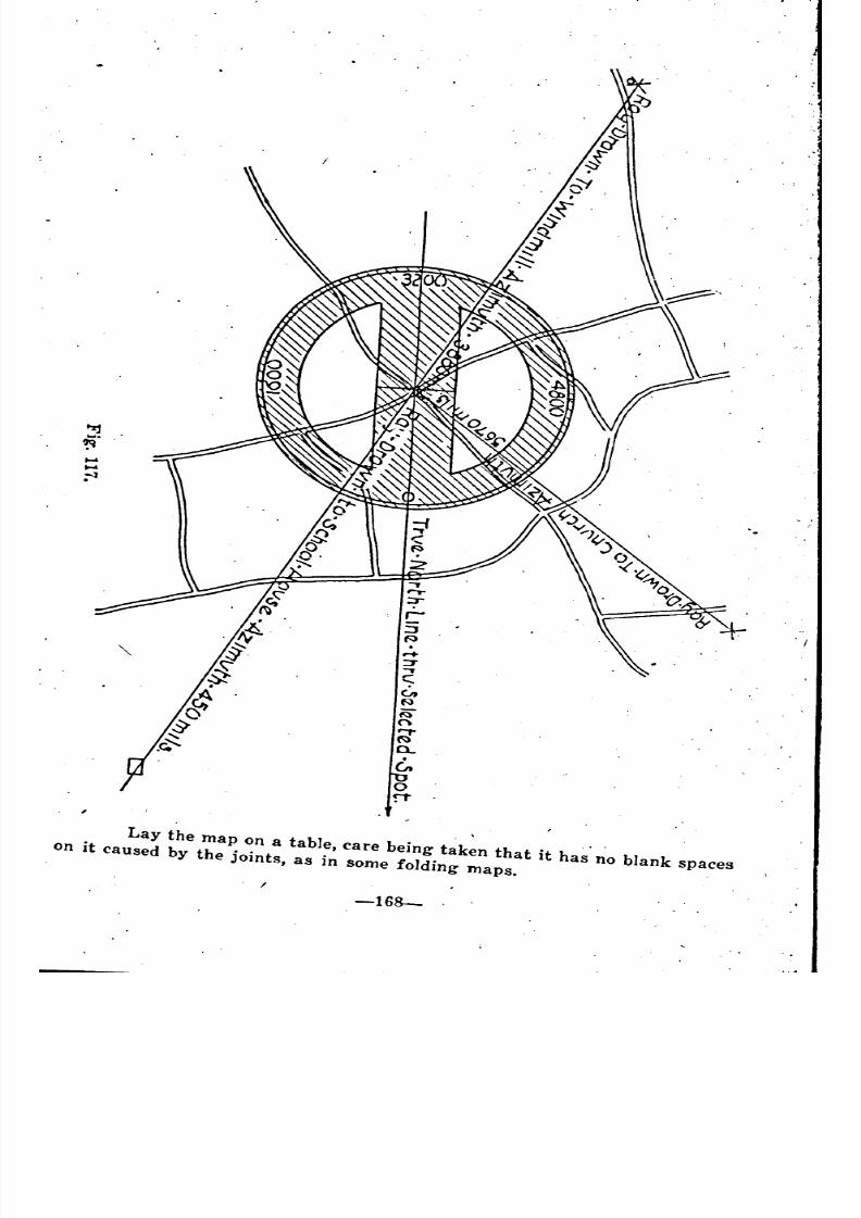
8/8/2019 Topography for Field Artillery
http://slidepdf.com/reader/full/topography-for-field-artillery 180/272
8/8/2019 Topography for Field Artillery
http://slidepdf.com/reader/full/topography-for-field-artillery 181/272
Magnetic declination as given in isogonic chart 100
4.' E
Secular change in 41/3 years .............................•.. 11.26' E
Total ...........................•..•...... 100
15.26' E
Less Diurnal variati~n for 3 p. m. May 1 2.4' 'V
Total ; 100
12.86' E
10° 12.86'=181.58'lt=182'1t.
B. COMPASS DECLINATION.
378. ,Compass Declination includes the magnetic declination, the mag-
netic variations, and the error of the compass itself. Naturally it will be
different for each compass.
Since all" of these are difficult to compute, and since the magnetic
declination and 'the variations generally are not subject to any suddenchanges of great size in a given locality, the most satisfactory method of
procedure is to determine the compass declination by a topographical opera-
tion and to' use the value so obtained for a limited period of time.
(1.) Comparison Of Azimuth And Bearings.
379. Determination of the compass declination may be secured in the fol-
lowing manner, see fig. 117.
Select a position to work from, which is clearly marked on the mapand from which can be seen at least three distant objects, widely separated
if possible, which also are clearly marked on the map. When selecting this
position, it is important to see that no metal is near which might have an
effect on the needle of the compa!'!!!.
Draw a line through the selected point on the map parallel to the
true north-south line found on the map.
Mark the selected point carefully on the line and draw rays from it
to the three indicated objects already selected.
Place a circular protractor on the map with its center on the point
where the rays meet, zero toward the north, 50 that the 0-3200 diameter
roincides with the true north-5<?uth line drawn on the map.
Read off the number 'of mils at which the rays to the three distant
objects cut the edge of the protractor; in other words, read the azimuths to
these objects, making a careful note of each in turn.
Set up the prismatic compass at the position on the ground from
which the azimuths have been read on the map, and read carefully the
magnetic bearings to the three distant objects, making a careful note of each
in turn as before. The average of difference between bearings, and azimuths
will give the mean compass declination.
In figure 117 is shown a map on ~hich a protractor is laid, 'giving
the azimuths to a schoolhouse; a church, and a windmill, all taken from a
turn in a main road.
A compass is set up at this turn and the magnetic bearings to these
three objects are read. The results are tabulated ~s follows:
-169-
~ -
' '

8/8/2019 Topography for Field Artillery
http://slidepdf.com/reader/full/topography-for-field-artillery 182/272
AZIMUTH MAGNETIC BEARING COMPASSREAD WITH PROTRACTOR READ WITH COMPASS DECLINATION
Schoolhouse. 450 mils 775 mils 325 mils \V
Church 5670 Ie 5985 315" W
Windmill 3880 .. 4185 .. 305" W
Total 945 WMean declination 315 "w
This mean declination can be taken as the compass declination of the
compass used for the experiment. If this is compared with the magnetic
declination computed for the particular locality and particular time, the
error of the compass can be ascertained and marked on the back for futureguidance in this locality. .
It is important to take at least three bearings to guard against per.
sonal error, and desirable to select objects as distant as Possible.
(2.) Declination Constant.
,380. The Declination Constant, is the reading which must be set off on an
instrument in order that, When the compass needle is brought opposite itsindex, the instrunlent will be oriented.
For a clockwise instrument the declination constant is the same as
the compass declination if the compass declination is east. If the compass
declination' is west, the declination constant is equal to 6400-the compasseclination.
,381. Y.Declination, fig 118, is the angle which magnetic north makes with
grid north. If the Y.Declination is used in orienting the instrument the
'declination constant is spoken of as The Magnetic Number. In this case the
",era of the instrument, When oriented will point toward Y-north
..
Fig. 118.
•
North,
Convu~~nc.~ .
-170-
"
' "
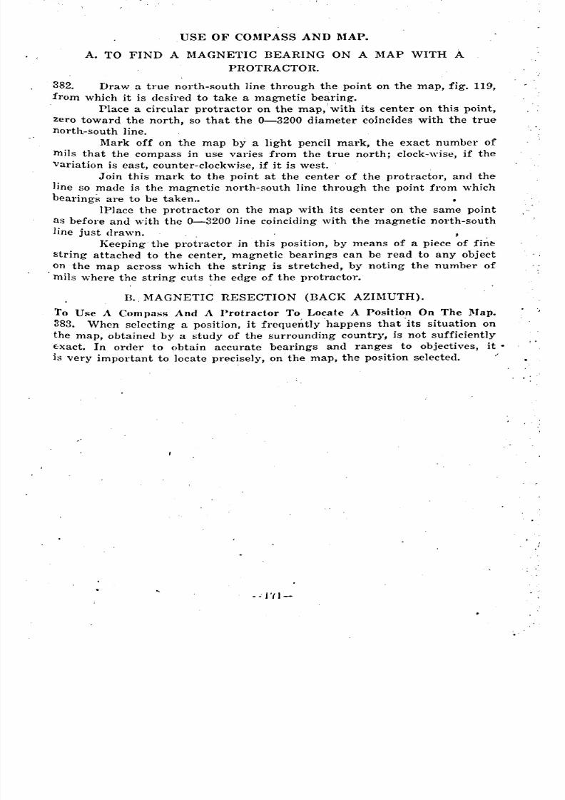
8/8/2019 Topography for Field Artillery
http://slidepdf.com/reader/full/topography-for-field-artillery 183/272
USE OF COMPASS AND MAP.
A. TO FIND A MAGNETIC BEARING ON A MAP WITH A
PROTRACTOR.
382. Draw a true north-south line through the point on the map, fig. 119,
from which it is desired to take a magnetic bearing.Place a circular pl'otractor on the map,'with its center on this point,
zero toward the north, so that the 0-3200 diameter coincides with the true
north-south line.
Mark off on the map by a light pencil mark, the exact number of
mils that the compass in use varies from the true north; clock-wise, if the
variation is east, counter-clockwise, if it is west.
Join this mark to the point at the center of the protractor, and the
line so made is the magnetic north-south line through the point from which
bearings are to be taken ..IPlace the protractor on the map with its center on the same point
as before and with the 0-3200 line coinciding with the magnetic north-south
line just drawn. ,
Keeping the protractor in this position, by means of a piece of fin~
string attached to the center, magnetic bearings can be read to any object
on the map across which the string is stretched, by noting the number of
mils where the string cuts the edge of the protractor.
B., MAGNETIC RESECTION (BACK AZIMUTH).To Use A Compass And A Protractor To Locate A Positio.n On The }\fap.
383. When selecting a position, it frequently happens that its situation on
the map, obtained by a study of the surrounding country, is not sufficiently
€:xact. In order to obtain accurate bearings and ranges to objectives, it.
is very important to locate precisely, on the map, the position selected .
. . ' "11-

8/8/2019 Topography for Field Artillery
http://slidepdf.com/reader/full/topography-for-field-artillery 184/272
Fig. 119.
-172-
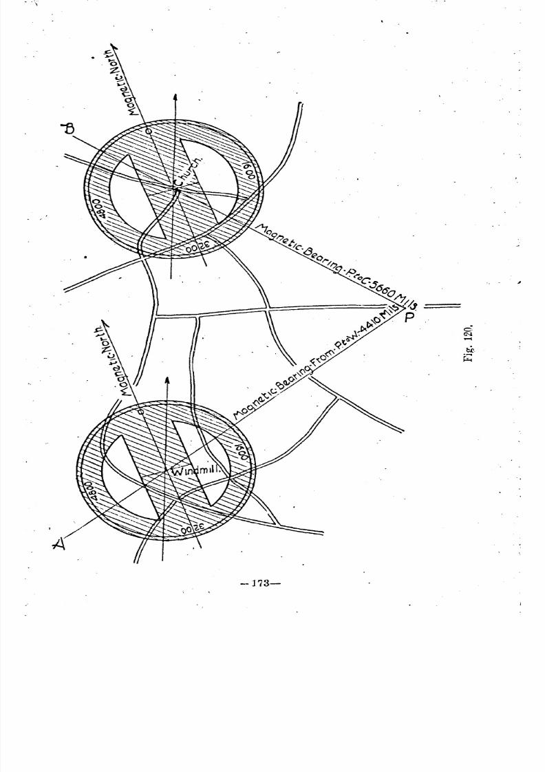
8/8/2019 Topography for Field Artillery
http://slidepdf.com/reader/full/topography-for-field-artillery 185/272
-173-
"
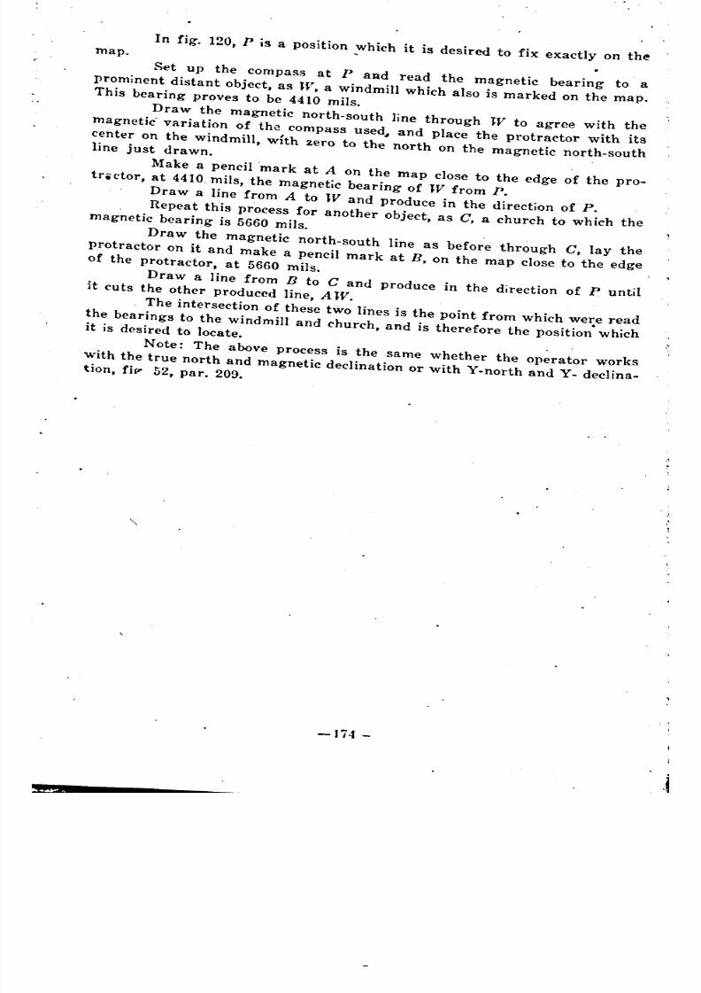
8/8/2019 Topography for Field Artillery
http://slidepdf.com/reader/full/topography-for-field-artillery 186/272
map. In fig. 120, P is a position ;Vhich it is desired to fix exactly on the
Set up the compass at PaRd read the magnetic bearing to a
prominent distant object, as W, a windmill which also is marked on the map.This bearing proves to be 4410 mils.
Draw the magnetic north-south line through TV to agree with themagnetic. variation of the compass used~ and place the protractor with its
center on the Windmill, wIth zero to the north on the magnetic north-southline just drawn.
Make a pencil mark at A on the map close to the edge of the pro-trictor, at 4410. mils, the magnetic bearing of TV from P.
Draw a line from A to TV and produce in the direction of P.
Repeat this process for another object, as C, a church to which themagnetic bearing is 5660 mils.
Draw the magnetic north-south line as before through C, lay theprotractor on it and make a pencil mark at B, on the map close to the edgeof the protractor, at 5660 mils.
Draw a line from B to C and produce in the direction of [J untilit cuts the other produced line, A W.
The intersection of these two lines is the point from which were read
the bearings to the windmill and church, and is therefore the position" whichit is desired to locate. .
Note: The above process is the same whether the operator works
with the true north and magnetic declination or with Y-north and y. declina-tion, fip' 52, par. 209.
-Ji4 -
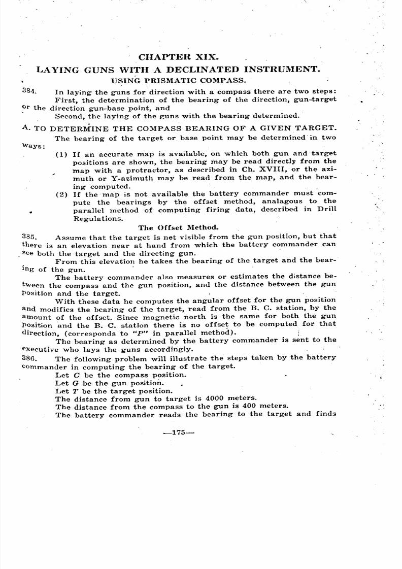
8/8/2019 Topography for Field Artillery
http://slidepdf.com/reader/full/topography-for-field-artillery 187/272
CHAPTER XIX.
I~AYING GUNS WITH A DECLINATED INSTRUl\IENT.USING PRISMATIC COMPASS.
384. In laying the guns for direction with a compass there are two steps:
First, the determination of the bearing of the direction, gun-target
Qr the direction gun-base point, and
. Second, the laying of the guns with the bearing determined ..
A.. TO DETERMINE THE COMPASS BEARING OF A GIVEN TARGET.
The bearing of the target or base point may be determined. in two
'Ways:
(1) If an accurate map is available, on which both gun and target
positions are shown, the bearing may be read directly from the
map with a protractor, as described in Ch. XVIII, or the azi-
muth or Y-azimuth may be read from the map, and the bear-
ing computed. .
(2) If the. map is not available the battery commander must com-
pute the bearings by the offset method, analagous to the
parallel method of computing firing data, described in DrillRegulations. .
The Offset Method.
385. Assume that the target is net visible from the gun position, but that
there is an elevation near at hand from which the battery commander can
, See both the target and the directing gun.
From this elevation he takes the bearing of the target and the bear-
ing of the gun.
The battery commander also measures or estimates the distance be-
tween the compass and the gun position, and the distance between the gun
Position and the target.
With these data he computes the angular offset for the gun position
and modifies the bearing of the target, read from the B. C. station, by the
amount of the offset. Since magnetic north is the same for both the gun
Position .and the B. C. station there is no offset to be computed for that
direction, (corresponds to HP" in parallel method). iThe bearing as determined by the battery commander is sent to the
<'xecutive who lays the guns accordingly.
386. The following problem will illustrate the steps taken by the battery
<:ommander in computing the bearing of the. target.
Let C be the compass position.
Let G be the gun position.
Let T be the target position.
The distance from gun to target is 4000 meters.
The distance from the compass to the gun is 400 meters.
The battery commander reads the bearing to the target and finds
-175-
c.
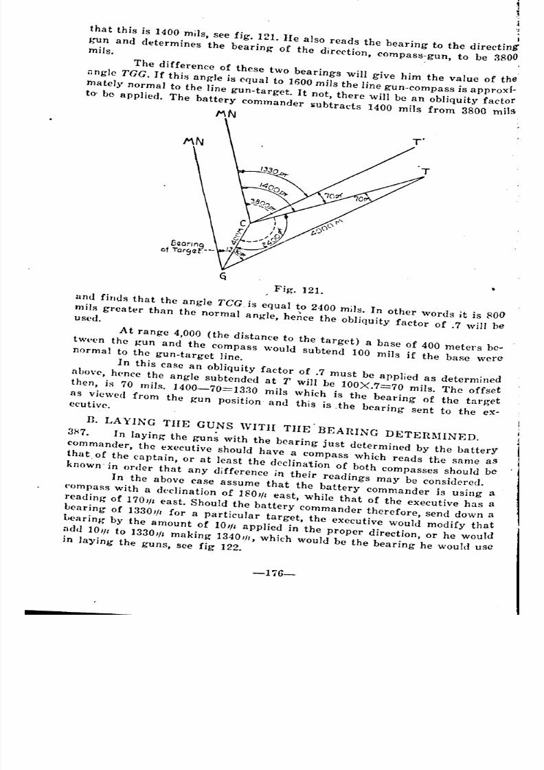
8/8/2019 Topography for Field Artillery
http://slidepdf.com/reader/full/topography-for-field-artillery 188/272
that this is 1400 mils, see fig. 121. He also reads the bearing to the directing
gun and determines the bearing of the direction, compass-gun, to be 3800mils.
The difference of these two bearings will give him the value of the
nngle TGG. If this angle is equal to 1600 mils the line gun-eompass is approxI-
mately normal to the line gun-target. It not, there will be an obliquity factorto' be applied. The battery commander subtracts 1400 mils from 3800 mils
!'IN
Fig. 121.
and finds that the angle TeG. is equal to 2400 mas. In other words it is 800
mils greater than the normal angle, he~ce the obliquity factor of .7 will besed.
At range 4,000 (the distance to the target) a base of 400 meters be- .tw,-en the gun and the compass would subtend 100 mils if the b"e werenormal to the gun-target line.
In this case an obliqUity factor of .7 must be applied as determinedabuve, hence the angle subtended at T will be 100X.7==70 mils. The offset
then, is 70 mils. 1400-70==1330 mils which is the bearing of the target
as viewed from the gun position' and this is the bearing sent to the ex-cutive.
n. LAYING TIlE GUNS WITII THE BEARING DETERMINED.
3H7. In laying the gun~ with the bearing iust determined by the battery
commander, the executive should have a compass which reads the same as
that. of the captain, or at least the declination of both compasses should be
known' in order that any differenee in their readings may be eonsidered.
In the above ease assume that the battery eommander is using a('ompass with a declination of 180'lz east, While that of the executive has a
reading of 1701/z east. Should the battery commander therefore, send down a
bearing of 1330,/, for a particular target, the executive would modify that
bearing by the amount of 10,/, applied in the proper direction, or he would
add 10", to 1330,/, making 1340"., which would be the bearing he would usein laYing the guns, see fig 122.
-176-
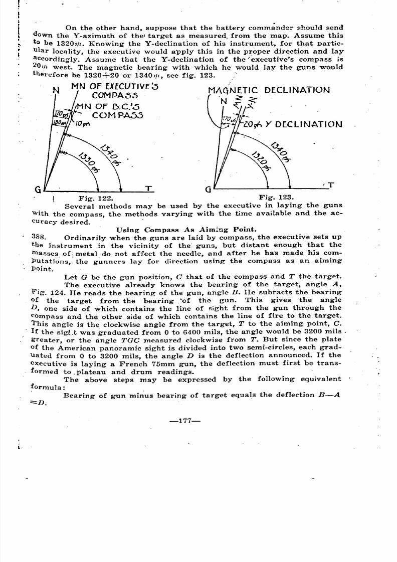
8/8/2019 Topography for Field Artillery
http://slidepdf.com/reader/full/topography-for-field-artillery 189/272
'T
MAQNETIC DECLINATION
'N <'~A
TG
On the other hand, suppose that the battery comm~nder should send
down the Y-azimuth of the\ target as measured, from the map. Assume this
to be 1320,11. Knowing the Y-declination of his instrument, for that Dartic-
ular locality, the executive would apply this in the proper direction and lay
accordingly. Assume that the Y-declination of the /executive's compass is
201ft west. The magnetic bearing with which he would lay the guns wouldtherefore be 1320+20 or 13401//, see fig. 123.
N MN OF EXeCUTIVE 0COMPA55
MN OF f>.C.'0
COMPA5510",
Fig. 122. Fig. 123.
Several methods may be used by the executive in laying the guns
With the compass, the methods varying with the time available and the ac-
Curacy desired.
Using Compass As Aim~ng Point.
388. Ordinarily when the guns are laid by compass, the executive sets up
the instrument in the vicinity of the' guns, but distant enough that the
masses of'metal do, not affect the needle, and after he ha's made his com-
Putatio'ns,,' the g~nners lay for direction using the compass as an aiming
Point.
Let G be the gun position, C that of the compass and T the target.
The executive already knows the bea,ring of the target, angle A,
Fig. 124. He reads the bearing of the gun, angle B. He subracts the bearing
of the target from the bearing ,'of the gun. This gives the angle
D, one side of which contains the line of sight from the gun through the
compass and the other side of which contains the line of fire to the target.
This angle is the clockwise angle from the target, T to the aiming point, C.
If the sigLt was graduated from 0 to 6400 mils, the angle would be 3200 mils.
greater, or the angle TGC measured clockwise from T. But since the plate
of the American panoramic sight is divided into two semi-circles, each grad-uated from 0 to 3200 mils, the angle D is the deflection announced. If the
executive is laying a French 75mm gun, the' deflection must first be trans-
formed to, plateau and drum readings.
The above steps may be expressed by the following equivalent
formula:
. Bearing of gun minus bearing of target equals the deflection B-A
:::::'D.
-177-
~ "
'
- -
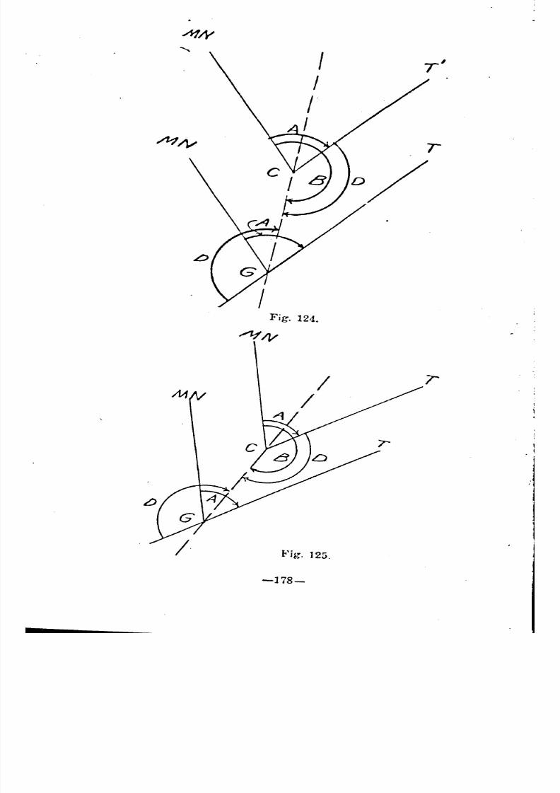
8/8/2019 Topography for Field Artillery
http://slidepdf.com/reader/full/topography-for-field-artillery 190/272
Fig. 124.
Fig. 125.
-178-
r
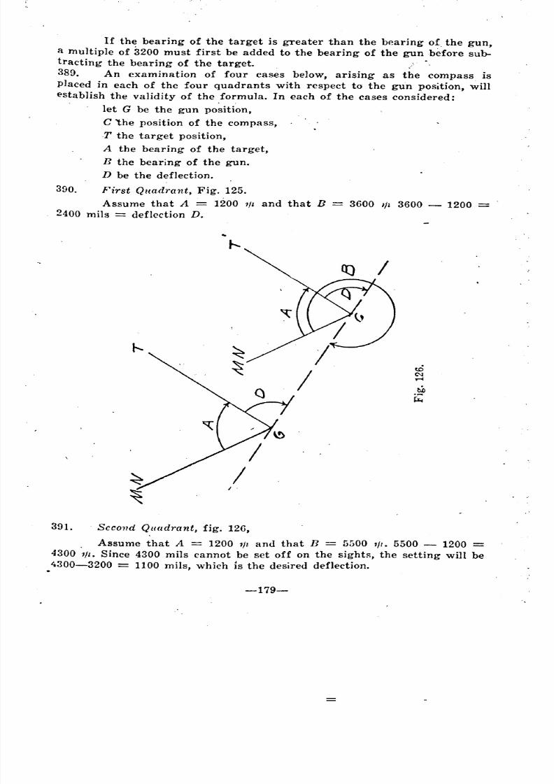
8/8/2019 Topography for Field Artillery
http://slidepdf.com/reader/full/topography-for-field-artillery 191/272
If the bearing of the target is greater than the bearing of the gun,
a multiple of 3200 must first be added to the bearing of the gun before sub-
tracting the bearing of the target.
389. An examination of four cases below, arising as the compass is
placed in each of the four quadrants with respect to the gun position, will
establish the validity of the formula. In each of the cases considered:
let G be the gun position,
C 'the position of the compass,
T the target position,
A the bearing of the target,
n the bearing of the gun.
D be the deflection.
390. First Quadrant, Fig. 125.
Assume that A = 1200 1f t and that n = 3600 III 3600 1200
2400 mils = deflection D.
391. Second Quadrant, fig. 126,
. Assume that A = 1200 111 and that n 5500 111. 5500 1200 =4300 111. Since 4300 mils cannot be set off on the sightg, the setting will be
4300-3200 = 1100 mils, which is the desired deflection.
-179-
- _
= -
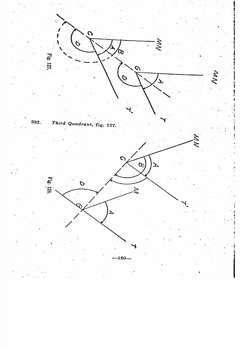
8/8/2019 Topography for Field Artillery
http://slidepdf.com/reader/full/topography-for-field-artillery 192/272
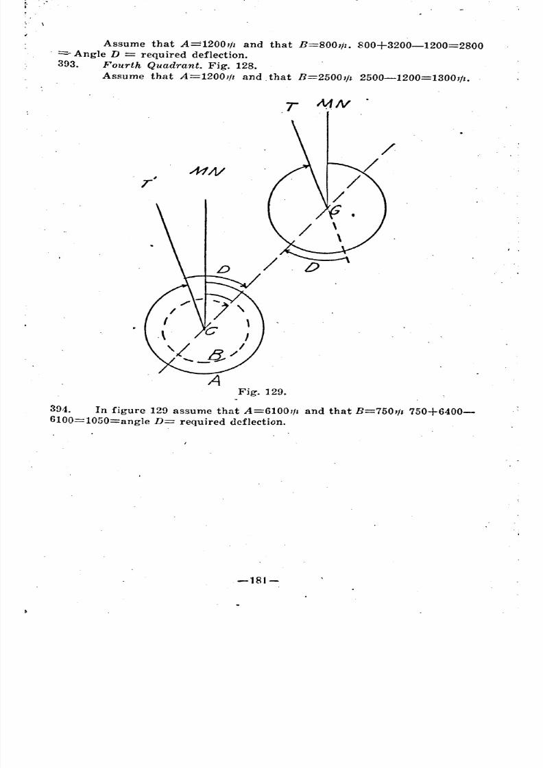
8/8/2019 Topography for Field Artillery
http://slidepdf.com/reader/full/topography-for-field-artillery 193/272
Assume that A=1200t!1 and that B=800t/z. 800+3200-1200=2800
. =- Angle D == required deflection.
393. Fourth Quadrant. Fig. 128.
Assume that A=1200,!z and. that B=2500,/1 2500-1200=1300//1.
T MN
r'
o
Fig. 129.
394. In figure 129 assume that A=6100,/1 and that B=750,/1 750+6400-
6100=1050=angle D= required deflection.
-181-
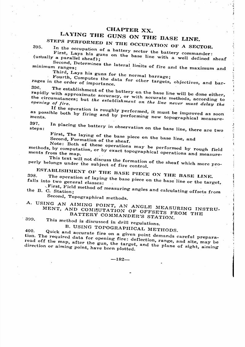
8/8/2019 Topography for Field Artillery
http://slidepdf.com/reader/full/topography-for-field-artillery 194/272
CHAPTER XX.
LAYING THE GUNS ON THE BASE LINE.
STJ<;PS PERFORMED IN THE OCCUPATION OF A SECfOR.
395. In the occupation of a battery sector the battery commander:
First, Lays his guns on the base line with a well defined sheaf(uS\lally a parallel sheaf);
Second, Determines the lateral limits of fire and the maximum andminimum ranges;
Third, Lays his guns for the normal barrage;
. Fourth, Computes the data for other targets, objectives, and bar-rages in the order of importance.
396. The establishment of the battery on the base line will be done either,
rapidly with approximate accuracy, or with accurate methods, according to
the circumstances; but the establishment on the line never must delay theopening of fi'.e.
lf the Opt!ration is roughly performed, it must be improved as soon
as possible both by firing and by performing new topographical measure-ments.
397. In placing the battery in observation on the base line, there are twosteps:
First, The laying of the base piece on the base line, andSecond, Formation of the sheaf.
Note: Both of these operations may be performed by rough field
methods, by computation, or by exact topographical operations and measure-ments from the map.
This text will not discuss the formation of the sheaf which more pro-perly belongs under the subject of fire control.
ESTABLISIDIEXT OF THE BASE PIECE ON THE BASE LINE.
398. The operation of laying the base piece on the base' line or the target,falls into two general classes:
"First, Field method of measuring angles and calculating offsets fromthe B. C. Station;
Second, Topographical methods.
, 399.
A. USING AN AIMING POINT, AN ANGLE MEASURING INSTRU-
MENT, AND COMI,UTATION OF OFFSETS FROM THEBATTERY COMMANDER'S STATION.
This method is discussed in drill regulations.
B. USING TOPOGRAPHICAL METHODS.
400. Quick and accurate fire on a given point demands careful prepara-
tion. The required data for opening fire: deflection, range, and site, may be
read off the map, after the gun, the target, and the plane of sight, aimingdirection or aiming point, have been plotted.
-182-
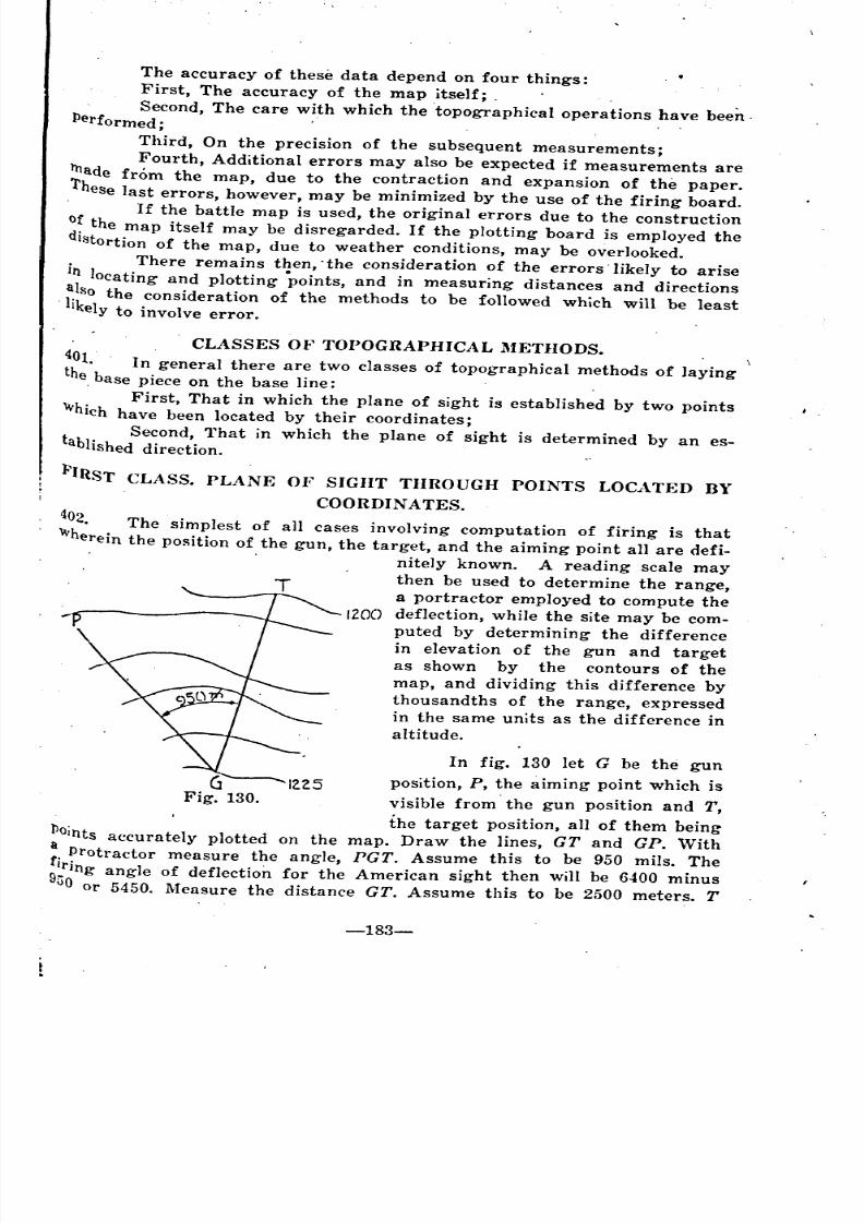
8/8/2019 Topography for Field Artillery
http://slidepdf.com/reader/full/topography-for-field-artillery 195/272
The accuracy of these data depend on four things:
First, The accuracy of the map itself; .
Second, The care with which the topographical operations have been.Performed; . .
Third, On the precision of the subsequent measurements;Fourth, Additional errors may also be expected if measurements are
1llade from the map, due to the contraction and expansion of the paper.
'l'hese
last errors, however, may be minimized by the use of the firing board.
. If the battle map is used, the original errors due to the construction
()~the map itself may be disregarded. If the plotting board is employed the
distortion of the map, due to weather conditions, may be overlooked.
. There remains then, .the consideration of the errors' likely to arise
In locating and plotting .points, and in measuring distances and directions
. flso the consideration of the methods to be followed which will be leastIkely to involve error.
CLASSES OF TOPOGRAPHICAL METHODS.
401. In general there are two classes of topographical methods of layingthe, base piece on the base line: .
First, That in which the plane of sight is established by two pointsWhich have been located by their coordinates;
t . Second, That in which the plane of sight is determined by an es-abhshed direction.
PIRST CLASS. PLANE OF SIGHT THROUGH POINTS LOCATED BY
COORDINATES.
I 402. The simplest of all cases involving computation of firing is that
"'herein the position of the gun, the target, and the aiming point all are defi-
nitely known. A reading scale may
then be used to determine the range,
a portractor employed to compute the
IZOO deflection, while the site may be com-
puted by determining the difference
in elevation of the gun and target
as shown by the contours of the
map, and dividing this difference by
thousandths of the range, expressed
in the same units as the difference in
altitude.
In fig. 130 let G be the gun
position, P, the aiming point which is
visible from' the gun position and T,
the target position, all of them beingllOints accurately plotted on the map. Draw the lines, GT and GP. With
a, Protractor measure the angle, PGT. Assume this to be 950 mils. The
:~ring angle of deflection for the American sight ~hen will be 6400 minus
vO or 5450. Measure the distance GT. Assume tll1S to be 2500 meters. T
-183-
" "
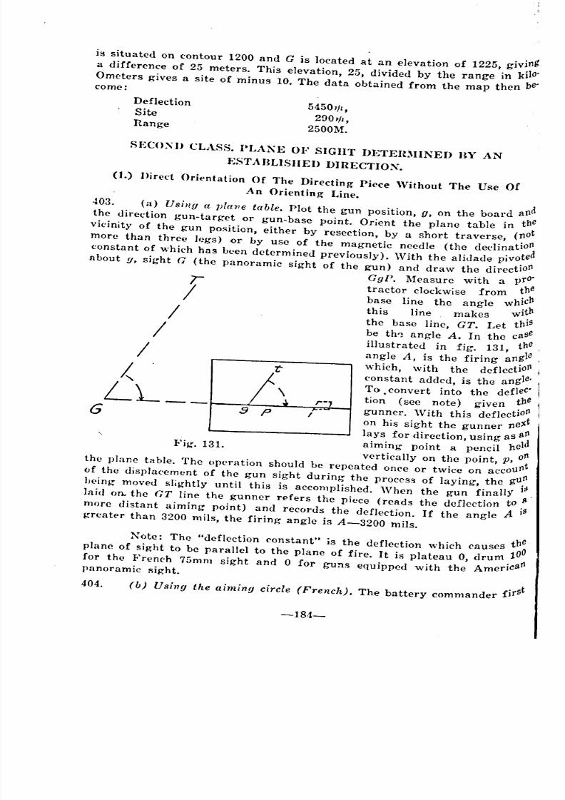
8/8/2019 Topography for Field Artillery
http://slidepdf.com/reader/full/topography-for-field-artillery 196/272
is situated on contour 1200 and G is located at an elevation of 1225, giving
a difference of 25 meters. This elevation, 25, divided by the range in kilo'
Ometers gives a site of minus 10. The data obtained from the map then be'come:
Deflection
Site
Range
54501/1,
290'11,
2500M.
SECOXU CLASS. PLAXE OF SIGHT DETEIUIINED BY AN
f:STABLISIIED DIRECTION.
r
:} p
Fig. 131.
r///
LL__G
(1.) Hired Orientation Of The Directing Piece 'Vithout The Use Of
An Orienting Line.
403. (a) Using (t l)[ane table. Plot the gun position, g, on the board and
the (lirection gun-target or gun-base point. Orient the plane table in the,
vicinity of the gun position, either by resection, by a short traverse, (not.
more than three legs) or by use of the magnetic needle (the dcclinatio~
constant of which has been determined previously). Wjth the aljdade pivoteabout g, sight G (the panoramic sight of the gun) and draw the directioJ1
GgP. l\Ieasure with a pro'
tractor clockWise from ~h:base line the angle WhlC
this line makes witb
the base line, GT. Let thiS
be th~ angle A. In the case
illustrated in fig. 131, the
angle A, is the firing angle
which, with the deflectioJ1
eon stant added, is the angle.
To convert into the defleC
tio~ (see note) given the
gunner. 'Vith this defleetiO~
on his sight the gunner ne~
lays for direction, using as a:
aiming point a pencil hel
vertically on the point, P, o~the plane table. The operation should be repeated once or twice on accou
l1
of the displacement of the gun sight during the process of laying, the gU,J1
h('ing moved slightly until this is accomplished. When the gun finally 1;laid on the GT line the gunner refers the piece (reads the deflection to.1'o
more distant aiming point) and records the deflection. If the angle Ii IS
greater than 3200 mils, the firing angle is A-3200 mils.
~ote: The "deflection constant" is the deflection which causes th~
plane of sight to be parallel to the plane of fire. It is plateau 0, drum 10
for the French 75mm sight and 0 for guns equipped with the Americatlpanoramic sight.
404. (b) Using the aiming circle (French). The battery commander first
-18-1-
~ '
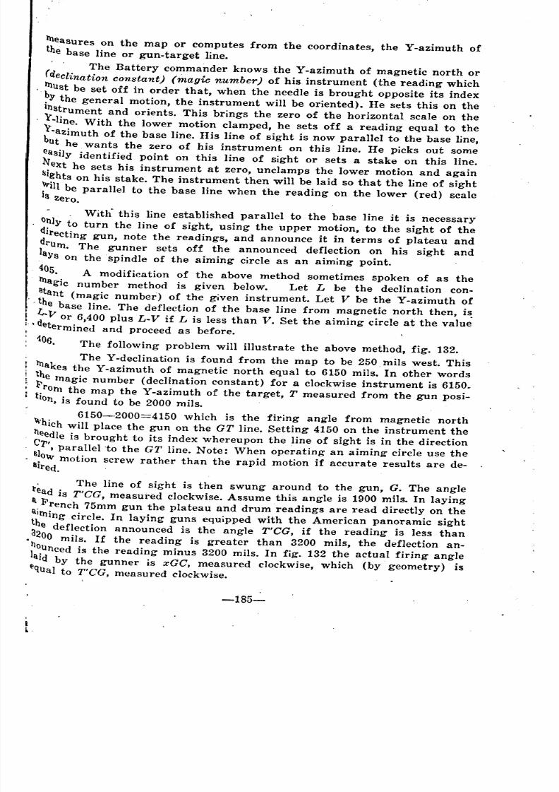
8/8/2019 Topography for Field Artillery
http://slidepdf.com/reader/full/topography-for-field-artillery 197/272
measures on the map or computes from the coordinates, the Y-azimuth ofthe base line or gun-target line.
'. The Battery commander knows the Y-azimuth of magnetic north or
(declination constant) (magic number) of his instrument (the reading which
~U8t be set off in order that, when the needle is brought opposite its index
• 'Y the general motion, the instrument will be oriented). He sets this on the
~s~rument and orients. This brings the zero of the horizontal scale on the
-lIne. With the lower motion clamped, he sets off a reading equal to the
~-aZimuth of the base line. His line of sight is now parallel to the base line,
ut he wants the zero of his instrument on this line. He picks out some
~asi1y identified point on this line of sight or sets a stake on this line .
.ext he sets his instrument at zero, unclamps the lower motion and again
~Ights on his stake. The instrument then will be laid so that the line of sight
~ill be parallel to the base line when the reading on the lower (red) scaleIS Zero.
With" this line established parallel to the base line it is necessary
O?ly to turn the line of sight, using the upper motion, to the sight of the
dIrecting gun, note the readings, and announce it in terms of plateau and
~rum. The gunner sets off the announced deflection on his sight and
ays on the spindle of the aiming circle as an aiming point .
.405. A modification of the above method sometimes spoken of as the
magic number method is given below. Let L be the declination con-
. Iltant (magic number) of the given instrument. Let V be the Y-azimuth of
' ~ h e base line. The deflection of the base line from magnetic north then, is.
d-'V or 6,400 plus L-V if L is less than V. Set the aiming circle at the value• etermined and proceed as before.
106. The following problem will illustrate the above method, fig. 132.
The Y-declination is found from the map to be 250 mils west. This
rnakes the Y-azimuth of magnetic north equal to 6150 mils. In other words
~e magic number (declination constant) for a clockwise instrument is 6150.
rrom the map the Y-azimuth of the target, T measured from the gun posi-Ion, is found to be 2000 mils.
6150-2000=4150 which is the firing angle from magnetic north
Whichwill place the gun on the GT line. Setting 4150 on the instrument the
tleedle is brought to its index whereupon the line of sight is in the direction
. C1", parallel to the GT line. Note: When operating an aiming circle use the
s~owmotion screw rather than the rapid motion if accurate results are de-Illred.
. The line of sight is then swung around to the gun, G. The angle
l'ead is T'CG, measured clockwise. Assume this angle is 1900 mils. In laying
a. French 75mm gun the plateau and drum readings are read directly on the
:Itning circle. In laying guns equipped with the American panoramic sight
3he
deflection announced is the angle T'CG, if the reading is less than
• 200 mils. If the reading is greater than 3200 mils, the deflection an-
~~unced is the reading minus 3200 mils. In fig. 132 the actual firing angle
aId by the gunner is xGC, measured clockwise, which (by geometry) istlqUalto T'CG, measured clockwise.
-185-
~
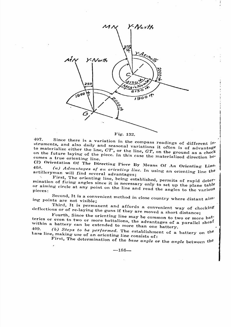
8/8/2019 Topography for Field Artillery
http://slidepdf.com/reader/full/topography-for-field-artillery 198/272
Fig. 132.
407. Since there is a variation in the compass readings of different iJ11
l>truments, and also daily and seasonal variations it often is of advantage
to materialize either the line, CT', or the line, CT, on th~ ground as a check
on the future laying of the piece. In this case the materialized direction bel
comes a true orienting line.(2) Orientation Of The J)irectin~ Pi{'ce By )Ieans Of An Orienting Line.
403. (a) Advanta{jes of an orienting line. In using an orienting line theartilleryman will find several advantages;
First, The orienting line, being established, permits of rapid deterl
mination of firing angles since it is necessary only to set up the plane table
or aiming circle at any point on the line and read the angles to the variouspieces:
Second, It is a convenient method in close country where distant ai}111ing points are not visible;
Third, It is permanent and affords a convenient way of checkiJ1g'
deflections or of re-Iaying the guns if they are moved a short distance;
Fourth, Since the orienting line may be common to two or more bat;
teries or even to two or more battalions, the advantages of a parallel shea
within a hattery can be extended to more than one battery.
409. (b) Steps to be performed. The establishment of a battery on the
base line, making use of an orienting line consists of:
First, The determination of the base angle or the angle between the
-186-
"
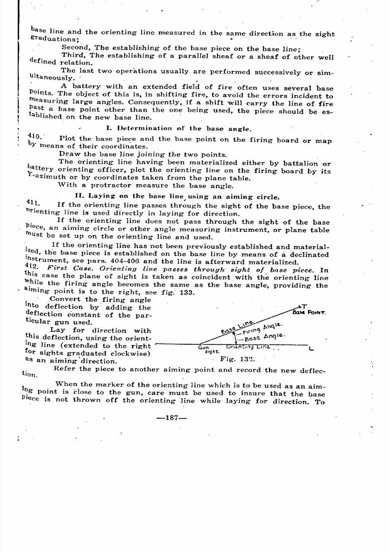
8/8/2019 Topography for Field Artillery
http://slidepdf.com/reader/full/topography-for-field-artillery 199/272
base line and the orienting line measured in the same direction as the sightgraduations;
, Second, The establishing of the base piece on the base line;
Third, The establishing of a parallel sheaf or a sheaf of other welldefined relation., .
The last two operations usually are performed successively or sim-
Ultaneously. '. ','
A battery with an extended field of fire often uses several base
POints. The object of this is, in shifting fir~, to avoid the errors incident to
llleasuring large angles. Consequently, if a shift will carry the line of fire
!last a base point other than the one being used, the piece should be es-
tablished on the new base line. ,
J. Determination of the base angle.
410. . Plot the base piece and the base point on the firing board or map
by means of their coordin'ates.
Draw the base line joining the two points.
The orienting line having been materialized either by battalion or
Lattery orienting ~fficer, plot the orienting line on the firing board by its
Y'azimuth or by coordinates taken from the plane table.
\Vith a protractor measure the base angle. .
Lun"Ight .
. Fig. 133.
II. Laying on the base line using an aiming circle.
411. If the orienting line passes thr~ugh the sight of the base piece, the~rienting line is used directly in laying for direction.
. If the orienting line does not pass through the sight of the base
PIece, an aiming circle or other angle measuring instrument, or plane table
ll1ust be set up on the orienting line and used. .
. If the orienting line has not been previously established and material-
~zed,th'e base piece is established on the base line by means of a declinated
Instrument, see pars. 404-406 and the line is afterward materialized.
412. First Case. Orienting line passes through' sight of base piece. In
this case the plane of sight is taken as coincident with the orienting line
While the firing angle becomes the same as the base angle, providing the
aiming point i~ to the right, see fig. 133.
. Convert the firing angle
Into deflection by adding the
deflection c'onstant of the par-
ticular gun used.
Lay for direction with
~his deflection, using the orient-
Ing line (extended to the right t--
for sights graduated clockwise)
as an aiming 'direction.
Refer the piece to another aiming point and record the new defIec-tion.
1 When the marker of the orienting line which is to be used as an aim-
ng point is Close to the gun, care must be used to insure that the base
lliece is not thrown off the orienting line while laying for direction. To
-187-
'
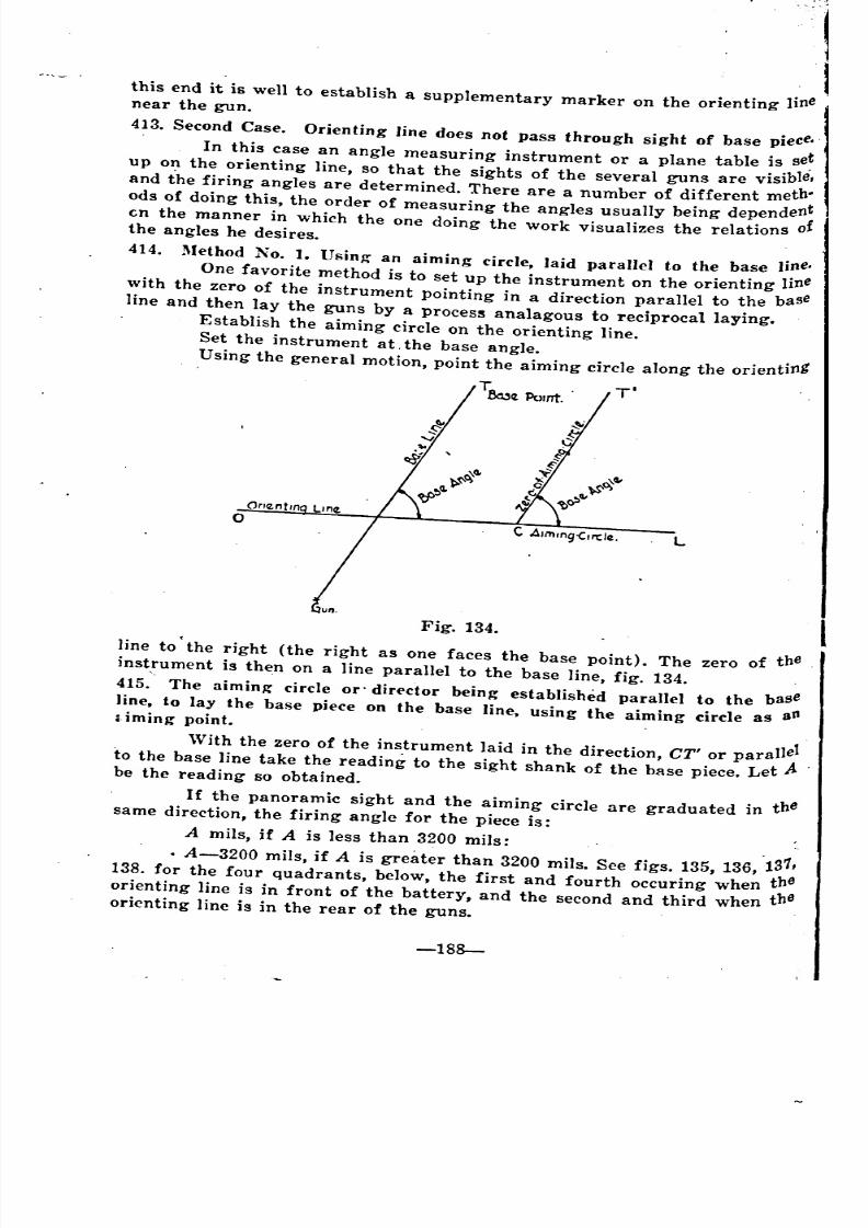
8/8/2019 Topography for Field Artillery
http://slidepdf.com/reader/full/topography-for-field-artillery 200/272
this end it is well to establish a supplementary marker on the orienting linenear the gun.
413. Second Case. Orienting line does not pass through sight of base piece.
. In this case an angle measuring instrument or a plane table is se~
up on the orienting line, so that the sights of the several guns are visible,
and the firing angles are determined. There are a number of different meth-
ods of doing this, the order of measuring the angles usually being dependen;
en the manner in which the one doing the work visualizes the relations 0the angles he desires.
414. Method No.1. Using- an aiming circle, laid parallel to the base line.
One favorite method is to set up the instrument on the orienting line
with the zero of the instrument pointing in a direction parallel to the baseline and then lay the guns by a process analagous to reciprocal laying.
Establish the aiming circle on the orienting line.
Set the instrument at. the base angle.
Using the general motion, point the aiming circle along the orienting'
1': . T'Be13~ Point.
L
Fig. 134.
line to' the right (the right as one faces the base point). The zero of the
inst,rument is then on a line parallel to the base line, fig. 134.
415. The aiming- circle or" director being established parallel to the base
line, to lay the base piece on the base line, using the aiming circle as an~.ming point.
With the zero of the instrument laid in the direction, CT' or parallelto the base line take the reading to the sight shank of the base piece. Let .Abe the reading so obtained.
If the panoramic sight and the aiming circle are graduated in thesame direction, the firing angle for the piece is:
A mils, if A is less than 3200 mils:. . .
. A-3200 mils, if A is greater than 3200 mils. See figs. 135, 136, 131,
138. for the four quadrants, below, the first and fourth occuring when the
orienting line is in front of the battery, and the second and third when theorienting line is in the rear of the guns.
~
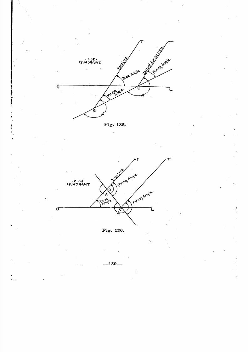
8/8/2019 Topography for Field Artillery
http://slidepdf.com/reader/full/topography-for-field-artillery 201/272
o
. ,-"t..QVAORANT.
L
o
.2 ndQvAORANT
Fig. 136.
-189-
T'
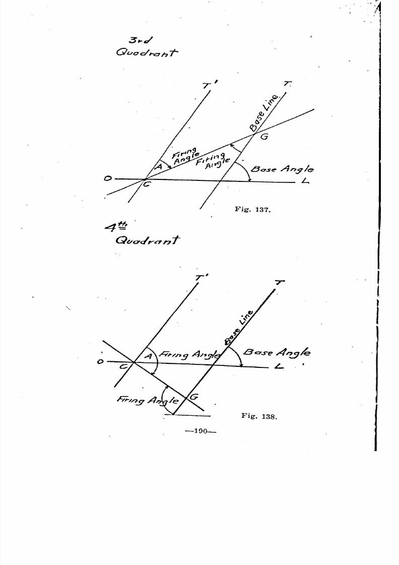
8/8/2019 Topography for Field Artillery
http://slidepdf.com/reader/full/topography-for-field-artillery 202/272
o
7'
Fig. 137.
r
4t;Q
Quadrant
r' ,T
l
0
Base A"..:J1e
L
Fig. 138.
-190-
I
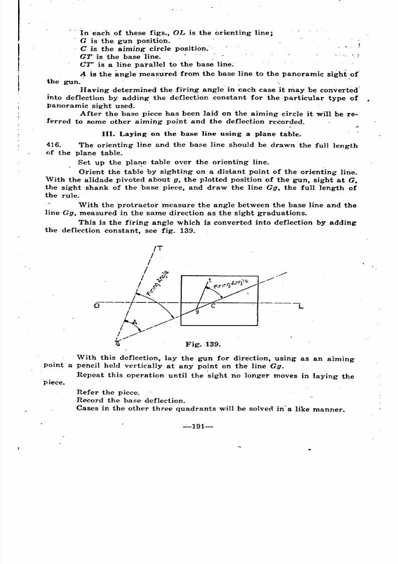
8/8/2019 Topography for Field Artillery
http://slidepdf.com/reader/full/topography-for-field-artillery 203/272
piece.
In' each of these figs., OL is the orienting line;
G is the gun position.
C is the aiming circle position."
GT is the baseline.. : .
CT' is a line parallel to the base line;
A is the angle measured from the base line to the panoramic sight of'the gun. . ". . .
Having determined the firing angle' in each case it may be converted'
into deflection by adding the deflection constant for the particular type of ,
panoramic sight used. .
After the base piece has been laid on the aiming circle it will be re-
ferred to some other aiming point and the deflection recorded.
III. Laying on the base line using a plane table.
416. The orientIng line and the base line should be drawn the full length
of the plane table.
Set up the pla~e table over the orienting line. .
Orient the table by sighting on a distant point of the orienting line.
\Vith the alidade pivoted about g, the plotted position of the gun, sight at G,
the sight shank of the base piece, and draw the line Gg. the full length of
the rule.
With the protractor measure the angle between the base line and the
line Gg. measured in the same direction as the sight graduations.
This is the firing angle which is converted into deflection by adding
the deflection constant, see fig. 139.
Fig. 139.
With this deflection, lay the gun for direction, using as an aiming
point a pencil held vertically at any point on the line Gg.
Repeat this operation until the 'sight no longer moves in laying the
Refer the piece.
Record the base deflection.
Cases in the other three quadrants will be solved in' a like manner.
~191-
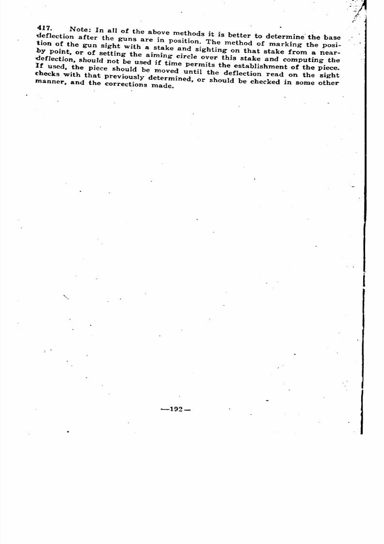
8/8/2019 Topography for Field Artillery
http://slidepdf.com/reader/full/topography-for-field-artillery 204/272
417. Note: In all of the above methods it is better to determine' the base
deflection after the guns are in position. The method of marking the posi-
tion of the gun sight with a stake and sighting on that stake from a near-
by point, or of setting the aiming circle over this stake and computing the
deflection, should not be used if time permits the establishment of the piece.If used, the piece should be moved until the deflection read on the sight
checks with that previously determined, or should be checked in some othermanner, and the corrections made.
-192-

8/8/2019 Topography for Field Artillery
http://slidepdf.com/reader/full/topography-for-field-artillery 205/272
\ ~ ..1
\
\
CHAPTER XXI.
TOPOGRAPHICAL OPERATIONS IN OCCUPATION OF
A BA1YfERY SECTOR.
GENERAL.
418. Topographical operations to be performed in the occupation of. a
battery sector are dependent on:
First, the time element;
Second the instrument available for use;
Third, the accuracy of the map used;
Fourth, the proximity of geodetic points or points of general con-
troI.
The object of the topographical operations is to determine the initial
elements of fire. These operations are performed, partly during rcon-
naissance, and partly after the position is occupied.
The topographical steps may be performed: (1) entirely by the bat-
tery commander or his reconnaissance officer; or, (2) by the battalion
reconnaissance officer who locates the orienting line and place marks for all
batteries, followed by the battery commander who completes the work for
bis particular battery.
GUN POSITION.
(A) WilEN COORDINATES OF GUN POSITION CAN BE READ
DIRECTLY FROM THE MAP.
419. The simplest operations arise when the battery is located at a point
which may be identified on the map so that the coordinates may be taken
directly from the sheet.If the base point or the target also can be identified on the map the
base line, or the direction to the target, may be taken from the map, as ..
may the range, while the site may be computed by using the map elevations.
In such a case a line of sight may be established through a distant.
aiming' point, or along a line of established direction, and the guns laid ac-
cordingly; or, the direction to the base point having been determined, the
guns may be laid. with a declinated instrument on the base line, see Ch. XX.
B. WHEN THE GUN POSITION CANNOT BE IDENTIFIEDON THE MAP.
420. In the majority of cases the position of the guns cannot be identified
on the map.
Since the position of the guns must be known before any firing data
may be computed from the map, the first topographical step is the de-
termination of the battery location. This may be accomplished in a number
of different ways.
-193-
8/8/2019 Topography for Field Artillery
http://slidepdf.com/reader/full/topography-for-field-artillery 206/272
(1) Using A Geodetic Point.
421. If the battery is close to a geodetic point the coordinates and eleva-
. tion of the gun position may be determined by a short traverse.
(2) By Resection.
422. If the battery is in a position from which two or more control points
can be seen, the position may be determined by resection.
(3) By An Orienting Point.
423. If neither of these conditions hold, it will be necessary to establish
an orienting point" which will be used as the starting point for further
topographical operations. The guns are located, in this case, by running
a traverse from the orienting point.
If the topographical operations are performed in advance of the ar-
r!val of the guns, it is customary to establish a place mark near the bat-tery position. The coordinates and elevation of this place mark will be
recorded and when the battery does arrive, the exact location of the guns,
hori"ontally and vertically, may be determined, either by traverse, or by
determining how much east or west, how much north or south, and how
much above or. below the place mark, the gun position may be.
BASE POINT OR TARGET.
A. WHBN THE POSITION OF THE BASE POINT. OR OTHER TAR-GETS MAY NOT BE DETERMINED FROM THE MAP.
42.1. (see Ch. XXII.)
B. DETERMINATION OF DIRECTION TO TARGET OR BASE
POINT FROM THE MAP.
425. \Vith the gun position and the target position determined by coordin-
ates, the direction or Y-azimuth may be read directly from the map by
means of a protractor, or the direction may be computed directly by a com-
parison of the two points, see Ch. XVII. /
AIMING POINT.
A. DETERMINING DIRECTION TO AIMING POINT.
426. The direction to the base point or target being known, it is neces-
sary, before the guns can be laid, that a plane of sight should be determined.
This also may be done topographically.
The desired direction may be determined by using a distant known
aiming point, see Ch. XX; by using a declinated instru~nt, see Ch. XX,or by making use of an orienting line.
B. THE ORIENTING LINE.
427. The orienting line, as the name implies, is a line of known direction
usually materialized on the ground by means of which the battery commander
can orient his guns. Magnetic north, as used in connection with a declinated
instrument, is such a direction, and if this direction is materialized on the
~round, it becomes a true orienting line. The direction, Gun-aiming Point,
if materialized on the ground, also becomes such a line.
-1~ t--
"

8/8/2019 Topography for Field Artillery
http://slidepdf.com/reader/full/topography-for-field-artillery 207/272
(1) rfwo Types Of Or\enting Lines. (See cuts, Appendix No.6.)
428. In general there are two types of orienting lines, viz;
(a) Those established through a known point or points, and
(b) Those established with a known direction.
Magnetic north, if materialized, is of the last type. In some cases it
is easier and more accurate to establish an orienting line by direction ratherthan to run it through known points. If such a line is established it is not
necessary to determine the coordinates of any points on the line. The line
may be run through the gun position, or in front or rear of it, and in any
direction, and the guns speedily laid by means of a plane table or angle
measuring instrument set up on it at any place visible from the guns.
42~. 'Vhere the orienting line is established by direction it still is neces-
sary for the battery commander or reconnaissance officer to take the topo-
graphical steps necessary to determine the coordinates of the battery.
On the other hand where the orienting line is run through an
orienting point which has been occupied in the work, the two sets of opera-
tions may be performed simutaneously and the reconnaissance officer will
reach a point in the vicinity of the battery with all control elements
determined.
T
Fig. 140.
.430. The orienting line should be established by means of a set of con-
spicuous stakes or markers set up at such intervals that, from anyone stake
.at least two otherg will be visible. This affords a check on direction and
-103-
'
8/8/2019 Topography for Field Artillery
http://slidepdf.com/reader/full/topography-for-field-artillery 208/272
alignment in case a stake is destroyed. Usually the stakes or markers ofeach battalion will be of a distinctive type. .
(2) A Typical Case.
431. Assume that the battalion has been assigned a sector, that the gen';
eral location of gun positi-;'ns and of objectives is known, and that there istime enough for the compl~tion of the topographical operations.
In such a case it is probable that an orienting line and place marks
would be established by the .battalion orienting officer after which the bat-tery commander would continue the work.
Assume that the battery positions are so situated that no controlpoints are visible therefrom, fig. 140.
. From the hill-top, P, the battalion orienting officer identifies three
control points, A, fl, and C, which he uses in making an Italian resection and
so establishes an orienting point, P. The battery positions cannot be seen
from the hill so the orienting officer runs a traverse pxy, and arrives at 'J/,
the coordinates and elevation of which he computes and records.
From y he notes a distant church steeple in the direction of the gun
positions and so decides to run the orienting line through that object. He
measures the Y-azimuth of the direction from y to the steeple and finds thatit is 2450'1&. This is recorded.
Starting from y, the orientin~ officer then runs a line with a Y.azi-
muth of 2450'/& past the battery positions, establishing his markers, and de-termining coordinates and elevations of one or more place marks in thevicinity of the batteries, see fig. 140.
432. All data secured is recorded, and the battery commanders are
furnished rough sketches showing the Y-azimuth of the orienting line and
the coordinates of the place marks in the vicinity of and visible from their
battery positions. 'Vith these data they then proceed to establish their gunson the base line.
I!II; .
8/8/2019 Topography for Field Artillery
http://slidepdf.com/reader/full/topography-for-field-artillery 209/272
....
CHAPTER XXII.
LOCATING TARGETS.
'JTERRESTRIAL OBSERVATION.
433. While the airplane and the areal photograph afford means of locat.
ing new targets, terrestrial observation continues the most important obser-
\'ation method, hence the battery commander, to secure the most effective
llse of his advantages must be familiar with all methods of securing the
coordinates of the targets in his sector. If a target is visible he may de-
termine the range and azimuth by registering on it and then swinging his
fire to a registration mark, the range and deflection of which are known.
With the range and azimuth so determined he then may plot the target it
l:lestion on his firing board or battle map. It frequently is possible, by
the employment of a few simple topographical operations, to accurately lo-
cate objectives in the battery sector, thereby saving time and ammunition
l'equired for the attack. Therefore all possible use of topographical methods
should be made in the determination of the coordinates of new targets~
COMPARISON OF METHODS.
434. The most common method of locating objectives is by intersection,
and where two observation posts both are accurately located, and are some
distance apart this method is quite satisfactory. It is necessary only to take
the Y-azimuth of a given objective as seen from the two stations and to plot
the direction on the firing board. It usually happens, however, that where
the observation posts are some distance apart they are unable to pick up the
, same objective. An auxiliary O. P. may be established near the first station,
but usually in such cases the base is so short that an intersection will show
a considerable error in range. Therefore it is better, where it can be done,
to determine the value of the angle subtended at the desired point by a base
of given length and thus determine range by use of the mil relation. There,
are a number of different methods of approaching such' a problem.
Case I.
435. Given an O. P. at A, fig. 141, a reference point at T, and a target'
'Which it is desired to locate, at some unknown point, T', From A, the ob-
server erects a perpendicular base to B. Assume this to be 100 meters in
length. The observer knows the distance to the reference point. Assume this
distance, AT, to be 2500 meters. The angle x subtended by the base of 100
meters is then 40 milc:;. At A the observer measures the angle a. Assume
this to be 110 mils. Proceeding to B the observer measures the angle, b.
Assume this to be 120 mils. By geometry a+x=b+y. Therefore a+x-b=y.
or 40+110-120=30 mils. An angle of 30 mils will subtend a base of 100
meters at a distance of 3333 meters, which is the distance to T'.
If the angular distance between T and T' is great, this method will
not be accurate.
-19i-
,

8/8/2019 Topography for Field Artillery
http://slidepdf.com/reader/full/topography-for-field-artillery 210/272
1
100
Fig. 142.
A 100 f)
Fig. 141.
T'T'
j
T T
T
J-j
j
Case II.
436. When T' is in line with T, aLlseen from the observation post, A, fig.
142. Layoff the base AB. Again assume this to be 100 meters. From B
measure the angle y between T and T'. Assume this to be 10 mils. Having
a known base, All, and a known distance, AT, the angle, a, is commputed.
Assume this to be 40 mils. By geometry a=x+y. Then a-y=x or 40-10
=30. If x equals 30 mils and AB equals 100 meters then the distance AT'equals 3333 meters.'
Case III.
437. Layoff a base, AB, from the O. P., fig. 143. Let this be 100 meters.
Assume the angle, a, to be equal to 1600 mils. At B take a back sight and
measure the angle, b. Assume this to be 1570 mils. By geometry a+b+x=
3200 mils. Therefore x= 30 mils. Therefore the distance to T equals .3333meters.
"Case IV.
438. From A the observer reads the bearing or the azimuth to the target,.
T, fig. 144. Assume this bearing, a, to be equal to 350 mils. Proceeding to
B, 100 meters distant, he reads the bearing to the point, T. Assume this to
Le 300 mils. By geometry a-b=x or 350-300=50 mils. Therefore T is2,000 meters distant.
Case V.
439. In any of the above cases where, because the obesrvation post is
under fire, it may be impossible to layoff a perpendicular base. It often is
possible in such ~ases to run a traverse down a trench line to B, fig. 145, and
by plotting this point determine the perpendicular distance, A'B, after which
the value of the angle x may be determined as. before.
-198-
_
-
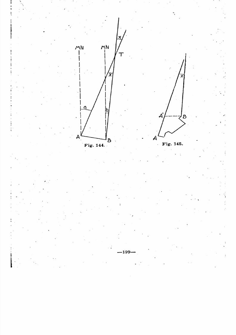
8/8/2019 Topography for Field Artillery
http://slidepdf.com/reader/full/topography-for-field-artillery 211/272
,
/"\N
III
"I. I .
I.\
IIa
-199-
"A. Fig. 145.
","
"
"
" \
8/8/2019 Topography for Field Artillery
http://slidepdf.com/reader/full/topography-for-field-artillery 212/272
APPENDIX I.SLOPES.
2111 .

8/8/2019 Topography for Field Artillery
http://slidepdf.com/reader/full/topography-for-field-artillery 213/272
8/8/2019 Topography for Field Artillery
http://slidepdf.com/reader/full/topography-for-field-artillery 214/272
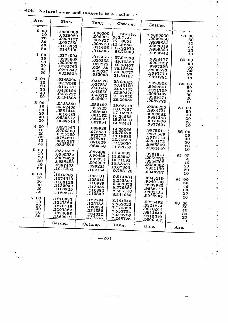
8/8/2019 Topography for Field Artillery
http://slidepdf.com/reader/full/topography-for-field-artillery 215/272
. 444. Natural sineR and tangents to a radius 1:
Arc. Sine.i
Tang. Cotang. Cosine. I,
---_. .
--0--";-o 00 .. 0000000 .000000 Infinite . 1.0000000 ! 90 000 .0029089
.002908 '343.7737 .9999958 500 .0058177 ~005817 /171.8854.9999831 400 .0087265
.008726 114.5886.9999619 30
0 .0116353 .011636 85.93979 .9999323 200 .0145439 .014545 68.75008 .9998942 101 00 .0174524 .017455 57.28996 .9998477 89 000 .0203608 .020365 49.10388 .9997927 500 .0232690 .023275 42.96407 .•9997292 400 .0261769 .026185 38.18845 .9996573 300 .0290847 .029097 34.36777 .9995770 200 .0319922 .032008
31.24157 .9994881 1000 .0348995 .034920 28.63625 .9993908 88 000 .0378065 .037833 26.43160 .9992851 500 .0407131 .040746 24.54175 .9991709 400 .0436194 .043660 22.90376 .9990482 3040 .0465253 .046575 21.47040 .9989171 200 .0494308 .049491 20.20555 .9987775 103 00 .0523360 .052407 19.08113 .9986295 87 000 .0552406 .055325 18.07497 .9984731 500 .0581448 .058243 1716933 .9983082
40
0 .0610485.061162 16.34985 .9981348 300 .0639517 .064082 15.60478 .9979530 20
0 .0668544 .067004 14.92441 .9977627 1000 .0697565 .069926 14.30066 .9975641 86 000 .0726580 .072850 13.72673 .9973569 500 .0755589 .075775 ! 13.19688
.9971413 40. 30 .0784591 .078701' 12.70620 .9969173 300 .0813587 .081629 12.25050 .9966849 200 .0842576 .084558 11.82616 .9964440 1000 .0871557 .087488 11.43005.
.9961947 8:; on0 .0900532 .090420 11.05943 .9959370 500 .0929499 .093354 10.71191 .9956708 400 .0958458 .096289 10.38539 .9953962 300 .0987408 .099225 10.07803 .9951132 200 .1016351 .102164 9.788173 .9948217 1000 .1045285 .105104 9.514364 .9945219 84 000 .1074210 .108046 9.255303 .9942136 500 .1103126 .110989 9.009826 .9938969 400 .1132032 .113935 8.776887 .9935719 300 .1160929 .116883 8.555546 .9932384
200
.1189816 .119832 8.344955 .9928965 107 00 .1218693 .122784 8.144346 .9925462 83 000 .1247560 .125738 7.953022 .9921874 500 .1276416 .128694 7.770350 .9918204 400 .1305262 .131652 7.595754 .9914449 300 .1334096 .134612 7.428706 .9910610 200 .1362919 .137575 7.268725 .9906687 10
--II ..... ---.,--'- -_ .osine.( Cotang. Tang. Sine.
Arc.
-204-
--- __
----- - --
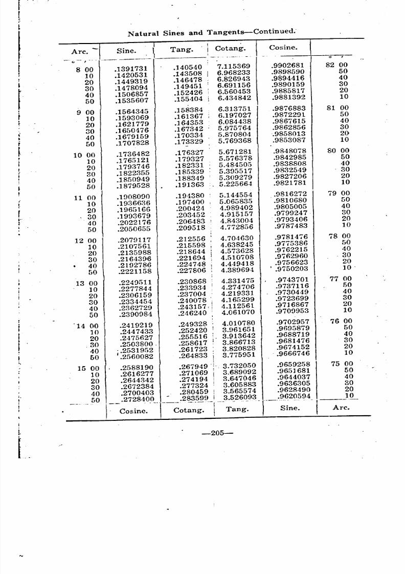
8/8/2019 Topography for Field Artillery
http://slidepdf.com/reader/full/topography-for-field-artillery 216/272
r.
!
Natural Sines and Tangents-Continued.
-I .
Arc. Sine. I Tang.' i Cotang. Cosine.
.. .. --i------------
, 8 00 .1391731.140540 7.115369 .9902681 82 00
10 .1420531 .143508 I 6.968233 .9898590 50
i 20 .1449319 .146478 6.826943 .9894416 40
t
30 .1478094 .149451 6.691156 .9890159 30
40 .1506857 .152426 6.560453 .9885817 20
50 .1535607 .155404 6.434842 .9881392 10
9 00 .1564345 .158384 6.313751 .9876883 81 00
t 10 .1593069 .161367 : 6.197027 .9872291 50
20 .1621779 .164353 6.084438 .9867615 40,'
30 .1650476 .167342 5.975764 .9862856 30
40 .1679159 .170334 5.870804 -.9858013 20
t50 .1707828 .173329 5.769368 .9853087
10
10 00 .1736482 .176327 5.671281 .9848078 80 00
rI 10 .1765121 .179327 5.576378 .9842985 50
20 .1793746 .182331 5.484505 .9838808 40
30 .1822355 .185339 5.395517 .9832549 . 30
40 .1850949 .188349 5.309279 .9827206 20
50 .1879528 .191363 5.225664 .9821781 10
11 00 .1908090 .194380 5.144554 .9816272 79 00
10 .1936636 .197400 , 5.06G835 .9810680 50
r20 .1965166 .200424 4.989402 .9805005 40
t. 30 .1993679 .203452 4.915157 .9799247 3040 .2022176 .206483 4.843004 .9793406 20
I
50 .2050655 .209518 4.772856 .9787483 10
12 00 .2079117 .212556 : 4.704630 .9781476 78 00
10 .2107561 .215598 I 4.638245 .9775386 50
20 .2135988 .218644 i 4.573628 .9762215 40
30 .2164396 .221694 4.510708 .9762960 .30
40 .2192786 .224748 i 4.449418 .9756623 20
50 .2221158 .227806 : 4.389694 I .9750203 10'
13 00.224%11 .230868 : 4.331475 .9743701 77 00
10 .2277844 .233934 : 4.274706 .9737116 50
20 .2306159 .237004 4.219331 .9730449 40
30 .2334454 .240078 'j 4.165299 .9723699 30
40 .2362729 .243157, ! 4.112561 .9716867 20
50 .2390984 .246240 : 4.061070 .9709953 10
'14 00 .2419219 .249328 ; 4.010780 .9702957 76 00
10 .2447433 .252420 3.961651 .9695879 50
20 .2475627 .255516 3.913642 .9688719 40
.30 .2503800, .258617 I 3.866713 .9681476 30
40 .2531952 .261723 3.820828 .9674152 20
50 .2560082 .264833 3.775951.. 9666746 10
15 00 .2588190 .267949 3.732050 .9659258 75 00
10 .2616277 .271069 3.689092 .9651681 50
20 .2644342 .274194 3.647046 .9644037 40
30 .2672384 .277324 3.605883 .9636305 30
40 .2700403 .280459 3.565574 .9628490 20
50 .2728400 .283599 I 3.526093 .9620594 10
1:--Cosine. -T-~ot~~;'-!- T~ng:
-r---' -- - - 1------Sine. I Arc.
i
-205-
~
-- -- ~ ____ __ ' '__
~ ~ ' j
~ '
~
'
-~ I
i
!
j
! -
~
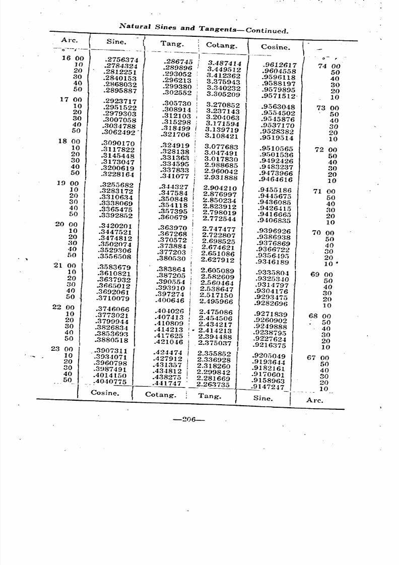
8/8/2019 Topography for Field Artillery
http://slidepdf.com/reader/full/topography-for-field-artillery 217/272
'
Natural Sines and Tangents-Continued.
(Tang. . \ Cotang. -r Cosine. \
Arc. Sine.
--0---'--- ---_ -------, ._--_ .. _-_.-16 00 .2756374 .286745 i 3.487414
.9612617 74 000
.2784324 .289896 3.449512 .9604558 500 .2812251 .293052 : 3.412362 .9596118 400 .2840153 .296213 3.375943 .9588197 300 .2868032 .299380 , 3.340232 .9579895 200 .2895887 .302552 : 3.305209 .9571512- 1017 00 .2923717 .305730 : 3.270852 .9563048 73 000 .2951522 .308914 ; 3.237143 .9554502 500 .2979303 .312103 I 3.204063 .9545876 400 .3007058 .315298 ; 3.171594 .9537170 300 .3034788 .318499 I 3.139719 .952838220
0 .3062492..321706 : 3.108421 .9519514 1018 00 .3090170 .324919 3.077683 .9510565 72 000 .3117822 .328138 I 3.047491 .9501536 500 .3145448 .331363 ; 3.017830 .9492426 400 .3173047 .334595 2.988685 .9483237 300 .3200619 .337833 2.960042 .9473966 200
.3228164/ .341077 2.931888 .9464616 1019 00 .3255682 .344327 2.904210 .9455186 71 000 .3283172 .347584 2.876997 .9445675 500 .3310634 .350848 2.850234.9436085 400 .33380691 .354118 2.823912 .9426415 300 .3365475 .357395 , 2.798019 .9416665 200 .3392852 .360679 ; 2.772544 .9406835 1020 00 .3420201 .363970 2.747477 .9396926 70 000 .3447521 .367268 ! 2.722807 .9386938 500 .3474812 .370572 : 2.698525 .9376869 400 .3502074 .373884 2.674621 .9366722 300 .3529306 .377203 , 2.651086 .9356.t9!) 200 .3556508 .380530 2.627912 .9346189
10 •\
I
21 00
!.3583679
.383864 : 2.605089 .9335804 69 000 .3610821 .387205 2.582609 .9325340 500 .3637932 .390.554 2.560464 .9314797 400 .3665012 .39.'3910 2.538647 .9304176 300 .3692061 .397274 2.517150 .9293475 200 .3710079 .400646 2.495966 .9282696 1022 00 .3746066 .404026 2.475086 .9271839 68 000 .3773021 .407413 2.454506 .9260902 500 .3799944 .410809 ! 2.434217 .9249888 400 .3826834 .414213 i. 2.414213 .9238795 300 .3853693 .417625: 2.394488.92'27624 200 .3880518 .421046 ! . 2.375037 .9216375 103 00 .3907311 .424474 I 2.3558.52 .9205049 67 000 .3934071 .4279!2 i 2.336928 .9193644 500 .3960798 .4313;)7 i 2.318260 .9182161 400 .3987491 .434812 i 2.299842 .9170601 300 .4014150 .438275 I 2.281669 .9158963 200 .4040775 .441747 2.26373.5 .9147247 10
Cosine. Cotang. Tang. Sine. Arc.
-206-
- f -
" --
'
~ -
r
-
I
'
-
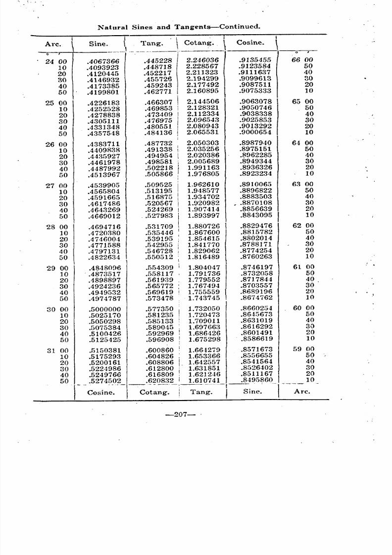
8/8/2019 Topography for Field Artillery
http://slidepdf.com/reader/full/topography-for-field-artillery 218/272
Natural Sines and Tangents-Continued.
Arc. Sine. { Tang. \ Cotang .. \ Cosine.
I--------(--
24 00 .4067366 .445228 2.246036 .9135455 66 00
10 .4093923 .448718 2.228567 .9123584 5020 .4120445 .4522171 2.211323 .9111637 40
30 .4146932 .455726 2.194299 .9099613 30
40 .4173385 .459243 2.177 492 .9087511 20
50 .4199801 .462771 2.160895 .9075333 10
25 00 .4226183 .466307 i 2.144506 .9063078 65 00
10 .4252528 .469853 2.128321 .9050746 50
20 .4278838 .473409 I 2.112334 .9038338 40
30 .4305111 .476975 I 2.096543 .9025853 30
40 .4331348 .480551 ! 2.080943 .9013292 20
50 .4357548 .484136 ! 2.065531 .9000654 10
26 00 .4383711 .487732 2.050303 .8987940 64 00
10 .4409838 .491338 : 2.035256 .8975151 50
20 .4435927 .494954 I 2.020386 .8962285 40
30 .4461978 .498581 2.005689 .8949344 30
40 .4487992 .502218 1.991163 .8936326 20
50 .4513967 .505866 1.976805 .8923234 10
2700 .4539905 .509525 1.962610 .8910065 63 00
10 .4565804 .513195 1.948577 .8896822 50
20 .4591665 .516875 1.934702 .8883503 40
30.4617486 .520567 1.920982 , .8870108 30
40 .4643269 .524269 1.907414 .8856639 2050 .4669012 .527983 1.893997 .8843095 10
28 00 .4694716 .531709 1.880726 1 .8829476 62 00
10 .4720380 .535446 1.867600 .8815782 50
20 .4746004 .539195 1.854615 .8802014 40
30 .4771588 .542955 ; 1.841770 .8788171 30
40 .4797131 .546728 : 1.829062 .8774254 20
50 .4822634 .550512 1.816489 .8760263 10
29 00 .4848096 .554309 I 1.804047 .8746197 61 00
10 . .4873517 .5.581171.791736 .8732058 50
20 .4898897 .561939 . 1.779552 .8717844 40
30 .4924236 .565772 , 1.767494 .8703557 30
40 .4949532 .569619 1.755559 .8689196 20
50 .4974787 .573478 1.743745 .8674762 10
30 00 .5000000 .577350 I 1.732050 .8660254 60 00
10 .5025170 .581235 1.720473 .8645673 50
20 .5050298 .585133 1.709011 .8631019 40
30 .5075384 .589045 : 1.697663 .8616292 30
40 .5100426 .592969 ! 1.686426 .8601491 20
50 .5125425 .596908 : 1.675298 .8586619 10
31 00 .5150381 .600860 i 1.664279 .8571673 59 00
10 .5175293 .604826 1.653366 .8556655 50
20 .5200161 .608806 1.642557 .8541564 40
30 .5224986 .612800 1.631851 .8526402 30
40 .5249766 .616809 1.621246 .8511167 20
50 .5274502 .620832 1.610741 .8495860 101-- ----\--------:-----'-- - . --I--~~c. -
osine. Cotang.! Tang. I Sine.
-207- .
-
1
_
\
' i
~ ~
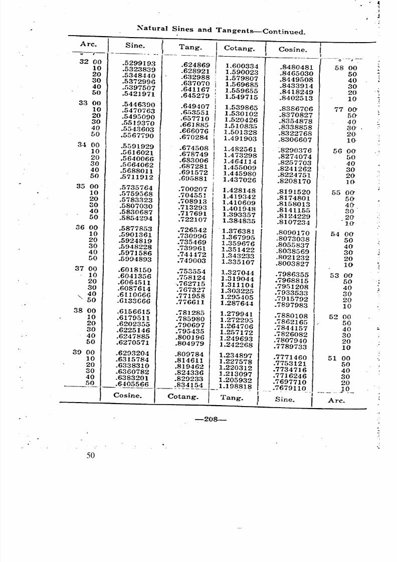
8/8/2019 Topography for Field Artillery
http://slidepdf.com/reader/full/topography-for-field-artillery 219/272
Xatural Sines and Tangents-Continued.
L~ ....___ Tang~_.Irc.
Cotang. Cosine. I,----0. 0,.
32 00 .5299193.624869 1.600334 .8480481 58 000 .5323839 .628921 i 1.590023 .8465030 500 .5348440 .632988 1.579807 .8449508 400 .5372996 .637070 1.569685 .8433914 30
;]40 .5397507 .641167 1.559655 .8418249 200 .5421971 .645279 1.549715 .8402513 10
33 00 .5446390 .649407 1.539865 .83867C6 77 00'10 .5470763 .653551 1.530102 .8370827 50'0 .5495090 .657710 1.520426 .8354878 400 .5519370 .661885 1.510835 .8338858 30' .0 .5543603 .6660761.501328 .8322768 20,0 .5567790 .670284 1.491903 .8306607 10.
34 00 .5591929 .674508 1.482561 '.8290376 56 00- -10 .5616021 .678749 1.473298 .8274074 500 .5640066 .683006 1.464114 .8257703 400 .5664062 .687281 1.455009 .8241262 300 .5688011 .691572 1.445980 .8224751 20 .-0 .5711912 .695881 1.437026 .8208170 1035 00 .5735764 .700207 1.428148 .8191520 55 00'0 .5759568 .70455J 1.419342 .8174801 50-20
.5783323 .708913 1.410609 .8158013 400 .5807030 .713293 1.401948 .8141155 300 .5830687 .717691 1.393357 .8124229 20'0 .5854294 .722107 1.384835 .8107234 10-36 00 .5877853 .726542 '1.376381 .8090170 54 00'0 .5901361 .730996 1.367995 .8073038 500 .5924819 .735469 1.359676 .8055837 40-30 .5948228 .739961 1.351422 .8038569 300 .5971586 .744472 1.343233 .8021232 20O .5994893 .749003 1.335107 .8003827 10
37 00 .6018150 .753554 1.327044 .7986355 53 00'0 .6041356 .758124 1.319044 .7968815 500 .6064511 ..762715 1.311104 .79,51208 400 .6087614 .767327 1.303225 .7933533 3040 .6110666 .771958 1.295405 .7915792 200 .6133666 .776611 1.287644 .7897983 10
38 00 .6156615 .781285 1.279941 .7880108 52 000 .6179511 .785980 1.272295 .7862165 500 .6202355 ,,790697 1.264706 .7844157 400 .6225146 .795435 1.257172 .7826082300 .6247885 .800196 1.249693 .7807940 20 J50 .6270571 .804979 1.242268 .7789733 10'
39 00 .6293204 .809784 1.234897 .7771460 51 000 .6315784 .814611 1.227578 .7753121 500 .6338310 .819462 1.220312 .7734716 400 .6360782 .824336 1.213097 .7716246 300 .6383201 .829233 1.205932 .7697710 200 .6405566 .834154 1.198818 .7679110 ______Q_--'--,----------------osine. Cotang. I Tang. ISine.
IArc.
-208-
------- __-~--
" .
"
:.
---
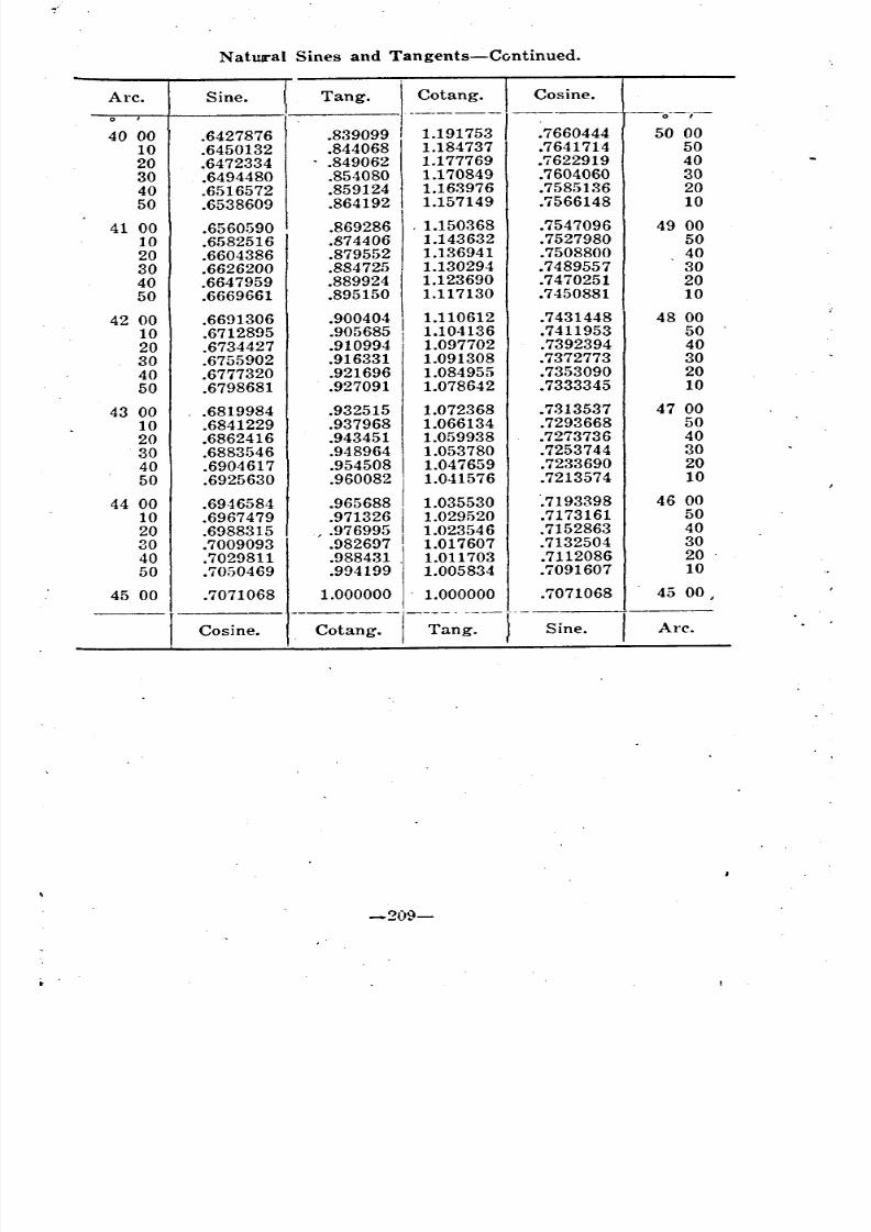
8/8/2019 Topography for Field Artillery
http://slidepdf.com/reader/full/topography-for-field-artillery 220/272
Natwral Sines and Tangents-Continued.
Cosine.otang.
---;~175; I~~604441.184737 .7641714 501.177769 .7622919 401.170849 .7604060 301.163976 .7585136 201.157149 .7566148 10
, 1.150368 .7547096 49 001.143632 .7527980 501.136941 .7508800 40
1.130294 .7489557 301.123690 .7470251 201.117130 .7450881 10
1.110612 .7431448 48 001.104136 .7411953 501.097702 .7392394 401.091308 .7372773 301.084955 .7353090 20
1.078642 .7333345 10
1.072368 .7313537 47 001.066134 .7293668 501.059938 .7273736 401.053780 .7253744 30
1.047659 .7233690 201.041576 .7213574 10
1.035530 .•7193398 46 00
1.029520 .7173161 501.023546 .7152863 401.017607 .7132504 301.011703 .7112086 20 .1.005834 .7091607 10
1.000000 .7071068 45 00 I
Cosine. --~~~-I--~~~~~-)---~ine. Arc.
Arc. Sine. Tang.
I40 00 .6427876 .839099 I
10 .6450132 .84406820 .6472334 .. 849062
30 .6494480 .854080
40 .6516572 .859124
50 .6538609 .864192
41 00 .6560590 .869286
10 .6582516 .874406
20 .6604386 .879552
30 .6626200 .884725
40 .6647959 .889924
50 .6669661 .895150
42 00 .6691306 .900404
10 .6712895 .905685
20 .6734427 .910994
30 .6755902 .916331
40 .6777320 .921696
50 .6798681 .927091
43 00 .6819984 .932515
10 .6841229 .937968
20 .6862416 .943451
30 .6883546 .948964
40 .6904617 .95450850 .6925630 .960082
44 00 .6946584 .965688
10 .6967479 .971326
20 .6988315 ., .976995
30 .7009093 .982697
40 .7029811 .988431 ,
50 .7050469 .994199
45 00 .7071068 1.000000
-209-
I ~~-~~

8/8/2019 Topography for Field Artillery
http://slidepdf.com/reader/full/topography-for-field-artillery 221/272
APPENDIX III.
(~IRCULAR MEASURE .
. 211-
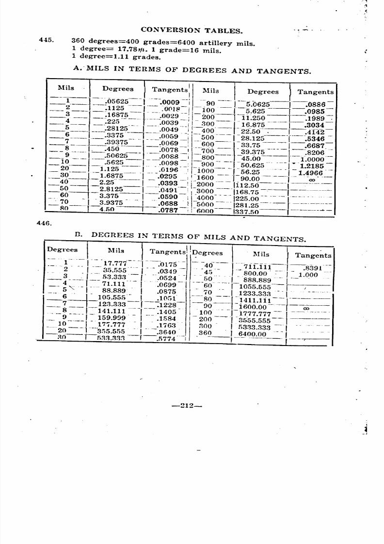
8/8/2019 Topography for Field Artillery
http://slidepdf.com/reader/full/topography-for-field-artillery 222/272
445.
CONVERSION TABLES.
360 degrees=400 grades=6400 artillery mils.
1 degree= 17.781/~. 1 grade=16 mils.
1 degree=l.l1 grades.
A.' MILS IN TERMS OF DEGREES AND TANGENTS.
446.
n. DEGREES IN TERMS OF MILS AND TANGENTS.
~~gTeesJ_. Mils .. _Tangent:! I~e~r~~,-I Mils I Tange~ts1 I 17.777 .0175 40 1- -71[ff1 ---1 -.8391 -.
, .,' 2' ".,=- 35.555-~ 1.- ~, .0349,~ , 45 .. ", '~800.00' I 1.000 -,.
_3 ~_I 53.333,,_1 ".0524 50 .._,1_ 888.889~1--- . ,.
4, I 71.111 I .0699 /60 I 1055.555 r--, -'-.-, -, .,5 ,,-, .. 88.889' I .0875 '\" 70 .- I 1233.333 -'I' ..
_.JJ~;:;;;-=--J.:-_~~~~~,==~g-.}I:~~:~~J~-00__8 I 141.111 1.1405 I 100 I 1777.777 I
'---9----'- 159.9!19' ,---- .1584 "-200---0['35'55.555--1-----
-= ~g=+'~~~:~~~::..:~~~~~~g: ~~~~:~~3.-.1. -_-:-:~(j-'!i33.333-r-.!i774-'-1 ---,-- --.---- ,--,--
-212-
,
_ r
- ~ _ ~- -__
-- - -- --
-
-

8/8/2019 Topography for Field Artillery
http://slidepdf.com/reader/full/topography-for-field-artillery 223/272
\
. APPENDIX IV.
REDUCTION OF STADIA READINGS.
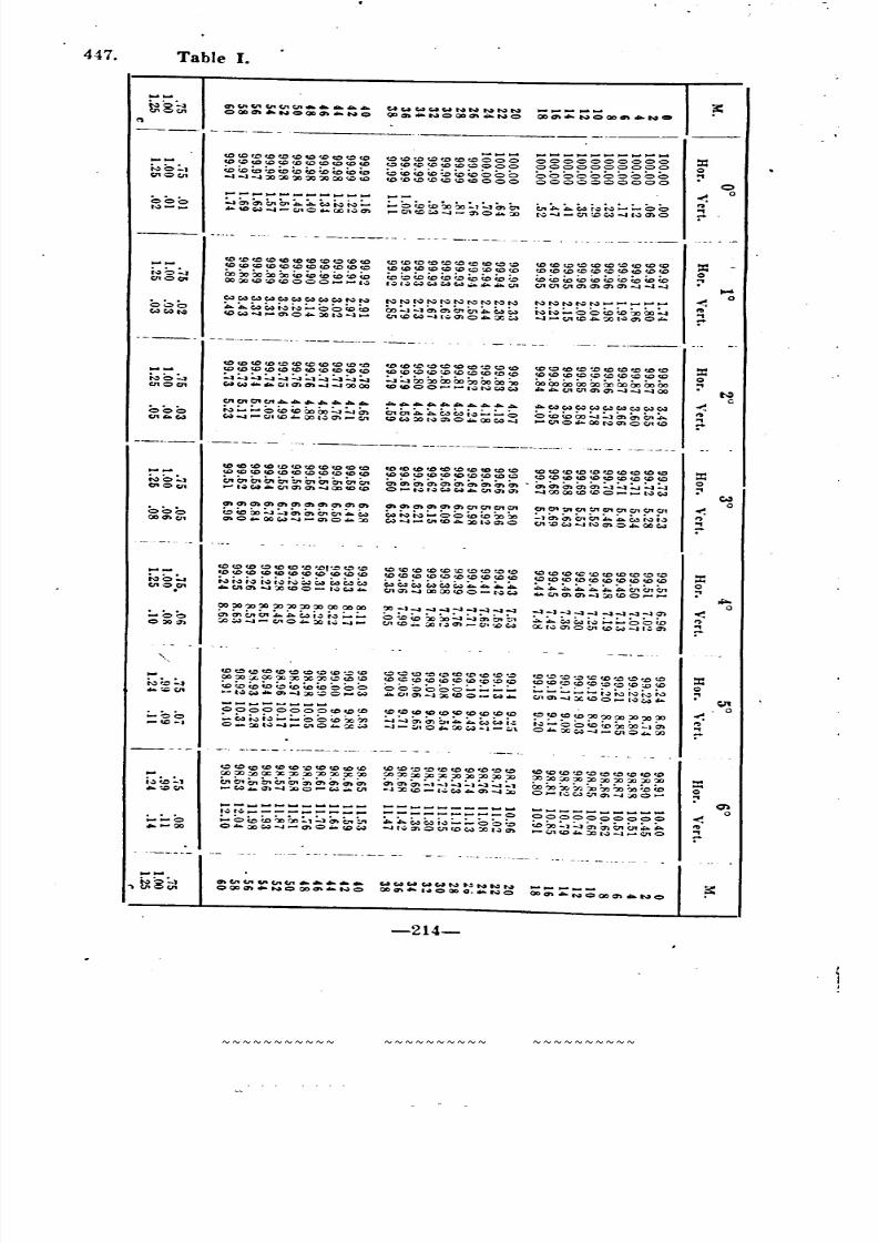
8/8/2019 Topography for Field Artillery
http://slidepdf.com/reader/full/topography-for-field-artillery 224/272
447. Table I.
000t.,)- ....
<I:> 'D "'"DOe.&>CO(.O(C(.J:)CQ(,C)(,Ql:OCC
Co t.o ",,:.0 U, f.o '.c tD (0 Co~~~~~~~~~<t:>'"
............................................
:..:.en~"'Q,~~~~~:-... 'D ~, 0 ... 00 1-:; Q)
.........~<I:>'D~"'<I:>"'OOOf,,:)CO""'(,CtOtO':.OOOO
<:> <c <c <c;.:><c <c 0 0 0<t:>"'000
---0 (0 X> 00:'1 en Crt. .. . 01COw -a--:nO ... :o
.........................................
0000000000
0000000000
00000000000000000000
Qo
-------_. -'.- _ .. .
...... CO~(O<oceCDCOt.OC:>(otO<0<0<1:><0<0<0<0<0<0<0 tOco~t:>tOtO('ocotOc.o :::OCOfDCO(OCCCQCOCQCOf,C<O<O<O<O<O<O<t:> "'<0<0 (0 COtOCQCO to CDCQ c,oc.oO:', Oo~~~~<c<c<c<c<c<c (o~t.L,(o~~~Q:>(O~ (O<O~(O(OCoto(ou,(oIlOC/t 00 OC C,Q to co 0 0 0 l~t.;ll.:l w <N w ........ l:/1 C/1C/1C/1a>a>a>a>~~~
0oOCoOCoOCoOCoOCoOCoOCoOCoONN NNNNNNNNNN N NN NN . .. .. .. .. .. .. .. .. .. .o~o .. A.e-,~~~:.....oo(or.o oo~:..:.~~Q,a,~~~ ~~~oou,to~oo:....CoOt-:l ec~-.a ......cno ... ;X) 1. )- -1 . .. .C11 co CN -.a t..;, <:n 0 ... :x w - .a . .. .. c:.nr.c .. ':.IOI'W(7)O~
--_ .._---- .. ----_ .._- -_._--
co co co co to co <0 co (0 co •0 co co (0 tOtO co co ... :> ( :) co<0<0 <0 'D <0 <0<0 <0<0 :::0<0<0<0<0"'<0<0<0<0<0
"'<0<0<0"'<0<0"''''<0"'<0"'<0<0<0<0"'<0<0NO:':' ~~:..:.:..:.~:..:.:..:.:..:.:..:.:..,:..:. ~:":'CoboooOoOoOoOoio 00000000~~00000000nocn "'. Q) Q)-J -:10000 tD co 0 0 ..........~ N '4. .. .. .. c :.nQ1<:ncn- .a -.a- :aoo
Ncncnc:nC11 ............. .,. ...................
....CoOCoOCoOCoOCoOCoOCoOCo>w000 N:-:.....O(OfDOOOO:..:.~~ en a. A. ;~;...:- 0 o(o<OOo:":':":'entnCn~Il"W -.a C,l'. (C 00 I":' en ... . c:.n(,:'l CN OC tv 0 .. 00 C4-.a
.... <:i\O~OONcnOCJ1(Q
----.- .- ..._----- ---------_._-----_. ---_.- .. _._---~~~~~~~~~(Q (Q(Q~~(Q(Q(Q(Q(Q(Q
(Q(Q(Q~(Q~(Q(Q(Q(Q(Q (Q(Q~(Q(Q~(Q(Q(Q~ ~(Q(Q(Q(Q(Q(Q(Q(Q(Q
~~~.~~~~~(Q(Q O-N~~~~~~~ ~OO~(Q(QQ~~~~
~~~a>~~~~a>a>~ ~~a>~~~~~cn~ cncn~~~~~C/1~~
~~~~~~~~~i~~Q~OO~~-~o~~ ~~-~(Q.~I~~O ~~~~N~Q~~~
:::o:'
o
(Q~~~(Q(Q~~~~~ ~~(Q(Q(Q=~~~(Q ~(Q~~~(Q(Q(Q~(Q
"'<O~~~"'<O"'~~'" "''''<O<O~'''<O~<O<O ~<O<O<O<O<O~~<O<O
~~~~~(QO_~~~ ~~~OOOO(QO-~~ ~~~~~~(QO~_
~~~~~~~~oo~oo
en en A. i~ r~ ; .. . ; . .. <:> :.= C o :.0 0, :';1 ::.. t -: J ; .. .: - <:> (0:JJW .... -"'O .... OOI .... -J_ l:I1(Q .. :.t:Jt~~-:.r.~c..a OC'r~c:nO-:ll(Q~-.aI.:c:n
"""
..- .. --- ....00000000"'<0'" <O<O~"'~~"'~~'" ~<O"'<O~OO~OO~OO
:""W Ni~:":'" 0 ~~~;., :....:..:, b,A. ~C4i.:. N;"'O ~(c Oc::x,:...0 .. :Cl1~-.a-",O .... :cW -a- -:l1 :> ... ::,()W -a- w\ O~ OOW-a_ c.nO ...
(Q~~(Q(Q~~~(Q=(Q ~~~~~(Q(Q(Q(Q~ (Q~~~~(Q~~~~
OO~~~~XX~~(Q(Q (Q~(Q(Q(Q(Q(Q(Q~(Q (Q(Q~(Q(Q~~(Q~(Q
~~~~~~~~;...~~~~~c:n-.aOO~O_~ ~CJtc:n-.aX(QO_~~ l:I1~-.a~(QO_~~~
~(Q(Q(Q(Q(Q~(Q(Q(Q(Q (Q~~~(Q(Q(Q~~~ (Q(Q(Q(Q~(Q(Q(Q(Q(Q
OO~~OOX~OO~XX~ OOOOOOOOXOOOO~~~ ~~::,()OOOO~OO~OO~
-~~~~~O_~~~ -JX~_~~~~~~ O-N~~~~~O~
.... - ..~-... _----~ I~ .. .-
;... f.o ~OO:'l~ <:nOt:r.O .... OOWr,)~,...~O ... f,Qw
...._------- ..---------0... c..., ~;~;.....:.... <:> 0:.0-.a I~ 0 CD X I~ :f')
...... - ........ - ..... --000000000
~~:"l~~~o-.c.n~~-Q1(,Q~;X)l-:J-.a,...~O
Q'l
o
-214-
------- ----------- ------
'" '" '" '" '" ~ '" ~
~ ~ -
"''''''''''''' ~ ~
- - - --- -- -
~ _ -~ ~
~ ~
---
'" ~ ~~ ...... ~
~ ~ ~ ~ ~ - ~ ~
- -
~~~~~~~~~~~ ~~~~~~~~~~~ ~~~~~~~~~~~~~~~~~~~~~ ~~~~~~~~~~~ ~~~~~~~~~~
~
~~~~~~~~~~~ ~~~~~~~~~~ ~~~~~~~~~~ ~~~~~~~~~~ ~~~~~~~~~~
~ ~ ~ ~ ~ ~ ~ ~ ~ ~ ~ ~
~ ~ ~ ~ ~ ~
~~~~~~~~~~~ ~~~~~~~~~~~
~~~~~~~~~~~ ~~~~~~~~~~ ~~~~~~~~~~ - - - - - - -
~~ ~ '" ~
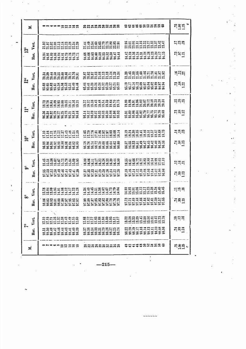
8/8/2019 Topography for Field Artillery
http://slidepdf.com/reader/full/topography-for-field-artillery 225/272
=i CtN""'CIO~:==: ON "llf'coaoON..,UtClO ON.,."'OO=N""Utao~ >t:lO>t:l..
NNNNN~MMMM ~'l)W')W')....,C'O r-:~~
...e"-1r-C"-IOO~aoC":)OO~~ --1"c:n~otOotOotO...-4 fJ:) .-t t :: > . .. .. to ':'J r- Co) r- C"1 t- r-C"l0>
..c:n~OO""''''''C'JC'JC''?C'?
~~tOtDtDr-r-OCOOQ) c:nOO .......... C'JC'JC"':)C"':)~'III:f"
~C'!C'-!GI "';"':e-ie-iNNNe-ie-ie--i c-i~e-iC'ie-iC'ie-ie-ie-iN e-i~MMMc?c?c?et5c?c?0 > C'lC\lCNC'lC\lC'JC'JC'JC'JC'J C'IC'IC'IC'IC'IC'IC'IC'IC'IC'I C'JC'lC'JC'JC'JC'JC'lC'JC'JC'JC'I
M.-4
....,..c:Df..C'III:f" ..... c:DCOC"?.-( OOCDC"':lO OOtOC'J Or-'" Nc:Dte..,. .....Of.DMOr-lQ C"lr--..CJ?~~~~~r--:~r--:I-: tDtDU'>c.etOtOtOtO~'III:f" ~C"?MC"':)C"?C'JC'JC'JC'J~"'" r-:~~
Q .;.~..,;~~~.;~~..;. ~';'';'';'';'..,;..;.';''';'.;.';'
=: 'III:f"""""~""''''''''''''''''''1'''''0>0>0>0>0>0>0>0>0>0> 0>0>0>0>0>0>0>0>0>0> 0>0>0>0>0>0>0>0>0>0>0>
--_.~- ..._- _." -"-- .. -'.- .'. -_._-_._--
t!..,.c:n~OtOOU'> ..... tO ..... r-C'-1t-C"?ooC"?oo~aa"" c:DtOOl.OOU> ..... U) .....-e:-1 CO C'I to-
~~~~~~~t-:r--:~ OOc:nc:nOO .......... C'JC'JC"? ~:;~~:::::::;::: ~C"!C"!
GI 0000000000OOO....:....;~....:,..:,..;....:
0 > C'JC'JC'IC'JC'J::'.JC'JC'JC'J:'-I C'1C'JC"JC'JC'JC'JC'\IC'lC'lC'J CNC'JC'\IC\lC'lC'lC'JC'JC'JC'\IC'J
N
OOtOC ""' ..... a::tDC? ... c:,Df,D ..,. ..... CD CD ""'1' C'1 c:n r-..,. C'I c:n t- ""1' IN 0) t- ""'1' e"1 0) r-..,. ..,OCC'l.. CO<QCDtDtOU:tOtO""'1'...,. ~~MC"?C"?C"?C'JC'JC\lC'J ...............0 OOOCD Cf)c:n ~o:C'!Q
tr.iu':itr.i~uo;ll:itr.itr.iU-;;..;tr.ilr,jtr.i.r;;Lti,~tr.itr.itr.iLti ,r,; IQ u-;; U; tr.i L"; tr.i .;. .;.
=: 0> 0> 0>0> 0> 0>0>Q'l 0>0> 0>0>0>0>0>0>0>0>0>0> 0>0>0>0>0>0>0>0>0>0>0>
_.__ .. _. _.- _._---- _._---- .._--
~OO..,.(7)lt:)OlO.....,CQ ..... r_ e'J00 M oc : . ., . 0) 0 lQ O~ . ... . C'Oe_Jr _e_JOCMOO~ >t:lOlO
.. r-r-OCOCCDOO .......... C'JM M ...,. lt:> '0 c.e r- r- O O O O (7 ) c n OO . . . . .. . . . .'Jt'J~ ~~C'!
GI ~~:~~~~~~~ aiaiaiaiOOOOOOO0
....................'lC'lC'JNNNC'.
.-4- .,. ~I 0) r- M ..... 00 tD ""'1'!Ncnr-.t:)~OlX)c.eC'o? C) to . ., .c... r- lQ (:'1 0 00 C"lI>':N
.. C":)~C"':)C\lC"Je"oJe"olC\J""''''' .....0 00 00 cn(7)) CDooCCooOOr-r-r-r-r-~ ""':~='!Q cDu)tDtOeDtDtDcDcDtC tOtDcDtD~tD~LO~LO ~.~~~~U-;;~~,~,~lfi
=: cn~cncncncnQ')cncncn cnO)cnCDQ)cncncncncn 0>0>0>0>0>0>0>0>0>0>0>
_. ,.- ..
o U) . .. .toO C'1
r- MOO"" c:')l.~OtD .... c.eC'J r-MOO~ C) 'Of1' 0 ...... D . ... . r- e"ol00 C"')
::~~.. .. .. .. .. C \I e:--I ( , M ..,. lQ lO CQt-t-COOOCDCDOO ..... ....t'lC":)M...,.~lO..oc.ec.er-
GI ~,.;r-..:r-=l..:r-..:~I'.:r...:t..: ~~~~:::~~~~~:,.. ...............................................
0.-4 .. 00 "'.c.,. ':'-J00 to ~NO 00 c.e C'1 0 00 ..,. C'J 0 r-lr.> C"? .. .. r- It:) C"1 0 00 tD .,.OC'"
Q ~~~~~~~~~oc: t- r- r- r- t- c.e CQ c.e CQ c.e lOlOlt:>Lt)~..,..,....,.~C":)C":) r-:~C'!
=: c.e'-CtDt.:lCDtOtDCQcDt.O tDtDcDtD~tttDtD~eD tOtDtDtDtDtDtDtDtDcDtD0> 0> 0> 0> -0> 0> 0> 0> a> 0> cncncnc:ncncncncncncn 0>0>0>0>0>0> o>o>c> 0> 0>
--_._-------------------------_ •._.-_._.
t!1t:> .... c.e C"1r- 00 ..,. en't:> o tD .... r- C'J OC M O ': l . .. .. 0 ,~ ..... t D e"oJr- MOO"" cn L~ 0
lOll':> CD CD r:- r- 00 00 en o O - ..... C'lC '1 C "C """'L O lOc.ec.er-r:-OOOCcncnO .....C' 1c,c . ... .
GI ~~~~~~::::::~::: :::~~~~~~~~:::: -:-:~0
lQ M ':"1 0 00 c .e . ., . M ..... en r- lQ M .....cn 00 to .. ,. e-l 0 00 to..,. C'1 0 00 to..,. ':'1 C 00.. lQlQlt:lQ.,....,...,."",...,.M C":>C":)C"":lMe-JC'J:"JC'JC'JC'1..........000000')
.,.0>'"Q r..:t.:r..:.....:~~r...:t..:r..:r..: ....:r...:r--=r-..:r...:r...:....:....:~.....: .....:.....:.....:.....:....:.....:.....:r..:""':""':u:i
=: O)a-~O)~C')aaa')O)~Q) c:nQ')O)Q')cnO')O')~Q)O) c:nO')~O')Q):r..Q)cnc:;)Q)O) l:~~
-_ .. _._,--- .. . .. .. .. .
OO.,.O)It:)....-ltOC'Jt-C'l?oo "'11' 0 It:) ..... c.e C"Jt- 0)01O....-ltOe--Jt-C"':)OO""Olt)
::;~~. t-oooocnOO....-l ...... C\IC\I C":)...,....,. 1010 to tOt-r:-CO Q)o)OO ......C\J"'C"":>~~
GI ~~~~..,;.~..;...;.~~ :::::::::: ~:~~~~~~~~~0
:,.. ...-t....-l ~_ ....-l
00
.. . to'~ .....0 00 t- 10 M C"1 OOCr-lt)C"lC'lOOOCOlt) M ...... O)OOU'''''1'N ..... cnr:-lt)
.~~~00000>0>0>0>0> 0> 00 00 00 OC 00 00 t- t- t- t-t-CDCDCQtOCDCQlJ:)lQlQ
QOOOOOOOOOO~r..:r..:r--:r--: r..:.....:r..:t--=r..:~r..:r..:r..:r--: ~~.....:~r..:r...:r--:r--:r..:....:~
=: 0> go. a> 0> 0> 0> Q> 0> 0> 0> 0>0>0>0>0>0>0>0>0>0> 0>0>0>0>0>0>0>0>0>0>0>
CN~~~ON~~~ OM~~~CN~~~CNNNNNMMMMM .~ •••
---_._---------------------------
NOo>r-CO.,.C"l_OooCO
C'\IC"J....-l_ ....................... OO
ooooooaOaOaOaOoc~oooo0>0>a>a>0>0>0>a>0>1j;0>
~OOOr-~~M .....Q) r-U)~~ .....OOr-~~lOlQ""~."""""".~ C":)C":)C"':)~~~"''''C'lN
00000000000000000000 000000000000000000000>0>0>0>0>0>0>0>0>0> 0>0>0>0>0>0>0>0>0>0>
t!GI0
:,..
..=:
=i
-215-
.........
_ ---- - ---
~ .
~ ~
--- - -- ---
~ ~
~~~~~~~~~~ ~ ~ ~ ..... ~
--- - --- -- _
~ ~
~~~~~~~~~~~ ~ ~ ~
---
~ ~ ~~~~~~~~~~ ~
~ __
- _ _ - , -
~ ~
...... .... ~ ...........
~
~~~~~~
~
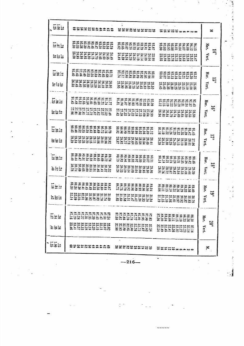
8/8/2019 Topography for Field Artillery
http://slidepdf.com/reader/full/topography-for-field-artillery 226/272
,-
~o:':' .....WWWCl'WNNNNN
;;:=:::~QDCft"'NC a::(;10C11 CQl)~"N=QoO\""N=
(X.O) N=CXlO \_NC
-CCDCOCOCCteCCtCCOf,O'D
<0<0<0<0<0<:><0<0<0<0<0<0<0<0 <0<0 <0<0 <0 CD :=WWWWW"'WWWW
Cot:lCot:lCot:lCot:l~Cot:lCot:lCot:l""Cot:lCot:l""'~Cot:l"'A~~~ ...\O:.... ~e-,~~:c..~A.Q,C:ntna.
~C:nC:n~~~~:.cx,00 toCo~eoOOOO:""~
'"'"...W OWaacoN01 ...,::,waa<o
r~"'-.I::>~c:nec ...... -JOl:o>01OC- ....... ONC11
"'to:)fI:)to:)~t..:>t:lt\:)I'o:)t.,:)'"t.,:)t.,:)I"'~t":)t.,:)t.,:)t.,:)"'f\:)
NNNNNNNNNN <:n ...................................................4
Cot:lCot:lCot:l~Cot:lCot:lCot:lCot:lCot:lCot:l4t~- Otof.oOOOO:...~~~Ot:. .COe,.,~N;..;...OO~ to~ 00~:"1C:n tntn~tIl'" 0(;10<110<110010(;1<0Ace ... ce .. ce ... ...
W:X>l:o>OCl:o>ool:o>ool..:> ...
<0<0<:><000<0<0<0<0<000CD <0<0<0<0<0<0<0<0<0
CD <0 <0 <0 <0 <0 CD <0 <0<0 :=~u,~to:. tv r~ N N C~ N N N N
I~ N I~ N N No t~ l~ N Cot:lCot:lCot:lCot:lCot:l~Cot:lCot:lCot:lCot:lCot:l:t..A. .... :r:..CnCno'~CnCn~
:':':':';"OoOoOoCoCoCo 0 OO:....;...;...:....t"'N""~
'"'"
QO\C~OCot:lc:nCCC4c:nceNtnOC_
"'-..OCot:lCDtON:11OC_ ~-.JOCot:lQ)OO O-.l
NNNNNNNN'..:>NNr"'t.,:)~I\:If'.:>Nt.,:)NNI\:)
NNNNl':)NNNNtv <::ncncnc:ncnc:nc:ncn~CJ)cn t11C1l01C110101~C1101Q1en C1l OtC11 C11 Cl1 c:.n:n "14;" Ot:r:..~C4to"=>N;"':"'OO eo eo XJ?o ;"1 =...t en C:n 0, tn ~A~~N~:"":""OO
.....0ocnO<l10<:11001o01o
<110<:1100.0<110<:110C110c:.nOCltO~'OOQ1 r-
-_. -----. -. --_._----_._----._._-----------~_ .._---
--- -----------_._-
_. --_. ---_._--------------_ .._-_.
~~:==;:~~~:=~::;:e...A.OtC:n~<:nC:nC:n:':'~~CJ' OCNQ1:O_C11:'O ...........
I..:lNNNt...:.NNNNNN
. .. . - J -.1-.1 -.1 -.1 -.1 -1 -.1 -1- .1
U:>Co~Oo~:..:aCn"'~tn ..en .....n .......II~ -..II~ -.l1~ ':D
"'00<0<0<000<0<0<0<0'"
00000000000
~"'C:na,Cn~~~~~:.:acnQO~,"COt-.::>~COtvenU)
r.:l N t..:'" t..: N) t,)COCO co CO (0 CO<DCO CO co 'X)
C4e-,~~~:-;"'OO(OCoCO"0010~ ....) <:)~
00 'X 'X 'X 'X 'X 'Xoo'XX 00':O(,QCOc.:>tQCOc.oCOc.oCOCO
;. ... 0. :r. a. en : .. .. : .,o .. -I .. c:.n CO I~ 0)
c.oe.:>e.:>~l:o>e.:>l:o>:'>l:o>e.:>e.:>
00000000000
~~~~c,..a.a,~:"'C4~00 .. CO ::n 0 en Q) I~
COCOCOCOt::l(OCO<.O~co
. .. .. r ., ;. r ,, ; r .. :: f~
OoOoOoCoCoCoOOOO.....~~C~-..Oto:la':lCO
t.) t~ t.) r,:) N t o: ) t o: ) N r~-..I-:I-I-J-J-J-J-J~~
~~~t-.:~;"":-OOf.o~OCwX~OOto:lCO"c.o
<O<O<O~<o<o"'<o<o'"000000 .....
OO~~<OCDtoOOO:...N 0)(0 I~a. CO 0) CO N
J...:>"''''NNNt..:NNN00 00 00 00 'X 0000000000
Oo~~:.:a~en~o.£..:s..-J1':>-.I~~to:IXl"CO ....
X OC'lO'lO 'X 'X: <0 <0 <0<0
"'<O"'<O~<OOOOO
:., ~:x.~ U:> <0 00 0:'"CO~:DO~-.lO ... -.I_
",,~~e,.,c:..:~c:,,)Nr.:lr,,:)0000000<0<0'"
r-.=N:"';"'OOO<O<O:x,OCC4':C~CO~00100\
COCOCOC='-OCOtOCOCOc.or~ I "; I .. :: r-.: I~ N N N r~ r~
:- ;... ;... t-.: i..::Nc:.nCOf...:l:J100 ....... -.lO
NNr"NNNNNNNc:nC')O')c:nO'»c:nQ')Q)c:ncn
CDOoOo:..:a~~~a,a,Cn~~~c.o .. CO ... ~CllO
;....;....~NN~~~~~0) CO N Q ) Co:) r~ t1\ CO r~ <:.n
NNNN~NNNNNOOOCOCoo()'OCooOCOC ...
~c,.,~N~:"';"'OOc.oCO ..OOlOcnOc:n_CD
<0 <0<0 <0 <0 <OtC <0<0<0
0000000000
;":"'NN~~~~~~.. OC ..... o:.n X l~ :n
t~ N N N r...: N N N t,,:) r"COf.QCOCOCO(,Of.Qc.:>c.e<::>
Oo~~~ena.a,~~~en N I.." :x: to:I OC .... CO
-------.-- --._-- lo... ••
'X'X'lO'lOOO'X'X'XOOOOOOQOQO':X1~JO~::IO:.o~OOXl
~~C4"'~~o.a.~~CnC'-X-C11COWen:::>M.-.I
e.:>WWCO,,"wcowe.:>e.:>wI":: (~r.;. I~ .................... ....
:"'OOOC:><OOox,:"J:.:a~.. CO ..... en (~ -.I (.r.) Xl .. CO
oo'lO'lO'lO'lOOCXoo'lO'"oo:lllOO:lllOOOO:X> 00 CO <0
:"J:"'l:..:a~ ~~fD fD <:><:>....rtocNen~w~O~
"'~OtC:n:..:c.C4c.,r~~t11 0 c:. . .. . . .. , I'; 'X OC ..
OO:X>OOoo'lOOO~ooxooc.oCOc.oCOCOe.cc.o<'oCO<.O
<:>;";";"'~r-'=N~c..,A.OO ....~'XJr-.:~COto:lO)O
wwwwwe.:>:.ol:o>:.oe_o........-00000
;";";"<:>O<CCcOoOo~<.Oc:nO"' . ... .. ... .. .~~~CJ:l
.-
_..
_--- ._---------------'X:oo:x>~~oooooo~oeoo-.J-a-.l~-a-J-.J-.I-a-J-I
;...t~ N N~~c., ... (,.(n~O .. -.J-c:,;'~w-.l
l:o>e.:>c.o~e.:>e.:>e_oe.:>e.:>e.:>e_o""c,.,)~C4~~~~w~C4
:..:-~~N~~;..;..OO-..I W :.0 -. 0 en . .. .. -a r~
OO'lO:X>X~X:X>OOOO:X>-.I-..I-..I-.I-.I-..I-J-.I-.I-I
c,.",,,,:,:,:,:,:,:, 00;" 00 CoCXlI~~O~-I_ <:Jl(C
we.:>e.:>,,"l:o>e.:>We.:>l:o>W(:.(,,:)t~t..;.NoI.:.I:.r..:.r..:.N
C, X! =x ~:'1 ~~,ex. CO c:.n 0 en (,,:)-J
00 oe 0000 0000 x oeoooo"':x> 000000 0000 000000
~ooo:"':"';"i...:~~cnO ... OO . .... c:.nCO~aao
e.:>We.:>e.:>e.:>e.:>e.:>l:o>l:o>e_o1 ,, :) 1' : N r~N 1~1 ... 1..,j1';' I~
e" :.. : c. . .. :0 N i,,:) ;.. ;..-. <c e;, en r~ -.J QCj . .
'\ ...~O-Jc:I10Cl' ~~~~~~..... WWWWWNNNNN
C~~.WC~~.~Q ~~~NC~~"NO ~~~NC~~.NC
-216-
~~~~~~ ....
----
~-
~ ~
~ ~ ~ ~ ---- --------
~
~ __ ~~
'" ~ '"
--
---
l
~ '" ~ ~
.....
~ ~ ~ - ~ _
_ _ ......
- - - - -
~
_ ~
~ ~ ~ ~ ~
~~~~~~~~~~
~ - ~
- ~ -- - • _
_ _
'" ~~~~~~~~~~
~ -
-------------
-
~ __
~ -
~
~ ~ ~ ~ ~ ~ ~
- ~
~~~~~
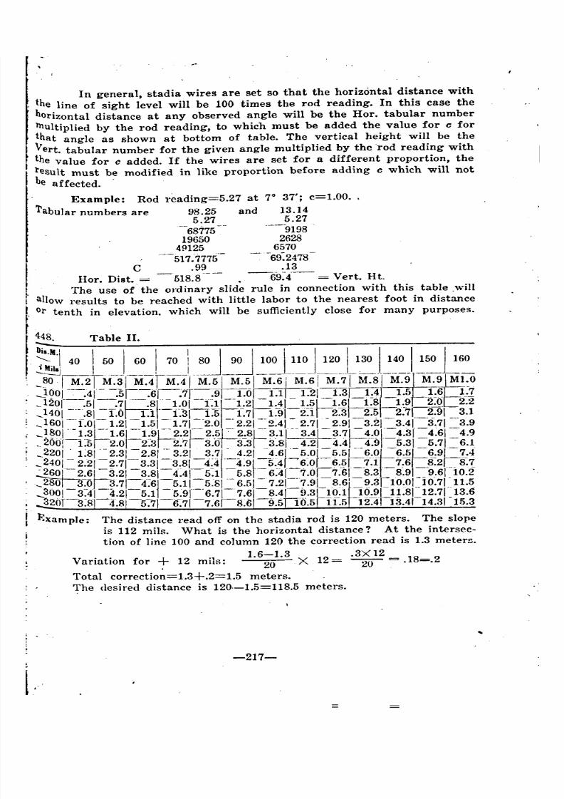
8/8/2019 Topography for Field Artillery
http://slidepdf.com/reader/full/topography-for-field-artillery 227/272
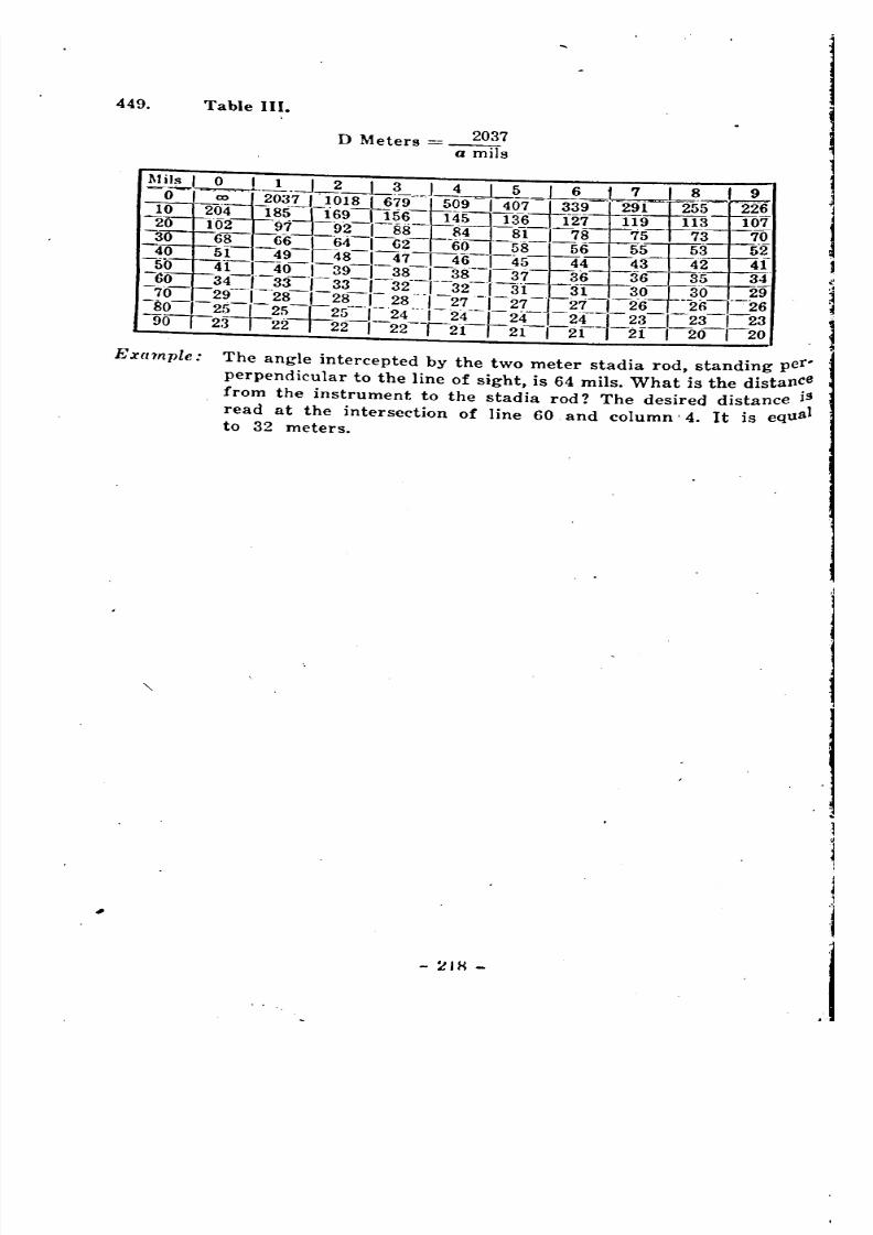
8/8/2019 Topography for Field Artillery
http://slidepdf.com/reader/full/topography-for-field-artillery 228/272
8/8/2019 Topography for Field Artillery
http://slidepdf.com/reader/full/topography-for-field-artillery 229/272
.APPENDIX V.
AZIMUTH OF POLARIS.
-219-
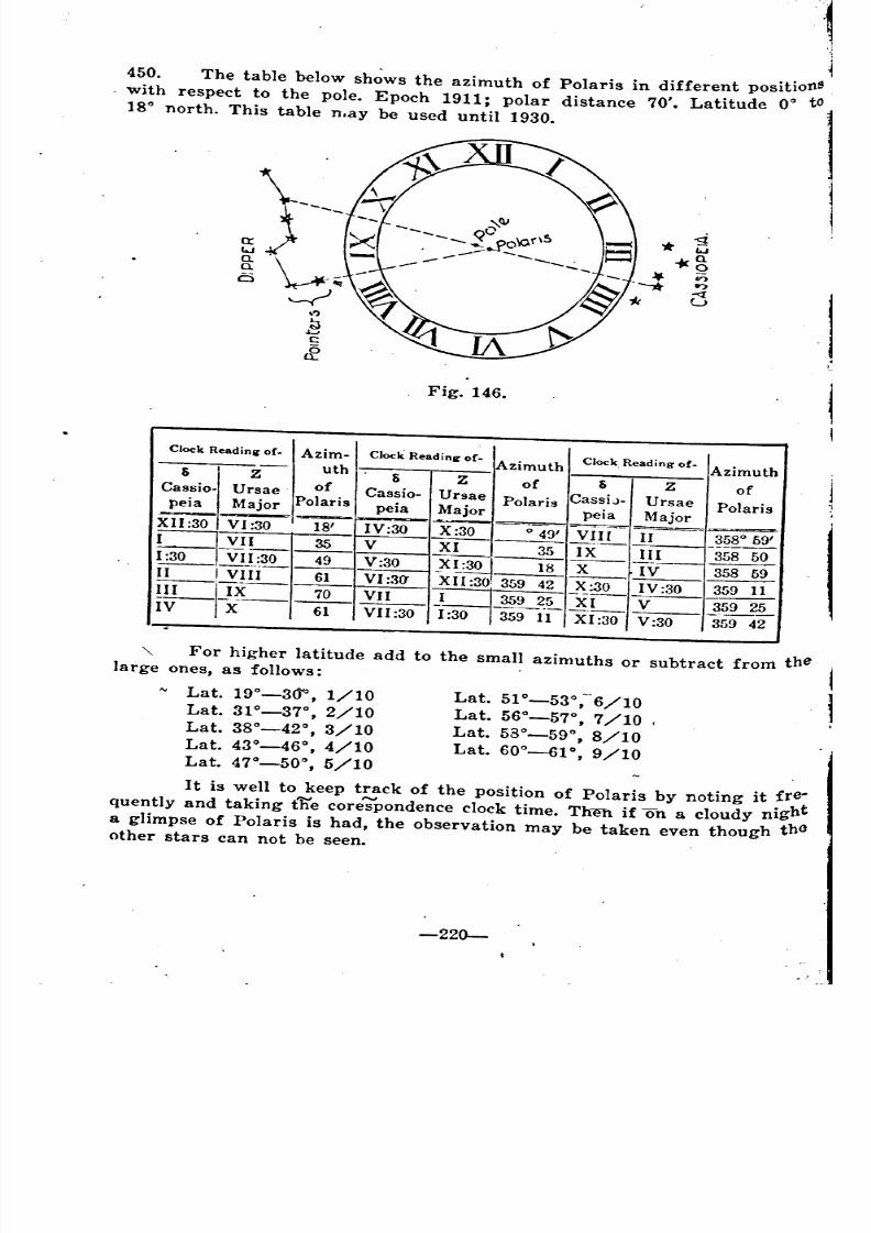
8/8/2019 Topography for Field Artillery
http://slidepdf.com/reader/full/topography-for-field-artillery 230/272
Lat. 51°-53°, 6/10
Lat. 56°_57°, 7/10 ,
Lat. 53°-59°, 8/10
Lat. 60°-6p, 9/10
.~
450. The table below sh~ws the azimuth of Polaris in different positionS
. with respect to the pole. Epoch 1911; polar distance 70'. Latitude 00 to18° north. This table n.ay be used until 1930.
Fig. 146.
Clock Readini ' 0(. Azim- Clock Readini' 0(. Azimuth Clock. Reading of. Azimuth
5 Z uth 5 Z of 5 Z of
Cassio- Ursae of Cassio- Ursae Polaris CassiJ- Ursae Polarispeia Major Polaris peia Major peia Major
XII :30 VI :30 18' IV:30 X :30 0 49' ~~Il II 358059'
I VII 35 V XI 35 IX III 358 50
~VII:30 49 V:30 XI:30 I 18 X IV-- 358 59
II I Vf!~ 61 VI :30' XII :30 359 42 X:30 359il!_II--IJ~-- }--L~~~~ ~I V --?~£IV X 61 VII:30 1:30 1359 11 XI:30 V:30 359 42
'\. For higher latitude add to the small azimuths or subtract from thelarge ones, as follows:
Lat. 19°-30°, 1/10
Lat. 31°-37°, 2/10
Lat. 38°-42°, 3/10
Lat. 43°-46°, 4/10
Lat. 47°-50°, 5/10
It is well to keep track of the position of Polaris by noting it fre-
quently and taking the corespondence clock time. Then if on a cloudy night
a glimpse of Polaris is had, the observation may be taken even though thOother stars can not be seen.
-220-
'1
~ ~ ~-
~ ~ ~ __ __
8/8/2019 Topography for Field Artillery
http://slidepdf.com/reader/full/topography-for-field-artillery 231/272
,
APPENDIX VI.
DEFINITIONS AND DIAGRAIUS.
-221-

8/8/2019 Topography for Field Artillery
http://slidepdf.com/reader/full/topography-for-field-artillery 232/272
Fig. 147.
-222-
TO ,sTEEPLE:(3. KiloS)
I'
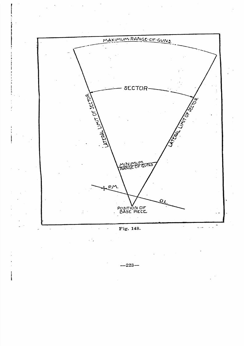
8/8/2019 Topography for Field Artillery
http://slidepdf.com/reader/full/topography-for-field-artillery 233/272
Fig. 148.
-223-
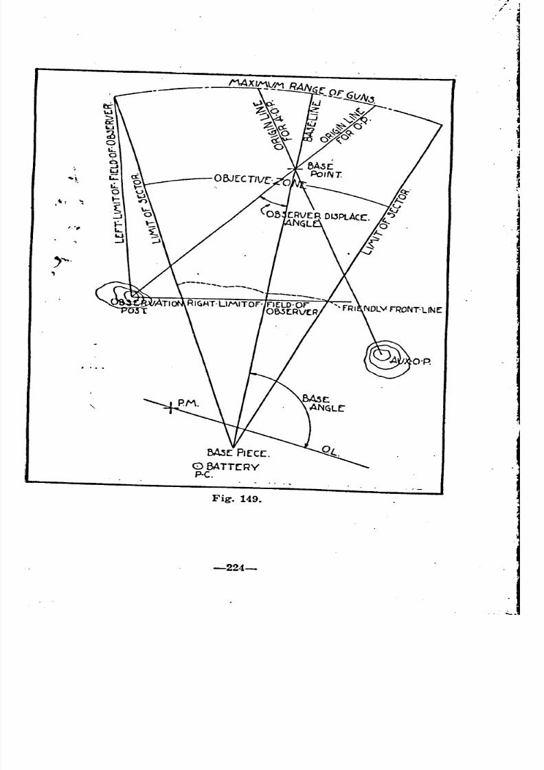
8/8/2019 Topography for Field Artillery
http://slidepdf.com/reader/full/topography-for-field-artillery 234/272
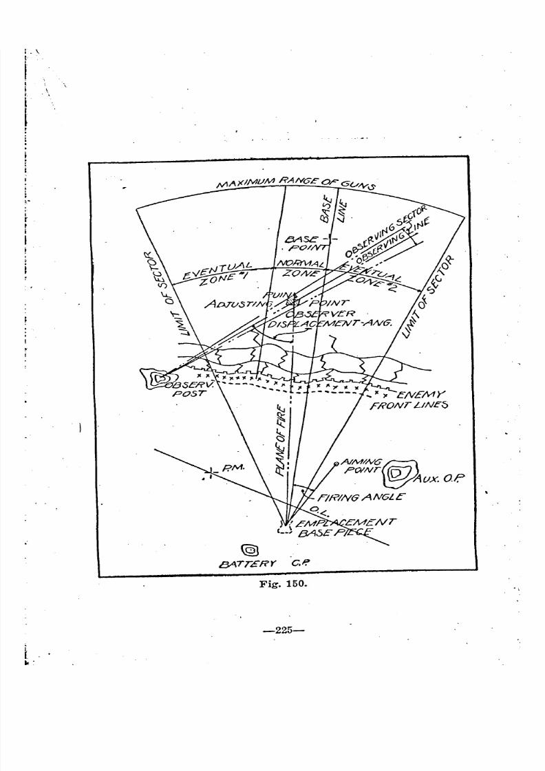
8/8/2019 Topography for Field Artillery
http://slidepdf.com/reader/full/topography-for-field-artillery 235/272
-
f
Ii
I[
.II
:
l..
@J
/3ATT£RY Co!!
Fig. 150.
-225-
'
.
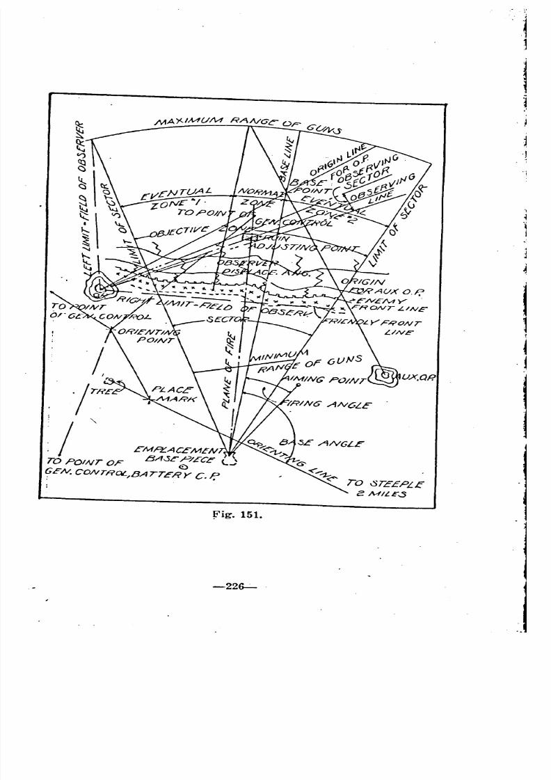
8/8/2019 Topography for Field Artillery
http://slidepdf.com/reader/full/topography-for-field-artillery 236/272
fig. 151.
-22~
,
-J
-I
-,
,
.
8/8/2019 Topography for Field Artillery
http://slidepdf.com/reader/full/topography-for-field-artillery 237/272
451. Adjusting Point. The point used for the adjustment of the elements
of fire is called an adjusting point. It is the particular part of the objective
on which the guns are adjusted.
Note: Terms used in .this chapter are illustrated graphically in
figs. 147, 148, 149, 150 and 151.
452. A iming Point. An aiming point is the point in which the gunner~ights when laying his piece for direction.
453. Base Angle. Tpe horizonal angle between the base line and the
orienting line, measured in thl~ same direction as the sight graduations,
is termed the base angle. It is a clockwise angle for the American panoramic
sight.
454. Base Deflection. Base Deflection is that deflection, which if used in
laying the base piece will direct the plane of fire of that gun on the base
Point, and for any other gun is the deflection that will direct the plane of
fire of that piece on a line parallel to the base line.
455. Base Line. The base line is the line joining the base piece and the
base point. It is always continued across the orienting line if an orienting
line exists, to form the base angle. It is used as an origin for direction from
the gun position.
456. Base Point. A base point is a well defined point of the terrain
Usually situated in the battery. sector, which, as one of the points defining
the base. line, is used as an origin for direction from the gun position. It
is generally shown on the map and it is desirable that it be plainly visible
from the observation post. It is advisable that a base point be chosen which
Inay be fired upon, so as to check the laying of the battery on the base line.
One base point may be common to several batteries.
A battery may have several bae points in which case they
are determined as "Base Point No.1, "No.2", etc.
457. Battle M'ap. A battle map is a large scale map showing the enemy
.works and occassionally the friendly works.
458. Eventual Zone. (Usually eventual zones Nos. 1 and 2). Zones with.
in the objective zone, but outside the normal zone, within which the bat-
tery may be called upon to fire under certain contigencies are termed
eventual zones. .
459. Control Point. A control point is a geodetic point or other point
\ the coordinates of which are known, that may be used in topographical
operations~
460. Control Sheet. A control sheet is a sheet containing a list of control
points for use by the battery reconnaisance officer, battery commander, or
battalion orienting officer, in the location and development of the position"
461. Datum Point. A datum point is a clearly visible point of knownlocation selected as an adjusting point. It is either shown on the battle map
or is a point that may be accurately plotted ..
462. Declinatinu Point. A declinating point is a point used for the declina-
ting of instruments. It is a point through which pass several lines, all ma.
terialized upon 'the ground, the azimuth of Y-azimuths of which lines are'
known. .
-227-
'
8/8/2019 Topography for Field Artillery
http://slidepdf.com/reader/full/topography-for-field-artillery 238/272
.,463. Deflection Constant. Deflection constant is the deflection setting
which must be set on the sight to bring the plane of sight parallel to the
plane of fire. For the American sight it is 0 and for the French 75 itis 100.
464. Directing Piece: The gun for which the initial data is computed,also called Base Piece.
.465. Field of Observation. The angle between the right and left limits
of observation either with the naked eye or with an instrument, is known
as the Field of Observation. Usually the field of observation is limited
by the location of the observation post. The O. P. should be located so that.
the entire objective zone is included in the field of observation.
466. Firing Angle. The firing angle is the horizontal angle between the
plane of fire and the direction of sighting measured in the same direction asthe sight of graduations.
467. Firing Board. The firing board is. a board of wood, or of wood and
zinc on which is mounted the firing chart or battle map, preparatory to the
measurement of the elements of fire.
468. Z.'iring Chart. A grid sheet, or the battle map itself on which are
shown the elements used in the computation and preparation of the firin~
data is termed a firing chart.
469. Limits of Fire. Limits of fi~e are lines marking limits of areas on
which fire can be delivered. .470. Ma-rker. The term marker is applied to'~ metal or wooden stake
three or four feet in height used in materializing an orienting line. The
markers used in staking out an orienting line should be distinctive for eachbattalion. .
471. Normal Zone. The normal zone, is the zone within the objective zone,
for which a battery is normally responsible, and within which its normalfire is directed.
472. Objective Zone. The objective zone includes the areas beyond the
friendly lines and within the lateral limits of fire. .
473. Observation Post (0. P.). An observation post is a post selected for
the observation and conduct of fire, for the observation of a sector, for the
study ,of objectives,. and for the purpose of securing information of the
enemy and his activities. Observation posts are classified as firing O. Po's
Command O. P's and Intelligence O. P's. .
474. Observer Displacement. The observer displacement angle is the
angle at the objective between the observer and the battery.
475. Observing Line. An observing line is the line joining the observerand the adjusting point.
476. Observing Sector. An observing sector is the sector subtended by the
objective as viewed by the observer. It contains the observing line.
477. On the Base Line. A battery is said to be on the base line when the
plane of fire of the base piece is directed on the base point and when the
planes of fire of the pieces are parallel.
478. Orienting Line. An orienting line is a line of known direction, ma4
terialized upon the 2Tound, and located on the map or chart, bi reference to
which the guns are laid for direction.
-228-

8/8/2019 Topography for Field Artillery
http://slidepdf.com/reader/full/topography-for-field-artillery 239/272
479. .Orienting Point. An orienting point is a point of known location
from which it is possible to orient.
480. Origin Line,. An origin line is a line selected near the center of the
. field of observation to which angular measurements are referred. If the sec-
tor is very extended several origin lines may be used. Usually the origin line
is .the line extended from the obsrvation post to the base point.481. Place Mark. A place mark is a point materialized upon the ground
and exactly located on the map, with known coordinates ana known eleva-
tion, by reference to which the guns may be located, on the ground and upon
the map, both horizontally and vertically.
482. Position. The position, strictly speaking, is the Gun Position, al-
though actually the position includes the battery organization for combat,
-or all elements outside the objective zone which may be used in the com-
putation of data, the observation and conduct of fire.
483. Range Deflection Fan. A range deflection fan is a graph composedof rays and arcs, showing range and' deflection, and drawn on the firing
~hart, the battle map, or separate transparencies, for the determination of
firing data. The fan is usually drawn for the directing piece, sometimes
for the observation post, and sometimes for both. In many cases the de-
flection arcs only will be shown and the ranges will be measured by a range
.arm.
484. Reference Point. A reference point is a prominent point on the ter-
rain by reference to which objectives may be identified. .
485. Referring Point. A referring point is an auxiliary or individualaiming point used by the gunner in referring his piece.
486. Witne88 Point. A witness point is a point clearly visible on the
ground, but not necessarily located accurately on the map which is used
for obtaining an adjustment preparatory to delivering fire on an unseen ob-
jective. The method consists of two adjustments; the first usually by aerial
-Observation on the objective, the other immediately afterward on the witness
point. The relation between the adjusted data for the witness point and the
-objective holds for subsequent firing. For such subsequent firing it is
necessary only to adjust on the witness point and calculate data for the<>bjective.
8/8/2019 Topography for Field Artillery
http://slidepdf.com/reader/full/topography-for-field-artillery 240/272
APPENDIX VII.
MAPS AND RECORDS.
8/8/2019 Topography for Field Artillery
http://slidepdf.com/reader/full/topography-for-field-artillery 241/272
CLASSES OF RECORDS.
487. One of the important duties of the battery commander is the com-
pilation of exact records, the elaborateness and exactness of which, depend
.Upon the stability and importance of the battery position to which theypertain. .
Records are kept of all battery activities and of all data affecting
the battery's functioning in combat, such records being for permanent use in
the battery position, either by the original battery commander or by his
Buccessors. Briefs of these records are made, from time to time, for trans-
mission to battalion, regimental and higher commanders.
Data pertaining to the artillery sector fall into two general classes;(1) maps and charts, and (2) written records.
A. MAPS AND CHARTS.
(1.) The Battle !\lap Of The Sector •
. 488. There should be kept at the observation post and at the command
post a battle map, of the latest edition, constantly kept up to date by the
aid of additions and revisions published by the topographical section.
(2.) Charts.
489. Among the several charts usually ~repared are the following:
(a) The firing chart: a great saving of time and ammunition can be
effected by making use of a suitably prepared firing chart, to be used forthe computations and measurements incidentto~ the preparation of fire.
A complete chart of the. Typical. Battery Sector would show:Preliminary topog7'aphical operation8;
The Sector, which is the area enclosed by the lateral limits of fire,
the maximum range and minimum range of the battery;
The Objective Zone, which is the area beyond the friendly line withinthe sector;
The Position, which means strictly the Gun Position,' but includesbattery organization for combat, or all outside the objective zone which is
used for the. computation of data, the observation and conduct of fire.
490. The following method of preparing a firing chart has been found
satisfactory. A sheet of drawing paper is mounted on a flat surface, a
wooden board or zinc sheet. Squares are drawn upon it, the sides of which
are 5cm. long. The lines are numbered to correspond to the grid lines of
the battle map of the sector considered. Upon the gridded sheet are plotted
the elements necessary to the calculation of map data for the conduct of
fire. No topographical detail is really essential on a firing chart, for it al-ways can be obtained from a corresponding battle map. However it is usualto draw, or paste on, the enemy organizations.
The grid system should be drawn first with a hard sharp pencil
and, after checking, with ink. It is essential that its construction be precise.
The error should not exceed .2 mm. in a 5 em. square. The following methodof procedure is suggested, fig 152.
-232-:-
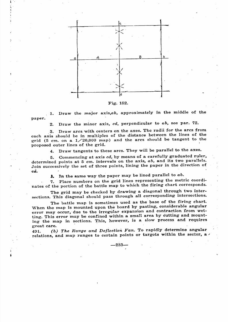
8/8/2019 Topography for Field Artillery
http://slidepdf.com/reader/full/topography-for-field-artillery 242/272
Co
... ,/ .
"-
, /
/\\
a A 8 b
I
'. /
" "
"- /'......
d
Fig. 152.
1. Draw the major axis,ab, approximately in the middle of the
paper.
2. Draw the minor axis, cd, perpendicular to ab, see par. 72•
.3. Draw arcs with centers on the axes. The radii for the arcs from
each axis should be in multiples of the distance between the lines of the
b'Tid (5 em. on a 1/20,000 map) and the arcs should be tangent to the
proposed outer lines of the grid.
4. Draw tangents to these arcs. They will be parallel to the axes.
5. Commencing at axis cd, by means of a carefully graduated ruler,
determined points at 5 em. intervals on the axis, ab, and its two parallels.
Join successively the set of three points, lining the paper in the direction of
ca.J. In the same way the paper may be lined parallel to ab.
7. Place numbers on the grid lines representing the metric coordi-
nates of the portion of the battle map to which the firing chart corresponds.
The grid may be checked by drawing a diagonal through two inter-
sections. This diagonal should pass through all corresponding intersections.
The battle map is somE:times used as the base of the firing chart.
When the map is mounted upon the board by pasting, considerable angular
error may occur, due to the irregUlar expansion and contraction 'from wet-
ting. This error may be confined within a small area by cutting and mount-
ing the map in sections. This, however, is a slow process and requires
great care. :
491. (b) The Range and Deflection Fan. To rapidly determine angular
relations, and map ranges to certain points or targets within the sector, a /
-233-
"
'"
'"
'
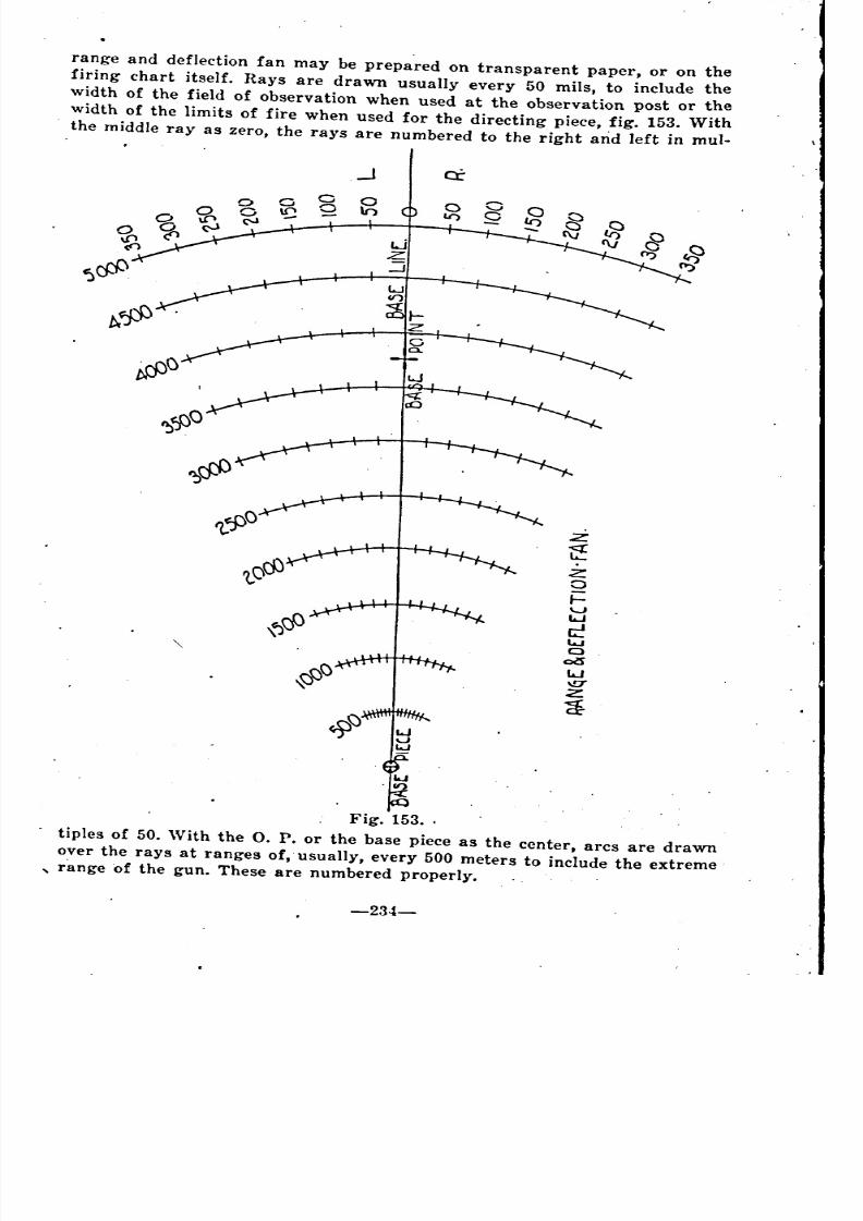
8/8/2019 Topography for Field Artillery
http://slidepdf.com/reader/full/topography-for-field-artillery 243/272
range and deflection fan may be prepared on transparent paper, or on the
firing chart itself. Hays are drawn usually every 50 mils, to include the
width of the field of observation when used at the observation post or the
width of the limits of fire when used for the directing piece, fig. 153. With
the middle ray as zero, the rays are numbered to the right arid left in mul-
Fig. 153..
tiples of 50. With the O. P. or the base piece as the center, arcs are drawn
over the rays at ranges of, usually, every 500 meters to include the extreme
, range of the gun. These are numbered properly.
-234-
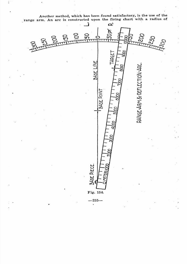
8/8/2019 Topography for Field Artillery
http://slidepdf.com/reader/full/topography-for-field-artillery 244/272
Another method, which has been found satisfactory, is the use of the
range arm. An arc is constructed upon the firing chart with a radius of
..J cr
wz J
:J exl.JIF) Z
a\0 r-
uLa..J-l
~.
2: La..J
C0
JsLJcl )
cr<;t:W\!JZ<{
ex
Fig. 154.
-235-
~ ~
~ ~
~ ~ ~
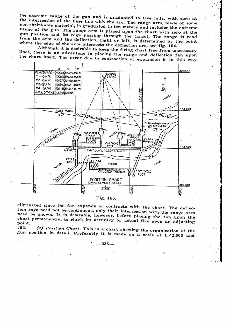
8/8/2019 Topography for Field Artillery
http://slidepdf.com/reader/full/topography-for-field-artillery 245/272
the extreme range of the gun and is graduated to five mils, with zero at
the intersection of the base line with the are. The range arm, made of some
non-shrinkable material, is graduated to ten meters and includes the extreme
range of the gun. The range arm is placed upon the chart with zero at the
. gun position and its edge passing through the target. The range is read
from the arm and the deflection, right or left, is determined by the pointwhere the edge of the arm intersects the deflection arc, see fig. 154. I
Although it is desirable to keep the firing chart free from unecessary
lines, there is an advantage in placing the range and deflection fan upon
the chart itself. The error due to contraction or expansion is in this way
VJZ4000
AlM1Nl~3TAK .
1\\ .
1\,/ I \
/ 1\\/ I \ \ .p')
/ I \ ~o;f
.' ! \
\
POJITION cMRTC.....PLActMt~T ~O.150
4c I 0c.
WOO.,.,-,
g,)l
V"l'
Fig. 155.
<'1iminated since the fan expands or contracts with the chart. The deflec-tion rays need not be continuous, only their intersection with the range arcs
need be shown. It is desirable, however, before placing the fan upon the
('hart permanently, to ch~ck its accuracy by actual fire upon an adjustingpoint.
492. (e) Po~ition Chart. This is a chart showing the organization of the
gun position in detail. Preferably it is made on a scale of 1/2,000 and
. -236-
"
~
~ ~ ~
8/8/2019 Topography for Field Artillery
http://slidepdf.com/reader/full/topography-for-field-artillery 246/272
usually shown:' (1) the position of each gun, its coordinates and elevation,
referred to the place- mark; (2) the orienting line; (3) aiming stakes for
day and night, and the direction and designation of aiming point or auxil-
liary aiming point; (4) avenues of ingress and egress" with notes on hours
for their use; (5) command post, deep shelters, telephone stations, latrines,
Kitchen, etc., fig. 155.
493. (d) Auxiliary Positions. Diagrams and _ charts are _ also prepared
showing au~iliary positions with routes thereto, and coordinates and eleva-
tions of place marks therefor.
494. (e) General System of Communication. Charts are required showing
the general system of communication between elements of the battery, with
other units, and with higher command posts.
495. (I) Chart of Visible and Invisible areas. The zones, visible and in-
visible, from the observation post should be accurately indicated, either ona special map posted at the observation post or charted to scale on trans-
parent paper which may be. superi~posed upon the firing chart or battle
maps of the sector. Copies of this chart are prepared for use by the bat-
talion and higher commanders. The method of preparing the chart has been
considered in Ch. XIII.
Areas that are invisible frorr( one O. P. may be visible from another.
By dividing the area included in the field of observation into small squares,
the possibilities of observation from auxiliary O. P's.,' on areas invisible
from any particular O. P., may be -indicated. The number -of numbers ofthe auxiliary O. P's. Which can be used are placed in the square in question,
fig. 156. .
496. (g) Chart of Dead Space. The study of the possibility and the ef-
fectiveness of fire on reverse slopes and on heavily wooded areas within a
. sector is purely topographic and its value depends upon the degree of ac-
curacy of the battle map. In no case, however, should the study be neg-
lected, for all topographlcal conditions capable of affecting the ,precision of
fire must be ascertained as far as possible. Such charts are particularly
important for the fire of guns with a flat trajectory. The chart of dead. areas is prepared to scale, either on a special map or on transparent paper
which may be superimposed upon the firing chart or battle map of the sector.
Copies of this chart are prepared for use by the battalion and higher com-
mander. The methods of computing dead space have been considered in
Ch. XIV.497. The possibilities of fire by neighboring batteries upon the dead
areas of a particular battery should be indicated upon the chart of dead
space of that battery. This may be accomplished by dividing the field of
fire into small squares, either 1cm. or 2.5 em. on a side; inserting the num-ber of the neighboring battery within the squares indicating the areas upon
which it can deliver fire. The correct squares may be determined by a study
of the chart of dead space of the "neighboring batteries, see fig. 157.
498. (h) Combined, Charts of Higher Commander. The topographical
records of the battalion and higher organizations comprise information trans-
mitted by the batteries, together with that secured form other sources. These
records consist of information relative to the organization of the gun posi-
-237-
-
'
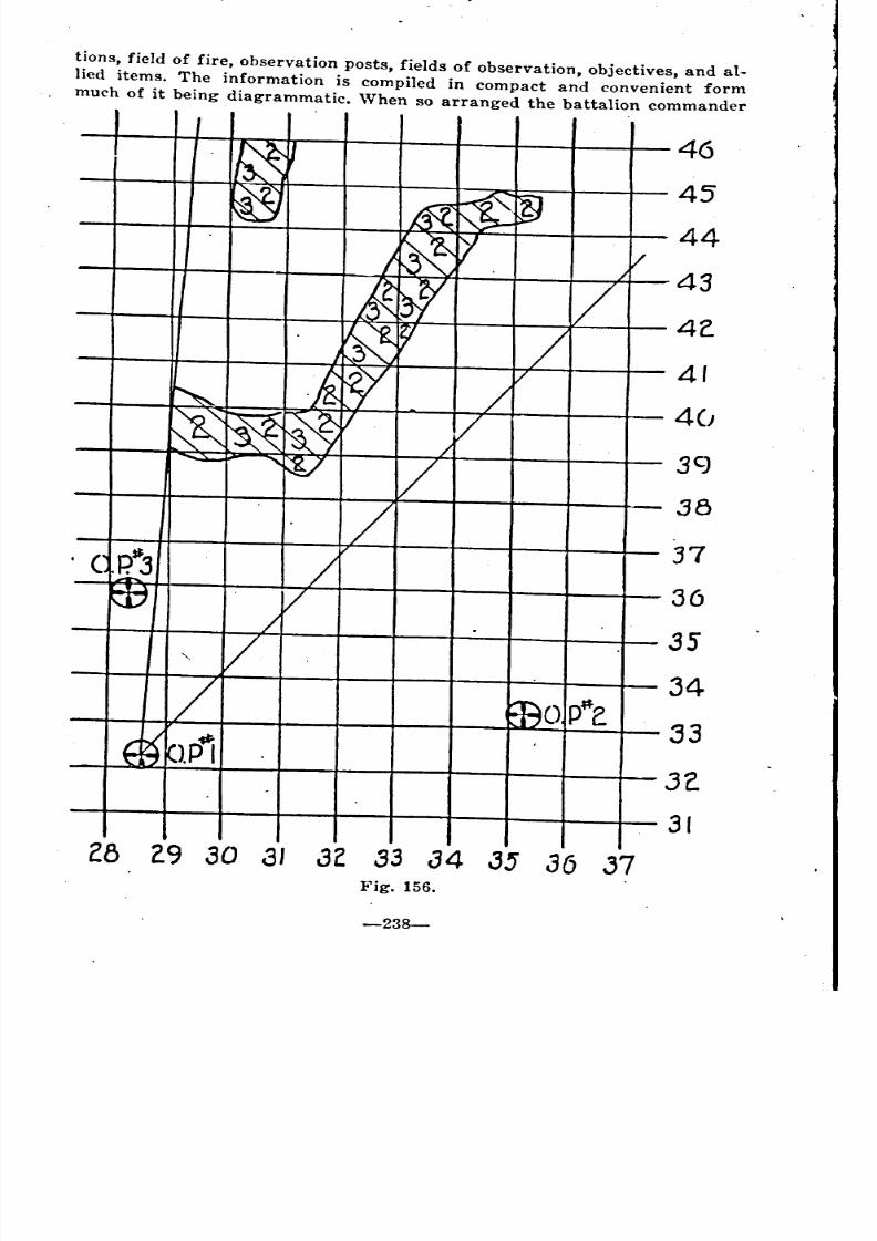
8/8/2019 Topography for Field Artillery
http://slidepdf.com/reader/full/topography-for-field-artillery 247/272

8/8/2019 Topography for Field Artillery
http://slidepdf.com/reader/full/topography-for-field-artillery 248/272
,. ,,\
J~1/
\\ "S" I
It:W . I....
.\ ~y /~,k$I
/'~V I
I,
(;E J--
A--ahU c.. ,:'
Ii;'\,.." I~\. I
f:'.
\ .-to\. :+-''I!l.
.~
-- /1\ /
L '1
\i" ;- .J (l\ -
~~\!!Y C!I!Jc '\t::J ,.~ CE~-d::-
-239-
~ ~~
~
~ ~ ~
~ ~ ~~ ~ ~ ~
~ ~
~ ~ ~
~ ~ ~ ~ ~
--
~ ~
~
~
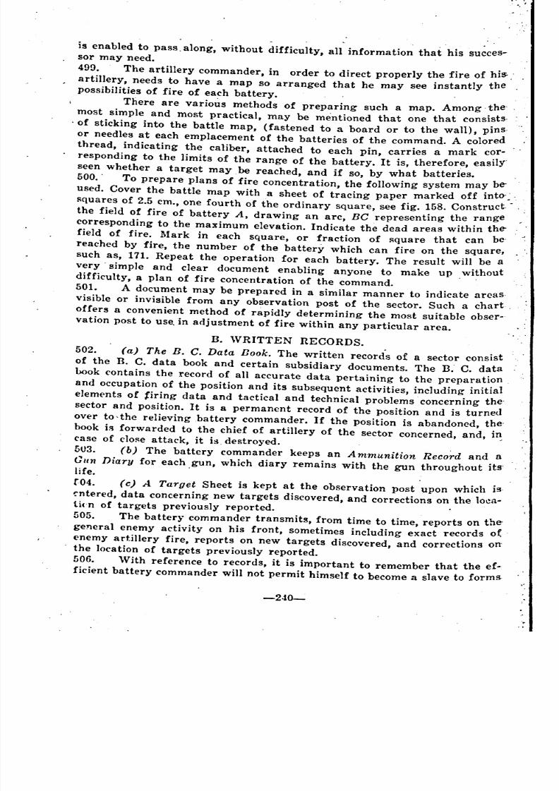
8/8/2019 Topography for Field Artillery
http://slidepdf.com/reader/full/topography-for-field-artillery 249/272
is enabled to pass. along, without difficulty, all information that his succes-sor may need.
499. The artillery commander, in order to direct properly the fire of his-.-
artillery, needs to have a map so arranged that he may see instantly thepossibilities of fire of each battery.
There are various methods of preparing such a map. Among. the
most simple and most practical, may be mentioned that one that consists.
of sticking into the battle map, (fastened to a board or to the wall), pins
or needles at each emplacement of the batteries of the command. A colored
thread, indicating the caliber, attached to each pin, carries a mark cor-
responding to the limits of the range of the battery. It is, therefore, easily
seen whether a target may, be reached, and if so, by what batteries.
500. . To prepare plans of fire concentration, the following system may be-
used. Cover the battle map with a sheet of tracing paper marked off into-:.
Rquares of 2.5 cm., one fourth of the ordinary square, see fig. 158. Construct .
the field of fire of battery A, drawing an are, BC representing the range
corresponding to the maximum elevation. Indicate the dead areas within the-
field of fire. Mark in each square, or fraction of Rquare that can be'
reached by fire, the number of the battery which can fire on the square,
such as, 171. Repeat the operation for each battery. The result will be a
very' simple and clear document enabling anyone to make up .without
difficulty, a plan of fire concentration of the command. .
501. A document may be prepared in a similar manner to indicate areas.
visible or invisible from any observation post of the sector. Such a chart.
offers a convenient method of rapidly determining the most suitable obser-
vation post to use, in adjustment of fire within any particular area.
B. 'VRITTEN RECORDS.
502. (a) The B. C. Data Book. The written records of a sector consist
of the B. C. data book and certain subsidiary documents. The n..C. databook contains the record of all accurate data pertaining to the preparation
and occupation of the position and its subsequent activities, including initial
elements of firing data and tactical and technical problems concerning the'sector and position. It is a permanent record of the position and is turned
over to,the relieving battery commander. If the position is abandoned, the'
hook is forwarded to the chief of artillery of the sector concerned, and, i~case of clOReattack, it is destroyed.
5U3. (b) The battery commander keeps an Ammunition Record and a
Gun Diary for each gun, which diary remains with the gun throughout its'life. .
r04. (c) A Target Sheet is kept at the observation post upon which is.
~ntered, data concerning new targets discovered, and corrections on the lo~a-tkn of targets previously reported.
505. The batter~' commander transmits, from time to time, reports on the
general enemy activity on his front, sometimes including exact records o( .
enemy artillery fire, reports on new targets discovered, and corrections on
the location of targets previously reported.
506. 'Vith reference to records, it is important to remember that the ef-
ficient battery commander will not permit himself to become a slave to forms.
-2-i0-
-
- _
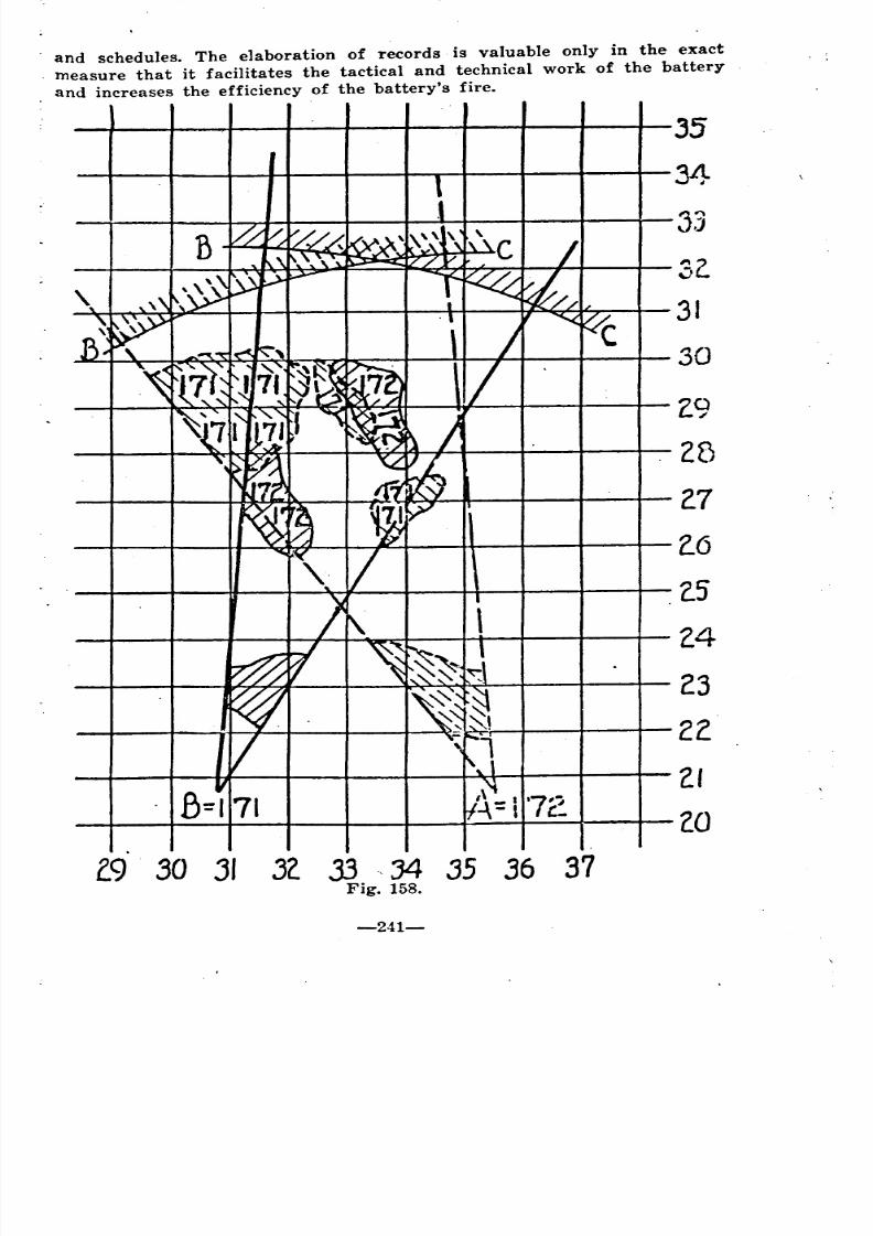
8/8/2019 Topography for Field Artillery
http://slidepdf.com/reader/full/topography-for-field-artillery 250/272
32.
31
30
35
34
33
2.9
25
2.7
2.6
2.5
2.4
23
2Z
ZI(0
II II
. and schedules. The elaboration of records is valuable only in the exact
. measure that it facilitates the tactical and technical work of the battery
. and increases the efficiency of the battery's fire.
(9 30 31 32. 33 "34 35 36 37Fig. 158.
-241-
8/8/2019 Topography for Field Artillery
http://slidepdf.com/reader/full/topography-for-field-artillery 251/272
408
308
197
7
16
451
162-164
340
338
INDEX.
A..Abney level
Abbreviated coordinates _~ ---- ---------------------------Absissae
Accuracy
Computation of minimum range and elevation --------------Inter~ection
Topography
Acute angle
'Adjus~ng point ----------------------------------------------.Advantage of
Orienting ]ine
.AimingCircle 142, 404-407, 411-415Direction 426-432Point 452, 426-432
Alidade 54, 153-156French 155
Leveling 155Sighting 154
Telescopic 156
Tests of' 59
Triangular 153
Al titude 84
Ammunition record 513
AngleAcute 16
Base 410, 454Definition '-_________ 15
Expression of-, by tangents 32-45Firing .______________ 466-499
--Of divergence ~_______________________ 345-347, 427-429
-of observer 'displacement. 474, 507
-of site 289, 294, 319, 295I~eflex 16
Round 16
. Straight 16
To plot-using gradient 47
, To plot-using percent 49
To plot-using tangent 35--traverse 188
Angular measure 15-29
Base equivalents 30
-243-
/
_ _
_ _ _
_
8/8/2019 Topography for Field Artillery
http://slidepdf.com/reader/full/topography-for-field-artillery 252/272
467
167, 168
333
502
222
502
506505
457
425, 427
399-400
384-386
382 .
134, 135
207
Conversions. in- ~_________________ 30, 31
Definitions ---------------_______________________________ .16
Systems --------------______________________________ 17
. Annual variation -------------________________________________ 375
Area sketches -------------__________________________________ 214-223
Border ---------------__________________________________ 222, 238Conventional signs ---------_____________________________ .218-220
Information ----------__________________________________ 217
:Lettering --------------_________________________________ 223
Title -----------------__________________________________ 221
Artillery sector ------------__________________ 451-486, 487-506, 395-397Auxiliary position
Chart of -------------___________________________________ 493
Azimuth -'______________ 369, 370, 372
Back-, resection by 209, 383
of Polaris ~____________________________ 451
Used to determine compass declination 379
Y ----------------_______________________________ 348, 369, 372
B.
Back azimuth, resection by --------____________________________ 209, 383
Band, elastic, visibility by means of ---_________________________ 288
Base
Angle ---------------------_____________________________ 410, 453
Deflection ---------------------_________________________ 454
.Equivalents ---------------------________________________ 10, 30
Line -------------------------__________________________ 455, 477
Point ---------------------_________________________ 424, 425, 456
Battery commanderData bookRecords
Reports
Battle 1\f aps :. .Bearing
Determination of compass declination by means ofOf target
To find a bearing with a protractorBench lllark
Bisectors, perpendicular .
BoardFiring
Slope
Donne projection
Dook, B. C. data
Border, position and area sketcheg
-244-
-,;j
------------
-------------
-----
-----------
-
~~ _ _ _
__ _ ~__
_ _ _
~ _ _ _ _ _
_ _
:
8/8/2019 Topography for Field Artillery
http://slidepdf.com/reader/full/topography-for-field-artillery 253/272
c.
\
500
331
44
13, 30
43
57
191
, 284
271-274
36
37
3
378-381
379
375
369-372
146-150
145388-394
384-394
383
--------------------------------------------------orth
Peign~
Prisma tic:...-
Used as aiming point .Usc"d to lay gunR
Used in magnetic resection
Concentration fire, plans of :..Conic projection
Constant
Calculation
Angular values above limits
Mental- in conversIons
Using tangent -----.-------------------------------------hainsChaining
ChartAuxiliary position 493
Combined 498, 499, 501Dead space 327
Firing 46~ 48~ 490
I General System of communication 494Invisible areas 495, 501
Isogonic ~_________ 374, 376, 377Position 492
Special- for dead space calculations 317-326Visible areas 495, 501
Visibility . 291, 292Circle 16
Aiming; See aiming circleCircular measure .16
Table for conversion "Appendix III
Clinometers .Abn~y 162-164
Gravity 165
Combined charts .:.. :..___________________________ 498, 499, 501
Communication, general system of . 494
ComparisonOf map and panoramic f'k~tch .:..
Of methods of panoramic sketchingOf bngent and mil calculation :..
01' t'tngent ratio and tangent0: ..~rfare methods
CompassDecl ina ti on
Determination of
Error
-245-
_ _ _
--------
_ _ _ _
--------------------------- ----
------------------------------------
_ " _
----
__ ------------------------
_ ~ _
" _ _
8/8/2019 Topography for Field Artillery
http://slidepdf.com/reader/full/topography-for-field-artillery 254/272
266-268
459
46Q
259, 270
4
255-258
218-220
4
345-347 .
Declination --------------__________________________ 380, 406, 407
Deflection ---------------_______________________________ 466
Construction of
Mounted timing scale -------______________________________ 107-109
Profiles ---------------_________________________________ 290
Reading scale -------------_______________________________ 96-99Slope board -------------_________________________________ 167
Slope scale ~_ 129-131
Special cKart for dead space ----___________________________ 318
Visibility chart ------------_______________________________ 292
VVorking scale ------------_______________________________ 101-105
VVorking scale graph -----________________________________ 111-118
Contours --------------____________________________ 134, 137, 138, 215Contouring, logical ---------__ 141
ControlHorizontal
Point
Sheet
Vertical
Conventional signsDefinition
. For panoramic sketches .
For position and area sketchesUse of
Convergence of meridian
Conversion
Angular measure -------------------______________________ 30, 31
Circular measure .. .. 30, 31, Appendix III
Gra(lients --------------------__________________________ 46, 52
Linear measure ------------------_______________________ 10, 12-14
Mental calculations in- ... 13, 30
Of degrees and minutes to decimals ----____________________ 20
Of angles above prescribed limits -----_____________________ 53Per cent ------------------------_________________________ 48, 52
Table of slope --------.:.---------- Appendix I
Tangents ~_________ 36, 52, 53
True mil equivalents ---------------_______________________ 31Coordinates
Abbreviated ----------------________________________ 340
Corn plete ---------------------__________________________ 339
Definition ---------------------_________________________ 337
Geographic ---------------------________________________ 337Ilectometric -------------------_________________________ 340
Lambert grid -----------------~---_______________________ 337
Location of point on ground by means of -__________________ 366, <367
Method of reading --------.:.------_____________________ 339, 352;-355
Method or plotting point3 by --------_____________ 343, 344, 350, 351
or origin --------------------____________________________ 383, 420
-246-
-------------
_ _ _ _ _ _ _ _
--------- -----
-----------
-------------------
-----
.
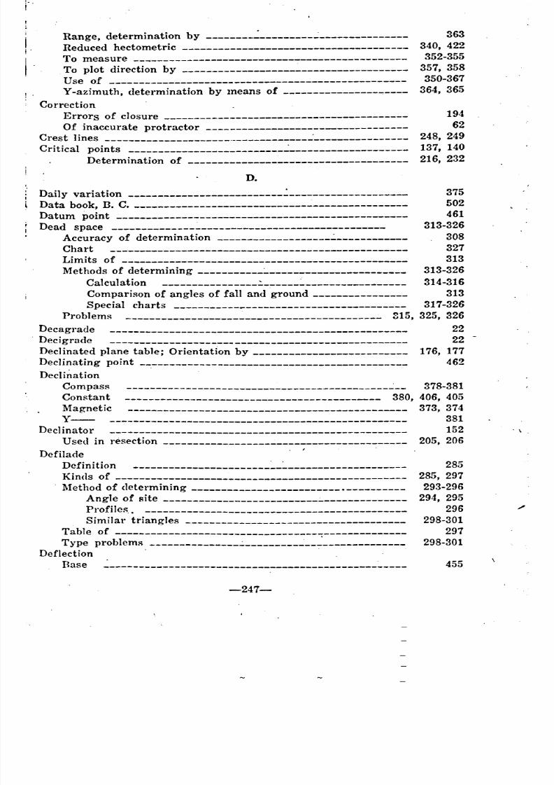
8/8/2019 Topography for Field Artillery
http://slidepdf.com/reader/full/topography-for-field-artillery 255/272
!
..
Range, determination by --------..:---------..:---------------
Reduced hectometrico measure
To plot direction byUse of
, . Y -azimuth, determination by means of ----------------"""----
CorrectionErrors of closure
Of inaccurate protractor
Crest lines . .:
Critical points ..:
Determination of
D.
363
340, 422
352-355
357, 358
350-367
364, 365
194
62
248, 249
137, 140
216, 232
455
285
285, 297
293-296
294, 295296
298-301
297
298-301
Daily variation .:___________________ 375
Data book, B. C. 502Datum point 461
Dead space 313-326
Accuracy of determination .:.____________ 308Chart 327
Limits of 313
Methods of determining :..._______________________ 313-326
Calculation 314-316
Comparison of angles of fall and ground 313Special charts 317-326
Problems 815, 325, 326
Decagrade 22
Decigrade 22
Dec1inated plane table; Orientation by 176, 177Declinating point .___________________________________________ 462
DeclinationCompass 378-381
Constant 380, 406, 405
Magnetic 373, 374y---- 381
Decl inator 152
U sed in resection 205, 206
DefiladeDefi ni tionKinds of
. Method of determining .Angle of site
Profiles.
Similar trianglesTable of
Type problem~
Deflection .
Base
-247-
. \ .
-------------------------------------- _ _ _
_ _ _ _ _
-
__
_ _ _ _ _ _ _
~ ~ _

8/8/2019 Topography for Field Artillery
http://slidepdf.com/reader/full/topography-for-field-artillery 256/272
463
172
20
29,39-4219 •
18-20
19
122
277-281
, II
Constant
To measure, by sito-goniometer
Degrees .Conversion for use
Limit of calculation by tangent ratio ..:.Sixteenth ofSystem
Twentieth of ..:.
U sed to express slope
Designation of targets :.
Devices
l\Ieasuring ---___________________________________________ 63
Technical, in panoramic sketching 0________________________ 243-258Diary, gun -----:- ~_______________________________ 503
Directing piece ---____________________________________________ 464~
Direction ------_____________________________________________ 71
From grid north -_________________________________________ 372
From magnetic north -____________________________________ 371, 453
From true north ------____________________________________ 370, 452 .'
Plotting-- ---------_____________________________________ 356-362
Director in laying gun ----___________ 404-407, 411-415
Displacement, angle of observer .:. _"_ 474
Distance -----------_________________________________________ 70
Expression on map . 75
lIorizontal ~_______________________ 159
~Iap .:. ~____ 75
Drawing
On panoramic sketches -------_____________________ 241-258, 265-286
E.
ElevationIIow shown
,Minimum--
Engineer's level
l~ngineer's scale
Equipment
Panoramic sketching •Itoad sketching
EquivalentBase
llorizontai
True mil
ErrorAllowable in resectionCompass
Explanation of, in tangent calculationIn closure
In traverse
134
I
302 'I66
55
260
226
10, 30
7531
200
375
40
194
194
-248-
~
_ _
~ _ _ _ _ _ ~
~ _
__
------- -
------------
-----------------
_ _ _ _
~------------- _ _ _ _ _ _ _ _ _ _
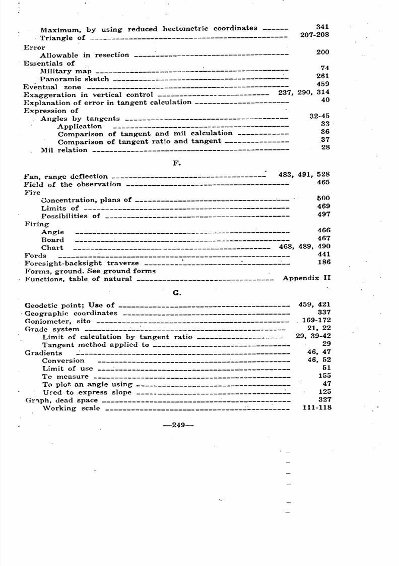
8/8/2019 Topography for Field Artillery
http://slidepdf.com/reader/full/topography-for-field-artillery 257/272
200
32-45
33
36
.37
28
Maximum, by using reduced hectometric coordinates 341. Triangle of 207-208
Error
Allowable in resection -----'------------------------------
Essentials ofMili tary map :..___________________ 74
Panoramic sketch _= _ 261
Eventual zone 459
Exaggeration in vertical control 237, 290, 314
Explanation of error in tangent calculation 40
Expression ofAngles by tangents
Applica tion
Comparison of tangent and mil calculation
Comparison of tangent ratio and tangentMil relation
F.
.fan, rangoe deflection .: 483, 491, 528
Field of the observation 465
FireConcentration, plans of '- . 600Limits of 469
Possibilities of 497
FiringAngle 466
Board 467
Chart 468, 489, 490
Fords 441
Foresight-backsight traverse \ ..:. ~__ 186
Form~, ground. See ground form")Functions, table of natural Appendix II
G.
Geodetic point; Use of
. Geographir. cOQrdinates
C;oniometer, sito
Grade system
Limit of calculation by tangent ratio
Tangent method applied toGradients
Conversion
Limit of use
Tc measure .
To plot an angle using
Ured to express slope ~_
Gr~ph, dead space
VVorking scale
-249-
459, 421
337
169-172
21, 22
29, 39-42
29
46, 47
46, 5251
155
47
125
327
111-118
_ _
------------
--------------- _
__
_ _ _
--------- ~ _ _
_ _ _ _
- _ _
~ _ _
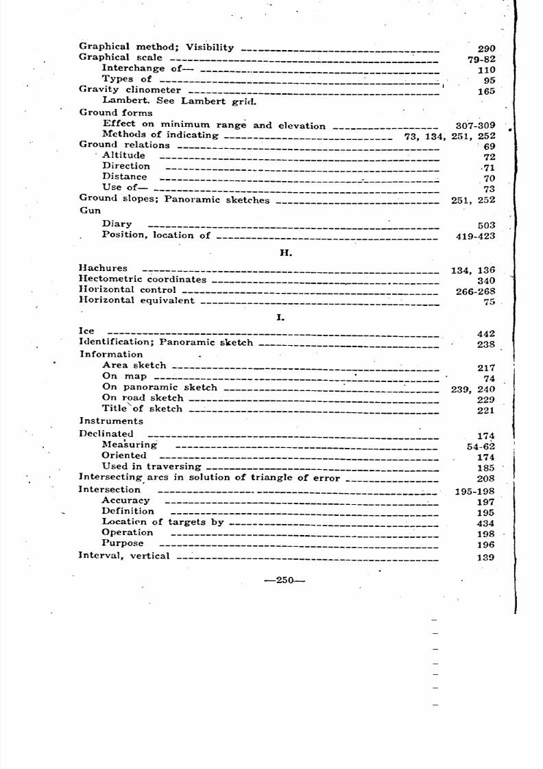
8/8/2019 Topography for Field Artillery
http://slidepdf.com/reader/full/topography-for-field-artillery 258/272
290
79-82
110
95
165
Graphical method; VisibilityGraphical scale
Interchange of .Types of ,
Gravity clinometer
Lambert. See Lambert grid.
Ground forms
Effect on minimum range and elevation 30'7-309
Methods of indicating 73, 134, 251, 252Ground relations 69
'Altitude -_______________________________________________ 72
Direction .71Distance , 70
Use of-- 73
Ground slopes; Panoramic sketches 251, 252
GunDiary 503
Position, location of 419-423
H.
I-Iachures
Heetometric coordinates ------.Horizon tal control
Hori zon tal equ ivaI ent ~_.:.
I.Ice
Identification; Panoramic sketch
InformationArea sketch
On map
On panoramic sketchOn road sketch
Title~of sketch
InstrumentsDec Ii nated
~feasuring
Oriented
U sed in t ra versing
Intersecting, arcs in solution of triangle of error
IntersectionAccuracy
Defin ition
LocatiC'n of targets by .:...Operation
Purpose
Interval, vertical
134, 136
340
266-26875
442
238
217
74
239, 240229
221
17~
54-62
174
185
208, I
195-198
197
195
434
198
196
139
-250-
_ ~ _
- _ _
'
_ _ _ _ _ _ _ _ _ _ _ _ _ _ _ _ _ _ _ _ _ _ _
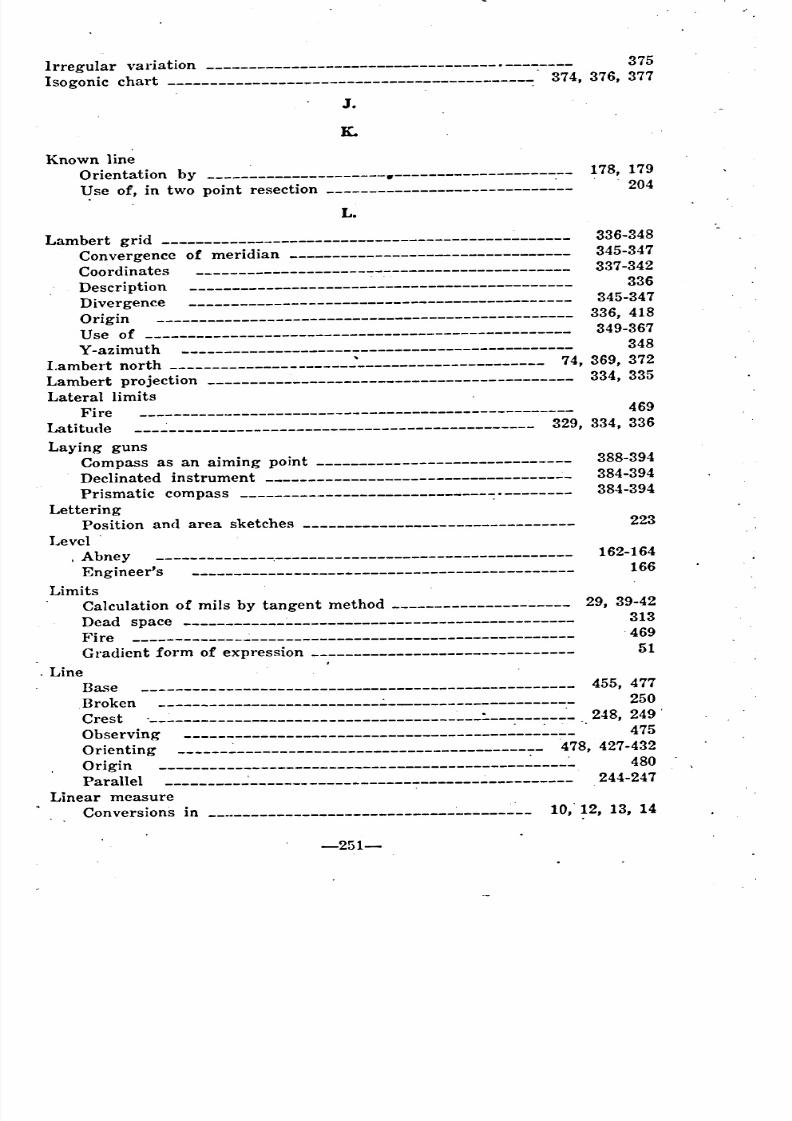
8/8/2019 Topography for Field Artillery
http://slidepdf.com/reader/full/topography-for-field-artillery 259/272
Irregular variation . 375
Isogonic chart 374, 376, 377
J.
K.
Known lineOrientation by •
l.!se of, in two point resection ---------------------------"--
L.
178, 179
"204
223
29, 39-42
313
469
51
Lambert grid 336-348
Convergence of meridian _-------------------------------- 345-347Coordinates 337-342
Description 336
Divergence 345-347
Origin 336, 418
Use of 349-367
Y-azimuth 348
Lambert north '______________________ 74, 369, 372
Lambert projection 334, 335
Lateral limitsFire 469
Latitude ..:___________________________________________ 329, 334, 336
Laying gunsCompass as an aiming point 388-394
Dec1inated instrument ...:_ 384-394
Prismatic compass . 384-394
LetteringPosition and area sketches
Level
. Abney ~--------------------_-_------------ 162-164Enginee~s 166
Limits
Calculation of mils by tangent method
Dead spaceire
Gradient form of expression
. LineBa~e 455, 477
Broken 250
Crest ~_ 248,249'Observing . 475
Orienting ~____________________________________4 78, 427-432Origin ~_____ 480
Parallel 244-247
Linear measureConversions in .___________________________________ 10," 12, 13, 14
-251-
--------
--------------------------
_ "
--------
" _
---------------------
---------------------------------------------- _ _
" ~
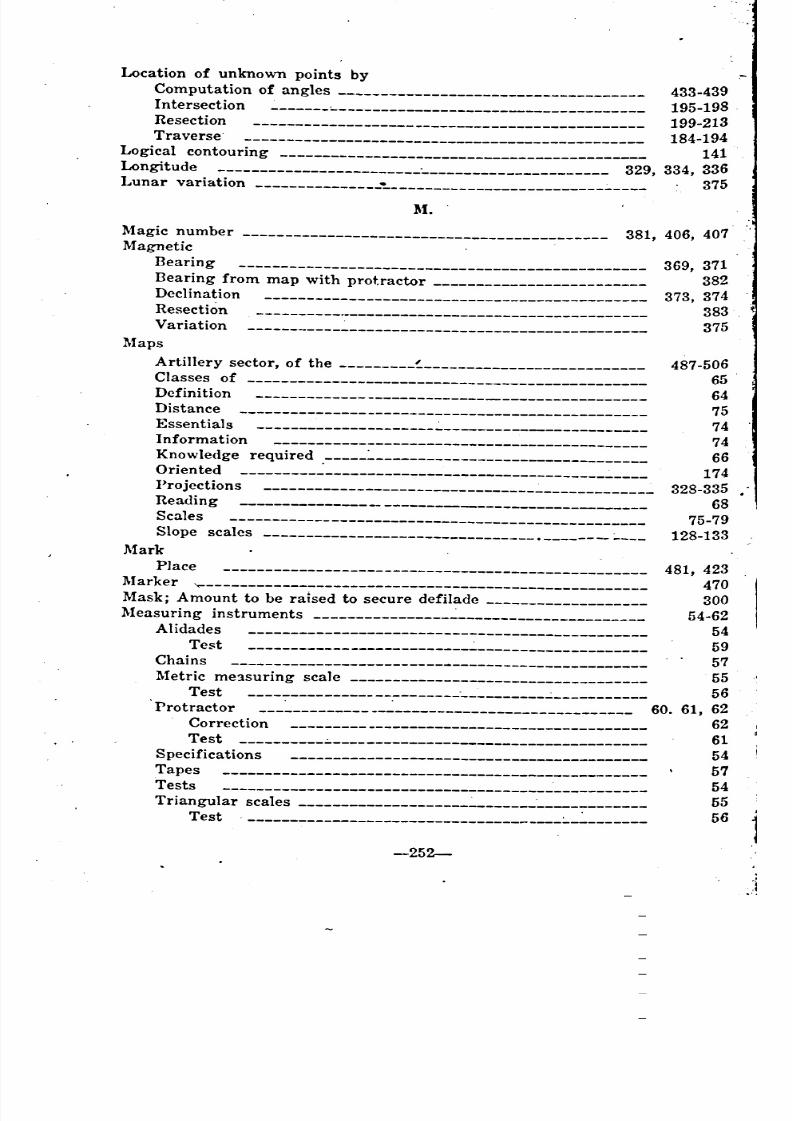
8/8/2019 Topography for Field Artillery
http://slidepdf.com/reader/full/topography-for-field-artillery 260/272
I
I
I
Location of unknown points byComputation of angles 433-439Intersection -___________________________________________ 195-198
Resection 199-213
Traverse' 184-194
Logical contouring 141
Longitude ---___________________________________________ 329, 334, 336
I...unar variation ~______________________________ 375
M.
487-506
65
64
75
74
74
66
174
328-335
68
75-79
128-133
369, 371
382373, 374
383
375
,
481, 423
470
300
54-62
54
59
57
55
56
60. 61, 6262
61
54
57
54
55
56j
.J
-----------------------------------------------
-----------------------------------------------
-252-
Magic number ----_______________________________________ 381, 406, 407
MagneticBearing
Bearing from map with protractorDeclination
Resection
Variation
Maps
Artillery sector, of the !.
Classes of
Defini tionDistance
Essen tialsInformation
Know ledge requiredOriented
!'ro jections
Reading
Scales
Slope scales •
MarkPlace
~Iarker
Mask; Amount to be raIsed to secure defilade~Ieasuring instruments
Alidades
Test
Chains
Metric me1suring scaleTest
Protractor
Correction
Test
Specifica tionsTapes
Tests
Triangular scales "-
Test
_ _
_ _ _ _ _
_ _ _
_ _ _
-- _ _
~------------ _ _
~ _ _ _
~ _ _ _
_ _
~ _ _ _ _ _
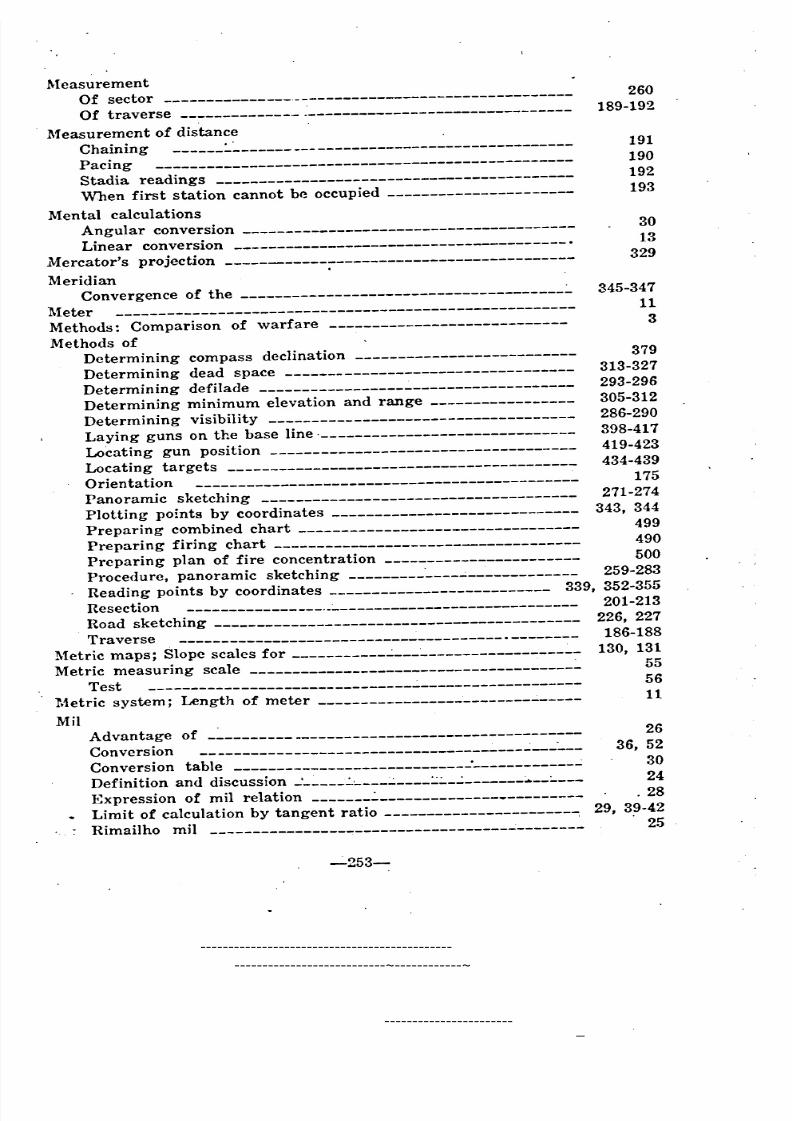
8/8/2019 Topography for Field Artillery
http://slidepdf.com/reader/full/topography-for-field-artillery 261/272
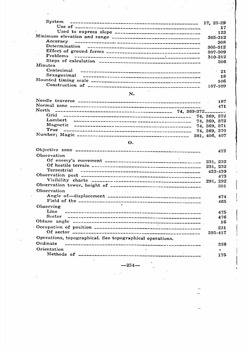
8/8/2019 Topography for Field Artillery
http://slidepdf.com/reader/full/topography-for-field-artillery 262/272
System
1Jse of
Vsed to express slope
.M inimum elevation and range. Accuracy.
Determina ti on
Effect of ground formsProblems
Steps of calculation
~finutesCentesimal
Sexagesimal
Mounted timing scale .Construction of
N.
17, 23-29
17
123
305-312
308305-312
307-309
310-312
306
. 21
18
106
107-109
~eedle traverse 187
Normal zone ~________ 471
North -------------_______________________________ 74, 369-372
Grid ---------_______________________________________ 74, 369, 372
Lambert -----___________________ 74, 369, 372
Magnetic -----__________ 74, 369, 371True -------_________________________________________ 74, 369, 370
Number; Magic ----______________________________________ 381, 406, 407
O.
Objective zone
ObservationOf enemy's movement
Of hostile terrainTerrestrial
Observation post
Visibility charts ...:.
Observation tower, height of
ObservationAngle of-displacementField of the
ObservingLine
Sector
Obtuse angle ., Occupation of position
Of sector
Operations, topographical. See topographical operations.Ordinate .
Orientation~fethods of _
-254-
472
231, 232
231, 232
433-439
473291, 292
301
474
465
475
476
16
231
395-417
338
175
_ _ _ _
~ _ _ _
~ _ _ _ _ _ _
--
_
_ _ _ _
~~ _ __
_ _ _ _ _ _ _ _
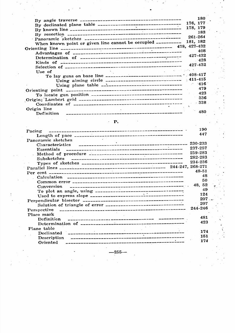
8/8/2019 Topography for Field Artillery
http://slidepdf.com/reader/full/topography-for-field-artillery 263/272
::
By angle traverse 180
By declinated plane table 176, 177
By known line :. ..:_ 178, 179
By resection .;.. ..:._______________ 183
, Panoramic sketches 261-264
When known point or given line cannot be occupied 181, 182Orienting line 478, 427-432
J\dvantages of ~___________ 408
Determination of 427-432
Kinds of _.:.. :.._ -428Selection of 427-432
Use ofTo lay guns on base line :_ .. 408-417
Using aiming circle . 411-415
Using plane table ,:,_______________'416'Orienting point 479
To locate gun position 423
,Origin; 'Lambert grid 336
Coordinates of .___ . 338 .
Origin lineDefinition '. 480
. P.
Pacing 190
Length of pace ~___________________________________ 447
Panoramic sketchesCharacteri.<:;tics .:.____________________________ 230-233Essentials 237-257
n1ethod of procedure _~___________________________________ 259-283
Subsketches 282-283
Types of sketches 234-236
Parallel lines .:.. ..:_____ 244-247, 268-271
Per cent ~___________________________ 48-51Calculation ~_________________ 48
Common error 50
Conversion . 48, 52
To plot an angle, using ..:. . 49
Used to express slope 124
Perpendicular bisector _~_____________________________________ 207 .•
Solution of triangle of error 207Perspective 244-246
Place markDefinition 481
Determination of ::. . 423
Plane tableDeclinated 174
Description 151
Oriented 174
-255-
~ ----------
~ ~ ~ -
~ __~
------
~~ ~ -
~
8/8/2019 Topography for Field Artillery
http://slidepdf.com/reader/full/topography-for-field-artillery 264/272
9
473
299493
492
482
419-423
231
214-223
222
218-220
?17223
221
497
To level --------------___________________________________ . 152
tJse -----------------_______________________________ 151, 403, 416tJsed in traverse ~_______________________ 185
Plotting directionsBy auxiliary points ..:_____ 359By coordinates -__________________________________________ 357, 358
By reversing directions 362
By similar triangles 360-361 .
By Y-azirnuth -----_______________________________________ 356
Plotting points by coordinates ~-----------7----------- 343, 344, 350, 351
PointAdjusting ---___________________________________________ 451
Aiming ------______________________________________ 452, 426, 432
Base ------________________________________________ 456, 424, 425
. Control ---______________________________________________ 459
Critical ---____________________________________________ 140, 216Datum -________________________________________________ 461
Declinating -____________________________________________ 462
Geodetic --------________________________________________ 459, 421
Important--:, Designation of 277-281
Location of-, by coordinates 366, 367
Method of plotting -______________________________ 343, 344, 350, 351~Iethod of reading ~___________________ 339, 352-355
. Orienting ---___________________________________________ 479
Reference -------------______________________________ 26C-268, 485
Referring ~____________________ 485
VVitness -------------------------_______________________ 486Polaris; Azimuth of :.___ 450
Polyconie projection ----------------__________________________ 332
Polyhedral projection ----------~-_____________________________ 330
Position
Amount of defilade, problemA uxil iary-, Chart ofChart
Defin itionGun
Reconnaissance and occupation of
Posit:on sketchesBorder
. Conventional signsInformation
Lettering .Title
Possibilities of fire
Posts. Obscrvat~n
. PrefixesLat'n and Greek
-256-
ffI•
1
i
t
-
~
-----------------
-------------------
' _
~ _ _ _ _
~------------- _ _
~-------------_ _ _ _ _ _

8/8/2019 Topography for Field Artillery
http://slidepdf.com/reader/full/topography-for-field-artillery 265/272
Prismatic compa!'!s
Compass as aiming point
Compute bearing of target -~-~---------------------:"------'
Laying guns with
ProblemsComputation, minimum range and elevation
Conversion of slo~es
Dead spaceefilade
Laying guns on base line with aiming circle
Laying guns with compass as aiming point
Locating targets by topographic means
~ap scales
Profile
Construction ofTo determine defilade --------..:-------------------.
To determine visibility
Projections, map ----------------------------------.
Bonneonic
Definition
Lambert~ercator's
PolyconicPolyhedral
Protractor
Corrections for inaccuracy
Descri pt ion
Testse of
Use of in finding magnetic bearing from map
Purpose of intersection
145
388-394
384-386
387-394
310-3.12127
315-316
298-301
411-415
390-394
435-439
82-91
290296
290
328-335
333
331
328
334, 335
329
332330
61, 62
60, 173
61
173
382
196
Q.
Quadrant, circular measure ..:. ~_____ 16
R•.
RangeDeflection fan ..,;______________________________________ 483, 491
Determination by coordinates ~!..- - ------------------ :..- - 363
Minimum
Accuracy 308Definition 302
Determination 305-312-
Effect of ground forms 307-309
To measure, sito goniometer .:..______________________ 171, 168
Steps of calculation ..:._.:._______________ 306
Reading of points ..:____________ 339, ~52-355
-257- '
------------------------------------------------
--------------------------------------------
--- ----~--------------------------
----------------------------------------
---------------
--------------------------------------
-----------~-------------------------------- _ -----------------
----------------
--------------------
----------------------------------------------
-------------------------------------------
--------
------------------------------------
----------
-------------------------------------------------- _ ----------------------------------------------
_ _
------------------------
-------------~------------------
---------------------------------------------
--------------------------------------------------- _ --------------
----------------------------------------
~
__ __
8/8/2019 Topography for Field Artillery
http://slidepdf.com/reader/full/topography-for-field-artillery 266/272
231
232
231
75
38, 42
42
.89-42
41, 42
139
505
77200
199-213
209, 383
199
210-213
383'
183
200
206422
201-203 .
204, 205
16
224-229
224, 225
229
Reading scales ------------------__________________________ 79, 80, 96-99
Construction of ----------------__________________________ 96-99.lJse of ~____________ 80
Ueconnaissance of
Enemy position'Example
Position
Records
Ammunition -----------_________________________________ 503
Artillery sector -----------_______________________________ 487-506
Classes of -----------------_______________________________ 487
Elaboration of ------------_______________________________ 506
.~faps and charts --------_________________________________ 487-501
Topographical .________ 4Written ------------_________________________________ 487, 502-506
Reduced hectometric coordinates 340
Reduction of stadia readings ----______________________________ 158, 477
Reference point -------------~________________________________ 484
. .. D.csirabl~. considerations -------__________________________ 267
Selection of ------------------____________________________ 266-268
lJse of --------------------______________________________ 268
.~ Referring point ------------:.---______________________________ 485
Reflex angles -----------------_______________________________ 16nelatio~ of
~. D. to II. E. _
Tangent computation and true angular valueTangent computation and degrees
Tangent computation and artillery mil
Tangent computation and R-mil .:.v. I. to scale of the mapReport of B. C.
Representative fraction
Requirements for accurate results in resectionResection
Back azimuth
DefinitionItalian
~fagnetic
Orientation by
Requirements for accurate results. ":"Three point method
To locate gun positions byTransparent paper method
. Two point methodRight angles
Road sketch
Cha racterist ics
InrGrm~tion
-25h
..
-----~-------------
~ _ _ _
---------
"
_ _ _ _ _ _ _ _
~~ _ ~ _
_ _
_ _ _
~ ~ _ _ _ _ _ _ _
~----------- _
8/8/2019 Topography for Field Artillery
http://slidepdf.com/reader/full/topography-for-field-artillery 267/272
Lateral limits
Method
228
226, 227
s.
21
18
I
214-223
222
214
294, 295
287
169-172
170-172
24
265
487-506
260
395-397
375
253, 254
82-91
92-94
79
76-79
55
106
95
139
128
55
95
80
78
95
111.118
Scales
ComputationsConversions
Graphical
~ap _
Metric measuring .
Mounted timingReading
Relation to V. I.
Slope ------------------r-------------------------------riangularTypes of
Use of
VVords and figures
VVorking
VVorking-graphs
SecondsCentesimal
Sexagesimal
Sector -----------------------------------------------------.nalysis of
. ~aps and records
Measurement of; Panoramic sketchOccupation of
Secular variations ..Shading
SheetControl 360
Target 504
Signs, see conventional signs 4, 218-220, 255-258
Similar triangles .To determine visibility 287To plot direction by .________________________________ 360, 361
Site~ngle of, used to determine defilade'
~ngle of, used to determine visibility -'-Sito-goniometer
Use ofSize of mil _
Sketch
Panoramic, see panoramic sketchPosition and area .
Border
Cha raeter isti cs
-2G9-
-------------------_ _ _ _ _ _ _ _
~ _ ~ _
~ _ _ _ _
~ _ _ _ _ _ _
_ _ _
~ _
__ _
------------------
8/8/2019 Topography for Field Artillery
http://slidepdf.com/reader/full/topography-for-field-artillery 268/272
.... ..
)
" i'tf, ,
121
313-321" ,
298-301
82-91
305-312''207-208 .
.
122
125
12~
124
, 12&
18-20
49B'
21, 22
328-335
23-29'
218-220
216
217 ,
223
215, 216
221
Conventional signs
Cri tical po intsInformation
:Lettering .. :.
~ethod of makingriUe
Road, see road sketch
SlopeBoard 167, 168
Construction .________________________________ 167
,Conversion of slope, problem 127Ground 251-252
Practicability of' :.. ~__________ 440
Scale ~____________________ 12&Construction 129-131
Use of ~_______________________ 132-133
, To measure :.. ~__ 150, 155, 12~
Units of expressionDegrees and minutesGradient'
~Iils
Per cent
Tangent
SolutionConversion of slope, problem :.:. __'Dead space
. Defilade
Map scale, problems _,;.
~inimum Range and elevationTriangle" of erro~
Space, dead (see ,dead space)
Stadia rod"o measure distances ~_______________________ 157, 158, 160, 161, 192" l
. Reduction or readings 447'
Straight edge tests _~ :____ 58'
Systems \_Degree or sexagesimal -:.
General communication ~_
Grade or contesimal -:. :.._~ap projections
~il
T.
, TablesAzimuth of polaris , ,(50
Conversion,- of :..' App:' III.
,Defilade 297 ..
Len21h of strida ,(43:'
-260-
- ~ "
'
'
_ _ _
~ _ ~ _
_
~__
~ ~__ _ _ _ _ _ _
~ ~ ~ _ _ _ _
~ ~ _
"
" ~ _
~ ~ _
_
8/8/2019 Topography for Field Artillery
http://slidepdf.com/reader/full/topography-for-field-artillery 269/272
38
39
57
172
157
171
58
59
5.1
61
56
206
221
395-417
404-407
399
408-414
403
152
51
45
36, 52
126
28
29
39-42
384-386
277-281
433-439
504
486
143
156
433
App. 11.
417
190
440
..Natural functions
Reduction of stadia readings.
Slope corrections
Slope practicabil ity
TangentsAbove 45 degrees
Addition and subtraction
Conversion ------------------------------.--------------
Used to express slope
Tangent methods .---------------~----------------------------Applied to degrees and grades
Tangent ratio, limits of calculation b}' 29,
Tangent valuesRelation of, to actual angular values --------------:.-------
Relation of, to artillery mil
Tapes
TargetBearing of
Designation ofLocation of 424, 425,
Sheet
VVitnessTelescope, battery commander's
Telescopic alidade
Terrestrial observation
Test~EdgesLine of sight of alidade r----------------. Measuring instruments ---------:---------------------------
Protractors
ScalesThree point method, resection by
Title, position and area sketch
'1'0 lay guns on base line
Aiming circle method
Aiming point method
Orienting line method
Plane table method
To level plane table
To locateAiming point or direction 426-432
Base point or target 424, 425Gun position _:--- 419-423
To measureAngles and deflection, sito-goniometer
Distance, telescopic alidade -----------------------------'-- ....
Minimum range, s:to-goniometer ------------------------.
Slope
-261-
-------------------------------------
------------------------------
----------~---------------------------------------------------------------------
---------------------------------------------------------------------------
------------------------------------
----------------------------
-------------------------------
------------------------------------------------------
----------------------------------------------
-------------------------------------------
--------------------------------------------------
--------------------------------------------------------------------------------
------------------------------------------------------------------------------------
--------------------------------- --------------~
--------------------------------------------
--------------------------------------------------------------------------------
--------------------------------
------------------------------------
------------------------------------
------------------------------------
------------------------------------
-----~---------------------------------
------------------------------------------
~ ---------------------

8/8/2019 Topography for Field Artillery
http://slidepdf.com/reader/full/topography-for-field-artillery 270/272
..
---------~-------------------------_. 343, 344, 350, 351
Leveling alidade
Peigne compass
Sito- gon iometer
To plot
Coordinates
DirectionCoordinates
Piegne compass ...Protractor
TopographyAdvantages
Defini tionUses of
Topographical information, how recorded ...:Topographical methods \
TopogTaphical operations
. Laying guns on base line .=.
Locating aiming directionLocating base point
Locating gun position :. ...:Topographical records
Essentials
TransitTraverse
Angle
Orientation byClosed
Definition
Errors in
Foresight-backsight
Instruments used : .
~feasurement of distance~Iethods
~eedle
Open
'friangle of error
Solution of
Intersecting arcs. .,
Perpendicular bisectors
Triangles, similar
To plot direction by, Visibility by
Twentieth of a degree
Two point method, resection by .:
.155
150
170
356-362
148
149
2
1
14
5418 .
395-417
426-432
424, 425
419-423
4
4
144
184-194
188
180
184
184
194
186
185
189
186-188
187
184
206-208
207-208
208
207
360-361
287
19
204, 205
u.
Unknown points
Location by
Computation of angles -----------__________________ 433-439
-.262-
_ _ _
_ _ _
_ _ _ _ _ _ _ _
~__ _ _ _ _ _ _ _ _ _ _ _
__ _ _ _ _ _ _ _ _
~ _ _ ~ _
_
8/8/2019 Topography for Field Artillery
http://slidepdf.com/reader/full/topography-for-field-artillery 271/272
Intersection
Resection
Traverse
----------------------------------------------------------------------------------
-------------------------------------------
195-198
199-213
184-194
Use of
Abney' level ~_________ 163, 164
Aiming circle -----------------0--- 404-407, 411-415Declinator 205, 206
Elastic band 288
Engineer's level -:..._____________ 166Gradient 47, 125
Graphical scale 80
Gravity clinometer 165Grid ~_________________ 349-367
Ground relations ~____________________________ 74Isogonic chart .:.___ 376, 377
Known line .:.._________________________ 178, 179, 204
Orienting line ..:____________________________________ 410-416
Origin line 480Panoramic sketch 233
Panoramic sketch pads 236, 263
Peigne compass 147, 148, 150
Plane table 151, 403, 416
Prismatic compass 384-394Profiles -:_______________________________ 290, 296
Right angled rule 355
'Similar triangles 287, 299, 301 ,
Sito-goniorneter 170-172
Slope board ~_ 16S
Slope scale .:. 133
Special chart, dead space .:..________________ 388, 389Stadia ~_________________________________ 158, 160, 161, 192
Telescopic alidade 157
Visibility chart 292
v.Variation, magnetic 375
Vertical control 269, 270
Exaggeration 270, 290
Vertical interval 139
Visi bili ty 285-292
Charts ,________________________ 495, 501, 291, 292Construction ~________________________________ 292
Definitions and limitations 285
Methods of determining 286-290
Angle of site ._________________________________ 289
Elastic band 288 .
Graphic method 290
Sintilar triangles 287
I
:.-263
I •
'
------------------------------------
~
------------
~ '
~
-
8/8/2019 Topography for Field Artillery
http://slidepdf.com/reader/full/topography-for-field-artillery 272/272
...... -
w.
215
22
'Vhole to part method
'Vind direction .
_ _