Embed Size (px)
Citation preview
SERVICE MANUAL
Parts marked with " " are important for maintaining the safety of the set. Be sure to replace these parts withspecified ones for maintaining the safety and performance of the set.
SHARP CORPORATIONThis document has been published to be usedfor after sales service only.The contents are subject to change without notice.
[1] SPECIFICATIONS . . . . . . . . . . . . . 1-1
[2] MAINTENANCE1. Maintenance table . . . . . . . . . . 2-1
[3] REPLACEMENT AND ADJUSTMENT1. Front door and covers . . . . . . . 3-12. Inner cover, paper feed unit . . . 3-13. Paper feed roller . . . . . . . . . . . . 3-14. LCT motors. . . . . . . . . . . . . . . . 3-25. Image position sensor board,
exit sensor . . . . . . . . . . . . . . . . 3-46. Paper height sensors,
paper size sensors . . . . . . . . . . 3-47. Main control board . . . . . . . . . . 3-48. Side registration adjustment . . . 3-59. Dehumidifier heater
installing procedures (0PQC4150431//) . . . . . . . . . . . 3-5
[4] DETAILED DESCRIPTIONS1. Paper feed . . . . . . . . . . . . . . . . 4-12. Paper lift . . . . . . . . . . . . . . . . . . 4-23. Paper size detection. . . . . . . . . 4-24. Remaining paper detectiion . . . 4-35. Paper end detection . . . . . . . . . 4-3
[5] OVERALL MECHANICAL INFORMATION1. Mechanical component
layout . . . . . . . . . . . . . . . . . . . . 5-12. Drive layout . . . . . . . . . . . . . . . 5-13. Electrical components . . . . . . . 5-24. A4/LT LCT MX-LCX4 layout
(with bypass) . . . . . . . . . . . . . . 5-35. Electrical component
summary . . . . . . . . . . . . . . . . . 5-3
TopPage
CONTENTS
CODE: 00ZMXLCX4/S1E
DIGITAL MULTIFUNCTIONAL SYSTEM OPTIONLARGE CAPACITY THREE TRAYS
MX-LCX4MODEL
MX-LCX4 Service Manual [1] SPECIFICATIONS
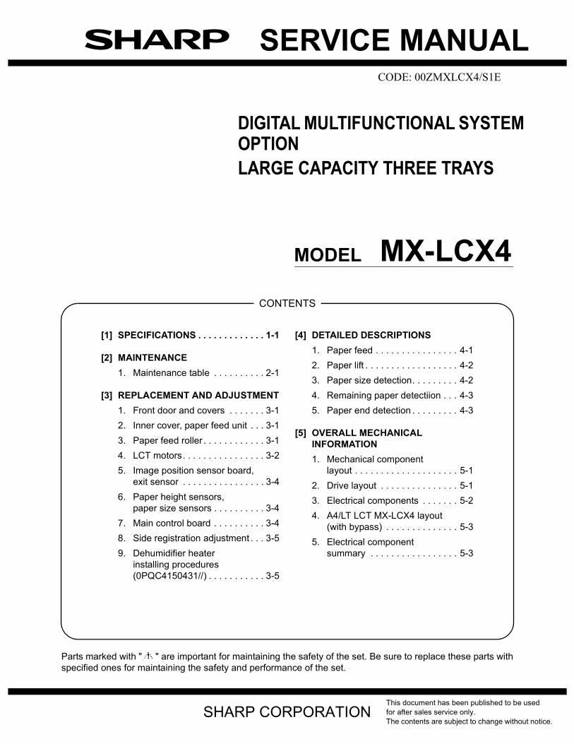
Form Large Capacity Trays (3 Trays)Transport speed 85 – 110 sheets/minute to be supported Transport standard Center alignmentPaper size A4, A5R, B5, 8.5 x 11, 5.5 x 8.5R, 9 x 12 (A4W)Paper size label AvailablePaper size setting Upper tray: User setting (Size setting by guide at Interior side of tray)
Middle tray: User setting (Size setting by guide at Interior side of tray)Lower tray: Service setting (Size setting by operation panel)
Paper size setting for shipment Inch: 8.5 x 11AB: A4
Feedable paper size/weight Upper tray: 52 – 205 g/m2 / 16 lbs Bond – 110 lbs IndexMiddle tray: 52 – 205 g/m2 / 16 lbs Bond – 110 lbs IndexLower tray: 52 – 163 g/m2 / 16 lbs Bond – 90 lbs Index
Paper type Plain paper, Heavy paper, Recycled paper, Thin paper, Pre-printed paper, letter head, Punched paper, Transparency paper, Colored paper, Tab paper (Not available for the Saddle tray), Label paper (Available only for the Offset tray)
Paper capacity Standard PaperUpper tray / Middle tray: 1000 sheetsLower tray: 2550 sheets (80 g/m2)
Detection of remaining paper Available level detection (5 levels)Upper tray / Middle tray: 100%, 75%, 50%, 25%, EmptyLower tray: 100%, 75%, 50%, 25%, Empty* Detection error 3%
Paper supply Paper supply from the upper section by the front loading methodTray rising/falling time Rising Upper tray / Middle tray: 10 seconds or less
Lower tray : 15 seconds or lessTime required from tray insertion to empty detection without paper
Falling Self-weight fallingReliability MCBJ in compliance with the main unit
MCBFLife 5 years or 24,000KPower consumption 150W or lessPower source DC24V (Supplied by the main unit)Dimensions W526 x D728 x H980 mmOccupied dimension 540 x 730 mmWeight Approximately 95 kgInstallation/Maintenance By service personHeater AC 18W x 2 36W (Service parts: 0PQC4150431//)
MX-LCX4 SPECIFICATIONS 1 – 1
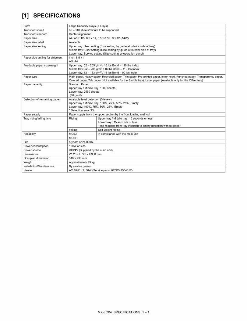
Paper Size/Type/WeightLCT(A4)
Upper Tray Middle Tray Lower TrayMinimum paper weight 52 g/m2
(14 lbs bond)52 g/m2
(14 lbs bond)52 g/m2
(14 lbs bond)Maximum paper weight 205 g/m2
(40 lbs bond)(110 lbs index)(65 lbs cover)
205 g/m2
(40 lbs bond)(110 lbs index)(65 lbs cover)
163 g/m2
(90 lbs Index)
Paper type Thin paper Yes(Even 52 g/m2
is possible)
Yes(Even 52 g/m2
is possible)
Yes(Even 52 g/m2
is possible)Plain paper Yes Yes YesRecycled paper Yes Yes YesColored paper Yes Yes YesLetter head Yes Yes YesPre-printed paper Yes Yes YesPre-punched paper Yes Yes YesHeavy paper 1 (106 – 128 g/m2) Yes Yes YesHeavy paper 2 (129 – 176 g/m2) Yes Yes YesHeavy paper 3 (177 – 205 g/m2) Yes Yes NoHeavy paper 4 (206 – 300 g/m2) No No NoTab paper Yes Yes NoTransparency paper Yes Yes YesLabel paper No Yes No
Paper size 12" x 18" (A3W) 305 x 457 — — —Ledger (11" x 17") 279 x 432 — — —Ledger (11" x 17") Z folding 279 x 216 — — —Legal (8.5" x 14") 216 x 356 — — —Legal (8.5" x 14") Z folding 216 x 178 — — —Mexican Legal (8.5" x 13.4") 216 x 340 — — —Foolscap (8.5" x 13") 216 x 330 — — —Letter (8.5" x 11") 279 x 216 Yes Yes YesLetter R (8.5" x 11" R) 216 x 279 — — —Letter R (8.5" x 11" R) Z folding 216 x 140 — — —Invoice (5.5" x 8.5") 216 x 140 — — —Invoice R (5.5" x 8.5" R) 140 x 216 Yes Yes YesExective R (7.25" x 10.5") 184 x 266 — — —9 x 12 (A4W) 305 x 229 Yes Yes YesA3 297 x 420 — — —A3 Z folding 297 x 210 — — —B4 257 x 364 — — —B4 Z folding 257 x 182 — — —A4 297 x 210 Yes Yes YesA4-R 210 x 297 — — —A4-R Z folding 210 x 148 — — —B5 257 x 182 Yes Yes YesB5-R 182 x 257 — — —A5 210 x 148 — — —A5-R 148 x 210 Yes Yes YesSRA3 320 x 450 mm — — —SRA4 320 x 225 mm — — —
318 x 234.75 mm — — —312.5 x 220 mm — — —318 x 469.5 mm — — —312.5 x 440 mm — — —
8K 270 x 390 — — —16K 270 x 195 — — —16K-R 195 x 270 — — —Postcard 100 x 148 — — —Special – Custom sizeCustom Range
No No Nomin Main — — —max Main — — —min Sub — — —max Sub — — —
Special – Size uncertain — — —
MX-LCX4 SPECIFICATIONS 1 – 2
MX-LCX4 MAINTENANCE 2 – 1
MX-LCX4 Service Manual [2] MAINTENANCE
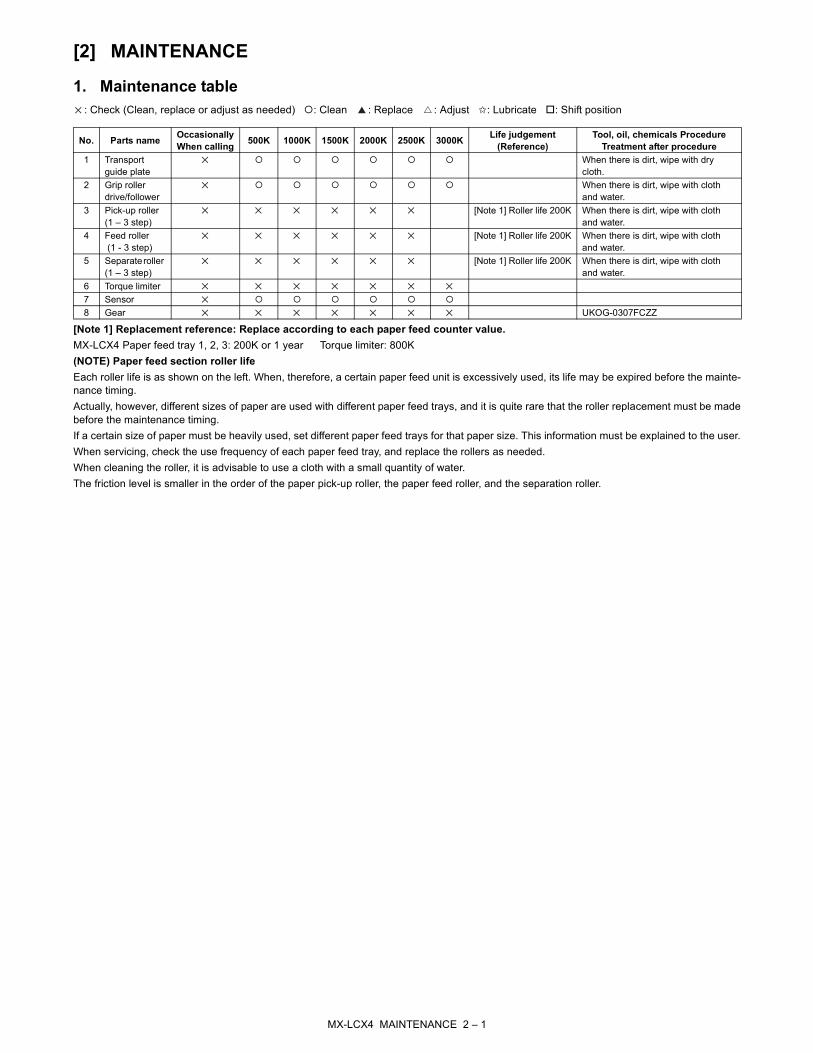
1. Maintenance table: Check (Clean, replace or adjust as needed) : Clean : Replace : Adjust ✩: Lubricate : Shift position
[Note 1] Replacement reference: Replace according to each paper feed counter value. MX-LCX4 Paper feed tray 1, 2, 3: 200K or 1 year Torque limiter: 800K(NOTE) Paper feed section roller lifeEach roller life is as shown on the left. When, therefore, a certain paper feed unit is excessively used, its life may be expired before the mainte-nance timing.Actually, however, different sizes of paper are used with different paper feed trays, and it is quite rare that the roller replacement must be madebefore the maintenance timing.If a certain size of paper must be heavily used, set different paper feed trays for that paper size. This information must be explained to the user.When servicing, check the use frequency of each paper feed tray, and replace the rollers as needed.When cleaning the roller, it is advisable to use a cloth with a small quantity of water.The friction level is smaller in the order of the paper pick-up roller, the paper feed roller, and the separation roller.
No. Parts name Occasionally When calling 500K 1000K 1500K 2000K 2500K 3000K Life judgement
(Reference)Tool, oil, chemicals Procedure
Treatment after procedure1 Transport
guide plateWhen there is dirt, wipe with dry cloth.
2 Grip roller drive/follower
When there is dirt, wipe with cloth and water.
3 Pick-up roller (1 – 3 step)
[Note 1] Roller life 200K When there is dirt, wipe with cloth and water.
4 Feed roller (1 - 3 step)
[Note 1] Roller life 200K When there is dirt, wipe with cloth and water.
5 Separate roller (1 – 3 step)
[Note 1] Roller life 200K When there is dirt, wipe with cloth and water.
6 Torque limiter7 Sensor8 Gear UKOG-0307FCZZ

MX-LCX4 Service Manual [3] REPLACEMENT AND
ADJUSTMENT
1. Front door and covers
[A] Top cover (screw x 4).[B] Front door (stopper x 1).
NOTE: While lifting the top cover, remove the snap ring and frontdoor.
[C] Rear cover (screw x 6).[D] Right cover (screw x 6).[E] Paper slot cover (screw x 2).
2. Inner cover, paper feed unit
• Open the front door.• Remove right cover (see 1.)Remove:[A] Pull out tray and remove it (screw x 4)[B] Knobs (x 3) (screw x 1 each)[C] Upper inner cover (screw x 2)[D] Knob (screw x 1)[E] Lower inner cover (screw x 1)[F] Paper feed unit (connector x 1, screw x 2)
3. Paper feed roller
Remove:• Remove the right cover (see 1.)• Remove the paper trays. (see 2.)[A] Pick-up roller (stopper x 1).[B] Feed roller (stopper x 1).[C] Separation roller (stopper x 1).
NOTE: 1) The LCT pick-up and separation rollers are the sameas pick-up and separation rollers of the main machine.These rollers are interchangeable.
2) The feed rollers of the LCT and main machine are dif-ferent because they are designed to rotate in oppositedirections. The feed rollers of the LCT and mainmachine are not interchangeable.
3) Never touch the surface of the rollers with bare hands.• Clear the PM counters for the new rollers (see Section "2. Pre-
ventive Maintenance).
[C]
[B]
[D]
[E] [A]
[A]
[B]
[C]
[D][E]
[F]
[A]
[B]
[C]
MX-LCX4 REPLACEMENT AND ADJUSTMENT 3 – 1

4. LCT motorsA. Paper feed, grip motors
Each paper feed unit has a paper feed motor (1) and a grip motor(2). The removal procedure is the same for each feed tray.Remove:• Rear cover (see 1.)[A] Motor unit (screw x 4, connector x 2)[B] Springs (x 2). First, loosen the screws (x 2) (3).[C] Paper feed motor (screw x 2)[D] Grip motor (screw x 2)Reinstallation• Attach the tension spring, then tighten the screws (3) to tighten
the belts.
B. 6th lift motor
Remove:• Rear cover (see 1.)[A] 6th lift motor (screw x 2, connector x 1)
C. 4th transport motor
Remove:• Rear cover. (see 1.)[A] 4th Transport motor unit (screw x 5, connector x 1).[B] Spring (x 1). First, loosen screw (1) (screw x 1).[C] 4th transport motor (screw x 2, Timing belt x 1)Reinstallation• Be sure that the tension spring is connected, then tighten the
screw (1).
[A]
(1)
(2)
[C]
[D]
(3)[B]
[A]
[A]
[B]
[C](1)
MX-LCX4 REPLACEMENT AND ADJUSTMENT 3 – 2

D. 5th transport motor
Remove:• Rear cover. (see 1.)[A] Motor unit (screw x 4, connector x 1).[B] Spring (x 1). First, loosen screw (1) (screw x 1).[C] 5th Transport motor (screw x 2, Timing belt x 1)Reinstallation• Be sure that the tension spring is connected, then tighten the
screw (1).
E. LCT exit motor
Remove:• Remove the rear cover. (see 1.)[A] Motor unit (screw x 6, connector x 1).[B] Spring (x 1). First, loosen screw (1) (screw x 1).[C] LCT exit motor (screw x 2, Timing belt x 1)Reinstallation• Be sure that the tension spring is connected, then tighten the
screw (1).
F. 6th transport motor
Remove:• Rear cover. (see 1.)[A] Motor unit (screw x 6, connector x 1).[B] Spring (x1). First, loosen screw (1) (screw x 1).[C] LCT exit motor (screw x 2, Timing belt x 1)Reinstallation• Be sure that the tension spring is connected, then tighten the
screw (1).
[A]
[B]
[C](1)
[A]
[B]
[C]
(1)
[A]
[B]
[C]
(1)
MX-LCX4 REPLACEMENT AND ADJUSTMENT 3 – 3
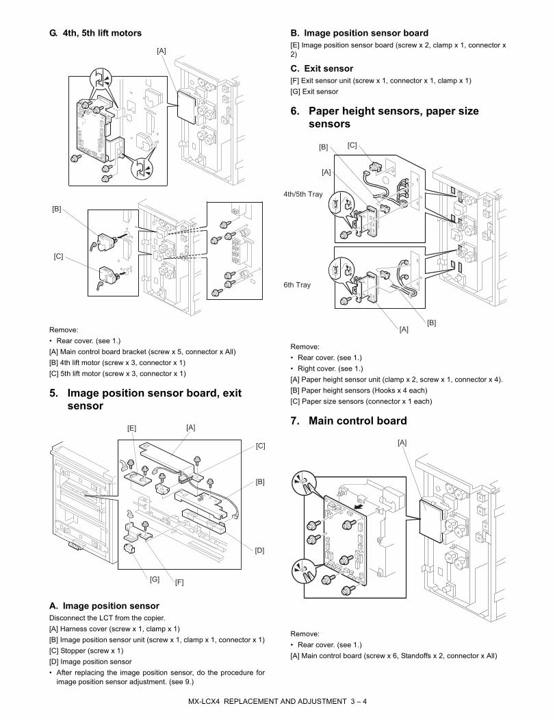
G. 4th, 5th lift motors
Remove:• Rear cover. (see 1.)[A] Main control board bracket (screw x 5, connector x All)[B] 4th lift motor (screw x 3, connector x 1)[C] 5th lift motor (screw x 3, connector x 1)
5. Image position sensor board, exit sensor
A. Image position sensorDisconnect the LCT from the copier.[A] Harness cover (screw x 1, clamp x 1)[B] Image position sensor unit (screw x 1, clamp x 1, connector x 1)[C] Stopper (screw x 1)[D] Image position sensor• After replacing the image position sensor, do the procedure for
image position sensor adjustment. (see 9.)
B. Image position sensor board[E] Image position sensor board (screw x 2, clamp x 1, connector x2)
C. Exit sensor[F] Exit sensor unit (screw x 1, connector x 1, clamp x 1)[G] Exit sensor
6. Paper height sensors, paper size sensors
Remove:• Rear cover. (see 1.)• Right cover. (see 1.)[A] Paper height sensor unit (clamp x 2, screw x 1, connector x 4).[B] Paper height sensors (Hooks x 4 each)[C] Paper size sensors (connector x 1 each)
7. Main control board
Remove:• Rear cover. (see 1.)[A] Main control board (screw x 6, Standoffs x 2, connector x All)
[A]
[B]
[C]
[A]
[B]
[C]
[D]
[E]
[G] [F]
[A]
[B]
[A][B]
[C]
4th/5th Tray
6th Tray
[A]
MX-LCX4 REPLACEMENT AND ADJUSTMENT 3 – 4

8. Side registration adjustment
Normally the side registration of the image can be adjusted in theSP mode.If the punch hole positions are not aligned from a particular feedstation, however, you can manually adjust the side registration bychanging the tray cover position for that tray, and then adjust theside registration of the image.1) Pull out the tray.2) Change the screw positions [A] at both the right and left sides
as shown.
NOTE: Adjustment range: 0 ± 2.0 mm adjustment step: 1.0 mm/step
9. Dehumidifier heater installing procedures (0PQC4150431//)
A. Component parts
B. Installing procedures1) Remove the lower-stage cassette (4 screws).
2) Remove the rear cabinet. (5 screws)
Remove the earth plate. (2 screws)
[A]
Heater cover
Interface harness
(with heater line)
Heater
(x 2)
M4 screw (x 7)
M4 washer screw (x 1)
MX-LCX4 REPLACEMENT AND ADJUSTMENT 3 – 5
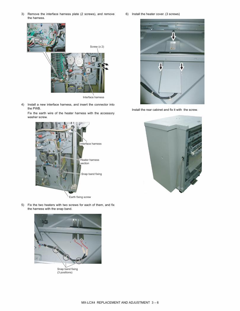
3) Remove the interface harness plate (2 screws), and removethe harness.
4) Install a new interface harness, and insert the connector intothe PWB.Fix the earth wire of the heater harness with the accessorywasher screw.
5) Fix the two heaters with two screws for each of them, and fixthe harness with the snap band.
6) Install the heater cover. (3 screws)
Install the rear cabinet and fix it with the screw.
Screw (x 2)
Interface harness
Interface harness
Heater harness
section
Snap band fixing
Earth fixing screw
Snap band fixing
(3 positions)
MX-LCX4 REPLACEMENT AND ADJUSTMENT 3 – 6
MX-LCX4 Service Manual [4] DETAILED DESCRIPTIONS
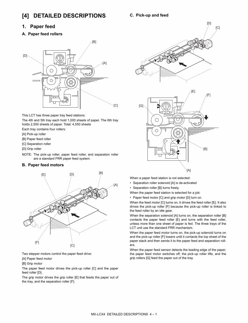
1. Paper feedA. Paper feed rollers
This LCT has three paper tray feed stations:The 4th and 5th tray each hold 1,000 sheets of paper. The 6th trayholds 2,550 sheets of paper. Total: 4,550 sheetsEach tray contains four rollers:[A] Pick-up roller[B] Paper feed roller[C] Separation roller[D] Grip roller
NOTE: The pick-up roller, paper feed roller, and separation rollerare a standard FRR paper feed system.
B. Paper feed motors
Two stepper motors control the paper feed drive:[A] Paper feed motor [B] Grip motorThe paper feed motor drives the pick-up roller [C] and the paperfeed roller [D].The grip motor drives the grip roller [E] that feeds the paper out ofthe tray, and the separation roller [F].
C. Pick-up and feed
When a paper feed station is not selected:• Separation roller solenoid [A] is de-activated• Separation roller [B] turns freely.When the paper feed station is selected for a job:• Paper feed motor [C] and grip motor [D] turn on.When the feed motor [C] turns on, it drives the feed roller [E]. It alsodrives the pick-up roller [F] because the pick-up roller is linked tothe feed roller by an idle gear.When the separation solenoid [A] turns on, the separation roller [B]contacts the paper feed roller [E] and turns with the feed roller,unless more than one sheet of paper is fed. The three trays of theLCT unit use the standard FRR mechanism.When the paper feed motor turns on, the pick-up solenoid turns onand the pick-up roller [F] lowers until it contacts the top sheet of thepaper stack and then sends it to the paper feed and separation roll-ers.When the paper feed sensor detects the leading edge of the paper,the paper feed motor switches off, the pick-up roller lifts, and thegrip rollers [G] feed the paper out of the tray.
[A]
[B]
[C]
[D]
[A]
[B]
[C]
[D][E]
[F]
[C]
[D]
[A]
[B]
[E][F]
[G]
MX-LCX4 DETAILED DESCRIPTIONS 4 – 1
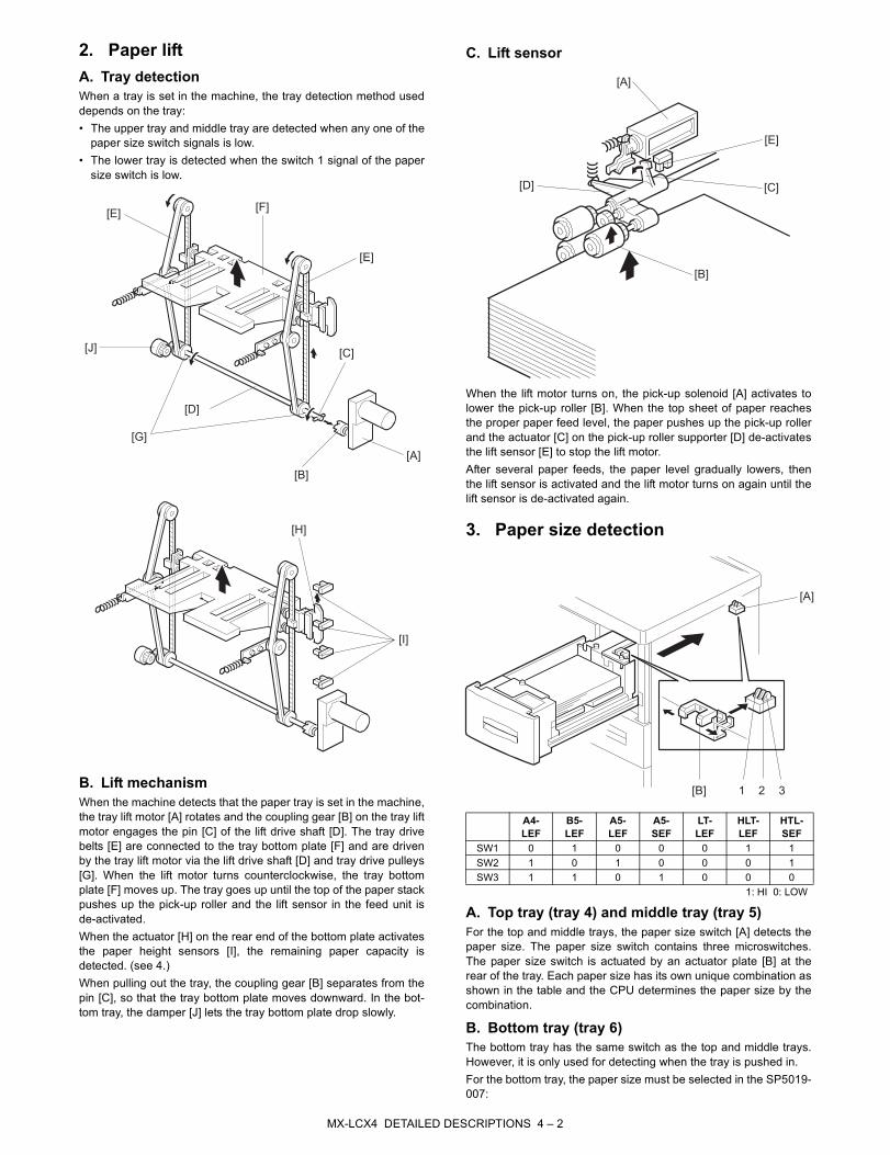
2. Paper liftA. Tray detectionWhen a tray is set in the machine, the tray detection method useddepends on the tray:• The upper tray and middle tray are detected when any one of the
paper size switch signals is low.• The lower tray is detected when the switch 1 signal of the paper
size switch is low.
B. Lift mechanismWhen the machine detects that the paper tray is set in the machine,the tray lift motor [A] rotates and the coupling gear [B] on the tray liftmotor engages the pin [C] of the lift drive shaft [D]. The tray drivebelts [E] are connected to the tray bottom plate [F] and are drivenby the tray lift motor via the lift drive shaft [D] and tray drive pulleys[G]. When the lift motor turns counterclockwise, the tray bottomplate [F] moves up. The tray goes up until the top of the paper stackpushes up the pick-up roller and the lift sensor in the feed unit isde-activated.When the actuator [H] on the rear end of the bottom plate activatesthe paper height sensors [I], the remaining paper capacity isdetected. (see 4.)When pulling out the tray, the coupling gear [B] separates from thepin [C], so that the tray bottom plate moves downward. In the bot-tom tray, the damper [J] lets the tray bottom plate drop slowly.
C. Lift sensor
When the lift motor turns on, the pick-up solenoid [A] activates tolower the pick-up roller [B]. When the top sheet of paper reachesthe proper paper feed level, the paper pushes up the pick-up rollerand the actuator [C] on the pick-up roller supporter [D] de-activatesthe lift sensor [E] to stop the lift motor. After several paper feeds, the paper level gradually lowers, thenthe lift sensor is activated and the lift motor turns on again until thelift sensor is de-activated again.
3. Paper size detection
A. Top tray (tray 4) and middle tray (tray 5)For the top and middle trays, the paper size switch [A] detects thepaper size. The paper size switch contains three microswitches.The paper size switch is actuated by an actuator plate [B] at therear of the tray. Each paper size has its own unique combination asshown in the table and the CPU determines the paper size by thecombination.
B. Bottom tray (tray 6)The bottom tray has the same switch as the top and middle trays.However, it is only used for detecting when the tray is pushed in.For the bottom tray, the paper size must be selected in the SP5019-007:
[F]
[A]
[E]
[J]
[D]
[E]
[C]
[B]
[G]
[H]
[I]
A4-LEF
B5-LEF
A5-LEF
A5-SEF
LT-LEF
HLT-LEF
HTL-SEF
SW1 0 1 0 0 0 1 1SW2 1 0 1 0 0 0 1SW3 1 1 0 1 0 0 0
1: HI 0: LOW
[A]
[E]
[D] [C]
[B]
[A]
[B] 21 3
MX-LCX4 DETAILED DESCRIPTIONS 4 – 2

4. Remaining paper detectiion
The amount of paper remaining in the tray is detected by the threepaper height photo-interrupter sensors on the left rail as the bottomplate rises. Five states, determined by the position of the actuatorare possible.1) With the actuator [A] below paper height sensor 1 [B], no sen-
sor is actuated and the display indicates 100%.2) When the actuator passes paper height sensor 1 [B] , the dis-
play indicates 75% of the paper supply remaining.3) When the actuator passes paper height sensor 2 [C], the dis-
play indicates 50% of the paper supply remaining.4) When the actuator passes paper height sensor 3 [D], the dis-
play indicates 25% of the paper supply remaining.
NOTE: When the actuator enters the gap of the near end sensor[E], the machine signals near end.
Finally, when the last sheet feeds, the paper end sensor signalsthat the tray is empty. (see 5.)
5. Paper end detection
The paper end sensor [A] detects the top sheet of the paper in thetray by monitoring the reflected light. When the paper tray runs outof paper, the paper end sensor does not receive the reflected lightdue to the cutout [B]. Then, the tray lift motor rotates backwards 2seconds to drop the tray bottom plate.
[A]
[B]
[C]
[D]
[E]
[A]
[B]
MX-LCX4 DETAILED DESCRIPTIONS 4 – 3
MX-LCX4 Service Manual [5] OVERALL MECHANICAL
INFORMATION
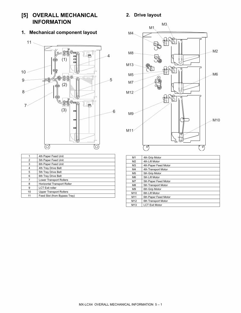
1. Mechanical component layout
2. Drive layout
1 4th Paper Feed Unit2 5th Paper Feed Unit 3 6th Paper Feed Unit 4 4th Tray Drive Belt5 5th Tray Drive Belt6 6th Tray Drive Belt7 Lower Transport Rollers8 Horizontal Transport Roller9 LCT Exit roller10 Upper Transport Rollers11 Feed Slot (from Bypass Tray)
(1)
(2)
(3)
4
5
67
8
9
10
11
M1 4th Grip Motor M2 4th Lift MotorM3 4th Paper Feed Motor M4 4th Transport Motor M5 5th Grip MotorM6 5th Lift Motor M7 5th Paper Feed MotorM8 5th Transport MotorM9 6th Grip MotorM10 6th Lift Motor M11 6th Paper Feed MotorM12 6th Transport MotorM13 LCT Exit Motor
M8
M3
M1
M4
M2
M6
M10
M11
M9
M12
M7
M5
M13
MX-LCX4 OVERALL MECHANICAL INFORMATION 5 – 1
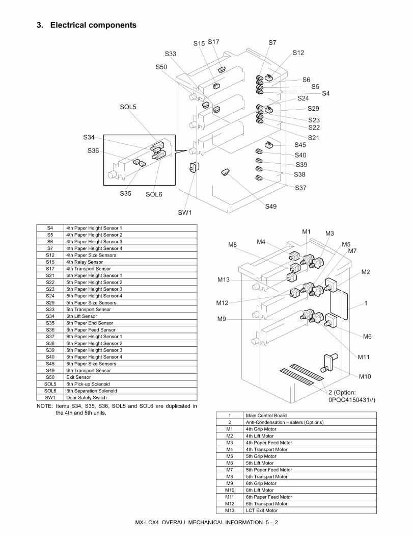
3. Electrical components
NOTE: Items S34, S35, S36, SOL5 and SOL6 are duplicated inthe 4th and 5th units.
S50
S33
S15 S17 S7
S12
S6
S5
S4S24
S29
S23
S22
S21
S45
S40
S39
S38
S37
S49
SW1
SOL6S35
S36
S34
SOL5
S4 4th Paper Height Sensor 1 S5 4th Paper Height Sensor 2S6 4th Paper Height Sensor 3S7 4th Paper Height Sensor 4S12 4th Paper Size SensorsS15 4th Relay SensorS17 4th Transport SensorS21 5th Paper Height Sensor 1 S22 5th Paper Height Sensor 2 S23 5th Paper Height Sensor 3 S24 5th Paper Height Sensor 4 S29 5th Paper Size Sensors S33 5th Transport Sensor S34 6th Lift Sensor S35 6th Paper End Sensor S36 6th Paper Feed Sensor S37 6th Paper Height Sensor 1 S38 6th Paper Height Sensor 2 S39 6th Paper Height Sensor 3 S40 6th Paper Height Sensor 4 S45 6th Paper Size Sensors S49 6th Transport Sensor S50 Exit Sensor
SOL5 6th Pick-up Solenoid SOL6 6th Separation Solenoid SW1 Door Safety Switch
1 Main Control Board2 Anti-Condensation Heaters (Options)
M1 4th Grip Motor M2 4th Lift MotorM3 4th Paper Feed MotorM4 4th Transport Motor M5 5th Grip MotorM6 5th Lift MotorM7 5th Paper Feed MotorM8 5th Transport MotorM9 6th Grip Motor M10 6th Lift Motor M11 6th Paper Feed MotorM12 6th Transport Motor M13 LCT Exit Motor
M8M4
M1 M3
M5
M7
M2
1
M6
M11
M10
2 (Option:
0PQC4150431//)
M9
M12
M13
MX-LCX4 OVERALL MECHANICAL INFORMATION 5 – 2
4. A4/LT LCT MX-LCX4 layout (with bypass)
5. Electrical component summary
M1 4th Grip MotorM1 Paper Feed Motor Bypass (MX-MFX2) M3 4th Paper Feed MotorM3 Transport Motor Bypass (MX-MFX2)M4 4th Transport MotorM4 Grip Motor Bypass (MX-MFX2) M5 5th Grip Motor M7 5th Paper Feed Motor M8 5th Transport Motor M9 6th Grip Motor M11 6th Paper Feed Motor M12 6th Transport Motor M13 LCT Exit Motor S3 4th Paper Feed SensorS4 Paper Feed Sensor Bypass (MX-MFX2) S8 Transport Sensor Bypass (MX-MFX2)S15 4th Relay Sensor S17 4th Transport SensorS20 5th Paper Feed Sensor S33 5th Transport Sensor S36 6th Paper Feed Sensor S49 6th Transport Sensor S50 LCT Exit Sensor
MotorsNo.
(Signal) Name Description
M1 (L1REVM)
4th Grip Motor Drives the separation roller and the grip roller of the 4th tray.
M2 (L1PRM)
4th Lift Motor Drives the bottom plate of the 4th tray up and down.
M3 (L1PUM)
4th Paper Feed Motor
Drives the pick-roller and feed roller that picks up each sheet and starts to feed it out of the 4th tray.
M4 (L1PFM)
4th Transport Motor
Drives the rollers in the vertical feed path that feed the paper from the 4th tray to the LCT exit motor.
M5 (L2REVM)
5th Grip Motor Drives the separation roller and the grip roller of the 5th tray.
M6 (L2PRM)
5th Lift Motor Drives the bottom plate of the 5th tray up and down.
M7 (L2PUM)
5th Paper Feed Motor
Drives the pick-roller and feed roller that picks up each sheet and starts to feed it out of the 5th tray.
M8 (L2PFM)
5th Transport Motor
Drives the transport rollers in the vertical feed path that feed the paper from the 4th tray and the 5th tray to the LCT exit motor.
M9 (L3REVM)
6th Grip Motor Drives the separation roller and the grip roller of the 6th tray.
Tray 4
Tray 5
Tray 6
Tray 7
(MX-MFX2)
M4
M7
S20
M8
S33
M11
S36
M1
S4
M4
S8
M3
M3
S3
M1
S17
M9
S49
M12
M13
S50
M5
S15
M10 (L3PRM)
6th Lift Motor Drives the 5th tray up and down.
M11 (L3PUM)
6th Paper Feed Motor
Drives the pick-roller and feed roller that picks up each sheet and starts to feed it out of the 6th tray.
M12 (L3PFM)
6th Transport Motor
Drives the rollers in the vertical feed path that feed the paper from the 6th tray to the LCT exit motor.
M13 (PEM)
LCT Exit Motor Feeds the paper out the LCT and into the entrance of the copier.
PCBsNo. Name Description
PCB1 Main Control Board
Controls the operation of all motors and sensors in the LCT unit.
SensorsNo.
(Signal) Name Description
S1 (L1ULS)
4th Lift Sensor Detects when the paper in the 4th tray is at the correct height for paper feed and switches the 4th lift motor off.
S2 (L1PES)
4th Paper End Sensor
Detects when the last sheet feeds from the 4th tray.
S3 (L1PFS)
4th Paper Feed Sensor
Detects the paper when it arrives at the 4th paper feed roller and checks for misfeeds.
S4 (L1PVS1)
4th Paper Height Sensor 1
4th from the bottom of the 4th tray, detects stack height: 100%
S5 (L1PVS2)
4th Paper Height Sensor 2
5th from the bottom of the 4th tray, detects stack height: 75%
S6 (L1PVS3)
4th Paper Height Sensor 3
6th from the bottom of the 4th tray, detects stack height: 50%
S7 (L1PVS4)
4th Paper Height Sensor 4
4th from the bottom of the 4th tray, detects stack height: 25% and signals near-end.
S12 (L1SIZ1)
4th Paper Size Sensor 1
1 of a set of 3 sensors that detect the width of the paper in the 4th tray.
S13 (L1SIZ2)
4th Paper Size Sensor 2
1 of a set of 3 sensors that detect the width of the paper in the 4th tray.
S14 (L1SIZ3)
4th Paper Size Sensor 3
1 of a set of 3 sensors that detect the width of the paper in the 4th tray.
S15 (L1IDS)
4th Relay Sensor
Detects the leading and trailing edges of the paper in the paper path near the bottom of the 4th tray. Checks the timing of the feed and signals a jam if the paper is late or lags at this location.
S17 (L1TS)
4th Transport Sensor
Detects jams in the paper path where the transport motor feeds the paper from the 4th tray.
S18 (L2ULS)
5th Lift Sensor Detects when the paper in the 5th tray is at the correct height for paper feed and switches the 4th lift motor off.
S19 (L2PES)
5th Paper End Sensor
Detects when the last sheet feeds from the 5th tray.
S20 (L2PFS)
5th Paper Feed Sensor
Detects the paper when it arrives at the 5th paper feed roller and checks for misfeeds.
S21 (L2PVS1)
5th Paper Height Sensor 1
4th from the bottom of the 5th tray, detects stack height: 100%
S22 (L2PVS2)
5th Paper Height Sensor 2
5th from the bottom of the 5th tray, detects stack height: 75%
S23 (L2PVS3)
5th Paper Height Sensor 3
6th from the bottom of the 5th tray, detects stack height: 50%
S24 (L2PVS4)
5th Paper Height Sensor 4
4th from the bottom of the 5th tray, detects stack height: 25% and signals near-end.
S29 (L2SIZ1)
5th Paper Size Sensor 1
1 of a set of 3 sensors that detect the width of the paper in the 5th tray.
S30 (L2SIZ2)
5th Paper Size Sensor 2
1 of a set of 3 sensors that detect the width of the paper in the 5th tray.
S31 (L2SIZ3)
5th Paper Size Sensor 3
1 of a set of 3 sensors that detect the width of the paper in the 5th tray.
S33 (L2TS)
5th Transport Sensor
Detects jams in the paper path where the transport motor feeds the paper from the 5th tray.
MotorsNo.
(Signal) Name Description
MX-LCX4 OVERALL MECHANICAL INFORMATION 5 – 3
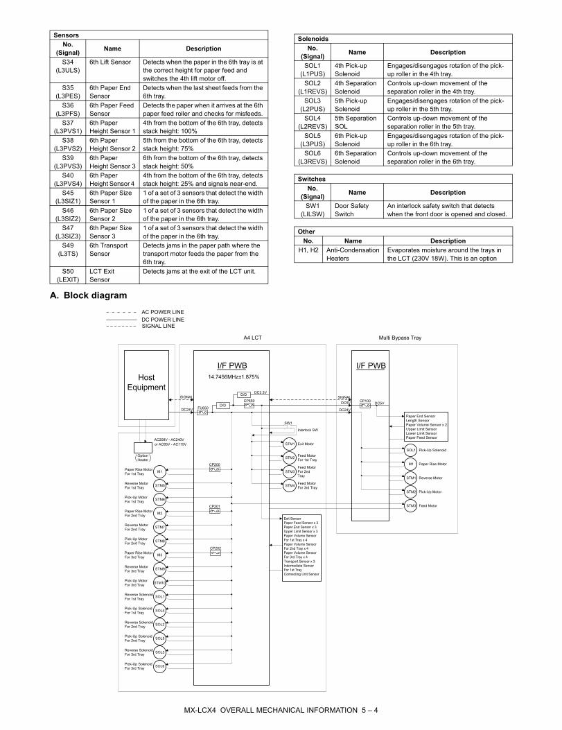
A. Block diagram
S34 (L3ULS)
6th Lift Sensor Detects when the paper in the 6th tray is at the correct height for paper feed and switches the 4th lift motor off.
S35 (L3PES)
6th Paper End Sensor
Detects when the last sheet feeds from the 6th tray.
S36 (L3PFS)
6th Paper Feed Sensor
Detects the paper when it arrives at the 6th paper feed roller and checks for misfeeds.
S37 (L3PVS1)
6th Paper Height Sensor 1
4th from the bottom of the 6th tray, detects stack height: 100%
S38 (L3PVS2)
6th Paper Height Sensor 2
5th from the bottom of the 6th tray, detects stack height: 75%
S39 (L3PVS3)
6th Paper Height Sensor 3
6th from the bottom of the 6th tray, detects stack height: 50%
S40 (L3PVS4)
6th Paper Height Sensor 4
4th from the bottom of the 6th tray, detects stack height: 25% and signals near-end.
S45 (L3SIZ1)
6th Paper Size Sensor 1
1 of a set of 3 sensors that detect the width of the paper in the 6th tray.
S46 (L3SIZ2)
6th Paper Size Sensor 2
1 of a set of 3 sensors that detect the width of the paper in the 6th tray.
S47 (L3SIZ3)
6th Paper Size Sensor 3
1 of a set of 3 sensors that detect the width of the paper in the 6th tray.
S49 (L3TS)
6th Transport Sensor
Detects jams in the paper path where the transport motor feeds the paper from the 6th tray.
S50 (LEXIT)
LCT Exit Sensor
Detects jams at the exit of the LCT unit.
SensorsNo.
(Signal) Name DescriptionSolenoids
No. (Signal) Name Description
SOL1 (L1PUS)
4th Pick-up Solenoid
Engages/disengages rotation of the pick-up roller in the 4th tray.
SOL2 (L1REVS)
4th Separation Solenoid
Controls up-down movement of the separation roller in the 4th tray.
SOL3 (L2PUS)
5th Pick-up Solenoid
Engages/disengages rotation of the pick-up roller in the 5th tray.
SOL4 (L2REVS)
5th Separation SOL
Controls up-down movement of the separation roller in the 5th tray.
SOL5 (L3PUS)
6th Pick-up Solenoid
Engages/disengages rotation of the pick-up roller in the 6th tray.
SOL6 (L3REVS)
6th Separation Solenoid
Controls up-down movement of the separation roller in the 6th tray.
SwitchesNo.
(Signal) Name Description
SW1 (LILSW)
Door Safety Switch
An interlock safety switch that detects when the front door is opened and closed.
OtherNo. Name Description
H1, H2 Anti-Condensation Heaters
Evaporates moisture around the trays in the LCT (230V 18W). This is an option
Host
Equipment
DC24V
SIGNAL
I/F PWB
D/D
CP650
DC24V
DC5V
DC3.3V
SOL6
SOL3
SOL5
SOL2
SOL4
SOL1
STM10
STM9
STM8
STM7
STM6
Reverse Motor
For 1st TraySTM5
STM3
M3
M2
M1
FU650
D/D
I/F PWB
STM2
M1
SOL1
STM1
SIGNAL
SIGNAL LINE
DC POWER LINE
Paper Rise Motor
For 1st Tray
Pick-Up Motor
For 1st Tray
Reverse Motor
For 2nd Tray
Paper Rise Motor
For 2nd Tray
Pick-Up Motor
For 2nd Tray
Reverse Motor
For 3rd Tray
Paper Rise Motor
For 3rd Tray
Pick-Up Motor
For 3rd Tray
Reverse Solenoid
For 1st Tray
Pick-Up Solenoid
For 1st Tray
Reverse Solenoid
For 2nd Tray
Pick-Up Solenoid
For 2nd Tray
Reverse Solenoid
For 3rd Tray
Pick-Up Solenoid
For 3rd Tray
Pick-Up Solenoid
Paper Rise Motor
Reverse Motor
Pick-Up Motor
Feed Motor
CP100DC5V
A4 LCT Multi Bypass Tray
Paper End Sensor
Length Sensor
Paper Volume Sensor x 2
Upper Limit Sensor
Lower Limit Sensor
Paper Feed Sensor
Exit Sensor
Paper Feed Sensor x 3
Paper End Sensor x 3
Upper Limit Sensor x 3
Paper Volume Sensor
For 1st Tray x 4
Paper Volume Sensor
For 2nd Tray x 4
Paper Volume Sensor
For 3rd Tray x 4
Transport Sensor x 3
Intermediate Sensor
For 1st Tray
Connecting Unit Sensor
Option
Heater
STM4
STM3
STM2
Exit MotorSTM1
Interlock SW
SW1
Feed Motor
For 1st Tray
Feed Motor
For 2nd
Tray
Feed Motor
For 3rd Tray
AC POWER LINE
14.7456MHz±1.875%
CP200
CP201
CP202
AC208V - AC240V
or AC85V - AC115V
MX-LCX4 OVERALL MECHANICAL INFORMATION 5 – 4
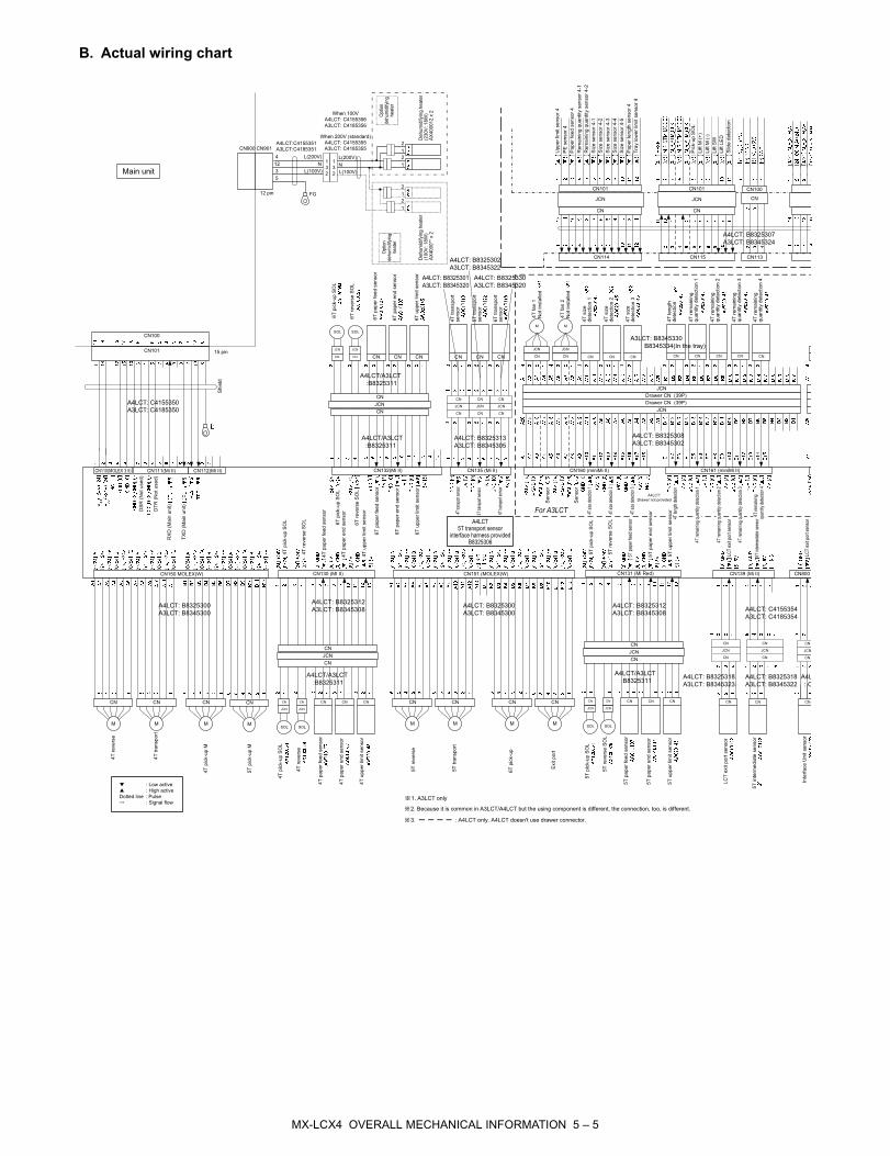
B. Actual wiring chart
CN
M
CN
M
CN
M
JCN
CN
SOL SOL
CN CN CN
JCN
CN
SOL SOL
CN CN CN
CN
M
JCN
CN
SOL
JCN
CN
SOL
CN CN CN
CN110(MOLEX 3.5) CN111(Mi II) CN112(Mi II)
CN115CN114
CN150 MOLEX(W) CN130 (MI II)
CN132(Mi II)
CN101
CN131 (Mi Red)
CN135 (Mi II)
CN
CN
JCN
CN
CN
JCN
CN
CN
JCN
CN113
CN
M
CN
M
CN151 (MOLEX(W)
CN
M
CN
M
CN139 (Mi II)
CN CN
CN CN CN CN CN CN CN
CN160 (miniMi II)
JCN
CN
M
JCN
CN
M
CN161 (miniMi II)
CN
Drawer CN (39P)
Drawer CN (39P)
JCN
JCN
CN CN
JCNJCN
CN CN CN
JCN JCN JCN
CN CN
CN CN CN
1. A3LCT only
2. Because it is common in A3LCT/A4LCT but the using component is different, the connection, too, is different.
A4LCT:C4155351
A3LCT:C4185351
A4LCT: B8325300
A3LCT: B8345300
A4LCT: B8325312
A3LCT: B8345308
A4LCT: C4155350
A3LCT: C4185350
A4LCT/A3LCT
:B8325311
A4LCT/A3LCT
:B8325311
A4LCT/A3LCT
:B8325311
A4LCT: B8325312
A3LCT: B8345308
A4LCT/A3LCT
:B8325311
A4LCT: B8325300
A3LCT: B8345300
A4LCT: B8325301
A3LCT: B8345320
A4LCT: B8325302
A3LCT: B8345322
A4LCT: B8325330
A3LCT: B8345320
A4LCT: B8325307
A3LCT: B8345324
A4LCT: B8325313
A3LCT: B8345305
A4LCT
5T transport sensor
interface harness provided
B8325306
A4LCT: C4155354
A3LCT: C4185354
A4LCT: B8325318
A3LCT: B8345323
A4LCT: B8325318
A3LCT: B8345322
A4LCT: B8325308
A3LCT: B8345302
A3LCT: B8345330
B8345334(In the tray)
3. : A4LCT only. A4LCT doesn't use drawer connector.
: Low active
: High active
Dotted line : Pulse
: Signal flow
CN900 CN901
FG
N
L(200V)
L(100V)
CN800
CN
N
L(200V)
L(100V)
12
5
3
4
When 200V (standard)
A4LCT: C4155355
A3LCT: C4185355
CN
JCN
CN
When 100V
A4LCT: C4155356
A3LCT: C4185356
A4L
: C
1
3
2
1
3
2
12 pin
15 pinJCN
CN CN CN CN
JCN
CN
Main unit
Option
dehumidifying
heater
Option
dehumidifying
heater
Dehumidifyingheater
(230V:18W)
AX400012x2
Dehumidifyingheater
(100V:18W)
AX4000**x2
PEsensor4
Paperfeedsensor4
Remainingquantitysensor4-1
Remainingquantitysensor4-2
Sizesensor4-1
Sizesensor4-2
Sizesensor4-3
Sizesensor4-4
Sizesensor4-5
Paperlengthsensor4
Traylowerlimitsensor4
Pick-upSOL
LiftM(+)
LiftM(-)
LiftSW
LiftLED
Slidedetection
4Tfan1
Notinstalled
4Tfan2
4Tsize
detection1
4Tsize
detection2
4Tsize
detection3
4Tlength
detection
4Tremaining
quantitydetection1
4Tremaining
quantitydetection2
4Tremaining
quantitydetection3
4Tremaining
quantitydetection4
Notinstalled
For A3LCT
LCTexitportsensor
5Tintermediatesensor
InterfaceUnitsensor
2
1
2
1
2
1
2
1
Upperlimitsensor4
CN101
CN100
CN101
JCN
CN100
CNJCN
CN CN
Shield
6Tpick-upSOL
6Tpaperfeedsensor
6Tpaperendsensor
6Tupperlimitsensor
4Ttransport
sensor
5Ttransport
sensor
6Ttransport
sensor
6TreverseSOL
DSR(Notused)
DTR(Notused)
RXD(Mainunit)
TXD(Mainunit)
4Tpick-upSOL
4TreverseSOL
4Tpaperfeedsensor
4Tpaperendsensor
4Tupperlimitsensor
5Tpick-upSOL
5TreverseSOL
5Tpaperfeedsensor
5Tpaperendsensor
5Tupperlimitsensor
LCTexitportsensor
LCTexitportsensor
5Tintermediatesensor
6Tpick-upSOL
6TreverseSOL
6Tpaperfeedsensor
6Tpaperendsensor
6Tupperlimitsensor
4Ttransportsensor
5Ttransportsensor
6Ttransportsensor
4Tsizedetection1
4Tsizedetection2
4Tsizedetection3
4Tlengthdetection
4Tremainingquantitydetection1
4Tremainingquantitydetection2
4Tremainingquantitydetection3
quantitydetection4
4Tremaining
Sensor
Sensor
A4LCT:
Drawer not provided
4Treverse
4Ttransport
4Tpick-upM
5Tpick-upM
4Tpick-upSOL
6Tpick-up
Exitport
4Treverse
5Treverse
5Ttransport
4Tpaperfeedsensor
4Tpaperendsensor
4Tupperlimitsensor
5Tpick-upSOL
5TreverseSOL
5Tpaperfeedsensor
5Tpaperendsensor
5Tupperlimitsensor
MX-LCX4 OVERALL MECHANICAL INFORMATION 5 – 5
CN116 (Red)
CN133 (Mi II)
JCN
CN
M
JCN
CN
M
JCN
CN
M
CN
141CN142
CN CN CN CN CN CN CN
CN164 (miniMi II)
JCN
CN
M
JCN
CN
M
CN165 (miniMi II)
CN
Drawer CN (39P)
Drawer CN (39P)
JCN
JCN
CN154 MOLEX (W)
CN
M
CN
M
CN CN CN CN CN CN CN
CN162 (miniMi II)
JCN
CN
M
JCN
CN
M
CN163 (miniMi II)
CN
Drawer CN (39P)
Drawer CN (39P)
JCN
JCN
CN730 (Mi Red)CN710 (Mi II)
CN CN CN
CN CN
JCN JCN
CN CN
CN160 (miniMi II)
CN
CN162 (miniMi II)
CN
CN
Not connected
A4LCT
4T intermediate
lower sensor interface
harness provided
B8325305
A4LCT: C4155354
A3LCT: B8345306A4LCT: B8325310
A3LCT: B8345301
A4LCT: B8325310
A3LCT: B8345303
A4LCT: B8325300
A3LCT: B8345300
A4LCT: B8325302
A3LCT: B8345321
A4LCT: -
A3LCT: B8345325
A4LCT: B8325308 A4LCT: B8325309
A4LCT: B8325310A4LCT: B8325309
A3LCT: B8345303
A4LCT: B8325310
A3LCT: B8345304
A4LCT:
Drawer not provided A4LCT:
Drawer not provided
A3LCT: B8345330
B8345334(In the tray)A3LCT: B8345332
B8345334(In the tray)
00 (Mi II)
CN
CN
JCN
CN
A4LCT/A3LCT
: C4155352
Transportsensor
Connectiondetection
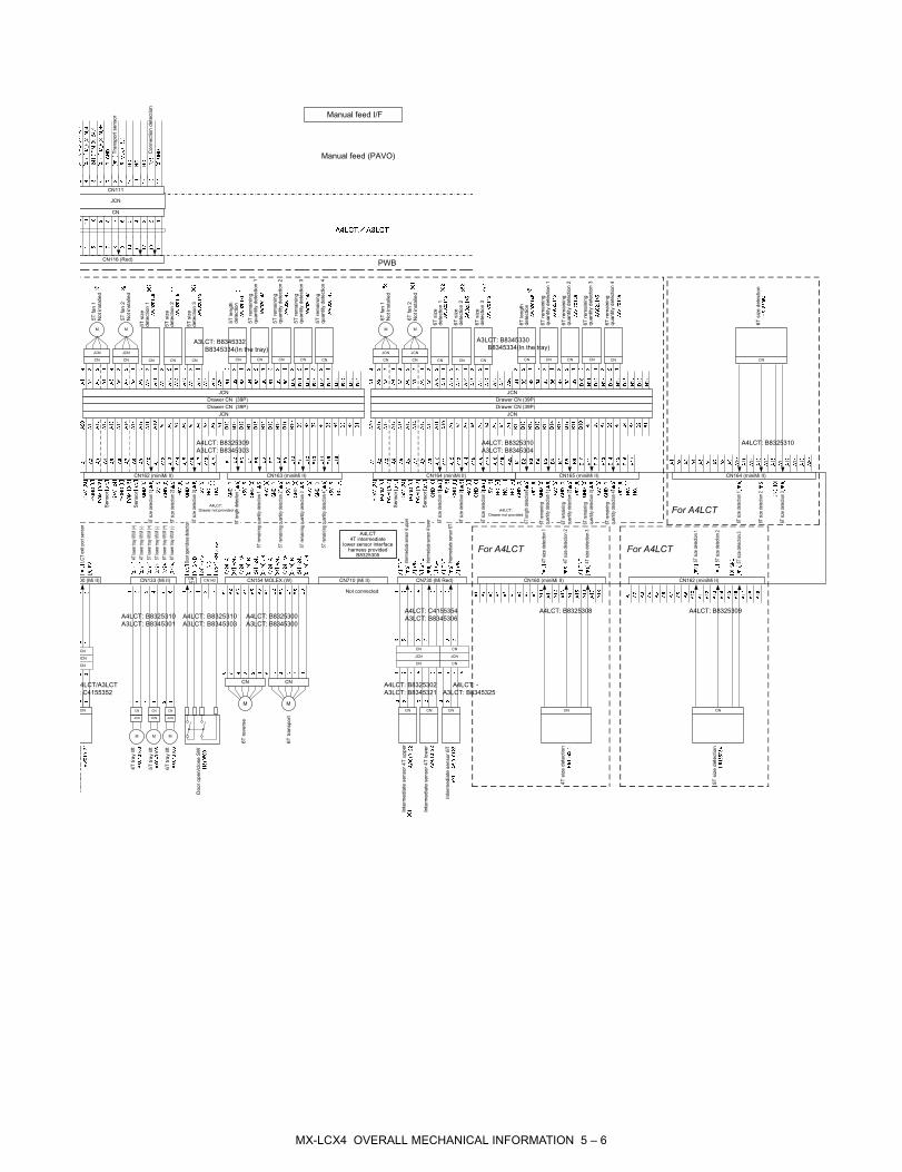
Manual feed I/F
Manual feed (PAVO)
PWB
5Tfan1
Notinstalled
6Tfan1
Notinstalled
6Tfan2
Notinstalled
6Tsize
detection1
6Tsize
detection2
6Tsize
detection3
6Tlength
detection
6Tremaining
quantitydetection1
6Tremaining
quantitydetection2
6Tremaining
quantitydetection3
6Tremaining
quantitydetection4
5Tfan2
5Tsize
detection1
5Tsize
detection2
5Tlength
detection
5Tremaining
quantitydetection1
5Tremaining
quantitydetection2
5Tremaining
quantitydetection3
5Tremaining
quantitydetection4
5Tsize
detection3
Notinstalled
InterfaceUnitsensor
4Ttraylift
Dooropen/closeSW
6Treverse
6Ttransport
6Ttraylift
5Ttraylift
Intermediatesensor4Tupper
Intermediatesensor4Tlower
Intermediatesensor6T
4Tsizedetection
5Tsizedetection
CN111
JCN
CN
LCTexitportsensor
4TlowertrayliftM(+)
4TlowertrayliftM(-)
5TlowertrayliftM(+)
5TlowertrayliftM(-)
6TlowertrayliftM(+)
6TlowertrayliftM(-)
Dooropen/closedetection
Intermediatesensor4upper
Intermediatesensor4lower
Intermediatesensor6T
Sensor
Sensor
Sensor
Sensor
5Tsizedetection1
5Tsizedetection2
5Tsizedetection3
6Tsizedetection1
6Tsizedetection2
6Tsizedetection3
6Tsizedetection1
5Tsizedetection1
5Tsizedetection2
5Tsizedetection3
4Tsizedetection1
4Tsizedetection2
4Tsizedetection3
6Tsizedetection2
6Tsizedetection3
6Tlengthdetection
6Tremaining
quantitydetection1
6Tremaining
quantitydetection2
6Tremaining
quantitydetection3
6Tremaining
quantitydetection4
5Tlengthdetection
5Tremainingquantitydetection1
5Tremainingquantitydetection2
5Tremainingquantitydetection3
5Tremainingquantitydetection4
For A4LCT
For A4LCT For A4LCT
6Tsizedetection
CN164 (miniMi II)
MX-LCX4 OVERALL MECHANICAL INFORMATION 5 – 6

Memo

Memo
No part of this publication may be reproduced,stored in a retrieval system, or transmitted inany form or by any means, electronic, mechanical,photocopying, recording, or otherwise, withoutprior written permission of the publisher.
COPYRIGHT © XXXX BYSHARP CORPORATION
ALL RIGHTS RESERVED.
The PWB’s of this model employs lead-free solder. The “LF” marks indicated on the PWB’s and the Service Manual mean “Lead-Free” solder.
LEAD-FREE SOLDER
The alphabet following the LF mark shows the kind of lead-free solder.
(1) NOTE FOR THE USE OF LEAD-FREE SOLDER THREAD
When repairing a lead-free solder PWB, use lead-free solder thread.
Never use conventional lead solder thread, which may cause a breakdown or an accident.
Since the melting point of lead-free solder thread is about 40°C higher than that of conventional lead solder thread, the use of the
exclusive-use soldering iron is recommended.
(2) NOTE FOR SOLDERING WORK
Since the melting point of lead-free solder is about 220°C, which is about 40°C higher than that of conventional lead solder, and its soldering
capacity is inferior to conventional one, it is apt to keep the soldering iron in contact with the PWB for longer time. This may cause land
separation or may exceed the heat-resistive temperature of components. Use enough care to separate the soldering iron from the PWB when
completion of soldering is confirmed.
Since lead-free solder includes a greater quantity of tin, the iron tip may corrode easily. Turn ON/OFF the soldering iron power frequently.
If different-kind solder remains on the soldering iron tip, it is melted together with lead-free solder. To avoid this, clean the soldering iron
tip after completion of soldering work.
If the soldering iron tip is discolored black during soldering work, clean and file the tip with steel wool or a fine filer.
Example:
5mm
Lead-Free
Solder composition
code (Refer to the
table at the right.)
<Solder composition code of lead-free solder>
Solder composition
Sn-Ag-Cu
Sn-Ag-Bi
Sn-Ag-Bi-Cu
Sn-Zn-Bi
Sn-In-Ag-Bi
Sn-Cu-Ni
Sn-Ag-Sb
Bi-Sn-Ag-P
Bi-Sn-Ag
a
b
z
i
n
s
p
Solder composition code
a
(Danish) ADVARSEL !
Lithiumbatteri – Eksplosionsfare ved fejlagtig håndtering.
Udskiftning må kun ske med batteri
af samme fabrikat og type.
Levér det brugte batteri tilbage til leverandoren.
(English) Caution !
Danger of explosion if battery is incorrectly replaced.
Replace only with the same or equivalent type
recommended by the manufacturer.
Dispose of used batteries according to manufacturer’s instructions.
(Finnish) VAROITUS
Paristo voi räjähtää, jos se on virheellisesti asennettu.
Vaihda paristo ainoastaan laitevalmistajan suosittelemaan
tyyppiin. Hävitä käytetty paristo valmistajan ohjeiden
mukaisesti.
(French) ATTENTION
Il y a danger d’explosion s’ il y a remplacement incorrect
de la batterie. Remplacer uniquement avec une batterie du
même type ou d’un type équivalent recommandé par
le constructeur.
Mettre au rebut les batteries usagées conformément aux
instructions du fabricant.
(Swedish) VARNING
Explosionsfara vid felaktigt batteribyte.
Använd samma batterityp eller en ekvivalent
typ som rekommenderas av apparattillverkaren.
Kassera använt batteri enligt fabrikantens
instruktion.
(German) Achtung
Explosionsgefahr bei Verwendung inkorrekter Batterien.
Als Ersatzbatterien dürfen nur Batterien vom gleichen Typ oder
vom Hersteller empfohlene Batterien verwendet werden.
Entsorgung der gebrauchten Batterien nur nach den vom
Hersteller angegebenen Anweisungen.
(For USA, CANADA)
“BATTERY DISPOSAL”
THIS PRODUCT CONTAINS A LITHIUM PRIMARY
(MANGANESS DIOXIDE) MEMORY BACK-UP BATTERY
THAT MUST BE DISPOSED OF PROPERLY. REMOVE THE
BATTERY FROM THE PRODUCT AND CONTACT YOUR
LOCAL ENVIRONMENTAL AGENCIES FOR INFORMATION
ON RECYCLING AND DISPOSAL OPTIONS.
“TRAITEMENT DES PILES USAGÉES”
CE PRODUIT CONTIENT UNE PILE DE SAUVEGARDE DE
MÉMOIRE LITHIUM PRIMAIRE (DIOXYDE DE MANGANÈSE)
QUI DOIT ÊTRE TRAITÉE CORRECTEMENT. ENLEVEZ LA
PILE DU PRODUIT ET PRENEZ CONTACT AVEC VOTRE
AGENCE ENVIRONNEMENTALE LOCALE POUR DES
INFORMATIONS SUR LES MÉTHODES DE RECYCLAGE ET
DE TRAITEMENT.
CAUTION FOR BATTERY REPLACEMENT
CAUTION FOR BATTERY DISPOSAL

All rights reserved.Printed in Japan.
No part of this publication may be reproduced,stored in a retrieval system, or transmitted,
in any form or by any means,electronic; mechanical; photocopying; recording or otherwise
without prior written permission of the publisher.
Trademark acknowledgements• Microsoft®, Windows®, Windows® 98, Windows® Me, Windows NT® 4.0,
Windows® 2000, Windows® XP, Windows® Vista, Windows® Server 2003 andInternet Explorer® are registered trademarks or trademarks ofMicrosoft Corporation in the U.S.A. and other countries.
• PostScript is a registered trademark of Adobe Systems Incorporated.
• Macintosh, Mac OS, AppleTalk, EtherTalk, LaserWriter, and Safari are registeredtrademarks or trademarks of Apple Computer, Inc.
• IBM, PC/AT, and PowerPC are trademarks of International Business MachinesCorporation.
• Acrobat® Reader Copyright® 1987- 2002 Adobe Systems Incorporated. All rightsreserved. Adobe, the Adobe logo, Acrobat, and the Acrobat logo are trademarks ofAdobe Systems Incorporated.
• PCL is a registered trademark of the Hewlett-Packard Company.
• All other trademarks and copyrights are the property of their respective owners.
COPYRIGHT © 2007 BY SHARP CORPORATION
• Sharpdesk is a trademark of Sharp Corporation.
SHARP CORPORATIONDigital Document System GroupCS Promotion CenterYamatokoriyama, Nara 639-1186, Japan
2007 May Printed in Japan


![1st Edition SERVICE MANUAL - Diagramas dediagramas.diagramasde.com/televisores/29LFG1L.pdf · IMPORTANT SERVICE NOTES [1] ... SOLID STATE DEVICE BASE DIAGRAM [1] ... sure it's go](https://img.pdfslide.net/doc/110x75/5aa771047f8b9aee748c102f/1st-edition-service-manual-diagramas-service-notes-1-solid-state-device.jpg)