Embed Size (px)
Citation preview
© 2004 HellersteinFeedback Control of Computing Systems
Feedback Control of Computing SystemsM6: Control Design
Joseph L. HellersteinIBM Thomas J Watson Research Center, [email protected]
September 23, 2004
2 © 2004 HellersteinFeedback Control of Computing Systems: M6 – Control Design
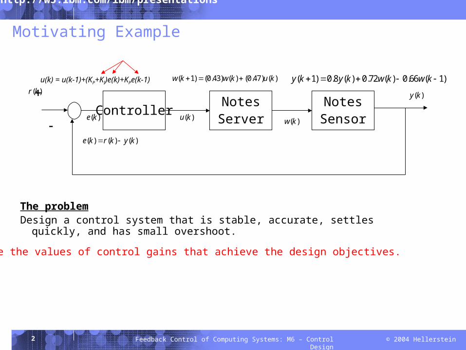
Motivating Example
( )r k ( )y k
( )e kController
NotesServer
NotesSensor
( )u k
( 1) (0.43) ( ) (0.47) ( )w k w k u k ( 1) 0.8 ( ) 0.72 ( ) 0.66 ( 1)y k y k w k w k
( )w k
( ) ( ) ( )e k r k y k
The problemDesign a control system that is stable, accurate, settles quickly, and has small
overshoot.
u(k) = u(k-1)+(KP+KI)e(k)+KPe(k-1)
Determine the values of control gains that achieve the design objectives.
3 © 2004 HellersteinFeedback Control of Computing Systems: M6 – Control Design
M6:Lecture
4 © 2004 HellersteinFeedback Control of Computing Systems: M6 – Control Design
Outline
Control design methodology Simple application In-class lab: Designing a load balancing system
Reference: “Feedback Control of Computer Systems”, Chapters 8,9.
5 © 2004 HellersteinFeedback Control of Computing Systems: M6 – Control Design
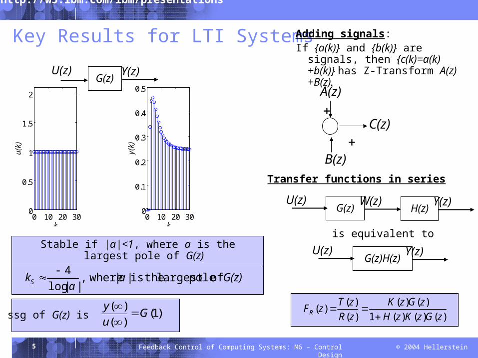
Key Results for LTI Systems
G(z)aa
kS of polelargest theis || where,||log
4
)1()()( G
uy
ssg of G(z) is
Stable if |a|<1, where a is the largest pole of G(z)
0 10 20 300
0.5
1
1.5
2
k
u(k
)
0 10 20 300
0.1
0.2
0.3
0.4
0.5
k
y(k
)
G(z) Y(z)U(z)
A(z)
C(z)
B(z)
Adding signals:If {a(k)} and {b(k)} are signals, then
{c(k)=a(k)+b(k)} has Z-Transform A(z)+B(z).
G(z) W(z)U(z)H(z) Y(z)
G(z)H(z)Y(z)U(z)is equivalent to
Transfer functions in series
)()()(1)()(
)()()(
zGzKzHzGzK
zRzTzFR
6 © 2004 HellersteinFeedback Control of Computing Systems: M6 – Control Design
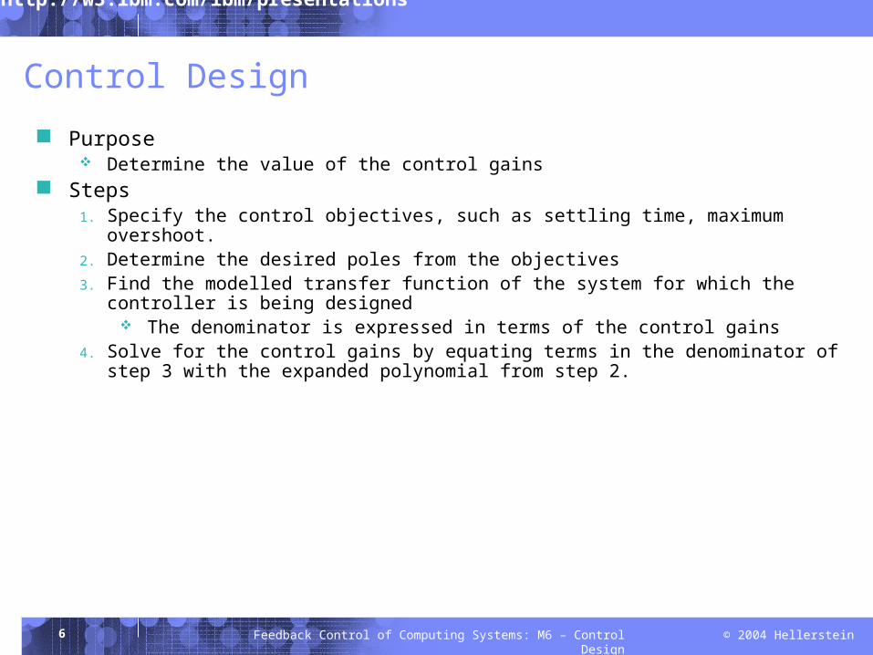
Control Design
Purpose Determine the value of the control gains
Steps1. Specify the control objectives, such as settling time, maximum overshoot.2. Determine the desired poles from the objectives3. Find the modelled transfer function of the system for which the controller is being
designed The denominator is expressed in terms of the control gains
4. Solve for the control gains by equating terms in the denominator of step 3 with the expanded polynomial from step 2.
7 © 2004 HellersteinFeedback Control of Computing Systems: M6 – Control Design
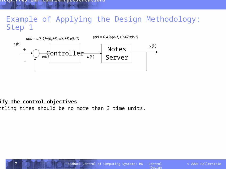
Example of Applying the Design Methodology: Step 1
Specify the control objectivesSettling times should be no more than 3 time units.
( )r k ( )y k
( )e kController
NotesServer
( )u k
u(k) = u(k-1)+(KP+KI)e(k)+KPe(k-1) y(k) = 0.43y(k-1)+0.47u(k-1)
8 © 2004 HellersteinFeedback Control of Computing Systems: M6 – Control Design
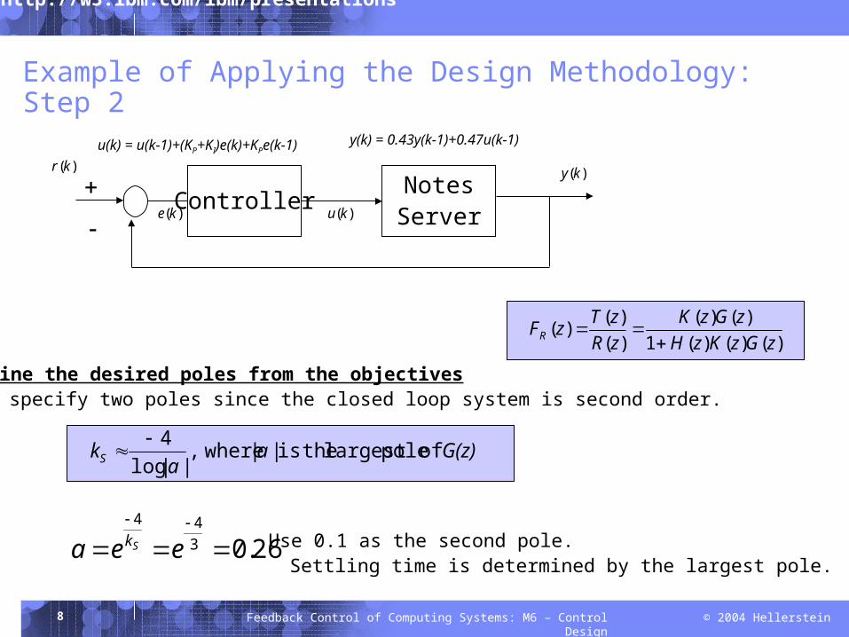
Example of Applying the Design Methodology: Step 2
Determine the desired poles from the objectivesMust specify two poles since the closed loop system is second order.
26.0344
eea Sk Use 0.1 as the second pole. Settling time is determined by the largest pole.
( )r k ( )y k
( )e kController
NotesServer
( )u k
u(k) = u(k-1)+(KP+KI)e(k)+KPe(k-1) y(k) = 0.43y(k-1)+0.47u(k-1)
)()()(1)()(
)()()(
zGzKzHzGzK
zRzTzFR
G(z)aa
kS of polelargest theis || where,||log
4
9 © 2004 HellersteinFeedback Control of Computing Systems: M6 – Control Design
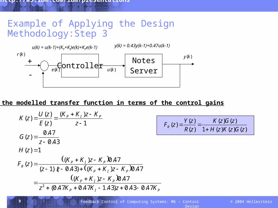
Example of Applying the Design Methodology:Step 3
Find the modelled transfer function in terms of the control gains
( )r k ( )y k
( )e kController
NotesServer
( )u k
u(k) = u(k-1)+(KP+KI)e(k)+KPe(k-1) y(k) = 0.43y(k-1)+0.47u(k-1)
)()()(1)()(
)()()(
zGzKzHzGzK
zRzYzFR
PIP
PIP
PIP
PIPR
PIP
KzKKzKzKK
KzKKzzKzKKzF
zHz
zG
zKzKK
zEzUzK
47.043.0)43.147.047.0(47.0)(
47.0)()43.0)(1(47.0)()(
1)(43.0
47.0)(
1)(
)()()(
2
10 © 2004 HellersteinFeedback Control of Computing Systems: M6 – Control Design
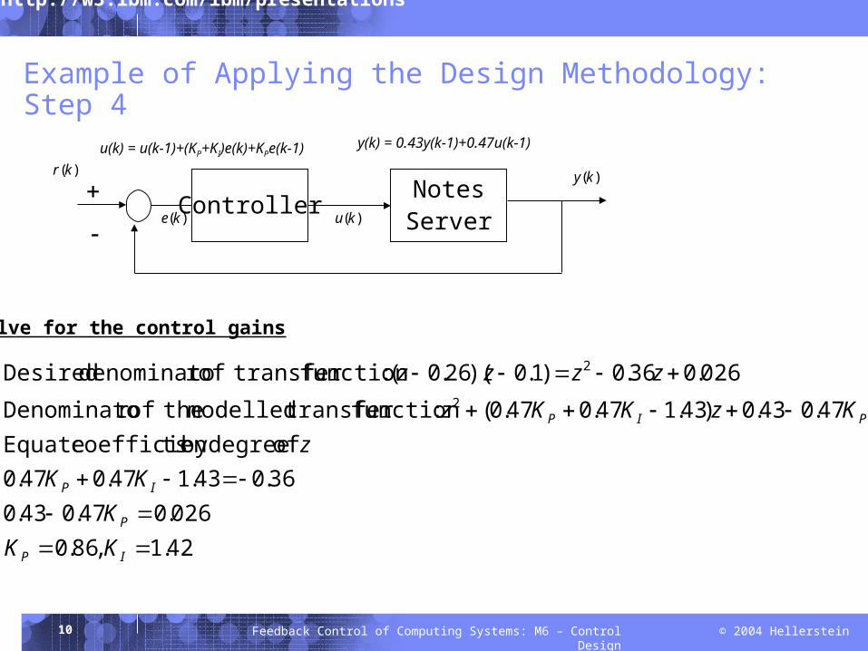
Example of Applying the Design Methodology: Step 4
Solve for the control gains
( )r k ( )y k
( )e kController
NotesServer
( )u k
u(k) = u(k-1)+(KP+KI)e(k)+KPe(k-1) y(k) = 0.43y(k-1)+0.47u(k-1)
42.1,86.0026.047.043.0
36.043.147.047.0 of degreeby tscoefficien Equate
47.043.0)43.147.047.0( :function transfer modelled theofr Denominato
026.036.0)1.0)(26.0( :function transfer ofr denominato Desired2
2
IP
P
IP
PIP
KKKKK
zKzKKz
zzzz
11 © 2004 HellersteinFeedback Control of Computing Systems: M6 – Control Design
M6:Group Lab
12 © 2004 HellersteinFeedback Control of Computing Systems: M6 – Control Design
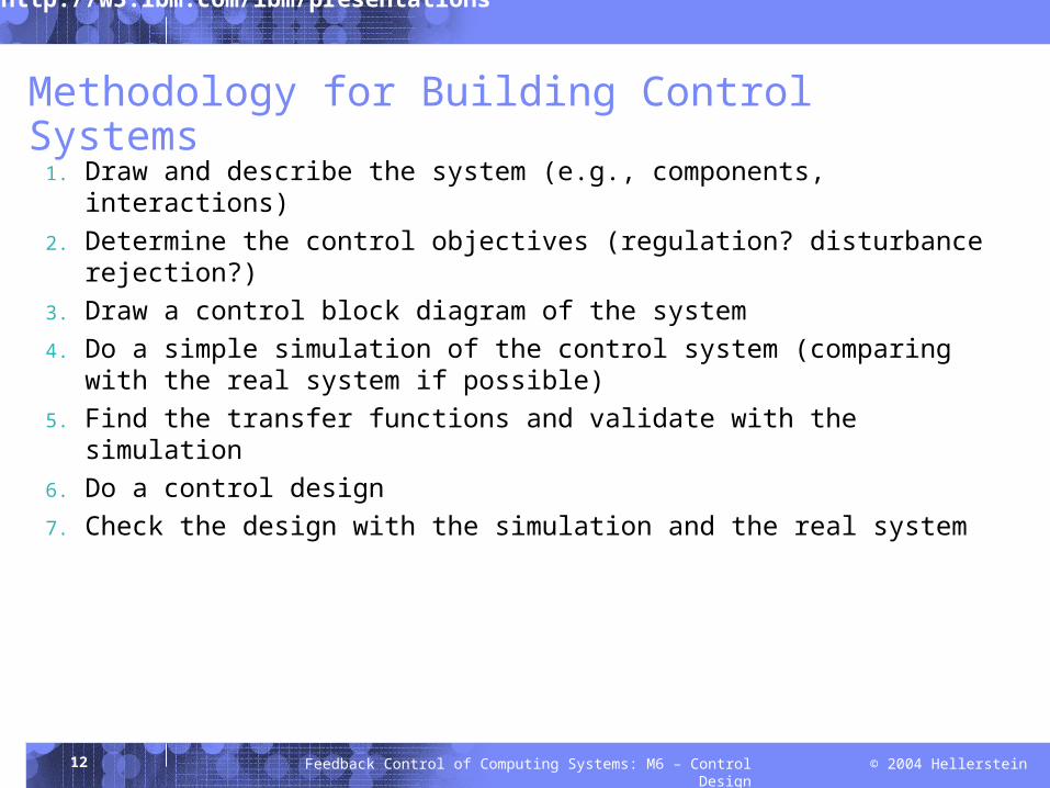
Methodology for Building Control Systems
1. Draw and describe the system (e.g., components, interactions)2. Determine the control objectives (regulation? disturbance rejection?)3. Draw a control block diagram of the system4. Do a simple simulation of the control system (comparing with the real system if
possible)5. Find the transfer functions and validate with the simulation6. Do a control design7. Check the design with the simulation and the real system
13 © 2004 HellersteinFeedback Control of Computing Systems: M6 – Control Design
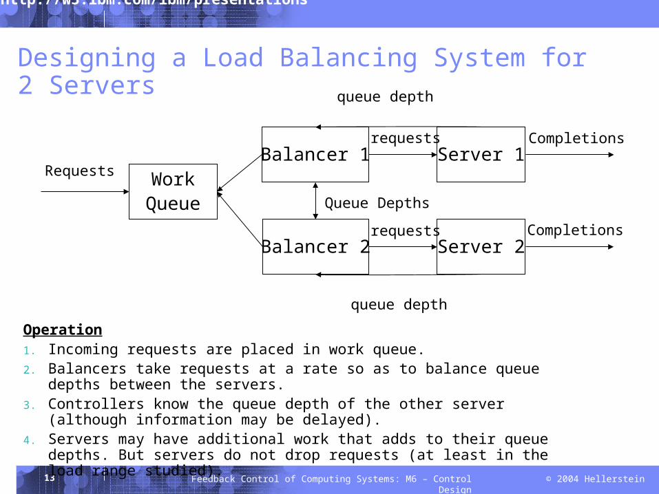
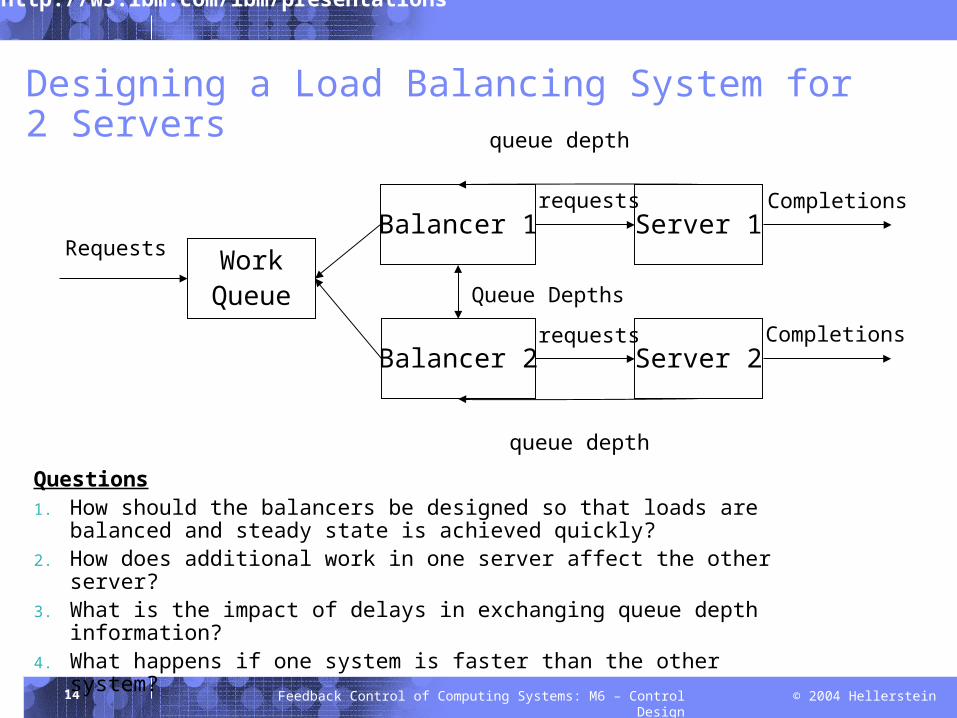
Designing a Load Balancing System for 2 Servers
WorkQueue
Balancer 1
Balancer 2
Requests
Queue Depths
Server 2
Server 1Completions
Completionsrequests
requests
queue depth
queue depth
Operation1. Incoming requests are placed in work queue.2. Balancers take requests at a rate so as to balance queue depths between the
servers.3. Controllers know the queue depth of the other server (although information
may be delayed).4. Servers may have additional work that adds to their queue depths. But
servers do not drop requests (at least in the load range studied).
14 © 2004 HellersteinFeedback Control of Computing Systems: M6 – Control Design
Designing a Load Balancing System for 2 Servers
WorkQueue
Balancer 1
Balancer 2
Requests
Queue Depths
Server 2
Server 1Completions
Completionsrequests
requests
queue depth
queue depth
Questions1. How should the balancers be designed so that loads are balanced and steady
state is achieved quickly?2. How does additional work in one server affect the other server?3. What is the impact of delays in exchanging queue depth information?4. What happens if one system is faster than the other system?
15 © 2004 HellersteinFeedback Control of Computing Systems: M6 – Control Design
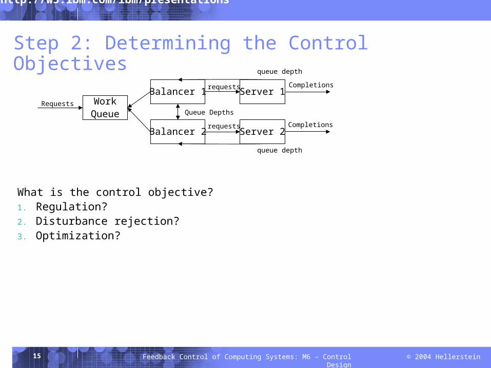
Step 2: Determining the Control Objectives
What is the control objective?1. Regulation?2. Disturbance rejection?3. Optimization?
WorkQueue
Balancer 1
Balancer 2
RequestsQueue Depths
Server 2
Server 1Completions
Completionsrequests
requests
queue depth
queue depth
16 © 2004 HellersteinFeedback Control of Computing Systems: M6 – Control Design
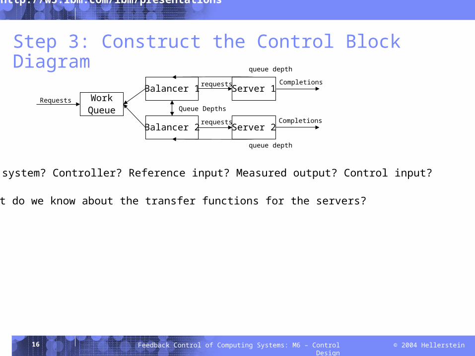
Step 3: Construct the Control Block Diagram
Target system? Controller? Reference input? Measured output? Control input?
WorkQueue
Balancer 1
Balancer 2
RequestsQueue Depths
Server 2
Server 1Completions
Completionsrequests
requests
queue depth
queue depth
What do we know about the transfer functions for the servers?
17 © 2004 HellersteinFeedback Control of Computing Systems: M6 – Control Design
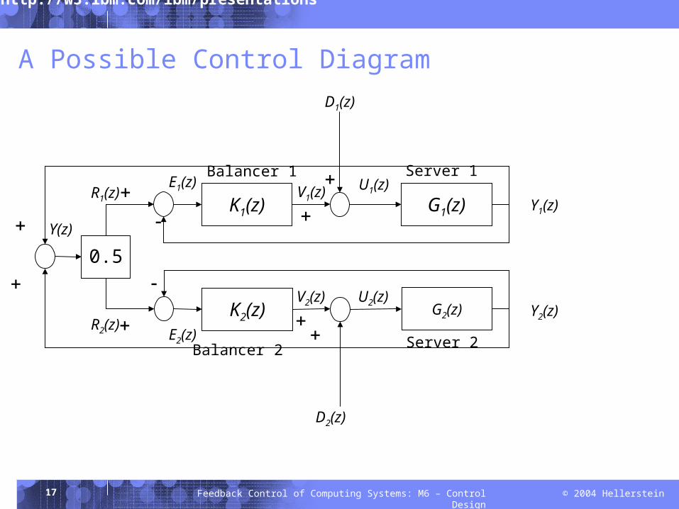
A Possible Control Diagram
K1(z) G1(z)
0.5
K2(z) G2(z)
D2(z)
D1(z)
Server 1
Server 2Balancer 2
Y1(z)
Y2(z)
Balancer 1
E2(z)
E1(z)R1(z)
R2(z)
Y(z)
V2(z) U2(z)
U1(z)V1(z)
18 © 2004 HellersteinFeedback Control of Computing Systems: M6 – Control Design
Step 4: Construct a Simple Simulation
See ShortClass-M6 Assume first order system for servers Consider P and I control
19 © 2004 HellersteinFeedback Control of Computing Systems: M6 – Control Design
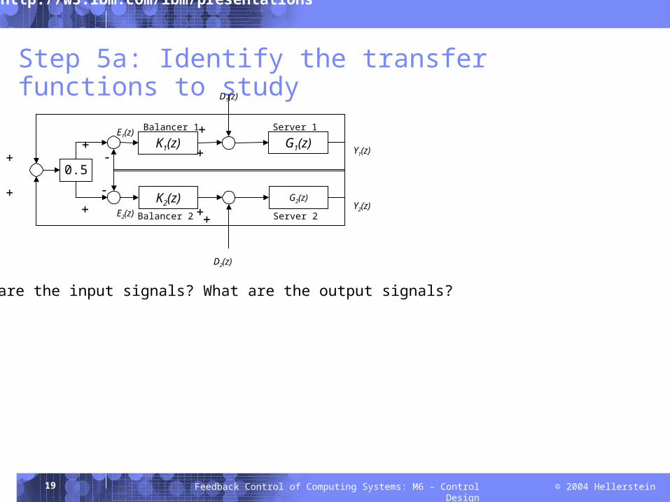
Step 5a: Identify the transfer functions to study
K1(z) G1(z)
0.5
K2(z) G2(z)
D2(z)
D1(z)
Server 1
Server 2Balancer 2
Y1(z)
Y2(z)
Balancer 1
E2(z)
E1(z)
What are the input signals? What are the output signals?
20 © 2004 HellersteinFeedback Control of Computing Systems: M6 – Control Design
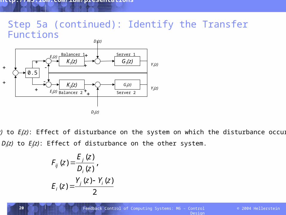
Step 5a (continued): Identify the Transfer Functions
K1(z) G1(z)
0.5
K2(z) G2(z)
D2(z)
D1(z)
Server 1
Server 2Balancer 2
Y1(z)
Y2(z)
Balancer 1
E2(z)
E1(z)
From Di(z) to Ei(z): Effect of disturbance on the system on which the disturbance occurred
From Di(z) to Ej(z): Effect of disturbance on the other system.
2)()(
)(
,)()(
)(
zYzYzE
zDzE
zF
iji
i
jij
21 © 2004 HellersteinFeedback Control of Computing Systems: M6 – Control Design
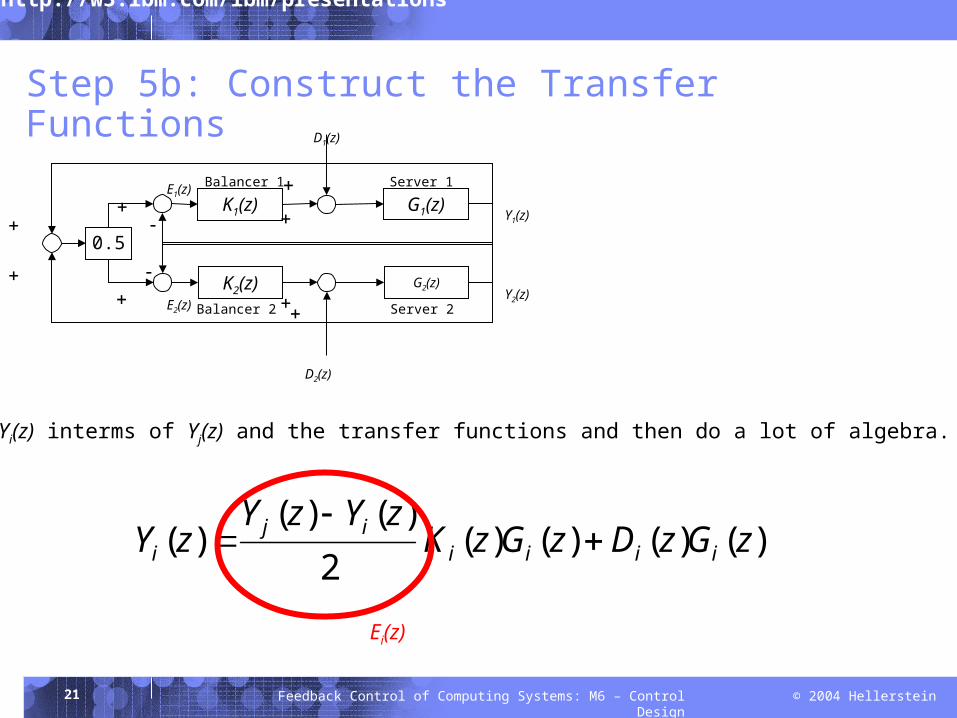
Step 5b: Construct the Transfer Functions
K1(z) G1(z)
0.5
K2(z) G2(z)
D2(z)
D1(z)
Server 1
Server 2Balancer 2
Y1(z)
Y2(z)
Balancer 1
E2(z)
E1(z)
Express Yi(z) interms of Yj(z) and the transfer functions and then do a lot of algebra.
)()()()(2
)()()( zGzDzGzK
zYzYzY iiii
iji
Ei(z)
22 © 2004 HellersteinFeedback Control of Computing Systems: M6 – Control Design
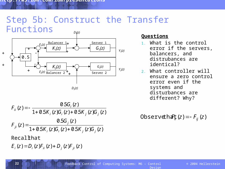
Step 5b: Construct the Transfer Functions
)()()()()( thatRecall
)()(5.0)()(5.01)(5.0
)(
)()(5.0)()(5.01)(5.0)(
zFzDzFzDzE
zGzKzGzKzG
zF
zGzKzGzKzGzF
jijiiii
jjii
jji
jjii
iii
K1(z) G1(z)
0.5
K2(z) G2(z)
D2(z)
D1(z)
Server 1
Server 2Balancer 2
Y1(z)
Y2(z)
Balancer 1
E2(z)
E1(z)
Questions1. What is the control error if
the servers, balancers, and distrubances are identical?
2. What controller will ensure a zero control error even if the systems and disturbances are different? Why?
)()( that Observe zFzF ijii
23 © 2004 HellersteinFeedback Control of Computing Systems: M6 – Control Design
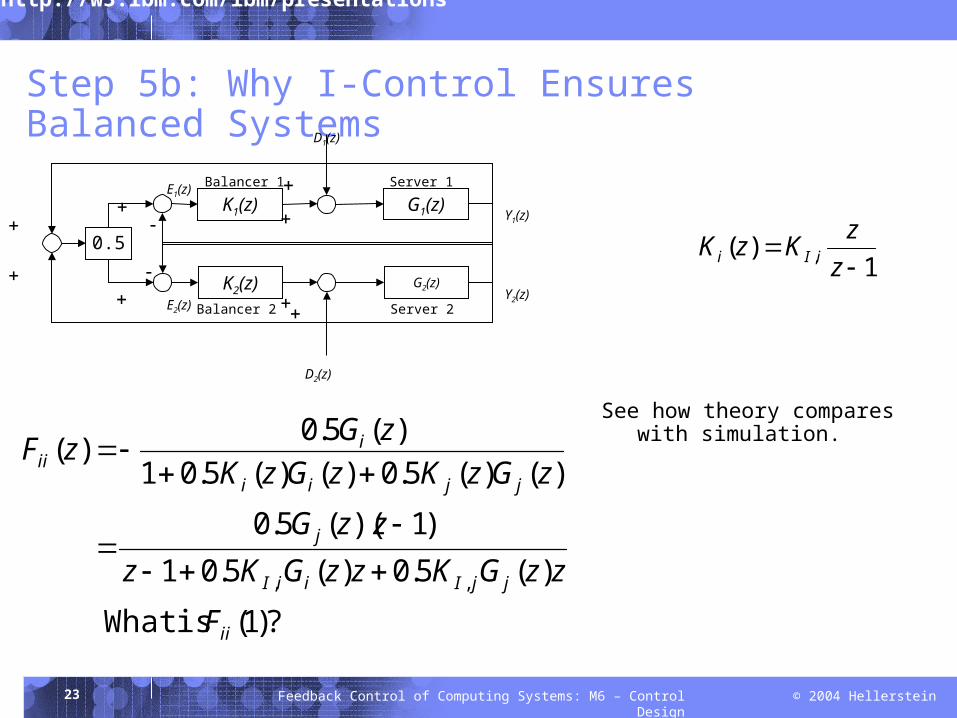
Step 5b: Why I-Control Ensures Balanced Systems
?)1( isWhat
)(5.0)(5.01)1)((5.0
)()(5.0)()(5.01)(5.0)(
,,
ii
jjIiiI
j
jjii
iii
F
zzGKzzGKzzzG
zGzKzGzKzGzF
K1(z) G1(z)
0.5
K2(z) G2(z)
D2(z)
D1(z)
Server 1
Server 2Balancer 2
Y1(z)
Y2(z)
Balancer 1
E2(z)
E1(z)
See how theory compares with simulation.
1)( ,
zzKzK iIi
24 © 2004 HellersteinFeedback Control of Computing Systems: M6 – Control Design
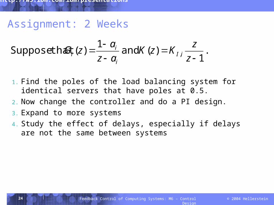
Assignment: 2 Weeks
1. Find the poles of the load balancing system for identical servers that have poles at 0.5.
2. Now change the controller and do a PI design.3. Expand to more systems4. Study the effect of delays, especially if delays are not the same
between systems
.1
)( and 1)( that Suppose ,
zzKzK
azazG iIi
ii
25 © 2004 HellersteinFeedback Control of Computing Systems: M6 – Control Design
Summary
Approach to control design Limited to systems that are second order in closed loop (More general approaches typically recall MIMO models.)
Load balancing case study Optimization instead of regulation
But still uses linear time invariant models Systematic methodology makes use of simulation, analysis, and (hopefully) real
systems