Embed Size (px)
Citation preview
1SIMPACK User Meeting, TOWER-MKS, November 2004
IST GmbH, Aachen
TOWER-MBSHydrodynamic bearings and sliders
in commercial MKS programs
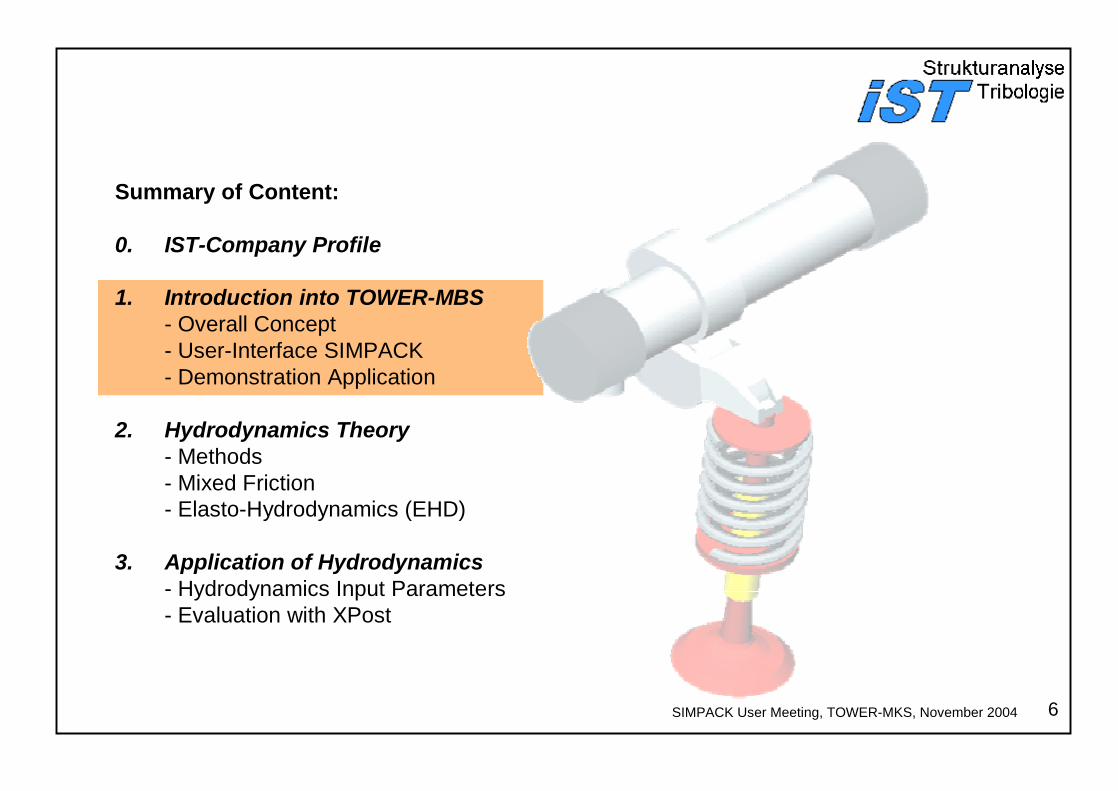
Summary of Content:
0. IST-Company Profile
1. Introduction into TOWER-MKS- Overall Concept- User-Interface SIMPACK- Demonstration Application
2. Hydrodynamics Theory - Methods- Mixed Friction- Elasto-Hydrodynamics (EHD)
3. Application of Hydrodynamics- Hydrodynamics Input Parameters- Evaluation with XPost
positioning
slider
2
SIMPACK User Meeting, TOWER-MKS, November 2004
Program System Overview
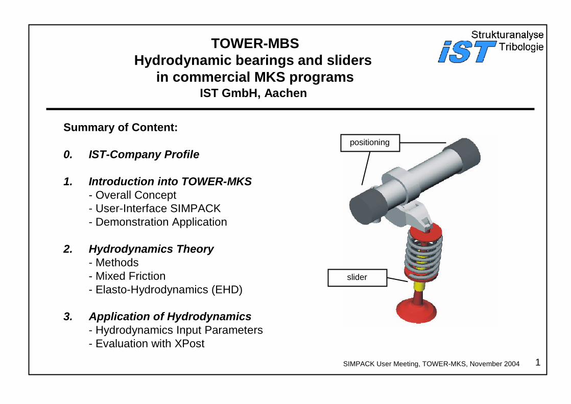
IST Ingenieurgesellschaft für Strukturanalyse und Tribologie mbH
.
TOWER
COMO3D
FIRST
MKS -HYDRO
Program Systems FIRST, PIMO3D, COMO3D und TOWERStructure DynamicsTribologie
Load
Deformations, velocities, accelerationsHydrodynamic lubricant film pressure, solid body contact, friction losses, Gap course, shifting course, bearing deformationBearing loads, stress of components•
••
PIMO3DThe ‘IST GmbH’ was found in 1997 as spin-off of the ‘RWTH Aachen’and of the ‘Universität Kassel’ headed by Prof. Knoll. The IST is an engineering association with core competences in the development of computer-assisted simulation software as well as its application on structure dynamics/elastohydrodynamics coupled engine components. Areas of application are dimensioning, weak point analysis and system optimisation of tribological, structure dynamical and acoustical problems. An extensive cooperation exists at present with enginemanufactures and their suppliers. Furthermore, the IST is responsible for the maintenance of software that was developed as part of the FVV research projects of the ‘Institut für Maschinenelemente und Konstruktionstechnik’ of the University of Kassel.
3
SIMPACK User Meeting, TOWER-MKS, November 2004
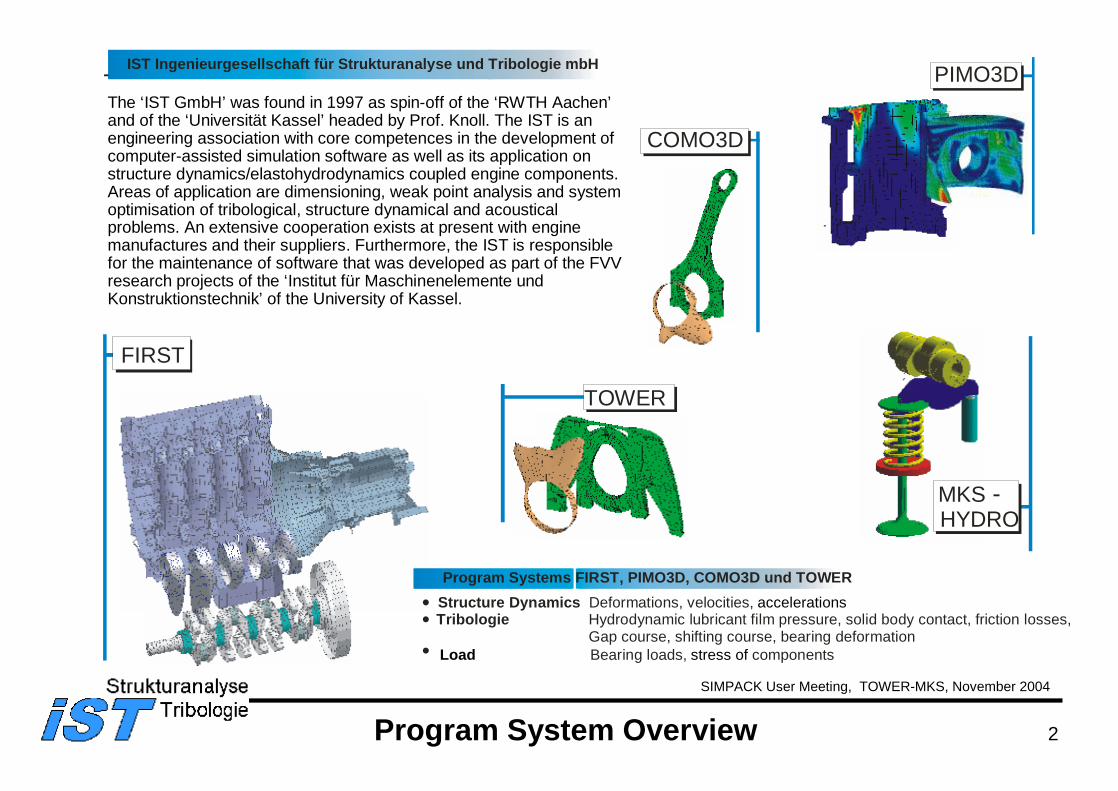
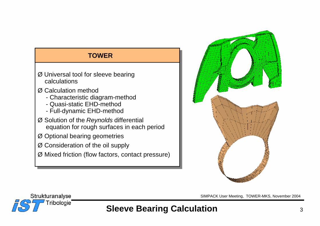
Ø Universal tool for sleeve bearingcalculations
Ø Calculation method- Characteristic diagram-method- Quasi-static EHD-method- Full-dynamic EHD-method
Ø Solution of the Reynolds differential equation for rough surfaces in each period
Ø Optional bearing geometriesØ Consideration of the oil supplyØ Mixed friction (flow factors, contact pressure)
Sleeve Bearing Calculation
TOWER
4
SIMPACK User Meeting, TOWER-MKS, November 2004
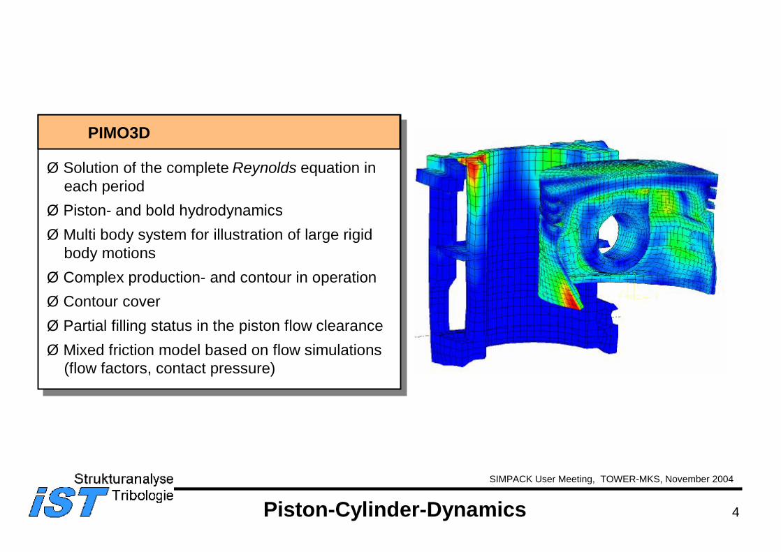
Ø Solution of the complete Reynolds equation in each period
Ø Piston- and bold hydrodynamicsØ Multi body system for illustration of large rigid
body motionsØ Complex production- and contour in operationØ Contour coverØ Partial filling status in the piston flow clearance Ø Mixed friction model based on flow simulations
(flow factors, contact pressure)
PIMO3D
Piston-Cylinder-Dynamics
5
SIMPACK User Meeting, TOWER-MKS, November 2004
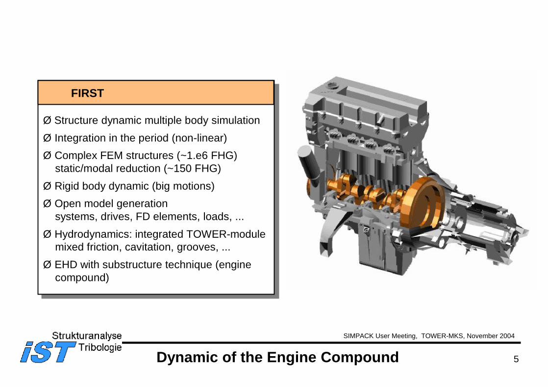
Ø Structure dynamic multiple body simulationØ Integration in the period (non-linear)Ø Complex FEM structures (~1.e6 FHG)
static/modal reduction (~150 FHG)Ø Rigid body dynamic (big motions)Ø Open model generation
systems, drives, FD elements, loads, ...Ø Hydrodynamics: integrated TOWER-module
mixed friction, cavitation, grooves, ...Ø EHD with substructure technique (engine
compound)
FIRST
Dynamic of the Engine Compound
6SIMPACK User Meeting, TOWER-MKS, November 2004
Summary of Content:
0. IST-Company Profile
1. Introduction into TOWER-MBS- Overall Concept- User-Interface SIMPACK- Demonstration Application
2. Hydrodynamics Theory - Methods- Mixed Friction- Elasto-Hydrodynamics (EHD)
3. Application of Hydrodynamics- Hydrodynamics Input Parameters- Evaluation with XPost
7
SIMPACK User Meeting, TOWER-MKS, November 2004
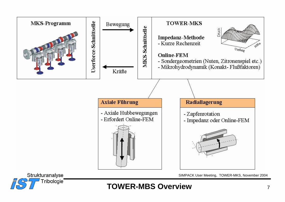
TOWER-MBS Overview
8
SIMPACK User Meeting, TOWER-MKS, November 2004
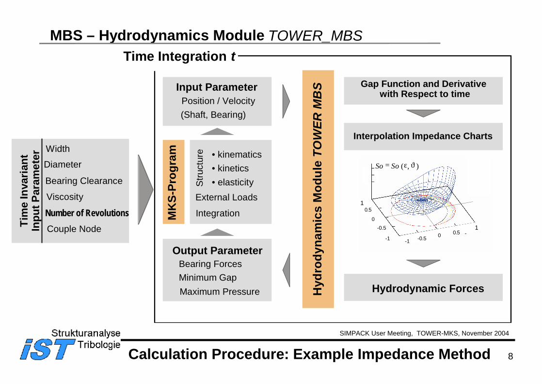
MBS – Hydrodynamics Module TOWER_MBSTime Integration t
Input ParameterPosition / Velocity(Shaft, Bearing)
Output ParameterBearing ForcesMinimum GapMaximum Pressure
10.5
0-0.5
-1 -1 -0.5 0 0.51
Interpolation Impedance Charts
Hydrodynamic Forces
Gap Function and Derivative with Respect to time
So So= ( , )ε ϑ
Calculation Procedure: Example Impedance Method
Hyd
rody
nam
ics
Mod
ule
TOW
ER M
BS
• kinematics• kinetics• elasticity
External Loads
IntegrationS
truct
ure
MK
S-Pr
ogra
mWidth
Diameter
Bearing Clearance
Viscosity
Number of RevolutionsCouple NodeTi
me
Inva
riant
Inpu
t Par
amet
er
9
SIMPACK User Meeting, TOWER-MKS, November 2004
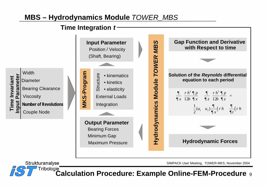
MBS – Hydrodynamics Module TOWER_MBSTime Integration t
Input ParameterPosition / Velocity(Shaft, Bearing)
Output ParameterBearing ForcesMinimum GapMaximum Pressure
Calculation Procedure: Example Online-FEM-Procedure
Hyd
rody
nam
ics
Mod
ule
TOW
ER M
BS
• kinematics• kinetics• elasticity
External Loads
IntegrationS
truct
ure
MK
S-Pr
ogra
mWidth
Diameter
Bearing Clearance
Viscosity
Number of RevolutionsCouple NodeTi
me
Inva
riant
Inpu
t Par
amet
er Solution of the Reynolds differential equation to each period
Hydrodynamic Forces
Gap Function and Derivative with Respect to time
( ) ( )
3 3
1 2
12 121 ( )2
+ =
+ +
h p h px x z z
u u h hx t
∂ ρ ∂ ∂ ρ ∂∂ η ∂ ∂ η ∂
∂ ∂ρ ρ
∂ ∂
10SIMPACK User Meeting, TOWER-MKS, November 2004
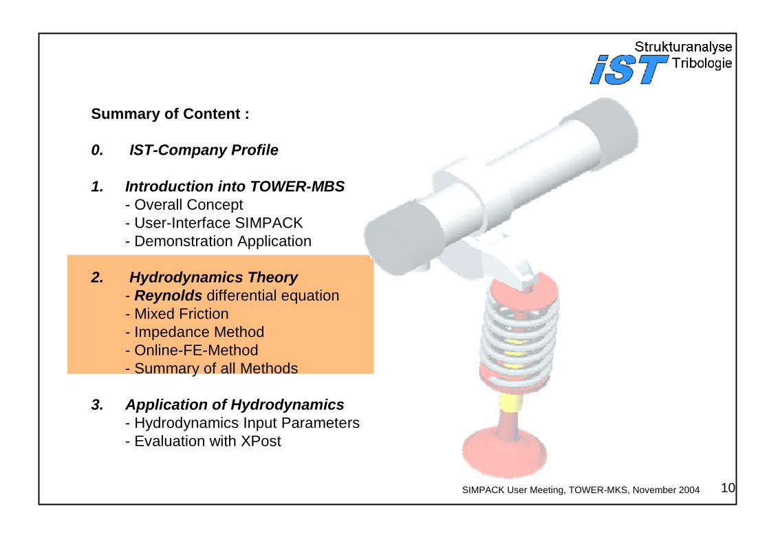
Summary of Content :
0. IST-Company Profile
1. Introduction into TOWER-MBS - Overall Concept- User-Interface SIMPACK- Demonstration Application
2. Hydrodynamics Theory - Reynolds differential equation- Mixed Friction- Impedance Method- Online-FE-Method- Summary of all Methods
3. Application of Hydrodynamics- Hydrodynamics Input Parameters- Evaluation with XPost
11
SIMPACK User Meeting, TOWER-MKS, November 2004
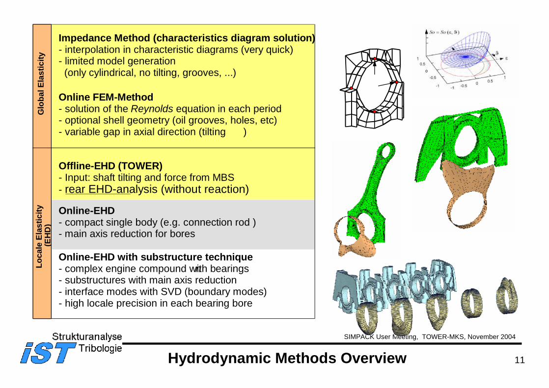
Hydrodynamic Methods Overview
Glo
bal E
last
icity
Loca
le E
last
icity
(EH
D)
Online-EHD with substructure technique- complex engine compound with bearingsn- substructures with main axis reduction- interface modes with SVD (boundary modes)- high locale precision in each bearing bore
Impedance Method (characteristics diagram solution)- interpolation in characteristic diagrams (very quick)- limited model generation(only cylindrical, no tilting, grooves, ...)
Online FEM-Method- solution of the Reynolds equation in each period- optional shell geometry (oil grooves, holes, etc)- variable gap in axial direction (tilting )
Offline-EHD (TOWER)- Input: shaft tilting and force from MBS- rear EHD-analysis (without reaction)
Online-EHD- compact single body (e.g. connection rod ) - main axis reduction for bores
12
SIMPACK User Meeting, TOWER-MKS, November 2004
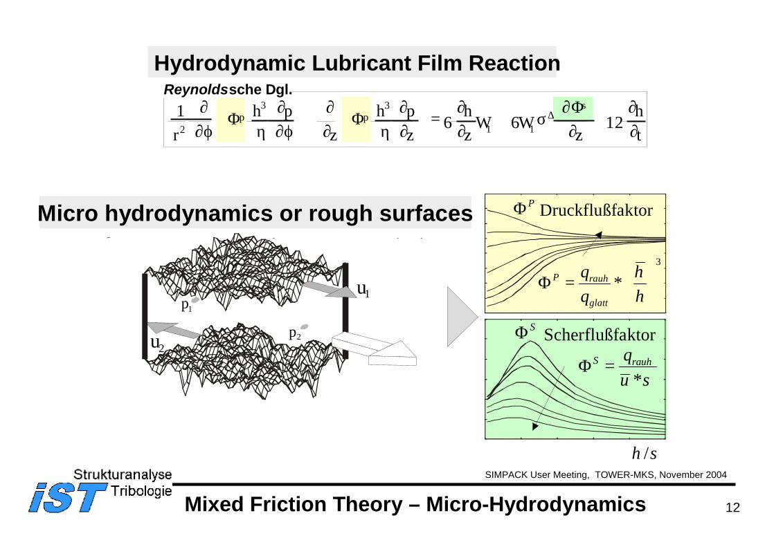
Mixed Friction Theory – Micro-Hydrodynamics
p 1
p 2
u 1
u 2
Micro hydrodynamics or rough surfaces
Hydrodynamic Lubricant Film Reaction
16 122 1 1r
W Wz
ht
p ps∂
∂ϕ η∂∂ϕ
∂∂ η
∂∂
∂∂
σ∂∂
∂∂
Φ ΦΦ∆h p
zh p
z6
hz
3 3
+
= + +
Reynoldssche Dgl.
Druckflußfaktor PΦ
/h σ
3P rauh
glatt
q hq h
Φ = ∗
Scherflußfaktor
/h σ
SΦS rauhq
u σΦ =
∗
13
SIMPACK User Meeting, TOWER-MKS, November 2004
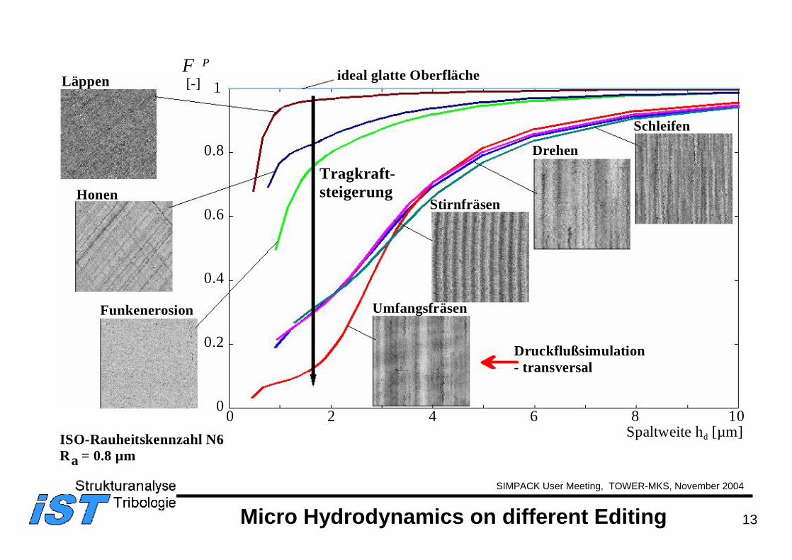
Umfangsfräsen
Läppen
Drehen
Schleifen
Honen
Funkenerosion
Stirnfräsen
0
0.2
0.4
0.6
0.8
1
0 2 4 6 8 10
Φ P
[-]
Spaltweite hd [µm]
Druckflußsimulation- transversal
ideal glatte Oberfläche
Tragkraft-steigerung
ISO-Rauheitskennzahl N6R = 0.8 µma
Micro Hydrodynamics on different Editing
14
SIMPACK User Meeting, TOWER-MKS, November 2004
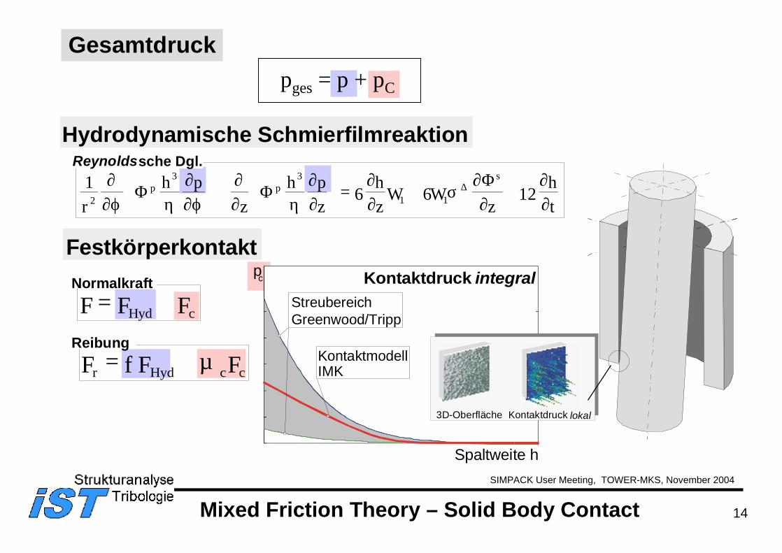
Mixed Friction Theory – Solid Body Contact
Hydrodynamische Schmierfilmreaktion
16 122 1 1r
W Wz
ht
p ps∂
∂ϕ η∂∂ϕ
∂∂ η
∂∂
∂∂
σ∂∂
∂∂
Φ ΦΦ∆h p
zh p
z6
hz
3 3
+
= + +
Reynoldssche Dgl.
Festkörperkontakt
F F FHyd c= +
F f F µ Fr Hyd c c= +
Normalkraft
ReibungKontaktmodellIMK
Spaltweite h
p c Kontaktdruck integralStreubereich Greenwood/Tripp
3D-Oberfläche Kontaktdruck lokal
Gesamtdruckpges = p + pC
15
SIMPACK User Meeting, TOWER-MKS, November 2004
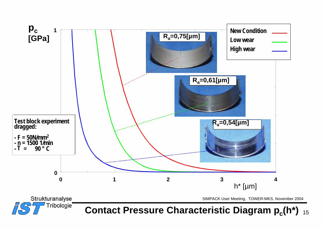
pc[GPa]
Contact Pressure Characteristic Diagram pc(h*)
0
1
0 1 2 3 4
Ra=0,75[µm]
Ra=0,61[µm]
Ra=0,54[µm]
h* [µm]
New ConditionLow wearHigh wear
Test block experimentdragged:- F = 50N/mm2- n = 1500 1/min- T = 90 ° C
16
SIMPACK User Meeting, TOWER-MKS, November 2004
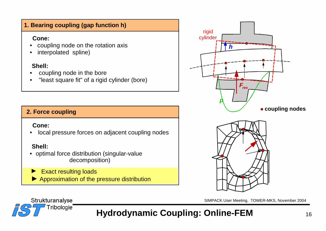
1. Bearing coupling (gap function h)
2. Force coupling
Cone: • coupling node on the rotation axis• interpolated spline)
Shell:• coupling node in the bore• "least square fit" of a rigid cylinder (bore)
Cone:• local pressure forces on adjacent coupling nodes
Shell:• optimal force distribution (singular-value
decomposition)
Exact resulting loads Approximation of the pressure distribution
Hydrodynamic Coupling: Online-FEM
rigidcylinder
h
p
Fres
coupling nodes
17
SIMPACK User Meeting, TOWER-MKS, November 2004
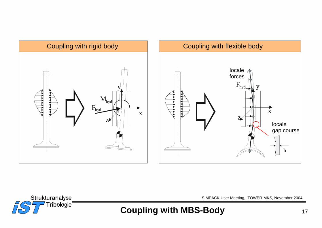
x
y
z
Fhyd
h
Coupling with rigid body Coupling with flexible body
localegap course
localeforces
x
y
z
Fhyd
hydM
Coupling with MBS-Body
18SIMPACK User Meeting, TOWER-MKS, November 2004
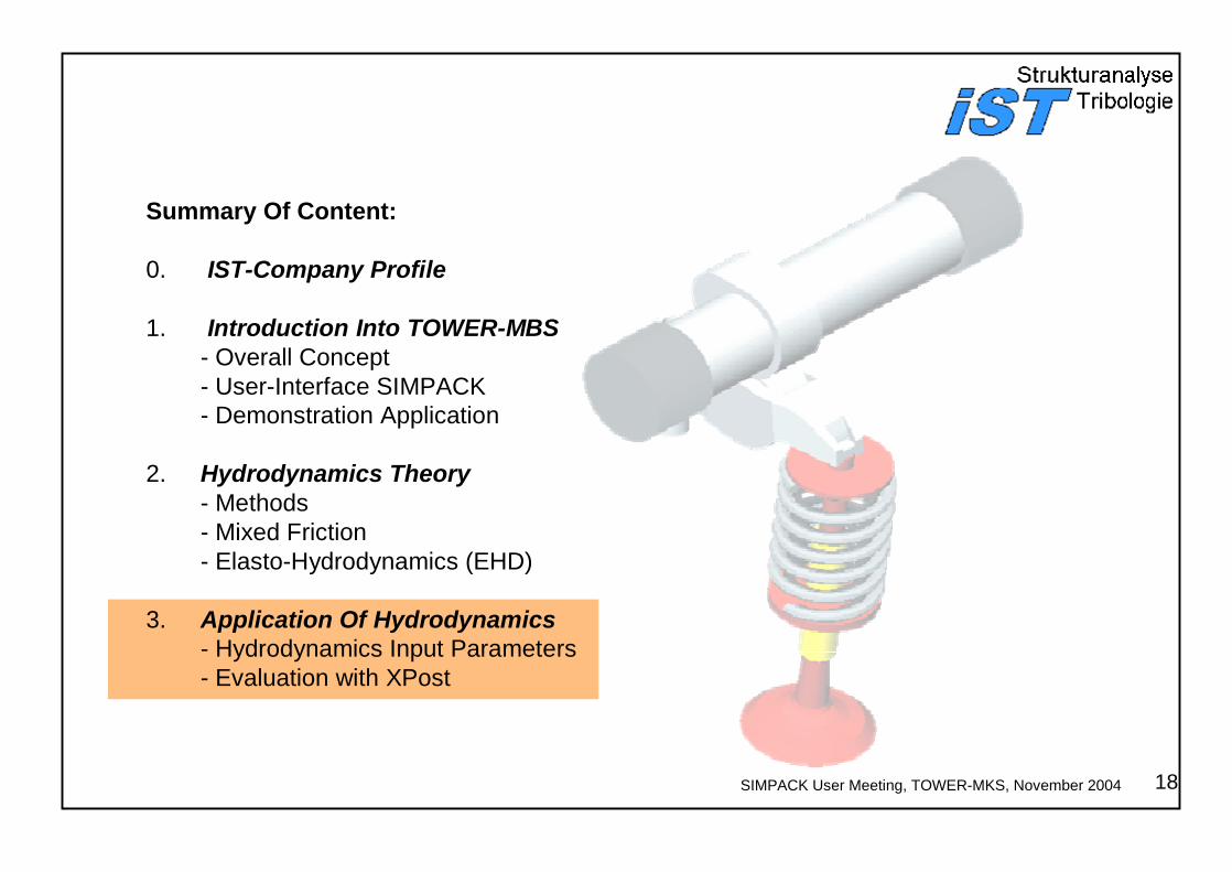
Summary Of Content:
0. IST-Company Profile
1. Introduction Into TOWER-MBS - Overall Concept- User-Interface SIMPACK- Demonstration Application
2. Hydrodynamics Theory - Methods- Mixed Friction- Elasto-Hydrodynamics (EHD)
3. Application Of Hydrodynamics- Hydrodynamics Input Parameters- Evaluation with XPost
19
SIMPACK User Meeting, TOWER-MKS, November 2004
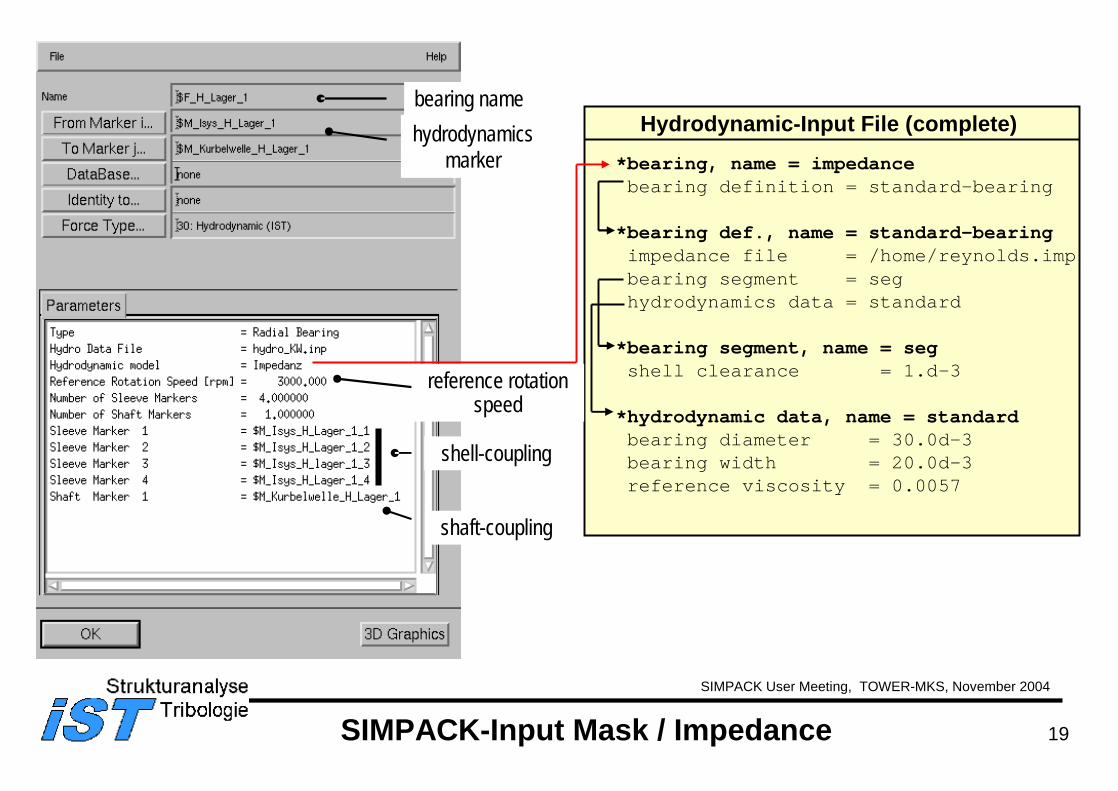
SIMPACK-Input Mask / Impedance
*bearing, name = impedancebearing definition = standard-bearing
*bearing def., name = standard-bearingimpedance file = /home/reynolds.impbearing segment = seghydrodynamics data = standard
*bearing segment, name = segshell clearance = 1.d-3
*hydrodynamic data, name = standardbearing diameter = 30.0d-3bearing width = 20.0d-3reference viscosity = 0.0057
Hydrodynamic-Input File (complete)bearing namehydrodynamics
marker
reference rotation speed
shell-coupling
shaft-coupling
20
SIMPACK User Meeting, TOWER-MKS, November 2004
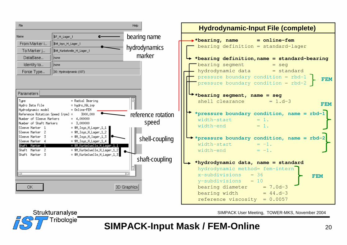
SIMPACK-Input Mask / FEM-Online
*bearing, name = online-fembearing definition = standard-lager
*bearing definition,name = standard-bearingbearing segment = seghydrodynamic data = standardpressure boundary condition = rbd-1pressure boundary condition = rbd-2
*bearing segment, name = segshell clearance = 1.d-3
*pressure boundary condition, name = rbd-1width-start = 1.width-end = 1.
*pressure boundary condition, name = rbd-2width-start = -1.width-end = -1.
*hydrodynamic data, name = standardhydrodynamic method= fem-internx-subdivisions = 36y-subdivisions = 10bearing diameter = 7.0d-3bearing width = 44.d-3reference viscosity = 0.0057
Hydrodynamic-Input File (complete)bearing namehydrodynamics
marker
reference rotation speed
shell-coupling
shaft-coupling
FEM
FEM
FEM
21
SIMPACK User Meeting, TOWER-MKS, November 2004
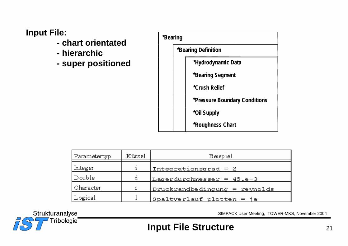
Input File Structure
Input File:- chart orientated- hierarchic- super positioned
*Bearing
*Bearing Definition
*Hydrodynamic Data
*Bearing Segment
*Crush Relief
*Pressure Boundary Conditions
*Oil Supply
*Roughness Chart
22
SIMPACK User Meeting, TOWER-MKS, November 2004
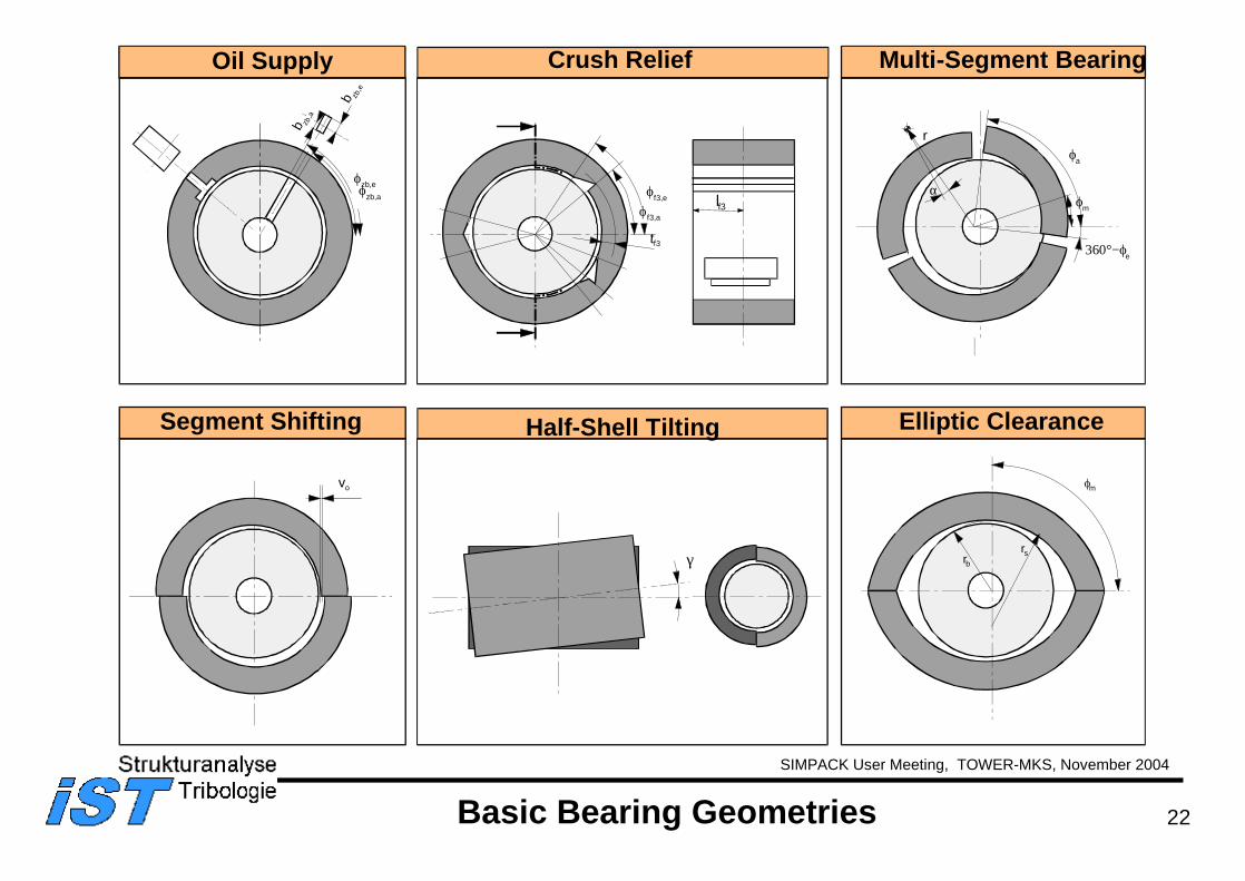
Half-Shell Tilting
b zb,e
ϕzb,a
ϕzb,e
b zb,a
Oil Supply
ϕf3,a
ϕf3,e
tf3
lf3
Crush Relief
vo
Segment Shifting
ϕa
360°−ϕe
ϕm
α
r
Multi-Segment Bearing
Elliptic Clearance
rsrb
ϕm
γ
Basic Bearing Geometries
23
SIMPACK User Meeting, TOWER-MKS, November 2004
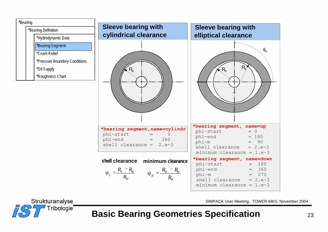
*bearing segment, name=upphi-start = 0 phi-end = 180 phi-m = 90shell clearance = 2.e-3minimum clearance = 1.e-3
*bearing segment, name=downphi-start = 180phi-end = 360phi-m = 270shell clearance = 2.e-3
*bearing segment,name=cylindrphi-start = 0 phi-end = 360 shell clearance = 2.e-3
Sleeve bearing withelliptical clearance
Sleeve bearing withcylindrical clearance
RSRB
ϕm
ψSS W
W
R RR
=−
ψBB W
W
R RR
=−
RB
shell clearance minimum clearance
Basic Bearing Geometries Specification
*Bearing
*Bearing Definition
*Hydrodynamic Data
*Bearing Segment
*Crush Relief
*Pressure Boundary Conditions
*Oil Supply*Roughness Chart
minimum clearance = 1.e-3
24
SIMPACK User Meeting, TOWER-MKS, November 2004
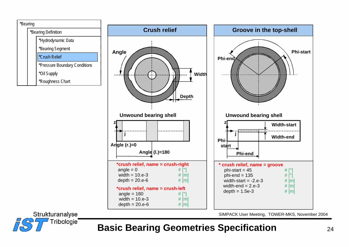
Crush relief
Depth
Width
Width-end
Groove in the top-shell
Phi-endPhi-start
Unwound bearing shell
ϕ
z
Phi-start
Phi-end
Width-start
*crush relief, name = crush-rightangle = 0 # [°]width = 10.e-3 # [m]depth = 20.e-6 # [m]
*crush relief, name = crush-leftangle = 180 # [°]width = 10.e-3 # [m]depth = 20.e-6 # [m]
Unwound bearing shell
ϕ
z
Angle (r.)=0Angle (l.)=180
* crush relief, name = groovephi-start = 45 # [°]phi-end = 135 # [°]width-start = -2.e-3 # [m]width-end = 2.e-3 # [m]depth = 1.5e-3 # [m]
Basic Bearing Geometries Specification
*Bearing
*Bearing Definition
*Hydrodynamic Data
*Bearing Segment
*Crush Relief
*Pressure Boundary Conditions
*Oil Supply*Roughness Chart
Angle
25
SIMPACK User Meeting, TOWER-MKS, November 2004
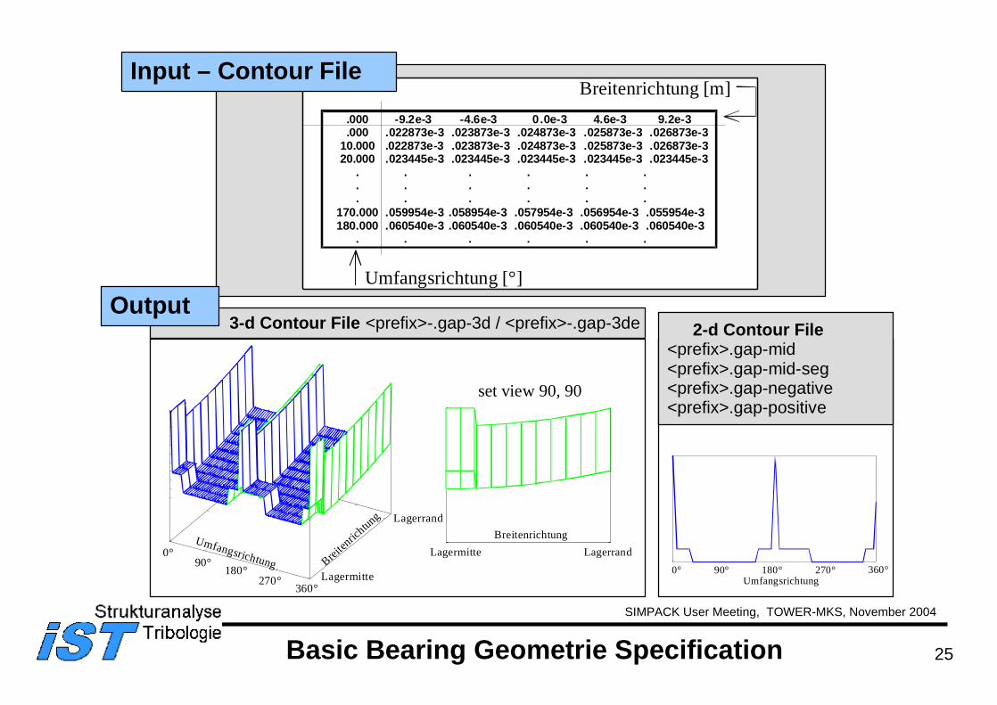
Lagermitte LagerrandBreitenrichtung
0°90°
180°270°
360°Lagermitte
Lagerrand
Umfangsrichtung Breiten
richtung
3-d Contour File <prefix>-.gap-3d / <prefix>-.gap-3de
set view 90, 90
0° 180° 270°90° 360°Umfangsrichtung
2-d Contour File<prefix>.gap-mid <prefix>.gap-mid-seg<prefix>.gap-negative <prefix>.gap-positive
.000 -9.2e-3 -4.6e-3 0.0e-3 4.6e-3 9.2e-3 .000 .022873e-3 .023873e-3 .024873e-3 .025873e-3 .026873e-3 10.000 .022873e-3 .023873e-3 .024873e-3 .025873e-3 .026873e-3 20.000 .023445e-3 .023445e-3 .023445e-3 .023445e-3 .023445e-3 . . . . . . . . . . . . . . . . . .170.000 .059954e-3 .058954e-3 .057954e-3 .056954e-3 .055954e-3 180.000 .060540e-3 .060540e-3 .060540e-3 .060540e-3 .060540e-3 . . . . . .
Umfangsrichtung [°]
Breitenrichtung [m]Input – Contour File
Output
Basic Bearing Geometrie Specification
26
SIMPACK User Meeting, TOWER-MKS, November 2004
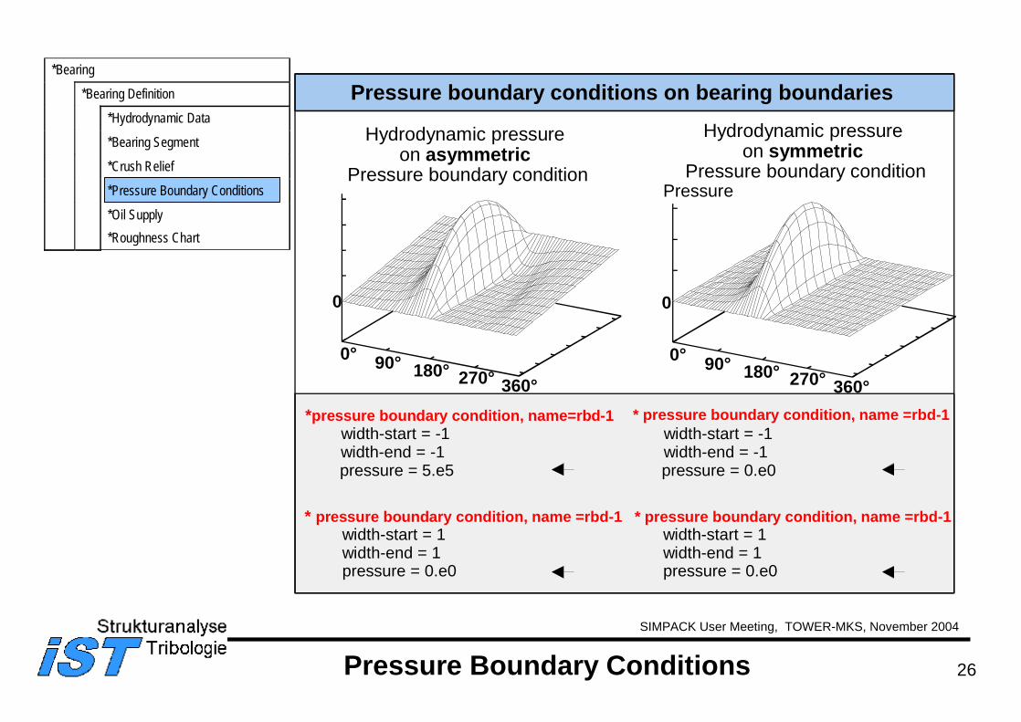
Pressure Boundary Conditions
*pressure boundary condition, name=rbd-1width-start = -1width-end = -1pressure = 5.e5
Pressure boundary conditions on bearing boundaries
0° 90° 180° 270° 360°
0
Pressure
0° 90° 180° 270° 360°
0
* pressure boundary condition, name =rbd-1width-start = 1width-end = 1pressure = 0.e0
Hydrodynamic pressure on asymmetric
Pressure boundary condition
* pressure boundary condition, name =rbd-1width-start = -1width-end = -1pressure = 0.e0
* pressure boundary condition, name =rbd-1width-start = 1width-end = 1pressure = 0.e0
*Bearing
*Bearing Definition
*Hydrodynamic Data
*Bearing Segment
*Crush Relief
*Pressure Boundary Conditions
*Oil Supply*Roughness Chart
Hydrodynamic pressure on symmetric
Pressure boundary condition
27
SIMPACK User Meeting, TOWER-MKS, November 2004
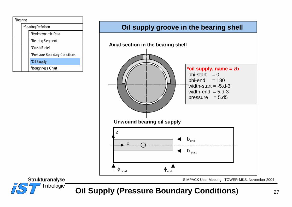
Oil Supply (Pressure Boundary Conditions)
*oil supply, name = zbphi-start = 0phi-end = 180width-start = -5.d-3width-end = 5.d-3pressure = 5.d5
Oil supply groove in the bearing shell
Axial section in the bearing shell
Unwound bearing oil supply
ϕ
z
ϕ start ϕend
bend
b start
*Bearing
*Bearing Definition
*Hydrodynamic Data
*Bearing Segment
*Crush Relief
*Pressure Boundary Conditions
*Oil Supply*Roughness Chart
28
SIMPACK User Meeting, TOWER-MKS, November 2004
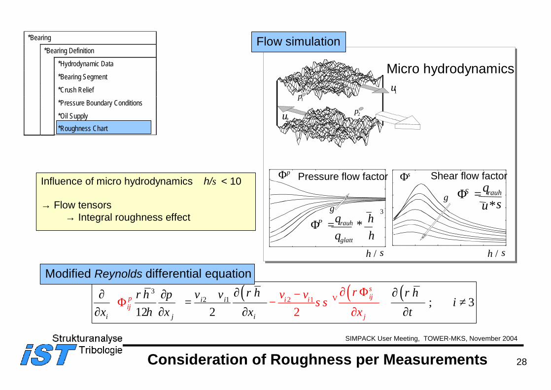
Consideration of Roughness per Measurements
( ) ( ) ( )31 2 12 ; 3
12 2 2
si i ijp
i j
i iij
ji
h hh p v v ix x x t
v vx
ρ ρρσσ
ρη
∂ ∂ Φ−Φ −
∂
∂ ∂ ∂ += + ≠ ∂ ∂ ∂ ∂
V
Modified Reynolds differential equation
Pressure flow factor Shear flow factorΦp Φs
h / σ
γ
h / σ
γ
ΦP rauh
glatt
hh
= ∗
3
p1
p2
u1
u2
Micro hydrodynamics
ΦS rauhqu
=*σ
Flow simulation
Influence of micro hydrodynamics ∼ h/σ < 10
→ Flow tensors→ Integral roughness effect
*Bearing
*Bearing Definition
*Hydrodynamic Data
*Bearing Segment
*Crush Relief
*Pressure Boundary Conditions
*Oil Supply*Roughness Chart
29
SIMPACK User Meeting, TOWER-MKS, November 2004
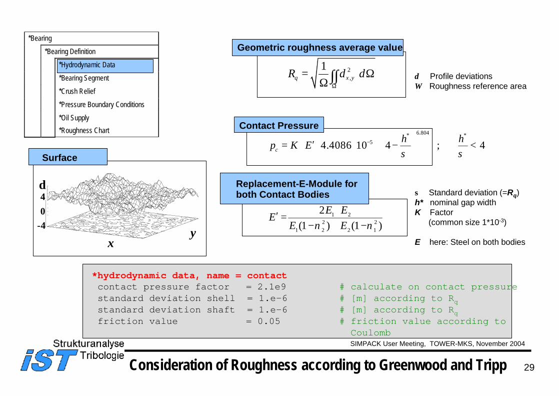
Surface
-404
xy
δ
2,
1Ω
= ΩΩ ∫∫q x yR dδ
σ Standard deviation (=Rq) h* nominal gap widthK Factor
(common size 1*10-3)
E here: Steel on both bodies
6.804* *54.4086 10 4 ; 4− ′= ⋅ ⋅ ⋅ ⋅ − <
c
h hp K Eσ σ
*hydrodynamic data, name = contactcontact pressure factor = 2.1e9 # calculate on contact pressurestandard deviation shell = 1.e-6 # [m] according to Rqstandard deviation shaft = 1.e-6 # [m] according to Rqfriction value = 0.05 # friction value according to
Coulomb
Geometric roughness average value
Contact Pressure
1 22 2
1 2 2 1
2(1 ) (1 )
⋅′ =− + −
E EEE Eν ν
Replacement-E-Module for both Contact Bodies
δ Profile deviationsΩ Roughness reference area
Consideration of Roughness according to Greenwood and Tripp
*Bearing
*Bearing Definition
*Hydrodynamic Data
*Bearing Segment
*Crush Relief
*Pressure Boundary Conditions
*Oil Supply*Roughness Chart
30
SIMPACK User Meeting, TOWER-MKS, November 2004
XPost V6.0
Program XPost
31
SIMPACK User Meeting, TOWER-MKS, November 2004
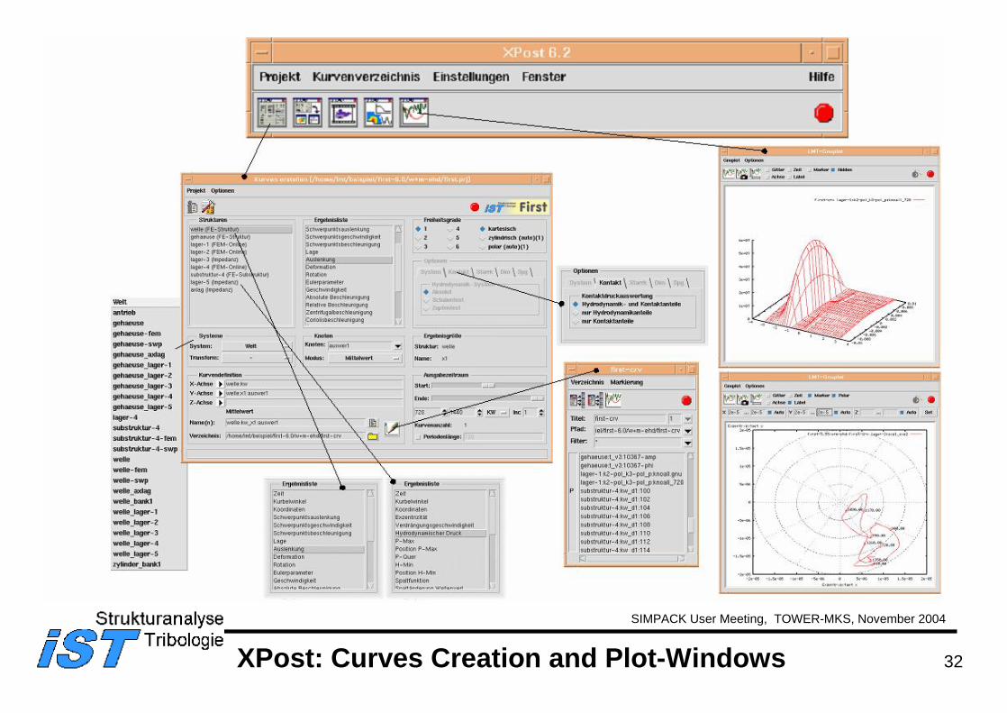
XPost V6.0
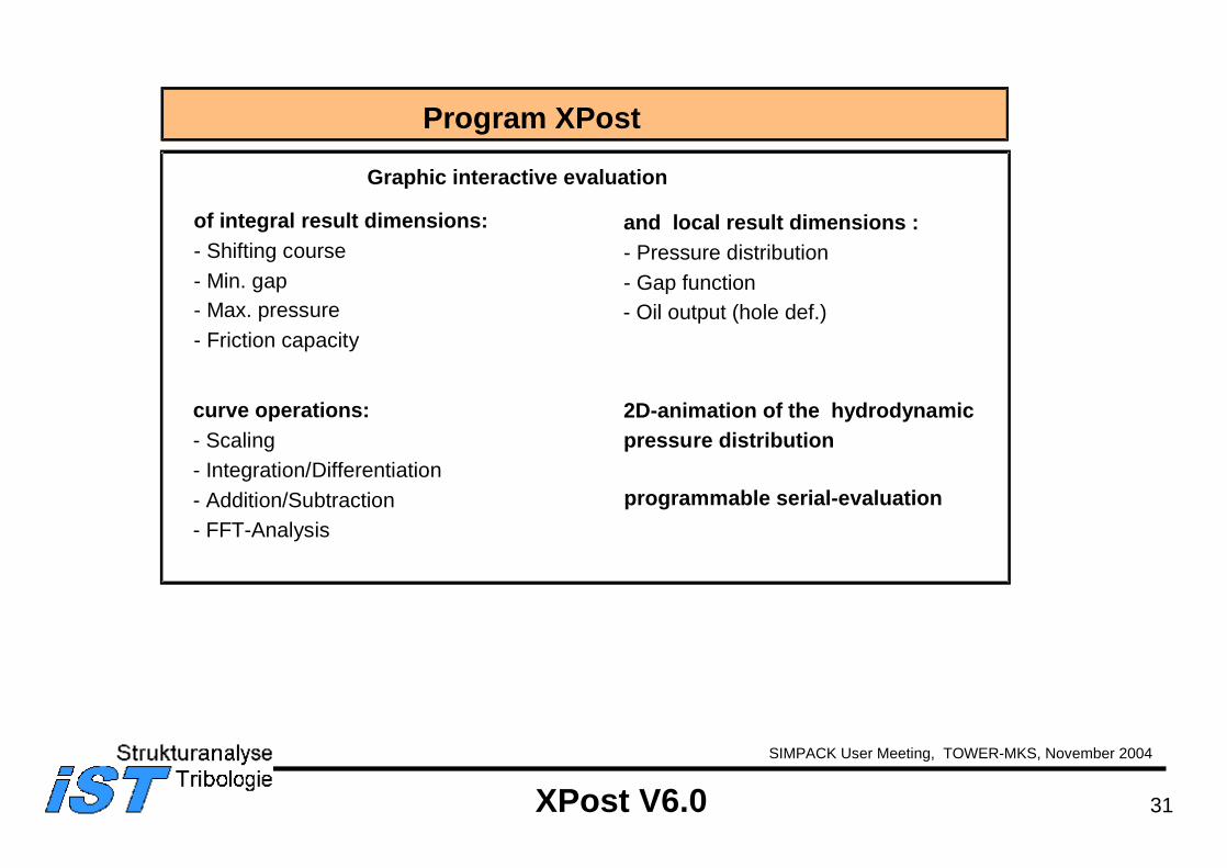
and local result dimensions :- Pressure distribution- Gap function- Oil output (hole def.)
Program XPost
Graphic interactive evaluation
of integral result dimensions:- Shifting course- Min. gap- Max. pressure- Friction capacity
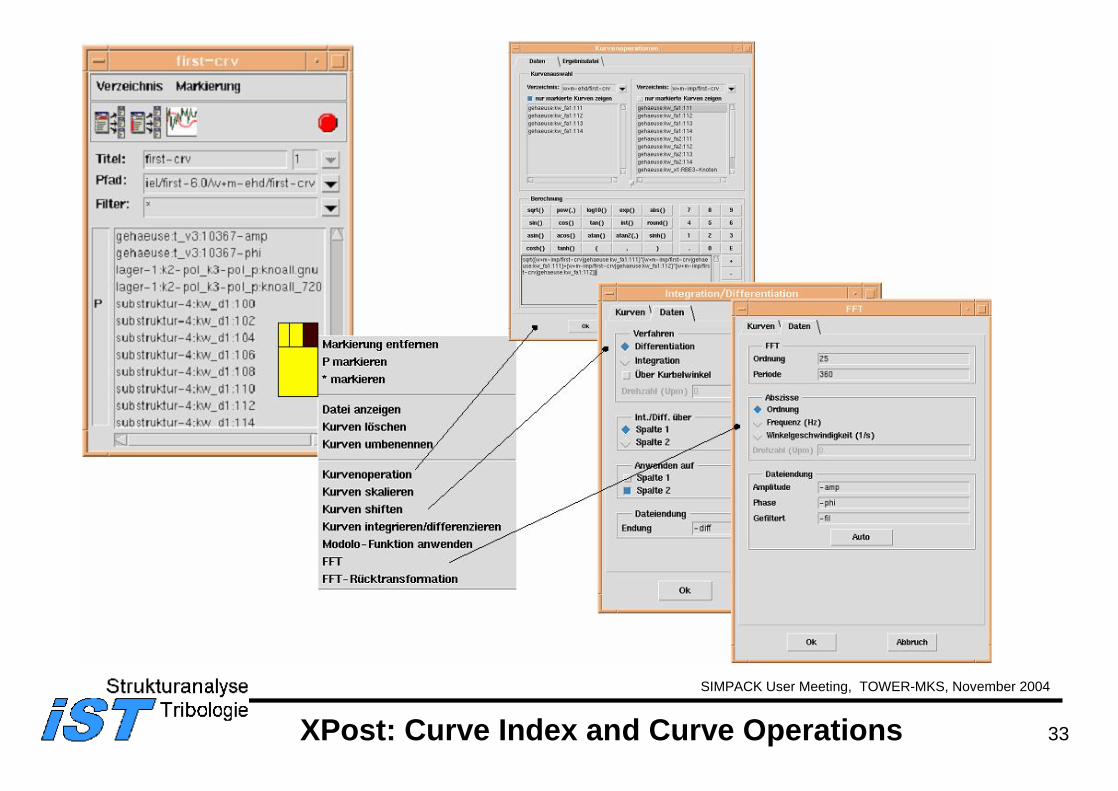
curve operations:- Scaling- Integration/Differentiation- Addition/Subtraction- FFT-Analysis
2D-animation of the hydrodynamicpressure distribution
programmable serial-evaluation
32
SIMPACK User Meeting, TOWER-MKS, November 2004
XPost: Curves Creation and Plot-Windows
33
SIMPACK User Meeting, TOWER-MKS, November 2004
XPost: Curve Index and Curve Operations
34
SIMPACK User Meeting, TOWER-MKS, November 2004
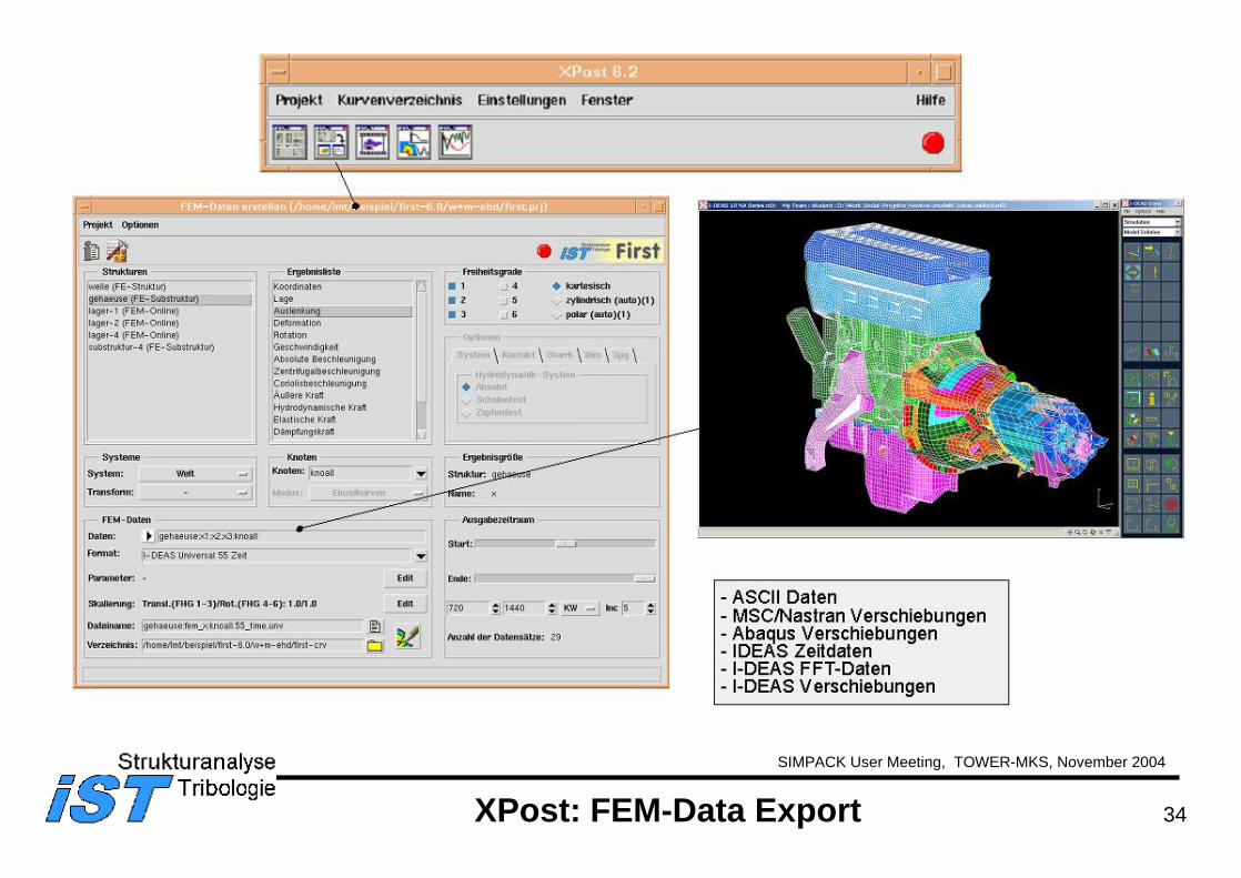
XPost: FEM-Data Export
35
SIMPACK User Meeting, TOWER-MKS, November 2004
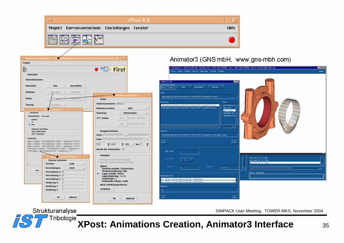
XPost: Animations Creation, Animator3 Interface
36
SIMPACK User Meeting, TOWER-MKS, November 2004
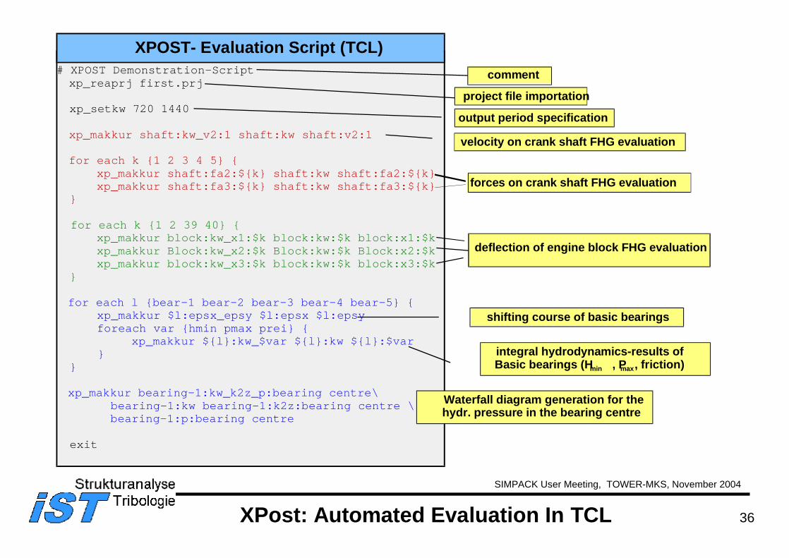
XPost: Automated Evaluation In TCL
XPOST- Evaluation Script (TCL)# XPOST Demonstration-Scriptxp_reaprj first.prj
xp_setkw 720 1440
xp_makkur shaft:kw_v2:1 shaft:kw shaft:v2:1
for each k 1 2 3 4 5 xp_makkur shaft:fa2:$k shaft:kw shaft:fa2:$kxp_makkur shaft:fa3:$k shaft:kw shaft:fa3:$k
for each k 1 2 39 40 xp_makkur block:kw_x1:$k block:kw:$k block:x1:$k xp_makkur Block:kw_x2:$k Block:kw:$k Block:x2:$k xp_makkur block:kw_x3:$k block:kw:$k block:x3:$k
for each l bear-1 bear-2 bear-3 bear-4 bear-5 xp_makkur $l:epsx_epsy $l:epsx $l:epsyforeach var hmin pmax prei
xp_makkur $l:kw_$var $l:kw $l:$var
xp_makkur bearing-1:kw_k2z_p:bearing centre\bearing-1:kw bearing-1:k2z:bearing centre \bearing-1:p:bearing centre
exit
forces on crank shaft FHG evaluation
velocity on crank shaft FHG evaluation
comment
project file importation
output period specification
integral hydrodynamics-results ofBasic bearings (Hmin , Pmax, friction)
Waterfall diagram generation for thehydr. pressure in the bearing centre
shifting course of basic bearings
deflection of engine block FHG evaluation
37
SIMPACK User Meeting, TOWER-MKS, November 2004
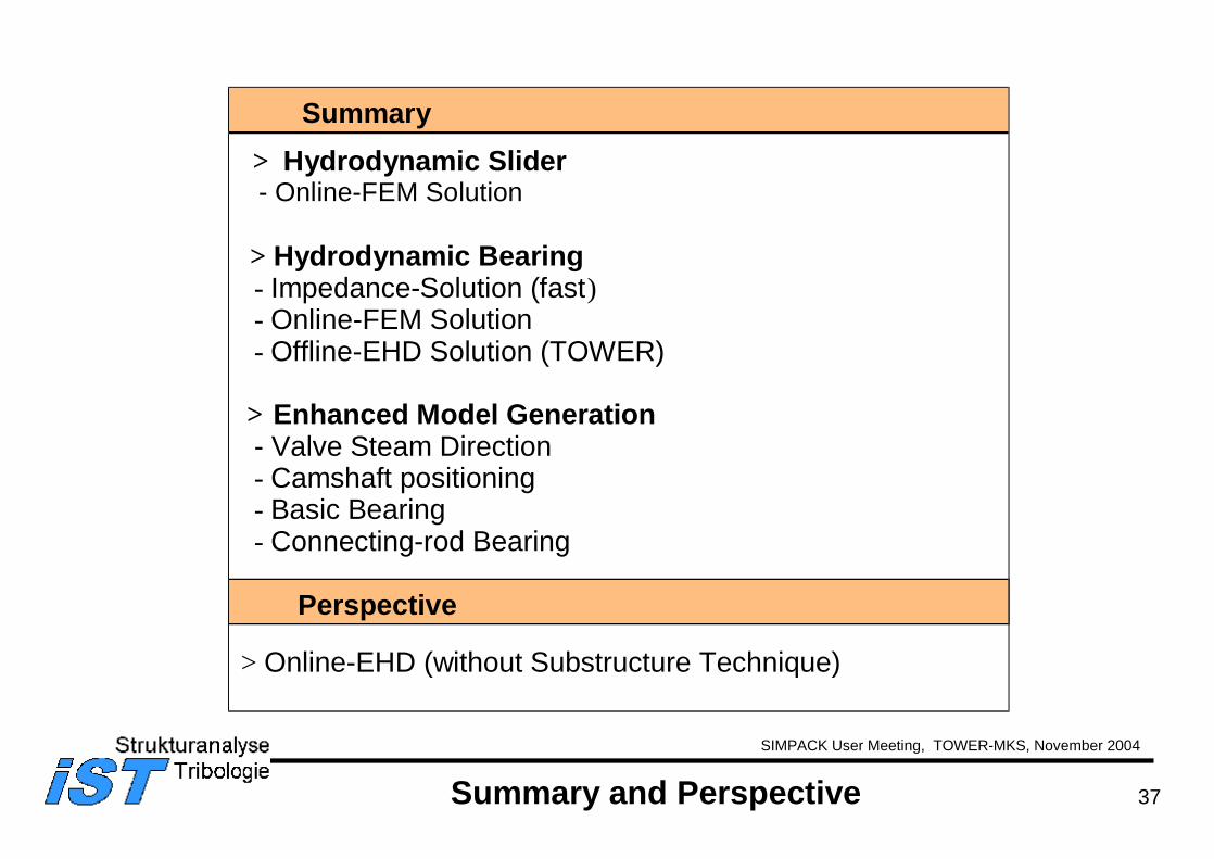
Summary
Perspective
> Hydrodynamic Slider- Online-FEM Solution
> Hydrodynamic Bearing- Impedance-Solution (fast)- Online-FEM Solution- Offline-EHD Solution (TOWER)
> Enhanced Model Generation- Valve Steam Direction- Camshaft positioning- Basic Bearing- Connecting-rod Bearing
> Online-EHD (without Substructure Technique)
Summary and Perspective