Embed Size (px)
Citation preview
TOYOTA YARIS HATCHBACK 2007 - INTERIOR LIGHT UPGRADE Preparation
Page 1 of 20 pages Issue: A 3/31/06
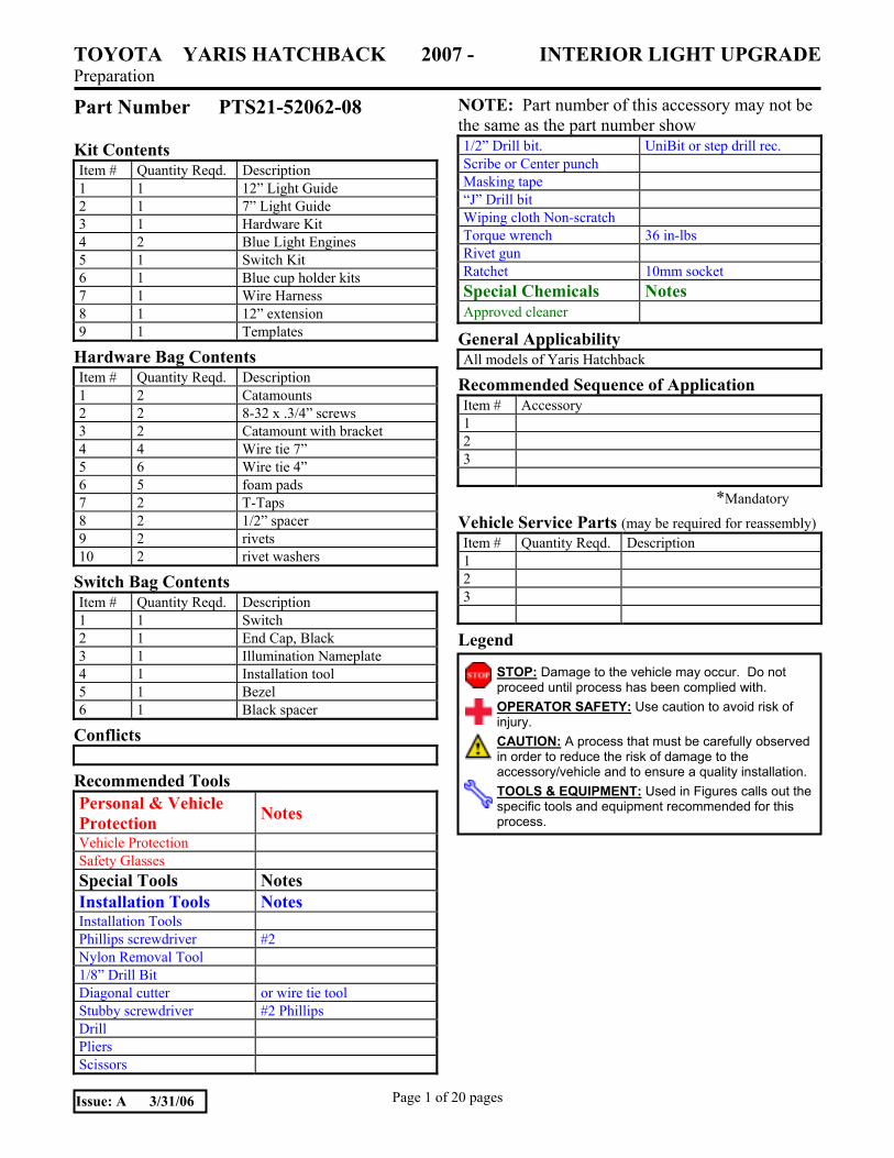
Part Number PTS21-52062-08 NOTE: Part number of this accessory may not be the same as the part number show
Kit Contents Item # Quantity Reqd. Description 1 1 12� Light Guide 2 1 7� Light Guide 3 1 Hardware Kit 4 2 Blue Light Engines 5 1 Switch Kit 6 1 Blue cup holder kits 7 1 Wire Harness 8 1 12� extension 9 1 Templates
Hardware Bag Contents Item # Quantity Reqd. Description 1 2 Catamounts 2 2 8-32 x .3/4� screws 3 2 Catamount with bracket 4 4 Wire tie 7� 5 6 Wire tie 4� 6 5 foam pads 7 2 T-Taps 8 2 1/2� spacer 9 2 rivets 10 2 rivet washers
Switch Bag Contents Item # Quantity Reqd. Description 1 1 Switch 2 1 End Cap, Black 3 1 Illumination Nameplate 4 1 Installation tool 5 1 Bezel 6 1 Black spacer
Conflicts
Recommended Tools Personal & Vehicle Protection Notes Vehicle Protection Safety Glasses Special Tools Notes Installation Tools Notes Installation Tools Phillips screwdriver #2 Nylon Removal Tool 1/8� Drill Bit Diagonal cutter or wire tie tool Stubby screwdriver #2 Phillips Drill Pliers Scissors
1/2� Drill bit. UniBit or step drill rec. Scribe or Center punch Masking tape �J� Drill bit Wiping cloth Non-scratch Torque wrench 36 in-lbs Rivet gun Ratchet 10mm socket Special Chemicals Notes Approved cleaner
General Applicability All models of Yaris Hatchback
Recommended Sequence of Application Item # Accessory 1 2 3
*Mandatory
Vehicle Service Parts (may be required for reassembly) Item # Quantity Reqd. Description 1 2 3
Legend STOP: Damage to the vehicle may occur. Do not
proceed until process has been complied with. OPERATOR SAFETY: Use caution to avoid risk of injury. CAUTION: A process that must be carefully observed in order to reduce the risk of damage to the accessory/vehicle and to ensure a quality installation.TOOLS & EQUIPMENT: Used in Figures calls out the specific tools and equipment recommended for this process.
TOYOTA YARIS HATCHBACK 2007 - INTERIOR LIGHT UPGRADE Procedure
Page 2 of 20 pages Issue: A 3/31/06
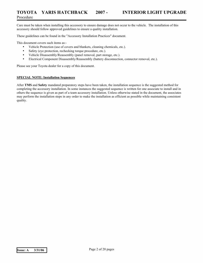
Care must be taken when installing this accessory to ensure damage does not occur to the vehicle. The installation of this accessory should follow approved guidelines to ensure a quality installation. These guidelines can be found in the "Accessory Installation Practices" document.
This document covers such items as:-
• Vehicle Protection (use of covers and blankets, cleaning chemicals, etc.). • Safety (eye protection, rechecking torque procedure, etc.). • Vehicle Disassembly/Reassembly (panel removal, part storage, etc.). • Electrical Component Disassembly/Reassembly (battery disconnection, connector removal, etc.).
Please see your Toyota dealer for a copy of this document. SPECIAL NOTE: Installation Sequences After TMS and Safety mandated preparatory steps have been taken, the installation sequence is the suggested method for completing the accessory installation. In some instances the suggested sequence is written for one associate to install and in others the sequence is given as part of a team accessory installation. Unless otherwise stated in the document, the associates may perform the installation steps in any order to make the installation as efficient as possible while maintaining consistent quality.
TOYOTA YARIS HATCHBACK 2007 - INTERIOR LIGHT UPGRADE Procedure
Page 3 of 20 pages Issue: A 3/31/06
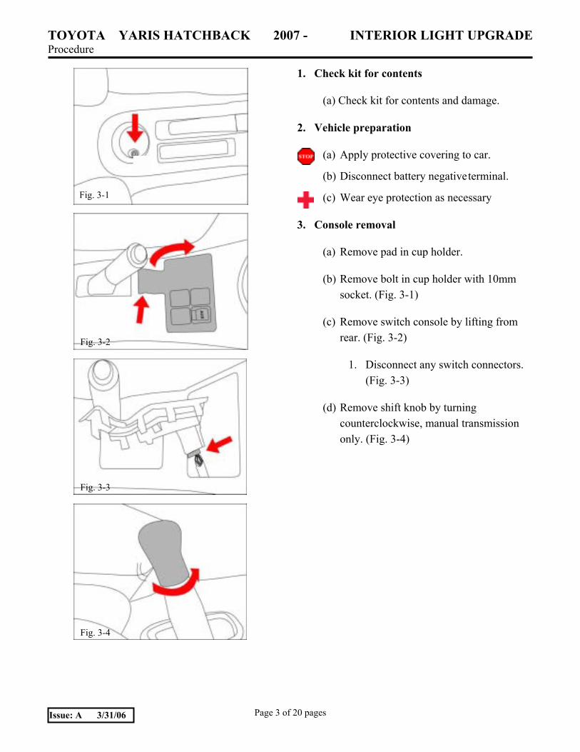
1. Check kit for contents
(a) Check kit for contents and damage.
2. Vehicle preparation
(a) Apply protective covering to car.
(b) Disconnect battery negative terminal.
(c) Wear eye protection as necessary
3. Console removal
(a) Remove pad in cup holder.
(b) Remove bolt in cup holder with 10mm socket. (Fig. 3-1)
(c) Remove switch console by lifting from rear. (Fig. 3-2)
1. Disconnect any switch connectors. (Fig. 3-3)
(d) Remove shift knob by turning counterclockwise, manual transmission only. (Fig. 3-4)
Fig. 3-1
Fig. 3-2
Fig. 3-3
Fig. 3-4
TOYOTA YARIS HATCHBACK 2007 - INTERIOR LIGHT UPGRADE Procedure
Page 4 of 20 pages Issue: A 3/31/06
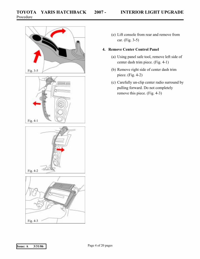
(e) Lift console from rear and remove from car. (Fig. 3-5)
4. Remove Center Control Panel
(a) Using panel safe tool, remove left side of center dash trim piece. (Fig. 4-1)
(b) Remove right side of center dash trim piece. (Fig. 4-2)
(c) Carefully un-clip center radio surround by pulling forward. Do not completely remove this piece. (Fig. 4-3)
Fig. 3-5
Fig. 4-1
Fig. 4-2
Fig. 4-3

TOYOTA YARIS HATCHBACK 2007 - INTERIOR LIGHT UPGRADE Procedure
Page 5 of 20 pages Issue: A 3/31/06
(d) Remove center control panel by pulling forward. HVAC panel must be supported, do not suspend from harness. (Fig. 4-4)
(e) Locate power leads that connect to power point. Location of power point is below HVAC control panel. (Fig. 4-5)
(f) Drop power leads below center control panel. Install T-taps in staggered fashion on power leads connected to power point, use pliers. (Fig. 4-6)
5. Install LED Lamps
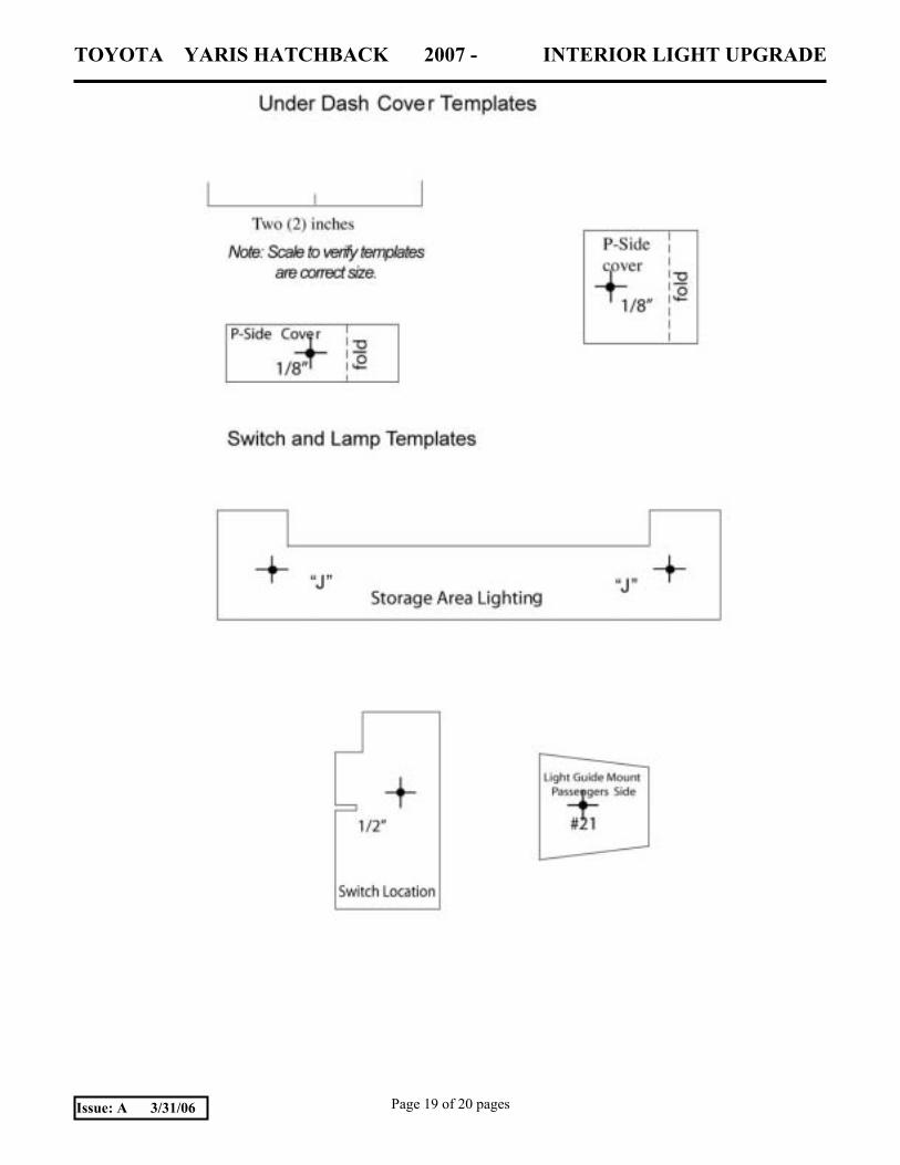
(a) Cut out marking template.
(b) Align console lighting area marking template on bottom as shown, tape in place as shown and mark hole locations using punch or scribe. (Fig. 5-1)
Fig. 4-4
Fig. 4-5
Fig. 4-6
Fig. 5-1
TOYOTA YARIS HATCHBACK 2007 - INTERIOR LIGHT UPGRADE Procedure
Page 6 of 20 pages Issue: A 3/31/06
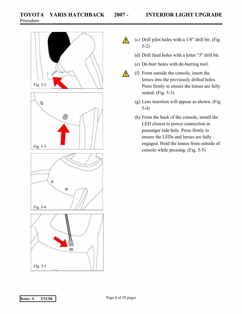
(c) Drill pilot holes with a 1/8� drill bit. (Fig. 5-2)
(d) Drill final holes with a letter �J� drill bit.
(e) De-burr holes with de-burring tool.
(f) From outside the console, insert the lenses into the previously drilled holes. Press firmly to ensure the lenses are fully seated. (Fig. 5-3)
(g) Lens insertion will appear as shown. (Fig. 5-4)
(h) From the back of the console, install the LED closest to power connection in passenger side hole. Press firmly to ensure the LEDs and lenses are fully engaged. Hold the lenses from outside of console while pressing. (Fig. 5-5)
Fig. 5-2
Fig. 5-3
Fig. 5-4
Fig. 5-5
TOYOTA YARIS HATCHBACK 2007 - INTERIOR LIGHT UPGRADE Procedure
Page 7 of 20 pages Issue: A 3/31/06
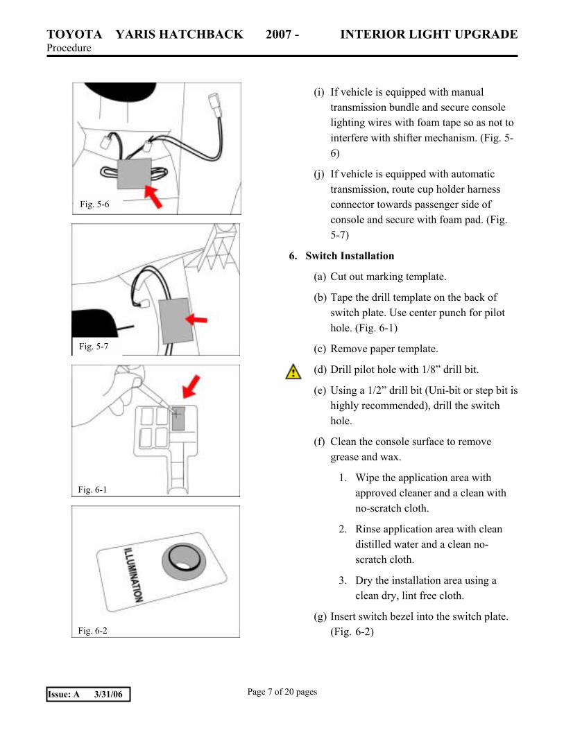
(i) If vehicle is equipped with manual transmission bundle and secure console lighting wires with foam tape so as not to interfere with shifter mechanism. (Fig. 5-6)
(j) If vehicle is equipped with automatic transmission, route cup holder harness connector towards passenger side of console and secure with foam pad. (Fig. 5-7)
6. Switch Installation
(a) Cut out marking template.
(b) Tape the drill template on the back of switch plate. Use center punch for pilot hole. (Fig. 6-1)
(c) Remove paper template.
(d) Drill pilot hole with 1/8� drill bit.
(e) Using a 1/2� drill bit (Uni-bit or step bit is highly recommended), drill the switch hole.
(f) Clean the console surface to remove grease and wax.
1. Wipe the application area with approved cleaner and a clean with no-scratch cloth.
2. Rinse application area with clean distilled water and a clean no-scratch cloth.
3. Dry the installation area using a clean dry, lint free cloth.
(g) Insert switch bezel into the switch plate. (Fig. 6-2)
Fig. 5-6
Fig. 5-7
Fig. 6-1
Fig. 6-2
TOYOTA YARIS HATCHBACK 2007 - INTERIOR LIGHT UPGRADE Procedure
Page 8 of 20 pages Issue: A 3/31/06
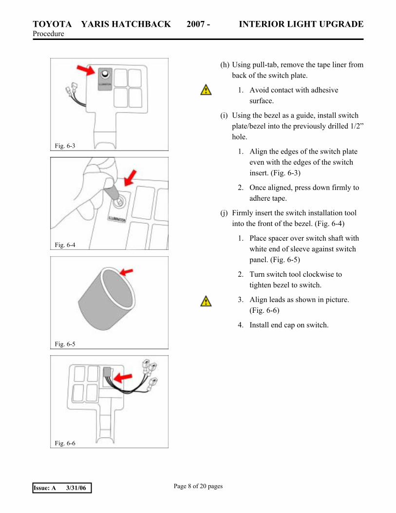
(h) Using pull-tab, remove the tape liner from back of the switch plate.
1. Avoid contact with adhesive surface.
(i) Using the bezel as a guide, install switch plate/bezel into the previously drilled 1/2� hole.
1. Align the edges of the switch plate even with the edges of the switch insert. (Fig. 6-3)
2. Once aligned, press down firmly to adhere tape.
(j) Firmly insert the switch installation tool into the front of the bezel. (Fig. 6-4)
1. Place spacer over switch shaft with white end of sleeve against switch panel. (Fig. 6-5)
2. Turn switch tool clockwise to tighten bezel to switch.
3. Align leads as shown in picture. (Fig. 6-6)
4. Install end cap on switch.
Fig. 6-3
Fig. 6-4
Fig. 6-6
Fig. 6-5
TOYOTA YARIS HATCHBACK 2007 - INTERIOR LIGHT UPGRADE Procedure
Page 9 of 20 pages Issue: A 3/31/06
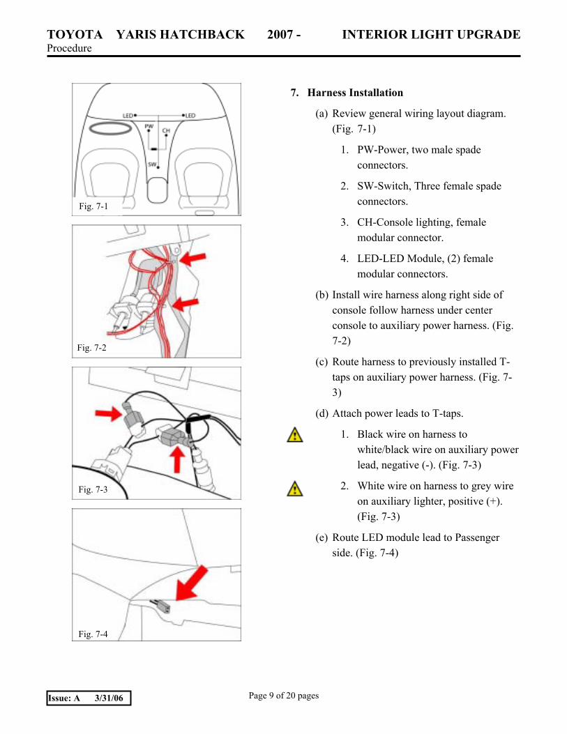
7. Harness Installation
(a) Review general wiring layout diagram. (Fig. 7-1)
1. PW-Power, two male spade connectors.
2. SW-Switch, Three female spade connectors.
3. CH-Console lighting, female modular connector.
4. LED-LED Module, (2) female modular connectors.
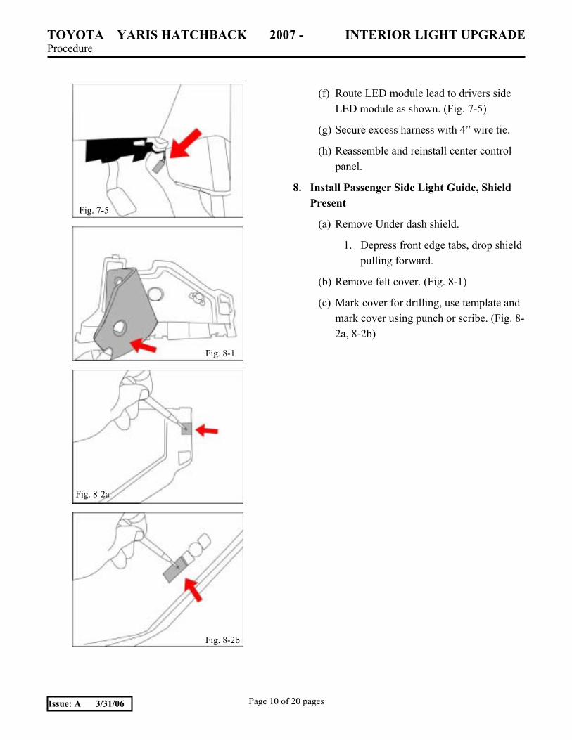
(b) Install wire harness along right side of console follow harness under center console to auxiliary power harness. (Fig. 7-2)
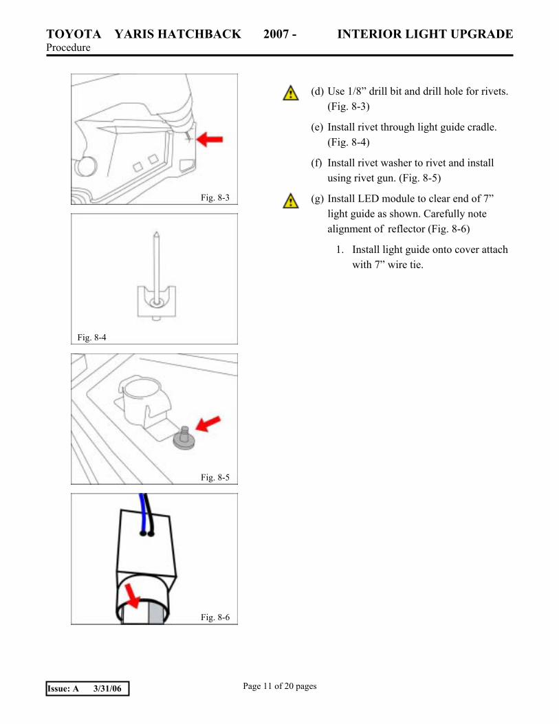
(c) Route harness to previously installed T-taps on auxiliary power harness. (Fig. 7-3)
(d) Attach power leads to T-taps.
1. Black wire on harness to white/black wire on auxiliary power lead, negative (-). (Fig. 7-3)
2. White wire on harness to grey wire on auxiliary lighter, positive (+). (Fig. 7-3)
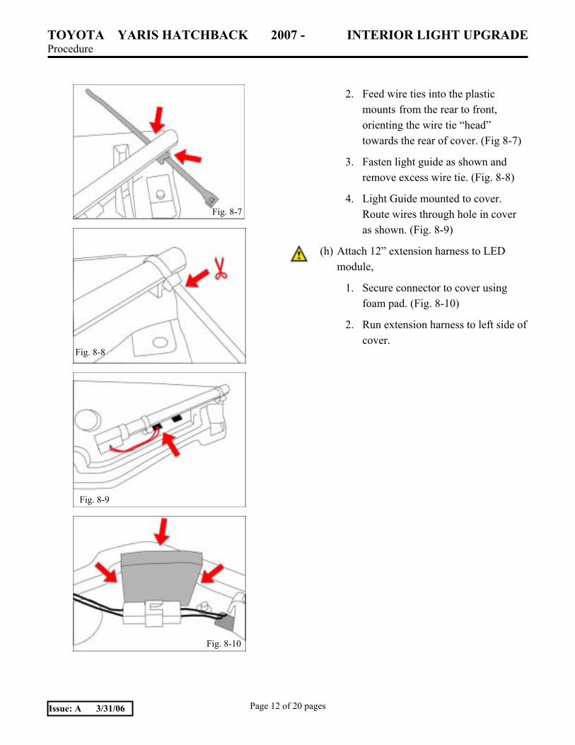
(e) Route LED module lead to Passenger side. (Fig. 7-4)
Fig. 7-1
Fig. 7-2
Fig. 7-3
Fig. 7-4
TOYOTA YARIS HATCHBACK 2007 - INTERIOR LIGHT UPGRADE Procedure
Page 10 of 20 pages Issue: A 3/31/06
(f) Route LED module lead to drivers side LED module as shown. (Fig. 7-5)
(g) Secure excess harness with 4� wire tie.
(h) Reassemble and reinstall center control panel.
8. Install Passenger Side Light Guide, Shield Present
(a) Remove Under dash shield.
1. Depress front edge tabs, drop shield pulling forward.
(b) Remove felt cover. (Fig. 8-1)
(c) Mark cover for drilling, use template and mark cover using punch or scribe. (Fig. 8-2a, 8-2b)
Fig. 7-5
Fig. 8-1
Fig. 8-2a
Fig. 8-2b
TOYOTA YARIS HATCHBACK 2007 - INTERIOR LIGHT UPGRADE Procedure
Page 11 of 20 pages Issue: A 3/31/06
(d) Use 1/8� drill bit and drill hole for rivets. (Fig. 8-3)
(e) Install rivet through light guide cradle. (Fig. 8-4)
(f) Install rivet washer to rivet and install using rivet gun. (Fig. 8-5)
(g) Install LED module to clear end of 7� light guide as shown. Carefully note alignment of reflector (Fig. 8-6)
1. Install light guide onto cover attach with 7� wire tie.
Fig. 8-3
Fig. 8-4
Fig. 8-6
Fig. 8-5
TOYOTA YARIS HATCHBACK 2007 - INTERIOR LIGHT UPGRADE Procedure
Page 12 of 20 pages Issue: A 3/31/06
2. Feed wire ties into the plastic mounts from the rear to front, orienting the wire tie �head� towards the rear of cover. (Fig 8-7)
3. Fasten light guide as shown and remove excess wire tie. (Fig. 8-8)
4. Light Guide mounted to cover. Route wires through hole in cover as shown. (Fig. 8-9)
(h) Attach 12� extension harness to LED module,
1. Secure connector to cover using foam pad. (Fig. 8-10)
2. Run extension harness to left side of cover.
Fig. 8-7
Fig. 8-8
Fig. 8-9
Fig. 8-10
TOYOTA YARIS HATCHBACK 2007 - INTERIOR LIGHT UPGRADE Procedure
Page 13 of 20 pages Issue: A 3/31/06
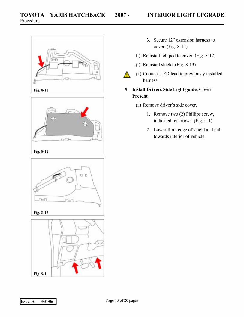
3. Secure 12� extension harness to cover. (Fig. 8-11)
(i) Reinstall felt pad to cover. (Fig. 8-12)
(j) Reinstall shield. (Fig. 8-13)
(k) Connect LED lead to previously installed harness.
9. Install Drivers Side Light guide, Cover Present
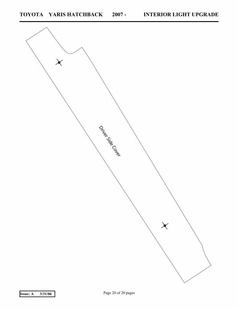
(a) Remove driver�s side cover.
1. Remove two (2) Phillips screw, indicated by arrows. (Fig. 9-1)
2. Lower front edge of shield and pull towards interior of vehicle.
Fig. 8-11
Fig. 8-12
Fig. 8-13
Fig. 9-1
TOYOTA YARIS HATCHBACK 2007 - INTERIOR LIGHT UPGRADE Procedure
Page 14 of 20 pages Issue: A 3/31/06
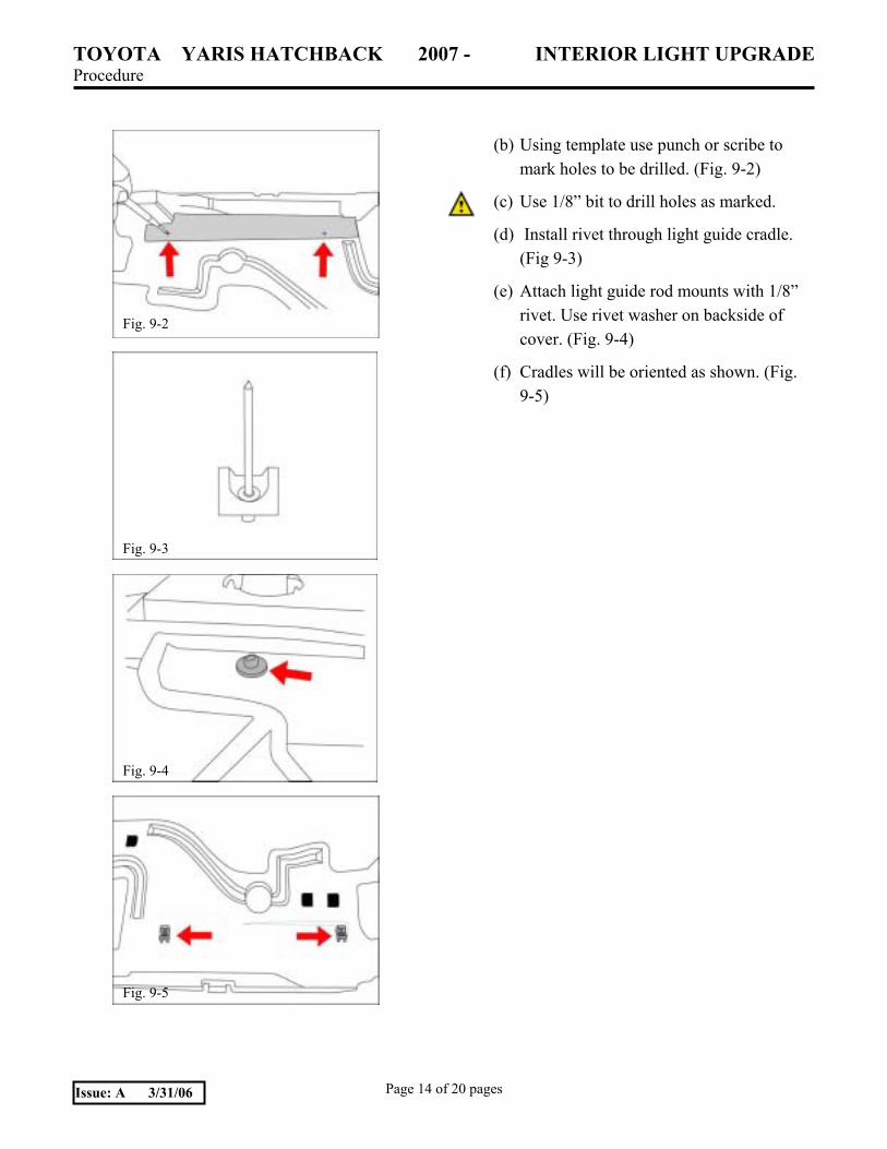
(b) Using template use punch or scribe to mark holes to be drilled. (Fig. 9-2)
(c) Use 1/8� bit to drill holes as marked.
(d) Install rivet through light guide cradle. (Fig 9-3)
(e) Attach light guide rod mounts with 1/8� rivet. Use rivet washer on backside of cover. (Fig. 9-4)
(f) Cradles will be oriented as shown. (Fig. 9-5)
Fig. 9-2
Fig. 9-3
Fig. 9-4
Fig. 9-5
TOYOTA YARIS HATCHBACK 2007 - INTERIOR LIGHT UPGRADE Procedure
Page 15 of 20 pages Issue: A 3/31/06
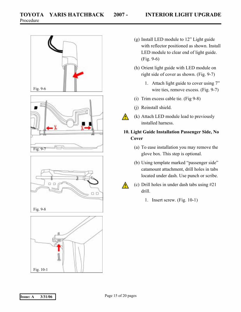
(g) Install LED module to 12� Light guide with reflector positioned as shown. Install LED module to clear end of light guide. (Fig. 9-6)
(h) Orient light guide with LED module on right side of cover as shown. (Fig. 9-7)
1. Attach light guide to cover using 7� wire ties, remove excess. (Fig. 9-7)
(i) Trim excess cable tie. (Fig 9-8)
(j) Reinstall shield.
(k) Attach LED module lead to previously installed harness.
10. Light Guide Installation Passenger Side, No Cover
(a) To ease installation you may remove the glove box. This step is optional.
(b) Using template marked �passenger side� catamount attachment, drill holes in tabs located under dash. Use punch or scribe.
(c) Drill holes in under dash tabs using #21 drill.
1. Insert screw. (Fig. 10-1)
Fig. 9-6
Fig. 9-7
Fig. 9-8
Fig. 10-1
TOYOTA YARIS HATCHBACK 2007 - INTERIOR LIGHT UPGRADE Procedure
Page 16 of 20 pages Issue: A 3/31/06
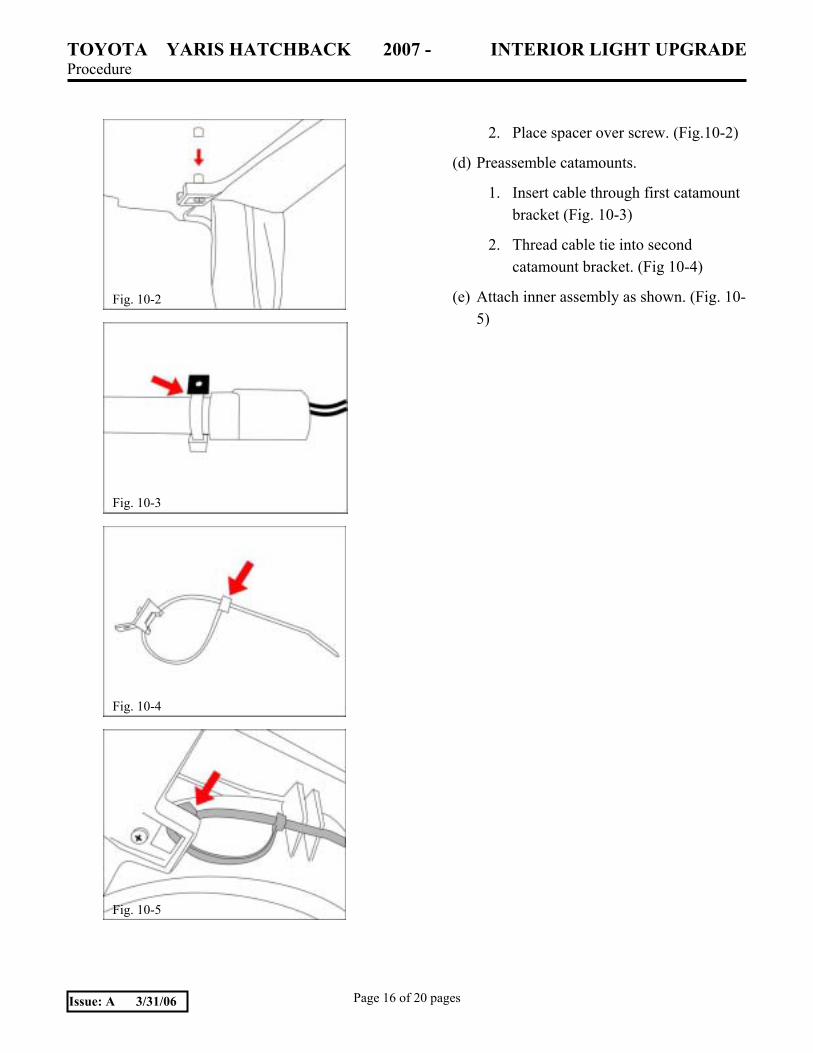
2. Place spacer over screw. (Fig. 10-2)
(d) Preassemble catamounts.
1. Insert cable through first catamount bracket (Fig. 10-3)
2. Thread cable tie into second catamount bracket. (Fig 10-4)
(e) Attach inner assembly as shown. (Fig. 10-5)
Fig. 10-3
Fig. 10-2
Fig. 10-4
Fig. 10-5
TOYOTA YARIS HATCHBACK 2007 - INTERIOR LIGHT UPGRADE Procedure
Page 17 of 20 pages Issue: A 3/31/06
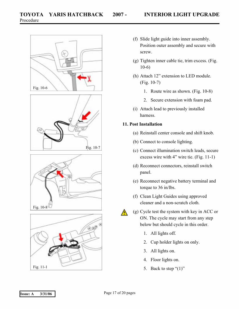
(f) Slide light guide into inner assembly. Position outer assembly and secure with screw.
(g) Tighten inner cable tie, trim excess. (Fig. 10-6)
(h) Attach 12� extension to LED module. (Fig. 10-7)
1. Route wire as shown. (Fig. 10-8)
2. Secure extension with foam pad.
(i) Attach lead to previously installed harness.
11. Post Installation
(a) Reinstall center console and shift knob.
(b) Connect to console lighting.
(c) Connect illumination switch leads, secure excess wire with 4� wire tie. (Fig. 11-1)
(d) Reconnect connectors, reinstall switch panel.
(e) Reconnect negative battery terminal and torque to 36 in/lbs.
(f) Clean Light Guides using approved cleaner and a non-scratch cloth.
(g) Cycle test the system with key in ACC or ON. The cycle may start from any step below but should cycle in this order.
1. All lights off.
2. Cup holder lights on only.
3. All lights on.
4. Floor lights on.
5. Back to step �(1)�
Fig. 10-6
Fig. 10-8
Fig. 11-1
Fig. 10-7
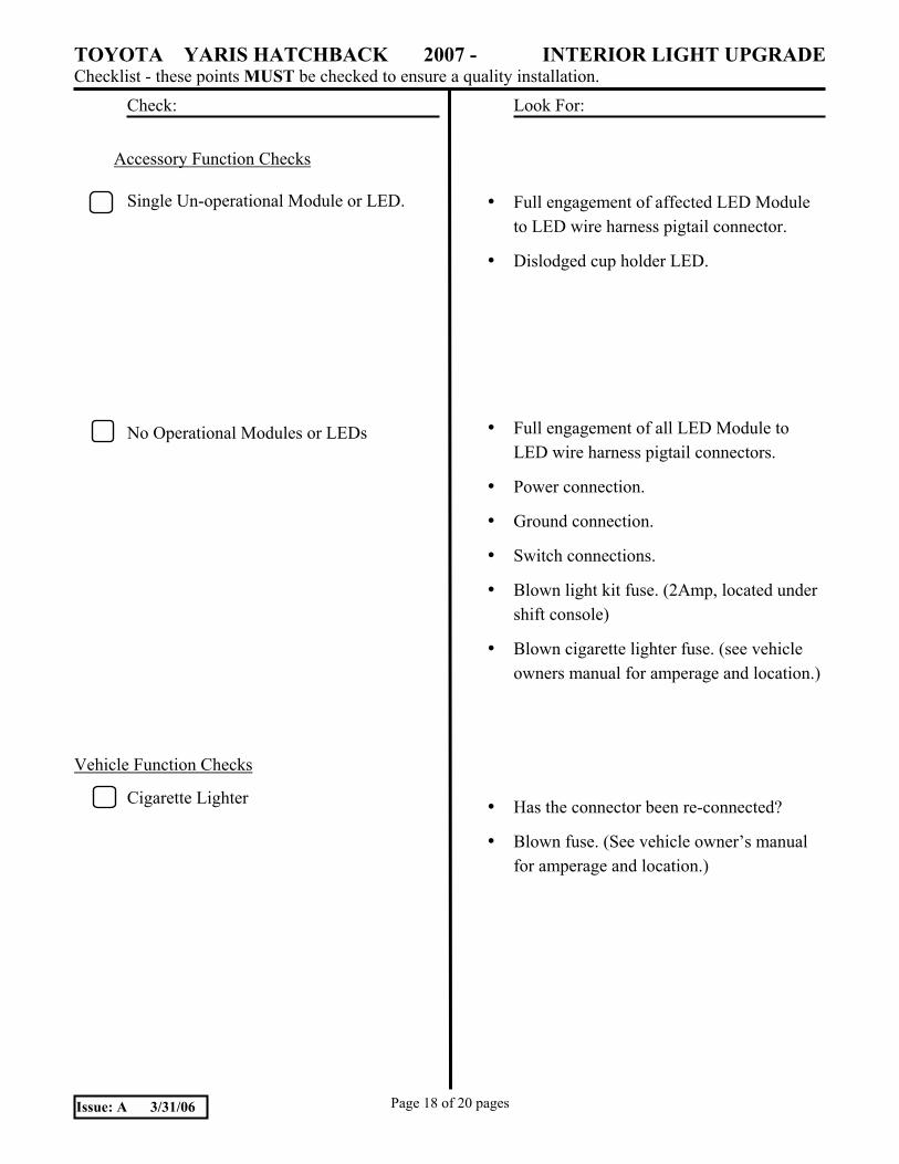
TOYOTA YARIS HATCHBACK 2007 - INTERIOR LIGHT UPGRADE Checklist - these points MUST be checked to ensure a quality installation.
Check: Look For:
Page 18 of 20 pages Issue: A 3/31/06
Accessory Function Checks
Single Un-operational Module or LED.
No Operational Modules or LEDs
Vehicle Function Checks
Cigarette Lighter
• Full engagement of affected LED Module to LED wire harness pigtail connector.
• Dislodged cup holder LED.
• Full engagement of all LED Module to LED wire harness pigtail connectors.
• Power connection.
• Ground connection.
• Switch connections.
• Blown light kit fuse. (2Amp, located under shift console)
• Blown cigarette lighter fuse. (see vehicle owners manual for amperage and location.)
• Has the connector been re-connected?
• Blown fuse. (See vehicle owner�s manual for amperage and location.)
TOYOTA YARIS HATCHBACK 2007 - INTERIOR LIGHT UPGRADE
Page 19 of 20 pages Issue: A 3/31/06
TOYOTA YARIS HATCHBACK 2007 - INTERIOR LIGHT UPGRADE
Page 20 of 20 pages Issue: A 3/31/06