Embed Size (px)
Citation preview
TECHNICAL REPORT
© The Broadband Forum. All rights reserved.
TR-156Using GPON Access in the context of TR-101
Issue: 1Issue Date: December 2008
Using GPON Access in the context of TR-101 TR-156 Issue 1
December 2008 © The Broadband Forum. All rights reserved 2
Notice
The Broadband Forum is a non-profit corporation organized to create guidelines for broadband network system development and deployment. This Broadband Forum Technical Report has been approved by members of the Forum. This Broadband Forum Technical Report is not binding on the Broadband Forum, any of its members, or any developer or service provider. This Broadband Forum Technical Report is subject to change, but only with approval of members of the Forum. This Technical Report is copyrighted by the Broadband Forum, and all rights are reserved. Portions of this Technical Report may be copyrighted by Broadband Forum members.
This Broadband Forum Technical Report is provided AS IS, WITH ALL FAULTS. ANY PERSON HOLDING A COPYRIGHT IN THIS BROADBAND FORUM TECHNICAL REPORT, OR ANY PORTION THEREOF, DISCLAIMS TO THE FULLEST EXTENT PERMITTED BY LAW ANY REPRESENTATION OR WARRANTY, EXPRESS OR IMPLIED, INCLUDING, BUT NOT LIMITED TO, ANY WARRANTY:
(A) OF ACCURACY, COMPLETENESS, MERCHANTABILITY, FITNESS FOR A PARTICULAR PURPOSE, NON-INFRINGEMENT, OR TITLE;
(B) THAT THE CONTENTS OF THIS BROADBAND FORUM TECHNICAL REPORT ARESUITABLE FOR ANY PURPOSE, EVEN IF THAT PURPOSE IS KNOWN TO THE COPYRIGHT HOLDER;
(C) THAT THE IMPLEMENTATION OF THE CONTENTS OF THE DOCUMENTATION WILL NOT INFRINGE ANY THIRD PARTY PATENTS, COPYRIGHTS, TRADEMARKS OR OTHER RIGHTS.
By using this Broadband Forum Technical Report, users acknowledge that implementation may require licenses to patents. The Broadband Forum encourages but does not require its members to identify such patents. For a list of declarations made by Broadband Forum member companies, please see http://www.broadband-forum.org. No assurance is given that licenses to patents necessary to implement this Technical Report will be available for license at all or on reasonable and non-discriminatory terms.
ANY PERSON HOLDING A COPYRIGHT IN THIS BROADBAND FORUM TECHNICAL REPORT, OR ANY PORTION THEREOF, DISCLAIMS TO THE FULLEST EXTENT PERMITTED BY LAW (A) ANY LIABILITY (INCLUDING DIRECT, INDIRECT, SPECIAL, OR CONSEQUENTIAL DAMAGES UNDER ANY LEGAL THEORY) ARISING FROM OR RELATED TO THE USE OF OR RELIANCE UPON THIS TECHNICAL REPORT; AND (B) ANY OBLIGATION TO UPDATE OR CORRECT THIS TECHNICAL REPORT.
Broadband Forum Technical Reports may be copied, downloaded, stored on a server or otherwise re-distributed in their entirety only, and may not be modified without the advance written permission of the Broadband Forum.
The text of this notice must be included in all copies of this Broadband Forum Technical Report.
Using GPON Access in the context of TR-101 TR-156 Issue 1
December 2008 © The Broadband Forum. All rights reserved 3
Issue History
IssueNumber
IssueDate
IssueEditor
Changes
1 December 2008 Tom Anschutz, AT&TLior Yeheskiel, ECI Telecom
Original
Technical comments or questions about this Technical Report should be directed to:
Editors: Tom Anschutz AT&T [email protected] Yeheskiel ECI Telecom [email protected]
A&T WG Chairs David Allan Nortel [email protected] Thorne BT [email protected]
Using GPON Access in the context of TR-101 TR-156 Issue 1
December 2008 © The Broadband Forum. All rights reserved 4
Table of Contents
1. PURPOSE .........................................................................................................................................................................7
2. SCOPE ..............................................................................................................................................................................8
2.1 DEFINITIONS..............................................................................................................................................................92.2 ABBREVIATIONS......................................................................................................................................................102.3 CONVENTIONS.........................................................................................................................................................112.4 KEYWORDS .............................................................................................................................................................11
3. REFERENCES...............................................................................................................................................................12
4. FUNDAMENTAL ARCHITECTURAL AND TOPOLOGICAL ASPECTS...........................................................13
4.1 ONU/ONT AND THE RESIDENTIAL GATEWAY ........................................................................................................134.2 U REFERENCE POINT INTERFACES...........................................................................................................................154.3 R/S AND S/R REFERENCE POINTS............................................................................................................................164.4 GPON TO ETHERNET ADAPTATION.........................................................................................................................164.5 DEPLOYMENT SCENARIOS .......................................................................................................................................17
5. GPON ACCESS ARCHITECTURE ............................................................................................................................20
5.1 VLANS AND GEM PORTS.......................................................................................................................................205.1.1 N:1 VLAN...........................................................................................................................................................215.1.2 1:1 VLAN ...........................................................................................................................................................225.1.3 VLANs for Business Ethernet Services (VBES)..................................................................................................235.1.4 VLAN Requirements...........................................................................................................................................24
5.2 QOS.........................................................................................................................................................................275.2.1 QoS Architecture................................................................................................................................................275.2.2 Upstream Traffic Management ..........................................................................................................................285.2.3 Downstream Traffic Management .....................................................................................................................295.2.4 Traffic Management Requirements ....................................................................................................................30
5.3 IGMP CONTROLLED MULTICAST ............................................................................................................................325.3.1 Introduction .......................................................................................................................................................325.3.2 GPON Specific Multicast Requirements ............................................................................................................32
5.4 NON-IGMP CONTROLLED MULTICAST AND BROADCAST .......................................................................................365.4.1 Introduction .......................................................................................................................................................365.4.2 Multicast that needs to be treated as unicast at the OLT...................................................................................375.4.3 Unknown MAC address frames at the OLT .......................................................................................................375.4.4 Broadcast MAC address frames at the OLT ......................................................................................................375.4.5 Downstream GEM Ports at the ONU.................................................................................................................37
5.5 SECURITY CONSIDERATIONS ...................................................................................................................................375.6 FILTERING ...............................................................................................................................................................385.7 PORT IDENTIFICATION AND CHARACTERIZATION ....................................................................................................38
6. OAM................................................................................................................................................................................41
6.1 OAM FOR 1:1 VLANS ............................................................................................................................................416.2 OAM FOR N:1 VLANS ...........................................................................................................................................436.3 OAM FOR BUSINESS ETHERNET SERVICES..............................................................................................................45
7. NETWORK MANAGEMENT .....................................................................................................................................48
7.1 REMOTE MANAGEMENT OF ONUS ..........................................................................................................................487.2 INITIAL PROVISIONING OF ONUS ............................................................................................................................48
APPENDIX A...........................................................................................................................................................................50
Using GPON Access in the context of TR-101 TR-156 Issue 1
December 2008 © The Broadband Forum. All rights reserved 5
List of FiguresFigure 1 – Network architecture for Ethernet-based GPON aggregation................................................... 9Figure 2 – ONT and RG as separate entities............................................................................................. 13Figure 3 – ONT and RG as a single entity................................................................................................ 14Figure 4 – ONU with Multiple Subscriber Ports ...................................................................................... 15Figure 5 – New Protocol Stacks for Interfaces at the U Reference Point................................................. 16Figure 6 – GPON to Ethernet adaptation.................................................................................................. 17Figure 7 – FTTH deployment scenario..................................................................................................... 17Figure 8 – FITH deployment scenario ...................................................................................................... 18Figure 9 – FTTO deployment scenario..................................................................................................... 18Figure 10 – MDU deployment scenario.................................................................................................... 18Figure 11 – MTU deployment scenario .................................................................................................... 19Figure 12 – N:1 VLAN Example.............................................................................................................. 22Figure 13 – 1:1 VLAN Example............................................................................................................... 23Figure 14 – Transparent LAN Example.................................................................................................... 24Figure 15 – GPON GEM adaptation of Ethernet...................................................................................... 28Figure 16 – Upstream Queuing and Scheduling Model Example ............................................................ 29Figure 17 – Downstream Queuing and Scheduling Model Example ....................................................... 30Figure 18 – GPON Multicast GEM ports ................................................................................................. 33Figure 19 – Ethernet CFM for 1:1 VLANs............................................................................................... 41Figure 20 – One Example of CFM Frame Formats at Different Points for 1:1 VLANs .......................... 43Figure 21 – Ethernet CFM for N:1 VLANs.............................................................................................. 44Figure 22 – Ethernet CFM for Carrier-S-tagged TLS VLANs................................................................. 45Figure 23 – Ethernet CFM for Customer-S-tagged TLS VLANs............................................................. 47Figure 24 – ONU Registration.................................................................................................................. 48
List of Tables
Table 1 – Port Identification String Elements........................................................................................... 39Table 2 – Four Classes with Strict Priority............................................................................................... 50Table 3 – Four Classes with Weighting and Priority................................................................................ 50
Using GPON Access in the context of TR-101 TR-156 Issue 1
December 2008 © The Broadband Forum. All rights reserved 6
Summary
TR-101 provided an Ethernet-based architecture that has become a global standard for triple-play deployments for residential and business customers that use DSL as the broadband access technology. However, many of TR-101’s architecture specifications are access agnostic, and they are also being widely used today with other access technologies, especially FTTx / PON.
This Technical Report strengthens the TR-101 requirements as applied to GPON by providing more detailed and specific requirements. In order to reduce operational complexity and maximize equipment interoperability, a subset of the GPON’s flexible configuration arrangements are specified here to facilitate the implementation of TR-101’s VLAN architecture options. Other parts of this specification enable providers to take full advantage of GPON’s abilities to achieve TR-101 requirements for multicast, Quality of Service (QoS), OAM and NMS.

Using GPON Access in the context of TR-101 TR-156 Issue 1
December 2008 © The Broadband Forum. All rights reserved 7
1. Purpose
TR-101 is a popular and successful Broadband Forum architecture that has enjoyed significant success in the marketplace. However, many of the benefits provided by TR-101 are not associated with DSL or DSLAM network elements, and some of the benefits and requirements that do apply to DSL access nodes are abstract enough to apply to many types of access – not just DSL.
Recognizing these benefits, some service providers planning Gigabit-capable Passive Optical Network (GPON) deployments are eager to use elements of the architecture and requirements provided by TR-101, but find that there are some aspects of GPON deployment that require definition and could benefit from standardization. This is especially true of service providers that are planning both GPON deployments as well as DSL deployments, or those that have already deployed DSL in a TR-101-compliant approach and intend to add GPON. Similarly, equipment vendors of the network elements and management systems described in TR-101 are very interested in determining the requirements and approach to make GPON equipment fit into TR-101 applications with minimal variation among service provider deployments.
This Technical Report is intended to provide the architectural basis and technical requirements in addition to those specified in TR-101 that are needed to successfully deploy GPON access nodes within a TR-101 architecture, either independently or alongside other TR-101 access node types.
Using GPON Access in the context of TR-101 TR-156 Issue 1
December 2008 © The Broadband Forum. All rights reserved 8
2. Scope
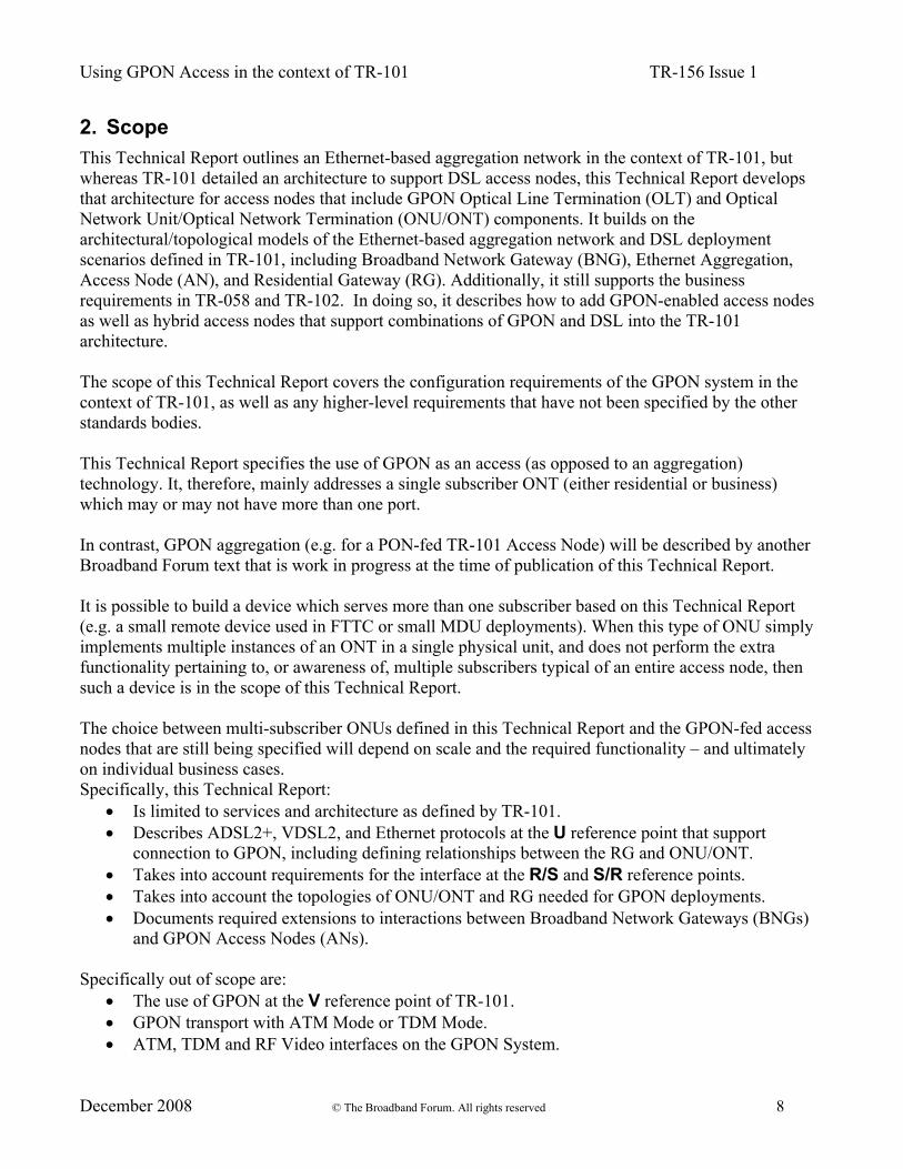
This Technical Report outlines an Ethernet-based aggregation network in the context of TR-101, but whereas TR-101 detailed an architecture to support DSL access nodes, this Technical Report develops that architecture for access nodes that include GPON Optical Line Termination (OLT) and Optical Network Unit/Optical Network Termination (ONU/ONT) components. It builds on the architectural/topological models of the Ethernet-based aggregation network and DSL deployment scenarios defined in TR-101, including Broadband Network Gateway (BNG), Ethernet Aggregation, Access Node (AN), and Residential Gateway (RG). Additionally, it still supports the business requirements in TR-058 and TR-102. In doing so, it describes how to add GPON-enabled access nodes as well as hybrid access nodes that support combinations of GPON and DSL into the TR-101 architecture.
The scope of this Technical Report covers the configuration requirements of the GPON system in the context of TR-101, as well as any higher-level requirements that have not been specified by the other standards bodies.
This Technical Report specifies the use of GPON as an access (as opposed to an aggregation) technology. It, therefore, mainly addresses a single subscriber ONT (either residential or business) which may or may not have more than one port.
In contrast, GPON aggregation (e.g. for a PON-fed TR-101 Access Node) will be described by another Broadband Forum text that is work in progress at the time of publication of this Technical Report.
It is possible to build a device which serves more than one subscriber based on this Technical Report(e.g. a small remote device used in FTTC or small MDU deployments). When this type of ONU simply implements multiple instances of an ONT in a single physical unit, and does not perform the extra functionality pertaining to, or awareness of, multiple subscribers typical of an entire access node, then such a device is in the scope of this Technical Report.
The choice between multi-subscriber ONUs defined in this Technical Report and the GPON-fed access nodes that are still being specified will depend on scale and the required functionality – and ultimately on individual business cases.Specifically, this Technical Report:
Is limited to services and architecture as defined by TR-101. Describes ADSL2+, VDSL2, and Ethernet protocols at the U reference point that support
connection to GPON, including defining relationships between the RG and ONU/ONT. Takes into account requirements for the interface at the R/S and S/R reference points. Takes into account the topologies of ONU/ONT and RG needed for GPON deployments. Documents required extensions to interactions between Broadband Network Gateways (BNGs)
and GPON Access Nodes (ANs).
Specifically out of scope are: The use of GPON at the V reference point of TR-101. GPON transport with ATM Mode or TDM Mode. ATM, TDM and RF Video interfaces on the GPON System.
Using GPON Access in the context of TR-101 TR-156 Issue 1
December 2008 © The Broadband Forum. All rights reserved 9
RAN
Regional BroadbandNetwork
Access Network
OLTEthAggIP
BNG
L2TS
IP - QoS
L2TP
Customer Prem. Net
RG
NSP2
ASP1
A10U
User1
User2T
NSP3
IP - QoS
V
NSP1
/BNG
ONT/ONUODN
R/SS/R
Access Node
Ethernet
RAN
Regional BroadbandNetwork
Access Network
OLTEthAggIP
BNG
L2TS
IP - QoS
L2TP
Customer Prem. Net
RG
NSP2
ASP1
A10U
User1
User2T
NSP3
IP - QoS
V
NSP1
/BNG
ONT/ONUODN
R/SS/R
Access Node
Ethernet
Figure 1 – Network architecture for Ethernet-based GPON aggregation
This specification encompasses OLT, ONU (including ONT) elements as well as changes to the Ureference point protocols and the introduction of the R/S and S/R reference points.
2.1Definitions
DBA A process, by which the Optical Line Terminal (OLT) distributes the upstream PON capacity between the traffic-bearing entities within Optical Network Units (ONUs), based on the dynamic indication of their activity status and their configured traffic contracts.
GEM Encapsulation G-PON Encapsulation Method (GEM): A data frame transport scheme used in G-PON systems that is connection-oriented and that supports fragmentation of the user data frames into variable sized transmission fragments.
GEM Port An abstraction on the GTC adaptation sublayer representing a logical connection associated with a specific client traffic flow. The GTC adaptation sublayer is a sublayer of the GPON Transmission Convergence layer that supports the functions of user data fragmentation and de-fragmentation, GEM encapsulation, GEM frame delineation, and GEM Port-ID filtering.
GEM Port Id A 12-bit value which is assigned by the OLT to the individual logical connections transported over the GPON interface and which is carried in the header of all the GEM frames associated with the given logical connection.
GPON Interface The interface at reference points S/R and R/S as specified in ITU-T G.984.1. This is a PON-specific interface that supports all the protocol elements necessary to allow transmission between OLT and ONUs.
GPON Network An OLT connected using an Optical Distribution Network (ODN) to one or more ONUs or ONTs. A GPON network is a subset of the Access Network.
OLT Optical Line Termination (OLT): A device that terminates the common (root) endpoint of an ODN, implements a PON protocol, such as that defined by G.984, and adapts PON PDUs for uplink communications over the provider service interface. The OLT provides management and maintenance functions for the subtended ODN and ONUs.
ONT Optical Network Termination (ONT): A single subscriber device that terminates any one of the distributed (leaf) endpoints of an ODN, implements a PON
Using GPON Access in the context of TR-101 TR-156 Issue 1
December 2008 © The Broadband Forum. All rights reserved 10
protocol, and adapts PON PDUs to subscriber service interfaces. An ONT is a special case of an ONU.
ONU Optical Network Unit (ONU): A generic term denoting a device that terminates any one of the distributed (leaf) endpoints of an ODN, implements a PON protocol, and adapts PON PDUs to subscriber service interfaces. In some contexts, an ONU implies a multiple subscriber device.
Subscriber A billable entity.T-CONT A traffic-bearing object within an ONU that represents a group of logical
connections, is managed via the ONU Management and Control Channel (OMCC), and is treated as a single entity for the purpose of upstream bandwidth assignment on the PON.
Traffic Flow A sequence of frames or packets traversing a particular reference point within a network that share a specific frame/packet header pattern. For example, an Ethernet traffic flow can be identified by any combination of specific source MAC address, destination MAC, VLAN ID, 802.1p bits, etc.
Traffic Classes (TC) - Traffic Classes are the set of upstream and downstream supported forwarding behaviours in the network element.
U interface U interface is a short form of expressing one or more of the interfaces defined in this Technical Report or in TR-101 at the U reference point. It is also essentially equivalent to a subscriber-facing interface at the access node.
V interface V interface is a short form of expressing one or more of the interfaces defined in TR-101 at the V reference point. It is also essentially equivalent to a network-facing interface at the access node.
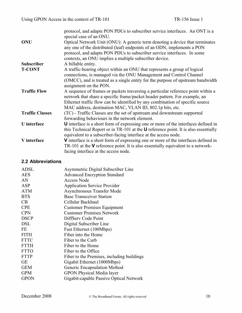
2.2 Abbreviations
ADSL Asymmetric Digital Subscriber LineAES Advanced Encryption StandardAN Access NodeASP Application Service ProviderATM Asynchronous Transfer ModeBTS Base Transceiver StationCB Cellular BackhaulCPE Customer Premises EquipmentCPN Customer Premises NetworkDSCP DiffServ Code PointDSL Digital Subscriber LineFE Fast Ethernet (100Mbps)FITH Fiber into the HomeFTTC Fiber to the CurbFTTH Fiber to the HomeFTTO Fiber to the OfficeFTTP Fiber to the Premises, including buildingsGE Gigabit Ethernet (1000Mbps)GEM Generic Encapsulation MethodGPM GPON Physical Media layerGPON Gigabit-capable Passive Optical Network
Using GPON Access in the context of TR-101 TR-156 Issue 1
December 2008 © The Broadband Forum. All rights reserved 11
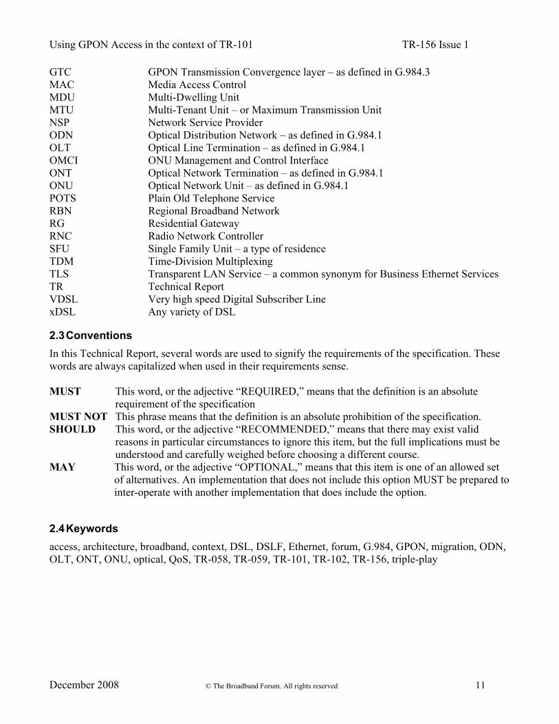
GTC GPON Transmission Convergence layer – as defined in G.984.3MAC Media Access Control MDU Multi-Dwelling UnitMTU Multi-Tenant Unit – or Maximum Transmission UnitNSP Network Service ProviderODN Optical Distribution Network – as defined in G.984.1OLT Optical Line Termination – as defined in G.984.1OMCI ONU Management and Control InterfaceONT Optical Network Termination – as defined in G.984.1ONU Optical Network Unit – as defined in G.984.1 POTS Plain Old Telephone ServiceRBN Regional Broadband NetworkRG Residential GatewayRNC Radio Network ControllerSFU Single Family Unit – a type of residenceTDM Time-Division MultiplexingTLS Transparent LAN Service – a common synonym for Business Ethernet ServicesTR Technical ReportVDSL Very high speed Digital Subscriber LinexDSL Any variety of DSL
2.3Conventions
In this Technical Report, several words are used to signify the requirements of the specification. These words are always capitalized when used in their requirements sense.
MUST This word, or the adjective “REQUIRED,” means that the definition is an absolute requirement of the specification
MUST NOT This phrase means that the definition is an absolute prohibition of the specification.SHOULD This word, or the adjective “RECOMMENDED,” means that there may exist valid
reasons in particular circumstances to ignore this item, but the full implications must be understood and carefully weighed before choosing a different course.
MAY This word, or the adjective “OPTIONAL,” means that this item is one of an allowed set of alternatives. An implementation that does not include this option MUST be prepared to inter-operate with another implementation that does include the option.
2.4Keywords
access, architecture, broadband, context, DSL, DSLF, Ethernet, forum, G.984, GPON, migration, ODN, OLT, ONT, ONU, optical, QoS, TR-058, TR-059, TR-101, TR-102, TR-156, triple-play

Using GPON Access in the context of TR-101 TR-156 Issue 1
December 2008 © The Broadband Forum. All rights reserved 12
3. References
The following references constitute provisions of this Technical Report. At the time of publication, the editions indicated were valid. All references are subject to revision; users of this Technical Report are therefore encouraged to investigate the possibility of applying the most recent edition of the references listed below. A list of the currently valid Broadband Forum Technical Reports is published at www.broadband-forum.org.
[1] Broadband Forum TR-101 (April 2006), Migration to Ethernet-Based DSL Aggregation.[2] ITU Specifications G.984 and their amendments: Gigabit-capable Passive Optical Networks
Using GPON Access in the context of TR-101 TR-156 Issue 1
December 2008 © The Broadband Forum. All rights reserved 13
4. Fundamental Architectural and Topological Aspects
This section describes those aspects and areas that differ from TR-101. There are no changes to the requirements for the BNG and Aggregation Node, nor changes to the protocols at the V reference point.
The case of a deployment scenario consisting of ONU and OLT can be regarded as an Access Node that is decomposed into two geographically distributed functions. One is the ONU facing the user with the Ureference point and the other is the OLT, which provides the aggregation and meets the V reference point. Given this, the functionality described in TR-101 can be distributed between these entities.
The approach taken for this Technical Report focuses on describing the functionalities that derive from the use of GPON between the OLT and ONU, and therefore in the following text OLT, ONU and ONT will be used to describe the physical entities. The general term Access Node will be used when describing a function that does not depend on the physical location but rather on the black box behaviour of the combination of OLT and ONU.
The Access Node, as described in TR-101, is distributed between the OLT and ONU. The OLT and ONU share the responsibility for Access Node requirements as specified in TR-101. The exception to this would be in the configuration where the ONU also encompasses the RG, and in this configuration the combined element would take on additional responsibility for both ONU as well as RG requirements.
4.1ONU/ONT and the Residential Gateway
There are three main deployment options for GPON ONUs. The following section details these options and provides a reference diagram for each option.
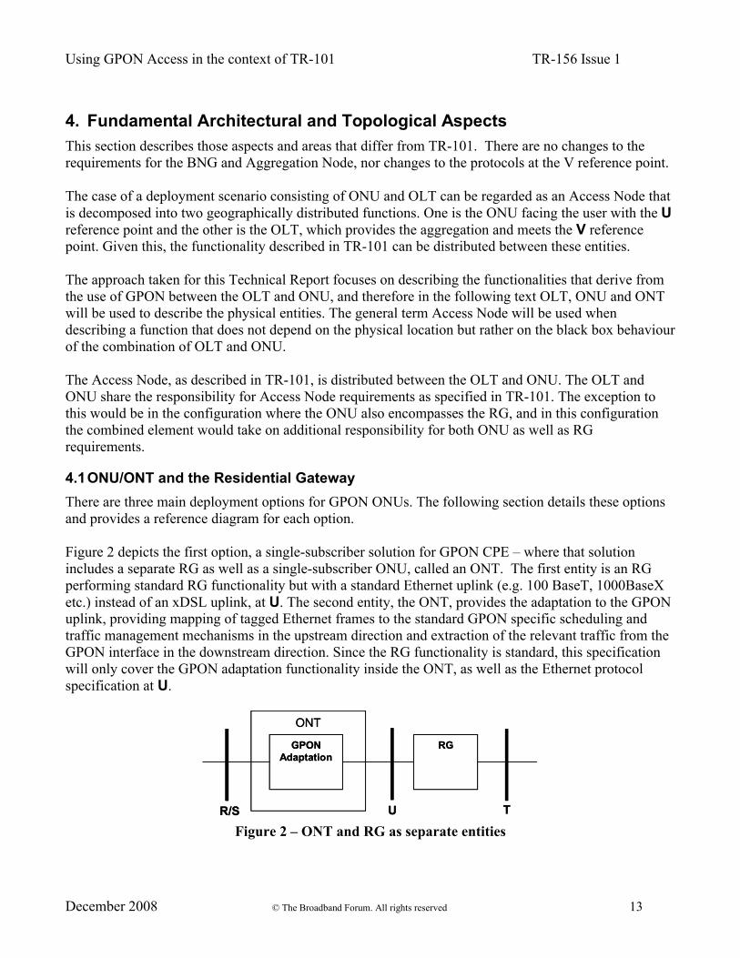
Figure 2 depicts the first option, a single-subscriber solution for GPON CPE – where that solution includes a separate RG as well as a single-subscriber ONU, called an ONT. The first entity is an RG performing standard RG functionality but with a standard Ethernet uplink (e.g. 100 BaseT, 1000BaseX etc.) instead of an xDSL uplink, at U. The second entity, the ONT, provides the adaptation to the GPON uplink, providing mapping of tagged Ethernet frames to the standard GPON specific scheduling and traffic management mechanisms in the upstream direction and extraction of the relevant traffic from the GPON interface in the downstream direction. Since the RG functionality is standard, this specification will only cover the GPON adaptation functionality inside the ONT, as well as the Ethernet protocol specification at U.
ONT
GPONAdaptation
RG
UR/S T
ONT
GPONAdaptation
RG
UR/S T
Figure 2 – ONT and RG as separate entities
Using GPON Access in the context of TR-101 TR-156 Issue 1
December 2008 © The Broadband Forum. All rights reserved 14
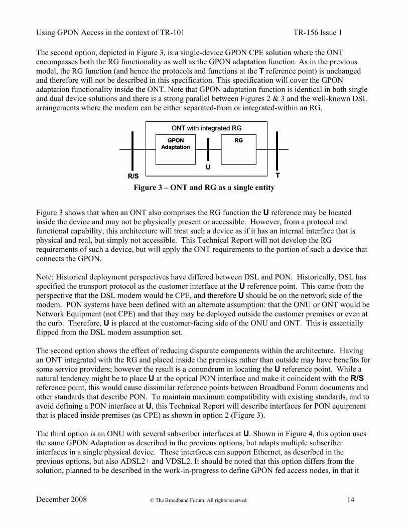
The second option, depicted in Figure 3, is a single-device GPON CPE solution where the ONT encompasses both the RG functionality as well as the GPON adaptation function. As in the previous model, the RG function (and hence the protocols and functions at the T reference point) is unchanged and therefore will not be described in this specification. This specification will cover the GPON adaptation functionality inside the ONT. Note that GPON adaptation function is identical in both single and dual device solutions and there is a strong parallel between Figures 2 & 3 and the well-known DSL arrangements where the modem can be either separated-from or integrated-within an RG.
ONT with integrated RG
GPONAdaptation
RG
UR/S T
ONT with integrated RG
GPONAdaptation
RG
UR/S T
Figure 3 – ONT and RG as a single entity
Figure 3 shows that when an ONT also comprises the RG function the U reference may be located inside the device and may not be physically present or accessible. However, from a protocol and functional capability, this architecture will treat such a device as if it has an internal interface that is physical and real, but simply not accessible. This Technical Report will not develop the RG requirements of such a device, but will apply the ONT requirements to the portion of such a device that connects the GPON.
Note: Historical deployment perspectives have differed between DSL and PON. Historically, DSL has specified the transport protocol as the customer interface at the U reference point. This came from the perspective that the DSL modem would be CPE, and therefore U should be on the network side of the modem. PON systems have been defined with an alternate assumption: that the ONU or ONT would be Network Equipment (not CPE) and that they may be deployed outside the customer premises or even at the curb. Therefore, U is placed at the customer-facing side of the ONU and ONT. This is essentially flipped from the DSL modem assumption set.
The second option shows the effect of reducing disparate components within the architecture. Having an ONT integrated with the RG and placed inside the premises rather than outside may have benefits for some service providers; however the result is a conundrum in locating the U reference point. While a natural tendency might be to place U at the optical PON interface and make it coincident with the R/Sreference point, this would cause dissimilar reference points between Broadband Forum documents and other standards that describe PON. To maintain maximum compatibility with existing standards, and to avoid defining a PON interface at U, this Technical Report will describe interfaces for PON equipment that is placed inside premises (as CPE) as shown in option 2 (Figure 3).
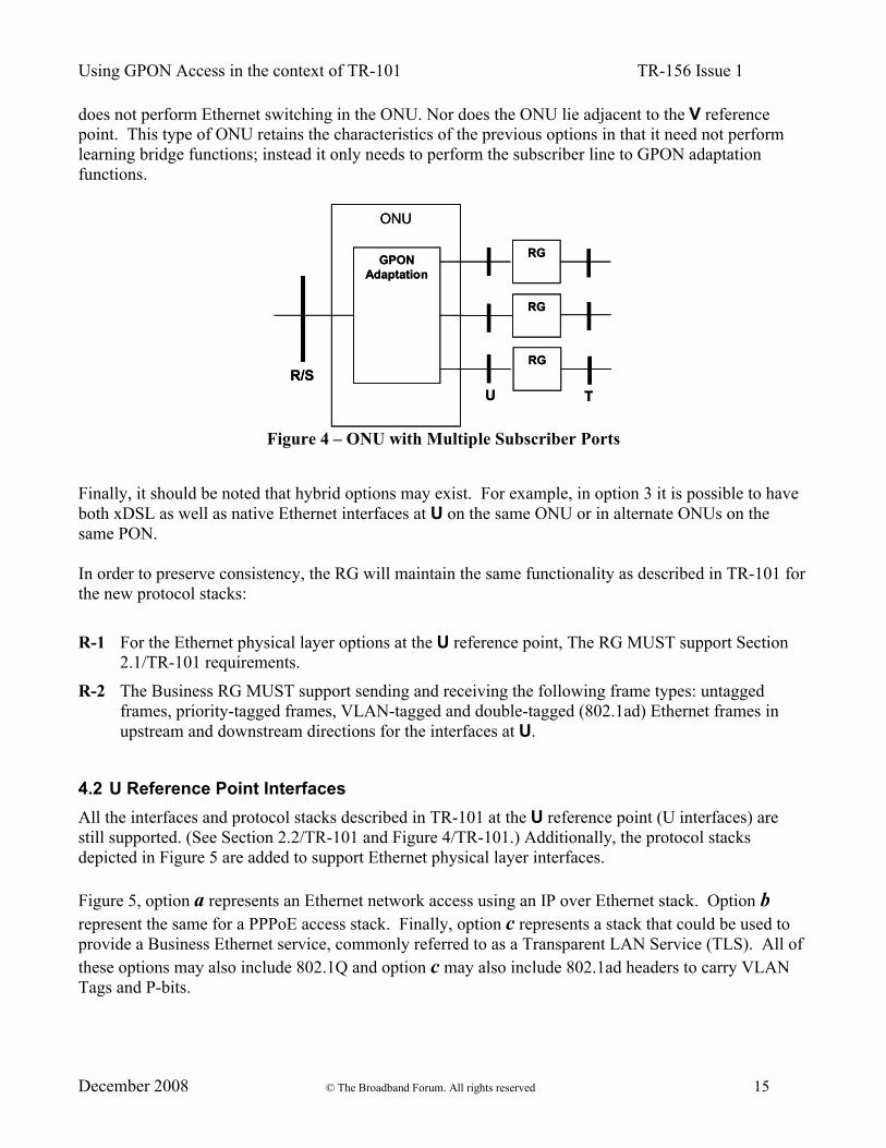
The third option is an ONU with several subscriber interfaces at U. Shown in Figure 4, this option uses the same GPON Adaptation as described in the previous options, but adapts multiple subscriber interfaces in a single physical device. These interfaces can support Ethernet, as described in the previous options, but also ADSL2+ and VDSL2. It should be noted that this option differs from the solution, planned to be described in the work-in-progress to define GPON fed access nodes, in that it
Using GPON Access in the context of TR-101 TR-156 Issue 1
December 2008 © The Broadband Forum. All rights reserved 15
does not perform Ethernet switching in the ONU. Nor does the ONU lie adjacent to the V reference point. This type of ONU retains the characteristics of the previous options in that it need not perform learning bridge functions; instead it only needs to perform the subscriber line to GPON adaptation functions.
ONU
GPONAdaptation
RG
UR/S
T
RG
RG
ONU
GPONAdaptation
RG
UR/S
T
RG
RG
Figure 4 – ONU with Multiple Subscriber Ports
Finally, it should be noted that hybrid options may exist. For example, in option 3 it is possible to have both xDSL as well as native Ethernet interfaces at U on the same ONU or in alternate ONUs on the same PON.
In order to preserve consistency, the RG will maintain the same functionality as described in TR-101 for the new protocol stacks:
R-1 For the Ethernet physical layer options at the U reference point, The RG MUST support Section 2.1/TR-101 requirements.
R-2 The Business RG MUST support sending and receiving the following frame types: untagged frames, priority-tagged frames, VLAN-tagged and double-tagged (802.1ad) Ethernet frames in upstream and downstream directions for the interfaces at U.
4.2 U Reference Point Interfaces
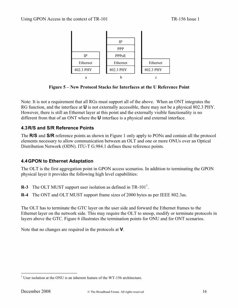
All the interfaces and protocol stacks described in TR-101 at the U reference point (U interfaces) are still supported. (See Section 2.2/TR-101 and Figure 4/TR-101.) Additionally, the protocol stacks depicted in Figure 5 are added to support Ethernet physical layer interfaces.
Figure 5, option a represents an Ethernet network access using an IP over Ethernet stack. Option brepresent the same for a PPPoE access stack. Finally, option c represents a stack that could be used to provide a Business Ethernet service, commonly referred to as a Transparent LAN Service (TLS). All of these options may also include 802.1Q and option c may also include 802.1ad headers to carry VLAN Tags and P-bits.
Using GPON Access in the context of TR-101 TR-156 Issue 1
December 2008 © The Broadband Forum. All rights reserved 16
c
802.3 PHY
a
802.3 PHY
IP
PPP
IP
Ethernet
b
PPPoE
Ethernet Ethernet
802.3 PHY
c
802.3 PHY
a
802.3 PHY
IP
PPP
IP
Ethernet
b
PPPoE
Ethernet Ethernet
802.3 PHY
Figure 5 – New Protocol Stacks for Interfaces at the U Reference Point
Note: It is not a requirement that all RGs must support all of the above. When an ONT integrates the RG function, and the interface at U is not externally accessible, there may not be a physical 802.3 PHY. However, there is still an Ethernet layer at this point and the externally visible functionality is no different from that of an ONT where the U interface is a physical and external interface.
4.3R/S and S/R Reference Points
The R/S and S/R reference points as shown in Figure 1 only apply to PONs and contain all the protocol elements necessary to allow communication between an OLT and one or more ONUs over an Optical Distribution Network (ODN). ITU-T G.984.1 defines these reference points.
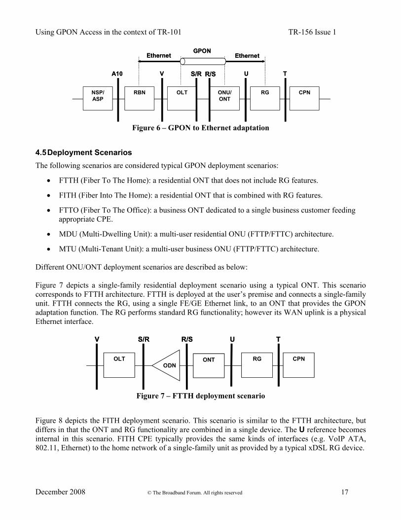
4.4GPON to Ethernet Adaptation
The OLT is the first aggregation point in GPON access scenarios. In addition to terminating the GPON physical layer it provides the following high level capabilities:
R-3 The OLT MUST support user isolation as defined in TR-1011.
R-4 The ONT and OLT MUST support frame sizes of 2000 bytes as per IEEE 802.3as.
The OLT has to terminate the GTC layer on the user side and forward the Ethernet frames to the Ethernet layer on the network side. This may require the OLT to snoop, modify or terminate protocols in layers above the GTC. Figure 6 illustrates the termination points for ONU and for ONT scenarios.
Note that no changes are required in the protocols at V.
1 User isolation at the ONU is an inherent feature of the WT-156 architecture.
Using GPON Access in the context of TR-101 TR-156 Issue 1
December 2008 © The Broadband Forum. All rights reserved 17
EthernetGPON
CPNRGONU/ONT
OLTRBNNSP/ASP
TUR/SVA10
Ethernet
S/R
EthernetGPON
CPNRGONU/ONT
OLTRBNNSP/ASP
TUR/SVA10
Ethernet
S/R
Figure 6 – GPON to Ethernet adaptation
4.5Deployment Scenarios
The following scenarios are considered typical GPON deployment scenarios:
FTTH (Fiber To The Home): a residential ONT that does not include RG features.
FITH (Fiber Into The Home): a residential ONT that is combined with RG features.
FTTO (Fiber To The Office): a business ONT dedicated to a single business customer feeding appropriate CPE.
MDU (Multi-Dwelling Unit): a multi-user residential ONU (FTTP/FTTC) architecture.
MTU (Multi-Tenant Unit): a multi-user business ONU (FTTP/FTTC) architecture.
Different ONU/ONT deployment scenarios are described as below:
Figure 7 depicts a single-family residential deployment scenario using a typical ONT. This scenariocorresponds to FTTH architecture. FTTH is deployed at the user’s premise and connects a single-family unit. FTTH connects the RG, using a single FE/GE Ethernet link, to an ONT that provides the GPON adaptation function. The RG performs standard RG functionality; however its WAN uplink is a physical Ethernet interface.
CPNRGONTOLT
TUR/SS/RV
ODNCPNRGONTOLT
TUR/SS/RV
ODN
Figure 7 – FTTH deployment scenario
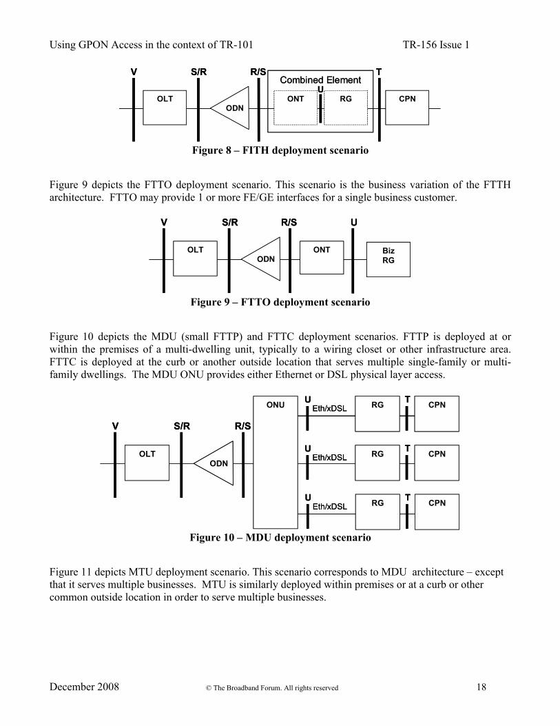
Figure 8 depicts the FITH deployment scenario. This scenario is similar to the FTTH architecture, but differs in that the ONT and RG functionality are combined in a single device. The U reference becomesinternal in this scenario. FITH CPE typically provides the same kinds of interfaces (e.g. VoIP ATA, 802.11, Ethernet) to the home network of a single-family unit as provided by a typical xDSL RG device.
Using GPON Access in the context of TR-101 TR-156 Issue 1
December 2008 © The Broadband Forum. All rights reserved 18
CPNRGONTOLT
T
U
R/SS/RV
ODN
Combined Element
CPNRGONTOLT
T
U
R/SS/RV
ODN
Combined Element
Figure 8 – FITH deployment scenario
Figure 9 depicts the FTTO deployment scenario. This scenario is the business variation of the FTTH architecture. FTTO may provide 1 or more FE/GE interfaces for a single business customer.
BizRG
ONTOLT
UR/SS/RV
ODNBizRG
ONTOLT
UR/SS/RV
ODN
Figure 9 – FTTO deployment scenario
Figure 10 depicts the MDU (small FTTP) and FTTC deployment scenarios. FTTP is deployed at or within the premises of a multi-dwelling unit, typically to a wiring closet or other infrastructure area. FTTC is deployed at the curb or another outside location that serves multiple single-family or multi-family dwellings. The MDU ONU provides either Ethernet or DSL physical layer access.
CPNRGOLTTU
R/SS/RV
ODNEth/xDSL
CPNRGTU
Eth/xDSL
CPNRGTU
Eth/xDSL
ONU
CPNRGOLTTU
R/SS/RV
ODNEth/xDSL
CPNRGTU
Eth/xDSL
CPNRGTU
Eth/xDSL
ONU
Figure 10 – MDU deployment scenario
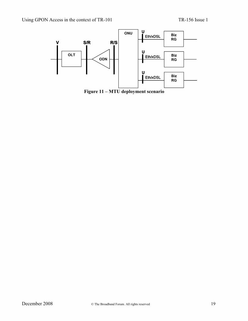
Figure 11 depicts MTU deployment scenario. This scenario corresponds to MDU architecture – except that it serves multiple businesses. MTU is similarly deployed within premises or at a curb or other common outside location in order to serve multiple businesses.
Using GPON Access in the context of TR-101 TR-156 Issue 1
December 2008 © The Broadband Forum. All rights reserved 19
OLT
R/SS/RV
ODN
UBizRG
Eth/xDSL
UBizRG
Eth/xDSL
UBizRG
Eth/xDSL
ONU
OLT
R/SS/RV
ODN
UBizRG
Eth/xDSL
UBizRG
Eth/xDSL
UBizRG
Eth/xDSL
ONU
Figure 11 – MTU deployment scenario
Using GPON Access in the context of TR-101 TR-156 Issue 1
December 2008 © The Broadband Forum. All rights reserved 20
5. GPON Access Architecture
5.1VLANs and GEM Ports
The OLT and ONU share the responsibility for Access Node VLAN requirements as specified in TR-101. TR-101 identifies two VLAN topologies (N:1 and 1:1) and these, along with specific portconfigurations to support ASP, NSP, and Business Ethernet services (TLS) still apply when there is a GPON based Access Node. These various VLAN and port configurations are supported simultaneously on the same GPON in this Technical Report.
The ONU supports equivalent functionality for the U interfaces of an Access Node as that specified in TR-101. The ONU assumes the responsibility of ingress traffic classification for the U interface. Similarly, the OLT supports equivalent functionality for the V interfaces of an Access Node as that specified in TR-101. The OLT assumes the responsibility of ingress traffic classification for the Vinterface. Between the ONU and OLT is the ODN, and Ethernet is supported here through the use of GEM channels.
GPON technology has introduced the GEM channel as part of its GPON Transmission Convergence (GTC) layer. The GEM channels carry variable-length frames, including Ethernet frames. This allows the GEM channels to support the TR-101 Ethernet-centric architecture. GEM channels are delineated and identified by a uniquely assigned identifier, the GEM Port ID. This identifier is assigned by the OLT upon creation of a new channel and remains constant during the entire lifecycle of the channel. The GEM Port IDs are virtual port identifiers that have significance within a single ODN. Each GPON interface for a given ONU can have several GEM Ports. A GEM Port ID is unique per GPON interface and represents a specific traffic flow or group of flows between the OLT and one or more ONUs. This Technical Report will use the term GEM Port to refer to an instance of a GEM channel with an arbitrary GEM Port ID.
GPON allows the OLT (through OMCI) to determine the allowed transmission directions (i.e. upstream and / or downstream) for each GEM channel during the configuration process. This Technical Reportuses two types of GEM channels:
Downstream (only) GEM channels – These channels can be used for the purpose of transmitting downstream flooded, broadcast, or multicast traffic. The frames are transmitted from the OLT into the GPON interface to all the ONUs, and are then selectively forwarded to U interfaces by those ONUs which are configured with that GEM port.
Bi-directional GEM channels – These channels are used for both upstream and downstream traffic between that ONU and the OLT. They are uniquely assigned per U interface on an ONU. The frames are transmitted from the OLT into the GPON interface and are forwarded only on the U interface of the ONU on which that GEM port has been assigned.
Note: PON systems are a broadcast medium in the downstream direction, so all ONUs receive all the downstream traffic for every GEM port, however ONUs silently discard traffic that is not addressed for them. Additionally, AES encryption can be (and typically is) applied over the bi-directional GEM ports. A different key per ONU is used by the OLT for encryption and by the ONU for decryption.
Using GPON Access in the context of TR-101 TR-156 Issue 1
December 2008 © The Broadband Forum. All rights reserved 21
GEM ports can also be used to differentiate among traffic classes. A given U interface may have several GEM ports associated with it that support different traffic classes. This arrangement can be described as follows: within the GPON interface, each GEM Port carries one or more traffic flows associated with a specific traffic class going to a specific U interface on a specific ONU.
On U interface ingress, traffic is classified into VLANs with various Ethernet priorities based on a number of criteria: physical port, VID, VLAN P-bits, EtherType and/or DSCP. Any combination of these criteria can be used to determine the Ethernet priority. The VID and EtherType can be used to determine the new VID. Once the traffic has been assigned a VLAN and Ethernet precedence, these two Ethernet header components are used to select an upstream GEM Port so that proper QoS can be applied to the flows. A GEM Port is mapped into one and only one T-CONT. Similarly for egress, the ONU is responsible for forwarding traffic received from GEM ports on the PON to the appropriate U interface.
The arrangement just described is a subset of the possible arrangements and configurations of GEM ports in a GPON. It was selected in order to add value by reducing operational complexity and interoperability issues between the OLT and the ONU at the GPON interface. Thus, this Technical Report limits the variability of how physical ports and traffic types can be assigned to GEM ports in order to simplify the GPON system requirements. Specifically, the architecture specified in this Technical Report has been crafted to allow the development of compliant ONUs that do not need to perform learning of MAC addresses in order to determine how to forward Ethernet frames to Uinterfaces.
R-5 GEM Port IDs MUST be assigned automatically by the OLT.
R-6 Within the GPON, a bidirectional GEM Port MUST be able to carry one or more traffic flows associated with the same traffic class going to a specific U interface on a specific ONU.
R-7 The OLT and the ONU MUST support one bi-directional GEM Port for each traffic class configured for a specific U interface on a specific ONU.
The OLT provides the interfaces at the V reference for an Access Node as specified in TR-101regardless of the VLAN arrangements.
5.1.1 N:1 VLAN
For N:1 VLANs, the implementation is for the ONU to always add an S-VID or translate an incoming tag S-VID for upstream traffic, so that there is always an S-VID at the R/S interface. It will also select the appropriate GEM port based on the classification criteria defined in section 5.2. The OLT will pass-through any upstream frames with an S-VID on them.
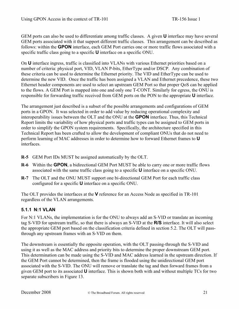
The downstream is essentially the opposite operation, with the OLT passing-through the S-VID and using it as well as the MAC address and priority bits to determine the proper downstream GEM port. This determination can be made using the S-VID and MAC address learned in the upstream direction. If the GEM Port cannot be determined, then the frame is flooded using the unidirectional GEM port associated with the S-VID. The ONU will remove or translate the tag and then forward frames from a given GEM port to its associated U interface. This is shown both with and without multiple TCs for two separate subscribers in Figure 13.
Using GPON Access in the context of TR-101 TR-156 Issue 1
December 2008 © The Broadband Forum. All rights reserved 22
N:1 traffic is always single-tagged at V.
OLT ONU/TV R/S U
GEM ID 11
GEM ID 12
GEM ID 13
GEM ID 21
S-VID101
TC1
TC2TC3
TC1
S-VID101
S-VID101S-VID101
S-VID101
MACTable
OLT ONU/TV R/S U
GEM ID 11
GEM ID 12
GEM ID 13
GEM ID 21
S-VID101
TC1
TC2TC3
TC1
S-VID101
S-VID101S-VID101
S-VID101
MACTable
Figure 12 – N:1 VLAN Example
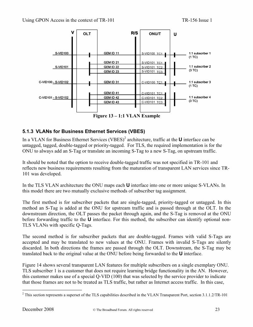
5.1.2 1:1 VLAN
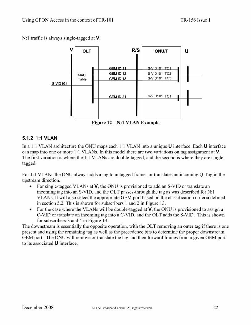
In a 1:1 VLAN architecture the ONU maps each 1:1 VLAN into a unique U interface. Each U interface can map into one or more 1:1 VLANs. In this model there are two variations on tag assignment at V. The first variation is where the 1:1 VLANs are double-tagged, and the second is where they are single-tagged.
For 1:1 VLANs the ONU always adds a tag to untagged frames or translates an incoming Q-Tag in the upstream direction.
For single-tagged VLANs at V, the ONU is provisioned to add an S-VID or translate an incoming tag into an S-VID, and the OLT passes-through the tag as was described for N:1 VLANs. It will also select the appropriate GEM port based on the classification criteria defined in section 5.2. This is shown for subscribers 1 and 2 in Figure 13.
For the case where the VLANs will be double-tagged at V, the ONU is provisioned to assign a C-VID or translate an incoming tag into a C-VID, and the OLT adds the S-VID. This is shown for subscribers 3 and 4 in Figure 13.
The downstream is essentially the opposite operation, with the OLT removing an outer tag if there is one present and using the remaining tag as well as the precedence bits to determine the proper downstream GEM port. The ONU will remove or translate the tag and then forward frames from a given GEM port to its associated U interface.
Using GPON Access in the context of TR-101 TR-156 Issue 1
December 2008 © The Broadband Forum. All rights reserved 23
C-VID101 - S-VID102
OLT ONU/TV R/S U
GEM ID 31
GEM ID 41
GEM ID 42
GEM ID 43
1:1 subscriber 3(1 TC)
1:1 subscriber 4(3 TC)
C-VID101
C-VID101C-VID101
C-VID100 - S-VID102 TC1
TC1
TC2TC3
C-VID100
GEM ID 11 1:1 subscriber 1(1 TC)
S-VID100 TC1S-VID100
GEM ID 21
GEM ID 22
GEM ID 23
1:1 subscriber 2(3 TC)
S-VID101TC1
TC2
TC3
S-VID101
S-VID101S-VID101
Figure 13 – 1:1 VLAN Example
5.1.3 VLANs for Business Ethernet Services (VBES)
In a VLAN for Business Ethernet Services (VBES)2 architecture, traffic at the U interface can be untagged, tagged, double-tagged or priority-tagged. For TLS, the required implementation is for the ONU to always add an S-Tag or translate an incoming S-Tag to a new S-Tag, on upstream traffic.
It should be noted that the option to receive double-tagged traffic was not specified in TR-101 and reflects new business requirements resulting from the maturation of transparent LAN services since TR-101 was developed.
In the TLS VLAN architecture the ONU maps each U interface into one or more unique S-VLANs. In this model there are two mutually exclusive methods of subscriber tag assignment.
The first method is for subscriber packets that are single-tagged, priority-tagged or untagged. In this method an S-Tag is added at the ONU for upstream traffic and is passed through at the OLT. In the downstream direction, the OLT passes the packet through again, and the S-Tag is removed at the ONU before forwarding traffic to the U interface. For this method, the subscriber can identify optional non-TLS VLANs with specific Q-Tags.
The second method is for subscriber packets that are double-tagged. Frames with valid S-Tags are accepted and may be translated to new values at the ONU. Frames with invalid S-Tags are silently discarded. In both directions the frames are passed through the OLT. Downstream, the S-Tag may be translated back to the original value at the ONU before being forwarded to the U interface.
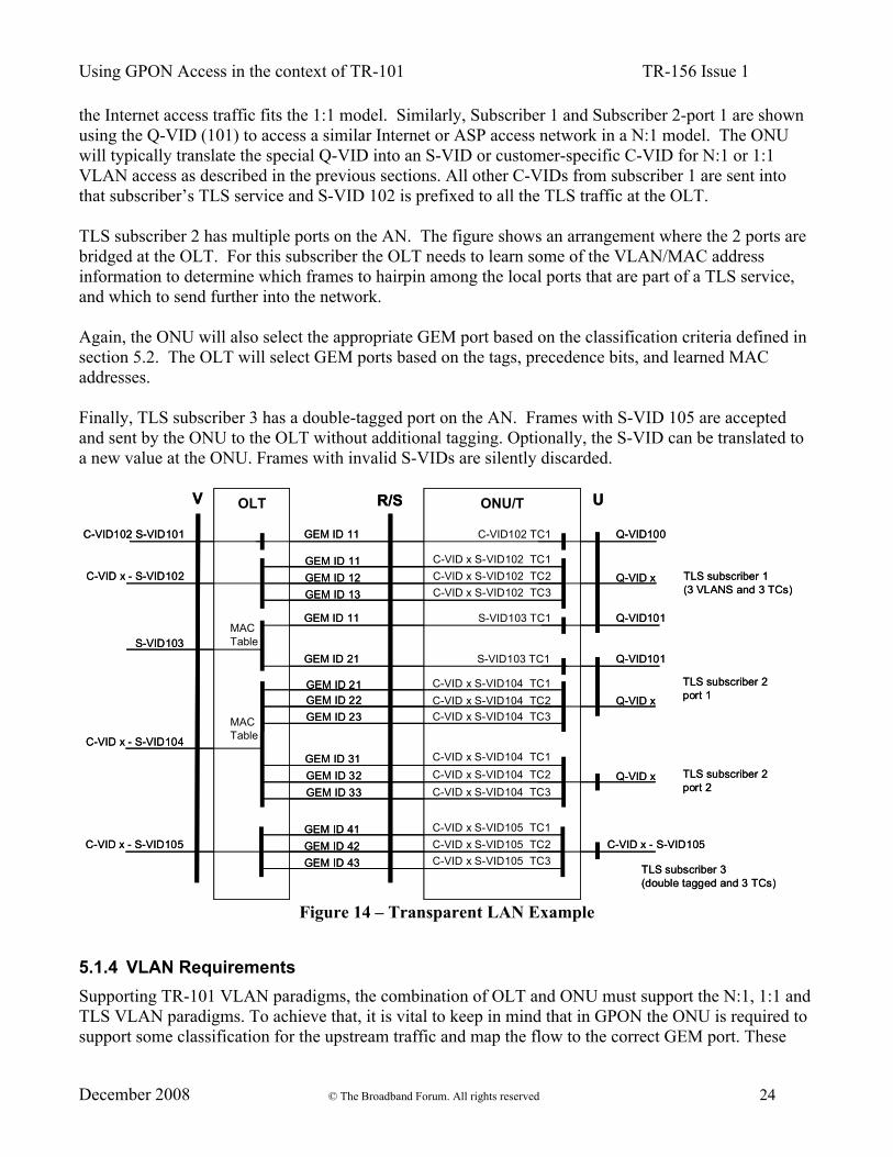
Figure 14 shows several transparent LAN features for multiple subscribers on a single exemplary ONU. TLS subscriber 1 is a customer that does not require learning bridge functionality in the AN. However, this customer makes use of a special Q-VID (100) that was selected by the service provider to indicate that those frames are not to be treated as TLS traffic, but rather as Internet access traffic. In this case,
2 This section represents a superset of the TLS capabilities described in the VLAN Transparent Port, section 3.1.1.2/TR-101
Using GPON Access in the context of TR-101 TR-156 Issue 1
December 2008 © The Broadband Forum. All rights reserved 24
the Internet access traffic fits the 1:1 model. Similarly, Subscriber 1 and Subscriber 2-port 1 are shown using the Q-VID (101) to access a similar Internet or ASP access network in a N:1 model. The ONU will typically translate the special Q-VID into an S-VID or customer-specific C-VID for N:1 or 1:1 VLAN access as described in the previous sections. All other C-VIDs from subscriber 1 are sent into that subscriber’s TLS service and S-VID 102 is prefixed to all the TLS traffic at the OLT.
TLS subscriber 2 has multiple ports on the AN. The figure shows an arrangement where the 2 ports are bridged at the OLT. For this subscriber the OLT needs to learn some of the VLAN/MAC address information to determine which frames to hairpin among the local ports that are part of a TLS service, and which to send further into the network.
Again, the ONU will also select the appropriate GEM port based on the classification criteria defined in section 5.2. The OLT will select GEM ports based on the tags, precedence bits, and learned MAC addresses.
Finally, TLS subscriber 3 has a double-tagged port on the AN. Frames with S-VID 105 are accepted and sent by the ONU to the OLT without additional tagging. Optionally, the S-VID can be translated to a new value at the ONU. Frames with invalid S-VIDs are silently discarded.
OLT ONU/TV R/S U
GEM ID 11
GEM ID 11
GEM ID 12
GEM ID 13
TLS subscriber 1(3 VLANS and 3 TCs)
C-VID x S-VID102 TC1
C-VID x S-VID102 TC2
C-VID x S-VID102 TC3
C-VID102 S-VID101
C-VID x - S-VID102
C-VID102 TC1 Q-VID100
Q-VID x
GEM ID 21GEM ID 22
GEM ID 23
TLS subscriber 2port 1
C-VID x S-VID104 TC1
C-VID x S-VID104 TC2
C-VID x S-VID104 TC3
C-VID x - S-VID104
Q-VID x
GEM ID 31
GEM ID 32
GEM ID 33
C-VID x S-VID104 TC1
C-VID x S-VID104 TC2
C-VID x S-VID104 TC3
Q-VID x TLS subscriber 2port 2
GEM ID 11
S-VID103
S-VID103 TC1 Q-VID101
GEM ID 21 S-VID103 TC1 Q-VID101
MACTable
MACTable
GEM ID 41
GEM ID 42
GEM ID 43
C-VID x S-VID105 TC1
C-VID x S-VID105 TC2
C-VID x S-VID105 TC3
C-VID x - S-VID105
TLS subscriber 3(double tagged and 3 TCs)
C-VID x - S-VID105
Figure 14 – Transparent LAN Example
5.1.4 VLAN Requirements
Supporting TR-101 VLAN paradigms, the combination of OLT and ONU must support the N:1, 1:1 and TLS VLAN paradigms. To achieve that, it is vital to keep in mind that in GPON the ONU is required to support some classification for the upstream traffic and map the flow to the correct GEM port. These
Using GPON Access in the context of TR-101 TR-156 Issue 1
December 2008 © The Broadband Forum. All rights reserved 25
functions reduce operational complexity and interoperability issues between the OLT and the ONU at the GPON interface.
R-8 The ONU and OLT MUST support all VID values from the range: 1-4094 as specified in IEEE 802.1Q, on all ports3.
R-9 The ONU MUST support setting VID for untagged and priority-tagged frames in the upstream direction based on EtherType, except on VLANs used for Business Ethernet Services.
For more details see R-26/TR-101 and R-27/TR-101.
N:1 VLANsIn this configuration the upstream traffic can be received either in a Multi-VC ATM Architecture4, VLAN tagged U or Untagged/Priority-tagged U. Thus, in order to provide simplicity within the GPONinterface, the ONU is required to classify the traffic accordingly and also to tag the untagged traffic or map a (specific) Q-Tag into a S-Tag with different values.
The following requirements apply to N:1 VLANs:
R-10 The ONU MUST support adding an S-Tag to upstream untagged traffic received from the Uinterface.
R-11 The ONU MUST support removing an S-Tag from downstream traffic received from the OLT.
R-12 The ONU MUST support unique, symmetric translation of Q-Tag VIDs received from the Uinterface into S-Tag VIDs .
R-13 The ONU MUST support unique, symmetric translation of the S-Tag VIDs used in the downstream-tagged traffic into the Q-Tag VIDs sent to the U interface.
R-14 The unique symmetric translation among tag VIDs MUST be done by means of a single provisioned table per U interface.
R-15 The OLT MUST support passing an S-Tag in the upstream direction.
R-16 The OLT MUST support passing an S-Tag in the downstream direction.
R-17 The OLT MUST support forwarding traffic received at the V interface (i.e. downstream direction) to GEM Ports on the PON based on S-Tag, including P-bits if needed, and destination MAC address.
R-18 The OLT MUST be able to prevent forwarding traffic between user ports (user isolation). This behavior MUST be configurable per S-VID.
R-19 The ONU MUST support mapping traffic from one or more GEM Ports to a U interface in the downstream direction.
1:1 VLANsIn this configuration the upstream traffic can be received either in a Multi-VC ATM Architecture, VLAN tagged U or Untagged/Priority-tagged U. Thus, in order to provide simplicity within the GPON
3 While the Broadband Forum notes that some of these requirements may seem pedantic or intuitive, the reason they have been included is that there is evidence that they have not been followed appropriately in the industry. 4 ATM may be used when an ONU has xDSL U interface ports. Typically, ONTs will not have this variant.
Using GPON Access in the context of TR-101 TR-156 Issue 1
December 2008 © The Broadband Forum. All rights reserved 26
interface, the ONU is required classify the traffic accordingly and also to tag the untagged traffic or map a Q-Tag into a new C-Tag or S-Tag.
The following requirements apply to 1:1 VLANs:
R-20 The ONU MUST support adding a C-Tag or S-Tag to upstream untagged traffic.
R-21 The ONU MUST support removing the tag from downstream traffic.
R-22 The ONU MUST support VID translation of the Q-Tag received from the U interface into the C-Tag or S-Tag for upstream-tagged traffic.
R-23 The ONU MUST support VID translation of the tag used in the downstream-tagged traffic into the Q-Tag sent to the U interface.
R-24 The OLT MUST support adding an S-Tag in the upstream direction for C-tagged traffic.
R-25 The OLT MUST support passing an S-Tag in the upstream direction.
R-26 The OLT MUST support passing an S-Tag in the downstream direction.
R-27 The OLT MUST support forwarding traffic to the V interface (i.e. upstream direction) based on S-VID.
R-28 The OLT SHOULD support forwarding traffic to the V interface (i.e. upstream direction) based on S-VID and C-VID.
R-29 The OLT MUST support forwarding traffic received at the V interface (i.e. downstream direction) to GEM Ports on the PON based on S-VID or (S-VID & C-VID), including P-bits, where needed, in the S-Tag.
R-30 The OLT MUST support removal of an S-Tag in the downstream direction when traffic is double-tagged.
R-31 The ONU MUST support mapping traffic from one or more GEM Ports to a U interface in the downstream direction.
R-32 The OLT MUST support deactivating MAC learning, for 1:1 VLANs
R-33 The Access Node MUST configure 1:1 VLANs so that the C-Tags are assigned to be unique across the U interfaces and across the entries in the 1:1 VLAN membership list.
The previous requirement is necessary because multiple 1:1 VLANs present at the same U interface cannot be distinguished at the OLT without a unique identifier imposed at the ONU.
VLANs for Business Ethernet ServicesIn this configuration the upstream traffic can be received on a tagged, untagged, double-tagged or priority-tagged U interface. Thus, in order to avoid sophisticated rules and requirements at the OLT, the ONU is always required to add an S-Tag to frames that are not already S-tagged.
The following requirements apply to such TLS VLANs:
R-34 The ONU MUST support adding an S-Tag in the upstream direction for Q-tagged, untagged, and priority-tagged frames.
R-35 The ONU MUST support validating and translating an S-Tag in the upstream direction for S-tagged frames.
Using GPON Access in the context of TR-101 TR-156 Issue 1
December 2008 © The Broadband Forum. All rights reserved 27
R-36 The ONU MUST support removing an S-Tag in the downstream direction.
R-37 The OLT MUST support forwarding traffic to the V interface (i.e. upstream direction) based on S-Tag.
R-38 The OLT MUST support passing an S-Tag in the upstream direction.
R-39 The OLT MUST support forwarding traffic in the downstream direction to GEM Ports based on the S-Tag, including P-bits, when needed, and destination MAC address.
NOTE: This requirement applies to traffic received both from V interface and GEM ports where TLS VLAN topologies require forwarding among GEM ports in a single OLT.
R-40 The OLT MUST support passing an S-Tag in the downstream direction.
R-41 The ONU MUST support mapping traffic from one or more GEM Ports to a U interface in the downstream direction.
R-42 The ONU MUST support VID translation of the S-Tag received from the U interface into a new S-Tag for upstream double-tagged traffic.
R-43 The ONU MUST support VID translation of the S-Tag received from the GPON interface into a new S-Tag for downstream double-tagged traffic sent to the U interface.
5.2QoS
5.2.1 QoS Architecture
In general the goals for QoS remain those defined in TR-101. The high level goals for the QoS architecture include the following:
Efficient use of bandwidth resources
Statistical multiplexing gain
Providing a forwarding class that can support low-latency flows
QoS mechanisms should allow for use of unutilized bandwidth among traffic classes.
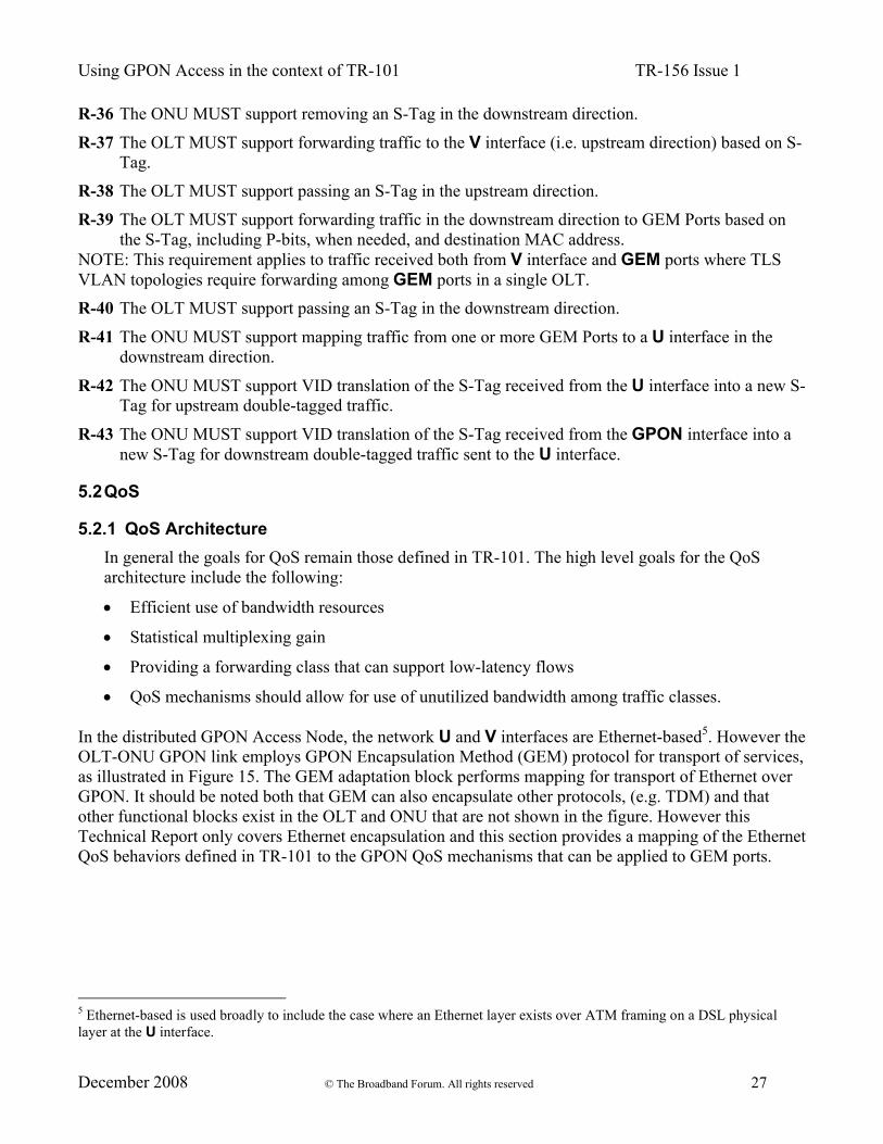
In the distributed GPON Access Node, the network U and V interfaces are Ethernet-based5. However the OLT-ONU GPON link employs GPON Encapsulation Method (GEM) protocol for transport of services, as illustrated in Figure 15. The GEM adaptation block performs mapping for transport of Ethernet over GPON. It should be noted both that GEM can also encapsulate other protocols, (e.g. TDM) and that other functional blocks exist in the OLT and ONU that are not shown in the figure. However this Technical Report only covers Ethernet encapsulation and this section provides a mapping of the Ethernet QoS behaviors defined in TR-101 to the GPON QoS mechanisms that can be applied to GEM ports.
5 Ethernet-based is used broadly to include the case where an Ethernet layer exists over ATM framing on a DSL physical layer at the U interface.
Using GPON Access in the context of TR-101 TR-156 Issue 1
December 2008 © The Broadband Forum. All rights reserved 28
OLT ONU
Traffic Manage-ment
UV
GPON
Ethernet
RG
Class-ification
GEMadap-tation
GEM Ethernet
GEMadap-tation
Class-ification
S/R R/S
OLT ONU
Traffic Manage-ment
UV
GPON
Ethernet
RG
Class-ification
GEMadap-tation
GEM Ethernet
GEMadap-tation
Class-ification
S/R R/S
Figure 15 – GPON GEM adaptation of Ethernet
The general requirement for GEM is to provide QoS mechanisms that can support the Ethernet QoS requirements of TR-101. By doing this, the set of Access Node QoS requirements defined by Section 3.3/TR-101, will still apply to the Ethernet domain of the GPON distributed access-node. In order to provide the QoS, two main mechanisms will be employed: classification of traffic; and forwarding the resulting traffic classes into GEM ports and T-CONTs configured to emulate Ethernet QoS behaviors.
GPON ONUs may potentially terminate multiple services, and have different types of U interfaces. An ONU may support an Ethernet data service on a U interface using Ethernet or DSL technology at the physical layer, and also support POTS, T1/E1 and other services on other interfaces. This variety of services and interfaces requires a broad range of QoS characteristics. However, the scope of this specification covers only Ethernet data services. In that context the QoS requirements are specified independently of the existence of other services on the ONU and GPON network. This allows simplifying the requirements and keeping the specification consistent with TR-101
The following sections detail service class requirements:
5.2.2 Upstream Traffic Management
Upstream Traffic Management Description
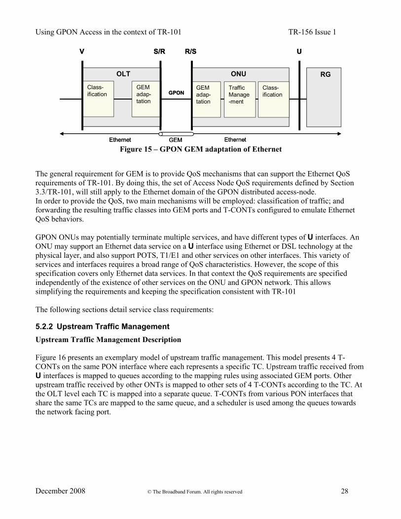
Figure 16 presents an exemplary model of upstream traffic management. This model presents 4 T-CONTs on the same PON interface where each represents a specific TC. Upstream traffic received from U interfaces is mapped to queues according to the mapping rules using associated GEM ports. Other upstream traffic received by other ONTs is mapped to other sets of 4 T-CONTs according to the TC. At the OLT level each TC is mapped into a separate queue. T-CONTs from various PON interfaces that share the same TCs are mapped to the same queue, and a scheduler is used among the queues towards the network facing port.
Using GPON Access in the context of TR-101 TR-156 Issue 1
December 2008 © The Broadband Forum. All rights reserved 29
OLT
Scheduler
PON-1
PON-n(same asabove)
…
V
ONU-1
ONU-n(same as above)
…
T-CONT A
T-CONT B
T-CONT C
T-CONT D
Classifier
UR/SS/R
Classifier
OLT
Scheduler
PON-1
PON-n(same asabove)
…
V
ONU-1
ONU-n(same as above)
…
T-CONT A
T-CONT B
T-CONT C
T-CONT D
Classifier
UR/SS/R
Classifier
Figure 16 – Upstream Queuing and Scheduling Model Example
5.2.3 Downstream Traffic Management
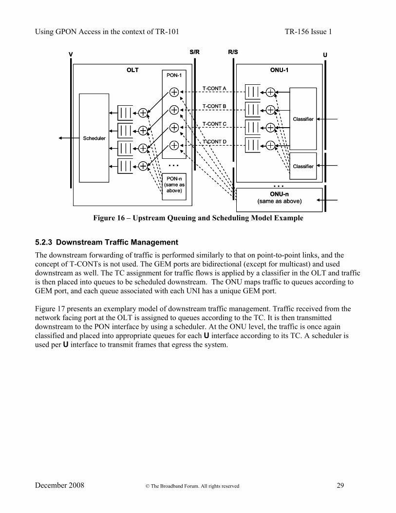
The downstream forwarding of traffic is performed similarly to that on point-to-point links, and the concept of T-CONTs is not used. The GEM ports are bidirectional (except for multicast) and used downstream as well. The TC assignment for traffic flows is applied by a classifier in the OLT and traffic is then placed into queues to be scheduled downstream. The ONU maps traffic to queues according to GEM port, and each queue associated with each UNI has a unique GEM port.
Figure 17 presents an exemplary model of downstream traffic management. Traffic received from the network facing port at the OLT is assigned to queues according to the TC. It is then transmitted downstream to the PON interface by using a scheduler. At the ONU level, the traffic is once again classified and placed into appropriate queues for each U interface according to its TC. A scheduler is used per U interface to transmit frames that egress the system.
Using GPON Access in the context of TR-101 TR-156 Issue 1
December 2008 © The Broadband Forum. All rights reserved 30
V
ONU-n(same as above)
…
UR/SS/R
OLT
Classifier
PON-1
PON-n(same asabove)
…
Sched-uler
ONU-1
Assign toqueues
accordingto GEM
Port
U -1
U-n(same asabove)
…
Sched-uler
V
ONU-n(same as above)
…
UR/SS/R
OLT
Classifier
PON-1
PON-n(same asabove)
…
Sched-uler
ONU-1
Assign toqueues
accordingto GEM
Port
U -1
U-n(same asabove)
…
Sched-uler
Figure 17 – Downstream Queuing and Scheduling Model Example
5.2.4 Traffic Management Requirements
The following requirements provide upstream and downstream queues, classifiers, and schedulers to support multiple TCs, support drop precedence, and set queue characteristics.
R-44 The OLT MUST support the basic traffic descriptor parameters as specified in G.984.3 (7.4.4.3 Fixed, Assured, Max BW and type NA or BE). These parameters MUST be configurable.
R-45 The OLT MUST support the extended traffic descriptor parameters Pi and i as specified in G.984.3. These parameters MUST be configurable.
R-46 The OLT and ONU MUST support at least 4 traffic classes for Ethernet frames.
R-47 The OLT and ONU SHOULD support at least 6 traffic classes for Ethernet frames.
R-48 The ONU MUST support deriving P-bit markings in the upstream direction based on an arbitrary combination of: user port, VID, received P-bit markings, and EtherType.
R-49 The ONU SHOULD support deriving the P-bit markings in the upstream direction based on an arbitrary combination of: user port, VID and received DSCP value.
R-50 The ONU MUST perform any necessary VID and P-bit manipulations before performing the mapping into GEM ports.
R-51 The ONU MUST support mapping traffic into GEM Ports based on arbitrary combination of user port, VID and P-bit values in the upstream direction6.
R-52 The ONU MUST NOT prevent multiple P-bit values being used in the same VLAN.
6 Note that user ports include both physical ports as well as PVCs on ports that have an ATM layer, like ADSL. For more information, see Section 2.5.1.1/TR-101.
Using GPON Access in the context of TR-101 TR-156 Issue 1
December 2008 © The Broadband Forum. All rights reserved 31
R-53 The ONU MUST NOT prevent multiple VLANs from using the same P-bits.
R-54 The OLT and ONU MUST support drop precedence within at least 2 traffic classes and MUST support configurable mapping to these classes and drop precedence from the 8 possible values of the Ethernet P-bits.
R-55 The OLT and ONU MUST support drop precedence within all supported traffic classes based on the DEI bit value of the 802.1ad header.
R-56 In the downstream direction, the ONU MUST support at least 4 queues per user port, one per traffic class.
R-57 In the upstream direction, the ONU MUST support at least 4 queues, one per traffic class.
R-58 In the downstream direction, the OLT MUST support at least 4 queues per PON, one per traffic class.
R-59 The OLT MUST support T-CONT types 1, 2, 3 and 4. Each T-CONT type MUST be able to use the full bandwidth available on the GPON.
R-60 In the downstream direction, the ONU SHOULD support at least 6 queues per user port, one per traffic class.
R-61 In the upstream direction, the ONU SHOULD support at least 6 queues, one per traffic class.
R-62 In the downstream direction, the OLT SHOULD support at least 6 queues per PON, one per traffic class.
R-63 The OLT and ONU MUST support scheduling of downstream queues according to strict priority among at least 4 TCs.
R-64 The OLT and ONU MUST support assigning an individual TC to a downstream queue.
R-65 The OLT and ONU SHOULD support assigning multiple downstream queues to the same priority. If multiple downstream queues are assigned to the same priority, queues assigned to the same priority MUST be scheduled according to a weighted algorithm (like WFQ) with weights assigned through provisioning.
This mechanism provides support for mapping DiffServ PHBs (e.g. EF, AF, BE, LE) to the Ethernet queues.
R-66 In the upstream direction, the OLT MUST support at least 4 queues per network facing port, one per traffic class.
R-67 In the upstream direction, the ONU MUST support at least 4 T-CONTs, one per traffic class.
R-68 In the upstream direction, the OLT SHOULD support at least 6 queues per network facing port, one per traffic class.
R-69 In the upstream direction, the ONU SHOULD support at least 6 T-CONTs, one per traffic class.
R-70 The OLT MUST support strict priority scheduling of upstream queues among at least 4 priorities.
R-71 The OLT MUST support assigning a TC to an upstream queue.
R-72 The OLT SHOULD support assigning multiple upstream queues to the same priority. If multiple upstream queues are assigned to the same priority, queues assigned to the same priority MUST be
Using GPON Access in the context of TR-101 TR-156 Issue 1
December 2008 © The Broadband Forum. All rights reserved 32
scheduled according to a weighted algorithm (like WFQ) with weights assigned through provisioning.
This mechanism provides support for mapping DiffServ PHBs (e.g. EF, AF, BE, LE) to the Ethernet queues.
R-73 The OLT MUST and ONU SHOULD support setting the maximum depth of all queues.
5.3IGMP Controlled Multicast
5.3.1 Introduction
Unidirectional, multicast GEM ports allow distribution of multicast traffic from the OLT to all of the ONUs on a given ODN. Thus, GEM ports allocated for downstream-multicast flows are shared by all ONUs on that PON. This enables sending a single instance of the content downstream. A single GEM port transports its multicast groups to all ONUs. Hence an ONU needs to perform filtering at the MAC layer to only forward the groups required by its own U interfaces. GPON AES encryption is disabled on the multicast GEM port. Because the multicast GEM port is unidirectional, upstream control flows use existing bidirectional data GEM ports with the appropriate TC.
There are a few unique considerations for deploying multicast services over GPON network: Point to multi-point topology – a GPON optical distribution network is a physical point to
multi-point network. This means that downstream data sent from the OLT is broadcast at the optical layer and will be received by all ONUs, however upstream traffic sent by any ONU is only received by the OLT. This characteristic is used to advantage for downstream multicast. In the upstream direction, however, multicast control traffic must make use of the unicast connectivity mechanisms.
Bandwidth – GPON can support significantly more user bandwidth than DSL. The bandwidth gains from multicast increase this difference even more.
Replication hierarchy – the hierarchy of multicast replication may be deeper in the physical network, first due to the OLT-ONU replication, and second due to the opportunity to replicate again in an MDU ONU.
Scale – the previous points show how a single OLT scales well for multicast traffic, especially compared to other access-nodes. GPON OLTs may support thousands of ONUs and tens of thousands of hosts (STBs) behind them, all fed from a single V interface. This requires higher attention to scalability of the access network.
5.3.2 GPON Specific Multicast Requirements
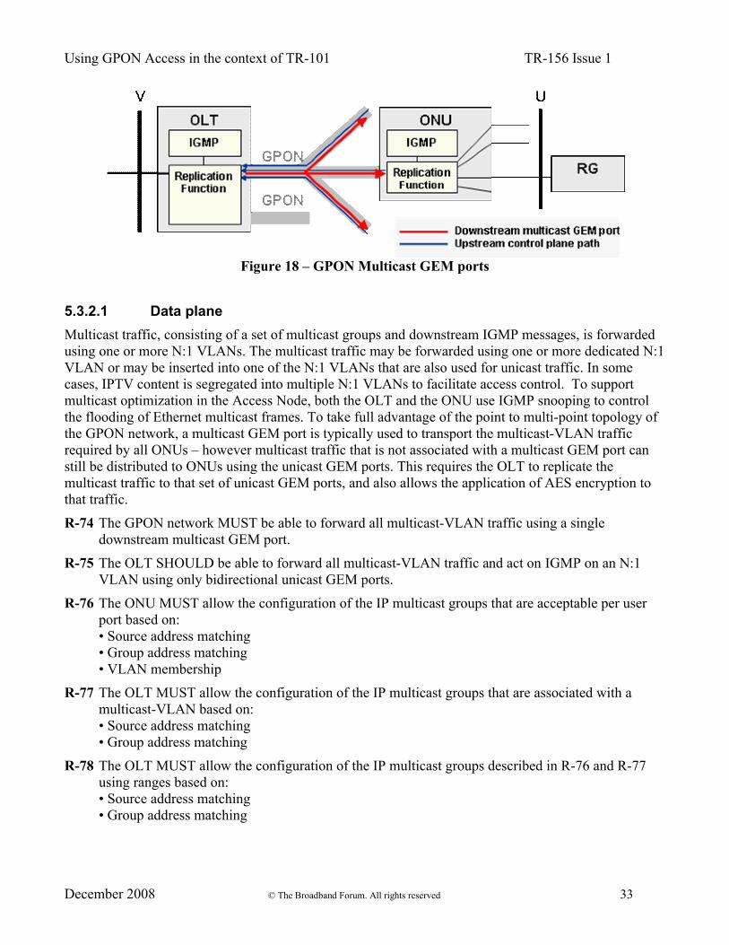
This section includes the configuration requirements that are specific to GPON, and clarifies the OLT vs. ONU responsibilities. Figure 18 illustrates the multicast service architecture. The GEM adaptation blocks are not shown for simplicity.
Using GPON Access in the context of TR-101 TR-156 Issue 1
December 2008 © The Broadband Forum. All rights reserved 33
Figure 18 – GPON Multicast GEM ports
5.3.2.1 Data plane
Multicast traffic, consisting of a set of multicast groups and downstream IGMP messages, is forwarded using one or more N:1 VLANs. The multicast traffic may be forwarded using one or more dedicated N:1 VLAN or may be inserted into one of the N:1 VLANs that are also used for unicast traffic. In some cases, IPTV content is segregated into multiple N:1 VLANs to facilitate access control. To support multicast optimization in the Access Node, both the OLT and the ONU use IGMP snooping to control the flooding of Ethernet multicast frames. To take full advantage of the point to multi-point topology of the GPON network, a multicast GEM port is typically used to transport the multicast-VLAN trafficrequired by all ONUs – however multicast traffic that is not associated with a multicast GEM port canstill be distributed to ONUs using the unicast GEM ports. This requires the OLT to replicate the multicast traffic to that set of unicast GEM ports, and also allows the application of AES encryption to that traffic.
R-74 The GPON network MUST be able to forward all multicast-VLAN traffic using a single downstream multicast GEM port.
R-75 The OLT SHOULD be able to forward all multicast-VLAN traffic and act on IGMP on an N:1 VLAN using only bidirectional unicast GEM ports.
R-76 The ONU MUST allow the configuration of the IP multicast groups that are acceptable per user port based on:• Source address matching • Group address matching• VLAN membership
R-77 The OLT MUST allow the configuration of the IP multicast groups that are associated with a multicast-VLAN based on:• Source address matching • Group address matching
R-78 The OLT MUST allow the configuration of the IP multicast groups described in R-76 and R-77using ranges based on:• Source address matching • Group address matching
Using GPON Access in the context of TR-101 TR-156 Issue 1
December 2008 © The Broadband Forum. All rights reserved 34
5.3.2.2 Control Plane
All downstream IGMP messages are transported within their multicast-VLAN. In the case where a multicast bridge is used in the ONU, the message is selectively flooded toward the user ports belonging to the same multicast-VLAN. All upstream IGMP messages are transparently snooped by the ONU before being forwarded upstream. Additional classification functions are required to support mapping multicast groups to multicast-VLANs to support multiple multicast-VLANs.
GPON splits the downstream multicast traffic from the upstream multicast control traffic, primarily due to the unidirectional nature of the downstream multicast GEM port. Upstream IGMP messages from a particular user port are typically mapped to a bi-directional GEM port of the respective TC assigned to the user port from which the message originated. Additionally, all the control plane enhancements established in TR-101 still apply.
R-79 The GPON network MUST use a bi-directional GEM port for upstream IGMP messages. This GEM Port can be shared by other VLANs from the same U interface that share the same TC.
R-80 The OLT SHOULD send downstream multicast IGMP messages (e.g. Global Query messages) using the same GEM port that is used to carry the multicast content.
R-81 The ONU MUST support receiving downstream multicast IGMP messages (e.g. Global Query messages) on either a unicast GEM port, or the multicast GEM port that is used to carry the multicast content.
R-82 The ONU and OLT MUST support the identification and processing of upstream IGMP messages. When this function is disabled on a port and/or VLAN, these messages are transparently forwarded.
R-83 The OLT MUST support configurable silent discard of all IGMP messages received on an ONU user port and/or VLAN.
R-84 The OLT and ONU MUST support matching groups conveyed by IGMP messages on a user portto the list of groups (R-76) associated with this port. When there is no match, the copy of IGMP message directed toward the multicast-VLAN MUST be silently discarded. When there is a match, the IGMP message SHOULD be forwarded within a multicast-VLAN, and enter the IGMP snooping function.
IGMP v3 report messages may carry membership information for multiple multicast groups. Therefore, a single IGMP report message may carry membership information on groups ‘matching’ a multicast-VLAN as well as on groups ‘not matching’ a multicast-VLAN.
R-85 The OLT MUST support mechanisms to stop user ports injecting multicast traffic to the aggregation network. This behaviour MUST be configurable per ONU user port and/or VLAN.
R-86 The OLT MUST be able to discard IGMP messages received from user-facing ports on a multicast-VLAN
R-87 The ONU and OLT MUST be able to rate-limit IGMP messages received from user-facing ports on a multicast-VLAN.
R-88 The ONU and OLT MUST support an IGMP v3 (as per RFC 3376) transparent snooping function. This MUST be configurable on a per VLAN basis.
Using GPON Access in the context of TR-101 TR-156 Issue 1
December 2008 © The Broadband Forum. All rights reserved 35
Note: V3 includes support of earlier versions of IGMP. Specifically, this function is responsible for configuring multicast filters such that frame replication is restricted to those user ports that requested receipt.
R-89 The ONU and OLT IGMP v3 transparent snooping function MUST support the capability to snoop the multicast source IP address and destination IP group address in IGMP messages and to set the corresponding MAC group address filters as specified in R-90.
Note: Since multicast forwarding is performed at layer 2, users of this Technical Report should coordinate IP group address assignment to avoid multiple IP source and destination addresses together mapping to the same MAC group address. Similarly, the ONU and OLT are not required to support in the ‘exclude multicast source’ feature of IGMP v3.
R-90 The ONU and OLT IGMP v3 transparent snooping function MUST be able to dynamically create and delete MAC-level Group Filter entries, enabling in turn, selective multicast forwarding from network-facing VLANs to user-facing ports.
R-91 The ONU MUST support IGMP immediate leave as part of the IGMP transparent snooping function.
R-92 Upon detecting topology changes (e.g. VLAN membership change, port being disabled by STP and network port changing state) the OLT MUST be able to issue an IGMP proxy query solicitation, i.e. an IGMP Group Leave with group address ‘0.0.0.0’. This will indicate to the BNG to immediately send Group Specific queries, which will populate the L2 multicast filters in the Access Node, in order to speed up network convergence. For reference see RFC 4541, chapter 2.1.1 section 4.
R-93 For security purposes, the ONU SHOULD and OLT MUST silently discard any user-initiated IGMP Leave messages for group ‘0.0.0.0’.
R-94 The ONU MUST support marking, in the upstream direction, user-initiated IGMP messages with Ethernet P-bits.
R-95 The OLT SHOULD provide the following statistics.Per VLAN, per multicast group:1. Total number of currently active hosts
Per U interface, per multicast-VLAN:1. Total number of successful joins
2. Total number of unsuccessful joins 3. Total number of leave messages
4. Total number of general queries sent to users5. Total number of specific queries sent to users6. Total number of invalid IGMP messages received
Per multicast-VLAN:1. Current number of active groups 2. Total number of sent joins3. Total number of joins received from users4. Total number of successful joins from users
5. Total number of unsuccessful joins from users
Using GPON Access in the context of TR-101 TR-156 Issue 1
December 2008 © The Broadband Forum. All rights reserved 36
6. Total number of leave messages7. Total number of leave messages received from users8. Total number of general queries sent9. Total number of general queries received from network10. Total number of specific queries sent to users11. Total number of specific queries received from network12. Total number of invalid IGMP messages received
R-96 The ONU MUST support configuring which user ports are members of a given multicast-VLAN.
R-97 The ONU and OLT MUST be able to configure per U interface the maximum number of simultaneous multicast groups allowed.
R-98 The ONU MUST silently discard IGMP v1 messages.
R-99 The ONU SHOULD support an IGMP/PPPoE transparent snooping function. This capability will use the methods described for classification and establishment of group address filters based on the baseline requirements (See section 6.2.2/TR-101).
R-100 If R-99 is supported, then for those IGMP messages observed within PPPoE, the ONU MUST be able to trigger a local IGMP Host function (aka “echo client”) when a group is joined or left by a user-facing port. The IGMP Host function MUST then locally generate IGMP/IPoE messages (e.g. membership report/leave) and locally reply to IGMP membership queries to reflect the groups whose delivery to the ONU is needed. The IGMP Host function MUST be triggered in the context of the multicast-VLAN.
Note: The IGMP Host function in the ONU may be optionally followed by a proxy/aggregation function in the OLT.
R-101 If R-99 is supported, then the instantiation of the local IGMP Host at the ONU MUST be configurable per multicast-VLAN and user port.
R-102 The OLT MUST support IGMP v3 snooping with proxy reporting configurable on a per VLAN basis.
R-103 The OLT MUST allow selection between transparent snooping and snooping with proxy reporting on a per-VLAN basis.
R-104 The IGMP snooping with proxy reporting function MUST support IGMP proxy query functions.
R-105 The OLT proxy-reporting function MUST support marking IGMP messages it initiates with Ethernet (VLAN) P-bits.
5.4Non-IGMP Controlled Multicast and Broadcast
5.4.1 Introduction
The following sections provide the requirements for the treatment of broadcast, multicast, and other flooded frames both at the ONT and the OLT.
Using GPON Access in the context of TR-101 TR-156 Issue 1
December 2008 © The Broadband Forum. All rights reserved 37
5.4.2 Multicast that needs to be treated as unicast at the OLT
If operators want an additional level of security for Multicast traffic, then they can configure the OLT to replicate the traffic and send it using unicast GEM ports. This configuration would result in the multicast traffic being transported in AES-encrypted GEM ports rather than the typical unencrypted multicast GEM ports.
R-106 The OLT SHOULD be able to create MAC multicast filter entries for VLANs and multicast groups that MUST be forwarded downstream using the bidirectional GEM ports – i.e. VLANs and groups that will not be multicast to all ONUs using a multicast GEM port.
R-107 If R-106 is supported, then the OLT MUST NOT forward any multicast traffic provisioned to use a bidirectional GEM port to GEM ports for ONUs that are not associated with the multicast-VLAN and group or have not joined the group.
R-108 If R-106 is supported, then upon receipt of an IGMP message to join a multicast group provisioned to be delivered using bidirectional GEM ports, the OLT MUST forward the associated multicast traffic to the unicast GEM port(s) through which it received the IGMP message.
5.4.3 Unknown MAC address frames at the OLT
R-109 It MUST be possible to configure each N:1 VLAN so that the OLT either silently discards or floods frames with MAC addresses that are not in the AN forwarding table.
R-110 For N:1 VLANs where flooding is enabled, when the OLT receives a tagged frame with an unknown unicast MAC address then it MUST be flooded by forwarding to a downstream GEM port.
5.4.4 Broadcast MAC address frames at the OLT
There are many filtering options that allow avoiding broadcast Ethernet frames for consumer access VLANs, however it is possible to turn these features off, so that broadcast is possible in N:1 VLANs.
R-111 It MUST be possible to configure each VLAN so that it silently discards broadcast frames.
R-112 For N:1 VLANs, when the OLT receives a broadcast frame, and if it is not otherwise filtered, then it MUST be forwarded using a downstream GEM port.
5.4.5 Downstream GEM Ports at the ONU
R-113 If the ONU receives a tagged frame on a downstream GEM Port, it MUST forward it to all U interfaces that are members of that VLAN.
5.5Security Considerations
Note: It is understood that TR101/R-89, expressed here as R-114, is probably more difficult to support in a GPON system than a TR-101 AN.
R-114 The OLT SHOULD be able to provide service to users with duplicate MAC addresses.
R-115 The OLT SHOULD be able to deny service to users with duplicate MAC addresses.
R-116 The OLT SHOULD provide a mechanism to prevent Broadband Network Gateway MAC address spoofing.
Using GPON Access in the context of TR-101 TR-156 Issue 1
December 2008 © The Broadband Forum. All rights reserved 38
R-117 The OLT SHOULD inspect upstream and downstream DHCP packets in order to discover the mapping of IP address to MAC address and populate an ARP table associating these addresses with their respective U-interface and VLAN.
R-118 The OLT SHOULD ensure that downstream broadcast ARP requests are not sent on U-interfaces that do not have the requested IP address.
R-119 The OLT SHOULD provide mechanisms to prevent user IP address spoofing, by discarding upstream IP packets received from U-interfaces that do not match the configured or DHCP-discovered source IP address.
R-120 The OLT SHOULD be configurable with a list of IP address associated with user port and VLAN, to be used for users having static IP configuration.
R-121 In order to prevent source MAC flooding attacks, the OLT MUST be able to limit the number of source MAC addresses learned and forwarded from each user port. This limit MUST be configurable per user port.
5.6Filtering
R-122 The OLT and ONU SHOULD allow configuring and applying the following filters. The OLT MUST apply any configured filters in the downstream direction, and the ONU MUST apply any configured filters in the upstream direction.
1. Source MAC address filter. This filter may be used in one of the following ways:i. Allowing access from a specific MAC address.ii. Denying access from a specific MAC address.
2. Destination MAC address filter. This filter may be used in one of the following ways:i. Allowing access to specific destinations.ii. Denying access to specific destinations.
R-123 The ONU SHOULD allow configuration of an EtherType filter, and applying it per U-interfacein the upstream direction. This filter may be used in one of the following ways:
i. Allowing a specific EtherType frame access (e.g. IPoE, PPPoE).ii. Denying a specific EtherType frame access (e.g. IPoE, PPPoE).
R-124 The OLT and ONU SHOULD be able to filter reserved group MAC destination addresses (in the 01:80:C2 range – See TR-101/R-95)
5.7Port Identification and Characterization
The configurable syntax of TR-101 line identifiers is retained for GPON; however, a new identifier is added to the flexible syntax list: the static identifier for the ONU.
R-125 The OLT MUST create the Agent Circuit ID and Remote ID as described in TR-101.
R-126 The OLT MUST use a static identifier, ONUID7, for each ONU device in a PON interface. This identifier MUST remain the same across re-initialization, software and firmware updates, and
7 The ONUID may be obtained in several ways, however it is only the identifier’s characteristics, and not the method by which it is derived that is important to the field.
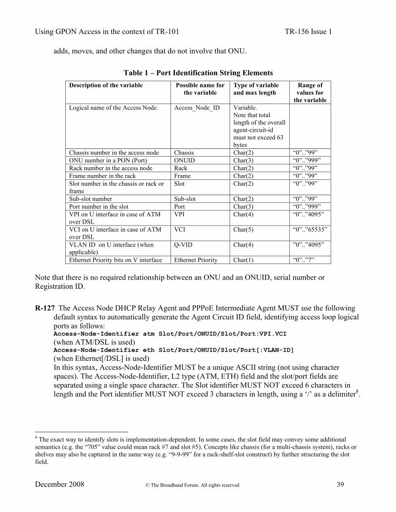
Using GPON Access in the context of TR-101 TR-156 Issue 1
December 2008 © The Broadband Forum. All rights reserved 39
adds, moves, and other changes that do not involve that ONU.
Table 1 – Port Identification String Elements
Description of the variable Possible name for the variable
Type of variable and max length
Range of values for
the variableLogical name of the Access Node. Access_Node_ID Variable.
Note that total length of the overall agent-circuit-id must not exceed 63 bytes
Chassis number in the access node Chassis Char(2) “0”..”99”ONU number in a PON (Port) ONUID Char(3) “0”..”999”Rack number in the access node Rack Char(2) “0”..”99”Frame number in the rack Frame Char(2) “0”..”99”Slot number in the chassis or rack or frame
Slot Char(2) “0”..”99”
Sub-slot number Sub-slot Char(2) “0”..”99”Port number in the slot Port Char(3) “0”..”999”VPI on U interface in case of ATM over DSL
VPI Char(4) “0”..”4095”
VCI on U interface in case of ATM over DSL
VCI Char(5) “0”..”65535”
VLAN ID on U interface (when applicable)
Q-VID Char(4) ”0”..”4095”
Ethernet Priority bits on V interface Ethernet Priority Char(1) “0”..”7”
Note that there is no required relationship between an ONU and an ONUID, serial number or Registration ID.
R-127 The Access Node DHCP Relay Agent and PPPoE Intermediate Agent MUST use the following default syntax to automatically generate the Agent Circuit ID field, identifying access loop logical ports as follows:Access-Node-Identifier atm Slot/Port/ONUID/Slot/Port:VPI.VCI (when ATM/DSL is used) Access-Node-Identifier eth Slot/Port/ONUID/Slot/Port[:VLAN-ID](when Ethernet[/DSL] is used)In this syntax, Access-Node-Identifier MUST be a unique ASCII string (not using character spaces). The Access-Node-Identifier, L2 type (ATM, ETH) field and the slot/port fields are separated using a single space character. The Slot identifier MUST NOT exceed 6 characters in length and the Port identifier MUST NOT exceed 3 characters in length, using a ‘/’ as a delimiter8.
8 The exact way to identify slots is implementation-dependent. In some cases, the slot field may convey some additional semantics (e.g. the “705” value could mean rack #7 and slot #5). Concepts like chassis (for a multi-chassis system), racks or shelves may also be captured in the same way (e.g. “9-9-99” for a rack-shelf-slot construct) by further structuring the slot field.
Using GPON Access in the context of TR-101 TR-156 Issue 1
December 2008 © The Broadband Forum. All rights reserved 40
The VPI, VCI and VLAN-ID fields (when applicable) are related to a given access loop (U-interface)9.
Note: the slot/port information after ONUID is dependent on the model and type of ONU. An OLT may not have sufficient information to properly add these fields. Nevertheless, the OLT should be able to create the default syntax by using information inserted by the ONU. For example, the OLT can combine slot/port information received from an ONU with the other information needed to create the string.
R-128 The OLT MUST be able to perform the Layer 2 DHCP relay agent function as specified in Section 3.9.1/TR-101.
R-129 The OLT MUST be able to perform the PPPoE Intermediate Agent function as specified in Section 3.9.2/TR-101.
9 In other words, in the ATM case, vpi/vci will always be used. In the EFM case, if the DHCP or PPPoE message is received with a VLAN Tag, the received VLAN ID will be appended to the string.
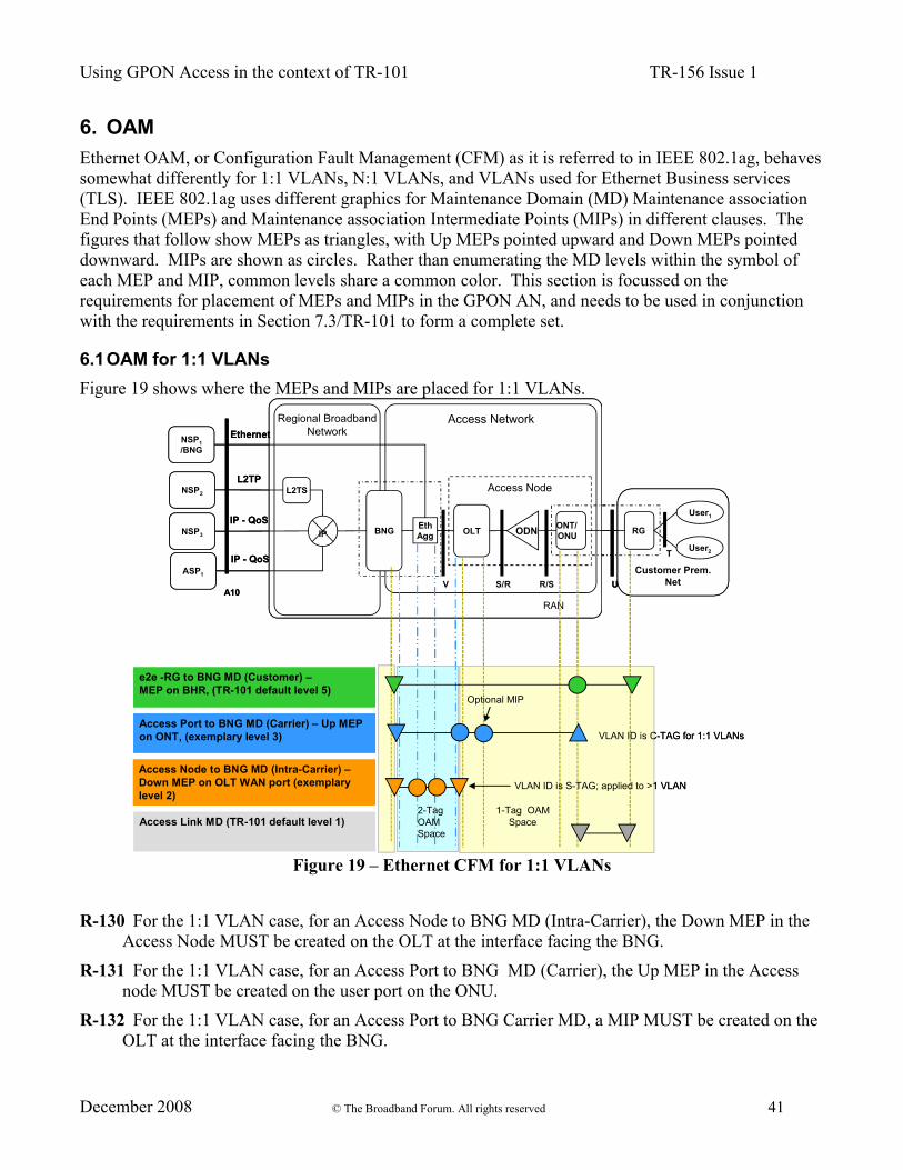
Using GPON Access in the context of TR-101 TR-156 Issue 1
December 2008 © The Broadband Forum. All rights reserved 41
6. OAM
Ethernet OAM, or Configuration Fault Management (CFM) as it is referred to in IEEE 802.1ag, behaves somewhat differently for 1:1 VLANs, N:1 VLANs, and VLANs used for Ethernet Business services (TLS). IEEE 802.1ag uses different graphics for Maintenance Domain (MD) Maintenance association End Points (MEPs) and Maintenance association Intermediate Points (MIPs) in different clauses. The figures that follow show MEPs as triangles, with Up MEPs pointed upward and Down MEPs pointed downward. MIPs are shown as circles. Rather than enumerating the MD levels within the symbol of each MEP and MIP, common levels share a common color. This section is focussed on therequirements for placement of MEPs and MIPs in the GPON AN, and needs to be used in conjunction with the requirements in Section 7.3/TR-101 to form a complete set.
6.1OAM for 1:1 VLANs
Figure 19 shows where the MEPs and MIPs are placed for 1:1 VLANs.
RAN
Access NetworkRegional BroadbandNetwork
OLTEthAggIP BNG
L2TS
IP - QoS
L2TP
Customer Prem. Net
RG
NSP2
ASP1
A10U
User1
User2T
NSP3
IP - QoS
V
NSP1
/BNG
ONT/ONUODN
R/SS/R
Access Node
Ethernet
Access Port to BNG MD (Carrier) – Up MEP on ONT, (exemplary level 3)
Access Node to BNG MD (Intra-Carrier) –Down MEP on OLT WAN port (exemplary level 2)
Access Link MD (TR-101 default level 1)
e2e -RG to BNG MD (Customer) –MEP on BHR, (TR-101 default level 5)
VLAN ID is C-TAG for 1:1 VLANs
VLAN ID is S-TAG; applied to >1 VLAN
Optional MIP
1-Tag OAM Space
2-Tag OAM Space
Figure 19 – Ethernet CFM for 1:1 VLANs
R-130 For the 1:1 VLAN case, for an Access Node to BNG MD (Intra-Carrier), the Down MEP in the Access Node MUST be created on the OLT at the interface facing the BNG.
R-131 For the 1:1 VLAN case, for an Access Port to BNG MD (Carrier), the Up MEP in the Access node MUST be created on the user port on the ONU.
R-132 For the 1:1 VLAN case, for an Access Port to BNG Carrier MD, a MIP MUST be created on the OLT at the interface facing the BNG.

Using GPON Access in the context of TR-101 TR-156 Issue 1
December 2008 © The Broadband Forum. All rights reserved 42
R-133 For the 1:1 VLAN case, for an Access Port to BNG Carrier MD, an MIP SHOULD be created on the OLT at the interface facing the ONU.
Note that the location of the C-tagged MIP may affect the implementation of Ethernet CFM on the OLT depending on whether that MIP can reside before the addition of the S-Tag in this double-tagged application. The details of implementation are left to the vendor to ensure VLAN Tags for the CFM messages are compliant at the interface locations A, B and C as per Figure 20.
R-134 For the 1:1 VLAN case, for end-to-end RG to BNG MD (Customer), a MIP MUST be created on the ONU at the interface facing the user10.
In the case of 1:1 VLANs, the Ethernet Virtual Circuit (EVC) is presumed to be using double Tags per IEEE 802.1ad Provider Bridge. The usage of the double Tags is accomplished in the following manner: The EVC frames between the RG and ONU are untagged, priority-tagged or single-tagged The EVC frames between the ONU and OLT use single-tagged frames (C-Tag). The EVC frames between the OLT and BNG use double-tagged frames (S-Tag and C-Tag).
Since the VLAN Tags for the EVC are different, depending on the device location in the network, it affects Ethernet OAM frames as well.
There are three major concepts depicted in Figure 19 with regard to the resultant OAM space that is created by the type of Tags used at the various nodes:
1. The double-tagged OAM Space begins and ends at the "east-west" points where the outer tag is added and removed.
2. The double-tagged OAM Space has free access to all eight MD levels, and it can use the same levels as the Single-tagged OAM Space and not cause a conflict.
3. The single-tagged OAM Flow Space has no access to OAM processing points at devices where the frame still has two Tags.
Each OAM Space includes a full set of MD Levels. So if the Single-tagged OAM Space uses level 3 for a particular use, this does not prevent the Double-tagged OAM Space from using level 3 for another use. This is because at any given point, only one OAM Space is active
R-135 For the 1:1 VLAN case, for the Access Node to BNG MD, Access Port to BNG Carrier MD, and the end-to-end RG to BNG Customer MD, the BNG MUST support MEP functionality at all 3 levels at the same time.
Figure 20 shows an example of the VLAN Tags in relation to the Intra-Carrier, Carrier and Customer MDs for the 1:1 VLAN case. Note that either untagged frames or single-tagged frames may be used at point C.
Note that at point A, the double-tagged OAM frames of the Carrier MD and Customer MD levels would not receive OAM processing, because they are members of the Single-tagged OAM Space.
10 It should be noted that devices implementing MEPs or MIPs are required to have a MAC address.

Using GPON Access in the context of TR-101 TR-156 Issue 1
December 2008 © The Broadband Forum. All rights reserved 43
Also note that it is required that the BNG will terminate the S-tagged flow and process the OAM frames of the double-tagged OAM Space. It would then process the C-tagged flow and process the OAM frames of the single-tagged OAM Space.
BNG OLT ONTA B RGC
Customer MD
Carrier MD
Intra-Carrier MD
DA SA S-VID CFM EtherType Intra-Carrier MD Level CFM Message
At A:
DA SA S-VID CFM EtherType Customer MD Level CFM MessageC-VID
DA SA S-VID CFM EtherType Carrier MD Level CFM MessageC-VID
At B:DA SA CFM EtherType Customer MD Level CFM MessageC-VID
DA SA CFM EtherType Carrier MD Level CFM MessageC-VID
At C:DA SA CFM EtherType Customer MD Level CFM Message
optional
DA SA CFM EtherType Customer MD Level CFM MessageC-VID (tagged)
(untagged)
Figure 20 – One Example of CFM Frame Formats at Different Points for 1:1 VLANs
6.2OAM for N:1 VLANs
Figure 21 where the MEPs and MIPs are placed for N:1 VLANs.
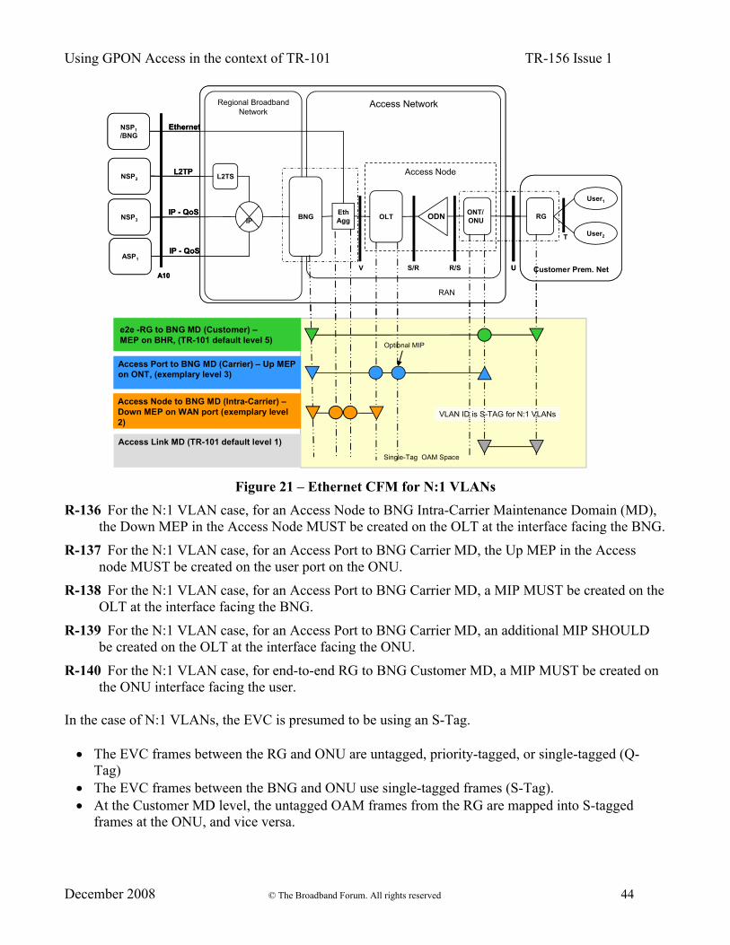
Using GPON Access in the context of TR-101 TR-156 Issue 1
December 2008 © The Broadband Forum. All rights reserved 44
RAN
Regional BroadbandNetwork
Access Network
OLTEthAggIP
BNG
L2TS
IP - QoS
L2TP
Customer Prem. Net
RG
NSP2
ASP1
A10U
User1
User2T
NSP3
IP - QoS
V
NSP1
/BNG
ONT/ONUODN
R/SS/R
Access Node
Ethernet
Access Port to BNG MD (Carrier) – Up MEP on ONT, (exemplary level 3)
Access Node to BNG MD (Intra-Carrier) –Down MEP on WAN port (exemplary level 2)
Access Link MD (TR-101 default level 1)
e2e -RG to BNG MD (Customer) –MEP on BHR, (TR-101 default level 5)
VLAN ID is S-TAG for N:1 VLANs
Optional MIP
Single-Tag OAM Space
Figure 21 – Ethernet CFM for N:1 VLANs
R-136 For the N:1 VLAN case, for an Access Node to BNG Intra-Carrier Maintenance Domain (MD), the Down MEP in the Access Node MUST be created on the OLT at the interface facing the BNG.
R-137 For the N:1 VLAN case, for an Access Port to BNG Carrier MD, the Up MEP in the Access node MUST be created on the user port on the ONU.
R-138 For the N:1 VLAN case, for an Access Port to BNG Carrier MD, a MIP MUST be created on the OLT at the interface facing the BNG.
R-139 For the N:1 VLAN case, for an Access Port to BNG Carrier MD, an additional MIP SHOULD be created on the OLT at the interface facing the ONU.
R-140 For the N:1 VLAN case, for end-to-end RG to BNG Customer MD, a MIP MUST be created on the ONU interface facing the user.
In the case of N:1 VLANs, the EVC is presumed to be using an S-Tag.
The EVC frames between the RG and ONU are untagged, priority-tagged, or single-tagged (Q-Tag)
The EVC frames between the BNG and ONU use single-tagged frames (S-Tag). At the Customer MD level, the untagged OAM frames from the RG are mapped into S-tagged
frames at the ONU, and vice versa.
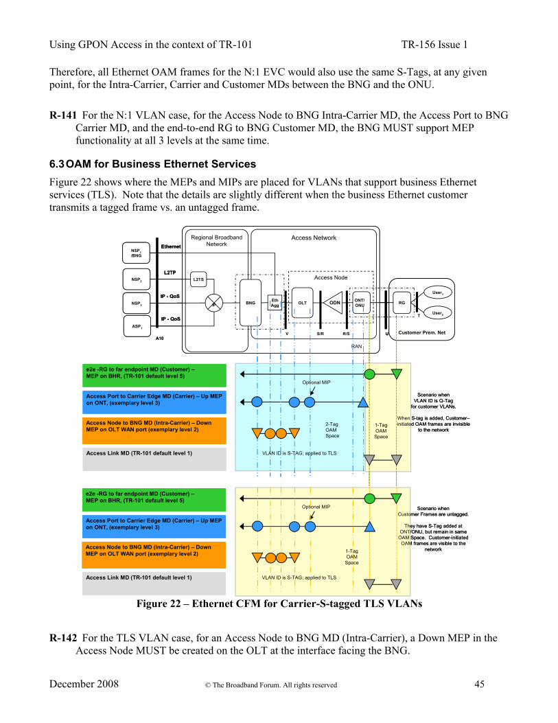
Using GPON Access in the context of TR-101 TR-156 Issue 1
December 2008 © The Broadband Forum. All rights reserved 45
Therefore, all Ethernet OAM frames for the N:1 EVC would also use the same S-Tags, at any given point, for the Intra-Carrier, Carrier and Customer MDs between the BNG and the ONU.
R-141 For the N:1 VLAN case, for the Access Node to BNG Intra-Carrier MD, the Access Port to BNG Carrier MD, and the end-to-end RG to BNG Customer MD, the BNG MUST support MEP functionality at all 3 levels at the same time.
6.3OAM for Business Ethernet Services
Figure 22 shows where the MEPs and MIPs are placed for VLANs that support business Ethernet services (TLS). Note that the details are slightly different when the business Ethernet customer transmits a tagged frame vs. an untagged frame.
RAN
Access NetworkRegional BroadbandNetwork
OLTEthAggIP BNG
L2TS
IP - QoS
L2TP
Customer Prem. Net
RG
NSP2
ASP1
A10U
User1
User2T
NSP3
IP - QoS
V
NSP1/BNG
ONT/ONU
ODN
R/SS/R
Access Node
Ethernet
Access Port to Carrier Edge MD (Carrier) – Up MEP on ONT, (exemplary level 3)
Access Node to BNG MD (Intra-Carrier) – Down MEP on OLT WAN port (exemplary level 2)
Access Link MD (TR-101 default level 1)
e2e -RG to far endpoint MD (Customer) –MEP on BHR, (TR-101 default level 5)
Scenario when VLAN ID is Q-Tag
for customer VLANs.
When S-tag is added, Customer–initiated OAM frames are invisible
to the network
VLAN ID is S-TAG; applied to TLS
Optional MIP
1-Tag OAM Space
2-Tag OAM Space
Access Port to Carrier Edge MD (Carrier) – Up MEP on ONT, (exemplary level 3)
Access Node to BNG MD (Intra-Carrier) – Down MEP on OLT WAN port (exemplary level 2)
Access Link MD (TR-101 default level 1)
e2e -RG to far endpoint MD (Customer) –MEP on BHR, (TR-101 default level 5)
Scenario when Customer Frames are untagged.
They have S-Tag added at ONT/ONU, but remain in same
OAM Space. Customer-initiated OAM frames are visible to the
network
VLAN ID is S-TAG; applied to TLS
Optional MIP
1-Tag OAM
Space
Figure 22 – Ethernet CFM for Carrier-S-tagged TLS VLANs
R-142 For the TLS VLAN case, for an Access Node to BNG MD (Intra-Carrier), a Down MEP in the Access Node MUST be created on the OLT at the interface facing the BNG.

Using GPON Access in the context of TR-101 TR-156 Issue 1
December 2008 © The Broadband Forum. All rights reserved 46
R-143 For the TLS VLAN case, for an Access Port to Carrier Edge MD (Carrier), an Up MEP in the Access node MUST be created on the user port on the ONU.
R-144 For the TLS VLAN case, for an Access Port to Carrier Edge MD, a MIP MUST be created on the OLT at the interface facing the BNG.
R-145 For the TLS VLAN case, for an Access Port to Carrier Edge MD, a MIP MUST be created on the BNG at the interface facing the OLT.
R-146 For the TLS VLAN case, for an Access Port to Carrier Edge MD, a MIP SHOULD be created on the OLT at the interface facing the ONU.
R-147 For the TLS VLAN case, for end-to-end RG to far endpoint (Customer) MD, a MIP MUST be created on the ONU at the interface facing the user11.
In the case of TLS, the Ethernet Virtual Circuit (EVC) may receive tagged or untagged frames from the customer (or a mixture). There are two cases to consider: The EVC frames between the RG and ONU are untagged, priority-tagged or single-tagged in most
cases and the ONU prepends an S-Tag. If the customer’s frame is tagged, then the additional S-tag creates a double tag and causes any customer-initiated OAM frames to be invisible to the network. However, if the customer’s frame is untagged, the addition of an S-tag does not hide the customer’s OAM frame, and it is visible. Both of these cases are shown in Figure 22.
The EVC frames between the RG and ONU are S-tagged only in the special case where the CPE may attach the S-Tag on behalf of the ONU. Functionally, this case works identically to the first case. It does not change the MEP point for the Access Port to Carrier Edge MD (level 3) when this happens, nor does it change the MIP for the end-to-end RG to far endpoint (Customer) MD –however this MIP is now accessible using the S-Tag at level 5. (Note, this case is shown in Figure 23.)
11 It should be noted that devices implementing MEPs or MIPs are required to have a MAC address.
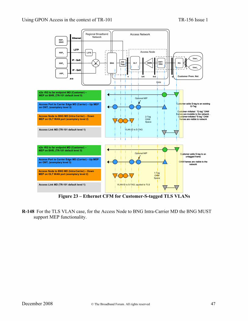
Using GPON Access in the context of TR-101 TR-156 Issue 1
December 2008 © The Broadband Forum. All rights reserved 47
RAN
Access NetworkRegional BroadbandNetwork
OLTEthAggIP BNG
L2TS
IP - QoS
L2TP
Customer Prem. Net
RG
NSP2
ASP1
A10U
User1
User2T
NSP3
IP - QoS
V
NSP1/BNG
ONT/ONUODN
R/SS/R
Access Node
Ethernet
Access Port to Carrier Edge MD (Carrier) – Up MEP on ONT, (exemplary level 3)
Access Node to BNG MD (Intra-Carrier) – Down MEP on OLT WAN port (exemplary level 2)
Access Link MD (TR-101 default level 1)
e2e -RG to far endpoint MD (Customer) –MEP on BHR, (TR-101 default level 5)
VLAN ID is S-TAG
Optional MIP
2-Tag OAM Space
Access Port to Carrier Edge MD (Carrier) – Up MEP on ONT, (exemplary level 3)
Access Node to BNG MD (Intra-Carrier) – Down MEP on OLT WAN port (exemplary level 2)
Access Link MD (TR-101 default level 1)
e2e -RG to far endpoint MD (Customer) –MEP on BHR, (TR-101 default level 5)
Customer adds S-tag to an untagged frame
OAM frames are visible to the network
VLAN ID is S-TAG; applied to TLS
Optional MIP
1-Tag OAM Space
Customer adds S-tag to an existing Q-Tag
Customer–initiated “Q-tag” OAM frames are invisible to the network .
Customer-initiated “S-tag” OAM frames are visible to network
Figure 23 – Ethernet CFM for Customer-S-tagged TLS VLANs
R-148 For the TLS VLAN case, for the Access Node to BNG Intra-Carrier MD the BNG MUST support MEP functionality.
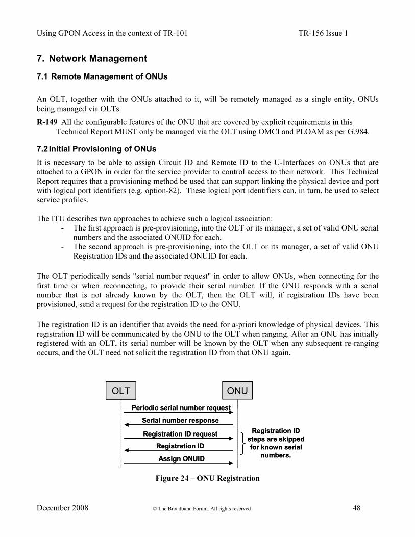
Using GPON Access in the context of TR-101 TR-156 Issue 1
December 2008 © The Broadband Forum. All rights reserved 48
7. Network Management
7.1 Remote Management of ONUs
An OLT, together with the ONUs attached to it, will be remotely managed as a single entity, ONUs being managed via OLTs.
R-149 All the configurable features of the ONU that are covered by explicit requirements in this Technical Report MUST only be managed via the OLT using OMCI and PLOAM as per G.984.
7.2Initial Provisioning of ONUs
It is necessary to be able to assign Circuit ID and Remote ID to the U-Interfaces on ONUs that are attached to a GPON in order for the service provider to control access to their network. This Technical Report requires that a provisioning method be used that can support linking the physical device and port with logical port identifiers (e.g. option-82). These logical port identifiers can, in turn, be used to select service profiles.
The ITU describes two approaches to achieve such a logical association:- The first approach is pre-provisioning, into the OLT or its manager, a set of valid ONU serial
numbers and the associated ONUID for each.- The second approach is pre-provisioning, into the OLT or its manager, a set of valid ONU
Registration IDs and the associated ONUID for each.
The OLT periodically sends "serial number request" in order to allow ONUs, when connecting for the first time or when reconnecting, to provide their serial number. If the ONU responds with a serial number that is not already known by the OLT, then the OLT will, if registration IDs have been provisioned, send a request for the registration ID to the ONU.
The registration ID is an identifier that avoids the need for a-priori knowledge of physical devices. Thisregistration ID will be communicated by the ONU to the OLT when ranging. After an ONU has initially registered with an OLT, its serial number will be known by the OLT when any subsequent re-ranging occurs, and the OLT need not solicit the registration ID from that ONU again.
OLT
Periodic serial number request
Serial number response
Assign ONUID
Registration ID request
Registration ID
ONU
Registration ID steps are skipped for known serial
numbers.
OLT
Periodic serial number request
Serial number response
Assign ONUID
Registration ID request
Registration ID
ONU
Registration ID steps are skipped for known serial
numbers.
Figure 24 – ONU Registration
Using GPON Access in the context of TR-101 TR-156 Issue 1
December 2008 © The Broadband Forum. All rights reserved 49
R-150 The OLT MUST support the pre-provisioning of ONU serial numbers and their associated ONUIDs.
R-151 The OLT MUST support the pre-provisioning of registration IDs and their associated ONUIDs.
R-152 ONUs that support the registration ID approach MUST support the local setting of a registration ID.
Note: R-152 does not imply that a craft terminal interface has to be present on the ONU.
R-153 ONUs that support the registration ID approach MUST retain the registration ID indefinitely.
R-154 When the OLT receives a serial number from an ONU during ranging, the OLT MUST determine whether the serial number is recognized either from a previous registration or from itsset of provisioned values.
R-155 In the case where a serial number is not recognized, an OLT MUST determine whether the registration ID is recognized from its set of provisioned values.
R-156 When an ONU registers successfully [per R-154/R-155] the OLT MUST add that ONUs serial number to the set of recognized serial numbers and assign an ONUID.

Using GPON Access in the context of TR-101 TR-156 Issue 1
December 2008 © The Broadband Forum. All rights reserved 50
Appendix A
In GPON, upstream traffic from all of the ONTs on a PON is managed by the OLT using DBA (Dynamic Bandwidth Assignment). Each T-CONT is assigned an Alloc-ID that is unique across all ONTs on a given PON, and the OLT associates each Alloc-ID with a traffic descriptor defining the DBA treatment of the upstream traffic flowing in that T-CONT, such as priority and weight.Specifically, in the extended bandwidth assignment model of G.984.3, the following traffic descriptor is defined for Alloc-ID=i:
iiiAB
iM
iA
iF
i PRRRD ω,,,,, In each traffic descriptor, RF is the fixed bandwidth, RA is the assured bandwidth, RM
is the maximum bandwidth, AB is the eligibility indicator, Pi is the priority, and i is the weight.Two examples will be given showing usage of these traffic descriptors. In these examples, RF = RA = 0, RM = 1 Gbps, and AB
= BE (best effort).
Table 2 shows a first example of traffic descriptors for a PON with two ONTs and a strict priority scheme with 4 priorities. The OLT will schedule traffic on the PON such that T-CONTs with lower priority will get a share of the PON bandwidth if and only if T-CONTs with higher priority have been exhausted. Further, T-CONTs with equal priority will get an equal share of the PON bandwidth.
Table 2 – Four Classes with Strict Priority
ONU Alloc-ID Pi i
1 300 1 11 400 2 11 500 3 11 600 4 12 700 1 12 800 2 12 900 3 12 1000 4 1
Table 3 shows a second example of traffic descriptors for a PON with two ONTs and a combination of weighted and strict priority scheduling. The OLT will schedule traffic on the PON such that T-CONTs with lower priority will get a share of the PON bandwidth if and only if T-CONTs with higher priority have been exhausted. Further, of the PON bandwidth remaining after T-CONTs with priority 3 have been exhausted, Alloc-IDs 400 and 800 will get 150 times more bandwidth than Alloc-IDs 500 and 900.
Table 3 – Four Classes with Weighting and Priority
ONU Alloc-ID Pi i
1 300 1 11 400 2 1501 500 2 11 600 3 12 700 1 12 800 2 1502 900 2 12 1000 3 1


![GPON module requirements for RG - Broadband Forum · It inherits from the GPON ONU requirements of TR-156 [5], TR-124 [3], TR-142 [4], and provides additional requirements specific](https://img.pdfslide.net/doc/110x75/606a5f8adbe6ba2bd70d6c29/gpon-module-requirements-for-rg-broadband-forum-it-inherits-from-the-gpon-onu.jpg)