Embed Size (px)
Citation preview
Tracer™ Controls
Tracer ZN.511 and ZN.521
Zone Controllers
BAS-PRC006-ENFebruary 2001
®
Introduction
The Tracer ZN.511 and ZN.521 zonecontrollers provide digital control forseveral types of heating, ventilating, andair-conditioning (HVAC) equipment.
The Tracer ZN.511 controls:
• Water-source heat pumps• Two-pipe hydronic fan coils• Four-pipe hydronic fan coils• Cabinet heaters with hydronic or
single-stage electric heat
The Tracer ZN.521 controls:
• Unit ventilators• Fan coils• Cabinet heaters• Blower coils
Tracer zone controllers operate as stand-alone devices or as part of a TraneIntegrated Comfort system (ICS). Thecontrollers communicate with a TracerSummit building automation system viaa LonTalk Comm5 communication link.Comm5 allows the controllers tooperate in peer-to-peer configuration andto communicate with other compatiblebuilding control systems.
Trane offers a variety of wall-mountedzone sensors for Tracer controllers. Zonesensors come with any of the followingoptions:
• Temperature setpoint thumbwheel• Fan speed switch• ON and CANCEL occupancy buttons• A communications jack for the Rover
service tool
™ ® The following are trademarks or registered trademarks of their respective com-
panies: Windows from Microsoft Corporation; LonTalk and LonMark from Echelon Cor-
poration; Integrated Comfort, Rover, Tracer, and Tracer Summit from Trane.
2 BAS-PRC006-EN©American Standard Inc. 2001
BAS-PRC006-EN 3
®
Contents
Introduction . . . . . . . . . . . . . . . . . . . . . . . . 2
Tracer ZN.511 zone controller . . . . . . . . . . 4
Inputs and outputs . . . . . . . . . . . . . . . . . . . . . . . . . . 4Features . . . . . . . . . . . . . . . . . . . . . . . . . . . . . . . . . . . 4Dimensions . . . . . . . . . . . . . . . . . . . . . . . . . . . . . . . . 5
Tracer ZN.521 zone controller . . . . . . . . . 6
Inputs and outputs . . . . . . . . . . . . . . . . . . . . . . . . . . 6Features . . . . . . . . . . . . . . . . . . . . . . . . . . . . . . . . . . . 6Dimensions . . . . . . . . . . . . . . . . . . . . . . . . . . . . . . . . 7
Network architecture . . . . . . . . . . . . . . . . 8
Zone sensor options . . . . . . . . . . . . . . . . . 9
Wiring diagrams . . . . . . . . . . . . . . . . . . . 10
Specifications . . . . . . . . . . . . . . . . . . . . . 12
®
The Tracer ZN.511 zone controllerprovides digital control of fan coils andwater-source heat pumps. The TracerZN.511 improves comfort control andprovides stand-alone or networkedbuilding automation.
Inputs and outputsTracer ZN.511 inputs and outputsinclude:
• Analog inputs: zone temperature,entering or leaving water temperature,discharge air temperature, zone tem-perature setpoint, fan mode switch
• Binary inputs: occupancy, conden-sate overflow, fan status, low watertemperature, low pressure protec-tion, high pressure protection
• Outputs: water-source heat pump:compressor 1, compressor 2, two-position outside air damper, reversingvalve, fan on/offFan coil: fan high, fan medium, fanlow, 1 cool, 1 heat, two-positionoutside air damper
• Generic points for use with a TracerSummit building automation system:binary input (shared with occupancy),binary output (shared with outside airdamper)
The generic inputs pass information tothe building automation system. They donot affect the operation of the unit. Thegeneric binary output is controlled bythe building automation system and itsstate is not changed by unit operation,even under a diagnostic shutdown.
Features
Easy installation
The controller can be installed in existingTrane and competitive HVAC equipmentwithout major wiring changes, andclearly labeled screw terminals ensurethat wires are connected quickly andaccurately. A compact enclosure designsimplifies installation in minimal space.
Entering water temperature sampling
A traditional system using a two-waycontrol valve on a fan coil might notsense the correct entering watertemperature during long periods whenthe control valve is closed. The TracerZN.511 solves this problem by openingthe valve for three minutes to allow thewater temperature to stabilize beforethe temperature is taken. This featureallows the use of two-way control valvesto provide accurate two-pipe systemchangeover for 1heat/1 cool applications.
Automatic heat/cool modedetermination
The Tracer ZN.511 automaticallydetermines whether heating or coolingis needed to maintain comfort levels,without the need to manually adjust unitcontrols. The controller measures thezone temperature and setpointtemperature, then uses a proportional/integral algorithm to maintain zonetemperature at the setpoint.
Occupied and unoccupied operation
The occupancy input works with amotion (occupancy) sensor or timeclock. A communicated value from abuilding automation system through theComm5 link can also be used. The inputallows the controllers to use unoccupied(setback) temperature setpoints.
Random start
This feature randomly staggers multiple-unit start-up to reduce electrical demandspikes.
Warm-up and cool-down
This feature is available when an outsideair damper is installed. When the roomtemperature drifts too far from thesetpoint, the controller temporarilycloses the damper to bring thetemperature to the desired setpoint asquickly as possible.
Manual output test
Pressing the test button on thecontroller exercises all binary outputs insequence. This feature is an invaluabletroubleshooting tool.
Peer-to-peer communication
Multiple controllers can share data whenone or several slave controllers arebound to a single master controller.Shared data can include setpoint, zonetemperature, mode, and fan status.Applications having more than one unitserving a single large space can benefitfrom this feature, which preventsmultiple units from simultaneouslyheating and cooling.
Interoperability
The Tracer ZN.511 conforms to theLonMark Space Comfort Controller(SCC) profile and communicates via theLonTalk protocol. This allows it to workwith other control systems that supportLonTalk and the SCC profile.
Continuous fan or fan-cyclingoperation
Users can choose to have the fan runcontinuously at a given speed, or cycleon and off automatically by selecting theAUTO mode.
Equipment protection
The Tracer ZN.511 includes inputs thatallow for the following equipmentprotection:
• Refrigerant high- and low-pressureprotection to prevent the unit fromoperating with high/low refrigerationpressure levels (heat pump only)
• Compressor minimum on and off tim-ers to extend compressor life by pre-venting short cycling (heat pump only)
• A condensate overflow switch to pre-vent water damage to the building
• Low-temperature detection to preventcompressor operation duringabnormal conditions (heat pump) orcoil freeze-up (fan coil)
4
Tracer ZN.511 zone controller
BAS-PRC006-EN
®
Timed override
The timed override function for afterhours operation allows users to requestunit operation by the touch of a buttonon the unit zone sensor. Additionally,users can press the CANCEL button atany time to place the unit back intounoccupied mode.
Fan status
The controller monitors the fan outputstatus as proof of airflow. This method iscost effective and commonly used ondirect drive fan applications.
Filter maintenance
Filter maintenance status is based onthe cumulative hours of operation of theunit fan. The controller has timers thatcan be reset, and when the time limitexpires, Tracer Summit software or theRover service tool indicates that unitmaintenance is recommended.
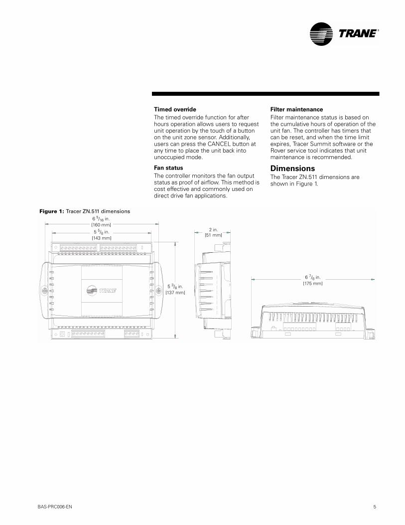
DimensionsThe Tracer ZN.511 dimensions areshown in Figure 1.
6 5/16 in.[160 mm]
5 5/8 in.[143 mm]
5 3/8 in.[137 mm]
2 in.[51 mm]
6 7/8 in.[175 mm]
Figure 1: Tracer ZN.511 dimensions
BAS-PRC006-EN
5
®
The Tracer ZN.521 zone controllerprovides digital control of fan coils, unitventilators, and blower coils. The TracerZN.521 improves comfort control andprovides stand-alone or networkedbuilding automation.
Inputs and outputsTracer ZN.521 inputs and outputsinclude:
• Analog inputs: zone temperature,space setpoint, fan speed, enteringwater temperature, discharge air tem-perature, outside air temperature,zone relative humidity
• Binary inputs: occupancy, low coiltemperature detection, fan status,condensate overflow detection
• Outputs: Fan high, fan medium, fanlow, exhaust fan on/of, cooling valve,heating valve, face and bypassdamper, economizer damper, electricheat (two stages)
• Generic points for use with a TracerSummit building automation system:binary input (shared with occupancy),binary output (shared with baseboardheat), two analog inputs (one sharedwith humidity sensor and often usedwith the optional carbon dioxidesensor, and the second shared withoutdoor air temperature)
The generic inputs pass information tothe building automation system. They donot affect the operation of the unit. Thegeneric binary output is controlled bythe building automation system and itsstate is not changed by unit operation,even under a diagnostic shutdown.
Features
Easy installation
The controller can be installed in existingTrane and competitive HVAC equipmentwithout major wiring changes, andclearly labeled screw terminals ensurethat wires are connected quickly andaccurately. A compact enclosure designsimplifies installation in minimal space.
Modulating control
The Tracer ZN.521 provides exceptionalcomfort control through hydronic valveand damper tri-state modulation and aproportional-integral control algorithm.
Cascade control
Cascade control differs from zonetemperature control in that the unitresets the discharge air temperature tocontrol the zone. Cascade controlmanages zone temperature moreeffectively than zone temperaturecontrol, in which the discharge airtemperature can exceed comfort levels.
Entering water temperature sampling
Traditional equipment using a two-waycontrol valve might not sense thecorrect entering water temperatureduring long periods when the controlvalve is closed. The Tracer ZN.521 solvesthis problem by opening the valve forthree minutes to allow the watertemperature to stabilize before thetemperature is taken. This feature allowsthe use of two-way control valves toprovide accurate two-pipe systemchangeover for 1heat/1 cool applications.
Automatic heat/cool modedetermination
The Tracer ZN.521 automaticallydetermines whether heating or coolingis needed to maintain comfort levels,without the need to manually adjust unitcontrols. The controller measures thezone temperature and setpointtemperature, then uses a proportional/integral algorithm to maintain zonetemperature at the setpoint.
Occupied and unoccupied operation
The occupancy input works with amotion (occupancy) sensor or timeclock. A communicated value from abuilding automation system through theComm5 link can also be used. The inputallows the controllers to use unoccupied(setback) temperature setpoints.
Random start
This feature randomly staggers multiple-unit start-up to reduce electrical demandspikes.
Warm-up and cool-down
This feature is available when an outsideair damper is installed. When the roomtemperature drifts too far from thesetpoint, the controller temporarilycloses the damper to bring thetemperature to the desired setpoint asquickly as possible.
Manual output test
Pressing the test button on thecontroller exercises all binary outputs insequence. This feature is an invaluabletroubleshooting tool.
Peer-to-peer communication
Multiple controllers can share data whenone or several slave controllers arebound to a single master controller.Shared data can include setpoint, zonetemperature, mode, and fan status.Applications having more than one unitserving a single large space can benefitfrom this feature, which preventsmultiple units from simultaneouslyheating and cooling.
Interoperability
The Tracer ZN.521 conforms to theLonMark Space Comfort Controller(SCC) profile and communicates via theLonTalk protocol. This allows it to workwith other control systems that supportLonTalk and the SCC profile.
Continuous fan or fan-cyclingoperation
Users can choose to have the fan runcontinuously at a given speed, or cycleon and off automatically by selecting theAUTO mode.
Equipment protection
The Tracer ZN.521 includes inputs thatallow for the following equipmentprotection:
• A condensate overflow switch to pre-vent water damage to the building
• Low-temperature detection to helpprevent coil freeze-up
• Discharge air temperature limiting tohelp prevent the coil from freezing
Automatic fan speed reset
Units set to AUTO operate at the defaultfan speeds (cooling and heating mayhave different default speeds). If thedefault fan speed is high, medium, orlow, the unit operates accordingly.
If the default fan speed is set to AUTO,the fan operates at low speed most ofthe time. If the temperature exceeds thesetpoint by more than 2°F, the controllerchanges the fan speed to medium orhigh. This allows the unit to operate atlow speed whenever possible.
6
Tracer ZN.521 zone controller
BAS-PRC006-EN
®
Automatic ventilation reset
Because ensuring proper ventilationrates is so important for indoor airquality, the Tracer ZN.521 is configuredwith two outside/fresh air damperminimum position setpoints foroccupied operation. As the fan speedchanges, the damper minimum positionchanges to maintain the correctventilation rate.
Fan status
The Tracer ZN.521 has two methods ofmonitoring fan status. The first methodmonitors the fan output status on theunit controller. This method is typicallyused with direct fan applications.
The controller can also accept a binaryinput from a fan proof switch for beltdriven applications. When fan operationis expected by the controller but notconfirmed by the proof switch, adiagnostic message is generated andunit operation is disabled.
Filter maintenance
Filter maintenance status is based onthe cumulative hours of operation of theunit fan. The controller has timers thatcan be reset, and when the time limitexpires, Tracer Summit software or theRover service tool indicates that unitmaintenance is recommended.
Water valve override
This function causes all of the watervalves in every unit to opensimultaneously at a command fromTracer Summit software or the Roverservice tool. This function reduces thetime required for balancing the waterdistribution system.
Relative humidity input
An analog input can be configured as arelative humidity input. The controllercan use this value to support thedehumidification function.
Active dehumidification
This feature keeps relative humiditylevels within ASHRAE 62-89R guidelinesto maximize comfort and minimize therisk of microbial growth and damage tothe building or furnishings due tohumidity. The controller can provideactive dehumidification when theequipment includes a reheat coil and ahumidity sensor.
CO2 input
An analog input can be configured tomeasure CO2. Tracer Summit can usethe input in a variety of applications. Thisinput has no direct effect on theoperation of the controller.
Two-stage electric heat
The Tracer ZN.521 supports 1- or 2-stageelectric heat operation for heating. Tocontrol the zone temperature, electricheat is cycled to control the discharge airtemperature. The rate of cycling isdependent on the load in the space andthe temperature of any incoming freshair from the economizer.
Two-pipe changeover units with electricheat use electric heat when hot water isnot available.
Economizing control
When the Tracer ZN.521 is configuredfor economizing control, it opens theoutdoor damper to the calculatedposition to provide “free” cooling asrequired. If the damper is completelyopen and the setpoint is still notachieved, the cooling valve opens tosatisfy load requirements. As coolingload requirements decrease, the valvecloses until the setpoint is reached orthe damper reaches its adjustableminimum position.
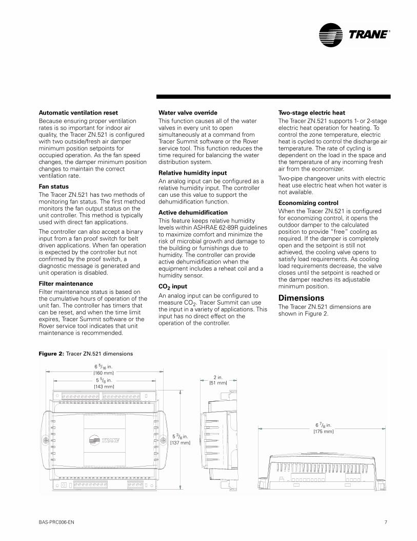
DimensionsThe Tracer ZN.521 dimensions areshown in Figure 2.
Figure 2: Tracer ZN.521 dimensions
6 5/16 in.[160 mm]
5 5/8 in.[143 mm]
5 3/8 in.[137 mm]
2 in.[51 mm]
6 7/8 in.[175 mm]
BAS-PRC006-EN
7
®
Tracer zone controllers, shown inFigure 3, can operate on a TracerSummit building automation system, ona peer-to-peer network, or as stand-alone devices.
The Rover service tool can configure thecontrollers through the communicationjack in a zone sensor or at any accessiblelocation on the Comm5 link.
Figure 3: Tracer zone controllers network architecture
Buildingcontrol unit
(BCU)
Tracer SummitPC Workstation
Unit ventilatorWater-sourceheat pump
Zonesensor
Fan coil
ZN.511
LAN (Ethernet or ARCNET)
ZN.511 ZN.521Tracer loopcontroller
Roverservice tool
ZN.511 ZN.511
Tracer zone controllers as part of a
building automation system
Tracer zone controllers on a
peer-to-peer network
One zone sensor formultiple fan coils
LonTalkComm5 link
8
Network architecture
BAS-PRC006-EN
®
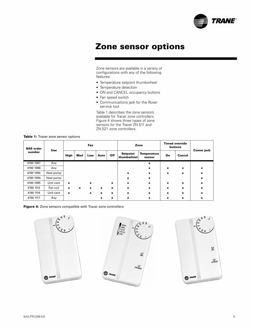
Zone sensors are available in a variety ofconfigurations with any of the followingfeatures:
• Temperature setpoint thumbwheel• Temperature detection• ON and CANCEL occupancy buttons• Fan speed switch• Communications jack for the Rover
service tool
Table 1 describes the zone sensorsavailable for Tracer zone controllers.Figure 4 shows three types of zonesensors for the Tracer ZN.511 andZN.521 zone controllers.
Table 1: Tracer zone sensor options
Figure 4: Zone sensors compatible with Tracer zone controllers
BAS ordernumber
Use
Fan Zone Timed overridebuttons
Comm jack
High Med Low Auto OffSetpoint
thumbwheelTemperature
sensor On Cancel
4190 1087 Any x
4190 1088 Any x x x x
4190 1090 Heat pump x x x x x
4190 1094 Heat pump x x x
4190 1095 Unit vent x x x x x x x x
4190 1115 Fan coil x x x x x x x x x x
4190 1116 Unit vent x x x x x x x x x
4190 1117 Any x x x x x x x
BAS-PRC006-EN
Zone sensor options
9
®
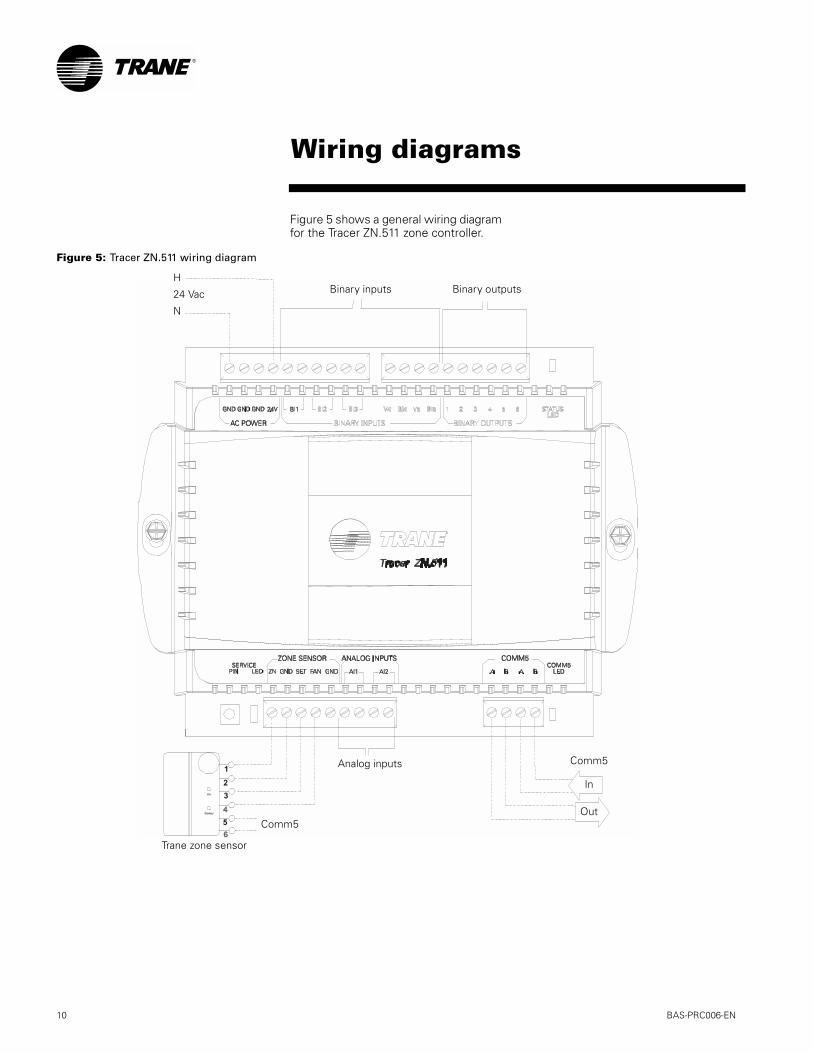
Figure 5 shows a general wiring diagramfor the Tracer ZN.511 zone controller.
Figure 5: Tracer ZN.511 wiring diagram
H
24 Vac
N
Binary inputs Binary outputs
Trane zone sensor
Analog inputs Comm5
Out
In
Comm5
10
Wiring diagrams
BAS-PRC006-EN

®
Figure 6 shows a general wiring diagramfor the Tracer ZN.521 zone controller.
Figure 6: Tracer ZN.521 wiring diagram
H
24 Vac
N
Binary inputs Binary outputs
Trane zone sensor
Analog inputs Comm5
Out
In
Comm5
BAS-PRC006-EN
11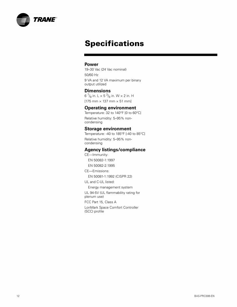
®
Power19–30 Vac (24 Vac nominal)
50/60 Hz
9 VA and 12 VA maximum per binaryoutput utilized
Dimensions6 7/8 in. L × 5 3/8 in. W × 2 in. H
[175 mm × 137 mm × 51 mm]
Operating environmentTemperature: 32 to 140°F [0 to 60°C]
Relative humidity: 5–95% non-condensing
Storage environmentTemperature: -40 to 185°F [-40 to 85°C]
Relative humidity: 5–95% non-condensing
Agency listings/complianceCE—Immunity:
EN 50082-1:1997
EN 50082-2:1995
CE—Emissions:
EN 50081-1:1992 (CISPR 22)
UL and C-UL listed:
Energy management system
UL 94-5V (UL flammability rating forplenum use)
FCC Part 15, Class A
LonMark Space Comfort Controller(SCC) profile
12
Specifications
BAS-PRC006-EN

The Trane CompanyAn American Standard Companywww.trane.com
For more information contactyour local district office ore-mail us at [email protected]
Since The Trane Company has a policy of continuous product and product data improvement, itreserves the right to change design and specifications without notice.
Literature Order Number BAS-PRC006-EN
File Number PL-ES-BAS-000-PRC006-0201
Supersedes New
Stocking Location La Crosse