Embed Size (px)
Citation preview

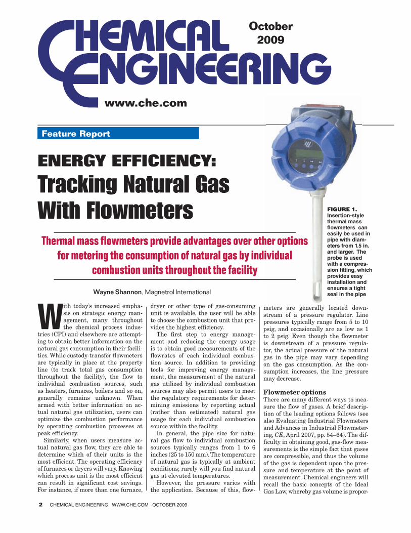
TRACKING NATURAL GAS WITH FLOWMETERS
S p e c i a l A p p l i c at i o n S e r i e s
1-27044838.indd 11-27044838.indd 1 12/1/09 3:33 PM12/1/09 3:33 PM
W ith today’s increased empha-sis on strategic energy man-agement, many throughout the chemical process indus-
tries (CPI) and elsewhere are attempt-ing to obtain better information on the natural gas consumption in their facili-ties. While custody-transfer flowmeters are typically in place at the property line (to track total gas consumption throughout the facility), the flow to individual combustion sources, such as heaters, furnaces, boilers and so on, generally remains unknown. When armed with better information on ac-tual natural gas utilization, users can optimize the combustion performance by operating combustion processes at peak efficiency.
Similarly, when users measure ac-tual natural gas flow, they are able to determine which of their units is the most efficient. The operating efficiency of furnaces or dryers will vary. Knowing which process unit is the most efficient can result in significant cost savings. For instance, if more than one furnace,
dryer or other type of gas-consuming unit is available, the user will be able to choose the combustion unit that pro-vides the highest efficiency.
The first step to energy manage-ment and reducing the energy usage is to obtain good measurements of the flowrates of each individual combus-tion source. In addition to providing tools for improving energy manage-ment, the measurement of the natural gas utilized by individual combustion sources may also permit users to meet the regulatory requirements for deter-mining emissions by reporting actual (rather than estimated) natural gas usage for each individual combustion source within the facility.
In general, the pipe size for natu-ral gas flow to individual combustion sources typically ranges from 1 to 6 inches (25 to 150 mm). The temperature of natural gas is typically at ambient conditions; rarely will you find natural gas at elevated temperatures.
However, the pressure varies with the application. Because of this, flow-
meters are generally located down-stream of a pressure regulator. Line pressures typically range from 5 to 10 psig, and occasionally are as low as 1 to 2 psig. Even though the flowmeter is downstream of a pressure regula-tor, the actual pressure of the natural gas in the pipe may vary depending on the gas consumption. As the con-sumption increases, the line pressure may decrease.
Flowmeter optionsThere are many different ways to mea-sure the flow of gases. A brief descrip-tion of the leading options follows (see also Evaluating Industrial Flowmeters and Advances in Industrial Flowmeter-ing, CE, April 2007, pp. 54–64). The dif-ficulty in obtaining good, gas-flow mea-surements is the simple fact that gases are compressible, and thus the volume of the gas is dependent upon the pres-sure and temperature at the point of measurement. Chemical engineers will recall the basic concepts of the Ideal Gas Law, whereby gas volume is propor-
Feature ReportFeature Report
ENERGY EFFICIENCY:
Tracking Natural Gas
With Flowmeters
Thermal mass flowmeters provide advantages over other options
for metering the consumption of natural gas by individual
combustion units throughout the facility
FIGURE 1. Insertion-style thermal mass fl owmeters can easily be used in pipe with diam-eters from 1.5 in. and larger. The probe is used with a compres-sion fi tting, which provides easy installation and ensures a tight seal in the pipeWayne Shannon, Magnetrol International
2 CHEMICAL ENGINEERING WWW.CHE.COM OCTOBER 2009
www.che.com
October2009
1-27044838.indd 21-27044838.indd 2 11/19/09 9:14:36 AM11/19/09 9:14:36 AM
tional to the temperature and inversely proportional to the pressure. This com-plicates gas flow measurement because, with the exception of thermal mass and Coriolis flowmeters, many gas-flow-measurement technologies measure the flow at the actual operating pres-sure and temperature. These units of measurement are typically expressed as either actual cubic feet per minute (acfm) or cubic meters per hour (m3/h).
When comparing natural gas usage at various combustion sources for energy-management systems, on the other hand, the desired goal is to mea-sure the flow relative to a defined pres-sure and temperature — at standard conditions (standard temperature and pressure; STP). While the definition of standard conditions will vary with different industries and in different geographic areas, when the flow is referenced to standard conditions, a mass flow measurement is obtained with units of measurement that are expressed as standard cubic feet per minute (scfm), standard cubic feet per hour (scfh), or normal cubic meters per hour (Nm3/h).Flow measurement via orifice plate.This is the traditional method of flow measurement for both gas and liquids. In simplest terms, an orifice is a plate with a hole that is smaller in diameter than the pipe diameter. The orifice plate is positioned between two flanges. As the gas is accelerated through the smaller orifice, the pres-sure decreases, creating a lower pres-sure on the downstream side of the ori-fice plate. The flowrate is proportional to the square root of the pressure drop.
Flow is therefore determined by mea-suring the pressure drop across the orifice plate.
The important thing to consider is that the pressure drop is based on the flowrate at the gas density at the ac-tual operating conditions. In order to get a mass flow measurement whereby the temperature and pressure are ref-erenced to standard conditions, it is necessary to also have a temperature transmitter, a pressure transmitter, and a flow computer or multi-variable transmitter. As a result, while the cost of the orifice plate itself is relatively inexpensive, the installed price of the complete system becomes substan-tially more expensive when one con-siders the additional instrumentation that is required to obtain an accurate mass flow measurement.
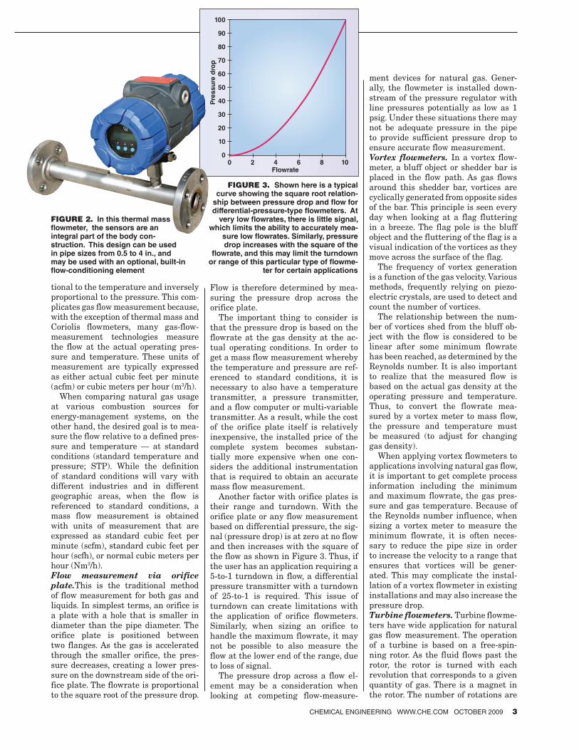
Another factor with orifice plates is their range and turndown. With the orifice plate or any flow measurement based on differential pressure, the sig-nal (pressure drop) is at zero at no flow and then increases with the square of the flow as shown in Figure 3. Thus, if the user has an application requiring a 5-to-1 turndown in flow, a differential pressure transmitter with a turndown of 25-to-1 is required. This issue of turndown can create limitations with the application of orifice flowmeters. Similarly, when sizing an orifice to handle the maximum flowrate, it may not be possible to also measure the flow at the lower end of the range, due to loss of signal.
The pressure drop across a flow el-ement may be a consideration when looking at competing flow-measure-
ment devices for natural gas. Gener-ally, the flowmeter is installed down-stream of the pressure regulator with line pressures potentially as low as 1 psig. Under these situations there may not be adequate pressure in the pipe to provide sufficient pressure drop to ensure accurate flow measurement.Vortex flowmeters. In a vortex flow-meter, a bluff object or shedder bar is placed in the flow path. As gas flows around this shedder bar, vortices are cyclically generated from opposite sides of the bar. This principle is seen every day when looking at a flag fluttering in a breeze. The flag pole is the bluff object and the fluttering of the flag is a visual indication of the vortices as they move across the surface of the flag.
The frequency of vortex generation is a function of the gas velocity. Various methods, frequently relying on piezo-electric crystals, are used to detect and count the number of vortices.
The relationship between the num-ber of vortices shed from the bluff ob-ject with the flow is considered to be linear after some minimum flowrate has been reached, as determined by the Reynolds number. It is also important to realize that the measured flow is based on the actual gas density at the operating pressure and temperature. Thus, to convert the flowrate mea-sured by a vortex meter to mass flow, the pressure and temperature must be measured (to adjust for changing gas density).
When applying vortex flowmeters to applications involving natural gas flow, it is important to get complete process information including the minimum and maximum flowrate, the gas pres-sure and gas temperature. Because of the Reynolds number influence, when sizing a vortex meter to measure the minimum flowrate, it is often neces-sary to reduce the pipe size in order to increase the velocity to a range that ensures that vortices will be gener-ated. This may complicate the instal-lation of a vortex flowmeter in existing installations and may also increase the pressure drop.Turbine flowmeters. Turbine flowme-ters have wide application for natural gas flow measurement. The operation of a turbine is based on a free-spin-ning rotor. As the fluid flows past the rotor, the rotor is turned with each revolution that corresponds to a given quantity of gas. There is a magnet in the rotor. The number of rotations are
FIGURE 3. Shown here is a typical curve showing the square root relation-
ship between pressure drop and fl ow for differential-pressure-type fl owmeters. At
very low fl owrates, there is little signal, which limits the ability to accurately mea-
sure low fl owrates. Similarly, pressure drop increases with the square of the
fl owrate, and this may limit the turndown or range of this particular type of fl owme-
ter for certain applications
Flowrate
00 2 4 6 8 10
10
20
30
40
50
60
70
80
90
100
Pre
ss
ure
dro
pFIGURE 2. In this thermal mass fl owmeter, the sensors are an integral part of the body con-struction. This design can be used in pipe sizes from 0.5 to 4 in., and may be used with an optional, built-in fl ow-conditioning element
CHEMICAL ENGINEERING WWW.CHE.COM OCTOBER 2009 3
1-27044838.indd 31-27044838.indd 3 11/19/09 9:14:37 AM11/19/09 9:14:37 AM
Feature Report
counted using an external pickup that provides a series of electronic pulses with each pulse equivalent to one rotation. The pulses are then sent to the transmitter.
The manufacturer provides a K fac-tor to relate each rotation to a given gas volume. The number of pulses that are counted over a given time period provide both the flowrate and the to-talized flow.
Turbine meters have relatively high turndown capabilities with corre-sponding high measurement accuracy. Like the previously mentioned flow-meter types, the turbine flowmeter is a volumetric device that measures the actual flow at the operating conditions and thus requires pressure and tem-perature correction to obtain accurate mass flow. Considerations when apply-ing turbine meters include the cleanli-ness of the gas and the fact that there are moving parts in the gas stream.Ultrasonic flowmeters. This technol-ogy measures the difference in transit time of pulses that travel from a down-stream transducer to the upstream transducer, compared to the time from the upstream transducer back to the downstream transducer. While this technology is accurate and accepted by AGA (American Gas Assn.) for the custody transfer of natural gas, the suitability of this technology for mea-suring the flow of natural gas to in-dividual combustion sources within a facility becomes questionable, consid-ering the relatively low velocities, and more importantly, the high cost of this device compared to other technology options. (Note that AGA also accepts orifice plate, turbine and Coriolis flow-meters.) Flowrate is measured at the actual operating conditions, requiring pressure and temperature to obtain mass flow. Some ultrasonic flowmeters will require a higher pressure (for in-stance, some units require a minimum of 150 psi operating pressure).Coriolis mass flowmeters. Coriolis flowmeters provide a direct mass -flow measurement by measuring the deflec-tion of a vibrating tube. This is a true mass flowmeter, as it is insensitive to changes in pressure, temperature, den-sity or gas composition. The Coriolis flowmeter is very accurate, with high turndown capabilities.
Coriolis flowmeters often require the pipe size to be reduced in order to ob-tain the desired range measurement. While suitable for measuring flow to
individual combustion sources, this ap-proach becomes rather expensive and is rarely used for the in-plant mea-surement of natural gas.Thermal mass flowmeters. Thermal mass flowmeters (Figures 1, 2 and 4) provide an inferred measurement of the mass flow of the gases passing through them. Specifically, thermal mass flowmeters measure heat trans-fer that is caused as the molecules (hence, the mass) of gas flow past a heated surface. The relationship be-tween heat transfer and mass flow is obtained during the calibration of the instrument.
In addition to providing a mass flow measurement without the need for ad-ditional devices to correct for pressure and temperature (as is required with the other flowmeters, with exception of Coriolis devices), thermal flowmeters also provide the following advantages:• Lower flow sensitivity. A thermal
mass flowmeter will easily measure flowrates that are much lower than those that can be measured using orifice plates or vortex flowmeters. This permits a thermal flowmeter to be retrofitted into existing natural gas pipes using a simple NPT (na-tional pipe thread) thread or flange connection on the pipe. This simpli-fies installation compared to other flowmeters, which may require a re-duction in the pipe size in order to obtain the desired rangeability
• Higher turndown capabilities. A range of 100-to-1 is easily obtained with a thermal mass flowmeter. Some combustion systems may have a high natural-gas firing rate during initial warm-up operation and then, once the desired temperature has
been obtained, the flowrate of the gas is typically reduced to maintain the desired operating temperature. A thermal mass flowmeter can easily handle this range, which may be dif-ficult to obtain with other technolo-gies
• Simplified installation. An insertion device permits simplicity of installing the flowmeter using NPT connection, flange, compression fitting or even a complete retractable probe assembly. Using a “hot tap” permits the user to install the flowmeter without having to shut down the operation. The in-sertion design also permits the use of the same instrument in different pipe sizes. Some use the insertion probe as a semi-portable instrument and reconfigure the transmitter for the different pipe sizes
• Lower pressure drop. There is virtu-ally no pressure drop when using a thermal mass flowmeter. This is ad-vantageous in low-pressure applica-tions where other technologies would consume operating pressure
Today, thermal mass flowmeters from different manufacturers rely on differ-ent methods of operation and sensor designs. All methods accomplish the same thing, which is to provide a mass flow measurement.
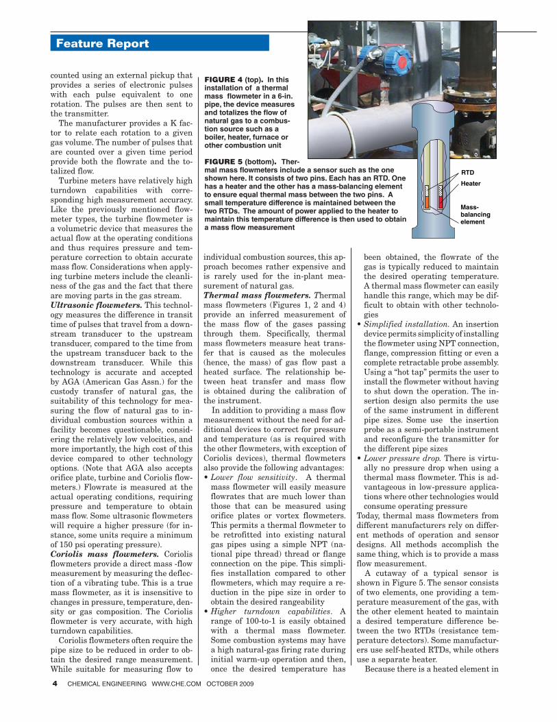
A cutaway of a typical sensor is shown in Figure 5. The sensor consists of two elements, one providing a tem-perature measurement of the gas, with the other element heated to maintain a desired temperature difference be-tween the two RTDs (resistance tem-perature detectors). Some manufactur-ers use self-heated RTDs, while others use a separate heater.
Because there is a heated element in
FIGURE 4 (top). In this installation of a thermal mass fl owmeter in a 6-in. pipe, the device measures and totalizes the fl ow of natural gas to a combus-tion source such as a boiler, heater, furnace or other combustion unit
FIGURE 5 (bottom). Ther-mal mass fl owmeters include a sensor such as the one shown here. It consists of two pins. Each has an RTD. One has a heater and the other has a mass-balancing element to ensure equal thermal mass between the two pins. A small temperature difference is maintained between the two RTDs. The amount of power applied to the heater to maintain this temperature difference is then used to obtain a mass fl ow measurement
RTD
Mass-balancing element
Heater
4 CHEMICAL ENGINEERING WWW.CHE.COM OCTOBER 2009
1-27044838.indd 41-27044838.indd 4 11/19/09 9:14:38 AM11/19/09 9:14:38 AM
contact with the natural gas, the user should ensure that the temperature rise of the sensor is less than the autoi-gnition temperature of natural gas, and that the instrument has all appropri-ate agency approvals for use in hazard-ous areas.
With this design, the electronics maintain a desired temperature differ-ence between the two pins. At no flow, there is little heat loss and it takes little energy to maintain the desired temperature difference.
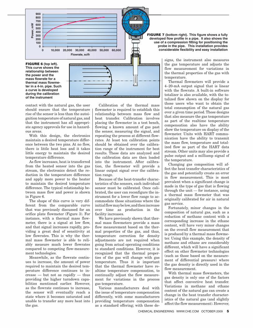
As flow increases, heat is transferred from the heated sensor into the gas stream, the electronics detect the re-duction in the temperature difference and apply more power to the heater to maintain the desired temperature difference. The typical relationship be-tween mass flow and power is shown in Figure 6.
The shape of this curve is very dif-ferent from the comparable curve that was previously discussed for an orifice plate flowmeter (Figure 3). For instance, with a thermal mass flow-meter, there is a signal at low flow, and that signal increases rapidly, pro-viding a great deal of sensitivity at low flowrates. This is why the ther-mal mass flowmeter is able to reli-ably measure much lower flowrates compared to competing flow-measure-ment technologies.
Meanwhile, as the flowrate contin-ues to increase, the amount of power required to maintain the desired tem-perature difference continues to in-crease — but not as rapidly — thus providing the higher turndown capa-bilities mentioned earlier. However, as the flowrate continues to increase, the sensor will eventually reach a state where it becomes saturated and unable to transfer any more heat into the gas.
Calibration of the thermal mass flowmeter is required to establish this relationship between mass flow and heat transfer. Calibration involves placing the flowmeter in a test bench, flowing a known amount of gas past the sensor, measuring the signal, and repeating the process at different flow-rates. At least ten calibration points should be obtained over the calibra-tion range of the instrument for best results. These data are analyzed and the calibration data are then loaded into the instrument. After calibra-tion, the flowmeter will provide a linear output signal over the calibra-tion range.
Because of the heat-transfer charac-teristics of the sensors, each individual sensor must be calibrated. Once cali-brated, the user can reconfigure the in-strument for a lower flow range to ac-commodate those situations where the initial flow may be low, and then increase over time as production in the facility increases.
We have previously shown that ther-mal mass flowmeters provide a mass flow measurement based on the ther-mal properties of the gas, and thus, temperature correction for density adjustments are not required when going from actual operating conditions to standard conditions. However, it is recognized that the thermal proper-ties of the gas will change with gas temperature. Thus it is important that the thermal flowmeter have re-altime temperature compensation, to continually adjust the flow measure-ment for variations in the process gas temperature.
Various manufacturers deal with the issue of temperature compensation differently, with some manufacturers providing temperature compensation as a standard offering; with these de-
signs, the instrument also measures the gas temperature and adjusts the flow measurement for variations in the thermal properties of the gas with temperature.
Thermal flowmeters will provide a 4–20-mA output signal that is linear with the flowrate. A built-in software totalizer is also available, with the to-talized flow shown on the display for those users who want to obtain the total consumption of the natural gas over a given time period. Those designs that also measure the gas temperature as part of the realtime temperature compensation also have the ability show the temperature on display of the flowmeter. Units with HART commu-nication have the ability to transmit the mass flow, temperature and total-ized flow as part of the HART data stream. Other units may also provide a pulse output and a milliamp signal of the temperature.
Changing gas composition will af-fect the heat transfer characteristics of the gas and potentially create an error in flow measurement. This is most prevalent when a significant change is made in the type of gas that is flowing through the unit — for instance, using a thermal mass flowmeter that was originally calibrated for air in natural gas service.
Fortunately, minor changes in the composition of natural gas, such as a reduction of methane content with a corresponding increase in the ethane content, will have very minor changes on the overall flow measurement that is produced by a thermal mass flowme-ter. Using this example, the density of methane and ethane are considerably different, which will have a significant effect on other flowmeter technologies (such as those based on the measure-ment of differential pressure) where the gas density is directly used in the flow measurement.
With thermal mass flowmeters, the gas density is only one of the factors that affect convective heat transfer. Variations in methane and ethane content of the natural gas can create a change in the heat transfer character-istics of the natural gas (and slightly affect the flow measurement). However,
FIGURE 6 (top left). This curve shows the relationship between the power and the mass fl owrate for a thermal mass fl owme-ter in a 4-in. pipe. Such a curve is developed during the calibration of the instrument
Flowrate, scfh
Po
we
r, m
W
0
100
200
300
400
500
600
700
800
900
0
10,000 20,000 30,000 40,000 50,000 60,000
Flowrate, scfh
000 30,000 40,000 50,000 60,000
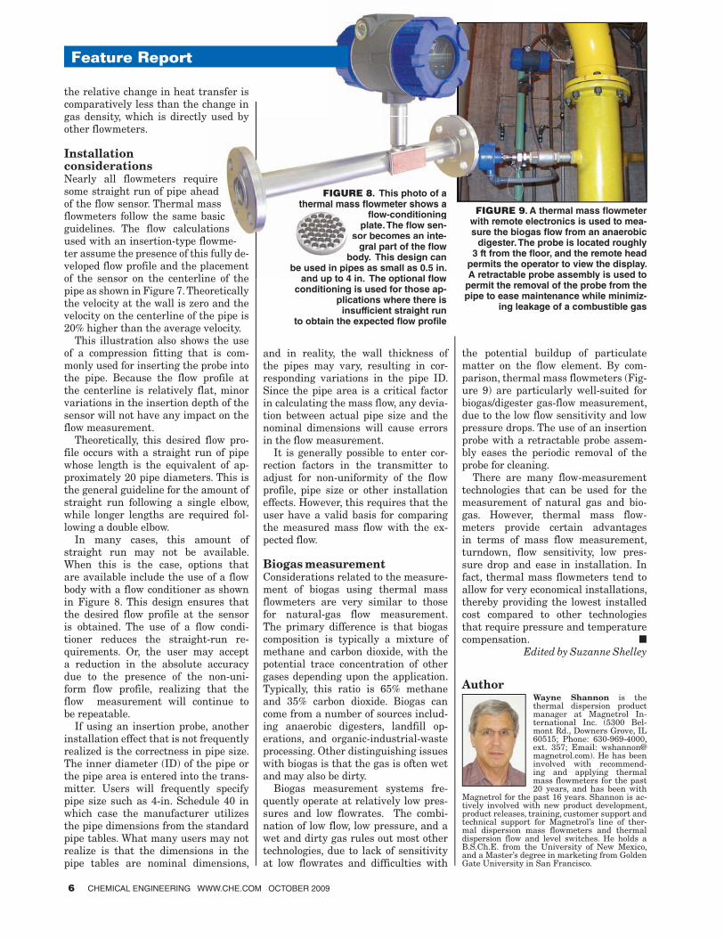
FIGURE 7 (bottom right). This fi gure shows a fully developed fl ow profi le in a pipe. It also shows the
use of a compression fi tting for positioning the probe in the pipe. This installation provides considerable fl exibility and easy installation
CHEMICAL ENGINEERING WWW.CHE.COM OCTOBER 2009 5
1-27044838.indd 51-27044838.indd 5 11/19/09 9:14:38 AM11/19/09 9:14:38 AM
the relative change in heat transfer is comparatively less than the change in gas density, which is directly used by other flowmeters.
Installation considerationsNearly all flowmeters require some straight run of pipe ahead of the flow sensor. Thermal mass flowmeters follow the same basic guidelines. The flow calculations used with an insertion-type flowme-ter assume the presence of this fully de-veloped flow profile and the placement of the sensor on the centerline of the pipe as shown in Figure 7. Theoretically the velocity at the wall is zero and the velocity on the centerline of the pipe is 20% higher than the average velocity.
This illustration also shows the use of a compression fitting that is com-monly used for inserting the probe into the pipe. Because the flow profile at the centerline is relatively flat, minor variations in the insertion depth of the sensor will not have any impact on the flow measurement.
Theoretically, this desired flow pro-file occurs with a straight run of pipe whose length is the equivalent of ap-proximately 20 pipe diameters. This is the general guideline for the amount of straight run following a single elbow, while longer lengths are required fol-lowing a double elbow.
In many cases, this amount of straight run may not be available. When this is the case, options that are available include the use of a flow body with a flow conditioner as shown in Figure 8. This design ensures that the desired flow profile at the sensor is obtained. The use of a flow condi-tioner reduces the straight-run re-quirements. Or, the user may accept a reduction in the absolute accuracy due to the presence of the non-uni-form flow profile, realizing that the flow measurement will continue to be repeatable.
If using an insertion probe, another installation effect that is not frequently realized is the correctness in pipe size. The inner diameter (ID) of the pipe or the pipe area is entered into the trans-mitter. Users will frequently specify pipe size such as 4-in. Schedule 40 in which case the manufacturer utilizes the pipe dimensions from the standard pipe tables. What many users may not realize is that the dimensions in the pipe tables are nominal dimensions,
and in reality, the wall thickness of the pipes may vary, resulting in cor-responding variations in the pipe ID. Since the pipe area is a critical factor in calculating the mass flow, any devia-tion between actual pipe size and the nominal dimensions will cause errors in the flow measurement.
It is generally possible to enter cor-rection factors in the transmitter to adjust for non-uniformity of the flow profile, pipe size or other installation effects. However, this requires that the user have a valid basis for comparing the measured mass flow with the ex-pected flow.
Biogas measurementConsiderations related to the measure-ment of biogas using thermal mass flowmeters are very similar to those for natural-gas flow measurement. The primary difference is that biogas composition is typically a mixture of methane and carbon dioxide, with the potential trace concentration of other gases depending upon the application. Typically, this ratio is 65% methane and 35% carbon dioxide. Biogas can come from a number of sources includ-ing anaerobic digesters, landfill op-erations, and organic-industrial-waste processing. Other distinguishing issues with biogas is that the gas is often wet and may also be dirty.
Biogas measurement systems fre-quently operate at relatively low pres-sures and low flowrates. The combi-nation of low flow, low pressure, and a wet and dirty gas rules out most other technologies, due to lack of sensitivity at low flowrates and difficulties with
the potential buildup of particulate matter on the flow element. By com-parison, thermal mass flowmeters (Fig-ure 9) are particularly well-suited for biogas/digester gas-flow measurement, due to the low flow sensitivity and low pressure drops. The use of an insertion probe with a retractable probe assem-bly eases the periodic removal of the probe for cleaning.
There are many flow-measurement technologies that can be used for the measurement of natural gas and bio-gas. However, thermal mass flow-meters provide certain advantages in terms of mass flow measurement, turndown, flow sensitivity, low pres-sure drop and ease in installation. In fact, thermal mass flowmeters tend to allow for very economical installations, thereby providing the lowest installed cost compared to other technologies that require pressure and temperature compensation. ■
Edited by Suzanne Shelley
FIGURE 8. This photo of a thermal mass fl owmeter shows a
fl ow-conditioningplate. The fl ow sen-
sor becomes an inte-gral part of the fl ow
body. This design canbe used in pipes as small as 0.5 in.
and up to 4 in. The optional fl ow conditioning is used for those ap-
plications where there isinsufficient straight run
to obtain the expected fl ow profi le
ansfer ishange inused by
ireadassasic tionsowme-s fully de-lacementne of the
FIGURE 8. This photo of a thermal mass fl owmeter shows a
fl ow-conditioningplate. The fl ow sen-
sor becomes an inte-gral part of the fl ow
body. This design canbe used in pipes as small as 0.5 in.
and up to 4 in The optional flow
Feature Report
AuthorWayne Shannon is the thermal dispersion product manager at Magnetrol In-ternational Inc. (5300 Bel-mont Rd., Downers Grove, IL 60515; Phone: 630-969-4000, ext. 357; Email: [email protected]). He has been involved with recommend-ing and applying thermal mass flowmeters for the past 20 years, and has been with
Magnetrol for the past 16 years. Shannon is ac-tively involved with new product development, product releases, training, customer support and technical support for Magnetrol’s line of ther-mal dispersion mass flowmeters and thermal dispersion flow and level switches. He holds a B.S.Ch.E. from the University of New Mexico, and a Master’s degree in marketing from Golden Gate University in San Francisco.
FIGURE 9. A thermal mass fl owmeter with remote electronics is used to mea-sure the biogas fl ow from an anaerobic
digester. The probe is located roughly 3 ft from the fl oor, and the remote head
permits the operator to view the display. A retractable probe assembly is used to
permit the removal of the probe from the pipe to ease maintenance while minimiz-
ing leakage of a combustible gas
6 CHEMICAL ENGINEERING WWW.CHE.COM OCTOBER 2009
1-27044838.indd 61-27044838.indd 6 11/19/09 9:14:39 AM11/19/09 9:14:39 AM

October 2009
www.che.comFLOWMETERS
1-27044838.indd 71-27044838.indd 7 11/19/09 9:14:43 AM11/19/09 9:14:43 AM
Guided Wave Radar Thru-Air Radar
Ultrasound
RF Capacitance Magnetostriction
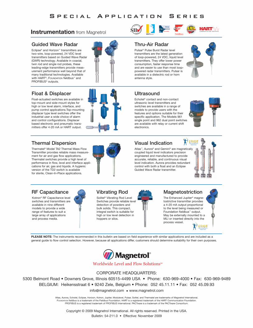
Thermal Dispersion
Float & Displacer
Instrumentation from Magnetrol
Eclipse® and Horizon™ transmitters aretwo-wire, loop-powered, 24 VDC leveltransmitters based on Guided Wave Radar(GWR) technology. Available in coaxial,twin rod and single rod probes, theseleading-edge transmitters provide meas-urement performance well beyond that ofmany traditional technologies. Availablewith HART®, FOUNDATION fieldbus™ andPROFIBUS® outputs.
CORPORATE HEADQUARTERS:5300 Belmont Road • Downers Grove, Illinois 60515-4499 USA • Phone: 630-969-4000 • Fax: 630-969-9489
BELGIUM: Heikensstraat 6 • 9240 Zele, Belgium • Phone: 052 45.11.11 • Fax: 052 [email protected] • www.magnetrol.com
Atlas, Aurora, Echotel, Eclipse, Horizon, Kotron, Jupiter, Modulevel, Pulsar, Solitel, and Thermatel are trademarks of Magnetrol International.FOUNDATION fieldbus is a trademark of the Fieldbus Foundation. HART is a registered trademark of the HART Communication Foundation.
PROFIBUS is a registered trademark of PROFIBUS International. PACTware is a trademark of the PACTware Consortium.
Copyright © 2009 Magnetrol International. All rights reserved. Printed in the USA.
Bulletin: 54-211.0 • Effective: November 2009
Worldwide Level and Flow SolutionsSM
Visual Indication
Vibrating Rod
Pulsar® Pulse Burst Radar leveltransmitters are the latest generationof loop-powered, 24 VDC, liquid leveltransmitters. They offer lower powerconsumption, faster response timeand are easier to use than most loop-powered radar transmitters. Pulsar isavailable in a dielectric rod or hornantenna style.
Float-actuated switches are available intop-mount and side-mount styles forhigh or low level alarm, interface, andpump control applications.Top-mountingdisplacer type level switches offer theindustrial user a wide choice of alarmand control configurations. Displacerbased electronic and pneumatic trans-mitters offer 4-20 mA or HART output.
Echotel® contact and non-contactultrasonic level transmitters andswitches are available in a range ofmodels to provide users with thefeatures and options suitable for theirspecific application. The Models 961single point and 962 dual point switchesare available with relay or current shiftelectronics.
Thermatel® Model TA2 Thermal Mass FlowTransmitter provides reliable mass measure-ment for air and gas flow applications.Thermatel switches provide a high level ofperformance in flow, level and interface appli-cations for air, gas and liquids. A hygienicversion of the TD2 switch is availablefor sterile, Clean-In-Place applications.
Atlas™, Aurora® and Gemini® are magneticallycoupled liquid level indicators precisionengineered and manufactured to provideaccurate, reliable, and continuous visuallevel indication. Aurora provides redundantcontrol with both a float and an EclipseGuided Wave Radar transmitter.
The Enhanced Jupiter® magne-tostrictive transmitter providesa 4-20 mA output proportionalto the level being measured orFoundation fieldbus™ output.May be externally mounted to aMLI or inserted directly into theprocess vessel.
Solitel® Vibrating Rod LevelSwitches provide reliable leveldetection of powders andbulk solids. This compact,integral switch is suitable forhigh or low level detection inhoppers or silos.
Kotron® RF Capacitance levelswitches and transmitters areavailable in nine differentmodels to provide a widerange of features to suit alarge array of applicationsand process media.
S p e c i a l A p p l i c at i o n S e r i e s
PLEASE NOTE: The instruments recommended in this bulletin are based on field experience with similar applications and are included as ageneral guide to flow control selection. However, because all applications differ, customers should determine suitability for their own purposes.
54-211.0 Chem Eng Article:Layout 1 12/1/09 2:58 PM Page 2