Embed Size (px)
Citation preview
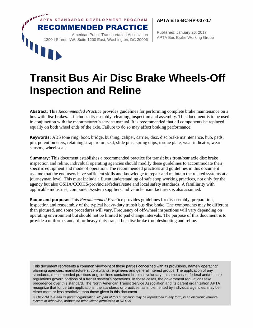
A P T A S T A N D A R D S D E V E L O P M E N T P R O G R A M
RECOMMENDED PRACTICE
American Public Transportation Association
1300 I Street, NW, Suite 1200 East, Washington, DC 20006
APTA BTS-BC-RP-007-17
Published: January 26, 2017
APTA Bus Brake Working Group
This document represents a common viewpoint of those parties concerned with its provisions, namely operating/ planning agencies, manufacturers, consultants, engineers and general interest groups. The application of any standards, recommended practices or guidelines contained herein is voluntary. In some cases, federal and/or state regulations govern portions of a transit system’s operations. In those cases, the government regulations take precedence over this standard. The North American Transit Service Association and its parent organization APTA recognize that for certain applications, the standards or practices, as implemented by individual agencies, may be either more or less restrictive than those given in this document.
© 2017 NATSA and its parent organization. No part of this publication may be reproduced in any form, in an electronic retrieval system or otherwise, without the prior written permission of NATSA.
Transit Bus Air Disc Brake Wheels-Off Inspection and Reline
Abstract: This Recommended Practice provides guidelines for performing complete brake maintenance on a
bus with disc brakes. It includes disassembly, cleaning, inspection and assembly. This document is to be used
in conjunction with the manufacturer’s service manual. It is recommended that all components be replaced
equally on both wheel ends of the axle. Failure to do so may affect braking performance.
Keywords: ABS tone ring, boot, bridge, bushing, caliper, carrier, disc, disc brake maintenance, hub, pads,
pin, potentiometers, retaining strap, rotor, seal, slide pins, spring clips, torque plate, wear indicator, wear
sensors, wheel seals
Summary: This document establishes a recommended practice for transit bus front/rear axle disc brake
inspection and reline. Individual operating agencies should modify these guidelines to accommodate their
specific equipment and mode of operation. The recommended practices and guidelines in this document
assume that the end users have sufficient skills and knowledge to repair and maintain the related systems at a
journeyman level. This must include a fluent understanding of safe shop working practices, not only for the
agency but also OSHA/CCOHS/provincial/federal/state and local safety standards. A familiarity with
applicable industries, component/system suppliers and vehicle manufacturers is also assumed.
Scope and purpose: This Recommended Practice provides guidelines for disassembly, preparation,
inspection and reassembly of the typical heavy-duty transit bus disc brake. The components may be different
than pictured, and some procedures will vary. Frequency of off-wheel inspections will vary depending on
operating environment but should not be limited to pad change intervals. The purpose of this document is to
provide a uniform standard for heavy-duty transit bus disc brake troubleshooting and reline.
© 2017 American Public Transportation Association | ii
Table of Contents
1. Hazardous material warning...................................................................................................... 1
2. Operation .................................................................................................................................... 1 2.1 Automatic adjustment ................................................................................................................................... 3
3. Inspection with wheels removed .............................................................................................. 4 3.1 Brake chamber identification ........................................................................................................................ 5 3.2 Brake chamber initial inspection ................................................................................................................... 6 3.3 Caliper inspection ......................................................................................................................................... 6 3.4 Torque plate inspection ................................................................................................................................. 7 3.5 Fasteners and mounting hardware ................................................................................................................. 7 3.6 Visual inspection ........................................................................................................................................... 7 3.7 Knorr-Bremse caliper movement test ........................................................................................................... 9 3.8 Knorr-Bremse guide pin inspection with pads installed ............................................................................. 10 3.9 Knorr-Bremse caliper adjuster test ............................................................................................................. 11 3.10 Meritor EX225 caliper movement test ...................................................................................................... 14 3.11 Meritor EX225 caliper adjuster test .......................................................................................................... 15 3.12 Meritor EX225 slide pin bushing tangential test....................................................................................... 16 3.13 Meritor EX225 slide pin bushing radial test ............................................................................................. 16 3.14 Caliper guide pin inspection with pads removed ...................................................................................... 17 3.16 Brake pad inspection ................................................................................................................................. 18 3.17 Rotor inspection ........................................................................................................................................ 20 3.18 Carrier and pad abutment inspection ........................................................................................................ 25 3.19 Guide and slide pin boot inspection .......................................................................................................... 26 3.20 Tappet boot and seal inspection ................................................................................................................ 27 3.21 Tappet seal and guide/slide pin seal replacement ..................................................................................... 28 3.22 Tappet inspection ...................................................................................................................................... 29 3.23 Brake chamber inspection ......................................................................................................................... 29 3.24 Brake chamber non-pressure housing plugs ............................................................................................. 32
Related APTA standards ................................................................................................................................... 36 References ......................................................................................................................................................... 36 Definitions......................................................................................................................................................... 36 Abbreviations and acronyms ............................................................................................................................. 36 Summary of document changes ........................................................................................................................ 36 Document history .............................................................................................................................................. 36
© 2017 American Public Transportation Association | iii
List of Figures and Tables
Figure 1 Axial and Radial Mounting Designs .................................................................. 2 Figure 2 Cross-Section of Knorr-Bremse Caliper Assembly ........................................... 2 Figure 3 Meritor EX225 Caliper Gear-Driven Adjustment Mechanism (Not Serviceable)3 Figure 4 Knorr-Bremse Timing Chain Mechanism (Not Serviceable) ............................. 4 Figure 5 Wheels-Off Inspection ....................................................................................... 5 Figure 6 Axial and Radial Positions ................................................................................. 5 Figure 7 Brake Chamber Types ........................................................................................ 6 Figure 8 Caliper Types ..................................................................................................... 6 Figure 9 Brake Assemblies With and Without Thermal Overload ................................... 8 Figure 10 Other Types of Brake Assembly Damage ........................................................ 9 Figure 11 Knorr-Bremse Caliper Movement Test ............................................................ 9 Figure 12 Knorr-Bremse Tappets-to-Pad Clearance....................................................... 10 Figure 13 Measuring Knorr-Bremse Caliper Guide Pin Wear ....................................... 10 Figure 14 Slide Pin Bushing Designs ............................................................................. 11 Figure 15 Adjuster Components ..................................................................................... 12 Figure 16 Knorr-Bremse Caliper Adjuster Test ............................................................. 13 Figure 17 Broken Shear Adapter .................................................................................... 13 Figure 18 Knorr-Bremse Caliper Adjuster Test ............................................................. 14 Figure 19 Meritor EX225 Caliper Movement Test ........................................................ 14 Figure 20 Meritor EX225 Dust Cap with Adjuster and Seal Visible ............................. 15 Figure 21 Meritor EX225 Caliper ................................................................................... 15 Figure 22 Checking Meritor EX225 Slide Pin Bushing Clearance ................................ 16 Figure 23 Checking Meritor EX225 Slide Pin Bushing Clearance ................................ 16 Figure 24 Checking for Smooth Caliper Movement on the Guide Pins ......................... 17 Figure 25 Brake Pad Removal ........................................................................................ 18 Figure 26 Brake Pad Inspection ...................................................................................... 19 Figure 27 Heat Checking ................................................................................................ 21 Figure 28 Radial Grooves ............................................................................................... 21 Figure 29 Axial Grooves ................................................................................................ 22 Figure 30 Measuring Brake Rotor Thickness with a Brake Rotor Micrometer .............. 22 Figure 31 Rotor Wear ..................................................................................................... 23 Figure 32 Checking the Rotor ......................................................................................... 24 Figure 33 Pad Abutment Inspection ............................................................................... 25 Figure 34 Maximum Permissible Gap Between the Rotor and Pad Abutment .............. 26 Figure 35 Guide/Slide Pin Boot Inspection .................................................................... 26 Figure 36 Examples of Damaged or Improperly Installed Tappet Boots ....................... 28 Figure 37 Knorr-Bremse Inner Tappet Seal Replacement ............................................... 28 Figure 38 Straight Edge Showing Uneven Tappet Height.............................................. 29 Figure 39 Brake Chamber Seal Protrusion ..................................................................... 30 Figure 40 MGM E-Stroke Brake Chamber Inspection ................................................... 30 Figure 41 Brake Chamber Push Rod Protrusion ............................................................. 31 Figure 42 Meritor EX225 Brake Chamber ..................................................................... 31 Figure 43 Meritor EX225 Caliper Seal and Shipping Plug ............................................ 32 Figure 44 Brake Chamber Non-Pressure Housing Plugs ................................................ 32 Figure 45 Brake Chamber Elbow Orientation ................................................................ 33 Figure 46 Brake Pad Installation and Adjustment .......................................................... 33
© 2017 American Public Transportation Association | iv
Participants
The American Public Transportation Association greatly appreciates the contributions of the APTA Bus
Brake Working Group, which provided the primary effort in the drafting of this document.
At the time this standard was completed, the working group included the following members:
Jerry Guaracino, Co-Chair
David Domine, Co-Chair
James Baldwin
Mark Barker
Alvin Blakes
John Brundage
John Campo
Bruce Dahl
Tim Derr
Jack Dooley
Heiner Falke
Steve Farrar
Frank Forde
Victor Guillot
Samet Gursel
Shannon Henry
Jim Heuchert
Chip Hurst
Andy Jacobson
David Kwapis
Geoff Lawrence
David Lawrence
Ricky Mares
Brian Markey
Dennis McNichol
Abdulkadir Omar
Chad Robinson
Karl Robinson
Oscar Tostado
Gene Walker
Hans Wimmer
Jeremy Zills
Project team
Saahir Brewington, APTA
Introduction
This introduction is not part of APTA BTS-BC-RP-007-17, “Transit Bus Air Disc Brake Wheels-Off
Inspection and Reline.”
This Recommended Practice reflects the consensus of the APTA Bus Standards Program members on the
items, methods and procedures that have provided the best performance record based on the experiences of
those present and participating in meetings of the program task forces and working groups. Recommended
Practices are voluntary, industry-developed and consensus-based practices that assist equipment suppliers,
vehicle and component manufacturers, and maintenance personnel in the construction, assembly, operation
and maintenance of transit bus vehicles. Recommended Practices may include test methodologies and
informational documents. They are nonexclusive and voluntary and are intended to neither endorse nor
discourage the use of any product or procedure. All areas and items included therein are subject to OEMs’ and
manufacturers’ supplemental or superseding recommendations.
APTA recommends the use of this document by:
individuals or organizations that operate rail transit systems;
individuals or organizations that contract with others for the operation of rail transit systems; and
individuals or organizations that influence how rail transit systems are operated (including but not
limited to consultants, designers and contractors).
APTA BTS-BC-RP-007-17 Transit Bus Air Disc Brake Wheels-Off Inspection and Reline
© 2017 American Public Transportation Association 1
Transit Bus Air Disc Brake Wheels-Off Inspection and Reline
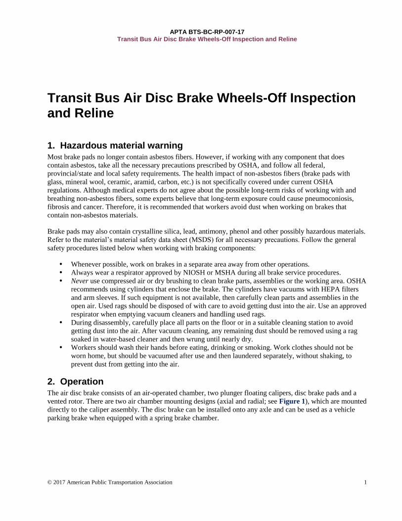
1. Hazardous material warning Most brake pads no longer contain asbestos fibers. However, if working with any component that does
contain asbestos, take all the necessary precautions prescribed by OSHA, and follow all federal,
provincial/state and local safety requirements. The health impact of non-asbestos fibers (brake pads with
glass, mineral wool, ceramic, aramid, carbon, etc.) is not specifically covered under current OSHA
regulations. Although medical experts do not agree about the possible long-term risks of working with and
breathing non-asbestos fibers, some experts believe that long-term exposure could cause pneumoconiosis,
fibrosis and cancer. Therefore, it is recommended that workers avoid dust when working on brakes that
contain non-asbestos materials.
Brake pads may also contain crystalline silica, lead, antimony, phenol and other possibly hazardous materials.
Refer to the material’s material safety data sheet (MSDS) for all necessary precautions. Follow the general
safety procedures listed below when working with braking components:
Whenever possible, work on brakes in a separate area away from other operations.
Always wear a respirator approved by NIOSH or MSHA during all brake service procedures.
Never use compressed air or dry brushing to clean brake parts, assemblies or the working area. OSHA
recommends using cylinders that enclose the brake. The cylinders have vacuums with HEPA filters
and arm sleeves. If such equipment is not available, then carefully clean parts and assemblies in the
open air. Used rags should be disposed of with care to avoid getting dust into the air. Use an approved
respirator when emptying vacuum cleaners and handling used rags.
During disassembly, carefully place all parts on the floor or in a suitable cleaning station to avoid
getting dust into the air. After vacuum cleaning, any remaining dust should be removed using a rag
soaked in water-based cleaner and then wrung until nearly dry.
Workers should wash their hands before eating, drinking or smoking. Work clothes should not be
worn home, but should be vacuumed after use and then laundered separately, without shaking, to
prevent dust from getting into the air.
2. Operation The air disc brake consists of an air-operated chamber, two plunger floating calipers, disc brake pads and a
vented rotor. There are two air chamber mounting designs (axial and radial; see Figure 1), which are mounted
directly to the caliper assembly. The disc brake can be installed onto any axle and can be used as a vehicle
parking brake when equipped with a spring brake chamber.
APTA BTS-BC-RP-007-17 Transit Bus Air Disc Brake Wheels-Off Inspection and Reline
© 2017 American Public Transportation Association 2
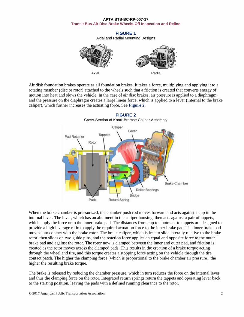
FIGURE 1 Axial and Radial Mounting Designs
Axial Radial
Air disk foundation brakes operate as all foundation brakes. It takes a force, multiplying and applying it to a
rotating member (disc or rotor) attached to the wheels such that a friction is created that converts energy of
motion into heat and slows the vehicle. In the case of air disc brakes, air pressure is applied to a diaphragm,
and the pressure on the diaphragm creates a large linear force, which is applied to a lever (internal to the brake
caliper), which further increases the actuating force. See Figure 2.
FIGURE 2 Cross-Section of Knorr-Bremse Caliper Assembly
When the brake chamber is pressurized, the chamber push rod moves forward and acts against a cup in the
internal lever. The lever, which has an abutment in the caliper housing, then acts against a pair of tappets,
which apply the force onto the inner brake pad. The distances from cup to abutment to tappets are designed to
provide a high leverage ratio to apply the required actuation force to the inner brake pad. The inner brake pad
moves into contact with the brake rotor. The brake caliper, which is free to slide laterally relative to the brake
rotor, then slides on two guide pins, and the reaction force applies an equal and opposite force to the outer
brake pad and against the rotor. The rotor now is clamped between the inner and outer pad, and friction is
created as the rotor moves across the clamped pads. This results in the creation of a brake torque acting
through the wheel and tire, and this torque creates a stopping force acting on the vehicle through the tire
contact patch. The higher the clamping force (which is proportional to the brake chamber air pressure), the
higher the resulting brake torque.
The brake is released by reducing the chamber pressure, which in turn reduces the force on the internal lever,
and thus the clamping force on the rotor. Integrated return springs return the tappets and operating lever back
to the starting position, leaving the pads with a defined running clearance to the rotor.
APTA BTS-BC-RP-007-17 Transit Bus Air Disc Brake Wheels-Off Inspection and Reline
© 2017 American Public Transportation Association 3
2.1 Automatic adjustment
To ensure a consistent running clearance between pads and rotor, the brake is equipped with an automatic
adjuster mechanism. The automatic adjuster inside the caliper adjusts the brake pad clearance to compensate
for pad and rotor wear. Every time the brake is applied, the system senses whether the running clearance of
the brake pads to the brake rotor is still within the specified range and does not need to be adjusted, or
whether it is beyond the specified range and adjustment is required. For Knorr-Bremse brakes, the total
running clearance (sum of clearance on both sides of the disc) should be between 0.024 in (0.60 mm) and
0.043 in. (1.1 mm); smaller clearances may lead to overheating problems. For Meritor EX225 brakes, no
minimum is specified, but clearance must not exceed 0.030 in. (0.75 mm).
Disc brakes by design do not allow for measurement of brake chamber pushrod travel, and therefore brake
chamber pushrod travel is not referenced in North American Commercial Vehicle Safety Alliance (NACVSA)
inspection or out-of-service criteria. Although brake chamber pushrod travel can be calculated by measuring
both rotor-to-brake-pad clearances and multiplying this dimension by the lever ratio, it is not necessary.
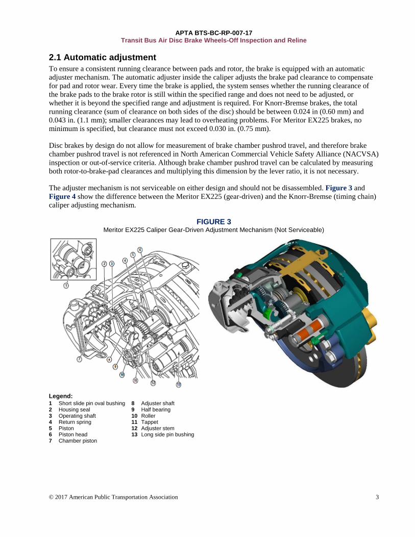
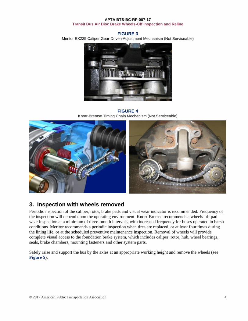
The adjuster mechanism is not serviceable on either design and should not be disassembled. Figure 3 and
Figure 4 show the difference between the Meritor EX225 (gear-driven) and the Knorr-Bremse (timing chain)
caliper adjusting mechanism.
FIGURE 3 Meritor EX225 Caliper Gear-Driven Adjustment Mechanism (Not Serviceable)
Legend: 1 Short slide pin oval bushing 2 Housing seal 3 Operating shaft 4 Return spring 5 Piston 6 Piston head 7 Chamber piston
8 Adjuster shaft 9 Half bearing 10 Roller 11 Tappet 12 Adjuster stem 13 Long side pin bushing
APTA BTS-BC-RP-007-17 Transit Bus Air Disc Brake Wheels-Off Inspection and Reline
© 2017 American Public Transportation Association 4
FIGURE 3 Meritor EX225 Caliper Gear-Driven Adjustment Mechanism (Not Serviceable)
FIGURE 4 Knorr-Bremse Timing Chain Mechanism (Not Serviceable)
3. Inspection with wheels removed Periodic inspection of the caliper, rotor, brake pads and visual wear indicator is recommended. Frequency of
the inspection will depend upon the operating environment. Knorr-Bremse recommends a wheels-off pad
wear inspection at a minimum of three-month intervals, with increased frequency for buses operated in harsh
conditions. Meritor recommends a periodic inspection when tires are replaced, or at least four times during
the lining life, or at the scheduled preventive maintenance inspection. Removal of wheels will provide
complete visual access to the foundation brake system, which includes caliper, rotor, hub, wheel bearings,
seals, brake chambers, mounting fasteners and other system parts.
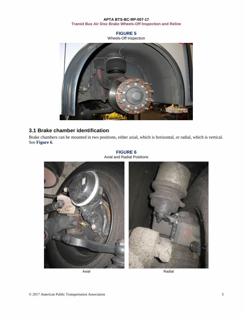
Safely raise and support the bus by the axles at an appropriate working height and remove the wheels (see
Figure 5).
APTA BTS-BC-RP-007-17 Transit Bus Air Disc Brake Wheels-Off Inspection and Reline
© 2017 American Public Transportation Association 5
FIGURE 5 Wheels-Off Inspection
3.1 Brake chamber identification
Brake chambers can be mounted in two positions, either axial, which is horizontal, or radial, which is vertical.
See Figure 6.
FIGURE 6 Axial and Radial Positions
Axial Radial
APTA BTS-BC-RP-007-17 Transit Bus Air Disc Brake Wheels-Off Inspection and Reline
© 2017 American Public Transportation Association 6
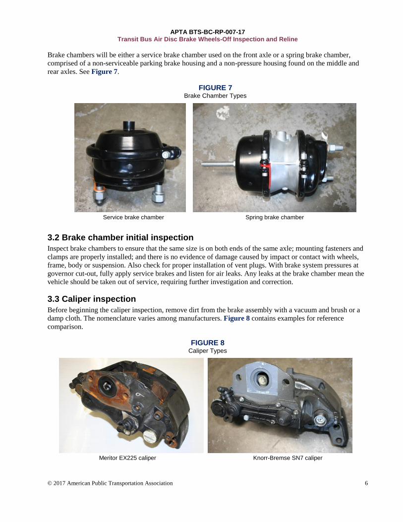
Brake chambers will be either a service brake chamber used on the front axle or a spring brake chamber,
comprised of a non-serviceable parking brake housing and a non-pressure housing found on the middle and
rear axles. See Figure 7.
FIGURE 7 Brake Chamber Types
Service brake chamber Spring brake chamber
3.2 Brake chamber initial inspection
Inspect brake chambers to ensure that the same size is on both ends of the same axle; mounting fasteners and
clamps are properly installed; and there is no evidence of damage caused by impact or contact with wheels,
frame, body or suspension. Also check for proper installation of vent plugs. With brake system pressures at
governor cut-out, fully apply service brakes and listen for air leaks. Any leaks at the brake chamber mean the
vehicle should be taken out of service, requiring further investigation and correction.
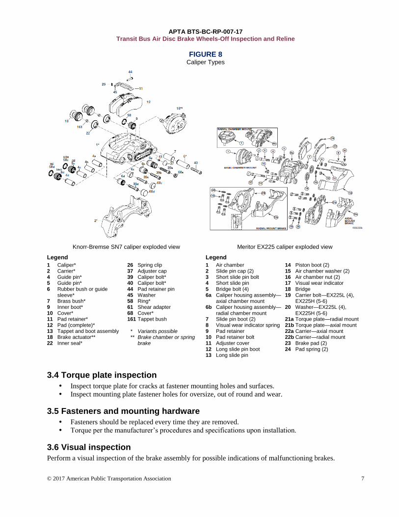
3.3 Caliper inspection
Before beginning the caliper inspection, remove dirt from the brake assembly with a vacuum and brush or a
damp cloth. The nomenclature varies among manufacturers. Figure 8 contains examples for reference
comparison.
FIGURE 8 Caliper Types
Meritor EX225 caliper Knorr-Bremse SN7 caliper
APTA BTS-BC-RP-007-17 Transit Bus Air Disc Brake Wheels-Off Inspection and Reline
© 2017 American Public Transportation Association 7
FIGURE 8 Caliper Types
Knorr-Bremse SN7 caliper exploded view Meritor EX225 caliper exploded view
Legend Legend
1 Caliper* 2 Carrier* 4 Guide pin* 5 Guide pin* 6 Rubber bush or guide
sleeve* 7 Brass bush* 9 Inner boot* 10 Cover* 11 Pad retainer* 12 Pad (complete)* 13 Tappet and boot assembly 18 Brake actuator** 22 Inner seal*
26 Spring clip 37 Adjuster cap 39 Caliper bolt* 40 Caliper bolt* 44 Pad retainer pin 45 Washer 58 Ring* 61 Shear adapter 68 Cover* 161 Tappet bush * Variants possible ** Brake chamber or spring
brake
1 Air chamber 2 Slide pin cap (2) 3 Short slide pin bolt 4 Short slide pin 5 Bridge bolt (4) 6a Caliper housing assembly—
axial chamber mount 6b Caliper housing assembly—
radial chamber mount 7 Slide pin boot (2) 8 Visual wear indicator spring 9 Pad retainer 10 Pad retainer bolt 11 Adjuster cover 12 Long slide pin boot 13 Long slide pin
14 Piston boot (2) 15 Air chamber washer (2) 16 Air chamber nut (2) 17 Visual wear indicator 18 Bridge 19 Carrier bolt—EX225L (4),
EX225H (5-6) 20 Washer—EX225L (4),
EX225H (5-6) 21a Torque plate—radial mount 21b Torque plate—axial mount 22a Carrier—axial mount 22b Carrier—radial mount 23 Brake pad (2) 24 Pad spring (2)
3.4 Torque plate inspection
Inspect torque plate for cracks at fastener mounting holes and surfaces.
Inspect mounting plate fastener holes for oversize, out of round and wear.
3.5 Fasteners and mounting hardware
Fasteners should be replaced every time they are removed.
Torque per the manufacturer’s procedures and specifications upon installation.
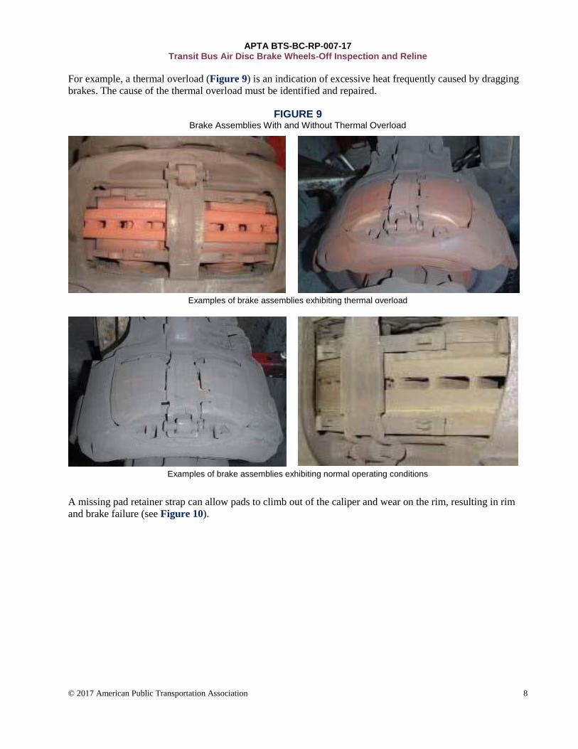
3.6 Visual inspection
Perform a visual inspection of the brake assembly for possible indications of malfunctioning brakes.
APTA BTS-BC-RP-007-17 Transit Bus Air Disc Brake Wheels-Off Inspection and Reline
© 2017 American Public Transportation Association 8
For example, a thermal overload (Figure 9) is an indication of excessive heat frequently caused by dragging
brakes. The cause of the thermal overload must be identified and repaired.
FIGURE 9 Brake Assemblies With and Without Thermal Overload
Examples of brake assemblies exhibiting thermal overload
Examples of brake assemblies exhibiting normal operating conditions
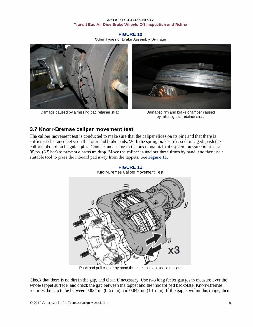
A missing pad retainer strap can allow pads to climb out of the caliper and wear on the rim, resulting in rim
and brake failure (see Figure 10).
APTA BTS-BC-RP-007-17 Transit Bus Air Disc Brake Wheels-Off Inspection and Reline
© 2017 American Public Transportation Association 9
FIGURE 10 Other Types of Brake Assembly Damage
Damage caused by a missing pad retainer strap Damaged rim and brake chamber caused
by missing pad retainer strap
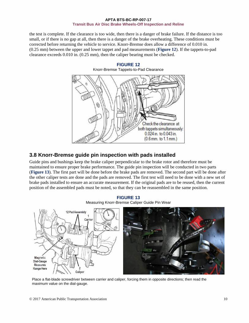
3.7 Knorr-Bremse caliper movement test
The caliper movement test is conducted to make sure that the caliper slides on its pins and that there is
sufficient clearance between the rotor and brake pads. With the spring brakes released or caged, push the
caliper inboard on its guide pins. Connect an air line to the bus to maintain air system pressure of at least
95 psi (6.5 bar) to prevent a pressure drop. Move the caliper in and out three times by hand, and then use a
suitable tool to press the inboard pad away from the tappets. See Figure 11.
FIGURE 11 Knorr-Bremse Caliper Movement Test
Push and pull caliper by hand three times in an axial direction.
Check that there is no dirt in the gap, and clean if necessary. Use two long feeler gauges to measure over the
whole tappet surface, and check the gap between the tappet and the inboard pad backplate. Knorr-Bremse
requires the gap to be between 0.024 in. (0.6 mm) and 0.043 in. (1.1 mm). If the gap is within this range, then
APTA BTS-BC-RP-007-17 Transit Bus Air Disc Brake Wheels-Off Inspection and Reline
© 2017 American Public Transportation Association 10
the test is complete. If the clearance is too wide, then there is a danger of brake failure. If the distance is too
small, or if there is no gap at all, then there is a danger of the brake overheating. These conditions must be
corrected before returning the vehicle to service. Knorr-Bremse does allow a difference of 0.010 in.
(0.25 mm) between the upper and lower tappet and pad measurements (Figure 12). If the tappets-to-pad
clearance exceeds 0.010 in. (0.25 mm), then the caliper bearing must be checked.
FIGURE 12 Knorr-Bremse Tappets-to-Pad Clearance
3.8 Knorr-Bremse guide pin inspection with pads installed
Guide pins and bushings keep the brake caliper perpendicular to the brake rotor and therefore must be
maintained to ensure proper brake performance. The guide pin inspection will be conducted in two parts
(Figure 13). The first part will be done before the brake pads are removed. The second part will be done after
the other caliper tests are done and the pads are removed. The first test will need to be done with a new set of
brake pads installed to ensure an accurate measurement. If the original pads are to be reused, then the current
position of the assembled pads must be noted, so that they can be reassembled in the same position.
FIGURE 13 Measuring Knorr-Bremse Caliper Guide Pin Wear
Place a flat-blade screwdriver between carrier and caliper, forcing them in opposite directions; then read the maximum value on the dial-gauge.
APTA BTS-BC-RP-007-17 Transit Bus Air Disc Brake Wheels-Off Inspection and Reline
© 2017 American Public Transportation Association 11
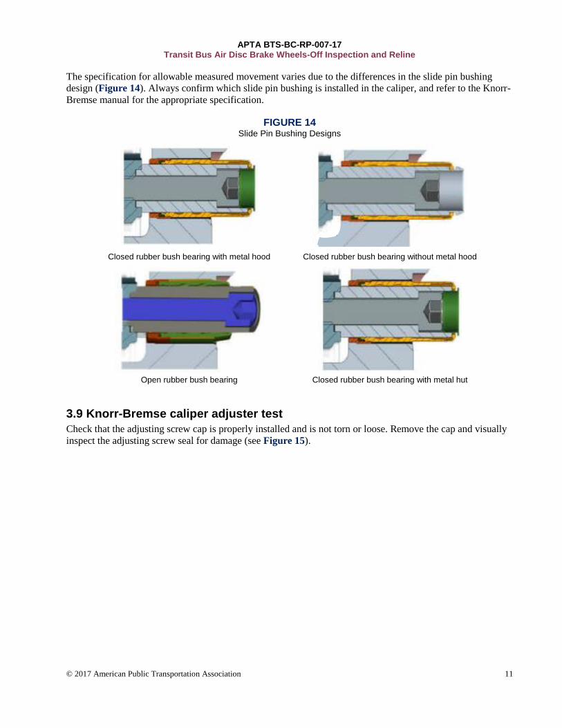
The specification for allowable measured movement varies due to the differences in the slide pin bushing
design (Figure 14). Always confirm which slide pin bushing is installed in the caliper, and refer to the Knorr-
Bremse manual for the appropriate specification.
FIGURE 14 Slide Pin Bushing Designs
Closed rubber bush bearing with metal hood Closed rubber bush bearing without metal hood
Open rubber bush bearing Closed rubber bush bearing with metal hut
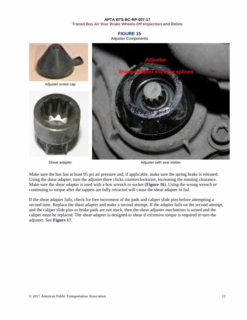
3.9 Knorr-Bremse caliper adjuster test
Check that the adjusting screw cap is properly installed and is not torn or loose. Remove the cap and visually
inspect the adjusting screw seal for damage (see Figure 15).
APTA BTS-BC-RP-007-17 Transit Bus Air Disc Brake Wheels-Off Inspection and Reline
© 2017 American Public Transportation Association 12
FIGURE 15 Adjuster Components
Adjuster screw cap
Shear adapter Adjuster with seal visible
Make sure the bus has at least 95 psi air pressure and, if applicable, make sure the spring brake is released.
Using the shear adapter, turn the adjuster three clicks counterclockwise, increasing the running clearance.
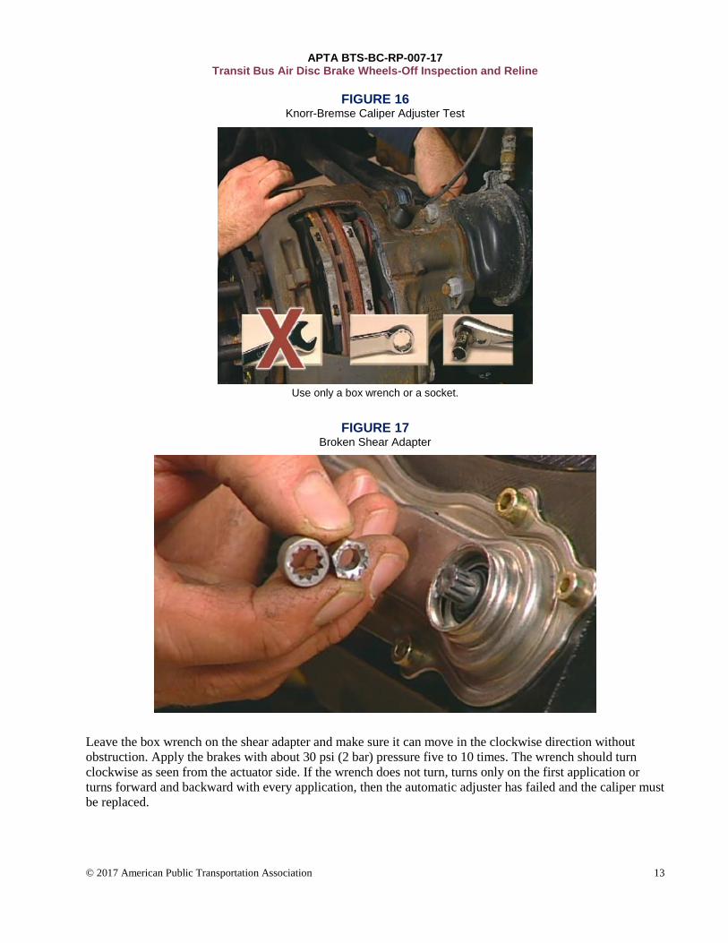
Make sure the shear adapter is used with a box wrench or socket (Figure 16). Using the wrong wrench or
continuing to torque after the tappets are fully retracted will cause the shear adapter to fail.
If the shear adapter fails, check for free movement of the pads and caliper slide pins before attempting a
second time. Replace the shear adapter and make a second attempt. If the adapter fails on the second attempt,
and the caliper slide pins or brake pads are not stuck, then the shear adjuster mechanism is seized and the
caliper must be replaced. The shear adapter is designed to shear if excessive torque is required to turn the
adjuster. See Figure 17.
APTA BTS-BC-RP-007-17 Transit Bus Air Disc Brake Wheels-Off Inspection and Reline
© 2017 American Public Transportation Association 13
FIGURE 16 Knorr-Bremse Caliper Adjuster Test
Use only a box wrench or a socket.
FIGURE 17 Broken Shear Adapter
Leave the box wrench on the shear adapter and make sure it can move in the clockwise direction without
obstruction. Apply the brakes with about 30 psi (2 bar) pressure five to 10 times. The wrench should turn
clockwise as seen from the actuator side. If the wrench does not turn, turns only on the first application or
turns forward and backward with every application, then the automatic adjuster has failed and the caliper must
be replaced.
APTA BTS-BC-RP-007-17 Transit Bus Air Disc Brake Wheels-Off Inspection and Reline
© 2017 American Public Transportation Association 14
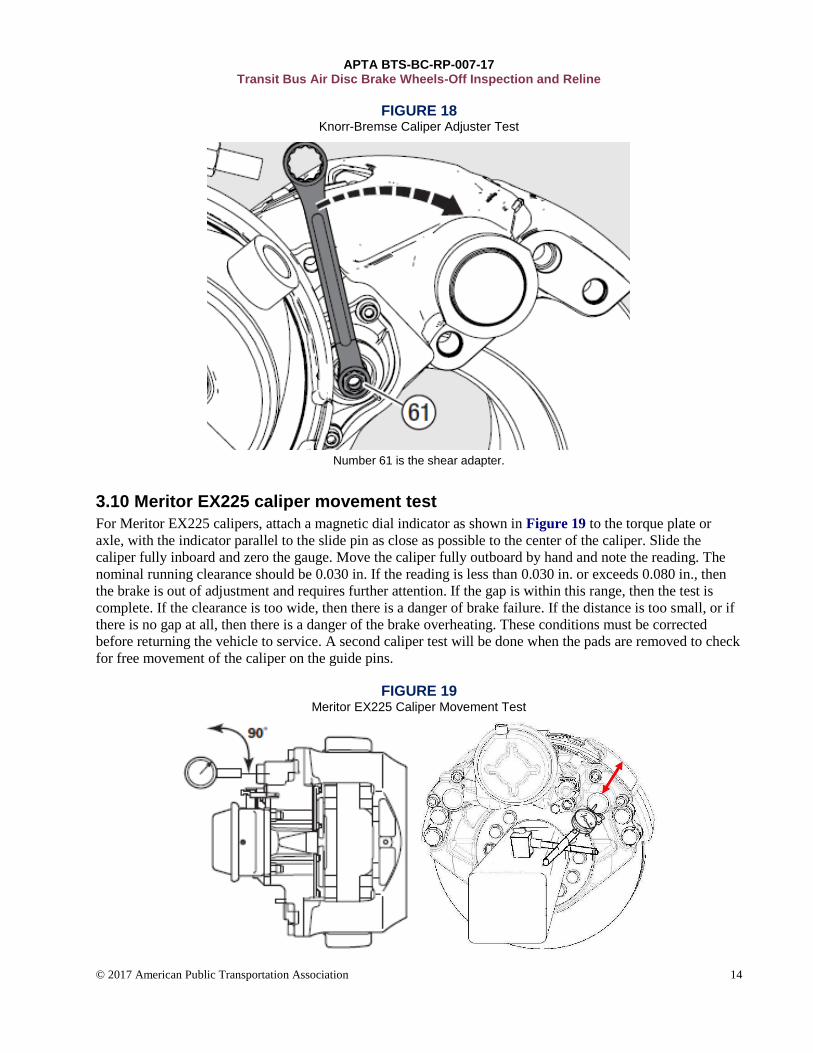
FIGURE 18 Knorr-Bremse Caliper Adjuster Test
Number 61 is the shear adapter.
3.10 Meritor EX225 caliper movement test
For Meritor EX225 calipers, attach a magnetic dial indicator as shown in Figure 19 to the torque plate or
axle, with the indicator parallel to the slide pin as close as possible to the center of the caliper. Slide the
caliper fully inboard and zero the gauge. Move the caliper fully outboard by hand and note the reading. The
nominal running clearance should be 0.030 in. If the reading is less than 0.030 in. or exceeds 0.080 in., then
the brake is out of adjustment and requires further attention. If the gap is within this range, then the test is
complete. If the clearance is too wide, then there is a danger of brake failure. If the distance is too small, or if
there is no gap at all, then there is a danger of the brake overheating. These conditions must be corrected
before returning the vehicle to service. A second caliper test will be done when the pads are removed to check
for free movement of the caliper on the guide pins.
FIGURE 19 Meritor EX225 Caliper Movement Test
APTA BTS-BC-RP-007-17 Transit Bus Air Disc Brake Wheels-Off Inspection and Reline
© 2017 American Public Transportation Association 15
3.11 Meritor EX225 caliper adjuster test
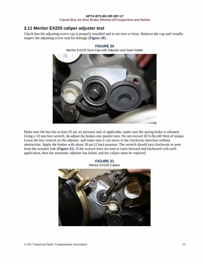
Check that the adjusting screw cap is properly installed and is not torn or loose. Remove the cap and visually
inspect the adjusting screw seal for damage (Figure 20).
FIGURE 20 Meritor EX225 Dust Cap with Adjuster and Seal Visible
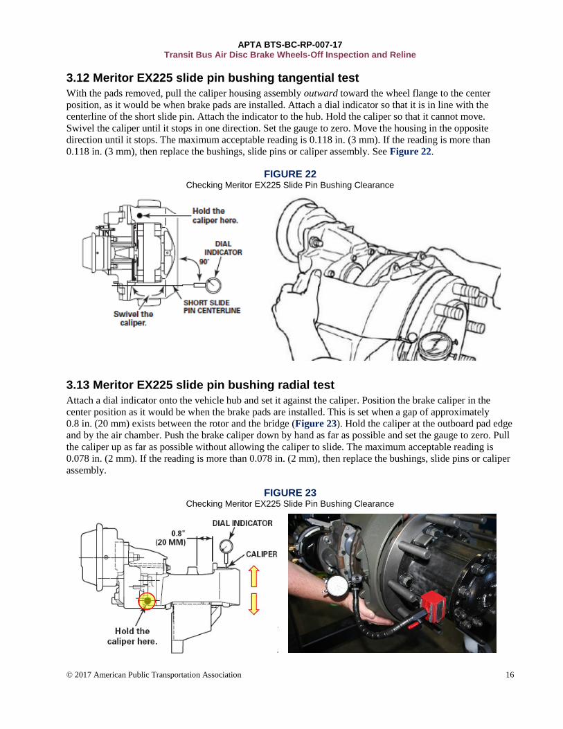
Make sure the bus has at least 95 psi air pressure and, if applicable, make sure the spring brake is released.
Using a 10 mm box wrench, de-adjust the brakes one quarter turn. Do not exceed 30 ft-lbs (40 Nm) of torque.
Leave the box wrench on the adjuster, and make sure it can move in the clockwise direction without
obstruction. Apply the brakes with about 30 psi (2 bar) pressure. The wrench should turn clockwise as seen
from the actuator side (Figure 21). If the wrench does not turn or turns forward and backward with each
application, then the automatic adjuster has failed, and the caliper must be replaced.
FIGURE 21 Meritor EX225 Caliper
APTA BTS-BC-RP-007-17 Transit Bus Air Disc Brake Wheels-Off Inspection and Reline
© 2017 American Public Transportation Association 16
3.12 Meritor EX225 slide pin bushing tangential test
With the pads removed, pull the caliper housing assembly outward toward the wheel flange to the center
position, as it would be when brake pads are installed. Attach a dial indicator so that it is in line with the
centerline of the short slide pin. Attach the indicator to the hub. Hold the caliper so that it cannot move.
Swivel the caliper until it stops in one direction. Set the gauge to zero. Move the housing in the opposite
direction until it stops. The maximum acceptable reading is 0.118 in. (3 mm). If the reading is more than
0.118 in. (3 mm), then replace the bushings, slide pins or caliper assembly. See Figure 22.
FIGURE 22 Checking Meritor EX225 Slide Pin Bushing Clearance
3.13 Meritor EX225 slide pin bushing radial test
Attach a dial indicator onto the vehicle hub and set it against the caliper. Position the brake caliper in the
center position as it would be when the brake pads are installed. This is set when a gap of approximately
0.8 in. (20 mm) exists between the rotor and the bridge (Figure 23). Hold the caliper at the outboard pad edge
and by the air chamber. Push the brake caliper down by hand as far as possible and set the gauge to zero. Pull
the caliper up as far as possible without allowing the caliper to slide. The maximum acceptable reading is
0.078 in. (2 mm). If the reading is more than 0.078 in. (2 mm), then replace the bushings, slide pins or caliper
assembly.
FIGURE 23 Checking Meritor EX225 Slide Pin Bushing Clearance
APTA BTS-BC-RP-007-17 Transit Bus Air Disc Brake Wheels-Off Inspection and Reline
© 2017 American Public Transportation Association 17
3.14 Caliper guide pin inspection with pads removed
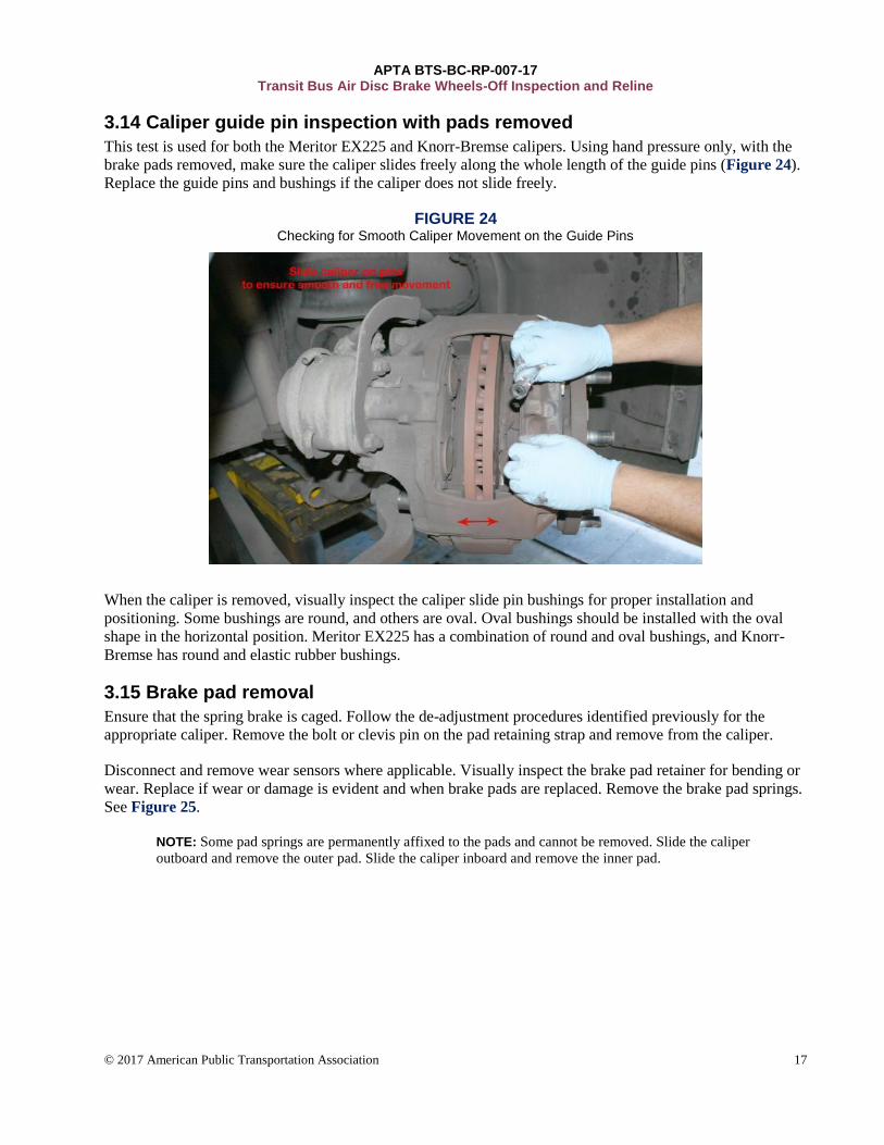
This test is used for both the Meritor EX225 and Knorr-Bremse calipers. Using hand pressure only, with the
brake pads removed, make sure the caliper slides freely along the whole length of the guide pins (Figure 24).
Replace the guide pins and bushings if the caliper does not slide freely.
FIGURE 24 Checking for Smooth Caliper Movement on the Guide Pins
When the caliper is removed, visually inspect the caliper slide pin bushings for proper installation and
positioning. Some bushings are round, and others are oval. Oval bushings should be installed with the oval
shape in the horizontal position. Meritor EX225 has a combination of round and oval bushings, and Knorr-
Bremse has round and elastic rubber bushings.
3.15 Brake pad removal
Ensure that the spring brake is caged. Follow the de-adjustment procedures identified previously for the
appropriate caliper. Remove the bolt or clevis pin on the pad retaining strap and remove from the caliper.
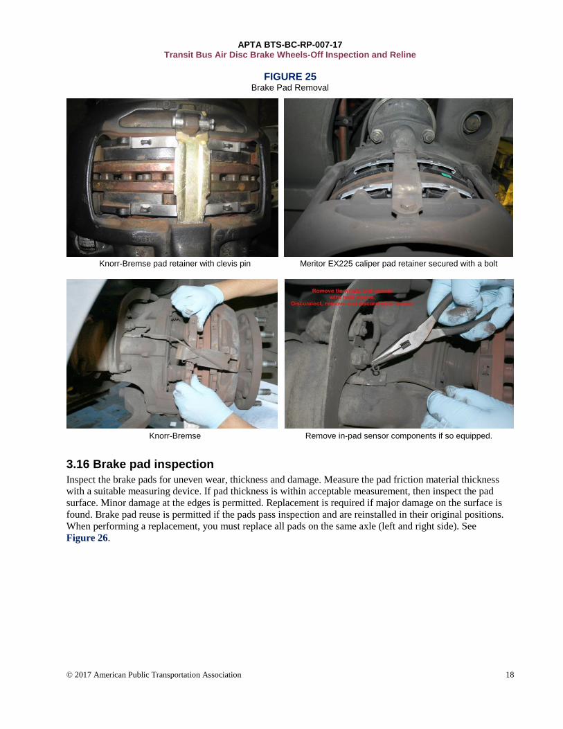
Disconnect and remove wear sensors where applicable. Visually inspect the brake pad retainer for bending or
wear. Replace if wear or damage is evident and when brake pads are replaced. Remove the brake pad springs.
See Figure 25.
NOTE: Some pad springs are permanently affixed to the pads and cannot be removed. Slide the caliper
outboard and remove the outer pad. Slide the caliper inboard and remove the inner pad.
APTA BTS-BC-RP-007-17 Transit Bus Air Disc Brake Wheels-Off Inspection and Reline
© 2017 American Public Transportation Association 18
FIGURE 25 Brake Pad Removal
Knorr-Bremse pad retainer with clevis pin Meritor EX225 caliper pad retainer secured with a bolt
Knorr-Bremse Remove in-pad sensor components if so equipped.
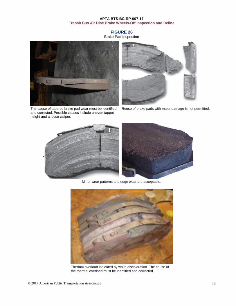
3.16 Brake pad inspection
Inspect the brake pads for uneven wear, thickness and damage. Measure the pad friction material thickness
with a suitable measuring device. If pad thickness is within acceptable measurement, then inspect the pad
surface. Minor damage at the edges is permitted. Replacement is required if major damage on the surface is
found. Brake pad reuse is permitted if the pads pass inspection and are reinstalled in their original positions.
When performing a replacement, you must replace all pads on the same axle (left and right side). See
Figure 26.
APTA BTS-BC-RP-007-17 Transit Bus Air Disc Brake Wheels-Off Inspection and Reline
© 2017 American Public Transportation Association 19
FIGURE 26 Brake Pad Inspection
The cause of tapered brake pad wear must be identified and corrected. Possible causes include uneven tappet height and a loose caliper.
Reuse of brake pads with major damage is not permitted.
Minor wear patterns and edge wear are acceptable.
Thermal overload indicated by white discoloration. The cause of the thermal overload must be identified and corrected.
APTA BTS-BC-RP-007-17 Transit Bus Air Disc Brake Wheels-Off Inspection and Reline
© 2017 American Public Transportation Association 20
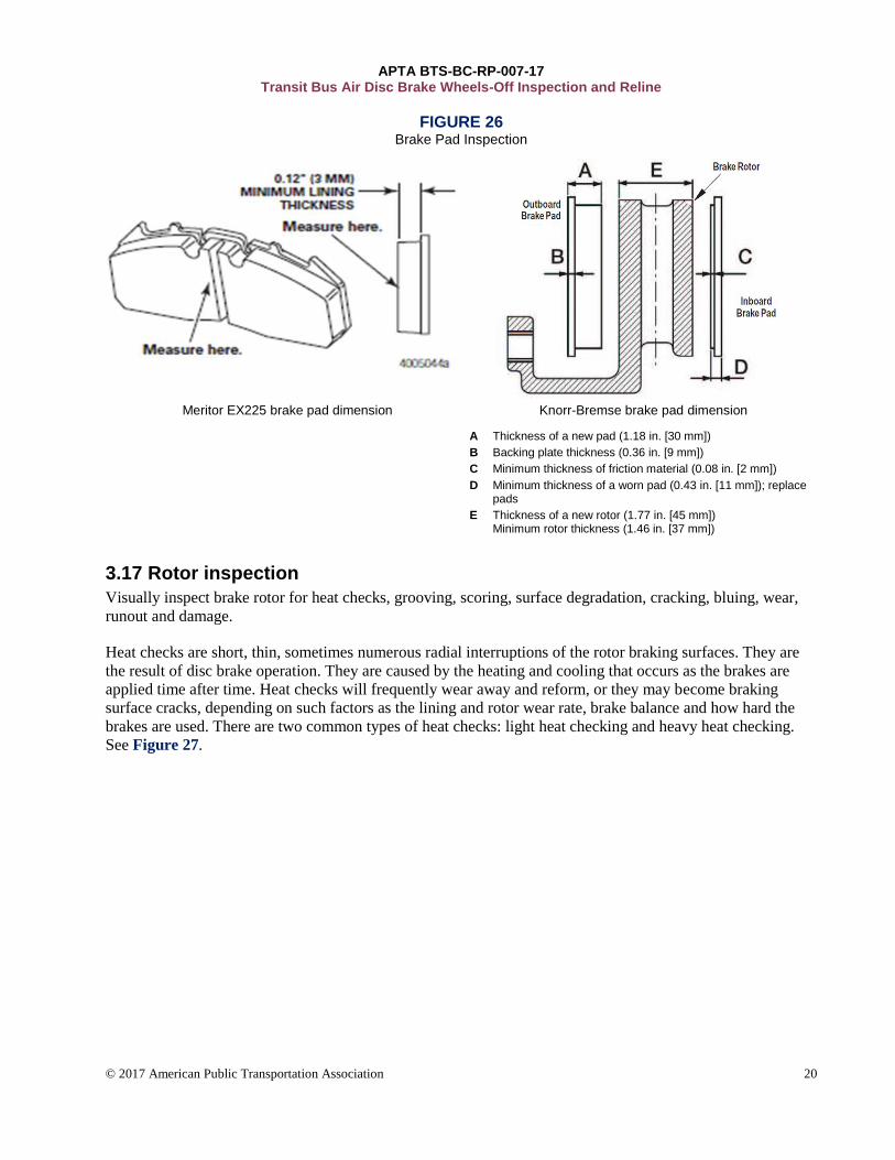
FIGURE 26 Brake Pad Inspection
Meritor EX225 brake pad dimension Knorr-Bremse brake pad dimension
A Thickness of a new pad (1.18 in. [30 mm])
B Backing plate thickness (0.36 in. [9 mm])
C Minimum thickness of friction material (0.08 in. [2 mm])
D Minimum thickness of a worn pad (0.43 in. [11 mm]); replace pads
E Thickness of a new rotor (1.77 in. [45 mm]) Minimum rotor thickness (1.46 in. [37 mm])
3.17 Rotor inspection
Visually inspect brake rotor for heat checks, grooving, scoring, surface degradation, cracking, bluing, wear,
runout and damage.
Heat checks are short, thin, sometimes numerous radial interruptions of the rotor braking surfaces. They are
the result of disc brake operation. They are caused by the heating and cooling that occurs as the brakes are
applied time after time. Heat checks will frequently wear away and reform, or they may become braking
surface cracks, depending on such factors as the lining and rotor wear rate, brake balance and how hard the
brakes are used. There are two common types of heat checks: light heat checking and heavy heat checking.
See Figure 27.
APTA BTS-BC-RP-007-17 Transit Bus Air Disc Brake Wheels-Off Inspection and Reline
© 2017 American Public Transportation Association 21
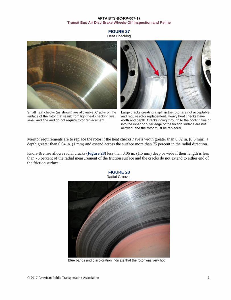
FIGURE 27 Heat Checking
Small heat checks (as shown) are allowable. Cracks on the surface of the rotor that result from light heat checking are small and fine and do not require rotor replacement.
Large cracks creating a split in the rotor are not acceptable and require rotor replacement. Heavy heat checks have width and depth. Cracks going through to the cooling fins or into the inner or outer edge of the friction surface are not allowed, and the rotor must be replaced.
Meritor requirements are to replace the rotor if the heat checks have a width greater than 0.02 in. (0.5 mm), a
depth greater than 0.04 in. (1 mm) and extend across the surface more than 75 percent in the radial direction.
Knorr-Bremse allows radial cracks (Figure 28) less than 0.06 in. (1.5 mm) deep or wide if their length is less
than 75 percent of the radial measurement of the friction surface and the cracks do not extend to either end of
the friction surface.
FIGURE 28 Radial Grooves
Blue bands and discoloration indicate that the rotor was very hot.
APTA BTS-BC-RP-007-17 Transit Bus Air Disc Brake Wheels-Off Inspection and Reline
© 2017 American Public Transportation Association 22
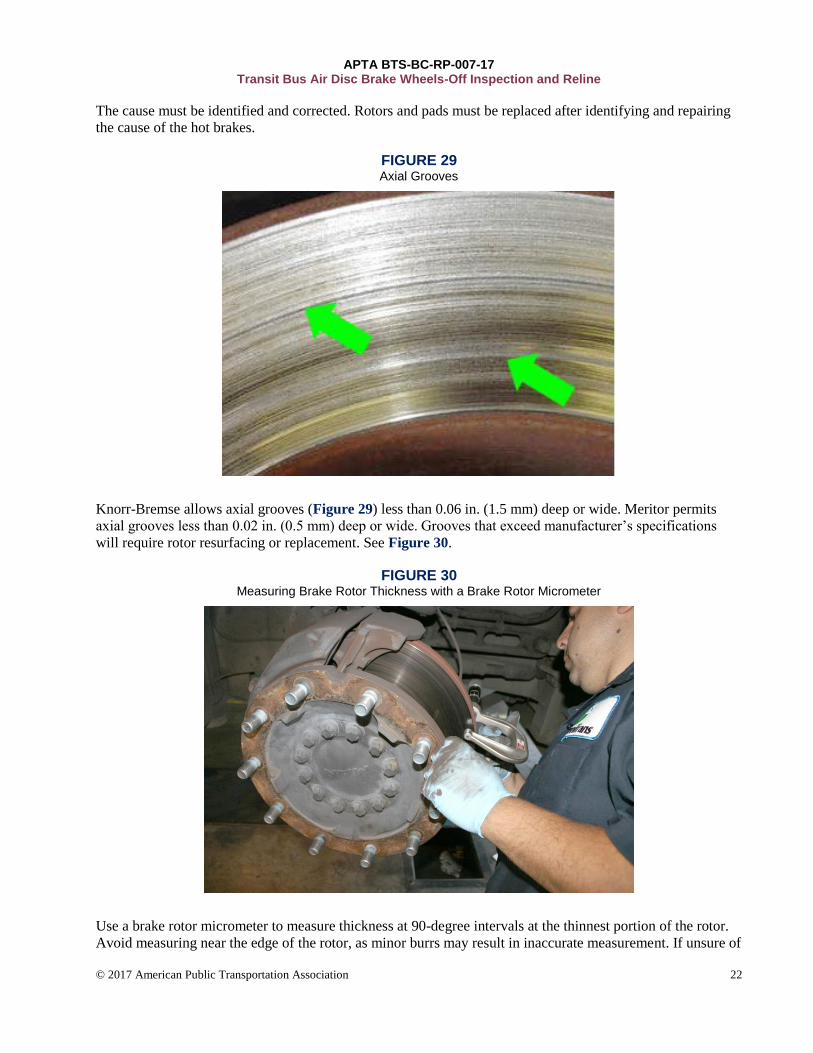
The cause must be identified and corrected. Rotors and pads must be replaced after identifying and repairing
the cause of the hot brakes.
FIGURE 29 Axial Grooves
Knorr-Bremse allows axial grooves (Figure 29) less than 0.06 in. (1.5 mm) deep or wide. Meritor permits
axial grooves less than 0.02 in. (0.5 mm) deep or wide. Grooves that exceed manufacturer’s specifications
will require rotor resurfacing or replacement. See Figure 30.
FIGURE 30 Measuring Brake Rotor Thickness with a Brake Rotor Micrometer
Use a brake rotor micrometer to measure thickness at 90-degree intervals at the thinnest portion of the rotor.
Avoid measuring near the edge of the rotor, as minor burrs may result in inaccurate measurement. If unsure of
APTA BTS-BC-RP-007-17 Transit Bus Air Disc Brake Wheels-Off Inspection and Reline
© 2017 American Public Transportation Association 23
the thinnest point, measure at three points. Point one is about 10 mm below the outer friction diameter. Point
two is at the friction surface center. Point three is about 10 mm above the inner friction diameter. The brake
rotor micrometer must be square to the rotor friction surface for accurate measurement. Typical new rotor
thickness is 45 mm. Rotors must be discarded when a minimum thickness of 37 mm or the minimum discard
thickness found on the rotor casting is reached. The discard thickness is frequently cast into the rotor hat
flange and is the minimum thickness the rotor can be worn to before the rotor is no longer considered safe for
operation. Minimum thickness is not the minimum brake pad change thickness. New brake pads can be
installed with a used rotor, providing that the rotor passes the visual inspection and no portion of the rotor
friction surface measures less than 39 mm in thickness.
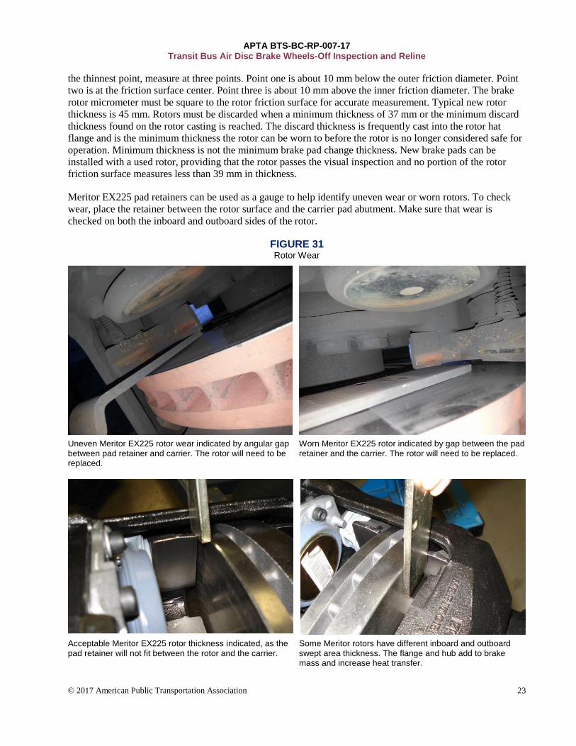
Meritor EX225 pad retainers can be used as a gauge to help identify uneven wear or worn rotors. To check
wear, place the retainer between the rotor surface and the carrier pad abutment. Make sure that wear is
checked on both the inboard and outboard sides of the rotor.
FIGURE 31 Rotor Wear
Uneven Meritor EX225 rotor wear indicated by angular gap between pad retainer and carrier. The rotor will need to be replaced.
Worn Meritor EX225 rotor indicated by gap between the pad retainer and the carrier. The rotor will need to be replaced.
Acceptable Meritor EX225 rotor thickness indicated, as the pad retainer will not fit between the rotor and the carrier.
Some Meritor rotors have different inboard and outboard swept area thickness. The flange and hub add to brake mass and increase heat transfer.
APTA BTS-BC-RP-007-17 Transit Bus Air Disc Brake Wheels-Off Inspection and Reline
© 2017 American Public Transportation Association 24
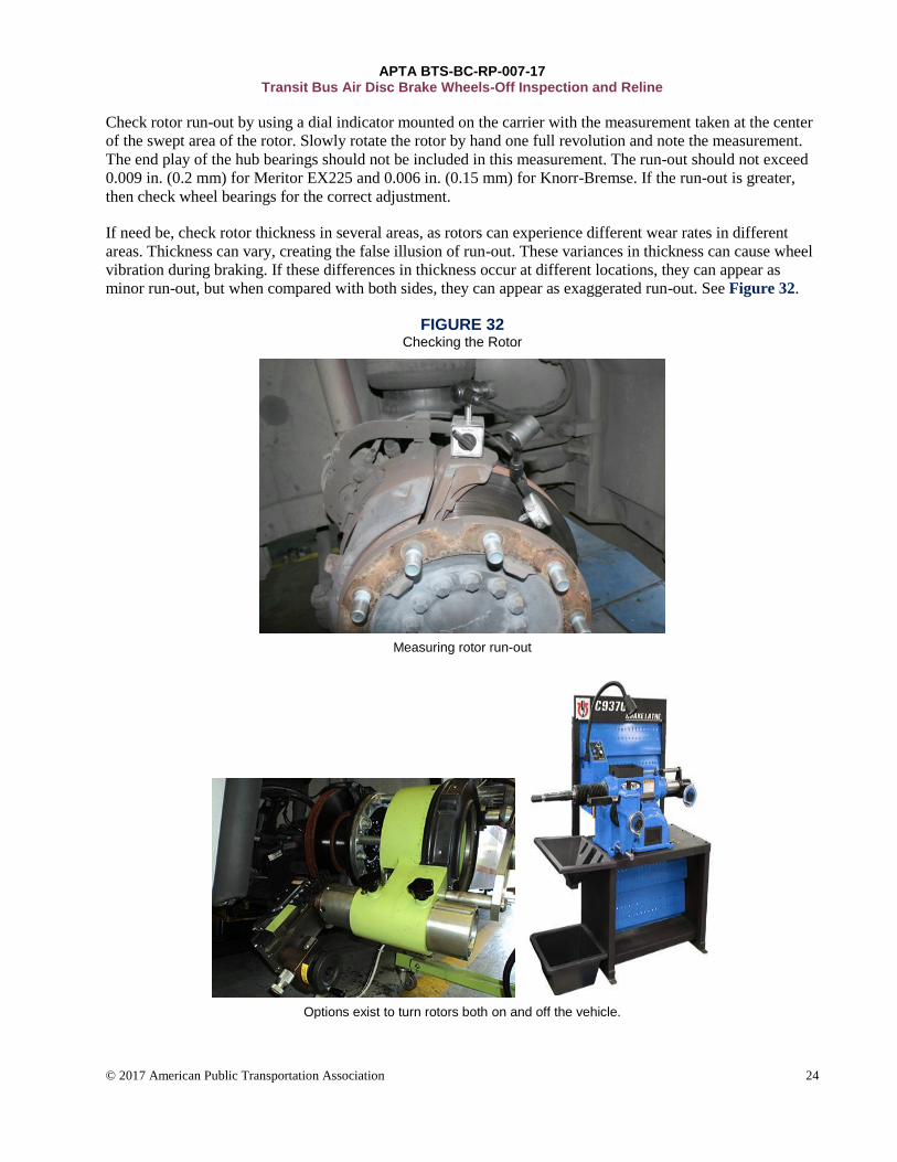
Check rotor run-out by using a dial indicator mounted on the carrier with the measurement taken at the center
of the swept area of the rotor. Slowly rotate the rotor by hand one full revolution and note the measurement.
The end play of the hub bearings should not be included in this measurement. The run-out should not exceed
0.009 in. (0.2 mm) for Meritor EX225 and 0.006 in. (0.15 mm) for Knorr-Bremse. If the run-out is greater,
then check wheel bearings for the correct adjustment.
If need be, check rotor thickness in several areas, as rotors can experience different wear rates in different
areas. Thickness can vary, creating the false illusion of run-out. These variances in thickness can cause wheel
vibration during braking. If these differences in thickness occur at different locations, they can appear as
minor run-out, but when compared with both sides, they can appear as exaggerated run-out. See Figure 32.
FIGURE 32 Checking the Rotor
Measuring rotor run-out
Options exist to turn rotors both on and off the vehicle.
APTA BTS-BC-RP-007-17 Transit Bus Air Disc Brake Wheels-Off Inspection and Reline
© 2017 American Public Transportation Association 25
Rotor discard thickness is frequently cast into the rotor hat flange and is the minimum thickness the rotor can
be worn to before the rotor is no longer considered safe for operation. Consideration should be taken as brake
rotors wear over the course of brake pad life. Wear rates can be calculated by first installing and measuring
new rotors and pads. Then measure both when the pads are worn to their minimum thickness. It is not
recommended to install brake pads if rotor wear rates would cause rotor thickness to wear below discard
limits during the expected life of the brake pads. Rotors can be resurfaced to acceptable conditions, providing
that all other specifications are met.
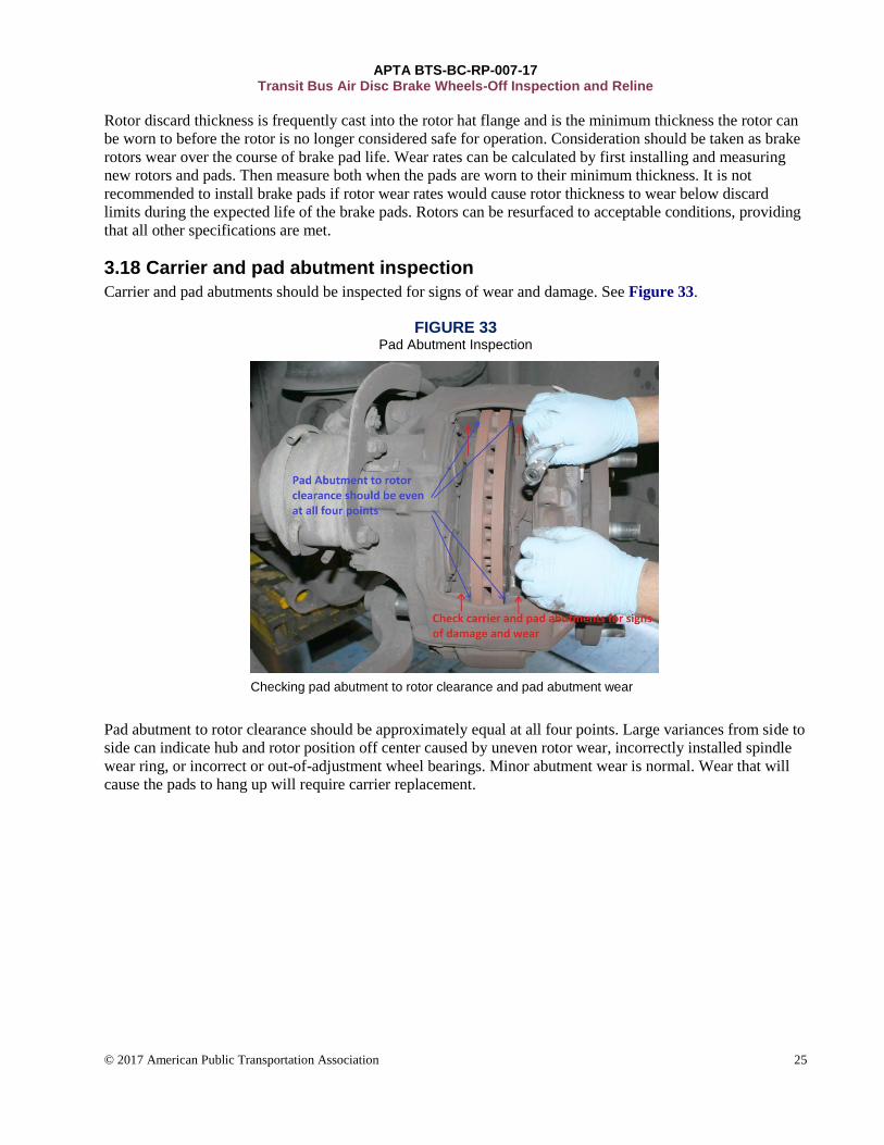
3.18 Carrier and pad abutment inspection
Carrier and pad abutments should be inspected for signs of wear and damage. See Figure 33.
FIGURE 33 Pad Abutment Inspection
Checking pad abutment to rotor clearance and pad abutment wear
Pad abutment to rotor clearance should be approximately equal at all four points. Large variances from side to
side can indicate hub and rotor position off center caused by uneven rotor wear, incorrectly installed spindle
wear ring, or incorrect or out-of-adjustment wheel bearings. Minor abutment wear is normal. Wear that will
cause the pads to hang up will require carrier replacement.
APTA BTS-BC-RP-007-17 Transit Bus Air Disc Brake Wheels-Off Inspection and Reline
© 2017 American Public Transportation Association 26
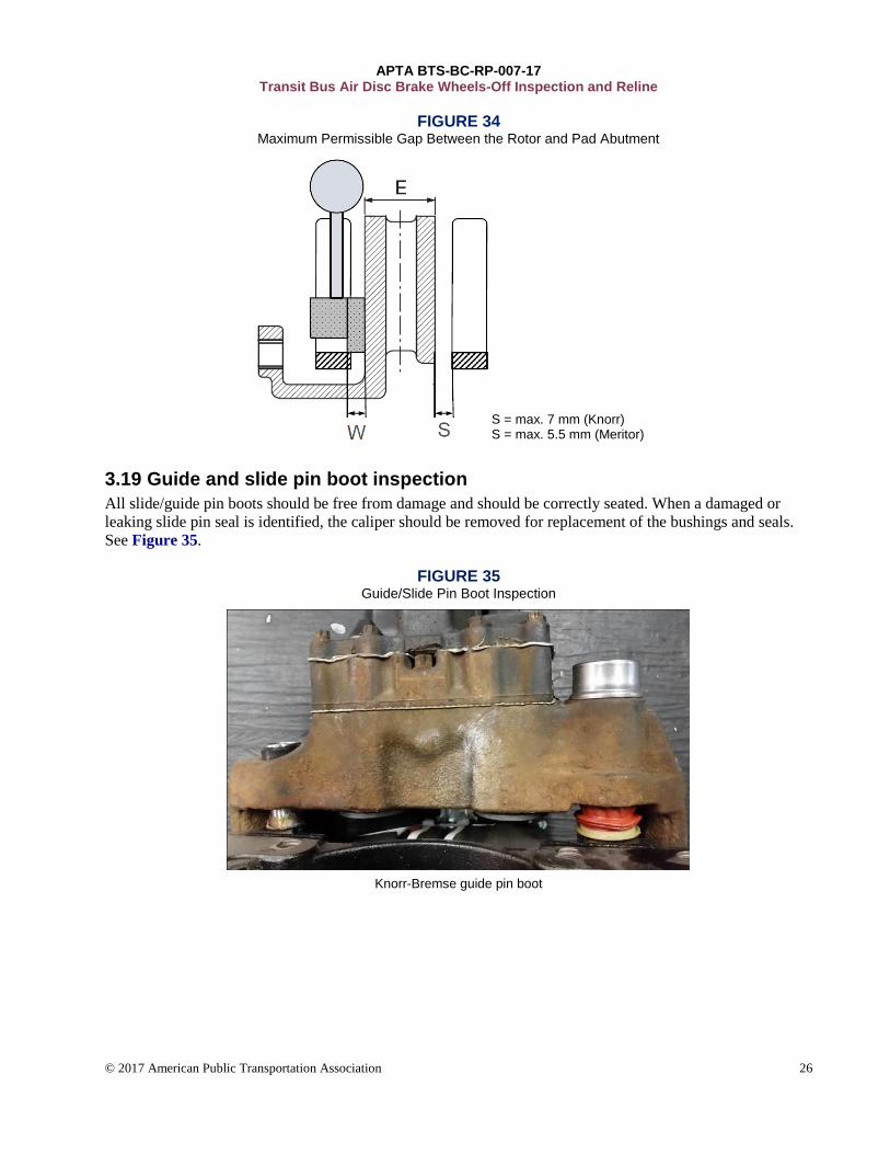
FIGURE 34
Maximum Permissible Gap Between the Rotor and Pad Abutment
S = max. 7 mm (Knorr) S = max. 5.5 mm (Meritor)
3.19 Guide and slide pin boot inspection
All slide/guide pin boots should be free from damage and should be correctly seated. When a damaged or
leaking slide pin seal is identified, the caliper should be removed for replacement of the bushings and seals.
See Figure 35.
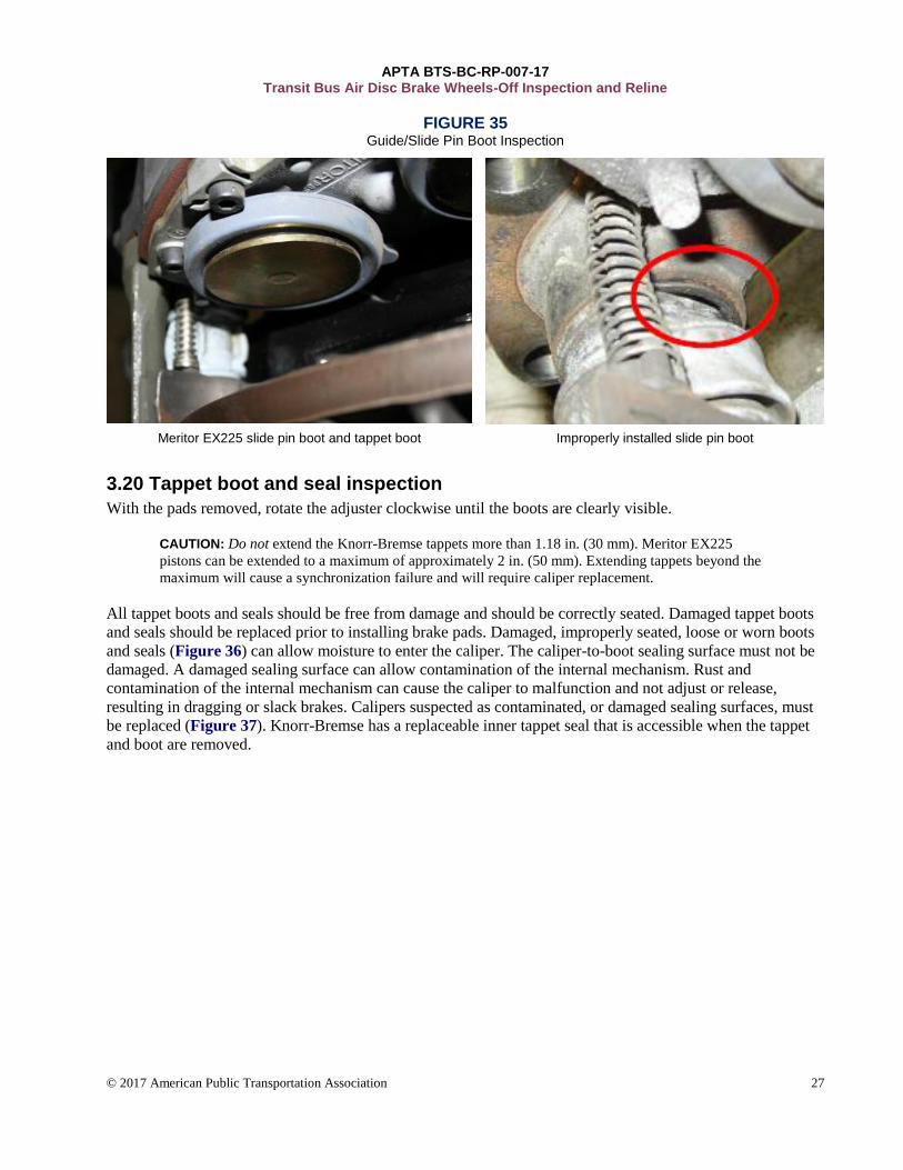
FIGURE 35 Guide/Slide Pin Boot Inspection
Knorr-Bremse guide pin boot
APTA BTS-BC-RP-007-17 Transit Bus Air Disc Brake Wheels-Off Inspection and Reline
© 2017 American Public Transportation Association 27
FIGURE 35 Guide/Slide Pin Boot Inspection
Meritor EX225 slide pin boot and tappet boot Improperly installed slide pin boot
3.20 Tappet boot and seal inspection
With the pads removed, rotate the adjuster clockwise until the boots are clearly visible.
CAUTION: Do not extend the Knorr-Bremse tappets more than 1.18 in. (30 mm). Meritor EX225
pistons can be extended to a maximum of approximately 2 in. (50 mm). Extending tappets beyond the
maximum will cause a synchronization failure and will require caliper replacement.
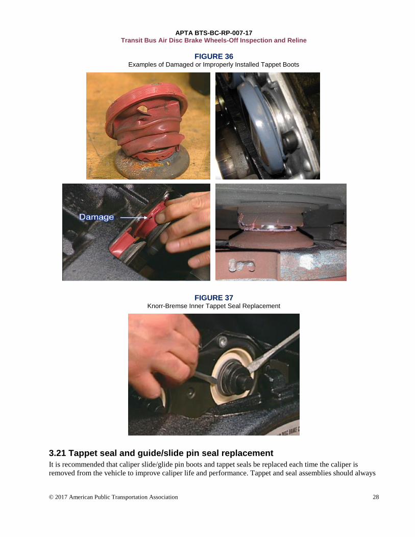
All tappet boots and seals should be free from damage and should be correctly seated. Damaged tappet boots
and seals should be replaced prior to installing brake pads. Damaged, improperly seated, loose or worn boots
and seals (Figure 36) can allow moisture to enter the caliper. The caliper-to-boot sealing surface must not be
damaged. A damaged sealing surface can allow contamination of the internal mechanism. Rust and
contamination of the internal mechanism can cause the caliper to malfunction and not adjust or release,
resulting in dragging or slack brakes. Calipers suspected as contaminated, or damaged sealing surfaces, must
be replaced (Figure 37). Knorr-Bremse has a replaceable inner tappet seal that is accessible when the tappet
and boot are removed.
APTA BTS-BC-RP-007-17 Transit Bus Air Disc Brake Wheels-Off Inspection and Reline
© 2017 American Public Transportation Association 28
FIGURE 36 Examples of Damaged or Improperly Installed Tappet Boots
FIGURE 37 Knorr-Bremse Inner Tappet Seal Replacement
3.21 Tappet seal and guide/slide pin seal replacement
It is recommended that caliper slide/glide pin boots and tappet seals be replaced each time the caliper is
removed from the vehicle to improve caliper life and performance. Tappet and seal assemblies should always
APTA BTS-BC-RP-007-17 Transit Bus Air Disc Brake Wheels-Off Inspection and Reline
© 2017 American Public Transportation Association 29
be replaced as a set. Replace inner tappet seals on Knorr-Bremse calipers whenever tappets and outer seal
assemblies are replaced.
To optimize caliper life, consider proactive preventive replacement of tappet seals and boots.
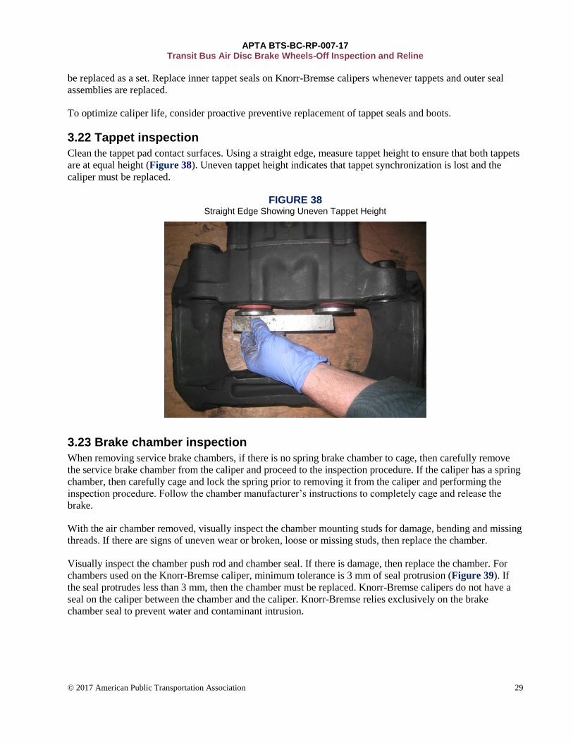
3.22 Tappet inspection
Clean the tappet pad contact surfaces. Using a straight edge, measure tappet height to ensure that both tappets
are at equal height (Figure 38). Uneven tappet height indicates that tappet synchronization is lost and the
caliper must be replaced.
FIGURE 38 Straight Edge Showing Uneven Tappet Height
3.23 Brake chamber inspection
When removing service brake chambers, if there is no spring brake chamber to cage, then carefully remove
the service brake chamber from the caliper and proceed to the inspection procedure. If the caliper has a spring
chamber, then carefully cage and lock the spring prior to removing it from the caliper and performing the
inspection procedure. Follow the chamber manufacturer’s instructions to completely cage and release the
brake.
With the air chamber removed, visually inspect the chamber mounting studs for damage, bending and missing
threads. If there are signs of uneven wear or broken, loose or missing studs, then replace the chamber.
Visually inspect the chamber push rod and chamber seal. If there is damage, then replace the chamber. For
chambers used on the Knorr-Bremse caliper, minimum tolerance is 3 mm of seal protrusion (Figure 39). If
the seal protrudes less than 3 mm, then the chamber must be replaced. Knorr-Bremse calipers do not have a
seal on the caliper between the chamber and the caliper. Knorr-Bremse relies exclusively on the brake
chamber seal to prevent water and contaminant intrusion.
APTA BTS-BC-RP-007-17 Transit Bus Air Disc Brake Wheels-Off Inspection and Reline
© 2017 American Public Transportation Association 30
FIGURE 39 Brake Chamber Seal Protrusion
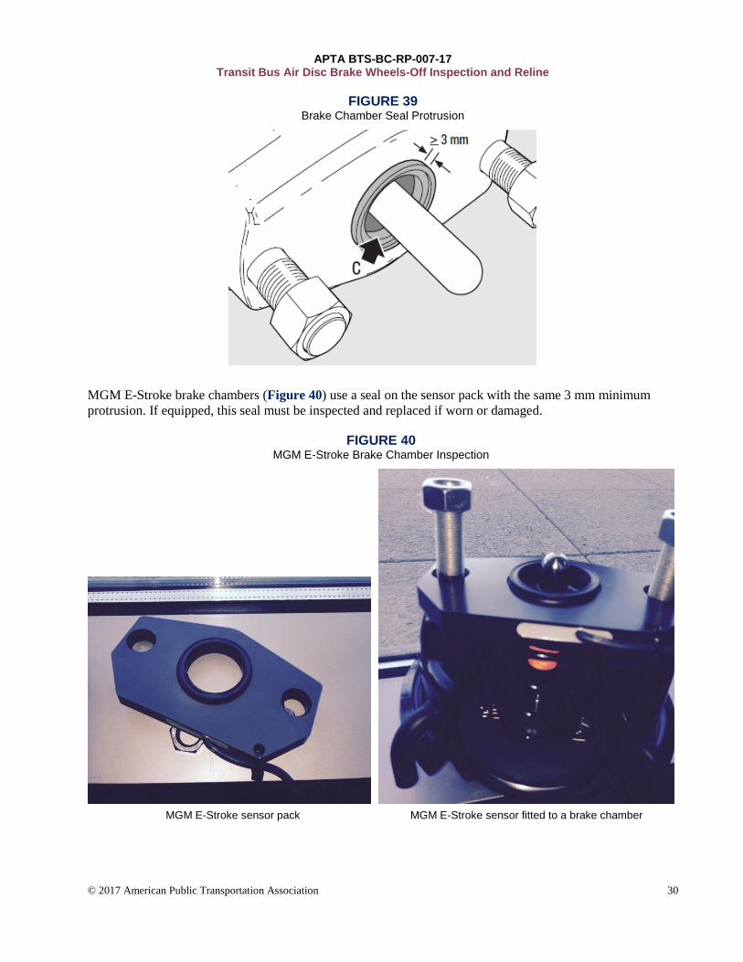
MGM E-Stroke brake chambers (Figure 40) use a seal on the sensor pack with the same 3 mm minimum
protrusion. If equipped, this seal must be inspected and replaced if worn or damaged.
FIGURE 40
MGM E-Stroke Brake Chamber Inspection
MGM E-Stroke sensor pack MGM E-Stroke sensor fitted to a brake chamber
APTA BTS-BC-RP-007-17 Transit Bus Air Disc Brake Wheels-Off Inspection and Reline
© 2017 American Public Transportation Association 31
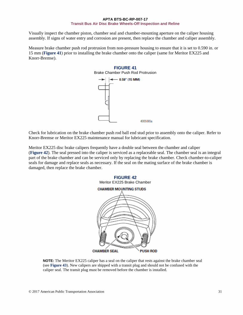
Visually inspect the chamber piston, chamber seal and chamber-mounting aperture on the caliper housing
assembly. If signs of water entry and corrosion are present, then replace the chamber and caliper assembly.
Measure brake chamber push rod protrusion from non-pressure housing to ensure that it is set to 0.590 in. or
15 mm (Figure 41) prior to installing the brake chamber onto the caliper (same for Meritor EX225 and
Knorr-Bremse).
FIGURE 41 Brake Chamber Push Rod Protrusion
Check for lubrication on the brake chamber push rod ball end stud prior to assembly onto the caliper. Refer to
Knorr-Bremse or Meritor EX225 maintenance manual for lubricant specification.
Meritor EX225 disc brake calipers frequently have a double seal between the chamber and caliper
(Figure 42). The seal pressed into the caliper is serviced as a replaceable seal. The chamber seal is an integral
part of the brake chamber and can be serviced only by replacing the brake chamber. Check chamber-to-caliper
seals for damage and replace seals as necessary. If the seal on the mating surface of the brake chamber is
damaged, then replace the brake chamber.
FIGURE 42 Meritor EX225 Brake Chamber
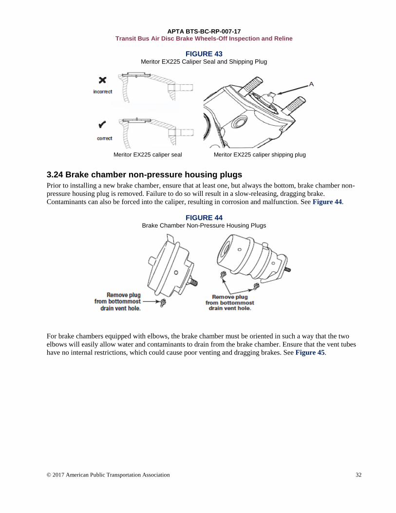
NOTE: The Meritor EX225 caliper has a seal on the caliper that rests against the brake chamber seal
(see Figure 43). New calipers are shipped with a transit plug and should not be confused with the
caliper seal. The transit plug must be removed before the chamber is installed.
APTA BTS-BC-RP-007-17 Transit Bus Air Disc Brake Wheels-Off Inspection and Reline
© 2017 American Public Transportation Association 32
FIGURE 43 Meritor EX225 Caliper Seal and Shipping Plug
Meritor EX225 caliper seal Meritor EX225 caliper shipping plug
3.24 Brake chamber non-pressure housing plugs
Prior to installing a new brake chamber, ensure that at least one, but always the bottom, brake chamber non-
pressure housing plug is removed. Failure to do so will result in a slow-releasing, dragging brake.
Contaminants can also be forced into the caliper, resulting in corrosion and malfunction. See Figure 44.
FIGURE 44 Brake Chamber Non-Pressure Housing Plugs
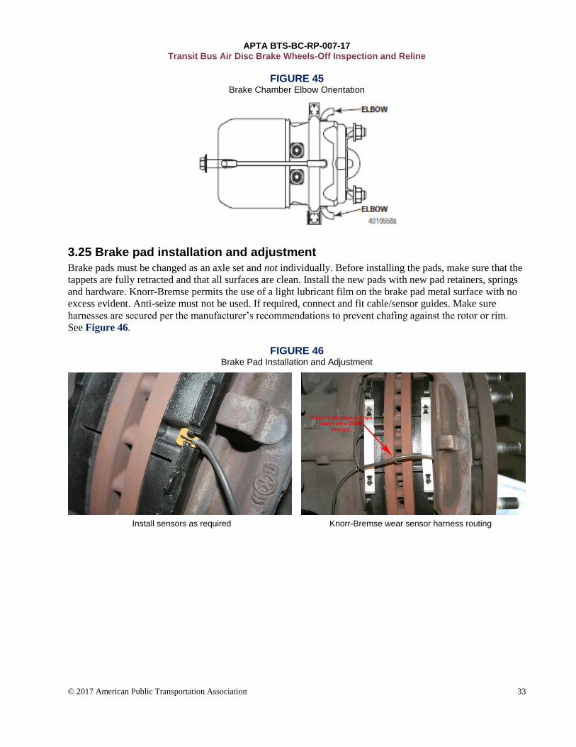
For brake chambers equipped with elbows, the brake chamber must be oriented in such a way that the two
elbows will easily allow water and contaminants to drain from the brake chamber. Ensure that the vent tubes
have no internal restrictions, which could cause poor venting and dragging brakes. See Figure 45.
APTA BTS-BC-RP-007-17 Transit Bus Air Disc Brake Wheels-Off Inspection and Reline
© 2017 American Public Transportation Association 33
FIGURE 45 Brake Chamber Elbow Orientation
3.25 Brake pad installation and adjustment
Brake pads must be changed as an axle set and not individually. Before installing the pads, make sure that the
tappets are fully retracted and that all surfaces are clean. Install the new pads with new pad retainers, springs
and hardware. Knorr-Bremse permits the use of a light lubricant film on the brake pad metal surface with no
excess evident. Anti-seize must not be used. If required, connect and fit cable/sensor guides. Make sure
harnesses are secured per the manufacturer’s recommendations to prevent chafing against the rotor or rim.
See Figure 46.
FIGURE 46 Brake Pad Installation and Adjustment
Install sensors as required Knorr-Bremse wear sensor harness routing
APTA BTS-BC-RP-007-17 Transit Bus Air Disc Brake Wheels-Off Inspection and Reline
© 2017 American Public Transportation Association 34
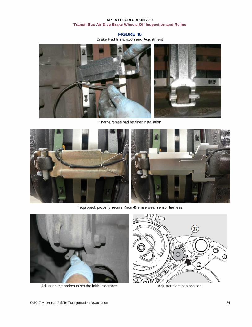
FIGURE 46 Brake Pad Installation and Adjustment
Knorr-Bremse pad retainer installation
If equipped, properly secure Knorr-Bremse wear sensor harness.
Adjusting the brakes to set the initial clearance Adjuster stem cap position
APTA BTS-BC-RP-007-17 Transit Bus Air Disc Brake Wheels-Off Inspection and Reline
© 2017 American Public Transportation Association 35
For Knorr-Bremse calipers, turn the shear adapter clockwise until the pads come in contact with the rotor.
Then back off the adjuster three clicks and check the running clearance. Clearance should be between 0.024
and 0.043 in. (0.6 and 1.2 mm). Apply and release the brake, making sure the hub turns easily by hand. Put a
small amount of grease in the adjuster stem sealing cap and install, noting the orientation of the tab.
To set the initial running clearance on Meritor EX225 calipers, use a 10 mm socket and turn the adjuster
clockwise until both pads contact the rotor. Turn the adjuster back one half-turn to create a running clearance.
Apply the brakes five times to set the correct running clearance. Check that the rotor is free to turn and
confirm that the brake-pad-to-rotor clearance is within specification. Nominal total pad-to-rotor clearance
should be 0.030 in. (0.75 mm). Install the adjuster stem cap.
Complete a final visual inspection. Install tires, follow brake pad manufacturer’s brake pad break-in
recommendations, and perform a brake performance test to verify satisfactory operation of the brakes.
APTA BTS-BC-RP-007-17 Transit Bus Air Disc Brake Wheels-Off Inspection and Reline
© 2017 American Public Transportation Association 36
Related APTA standards APTA BTS-BC-RP-006-17, Transit Bus Air Disc Brake Operation and Wheels-On Inspection
References
This Recommended Practice is to be used in conjunction with the OEM and disc brake manufacturer service
manuals.
Definitions
disc brake assembly: Consists of the brake pads, rotor and caliper assembly.
These terms are interchangeable:
• brake pad: friction material, brake lining
• bearing cups: bearing races
• brake chamber: air chamber
• machining: turning, reboring, grinding, sanding and cutting of components
Abbreviations and acronyms
CCOHS Canadian Centre for Occupational Health and Safety
EBM electronic brake monitoring
ECU electronic control unit
ft-lbs foot-pounds
HEPA high-efficiency particulate air
MSDS material safety data sheet
MSHA Mine Safety and Health Administration
NACVSA North American Commercial Vehicle Safety Alliance
NATSA North American Transportation Services Association
Nm Newton-meters
NIOSH National Institute for Occupational Safety and Health
OEM original equipment manufacturer
OSHA Occupational Safety and Health Administration
psi pounds per square inch
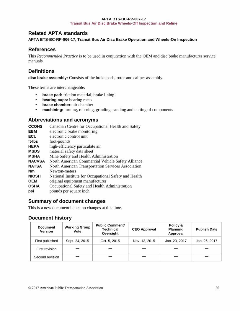
Summary of document changes
This is a new document hence no changes at this time.
Document history
Document Version
Working Group Vote
Public Comment/ Technical Oversight
CEO Approval Policy & Planning Approval
Publish Date
First published Sept. 24, 2015 Oct. 5, 2015 Nov. 13, 2015 Jan. 23, 2017 Jan. 26, 2017
First revision — — — — —
Second revision — — — — —