Embed Size (px)
Citation preview
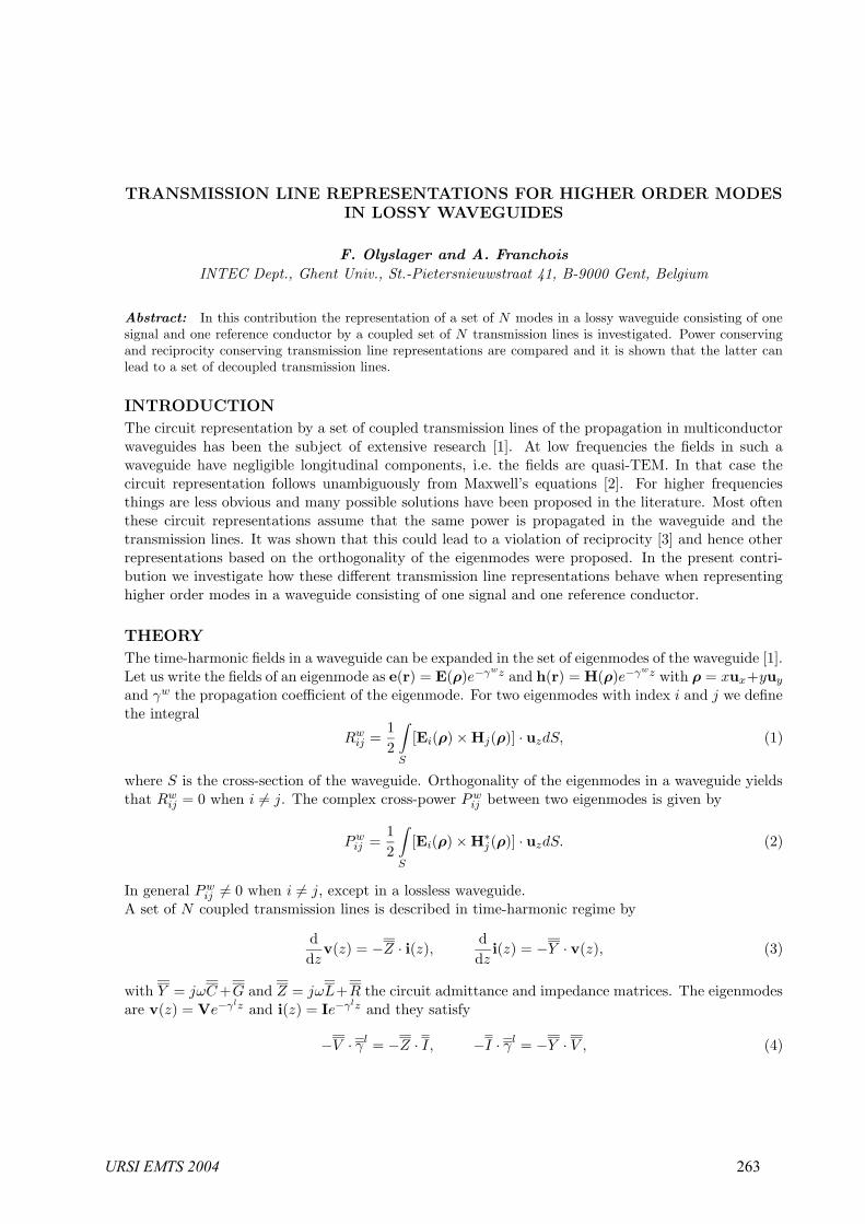
TRANSMISSION LINE REPRESENTATIONS FOR HIGHER ORDER MODESIN LOSSY WAVEGUIDES
F. Olyslager and A. Franchois
INTEC Dept., Ghent Univ., St.-Pietersnieuwstraat 41, B-9000 Gent, Belgium
Abstract: In this contribution the representation of a set of N modes in a lossy waveguide consisting of onesignal and one reference conductor by a coupled set of N transmission lines is investigated. Power conservingand reciprocity conserving transmission line representations are compared and it is shown that the latter canlead to a set of decoupled transmission lines.
INTRODUCTION
The circuit representation by a set of coupled transmission lines of the propagation in multiconductorwaveguides has been the subject of extensive research [1]. At low frequencies the fields in such awaveguide have negligible longitudinal components, i.e. the fields are quasi-TEM. In that case thecircuit representation follows unambiguously from Maxwell’s equations [2]. For higher frequenciesthings are less obvious and many possible solutions have been proposed in the literature. Most oftenthese circuit representations assume that the same power is propagated in the waveguide and thetransmission lines. It was shown that this could lead to a violation of reciprocity [3] and hence otherrepresentations based on the orthogonality of the eigenmodes were proposed. In the present contri-bution we investigate how these different transmission line representations behave when representinghigher order modes in a waveguide consisting of one signal and one reference conductor.
THEORY
The time-harmonic fields in a waveguide can be expanded in the set of eigenmodes of the waveguide [1].Let us write the fields of an eigenmode as e(r) = E(ρ)e−γwz and h(r) = H(ρ)e−γwz with ρ = xux+yuy
and γw the propagation coefficient of the eigenmode. For two eigenmodes with index i and j we definethe integral
Rwij =
12
∫
S
[Ei(ρ) × Hj(ρ)] · uzdS, (1)
where S is the cross-section of the waveguide. Orthogonality of the eigenmodes in a waveguide yieldsthat Rw
ij = 0 when i = j. The complex cross-power P wij between two eigenmodes is given by
Pwij =
12
∫
S
[Ei(ρ) × H∗j (ρ)] · uzdS. (2)
In general Pwij = 0 when i = j, except in a lossless waveguide.
A set of N coupled transmission lines is described in time-harmonic regime by
ddz
v(z) = −Z · i(z),ddz
i(z) = −Y · v(z), (3)
with Y = jωC +G and Z = jωL+R the circuit admittance and impedance matrices. The eigenmodesare v(z) = Ve−γlz and i(z) = Ie−γlz and they satisfy
−V · γl = −Z · I, −I · γl = −Y · V , (4)
URSI EMTS 2004 263
where V and I group the modal currents Ii and voltages Vi, i = 1, 2, ..., N , columnwise and where γl
is a diagonal matrix with the corresponding propagation coefficients. The matrix Rl= V
T · I/2 is di-
agonal due to orthogonality and the cross-power matrix Pl= V
T ·I∗/2 is only diagonal in lossless cases.
We will now derive expressions for the transmission line parameters Y and Z as a function of themodal fields in the waveguide. In order that waves in both the waveguide and the transmission linehave the same velocity we demand that γ
l = γw. In power based transmission line representations we
also demand that Pl= P
w. These two constraints give rise to the following expressions for Y and Z
Y =12I · γw · [(Pw
)T ]−1 · IT∗, Z = 2(I
T∗)−1 · (Pw
)T · γw · I−1, (5)
where I still needs to be determined. In general the matrices Y and Z will not be symmetric meaningthat the transmission line is non-reciprocal whereas the waveguide consists only of reciprocal materials.
In order to avoid this discrepancy it was suggested in [3] to replace Pl= P
wby R
l= R
wresulting in
reciprocity based transmission line representations with symmetric Y and Z given by
Y =12I · γw · [(Rw
)T ]−1 · IT, Z = 2(I
T)−1 · (Rw
)T · γw · I−1. (6)
In a multiconductor waveguide with N signal conductors it is obvious how to define I in current basedtransmission line models, see e.g. [3]. However, it is not clear how to define the elements of I whenthere is only one signal conductor. We can still demand that the total current on the signal conductorin the waveguide is equal to the sum of all the currents on all the lines in the transmission line, i.e.
N∑j=1
Iij =∮
c
Hi(ρ) · dl, (7)
where c is the boundary of the signal conductor. This assumes that at the load and generator of the setof coupled transmission lines all the signal conductors are connected with each other. Obviously (7)defines only N conditions on I, leaving many degrees of freedom. One choice is to make I a diagonalmatrix such that
Iii =∮
c
Hi(ρ) · dl. (8)
From (6) it then follows that Y and Z are diagonal matrices, i.e. that the set of transmission linesbecomes a decoupled set of equations. Note that Y and Z following from (5) will not be diagonal.
NUMERICAL EXAMPLE
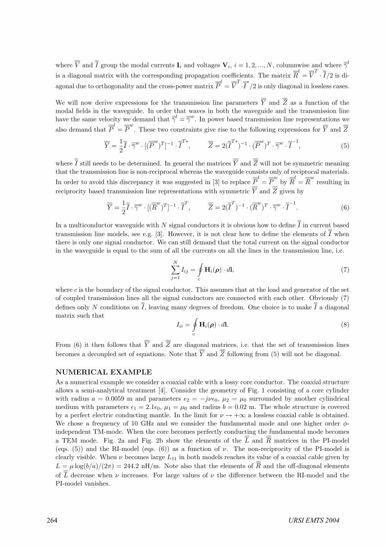
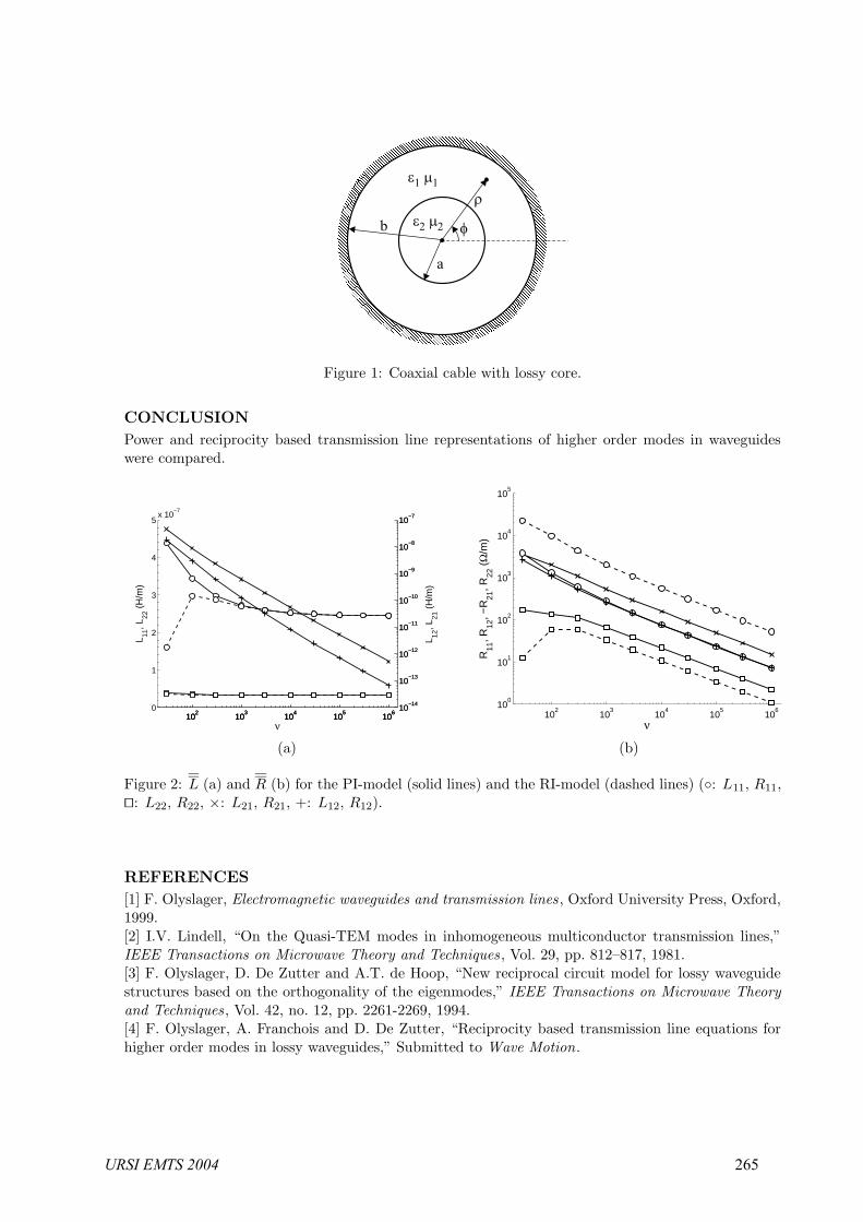
As a numerical example we consider a coaxial cable with a lossy core conductor. The coaxial structureallows a semi-analytical treatment [4]. Consider the geometry of Fig. 1 consisting of a core cylinderwith radius a = 0.0059 m and parameters ε2 = −jνε0, µ2 = µ0 surrounded by another cylindricalmedium with parameters ε1 = 2.1ε0, µ1 = µ0 and radius b = 0.02 m. The whole structure is coveredby a perfect electric conducting mantle. In the limit for ν → +∞ a lossless coaxial cable is obtained.We chose a frequency of 10 GHz and we consider the fundamental mode and one higher order φ-independent TM-mode. When the core becomes perfectly conducting the fundamental mode becomesa TEM mode. Fig. 2a and Fig. 2b show the elements of the L and R matrices in the PI-model(eqs. (5)) and the RI-model (eqs. (6)) as a function of ν. The non-reciprocity of the PI-model isclearly visible. When ν becomes large L11 in both models reaches its value of a coaxial cable given byL = µ log(b/a)/(2π) = 244.2 nH/m. Note also that the elements of R and the off-diagonal elementsof L decrease when ν increases. For large values of ν the difference between the RI-model and thePI-model vanishes.
264 URSI EMTS 2004
b
a
Figure 1: Coaxial cable with lossy core.
CONCLUSION
Power and reciprocity based transmission line representations of higher order modes in waveguideswere compared.
102
103
104
105
106
0
1
2
3
4
5x 10
−7
L 11, L
22 (
H/m
)
102
103
104
105
106
10−14
10−13
10−12
10−11
10−10
10−9
10−8
10−7
102
103
104
105
106
10−14
10−13
10−12
10−11
10−10
10−9
10−8
10−7
ν
L 12, L
21 (
H/m
)
102
103
104
105
106
100
101
102
103
104
105
R11
, R12
, −R
21, R
22 (
Ω/m
)
ν
(a) (b)
Figure 2: L (a) and R (b) for the PI-model (solid lines) and the RI-model (dashed lines) (: L11, R11,: L22, R22, ×: L21, R21, +: L12, R12).
REFERENCES
[1] F. Olyslager, Electromagnetic waveguides and transmission lines , Oxford University Press, Oxford,1999.[2] I.V. Lindell, “On the Quasi-TEM modes in inhomogeneous multiconductor transmission lines,”IEEE Transactions on Microwave Theory and Techniques , Vol. 29, pp. 812–817, 1981.[3] F. Olyslager, D. De Zutter and A.T. de Hoop, “New reciprocal circuit model for lossy waveguidestructures based on the orthogonality of the eigenmodes,” IEEE Transactions on Microwave Theoryand Techniques, Vol. 42, no. 12, pp. 2261-2269, 1994.[4] F. Olyslager, A. Franchois and D. De Zutter, “Reciprocity based transmission line equations forhigher order modes in lossy waveguides,” Submitted to Wave Motion.
URSI EMTS 2004 265