Embed Size (px)
Citation preview

R
Traverse Hardware Installation and Commissioning Guide TR5.0.x October 2011

Copyright © 2011 Force10 Networks, Inc.
All rights reserved. Force10 Networks ® reserves the right to change, modify, revise this publication without notice.
Trademarks
Force10 Networks® and E-Series® are registered trademarks of Force10 Networks, Inc.
Traverse, TraverseEdge, TraversePacketEdge, TransAccess, are registered trademarks of Force10 Networks, Inc. Force10, the Force10 logo, and TransNav are trademarks of Force10 Networks, Inc. or its affiliates in the United States and other countries and are protected by U.S. and international copyright laws. All other brand and product names are registered trademarks or trademarks of their respective holders.
Statement of Conditions
In the interest of improving internal design, operational function, and/or reliability, Force10 Networks, Inc. reserves the right to make changes to products described in this document without notice. Force10 Networks, Inc. does not assume any liability that may occur due to the use or application of the product(s) described herein.
CONTENTS
Chapter 1Installation and Commissioning Overview
Traverse Installation Process . . . . . . . . . . . . . . . . . . . . . . . . . . . . . . . . . . . . . 1
Traverse Shelf Interface Specifications . . . . . . . . . . . . . . . . . . . . . . . . . . . . . 2
Traverse System Rack Installation. . . . . . . . . . . . . . . . . . . . . . . . . . . . . . . . . 2
Required Equipment and Tools . . . . . . . . . . . . . . . . . . . . . . . . . . . . . . . . . . . 2
Traverse Shelf Back Covers. . . . . . . . . . . . . . . . . . . . . . . . . . . . . . . . . . . . . . 4
Grounding the Shelf and Fan Tray Holder . . . . . . . . . . . . . . . . . . . . . . . . . . . 4
Traverse System Rack Hardware Installation Process . . . . . . . . . . . . . . . . . 5
Chapter 2Traverse System Configuration Examples
Traverse System Configuration Example. . . . . . . . . . . . . . . . . . . . . . . . . . . . 8
Example Traverse Shelf Card Layout . . . . . . . . . . . . . . . . . . . . . . . . . . . . . . 9
Chapter 3Precautions to Installing Traverse Equipment
Environmental Precautions . . . . . . . . . . . . . . . . . . . . . . . . . . . . . . . . . . . . . . 12
Hardware Installation Precautions . . . . . . . . . . . . . . . . . . . . . . . . . . . . . . . . . 13
Electrical Precautions. . . . . . . . . . . . . . . . . . . . . . . . . . . . . . . . . . . . . . . . . . . 14
Fiber Optic Cabling Precautions. . . . . . . . . . . . . . . . . . . . . . . . . . . . . . . . . . . 15
Card Precautions . . . . . . . . . . . . . . . . . . . . . . . . . . . . . . . . . . . . . . . . . . . . . . 16
Electrostatic Discharge Protection . . . . . . . . . . . . . . . . . . . . . . . . . . . . . . . . . 17
ESD Jack Locations . . . . . . . . . . . . . . . . . . . . . . . . . . . . . . . . . . . . . . . . . . . . 18
Chapter 4Removing and Replacing Back Covers
Required Equipment and Tools . . . . . . . . . . . . . . . . . . . . . . . . . . . . . . . . . . . 21
Main Backplane Covers . . . . . . . . . . . . . . . . . . . . . . . . . . . . . . . . . . . . . . . . . 21
Remove and Replace the Fiber Optic Management Tray Cover . . . . . . . . . . 23
Remove and Replace the Fiber Management Tray Cover. . . . . . . . . . . . . . . 23
Remove and Replace the Traverse 600 Fiber Management Tray Cover. . . . 24
Remove the PDAP Protective Back Cover. . . . . . . . . . . . . . . . . . . . . . . . . . . 26
Replace the PDAP Protective Back Cover. . . . . . . . . . . . . . . . . . . . . . . . . . . 26
Chapter 5Inserting and Removing Cards
Required Equipment and Tools . . . . . . . . . . . . . . . . . . . . . . . . . . . . . . . . . . . 27
Clean Fiber Optic MPX Connectors . . . . . . . . . . . . . . . . . . . . . . . . . . . . . . . . 28
Insert a Card. . . . . . . . . . . . . . . . . . . . . . . . . . . . . . . . . . . . . . . . . . . . . . . . . . 31
Remove a Card . . . . . . . . . . . . . . . . . . . . . . . . . . . . . . . . . . . . . . . . . . . . . . . 36
Chapter 6Insert Fan Module and Air Filters
Traverse Hardware Installation and Commissioning Guide, Release TR4.0.x 1
Required Equipment and Tools . . . . . . . . . . . . . . . . . . . . . . . . . . . . . . . . . . . 37
Insert a Traverse 1600 and Traverse 2000 Fan Assembly. . . . . . . . . . . . . . . 38
Insert a Traverse 1600 and Traverse 2000 Fan Air Filter . . . . . . . . . . . . . . . . 39
Insert a Traverse 600 Fan Assembly . . . . . . . . . . . . . . . . . . . . . . . . . . . . . . . 40
Insert a Traverse 600 Fan Air Filter . . . . . . . . . . . . . . . . . . . . . . . . . . . . . . . . 43
Chapter 7Traverse System Hardware Installation
Install the Rack Adapters . . . . . . . . . . . . . . . . . . . . . . . . . . . . . . . . . . . . . . . . 46
Install the Traverse Shelf . . . . . . . . . . . . . . . . . . . . . . . . . . . . . . . . . . . . . . . . 47
Flush Mount a Traverse Shelf. . . . . . . . . . . . . . . . . . . . . . . . . . . . . . . . . . . . . 48
Install the Front Inlet Fan Tray Holder . . . . . . . . . . . . . . . . . . . . . . . . . . . . . . 49
Install the Fan Tray Holder with Separate Air Ramp. . . . . . . . . . . . . . . . . . . . 50
Install the Air Ramp . . . . . . . . . . . . . . . . . . . . . . . . . . . . . . . . . . . . . . . . . . . . 52
Chapter 8Traverse 2000 Installation into a 19-inch Rack
Vertical Traverse 2000 Rack Configuration . . . . . . . . . . . . . . . . . . . . . . . . . . 56
Install the Horizontal Rack Adapter Brackets . . . . . . . . . . . . . . . . . . . . . . . . . 58
Install the Front Inlet Fan Tray Holder in a 19-inch Rack . . . . . . . . . . . . . . . . 59
Install a Traverse 2000 in a 19-inch Rack. . . . . . . . . . . . . . . . . . . . . . . . . . . . 61
Chapter 9Power System Overview
Power Distribution and Alarm Panel (PDAP) Description . . . . . . . . . . . . . . . . 63
PDAP Installation and Cabling Process . . . . . . . . . . . . . . . . . . . . . . . . . . . . . 64
Chapter 10Power System Hardware Installation
Required Equipment and Tools . . . . . . . . . . . . . . . . . . . . . . . . . . . . . . . . . . . 65
Power System Installation. . . . . . . . . . . . . . . . . . . . . . . . . . . . . . . . . . . . . . . . 66
Grounding the PDAP . . . . . . . . . . . . . . . . . . . . . . . . . . . . . . . . . . . . . . . . . . . 68
Chapter 11Battery and Battery Return Distribution
Required Equipment and Tools . . . . . . . . . . . . . . . . . . . . . . . . . . . . . . . . . . . 69
Battery and Battery Return Distribution Cabling Procedures . . . . . . . . . . . . . 71
Connect PDAP-4S Battery Distribution Cables. . . . . . . . . . . . . . . . . . . . . . . . 71
Connect PDAP-4S Battery Return Distribution Cables. . . . . . . . . . . . . . . . . . 74
Connect PDAP-15A Battery Distribution Cables. . . . . . . . . . . . . . . . . . . . . . . 77
Connect PDAP-15A Battery Return Distribution Cables. . . . . . . . . . . . . . . . . 79
Chapter 12Battery and Battery Return Supply
Required Equipment and Tools . . . . . . . . . . . . . . . . . . . . . . . . . . . . . . . . . . . 84
Connect Battery Supply Cables to the PDAP . . . . . . . . . . . . . . . . . . . . . . . . . 85
Connect Battery Return Supply Cables to the PDAP . . . . . . . . . . . . . . . . . . . 87
Connect Supply Cables to the Central Office Source. . . . . . . . . . . . . . . . . . . 89
Verify Polarity . . . . . . . . . . . . . . . . . . . . . . . . . . . . . . . . . . . . . . . . . . . . . . . . . 91
2 Traverse Hardware Installation and Commissioning Guide, Release TR4.0.x

Verify Voltage . . . . . . . . . . . . . . . . . . . . . . . . . . . . . . . . . . . . . . . . . . . . . . . . . 92
Chapter 13Traverse Node Start-up and Commissioning
Before You Begin . . . . . . . . . . . . . . . . . . . . . . . . . . . . . . . . . . . . . . . . . . . . . . 93
Required Node Commissioning Parameters . . . . . . . . . . . . . . . . . . . . . . . . . 96
Conditional Node Commissioning Parameters. . . . . . . . . . . . . . . . . . . . . . . . 98
Commissioning Process. . . . . . . . . . . . . . . . . . . . . . . . . . . . . . . . . . . . . . . . . 100
Insert the Active GCM . . . . . . . . . . . . . . . . . . . . . . . . . . . . . . . . . . . . . . . . . . 100
Commission the Node . . . . . . . . . . . . . . . . . . . . . . . . . . . . . . . . . . . . . . . . . . 101
Insert the Standby GCM and All Cards in the Traverse Node . . . . . . . . . . . . 104
Visual Status During and After Start-up . . . . . . . . . . . . . . . . . . . . . . . . . . . . . 105
Chapter 14Hardware Installation
Before You Begin . . . . . . . . . . . . . . . . . . . . . . . . . . . . . . . . . . . . . . . . . . . . . . 107
Power Distribution and Alarm Panel (PDAP) Description . . . . . . . . . . . . . . . 108
Power System (PDAP-15A) Installation . . . . . . . . . . . . . . . . . . . . . . . . . . . . . 109
Back Cover. . . . . . . . . . . . . . . . . . . . . . . . . . . . . . . . . . . . . . . . . . . . . . . . . . . 110
Hardware Installation . . . . . . . . . . . . . . . . . . . . . . . . . . . . . . . . . . . . . . . . . . . 110
Grounding the Shelf . . . . . . . . . . . . . . . . . . . . . . . . . . . . . . . . . . . . . . . . . . . . 112
Rack Adapter Installation . . . . . . . . . . . . . . . . . . . . . . . . . . . . . . . . . . . . . . . . 112
Chapter 15Installing the Wall Mount Bracket
Wall Mount Bracket Specifications . . . . . . . . . . . . . . . . . . . . . . . . . . . . . . . . . 113
Attach the Wall Mount Bracket . . . . . . . . . . . . . . . . . . . . . . . . . . . . . . . . . . . . 114
Install the Shelf in the Wall Mount Bracket. . . . . . . . . . . . . . . . . . . . . . . . . . . 115
Chapter 16Installation and Commissioning Checklists
Power System Hardware Installation Checklist . . . . . . . . . . . . . . . . . . . . . . . 118
Traverse System Hardware Installation Checklist . . . . . . . . . . . . . . . . . . . . . 119
Network Cabling Checklist . . . . . . . . . . . . . . . . . . . . . . . . . . . . . . . . . . . . . . . 121
Alarm Cabling Checklist . . . . . . . . . . . . . . . . . . . . . . . . . . . . . . . . . . . . . . . . . 123
Timing and Management Cabling Checklist . . . . . . . . . . . . . . . . . . . . . . . . . . 126
Power Cabling Checklist . . . . . . . . . . . . . . . . . . . . . . . . . . . . . . . . . . . . . . . . 128
Node Start-up and Commissioning Checklist . . . . . . . . . . . . . . . . . . . . . . . . . 131
Traverse Hardware Installation and Commissioning Guide, Release TR4.0.x 3

4 Traverse Hardware Installation and Commissioning Guide, Release TR4.0.x
Chapter 1 Installation and Commissioning Overview
Introduction This chapter includes the following topics:• Traverse Installation Process• Traverse Shelf Interface Specifications• Traverse System Rack Installation
Traverse Installation Process
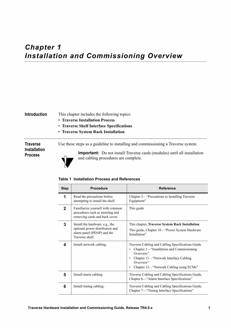
Use these steps as a guideline to installing and commissioning a Traverse system
Important: Do not install Traverse cards (modules) until all installation and cabling procedures are complete.
Table 1 Installation Process and References
Step Procedure Reference
1 Read the precautions before attempting to install the shelf.
Chapter 3—“Precautions to Installing Traverse Equipment”
2 Familiarize yourself with common procedures such as inserting and removing cards and back cover.
This guide
3 Install the hardware, e.g., the optional power distribution and alarm panel (PDAP) and the Traverse shelf.
This chapter, Traverse System Rack Installation
This guide, Chapter 10—“Power System Hardware Installation”
4 Install network cabling. Traverse Cabling and Cabling Specifications Guide• Chapter 1—“Installation and Commissioning
Overview”• Chapter 11—“Network Interface Cabling
Overview”• Chapter 12—“Network Cabling using ECMs”
5 Install alarm cabling. Traverse Cabling and Cabling Specifications Guide, Chapter 6—“Alarm Interface Specifications”
6 Install timing cabling. Traverse Cabling and Cabling Specifications Guide, Chapter 7—“Timing Interface Specifications”
Traverse Hardware Installation and Commissioning Guide, Release TR4.0.x 1
Traverse Shelf Interface Specifications
Traverse shelf interface specifications are in the following chapters:• Network Interface specification chapters• Alarm, Timing, and Management specification chapters • Power Interface specification chapters• Cable Management specification chapters
Traverse System Rack Installation
The Traverse system consists of the following rack hardware installation components: • Traverse shelf• Fan tray holder• Fan tray module• Air ramp (optional equipment, depending on installation need)
This chapter provides the following information, including an instruction guide to the procedures for installing the Traverse system components into a 7-foot (2133.6 mm) high, 19-inch or 23-inch (483 mm or 584 mm) wide telco rack.• Required Equipment and Tools• Traverse Shelf Back Covers• Grounding the Shelf and Fan Tray Holder• Traverse System Rack Hardware Installation Process
Required Equipment and Tools
The following equipment and tools are required to install the Traverse 1600 or Traverse 2000 shelf and front inlet fan tray holder with integrated air ramp into a rack:• Standard 7-foot (2133.6 mm) high, 19-inch or 23-inch (483 mm or 584 mm) wide
telco rack.
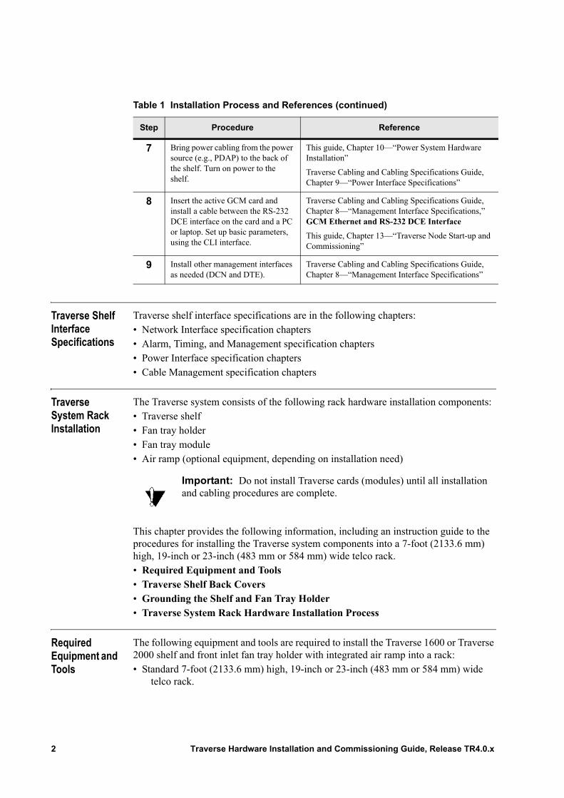
7 Bring power cabling from the power source (e.g., PDAP) to the back of the shelf. Turn on power to the shelf.
This guide, Chapter 10—“Power System Hardware Installation”
Traverse Cabling and Cabling Specifications Guide, Chapter 9—“Power Interface Specifications”
8 Insert the active GCM card and install a cable between the RS-232 DCE interface on the card and a PC or laptop. Set up basic parameters, using the CLI interface.
Traverse Cabling and Cabling Specifications Guide, Chapter 8—“Management Interface Specifications,” GCM Ethernet and RS-232 DCE Interface
This guide, Chapter 13—“Traverse Node Start-up and Commissioning”
9 Install other management interfaces as needed (DCN and DTE).
Traverse Cabling and Cabling Specifications Guide, Chapter 8—“Management Interface Specifications”
Table 1 Installation Process and References (continued)
Step Procedure Reference
Important: Do not install Traverse cards (modules) until all installation and cabling procedures are complete.
2 Traverse Hardware Installation and Commissioning Guide, Release TR4.0.x

• Standard conductive plated rack adapters1 (mounted with thread-forming screws) are required for installing 19-inch (483 mm) wide equipment into a 23-inch (584 mm) wide rack.– (SDH network only) Standard conductive plated rack adapters may be required
for installing the Traverse 1600 and other related equipment into ETSI-specific racks.
• Two horizontal conductive-plated rack adapter brackets (mounted with thread-forming screws) are required for vertical-mount installation of the Traverse 2000 system into a standard 7-foot (2133.6 mm) high, 19-inch (483 mm) wide telco rack.
• Traverse 1600 or Traverse 2000 shelf• Fan tray holder• Air ramp (already integrated with front-inlet fan tray holder type)• Fourteen appropriate-sized (e.g., 12-24) thread-forming screws for securing and
grounding the rack equipment. Torque screws to 65 lbs/in.• A 5/16-inch (8 mm) socket for all thread-forming screws• Electrostatic Discharge (ESD) wrist strap• Stepladder (optional)• A second person to lift and position the Traverse 1600 or Traverse 2000 shelf. The
Traverse 1600 shelf weighs 15 pounds. (6.8 kg.) without cards. The Traverse 2000 shelf weighs 16 pounds (7.2 kg) without cards.
The following other hand tools are required for the remaining installation sections of this manual. Refer to the remaining sections in this manual for further installation details:• Large flat blade screwdriver for backplane covers and electrical connector modules
(ECMs)• Large Phillips screwdriver for the fiber optic maintenance tray cover• Small flat blade screwdriver for network interface ECM Telco cable assemblies• Various wire-wrap, crimping, punchdown, stripping, and cutting tools (as well as
connectors) for network interface cabling (copper and coax) at an intermediate patch panel; for timing cabling (twisted-pair or balun—twisted-pair to coax); for DCN Ethernet and external RS-232 interfaces; and for power cabling.
• A 1/4-inch socket (or nutdriver) for Traverse shelf backplane power terminal connections
• Volt Ohm Meter (VOM) for power cabling• A 5/16-inch (8 mm) and 7/16-inch (11 mm) socket for PDAP-4S power cabling• A Phillips screwdriver and 5/16-inch (8 mm) socket for PDAP-15A power cabling• A 3/8-inch (9 mm) and 9/16-inch (14 mm) socket for PDAP-2S power cabling• Wire brush for removing paint and non-conductive material on the rack.
1 Two 2-Rack Unit (RU) rack adapters are required for Traverse 1600 front inlet fan tray holder 23-inch (600 mm) rack installation. Two 10-RU rack adapters are required for Traverse 1600 shelf 23-inch (600 mm) rack installation. The PDAP, Traverse 1600 shelf, and front inlet fan tray holder can be installed in a 23-inch (600 mm) rack using two 15-RU rack adapters instead of individual rack adapters for each piece of equipment.
Traverse Hardware Installation and Commissioning Guide, Release TR4.0.x 3
Traverse Shelf Back Covers
The Traverse shelf has removable back covers to provide access to the fiber optic backplane, main backplane, and front inlet fan tray holder connector. The covers are easily removed for cabling, but must be replaced during normal operation to ensure proper air flow and electromagnetic interference (EMI) protection. For more information, see Chapter 4—“Removing and Replacing Back Covers.”
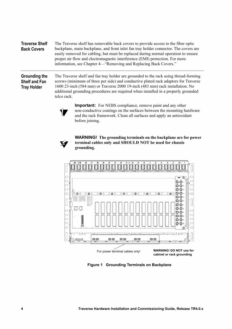
Grounding the Shelf and Fan Tray Holder
The Traverse shelf and fan tray holder are grounded to the rack using thread-forming screws (minimum of three per side) and conductive plated rack adapters for Traverse 1600 23-inch (584 mm) or Traverse 2000 19-inch (483 mm) rack installation. No additional grounding procedures are required when installed in a properly grounded telco rack.
Figure 1 Grounding Terminals on Backplane
Important: For NEBS compliance, remove paint and any other non-conductive coatings on the surfaces between the mounting hardware and the rack framework. Clean all surfaces and apply an antioxidant before joining.
WARNING! The grounding terminals on the backplane are for power terminal cables only and SHOULD NOT be used for chassis grounding.
For power terminal cables only! WARNING! DO NOT use for cabinet or rack grounding
4 Traverse Hardware Installation and Commissioning Guide, Release TR4.0.x
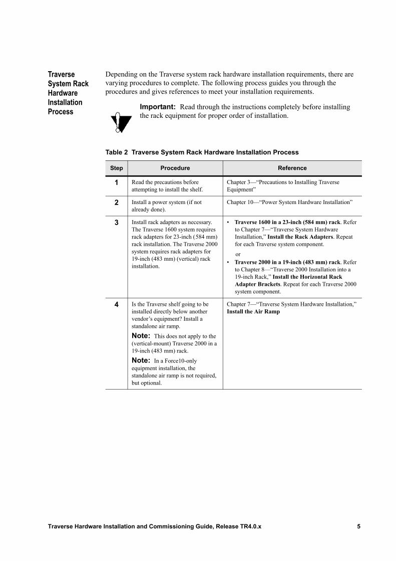
Traverse System Rack Hardware Installation Process
Depending on the Traverse system rack hardware installation requirements, there are varying procedures to complete. The following process guides you through the procedures and gives references to meet your installation requirements.
Important: Read through the instructions completely before installing the rack equipment for proper order of installation.
Table 2 Traverse System Rack Hardware Installation Process
Step Procedure Reference
1 Read the precautions before attempting to install the shelf.
Chapter 3—“Precautions to Installing Traverse Equipment”
2 Install a power system (if not already done).
Chapter 10—“Power System Hardware Installation”
3 Install rack adapters as necessary. The Traverse 1600 system requires rack adapters for 23-inch (584 mm) rack installation. The Traverse 2000 system requires rack adapters for 19-inch (483 mm) (vertical) rack installation.
• Traverse 1600 in a 23-inch (584 mm) rack. Refer to Chapter 7—“Traverse System Hardware Installation,” Install the Rack Adapters. Repeat for each Traverse system component.
or• Traverse 2000 in a 19-inch (483 mm) rack. Refer
to Chapter 8—“Traverse 2000 Installation into a 19-inch Rack,” Install the Horizontal Rack Adapter Brackets. Repeat for each Traverse 2000 system component.
4 Is the Traverse shelf going to be installed directly below another vendor’s equipment? Install a standalone air ramp.
Note: This does not apply to the (vertical-mount) Traverse 2000 in a 19-inch (483 mm) rack.
Note: In a Force10-only equipment installation, the standalone air ramp is not required, but optional.
Chapter 7—“Traverse System Hardware Installation,” Install the Air Ramp
Traverse Hardware Installation and Commissioning Guide, Release TR4.0.x 5
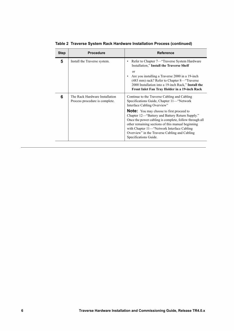
5 Install the Traverse system. • Refer to Chapter 7—“Traverse System Hardware Installation,” Install the Traverse Shelf
or• Are you installing a Traverse 2000 in a 19-inch
(483 mm) rack? Refer to Chapter 8—“Traverse 2000 Installation into a 19-inch Rack,” Install the Front Inlet Fan Tray Holder in a 19-inch Rack
6 The Rack Hardware Installation Process procedure is complete.
Continue to the Traverse Cabling and Cabling Specifications Guide, Chapter 11—“Network Interface Cabling Overview”
Note: You may choose to first proceed to Chapter 12—“Battery and Battery Return Supply.” Once the power cabling is complete, follow through all other remaining sections of this manual beginning with Chapter 11—“Network Interface Cabling Overview” in the Traverse Cabling and Cabling Specifications Guide.
Table 2 Traverse System Rack Hardware Installation Process (continued)
Step Procedure Reference
6 Traverse Hardware Installation and Commissioning Guide, Release TR4.0.x
Chapter 2 Traverse System Configuration Examples
Introduction This chapter includes the following topics:• Traverse System Configuration Example• Example Traverse Shelf Card Layout
Traverse Hardware Installation and Commissioning Guide, Release TR4.0.x 7
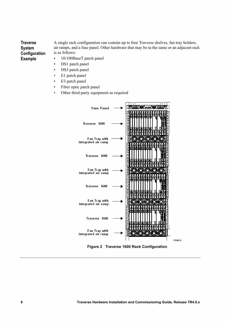
Traverse System Configuration Example
A single rack configuration can contain up to four Traverse shelves, fan tray holders, air ramps, and a fuse panel. Other hardware that may be in the same or an adjacent rack is as follows:• 10/100BaseT patch panel• DS1 patch panel• DS3 patch panel• E1 patch panel• E3 patch panel• Fiber optic patch panel• Other third-party equipment as required
Figure 2 Traverse 1600 Rack Configuration
8 Traverse Hardware Installation and Commissioning Guide, Release TR4.0.x
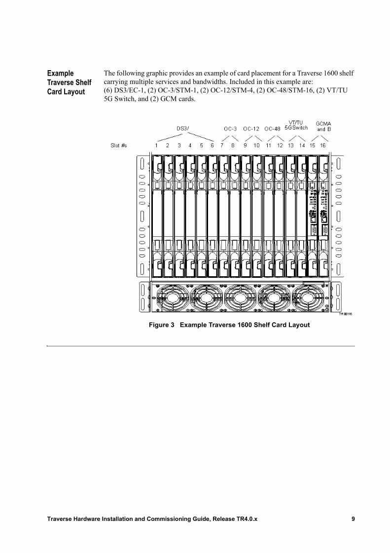
Example Traverse Shelf Card Layout
The following graphic provides an example of card placement for a Traverse 1600 shelf carrying multiple services and bandwidths. Included in this example are: (6) DS3/EC-1, (2) OC-3/STM-1, (2) OC-12/STM-4, (2) OC-48/STM-16, (2) VT/TU 5G Switch, and (2) GCM cards.
Figure 3 Example Traverse 1600 Shelf Card Layout
Traverse Hardware Installation and Commissioning Guide, Release TR4.0.x 9

10 Traverse Hardware Installation and Commissioning Guide, Release TR4.0.x
Chapter 3 Precautions to Installing Traverse Equipment
Introduction This chapter is intended to provide all necessary precautions. Follow these precautions to ensure personal safety and to avoid any equipment damage during installation, configuration, or maintenance procedures. The precautions listed in this chapter relate to the Traverse system, including: Traverse 1600, Traverse 2000, and Traverse 600 shelves unless otherwise noted.• Environmental Precautions• Hardware Installation Precautions• Electrical Precautions• Fiber Optic Cabling Precautions• Card Precautions• Electrostatic Discharge Protection• ESD Jack Locations
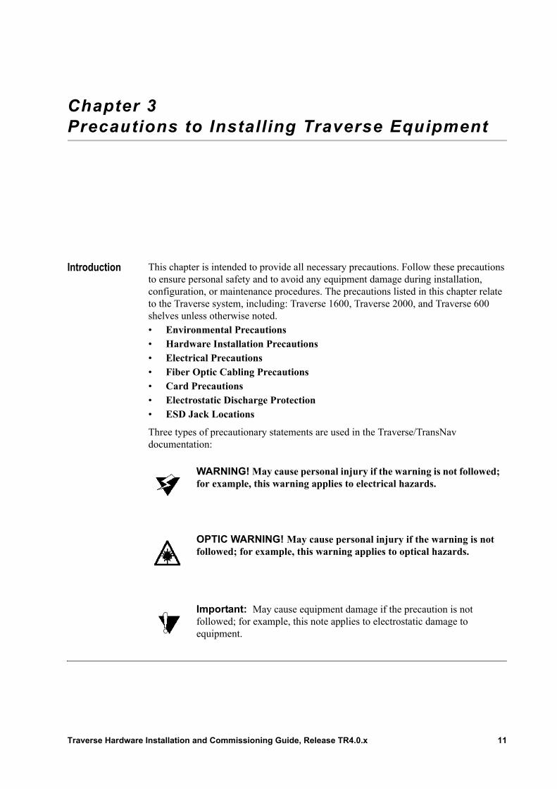
Three types of precautionary statements are used in the Traverse/TransNav documentation:
WARNING! May cause personal injury if the warning is not followed; for example, this warning applies to electrical hazards.
OPTIC WARNING! May cause personal injury if the warning is not followed; for example, this warning applies to optical hazards.
Important: May cause equipment damage if the precaution is not followed; for example, this note applies to electrostatic damage to equipment.
Traverse Hardware Installation and Commissioning Guide, Release TR4.0.x 11

Environmental Precautions Important: Traverse systems are designed to comply with
GR-1089-CORE, GR-63-CORE, and CE Mark requirements. Install and operate the Traverse system in environments that do not expose wiring, cabling, or connectors to the outside plant. Acceptable applications include Central Office Environments (COEs), Electronic Equipment Enclosures (EEEs), Controlled Environment Vaults (CEVs), huts, and customer premises environment.
The Traverse systems are classified as being powered by Class A1 voltages per GR-1089-CORE.
The Traverse system design supports installation in locations with restricted access.
Important: Always use caution while working in an environment with rotating or moving equipment parts (e.g., fan modules).
Important: This symbol is on the product and means do not discard Force10 products into residential or commercial waste.
Most countries or regions have established methods and procedures to collect and recycle electronic and electrical waste. Contact your local authorities for established procedures. If no local procedures are available, contact the Force10 Networks Technical Assistance Center (TAC).
12 Traverse Hardware Installation and Commissioning Guide, Release TR4.0.x
Hardware Installation Precautions
Important: Always use thread-forming screws when installing a Traverse shelf to ensure electrical continuity. This is especially critical when installing equipment in a rack coated with a non-conductive coating.
Important: To ensure proper air flow, 3/8-inch (9.5 mm) of space is required between the Fuse Panel and the first Traverse 1600 or Traverse 2000 shelf in a standard horizontal-mount installation.
Important: Traverse 2000 shelf installation into a 19-inch (483 mm) wide telco rack is a standard-mount only—5 inch (127 mm) forward. A flush-mount configuration is not currently available.
Important: The fan tray holder, with fay tray module and fan filter, must be installed either directly below the Traverse 1600 or Traverse 2000 shelf in a standard horizontal installation or flush with the Traverse 2000 shelf in a 19-inch rack installation (vertical) so that there is no gap between the shelf and fan tray holder to ensure proper air flow.
Important: The Traverse shelf has a removable back cover to provide access to the main and fiber optic backplane and fan tray holder connector. The cover removes easily for cabling, but must be replaced during normal operation to ensure proper air flow and electromagnetic interference (EMI) protection.
Important: If installing a Traverse 2000 shelf vertically, the following requirements must be met to ensure proper airflow: • If the front door is solid, the front of the fan tray must be at least 2
inches (50.8mm) from the inside surface of the front door.– Force10 recommends that the front door be a full mesh screen to
allow air to be drawn into the front of the fan tray. The screen must be cleaned on a regular basis to ensure dust and debris do not impede air flow.
• Vent the rear door of the cabinet to increase airflow.• Vent the top of the cabinet to draw exhaust air from the cabinet.
– Force10 recommends adding an exhaust fan for better cooling.
Traverse Hardware Installation and Commissioning Guide, Release TR4.0.x 13
Electrical Precautions
Important: Carefully plan your power supply capacity. The Force10 PDAP with standard 40 amp fuses at -40 VDC provides 1600 watts. Force10 recommends using higher amperage fuses if your power requirements go above a minimum of 1400 watts. If you fail to make sufficient plans to meet the power requirements of your specific configuration and the power draw goes above the maximum capacity of your power supply design, it can cause a circuit breaker to trip, resulting in a loss of traffic.
WARNING! Only power-certified personnel should install power equipment and cabling.
WARNING! Do not install Traverse cards (modules) until all installation and cabling procedures are complete and you verify the correct polarity of your power installation.
WARNING! A common return jumper plate is pre-installed on the shelf to help prevent system damage in the event of faulty wiring. If you remove this jumper plate, you MUST check and verify polarity before installing the battery and battery return cabling. Reverse polarity from incorrect wiring can cause sparking and may result in fire or other severe damage. Verify that the polarity is the same (-48VDC) for both -48VDC_A and -48VDC_B battery cable connections. Verify that the polarity is the same (RETURN) for both RETURN_A and RETURN_B battery return cable connections.
WARNING! Do not connect central office battery and battery return supply cables at the central office source until all cabling at the Fuse Panel and Traverse shelf backplane is complete. Before connecting the supply cables, go to the front of the PDAP and verify that all circuit breakers are in the OFF position, TPA fuse holders are empty, and that GMT fuse positions are empty or contain dummy fuses.
WARNING! The protective back covers are removed from the Fuse Panel during cabling activities. Fuse Panel back covers must be replaced after cabling is complete and before –48 VDC power supply cables are connected to the central office source. The Fuse Panel protective back covers must remain in place during normal operation to protect against possible electric shock.
14 Traverse Hardware Installation and Commissioning Guide, Release TR4.0.x
Fiber Optic Cabling Precautions
Important: Carefully plan your power supply capacity. The Force10 PDAP-4S with standard 40 amp fuses at -40 VDC provides 1600 watts. Force10 recommends using higher amperage fuses if your power requirements go above a minimum of 1400 watts. If you fail to make sufficient plans to meet the power requirements of your specific configuration and the power draw goes above the maximum capacity of your power supply design, it can cause a circuit breaker to trip, resulting in a loss of traffic.
Important: The Traverse shelf design is compatible with the Common Bonding Network (CBN).
Important: Always use a properly grounded Electrostatic Discharge (ESD) wrist strap when connecting copper cables to the Fuse Panel, main backplane, and fan tray holder. Plug the ESD wrist strap into the ESD jack provided on the Traverse front inlet fan module, standalone air ramp, or other confirmed source of earth ground. Refer to ESD Jack Locations.
OPTIC WARNING! The Traverse system is a class 1 product that contains a class IIIb laser and is intended for operation in a closed environment with fiber attached. Do not look into the optical connector of the transmitter with power applied. Laser output is invisible and eye damage can result. Do not defeat safety features that prevent looking into the optical connector.
OPTIC WARNING! The optical connector system used on the Traverse fiber optic backplane is designed with a mechanical shutter mechanism that blocks physical and visual access to the optical connector. Do not defeat this safety feature designed to prevent eye damage.
OPTIC WARNING! Follow all warning labels when working with optical fibers. Always wear eye protection when working with optical fibers. Never look directly into the end of a terminated or unterminated fiber or connector as it may cause eye damage.
Traverse Hardware Installation and Commissioning Guide, Release TR4.0.x 15
Card Precautions
‘
Important: To prevent possible damage to the fiber optic cables, do not twist or cross one cable over another.
Important: To prevent possible damage to the fiber optic cables, do not bend optical fibers in a radius less than 1½-inches (38.1 mm).
Important: Always use a properly grounded Electrostatic Discharge (ESD) wrist strap when connecting optical cables to the fiber optic backplane. Plug the ESD wrist strap into the ESD jack provided on the Traverse front inlet fan module, standalone air ramp, or other confirmed source of earth ground. Refer to ESD Jack Locations.
Important: Always use a properly grounded Electrostatic Discharge (ESD) wrist strap when handling Traverse cards to prevent damage to the circuitry. Plug the ESD wrist strap into the ESD jack provided on the Traverse front inlet fan module, standalone air ramp, or other confirmed source of earth ground. Refer to ESD Jack Locations.
Important: Do not install Traverse cards (modules) until all installation and cabling procedures are complete.
Important: Handle cards with care. Dropping a card can cause component or other damage beyond repair or use.
Important: Handle cards by the edges and faceplate only. Do not touch any card connectors or components.
Important: Observe all electrostatic sensitive device warnings and precautions when handling Traverse cards.
16 Traverse Hardware Installation and Commissioning Guide, Release TR4.0.x
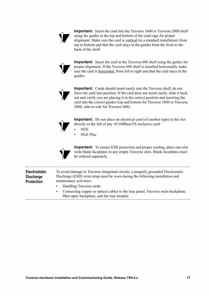
Electrostatic Discharge Protection
To avoid damage to Traverse integrated circuits, a properly grounded Electrostatic Discharge (ESD) wrist strap must be worn during the following installation and maintenance activities:• Handling Traverse cards. • Connecting copper or optical cables to the fuse panel, Traverse main backplane,
fiber optic backplane, and fan tray module.
Important: Insert the card into the Traverse 1600 or Traverse 2000 shelf using the guides at the top and bottom of the card cage for proper alignment. Make sure the card is vertical (in a standard installation) from top to bottom and that the card stays in the guides from the front to the back of the shelf.
Important: Insert the card in the Traverse 600 shelf using the guides for proper alignment. If the Traverse 600 shelf is installed horizontally make sure the card is horizontal, from left to right and that the card stays in the guides.
Important: Cards should insert easily into the Traverse shelf, do not force the card into position. If the card does not insert easily, slide it back out and verify you are placing it in the correct position and inserting the card into the correct guides (top and bottom for Traverse 1600 or Traverse 2000, side-to-side for Traverse 600).
Important: Do not place an electrical card (of another type) in the slot directly to the left of any 10/100BaseTX-inclusive card:• NGE• NGE Plus
Important: To ensure EMI protection and proper cooling, place one-slot wide blank faceplates in any empty Traverse slots. Blank faceplates must be ordered separately.
Traverse Hardware Installation and Commissioning Guide, Release TR4.0.x 17
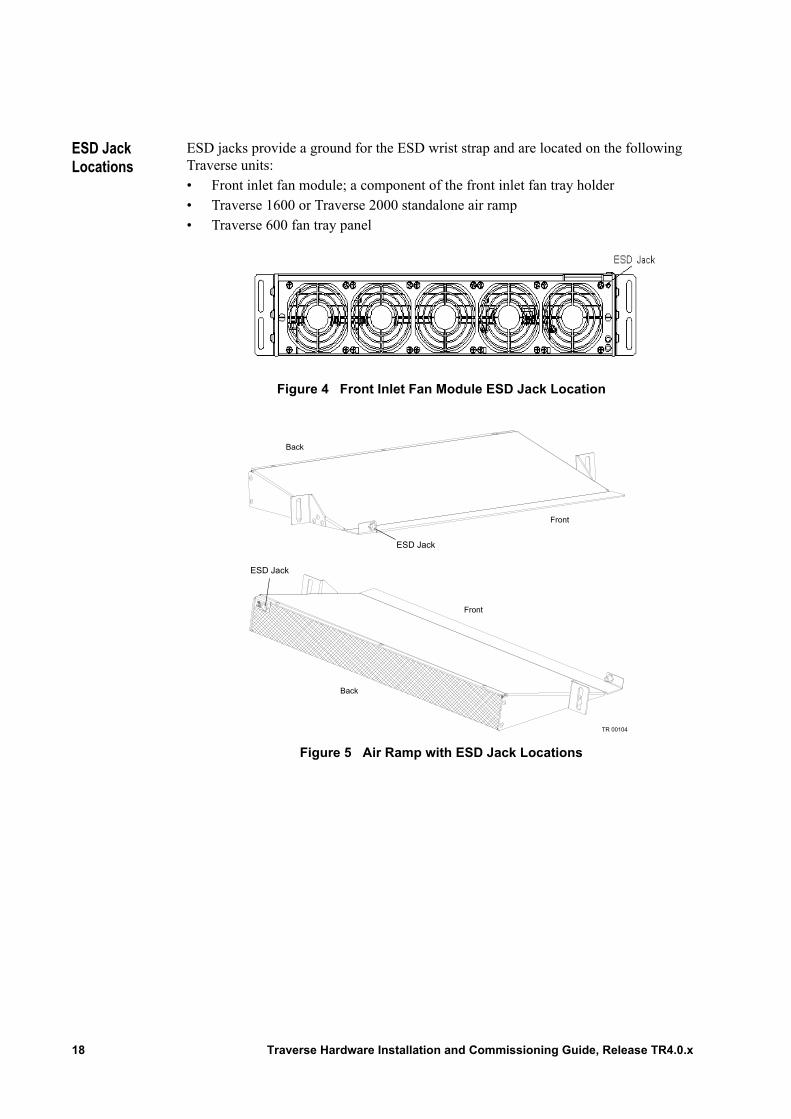
ESD Jack Locations
ESD jacks provide a ground for the ESD wrist strap and are located on the following Traverse units:• Front inlet fan module; a component of the front inlet fan tray holder• Traverse 1600 or Traverse 2000 standalone air ramp• Traverse 600 fan tray panel
Figure 4 Front Inlet Fan Module ESD Jack Location
Figure 5 Air Ramp with ESD Jack Locations
Back
Front
ESD Jack
ESD Jack
Front
Back
TR 00104
18 Traverse Hardware Installation and Commissioning Guide, Release TR4.0.x
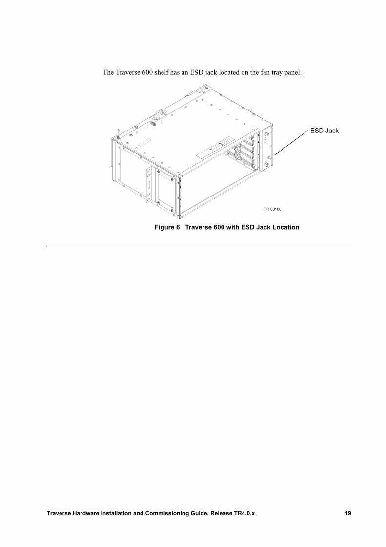
The Traverse 600 shelf has an ESD jack located on the fan tray panel.
Figure 6 Traverse 600 with ESD Jack Location
TR 00106
ESD Jack
Traverse Hardware Installation and Commissioning Guide, Release TR4.0.x 19

20 Traverse Hardware Installation and Commissioning Guide, Release TR4.0.x
Chapter 4 Removing and Replacing Back Covers
Introduction This chapter provides step-by-step instructions for removing back covers:• Required Equipment and Tools• Main Backplane Covers• Remove and Replace the Fiber Optic Management Tray Cover• Remove the PDAP Protective Back Cover• Replace the PDAP Protective Back Cover
Refer to this chapter as required while completing the Traverse Hardware Installation and Commissioning Guide procedures. Use the topic labels in the left margin to scan this document for the tasks you need to review.
Required Equipment and Tools
The following equipment and tools are required to complete these procedures:• Traverse shelf• PDAP• Electrostatic Discharge (ESD) wrist strap• Large flat blade screwdriver for backplane covers• Large Phillips screwdriver for fiber optic management tray cover
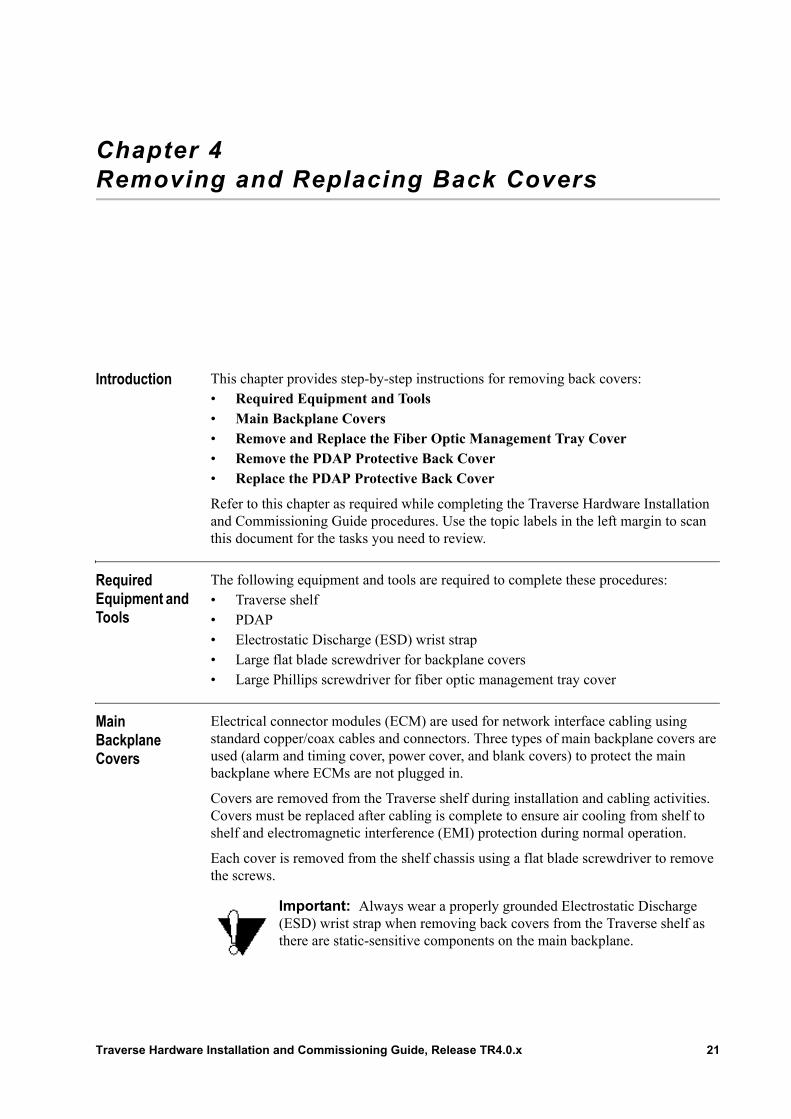
Main Backplane Covers
Electrical connector modules (ECM) are used for network interface cabling using standard copper/coax cables and connectors. Three types of main backplane covers are used (alarm and timing cover, power cover, and blank covers) to protect the main backplane where ECMs are not plugged in.
Covers are removed from the Traverse shelf during installation and cabling activities. Covers must be replaced after cabling is complete to ensure air cooling from shelf to shelf and electromagnetic interference (EMI) protection during normal operation.
Each cover is removed from the shelf chassis using a flat blade screwdriver to remove the screws.
Important: Always wear a properly grounded Electrostatic Discharge (ESD) wrist strap when removing back covers from the Traverse shelf as there are static-sensitive components on the main backplane.
Traverse Hardware Installation and Commissioning Guide, Release TR4.0.x 21
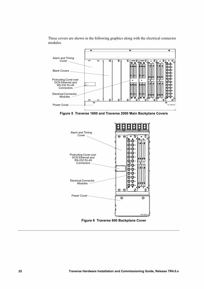
These covers are shown in the following graphics along with the electrical connector modules.
Figure 5 Traverse 1600 and Traverse 2000 Main Backplane Covers
Figure 6 Traverse 600 Backplane Cover
Alarm and Timing Cover
Power Cover
Blank Covers
Electrical Connector Modules
Protruding Cover over DCN Ethernet and
RS-232 RJ-45 Connectors
Alarm and Timing Cover
Power Cover
Electrical Connector Modules
Protruding Cover over DCN Ethernet and
RS-232 RJ-45 Connectors
22 Traverse Hardware Installation and Commissioning Guide, Release TR4.0.x
Remove and Replace the Fiber Optic Management Tray Cover
The fiber optic management tray cover is removed during cabling activities. This cover must be replaced after cabling is complete to protect fiber optic connections during normal operation.
The Traverse 1600 and Traverse 2000 procedure to remove and replace the fiber optic management tray cover is similar. The Traverse 600 procedure is different.• Remove and Replace the Fiber Management Tray Cover• Remove and Replace the Traverse 600 Fiber Management Tray Cover
Remove and Replace the Fiber Management Tray Cover
Follow these instructions to remove and replace the fiber optic management tray cover from a Traverse 1600 or Traverse 2000 shelf.
Important: Always wear a properly grounded Electrostatic Discharge (ESD) wrist strap when removing Traverse back covers as there are static-sensitive components on the backplane.
Important: Always wear a properly grounded Electrostatic Discharge (ESD) wrist strap when removing Traverse back covers as there are static-sensitive components on the backplane.
Table 3 Remove and Replace the Fiber Optic Management Tray Cover
Step Procedure
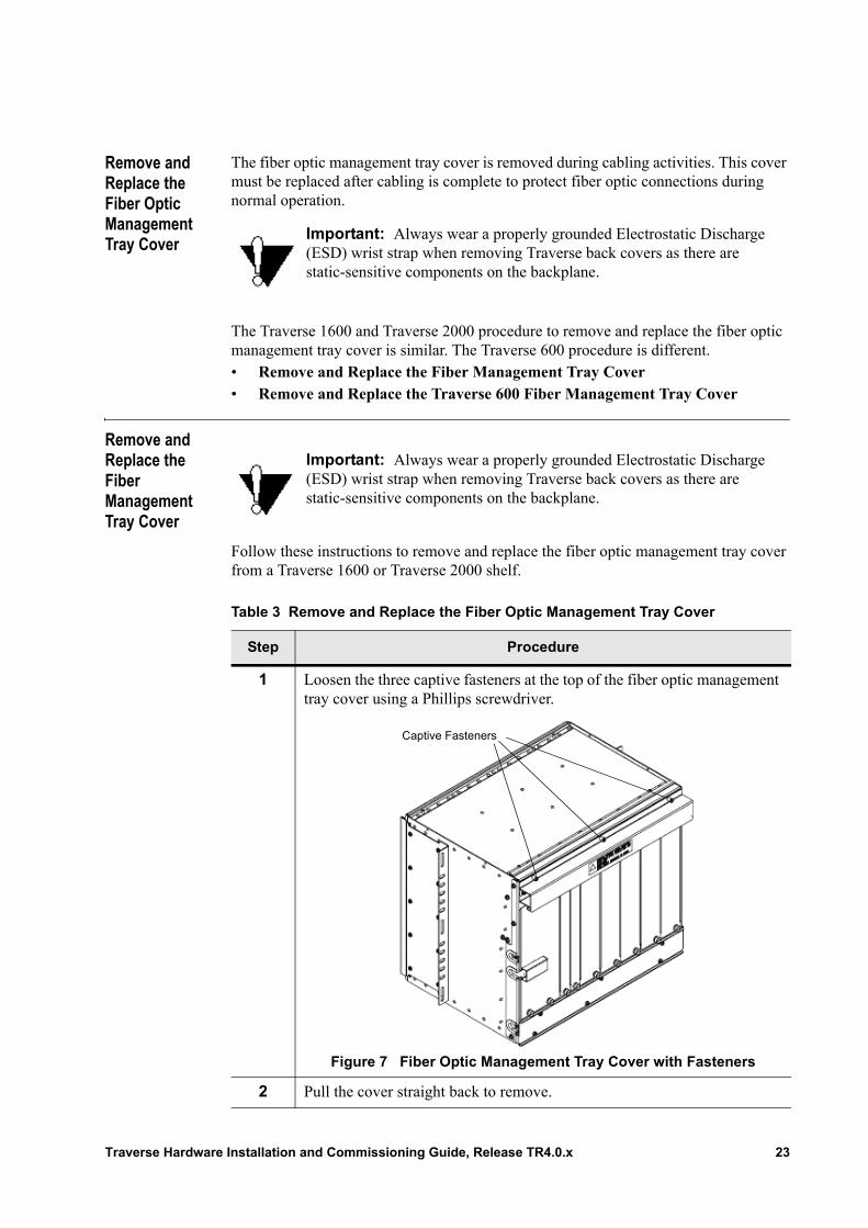
1 Loosen the three captive fasteners at the top of the fiber optic management tray cover using a Phillips screwdriver.
Figure 7 Fiber Optic Management Tray Cover with Fasteners
2 Pull the cover straight back to remove.
Captive Fasteners
Traverse Hardware Installation and Commissioning Guide, Release TR4.0.x 23
Remove and Replace the Traverse 600 Fiber Management Tray Cover
Follow these instructions to remove and replace the fiber optic backplane cover from a Traverse 600 shelf.
3 To replace the fiber optic management tray cover, line up the fasteners with the holes at the top of the chassis.
4 Push the cover straight forward and tighten the fasteners.
5 The Remove and Replace the Fiber Optic Management Tray Cover procedure is complete.
Table 3 Remove and Replace the Fiber Optic Management Tray Cover
Step Procedure
Table 4 Remove and Replace the Traverse 600 Fiber Management Tray Cover
Step Procedure
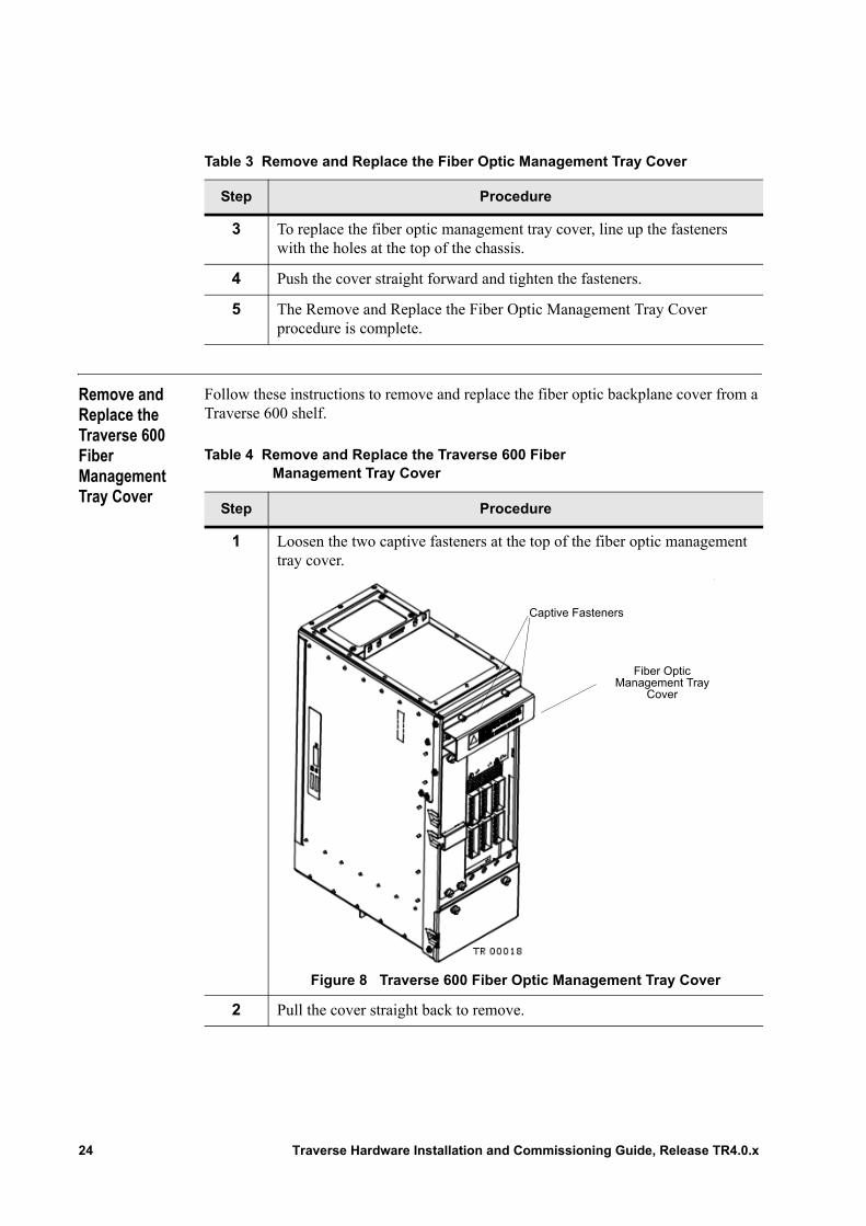
1 Loosen the two captive fasteners at the top of the fiber optic management tray cover.
Figure 8 Traverse 600 Fiber Optic Management Tray Cover
2 Pull the cover straight back to remove.
Captive Fasteners
Fiber Optic Management Tray
Cover
24 Traverse Hardware Installation and Commissioning Guide, Release TR4.0.x
3 To replace the fiber optic management tray cover, line up the fasteners on top of the fiber optic management tray cover with the holes at the top of the chassis.
4 Push the cover straight forward and tighten the fasteners.
5 The Remove and Replace the Traverse 600 Fiber Management Tray Cover procedure is complete.
Table 4 Remove and Replace the Traverse 600 Fiber Management Tray Cover
Step Procedure
Traverse Hardware Installation and Commissioning Guide, Release TR4.0.x 25
Remove the PDAP Protective Back Cover
Follow these instructions to remove the PDAP protective back cover.
Replace the PDAP Protective Back Cover
Follow these instructions to replace the PDAP protective back cover.
WARNING! The protective back cover is removed from the PDAP during power cabling activities. PDAP back covers must be replaced after cabling is complete and before –48 VDC power supply cables are connected to the central office source. The PDAP protective back cover must remain in place during normal operation to protect against possible electric shock.
Table 5 Remove the PDAP Protective Back Cover
Step Procedure
1 Loosen (you need not remove) the two thumb screws securing the protective cover onto the back panel.
2 Pull the protective cover straight out to remove.
3 The Remove the PDAP Protective Back Cover procedure is complete.
Table 6 Replace the PDAP Protective Back Cover
Step Procedure
1 Align the protective cover to the back panel with the two thumb screws.
2 Tighten the two thumb screws to secure the protective cover.
3 The Replace the PDAP Protective Back Cover procedure is complete.
26 Traverse Hardware Installation and Commissioning Guide, Release TR4.0.x
Chapter 5 Inserting and Removing Cards
Introduction This chapter provides basic step-by-step instructions for inserting and removing cards in a Traverse shelf. Refer to this chapter as required while completing the Traverse Installation and Commissioning Guide procedures.• Required Equipment and Tools• Clean Fiber Optic MPX Connectors• Insert a Card• Remove a Card
For a card placement example, refer first to the Traverse Hardware Guide, Chapter 2—“Traverse System Configuration Examples,” Example Traverse Shelf Card Layout.
Exact placement of the cards into Traverse shelf slots is explained in Operations and Maintenance Guide, Chapter 21—“Card Placement Planning and Guidelines.”
Required Equipment and Tools
The following hardware equipment and tools are required to place cards in a Traverse shelf.
General
• Electrostatic Discharge (ESD) wrist strap• Eye protection• 1-slot wide blank faceplates for any empty slots to ensure EMI protection and
proper cooling. Blank faceplates must be ordered separately.
Traverse Shelf
• MPX cleaning materials to clean fiber optic cable and card MPX connectors:– Isopropyl alcohol of at least 91% purity– Lint-free wipes– Lint-free cleaning swabs with urethane foam heads– Pressurized optical duster (canned air)
Traverse Hardware Installation and Commissioning Guide, Release TR4.0.x 27
• 1 or 2 control cards, as well as any spares• System interface card (SIM) cards
Note: The number and combination of SIMs is based on your network requirements and physical cabling at the Traverse main and fiber optic backplanes.
Clean Fiber Optic MPX Connectors
It is critical that the cable and card MPX connectors are clean to ensure proper operation. Force10 recommends that you visually inspect the MPX connectors on both the fiber optic cables and optical cards using fiber optic magnification equipment. Force10 also recommends that you clean the fiber optic cable and card MPX connectors using the following procedure.
OPTIC WARNING! The Traverse system is a class 1 product that contains a class IIIb laser and is intended for operation in a closed environment with fiber attached. Do not look into the optical connector of the transmitter when power is applied. Laser output is invisible and eye damage can result. Follow these safety features to prevent looking into the optical connector.
OPTIC WARNING! The optical connector system used on the Traverse fiber optic backplane is designed with a mechanical shutter mechanism that blocks physical and visual access to the optical connector. Follow this safety feature as it is designed to prevent eye damage.
OPTIC WARNING! Follow all warning labels when working with optical fibers. Always wear eye protection when working with optical fibers. Never look directly into the end of a terminated or unterminated fiber or connector, as it may cause eye damage.
Important: Always wear a properly grounded Electrostatic Discharge (ESD) wrist strap when handling and placing cards in the Traverse shelf. Follow all warnings and instructions included in card packaging to prevent electrostatic damage.
Important: Handle cards by the edges and faceplate only. Do not touch any card connectors or components.
Important: Do not touch the end of the MPX connectors.
28 Traverse Hardware Installation and Commissioning Guide, Release TR4.0.x
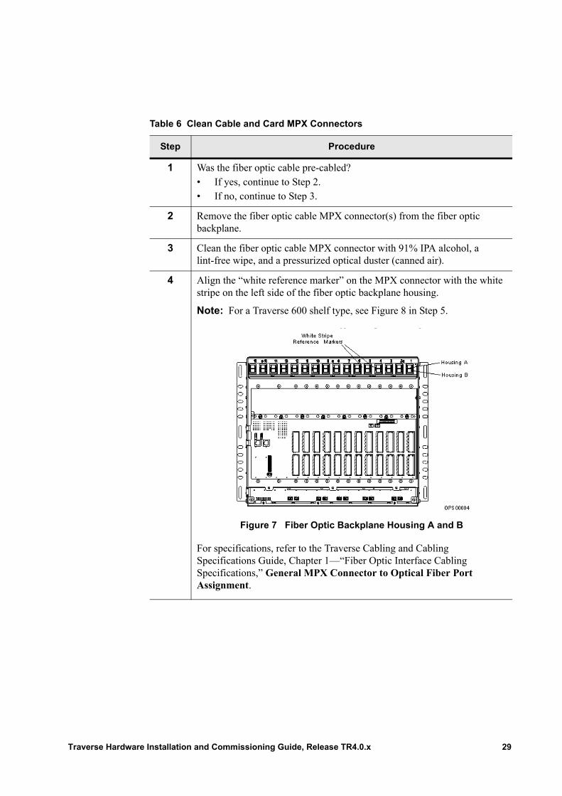
Table 6 Clean Cable and Card MPX Connectors
Step Procedure
1 Was the fiber optic cable pre-cabled?• If yes, continue to Step 2.• If no, continue to Step 3.
2 Remove the fiber optic cable MPX connector(s) from the fiber optic backplane.
3 Clean the fiber optic cable MPX connector with 91% IPA alcohol, a lint-free wipe, and a pressurized optical duster (canned air).
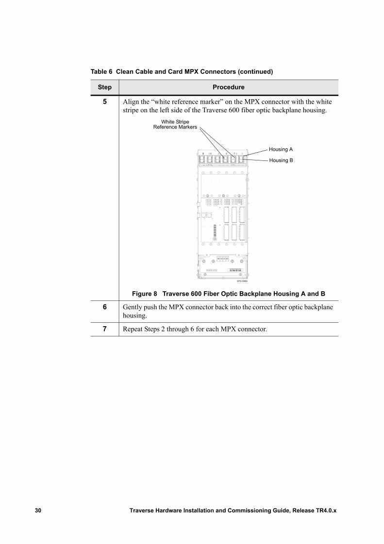
4 Align the “white reference marker” on the MPX connector with the white stripe on the left side of the fiber optic backplane housing.
Note: For a Traverse 600 shelf type, see Figure 8 in Step 5.
Figure 7 Fiber Optic Backplane Housing A and B
For specifications, refer to the Traverse Cabling and Cabling Specifications Guide, Chapter 1—“Fiber Optic Interface Cabling Specifications,” General MPX Connector to Optical Fiber Port Assignment.
Traverse Hardware Installation and Commissioning Guide, Release TR4.0.x 29
5 Align the “white reference marker” on the MPX connector with the white stripe on the left side of the Traverse 600 fiber optic backplane housing.
Figure 8 Traverse 600 Fiber Optic Backplane Housing A and B
6 Gently push the MPX connector back into the correct fiber optic backplane housing.
7 Repeat Steps 2 through 6 for each MPX connector.
Table 6 Clean Cable and Card MPX Connectors (continued)
Step Procedure
OPS 00085
Housing A
Housing B
White StripeReference Markers
30 Traverse Hardware Installation and Commissioning Guide, Release TR4.0.x
Insert a Card
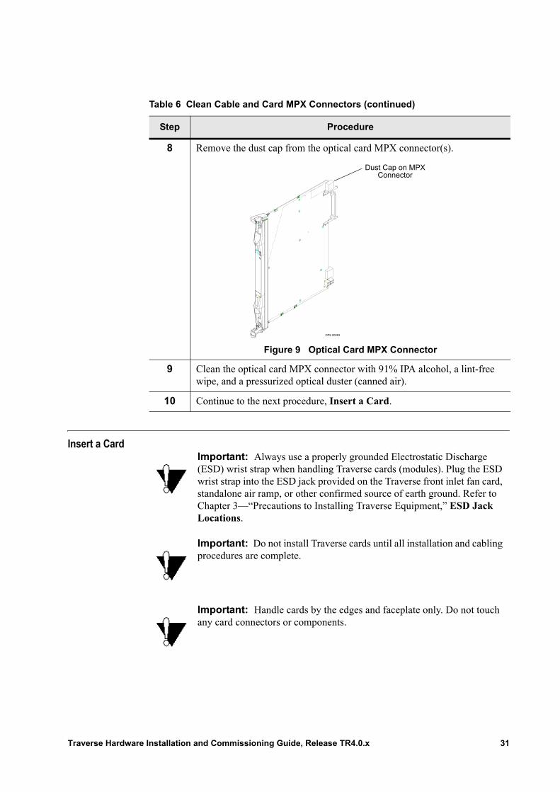
8 Remove the dust cap from the optical card MPX connector(s).
Figure 9 Optical Card MPX Connector
9 Clean the optical card MPX connector with 91% IPA alcohol, a lint-free wipe, and a pressurized optical duster (canned air).
10 Continue to the next procedure, Insert a Card.
Table 6 Clean Cable and Card MPX Connectors (continued)
Step Procedure
OPS 00083
Dust Cap on MPX Connector
Important: Always use a properly grounded Electrostatic Discharge (ESD) wrist strap when handling Traverse cards (modules). Plug the ESD wrist strap into the ESD jack provided on the Traverse front inlet fan card, standalone air ramp, or other confirmed source of earth ground. Refer to Chapter 3—“Precautions to Installing Traverse Equipment,” ESD Jack Locations.
Important: Do not install Traverse cards until all installation and cabling procedures are complete.
Important: Handle cards by the edges and faceplate only. Do not touch any card connectors or components.
Traverse Hardware Installation and Commissioning Guide, Release TR4.0.x 31

Important: Observe all electrostatic sensitive device warnings and precautions when handling Traverse cards.
Important: Insert the card into the Traverse shelf using the guides at the top and bottom of the card cage for proper alignment. Make sure the card is vertical, from top to bottom, and that the card stays in the guides from the front to the back of the shelf.
Important: Do not place an electrical card (of another type) in the slot directly to the left of any 10/100BaseTX-inclusive card:• NGE• NGE Plus• EoPDH
Important: Cards should insert easily into the Traverse shelf. Do not force the card into position. If the card does not insert easily, slide it back out, verify you are placing it in the correct position and inserting the card into the correct guides top and bottom.
Important: Insert the card in the Traverse 600 shelf using the guides for proper alignment. If the Traverse 600 shelf is installed horizontally make sure the card is horizontal, from left to right, and that the card stays in the guides.
Important: To ensure EMI protection and proper cooling, place one-slot wide blank faceplates in any empty Traverse slots. Blank faceplates must be ordered separately.
32 Traverse Hardware Installation and Commissioning Guide, Release TR4.0.x
Follow these steps to insert a card.
Table 1 Insert a Card
Step Procedure
1 Is this an optical card with MPX connectors?• If yes, complete the Clean MPX Connectors procedure before
proceeding.• If no, continue to Step 2.
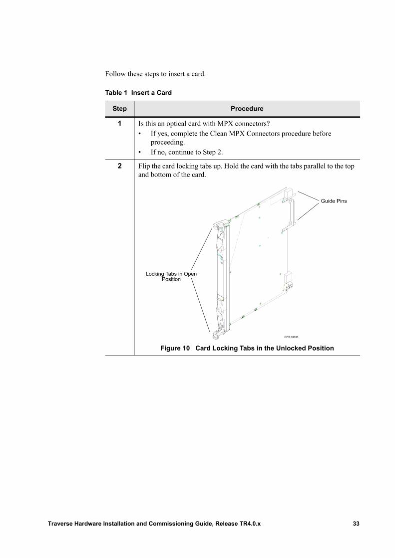
2 Flip the card locking tabs up. Hold the card with the tabs parallel to the top and bottom of the card.
Figure 10 Card Locking Tabs in the Unlocked Position
OPS 00083
Guide Pins
Locking Tabs in Open Position
Traverse Hardware Installation and Commissioning Guide, Release TR4.0.x 33
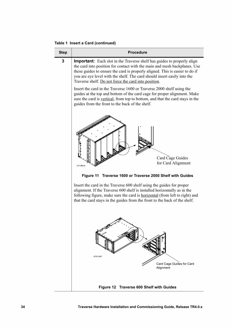
3 Important: Each slot in the Traverse shelf has guides to properly align the card into position for contact with the main and mesh backplanes. Use these guides to ensure the card is properly aligned. This is easier to do if you are eye level with the shelf. The card should insert easily into the Traverse shelf. Do not force the card into position.
Insert the card in the Traverse 1600 or Traverse 2000 shelf using the guides at the top and bottom of the card cage for proper alignment. Make sure the card is vertical, from top to bottom, and that the card stays in the guides from the front to the back of the shelf.
Figure 11 Traverse 1600 or Traverse 2000 Shelf with Guides
Insert the card in the Traverse 600 shelf using the guides for proper alignment. If the Traverse 600 shelf is installed horizontally as in the following figure, make sure the card is horizontal (from left to right) and that the card stays in the guides from the front to the back of the shelf.
Figure 12 Traverse 600 Shelf with Guides
Table 1 Insert a Card (continued)
Step Procedure
Card Cage Guides for Card Alignment
Card Cage Guides for Card Alignment
34 Traverse Hardware Installation and Commissioning Guide, Release TR4.0.x
4 Push the center of the card faceplate until the locking tabs begin to close and the locking tabs start to roll around the lip of the Traverse shelf. The optical card makes an audible “click” indicating it is making contact with the fiber optic backplane connectors.
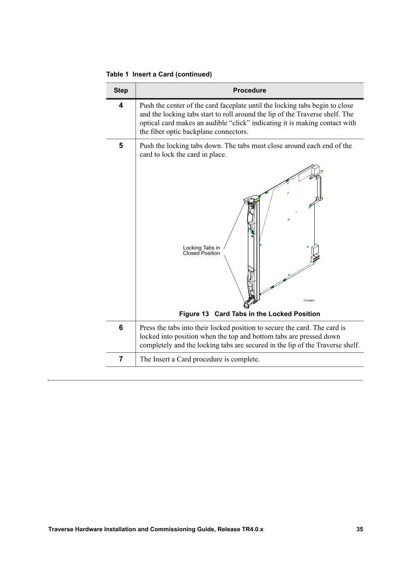
5 Push the locking tabs down. The tabs must close around each end of the card to lock the card in place.
Figure 13 Card Tabs in the Locked Position
6 Press the tabs into their locked position to secure the card. The card is locked into position when the top and bottom tabs are pressed down completely and the locking tabs are secured in the lip of the Traverse shelf.
7 The Insert a Card procedure is complete.
Table 1 Insert a Card (continued)
Step Procedure
Locking Tabs inClosed Position
Traverse Hardware Installation and Commissioning Guide, Release TR4.0.x 35
Remove a Card
Follow these instructions to remove a card from a slot in a shelf.
Important: A properly grounded ESD wrist strap must be worn at all times while handling Traverse cards to prevent damage to the circuitry.
Important: Handle cards by the edges and face plate only. Do not touch any card connectors or components.
Table 2 Remove a Card
Step Procedure
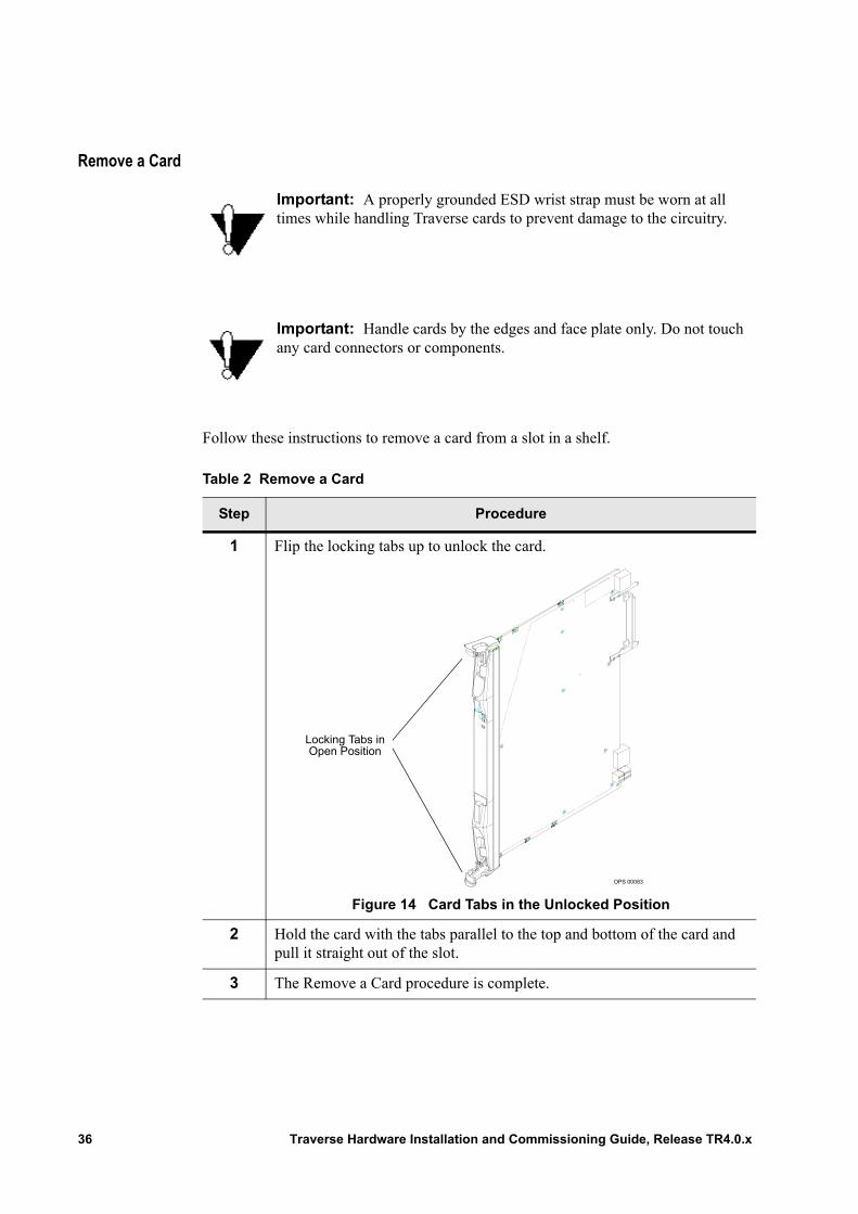
1 Flip the locking tabs up to unlock the card.
Figure 14 Card Tabs in the Unlocked Position
2 Hold the card with the tabs parallel to the top and bottom of the card and pull it straight out of the slot.
3 The Remove a Card procedure is complete.
OPS 00083
Locking Tabs inOpen Position
36 Traverse Hardware Installation and Commissioning Guide, Release TR4.0.x

Chapter 6 Insert Fan Module and Air Filters
Introduction This chapter includes step-by-step instructions to insert a fan module and air filter.
The Traverse system supports three fan assembly types. Refer to the correct fan module and air filter procedure in this chapter depending on the fan assembly type.• Required Equipment and Tools• Insert a Traverse 1600 and Traverse 2000 Fan Assembly• Insert a Traverse 1600 and Traverse 2000 Fan Air Filter• Insert a Traverse 600 Fan Assembly• Insert a Traverse 600 Fan Air Filter
Required Equipment and Tools
The following equipment and tools are required to install the fan and air filter:• Fan tray holder pre-installed (for Traverse 1600 and Traverse 2000)• Fan module (Traverse 1600 and Traverse 2000) or Fan assembly (Traverse 600)• Air filter1
• Electrostatic Discharge (ESD) wrist strap
1 Fan tray air filters are available in 63% arrestance at 300 FPM—feet per minute (91.4 meters per minute) and 80% arrestance at 300 FPM (91.4 meters per minute) depending on your installation requirements.
Traverse Hardware Installation and Commissioning Guide, Release TR4.0.x 37
Insert a Traverse 1600 and Traverse 2000 Fan Assembly
Follow these instructions to insert the front inlet fan module for the Traverse 1600 or Traverse 2000 into the fan tray holder.
Important: Wear a properly grounded Electrostatic Discharge (ESD) wrist strap when installing the fan module as it contains static-sensitive components.
Table 3 Insert a Traverse 1600 and Traverse 2000 Fan Assembly
Step Procedure
1 Lift the front inlet fan card to be level with the front inlet fan tray holder. Slide the fan card into the front of the fan tray holder and push it straight in until the two connectors engage.
2 The front inlet fan card is in the correct position when it is flush with the front of the fan tray holder.
Important: Do not force the fan card into position. If it does not plug in easily, slide it back out. Check for any obstructions or a damaged connector that might prevent it from sliding into position and verify it is in the correct guides before attempting to insert it again.
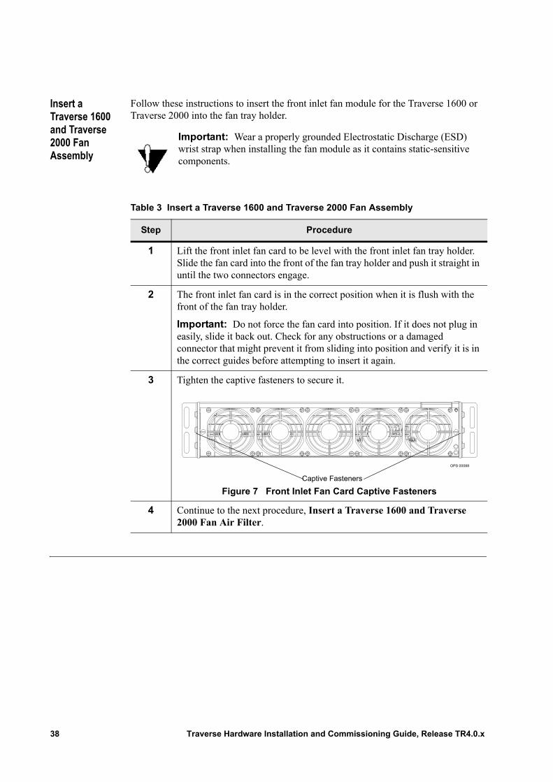
3 Tighten the captive fasteners to secure it.
Figure 7 Front Inlet Fan Card Captive Fasteners
4 Continue to the next procedure, Insert a Traverse 1600 and Traverse 2000 Fan Air Filter.
OPS 00088
Captive Fasteners
38 Traverse Hardware Installation and Commissioning Guide, Release TR4.0.x
Insert a Traverse 1600 and Traverse 2000 Fan Air Filter
The front inlet fan module requires a foam air filter that is placed at the top of the front inlet fan tray holder after the fan module is installed.
The front inlet fan tray air filters are available in 63% or 80% arrestance at 300 FPM— feet per minute (91.4 meters per minute) depending on your installation requirements.
The following procedure provides step-by-step instructions on how to insert the front inlet fan tray air filter.
Table 4 Insert a Traverse 1600 and Traverse 2000 Fan Air Filter
Step Procedure
1 If you are replacing an old air filter, carefully remove the old air filter from the fan tray holder to avoid contaminating the equipment,.
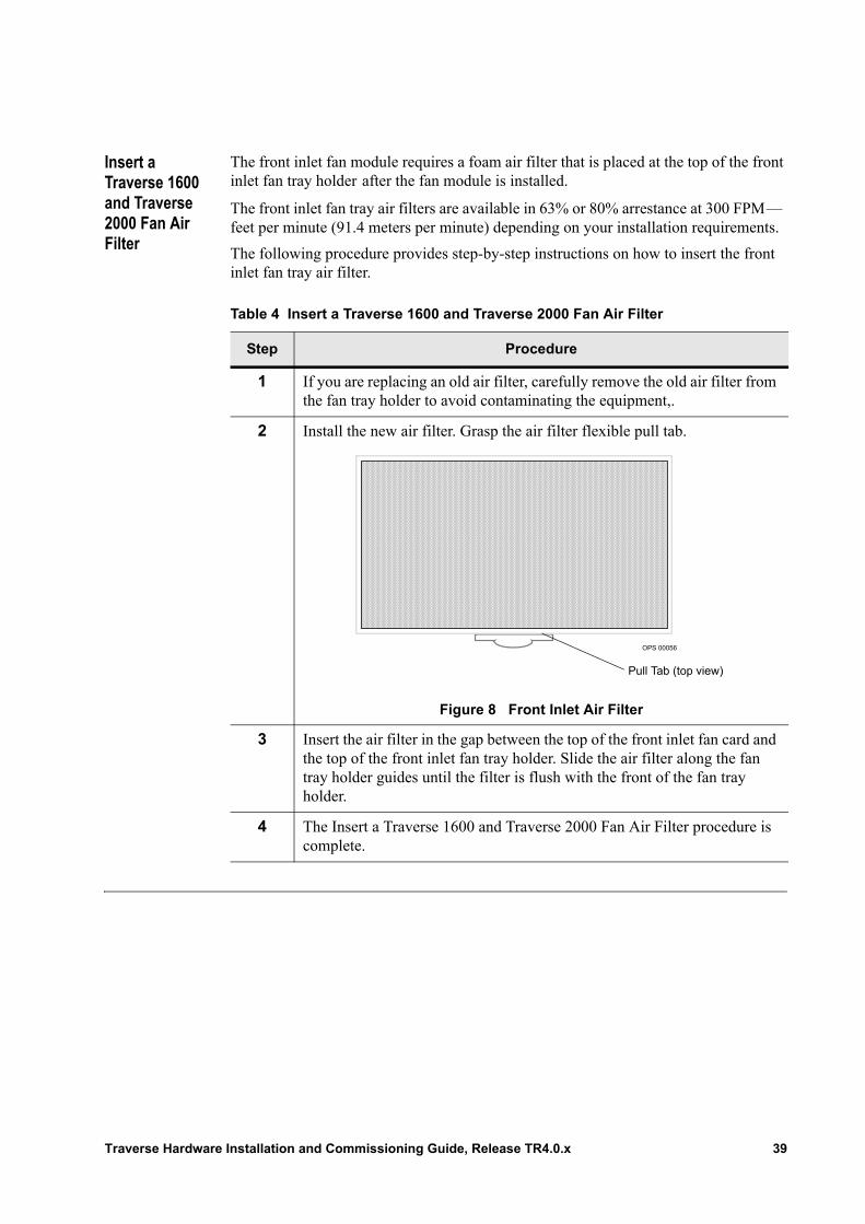
2 Install the new air filter. Grasp the air filter flexible pull tab.
Figure 8 Front Inlet Air Filter
3 Insert the air filter in the gap between the top of the front inlet fan card and the top of the front inlet fan tray holder. Slide the air filter along the fan tray holder guides until the filter is flush with the front of the fan tray holder.
4 The Insert a Traverse 1600 and Traverse 2000 Fan Air Filter procedure is complete.
OPS 00056
Pull Tab (top view)
Traverse Hardware Installation and Commissioning Guide, Release TR4.0.x 39

Insert a Traverse 600 Fan Assembly
The Traverse 600 fan assembly (module with integral fan tray) is bundled and shipped with the Traverse 600 system. Proceed with the following steps to install the fan assembly.
Important: Wear a properly grounded Electrostatic Discharge (ESD) wrist strap when installing the fan tray module as it contains static-sensitive components.
40 Traverse Hardware Installation and Commissioning Guide, Release TR4.0.x
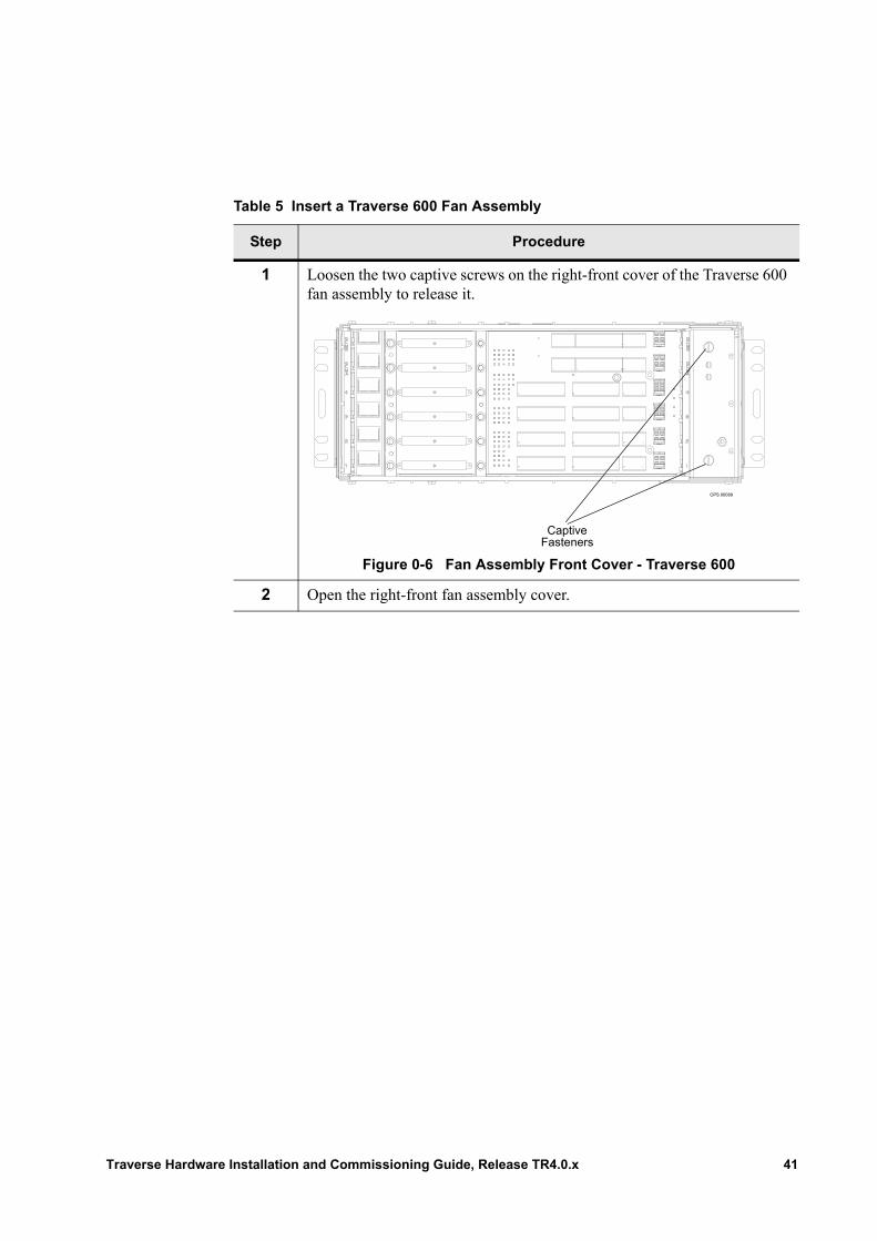
Table 5 Insert a Traverse 600 Fan Assembly
Step Procedure
1 Loosen the two captive screws on the right-front cover of the Traverse 600 fan assembly to release it.
Figure 0-6 Fan Assembly Front Cover - Traverse 600
2 Open the right-front fan assembly cover.
OPS 00089
Captive Fasteners
Traverse Hardware Installation and Commissioning Guide, Release TR4.0.x 41
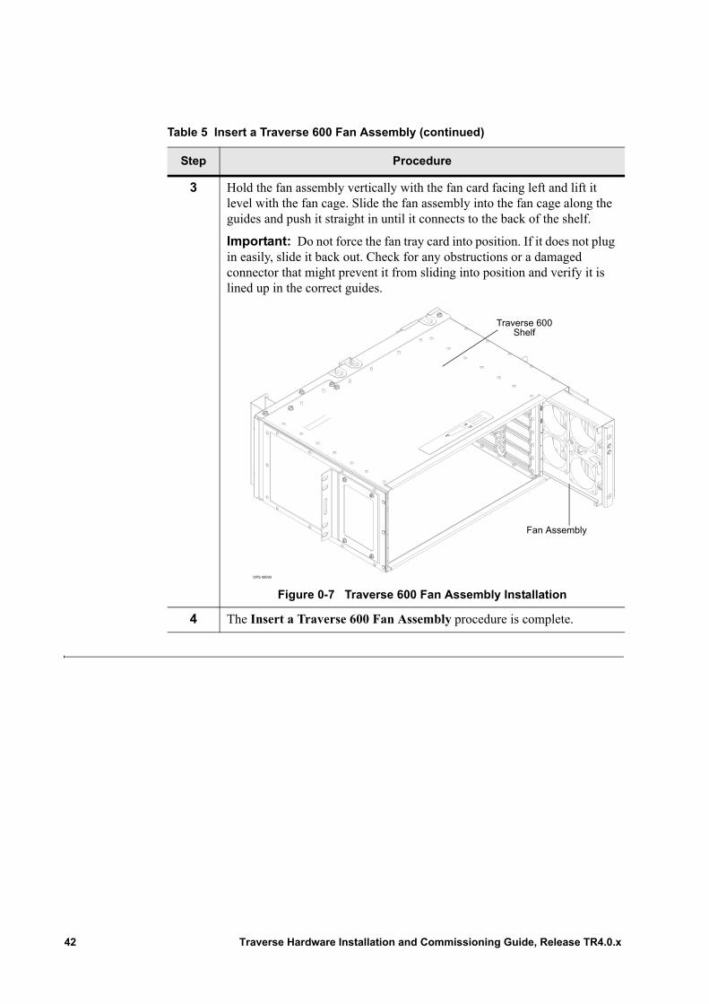
3 Hold the fan assembly vertically with the fan card facing left and lift it level with the fan cage. Slide the fan assembly into the fan cage along the guides and push it straight in until it connects to the back of the shelf.
Important: Do not force the fan tray card into position. If it does not plug in easily, slide it back out. Check for any obstructions or a damaged connector that might prevent it from sliding into position and verify it is lined up in the correct guides.
Figure 0-7 Traverse 600 Fan Assembly Installation
4 The Insert a Traverse 600 Fan Assembly procedure is complete.
Table 5 Insert a Traverse 600 Fan Assembly (continued)
Step Procedure
OPS 00090
Traverse 600 Shelf
Fan Assembly
42 Traverse Hardware Installation and Commissioning Guide, Release TR4.0.x
Insert a Traverse 600 Fan Air Filter
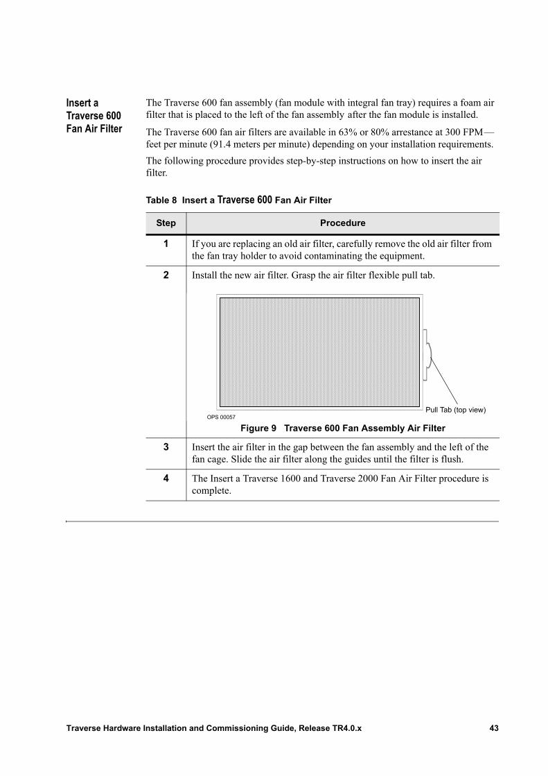
The Traverse 600 fan assembly (fan module with integral fan tray) requires a foam air filter that is placed to the left of the fan assembly after the fan module is installed.
The Traverse 600 fan air filters are available in 63% or 80% arrestance at 300 FPM— feet per minute (91.4 meters per minute) depending on your installation requirements.
The following procedure provides step-by-step instructions on how to insert the air filter.
Table 8 Insert a Traverse 600 Fan Air Filter
Step Procedure
1 If you are replacing an old air filter, carefully remove the old air filter from the fan tray holder to avoid contaminating the equipment.
2 Install the new air filter. Grasp the air filter flexible pull tab.
Figure 9 Traverse 600 Fan Assembly Air Filter
3 Insert the air filter in the gap between the fan assembly and the left of the fan cage. Slide the air filter along the guides until the filter is flush.
4 The Insert a Traverse 1600 and Traverse 2000 Fan Air Filter procedure is complete.
OPS 00057Pull Tab (top view)
Traverse Hardware Installation and Commissioning Guide, Release TR4.0.x 43

44 Traverse Hardware Installation and Commissioning Guide, Release TR4.0.x
Chapter 7 Traverse System Hardware Installation
Introduction For hardware installation overview and guidelines, refer first to Chapter 1—“Installation and Commissioning Overview.”
This chapter provides the following procedures to complete a standard horizontal-mount installation of a Traverse shelf and fan tray holder with integrated or separate air ramp into a standard 7-foot (2133.6 mm) high, 19-inch or 23-inch (483 mm or 584 mm) wide telco rack.• Install the Rack Adapters• Install the Traverse Shelf• Flush Mount a Traverse Shelf• Install the Front Inlet Fan Tray Holder• Install the Fan Tray Holder with Separate Air Ramp• Install the Air Ramp
Please refer to Chapter 15—“Installing the Wall Mount Bracket” if you are installing a Traverse 600 shelf in a wall-mount cabinet.
Refer to Chapter 7—“Traverse System Hardware Installation” to complete a vertical and standard 5 inch (127 mm) forward-mount installation of the Traverse 2000 system into a standard 7-foot (2133.6 mm) high, 19-inch (483 mm) wide telco rack.
The instructions may be too detailed if you are experienced in central office installations. In this case, scan the topic labels in the left margin for tasks to review or refer to Chapter 16—“Installation and Commissioning Checklists.”
Important: Do not install Traverse cards (modules) until all installation and cabling procedures are complete.
Traverse Hardware Installation and Commissioning Guide, Release TR4.0.x 45
Install the Rack Adapters
Use standard rack adapters to install Traverse system components into a 23-inch (584 mm) telco rack. Rack adapters come with thread-forming mounting screws and in various lengths depending on your installation requirements.
Install the Traverse system in the central office bay and rack designated by your engineering work order using a minimum of six 12-24 thread-forming screws.
Table 9 Install the Rack Adapters
Step Procedure
1 Install conductive plated rack adapters on both sides of the rack for the relevant Traverse system component. Align and position the rack adapter slots with the holes in the rack.
2 Place and tighten thread-forming screws through the rack adapter slots and into the rack. Thread-forming screws are used to ground the rack adapters and Traverse system component to the rack. Torque screws to 65 lbs/in.
3 Within the procedures shown in the next step, you will place and tighten screws on each side of the Traverse system component to secure it to the rack adapters and thus the rack.
4 The Install the Rack Adapters procedure is complete.
Continue to the installation procedure for the specific Traverse system component.• Install the Traverse Shelf• Install the Front Inlet Fan Tray Holder• Install the Fan Tray Holder with Separate Air Ramp• Install the Air Ramp
46 Traverse Hardware Installation and Commissioning Guide, Release TR4.0.x
Install the Traverse Shelf
Install the Traverse shelf in the central office bay and rack designated by your engineering work order using a minimum of six 12-24 thread-forming screws.
Note: Standard conductive plated rack adapters may be required for installation. If so, refer to Install the Rack Adapters.
Important: Install the first Traverse shelf below the Fuse Panel in the rack. A 3/8-inch (9.5 mm) space is required between the Fuse Panel and the first Traverse shelf to allow for proper air flow.
Important: If the Traverse shelf is to be installed below another vendor’s equipment, an air ramp must be installed above the Traverse shelf.
Table 10 Install the Traverse Shelf, Standard Configuration
Step Procedure
1 Lift the Traverse shelf to its assigned position in the rack.
2 Align the flange holes with the holes in the rack. Each shelf flange has three 1-RU slots at the top, middle, and bottom for easy alignment.
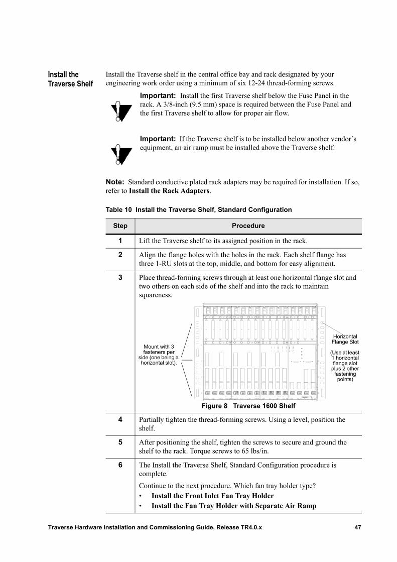
3 Place thread-forming screws through at least one horizontal flange slot and two others on each side of the shelf and into the rack to maintain squareness.
Figure 8 Traverse 1600 Shelf
4 Partially tighten the thread-forming screws. Using a level, position the shelf.
5 After positioning the shelf, tighten the screws to secure and ground the shelf to the rack. Torque screws to 65 lbs/in.
6 The Install the Traverse Shelf, Standard Configuration procedure is complete.
Continue to the next procedure. Which fan tray holder type?• Install the Front Inlet Fan Tray Holder• Install the Fan Tray Holder with Separate Air Ramp
Mount with 3 fasteners per
side (one being a horizontal slot).
Horizontal Flange Slot
(Use at least 1 horizontal flange slot
plus 2 other fastening points)
Traverse Hardware Installation and Commissioning Guide, Release TR4.0.x 47
Flush Mount a Traverse Shelf
In a standard configuration, the mounting flanges are set so the chassis or fan tray extends out five inches from the front edge of the rack. To flush-mount the Traverse shelf, use the following instructions.
Table 11 Install the Traverse Shelf, Flush Mount Configuration
Step Procedure
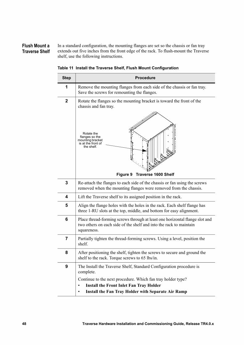
1 Remove the mounting flanges from each side of the chassis or fan tray. Save the screws for remounting the flanges.
2 Rotate the flanges so the mounting bracket is toward the front of the chassis and fan tray.
Figure 9 Traverse 1600 Shelf
3 Re-attach the flanges to each side of the chassis or fan using the screws removed when the mounting flanges were removed from the chassis.
4 Lift the Traverse shelf to its assigned position in the rack.
5 Align the flange holes with the holes in the rack. Each shelf flange has three 1-RU slots at the top, middle, and bottom for easy alignment.
6 Place thread-forming screws through at least one horizontal flange slot and two others on each side of the shelf and into the rack to maintain squareness.
7 Partially tighten the thread-forming screws. Using a level, position the shelf.
8 After positioning the shelf, tighten the screws to secure and ground the shelf to the rack. Torque screws to 65 lbs/in.
9 The Install the Traverse Shelf, Standard Configuration procedure is complete.
Continue to the next procedure. Which fan tray holder type?• Install the Front Inlet Fan Tray Holder• Install the Fan Tray Holder with Separate Air Ramp
Rotate the flanges so the
mounting bracket is at the front of
the shelf.
48 Traverse Hardware Installation and Commissioning Guide, Release TR4.0.x
Install the Front Inlet Fan Tray Holder
The front inlet fan tray holder (with integrated air ramp) is required to cool the Traverse shelf during normal operation. Follow these installation steps.
Note: Standard conductive plated rack adapters may be required for installation. If so, refer to Install the Rack Adapters.
Important: Install the front inlet fan tray holder directly below the Traverse shelf so that no gap remains in order to ensure proper air flow.
Table 12 Install the Front Inlet Fan Tray Holder
Step Procedure
1 It is easier to connect the front inlet fan tray holder power cable to the Traverse backplane before installing the front inlet fan tray holder in the rack. Grasp the power cable and bring it out the top of the front inlet fan tray holder.
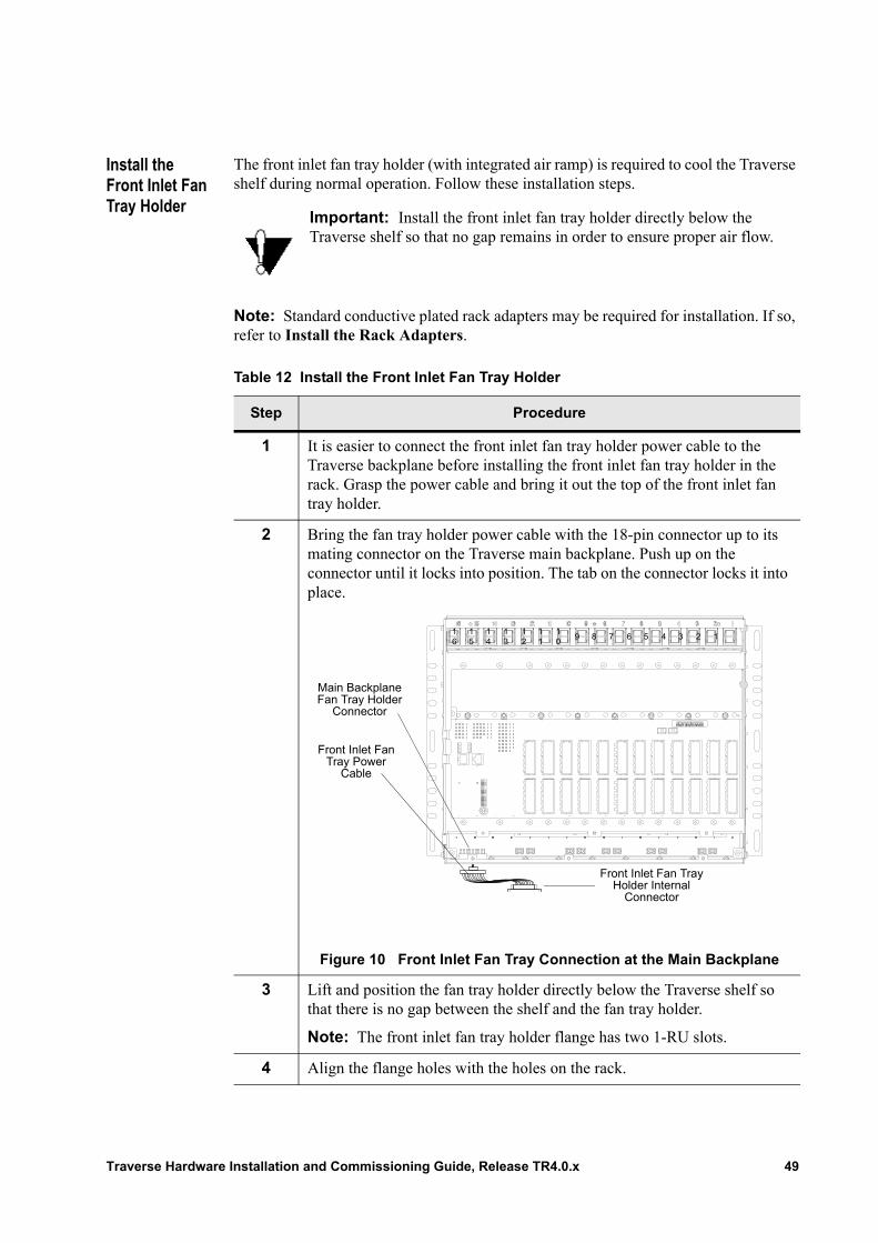
2 Bring the fan tray holder power cable with the 18-pin connector up to its mating connector on the Traverse main backplane. Push up on the connector until it locks into position. The tab on the connector locks it into place.
Figure 10 Front Inlet Fan Tray Connection at the Main Backplane
3 Lift and position the fan tray holder directly below the Traverse shelf so that there is no gap between the shelf and the fan tray holder.
Note: The front inlet fan tray holder flange has two 1-RU slots.
4 Align the flange holes with the holes on the rack.
16
15
14
13
12
11
10
9 8 7 6 5 4 3 2 1
Main Backplane Fan Tray Holder
Connector
Front Inlet Fan Tray Power
Cable
Front Inlet Fan Tray Holder Internal
Connector
Traverse Hardware Installation and Commissioning Guide, Release TR4.0.x 49
Install the Fan Tray Holder with Separate Air Ramp
The fan tray holder with separate air ramp is required to cool the Traverse shelf during normal operation. The fan tray holder must be installed directly below the Traverse shelf. Follow these fan tray holder power cabling and installation steps.
Note: Standard conductive plated rack adapters may be required for installation. If so, refer to Install the Rack Adapters.
5 Place thread-forming screws through the flange slot on each side of the front inlet fan tray holder and into the rack.
6 Partially tighten the thread-forming screws and position the front inlet fan tray holder.
7 Tighten the screws to secure and ground the front inlet fan tray holder to the rack. Torque screws to 65 lbs/in.
8 Complete the following procedure in Chapter 6—“Insert Fan Module and Air Filters,” Insert a Traverse 1600 and Traverse 2000 Fan Air Filter to install the fan tray module and air filter.
9 The Install the Front Inlet Fan Tray Holder procedure is complete.
Continue to the Traverse Cabling and Cabling Specifications Guide, Chapter 11—“Network Interface Cabling Overview.”
Table 12 Install the Front Inlet Fan Tray Holder (continued)
Step Procedure
Table 13 Install the Fan Tray Holder with Separate Air Ramp
Step Procedure
1 It is easier to connect the fan tray holder power cable to the Traverse backplane before installing the fan tray holder in the rack.
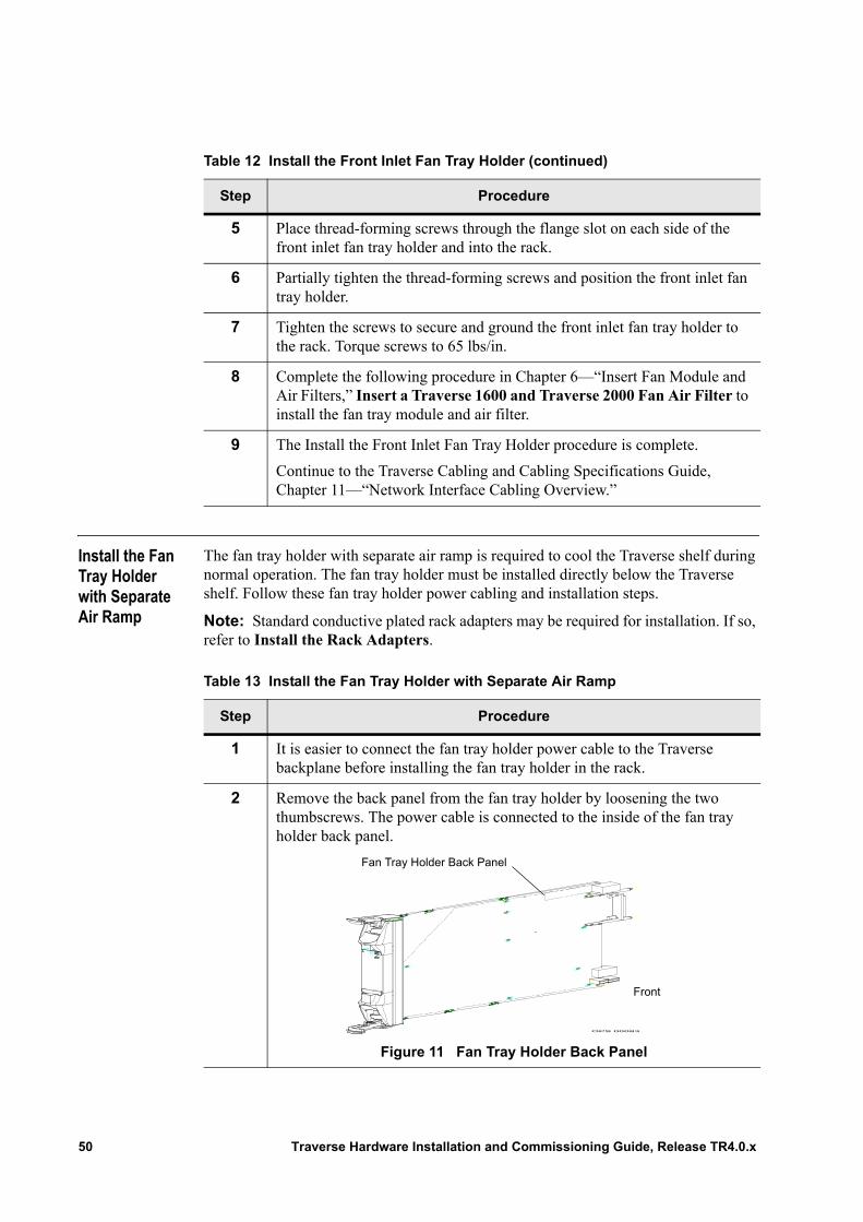
2 Remove the back panel from the fan tray holder by loosening the two thumbscrews. The power cable is connected to the inside of the fan tray holder back panel.
Figure 11 Fan Tray Holder Back Panel
OPS 00083
Front
Fan Tray Holder Back Panel
50 Traverse Hardware Installation and Commissioning Guide, Release TR4.0.x
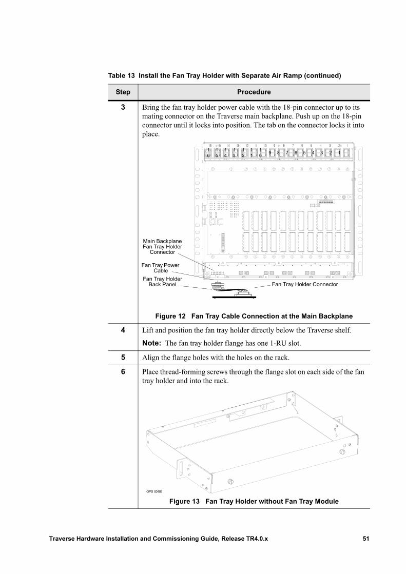
3 Bring the fan tray holder power cable with the 18-pin connector up to its mating connector on the Traverse main backplane. Push up on the 18-pin connector until it locks into position. The tab on the connector locks it into place.
.
Figure 12 Fan Tray Cable Connection at the Main Backplane
4 Lift and position the fan tray holder directly below the Traverse shelf.
Note: The fan tray holder flange has one 1-RU slot.
5 Align the flange holes with the holes on the rack.
6 Place thread-forming screws through the flange slot on each side of the fan tray holder and into the rack.
Figure 13 Fan Tray Holder without Fan Tray Module
Table 13 Install the Fan Tray Holder with Separate Air Ramp (continued)
Step Procedure
16
15
14
13
12
11
10
9 8 7 6 5 4 3 2 1
Main Backplane Fan Tray Holder
Connector
Fan Tray Holder Back Panel
Fan Tray Power Cable
Fan Tray Holder Connector
OPS 00103
Traverse Hardware Installation and Commissioning Guide, Release TR4.0.x 51
Install the Air Ramp
Install the air ramp directly below the fan tray holder.
Follow these air ramp installation steps.
Note: Standard conductive plated rack adapters may be required for installation. If so, refer to Install the Rack Adapters.
7 Partially tighten the thread-forming screws and position the fan tray holder.
8 Tighten the screws to secure and ground the fan tray holder to the rack. Torque screws to 65 lbs/in.
9 Bring the fan tray holder power cable (connected to the fan tray holder back panel) into position at the back of the fan tray holder. Line up the male connector to the female connector on the fan tray holder while tightening the back panel thumb screws.
10 The Install the Fan Tray Holder with Separate Air Ramp procedure is complete. Continue to the next procedure, Install the Front Inlet Fan Tray Holder.
Table 13 Install the Fan Tray Holder with Separate Air Ramp (continued)
Step Procedure
Important: If installing a Traverse shelf below another vendor’s equipment, install a standalone air ramp directly above the Traverse shelf.
Table 14 Install the Air Ramp
Step Procedure
1 Lift and position the air ramp. See the figure in Step 2 for a front view.
Note: The air ramp flange has one 1-RU slot.
2 Align the flange holes with the holes on the rack.
52 Traverse Hardware Installation and Commissioning Guide, Release TR4.0.x
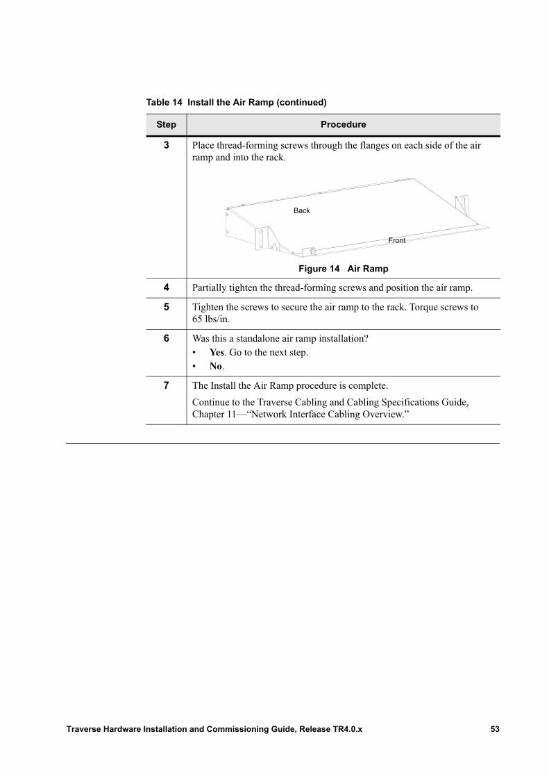
3 Place thread-forming screws through the flanges on each side of the air ramp and into the rack.
Figure 14 Air Ramp
4 Partially tighten the thread-forming screws and position the air ramp.
5 Tighten the screws to secure the air ramp to the rack. Torque screws to 65 lbs/in.
6 Was this a standalone air ramp installation?• Yes. Go to the next step.• No.
7 The Install the Air Ramp procedure is complete.
Continue to the Traverse Cabling and Cabling Specifications Guide, Chapter 11—“Network Interface Cabling Overview.”
Table 14 Install the Air Ramp (continued)
Step Procedure
Back
Front
Traverse Hardware Installation and Commissioning Guide, Release TR4.0.x 53

54 Traverse Hardware Installation and Commissioning Guide, Release TR4.0.x
Chapter 8 Traverse 2000 Installation into a 19-inch Rack
Introduction For hardware installation overview and guidelines, refer first to Chapter 1—“Installation and Commissioning Overview.”
This chapter provides the following information and procedures to complete a vertical- and standard 5 inch (127 mm) forward-mount installation of the Traverse 2000 system into a standard 7-foot (2133.6 mm) high, 19-inch (483 mm) wide telco rack.
• Vertical Traverse 2000 Rack Configuration• Install the Horizontal Rack Adapter Brackets• Install the Front Inlet Fan Tray Holder in a 19-inch Rack• Install a Traverse 2000 in a 19-inch Rack
Important: These instructions also apply to the installation of ETSI 600mm racks.
Traverse Hardware Installation and Commissioning Guide, Release TR4.0.x 55
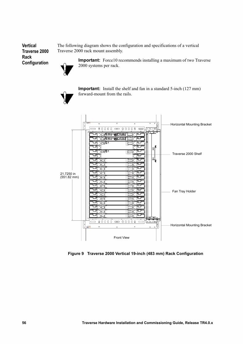
Vertical Traverse 2000 Rack Configuration
The following diagram shows the configuration and specifications of a vertical Traverse 2000 rack mount assembly.
Figure 9 Traverse 2000 Vertical 19-inch (483 mm) Rack Configuration
Important: Force10 recommends installing a maximum of two Traverse 2000 systems per rack.
Important: Install the shelf and fan in a standard 5-inch (127 mm) forward-mount from the rails.
Traverse 2000 Shelf
Horizontal Mounting Bracket
Horizontal Mounting Bracket
Fan Tray Holder
21.7250 in(551.82 mm)
Front View
56 Traverse Hardware Installation and Commissioning Guide, Release TR4.0.x
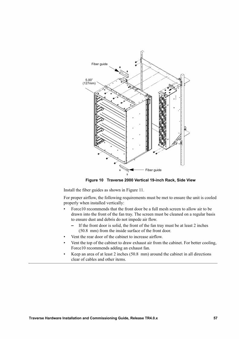
Figure 10 Traverse 2000 Vertical 19-inch Rack, Side View
Install the fiber guides as shown in Figure 11.
For proper airflow, the following requirements must be met to ensure the unit is cooled properly when installed vertically:• Force10 recommends that the front door be a full mesh screen to allow air to be
drawn into the front of the fan tray. The screen must be cleaned on a regular basis to ensure dust and debris do not impede air flow.– If the front door is solid, the front of the fan tray must be at least 2 inches
(50.8 mm) from the inside surface of the front door.• Vent the rear door of the cabinet to increase airflow.• Vent the top of the cabinet to draw exhaust air from the cabinet. For better cooling,
Force10 recommends adding an exhaust fan. • Keep an area of at least 2 inches (50.8 mm) around the cabinet in all directions
clear of cables and other items.
Fiber guide
5.00”(127mm)
Fiber guide
Traverse Hardware Installation and Commissioning Guide, Release TR4.0.x 57
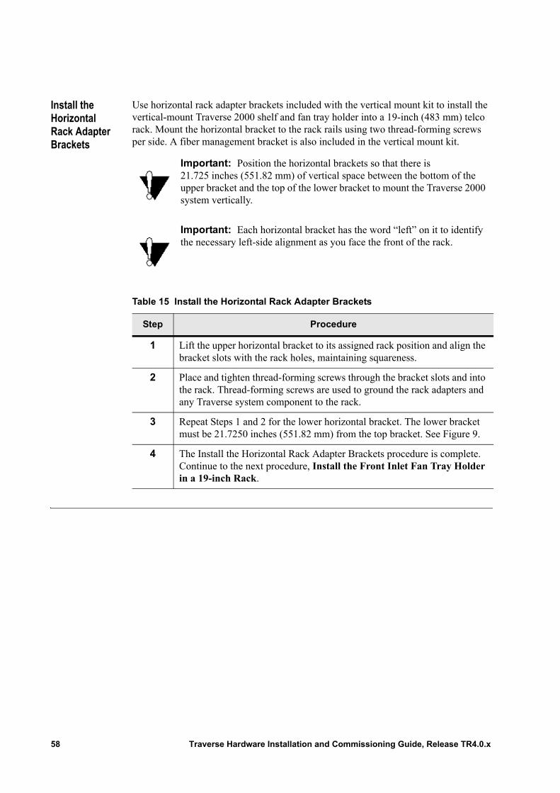
Install the Horizontal Rack Adapter Brackets
Use horizontal rack adapter brackets included with the vertical mount kit to install the vertical-mount Traverse 2000 shelf and fan tray holder into a 19-inch (483 mm) telco rack. Mount the horizontal bracket to the rack rails using two thread-forming screws per side. A fiber management bracket is also included in the vertical mount kit.
Important: Position the horizontal brackets so that there is 21.725 inches (551.82 mm) of vertical space between the bottom of the upper bracket and the top of the lower bracket to mount the Traverse 2000 system vertically.
Important: Each horizontal bracket has the word “left” on it to identify the necessary left-side alignment as you face the front of the rack.
Table 15 Install the Horizontal Rack Adapter Brackets
Step Procedure
1 Lift the upper horizontal bracket to its assigned rack position and align the bracket slots with the rack holes, maintaining squareness.
2 Place and tighten thread-forming screws through the bracket slots and into the rack. Thread-forming screws are used to ground the rack adapters and any Traverse system component to the rack.
3 Repeat Steps 1 and 2 for the lower horizontal bracket. The lower bracket must be 21.7250 inches (551.82 mm) from the top bracket. See Figure 9.
4 The Install the Horizontal Rack Adapter Brackets procedure is complete. Continue to the next procedure, Install the Front Inlet Fan Tray Holder in a 19-inch Rack.
58 Traverse Hardware Installation and Commissioning Guide, Release TR4.0.x
Install the Front Inlet Fan Tray Holder in a 19-inch Rack
The front inlet fan tray holder (with integrated air ramp) is required to cool the Traverse shelf during normal operation. Follow these installation steps.
Important: Install the front inlet fan tray holder so it will be flush with the bottom of the Traverse shelf and that no gap remains to ensure proper air flow.
Table 16 Install the Front Inlet Fan Tray Holder in a 19-inch Rack
Step Procedure
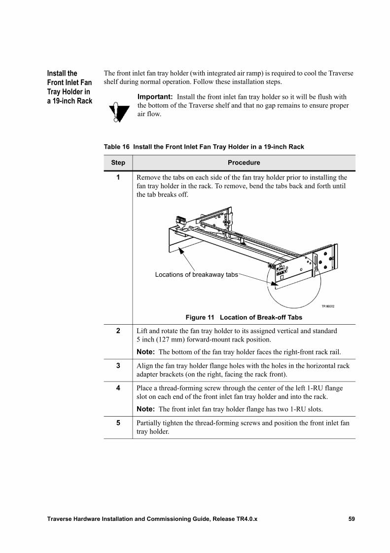
1 Remove the tabs on each side of the fan tray holder prior to installing the fan tray holder in the rack. To remove, bend the tabs back and forth until the tab breaks off.
Figure 11 Location of Break-off Tabs
2 Lift and rotate the fan tray holder to its assigned vertical and standard 5 inch (127 mm) forward-mount rack position.
Note: The bottom of the fan tray holder faces the right-front rack rail.
3 Align the fan tray holder flange holes with the holes in the horizontal rack adapter brackets (on the right, facing the rack front).
4 Place a thread-forming screw through the center of the left 1-RU flange slot on each end of the front inlet fan tray holder and into the rack.
Note: The front inlet fan tray holder flange has two 1-RU slots.
5 Partially tighten the thread-forming screws and position the front inlet fan tray holder.
Locations of breakaway tabs
Traverse Hardware Installation and Commissioning Guide, Release TR4.0.x 59

6 Tighten the screws to secure and ground the front inlet fan tray holder to the rack.
7 The Install the Front Inlet Fan Tray Holder in a 19-inch Rack procedure is complete.
Continue to the next procedure, Install a Traverse 2000 in a 19-inch Rack.
Table 16 Install the Front Inlet Fan Tray Holder in a 19-inch Rack (continued)
Step Procedure
60 Traverse Hardware Installation and Commissioning Guide, Release TR4.0.x
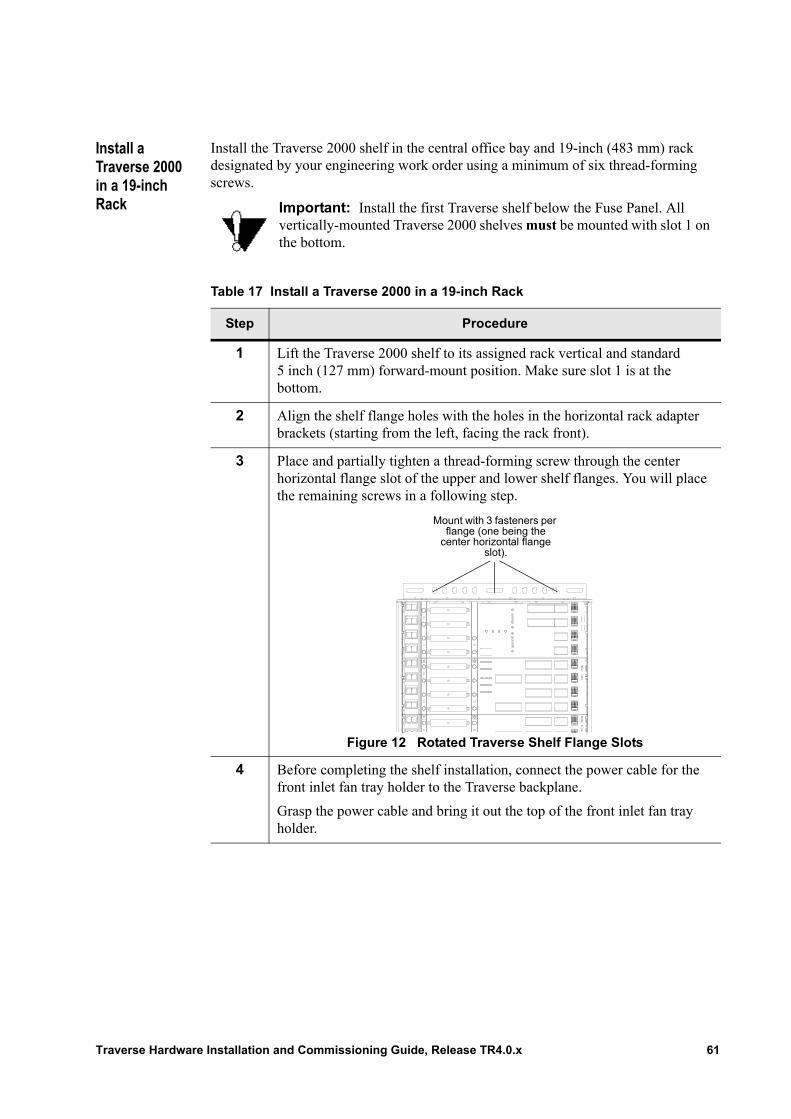
Install a Traverse 2000 in a 19-inch Rack
Install the Traverse 2000 shelf in the central office bay and 19-inch (483 mm) rack designated by your engineering work order using a minimum of six thread-forming screws.
Important: Install the first Traverse shelf below the Fuse Panel. All vertically-mounted Traverse 2000 shelves must be mounted with slot 1 on the bottom.
Table 17 Install a Traverse 2000 in a 19-inch Rack
Step Procedure
1 Lift the Traverse 2000 shelf to its assigned rack vertical and standard 5 inch (127 mm) forward-mount position. Make sure slot 1 is at the bottom.
2 Align the shelf flange holes with the holes in the horizontal rack adapter brackets (starting from the left, facing the rack front).
3 Place and partially tighten a thread-forming screw through the center horizontal flange slot of the upper and lower shelf flanges. You will place the remaining screws in a following step.
Figure 12 Rotated Traverse Shelf Flange Slots
4 Before completing the shelf installation, connect the power cable for the front inlet fan tray holder to the Traverse backplane.
Grasp the power cable and bring it out the top of the front inlet fan tray holder.
Mount with 3 fasteners per flange (one being the
center horizontal flange slot).
Traverse Hardware Installation and Commissioning Guide, Release TR4.0.x 61
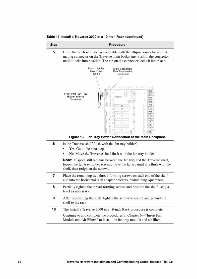
5 Bring the fan tray holder power cable with the 18-pin connector up to its mating connector on the Traverse main backplane. Push in the connector until it locks into position. The tab on the connector locks it into place.
Figure 13 Fan Tray Power Connection at the Main Backplane
6 Is the Traverse shelf flush with the fan tray holder?• Yes. Go to the next step.• No. Move the Traverse shelf flush with the fan tray holder.
Note: If space still remains between the fan tray and the Traverse shelf, loosen the fan tray holder screws, move the fan try until it is flush with the shelf, then retighten the screws.
7 Place the remaining two thread-forming screws on each end of the shelf and into the horizontal rack adapter brackets, maintaining squareness.
8 Partially tighten the thread-forming screws and position the shelf using a level as necessary.
9 After positioning the shelf, tighten the screws to secure and ground the shelf to the rack.
10 The Install a Traverse 2000 in a 19-inch Rack procedure is complete.
Continue to and complete the procedures in Chapter 6—“Insert Fan Module and Air Filters” to install the fan tray module and air filter.
Table 17 Install a Traverse 2000 in a 19-inch Rack (continued)
Step Procedure16
1514
1312
1110
98
76
54
3
Main Backplane Fan Tray Holder
Connector
Front Inlet Fan Tray Power
Cable
Front Inlet Fan Tray Holder Internal
Connector
62 Traverse Hardware Installation and Commissioning Guide, Release TR4.0.x

Chapter 9 Power System Overview
Introduction Several power system equipment choices are available to the user in order to providepower distribution and alarm capabilities in a Traverse system installation. The Force10power distribution and alarm panel (PDAP) is one choice and is considered an optional,adjunct component of the Traverse system.
This chapter includes the following topics:• Power Distribution and Alarm Panel (PDAP) Description• PDAP Installation and Cabling Process
For Traverse power terminal locations, refer to any one of the Traverse rear view topics in the Traverse Hardware Guide.
For power consumption values, refer to the Planning and Engineering Guide, Chapter 1—“Traverse Equipment Specifications,” Power Consumption.
Power Distribution and Alarm Panel (PDAP) Description
The Traverse system is powered by the central office battery (–48 VDC). Redundant central office (CO) battery and battery return is connected to the Power Distribution and Alarm Panel (PDAP).
The PDAP provides the following:• Terminates redundant –48 VDC central office battery• Terminates central office battery return• Distributes redundant battery and battery return• Provides power protection for Traverse shelves and auxiliary equipment• Visually display input power, fuse power, and critical, major, and minor bay alarms
Important: Carefully plan your power supply capacity. The Force10 PDAP-4S with standard 40 amp fuses at –40 VDC provides 1600 watts. Force10 recommends using higher amperage fuses if your power requirements go above a minimum of 1400 watts. If you fail to make sufficient plans to meet the power requirements of your specific configuration, and the power draw goes above the maximum capacity of your power supply design, it can cause a circuit breaker to trip, resulting in a loss of traffic.
Traverse Hardware Installation and Commissioning Guide, Release TR4.0.x 63
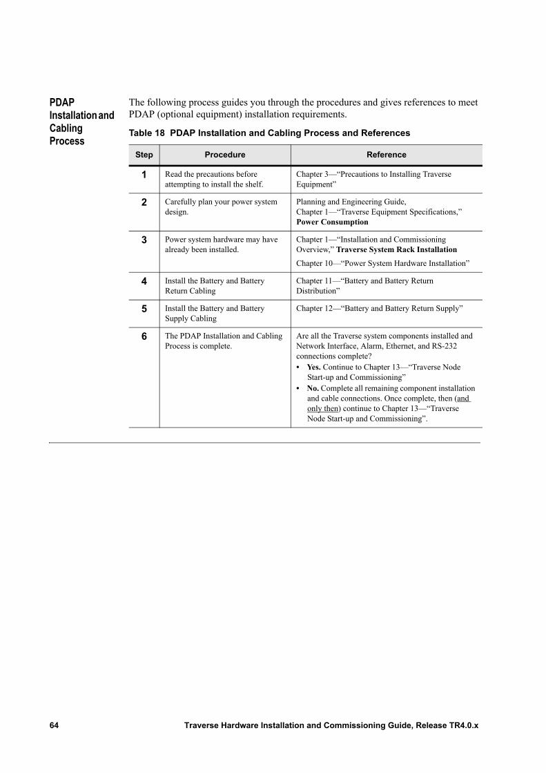
PDAP Installation and Cabling Process
The following process guides you through the procedures and gives references to meet PDAP (optional equipment) installation requirements.
Table 18 PDAP Installation and Cabling Process and References
Step Procedure Reference
1 Read the precautions before attempting to install the shelf.
Chapter 3—“Precautions to Installing Traverse Equipment”
2 Carefully plan your power system design.
Planning and Engineering Guide, Chapter 1—“Traverse Equipment Specifications,” Power Consumption
3 Power system hardware may have already been installed.
Chapter 1—“Installation and Commissioning Overview,” Traverse System Rack Installation
Chapter 10—“Power System Hardware Installation”
4 Install the Battery and Battery Return Cabling
Chapter 11—“Battery and Battery Return Distribution”
5 Install the Battery and Battery Supply Cabling
Chapter 12—“Battery and Battery Return Supply”
6 The PDAP Installation and Cabling Process is complete.
Are all the Traverse system components installed and Network Interface, Alarm, Ethernet, and RS-232 connections complete?• Yes. Continue to Chapter 13—“Traverse Node
Start-up and Commissioning”• No. Complete all remaining component installation
and cable connections. Once complete, then (and only then) continue to Chapter 13—“Traverse Node Start-up and Commissioning”.
64 Traverse Hardware Installation and Commissioning Guide, Release TR4.0.x
Chapter 10 Power System Hardware Installation
Introduction This chapter provides step-by-step instructions on how to install a PDAP in a standard 7-foot (2133.6 mm) high, 19-inch or 23-inch (483 mm or 584 mm) wide telco rack.
This chapter provides the following topics to complete power system installation.• Required Equipment and Tools• Power System Installation• Grounding the PDAP
The instructions may be too detailed if you are experienced in central office installations. In this case, scan the topic labels in the left margin for tasks to review or refer to Chapter 16—“Installation and Commissioning Checklists.”
Required Equipment and Tools
The following equipment and tools are required to install the power system hardware:• Standard 7-foot (2133.6 mm) high, 19-inch or 23-inch (483 mm or 584 mm) wide
telco rack• Standard conductive plated rack adapters with tread-forming screws required for
rack installation, where applicable• Power system (e.g., PDAP-4S or PDAP-15A• Four appropriate-sized (e.g., 12-24) thread-forming screws for securing and
grounding the equipment• A 5/16-inch socket for thread-forming screws• Green (#10 AWG or 6 mm2 yellow-green) copper ground wire for grounding:
– Up to #4 AWG (25 mm2) for the PDAP-4S (depending on the input interrupt device)
– Up to #6 AWG (15 mm2) for the PDAP-15A (depending on the input interrupt device)
• 1 – double-hole copper barrel cable lug for ground terminal connection:– 1 – 1/4-inch (6.35 mm) (clearance hole with .625-inch spacing) for the
PDAP-4S– 1 – M5 (0.19-inch or 5 mm) (clearance hole with .625-inch spacing) for the
PDAP-15A• Step ladder (optional)
Traverse Hardware Installation and Commissioning Guide, Release TR4.0.x 65
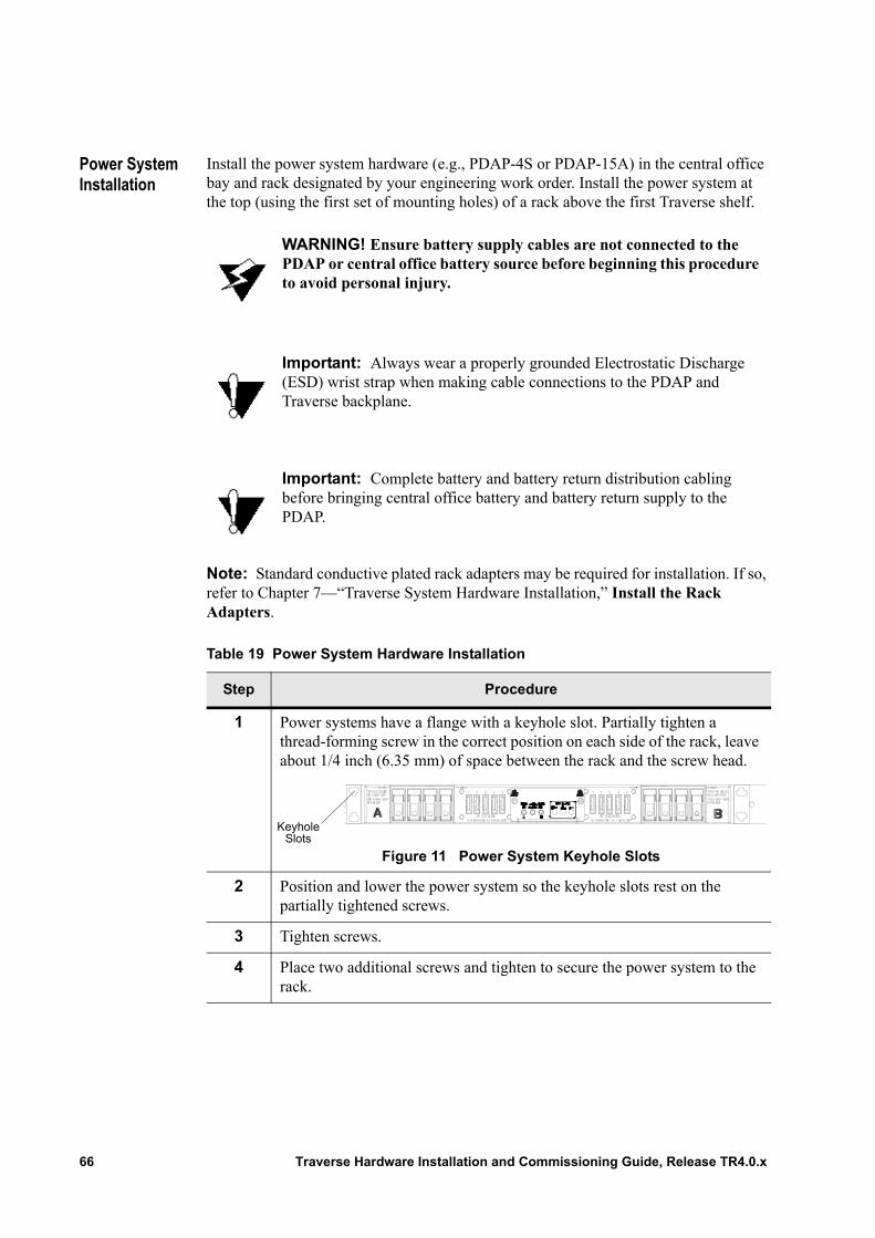
Power System Installation
Install the power system hardware (e.g., PDAP-4S or PDAP-15A) in the central office bay and rack designated by your engineering work order. Install the power system at the top (using the first set of mounting holes) of a rack above the first Traverse shelf.
Note: Standard conductive plated rack adapters may be required for installation. If so, refer to Chapter 7—“Traverse System Hardware Installation,” Install the Rack Adapters.
WARNING! Ensure battery supply cables are not connected to the PDAP or central office battery source before beginning this procedure to avoid personal injury.
Important: Always wear a properly grounded Electrostatic Discharge (ESD) wrist strap when making cable connections to the PDAP and Traverse backplane.
Important: Complete battery and battery return distribution cabling before bringing central office battery and battery return supply to the PDAP.
Table 19 Power System Hardware Installation
Step Procedure
1 Power systems have a flange with a keyhole slot. Partially tighten a thread-forming screw in the correct position on each side of the rack, leave about 1/4 inch (6.35 mm) of space between the rack and the screw head.
Figure 11 Power System Keyhole Slots
2 Position and lower the power system so the keyhole slots rest on the partially tightened screws.
3 Tighten screws.
4 Place two additional screws and tighten to secure the power system to the rack.
KeyholeSlots
66 Traverse Hardware Installation and Commissioning Guide, Release TR4.0.x
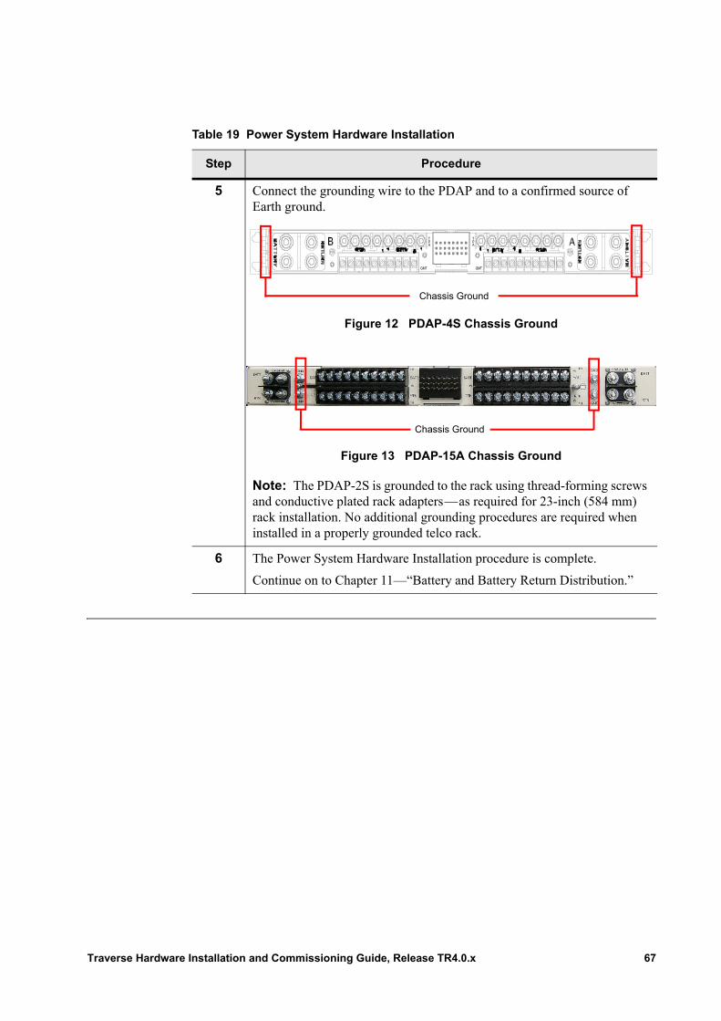
5 Connect the grounding wire to the PDAP and to a confirmed source of Earth ground.
Figure 12 PDAP-4S Chassis Ground
Figure 13 PDAP-15A Chassis Ground
Note: The PDAP-2S is grounded to the rack using thread-forming screws and conductive plated rack adapters—as required for 23-inch (584 mm) rack installation. No additional grounding procedures are required when installed in a properly grounded telco rack.
6 The Power System Hardware Installation procedure is complete.
Continue on to Chapter 11—“Battery and Battery Return Distribution.”
Table 19 Power System Hardware Installation
Step Procedure
TPA
PA
T
GMT GMT
Chassis Ground
Chassis Ground
Traverse Hardware Installation and Commissioning Guide, Release TR4.0.x 67
Grounding the PDAP
There is a chassis ground location on the PDAP-4S and PDAP-15A for connecting a grounding wire. Connect the grounding wire to the PDAP and to a confirmed source of earth ground. For PDAP chassis ground locations, refer to the Traverse Cabling and Cabling Specifications Guide, Chapter 9—“Power Interface Specifications,” Power Distribution and Alarm Panel (PDAP) Description.
The PDAP-2S is grounded to the rack using thread-forming screws and conductive plated rack adapters—as required for 23-inch (584 mm) rack installation. No additional grounding procedures are required when installed in a properly grounded telco rack. Isolate DC power returns from frame ground (DC-I).
Important: For NEBS compliance, remove paint and any other non-conductive coatings on the surfaces between the mounting hardware and the rack framework. Clean all surfaces and apply anti-oxidant before joining.
Coat all bare conductors with an appropriate anti-oxidant compound before crimp connections are made. Bring all connectors to a bright finish and coat with an anti-oxidant before making the connection.
68 Traverse Hardware Installation and Commissioning Guide, Release TR4.0.x
Chapter 11 Battery and Battery Return Distribution
Introduction For power system installation overview and guidelines, refer first to Chapter 9—“Power System Overview.”
This chapter provides step-by-step instructions on how to connect battery and battery return distribution cables from each Traverse shelf in a single-rack configuration to the PDAP.• Required Equipment and Tools• Battery and Battery Return Distribution Cabling Procedures
The instructions may be too detailed if you are experienced in CO installations. In this case, scan the topic labels in the left margin for tasks to review or refer to Chapter 16—“Installation and Commissioning Checklists.”
Required Equipment and Tools
The following equipment and tools are required to make central office battery and battery return distribution connections to each Traverse shelf and the PDAP.
General
• Electrostatic Discharge (ESD) wrist strap• Diagonal cutters• Crimping tool• Volt Ohm Meter (VOM)
Note: Power (-48VDC and RETURN) copper area wire colors are dependent on your local cable requirements.
Important: Read through Chapter 3—“Precautions to Installing Traverse Equipment,” Electrical Precautions before you begin.
Traverse Hardware Installation and Commissioning Guide, Release TR4.0.x 69
Traverse shelf only
• 4 – #10 (clearance hole with .625-inch spacing) double-hole copper barrel cable lugs to connect battery distribution (-48VDC) cables (e.g., #8 AWG or 9 mm2 for PDAP-4S or -2S, #12 AWG or 3.3 mm2 for PDAP-15A red or gray copper area wire) and battery return distribution (RETURN) cables (e.g., #8 AWG or 9 mm2 for PDAP-4S or -2S, #12 AWG or 3.3 mm2 for PDAP-15A black or blue copper area wire) to the Traverse backplane
• 8 – #8-32 SEMS screws to connect battery distribution (-48VDC) and battery return distribution (RETURN) cables to the Traverse backplane
• A common power return jumper plate to prevent faulty wiring short circuit. This item comes pre-installed at the common return (RETURN_A RETURN_B) power terminals on the bottom-center of the Traverse backplane
• A 1/4-inch socket (or nutdriver) for Traverse shelf backplane power terminal connections
PDAP-4S only
• 2 – battery distribution (-48VDC) cables (e.g., #8 AWG or 9 mm2 red or gray copper area wire)
• 2 – battery return distribution (RETURN) cables (e.g., #8 AWG or 9 mm2 black or blue copper area wire)
• 4 – #10 single-hole copper barrel cable lugs to connect battery distribution (-48VDC) cables (e.g., #8 AWG or 9 mm2 red or gray copper area wire) and battery return distribution (RETURN) cables (e.g., #8 AWG or 9 mm2 black or blue copper area wire) to the PDAP-4S
• 4 – #10-32 KEP nuts to connect battery distribution (-48VDC) and battery return distribution (RETURN) cables to the PDAP-4S
• A 5/16-inch (8 mm) socket
PDAP-15A only
• 2 – battery distribution (-48VDC) cables (e.g., #12 AWG or 3.3 mm2 red or gray copper area wire)
• 2 – battery return distribution (RETURN) cables (e.g., #12 AWG or 3.3 mm2 black or blue copper area wire)
• 4 – #6 single-hole copper barrel cable lugs to connect battery distribution (-48VDC) cables (e.g., #12 AWG or 3.3 mm2 red or gray copper area wire) and battery return distribution (RETURN) cables (e.g., #12 AWG or 3.3 mm2 black or blue copper area wire) to the PDAP-15A
• 4 – SEMS screws to connect battery distribution (-48VDC) and battery return distribution (RETURN) cables to the PDAP-15A
• A Phillips screwdriver
70 Traverse Hardware Installation and Commissioning Guide, Release TR4.0.x
Battery and Battery Return Distribution Cabling Procedures
Battery and battery return distribution cabling procedures are written for each PDAP type. Refer to the correct procedures based on the type of PDAP installed in the rack:• Connect PDAP-4S Battery Distribution Cables• Connect PDAP-4S Battery Return Distribution Cables• Connect PDAP-15A Battery Distribution Cables• Connect PDAP-15A Battery Return Distribution Cables
Connect PDAP-4S Battery Distribution Cables
The PDAP-4S distributes central office battery (-48VDC) to up to four Traverse 1600 or Traverse 2000 shelves in a rack.
Follow these steps to connect battery distribution cables (-48VDC) from a Traverse shelf to the PDAP-4S.
Note: Traverse 2000 main backplane graphics are used in the following procedure. Battery (-48VDC_A and -48VDC_B) terminals are located in the same place on the Traverse 1600 backplane.
WARNING! Ensure battery supply cables are not connected to the PDAP or central office battery source before beginning this procedure to avoid personal injury.
Important: Always wear a properly grounded Electrostatic Discharge (ESD) wrist strap when making cable connections to the PDAP and Traverse main backplane.
Important: Complete battery and battery return distribution cabling before bringing central office battery and battery return supply to the PDAP-4S.
Table 20 Connect PDAP-4S Battery Distribution Cables
Step Procedure
1 Remove the protective cover from the back of the PDAP-4S. Refer to Chapter 4—“Removing and Replacing Back Covers,” Remove the PDAP Protective Back Cover for details.
2 Remove the back cover from the [first] Traverse shelf in the rack. Refer to Chapter 4—“Removing and Replacing Back Covers,” Main Backplane Covers for details.
Traverse Hardware Installation and Commissioning Guide, Release TR4.0.x 71
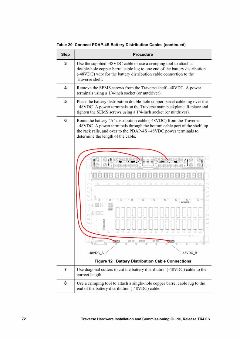
3 Use the supplied -48VDC cable or use a crimping tool to attach a double-hole copper barrel cable lug to one end of the battery distribution (-48VDC) wire for the battery distribution cable connection to the Traverse shelf.
4 Remove the SEMS screws from the Traverse shelf –48VDC_A power terminals using a 1/4-inch socket (or nutdriver).
5 Place the battery distribution double-hole copper barrel cable lug over the –48VDC_A power terminals on the Traverse main backplane. Replace and tighten the SEMS screws using a 1/4-inch socket (or nutdriver).
6 Route the battery "A" distribution cable (-48VDC) from the Traverse –48VDC_A power terminals through the bottom cable port of the shelf, up the rack rails, and over to the PDAP-4S –48VDC power terminals to determine the length of the cable.
Figure 12 Battery Distribution Cable Connections
7 Use diagonal cutters to cut the battery distribution (-48VDC) cable to the correct length.
8 Use a crimping tool to attach a single-hole copper barrel cable lug to the end of the battery distribution (-48VDC) cable.
Table 20 Connect PDAP-4S Battery Distribution Cables (continued)
Step Procedure
TPA
PA
T
GMT GMT
-48VDC_B-48VDC_A
72 Traverse Hardware Installation and Commissioning Guide, Release TR4.0.x

9 Remove the KEP nut from the PDAP-4S battery "A" distribution power terminal, position A1 (shelf 1).
Figure 13 PDAP-4S Battery Distribution Power Terminals
Note: Battery "A" distribution power terminal positions on the PDAP-4S are: position A1 (shelf 1), A2 (shelf 2), A3 (shelf 3), and position A4 (shelf 4). Battery "B" distribution power terminal positions on the PDAP-4S are: position B1 (shelf 1), B2 (shelf 2), B3 (shelf 3), and position B4 (shelf 4).
10 Place the single-hole copper barrel cable lug on the battery "A" distribution power terminal (position A1). Replace and tighten the nut.
11 Repeat Steps 1 through 10 for the battery "B" distribution cable (i.e., connect the battery cable from the Traverse –48VDC_B power terminals to position B1 of the PDAP-4S battery distribution terminals).
12 Are there additional Traverse shelves in the rack?• Yes. Repeat Steps 1 through 11 for each Traverse shelf.• No. Continue to Step 13.
13 The Connect PDAP-4S Battery Distribution Cables procedure is complete.
Continue to the next procedure, Connect PDAP-4S Battery Return Distribution Cables.
Table 20 Connect PDAP-4S Battery Distribution Cables (continued)
Step Procedure
Battery “A” DistributionBattery “B” Distribution
Traverse Hardware Installation and Commissioning Guide, Release TR4.0.x 73
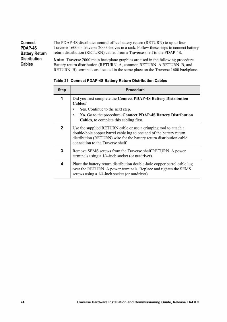
Connect PDAP-4S Battery Return Distribution Cables
The PDAP-4S distributes central office battery return (RETURN) to up to four Traverse 1600 or Traverse 2000 shelves in a rack. Follow these steps to connect battery return distribution (RETURN) cables from a Traverse shelf to the PDAP-4S.
Note: Traverse 2000 main backplane graphics are used in the following procedure. Battery return distribution (RETURN_A, common RETURN_A RETURN_B, and RETURN_B) terminals are located in the same place on the Traverse 1600 backplane.
Table 21 Connect PDAP-4S Battery Return Distribution Cables
Step Procedure
1 Did you first complete the Connect PDAP-4S Battery Distribution Cables?• Yes. Continue to the next step.• No. Go to the procedure, Connect PDAP-4S Battery Distribution
Cables, to complete this cabling first.
2 Use the supplied RETURN cable or use a crimping tool to attach a double-hole copper barrel cable lug to one end of the battery return distribution (RETURN) wire for the battery return distribution cable connection to the Traverse shelf.
3 Remove SEMS screws from the Traverse shelf RETURN_A power terminals using a 1/4-inch socket (or nutdriver).
4 Place the battery return distribution double-hole copper barrel cable lug over the RETURN_A power terminals. Replace and tighten the SEMS screws using a 1/4-inch socket (or nutdriver).
74 Traverse Hardware Installation and Commissioning Guide, Release TR4.0.x
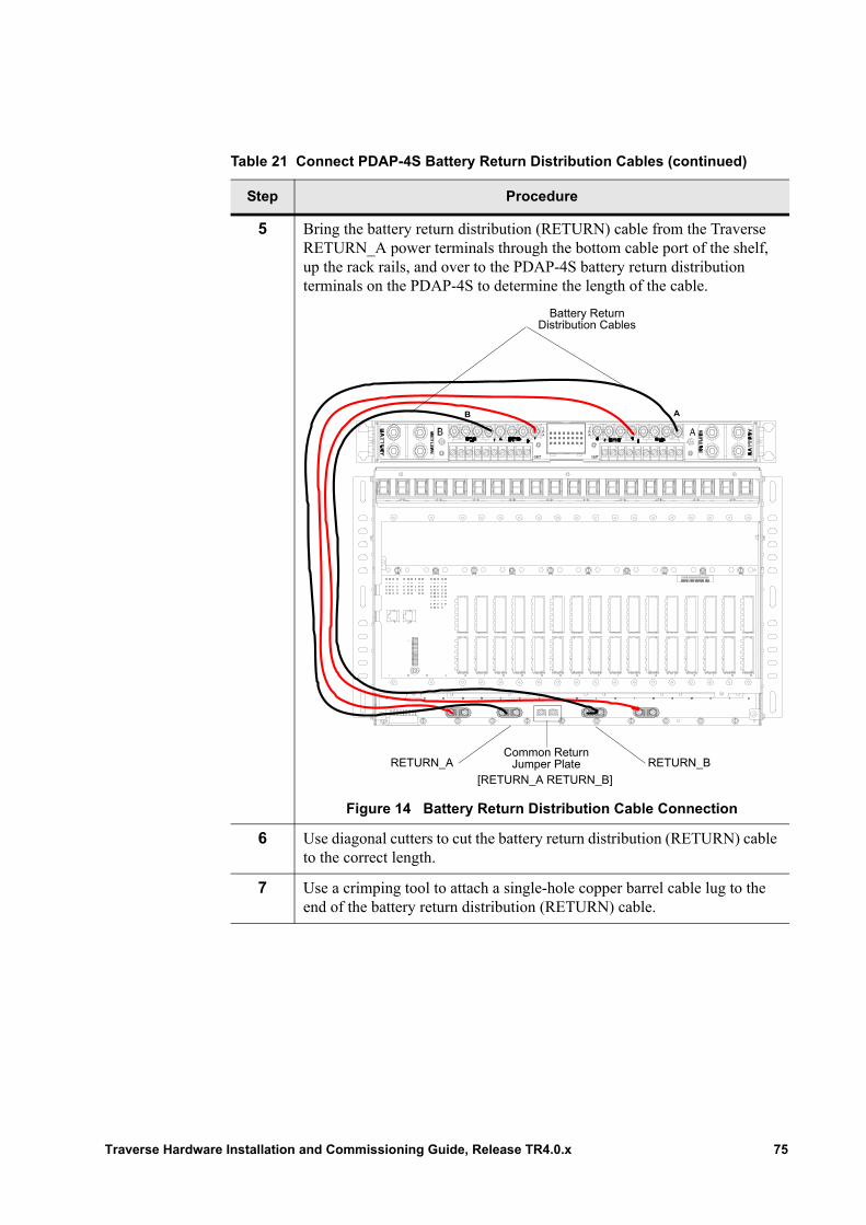
5 Bring the battery return distribution (RETURN) cable from the Traverse RETURN_A power terminals through the bottom cable port of the shelf, up the rack rails, and over to the PDAP-4S battery return distribution terminals on the PDAP-4S to determine the length of the cable.
Figure 14 Battery Return Distribution Cable Connection
6 Use diagonal cutters to cut the battery return distribution (RETURN) cable to the correct length.
7 Use a crimping tool to attach a single-hole copper barrel cable lug to the end of the battery return distribution (RETURN) cable.
Table 21 Connect PDAP-4S Battery Return Distribution Cables (continued)
Step Procedure
AB
TPA
PA
T
GMT GMT
Battery Return Distribution Cables
RETURN_A RETURN_B
[RETURN_A RETURN_B]
Common Return Jumper Plate
Traverse Hardware Installation and Commissioning Guide, Release TR4.0.x 75
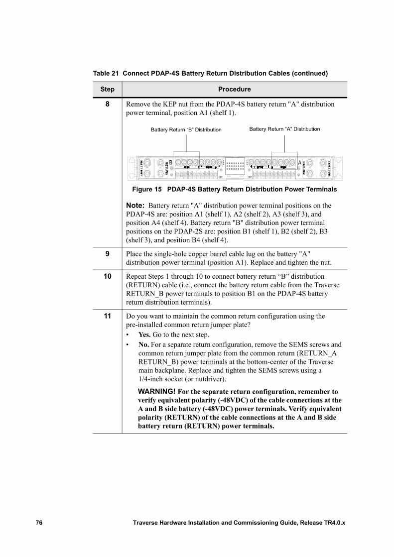
8 Remove the KEP nut from the PDAP-4S battery return "A" distribution power terminal, position A1 (shelf 1).
Figure 15 PDAP-4S Battery Return Distribution Power Terminals
Note: Battery return "A" distribution power terminal positions on the PDAP-4S are: position A1 (shelf 1), A2 (shelf 2), A3 (shelf 3), and position A4 (shelf 4). Battery return "B" distribution power terminal positions on the PDAP-2S are: position B1 (shelf 1), B2 (shelf 2), B3 (shelf 3), and position B4 (shelf 4).
9 Place the single-hole copper barrel cable lug on the battery "A" distribution power terminal (position A1). Replace and tighten the nut.
10 Repeat Steps 1 through 10 to connect battery return “B” distribution (RETURN) cable (i.e., connect the battery return cable from the Traverse RETURN_B power terminals to position B1 on the PDAP-4S battery return distribution terminals).
11 Do you want to maintain the common return configuration using the pre-installed common return jumper plate?• Yes. Go to the next step.• No. For a separate return configuration, remove the SEMS screws and
common return jumper plate from the common return (RETURN_A RETURN_B) power terminals at the bottom-center of the Traverse main backplane. Replace and tighten the SEMS screws using a 1/4-inch socket (or nutdriver).
WARNING! For the separate return configuration, remember to verify equivalent polarity (-48VDC) of the cable connections at the A and B side battery (-48VDC) power terminals. Verify equivalent polarity (RETURN) of the cable connections at the A and B side battery return (RETURN) power terminals.
Table 21 Connect PDAP-4S Battery Return Distribution Cables (continued)
Step Procedure
TPA
PA
T
GMT GMT
Battery Return “A” DistributionBattery Return “B” Distribution
76 Traverse Hardware Installation and Commissioning Guide, Release TR4.0.x
Connect PDAP-15A Battery Distribution Cables
The PDAP-15A distributes central office battery (-48VDC) to the Traverse 600 shelf.
Follow these steps to connect battery distribution (-48VDC) cables from a Traverse 600 shelf to the PDAP-15A.
12 Are there additional Traverse shelves in the rack?• Yes. Repeat Steps 1 through 11 for the second shelf.• No. Continue to Step 13.
13 The Connect PDAP-4S Battery Return Distribution Cables procedure is complete.
Continue to Chapter 12—“Battery and Battery Return Supply.”.
Table 21 Connect PDAP-4S Battery Return Distribution Cables (continued)
Step Procedure
WARNING! Ensure battery supply cables are not connected to the PDAP or central office battery source before beginning this procedure to avoid personal injury.
Important: Always wear a properly grounded Electrostatic Discharge (ESD) wrist strap when making cable connections to the PDAP and Traverse main backplane.
Important: Complete battery and battery return distribution cabling before bringing central office battery and battery return supply to the PDAP-15A.
Table 22 Connect PDAP-15A Battery Distribution Cables
Step Procedure
1 Remove the protective cover from the back of the PDAP-15A. Refer to Chapter 4—“Removing and Replacing Back Covers,” Remove the PDAP Protective Back Cover for details.
2 Remove the back cover from the [first] Traverse shelf in the rack. Refer to Chapter 4—“Removing and Replacing Back Covers,” Main Backplane Covers for details.
Traverse Hardware Installation and Commissioning Guide, Release TR4.0.x 77
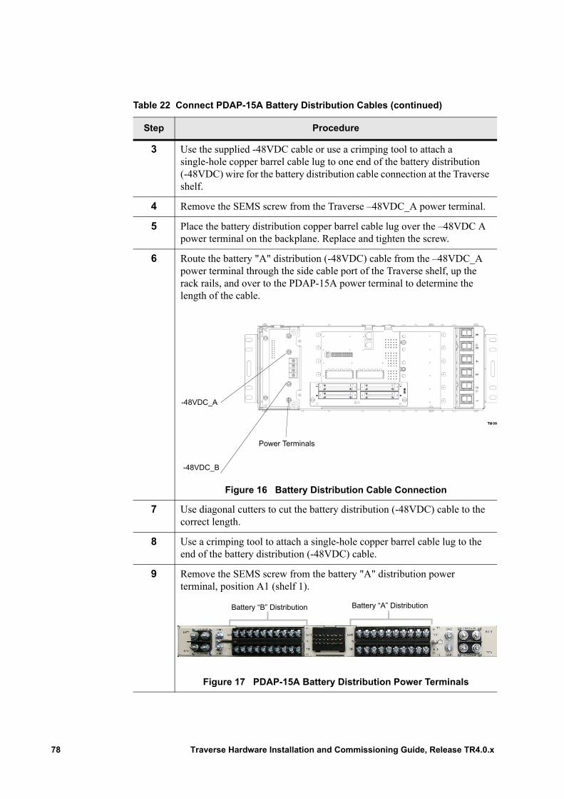
3 Use the supplied -48VDC cable or use a crimping tool to attach a single-hole copper barrel cable lug to one end of the battery distribution (-48VDC) wire for the battery distribution cable connection at the Traverse shelf.
4 Remove the SEMS screw from the Traverse –48VDC_A power terminal.
5 Place the battery distribution copper barrel cable lug over the –48VDC A power terminal on the backplane. Replace and tighten the screw.
6 Route the battery "A" distribution (-48VDC) cable from the –48VDC_A power terminal through the side cable port of the Traverse shelf, up the rack rails, and over to the PDAP-15A power terminal to determine the length of the cable.
Figure 16 Battery Distribution Cable Connection
7 Use diagonal cutters to cut the battery distribution (-48VDC) cable to the correct length.
8 Use a crimping tool to attach a single-hole copper barrel cable lug to the end of the battery distribution (-48VDC) cable.
9 Remove the SEMS screw from the battery "A" distribution power terminal, position A1 (shelf 1).
Figure 17 PDAP-15A Battery Distribution Power Terminals
Table 22 Connect PDAP-15A Battery Distribution Cables (continued)
Step Procedure
-48VDC_B
-48VDC_A
Power Terminals
Battery “B” Distribution Battery “A” Distribution
78 Traverse Hardware Installation and Commissioning Guide, Release TR4.0.x
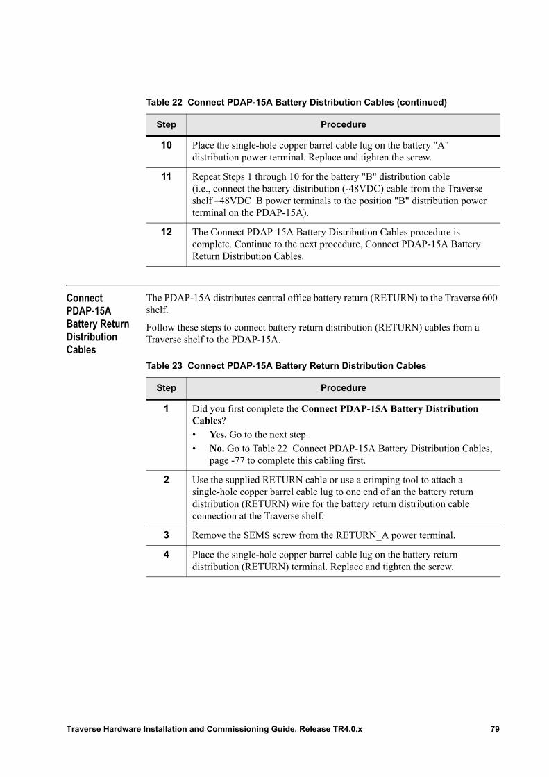
Connect PDAP-15A Battery Return Distribution Cables
The PDAP-15A distributes central office battery return (RETURN) to the Traverse 600 shelf.
Follow these steps to connect battery return distribution (RETURN) cables from a Traverse shelf to the PDAP-15A.
10 Place the single-hole copper barrel cable lug on the battery "A" distribution power terminal. Replace and tighten the screw.
11 Repeat Steps 1 through 10 for the battery "B" distribution cable (i.e., connect the battery distribution (-48VDC) cable from the Traverse shelf –48VDC_B power terminals to the position "B" distribution power terminal on the PDAP-15A).
12 The Connect PDAP-15A Battery Distribution Cables procedure is complete. Continue to the next procedure, Connect PDAP-15A Battery Return Distribution Cables.
Table 22 Connect PDAP-15A Battery Distribution Cables (continued)
Step Procedure
Table 23 Connect PDAP-15A Battery Return Distribution Cables
Step Procedure
1 Did you first complete the Connect PDAP-15A Battery Distribution Cables?• Yes. Go to the next step.• No. Go to Table 22 Connect PDAP-15A Battery Distribution Cables,
page -77 to complete this cabling first.
2 Use the supplied RETURN cable or use a crimping tool to attach a single-hole copper barrel cable lug to one end of an the battery return distribution (RETURN) wire for the battery return distribution cable connection at the Traverse shelf.
3 Remove the SEMS screw from the RETURN_A power terminal.
4 Place the single-hole copper barrel cable lug on the battery return distribution (RETURN) terminal. Replace and tighten the screw.
Traverse Hardware Installation and Commissioning Guide, Release TR4.0.x 79
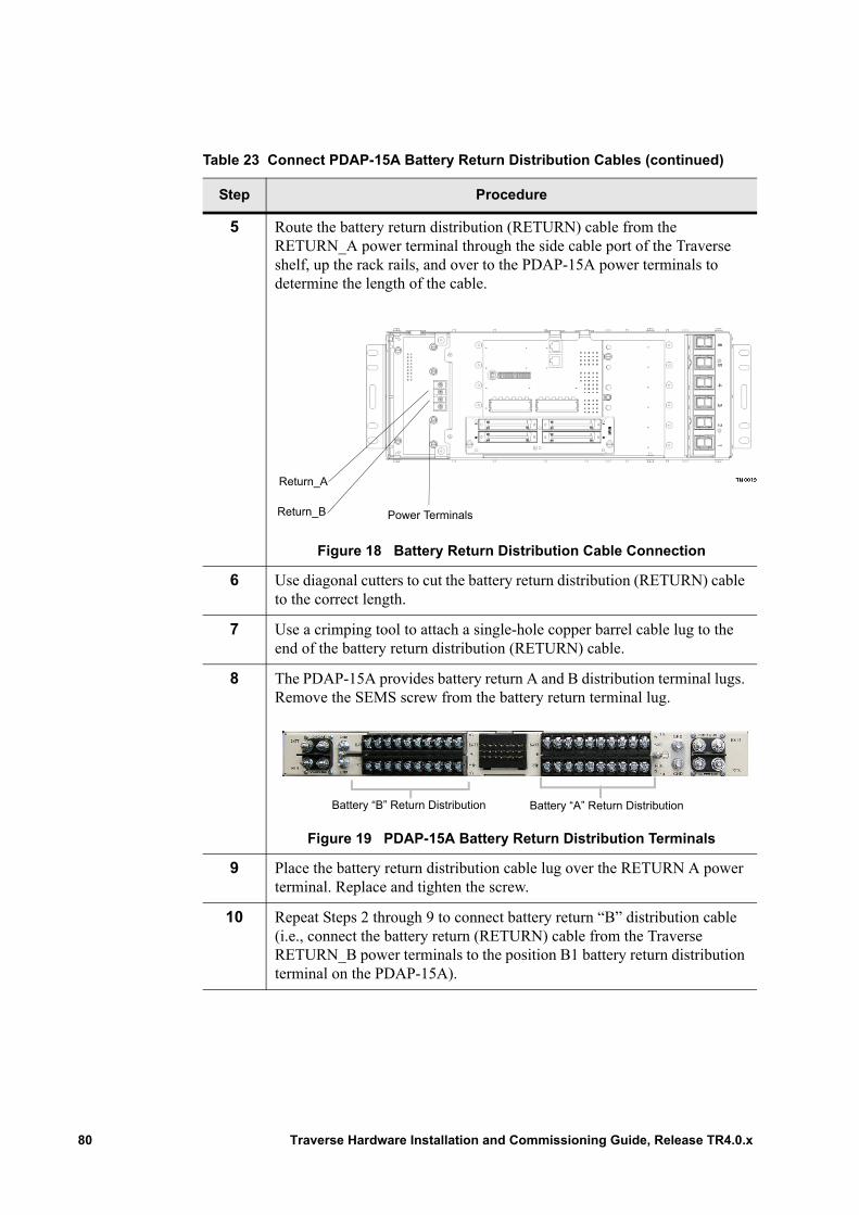
5 Route the battery return distribution (RETURN) cable from the RETURN_A power terminal through the side cable port of the Traverse shelf, up the rack rails, and over to the PDAP-15A power terminals to determine the length of the cable.
Figure 18 Battery Return Distribution Cable Connection
6 Use diagonal cutters to cut the battery return distribution (RETURN) cable to the correct length.
7 Use a crimping tool to attach a single-hole copper barrel cable lug to the end of the battery return distribution (RETURN) cable.
8 The PDAP-15A provides battery return A and B distribution terminal lugs. Remove the SEMS screw from the battery return terminal lug.
Figure 19 PDAP-15A Battery Return Distribution Terminals
9 Place the battery return distribution cable lug over the RETURN A power terminal. Replace and tighten the screw.
10 Repeat Steps 2 through 9 to connect battery return “B” distribution cable (i.e., connect the battery return (RETURN) cable from the Traverse RETURN_B power terminals to the position B1 battery return distribution terminal on the PDAP-15A).
Table 23 Connect PDAP-15A Battery Return Distribution Cables (continued)
Step Procedure
Power Terminals
Return_A
Return_B
Battery “B” Return Distribution Battery “A” Return Distribution
80 Traverse Hardware Installation and Commissioning Guide, Release TR4.0.x
11 Do you want to maintain the common return configuration using the pre-installed common return jumper plate?• Yes. Go to the next step.• No. For a separate return configuration, remove the SEMS screws and
common return jumper plate from the common return (RETURN_A RETURN_B) power terminals at the bottom-center of the Traverse main backplane. Replace and tighten the SEMS screws.
WARNING! For the separate return configuration, remember to verify equivalent polarity (-48VDC) of the cable connections at the A and B side battery (-48VDC) power terminals. Verify equivalent polarity (RETURN) of the cable connections at the A and B side battery return (RETURN) power terminals.
12 The Connect PDAP-15A Battery Return Distribution Cables procedure is complete.
Continue to Chapter 12—“Battery and Battery Return Supply.”
Table 23 Connect PDAP-15A Battery Return Distribution Cables (continued)
Step Procedure
Traverse Hardware Installation and Commissioning Guide, Release TR4.0.x 81

82 Traverse Hardware Installation and Commissioning Guide, Release TR4.0.x

Chapter 12 Battery and Battery Return Supply
Introduction For power system installation overview and guidelines, refer first to Chapter 9—“Power System Overview.”
This chapter provides step-by-step instructions on how to connect:• Battery cables from the central office power supply to the PDAP.• Battery return cables from the central office battery return supply to the PDAP.
The topics are as follows:• Required Equipment and Tools• Connect Battery Supply Cables to the PDAP• Connect Battery Return Supply Cables to the PDAP• Connect Supply Cables to the Central Office Source• Verify Polarity• Verify Voltage
The instructions may be too detailed if you are experienced in CO installations. In this case, scan the topic labels in the left margin for tasks to review or refer to Chapter 16—“Installation and Commissioning Checklists.”
Traverse Hardware Installation and Commissioning Guide, Release TR4.0.x 83
Required Equipment and Tools
The following equipment and tools are required to make central office battery and battery return supply connections to the PDAP.
General:
• 2 – (customer-supplied) battery supply cables• 2 – (customer-supplied) battery return supply cables• 4 – (customer-supplied) copper cable lugs for connection at the central office
battery source
• Electrostatic Discharge (ESD) wrist strap• Crimping tool• Diagonal cutters• Volt Ohm Meter (VOM)
PDAP-4S only:
• 4 – 1/4-inch (clearance hole with 3/4-inch spacing) double-hole copper barrel cable lugs for battery and battery return supply cable connection to the PDAP-4S
• 8 – 1/4-20 nuts to connect battery and battery return supply cables to the PDAP-4S• 8 – 1/4-inch lock washers to connect battery and battery return supply cables to the
PDAP-4S• 8 – 1/4-inch flat washers to connect battery and battery return supply cables to the
PDAP-4S• A 7/16-inch (11 mm) socket• For further information, refer to the Telect website at www.telect.com. and request
the publication for Model #009-8005-1404.
PDAP-15A only:
• 4 – #10 (clearance hole with 5/8-inch spacing) double-hole copper barrel cable lugs for battery and battery return supply cable connection to the PDAP-15A
• 4 – M5 (0.19-inch or 5 mm) nuts to connect battery and battery return supply cables at the PDAP-15A
• 4 – M5 (0.19-inch or 5 mm) lock washers to connect battery and battery return supply cables at the PDAP-15A
• A 5/16-inch (8 mm) socket• For further information, refer to the Telect website at www.telect.com.and request
the publication for Model #0HPGMT05BR.
Important: Read through Chapter 3—“Precautions to Installing Traverse Equipment,” Electrical Precautions before you begin.
Important: The customer-supplied battery and battery return supply cables and lugs are required for power distribution to the current feed size. Refer to your local electrical code for cable and lug requirements based on input feed size.
84 Traverse Hardware Installation and Commissioning Guide, Release TR4.0.x
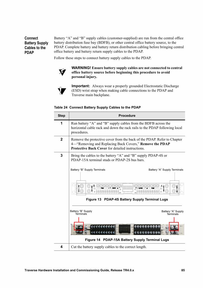
Connect Battery Supply Cables to the PDAP
Battery “A” and “B” supply cables (customer-supplied) are run from the central office battery distribution fuse bay (BDFB), or other central office battery source, to the PDAP. Complete battery and battery return distribution cabling before bringing central office battery and battery return supply cables to the PDAP.
Follow these steps to connect battery supply cables to the PDAP.
WARNING! Ensure battery supply cables are not connected to central office battery source before beginning this procedure to avoid personal injury.
Important: Always wear a properly grounded Electrostatic Discharge (ESD) wrist strap when making cable connections to the PDAP and Traverse main backplane.
Table 24 Connect Battery Supply Cables to the PDAP
Step Procedure
1 Run battery “A” and “B” supply cables from the BDFB across the horizontal cable rack and down the rack rails to the PDAP following local procedures.
2 Remove the protective cover from the back of the PDAP. Refer to Chapter 4—“Removing and Replacing Back Covers,” Remove the PDAP Protective Back Cover for detailed instructions.
3 Bring the cables to the battery “A” and “B” supply PDAP-4S or PDAP-15A terminal studs or PDAP-2S bus bars.
Figure 13 PDAP-4S Battery Supply Terminal Lugs
Figure 14 PDAP-15A Battery Supply Terminal Lugs
4 Cut the battery supply cables to the correct length.
TPA
PA
T
GMT GMT
Battery “B” Supply Terminals Battery “A” Supply Terminals
Battery “A” Supply Terminals
Battery “B” Supply Terminals
Traverse Hardware Installation and Commissioning Guide, Release TR4.0.x 85
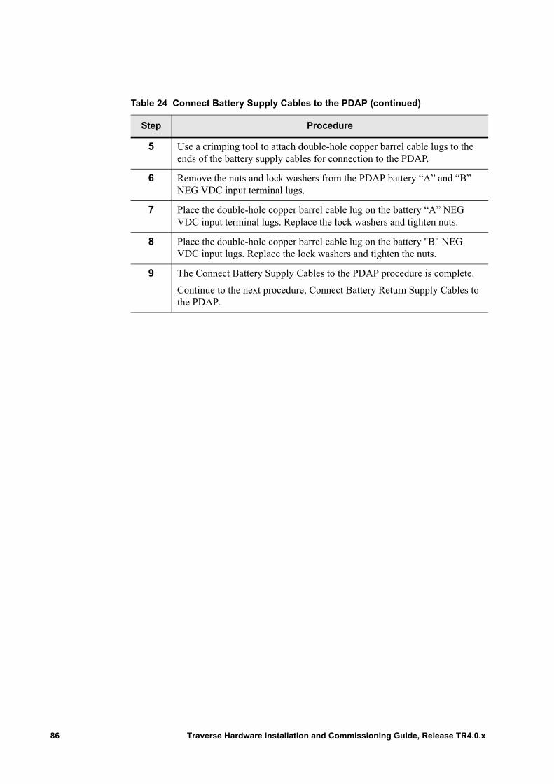
5 Use a crimping tool to attach double-hole copper barrel cable lugs to the ends of the battery supply cables for connection to the PDAP.
6 Remove the nuts and lock washers from the PDAP battery “A” and “B” NEG VDC input terminal lugs.
7 Place the double-hole copper barrel cable lug on the battery “A” NEG VDC input terminal lugs. Replace the lock washers and tighten nuts.
8 Place the double-hole copper barrel cable lug on the battery "B" NEG VDC input lugs. Replace the lock washers and tighten the nuts.
9 The Connect Battery Supply Cables to the PDAP procedure is complete.
Continue to the next procedure, Connect Battery Return Supply Cables to the PDAP.
Table 24 Connect Battery Supply Cables to the PDAP (continued)
Step Procedure
86 Traverse Hardware Installation and Commissioning Guide, Release TR4.0.x
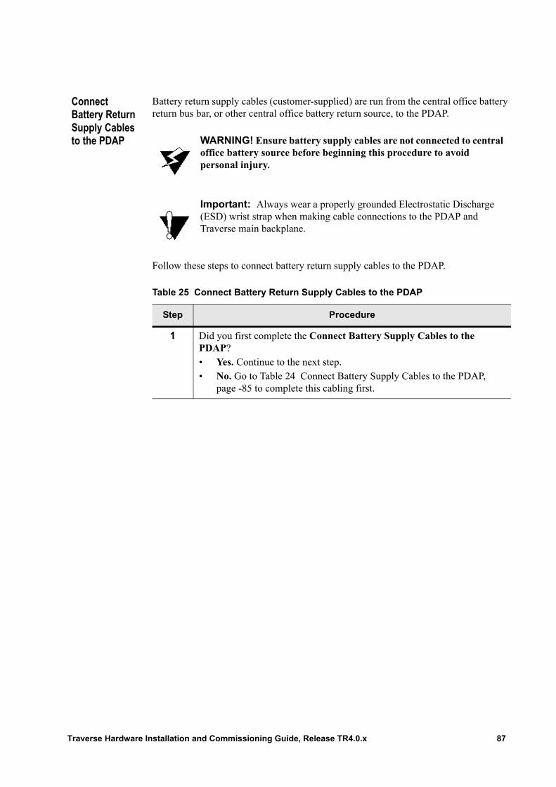
Connect Battery Return Supply Cables to the PDAP
Battery return supply cables (customer-supplied) are run from the central office battery return bus bar, or other central office battery return source, to the PDAP.
Follow these steps to connect battery return supply cables to the PDAP.
WARNING! Ensure battery supply cables are not connected to central office battery source before beginning this procedure to avoid personal injury.
Important: Always wear a properly grounded Electrostatic Discharge (ESD) wrist strap when making cable connections to the PDAP and Traverse main backplane.
Table 25 Connect Battery Return Supply Cables to the PDAP
Step Procedure
1 Did you first complete the Connect Battery Supply Cables to the PDAP?• Yes. Continue to the next step.• No. Go to Table 24 Connect Battery Supply Cables to the PDAP,
page -85 to complete this cabling first.
Traverse Hardware Installation and Commissioning Guide, Release TR4.0.x 87
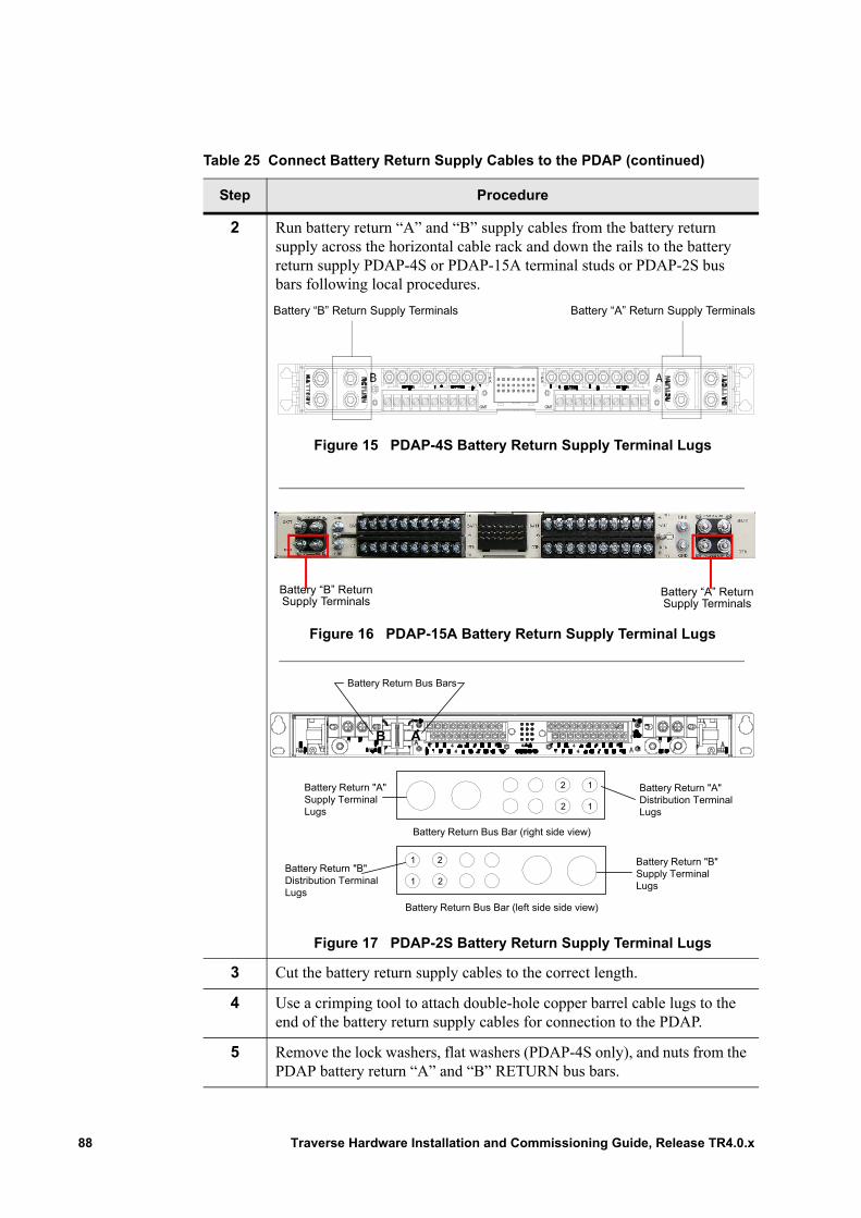
2 Run battery return “A” and “B” supply cables from the battery return supply across the horizontal cable rack and down the rails to the battery return supply PDAP-4S or PDAP-15A terminal studs or PDAP-2S bus bars following local procedures.
Figure 15 PDAP-4S Battery Return Supply Terminal Lugs
Figure 16 PDAP-15A Battery Return Supply Terminal Lugs
Figure 17 PDAP-2S Battery Return Supply Terminal Lugs
3 Cut the battery return supply cables to the correct length.
4 Use a crimping tool to attach double-hole copper barrel cable lugs to the end of the battery return supply cables for connection to the PDAP.
5 Remove the lock washers, flat washers (PDAP-4S only), and nuts from the PDAP battery return “A” and “B” RETURN bus bars.
Table 25 Connect Battery Return Supply Cables to the PDAP (continued)
Step Procedure
TPA
PA
T
GMT GMT
Battery “B” Return Supply Terminals Battery “A” Return Supply Terminals
Battery “A” Return Supply Terminals
Battery “B” Return Supply Terminals
Battery Return "A"Distribution TerminalLugs
Battery Return "A"Supply TerminalLugs
Battery Return "B"Distribution TerminalLugs
Battery Return "B"Supply TerminalLugs
Battery Return Bus Bar (left side side view)
Battery Return Bus Bar (right side view)
AB
Battery Return Bus Bars
1
12
1
1 2
2
2
88 Traverse Hardware Installation and Commissioning Guide, Release TR4.0.x
Connect Supply Cables to the Central Office Source
Follow these steps to connect battery and battery return supply cables and lugs (customer-supplied) to the central office source.
6 Place the double-hole copper barrel cable lug on the battery return “A” RETURN terminal lugs. Replace the lock washers, flat washers (PDAP-4S only), and tighten the nuts.
7 Place the double-hole copper barrel cable lug on the battery return “B” RETURN terminal lugs. Replace the lock washers, flat washers (PDAP-4S only), and tighten the nuts.
WARNING! Use a Volt Ohm Meter (VOM) to verify continuity of battery and battery return supply cables.
8 Replace the protective cover on the back of the PDAP. Refer to Chapter 4—“Removing and Replacing Back Covers,” Replace the PDAP Protective Back Cover for detailed instructions.
9 The Connect Battery Return Supply Cables to the PDAP procedure is complete.
Continue to the next procedure, Connect Supply Cables to the Central Office Source.
Table 25 Connect Battery Return Supply Cables to the PDAP (continued)
Step Procedure
WARNING! Use extreme caution when working with battery and battery return supply cables. Remove all metal jewelry when working with power circuits.
WARNING! Complete continuity testing before connecting battery and battery return cables to the central office source.
Traverse Hardware Installation and Commissioning Guide, Release TR4.0.x 89
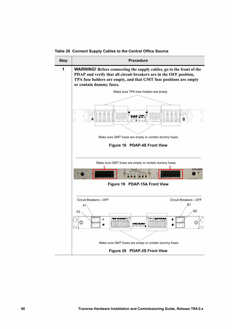
Table 26 Connect Supply Cables to the Central Office Source
Step Procedure
1 WARNING! Before connecting the supply cables, go to the front of the PDAP and verify that all circuit breakers are in the OFF position, TPA fuse holders are empty, and that GMT fuse positions are empty or contain dummy fuses.
Figure 18 PDAP-4S Front View
Figure 19 PDAP-15A Front View
Figure 20 PDAP-2S Front View
Make sure TPA fuse holders are empty
Make sure GMT fuses are empty or contain dummy fuses
Make sure GMT fuses are empty or contain dummy fuses
A1
A2
B1
B2
Circuit Breakers—OFF Circuit Breakers—OFF
Make sure GMT fuses are empty or contain dummy fuses
90 Traverse Hardware Installation and Commissioning Guide, Release TR4.0.x
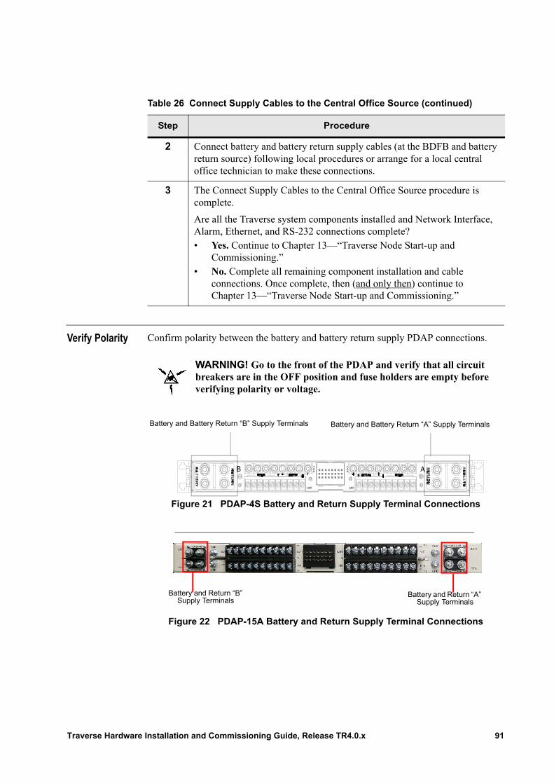
Verify Polarity Confirm polarity between the battery and battery return supply PDAP connections.
Figure 21 PDAP-4S Battery and Return Supply Terminal Connections
Figure 22 PDAP-15A Battery and Return Supply Terminal Connections
2 Connect battery and battery return supply cables (at the BDFB and battery return source) following local procedures or arrange for a local central office technician to make these connections.
3 The Connect Supply Cables to the Central Office Source procedure is complete.
Are all the Traverse system components installed and Network Interface, Alarm, Ethernet, and RS-232 connections complete?• Yes. Continue to Chapter 13—“Traverse Node Start-up and
Commissioning.”• No. Complete all remaining component installation and cable
connections. Once complete, then (and only then) continue to Chapter 13—“Traverse Node Start-up and Commissioning.”
Table 26 Connect Supply Cables to the Central Office Source (continued)
Step Procedure
WARNING! Go to the front of the PDAP and verify that all circuit breakers are in the OFF position and fuse holders are empty before verifying polarity or voltage.
TPA
PA
T
GMT GMT
Battery and Battery Return “A” Supply TerminalsBattery and Battery Return “B” Supply Terminals
Battery and Return “A” Supply Terminals
Battery and Return “B” Supply Terminals
Traverse Hardware Installation and Commissioning Guide, Release TR4.0.x 91
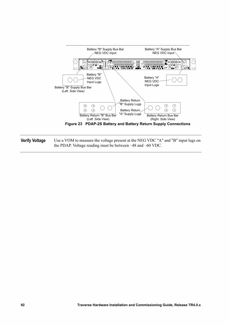
Figure 23 PDAP-2S Battery and Battery Return Supply Connections
Verify Voltage Use a VOM to measure the voltage present at the NEG VDC "A" and "B" input lugs on the PDAP. Voltage reading must be between –48 and –60 VDC.
Battery "A"NEG VDCInput Lugs
Battery "B"NEG VDCInput Lugs
Battery "B" Supply Bus BarNEG VDC Input
Battery "A" Supply Bus BarNEG VDC Input
3
3
4
4
2
2
1
1
Battery Return Bus Bar(Right Side View)
Battery Return"A" Supply Lugs
Battery Return"B" Supply Lugs
Battery Return "B" Bus Bar(Left Side View)
Battery "B" Supply Bus Bar(Left Side View)
92 Traverse Hardware Installation and Commissioning Guide, Release TR4.0.x
Chapter 13 Traverse Node Start-up and Commissioning
Introduction The Traverse node is ready for power-up after all the hardware is installed: shelf, fan tray, and air ramp, cabling (network, alarm, timing, Ethernet, power), and polarity and voltage testing are complete. This chapter provides instructions to start up and commission a Traverse shelf:• Before You Begin• Required Node Commissioning Parameters• Conditional Node Commissioning Parameters• Commissioning Process• Visual Status During and After Start-up
Before You Begin
Review this information before you begin.
Table 27 Node Start-up Requirements
Requirement Reference
Read through the entire chapter and gather together reference material first.
This chapter.
All hardware is installed. This guide• Chapter 1—“Installation and Commissioning
Overview”• Chapter 5—“Inserting and Removing Cards”• Chapter 6—“Insert Fan Module and Air Filters”• Chapter 7—“Traverse System Hardware
Installation”
Traverse Hardware Installation and Commissioning Guide, Release TR4.0.x 93
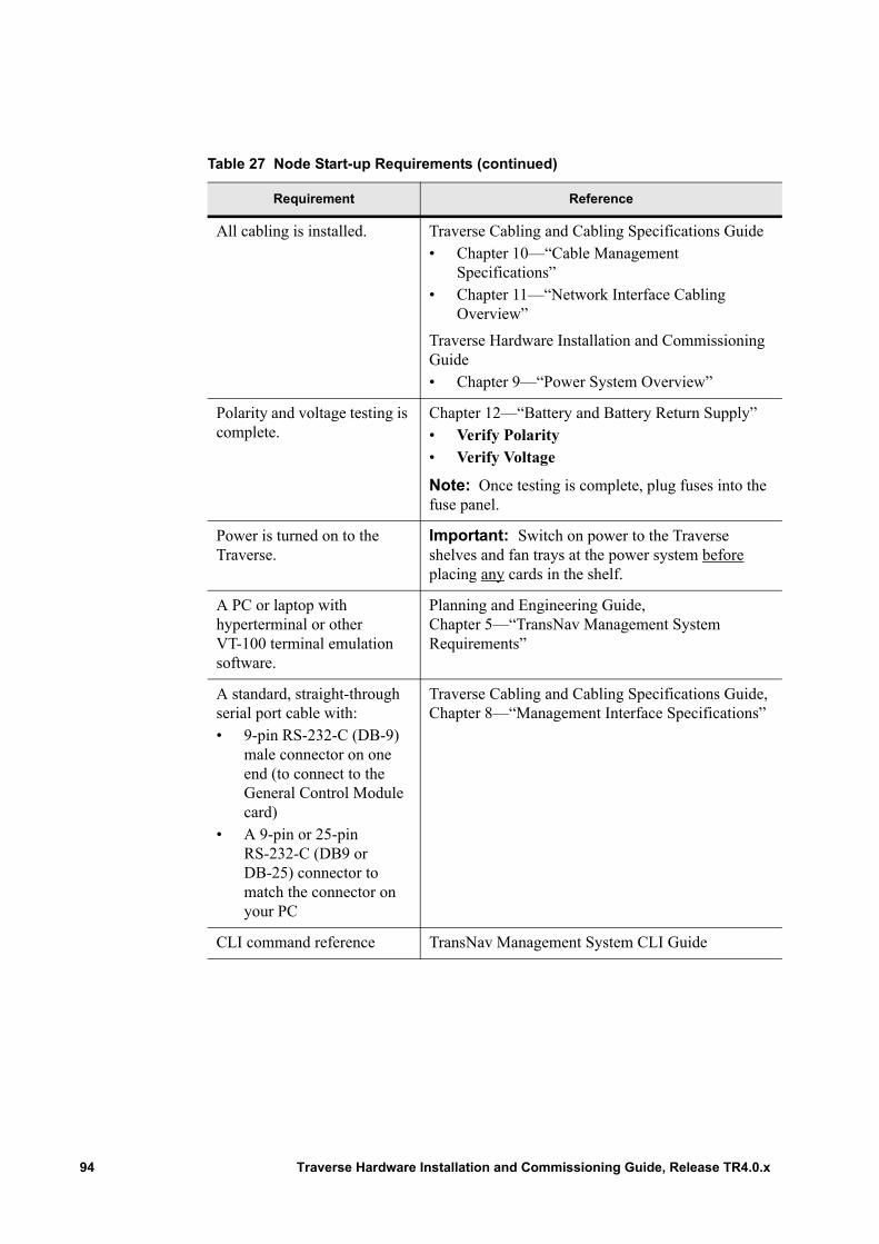
All cabling is installed. Traverse Cabling and Cabling Specifications Guide• Chapter 10—“Cable Management
Specifications”• Chapter 11—“Network Interface Cabling
Overview”
Traverse Hardware Installation and Commissioning Guide• Chapter 9—“Power System Overview”
Polarity and voltage testing is complete.
Chapter 12—“Battery and Battery Return Supply”• Verify Polarity• Verify Voltage
Note: Once testing is complete, plug fuses into the fuse panel.
Power is turned on to the Traverse.
Important: Switch on power to the Traverse shelves and fan trays at the power system before placing any cards in the shelf.
A PC or laptop with hyperterminal or other VT-100 terminal emulation software.
Planning and Engineering Guide, Chapter 5—“TransNav Management System Requirements”
A standard, straight-through serial port cable with:• 9-pin RS-232-C (DB-9)
male connector on one end (to connect to the General Control Module card)
• A 9-pin or 25-pin RS-232-C (DB9 or DB-25) connector to match the connector on your PC
Traverse Cabling and Cabling Specifications Guide, Chapter 8—“Management Interface Specifications”
CLI command reference TransNav Management System CLI Guide
Table 27 Node Start-up Requirements (continued)
Requirement Reference
94 Traverse Hardware Installation and Commissioning Guide, Release TR4.0.x
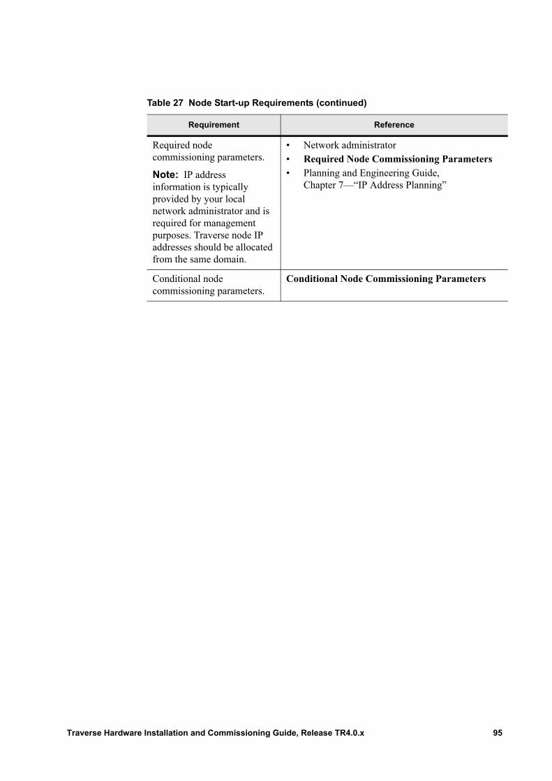
Required node commissioning parameters.
Note: IP address information is typically provided by your local network administrator and is required for management purposes. Traverse node IP addresses should be allocated from the same domain.
• Network administrator• Required Node Commissioning Parameters• Planning and Engineering Guide,
Chapter 7—“IP Address Planning”
Conditional node commissioning parameters.
Conditional Node Commissioning Parameters
Table 27 Node Start-up Requirements (continued)
Requirement Reference
Traverse Hardware Installation and Commissioning Guide, Release TR4.0.x 95
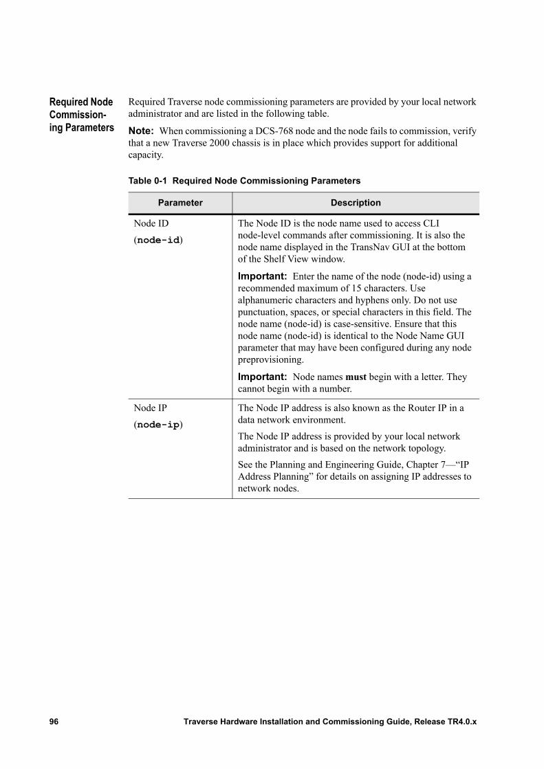
Required Node Commission-ing Parameters
Required Traverse node commissioning parameters are provided by your local network administrator and are listed in the following table.
Note: When commissioning a DCS-768 node and the node fails to commission, verify that a new Traverse 2000 chassis is in place which provides support for additional capacity.
Table 0-1 Required Node Commissioning Parameters
Parameter Description
Node ID
(node-id)
The Node ID is the node name used to access CLI node-level commands after commissioning. It is also the node name displayed in the TransNav GUI at the bottom of the Shelf View window.
Important: Enter the name of the node (node-id) using a recommended maximum of 15 characters. Use alphanumeric characters and hyphens only. Do not use punctuation, spaces, or special characters in this field. The node name (node-id) is case-sensitive. Ensure that this node name (node-id) is identical to the Node Name GUI parameter that may have been configured during any node preprovisioning.
Important: Node names must begin with a letter. They cannot begin with a number.
Node IP
(node-ip)
The Node IP address is also known as the Router IP in a data network environment.
The Node IP address is provided by your local network administrator and is based on the network topology.
See the Planning and Engineering Guide, Chapter 7—“IP Address Planning” for details on assigning IP addresses to network nodes.
96 Traverse Hardware Installation and Commissioning Guide, Release TR4.0.x
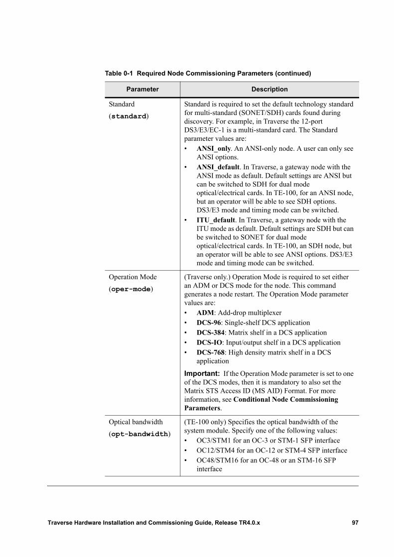
Standard
(standard)
Standard is required to set the default technology standard for multi-standard (SONET/SDH) cards found during discovery. For example, in Traverse the 12-port DS3/E3/EC-1 is a multi-standard card. The Standard parameter values are:• ANSI_only. An ANSI-only node. A user can only see
ANSI options. • ANSI_default. In Traverse, a gateway node with the
ANSI mode as default. Default settings are ANSI but can be switched to SDH for dual mode optical/electrical cards. In TE-100, for an ANSI node, but an operator will be able to see SDH options. DS3/E3 mode and timing mode can be switched.
• ITU_default. In Traverse, a gateway node with the ITU mode as default. Default settings are SDH but can be switched to SONET for dual mode optical/electrical cards. In TE-100, an SDH node, but an operator will be able to see ANSI options. DS3/E3 mode and timing mode can be switched.
Operation Mode
(oper-mode)
(Traverse only.) Operation Mode is required to set either an ADM or DCS mode for the node. This command generates a node restart. The Operation Mode parameter values are:• ADM: Add-drop multiplexer• DCS-96: Single-shelf DCS application• DCS-384: Matrix shelf in a DCS application• DCS-IO: Input/output shelf in a DCS application• DCS-768: High density matrix shelf in a DCS
application
Important: If the Operation Mode parameter is set to one of the DCS modes, then it is mandatory to also set the Matrix STS Access ID (MS AID) Format. For more information, see Conditional Node Commissioning Parameters.
Optical bandwidth
(opt-bandwidth)
(TE-100 only) Specifies the optical bandwidth of the system module. Specify one of the following values: • OC3/STM1 for an OC-3 or STM-1 SFP interface• OC12/STM4 for an OC-12 or STM-4 SFP interface• OC48/STM16 for an OC-48 or an STM-16 SFP
interface
Table 0-1 Required Node Commissioning Parameters (continued)
Parameter Description
Traverse Hardware Installation and Commissioning Guide, Release TR4.0.x 97
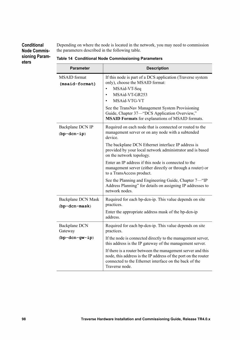
Conditional Node Commis-sioning Param-eters
Depending on where the node is located in the network, you may need to commission the parameters described in the following table.
Table 14 Conditional Node Commissioning Parameters
Parameter Description
MSAID format
(msaid-format)
If this node is part of a DCS application (Traverse system only), choose the MSAID format:• MSAid-VT-Seq• MSAid-VT-GR253• MSAid-VTG-VT
See the TransNav Management System Provisioning Guide, Chapter 37—“DCS Application Overview,” MSAID Formats for explanations of MSAID formats.
Backplane DCN IP
(bp-dcn-ip)
Required on each node that is connected or routed to the management server or on any node with a subtended device.
The backplane DCN Ethernet interface IP address is provided by your local network administrator and is based on the network topology.
Enter an IP address if this node is connected to the management server (either directly or through a router) or to a TransAccess product.
See the Planning and Engineering Guide, Chapter 7—“IP Address Planning” for details on assigning IP addresses to network nodes.
Backplane DCN Mask
(bp-dcn-mask)
Required for each bp-dcn-ip. This value depends on site practices.
Enter the appropriate address mask of the bp-dcn-ip address.
Backplane DCN Gateway
(bp-dcn-gw-ip)
Required for each bp-dcn-ip. This value depends on site practices.
If the node is connected directly to the management server, this address is the IP gateway of the management server.
If there is a router between the management server and this node, this address is the IP address of the port on the router connected to the Ethernet interface on the back of the Traverse node.
98 Traverse Hardware Installation and Commissioning Guide, Release TR4.0.x
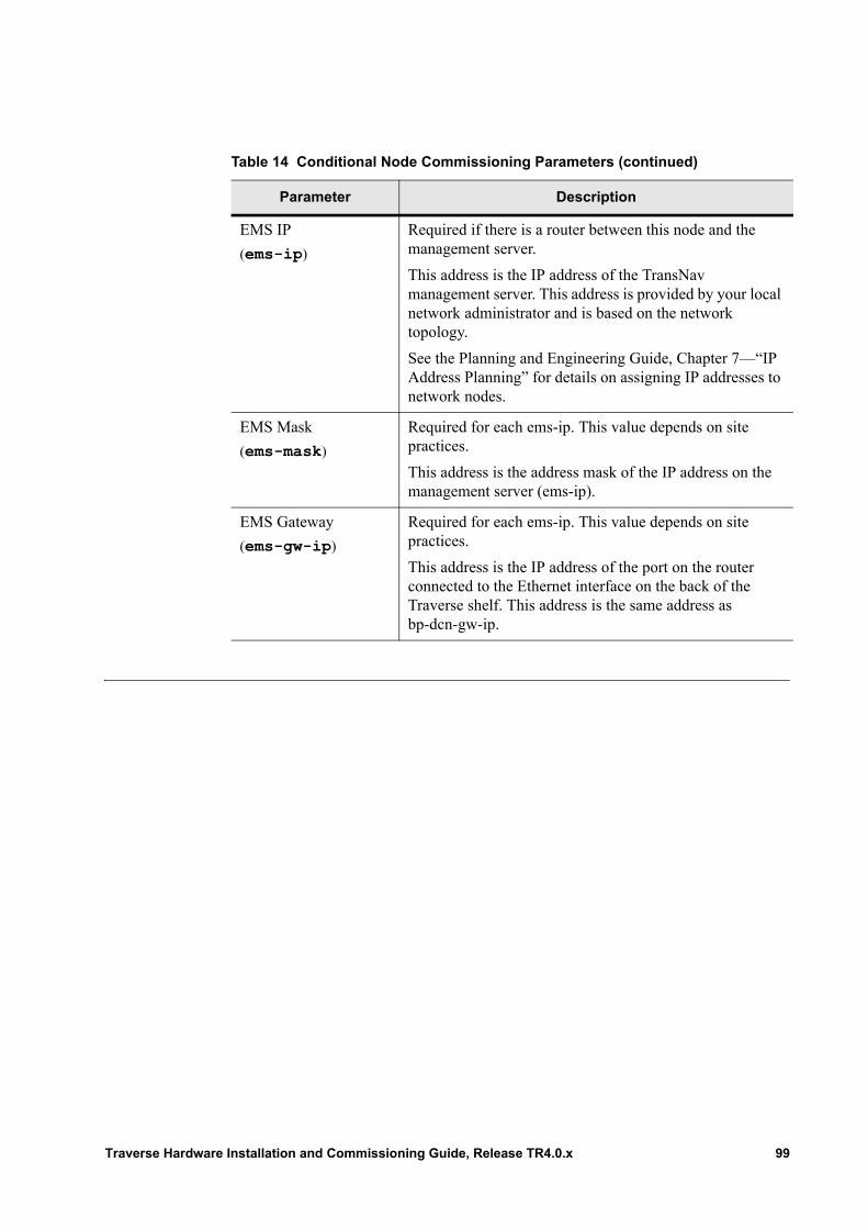
EMS IP
(ems-ip)
Required if there is a router between this node and the management server.
This address is the IP address of the TransNav management server. This address is provided by your local network administrator and is based on the network topology.
See the Planning and Engineering Guide, Chapter 7—“IP Address Planning” for details on assigning IP addresses to network nodes.
EMS Mask
(ems-mask)
Required for each ems-ip. This value depends on site practices.
This address is the address mask of the IP address on the management server (ems-ip).
EMS Gateway
(ems-gw-ip)
Required for each ems-ip. This value depends on site practices.
This address is the IP address of the port on the router connected to the Ethernet interface on the back of the Traverse shelf. This address is the same address as bp-dcn-gw-ip.
Table 14 Conditional Node Commissioning Parameters (continued)
Parameter Description
Traverse Hardware Installation and Commissioning Guide, Release TR4.0.x 99
Commission-ing Process
Complete the following procedures in the commissioning process.
Insert the Active GCM
Insert a GCM in Traverse slot GCMA or GCMB; this becomes the active GCM.
For detailed information, refer to the procedures in Chapter 5—“Inserting and Removing Cards.”• Clean Fiber Optic MPX Connectors if you are placing a GCM with integrated
optics (GCM OC-12/STM-4 or GCM OC-48/STM-16)• Insert a Card
Important: Refer to Visual Status During and After Start-up and the Operations and Maintenance Guide, Chapter 8—“LEDs and Module Status,” Power and Standby LED Indicators—All Modules as necessary.
Table 1 Commissioning Process
Step Procedure
1 Power up the node. See Chapter 9—“Power System Overview.”
2 Insert the Active GCM.
3 Commission the Node. For examples of network timing, refer to the TransNav Management System Provisioning Guide, Chapter 3—“Configure Network Timing,” Network Timing Examples.
4 Insert the Standby GCM and All Cards in the Traverse Node.
5 The Commissioning Process is complete.
Important: Always wear a properly grounded ESD wrist strap when working with Traverse cards.
Important: The GCM power LED is solid green indicating that the GCM has power. The solid green Active/Standby LED indicates the active GCM card. Use the CLI to commission and configure the active GCM.
100 Traverse Hardware Installation and Commissioning Guide, Release TR4.0.x
Commission the Node
Follow these steps to commission the node.
Important: TransNav CLI commands are used in the following procedures. TransNav system software is backward compatible with the previous major release.
WARNING! Do not change the Node ID or Node IP Address once these are set during commissioning. Changing the Node ID or Node IP Address will affect services.
Table 2 Commission the Node
Step Procedure
1 Is the active GCM card inserted into the Traverse shelf?• Yes. Connect a serial port cable to the active GCM RS-232 interface
(DB-9 connector) and to your PC or laptop. Refer to the Traverse Hardware Guide, Chapter 6—“General Control Module (GCM) Cards” for the location of the RS-232 interface on the faceplate of the GCM.
• No. First, Insert the Active GCM, then connect the serial cable as stated above.
2 Power up your PC or laptop.
3 Start VT-100 emulation software.
4 Open your terminal emulation session.
5 Enter the correct parameters settings for the communications port (COM1 or COM2):
Baud Rate: 9600Data Bits: 8Parity: NoneStop Bits: 1Flow Control: None
Note: In some instances, it may be necessary to enable Line Feed.
6 Important: You may have to press the Enter button several times to establish the session and to receive the Force10 logo and session prompt.
Your terminal responds with the Force10 logo.
Please type CLI to start a new session...
7 To log on to the CLI:
Type: CLI
Traverse Hardware Installation and Commissioning Guide, Release TR4.0.x 101
8 The CLI responds:
Login:
Type: admin
Password:
Type: admin
9 At the command line, type the following command sequence:
exec node commission node-id nodeName node-ip aaa.bbb.ccc.ddd standard technologyStandard oper-mode operationMode
See Required Node Commissioning Parameters for the descriptions of these parameters.
10 At the command prompt:
Changing node commissioning will result in a reinitialization of the Database. Are you sure? [yes|no]:
Type y to reinitialize the database on the GCM.
11 If the value in the Operation Mode (oper-mode) parameter is DCS-IO, DCS-96, or DCS-384, enter the following command:
set node general msaid-format msaidFormat
See Conditional Node Commissioning Parameters for the descriptions of this parameter.
12 Is this node connected to a DCN or a subtended device? • No. Go to Step 14.• Yes. Enter the backplane DCN IP address information.
Type: set node ip bp-dcn-ip aaa.bbb.ccc.ddd bp-dcn-mask aaa.bbb.ccc.ddd bp-dcn-gw-ip aaa.bbb.ccc.dddwhere:aaa.bbb.ccc.ddd is the correct IP address from your network administrator.
13 Is this node is connected or routed to the management server?• No. Go to Step 14.• Yes. Enter the EMS IP information:
Type: set node ip ems-ip aaa.bbb.ccc.ddd ems-mask aaa.bbb.ccc.ddd ems-gw aaa.bbb.ccc.dddwhere:aaa.bbb.ccc.ddd is the correct IP address from your network administrator.
Table 2 Commission the Node (continued)
Step Procedure
102 Traverse Hardware Installation and Commissioning Guide, Release TR4.0.x

14 Restart the node:
Type: exec node restart
CLI responds: Are you sure you want to execute this command? [yes|no]:
Type: yes
The node begins the restart sequence.
15 Exit your terminal emulation session.
16 The Commission the Node procedure is complete.
Continue to Insert the Standby GCM and All Cards in the Traverse Node.
Table 2 Commission the Node (continued)
Step Procedure
Traverse Hardware Installation and Commissioning Guide, Release TR4.0.x 103
Insert the Standby GCM and All Cards in the Traverse Node
Insert the standby GCM and all other cards in the node after commissioning is complete on the active GCM. Follow these steps to continue inserting cards in the shelf.
Refer to the Operations and Maintenance Guide, Chapter 21—“Card Placement Planning and Guidelines” and the following procedures in the Traverse Hardware Installation and Commissioning Guide, Chapter 5—“Inserting and Removing Cards” for detailed information:• Clean Fiber Optic MPX Connectors if inserting optical cards• Insert a Card
Important: Always wear a properly grounded ESD wrist strap when working with Traverse cards.
Table 3 Insert the Standby GCM and All Other Cards
Step Procedure
1 Insert the standby GCM in the remaining GCM slot, GCMA or GCMB.
The Active/Standby LED on the standby GCM flashes amber while it is synchronizing with the active GCM.
2 Wait for synchronization to complete on the standby GCM. The Active/Standby LED flashes green indicating that it is the standby GCM and that synchronization is complete.
3 Insert the remaining cards in the Traverse node based on your engineering work order and the physical cabling at the main and fiber optic backplanes. Refer to the Operations and Maintenance Guide, Chapter 21—“Card Placement Planning and Guidelines” for more information.
Note: All cards and ports come up “locked” and the port LEDs remain “off”. Cards and ports are “unlocked” or enabled as part of equipment configuration. Refer to the TransNav Management System Provisioning Guide for more information.
4 The Insert the Standby GCM and All Cards in the Traverse Node procedure is complete.
The Traverse system installation, start-up, and commissioning are complete.
104 Traverse Hardware Installation and Commissioning Guide, Release TR4.0.x

Visual Status During and After Start-up
The GCM power LED indicates the status of start-up and initialization. The GCM power LED will go through the following sequence:
Flashing red
Power On Self Test (POST) is started 1.
Solid green
Initialization complete and successful.
For more information on LEDs, see the Operations and Maintenance Guide, Chapter 8—“LEDs and Module Status.”
1 The POST takes approximately one minute to run and it invokes the LED activity for initialization.
Important: The solid green Active/Standby LED indicates the active GCM card. Use the CLI to commission and configure the active GCM.
Traverse Hardware Installation and Commissioning Guide, Release TR4.0.x 105

106 Traverse Hardware Installation and Commissioning Guide, Release TR4.0.x
Chapter 14 Hardware Installation
Introduction This chapter provides instructions for installing the power distribution and alarm panel (PDAP-15A, an optional power supply solution provided by Force10) and the TraverseEdge 100 (TE-100) shelf into a 7-foot (2200 mm), 19- or 23-inch (ETSI/500 mm or 600 mm) telco rack.• Before You Begin• Power Distribution and Alarm Panel (PDAP) Description• Power System (PDAP-15A) Installation• Back Cover• Hardware Installation• Grounding the Shelf• Rack Adapter Installation
Before You Begin
Review this information before you start the installation procedure.
Table 4 Installation Procedure Requirements
Requirement Reference
Familiarize yourself with all precautions and common procedures
Chapter 3—“Precautions to Installing Traverse Equipment”
Chapter 4—“Removing and Replacing Back Covers”
Chapter 5—“Inserting and Removing Cards”
Chapter 6—“Insert Fan Module and Air Filters”
Electrostatic Discharge (ESD) wrist strap Chapter 3—“Precautions to Installing Traverse Equipment,” ESD Jack Locations
Equipment and Tools
Standard 7-foot (2200 mm) high, 19- or 23-inch (ETSI/500 mm or 600 mm) wide telco rack
Standard conductive plated rack adapters with tread-forming screws required for rack installation
Stepladder (optional)
PDAP-15A Installation
Power system (e.g., PDAP-15A)
Traverse Hardware Installation and Commissioning Guide, Release TR4.0.x 107
Power Distribution and Alarm Panel (PDAP) Description
The TE-100 system is powered by an external power supply (or central office) battery (–48 VDC). The redundant external power supply (or central office) battery and battery return can be connected to the optional Power Distribution and Alarm Panel (PDAP-15A) supplied by Force10 or to an equivalent GMT fuse panel to meet building installation requirements.
The Force10 PDAP-15A has a 10-position Universal GMT Panel. Fuse input connections are made at the back of the PDAP-15A.
The PDAP-15A provides the following:• Terminates redundant –48 VDC central office battery.• Terminates central office battery return.• Distributes redundant battery and battery return.• Provides power protection for TE-100 shelves and auxiliary equipment.• Displays input power, fuse power, and critical, major, and minor bay alarms.• Provides a power disconnect device for the TE-100 shelves and auxiliary
equipment
For detailed specifications, see the Traverse Hardware Guide, Chapter 5—“Power Distribution and Alarm Panels” and Traverse Cabling and Cabling Specifications Guide, Chapter 9—“Power Interface Specifications.”
The following procedures assume that you are using the Force10 PDAP. If you are using another fuse panel, you may find these steps helpful for general reference.
Green (6 mm2 yellow-green) copper ground wire (up to #6 AWG for the PDAP-15A depending on the input interrupt device) for grounding.
1 double-hole copper barrel cable lugs (M5 stud with 5/8-inch spacing) for ground terminal connection.
Large phillips head screwdriver or lex socket
Four 12-24 thread-forming screws
TE-100 Shelf Installation
TE-100 shelf
Fourteen 12-24 thread-forming screws
A 5/16-inch socket for all thread-forming screws
A 1/4-inch socket (or nut driver) for TE-100 shelf backplane power terminal connections
Table 4 Installation Procedure Requirements (continued)
Requirement Reference
108 Traverse Hardware Installation and Commissioning Guide, Release TR4.0.x
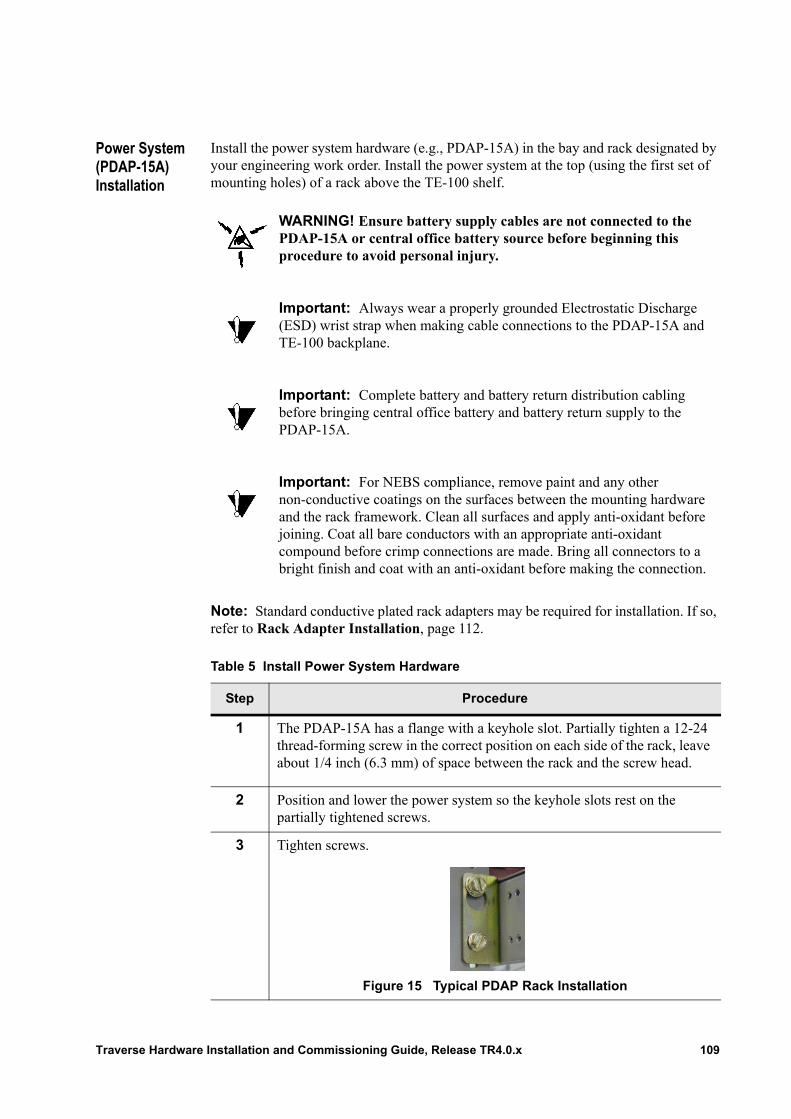
Power System (PDAP-15A) Installation
Install the power system hardware (e.g., PDAP-15A) in the bay and rack designated by your engineering work order. Install the power system at the top (using the first set of mounting holes) of a rack above the TE-100 shelf.
Note: Standard conductive plated rack adapters may be required for installation. If so, refer to Rack Adapter Installation, page 112.
WARNING! Ensure battery supply cables are not connected to the PDAP-15A or central office battery source before beginning this procedure to avoid personal injury.
Important: Always wear a properly grounded Electrostatic Discharge (ESD) wrist strap when making cable connections to the PDAP-15A and TE-100 backplane.
Important: Complete battery and battery return distribution cabling before bringing central office battery and battery return supply to the PDAP-15A.
Important: For NEBS compliance, remove paint and any other non-conductive coatings on the surfaces between the mounting hardware and the rack framework. Clean all surfaces and apply anti-oxidant before joining. Coat all bare conductors with an appropriate anti-oxidant compound before crimp connections are made. Bring all connectors to a bright finish and coat with an anti-oxidant before making the connection.
Table 5 Install Power System Hardware
Step Procedure
1 The PDAP-15A has a flange with a keyhole slot. Partially tighten a 12-24 thread-forming screw in the correct position on each side of the rack, leave about 1/4 inch (6.3 mm) of space between the rack and the screw head.
2 Position and lower the power system so the keyhole slots rest on the partially tightened screws.
3 Tighten screws.
Figure 15 Typical PDAP Rack Installation
Traverse Hardware Installation and Commissioning Guide, Release TR4.0.x 109
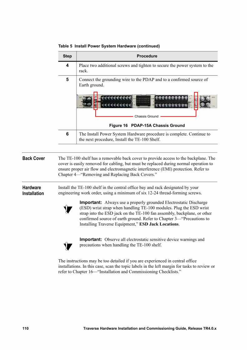
Back Cover The TE-100 shelf has a removable back cover to provide access to the backplane. The cover is easily removed for cabling, but must be replaced during normal operation to ensure proper air flow and electromagnetic interference (EMI) protection. Refer to Chapter 4—“Removing and Replacing Back Covers.”
Hardware Installation
Install the TE-100 shelf in the central office bay and rack designated by your engineering work order, using a minimum of six 12-24 thread-forming screws.
The instructions may be too detailed if you are experienced in central office installations. In this case, scan the topic labels in the left margin for tasks to review or refer to Chapter 16—“Installation and Commissioning Checklists.”
4 Place two additional screws and tighten to secure the power system to the rack.
5 Connect the grounding wire to the PDAP and to a confirmed source of Earth ground.
Figure 16 PDAP-15A Chassis Ground
6 The Install Power System Hardware procedure is complete. Continue to the next procedure, Install the TE-100 Shelf.
Table 5 Install Power System Hardware (continued)
Step Procedure
Chassis Ground
Important: Always use a properly grounded Electrostatic Discharge (ESD) wrist strap when handling TE-100 modules. Plug the ESD wrist strap into the ESD jack on the TE-100 fan assembly, backplane, or other confirmed source of earth ground. Refer to Chapter 3—“Precautions to Installing Traverse Equipment,” ESD Jack Locations.
Important: Observe all electrostatic sensitive device warnings and precautions when handling the TE-100 shelf.
110 Traverse Hardware Installation and Commissioning Guide, Release TR4.0.x
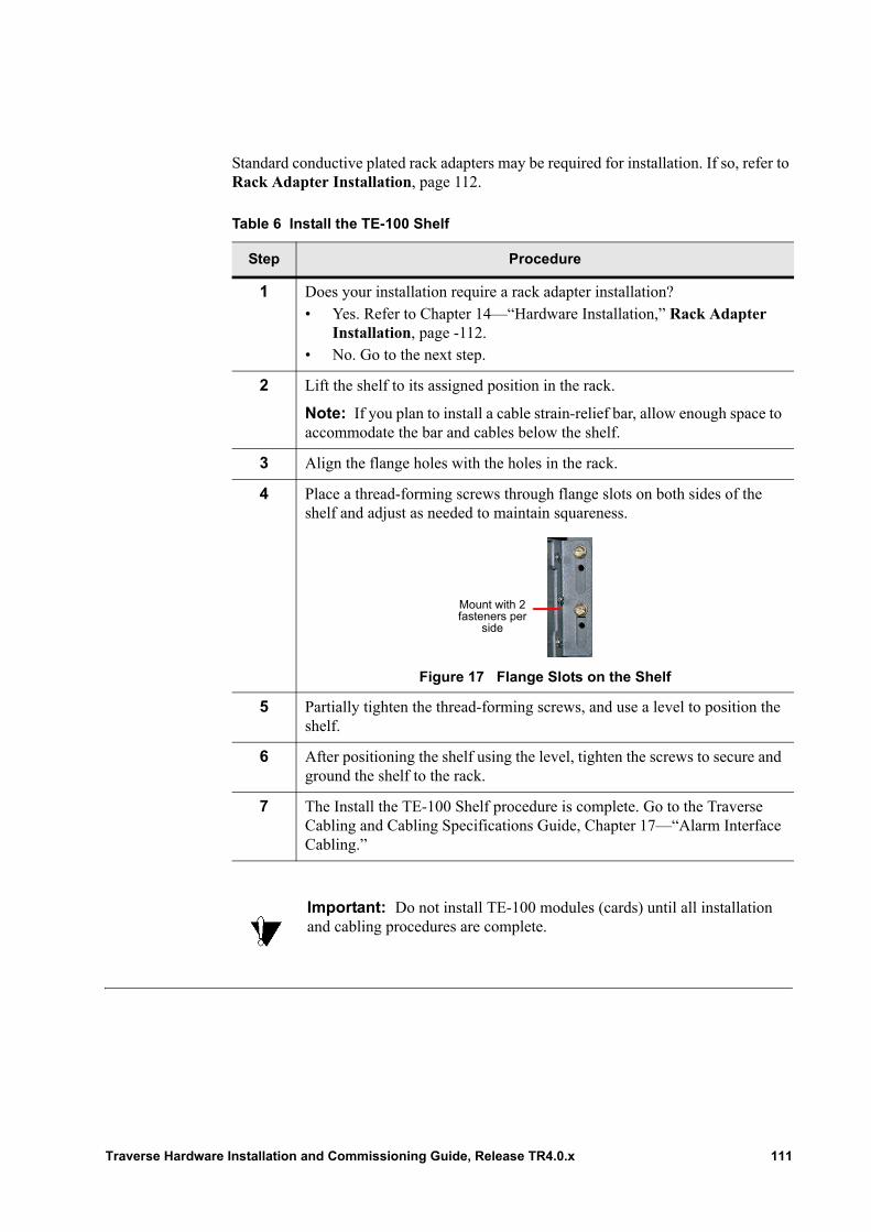
Standard conductive plated rack adapters may be required for installation. If so, refer to Rack Adapter Installation, page 112.
Table 6 Install the TE-100 Shelf
Step Procedure
1 Does your installation require a rack adapter installation?• Yes. Refer to Chapter 14—“Hardware Installation,” Rack Adapter
Installation, page -112.• No. Go to the next step.
2 Lift the shelf to its assigned position in the rack.
Note: If you plan to install a cable strain-relief bar, allow enough space to accommodate the bar and cables below the shelf.
3 Align the flange holes with the holes in the rack.
4 Place a thread-forming screws through flange slots on both sides of the shelf and adjust as needed to maintain squareness.
Figure 17 Flange Slots on the Shelf
5 Partially tighten the thread-forming screws, and use a level to position the shelf.
6 After positioning the shelf using the level, tighten the screws to secure and ground the shelf to the rack.
7 The Install the TE-100 Shelf procedure is complete. Go to the Traverse Cabling and Cabling Specifications Guide, Chapter 17—“Alarm Interface Cabling.”
Important: Do not install TE-100 modules (cards) until all installation and cabling procedures are complete.
Mount with 2 fasteners per
side
Traverse Hardware Installation and Commissioning Guide, Release TR4.0.x 111
Grounding the Shelf
The shelf is grounded to the rack using thread-forming screws and conductive plated rack adapters (as required for 23-inch (600 mm) rack installation). No additional grounding procedures are required when installed in a properly grounded telco rack.
Rack Adapter Installation
Use standard rack adapters to install TE-100 shelf components into a 23-inch (600 mm) telco rack. Rack adapters come with thread-forming mounting screws and in various lengths depending on your installation requirements.
Install the TE-100 shelf in the central office bay and rack designated by your engineering work order using a minimum of six 12-24 thread-forming screws.
Important: (SONET network only) For NEBS compliance, remove paint and any other non-conductive coatings on the surfaces between the mounting hardware and the rack framework. Clean all surfaces and apply anti-oxidant before joining.
Table 7 Install Rack Adapters
Step Procedure
1 Install conductive plated rack adapters on both sides of the rack. Align and position the rack adapter slots with the holes in the rack.
2 Place and tighten thread-forming screws through the rack adapter slots and into the rack. Thread-forming screws are used to ground the rack adapters (and TE-100 shelf) to the rack.
3 Place and tighten screws on each side of the TE-100 to secure it to the rack adapters (and thus the rack).
4 The Install Rack Adapters procedure is complete. Continue to the Hardware Installation, page 111.
112 Traverse Hardware Installation and Commissioning Guide, Release TR4.0.x
Chapter 15 Installing the Wall Mount Bracket
Introduction This section describes the optional wall mount bracket and provides instructions on how to install it for TE-100 or TE-206 shelves.
Wall Mount Bracket Specifications
Each wall mount bracket is shipped with the equipment specified in the following table. Installations for TE-206 shelves require 23-inch mounting brackets for use with the wall mount bracket. The 23-inch mounting brackets are shipped with the TE-206 shelf.
Table 8 Wall Mount Bracket Specifications
Parameter Specifications
Dimensions inches 27.75” x 18.50” x 1.5”
centimeters 704.85 mm x 469.9 mm x 38.1 mm
Weight pounds 13.0 lbs
kilograms 5.9 kg
Equipment Provided
2-1/2” LAG screws, Qty 4 For mounting bracket to wall
Washers, Qty 4 For use with LAG screws
10-32 x 3/8” l PPH SEM screws, Qty 4
To ground bracket to cable
Equipment Required, not provided
Level To ensure wall mount bracket is installed level.
Electric drill with Phillips head bitor Phillips head screwdriver
To install ground cable to wall mount bracket
5/16” Hex driver For shelf mounting hardware.
Voltmeter For confirming wall mount bracket is grounded
Lugs1 For grounding cable on bracket
1 #10 hole lug, 5/8” spacing. Allows for two-hole lug up to 6 AWG wire.
Traverse Hardware Installation and Commissioning Guide, Release TR4.0.x 113
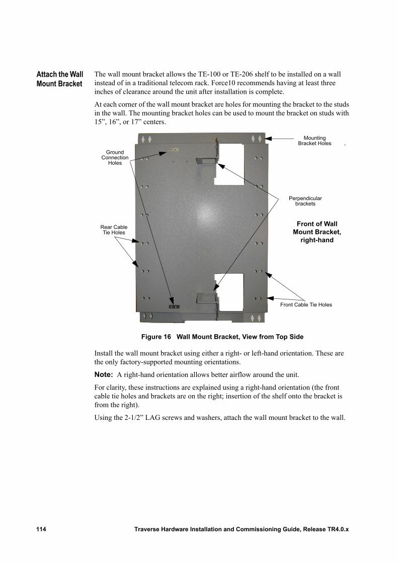
Attach the Wall Mount Bracket
The wall mount bracket allows the TE-100 or TE-206 shelf to be installed on a wall instead of in a traditional telecom rack. Force10 recommends having at least three inches of clearance around the unit after installation is complete.
At each corner of the wall mount bracket are holes for mounting the bracket to the studs in the wall. The mounting bracket holes can be used to mount the bracket on studs with 15”, 16”, or 17” centers.
Figure 16 Wall Mount Bracket, View from Top Side
Install the wall mount bracket using either a right- or left-hand orientation. These are the only factory-supported mounting orientations.
Note: A right-hand orientation allows better airflow around the unit.
For clarity, these instructions are explained using a right-hand orientation (the front cable tie holes and brackets are on the right; insertion of the shelf onto the bracket is from the right).
Using the 2-1/2” LAG screws and washers, attach the wall mount bracket to the wall.
Mounting Bracket Holes ,
Front Cable Tie Holes
Rear Cable Tie Holes
Ground Connection
Holes
Perpendicular brackets
Front of Wall Mount Bracket,
right-hand
114 Traverse Hardware Installation and Commissioning Guide, Release TR4.0.x
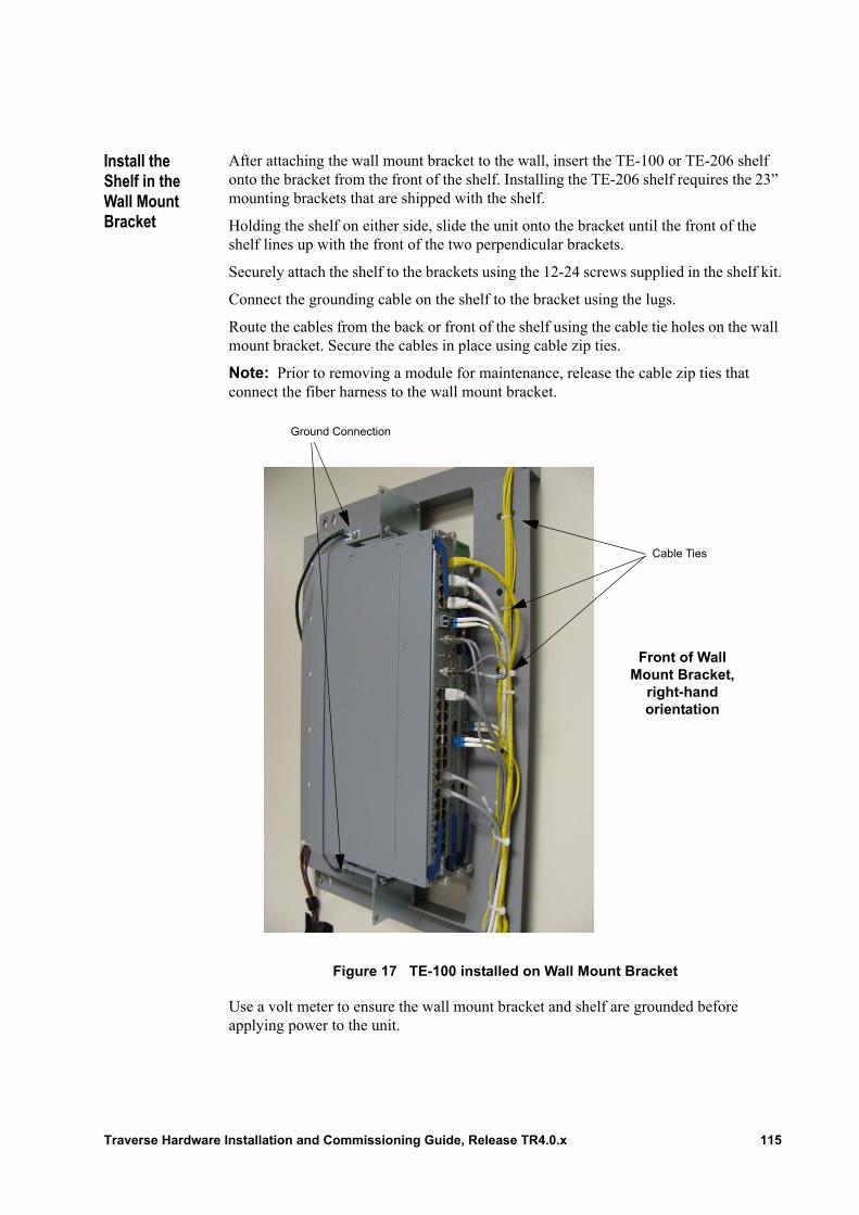
Install the Shelf in the Wall Mount Bracket
After attaching the wall mount bracket to the wall, insert the TE-100 or TE-206 shelf onto the bracket from the front of the shelf. Installing the TE-206 shelf requires the 23” mounting brackets that are shipped with the shelf.
Holding the shelf on either side, slide the unit onto the bracket until the front of the shelf lines up with the front of the two perpendicular brackets.
Securely attach the shelf to the brackets using the 12-24 screws supplied in the shelf kit.
Connect the grounding cable on the shelf to the bracket using the lugs.
Route the cables from the back or front of the shelf using the cable tie holes on the wall mount bracket. Secure the cables in place using cable zip ties.
Note: Prior to removing a module for maintenance, release the cable zip ties that connect the fiber harness to the wall mount bracket.
Figure 17 TE-100 installed on Wall Mount Bracket
Use a volt meter to ensure the wall mount bracket and shelf are grounded before applying power to the unit.
Ground Connection
Cable Ties
Front of Wall Mount Bracket,
right-hand orientation
Traverse Hardware Installation and Commissioning Guide, Release TR4.0.x 115

116 Traverse Hardware Installation and Commissioning Guide, Release TR4.0.x
Chapter 16 Installation and Commissioning Checklists
Introduction This chapter includes checklists to provide the basic steps necessary to complete Traverse system hardware installation, cabling and initial configuration steps. Each step references the related detail-level procedure for additional information.• Power System Hardware Installation Checklist• Traverse System Hardware Installation Checklist• Network Cabling Checklist• Alarm Cabling Checklist• Timing and Management Cabling Checklist• Power Cabling Checklist• Node Start-up and Commissioning Checklist
Traverse Hardware Installation and Commissioning Guide, Release TR4.0.x 117
Power System Hardware Installation Checklist
Basic precautions for electrostatic discharge protection, electrical and fiber optic cabling are provided in the Traverse Hardware Installation and Commissioning Guide, Chapter 3—“Precautions to Installing Traverse Equipment.”
All power system hardware installation detail-level procedure references are to the Traverse Hardware Installation and Commissioning Guide, Chapter 10—“Power System Hardware Installation.” Required equipment and tools are also provided as part of this chapter.d
Table 9 Power System Hardware Installation Checklist
Step Description and Procedure Reference
1 Install the power system hardware (e.g., PDAP-4S, PDAP-15A, or PDAP-2S) in the central office bay and rack indicated on your engineering work order using thread-forming screws. Ground the hardware to a properly grounded telco rack.
Note: Installation of power system hardware in a 23-inch (584 mm or other ETSI) rack requires standard conductive plated rack adapters. Refer to the Traverse Hardware Installation and Commissioning Guide, Chapter 7—“Traverse System Hardware Installation,” Install the Rack Adapters.
Power System (PDAP). Install the power system at the top of the equipment rack. The detail-level installation procedure is in the Traverse Hardware Installation and Commissioning Guide, Chapter 7—“Traverse System Hardware Installation.”
2 All Traverse System Hardware Installation Checklist steps are complete.
118 Traverse Hardware Installation and Commissioning Guide, Release TR4.0.x
Traverse System Hardware Installation Checklist
Basic precautions for electrostatic discharge protection, electrical and fiber optic cabling are provided in the Traverse Hardware Installation and Commissioning Guide, Chapter 3—“Precautions to Installing Traverse Equipment.”
All network cabling detail-level procedure references are found in the Traverse Hardware Installation and Commissioning Guide. Required equipment and tools are also provided as part of each installation chapter.
Table 10 Traverse System Hardware Installation Checklist
Step Description and Procedure Reference
1 Is power system hardware installation complete?
Yes. Go to Step 2.
No. Refer to the Power System Hardware Installation Checklist.
2 Install Rack Adapters.
Install rack adapters as necessary for:• Traverse 1600 system installation in a 23-inch (584 mm) rack.
Refer to Chapter 7—“Traverse System Hardware Installation,” Install the Rack Adapters and repeat for each Traverse system component.
• Traverse 2000 system installation in a 19-inch (483 mm) rack. Refer to Chapter 8—“Traverse 2000 Installation into a 19-inch Rack,” Install the Horizontal Rack Adapter Brackets and repeat for each Traverse 2000 system component
3 Traverse System.
Are you installing a Traverse 2000 system in a 19-inch (483 mm) rack? • Yes. Install the fan first, then the shelf. Refer to Chapter
8—“Traverse 2000 Installation into a 19-inch Rack”:– Install the Front Inlet Fan Tray Holder in a 19-inch
Rack– Install a Traverse 2000 in a 19-inch Rack– Go to Step 5
• No. Install the shelf first, then the fan. Remember to install the first Traverse shelf below the power system with a 3/8-inch (9.5 mm) space (for non-vertical installations only) to allow for proper air flow. Refer to Chapter 7—“Traverse System Hardware Installation.”– Install the Traverse Shelf– Go to the next step
Traverse Hardware Installation and Commissioning Guide, Release TR4.0.x 119

4 Fan Tray Holder (and Air Ramp). A fan tray holder with air ramp is required for each Traverse shelf to ensure proper cooling. Connect the fan tray holder power cable to the J1 FAN TRAY INTERFACE connector on the Traverse main backplane. Install the fan tray holder directly below the Traverse shelf in the rack.
Select one of the detail-level installation procedures in the Traverse Hardware Installation and Commissioning Guide, Chapter 7—“Traverse System Hardware Installation” depending on the fan tray holder type:• Install the Front Inlet Fan Tray Holder• Install the Fan Tray Holder with Separate Air Ramp
5 Fan Tray Module (and Air Filter). Install the fan tray module into the fan tray holder. Place the foam air filter in the gap between the fan module and the top of the fan tray holder.
Select one group of detail-level installation procedures in the Traverse Hardware Installation and Commissioning Guide, Chapter 6—“Insert Fan Module and Air Filters” depending on the fan tray type:• Front Inlet:
– Insert a Traverse 1600 and Traverse 2000 Fan Assembly
– Insert a Traverse 1600 and Traverse 2000 Fan Air Filter
6 All Traverse System Hardware Installation Checklist steps are complete.
Table 10 Traverse System Hardware Installation Checklist (continued)
Step Description and Procedure Reference
120 Traverse Hardware Installation and Commissioning Guide, Release TR4.0.x
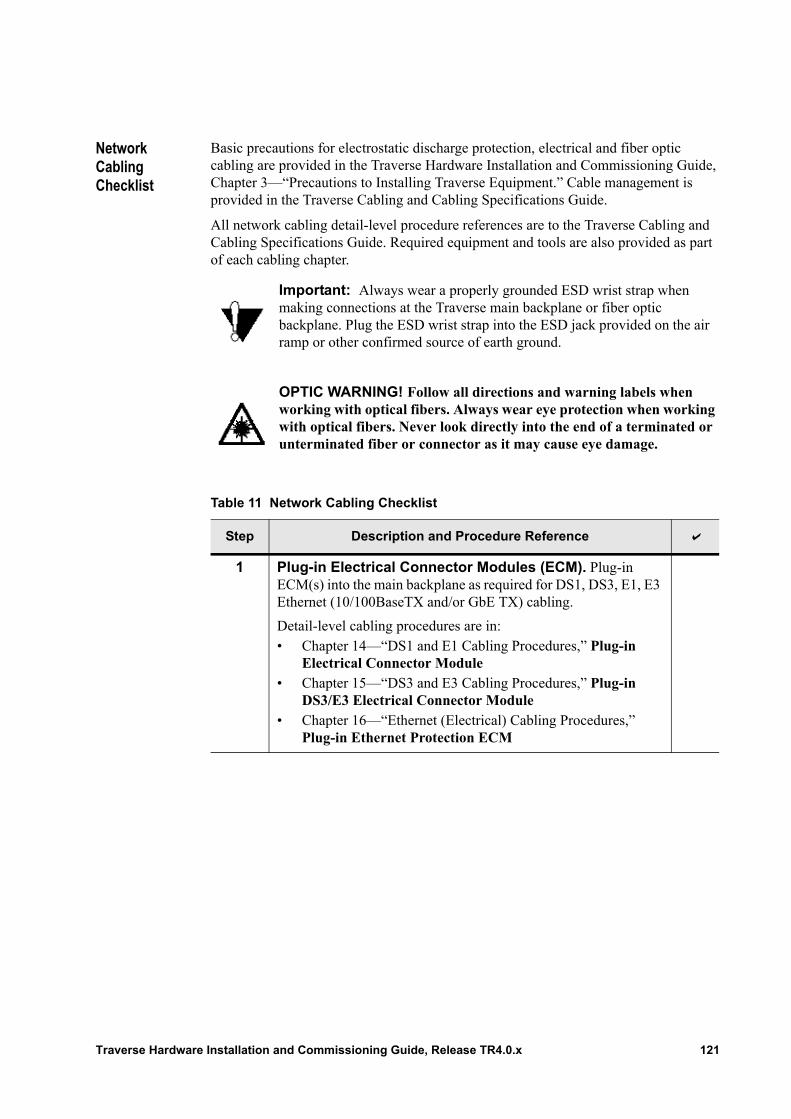
Network Cabling Checklist
Basic precautions for electrostatic discharge protection, electrical and fiber optic cabling are provided in the Traverse Hardware Installation and Commissioning Guide, Chapter 3—“Precautions to Installing Traverse Equipment.” Cable management is provided in the Traverse Cabling and Cabling Specifications Guide.
All network cabling detail-level procedure references are to the Traverse Cabling and Cabling Specifications Guide. Required equipment and tools are also provided as part of each cabling chapter.
.
Important: Always wear a properly grounded ESD wrist strap when making connections at the Traverse main backplane or fiber optic backplane. Plug the ESD wrist strap into the ESD jack provided on the air ramp or other confirmed source of earth ground.
OPTIC WARNING! Follow all directions and warning labels when working with optical fibers. Always wear eye protection when working with optical fibers. Never look directly into the end of a terminated or unterminated fiber or connector as it may cause eye damage.
Table 11 Network Cabling Checklist
Step Description and Procedure Reference
1 Plug-in Electrical Connector Modules (ECM). Plug-in ECM(s) into the main backplane as required for DS1, DS3, E1, E3 Ethernet (10/100BaseTX and/or GbE TX) cabling.
Detail-level cabling procedures are in:• Chapter 14—“DS1 and E1 Cabling Procedures,” Plug-in
Electrical Connector Module• Chapter 15—“DS3 and E3 Cabling Procedures,” Plug-in
DS3/E3 Electrical Connector Module• Chapter 16—“Ethernet (Electrical) Cabling Procedures,”
Plug-in Ethernet Protection ECM
Traverse Hardware Installation and Commissioning Guide, Release TR4.0.x 121
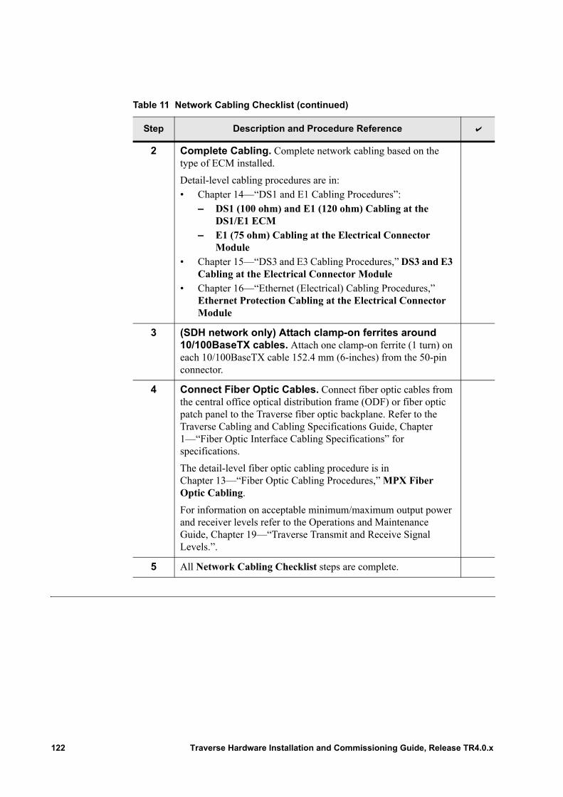
2 Complete Cabling. Complete network cabling based on the type of ECM installed.
Detail-level cabling procedures are in:• Chapter 14—“DS1 and E1 Cabling Procedures”:
– DS1 (100 ohm) and E1 (120 ohm) Cabling at the DS1/E1 ECM
– E1 (75 ohm) Cabling at the Electrical Connector Module
• Chapter 15—“DS3 and E3 Cabling Procedures,” DS3 and E3 Cabling at the Electrical Connector Module
• Chapter 16—“Ethernet (Electrical) Cabling Procedures,” Ethernet Protection Cabling at the Electrical Connector Module
3 (SDH network only) Attach clamp-on ferrites around 10/100BaseTX cables. Attach one clamp-on ferrite (1 turn) on each 10/100BaseTX cable 152.4 mm (6-inches) from the 50-pin connector.
4 Connect Fiber Optic Cables. Connect fiber optic cables from the central office optical distribution frame (ODF) or fiber optic patch panel to the Traverse fiber optic backplane. Refer to the Traverse Cabling and Cabling Specifications Guide, Chapter 1—“Fiber Optic Interface Cabling Specifications” for specifications.
The detail-level fiber optic cabling procedure is in Chapter 13—“Fiber Optic Cabling Procedures,” MPX Fiber Optic Cabling.
For information on acceptable minimum/maximum output power and receiver levels refer to the Operations and Maintenance Guide, Chapter 19—“Traverse Transmit and Receive Signal Levels.”.
5 All Network Cabling Checklist steps are complete.
Table 11 Network Cabling Checklist (continued)
Step Description and Procedure Reference
122 Traverse Hardware Installation and Commissioning Guide, Release TR4.0.x
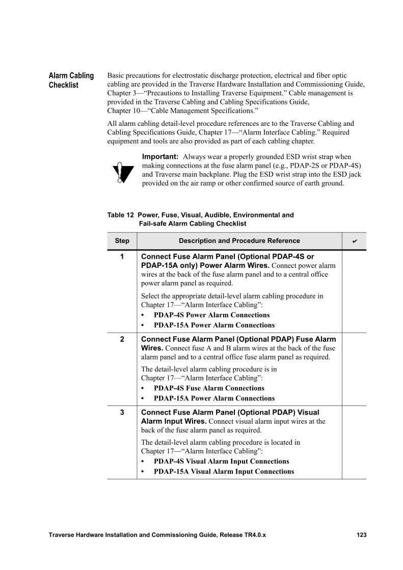
Alarm Cabling Checklist
Basic precautions for electrostatic discharge protection, electrical and fiber optic cabling are provided in the Traverse Hardware Installation and Commissioning Guide, Chapter 3—“Precautions to Installing Traverse Equipment.” Cable management is provided in the Traverse Cabling and Cabling Specifications Guide, Chapter 10—“Cable Management Specifications.”
All alarm cabling detail-level procedure references are to the Traverse Cabling and Cabling Specifications Guide, Chapter 17—“Alarm Interface Cabling.” Required equipment and tools are also provided as part of each cabling chapter.
.
Important: Always wear a properly grounded ESD wrist strap when making connections at the fuse alarm panel (e.g., PDAP-2S or PDAP-4S) and Traverse main backplane. Plug the ESD wrist strap into the ESD jack provided on the air ramp or other confirmed source of earth ground.
Table 12 Power, Fuse, Visual, Audible, Environmental and Fail-safe Alarm Cabling Checklist
Step Description and Procedure Reference
1 Connect Fuse Alarm Panel (Optional PDAP-4S or PDAP-15A only) Power Alarm Wires. Connect power alarm wires at the back of the fuse alarm panel and to a central office power alarm panel as required.
Select the appropriate detail-level alarm cabling procedure in Chapter 17—“Alarm Interface Cabling”:• PDAP-4S Power Alarm Connections• PDAP-15A Power Alarm Connections
2 Connect Fuse Alarm Panel (Optional PDAP) Fuse Alarm Wires. Connect fuse A and B alarm wires at the back of the fuse alarm panel and to a central office fuse alarm panel as required.
The detail-level alarm cabling procedure is in Chapter 17—“Alarm Interface Cabling”:• PDAP-4S Fuse Alarm Connections• PDAP-15A Power Alarm Connections
3 Connect Fuse Alarm Panel (Optional PDAP) Visual Alarm Input Wires. Connect visual alarm input wires at the back of the fuse alarm panel as required.
The detail-level alarm cabling procedure is located in Chapter 17—“Alarm Interface Cabling”:• PDAP-4S Visual Alarm Input Connections• PDAP-15A Visual Alarm Input Connections
Traverse Hardware Installation and Commissioning Guide, Release TR4.0.x 123
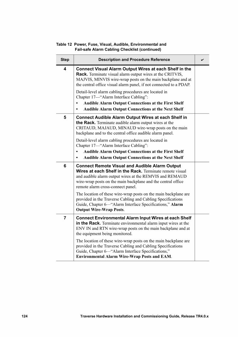
4 Connect Visual Alarm Output Wires at each Shelf in the Rack. Terminate visual alarm output wires at the CRITVIS, MAJVIS, MINVIS wire-wrap posts on the main backplane and at the central office visual alarm panel, if not connected to a PDAP.
Detail-level alarm cabling procedures are located in Chapter 17—“Alarm Interface Cabling”:• Audible Alarm Output Connections at the First Shelf• Audible Alarm Output Connections at the Next Shelf
5 Connect Audible Alarm Output Wires at each Shelf in the Rack. Terminate audible alarm output wires at the CRITAUD, MAJAUD, MINAUD wire-wrap posts on the main backplane and to the central office audible alarm panel.
Detail-level alarm cabling procedures are located in Chapter 17—“Alarm Interface Cabling”:• Audible Alarm Output Connections at the First Shelf• Audible Alarm Output Connections at the Next Shelf
6 Connect Remote Visual and Audible Alarm Output Wires at each Shelf in the Rack. Terminate remote visual and audible alarm output wires at the REMVIS and REMAUD wire-wrap posts on the main backplane and the central office remote alarm cross-connect panel.
The location of these wire-wrap posts on the main backplane are provided in the Traverse Cabling and Cabling Specifications Guide, Chapter 6—“Alarm Interface Specifications,” Alarm Output Wire-Wrap Posts.
7 Connect Environmental Alarm Input Wires at each Shelf in the Rack. Terminate environmental alarm input wires at the ENV IN and RTN wire-wrap posts on the main backplane and at the equipment being monitored.
The location of these wire-wrap posts on the main backplane are provided in the Traverse Cabling and Cabling Specifications Guide, Chapter 6—“Alarm Interface Specifications,” Environmental Alarm Wire-Wrap Posts and EAM.
Table 12 Power, Fuse, Visual, Audible, Environmental and Fail-safe Alarm Cabling Checklist (continued)
Step Description and Procedure Reference
124 Traverse Hardware Installation and Commissioning Guide, Release TR4.0.x
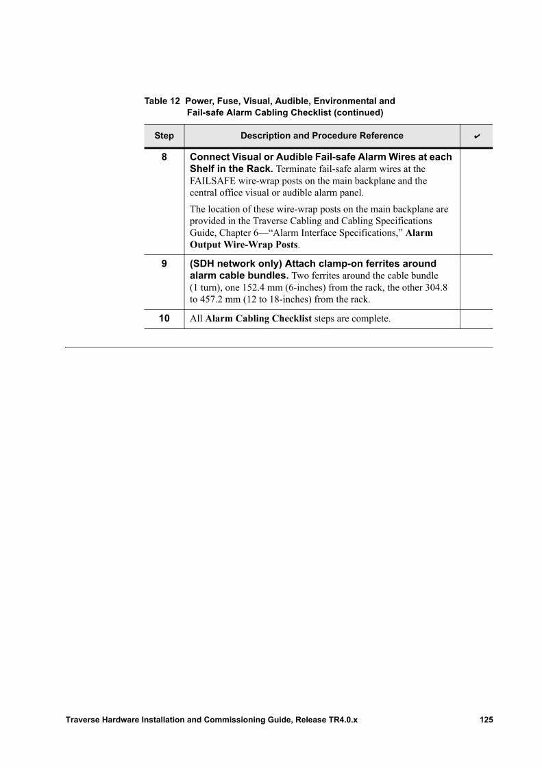
8 Connect Visual or Audible Fail-safe Alarm Wires at each Shelf in the Rack. Terminate fail-safe alarm wires at the FAILSAFE wire-wrap posts on the main backplane and the central office visual or audible alarm panel.
The location of these wire-wrap posts on the main backplane are provided in the Traverse Cabling and Cabling Specifications Guide, Chapter 6—“Alarm Interface Specifications,” Alarm Output Wire-Wrap Posts.
9 (SDH network only) Attach clamp-on ferrites around alarm cable bundles. Two ferrites around the cable bundle (1 turn), one 152.4 mm (6-inches) from the rack, the other 304.8 to 457.2 mm (12 to 18-inches) from the rack.
10 All Alarm Cabling Checklist steps are complete.
Table 12 Power, Fuse, Visual, Audible, Environmental and Fail-safe Alarm Cabling Checklist (continued)
Step Description and Procedure Reference
Traverse Hardware Installation and Commissioning Guide, Release TR4.0.x 125
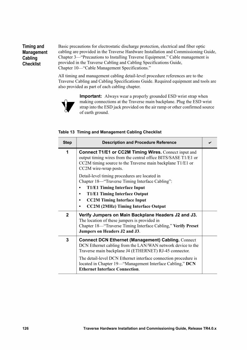
Timing and Management Cabling Checklist
Basic precautions for electrostatic discharge protection, electrical and fiber optic cabling are provided in the Traverse Hardware Installation and Commissioning Guide, Chapter 3—“Precautions to Installing Traverse Equipment.” Cable management is provided in the Traverse Cabling and Cabling Specifications Guide, Chapter 10—“Cable Management Specifications.”
All timing and management cabling detail-level procedure references are to the Traverse Cabling and Cabling Specifications Guide. Required equipment and tools are also provided as part of each cabling chapter.
.
Important: Always wear a properly grounded ESD wrist strap when making connections at the Traverse main backplane. Plug the ESD wrist strap into the ESD jack provided on the air ramp or other confirmed source of earth ground.
Table 13 Timing and Management Cabling Checklist
Step Description and Procedure Reference
1 Connect T1/E1 or CC2M Timing Wires. Connect input and output timing wires from the central office BITS/SASE T1/E1 or CC2M timing source to the Traverse main backplane T1/E1 or CC2M wire-wrap posts.
Detail-level timing procedures are located in Chapter 18—“Traverse Timing Interface Cabling”:• T1/E1 Timing Interface Input• T1/E1 Timing Interface Output• CC2M Timing Interface Input• CC2M (2MHz) Timing Interface Output
2 Verify Jumpers on Main Backplane Headers J2 and J3. The location of these jumpers is provided in Chapter 18—“Traverse Timing Interface Cabling,” Verify Preset Jumpers on Headers J2 and J3.
3 Connect DCN Ethernet (Management) Cabling. Connect DCN Ethernet cabling from the LAN/WAN network device to the Traverse main backplane J4 (ETHERNET) RJ-45 connector.
The detail-level DCN Ethernet interface connection procedure is located in Chapter 19—“Management Interface Cabling,” DCN Ethernet Interface Connection.
126 Traverse Hardware Installation and Commissioning Guide, Release TR4.0.x
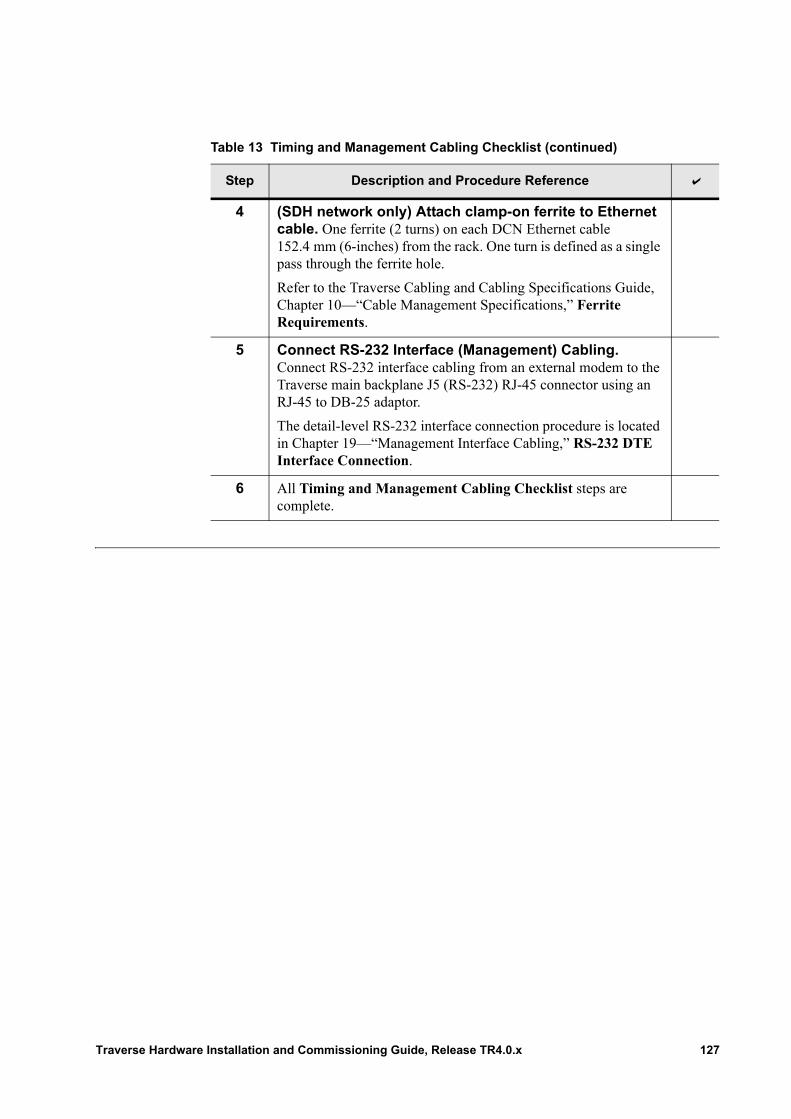
4 (SDH network only) Attach clamp-on ferrite to Ethernet cable. One ferrite (2 turns) on each DCN Ethernet cable 152.4 mm (6-inches) from the rack. One turn is defined as a single pass through the ferrite hole.
Refer to the Traverse Cabling and Cabling Specifications Guide, Chapter 10—“Cable Management Specifications,” Ferrite Requirements.
5 Connect RS-232 Interface (Management) Cabling. Connect RS-232 interface cabling from an external modem to the Traverse main backplane J5 (RS-232) RJ-45 connector using an RJ-45 to DB-25 adaptor.
The detail-level RS-232 interface connection procedure is located in Chapter 19—“Management Interface Cabling,” RS-232 DTE Interface Connection.
6 All Timing and Management Cabling Checklist steps are complete.
Table 13 Timing and Management Cabling Checklist (continued)
Step Description and Procedure Reference
Traverse Hardware Installation and Commissioning Guide, Release TR4.0.x 127
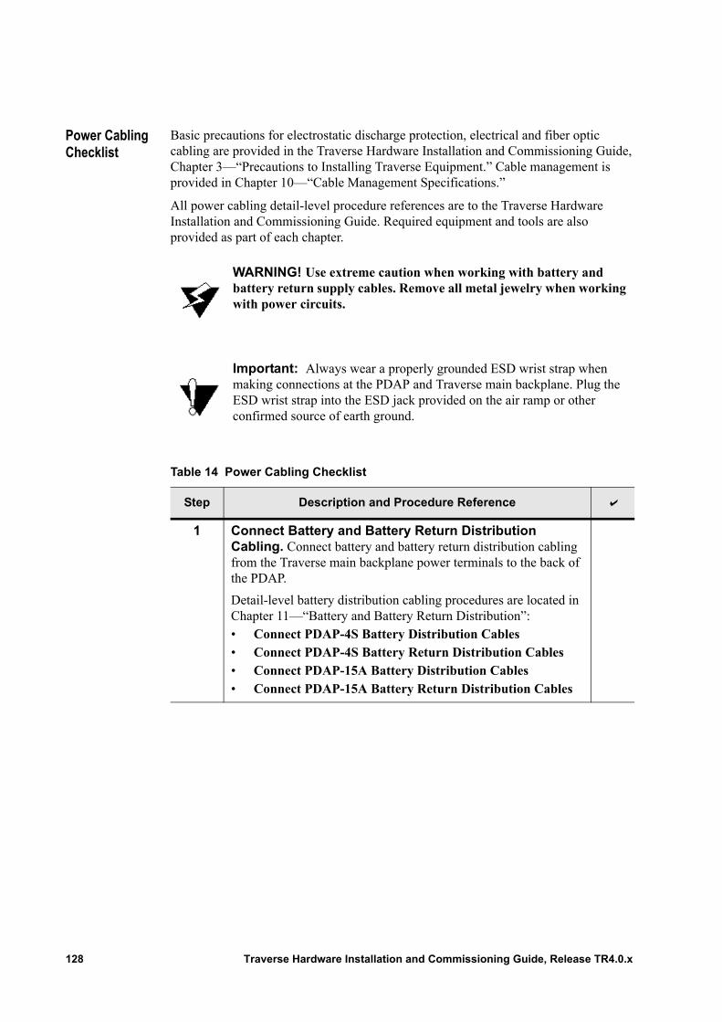
Power Cabling Checklist
Basic precautions for electrostatic discharge protection, electrical and fiber optic cabling are provided in the Traverse Hardware Installation and Commissioning Guide, Chapter 3—“Precautions to Installing Traverse Equipment.” Cable management is provided in Chapter 10—“Cable Management Specifications.”
All power cabling detail-level procedure references are to the Traverse Hardware Installation and Commissioning Guide. Required equipment and tools are also provided as part of each chapter.
.
WARNING! Use extreme caution when working with battery and battery return supply cables. Remove all metal jewelry when working with power circuits.
Important: Always wear a properly grounded ESD wrist strap when making connections at the PDAP and Traverse main backplane. Plug the ESD wrist strap into the ESD jack provided on the air ramp or other confirmed source of earth ground.
Table 14 Power Cabling Checklist
Step Description and Procedure Reference
1 Connect Battery and Battery Return Distribution Cabling. Connect battery and battery return distribution cabling from the Traverse main backplane power terminals to the back of the PDAP.
Detail-level battery distribution cabling procedures are located in Chapter 11—“Battery and Battery Return Distribution”:• Connect PDAP-4S Battery Distribution Cables• Connect PDAP-4S Battery Return Distribution Cables• Connect PDAP-15A Battery Distribution Cables• Connect PDAP-15A Battery Return Distribution Cables
128 Traverse Hardware Installation and Commissioning Guide, Release TR4.0.x
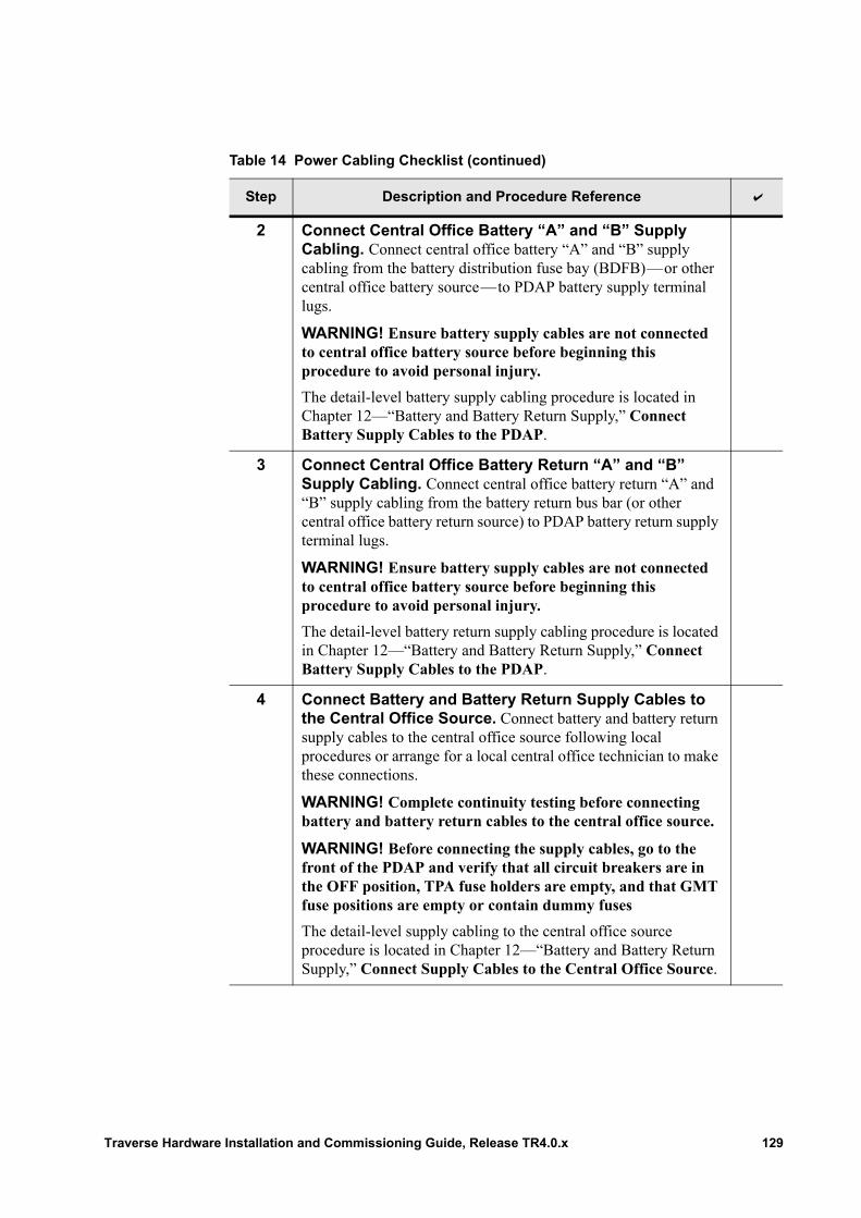
2 Connect Central Office Battery “A” and “B” Supply Cabling. Connect central office battery “A” and “B” supply cabling from the battery distribution fuse bay (BDFB)—or other central office battery source—to PDAP battery supply terminal lugs.
WARNING! Ensure battery supply cables are not connected to central office battery source before beginning this procedure to avoid personal injury.
The detail-level battery supply cabling procedure is located in Chapter 12—“Battery and Battery Return Supply,” Connect Battery Supply Cables to the PDAP.
3 Connect Central Office Battery Return “A” and “B” Supply Cabling. Connect central office battery return “A” and “B” supply cabling from the battery return bus bar (or other central office battery return source) to PDAP battery return supply terminal lugs.
WARNING! Ensure battery supply cables are not connected to central office battery source before beginning this procedure to avoid personal injury.
The detail-level battery return supply cabling procedure is located in Chapter 12—“Battery and Battery Return Supply,” Connect Battery Supply Cables to the PDAP.
4 Connect Battery and Battery Return Supply Cables to the Central Office Source. Connect battery and battery return supply cables to the central office source following local procedures or arrange for a local central office technician to make these connections.
WARNING! Complete continuity testing before connecting battery and battery return cables to the central office source.
WARNING! Before connecting the supply cables, go to the front of the PDAP and verify that all circuit breakers are in the OFF position, TPA fuse holders are empty, and that GMT fuse positions are empty or contain dummy fuses
The detail-level supply cabling to the central office source procedure is located in Chapter 12—“Battery and Battery Return Supply,” Connect Supply Cables to the Central Office Source.
Table 14 Power Cabling Checklist (continued)
Step Description and Procedure Reference
Traverse Hardware Installation and Commissioning Guide, Release TR4.0.x 129
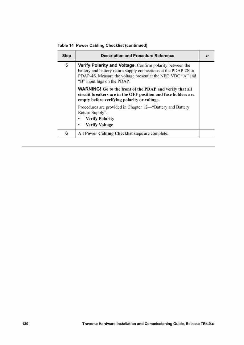
5 Verify Polarity and Voltage. Confirm polarity between the battery and battery return supply connections at the PDAP-2S or PDAP-4S. Measure the voltage present at the NEG VDC “A” and “B” input lugs on the PDAP.
WARNING! Go to the front of the PDAP and verify that all circuit breakers are in the OFF position and fuse holders are empty before verifying polarity or voltage.
Procedures are provided in Chapter 12—“Battery and Battery Return Supply”:• Verify Polarity• Verify Voltage
6 All Power Cabling Checklist steps are complete.
Table 14 Power Cabling Checklist (continued)
Step Description and Procedure Reference
130 Traverse Hardware Installation and Commissioning Guide, Release TR4.0.x
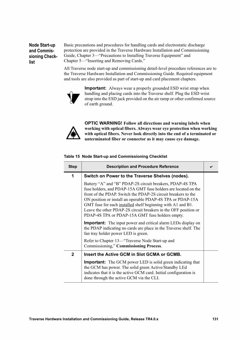
Node Start-up and Commis-sioning Check-list
Basic precautions and procedures for handling cards and electrostatic discharge protection are provided in the Traverse Hardware Installation and Commissioning Guide, Chapter 3—“Precautions to Installing Traverse Equipment” and Chapter 5—“Inserting and Removing Cards.”
All Traverse node start-up and commissioning detail-level procedure references are to the Traverse Hardware Installation and Commissioning Guide. Required equipment and tools are also provided as part of start-up and card placement chapters.
Important: Always wear a properly grounded ESD wrist strap when handling and placing cards into the Traverse shelf. Plug the ESD wrist strap into the ESD jack provided on the air ramp or other confirmed source of earth ground.
OPTIC WARNING! Follow all directions and warning labels when working with optical fibers. Always wear eye protection when working with optical fibers. Never look directly into the end of a terminated or unterminated fiber or connector as it may cause eye damage.
Table 15 Node Start-up and Commissioning Checklist
Step Description and Procedure Reference
1 Switch on Power to the Traverse Shelves (nodes).
Battery “A” and “B” PDAP-2S circuit breakers, PDAP-4S TPA fuse holders, and PDAP-15A GMT fuse holders are located on the front of the PDAP. Switch the PDAP-2S circuit breakers to the ON position or install an operable PDAP-4S TPA or PDAP-15A GMT fuse for each installed shelf beginning with A1 and B1. Leave the other PDAP-2S circuit breakers in the OFF position or PDAP-4S TPA or PDAP-15A GMT fuse holders empty.
Important: The input power and critical alarm LEDs display on the PDAP indicating no cards are place in the Traverse shelf. The fan tray holder power LED is green.
Refer to Chapter 13—“Traverse Node Start-up and Commissioning,” Commissioning Process.
2 Insert the Active GCM in Slot GCMA or GCMB.
Important: The GCM power LED is solid green indicating that the GCM has power. The solid green Active/Standby LEd indicates that it is the active GCM card. Initial configuration is done through the active GCM via the CLI.
Traverse Hardware Installation and Commissioning Guide, Release TR4.0.x 131
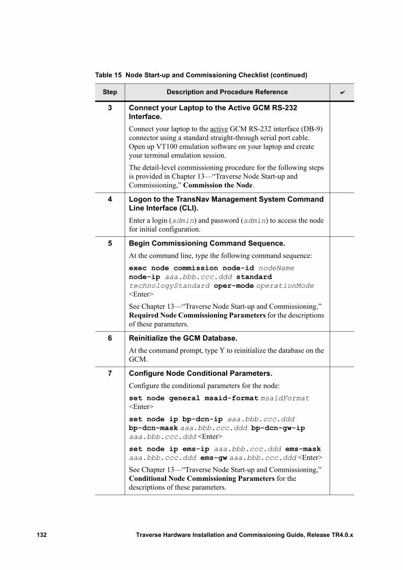
3 Connect your Laptop to the Active GCM RS-232 Interface.
Connect your laptop to the active GCM RS-232 interface (DB-9) connector using a standard straight-through serial port cable. Open up VT100 emulation software on your laptop and create your terminal emulation session.
The detail-level commissioning procedure for the following steps is provided in Chapter 13—“Traverse Node Start-up and Commissioning,” Commission the Node.
4 Logon to the TransNav Management System Command Line Interface (CLI).
Enter a login (admin) and password (admin) to access the node for initial configuration.
5 Begin Commissioning Command Sequence.
At the command line, type the following command sequence:
exec node commission node-id nodeName node-ip aaa.bbb.ccc.ddd standard technologyStandard oper-mode operationMode <Enter>
See Chapter 13—“Traverse Node Start-up and Commissioning,” Required Node Commissioning Parameters for the descriptions of these parameters.
6 Reinitialize the GCM Database.
At the command prompt, type Y to reinitialize the database on the GCM.
7 Configure Node Conditional Parameters.
Configure the conditional parameters for the node:
set node general msaid-format msaidFormat <Enter>
set node ip bp-dcn-ip aaa.bbb.ccc.ddd bp-dcn-mask aaa.bbb.ccc.ddd bp-dcn-gw-ip aaa.bbb.ccc.ddd <Enter>
set node ip ems-ip aaa.bbb.ccc.ddd ems-mask aaa.bbb.ccc.ddd ems-gw aaa.bbb.ccc.ddd <Enter>
See Chapter 13—“Traverse Node Start-up and Commissioning,” Conditional Node Commissioning Parameters for the descriptions of these parameters.
Table 15 Node Start-up and Commissioning Checklist (continued)
Step Description and Procedure Reference
132 Traverse Hardware Installation and Commissioning Guide, Release TR4.0.x
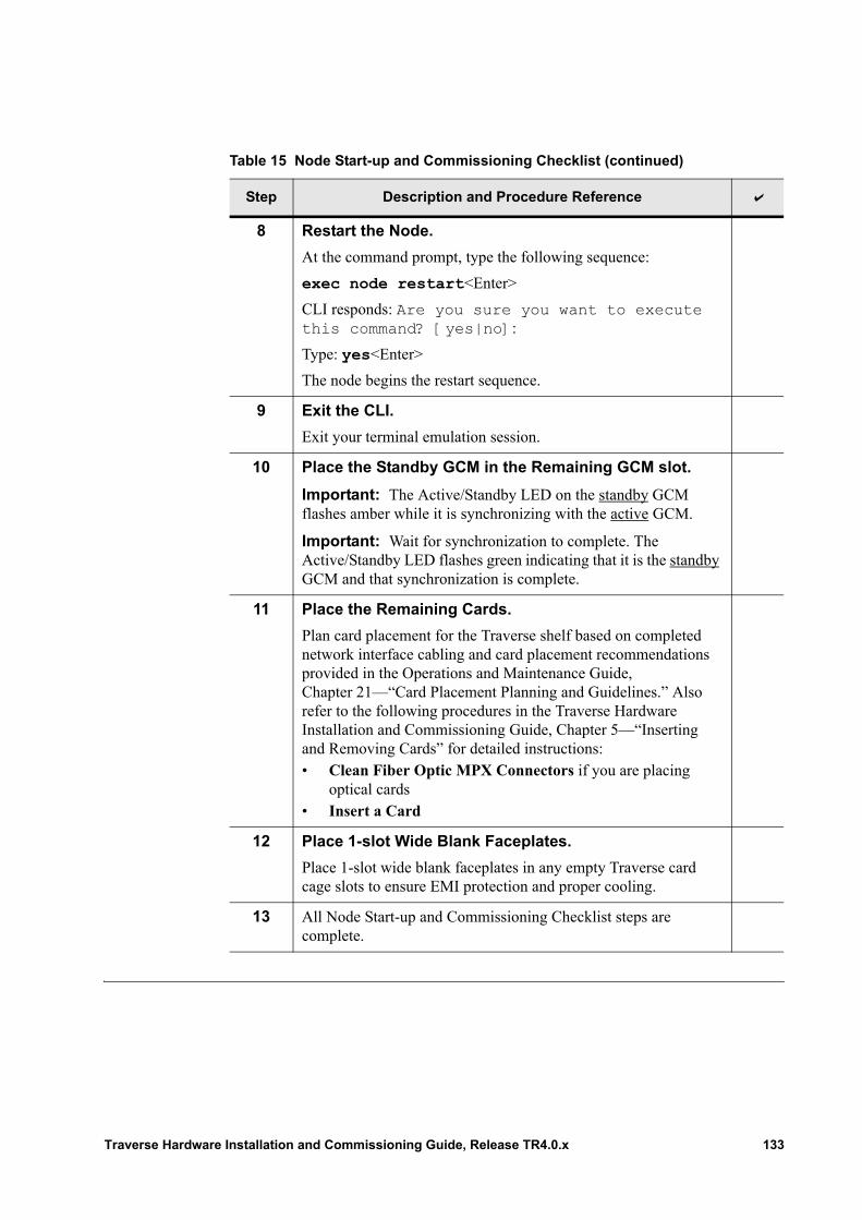
8 Restart the Node.
At the command prompt, type the following sequence:
exec node restart<Enter>
CLI responds: Are you sure you want to execute this command? [yes|no]:
Type: yes<Enter>
The node begins the restart sequence.
9 Exit the CLI.
Exit your terminal emulation session.
10 Place the Standby GCM in the Remaining GCM slot.
Important: The Active/Standby LED on the standby GCM flashes amber while it is synchronizing with the active GCM.
Important: Wait for synchronization to complete. The Active/Standby LED flashes green indicating that it is the standby GCM and that synchronization is complete.
11 Place the Remaining Cards.
Plan card placement for the Traverse shelf based on completed network interface cabling and card placement recommendations provided in the Operations and Maintenance Guide, Chapter 21—“Card Placement Planning and Guidelines.” Also refer to the following procedures in the Traverse Hardware Installation and Commissioning Guide, Chapter 5—“Inserting and Removing Cards” for detailed instructions:• Clean Fiber Optic MPX Connectors if you are placing
optical cards• Insert a Card
12 Place 1-slot Wide Blank Faceplates.
Place 1-slot wide blank faceplates in any empty Traverse card cage slots to ensure EMI protection and proper cooling.
13 All Node Start-up and Commissioning Checklist steps are complete.
Table 15 Node Start-up and Commissioning Checklist (continued)
Step Description and Procedure Reference
Traverse Hardware Installation and Commissioning Guide, Release TR4.0.x 133

134 Traverse Hardware Installation and Commissioning Guide, Release TR4.0.x
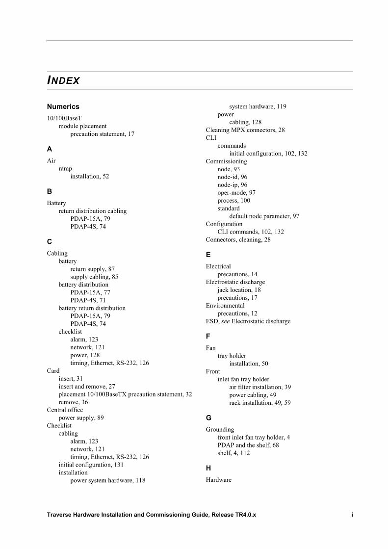
INDEX
Numerics
10/100BaseTmodule placement
precaution statement, 17
A
Airramp
installation, 52
B
Batteryreturn distribution cabling
PDAP-15A, 79PDAP-4S, 74
C
Cablingbattery
return supply, 87supply cabling, 85
battery distributionPDAP-15A, 77PDAP-4S, 71
battery return distributionPDAP-15A, 79PDAP-4S, 74
checklistalarm, 123network, 121power, 128timing, Ethernet, RS-232, 126
Cardinsert, 31insert and remove, 27placement 10/100BaseTX precaution statement, 32remove, 36
Central officepower supply, 89
Checklistcabling
alarm, 123network, 121timing, Ethernet, RS-232, 126
initial configuration, 131installation
power system hardware, 118
system hardware, 119power
cabling, 128Cleaning MPX connectors, 28CLI
commandsinitial configuration, 102, 132
Commissioningnode, 93node-id, 96node-ip, 96oper-mode, 97process, 100standard
default node parameter, 97Configuration
CLI commands, 102, 132Connectors, cleaning, 28
E
Electricalprecautions, 14
Electrostatic dischargejack location, 18precautions, 17
Environmentalprecautions, 12
ESD, see Electrostatic discharge
F
Fantray holder
installation, 50Front
inlet fan tray holderair filter installation, 39power cabling, 49rack installation, 49, 59
G
Groundingfront inlet fan tray holder, 4PDAP and the shelf, 68shelf, 4, 112
H
Hardware
Traverse Hardware Installation and Commissioning Guide, Release TR4.0.x i

checklistinstallation, power system, 118
installation checklist, 119precautions, 13
I
Installair ramp, 52fan tray holder, 50front inlet fan tray air filter, 39front inlet fan tray holder, 49, 59hardware
requirements, 107rack adaptation, 46rack adapter, 112shelf, 47, 61
T2000, rotated, 55Installation
checklistpower system hardware, 118system hardware, 119
L
LEDsvisual status
GCM start-up, 105
M
Moduleinsert, 31see also card
MPX connectorscleaning, 28
N
Nodecommissioning, 100
ID, 96IP, 96
start-up and commissioning, 93Nutdriver, 1/4-inch
shelf power connections, 3, 108
O
Operation modecommissioning, 97
P
PDAP19-inch rack installation, 66, 109ETSI rack installation, 66
protective back coverremove, 26replace, 26
Polarityverify, 91
Powerbattery distribution cabling
PDAP-15A, 77PDAP-4S, 71
battery return distributionPDAP-15A, 79PDAP-4S, 74
battery return supply cabling, 87battery supply cabling, 85node, 93supply
central office, 89Precaution statements, 11
10/100BaseTmodule placement, 17
electrical, 14electrostatic discharge, 17environmental, 12hardware, 13module, 16
S
Shelfback covers
removing, 21, 23replacing, 21
flush mounting, 48grounding, 112rack adapter installation, 112rack installation, 47, 61
adaptation, 46start-up and commissioning, 93
Start-upinitial configuration
checklist, 131LED
GCM visual status, 105node, 93
Systemconfiguration
example, 8
V
Verifypolarity, 91voltage, 92
Voltage
ii Traverse Hardware Installation and Commissioning Guide, Release TR4.0.x

verify, 92
W
Warning statements, see Precaution statements
Traverse Hardware Installation and Commissioning Guide, Release TR4.0.x iii