Embed Size (px)
Citation preview
Reliability Engineering and System Safety 40 (1993) 295-309
TREE-EXPERT: a tree-based expert system for fault tree construction*
Gang Xie, Dazhi Xue & Shuren Xi Institute of Nuclear Energy Technology, Tsinghua University, Beijing 100084, People's Republic of China.
(Received 11 March 1992; accepted 23 September 1992)
This paper addresses the topic of automatic fault tree construction, utilizing an expert system with Artificial Intelligence (AI) techniques and presents the related software tool, TREE-EXPERT--an expert system for automatic fault tree construction. In the light of the features involved in developing a fault tree, a new and more reasonable structure of knowledge representation, which is knowledge tree based, has been established. The knowledge tree provides the means by which component failure behaviors can be described by a group of particular fault tree modules instead of production rules. By introducing the conditional branch function, the new design of the knowledge base incorpor- ates many good features such as strong expressivity, flexibility and ease of extension and it takes advantage of the user's familiarity with the field of fault tree analysis. Additionally, the design of the inference engine is original in that it deals with nodes, which it treats, as special components, so that many complicated engineering cases, such as the application of success criteria, and the problems of flow diversions and flow reversals in a process system, can be well managed and the function of the expert system is improved as a whole. TREE-EXPERT can be used to deal with large-scale and complicated engineering systems, and many engineering factors can be considered, e.g. more than one system parameter and the effect on them switching of the system operating states, bi-directional inference, human error failure, common-cause failure, maintenance and test, etc. On the other hand, the software uses P & ID (Pipe & Instrument Diagram) type interface to describe the system topology, which provides an easier man-machine interface with powerful graphics functions. This software can handle not only 'process' systems but also, with appropriate additions to the generic knowledge base, electrical systems and other similar systems.
1 I N T R O D U C T I O N
1.1 Background
Automat ion of logic modeling has been the main aim in applying artificial intelligence (AI) techniques to probability safety analysis (PSA). 2-1° System analysis in conventional PSA, especially fault tree construc- tion, is t ime-consuming and susceptible to human error. Various degrees of ' au tomat ion of the tree
• This paper is written based on Dr. Xie's doctoral dissertation, see Ref. (1).
Reliability Engineering an d System Safety 0951-8320/93 / $06.00 © 1993 Elsevier Science Publishers Ltd, England.
295
construction process ' can certainly increase the speed of system analysis and reduce the opportunit ies for human error. However , this is achieved at a certain price. Similar work had been under taken by PSA analysts before they were aware of AI techniques and expert systems. Research was done on the so-called 'computer-aided construction of fault trees ' for electrical systems, chemical process systems, and nuclear reactor systems. Although they have not been called expert systems, these software tools do possess similar knowledge and inference logic structures. None of them, however, has been used extensively by the PSA community. The main reasons for this can be summarized as follows:
• Although the logical mechanisms in these tools are well developed, the user-interface devices are
296 G. Xie, D. Xue, S. Xi
not designed in a satisfactory manner. For example, some codes require numerical coding in their input of all the failure modes and connection nodes, and they generate long lists of coded numbers in their output. Users usually find that the interpretation of these results requires significant effort and causes errors.
• Even for system analysis, PSA requires many judgements. For example, the analysts needs to determine the possible impact of human actions, such as maintenance work or emergency proce- dures, on the function of systems or components. Another example is the judgement involved in assessing the effects of common-cause failure. These events are not easily dealt with by a computerized tool, because the logical reasoning involved is usually not straightforward. This causes difficulties in constructing a fault tree in a 'fully automatic' way.
• The fault tree construction itself is an important process in the safety analysis, during which the analyst gains a deep understanding of the system behavior and learns about potential system malfunctions and their causes. Therefore many safety analysts think that automatic fault tree construction skips one of the important steps in the safety analysis.
For those reasons, the effort involved in automatic fault tree construction will not be accepted by the safety analyst unless the drawbacks are eliminated. The authors think that the current development of computer techniques could produce a satisfactory man-machine interface for analysts, and by means of AI techniques (e.g. an expert system) more complicated logical reasoning and even engineering judgment could be involved. It is not necessary to worry that the computer software will replace analysts in conducting system analysis. In fact, the objective in developing this kind of expert system is to help system analysts to work in an efficient way. With the current development of AI techniques and expert systems, methods for automatic fault tree construction and their applications seem to have regained momentum. Lessons learned in the past will be helpful in developing future expert systems. From these points of view, a software development project on T R E E - E X P E R T has been initiated with the following aims:
• The expert system should deal with systems for which the system topology can be described by a P&ID diagram, such as hydraulic systems, electrical systems, etc.
• A more reasonable knowledge base structure should be produced to make inference convenient.
• It should be possible to consider more than one
system parameter, e.g. pressure, temperature, flow rate, liquid level, etc., simultaneously.
• Engineering judgment should be involved in some complicated engineering cases, for instance, for the application of success criteria, and in problems involving, flow diversions and flow reversals.
• The logical reasoning should be bi-directional, i.e. upstream and downstream, so that inference could be started from any point of the system.
• It should be possible to consider more than one configuration, to deal with the switching of the system operating states.
• Maintenance and test, human error, support system, and common-cause failure should be involved on demand of the user.
• The software should be PC-based to benefit users in the PC community.
• The software interface should be user-friendly and easy to use. Generally, graphics techniques should be applied.
1.2 Overview of the TREE-EXPERT structure
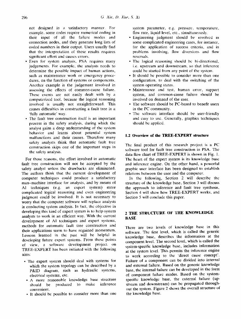
The final product of this research project is a PC software tool for fault tree construction in PSA. The data flow chart of T R E E - E X P E R T is shown in Fig. 1. The heart of the expert system is its knowledge base and inference engine. On the other hand, a powerful graphic user interface has been designed to establish relations between the user and the computer.
In the following, Section 2 will describe the structure of the knowledge base, Section 3 will discuss the approach to inference and fault tree synthesis, Section 4 will show how T R E E - E X P E R T works, and Section 5 will conclude this paper.
2 THE STRUCTURE OF THE KNOWLEDGE BASE
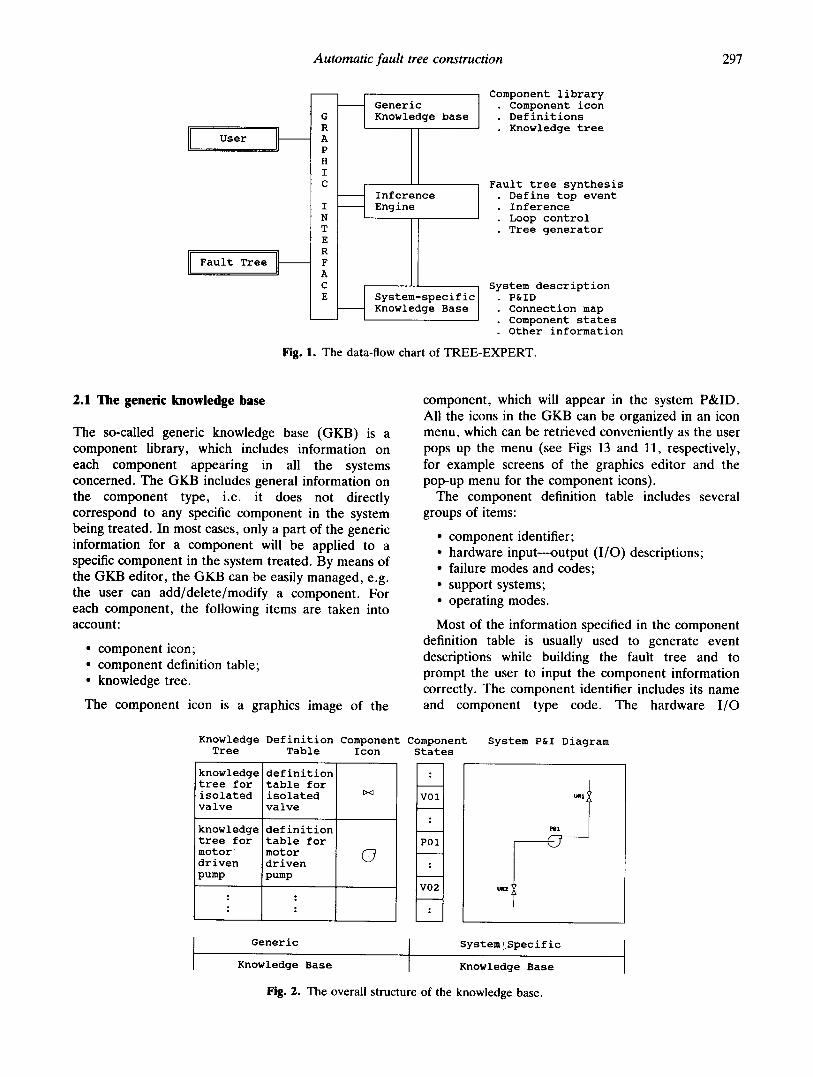
There are two levels of knowledge base in this software. The first level, which is called the generic knowledge base, describes the information at the component level. The second level, which is called the system-specific knowledge base, includes information at the system level. This permits the inference engine to work according to the 'direct cause concept' . Failure of a component can be divided into internal and external failure. Based on the generic knowledge base, the internal failure can be developed in the form of component failure modes. Based on the system- specific knowledge base, the external failure (up- stream and downstream) can be propagated through- out the system. Figure 2 shows the overall structure of the knowledge base.
Automatic fault tree construction 297
User
Fault Tree
G R
A P H I C
I N
T E R
F A C E
Generic Knowledge base
Inference Engine
System-specific] Knowledge Base
Component library • Component icon • Definitions • Knowledge tree
Fault tree synthesis • Define top event • Inference • Loop control • Tree generator
System description . P&ID • Connection map • Component states . Other information
Fig. 1. The data-flow chart of TREE-EXPERT.
2 . 1 T h e g e n e r i c k n o w l e d g e b a s e
The so-called generic knowledge base (GKB) is a component library, which includes information on each component appearing in all the systems concerned. The GKB includes general information on the component type, i.e. it does not directly correspond to any specific component in the system being treated. In most cases, only a part of the generic information for a component will be applied to a specific component in the system treated. By means of the GKB editor, the GKB can be easily managed, e.g. the user can add/delete/modify a component. For each component, the following items are taken into account:
• component icon; • component definition table; • knowledge tree.
The component icon is a graphics image of the
component, which will appear in the system P&ID. All the icons in the GKB can be organized in an icon menu, which can be retrieved conveniently as the user pops up the menu (see Figs 13 and 11, respectively, for example screens of the graphics editor and the pop-up menu for the component icons).
The component definition table includes several groups of items:
• component identifier; • hardware input---output (I/O) descriptions; • failure modes and codes; • support systems; • operating modes.
Most of the information specified in the component definition table is usually used to generate event descriptions while building the fault tree and to prompt the user to input the component information correctly. The component identifier includes its name and component type code. The hardware I/O
Knowledge Tree
Definition Component Component Table Icon States
-I >~ VOI: I
POII
<7
V 0 2
: I
" " I
knowledge tree for isolated valve
knowledge tree for motor ~ driven pump
!definition table for isolated valve
definition table for motor driven pump
Generic
Knowledge Base
System!Specific
Knowledge Base
Fig. 2. The overall structure of the knowledge base.
System P&I Diagram
67
298 G. Xie, D. Xue, S. Xi
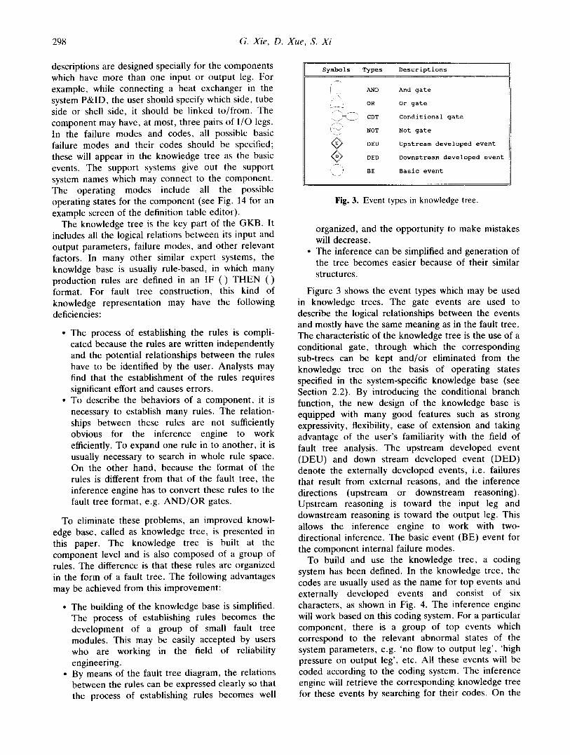
descriptions are designed specially for the components which have more than one input or output leg. For example, while connecting a heat exchanger in the system P&ID, the user should specify which side, tube side or shell side, it should be linked to/from. The component may have, at most, three pairs of I/O legs. In the failure modes and codes, all possible basic failure modes and their codes should be specified; these will appear in the knowledge tree as the basic events. The support systems give out the support system names which may connect to the component. The operating modes include all the possible operating states for the component (see Fig. 14 for an example screen of the definition table editor).
The knowledge tree is the key part of the GKB. It includes all the logical relations between its input and output parameters, failure modes, and other relevant factors. In many other similar expert systems, the knowldge base is usually rule-based, in which many production rules are defined in an IF () THEN () format. For fault tree construction, this kind of knowledge representation may have the following deficiencies:
• The process of establishing the rules is compli- cated because the rules are written independently and the potential relationships between the rules have to be identified by the user. Analysts may find that the establishment of the rules requires significant effort and causes errors.
• To describe the behaviors of a component, it is necessary to establish many rules. The relation- ships between these rules are not sufficiently obvious for the inference engine to work efficiently. To expand one rule in to another, it is usually necessary to search in whole rule space. On the other hand, because the format of the rules is different from that of the fault tree, the inference engine has to convert these rules to the fault tree format, e.g. AND/OR gates.
To eliminate these problems, an improved knowl- edge base, called as knowledge tree, is presented in this paper. The knowledge tree is built at the component level and is also composed of a group of rules. The difference is that these rules are organized in the form of a fault tree. The following advantages may be achieved from this improvement:
• The building of the knowledge base is simplified. The process of establishing rules becomes the development of a group of small fault tree modules. This may be easily accepted by users who are working in the field of reliability engineering.
• By means of the fault tree diagram, the relations between the rules can be expressed clearly so that the process of establishing rules becomes well
Symbols Types Descriptions
i ]
f~
@ @ i ,i
\ _ s
AND And gate
OR Or gate
CDT Conditional gate
NOT Not gate
DEU Upstream developed event
DED Downstream developed event
BE Basic event
Fig. 3. Event types in knowledge tree.
organized, and the opportunity to make mistakes will decrease.
• The inference can be simplified and generation of the tree becomes easier because of their similar structures.
Figure 3 shows the event types which may be used in knowledge trees. The gate events are used to describe the logical relationships between the events and mostly have the same meaning as in the fault tree. The characteristic of the knowledge tree is the use of a conditional gate, through which the corresponding sub-trees can be kept and/or eliminated from the knowledge tree on the basis of operating states specified in the system-specific knowledge base (see Section 2.2). By introducing the conditional branch function, the new design of the knowledge base is equipped with many good features such as strong expressivity, flexibility, ease of extension and taking advantage of the user's familiarity with the field of fault tree analysis. The upstream developed event (DEU) and down stream developed event (DED) denote the externally developed events, i.e. failures that result from external reasons, and the inference directions (upstream or downstream reasoning). Upstream reasoning is toward the input leg and downstream reasoning is toward the output leg. This allows the inference engine to work with two- directional inference. The basic event (BE) event for the component internal failure modes.
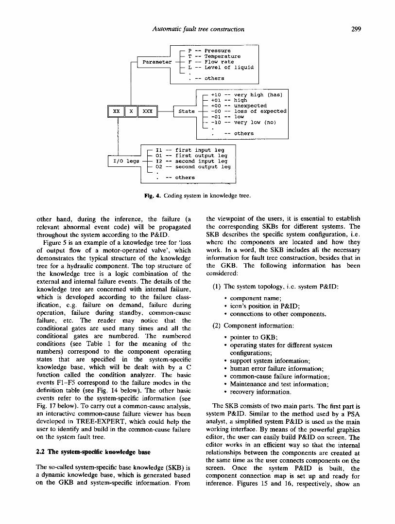
To build and use the knowledge tree, a coding system has been defined. In the knowledge tree, the codes are usually used as the name for top events and externally developed events and consist of six characters, as shown in Fig. 4. The inference engine will work based on this coding system. For a particular component, there is a group of top events which correspond to the relevant abnormal states of the system parameters, e.g. 'no flow to output leg', 'high pressure on output leg', etc. All these events will be coded according to the coding system. The inference engine will retrieve the corresponding knowledge tree for these events by searching for their codes. On the
Automatic fault tree construction 299
Parameter - -
xx x
P -- Pressure T -- Temperature F -- Flow rate L -- Level of liquid
IlO leqs I
I
State - -
-- others
~ +i0 -- very high (has) +01 -- high +00 -- unexpected -00 -- loss of expected -01 -- low -i0 -- very low (no)
-- others
Ii -- first input leg Ol -- first output leg
-- I2 -- second input leg 02 -- second output leg
-- others
Fig. 4. Coding system in knowledge tree.
other hand, during the inference, the failure (a relevant abnormal event code) will be propagated throughout the system according to the P&ID.
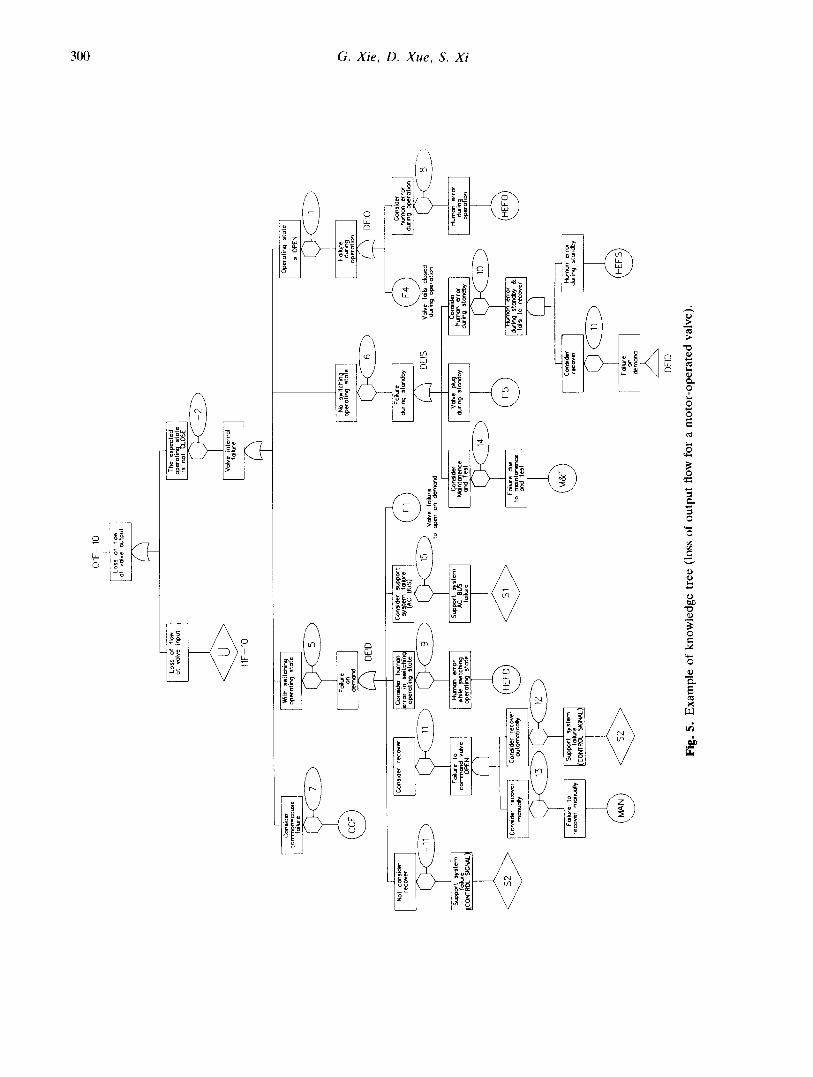
Figure 5 is an example of a knowledge tree for 'loss of output flow of a motor-operated valve', which demonstrates the typical structure of the knowledge tree for a hydraulic component. The top structure of the knowledge tree is a logic combination of the external and internal failure events. The details of the knowledge tree are concerned with internal failure, which is developed according to the failure class- ification, e.g. failure on demand, failure during operation, failure during standby, common-cause failure, etc. The reader may notice that the conditional gates are used many times and all the conditional gates are numbered. The numbered conditions (see Table 1 for the meaning of the numbers) correspond to the component operating states that are specified in the system-specific knowledge base, which will be dealt with by a C function called the condition analyzer. The basic events F1-F5 correspond to the failure modes in the definition table (see Fig. 14 below). The other basic events refer to the system-specific information (see Fig. 17 below). To carry out a common-cause analysis, an interactive common-cause failure viewer has been developed in TREE-EXPERT, which could help the user to identify and build in the common-cause failure on the system fault tree.
2.2 The system-specific knowledge base
The so-called system-specific base knowledge (SKB) is a dynamic knowledge base, which is generated based on the GKB and system-specific information. From
the viewpoint of the users, it is essential to establish the corresponding SKBs for different systems. The SKB describes the specific system configuration, i.e. where the components are located and how they work. In a word, the SKB includes all the necessary information for fault tree construction, besides that in the GKB. The following information has been considered:
(1) The system topology, i.e. system P&ID:
• component name; • icon's position in P&ID; • connections to other components.
(2) Component information:
• pointer to GKB; • operating states for different system
configurations; • support system information; • human error failure information; • common-cause failure information; • Maintenance and test information; • recovery information.
The SKB consists of two main parts. The first part is system P&ID. Similar to the method used by a PSA analyst, a simplified system P&ID is used as the main working interface. By means of the powerful graphics editor, the user can easily build P&ID on screen. The editor works in an efficient way so that the internal relationships between the components are created at the same time as the user connects components on the screen. Once the system P&ID is built, the component connection map is set up and ready for inference. Figures 15 and 16, respectively, show an
I Co
ns~d
e( co
rrfn
on-
cot.c
s e
to~l
ur e
I Lo
ss
of
flow
at
vc
dve
inpu
t
4>
11F-
10
01
F-1
0
I a,%Sg
,~ °' ~
t%t
#
I N
ot
cons
ider
re
cove
r
~ppo
r t
~y s t
enn
foilu
re
ICO
NTRO
L SI
GNA
L ~
I W
ith
switc
hing
op
erat
ing
stat
e
FNlur
e de
g,~
I Th
e ex
pect
ed
oper
otin
st
ate
is
not
gCLO
SE
V~v
e in
tern
al
to'lu
re
No
switc
hln
oper
atin
g st
oC~e
DE
ID
, +
J C
on~i
der
~ C
on~d
er
art
F oilu
r e
Con
side
r re
cove
r er
rOro
pera
tlngin
sw
itchin
gstot
e sY
~ACt
em B
~f°
l e
durin
g st
ondb
y
I I
Failu
re
to
H~T
~n
erro
r Su
p~)o
rl B
corw
'no~
:l vo
~e
whi
le
switc
hing
~
'~u~ s
tem
M
ant o
nenc
e du
rln 9
S ~a~
dby
Con
side
r V(
~ve
lug
OPE
N op
erat
ing
stat
e al
lure
an
d Te
st
reco
ver
man
ually
fNlur e
CONT
ROL S
IGNA
L
+
dem
and
DE
ID
Fig.
5.
E
xam
ple
of k
now
ledg
e tr
ee (
loss
of
outp
ut f
low
for
a m
otor
-ope
rate
d va
lve)
.
Valv
e fo
ils
clos
ed
durin
g op
erat
ion
Fmlu
re
due
to
moi
nt o
nenc
e an
d te
st
Ope
ratin
g st
ate
is
OPE
N
FNlure
duri
r~
aper
ohoi
~
DE
IO I
Con
side
r hu
man
err
or
durin
g st
ondb
y
Hum
an e
rror
du
ring
stan
dby
& fo
ils
to
reco
ver
©
1 H
~nno
n er
ror
durin
g st
ond
by
Conm
ider
hu
man
er
ror
durin
g op
erat
ion
H~
er
r~
~ri
n
op~o
~on
Automatic fault tree construction 301
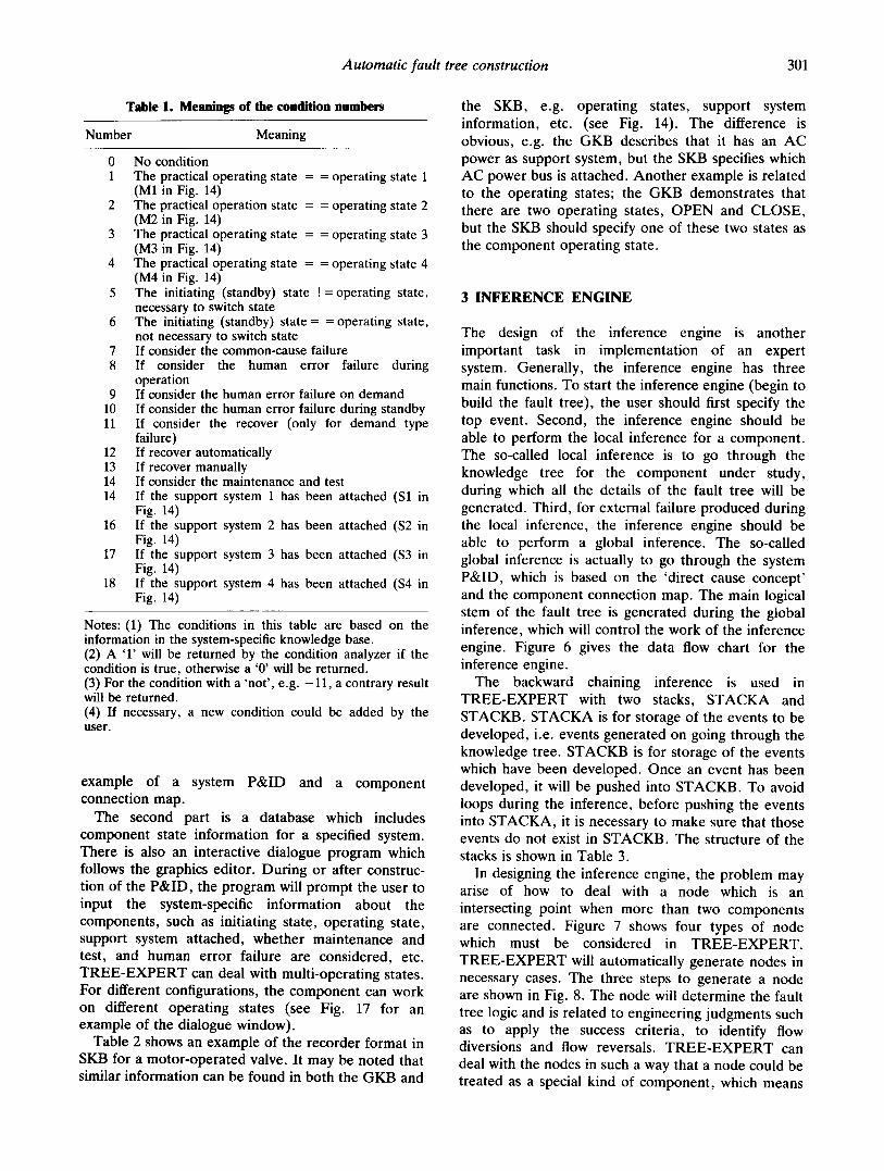
Table 1. Meanings of the condition numbers
Number Meaning
0 No condition 1 The practical operating state = = operating state 1
(M1 in Fig. 14) 2 The practical operation state = = operating state 2
(M2 in Fig. 14) 3 The practical operating state = = operating state 3
(M3 in Fig. 14) 4 The practical operating state = = operating state 4
(M4 in Fig. 14) 5 The initiating (standby) state !=operating state,
necessary to switch state 6 The initiating (standby) state = = operating state,
not necessary to switch state 7 If consider the common-cause failure 8 If consider the human error failure during
operation 9 If consider the human error failure on demand
10 If consider the human error failure during standby 11 If consider the recover (only for demand type
failure) 12 If recover automatically 13 If recover manually 14 If consider the maintenance and test 14 If the support system 1 has been attached (S1 in
Fig. 14) 16 If the support system 2 has been attached ($2 in
Fig. 14) 17 If the support system 3 has been attached ($3 in
Fig. 14) 18 If the support system 4 has been attached ($4 in
Fig. 14)
Notes: (1) The conditions in this table are based on the information in the system-specific knowledge base. (2) A '1' will be returned by the condition analyzer if the condition is true, otherwise a '0' will be returned. (3) For the condition with a 'not', e.g. -11, a contrary result will be returned. (4) If necessary, a new condition could be added by the user.
example of a system P&ID and a component connection map.
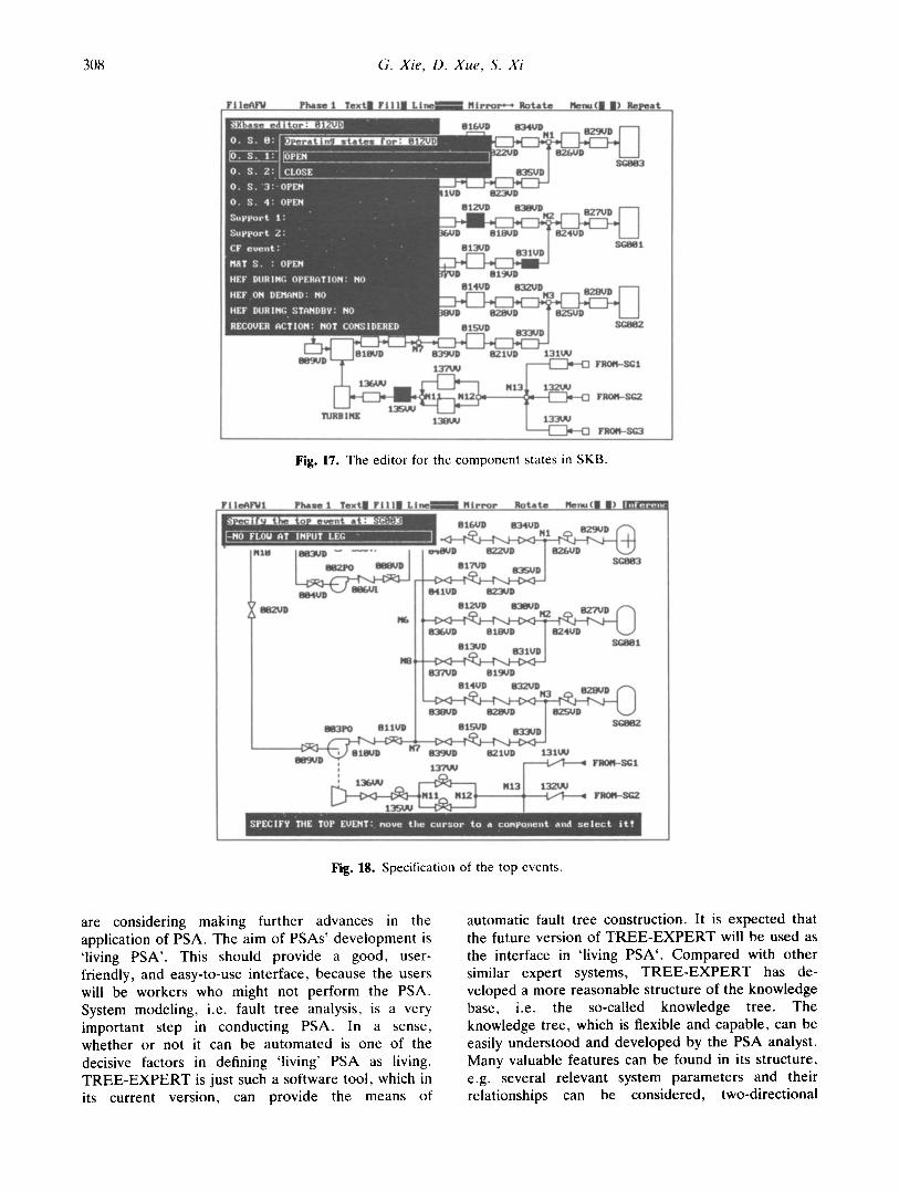
The second part is a database which includes component state information for a specified system. There is also an interactive dialogue program which follows the graphics editor. During or after construc- tion of the P&ID, the program will prompt the user to input the system-specific information about the components, such as initiating state., operating state, support system attached, whether maintenance and test, and human error failure are considered, etc. T R E E - E X P E R T can deal with multi-operating states. For different configurations, the component can work on different operating states (see Fig. 17 for an example of the dialogue window).
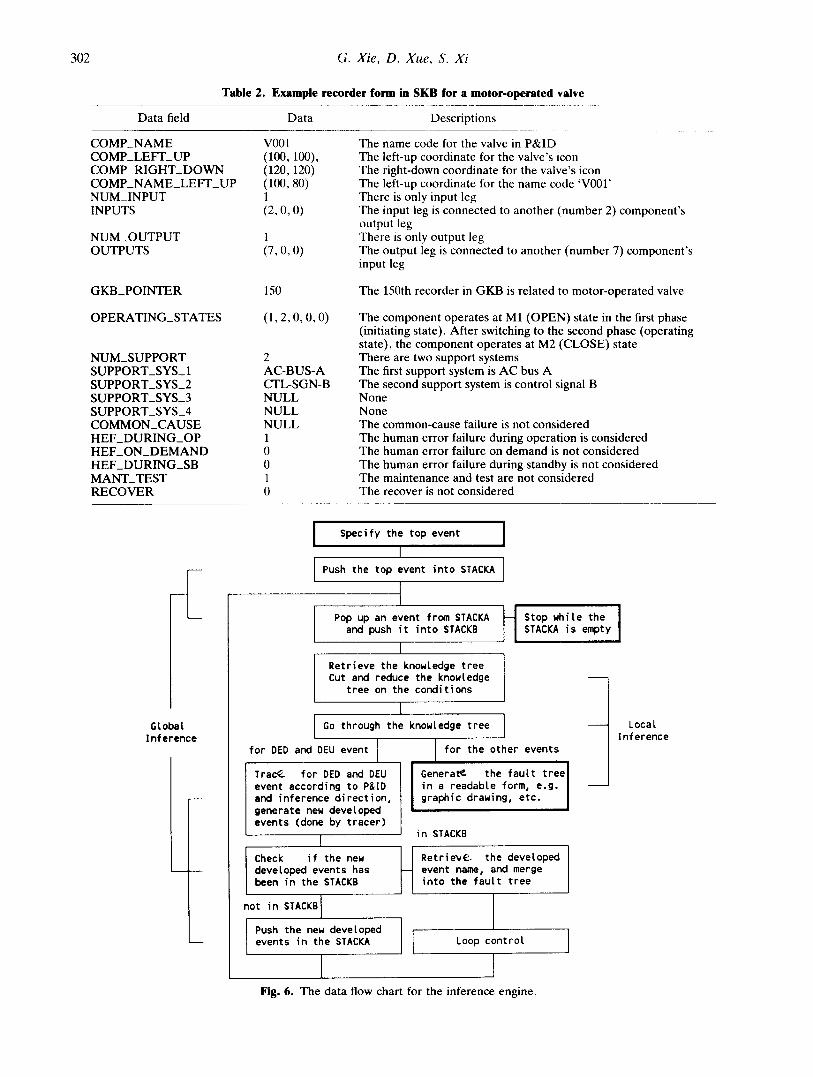
Table 2 shows an example of the recorder format in SKB for a motor-operated valve. It may be noted that similar information can be found in both the GKB and
the SKB, e.g. operating states, support system information, etc. (see Fig. 14). The difference is obvious, e.g. the GKB describes that it has an AC power as support system, but the SKB specifies which AC power bus is attached. Another example is related to the operating states; the GKB demonstrates that there are two operating states, OPEN and CLOSE, but the SKB should specify one of these two states as the component operating state.
3 INFERENCE ENGINE
The design of the inference engine is another important task in implementation of an expert system. Generally, the inference engine has three main functions. To start the inference engine (begin to build the fault tree), the user should first specify the top event. Second, the inference engine should be able to perform the local inference for a component . The so-called local inference is to go through the knowledge tree for the component under study, during which all the details of the fault tree will be generated. Third, for external failure produced during the local inference, the inference engine should be able to perform a global inference. The so-called global inference is actually to go through the system P&ID, which is based on the 'direct cause concept' and the component connection map. The main logical stem of the fault tree is generated during the global inference, which will control the work of the inference engine. Figure 6 gives the data flow chart for the inference engine.
The backward chaining inference is used in T R E E - E X P E R T with two stacks, STACKA and STACKB. STACKA is for storage of the events to be developed, i.e. events generated on going through the knowledge tree. STACKB is for storage of the events which have been developed. Once an event has been developed, it will be pushed into STACKB. To avoid loops during the inference, before pushing the events into STACKA, it is necessary to make sure that those events do not exist in STACKB. The structure of the stacks is shown in Table 3.
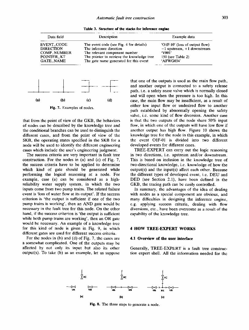
In designing the inference engine, the problem may arise of how to deal with a node which is an intersecting point when more than two components are connected. Figure 7 shows four types of node which must be considered in T R E E - E X P E R T . T R E E - E X P E R T will automatically generate nodes in necessary cases. The three steps to generate a node are shown in Fig. 8. The node will determine the fault tree logic and is related to engineering judgments such as to apply the success criteria, to identify flow diversions and flow reversals. T R E E - E X P E R T can deal with the nodes in such a way that a node could be treated as a special kind of component , which means
302
Data field
G. Xie, D. Xue, S. Xi
Table 2. Example recorder form in SKB for a motor-operated valve
Data Descriptions
COMP_NAME COMP_LEFT_UP COMP_RIGHT_DOWN COMP_NAME_LEFT_UP NUM_INPUT INPUTS
NUM_OUTPUT OUTPUTS
GKB_POINTER
OPERATING_STATES
NUM_SUPPORT SUPPORT_SYS_ 1 SUPPORT_SYS_2 SUPPORT_SYS_3 SUPPORT_SYS_4 COMMON_CAUSE HEF_DURING_OP HEF_ON_DEMAND HEF_DURING_SB MANT_TEST RECOVER
v001 (100, 100), (120,120) (100, 80) 1 (2, O, O)
l (7, O, O)
150
(1 ,2 ,0 ,0 ,0 )
2 AC-BUS-A CTL-SGN-B NULL NULL NULL 1 0 0 1 0
The name code for the valve in P&ID The left-up coordinate for the valve's icon The right-down coordinate for the valve's icon The left-up coordinate for the name code 'V001' There is only input leg The input leg is connected to another (number 2) component's output leg There is only output leg The output leg is connected to another (number 7) component's input leg
The 150th recorder in GKB is related to motor-operated valve
The component operates at M1 (OPEN) state in the first phase (initiating state). After switching to the second phase (operating state), the component operates at M2 (CLOSE) state There are two support systems The first support system is AC bus A The second support system is control signal B None None The common-cause failure is not considered The human error failure during operation is considered The human error failure on demand is not considered The human error failure during standby is not considered The maintenance and test are not considered The recover is not considered
Global Inference
Specify the top event l
I Push the top event into STACKA I
Pop up an event from STACKA and push i t into STACKB
I Retrieve the knowledge t ree Cut and reduce the knowledge
tree on the condi t ions
I Go through the knowledge tree
fo r DED and DEU event I m
Trac~ for DED and DEU event according to P&ID and inference direction, generate new developed events (done by tracer)
in STACKB I I t
Check i f the new I I developed events has H been in the STACKB
not in STACKB i
Push the new developed I t events in the STACKA II
l
H Stop white the I STACKA is empty
fo r the other events
Generat~ the f a u l t t ree I in a readable form, e.g. I graphic drawing, etc. I
Retrie~E~ the developed event name, and merge into the fault tree
Loop control
Fig. 6. The data flow chart for the inference engine.
Local inference
Automatic fault tree construction
Table 3. Structure of the stacks for inference engine
303
Data field Description Example data
EVENT_CODE DIRECTION COMP_NUMBER POINTER_KT GATE_NAME
The event code (see Fig. 4 for details) The inference direction The relevant component number The pointer to retrieve the knowledge tree The gate name generated for this event
'OIF-10' (loss of output flow) - 1 upstream, +1 downstream 'V001' 150 (see Table 2) 'AFWG034'
(a) (b) (c)
_ l t (d)
Fig. 7. Examples of nodes.
that from the point of view of the GKB, the behaviors of nodes can be described by the knowledge tree and the conditional branches can be used to distinguish the different cases, and from the point of view of the SKB, the operating states specified in the SKB for a node will be used to identify the different engineering cases which include the user's engineering judgment.
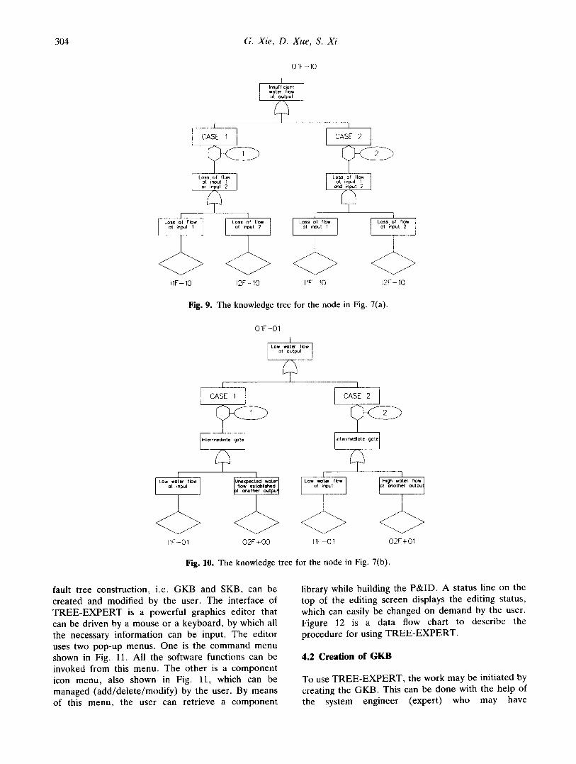
The success criteria are very important in fault tree construction. For the nodes in (a) and (c) of Fig. 7, the success criteria have to be applied to determine which kind of gate should be generated while performing the logical reasoning at a node. For example, case (a) can be considered as a high- reliability water supply system, in which the two inputs come from two pump trains. The related failure event is 'loss of water flow at its output ' . If the success criterion is ' the output is sufficient if one of the two pump trains is working', then an AND gate would be necessary in the fault tree for this node. On the other hand, if the success criterion is ' the output is sufficient while both pump trains are working', then an O R gate would be necessary. An example of a knowledge tree for this kind of node is given in Fig. 9, ill which different gates are used for different success criteria.
For the nodes in (b) and (d) of Fig. 7, the cases are a somewhat complicated. One of the outputs may be affected by not only its input but also its other output(s). To take (b) as an example, let us suppose
that one of the outputs is used as the main flow path, and another output is connected to a safety release path, i.e. a safety rease valve which is normally closed and will open when the pressure is too high. In this case, the main flow may be insufficient, as a result of either low input flow or undesired flow to another path established by abnormally opening the safety valve, i.e. some kind of flow diversion. Another case is that the two outputs of the node share 50% input flow, in which one of the outputs will have low flow if another output has high flow. Figure 10 shows the knowledge tree for the node in this example, in which the event O1F-01 is divided into two different developed events for different cases.
T R E E - E X P E R T can carry out the logic reasoning in two directions, i.e. upstream and/or downstream. This is based on inclusion in the knowledge tree of two-directional knowledge, i.e. knowledge of how the output(s) and the input(s) affect each other. Because the different types of developed event, i.e. D E U and DED (see Section 2.1), have been defined in the GKB, the tracing path can be easily controlled.
In summary, the advantages of the idea of dealing with nodes as a special component are obvious, and many difficulties in designing the inference engine, e.g. applying success criteria, dealing with flow diversions, etc., have been overcome as a result of the capability of the knowledge tree.
4 H O W T R E E - E X P E R T W O R K S
4.1 O v e r v i e w of the user interface
Generally, T R E E - E X P E R T is a fault tree construc- tion expert shell. All the information needed for the
t ~ t l~ t °c
~ ~ ) t><l------ ------t>~ ~ - ; I:><3----- UB U~ UB t ~ FI 1 UB
la) Ibl Icl
Fig. 8. The three steps to generate a node.
304 G. Xie, D. Xue, S. Xi
01F-I0
I k~suf ficient woter flow ot output
I
I CASE 1
Loss of flow at input 1 or input 2
I I I i Loss ol Flow Loss of flow Loss of flow l
ot input 1 ot input 2 ot input 1 I
< > + d > 11F-I0 12F-I0 11F-I0
I
LOSS of flow ot input 1
end input 2
I Loss of flow
ot input 2
12F-I0
Fig. 9. The knowledge tree for the node in Fig. 7(a).
I Lo.~ woter flow
ot input
11F-01
01F-01
I Low woter flow
ol output
# I 1 i
CASE I [ CASE 2 I
Intermed~ote gote Interme~ote 9ore
1 I I / ~ . ~ , ° a .oto, l Lo. ~ t . , , e . / ~ .ot.~ ,~.m
flow estoblished/ ot input r t cmother outpu] tot or, other output~
<> <> <> 02F+O0 IIF-01 O2F+01
Fig. 10. The knowledge tree for the node in Fig. 7(b).
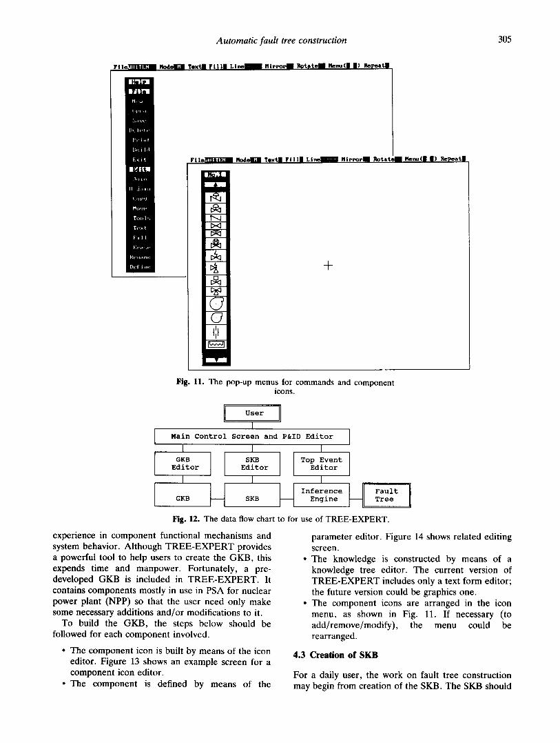
fault tree construction, i.e. GKB and SKB, can be created and modified by the user. The interface of T R E E - E X P E R T is a powerful graphics editor that can be driven by a mouse or a keyboard, by which all the necessary information can be input. The editor uses two pop-up menus. One is the command menu shown in Fig. 11. All the software functions can be invoked from this menu. The other is a component icon menu, also shown in Fig. 11, which can be managed (add/dele te /modify) by the user. By means of this menu, the user can retrieve a component
library while building the P&ID. A status line on the top of the editing screen displays the editing status, which can easily be changed on demand by the user. Figure 12 is a data flow chart to describe the procedure for using T R E E - E X P E R T .
4.2 Creation of G K B
To use T R E E - E X P E R T , the work may be initiated by creating the GKB. This can be done with the help of the system engineer (expert) who may have
Automatic fault tree construction
F i l e Nod Tex t F i l l LI H l r r o Rotat Menu( I Re at
• ~I'31
1411"II
1) , : I , ' ! ,:
1'," i , i t
lh~ i I d
E ~ i t
I¢IIl
Fill
D e f i n t . ~
305
F i l e nod Tex t F i l l L i n e t l i r r ~ r R o t a t e Menu( ) Re a t
+
Fig. 11. The pop-up menus for commands and component icons.
U s e r
] Main Control Screen and P&ID Editor
I I I GKB SKB Top Event
Editor Editor Editor
I I I II Inference I Fault
GKB SKB Engine Tree
Fig. ~ . The data flow chart to for use of TREE-EXPERT.
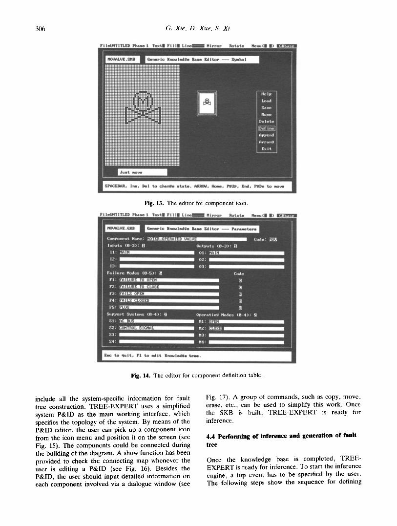
parameter editor. Figure 14 shows related editing screen. The knowledge is constructed by means of a knowledge tree editor. The current version of T R E E - E X P E R T includes only a text form editor; the future version could be graphics one. The component icons are arranged in the icon menu, as shown in Fig. 11. If necessary (to add/remove/modify) , the menu could be rearranged.
experience in component functional mechanisms and system behavior. Although T R E E - E X P E R T provides a powerful tool to help users to create the GKB, this expends time and manpower. Fortunately, a pre- developed GKB is included in T R E E - E X P E R T . It contains components mostly in use in PSA for nuclear power plant (NPP) so that the user need only make some necessary additions and/or modifications to it.
To build the GKB, the steps below should be followed for each component involved.
• The component icon is built by means of the icon editor. Figure 13 shows an example screen for a component icon editor.
• The component is defined by means of the
4.3 Creation of SKB
For a daily user, the work on fault tree construction may begin from creation of the SKB. The SKB should
306 G. Xie, D. Xue, S. Xi
Fig. 13. The editor for component icon.
Fig. 14. The editor for component definition table.
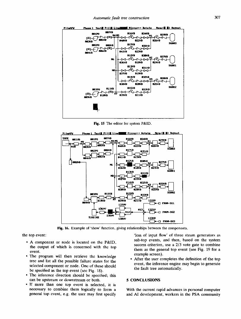
include all the system-specific information for fault tree construction. T R E E - E X P E R T uses a simplified system P&ID as the main working interface, which specifies the topology of the system. By means of the P&ID editor, the user can pick up a component icon from the icon menu and position it on the screen (see Fig. 15). The components could be connected during the building of the diagram. A show function has been provided to check the connecting map whenever the user is editing a P&ID (see Fig. 16). Besides the P&ID, the user should input detailed information on each component involved via a dialogue window (see
Fig. 17). A group of commands, such as copy, move, erase, etc., can be used to simplify this work. Once the SKB is built, T R E E - E X P E R T is ready for inference.
4.4 Performing of inference and generation of fault tree
Once the knowledge base is completed, TR EE- EX P ERT is ready for inference. To start the inference engine, a top event has to be specified by the user. The following steps show the sequence for defining
Automatic fault tree construction 307
F i l a ~ e l f p l , . . ~ 1 T e x 4 F i l l | L i t : m H l r r ~ - ~ Rotate
mlFO E~PPD
BO2PO M
BS, ND
I I . u ( I I ) b ~ t
5 816UD B344/D 829UD
B41UD BZ3K/D
01ZUD 838UD 8Z'M,JD
! 8 3 " P ~ 819UD i 8141)D 832UD O28UD
818UD - " 839UD 821UD
t Fig. 15 The editor for system P&ID.
Fi leN~lJ phx.~_ 1 Tex t l l F i l l | L i ~ m H i r r o r * - , R o t a t e I1enu(n II) RePea t
T~4X 881UD 887VD 816UD 834VD _ _ BBIPO . . . . . . . . . . a,~:mm I " ' - I
BH~PO e~SUD
84eUD 8Z2VD T 8 2 ~ D I I
8'11U]) BT-.'~D
81ZVD 83~/D 827VD 1"--7
83151D 819UD
814UD H3ZUD ~
8BgUD
TUPJ I1~
811UD
1 ~ ¸
the top event:
• A component or node is located on the P&ID, the output of which is concerned with the top event.
• The program will then retrieve the knowledge tree and list all the possible failure states for the selected component or node. One of these should be specified as the top event (see Fig. 18).
• The inference direction should be specified; this can be upstream or downstream or both.
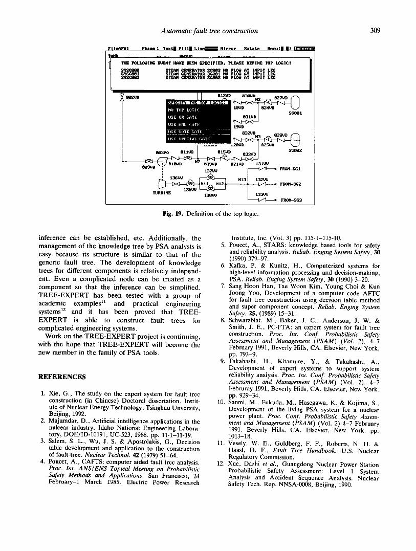
• If more than one top event is selected, it is necessary to combine them logically to form a general top event, e.g. the user may first specify
0.3BUD ~ D ~ ~ D I I
B39UD 821UD 13lUll 1 ~ FROIS.-SG1
FROH-S~2
13:3~,~ 131K~ ~ FROM-SG3
Fig. 16. Example of 'show' function, giving relationships between the components.
'loss of input flow' of three steam generators as sub-top events, and then, based on the system success criterion, use a 2/3 vote gate to combine them as the general top event (see Fig. 19 for a example screen).
• After the user completes the definition of the top event, the inference engine may begin to generate the fault tree automatically.
5 CONCLUSIONS
With the current rapid advances in personal computer and AI development, workers in the PSA community
308
Fi h~h~J
G. Xie, D. Xue, S. Xi
pk~,L.~ 1 Tex tn F i l l l L | " ~ m Nlrr.m~,-. R o t a t e
Fig. 17. The editor for the component states in SKB.
F I le~US~Jl
RlU
OaZVD
I ~ - ~ 1 Text I F I l l I L ~ - - / N i r r o r R o t a t e I~le'mt(ll n ) i . . . . . . . . . .
81~/D 8340D 8~UD / - ~
841VD 11~3UD
8 ~ 83~/D 8~r/VD
148 ~ ~ 1
837VD 8 1 ~ D
t I 814VD 832VDN3 828UD / - ~
~ - ~ J 818Vn " ' 83~7n 821Vn 1 3 1 ~
Fig. 18. Specification of the top events.
are considering making further advances in the application of PSA. The aim of PSAs' development is 'living PSA'. This should provide a good, user- friendly, and easy-to-use interface, because the users will be workers who might not perform the PSA. System modeling, i.e. fault tree analysis, is a very important step in conducting PSA. In a sense, whether or not it can be automated is one of the decisive factors in defining 'living' PSA as living. T R E E - E X P E R T is just such a software tool, which in its current version, can provide the means of
automatic fault tree construction. It is expected that the future version of T R E E - E X P E R T will be used as the interface in 'living PSA'. Compared with other similar expert systems, T R E E - E X P E R T has de- veloped a more reasonable structure of the knowledge base, i.e. the so-called knowledge tree. The knowledge tree, which is flexible and capable, can be easily understood and developed by the PSA analyst. Many valuable features can be found in its structure, e.g. several relevant system parameters and their relationships can be considered, two-directional
Automatic fault tree construction
F I I m ~ V l P h a s e I T e x t F i l l L i n e N i r r o r R o t a t e I ~ n u ( R m ) IJDls~LV~
LOGlC!
STEAM GENERRTOR ~ NO FLOW AT INPUT LEG
309
H13 1 3 2 ~ ,~ FROIT--,~2 T
'IMJRB n, lE 138vtJ / 133t,~ /
• FROI'I-SG3
Fig. 19. Definition of the top logic.
inference can be established, etc. Additionally, the management of the knowledge tree by PSA analysts is easy because its structure is similar to that of the generic fault tree. The development of knowledge trees for different components is relatively independ- ent. Even a complicated node can be treated as a component so that the inference can be simplified. T R E E - E X P E R T has been tested with a group of academic examples 11 and practical engineering systems 12 and it has been proved that TREE- E X P E R T is able to construct fault trees for complicated engineering systems.
Work on the T R E E - E X P E R T project is continuing, with the hope that T R E E - E X P E R T will become the new member in the family of PSA tools.
REFERENCES
1. Xie, G., The study on the expert system for fault tree construction (in Chinese) Doctoral dissertation, Instit- ute of Nuclear Energy Technology, Tsinghau Unversity, Beijing, 1992.
2. Majumdar, D., Artificial intelligence applications in the nulcear industry. Idaho National Engineering Labora- tory, DOE/ID-10191, UC-523, 1988. pp. 11-1-11-19.
3. Salem, S. L., Wu, J. S. & Apostolakis, G., Decision table development and application to the construction of fault-tree. Nuclear Technol. 42 (1979) 51-64.
4. Poucet, A., CAFFS: computer aided fault tree analysis. Proc. Int. ANS/ENS Topical Meeting on Probabilistic Safety Methods and Applications, San Francisco, 24 February-1 March 1985. Electric Power Research
Institute, Inc. (Vol. 3) pp. 115-1-115-10. 5. Poucet, A., STARS: knowledge based tools for safety
and reliability analysis. Reliab. Enging System Safety, 30 (1990) 379-97.
6. Kafka, P. & Kunitz, H., Computerized systems for high-level information processing and decision-making, PSA. Reliab. Enging System Safety, 30 (1990) 3-20.
7. Sang Hoon Han, Tae Woon Kim, Young Choi & Kun Joong Yoo, Development of a computer code AFFC for fault tree construction using decision table method and super component concept. Reliab. Enging System Safety, 25, (1989) 15-31.
8. Schwarzblat, M., Baker, J. C., Anderson, J. W. & Smith, J. E., PC-FTA: an expert system for fault tree construction. Proc. Int. Conf. Probabilistic Safety Assessment and Management (PSAM) (Vol. 2), 4-7 February 1991, Beverly Hills, CA. Elsevier, New York, pp. 793-9.
9. Takahashi, H., Kitamure, Y., & Takahashi, A., Development of expert systems to support system reliability analysis. Proc. Int. Conf. Probabilistic Safety Assessment and Management (PSAM) (Vol. 2). 4-7 Februray 1991, Beverly Hills, CA. Elsevier, New York. pp. 929-34.
10. Sanmi, M., Fukuda, M., Hasegawa, K. & Kojima, S., Development of the living PSA system for a nuclear power plant. Proc. Conf. Probabilistic Safety Assess- ment and Management (PSAM) (Vol. 2) 4-7 February 1991, Beverly Hills, CA. Elsevier, New York. pp. 1013-18.
11. Vesely, W. E., Goldberg, F. F., Roberts, N. H. & Haasl, D. F., Fault Tree Handbook. U.S. Nuclear Regulatory Commission.
12. Xue, Dazhi et al., Guangdong Nuclear Power Station Probabilistic Safety Assessment: Level 1 System Analysis and Accident Sequence Analysis. Nuclear Safety Tech. Rep. NNSA-0008, Beijing, 1990.


![Fault Tree Diagram[1]](https://img.pdfslide.net/doc/110x75/55cf8c8a5503462b138d7284/fault-tree-diagram1.jpg)
