Embed Size (px)
Citation preview
Trench-filled cellular parylene electret for piezoelectric transducerYue Feng, Kei Hagiwara, Yoshinori Iguchi, and Yuji Suzuki Citation: Applied Physics Letters 100, 262901 (2012); doi: 10.1063/1.4730952 View online: http://dx.doi.org/10.1063/1.4730952 View Table of Contents: http://scitation.aip.org/content/aip/journal/apl/100/26?ver=pdfcov Published by the AIP Publishing Articles you may be interested in Fluoroethylenepropylene ferroelectret films with cross-tunnel structure for piezoelectric transducers and microenergy harvesters J. Appl. Phys. 116, 074109 (2014); 10.1063/1.4893367 Controlled inflation of voids in cellular polymer ferroelectrets: Optimizing electromechanical transducer properties Appl. Phys. Lett. 84, 392 (2004); 10.1063/1.1641171 Thermally stable dynamic piezoelectricity in sandwich films of porous and nonporous amorphous fluoropolymer Appl. Phys. Lett. 79, 1852 (2001); 10.1063/1.1404405 Large and broadband piezoelectricity in smart polymer-foam space-charge electrets Appl. Phys. Lett. 77, 3827 (2000); 10.1063/1.1331348 Electromechanical response of cellular electret films Appl. Phys. Lett. 75, 3405 (1999); 10.1063/1.125308
This article is copyrighted as indicated in the article. Reuse of AIP content is subject to the terms at: http://scitation.aip.org/termsconditions. Downloaded to IP:
136.165.238.131 On: Fri, 19 Dec 2014 15:28:47
Trench-filled cellular parylene electret for piezoelectric transducer
Yue Feng,1,a) Kei Hagiwara,1,2 Yoshinori Iguchi,2 and Yuji Suzuki11Department of Mechanical Engineering, The University of Tokyo, 7-3-1 Hongo, Bunkyo-ku,Tokyo 113-8654, Japan2NHK Science and Technology Research Laboratories, 1-10-11 Kinuta, Setagaya-ku, Tokyo 157-8510, Japan
(Received 15 April 2012; accepted 8 June 2012; published online 25 June 2012)
Cellular ferroelectrets with charged voids are promising for piezoelectric transducers, but the
long-term stability or reproducibility due to the conventional “stochastic” fabrication and the
corona charging methods is of concern. We microfabricated a high-density cellular piezoelectret
with high-aspect-ratio polymer structures based on the trench-filled parylene technology. Vertical
walls of the parylene structures are charged using soft x-ray to realize uniform artificial dipoles, of
which moments could vary along with parylene structural deformation driven by the inertia of a
seismic mass. Charge and voltage sensitivities of 9600 pC/N and 960 V/N with respect to the in-
plane resonant oscillation have been achieved at 149 Hz, respectively. VC 2012 American Institute ofPhysics. [http://dx.doi.org/10.1063/1.4730952]
Piezoelectric transducers are widely used in the micro-
electro-mechanical system (MEMS) transducers such as
inertial sensors, actuators, and energy harvesters.1 Lead
zirconate titanate (PZT) thin films prepared with sol-gel or
sputtering methods could offer high piezoelectric constants
(d33� 360 pC/N), whereas the resonant frequencies of the
MEMS piezoelectric devices are often very high due to
their large Young’s moduli. Soft piezoelectric polymers,
such as polyvinylidene fluoride (PVDF), have been widely
investigated,2 but their piezoelectric responses are some-
what limited to low values (d33< 35 pC/N). Recently, cellu-
lar polymer electrets,3–6 which contain a large number of
micro-scale voids with implanted charges, have attracted
much attention due to their low effective Young’s moduli,
tolerances for large deflection, and high electromechanical
sensitivities.
In previous studies, porous structures are formed in solid
films by thermal expansion or physical foaming methods,
which result in random distribution of ellipsoidal voids with
different dimensions. Although inflation and stretching proc-
esses are often employed to optimize the void heights and
thus the porosity of the film, somewhat broad distribution of
the void dimensions would result in higher stiffness of the
structure and/or nonuniform polarization of the polymer film
through dielectric barrier discharges in the cavities with dif-
ferent heights.7–10 In addition, previous cellular polymers ex-
hibit relatively poor structural stabilities. Under external
forces, high-pressure gases inside the voids could leak to the
outside, which leads to a decrease of the film thickness and
deterioration of the piezoelectric response. Cellular struc-
tures with only a few layers, such as cellular polydimethylsi-
loxane (PDMS), can be made by thermal molding or
bonding polymer substrates with cavities.11,12 However, it is
not straightforward process to bond many layers firmly with-
out crushing voids at an elevated temperature around the
glass transition temperature.
In the present study, we develop MEMS-based high-
aspect-ratio cellular polymer structures, which enable in-
plane oscillation with a low resonant frequency. In addition,
we employ an effective charging method using soft x-ray
irradiation to obtain uniform surface charge density on the
vertical walls of the cellular structures.
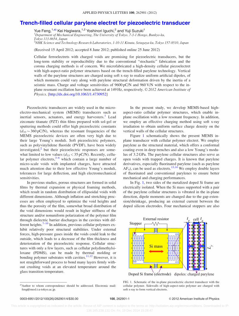
Figure 1 schematically shows the present MEMS in-
plane transducer with cellular polymer electret. We employ
parylene as the structural material, which offers a conformal
coating even in deep trenches and also a low Young’s modu-
lus of 3.2 GPa. The parylene cellular structures also serve as
open voids with trapped charges. It is known that parylene
derivatives, especially fluorinated parylene (such as parylene
AF4), can be used as electrets.13,14 We employ double layers
of fluorinated and conventional parylenes to ensure better
mechanical and charging performances.
In Fig. 1, two sides of the metalized doped Si frame are
electrically isolated. When the Si mass supported with a pair
of the parylene cellular structures is vibrated in the in-plane
direction, dipole moments are changed due to the gap exten-
sion/shrinkage, producing an external current between the
doped silicon electrodes. Four mechanical stoppers are also
FIG. 1. Schematic of the in-plane piezoelectric electret transducer with the
cellular polymer. Sidewalls of high-aspect-ratio polymer are charged with
soft x-ray to form vertical electrets.
a)Author to whom correspondence should be addressed. Electronic mail:
0003-6951/2012/100(26)/262901/4/$30.00 VC 2012 American Institute of Physics100, 262901-1
APPLIED PHYSICS LETTERS 100, 262901 (2012)
This article is copyrighted as indicated in the article. Reuse of AIP content is subject to the terms at: http://scitation.aip.org/termsconditions. Downloaded to IP:
136.165.238.131 On: Fri, 19 Dec 2014 15:28:47
devised into the Si frame to ensure the minimum distance of
the air gap avoiding discharge or neutralization of opposite
charges during oscillation.
The cellular spring is composed of multiple voids of Nx
and Ny in the vibration and the perpendicular directions,
respectively. The effective spring constant kt in the vibration
direction is given with that of a single cell ks as
kt ¼ 2ksNy
Nx
� �¼ 16Eh
tp
Lye
� �3 Ny
Nx
� �; (1)
where E, h, and tp are the Young’s modulus, the height, and
the thickness of the high-aspect-ratio spring, respectively. Lye
is the effective length of beam of each cell, in which the fixed
support part in the center of the void beam is excluded. The
resonant frequency of the mass is then given with the mass m,
fr ¼ffiffiffiffiffiffiffiffiffiffiffiffiffiðkt=mÞ
p2p
¼2ffiffiffiffiffiffiffiffiffiffiffiffiffiffiffiffiffiffiffiffiffiffiffiffiffiffiffiffiffiffiffiEhð tp
LyeÞ3Ny=Nxm
qp
: (2)
A model of cellular polymer electrets based on a parallel
stack of solid and air layers15 is used to optimize the design
parameters. Assuming the permittivities of air and solid are
�g and �p, respectively, the piezoelectric constant of the de-
vice d33 can be derived as
d33 ¼L3
yeLyr�g�p
4Eð�gt2p þ �ptgtpÞ2; (3)
where tg and tp are the thicknesses of the air and solid layers,
respectively. Thus, d33 is proportional to the surface charge
density r of charged layers and inversely proportional to the
Young’s modulus of parylene. In Eq. (3), d33 is maximized,
when the permittivity and thickness ratios of the solid to the
air layers are equal, i.e., tp=tg ¼ �p=�g. In the present study,
tp and tg are chosen as 15 lm and 25 lm, respectively, which
is somewhat lower than the optimum value of �p=�g ¼ 2:1.
Dimensions of each cell are 820 lm in length (Ly) and 40 lm
in width (including the connection beam), respectively. The
geometrical parameters are given in Table I. The theoretical
resonant frequency calculated with Eq. (2) is 143 Hz.
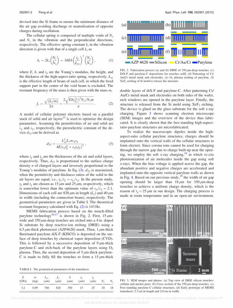
MEMS fabrication process based on the trench-filled
parylene technology16,17 is shown in Fig. 2. First, 15 lm-
wide and 350 lm-deep trenches are etched into a 4 in. doped
Si substrate by deep reactive-ion etching (DRIE) using a
6.5 lm-thick photoresist (AZP4620) mask. Then, 1 lm-thick
fluorinated parylene diX-F (KISCO) is deposited on the sur-
face of deep trenches by chemical vapor deposition (CVD).
This is followed by a successive deposition of 9 lm-thick
parylene-C and etch-back of the parylene layers using O2
plasma. Then, the second deposition of 5 lm-thick parylene-
C is made to fully fill the trenches to form a 15 lm-thick
double layers of diX-F and parylene-C. After patterning Cr/
Au/Cr metal mask and electrodes on both sides of the wafer,
etch windows are opened in the parylene layer. Finally, the
structure is released from the Si mold using XeF2 etching.
The device is glued on the glass substrate for the soft x-ray
charging. Figure 3 shows scanning electron microscope
(SEM) images and the overview of the device thus fabri-
cated. It is clearly shown that the free-standing high-aspect-
ratio parylene structures are microfabricated.
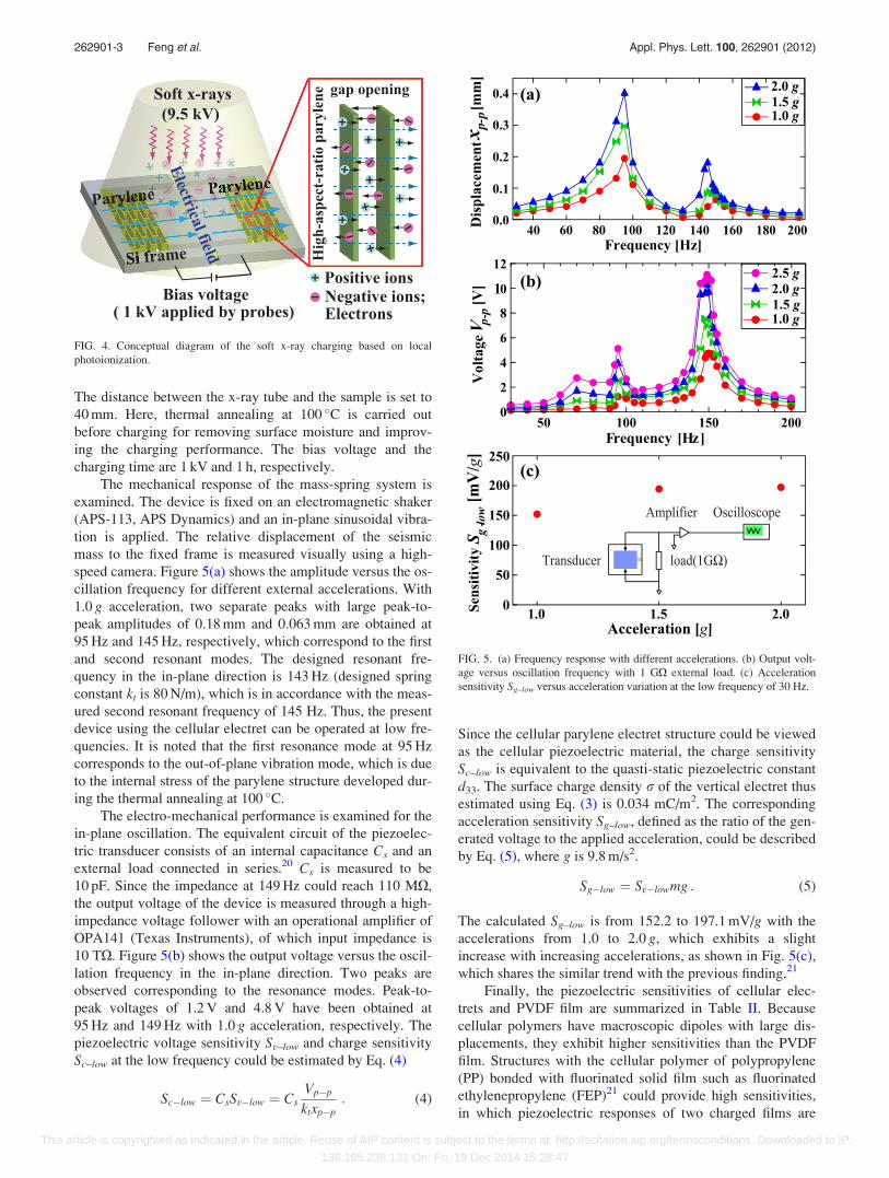
To realize the macroscopic dipoles inside the high-
aspect-ratio cellular parylene structures, charges should be
implanted onto the vertical walls of the cellular structures to
form electret. Since corona ions cannot be used for charging
through the narrow gap due to charge built-up near the open-
ing, we employ the soft x-ray charging,18 in which in-situphotoionization of air molecules inside the gap using soft
x-rays. When the bias voltage is applied across the gap, the
abundant positive and negative charges are accelerated and
implanted onto the opposite vertical parylene walls as shown
in Fig. 4. Based on our previous study,19 the width of air gap
opening should be larger than 18 lm for 350 lm-deep
trenches to achieve a uniform charge density, which is the
reason of tg¼ 25 lm in our design. The charging process is
made at room temperature and in an open-air environment.
TABLE I. The geometrical parameters of the transducer.
E m Lye Ly h tp tg(GPa) (mg) (lm) (lm) (lm) (lm) (lm) Ny Nx
3.2 0.09 760 820 350 15 25 10 18
FIG. 2. Fabrication process (a) and (b) DRIE of 350 lm-deep trenches. (c)
DiX-F and parylene-C depositions for trenches refill. (d) Patterning of Cr/
Au/Cr metal mask and electrodes. (e) O2 plasma etching of parylene. (f)
XeF2 etching of Si mold to release the structure.
FIG. 3. SEM images and photos. (a) Top view of DRIE silicon trenches:
cellular and anchor parts. (b) Cross section of the 350 lm-deep trenches. (c)
Free-standing parylene-C cellular structures. (d) Early prototype of MEMS
transducer: 2.3 cm in length and 2.0 cm in width.
262901-2 Feng et al. Appl. Phys. Lett. 100, 262901 (2012)
This article is copyrighted as indicated in the article. Reuse of AIP content is subject to the terms at: http://scitation.aip.org/termsconditions. Downloaded to IP:
136.165.238.131 On: Fri, 19 Dec 2014 15:28:47
The distance between the x-ray tube and the sample is set to
40 mm. Here, thermal annealing at 100 �C is carried out
before charging for removing surface moisture and improv-
ing the charging performance. The bias voltage and the
charging time are 1 kV and 1 h, respectively.
The mechanical response of the mass-spring system is
examined. The device is fixed on an electromagnetic shaker
(APS-113, APS Dynamics) and an in-plane sinusoidal vibra-
tion is applied. The relative displacement of the seismic
mass to the fixed frame is measured visually using a high-
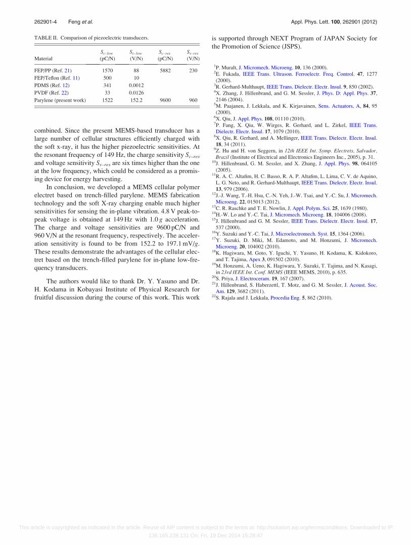
speed camera. Figure 5(a) shows the amplitude versus the os-
cillation frequency for different external accelerations. With
1.0 g acceleration, two separate peaks with large peak-to-
peak amplitudes of 0.18 mm and 0.063 mm are obtained at
95 Hz and 145 Hz, respectively, which correspond to the first
and second resonant modes. The designed resonant fre-
quency in the in-plane direction is 143 Hz (designed spring
constant kt is 80 N/m), which is in accordance with the meas-
ured second resonant frequency of 145 Hz. Thus, the present
device using the cellular electret can be operated at low fre-
quencies. It is noted that the first resonance mode at 95 Hz
corresponds to the out-of-plane vibration mode, which is due
to the internal stress of the parylene structure developed dur-
ing the thermal annealing at 100 �C.
The electro-mechanical performance is examined for the
in-plane oscillation. The equivalent circuit of the piezoelec-
tric transducer consists of an internal capacitance Cs and an
external load connected in series.20 Cs is measured to be
10 pF. Since the impedance at 149 Hz could reach 110 MX,
the output voltage of the device is measured through a high-
impedance voltage follower with an operational amplifier of
OPA141 (Texas Instruments), of which input impedance is
10 TX. Figure 5(b) shows the output voltage versus the oscil-
lation frequency in the in-plane direction. Two peaks are
observed corresponding to the resonance modes. Peak-to-
peak voltages of 1.2 V and 4.8 V have been obtained at
95 Hz and 149 Hz with 1.0 g acceleration, respectively. The
piezoelectric voltage sensitivity Sv–low and charge sensitivity
Sc–low at the low frequency could be estimated by Eq. (4)
Sc�low ¼ CsSv�low ¼ CsVp�p
ktxp�p: (4)
Since the cellular parylene electret structure could be viewed
as the cellular piezoelectric material, the charge sensitivity
Sc–low is equivalent to the quasti-static piezoelectric constant
d33. The surface charge density r of the vertical electret thus
estimated using Eq. (3) is 0.034 mC/m2. The corresponding
acceleration sensitivity Sg–low, defined as the ratio of the gen-
erated voltage to the applied acceleration, could be described
by Eq. (5), where g is 9.8 m/s2.
Sg�low ¼ Sv�lowmg : (5)
The calculated Sg–low is from 152.2 to 197.1 mV/g with the
accelerations from 1.0 to 2.0 g, which exhibits a slight
increase with increasing accelerations, as shown in Fig. 5(c),
which shares the similar trend with the previous finding.21
Finally, the piezoelectric sensitivities of cellular elec-
trets and PVDF film are summarized in Table II. Because
cellular polymers have macroscopic dipoles with large dis-
placements, they exhibit higher sensitivities than the PVDF
film. Structures with the cellular polymer of polypropylene
(PP) bonded with fluorinated solid film such as fluorinated
ethylenepropylene (FEP)21 could provide high sensitivities,
in which piezoelectric responses of two charged films are
Positive ionsNegative ions;Bias voltage
Si frame
Soft x-rays(9.5 kV)
Hig
h-as
pect
-rat
io p
aryl
ene
Parylene
Electrical field
Electrons
gap opening
( 1 kV applied by probes)
FIG. 4. Conceptual diagram of the soft x-ray charging based on local
photoionization.
FIG. 5. (a) Frequency response with different accelerations. (b) Output volt-
age versus oscillation frequency with 1 GX external load. (c) Acceleration
sensitivity Sg–low versus acceleration variation at the low frequency of 30 Hz.
262901-3 Feng et al. Appl. Phys. Lett. 100, 262901 (2012)
This article is copyrighted as indicated in the article. Reuse of AIP content is subject to the terms at: http://scitation.aip.org/termsconditions. Downloaded to IP:
136.165.238.131 On: Fri, 19 Dec 2014 15:28:47
combined. Since the present MEMS-based transducer has a
large number of cellular structures efficiently charged with
the soft x-ray, it has the higher piezoelectric sensitivities. At
the resonant frequency of 149 Hz, the charge sensitivity Sc–res
and voltage sensitivity Sv–res are six times higher than the one
at the low frequency, which could be considered as a promis-
ing device for energy harvesting.
In conclusion, we developed a MEMS cellular polymer
electret based on trench-filled parylene. MEMS fabrication
technology and the soft X-ray charging enable much higher
sensitivities for sensing the in-plane vibration. 4.8 V peak-to-
peak voltage is obtained at 149 Hz with 1.0 g acceleration.
The charge and voltage sensitivities are 9600 pC/N and
960 V/N at the resonant frequency, respectively. The acceler-
ation sensitivity is found to be from 152.2 to 197.1 mV/g.
These results demonstrate the advantages of the cellular elec-
tret based on the trench-filled parylene for in-plane low-fre-
quency transducers.
The authors would like to thank Dr. Y. Yasuno and Dr.
H. Kodama in Kobayasi Institute of Physical Research for
fruitful discussion during the course of this work. This work
is supported through NEXT Program of JAPAN Society for
the Promotion of Science (JSPS).
1P. Muralt, J. Micromech. Microeng. 10, 136 (2000).2E. Fukada, IEEE Trans. Ultrason. Ferroelectr. Freq. Control. 47, 1277
(2000).3R. Gerhard-Multhaupt, IEEE Trans. Dielectr. Electr. Insul. 9, 850 (2002).4X. Zhang, J. Hillenbrand, and G. M. Sessler, J. Phys. D: Appl. Phys. 37,
2146 (2004).5M. Paajanen, J. Lekkala, and K. Kirjavainen, Sens. Actuators, A, 84, 95
(2000).6X. Qiu, J. Appl. Phys. 108, 01110 (2010).7P. Fang, X. Qiu, W. Wirges, R. Gerhard, and L. Zirkel, IEEE Trans.
Dielectr. Electr. Insul. 17, 1079 (2010).8X. Qiu, R. Gerhard, and A. Mellinger, IEEE Trans. Dielectr. Electr. Insul.
18, 34 (2011).9Z. Hu and H. von Seggern, in 12th IEEE Int. Symp. Electrets, Salvador,Brazil (Institute of Electrical and Electronics Engineers Inc., 2005), p. 31.
10J. Hillenbrand, G. M. Sessler, and X. Zhang, J. Appl. Phys. 98, 064105
(2005).11R. A. C. Altafim, H. C. Basso, R. A. P. Altafim, L. Lima, C. V. de Aquino,
L. G. Neto, and R. Gerhard-Multhaupt, IEEE Trans. Dielectr. Electr. Insul.
13, 979 (2006).12J.-J. Wang, T.-H. Hsu, C.-N. Yeh, J.-W. Tsai, and Y.-C. Su, J. Micromech.
Microeng. 22, 015013 (2012).13C. R. Raschke and T. E. Nowlin, J. Appl. Polym. Sci. 25, 1639 (1980).14H.-W. Lo and Y.-C. Tai, J. Micromech. Microeng. 18, 104006 (2008).15J. Hillenbrand and G. M. Sessler, IEEE Trans. Dielectr. Electr. Insul. 17,
537 (2000).16Y. Suzuki and Y.-C. Tai, J. Microelectromech. Syst. 15, 1364 (2006).17Y. Suzuki, D. Miki, M. Edamoto, and M. Honzumi, J. Micromech.
Microeng. 20, 104002 (2010).18K. Hagiwara, M. Goto, Y. Iguchi, Y. Yasuno, H. Kodama, K. Kidokoro,
and T. Tajima, Apex 3, 091502 (2010).19M. Honzumi, A. Ueno, K. Hagiwara, Y. Suzuki, T. Tajima, and N. Kasagi,
in 23rd IEEE Int. Conf. MEMS (IEEE MEMS, 2010), p. 635.20S. Priya, J. Electroceram. 19, 167 (2007).21J. Hillenbrand, S. Haberzettl, T. Motz, and G. M. Sessler, J. Acoust. Soc.
Am. 129, 3682 (2011).22S. Rajala and J. Lekkala, Procedia Eng. 5, 862 (2010).
TABLE II. Comparison of piezoelectric transducers.
Material
Sc–low
(pC/N)
Sv–low
(V/N)
Sc–res
(pC/N)
Sv–res
(V/N)
FEP/PP (Ref. 21) 1570 88 5882 230
FEP/Teflon (Ref. 11) 500 10
PDMS (Ref. 12) 341 0.0012
PVDF (Ref. 22) 33 0.0126
Parylene (present work) 1522 152.2 9600 960
262901-4 Feng et al. Appl. Phys. Lett. 100, 262901 (2012)
This article is copyrighted as indicated in the article. Reuse of AIP content is subject to the terms at: http://scitation.aip.org/termsconditions. Downloaded to IP:
136.165.238.131 On: Fri, 19 Dec 2014 15:28:47