Embed Size (px)
Citation preview
This content has been downloaded from IOPscience. Please scroll down to see the full text.
Download details:
IP Address: 93.180.53.211
This content was downloaded on 02/01/2014 at 18:48
Please note that terms and conditions apply.
Trials of RF plasma production using different antenna geometries with magnetic field
View the table of contents for this issue, or go to the journal homepage for more
1998 Plasma Phys. Control. Fusion 40 2081
(http://iopscience.iop.org/0741-3335/40/12/008)
Home Search Collections Journals About Contact us My IOPscience
Plasma Phys. Control. Fusion40 (1998) 2081–2095. Printed in the UK PII: S0741-3335(98)94734-0
Trials of RF plasma production using different antennageometries with magnetic field
Shunjiro Shinohara† and Tsutomu SoejimaInterdisciplinary Graduate School of Engineering Sciences, Kyushu University, Kasuga,Fukuoka 816-8580, Japan
Received 1 June 1998, in final form 18 September 1998
Abstract. Plasma production studies excited by the radio frequency (RF) wave were carriedout using various antenna configurations. Six types of side antennae, located outside the largecylindrical chamber, and two types of internal loop antennae were tested. The ion saturationcurrentIis of a probe and the plasma emission were measured as a function of the filling pressure,the RF power and the magnetic field. With the increase in the power and the magnetic field,Iis
increased in most cases, while some of the antennae showed the maximumIis values under lowmagnetic field. Among the side antennae, a spiral antenna produced the highest value ofIis ina wide operational window. For the case of the internal loop antennae, the electric field parallelto the magnetic field did not show a significant contribution to plasma production. These resultssuggest the importance of the loop-like RF-induced electric field. When an external magneticfield was applied, the uniformity of the plasma produced by the internal loop antennae in boththe radial and axial directions was improved.
1. Introduction
High-density plasmas generated at low filling pressure are urgently required for materialprocessing applications and toroidal confinement devices. In order to fulfil the requirementsof applications such as dry etching, inductively coupled plasma (ICP)/transformer coupledplasma (TCP) sources [1] and a helicon wave plasma [2–9] have been actively developedusing radio frequency (RF) power sources. In ICP sources, a planar spiral coil [10, 11] hasbeen used due to its relatively simple geometry, and the addition of an external magnetic fieldhas led to better plasma performance [12–15]. As for the nuclear fusion field, in stellarators,plasma production studies have been performed in the ion cyclotron range of frequencies(ICRF) using slot and three half-turn antennae located outside the chamber [16–18]. Morerecently, ICRF plasma production for the purpose of wall conditioning, preionization andplasma sustainment has been performed in stellarators and tokamaks using the conventionalloop antennae located inside the chamber [19–23]. The RF range has some advantagescompared to other regimes, such as the microwave frequency range, due to the possibleuse of the continuous frequency with cheaper sources and the easier operation, and in somecases, a lower sensitivity of plasma production efficiency to the magnetic field.
In most previous applications, plasma sources which used RF antennae were of twotypes. In the first type, an antenna is located at the end of a cylindrical chamber, and poweris coupled through a dielectric window. In the second type, an antenna is wound around the
† E-mail address: [email protected]
0741-3335/98/122081+15$19.50c© 1998 IOP Publishing Ltd 2081
2082 S Shinohara and T Soejima
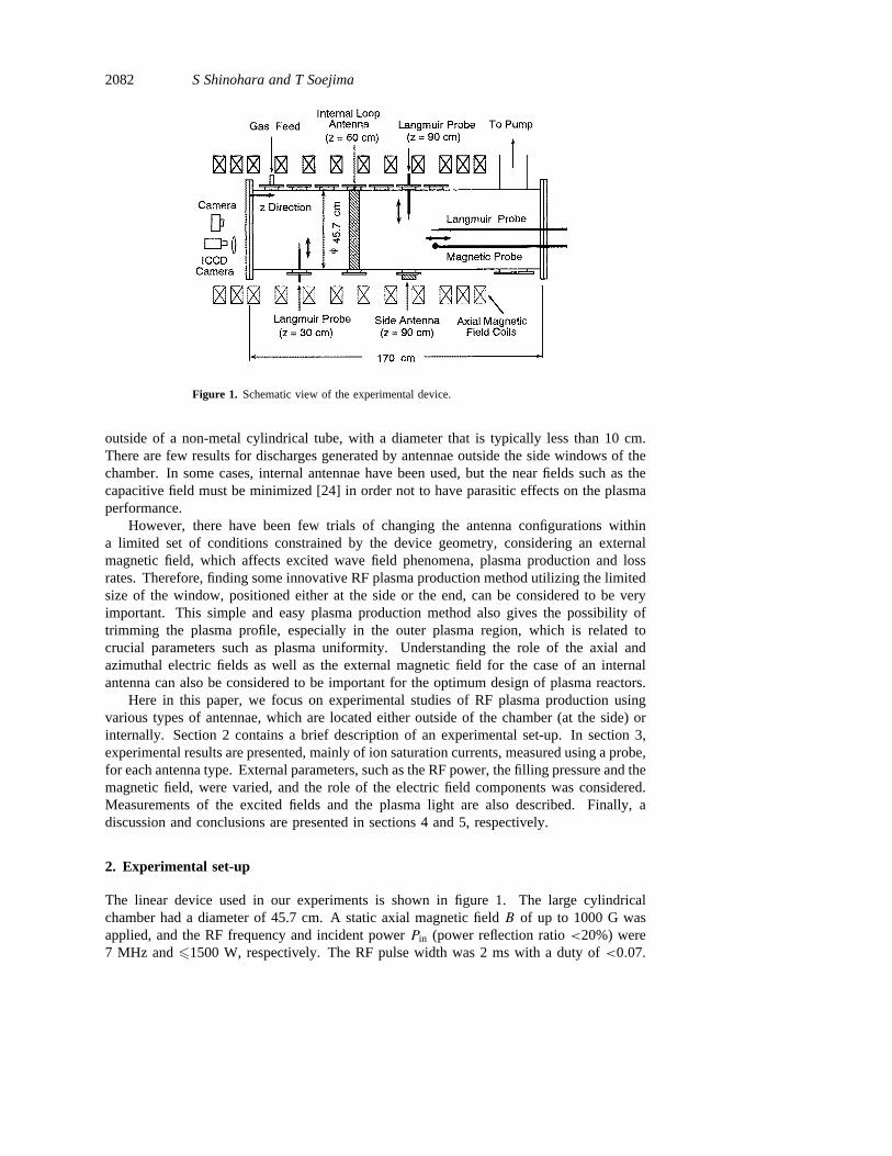
Figure 1. Schematic view of the experimental device.
outside of a non-metal cylindrical tube, with a diameter that is typically less than 10 cm.There are few results for discharges generated by antennae outside the side windows of thechamber. In some cases, internal antennae have been used, but the near fields such as thecapacitive field must be minimized [24] in order not to have parasitic effects on the plasmaperformance.
However, there have been few trials of changing the antenna configurations withina limited set of conditions constrained by the device geometry, considering an externalmagnetic field, which affects excited wave field phenomena, plasma production and lossrates. Therefore, finding some innovative RF plasma production method utilizing the limitedsize of the window, positioned either at the side or the end, can be considered to be veryimportant. This simple and easy plasma production method also gives the possibility oftrimming the plasma profile, especially in the outer plasma region, which is related tocrucial parameters such as plasma uniformity. Understanding the role of the axial andazimuthal electric fields as well as the external magnetic field for the case of an internalantenna can also be considered to be important for the optimum design of plasma reactors.
Here in this paper, we focus on experimental studies of RF plasma production usingvarious types of antennae, which are located either outside of the chamber (at the side) orinternally. Section 2 contains a brief description of an experimental set-up. In section 3,experimental results are presented, mainly of ion saturation currents, measured using a probe,for each antenna type. External parameters, such as the RF power, the filling pressure and themagnetic field, were varied, and the role of the electric field components was considered.Measurements of the excited fields and the plasma light are also described. Finally, adiscussion and conclusions are presented in sections 4 and 5, respectively.
2. Experimental set-up
The linear device used in our experiments is shown in figure 1. The large cylindricalchamber had a diameter of 45.7 cm. A static axial magnetic fieldB of up to 1000 G wasapplied, and the RF frequency and incident powerPin (power reflection ratio<20%) were7 MHz and61500 W, respectively. The RF pulse width was 2 ms with a duty of<0.07.
Trials of RF plasma production 2083
The side and internal loop antennae were positioned atz = 90 and 60 cm, respectively,wherez was taken from the inner left surface of the vacuum chamber along the centre axis.The plasma was operated in argon gas, with a pressureP0 in the range 0.8–16 mTorr, andplasma parameters were measured by movable Langmuir probes inserted into the plasmaradially and axially. The excited wave fields were measured by a movable magnetic probe,and a balanced mixer for the interferometric wave measurement and a boxcar integratorwere also used. The plasma light was monitored by an ICCD camera (a CCD camera withan image intensifier) and by a conventional camera.
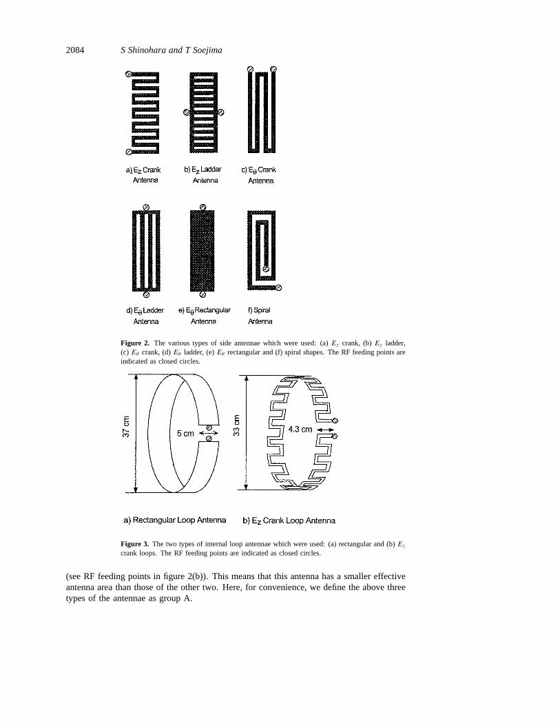
Figure 2 shows the antenna structure of the side antennae, which were put on theouter surface of the quartz window, which was 28.6 cm high, 12.8 cm wide and 1 cmthick. The height and width of the flange hole were 25 cm and 9.2 cm, respectively.The distance between the antenna and the inner surface of the main chamber was 3.7 cm.For checking the role of the electric field components, six types of antennae made ofcopper with 0.03 cm thickness were used. TheEz crank andEz ladder antennae, shownin figures 2(a) and 2(b), induce mainly thez component of the electric field in cylindricalgeometry. TheEθ crank,Eθ ladder andEθ rectangular antennae, shown in figures 2(c)–(e),induce mainly the azimuthalθ component of the electric field. The spiral antenna, shownin figure 2(f), which has a mixture ofz andθ components, generates the radial componentof the oscillating magnetic field. Note that theEz crank (Eθ crank) antenna also has anon-negligible component of theEθ (Ez) induced field.
Figure 3 shows two types of loop antennae (made of copper of 0.03 cm thickness)which were placed inside the vacuum chamber. The rectangular loop is a conventionalEθinduction antenna and theEz crank loop, which has 32 parallel (to the axis) elements, caninduce theEθ field component as well as theEz one. These two antennae were covered byflexible Teflon plate of 0.038 cm thickness, in order to reduce electrostatic coupling.
3. Experimental results
3.1. Side antennae
The Langmuir probe used to measure plasma parameters was located at the same axialposition of the antenna (z = 90 cm) at a radial distance of 3.7 cm from the antenna.The electron temperatureTe, which was in the range of 3–4 eV, did not change appreciablyregardless of the antenna shape and the magnetic field forPin = 1000 W andP0 = 16 mTorr.
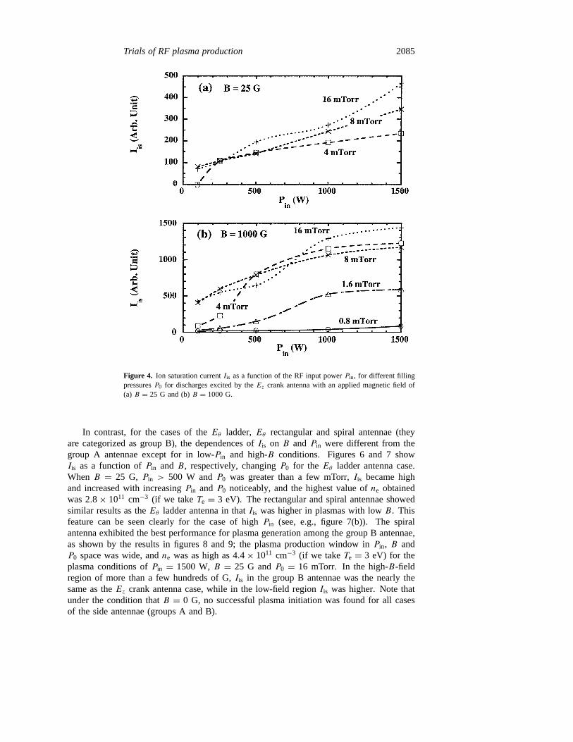
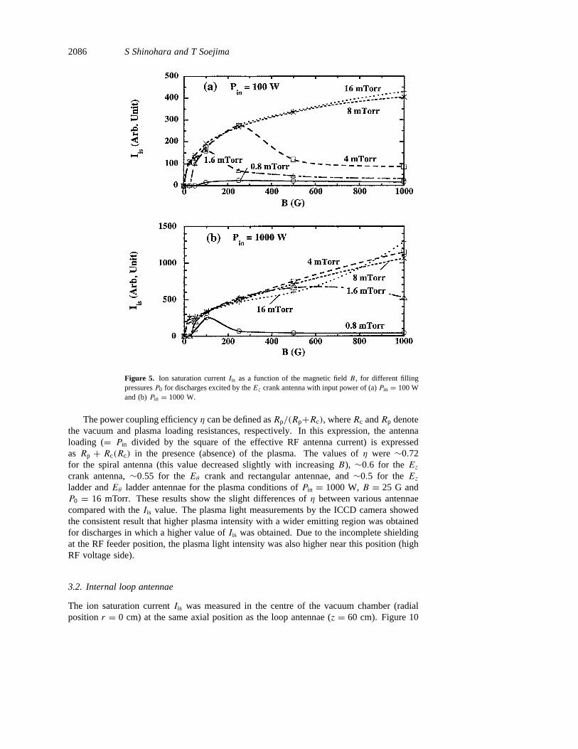
Figures 4 and 5 show the ion saturation currentIis as a function ofPin and the axialmagnetic fieldB, respectively, changingP0 for the Ez crank antenna case. In this case,Iis = 1000 corresponds to the electron densityne = 4× 1010 cm−3 if we takeTe = 3 eV.With an increase inPin and/orB, Iis increased, andne = 5.8 × 1010 cm−3 (under theassumption ofTe = 3 eV) was obtained for the plasma conditions ofPin = 1500 W,B = 1000 G andP0 = 16 mTorr. The plasma could not be generated in low-B and low-P0
conditions, andIis decreased for values ofB above a critical fieldB whenP0 was low,even though a plasma was produced. The e-folding length along the radial direction was<10 cm, and this length became shorter gradually asB increased. This is mainly a resultof the reduction of radial diffusion.
For the cases of theEz ladder andEθ crank antennae, the dependences ofIis on Pin, BandP0 was similar to those of theEz crank antenna case. However, for the case of theEzladder antenna, the absolute value ofIis was smaller by about a factor of two. This may bepartly due to the fact that, for theEz ladder antenna case, the RF antenna current flowedmainly near the central elements and the top and bottom ones had small antenna currents
2084 S Shinohara and T Soejima
Figure 2. The various types of side antennae which were used: (a)Ez crank, (b)Ez ladder,(c) Eθ crank, (d)Eθ ladder, (e)Eθ rectangular and (f) spiral shapes. The RF feeding points areindicated as closed circles.
Figure 3. The two types of internal loop antennae which were used: (a) rectangular and (b)Ezcrank loops. The RF feeding points are indicated as closed circles.
(see RF feeding points in figure 2(b)). This means that this antenna has a smaller effectiveantenna area than those of the other two. Here, for convenience, we define the above threetypes of the antennae as group A.
Trials of RF plasma production 2085
Figure 4. Ion saturation currentIis as a function of the RF input powerPin, for different fillingpressuresP0 for discharges excited by theEz crank antenna with an applied magnetic field of(a) B = 25 G and (b)B = 1000 G.
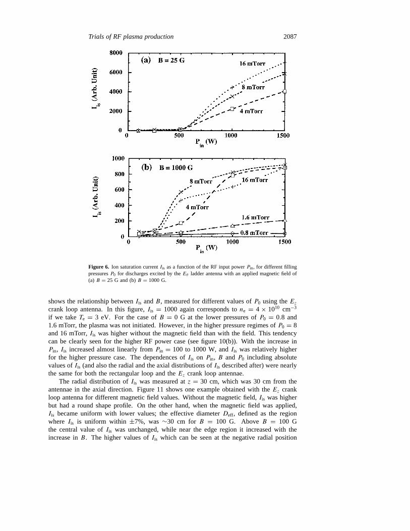
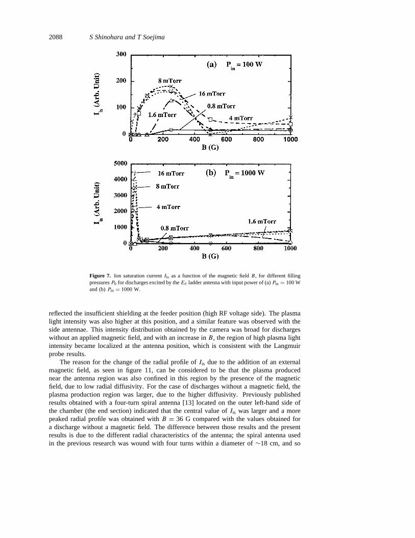
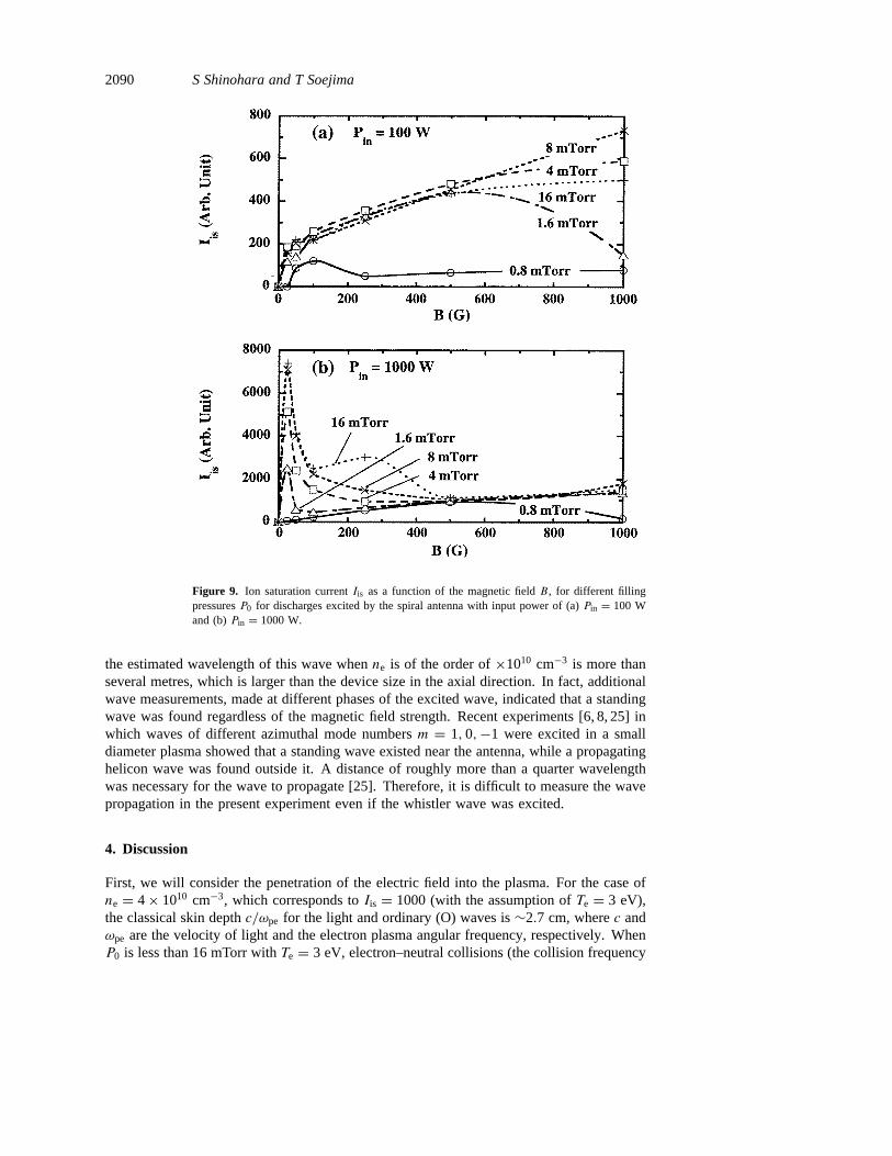
In contrast, for the cases of theEθ ladder,Eθ rectangular and spiral antennae (theyare categorized as group B), the dependences ofIis on B andPin were different from thegroup A antennae except for in low-Pin and high-B conditions. Figures 6 and 7 showIis as a function ofPin andB, respectively, changingP0 for the Eθ ladder antenna case.WhenB = 25 G, Pin > 500 W andP0 was greater than a few mTorr,Iis became highand increased with increasingPin andP0 noticeably, and the highest value ofne obtainedwas 2.8× 1011 cm−3 (if we takeTe = 3 eV). The rectangular and spiral antennae showedsimilar results as theEθ ladder antenna in thatIis was higher in plasmas with lowB. Thisfeature can be seen clearly for the case of highPin (see, e.g., figure 7(b)). The spiralantenna exhibited the best performance for plasma generation among the group B antennae,as shown by the results in figures 8 and 9; the plasma production window inPin, B andP0 space was wide, andne was as high as 4.4× 1011 cm−3 (if we takeTe = 3 eV) for theplasma conditions ofPin = 1500 W,B = 25 G andP0 = 16 mTorr. In the high-B-fieldregion of more than a few hundreds of G,Iis in the group B antennae was the nearly thesame as theEz crank antenna case, while in the low-field regionIis was higher. Note thatunder the condition thatB = 0 G, no successful plasma initiation was found for all casesof the side antennae (groups A and B).
2086 S Shinohara and T Soejima
Figure 5. Ion saturation currentIis as a function of the magnetic fieldB, for different fillingpressuresP0 for discharges excited by theEz crank antenna with input power of (a)Pin = 100 Wand (b)Pin = 1000 W.
The power coupling efficiencyη can be defined asRp/(Rp+Rc), whereRc andRp denotethe vacuum and plasma loading resistances, respectively. In this expression, the antennaloading (= Pin divided by the square of the effective RF antenna current) is expressedas Rp + Rc(Rc) in the presence (absence) of the plasma. The values ofη were∼0.72for the spiral antenna (this value decreased slightly with increasingB), ∼0.6 for theEzcrank antenna,∼0.55 for theEθ crank and rectangular antennae, and∼0.5 for the Ezladder andEθ ladder antennae for the plasma conditions ofPin = 1000 W,B = 25 G andP0 = 16 mTorr. These results show the slight differences ofη between various antennaecompared with theIis value. The plasma light measurements by the ICCD camera showedthe consistent result that higher plasma intensity with a wider emitting region was obtainedfor discharges in which a higher value ofIis was obtained. Due to the incomplete shieldingat the RF feeder position, the plasma light intensity was also higher near this position (highRF voltage side).
3.2. Internal loop antennae
The ion saturation currentIis was measured in the centre of the vacuum chamber (radialpositionr = 0 cm) at the same axial position as the loop antennae (z = 60 cm). Figure 10
Trials of RF plasma production 2087
Figure 6. Ion saturation currentIis as a function of the RF input powerPin, for different fillingpressuresP0 for discharges excited by theEθ ladder antenna with an applied magnetic field of(a) B = 25 G and (b)B = 1000 G.
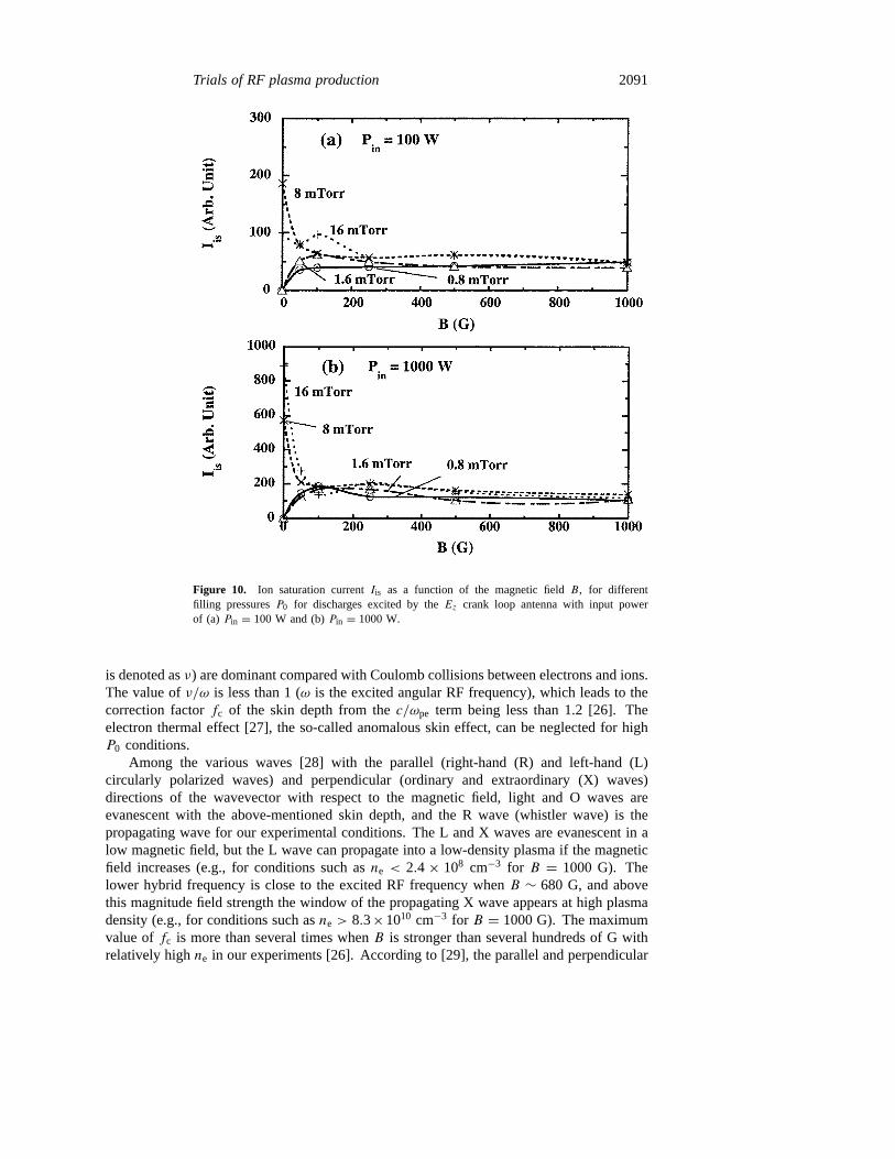
shows the relationship betweenIis andB, measured for different values ofP0 using theEzcrank loop antenna. In this figure,Iis = 1000 again corresponds tone = 4× 1010 cm−3
if we takeTe = 3 eV. For the case ofB = 0 G at the lower pressures ofP0 = 0.8 and1.6 mTorr, the plasma was not initiated. However, in the higher pressure regimes ofP0 = 8and 16 mTorr,Iis was higher without the magnetic field than with the field. This tendencycan be clearly seen for the higher RF power case (see figure 10(b)). With the increase inPin, Iis increased almost linearly fromPin = 100 to 1000 W, andIis was relatively higherfor the higher pressure case. The dependences ofIis on Pin, B andP0 including absolutevalues ofIis (and also the radial and the axial distributions ofIis described after) were nearlythe same for both the rectangular loop and theEz crank loop antennae.
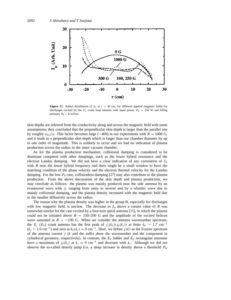
The radial distribution ofIis was measured atz = 30 cm, which was 30 cm from theantennae in the axial direction. Figure 11 shows one example obtained with theEz crankloop antenna for different magnetic field values. Without the magnetic field,Iis was higherbut had a round shape profile. On the other hand, when the magnetic field was applied,Iis became uniform with lower values; the effective diameterDeff, defined as the regionwhere Iis is uniform within ±7%, was∼30 cm for B = 100 G. AboveB = 100 Gthe central value ofIis was unchanged, while near the edge region it increased with theincrease inB. The higher values ofIis which can be seen at the negative radial position
2088 S Shinohara and T Soejima
Figure 7. Ion saturation currentIis as a function of the magnetic fieldB, for different fillingpressuresP0 for discharges excited by theEθ ladder antenna with input power of (a)Pin = 100 Wand (b)Pin = 1000 W.
reflected the insufficient shielding at the feeder position (high RF voltage side). The plasmalight intensity was also higher at this position, and a similar feature was observed with theside antennae. This intensity distribution obtained by the camera was broad for dischargeswithout an applied magnetic field, and with an increase inB, the region of high plasma lightintensity became localized at the antenna position, which is consistent with the Langmuirprobe results.
The reason for the change of the radial profile ofIis due to the addition of an externalmagnetic field, as seen in figure 11, can be considered to be that the plasma producednear the antenna region was also confined in this region by the presence of the magneticfield, due to low radial diffusivity. For the case of discharges without a magnetic field, theplasma production region was larger, due to the higher diffusivity. Previously publishedresults obtained with a four-turn spiral antenna [13] located on the outer left-hand side ofthe chamber (the end section) indicated that the central value ofIis was larger and a morepeaked radial profile was obtained withB = 36 G compared with the values obtained fora discharge without a magnetic field. The difference between those results and the presentresults is due to the different radial characteristics of the antenna; the spiral antenna usedin the previous research was wound with four turns within a diameter of∼18 cm, and so

Trials of RF plasma production 2089
Figure 8. Ion saturation currentIis as a function of the RF input powerPin, for differentfilling pressuresP0 for discharges excited by the spiral antenna with an applied magnetic fieldof (a) B = 25 G and (b)B = 1000 G.
the plasma production region was near the centre of the vacuum chamber. In the presentcase, theEz crank loop antenna (one turn) has a diameter of 33 cm (see figure 3), and sothe plasma is produced in the outer region of the chamber.
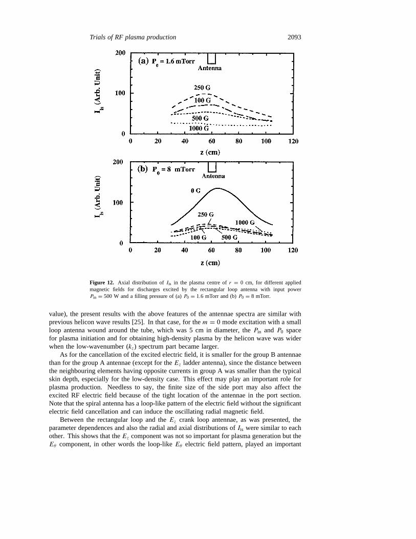
Figure 12 shows the axial distribution ofIis at r = 0 cm, for discharges produced withthe rectangular loop antenna. For the case of the lower pressure ofP0 = 1.6 mTorr, Iis
decreased with increasingB (B > 250 G), and no plasma production was found without theapplied magnetic field. For the higher pressure case ofP0 = 8 mTorr, Iis was not changedappreciably regardless of the magnetic field strength (B > 100 G), while the more peakedprofile and higher values ofIis were obtained withB = 0 G, which has the same tendencyas the radial distribution ofIis (see figure 11).
In order to check the wave propagation along the axial direction, measurements of theexcited magnetic field were made. The excited field (Br component in the intermediateradius of the chamber) was fairly constant in an extended region, up to∼20 cm along theaxial direction, and then decayed with an e-folding length of<5 cm. There was a tendencyfor the extended region and the decay length to become longer asB was increased. Forour experimental conditions, the most likely candidate for the propagating wave is thewhistler wave (see also the discussion in section 4), also known as the helicon wave, but
2090 S Shinohara and T Soejima
Figure 9. Ion saturation currentIis as a function of the magnetic fieldB, for different fillingpressuresP0 for discharges excited by the spiral antenna with input power of (a)Pin = 100 Wand (b)Pin = 1000 W.
the estimated wavelength of this wave whenne is of the order of×1010 cm−3 is more thanseveral metres, which is larger than the device size in the axial direction. In fact, additionalwave measurements, made at different phases of the excited wave, indicated that a standingwave was found regardless of the magnetic field strength. Recent experiments [6, 8, 25] inwhich waves of different azimuthal mode numbersm = 1, 0,−1 were excited in a smalldiameter plasma showed that a standing wave existed near the antenna, while a propagatinghelicon wave was found outside it. A distance of roughly more than a quarter wavelengthwas necessary for the wave to propagate [25]. Therefore, it is difficult to measure the wavepropagation in the present experiment even if the whistler wave was excited.
4. Discussion
First, we will consider the penetration of the electric field into the plasma. For the case ofne = 4× 1010 cm−3, which corresponds toIis = 1000 (with the assumption ofTe = 3 eV),the classical skin depthc/ωpe for the light and ordinary (O) waves is∼2.7 cm, wherec andωpe are the velocity of light and the electron plasma angular frequency, respectively. WhenP0 is less than 16 mTorr withTe = 3 eV, electron–neutral collisions (the collision frequency
Trials of RF plasma production 2091
Figure 10. Ion saturation currentIis as a function of the magnetic fieldB, for differentfilling pressuresP0 for discharges excited by theEz crank loop antenna with input powerof (a) Pin = 100 W and (b)Pin = 1000 W.
is denoted asν) are dominant compared with Coulomb collisions between electrons and ions.The value ofν/ω is less than 1 (ω is the excited angular RF frequency), which leads to thecorrection factorfc of the skin depth from thec/ωpe term being less than 1.2 [26]. Theelectron thermal effect [27], the so-called anomalous skin effect, can be neglected for highP0 conditions.
Among the various waves [28] with the parallel (right-hand (R) and left-hand (L)circularly polarized waves) and perpendicular (ordinary and extraordinary (X) waves)directions of the wavevector with respect to the magnetic field, light and O waves areevanescent with the above-mentioned skin depth, and the R wave (whistler wave) is thepropagating wave for our experimental conditions. The L and X waves are evanescent in alow magnetic field, but the L wave can propagate into a low-density plasma if the magneticfield increases (e.g., for conditions such asne < 2.4× 108 cm−3 for B = 1000 G). Thelower hybrid frequency is close to the excited RF frequency whenB ∼ 680 G, and abovethis magnitude field strength the window of the propagating X wave appears at high plasmadensity (e.g., for conditions such asne > 8.3×1010 cm−3 for B = 1000 G). The maximumvalue offc is more than several times whenB is stronger than several hundreds of G withrelatively highne in our experiments [26]. According to [29], the parallel and perpendicular
2092 S Shinohara and T Soejima
Figure 11. Radial distribution ofIis at z = 30 cm, for different applied magnetic fields fordischarges excited by theEz crank loop antenna with input powerPin = 250 W and fillingpressureP0 = 8 mTorr.
skin depths are inferred from the conductivity along and across the magnetic field with someassumptions; they concluded that the perpendicular skin depth is larger than the parallel oneby roughlyωce/ω. This factor becomes large (∼400) in our experiments withB = 1000 G,and it leads to a perpendicular skin depth which is larger than our chamber diameter by upto one order of magnitude. This is unlikely to occur and we had no indication of plasmaproduction across the radius in the inner vacuum chamber.
As for the plasma production mechanism, collisional damping is considered to bedominant compared with other dampings, such as the lower hybrid resonance and theelectron Landau damping. We did not have a clear indication of any correlation ofIis
with B near the lower hybrid frequency and there might be a small window to have thematching condition of the phase velocity and the electron thermal velocity for the Landaudamping. For the low-P0 case, collisionless damping [27] may also contribute to the plasmaproduction. From the above discussions of the skin depth and plasma production, wemay conclude as follows: the plasma was mainly produced near the side antenna by anevanescent wave withfc ranging from unity to several and by a whistler wave due tomainly collisional damping, and the plasma density increased with the magnetic field dueto the smaller diffusivity across the radius.
The reason why the plasma density was higher in the group B, especially for dischargeswith low magnetic field, is unclear. The decrease inIis above a certain value ofB wassomewhat similar for the case excited by a four-turn spiral antenna [15], in which the plasmacould not be initiated aboveB = 150–200 G and the amplitude of the excited heliconwave saturated atB > ∼100 G. When we consider the antenna wavenumber spectrum,the Ez (Eθ ) crank antenna has the first peak ofjz(kθ )(jθ (kz)) at finite kθ ∼ 1.7 cm−1
(kz ∼ 1.6 cm−1) and zero atkθ (kz) = 0 cm−1. Here, we definej (k) as the Fourier spectrumof the antenna currentj (k and the suffix show the wavenumber and the component incylindrical geometry, respectively). In contrast, theEθ ladder andEθ rectangular antennaehave a maximum ofjθ (kz) at kz = 0 cm−1 and decrease withkz. Although we did notobserve the so-called density jump (i.e. a steep increase in density above a thresholdPin
Trials of RF plasma production 2093
Figure 12. Axial distribution of Iis in the plasma centre ofr = 0 cm, for different appliedmagnetic fields for discharges excited by the rectangular loop antenna with input powerPin = 500 W and a filling pressure of (a)P0 = 1.6 mTorr and (b)P0 = 8 mTorr.
value), the present results with the above features of the antennae spectra are similar withprevious helicon wave results [25]. In that case, for them = 0 mode excitation with a smallloop antenna wound around the tube, which was 5 cm in diameter, thePin andP0 spacefor plasma initiation and for obtaining high-density plasma by the helicon wave was widerwhen the low-wavenumber (kz) spectrum part became larger.
As for the cancellation of the excited electric field, it is smaller for the group B antennaethan for the group A antennae (except for theEz ladder antenna), since the distance betweenthe neighbouring elements having opposite currents in group A was smaller than the typicalskin depth, especially for the low-density case. This effect may play an important role forplasma production. Needless to say, the finite size of the side port may also affect theexcited RF electric field because of the tight location of the antennae in the port section.Note that the spiral antenna has a loop-like pattern of the electric field without the significantelectric field cancellation and can induce the oscillating radial magnetic field.
Between the rectangular loop and theEz crank loop antennae, as was presented, theparameter dependences and also the radial and axial distributions ofIis were similar to eachother. This shows that theEz component was not so important for plasma generation but theEθ component, in other words the loop-likeEθ electric field pattern, played an important
2094 S Shinohara and T Soejima
role for the production, as was the case for the side antennae. However, there may be acancelling effect of theEz component between the neighbouring opposite current elementsdue to the relatively large skin depth mentioned above.
Note that, although an RF frequency of 7 MHz was used throughout our experiments,the obtained dependences of plasma parameters such asIis on the external parameters maynot change appreciably with RF frequency, as long as the antenna size is much smaller thanthe RF wavelength in free space and the wave resonance condition is not satisfied.
From the experimental results presented here, for designing a new antenna, regardlessof the antenna position and its shape, it is very important to consider the loop-like RFelectric field and/or the reduction of the cancellation effect of the electric field from theneighbouring RF current elements, which are also related to the wavenumber spectrum.Needless to say, the increase in the effective antenna area may improve the efficiency ofthe plasma production, and the effect of the feeder part of the antenna must be minimized.In addition, the skin depth of the individual components of the excited electric field in theplasma for the case of the evanescent wave, and the condition for the excitation of thepropagating wave, must be taken into consideration.
5. Conclusions
Plasma production studies excited by the RF wave with frequency of 7 MHz were carriedout, using six types of side antennae, located outside the large cylindrical chamber witha diameter of 45.7 cm, and two types of internal loop antennae. The discharge wasoperated in argon at pressuresP0 ranging from 0.8 to 16 mTorr. With increasing RFpower (Pin 6 1500 W) and magnetic field (B 6 1000 G),Iis generally increased for thegroup A antennae (Ez crank,Ez ladder andEθ crank antennae), while the groupB antennae(Eθ ladder,Eθ rectangular and spiral antennae) and also the rectangular loop andEz crankloop internal antennae showed maximumIis values for low values of the magnetic field(B < 100 G typically).
The spiral antenna demonstrated the highestIis value over a wide operational window(Pin, P0 andB) for the plasma production among the side antennae; the maximumne was ashigh as 4.4×1011 cm−3 if we takeTe = 3 eV. In addition, theEz electric field component forthe internal loop antenna case did not show a significant contribution to plasma production.These results suggest the importance of the loop-like RF-induced electric field and/or thereduction of the cancelling effect between the neighbouring RF current elements. When amagnetic field was applied to discharges excited by the internal loop antennae, the uniformityof the plasma distribution along the radial and axial directions was improved; the effectivediameterDeff (Iis was within±7%) was up to∼30 cm.
Acknowledgments
We would like to thank Professor Y Kawai for his continuous encouragement and DrM D Bowden for checking the English.
References
[1] Hopwood J 1992Plasma Sources Sci. Technol.1 109[2] Boswell R W 1984Plasma Phys. Control. Fusion26 1147[3] Chen F F 1991Plasma Phys. Control. Fusion33 339[4] Shoji T, Sakawa Y, Nakazawa S, Kadota K and Sato T 1993Plasma Sources Sci. Technol.2 5
Trials of RF plasma production 2095
[5] Yasaka Y and Hara Y 1994Japan. J. Appl. Phys.33 5950[6] Shinohara S, Miyauchi Y and Kawai Y 1995Plasma Phys. Control. Fusion37 1015[7] Shinohara S and Kawai Y 1995Japan. J. Appl. Phys.34 L1571[8] Shinohara S, Miyauchi Y and Kawai Y 1996Japan. J. Appl. Phys.35 L731[9] Shinohara S 1997Japan. J. Appl. Phys.36 4695 and references therein
[10] Hopwood J, Guarnieri C R, Whitehair S J and Cuomo J J 1993J. Vac. Sci. Technol.A 11 147[11] O’Neil J A, Barnes M S and Keller J H 1993Appl. Phys. Lett.73 1621[12] Stevens J E, Sowa M J and Cecchi J L 1995J. Vac. Sci. Technol.A 13 2476[13] Shinohara S, Takechi S and Kawai Y 1996Japan. J. Appl. Phys.35 4503[14] Takechi S, Shinohara S and Kawai Y 1997Japan. J. Appl. Phys.36 4558[15] Shinohara S, Takechi S, Kaneda N and Kawai Y 1997Plasma Phys. Control. Fusion39 1479[16] Shvets O M, Kalinichenko S S, Lysoivan A I, Nazarov N I, Slavnyi A S and Terasenko V F 1981Sov. J.
Plasma Phys.7 261[17] Golovato S Net al 1988Phys. Fluids31 3744[18] Lysoivan A I et al 1995Fusion Eng. Design26 185[19] Koch R et al 1996Proc. 16th IAEA Conf. on Fusion Energy (Montreal, 1996)vol 1, p 633[20] de la Cal E and Gauthier E 1997Plasma Phys. Control. Fusion39 1083[21] Esser H G, Lyssoivan A, Freisinger M, Koch R, Van Oost G, Weschenfelder F and Winter J 1997J. Nucl.
Mater. 241–243861[22] Hartmann D A, Cattanei G, Lyon J F, Plysnin V, the ICRF Group and the W7-AS Team 1997Proc. 24th
Eur. Conf. on Control. Fusion and Plasma Phys. (Berchtesgaden, 1997)vol 21A, part IV, p 1633[23] Lyssoivan A I et al 1998 Proc. 2nd Europhysics Topical Conf. on Radio Frequency Heating and Current
Drive of Fusion Devices (Brussels, 1998)vol 22A, p 85[24] Sugai H, Nakamura K and Suzuki K 1994Japan. J. Appl. Phys.33 2189[25] Shinohara S, Kaneda N and Kawai Y 1998Thin Solid Films316 139[26] Shinohara S and Kawai Y 1996Japan. J. Appl. Phys.35 L725[27] Turner M M 1993 Phys. Rev. Lett.71 1844[28] Stix T H 1992Waves in Plasmas(New York: American Institute of Physics)[29] Degeling A, Mikhelson N, Boswell R and Sadeghi N 1998Phys. Plasmas3 572


![A RECONFIGURABLE U-KOCH MICROSTRIP ANTENNA FOR … · geometries, and that Koch fractal antennas are multiband structures. The authors of [10] related multiple resonant frequencies](https://img.pdfslide.net/doc/110x75/5e764ec1b5799e0f2317c4ff/a-reconfigurable-u-koch-microstrip-antenna-for-geometries-and-that-koch-fractal.jpg)


![Design and Fabrication of Antennas Using 3D PrintingThe second design is a spiral antenna. Spiral antennas are circularly polarized wideband antennas [17] with geometries determined](https://img.pdfslide.net/doc/110x75/612a24e510b629476b55dcc8/design-and-fabrication-of-antennas-using-3d-printing-the-second-design-is-a-spiral.jpg)