Embed Size (px)
Citation preview
Trusted Computing Engineering forResource Constrained Embedded
Systems Applications
Deliverable 4.2
Repository Structure Specification
Project: TERESAProject Number: IST-248410Deliverable: D4.2Title: Repository Structure SpecificationVersion: v1.6Confidentiality: Public Part of the SeventhEditors: B. Hamid (IRIT), N. Desnos (IRIT) Framework Program
Funded by the EC - DG INFSODate: June 6, 2011
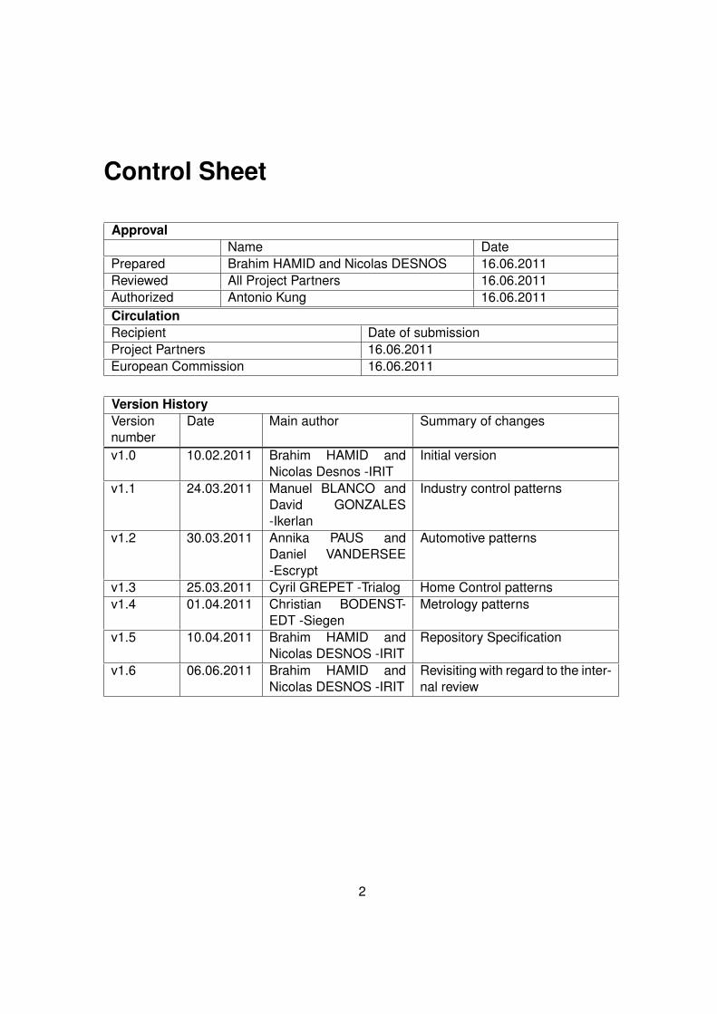
Control Sheet
ApprovalName Date
Prepared Brahim HAMID and Nicolas DESNOS 16.06.2011Reviewed All Project Partners 16.06.2011Authorized Antonio Kung 16.06.2011CirculationRecipient Date of submissionProject Partners 16.06.2011European Commission 16.06.2011
Version HistoryVersionnumber
Date Main author Summary of changes
v1.0 10.02.2011 Brahim HAMID andNicolas Desnos -IRIT
Initial version
v1.1 24.03.2011 Manuel BLANCO andDavid GONZALES-Ikerlan
Industry control patterns
v1.2 30.03.2011 Annika PAUS andDaniel VANDERSEE-Escrypt
Automotive patterns
v1.3 25.03.2011 Cyril GREPET -Trialog Home Control patternsv1.4 01.04.2011 Christian BODENST-
EDT -SiegenMetrology patterns
v1.5 10.04.2011 Brahim HAMID andNicolas DESNOS -IRIT
Repository Specification
v1.6 06.06.2011 Brahim HAMID andNicolas DESNOS -IRIT
Revisiting with regard to the inter-nal review
2
Contents
1 Introduction 7
2 TERESA Vision in Action 8
3 Background 103.1 SEMCO . . . . . . . . . . . . . . . . . . . . . . . . . . . . . . . . . . . . . . 103.2 Documentation Approach: Template . . . . . . . . . . . . . . . . . . . . . . 123.3 TERESA Partners Application Sectors . . . . . . . . . . . . . . . . . . . . . 14
3.3.1 Patterns for Industry Control Applications . . . . . . . . . . . . . . . 143.3.2 Patterns for Automotive Applications . . . . . . . . . . . . . . . . . . 183.3.3 Patterns for Metrology Sector Applications . . . . . . . . . . . . . . . 223.3.4 Patterns for Home Control . . . . . . . . . . . . . . . . . . . . . . . . 27
3.4 Review of the TERESA Requirements . . . . . . . . . . . . . . . . . . . . . 313.4.1 Pattern Life Cycle (PLC) Requirements . . . . . . . . . . . . . . . . 323.4.2 Repository Requirements . . . . . . . . . . . . . . . . . . . . . . . . 33
3.5 State of the Art on Pattern Modeling and S&D Concern . . . . . . . . . . . 343.5.1 Pattern Languages . . . . . . . . . . . . . . . . . . . . . . . . . . . . 343.5.2 S&D Modeling Languages . . . . . . . . . . . . . . . . . . . . . . . . 353.5.3 S&D Patterns . . . . . . . . . . . . . . . . . . . . . . . . . . . . . . . 36
3.6 State of the Art on Repository . . . . . . . . . . . . . . . . . . . . . . . . . . 363.6.1 Model Repository . . . . . . . . . . . . . . . . . . . . . . . . . . . . 373.6.2 Pattern Repository . . . . . . . . . . . . . . . . . . . . . . . . . . . . 38
3.7 Synthesis and discussion . . . . . . . . . . . . . . . . . . . . . . . . . . . . 403.7.1 S&D Pattern Modeling . . . . . . . . . . . . . . . . . . . . . . . . . . 403.7.2 Pattern Repository . . . . . . . . . . . . . . . . . . . . . . . . . . . . 42
4 S&D Pattern Modeling 434.1 S&D Patterns Conceptual Framework . . . . . . . . . . . . . . . . . . . . . 43
4.1.1 Motivating Example: Secure Communication Pattern . . . . . . . . . 444.1.2 Pattern Fundamental Structure (PFS) . . . . . . . . . . . . . . . . . 45
4.2 Modeling S&D Patterns . . . . . . . . . . . . . . . . . . . . . . . . . . . . . 484.2.1 Domain Independent Pattern Model (DIPM) . . . . . . . . . . . . . . 494.2.2 Domain Specific Pattern Model (DSPM) . . . . . . . . . . . . . . . . 49
5 Repository Specification 515.1 Overview . . . . . . . . . . . . . . . . . . . . . . . . . . . . . . . . . . . . . 51
5.1.1 Repository Working . . . . . . . . . . . . . . . . . . . . . . . . . . . 525.1.2 Repository Specification . . . . . . . . . . . . . . . . . . . . . . . . . 52
3
Deliverable 4.2 v1.6
5.1.3 Repository Packages . . . . . . . . . . . . . . . . . . . . . . . . . . 535.2 Core Repository Package . . . . . . . . . . . . . . . . . . . . . . . . . . . . 545.3 Interaction Interface Package . . . . . . . . . . . . . . . . . . . . . . . . . . 565.4 View Interface Package . . . . . . . . . . . . . . . . . . . . . . . . . . . . . 58
6 Conclusion 606.1 Future Work . . . . . . . . . . . . . . . . . . . . . . . . . . . . . . . . . . . . 60
6.1.1 Modeling . . . . . . . . . . . . . . . . . . . . . . . . . . . . . . . . . 606.1.2 Suit tool . . . . . . . . . . . . . . . . . . . . . . . . . . . . . . . . . . 62
6.2 Additional Research Activities . . . . . . . . . . . . . . . . . . . . . . . . . . 62
7 Bibliography 64
June 6, 2011 IST-224201 4
List of Figures
0.1 Deliverables Dependencies . . . . . . . . . . . . . . . . . . . . . . . . . . . 6
2.1 An overview of the proposed TERESA approach . . . . . . . . . . . . . . . 9
3.1 SEMCO Solution . . . . . . . . . . . . . . . . . . . . . . . . . . . . . . . . . 113.2 SEMCO Foundations and Conceptual Framework . . . . . . . . . . . . . . 123.3 TERESA WP4 . . . . . . . . . . . . . . . . . . . . . . . . . . . . . . . . . . 133.4 Ikerlan Artifacts . . . . . . . . . . . . . . . . . . . . . . . . . . . . . . . . . . 143.5 Ikerlan: Static / Class Diagram . . . . . . . . . . . . . . . . . . . . . . . . . 163.6 Ikerlan: Sequence Diagram . . . . . . . . . . . . . . . . . . . . . . . . . . . 173.7 Secure Communication: Sequence Diagram . . . . . . . . . . . . . . . . . 193.8 Secure Communication: Class Diagram . . . . . . . . . . . . . . . . . . . . 203.9 Remote Attestation: sequence diagram . . . . . . . . . . . . . . . . . . . . 223.10 Metrology: Static Structure . . . . . . . . . . . . . . . . . . . . . . . . . . . 263.11 Metrology: Sequence Diagram . . . . . . . . . . . . . . . . . . . . . . . . . 263.12 Secure Service Discovery: Pattern Structure . . . . . . . . . . . . . . . . . 303.13 Secure Service Discovery: Pattern Structure . . . . . . . . . . . . . . . . . 31
4.1 S&D Pattern Modeling Framework Structure . . . . . . . . . . . . . . . . . . 434.2 Representation of an S&D Pattern . . . . . . . . . . . . . . . . . . . . . . . 454.3 S&D Pattern Metamodel Dependencies . . . . . . . . . . . . . . . . . . . . 46
5.1 Overview of the Standard Working . . . . . . . . . . . . . . . . . . . . . . . 515.2 Overview of the Repository Specification . . . . . . . . . . . . . . . . . . . . 525.3 Repository Packages organized following a MVC approach . . . . . . . . . 535.4 Core Repository Package . . . . . . . . . . . . . . . . . . . . . . . . . . . . 555.5 Interaction Interface Package . . . . . . . . . . . . . . . . . . . . . . . . . . 575.6 View Interface Package . . . . . . . . . . . . . . . . . . . . . . . . . . . . . 59
5
Executive Summary
In this deliverable, we propose an approach based on model driven engineering (MDE)to build security and dependability (S&D) patterns for trusted RCES applications. We usemodel-based techniques to capture a set of artifacts to encode S&D patterns followingthe the MDE process and thus links concrete modeling artifacts to the S&D requirementsidentified at higher levels of abstraction. Note, however, that the latter will be studied inthe next steps of the project (deliverable D4.3). However, we test the proposed approachhas been used for modeling a security-based pattern (i.e., security channel). Therefore,patterns can be stored in a repository and can be loaded in function of desired S&Dproperties. As a result, S&D patterns will be used as brick to build trusted applicationsthrough a model driven engineering approach.
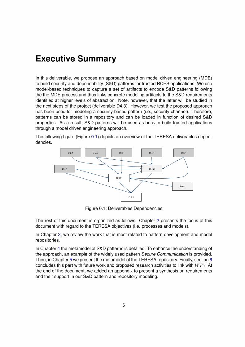
The following figure (Figure 0.1) depicts an overview of the TERESA deliverables depen-dencies.
D 7.1
D 4.1
D 4.2
D 3.2
D 7.2
D 3.1D 2.2 D 5.1D 2.1
D 6.1
Figure 0.1: Deliverables Dependencies
The rest of this document is organized as follows. Chapter 2 presents the focus of thisdocument with regard to the TERESA objectives (i.e. processes and models).
In Chapter 3, we review the work that is most related to pattern development and modelrepositories.
In Chapter 4 the metamodel of S&D patterns is detailed. To enhance the understanding ofthe approach, an example of the widely used pattern Secure Communication is provided.Then, in Chapter 5 we present the metamodel of the TERESA repository. Finally, section 6concludes this part with future work and proposed research activities to link with WP7. Atthe end of the document, we added an appendix to present a synthesis on requirementsand their support in our S&D pattern and repository modeling.
6
1 Introduction
Embedded systems [1] are not classical software which can be built with usual paradigms.In particular, the development of resource constrained embedded systems (RCES) has toaddress constraints regarding memory, computational processing power and/or limitedenergy.
Non-functional requirements such as security and dependability (S&D) [2] become moreimportant as well as more difficult to achieve. The integration of S&D features requiresthe availability of both application domain specific knowledge and S&D expertise at thesame time. Currently, the integration of S&D mechanisms is still new in many domains(i.e., smart metering or home control), hence embedded systems developers usually havelimited S&D expertise. Hence capturing and providing this expertise by way of S&D pat-terns can support embedded systems development. Model-Driven Engineering (MDE)provides a very useful contribution for the design of trusted systems, since it bridges thegap between design issues and implementation concerns. It helps the designer to spec-ify in a separate way non-functional requirements such as security and/or dependabilityneeds at a higher level of abstraction. This allows implementation independent validationof models, for instance, generally considered as an important assurance step.
The question remains at which state of the development process to integrate S&D pat-terns. As a prerequisite work, we investigate the design process of S&D patterns. In thisdocument, we propose an approach for S&D pattern development and validation that fol-lows the MDE paradigm. Security and dependability patterns on domain independent anddomain specific level, respectively, that are derived from and associated with domain spe-cific models will help developers to integrate application building blocks with S&D buildingblocks.
The motivation driving the modeling and formalization of security and dependability ofsoftware has typically been the need to amend the principal characteristics of the systemtargeting several domains with the same set of user requirements. Achieving this goalrequires to get (1) a common representation of patterns for several domains; (2) a patternflexible structure; (3) unified formal validation of patterns; (4) guidelines for platform spe-cific implementation of the patterns and (5) guidelines to guarantee the correctness of thepattern integration step.
The goal of the document is to propose a new pattern development technique and pack-aging in order to make easy their use in a building process of software applications withS&D support. Reaching this target requires to get (i) a common representation of patternsfor several domains in the context of RCES and (ii) flexible repository structure to storethe required artifacts for the trust engineering process including patterns.
7
2 TERESA Vision in Action
The main goal of the WP4 is to define a technique that provides an easy and efficientS&D pattern development and packaging. Unfortunately, most of S&D patterns are ex-pressed in a textual form, as informal indications on how to solve some security problems.Some of them use more precise representations based on UML diagrams, but these pat-terns do not include sufficient semantic descriptions in order to automate their processingand to extend their use. Furthermore, there is no guarantee of the correct application ofa pattern because the description does not consider the effects of interactions, adapta-tion and combination. This makes them unappropriate for automated processing within atool-supported development process. Finally, due to manual pattern implementation use,the problem of incorrect implementation (the most important source of security issues)remains unsolved.
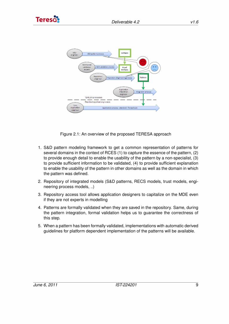
The TERESA approach promotes a model-based approach coupled with a repository ofS&D patterns to define an engineering discipline for trust that is adapted to resourceconstrained embedded systems. The TERESA vision (see Figure. 2.1) is the following:the S&D patterns derived from (resp. associated with) domain specific models aim athelping the application developer to integrate application S&D building blocks. This is thereason why we advocate the use of a model-based repository, where patterns are clearlyrelated to domain models.
Patterns are used to specify architecture and design aspects. Usually, they refer to tem-plates which describe solutions for commonly occurring problems. Security and depend-ability patterns are not only defined from a platform independence viewpoint (i.e. they areindependent from the implementation), they are also expressed in a consistent way withdomain specific trust models. Consequently, they will be much easier to understand andvalidate by application designers in a specific area. That is:
• S&D experts can make patterns publically available
• S&D patterns can be used by RCES developers in other companies
• S&D patterns can be derived from and associated with domain specific models
• S&D patterns help application developers to integrate application building blockswith S&D building blocks
The resulting documentation and repository prototype as well as a number of guidelineswill facilitate 1) the populating of the repository with further security and dependabilityor S&D patterns, and 2) the transformation of the S&D patterns into platform dependentspecifications. This will be completed by the following concerns:
8
Deliverable 4.2 v1.6
Figure 2.1: An overview of the proposed TERESA approach
1. S&D pattern modeling framework to get a common representation of patterns forseveral domains in the context of RCES (1) to capture the essence of the pattern, (2)to provide enough detail to enable the usability of the pattern by a non-specialist, (3)to provide sufficient information to be validated, (4) to provide sufficient explanationto enable the usability of the pattern in other domains as well as the domain in whichthe pattern was defined.
2. Repository of integrated models (S&D patterns, RECS models, trust models, engi-neering process models, ..)
3. Repository access tool allows application designers to capitalize on the MDE evenif they are not experts in modelling
4. Patterns are formally validated when they are saved in the repository. Same, duringthe pattern integration, formal validation helps us to guarantee the correctness ofthis step.
5. When a pattern has been formally validated, implementations with automatic derivedguidelines for platform dependent implementation of the patterns will be available.
June 6, 2011 IST-224201 9
3 Background
In this chapter, we outline different tools used in our proposed approach including repos-itory of models, S&D pattern modeling, IRIT SEMCO approach and some related stan-dards. The template part gives some concepts about the required information to representpatterns in the domain of software engineering in order to describe S&D patterns for eachTeresa application domain. In the next part, we review the TERESA requirements. Then,we review briefly exiting solutions and related works about repository development forsoftwares and systems and pattern definition and modeling The chapter is concluded witha synthesis and discussion.
3.1 SEMCO
The following presents briefly the SEMCO Modeling Platform (System and software Engi-neering for embedded systems applications with Multi-COncerns) as IRIT under develop-ment platform. We build on a theory and novel methods based on an integrated commonmetamodels for multi-concerns specification and management which (1) promote engi-neering separation of concerns, (2) supports multi-concerns, (3) use patterns to embedsolutions of engineering concerns and (3) supports multi-domain specific process. Thisplatform is three-folded: providing repository of modeling artifacts, tools to manage theseartifacts and guidelines to build complete engineering systems.
SEMCO covers a wide spectrum of applications ranging across DRTES and RCES toname a few. One of the major considerations in designing multi-concerns systems isto determine at which level of abstraction concerns should be placed. The supportingresearch includes system architecture, specification, modeling, implementation mecha-nisms, verification... For example, distributed systems are organized into separate layersfollowing some reference models, e.g. applications, middleware and the operating systemservices.
The proposed approach is to use an integrated repository of artifacts to represent severalconcerns of safety critical embedded systems. These artifacts will be used to capture inorder to model all the facets of the system and its parts: logical (software and hardwarecomponents) and the infrastructure. They are provided as informal textual document, assemi-formal document using UML, SysML and Eclipse modeling framework, and as formalartifact using formal frameworks.
SEMCO solution, as depicted in Figure. 3.1, involves widely diverse core expertise rangingfrom:
10
Deliverable 4.2 v1.6
• Software Engineering
• Requirement Engineering
• Specification
• Modeling
• Formalization
• Implementation mechanisms
Figure 3.1: SEMCO Solution
Today, design patterns are considered as fundamental technique to build software bycapitalizing knowledge to solve occurring problems in many specific domains. SEMCOapproach promotes the use of patterns as first-class artifacts to embed solutions of extra-functional concerns such as safety, security and performance requirements of systems;specify the set of correct configurations; and capture the execution infrastructure of thesystems, supporting the mechanisms to implement these concerns.
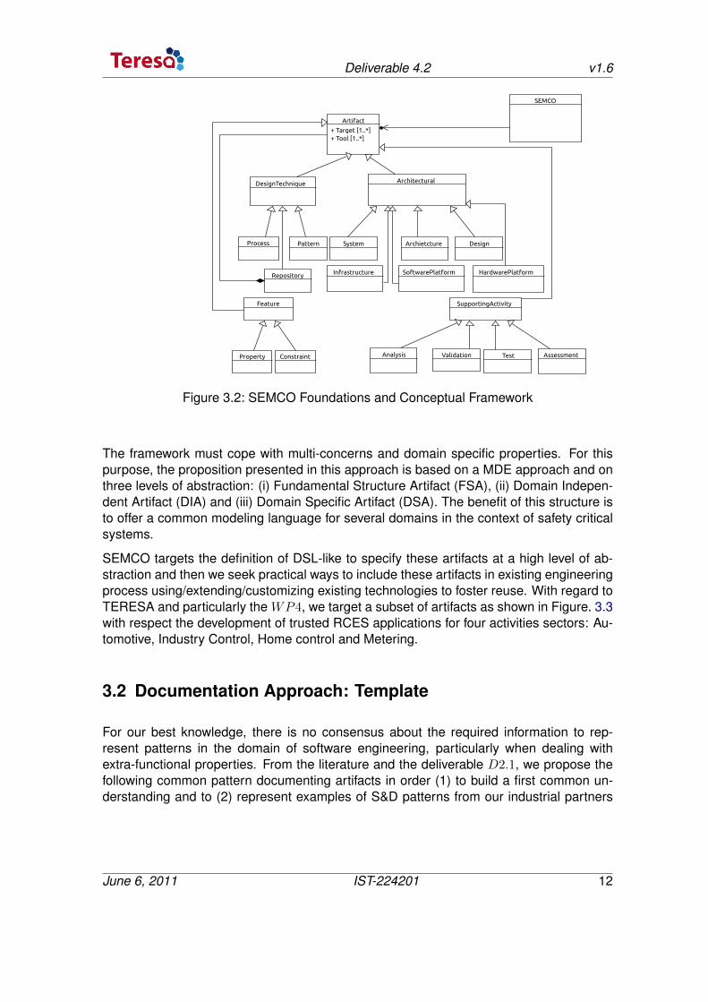
Currently, in addition to the process, pattern and the repository itself artifacts (see Fig. 3.2)SEMCO defines and targets to provide 13 different artifacts types representing differentengineering concerns and architectural information.
June 6, 2011 IST-224201 11
Deliverable 4.2 v1.6
Artifact
+ Target [1..*] + Tool [1..*]
Feature
DesignTechnique
Property Constraint
Process Pattern
Repository
Architectural
System Archietcture Design
SEMCO
Infrastructure SoftwarePlatform HardwarePlatform
SupportingActivity
Analysis Validation Test Assessment
Figure 3.2: SEMCO Foundations and Conceptual Framework
The framework must cope with multi-concerns and domain specific properties. For thispurpose, the proposition presented in this approach is based on a MDE approach and onthree levels of abstraction: (i) Fundamental Structure Artifact (FSA), (ii) Domain Indepen-dent Artifact (DIA) and (iii) Domain Specific Artifact (DSA). The benefit of this structure isto offer a common modeling language for several domains in the context of safety criticalsystems.
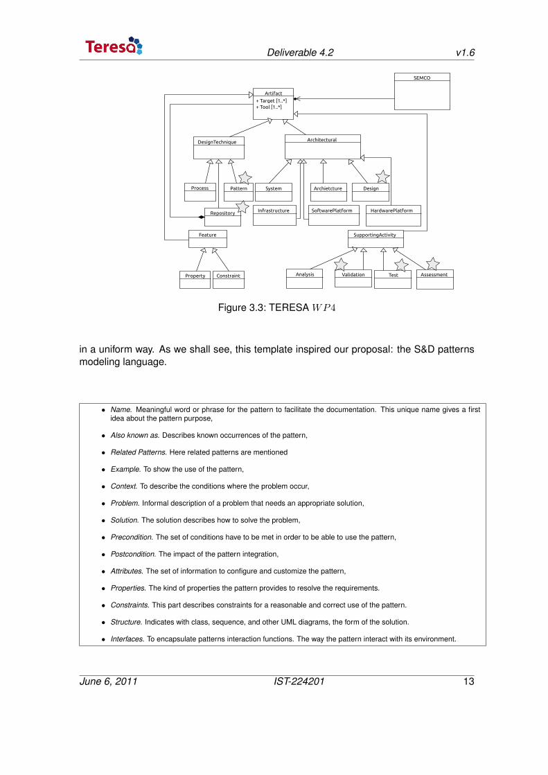
SEMCO targets the definition of DSL-like to specify these artifacts at a high level of ab-straction and then we seek practical ways to include these artifacts in existing engineeringprocess using/extending/customizing existing technologies to foster reuse. With regard toTERESA and particularly the WP4, we target a subset of artifacts as shown in Figure. 3.3with respect the development of trusted RCES applications for four activities sectors: Au-tomotive, Industry Control, Home control and Metering.
3.2 Documentation Approach: Template
For our best knowledge, there is no consensus about the required information to rep-resent patterns in the domain of software engineering, particularly when dealing withextra-functional properties. From the literature and the deliverable D2.1, we propose thefollowing common pattern documenting artifacts in order (1) to build a first common un-derstanding and to (2) represent examples of S&D patterns from our industrial partners
June 6, 2011 IST-224201 12
Deliverable 4.2 v1.6
Artifact
+ Target [1..*] + Tool [1..*]
Feature
DesignTechnique
Property Constraint
Process Pattern
Repository
Architectural
System Archietcture Design
SEMCO
Infrastructure SoftwarePlatform HardwarePlatform
SupportingActivity
Analysis Validation Test Assessment
Figure 3.3: TERESA WP4
in a uniform way. As we shall see, this template inspired our proposal: the S&D patternsmodeling language.
• Name. Meaningful word or phrase for the pattern to facilitate the documentation. This unique name gives a firstidea about the pattern purpose,
• Also known as. Describes known occurrences of the pattern,
• Related Patterns. Here related patterns are mentioned
• Example. To show the use of the pattern,
• Context. To describe the conditions where the problem occur,
• Problem. Informal description of a problem that needs an appropriate solution,
• Solution. The solution describes how to solve the problem,
• Precondition. The set of conditions have to be met in order to be able to use the pattern,
• Postcondition. The impact of the pattern integration,
• Attributes. The set of information to configure and customize the pattern,
• Properties. The kind of properties the pattern provides to resolve the requirements.
• Constraints. This part describes constraints for a reasonable and correct use of the pattern.
• Structure. Indicates with class, sequence, and other UML diagrams, the form of the solution.
• Interfaces. To encapsulate patterns interaction functions. The way the pattern interact with its environment.
June 6, 2011 IST-224201 13
Deliverable 4.2 v1.6
3.3 TERESA Partners Application Sectors
This section is dedicated to the description of S&D patterns for each Teresa applicationdomain. This description is made in an informal way. The objective is to extract thecommon information we need to propose a common representation of S&D pattern.
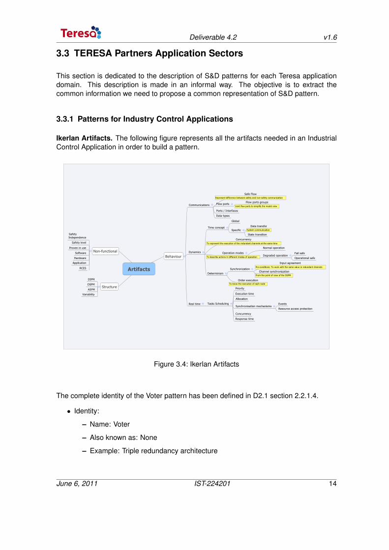
3.3.1 Patterns for Industry Control Applications
Ikerlan Artifacts. The following figure represents all the artifacts needed in an IndustrialControl Application in order to build a pattern.
Represent difference between safety and non-safety communication
Joint flow ports to simplify the model view
System communication
To represent the execution of the redundant channels at the same time
To describe actions in different modes of operation
Pre-conditions: To work with the same value in redundant channels
From the point of view of the DSPM
To know the execution of each node
Figure 3.4: Ikerlan Artifacts
The complete identity of the Voter pattern has been defined in D2.1 section 2.2.1.4.
• Identity:
– Name: Voter
– Also known as: None
– Example: Triple redundancy architecture
June 6, 2011 IST-224201 14
Deliverable 4.2 v1.6
– Context: A critical application that must perform a safety-related functionalityregardless the presence of a transient fault.
– Problem: A transient fault in a critical application which leads to a system failureis not detected.
– Solution: It consists of two actions. The Redundant Architecture applies a repli-cation of the system to enhance the system availability/reliability in the pres-ence of transient fault, and the Decision Maker must decide which system isproperly running.
• Attributes: The complete attributes have been defined in D2.1 section 2.2.1.4. Therelated information is:
– Preconditions:
∗ System architecture has been defined.
∗ The safety function has been identified.
∗ Input agreement
– Post-conditions:
∗ Without redundancy
· IN01− ρ(IN01) = (1− ρ(S′))∗(1− ρ(N ′))∗(1− ρ(R′))
· IN02− ρ(IN02) = (1− ρ(S′))∗(1− ρ(N ′))∗(1− ρ(R′))
ρ(S′)=probability that a sensor fails
ρ(N ′)=probability that a network fails
ρ(R′)=probability that a receiver fails
∗ With redundancy
· IN01− ρ(IN01) = (3∗x2∗ − 2∗x3)∗(1− ρ(DM ′)),
which is better than x in case x > 0.5
· IN02− ρ(IN01) = (3∗x2∗ − 2∗x3)∗(1− ρ(DM ′)),
which is better than x in case x > 0.5;
x = (1− ρ(S′))∗(1− ρ(N ′))∗(1− ρ(R′));
DM ′ =Probability that the Decision Maker fails
– Attributes:
∗ Needs of the pattern: Channel Synchronization
∗ Needs of the pattern: Sequential Code
∗ Safety critical: Determinism of the system
∗ Safety critical: Diversity of SW and HW
June 6, 2011 IST-224201 15
Deliverable 4.2 v1.6
∗ Safety critical: Reciprocal monitoring
• Properties
– RCES: Data agreement
– RCES: Order execution
– RCES: Synchronization between channel execution
– Dependability: Fault tolerant
– Safety Standard: SIL 4
– Quality Standard: Documentation control / internal review / safety audits / as-sessment.
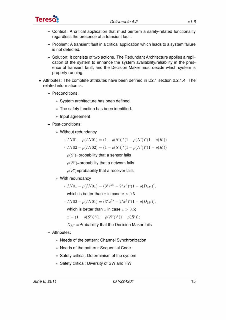
• Internal Structure
– Static / Class Diagram
Figure 3.5: Ikerlan: Static / Class Diagram
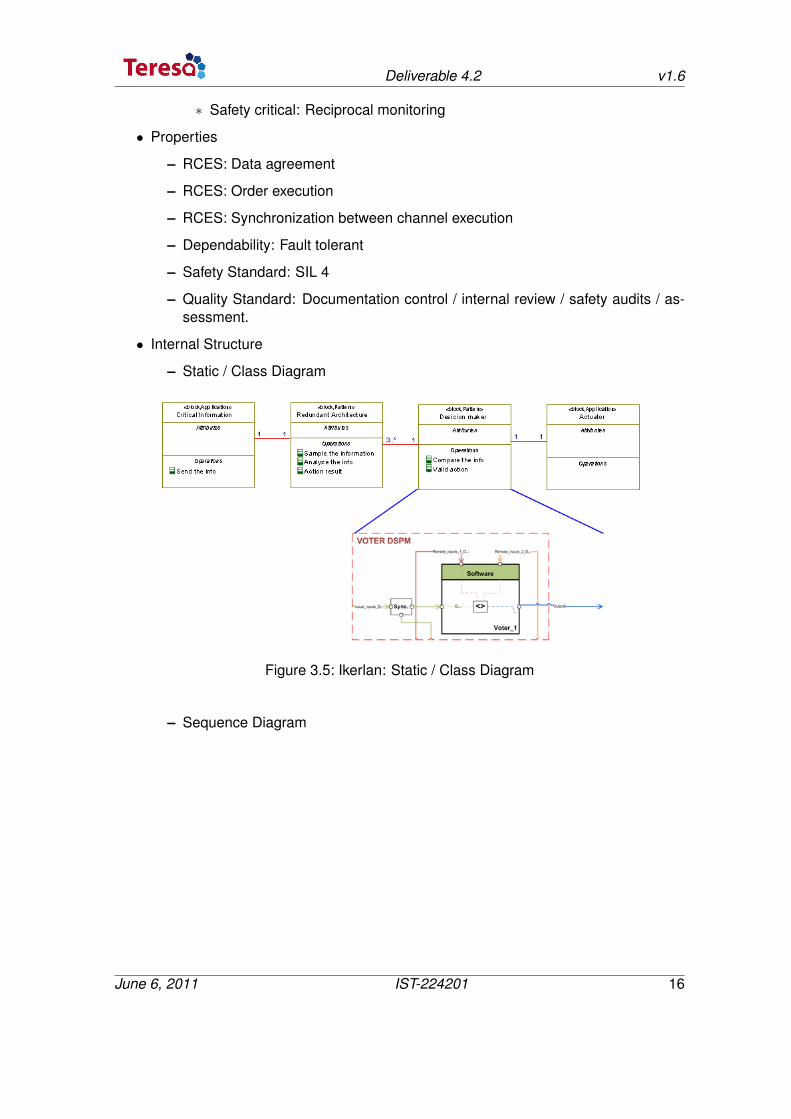
– Sequence Diagram
June 6, 2011 IST-224201 16
Deliverable 4.2 v1.6
Figure 3.6: Ikerlan: Sequence Diagram
• Interfaces are extracted from the internal structure and for the analysis of possiblescenarios where the pattern can be used.
– External interfaces :
∗ input: Data type, Number of inputs, Direction, Port
∗ output: Data type, Number of inputs, Direction, Port
– Internal Interfaces
∗ Synchronization
∗ Vote
∗ Innacurate voting
∗ Monitoring
June 6, 2011 IST-224201 17
Deliverable 4.2 v1.6
3.3.2 Patterns for Automotive Applications
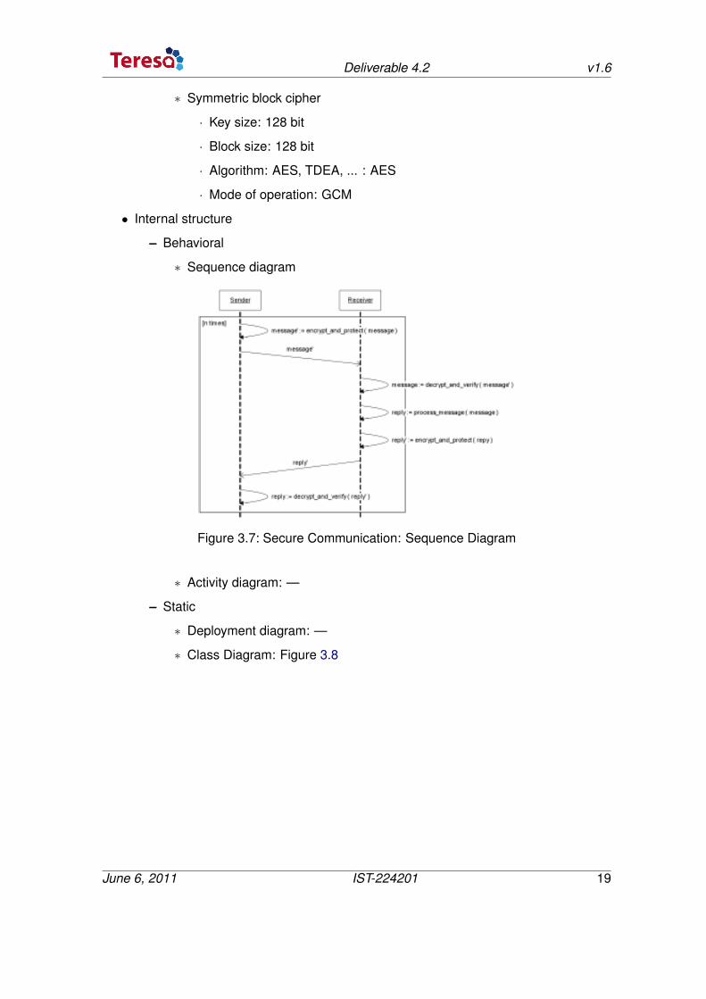
Secure communication. The following pattern description is rather an example than areal TERESA pattern.
• Identity
– ID: P_AD_SC
– Author: escrypt GmbH
– Date: 24.03.2011
– Level: Design
– Domain: Automotive
– Pattern name: Secure Communication
– Also known as: —
– Related patterns
∗ Extends pattern (reference): —
∗ Includes pattern (reference): Mutual Authentication, Key Agreement, PKI
– Problem description: messages need to be protected from being eavesdroppedor manipulated.
– Context: regarding the use case toll collection, the communication of the carsOBU with the RSU of the toll provider has to be protected. Besides avoiding thetransferred messages from being eavesdropped (Confidentiality) the identity ofthe communicating entities has to be verified (Mutual Authenticity). Further-more it has to be ensured that the messages are transferred directly withoutbeing recorded (Freshness) and to make sure that the data sent from the vehi-cle and the RSU is not manipulated (Data Integrity).
– Use case (reference): UC_AD_SC
• Properties
– Security services (multiple)
∗ Authenticity: Yes
∗ Data integrity: Yes
∗ Freshness: Yes
∗ Confidentiality: Yes
∗ Non-repudiation: No
• Attributes
– Cryptographic algorithms (multiple)
June 6, 2011 IST-224201 18
Deliverable 4.2 v1.6
∗ Symmetric block cipher
· Key size: 128 bit
· Block size: 128 bit
· Algorithm: AES, TDEA, ... : AES
· Mode of operation: GCM
• Internal structure
– Behavioral
∗ Sequence diagram
Figure 3.7: Secure Communication: Sequence Diagram
∗ Activity diagram: —
– Static
∗ Deployment diagram: —
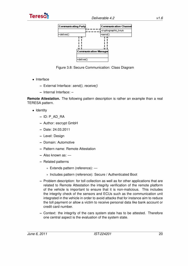
∗ Class Diagram: Figure 3.8
June 6, 2011 IST-224201 19
Deliverable 4.2 v1.6
Figure 3.8: Secure Communication: Class Diagram
• Interface
– External Interface: send(), receive()
– Internal Interface: –
Remote Attestation. The following pattern description is rather an example than a realTERESA pattern.
• Identity
– ID: P_AD_RA
– Author: escrypt GmbH
– Date: 24.03.2011
– Level: Design
– Domain: Automotive
– Pattern name: Remote Attestation
– Also known as: —
– Related patterns
∗ Extends pattern (reference): —
∗ Includes pattern (reference): Secure / Authenticated Boot
– Problem description: for toll collection as well as for other applications that arerelated to Remote Attestation the integrity verification of the remote platformof the vehicle is important to ensure that it is non-malicious. This includesthe integrity check of the sensors and ECUs such as the communication unitintegrated in the vehicle in order to avoid attacks that for instance aim to reducethe toll payment or allow a victim to receive personal data like bank account orcredit card number.
– Context: the integrity of the cars system state has to be attested. Thereforeone central aspect is the evaluation of the system state.
June 6, 2011 IST-224201 20
Deliverable 4.2 v1.6
– Use case (reference): UC_AD_RA
• Properties
– Security services (multiple)
∗ Authenticity: Yes
∗ Data integrity: Yes
∗ Freshness: Yes
∗ Confidentiality: No
∗ Non-repudiation: No
• Attributes
– Cryptographic algorithms (multiple)
∗ Cryptographic HASH
· Hash size: 512 bit
· Algorithm (SHA-1, SHA-256, ... ): SHA-512
∗ Asymmetric cipher
· Key size: 2048 bit
· Algorithm (RSA, ECC): RSA
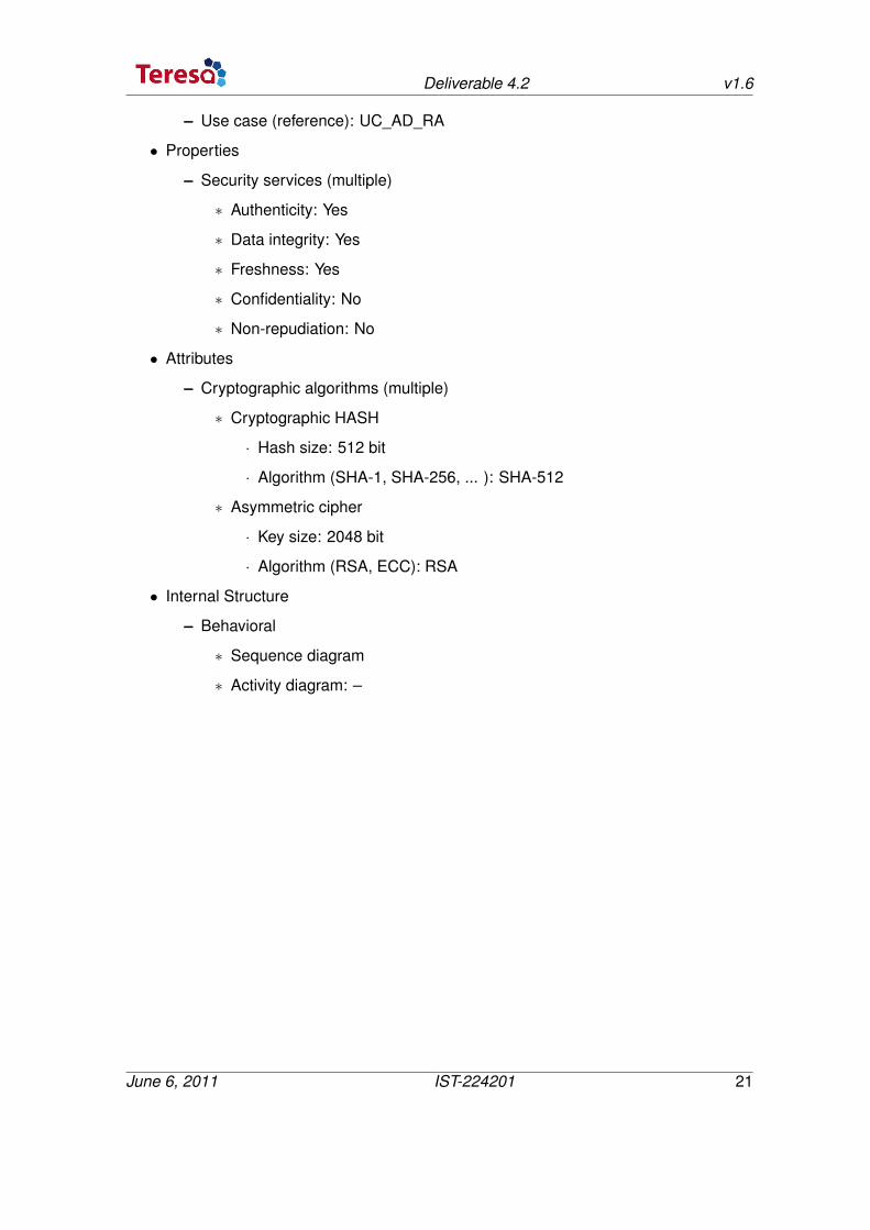
• Internal Structure
– Behavioral
∗ Sequence diagram
∗ Activity diagram: –
June 6, 2011 IST-224201 21
Deliverable 4.2 v1.6
Figure 3.9: Remote Attestation: sequence diagram
– Static
∗ Deployment diagram: –
∗ Class diagram: –
• Interface
– External Interface: attest()
– Internal Interface: quote()
3.3.3 Patterns for Metrology Sector Applications
• Identity:
The complete identity of the Secure Software Download Pattern has been de-fined in document D2.1. Related information:
– Name: Secure Software Download
– Also Known As: Firmware Update, Software Update
– Example: secure software download for embedded systems like meters, elec-tronic control units et cetera, wherever a software update is necessary withoutdirect physical access to the system.
– Context:
∗ The target device stays in use at the customer for a longer period of time,e.g. 20 years without direct access by service personnel.
June 6, 2011 IST-224201 22
Deliverable 4.2 v1.6
∗ The target device is connected to a possibly unsafe communication net-work
∗ The target device has restricted memory resources. There is only enoughspace for two software images: the currently running version and the newsoftware version.
∗ The bootloader shall be as small as possible. E.g. it does not contain anycryptographic functions or libraries.
∗ A secure storage is available which guarantees authenticity of the savedsoftware image.
∗ Approval of the software image by an external Certification Body
– Problem: guarantee authenticity and integrity of the firmware image and accesscontrol to the update interface. Ensure that only certified software images (inregard to compulsory relevance) are downloaded and installed.
– Solution: the update takes place in three steps. At first the client that providesthe new software has to authenticate at the target system, so the target systemcan enable the download functionality. In a second step, the software is trans-ferred into a designated secure memory region at the target system and theintegrity and authenticity of the software image is checked on the target sys-tem. As the last step, the target system is restarted and the bootloader loadsthe new software image from the designated memory and starts it.
• Attributes: the complete attributes have been defined in D2.1. The related informa-tion is:
– Preconditions:
∗ For the creation and verification of digital signatures, asymmetric cryp-tography is used. Thus each embedded device needs an individual pri-vate/public key pair, the private key of the embedded device must not bemanipulated or read out from the embedded device and the public keys ofthe involved parties must be available.
∗ Cryptographic keys and the unique identifiers of the involved parties mustbe available in the Embedded Device (see Parameters to be provided).
∗ Secure storage for keys and identifiers: For an unauthorized person, itmust not be possible to manipulate the identifiers and cryptographic keys.It must not be possible to read out the private key of the Embedded Device.
∗ Bootloader and Secure storage for software image: when the software im-age is loaded from the designated memory into the program memory ofthe MCU/CPU, only a very small bootloader is running. The bootloader isnot able to check cryptographic signatures, thus the software image itselfhas to be saved in a secure storage in order to provide authenticity of thesoftware image.
June 6, 2011 IST-224201 23
Deliverable 4.2 v1.6
∗ Cryptographic Library providing a one way hash function and algorithmsfor asymmetric en- and decryption.
∗ Secure storage size: The secure storage provides space for at least twosoftware images.
∗ Secure storage: The secure storage can only be accessed by the embed-ded device itself. It is not possible for an external party to manipulate orread the stored data. Authenticity of stored data is preserved.
– Parameters to be provided:
∗ The following parameters have to be provided to the embedded system:
· PrivKED: Private Key of the Embedded Device (to sign parts of theresponses). –> Requirement: PrivKED must only be known to the Em-bedded Device. It must not be possible for external agents to read outor change the Private Key.
· PubKEASD: Public key of the Entity authorized for software download (tocheck the authenticity of this actor for access control and to check theauthenticity of the origin of data of the Software Image). –> Require-ment: PubKEASD must authentically originate from the Entity authorizedfor software download.
· PubKCB: Public key of the Certification Body (to check the crypto-graphic signature of approved software images). –> Requirement: PubKCB
must authentically originate from the Certification Body
· IDEASD: The unique identifier of the Entity authorized for software down-load. –> Requirement: IDEASD must authentically originate from theEntity authorized for software download
· IDCB: The unique identifier of the Metrology Institute. –> Requirement:IDCB must authentically originate from the Certification Body
· IDED: The unique identifier of the Embedded Device.
∗ The following parameters have to be provided to the Entity authorized forsoftware download:
· PubKED: Public Key of the Embedded Device (to check cryptographicsignatures in responses of the ED). –> Requirement: PubKED mustauthentically originate from the Embedded Device
· PrivKEASD: Private Key of the Entity authorized for software download(to create cryptographic signatures). –> Requirement: PrivKEASD mustauthentically originate from the Entity authorized for software download
· IDEASD: The unique identifier of the Entity authorized for software down-load. –> Requirement: IDEASD must authentically originate from theEntity authorized for software download
June 6, 2011 IST-224201 24
Deliverable 4.2 v1.6
· IDCB: The unique identifier of the Certification Body. –> Requirement:IDCB must authentically originate from the Certification Body
· IDED: The unique identifier of the Embedded Device to address. –>Requirement: IDED must authentically originate from the EmbeddedDevice
– Postconditions:
∗ Embedded device runs with downloaded software update.
∗ The authenticity of the person initiating the software download has beenverified.
∗ The integrity of the downloaded software image has been checked.
∗ The authenticity of the software image origin has been checked.
∗ The version number of the new software image is greater than the versionnumber of the previously running software.
∗ For the update of legally relevant software only software images approvedby the Certification Body are accepted.
– Attributes:
∗ Digital signature scheme: e.g. ECDSA
∗ Encryption of transmitted software image: optional
∗ Key-Exchange Mechanism (if encryption of image is chosen): e.g. Diffie-Hellman
∗ Symmetric Crypto Algorithm (if encryption of image is chosen): e.g. AES
∗ For the metrology domain, a digital signature from the Metrology Instituteis needed to represent the successful type approval.
• Properties
– Security-property: Authenticity of the person initiating a secure software down-load
– Security-property: Integrity of the software image transmitted via Secure Soft-ware Download
– Security-property: Authenticity of the software images origin transmitted viaSecure Software Download
– Security-property: Software version check in Secure Software Download
– Security-property: Software Image transmitted via Secure Software Downloadmust have been approved by Metrology Institute.
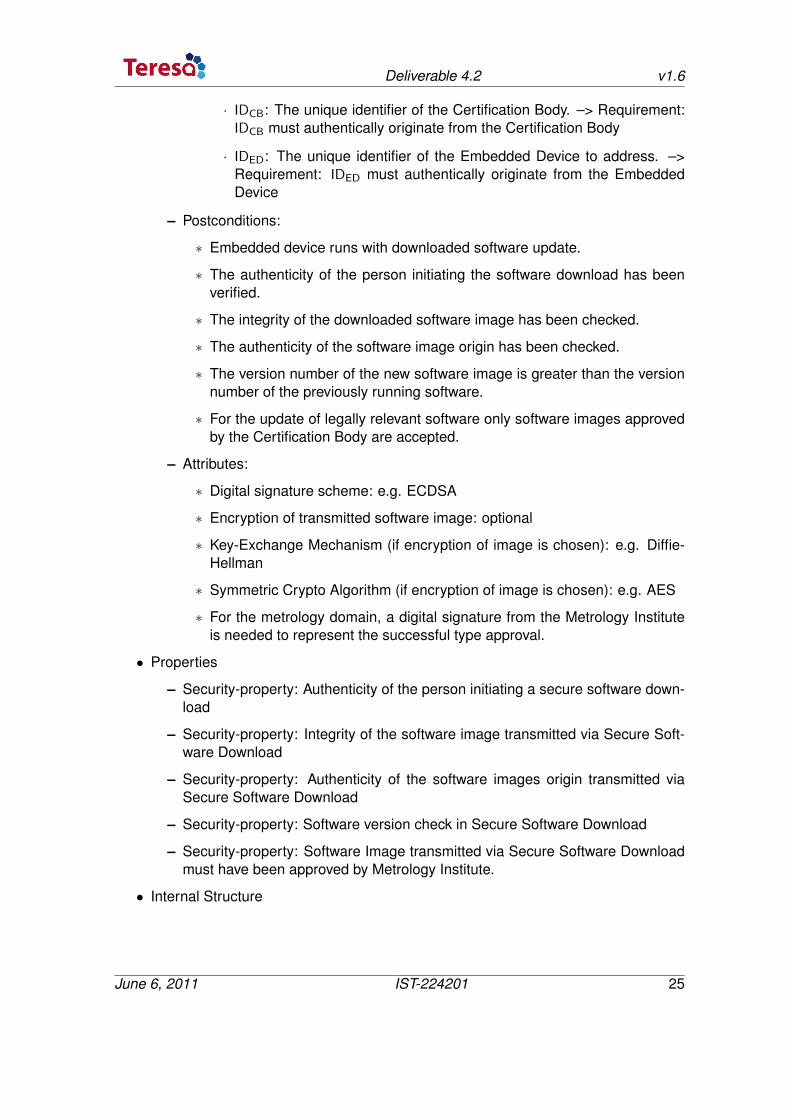
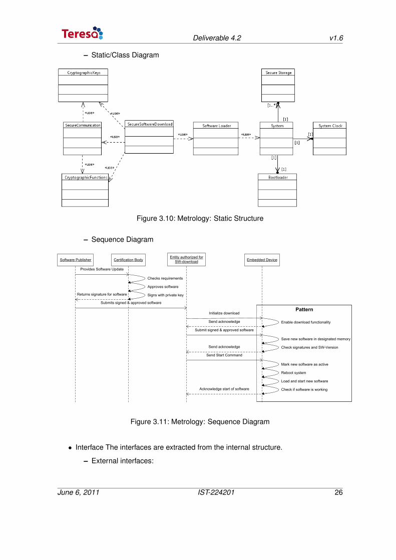
• Internal Structure
June 6, 2011 IST-224201 25
Deliverable 4.2 v1.6
– Static/Class Diagram
Figure 3.10: Metrology: Static Structure
– Sequence Diagram
Software Publisher Certification BodyEntity authorized for
SW-download
Provides Software Update
Embedded Device
Checks requirements
Approves software
Signs with private key
Submits signed & approved software
Initialize download
Enable download functionalitySend acknowledge
Submit signed & approved software
Save new software in designated memory
Check signatures and SW-Version
Mark new software as active
Reboot system
Load and start new software
Check if software is workingAcknowledge start of software
Returns signature for software
Send Start Command
Send acknowledge
Pattern
Figure 3.11: Metrology: Sequence Diagram
• Interface The interfaces are extracted from the internal structure.
– External interfaces:
June 6, 2011 IST-224201 26
Deliverable 4.2 v1.6
∗ Init
∗ DownloadImage
∗ StartImage
– Internal interfaces:
∗ Cryptography:
· VerifySignature
· SignData
· VerifyHash
∗ Optional Cryptography:
· GenerateKey
· Encrypt
· Decrypt
∗ Secure Storage:
· AllocateMemory
· StoreImage
∗ System:
· GetSystemTime
· SafeSystemRestart
· SelectBootableImage
3.3.4 Patterns for Home Control
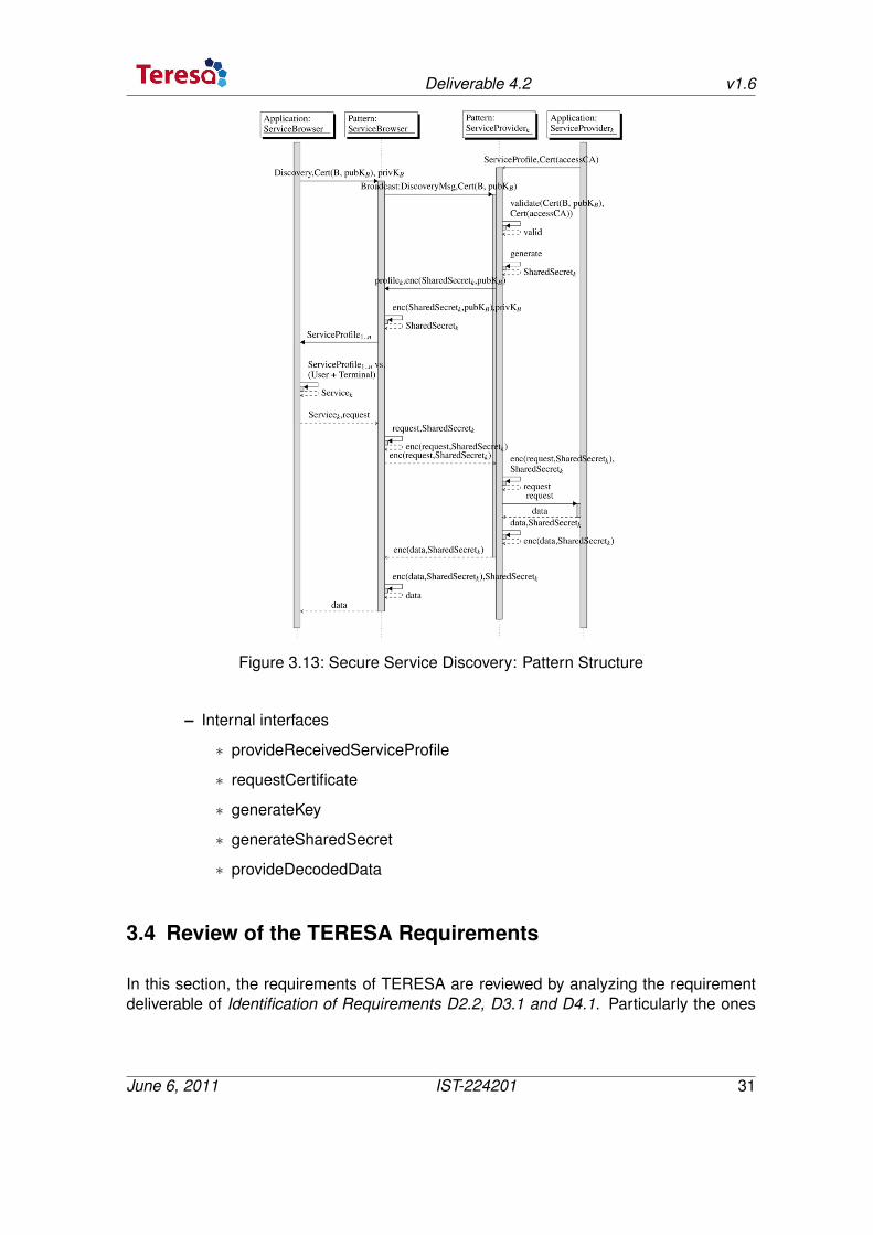
Secure Service Discovery. The Secure Service Discovery Pattern complete identity havebeen defined in D2.1 section 3.2.3.4. The related information are:
• Identity
– Name: Secure service discovery
– Also Known As: None
– Example: terminal (could be TV, Security camera, etc.) need to discover andselect available services in the house according to the user profile (child, oldperson, nurse, etc.)
– Context:
June 6, 2011 IST-224201 27
Deliverable 4.2 v1.6
∗ Ad-hoc networked service environment which have potentially large num-bers of services
∗ Service browser to find and utilize services.
∗ Some services have to be secure and the network could be unsafe.
– Problem:
∗ Communication are not secure
∗ Discovery services relying on user profile and reactive (other use casecould be the proactive one) announcement of possibly large amount ofservices
∗ Encryption has overhead
– Solution: use of a combination of Secure Channel and Intelligent Service pat-terns
• Attribute: the complete attribute have been defined in D2.1 section 3.2.3.4. Therelated information are :
• Preconditions:
– Existing Home network
– Access to Home network for Pattern
– AccessCA-Certificate predeployed to all Service Providers
– AccessCA-Certificate cannot be exchanged by rogue entity
– Device Certificate issued by accessCA and corresponding private keys prede-ployed to all trusted Service Browsers
– Private key is confidential to Service Browser application and pattern
– Communication between respective Applications and Pattern instances on eachdevice cannot be eavesdropped or altered
– Data must be generated and handled confidentially on the devices.
• Post-conditions:
– ServiceBrowsers are authentic to belong to the group of trusted devices beforeacting upon Service Request (i.e. Service data).
– The Service Interactions (consisting of service request and service data) areconfidential to the authentic ServiceBrowser from the set of trusted devices,to the non-authentic ServiceProvider and those agents granted access by theServiceProvider.
June 6, 2011 IST-224201 28
Deliverable 4.2 v1.6
– The integrity of Service Interactions (consisting of service request and servicedata) are being assured such that they can only be altered by the authenticServiceBrowser from the set of trusted devices, from the non-authentic Servi-ceProvider and those agents granted access by the ServiceProvider.
In other world the attribute are:
– Existing Home Network
– Existing group of Trusted devices
– Existing trusted accessCA
– Existing Secure Storage
– Cryptographic capability available: SSL, Elliptic Curve, ...
– Existing secure communication between the Secure Storage, the Cryptographyand the Pattern
– Weakness : Service Provider Authentication
• Properties
– Certificate Based one-way Authentication
– Asymmetric Encryption
– Symmetric Integrity Preserving Encryption
– Intelligent Service Discovery
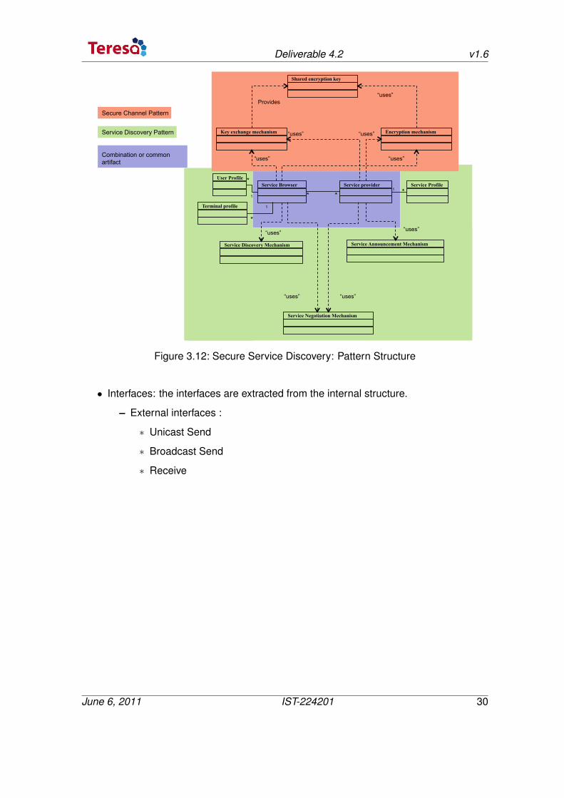
• Internal Structure: the internal structure has been defined in D2.1 Section 3.2.3.4
June 6, 2011 IST-224201 29
Deliverable 4.2 v1.6
Combination or common artifact
Service Discovery Pattern
Secure Channel Pattern
Key exchange mechanism
Shared encryption key
Service provider Service Browser
Encryption mechanism
* *
“uses”
“uses”
“uses”
“uses”
“uses” Provides
Service Discovery Mechanism
User Profile
Terminal profile
Service Announcement Mechanism
Service Negotiation Mechanism
“uses”
“uses” “uses”
*
*
1
1
Service Profile * 1
“uses”
Figure 3.12: Secure Service Discovery: Pattern Structure
• Interfaces: the interfaces are extracted from the internal structure.
– External interfaces :
∗ Unicast Send
∗ Broadcast Send
∗ Receive
June 6, 2011 IST-224201 30
Deliverable 4.2 v1.6
Figure 3.13: Secure Service Discovery: Pattern Structure
– Internal interfaces
∗ provideReceivedServiceProfile
∗ requestCertificate
∗ generateKey
∗ generateSharedSecret
∗ provideDecodedData
3.4 Review of the TERESA Requirements
In this section, the requirements of TERESA are reviewed by analyzing the requirementdeliverable of Identification of Requirements D2.2, D3.1 and D4.1. Particularly the ones
June 6, 2011 IST-224201 31
Deliverable 4.2 v1.6
cited in Section 5 and Section 7 concerning requirements on the pattern life cycle andrequirements on the repository structure.
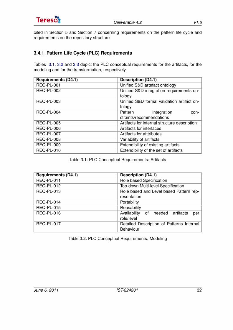
3.4.1 Pattern Life Cycle (PLC) Requirements
Tables 3.1, 3.2 and 3.3 depict the PLC conceptual requirements for the artifacts, for themodeling and for the transformation, respectively.
Requirements (D4.1) Description (D4.1)REQ-PL-001 Unified S&D artefact ontologyREQ-PL-002 Unified S&D integration requirements on-
tologyREQ-PL-003 Unified S&D formal validation artifact on-
tologyREQ-PL-004 Pattern integration con-
straints/recommendationsREQ-PL-005 Artifacts for internal structure descriptionREQ-PL-006 Artifacts for interfacesREQ-PL-007 Artifacts for atttributesREQ-PL-008 Variability of artifactsREQ-PL-009 Extendibility of existing artifactsREQ-PL-010 Extendibility of the set of artifacts
Table 3.1: PLC Conceptual Requirements: Artifacts
Requirements (D4.1) Description (D4.1)REQ-PL-011 Role based SpecificationREQ-PL-012 Top-down Multi-level SpecificationREQ-PL-013 Role based and Level based Pattern rep-
resentationREQ-PL-014 PortabilityREQ-PL-015 ReusabilityREQ-PL-016 Availability of needed artifacts per
role/levelREQ-PL-017 Detailed Description of Patterns Internal
Behaviour
Table 3.2: PLC Conceptual Requirements: Modeling
June 6, 2011 IST-224201 32
Deliverable 4.2 v1.6
Requirements (D4.1) Description (D4.1)REQ-PL-018 Traceability of artefacts during the pattern
life cycleREQ-PL-019 Traceability of properties during mecha-
nismREQ-PL-020 Consistency between pattern levelsREQ-PL-021 Guidelines for easy pattern definition
Table 3.3: PLC Conceptual Requirements: Transformation
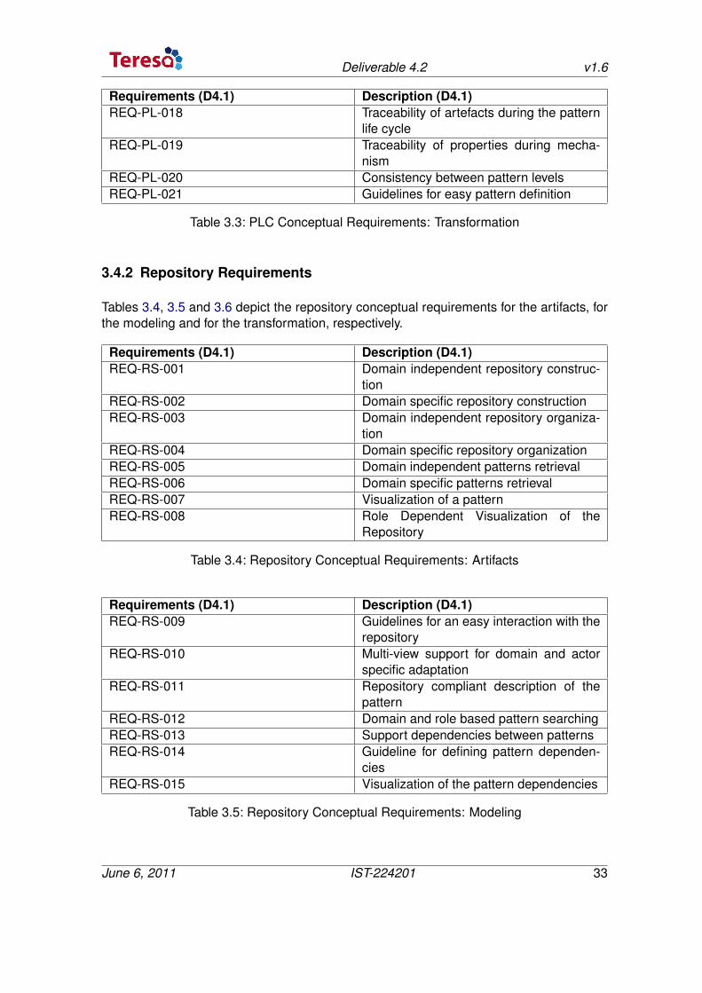
3.4.2 Repository Requirements
Tables 3.4, 3.5 and 3.6 depict the repository conceptual requirements for the artifacts, forthe modeling and for the transformation, respectively.
Requirements (D4.1) Description (D4.1)REQ-RS-001 Domain independent repository construc-
tionREQ-RS-002 Domain specific repository constructionREQ-RS-003 Domain independent repository organiza-
tionREQ-RS-004 Domain specific repository organizationREQ-RS-005 Domain independent patterns retrievalREQ-RS-006 Domain specific patterns retrievalREQ-RS-007 Visualization of a patternREQ-RS-008 Role Dependent Visualization of the
Repository
Table 3.4: Repository Conceptual Requirements: Artifacts
Requirements (D4.1) Description (D4.1)REQ-RS-009 Guidelines for an easy interaction with the
repositoryREQ-RS-010 Multi-view support for domain and actor
specific adaptationREQ-RS-011 Repository compliant description of the
patternREQ-RS-012 Domain and role based pattern searchingREQ-RS-013 Support dependencies between patternsREQ-RS-014 Guideline for defining pattern dependen-
ciesREQ-RS-015 Visualization of the pattern dependencies
Table 3.5: Repository Conceptual Requirements: Modeling
June 6, 2011 IST-224201 33
Deliverable 4.2 v1.6
Requirements (D4.1) Description (D4.1)REQ-RS-016 Adaptation of the visualization according
to the user roleREQ-RS-017 Data structure to implement the Reposi-
tory
Table 3.6: Repository Conceptual Requirements: Transformation
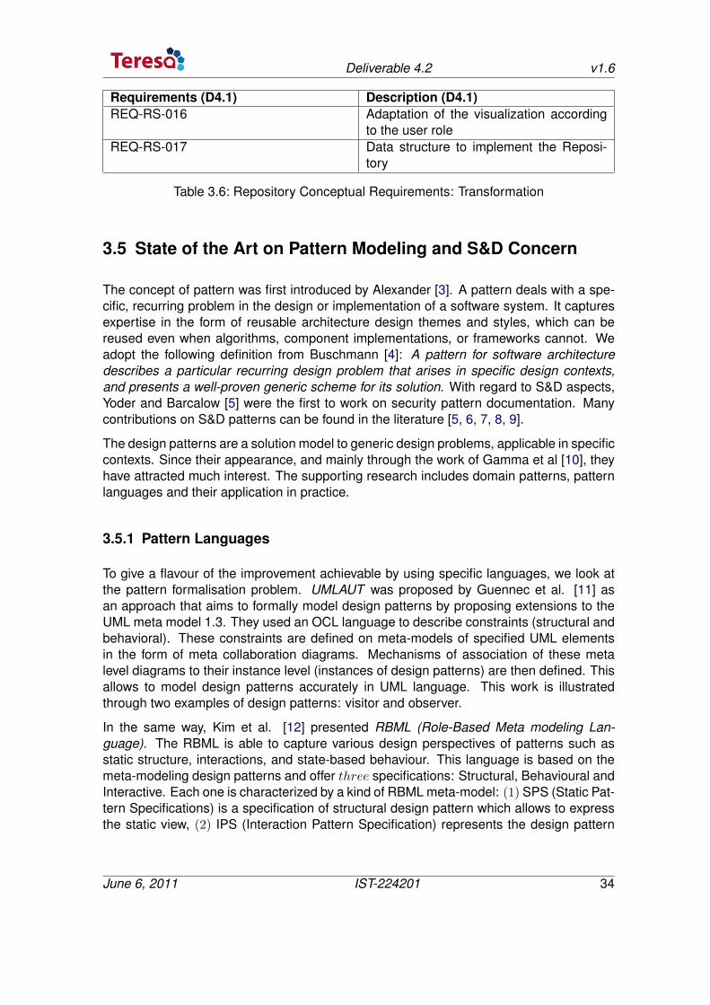
3.5 State of the Art on Pattern Modeling and S&D Concern
The concept of pattern was first introduced by Alexander [3]. A pattern deals with a spe-cific, recurring problem in the design or implementation of a software system. It capturesexpertise in the form of reusable architecture design themes and styles, which can bereused even when algorithms, component implementations, or frameworks cannot. Weadopt the following definition from Buschmann [4]: A pattern for software architecturedescribes a particular recurring design problem that arises in specific design contexts,and presents a well-proven generic scheme for its solution. With regard to S&D aspects,Yoder and Barcalow [5] were the first to work on security pattern documentation. Manycontributions on S&D patterns can be found in the literature [5, 6, 7, 8, 9].
The design patterns are a solution model to generic design problems, applicable in specificcontexts. Since their appearance, and mainly through the work of Gamma et al [10], theyhave attracted much interest. The supporting research includes domain patterns, patternlanguages and their application in practice.
3.5.1 Pattern Languages
To give a flavour of the improvement achievable by using specific languages, we look atthe pattern formalisation problem. UMLAUT was proposed by Guennec et al. [11] asan approach that aims to formally model design patterns by proposing extensions to theUML meta model 1.3. They used an OCL language to describe constraints (structural andbehavioral). These constraints are defined on meta-models of specified UML elementsin the form of meta collaboration diagrams. Mechanisms of association of these metalevel diagrams to their instance level (instances of design patterns) are then defined. Thisallows to model design patterns accurately in UML language. This work is illustratedthrough two examples of design patterns: visitor and observer.
In the same way, Kim et al. [12] presented RBML (Role-Based Meta modeling Lan-guage). The RBML is able to capture various design perspectives of patterns such asstatic structure, interactions, and state-based behaviour. This language is based on themeta-modeling design patterns and offer three specifications: Structural, Behavioural andInteractive. Each one is characterized by a kind of RBML meta-model: (1) SPS (Static Pat-tern Specifications) is a specification of structural design pattern which allows to expressthe static view, (2) IPS (Interaction Pattern Specification) represents the design pattern
June 6, 2011 IST-224201 34
Deliverable 4.2 v1.6
in terms of possible interactions between different roles, (3) SIMP (StateMachine PatternSpecifications) can add a behavioural view point to describe the various states in which itmay lie in its execution.
Another issue raised in [13] and [14] is visualization. Eden et al. [13] presented a formaland visual language for specifying design patterns called LePUS. It defines a pattern inan accurate and complete form of formula with a graphical representation. A diagramin LePUS is a graph whose nodes correspond to variables and whose arcs are labeledwith binary relations. With regard to the integration of patterns in software systems, theDPML (Design Pattern Modeling Language) [14] allows the incorporation of patterns inUML class models.
3.5.2 S&D Modeling Languages
Many studies have already been done on modeling security in UML. [15] presents anextension of UML, UMLsec, that enables to express security relevant information withinthe diagrams in a system specification. UMLsec is defined in form of a UML profile usingthe UML standard extension mechanisms. [16] presents a modeling language for themodel-driven development of secure, distributed systems based on UML. Their approachis based on role-based access control with additional support for specifying authorizationconstraints. SecureUML is a modeling language that defines a vocabulary for annotatingUML-based models with information relevant to access control.
In [17], a methodology is proposed which associates a model driven approach and com-ponent based development to design distributed applications that has fault-tolerance re-quirements. UML based modeling is used to capture application structure and relatednon-functional requirements thanks to the complementary profile named FT profile whichis composed of an extension of a subset of QoS&FT and uses the NFP (Non FunctionalProperties) sub-profile of MARTE [18] (profile for Modeling and Analysis of Real-TimeEmbedded systems). Stereotypes dedicated to fault-tolerance specify the fault-detectionpolicy, replication management style and replica group management. From this model de-scriptor files are generated (according to Deployment and Configuration standard (D&C))to build bootcode (static deployment) which instantiates, configures and connects com-ponents and to load configured components. Within this process, component replicationand FT properties are declaratively specified at model level and are transparent for thecomponent implementation.
In addition to the above, the recently completed FP6 SERENITY project has introduced anew notion of S&D patterns. SERENITY’s S&D patterns are precise specifications of vali-dated S&D mechanisms, including a precise behavioral description, references to the S&Dprovided properties, constraints on the context required for deployment, information de-scribing how to adapt and monitor the mechanism, and trust mechanisms. Such validatedS&D patterns, along with the formal characterization of their behavior and semantics, canalso be the basic building blocks for S&D engineering for embedded systems. [19] ex-plains how this can be achieved by using a library of precisely described and formally
June 6, 2011 IST-224201 35
Deliverable 4.2 v1.6
verified security and dependability (S&D) solutions, i.e., S&D classes, S&D patterns, andS&D integration schemes.
3.5.3 S&D Patterns
Several approaches exist in the S&D design pattern literature [5, 6, 7, 8, 9]. They allow tosolve very general problems that appear frequently as sub-tasks in the design of systemswith security and dependability requirements. These elementary tasks include securecommunication, fault tolerance, etc.
Particularly, [5] presents a collection of patterns to be used when dealing with applica-tion security. The proposed catalogue includes secure access layer, single access point,check point, etc.. The work of [6] reports an empirical experience, about the adopting andeliciting S&D patterns in the Air Traffic Management (ATM) domain, and show the powerof using patterns as a guidance to structure the analysis of operational aspects when theyare used at the design stage. A survey of approaches to security patterns is proposed in[7].
Also, in developing fault-tolerant software applications, the use of patterns would lead towell structured applications. That is, [8] described an hybrid set of patterns to be usedin the development of fault-tolerant software applications. These patterns are based onclassical fault tolerant strategies such as N -Version programming and recovery block,consensus, voting. In addition, the hybrid pattern structure can be constructed throughrecursive combination of N-Version programming and the others. The work addressedalso the power of the technique through the support of the advanced software votingtechniques. Extending this framework, [9] proposed a framework for the development ofdependable software systems based on a pattern approach. They reused proven faulttolerance techniques in form of fault tolerance patterns. The pattern specification consistsof a service-based architectural design and deployment restrictions in form of UML de-ployment diagrams for the different architectural services. The work is illustrated with anapplication to guide the self-repair of the system after the detection of a node crash.
3.6 State of the Art on Repository
This section aims to present a set of works which deal with the repository concept in orderto determine the most appropriate structure for the TERESA repository. The repositoryconcept is used in different research fields. Among them we can distinguish: model repos-itory, pattern repository, software repository, repository of software components, ontologyrepository for the semantic web, web services repository, etc. However, in the context ofTERESA we address the model repository and pattern repository.
June 6, 2011 IST-224201 36
Deliverable 4.2 v1.6
3.6.1 Model Repository
In the Model Driven Development (MDD), model repositories [20, 21, 22, 23, 24] are usedto facilitate the interoperability of models and tools by managing modeling artifacts. Modelrepositories are often built as a layer on top of existing basic technologies (for instance:databases). According to Bernstein and Dayal [24], a repository is a shared databaseof information about engineered artifacts. Thus, in their paper Bernstein and Dayal givea fundamental overview of repository technology as well as functional requirements of arepository. They introduce the fact that a repository has a Manager (for modeling, re-trieving, and managing the objects in a repository), a Database (to store the data) andFunctionalities (to interact with the repository).
In order to ease the query on the repository, metadata can be added to select the "right"artefacts. Therefore some repositories exist which are composed solely of metatdata. Forinstance this is the case for the web services. A service repository can be seen as a meta-data repository that contains metadata about location information to find a service. (seethe standard ebXML [25] and an ebXML Repository Reference Implementation [26]).
On one hand, Netbeans MDR [27] is a well known model repository implementation thatstores models and model instances. On the other hand, Eclipse CDO [28] allows to storemodels, but no XMI model instances. Furthermore, some repositories can support ver-sioning, or yet security aspects, etc.
The ReMODD project [23] (Repository for Model Driven Development) focuses on theMDD for reducing the effort of developing complex software by raising the level of abstrac-tion at which software systems are developed. This approach is based on a repository thatcontains artifacts that support research and education in MDD. The ReMoDD platform hasbeen developed which provides a set of tools to interact with the repository. Concretely,ReMoDD artifacts consist of: documented MDD case studies, examples of models reflect-ing good and bad modeling practices, modeling exercises and problems that can be usedto develop classroom assignments and projects.
In the GraMMi project [29], the idea is to use a standard repository management systemto build a generic graphical modeling tool. In this project the repository is based on threelevels of abstraction (metametamodel, metamodel and model). The repository stores bothmetamodels (notation definitions) and models (instantiation definitions). The repositoryaccess is made thanks an interface provided by itself. GrammiKernel allows to managepersistent objects. So this kernel aims at converting the objects (models) in an under-standable form for the user via the graphical interface.
In [30] the authors present design and implementation of a repository that supports storingand managing of artifacts. The kind of artifacts used here are: metamodels, models,constraints, meta-data, specifications, transformation rules, code, templates, configurationor documentation, and their metadata.
MORSE [31] is the Model-Aware Service Environment, for facilitating services to dynam-ically reflection models. MORSE addresses two common problems in MDD systems:traceability and collaboration. The model repository is the main component of MORSE
June 6, 2011 IST-224201 37
Deliverable 4.2 v1.6
and has been designed with the goal to abstract from specific technologies. MORSE fo-cuses on runtime services and processes and their integration and interaction with therepository.
In [22] the authors propose a reusable architecture decision model for setting-up modeland metadata repositories. Here the aim is the data design for model and metadatarepositories. The authors propose to help the developer for selecting a basic repositorytechnology, choosing appropriate repository metadata, and selecting suitable modelinglevels of the model information stored in the repository.
In Biology, the CellML Model Repository [32] provides free access to over 330 biologicalmodels. The CellML Model Repository deals with the versioning and uses the repositoryto store version information at the model level. When a model is modified then a newversion is created and added to the repository.
3.6.2 Pattern Repository
Patterns are stored in repositories to comprehensibly plain their classification. The orga-nization of patterns in a repository allows to discover the relationships among them andto facilitate the selection of the most appropriate ones. The repository may have a struc-ture in order to optimize the accesses (selecting patterns with criterion’s and publishingnew patterns into). Finding the appropriate pattern to solve a particular security or/anddependability problem is difficult because of the lack of a scientific classification schemefor S&D patterns. In this way, certain works deal with classification schemes to help infinding the appropriate pattern.
Some classifications are based on security concepts. ISO/IEC 13335 [33] provides adefinition of the five key concepts of security, confidentiality, integrity, availability and ac-countability. A pattern classification scheme based on these domain level concepts, willfacilitate pattern mining and pattern navigation. In [34] the authors describe an implicitculture approach for supporting developers in choosing patterns suitable for a given prob-lem. The repository contains patterns, which are selected depending on the history ofdecisions made by other developers regarding which patterns to use in related problems.In [35] the authors present mathematical structures for organizing patterns depending ofseveral categories.
An ontological approach for selecting design patterns is proposed in [36] to facilitate theunderstanding and reuse during software development. In their paper, the authors presentan ontology which describes the design pattern format and their relationships. They use apattern system/language in order to facilitate the design, integration, selection and reuseof design patterns.
SERENITY [37] is an european project that focuses on security and dependability pat-terns. This project proposes several levels of abstraction to bridge the gap between ab-stract solution and implementation – S&D classes, S&D patterns and S&D implementa-tion. In the SERENITY project, a new notion of S&D pattern has been introduced. AnS&D pattern represents precise specifications such as:
June 6, 2011 IST-224201 38
Deliverable 4.2 v1.6
• validated security mechanisms,
• including a precise behavioral description,
• references to the S&D properties provided,
• constraints on the context required for deployment,
• information describing how to adapt and monitor the mechanism,
• trust mechanisms.
Such validated S&D patterns, along with the formal characterization of their behavior andsemantics, can also be the basic building blocks for S&D engineering for embedded sys-tems.
Also, S&D patterns have to be considered into the context of a pattern repository becausethey may impact on the design of the repository. Indeed, the main motivation of a patterndesigner is to provide criteria to put the pattern into a repository. In the same way, the mainmotivation of a pattern end-user is firstly to get a more efficient browsing of a repositoryand secondly to get an easier selection of needed patterns.
A classification of security patterns can be found in [38]. Thus, such a classical classifica-tion takes into account of the following elements:
• Applicability is used to protect resources against unauthorized use, disclosure ormodification. In addition, applicability is used to make predictable and uninterruptedaccess to resources or services.
• Product and process (structural and procedural)
• Logical tiers (a) web: this tier takes into account of the external requests, authen-tication and authorization (b) business: this tier takes into account of the securityservices in the business like RBAC (c) integration: this tier facilitates secure integra-tion with external data sources
• Security concept (confidentiality, integrity, availability and accountability) – see ISOIEC13335-1 and ISO 7498-2 [39, 40].
Based on the idea of the Zachman Framework [41] (classification based on system view-points and interrogatives) the Microsoft Patterns and Practices group Classification [42]distinguishes the following elements: (a) Merits (clearly identifies the context of each pat-tern, help to identify missing patterns), (b) Flaws (more dedicated to functional patterns –non-functional patterns tend to cover many levels of system development and also manyinterrogatives), (c) Improvement (add icons in each pattern to provides classifications).
Another approach based on a multidimensional matrix is presented in [43]. This approachproposes six primary dimensions of classification (life stage, code source, response, arch.laver, constraint and domain).
June 6, 2011 IST-224201 39
Deliverable 4.2 v1.6
3.7 Synthesis and discussion
In this section is presented a synthesis about the required artifacts to model S&D patternsand to build a repository.
3.7.1 S&D Pattern Modeling
While many S&D patterns have been designed, still few works propose general techniquesfor S&D patterns. As soon as most of them use the same generic concepts to characterizepatterns, there is not a real consensus about what a pattern is. Furthermore, the termpattern is often ambiguous because it is used to encode the solution of a recurrent problemand to deal with a model in the better case instead of the pattern implementation. Insoftware engineering, design patterns are considered as effective tools for the reuse ofspecific knowledge. However, there is still a gap between the development of the systemand the pattern information.
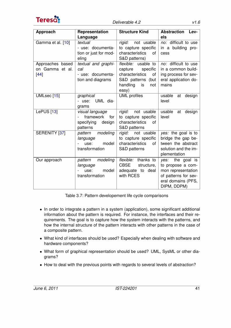
For the first kind of approaches [10], design patterns are usually represented by diagramswith notations such as UML object diagrams, accompanied by textual descriptions andexamples of code to complete the description. Furthermore their structure is rigid (Con-text, Structure, Solution, etc.). Unfortunately, the use and / or application of a pattern canbe difficult or inaccurate. Actually, the existing descriptions are not formal definitions andsometimes leave some ambiguities about the exact meaning of patterns. There are somepromising and well-proven approaches [44] based on Gamma et al. However this kind oftechniques do not allow to reach the high degree of flexibility in the pattern structure whichis required to reach the TERESA target.
The visualization technique promoted by LePUS [13] is interesting but the degree of ex-pressiveness proposed to design a pattern is too restrictive.
UMLsec [15] (approach based on modeling security in UML) and the TERESA proposalare not in competition but they complement each other by providing different view pointsto the secure information system. In concept, the TERESA modeling framework is similarto the one proposed in the SERENITY project. Nevertheless the pattern structure is rigid(a pattern is defined as quadruplet) and consequently is not usable to capture specificcharacteristics of S&D patterns. Please note, however, that SERENITY proposes severallevels of abstraction to bridge the gap between abstract solution and implementation butnot to get a common representation of patterns for several domains.
In the TERESA approach, different levels of abstraction are used to get a common rep-resentation of patterns for several domains. In the TERESA concern, systems includea combination of hardware and software components. This may add some difficulties tobuild a simple modeling framework. An even high level of abstraction is proposed to repre-sent S&D patterns to capture several aspects of security and dependability in the differentdomains of RCES, not an implementation of a specific solution. Other issues are:
June 6, 2011 IST-224201 40
Deliverable 4.2 v1.6
Approach RepresentationLanguage
Structure Kind Abstraction Lev-els
Gamma et al. [10] textual- use: documenta-tion or just for mod-eling
rigid: not usableto capture specificcharacteristics ofS&D patterns)
no: difficult to usein a building pro-cess
Approaches basedon Gamma et al.[44]
textual and graphi-cal- use: documenta-tion and diagrams
flexible: usable tocapture specificcharacteristics ofS&D patterns (buthandling is noteasy)
no: difficult to usein a common build-ing process for sev-eral application do-mains
UMLsec [15] graphical- use: UML dia-grams
UML profiles usable at designlevel
LePUS [13] visual language- framework forspecifying designpatterns
rigid: not usableto capture specificcharacteristics ofS&D patterns
usable at designlevel
SERENITY [37] pattern modelinglanguage- use: modeltransformation
rigid: not usableto capture specificcharacteristics ofS&D patterns
yes: the goal is tobridge the gap be-tween the abstractsolution and the im-plementation
Our approach pattern modelinglanguage- use: modeltransformation
flexible: thanks toCBSE structure,adequate to dealwith RCES
yes: the goal isto propose a com-mon representationof patterns for sev-eral domains (PFS,DIPM, DDPM)
Table 3.7: Pattern developement life cycle comparisons
• In order to integrate a pattern in a system (application), some significant additionalinformation about the pattern is required. For instance, the interfaces and their re-quirements. The goal is to capture how the system interacts with the patterns, andhow the internal structure of the pattern interacts with other patterns in the case ofa composite pattern.
• What kind of interfaces should be used? Especially when dealing with software andhardware components?
• What form of graphical representation should be used? UML, SysML or other dia-grams?
• How to deal with the previous points with regards to several levels of abstraction?
June 6, 2011 IST-224201 41
Deliverable 4.2 v1.6
3.7.2 Pattern Repository
The main goal of a repository is to store data and to offer a set of actions to interact with.Most of the time a repository has to provide the following actions: store files, authentica-tion and access control, check-out/check-in files, file versioning, file metadata storage andsearch data. Some of the classical formats used are XML, XMI and XSD. Then the graph-ical view of artifacts can be made by using some format transformations. This one canbe realized thanks to XSLT (eXtensible Stylesheet Language Transformation) transforma-tions to ease the reuse of XML solutions. On another hand, XBRL (eXtensible BusinessReporting Language), an XML format, also allows the interoperability of information. Thus,an XBRL file can be converted to a standard format such as HTML ASCII and also PDF,which will provide an ergonomic aspect.
Therefore, the following questions arise about the specification of the repository:
• What kind of visualization interfaces to use?
• What kind of interaction interfaces to use? (some information about how artifactsare published and how artifacts are queried must be provided by the repository)
• How to organize the data ?
– what kind of metadata to make the selection of data?
– what kind of data structure to use?
– what kind of use is supported? (static and/or dynamic).
• how to store the data ?
– what kind of format to use in order to store the data?
June 6, 2011 IST-224201 42
4 S&D Pattern Modeling
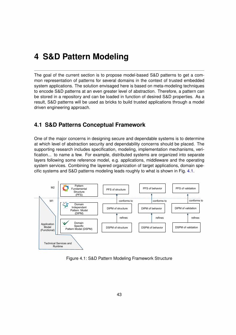
The goal of the current section is to propose model-based S&D patterns to get a com-mon representation of patterns for several domains in the context of trusted embeddedsystem applications. The solution envisaged here is based on meta-modeling techniquesto encode S&D patterns at an even greater level of abstraction. Therefore, a pattern canbe stored in a repository and can be loaded in function of desired S&D properties. As aresult, S&D patterns will be used as bricks to build trusted applications through a modeldriven engineering approach.
4.1 S&D Patterns Conceptual Framework
One of the major concerns in designing secure and dependable systems is to determineat which level of abstraction security and dependability concerns should be placed. Thesupporting research includes specification, modeling, implementation mechanisms, veri-fication... to name a few. For example, distributed systems are organized into separatelayers following some reference model, e.g. applications, middleware and the operatingsystem services. Combining the layered organization of target applications, domain spe-cific systems and S&D patterns modeling leads roughly to what is shown in Fig. 4.1.
Figure 4.1: S&D Pattern Modeling Framework Structure
43
Deliverable 4.2 v1.6
The framework must cope with S&D, RCES and domain specific properties. For this pur-pose, the proposition presented in this part of the deliverable is based on three levelsof abstraction: (i) Pattern Fundamental Structure (PFS), (ii) Domain Independent PatternModel (DIPM) and (iii) Domain Specific Pattern Model (DSPM). Firstly this decomposi-tion aims at allowing the design of S&D applications in the context of embedded systems(since combining S&D and domain specific artifacts introduces a great complexity), andsecondly to overcome the lack of formalism of the classical pattern form (e.g. textual).The benefit of this structure is to offer a common modeling language for several domainsin the context of trusted embedded systems.
The following subsection describes an example in order to enhance the issues identifiedin the document. Then, the first level of abstraction, namely PFS, will be described.
4.1.1 Motivating Example: Secure Communication Pattern
The essence of Fig. 4.1 is to promote the separation of general-purpose services from im-plementations. In our context, this structure highlights the separation of general-purposeof the pattern from its related mechanisms. This is an important issue to understand theuse of patterns for security and dependability and, in particular, the notion of trust. Inwhich layer security mechanisms are placed depends on the trust a client has in how se-cure the services are in some particular layer. As example of a widely used pattern wechoose the Secure Communication Pattern referred to in the following as SCP. Messagespassing across any public network can be intercepted. The problem is how to ensure thatthe data is secure in transit, i.e. how to guarantee data authenticity. This is one of thegoals of the SCP.
However, SCP are slightly different with regard to the application domain. A system do-main may have its own mechanisms and means, protocols that can be used to implementthis pattern range from SSL, TLS, Kerberos, IPSec, SSH, to WS-Security. In summary,they are similar in the goal, but different in the implementation issues. So, the motivationis to handle the modeling of S&D patterns by following abstraction. As an example we useSSL mechanism 1 as a concrete implementation of the SCP.
The SSL mechanism is composed of two phases: The SSL Handshake that establishes asecure channel, and the SSL Record in which this channel can be used to exchange datasecurely. The client initiates the SSL handshake by providing the server with a randomnumber and information about the cryptographic algorithms it can handle. The serverreplies by choosing the actual algorithm to use, requiring the client to authenticate itself(this is optional and used in our example) and by sending a random number of its own andits certificate issued by some CA trusted by both the server and the client.
These are first two messages. For authenticating itself, in the final handshake messagethe client includes its own certificate, a signature on all handshake messages generatedwith the respective private key, and a third random number encrypted using the server’spublic key contained in the server’s certificate. After having verified the certificates and
1SSL or its update named TLS proposed in RFC 2246
June 6, 2011 IST-224201 44
Deliverable 4.2 v1.6
signature, both client and server use the exchanged random numbers to generate sessionkeys for generating and verifying message authentication codes (MACs) and for encrypt-ing and decrypting messages.
Since the key used by the client for generating a MAC / encrypting a message is usedby the server only for MAC verification / decryption and vice versa, and since they arebased on one random number confidential for the client and the server, the keys establisha channel that provides authenticity and confidentiality for both client and server.
4.1.2 Pattern Fundamental Structure (PFS)
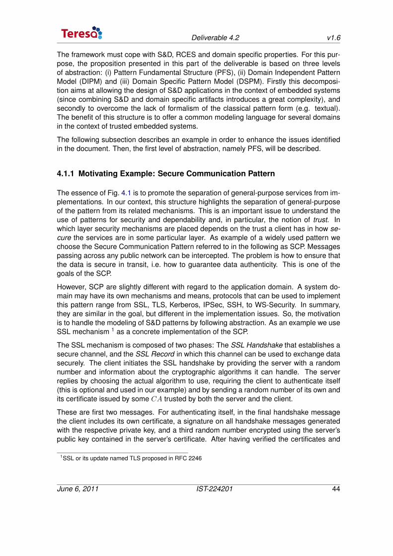
PFS is a metamodel defining a new formalism (i.e., language) for describing S&D pat-terns, and constitutes the base of our pattern modeling language. PFS describes all theartifacts (and their relations) needed to represent S&D patterns in the context of trustedembedded systems applications. Here we consider patterns as building blocks that ex-pose services (via interfaces) and manage S&D and RCES properties (via features) yield-ing a way to capture meta-information related to patterns and their context of use. Thesepattern are specified by means of a domain-independent generic representation and adomain-specific representation.
This pattern definition, as shown in Figure. 4.2, provides a clear and flexible structure.Such a structure is already used with success in CBSE (Component-Based SoftwareEngineering). CBSE is a discipline that is known to be reliable in the area of softwareengineering and that is considered as to be a good solution to optimise software reuseand dynamic evolution while guaranteeing the quality of the software [45]. Moreover, themodularity enables to tame the complexity of large systems.
Static Internal Structure
Dynamic Internal Structure
Constraint
Prop
erty
External Interface
Internal Interface
Figure 4.2: Representation of an S&D Pattern
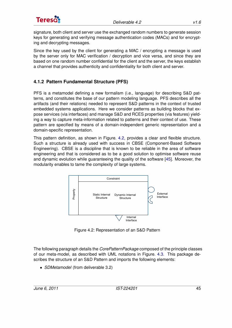
The following paragraph details the CorePatternPackage composed of the principle classesof our meta-model, as described with UML notations in Figure. 4.3. This package de-scribes the structure of an S&D Pattern and imports the following elements:
• SDMetamodel (from deliverable 3.2)
June 6, 2011 IST-224201 45
Deliverable 4.2 v1.6
• RCESMetamodel (from deliverable 3.2)
• ConstraintMetamodel (from results of workpackage 6)
• ValidationMetamodel (from results of workpackage 5)
Figure 4.3: S&D Pattern Metamodel Dependencies
The CorePatternPackage is composed of several elements as follows:
• IPattern represents a modular part of a system that encapsulates a solution of arecurrent problem. An IPattern is modeled throughout the development life cycleand successively refined into deployment and run-time. An IPattern may be manifestby one or more artifacts, and in turn, that artifact may be deployed to its executionenvironment. A deployment specification may define values that parameterize thepattern’s execution. The IPattern has some fields that define its identity. These fieldsare based on the GoF [10] information and are defined as follows:
– name is the name of the pattern.
– id defines the identity of the pattern.
June 6, 2011 IST-224201 46
Deliverable 4.2 v1.6
– publisher identity is the identity of the publisher(s) – login, PW, name, organi-zation, email.
– origin corresponds to the origin of the pattern – Industrial, Academic.
– also known as gives a list of names under which the pattern is also known.
– related patterns describes the dependencies with other patterns.
– consequences corresponds to the set of consequences which occur once thepattern is integrated.
– problems describes the problem solved by the pattern.
– level is the level of conception – Architecture, Design, Implementation.
– example provides an example.
• Interface. IPattern interacts with its environment with Interfaces which are com-posed of Operations. So, larger pieces of a system’s functionality may be assem-bled by reusing patterns as parts in an encompassing pattern or assembly of pat-terns, and wiring together their required and provided interfaces. More precisely, anIPattern owns provided and required interfaces. A provided interface is implementedby the IPattern and highlights the services exposed to the environment. A requiredinterface corresponds to services needed by the pattern to work properly. Finally,two kinds of interfaces are considered:
– External interfaces allow implementing interaction with regard to:
∗ integrate an IPattern to an application model. These interfaces are realizedby the IPattern.
∗ compose IPatterns together.
– Internal interfaces allow implementing interaction with the platform. For in-stance, at a low level, it is possible to define links with software or hardwaremodule for the cryptographic key management. These interfaces are realizedby the SPattern. Please, Note an IPattern does not have InternalInterface.
• Property is a particular characteristic of a pattern. A Property is either an SDProp-erty or a RCESProperty (see deliverable D3.2). So, each property of a pattern willbe validated at the time of the pattern validating process and the result will be com-piled as a set of constraints (see the ConstraintMetaModel) which have to satisfiedby the platform.
• Internal Structure constitutes the implementation of the solution proposed by thepattern. Thus the InternalStructure can be considered as a white box which exposesthe details of the IPatterns. In order to capture all the key elements of the solution,the Internal Structure is composed of two kinds of Structure: static and dynamic.Please, note that a same pattern would have several possible implementations.
June 6, 2011 IST-224201 47
Deliverable 4.2 v1.6
• Static Diagram Package is the diagram that allows to design the static internalstructure of a pattern. The two main classes are: Entity and Binding – see deliver-able D3.2.
• Dynamic Diagram Package is the diagram that allows to design the dynamic in-ternal structure of a pattern. The two main classes are: Entity and Action – seedeliverable D3.2.
• Specification Diagram Package represents the main diagram for designing a pat-tern.
• SPattern inherits from IPattern. It is used to build a model at DSPM. A SPattern hasa set of Constraints which are defined into the ConstraintMetaModel. A Constraintis a either an SD_Constraint or a RCES_Constraint. Furthermore a SPattern hasInternal Interfaces in order to interact with the platform.
In the following, some fundamental concepts (imported from RCESMetamodel, SDMeta-model, and ConstraintMetamodel) are described.
• RCESMetamodel. The concept of Attribute is imported from the RCESMetamodel.
• TrustSDMetamodel. The concept of Property is imported from the SDMetamodel.
• ConstraintMetamodel. The concept of RCES_Constraint and SDConstraint areimported from the ConstraintMetamodel.
• ValidationMetamodel contains the validation artifacts for the pattern validating pro-cess. So the central element of these artifacts is the Building Block (see the deliver-able D5.1.). This one can be seen as a black box that allows to prove some proper-ties. A VBuildingBlock takes in input a set of VProperties and produces validatednew VProperties. The principle is based on the following aspect: an homomorphismmust be found between a property at domain independent domain (VDIProperty)and a property at domain specific domain (VDSProperty). Please, for more detailssee the Deliverable D5.1.
An important point concerns the completeness of the internal pattern representation. Forthis purpose, we have proposed an extension mechanism which will be specified in thefuture. Thus, if a domain specific artifact is missing, the repository supports the extensionmechanism which allows the user to add the needed artifact.
4.2 Modeling S&D Patterns
As mentioned earlier, our modeling framework promotes to use three levels of abstraction:(i) Pattern Fundamental Structure (PFS), (ii) Domain Independent Pattern Model (DIPM)and (iii) Domain Specific Pattern Model (DSPM).
In this section, the required artifacts will be pointed out while following the two abstractionlevels (i.e., DIPM and DSPM). These two levels with a Secure Communication Pattern
June 6, 2011 IST-224201 48
Deliverable 4.2 v1.6
(SCP) presented in Section 4.1.1 are illustrated. Note, however, that for For simplicity’ssake, many functions of this use case have been omitted.
4.2.1 Domain Independent Pattern Model (DIPM)
This level focuses on pattern domain independent artifacts. This is an instance of the PFS.As we shall see, we introduce new concepts through instantiation of existing concepts ofthe PFS meta-model in order to cover most existing S&D patterns in RCES applications.In our case study, the DIPM of the SCP consists of two entities communicating through asecure channel. The SCP is defined as follows:
Properties. At this level, we identify two S&D properties: authenticity and trust.
External Interfaces. Let SCPExtDI denote the external interface to expose the SCP func-tionalities through function calls:Send(P,Q, ch(P,Q),m), Receive(P,Q, ch(P,Q),m), with P,Q ∈ {C, S},ch(C, S) = ch(S,C) denoting the communication channel of client and server, and m a mes-sage.
Internal Structure. The behavior of SCP can be modeled by a UML Sequence Diagramdescribing secure date exchange between client and server through SCPExtDI in-terface.
4.2.2 Domain Specific Pattern Model (DSPM)
The objective of the specific design level is to specify the S&D patterns for a specificapplication domain. This level offers artifacts at a low level of abstraction with more preciseinformation and constraints about the target domain. This modeling level is a refinement ofthe DIPM that considers the specific characteristics and dependencies of the applicationdomain. Different DSPM can refine the same DIPM for different domains. When usingthe SSL protocol as a mechanism related to the application domain to refine the SCP atDSPM, we introduce the following artifacts:
Properties. In addition to the refinement of the two S&D properties identified in the DIPM,at this level we identify some related RECS properties, e.g. the size of the crypto-graphic key.
External Interfaces. Let SCPExtDS denote the external interface. This is a refinement ofthe DIPM external interface:- send(C, S,macC(m),m): the client sends m and the corresponding MAC (Message Au-thentication Code) to the server.- recv(S,C,macC(m),m): the server receives m and corresponding MAC.
June 6, 2011 IST-224201 49
Deliverable 4.2 v1.6
Internal Interfaces. Let SCPIntDS denote the internal interface as a subset of functionsrelated to the use of SSL to refine the SCP pattern:- genRand(P,R);P ∈ {C, S}: P generates a random number.- sign(): the client signs the SSL handshake messages.- verifyCert(): the client and server certificate, respectively, is verified.- extractPubKey(): the server’s public key is extracted from the certificate.- genMac(C,macKeyC ,m,macC(m)): the client generates the message authentication code(MAC) for a message using its own SSL shared secret for MAC generation.- verify(S,macKeyS ,m,macC(m)): the server verifies, using its shared secret for verifica-tion, that the message authentication code for m is correct and originates from the client.
Internal Structure. The behavior of SCP can be modeled by a UML Sequence Diagramfollowing the SSL protocol described in Section 4.1.1, involving SCPExtDS andSCPIntDS interfaces.
June 6, 2011 IST-224201 50
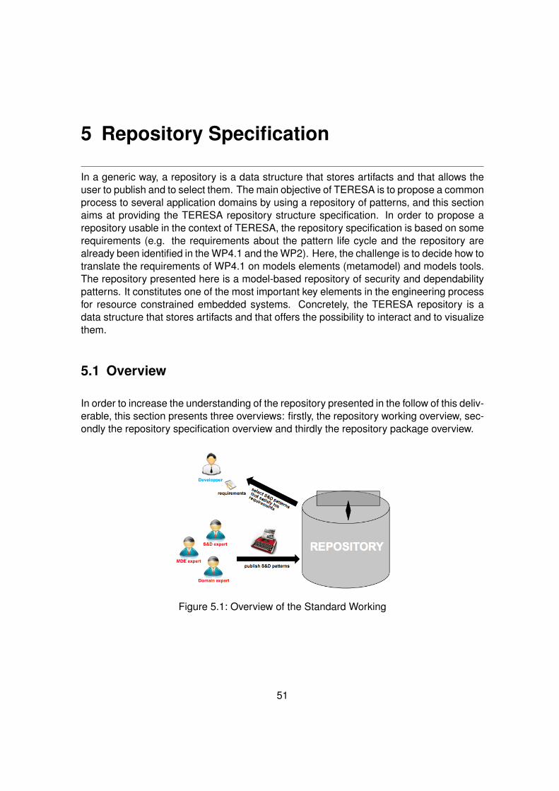
5 Repository Specification
In a generic way, a repository is a data structure that stores artifacts and that allows theuser to publish and to select them. The main objective of TERESA is to propose a commonprocess to several application domains by using a repository of patterns, and this sectionaims at providing the TERESA repository structure specification. In order to propose arepository usable in the context of TERESA, the repository specification is based on somerequirements (e.g. the requirements about the pattern life cycle and the repository arealready been identified in the WP4.1 and the WP2). Here, the challenge is to decide how totranslate the requirements of WP4.1 on models elements (metamodel) and models tools.The repository presented here is a model-based repository of security and dependabilitypatterns. It constitutes one of the most important key elements in the engineering processfor resource constrained embedded systems. Concretely, the TERESA repository is adata structure that stores artifacts and that offers the possibility to interact and to visualizethem.
5.1 Overview
In order to increase the understanding of the repository presented in the follow of this deliv-erable, this section presents three overviews: firstly, the repository working overview, sec-ondly the repository specification overview and thirdly the repository package overview.
Figure 5.1: Overview of the Standard Working
51
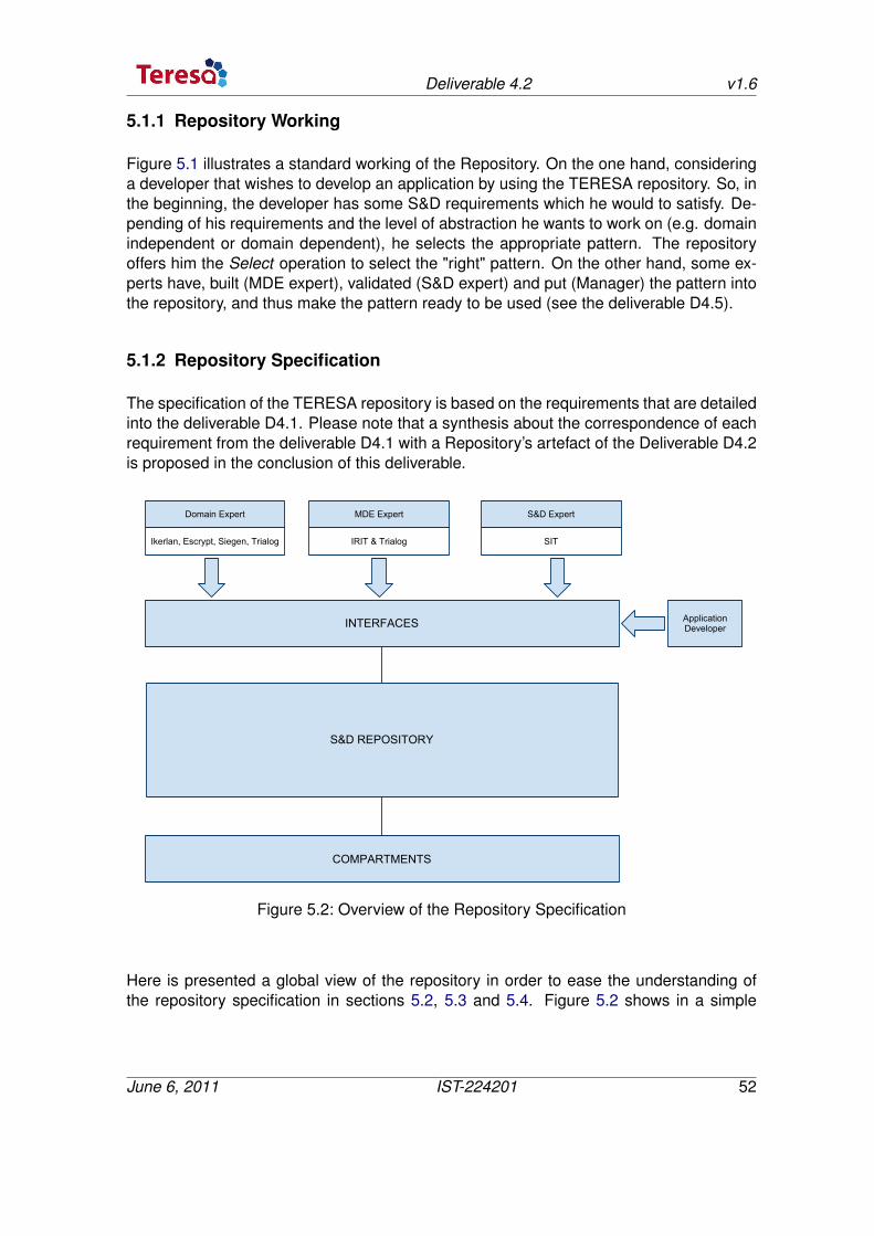
Deliverable 4.2 v1.6
5.1.1 Repository Working
Figure 5.1 illustrates a standard working of the Repository. On the one hand, consideringa developer that wishes to develop an application by using the TERESA repository. So, inthe beginning, the developer has some S&D requirements which he would to satisfy. De-pending of his requirements and the level of abstraction he wants to work on (e.g. domainindependent or domain dependent), he selects the appropriate pattern. The repositoryoffers him the Select operation to select the "right" pattern. On the other hand, some ex-perts have, built (MDE expert), validated (S&D expert) and put (Manager) the pattern intothe repository, and thus make the pattern ready to be used (see the deliverable D4.5).
5.1.2 Repository Specification
The specification of the TERESA repository is based on the requirements that are detailedinto the deliverable D4.1. Please note that a synthesis about the correspondence of eachrequirement from the deliverable D4.1 with a Repository’s artefact of the Deliverable D4.2is proposed in the conclusion of this deliverable.
Domain Expert
Ikerlan, Escrypt, Siegen, Trialog
MDE Expert
IRIT & Trialog
S&D Expert
SIT
S&D REPOSITORY
INTERFACES
COMPARTMENTS
Application Developer
Figure 5.2: Overview of the Repository Specification
Here is presented a global view of the repository in order to ease the understanding ofthe repository specification in sections 5.2, 5.3 and 5.4. Figure 5.2 shows in a simple
June 6, 2011 IST-224201 52
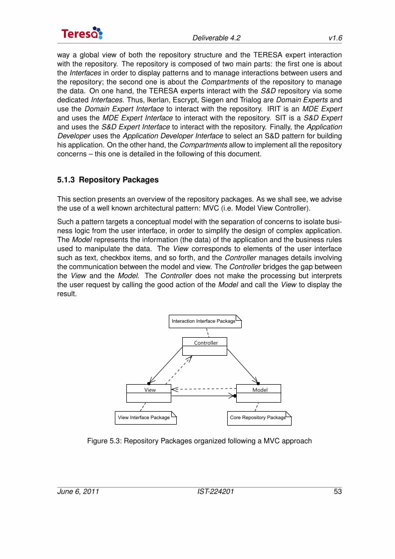
Deliverable 4.2 v1.6
way a global view of both the repository structure and the TERESA expert interactionwith the repository. The repository is composed of two main parts: the first one is aboutthe Interfaces in order to display patterns and to manage interactions between users andthe repository; the second one is about the Compartments of the repository to managethe data. On one hand, the TERESA experts interact with the S&D repository via somededicated Interfaces. Thus, Ikerlan, Escrypt, Siegen and Trialog are Domain Experts anduse the Domain Expert Interface to interact with the repository. IRIT is an MDE Expertand uses the MDE Expert Interface to interact with the repository. SIT is a S&D Expertand uses the S&D Expert Interface to interact with the repository. Finally, the ApplicationDeveloper uses the Application Developer Interface to select an S&D pattern for buildinghis application. On the other hand, the Compartments allow to implement all the repositoryconcerns – this one is detailed in the following of this document.
5.1.3 Repository Packages
This section presents an overview of the repository packages. As we shall see, we advisethe use of a well known architectural pattern: MVC (i.e. Model View Controller).
Such a pattern targets a conceptual model with the separation of concerns to isolate busi-ness logic from the user interface, in order to simplify the design of complex application.The Model represents the information (the data) of the application and the business rulesused to manipulate the data. The View corresponds to elements of the user interfacesuch as text, checkbox items, and so forth, and the Controller manages details involvingthe communication between the model and view. The Controller bridges the gap betweenthe View and the Model. The Controller does not make the processing but interpretsthe user request by calling the good action of the Model and call the View to display theresult.
Figure 5.3: Repository Packages organized following a MVC approach
June 6, 2011 IST-224201 53
Deliverable 4.2 v1.6
Figure 5.3 depicts the three main packages of the S&D repository seen as an MVC ap-proach. The main package is the CoreRepositoryPackage and corresponds to the Modelpart into the MVC approach – this is described in section 5.2. Then the ViewInterfacePack-age corresponds to the View part into the MVC approach – this is described in section 5.4.Finally, the InteractionInterfacePackage corresponds to the Controller part into the MVCapproach – see section 5.3.
5.2 Core Repository Package
The main package is the CoreRepositoryPackage (see Figure 5.4 ) with dependencesfrom six other packages as follows:
June 6, 2011 IST-224201 54
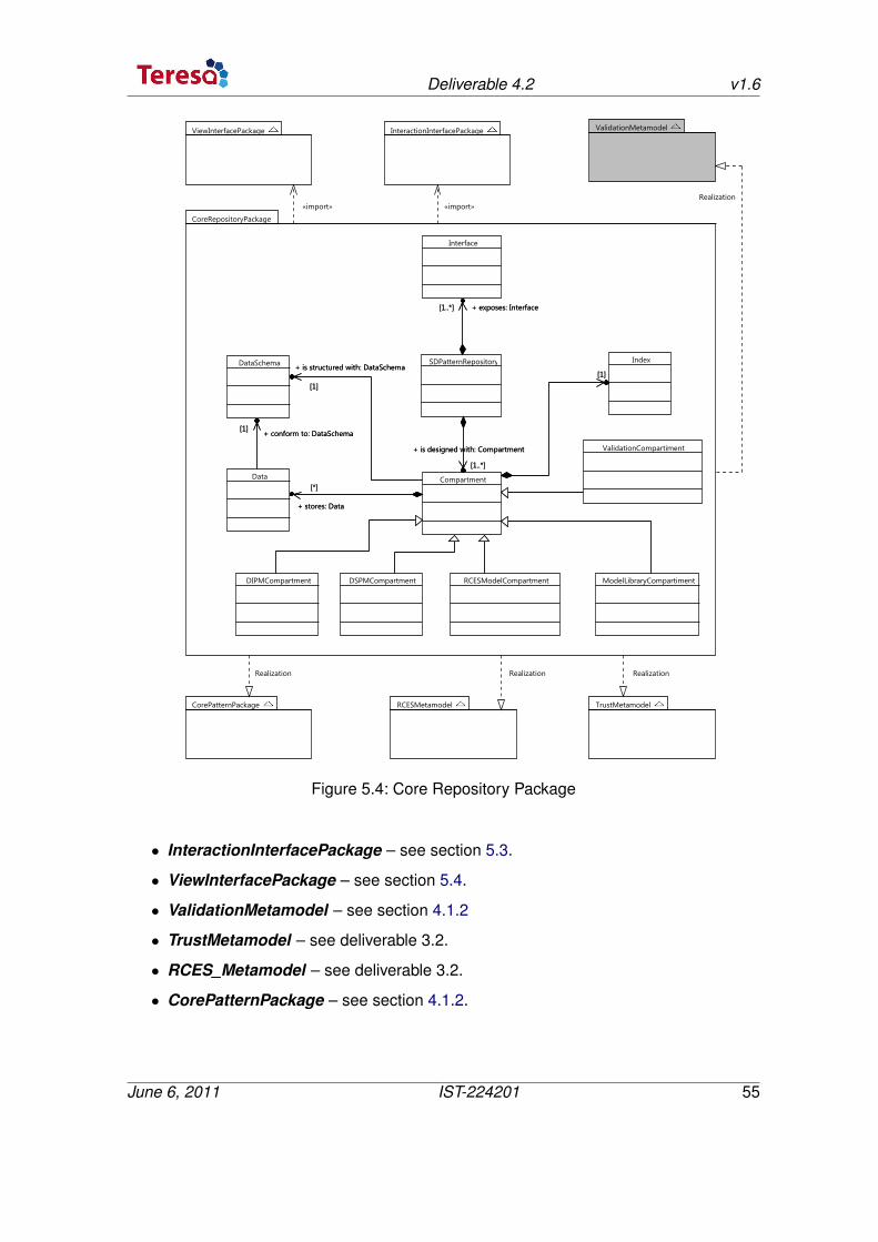
Deliverable 4.2 v1.6
Figure 5.4: Core Repository Package
• InteractionInterfacePackage – see section 5.3.
• ViewInterfacePackage – see section 5.4.
• ValidationMetamodel – see section 4.1.2
• TrustMetamodel – see deliverable 3.2.
• RCES_Metamodel – see deliverable 3.2.
• CorePatternPackage – see section 4.1.2.
June 6, 2011 IST-224201 55
Deliverable 4.2 v1.6
The SD_PatternRepository (see Figure 5.4 ) exposes a set of Interfaces and is designedwith a set of Compartments. On one hand, the different types of Interfaces are describedin the two sections 5.3 and 5.4. On the other hand, the Compartment deals with the dataand the data structure for processing the data. So, the Compartment is composed of threemain elements:
• Data corresponds to the concrete data stored into the S&D repository.
• DataSchema is the structure that specifies how the data is organized.
• Index is a data structure that eases the artifact access into the S&D repository.
Then five kinds of Compartment are considered as follows:
• DIPMCompartment realises the CorePatternPackage. After instantiating the meta-model, the Data becomes an IPattern. We propose to use XML schema to modelthe DataSchema and the associated Index.
• DSPMCompartment realises the CorePatternPackage. After instantiating the meta-model, the Data becomes an SPattern. The domain independent XML schema willbe specialized to capture both the Index and the SPatterns.
• PlatformModelCompartment allows to manage the platform model.
• ModelLibraryCompartment realises both the RCESMetamodel and the TrustMeta-model.
• ValidationCompartment realises the ValidationMetamodel.
Two subtypes of Interfaces are considered as follows:
• InteractionInterface is dedicated to manage all kinds of interaction between the"external world" and the repository. Several subtypes of InteractionInterface areconsidered – see section 5.3.
• VisualizationInterface is dedicated to display some artifacts by taking into accountof the user role (e.g. Administrator, Developer, MDE expert, S&D expert, etc.) – seesection 5.4.
5.3 Interaction Interface Package
This section describes the InteractionInterfacePackage. This one allows to manage theinteractions with the repository. Several subtypes of InteractionInterface are consideredas follow (see Figure 5.5 ):
• AdministratorInteractionInterface is dedicated to the administrator of the reposi-tory. Such an interface provides the operation manage().
• PatternDeveloperInteractionInterface is dedicated to experts. Such an interfaceprovides the following operations:
June 6, 2011 IST-224201 56
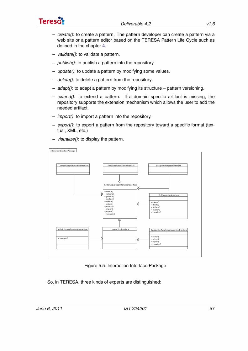
Deliverable 4.2 v1.6
– create(): to create a pattern. The pattern developer can create a pattern via aweb site or a pattern editor based on the TERESA Pattern Life Cycle such asdefined in the chapter 4.
– validate(): to validate a pattern.
– publish(): to publish a pattern into the repository.
– update(): to update a pattern by modifying some values.
– delete(): to delete a pattern from the repository.
– adapt(): to adapt a pattern by modifying its structure – pattern versioning.
– extend(): to extend a pattern. If a domain specific artifact is missing, therepository supports the extension mechanism which allows the user to add theneeded artifact.
– import(): to import a pattern into the repository.
– export(): to export a pattern from the repository toward a specific format (tex-tual, XML, etc.)
– visualize(): to display the pattern.
Figure 5.5: Interaction Interface Package
So, in TERESA, three kinds of experts are distinguished:
June 6, 2011 IST-224201 57
Deliverable 4.2 v1.6
– DomainExpertInteractionInterface is dedicated to the domain expert. (Iker-lan, Escrypt, Siegen, Trialog)
– MDEExpertInteractionInterface is dedicated to the MDE expert. (IRIT andTrialog)
– SDExpertInteractionInterface is dedicated to the S&D expert. (SIT)
• ApplicationDeveloperInteractionInterface is dedicated to the developer of an ap-plication. The available operations are:
– search(): to search a set of patterns in the repository depending of a set ofproperties.
– select(): to select the wished pattern among a set of pre-selected patterns.
– export(): to export a pattern from the repository toward a specific format (tex-tual, XML, etc.)
– visualize(): to display the pattern.
• GoFInteractionInterface is dedicated to a textual Publisher. The available opera-tions are:
– create(): to create a pattern – here the pattern is created following a textualform and according with the GoF.
– delete(): to delete a pattern from the repository.
– update(): to update a pattern by modifying some values.
– publish(): to put the pattern into the repository – e.g. the pattern is ready to beused.
– visualize(): to display the pattern.
5.4 View Interface Package
This section describes the ViewInterfacePackage. This one corresponds to the HumanMachine Interface. Several subtypes of ViewInterface are considered as follows (see Fig-ure 5.6):
June 6, 2011 IST-224201 58
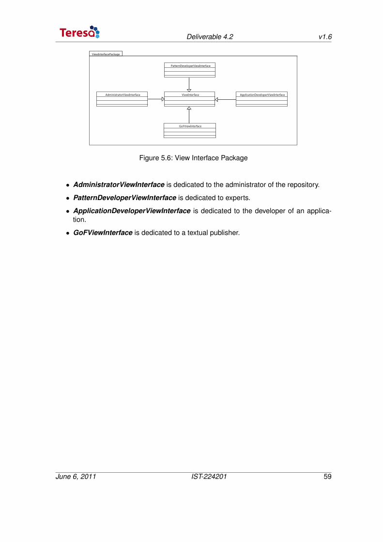
Deliverable 4.2 v1.6
Figure 5.6: View Interface Package
• AdministratorViewInterface is dedicated to the administrator of the repository.
• PatternDeveloperViewInterface is dedicated to experts.
• ApplicationDeveloperViewInterface is dedicated to the developer of an applica-tion.
• GoFViewInterface is dedicated to a textual publisher.
June 6, 2011 IST-224201 59
6 Conclusion
Security and dependability are not building blocks added to an application at the end ofthe life cycle. It is necessary to take into account of this concern from the requirement tothe integration phases. In this part, we have proposed an approach for S&D pattern devel-opment and packaging that follows the MDE paradigm. Our approach is based on meta-modeling techniques that allow to specify S&D patterns at different levels of abstraction.An S&D pattern at domain independent level allows the application developer to identifyS&D requirements and select an respective abstract solution without specific knowledgeon how the solution is designed and implemented. Thus a DIPM pattern can easily beintegrated into the overall abstract system specification. The benefit of this structure is tooffer a common language for different domain applications. So far, this common languageencompasses four industrial sectors, namely, home control, industry control, automotive,and metering [46].
On the other hand, we proposed an operational architecture of the repository, based on theMVC structure, devoted to store the TERESA models, including patterns. The core of therepository (M) is a data structure to store models following the two abstraction modelinglevels and ease the interaction (C) and the visualization (V).
An important point concerns the completeness of the internal pattern representation whichwill be specified in the future. Thus, if a domain specific artifact is missing, the repositorysupports the extension mechanism which allows the user to add the needed artifact.
In what follows we discuss some possible extensions.
6.1 Future Work
6.1.1 Modeling
As a side remark, note that the goal is to obtain an even high level abstraction to representS&D patterns to capture several facets of security and dependability in the different domainof embedded system applications, not an implementation of a specific solution. The keyis then to show that the major sectors of trusted embedded systems applications dealingwith security and dependability are covered by our approach. This result leads to someanticipated issues about general techniques to model S&D patterns. This result is ofparticular interest to build a trusted computing engineering discipline that is suited to anumber of sectors in embedded systems.
60
Deliverable 4.2 v1.6
The next steps of this work consist in integrating all the presented results in a more globalprocess with the pattern life cycle (i.e., create, update, store patterns) and the integrationof a pattern in an application (see WP3). All patterns are stored in a repository. Thanks toit, it is possible to find a pattern regarding to S&D criteria. Patterns and the application areformally validated regarding to S&D properties. At last, guidelines will be provided duringthe pattern development and the application development (i.e., help to select a suitablepattern with respect to the constraint and the specificity of the target application and/orplatform).
Following the MDE process, the domain independent model of patterns is then refinedtowards a domain specific level, taking into account domain artefacts, concrete elementssuch as mechanisms to use, devices that are available, etc. Consequently, a S&D patternat domain specific level contains the respective information.
Pattern validation follows these two abstraction levels, i.e. we validate a DIPM pattern andpossible DSPM instantiations independently. However, the additional final validation stepproves that the latter is indeed a refinement of the former which in turn proves that theoverall application system indeed satisfies the S&D requirements initially specified by theapplication developer. This process may significantly reduce the cost of engineering thesystem, since it enables to address S&D issues early in the system development processwhile at the same time relieving the developer from the technical details.
Yet an important task remains to be performed when integrating an S&D pattern into anapplication: It has to be ensured that the assumptions used for proving the correctnessof the DSPM pattern are indeed satisfied by the particular environment of the application.While so far these assumptions are specified in terms of formal security properties, fu-ture steps consist in deriving them into environment constraints throw the external modellibraries discussed in D3.2 (i.e., S&D and RCES properties).
With regard to the formal validation, we seek a set of artifacts for the validation of thesepatterns in order to guarantee their correctness. The formal validation in turn follows theMDE process and thus links concrete validation results to the S&D requirements identifiedat higher levels of abstraction.
In the futur, we will integrate the following models in the S&D pattern modeling frame-work:
• SDMetamodel (related to WP 3)
• RCESMetamodel (related to WP 3)
• ConstraintMetamodel (related to WP 6)
• ValidationMetamodel (related to WP 5)
June 6, 2011 IST-224201 61
Deliverable 4.2 v1.6
6.1.2 Suit tool
We target the development of both a Pattern Editor and a Repository based on Eclipsetechnologies (EMF, GMF, CDO, Papyrus).
In the context of TERESA project, we target a customization of Papyrus (http://www.eclipse.org/papyrus/)to support some of the SEMCO DSLs required for TERESA. We will base our tooling onexisting Papyrus components including Profiles (MARTE, SYSML) and their related dia-grams and libraries. We propose:
1) a framework to model TERESA patterns based on UML Profile and a set of libraries,including S&D properties and RCES properties libraries.
2) a repository of integrated models (patterns, S&D models, ..) and a repository accesstool to allow application designers to capitalize on the MDE even if they are not experts inmodeling. We plan to use CDO technology (http://www.eclipse.org/cdo/).
6.2 Additional Research Activities
TERESA partners defined some related research activities related to the challenge ad-dressed in this part of the project. These activities are more related to WP7.
Pattern Modeling
In this workpackage, we deal with the domain independent and specific modeling of S&Dpatterns, by presenting a metamodel and derive models from this metamodel. However,basically, the main idea is how to construct a domain specific pattern deriving from thegiven pattern metamodel. This work is in the level of domain specific development. Gen-erally speaking, this is a vertical transformation from domain independent to domain spe-cific.
In the domain specific level, we often develop the softwares or systems as product lines.The process of how to develop a customized product from a given product line is anotherprocess compared with the above process. Thus, in some view, we can say that theproduct line development is a horizontal process in domain specific development. Theprocess of developing specific product in a product line concentrates on the problem of(1) how to adapt all the activities based on the product line, and (2) how to add the varietyinto the product based on the common design of product line. The second research workfocuses on the tests. Here we deal with the finding of test cases from the models andhow the process of building these test cases can be automated. In addition, we wouldlike to study the construction of test cases before the creation of models. This will reducethe verification gap between the model and its validation (WP5). In another words, applyagile processes. As a result we study and compare our results with exiting standards.
June 6, 2011 IST-224201 62
Deliverable 4.2 v1.6
Repository Modeling
To enhance the repository implementation we seek new technologies combined with mod-eling. In this way we will study the impact on using Lattices techniques to implement therepository of patterns and models.
The solution we propose to investigate is based on the FCA (Formal Concept Analysis).FCA is a powerful technique that allows to make and to organize concepts in order tounderstand relations liking the concepts. Conceptual graphs used in FCA can be seen asan intermediate language allowing to translate computer-oriented formalisms to and fromnatural languages. The graphic representation offered by FCA can be used to visualize therelations between the concepts. In order to manage concepts in a good way, conceptualgraphs that form lattices are used. So, FCA is a principled way of automatically derivingan ontology from a collection of objects and their properties.
In the context of model repository, FCA is used both to classify patterns and to visualizethem with their relations. More precisely each level of abstraction is structured with alattice. In other words, the DIPM is structured with the Domain Independent Level Latticeand the DSPM is structured with the Domain Specific Level Lattice. Furthermore, eachlattice is linked to another. These lattices provide the architect or developer with intelligibleclassifications for pattern features following two levels of abstraction. Thus, they allow toindex for the search of a pattern which verify certain kinds of properties and at wishedlevel of abstraction.
This approach has three kinds of advantages described as follow: (1) use: possibility toadd dynamically a new pattern in an easy way; select a pattern can be realized in botheasy and fast way, (2) implementation: the space required to implement this structure canbe optimized, (3) visualization: the obtained lattices can be used not only as a componentindex to ease search, but also as a way of visualizing the content of pattern libraries usingthe graphical interface.
June 6, 2011 IST-224201 63
7 Bibliography
[1] R. Zurawski, “Embedded systems.” CRC Press Inc, 2005.
[2] S. Ravi, A. Raghunathan, P. Kocher, and S. Hattangady, “Security in embedded sys-tems: Design challenges,” ACM Trans. Embed. Comput. Syst., vol. 3, no. 3, pp. 461–491, 2004.
[3] C. Alexander, S. Ishikawa, and M. Silverstein, A Pattern Language, ser. Center forEnvironmental Structure Series. New York, NY: Oxford University Press, 1977, vol. 2.
[4] G. Buschmann, R. Meunier, H. Rohnert, P. Sommerlad, and M. Stal, Pattern-OrientedSoftware Architecture: a system of patterns. John Wiley and Sons, 1996, vol. 1.
[5] J. Yoder and J. Barcalow, “Architectural patterns for enabling application security,” inConference on Pattern Languages of Programs (PLoP 1997), 1998.
[6] V. D. Giacomo, M. Felici, V. Meduri, D. Presenza, C. Riccucci, and A. Tedeschi,“Using security and dependability patterns for reaction processes,” in Proceedingsof the 2008 19th International Conference on Database and Expert SystemsApplication. Washington, DC, USA: IEEE Computer Society, 2008, pp. 315–319.[Online]. Available: http://portal.acm.org/citation.cfm?id=1440465.1441170
[7] N. Yoshioka, H. Washizaki, and K. Maruyama, “A survey of security patterns,”Progress in Informatics, no. 5, pp. 35–47, 2008.
[8] F. Daniels, “The reliable hybrid pattern: A generalized software fault tolerant designpattern,” in Proc. of the Pattern Language of Programs (PLoP’97), 1997.
[9] M. Tichy, D. Schilling, and H. Giese, “Design of self-managing dependable systemswith uml and fault tolerance patterns,” in Proceedings of the 1st ACM SIGSOFTworkshop on Self-managed systems, ser. WOSS ’04. New York, NY, USA: ACM,2004, pp. 105–109. [Online]. Available: http://doi.acm.org/10.1145/1075405.1075426
[10] E. Gamma, R. Helm, R. E. Johnson, and J.Vlissides, Design Patterns: Elements ofReusable Object-Oriented Software. Addison-Wesley, 1995.
[11] J.-M. J. A. L. Guennec, G.n Sunyé, “Precise modeling of design patterns,” in In Pro-ceedings of UML’00. Springer-Verlag, 2000.
[12] S. G. D-K Kim, R. France and E. Song, “A uml-based meta-modeling language tospecify design patterns,” in Patterns,” Proc. Workshop Software Model Eng. (WiSME)with Unified Modeling Languages, 2004.
64
Deliverable 4.2 v1.6
[13] A. H. E. E. Gasparis, J. Nicholson, “Lepus3: An object-oriented design descrip-tion language,” in In: Gem Stapleton et al. (eds.) DIAGRAMS, LNAI 5223, 2008,p. 364–367.
[14] J. G. D. Mapelsden, J. Hosking, “Design pattern modelling and instantiation usingdpml,” in CRPIT ’02: Proceedings of the Fortieth International Conference on ToolsPacific. Australian Computer Society, Inc., 2002, pp. 3–11.
[15] J. Jürjens, “Umlsec: Extending uml for secure systems development,” in Proceedingsof the 5th International Conference on The Unified Modeling Language, ser. UML ’02.London, UK: Springer-Verlag, 2002, pp. 412–425.
[16] T. Lodderstedt, D. Basin, and J. Doser, “Secureuml: A uml-based modeling languagefor model-driven security,” in Proceedings of the 5th International Conference on TheUnified Modeling Language, ser. UML ’02. London, UK: Springer-Verlag, 2002, pp.426–441.
[17] B. Hamid, A. Radermacher, A. Lanusse, C. Jouvray, S. Gérard, and F. Terrier, “De-signing fault-tolerant component based applications with a model driven approach.”in The IFIP Workshop on Software Technologies for Future Embedded and Ubiqui-tous Systems(SEUS), ser. Lecture Notes in Computer Science. Springer, 2008, pp.9–20.
[18] OMG, “Omg. a uml profile for marte: Modeling and analysis of real-time embeddedsystems,beta 2.” http://www.omgmarte.org/Documents/Specifications/08-06-09.pdf,June 2008.
[19] D. Serrano, A. Mana, and A.-D. Sotirious, “Towards precise and certified securitypatterns,” in Proceedings of 2nd International Workshop on Secure systems method-ologies using patterns (Spattern 2008). IEEE Computer Society, September 2008,pp. 287–291.
[20] P. Sriplakich, X. Blanc, and M. Gervais, “Supporting transparent model update indistributed case tool integration,” in Proceedings of the 2006 ACM symposium onApplied computing, ser. SAC ’06. New York, NY, USA: ACM, 2006, pp. 1759–1766.
[21] G. Kramler, G. Kappel, T. Reiter, E. Kapsammer, W. Retschitzegger, andW. Schwinger, “Towards a semantic infrastructure supporting model-based tool in-tegration,” in Proceedings of the 2006 international workshop on Global integratedmodel management, ser. GaMMa ’06. New York, NY, USA: ACM, 2006, pp. 43–46.
[22] C. Mayr, U. Zdun, and S. Dustdar, “Reusable architectural decision model for modeland metadata repositories,” in FMCO, 2008, pp. 1–20.
[23] R. B. France, J. M. Bieman, and B. H. C. Cheng, “Repository for model driven devel-opment (remodd).” in MoDELS Workshops’06, 2006, pp. 311–317.
[24] P. A. Bernstein and U. Dayal, “An overview of repository technology,” in Proceed-ings of the 20th International Conference on Very Large Data Bases, ser. VLDB ’94.Morgan Kaufmann Publishers Inc., 1994, pp. 705–713.
[25] “ebxml: Oasis registry services specification v2.5,” 2003.
June 6, 2011 IST-224201 65
Deliverable 4.2 v1.6
[26] “freebxml: Oasis ebxml registry reference implementation project,”http://ebxmlrr.sourceforge.net/, 2007.
[27] “Netbeans community: Metadata repository (mdr),” http://mdr.netbeans.org/, 2009.
[28] “Eclipse: Eclipse cdo (ccopyright2011),” http://wiki.eclipse.org/CDO, 2011.
[29] C. Sapia, M. Blaschka, and G. Höfling, “Grammi: Using a standard repository man-agement system to build a generic graphical modeling tool,” in Proceedings of the33rd Hawaii International Conference on System Sciences-Volume 8 - Volume 8, ser.HICSS ’00. IEEE Computer Society, 2000, pp. 8058–.
[30] N. Milanovic, R.-D. Kutsche, T. Baum, M. Cartsburg, H. Elmasgünes, M. Pohl, andJ. Widiker, “Model&metamodel, metadata and document repository for software anddata integration,” in MoDELS, 2008, pp. 416–430.
[31] T. Holmes, U. Zdun, and S. Dustdar, “Morse: A model-aware service environment,”2009.
[32] C. M. Lloyd, J. R. Lawson, P. J. Hunter, and P. F. Nielsen, “The cellml model repos-itory,” Bioinformatics/computer Applications in The Biosciences, vol. 24, pp. 2122–2123, 2008.
[33] “Standard: Iso/iec 13335,” 2004.
[34] R. Birukou, E. Blanzieri, P. Giorgini, and M. Weiss, “Facilitating pattern repository ac-cess with the implicit culture framework,” in Proceedings of "EuroPLoP 2007", 2007.
[35] S. R. S. R. Kodituwakku and P. Bertok, “Pattern categories: A mathematical approachfor organizing design patterns,” in Pattern Languages of Programs 2002. Revisedpapers from the Third Asia-Pacific Conference on Pattern Languages of Programs,(KoalaPLoP 2002), ser. CRPIT, J. Noble, Ed., vol. 13. Melbourne, Australia: ACS,2003, p. 63.
[36] R. Girardi and A. N. Lindoso, “An ontology-based knowledge base for the represen-tation and reuse of software patterns,” ACM SIGSOFT Software Engineering Notes,vol. 31, no. 1, pp. 1–6, 2006.
[37] “Serenity, system engineering for security & dependability,” www.serenity-project.org,2006.
[38] R. Johnson and M. Hfiz, “Security patterns and their classification schemes,” Techni-cal Report, 2006.
[39] “Iso/iec 13335-1. information technology - guidelines for the management of it secu-rity - part 1: Concepts and models for it security,” Technical Report, 1996.
[40] “Iso 7498-2. . information processing system - open systems interconnections - basicreference model - part 2: Security architecture,” Technical Report, 1989.
[41] J. A. Zachman, “A framework for information systems architecture,” IBMSyst. J., vol. 26, pp. 276–292, September 1987. [Online]. Available: http://dx.doi.org/10.1147/sj.263.0276
June 6, 2011 IST-224201 66
Deliverable 4.2 v1.6
[42] D. Trowbridge, W. Cunningham, M. Evans, L. Brader, and P. Slater, “Describing theenterprise architectural space,” MSDN, 2004.
[43] M. Vanhilst, E. B. Fernandez, and F. A. Braz, “A multi-dimensional classification forusers of security patterns,” in Security in Information Systems, 2008, pp. 89–98.
[44] B. P. Douglass, Real-time UML: Developing Efficient Objects for Embedded Systems.Addison-Wesley, 1998.
[45] A. W. Brown and K. C. Wallnau, “The current state of CBSE,” IEEE Software, vol. 15,no. 5, pp. 37–46, 1998.
[46] B. Hamid, N. Desnos, C. Grepet, and C. Jouvray, “Model-based security and de-pendability patterns in rces: the teresa approach,” in Proceedings of the InternationalWorkshop on Security and Dependability for Resource Constrained Embedded Sys-tems,SD4RCES ’10. ACM, 2010.
June 6, 2011 IST-224201 67
Terminology and abbreviation
• EFP. Extra Functional Properties
• NFP. Non Functional Properties
• RCES. Resource Constrained Embedded Systems
• S&D. Security and Dependability
• PFS. Pattern Fundamental Structure (meta-model)
• DIPM. Domain Independent Pattern Model
• DSPM. Domain Specific Pattern Model
68
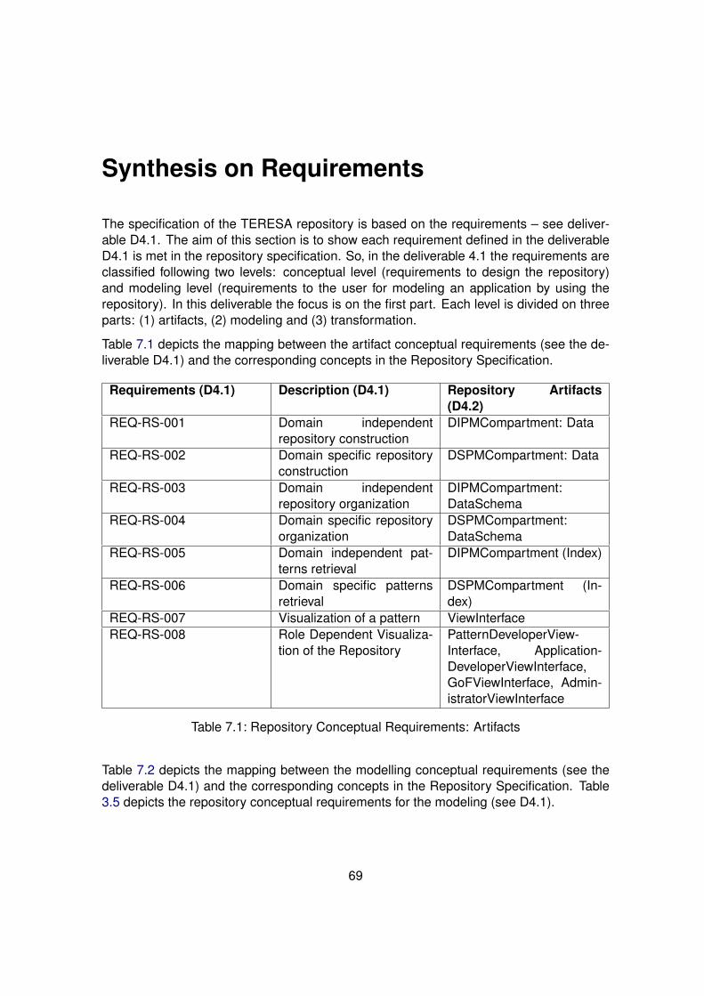
Synthesis on Requirements
The specification of the TERESA repository is based on the requirements – see deliver-able D4.1. The aim of this section is to show each requirement defined in the deliverableD4.1 is met in the repository specification. So, in the deliverable 4.1 the requirements areclassified following two levels: conceptual level (requirements to design the repository)and modeling level (requirements to the user for modeling an application by using therepository). In this deliverable the focus is on the first part. Each level is divided on threeparts: (1) artifacts, (2) modeling and (3) transformation.
Table 7.1 depicts the mapping between the artifact conceptual requirements (see the de-liverable D4.1) and the corresponding concepts in the Repository Specification.
Requirements (D4.1) Description (D4.1) Repository Artifacts(D4.2)
REQ-RS-001 Domain independentrepository construction
DIPMCompartment: Data
REQ-RS-002 Domain specific repositoryconstruction
DSPMCompartment: Data
REQ-RS-003 Domain independentrepository organization
DIPMCompartment:DataSchema
REQ-RS-004 Domain specific repositoryorganization
DSPMCompartment:DataSchema
REQ-RS-005 Domain independent pat-terns retrieval
DIPMCompartment (Index)
REQ-RS-006 Domain specific patternsretrieval
DSPMCompartment (In-dex)
REQ-RS-007 Visualization of a pattern ViewInterfaceREQ-RS-008 Role Dependent Visualiza-
tion of the RepositoryPatternDeveloperView-Interface, Application-DeveloperViewInterface,GoFViewInterface, Admin-istratorViewInterface
Table 7.1: Repository Conceptual Requirements: Artifacts
Table 7.2 depicts the mapping between the modelling conceptual requirements (see thedeliverable D4.1) and the corresponding concepts in the Repository Specification. Table3.5 depicts the repository conceptual requirements for the modeling (see D4.1).
69
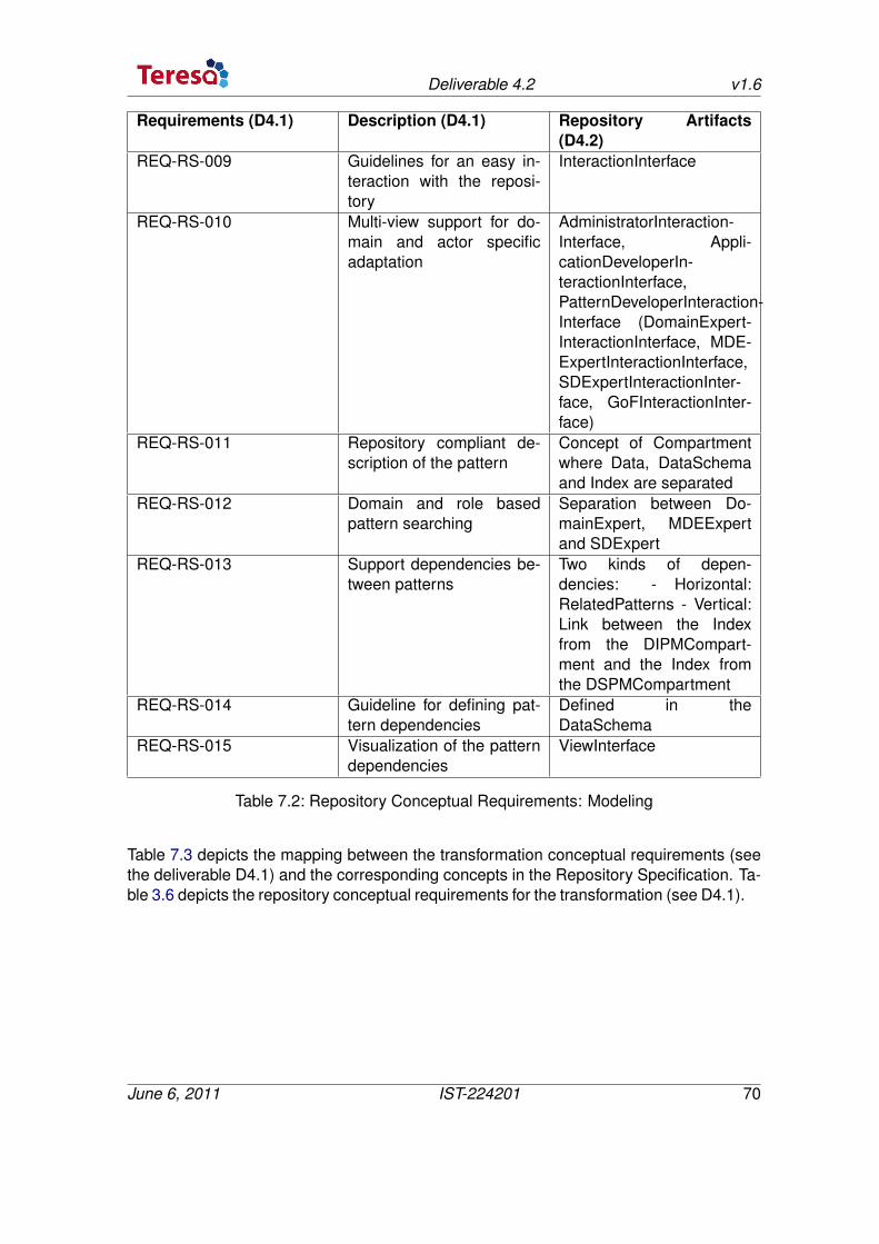
Deliverable 4.2 v1.6
Requirements (D4.1) Description (D4.1) Repository Artifacts(D4.2)
REQ-RS-009 Guidelines for an easy in-teraction with the reposi-tory
InteractionInterface
REQ-RS-010 Multi-view support for do-main and actor specificadaptation
AdministratorInteraction-Interface, Appli-cationDeveloperIn-teractionInterface,PatternDeveloperInteraction-Interface (DomainExpert-InteractionInterface, MDE-ExpertInteractionInterface,SDExpertInteractionInter-face, GoFInteractionInter-face)
REQ-RS-011 Repository compliant de-scription of the pattern
Concept of Compartmentwhere Data, DataSchemaand Index are separated
REQ-RS-012 Domain and role basedpattern searching
Separation between Do-mainExpert, MDEExpertand SDExpert
REQ-RS-013 Support dependencies be-tween patterns
Two kinds of depen-dencies: - Horizontal:RelatedPatterns - Vertical:Link between the Indexfrom the DIPMCompart-ment and the Index fromthe DSPMCompartment
REQ-RS-014 Guideline for defining pat-tern dependencies
Defined in theDataSchema
REQ-RS-015 Visualization of the patterndependencies
ViewInterface
Table 7.2: Repository Conceptual Requirements: Modeling
Table 7.3 depicts the mapping between the transformation conceptual requirements (seethe deliverable D4.1) and the corresponding concepts in the Repository Specification. Ta-ble 3.6 depicts the repository conceptual requirements for the transformation (see D4.1).
June 6, 2011 IST-224201 70
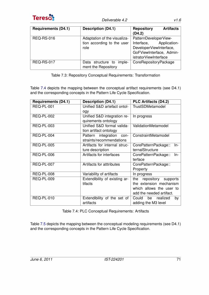
Deliverable 4.2 v1.6
Requirements (D4.1) Description (D4.1) Repository Artifacts(D4.2)
REQ-RS-016 Adaptation of the visualiza-tion according to the userrole
PatternDeveloperView-Interface, Application-DeveloperViewInterface,GoFViewInterface, Admin-istratorViewInterface
REQ-RS-017 Data structure to imple-ment the Repository
CoreRepositoryPackage
Table 7.3: Repository Conceptual Requirements: Transformation
Table 7.4 depicts the mapping between the conceptual artifact requirements (see D4.1)and the corresponding concepts in the Pattern Life Cycle Specification.
Requirements (D4.1) Description (D4.1) PLC Artifacts (D4.2)REQ-PL-001 Unified S&D artefact ontol-
ogyTrustSDMetamodel
REQ-PL-002 Unified S&D integration re-quirements ontology
In progress
REQ-PL-003 Unified S&D formal valida-tion artifact ontology
ValidationMetamodel
REQ-PL-004 Pattern integration con-straints/recommendations
ConstraintMetamodel
REQ-PL-005 Artifacts for internal struc-ture description
CorePatternPackage:: In-ternalStructure
REQ-PL-006 Artifacts for interfaces CorePatternPackage:: In-terface
REQ-PL-007 Artifacts for atttributes CorePatternPackage::Property
REQ-PL-008 Variability of artifacts In progressREQ-PL-009 Extendibility of existing ar-
tifactsthe repository supportsthe extension mechanismwhich allows the user toadd the needed artifact.
REQ-PL-010 Extendibility of the set ofartifacts
Could be realized byadding the M3 level
Table 7.4: PLC Conceptual Requirements: Artifacts
Table 7.5 depicts the mapping between the conceptual modeling requirements (see D4.1)and the corresponding concepts in the Pattern Life Cycle Specification.
June 6, 2011 IST-224201 71
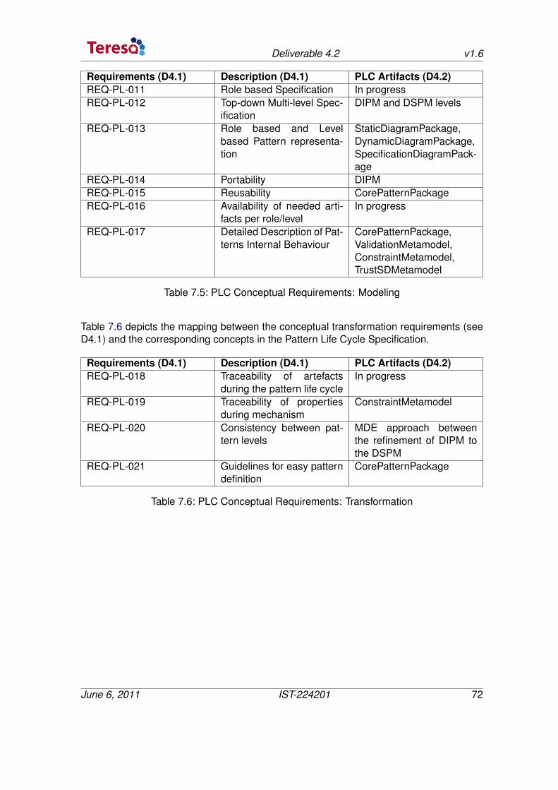
Deliverable 4.2 v1.6
Requirements (D4.1) Description (D4.1) PLC Artifacts (D4.2)REQ-PL-011 Role based Specification In progressREQ-PL-012 Top-down Multi-level Spec-
ificationDIPM and DSPM levels
REQ-PL-013 Role based and Levelbased Pattern representa-tion
StaticDiagramPackage,DynamicDiagramPackage,SpecificationDiagramPack-age
REQ-PL-014 Portability DIPMREQ-PL-015 Reusability CorePatternPackageREQ-PL-016 Availability of needed arti-
facts per role/levelIn progress
REQ-PL-017 Detailed Description of Pat-terns Internal Behaviour
CorePatternPackage,ValidationMetamodel,ConstraintMetamodel,TrustSDMetamodel
Table 7.5: PLC Conceptual Requirements: Modeling
Table 7.6 depicts the mapping between the conceptual transformation requirements (seeD4.1) and the corresponding concepts in the Pattern Life Cycle Specification.
Requirements (D4.1) Description (D4.1) PLC Artifacts (D4.2)REQ-PL-018 Traceability of artefacts
during the pattern life cycleIn progress
REQ-PL-019 Traceability of propertiesduring mechanism
ConstraintMetamodel
REQ-PL-020 Consistency between pat-tern levels
MDE approach betweenthe refinement of DIPM tothe DSPM
REQ-PL-021 Guidelines for easy patterndefinition
CorePatternPackage
Table 7.6: PLC Conceptual Requirements: Transformation
June 6, 2011 IST-224201 72