Embed Size (px)
Citation preview
ETSI TS 129 118 V15.2.0 (2018-07)
Universal Mobile Telecommunications System (UMTS); LTE;
Mobility Management Entity (MME) - Visitor Location Register (VLR) SGs interface specification
(3GPP TS 29.118 version 15.2.0 Release 15)
TECHNICAL SPECIFICATION
ETSI
ETSI TS 129 118 V15.2.0 (2018-07)13GPP TS 29.118 version 15.2.0 Release 15
Reference RTS/TSGC-0129118vf20
Keywords LTE,UMTS
ETSI
650 Route des Lucioles F-06921 Sophia Antipolis Cedex - FRANCE
Tel.: +33 4 92 94 42 00 Fax: +33 4 93 65 47 16
Siret N° 348 623 562 00017 - NAF 742 C
Association à but non lucratif enregistrée à la Sous-Préfecture de Grasse (06) N° 7803/88
Important notice
The present document can be downloaded from: http://www.etsi.org/standards-search
The present document may be made available in electronic versions and/or in print. The content of any electronic and/or print versions of the present document shall not be modified without the prior written authorization of ETSI. In case of any
existing or perceived difference in contents between such versions and/or in print, the only prevailing document is the print of the Portable Document Format (PDF) version kept on a specific network drive within ETSI Secretariat.
Users of the present document should be aware that the document may be subject to revision or change of status. Information on the current status of this and other ETSI documents is available at
https://portal.etsi.org/TB/ETSIDeliverableStatus.aspx
If you find errors in the present document, please send your comment to one of the following services: https://portal.etsi.org/People/CommiteeSupportStaff.aspx
Copyright Notification
No part may be reproduced or utilized in any form or by any means, electronic or mechanical, including photocopying and microfilm except as authorized by written permission of ETSI.
The content of the PDF version shall not be modified without the written authorization of ETSI. The copyright and the foregoing restriction extend to reproduction in all media.
© ETSI 2018.
All rights reserved.
DECTTM, PLUGTESTSTM, UMTSTM and the ETSI logo are trademarks of ETSI registered for the benefit of its Members. 3GPPTM and LTETM are trademarks of ETSI registered for the benefit of its Members and
of the 3GPP Organizational Partners. oneM2M logo is protected for the benefit of its Members.
GSM® and the GSM logo are trademarks registered and owned by the GSM Association.
ETSI
ETSI TS 129 118 V15.2.0 (2018-07)23GPP TS 29.118 version 15.2.0 Release 15
Intellectual Property Rights Essential patents
IPRs essential or potentially essential to normative deliverables may have been declared to ETSI. The information pertaining to these essential IPRs, if any, is publicly available for ETSI members and non-members, and can be found in ETSI SR 000 314: "Intellectual Property Rights (IPRs); Essential, or potentially Essential, IPRs notified to ETSI in respect of ETSI standards", which is available from the ETSI Secretariat. Latest updates are available on the ETSI Web server (https://ipr.etsi.org/).
Pursuant to the ETSI IPR Policy, no investigation, including IPR searches, has been carried out by ETSI. No guarantee can be given as to the existence of other IPRs not referenced in ETSI SR 000 314 (or the updates on the ETSI Web server) which are, or may be, or may become, essential to the present document.
Trademarks
The present document may include trademarks and/or tradenames which are asserted and/or registered by their owners. ETSI claims no ownership of these except for any which are indicated as being the property of ETSI, and conveys no right to use or reproduce any trademark and/or tradename. Mention of those trademarks in the present document does not constitute an endorsement by ETSI of products, services or organizations associated with those trademarks.
Foreword This Technical Specification (TS) has been produced by ETSI 3rd Generation Partnership Project (3GPP).
The present document may refer to technical specifications or reports using their 3GPP identities, UMTS identities or GSM identities. These should be interpreted as being references to the corresponding ETSI deliverables.
The cross reference between GSM, UMTS, 3GPP and ETSI identities can be found under http://webapp.etsi.org/key/queryform.asp.
Modal verbs terminology In the present document "shall", "shall not", "should", "should not", "may", "need not", "will", "will not", "can" and "cannot" are to be interpreted as described in clause 3.2 of the ETSI Drafting Rules (Verbal forms for the expression of provisions).
"must" and "must not" are NOT allowed in ETSI deliverables except when used in direct citation.
ETSI
ETSI TS 129 118 V15.2.0 (2018-07)33GPP TS 29.118 version 15.2.0 Release 15
Contents Intellectual Property Rights ................................................................................................................................ 2
Foreword ............................................................................................................................................................. 2
Modal verbs terminology .................................................................................................................................... 2
Foreword ............................................................................................................................................................. 8
1 Scope ........................................................................................................................................................ 9
2 References ................................................................................................................................................ 9
3 Definitions and abbreviations ................................................................................................................. 10
3.1 Definitions ........................................................................................................................................................ 10
3.2 Abbreviations ................................................................................................................................................... 11
4 Description of the SGs association between a VLR and an MME ......................................................... 11
4.1 General ............................................................................................................................................................. 11
4.2 SGs association at the VLR .............................................................................................................................. 11
4.2.1 General ........................................................................................................................................................ 11
4.2.2 States at the VLR ........................................................................................................................................ 12
4.3 SGs association at the MME ............................................................................................................................ 12
4.3.1 General ........................................................................................................................................................ 12
4.3.2 MM context variables at the MME ............................................................................................................. 13
4.3.3 States at the MME ...................................................................................................................................... 13
4.3.4 State transitions in the MME without SGsAP signalling ............................................................................ 14
4.3.5 State transitions in the VLR without SGsAP signalling ............................................................................. 14
5 Procedures for SGs ................................................................................................................................. 15
5.1 Paging for non-EPS services procedure ........................................................................................................... 15
5.1.1 General description ..................................................................................................................................... 15
5.1.2 Procedures in the VLR ................................................................................................................................ 15
5.1.2.1 General .................................................................................................................................................. 15
5.1.2.2 Paging Initiation .................................................................................................................................... 15
5.1.2.3 Paging Response ................................................................................................................................... 16
5.1.2.4 Paging Failure ....................................................................................................................................... 16
5.1.2.5 UE unreachable ..................................................................................................................................... 17
5.1.3 Procedures in the MME .............................................................................................................................. 17
5.1.3.1 General .................................................................................................................................................. 17
5.1.3.2 Procedure when no NAS signalling connection exists .......................................................................... 20
5.1.3.3 Procedure when a NAS signalling connection exists ............................................................................ 21
5.2 Location update for non-EPS services procedure ............................................................................................. 21
5.2.1 General description ..................................................................................................................................... 21
5.2.2 Procedures in the MME .............................................................................................................................. 22
5.2.2.1 General .................................................................................................................................................. 22
5.2.2.2 Location update initiation ..................................................................................................................... 22
5.2.2.2.1 General ............................................................................................................................................ 22
5.2.2.2.2 VLR fails without restart ................................................................................................................. 24
5.2.2.3 Location update response ...................................................................................................................... 25
5.2.2.4 Location update failure ......................................................................................................................... 25
5.2.2.5 Abnormal cases ..................................................................................................................................... 25
5.2.2.6 Additional MME procedure for UE supporting NB-S1 mode only ...................................................... 26
5.2.3 Procedures in the VLR ................................................................................................................................ 27
5.2.3.1 General .................................................................................................................................................. 27
5.2.3.2 Location update response ...................................................................................................................... 27
5.2.3.3 Location update failure ......................................................................................................................... 28
5.2.3.4 TMSI reallocation procedure ................................................................................................................ 28
5.2.3.5 Abnormal cases ..................................................................................................................................... 28
5.3 Non-EPS alert procedure .................................................................................................................................. 29
5.3.1 General description ..................................................................................................................................... 29
5.3.2 Procedures in the VLR ................................................................................................................................ 29
5.3.2.1 Alert Initiation ....................................................................................................................................... 29
ETSI
ETSI TS 129 118 V15.2.0 (2018-07)43GPP TS 29.118 version 15.2.0 Release 15
5.3.2.2 Alert Response ...................................................................................................................................... 29
5.3.2.3 Alert Failure .......................................................................................................................................... 29
5.3.2.4 Alert Indication ..................................................................................................................................... 29
5.3.2.5 Abnormal cases ..................................................................................................................................... 30
5.3.3 Procedures in the MME .............................................................................................................................. 30
5.3.3.1 Alert response ....................................................................................................................................... 30
5.3.3.2 Alert failure ........................................................................................................................................... 30
5.3.3.3 Alert indication ..................................................................................................................................... 30
5.4 Explicit IMSI detach from EPS services .......................................................................................................... 30
5.4.1 General description ..................................................................................................................................... 30
5.4.2 Procedures in the MME .............................................................................................................................. 31
5.4.2.1 Explicit EPS detach initiation ............................................................................................................... 31
5.4.2.2 Explicit EPS detach response ................................................................................................................ 31
5.4.2.3 Abnormal cases ..................................................................................................................................... 31
5.4.3 Procedures in the VLR ................................................................................................................................ 31
5.5 Explicit IMSI detach from non-EPS services ................................................................................................... 32
5.5.1 General description ..................................................................................................................................... 32
5.5.2 Procedures in the MME .............................................................................................................................. 32
5.5.2.1 Explicit IMSI detach initiation .............................................................................................................. 32
5.5.2.2 Explicit IMSI detach response .............................................................................................................. 32
5.5.2.3 Abnormal cases ..................................................................................................................................... 32
5.5.3 Procedures in the VLR ................................................................................................................................ 33
5.6 Implicit IMSI detach from non-EPS services ................................................................................................... 33
5.6.1 General description ..................................................................................................................................... 33
5.6.2 Procedures in the MME .............................................................................................................................. 33
5.6.3 Procedures in the VLR ................................................................................................................................ 33
5.7 VLR failure procedure ...................................................................................................................................... 34
5.7.1 General description ..................................................................................................................................... 34
5.7.2 Procedures in the VLR ................................................................................................................................ 34
5.7.2.1 VLR Reset Initiation ............................................................................................................................. 34
5.7.2.2 VLR Reset Response............................................................................................................................. 34
5.7.2.3 Abnormal cases ..................................................................................................................................... 34
5.7.3 Procedures in the MME .............................................................................................................................. 34
5.7.3.1 VLR reset indication ............................................................................................................................. 34
5.7.3.2 Void....................................................................................................................................................... 35
5.8 MME failure procedure .................................................................................................................................... 35
5.8.1 General description ..................................................................................................................................... 35
5.8.2 Procedures in the MME .............................................................................................................................. 35
5.8.2.1 MME Reset Initiation ............................................................................................................................ 35
5.8.2.2 MME Reset Response ........................................................................................................................... 35
5.8.2.3 Abnormal cases ..................................................................................................................................... 35
5.8.3 Procedures in the VLR ................................................................................................................................ 35
5.9 HSS failure ....................................................................................................................................................... 36
5.9.1 General description ..................................................................................................................................... 36
5.9.2 Procedures in the MME .............................................................................................................................. 36
5.10 MM information procedure .............................................................................................................................. 36
5.10.1 General description ..................................................................................................................................... 36
5.10.2 Procedures in the VLR ................................................................................................................................ 36
5.10.3 Procedures in the MME .............................................................................................................................. 36
5.11 Procedure for tunnelling of NAS messages ...................................................................................................... 37
5.11.1 General description ..................................................................................................................................... 37
5.11.2 Uplink unitdata procedure .......................................................................................................................... 37
5.11.2.1 Procedures in the MME ........................................................................................................................ 37
5.11.2.2 Procedures in the VLR .......................................................................................................................... 37
5.11.2.2.1 General description .......................................................................................................................... 37
5.11.2.2.2 Abnormal cases ............................................................................................................................... 38
5.11.2.3 Void....................................................................................................................................................... 38
5.11.3 Downlink unitdata procedure ...................................................................................................................... 38
5.11.3.1 Procedures in the VLR .......................................................................................................................... 38
5.11.3.2 Procedures in the MME ........................................................................................................................ 38
5.11.3.2.1 General description .......................................................................................................................... 38
5.11.3.2.2 Abnormal cases ............................................................................................................................... 38
ETSI
ETSI TS 129 118 V15.2.0 (2018-07)53GPP TS 29.118 version 15.2.0 Release 15
5.11.3.3 Void....................................................................................................................................................... 39
5.11.4 Release procedure ....................................................................................................................................... 39
5.12 Service request procedure................................................................................................................................. 39
5.12.1 General description ..................................................................................................................................... 39
5.12.2 Procedures in the MME .............................................................................................................................. 39
5.12.3 Procedures in the VLR ................................................................................................................................ 40
5.13 Service abort procedure .................................................................................................................................... 40
5.13.1 General description ..................................................................................................................................... 40
5.13.2 Procedures in the VLR ................................................................................................................................ 40
5.13.3 Procedures in the MME .............................................................................................................................. 40
5.14 Implicit IMSI detach from EPS services .......................................................................................................... 40
5.14.1 General description ..................................................................................................................................... 40
5.14.2 Procedures in the MME .............................................................................................................................. 41
5.14.3 Procedures in the VLR ................................................................................................................................ 41
5.15 UE fallback supervision procedure................................................................................................................... 41
5.15.0 General description ..................................................................................................................................... 41
5.15.1 Procedures in the VLR ................................................................................................................................ 41
5.16 Procedure for MO CSFB indication ................................................................................................................. 42
5.16.1 General description ..................................................................................................................................... 42
5.16.2 Procedures in the MME .............................................................................................................................. 42
5.16.3 Procedures in the VLR ................................................................................................................................ 42
6 SGs transport .......................................................................................................................................... 42
6.1 General ............................................................................................................................................................. 42
6.2 IP layer ............................................................................................................................................................. 42
6.3 Transport layer ................................................................................................................................................. 42
7 Error handling ........................................................................................................................................ 43
7.1 General ............................................................................................................................................................. 43
7.2 Message too short ............................................................................................................................................. 43
7.3 Unknown or unforeseen message type ............................................................................................................. 43
7.4 Missing mandatory information element .......................................................................................................... 44
7.5 Information elements unknown or unforeseen in the message ......................................................................... 44
7.6 Out of sequence information elements ............................................................................................................. 44
7.7 Repeated information elements ........................................................................................................................ 44
7.8 Syntactically incorrect mandatory information element. .................................................................................. 44
7.9 Syntactically incorrect optional information elements ..................................................................................... 44
7.10 Conditional information element errors ........................................................................................................... 44
7.11 Information elements with semantically incorrect contents ............................................................................. 44
8 Message functional definitions and contents .......................................................................................... 45
8.1 SGsAP-ALERT-ACK message ........................................................................................................................ 45
8.2 SGsAP-ALERT-REJECT message .................................................................................................................. 45
8.3 SGsAP-ALERT-REQUEST message .............................................................................................................. 45
8.4 SGsAP-DOWNLINK-UNITDATA message ................................................................................................... 45
8.5 SGsAP-EPS-DETACH-ACK message ............................................................................................................ 46
8.6 SGsAP-EPS-DETACH-INDICATION message ............................................................................................. 46
8.7 SGsAP-IMSI-DETACH-ACK message ........................................................................................................... 46
8.8 SGsAP-IMSI-DETACH-INDICATION message ............................................................................................ 46
8.9 SGsAP-LOCATION-UPDATE-ACCEPT message ........................................................................................ 47
8.9.1 Message definition ...................................................................................................................................... 47
8.9.2 New TMSI, or IMSI.................................................................................................................................... 47
8.10 SGsAP-LOCATION-UPDATE-REJECT message .......................................................................................... 47
8.10.1 Message definition ...................................................................................................................................... 47
8.10.2 Location area identifier ............................................................................................................................... 48
8.11 SGsAP-LOCATION-UPDATE-REQUEST message ...................................................................................... 48
8.11.1 Message definition ...................................................................................................................................... 48
8.11.2 Old location area identifier ......................................................................................................................... 48
8.11.3 TMSI status ................................................................................................................................................. 48
8.11.4 IMEISV ...................................................................................................................................................... 48
8.11.5 TAI.............................................................................................................................................................. 48
8.11.6 E-CGI .......................................................................................................................................................... 48
8.11.7 TMSI based NRI container ......................................................................................................................... 49
ETSI
ETSI TS 129 118 V15.2.0 (2018-07)63GPP TS 29.118 version 15.2.0 Release 15
8.11.8 Selected CS domain operator ...................................................................................................................... 49
8.12 SGsAP-MM-INFORMATION-REQUEST ..................................................................................................... 49
8.13 SGsAP-PAGING-REJECT message ................................................................................................................ 49
8.14 SGsAP-PAGING-REQUEST message ............................................................................................................ 49
8.14.1 Message definition ...................................................................................................................................... 49
8.14.2 TMSI ........................................................................................................................................................... 50
8.14.3 CLI .............................................................................................................................................................. 50
8.14.4 Location area identifier ............................................................................................................................... 50
8.14.5 Global CN-Id .............................................................................................................................................. 50
8.14.6 SS code ....................................................................................................................................................... 50
8.14.7 LCS indicator .............................................................................................................................................. 51
8.14.8 LCS client identity ...................................................................................................................................... 51
8.14.9 Channel needed ........................................................................................................................................... 51
8.14.10 eMLPP priority ........................................................................................................................................... 51
8.14.11 Additional paging indicators ....................................................................................................................... 51
8.14.12 SM Delivery Timer ..................................................................................................................................... 51
8.14.13 SM Delivery Start Time .............................................................................................................................. 51
8.14.4 Maximum Retransmission Time ................................................................................................................. 51
8.15 SGsAP-RESET-ACK message ........................................................................................................................ 51
8.15.1 Message definition ...................................................................................................................................... 51
8.15.2 MME name ................................................................................................................................................. 52
8.15.3 VLR name ................................................................................................................................................... 52
8.16 SGsAP-RESET-INDICATION message ......................................................................................................... 52
8.16.1 Message definition ...................................................................................................................................... 52
8.16.2 MME name ................................................................................................................................................. 52
8.16.3 VLR name ................................................................................................................................................... 52
8.17 SGsAP-SERVICE-REQUEST message ........................................................................................................... 53
8.17.1 Message definition ...................................................................................................................................... 53
8.17.2 IMEISV ...................................................................................................................................................... 53
8.17.3 UE Time Zone ............................................................................................................................................ 53
8.17.4 Mobile Station Classmark 2 ........................................................................................................................ 53
8.17.5 TAI.............................................................................................................................................................. 53
8.17.6 E-CGI .......................................................................................................................................................... 53
8.17.7 UE EMM Mode .......................................................................................................................................... 53
8.18 SGsAP-STATUS message ............................................................................................................................... 53
8.18.1 Message definition ...................................................................................................................................... 53
8.18.2 IMSI ............................................................................................................................................................ 54
8.19 SGsAP-TMSI-REALLOCATION-COMPLETE message ............................................................................... 54
8.20 SGsAP-UE-ACTIVITY-INDICATION message ............................................................................................ 54
8.20.1 Maximum UE Availability Time ................................................................................................................ 54
8.21 SGsAP-UE-UNREACHABLE message .......................................................................................................... 54
8.21.1 Requested Retransmission Time ................................................................................................................. 55
8.21.2 Additional UE Unreachable indicators ....................................................................................................... 55
8.22 SGsAP-UPLINK-UNITDATA message .......................................................................................................... 55
8.22.1 Message definition ...................................................................................................................................... 55
8.22.2 IMEISV ...................................................................................................................................................... 55
8.22.3 UE Time Zone ............................................................................................................................................ 55
8.22.4 Mobile Station Classmark 2 ........................................................................................................................ 56
8.22.5 TAI.............................................................................................................................................................. 56
8.22.6 E-CGI .......................................................................................................................................................... 56
8.23 SGsAP-RELEASE-REQUEST message .......................................................................................................... 56
8.23.1 Message definition ...................................................................................................................................... 56
8.23.2 SGs Cause ................................................................................................................................................... 56
8.24 SGsAP-SERVICE-ABORT-REQUEST message ............................................................................................ 56
8.24.1 Message definition ...................................................................................................................................... 56
8.25 SGsAP-MO-CSFB-INDICATION message .................................................................................................... 56
8.25.1 Message definition ...................................................................................................................................... 56
8.25.2 TAI.............................................................................................................................................................. 57
8.25.3 E-CGI .......................................................................................................................................................... 57
9 Information element coding ................................................................................................................... 57
9.1 Overview .......................................................................................................................................................... 57
ETSI
ETSI TS 129 118 V15.2.0 (2018-07)73GPP TS 29.118 version 15.2.0 Release 15
9.2 Message type .................................................................................................................................................... 58
9.3 Information element identifiers ........................................................................................................................ 59
9.3a Length indicator ............................................................................................................................................... 59
9.4 Information elements ........................................................................................................................................ 59
9.4.1 CLI .............................................................................................................................................................. 59
9.4.2 EPS location update type ............................................................................................................................ 60
9.4.3 Erroneous message ..................................................................................................................................... 60
9.4.3a E-UTRAN Cell Global Identity .................................................................................................................. 60
9.4.4 Global CN-Id .............................................................................................................................................. 60
9.4.5 IMEISV ...................................................................................................................................................... 61
9.4.6 IMSI ............................................................................................................................................................ 61
9.4.7 IMSI detach from EPS service type ............................................................................................................ 61
9.4.8 IMSI detach from non-EPS service type..................................................................................................... 61
9.4.9 LCS client identity ...................................................................................................................................... 62
9.4.10 LCS indicator .............................................................................................................................................. 62
9.4.11 Location area identifier ............................................................................................................................... 62
9.4.12 MM information ......................................................................................................................................... 63
9.4.13 MME name ................................................................................................................................................. 63
9.4.14 Mobile identity ............................................................................................................................................ 63
9.4.14a Mobile Station Classmark 2 ........................................................................................................................ 63
9.4.15 NAS message container .............................................................................................................................. 63
9.4.16 Reject cause ................................................................................................................................................ 64
9.4.17 Service indicator ......................................................................................................................................... 64
9.4.18 SGs cause .................................................................................................................................................... 64
9.4.19 SS code ....................................................................................................................................................... 65
9.4.20 TMSI ........................................................................................................................................................... 65
9.4.21 TMSI status ................................................................................................................................................. 65
9.4.21a Tracking Area Identity ................................................................................................................................ 65
9.4.21b UE Time Zone ............................................................................................................................................ 66
9.4.21c UE EMM mode ........................................................................................................................................... 66
9.4.22 VLR name ................................................................................................................................................... 66
9.4.23 Channel needed ........................................................................................................................................... 67
9.4.24 eMLPP priority ........................................................................................................................................... 67
9.4.25 Additional paging indicators ....................................................................................................................... 67
9.4.26 TMSI based NRI container ......................................................................................................................... 67
9.4.27 Selected CS domain operator ...................................................................................................................... 67
9.4.28 Maximum UE Availability Time ................................................................................................................ 68
9.4.29 SM Delivery Timer ..................................................................................................................................... 68
9.4.30 SM Delivery Start Time .............................................................................................................................. 68
9.4.31 Additional UE Unreachable indicators ....................................................................................................... 69
9.4.32 Maximum Retransmission Time ................................................................................................................. 69
9.4.33 Requested Retransmission Time ................................................................................................................. 69
10 List of system variables .......................................................................................................................... 70
10.1 Timers .............................................................................................................................................................. 70
10.2 Retry counters .................................................................................................................................................. 71
Annex A (informative): Change history ............................................................................................... 72
History .............................................................................................................................................................. 76
ETSI
ETSI TS 129 118 V15.2.0 (2018-07)83GPP TS 29.118 version 15.2.0 Release 15
Foreword This Technical Specification has been produced by the 3rd Generation Partnership Project (3GPP).
The contents of the present document are subject to continuing work within the TSG and may change following formal TSG approval. Should the TSG modify the contents of the present document, it will be re-released by the TSG with an identifying change of release date and an increase in version number as follows:
Version x.y.z
where:
x the first digit:
1 presented to TSG for information;
2 presented to TSG for approval;
3 or greater indicates TSG approved document under change control.
y the second digit is incremented for all changes of substance, i.e. technical enhancements, corrections, updates, etc.
z the third digit is incremented when editorial only changes have been incorporated in the document.
ETSI
ETSI TS 129 118 V15.2.0 (2018-07)93GPP TS 29.118 version 15.2.0 Release 15
1 Scope CS Fallback in the Evolved Packet System (EPS) enables the provisioning of CS-domain services (e.g. voice call, Location Services (LCS) or supplementary services) by reuse of CS infrastructure when the UE is served by E-UTRAN. Additionally, SMS delivery via the CS core network is realized without CS fallback.
The present document specifies the procedures and the SGs Application Part (SGsAP) messages used on the SGs interface between the Mobility Management Entity (MME) in the EPS and the Visitor Location Register (VLR), to allow location management coordination and to relay certain messages related to GSM circuit switched services over the EPS system.
The present document also specifies the use of Stream Control Transmission Protocol (SCTP) for the transport of SGsAP messages.
The present document is applicable to the MME in the EPS and to the VLR. The functional split between the MME and the VLR is defined in 3GPP TS 23.272 [7].
2 References The following documents contain provisions which, through reference in this text, constitute provisions of the present document.
- References are either specific (identified by date of publication, edition number, version number, etc.) or non-specific.
- For a specific reference, subsequent revisions do not apply.
- For a non-specific reference, the latest version applies. In the case of a reference to a 3GPP document (including a GSM document), a non-specific reference implicitly refers to the latest version of that document in the same Release as the present document.
[1] 3GPP TR 21.905: "Vocabulary for 3GPP Specifications".
[2] 3GPP TS 22.101: "Service aspects; Service principles".
[3] 3GPP TS 23.003: "Numbering, addressing and identification".
[4] 3GPP TS 23.007: "Restoration procedures".
[5] 3GPP TS 23.018: "Basic call handling; Technical realization".
[5AA] 3GPP TS 23.078: "Customised Applications for Mobile network Enhanced Logic (CAMEL) Phase 4; Stage 2".
[5A] 3GPP TS 23.081: "Line identification supplementary services".
[5B] 3GPP TS 23.082: "Call Forwarding (CF) supplementary services".
[6] Void.
[6A] 3GPP TS 23.236: "Intra-domain connection of Radio Access Network (RAN) nodes to multiple Core Network (CN) nodes".
[7] 3GPP TS 23.272: "Circuit Switched Fallback in Evolved Packet System; Stage 2".
[7A] 3GPP TS 23.251: "Network Sharing; Architecture and Functional Description".
[7B] 3GPP TS 23.401: "GPRS enhancements for E-UTRAN access".
[8] 3GPP TS 24.008: "Mobile radio interface Layer 3 specification; Core network protocols; Stage 3".
[9] 3GPP TS 24.010: "Supplementary services specification; General aspects".
ETSI
ETSI TS 129 118 V15.2.0 (2018-07)103GPP TS 29.118 version 15.2.0 Release 15
[10] 3GPP TS 24.011: "Point-to-Point (PP) Short Message Service (SMS) support on mobile radio interface".
[11] 3GPP TS 24.030: "Location Services (LCS); Supplementary service operations; Stage 3".
[12] 3GPP TS 24.081: "Line Identification Supplementary Services - Stage 3".
[13] 3GPP TS 24.082: "Call Forwarding (CF) supplementary services; Stage 3".
[14] 3GPP TS 24.301: "Non-Access-Stratum (NAS) protocol for Evolved Packet System (EPS); Stage 3".
[15] 3GPP TS 29.002: "Mobile Application Part (MAP) specification".
[15A] 3GPP TS 29.011: "Signalling interworking for supplementary services".
[16] 3GPP TS 29.018: "Serving GPRS Support Node (SGSN) - Visitors Location Register (VLR) Gs interface layer 3 specification".
[16A] 3GPP TS 29.060: General Packet Radio Service (GPRS);GPRS Tunnelling Protocol (GTP) across the Gn and Gp interface.
[17] 3GPP TS 29.272: "MME and SGSN Related Interfaces Based on Diameter Protocol".
[17A] 3GPP TS 29.274: "3GPP Evolved Packet System (EPS); Evolved General Packet Radio Service (GPRS) Tunnelling Protocol for Control plane (GTPv2-C); Stage 3".
[17B] 3GPP TS 32.250: "Telecommunication management; Charging management; Circuit Switched (CS) domain charging".
[18] 3GPP TS 32.422: "Telecommunication management; Subscriber and equipment trace; Trace control and configuration management (CM)".
[19] 3GPP TS 36.331: "Evolved Universal Terrestrial Radio Access (E-UTRA); Radio Resource Control (RRC) protocol specification".
[20] IETF RFC 791 (September 1981): "Internet Protocol".
[21] Void.
[22] IETF RFC 2460 (December 1998): "Internet Protocol, Version 6 (IPv6) Specification".
[23] IETF RFC 4960 (September 2007): "Stream Control Transmission Protocol".
[24] 3GPP TS 22.067: "enhanced Multi Level Precedence and Pre-emption service (eMLPP); Stage 1".
[25] 3GPP TS 23.067: "enhanced Multi-Level Precedence and Pre-emption service (eMLPP); Stage 2".
[26] 3GPP TS 23.216: "Single Radio Voice Call Continuity (SRVCC); Stage 2".
[27] Void.
3 Definitions and abbreviations
3.1 Definitions For the purposes of the present document, the terms and definitions given in 3GPP TR 21.905 [1] apply. Additionally the following definitions of 3GPP TS 24.301 [14] apply:
Non-EPS services SMS only
For the purposes of the present document, the following terms and definitions given in 3GPP TS 23.272 [7] apply:
CS fallback
ETSI
ETSI TS 129 118 V15.2.0 (2018-07)113GPP TS 29.118 version 15.2.0 Release 15
SMS over SGs SMS in MME
For the purposes of the present document, the following terms and definitions given in 3GPP TS 23.251 [7A] apply:
Common PLMN Gateway core network (GWCN)
For the purposes of the present document, the following terms and definitions given in 3GPP TS 24.301 [14] apply:
In NB-S1 mode
3.2 Abbreviations For the purposes of the present document, the abbreviations given in 3GPP TR 21.905 [1] and the following apply. An abbreviation defined in the present document takes precedence over the definition of the same abbreviation, if any, in 3GPP TR 21.905 [1].
LCS Location Services MME Mobility Management Entity NEAF Non-EPS Alert Flag SCTP Stream Control Transmission Protocol SGsAP SGs Application Part SMS Short Message Service PSI Provide Subscriber Information
4 Description of the SGs association between a VLR and an MME
4.1 General CS fallback function and SMS delivery via the CS core network is realized by reusing Gs interface mechanisms as defined in 3GPP TS 29.018 [16] on the interface between the MME in the EPS and the VLR. This interface is called SGs interface.
NOTE: Within this specification, the term VLR refers to MSC/VLR or MSC Server/VLR.
The SGs interface connects the databases in the VLR and the MME. The procedures described in the present document are used to co-ordinate the location information of UEs that are IMSI attached to both EPS and non-EPS services. The SGs interface is also used to convey some circuit switched related procedures via the MME.
The basis for the interworking between a VLR and an MME is the existence of a SGs association between those entities per UE. The SGs association is applicable to UEs which are configured to use CS fallback and SMS over SGs, or SMS over SGs only. The SGs association is not applicable if the subscriber data indicates that the subscription is for packet only. The SGs association is also not applicable if the MME is registered for SMS for the UE as specified in 3GPP TS 23.272 [7].
In NB-S1 mode, the SGs association is also applicable to UEs supports NB-S1 mode only to use SMS over SGs only.
The behaviour of the VLR and the MME entities related to the SGs interface are defined by the state of the SGs association for a UE. Individual SGs association states are maintained at both the VLR and the MME for each UE.
4.2 SGs association at the VLR
4.2.1 General
The states associated to the SGs interface in the VLR are specified in subclause 4.2.2 and the state diagram at the VLR is shown in figure 4.2.2.1. The state diagram does not include the message error handling specified in clause 7.

ETSI
ETSI TS 129 118 V15.2.0 (2018-07)123GPP TS 29.118 version 15.2.0 Release 15
4.2.2 States at the VLR
SGs-NULL
There is no SGs association with an MME for the UE and therefore the VLR considers that the UE is IMSI detached for EPS services. In this state no SGsAP-MM-INFORMATION-REQUEST messages are sent to the MME. The VLR may initiate paging on the SGs interface if the "Confirmed by Radio Contact" restoration indicator in the VLR is set to "false" (see 3GPP TS 23.007 [4]). Any message from the MME is ignored except SGsAP-LOCATION-UPDATE-REQUEST, SGsAP-IMSI-DETACH-INDICATION and SGsAP-EPS-DETACH-INDICATION.
LA-UPDATE-PRESENT
The VLR has received an SGsAP-LOCATION-UPDATE-REQUEST message from the MME. In this state, the VLR may be waiting for the outcome of the Update Location procedure from the HSS, if the IMSI is not known in the VLR. For UEs which are configured to use CS fallback and SMS over SGs, or SMS over SGs only, the VLR sends SGsAP-PAGING-REQUEST messages via the SGs interface.
SGs-ASSOCIATED
The VLR considers that the UE is attached to both EPS and non-EPS services. For UEs which are configured to use CS fallback and SMS over SGs, or SMS over SGs only, the VLR sends SGsAP-PAGING-REQUEST messages via the SGs interface. The VLR can perform the MM information procedure.
From one of
the three states
(at the VLR) SGs-
NULL
SGs-
ASSOCIATED
LA-UPDATE-
PRESENT
NOTE: Receipt of an SGsAP-RESET-INDICATION message from the MME may change or not the state of the SGs interface of all the associations associated to the restarted MME, see subclause 5.8.3.
Figure 4.2.2.1: State diagram at the VLR
4.3 SGs association at the MME
4.3.1 General
The MM context variables associated to the SGs interface in the MME are specified in subclause 4.3.2 and states associated to the SGs interface in the MME are specified in subclause 4.3.3. The state diagram at the MME is shown in figure 4.3.3.1. The state diagram does not include the message error handling specified in clause 7.
ETSI
ETSI TS 129 118 V15.2.0 (2018-07)133GPP TS 29.118 version 15.2.0 Release 15
4.3.2 MM context variables at the MME
VLR-Reliable:
Boolean set to "false" when the MME has received a reset indication from the VLR. The MME may:
- upon reception of a combined tracking area update request from a UE that is still attached for non-EPS services, perform immediately the location update for non-EPS services procedure; or
- upon reception of a periodic tracking area update request from a UE that is still attached for non-EPS services, dependent on network configuration and operator policy,
- perform a network initiated detach with detach type "IMSI detach" immediately after the completion of the periodic tracking area update procedure; or
- perform immediately the location update for non-EPS services procedure.
MME-Reset:
Boolean set to "true" when the MME restarts after a failure. The "MME-Reset" restoration indicator is unique within an MME and it applies to all the MM contexts stored in the MME.
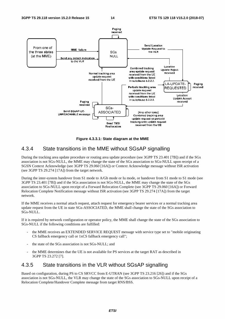
4.3.3 States at the MME
SGs-NULL
There is no SGs association with a VLR for the UE and therefore the MME considers that the UE is IMSI detached for non-EPS services. In this state the MME accepts SGsAP-PAGING-REQUEST messages to UEs only if:
- the "MME-Reset" restoration indicator in the MME is set to "true"; or
- the MME supports the CS restoration indicator set in the Additional paging indicators information element in the SGs-PAGING-REQUEST message.
LA-UPDATE-REQUESTED
The MME has sent an SGsAP-LOCATION-UPDATE-REQUEST message to the VLR. In this state the MME waits for the outcome of the Update Location for non-EPS services procedure at the VLR before sending the response to the UE. In this state the MME accepts SGsAP-PAGING-REQUEST messages.
SGs-ASSOCIATED
The MME stores an SGs association for the UE. In this state the MME performs the location update for non-EPS services procedure towards the VLR, e.g. when the location area is changed. All conditions describing when to trigger the location update for non-EPS services procedure are listed in subclause 5.2.2.2.
ETSI
ETSI TS 129 118 V15.2.0 (2018-07)143GPP TS 29.118 version 15.2.0 Release 15
Send TMSI
Reallocation
MME failure
Paging
received
Send any detach indication to the VLR
From one of
the three states
(at the MME)
Paging received
SGs-
NULL
Send SGsAP-UE-UNREACHABLE message
LA-UPDATE-
REQUESTED
Paging received
Normal tracking area update request
received from the UE
Location Update Accept
received
Location Update Reject
received
Send Location
Update Request to the VLR
SGs-
ASSOCIATED [Any other case] Combined tracking area
update request or periodic tracking area update request
received from the UE
Combined tracking
area update request received from the UE with conditions listed
in subclause 5.2.2.2.
Periodic tracking area
update request received from the UE with conditions listed
in subclause 5.2.2.2.
Figure 4.3.3.1: State diagram at the MME
4.3.4 State transitions in the MME without SGsAP signalling
During the tracking area update procedure or routing area update procedure (see 3GPP TS 23.401 [7B]) and if the SGs association is not SGs-NULL, the MME may change the state of the SGs association to SGs-NULL upon receipt of a SGSN Context Acknowledge (see 3GPP TS 29.060 [16A]) or Context Acknowledge message without ISR activation (see 3GPP TS 29.274 [17A]) from the target network.
During the inter-system handover from S1 mode to A/Gb mode or Iu mode, or handover from S1 mode to S1 mode (see 3GPP TS 23.401 [7B]) and if the SGs association is not SGs-NULL, the MME may change the state of the SGs association to SGs-NULL upon receipt of a Forward Relocation Complete (see 3GPP TS 29.060 [16A]) or Forward Relocation Complete Notification message without ISR activation (see 3GPP TS 29.274 [17A]) from the target network.
If the MME receives a normal attach request, attach request for emergency bearer services or a normal tracking area update request from the UE in state SGs-ASSOCIATED, the MME shall change the state of the SGs association to SGs-NULL.
If it is required by network configuration or operator policy, the MME shall change the state of the SGs association to SGs-NULL if the following conditions are fulfilled:
- the MME receives an EXTENDED SERVICE REQUEST message with service type set to "mobile originating CS fallback emergency call or 1xCS fallback emergency call";
- the state of the SGs association is not SGs-NULL; and
- the MME determines that the UE is not available for PS services at the target RAT as described in 3GPP TS 23.272 [7].
4.3.5 State transitions in the VLR without SGsAP signalling
Based on configuration, during PS to CS SRVCC from E-UTRAN (see 3GPP TS 23.216 [26]) and if the SGs association is not SGs-NULL, the VLR may change the state of the SGs association to SGs-NULL upon receipt of a Relocation Complete/Handover Complete message from target RNS/BSS.
ETSI
ETSI TS 129 118 V15.2.0 (2018-07)153GPP TS 29.118 version 15.2.0 Release 15
5 Procedures for SGs
5.1 Paging for non-EPS services procedure
5.1.1 General description
This procedure is used by the VLR to send an SGsAP-PAGING-REQUEST message to a UE. This procedure applies to UEs that are simultaneously attached for EPS services and non-EPS services, or for EPS services and SMS only.
5.1.2 Procedures in the VLR
5.1.2.1 General
The VLR shall handle the timers, queuing and retransmission for sending the SGsAP-PAGING-REQUEST message on the SGs interface in the same way that it handles the sending of a PAGING message on the A or Iu interface.
5.1.2.2 Paging Initiation
When a VLR has to page a UE, the VLR shall check whether the VLR has a SGs association for that UE. The VLR sends SGsAP-PAGING-REQUEST messages to the MME if the MME is in service and the state of the SGs association for the UE is in any of the following states:
- SGs-ASSOCIATED;
- LA-UPDATE-PRESENT or
- SGs-NULL and the "Confirmed by Radio Contact" restoration indicator is set to "false".
If the VLR detects that the MME serving the UE is no longer in service and the VLR supports MT CS services delivery via an alternative MME in the MME pool as defined in 3GPP TS 23.007 [4], the VLR shall send the SGs-PAGING-REQUEST message to one alternative MME in the same MME pool. The VLR shall set the CS restoration indicator in the Additional paging indicators information element.
NOTE 1: The VLR can detect that an MME is no longer in service if there are no SCTP associations in service with that MME.
The sending of the SGsAP-PAGING-REQUEST message does not change the state of the SGs association with the MME.
If the "Confirmed by Radio Contact" restoration indicator is set to "true", the VLR shall include the Location area identifier information element into the SGsAP-PAGING-REQUEST message, otherwise (i.e. after a VLR failure), the VLR shall not include the Location area identifier information element. When sending the SGsAP-PAGING-REQUEST message, the VLR shall start timer Ts5.
If the state of the SGs association is SGs-NULL and the "Confirmed by Radio Contact" restoration indicator is set to "false", the VLR shall also perform a search procedure as specified in 3GPP TS 23.018 [5].
In this message, the VLR includes the Service indicator information element which will be used to indicate the type of CS service. If the SGs paging request is sent as a result of reception of Provide Subscriber Information Request message, the VLR sets the Service indicator information element to either "SMS indicator" or "CS call indicator" as specified in subclause 7.2.3.5 of 3GPP TS 23.018 [5]. For SMS, SMS indicator is used. For all the other CS services, CS call indicator is used.
If the network supports CSFB priority call handling (see 3GPP TS 23.272 [7]) and the call was received with an eMLPP priority level indication (see 3GPP TS 24.008 [8], 3GPP TS 22.067 [24] and 3GPP TS 23.067 [25]), the VLR shall include the value of the received priority level indication in the eMLPP priority information element in the SGsAP-PAGING-REQUEST message.
The eMLPP priority information element may be used to derive the appropriate priority of a SCTP association for the SGsAP-PAGING-REQUEST message.
ETSI
ETSI TS 129 118 V15.2.0 (2018-07)163GPP TS 29.118 version 15.2.0 Release 15
If the Calling Line Identification of the service (see 3GPP TS 24.081 [12]) is available in the VLR, the VLR may include the CLI information element in the SGsAP-PAGING-REQUEST message. The conditions specified in 3GPP TS 23.081 [5A] and 3GPP TS 29.011 [15A] apply also here.
If the paging is due to a NW-initiated Call Independent SS procedure as defined in 3GPP TS 24.010 [9], the VLR may include the SS code in the SGsAP-PAGING-REQUEST message as defined in 3GPP TS 29.002 [15].
NOTE 2: The SS code used by the VLR does not link to a specific supplementary service. The VLR can use any SS code defined in 3GPP TS 29.002 [15], in the SGsAP-PAGING-REQUEST message.
If the paging is due to a Mobile Terminated Location Request as defined in 3GPP TS 24.030 [11], the VLR shall include LCS indicator in the SGsAP-PAGING-REQUEST message. Additionally, the VLR may include LCS client identity as defined in 3GPP TS 29.002 [15] in the SGsAP-PAGING-REQUEST message.
For Deployment Option 2 (see subclause 8.2.4a.1 of 3GPP TS 23.272 [7]), if the paging was due to SMS and the SM Delivery Timer and SM Delivery Start Time IEs were received from the SMS-GMSC as defined in 3GPP TS 29.002 [15], the VLR may include these IEs in the SGsAP-PAGING-REQUEST message.
For Deployment Option 2 (see subclause 8.2.4a.1 of 3GPP TS 23.272 [7]), if the paging was due to SMS and the Maximum Retransmission Time IE was received from the SMS-GMSC as defined in 3GPP TS 29.002 [15], the VLR may include the received Maximum Retransmission Time IE in the SGsAP-PAGING-REQUEST message.
While domain specific access control of the PS domain is ongoing, the VLR shall be configured to send paging messages on both the SGs and the A/Iu interface.
The VLR may apply implementation specific rules for sending the paging on the A/Iu interface. Dependent on network configuration or operator policy, if the UE does not respond to a first paging on SGs interface or the VLR considers UE fallback was failed as described in subclause 5.15.1, and A/Iu paging has not been initiated already, the VLR shall page on the A/Iu interface.
5.1.2.3 Paging Response
The VLR stops the paging procedure towards the MME on expiry of timer Ts5 or on receipt of a SGsAP-SERVICE-REQUEST message from the MME.
On receipt of an SCCP connection establishment containing the Initial L3 message from the UE via the A or Iu interface, the VLR shall stop the paging procedure.
Upon receiving the SGsAP-SERVICE-REQUEST message with the UE EMM mode information element indicating "EMM-CONNECTED", if the Service indicator information element in the SGsAP-SERVICE-REQUEST message indicates "CS call indicator" and Call Forwarding on No Reply (CFNRy) is activated for the subscriber, the VLR shall start the CFNRy timer as specified in 3GPP TS 23.082 [5B].
If the paging response is received via the A or Iu interface from a location area which differs from the one stored in the VLR, the VLR shall move the SGs association to the SGs-NULL state after the UE has been authenticated successfully.
NOTE 2: UE sends this paging response as a result of receiving paging request with IMSI and with CN domain indicator set to "CS" (see 3GPP TS 24.301 [14]).
5.1.2.4 Paging Failure
On receipt of an SGsAP-PAGING-REJECT message before the timer Ts5 expires, the VLR stops timer Ts5. If the SGs cause information element in the SGsAP-PAGING-REJECT message does not indicate "Mobile terminating CS fallback call rejected by the user", the SGs association is moved to the SGs-NULL state and within this state the SGs association is marked with the contents of the SGs cause information element. If the SGs cause information element in the SGsAP-PAGING-REJECT message indicates "IMSI detached for EPS services" the VLR shall send the paging message on the A/Iu interface. If the SGs cause information element indicates "Mobile terminating CS fallback call rejected by the user", the SGs association state shall not be changed.
When the VLR receives the SGsAP-PAGING-REJECT message with the SGs cause information element indicating "Mobile terminating CS fallback call rejected by the user", the VLR shall trigger User Determined User Busy (UDUB) as specified in 3GPP TS 24.082 [13].
ETSI
ETSI TS 129 118 V15.2.0 (2018-07)173GPP TS 29.118 version 15.2.0 Release 15
5.1.2.5 UE unreachable
On receipt of an SGsAP-UE-UNREACHABLE message before the timer Ts5 expires, the VLR stops timer Ts5, and the paging procedure for that paging request towards the MME is stopped. The state of the SGs association at the VLR is unchanged.
For Deployment Option 2 (see subclause 8.2.4a.1 of 3GPP TS 23.272 [7]), if the paging was due to SMS and the VLR included the SM-Delivery-Timer and SM-Delivery-Start-Time IEs in the SGsAP-PAGING-REQUEST, and if the SM Buffer Request Indicator bit is set in the Additional UE Unreachable indicators IE in the SGsAP_UE_UNREACHABLE message, the VLR may buffer the Short Message until the time indicated in the SGsAP-PAGING-REQUEST or until receipt of any earlier SGsAP message for the UE.
For Deployment Option 2 (see subclause 8.2.4a.1 of 3GPP TS 23.272 [7]), if the Retransmission Time IE was included in the SGsAP-UE-UNREACHABLE message, the VLR may forward the received Requested Retransmission Time IE to the SMS-GMSC as defined in 3GPP TS 29.002 [15]. In this case, the VLR shall not set the MNRF flag.
NOTE 1: A/Iu paging can be ongoing.
NOTE 2: If the VLR considers the paging procedure completed, and no response from the UE has been received, and CFNRc has been configured and activated for the terminating UE, the VLR applies the equivalent handling as for Call Forwarding on Not Reachable, as specified in 3GPP TS 23.082 [5B] and 3GPP TS 29.011 [15A].
5.1.3 Procedures in the MME
5.1.3.1 General
The MME accepts SGsAP-PAGING-REQUEST messages in any state of the SGs association. In the SGs-NULL state, the MME accepts SGsAP-PAGING-REQUEST messages only if:
- the "MME-Reset" restoration indicator is set to "true"; or
- the MME supports MT CS services delivery via an alternative MME in the MME pool as defined in 3GPP TS 23.007 [4] and the CS restoration indicator is set in the Additional paging indicators information element in the SGs-PAGING-REQUEST message.
When a MME receives a SGsAP-PAGING-REQUEST message from a VLR, the MME shall first check if the UE is known by the MME. The handling of the paging request depends on the state of the SGs association, the EMM context variables at the MME, and the Service indicator information element in the SGsAP-PAGING-REQUEST message. The MME shall process the paging request and subsequent SGs procedures related to this request preferentially compared to other normal procedures if the SGsAP-PAGING-REQUEST message includes the eMLPP priority information element and if the MME determines the CS call has high priority based on the received value in the eMLPP priority information element (see 3GPP TS 23.272 [7]).
If the Service indicator information element in the SGsAP-PAGING-REQUEST message indicates "CS call indicator", the MME shall handle the paging request as follows:
a) If the UE is known:
- if the UE is considered to be IMSI attached for EPS services and "SMS only", the MME shall return an SGsAP-PAGING-REJECT message to the VLR indicating in the SGs cause information element "Mobile terminating CS fallback call rejected by the user";
- if the UE is considered to be IMSI attached for EPS and non-EPS services (i.e. the SGs association is not in the state SGs-NULL), the MME shall page the UE based on the location information stored in the MME, i.e. in all tracking areas of the stored list. If the SGsAP-PAGING-REQUEST message does not include the Location area identifier information element, the MME may set the "VLR-Reliable" MM context variable to "false". If ISR is activated, and in addition the SGsAP-PAGING-REQUEST message does not include the Location area identifier or the "VLR-Reliable" MM context variable in the MME is set to "false", then the MME shall send Detach Notification (Local Detach) message to the associated SGSN;
- if the MME detects that the UE currently has an ongoing IMS emergency session as specified in subclause 4.6a, 3GPP TS 23.272 [7], the MME shall return an SGsAP-PAGING-REJECT message to the
ETSI
ETSI TS 129 118 V15.2.0 (2018-07)183GPP TS 29.118 version 15.2.0 Release 15
VLR indicating in the SGs cause information element "Mobile terminating CS fallback call rejected by the user";
- if the MME detects that the UE currently has an EPS bearer context with QCI=1 and the MME determines that SRVCC (as specified in 3GPP TS 23.216 [26]) is not supported in the network or it determines that the UE does not support SRVCC, MME shall return SGsAP-PAGING-REJECT message to that VLR with SGs cause information element "Mobile terminating CS fallback call rejected by the user";
- if the UE is marked as IMSI detached for EPS services or IMSI (implicitly or explicitly) detached for non-EPS services (i.e. the state of the SGs association is SGs-NULL):
- if the UE is in the EMM-DEREGISTERED state (see 3GPP TS 24.301 [14]) and if the MME supports MT CS services delivery via an alternative MME in the MME pool and the CS restoration indicator is set in the SGsAP-PAGING-REQUEST message, the MME shall send the paging request with the location information provided by the VLR, regardless of the value of the "MME-Reset" indicator. If no such location information is provided, the MME may either page the UE in all the tracking areas served by that MME or in the tracking areas served by the MME and by the VLR, or reject the paging request per operator policy;
- otherwise, the MME shall return an SGsAP-PAGING-REJECT message to that VLR indicating in the SGs cause information element the detach circumstance ("IMSI detached for EPS services", "IMSI detached for non-EPS services" or "IMSI implicitly detached for non-EPS services");
- if the UE is marked as unreachable, indicated by Paging Proceed Flag set to "false", and the ISR is not activated, the MME shall return an SGsAP-UE-UNREACHABLE message to that VLR indicating in the SGs cause information element "UE unreachable". The state of the SGs association does not change at the MME; or
- if the UE is marked as unreachable, indicated by Paging Proceed Flag set to "false", and the ISR is activated, the MME shall not return an SGsAP-UE-UNREACHABLE message to that VLR. If the SGsAP-PAGING-REQUEST message does not include the Location area identifier or the "VLR-Reliable" MM context variable in the MME is set to "false", then the MME shall send Detach Notification (Local Detach) message to the associated SGSN; Otherwise the MME shall forward the paging request to the associated SGSN, as described in 3GPP TS 29.274 [17A].
b) If the UE is not known and the "MME-Reset" restoration indicator at the MME is set to "false" and if:
- the MME does not support MT CS services delivery via an alternative MME in the MME pool; or
- the MME supports MT CS services delivery via an alternative MME in the MME pool and the CS restoration indicator is not set in the SGsAP-PAGING-REQUEST message;
the MME shall handle the paging request as follows:
- the MME shall return an SGsAP-PAGING-REJECT message to that VLR indicating in the SGs cause information element "IMSI unknown".
c) If the UE is not known and if:
- the "MME-Reset" restoration indicator at the MME is set to "true"; or
- the MME supports MT CS services delivery via an alternative MME in the MME pool and the CS restoration indicator is set in the SGsAP-PAGING-REQUEST message;
the MME shall handle the paging request as follows:
- if the MME only supports "SMS only", the MME shall return an SGsAP-PAGING-REJECT message to the VLR indicating in the SGs cause information element "Mobile terminating CS fallback call rejected by the user";
- if the SGsAP-PAGING-REQUEST message includes the Location area identifier information element, the MME shall page the UE in all the tracking areas served by the MME that can be mapped to the location area indicated in the Location area identifier information element; or
ETSI
ETSI TS 129 118 V15.2.0 (2018-07)193GPP TS 29.118 version 15.2.0 Release 15
- if the SGsAP-PAGING-REQUEST message does not include the Location area identifier information element, the MME may page in all the tracking areas served by the MME, or the tracking areas served by the MME and by the VLR or reject the paging request per operator policy.
If the Service indicator information element in the SGsAP-PAGING-REQUEST message indicates "SMS indicator", the MME shall handle the paging request as follows:
a) If the UE is known:
- if the UE is considered to be IMSI attached for EPS and non-EPS services or IMSI attached for EPS services and "SMS only", the MME shall page the UE based on the location information stored in the MME. If the SGsAP-PAGING-REQUEST message does not include the Location area identifier information element, the MME may set the "VLR-Reliable" MM context variable to "false". If the UE is using eDRX, the MME may, subject to local operator policy, return an SGsAP-UE-UNREACHABLE message to the VLR indicating in the SGs cause information element "UE temporarily unreachable" while continuing to page the UE. If ISR is activated, and in addition the SGsAP-PAGING-REQUEST message does not include the Location area identifier or the "VLR-Reliable" MM context variable in the MME is set to "false", then the MME shall send Detach Notification (Local Detach) message to the associated SGSN; or
NOTE 2: If location area identifier information element is included in the SGsAP-PAGING-REQUEST, it is not used in paging the UE.
- for Deployment Option 2 (see subclause 8.2.4a.1 of 3GPP TS 23.272 [7]), if the UE is using eDRX, the SGsAP-PAGING-REQUEST message includes the SM Delivery Timer and SM Delivery Start Time IEs, and the UE is expected to be reachable before the time indicated by the SM-Delivery-Timer and SM-Delivery-Start-Time IEs, the MME may return an SGsAP-UE-UNREACHABLE message to the VLR indicating in the SGs cause information element "UE temporarily unreachable" and setting the SM Buffer Request Indicator bit in the Additional UE Unreachable indicators information element. The state of the SGs association does not change at the MME. The MME should then page the UE when the UE is expected to be reachable.
- for Deployment Option 2 (see subclause 8.2.4a.1 of 3GPP TS 23.272 [7]), if the UE is using eDRX and the SGsAP-PAGING-REQUEST message includes the Maximum Retransmission Time IEs, the MME may return an SGsAP-UE-UNREACHABLE message to that VLR indicating in the SGs cause information element "UE temporarily unreachable" and including the Requested Retransmission Time IE. In this case, the MME shall set the NEAF. The state of the SGs association does not change at the MME.
NOTE 3: This mechanism does not cause additional signalling at the HLR to retransmit the Short Message.
- if the UE is marked as IMSI detached for EPS services or IMSI (implicitly or explicitly) detached for non-EPS services, or as unreachable, the MME shall proceed as specified for the case when the service indicator indicates "CS call indicator".
b) If the UE is not known and the "MME-Reset" restoration indicator at the MME is set to "false" and if:
- the MME does not support MT CS services delivery via an alternative MME in the MME pool; or
- the MME supports MT CS services delivery via an alternative MME in the MME pool and the CS restoration indicator is not set in the SGsAP-PAGING-REQUEST message;
the MME shall handle the paging request as follows:
- the MME shall return an SGsAP-PAGING-REJECT message to that VLR indicating in the SGs cause information element "IMSI unknown".
c) If the UE is not known and if:
- the "MME-Reset" restoration indicator at the MME is set to "true"; or
- the MME supports MT CS services delivery via an alternative MME in the MME pool and the CS restoration indicator is set in the SGsAP-PAGING-REQUEST message;
the MME shall handle the paging request as follows:
- if the SGsAP-PAGING-REQUEST message includes the Location area identifier information element, the MME shall page the UE in all the tracking areas served by the MME that can be mapped to the location area indicated in the Location area identifier information element; or
ETSI
ETSI TS 129 118 V15.2.0 (2018-07)203GPP TS 29.118 version 15.2.0 Release 15
- if the SGsAP-PAGING-REQUEST message does not include the Location area identifier information element, the MME may page in all the tracking areas served by the MME, or the tracking areas served by the MME and by the VLR or reject the paging request per operator policy.
5.1.3.2 Procedure when no NAS signalling connection exists
If the Service indicator information element in the SGsAP-PAGING-REQUEST message indicates "CS call indicator" and the MME accepts the paging request, the MME shall proceed as follows:
- If the SGsAP-PAGING-REQUEST message includes the Location area identifier and the "VLR-Reliable" MM context variable in the MME is set to "true":
- if the UE is considered to be IMSI attached for EPS and non-EPS services, the MME pages the UE with CN domain indicator set to "CS".
if
- the SGsAP-PAGING-REQUEST message includes the IMSI without TMSI and the location area stored in the MME is the same as the one received in the SGsAP-PAGING-REQUEST message and S-TMSI can be retrieved, and the operator’s policy allows the use of S-TMSI as paging address; or
NOTE: The operator’s policy is related to MSC pool in target RAT.
- the SGsAP-PAGING-REQUEST message includes the TMSI and the location area stored in the MME is the same as the one received in the SGsAP-PAGING-REQUEST message;
then the MME uses the S-TMSI as paging address at the radio interface; else the MME uses the IMSI; and
- if the UE is not known, or is marked as IMSI detached for EPS services or IMSI (implicitly or explicitly) detached for non-EPS services, the MME pages the UE with IMSI and CN domain indicator set to "PS".
- If the SGsAP-PAGING-REQUEST message does not include the Location area identifier, or the "VLR-Reliable" MM context variable in the MME is set to "false":
- if the UE is considered to be IMSI attached for EPS and non-EPS services, the MME uses IMSI as a paging address at the radio interface and CN domain indicator set to "CS". When the MME receives the paging response from the UE, the MME requests the UE to re-attach for non-EPS services as described in 3GPP TS 24.301 [14]; and
- if the UE is not known, or is marked as IMSI detached for EPS services or IMSI (implicitly or explicitly) detached for non-EPS services, the MME pages the UE with IMSI with CN domain indicator set to "PS" to force the UE to re-attach to EPS and non-EPS services as described in 3GPP TS 24.301 [14].
If the Service indicator information element in the SGsAP-PAGING-REQUEST message indicates "SMS indicator" and the MME accepts the paging request, the MME shall proceed as follows:
- If the SGsAP-PAGING-REQUEST message includes the Location area identifier and the "VLR-Reliable" MM context variable in the MME is set to "true":
- if the UE is considered to be IMSI attached for EPS and non-EPS services or IMSI attached for EPS services and "SMS only", the MME shall use the S-TMSI as paging address at the radio interface with CN domain indicator set to "PS". The MME takes action as described in 3GPP TS 24.301 [14], subclause 5.6.2.4; and
- if the UE is not known, or is marked as IMSI detached for EPS services or IMSI (implicitly or explicitly) detached for non-EPS services, the MME pages the UE with IMSI as paging address at the radio interface with CN domain indicator set to "PS". The MME takes action as described in 3GPP TS 24.301 [14], subclause 5.6.2.4.
- If the SGsAP-PAGING-REQUEST message does not include the Location area identifier information element or the "VLR-Reliable" MM context variable is set to "false":
- if the UE is considered to be IMSI attached for EPS and non-EPS services or IMSI attached for EPS services and for "SMS only", the MME uses S-TMSI as paging address at the radio interface with CN domain indicator set to "PS". When the MME receives the paging response from the UE, the MME requests the UE to re-attach for non-EPS services as specified in 3GPP TS 24.301 [14]; and
ETSI
ETSI TS 129 118 V15.2.0 (2018-07)213GPP TS 29.118 version 15.2.0 Release 15
- if the UE is not known, or is marked as IMSI detached for EPS services or IMSI (implicitly or explicitly) detached for non-EPS services, the MME pages the UE with IMSI with CN domain indicator set to "PS" to force the UE to re-attach to EPS and non-EPS services as described in 3GPP TS 24.301 [14].
Independent of the Service indicator information element, if the MME has activated Idle mode Signalling Reduction for the UE, the MME shall forward the paging request to the associated SGSN, as described in 3GPP TS 29.274 [17A].
Independent of the Service indicator information element, the MME shall not retransmit the paging message to the UE. Additionally, if the MME has activated Idle mode Signalling Reduction for the UE, the MME shall not retransmit the paging request to the associated SGSN.
5.1.3.3 Procedure when a NAS signalling connection exists
If the Service indicator information element in the SGsAP-PAGING-REQUEST message indicates "CS call indicator" and the MME accepts the paging request, the MME shall proceed as follows:
- The MME requests the UE to re-attach for non-EPS services as specified in 3GPP TS 24.301 [14] if the SGsAP-PAGING-REQUEST message does not include the Location area identifier, or the "VLR-Reliable" MM context variable in the MME is set to "false"; and
- otherwise, the MME sends the CS SERVICE NOTIFICATION message to the UE through the NAS signalling connection, including the CS service related parameters (CLI, SS code, LCS indicator and LCS client identity), received from the VLR.
If the Service indicator information element in the SGsAP-PAGING-REQUEST message indicates "SMS indicator" and the MME accepts the paging request, the MME shall proceed as follows:
- If the Location area identifier information element is not included in the SGsAP-PAGING-REQUEST message or the "VLR-Reliable" MM context variable is set to "false", the MME requests the UE to re-attach for non-EPS services as specified in 3GPP TS 24.301 [14]; and
- otherwise, the MME need not take any action towards the UE.
5.2 Location update for non-EPS services procedure
5.2.1 General description
The location update for non-EPS services procedure is a general procedure used by UEs which are configured to use CS fallback and SMS over SGs, or SMS over SGs only. This procedure is not performed if:
- the subscriber data indicates that the subscription is for packet only; or
- the MME is registered for SMS for the UE (see 3GPP TS 23.272 [7]).
NOTE: For the cases specified above, the registration with a VLR is not required and the MME does not initiate the location update for non-EPS services procedure.
This procedure allows UEs and the network to perform:
- combined IMSI attach for EPS and non-EPS services or for SMS only;
- IMSI attach for non-EPS services or for SMS only if the UE is already IMSI attached for EPS services;
- normal location update procedure to the VLR if the UE is IMSI attached for both EPS and non-EPS services, or for SMS only; or
- allocation of new TMSI to an UE.
The location update for non-EPS services procedure in the SGs interface is always started as a consequence of a direct action from the UE. The combined attach and tracking area update procedures are further specified in 3GPP TS 23.272 [7] and 3GPP TS 24.301 [14].
When a UE is IMSI attached for EPS and non-EPS services, the VLR shall stop any implicit detach timer. Instead the MME uses the "Paging Proceed Flag" to determine the likely availability of the UE to the network. Upon reception of the periodic Tracking Area Update message, the MME does not report to the VLR, and the MME shall not change the
ETSI
ETSI TS 129 118 V15.2.0 (2018-07)223GPP TS 29.118 version 15.2.0 Release 15
state of the SGs association. When the UE performs a detach only for EPS services or the MME performs an implicit detach for EPS services, and the VLR's implicit detach timer is not already running, the EPS detach indication to the VLR shall cause the VLR's implicit detach timer to be restarted from its initial value.
If the MME performs an implicit detach for both EPS and non-EPS services, then the MME shall send to the VLR an SGsAP-IMSI-DETACH-INDICATION message with cause "Implicit network initiated IMSI detach from EPS and non-EPS services", as further described in subclause 5.6 (the implicit IMSI detach message indicates that the UE is unavailable for both EPS and non-EPS services).
5.2.2 Procedures in the MME
5.2.2.1 General
The location update for non-EPS services procedure is initiated with a combined attach or a combined tracking area update procedure. On receipt of an ATTACH REQUEST message or a TRACKING AREA UPDATE REQUEST message from the UE, the MME handles the EPS related request as specified in 3GPP TS 24.301 [14].
When the MME receives the Update Location Answer message containing subscription data from the HSS, the MME determines whether it needs to perform location update for non-EPS services procedure. For the cases identified below, if the MME is configured with ability not to perform registrations with a VLR for the UE, the MME sends response message to the UE without starting the location update for non-EPS services procedure:
- if the Network Access Mode (NAM) subscription data indicates that the subscription is for packet only (see 3GPP TS 29.272 [17]); or
- if the Network Access Mode (NAM) subscription data indicates that the subscription is for packet and circuit (see 3GPP TS 29.272 [17]) and the MME is registered for SMS as specified in annex C of 3GPP TS 23.272 [7] for this UE.
NOTE 1: When the MME supports both SMS in MME feature and SMS over SGs, depending on UE capability and/or network configuration and/or “PS and SMS only” subscription, it can be preferred to provide SMS services via SMS in MME to avoid the VLR registration.
Otherwise, the MME shall start the location update for non-EPS services procedure and shall wait for the outcome of both location update procedures towards the VLR and the HSS before sending the response message to the UE.
NOTE 2: When the combined attach or tracking area update procedure is for both EPS services and non-EPS services and the MME is not registered for SMS for the UE (see 3GPP TS 23.272 [7]) and the UE has "PS and SMS only" subscription, the MME starts the location update for non-EPS services procedure for SMS over SGs only.
5.2.2.2 Location update initiation
5.2.2.2.1 General
If timer Ts6-1 is not running, the MME shall start the location update for non-EPS services procedure when it receives from the UE:
- an attach request indicating combined EPS/IMSI attach;
- a combined tracking area update request indicating Combined TA/LA updating with IMSI attach;
- a combined tracking area update request and the MME detects that the LAI has changed;
- a combined tracking area update request and the state of the SGs association is SGs-NULL; or
- a combined tracking area update request and the MME serving the UE has changed.
If timer Ts6-1 is not running, the MME may start the location update for non-EPS services procedure when it receives from the UE:
- a combined tracking area update request or a periodic tracking area update , if the MM context variable "VLR-Reliable" for the UE is set to "false" (see subclause 5.7.3).
ETSI
ETSI TS 129 118 V15.2.0 (2018-07)233GPP TS 29.118 version 15.2.0 Release 15
If multiple PLMNs are available for the CS domain, the MME shall select a PLMN for CS domain as specified in 3GPP TS 23.272 [7]. If the MME cannot select any PLMN for CS domain for the UE, the MME informs the UE that the CS domain is not available.
The MME shall determine the new location area identification as follows:
- if the MME received a combined attach request or combined tracking area update request from the UE with an indication for "SMS only", or the network only supports "SMS only" or the network only has a few VLRs that support SGs interface, the MME may allocate a default location area identification specifically configured for that case;
- else the MME derives the location area identification from the current tracking area identity where the UE is located. For this the MME may take any access restrictions provided by the HSS into account, if the network is using separate location areas for GERAN and UTRAN cells.
The MME shall derive the VLR name from the location area identification which was determined. For networks supporting the feature 'Intra Domain Connection of RAN Nodes to Multiple CN Nodes', the VLR name is derived as described in 3GPP TS 23.236 [6A].The MME shall include the location area identification in the new location area identifier information element in the SGsAP-LOCATION-UPDATE-REQUEST message.
NOTE 1: The selection of the VLR in the MME follows the same rule as the selection of the VLR in the SGSN, as defined in 3GPP TS 23.236 [6A].
In networks supporting the feature 'Intra Domain Connection of RAN Nodes to Multiple CN Nodes' (3GPP TS 23.236 [6A]), if the TMSI based NRI container is not received from the UE, and the MME determines that the serving VLR of the UE is changed, the MME shall include in the Old location area identifier a specific LAI value which is not broadcasted in the network and not associated with any VLR.
NOTE 2: The MME determines that the serving VLR of the UE is changed when the SGs association changes from one serving VLR to a different one, or based on implementation dependent criteria.
NOTE 3: When the VLR receives the SGsAP-LOCATION-UPDATE-REQUEST message with the specific LAI value, the VLR retrieves the MM context of the UE from the HLR.
In networks supporting the feature "Intra Domain Connection of RAN Nodes to Multiple CN Nodes" as defined in 3GPP TS 23.236 [6A], the MME shall support load re-distribution of UEs to another VLR than the current one. When the MME receives a periodic tracking area update request or a combined tracking area update request, the MME shall check whether for this UE there is a SGs association to a VLR for which load re-distribution has been initiated in the MME by O&M. If this is the case and
- if a combined tracking area update request is received, the MME shall derive the new VLR name as described in 3GPP TS 23.236 [6A] and then send the SGsAP-LOCATION-UPDATE-REQUEST message to the new selected VLR; or
- if a periodic tracking area update request is received, dependent on network configuration and operator policy, the MME shall take one of the following actions:
- perform a network initiated detach with detach type "IMSI detach" immediately after the completion of the periodic tracking area update procedure; or
- derive the new VLR name as described in 3GPP TS 23.236 [6A] and then send the SGsAP-LOCATION-UPDATE-REQUEST message to the new selected VLR.
If the VLR is configured for gateway core network (GWCN), the MME shall select a CS domain operator as specified in 3GPP TS 23.272 [7] and proceed as follows:
- If the preferred RAT of the selected CS domain operator is GERAN and the UE does not support GERAN network sharing (see 3GPP TS 24.008 [8], subclause 10.5.5.12), the MME shall include the selected CS domain operator in the selected CS domain operator information element, and the common PLMN in the new location area identifier information element in the SGsAP-LOCATION-UPDATE-REQUEST message; or
- If only common PLMN ID and no multiple PLMN IDs are provided in CS domain for selection by the UE (see 3GPP TS 23.251 [7A], subclause 4.2.3.1), the MME shall include the selected CS domain operator in the selected CS domain operator information element, and the common PLMN in the new location area identifier information element in the SGsAP-LOCATION-UPDATE-REQUEST message.
ETSI
ETSI TS 129 118 V15.2.0 (2018-07)243GPP TS 29.118 version 15.2.0 Release 15
If multiple PLMN IDs are provided in CS domain for selection by the UE and the UE supports GERAN network sharing (see 3GPP TS 24.008 [8], subclause 10.5.5.12), the MME shall include the selected PLMN for CS domain in the new location area identifier information element as specified in 3GPP TS 23.251 [7A].
The SGsAP-LOCATION-UPDATE-REQUEST message includes the type of location update performed by the UE in the EPS location update type information element. If the UE has performed a combined attach or a combined tracking area update indicating "combined TA/LA updating with IMSI attach", the MME indicates "IMSI attach", otherwise the MME indicates "Normal location update".
The MME shall include the TMSI status in the SGsAP-LOCATION-UPDATE-REQUEST message if the UE indicates in the ATTACH REQUEST or the TRACKING AREA UPDATE REQUEST message that it has no valid TMSI available. The MME shall also include the old location area identifier in the SGsAP-LOCATION-UPDATE-REQUEST message if the UE included the old location area identification in the ATTACH REQUEST or TRACKING AREA UPDATE REQUEST message.
The MME shall include the TMSI based NRI container in the SGsAP-LOCATION-UPDATE-REQUEST message if received from the UE.
If the MME supports the "Automatic Device Detection" (see 3GPP TS 22.101 [2]) or the "Trace for Management Based Activation/Deactivation" (see 3GPP TS 32.422 [18]), the MME shall include the IMEISV in the SGsAP-LOCATION-UPDATE-REQUEST message.
The MME shall add the UE's current TAI and E-CGI to the SGsAP-LOCATION-UPDATE-REQUEST message.
When the MME sends the SGsAP-LOCATION-UPDATE-REQUEST, the MME shall start timer Ts6-1.
If timer Ts6-1 is running and the MME receives from the UE:
- an attach request indicating combined EPS/IMSI attach; or
- a combined tracking area update with or without IMSI attach.
Then:
- if the LAI determined by the MME is the same as in the outstanding request, the MME shall not process this new request and shall wait for the VLR response to the ongoing procedure;
- if the LAI determined by the MME is different but the VLR name is the same as for previous LAI, any response from the VLR to the outstanding request is ignored, the MME shall stop and reset timer Ts6-1 and the MME shall start the location update for non-EPS services procedure; or
- if the LAI determined by the MME is different and the VLR name is different as for previous LAI, any response from the previously addressed VLR to the outstanding request is ignored, the MME shall stop and reset timer Ts6-1, and the MME shall start the location update for non-EPS services procedure.
When the MME receives from the UE a tracking area update request and the MME serving the UE has changed, the MME shall stop and reset timer Ts6-1.
5.2.2.2.2 VLR fails without restart
If the MME supports restoration for CS services via an alternative VLR as defined in 3GPP TS 23.007 [4] and, upon reception of a combined tracking area update request or a periodic tracking area update request from the UE, the MME determines that the VLR serving the UE is no longer in service, the MME may:
- if a combined tracking area update request is received, select an alternative VLR that is in service for the UE and immediately perform the location update for non-EPS services procedure towards the selected VLR as described in subclause 5.2; or
- if a periodic tracking area update request is received, dependent on network configuration and operator policy,
- perform a network initiated detach with detach type "IMSI detach" immediately after the completion of the periodic tracking area update procedure and then select an alternative VLR that is in service for the UE during the subsequent combined tracking area update procedure, before performing the location update for non-EPS services procedure towards the selected VLR as described in subclause 5.2; or
ETSI
ETSI TS 129 118 V15.2.0 (2018-07)253GPP TS 29.118 version 15.2.0 Release 15
- select an alternative VLR that is in service for the UE and immediately perform the location update for non-EPS services procedure towards the selected VLR as described in subclause 5.2.
If the MME supports restoration for CS services via an alternative VLR as defined in 3GPP TS 23.007 [4] and, upon reception of an UPLINK NAS TRANSPORT message (see 3GPP TS 24.301 [14]) from the UE, the MME determines that the VLR serving the UE is no longer in service, the MME may:
- request the UE to re-attach for non-EPS services as specified in 3GPP TS 24.301 [14] and then select an alternative VLR that is in service for the UE during the subsequent combined tracking area update procedure, before performing the location update for non-EPS services procedure towards the selected VLR as described in subclause 5.2.
NOTE 1: How an MME detects a VLR is no longer in service and triggers selection of alternative VLR is implemention dependent.
NOTE 2: To avoid large amounts of UEs initiating re-attach for non-EPS services simultaneously, the MME can ignore some MO-SMS. Selection of MO-SMS to ignore is implementation dependent.
5.2.2.3 Location update response
If the MME receives an SGsAP-LOCATION-UPDATE-ACCEPT message from the VLR, the MME shall stop timer Ts6-1 and:
- move the state of the SGs association to SGs-ASSOCIATED;
- set the MM context variable "VLR-Reliable" to "true"; and
- indicate to the UE the acceptance of the VLR to the location update procedure. The message sent to the UE includes the Location Area Identity (see 3GPP TS 24.301 [14]).
The MME shall wait for the outcome of the location update for non-EPS services procedure towards the VLR before sending a response to location update procedure to the UE. When the MME receives an SGsAP-LOCATION-UPDATE-REJECT message from the VLR, it will map the reject cause received to the appropriate reject cause as specified in 3GPP TS 24.301 [14], and report this reject cause to the UE.
If the VLR included the Mobile identity information element in the SGsAP-LOCATION-UPDATE-ACCEPT message, the MME shall relay the information received to the UE. If the Mobile identity information element contains a new TMSI, this will cause the UE to perform a TMSI reallocation procedure. In this case, the MME shall send to the VLR the SGsAP-TMSI-REALLOCATION-COMPLETE message when the MME receives the ATTACH COMPLETE or the TRACKING AREA UPDATE COMPLETE message from the UE. If the Mobile identity information element contains an IMSI, this will cause the UE to deallocate its TMSI.
5.2.2.4 Location update failure
If the MME receives an SGsAP-LOCATION-UPDATE-REJECT message from the VLR, the MME
- shall stop timer Ts6-1;
- shall move the state of the SGs association to SGs-NULL; and
- indicates to the UE the rejection of the Location Update procedure by the VLR as specified in 3GPP TS 24.301 [14]. The Reject cause value sent by the VLR shall be mapped to the appropriate reject cause as specified in 3GPP TS 24.301 [14], and the latter is forwarded to the UE.
NOTE: Upon receiving an SGsAP-LOCATION-UPDATE-REJECT message with MM cause #11 or MM cause #13, if the MME is configured to know that the VPLMN has a suitable roaming agreement for E-UTRAN with the HPLMN of the UE, the MME can map the MM cause to EMM cause #18 as specified in 3GPP TS 24.301 [14].
5.2.2.5 Abnormal cases
If timer Ts6-1 expires, the MME shall abort the Location Update for non-EPS service procedure and indicate this to the UE with the Reject cause value 'MSC temporarily not reachable'. The state of the SGs association to the VLR shall be SGs-NULL.
ETSI
ETSI TS 129 118 V15.2.0 (2018-07)263GPP TS 29.118 version 15.2.0 Release 15
If the MME receives an SGsAP-LOCATION-UPDATE-ACCEPT message and timer Ts6-1 is not running then:
- if timer Ts8 is running (see subclause 5.4), the message shall be ignored;
- if timer Ts9 is running (see subclause 5.5), the message shall be ignored; or
- if timers Ts8 and Ts9 are not running:
- if the state of the SGs association to the VLR is SGs-ASSOCIATED, the message shall be ignored; or
- if the state of the SGs association to the VLR is different than SGs-ASSOCIATED, the message shall be treated as a message incompatible with the protocol state of the MME (see subclause 7.3).
5.2.2.6 Additional MME procedure for UE supporting NB-S1 mode only
This subclause applies when the UE supporting NB-S1 mode only requests SMS services via a normal attach request or tracking area update request.
If the UE supporting NB-S1 mode only requests SMS services using normal attach request or tracking area update request, the location update for non-EPS services procedure can be initiated by the MME when SMS over SGs is used.
If timer Ts6-1 is not running, the MME shall start the location update for non-EPS services procedure when it receives from the UE:
- an attach request indicating EPS attach and "SMS only" in NB-S1 mode, SMS services via SMS in MME are not available and SMS over SGs is used for the UE;
- a tracking area update request indicating TA updating and "SMS only" in NB-S1 mode, SMS services via SMS in MME are not available, SMS over SGs is used for the UE and the MME detects that the LAI has changed;
- a tracking area update request indicating TA updating and "SMS only" in NB-S1 mode, SMS services via SMS in MME are not available, SMS over SGs is used for the UE and the state of the SGs association is SGs-NULL; or
- a tracking area update request indicating TA updating and "SMS only" in NB-S1 mode, SMS services via SMS in MME are not available, SMS over SGs is used for the UE and the MME detects that the MME serving the UE has changed.
NOTE 1: When the MME supports both SMS in MME feature and SMS over SGs, depending on UE capability and/or network configuration and/or "PS and SMS only" subscription, it can be preferred to provide SMS services via SMS in MME to avoid the VLR registration.
NOTE 2: The UE does not include the MS Classmark 2 IE in a normal attach request or normal tracking area update request, and the MME does not store this information or include it in subsequent messages to the VLR. Services that use information part of MS Classmark 2, e.g. CAMEL, can therefore fail when SMS over SGs is provided via normal procedures.
If the MME has a stored TMSI for the UE, the MME may include this TMSI in the TMSI based NRI container IE in the SGsAP-LOCATION-UPDATE-REQUEST message. Otherwise the MME shall indicate "no valid TMSI available" in the TMSI status IE in the SGsAP-LOCATION-UPDATE-REQUEST message.
If the MME received a normal attach request or normal tracking area update request from the UE with an indication for "SMS only", the MME may allocate a default location area identification specifically configured for that case.
If the MME receives an SGsAP-LOCATION-UPDATE-ACCEPT message from the VLR, the MME shall:
- stop timer Ts6-1 and move the state of the SGs association to SGs-ASSOCIATED;
- set the MM context variable "VLR-Reliable" to "true"; and
- indicate to the UE the acceptance of SMS services as specified in 3GPP TS 24.301 [14].
NOTE 3: The message sent to the UE does not include the Location Area Identity or the Mobile identity information element if received from the VLR.
ETSI
ETSI TS 129 118 V15.2.0 (2018-07)273GPP TS 29.118 version 15.2.0 Release 15
If the VLR included the Location area identifier or the Mobile identity information element in the SGsAP-LOCATION-UPDATE-ACCEPT message, the MME may store the received Location area identifier or the Mobile identity information element for the subsequent location update for non-EPS services procedure for the UE. If the Mobile identity information element contains a new TMSI, the MME may send to the VLR the SGsAP-TMSI-REALLOCATION-COMPLETE message when the MME indicates to the UE the acceptance of SMS services. If the Mobile identity information element contains an IMSI, the MME may delete any stored TMSI for the UE.
If the MME receives an SGsAP-LOCATION-UPDATE-REJECT message from the VLR, the MME shall:
- stop timer Ts6-1 and move the state of the SGs association to SGs-NULL; and
- indicate to the UE the rejection of SMS services as specified in 3GPP TS 24.301 [14]. The MME maps the location update reject cause received from the VLR to an appropriate value as specified in 3GPP TS 24.301 [14] and forwards to the UE.
If timer Ts6-1 expires, the MME shall abort the Location Update for non-EPS service procedure. The MME indicates to the UE the rejection of SMS services by setting an appropriate value and shall as specified in 3GPP TS 24.301 [14] and forwards to the UE. The state of the SGs association to the VLR shall be SGs-NULL.
5.2.3 Procedures in the VLR
5.2.3.1 General
When a VLR receives an SGsAP-LOCATION-UPDATE-REQUEST message, the VLR checks whether the IMSI is known. If the IMSI is not known, the VLR retrieves the MM context of the UE from the HSS.
In networks supporting the feature 'Intra Domain Connection of RAN Nodes to Multiple CN Nodes' (3GPP TS 23.236 [6A]), if the TMSI based NRI container is received in the SGsAP-LOCATION-UPDATE-REQUEST message, the VLR derives the NRI value. If the NRI value is not allocated by the VLR, the VLR retrieves the MM context of the UE from the HSS.
When the VLR is configured for gateway core network (GWCN), the VLR shall select the serving CS domain operator as follows:
- If the selected CS domain operator information element is received in the SGsAP-LOCATION-UPDATE-REQUEST message, the VLR shall select the serving CS domain operator as specified in the selected CS domain operator information element;
- If the selected CS domain operator information element is not received in the SGsAP-LOCATION-UPDATE-REQUEST message and the PLMN ID included in the new location area identifier information element identifies a CS domain operator, the VLR shall select the serving CS domain operator as specified in the new location area identifier information element;
- Otherwise, the VLR selects the serving CS domain operator based on local policies.
5.2.3.2 Location update response
If the location update is accepted by the VLR and, if necessary, by the HSS, the VLR shall:
- move the SGs association to the SGs-ASSOCIATED state;
- set the "Confirmed by Radio Contact" restoration indicator to "true";
- update the SGs association by storing the MME address included in SGsAP-LOCATION-UPDATE-REQUEST message; and
- send an SGsAP-LOCATION-UPDATE-ACCEPT message to the sending MME. This message includes the location area identifier received in the New location area identifier information element in the previous SGsAP-LOCATION-UPDATE-REQUEST message.
After the VLR has updated the SGs association, if Ts5 is still running for a MT service for this UE, the VLR shall repeat SGs Paging Request towards the updated SGs association.
ETSI
ETSI TS 129 118 V15.2.0 (2018-07)283GPP TS 29.118 version 15.2.0 Release 15
5.2.3.3 Location update failure
If the location update is rejected by the VLR, the VLR shall:
- send an SGsAP-LOCATION-UPDATE-REJECT message to the MME with the appropriate reject cause as indicated in 3GPP TS 24.008 [8] and shall indicate to the MME the Location area identifier received in the corresponding SGsAP-LOCATION-UPDATE-REQUEST message; and
- move the SGs association to SGs-NULL.
5.2.3.4 TMSI reallocation procedure
If the VLR decides to allocate a new TMSI to the UE, the VLR shall include the new TMSI in the SGsAP-LOCATION-UPDATE-ACCEPT message. After sending the SGsAP-LOCATION-UPDATE-ACCEPT message with a new TMSI the VLR shall start timer Ts6-2. If the VLR decides to deallocate the TMSI of the UE, the VLR shall include the IMSI of the UE in the SGsAP-LOCATION-UPDATE-ACCEPT message.
Upon receipt of the SGsAP-TMSI-REALLOCATION-COMPLETE message, the VLR shall stop the timer Ts6-2 and consider the new TMSI as valid.
If the IMSI was sent to the UE, the VLR considers the old TMSI if available, as deleted.
If no SGsAP-TMSI-REALLOCATION-COMPLETE message is received by the VLR before the timer Ts6-2 expires, the VLR shall abort the TMSI reallocation procedure. The VLR shall consider the old TMSI if available, occupied until the new TMSI is used in a subsequent A/Iu message, or for an implementation dependent time. The outcome of the TMSI reallocation procedure does not change the state of the SGs association. The VLR uses the IMSI or a TMSI, either the new TMSI or the old TMSI if available, for paging.
NOTE: Whether the new TMSI or old TMSI is used in the SGs paging request does not impact the paging procedure or UE response.
5.2.3.5 Abnormal cases
The following abnormal cases can be identified:
i) MM signalling via A or Iu interface
If the VLR receives a Location Update request or an IMSI detach indication from the UE by the A or Iu interface when the state of the SGs association in the VLR is not SGs-NULL, the VLR shall move the state of the SGs association to SGs-NULL.
ii) Additional Location Update Request
If the state of the SGs association in the VLR is LA-UPDATE PRESENT and an SGsAP-LOCATION-UPDATE-REQUEST message is received, then:
- if the message is from the same MME and indicates the same New location area identifier information element as the outstanding location update request, then the VLR shall ignore this additional SGsAP-LOCATION-UPDATE-REQUEST message;
- if the message is from the same MME but indicates a different New location area identifier information element to the outstanding location update request, then the VLR shall treat this additional SGsAP-LOCATION-UPDATE-REQUEST message and the VLR shall not send any response to the previous SGsAP-LOCATION-UPDATE-REQUEST message; or
- if the message is from a different MME (indicating either the same or different New location area identifier information element) to the outstanding location update request, then the VLR shall treat this additional SGsAP-LOCATION-UPDATE-REQUEST message and the VLR shall not send any response to the previous SGsAP-LOCATION-UPDATE-REQUEST message.
iii) Detach signalling from the MME
If the state of the SGs association in the VLR is LA-UPDATE PRESENT and either an SGsAP-EPS-DETACH-INDICATION or an SGsAP-IMSI-DETACH-INDICATION message is received, then the VLR shall abandon the Location Update for non-EPS services procedure (neither an SGsAP-LOCATION-UPDATE-ACCEPT nor
ETSI
ETSI TS 129 118 V15.2.0 (2018-07)293GPP TS 29.118 version 15.2.0 Release 15
an SGsAP-LOCATION-UPDATE-REJECT messages is sent) and the further actions described in subclauses 5.4 or 5.5 or 5.6 are followed.
iv) Signalling via Gs interface
If the VLR receives for a UE a BSSAP+-LOCATION-UPDATE-REQUEST message (as defined in 3GPP TS 29.018 [16]) from an SGSN when the state of the SGs association for this UE in the VLR is not SGs-NULL, the VLR shall move the state of the SGs association to SGs-NULL.
v) New Location Update Request during TMSI reallocation procedure
If the VLR receives an SGsAP-LOCATION-UPDATE-REQUEST message while Ts6-2 is running, the VLR shall stop timer Ts6-2, abort the TMSI reallocation procedure and proceed with the new location update for non-EPS services procedure. If the VLR needs to page the MS during the new location update for non-EPS services procedure, the VLR uses the IMSI or a TMSI, either the new TMSI from the aborted TMSI reallocation procedure or the old TMSI if available, for paging.
NOTE: Whether the new TMSI or old TMSI is used in the SGs paging request does not impact the paging procedure or UE response.
vi) Reset signalling from the MME
If the state of the SGs association in the VLR is LA-UPDATE PRESENT and an SGsAP-RESET-INDICATION message is received from the MME, then the VLR shall abandon the Location Update for non-EPS services procedure (neither an SGsAP-LOCATION-UPDATE-ACCEPT nor an SGsAP-LOCATION-UPDATE-REJECT messages is sent) and the further actions described in subclause 5.8 are followed.
vii) Collision between A or Iu paging and Location Update Request
If the VLR receives Location Update Request when A or Iu paging is ongoing, then the VLR may abort paging procedure over A or Iu interface and may initiate paging procedure over SGs interface after location updating procedure has successfully completed.
5.3 Non-EPS alert procedure
5.3.1 General description
This procedure is used by the VLR to request from an MME an indication when any signalling activity from the UE is detected. This procedure can be invoked at any time by the VLR. The MME shall acknowledge the SGsAP-ALERT-REQUEST message.
5.3.2 Procedures in the VLR
5.3.2.1 Alert Initiation
The VLR may start the Non-EPS alert procedure at any time. When the VLR wants to request from an MME that further activity from a UE is reported by the MME, the VLR shall send an SGsAP-ALERT-REQUEST message to that MME. The VLR starts timer Ts7 when the SGsAP-ALERT-REQUEST message is sent.
5.3.2.2 Alert Response
When an SGsAP-ALERT-ACK message is received, the VLR shall stop the timer Ts7. The state of the SGs association is not changed.
5.3.2.3 Alert Failure
If an SGsAP-ALERT-REJECT message is received, the VLR shall stop the timer Ts7, move the state of the SGs association to SGs-NULL and within this state the SGs association is marked with the contents of the SGs cause information element.
5.3.2.4 Alert Indication
The VLR shall not change the state of the SGs association upon reception of an SGsAP-UE-ACTIVITY-INDICATION message.
ETSI
ETSI TS 129 118 V15.2.0 (2018-07)303GPP TS 29.118 version 15.2.0 Release 15
For Deployment Option 2 (see subclause 8.2.4a.1 of 3GPP TS 23.272 [7]), if the SGsAP-UE-ACTIVITY-INDICATION message includes the Maximum UE Availability Time IE and the MNRF flag is set in the VLR, the VLR may forward the Maximum UE Availability Time IE to the HLR as defined in 3GPP TS 29.002 [15].
5.3.2.5 Abnormal cases
If no SGsAP-ALERT-ACK message is received before the timer Ts7 expires, the VLR shall retransmit the SGsAP-ALERT-REQUEST message a maximum of Ns7 times.
NOTE: If no SGsAP-ALERT-ACK message is received after that, a report is made to the O&M system. The state of the SGs association is not changed.
5.3.3 Procedures in the MME
5.3.3.1 Alert response
The MME may receive an SGsAP-ALERT-REQUEST message in any state of the SGs association. Upon receipt of an SGsAP-ALERT-REQUEST message from the VLR and if the IMSI is known in the MME, the MME shall reply with an SGsAP-ALERT-ACK message and set the NEAF. If the MME has activated Idle mode Signaling Reduction for the UE, the MME shall send an Alert MME Notification message to the associated SGSN, as described in 3GPP TS 29.274 [17A], except for the conditions specified in subclause 8.2.5c of 3GPP TS 23.272 [7].
5.3.3.2 Alert failure
If an SGsAP-ALERT-REQUEST message is received for an IMSI that is unknown at the MME, the MME shall return an SGsAP-ALERT-REJECT message to the VLR indicating the SGs cause information element value "IMSI unknown".
5.3.3.3 Alert indication
The MME shall report to the VLR upon detection of any activity in E-UTRAN (either signalling or, indirectly detected via S-GW, data transfer) from the UE if the NEAF is set. If the MME detects EPS signalling that leads to a procedure towards the VLR, the MME shall follow this procedure and reset the NEAF. If the MME detects activity that does not lead to any procedure towards the VLR, the MME shall send an SGsAP-UE-ACTIVITY-INDICATION message towards the VLR and reset the NEAF. Upon receipt of a UE Activity Notification message from the SGSN, the MME shall reply with a UE Activity Acknowledge message, send an SGsAP-UE-ACTIVITY-INDICATION message to the VLR and reset the NEAF flag.
For Deployment Option 2 (see subclause 8.2.4a.1 of 3GPP TS 23.272 [7]), if the UE is using eDRX, the MME may include the Maximum UE Availability Time IE in the SGsAP-UE-ACTIVITY-INDICATION message.
NOTE: This information can be used by the SMS Service Center to prioritize the retransmission of pending Mobile Terminated Short Messages to UEs using eDRX.
5.4 Explicit IMSI detach from EPS services
5.4.1 General description
This procedure is used by the MME to indicate to the VLR that the UE has been detached from EPS services and therefore the SGs association between the MME and the VLR has to be deactivated. This procedure only applies to UEs which are not in the SGs-NULL state at the MME. The procedures specified in this subclause apply to EPS detach indication initiated by the UE or by the network as specified in 3GPP TS 24.301 [14].
The procedure is also used by the MME to indicate to the VLR when a combined tracking area update procedure has been rejected by the MME, except when the MME performs the NAS level mobility management congestion control as specified in 3GPP TS 24.301 [14], or the MME receives the Detach Notification from the SGSN, as described in 3GPP TS 29.274 [17A], when Idle mode Signalling Reduction is activated.
The procedure is also used by the MME to indicate to the VLR when a periodic tracking area update procedure has been rejected by the MME, except when the MME performs the NAS level mobility management congestion control as specified in 3GPP TS 24.301 [14], for a UE for which an SGs association exists.
ETSI
ETSI TS 129 118 V15.2.0 (2018-07)313GPP TS 29.118 version 15.2.0 Release 15
The Explicit IMSI detach from EPS services procedure aborts any other ongoing procedure related to this UE on the SGs interface in the MME and in the VLR.
5.4.2 Procedures in the MME
5.4.2.1 Explicit EPS detach initiation
The MME shall send an SGsAP-EPS-DETACH-INDICATION message to a VLR if:
- the MME receives a detach for EPS from the UE;
- the MME performs network initiated EPS detach procedure;
- the combined tracking area update procedure is rejected by the MME, except when the MME performs the NAS level mobility management congestion control as specified in 3GPP TS 24.301 [14];
- the periodic tracking area update procedure is rejected by the MME, except when the MME performs the NAS level mobility management congestion control as specified in 3GPP TS 24.301 [14], for a UE for which an SGs association exists; or
- the MME receives a Detach Notification from the SGSN with the Detach type indicating "PS Detach".
If the MME receives a Detach Request from a UE or Detach Notification from an SGSN and the state of the SGs association to a VLR for that UE is not SGs-NULL, the MME shall check the detach type indicated in the Detach Request message or the detach type indicated in the Detach Notification message. If the UE has indicated EPS detach the MME shall send an SGsAP-EPS-DETACH-INDICATION message to the VLR indicating "UE initiated IMSI detach from EPS services".
If the MME performs a network initiated detach procedure and the state of the SGs association to a VLR for that UE is not SGs-NULL, the MME shall send an SGsAP-EPS-DETACH-INDICATION message to the VLR indicating "Network initiated IMSI detach from EPS services".
If the combined or periodic tracking area update procedure is rejected at the MME, except when the MME performs the NAS level mobility management congestion control as specified in 3GPP TS 24.301 [14], for a UE with an SGs association state different from SGs-NULL, the MME shall send an SGsAP-EPS-DETACH-INDICATION to the VLR indicating "EPS services not allowed".
After sending of the SGsAP-EPS-DETACH-INDICATION message, the MME shall move the state of the SGs association to SGs-NULL. The MME shall start timer Ts8 upon transmission of the SGsAP-EPS-DETACH-INDICATION message and the MME shall stop and reset timer Ts6-1 if running.
5.4.2.2 Explicit EPS detach response
If the MME receives an SGsAP-EPS-DETACH-ACK message from the VLR, the MME shall stop timer Ts8. If a confirmation of the detach needs to be sent to the UE, the MME shall not wait for the reception of the SGsAP-EPS-DETACH-ACK message to send such confirmation.
5.4.2.3 Abnormal cases
If no SGsAP-EPS-DETACH-ACK message is received by the MME in response to a previous SGsAP-EPS-DETACH-INDICATION message before timer Ts8 expires, the MME shall repeat the SGsAP-EPS-DETACH-INDICATION message a maximum of Ns8 times.
NOTE: If no SGsAP-EPS-DETACH-ACK message is received after that, a report is made to the O&M system. The state of the SGs association during the acknowledgement procedure remains SGs-NULL.
5.4.3 Procedures in the VLR
When a VLR receives an SGsAP-EPS-DETACH-INDICATION message, the VLR shall send an SGsAP-EPS-DETACH-ACK message to the sending MME. The VLR shall check the MME name indicated in the SGsAP-EPS-DETACH-INDICATION message. If the received MME name is not changed comparing to the MME name stored in the VLR, the VLR shall move the state of the SGs association for the UE from any state to SGs-NULL and marks the SGs association as "detached for EPS services". Otherwise, the VLR shall not change the state of the SGs association.
ETSI
ETSI TS 129 118 V15.2.0 (2018-07)323GPP TS 29.118 version 15.2.0 Release 15
If the VLR’s implicit detach timer is not running then the VLR shall set and restart the implicit detach timer upon reception of an SGsAP-EPS-DETACH-INDICATION message. If the VLR’s implicit detach timer is running (the state of the SGs association was already SGs-NULL) then the reception of an SGsAP-EPS-DETACH-INDICATION message shall not affect VLR’s implicit detach timer.
5.5 Explicit IMSI detach from non-EPS services
5.5.1 General description
This procedure is used by the MME to indicate to the VLR that the UE has performed IMSI detach from non-EPS services and therefore the SGs association between the MME and the VLR has to be deactivated. This procedure applies only to UEs for which there is a SGs association at the MME. The procedures specified in this subclause apply only to IMSI detach request, combined IMSI and EPS detach requests from the UE or Detach Notification message from an SGSN.
The explicit IMSI detach from non-EPS services procedure aborts any other ongoing procedure related to this UE on the SGs interface in the MME and in the VLR.
In order to ensure that the VLR and the UE are synchronized as to which paging channel to use for any of the subsequent paging events, the MME shall attempt to inform the VLR about the detach event by using a retry scheme if the initial delivery of the SGsAP-IMSI-DETACH-INDICATION message fails.
5.5.2 Procedures in the MME
5.5.2.1 Explicit IMSI detach initiation
When an MME receives a Detach Request from a UE for which an SGs association exists, the MME shall check the detach type indicated. If the UE is indicating IMSI detach or combined EPS/IMSI detach, the MME shall send an SGsAP-IMSI-DETACH-INDICATION message to the VLR indicating "Explicit UE initiated IMSI detach from non-EPS services" or "Combined UE initiated IMSI detach from EPS and non-EPS services".
When an MME receives a Detach Notification message for a UE from an SGSN and an SGs association for the UE exists, the MME shall check the cause and detach type indicated. If the cause is indicating "IMSI Detach only", the MME shall send an SGsAP-IMSI-DETACH-INDICATION message to the VLR indicating "Explicit UE initiated IMSI detach from non-EPS services". If the cause is indicating "Complete Detach" and detach type is indicating "Combined PS/CS Detach" as specified in 3GPP TS 29.274 [17A], the MME shall send an SGsAP-IMSI-DETACH-INDICATION message to the VLR indicating "Combined UE initiated IMSI detach from EPS and non-EPS services".
After the sending of the SGsAP-IMSI-DETACH-INDICATION message to the VLR, the MME shall move the state of the SGs association to SGs-NULL. The MME shall start timer Ts9 upon transmission of the SGsAP-IMSI-DETACH-INDICATION message and the MME shall stop and reset timer Ts6-1, if running.
5.5.2.2 Explicit IMSI detach response
If the MME receives an SGsAP-IMSI-DETACH-ACK message from the VLR, the MME shall stop timer Ts9. If the detach type received from the UE indicated IMSI only detach or combined EPS/IMSI detach not due to switch off, the MME shall wait for the reception of the SGsAP-IMSI-DETACH-ACK message before sending the confirmation of the detach to the UE.
5.5.2.3 Abnormal cases
The following abnormal cases can be identified:
i) no SGsAP-IMSI-DETACH-ACK received for a detach with switch off
If the MME sent an SGsAP-IMSI-DETACH-INDICATION message for a combined IMSI and EPS detach due to switch off and timer Ts9 expires, the MME shall repeat the SGsAP-IMSI-DETACH-INDICATION message a maximum of Ns9 times.
ii) no SGsAP-IMSI-DETACH-ACK received for a detach with no switch off
If the MME sent an SGsAP-IMSI-DETACH-INDICATION message for an IMSI only detach or a combined IMSI and EPS detach not due to switch off and timer Ts9 expires, the MME shall repeat the SGsAP-IMSI-
ETSI
ETSI TS 129 118 V15.2.0 (2018-07)333GPP TS 29.118 version 15.2.0 Release 15
DETACH-INDICATION message a maximum of Ns9 times. If no SGsAP-IMSI-DETACH-ACK is received after that the MME shall send the confirmation of the detach to the UE.
5.5.3 Procedures in the VLR
When a VLR receives an SGsAP-IMSI-DETACH-INDICATION message, the VLR shall send an SGsAP-IMSI-DETACH-ACK message to the sending MME.
The VLR shall check the MME name indicated in the SGsAP-IMSI-DETACH-INDICATION message. If the received MME name is not changed comparing to the MME name stored in the VLR, the VLR shall move the state of the SGs association for the UE from any state to SGs-NULL. If the SGsAP-IMSI-DETACH-INDICATION message indicated "Explicit UE initiated IMSI detach from non-EPS services", the VLR marks the SGs association as "IMSI detached for non-EPS services". If the SGsAP-IMSI-DETACH-INDICATION message indicated "Combined UE initiated IMSI detach from EPS and non-EPS services", the VLR marks the SGs association as "IMSI detached for EPS and non-EPS services". The VLR shall mark the UE as detached.
If the received MME name is different from the MME name stored in the VLR, the VLR shall not change the state of the SGs association.
5.6 Implicit IMSI detach from non-EPS services
5.6.1 General description
This procedure is used by the MME to indicate when, based on the criteria for implicit detach as specified in 3GPP TS 23.401 [7B], the MME has decided to delete the EMM context of an UE or mark its EMM context as detached. This procedure only applies to UEs for which there is an SGs association at the MME.
The implicit IMSI detach from non-EPS services procedure aborts any other ongoing procedure related to this UE on the SGs interface in the MME and in the VLR.
In order to ensure that the VLR and the UE are synchronized as to which paging channel to use for any of the subsequent paging events the MME shall attempt to inform the VLR about the detach event by using a retry scheme if the initial delivery of the SGsAP-IMSI-DETACH-INDICATION message fails.
5.6.2 Procedures in the MME
When the implicit IMSI detach from non-EPS services procedure is started for a UE, the MME shall send an SGsAP-IMSI-DETACH-INDICATION message to the VLR indicating "Implicit network initiated IMSI detach from EPS and non-EPS services".
After the sending of the SGsAP-IMSI-DETACH-INDICATION message, the MME shall move the state of the SGs association to SGs-NULL. The MME shall start timer Ts10 upon transmission of the SGsAP-IMSI-DETACH-INDICATION message.
If the MME receives an SGsAP-IMSI-DETACH-ACK message from the VLR, the MME shall stop timer Ts10.
If no SGsAP-IMSI-DETACH-ACK message is received by the MME to a previous SGsAP-IMSI-DETACH-INDICATION message before timer Ts10 expires, the MME shall repeat the SGsAP-IMSI-DETACH-INDICATION message a maximum of Ns10 times. The state of the SGs association during the acknowledgement procedure remains SGs-NULL.
5.6.3 Procedures in the VLR
When a VLR receives the SGsAP-IMSI-DETACH-INDICATION message, the VLR shall send an SGsAP-IMSI-DETACH-ACK message to the sending MME.
The VLR shall check the MME name indicated in the SGsAP-IMSI-DETACH-INDICATION message. If the received MME name is not changed comparing to the MME name stored in the VLR and the state of the SGs association is not SGs-NULL, the VLR proceeds as follows:
- The VLR shall move the state of the SGs association for the UE to SGs-NULL. If the VLR does not have a signalling connection for the UE, the VLR shall mark the UE as detached. Additionally, the VLR marks the SGs association as "IMSI implicitly detached for EPS and non-EPS services".
ETSI
ETSI TS 129 118 V15.2.0 (2018-07)343GPP TS 29.118 version 15.2.0 Release 15
If the received MME name is different from the MME name stored in the VLR, the VLR shall not change the state of the SGs association.
5.7 VLR failure procedure
5.7.1 General description
This procedure is used by the VLR to inform the MMEs with an SGs association about the recovery from an internal failure that has affected the SGs association with the MMEs when the VLR fails with restart.
NOTE: The VLR recovery procedure is handled in such a way that the signalling load on the VLR and MMEs does not create any overload problem.
5.7.2 Procedures in the VLR
5.7.2.1 VLR Reset Initiation
In the event of a failure at the VLR which has resulted in the loss of the SGs association information for some UEs, the VLR shall move from any state to the SGs-NULL state for these UEs. The VLR shall also set the "Confirmed by Radio Contact" restoration indicator to "false" (see 3GPP TS 23.007 [4]) for affected UEs. The VLR shall not send any SGsAP-MM-INFORMATION-REQUEST messages to UEs with the SGs association in the SGs-NULL state.
When the VLR restarts, the VLR shall send an SGsAP-RESET-INDICATION message to all the MMEs connected to the VLR by the SGs interface. This message indicates to the MME that for the UEs with an SGs association to that VLR, the SGs association is no longer reliable. The VLR shall also start a separate timer Ts11 for each MME.
5.7.2.2 VLR Reset Response
Upon receipt of an SGsAP-RESET-ACK message from an MME, the VLR shall stop the timer Ts11 for that MME.
5.7.2.3 Abnormal cases
If the VLR does not receive an SGsAP-RESET-ACK message from that MME before the timer Ts11 expires, the VLR shall retransmit the SGsAP-RESET-INDICATION message. The retransmission is repeated a maximum of Ns11 times.
NOTE: If no SGsAP-RESET-ACK is received after that a report is made to the O&M system.
5.7.3 Procedures in the MME
5.7.3.1 VLR reset indication
Upon receipt of an SGsAP-RESET-INDICATION message from the VLR, the MME is informed that all the SGs associations with that VLR for all the UEs registered in the MME are no longer reliable because the VLR has lost information about the state of the UEs and during the failure the VLR might have missed signalling messages. The MME shall set the "VLR-Reliable" MM context variable to "false". The detach procedures for deleting the SGs association are still applicable (see subclauses 5.4, 5.5 and 5.6).
The MME sends an SGsAP-RESET-ACK message to the VLR.
If the "VLR-Reliable" MM context variable is set to "false", upon reception of a combined tracking area update request or a periodic tracking area update request from the UE that is attached for non-EPS service, the MME may:
- if a combined tracking area update request is received, immediately perform the location update for non-EPS services procedure towards the VLR as described in subclause 5.2; or
- if a periodic tracking area update request is received, dependent on network configuration and operator policy,
- perform a network initiated detach with detach type "IMSI detach" immediately after the completion of the periodic tracking area update procedure; or
- perform immediately the location update for non-EPS services procedure towards the VLR as described in subclause 5.2.
ETSI
ETSI TS 129 118 V15.2.0 (2018-07)353GPP TS 29.118 version 15.2.0 Release 15
5.7.3.2 Void
5.8 MME failure procedure
5.8.1 General description
This procedure is used by the MME to inform the associated VLRs about the recovery from an internal failure that has affected the SGs association with the VLRs.
NOTE: The MME recovery procedure is handled in such a way that the signalling load on the MME and VLRs does not create any overload problem.
5.8.2 Procedures in the MME
5.8.2.1 MME Reset Initiation
In the event of a failure at the MME which has resulted in the loss of the SGs association information on some UEs, the MME shall move from any state to the SGs-NULL state for these affected UEs. The MME shall also set the "MME-Reset" MM context variable to "true" and start the timer Ts12-1. When the timer Ts12-1 expires the "MME-Reset" MM context variable is set to "false".
The MME may send an SGsAP-RESET-INDICATION message to all the VLRs connected to the MME by SGs interfaces. The SGsAP-RESET-INDICATION message indicates to the VLR that all the SGs associations with that particular MME for all the UEs registered in the VLR are no longer reliable. The normal procedures for updating the SGs association are still applicable (see subclauses 5.2, 5.4, 5.5 and 5.6). The MME shall also start a separate timer Ts12-2 for each VLR.
If the MME does not send an SGsAP-RESET-INDICATION message, the MME shall move from any state to the SGs-NULL state only for the associations of the UEs affected by the loss of VLR association information.
NOTE: The option to not send any SGsAP-RESET-INDICATION message to all the VLRs connected to the MME by SGs interfaces reduces subsequent paging signalling initiated by VLRs by avoiding a complete search of the UE on the entire VLR area.
5.8.2.2 MME Reset Response
Upon receipt of an SGsAP-RESET-ACK message, the MME shall stop the timer Ts12-2 for that VLR.
5.8.2.3 Abnormal cases
If the MME does not receive an SGsAP-RESET-ACK message from that VLR before the timer Ts12-2 expires, the MME shall retransmit the SGsAP-RESET-INDICATION message. The retransmission is repeated a maximum of Ns12 times.
NOTE: If no SGsAP-RESET-ACK is received after that a report is made to the O&M system.
5.8.3 Procedures in the VLR
Upon receipt of an SGsAP-RESET-INDICATION message from the MME, the VLR is informed that all the SGs associations with that MME for all the UEs registered in the MME are no longer reliable because the MME has lost information about the state of the UEs for that VLR and during the failure the MME might have missed signalling messages. The VLR shall either:
- set the "Confirmed by Radio Contact" restoration indicator to "false" in all the SGs associations containing the restarted MME and set the state of all the SGs associations containing the restarted MME to the SGs-NULL state; or
- keep the 'Confirmed by Radio Contact' restoration indication and the state of all the SGs associations containing the restarted MME unchanged.
NOTE: The option to not set the 'Confirmed by Radio Contact' restoration indicator to 'false' in all the associations containing the restarted MME reduces subsequent paging signalling the VLR can initiate by avoiding a complete search of the UE on the entire VLR area.
ETSI
ETSI TS 129 118 V15.2.0 (2018-07)363GPP TS 29.118 version 15.2.0 Release 15
The VLR shall then send an SGsAP-RESET-ACK message to the MME.
If the "Confirmed by Radio Contact" restoration indicator is "false" the VLR may send paging messages on both the SGs and the A/Iu interface.
5.9 HSS failure
5.9.1 General description
This subclause describes the MME behaviour towards the VLR as a consequence of an HSS reset.
In the case of an HSS failure, the HSS informs the associated MMEs about the recovery from an internal failure that has affected the SGs association with the MMEs according to the HSS reset procedure specified in 3GPP TS 29.272 [17].
This information is used in the MME to trigger the VLR to perform a location update towards the HSS in order to restore the HSS subscriber data.
5.9.2 Procedures in the MME
Upon receipt of a HSS reset indication from the HSS, the MME shall set the NEAF for all registered UEs in the MME for which a valid SGs association with a VLR exists.
Upon detection of any signalling activity from the UE, the MME shall report to the VLR if the NEAF, as defined in subclause 5.3.3, is set for this UE. If the MME detects signalling that leads to a procedure towards the VLR, the MME shall follow this procedure and reset the NEAF. If the MME detects activity that does not lead to any procedure towards the VLR, the MME shall send an SGsAP-UE-ACTIVITY-INDICATION message towards the VLR and reset the NEAF. The MME may delay sending the activity indication for a maximum operator-configuration depending time period to avoid high signalling load.
5.10 MM information procedure
5.10.1 General description
The MM information procedure is performed between the VLR and the MME via the SGs interface if the target UE for the MM information procedure is IMSI attached to both EPS and non-EPS services (i.e. the state of the SGs association is SGs-ASSOCIATED). The outcome of the MM Information procedure does not change the state of the SGs association at the VLR or MME.
5.10.2 Procedures in the VLR
If for the target UE for the MM information procedure the state of the SGs association in the VLR is SGs-ASSOCIATED, the VLR may initiate the MM information procedure by transferring an SGsAP-MM-INFORMATION-REQUEST message to the MME.
5.10.3 Procedures in the MME
If an SGsAP-MM-INFORMATION-REQUEST message is received for a UE for which there exists an SGs association at the MME, dependent on operator preference the MME shall either:
1) check and update the contents of the received MM information information element. The MME then sends the resultant contents of the MM information information element to the UE indicated in the SGsAP-MM-INFORMATION-REQUEST message, using an EMM INFORMATION message as defined in 3GPP TS 24.301 [14]; or
2) discard the SGsAP-MM-INFORMATION-REQUEST message. In this case the MME can send an EMM INFORMATION message as defined in 3GPP TS 24.301 [14] to the UE, with contents generated locally by the MME.
The MME should avoid sending both EMM INFORMATION messages according to option 1 and EMM INFORMATION messages according to option 2 to the same UE.
NOTE 1: Sending messages according to option 1 and option 2 to the same UE can result in short-time changes of the network name or the local time displayed by the UE.
ETSI
ETSI TS 129 118 V15.2.0 (2018-07)373GPP TS 29.118 version 15.2.0 Release 15
For option 1) the MME checks and updates the contents of the MM information information element as follows:
a) If LSA Identity has been included in the MM information, the MME shall discard the LSA Identity;
b) If the network spans more than one time zone, the MME shall handle the time-related parameters as follows:
- if Network Daylight Saving Time has been included in the MM information, then the MME shall discard the Network Daylight Saving Time;
- if Local Time Zone has been included in the MM information, then the MME shall replace the Local Time Zone with the Local Time Zone applicable for this UE. In addition, if the local time zone in the MME has been adjusted for daylight saving time, the MME shall indicate this by including the value used for adjustment in Network Daylight Saving Time IE in the MM information;
- if Universal time and local time zone has been included in the MM information, then the MME shall replace it with the Universal time and local time zone applicable for this UE. In addition, if the local time zone in the MME has been adjusted for daylight saving time, the MME shall indicate this by including the value used for adjustment in Network Daylight Saving Time IE in the MM information;
NOTE 2: For the determination of the number of time zones, both CS and PS domain are taken into account.
c) If the network name, i.e. Full name for network or Short name for network or both, has been included by the VLR in the MM information information element, then dependent on operator preference and other information, e.g. the IMSI of the subscriber, the MME may
- replace the network name received from the VLR with a different network name;
- remove the network name from the MM information information element; or
- keep the network name received from the VLR unchanged.
NOTE 3: The network name received from the VLR can be different from the network name provided by the MME, e.g. if multiple PLMNs are available for the CS domain.
5.11 Procedure for tunnelling of NAS messages
5.11.1 General description
The tunnelling of NAS messages procedure is used to encapsulate the NAS messages exchanged between the UE and the VLR. This procedure can be used by either the VLR or the MME depending on the direction of the NAS message. The two procedures are identified as uplink unitdata, in the direction from the MME to the VLR, and downlink unitdata in the direction from the VLR to the MME.
5.11.2 Uplink unitdata procedure
5.11.2.1 Procedures in the MME
When the MME receives an Uplink NAS Transport message (see 3GPP TS 24.301 [14]) from a UE, the MME shall copy the value part of the NAS message container information element to the value part of the NAS message container information element of the SGsAP-UPLINK-UNITDATA message and send the SGsAP-UPLINK-UNITDATA message to the VLR if the "VLR-Reliable" MM context variable is not set to "false". If the "VLR-Reliable" MM context variable is set to "false", the MME requests the UE to re-attach for non-EPS services as specified in 3GPP TS 24.301 [14].
In order to permit the VLR to create an accurate charging record, the MME shall add the IMEISV, the UE Time Zone, the Mobile Station Classmark 2, and the UE’s current TAI and E-CGI to the SGsAP-UPLINK-UNITDATA message.
5.11.2.2 Procedures in the VLR
5.11.2.2.1 General description
Upon reception of an SGsAP-UPLINK-UNITDATA, the VLR shall extract the NAS message container information element and treat the value part of this information element according to the procedures defined in 3GPP TS 24.011 [10].
ETSI
ETSI TS 129 118 V15.2.0 (2018-07)383GPP TS 29.118 version 15.2.0 Release 15
Other parameters in the message may be used as specified in 3GPP TS 32.250 [17B] and 3GPP TS 23.078 [5AA].
5.11.2.2.2 Abnormal cases
The following abnormal cases can be identified:
i) subscriber data does not exist or is not confirmed by HLR
If the VLR receives an SGsAP-UPLINK-UNITDATA message from the MME for a UE for which subscriber data does not exist or is not confirmed by HLR, then the VLR shall ignore the received message, and return an SGsAP-RELEASE-REQUEST message to the MME with an SGs cause information element indicating "IMSI unknown".
ii) subscriber data exists, but there is no SGs association for the UE at the VLR
If the VLR receives an SGsAP-UPLINK-UNITDATA message from the MME for a UE for which no SGs association exists, then the VLR shall ignore the received message, and return an SGsAP-RELEASE-REQUEST message to the MME with an SGs cause information element indicating "IMSI detached for non-EPS services".
5.11.2.3 Void
5.11.3 Downlink unitdata procedure
5.11.3.1 Procedures in the VLR
When the VLR needs to send a NAS message to the UE, the VLR shall first verify whether or not it has an SGs association for the UE. If the state of the SGs association for the UE is SGs-ASSOCIATED and LA-UPDATE-PRESENT, then the VLR continues with the procedure. The VLR shall build and encapsulate the NAS message into the value part of the NAS message container information element of an SGsAP-DOWNLINK-UNITDATA message and send the SGsAP-DOWNLINK-UNITDATA message to the MME.
5.11.3.2 Procedures in the MME
5.11.3.2.1 General description
Upon reception of an SGsAP-DOWNLINK-UNITDATA message, the MME shall proceed as follows:
- If the UE was in EMM-CONNECTED mode, the MME shall copy the value part of the NAS message container information element to the value part of the NAS message container information element of a Downlink NAS Transport message (see 3GPP TS 24.301 [14]) and shall send the Downlink NAS Transport message to the UE; or
- In Deployment Option 3 (see subclause 8.2.4a.1 of 3GPP TS 23.272 [7]), if the UE was in EMM-IDLE mode and temporarily unreachable for paging due to using eDRX (as specified in 3GPP TS 24.301 [14]), the MME behaves as specified in subclause 8.2.4a.3 of 3GPP TS 23.272 [7].
5.11.3.2.2 Abnormal cases
The following abnormal cases can be identified:
i) subscriber data does not exist or is not confirmed by HSS
If the MME receives an SGsAP-DOWNLINK-UNITDATA message from the VLR for a UE for which subscriber data does not exist or is not confirmed by HSS, then the MME shall ignore the received message.
ii) subscriber data exists, but there is no SGs association for the UE at the MME
If the MME receives an SGsAP-DOWNLINK-UNITDATA message from the VLR for a UE for which there is no SGs association, then the MME shall ignore the received message.
ETSI
ETSI TS 129 118 V15.2.0 (2018-07)393GPP TS 29.118 version 15.2.0 Release 15
5.11.3.3 Void
5.11.4 Release procedure
When the VLR determines that there are no more NAS messages to be exchanged between the VLR and the UE, or when a further exchange of NAS messages for the specified UE is not possible due to an error, the VLR shall send the SGsAP-RELEASE-REQUEST message to the MME, including the IMSI of the UE for which there are no more NAS messages to be tunnelled.
NOTE: For the SMS transport, the VLR can send the SGsAP-RELEASE-REQUEST message when the SMS transaction is complete (reception of a CP-ACK message for the MO case, sending of a CP-ACK message for the MT case), upon reception of a CP-ERROR message, abort of SMS transaction by upper layers, or upon some error cases such as TC1 expiry, no SGs association for the UE or IMSI unknown.
Upon receipt of an SGsAP-RELEASE-REQUEST message with an SGs cause information element indicating "IMSI unknown" or "IMSI detached for non-EPS services", the MME shall set the "VLR-Reliable" MM context variable to "false". In addition, the MME requests the UE to re-attach for non-EPS services as specified in 3GPP TS 24.301 [14].
5.12 Service request procedure
5.12.1 General description
After the reception of an SGsAP-PAGING-REQUEST message from the VLR, the MME will use this procedure to indicate to the VLR that a NAS signalling connection exists between the UE and the MME.
The procedure can be invoked, by the MME as follows:
- Upon reception of a Service Request message or Extended Service Request message from the UE;
- Directly after receiving the SGsAP-PAGING-REQUEST message from the VLR, based on the UE’s EMM mode; or
- In Deployment Option 3 (see subclause 8.2.4a.1 of 3GPP TS 23.272 [7]), detecting the UE is temporarily unreachable for paging due to using eDRX (as specified in 3GPP TS 24.301 [14]) and the Service indicator information element in the SGsAP-PAGING-REQUEST message indicates "SMS indicator".
5.12.2 Procedures in the MME
When receiving the SGsAP-PAGING-REQUEST message, the MME shall first take action as described in subclause 5.1.3 and check whether the UE, for which the paging is sent, is in EMM-IDLE or EMM-CONNECTED mode.
If the MME accepts the paging request, the MME shall proceed as follows:
- If the UE was in EMM-CONNECTED mode, the MME creates and sends an SGsAP-SERVICE-REQUEST message to the VLR based on the conditions specified in 3GPP TS 23.272 [7]. If the UE subsequently rejects the CS fallback call, the MME shall send the SGsAP-PAGING-REJECT message to the VLR with the SGs cause information element indicating "Mobile terminating CS fallback call rejected by the user";
- If the UE was in EMM-IDLE mode and the SGsAP-PAGING-REQUEST message was received with LAI, the MME shall send the SGsAP-SERVICE-REQUEST message to the VLR when the UE enters EMM-CONNECTED mode;
- If the UE was in EMM-IDLE mode and the SGsAP-PAGING-REQUEST message was received without LAI, the MME behaves as specified in subclause 4.8.1 of 3GPP TS 23.272 [7]; or
- In Deployment Option 3 (see subclause 8.2.4a.1 of 3GPP TS 23.272 [7]), if the UE was in EMM-IDLE mode and temporarily unreachable for paging due to using eDRX (as specified in 3GPP TS 24.301 [14]), and the Service indicator information element in the SGsAP-PAGING-REQUEST message indicates "SMS indicator", the MME behaves as specified in subclause 8.2.4a.3 of 3GPP TS 23.272 [7].
The MME shall set the service indicator in the SGsAP-SERVICE-REQUEST message equal to what was received in the SGsAP-PAGING-REQUEST message. Additionally, in order to permit the VLR to create an accurate charging
ETSI
ETSI TS 129 118 V15.2.0 (2018-07)403GPP TS 29.118 version 15.2.0 Release 15
record, the MME shall add the IMEISV, the UE Time Zone, the Mobile Station Classmark 2, and the UE's current TAI and E-CGI to the SGsAP-SERVICE-REQUEST message.
5.12.3 Procedures in the VLR
Upon reception of the SGsAP-SERVICE-REQUEST message, the VLR shall stop Timer Ts5 and consider the paging procedure as successful. If the paging procedure is for SMS, the VLR shall then start the delivery of the SMS message(s) according to the subclause 5.11.3.1. If the paging procedure with the Service indicator information element indicating "SMS Indicator" was triggered upon reception of a Provide Subscriber Information Request message, the VLR can return an SGs AP-RELEASE-REQUEST message to the MME as specified in subclause 7.2.3.5 of 3GPP TS 23.018 [5].
Other parameters in the message may be used as specified in 3GPP TS 32.250 [17B] and 3GPP TS 23.078 [5AA].
5.13 Service abort procedure
5.13.1 General description
This procedure can be invoked by the VLR to abort a mobile terminating CS fallback call during call establishment. The procedure applies to UEs that are simultaneously attached for EPS services and non-EPS services, but not to UEs attached for EPS services and SMS only.
5.13.2 Procedures in the VLR
If the VLR decides to abort a mobile terminating CS fallback call for which it has sent an SGsAP-PAGING-REQUEST message to the MME, and the VLR has not received an SCCP connection establishment containing the Initial L3 message from the UE via the A or Iu interface, the VLR shall send the SGsAP-SERVICE-ABORT-REQUEST message to the MME. The state of the SGs association is not changed.
5.13.3 Procedures in the MME
When the MME receives the SGsAP-SERVICE-ABORT-REQUEST message from the VLR, the MME shall set the Call Cancelled Flag to "true".
If the MME receives an EXTENDED SERVICE REQUEST message from the UE with Service type set to "mobile terminating CS fallback or 1xCS fallback" and CSFB response set to "CS fallback accepted by the UE" and the Call Cancelled Flag is set to "true", the MME shall set the Call Cancelled Flag to "false" and will reject the CS fallback call as specified in 3GPP TS 24.301 [14].
If the Call Cancelled Flag is set to "true", the MME shall set the Call Cancelled Flag to "false":
- upon reception of the EXTENDED SERVICE REQUEST message from the UE with Service type set to a value other than "mobile terminating CS fallback or 1xCS fallback" or CSFB response set to a value other than "CS fallback accepted by the UE"; or
- upon reception of a new SGsAP-PAGING-REQUEST message from the VLR.
When the MME receives the SGsAP-SERVICE-ABORT-REQUEST message after the UE has accepted the CS fallback call, the MME shall discard the SGsAP-SERVICE-ABORT-REQUEST message. The state of the SGs association is not changed.
5.14 Implicit IMSI detach from EPS services
5.14.1 General description
This procedure is used by the MME to indicate when, based on the criteria for implicit detach as specified in 3GPP TS 23.401 [7B], the MME has decided to delete the EMM context of an UE or mark its EMM context as detached. This procedure only applies to UEs for which there is an SGs association at the MME and the network operating in NMO I and supporting ISR.
The implicit IMSI detach from EPS services procedure aborts any other ongoing procedure related to this UE on the SGs interface in the MME and in the VLR.
ETSI
ETSI TS 129 118 V15.2.0 (2018-07)413GPP TS 29.118 version 15.2.0 Release 15
In order to ensure that the VLR and the UE are synchronized as to which paging channel to use for any of the subsequent paging events the MME shall attempt to inform the VLR about the detach event by using a retry scheme if the initial delivery of the SGsAP-EPS-DETACH-INDICATION message fails.
5.14.2 Procedures in the MME
When the implicit IMSI detach from EPS services procedure is started for a UE, the MME shall send an SGsAP-EPS-DETACH-INDICATION message to the VLR indicating "Network initiated IMSI detach from EPS services".
After the sending of the SGsAP-EPS-DETACH-INDICATION message, the MME shall move the state of the SGs association to SGs-NULL. The MME shall start timer Ts13 upon transmission of the SGsAP-EPS-DETACH-INDICATION message.
If the MME receives an SGsAP-EPS-DETACH-ACK message from the VLR, the MME shall stop timer Ts13.
If no SGsAP-EPS-DETACH-ACK message is received by the MME to a previous SGsAP-EPS-DETACH-INDICATION message before timer Ts13 expires, the MME shall repeat the SGsAP-EPS-DETACH-INDICATION message a maximum of Ns10 times. The state of the SGs association during the acknowledgement procedure remains SGs-NULL.
5.14.3 Procedures in the VLR
When a VLR receives an SGsAP-EPS-DETACH-INDICATION message, the VLR shall perform the procedures described in subclause 5.4.3.
5.15 UE fallback supervision procedure
5.15.0 General description
This procedure is used by the VLR to monitor the status of the UE fallback procedure, after the VLR has sent an SGsAP-PAGING-REQUEST message to the MME.
5.15.1 Procedures in the VLR
Upon receipt of an SGsAP-SERVICE-REQUEST message from the MME, if the Service indicator information element in the SGsAP-SERVICE-REQUEST message indicates "CS call indicator", the VLR shall start timer Ts14 to supervise the success of UE fallback.
The VLR shall stop timer Ts14 in the following cases:
- upon receipt of an SCCP connection establishment containing the Initial L3 message from the UE via the A or Iu interface;
- upon receipt of an SGsAP-PAGING-REJECT message; or
- upon expiry of the CFNRy timer and if Call Forwarding on No Reply (CFNRy) has been configured and activated for the terminating UE.
NOTE 1: Upon expiry of the CFNRy timer, the VLR triggers Call Forwarding on No Reply (CFNRy) as specified in 3GPP TS 23.082 [5B] and 3GPP TS 29.011 [15A].
If Call Forwarding on No Reply (CFNRy) is not activated for the terminating UE, upon expiry of timer Ts14, the VLR shall release the call as specified in 3GPP TS 24.008[8].
NOTE 2: Before releasing the call, the VLR needs to consider whether A/Iu paging is ongoing. In addition, if the VLR considers the paging procedure completed, and no response has been received from the UE via the A or Iu interface, and if CFNRc has been configured and activated for the terminating UE, the VLR applies the equivalent handling as for Call Forwarding on Not Reachable, as specified in 3GPP TS 23.082 [5B] and 3GPP TS 29.011 [15A].
ETSI
ETSI TS 129 118 V15.2.0 (2018-07)423GPP TS 29.118 version 15.2.0 Release 15
5.16 Procedure for MO CSFB indication
5.16.1 General description
If the network is configured to support the return to the last used E-UTRAN PLMN after CS fallback as specified in 3GPP TS 23.272 [7], this procedure is used to indicate to the VLR that the UE initiated a service request for MO CS fallback.
5.16.2 Procedures in the MME
If the MME is configured to support the return to the last used E-UTRAN PLMN after CS fallback, upon reception of an EXTENDED SERVICE REQUEST message (see 3GPP TS 24.301 [14]) from the UE with Service type set to "mobile originating CS fallback or 1xCS fallback" or "mobile originating CS fallback emergency call or 1xCS fallback emergency call" from the UE, the MME shall send the SGsAP-MO-CSFB-INDICATION message to the VLR.
5.16.3 Procedures in the VLR
If the VLR is configured to support the return to the last used E-UTRAN PLMN after CS fallback, upon reception of an SGsAP-MO-CSFB-INDICATION, the VLR shall start timer Ts15 to supervise the success of the UE fallback.
If an SCCP connection establishment containing the Initial L3 message is received from the UE via the A or Iu interface, the VLR shall stop timer Ts15 and apply specific handling related to the return to the last used E-UTRAN PLMN after CS fallback.
Upon expiry of Ts15, the VLR considers the MO CSFB to have failed and does not apply specific handling related to support of the return to the last used E-UTRAN PLMN after CS fallback.
6 SGs transport
6.1 General This subclause specifies the standards for signalling transport to be used across SGs interface. SGs interface is a logical interface between the MME and the VLR. All the SGsAP messages described in the present document require an SCTP association between the MME and the VLR.
6.2 IP layer The MME and the VLR shall support IPv6 (see IETF RFC 2460 [22]) and/or IPv4 (see IETF RFC 791 [20]).
The IP layer of SGs only supports point-to-point transmission for delivering SGsAP messages.
6.3 Transport layer SCTP (see IETF RFC 4960 [23]) shall be supported as the transport layer of SGsAP messages.
Semi-permanent SCTP associations shall be established between the MME and VLR, i.e. the SCTP associations shall remain up under normal circumstances. The MME shall establish the SCTP association.
Transport network redundancy can be achieved by SCTP multi-homing between two end-points, of which one or both is assigned with multiple IP addresses. SCTP end-points shall support a multi-homed remote SCTP end-point.
NOTE 1: If the association initialization to an IP destination address of the VLR is unsuccessful and alternative destination IP address(es) are known, the MME reattempts initialization to an alternative IP address.
For SCTP endpoint redundancy, an SCTP endpoint (in the MME or VLR) may send an INIT, at any time for an already established SCTP association, which the other SCTP endpoint shall handle as defined in IETF RFC 4960 [23].
MME and VLR shall support a configuration with a single SCTP association per MME/VLR pair. Configurations with multiple SCTP endpoints per MME/VLR pair may be supported.
ETSI
ETSI TS 129 118 V15.2.0 (2018-07)433GPP TS 29.118 version 15.2.0 Release 15
NOTE 2: If multiple SCTP endpoints are configured and several SCTP associations are established between the MME/VLR pair, whether the VLR and the MME send and receive SGsAP messages via same or different SCTP associations for a given UE is up to implementation.
Within the SCTP association established between one MME and one VLR, both MME and VLR shall reserve several stream identifiers, based on the INIT message exchange for the sole use of SGsAP procedures.
The registered port number for SGsAP is 29118.
The payload protocol identifier to be used for SGsAP is 0.
7 Error handling
7.1 General This subclause specifies procedures for the handling of unknown, unforeseen, and erroneous protocol data by the receiving entity (i.e. the MME or the VLR). These procedures are called "error handling procedures", but in addition to providing recovery mechanisms for error situations, they define a compatibility mechanism for future extensions of the protocol.
In this subclause, the following terminology is used:
- an information element is defined to be syntactically incorrect in a message if it contains at least one value defined as "reserved", or if its value part violates coding rules. However, it is not a syntactical error that an information element indicates in its Length Indicator a greater length than defined in the relevant subclause; and
- a message is defined to have semantically incorrect contents if it contains information which, possibly dependant on the state of the receiver, is in contradiction to the resources of the receiver and/or to the procedural part of current specification.
When a receiving entity detects the need to send an SGsAP-STATUS message (see errors detailed below), the entity shall copy the IMSI information element value (if included) of the incorrect message to the IMSI information element of the SGsAP-STATUS message. The message in error is also included in the SGsAP-STATUS message. Both the receiving and the sending entity shall abandon the procedure related to the incorrect message and return to the state from where the procedure related to the incorrect message was started.
An SGsAP-STATUS message shall not be sent in response to a received SGsAP-STATUS message.
Both the receiving and the sending entity shall inform the O&M entity upon sending or receiving an SGsAP-STATUS message.
The next subclauses shall be applied in order of precedence.
7.2 Message too short When the receiving entity receives a message that is too short to contain a complete message type information element, the receiving entity shall ignore that message.
7.3 Unknown or unforeseen message type The entity receiving a message with a message type not defined or not implemented shall ignore the message. The receiving entity shall return an SGsAP-STATUS message with the SGs cause information element set to "message unknown" and the Erroneous message information element containing the received message.
The entity receiving a message that is not compatible with the protocol state shall return an SGsAP-STATUS message with the SGs cause information element set to "message not compatible with the protocol state" and the erroneous message.
The entity receiving a message that is not defined to be received by that entity (i.e. the message is sent in the wrong direction) shall treat the message as unknown message and shall ignore the message. The entity shall return an SGsAP-STATUS message with the SGs cause information element set to "message unknown" and the Erroneous message information element containing the received message.
ETSI
ETSI TS 129 118 V15.2.0 (2018-07)443GPP TS 29.118 version 15.2.0 Release 15
7.4 Missing mandatory information element When the receiving entity diagnoses a "missing mandatory information element" error, the receiving entity shall ignore the message and return an SGsAP-STATUS message with the SGs cause information element set to "missing mandatory information element" and shall return the Erroneous message information element containing the received message.
7.5 Information elements unknown or unforeseen in the message
The receiving entity shall ignore all information elements unknown or unforeseen in a message.
7.6 Out of sequence information elements The receiving entity shall ignore all information elements that are out of sequence.
7.7 Repeated information elements If an information element with format T, TV, or TLV is repeated in a message in which repetition of the information element is not specified, the receiving entity shall only handle the contents of the information element appearing first and shall ignore all subsequent repetitions of the information element. When repetition of information elements is specified, the receiving entity shall only handle the contents of specified repeated information elements. If the limit on repetition of information elements is exceeded, the receiving entity shall handle the contents of information elements appearing first up to the limit of repetitions and shall ignore all subsequent repetitions of the information element.
7.8 Syntactically incorrect mandatory information element. On receipt of a message which contains a syntactically incorrect mandatory information element, the receiver shall ignore the message and return an SGsAP-STATUS message with the SGs cause information element set to "invalid mandatory information" and shall return the Erroneous message information element containing the received message.
7.9 Syntactically incorrect optional information elements The receiving entity shall treat all optional information elements that are syntactically incorrect in a message as not present in the message.
7.10 Conditional information element errors When the entity receiving a message diagnoses a "missing conditional information element" error or an "unexpected conditional information element" error or when it receives a message containing at least one syntactically incorrect conditional information element which is required to be present in the message, the receiving entity shall ignore the message and return an SGsAP-STATUS message with the SGs cause information element set to "conditional information element error" and shall return the Erroneous message information element containing the received message.
When the entity receives a message containing a syntactically incorrect conditional information element which is not required to be present in the message, nor required to be absent in the message, then the receiving entity shall ignore that information element.
7.11 Information elements with semantically incorrect contents When an information element with semantically incorrect contents is received, the foreseen reactions of the procedural part of the present specification are performed.
If however no such reactions are specified, the receiving entity shall ignore that information element and treat the rest of the message. If, because this information element was ignored, the rest of the message can no longer be handled then the receiving entity shall return an SGsAP-STATUS message with the SGs cause information element set to "semantically incorrect message" and shall return the Erroneous message information element containing the received message.
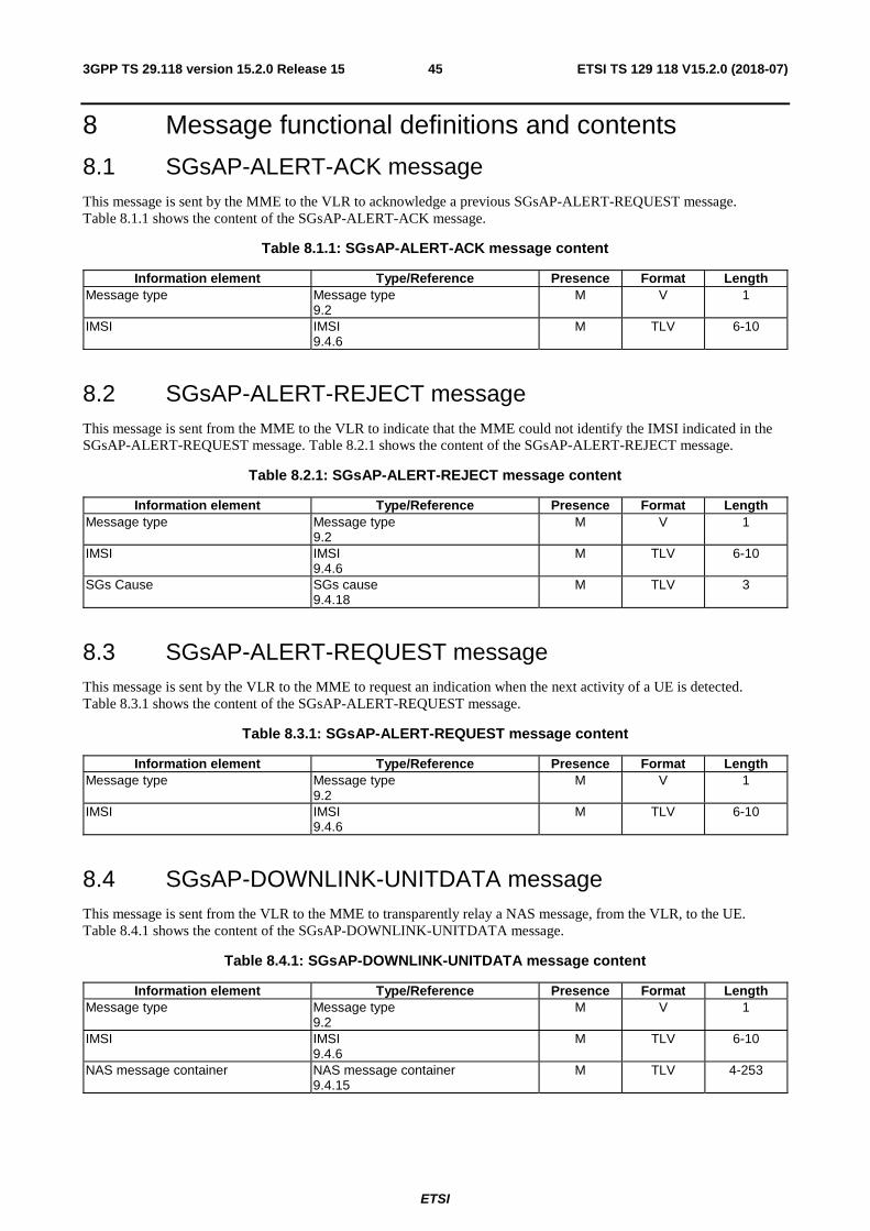
ETSI
ETSI TS 129 118 V15.2.0 (2018-07)453GPP TS 29.118 version 15.2.0 Release 15
8 Message functional definitions and contents
8.1 SGsAP-ALERT-ACK message This message is sent by the MME to the VLR to acknowledge a previous SGsAP-ALERT-REQUEST message. Table 8.1.1 shows the content of the SGsAP-ALERT-ACK message.
Table 8.1.1: SGsAP-ALERT-ACK message content
Information element Type/Reference Presence Format Length Message type Message type
9.2 M V 1
IMSI IMSI 9.4.6
M TLV 6-10
8.2 SGsAP-ALERT-REJECT message This message is sent from the MME to the VLR to indicate that the MME could not identify the IMSI indicated in the SGsAP-ALERT-REQUEST message. Table 8.2.1 shows the content of the SGsAP-ALERT-REJECT message.
Table 8.2.1: SGsAP-ALERT-REJECT message content
Information element Type/Reference Presence Format Length Message type Message type
9.2 M V 1
IMSI IMSI 9.4.6
M TLV 6-10
SGs Cause SGs cause 9.4.18
M TLV 3
8.3 SGsAP-ALERT-REQUEST message This message is sent by the VLR to the MME to request an indication when the next activity of a UE is detected. Table 8.3.1 shows the content of the SGsAP-ALERT-REQUEST message.
Table 8.3.1: SGsAP-ALERT-REQUEST message content
Information element Type/Reference Presence Format Length Message type Message type
9.2 M V 1
IMSI IMSI 9.4.6
M TLV 6-10
8.4 SGsAP-DOWNLINK-UNITDATA message This message is sent from the VLR to the MME to transparently relay a NAS message, from the VLR, to the UE. Table 8.4.1 shows the content of the SGsAP-DOWNLINK-UNITDATA message.
Table 8.4.1: SGsAP-DOWNLINK-UNITDATA message content
Information element Type/Reference Presence Format Length Message type Message type
9.2 M V 1
IMSI IMSI 9.4.6
M TLV 6-10
NAS message container NAS message container 9.4.15
M TLV 4-253
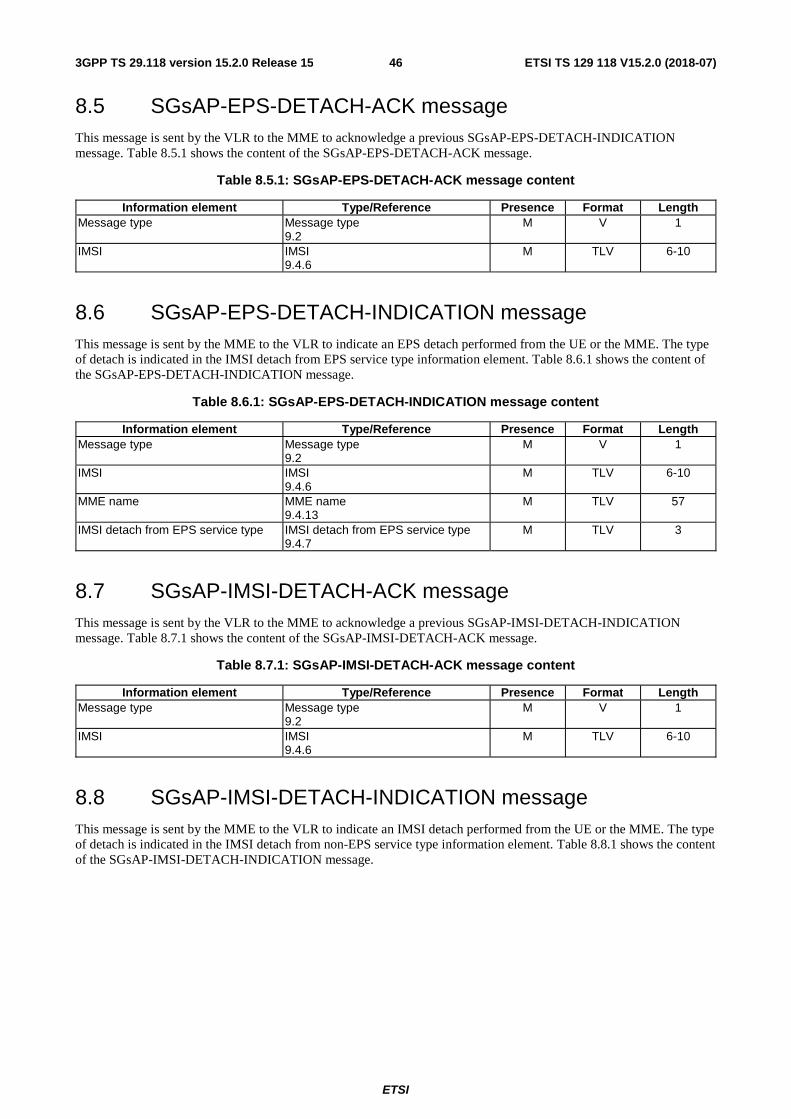
ETSI
ETSI TS 129 118 V15.2.0 (2018-07)463GPP TS 29.118 version 15.2.0 Release 15
8.5 SGsAP-EPS-DETACH-ACK message This message is sent by the VLR to the MME to acknowledge a previous SGsAP-EPS-DETACH-INDICATION message. Table 8.5.1 shows the content of the SGsAP-EPS-DETACH-ACK message.
Table 8.5.1: SGsAP-EPS-DETACH-ACK message content
Information element Type/Reference Presence Format Length Message type Message type
9.2 M V 1
IMSI IMSI 9.4.6
M TLV 6-10
8.6 SGsAP-EPS-DETACH-INDICATION message This message is sent by the MME to the VLR to indicate an EPS detach performed from the UE or the MME. The type of detach is indicated in the IMSI detach from EPS service type information element. Table 8.6.1 shows the content of the SGsAP-EPS-DETACH-INDICATION message.
Table 8.6.1: SGsAP-EPS-DETACH-INDICATION message content
Information element Type/Reference Presence Format Length Message type Message type
9.2 M V 1
IMSI IMSI 9.4.6
M TLV 6-10
MME name MME name 9.4.13
M TLV 57
IMSI detach from EPS service type IMSI detach from EPS service type 9.4.7
M TLV 3
8.7 SGsAP-IMSI-DETACH-ACK message This message is sent by the VLR to the MME to acknowledge a previous SGsAP-IMSI-DETACH-INDICATION message. Table 8.7.1 shows the content of the SGsAP-IMSI-DETACH-ACK message.
Table 8.7.1: SGsAP-IMSI-DETACH-ACK message content
Information element Type/Reference Presence Format Length Message type Message type
9.2 M V 1
IMSI IMSI 9.4.6
M TLV 6-10
8.8 SGsAP-IMSI-DETACH-INDICATION message This message is sent by the MME to the VLR to indicate an IMSI detach performed from the UE or the MME. The type of detach is indicated in the IMSI detach from non-EPS service type information element. Table 8.8.1 shows the content of the SGsAP-IMSI-DETACH-INDICATION message.
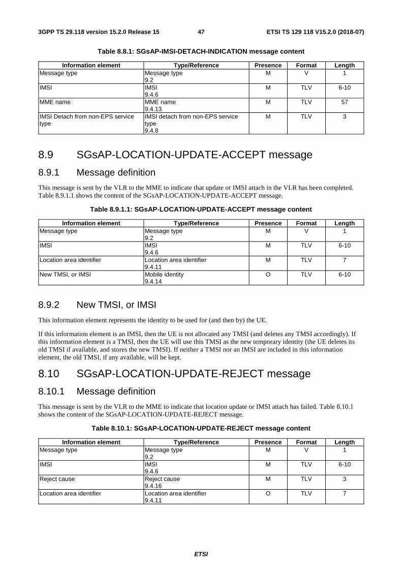
ETSI
ETSI TS 129 118 V15.2.0 (2018-07)473GPP TS 29.118 version 15.2.0 Release 15
Table 8.8.1: SGsAP-IMSI-DETACH-INDICATION message content
Information element Type/Reference Presence Format Length Message type Message type
9.2 M V 1
IMSI IMSI 9.4.6
M TLV 6-10
MME name MME name 9.4.13
M TLV 57
IMSI Detach from non-EPS service type
IMSI detach from non-EPS service type 9.4.8
M TLV 3
8.9 SGsAP-LOCATION-UPDATE-ACCEPT message
8.9.1 Message definition
This message is sent by the VLR to the MME to indicate that update or IMSI attach in the VLR has been completed. Table 8.9.1.1 shows the content of the SGsAP-LOCATION-UPDATE-ACCEPT message.
Table 8.9.1.1: SGsAP-LOCATION-UPDATE-ACCEPT message content
Information element Type/Reference Presence Format Length Message type Message type
9.2 M V 1
IMSI IMSI 9.4.6
M TLV 6-10
Location area identifier Location area identifier 9.4.11
M TLV 7
New TMSI, or IMSI Mobile identity 9.4.14
O TLV 6-10
8.9.2 New TMSI, or IMSI
This information element represents the identity to be used for (and then by) the UE.
If this information element is an IMSI, then the UE is not allocated any TMSI (and deletes any TMSI accordingly). If this information element is a TMSI, then the UE will use this TMSI as the new temporary identity (the UE deletes its old TMSI if available, and stores the new TMSI). If neither a TMSI nor an IMSI are included in this information element, the old TMSI, if any available, will be kept.
8.10 SGsAP-LOCATION-UPDATE-REJECT message
8.10.1 Message definition
This message is sent by the VLR to the MME to indicate that location update or IMSI attach has failed. Table 8.10.1 shows the content of the SGsAP-LOCATION-UPDATE-REJECT message.
Table 8.10.1: SGsAP-LOCATION-UPDATE-REJECT message content
Information element Type/Reference Presence Format Length Message type Message type
9.2 M V 1
IMSI IMSI 9.4.6
M TLV 6-10
Reject cause Reject cause 9.4.16
M TLV 3
Location area identifier Location area identifier 9.4.11
O TLV 7
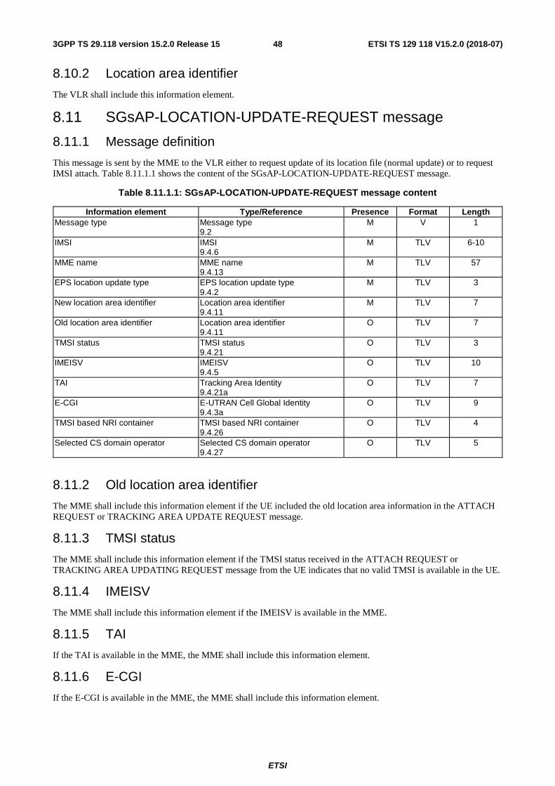
ETSI
ETSI TS 129 118 V15.2.0 (2018-07)483GPP TS 29.118 version 15.2.0 Release 15
8.10.2 Location area identifier
The VLR shall include this information element.
8.11 SGsAP-LOCATION-UPDATE-REQUEST message
8.11.1 Message definition
This message is sent by the MME to the VLR either to request update of its location file (normal update) or to request IMSI attach. Table 8.11.1.1 shows the content of the SGsAP-LOCATION-UPDATE-REQUEST message.
Table 8.11.1.1: SGsAP-LOCATION-UPDATE-REQUEST message content
Information element Type/Reference Presence Format Length Message type Message type
9.2 M V 1
IMSI IMSI 9.4.6
M TLV 6-10
MME name MME name 9.4.13
M TLV 57
EPS location update type EPS location update type 9.4.2
M TLV 3
New location area identifier Location area identifier 9.4.11
M TLV 7
Old location area identifier Location area identifier 9.4.11
O TLV 7
TMSI status TMSI status 9.4.21
O TLV 3
IMEISV IMEISV 9.4.5
O TLV 10
TAI Tracking Area Identity 9.4.21a
O TLV 7
E-CGI E-UTRAN Cell Global Identity 9.4.3a
O TLV 9
TMSI based NRI container TMSI based NRI container 9.4.26
O TLV 4
Selected CS domain operator Selected CS domain operator 9.4.27
O TLV 5
8.11.2 Old location area identifier
The MME shall include this information element if the UE included the old location area information in the ATTACH REQUEST or TRACKING AREA UPDATE REQUEST message.
8.11.3 TMSI status
The MME shall include this information element if the TMSI status received in the ATTACH REQUEST or TRACKING AREA UPDATING REQUEST message from the UE indicates that no valid TMSI is available in the UE.
8.11.4 IMEISV
The MME shall include this information element if the IMEISV is available in the MME.
8.11.5 TAI
If the TAI is available in the MME, the MME shall include this information element.
8.11.6 E-CGI
If the E-CGI is available in the MME, the MME shall include this information element.
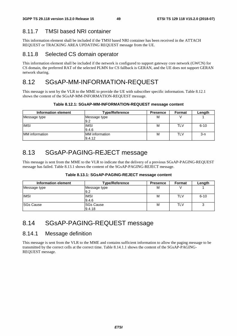
ETSI
ETSI TS 129 118 V15.2.0 (2018-07)493GPP TS 29.118 version 15.2.0 Release 15
8.11.7 TMSI based NRI container
This information element shall be included if the TMSI based NRI container has been received in the ATTACH REQUEST or TRACKING AREA UPDATING REQUEST message from the UE.
8.11.8 Selected CS domain operator
This information element shall be included if the network is configured to support gateway core network (GWCN) for CS domain, the preferred RAT of the selected PLMN for CS fallback is GERAN, and the UE does not support GERAN network sharing.
8.12 SGsAP-MM-INFORMATION-REQUEST This message is sent by the VLR to the MME to provide the UE with subscriber specific information. Table 8.12.1 shows the content of the SGsAP-MM-INFORMATION-REQUEST message.
Table 8.12.1: SGsAP-MM-INFORMATION-REQUEST message content
Information element Type/Reference Presence Format Length Message type Message type
9.2 M V 1
IMSI IMSI 9.4.6
M TLV 6-10
MM information MM information 9.4.12
M TLV 3-n
8.13 SGsAP-PAGING-REJECT message This message is sent from the MME to the VLR to indicate that the delivery of a previous SGsAP-PAGING-REQUEST message has failed. Table 8.13.1 shows the content of the SGsAP-PAGING-REJECT message.
Table 8.13.1: SGsAP-PAGING-REJECT message content
Information element Type/Reference Presence Format Length Message type Message type
9.2 M V 1
IMSI IMSI 9.4.6
M TLV 6-10
SGs Cause SGs Cause 9.4.18
M TLV 3
8.14 SGsAP-PAGING-REQUEST message
8.14.1 Message definition
This message is sent from the VLR to the MME and contains sufficient information to allow the paging message to be transmitted by the correct cells at the correct time. Table 8.14.1.1 shows the content of the SGsAP-PAGING-REQUEST message.
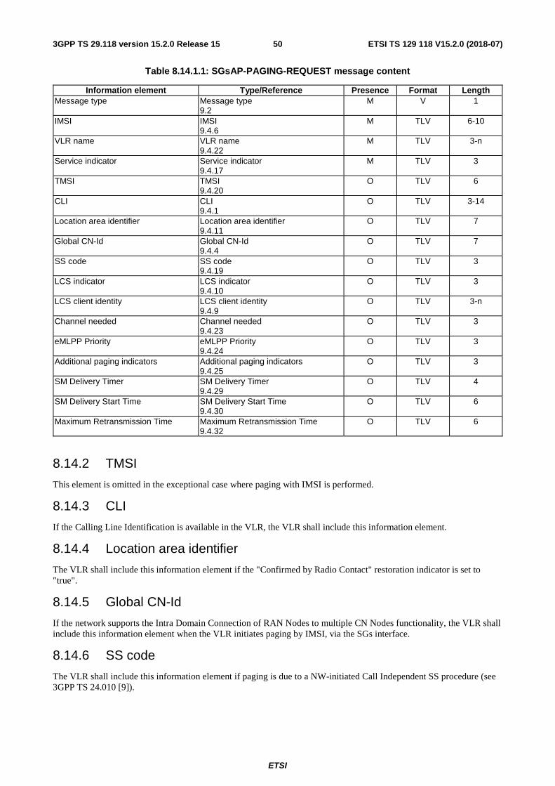
ETSI
ETSI TS 129 118 V15.2.0 (2018-07)503GPP TS 29.118 version 15.2.0 Release 15
Table 8.14.1.1: SGsAP-PAGING-REQUEST message content
Information element Type/Reference Presence Format Length Message type Message type
9.2 M V 1
IMSI IMSI 9.4.6
M TLV 6-10
VLR name VLR name 9.4.22
M TLV 3-n
Service indicator Service indicator 9.4.17
M TLV 3
TMSI TMSI 9.4.20
O TLV 6
CLI CLI 9.4.1
O TLV 3-14
Location area identifier Location area identifier 9.4.11
O TLV 7
Global CN-Id Global CN-Id 9.4.4
O TLV 7
SS code SS code 9.4.19
O TLV 3
LCS indicator LCS indicator 9.4.10
O TLV 3
LCS client identity LCS client identity 9.4.9
O TLV 3-n
Channel needed Channel needed 9.4.23
O TLV 3
eMLPP Priority eMLPP Priority 9.4.24
O TLV 3
Additional paging indicators Additional paging indicators 9.4.25
O TLV 3
SM Delivery Timer SM Delivery Timer 9.4.29
O TLV 4
SM Delivery Start Time SM Delivery Start Time 9.4.30
O TLV 6
Maximum Retransmission Time Maximum Retransmission Time 9.4.32
O TLV 6
8.14.2 TMSI
This element is omitted in the exceptional case where paging with IMSI is performed.
8.14.3 CLI
If the Calling Line Identification is available in the VLR, the VLR shall include this information element.
8.14.4 Location area identifier
The VLR shall include this information element if the "Confirmed by Radio Contact" restoration indicator is set to "true".
8.14.5 Global CN-Id
If the network supports the Intra Domain Connection of RAN Nodes to multiple CN Nodes functionality, the VLR shall include this information element when the VLR initiates paging by IMSI, via the SGs interface.
8.14.6 SS code
The VLR shall include this information element if paging is due to a NW-initiated Call Independent SS procedure (see 3GPP TS 24.010 [9]).
ETSI
ETSI TS 129 118 V15.2.0 (2018-07)513GPP TS 29.118 version 15.2.0 Release 15
8.14.7 LCS indicator
The VLR shall include this information element if the paging is due to a Mobile Terminated Location Request (see 3GPP TS 24.030 [11]).
8.14.8 LCS client identity
The VLR may include this information element if the paging is due to a Mobile Terminated Location Request (see 3GPP TS 24.030 [11]). If the paging is due to emergency positioning, then VLR should include this information element.
8.14.9 Channel needed
This information element shall be included if the VLR intends to indicate which channel the UE should use.
8.14.10 eMLPP priority
This information element shall be included if the VLR supports CSFB priority call handling and the callwas received with eMLPP priority level indication.
The eMLPP priority IE may be used to determine the required priority of a SCTP association for the associated SGsAP message.
8.14.11 Additional paging indicators
This information element shall be included if additional paging information e.g. CS restoration indicator needs to be passed to the MME.
8.14.12 SM Delivery Timer
For Deployment Option 2 (see subclause 8.2.4a.1 of 3GPP TS 23.272 [7]), this information element may be included if the Service Indicator IE indicates "SMS indicator" and the SM Delivery Timer and SM Delivery Start Time IEs were received from the SMS-GMSC as defined in 3GPP TS 24.010 [9].
8.14.13 SM Delivery Start Time
For Deployment Option 2 (see subclause 8.2.4a.1 of 3GPP TS 23.272 [7]), this information element may be included if the Service Indicator IE indicates "SMS indicator" and the SM Delivery Timer and SM Delivery Start Time IEs were received from the SMS-GMSC as defined in 3GPP TS 24.010 [9].
8.14.4 Maximum Retransmission Time
For Deployment Option 2 (see subclause 8.2.4a.1 of 3GPP TS 23.272 [7]), this information element may be included if the Service Indicator IE indicates "SMS indicator" and if the Maximum Retransmission Time IE was received from the SMS-GMSC as defined in 3GPP TS 29.002 [15].
8.15 SGsAP-RESET-ACK message
8.15.1 Message definition
This message is sent from the MME or the VLR to acknowledge a previous SGsAP-RESET-INDICATION message. This message indicates that all the SGs associations to the VLR or the MME have been marked as invalid.
The sending entity (either the MME or the VLR) includes its identity in the form of a name in the SGsAP-RESET-ACK message. Table 8.15.1.1 shows the content of the SGsAP-RESET-ACK message.
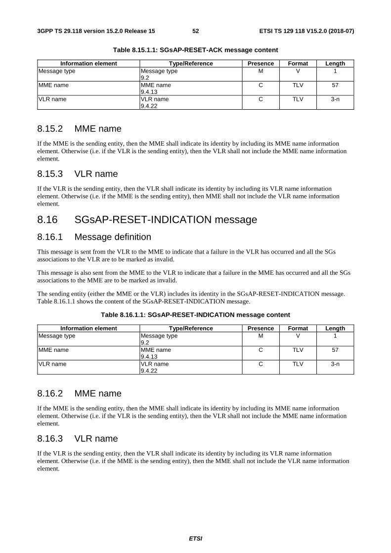
ETSI
ETSI TS 129 118 V15.2.0 (2018-07)523GPP TS 29.118 version 15.2.0 Release 15
Table 8.15.1.1: SGsAP-RESET-ACK message content
Information element Type/Reference Presence Format Length Message type Message type
9.2 M V 1
MME name MME name 9.4.13
C TLV 57
VLR name VLR name 9.4.22
C TLV 3-n
8.15.2 MME name
If the MME is the sending entity, then the MME shall indicate its identity by including its MME name information element. Otherwise (i.e. if the VLR is the sending entity), then the VLR shall not include the MME name information element.
8.15.3 VLR name
If the VLR is the sending entity, then the VLR shall indicate its identity by including its VLR name information element. Otherwise (i.e. if the MME is the sending entity), then MME shall not include the VLR name information element.
8.16 SGsAP-RESET-INDICATION message
8.16.1 Message definition
This message is sent from the VLR to the MME to indicate that a failure in the VLR has occurred and all the SGs associations to the VLR are to be marked as invalid.
This message is also sent from the MME to the VLR to indicate that a failure in the MME has occurred and all the SGs associations to the MME are to be marked as invalid.
The sending entity (either the MME or the VLR) includes its identity in the SGsAP-RESET-INDICATION message. Table 8.16.1.1 shows the content of the SGsAP-RESET-INDICATION message.
Table 8.16.1.1: SGsAP-RESET-INDICATION message content
Information element Type/Reference Presence Format Length Message type Message type
9.2 M V 1
MME name MME name 9.4.13
C TLV 57
VLR name VLR name 9.4.22
C TLV 3-n
8.16.2 MME name
If the MME is the sending entity, then the MME shall indicate its identity by including its MME name information element. Otherwise (i.e. if the VLR is the sending entity), then the VLR shall not include the MME name information element.
8.16.3 VLR name
If the VLR is the sending entity, then the VLR shall indicate its identity by including its VLR name information element. Otherwise (i.e. if the MME is the sending entity), then the MME shall not include the VLR name information element.
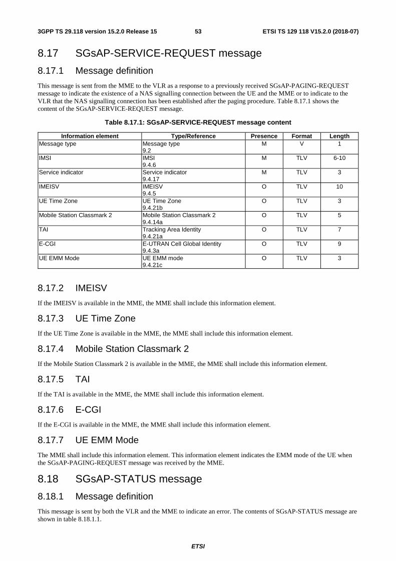
ETSI
ETSI TS 129 118 V15.2.0 (2018-07)533GPP TS 29.118 version 15.2.0 Release 15
8.17 SGsAP-SERVICE-REQUEST message
8.17.1 Message definition
This message is sent from the MME to the VLR as a response to a previously received SGsAP-PAGING-REQUEST message to indicate the existence of a NAS signalling connection between the UE and the MME or to indicate to the VLR that the NAS signalling connection has been established after the paging procedure. Table 8.17.1 shows the content of the SGsAP-SERVICE-REQUEST message.
Table 8.17.1: SGsAP-SERVICE-REQUEST message content
Information element Type/Reference Presence Format Length Message type Message type
9.2 M V 1
IMSI IMSI 9.4.6
M TLV 6-10
Service indicator Service indicator 9.4.17
M TLV 3
IMEISV IMEISV 9.4.5
O TLV 10
UE Time Zone UE Time Zone 9.4.21b
O TLV 3
Mobile Station Classmark 2 Mobile Station Classmark 2 9.4.14a
O TLV 5
TAI Tracking Area Identity 9.4.21a
O TLV 7
E-CGI E-UTRAN Cell Global Identity 9.4.3a
O TLV 9
UE EMM Mode UE EMM mode 9.4.21c
O TLV 3
8.17.2 IMEISV
If the IMEISV is available in the MME, the MME shall include this information element.
8.17.3 UE Time Zone
If the UE Time Zone is available in the MME, the MME shall include this information element.
8.17.4 Mobile Station Classmark 2
If the Mobile Station Classmark 2 is available in the MME, the MME shall include this information element.
8.17.5 TAI
If the TAI is available in the MME, the MME shall include this information element.
8.17.6 E-CGI
If the E-CGI is available in the MME, the MME shall include this information element.
8.17.7 UE EMM Mode
The MME shall include this information element. This information element indicates the EMM mode of the UE when the SGsAP-PAGING-REQUEST message was received by the MME.
8.18 SGsAP-STATUS message
8.18.1 Message definition
This message is sent by both the VLR and the MME to indicate an error. The contents of SGsAP-STATUS message are shown in table 8.18.1.1.
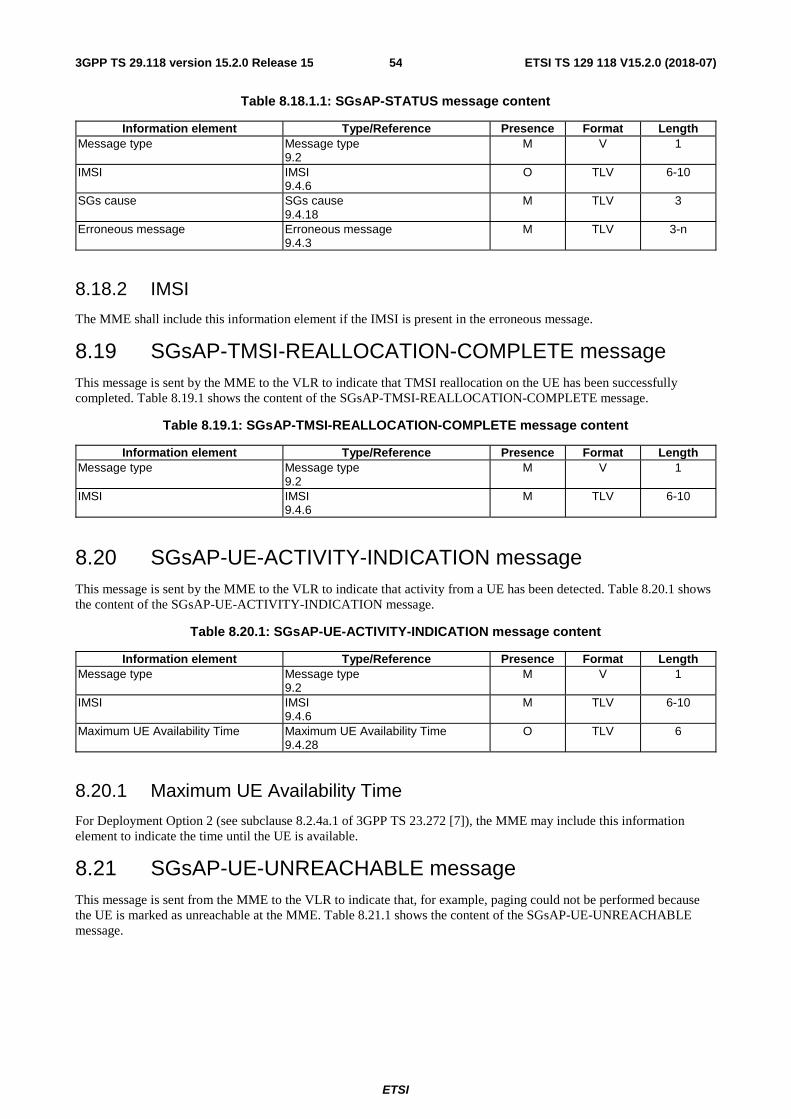
ETSI
ETSI TS 129 118 V15.2.0 (2018-07)543GPP TS 29.118 version 15.2.0 Release 15
Table 8.18.1.1: SGsAP-STATUS message content
Information element Type/Reference Presence Format Length Message type Message type
9.2 M V 1
IMSI IMSI 9.4.6
O TLV 6-10
SGs cause SGs cause 9.4.18
M TLV 3
Erroneous message Erroneous message 9.4.3
M TLV 3-n
8.18.2 IMSI
The MME shall include this information element if the IMSI is present in the erroneous message.
8.19 SGsAP-TMSI-REALLOCATION-COMPLETE message This message is sent by the MME to the VLR to indicate that TMSI reallocation on the UE has been successfully completed. Table 8.19.1 shows the content of the SGsAP-TMSI-REALLOCATION-COMPLETE message.
Table 8.19.1: SGsAP-TMSI-REALLOCATION-COMPLETE message content
Information element Type/Reference Presence Format Length Message type Message type
9.2 M V 1
IMSI IMSI 9.4.6
M TLV 6-10
8.20 SGsAP-UE-ACTIVITY-INDICATION message This message is sent by the MME to the VLR to indicate that activity from a UE has been detected. Table 8.20.1 shows the content of the SGsAP-UE-ACTIVITY-INDICATION message.
Table 8.20.1: SGsAP-UE-ACTIVITY-INDICATION message content
Information element Type/Reference Presence Format Length Message type Message type
9.2 M V 1
IMSI IMSI 9.4.6
M TLV 6-10
Maximum UE Availability Time Maximum UE Availability Time 9.4.28
O TLV 6
8.20.1 Maximum UE Availability Time
For Deployment Option 2 (see subclause 8.2.4a.1 of 3GPP TS 23.272 [7]), the MME may include this information element to indicate the time until the UE is available.
8.21 SGsAP-UE-UNREACHABLE message This message is sent from the MME to the VLR to indicate that, for example, paging could not be performed because the UE is marked as unreachable at the MME. Table 8.21.1 shows the content of the SGsAP-UE-UNREACHABLE message.
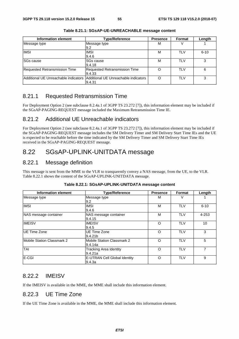
ETSI
ETSI TS 129 118 V15.2.0 (2018-07)553GPP TS 29.118 version 15.2.0 Release 15
Table 8.21.1: SGsAP-UE-UNREACHABLE message content
Information element Type/Reference Presence Format Length Message type Message type
9.2 M V 1
IMSI IMSI 9.4.6
M TLV 6-10
SGs cause SGs cause 9.4.18
M TLV 3
Requested Retransmission Time Requested Retransmission Time 9.4.33
O TLV 6
Additional UE Unreachable indicators Additional UE Unreachable indicators 9.4.31
O TLV 3
8.21.1 Requested Retransmission Time
For Deployment Option 2 (see subclause 8.2.4a.1 of 3GPP TS 23.272 [7]), this information element may be included if the SGsAP-PAGING-REQUEST message included the Maximum Retransmission Time IE.
8.21.2 Additional UE Unreachable indicators
For Deployment Option 2 (see subclause 8.2.4a.1 of 3GPP TS 23.272 [7]), this information element may be included if the SGsAP-PAGING-REQUEST message includes the SM Delivery Timer and SM Delivery Start Time IEs and the UE is expected to be reachable before the time indicated by the SM Delivery Timer and SM Delivery Start Time IEs received in the SGsAP-PAGING-REQUEST message.
8.22 SGsAP-UPLINK-UNITDATA message
8.22.1 Message definition
This message is sent from the MME to the VLR to transparently convey a NAS message, from the UE, to the VLR. Table 8.22.1 shows the content of the SGsAP-UPLINK-UNITDATA message.
Table 8.22.1: SGsAP-UPLINK-UNITDATA message content
Information element Type/Reference Presence Format Length Message type Message type
9.2 M V 1
IMSI IMSI 9.4.6
M TLV 6-10
NAS message container NAS message container 9.4.15
M TLV 4-253
IMEISV IMEISV 9.4.5
O TLV 10
UE Time Zone UE Time Zone 9.4.21b
O TLV 3
Mobile Station Classmark 2 Mobile Station Classmark 2 9.4.14a
O TLV 5
TAI Tracking Area Identity 9.4.21a
O TLV 7
E-CGI E-UTRAN Cell Global Identity 9.4.3a
O TLV 9
8.22.2 IMEISV
If the IMEISV is available in the MME, the MME shall include this information element.
8.22.3 UE Time Zone
If the UE Time Zone is available in the MME, the MME shall include this information element.
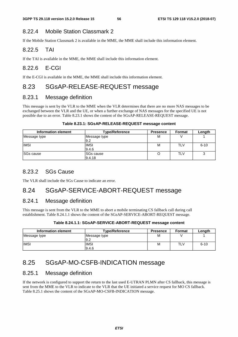
ETSI
ETSI TS 129 118 V15.2.0 (2018-07)563GPP TS 29.118 version 15.2.0 Release 15
8.22.4 Mobile Station Classmark 2
If the Mobile Station Classmark 2 is available in the MME, the MME shall include this information element.
8.22.5 TAI
If the TAI is available in the MME, the MME shall include this information element.
8.22.6 E-CGI
If the E-CGI is available in the MME, the MME shall include this information element.
8.23 SGsAP-RELEASE-REQUEST message
8.23.1 Message definition
This message is sent by the VLR to the MME when the VLR determines that there are no more NAS messages to be exchanged between the VLR and the UE, or when a further exchange of NAS messages for the specified UE is not possible due to an error. Table 8.23.1 shows the content of the SGsAP-RELEASE-REQUEST message.
Table 8.23.1: SGsAP-RELEASE-REQUEST message content
Information element Type/Reference Presence Format Length Message type Message type
9.2 M V 1
IMSI IMSI 9.4.6
M TLV 6-10
SGs cause SGs cause 9.4.18
O TLV 3
8.23.2 SGs Cause
The VLR shall include the SGs Cause to indicate an error.
8.24 SGsAP-SERVICE-ABORT-REQUEST message
8.24.1 Message definition
This message is sent from the VLR to the MME to abort a mobile terminating CS fallback call during call establishment. Table 8.24.1.1 shows the content of the SGsAP-SERVICE-ABORT-REQUEST message.
Table 8.24.1.1: SGsAP-SERVICE-ABORT-REQUEST message content
Information element Type/Reference Presence Format Length Message type Message type
9.2 M V 1
IMSI IMSI 9.4.6
M TLV 6-10
8.25 SGsAP-MO-CSFB-INDICATION message
8.25.1 Message definition
If the network is configured to support the return to the last used E-UTRAN PLMN after CS fallback, this message is sent from the MME to the VLR to indicate to the VLR that the UE initiated a service request for MO CS fallback. Table 8.25.1 shows the content of the SGsAP-MO-CSFB-INDICATION message.
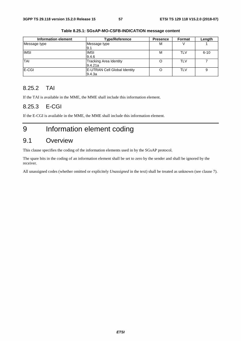
ETSI
ETSI TS 129 118 V15.2.0 (2018-07)573GPP TS 29.118 version 15.2.0 Release 15
Table 8.25.1: SGsAP-MO-CSFB-INDICATION message content
Information element Type/Reference Presence Format Length Message type Message type
9.1 M V 1
IMSI IMSI 9.4.6
M TLV 6-10
TAI Tracking Area Identity 9.4.21a
O TLV 7
E-CGI E-UTRAN Cell Global Identity 9.4.3a
O TLV 9
8.25.2 TAI
If the TAI is available in the MME, the MME shall include this information element.
8.25.3 E-CGI
If the E-CGI is available in the MME, the MME shall include this information element.
9 Information element coding
9.1 Overview This clause specifies the coding of the information elements used in by the SGsAP protocol.
The spare bits in the coding of an information element shall be set to zero by the sender and shall be ignored by the receiver.
All unassigned codes (whether omitted or explicitely Unassigned in the text) shall be treated as unknown (see clause 7).
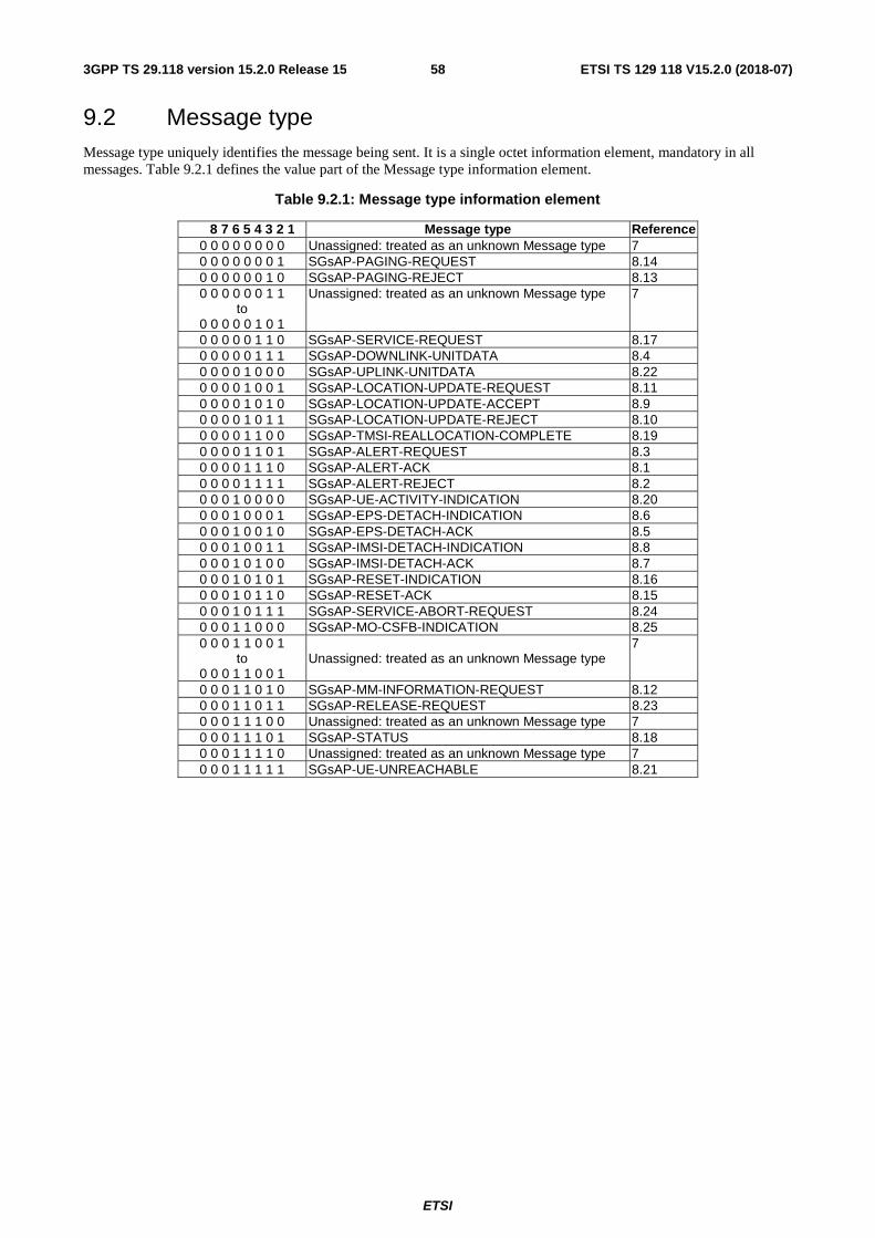
ETSI
ETSI TS 129 118 V15.2.0 (2018-07)583GPP TS 29.118 version 15.2.0 Release 15
9.2 Message type Message type uniquely identifies the message being sent. It is a single octet information element, mandatory in all messages. Table 9.2.1 defines the value part of the Message type information element.
Table 9.2.1: Message type information element
8 7 6 5 4 3 2 1 Message type Reference 0 0 0 0 0 0 0 0 Unassigned: treated as an unknown Message type 7 0 0 0 0 0 0 0 1 SGsAP-PAGING-REQUEST 8.14 0 0 0 0 0 0 1 0 SGsAP-PAGING-REJECT 8.13 0 0 0 0 0 0 1 1
to 0 0 0 0 0 1 0 1
Unassigned: treated as an unknown Message type 7
0 0 0 0 0 1 1 0 SGsAP-SERVICE-REQUEST 8.17 0 0 0 0 0 1 1 1 SGsAP-DOWNLINK-UNITDATA 8.4 0 0 0 0 1 0 0 0 SGsAP-UPLINK-UNITDATA 8.22 0 0 0 0 1 0 0 1 SGsAP-LOCATION-UPDATE-REQUEST 8.11 0 0 0 0 1 0 1 0 SGsAP-LOCATION-UPDATE-ACCEPT 8.9 0 0 0 0 1 0 1 1 SGsAP-LOCATION-UPDATE-REJECT 8.10 0 0 0 0 1 1 0 0 SGsAP-TMSI-REALLOCATION-COMPLETE 8.19 0 0 0 0 1 1 0 1 SGsAP-ALERT-REQUEST 8.3 0 0 0 0 1 1 1 0 SGsAP-ALERT-ACK 8.1 0 0 0 0 1 1 1 1 SGsAP-ALERT-REJECT 8.2 0 0 0 1 0 0 0 0 SGsAP-UE-ACTIVITY-INDICATION 8.20 0 0 0 1 0 0 0 1 SGsAP-EPS-DETACH-INDICATION 8.6 0 0 0 1 0 0 1 0 SGsAP-EPS-DETACH-ACK 8.5 0 0 0 1 0 0 1 1 SGsAP-IMSI-DETACH-INDICATION 8.8 0 0 0 1 0 1 0 0 SGsAP-IMSI-DETACH-ACK 8.7 0 0 0 1 0 1 0 1 SGsAP-RESET-INDICATION 8.16 0 0 0 1 0 1 1 0 SGsAP-RESET-ACK 8.15 0 0 0 1 0 1 1 1 SGsAP-SERVICE-ABORT-REQUEST 8.24 0 0 0 1 1 0 0 0 SGsAP-MO-CSFB-INDICATION 8.25 0 0 0 1 1 0 0 1
to 0 0 0 1 1 0 0 1
Unassigned: treated as an unknown Message type
7
0 0 0 1 1 0 1 0 SGsAP-MM-INFORMATION-REQUEST 8.12 0 0 0 1 1 0 1 1 SGsAP-RELEASE-REQUEST 8.23 0 0 0 1 1 1 0 0 Unassigned: treated as an unknown Message type 7 0 0 0 1 1 1 0 1 SGsAP-STATUS 8.18 0 0 0 1 1 1 1 0 Unassigned: treated as an unknown Message type 7 0 0 0 1 1 1 1 1 SGsAP-UE-UNREACHABLE 8.21
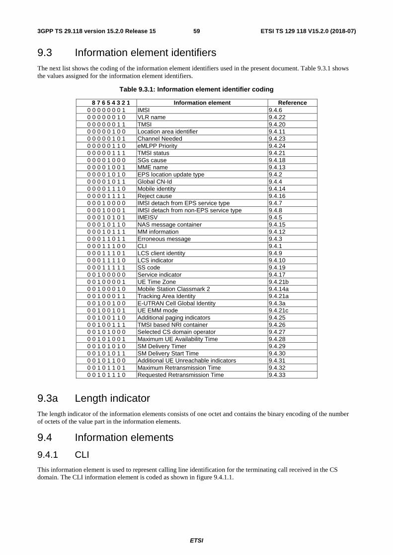
ETSI
ETSI TS 129 118 V15.2.0 (2018-07)593GPP TS 29.118 version 15.2.0 Release 15
9.3 Information element identifiers The next list shows the coding of the information element identifiers used in the present document. Table 9.3.1 shows the values assigned for the information element identifiers.
Table 9.3.1: Information element identifier coding
8 7 6 5 4 3 2 1 Information element Reference 0 0 0 0 0 0 0 1 IMSI 9.4.6 0 0 0 0 0 0 1 0 VLR name 9.4.22 0 0 0 0 0 0 1 1 TMSI 9.4.20 0 0 0 0 0 1 0 0 Location area identifier 9.4.11 0 0 0 0 0 1 0 1 Channel Needed 9.4.23 0 0 0 0 0 1 1 0 eMLPP Priority 9.4.24 0 0 0 0 0 1 1 1 TMSI status 9.4.21 0 0 0 0 1 0 0 0 SGs cause 9.4.18 0 0 0 0 1 0 0 1 MME name 9.4.13 0 0 0 0 1 0 1 0 EPS location update type 9.4.2 0 0 0 0 1 0 1 1 Global CN-Id 9.4.4 0 0 0 0 1 1 1 0 Mobile identity 9.4.14 0 0 0 0 1 1 1 1 Reject cause 9.4.16 0 0 0 1 0 0 0 0 IMSI detach from EPS service type 9.4.7 0 0 0 1 0 0 0 1 IMSI detach from non-EPS service type 9.4.8 0 0 0 1 0 1 0 1 IMEISV 9.4.5 0 0 0 1 0 1 1 0 NAS message container 9.4.15 0 0 0 1 0 1 1 1 MM information 9.4.12 0 0 0 1 1 0 1 1 Erroneous message 9.4.3 0 0 0 1 1 1 0 0 CLI 9.4.1 0 0 0 1 1 1 0 1 LCS client identity 9.4.9 0 0 0 1 1 1 1 0 LCS indicator 9.4.10 0 0 0 1 1 1 1 1 SS code 9.4.19 0 0 1 0 0 0 0 0 Service indicator 9.4.17 0 0 1 0 0 0 0 1 UE Time Zone 9.4.21b 0 0 1 0 0 0 1 0 Mobile Station Classmark 2 9.4.14a 0 0 1 0 0 0 1 1 Tracking Area Identity 9.4.21a 0 0 1 0 0 1 0 0 E-UTRAN Cell Global Identity 9.4.3a 0 0 1 0 0 1 0 1 UE EMM mode 9.4.21c 0 0 1 0 0 1 1 0 Additional paging indicators 9.4.25 0 0 1 0 0 1 1 1 TMSI based NRI container 9.4.26 0 0 1 0 1 0 0 0 Selected CS domain operator 9.4.27 0 0 1 0 1 0 0 1 Maximum UE Availability Time 9.4.28 0 0 1 0 1 0 1 0 SM Delivery Timer 9.4.29 0 0 1 0 1 0 1 1 SM Delivery Start Time 9.4.30 0 0 1 0 1 1 0 0 Additional UE Unreachable indicators 9.4.31 0 0 1 0 1 1 0 1 Maximum Retransmission Time 9.4.32 0 0 1 0 1 1 1 0 Requested Retransmission Time 9.4.33
9.3a Length indicator The length indicator of the information elements consists of one octet and contains the binary encoding of the number of octets of the value part in the information elements.
9.4 Information elements
9.4.1 CLI
This information element is used to represent calling line identification for the terminating call received in the CS domain. The CLI information element is coded as shown in figure 9.4.1.1.
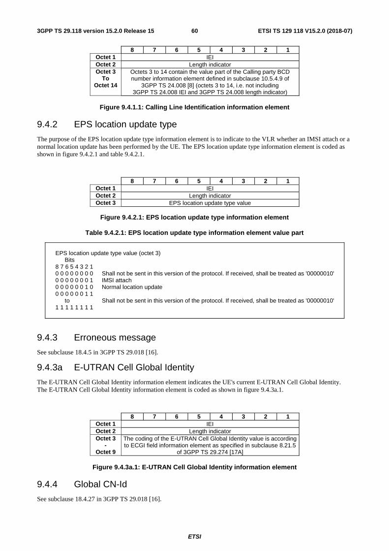
ETSI
ETSI TS 129 118 V15.2.0 (2018-07)603GPP TS 29.118 version 15.2.0 Release 15
8 7 6 5 4 3 2 1 Octet 1 IEI Octet 2 Length indicator Octet 3
To Octet 14
Octets 3 to 14 contain the value part of the Calling party BCD number information element defined in subclause 10.5.4.9 of
3GPP TS 24.008 [8] (octets 3 to 14, i.e. not including 3GPP TS 24.008 IEI and 3GPP TS 24.008 length indicator)
Figure 9.4.1.1: Calling Line Identification information element
9.4.2 EPS location update type
The purpose of the EPS location update type information element is to indicate to the VLR whether an IMSI attach or a normal location update has been performed by the UE. The EPS location update type information element is coded as shown in figure 9.4.2.1 and table 9.4.2.1.
8 7 6 5 4 3 2 1 Octet 1 IEI Octet 2 Length indicator Octet 3 EPS location update type value
Figure 9.4.2.1: EPS location update type information element
Table 9.4.2.1: EPS location update type information element value part
EPS location update type value (octet 3) Bits 8 7 6 5 4 3 2 1 0 0 0 0 0 0 0 0 Shall not be sent in this version of the protocol. If received, shall be treated as '00000010' 0 0 0 0 0 0 0 1 IMSI attach 0 0 0 0 0 0 1 0 Normal location update 0 0 0 0 0 0 1 1 to Shall not be sent in this version of the protocol. If received, shall be treated as '00000010' 1 1 1 1 1 1 1 1
9.4.3 Erroneous message
See subclause 18.4.5 in 3GPP TS 29.018 [16].
9.4.3a E-UTRAN Cell Global Identity
The E-UTRAN Cell Global Identity information element indicates the UE's current E-UTRAN Cell Global Identity. The E-UTRAN Cell Global Identity information element is coded as shown in figure 9.4.3a.1.
8 7 6 5 4 3 2 1 Octet 1 IEI Octet 2 Length indicator Octet 3
- Octet 9
The coding of the E-UTRAN Cell Global Identity value is according to ECGI field information element as specified in subclause 8.21.5
of 3GPP TS 29.274 [17A]
Figure 9.4.3a.1: E-UTRAN Cell Global Identity information element
9.4.4 Global CN-Id
See subclause 18.4.27 in 3GPP TS 29.018 [16].
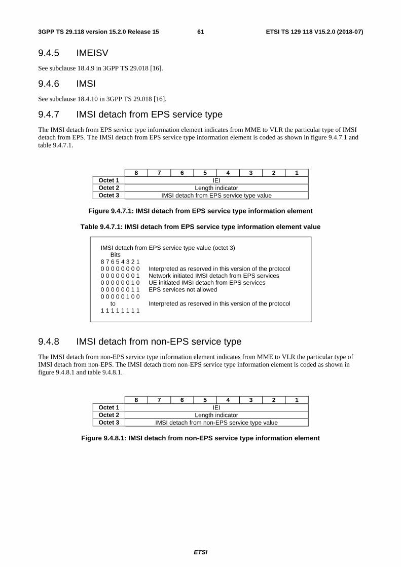
ETSI
ETSI TS 129 118 V15.2.0 (2018-07)613GPP TS 29.118 version 15.2.0 Release 15
9.4.5 IMEISV
See subclause 18.4.9 in 3GPP TS 29.018 [16].
9.4.6 IMSI
See subclause 18.4.10 in 3GPP TS 29.018 [16].
9.4.7 IMSI detach from EPS service type
The IMSI detach from EPS service type information element indicates from MME to VLR the particular type of IMSI detach from EPS. The IMSI detach from EPS service type information element is coded as shown in figure 9.4.7.1 and table 9.4.7.1.
8 7 6 5 4 3 2 1 Octet 1 IEI Octet 2 Length indicator Octet 3 IMSI detach from EPS service type value
Figure 9.4.7.1: IMSI detach from EPS service type information element
Table 9.4.7.1: IMSI detach from EPS service type information element value
IMSI detach from EPS service type value (octet 3) Bits 8 7 6 5 4 3 2 1 0 0 0 0 0 0 0 0 Interpreted as reserved in this version of the protocol 0 0 0 0 0 0 0 1 Network initiated IMSI detach from EPS services 0 0 0 0 0 0 1 0 UE initiated IMSI detach from EPS services 0 0 0 0 0 0 1 1 EPS services not allowed 0 0 0 0 0 1 0 0 to Interpreted as reserved in this version of the protocol 1 1 1 1 1 1 1 1
9.4.8 IMSI detach from non-EPS service type
The IMSI detach from non-EPS service type information element indicates from MME to VLR the particular type of IMSI detach from non-EPS. The IMSI detach from non-EPS service type information element is coded as shown in figure 9.4.8.1 and table 9.4.8.1.
8 7 6 5 4 3 2 1 Octet 1 IEI Octet 2 Length indicator Octet 3 IMSI detach from non-EPS service type value
Figure 9.4.8.1: IMSI detach from non-EPS service type information element
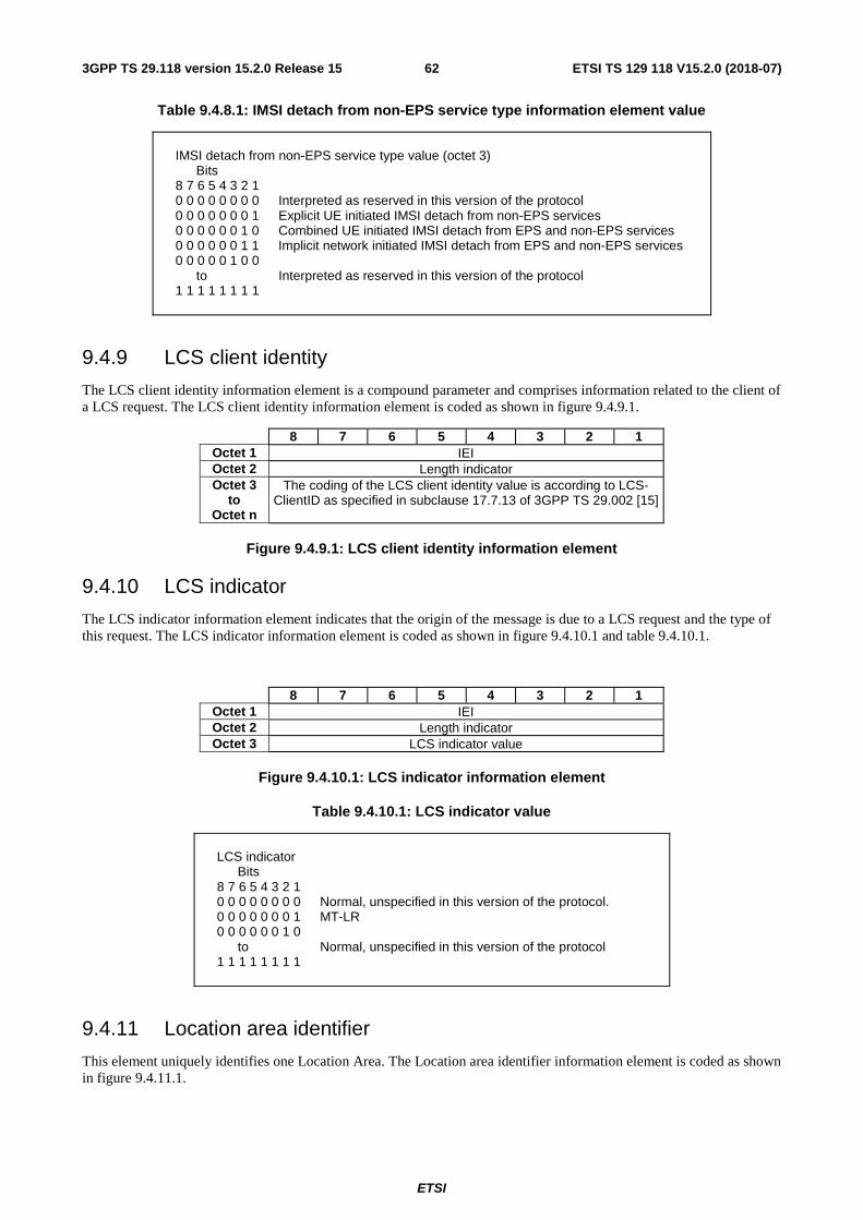
ETSI
ETSI TS 129 118 V15.2.0 (2018-07)623GPP TS 29.118 version 15.2.0 Release 15
Table 9.4.8.1: IMSI detach from non-EPS service type information element value
IMSI detach from non-EPS service type value (octet 3) Bits 8 7 6 5 4 3 2 1 0 0 0 0 0 0 0 0 Interpreted as reserved in this version of the protocol 0 0 0 0 0 0 0 1 Explicit UE initiated IMSI detach from non-EPS services 0 0 0 0 0 0 1 0 Combined UE initiated IMSI detach from EPS and non-EPS services 0 0 0 0 0 0 1 1 Implicit network initiated IMSI detach from EPS and non-EPS services 0 0 0 0 0 1 0 0 to Interpreted as reserved in this version of the protocol 1 1 1 1 1 1 1 1
9.4.9 LCS client identity
The LCS client identity information element is a compound parameter and comprises information related to the client of a LCS request. The LCS client identity information element is coded as shown in figure 9.4.9.1.
8 7 6 5 4 3 2 1 Octet 1 IEI Octet 2 Length indicator Octet 3
to Octet n
The coding of the LCS client identity value is according to LCS-ClientID as specified in subclause 17.7.13 of 3GPP TS 29.002 [15]
Figure 9.4.9.1: LCS client identity information element
9.4.10 LCS indicator
The LCS indicator information element indicates that the origin of the message is due to a LCS request and the type of this request. The LCS indicator information element is coded as shown in figure 9.4.10.1 and table 9.4.10.1.
8 7 6 5 4 3 2 1 Octet 1 IEI Octet 2 Length indicator Octet 3 LCS indicator value
Figure 9.4.10.1: LCS indicator information element
Table 9.4.10.1: LCS indicator value
LCS indicator Bits 8 7 6 5 4 3 2 1 0 0 0 0 0 0 0 0 Normal, unspecified in this version of the protocol. 0 0 0 0 0 0 0 1 MT-LR 0 0 0 0 0 0 1 0 to Normal, unspecified in this version of the protocol 1 1 1 1 1 1 1 1
9.4.11 Location area identifier
This element uniquely identifies one Location Area. The Location area identifier information element is coded as shown in figure 9.4.11.1.
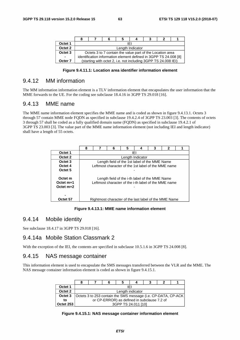
ETSI
ETSI TS 129 118 V15.2.0 (2018-07)633GPP TS 29.118 version 15.2.0 Release 15
8 7 6 5 4 3 2 1 Octet 1 IEI Octet 2 Length Indicator Octet 3
- Octer 7
Octets 3 to 7 contain the value part of the Location area identification information element defined in 3GPP TS 24.008 [8]
(starting with octet 2, i.e. not including 3GPP TS 24.008 IEI)
Figure 9.4.11.1: Location area identifier information element
9.4.12 MM information
The MM information information element is a TLV information element that encapsulates the user information that the MME forwards to the UE. For the coding see subclause 18.4.16 in 3GPP TS 29.018 [16].
9.4.13 MME name
The MME name information element specifies the MME name and is coded as shown in figure 9.4.13.1. Octets 3 through 57 contain MME node FQDN as specified in subclause 19.4.2.4 of 3GPP TS 23.003 [3]. The contents of octets 3 through 57 shall be coded as a fully qualified domain name (FQDN) as specified in subclause 19.4.2.1 of 3GPP TS 23.003 [3]. The value part of the MME name information element (not including IEI and length indicator) shall have a length of 55 octets.
8 7 6 5 4 3 2 1 Octet 1 IEI Octet 2 Length Indicator Octet 3 Octet 4 Octet 5
Octet m
Octet m+1 Octet m+2
-
Octet 57
Length field of the 1st label of the MME Name Leftmost character of the 1st label of the MME name
-
Length field of the i-th label of the MME Name Leftmost character of the i-th label of the MME name
-
Rightmost character of the last label of the MME Name
Figure 9.4.13.1: MME name information element
9.4.14 Mobile identity
See subclause 18.4.17 in 3GPP TS 29.018 [16].
9.4.14a Mobile Station Classmark 2
With the exception of the IEI, the contents are specified in subclause 10.5.1.6 in 3GPP TS 24.008 [8].
9.4.15 NAS message container
This information element is used to encapsulate the SMS messages transferred between the VLR and the MME. The NAS message container information element is coded as shown in figure 9.4.15.1.
8 7 6 5 4 3 2 1
Octet 1 IEI Octet 2 Length indicator Octet 3
to Octet 253
Octets 3 to 253 contain the SMS message (i.e. CP-DATA, CP-ACK or CP-ERROR) as defined in subclause 7.2 of
3GPP TS 24.011 [10]
Figure 9.4.15.1: NAS message container information element
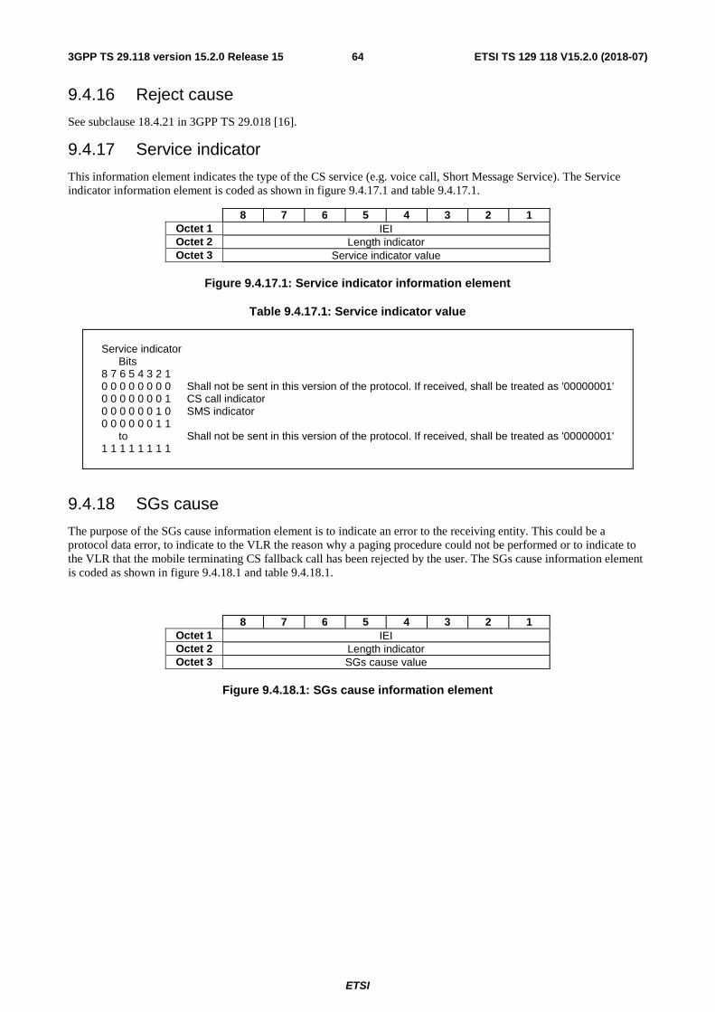
ETSI
ETSI TS 129 118 V15.2.0 (2018-07)643GPP TS 29.118 version 15.2.0 Release 15
9.4.16 Reject cause
See subclause 18.4.21 in 3GPP TS 29.018 [16].
9.4.17 Service indicator
This information element indicates the type of the CS service (e.g. voice call, Short Message Service). The Service indicator information element is coded as shown in figure 9.4.17.1 and table 9.4.17.1.
8 7 6 5 4 3 2 1 Octet 1 IEI Octet 2 Length indicator Octet 3 Service indicator value
Figure 9.4.17.1: Service indicator information element
Table 9.4.17.1: Service indicator value
Service indicator Bits 8 7 6 5 4 3 2 1 0 0 0 0 0 0 0 0 Shall not be sent in this version of the protocol. If received, shall be treated as '00000001' 0 0 0 0 0 0 0 1 CS call indicator 0 0 0 0 0 0 1 0 SMS indicator 0 0 0 0 0 0 1 1 to Shall not be sent in this version of the protocol. If received, shall be treated as '00000001' 1 1 1 1 1 1 1 1
9.4.18 SGs cause
The purpose of the SGs cause information element is to indicate an error to the receiving entity. This could be a protocol data error, to indicate to the VLR the reason why a paging procedure could not be performed or to indicate to the VLR that the mobile terminating CS fallback call has been rejected by the user. The SGs cause information element is coded as shown in figure 9.4.18.1 and table 9.4.18.1.
8 7 6 5 4 3 2 1 Octet 1 IEI Octet 2 Length indicator Octet 3 SGs cause value
Figure 9.4.18.1: SGs cause information element
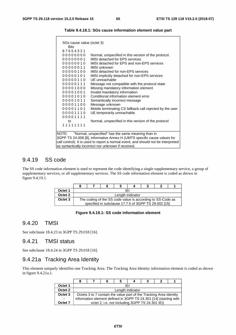
ETSI
ETSI TS 129 118 V15.2.0 (2018-07)653GPP TS 29.118 version 15.2.0 Release 15
Table 9.4.18.1: SGs cause information element value part
SGs cause value (octet 3) Bits 8 7 6 5 4 3 2 1 0 0 0 0 0 0 0 0 Normal, unspecified in this version of the protocol. 0 0 0 0 0 0 0 1 IMSI detached for EPS services 0 0 0 0 0 0 1 0 IMSI detached for EPS and non-EPS services 0 0 0 0 0 0 1 1 IMSI unknown 0 0 0 0 0 1 0 0 IMSI detached for non-EPS services 0 0 0 0 0 1 0 1 IMSI implicitly detached for non-EPS services 0 0 0 0 0 1 1 0 UE unreachable 0 0 0 0 0 1 1 1 Message not compatible with the protocol state 0 0 0 0 1 0 0 0 Missing mandatory information element 0 0 0 0 1 0 0 1 Invalid mandatory information 0 0 0 0 1 0 1 0 Conditional information element error 0 0 0 0 1 0 1 1 Semantically incorrect message 0 0 0 0 1 1 0 0 Message unknown 0 0 0 0 1 1 0 1 Mobile terminating CS fallback call rejected by the user 0 0 0 0 1 1 1 0 UE temporarily unreachable 0 0 0 0 1 1 1 1 to Normal, unspecified in this version of the protocol 1 1 1 1 1 1 1 1 NOTE: "Normal, unspecified" has the same meaning than in 3GPP TS 24.008 [8], informative Annex H (UMTS specific cause values for call control). It is used to report a normal event, and should not be interpreted as syntactically incorrect nor unknown if received.
9.4.19 SS code
The SS code information element is used to represent the code identifying a single supplementary service, a group of supplementary services, or all supplementary services. The SS code information element is coded as shown in figure 9.4.19.1.
8 7 6 5 4 3 2 1 Octet 1 IEI Octet 2 Length indicator Octet 3 The coding of the SS code value is according to SS-Code as
specified in subclause 17.7.5 of 3GPP TS 29.002 [15]
Figure 9.4.19.1: SS code information element
9.4.20 TMSI
See subclause 18.4.23 in 3GPP TS 29.018 [16].
9.4.21 TMSI status
See subclause 18.4.24 in 3GPP TS 29.018 [16].
9.4.21a Tracking Area Identity
This element uniquely identifies one Tracking Area. The Tracking Area Identity information element is coded as shown in figure 9.4.21a.1.
8 7 6 5 4 3 2 1 Octet 1 IEI Octet 2 Length indicator Octet 3
- Octet 7
Octets 3 to 7 contain the value part of the Tracking Area Identity information element defined in 3GPP TS 24.301 [14] (starting with
octet 2, i.e. not including 3GPP TS 24.301 IEI)
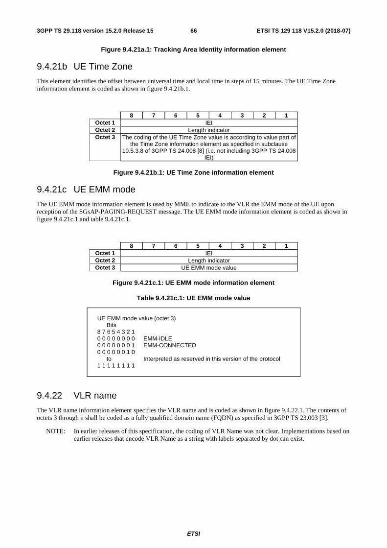
ETSI
ETSI TS 129 118 V15.2.0 (2018-07)663GPP TS 29.118 version 15.2.0 Release 15
Figure 9.4.21a.1: Tracking Area Identity information element
9.4.21b UE Time Zone
This element identifies the offset between universal time and local time in steps of 15 minutes. The UE Time Zone information element is coded as shown in figure 9.4.21b.1.
8 7 6 5 4 3 2 1 Octet 1 IEI Octet 2 Length indicator Octet 3 The coding of the UE Time Zone value is according to value part of
the Time Zone information element as specified in subclause 10.5.3.8 of 3GPP TS 24.008 [8] (i.e. not including 3GPP TS 24.008
IEI)
Figure 9.4.21b.1: UE Time Zone information element
9.4.21c UE EMM mode
The UE EMM mode information element is used by MME to indicate to the VLR the EMM mode of the UE upon reception of the SGsAP-PAGING-REQUEST message. The UE EMM mode information element is coded as shown in figure 9.4.21c.1 and table 9.4.21c.1.
8 7 6 5 4 3 2 1 Octet 1 IEI Octet 2 Length indicator Octet 3 UE EMM mode value
Figure 9.4.21c.1: UE EMM mode information element
Table 9.4.21c.1: UE EMM mode value
UE EMM mode value (octet 3) Bits 8 7 6 5 4 3 2 1 0 0 0 0 0 0 0 0 EMM-IDLE 0 0 0 0 0 0 0 1 EMM-CONNECTED 0 0 0 0 0 0 1 0 to Interpreted as reserved in this version of the protocol 1 1 1 1 1 1 1 1
9.4.22 VLR name
The VLR name information element specifies the VLR name and is coded as shown in figure 9.4.22.1. The contents of octets 3 through n shall be coded as a fully qualified domain name (FQDN) as specified in 3GPP TS 23.003 [3].
NOTE: In earlier releases of this specification, the coding of VLR Name was not clear. Implementations based on earlier releases that encode VLR Name as a string with labels separated by dot can exist.
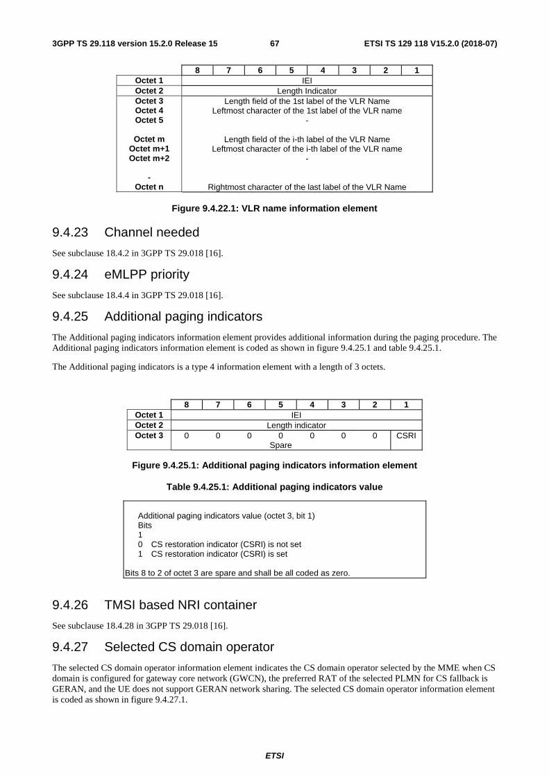
ETSI
ETSI TS 129 118 V15.2.0 (2018-07)673GPP TS 29.118 version 15.2.0 Release 15
8 7 6 5 4 3 2 1 Octet 1 IEI Octet 2 Length Indicator Octet 3 Octet 4 Octet 5
Octet m
Octet m+1 Octet m+2
-
Octet n
Length field of the 1st label of the VLR Name Leftmost character of the 1st label of the VLR name
-
Length field of the i-th label of the VLR Name Leftmost character of the i-th label of the VLR name
-
Rightmost character of the last label of the VLR Name
Figure 9.4.22.1: VLR name information element
9.4.23 Channel needed
See subclause 18.4.2 in 3GPP TS 29.018 [16].
9.4.24 eMLPP priority
See subclause 18.4.4 in 3GPP TS 29.018 [16].
9.4.25 Additional paging indicators
The Additional paging indicators information element provides additional information during the paging procedure. The Additional paging indicators information element is coded as shown in figure 9.4.25.1 and table 9.4.25.1.
The Additional paging indicators is a type 4 information element with a length of 3 octets.
8 7 6 5 4 3 2 1 Octet 1 IEI Octet 2 Length indicator Octet 3 0 0 0 0 0 0 0 CSRI
Spare
Figure 9.4.25.1: Additional paging indicators information element
Table 9.4.25.1: Additional paging indicators value
Additional paging indicators value (octet 3, bit 1) Bits 1 0 CS restoration indicator (CSRI) is not set 1 CS restoration indicator (CSRI) is set Bits 8 to 2 of octet 3 are spare and shall be all coded as zero.
9.4.26 TMSI based NRI container
See subclause 18.4.28 in 3GPP TS 29.018 [16].
9.4.27 Selected CS domain operator
The selected CS domain operator information element indicates the CS domain operator selected by the MME when CS domain is configured for gateway core network (GWCN), the preferred RAT of the selected PLMN for CS fallback is GERAN, and the UE does not support GERAN network sharing. The selected CS domain operator information element is coded as shown in figure 9.4.27.1.
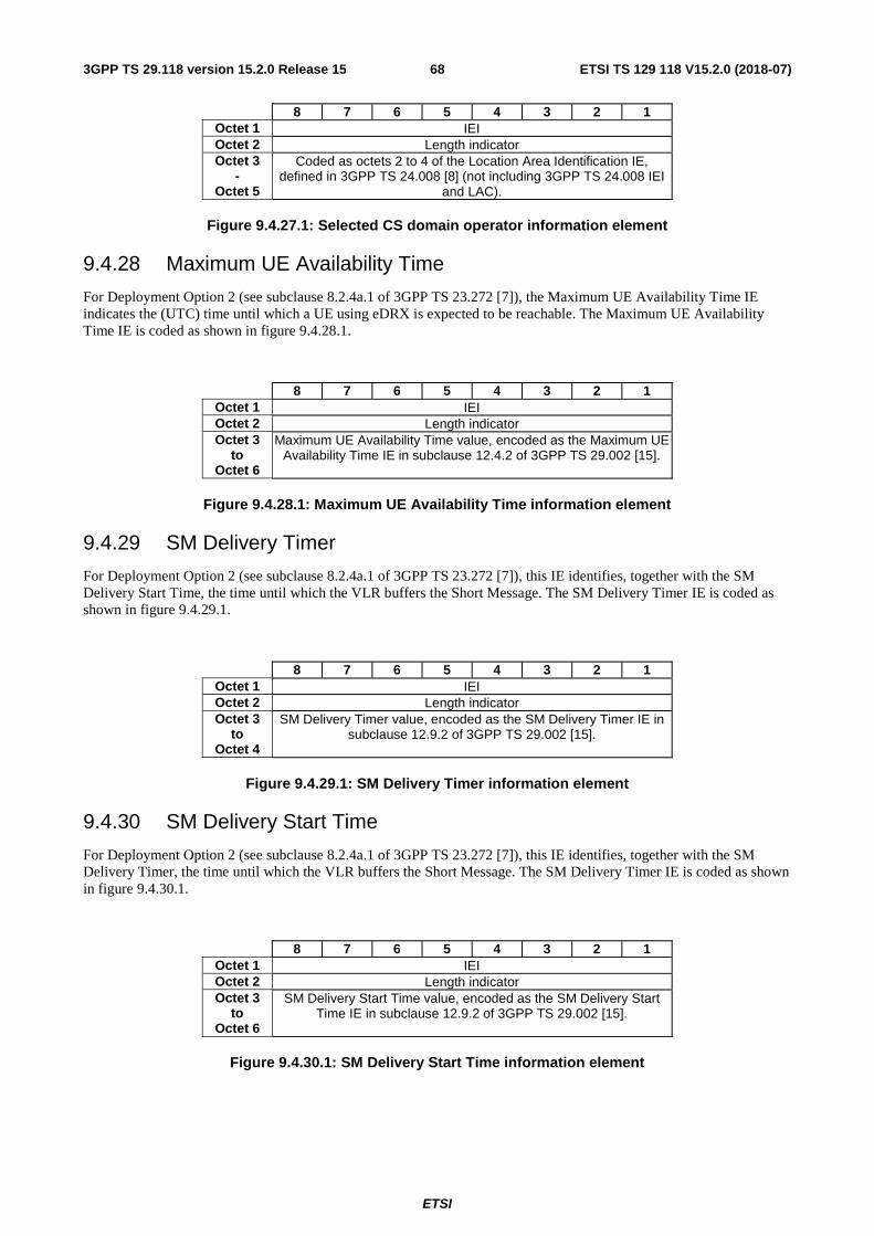
ETSI
ETSI TS 129 118 V15.2.0 (2018-07)683GPP TS 29.118 version 15.2.0 Release 15
8 7 6 5 4 3 2 1 Octet 1 IEI Octet 2 Length indicator Octet 3
- Octet 5
Coded as octets 2 to 4 of the Location Area Identification IE, defined in 3GPP TS 24.008 [8] (not including 3GPP TS 24.008 IEI
and LAC).
Figure 9.4.27.1: Selected CS domain operator information element
9.4.28 Maximum UE Availability Time
For Deployment Option 2 (see subclause 8.2.4a.1 of 3GPP TS 23.272 [7]), the Maximum UE Availability Time IE indicates the (UTC) time until which a UE using eDRX is expected to be reachable. The Maximum UE Availability Time IE is coded as shown in figure 9.4.28.1.
8 7 6 5 4 3 2 1 Octet 1 IEI Octet 2 Length indicator Octet 3
to Octet 6
Maximum UE Availability Time value, encoded as the Maximum UE Availability Time IE in subclause 12.4.2 of 3GPP TS 29.002 [15].
Figure 9.4.28.1: Maximum UE Availability Time information element
9.4.29 SM Delivery Timer
For Deployment Option 2 (see subclause 8.2.4a.1 of 3GPP TS 23.272 [7]), this IE identifies, together with the SM Delivery Start Time, the time until which the VLR buffers the Short Message. The SM Delivery Timer IE is coded as shown in figure 9.4.29.1.
8 7 6 5 4 3 2 1 Octet 1 IEI Octet 2 Length indicator Octet 3
to Octet 4
SM Delivery Timer value, encoded as the SM Delivery Timer IE in subclause 12.9.2 of 3GPP TS 29.002 [15].
Figure 9.4.29.1: SM Delivery Timer information element
9.4.30 SM Delivery Start Time
For Deployment Option 2 (see subclause 8.2.4a.1 of 3GPP TS 23.272 [7]), this IE identifies, together with the SM Delivery Timer, the time until which the VLR buffers the Short Message. The SM Delivery Timer IE is coded as shown in figure 9.4.30.1.
8 7 6 5 4 3 2 1 Octet 1 IEI Octet 2 Length indicator Octet 3
to Octet 6
SM Delivery Start Time value, encoded as the SM Delivery Start Time IE in subclause 12.9.2 of 3GPP TS 29.002 [15].
Figure 9.4.30.1: SM Delivery Start Time information element
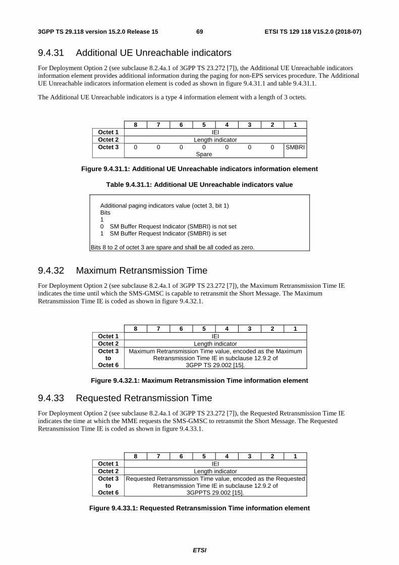
ETSI
ETSI TS 129 118 V15.2.0 (2018-07)693GPP TS 29.118 version 15.2.0 Release 15
9.4.31 Additional UE Unreachable indicators
For Deployment Option 2 (see subclause 8.2.4a.1 of 3GPP TS 23.272 [7]), the Additional UE Unreachable indicators information element provides additional information during the paging for non-EPS services procedure. The Additional UE Unreachable indicators information element is coded as shown in figure 9.4.31.1 and table 9.4.31.1.
The Additional UE Unreachable indicators is a type 4 information element with a length of 3 octets.
8 7 6 5 4 3 2 1 Octet 1 IEI Octet 2 Length indicator Octet 3 0 0 0 0 0 0 0 SMBRI
Spare
Figure 9.4.31.1: Additional UE Unreachable indicators information element
Table 9.4.31.1: Additional UE Unreachable indicators value
Additional paging indicators value (octet 3, bit 1) Bits 1 0 SM Buffer Request Indicator (SMBRI) is not set 1 SM Buffer Request Indicator (SMBRI) is set Bits 8 to 2 of octet 3 are spare and shall be all coded as zero.
9.4.32 Maximum Retransmission Time
For Deployment Option 2 (see subclause 8.2.4a.1 of 3GPP TS 23.272 [7]), the Maximum Retransmission Time IE indicates the time until which the SMS-GMSC is capable to retransmit the Short Message. The Maximum Retransmission Time IE is coded as shown in figure 9.4.32.1.
8 7 6 5 4 3 2 1 Octet 1 IEI Octet 2 Length indicator Octet 3
to Octet 6
Maximum Retransmission Time value, encoded as the Maximum Retransmission Time IE in subclause 12.9.2 of
3GPP TS 29.002 [15].
Figure 9.4.32.1: Maximum Retransmission Time information element
9.4.33 Requested Retransmission Time
For Deployment Option 2 (see subclause 8.2.4a.1 of 3GPP TS 23.272 [7]), the Requested Retransmission Time IE indicates the time at which the MME requests the SMS-GMSC to retransmit the Short Message. The Requested Retransmission Time IE is coded as shown in figure 9.4.33.1.
8 7 6 5 4 3 2 1 Octet 1 IEI Octet 2 Length indicator Octet 3
to Octet 6
Requested Retransmission Time value, encoded as the Requested Retransmission Time IE in subclause 12.9.2 of
3GPPTS 29.002 [15].
Figure 9.4.33.1: Requested Retransmission Time information element
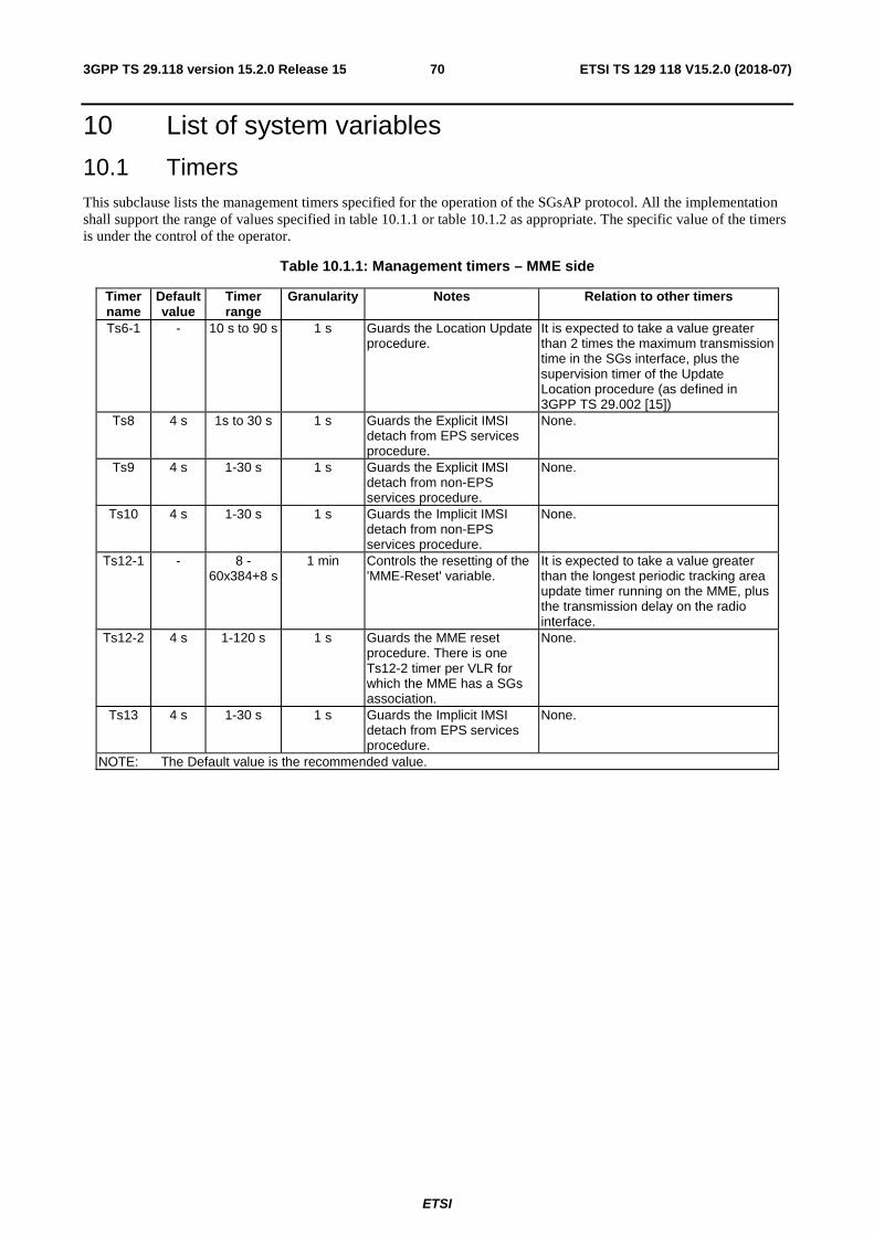
ETSI
ETSI TS 129 118 V15.2.0 (2018-07)703GPP TS 29.118 version 15.2.0 Release 15
10 List of system variables
10.1 Timers This subclause lists the management timers specified for the operation of the SGsAP protocol. All the implementation shall support the range of values specified in table 10.1.1 or table 10.1.2 as appropriate. The specific value of the timers is under the control of the operator.
Table 10.1.1: Management timers – MME side
Timer name
Default value
Timer range
Granularity Notes Relation to other timers
Ts6-1 - 10 s to 90 s 1 s Guards the Location Update procedure.
It is expected to take a value greater than 2 times the maximum transmission time in the SGs interface, plus the supervision timer of the Update Location procedure (as defined in 3GPP TS 29.002 [15])
Ts8 4 s 1s to 30 s 1 s Guards the Explicit IMSI detach from EPS services procedure.
None.
Ts9 4 s 1-30 s 1 s Guards the Explicit IMSI detach from non-EPS services procedure.
None.
Ts10 4 s 1-30 s 1 s Guards the Implicit IMSI detach from non-EPS services procedure.
None.
Ts12-1 - 8 - 60x384+8 s
1 min Controls the resetting of the 'MME-Reset' variable.
It is expected to take a value greater than the longest periodic tracking area update timer running on the MME, plus the transmission delay on the radio interface.
Ts12-2 4 s 1-120 s 1 s Guards the MME reset procedure. There is one Ts12-2 timer per VLR for which the MME has a SGs association.
None.
Ts13 4 s 1-30 s 1 s Guards the Implicit IMSI detach from EPS services procedure.
None.
NOTE: The Default value is the recommended value.
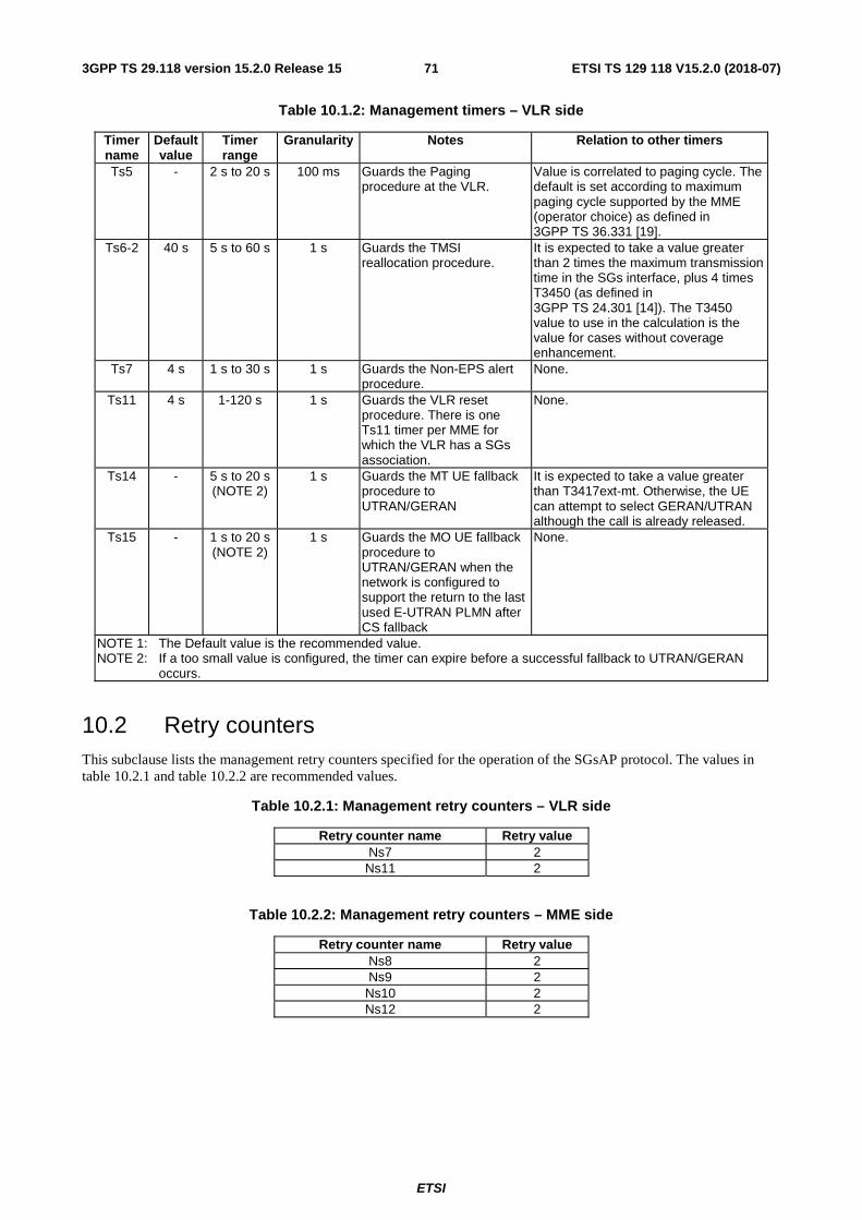
ETSI
ETSI TS 129 118 V15.2.0 (2018-07)713GPP TS 29.118 version 15.2.0 Release 15
Table 10.1.2: Management timers – VLR side
Timer name
Default value
Timer range
Granularity Notes Relation to other timers
Ts5 - 2 s to 20 s 100 ms Guards the Paging procedure at the VLR.
Value is correlated to paging cycle. The default is set according to maximum paging cycle supported by the MME (operator choice) as defined in 3GPP TS 36.331 [19].
Ts6-2 40 s 5 s to 60 s 1 s Guards the TMSI reallocation procedure.
It is expected to take a value greater than 2 times the maximum transmission time in the SGs interface, plus 4 times T3450 (as defined in 3GPP TS 24.301 [14]). The T3450 value to use in the calculation is the value for cases without coverage enhancement.
Ts7 4 s 1 s to 30 s 1 s Guards the Non-EPS alert procedure.
None.
Ts11 4 s 1-120 s 1 s Guards the VLR reset procedure. There is one Ts11 timer per MME for which the VLR has a SGs association.
None.
Ts14 - 5 s to 20 s (NOTE 2)
1 s Guards the MT UE fallback procedure to UTRAN/GERAN
It is expected to take a value greater than T3417ext-mt. Otherwise, the UE can attempt to select GERAN/UTRAN although the call is already released.
Ts15 - 1 s to 20 s (NOTE 2)
1 s Guards the MO UE fallback procedure to UTRAN/GERAN when the network is configured to support the return to the last used E-UTRAN PLMN after CS fallback
None.
NOTE 1: The Default value is the recommended value. NOTE 2: If a too small value is configured, the timer can expire before a successful fallback to UTRAN/GERAN
occurs.
10.2 Retry counters This subclause lists the management retry counters specified for the operation of the SGsAP protocol. The values in table 10.2.1 and table 10.2.2 are recommended values.
Table 10.2.1: Management retry counters – VLR side
Retry counter name Retry value Ns7 2
Ns11 2
Table 10.2.2: Management retry counters – MME side
Retry counter name Retry value Ns8 2 Ns9 2
Ns10 2 Ns12 2
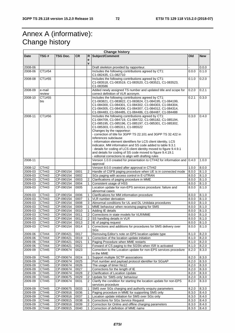
ETSI
ETSI TS 129 118 V15.2.0 (2018-07)723GPP TS 29.118 version 15.2.0 Release 15
Annex A (informative): Change history
Change history Date TSG # TSG Doc. CR R
ev
Subject/Comment Old New
2008-06 Draft skeleton provided by rapporteur. - 0.0.0 2008-06 CT1#54 Includes the following contributions agreed by CT1:
C1-082435, C1-082710 0.0.0 0.1.0
2008-08 CT1#55 Includes the following contributions agreed by CT1: C1-083518, C1-083519, C1-083520, C1-083521, C1-083523, C1-083586
0.1.0 0.2.0
2008-09 e-mail review
Added newly assigned TS number and updated title and scope for correct definition of VLR acronym.
0.2.0 0.2.1
2008-10 CT1#55 bis
Includes the following contributions agreed by CT1: C1-083821, C1-083822, C1-083824, C1-084195, C1-084199, C1-084300, C1-084301, C1-084302, C1-084303, C1-084304, C1-084305, C1-084306, C1-084307, C1-084312, C1-084314, C1-084483, C1-084485, C1-084486, C1-084487, C1-084488
0.2.1 0.3.0
2008-11 CT1#56 Includes the following contributions agreed by CT1: C1-084709, C1-084719, C1-084722, C1-085182, C1-085194, C1-085195, C1-085196, C1-085197, C1-085301, C1-085302, C1-085303, C1-085311, C1-085522 Changes by the rapporteur: - correction of title for 3GPP TS 22.101 and 3GPP TS 32.422 in references subclause - information element identifiers for LCS client identity, LCS indicator, MM information and SS code added to table 9.3.1 - details for coding of LCS client identity moved to figure 9.4.9.1 and details for coding of SS code moved to figure 9.4.19.1 - editorial corrections to align with drafting rules
0.3.0 0.4.0
2008-11 Version 1.0.0 created for presentation to CT#42 for information and approval
0.4.0 1.0.0
2008-12 CT#42 Version 8.0.0 created after approval in CT#42 1.0.0 8.0.0 2009-03 CT#43 CP-090154 0001 2 Handle of CSFB paging procedure when UE is in connected mode 8.0.0 8.1.0 2009-03 CT#43 CP-090154 0002 SGs paging with access control in E-UTRAN 8.0.0 8.1.0 2009-03 CT#43 CP-090154 0003 2 Clarifications of paging procedure in MME 8.0.0 8.1.0 2009-03 CT#43 CP-090154 0004 1 Consistent usage of HSS 8.0.0 8.1.0 2009-03 CT#43 CP-090154 0005 Location update for non-EPS services procedure: failure and
abnormal cases 8.0.0 8.1.0
2009-03 CT#43 CP-090154 0006 1 Clarifications for MM information procedure 8.0.0 8.1.0 2009-03 CT#43 CP-090154 0007 1 VLR number derivation 8.0.0 8.1.0 2009-03 CT#43 CP-090154 0008 3 Abnormal conditions for UL and DL Unitdata procedures 8.0.0 8.1.0 2009-03 CT#43 CP-090154 0009 1 MME behaviour when receiving paging for SMS 8.0.0 8.1.0 2009-03 CT#43 CP-090154 0010 1 Adding IE details 8.0.0 8.1.0 2009-03 CT#43 CP-090154 0011 2 Corrections in state models for VLR/MME 8.0.0 8.1.0 2009-03 CT#43 CP-090154 0012 2 SS handling details in VLR 8.0.0 8.1.0 2009-03 CT#43 CP-090154 0013 2 IE of paging request 8.0.0 8.1.0 2009-03 CT#43 CP-090154 0014 1 Corrections and additions for procedures for SMS delivery over
SGs 8.0.0 8.1.0
2009-06 CT#44 CP-090421 0017 Removing Editor’s note on EPS location update type 8.1.0 8.2.0 2009-06 CT#44 CP-090421 0019 1 Correction of the location update initiation 8.1.0 8.2.0 2009-06 CT#44 CP-090421 0021 1 Paging Procedure when MME restarts 8.1.0 8.2.0 2009-06 CT#44 CP-090421 0022 Forward of CS paging to the SGSN when ISR is activated 8.1.0 8.2.0 2009-09 CT#45 CP-090674 0023 Correction to the Location update for non-EPS services procedure
in the MME 8.2.0 8.3.0
2009-09 CT#45 CP-090674 0024 1 Support multiple SCTP associations 8.2.0 8.3.0 2009-09 CT#45 CP-090674 0025 Port number and payload protocol identifier for SGsAP 8.2.0 8.3.0 2009-09 CT#45 CP-090674 0026 The usage of timer Ns12 8.2.0 8.3.0 2009-09 CT#45 CP-090674 0027 Corrections for the length of IE 8.2.0 8.3.0 2009-09 CT#45 CP-090674 0028 2 Clarification of Location Update 8.2.0 8.3.0 2009-09 CT#45 CP-090675 0029 2 Update for ‘SMS-only’ behaviour 8.2.0 8.3.0 2009-09 CT#45 CP-090674 0031 2 Clarify the condition for starting the location update for non-EPS
services procedure 8.2.0 8.3.0
2009-09 CT#45 CP-090675 0033 1 SMS over SGs charging and authority enquiry parameters 8.2.0 8.3.0 2009-09 CT#46 CP-090916 0036 1 Paging procedure in MME for supporting SMS only 8.3.0 8.4.0 2009-09 CT#46 CP-090916 0037 1 Location update initiation for SMS over SGs only 8.3.0 8.4.0 2009-09 CT#46 CP-090915 0038 6 Corrections for SGs Service Request 8.3.0 8.4.0 2009-09 CT#46 CP-090916 0039 2 Correction for Online and offline charging parameters 8.3.0 8.4.0 2009-09 CT#46 CP-090915 0040 1 Correction of definition of MME name 8.3.0 8.4.0
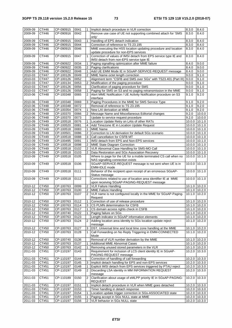
ETSI
ETSI TS 129 118 V15.2.0 (2018-07)733GPP TS 29.118 version 15.2.0 Release 15
2009-09 CT#46 CP-090915 0041 1 Implicit detach procedure in VLR correction 8.3.0 8.4.0 2009-09 CT#46 CP-090916 0042 Remove use case of UE not supporting combined attach for ‘SMS
only’ 8.3.0 8.4.0
2009-09 CT#46 CP-090915 0043 1 Handling of EPS detach indication 8.3.0 8.4.0 2009-09 CT#46 CP-090915 0044 Correction of reference to TS 23.195 8.3.0 8.4.0 2009-09 CT#46 CP-090915 0046 MME executing the HSS location updating procedure and location
update procedure for non-EPS services 8.3.0 8.4.0
2009-09 CT#46 CP-090915 0047 1 Correction of values of IMSI detach from EPS service type IE and IMSI detach from non-EPS service type IE
8.3.0 8.4.0
2009-09 CT#46 CP-090922 0034 1 Paging signalling optimization after MME failure 8.4.0 9.0.0 2009-09 CT#46 CP-090922 0035 2 Paging clarifications 8.4.0 9.0.0 2009-09 CT#46 CP-090922 0048 1 Add UE EMM Mode IE in SGsAP-SERVICE-REQUEST message 8.4.0 9.0.0 2010-03 CT#47 CP-100126 0049 2 MME Name octet length correction 9.0.0 9.1.0 2010-03 CT#47 CP-100126 0052 Alignment term "CSFB and SMS over SGs" with TS23.401 (Part III) 9.0.0 9.1.0 2010-03 CT#47 CP-100134 0053 2 Modification of the paging procedure 9.0.0 9.1.0 2010-03 CT#47 CP-100126 0056 Clarification of paging procedure for SMS 9.0.0 9.1.0 2010-03 CT#47 CP-100126 0058 1 Paging for SMS on S3 and no paging retransmission in the MME 9.0.0 9.1.0 2010-06 CT#48 CP-100348 0065 2 Alert MME Notification / UE Activity Notification procedure on S3
interface 9.1.0 9.2.0
2010-06 CT#48 CP-100348 0069 3 Paging Procedures in the MME for SMS Service Type 9.1.0 9.2.0 2010-06 CT#48 CP-100348 0072 Removal of reference to TS 23.195 9.1.0 9.2.0 2010-06 CT#48 CP-100354 0074 1 New LAI derivation at MME 9.1.0 9.2.0 2010-06 CT#48 CP-100370 0066 2 Message Name and Miscellaneous Editorial changes 9.2.0 10.0.0 2010-06 CT#48 CP-100370 0073 Update to service request procedure 9.2.0 10.0.0 2010-09 CT#49 CP-100518 0076 1 Location Update Retry on LAIs of other RATs 10.0.0 10.1.0 2010-09 CT#49 CP-100520 0081 4 Add Timezone IE in Location Update Request 10.0.0 10.1.0 2010-09 CT#49 CP-100518 0083 1 MME Name 10.0.0 10.1.0 2010-09 CT#49 CP-100501 0086 2 Correction to LAI derivation for default SGs scenario 10.0.0 10.1.0 2010-09 CT#49 CP-100518 0088 3 Call cancellation for CSFB MT 10.0.0 10.1.0 2010-09 CT#49 CP-100495 0091 1 IMSI detach from EPS and Non-EPS services 10.0.0 10.1.0 2010-09 CT#49 CP-100518 0098 2 MME State Diagram Correction 10.0.0 10.1.0 2010-09 CT#49 CP-100518 0102 2 VLR Abnormal Case Handling for SMS-MO Call 10.0.0 10.1.0 2010-09 CT#49 CP-100518 0103 2 Data Restoration and SGs Association Recovery 10.0.0 10.1.0 2010-09 CT#49 CP-100518 0105 Where to page for the UE for a mobile terminated CS call when no
NAS signalling connection exists 10.0.0 10.1.0
2010-09 CT#49 CP-100518 0106 SGsAP-SERVICE-REQUEST message is not sent when UE is in EMM-IDLE mode
10.0.0 10.1.0
2010-09 CT#49 CP-100518 0111 Behavior of the recipient upon receipt of an erroneous SGsAP-Status message
10.0.0 10.1.0
2010-09 CT#49 CP-100518 0112 Corrections related to use of location area identifier IE at MME upon receiving SGsAP-PAGING-REQUEST message
10.0.0 10.1.0
2010-12 CT#50 CP-100763 0099 2 VLR Failure Handling 10.1.0 10.2.0 2010-12 CT#50 CP-100763 0100 2 MME Failure Handling 10.1.0 10.2.0 2010-12 CT#50 CP-100763 0107 2 VLR name is not configured locally in the MME for SGsAP-Paging-
Request 10.1.0 10.2.0
2010-12 CT#50 CP-100763 0112 1 Correction of use of release procedure 10.1.0 10.2.0 2010-12 CT#50 CP-100763 0114 3 CS PLMN determination for CSFB 10.1.0 10.2.0 2010-12 CT#50 CP-100763 0117 1 CS domain access rights check in CSFB 10.1.0 10.2.0 2010-12 CT#50 CP-100740 0122 1 Paging failure on SGs 10.1.0 10.2.0 2010-12 CT#50 CP-100763 0123 Length indicator in SGsAP information elements 10.1.0 10.2.0 2010-12 CT#50 CP-100763 0124 2 Adding location area identity to SGs location update reject
message 10.1.0 10.2.0
2010-12 CT#50 CP-100763 0127 3 DST, Universal time and local time zone handling at the MME 10.1.0 10.2.0 2010-12 CT#50 CP-100763 0128 1 Call Forwarding on No Reply Triggering in EMM-CONNECTED
Mode 10.1.0 10.2.0
2010-12 CT#50 CP-100740 0136 Removal of VLR number derivation by the MME 10.1.0 10.2.0 2010-12 CT#50 CP-100763 0137 1 Additional MME Abnormal Cases 10.1.0 10.2.0 2010-12 CT#50 CP-100763 0142 1 Removing unused stored parameters in the VLR 10.1.0 10.2.0 2011-03 CT#51 CP-110197 0143 Requirement for inclusion of LCS client identity IE in SGsAP-
PAGING-REQUEST message 10.2.0 10.3.0
2011-03 CT#51 CP-110197 0144 Correction of handling of call forwarding 10.2.0 10.3.0 2011-03 CT#51 CP-110197 0145 3 Implicit detach handling for EPS and non-EPS services 10.2.0 10.3.0 2011-03 CT#51 CP-110197 0148 1 Explicit IMSI detach from EPS services triggered by PTAU reject 10.2.0 10.3.0 2011-03 CT#51 CP-110197 0149 2 Discarding LSA identity in MM INFORMATION REQUEST
message 10.2.0 10.3.0
2011-03 CT#51 CP-110189 0150 2 Clarification about usage of eMLPP priority IE in SGsAP-PAGING-REQUEST
10.2.0 10.3.0
2011-03 CT#51 CP-110197 0151 1 Implicit detach procedure in VLR when MME goes detached 10.2.0 10.3.0 2011-03 CT#51 CP-110197 0153 Timer handling in detach response 10.2.0 10.3.0 2011-03 CT#51 CP-110197 0154 1 Location update trigger correction in SGs-ASSOCIATED state 10.2.0 10.3.0 2011-03 CT#51 CP-110197 0155 1 Paging accept in SGs NULL state at MME 10.2.0 10.3.0 2011-03 CT#51 CP-110197 0156 2 VLR behavior in SGs NULL state 10.2.0 10.3.0
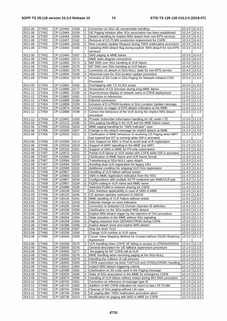
ETSI
ETSI TS 129 118 V15.2.0 (2018-07)743GPP TS 29.118 version 15.2.0 Release 15
2011-06 CT#52 CP-110464 0158 2 Correction on SGs UE unreachable handling 10.3.0 10.4.0 2011-06 CT#52 CP-110464 0159 1 UE Paging Initiation after SGs association has been established 10.3.0 10.4.0 2011-06 CT#52 CP-110464 0160 1 Detach handling for Implicit IMSI detach from non-EPS services 10.3.0 10.4.0 2011-06 CT#52 CP-110457 0162 1 Removal of CS PLMN reselection requirement for CSFB 10.3.0 10.4.0 2011-06 CT#52 CP-110464 0163 1 New Location Update Request during TMSI reallocation procedure 10.3.0 10.4.0 2011-06 CT#52 CP-110464 0165 1 Updating IMSI detach flag during explicit IMSI detach for non-EPS
services 10.3.0 10.4.0
2011-06 CT#52 CP-110464 0167 1 SMS paging at MME failure 10.3.0 10.4.0 2011-06 CT#52 CP-110464 0171 MME state diagram corrections 10.3.0 10.4.0 2011-09 CT#53 CP-110682 0174 2 MO SMS over SGs handling at VLR failure 10.4.0 10.5.0 2011-09 CT#53 CP-110684 0175 2 MT SMS over SGs handling at VLR failure 10.4.0 10.5.0 2011-09 CT#53 CP-110682 0176 1 Correction on detach in SGs-NULL state for non-EPS service 10.4.0 10.5.0 2011-09 CT#53 CP-110694 0169 3 Abnormal case for SGs location update procedure 10.5.0 11.0.0 2011-09 CT#53 CP-110691 0179 1 Inclusion of SS Code in SGs Paging for Network initiated CISS
Procedure 10.5.0 11.0.0
2011-09 CT#53 CP-110691 0182 2 Overlapping with TS 24.301 scope 10.5.0 11.0.0 2011-12 CT#54 CP-110886 0177 6 Restoration of CS Services during long MME failure 11.0.0 11.1.0 2011-12 CT#54 CP-110882 0180 4 Asynchronous display of network name in CSFB deployment 11.0.0 11.1.0 2011-12 CT#54 CP-110882 0181 1 Correction to references 11.0.0 11.1.0 2011-12 CT#54 CP-110888 0184 1 Editorial corrections 11.0.0 11.1.0 2011-12 CT#54 CP-110858 0193 1 Inclusion of E-UTRAN location in SGs Location Update message 11.0.0 11.1.0 2011-12 CT#54 CP-110874 0194 1 Correction on trigger of EPS detach indication at the MME 11.0.0 11.1.0 2011-12 CT#54 CP-110888 0198 2 Correct the behaviors of the VLR during the implicit IMSI detach
procedure 11.0.0 11.1.0
2011-12 CT#54 CP-110942 0183 6 Provide Subscriber Information handling for UE under LTE 11.0.0 11.1.0 2012-03 CT#55 CP-120113 0186 6 SGs paging handling in the VLR and the MME failure cases 11.1.0 11.2.0 2012-06 CT#56 CP-120318 0203 3 MME paging handling for "SMS Indicator" case 11.2.0 11.3.0 2012-06 CT#56 CP-120293 0207 2 Change to the detach message for implicit detach at MME 11.2.0 11.3.0 2012-06 CT#56 CP-120293 0211 2 Clarification of MME behaviour in receiving CS Paging when MRT
has expired but IDT is running while ISR is activated 11.2.0 11.3.0
2012-06 CT#56 CP-120309 0213 2 SGs Support for MSC in Pool to avoid dual VLR registration 11.2.0 11.3.0 2012-06 CT#56 CP-120318 0219 3 Support of MAP signalling in the MME (via IWF) 11.2.0 11.3.0 2012-06 CT#56 CP-120315 0201 6 Support of SMS in MME for PS-only subscription 11.2.0 11.3.0 2012-09 CT#57 CP-120572 0221 2 Partial VLR failure or VLR restart with CSFB while ISR is activated 11.3.0 11.4.0 2012-09 CT#57 CP-120594 0225 1 Clarification of MME Name and VLR Name format 11.3.0 11.4.0 2012-09 CT#57 CP-120594 0227 1 Transitioning to SGs-NULL upon Attach 11.3.0 11.4.0 2012-09 CT#57 CP-120584 0228 1 Avoiding dual VLR registration for legacy UEs 11.3.0 11.4.0 2012-09 CT#57 CP-120589 0222 2 Additional condition for skipping VLR SGs registration 11.3.0 11.4.0 2012-12 CT#58 CP-120807 0232 3 Handling of VLR failure without restart 11.4.0 11.5.0 2012-12 CT#58 CP-120803 0233 5 SMS in MME registration indication from the HSS 11.4.0 11.5.0 2012-12 CT#58 CP-120807 0234 2 Configurations with multiple SCTP endpoints per MME/VLR pair 11.4.0 11.5.0 2012-12 CT#58 CP-120807 0239 5 FQDN coding in VLR name and MME name 11.4.0 11.5.0 2012-12 CT#58 CP-120898 0230 7 Selected PLMN in network sharing for CSFB 11.4.0 11.5.0 2013-03 CT#59 CP-130108 0242 SGs Interface applicability in case of SMS in MME 11.5.0 11.6.0 2013-03 CT#59 CP-130123 0246 2 CS domain operator selection in GWCN 11.5.0 11.6.0 2013-03 CT#59 CP-130134 0241 6 MME handling of VLR Failure without restart 11.6.0 12.0.0 2013-03 CT#59 CP-130125 0243 2 Editorial change on reset indication 11.6.0 12.0.0 2013-06 CT#60 CP-130255 0249 1 Correction to Selected CS Domain Operator IE definition 12.0.0 12.1.0 2013-06 CT#60 CP-130258 0256 1 Clarification on the SGs-implicit IMSI detach 12.0.0 12.1.0 2013-06 CT#60 CP-130239 0259 2 Explicit IMSI detach trigger by the rejection of TAU procedure 12.0.0 12.1.0 2013-06 CT#60 CP-130264 0264 3 State transition in the MME without SGs signaling 12.0.0 12.1.0 2013-06 CT#60 CP-130258 0265 3 Paging response from GERAN/UTRAN during CSFB 12.0.0 12.1.0 2013-06 CT#60 CP-130386 0266 3 Implicit detach timer and implicit IMSI detach 12.0.0 12.1.0 2013-06 CT#60 CP-130258 0267 Stop the timer Ts13 12.0.0 12.1.0 2013-06 CT#60 CP-130258 0268 Change VLR number to VLR name 12.0.0 12.1.0 2013-06 CT#60 CP-130264 0269 4 Cause Value Mapping Method for Contact without 2G/3G Roaming
Agreement 12.0.0 12.1.0
2013-06 CT#60 CP-130258 0270 3 VLR handling when CSFB UE failing to access to UTRAN/GERAN 12.0.0 12.1.0 2013-09 CT#61 CP-130505 0276 General description for UE fallback supervision procedure 12.1.0 12.2.0 2013-09 CT#61 CP-130505 0277 2 Re-paging for MT CSFB call at VLR 12.1.0 12.2.0 2013-09 CT#61 CP-130505 0278 1 MME handling when receiving paging at the SGs-NULL 12.1.0 12.2.0 2013-09 CT#61 CP-130505 0279 2 Handling the collision of call services 12.1.0 12.2.0 2013-09 CT#61 CP-130505 0283 2 CSFB supervision via timer Ts5/Ts14 and CFNRy/CRNRc handling 12.1.0 12.2.0 2013-09 CT#61 CP-130510 0284 2 Implicit IMSI detach triggering criteria 12.1.0 12.2.0 2013-09 CT#61 CP-130498 0292 1 Clarification on SS code used in the Paging message 12.1.0 12.2.0 2013-09 CT#61 CP-130525 0296 2 State of SGs association in the MME for emergency CSFB 12.1.0 12.2.0 2013-09 CT#61 CP-130573 0290 4 Handling of VLR failure without restart during MO-SMS procedure 12.1.0 12.2.0 2013-12 CT#62 CP-130762 0301 Correction on reference of message type IE 12.2.0 12.3.0 2013-12 CT#62 CP-130742 0303 5 Addition of MO CSFB indication for return to last LTE PLMN 12.2.0 12.3.0 2013-12 CT#62 CP-130754 0304 1 Cleanup of SGs paging without LAI case 12.2.0 12.3.0 2013-12 CT#62 CP-130745 0306 6 UE paging after TMSI reallocation procedure abort 12.2.0 12.3.0 2013-12 CT#62 CP-130739 0313 1 Modification for paging with IMSI in MME for CSFB 12.2.0 12.3.0
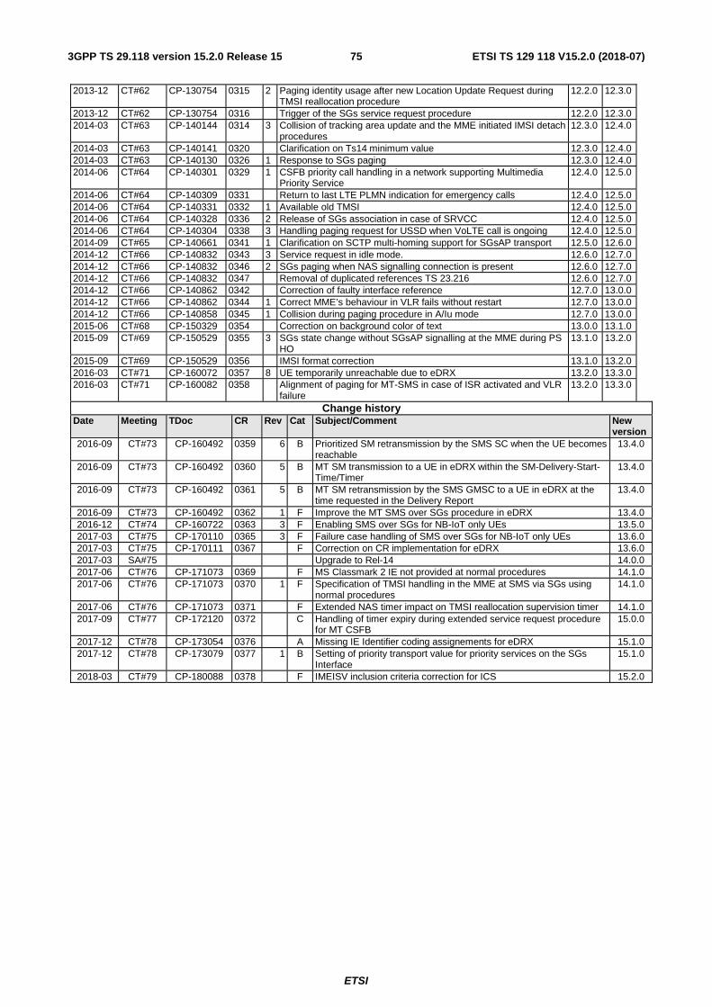
ETSI
ETSI TS 129 118 V15.2.0 (2018-07)753GPP TS 29.118 version 15.2.0 Release 15
2013-12 CT#62 CP-130754 0315 2 Paging identity usage after new Location Update Request during TMSI reallocation procedure
12.2.0 12.3.0
2013-12 CT#62 CP-130754 0316 Trigger of the SGs service request procedure 12.2.0 12.3.0 2014-03 CT#63 CP-140144 0314 3 Collision of tracking area update and the MME initiated IMSI detach
procedures 12.3.0 12.4.0
2014-03 CT#63 CP-140141 0320 Clarification on Ts14 minimum value 12.3.0 12.4.0 2014-03 CT#63 CP-140130 0326 1 Response to SGs paging 12.3.0 12.4.0 2014-06 CT#64 CP-140301 0329 1 CSFB priority call handling in a network supporting Multimedia
Priority Service 12.4.0 12.5.0
2014-06 CT#64 CP-140309 0331 Return to last LTE PLMN indication for emergency calls 12.4.0 12.5.0 2014-06 CT#64 CP-140331 0332 1 Available old TMSI 12.4.0 12.5.0 2014-06 CT#64 CP-140328 0336 2 Release of SGs association in case of SRVCC 12.4.0 12.5.0 2014-06 CT#64 CP-140304 0338 3 Handling paging request for USSD when VoLTE call is ongoing 12.4.0 12.5.0 2014-09 CT#65 CP-140661 0341 1 Clarification on SCTP multi-homing support for SGsAP transport 12.5.0 12.6.0 2014-12 CT#66 CP-140832 0343 3 Service request in idle mode. 12.6.0 12.7.0 2014-12 CT#66 CP-140832 0346 2 SGs paging when NAS signalling connection is present 12.6.0 12.7.0 2014-12 CT#66 CP-140832 0347 Removal of duplicated references TS 23.216 12.6.0 12.7.0 2014-12 CT#66 CP-140862 0342 Correction of faulty interface reference 12.7.0 13.0.0 2014-12 CT#66 CP-140862 0344 1 Correct MME’s behaviour in VLR fails without restart 12.7.0 13.0.0 2014-12 CT#66 CP-140858 0345 1 Collision during paging procedure in A/Iu mode 12.7.0 13.0.0 2015-06 CT#68 CP-150329 0354 Correction on background color of text 13.0.0 13.1.0 2015-09 CT#69 CP-150529 0355 3 SGs state change without SGsAP signalling at the MME during PS
HO 13.1.0 13.2.0
2015-09 CT#69 CP-150529 0356 IMSI format correction 13.1.0 13.2.0 2016-03 CT#71 CP-160072 0357 8 UE temporarily unreachable due to eDRX 13.2.0 13.3.0 2016-03 CT#71 CP-160082 0358 Alignment of paging for MT-SMS in case of ISR activated and VLR
failure 13.2.0 13.3.0
Change history Date Meeting TDoc CR Rev Cat Subject/Comment New
version 2016-09 CT#73 CP-160492 0359 6 B Prioritized SM retransmission by the SMS SC when the UE becomes
reachable 13.4.0
2016-09 CT#73 CP-160492 0360 5 B MT SM transmission to a UE in eDRX within the SM-Delivery-Start-Time/Timer
13.4.0
2016-09 CT#73 CP-160492 0361 5 B MT SM retransmission by the SMS GMSC to a UE in eDRX at the time requested in the Delivery Report
13.4.0
2016-09 CT#73 CP-160492 0362 1 F Improve the MT SMS over SGs procedure in eDRX 13.4.0 2016-12 CT#74 CP-160722 0363 3 F Enabling SMS over SGs for NB-IoT only UEs 13.5.0 2017-03 CT#75 CP-170110 0365 3 F Failure case handling of SMS over SGs for NB-IoT only UEs 13.6.0 2017-03 CT#75 CP-170111 0367 F Correction on CR implementation for eDRX 13.6.0 2017-03 SA#75 Upgrade to Rel-14 14.0.0 2017-06 CT#76 CP-171073 0369 F MS Classmark 2 IE not provided at normal procedures 14.1.0 2017-06 CT#76 CP-171073 0370 1 F Specification of TMSI handling in the MME at SMS via SGs using
normal procedures 14.1.0
2017-06 CT#76 CP-171073 0371 F Extended NAS timer impact on TMSI reallocation supervision timer 14.1.0 2017-09 CT#77 CP-172120 0372 C Handling of timer expiry during extended service request procedure
for MT CSFB 15.0.0
2017-12 CT#78 CP-173054 0376 A Missing IE Identifier coding assignements for eDRX 15.1.0 2017-12 CT#78 CP-173079 0377 1 B Setting of priority transport value for priority services on the SGs
Interface 15.1.0
2018-03 CT#79 CP-180088 0378 F IMEISV inclusion criteria correction for ICS 15.2.0
ETSI
ETSI TS 129 118 V15.2.0 (2018-07)763GPP TS 29.118 version 15.2.0 Release 15
History
Document history
V15.2.0 July 2018 Publication


![TS 128 533 - V15.2.0 - 5G; Management and orchestration ... · 3GPP TS 28.533 version 15.2.0 Release 15 7 ETSI TS 128 533 V15.2.0 (2019-10) [17] 3GPP TS 28.517: "Telecommunication](https://img.pdfslide.net/doc/110x75/60a24803120d833377411703/ts-128-533-v1520-5g-management-and-orchestration-3gpp-ts-28533-version.jpg)