Embed Size (px)
Citation preview
ETSI TS 138 425 V15.2.0 (2018-07)
5G; NG-RAN;
NR user plane protocol (3GPP TS 38.425 version 15.2.0 Release 15)
TECHNICAL SPECIFICATION
ETSI
ETSI TS 138 425 V15.2.0 (2018-07)13GPP TS 38.425 version 15.2.0 Release 15
Reference DTS/TSGR-0338425vf20
Keywords 5G
ETSI
650 Route des Lucioles F-06921 Sophia Antipolis Cedex - FRANCE
Tel.: +33 4 92 94 42 00 Fax: +33 4 93 65 47 16
Siret N° 348 623 562 00017 - NAF 742 C
Association à but non lucratif enregistrée à la Sous-Préfecture de Grasse (06) N° 7803/88
Important notice
The present document can be downloaded from: http://www.etsi.org/standards-search
The present document may be made available in electronic versions and/or in print. The content of any electronic and/or print versions of the present document shall not be modified without the prior written authorization of ETSI. In case of any
existing or perceived difference in contents between such versions and/or in print, the only prevailing document is the print of the Portable Document Format (PDF) version kept on a specific network drive within ETSI Secretariat.
Users of the present document should be aware that the document may be subject to revision or change of status. Information on the current status of this and other ETSI documents is available at
https://portal.etsi.org/TB/ETSIDeliverableStatus.aspx
If you find errors in the present document, please send your comment to one of the following services: https://portal.etsi.org/People/CommiteeSupportStaff.aspx
Copyright Notification
No part may be reproduced or utilized in any form or by any means, electronic or mechanical, including photocopying and microfilm except as authorized by written permission of ETSI.
The content of the PDF version shall not be modified without the written authorization of ETSI. The copyright and the foregoing restriction extend to reproduction in all media.
© ETSI 2018.
All rights reserved.
DECTTM, PLUGTESTSTM, UMTSTM and the ETSI logo are trademarks of ETSI registered for the benefit of its Members. 3GPPTM and LTETM are trademarks of ETSI registered for the benefit of its Members and
of the 3GPP Organizational Partners. oneM2M logo is protected for the benefit of its Members.
GSM® and the GSM logo are trademarks registered and owned by the GSM Association.
ETSI
ETSI TS 138 425 V15.2.0 (2018-07)23GPP TS 38.425 version 15.2.0 Release 15
Intellectual Property Rights Essential patents
IPRs essential or potentially essential to normative deliverables may have been declared to ETSI. The information pertaining to these essential IPRs, if any, is publicly available for ETSI members and non-members, and can be found in ETSI SR 000 314: "Intellectual Property Rights (IPRs); Essential, or potentially Essential, IPRs notified to ETSI in respect of ETSI standards", which is available from the ETSI Secretariat. Latest updates are available on the ETSI Web server (https://ipr.etsi.org/).
Pursuant to the ETSI IPR Policy, no investigation, including IPR searches, has been carried out by ETSI. No guarantee can be given as to the existence of other IPRs not referenced in ETSI SR 000 314 (or the updates on the ETSI Web server) which are, or may be, or may become, essential to the present document.
Trademarks
The present document may include trademarks and/or tradenames which are asserted and/or registered by their owners. ETSI claims no ownership of these except for any which are indicated as being the property of ETSI, and conveys no right to use or reproduce any trademark and/or tradename. Mention of those trademarks in the present document does not constitute an endorsement by ETSI of products, services or organizations associated with those trademarks.
Foreword This Technical Specification (TS) has been produced by ETSI 3rd Generation Partnership Project (3GPP).
The present document may refer to technical specifications or reports using their 3GPP identities, UMTS identities or GSM identities. These should be interpreted as being references to the corresponding ETSI deliverables.
The cross reference between GSM, UMTS, 3GPP and ETSI identities can be found under http://webapp.etsi.org/key/queryform.asp.
Modal verbs terminology In the present document "shall", "shall not", "should", "should not", "may", "need not", "will", "will not", "can" and "cannot" are to be interpreted as described in clause 3.2 of the ETSI Drafting Rules (Verbal forms for the expression of provisions).
"must" and "must not" are NOT allowed in ETSI deliverables except when used in direct citation.
ETSI
ETSI TS 138 425 V15.2.0 (2018-07)33GPP TS 38.425 version 15.2.0 Release 15
Contents Intellectual Property Rights ................................................................................................................................ 2
Foreword ............................................................................................................................................................. 2
Modal verbs terminology .................................................................................................................................... 2
Foreword ............................................................................................................................................................. 5
1 Scope ........................................................................................................................................................ 6
2 References ................................................................................................................................................ 6
3 Definitions and abbreviations ................................................................................................................... 6
3.1 Definitions .......................................................................................................................................................... 6
3.2 Abbreviations ..................................................................................................................................................... 6
4 General ..................................................................................................................................................... 7
4.1 General aspects ................................................................................................................................................... 7
5 NR user plane protocol ............................................................................................................................. 7
5.1 General ............................................................................................................................................................... 7
5.2 NR user plane protocol layer services ................................................................................................................ 7
5.3 Services expected from the Transport Network Layer ....................................................................................... 8
5.4 Elementary procedures ....................................................................................................................................... 9
5.4.1 Transfer of Downlink User Data ................................................................................................................... 9
5.4.1.1 Successful operation................................................................................................................................ 9
5.4.1.2 Unsuccessful operation ........................................................................................................................... 9
5.4.2 Downlink Data Delivery Status .................................................................................................................... 9
5.4.2.1 Successful operation................................................................................................................................ 9
5.4.2.2 Unsuccessful operation ......................................................................................................................... 11
5.4.3 Transfer of Assistance Information ............................................................................................................ 11
5.4.3.1 Successful operation.............................................................................................................................. 11
5.5 Elements for the NR user plane protocol .......................................................................................................... 12
5.5.1 General ........................................................................................................................................................ 12
5.5.2 Frame format for the NR user plane protocol ............................................................................................. 13
5.5.2.1 DL USER DATA (PDU Type 0) .......................................................................................................... 13
5.5.2.2 DL DATA DELIVERY STATUS (PDU Type 1) ................................................................................. 13
5.5.2.3 ASSISTANCE INFORMATION (PDU Type 2) .................................................................................. 14
5.5.3 Coding of information elements in frames ................................................................................................. 15
5.5.3.1 PDU Type ............................................................................................................................................. 15
5.5.3.2 Spare ..................................................................................................................................................... 15
5.5.3.3 Report polling ....................................................................................................................................... 15
5.5.3.4 NR-U Sequence Number ....................................................................................................................... 15
5.5.3.5 Desired buffer size for the data radio bearer ......................................................................................... 15
5.5.3.6 Desired Data Rate ................................................................................................................................. 16
5.5.3.7 DL Flush ............................................................................................................................................... 16
5.5.3.8 DL discard NR PDCP PDU SN ............................................................................................................ 16
5.5.3.9 DL Discard Blocks ................................................................................................................................ 16
5.5.3.10 DL discard NR PDCP PDU SN start .................................................................................................... 16
5.5.3.11 DL discard Number of blocks ............................................................................................................... 16
5.5.3.12 Discarded Block size ............................................................................................................................. 16
5.5.3.13 Lost Packet Report ................................................................................................................................ 17
5.5.3.14 Final Frame Indication .......................................................................................................................... 17
5.5.3.15 Number of lost NR-U Sequence Number ranges reported .................................................................... 17
5.5.3.16 Start of lost NR-U Sequence Number range ......................................................................................... 17
5.5.3.17 End of lost NR-U Sequence Number range .......................................................................................... 17
5.5.3.18 Highest Delivered NR PDCP SN Ind .................................................................................................... 17
5.5.3.19 Highest successfully delivered NR PDCP Sequence Number .............................................................. 17
5.5.3.20 Highest Transmitted NR PDCP SN Ind ................................................................................................ 17
5.5.3.21 Highest transmitted NR PDCP Sequence Number ................................................................................ 18
5.5.3.22 Cause Report ......................................................................................................................................... 18
5.5.3.23 Cause Value .......................................................................................................................................... 18
ETSI
ETSI TS 138 425 V15.2.0 (2018-07)43GPP TS 38.425 version 15.2.0 Release 15
5.5.3.24 Padding ................................................................................................................................................. 18
5.5.3.28 Void....................................................................................................................................................... 18
5.5.3.29 Retransmission flag ............................................................................................................................... 18
5.5.3.30 Highest Delivered Retransmitted NR PDCP SN Ind ............................................................................ 18
5.5.3.31 Highest Retransmitted NR PDCP SN Ind ............................................................................................. 18
5.5.3.32 Highest successfully delivered retransmitted NR PDCP Sequence Number ........................................ 19
5.5.3.33 Highest retransmitted NR PDCP Sequence Number ............................................................................. 19
5.5.3.34 Data Rate Indication .............................................................................................................................. 19
5.5.3.35 PDCP Duplication Indication ................................................................................................................ 19
5.5.3.36 PDCP Duplication Activation Suggestion ............................................................................................ 19
5.5.3.37 Number of Assistance Information Field .............................................................................................. 19
5.5.3.38 Assistance Information Type ................................................................................................................ 19
5.5.3.39 Radio Quality Assistance Information .................................................................................................. 20
5.5.3.40 Assistance Information Report Polling Flag ......................................................................................... 20
5.5.4 Timers ......................................................................................................................................................... 20
5.6 Handling of unknown, unforeseen and erroneous protocol data ...................................................................... 20
Annex A (informative): Example of using future Extension .............................................................. 21
A.1 Example of using Future Extension field ............................................................................................... 21
A.1.1 New IE Flags .................................................................................................................................................... 21
Annex B (informative): Change history ............................................................................................... 22
History .............................................................................................................................................................. 23
ETSI
ETSI TS 138 425 V15.2.0 (2018-07)53GPP TS 38.425 version 15.2.0 Release 15
Foreword This Technical Specification has been produced by the 3rd Generation Partnership Project (3GPP).
The contents of the present document are subject to continuing work within the TSG and may change following formal TSG approval. Should the TSG modify the contents of the present document, it will be re-released by the TSG with an identifying change of release date and an increase in version number as follows:
Version x.y.z
where:
x the first digit:
1 presented to TSG for information;
2 presented to TSG for approval;
3 or greater indicates TSG approved document under change control.
y the second digit is incremented for all changes of substance, i.e. technical enhancements, corrections, updates, etc.
z the third digit is incremented when editorial only changes have been incorporated in the document.
ETSI
ETSI TS 138 425 V15.2.0 (2018-07)63GPP TS 38.425 version 15.2.0 Release 15
1 Scope The present document specifies the NR user plane protocol functions used within NG-RAN and, for EN-DC, within E-UTRAN. NR user plane protocol functions may reside in nodes terminating either the X2-U (for EN-DC) or the Xn-U or the F1-U interface.
2 References The following documents contain provisions which, through reference in this text, constitute provisions of the present document.
- References are either specific (identified by date of publication, edition number, version number, etc.) or non-specific.
- For a specific reference, subsequent revisions do not apply.
- For a non-specific reference, the latest version applies. In the case of a reference to a 3GPP document (including a GSM document), a non-specific reference implicitly refers to the latest version of that document in the same Release as the present document.
[1] 3GPP TR 21.905: "Vocabulary for 3GPP Specifications".
[2] 3GPP TS 29.281: "General Packet Radio System (GPRS) Tunnelling Protocol User Plane (GTPv1-U)".
[3] 3GPP TS 37.340: "NR; Multi-connectivity; Overall description; Stage-2".
[4] 3GPP TS 36.321: "Evolved Universal Terrestrial Radio Access (E-UTRA); Medium Access Control (MAC) protocol specification".
[5] 3GPP TS 38.321: "NR; Medium Access Control (MAC) protocol specification".
3 Definitions and abbreviations
3.1 Definitions For the purposes of the present document, the terms and definitions given in 3GPP TR 21.905 [1] and the following apply. A term defined in the present document takes precedence over the definition of the same term, if any, in 3GPP TR 21.905 [1].
Corresponding node: a node interacting with a node hosting NR PDCP for flow control.
Master node: as defined in TS 37.340 [3].
Secondary node: as defined in TS 37.340 [3].
3.2 Abbreviations For the purposes of the present document, the abbreviations given in 3GPP TR 21.905 [1] and the following apply. An abbreviation defined in the present document takes precedence over the definition of the same abbreviation, if any, in 3GPP TR 21.905 [1].
EN-DC E-UTRA-NR Dual Connectivity MR-DC Multi-RAT Dual Connectivity
ETSI
ETSI TS 138 425 V15.2.0 (2018-07)73GPP TS 38.425 version 15.2.0 Release 15
4 General
4.1 General aspects The NR user plane protocol is located in the User Plane of the Radio Network layer over either the Xn or the X2 or the F1 interface.
The NR user plane protocol is used to convey control information related to the user data flow management of data radio bearers.
Each NR user plane protocol instance is associated to one data radio bearer only.
If configured, NR user plane protocol instances exist at the Master node and the Secondary node in the context of MR-DC or at nodes hosting F1-U protocol terminations. The NR user plane protocol supports direct communication between NR user plane protocol entities, regardless of whether they terminate the same or different user plane interfaces.
NOTE: User data radio bearers may be setup for data forwarding purposes during Xn HO or during DC related mobility do not require the execution of any additional data radio bearer related user plane protocol functions related to an NR user plane protocol instance.
On each data radio bearer, the NR user plane protocol operates with RLC AM or RLC UM.
In this version of the present document, NR user plane protocol data is conveyed by GTP-U protocol means, more specifically, by means of the "NR RAN Container" GTP-U extension header as defined in TS 29.281 [2].
5 NR user plane protocol
5.1 General The NR user plane protocol layer is using services of the transport network layer in order to allow flow control of user data packets transferred from the node hosting NR PDCP to the corresponding node.
5.2 NR user plane protocol layer services The following functions are provided by the NR user plane protocol:
- Provision of NR user plane specific sequence number information for user data transferred from the node hosting NR PDCP to the corresponding node for a specific data radio bearer.
- Information of successful in sequence delivery of NR PDCP PDUs to the UE from the corresponding node for user data associated with a specific data radio bearer.
- Information of NR PDCP PDUs that were not delivered to the UE or the lower layers.
- Information of NR PDCP PDUs transmitted to the lower layers for user data associated with a specific data radio bearer.
- Information of downlink NR PDCP PDUs to be discarded for user data associated with a specific data radio bearer;
- Information of the currently desired buffer size at the corresponding node for transmitting to the UE user data associated with a specific data radio bearer.
- Information of the currently desired data rate in bytes at the corresponding node for transmitting to the UE user data associated with a specific data radio bearer configured for the UE at the corresponding node;
- Information of successful in sequence delivery of NR PDCP PDUs to the UE from the corresponding node for retransmission user data associate with a specific data radio bearer;
- Information of NR PDCP PDUs transmitted to the lower layers for retransmission user data associated with a specific data radio bearer.

ETSI
ETSI TS 138 425 V15.2.0 (2018-07)83GPP TS 38.425 version 15.2.0 Release 15
- Information of the specific events at the corresponding node.
- Information on Radio Link Quality from the corresponding node for user data associated with a specific data bearer.
5.3 Services expected from the Transport Network Layer The NR user plane protocol layer expects the following services from the Transport Network Layer:
- Transfer of user data.
ETSI
ETSI TS 138 425 V15.2.0 (2018-07)93GPP TS 38.425 version 15.2.0 Release 15
5.4 Elementary procedures
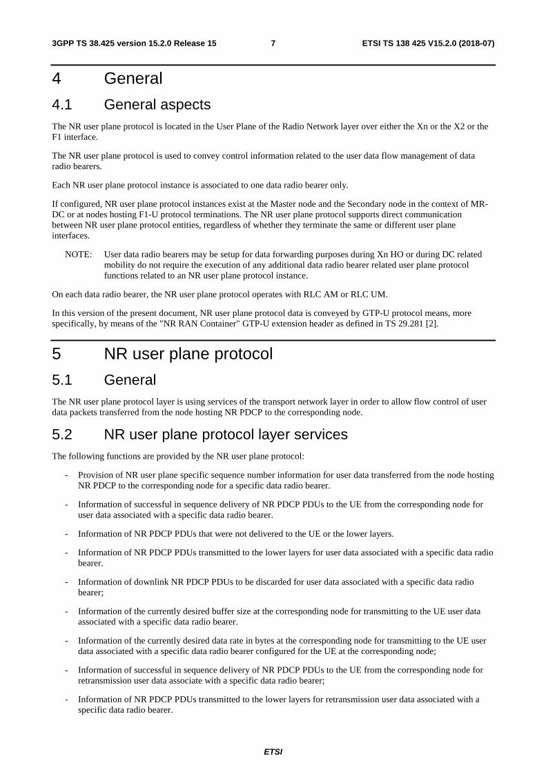
5.4.1 Transfer of Downlink User Data
5.4.1.1 Successful operation
The purpose of the Transfer of Downlink User Data procedure is to provide NR-U specific sequence number information at the transfer of user data carrying a DL NR PDCP PDU from the node hosting the NR PDCP entity to the corresponding node.
An NR user plane instance making use of the Transfer of Downlink User Data procedure is associated to a single data radio bearer only.
The node hosting the NR PDCP entity shall assign consecutive NR-U sequence numbers to each transferred NR-U packet.
If the Assistance Information Report Polling Flag is equal to 1, the corresponding node shall send the ASSISTANCE INFORMATION DATA to the node hosting the NR PDCP.
The corresponding node shall detect whether an NR-U packet was lost and memorise the respective sequence number after it has declared the respective NR-U packet as being "lost".
The corresponding node shall transfer the remaining NR PDCP PDUs towards the UE and memorise the highest NR PDCP PDU sequence number of the NR PDCP PDU that was successfully delivered in sequence towards the UE (in case RLC AM is used) and the highest NR PDCP PDU sequence number of the NR PDCP PDU that was transmitted to the lower layers.
The corresponding node shall send the DL DATA DELIVERY STATUS if the Report Polling Flag is set, unless a situation of overload at the corresponding node is encountered.
NOTE: The Transfer of Downlink User Data procedure and the associated feedback of lost NR-U packets assist the node hosting the NR PDCP entity in avoiding NR PDCP HFN de-synchronisation. If a deployment decides to not use the Transfer of Downlink User Data procedure, NR PDCP HFN synchronization should be ensured by other means.
The node hosting the NR PDCP entity indicates to the corresponding node whether this NR-U packet is a retransmission of NR PDCP PDU.
The node hosting the NR PDCP entity can indicate to the corresponding node to either discard all NR PDCP PDUs up to and including a defined DL discard NR PDCP PDU SN or discard one or a number of blocks of downlink NR PDCP PDUs.
node hosting NR PDCP
correspondingnode
DL USER DATA
Figure 5.4.1.1-1: Successful Transfer of Downlink User Data
5.4.1.2 Unsuccessful operation
Void.
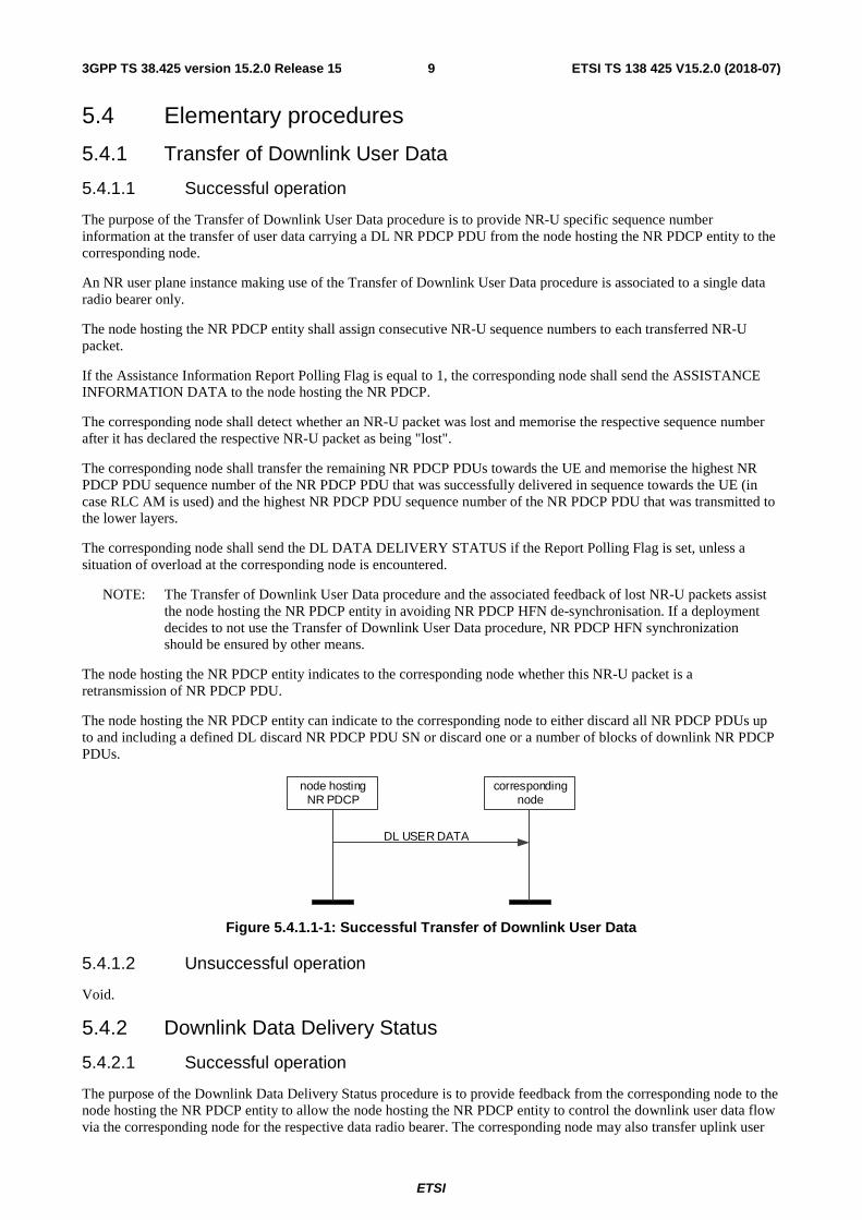
5.4.2 Downlink Data Delivery Status
5.4.2.1 Successful operation
The purpose of the Downlink Data Delivery Status procedure is to provide feedback from the corresponding node to the node hosting the NR PDCP entity to allow the node hosting the NR PDCP entity to control the downlink user data flow via the corresponding node for the respective data radio bearer. The corresponding node may also transfer uplink user
ETSI
ETSI TS 138 425 V15.2.0 (2018-07)103GPP TS 38.425 version 15.2.0 Release 15
data for the concerned data radio bearer to the node hosting the NR PDCP entity together with a DL DATA DELIVERY STATUS frame within the same GTP-U PDU.
The Downlink Data Delivery Status procedure is also used to provide feedback from the corresponding node to the node hosting the NR PDCP entity to allow the node hosting the NR PDCP entity to control the successful delivery of DL control data to the corresponding node.
When the corresponding node decides to trigger the Feedback for Downlink Data Delivery procedure it shall report as specified in section 5.2:
a) in case of RLC AM, the highest NR PDCP PDU sequence number successfully delivered in sequence to the UE among those NR PDCP PDUs received from the node hosting the NR PDCP entity i.e. excludes those retransmission NR PDCP PDUs;
b) the desired buffer size in bytes for the concerned data radio bearer;
c) optionally, the desired data rate in bytes associated with a specific data radio bearer configured for the UE;
d) the NR-U packets that were declared as being "lost" by the corresponding node and have not yet been reported to the node hosting the NR PDCP entity within the DL DATA DELIVERY STATUS frame;
e) if retransmission NR PDCP PDUs have been delivered, the highest NR PDCP PDU sequence number successfully delivered in sequence to the UE among those retransmission NR PDCP PDUs received from the node hosting the NR PDCP entity;
f) if retransmission NR PDCP PDUs have been transmitted, the highest NR PDCP PDU sequence number transmitted to the lower layers among those retransmission NR PDCP PDUs received from the node hosting the NR PDCP entity;
g) the highest NR PDCP PDU sequence number transmitted to the lower layers among those NR PDCP PDUs received from the node hosting the NR PDCP entity i.e. excludes those retransmission NR PDCP PDUs.
NOTE: If a deployment has decided not to use the Transfer of Downlink User Data procedure, d), e) and f) above are not applicable.
As soon as the corresponding node detects the successful RACH access by the UE for the corresponding data bearer(s), the corresponding node shall send initial DL DATA DELIVERY STATUS frame to the node(s) hosting the NR PDCP entity(ies). The node hosting NR PDCP entity may start sending DL data before receiving the initial DL DATA DELIVERY STATUS frame. In case the DL DATA DELIVERY STATUS frame is sent before any NR PDCP PDU is transferred to lower layers, the information on the highest NR PDCP PDU sequence number successfully delivered in sequence to the UE and the highest NR PDCP PDU sequence number transmitted to the lower layers may not be provided.
The DL DATA DELIVERY STATUS frame shall also include a final frame indication signalling whether the frame is the last DL status report received in the course of releasing a bearer from the corresponding node. Namely, the final frame indication is signalled in cases where the corresponding node knows that the bearer will be released before the DL status report is signalled. When receiving such indication, if applicable, the node hosting the NR PDCP entity considers that no more UL or DL data is expected to be transmitted between the corresponding node and the UE.
The DL DATA DELIVERY STATUS frame may also include an indication of detected radio link outage or radio link resume. When receiving an indication of radio link outage detection, the node hosting the NR PDCP entity considers that traffic delivery over data radio bearers configured for the UE is unavailable at the corresponding node both in UL and DL. When receiving an indication of radio link resume detection, the node hosting the NR PDCP entity considers that traffic delivery over data radio bearers configured for the UE is available at the corresponding node both in UL and in DL. When receiving an indication of UL or DL radio link outage detection, the node hosting the NR PDCP entity considers that traffic delivery over DRBs configured for the UE is unavailable at the corresponding node for UL or DL, depending on the indicated outage. When receiving an indication of UL or DL radio link resume detection, the node hosting the NR PDCP entity considers that traffic delivery over DRBs configured for the UE is available at the corresponding node in UL or in DL, depending on the indicated resume.
The node hosting the NR PDCP entity, when receiving the DL DATA DELIVERY STATUS frame:
- regards the desired buffer size under b) and the data rate under c) above as the amount of data to be sent from the hosting node:
ETSI
ETSI TS 138 425 V15.2.0 (2018-07)113GPP TS 38.425 version 15.2.0 Release 15
- If the value of the desired buffer size is 0, the hosting node shall stop sending any data per bearer.
- If the value of the desired buffer size in b) above is greater than 0, the hosting node may send up to this amount of data per bearer beyond the "Highest Delivered NR PDCP SN" for RLC AM, or the hosting node may send up to this amount of data per bearer beyond the "Highest Transmitted NR PDCP SN" for RLM UM.
- The value of the desired data rate in c) above is the amount of data desired to be received in a specific amount of time. The amount of time is 1 sec.
- The information of the buffer size in b) above and of the data rate in c) above is valid until the next DL DATA DELIVERY STATUS frame is transferred.
- is allowed to remove the buffered NR PDCP PDUs according to the feedback of transmitted and/or successfully delivered NR PDCP PDUs;
- decides upon the actions necessary to take for NR PDCP PDUs reported other than transmitted and/or successfully delivered.
In case of RLC AM, after the highest NR PDCP PDU sequence number successfully delivered in sequence is reported to the node hosting the NR PDCP entity, the corresponding node removes the respective NR PDCP PDUs. For RLC UM, the corresponding node may remove the respective NR PDCP PDUs after transmitting to lower layers.
node hosting NR PDCP
correspondingnode
DL DATA DELIVERY STATUS
Figure 5.4.2.1-1: Successful Downlink Data Delivery Status
5.4.2.2 Unsuccessful operation
Void.
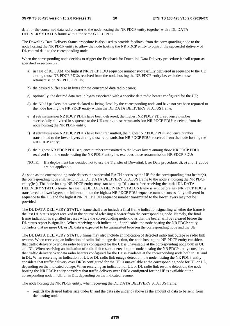
5.4.3 Transfer of Assistance Information
5.4.3.1 Successful operation
The purpose of the Transfer of Assistance Information procedure is to provide assistance information to the node hosting the NR PDCP. Such information may be taken into consideration by the node hosting the NR PDCP for UP management and optimisation procedures.
An NR user plane instance making use of the Transfer of Assistance Information procedure is associated to a single data bearer only.
The Transfer of Assistance Information procedure may be invoked if the corresponding node decides to send the Radio Quality Assistance Information and/or the PDCP duplication activation suggestion to the node hosting the NR PDCP for that particular data bearer.
The ASSISTANCE INFORMATION DATA frame may include Radio Quality Assistance Information. The information shall consist of one or more of the information indicated in the Assistance Information Type.
The ASSISTANCE INFORMATION DATA shall be sent when the corresponding node receives a DL USER DATA PDU including the Assistance Information Report Polling Flag set to 1.
The ASSISTANCE INFORMATION DATA frame may include the PDCP Duplication Activation Suggestion, which informs the node hosting the NR PDCP of the suggestion from the corresponding node on whether to activate or not activate PDCP duplication. The node hosting the NR PDCP may take this information into account to take a decision on whether to activate or not activate PDCP duplication.
ETSI
ETSI TS 138 425 V15.2.0 (2018-07)123GPP TS 38.425 version 15.2.0 Release 15
node hosting NR PDCP
correspondingnode
ASSISTANCE INFORMATION DATA
Figure 5.4.3.1-1: Successful Transfer of Assistance Information Data
5.5 Elements for the NR user plane protocol
5.5.1 General
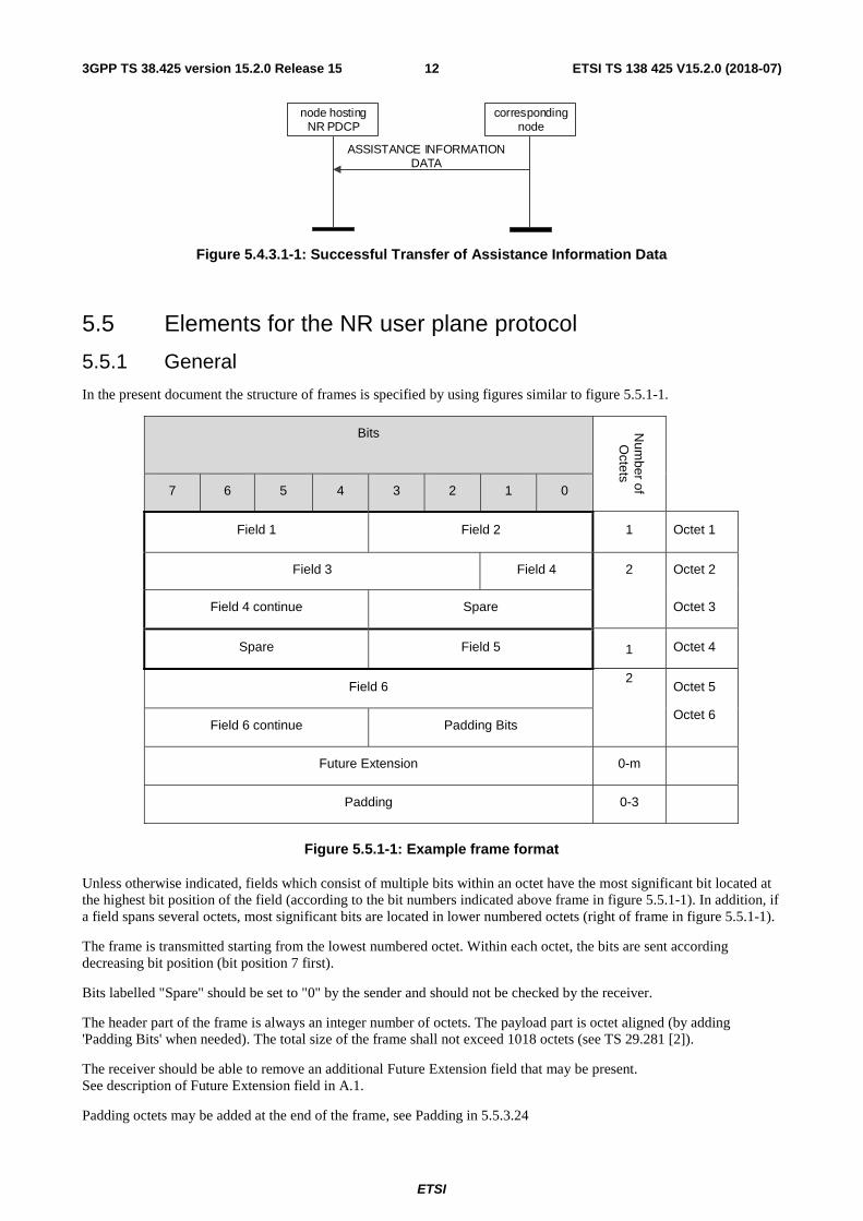
In the present document the structure of frames is specified by using figures similar to figure 5.5.1-1.
Bits Num
ber of O
ctets
7 6 5 4 3 2 1 0
Field 1 Field 2 1 Octet 1
Field 3 Field 4 2 Octet 2
Field 4 continue Spare Octet 3
Spare Field 5 1 Octet 4
Field 6 2
Octet 5
Octet 6 Field 6 continue Padding Bits
Future Extension 0-m
Padding 0-3
Figure 5.5.1-1: Example frame format
Unless otherwise indicated, fields which consist of multiple bits within an octet have the most significant bit located at the highest bit position of the field (according to the bit numbers indicated above frame in figure 5.5.1-1). In addition, if a field spans several octets, most significant bits are located in lower numbered octets (right of frame in figure 5.5.1-1).
The frame is transmitted starting from the lowest numbered octet. Within each octet, the bits are sent according decreasing bit position (bit position 7 first).
Bits labelled "Spare" should be set to "0" by the sender and should not be checked by the receiver.
The header part of the frame is always an integer number of octets. The payload part is octet aligned (by adding 'Padding Bits' when needed). The total size of the frame shall not exceed 1018 octets (see TS 29.281 [2]).
The receiver should be able to remove an additional Future Extension field that may be present. See description of Future Extension field in A.1.
Padding octets may be added at the end of the frame, see Padding in 5.5.3.24
ETSI
ETSI TS 138 425 V15.2.0 (2018-07)133GPP TS 38.425 version 15.2.0 Release 15
5.5.2 Frame format for the NR user plane protocol
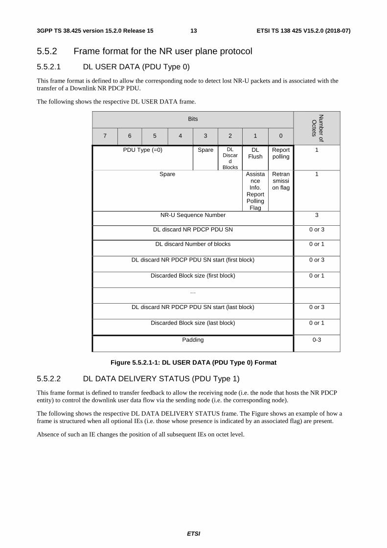
5.5.2.1 DL USER DATA (PDU Type 0)
This frame format is defined to allow the corresponding node to detect lost NR-U packets and is associated with the transfer of a Downlink NR PDCP PDU.
The following shows the respective DL USER DATA frame.
Bits
Num
ber of O
ctets 7 6 5 4 3 2 1 0
PDU Type (=0) Spare DL Discar
d Blocks
DL Flush
Report polling
1
Spare Assistance Info.
Report Polling Flag
Retransmission flag
1
NR-U Sequence Number 3
DL discard NR PDCP PDU SN 0 or 3
DL discard Number of blocks 0 or 1
DL discard NR PDCP PDU SN start (first block) 0 or 3
Discarded Block size (first block) 0 or 1
…
DL discard NR PDCP PDU SN start (last block) 0 or 3
Discarded Block size (last block) 0 or 1
Padding 0-3
Figure 5.5.2.1-1: DL USER DATA (PDU Type 0) Format
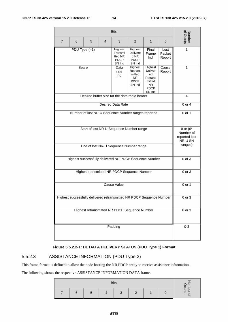
5.5.2.2 DL DATA DELIVERY STATUS (PDU Type 1)
This frame format is defined to transfer feedback to allow the receiving node (i.e. the node that hosts the NR PDCP entity) to control the downlink user data flow via the sending node (i.e. the corresponding node).
The following shows the respective DL DATA DELIVERY STATUS frame. The Figure shows an example of how a frame is structured when all optional IEs (i.e. those whose presence is indicated by an associated flag) are present.
Absence of such an IE changes the position of all subsequent IEs on octet level.
ETSI
ETSI TS 138 425 V15.2.0 (2018-07)143GPP TS 38.425 version 15.2.0 Release 15
Bits Num
ber of O
ctets 7 6 5 4 3 2 1 0
PDU Type (=1) Highest Transmitted NR PDCP SN Ind
Highest Delivere
d NR PDCP SN Ind
Final Frame
Ind.
Lost Packet Report
1
Spare Data rate Ind.
Highest Retransmitted
NR PDCP SN Ind
Highest Deliver
ed Retransmitted
NR PDCP SN Ind
Cause Report
1
Desired buffer size for the data radio bearer 4
Desired Data Rate 0 or 4
Number of lost NR-U Sequence Number ranges reported 0 or 1
Start of lost NR-U Sequence Number range 0 or (6* Number of
reported lost NR-U SN ranges) End of lost NR-U Sequence Number range
Highest successfully delivered NR PDCP Sequence Number 0 or 3
Highest transmitted NR PDCP Sequence Number 0 or 3
Cause Value 0 or 1
Highest successfully delivered retransmitted NR PDCP Sequence Number 0 or 3
Highest retransmitted NR PDCP Sequence Number 0 or 3
Padding 0-3
Figure 5.5.2.2-1: DL DATA DELIVERY STATUS (PDU Type 1) Format
5.5.2.3 ASSISTANCE INFORMATION (PDU Type 2)
This frame format is defined to allow the node hosting the NR PDCP entity to receive assistance information.
The following shows the respective ASSISTANCE INFORMATION DATA frame.
Bits
Num
ber of O
ctets 7 6 5 4 3 2 1 0
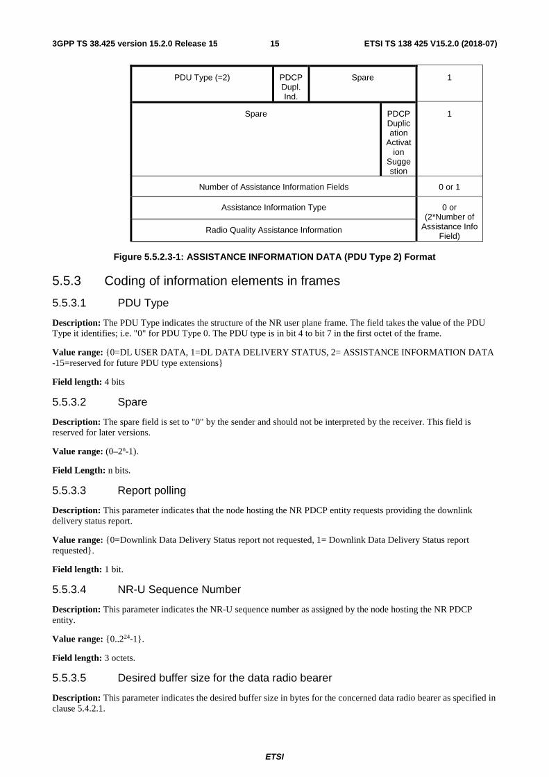
ETSI
ETSI TS 138 425 V15.2.0 (2018-07)153GPP TS 38.425 version 15.2.0 Release 15
PDU Type (=2) PDCP Dupl. Ind.
Spare 1
Spare PDCP Duplication
Activation
Suggestion
1
Number of Assistance Information Fields 0 or 1
Assistance Information Type 0 or (2*Number of
Assistance Info Field)
Radio Quality Assistance Information
Figure 5.5.2.3-1: ASSISTANCE INFORMATION DATA (PDU Type 2) Format
5.5.3 Coding of information elements in frames
5.5.3.1 PDU Type
Description: The PDU Type indicates the structure of the NR user plane frame. The field takes the value of the PDU Type it identifies; i.e. "0" for PDU Type 0. The PDU type is in bit 4 to bit 7 in the first octet of the frame.
Value range: {0=DL USER DATA, 1=DL DATA DELIVERY STATUS, 2= ASSISTANCE INFORMATION DATA -15=reserved for future PDU type extensions}
Field length: 4 bits
5.5.3.2 Spare
Description: The spare field is set to "0" by the sender and should not be interpreted by the receiver. This field is reserved for later versions.
Value range: (0–2n-1).
Field Length: n bits.
5.5.3.3 Report polling
Description: This parameter indicates that the node hosting the NR PDCP entity requests providing the downlink delivery status report.
Value range: {0=Downlink Data Delivery Status report not requested, 1= Downlink Data Delivery Status report requested}.
Field length: 1 bit.
5.5.3.4 NR-U Sequence Number
Description: This parameter indicates the NR-U sequence number as assigned by the node hosting the NR PDCP entity.
Value range: {0..224-1}.
Field length: 3 octets.
5.5.3.5 Desired buffer size for the data radio bearer
Description: This parameter indicates the desired buffer size in bytes for the concerned data radio bearer as specified in clause 5.4.2.1.
ETSI
ETSI TS 138 425 V15.2.0 (2018-07)163GPP TS 38.425 version 15.2.0 Release 15
Value range: {0..232-1}.
Field length: 4 octets.
5.5.3.6 Desired Data Rate
Description: This parameter indicates the amount of data desired to be received in bytes in a specific amount of time (1 s) for a specific data radio bearer established for the UE as specified in clause 5.4.2.1.
Value range: {0..232-1}.
Field length: 4 octets.
5.5.3.7 DL Flush
Description: This parameter indicates the presence of DL discard NR PDCP PDU SN.
Value range: {0= DL discard NR PDCP PDU SN not present, 1= DL discard NR PDCP PDU SN present}.
Field length: 1 bit.
5.5.3.8 DL discard NR PDCP PDU SN
Description: This parameter indicates the downlink NR discard PDCP PDU sequence number up to and including which all the NR PDCP PDUs should be discarded.
Value range: {0..218-1}.
Field length: 3 octets.
5.5.3.9 DL Discard Blocks
Description: This parameter indicates the presence of DL discard Number of blocks, DL discard NR PDCP PDU SN start and Discarded Block size.
Value range: {0= DL discard Number of blocks, DL discard NR PDCP PDU SN start and Discarded Block size not present, 1= DL discard Number of blocks, DL discard NR PDCP PDU SN start and Discarded Block size present}.
Field length: 1 bit.
5.5.3.10 DL discard NR PDCP PDU SN start
Description: This parameter indicates the starting SN of a downlink NR PDCP PDU block to be discarded.
Value range: {0..218-1}.
Field length: 3 octets.
5.5.3.11 DL discard Number of blocks
Description: This parameter indicates the number of NR PDCP PDU blocks to be discarded.
Value range: {0..244}.
Field length: 1 octet.
5.5.3.12 Discarded Block size
Description: This parameter indicates the number of NR PDCP PDUs counted from the starting SN to be discarded.
Value range: {1..255}.
Field length: 1 octet.
ETSI
ETSI TS 138 425 V15.2.0 (2018-07)173GPP TS 38.425 version 15.2.0 Release 15
5.5.3.13 Lost Packet Report
Description: This parameter indicates the presence of Number of lost NR-U Sequence Number ranges reported, Start of lost NR-U Sequence Number range and End of lost NR-U Sequence Number range.
Value range: {0= Number of lost NR-U Sequence Number ranges reported, Start of lost NR-U Sequence Number range and End of lost NR-U Sequence Number range not present, 1= Number of lost NR-U Sequence Number ranges reported, Start of lost NR-U Sequence Number range and End of lost NR-U Sequence Number range present}.
Field length: 1 bit.
5.5.3.14 Final Frame Indication
Description: This parameter indicates whether the frame is the last DL status report as described in clause 5.4.2.1.
Value range: {0=Frame is not final, 1= Frame is final}.
Field length: 1 bit.
5.5.3.15 Number of lost NR-U Sequence Number ranges reported
Description: This parameter indicates the number of NR-U Sequence Number ranges reported to be lost.
Value range: {1..161}.
Field length: 1 octet.
5.5.3.16 Start of lost NR-U Sequence Number range
Description: This parameter indicates the start of an NR-U sequence number range reported to be lost.
Value range: {0..224-1}.
Field length: 3 octets.
5.5.3.17 End of lost NR-U Sequence Number range
Description: This parameter indicates the end of an NR-U sequence number range reported to be lost.
Value range: {0..224-1}.
Field length: 3 octets.
5.5.3.18 Highest Delivered NR PDCP SN Ind
Description: This parameter indicates the presence of Highest successfully delivered PDCP Sequence Number.
Value range: {0= Highest successfully delivered PDCP Sequence Number not present, 1= Highest successfully delivered PDCP Sequence Number present}.
Field length: 1 bit.
5.5.3.19 Highest successfully delivered NR PDCP Sequence Number
Description: This parameter indicates feedback about the in-sequence delivery status of NR PDCP PDUs at the corresponding node towards the UE.
Value range: {0..218-1}.
Field length: 3 octets.
5.5.3.20 Highest Transmitted NR PDCP SN Ind
Description: This parameter indicates the presence of the Highest transmitted NR PDCP Sequence Number.
Value range: {0= Highest transmitted NR PDCP Sequence Number not present, 1= Highest transmitted NR PDCP Sequence Number present}.
ETSI
ETSI TS 138 425 V15.2.0 (2018-07)183GPP TS 38.425 version 15.2.0 Release 15
Field length: 1 bit.
5.5.3.21 Highest transmitted NR PDCP Sequence Number
Description: This parameter indicates the feedback about the transmitted status of NR PDCP PDU sequence at the corresponding node to the lower layers.
Value range: {0..218-1}.
Field length: 3 octets.
5.5.3.22 Cause Report
Description: This parameter indicates the presence of Cause Value.
Value range: {0=Cause Value not present, 1=Cause Value present}.
Field length: 1 bit.
5.5.3.23 Cause Value
Description: This parameter indicates specific events reported by the corresponding node.
Value range: {0=UNKNOWN, 1=RADIO LINK OUTAGE, 2=RADIO LINK RESUME, 3=UL RADIO LINK OUTAGE, 4=DL RADIO LINK OUTAGE, 5=UL RADIO LINK RESUME, 6=DL RADIO LINK RESUME, 7-228=reserved for future value extensions, 229-255=reserved for test purposes}
Field length: 1 octet.
5.5.3.24 Padding
Description: The padding is included at the end of the frame to ensure that the NR user plane protocol pdu length (including padding and the Future Extension) is (n*4– 2) octets, where n is a positive integer . If there is any Future Extension, the padding should be added after the Future Extensions.
Field Length: 0–3 octets.
5.5.3.28 Void
Void.
5.5.3.29 Retransmission flag
Description: This parameter indicates whether the NR PDCP PDU is a retransmission NR-U packet sent by the node hosting the NR PDCP to the corresponding node.
Value range: {0= Not a retransmission NR-U packet, 1= Retransmission NR-U packet}.
Field length: 1 bit.
5.5.3.30 Highest Delivered Retransmitted NR PDCP SN Ind
Description: This parameter indicates the presence of highest successfully delivered retransmitted PDCP Sequence Number.
Value range: {0= Highest successfully delivered retransmitted PDCP Sequence Number not present, 1= Highest successfully delivered retransmitted PDCP Sequence Number present}.
Field length: 1 bit.
5.5.3.31 Highest Retransmitted NR PDCP SN Ind
Description: This parameter indicates the presence of highest retransmitted NR PDCP Sequence Number.
ETSI
ETSI TS 138 425 V15.2.0 (2018-07)193GPP TS 38.425 version 15.2.0 Release 15
Value range: {0= Highest Retransmitted NR PDCP Sequence Number not present, 1= Highest Retransmitted NR PDCP Sequence Number present}.
Field length: 1 bit.
5.5.3.32 Highest successfully delivered retransmitted NR PDCP Sequence Number
Description: This parameter indicates feedback about the in-sequence delivery status of NR PDCP PDUs of the retransmission data at the corresponding node towards the UE.
Value range: {0..218-1}.
Field length: 3 octets.
5.5.3.33 Highest retransmitted NR PDCP Sequence Number
Description: This parameter indicates the feedback about the transmitted status of NR PDCP PDU of the retransmission data at the corresponding node to the lower layers.
Value range: {0..218-1}.
Field length: 3 octets.
5.5.3.34 Data Rate Indication
Description: This parameter indicates the presence of the Desired Data Rate.
Value range: {0= Desired Data Rate Information is not present, 1= Desired Data Rate Information is present}.
Field length: 1 bit.
5.5.3.35 PDCP Duplication Indication
Description: This field indicates the presence of the PDCP Duplication Activation Suggestion.
Value range: {0= PDCP Duplication Activation Suggestion not present, 1= PDCP Duplication Activation Suggestion present}.
Field length: 1 bit.
5.5.3.36 PDCP Duplication Activation Suggestion
Description: This parameter indicates the suggestion given by the corresponding node on whether PDCP duplication should be activated or not.
Value range: {0= Do not duplicate, 1= Duplicate}.
Field length: 1 bit.
5.5.3.37 Number of Assistance Information Field
Description: This field indicates the number of Assistance Information Type and Radio Quality Assistance Information pairs concatenated.
Value range: {0..28-1}.
Field length: 1 octets.
5.5.3.38 Assistance Information Type
Description: This field describes the type of radio quality assistance information provided by the corresponding node to the node hosting the NR PDCP. The DL Radio Quality Index is a numerical index expressing the radio quality of the DRB in DL, where the value 0 represents the lowest quality. The UL Radio Quality Index is a numerical index expressing the radio quality of the DRB in UL, where the value 0 represents the lowest quality. The averaging window for the Average CQI, Average HARQ Failure and Average HARQ Retransmission is set by means of configuration.
ETSI
ETSI TS 138 425 V15.2.0 (2018-07)203GPP TS 38.425 version 15.2.0 Release 15
Power Headroom Report is reported over MAC control element from UE as defined in 3GPP TS 36.321[4] and 3GPP TS 38.321[5]
Value range: {0=UNKNOWN, 1=Average CQI, 2=Average HARQ Failure, 3=Average HARQ Retransmissions, 4= DL Radio Quality Index, 5= UL Radio Quality Index, 6= Power Headroom Report, 7-228=reserved for future value extensions, 229-255=reserved for test purposes}.
Field length: 1 octets.
5.5.3.39 Radio Quality Assistance Information
Description: This parameter indicates one of the assistance information indicated by the Assistance Information Type.
Value range: {0..28-1}.
Field length: 1 octets.
5.5.3.40 Assistance Information Report Polling Flag
Description: This parameter indicates that the node hosting the NR PDCP entity requests the corresponding node to send an ASSISTANCE INFORMATION DATA PDU.
Value range: {0= Assistance Information Data not requested, 1= Assistance Information Data requested}.
Field length: 1 bit.
5.5.4 Timers
Not applicable.
5.6 Handling of unknown, unforeseen and erroneous protocol data
Void.
ETSI
ETSI TS 138 425 V15.2.0 (2018-07)213GPP TS 38.425 version 15.2.0 Release 15
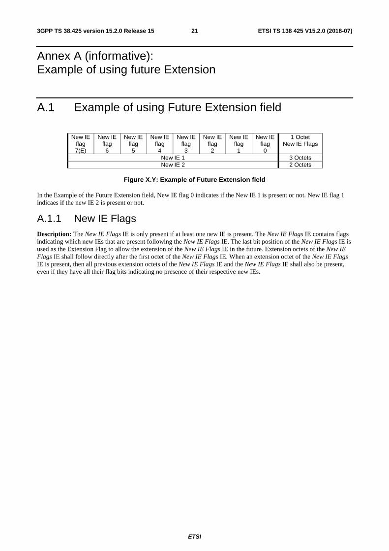
Annex A (informative): Example of using future Extension
A.1 Example of using Future Extension field
New IE flag 7(E)
New IE flag 6
New IE flag 5
New IE flag 4
New IE flag 3
New IE flag 2
New IE flag 1
New IE flag 0
1 Octet New IE Flags
New IE 1 3 Octets New IE 2 2 Octets
Figure X.Y: Example of Future Extension field
In the Example of the Future Extension field, New IE flag 0 indicates if the New IE 1 is present or not. New IE flag 1 indicaes if the new IE 2 is present or not.
A.1.1 New IE Flags Description: The New IE Flags IE is only present if at least one new IE is present. The New IE Flags IE contains flags indicating which new IEs that are present following the New IE Flags IE. The last bit position of the New IE Flags IE is used as the Extension Flag to allow the extension of the New IE Flags IE in the future. Extension octets of the New IE Flags IE shall follow directly after the first octet of the New IE Flags IE. When an extension octet of the New IE Flags IE is present, then all previous extension octets of the New IE Flags IE and the New IE Flags IE shall also be present, even if they have all their flag bits indicating no presence of their respective new IEs.
ETSI
ETSI TS 138 425 V15.2.0 (2018-07)223GPP TS 38.425 version 15.2.0 Release 15
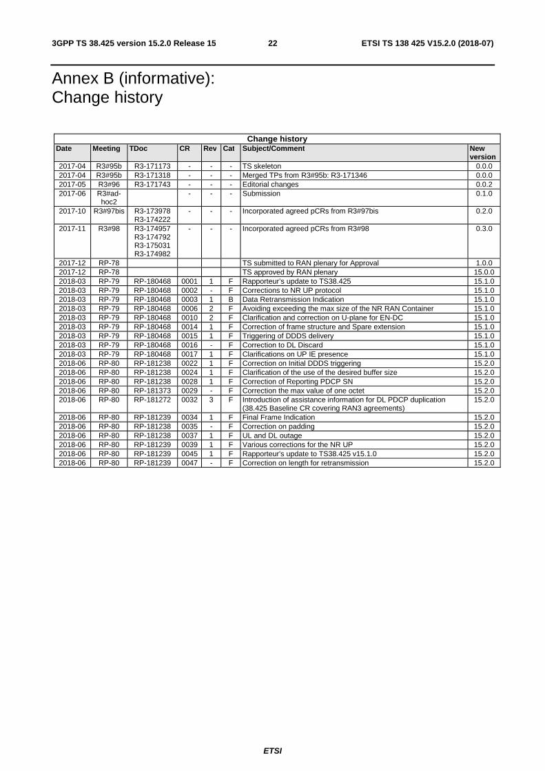
Annex B (informative): Change history
Change history Date Meeting TDoc CR Rev Cat Subject/Comment New
version 2017-04 R3#95b R3-171173 - - - TS skeleton 0.0.0 2017-04 R3#95b R3-171318 - - - Merged TPs from R3#95b: R3-171346 0.0.0 2017-05 R3#96 R3-171743 - - - Editorial changes 0.0.2 2017-06 R3#ad-
hoc2 - - - Submission 0.1.0
2017-10 R3#97bis R3-173978 R3-174222
- - - Incorporated agreed pCRs from R3#97bis 0.2.0
2017-11 R3#98 R3-174957 R3-174792 R3-175031 R3-174982
- - - Incorporated agreed pCRs from R3#98 0.3.0
2017-12 RP-78 TS submitted to RAN plenary for Approval 1.0.0 2017-12 RP-78 TS approved by RAN plenary 15.0.0 2018-03 RP-79 RP-180468 0001 1 F Rapporteur’s update to TS38.425 15.1.0 2018-03 RP-79 RP-180468 0002 - F Corrections to NR UP protocol 15.1.0 2018-03 RP-79 RP-180468 0003 1 B Data Retransmission Indication 15.1.0 2018-03 RP-79 RP-180468 0006 2 F Avoiding exceeding the max size of the NR RAN Container 15.1.0 2018-03 RP-79 RP-180468 0010 2 F Clarification and correction on U-plane for EN-DC 15.1.0 2018-03 RP-79 RP-180468 0014 1 F Correction of frame structure and Spare extension 15.1.0 2018-03 RP-79 RP-180468 0015 1 F Triggering of DDDS delivery 15.1.0 2018-03 RP-79 RP-180468 0016 - F Correction to DL Discard 15.1.0 2018-03 RP-79 RP-180468 0017 1 F Clarifications on UP IE presence 15.1.0 2018-06 RP-80 RP-181238 0022 1 F Correction on Initial DDDS triggering 15.2.0 2018-06 RP-80 RP-181238 0024 1 F Clarification of the use of the desired buffer size 15.2.0 2018-06 RP-80 RP-181238 0028 1 F Correction of Reporting PDCP SN 15.2.0 2018-06 RP-80 RP-181373 0029 - F Correction the max value of one octet 15.2.0 2018-06 RP-80 RP-181272 0032 3 F Introduction of assistance information for DL PDCP duplication
(38.425 Baseline CR covering RAN3 agreements) 15.2.0
2018-06 RP-80 RP-181239 0034 1 F Final Frame Indication 15.2.0 2018-06 RP-80 RP-181238 0035 - F Correction on padding 15.2.0 2018-06 RP-80 RP-181238 0037 1 F UL and DL outage 15.2.0 2018-06 RP-80 RP-181239 0039 1 F Various corrections for the NR UP 15.2.0 2018-06 RP-80 RP-181239 0045 1 F Rapporteur's update to TS38.425 v15.1.0 15.2.0 2018-06 RP-80 RP-181239 0047 - F Correction on length for retransmission 15.2.0

ETSI
ETSI TS 138 425 V15.2.0 (2018-07)233GPP TS 38.425 version 15.2.0 Release 15
History
Document history
V15.2.0 July 2018 Publication


![MSK CT PROTOCOL[2] - jefferson.edu · AC joint. SHOULDER Coronal Imaging Plane Coronal Imaging Plane •Prescribe coronal plane off of axial images parallel to supraspinatus muscle](https://img.pdfslide.net/doc/110x75/5d645f8588c9930e728b6075/msk-ct-protocol2-ac-joint-shoulder-coronal-imaging-plane-coronal-imaging.jpg)