Embed Size (px)
Citation preview

Plumbing & Heating Products
TUCSON®
Tucson Plumbing & Heating ProductsHead O�ce: Santry Avenue, Dublin 9
D09K160, Ireland
Email: [email protected]: +44 12166 77883
www.tucsonproducts.co.uk
Superior Plumbing Products
Plumbing & Heating Products
TUCSON®
1
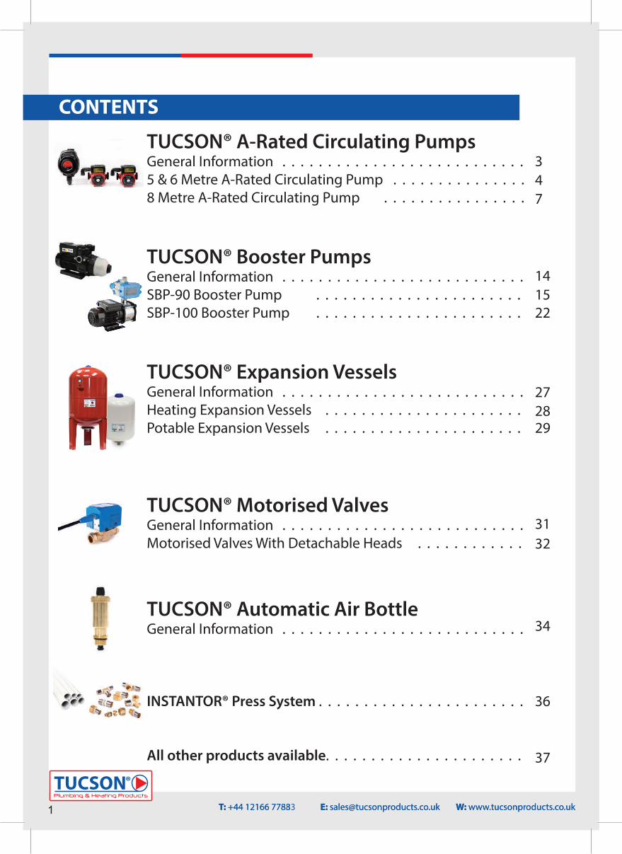
TUCSON® A-Rated Circulating PumpsGeneral Information . . . . . . . . . . . . . . . . . . . . . . . . . . .5 & 6 Metre A-Rated Circulating Pump . . . . . . . . . . . . . . .8 Metre A-Rated Circulating Pump . . . . . . . . . . . . . . . .
TUCSON® Booster PumpsGeneral Information . . . . . . . . . . . . . . . . . . . . . . . . . . .SBP-90 Booster Pump . . . . . . . . . . . . . . . . . . . . . . .SBP-100 Booster Pump . . . . . . . . . . . . . . . . . . . . . . .
TUCSON® Expansion VesselsGeneral Information . . . . . . . . . . . . . . . . . . . . . . . . . . .Heating Expansion Vessels . . . . . . . . . . . . . . . . . . . . . .Potable Expansion Vessels . . . . . . . . . . . . . . . . . . . . . .
TUCSON® Motorised ValvesGeneral Information . . . . . . . . . . . . . . . . . . . . . . . . . . .Motorised Valves With Detachable Heads . . . . . . . . . . . .
TUCSON® Automatic Air Bottle General Information . . . . . . . . . . . . . . . . . . . . . . . . . . .
INSTANTOR® Press System . . . . . . . . . . . . . . . . . . . . . . .
All other products available. . . . . . . . . . . . . . . . . . . . . .
347
141522
272829
3132
34
36
37
T: +44 12166 7783 E: [email protected] W: www.tucsonproducts.co.ukT: +44 12166 77883 E: [email protected] W: www.tucsonproducts.co.uk
CONTENTS
347
141522
272829
3132
34
36
37
Plumbing & Heating Products
TUCSON®
2
TUCSON® A-RATED CIRCULATING PUMP’S
T: +44 12166 77883 E: [email protected] W: www.tucsonproducts.co.uk
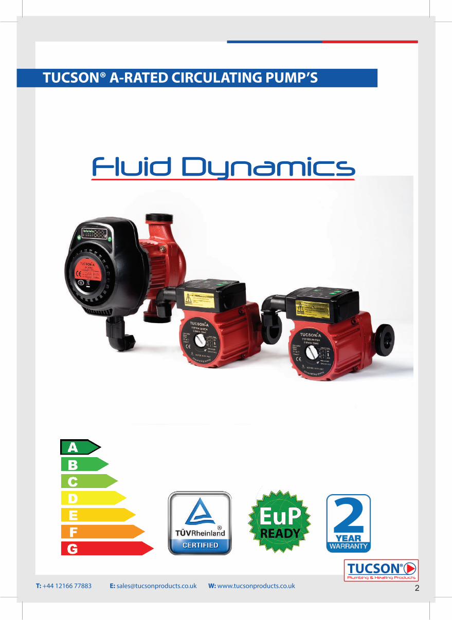
Fluid Dynamics
2
GENERAL INFORMATION1. A-Rated Circulating PumpOur A-Rated circulating pumps are designed for the circulation of water in heating systems. They can be used in the following installations:• Under�oor heating systems• One-pipe systems• Two-pipe systemsThey incorporate a permanent-magnet motor and variable-pressure control, enabling continuous adjustment of the pumps performance to the actual requirements. NB: When the pump is being used for a solid fuel application, please ensure it is switched to a ‘manual’ setting ONLY
2. Advantages of installing an A-Rated Circulating Pump• Our A-Rated Pumps are easy to install in most cases, with the factory setting allowing the pump to be started without making any adjustments.• A high degree of comfort due to minimal noise from the pump and throughout the system.• Low energy consumption compared to conventional circulating pumps. Our A-Rated pumps are fully compliant with the European Union ErP (Energy-related Products) directive, they exceed the bench mark for energy e�ciency with an EEI rating of ≤0.20.
3. Pump liquidThe water within the system and the pump must be clean, non-aggressive and non-explosive. It must also be free from solid particles, �bres or mineral oil. In heating systems, the water must meet the requirements of accepted standards for water quality in a heating system.
4. ErP (ecological design) directive• The benchmark for the most e�cient circulators is EEI ≤0.20.• Information on recycling/disposal: The product should be disposed of seprately from household waste in line with local laws and regulations. When the product reaches its end of life, dispose of it at your local waste collection point/recycling centre.• The separate collection and recycling of your product at the time of disposal will help conserve natural resources and ensure that it is recycled in a manner that protects human health and the environment.
5. Warranty Tucson® A-Rated circulating pumps are sold with a 2 year warranty e�ective from date of purchase. This warranty covers any manufacturing fault which may cause the pump to fail and not perform its designed operations correctly.The warranty is valid on the assumption the following has been applied to the installation:• Product installed correctly and used as speci�ed in the instructions.• It has been installed by a fully quali�ed tradesperson.• The installation complies with the local building regulations and also any regulations which are relative to circulating pump installations.
The warranty of the pump is invalid if any of the following occurs during installation: • The pump has been installed to operate for other purposes than what it is designed for.• The pump is not installed by a quali�ed or competent person.• The pump has been installed incorrectly or not to the installation instructions.• The pump has failed outside of the warranty period.• The pump has been damaged by outside interference such as bad workmanship or physical damage.
Plumbing & Heating Products
TUCSON®
3
TUCSON® A-RATED CIRCULATING PUMP’S
T: +44 12166 77883 E: [email protected] W: www.tucsonproducts.co.uk
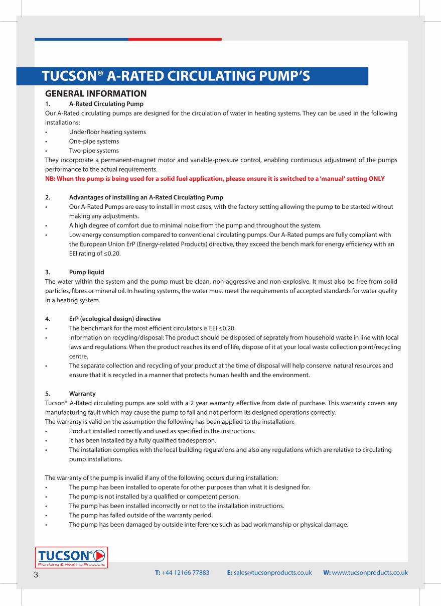
5 & 6 METRE HEAD A-RATED CIRCULATING PUMP
Code
Efficiency
Voltage
Frequency
Speed
Isolation Class
Fluid Temperature Working Range
Max Working Pressure
Ambient Temperature
Waterproof Rating
Pump Weight
EEI≤0.20
Single Phase, 230V+/- 10%
50 Hz
1 to 3 Speed, Auto
F
-10°C to 110°C
10 Bar
-10°C to 50°C
IP44
2.2KG
Min Power Output 5W
Screwed pipe pumpNominal width (mm)15(=1”), 25(= 1½”), 32(=2”)Maximum head (M)Electrical autoPort to port length (mm)
RS 25/6 EA 130Type Key 5M
771903(5M) / 771904(6M)
Max Power Output 45W (5M) / 47W (6M)
Screwed pipe pumpNominal width (mm)15(=1”), 25(= 1½”), 32(=2”)Maximum head (M)Electrical autoPort to port length (mm)
RS 25/7 EA 130Type Key 6M
Plumbing & Heating Products
TUCSON®
4T: +44 12166 77883 E: [email protected] W: www.tucsonproducts.co.uk
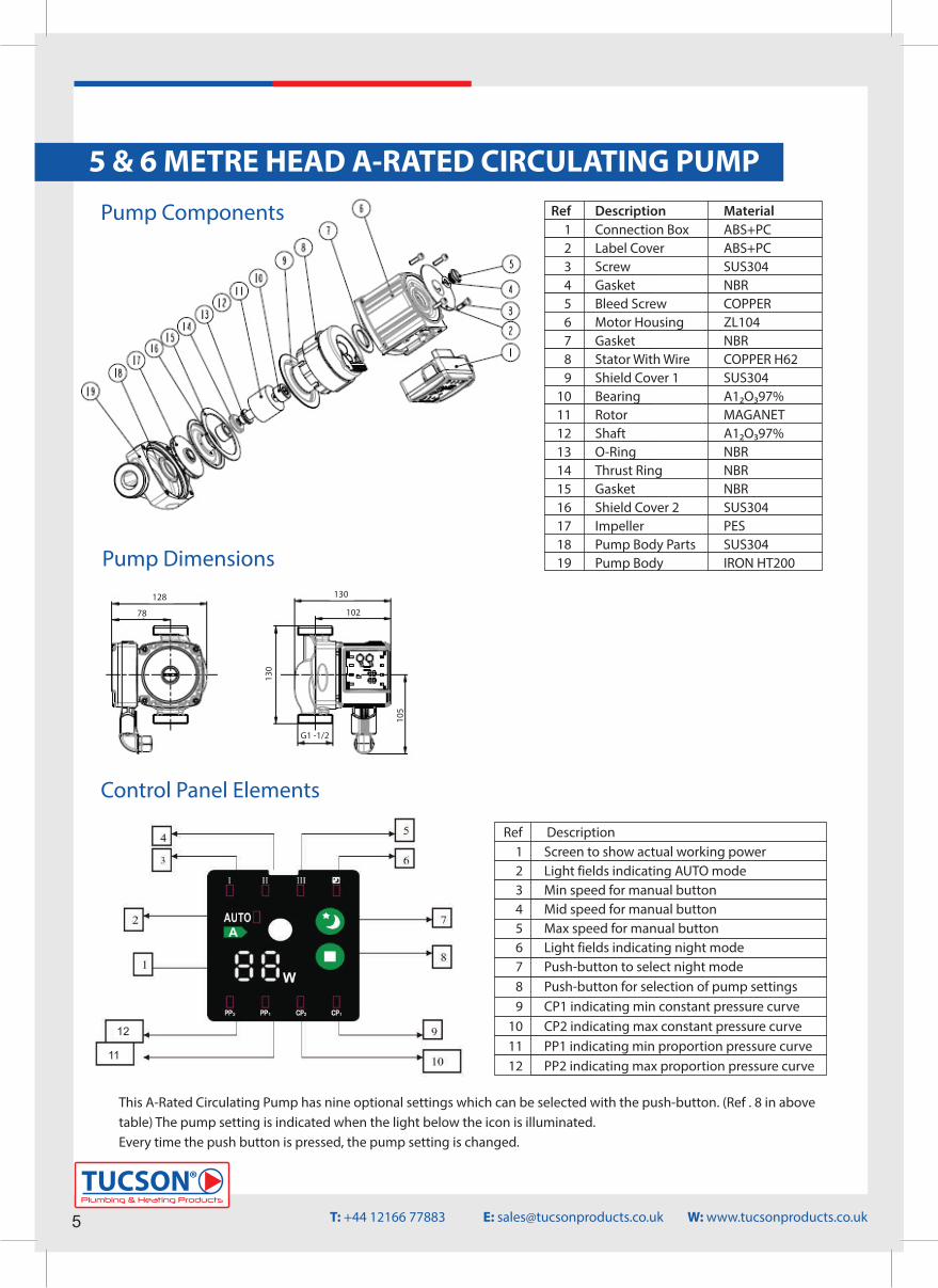
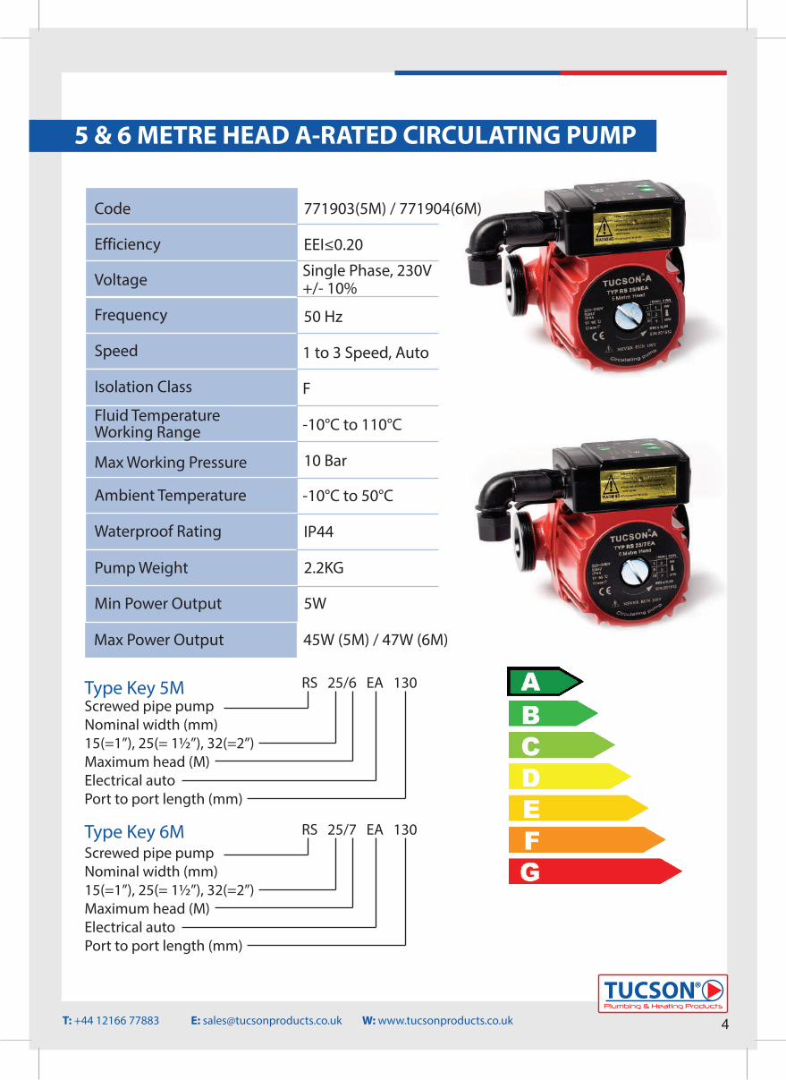
Control Panel Elements
Ref123456789
101112
Screen to show actual working powerLight fields indicating AUTO modeMin speed for manual buttonMid speed for manual buttonMax speed for manual buttonLight fields indicating night modePush-button to select night modePush-button for selection of pump settingsCP1 indicating min constant pressure curveCP2 indicating max constant pressure curvePP1 indicating min proportion pressure curvePP2 indicating max proportion pressure curve
Description
This A-Rated Circulating Pump has nine optional settings which can be selected with the push-button. (Ref . 8 in above table) The pump setting is indicated when the light below the icon is illuminated.Every time the push button is pressed, the pump setting is changed.
5 METRE HEAD A-RATED CIRCULATING PUMP
123456789
10111213141516171819
RefConnection BoxLabel CoverScrewGasketBleed ScrewMotor HousingGasketStator With WireShield Cover 1BearingRotorShaftO-RingThrust RingGasketShield Cover 2ImpellerPump Body PartsPump Body
ABS+PCABS+PCSUS304NBRCOPPERZL104NBRCOPPER H62SUS304A12O397%MAGANETA12O397%NBRNBRNBRSUS304PESSUS304IRON HT200
Description Material
128
78
130
102
130
105
G1 -1/2
128
78
130
102
130
105
G1 -1/2
Pump Components
Pump Dimensions
5 & 6 METRE HEAD A-RATED CIRCULATING PUMP
5Plumbing & Heating Products
TUCSON®
T: +44 12166 77883 E: [email protected] W: www.tucsonproducts.co.uk
11
12
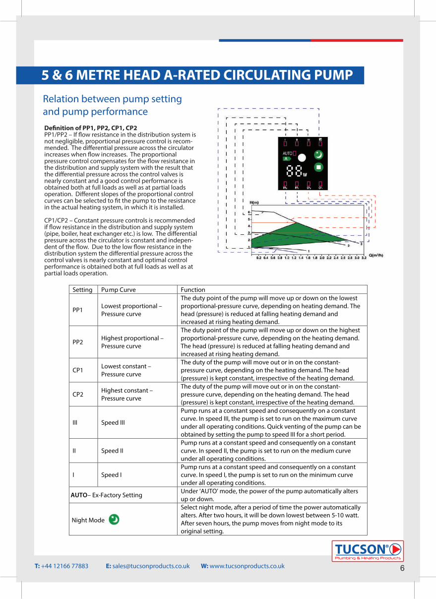
Relation between pump settingand pump performance
Setting Pump Curve Function
PP1 Lowest proportional – Pressure curve
The duty point of the pump will move up or down on the lowest proportional-pressure curve, depending on heating demand. The head (pressure) is reduced at falling heating demand and increased at rising heating demand.
PP2 Highest proportional – Pressure curve
The duty point of the pump will move up or down on the highest proportional-pressure curve, depending on the heating demand. The head (pressure) is reduced at falling heating demand and increased at rising heating demand.
CP1 Lowest constant – Pressure curve
The duty of the pump will move out or in on the constant-pressure curve, depending on the heating demand. The head (pressure) is kept constant, irrespective of the heating demand.
CP2 Highest constant – Pressure curve
The duty of the pump will move out or in on the constant-pressure curve, depending on the heating demand. The head (pressure) is kept constant, irrespective of the heating demand.
III Speed III
Pump runs at a constant speed and consequently on a constant curve. In speed III, the pump is set to run on the maximum curve under all operating conditions. Quick venting of the pump can be obtained by setting the pump to speed III for a short period.
II Speed II Pump runs at a constant speed and consequently on a constant curve. In speed II, the pump is set to run on the medium curve under all operating conditions.
I Speed I Pump runs at a constant speed and consequently on a constant curve. In speed I, the pump is set to run on the minimum curve under all operating conditions.
AUTO– Ex-Factory Setting Under ‘AUTO’ mode, the power of the pump automatically alters up or down.
Night Mode
Select night mode, after a period of time the power automatically alters. After two hours, it will be down lowest between 5-10 watt. After seven hours, the pump moves from night mode to its original setting.
5 & 6 METRE HEAD A-RATED CIRCULATING PUMP
Plumbing & Heating Products
TUCSON®
6T: +44 12166 77883 E: [email protected] W: www.tucsonproducts.co.uk
De�nition of PP1, PP2, CP1, CP2PP1/PP2 – If �ow resistance in the distribution system is not negligible, proportional pressure control is recom-mended. The di�erential pressure across the circulator increases when �ow increases. The proportional pressure control compensates for the �ow resistance in the distribution and supply system with the result that the di�erential pressure across the control valves is nearly constant and a good control performance is obtained both at full loads as well as at partial loads operation. Di�erent slopes of the proportional control curves can be selected to �t the pump to the resistance in the actual heating system, in which it is installed.
CP1/CP2 – Constant pressure controls is recommended if �ow resistance in the distribution and supply system (pipe, boiler, heat exchanger etc.) is low. The di�erential pressure across the circulator is constant and indepen-dent of the �ow. Due to the low �ow resistance in the distribution system the di�erential pressure across the control valves is nearly constant and optimal control performance is obtained both at full loads as well as at partial loads operation.
GENERAL INFORMATION1. A-Rated Circulating PumpOur A-Rated circulating pumps are designed for the circulation of water in heating systems. They can be used in the following installations:• Under�oor heating systems• One-pipe systems• Two-pipe systemsThey incorporate a permanent-magnet motor and variable-pressure control, enabling continuous adjustment of the pumps performance to the actual requirements. NB: When the pump is being used for a solid fuel application, please ensure it is switched to a ‘manual’ setting ONLY
2. Advantages of installing an A-Rated Circulating Pump• Our A-Rated Pumps are easy to install in most cases, with the factory setting allowing the pump to be started without making any adjustments.• A high degree of comfort due to minimal noise from the pump and throughout the system.• Low energy consumption compared to conventional circulating pumps. Our A-Rated pumps are fully compliant with the European Union ErP (Energy-related Products) directive, they exceed the bench mark for energy e�ciency with an EEI rating of ≤0.20.
3. Pump liquidThe water within the system and the pump must be clean, non-aggressive and non-explosive. It must also be free from solid particles, �bres or mineral oil. In heating systems, the water must meet the requirements of accepted standards for water quality in a heating system.
4. ErP (ecological design) directive• The benchmark for the most e�cient circulators is EEI ≤0.20.• Information on recycling/disposal: The product should be disposed of seprately from household waste in line with local laws and regulations. When the product reaches its end of life, dispose of it at your local waste collection point/recycling centre.• The separate collection and recycling of your product at the time of disposal will help conserve natural resources and ensure that it is recycled in a manner that protects human health and the environment.
5. Warranty Tucson® A-Rated circulating pumps are sold with a 2 year warranty e�ective from date of purchase. This warranty covers any manufacturing fault which may cause the pump to fail and not perform its designed operations correctly.The warranty is valid on the assumption the following has been applied to the installation:• Product installed correctly and used as speci�ed in the instructions.• It has been installed by a fully quali�ed tradesperson.• The installation complies with the local building regulations and also any regulations which are relative to circulating pump installations.
The warranty of the pump is invalid if any of the following occurs during installation: • The pump has been installed to operate for other purposes than what it is designed for.• The pump is not installed by a quali�ed or competent person.• The pump has been installed incorrectly or not to the installation instructions.• The pump has failed outside of the warranty period.• The pump has been damaged by outside interference such as bad workmanship or physical damage.
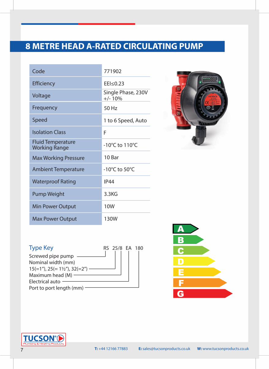
8 METRE HEAD A-RATED CIRCULATING PUMP
Code
Efficiency
Voltage
Frequency
Speed
Isolation Class
Fluid Temperature Working Range
Max Working Pressure
Ambient Temperature
Waterproof Rating
Pump Weight
EEI≤0.23
Single Phase, 230V+/- 10%
50 Hz
1 to 6 Speed, Auto
F
-10°C to 110°C
10 Bar
-10°C to 50°C
IP44
3.3KG
771902
Screwed pipe pumpNominal width (mm)15(=1”), 25(= 1½”), 32(=2”)Maximum head (M)Electrical autoPort to port length (mm)
RS 25/8 EA 180Type Key
Min Power Output 10W
Max Power Output 130W
7Plumbing & Heating Products
TUCSON®
T: +44 12166 77883 E: [email protected] W: www.tucsonproducts.co.uk
8 METRE HEAD A-RATED CIRCULATING PUMP
Pump Dimensions
Pump Components
129
236182
180
G1 - 1/2
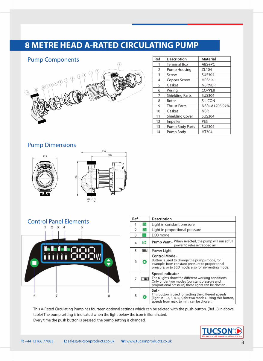
Ref123
Light in constant pressureLight in proportional pressureECO mode
Pump Vent -
Description
When selected, the pump will run at full power to release trapped air.
Power LightControl Mode - Button is used to change the pumps mode, forexample, from constant pressure to proportionalpressure, or to ECO mode, also for air-venting mode.
Speed Indicator - The 6 lights show the different working conditions. Only under two modes (constant pressure and proportional pressure) these lights can be chosen.
Set -This button is used for setting the different speeds(light in 1, 2, 3, 4, 5, 6) for two modes. Using this button, speeds from max. to min. can be chosen.
8
7
4
5
6
Control Panel Elements
This A-Rated Circulating Pump has fourteen optional settings which can be selcted with the push-button. (Ref . 8 in above table) The pump setting is indicated when the light below the icon is illuminated.Every time the push button is pressed, the pump setting is changed.
123456789
1011121314
RefTerminal BoxPump HousingScrewCopper ScrewGasketWiringShielding PartsRotorThrust PartsGasketShielding CoverImpellerPump Body PartsPump Body
ABS+PCZL104SUS304HPB59-1NBRNBRCOPPER SUS304SILICONNBR+A1203 97%NBRSUS304PESSUS304HT304
Description Material
Plumbing & Heating Products
TUCSON®
8T: +44 12166 77883 E: [email protected] W: www.tucsonproducts.co.uk
8 METRE HEAD A-RATED CIRCULATING PUMP
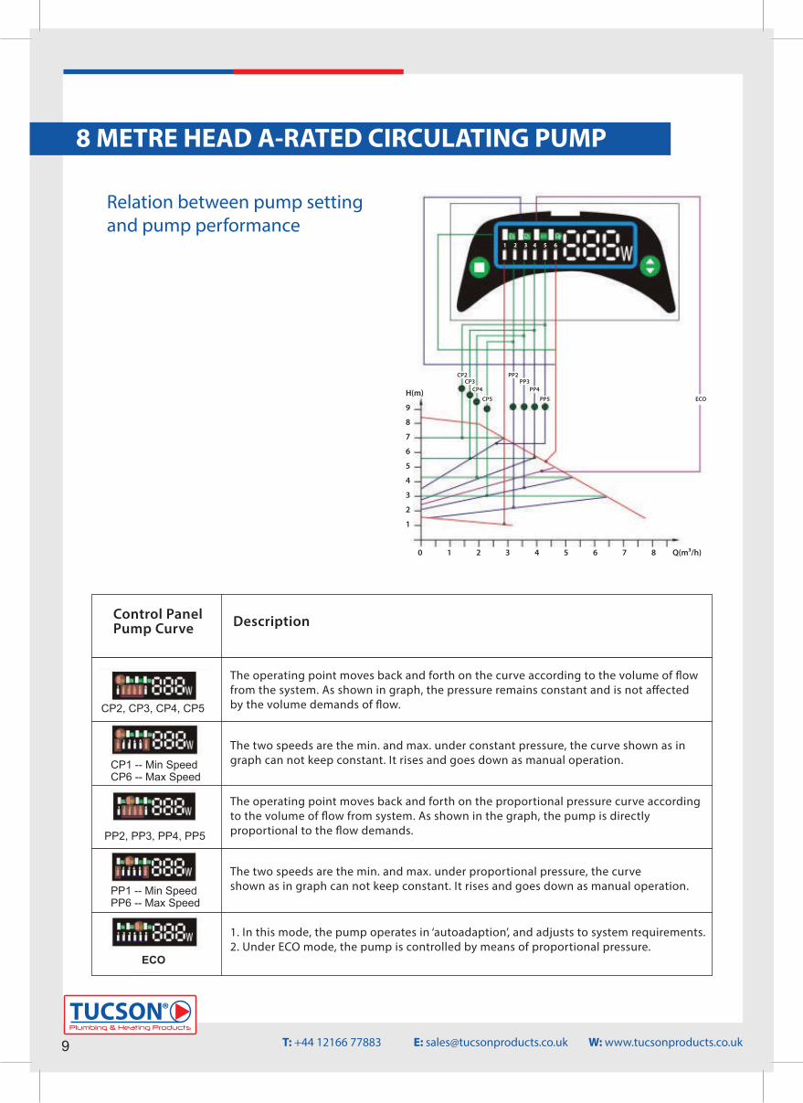
Relation between pump settingand pump performance
H(m)
9
8
7
6
5
4
3
2
1
0 1 2 3 4 5 6 7 8 Q(m³/h)
CP2CP3
CP4
CP5
PP2PP3
PP4
PP5
1 2 3 4 5 6
ECO
Control PanelPump Curve
The operating point moves back and forth on the curve according to the volume of �owfrom the system. As shown in graph, the pressure remains constant and is not a�ected by the volume demands of �ow.
The two speeds are the min. and max. under constant pressure, the curve shown as in graph can not keep constant. It rises and goes down as manual operation.
The operating point moves back and forth on the proportional pressure curve accordingto the volume of �ow from system. As shown in the graph, the pump is directlyproportional to the �ow demands.
The two speeds are the min. and max. under proportional pressure, the curve shown as in graph can not keep constant. It rises and goes down as manual operation.
1. In this mode, the pump operates in ‘autoadaption’, and adjusts to system requirements.2. Under ECO mode, the pump is controlled by means of proportional pressure.
Description
CP2, CP3, CP4, CP5
CP1 -- Min SpeedCP6 -- Max Speed
PP2, PP3, PP4, PP5
PP1 -- Min SpeedPP6 -- Max Speed
ECO
9Plumbing & Heating Products
TUCSON®
T: +44 12166 77883 E: [email protected] W: www.tucsonproducts.co.uk
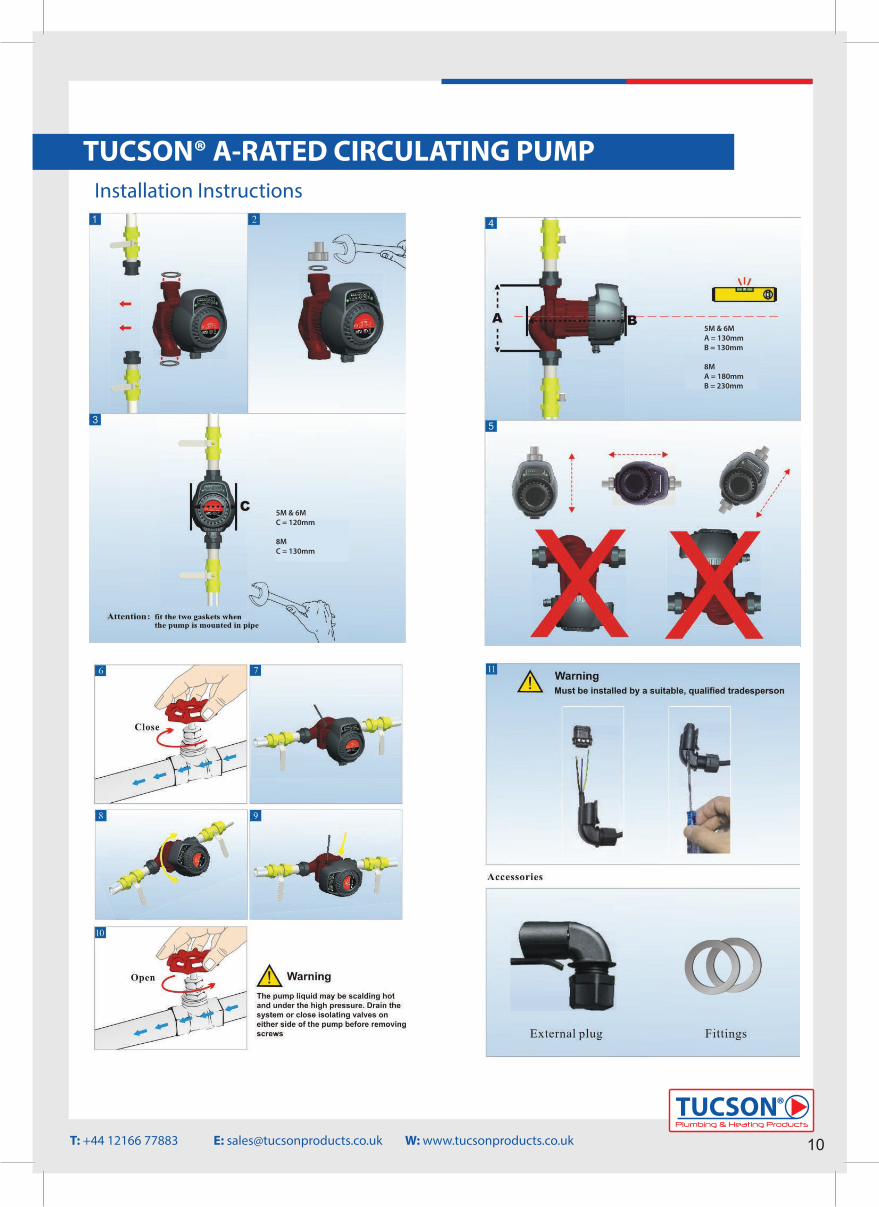
TUCSON® A-RATED CIRCULATING PUMPInstallation Instructions
5M & 6M C = 120mm
8M C = 130mm
5M & 6MA = 130mmB = 130mm
8MA = 180mmB = 230mm
Plumbing & Heating Products
TUCSON®
10T: +44 12166 77883 E: [email protected] W: www.tucsonproducts.co.uk
TUCSON® A-RATED CIRCULATING PUMP
Electrical Connection
Commissioning
• The electrical connection for the TUCSON® circulating pump must be installed correctly by a fully quali�ed tradesperson.• An electrical connection for the TUCSON® circulating pump is supplied with every pump and must be used.• The frequency and supply voltage must be the same as per instructions and control panel.• All electrical connections must comply with local building regulations.• Once power has been connected correctly to the pump and switched on, the control panel will illuminate to show the power supply is working correctly.
Before initial pump start up please ensure the following – • The pump has been installed correctly and there are no leaks on the plumbing connections.• The electrical connections have been installed correctly and the correct power is running to the pump when it is switched on and in operation.• The liquid in the heating system is clean.• Both service valves on each side of the pump are open to ensure the water will �ow through the pump when running.• Ensure the system is full with water and all air has been removed.• N.B Do not run the pump without any water in the system as this may lead to failure and will not be covered under warranty.• N.B Do not use the pump as a way to vent the system of air. We recommend that an automatic air bottle is installed at the highest point possible on the heating circuit to ensure the air can be removed from the system.
11Plumbing & Heating Products
TUCSON®
T: +44 12166 77883 E: [email protected] W: www.tucsonproducts.co.uk
TUCSON® A-RATED CIRCULATING PUMP
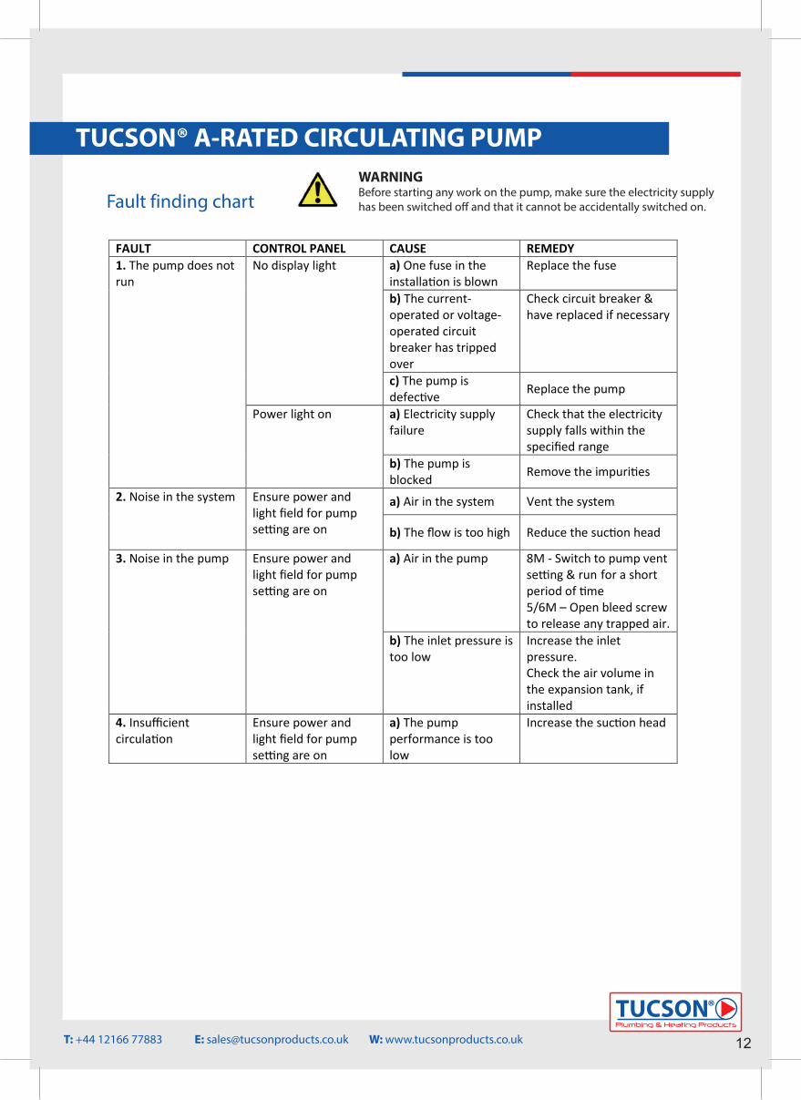
Fault finding chartWARNINGBefore starting any work on the pump, make sure the electricity supply has been switched o� and that it cannot be accidentally switched on.
FAULT CONTROL PANEL CAUSE REMEDY 1. The pump does not run
No display light a) One fuse in the installation is blown
Replace the fuse
b) The current-operated or voltage-operated circuit breaker has tripped over
Check circuit breaker & have replaced if necessary
c) The pump is defective Replace the pump
Power light on a) Electricity supply failure
Check that the electricity supply falls within the specified range
b) The pump is blocked Remove the impurities
2. Noise in the system Ensure power and light field for pump setting are on
a) Air in the system Vent the system
b) The flow is too high Reduce the suction head
3. Noise in the pump Ensure power and light field for pump setting are on
a) Air in the pump 8M - Switch to pump vent setting & run for a short period of time 5/6M – Open bleed screw to release any trapped air.
b) The inlet pressure is too low
Increase the inlet pressure. Check the air volume in the expansion tank, if installed
4. Insufficient circulation
Ensure power and light field for pump setting are on
a) The pump performance is too low
Increase the suction head
Plumbing & Heating Products
TUCSON®
12T: +44 12166 77883 E: [email protected] W: www.tucsonproducts.co.uk
TUCSON® SBP BOOSTER PUMPS
13Plumbing & Heating Products
TUCSON®
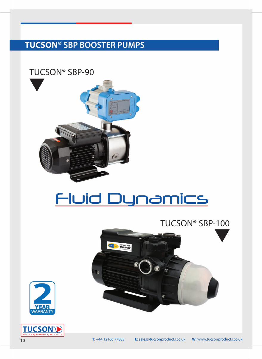
TUCSON® SBP-90
TUCSON® SBP-100
T: +44 12166 77883 E: [email protected] W: www.tucsonproducts.co.uk
Fluid Dynamics
2
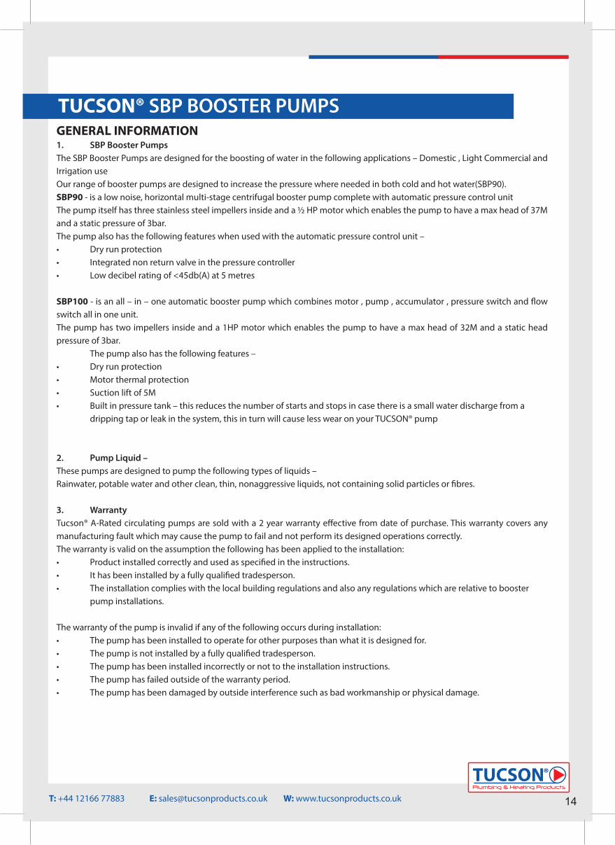
TUCSON® SBP BOOSTER PUMPSGENERAL INFORMATION1. SBP Booster PumpsThe SBP Booster Pumps are designed for the boosting of water in the following applications – Domestic , Light Commercial and Irrigation useOur range of booster pumps are designed to increase the pressure where needed in both cold and hot water(SBP90).SBP90 - is a low noise, horizontal multi-stage centrifugal booster pump complete with automatic pressure control unitThe pump itself has three stainless steel impellers inside and a ½ HP motor which enables the pump to have a max head of 37M and a static pressure of 3bar.The pump also has the following features when used with the automatic pressure control unit – • Dry run protection• Integrated non return valve in the pressure controller• Low decibel rating of <45db(A) at 5 metres
SBP100 - is an all – in – one automatic booster pump which combines motor , pump , accumulator , pressure switch and �ow switch all in one unit.The pump has two impellers inside and a 1HP motor which enables the pump to have a max head of 32M and a static head pressure of 3bar. The pump also has the following features – • Dry run protection• Motor thermal protection• Suction lift of 5M• Built in pressure tank – this reduces the number of starts and stops in case there is a small water discharge from a dripping tap or leak in the system, this in turn will cause less wear on your TUCSON® pump
2. Pump Liquid – These pumps are designed to pump the following types of liquids – Rainwater, potable water and other clean, thin, nonaggressive liquids, not containing solid particles or �bres.
3. Warranty Tucson® A-Rated circulating pumps are sold with a 2 year warranty e�ective from date of purchase. This warranty covers any manufacturing fault which may cause the pump to fail and not perform its designed operations correctly.The warranty is valid on the assumption the following has been applied to the installation:• Product installed correctly and used as speci�ed in the instructions.• It has been installed by a fully quali�ed tradesperson.• The installation complies with the local building regulations and also any regulations which are relative to booster pump installations.
The warranty of the pump is invalid if any of the following occurs during installation: • The pump has been installed to operate for other purposes than what it is designed for.• The pump is not installed by a fully quali�ed tradesperson.• The pump has been installed incorrectly or not to the installation instructions.• The pump has failed outside of the warranty period.• The pump has been damaged by outside interference such as bad workmanship or physical damage.
Plumbing & Heating Products
TUCSON®
14T: +44 12166 77883 E: [email protected] W: www.tucsonproducts.co.uk
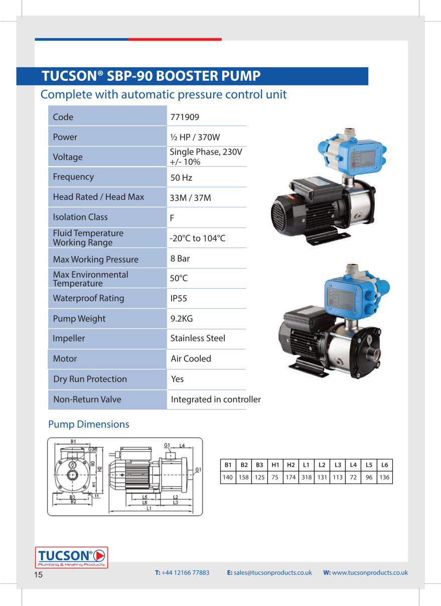
Code
Power
Voltage
Frequency
Head Rated / Head Max
Isolation Class
Fluid Temperature Working Range
Max Working Pressure
Max EnvironmentalTemperature
Waterproof Rating
Pump Weight
½ HP / 370W
Single Phase, 230V+/- 10%
50 Hz
33M / 37M
F
-20°C to 104°C
8 Bar
50°C
IP55
9.2KG
771909
Impeller Stainless Steel
Motor Air Cooled
Dry Run Protection Yes
Non-Return Valve Integrated in controller
B1 B2 B3 H1 H2 L1 L2 L3 L4 L5 L6
140 158 125 75 174 318 131 113 72 96 136
Pump Dimensions
Complete with automatic pressure control unitTUCSON® SBP-90 BOOSTER PUMP
15Plumbing & Heating Products
TUCSON®
T: +44 12166 77883 E: [email protected] W: www.tucsonproducts.co.uk
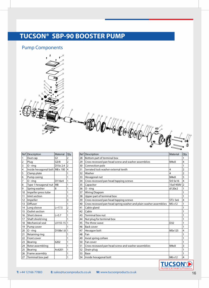
TUCSON® SBP-90 BOOSTER PUMPPump Components
1417 16 12
18
15
1920
112 11
10 9
14 1312
5
43 2 1
6
8 7
22
24
26
23
25
27
52
21
53
54
36
35
34
33
28
29
30
31
32
40
38
39
37
41
34
4243
44
454647
484950
51
Ref Description Material Qty Ref Description Material Qty 1 Dust cap G1 2 28 Bottom part of terminal box 12 Plug G3/8 2 29 Cross recessed pan head screw and washer assemblies M4x8 43 O - ring D15x 2.4 2 30 Connection pole 14 Inside hexagonal bolt M8 x 100 4 31 Serrated lock washer external teeth 4 25 Clamp plate 1 32 Washer 4 26 Pump casing 1 33 Hexagonal nut M4x8 57 O - ring D116x4 1 34 Cross recessed pan head tapping screws St3 5x16 48 Type 1 hexagonal nut M8 1 35 Capacitor 15uf/450V 29 Spring washer 8 1 36 O - ring d120x2 110 Impeller press tube 1 37 Wiring Diagram 111 Inlet section 1 38 Upper part of terminal box 112 Impeller 3 39 Cross recessed pan head tapping screws ST3. 5x6 413 Di�user 1 40 Cross recessed pan head spring washer and plain washer assemblies M5 x12 114 Long sleeve L=17.5 2 41 Cable gland 115 Outlet section 1 42 Cable 116 Short sleeve L=5.7 1 43 Terminal box nut 117 Shaft shield ring 1 44 Nut plug for terminal box 118 Mechanical seal LX155-15 1 45 The three wave D32 119 Pump cover 1 46 Back cover 120 O - ring D108x1.8 1 47 Hexagon bolt M5x125 421 Retaining ring 1 48 Fan 122 Front cover 1 49 Axial spring collare 123 Bearing 6202 1 50 Fan cover 124 Rotor assembling 1 51 Cross receased pan head screw and washer assemblies M4x8 325 Bearing Ac6201 1 52 Drain plug 126 Frame assembly 1 53 Base 127 Terminal box pad 1 54 Inside hexagonal bolt M6 x12 4
Plumbing & Heating Products
TUCSON®
16T: +44 12166 77883 E: [email protected] W: www.tucsonproducts.co.uk
TUCSON® SBP-90 BOOSTER PUMP
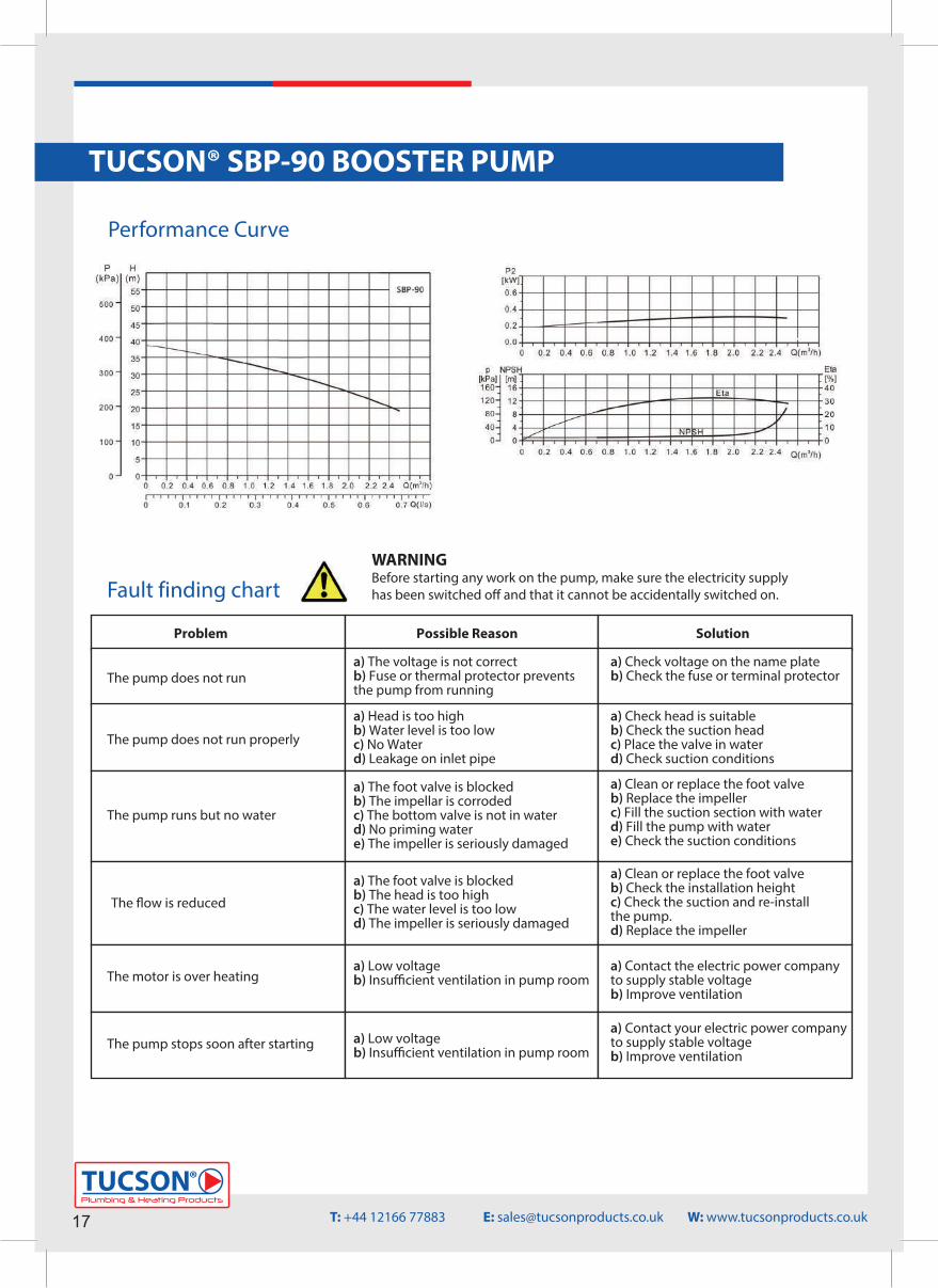
Performance Curve
Fault finding chart
Problem Possible Reason Solution
The pump does not run
The pump does not run properly
The pump runs but no water
The �ow is reduced
The motor is over heating
The pump stops soon after starting
a) The voltage is not correctb) Fuse or thermal protector preventsthe pump from running
a) Head is too highb) Water level is too lowc) No Waterd) Leakage on inlet pipe
a) The foot valve is blockedb) The impellar is corrodedc) The bottom valve is not in waterd) No priming watere) The impeller is seriously damaged
a) The foot valve is blockedb) The head is too highc) The water level is too lowd) The impeller is seriously damaged
a) Low voltageb) Insu�cient ventilation in pump room
a) Low voltageb) Insu�cient ventilation in pump room
a) Check voltage on the name plateb) Check the fuse or terminal protector
a) Check head is suitableb) Check the suction headc) Place the valve in waterd) Check suction conditions
a) Clean or replace the foot valveb) Replace the impellerc) Fill the suction section with waterd) Fill the pump with watere) Check the suction conditions
a) Clean or replace the foot valveb) Check the installation heightc) Check the suction and re-installthe pump.d) Replace the impeller
a) Contact the electric power companyto supply stable voltageb) Improve ventilation
a) Contact your electric power companyto supply stable voltageb) Improve ventilation
17Plumbing & Heating Products
TUCSON®
T: +44 12166 77883 E: [email protected] W: www.tucsonproducts.co.uk
WARNINGBefore starting any work on the pump, make sure the electricity supply has been switched o� and that it cannot be accidentally switched on.
Plumbing & Heating Products
TUCSON®
18
TUCSON® SBP-90 BOOSTER PUMP
Electrical Connection
Commissioning
• The electrical connection for the TUCSON® booster pump must be installed correctly by a fully quali�ed tradesperson.• Ensure the voltage(V), frequency (Hz), phase (PH) conforms to those marked on the data plate label. • If there is a surge or drop in voltage by ±10%, the motor will stop running to prevent damage to the pump.• All electrical connections must comply with local building regulations.• Once power has been connected correctly to the pump and switched on, the automatic pressure control unit will illuminate to show the power supply is working correctly.
Before initial pump start up please ensure the following – • The pump has been installed correctly and there are no leaks on the plumbing connections.• The electrical connections have been installed correctly and the correct power is running to the pump when it is switched on and in operation.• The liquid in the system is clean.• Ensure both the system and pump is full with water and all air has been removed.• For stable operation, please mount and bolt the booster pump securely. • The place of installation must be dry with good ventilation and adequate space for future maintenance and service. • A proper shelter is required for outdoor installation; exposure to rain will damage the insulation of electrical wiring.• Be careful not to allow any foreign objects (PVC adhesive gum, dirt, sand etc.) into the pump, otherwise the pump will be damaged and its operating life shortened. It is recommended to use a strainer to prevent that.
T: +44 12166 77883 E: [email protected] W: www.tucsonproducts.co.uk
19Plumbing & Heating Products
TUCSON®
TUCSON® AUTOMATIC PRESSURE CONTROL UNIT
Intensity Max
Voltage
Frequency
Max Working Pressure
Max Working Temperature
Protection Rating
Connection
220V - 240V
50 Hz
10 Bar
1” Male
IP65
Restart Pressure 1.5 Bar
10A
60°C
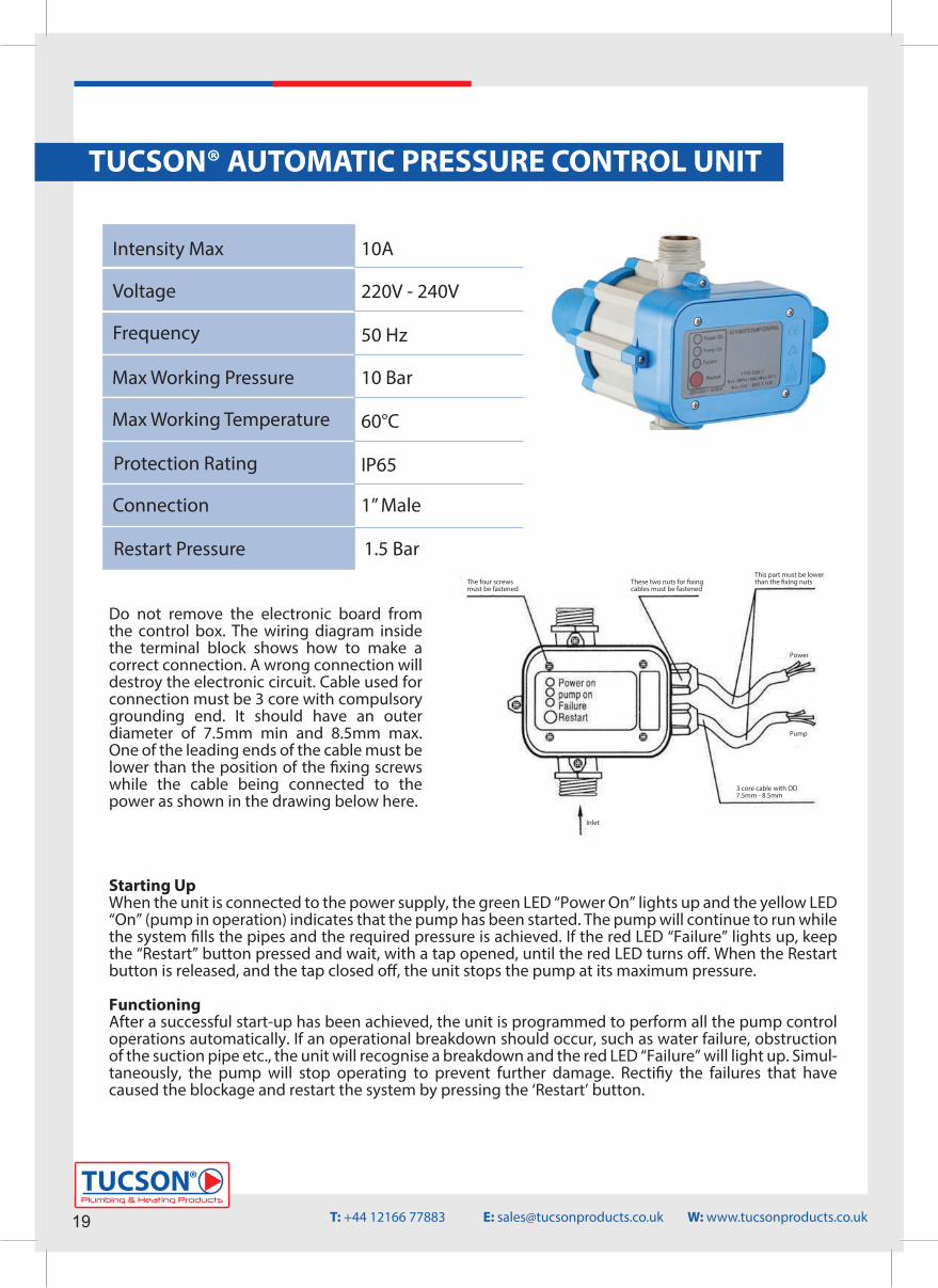
Do not remove the electronic board from the control box. The wiring diagram inside the terminal block shows how to make a correct connection. A wrong connection will destroy the electronic circuit. Cable used for connection must be 3 core with compulsory grounding end. It should have an outer diameter of 7.5mm min and 8.5mm max. One of the leading ends of the cable must be lower than the position of the �xing screws while the cable being connected to the power as shown in the drawing below here.
Starting UpWhen the unit is connected to the power supply, the green LED “Power On” lights up and the yellow LED “On” (pump in operation) indicates that the pump has been started. The pump will continue to run while the system �lls the pipes and the required pressure is achieved. If the red LED “Failure” lights up, keep the “Restart” button pressed and wait, with a tap opened, until the red LED turns o�. When the Restart button is released, and the tap closed o�, the unit stops the pump at its maximum pressure.
FunctioningAfter a successful start-up has been achieved, the unit is programmed to perform all the pump control operations automatically. If an operational breakdown should occur, such as water failure, obstruction of the suction pipe etc., the unit will recognise a breakdown and the red LED “Failure” will light up. Simul-taneously, the pump will stop operating to prevent further damage. Recti�y the failures that have caused the blockage and restart the system by pressing the ‘Restart’ button.
The four screwsmust be fastened
These two nuts for �xing cables must be fastened
This part must be lowerthan the �xing nuts
Power
Pump
3 core cable with OD7.5mm - 8.5mm
Inlet
T: +44 12166 77883 E: [email protected] W: www.tucsonproducts.co.uk
Plumbing & Heating Products
TUCSON®
20
TUCSON® AUTOMATIC PRESSURE CONTROL UNIT
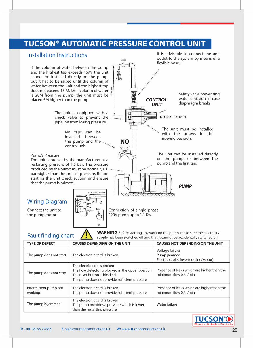
If the column of water between the pump and the highest tap exceeds 15M, the unit cannot be installed directly on the pump, but it has to be raised until the column of water between the unit and the highest tap does not exceed 15 M. I.E. If column of water is 20M from the pump, the unit must be placed 5M higher than the pump.
The unit is equipped with a check valve to prevent the pipeline from losing pressure.
No taps can be installed between the pump and the control unit.
Pump’s Pressure:The unit is pre-set by the manufacturer at a restarting pressure of 1.5 bar. The pressure produced by the pump must be normally 0.8 bar higher than the pre-set pressure. Before starting the unit check suction and ensure that the pump is primed.
It is advisable to connect the unit outlet to the system by means of a �exible hose.
CONTROL UNIT
Safety valve preventing water emission in case diaphragm breaks.
The unit must be installed with the arrows in the upward position.
The unit can be installed directly on the pump, or between the pump and the �rst tap.
PUMP
Installation Instructions
Wiring DiagramConnect the unit to the pump motor
Connection of single phase 220V pump up to 1.1 Kw.
TYPE OF DEFECT CAUSES DEPENDING ON THE UNIT CAUSES NOT DEPENDING ON THE UNIT
The pump does not start
The pump does not stop
Intermittent pump notworking
The pump is jammed
The electronic card is broken
The electric card is brokenThe �ow detector is blocked in the upper positionThe reset button is blockedThe pump does not provide su�cient pressure
The electronic card is brokenThe pump does not provide su�cient pressure
The electronic card is brokenThe pump provides a pressure which is lowerthan the restarting pressure
Voltage failurePump jammedElectric cables inverted(Line/Motor)
Presence of leaks which are higher than theminimum �ow 0.6 l/min
Presence of leaks which are higher than theminimum �ow 0.6 l/min
Water failure
Fault finding chart
T: +44 12166 77883 E: [email protected] W: www.tucsonproducts.co.uk
WARNING Before starting any work on the pump, make sure the electricity supply has been switched o� and that it cannot be accidentally switched on.
L1-1-50 Hz 220-240VNPE
M1-
L1
N
U
V
21
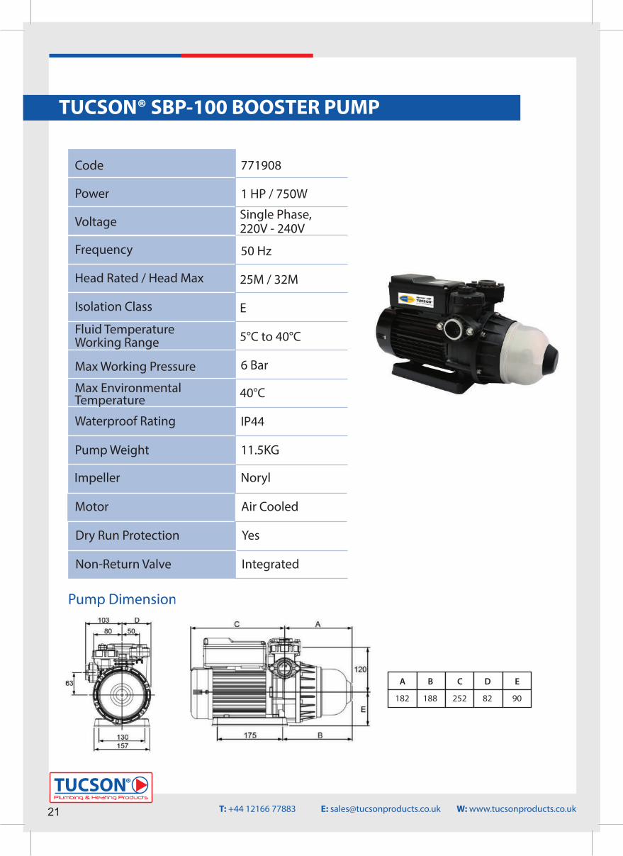
TUCSON® SBP-100 BOOSTER PUMP
Code
Power
Voltage
Frequency
Head Rated / Head Max
Isolation Class
Fluid Temperature Working Range
Max Working Pressure
Max EnvironmentalTemperature
Waterproof Rating
Pump Weight
1 HP / 750W
Single Phase,220V - 240V
50 Hz
25M / 32M
E
5°C to 40°C
6 Bar
40°C
IP44
11.5KG
Plumbing & Heating Products
TUCSON®
771908
Impeller Noryl
Motor Air Cooled
Dry Run Protection Yes
Non-Return Valve Integrated
Pump Dimensions
A B C D E
182 188 252 82 90
Operating Conditions 1. Ambient Temperature : +5 ºC ~ +40 ºC 2. Liquid Temperature
Regular Model : +5ºC ~ +40ºC Hot Water Model : +5ºC ~ +90ºC
3. Maximum Operating Pressure : 6 kg/cm2
4. Rated Discharge Head / HeightASB25(H) : 1.5 kg/cm 2 / 15 mASB50(H) : 2.0 kg/cm 2 / 20 mASB100(H) : 2.5 kg/cm 2 / 25 m
Item Name Description Item Name Description Item Name Description
1 Motor 1 2 Poles 15 Inlet Flange Gasket Rubber 25 Bolt S45C2 Bolt S45C 16 Inlet Flange NYLON 26 Wiring Box Cover NYLON3 Pump Casing Noryl 17 Flange Bolt SUS304 27 Bolt S45C
18 Outet Flange Gasket Rubber4 Mechanical Seal Ceramic+NBR
+Carbon 19 Outlet Flange NYLON28 Controller Triac-Based
5 Impeller Chamber NORYL 20 Flange Bolt SUS3046 Impeller NORYL 21-1 Priming Plug NYLON
29 Pressure Switch For Turn-OnPressure Setting
7 Diffuser NORYL 21-2 Air Evacuation Plug NYLON 30 Switch Cover NYLON8 Impeller NORYL 22-0 Flow Switch Set Flow Detection 31 Thermal Protector Auto Reset9 O Ring NBR 22-1 Spring SUS304 32 Pump Base ABS10 Bolt SUS304 22-2 Stopper NORYL 33 Bolt S45C11*1 Pump Cover NYLON 22-3 Seal O Ring NBR 34* 2 Impeller Chamber NORYL12 O Ring NBR 22-4 Locking Ring NYLON 35* 2 Impeller NORYL13 Pressure Tank SUS304 23 Seal Gasket Rubber 36* 2 Pump Cover NYLON14 Pump Cover Bolt SUS304 24 Wiring Box NYLON 37 Motor Capacitor Plastic Film
*1 Parts for 60 Hz models.*2 Parts for 50 Hz models.
Installation and Piping
Construction ( ASB-H Hot water Model with stainless steel impeller.) Item Name Description Item Name Description Item Name Description
1 Motor 1 2 Poles 13 Pressure Tank SUS304 24 Wiring Box NYLON2 Bolt S45C 14 Pump Cover Bolt SUS304 25 Bolt S45C3 Pump Casing Noryl 15 Inlet Flange Gasket Rubber 26 Wiring Box Cover NYLON
16 Inlet Flange NYLON 27 Bolt S45C4 Mechanical Seal Ceramic+ Viton
+Carbon*3 17 Flange Bolt SUS304 28 Controller Triac Based5 Impeller Chamber NORYL 18 Outlet Flange Gasket Rubber6 Impeller SUS304* 3 19 Outlet Flange NYLON
29 Pressure Switch For Turn-OnPressure Setting
6-1* 3 Shaft Sleeve PPS 20 Flange Bolt SUS304 30 Switch Cover NYLON7 Diffuser NORYL 21-1 Priming Plug NYLON 31 Thermal Protector Auto Reset8 Impeller SUS304* 3 21-2 Air Evacuation Plug NYLON 32 Pump Base ABS
8-1* 3 Shaft Sleeve PPS 22-0 Flow Switch Set Flow Detection 33 Bolt S45C9 O Ring NBR 22-1 Spring SUS304 34* 2 Impeller Chamber NORYL10 Bolt SUS304 22-2 Stopper NORYL 35* 2 Impeller SUS304* 3
10-1*3 Shaft Sleeve SUS304 22-3 Seal O Ring NBR 35-1*3 Shaft Sleeve PPS11*1 Pump Cover NYLON 22-4 Locking Ring NYLON 36* 2 Pump Cover NYLON12 Tank O Ring Silicon Rubber*3 23 Seal Gasket Rubber 37 Motor Capacitor Plastic Film
Operation and Important Notes
(a) Single Voltage Model Wiring
Description
Construction ( ASB Regular model with thermoplastic impeller.)
14131211109876543
181920
232437272628252930
2730
27
31
151617
32 33 32 33
34 35 36 34 35 36
141312111098721-2
35-1
22-222-1
21-122-422-0 2324372726282529 21-1
6-1 8-1
22-422-022-3
181920
21-2
22-222-1
10-1
22-3
12 6543
*3 Parts or materials for hot water models only.*2 Parts for 50 Hz models.*1 Parts for 60 Hz models.
The ASB series booster pump is an all-in-one compact and reliable automaticmultistage centrifugal booster pump, which integrates motor, pump, accumulator,pressure switch and flow switch, all in one unit. The flow switch equipped withthe pump prevents the pump from continuously starting and stopping undersmall discharge. It is very suitable for domestic water supply.
1. For stable operation, please mount and bolt the booster pump securely. Theplace of installation must be dry with good ventilation and adequate space
for future maintenance and service. A proper shelter is required for outdoor installation; exposure to rain will damage the insulation of electrical wiring.
2. The pump should be installed as close as possible to the reservoir or well. Forhot water (40~90ºC) pumping, negative inlet pressure application is requiredto avoid cavitations. Piping joints should be fitted carefully to prevent leaks.A leak in the suction piping will cause the pump to lose suction capacity, whilea leak in the discharge piping will cause a high frequency ON/OFF motor
operation while the faucets valves are closed.
3.The protective rubber films within the centre of the suction/discharge flange gaskets (Part No. 15 & 18) must be removed during installation.
4. Be careful not to allow any foreign objects (PVC adhesive gum, dirt, sand etc.) into the pump, otherwise the pump will be damaged and its operating life
shortened. It is recommended to use a strainer to prevent that.5. Check the voltage and wiring of the motor power against the connecting
diagram shown below or inside the cover. Be sure to arrange earth or circuitbreaker against electric leakage in accordance with local electrical code.
6. The pump thermal protector (Part No. 31) is designed to protect the pumpfrom dry run. It is also used to prevent hot water pumping which will damagethe pump structure. The electrical power will be cut off after several minutesif dry run occurs, and will be turned on periodically. Shutting off the electricalpower manually is recommended during any water shortage period to saveenergy.
7. An auto-reset thermal protector is equipped within the motor winding. Power will be cut off when the motor winding temperature is abnormal, and will restart when the temperature is back to normal.
1. Before turning the power on, the pump chamber and suction pipe must be filled with water in accordance with the following:
◎For the negative inlet pressure application ( inlet water level is below the pumpinput ), remove the priming plugs (Part No. 21-1 or 21-2), and pour water intothe pump via priming hole completely. Then, secure the priming plugs backin place.
◎For the positive inlet pressure application ( inlet water level is higher thanpump input ), loosen the priming plug (Part No. 21-2), and then secure it
after the water drains out from the priming hole.
Pressure Switch Adjustment
2. Insert a crossed screwdriver into the motor shaft end, and turn the shaftseveral turns clockwise to check whether the pump can be rotated freely. If
not, disassemble and clean the pump chamber.
3. Double check the voltage and wiring of the motor power and then turn thepower switch ON. Open faucet or water appliances on the discharge piping
side. The water should be delivered after several seconds.4. If the water is not delivered after several minutes, turn off the pump immediately.
Repeat step 1, pour water into the pump and suction piping, and switch power ON and OFF continuously.5. Once the water is pumped out, close and open the water appliances on the discharge side repeatedly to check automatic ON/OFF operation.
6. Measure the motor current and check with the data shown on the nameplate. If the current is over, check the voltage again.7. When re-starting the pump after long term shut down, please repeat step 1~6 to ensure normal operation.
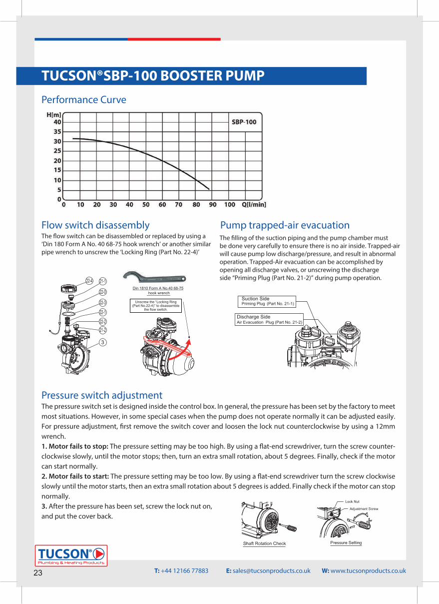
The pressure switch set is designed inside the control box. In general, thepressure has been set by the factory to meet most situations. However, in some special cases, when the pump does not operate normally, it can be adjusted easily. Please check the trouble shooting procedures, and read the followinginstructions carefully in advance. For pressure adjustment, first remove the switch cover, and loosen the lock nut counterclockwise by using a 12mm wrench.
1. Motor fails to stopThe pressure setting may be too high. By using a flat-end screwdriver, turn thescrew counterclockwise slowly, until the motor stops; then, turn an extra smallrotation, about 5 degrees. Finally, check if the motor can start normally.
2. Motor fails to startThe pressure setting may be too low. By using a flat-end screwdriver, turn thescrew clockwise slowly, until the motor starts, then an extra small rotation, about5 degrees, is added. Finally, check if the motor can stop normally.
3. After the pressure has been set, screw the lock nut on, and put the cover back.
T: +44 12166 77883 E: [email protected] W: www.tucsonproducts.co.uk
Plumbing & Heating Products
TUCSON®
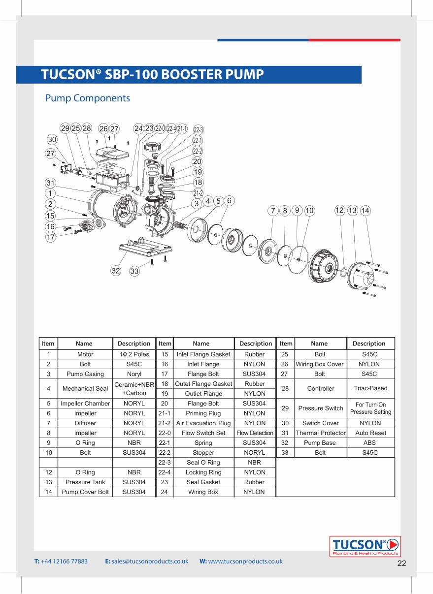
TUCSON® SBP-100 BOOSTER PUMP Pump Components
14131236109876543
181920
232437272628252930
27
32 33
34 35
21-2
22-222-1
21-122-422-0 22-3
Drawing For Parts List ASB25 / 50 / 100 . 50Hz
Item Name Description Item Name Description Item Name Description
1 Motor 1Φ 2 Poles 15 Inlet Flange Gasket Rubber 25 Bolt S45C2 Bolt S45C 16 Inlet Flange NYLON 26 Wiring Box Cover NYLON3 Pump Casing Noryl 17 Flange Bolt SUS304 27 Bolt S45C
18 Outet Flange Gasket Rubber4 Mechanical Seal Ceramic+NBR
+Carbon 19 Outlet Flange NYLON28 Controller Triac-Based
5 Impeller Chamber NORYL 20 Flange Bolt SUS3046 Impeller NORYL 21-1 Priming Plug NYLON
29 Pressure Switch For Turn-OnPressure Setting
7 Diffuser NORYL 21-2 Air Evacuation Plug NYLON 30 Switch Cover NYLON8 Impeller NORYL 22-0 Flow Switch Set Flow Detection 31 Thermal Protector Auto Reset9 O Ring NBR 22-1 Spring SUS304 32 Pump Base ABS10 Bolt SUS304 22-2 Stopper NORYL 33 Bolt S45C
22-3 Seal O Ring NBR 34* 2 Impeller Chamber NORYL12 O Ring NBR 22-4 Locking Ring NYLON 35* 2 Impeller NORYL13 Pressure Tank SUS304 23 Seal Gasket Rubber 36* 2 Pump Cover NYLON14 Pump Cover Bolt SUS304 24 Wiring Box NYLON 37 Motor Capacitor Plastic Film
22
Operating Conditions 1. Ambient Temperature : +5 ºC ~ +40 ºC 2. Liquid Temperature
Regular Model : +5ºC ~ +40ºC Hot Water Model : +5ºC ~ +90ºC
3. Maximum Operating Pressure : 6 kg/cm2
4. Rated Discharge Head / HeightASB25(H) : 1.5 kg/cm 2 / 15 mASB50(H) : 2.0 kg/cm 2 / 20 mASB100(H) : 2.5 kg/cm 2 / 25 m
Item Name Description Item Name Description Item Name Description
1 Motor 1 2 Poles 15 Inlet Flange Gasket Rubber 25 Bolt S45C2 Bolt S45C 16 Inlet Flange NYLON 26 Wiring Box Cover NYLON3 Pump Casing Noryl 17 Flange Bolt SUS304 27 Bolt S45C
18 Outet Flange Gasket Rubber4 Mechanical Seal Ceramic+NBR
+Carbon 19 Outlet Flange NYLON28 Controller Triac-Based
5 Impeller Chamber NORYL 20 Flange Bolt SUS3046 Impeller NORYL 21-1 Priming Plug NYLON
29 Pressure Switch For Turn-OnPressure Setting
7 Diffuser NORYL 21-2 Air Evacuation Plug NYLON 30 Switch Cover NYLON8 Impeller NORYL 22-0 Flow Switch Set Flow Detection 31 Thermal Protector Auto Reset9 O Ring NBR 22-1 Spring SUS304 32 Pump Base ABS10 Bolt SUS304 22-2 Stopper NORYL 33 Bolt S45C11*1 Pump Cover NYLON 22-3 Seal O Ring NBR 34* 2 Impeller Chamber NORYL12 O Ring NBR 22-4 Locking Ring NYLON 35* 2 Impeller NORYL13 Pressure Tank SUS304 23 Seal Gasket Rubber 36* 2 Pump Cover NYLON14 Pump Cover Bolt SUS304 24 Wiring Box NYLON 37 Motor Capacitor Plastic Film
*1 Parts for 60 Hz models.*2 Parts for 50 Hz models.
Installation and Piping
Construction ( ASB-H Hot water Model with stainless steel impeller.) Item Name Description Item Name Description Item Name Description
1 Motor 1 2 Poles 13 Pressure Tank SUS304 24 Wiring Box NYLON2 Bolt S45C 14 Pump Cover Bolt SUS304 25 Bolt S45C3 Pump Casing Noryl 15 Inlet Flange Gasket Rubber 26 Wiring Box Cover NYLON
16 Inlet Flange NYLON 27 Bolt S45C4 Mechanical Seal Ceramic+ Viton
+Carbon*3 17 Flange Bolt SUS304 28 Controller Triac Based5 Impeller Chamber NORYL 18 Outlet Flange Gasket Rubber6 Impeller SUS304* 3 19 Outlet Flange NYLON
29 Pressure Switch For Turn-OnPressure Setting
6-1* 3 Shaft Sleeve PPS 20 Flange Bolt SUS304 30 Switch Cover NYLON7 Diffuser NORYL 21-1 Priming Plug NYLON 31 Thermal Protector Auto Reset8 Impeller SUS304* 3 21-2 Air Evacuation Plug NYLON 32 Pump Base ABS
8-1* 3 Shaft Sleeve PPS 22-0 Flow Switch Set Flow Detection 33 Bolt S45C9 O Ring NBR 22-1 Spring SUS304 34* 2 Impeller Chamber NORYL10 Bolt SUS304 22-2 Stopper NORYL 35* 2 Impeller SUS304* 3
10-1*3 Shaft Sleeve SUS304 22-3 Seal O Ring NBR 35-1*3 Shaft Sleeve PPS11*1 Pump Cover NYLON 22-4 Locking Ring NYLON 36* 2 Pump Cover NYLON12 Tank O Ring Silicon Rubber*3 23 Seal Gasket Rubber 37 Motor Capacitor Plastic Film
Operation and Important Notes
(a) Single Voltage Model Wiring
Description
Construction ( ASB Regular model with thermoplastic impeller.)
14131211109876543
181920
232437272628252930
2730
27
31
151617
32 33 32 33
34 35 36 34 35 36
141312111098721-2
35-1
22-222-1
21-122-422-0 2324372726282529 21-1
6-1 8-1
22-422-022-3
181920
21-2
22-222-1
10-1
22-3
12 6543
*3 Parts or materials for hot water models only.*2 Parts for 50 Hz models.*1 Parts for 60 Hz models.
The ASB series booster pump is an all-in-one compact and reliable automaticmultistage centrifugal booster pump, which integrates motor, pump, accumulator,pressure switch and flow switch, all in one unit. The flow switch equipped withthe pump prevents the pump from continuously starting and stopping undersmall discharge. It is very suitable for domestic water supply.
1. For stable operation, please mount and bolt the booster pump securely. Theplace of installation must be dry with good ventilation and adequate space
for future maintenance and service. A proper shelter is required for outdoor installation; exposure to rain will damage the insulation of electrical wiring.
2. The pump should be installed as close as possible to the reservoir or well. Forhot water (40~90ºC) pumping, negative inlet pressure application is requiredto avoid cavitations. Piping joints should be fitted carefully to prevent leaks.A leak in the suction piping will cause the pump to lose suction capacity, whilea leak in the discharge piping will cause a high frequency ON/OFF motor
operation while the faucets valves are closed.
3.The protective rubber films within the centre of the suction/discharge flange gaskets (Part No. 15 & 18) must be removed during installation.
4. Be careful not to allow any foreign objects (PVC adhesive gum, dirt, sand etc.) into the pump, otherwise the pump will be damaged and its operating life
shortened. It is recommended to use a strainer to prevent that.5. Check the voltage and wiring of the motor power against the connecting
diagram shown below or inside the cover. Be sure to arrange earth or circuitbreaker against electric leakage in accordance with local electrical code.
6. The pump thermal protector (Part No. 31) is designed to protect the pumpfrom dry run. It is also used to prevent hot water pumping which will damagethe pump structure. The electrical power will be cut off after several minutesif dry run occurs, and will be turned on periodically. Shutting off the electricalpower manually is recommended during any water shortage period to saveenergy.
7. An auto-reset thermal protector is equipped within the motor winding. Power will be cut off when the motor winding temperature is abnormal, and will restart when the temperature is back to normal.
1. Before turning the power on, the pump chamber and suction pipe must be filled with water in accordance with the following:
◎For the negative inlet pressure application ( inlet water level is below the pumpinput ), remove the priming plugs (Part No. 21-1 or 21-2), and pour water intothe pump via priming hole completely. Then, secure the priming plugs backin place.
◎For the positive inlet pressure application ( inlet water level is higher thanpump input ), loosen the priming plug (Part No. 21-2), and then secure it
after the water drains out from the priming hole.
Pressure Switch Adjustment
2. Insert a crossed screwdriver into the motor shaft end, and turn the shaftseveral turns clockwise to check whether the pump can be rotated freely. If
not, disassemble and clean the pump chamber.
3. Double check the voltage and wiring of the motor power and then turn thepower switch ON. Open faucet or water appliances on the discharge piping
side. The water should be delivered after several seconds.4. If the water is not delivered after several minutes, turn off the pump immediately.
Repeat step 1, pour water into the pump and suction piping, and switch power ON and OFF continuously.5. Once the water is pumped out, close and open the water appliances on the discharge side repeatedly to check automatic ON/OFF operation.
6. Measure the motor current and check with the data shown on the nameplate. If the current is over, check the voltage again.7. When re-starting the pump after long term shut down, please repeat step 1~6 to ensure normal operation.
The pressure switch set is designed inside the control box. In general, thepressure has been set by the factory to meet most situations. However, in some special cases, when the pump does not operate normally, it can be adjusted easily. Please check the trouble shooting procedures, and read the followinginstructions carefully in advance. For pressure adjustment, first remove the switch cover, and loosen the lock nut counterclockwise by using a 12mm wrench.
1. Motor fails to stopThe pressure setting may be too high. By using a flat-end screwdriver, turn thescrew counterclockwise slowly, until the motor stops; then, turn an extra smallrotation, about 5 degrees. Finally, check if the motor can start normally.
2. Motor fails to startThe pressure setting may be too low. By using a flat-end screwdriver, turn thescrew clockwise slowly, until the motor starts, then an extra small rotation, about5 degrees, is added. Finally, check if the motor can stop normally.
3. After the pressure has been set, screw the lock nut on, and put the cover back.
T: +44 12166 77883 E: [email protected] W: www.tucsonproducts.co.uk
Item Name Description Item Name Description Item Name Description
23Plumbing & Heating Products
TUCSON®
Performance Curve
Din 1810 Form A No.40 68-75hook wrench
Unscrew the “Locking Ring(Part No.22-4)” to disassemble
the flow switch.
Discharge SideAir Evacuation Plug (Part No. 21-2)
Suction SidePriming Plug (Part No. 21-1)
Flow Switch Disassembly
Pump Trapped-Air Evacuation
21-122-4
22-0
22-3
22-2
22-1
21-2
3
The flow switch can be disassembled or replaced by using a “Din 1810 Form A
No.40 68-75 hook wrench” or other similar pipe wrench to unscrew the “LockingRing (Part No. 22-4)”
The filling of the suction piping and the pump chamber must be done very carefully to ensure there is no air inside. Trapped-air will cause pump lowdischarge/pressure, and result in abnormal operation. Trapped-Air evacuationcan be accomplished by opening all discharge valves, or unscrewing thedischarge side “Priming Plug (Part No. 21-2)” during pump operation.
Flow switch disassemblyThe �ow switch can be disassembled or replaced by using a‘Din 180 Form A No. 40 68-75 hook wrench’ or another similar pipe wrench to unscrew the ‘Locking Ring (Part No. 22-4)’
Pump trapped-air evacuationThe �lling of the suction piping and the pump chamber must be done very carefully to ensure there is no air inside. Trapped-air will cause pump low discharge/pressure, and result in abnormal operation. Trapped-Air evacuation can be accomplished by opening all discharge valves, or unscrewing the discharge side “Priming Plug (Part No. 21-2)” during pump operation.
Discharge SideAir Evacuation Plug (Part No. 21-2)
Suction SidePriming Plug (Part No. 21-1)
Din 1810 Form A No.40 68-75hook wrench
Unscrew the “Locking Ring(Part No.22-4)” to disassemble
the flow switch.
Flow Switch Disassembly
Pump Trapped-Air Evacuation
21-122-4
22-0
22-3
22-2
22-1
21-2
3
The flow switch can be disassembled or replaced by using a “Din 1810 Form ANo.40 68-75 hook wrench” or other similar pipe wrench to unscrew the “LockingRing (Part No. 22-4)”
The filling of the suction piping and the pump chamber must be done very carefully to ensure there is no air inside. Trapped-air will cause pump lowdischarge/pressure, and result in abnormal operation. Trapped-Air evacuationcan be accomplished by opening all discharge valves, or unscrewing thedischarge side “Priming Plug (Part No. 21-2)” during pump operation.
TUCSON®SBP-100 BOOSTER PUMP
ASB SeriesInstallation and Operating Instructions
Auto Silent Booster Pump
Din 1810 Form A No.40 68-75hook wrench
Unscrew the “Locking Ring(Part No.22-4)” to disassemble
the flow switch.
Discharge SideAir Evacuation Plug (Part No. 21-2)
Suction SidePriming Plug (Part No. 21-1)
Flow Switch Disassembly
Pump Trapped-Air Evacuation
21-122-4
22-0
22-3
22-2
22-1
21-2
3
The flow switch can be disassembled or replaced by using a “Din 1810 Form ANo.40 68-75 hook wrench” or other similar pipe wrench to unscrew the “LockingRing (Part No. 22-4)”
PROBLEM – Pumps fail to start when the discharge devices are opened.Test Schematic Status
Voltageis normal Go to test “A-2".A-1
InputVoltageCheck No power Check the controller power source and circuit breaker.
Voltageis normal
A-2
OutputVoltageCheck
No power Go to test “A-3”. Motor still fails to start Replace the controller. A-3
Short“P”
SocketMotor starts running
CAUTIONPLEASE DO NOT ADJUST PRESSURE SWITCH SETTING UNLESS
Troubleshooting
Causes / Solutions
R
Comfort Home WEBSITE : www.comforthomewater.com E-MAIL : [email protected]
R
Comfort Home
CCAASB0E01
This Product is warranted to the first user only to be free of defects inmaterial and workmanship for a period of 12 months from date of installation,but no more than 24 months from date of manufacture. Comfort Homeliability under this warranty shall be limited to repairing or replacing at ourelection, without charge, FOB Comfort Home's distribution center orauthorised service agent. Comfort Home will not be liable for any cost ofremoval, installation, transportation or any other charges that may arise inconnection with warranty claim.
The warranty period commences on the date of original purchase of theequipment. Proof of purchase and installation date, failure date, andsupporting installation data must be provided when claiming repairs underwarranty.
This warranty is subject to due compliance by the original purchaser with alldirections and conditions set out in the installation and operating instructions.Failure to comply with these instructions, damage or breakdown causedby fair wear and tear, negligence, misuse, incorrect installation, inappropriatechemicals or additives in the water, inadequate protection against freezing,rain or other adverse weather conditions, corrosive or abrasive water,lightning or high voltage spikes or through unauthorised persons attemptingrepairs are not covered under warranty.
Comfort Home will not be liable for any incidental or consequential damages,losses, or expenses, arising from installation, use, or any other causes.There are no express or implied warranties, including merchantabilityor fitness for a particular purpose, which extend beyond thosewarranties described or referred to above.
Certain countries do not permit the exclusion or limitation of incidentalor consequential damages or the placing of limitations on the durationof an implied warranty, therefore, the limitations or exclusions hereinmay not apply. This warranty sets forth specific legal rights andobligations, however, additional rights may exist, which may vary fromcountry to country.
Supersedes all previous publications.
Limited Warranty:
ALL THE TROUBLESHOOTING PROCESSES HAVE BEEN PERFORMED
1: Turn the power off, and check if the motor rotates manually. 2: If the motor or pump casing is overheating, the motor
winding or pump casing thermostat might have tripped dueto motor overloading or pump dry running. The motor willstart running automatically, when the motor winding orpump casing temperature is back to normal.
1: Make sure the discharge device is fully opened, ordischarge piping is not blocked.
2: Lower the pressure switch setting.3: Replace the pressure switch.
PROBLEM – Pumps fail to stop after all the discharge appliances are closed.Test Schematic Status
Motor stops Go to test “B-2” and “B-3”. B-1
Remove“P” & “Q”
Plugs Motor still running Replace the controller.
Motor Stops The flow switch function is normal. B-2
Remove“P”
PlugMotor still running
1: Check if the flow switch is activated due to leakage of discharge piping or devices.2: Clean the inlet check valve to ensure the flow switch can
go back to normal position.3: Replace the flow switch.
Motor Stops The pressure switch function is normal. B-3
Remove“Q”Plug
Motor still running
1: Make sure the inlet water source is adequate.2: Check the suction piping for air-locks or leakage which
can result in low pump output pressure.3: Lower the pressure switch setting.4: Replace the pressure switch.
PROBLEM – Pump cycles frequently or is unstable when “Power ON”Test Schematic Status
Motor back to normal
1: Avoid small discharge of pipe leakage or any operation which will cause unstable flow switch ON/OFF switching.2: Recharge pressure tank air up to 1~1.2 kg/cm2.3: Replace the flow switch.
C-1
Short“Q”
Socket Motor still unstable Replace the controller.
Causes / Solutions
Causes / Solutions
The filling of the suction piping and the pump chamber must be done very carefully to ensure there is no air inside. Trapped-air will cause pump lowdischarge/pressure, and result in abnormal operation. Trapped-Air evacuationcan be accomplished by opening all discharge valves, or unscrewing thedischarge side “Priming Plug (Part No. 21-2)” during pump operation.
The pressure switch set is designed inside the control box. In general, the pressure has been set by the factory to meet most situations. However, in some special cases when the pump does not operate normally it can be adjusted easily. For pressure adjustment, �rst remove the switch cover and loosen the lock nut counterclockwise by using a 12mm wrench.1. Motor fails to stop: The pressure setting may be too high. By using a �at-end screwdriver, turn the screw counter-clockwise slowly, until the motor stops; then, turn an extra small rotation, about 5 degrees. Finally, check if the motor can start normally.2. Motor fails to start: The pressure setting may be too low. By using a �at-end screwdriver turn the screw clockwise slowly until the motor starts, then an extra small rotation about 5 degrees is added. Finally check if the motor can stop normally.3. After the pressure has been set, screw the lock nut on, and put the cover back.
Pressure switch adjustment
Operating Conditions 1. Ambient Temperature : +5 ºC ~ +40 ºC 2. Liquid Temperature
Regular Model : +5ºC ~ +40ºC Hot Water Model : +5ºC ~ +90ºC
3. Maximum Operating Pressure : 6 kg/cm2
4. Rated Discharge Head / HeightASB25(H) : 1.5 kg/cm 2 / 15 mASB50(H) : 2.0 kg/cm 2 / 20 mASB100(H) : 2.5 kg/cm 2 / 25 m
Item Name Description Item Name Description Item Name Description
1 Motor 1 2 Poles 15 Inlet Flange Gasket Rubber 25 Bolt S45C2 Bolt S45C 16 Inlet Flange NYLON 26 Wiring Box Cover NYLON3 Pump Casing Noryl 17 Flange Bolt SUS304 27 Bolt S45C
18 Outet Flange Gasket Rubber4 Mechanical Seal Ceramic+NBR
+Carbon 19 Outlet Flange NYLON28 Controller Triac-Based
5 Impeller Chamber NORYL 20 Flange Bolt SUS3046 Impeller NORYL 21-1 Priming Plug NYLON
29 Pressure Switch For Turn-OnPressure Setting
7 Diffuser NORYL 21-2 Air Evacuation Plug NYLON 30 Switch Cover NYLON8 Impeller NORYL 22-0 Flow Switch Set Flow Detection 31 Thermal Protector Auto Reset9 O Ring NBR 22-1 Spring SUS304 32 Pump Base ABS10 Bolt SUS304 22-2 Stopper NORYL 33 Bolt S45C11*1 Pump Cover NYLON 22-3 Seal O Ring NBR 34* 2 Impeller Chamber NORYL12 O Ring NBR 22-4 Locking Ring NYLON 35* 2 Impeller NORYL13 Pressure Tank SUS304 23 Seal Gasket Rubber 36* 2 Pump Cover NYLON14 Pump Cover Bolt SUS304 24 Wiring Box NYLON 37 Motor Capacitor Plastic Film
*1 Parts for 60 Hz models.*2 Parts for 50 Hz models.
Installation and Piping
Construction ( ASB-H Hot water Model with stainless steel impeller.) Item Name Description Item Name Description Item Name Description
1 Motor 1 2 Poles 13 Pressure Tank SUS304 24 Wiring Box NYLON2 Bolt S45C 14 Pump Cover Bolt SUS304 25 Bolt S45C3 Pump Casing Noryl 15 Inlet Flange Gasket Rubber 26 Wiring Box Cover NYLON
16 Inlet Flange NYLON 27 Bolt S45C4 Mechanical Seal Ceramic+ Viton
+Carbon*3 17 Flange Bolt SUS304 28 Controller Triac Based5 Impeller Chamber NORYL 18 Outlet Flange Gasket Rubber6 Impeller SUS304* 3 19 Outlet Flange NYLON
29 Pressure Switch For Turn-OnPressure Setting
6-1* 3 Shaft Sleeve PPS 20 Flange Bolt SUS304 30 Switch Cover NYLON7 Diffuser NORYL 21-1 Priming Plug NYLON 31 Thermal Protector Auto Reset8 Impeller SUS304* 3 21-2 Air Evacuation Plug NYLON 32 Pump Base ABS
8-1* 3 Shaft Sleeve PPS 22-0 Flow Switch Set Flow Detection 33 Bolt S45C9 O Ring NBR 22-1 Spring SUS304 34* 2 Impeller Chamber NORYL10 Bolt SUS304 22-2 Stopper NORYL 35* 2 Impeller SUS304* 3
10-1*3 Shaft Sleeve SUS304 22-3 Seal O Ring NBR 35-1*3 Shaft Sleeve PPS11*1 Pump Cover NYLON 22-4 Locking Ring NYLON 36* 2 Pump Cover NYLON12 Tank O Ring Silicon Rubber*3 23 Seal Gasket Rubber 37 Motor Capacitor Plastic Film
Operation and Important Notes
(a) Single Voltage Model Wiring
Description
Construction ( ASB Regular model with thermoplastic impeller.)
14131211109876543
181920
232437272628252930
2730
27
31
151617
32 33 32 33
34 35 36 34 35 36
141312111098721-2
35-1
22-222-1
21-122-422-0 2324372726282529 21-1
6-1 8-1
22-422-022-3
181920
21-2
22-222-1
10-1
22-3
12 6543
*3 Parts or materials for hot water models only.*2 Parts for 50 Hz models.*1 Parts for 60 Hz models.
The ASB series booster pump is an all-in-one compact and reliable automaticmultistage centrifugal booster pump, which integrates motor, pump, accumulator,pressure switch and flow switch, all in one unit. The flow switch equipped withthe pump prevents the pump from continuously starting and stopping undersmall discharge. It is very suitable for domestic water supply.
1. For stable operation, please mount and bolt the booster pump securely. Theplace of installation must be dry with good ventilation and adequate space
for future maintenance and service. A proper shelter is required for outdoor installation; exposure to rain will damage the insulation of electrical wiring.
2. The pump should be installed as close as possible to the reservoir or well. Forhot water (40~90ºC) pumping, negative inlet pressure application is requiredto avoid cavitations. Piping joints should be fitted carefully to prevent leaks.A leak in the suction piping will cause the pump to lose suction capacity, whilea leak in the discharge piping will cause a high frequency ON/OFF motor
operation while the faucets valves are closed.
3.The protective rubber films within the centre of the suction/discharge flange gaskets (Part No. 15 & 18) must be removed during installation.
4. Be careful not to allow any foreign objects (PVC adhesive gum, dirt, sand etc.) into the pump, otherwise the pump will be damaged and its operating life
shortened. It is recommended to use a strainer to prevent that.5. Check the voltage and wiring of the motor power against the connecting
diagram shown below or inside the cover. Be sure to arrange earth or circuitbreaker against electric leakage in accordance with local electrical code.
6. The pump thermal protector (Part No. 31) is designed to protect the pumpfrom dry run. It is also used to prevent hot water pumping which will damagethe pump structure. The electrical power will be cut off after several minutesif dry run occurs, and will be turned on periodically. Shutting off the electricalpower manually is recommended during any water shortage period to saveenergy.
7. An auto-reset thermal protector is equipped within the motor winding. Power will be cut off when the motor winding temperature is abnormal, and will restart when the temperature is back to normal.
1. Before turning the power on, the pump chamber and suction pipe must be filled with water in accordance with the following:
◎For the negative inlet pressure application ( inlet water level is below the pumpinput ), remove the priming plugs (Part No. 21-1 or 21-2), and pour water intothe pump via priming hole completely. Then, secure the priming plugs backin place.
◎For the positive inlet pressure application ( inlet water level is higher thanpump input ), loosen the priming plug (Part No. 21-2), and then secure it
after the water drains out from the priming hole.
Pressure Switch Adjustment
2. Insert a crossed screwdriver into the motor shaft end, and turn the shaftseveral turns clockwise to check whether the pump can be rotated freely. If
not, disassemble and clean the pump chamber.
3. Double check the voltage and wiring of the motor power and then turn thepower switch ON. Open faucet or water appliances on the discharge piping
side. The water should be delivered after several seconds.4. If the water is not delivered after several minutes, turn off the pump immediately.
Repeat step 1, pour water into the pump and suction piping, and switch power ON and OFF continuously.5. Once the water is pumped out, close and open the water appliances on the discharge side repeatedly to check automatic ON/OFF operation.
6. Measure the motor current and check with the data shown on the nameplate. If the current is over, check the voltage again.7. When re-starting the pump after long term shut down, please repeat step 1~6 to ensure normal operation.
The pressure switch set is designed inside the control box. In general, thepressure has been set by the factory to meet most situations. However, in some special cases, when the pump does not operate normally, it can be adjusted easily. Please check the trouble shooting procedures, and read the followinginstructions carefully in advance. For pressure adjustment, first remove the switch cover, and loosen the lock nut counterclockwise by using a 12mm wrench.
1. Motor fails to stopThe pressure setting may be too high. By using a flat-end screwdriver, turn thescrew counterclockwise slowly, until the motor stops; then, turn an extra smallrotation, about 5 degrees. Finally, check if the motor can start normally.
2. Motor fails to startThe pressure setting may be too low. By using a flat-end screwdriver, turn thescrew clockwise slowly, until the motor starts, then an extra small rotation, about5 degrees, is added. Finally, check if the motor can stop normally.
3. After the pressure has been set, screw the lock nut on, and put the cover back.
T: +44 12166 77883 E: [email protected] W: www.tucsonproducts.co.uk
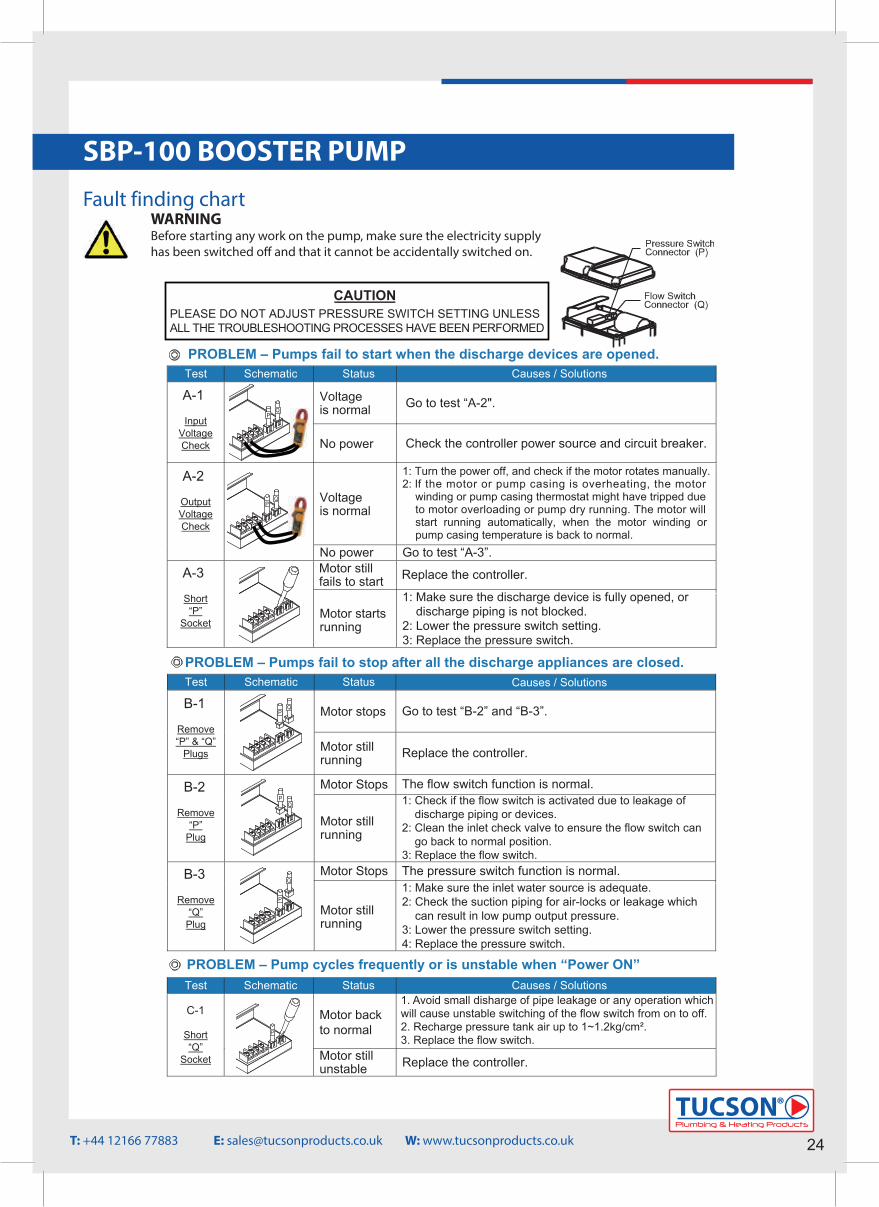
SBP-100 BOOSTER PUMP Fault finding chart
ASB SeriesInstallation and Operating Instructions
Auto Silent Booster Pump
Din 1810 Form A No.40 68-75hook wrench
Unscrew the “Locking Ring(Part No.22-4)” to disassemble
the flow switch.
Discharge SideAir Evacuation Plug (Part No. 21-2)
Suction SidePriming Plug (Part No. 21-1)
Flow Switch Disassembly
Pump Trapped-Air Evacuation
21-122-4
22-0
22-3
22-2
22-1
21-2
3
The flow switch can be disassembled or replaced by using a “Din 1810 Form ANo.40 68-75 hook wrench” or other similar pipe wrench to unscrew the “LockingRing (Part No. 22-4)”
PROBLEM – Pumps fail to start when the discharge devices are opened.Test Schematic Status
Voltageis normal Go to test “A-2".A-1
InputVoltageCheck No power Check the controller power source and circuit breaker.
Voltageis normal
A-2
OutputVoltageCheck
No power Go to test “A-3”. Motor still fails to start Replace the controller. A-3
Short“P”
SocketMotor starts running
CAUTIONPLEASE DO NOT ADJUST PRESSURE SWITCH SETTING UNLESS
Troubleshooting
Causes / Solutions
R
Comfort Home WEBSITE : www.comforthomewater.com E-MAIL : [email protected]
R
Comfort Home
CCAASB0E01
This Product is warranted to the first user only to be free of defects inmaterial and workmanship for a period of 12 months from date of installation,but no more than 24 months from date of manufacture. Comfort Homeliability under this warranty shall be limited to repairing or replacing at ourelection, without charge, FOB Comfort Home's distribution center orauthorised service agent. Comfort Home will not be liable for any cost ofremoval, installation, transportation or any other charges that may arise inconnection with warranty claim.
The warranty period commences on the date of original purchase of theequipment. Proof of purchase and installation date, failure date, andsupporting installation data must be provided when claiming repairs underwarranty.
This warranty is subject to due compliance by the original purchaser with alldirections and conditions set out in the installation and operating instructions.Failure to comply with these instructions, damage or breakdown causedby fair wear and tear, negligence, misuse, incorrect installation, inappropriatechemicals or additives in the water, inadequate protection against freezing,rain or other adverse weather conditions, corrosive or abrasive water,lightning or high voltage spikes or through unauthorised persons attemptingrepairs are not covered under warranty.
Comfort Home will not be liable for any incidental or consequential damages,losses, or expenses, arising from installation, use, or any other causes.There are no express or implied warranties, including merchantabilityor fitness for a particular purpose, which extend beyond thosewarranties described or referred to above.
Certain countries do not permit the exclusion or limitation of incidentalor consequential damages or the placing of limitations on the durationof an implied warranty, therefore, the limitations or exclusions hereinmay not apply. This warranty sets forth specific legal rights andobligations, however, additional rights may exist, which may vary fromcountry to country.
Supersedes all previous publications.
Limited Warranty:
ALL THE TROUBLESHOOTING PROCESSES HAVE BEEN PERFORMED
1: Turn the power off, and check if the motor rotates manually. 2: If the motor or pump casing is overheating, the motor
winding or pump casing thermostat might have tripped dueto motor overloading or pump dry running. The motor willstart running automatically, when the motor winding orpump casing temperature is back to normal.
1: Make sure the discharge device is fully opened, ordischarge piping is not blocked.
2: Lower the pressure switch setting.3: Replace the pressure switch.
PROBLEM – Pumps fail to stop after all the discharge appliances are closed.Test Schematic Status
Motor stops Go to test “B-2” and “B-3”. B-1
Remove“P” & “Q”
Plugs Motor still running Replace the controller.
Motor Stops The flow switch function is normal. B-2
Remove“P”
PlugMotor still running
1: Check if the flow switch is activated due to leakage of discharge piping or devices.2: Clean the inlet check valve to ensure the flow switch can
go back to normal position.3: Replace the flow switch.
Motor Stops The pressure switch function is normal. B-3
Remove“Q”Plug
Motor still running
1: Make sure the inlet water source is adequate.2: Check the suction piping for air-locks or leakage which
can result in low pump output pressure.3: Lower the pressure switch setting.4: Replace the pressure switch.
PROBLEM – Pump cycles frequently or is unstable when “Power ON”Test Schematic Status
Motor back to normal
1: Avoid small discharge of pipe leakage or any operation which will cause unstable flow switch ON/OFF switching.2: Recharge pressure tank air up to 1~1.2 kg/cm2.3: Replace the flow switch.
C-1
Short“Q”
Socket Motor still unstable Replace the controller.
Causes / Solutions
Causes / Solutions
The filling of the suction piping and the pump chamber must be done very carefully to ensure there is no air inside. Trapped-air will cause pump lowdischarge/pressure, and result in abnormal operation. Trapped-Air evacuationcan be accomplished by opening all discharge valves, or unscrewing thedischarge side “Priming Plug (Part No. 21-2)” during pump operation.
Plumbing & Heating Products
TUCSON®
24T: +44 12166 77883 E: [email protected] W: www.tucsonproducts.co.uk
WARNINGBefore starting any work on the pump, make sure the electricity supply has been switched o� and that it cannot be accidentally switched on.
1. Avoid small disharge of pipe leakage or any operation whichwill cause unstable switching of the flow switch from on to off.2. Recharge pressure tank air up to 1~1.2kg/cm².3. Replace the flow switch.
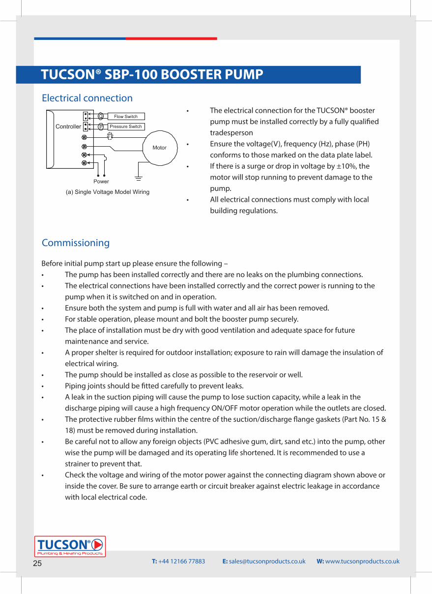
25Plumbing & Heating Products
TUCSON®
Electrical connection
TUCSON® SBP-100 BOOSTER PUMP
• The electrical connection for the TUCSON® booster pump must be installed correctly by a fully quali�ed tradesperson• Ensure the voltage(V), frequency (Hz), phase (PH) conforms to those marked on the data plate label. • If there is a surge or drop in voltage by ±10%, the motor will stop running to prevent damage to the pump.• All electrical connections must comply with local building regulations.
Operating Conditions 1. Ambient Temperature : +5 ºC ~ +40 ºC 2. Liquid Temperature
Regular Model : +5ºC ~ +40ºC Hot Water Model : +5ºC ~ +90ºC
3. Maximum Operating Pressure : 6 kg/cm2
4. Rated Discharge Head / HeightASB25(H) : 1.5 kg/cm 2 / 15 mASB50(H) : 2.0 kg/cm 2 / 20 mASB100(H) : 2.5 kg/cm 2 / 25 m
Item Name Description Item Name Description Item Name Description
1 Motor 1 2 Poles 15 Inlet Flange Gasket Rubber 25 Bolt S45C2 Bolt S45C 16 Inlet Flange NYLON 26 Wiring Box Cover NYLON3 Pump Casing Noryl 17 Flange Bolt SUS304 27 Bolt S45C
18 Outet Flange Gasket Rubber4 Mechanical Seal Ceramic+NBR
+Carbon 19 Outlet Flange NYLON28 Controller Triac-Based
5 Impeller Chamber NORYL 20 Flange Bolt SUS3046 Impeller NORYL 21-1 Priming Plug NYLON
29 Pressure Switch For Turn-OnPressure Setting
7 Diffuser NORYL 21-2 Air Evacuation Plug NYLON 30 Switch Cover NYLON8 Impeller NORYL 22-0 Flow Switch Set Flow Detection 31 Thermal Protector Auto Reset9 O Ring NBR 22-1 Spring SUS304 32 Pump Base ABS10 Bolt SUS304 22-2 Stopper NORYL 33 Bolt S45C11*1 Pump Cover NYLON 22-3 Seal O Ring NBR 34* 2 Impeller Chamber NORYL12 O Ring NBR 22-4 Locking Ring NYLON 35* 2 Impeller NORYL13 Pressure Tank SUS304 23 Seal Gasket Rubber 36* 2 Pump Cover NYLON14 Pump Cover Bolt SUS304 24 Wiring Box NYLON 37 Motor Capacitor Plastic Film
*1 Parts for 60 Hz models.*2 Parts for 50 Hz models.
Installation and Piping
Construction ( ASB-H Hot water Model with stainless steel impeller.) Item Name Description Item Name Description Item Name Description
1 Motor 1 2 Poles 13 Pressure Tank SUS304 24 Wiring Box NYLON2 Bolt S45C 14 Pump Cover Bolt SUS304 25 Bolt S45C3 Pump Casing Noryl 15 Inlet Flange Gasket Rubber 26 Wiring Box Cover NYLON
16 Inlet Flange NYLON 27 Bolt S45C4 Mechanical Seal Ceramic+ Viton
+Carbon*3 17 Flange Bolt SUS304 28 Controller Triac Based5 Impeller Chamber NORYL 18 Outlet Flange Gasket Rubber6 Impeller SUS304* 3 19 Outlet Flange NYLON
29 Pressure Switch For Turn-OnPressure Setting
6-1* 3 Shaft Sleeve PPS 20 Flange Bolt SUS304 30 Switch Cover NYLON7 Diffuser NORYL 21-1 Priming Plug NYLON 31 Thermal Protector Auto Reset8 Impeller SUS304* 3 21-2 Air Evacuation Plug NYLON 32 Pump Base ABS
8-1* 3 Shaft Sleeve PPS 22-0 Flow Switch Set Flow Detection 33 Bolt S45C9 O Ring NBR 22-1 Spring SUS304 34* 2 Impeller Chamber NORYL10 Bolt SUS304 22-2 Stopper NORYL 35* 2 Impeller SUS304* 3
10-1*3 Shaft Sleeve SUS304 22-3 Seal O Ring NBR 35-1*3 Shaft Sleeve PPS11*1 Pump Cover NYLON 22-4 Locking Ring NYLON 36* 2 Pump Cover NYLON12 Tank O Ring Silicon Rubber*3 23 Seal Gasket Rubber 37 Motor Capacitor Plastic Film
Operation and Important Notes
(a) Single Voltage Model Wiring
Description
Construction ( ASB Regular model with thermoplastic impeller.)
14131211109876543
181920
232437272628252930
2730
27
31
151617
32 33 32 33
34 35 36 34 35 36
141312111098721-2
35-1
22-222-1
21-122-422-0 2324372726282529 21-1
6-1 8-1
22-422-022-3
181920
21-2
22-222-1
10-1
22-3
12 6543
*3 Parts or materials for hot water models only.*2 Parts for 50 Hz models.*1 Parts for 60 Hz models.
The ASB series booster pump is an all-in-one compact and reliable automaticmultistage centrifugal booster pump, which integrates motor, pump, accumulator,pressure switch and flow switch, all in one unit. The flow switch equipped withthe pump prevents the pump from continuously starting and stopping undersmall discharge. It is very suitable for domestic water supply.
1. For stable operation, please mount and bolt the booster pump securely. Theplace of installation must be dry with good ventilation and adequate space
for future maintenance and service. A proper shelter is required for outdoor installation; exposure to rain will damage the insulation of electrical wiring.
2. The pump should be installed as close as possible to the reservoir or well. Forhot water (40~90ºC) pumping, negative inlet pressure application is requiredto avoid cavitations. Piping joints should be fitted carefully to prevent leaks.A leak in the suction piping will cause the pump to lose suction capacity, whilea leak in the discharge piping will cause a high frequency ON/OFF motor
operation while the faucets valves are closed.
3.The protective rubber films within the centre of the suction/discharge flange gaskets (Part No. 15 & 18) must be removed during installation.
4. Be careful not to allow any foreign objects (PVC adhesive gum, dirt, sand etc.) into the pump, otherwise the pump will be damaged and its operating life
shortened. It is recommended to use a strainer to prevent that.5. Check the voltage and wiring of the motor power against the connecting
diagram shown below or inside the cover. Be sure to arrange earth or circuitbreaker against electric leakage in accordance with local electrical code.
6. The pump thermal protector (Part No. 31) is designed to protect the pumpfrom dry run. It is also used to prevent hot water pumping which will damagethe pump structure. The electrical power will be cut off after several minutesif dry run occurs, and will be turned on periodically. Shutting off the electricalpower manually is recommended during any water shortage period to saveenergy.
7. An auto-reset thermal protector is equipped within the motor winding. Power will be cut off when the motor winding temperature is abnormal, and will restart when the temperature is back to normal.
1. Before turning the power on, the pump chamber and suction pipe must be filled with water in accordance with the following:
◎For the negative inlet pressure application ( inlet water level is below the pumpinput ), remove the priming plugs (Part No. 21-1 or 21-2), and pour water intothe pump via priming hole completely. Then, secure the priming plugs backin place.
◎For the positive inlet pressure application ( inlet water level is higher thanpump input ), loosen the priming plug (Part No. 21-2), and then secure it
after the water drains out from the priming hole.
Pressure Switch Adjustment
2. Insert a crossed screwdriver into the motor shaft end, and turn the shaftseveral turns clockwise to check whether the pump can be rotated freely. If
not, disassemble and clean the pump chamber.
3. Double check the voltage and wiring of the motor power and then turn thepower switch ON. Open faucet or water appliances on the discharge piping
side. The water should be delivered after several seconds.4. If the water is not delivered after several minutes, turn off the pump immediately.
Repeat step 1, pour water into the pump and suction piping, and switch power ON and OFF continuously.5. Once the water is pumped out, close and open the water appliances on the discharge side repeatedly to check automatic ON/OFF operation.
6. Measure the motor current and check with the data shown on the nameplate. If the current is over, check the voltage again.7. When re-starting the pump after long term shut down, please repeat step 1~6 to ensure normal operation.
The pressure switch set is designed inside the control box. In general, thepressure has been set by the factory to meet most situations. However, in some special cases, when the pump does not operate normally, it can be adjusted easily. Please check the trouble shooting procedures, and read the followinginstructions carefully in advance. For pressure adjustment, first remove the switch cover, and loosen the lock nut counterclockwise by using a 12mm wrench.
1. Motor fails to stopThe pressure setting may be too high. By using a flat-end screwdriver, turn thescrew counterclockwise slowly, until the motor stops; then, turn an extra smallrotation, about 5 degrees. Finally, check if the motor can start normally.
2. Motor fails to startThe pressure setting may be too low. By using a flat-end screwdriver, turn thescrew clockwise slowly, until the motor starts, then an extra small rotation, about5 degrees, is added. Finally, check if the motor can stop normally.
3. After the pressure has been set, screw the lock nut on, and put the cover back.
Commissioning
Before initial pump start up please ensure the following – • The pump has been installed correctly and there are no leaks on the plumbing connections.• The electrical connections have been installed correctly and the correct power is running to the pump when it is switched on and in operation.• Ensure both the system and pump is full with water and all air has been removed. • For stable operation, please mount and bolt the booster pump securely. • The place of installation must be dry with good ventilation and adequate space for future mainte nance and service. • A proper shelter is required for outdoor installation; exposure to rain will damage the insulation of electrical wiring.• The pump should be installed as close as possible to the reservoir or well. • Piping joints should be �tted carefully to prevent leaks. • A leak in the suction piping will cause the pump to lose suction capacity, while a leak in the discharge piping will cause a high frequency ON/OFF motor operation while the outlets are closed.• The protective rubber �lms within the centre of the suction/discharge �ange gaskets (Part No. 15 & 18) must be removed during installation. • Be careful not to allow any foreign objects (PVC adhesive gum, dirt, sand etc.) into the pump, other wise the pump will be damaged and its operating life shortened. It is recommended to use a strainer to prevent that.• Check the voltage and wiring of the motor power against the connecting diagram shown above or inside the cover. Be sure to arrange earth or circuit breaker against electric leakage in accordance with local electrical code.
T: +44 12166 77883 E: [email protected] W: www.tucsonproducts.co.uk
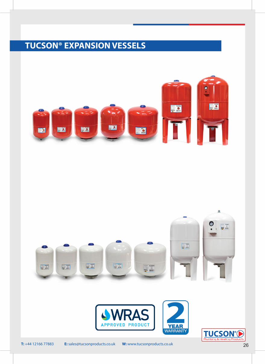
Operating Conditions 1. Ambient Temperature : +5 ºC ~ +40 ºC 2. Liquid Temperature
Regular Model : +5ºC ~ +40ºC Hot Water Model : +5ºC ~ +90ºC
3. Maximum Operating Pressure : 6 kg/cm2
4. Rated Discharge Head / HeightASB25(H) : 1.5 kg/cm 2 / 15 mASB50(H) : 2.0 kg/cm 2 / 20 mASB100(H) : 2.5 kg/cm 2 / 25 m
Item Name Description Item Name Description Item Name Description
1 Motor 1 2 Poles 15 Inlet Flange Gasket Rubber 25 Bolt S45C2 Bolt S45C 16 Inlet Flange NYLON 26 Wiring Box Cover NYLON3 Pump Casing Noryl 17 Flange Bolt SUS304 27 Bolt S45C
18 Outet Flange Gasket Rubber4 Mechanical Seal Ceramic+NBR
+Carbon 19 Outlet Flange NYLON28 Controller Triac-Based
5 Impeller Chamber NORYL 20 Flange Bolt SUS3046 Impeller NORYL 21-1 Priming Plug NYLON
29 Pressure Switch For Turn-OnPressure Setting
7 Diffuser NORYL 21-2 Air Evacuation Plug NYLON 30 Switch Cover NYLON8 Impeller NORYL 22-0 Flow Switch Set Flow Detection 31 Thermal Protector Auto Reset9 O Ring NBR 22-1 Spring SUS304 32 Pump Base ABS10 Bolt SUS304 22-2 Stopper NORYL 33 Bolt S45C11*1 Pump Cover NYLON 22-3 Seal O Ring NBR 34* 2 Impeller Chamber NORYL12 O Ring NBR 22-4 Locking Ring NYLON 35* 2 Impeller NORYL13 Pressure Tank SUS304 23 Seal Gasket Rubber 36* 2 Pump Cover NYLON14 Pump Cover Bolt SUS304 24 Wiring Box NYLON 37 Motor Capacitor Plastic Film
*1 Parts for 60 Hz models.*2 Parts for 50 Hz models.
Installation and Piping
Construction ( ASB-H Hot water Model with stainless steel impeller.) Item Name Description Item Name Description Item Name Description
1 Motor 1 2 Poles 13 Pressure Tank SUS304 24 Wiring Box NYLON2 Bolt S45C 14 Pump Cover Bolt SUS304 25 Bolt S45C3 Pump Casing Noryl 15 Inlet Flange Gasket Rubber 26 Wiring Box Cover NYLON
16 Inlet Flange NYLON 27 Bolt S45C4 Mechanical Seal Ceramic+ Viton
+Carbon*3 17 Flange Bolt SUS304 28 Controller Triac Based5 Impeller Chamber NORYL 18 Outlet Flange Gasket Rubber6 Impeller SUS304* 3 19 Outlet Flange NYLON
29 Pressure Switch For Turn-OnPressure Setting
6-1* 3 Shaft Sleeve PPS 20 Flange Bolt SUS304 30 Switch Cover NYLON7 Diffuser NORYL 21-1 Priming Plug NYLON 31 Thermal Protector Auto Reset8 Impeller SUS304* 3 21-2 Air Evacuation Plug NYLON 32 Pump Base ABS
8-1* 3 Shaft Sleeve PPS 22-0 Flow Switch Set Flow Detection 33 Bolt S45C9 O Ring NBR 22-1 Spring SUS304 34* 2 Impeller Chamber NORYL10 Bolt SUS304 22-2 Stopper NORYL 35* 2 Impeller SUS304* 3
10-1*3 Shaft Sleeve SUS304 22-3 Seal O Ring NBR 35-1*3 Shaft Sleeve PPS11*1 Pump Cover NYLON 22-4 Locking Ring NYLON 36* 2 Pump Cover NYLON12 Tank O Ring Silicon Rubber*3 23 Seal Gasket Rubber 37 Motor Capacitor Plastic Film
Operation and Important Notes
(a) Single Voltage Model Wiring
Description
Construction ( ASB Regular model with thermoplastic impeller.)
14131211109876543
181920
232437272628252930
2730
27
31
151617
32 33 32 33
34 35 36 34 35 36
141312111098721-2
35-1
22-222-1
21-122-422-0 2324372726282529 21-1
6-1 8-1
22-422-022-3
181920
21-2
22-222-1
10-1
22-3
12 6543
*3 Parts or materials for hot water models only.*2 Parts for 50 Hz models.*1 Parts for 60 Hz models.
The ASB series booster pump is an all-in-one compact and reliable automaticmultistage centrifugal booster pump, which integrates motor, pump, accumulator,pressure switch and flow switch, all in one unit. The flow switch equipped withthe pump prevents the pump from continuously starting and stopping undersmall discharge. It is very suitable for domestic water supply.
1. For stable operation, please mount and bolt the booster pump securely. Theplace of installation must be dry with good ventilation and adequate space
for future maintenance and service. A proper shelter is required for outdoor installation; exposure to rain will damage the insulation of electrical wiring.
2. The pump should be installed as close as possible to the reservoir or well. Forhot water (40~90ºC) pumping, negative inlet pressure application is requiredto avoid cavitations. Piping joints should be fitted carefully to prevent leaks.A leak in the suction piping will cause the pump to lose suction capacity, whilea leak in the discharge piping will cause a high frequency ON/OFF motor
operation while the faucets valves are closed.
3.The protective rubber films within the centre of the suction/discharge flange gaskets (Part No. 15 & 18) must be removed during installation.
4. Be careful not to allow any foreign objects (PVC adhesive gum, dirt, sand etc.) into the pump, otherwise the pump will be damaged and its operating life
shortened. It is recommended to use a strainer to prevent that.5. Check the voltage and wiring of the motor power against the connecting
diagram shown below or inside the cover. Be sure to arrange earth or circuitbreaker against electric leakage in accordance with local electrical code.
6. The pump thermal protector (Part No. 31) is designed to protect the pumpfrom dry run. It is also used to prevent hot water pumping which will damagethe pump structure. The electrical power will be cut off after several minutesif dry run occurs, and will be turned on periodically. Shutting off the electricalpower manually is recommended during any water shortage period to saveenergy.
7. An auto-reset thermal protector is equipped within the motor winding. Power will be cut off when the motor winding temperature is abnormal, and will restart when the temperature is back to normal.
1. Before turning the power on, the pump chamber and suction pipe must be filled with water in accordance with the following:
◎For the negative inlet pressure application ( inlet water level is below the pumpinput ), remove the priming plugs (Part No. 21-1 or 21-2), and pour water intothe pump via priming hole completely. Then, secure the priming plugs backin place.
◎For the positive inlet pressure application ( inlet water level is higher thanpump input ), loosen the priming plug (Part No. 21-2), and then secure it
after the water drains out from the priming hole.
Pressure Switch Adjustment
2. Insert a crossed screwdriver into the motor shaft end, and turn the shaftseveral turns clockwise to check whether the pump can be rotated freely. If
not, disassemble and clean the pump chamber.
3. Double check the voltage and wiring of the motor power and then turn thepower switch ON. Open faucet or water appliances on the discharge piping
side. The water should be delivered after several seconds.4. If the water is not delivered after several minutes, turn off the pump immediately.
Repeat step 1, pour water into the pump and suction piping, and switch power ON and OFF continuously.5. Once the water is pumped out, close and open the water appliances on the discharge side repeatedly to check automatic ON/OFF operation.
6. Measure the motor current and check with the data shown on the nameplate. If the current is over, check the voltage again.7. When re-starting the pump after long term shut down, please repeat step 1~6 to ensure normal operation.
The pressure switch set is designed inside the control box. In general, thepressure has been set by the factory to meet most situations. However, in some special cases, when the pump does not operate normally, it can be adjusted easily. Please check the trouble shooting procedures, and read the followinginstructions carefully in advance. For pressure adjustment, first remove the switch cover, and loosen the lock nut counterclockwise by using a 12mm wrench.
1. Motor fails to stopThe pressure setting may be too high. By using a flat-end screwdriver, turn thescrew counterclockwise slowly, until the motor stops; then, turn an extra smallrotation, about 5 degrees. Finally, check if the motor can start normally.
2. Motor fails to startThe pressure setting may be too low. By using a flat-end screwdriver, turn thescrew clockwise slowly, until the motor starts, then an extra small rotation, about5 degrees, is added. Finally, check if the motor can stop normally.
3. After the pressure has been set, screw the lock nut on, and put the cover back.
Plumbing & Heating Products
TUCSON®
26
TUCSON® EXPANSION VESSELS
T: +44 12166 77883 E: [email protected] W: www.tucsonproducts.co.uk
2
GENERAL INFORMATION1. Expansion VesselsWe have two main types of Expansion Vessels available dependent on what application you have. Normally you will be able to �nd a Red Vessel (Heating Vessels) used on a Sealed System Heating application whilst the most common use for our White Vessel (Potable Vessels) would be in a potable application such as an Unvented Water Heater or a Pumped System.
Our range of TUCSON® Potable Expansion Vessels are built from di�erent materials than our range of Heating Expansion Vessels to ensure that the water is contaminant free and safe for human consumption. Expansion Vessels operate on the basis that the internal chamber is separated by a rubber membrane, Inside this membrane sits the water and surrounding this sits a pocket of air. As the water inside the sealed system is heated the water pressure increases due to water been non compressible. The air inside the air chamber of the Expansion Vessel will then become compressed thus leaving the system safe from over pressurisa-tion. As water has the ability to increase by 4.5% in volume when heated from 0-100 DegC an Expansion Vessel is a vital part of any sealed heating system.
Expansion Vessels are commonly used on pumped systems to remove the requirements of a continuous pump. This works as the user will set a low and high pressure on the pump settings, when the water pressure reaches the lowest setting the pump will engage and �ll the Expansion Vessel to the high pressure point and stop. Once this cycle has been completed the Expansion Vessel puts the stored water under pressure ensuring higher pressure water. This will continue until the Expansion Vessels pressure drops to the lower point and the pump starts its cycle again.
TUCSON® Expansion Vessels also come with a replaceable WRAS approved membrane.
2. Warranty TUCSON® Expansion Vessels are sold with a 2 year warranty e�ective from date of purchase. This warranty covers any manufactur-ing fault which may cause the vessel to fail and not perform its designed operations correctly.The warranty is valid on the assumption the following has been applied to the installation:• Product installed correctly and used as speci�ed in the instructions.• It has been installed by a fully quali�ed tradesperson.• The installation complies with the local building regulations and also any regulations which are relative to expansion vessel installations.
The warranty of the vessel is invalid if any of the following occurs during installation: • The vessel has been installed to operate for other purposes than what it is designed for.• The vessel is not installed by a fully quali�ed tradesperson.• The vessel has been installed incorrectly or not to the installation instructions.• The vessel has failed outside of the warranty period.• The vessel has been damaged by outside interference such as bad workmanship or physical damage.
TUCSON® EXPANSION VESSELS
Plumbing & Heating Products
TUCSON®
27 T: +44 12166 77883 E: [email protected] W: www.tucsonproducts.co.uk
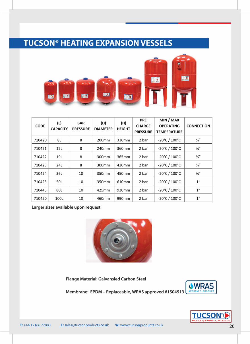
TUCSON® HEATING EXPANSION VESSELS
CODE (L)
CAPACITY BAR
PRESSURE (D)
DIAMETER (H)
HEIGHT
PRE CHARGE
PRESSURE
MIN / MAX OPERATING
TEMPERATURE CONNECTION
710420 8L 8 200mm 330mm 2 bar -20°C / 100°C ¾”
710421 12L 8 240mm 360mm 2 bar -20°C / 100°C ¾”
710422 19L 8 300mm 365mm 2 bar -20°C / 100°C ¾”
710423 24L 8 300mm 430mm 2 bar -20°C / 100°C ¾”
710424 36L 10 350mm 450mm 2 bar -20°C / 100°C ¾”
710425 50L 10 -20°C / 100°C 1”
710445 80L 10 -20°C / 100°C 1”
710450 100L 10 -20°C / 100°C 1”
350mm
425mm
460mm
610mm
930mm
990mm
2 bar
2 bar
2 bar
Flange Material: Galvansied Carbon Steel
Membrane: EPDM – Replaceable, WRAS approved #1504513
Plumbing & Heating Products
TUCSON®
28T: +44 12166 77883 E: [email protected] W: www.tucsonproducts.co.uk
Larger sizes available upon request
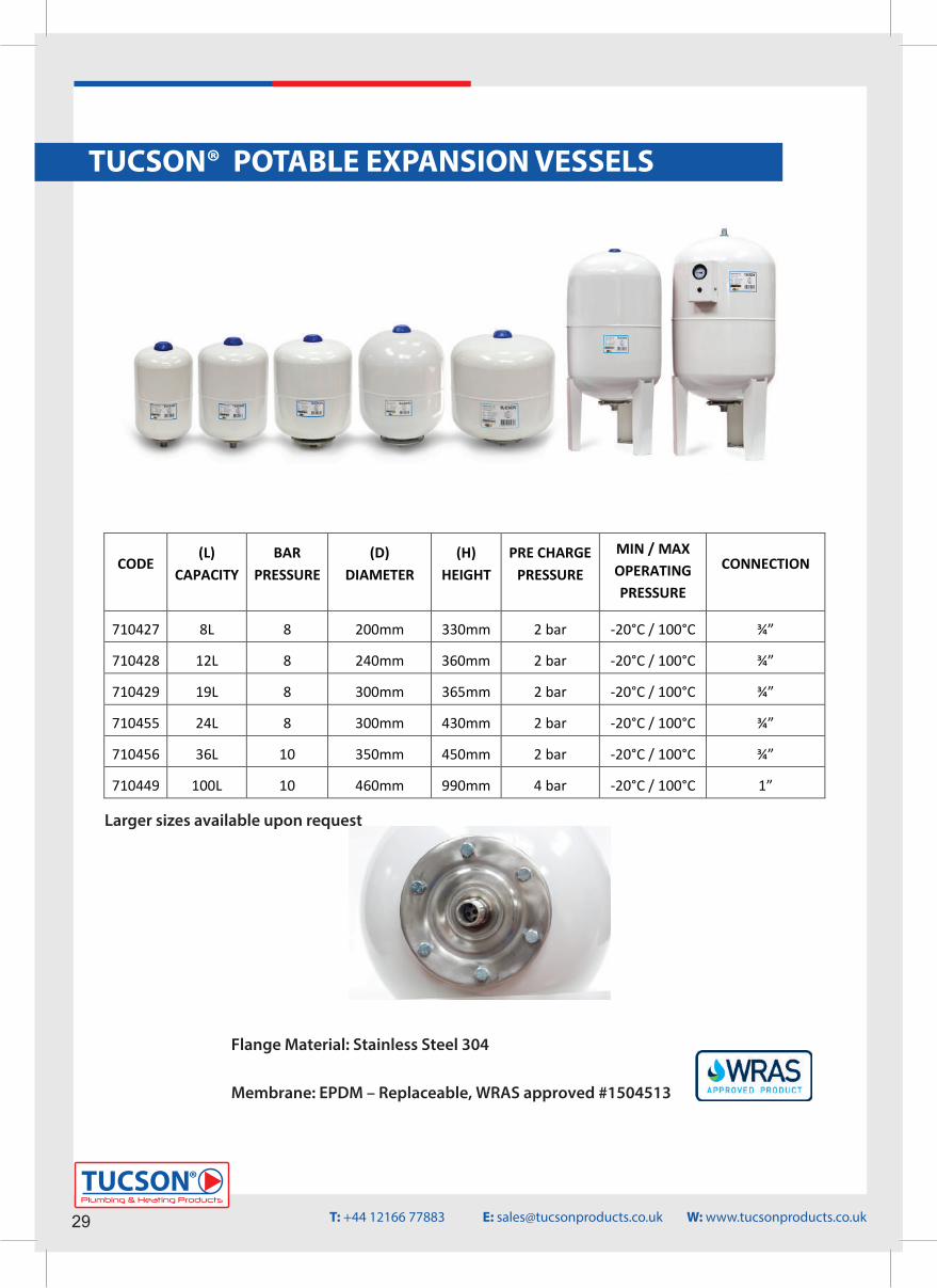
TUCSON® POTABLE EXPANSION VESSELS
CODE (L)
CAPACITY BAR
PRESSURE (D)
DIAMETER (H)
HEIGHT PRE CHARGE
PRESSURE
MIN / MAX OPERATING PRESSURE
CONNECTION
710427 8L 8 200mm 330mm 2 bar -20°C / 100°C ¾”
710428 12L 8 240mm 360mm 2 bar -20°C / 100°C ¾”
710429 19L 8 300mm 365mm 2 bar -20°C / 100°C ¾”
710455 24L 8 300mm 430mm 2 bar -20°C / 100°C ¾”
710456 36L 10 350mm 450mm 2 bar -20°C / 100°C ¾”
710449 100L 10 460mm 990mm 4 bar -20°C / 100°C 1”
Flange Material: Stainless Steel 304
Membrane: EPDM – Replaceable, WRAS approved #1504513
29Plumbing & Heating Products
TUCSON®
T: +44 12166 77883 E: [email protected] W: www.tucsonproducts.co.uk
Larger sizes available upon request
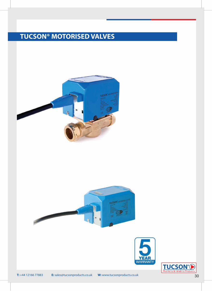
Plumbing & Heating Products
TUCSON®
30
TUCSON® MOTORISED VALVES
T: +44 12166 77883 E: [email protected] W: www.tucsonproducts.co.uk
Plumbing & Heating Products
TUCSON®
TUCSON® MOTORISED VALVES
31
GENERAL INFORMATION1. Motorised Valves• TUCSON® motorised valves are designed to allow or restrict the �ow of water to certain areas or zones based on the system design and demands.• The valve has 2 pipe connections (ports) and permits or blocks �ow between the ports depending on whether it is actuated or not. Flow is permitted and the valve opened when the valve is actuated / powered.• When the valve is powered a synchronous motor drives the valve to the open position until the motor stalls and reaches the fully open position. • When the valve is required to close, the power will be switched o� to the valve and a spring pulls the mechanism (and the motor) back, returning it to its original, closed, position.• These valves can also be opened manually for �lling or draining of the system along with any maintenance that may need to be carried out.TUCSON® motorised valves come with the following features – • Detachable head• Detachable cable • LED power light indicator• CW617N high quality brass body• NSAI approved INSTANTOR® nuts & olives
2. System Liquid – These motorised valves are designed to pump the following types of liquids – Rainwater, potable water or other clean, thin, nonaggressive liquids, not containing solid particles or �bres.
3. Warranty TUCSON® Motorised valves are sold with a 5 year warranty e�ective from date of purchase. This warranty covers any manufactur-ing fault which may cause the pump to fail and not perform its designed operations correctly.The warranty is valid on the assumption the following has been applied to the installation:• Product installed correctly and used as speci�ed in the instructions.• It has been installed by a fully quali�ed tradesperson.• The installation complies with the local building regulations and also any regulations which are relative to motorised valves installations.
The warranty of the motorised valves is invalid if any of the following occurs during installation: • The motorised valve has been installed to operate for other purposes than what it is designed for.• The motorised valve is not installed by a fully quali�ed tradesperson.• The motorised valve has been installed incorrectly or not to the installation instructions.• The motorised valve has failed outside of the warranty period.• The motorised valve has been damaged by outside interference such as bad workmanship or physical damage.
T: +44 12166 77883 E: [email protected] W: www.tucsonproducts.co.uk
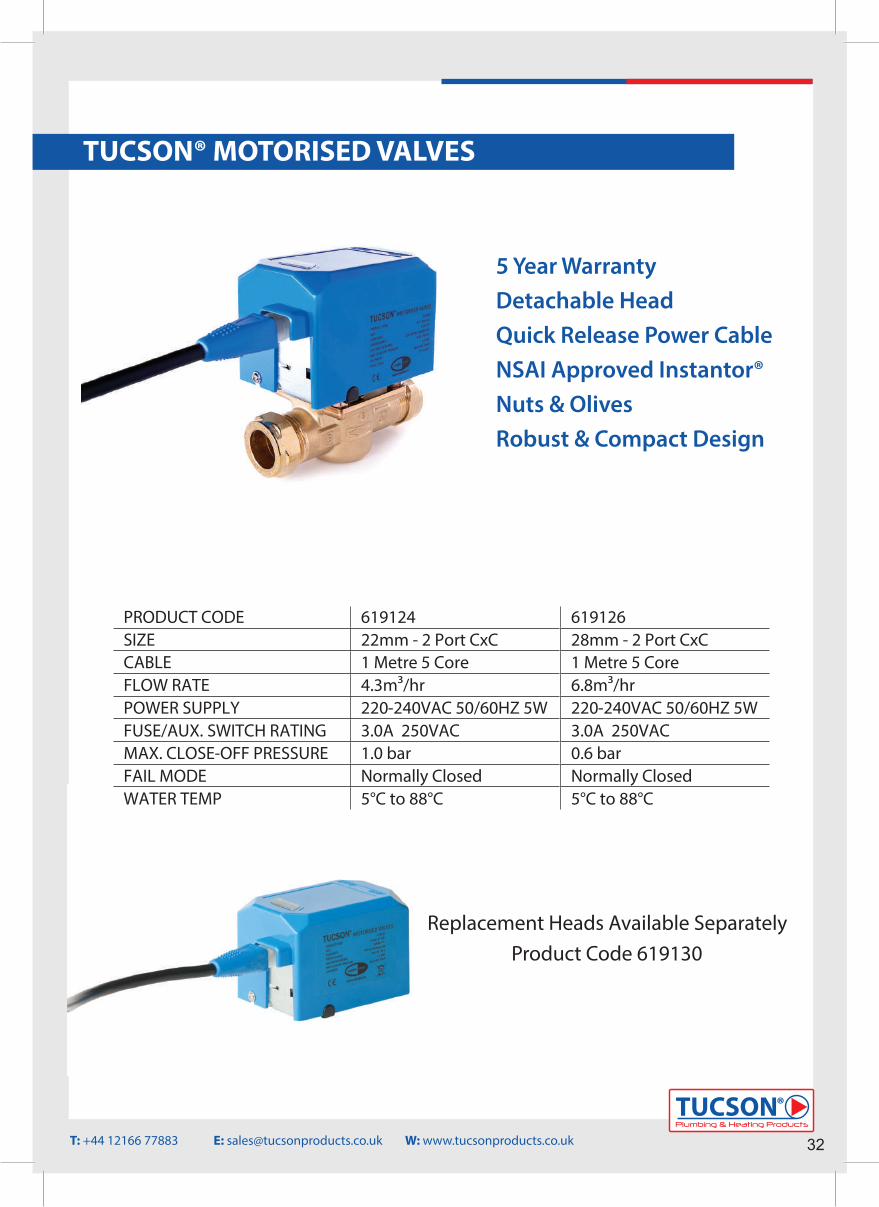
Plumbing & Heating Products
TUCSON®
32
TUCSON® MOTORISED VALVES
Replacement Heads Available SeparatelyProduct Code 619130
619126 28mm - 2 Port CxC 1 Metre 5 Core 6.8m³/hr 220-240VAC 50/60HZ 5W 3.0A 250VAC 0.6 bar Normally Closed 5°C to 88°C
PRODUCT CODE SIZE CABLE FLOW RATE POWER SUPPLY FUSE/AUX. SWITCH RATING MAX. CLOSE-OFF PRESSURE FAIL MODE WATER TEMP
619124 22mm - 2 Port CxC 1 Metre 5 Core 4.3m³/hr 220-240VAC 50/60HZ 5W 3.0A 250VAC 1.0 bar Normally Closed 5°C to 88°C
5 Year WarrantyDetachable HeadQuick Release Power CableNSAI Approved Instantor®Nuts & OlivesRobust & Compact Design
T: +44 12166 77883 E: [email protected] W: www.tucsonproducts.co.uk
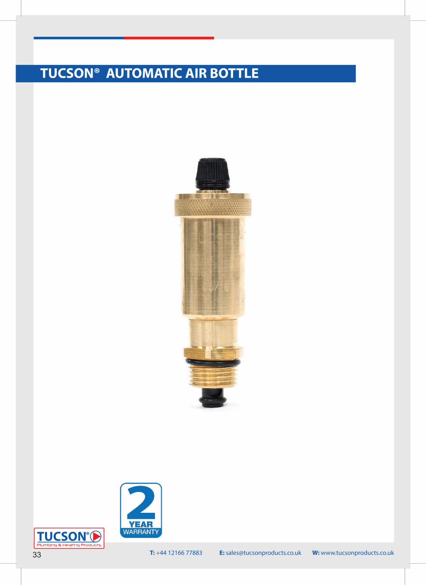
TUCSON® AUTOMATIC AIR BOTTLE
33Plumbing & Heating Products
TUCSON®
T: +44 12166 77883 E: [email protected] W: www.tucsonproducts.co.uk
2
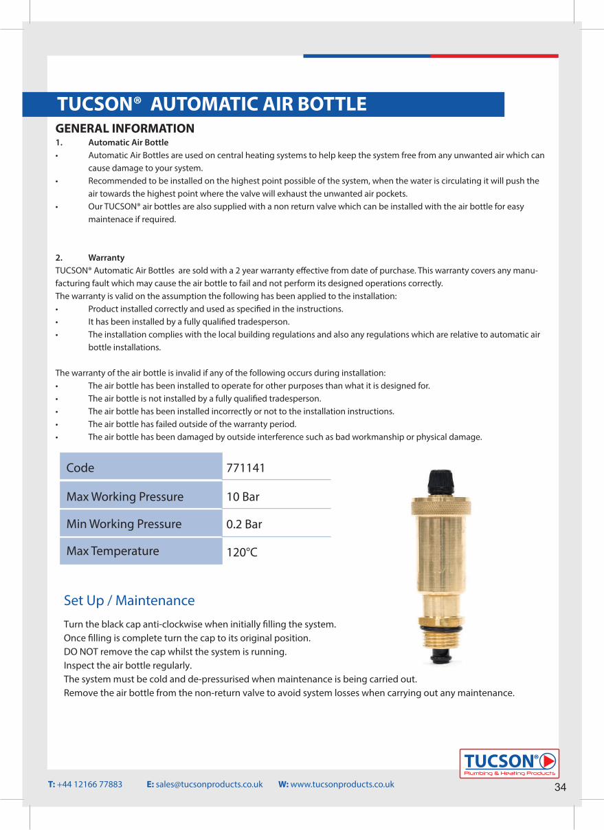
Plumbing & Heating Products
TUCSON®
34T: +44 12166 77883 E: [email protected] W: www.tucsonproducts.co.uk
TUCSON® AUTOMATIC AIR BOTTLE
Max Working Pressure
Min Working Pressure
Max Temperature
0.2 Bar
120°C
10 Bar
Set Up / Maintenance
GENERAL INFORMATION1. Automatic Air Bottle• Automatic Air Bottles are used on central heating systems to help keep the system free from any unwanted air which can cause damage to your system.• Recommended to be installed on the highest point possible of the system, when the water is circulating it will push the air towards the highest point where the valve will exhaust the unwanted air pockets.• Our TUCSON® air bottles are also supplied with a non return valve which can be installed with the air bottle for easy maintenace if required.
2. Warranty TUCSON® Automatic Air Bottles are sold with a 2 year warranty e�ective from date of purchase. This warranty covers any manu-facturing fault which may cause the air bottle to fail and not perform its designed operations correctly.The warranty is valid on the assumption the following has been applied to the installation:• Product installed correctly and used as speci�ed in the instructions.• It has been installed by a fully quali�ed tradesperson.• The installation complies with the local building regulations and also any regulations which are relative to automatic air bottle installations.
The warranty of the air bottle is invalid if any of the following occurs during installation: • The air bottle has been installed to operate for other purposes than what it is designed for.• The air bottle is not installed by a fully quali�ed tradesperson.• The air bottle has been installed incorrectly or not to the installation instructions.• The air bottle has failed outside of the warranty period.• The air bottle has been damaged by outside interference such as bad workmanship or physical damage.
Turn the black cap anti-clockwise when initially �lling the system.Once �lling is complete turn the cap to its original position.DO NOT remove the cap whilst the system is running.Inspect the air bottle regularly.The system must be cold and de-pressurised when maintenance is being carried out.Remove the air bottle from the non-return valve to avoid system losses when carrying out any maintenance.
Code 771141
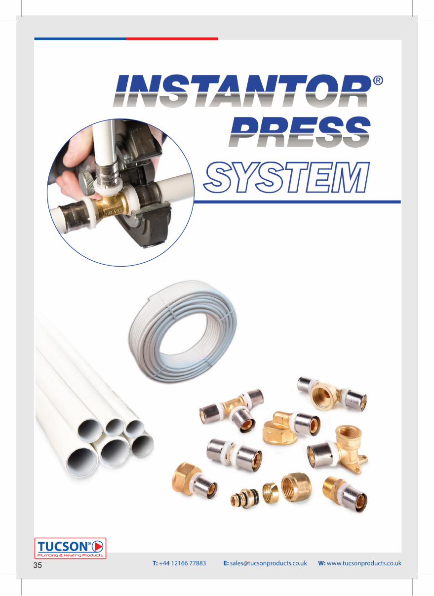
35Plumbing & Heating Products
TUCSON®
T: +44 12166 77883 E: [email protected] W: www.tucsonproducts.co.uk
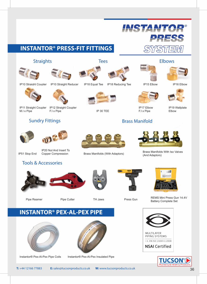
Plumbing & Heating Products
TUCSON®
36T: +44 12166 77883 E: [email protected] W: www.tucsonproducts.co.uk
INSTANTOR® PRESS-FIT FITTINGS
IP10 Straight Coupler IP10 Straight Reducer
IP11 Straight Coupler M.I x Pipe
IP12 Straight CouplerF.I x Pipe
IP18 Equal Tee IP18 Reducing Tee
IP 30 TEE
IP15 Elbow IP16 Elbow
IP17 ElbowF.I x Pipe
IP19 WallplateElbow
IP51 Stop EndIP20 Nut And Insert ToCopper Compression Brass Manifolds (With Adaptors)
Brass Manifolds With Iso Valves(And Adaptors)
Pipe Reamer Pipe Cutter TH Jaws Press Gun REMS Mini Press Gun 14.4VBattery Complete Set
Instantor® Pex-Al-Pex Pipe Coils Instantor® Pex-Al-Pex Insulated Pipe
INSTANTOR® PEX-AL-PEX PIPE
Tools & Accessories
Sundry Fittings Brass Manifold
Straights Tees Elbows
INSTANTOR® PRESS-FIT FITTINGS
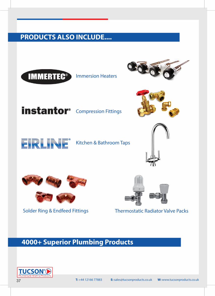
PRODUCTS ALSO INCLUDE....
Immersion Heaters
Compression Fittings
Kitchen & Bathroom Taps
Solder Ring & Endfeed Fittings Thermostatic Radiator Valve Packs
4000+ Superior Plumbing Products
37Plumbing & Heating Products
TUCSON®
T: +44 12166 77883 E: [email protected] W: www.tucsonproducts.co.uk

Plumbing & Heating Products
TUCSON®
38T: +44 12166 77883 E: [email protected] W: www.tucsonproducts.co.uk
NOTES

Plumbing & Heating Products
TUCSON®
www.tucsonproducts.co.uk
TUCSON Plumbing & Heating ProductsSantry AvenueDublin D09 K160Ireland
E-mail: [email protected]: +44 1216677883Technical Support: +353 87 6914223
TUCSON® Plumbing & Heating Products is a Northstone Limited affilated company. (IE290425)