Embed Size (px)
Citation preview
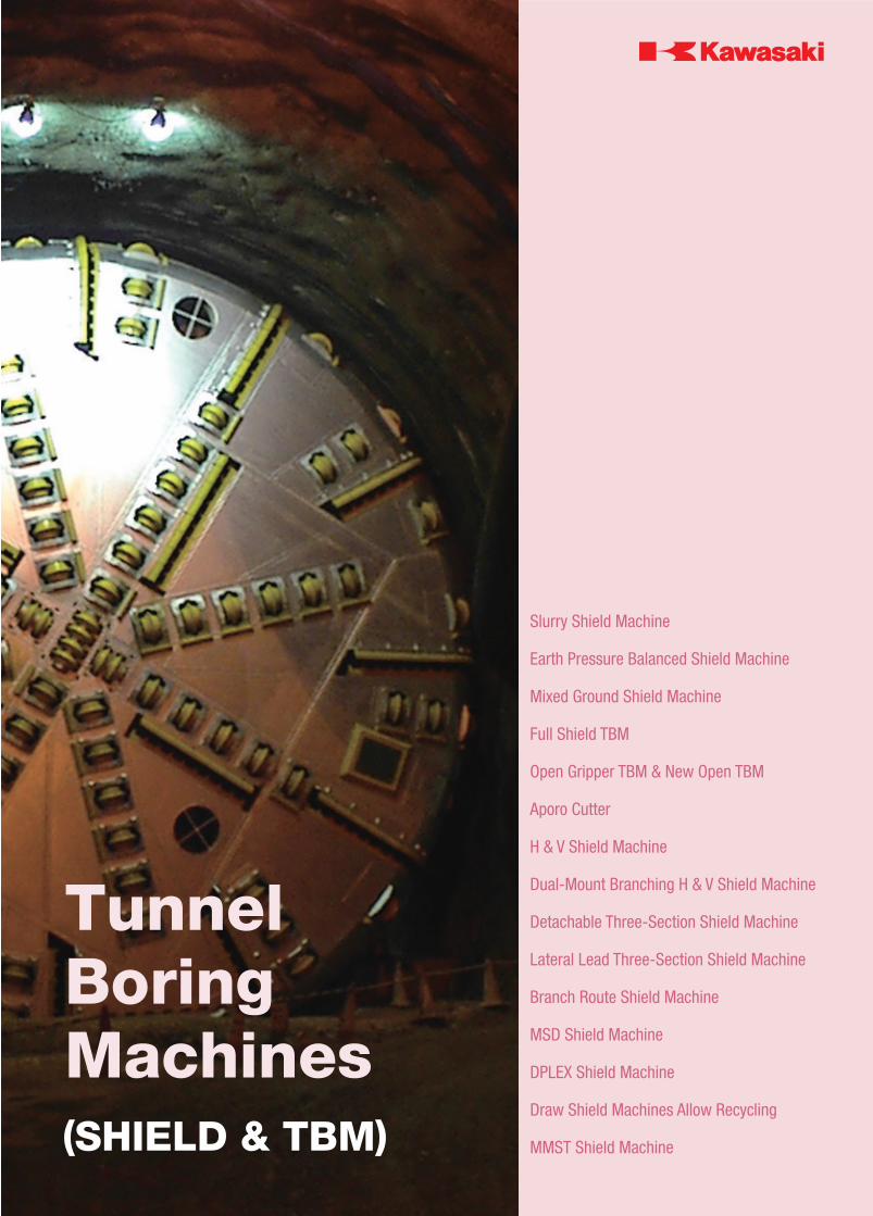
(SHIELD & TBM)
Tunnel Boring Machines
Slurry Shield Machine
Earth Pressure Balanced Shield Machine
Mixed Ground Shield Machine
Full Shield TBM
Open Gripper TBM & New Open TBM
Aporo Cutter
H & V Shield Machine
Dual-Mount Branching H & V Shield Machine
Detachable Three-Section Shield Machine
Lateral Lead Three-Section Shield Machine
Branch Route Shield Machine
MSD Shield Machine
DPLEX Shield Machine
Draw Shield Machines Allow Recycling
MMST Shield Machine
Contents
Slurry Shield Machine ………………………………… 6
Earth Pressure Balanced Shield Machine ……… 8
Mixed Ground Shield Machine …………………… 10
Full Shield TBM ………………………………………… 12
Open Gripper TBM & New Open TBM …………… 14
Special Shield Machine ……………………………… 16
Supply Record ………………………………………… 19
Fundamenral Technologies ………………………… 24
After Service / Support ……………………………… 26
Harima Works ………………………………………… 27
Inquiries
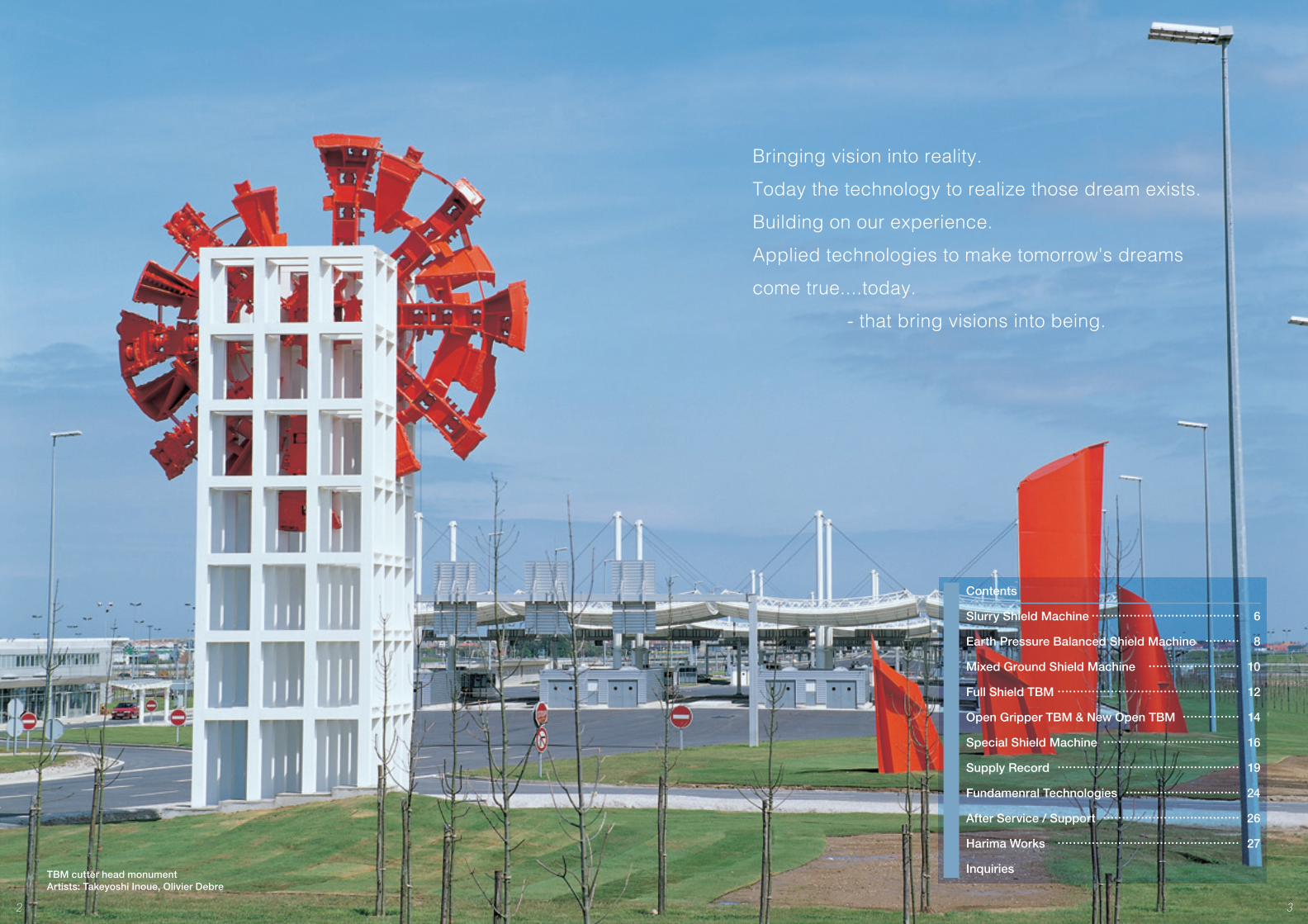
Bringing vision into reality.
Today the technology to realize those dream exists.
Building on our experience.
Applied technologies to make tomorrow's dreams
come true....today.
- that bring visions into being.
TBM cutter head monumentArtists: Takeyoshi Inoue, Olivier Debre
2 3
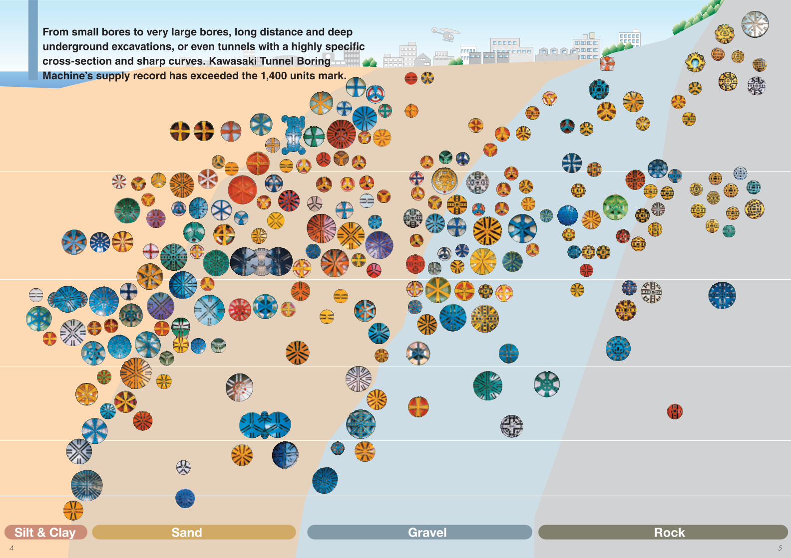
Silt & Clay Sand Gravel Rock
From small bores to very large bores, long distance and deep underground excavations, or even tunnels with a highly specifi c cross-section and sharp curves. Kawasaki Tunnel Boring Machine’s supply record has exceeded the 1,400 units mark.
4 5
Rear section working deckSlurry feeding pipe
Slurry discharging pipe
Segment
Operating panel
Grease pump unit
Tail seal greasing device
Hydraulic pump unit P2 pumpCrusher
Starter panelOil tank unit Transformer Panel Cable reel Plunger valveHose drum
Segment feeder
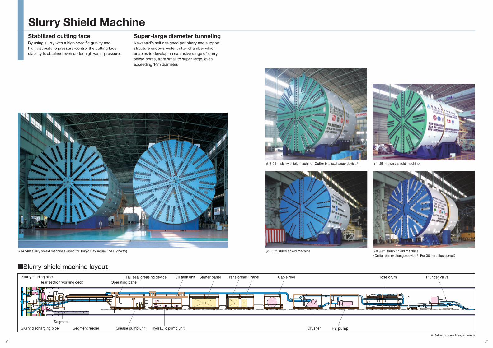
Stabilized cutting faceBy using slurry with a high specifi c gravity and high viscosity to pressure-control the cutting face, stability is obtained even under high water pressure.
■Slurry shield machine layout
Super-large diameter tunnelingKawasaki’s self designed periphery and support structure endows wider cutter chamber which enables to develop an extensive range of slurry shield bores, from small to super large, even exceeding 14m diameter.
Slurry Shield Machine
φ14.14m slurry shield machines (used for Tokyo Bay Aqua-Line Highway)
φ13.05m slurry shield machine (Cutter bits exchange device*)
φ8.99m slurry shield machine (Cutter bits exchange device*, For 30 m radius curvat)
φ10.0m slurry shield machine
φ11.56m slurry shield machine
*Cutter bits exchange device
6 7
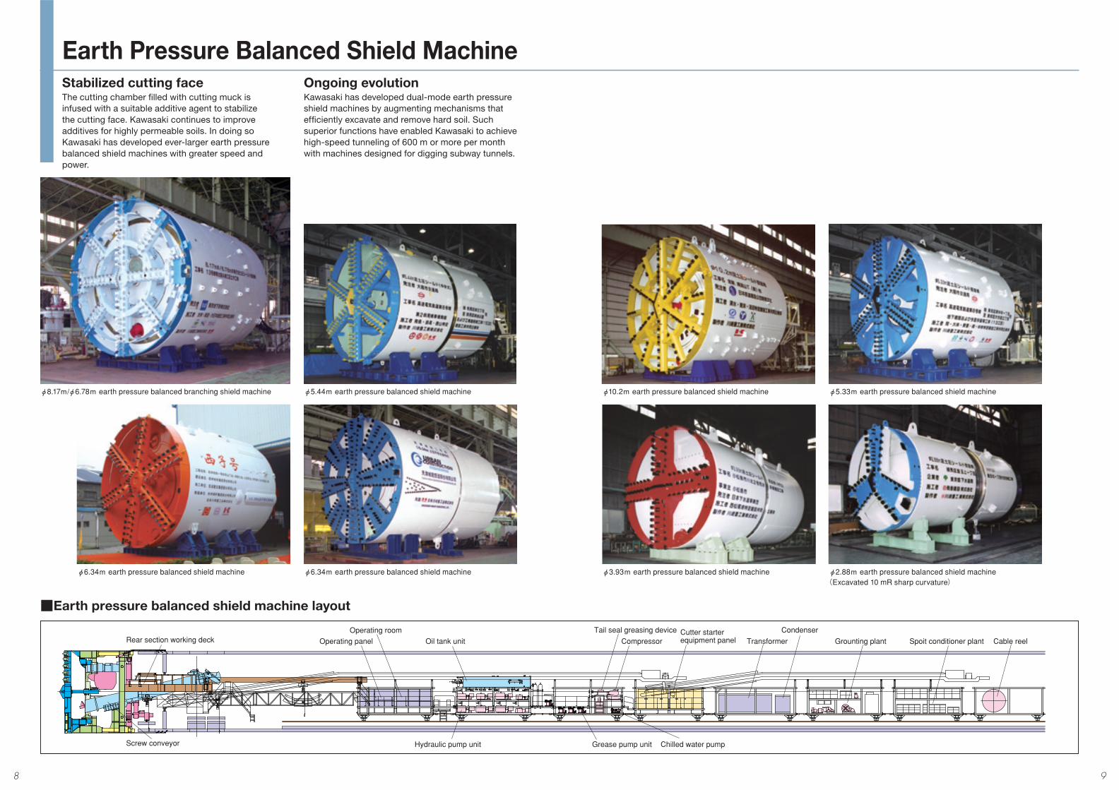
Rear section working deck
Screw conveyor
Operating panelOperating room
Oil tank unit
Hydraulic pump unit Grease pump unit Chilled water pump
Tail seal greasing deviceCompressor
Cutter starter equipment panel
CondenserTransformer Grounting plant Spoit conditioner plant Cable reel
Stabilized cutting faceThe cutting chamber fi lled with cutting muck is infused with a suitable additive agent to stabilize the cutting face. Kawasaki continues to improve additives for highly permeable soils. In doing so Kawasaki has developed ever-larger earth pressure balanced shield machines with greater speed and power.
■Earth pressure balanced shield machine layout
Ongoing evolutionKawasaki has developed dual-mode earth pressure shield machines by augmenting mechanisms that effi ciently excavate and remove hard soil. Such superior functions have enabled Kawasaki to achieve high-speed tunneling of 600 m or more per month with machines designed for digging subway tunnels.
Earth Pressure Balanced Shield Machine
φ6.34m earth pressure balanced shield machineφ6.34m earth pressure balanced shield machine
φ8.17m/φ6.78m earth pressure balanced branching shield machine φ5.44m earth pressure balanced shield machine φ10.2m earth pressure balanced shield machine
φ3.93m earth pressure balanced shield machine
φ5.33m earth pressure balanced shield machine
φ2.88m earth pressure balanced shield machine (Excavated 10 mR sharp curvature)
8 9
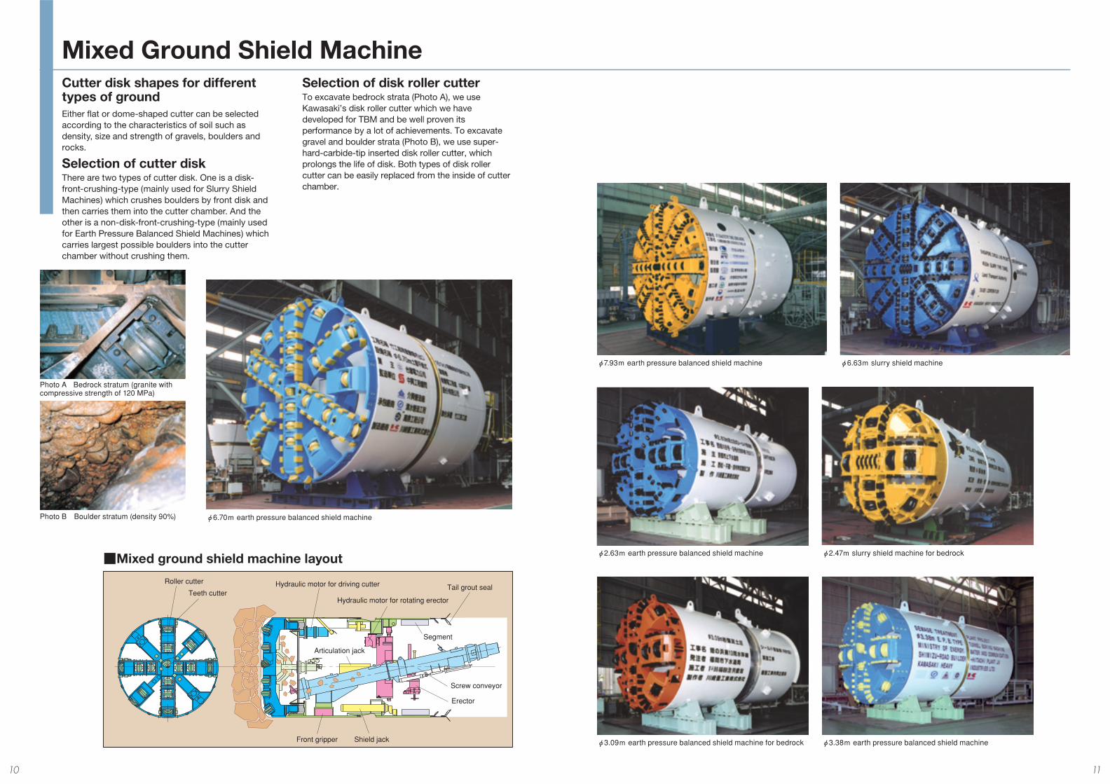
Roller cutter
Teeth cutterHydraulic motor for driving cutter
Hydraulic motor for rotating erector
Tail grout seal
Front gripper Shield jack
Articulation jack
Erector
Segment
Screw conveyor
Cutter disk shapes for different types of groundEither fl at or dome-shaped cutter can be selected according to the characteristics of soil such as density, size and strength of gravels, boulders and rocks.
Selection of cutter diskThere are two types of cutter disk. One is a disk-front-crushing-type (mainly used for Slurry Shield Machines) which crushes boulders by front disk and then carries them into the cutter chamber. And the other is a non-disk-front-crushing-type (mainly used for Earth Pressure Balanced Shield Machines) which carries largest possible boulders into the cutter chamber without crushing them.
■Mixed ground shield machine layout
Selection of disk roller cutterTo excavate bedrock strata (Photo A), we use Kawasaki’s disk roller cutter which we have developed for TBM and be well proven its performance by a lot of achievements. To excavate gravel and boulder strata (Photo B), we use super-hard-carbide-tip inserted disk roller cutter, which prolongs the life of disk. Both types of disk roller cutter can be easily replaced from the inside of cutter chamber.
Mixed Ground Shield Machine
Photo B Boulder stratum (density 90%)
Photo A Bedrock stratum (granite with compressive strength of 120 MPa)
φ6.70m earth pressure balanced shield machine
φ7.93m earth pressure balanced shield machine φ6.63m slurry shield machine
φ3.09m earth pressure balanced shield machine for bedrock φ3.38m earth pressure balanced shield machine
φ2.63m earth pressure balanced shield machine φ2.47m slurry shield machine for bedrock
10 11
φ5,000
Cutter head
Thrust jack
Articulation jack
Shield jack ErectorCutter drive unit
Main gripper No.1 belt conveyor
Front gripper
No.2 belt conveyor No.3 belt conveyor Oil tank unit TransformerStarter panel
Operating panel
Dust collector
Cable reel
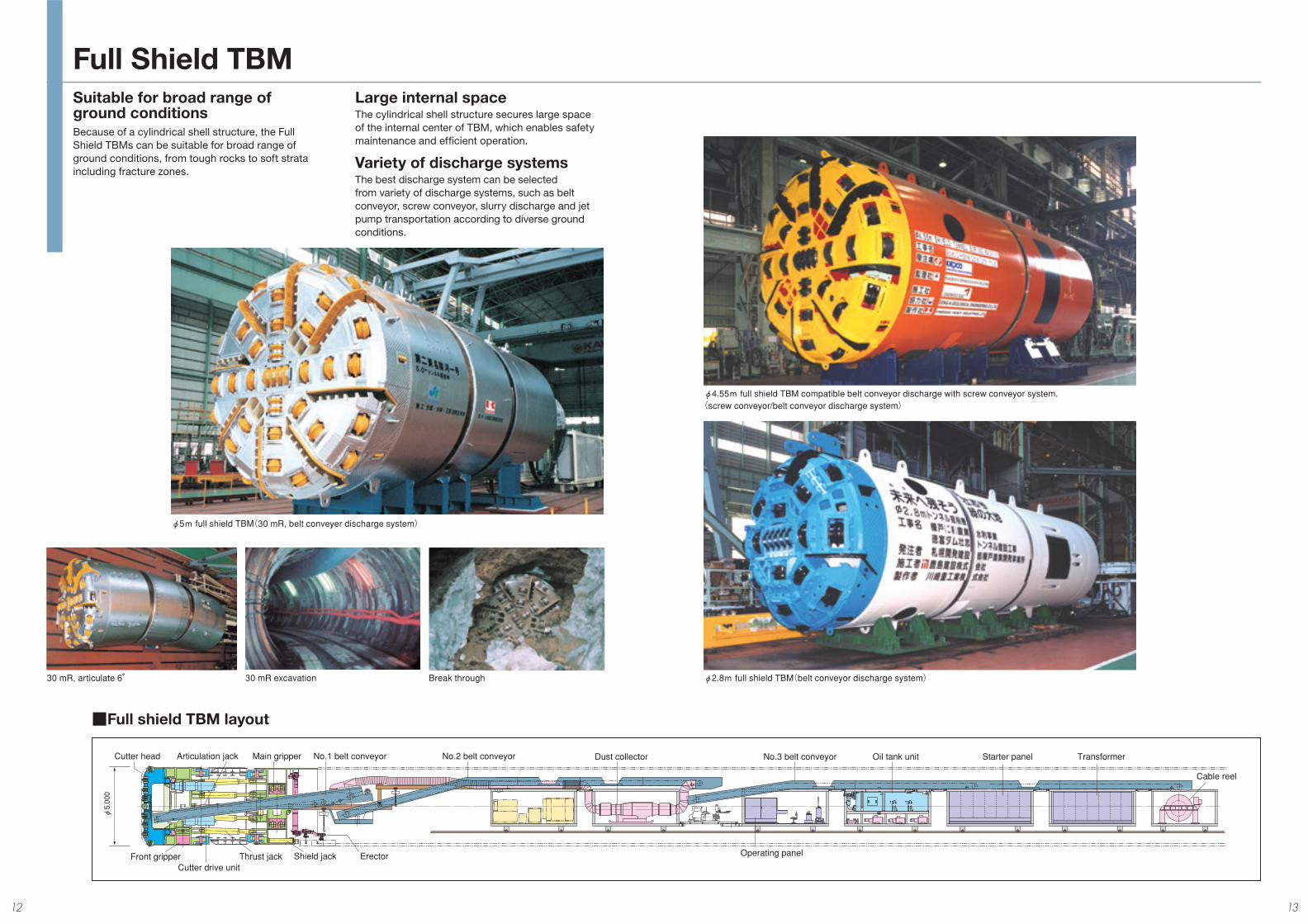
Suitable for broad range of ground conditionsBecause of a cylindrical shell structure, the Full Shield TBMs can be suitable for broad range of ground conditions, from tough rocks to soft strata including fracture zones.
Large internal spaceThe cylindrical shell structure secures large space of the internal center of TBM, which enables safety maintenance and effi cient operation.
Variety of discharge systemsThe best discharge system can be selected from variety of discharge systems, such as belt conveyor, screw conveyor, slurry discharge and jet pump transportation according to diverse ground conditions.
■Full shield TBM layout
Full Shield TBM
φ5m full shield TBM(30 mR, belt conveyer discharge system)
30 mR, articulate 6° 30 mR excavation Break through
φ4.55m full shield TBM compatible belt conveyor discharge with screw conveyor system.(screw conveyor/belt conveyor discharge system)
φ2.8m full shield TBM(belt conveyor discharge system)
12 13
Cutter head Cutter drive unit
Roof support
ErectorMain gripper
Auxiliary propulsion jack Gripper body Main beam
Rear support
No.1 belt conveyor
Pre-boring machine
φ12,840
Cutter head Thrust jack Main gripper Drill unit
Operating platform trailer with crane
Mortar mixer
Concrete pump
Water tank
Grease pump unit Backfill material plant
Dust collectorOperating room
Water hose reel
Pre-boring machine
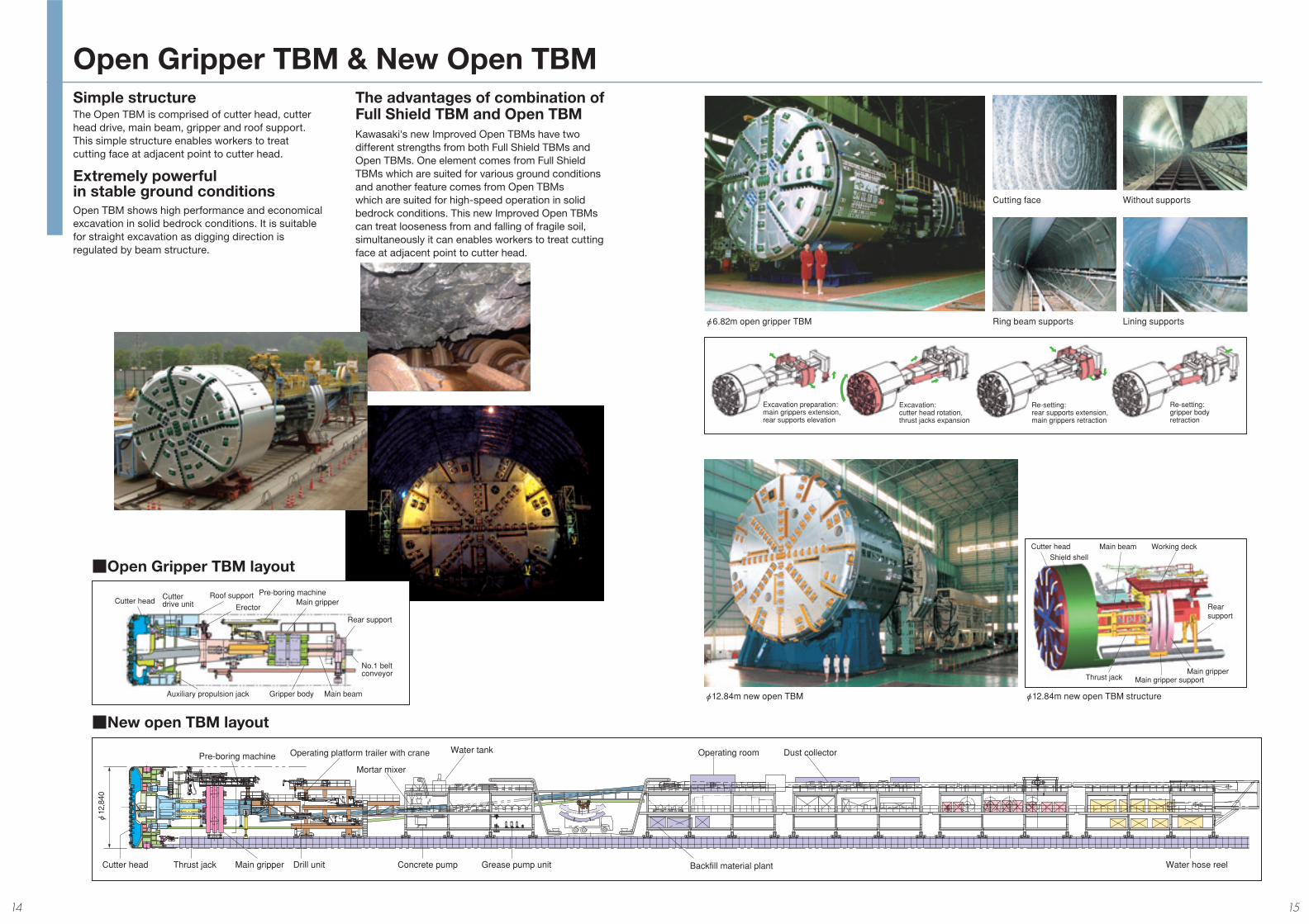
Excavation preparation: main grippers extension, rear supports elevation
Excavation: cutter head rotation, thrust jacks expansion
Re-setting: rear supports extension, main grippers retraction
Re-setting: gripper body retraction
Cutter head Main beam Working deck
Main gripper
Rear support
Thrust jack Main gripper support
Shield shell
Simple structureThe Open TBM is comprised of cutter head, cutter head drive, main beam, gripper and roof support. This simple structure enables workers to treat cutting face at adjacent point to cutter head.
Extremely powerful in stable ground conditionsOpen TBM shows high performance and economical excavation in solid bedrock conditions. It is suitable for straight excavation as digging direction is regulated by beam structure.
■New open TBM layout
■Open Gripper TBM layout
The advantages of combination of Full Shield TBM and Open TBMKawasaki's new Improved Open TBMs have two different strengths from both Full Shield TBMs and Open TBMs. One element comes from Full Shield TBMs which are suited for various ground conditions and another feature comes from Open TBMs which are suited for high-speed operation in solid bedrock conditions. This new Improved Open TBMs can treat looseness from and falling of fragile soil, simultaneously it can enables workers to treat cutting face at adjacent point to cutter head.
Open Gripper TBM & New Open TBM
φ12.84m new open TBM
φ6.82m open gripper TBM Ring beam supports Lining supports
Cutting face Without supports
φ12.84m new open TBM structure
14 15
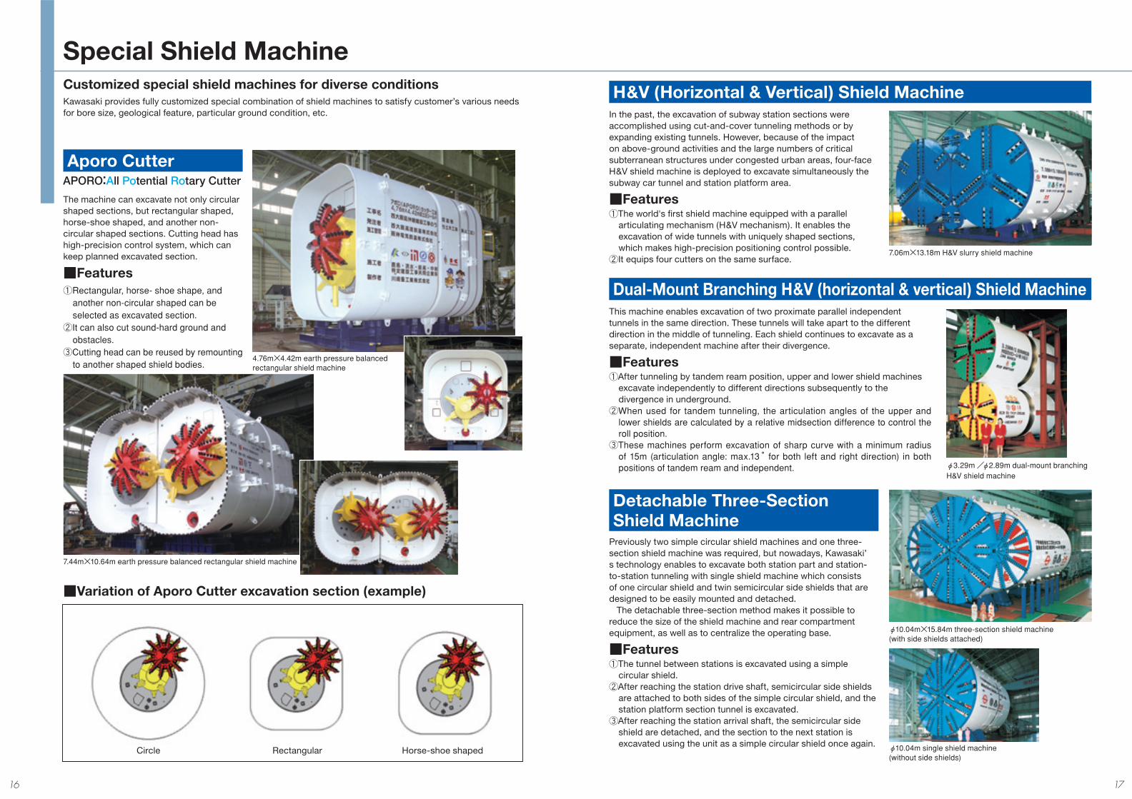
Customized special shield machines for diverse conditions
The machine can excavate not only circular shaped sections, but rectangular shaped, horse-shoe shaped, and another non-circular shaped sections. Cutting head has high-precision control system, which can keep planned excavated section.
■Features①Rectangular, horse- shoe shape, and another non-circular shaped can be selected as excavated section.
②It can also cut sound-hard ground and obstacles.
③Cutting head can be reused by remounting to another shaped shield bodies.
Aporo Cutter
■Variation of Aporo Cutter excavation section (example)
Circle Rectangular Horse-shoe shaped
APORO:All Potential Rotary Cutter
In the past, the excavation of subway station sections were accomplished using cut-and-cover tunneling methods or by expanding existing tunnels. However, because of the impact on above-ground activities and the large numbers of critical subterranean structures under congested urban areas, four-face H&V shield machine is deployed to excavate simultaneously the subway car tunnel and station platform area.
■Features①The world's fi rst shield machine equipped with a parallel
articulating mechanism (H&V mechanism). It enables the excavation of wide tunnels with uniquely shaped sections, which makes high-precision positioning control possible.
②It equips four cutters on the same surface.
H&V (Horizontal & Vertical) Shield Machine
This machine enables excavation of two proximate parallel independent tunnels in the same direction. These tunnels will take apart to the different direction in the middle of tunneling. Each shield continues to excavate as a separate, independent machine after their divergence.
■Features①After tunneling by tandem ream position, upper and lower shield machines
excavate independently to different directions subsequently to the divergence in underground.
②When used for tandem tunneling, the articulation angles of the upper and lower shields are calculated by a relative midsection difference to control the roll position.
③These machines perform excavation of sharp curve with a minimum radius of 15m (articulation angle: max.13 °for both left and right direction) in both positions of tandem ream and independent.
Dual-Mount Branching H&V (horizontal & vertical) Shield Machine
Previously two simple circular shield machines and one three-section shield machine was required, but nowadays, Kawasaki’s technology enables to excavate both station part and station-to-station tunneling with single shield machine which consists of one circular shield and twin semicircular side shields that are designed to be easily mounted and detached. The detachable three-section method makes it possible to reduce the size of the shield machine and rear compartment equipment, as well as to centralize the operating base.
■Features①The tunnel between stations is excavated using a simple
circular shield.②After reaching the station drive shaft, semicircular side shields
are attached to both sides of the simple circular shield, and the station platform section tunnel is excavated.
③After reaching the station arrival shaft, the semicircular side shield are detached, and the section to the next station is excavated using the unit as a simple circular shield once again.
Detachable Three-Section Shield Machine
Special Shield Machine
Kawasaki provides fully customized special combination of shield machines to satisfy customer’s various needs for bore size, geological feature, particular ground condition, etc.
4.76m×4.42m earth pressure balanced rectangular shield machine
7.44m×10.64m earth pressure balanced rectangular shield machine
7.06m×13.18m H&V slurry shield machine
φ3.29m/φ2.89m dual-mount branching H&V shield machine
φ10.04m×15.84m three-section shield machine (with side shields attached)
φ10.04m single shield machine (without side shields)
16 17
Equipped with advanced rotating cutter heads on each side, an oscillating (“wagging”) cutter head ensures space between the machines in the center section and independent rotating cutter heads in the center to achieve even greater excavating effi ciency than Kawasaki's detachable three-section shield machine. The slurry removal systems are combined into a single system.
Lateral Lead Three-Section Shield MachineWhen the shield machine has reached the divergence point, the divergence shield emerges from inside the machine and each shield continues to perform its own independent excavations. Because this construction method allows the divergence operation to be completed underground, there is no need to prepare a departure shaft for the divergence shield machine.
■Construction method①The mainline shield machine tunnels as far as the divergence
point with the divergence shield machine installed inside.②At the divergence point, the forward body section and the
exterior skin plate of the center body section of the mainline shield slide forward and the divergence shield emerges to begin excavation.
③After divergence, both the mainline and the divergence shield machines simultaneously continue their excavation progress.
Branch Route Shield Machine
DSR (Draw a Shield for Recycle system)The shield’s external casing and internal unit are constructed as independent units, and the internal (drive) unit is removed following completion of tunneling of the fi rst section. It is taken to the departure shaft, where a new external casing is fi tted, and excavation is then begun on the next construction section. Because the shield’s internal unit is reused, there is no need to construct an arrival shaft. The drive shaft can also be set up anywhere along the construction route.
Draw Shield Machines Allow Recycling
MSD Shield Machine
DPLEX Shield Machine
MMST Shield Machine
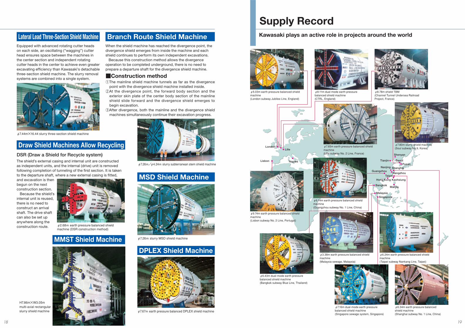
Kawasaki plays an active role in projects around the world
LondonLille
Lisbon Naples
ShanghaiGuangzhou
Hong Kong
Bangkok
Singapore
Malaysia
Pusan
Taipei
φ5.03m earth pressure balanced shield machine (London subway Jubilee Line, England)
φ8.11m dual-mode earth pressure balanced shield machine(CTRL, England)
φ8.78m shield TBM (Channel Tunnel Undersea Railroad Project, France)
φ9.74m earth pressure balanced shield machine(Lisbon subway No. 2 Line, Portugal)
φ6.14m earth pressure balanced shield machine (Guangzhou subway No. 1 Line, China)
φ7.65m earth pressure balanced shield machine (Lille subway No. 2 Line, France)
φ7.80m slurry shield machine(Soul subway No.9, Korea)
φ3.38m earth pressure balanced shield machine(Malaysia sewage, Malaysia)
φ6.24m earth pressure balanced shield machine (Taipei subway Nankang Line, Taipei)
φ7.16m dual-mode earth pressure balanced shield machine (Singapore sewage system, Singapore)
φ6.34m earth pressure balanced shield machine (Shanghai subway No. 1 Line, China)
φ6.43m dual-mode earth pressure balanced shield machine (Bangkok subway Blue Line, Thailand)
Tianjin Seoul
Kaohsiung
Nanjing
Manila
Hangzhou
Shenyan
Supply Record
φ7.44m×16.44 slurry three-section shield machine
φ7.26m/φ4.24m slurry subterranean stem shield machine
φ2.68m earth pressure balanced shield machine (DSR construction method)
φ7.26m slurry MSD shield machine
φ7.67m earth pressure balanced DPLEX shield machine
H7.86m×W3.05mmulti-axial rectangular slurry shield machine
18 19
Cutter head
Roller cutterCutter bit
Slide drumArticulation apparatus Articulation jack
Shield jackNo.1 discharge gate
Total length 13,745 mm
Belt conveyor
No.2 discharge gateMan lockFront gripper
Thrust jack Rear gripper
Segment erector
Segment exterior diameter
8,400 mm
Shield diameter 8,720 mm
Copy cutter
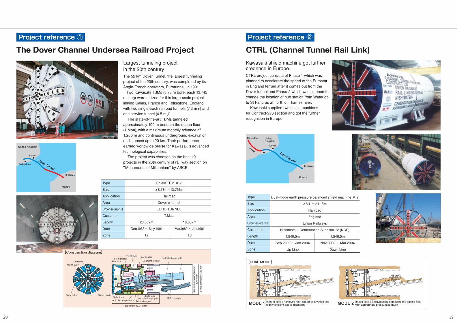
Shield TBM × 2
φ8.78m×13.745m
Railroad
Dover channel
EURO TUNNEL
T.M.L.
20,009m 18,857m
Dec.1988 ~ May 1991 Mar.1989 ~ Jun.1991
T2 T3
Type
Size
Application
Area
Order enterprise
Customer
Length
Date
Zone
United Kingdom
France
Dover
Calais
Folkestone
Dover Tunnel
In hard soils : Achieves high-speed excavation and highly efficient debris discharge
In soft soils : Excavates by stabilizing the cutting face with appropriate pressurized muckMODE 2MODE 1
London
CTRL
United Kingdom
France
Dover
Calais
Dover Tunnel
Dual-mode earth pressure balanced shield machine × 2
φ8.11m×11.5m
Railroad
England
Union Railways
Nishimatsu- Cementation Skanska JV (NCS)
7,540.5m 7,546.5m
Sep.2002~ Jan.2004 Nov.2002~Mar.2004
Up Line Down Line
Type
Size
Application
Area
Order enterprise
Customer
Length
Date
Zone
The Dover Channel Undersea Railroad ProjectLargest tunneling project in the 20th century─The 52 km Dover Tunnel, the largest tunneling project of the 20th century, was completed by its Anglo-French operators, Eurotunnel, in 1991. Two Kawasaki TBMs (8.78 m bore, each 13.745 m long) were utilized for this large-scale project linking Calais, France and Folkestone, England with two single-track railroad tunnels (7.3 mφ) and one service tunnel (4.5 mφ) The state-of-the-art TBMs tunneled approximately 100 m beneath the ocean fl oor (1 Mpa), with a maximum monthly advance of 1,200 m and continuous underground excavation at distances up to 20 km. Their performance earned worldwide praise for Kawasaki's advanced technological capabilities. The project was choosen as the best 10 projects in the 20th century of rail way section on “Monuments of Millennium” by ASCE.
【Construction diagram】
CTRL (Channel Tunnel Rail Link)Kawasaki shield machine got further credence in Europe.CTRL project consists of Phase-1 which was planned to accelerate the speed of the Eurostar in England terrain after it comes out from the Dover tunnel and Phase-2 which was planned to change the location of hub station from Waterloo to St Pancras at north of Thames river. Kawasaki supplied two shield machines for Contract-220 section and got the further recognition in Europe.
【DUAL MODE】
Project reference ① Project reference ②
20 21
Type
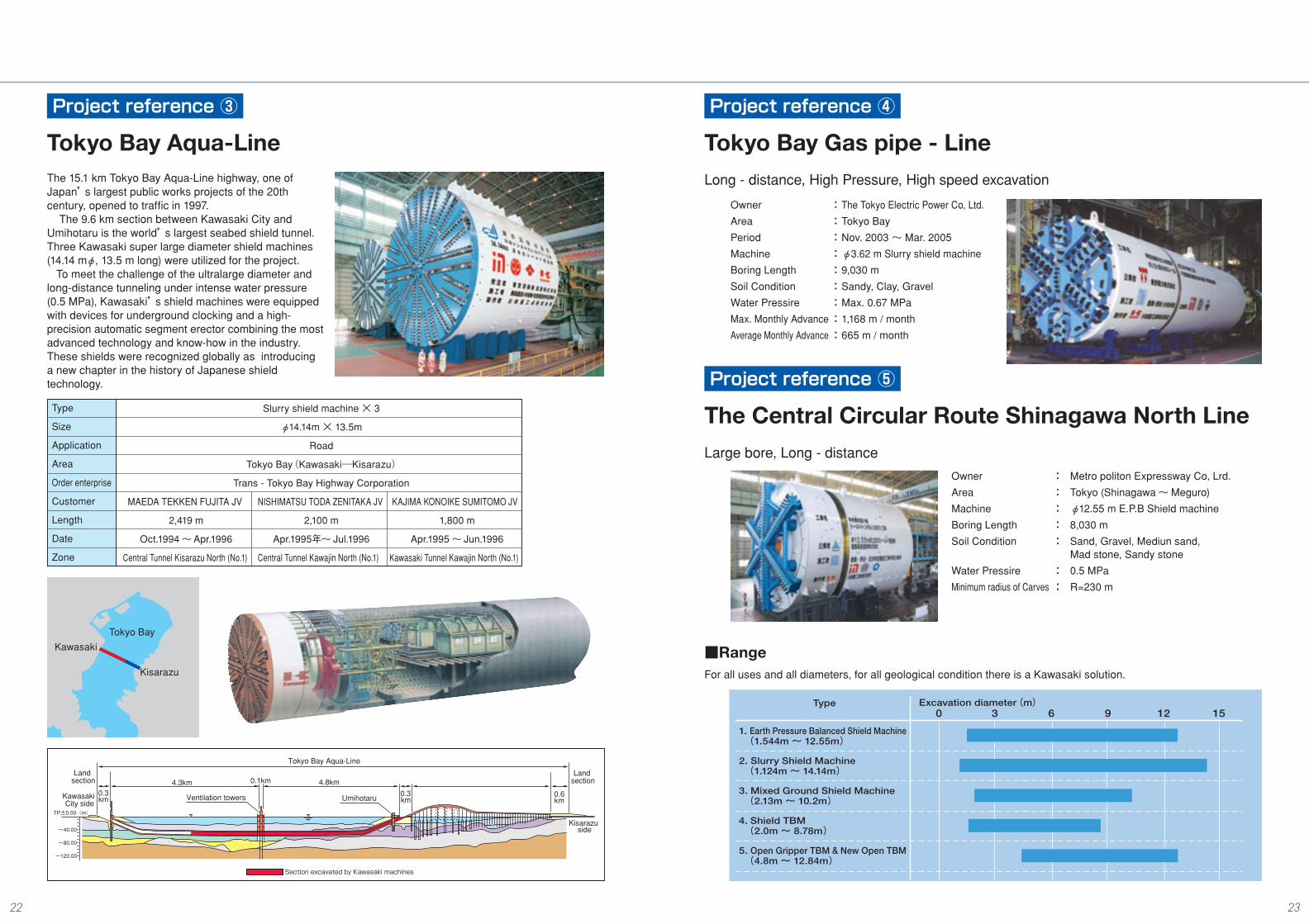
1. Earth Pressure Balanced Shield Machine (1.544m ~ 12.55m)
2. Slurry Shield Machine (1.124m ~ 14.14m)
3. Mixed Ground Shield Machine (2.13m ~ 10.2m)
4. Shield TBM (2.0m ~ 8.78m)
5. Open Gripper TBM & New Open TBM (4.8m ~ 12.84m)
Excavation diameter(m)0 3 6 9 12 15
Slurry shield machine × 3
φ14.14m × 13.5m
Road
Tokyo Bay(Kawasaki―Kisarazu)
Trans - Tokyo Bay Highway Corporation
MAEDA TEKKEN FUJITA JV NISHIMATSU TODA ZENITAKA JV KAJIMA KONOIKE SUMITOMO JV
2,419 m 2,100 m 1,800 m
Oct.1994~Apr.1996 Apr.1995年~ Jul.1996 Apr.1995 ~ Jun.1996
Central Tunnel Kisarazu North (No.1) Central Tunnel Kawajin North (No.1) Kawasaki Tunnel Kawajin North (No.1)
Type
Size
Application
Area
Order enterprise
Customer
Length
Date
Zone
Kawasaki
Kisarazu
Tokyo Bay
TP±0.00(m)
-40.00
-80.00
-120.00
Land section
Kawasaki City side
0.3km
4.3km 0.1km 4.8km0.3km
Land section
0.6km
Kisarazu side
Tokyo Bay Aqua-Line
Section excavated by Kawasaki machines
Ventilation towers Umihotaru
Tokyo Bay Aqua-LineThe 15.1 km Tokyo Bay Aqua-Line highway, one of Japan’s largest public works projects of the 20th century, opened to traffi c in 1997. The 9.6 km section between Kawasaki City and Umihotaru is the world’s largest seabed shield tunnel. Three Kawasaki super large diameter shield machines (14.14 mφ, 13.5 m long) were utilized for the project. To meet the challenge of the ultralarge diameter and long-distance tunneling under intense water pressure (0.5 MPa), Kawasaki’s shield machines were equipped with devices for underground clocking and a high-precision automatic segment erector combining the most advanced technology and know-how in the industry. These shields were recognized globally as introducing a new chapter in the history of Japanese shield technology.
For all uses and all diameters, for all geological condition there is a Kawasaki solution.
■Range
Long - distance, High Pressure, High speed excavation
Owner : The Tokyo Electric Power Co, Ltd.
Area : Tokyo Bay
Period : Nov. 2003 ~ Mar. 2005
Machine : φ3.62 m Slurry shield machine
Boring Length : 9,030 m
Soil Condition : Sandy, Clay, Gravel
Water Pressire : Max. 0.67 MPa
Max. Monthly Advance : 1,168 m / month
Average Monthly Advance : 665 m / month
Large bore, Long - distance
Owner : Metro politon Expressway Co, Lrd.
Area : Tokyo (Shinagawa~Meguro)
Machine : φ12.55 m E.P.B Shield machine
Boring Length : 8,030 m
Soil Condition : Sand, Gravel, Mediun sand, Mad stone, Sandy stone
Water Pressire : 0.5 MPa
Minimum radius of Carves : R=230 m
Project reference ③ Project reference ④
Project reference ⑤
Tokyo Bay Gas pipe - Line
The Central Circular Route Shinagawa North Line
22 23
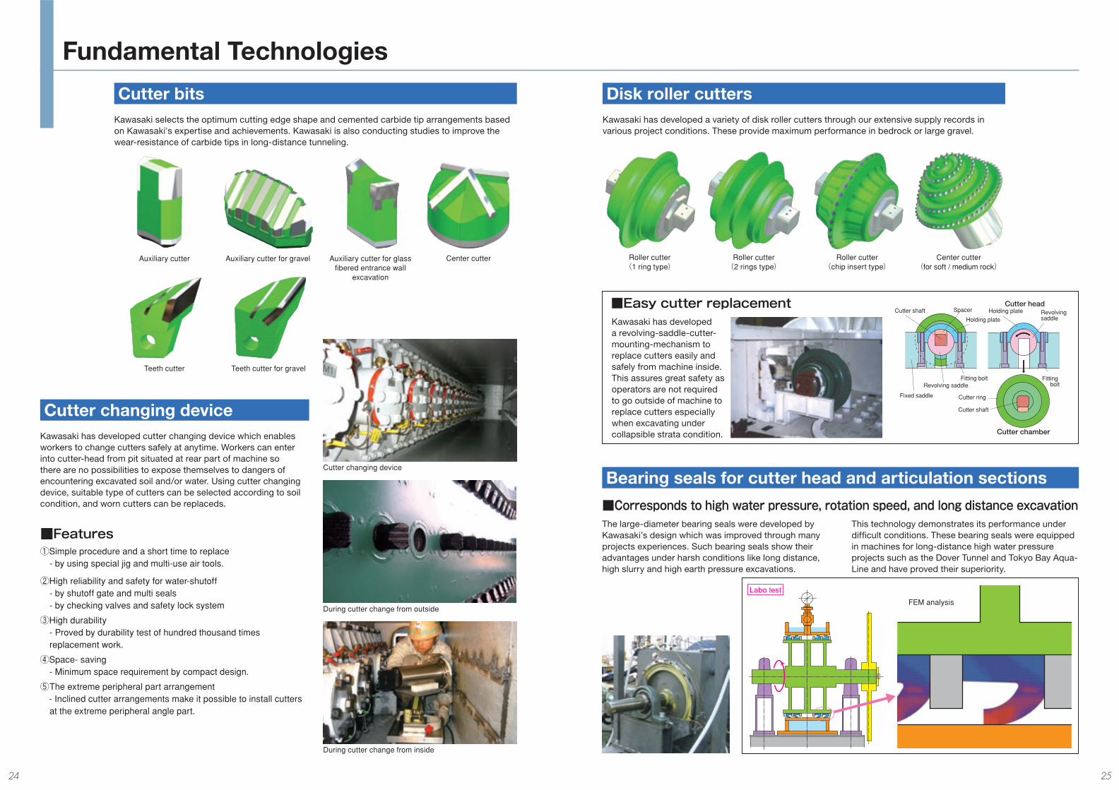
Revolving saddle
Holding plate
Spacer
Fitting bolt
Fixed saddle
Cutter shaft
Cutter shaft
Cutter ring
Holding plate
Fitting bolt
Cutter chamber
Cutter headRevolving saddle
Cutter bits
Cutter changing device
Kawasaki selects the optimum cutting edge shape and cemented carbide tip arrangements based on Kawasaki's expertise and achievements. Kawasaki is also conducting studies to improve the wear-resistance of carbide tips in long-distance tunneling.
Kawasaki has developed cutter changing device which enables workers to change cutters safely at anytime. Workers can enter into cutter-head from pit situated at rear part of machine so there are no possibilities to expose themselves to dangers of encountering excavated soil and/or water. Using cutter changing device, suitable type of cutters can be selected according to soil condition, and worn cutters can be replaceds.
Cutter changing device
During cutter change from outside
During cutter change from inside
■Features①Simple procedure and a short time to replace - by using special jig and multi-use air tools.
②High reliability and safety for water-shutoff - by shutoff gate and multi seals - by checking valves and safety lock system
③High durability - Proved by durability test of hundred thousand times replacement work.
④Space- saving - Minimum space requirement by compact design.
⑤ The extreme peripheral part arrangement - Inclined cutter arrangements make it possible to install cutters at the extreme peripheral angle part.
Disk roller cuttersKawasaki has developed a variety of disk roller cutters through our extensive supply records in various project conditions. These provide maximum performance in bedrock or large gravel.
■Easy cutter replacementKawasaki has developed a revolving-saddle-cutter-mounting-mechanism to replace cutters easily and safely from machine inside. This assures great safety as operators are not required to go outside of machine to replace cutters especially when excavating under collapsible strata condition.
■Corresponds to high water pressure, rotation speed, and long distance excavation
Bearing seals for cutter head and articulation sections
The large-diameter bearing seals were developed by Kawasaki’s design which was improved through many projects experiences. Such bearing seals show their advantages under harsh conditions like long distance, high slurry and high earth pressure excavations.
This technology demonstrates its performance under diffi cult conditions. These bearing seals were equipped in machines for long-distance high water pressure projects such as the Dover Tunnel and Tokyo Bay Aqua-Line and have proved their superiority.
FEM analysis
Labo test
Fundamental Technologies
Teeth cutter Teeth cutter for gravel
Center cutterAuxiliary cutter Auxiliary cutter for gravel Auxiliary cutter for glass fi bered entrance wall
excavation
Roller cutter(1 ring type)
Roller cutter(2 rings type)
Roller cutter(chip insert type)
Center cutter(for soft / medium rock)
24 25
Akashi nishi ICHigashikakogawa
Sanyo Shinkansen
Kakogawa bypass
Route 2Route 250
Tsuchiyama JR Sanyo line
Uozumi
←himejiHarima cho Nishi futami Higashi futami Nishi
akasi→Sanyo Electric RailwayRoute 718
HigashiHarimaBay
Niijima
Futami coastal industrial complex
HarimaWorks
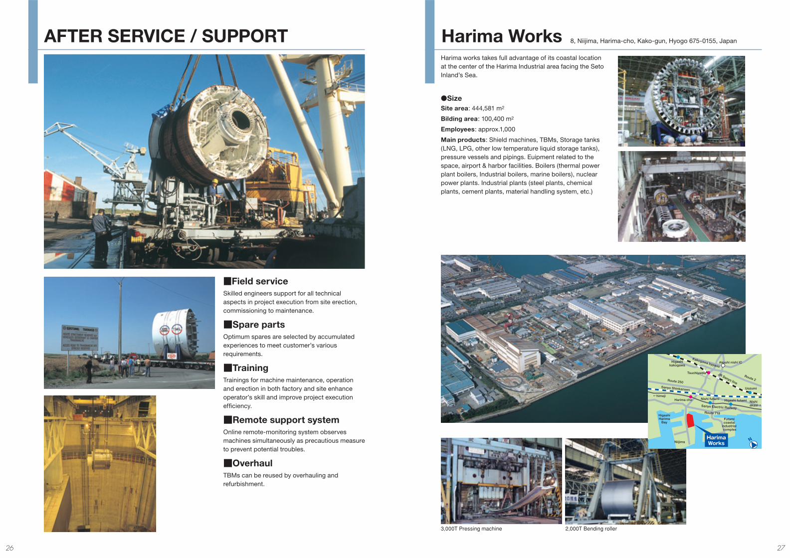
■Field serviceSkilled engineers support for all technical aspects in project execution from site erection, commissioning to maintenance.
■Spare partsOptimum spares are selected by accumulated experiences to meet customer’s various requirements.
■TrainingTrainings for machine maintenance, operation and erection in both factory and site enhance operator’s skill and improve project execution effi ciency.
■Remote support systemOnline remote-monitoring system observes machines simultaneously as precautious measure to prevent potential troubles.
■OverhaulTBMs can be reused by overhauling and refurbishment.
Harima works takes full advantage of its coastal location at the center of the Harima Industrial area facing the Seto Inland’s Sea.
●SizeSite area: 444,581 m2
Bilding area: 100,400 m2
Employees: approx.1,000
Main products: Shield machines, TBMs, Storage tanks (LNG, LPG, other low temperature liquid storage tanks), pressure vessels and pipings. Euipment related to the space, airport & harbor facilities. Boilers (thermal power plant boilers, Industrial boilers, marine boilers), nuclear power plants. Industrial plants (steel plants, chemical plants, cement plants, material handling system, etc.)
8, Niijima, Harima-cho, Kako-gun, Hyogo 675-0155, Japan
3,000T Pressing machine 2,000T Bending roller
AFTER SERVICE / SUPPORT Harima Works
26 27
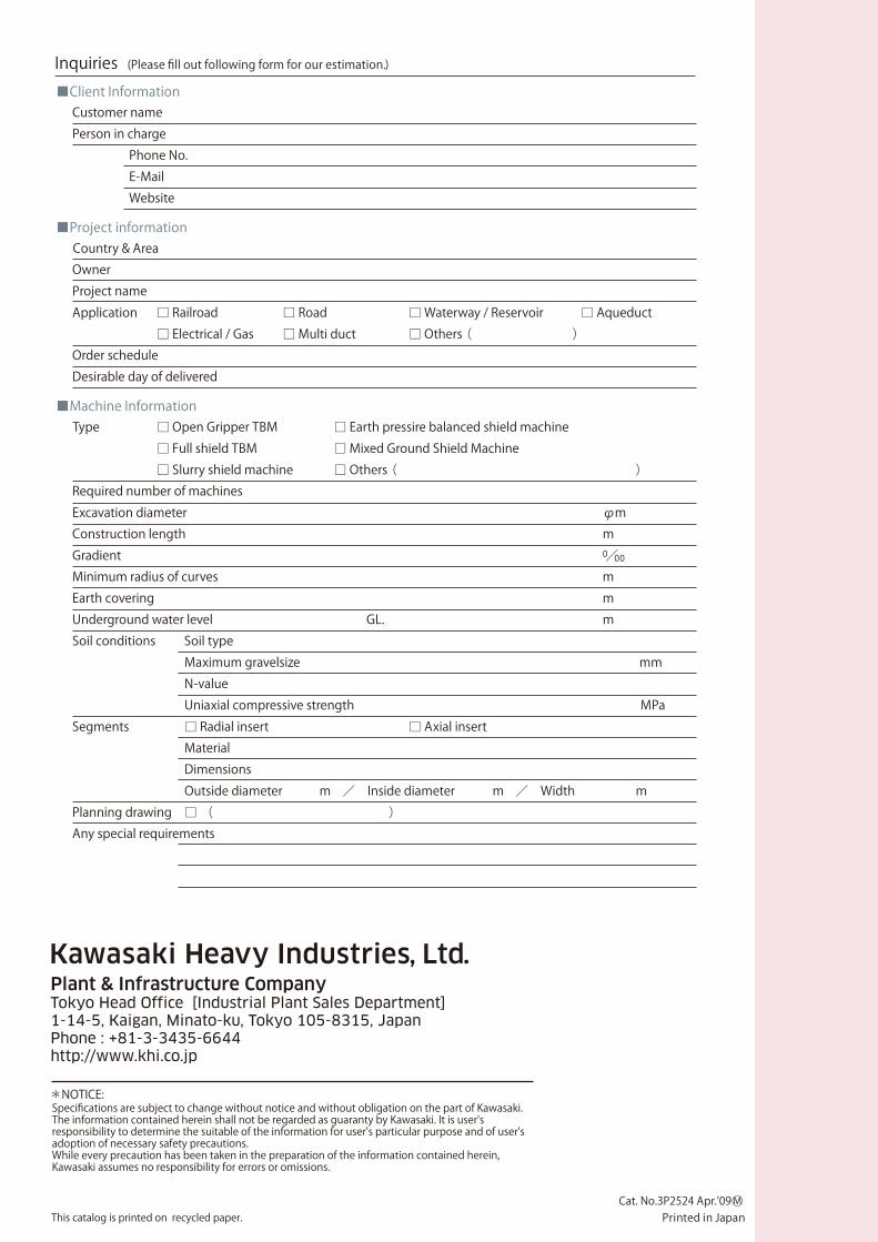
Inquiries (Please fill out following form for our estimation.)■Client Information Customer name Person in charge Phone No. E-Mail Website
■Project information Country & Area Owner Project name Application □ Railroad □ Road □ Waterway / Reservoir □ Aqueduct □ Electrical / Gas □ Multi duct □ Others( ) Order schedule Desirable day of delivered
■Machine Information Type □ Open Gripper TBM □ Earth pressire balanced shield machine □ Full shield TBM □ Mixed Ground Shield Machine □ Slurry shield machine □ Others( ) Required number of machines Excavation diameter φm Construction length m Gradient 0/00 Minimum radius of curves m Earth covering m Underground water level GL. m Soil conditions Soil type Maximum gravelsize mm N-value Uniaxial compressive strength MPa Segments □ Radial insert □ Axial insert Material Dimensions Outside diameter m / Inside diameter m / Width m Planning drawing □ ( ) Any special requirements
This catalog is printed on recycled paper.
Specifications are subject to change without notice and without obligation on the part of Kawasaki.The information contained herein shall not be regarded as guaranty by Kawasaki. It is user's responsibility to determine the suitable of the information for user's particular purpose and of user's adoption of necessary safety precautions.While every precaution has been taken in the preparation of the information contained herein, Kawasaki assumes no responsibility for errors or omissions.
*NOTICE:
Cat. No.3P2524 Apr.’09 M○Printed in Japan