Embed Size (px)
Citation preview
Contents lists available at ScienceDirect
Tunnelling and Underground Space Technology
journal homepage: www.elsevier.com/locate/tust
Practical use of the concept of geotechnical categories in rock engineering
Håkan Stillea,⁎, Arild Palmströmb
a KTH Swedenb RockMass AS, Norway
A R T I C L E I N F O
Keywords:Geological uncertaintiesRiskGeotechnical categoriesEurocodeRock design
A B S T R A C T
The aim of the paper is to show how Eurocode 7: Geotechnical Design Part 1: General Rules (EC7) could bedeveloped in order to be in accordance with practise in rock engineering and construction. A main feature is thegeological uncertianties, which imply that a risk based approch should be used. The use of GeotechnicalCategory (GC) has therefore to be improved by (1) combining the consequences of a failure to the geologicaluncertainties before excavation, and (2) combining the consequences to the ground quality found after ex-cavation. Three GC classes are needed to properly use the GC in rock construction.
The paper further describes how GC influences the design, which design method to be applied. It also outlinesthe types of control, inspection and supervision to be applied in the various GC classes during various stages of aproject. An example is presented showing how GC can be determined at various stages of a rock construction.
1. Introduction
In 1975, the Commission of the European Community promoted anaction program in the field of civil works construction to harmonize therules for design and construction. The European Committee forStandardization approved in 2002 the standard EN1990:2002 “Basis ofStructural design” with the objective to establish the principles andrequirements for the safety, serviceability and durability of structures.
The standard for geotechnical design EN 1997-1:2004, which is apart of EN1990, was given the name Eurocode 7: Geotechnical DesignPart 1: General Rules (EC7). Approved in 2004, it has been given thestatus of national standard in all European countries from 2010. Thereis, however, a debate on whether the standard can be directly appliedon rock engineering issues like foundations, slopes, cuttings and un-derground openings. This paper provides suggestions on how theEurocode could be developed an interpreted in order to be in ac-cordance with rock engineering practice. The objective is to show howinvestigation, design, control and monitoring can be related to geo-technical risks and their classification into geotechnical categories. Thepaper also shows the design tools suitable for various geotechnical ca-tegories.
2. Basis of geotechnical design and rock mechanics
A general base for design is that the prevailing uncertainties shouldbe covered by the safety margin of the designed structure. The size ofthe safety margin (reliability index) is related to the consequences of
failure. More severe consequences will require higher margins. Thisimplies that the design ought to be carried out with a method based onreliability and probability. Modern codes like EN1990: 2002 Basis ofstructural design are based on such thoughts. In the code, three differentconsequence classes are defined, and to each class a minimum value forreliability index is recommended with the intention of keeping a con-stant risk level.
The design of underground openings in rock has been discussed inmany papers and textbooks such as those by Hoek and Brown (1980),Bieniawski (1984, 1989) and Palmstrom and Stille (2015).
As for all other engineering structures, and as stated in modernbuilding codes, such as the European codes (EN 1990: 2002 Basis ofstructural design and EN 1997-1:2004 Geotechnical design), the designgoals in rock must include structural resistance, durability and servi-ceability. The environmental impacts from construction and usage ofthe structure are to be acceptable. The main differences betweenstructural and geotechnical design is the building material. In structuraldesign, materials are man-made with well-defined properties. In geo-technical design, the soil and rock material is as given by nature withlarger variation and uncertainties in properties. As stated above, theactual geological conditions will be revealed only upon excavation. Thisimplies that the final design cannot be carried out in advance. In rockmechanics, the terms preliminary and final design are used to describethe time-related procedures required to obtain adequate information ofthe ground and the adapted design.
Structural resistance and serviceability as well as environmentallyacceptable impacts are defined by ultimate or serviceability limit states.
https://doi.org/10.1016/j.tust.2018.04.035Received 23 March 2017; Received in revised form 29 April 2018; Accepted 29 April 2018
⁎ Corresponding author at: Östermalmsgatan 28, SE-114 26 Stockholm, Sweden.E-mail addresses: [email protected] (H. Stille), [email protected] (A. Palmström).
Tunnelling and Underground Space Technology 79 (2018) 1–11
Available online 04 May 20180886-7798/ © 2018 Elsevier Ltd. All rights reserved.
T
Adequate reliability of the structure shall be achieved. Durability is apart of this issue, but is related also to working life and maintenance.These factors require consideration at all stages of the design, and thedesign process should be transparent and the design work is traceable.This is facilitated if the design is carried out in accordance with ac-cepted rules or standards. Further, rock design is based on the use ofstructural elements like steel bolts and concrete linings in interactionwith the rock mass to improve stability. Compatibility with standardsfor structural design will then be required.
The two main types of structures related to rock engineering areunderground openings and rock slopes. The environmental impacts areoften due to spoil disposal, the effect on the groundwater changes in thesurroundings and of the vibrations from the construction works andfrom usage. The structures and impacts can be classified as both tem-porary and permanent. The measures used during constructions to sa-tisfy given requirements are in many cases governing for the permanentdesign.
In rock engineering, all these different issues are described as dif-ferent design situations. The design situation has to be used in broadsense for describing issues related both to temporary and to permanentstructures, including impacts as well as local and total stability.
In Eurocode, the design situation is classified according to the typeof loads: persistent (normal use), transient (temporary), accidental(exceptional) or from impact of seismic events.
The basic requirements set up in EN 1990, should in the opinion ofthe authors to be redefined and be met by:
• adequate investigation of prevailing materials (ground conditions);
• appropriate choice of design tool;
• appropriate design situation and stages;
• suitable construction methods; and
• specified control procedures for design, construction and usage re-levant to the particular project.
3. Main features in geotechnical design
3.1. Geological uncertainties
Geological uncertainties are related to the assessment of the geo-logical and geotechnical conditions. They include incomplete knowl-edge of the actual geological conditions as well as poor accuracy interms of properties and geometries. The geological uncertainties arerelated to the limited extent of ground investigations and also that thebasis for rock mechanics and rock engineering are largely empirical.This implies that the geological uncertainties will decrease during ex-cavation as the actual geology is revealed. The nature of many rockexcavation projects implies that the level of confidence in the estimatedground conditions can be low based on the pre-investigation, especiallyin complex geological formations.
Muir Wood (1994) argues that geology is the prime source of un-certainty in geotechnical engineering. Unidentified features of theground may lead to unexpected behaviour (incompleteness), secondly:identified features may not be expressible in quantified terms or tosome degree unknown (system uncertainty) and thirdly: there may be afailure in communication between parties (human factors).
3.2. Ground conditions and behaviour types
Rock mechanics and soil mechanics form the scientific basis forgeotechnical engineering. The properties of soils can be determined inlaboratory tests with reasonable accuracy and application of establishedtheories and design methods give good predictions of prototype beha-viour.
In rock mechanics, the interaction of the blocks that form a rockmass dominates its behaviour. The randomness of the joints (joint di-rection and strength) within each joint set makes it difficult to
characterise the mechanical behaviour of the rock mass. Laboratorytesting has limited application due to scale effects. The assessment ofproperties in rock mechanics is therefore empirically based (based onobservation of rock behaviour). This implies generally larger un-certainties of mechanical properties of rock masses than for soil mate-rials. Rock masses can behave in different ways depending on the rockmass properties and applied stresses. Different behaviours require theapplication of different methods of assessment and design. Therefore itis necessary to understand the actual type of behaviour, as a pre-requisite for estimating of rock support and other evaluations.
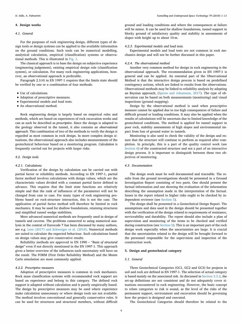
Behaviour type is an important concept in rock mechanics(Terzaghi, 1946; Hoek et al., 1995; Martin et al., 1999; Schubert et al.,2004; Palmstrom and Stille, 2015). They can be put into three groups:gravity driven, stress induced and water influenced. These phenomenaare in not mutually exclusive and can therefore occur at the same timeat any location.
A list of behaviour types is shown in Table 2. Depending on thegeology, some types can be regarded as local instability, while in othersituations they may influence on the total stability. Some will onlyprevail during excavation, others may only influence on the permanentstability.
3.3. Risks and consequences
3.3.1. Risks in rock engineeringRisk is in engineering defined as the combination of consequences of
failure and the probability of failure and emanate from the underlyinguncertainties. Geological uncertainties are dominant in rock en-gineering. Hazard is defined as potential source of undesirable con-sequences.
Risk management can be defined (ISO 31000) as handling suchuncertainties that might prevent the objectives of the project frombeing obtained. The objectives can be expressed as the quality of theresult, which means that implied or stated needs are fulfilled (IS09000). Projects may fail in many ways. Some issues like assessments ofstrength of structure material are so well known that they are notnormally defined as involving any risks although they have to be con-trolled. However, all issues controlled during the work can have asso-ciated risks. Thus, the standard quality control work is part of riskmanagement.
Risk in rock engineering includes many different issues and types ofhazards. General aspects have been given by many authors, e.g.Blockley (1994) and Stille (2017). Guidelines have been elaborated byEskensen et al. (2004).
Geotechnical risks are risks associated with geology as it affects thebehaviour of permanent structures and their construction. Mitigation ofthese risks is a significant factor in cost and schedule control on allmajor engineering projects, see Hoek and Palmieri (1998). The re-sistance, durability and serviceability of the permanent tunnel structureare issues, which are to be handled in the design comparable with otherbuilding projects. However, stability issues and environmental impactduring construction have also to be covered of the design work and cangive consequences comparable with failure of permanent structures.
Geotechnical uncertainties can be split into two categories related tothe sources. The first category is related to uncertainties from assess-ment of actual geological conditions. Example of this type of un-certainties is the limitations of observations of the geology ahead of thetunnel front at the time of construction. The second type is related tothe uncertainties from estimation of ground properties of observedgeology. Even if detailed assessments of the geological conditions ispossible from mapping of excavated rock surfaces there remains un-certainties of the mechanical properties to be used in the deign.
Geotechnical risks can managed in different ways. The epistemicnature of the uncertainties implies that further information about thegeological conditions can reduce the uncertainties. This may beachieved by additional geological investigations in the preconstruction
H. Stille, A. Palmström Tunnelling and Underground Space Technology 79 (2018) 1–11
2
stages or during excavation. In some cases, adoption of an observationalapproach will be required. The level of investigation, control andmonitoring have to be adapted to the chosen design process and risklevel.
3.3.2. Geotechnical categoriesEN 1997-1 introduces three geotechnical categories (GC) based on
associated risks or difficulties due to ground or loading conditions(Table 1). Section 2 of the Eurocode defines the three GC classes. Ac-cording to this, most underground excavations in rock will fall withinGC3, with a few in GC2, while very few (or none) will be in GC1. This isunsatisfactorily as the uncertainties and risks for underground con-structions have a much wider span. Further, the descriptions in EN1997-1 are not clear and do not cover the design issues related to rockexcavation. The terms “difficult soil or loading conditions” are vague and
unhelpful in this context.This paper therefore proposes that GC classes for rock engineering
purposes should be applied both for rock excavation and permanentrock structure. In both cases the GC classes should be related to the risk,i.e. the combination of consequences and uncertainties as described inSection 5, since risk is the central term describing the design condition.
Table 1Excerpt of geotechnical categories described in EN 1997-1.
Geotechnical category Reliability/risk
GC1 Only small and relatively simple structures Negligible riskGC2 Conventional types of structure and
foundation with no exceptional risk ordifficult soil or loading conditions
No exceptional risk ordifficult soil or loadingconditions
GC3 Structures or parts of structures, which falloutside the limits of GeotechnicalCategories 1 and 2
Risk level is not described
Table 2Behaviour types in underground excavations (Palmstrom and Stille, 2015, Data taken from Palmström and Stille (2007) based on Terzaghi (1946), Schubert et al.(2004).
Behaviour type Definition Comments
Group 1: Gravity drivena. Stable The surrounding ground will stand unsupported for several days or longer Massive, durable rocks at low and moderate depthsb. Block fall(s) of single blocks Stable, with potential fall of individual blocks Discontinuity-controlled failure
of severalblocks
Stable, with potential fall of several blocks (slide volume < 10m3).
c. Cave-in Inward, quick movement of larger volumes (> 10m3) of rock fragments orsmall blocks
Encountered in highly jointed or crushed rock
d. Running ground A particulate material quickly invades the tunnel until a stable slope isformed at the face. Stand-up time is zero or nearly zero
Examples are clean medium to coarse sands and gravels abovegroundwater level
Group 2: Stress inducede. Buckling Breaking out of fragments in tunnel surface Occurs in anisotropic, hard, brittle rock under sufficiently high
load due to deflection of the rock structuref. Rupturing from stresses Gradually breaking up into pieces, flakes or fragments in the tunnel
surfaceThe time-dependent effect of slabbing or rock burst fromredistribution of stresses
g. Slabbing Sudden, violent detachment of thin rock slabs from sides or roof Moderate to high overstressing of massive hard, brittle rock.Includes popping or spallinga
h. Rock burst Much more violent than slabbing, and involves considerably largervolumes
Very high overstressing of massive hard, brittle rockconsiderably larger volumes (heavy rock bursting often registersas a seismic event)
i. Plastic behaviour (initial) Initial deformations caused by shear failures in combination withdiscontinuity and gravity-controlled failure of the rockmass
Takes place in plastic (deformable) rock from overstressing.Often the start of squeezing
j. Squeezing Time-dependent deformation, essentially associated with creep caused byoverstressing.Deformations may terminate during construction or continueover a long period
Overstressed plastic, massive rocks and materials with a highpercentage of micaceous minerals or of clay minerals with a lowswelling capacity
Group 3: Water influencedk. Ravelling from slaking Ground breaks gradually up into pieces, flakes or fragments Disintegration (slaking) of some moderately coherent and friable
materialsExamples: mudstones and stiff, fissured clays
l. Swelling of certain rocks Advance of surrounding ground into the tunnel due to expansion causedby water adsorption. The process may sometimes be mistaken forsqueezing
Occurs in swelling of rocks, in which anhydrite, halite (rock salt)and swelling clay minerals, such as smectite (montmorillonite),constitute a significant portion
of certain clayseams or fillings
Swelling of clay seams caused by adsorption of water. This leads toloosening of blocks and reduced shear strength of clay
The swelling takes place in seams having fillings of swelling clayminerals (smectite, montmorillonite)
m. Flowing ground A mixture of water and solids quickly invades the tunnel from all sides,including the invert
May occur in tunnels below the groundwater table in particulatematerials with little or no coherence
n. Water ingress Pressurised water invades the excavation through channels or openings inrocks
May occur in porous and soluble rocks, or along significantopenings or channels in fractures or joints
a This term was often used by Terzaghi (1946) as synonymous with the falling out of individual blocks, primarily as a result of damage during excavation.
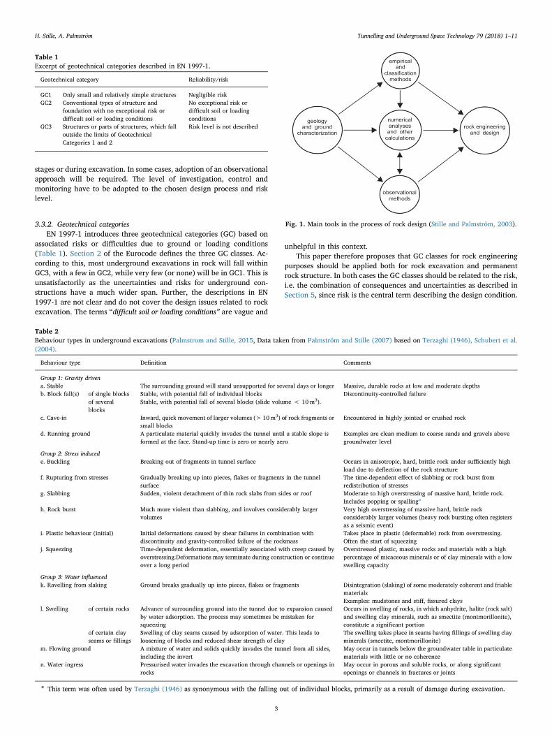
Fig. 1. Main tools in the process of rock design (Stille and Palmström, 2003).
H. Stille, A. Palmström Tunnelling and Underground Space Technology 79 (2018) 1–11
3
4. Design works
4.1. General
For the purposes of rock engineering design, different types of de-sign tools or design systems can be applied to the available informationon the ground conditions. Such tools can be numerical modelling,analytical calculation, empirical (classification) systems or observa-tional methods. This is illustrated in Fig. 1.
The classical approach is to base the design on subjective experience(engineering judgement), existing empirical design rule (classificationsystem), or calculation. For many rock engineering applications, how-ever, an observational approach is preferable.
Paragraph 2.1(4) in EN 1997-1 requires that the limits state shouldbe verified by one or a combination of four methods:
• Use of calculations.
• Adoption of prescriptive measures.
• Experimental models and load tests.
• An observational method.
Rock engineering design is largely based on empirical rules andmethods, which are based on experiences of rock excavation works andcan as such be described as prescriptive. Since the design is adapted tothe geology observed in the tunnel, it also contains an observationalapproach. This combination of two of the methods to verify the design isregarded as most common in rock design. In more complex design si-tuations, the observational approach also includes measurements of thegeotechnical behaviour based on a monitoring program. Calculation isfrequently carried out for projects with larger risks.
4.2. Design tools
4.2.1. CalculationsVerification of the design by calculation can be carried out with
partial factor or reliability methods. According to EN 1997-1, partialfactor method involves calculations with design values, which are thecharacteristic values divided with a constant partial factor defined inadvance. This requires that the limit state functions are relativelysimple and that the rank of influences of the parameters will not bechanged from case to case. For many types of rock engineering pro-blems based on rock-structure interaction, this is not the case. Theapplication of partial factor method will therefore be limited in rockmechanics. It may be used for shallow foundations, retaining structuresand simplified tunnel wedge stabilities.
More advanced numerical methods are frequently used in design oftunnels and caverns. The problems connected to using numerical ana-lysis in the context of Eurocode 7 has been discussed by many authors,see e.g. Lees (2017) and Schweiger et al. (2018). Numerical methodsare suited to calculate the expected behaviour. Such calculations basedon design values may give conservative results.
Reliability methods are approved in EN 1990 – “Basis of structuraldesign” even if not directly mentioned in the EN 1997-1. This approachgives a better overview of the influences each uncertainty will have onthe result. The FORM (First Order Reliability Method) and the MonteCarlo simulation are most commonly applied.
4.2.2. Prescriptive measuresAdoption of prescriptive measures is common in rock mechanics.
Rock mass classification systems with recommended rock support arebased on experience and belong to this category. The defined rocksupport is adopted without calculation and is purely empirically based.The design by prescriptive measures may be used where experiencemake calculation unnecessary or where design tools are not available.The method involves conventional and generally conservative rules. Itcan be used for structures and structural members, without difficult
ground and loading conditions and where the consequences at failurewill be minor. It can be used for shallow foundations, tunnel support inblocky ground of satisfactory quality and stability in assessments ofslopes with height up to about 10m.
4.2.3. Experimental models and load tests.Experimental models and load tests are not common in rock me-
chanics design and will not be further discussed in this paper.
4.2.4. The observational methodAnother very common method for design in rock engineering is the
observational approach. The recommendation given in EN 1997:1 isgeneral and can be applied. An essential part of the ObservationalMethod is that the interactive design process is based on predefinedcontingency actions, which are linked to results from the observations.Observational methods may be linked to reliability analysis by adaptingan Baysian approach, (Spross and Johansson, 2017). The type of ob-servation can be based on both measurements (monitoring) and visualinspections (ground mapping).
Design by the observational method is used when prescriptivemeasure cannot be applied due to too high consequences of failure anddifficult ground or loading conditions. It may also be applied when theresults of calculations will be uncertain due to limited knowledge of thegeotechnical conditions. The method is applied for tunnel support inpoor rock, stability assessments of high slopes and environmental im-pact from loss of ground water to tunnels.
Monitoring is also used to check the validity of the design and en-sure that the structure will continue to perform as required after com-pletion. In principle, this is a part of the quality control work (seeSection 6) of the constructed structure and not a part of an interactivedesign process. It is important to distinguish between these two ob-jectives of monitoring.
4.3. Documentation
The design work must be well documented and traceable. The re-sults from the ground investigations should be presented in a GroundInvestigation Report consisting of two parts. One should present thefactual information and one showing the evaluation of the informationdescribing the assumption made in the interpretation of the factual.Issues in the report related to higher risks ought to be checked by in-dependent reviewer (see Section 5).
The design shall be presented in a Geotechnical Design Report. Theassumptions and data used in the design should be presented togetherwith the verification of the design related to requirements of resistance,serviceability and durability. The report should also include a plan ofsupervision and monitoring of the items to be checked and verifiedduring construction (see Section 5). This is an important part of the rockdesign work especially when the uncertainties are large. It is crucialthat the uncertainties related to the design will be brought forward tothe personnel responsible for the supervision and inspection of theconstruction work.
5. Design and geotechnical category
5.1. General
Three Geotechnical Categories (GC1, GC2 and GC3) for projects insoil and rock are defined in EN 1997-1. The selection of actual categoryis based mainly on the associated risk. As discussed in Section 3.3.2, theset-up definitions are not consistent and do not adequately cover si-tuations encountered in rock engineering. However, the basic conceptto relate categories to risk is sound, as the level of the risks of thepermanent support, environment and excavation should be governinghow the project is designed and executed.
The Geotechnical Categories should therefore be related to the
H. Stille, A. Palmström Tunnelling and Underground Space Technology 79 (2018) 1–11
4
associated risk, both to the consequences and to the level of un-certainties. The latter is strongly correlated to the probability of failure.By introducing Geotechnical Categories to cover both rock construc-tions with temporary support and permanent structures, better appli-cations of GC will be achieved in rock engineering. Some clarificationsand adjustments of the EN 1997-1 would then be required as describedin this section.
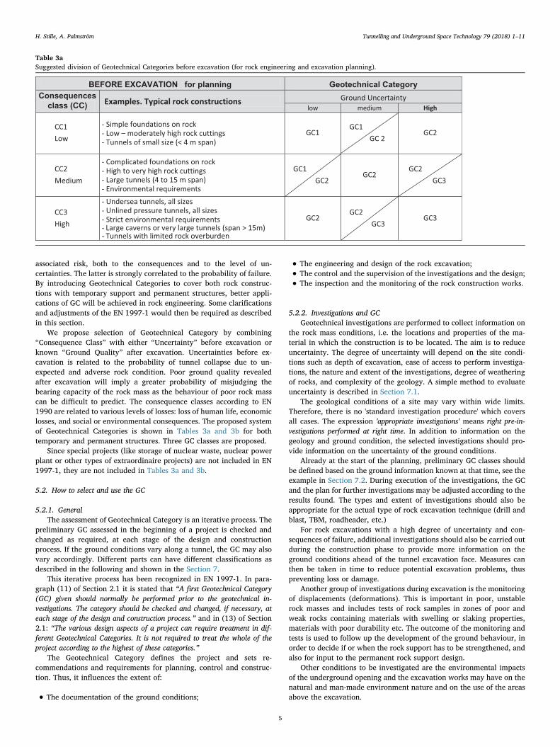
We propose selection of Geotechnical Category by combining“Consequence Class” with either “Uncertainty” before excavation orknown “Ground Quality” after excavation. Uncertainties before ex-cavation is related to the probability of tunnel collapse due to un-expected and adverse rock condition. Poor ground quality revealedafter excavation will imply a greater probability of misjudging thebearing capacity of the rock mass as the behaviour of poor rock masscan be difficult to predict. The consequence classes according to EN1990 are related to various levels of losses: loss of human life, economiclosses, and social or environmental consequences. The proposed systemof Geotechnical Categories is shown in Tables 3a and 3b for bothtemporary and permanent structures. Three GC classes are proposed.
Since special projects (like storage of nuclear waste, nuclear powerplant or other types of extraordinaire projects) are not included in EN1997-1, they are not included in Tables 3a and 3b.
5.2. How to select and use the GC
5.2.1. GeneralThe assessment of Geotechnical Category is an iterative process. The
preliminary GC assessed in the beginning of a project is checked andchanged as required, at each stage of the design and constructionprocess. If the ground conditions vary along a tunnel, the GC may alsovary accordingly. Different parts can have different classifications asdescribed in the following and shown in the Section 7.
This iterative process has been recognized in EN 1997-1. In para-graph (11) of Section 2.1 it is stated that “A first Geotechnical Category(GC) given should normally be performed prior to the geotechnical in-vestigations. The category should be checked and changed, if necessary, ateach stage of the design and construction process.” and in (13) of Section2.1: “The various design aspects of a project can require treatment in dif-ferent Geotechnical Categories. It is not required to treat the whole of theproject according to the highest of these categories.”
The Geotechnical Category defines the project and sets re-commendations and requirements for planning, control and construc-tion. Thus, it influences the extent of:
• The documentation of the ground conditions;
• The engineering and design of the rock excavation;
• The control and the supervision of the investigations and the design;
• The inspection and the monitoring of the rock construction works.
5.2.2. Investigations and GCGeotechnical investigations are performed to collect information on
the rock mass conditions, i.e. the locations and properties of the ma-terial in which the construction is to be located. The aim is to reduceuncertainty. The degree of uncertainty will depend on the site condi-tions such as depth of excavation, ease of access to perform investiga-tions, the nature and extent of the investigations, degree of weatheringof rocks, and complexity of the geology. A simple method to evaluateuncertainty is described in Section 7.1.
The geological conditions of a site may vary within wide limits.Therefore, there is no 'standard investigation procedure' which coversall cases. The expression 'appropriate investigations' means right pre-in-vestigations performed at right time. In addition to information on thegeology and ground condition, the selected investigations should pro-vide information on the uncertainty of the ground conditions.
Already at the start of the planning, preliminary GC classes shouldbe defined based on the ground information known at that time, see theexample in Section 7.2. During execution of the investigations, the GCand the plan for further investigations may be adjusted according to theresults found. The types and extent of investigations should also beappropriate for the actual type of rock excavation technique (drill andblast, TBM, roadheader, etc.)
For rock excavations with a high degree of uncertainty and con-sequences of failure, additional investigations should also be carried outduring the construction phase to provide more information on theground conditions ahead of the tunnel excavation face. Measures canthen be taken in time to reduce potential excavation problems, thuspreventing loss or damage.
Another group of investigations during excavation is the monitoringof displacements (deformations). This is important in poor, unstablerock masses and includes tests of rock samples in zones of poor andweak rocks containing materials with swelling or slaking properties,materials with poor durability etc. The outcome of the monitoring andtests is used to follow up the development of the ground behaviour, inorder to decide if or when the rock support has to be strengthened, andalso for input to the permanent rock support design.
Other conditions to be investigated are the environmental impactsof the underground opening and the excavation works may have on thenatural and man-made environment nature and on the use of the areasabove the excavation.
Table 3aSuggested division of Geotechnical Categories before excavation (for rock engineering and excavation planning).
H. Stille, A. Palmström Tunnelling and Underground Space Technology 79 (2018) 1–11
5
5.2.3. Selection of design toolsTable 4 may act as guideline to determine suitable design tools for
different geotechnical categories.Every project is unique. Recommendations on the suitability of
different design tools can only be indicative, especially as variouscombinations of the available tools may be appropriate. In a projectwith major consequences of delay or failure, all the tools are often usedto achieve an acceptable safe design, whilst for simple projects with lowground uncertainty, an approach based on empirical design methods orengineering judgement may be appropriate.
5.2.4. GC assessed for constructionFor rock construction works, risks are associated with degree of
ground uncertainties assessed from the investigations and the com-plexity of the rock excavation work, see Table 3a. The consequences are
related to potentially severe accidents, environmental problems andeconomic losses. As the ground conditions along the tunnel cannot bedetermined accurately before excavation, a main issue is to make anassessment of the geological uncertainties from field investigation re-sults and the information collected from comparable rock excavationsnearby, see Table 10.
The ground conditions will often vary along the excavation; thismay cause that the GC will vary accordingly, see Fig. 3.
5.2.5. GC for the permanent structuresThe main risk of the permanent structure is related to the con-
sequences and the probability of failure of the encountered rock massconditions. The consequences are related to the usage. The probabilityof failure is related to the quality of the ground encountered in thetunnel. The ground quality will form the main issue in the design of the
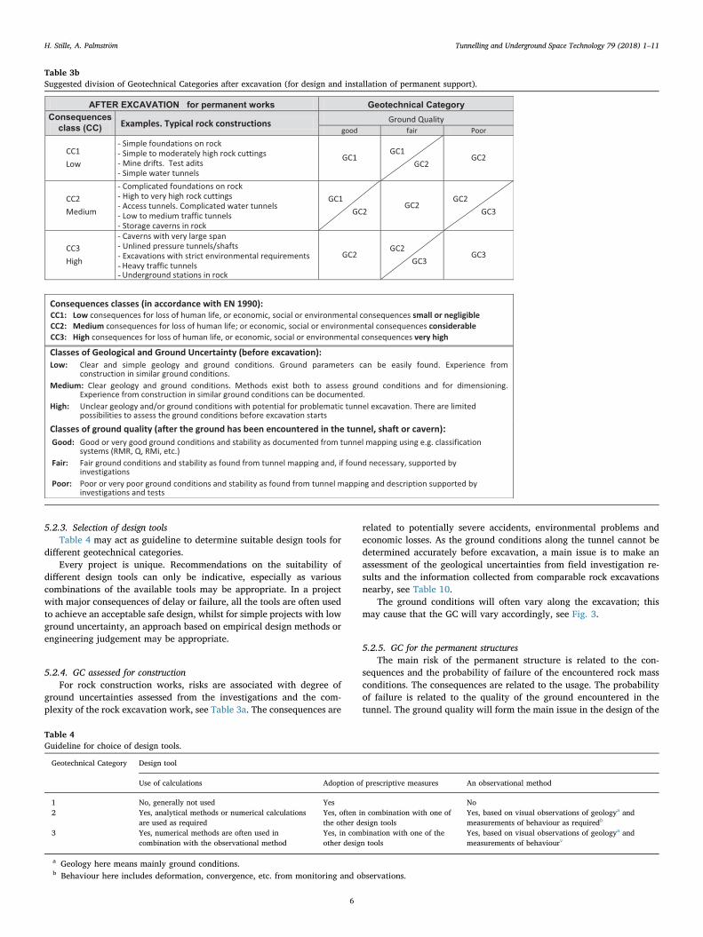
Table 3bSuggested division of Geotechnical Categories after excavation (for design and installation of permanent support).
Table 4Guideline for choice of design tools.
Geotechnical Category Design tool
Use of calculations Adoption of prescriptive measures An observational method
1 No, generally not used Yes No2 Yes, analytical methods or numerical calculations
are used as requiredYes, often in combination with one ofthe other design tools
Yes, based on visual observations of geologya andmeasurements of behaviour as requiredb
3 Yes, numerical methods are often used incombination with the observational method
Yes, in combination with one of theother design tools
Yes, based on visual observations of geologya andmeasurements of behaviourv
a Geology here means mainly ground conditions.b Behaviour here includes deformation, convergence, etc. from monitoring and observations.
H. Stille, A. Palmström Tunnelling and Underground Space Technology 79 (2018) 1–11
6
permanent support as well as in the maintenance and monitoring plans.Consequently, this is the main input in the selection of the GC, seeTable 3b. The behaviour with good ground conditions is generallysufficiently well-known. In poor ground conditions, there may be morebehaviour types present such as plastic behaviour, squeezing, swellingor ravelling, see Table 2. They all represent a higher risk of collapse.The risk for negative impact on the environment due to the usage of theexcavation will also influence on the selection of Geotechnical Cate-gory.
Ground quality mapped and measured in the excavation may becharacterized according to pre-set definitions, such as an appropriaterockmass classification system. In poor ground conditions, additionalassessments are often required.
In locations where uncertain loads may occur (such as swelling,squeezing), special investigations of the ground conditions must becarried out to allow appropriate design of the permanent support. Theselected GC will determine the method of control of the design andconstruction of the support. Additional requirements may be put on thedesign of the permanent support, especially when the economic lossesmay be significant.
6. Control and supervision
6.1. General
Control and supervision of the execution of the construction worksis carried out in order to reduce the probability or the consequences ofmistakes, and can be regarded as a part of the quality assurance. Theyare also part of the risk mitigation and should be based on the riskassessments. In this respect the quality control and supervision will berelated to the actual geotechnical category. The risks connected to bothoperation and the execution of the work is also related to the designtools used since they have different risk profiles.
In many cases it is not feasible or optimal to collect adequate in-formation of the ground conditions during the pre-investigation phase.Most underground projects must be regarded as development projectswith unknown factors, which will be discovered during the execution ofthe project. For managing the project with acceptable risk, holdingpoints have to be defined in advance, Stille et al. (1998). Such pointsare called tollgates and the contractor is not allowed to be passed beforego-ahead from the responsible.
The following types of control and supervision are essential in rockconstructions:
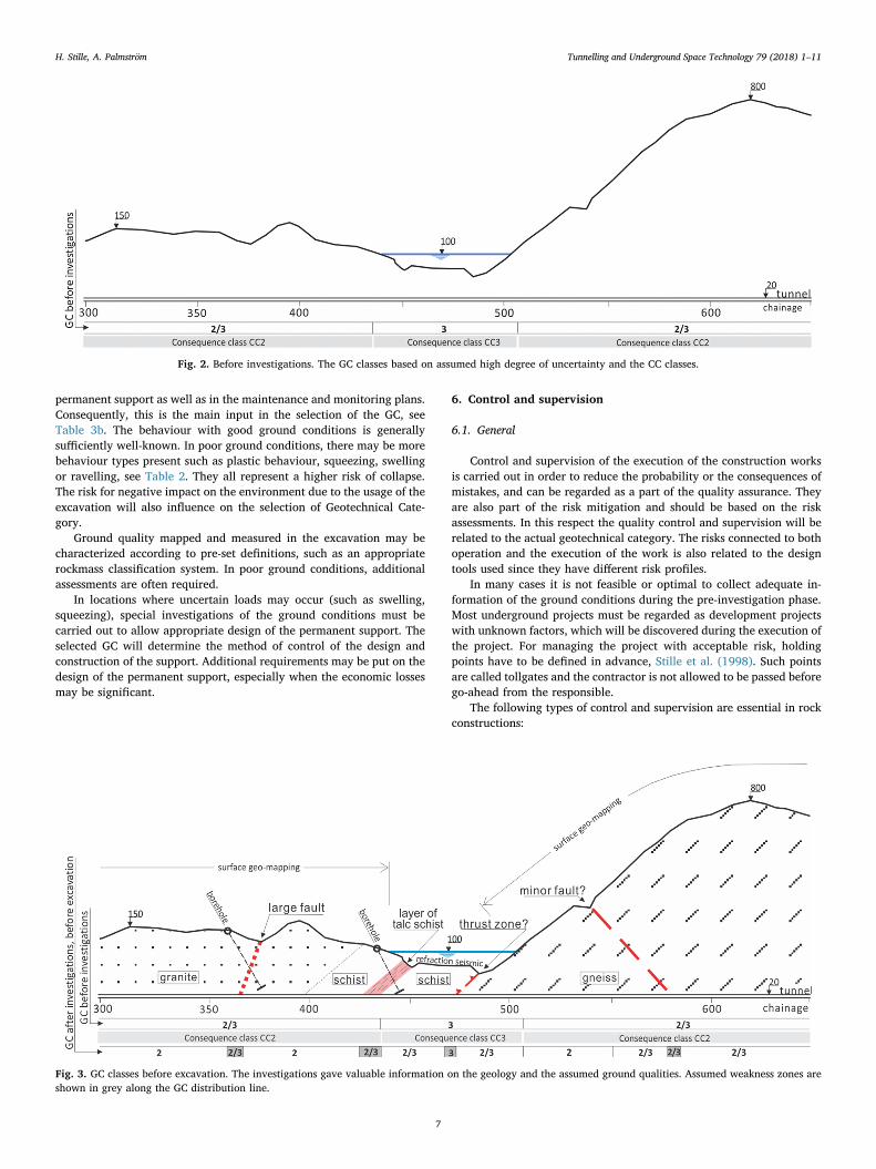
Fig. 2. Before investigations. The GC classes based on assumed high degree of uncertainty and the CC classes.
Fig. 3. GC classes before excavation. The investigations gave valuable information on the geology and the assumed ground qualities. Assumed weakness zones areshown in grey along the GC distribution line.
H. Stille, A. Palmström Tunnelling and Underground Space Technology 79 (2018) 1–11
7
(1) Quality Control (QC) of the field investigations and tests, including:
– Means, methods and results.
(2) Design supervision, including:
– QC of the basic assumption, i.e. evaluations of the basic data used, ofthe Geotechnical Category defined, and of the planned control andinspection during excavation.
– QC of the principles involved in the proposed design and the cal-culation models.
– QC of the selected dimensions including safety and economy, andthat drawings and descriptions are unambiguous and fit for purpose.
(3) Rock engineering supervision including:
– QC of selected excavation methods and plans, including workers'safety, economy and time.
(4) Inspection during excavation, including:
– Inspection and mapping of the ground conditions encountered:– Supervision of the excavation and rock supporting works– Monitoring and testing of the initial support– QC of the construction materials used
(5) QC of the permanent structure including:
– QC of the mapped ground conditions– QC of construction materials used– Monitoring and testing of the final support
(6) Monitoring during permanent use of the project, including:
– Monitoring and testing of the long-term behaviour of the groundand the permanent support
All types of quality control should follow standardized proceduresand plans and check lists. The extent of the control will depend andvary with the project stage as shown in Table 5.
6.2. Quality control of field investigation
The objective is to check that the findings and interpretations fromthe investigations are correct. This is required for both limited andnormal control, see Table 6. Extended control also require checks thatmeans and methods are adequate with respect to expected conditionsand that the uncertainties are adequately described in the field in-vestigation report.
6.3. Design and rock engineering supervision
The quality control of the design and the engineering should includeassumptions, principles and results. The control should also verify thatthe empirical input data and the models are reliable and that the re-quirements regarding stability, environmental impact and safety levelare achieved. This is mandatory for all control levels. Extended controlwill also include an independent review regarding the most critical is-sues and risks. The control level expressed as extent of control varieswith the GC classes as shown in Table 6.
At the end of planning stage, plans for the construction control andthe control of the permanent design are worked out, see Table 7. Pro-gram for inspection, monitoring, as well as principles for samplingduring excavation and construction should be described in the planningreport. The plans should be revised from the registration of informationand experience gained as the works proceed.
The control plans must also contain means and methods to be usedin the case the design is verified by the Observational Method. Designby adaption of prescriptive measures will require that the prerequisitesof the prescriptive measures are checked.
In addition, the project planning report should define possible cri-tical construction elements requiring regular control, inspections ormonitoring during operation.
6.4. Inspection during execution
The normal daily follow-up of underground works including geo-logical mapping, testing of shotcrete quality and thickness and controlof rock support installation is one part of the inspection to ensurequality Methods and frequency should depend on associated risks. Forexample, traffic tunnels and openings with public access will requiremore inspection than a water tunnel since consequences of failure arelarger and thus the required probability of failure lower for the sameacceptable risk.
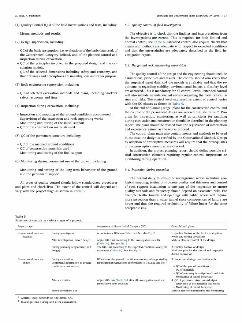
Table 5Summary of controls in various stages of a project.
Project stage Assessment of Geotechnical Category (GC) Controlsa and plans
Ground conditions areassumed
During investigation A preliminary GC class (Table 3a). See also Fig. 2 1. Quality Control of the field investigationworks and testing procedures
After investigation, before design Adjust GC class according to the investigations results(Table 3a). See also Fig. 3
Make a plan for control of the design
During planning (engineering anddesign)
The GC class according to the expected conditions along theexcavation (Table 3a). See also Fig. 3
2. Quality Control of designWork out plan for the control and inspectionduring excavation
Ground conditions areknown
During excavation.Continuous information of groundconditions encountered
GC class for the ground conditions encountered supported byresults from investigations performed (Fig. 3b). See also Fig. 4
3. Inspection during construction with:
– QC of the ground conditions– QC of materials– QC of necessary investigations2) and tests– Monitoring of tunnel behaviour.
After excavation Adjust GC class (Table 3b) after all investigations and testresults have been collected
4. QC of permanent structures (design)– upervision of the materials and works– Monitoring of tunnel behaviour
Before permanent use Make a plan for maintenance and monitoring.
a Control level depends on the actual GC.b Investigations during and after excavation.
H. Stille, A. Palmström Tunnelling and Underground Space Technology 79 (2018) 1–11
8
The extent of inspection of the rock excavation works will increasewith higher Geotechnical Category, as shown in Table 8. The focus ofthe inspection should include both stability issues of the excavation andenvironmental disturbances from the work, like noise, vibration, airpollution and changes of ground water regime.
The checking of the ground conditions should be regarded in abroad sense. It includes checks that the ground conditions are as ex-pected, either from tunnel mapping or from investigation (such aspresoundings, geophysical measurements, etc.) from the tunnel face.
Some comments on the various inspections:
• The inspection performed should be documented and signed by theperson who has done it.
• Requirements for materials and quality control of the works arenormally given in national standards other than EN 1997-1, and willbe handled by the contractor in his quality system.
• Site inspection includes functions such as recording of the groundconditions encountered during excavation (see Table 8).
• Site inspection also includes monitoring of displacements (de-formations) as well as tests of rock samples, for example from zonesof poor and weak rocks, possibly with swelling or slaking properties,or with poor durability. The outcome of the monitoring and tests isused in the assessment of ground behaviour used in the design of
permanent rock support.
6.5. Control of permanent design
The permanent construction shall be maintained so as to meet thestability requirements over time. For unlined water tunnels for ex-ample, downfall of fragments and single blocks are often accepted andlimited maintenance work is necessary. At high consequences such aswith underground space used by the public where no damage can beaccepted, regular maintenance work and inspections are required overthe lifetime of the structure.
The tunnel has to be inspected and maintained during operation.Both the rock, the rock support and the installations can deterioratewith time. Focus should be on issues related to the function of theproject, damage to the environment and risks to the public.
These risks will vary with the conditions along the tunnel. Poor andaltered rock may deteriorate faster and can give risk for tunnel collapse.Such conditions have to be monitored.
Ingress of water to tunnels and outflow from pressurized tunnelshave to be checked by long-term monitoring. This will also be part ofcontrol of the permanent design.
7. Worked example
7.1. A practical, simple method to evaluate geological uncertainty
Simple geology requires less investigation effort than complicatedgeological conditions. Simple geology can be areas with fresh, exposedcrystalline rocks in a surface created by ice erosion during theQuaternary, where the various geological features, such as faults andjoints can be easily observed on the surface. From simple surface ob-servation and aerial photographic studies, a fairly good interpretationof the geological and ground conditions can easily be provided at lowcost Table 9.
Complex geology may occur where there is a mixture of rocksnormally connected to intense faulting and folding. Large areas, alongthe tunnel or above the area of the open pit, covered by soil or loosematerials increase uncertainties of the rocks below. Other features thatcomplicate the interpretations of ground conditions can be deep surfaceweathering, areas below water or cover by urban development. The riskof encountering geological features, which have not been detected fromthe field investigations and therefore may appear unexpectedly duringthe excavation, is larger in complicated ground and where rock out-crops are not found.
The degree or class of ground condition uncertainty can be found by
Table 6The design supervision levels.
Geotechnical category Control level Control class/control of the planning (engineering and design)
GC1 Limited control Self-checkingChecking performed by the person who has prepared the task.
GC2 Normal control Checking by different persons than those originally responsible and in accordance with the procedures of the organisation.GC3 Extended control Third party checking:
Checking performed by persons from an organisation different from that which has prepared the task.
Table 7Example of quality control plans for construction.
Geotechnical category Type of controls
GC1 Site inspections, quality controls of materials according to national standards, e.g. concrete control, shotcrete control, testing of rock bolts, etc. Control ofthe works
GC2 In addition to GC1, where relevant: observations or measurements of ground properties, e.g. field investigations (stress measurements, ground waterpressure) or laboratory tests of representative samples (for strength measurements, swelling properties, quartz content, etc.)
GC3 In addition to GC2, where relevant: measurements, supervision, monitoring: e.g. convergence/displacement/deformation measurements, load cellmeasurements, rock stress measurements, etc.
Table 8The site inspections depending on Geotechnical Category.
Geotechnical category Types of control and reporting during construction
GC1 Self-inspection:Check that the site ground conditions andenvironmental disturbance are as assumed in the design.Simple, written reporting.
GC2 Check that the site ground conditions andenvironmental disturbance are as assumed in the design.Supervision by experienced persons during importantphases of the work.Monitoring of very important construction parts andwork operations.Regular, written reporting.
GC3 Control of work execution and materialsCheck that the site ground conditions andenvironmental disturbance are as assumed in the design.Continuous supervision by experienced persons.Important phases of the construction controlled by thirdparty.Monitoring and sampling for testing may be required.Regular, written reporting with a final report.
H. Stille, A. Palmström Tunnelling and Underground Space Technology 79 (2018) 1–11
9
giving ratings to certain parameters for geology, rock cover, andweathering of the rocks at the terrain surface (Table 10).
In rock excavations, there will always be some degree of un-certainty. However, more field investigations will generally lead to lessuncertainty. As shown in the example below, uncertainty may varyalong the tunnel.
7.2. Examples. The GC found at various stages of a tunnel project
The examples in Figs. 2–4 show a road tunnel with moderate rockcover (50–150m) in the first part (chainage 300–550) and high over-burden (up to 780m) in its last part. Between these two parts, there is asection where the tunnel passes beneath a lake (with undersea condi-tions)
The planned access tunnel of medium size (span=10m) will belocated in rocks of Precambrian age. Before the field investigations arecarried out, the Consequence Classes (CC) (see Table 3a) of the projectare evaluated along the tunnel, as shown in Fig. 2. Little geologicalinformation exists, but some experiences from other tunnel project insimilar geology are known. The degree of geological uncertainty beforethe start of investigations is assumed as follows (see Table 10):
• Complicated geological conditions (rating=4);
• Moderate degree of rock weathering at surface (rating=1);
• Comprehensive cover of loose materials and vegetation (rating=5);
• The rock cover of 50–200m rock overburden along the first part andup to 700m overburden along the last part (rating=1 and 4).
The sum of the ratings, Σ=11–14, places the geological uncertaintyas ‘High’, which indicates that extensive field investigations should beperformed to reduce uncertainty. The Geotechnical Categories are
shown in Fig. 2Extensive field investigations were carried out, consisting of geo-
logical, engineering geological survey, mapping, core drillings and re-fraction seismic measurements, as well as laboratory tests. From theresults the Ground Uncertainties were characterized as (see Table 10):
• The geological setting can be characterized as ‘clear’ (rating=2),except for the fault zones where the settings are assumed to becomplicated (rating= 4).
• The overall degree of rock weathering at the terrain surface has beenfound as 'moderate' (rating=1).
• The investigations have revealed that the rocks at terrain surface arepartly covered by soil and vegetation. Because drillings and refrac-tion seismic measurements (also along the bottom of the lake) havebeen carried out, the effect of loose material is assigned as ‘mod-erate’ (rating=3).
• The rock overburden of 50–150m along the first part (rating=1)and up to 780m overburden along the last part (rating=4).
From this it is found that along the first part with low to moderateoverburden, Σ=7 (medium uncertainty), with Σ=9 (high) for loca-tions with weakness zones (faults, thrust zone, talc schist zone). Alongthe section with high overburden, Σ=10 (high), with Σ=12 (high) forweakness zones.
These Uncertainty and Consequence Classes are used in selectingthe GC before excavation starts (using Table 3a). The GeotechnicalCategories found are presented in Fig. 3. Under the lake, higher GCclasses are used due to the Consequence Class for undersea conditions(CC3).
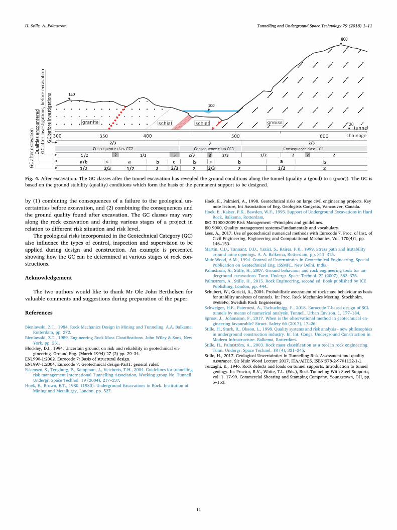
After the tunnel was excavated, the rockmass conditions wereknown from the tunnel geo-mapping. From this, the GC, according tothe ground qualities found, can be given along the tunnel (Fig. 4).
Notes:
(1) Some of the weakness zones were encountered at other locations inthe tunnel than assumed, others were not encountered.
(2) Where the Geotechnical Category is 1/2 or 2/3, the most appro-priate value 1, 2 or 3 is selected from evaluation of the site con-ditions.
8. Conclusion
The General Rules of Eurocode 7: Geotechnical Design Part 1 is notdirectly applicable in rock engineering design work. The principle canbe applied, but the special context emanating from geological un-certainties and related risks must be considered. Classification of risklevel by Geotechnical Category (GC) is usable, but has to be improved
Table 9Inspections during operation of the project.
Geotechnical category Types of inspections and reporting during operation
GC1 Inspection of the tunnel or the slope at periods of5–10 years.Simple, written reporting
GC2 Inspection of the tunnel or the slope at periods of3–5 years.Environmental control every year.Regular, written reporting.
GC3 Inspection of the tunnel or the slope at periods of1–3 years.Environmental control every year.Monitoring may be required.Regular, written reporting.
Table 10Geological uncertainty found from various geological features influencing on geological and investigation conditions (revised from Palmstrom and Stille, 2015).
Site conditions influencing on geological andground uncertainty
Division with ratings Comments
1 Geological settinga Simple Clear Complicated The distribution and composition of rocks, tectonic structures, foldings, etc.1 2 4
2 Degree of rock weathering at the terrainsurface
Minor Moderate High The degree of weathering at the rock surface, making observations andinterpretations of the rocks at tunnel/cavern level more difficult0.5 1 3
3 Area of the rock surface coveredb (by soil,lake/sea, vegetation, buildings, etc.)
None or minor Moderate Comprehensive The rock cover reduces the possibilities to forecast the rockmass conditionsunderground1 3 5
4 Rock overburden. Distance from excavationto rock surface
< 10m/10–50m
50–300m >300m Long distance from rock surface to the tunnel increases the uncertainties inforecasting the rockmass conditions. As limited (low) rock cover (< 10m) is a risk,a rating= 2 is suggested. The same rating is set to surface excavation.
2 / 0.5 1 4
Degree of geological uncertainty Sum (Σ) of the values from each topicLow: Σ < 5 Medium: Σ=5–8 High: Σ > 8
a After information from investigations.b Which has not been investigated.
H. Stille, A. Palmström Tunnelling and Underground Space Technology 79 (2018) 1–11
10
by (1) combining the consequences of a failure to the geological un-certainties before excavation, and (2) combining the consequences andthe ground quality found after excavation. The GC classes may varyalong the rock excavation and during various stages of a project inrelation to different risk situation and risk level.
The geological risks incorporated in the Geotechnical Category (GC)also influence the types of control, inspection and supervision to beapplied during design and construction. An example is presentedshowing how the GC can be determined at various stages of rock con-structions.
Acknowledgement
The two authors would like to thank Mr Ole John Berthelsen forvaluable comments and suggestions during preparation of the paper.
References
Bieniawski, Z.T., 1984. Rock Mechanics Design in Mining and Tunneling. A.A. Balkema,Rotterdam, pp. 272.
Bieniawski, Z.T., 1989. Engineering Rock Mass Classifications. John Wiley & Sons, NewYork, pp. 251.
Blockley, D.I., 1994. Uncertain ground; on risk and reliability in geotechnical en-gineering. Ground Eng. (March 1994) 27 (2) pp. 29–34.
EN1990-1:2002. Eurocode 7: Basis of structural design.EN1997-1:2004. Eurocode 7: Geotechnical design-Part1: general rules.Eskensen, S., Tengborg, P., Kampman, J., Veicherts, T.H., 2004. Guidelines for tunnelling
risk management International Tunnelling Association, Working group No. Tunnell.Undergr. Space Technol. 19 (2004), 217–237.
Hoek, E., Brown, E.T., 1980. (1980): Underground Excavations in Rock. Institution ofMining and Metallurgy, London, pp. 527.
Hoek, E., Palmieri, A., 1998. Geotechnical risks on large civil engineering projects. Keynote lecture, Int Association of Eng. Geologists Congress, Vancouver, Canada.
Hoek, E., Kaiser, P.K., Bawden, W.F., 1995. Support of Underground Excavations in HardRock. Balkema, Rotterdam.
ISO 31000:2009 Risk Management –Principles and guidelines.IS0 9000, Quality management systems-Fundamentals and vocabulary.Lees, A., 2017. Use of geotechnical numerical methods with Eurocode 7. Proc. of Inst. of
Civil Engineering. Engineering and Computational Mechanics, Vol. 170(4)1, pp.146–153.
Martin, C.D., Tannant, D.D., Yazici, S., Kaiser, P.K., 1999. Stress path and instabilityaround mine openings. A. A. Balkema, Rotterdam, pp. 311–315.
Muir Wood, A.M., 1994. Control of Uncertainties in Geotechnical Engineering, SpecialPublication on Geotechnical Eng. ISSMFE, New Delhi, India.
Palmström, A., Stille, H., 2007. Ground behaviour and rock engineering tools for un-derground excavations. Tunn. Undergr. Space Technol. 22 (2007), 363–376.
Palmstrom, A., Stille, H., 2015. Rock Engineering, second ed. Book published by ICEPublishing, London, pp. 444.
Schubert, W., Goricki, A., 2004. Probabilistic assessment of rock mass behaviour as basisfor stability analyses of tunnels. In: Proc. Rock Mechanics Meeting, Stockholm.SveBeFo, Swedish Rock Engineering.
Schweiger, H.F., Paternesi, A., Tschuchnigg, F., 2018. Eurocode 7-based design of SCLtunnels by means of numerical analysis. Tunnell. Urban Environ. 1, 177–184.
Spross, J., Johansson, F., 2017. When is the observational method in geotechnical en-gineering favourable? Struct. Safety 66 (2017), 17–26.
Stille, H., Sturk, R., Olsson, L., 1998. Quality systems and risk analysis - new philosophiesin underground construction industry. In: Int. Congr. Underground Construction inModern Infrastructure. Balkema, Rotterdam.
Stille, H., Palmström, A., 2003. Rock mass classification as a tool in rock engineering.Tunn. Undergr. Space Technol. 18 (4), 331–345.
Stille, H., 2017. Geological Uncertainties in Tunnelling-Risk Assessment and qualityAssurance, Sir Muir Wood Lecture 2017, ITA/AITES, ISBN:978-2-9701122-1-1.
Terzaghi, K., 1946. Rock defects and loads on tunnel supports. Introduction to tunnelgeology. In: Proctor, R.V., White, T.L. (Eds.), Rock Tunneling With Steel Supports,vol. 1. 17-99. Commercial Shearing and Stamping Company, Youngstown, OH, pp.5–153.
Fig. 4. After excavation. The GC classes after the tunnel excavation has revealed the ground conditions along the tunnel (quality a (good) to c (poor)). The GC isbased on the ground stability (quality) conditions which form the basis of the permanent support to be designed.
H. Stille, A. Palmström Tunnelling and Underground Space Technology 79 (2018) 1–11
11