Embed Size (px)
Citation preview
X.S. Bai TC in piston engines
Lecture 10.
Turbulent Combustion in Piston Engines
part 1
X.S. Bai TC in piston engines
Content
• Piston engines – introduction and definitions• Flow and turbulence in piston engines• Laminar and turbulent burning velocity• Combustion duration• Engine knock and compression ratio
X.S. Bai TC in piston engines
X.S. Bai TC in piston engines
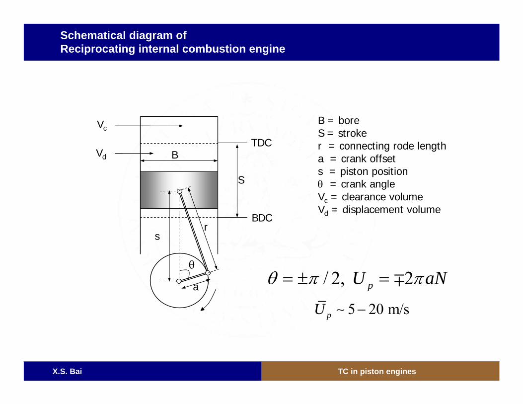
Schematical diagram of Reciprocating internal combustion engine
B = boreS = stroker = connecting rode lengtha = crank offsets = piston positionθ = crank angleVc = clearance volumeVd = displacement volume
/ 2, 2pU aNθ π π= ± = ∓5 20 m/spU −∼
a
s
B
r
S
BDC
TDC
Vc
Vd
θ
X.S. Bai TC in piston engines
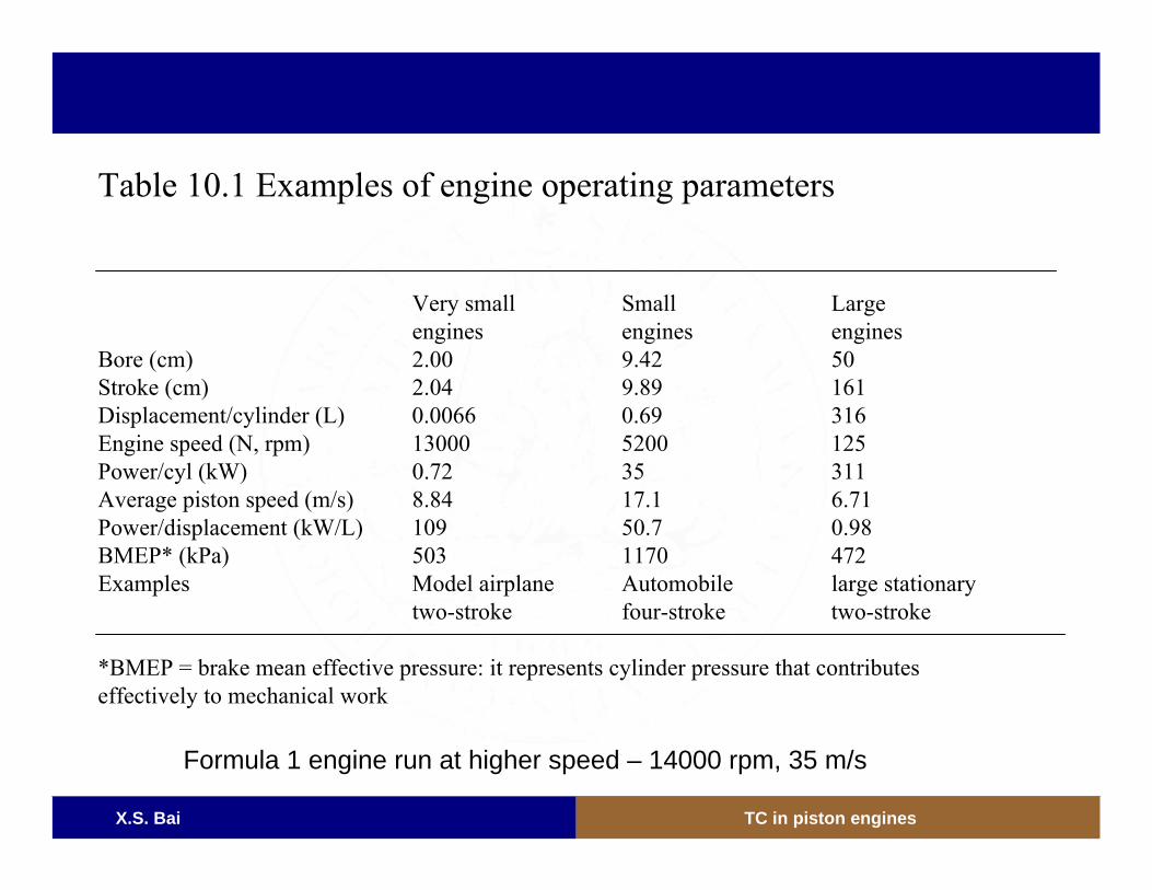
Table 10.1 Examples of engine operating parameters
Very small Small Largeengines engines engines
Bore (cm) 2.00 9.42 50Stroke (cm) 2.04 9.89 161Displacement/cylinder (L) 0.0066 0.69 316Engine speed (N, rpm) 13000 5200 125Power/cyl (kW) 0.72 35 311Average piston speed (m/s) 8.84 17.1 6.71Power/displacement (kW/L) 109 50.7 0.98BMEP* (kPa) 503 1170 472Examples Model airplane Automobile large stationary
two-stroke four-stroke two-stroke
*BMEP = brake mean effective pressure: it represents cylinder pressure that contributes effectively to mechanical work
Formula 1 engine run at higher speed – 14000 rpm, 35 m/s
X.S. Bai TC in piston engines
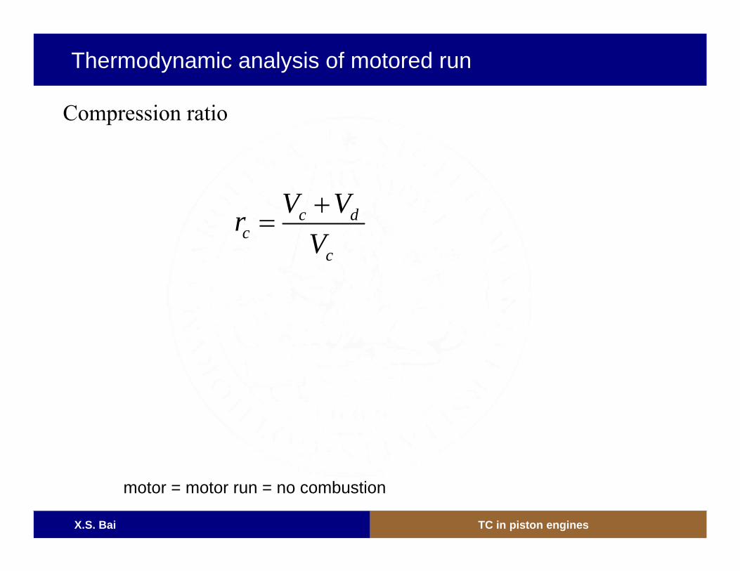
c dc
c
V VrV+
=
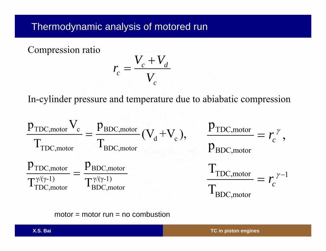
Compression ratio
Thermodynamic analysis of motored run
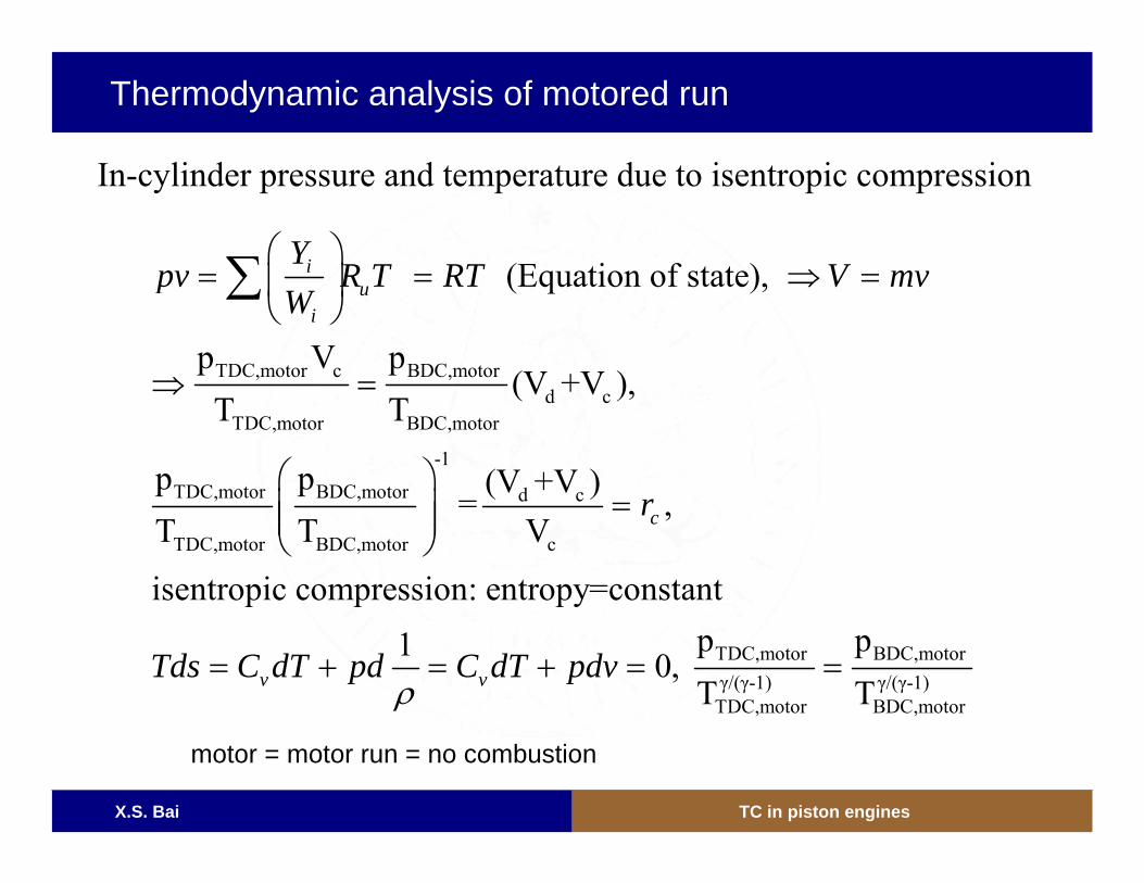
motor = motor run = no combustion
X.S. Bai TC in piston engines
TDC,motor c BDC,motord c
TDC,motor BDC,motor
-1
TDC,motor BDC,motor d c
TDC,motor BDC,motor c
(Equation of state),
p V p(V +V ),
T T
p p (V +V )= ,
T T V
isentropic compression: entropy=con
iu
i
c
Ypv R T RT V mv
W
r
⎛ ⎞= = ⇒ =⎜ ⎟
⎝ ⎠
⇒ =
⎛ ⎞=⎜ ⎟⎜ ⎟
⎝ ⎠
∑
TDC,motor BDC,motorγ/(γ-1) γ/(γ-1)TDC,motor BDC,motor
stant p p1 0, T Tv vTds C dT pd C dT pdv
ρ= + = + = =
In-cylinder pressure and temperature due to isentropic compression
Thermodynamic analysis of motored run
motor = motor run = no combustion
X.S. Bai TC in piston engines
c dc
c
V VrV+
=
TDC,motor c BDC,motord c
TDC,motor BDC,motor
TDC,motor BDC,motorγ/(γ-1) γ/(γ-1)TDC,motor BDC,motor
p V p(V +V ),
T Tp pT T
=
=
TDC,motor
BDC,motor
TDC,motor 1
BDC,motor
p,
p
TT
c
c
r
r
γ
γ −
=
=
In-cylinder pressure and temperature due to abiabatic compression
Compression ratio
Thermodynamic analysis of motored run
motor = motor run = no combustion
X.S. Bai TC in piston engines9
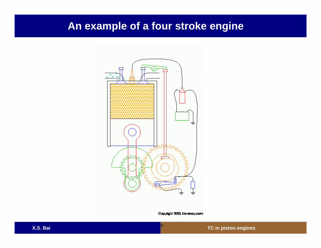
An example of a four stroke engine
X.S. Bai TC in piston engines
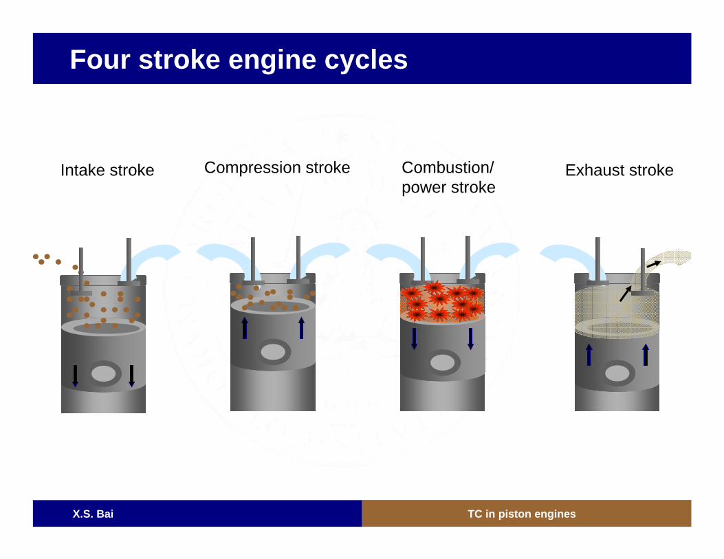
Four stroke engine cycles
Intake stroke Compression stroke Combustion/power stroke
Exhaust stroke
X.S. Bai TC in piston engines
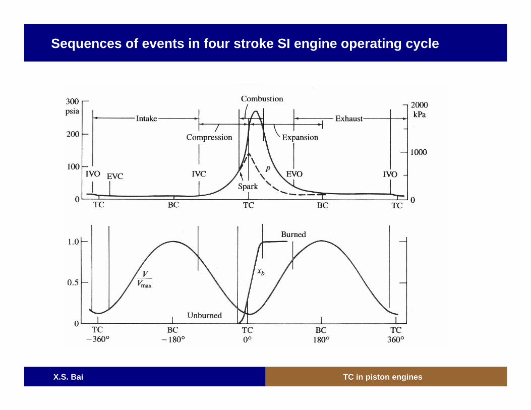
Sequences of events in four stroke SI engine operating cycle
X.S. Bai TC in piston engines
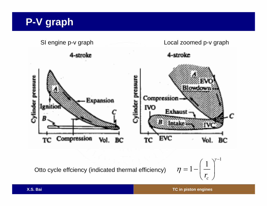
P-V graph
Otto cycle effciency (indicated thermal efficiency)
111cr
γ
η−
⎛ ⎞= − ⎜ ⎟
⎝ ⎠
SI engine p-v graph Local zoomed p-v graph
X.S. Bai TC in piston engines
Works
• Indicated work: work generated in the combustion chamber (area in the P-V graph)
– Gross indicated work: area A– Pump work: area B– Net indicated work (without supercharger): area A – area B
• Friction work
• Brake work: actual work available at the crankshaft– Brake work = indicated work – friction and parasitic work
• Mechanical efficiency: brake work/indicated work (40-90%)– lower engine speed has higher mechanical efficiency (friction)– lower engine speed has lower thermal efficiency (heat loss)
X.S. Bai TC in piston engines
Mean effective pressure (mep) and power
• Mean effective pressure = work / displacement volume– imep– fmep– bmep– pmep
• Power: rate of work of the engine– Power = work x engine speed / number of revolution per cycle– Power = (mep) x face area of all pistons x averaged piston
velocity
• Torque: force acting at a moment distance = brake work /2π– Torgue = (bmep) x dispacement distance / 2π / number of
revolution per cycle
X.S. Bai TC in piston engines
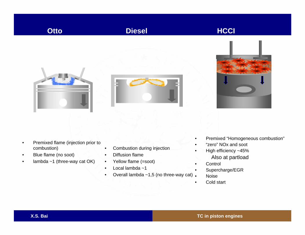
• Combustion during injection• Diffusion flame• Yellow flame (=soot)• Local lambda ~1• Overall lambda ~1,5 (no three-way cat)
• Premixed flame (injection prior to combustion)
• Blue flame (no soot)• lambda ~1 (three-way cat OK)
• Premixed “Homogeneous combustion”• “zero” NOx and soot• High efficiency ~45%
Also at partload• Control• Supercharge/EGR• Noise• Cold start
Otto Diesel HCCI
X.S. Bai TC in piston engines
SI engines

X.S. Bai TC in piston engines
Most cars run with SI engine
X.S. Bai TC in piston engines
X.S. Bai TC in piston engines
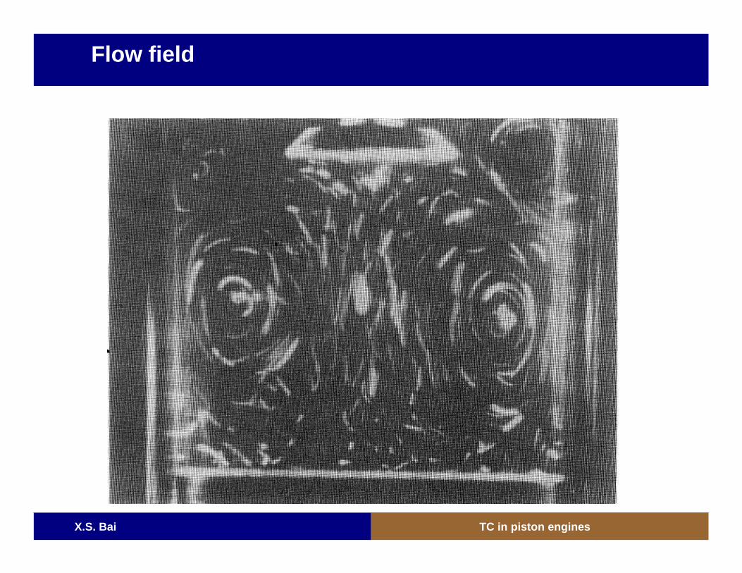
Flow field
X.S. Bai TC in piston engines
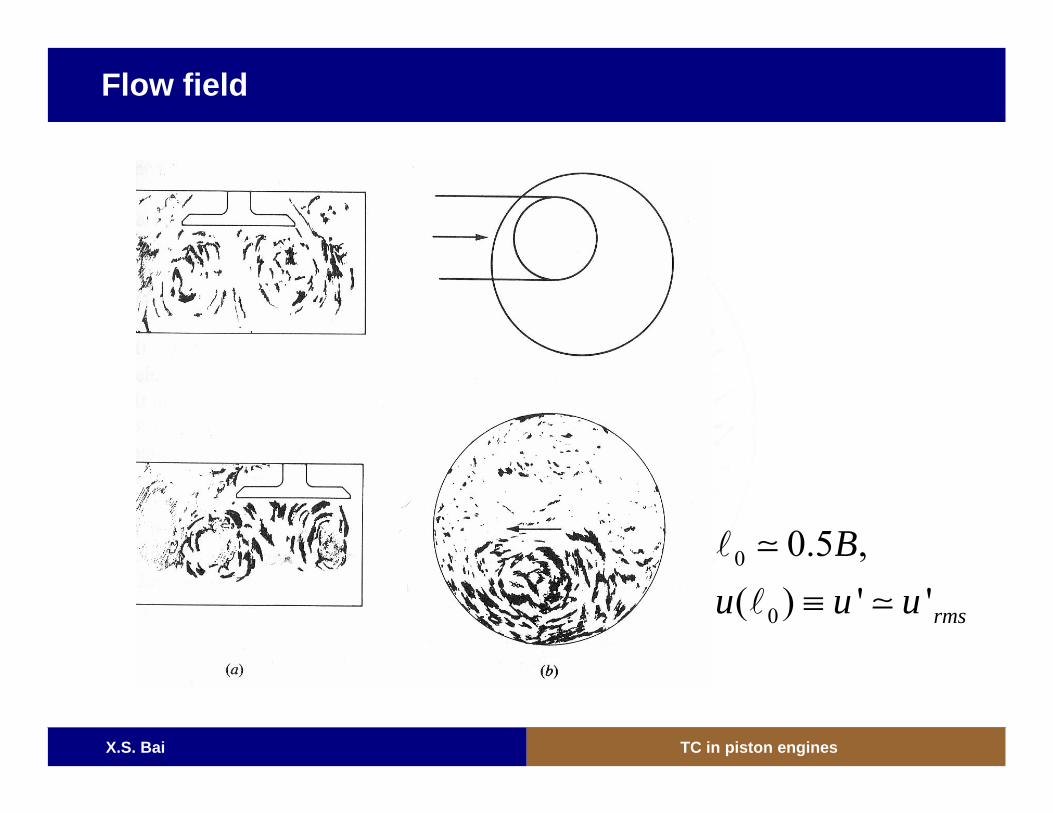
Flow field
0
0
0.5 ,( ) ' 'rms
Bu u u≡
X.S. Bai TC in piston engines
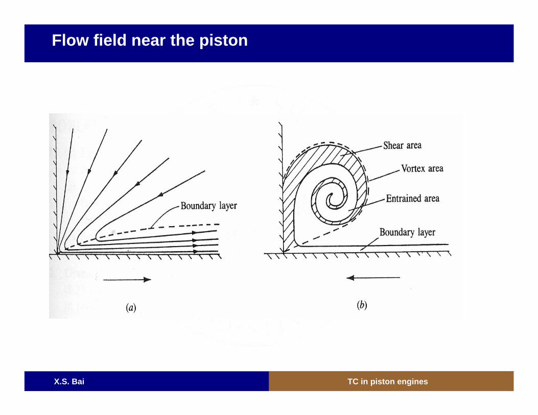
Flow field near the piston
X.S. Bai TC in piston engines
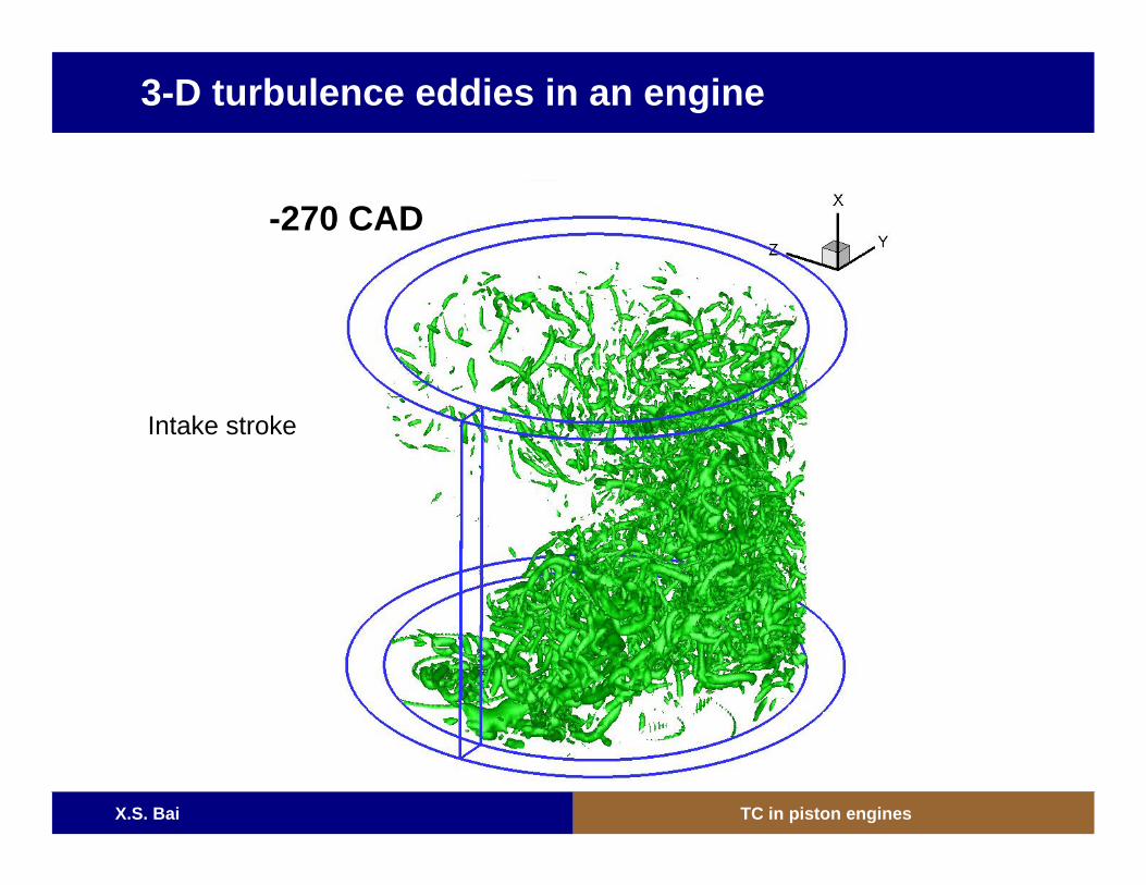
3-D turbulence eddies in an engine
-270 CAD
Intake stroke
X.S. Bai TC in piston engines
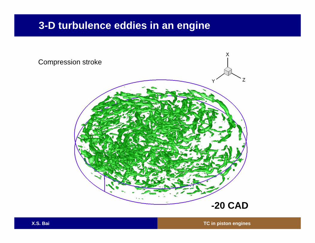
-20 CAD
3-D turbulence eddies in an engine
Compression stroke
X.S. Bai TC in piston engines
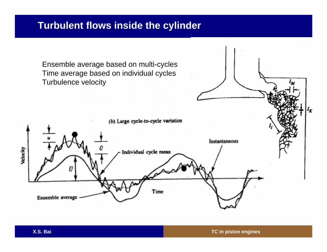
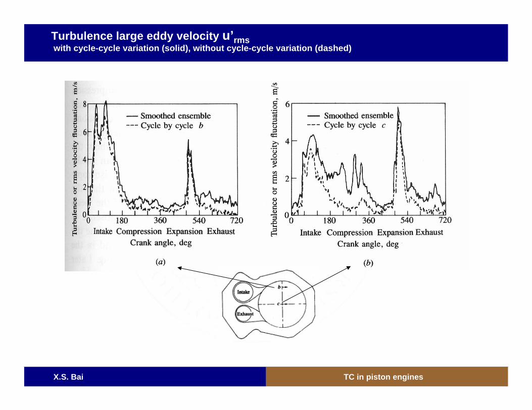
Turbulent flows inside the cylinder
Ensemble average based on multi-cyclesTime average based on individual cyclesTurbulence velocity
X.S. Bai TC in piston engines
Turbulence large eddy velocity u’rmswith cycle-cycle variation (solid), without cycle-cycle variation (dashed)
X.S. Bai TC in piston engines
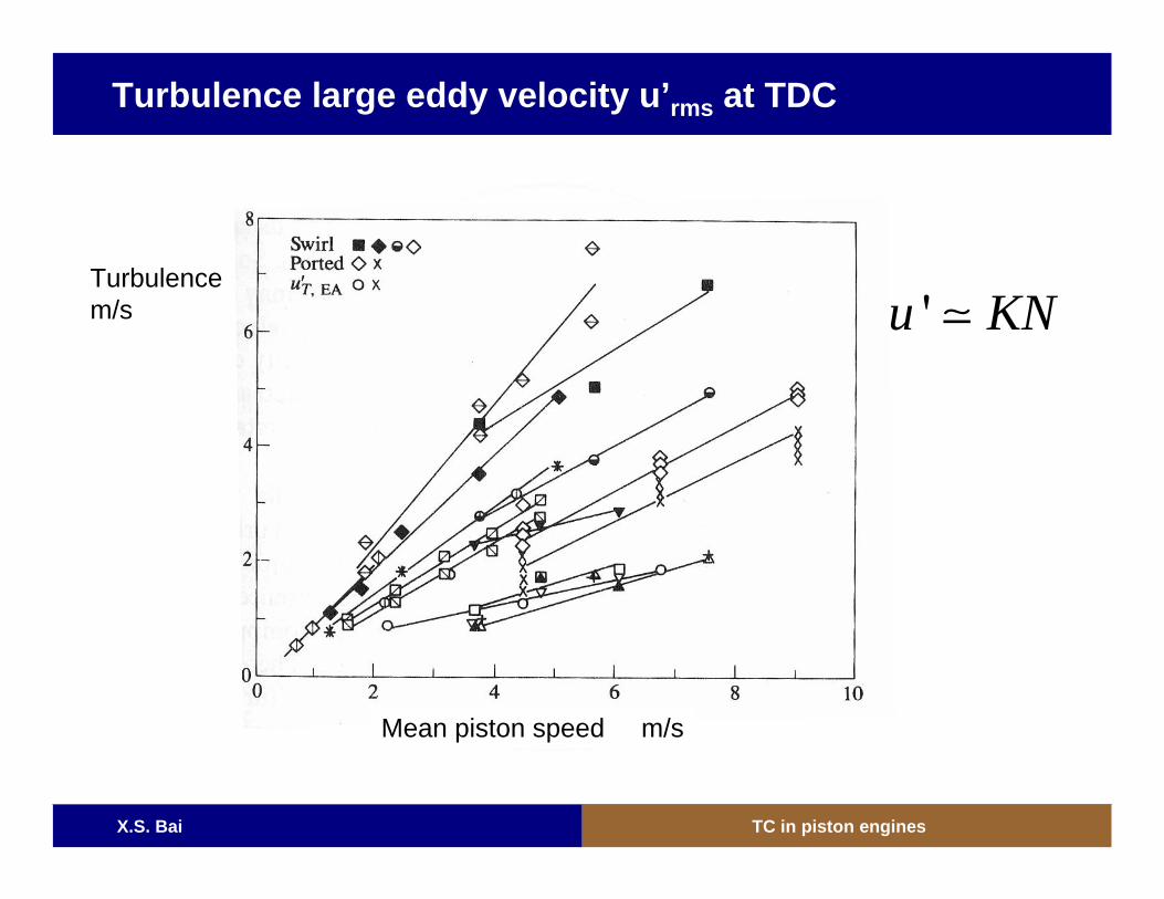
Turbulence large eddy velocity u’rms at TDC
Mean piston speed m/s
Turbulencem/s 'u KN
X.S. Bai TC in piston engines
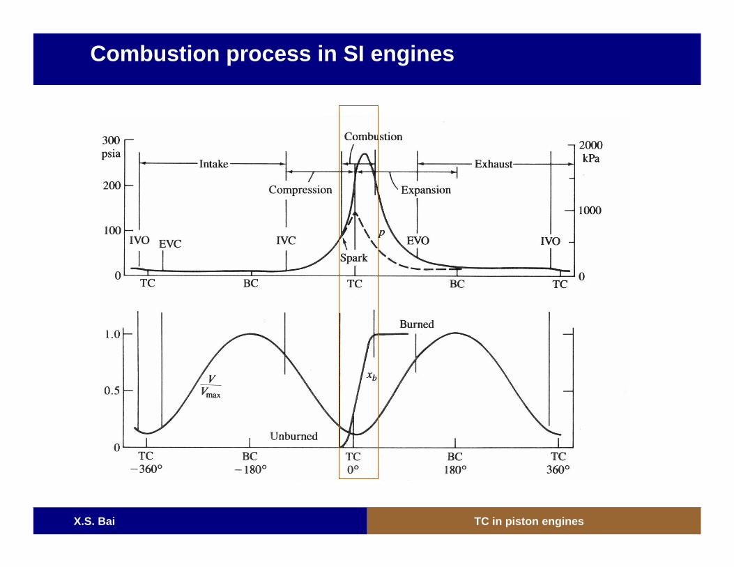
Combustion process in SI engines
X.S. Bai TC in piston engines
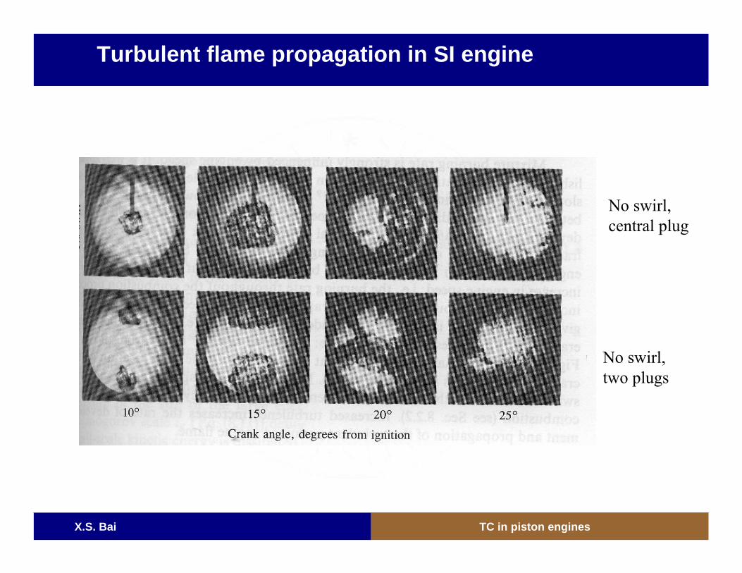
Turbulent flame propagation in SI engine
No swirl, central plug
No swirl, two plugs
X.S. Bai TC in piston engines
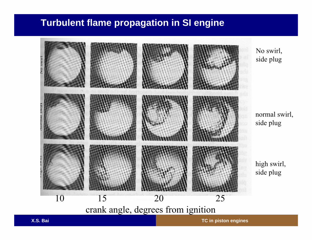
Turbulent flame propagation in SI engine
No swirl, side plug
normal swirl, side plug
10 15 20 25crank angle, degrees from ignition
high swirl, side plug
X.S. Bai TC in piston engines
X.S. Bai TC in piston engines
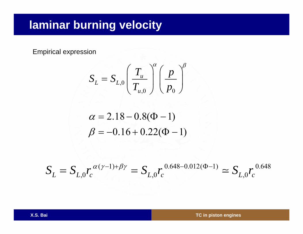
laminar burning velocity
,0,0 0
uL L
u
T pS ST p
α β⎛ ⎞ ⎛ ⎞= ⎜ ⎟ ⎜ ⎟
⎝ ⎠⎝ ⎠
2.18 0.8( 1)0.16 0.22( 1)
αβ= − Φ −= − + Φ −
( 1) 0.648 0.012( 1) 0.648,0 ,0 ,0L L c L c L cS S r S r S rα γ βγ− + − Φ−= =
Empirical expression
X.S. Bai TC in piston engines
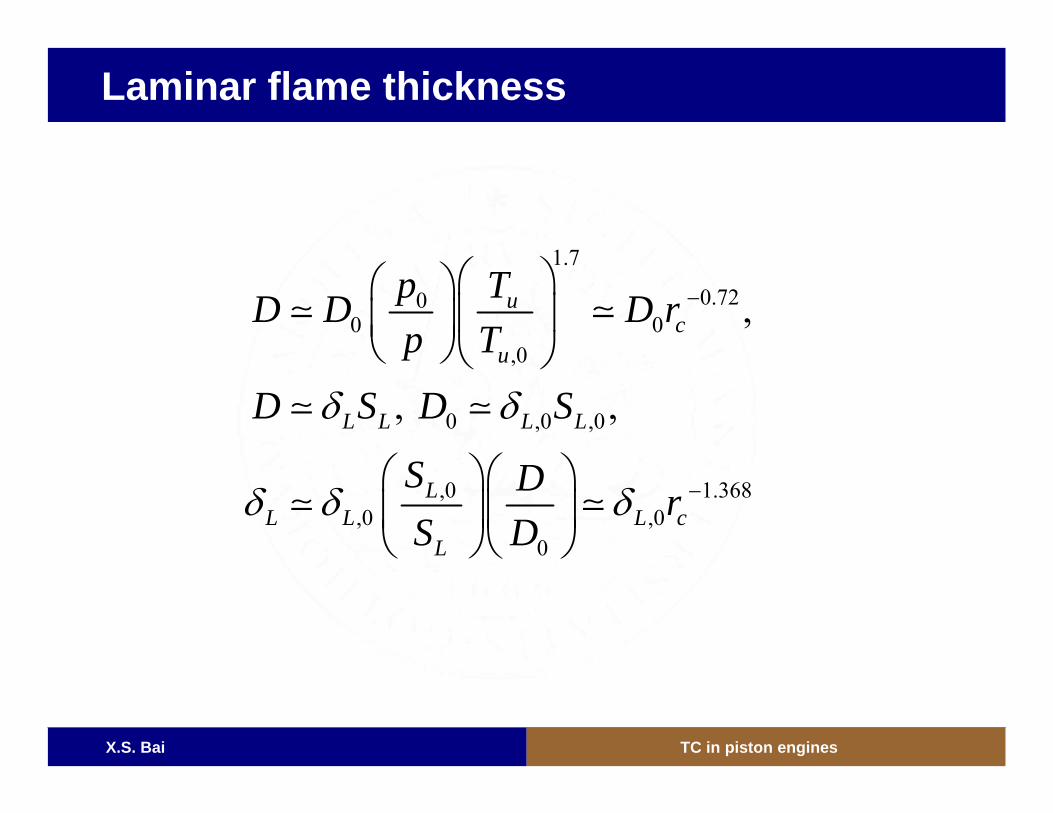
Laminar flame thickness
1.7
0.7200 0
,0
0 ,0 ,0
,0 1.368,0 ,0
0
,
, ,
uc
u
L L L L
LL L L c
L
p TD D D rp T
D S D S
S D rS D
δ δ
δ δ δ
−
−
⎛ ⎞⎛ ⎞⎜ ⎟⎜ ⎟
⎝ ⎠⎝ ⎠
⎛ ⎞⎛ ⎞⎜ ⎟⎜ ⎟
⎝ ⎠⎝ ⎠
X.S. Bai TC in piston engines
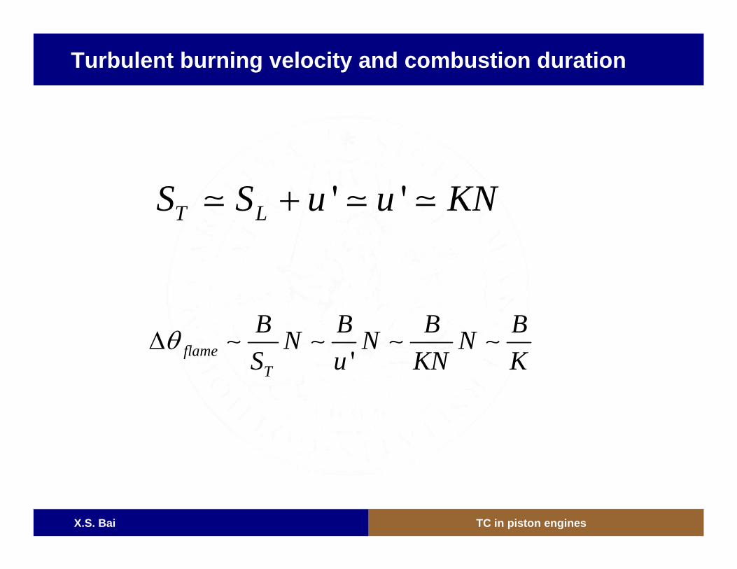
Turbulent burning velocity and combustion duration
' 'T LS S u u KN+
'flameT
B B B BN N NS u KN K
θΔ ∼ ∼ ∼ ∼
X.S. Bai TC in piston engines
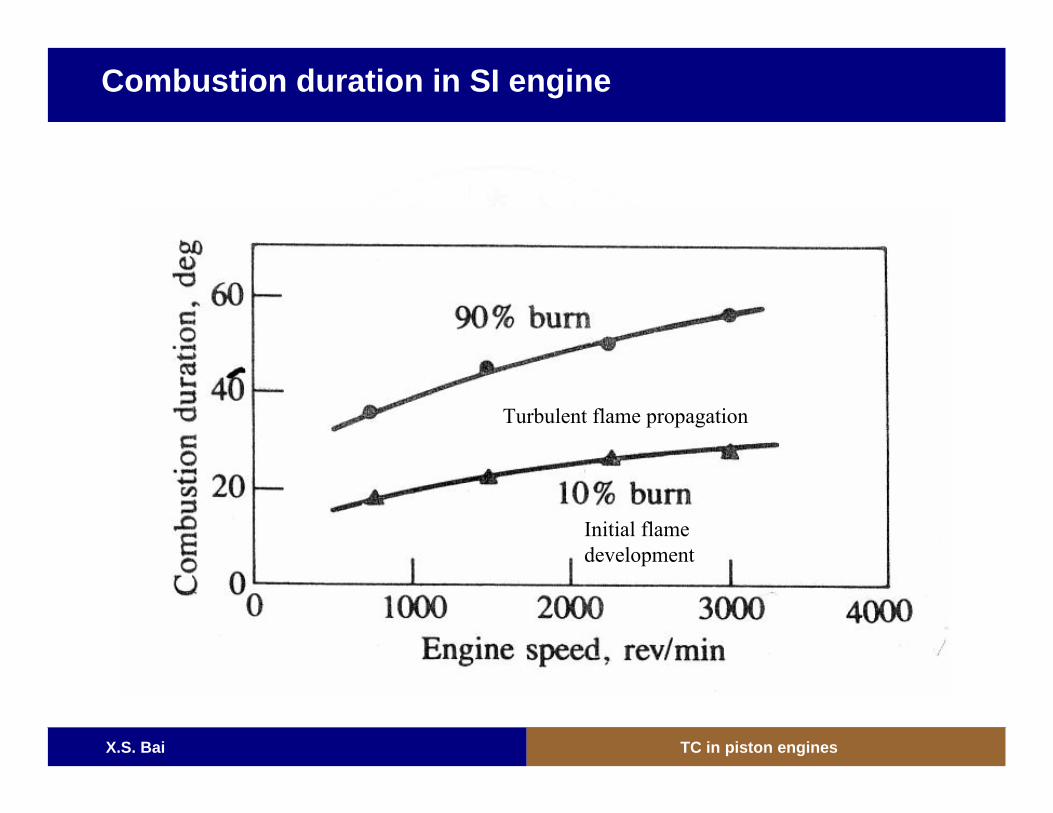
Combustion duration in SI engine
Initial flamedevelopment
Turbulent flame propagation
X.S. Bai TC in piston engines
Combustion stages
• Ignition stage: spark ignition needs to last a short time to initiate the flame propagation. The flame kernel initially is very small. The small kernel is not highly wrinkled by turbulence. The propagation speed of the small flame kernel is low.
• Turbulent flame propagation stage: As the flame kernel grows theflame surface area becomes also more wrinkled. The flame propagation speed is much higher than the laminar flame speed. The higher the turbulence level the faster the turbulent flame speed. This makes the combustion duration in terms of crank angle degrees roughly the same at different engine speed.
• Burning in the post flame zones: If the engine runs at very highspeed, the combustion intermediates such as CO may not fully burned at the flame front. Since the engine is at very high pressure and temperature, these intermediate can be further oxidized later before the exhaust gas is released.
X.S. Bai TC in piston engines
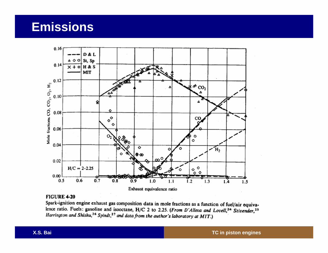
Emissions
X.S. Bai TC in piston engines
Compression ratio in SI engines
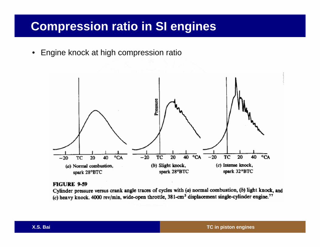
• Engine knock at high compression ratio
X.S. Bai TC in piston engines
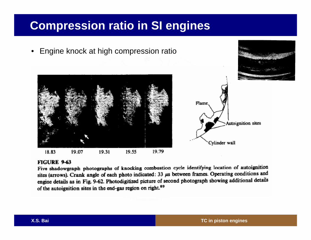
Compression ratio in SI engines
• Engine knock at high compression ratio
X.S. Bai TC in piston engines
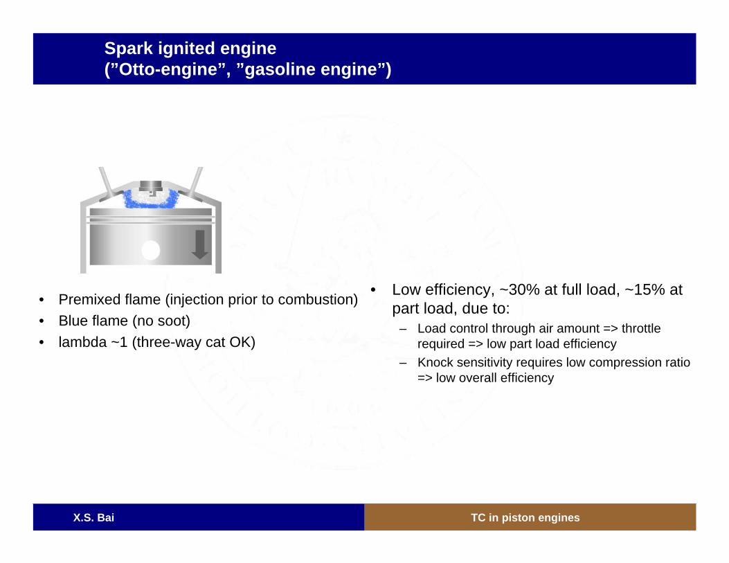
Spark ignited engine(”Otto-engine”, ”gasoline engine”)
• Premixed flame (injection prior to combustion)• Blue flame (no soot)• lambda ~1 (three-way cat OK)
• Low efficiency, ~30% at full load, ~15% at part load, due to:
– Load control through air amount => throttlerequired => low part load efficiency
– Knock sensitivity requires low compression ratio=> low overall efficiency