Embed Size (px)
DESCRIPTION
Transformer fault
Citation preview

SENSITIVE TURN-TO-TURN FAULT PROTECTION
FOR POWER TRANSFORMERS
Zoran Gajić*, Ivo Brnčić, Birger Hillström Fahrudin Mekić Igor Ivanković ABB, Sweden ABBInc. HEP, Croatia 1. INTRODUCTION
Three most typical weaknesses of the electro-mechanical and solid-state power transformer differential relays have been:
1. Long operating time in case of heavy internal faults followed by main CT saturation
2. Unwanted operations for external faults and transformer inrush
3. Bad sensitivity for low-level internal faults, such as winding turn-to-turn faults
With the introduction of the numerical technology the first two problems could be handled in much better way [4]. However sensitivity for internal winding turn-to-turn faults did not improve much. This paper introduces the new protection principle, which will improve differential relay sensitivity for minor internal turn-to-turn faults. However, the first two challenges are as well efficiently removed by applying the solution described in the paper.
A short circuit of a few turns of the winding will give rise to a heavy fault current in the short-circuited turns, but changes in the transformer terminal currents will be very small, because of the high ratio of transformation between the whole winding and the short-circuited turns. For that reason, the traditional transformer differential protection was typically not sensitive enough to detect such winding turn-to-turn faults before they developed into more serious and costly to repair ground-faults. Alternatively, such faults can be as well detected by Sudden Pressure Relay relays. However, these relays detect such low-level faults with a delay typically 50 ms – 100 ms that often allows the fault to evolve into a more serious one.
The new protection principle is based on the theory of symmetrical components [1] and [2], or more exact, on the negative-sequence currents. The very existence of relatively high negative-sequence currents is in itself an indication of a disturbance, as the negative sequence currents are superimposed, pure-fault quantities. The negative-sequence quantities are particularly suitable for different kinds of directional tests. For specific applications they seem to be superior to the zero-sequence quantities, which so far have been more extensively used, mostly due to the fact that they were easy to measure.
The new protection principle yields a very sensitive protection for low-level turn-to-turn faults. All such faults, which involve around 1% short-circuited turns, can be detected. This low value is limited downwards only by an eventual small amount of the false, “steady-state” negative-sequence currents. The new negative-sequence-current-based sensitive protection is a good complement to the traditional power transformer differential protection, which is based on the well-known bias–differential characteristic. The paper presents the principle of this new protection, and concludes with a case study.
2. PROBLEM STATEMENT
A study of the records of modern transformer breakdowns, which occurred over a period of years, showed that between 70% and 80% of the total number of transformer failures are eventually traced to internal winding insulation failure. If not quickly detected, these turn-to-turn faults usually develop into more serious and costly to repair ground-faults involving power transformer iron core. Alternatively they cause arcing within the power transformer tank, which creates a lot of damage until it is tripped by Sudden Pressure Relay.
These winding faults are mostly a result of the degradation of the insulation system due to thermal, electrical, and mechanical stress, moisture, and so on [8]. Degradation means reduced insulation quality, which will eventually cause a breakdown in the insulation, either leads to adjacent winding turns being shorted (turn-to-turn short circuit fault), or directly to a winding being shorted to the ground (winding to ground failure). Most often the insulation undergoes a gradual aging process before such a fault happens. Ageing of the insulation reduces both the mechanical and dielectric-withstand strength. Under external fault conditions, power transformer windings are temporarily subjected to high radial and compressive forces. As the load increases with system growth, the operating stresses increase. In an ageing transformer the conductor insulation is weakened to the point where it can no longer sustain much additional stress. Under increased stress, for example due to some external fault, insulation between adjacent turns suffers a dielectric failure and a turn-to-turn fault develops.
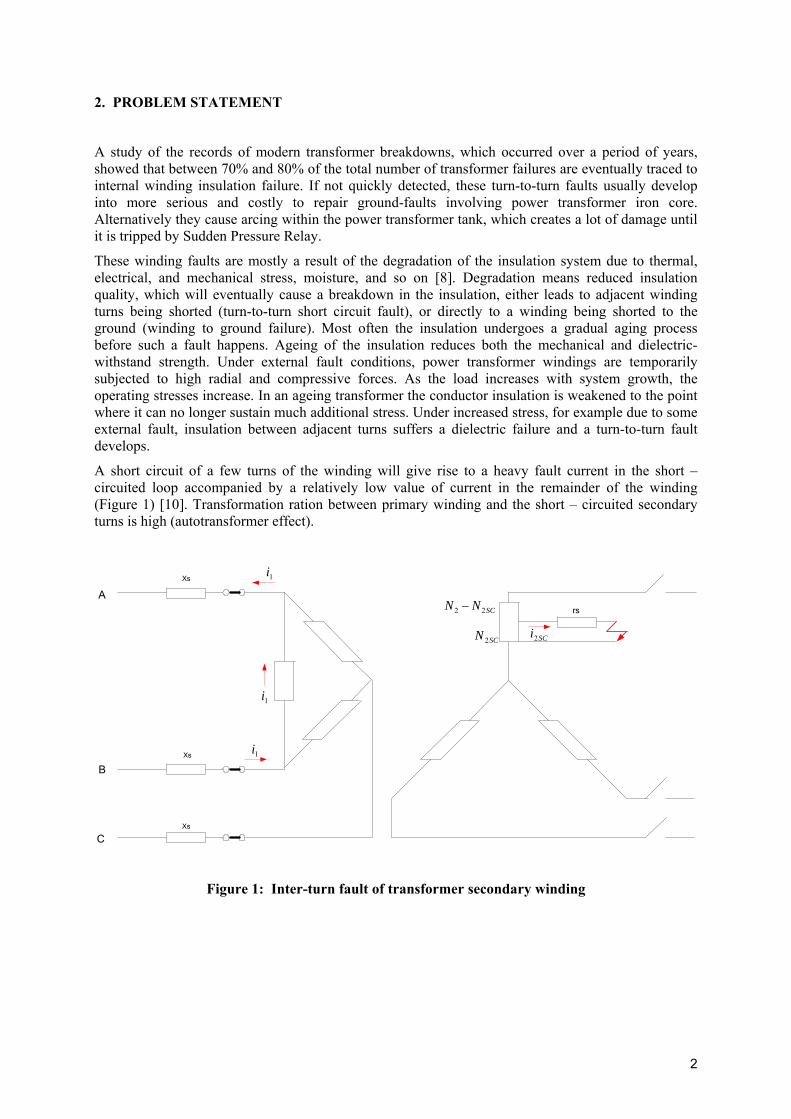
A short circuit of a few turns of the winding will give rise to a heavy fault current in the short – circuited loop accompanied by a relatively low value of current in the remainder of the winding (Figure 1) [10]. Transformation ration between primary winding and the short – circuited secondary turns is high (autotransformer effect).
Xs
Xs
Xs
A
B
C
rs
SCi2
SCNN 22 −
SCN 2
1i
1i
1i
Figure 1: Inter-turn fault of transformer secondary winding
2
1i
SCi2
15
0
Cur
rent
in p
.u. o
f tra
nsfo
rmer
rate
d cu
rrent
%100*)(2
2
NNX SC=0 100
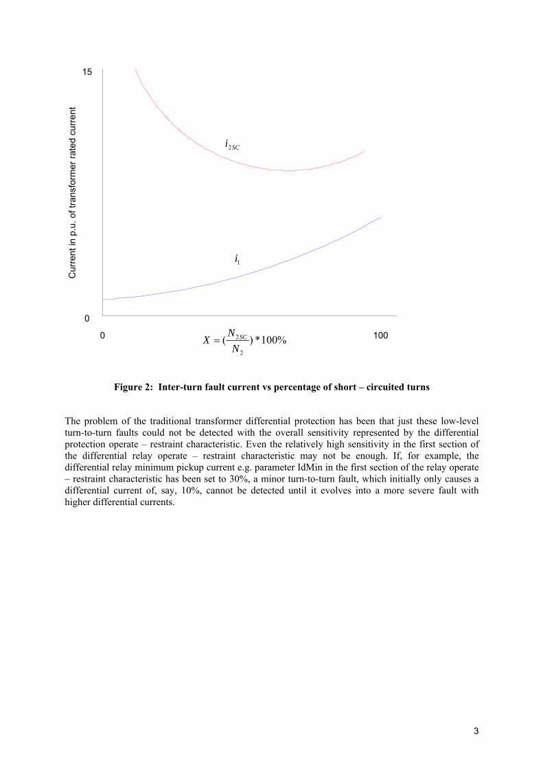
Figure 2: Inter-turn fault current vs percentage of short – circuited turns
The problem of the traditional transformer differential protection has been that just these low-level turn-to-turn faults could not be detected with the overall sensitivity represented by the differential protection operate – restraint characteristic. Even the relatively high sensitivity in the first section of the differential relay operate – restraint characteristic may not be enough. If, for example, the differential relay minimum pickup current e.g. parameter IdMin in the first section of the relay operate – restraint characteristic has been set to 30%, a minor turn-to-turn fault, which initially only causes a differential current of, say, 10%, cannot be detected until it evolves into a more severe fault with higher differential currents.
3
kVE s 1151 1 =kVE s 1151 2 =
Ω∠=
Ω∠=0
1
01
802.130
802.131
s
s
Z
ZΩ∠=
Ω∠=0
2
02
808.190
802.131
s
s
Z
Z
Ω∠= 08894.71TRZWye Wye
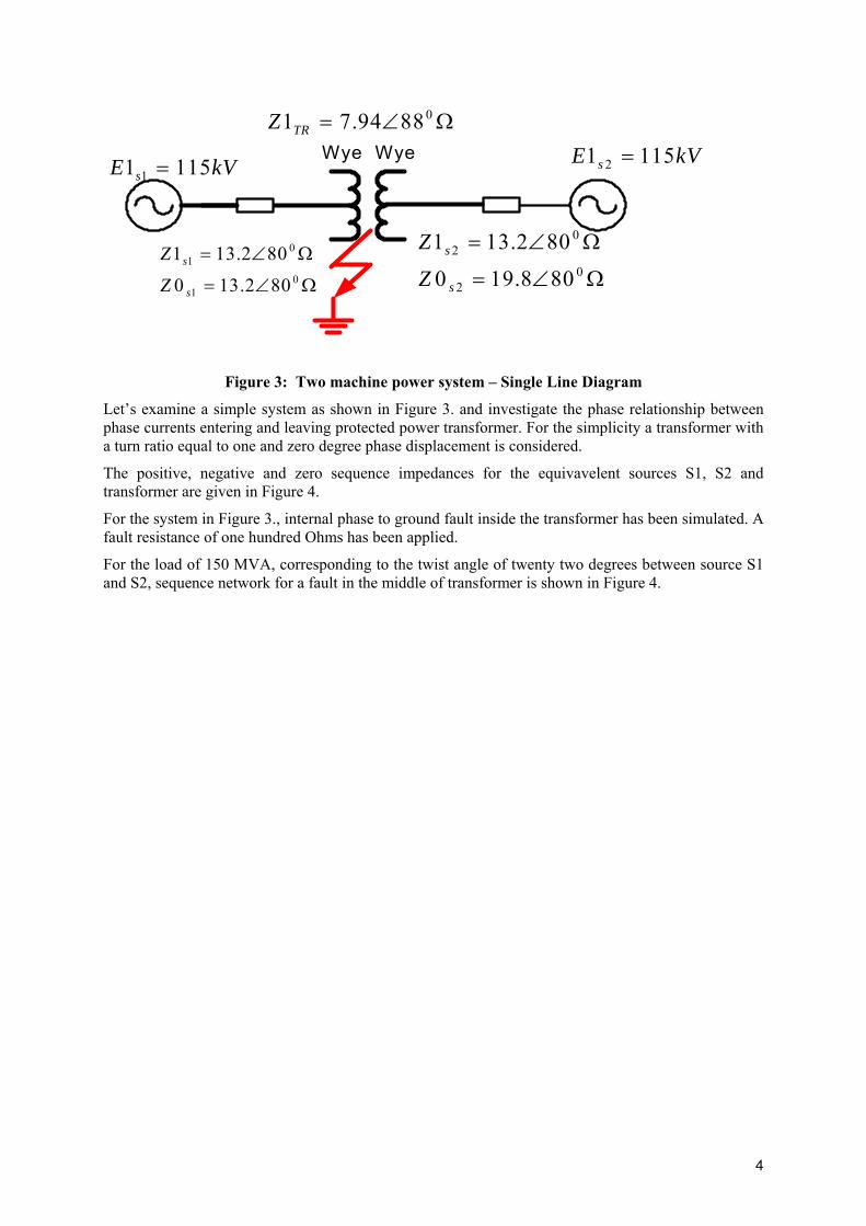
Figure 3: Two machine power system – Single Line Diagram
Let’s examine a simple system as shown in Figure 3. and investigate the phase relationship between phase currents entering and leaving protected power transformer. For the simplicity a transformer with a turn ratio equal to one and zero degree phase displacement is considered.
The positive, negative and zero sequence impedances for the equivavelent sources S1, S2 and transformer are given in Figure 4.
For the system in Figure 3., internal phase to ground fault inside the transformer has been simulated. A fault resistance of one hundred Ohms has been applied.
For the load of 150 MVA, corresponding to the twist angle of twenty two degrees between source S1 and S2, sequence network for a fault in the middle of transformer is shown in Figure 4.
4
01 4.22661 ∠= kVE s
02 0661 ∠= kVE S
Ω= 3003R
802.13 ∠
802.13 ∠
802.13 ∠
802.13 ∠
802.13 ∠ 808.19 ∠
8897.3 ∠8897.3 ∠
8897.3 ∠8897.3 ∠
8897.3 ∠8897.3 ∠
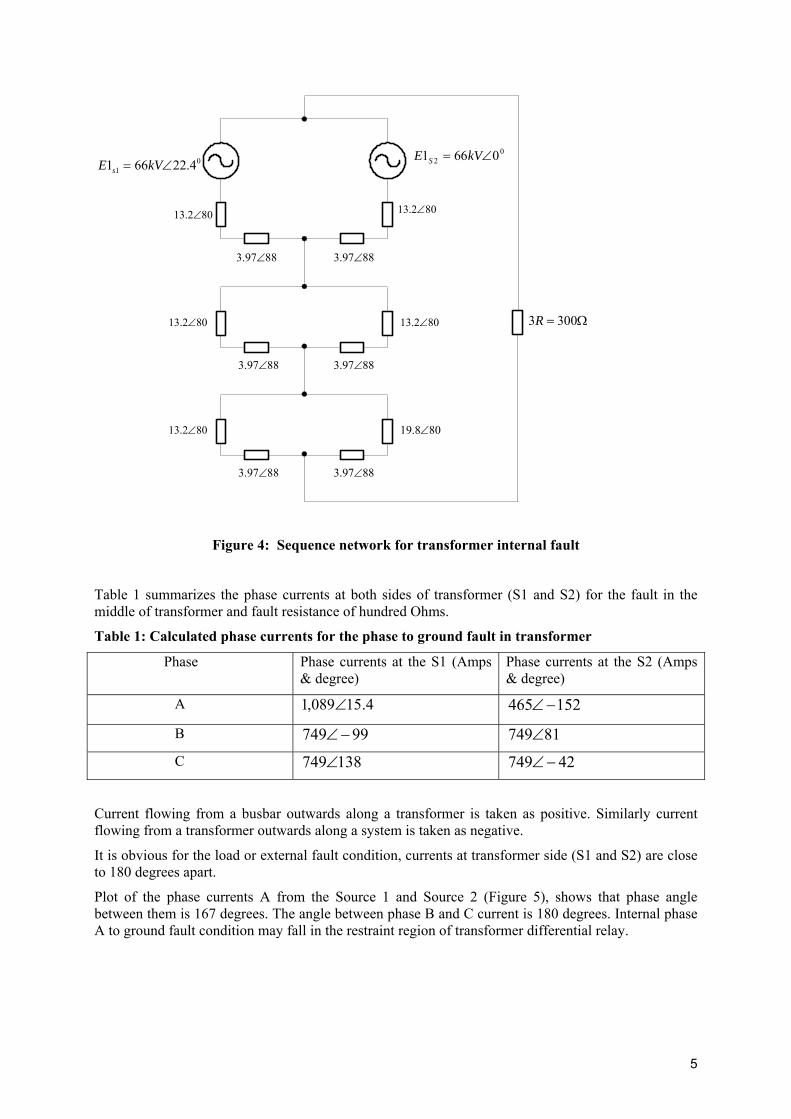
Figure 4: Sequence network for transformer internal fault
Table 1 summarizes the phase currents at both sides of transformer (S1 and S2) for the fault in the middle of transformer and fault resistance of hundred Ohms.
Table 1: Calculated phase currents for the phase to ground fault in transformer
Phase Phase currents at the S1 (Amps & degree)
Phase currents at the S2 (Amps & degree)
A 4.15089,1 ∠ 152465 −∠
B 99749 −∠ 81749∠
C 138749∠ 42749 −∠
Current flowing from a busbar outwards along a transformer is taken as positive. Similarly current flowing from a transformer outwards along a system is taken as negative.
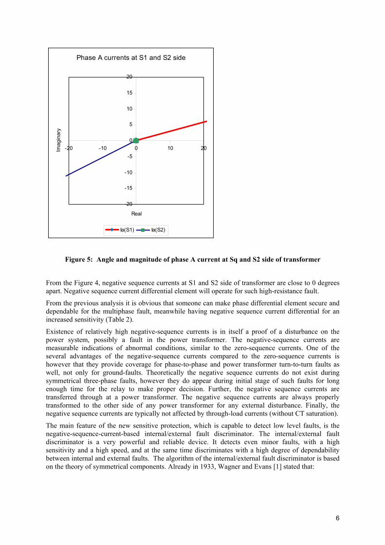
It is obvious for the load or external fault condition, currents at transformer side (S1 and S2) are close to 180 degrees apart.
Plot of the phase currents A from the Source 1 and Source 2 (Figure 5), shows that phase angle between them is 167 degrees. The angle between phase B and C current is 180 degrees. Internal phase A to ground fault condition may fall in the restraint region of transformer differential relay.
5
Phase A currents at S1 and S2 side
-20
-15
-10
-5
0
5
10
15
20
-20 -10 0 10 20
Real
Imag
inar
y
Ia(S1) Ia(S2)
Figure 5: Angle and magnitude of phase A current at Sq and S2 side of transformer
From the Figure 4, negative sequence currents at S1 and S2 side of transformer are close to 0 degrees apart. Negative sequence current differential element will operate for such high-resistance fault.
From the previous analysis it is obvious that someone can make phase differential element secure and dependable for the multiphase fault, meanwhile having negative sequence current differential for an increased sensitivity (Table 2).
Existence of relatively high negative-sequence currents is in itself a proof of a disturbance on the power system, possibly a fault in the power transformer. The negative-sequence currents are measurable indications of abnormal conditions, similar to the zero-sequence currents. One of the several advantages of the negative-sequence currents compared to the zero-sequence currents is however that they provide coverage for phase-to-phase and power transformer turn-to-turn faults as well, not only for ground-faults. Theoretically the negative sequence currents do not exist during symmetrical three-phase faults, however they do appear during initial stage of such faults for long enough time for the relay to make proper decision. Further, the negative sequence currents are transferred through at a power transformer. The negative sequence currents are always properly transformed to the other side of any power transformer for any external disturbance. Finally, the negative sequence currents are typically not affected by through-load currents (without CT saturation).
The main feature of the new sensitive protection, which is capable to detect low level faults, is the negative-sequence-current-based internal/external fault discriminator. The internal/external fault discriminator is a very powerful and reliable device. It detects even minor faults, with a high sensitivity and a high speed, and at the same time discriminates with a high degree of dependability between internal and external faults. The algorithm of the internal/external fault discriminator is based on the theory of symmetrical components. Already in 1933, Wagner and Evans [1] stated that:
6
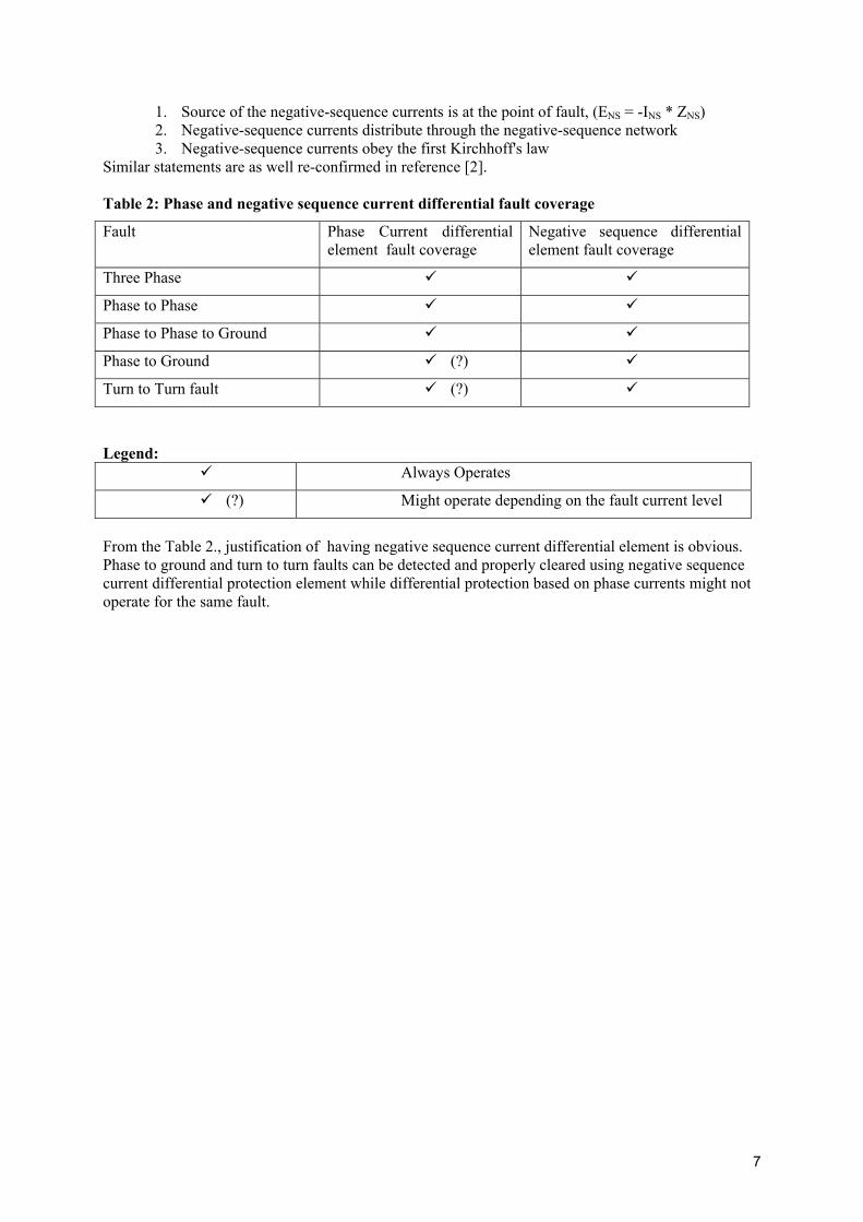
1. Source of the negative-sequence currents is at the point of fault, (ENS = -INS * ZNS) 2. Negative-sequence currents distribute through the negative-sequence network 3. Negative-sequence currents obey the first Kirchhoff's law
Similar statements are as well re-confirmed in reference [2]. Table 2: Phase and negative sequence current differential fault coverage
Fault Phase Current differential element fault coverage
Negative sequence differential element fault coverage
Three Phase
Phase to Phase
Phase to Phase to Ground
Phase to Ground (?)
Turn to Turn fault (?)
Legend:
Always Operates
(?) Might operate depending on the fault current level
From the Table 2., justification of having negative sequence current differential element is obvious. Phase to ground and turn to turn faults can be detected and properly cleared using negative sequence current differential protection element while differential protection based on phase currents might not operate for the same fault.
7
3. PRINCIPLES OF THE NEW SENSITIVE DIFFERENTIAL PROTECTION
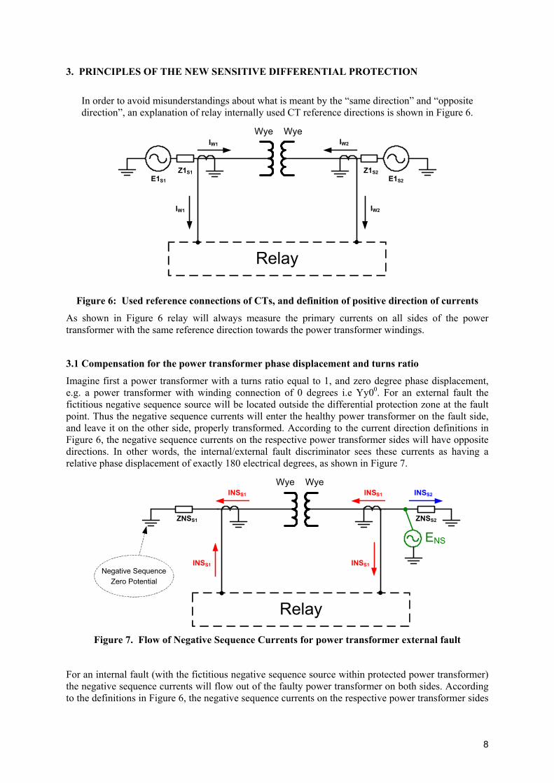
In order to avoid misunderstandings about what is meant by the “same direction” and “opposite direction”, an explanation of relay internally used CT reference directions is shown in Figure 6.
Relay
E1S1
Z1S1E1S2
Z1S2
IW1 IW2
IW1 IW2
Wye Wye
Figure 6: Used reference connections of CTs, and definition of positive direction of currents
As shown in Figure 6 relay will always measure the primary currents on all sides of the power transformer with the same reference direction towards the power transformer windings.
3.1 Compensation for the power transformer phase displacement and turns ratio
Imagine first a power transformer with a turns ratio equal to 1, and zero degree phase displacement, e.g. a power transformer with winding connection of 0 degrees i.e Yy00. For an external fault the fictitious negative sequence source will be located outside the differential protection zone at the fault point. Thus the negative sequence currents will enter the healthy power transformer on the fault side, and leave it on the other side, properly transformed. According to the current direction definitions in Figure 6, the negative sequence currents on the respective power transformer sides will have opposite directions. In other words, the internal/external fault discriminator sees these currents as having a relative phase displacement of exactly 180 electrical degrees, as shown in Figure 7.
Relay
ENS
ZNSS1 ZNSS2
INSS1 INSS1
INSS1 INSS1
INSS2
Negative Sequence Zero Potential
Wye Wye
Figure 7. Flow of Negative Sequence Currents for power transformer external fault
For an internal fault (with the fictitious negative sequence source within protected power transformer) the negative sequence currents will flow out of the faulty power transformer on both sides. According to the definitions in Figure 6, the negative sequence currents on the respective power transformer sides
8
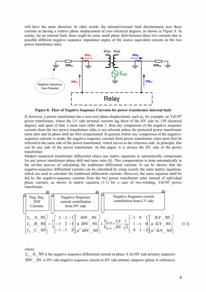
will have the same direction. In other words, the internal/external fault discriminator sees these currents as having a relative phase displacement of zero electrical degrees, as shown in Figure 8. In reality, for an internal fault, there might be some small phase shift between these two currents due to possible different negative sequence impedance angles of the source equivalent circuits on the two power transformer sides.
Relay
ENS
ZNSS1 ZNSS2
INSS2INSS1
INSS1 INSS2Negative Sequence
Zero Potential
Wye Wye
Figure 8. Flow of Negative Sequence Currents for power transformer internal fault
If, however, a power transformer has a non-zero phase displacement, such as, for example, an Yd1500 power transformer, where the LV side terminal currents lag those of the HV side by 150 electrical degrees, and apart of that, a turns ratio other than 1, then any comparison of the negative sequence currents from the two power transformer sides is not relevant unless the protected power transformer turns ratio and its phase shift are first compensated. In general, before any comparison of the negative-sequence currents is made, the negative-sequence currents from power transformer sides must first be referred to the same side of the power transformer, which serves as the reference side. In principle, this can be any side of the power transformer. In this paper, it is always the HV side of the power transformer. Modern numerical transformer differential relays use matrix equations to automatically compensate for any power transformer phase shift and turns ratio [6]. This compensation is done automatically in the on-line process of calculating the traditional differential currents. It can be shown, that the negative-sequence differential currents can be calculated by using exactly the same matrix equations, which are used to calculate the traditional differential currents. However, the same equation shall be fed by the negative-sequence currents from the two power transformer sides instead of individual phase currents, as shown in matrix equation (1.1) for a case of two-winding, Yd1500 power transformer.
Negative Sequence current contribution from LV side
Neg. Seq. Diff
Currents
Negative Sequence current contribution
from HV side
)1.1(___
110011101
31
__
___
211121112
31
______
22 ⎥⎥⎥
⎦
⎤
⎢⎢⎢
⎣
⎡
⎥⎥⎥
⎦
⎤
⎢⎢⎢
⎣
⎡
−−
−+
⎥⎥⎥
⎦
⎤
⎢⎢⎢
⎣
⎡
⎥⎥⎥
⎦
⎤
⎢⎢⎢
⎣
⎡
−−−−−−
=⎥⎥⎥
⎦
⎤
⎢⎢⎢
⎣
⎡
Φ−Φ
Φ−Φ
NSILVaNSILVaNSILV
HVVLVV
NSIHVaNSIHVaNSIHV
NSCINSBINSAI
d
d
d
where:
NSAId __ is the negative sequence differential current in phase A (in HV side primary amperes) NSIHV _ is HV side negative sequence current in HV side primary amperes (phase A reference)
9
is LV side negative sequence current in LV side primary amperes (phase A reference) NSILV _HVV _Φ−Φ is transformer rated phase-to-phase voltage on HV side (setting parameter) LVV _Φ−Φ is transformer rated phase-to-phase voltage on LV side (setting parameter)
a is the well-known complex operator for sequence quantities, e.g. 120 1 32 2
oja e j⋅= = − + ⋅
In reality only the first negative sequence differential current, e.g. , needs to be calculated, because the negative sequence currents always form the symmetrical three phase current system on each transformer side and three negative sequence differential currents will always have the same magnitude and be phase displaced for 120 electrical degrees from each other.
NSAId __
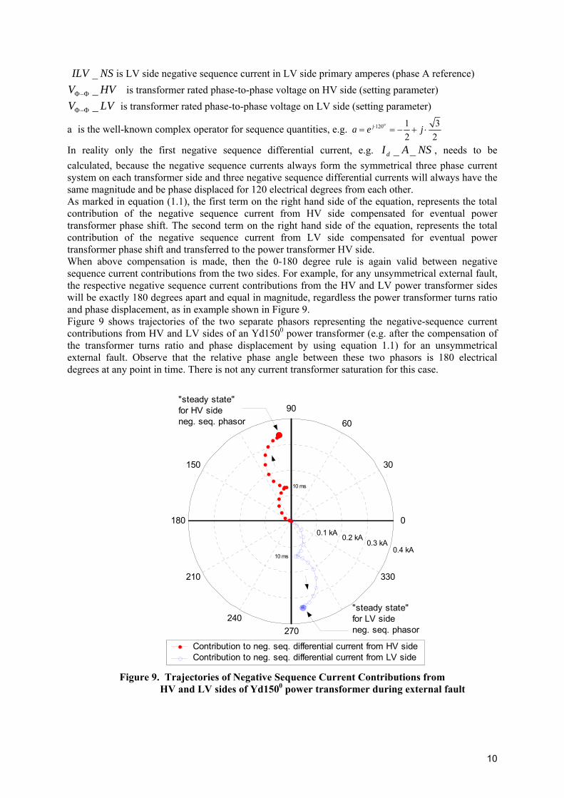
As marked in equation (1.1), the first term on the right hand side of the equation, represents the total contribution of the negative sequence current from HV side compensated for eventual power transformer phase shift. The second term on the right hand side of the equation, represents the total contribution of the negative sequence current from LV side compensated for eventual power transformer phase shift and transferred to the power transformer HV side. When above compensation is made, then the 0-180 degree rule is again valid between negative sequence current contributions from the two sides. For example, for any unsymmetrical external fault, the respective negative sequence current contributions from the HV and LV power transformer sides will be exactly 180 degrees apart and equal in magnitude, regardless the power transformer turns ratio and phase displacement, as in example shown in Figure 9. Figure 9 shows trajectories of the two separate phasors representing the negative-sequence current contributions from HV and LV sides of an Yd1500 power transformer (e.g. after the compensation of the transformer turns ratio and phase displacement by using equation 1.1) for an unsymmetrical external fault. Observe that the relative phase angle between these two phasors is 180 electrical degrees at any point in time. There is not any current transformer saturation for this case.
0.1 kA
30
210
60
240
90
270
150
330
180 0
Contribution to neg. seq. differential current from HV sideContribution to neg. seq. differential current from LV side
0.2 kA 0.3 kA
0.4 kA
"steady state"for HV sideneg. seq. phasor
"steady state"for LV sideneg. seq. phasor
10 ms
10 ms
Figure 9. Trajectories of Negative Sequence Current Contributions from HV and LV sides of Yd1500 power transformer during external fault
10
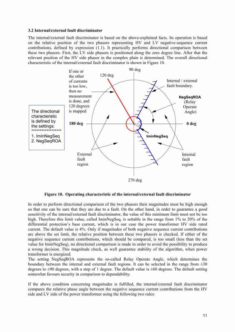
3.2 Internal/external fault discriminator
The internal/external fault discriminator is based on the above-explained facts. Its operation is based on the relative position of the two phasors representing HV and LV negative-sequence current contributions, defined by expression (1.1). It practically performs directional comparison between these two phasors. First, the LV side phasors is positioned along the zero degree line. After that the relevant position of the HV side phasor in the complex plain is determined. The overall directional characteristic of the internal/external fault discriminator is shown in Figure 10.
Internal fault region
Internal / external fault boundary.
0 deg 180 deg
90 deg
270 deg
External fault region
120 deg If one or the other of currents is too low, then no measurement is done, and 120 degrees is mapped
NegSeqROA(Relay Operate Angle)
IminNegSeq
The directional characteristic is defined by the settings: ****************** 1. IminNegSeq 2. NegSeqROA
Figure 10. Operating characteristic of the internal/external fault discriminator In order to perform directional comparison of the two phasors their magnitudes must be high enough so that one can be sure that they are due to a fault. On the other hand, in order to guarantee a good sensitivity of the internal/external fault discriminator, the value of this minimum limit must not be too high. Therefore this limit value, called IminNegSeq, is settable in the range from 1% to 20% of the differential protection’s base current, which is in our case the power transformer HV side rated current. The default value is 4%. Only if magnitudes of both negative sequence current contributions are above the set limit, the relative position between these two phasors is checked. If either of the negative sequence current contributions, which should be compared, is too small (less than the set value for IminNegSeq), no directional comparison is made in order to avoid the possibility to produce a wrong decision. This magnitude check, as well guarantee stability of the algorithm, when power transformer is energized. The setting NegSeqROA represents the so-called Relay Operate Angle, which determines the boundary between the internal and external fault regions. It can be selected in the range from ±30 degrees to ±90 degrees, with a step of 1 degree. The default value is ±60 degrees. The default setting somewhat favours security in comparison to dependability. If the above condition concerning magnitudes is fulfilled, the internal/external fault discriminator compares the relative phase angle between the negative sequence current contributions from the HV side and LV side of the power transformer using the following two rules:
11
If the negative sequence currents contributions from HV and LV sides are in phase, the fault is internal (i.e. both phasors are within internal fault region)
If the negative sequence currents contributions from HV and LV sides are 180 degrees out of phase, the fault is external (i.e. HV phasors is outside internal fault region)
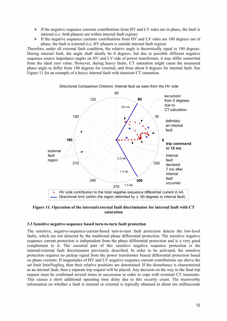
Therefore, under all external fault condition, the relative angle is theoretically equal to 180 degrees. During internal fault, the angle shall ideally be 0 degrees, but due to possible different negative sequence source impedance angles on HV and LV side of power transformer, it may differ somewhat from the ideal zero value. However, during heavy faults, CT saturation might cause the measured phase angle to differ from 180 degrees for external, and from about 0 degrees for internal fault. See Figure 11 for an example of a heavy internal fault with transient CT saturation.
0.5 kA
30
210
60
240
90
270
120
300
150
330
180 0
HV side contribution to the total negative sequence differential current in kADirectional limit (within the region delimited by ± 60 degrees is internal fault)
1.0 kA
1.5 kA
definitely an internalfault
Internal fault declared 7 ms afterinternal fault occurred
trip commandin 12 ms
excursion from 0 degreesdue to CT saturation
externalfault region
35 ms
Directional Comparison Criterion: Internal fault as seen from the HV side
Figure 11. Operation of the internal/external fault discriminator for internal fault with CT
saturation
3.3 Sensitive negative-sequence based turn-to-turn fault protection
The sensitive, negative-sequence-current-based turn-to-turn fault protection detects the low-level faults, which are not detected by the traditional phase differential protection. The sensitive negative sequence current protection is independent from the phase differential protection and is a very good complement to it. The essential part of this sensitive negative sequence protection is the internal/external fault discriminator previously described. In order to be activated, the sensitive protection requires no pickup signal from the power transformer biased differential protection based on phase currents. If magnitudes of HV and LV negative sequence current contributions are above the set limit IminNegSeq, then their relative positions are determined. If the disturbance is characterized as an internal fault, then a separate trip request will be placed. Any decision on the way to the final trip request must be confirmed several times in succession in order to cope with eventual CT transients. This causes a short additional operating time delay due to this security count. The trustworthy information on whether a fault is internal or external is typically obtained in about ten milliseconds
12
after the fault inception, depending on the setting IminNegSeq, and the magnitudes of the fault currents. For very low-level turn-to-turn faults the overall response time of this protection is about thirty milliseconds. At heavy faults, approximately five milliseconds time-to-saturation of the main CT is sufficient in order to produce a correct discrimination between internal and external faults.
13
4. TEST CASE FROM RECORDING CAPTURED IN THE FIELD
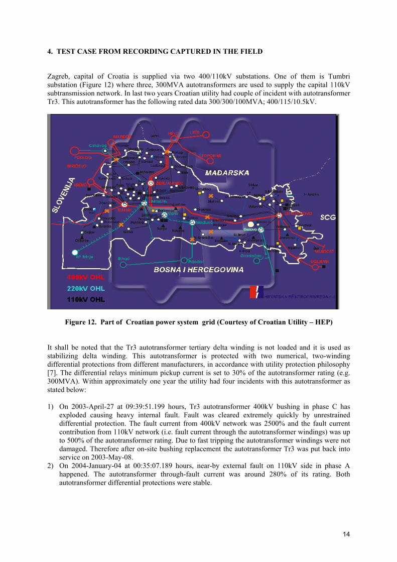
Zagreb, capital of Croatia is supplied via two 400/110kV substations. One of them is Tumbri substation (Figure 12) where three, 300MVA autotransformers are used to supply the capital 110kV subtransmission network. In last two years Croatian utility had couple of incident with autotransformer Tr3. This autotransformer has the following rated data 300/300/100MVA; 400/115/10.5kV.
Figure 12. Part of Croatian power system grid (Courtesy of Croatian Utility – HEP) It shall be noted that the Tr3 autotransformer tertiary delta winding is not loaded and it is used as stabilizing delta winding. This autotransformer is protected with two numerical, two-winding differential protections from different manufacturers, in accordance with utility protection philosophy [7]. The differential relays minimum pickup current is set to 30% of the autotransformer rating (e.g. 300MVA). Within approximately one year the utility had four incidents with this autotransformer as stated below: 1) On 2003-April-27 at 09:39:51.199 hours, Tr3 autotransformer 400kV bushing in phase C has
exploded causing heavy internal fault. Fault was cleared extremely quickly by unrestrained differential protection. The fault current from 400kV network was 2500% and the fault current contribution from 110kV network (i.e. fault current through the autotransformer windings) was up to 500% of the autotransformer rating. Due to fast tripping the autotransformer windings were not damaged. Therefore after on-site bushing replacement the autotransformer Tr3 was put back into service on 2003-May-08.
2) On 2004-January-04 at 00:35:07.189 hours, near-by external fault on 110kV side in phase A happened. The autotransformer through-fault current was around 280% of its rating. Both autotransformer differential protections were stable.
14
3) On 2004-May-04 at 05:10:30.614 hours, near-by external fault on 110kV side in phase C happened. The autotransformer through-fault current was around 310% of its rating. Both autotransformer differential protections were stable.
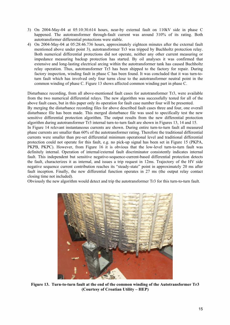
4) On 2004-May-04 at 05:28:46.736 hours, approximately eighteen minutes after the external fault mentioned above under point 3), autotransformer Tr3 was tripped by Buchholtz protection relay. Both numerical differential protections did not operate, neither any other current measuring or impedance measuring backup protection has started. By oil analyses it was confirmed that extensive and long-lasting electrical arcing within the autotransformer tank has caused Buchholtz relay operation. Thus, autotransformer Tr3 has been shipped to the factory for repair. During factory inspection, winding fault in phase C has been found. It was concluded that it was turn-to-turn fault which has involved only four turns close to the autotransformer neutral point in the common winding of phase C. Figure 13 shows affected common winding part in phase C.
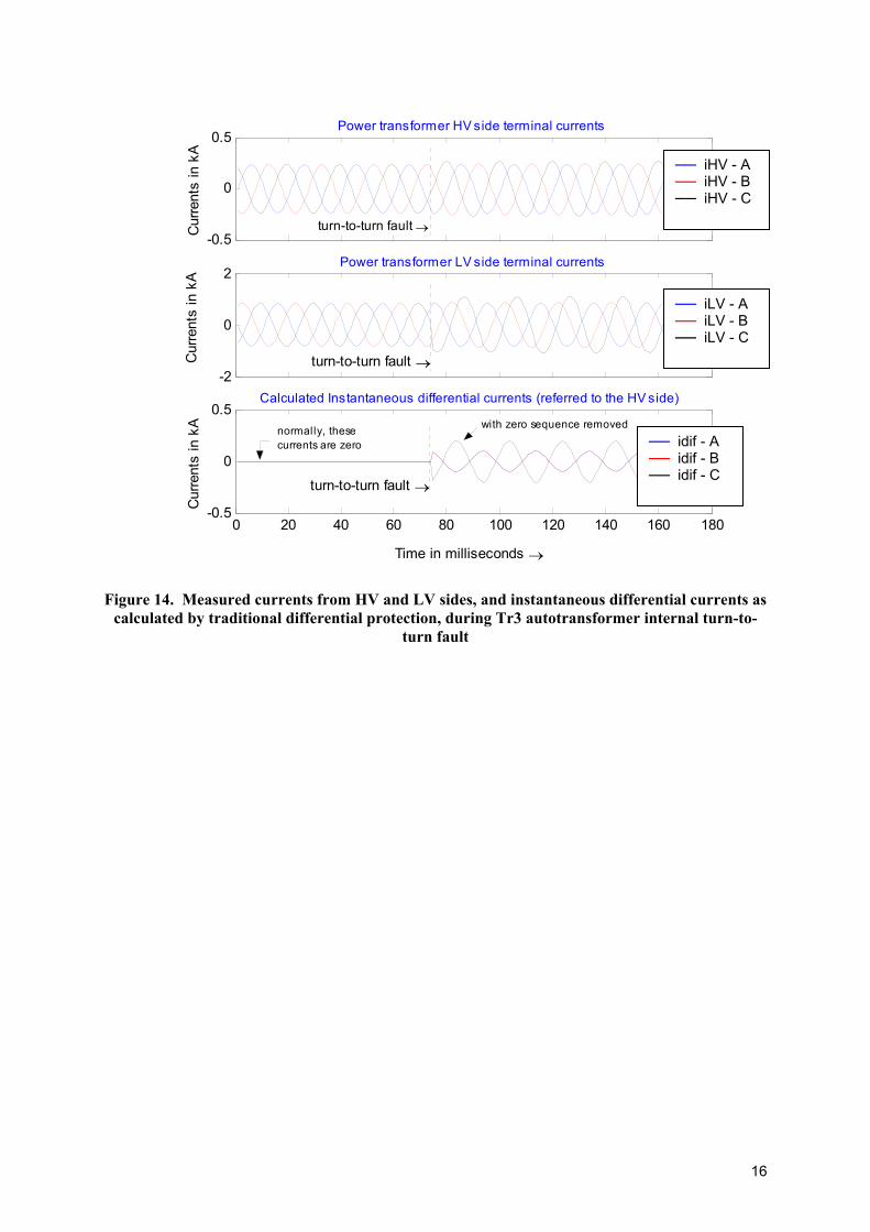
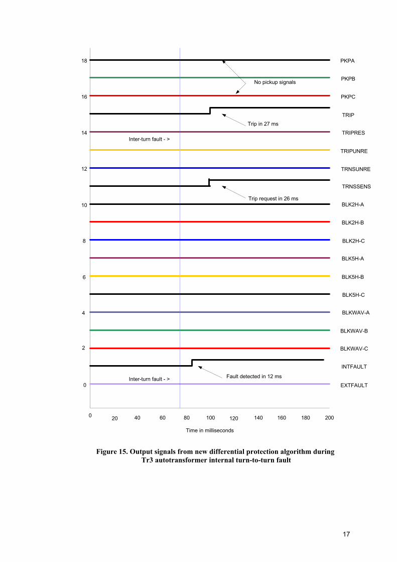
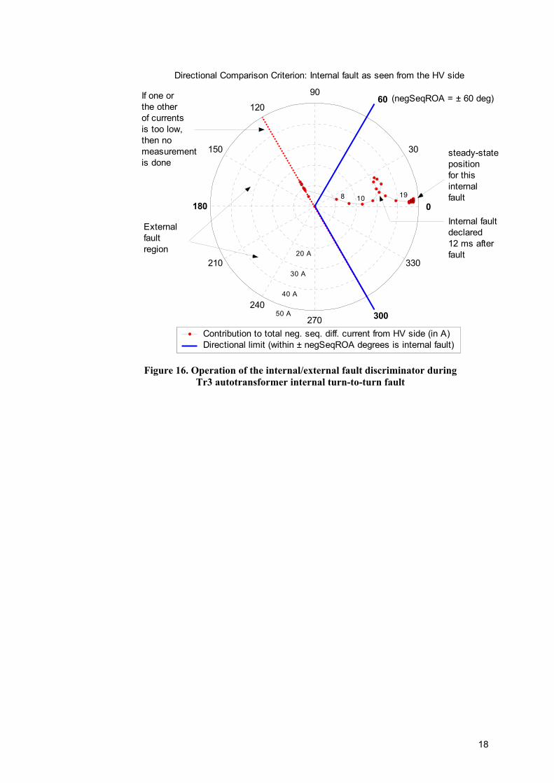
Disturbance recording, from all above-mentioned fault cases for autotransformer Tr3, were available from the two numerical differential relays. The new algorithm was successfully tested for all of the above fault cases, but in this paper only its operation for fault case number four will be presented. By merging the disturbance recording files for above described fault cases three and four, one overall disturbance file has been made. This merged disturbance file was used to specifically test the new sensitive differential protection algorithm. The output results from the new differential protection algorithm during autotransformer Tr3 internal turn-to-turn fault are shown in Figures 13, 14 and 15. In Figure 14 relevant instantaneous currents are shown. During entire turn-to-turn fault all measured phase currents are smaller than 60% of the autotransformer rating. Therefore the traditional differential currents were smaller than pre-set differential minimum operational level and traditional differential protection could not operate for this fault, e.g. no pick-up signal has been set in Figure 15 (PKPA, PKPB, PKPC). However, from Figure 16 it is obvious that the low-level turn-to-turn fault was definitely internal. Operation of internal/external fault discriminator consistently indicates internal fault. This independent but sensitive negative-sequence-current-based differential protection detects the fault, characterizes it as internal, and issues a trip request in 12ms. Trajectory of the HV side negative sequence current contribution reaches its “steady-state” point in approximately 20 ms after fault inception. Finally, the new differential function operates in 27 ms (the output relay contact closing time not included). Obviously the new algorithm would detect and trip the autotransformer Tr3 for this turn-to-turn fault.
Figure 13. Turn-to-turn fault at the end of the common winding of the Autotransformer Tr3
(Courtesy of Croatian Utility – HEP)
15
-0.5
0
0.5
Cur
rent
s in
kA
Power transformer HV side terminal currents
iHV-L1V-L2V-L3
iHiH
-2
0
2
Cur
rent
s in
kA
Power transformer LV side terminal currents
iLV-L1V-L2V-L3
iLiL
0 20 40 60 80 100 120 140 160 180-0.5
0
0.5
Time in milliseconds →
Cur
rent
s in
kA
Calculated Instantaneous differential currents (referred to the HV side)
turn-to-turn fault →
turn-to-turn fault →
turn-to-turn fault →
normally, these currents are zero
with zero sequence removed
iHV - A iHV - B iHV - C
iLV - A iLV - B iLV - C
idif-L1if-L2if-L3
idid
idif - A idif - B idif - C
Figure 14. Measured currents from HV and LV sides, and instantaneous differential currents as
calculated by traditional differential protection, during Tr3 autotransformer internal turn-to-turn fault
16
0 20 40 60 80 100 120 140 160 180 200
2
4
6
8
10
12
14
16
18
BLKWAV-A
INTFAULT
EXTFAULT
BLKWAV-B
BLKWAV-C
BLK5H-C
BLK5H-B
BLK5H-A
BLK2H-A
BLK2H-B
BLK2H-C
TRNSSENS
TRNSUNRE
TRIPUNRE
TRIPRES
TRIP
PKPA
PKPB
PKPC
0
Time in milliseconds
Inter-turn fault - >
Inter-turn fault - >
No pickup signals
Trip in 27 ms
Trip request in 26 ms
Fault detected in 12 ms
Figure 15. Output signals from new differential protection algorithm during Tr3 autotransformer internal turn-to-turn fault
17
20 A
30
210
60
240
90
270
120
300
150
330
180 0
Contribution to total neg. seq. diff. current from HV side (in A)Directional limit (within ± negSeqROA degrees is internal fault)
30 A
40 A
50 A
8 10
Internal faultdeclared 12 ms after fault
steady-stateposition for this internal fault 19
External fault region
If one or the other of currents is too low, then no measurement is done
Directional Comparison Criterion: Internal fault as seen from the HV side
(negSeqROA = ± 60 deg)
Figure 16. Operation of the internal/external fault discriminator during
Tr3 autotransformer internal turn-to-turn fault
18
5. CONCLUSION
The new sensitive turn-to-turn fault protection algorithm for power transformers and autotransformers has been presented. In the paper all theory and case study were done for the two winding power transformer. However, the same protection principle, with minor adjustments, can be applied for protection of two, three or multi winding power transformers and autotransformers. Operation of new internal/external fault discriminator for power transformers has been successfully tested, by using simulation files produced by ATP [9], disturbance recording files from independent transformer differential protection testing on the analogue network simulator [5] and finally from the disturbance recordings captured in the field. All these tests indicate excellent performance of internal/external fault discriminator for power transformers. It detects even minor faults, with a high sensitivity and a high speed, and at the same time discriminates with a high degree of dependability between internal and external faults. However, for internal faults power transformers are always tripped three-phase, while from the captured disturbance record at the moment of tripping the faulty phase(s) can be identified. This paper shows, that by using advanced numerical technology, it is now possible to protect power transformers with new differential protection principle, which has much higher sensitivity than traditional transformer differential protection for low-level internal faults, for example winding turn-to-turn faults. This new protection principle only utilize transformer terminal currents, but it is capable to detect turn-to-turn fault which has involved only four turns (less than 1% of turns – as shown in Figure 13) close to the neutral point in the common winding of phase C of the 300MVA, 400/110kV autotransformer. The same protection principle can be used for differential protection of other power system components like generators, shunt reactors, busbars etc. However, for all these applications where there are galvanical connections between all ends of the protected object, this new principle will only provide protection against internal multi-phase faults and ground-faults, i.e. it will not provide protection against turn-to-turn faults as in case of power transformers.
6. REFERENCES [1] C.F. Wagner, R.D. Evans, Book: “Symmetrical Components", McGraw-Hill, New York & London, 1933
[2] J.L. Blackburn, Book: “Symmetrical Components for Power System Engineering”, Marcel Dekker, New York, Basel, Hong Kong,
1993; ISBN: 0-8247-8767-6
[3] International Standard IEC 60076-1, "Power Transformers – General", Edition 2.1, 2000-04
[4] B. Hillström, N. Ćosić, I. Brnčić, "Advances in Power System Protection", 11th International Conference on Power System Protection PSP98, 1998, Bled, Slovenia
[5] Z. Gajić, G.Z. Shen, J.M. Chen, Z.F. Xiang," Verification of utility requirements on modern numerical transformer protection by dynamic simulation" presented at the IEE Conference on Developments in Power System Protection, Amsterdam, Netherlands, 2001
[6] F. Mekić, Z. Gajić and S. Ganesan, "Adaptive Features of Numerical Differential Relays," presented at the 29th Annual Conference for Protective Relay Engineers, Spokane, Washington, USA, October 2002
[7] Z. Gajić, I. Ivanković, B. Filipović-Grčić, “Differential Protection Issues for Combined Autotransformer – Phase Shifting Transformer”, presented at the IEE Conference on Developments in Power System Protection, Amsterdam, Netherlands, 2004
[8] W. Bartley, “Analysis of Transformer Failures”, International Association of Engineering Insurers 36th Annual Conference, Stockholm,
Sweden, 2003 (http://www.imia.com/) [9] ATP is the royalty-free version of the Electromagnetic Transients Program (EMTP). For more info please visit one of the following
web sites: http://www.eeug.de/ or http://www.ee.mtu.edu/atp/ [10] Generator and Transformer Protection – ABB Lecture 1MRB 520046-Len
19
BIOGRAPHICAL SKETCHES Zoran Gajić was born in Serbia, former Yugoslavia in 1965. He received his Diploma Engineer Degree with honors from University of Belgrade, Yugoslavia in 1990 and GDE in Computer Engineering from Witwatersrand University, Johannesburg-RSA in 1995. Since 1993 he has been working in the area of power system protection and control within ABB Group of companies, where he had various engineering positions. Currently he has a position of Protection Application Senior Specialist with ABB Power Technologies, Substation Automation in Sweden. He is a member of Cigré and IEEE. Currently he is the Convenor for Cigré, Study Committee B5, WG16. Zoran has published numerous technical papers in the relay protection area. His main working areas are computer applications for protection and control of electrical power systems, development of advanced protection algorithms for numerical relays and power system simulation. Zoran is co-holder of two patents. Ivo Brncic was born in Slovenia, former Yugoslavia, in 1946. He received his Diploma Engineer Degree with honors from University of Ljubljana, Slovenia, in 1972. Since 1974 he has been working as a development engineer in the area of power system protection and automation within Iskra, Slovenia. Areas of his particular interest were automatic start-up and synchronization of generators, control of generated active and reactive power, measurement of the fundamental power system frequency, etc. Since 1990 Ivo is with ABB where he currently works as a research and development engineer with ABB Power Technologies, Substation Automation in Sweden. Here he works mainly on the subject of differential protections such as power transformer and generator differential protections, adaptive filtering, etc. Ivo has published several technical papers in the relay protection area, and is a co-holder of two patents. Birger Hillström was born in Sweden 1944. He received his M.Sc.E.E degree from Chalmers Technical University in Göteborg Sweden, 1968. He was employed as development engineer at ASEA, Sweden, 1970 and is currently working as development project manager at ABB Power Technologies, Substation Automation, Sweden. During ten years he was relay laboratory manager and was then responsible for development of a digitally controlled, analogue power system simulator and was after that part of a specification group of a real time digital power system simulator. His special areas of interest are transient network analysis, development and testing of line and transformer static and numerical relays. Fahrudin Mekić was born in former Yugoslavia in 1967. He received his BSEE with honors from Sarajevo University, Bosnia and Herzegovina in 1991 where he also worked as research assistant. He received his MSEE degree from Istanbul Technical University, Turkey in 1996. Since 1996 he has been working in the area of power system protection and control within ABB, where he had various engineering positions. Currently he is Senior Application Engineer with the Substation Automation and Protection Division, ABB Inc, in Allentown, PA. Fahrudin has published several technical papers in the area of protection and reliability. He is currently responsible for the application and technical issues associated with ABB relays. He is a member of IEEE. Igor Ivanković was born in Croatia in 1965. He received his Diploma Engineer Degree and Master of Science Degree from University of Zagreb, Croatia in 1991 and 2005 respectively. He has two years of working experience in Croatian Railway Company and also two years of experience in Končar Company in the field of low voltage switchgear production. Since 1995 he has been working in the area of relay protection with the Croatian Transmission Company. Currently he has a position Head of relay protection department. He is a member of Cigré Paris and he is a chairman of Croatian Study Committee B5 Protection and Automation. His main topics of interest were transmission protection, voltage collapse, system protection function and wide area monitoring and protection. This interest was then implicated by involvement in many projects for secondary protection and control systems in Croatian transmission grid. Igor has published several articles in the area of protection and control.
20


![Welcome [] Walker.pdf · IDC Fault current hAssumptions for simple fault current calculations: hIgnore cable between switchgear and fault hCable between transformer and fault? hIgnore](https://img.pdfslide.net/doc/110x75/5e9b23eeaae6672497011698/welcome-walkerpdf-idc-fault-current-hassumptions-for-simple-fault-current.jpg)