Embed Size (px)
Citation preview
n
Two-step digit-set-restricted modified signed-digitaddition–subtraction algorithm and itsoptoelectronic implementation
Feng Qian, Guoqiang Li, Hao Ruan, Hongmei Jing, and Liren Liu
A novel, to our knowledge, two-step digit-set-restricted modified signed-digit ~MSD! addition–subtractionalgorithm is proposed. With the introduction of the reference digits, the operand words are mapped intoan intermediate carry word with all digits restricted to the set $1# , 0% and an intermediate sum word withall digits restricted to the set $0, 1%, which can be summed to form the final result without carrygeneration. The operation can be performed in parallel by use of binary logic. An optical system thatutilizes an electron-trapping device is suggested for accomplishing the required binary logic operations.By programming of the illumination of data arrays, any complex logic operations of multiple variables canbe realized without additional temporal latency of the intermediate results. This technique has a highspace–bandwidth product and signal-to-noise ratio. The main structure can be stacked to construct acompact optoelectronic MSD adder–subtracter. © 1999 Optical Society of America
OCIS codes: 200.0200, 200.4660, 200.4960, 200.3760, 200.4560.
w
d
1. Introduction
Because of the high-speed and parallel processingpower of optics, optical computing has gained increas-ing attention over the past two decades.1 The mostfundamental operation for any arithmetic computa-tion is addition, since other arithmetic operations,such as subtraction, multiplication, and division, canall be realized through addition together with logicoperations. However, the computation speed of ad-dition based on the conventional binary number sys-tem is limited because of the carry propagation fromthe least-significant-bit ~LSB! position to the most-significant-bit ~MSB! position. To cope with thisproblem, various nonbinary number systems havebeen proposed, e.g., residue number,2 multiple-valued fixed-radix number,3–6 and signed-digit ~SD!
umber.7–24 These number representations make itpossible to utilize the parallelism of optics more effi-ciently.
The authors are with the Shanghai Institute of Optics andFine Mechanics, Academica Sinica, P.O. Box 800-211, Shanghai201800, China. F. Qian’s e-mail address is [email protected].
Received 25 February 1999; revised manuscript received 14June 1999.
0003-6935y99y265621-10$15.00y0© 1999 Optical Society of America
1
The modified SD ~MSD! number representation,hich was invented by Avizienis7 and introduced to
the optics community by Drake et al.,8 is a subset ofthe SD number system with the radix r 5 2 and the
igit set $1# , 0, 1%, where 1# denotes 21. Because carrypropagation is confined within two adjacent digit po-sitions, the MSD representation provides fully paral-lel, carry-free arithmetic operations, and variousassociated algorithms that are suitable for opticalarchitectures have been developed. Furthermore,negabinary SD13 computing has recently been pro-posed, and numeric operations on trinary SD14,15 andquaternary SD16,17 computing have been intensivelystudied. For the purpose of implementing these al-gorithms optically, parallel architectures of lookuptruth table,19 symbolic substitution,9–12 logic arrayprocessing,13 and matrix–matrix multiplication18 areemployed. Numerous studies on SD computinghave addressed various optoelectronic implementa-tions, such as content-addressable memory,8,9,19
shared content-addressable memory,20 coherent18
and incoherent17 optical correlators, and the nonlin-ear logic gate array.13,21–23
Realizing arithmetic algorithms by use of opticallogic operations is one of the major trends in opticalcomputing, since it is promising for building ageneral-purpose optical computing system. Thishas motivated researchers to develop shadow-castinglogic, polarization logic, electron-trapping ~ET! logic,
0 September 1999 y Vol. 38, No. 26 y APPLIED OPTICS 5621
TansppFcc
~na
srttdpibtt
ostceHcmpmppm
5
symbolic substitution logic, holographic logic, logicbased on optical bistability, and so on.1 Because aMSD digit has three possible states, i.e., 1# , 0, and 1,traditional binary encoding schemes do not have suf-ficient encoding states to code it. Multiple-state en-coding schemes increase the complexity of the opticalsystem, and the optical logic operations are thusdifficult to realize.21 Recently MSD addition wasperformed by polarization-encoded binary logic oper-ations.22,23
In this paper a novel, to our knowledge, two-stepdigit-set-restricted MSD addition–subtraction algo-rithm based on binary logic is proposed. By intro-duction of the reference digits, the operand words aremapped into an intermediate carry word with all dig-its restricted to the set $1# , 0% and an intermediate sumword with all digits restricted to the set $0, 1%. Thefinal result is generated by summation of the digit-set-restricted intermediate carry and sum words.The addition–subtraction can be completed in twosteps with the proposed encoding scheme. The al-gorithm, which is independent of the length of theoperands, can be performed at each digit position inparallel by means of binary logic operations. Thisproperty matches well with the optical cellular archi-tecture, and the algorithm is thus suitable for opticalimplementation. Note that subtraction can be ac-complished in parallel with the same binary logicfunctions of the addition by means of complementingthe subtrahend. This offers a technique for perform-ing space-variant arithmetic-logic functions withspace-invariant instructions. Each digit is encodedwith a single pixel in binary status. Based on thestorage and erasure characteristics of the ET device,any complex logic operations of multiple variablescan be performed easily with a high space–bandwidth product ~SBWP! and signal-to-noise ratio~SNR! by programming of the illumination of dataarrays. The system is compact, cost effective, and ofgeneral purpose.
2. Background of Modified Signed-Digit NumberSystem
A given decimal number X can be represented by anN-digit MSD number as
X 5 (i50
N21
xi2i, xi [ $1# , 0, 1%. (1)
his redundant binary representation can expressny number except zero in more than one form. Aegative number is represented in the MSD repre-entation by complementing of each digit of the MSDositive number. The complement of 1 is 1# , the com-lement of 1# is 1, and the complement of 0 is 0 itself.or this reason subtraction can be performed first byomplementing of the subtrahend and then by appli-ation of the addition operation.
When two MSD numbers are added, the digit pairs1, 1! or ~1# , 1# ! will cause a carry propagation to theext-higher-order digit. This problem can be allevi-ted by mapping of the two digits ~xi, yi! in question
622 APPLIED OPTICS y Vol. 38, No. 26 y 10 September 1999
into an intermediate carry and sum, which are alsocalled transfer and weight digits, respectively, suchthat the ith intermediate sum si and the ~i 2 1!thintermediate carry ci generate the final sum digit ziwithout carry generation. The addition operation isperformed in two steps, which comply with the fol-lowing two equations:
step 1: xi 1 yi 5 2ci11 1 si, (2)
step 2: zi 5 ci 1 si. (3)
The property of redundancy in MSD representationenables the generated carry to be eliminated withintwo adjacent digit positions to the left-hand side. Inthe previous algorithms the intermediate carry andsum digits are members of the entire MSD set $1# , 0,1%.8–12
According to the number of steps needed to yieldthe final sum, the algorithms can be classified intothree categories, i.e., three-step method,8,18 two-stepmethod,9–12 and single-step method.19 In the three-step arithmetic the first step is to generate a transferword and a weight word in parallel. These weightsand transfers are then used to generate a second setof transfer and weight digits, which are added to givethe final result in the final step. For a two- ~oringle-! step MSD arithmetic approach, by incorpo-ating additional information from the next one ~orwo! lower-order pairs of input digits, we can combinehe first two ~or three! steps into one step. The ad-ition or subtraction operation may then be com-leted in two ~or one! steps but at the cost ofncreasing the complexity of the operation truth ta-les and the difficulty of optical implementation. Inerms of computation speed and storage complexityhe two-step method is a moderate choice.
When a MSD processing system interfaces with anrdinary binary processing system, the MSD repre-entation must be converted to and from a conven-ional binary representation. We can perform theonversion from 2’s complement form to its MSD formasily by changing only the MSB to 1# if the MSB is 1.owever, the conversion from the MSD form to its 2’s
omplement form is more complex. Inefficientethods will counteract the benefit of using MSD
arallel algorithms. The conventional conversionethod involves splitting the MSD number into two
arts, a positive part and a negative part, and thenerforming subtraction of two numbers in 2’s comple-ent binary form.7,24 The carry propagation limits
the operation speed significantly. Casasent andWoodford18 developed a serial algorithm that oper-ates sequentially from the LSB to the MSB. Erce-govac and Lang25 proposed another on-the-flyconversion algorithm, and Li et al.26 implemented thealgorithm optically. It uses two conditional forms ofthe current result, and the digits of the result areobtained in a serial fashion from the MSB to the LSB.The proposed optical system can perform the conver-sion at the speed of light. However, the system maybe rather complex and has poor tolerance to optical
27
ate
t
Tis
ipt
npsmcw
t
E
0fiuf
e
Stmudt
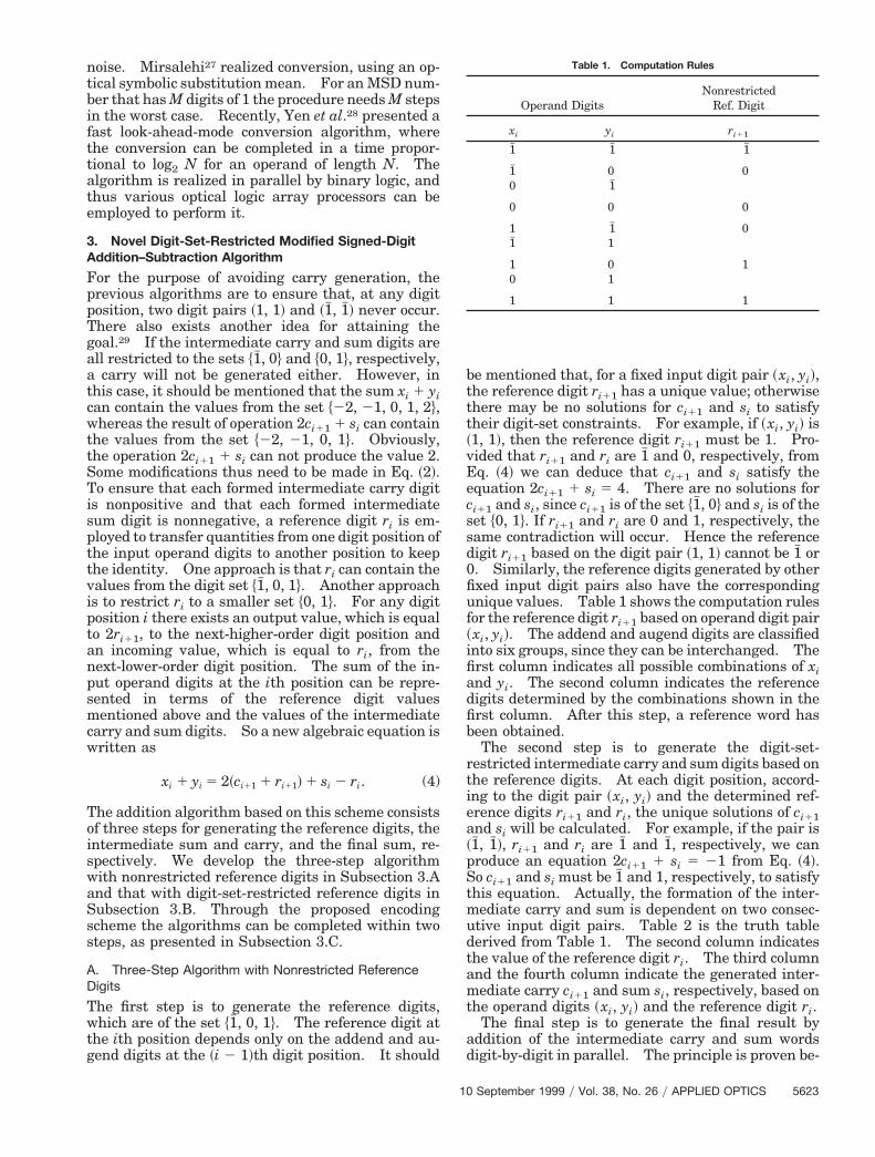
Table 1. Computation Rules
noise. Mirsalehi realized conversion, using an op-tical symbolic substitution mean. For an MSD num-ber that has M digits of 1 the procedure needs M stepsin the worst case. Recently, Yen et al.28 presented afast look-ahead-mode conversion algorithm, wherethe conversion can be completed in a time propor-tional to log2 N for an operand of length N. Thelgorithm is realized in parallel by binary logic, andhus various optical logic array processors can bemployed to perform it.3. Novel Digit-Set-Restricted Modified Signed-DigitAddition–Subtraction Algorithm
For the purpose of avoiding carry generation, theprevious algorithms are to ensure that, at any digitposition, two digit pairs ~1, 1! and ~1# , 1# ! never occur.There also exists another idea for attaining thegoal.29 If the intermediate carry and sum digits areall restricted to the sets $1# , 0% and $0, 1%, respectively,a carry will not be generated either. However, inthis case, it should be mentioned that the sum xi 1 yican contain the values from the set $22, 21, 0, 1, 2%,whereas the result of operation 2ci11 1 si can containhe values from the set $22, 21, 0, 1%. Obviously,
the operation 2ci11 1 si can not produce the value 2.Some modifications thus need to be made in Eq. ~2!.
o ensure that each formed intermediate carry digits nonpositive and that each formed intermediateum digit is nonnegative, a reference digit ri is em-
ployed to transfer quantities from one digit position ofthe input operand digits to another position to keepthe identity. One approach is that ri can contain thevalues from the digit set $1# , 0, 1%. Another approachs to restrict ri to a smaller set $0, 1%. For any digitosition i there exists an output value, which is equalo 2ri11, to the next-higher-order digit position and
an incoming value, which is equal to ri, from theext-lower-order digit position. The sum of the in-ut operand digits at the ith position can be repre-ented in terms of the reference digit valuesentioned above and the values of the intermediate
arry and sum digits. So a new algebraic equation isritten as
xi 1 yi 5 2~ci11 1 ri11! 1 si 2 ri. (4)
The addition algorithm based on this scheme consistsof three steps for generating the reference digits, theintermediate sum and carry, and the final sum, re-spectively. We develop the three-step algorithmwith nonrestricted reference digits in Subsection 3.Aand that with digit-set-restricted reference digits inSubsection 3.B. Through the proposed encodingscheme the algorithms can be completed within twosteps, as presented in Subsection 3.C.
A. Three-Step Algorithm with Nonrestricted ReferenceDigits
The first step is to generate the reference digits,which are of the set $1# , 0, 1%. The reference digit atthe ith position depends only on the addend and au-gend digits at the ~i 2 1!th digit position. It should
10
be mentioned that, for a fixed input digit pair ~xi, yi!,the reference digit ri11 has a unique value; otherwisethere may be no solutions for ci11 and si to satisfyheir digit-set constraints. For example, if ~xi, yi! is
~1, 1!, then the reference digit ri11 must be 1. Pro-vided that ri11 and ri are 1# and 0, respectively, from
q. ~4! we can deduce that ci11 and si satisfy theequation 2ci11 1 si 5 4. There are no solutions forci11 and si, since ci11 is of the set $1# , 0% and si is of theset $0, 1%. If ri11 and ri are 0 and 1, respectively, thesame contradiction will occur. Hence the referencedigit ri11 based on the digit pair ~1, 1! cannot be 1# or. Similarly, the reference digits generated by otherxed input digit pairs also have the correspondingnique values. Table 1 shows the computation rulesor the reference digit ri11 based on operand digit pair
~xi, yi!. The addend and augend digits are classifiedinto six groups, since they can be interchanged. Thefirst column indicates all possible combinations of xiand yi. The second column indicates the referencedigits determined by the combinations shown in thefirst column. After this step, a reference word hasbeen obtained.
The second step is to generate the digit-set-restricted intermediate carry and sum digits based onthe reference digits. At each digit position, accord-ing to the digit pair ~xi, yi! and the determined ref-rence digits ri11 and ri, the unique solutions of ci11
and si will be calculated. For example, if the pair is~1# , 1# !, ri11 and ri are 1# and 1# , respectively, we canproduce an equation 2ci11 1 si 5 21 from Eq. ~4!.
o ci11 and si must be 1# and 1, respectively, to satisfyhis equation. Actually, the formation of the inter-ediate carry and sum is dependent on two consec-tive input digit pairs. Table 2 is the truth tableerived from Table 1. The second column indicateshe value of the reference digit ri. The third column
and the fourth column indicate the generated inter-mediate carry ci11 and sum si, respectively, based onthe operand digits ~xi, yi! and the reference digit ri.
The final step is to generate the final result byaddition of the intermediate carry and sum wordsdigit-by-digit in parallel. The principle is proven be-
Operand DigitsNonrestricted
Ref. Digit
xi yi ri11
1# 1# 1#
1# 0 00 1#
0 0 0
1 1# 01# 1
1 0 10 1
1 1 1
September 1999 y Vol. 38, No. 26 y APPLIED OPTICS 5623
c
T
C
b
FMir
brtedy
Table 2. Computation Rules
5
low. The summation of two N-digit MSD numbers Xand Y can be expressed as
X 1 Y 5 (i50
N21
2i~xi 1 yi!. (5)
Substitution of Eq. ~4! into Eq. ~5! leads to
X 1 Y 5 (i50
N21
2i@2~ci11 1 ri11! 1 si 2 ri#
5 (i50
N21
2i11ci11 1 (i50
N21
2isi 1 (i50
N21
2i11ri11 2 (i50
N21
2iri.
(6)
The first term of Eq. ~6!, which is equivalent toN, . . . , c2c10, can be rewritten as ¥i50
N 2ici, since c0 50. The second term ¥i50
N21 2isi can be expressed as
(i50
N21
2isi 5 (i50
N
2isi 2 2NsN. (7)
The third term of Eq. ~6! is equivalent to the wordrN, . . . , r2r10, and the fourth term is equivalent tothe word rN21, . . . , r2r1r0, where r0 5 0. Thereforethe difference of the third and the fourth terms is
(i50
N21
2i11ri11 2 (i50
N21
2iri 5 2NrN. (8)
As a result Eq. ~6! becomes
X 1 Y 5 (i50
N
2i~ci 1 si! 1 2N~rN 2 sN!. (9)
Note that xN 5 0 and yN 5 0. The reference digit rNhas three possible states, i.e., 1# , 0, and 1. In the
OperandDigits
NonrestrictedRef. Digit
Digit-Set-RestrictedIntermediate
Carry Sum
xi yi ri ci11 si
1# 1# 11# 1# 0 0 0
1 0 1
1# 0 1# 1# 00 1# 1
0 1# 1 0 0
1# 1# 10 0 0 0 0
1 0 1
1 1# 1# 1# 10 0 0
1# 1 1 0 1
1 0 1# 1# 00 1# 1
0 1 1 0 0
1# 1# 11 1 0 0 0
1 0 1
624 APPLIED OPTICS y Vol. 38, No. 26 y 10 September 1999
following we discuss these three cases, in sequence,on the basis of the computation rule for the inputdigit pair ~0, 0! in Table 2.
Case I. rN 5 1# : There exist cN11 5 1# , sN 5 1.The second term of Eq. ~9! is written as
2N~rN 2 sN! 5 2N~1# 2 1! 5 2N11cN11. (10)
Case II. rN 5 0: There exist cN11 5 0, sN 5 0.he second term of Eq. ~9! is written as
2N~rN 2 sN! 5 2N11cN11. (11)
Case III. rN 5 1: There exist cN11 5 0, sN 5 1.The second term of Eq. ~9! is written as
2N~rN 2 sN! 5 2N11cN11. (12)
onsequently, Eq. ~9! can be simplified as
X 1 Y 5 (i50
N
2i~ci 1 si! 1 2N11cN11
5 (i50
N11
2ici 1 (i50
N11
2isi, (13)
where sN11 5 0. The first and the second termsrepresent the ~N 1 2!-bit intermediate carry word Cand sum word S, respectively. That is, Eq. ~13! cane rewritten as
X 1 Y 5 C 1 S. (14)
rom Eq. ~14! we conclude that the sum of two N-digitSD words is equal to the sum of the ~N 1 2!-bit
ntermediate carry and sum words, regardless of theeference word.
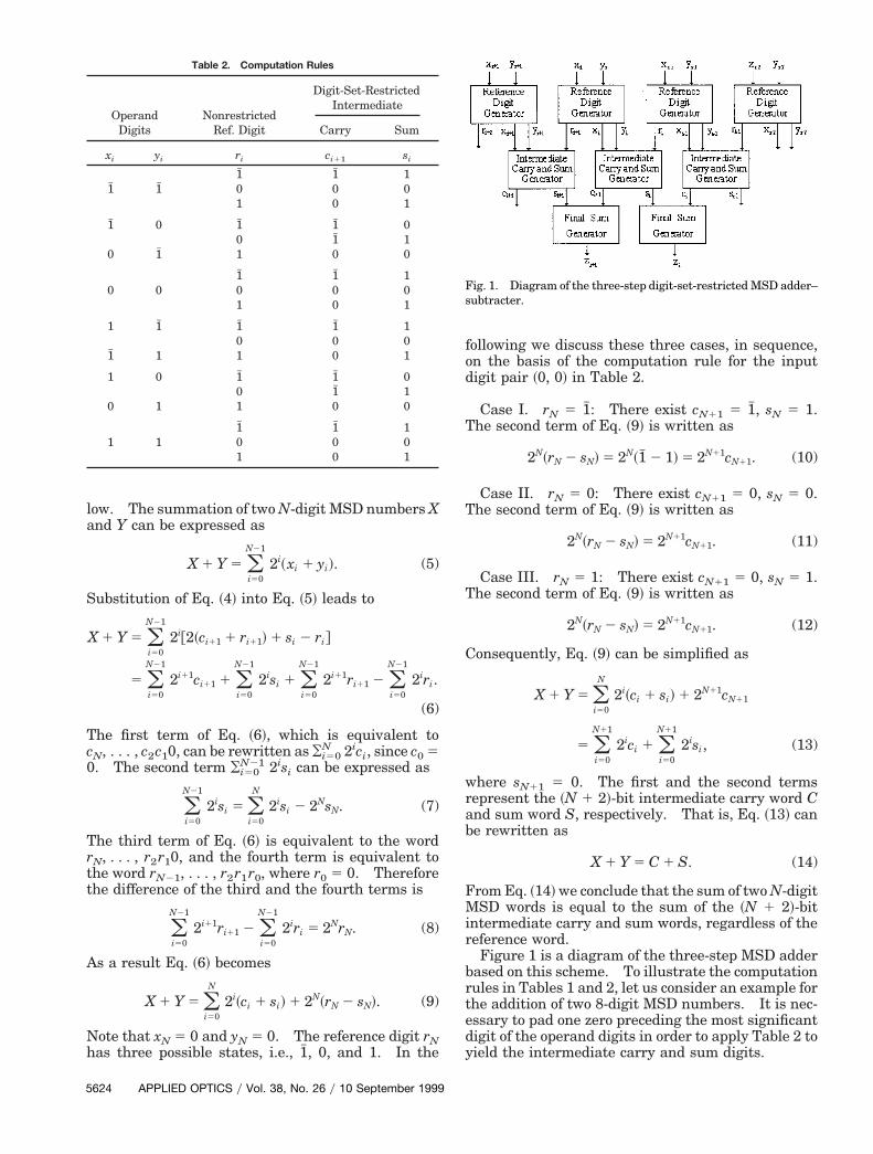
Figure 1 is a diagram of the three-step MSD adderased on this scheme. To illustrate the computationules in Tables 1 and 2, let us consider an example forhe addition of two 8-digit MSD numbers. It is nec-ssary to pad one zero preceding the most significantigit of the operand digits in order to apply Table 2 toield the intermediate carry and sum digits.
Fig. 1. Diagram of the three-step digit-set-restricted MSD adder–subtracter.
ttodwi
wairsssstpls
dt
r
Nm
wdT0tst
Table 3. Computation Rules Table 4. Computation rules
Example 1
~X! f 1# 0 1 1# 1# 0 1 1 5 ~2117!10
~Y! f 1 1# 0 0 1 1# 0 1 5 ~69!10
step 1: ~R! 0 0 1 0 0 0 1 1 f
step 2: ~C! 0 0 0 1# 1# 0 0 0 0 f
~S! f 0 0 0 1 1 0 0 0 0
step 3: ~Z! 0 0 0 1# 0 1 0 0 0 0 5 ~248!10.
Here the symbol f denotes a padded zero.The key of this algorithm lies in the utilization of
he reference digits. Their function is to determinehe values transferred from one digit position of theperand words to another digit position so that theigits of the formed intermediate carry and sumords are all restricted to a smaller set and their sum
s equal to the sum of the operand words.
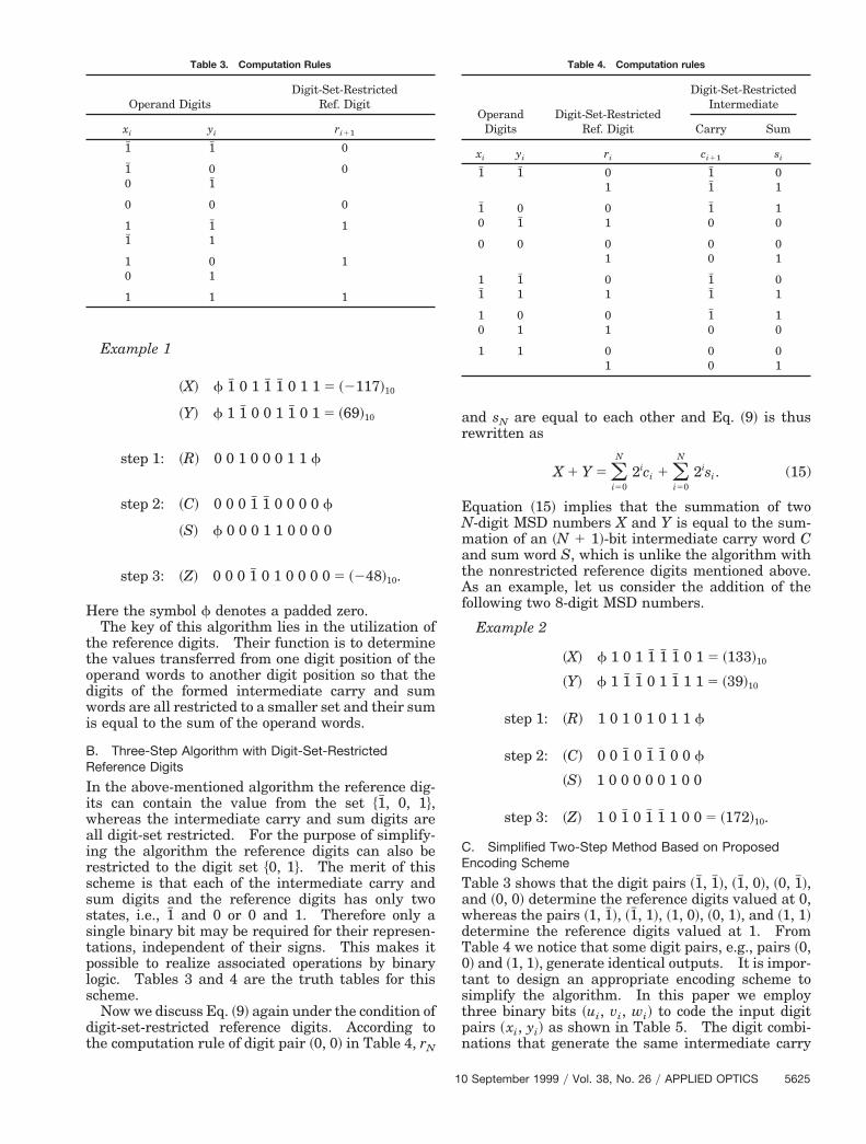
B. Three-Step Algorithm with Digit-Set-RestrictedReference Digits
In the above-mentioned algorithm the reference dig-its can contain the value from the set $1# , 0, 1%,
hereas the intermediate carry and sum digits arell digit-set restricted. For the purpose of simplify-ng the algorithm the reference digits can also beestricted to the digit set $0, 1%. The merit of thischeme is that each of the intermediate carry andum digits and the reference digits has only twotates, i.e., 1# and 0 or 0 and 1. Therefore only aingle binary bit may be required for their represen-ations, independent of their signs. This makes itossible to realize associated operations by binaryogic. Tables 3 and 4 are the truth tables for thischeme.Now we discuss Eq. ~9! again under the condition of
igit-set-restricted reference digits. According tohe computation rule of digit pair ~0, 0! in Table 4, rN
Operand DigitsDigit-Set-Restricted
Ref. Digit
xi yi ri11
1# 1# 0
1# 0 00 1#
0 0 0
1 1# 11# 1
1 0 10 1
1 1 1
10
and sN are equal to each other and Eq. ~9! is thusewritten as
X 1 Y 5 (i50
N
2ici 1 (i50
N
2isi. (15)
Equation ~15! implies that the summation of two-digit MSD numbers X and Y is equal to the sum-ation of an ~N 1 1!-bit intermediate carry word C
and sum word S, which is unlike the algorithm withthe nonrestricted reference digits mentioned above.As an example, let us consider the addition of thefollowing two 8-digit MSD numbers.
Example 2
~X! f 1 0 1 1# 1# 1# 0 1 5 ~133!10
~Y! f 1 1# 1# 0 1 1# 1 1 5 ~39!10
step 1: ~R! 1 0 1 0 1 0 1 1 f
step 2: ~C! 0 0 1# 0 1# 1# 0 0 f
~S! 1 0 0 0 0 0 1 0 0
step 3: ~Z! 1 0 1# 0 1# 1# 1 0 0 5 ~172!10.
C. Simplified Two-Step Method Based on ProposedEncoding Scheme
Table 3 shows that the digit pairs ~1# , 1# !, ~1# , 0!, ~0, 1# !,and ~0, 0! determine the reference digits valued at 0,
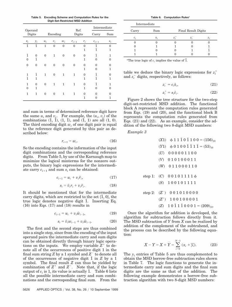
hereas the pairs ~1, 1# !, ~1# , 1!, ~1, 0!, ~0, 1!, and ~1, 1!etermine the reference digits valued at 1. Fromable 4 we notice that some digit pairs, e.g., pairs ~0,! and ~1, 1!, generate identical outputs. It is impor-ant to design an appropriate encoding scheme toimplify the algorithm. In this paper we employhree binary bits ~ui, vi, wi! to code the input digit
pairs ~xi, yi! as shown in Table 5. The digit combi-nations that generate the same intermediate carry
OperandDigits
Digit-Set-RestrictedRef. Digit
Digit-Set-RestrictedIntermediate
Carry Sum
xi yi ri ci11 si
1# 1# 0 1# 01 1# 1
1# 0 0 1# 10 1# 1 0 0
0 0 0 0 01 0 1
1 1# 0 1# 01# 1 1 1# 1
1 0 0 1# 10 1 1 0 0
1 1 0 0 01 0 1
September 1999 y Vol. 38, No. 26 y APPLIED OPTICS 5625
Sddmpa
t~
ioctnfi
o
d
att
Table 5. Encoding Scheme and Computation Rules for the Table 6. Computation Rulesa
5
and sum in terms of determined reference digit havethe same ui and vi. For example, the ~ui, vi! of thecombinations ~1# , 1# !, ~1, 1# !, and ~1# , 1! are all ~1, 0!.The third encoding digit wi of one digit pair is equalto the reference digit generated by this pair as de-scribed below:
ri11 5 wi. (16)
o the encoding contains the information of the inputigit combinations and the corresponding referenceigits. From Table 5, by use of the Karnaugh map toinimize the logical minterms for the nonzero out-
uts, the binary logic expressions for the intermedi-te carry ci11 and sum si can be obtained:
ci11 5 ui 1 vir#i, (17)
si 5 v# iri 1 vir#i. (18)
It should be mentioned that for the intermediatecarry digits, which are restricted to the set $1# , 0%, therue logic denotes negative digit 1# . Inserting Eq.16! into Eqs. ~17! and ~18! results in
ci11 5 ui 1 viw# i21, (19)
si 5 v# iwi21 1 viw# i21. (20)
The first and the second steps are thus combinednto a single step, since from the encoding of the inputperand pairs the intermediate carry and sum digitsan be obtained directly through binary logic opera-ions on the inputs. We employ variable Z1 to de-ote all of the occurrences of positive digit 1 in thenal sum string Z by a 1 symbol and Z2 to denote all
of the occurrences of negative digit 1# in Z by a 1symbol. The final result Z can thus be yielded bycombination of Z1 and Z2. Note that, if the logicutput of ci is 1, its value is actually 1# . Table 6 lists
all the possible intermediate carry and sum combi-nations and the corresponding final sum. From the
Digit-Set-Restricted MSD Addition
OperandDigits Encoding
Ref.Digits
Intermediate
Carry Sum
xi yi ui vi wi ri11 ri ci11 si
1# 1# 1 0 0 0 0 1# 01 1# 1
1# 0 0 1 0 0 0 1# 10 1# 1 0 0
0 0 0 0 0 0 0 0 01 0 1
1 1# 1 0 1 1 0 1# 01# 1 1 1# 1
1 0 0 1 1 1 0 1# 10 1 1 0 0
1 1 0 0 1 1 0 0 01 0 1
626 APPLIED OPTICS y Vol. 38, No. 26 y 10 September 1999
table we deduce the binary logic expressions for zi1
and zi2 digits, respectively, as follows:
zi2 5 cis#i, (21)
zi1 5 sic#i. (22)
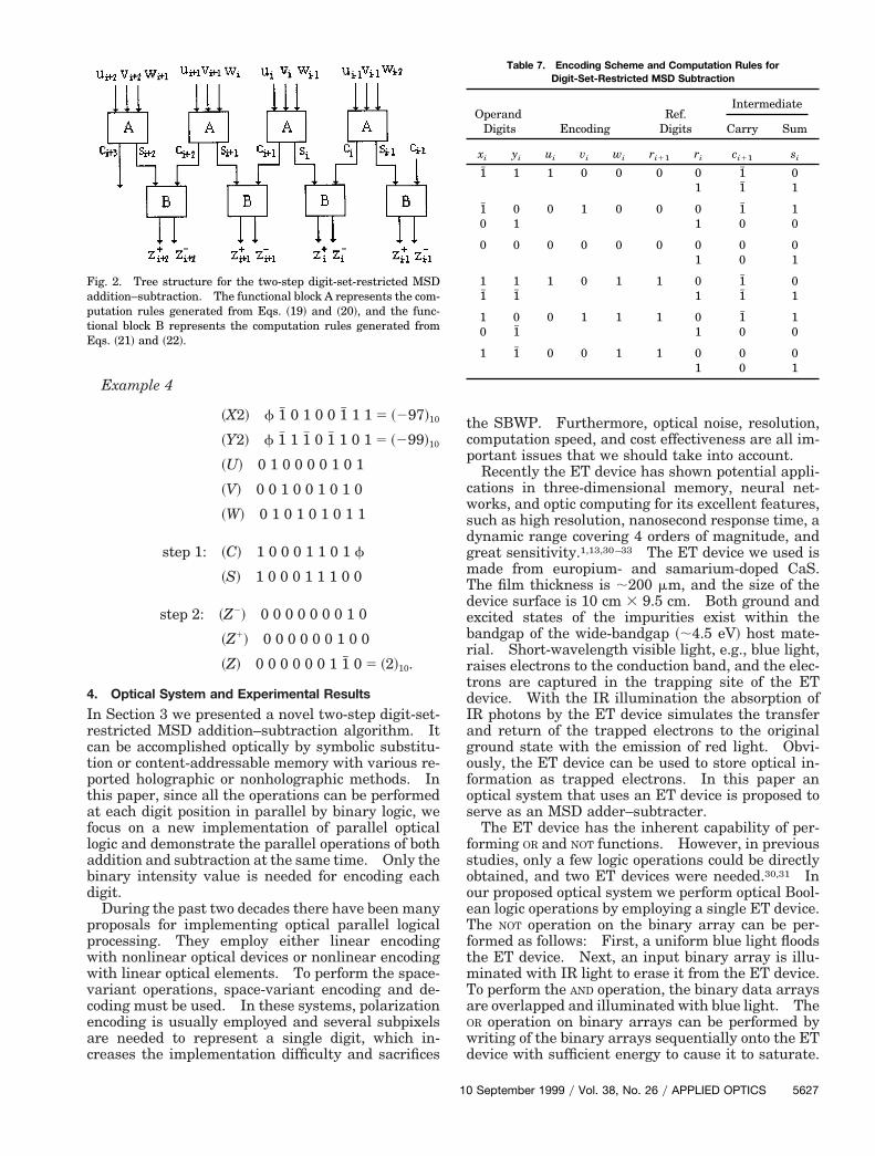
Figure 2 shows the tree structure for the two-stepdigit-set-restricted MSD addition. The functionalblock A represents the computation rules generatedfrom Eqs. ~19! and ~20!, and the functional block Brepresents the computation rules generated fromEqs. ~21! and ~22!. As an example, consider the ad-
ition of the following two 8-digit MSD numbers:
Example 3
~X1! f 1 1 1# 0 1# 1 0 0 5 ~156!10
~Y1! f 0 1 0 0 1# 1# 1 1# 5 ~53!10
~U! 0 0 0 0 0 1 1 0 0
~V! 0 1 0 1 0 0 0 1 1
~W! 0 1 1 0 0 0 1 1 0
step 1: ~C! 0 0 1 0 1 1 1 1 f
~S! 1 0 0 1 0 1 1 1 1
step 2: ~Z2! 0 0 1 0 1 0 0 0 0
~Z1! 1 0 0 1 0 0 0 0 1
~Z! 1 0 1# 1 1# 0 0 0 1 5 ~209!10.
Once the algorithm for addition is developed, thealgorithm for subtraction follows directly from it.The MSD subtraction of Y from X can be realized byddition of the complement of the subtrahend, andhe process can be described by the following equa-ion:
X 2 Y 5 X 1 Y 5 (i50
N21
~xi 1 yi!. (23)
The yi entries of Table 5 are thus complemented toobtain the MSD borrow-free subtraction rules shownin Table 7. The logic functions to generate the in-termediate carry and sum digits and the final sumdigits are the same as that of the addition. Thefollowing example demonstrates a borrow-free sub-traction algorithm with two 8-digit MSD numbers:
Intermediate
Final Result DigitsCarry Sum
ci si zi1 zi
2 zi
0 0 0 0 00 1 1 0 11 0 0 1 1#1 1 0 0 0
aThe true logic of ci implies the value of 1.
debrrtdIagofos
f
Table 7. Encoding Scheme and Computation Rules for
Example 4
~X2! f 1# 0 1 0 0 1# 1 1 5 ~297!10
~Y2! f 1# 1 1# 0 1# 1 0 1 5 ~299!10
~U! 0 1 0 0 0 0 1 0 1
~V! 0 0 1 0 0 1 0 1 0
~W! 0 1 0 1 0 1 0 1 1
step 1: ~C! 1 0 0 0 1 1 0 1 f
~S! 1 0 0 0 1 1 1 0 0
step 2: ~Z2! 0 0 0 0 0 0 0 1 0
~Z1! 0 0 0 0 0 0 1 0 0
~Z! 0 0 0 0 0 0 1 1# 0 5 ~2!10.
4. Optical System and Experimental Results
In Section 3 we presented a novel two-step digit-set-restricted MSD addition–subtraction algorithm. Itcan be accomplished optically by symbolic substitu-tion or content-addressable memory with various re-ported holographic or nonholographic methods. Inthis paper, since all the operations can be performedat each digit position in parallel by binary logic, wefocus on a new implementation of parallel opticallogic and demonstrate the parallel operations of bothaddition and subtraction at the same time. Only thebinary intensity value is needed for encoding eachdigit.
During the past two decades there have been manyproposals for implementing optical parallel logicalprocessing. They employ either linear encodingwith nonlinear optical devices or nonlinear encodingwith linear optical elements. To perform the space-variant operations, space-variant encoding and de-coding must be used. In these systems, polarizationencoding is usually employed and several subpixelsare needed to represent a single digit, which in-creases the implementation difficulty and sacrifices
Fig. 2. Tree structure for the two-step digit-set-restricted MSDaddition–subtraction. The functional block A represents the com-putation rules generated from Eqs. ~19! and ~20!, and the func-tional block B represents the computation rules generated fromEqs. ~21! and ~22!.
10
the SBWP. Furthermore, optical noise, resolution,computation speed, and cost effectiveness are all im-portant issues that we should take into account.
Recently the ET device has shown potential appli-cations in three-dimensional memory, neural net-works, and optic computing for its excellent features,such as high resolution, nanosecond response time, adynamic range covering 4 orders of magnitude, andgreat sensitivity.1,13,30–33 The ET device we used ismade from europium- and samarium-doped CaS.The film thickness is ;200 mm, and the size of the
evice surface is 10 cm 3 9.5 cm. Both ground andxcited states of the impurities exist within theandgap of the wide-bandgap ~;4.5 eV! host mate-ial. Short-wavelength visible light, e.g., blue light,aises electrons to the conduction band, and the elec-rons are captured in the trapping site of the ETevice. With the IR illumination the absorption ofR photons by the ET device simulates the transfernd return of the trapped electrons to the originalround state with the emission of red light. Obvi-usly, the ET device can be used to store optical in-ormation as trapped electrons. In this paper anptical system that uses an ET device is proposed toerve as an MSD adder–subtracter.The ET device has the inherent capability of per-
orming OR and NOT functions. However, in previousstudies, only a few logic operations could be directlyobtained, and two ET devices were needed.30,31 Inour proposed optical system we perform optical Bool-ean logic operations by employing a single ET device.The NOT operation on the binary array can be per-formed as follows: First, a uniform blue light floodsthe ET device. Next, an input binary array is illu-minated with IR light to erase it from the ET device.To perform the AND operation, the binary data arraysare overlapped and illuminated with blue light. TheOR operation on binary arrays can be performed bywriting of the binary arrays sequentially onto the ETdevice with sufficient energy to cause it to saturate.
Digit-Set-Restricted MSD Subtraction
OperandDigits Encoding
Ref.Digits
Intermediate
Carry Sum
xi yi ui vi wi ri11 ri ci11 si
1# 1 1 0 0 0 0 1# 01 1# 1
1# 0 0 1 0 0 0 1# 10 1 1 0 0
0 0 0 0 0 0 0 0 01 0 1
1 1 1 0 1 1 0 1# 01# 1# 1 1# 1
1 0 0 1 1 1 0 1# 10 1# 1 0 0
1 1# 0 0 1 1 0 0 01 0 1
September 1999 y Vol. 38, No. 26 y APPLIED OPTICS 5627
e
dbpcp
tr
~
2
w
5
When the device is read with IR light, the outputluminescence shows the result. It should be men-tioned that the NOT operation can also be realized bynegation of the corresponding digits with a spatiallight modulator ~SLM!. Thus the negation is in-cluded in the input, and the operation steps are de-creased.
We can express any complex combinational logicfunctions either in the form of sum-of-product or inthe form of product-of-sum, where the sum and theproduct correspond to the OR and the AND logic oper-ations, respectively. We can realize the OR logic op-ration by utilizing the inherent ability of ET, and the
AND logic operation of multiple variables can beirectly performed with cascaded SLM’s. If the com-inational logic functions are in the form of sum-of-roduct, the intermediate results from AND operationsan be written into the ET device sequentially toerform the OR operations among them naturally.
We can obtain the final result from the ET devicedirectly when the involved AND operations are per-formed. Consequently, the intermediate result neednot be fed back as the input for the next operations.In contrast, if the combinational logic functions areexpressed in the form of product-of-sum, the interme-diate result of each OR operation must be convertedinto electronic signals and stored. When all the OR
operations are executed, the intermediate results areinput into the SLM’s for the final AND operation. Ob-viously, this procedure includes more optoelectronicand electro-optic conversions, which decreases thesystem throughput. Therefore the sum-of-productis the preferred form for the complex combinationallogic representations.
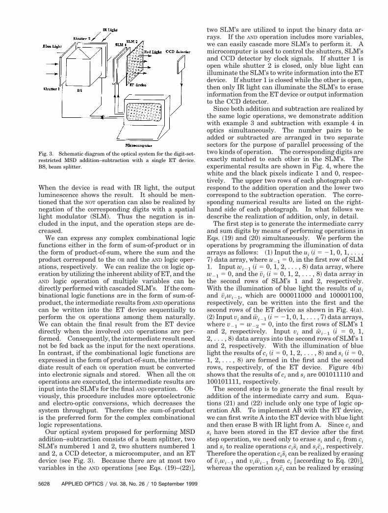
Our optical system proposed for performing MSDaddition–subtraction consists of a beam splitter, twoSLM’s numbered 1 and 2, two shutters numbered 1and 2, a CCD detector, a microcomputer, and an ETdevice ~see Fig. 3!. Because there are at most twovariables in the AND operations @see Eqs. ~19!–~22!#,
Fig. 3. Schematic diagram of the optical system for the digit-set-restricted MSD addition–subtraction with a single ET device.BS, beam splitter.
628 APPLIED OPTICS y Vol. 38, No. 26 y 10 September 1999
wo SLM’s are utilized to input the binary data ar-ays. If the AND operation includes more variables,
we can easily cascade more SLM’s to perform it. Amicrocomputer is used to control the shutters, SLM’sand CCD detector by clock signals. If shutter 1 isopen while shutter 2 is closed, only blue light canilluminate the SLM’s to write information into the ETdevice. If shutter 1 is closed while the other is open,then only IR light can illuminate the SLM’s to eraseinformation from the ET device or output informationto the CCD detector.
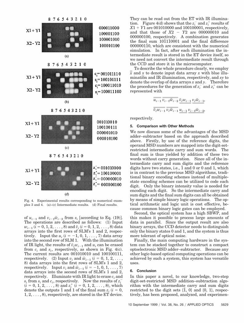
Since both addition and subtraction are realized bythe same logic operations, we demonstrate additionwith example 3 and subtraction with example 4 inoptics simultaneously. The number pairs to beadded or subtracted are arranged in two separatesectors for the purpose of parallel processing of thetwo kinds of operation. The corresponding digits areexactly matched to each other in the SLM’s. Theexperimental results are shown in Fig. 4, where thewhite and the black pixels indicate 1 and 0, respec-tively. The upper two rows of each photograph cor-respond to the addition operation and the lower twocorrespond to the subtraction operation. The corre-sponding numerical results are listed on the right-hand side of each photograph. In what follows wedescribe the realization of addition, only, in detail.
The first step is to generate the intermediate carryand sum digits by means of performing operations inEqs. ~19! and ~20! simultaneously. We perform theoperations by programming the illumination of dataarrays as follows: ~1! Input the ui ~i 5 21, 0, 1, . . . ,7! data array, where u21 5 0, in the first row of SLM1. Input wi21 ~i 5 0, 1, 2, . . . , 8! data array, wherew21 5 0, and the v# i ~i 5 0, 1, 2, . . . , 8! data array inthe second rows of SLM’s 1 and 2, respectively.With the illumination of blue light the results of uiand v# iwi21, which are 000011000 and 100001100,respectively, can be written into the first and thesecond rows of the ET device as shown in Fig. 4~a!.2! Input vi and w# i21 ~i 5 21, 0, 1, . . . , 7! data arrays,
where v21 5 w22 5 0, into the first rows of SLM’s 1and 2, respectively. Input vi and w# i21 ~i 5 0, 1,, . . . , 8! data arrays into the second rows of SLM’s 1
and 2, respectively. With the illumination of bluelight the results of ci ~i 5 0, 1, 2, . . . , 8! and si ~i 5 0,1, 2, . . . , 8! are formed in the first and the secondrows, respectively, of the ET device. Figure 4~b!shows that the results of ci and si are 001011110 and100101111, respectively.
The second step is to generate the final result byaddition of the intermediate carry and sum. Equa-tions ~21! and ~22! include only one type of logic op-eration AB# . To implement AB# with the ET device,we can first write A into the ET device with blue lightand then erase B with IR light from A. Since ci andsi have been stored in the ET device after the firststep operation, we need only to erase si and ci from ciand si to realize operations cis#i and sic#i, respectively.Therefore the operation cis#i can be realized by erasingof v# iwi21 and viw# i21 from ci @according to Eq. ~20!#,
hereas the operation sic#i can be realized by erasing
Tr
s
tr
t
of ui21 and vi21w# i22 from si @according to Eq. ~19!#.The operations are described as follows: ~1! Inputwi21 ~i 5 0, 1, 2, . . . , 8! and v# i ~i 5 0, 1, 2, . . . , 8! dataarrays into the first rows of SLM’s 1 and 2, respec-tively. Input the ui ~i 5 21, 0, 1, . . . , 7! data arrayinto the second row of SLM 1. With the illuminationof IR light, the results of v# iwi21 and ui can be erasedfrom ci and si, respectively, as shown in Fig. 4~c!.
he current results are 001010010 and 100100111,espectively. ~2! Input vi and w# i21 ~i 5 0, 1, 2, . . . ,
8! data arrays into the first rows of SLM’s 1 and 2,respectively. Input vi and w# i21 ~i 5 21, 0, 1, . . . , 7!data arrays into the second rows of SLM’s 1 and 2,respectively. Illuminate with IR light to erase ci and
i from si and ci, respectively. Now the results of zi2
~i 5 0, 1, 2, . . . , 8! and zi1 ~i 5 0, 1, 2, . . . , 8!, which
denote the outputs 1# and 1 of the final sum zi ~i 5 0,1, 2, . . . , 8!, respectively, are stored in the ET device.
Fig. 4. Experimental results corresponding to numerical exam-ples 3 and 4. ~a!–~c! Intermediate results. ~d! Final results.
10
They can be read out from the ET with IR illumina-tion. Figure 4~d! shows that the zi
2 and zi1 results of
X1 1 Y1 are 001010000 and 100100001, respectively,and that those of X2 2 Y2 are 000000010 and000000100, respectively. A combination generatesthe final sum 101#11#0001 and the final difference00000011#0, which are consistent with the numericalsimulation. In fact, after each illumination the in-termediate result is stored in the ET device itself, sowe need not convert the intermediate result throughthe CCD and store it in the microcomputer.
To describe the whole procedure clearly, we employx and x to denote input data array x with blue illu-mination and IR illumination, respectively, and xy todenote the overlap of data arrays x and y. Thereforehe procedures for the generation of zi
2 and zi1 can be
epresented with
ui21 vi21w# i22 v# iwi21 viw# i21,
v# iwi21 viw# i21 ui21 vi21w# i22,
respectively.
5. Comparison with Other Methods
We now discuss some of the advantages of the MSDadder–subtracter based on the approach describedabove. Firstly, by use of the reference digits, theoperand MSD numbers are mapped into the digit-set-restricted intermediate carry and sum words. Thefinal sum is thus yielded by addition of these twowords without carry generation. Since all of the in-termediate carry and sum digits and the referencedigits have two states, i.e., 1# and 0 or 0 and 1, whichis in contrast to the previous MSD algorithms, tradi-tional binary encoding schemes instead of multiple-state encoding schemes can be utilized to code eachdigit. Only the binary intensity value is needed forencoding each digit. So the intermediate carry andsum digits and the final sum digits can all be obtainedby means of simple binary logic operations. The op-tical arithmetic and logic unit is cost effective, be-cause common binary logic gates can be employed.
Second, the optical system has a high SBWP, andthis makes it possible to process large amounts ofdata in parallel. Since the output result are alsobinary arrays, the CCD detector needs to distinguishonly the binary states 0 and 1, and the system is thusmore tolerant of optical noise.
Finally, the main computing hardware in the sys-tem can be stacked together to construct a compactoptoelectronic MSD adder–subtracter. Because anyother logic-based optical computing operations can beachieved by such a system, this system has versatileuses.
6. Conclusion
In this paper a novel, to our knowledge, two-stepdigit-set-restricted MSD addition–subtraction algo-rithm with the intermediate carry and sum digitsrestricted to the digit sets $1# , 0% and $0, 1%, respec-ively, has been proposed, analyzed, and experimen-
September 1999 y Vol. 38, No. 26 y APPLIED OPTICS 5629
15. A. K. Cherri, M. K. Habib, and M. S. Alam, “Optoelectronic
5
tally demonstrated. The algorithm can be realizedby binary logic operations. To implement it opti-cally, an optical system that uses a single ET deviceis suggested. This optical system has the advan-tages of high SBWP and high signal-to-noise ratio.The main hardware can be stacked to construct acompact optoelectronic MSD adder–subtracter, andthe system has versatile uses.
This study was supported in part by the ShanghaiScience and Technology Committee, the ChineseAcademy of Sciences, and the National Natural Sci-ence Foundation of China. The authors thank thereferees for providing constructive suggestions.
References1. F. T. S. Yu and S. Jutamulia, Optical Signal Processing, Com-
puting, and Neural Networks ~Wiley, New York, 1992!.2. A. P. Goutzoulis, D. K. Davies, and E. C. Malarkey, “Prototype
position-encoded residue look-up table using laser diodes,”Opt. Commun. 61, 302–308 ~1987!.
3. D. Psaltis, D. Casasent, D. Neft, and M. Carlotto, “Accuratenumerical computation by optical convolution,” in 1980 Inter-national Optical Computing Conference II, W. T. Rhodes, ed.,Proc. SPIE 232, 151–156 ~1980!.
4. P. S. Guilfoyle, “Systolic acousto-optic binary convolver,” Opt.Eng. 23, 020–025 ~1984!.
5. G. Li, L. Liu, L. Shao, and Y. Yin, “Modified direct two’s com-plement parallel array multiplication algorithm for opticalcomplex matrix operation,” Appl. Opt. 34, 1321–1328 ~1995!.
6. G. Li, L. Liu, L. Shao, and Z. Wang, “Negabinary arithmeticalgorithms for digital parallel optical computation,” Opt. Lett.19, 1337–1339 ~1994!.
7. A. Avizienis, “Signed-digit number representations for fastparallel arithmetic,” IRE Trans. Electron. Comput. EC-10,389–400 ~1961!.
8. B. L. Drake, R. P. Bocker, M. E. Lasher, R. H. Patterson, andW. J. Miceli, “Photonic computing using the modified signed-digit number representation,” Opt. Eng. 25, 38–43 ~1986!.
9. Y. Li and G. Eichmann, “Conditional symbolic modified signed-digit arithmetic using optical content-addressable memorylogic elements,” Appl. Opt. 26, 2328–2333 ~1987!.
10. A. K. Cherri and M. A. Karim, “Modified-signed digit arith-metic using an efficient symbolic substitution,” Appl. Opt. 27,3824–3827 ~1988!.
11. A. A. S. Awwal, “Recoded signed-digit binary addition–subtraction using optoelectronic symbolic substitution,” Appl.Opt. 31, 3205–3208 ~1992!.
12. M. S. Alam, M. A. Karim, A. A. S. Awwal, and J. J.Westerkamp, “Optical processing based on conditional higher-order trinary modified signed-digit symbolic substitution,”Appl. Opt. 31, 5614–5621 ~1992!.
13. G. Li, F. Qian, H. Ruan, and L. Liu, “Parallel optical negabi-nary signed-digit computing: algorithm and optical imple-mentation,” Opt. Eng. 38, 403–414 ~1999!.
14. M. S. Alam, “Efficient binary signed-digit symbolic arith-metic,” Opt. Lett. 19, 353–355 ~1994!.
630 APPLIED OPTICS y Vol. 38, No. 26 y 10 September 1999
recoded and nonrecoded binary signed-digit adder that usesoptical correlation,” Appl. Opt. 37, 2153–2163 ~1998!.
16. M. S. Alam, Y. Ahuja, A. K. Cherri, and A. Chatterjea, “Sym-metrically recoded quaternary signed-digit arithmetic using ashared content-addressable memory,” Opt. Eng. 35, 1141–1149 ~1996!.
17. G. Li, L. Liu, H. Cheng, and H. Jing, “Simplified quaternarysigned-digit arithmetic and its optical implementation,” Opt.Commun. 137, 389–396 ~1997!.
18. D. Casasent and P. Woodford, “Symbolic substitution modifiedsigned-digit optical adder,” Appl. Opt. 33, 1498–1506 ~1994!.
19. M. M. Mirsalehi and T. K. Gaylord, “Logical minimization ofmultilevel coded functions,” Appl. Opt. 25, 3078–3088 ~1986!.
20. B. Ha and Y. Li, “Parallel modified signed-digit arithmeticusing an optoelectronic shared content-addressable-memoryprocessor,” Appl. Opt. 33, 3647–3662 ~1994!.
21. M. Karim, A. A. S. Awwal, and A. K. Cherri, “Polarization-encoded optical shadow-casting logic units: design,” Appl.Opt. 28, 2720–2725 ~1987!.
22. K. W. Wong and L. M. Cheng, “Optical modiofied signed-digitaddition based on binary logical operations,” Opt. Laser Tech-nol. 26, 213–217 ~1994!.
23. Y. Wu, Z. Zhang, L. Liu, and Z. Wang, “Arithmetic operationsusing binary encoding modified-signed-digit system,” Opt.Commun. 100, 53–58 ~1993!.
24. K. Hwang and A. Louri, “Optical multiplication and divisionusing modified-signed-digit symbolic substitution,” Opt. Eng.28, 364–372 ~1989!.
25. M. D. Ercegovac and T. Lang, “On-the-fly conversion of redun-dant into conventional representation,” IEEE Trans. Comput.C-36, 895–897 ~1987!.
26. Y. Li, J. Zhu, and G. Eichmann, “Optical on-the-fly conversionof a modified signed digit into two’s complement binary num-ber representation,” Opt. Lett. 13, 294–296 ~1988!.
27. M. M. Mirsalehi, “Modified signed-digit to binary conversionusing symbolic substitution,” in Optical Information and Pro-cessing Architectures IV, B. Javidi, ed., Proc. SPIE 1772, 374–376 ~1992!.
28. S. Yen, C. Laih, C. Chen, and J. Lee, “An efficient redundant-binary number to binary number converter,” IEEE J. Solid-State Circuits 27, 109–112 ~1992!.
29. M. A. Thornton, “Signed binary addition circuitry with inher-ent even parity outputs,” IEEE Trans. Comput. 46, 811–816~1997!.
30. A. D. McAulay, “Logic and arithmetic with luminescent re-broadcasting devices,” in Advances in Optical Information Pro-cessing III, D. R. Pape, ed., Proc. SPIE 936, 321–326 ~1988!.
31. S. Jutamula, G. M. Storti, and J. Lindmayer, “Use of electrontrapping materials in optical signal processing. 1. ParallelBoolean logic,” Appl. Opt. 29, 4806–4811 ~1990!.
32. X. Yang, C. Y. Wrigley, and J. Lindmayer, “Three-dimensionaloptical memory based on transparent electron thin film,” inPhotonics for Computers, Neural Networks, and Memories,W. J. Miceli, A. Neff, and T. Kowel, eds., Proc. SPIE 1773,413–422 ~1992!.
33. A. D. McAulay, J. Wang, and X. Xu, “Optical perception learn-ing for binary classification with spatial light rebroadcasters,”Appl. Opt. 32, 1346–1353 ~1993!.