Embed Size (px)
Citation preview

U16, U24 and U32Professional Audio Mixing Consoles
Operator Manual
MUSIC Group Research UK Limited, Klark Industrial Park,Walter Nash Road,
Kidderminster.Worcestershire.
DY11 7HJ.England.
Tel: +44 1562 741515Fax: +44 1562 745371
Email: [email protected]: www.midasconsoles.com
VeniceU — Operator Manual DOC02-VENICEU Issue E — November 2013
© MUSIC Group IP Limited
© 2013 MUSIC Group IP Ltd. Technical specifications and appearances are subject to change without notice and accuracy is not guaranteed. MIDAS and KLARK TEKNIK are part of the MUSIC Group (music-group.com).

VeniceU Operator Manual iii
MUSIC Group IP Limited
Important safety instructions
Terminals marked with this symbol carry electrical current of sufficient magnitude to constitute risk of electric shock. Use only
high-quality commercially-available speaker cables with ¼" TS plugs pre-installed. All other installation or modification should be performed only by qualified personnel.
This symbol, wherever it appears, alerts you to the presence of uninsulated dangerous voltage inside the enclosure - voltage that
may be sufficient to constitute a risk of shock.
This symbol, wherever it appears, alerts you to important operating and maintenance instructions in the accompanying literature.
Please read the manual.
CautionTo reduce the risk of electric shock, do not remove the top cover (or the rear section). No
user serviceable parts inside. Refer servicing to qualified personnel.
CautionTo reduce the risk of fire or electric shock, do not expose this appliance to rain and moisture.
The apparatus shall not be exposed to dripping or splashing liquids and no objects filled with liquids, such as vases, shall be placed on the apparatus.
CautionThese service instructions are for use by qualified service personnel only. To reduce the risk of electric
shock do not perform any servicing other than that contained in the operation instructions. Repairs have to be performed by qualified service personnel.
1 Read these instructions.
2 Keep these instructions.
3 Heed all warnings.
4 Follow all instructions.
5 Do not use this apparatus near water.
6 Clean only with dry cloth.
7 Do not block any ventilation openings. Install in accordance with the manufacturer's instructions.
8 Do not install near any heat sources such as radiators, heat registers, stoves, or other apparatus (including amplifiers) that produce heat.
9 Do not defeat the safety purpose of the polarized or grounding-type plug. A polarized plug has two blades with one wider than the other. A grounding-type plug has two blades and a third grounding prong. The wide blade or the third prong are provided for your safety. If the provided plug does not fit into your outlet, consult an electrician for replacement of the obsolete outlet.
10 Protect the power cord from being walked on or pinched particularly at plugs, convenience receptacles, and the point where they exit from the apparatus.
11 Use only attachments/accessories specified by the manufacturer.
12 Use only with the cart, stand, tripod, bracket, or table specified by the manufacturer, or sold with the apparatus. When a cart is used, use caution when
moving the cart/apparatus combination to avoid injury from tip-over.
13 Unplug this apparatus during lightning storms or when unused for long periods of time.
14 Refer all servicing to qualified service personnel. Servicing is required when the apparatus has been damaged in any way, such as power supply cord or plug is damaged, liquid has been spilled or objects have fallen into the apparatus, the apparatus has been exposed to rain or moisture, does not operate normally, or has been dropped.
15 The apparatus shall be connected to a MAINS socket outlet with a protective earthing connection.
16 Where the MAINS plug or an appliance coupler is used as the disconnect device, the disconnect device shall remain readily operable.
Legal disclaimerTechnical specifications and appearances are subject to change without notice and accuracy is not guaranteed. MIDAS and KLARK TEKNIK are part of the MUSIC Group (music-group.com). All trademarks are the property of their respective owners. MUSIC Group accepts no liability for any loss which may be suffered by any person who relies either wholly or in part upon any description, photograph or statement contained herein. Colours and specifications may vary slightly from product. Midas products are sold through
authorized dealers only. Distributors and dealers are not agents of MUSIC Group and have absolutely no authority to bind MUSIC Group by any express or implied undertaking or representation. This manual is copyrighted. No part of this manual may be reproduced or transmitted in any form or by any means, electronic or mechanical, including photocopying and recording of any kind, for any purpose, without the express written permission of MUSIC Group IP Limited
ALL RIGHTS RESERVED. © 2013 MUSIC Group IP LimitedTrident Chambers, Wickhams Cay, P.O. Box 146, Road Town, Tortola, British Virgin Islands
Limited warranty§ 1 Warranty1. This limited warranty is valid only if youpurchased the product from a MUSIC Group authorized dealer in the country of purchase. A list of authorized dealers can be found on MUSIC Group's website www.midasconsoles.com, or you can contact the MUSIC Group office closest to you.
2. MUSIC Group* warrants the mechanical andelectronic components of this product to be free of defects in material and workmanship if used under normal operating conditions for a period of three (3) years from the original date of purchase (see the Limited Warranty terms in § 4 below), unless a longer minimum warranty period is mandated by applicable local laws. If the product shows any defects within the specified warranty period and that defect is not excluded under § 4, MUSIC Group shall, at its discretion, either replace or repair the product using suitable new or reconditioned product or parts. In case MUSIC Group decides to replace the entire product, this limited warranty shall apply to the replacement product for the remaining initial warranty period, i.e., three (3) years (or otherwise applicableminimum warranty period) from the date of purchase of the original product.
3. Upon validation of the warranty claim, therepaired or replacement product will be returned to the user freight prepaid by MUSIC Group.
4. Warranty claims other than those indicatedabove are expressly excluded.
PLEASE RETAIN YOUR SALES RECEIPT. IT IS YOUR PROOF OF PURCHASE COVERING YOUR LIMITED WARRANTY. THIS LIMITED WARRANTY IS VOID WITHOUT SUCH PROOF OF PURCHASE.
§ 2 Online registrationPlease do remember to register your new Midas equipment right after your purchase at www.midasconsoles.com and kindly read the terms and conditions of our limited warranty
CAUTION
ATTENTION
RISK OF ELECTRIC SHOCK!DO NOT OPEN!
RISQUE DE CHOC ELECTRIQUE!NE PAS OUVRIR!
iv VeniceU
MUSIC Group IP Limited
carefully. Registering your purchase and equipment with us helps us process your repair claims quicker and more efficiently. Thank you for your cooperation!
§ 3 Return materials authorization1. To obtain warranty service, please contact the retailer from whom the equipment was purchased. Should your MUSIC Group dealer not be located in your vicinity, you may contact the MUSIC Group distributor for your country listed at www.midasconsoles.com. If your country is not listed please contact the “United Kingdom (Midas/KT main office)” located under “Service Service/Repairs” on the www.midasconsoles.com website. Alternatively, please submit the online warranty return form found under “Service Warranty Registration” on www.midasconsoles.com BEFORE returning the product. All enquires must be accompanied by the description of the problem and the serial number of the product. The warranty eligibility will be verified from the original sales receipt.
2. Subsequently, the product must be returned in its original shipping carton, together with the return authorization number to the address indicated by MUSIC Group.
3. Shipments without freight prepaid will not be accepted.
§ 4 Warranty Exclusions1. This limited warranty does not cover consumable parts including, but not limited to, fuses and batteries. Where applicable, MUSIC Group warrants the valves or meters contained in the product to be free from defects in material and workmanship for a period of ninety (90) days from date of purchase.
2. This limited warranty does not cover the product if it has been electronically or mechanically modified in any way. If the product needs to be modified or adapted in order to comply with applicable technical or safety standards on a national or local level, in any country which is not the country for which the product was originally developed and manufactured, this modification/adaptation shall not be considered a defect in materials or workmanship. This limited warranty does not cover any such modification/adaptation, regardless of whether it was carried out properly or not. Under the terms of this limited warranty, MUSIC Group shall not be held responsible for any cost resulting from such a modification/adaptation.
3. This limited warranty covers only the product hardware. It does not cover technical assistance for hardware or software usage and it does not cover any software products whether or not contained in the product. Any such software is provided "AS IS" unless expressly provided for in any enclosed software limited warranty.
4. This limited warranty is invalid if the factory-applied serial number has been altered or removed from the product.
5. Free inspections and maintenance/repair work are expressly excluded from this limited warranty, in particular, if caused by improper handling of the product by the user. This also applies to defects caused by normal wear and tear, in particular, of faders, crossfaders, potentiometers, keys/buttons, guitar strings, illuminants and similar parts.
6. Damage/defects caused by the following conditions are not covered by this limited warranty:
• improper handling, neglect or failure to operate the unit in compliance with the instructions given in Midas user or service manuals;
• connection or operation of the unit in any way that does not comply with the technical or safety regulations applicable in the country where the product is used;
• damage/defects caused by acts of God/Nature (accident, fire, flood, etc) or any other condition that is beyond the control of MUSIC Group.
7. Any repair or opening of the unit carried out by unauthorised personnel (user included) will void the limited warranty.
8. If an inspection of the product by MUSIC Group shows that the defect in question is not covered by the limited warranty, the inspection costs are payable by the customer.
9. Products which do not meet the terms of this limited warranty will be repaired exclusively at the buyer's expense. MUSIC Group or its authorized service centre will inform the buyer of any such circumstance. If the buyer fails to submit a written repair order within 6 weeks after notification, MUSIC Group will return the unit C.O.D. with a separate invoice for freight and packing. Such costs will also be invoiced separately when the buyer has sent in a written repair order.
10. Authorized MUSIC Group dealers do not sell new products directly in online auctions. Purchases made through an online auction are on a "buyer beware" basis. Online auction confirmations or sales receipts are not accepted for warranty verification and MUSIC Group will not repair or replace any product purchased through an online auction.
§ 5 Warranty transferabilityThis limited warranty is extended exclusively to the original buyer (customer of authorized retail dealer) and is not transferable to anyone who may subsequently purchase this product. No other person (retail dealer, etc.) shall be entitled to give any warranty promise on behalf of MUSIC Group.
§ 6 Claim for damageSubject only to the operation of mandatory applicable local laws, MUSIC Group shall have no liability to the buyer under this warranty for any consequential or indirect loss or damage of any kind. In no event shall the liability of MUSIC Group under this limited warranty exceed the invoiced value of the product.
§ 7 Limitation of liabilityThis limited warranty is the complete and exclusive warranty between you and MUSIC Group. It supersedes all other written or oral communications related to this product. MUSIC Group provides no other warranties for this product.
§ 8 Other warranty rights and national law1. This limited warranty does not exclude or limit the buyer's statutory rights as a consumer in any way.
2. The limited warranty regulations mentioned herein are applicable unless they constitute an infringement of applicable mandatory local laws.
3. This warranty does not detract from the seller's obligations in regard to any lack of conformity of the product and any hidden defect.
§ 9 AmendmentWarranty service conditions are subject to change without notice. For the latest warranty terms and conditions and additional information regarding MUSIC Group's limited warranty, please see complete details online at www.midasconsoles.com.
* MUSIC Group Macao Commercial Offshore Limited of Rue de Pequim No. 202-A, Macau Finance Centre 9/J, Macau, including all MUSIC Group companies
Operator Manual v
Other important information1 Register online. Please register your new Midas equipment right after you purchase it by visiting www.midasconsoles.com. Registering your purchase using our simple online form helps us to process your repair claims more quickly and efficiently. Also, read the terms and conditions of our warranty, if applicable.
2 Malfunction. Should your MUSIC Group Authorized Reseller not be located in your vicinity, you may contact the MUSIC Group Authorized Fulfiller for your country at www.midasconsoles.com. If your country is not listed please contact the “United Kingdom (Midas/KT main office)” located under “Service Service/Repairs” on the www.midasconsoles.com website. Alternatively, please submit the online warranty return form found under “Service Warranty Registration” on www.midasconsoles.com BEFORE returning the product. All enquires must be accompanied by the description of the problem and the serial number of the product. The warranty eligibility will be verified from the original sales receipt.
3 Power Connections. Before plugging the unit into a power socket, please make sure you are using the correct mains voltage for your particular model. Faulty fuses must be replaced with fuses of the same type and rating without exception.
Mac and the Mac logo are trademarks of Apple Inc., registered in the U.S. and other countries.
Microsoft and Windows are registered trademarks of Microsoft Corporation in the United States and other countries.

vi VeniceU
MUSIC Group IP Limited
vii
VeniceUOperator Manual
Contents
Important safety instructions . . . . . . . . . . . . . . . . . . . . . . . . . . . . . . . . iii
Other important information . . . . . . . . . . . . . . . . . . . . . . . . . . . . . . . . . . v
Chapter 1 Introduction . . . . . . . . . . . . . . . . . . . . . . . . . . . . . . . . .1Overview of the VeniceU . . . . . . . . . . . . . . . . . . . . . . . . . . . . . . . . . . 1Key features . . . . . . . . . . . . . . . . . . . . . . . . . . . . . . . . . . . . . . . . . . 3Control surface . . . . . . . . . . . . . . . . . . . . . . . . . . . . . . . . . . . . . . . . 4Rear panel . . . . . . . . . . . . . . . . . . . . . . . . . . . . . . . . . . . . . . . . . . . . 6External connections . . . . . . . . . . . . . . . . . . . . . . . . . . . . . . . . . . . . . 7Signal flow . . . . . . . . . . . . . . . . . . . . . . . . . . . . . . . . . . . . . . . . . . . . 8Mix matrix . . . . . . . . . . . . . . . . . . . . . . . . . . . . . . . . . . . . . . . . . . . 10About this manual . . . . . . . . . . . . . . . . . . . . . . . . . . . . . . . . . . . . . 10Service and support . . . . . . . . . . . . . . . . . . . . . . . . . . . . . . . . . . . . 11
Chapter 2 Getting Started. . . . . . . . . . . . . . . . . . . . . . . . . . . . . .13Installation . . . . . . . . . . . . . . . . . . . . . . . . . . . . . . . . . . . . . . . . . . 13
Handling the equipment . . . . . . . . . . . . . . . . . . . . . . . . . . . . . . . 13Electric fields . . . . . . . . . . . . . . . . . . . . . . . . . . . . . . . . . . . . . . . 14
Connecting up . . . . . . . . . . . . . . . . . . . . . . . . . . . . . . . . . . . . . . . . 14Audio connections . . . . . . . . . . . . . . . . . . . . . . . . . . . . . . . . . . . 14Connecting to balanced/unbalanced equipment . . . . . . . . . . . . . . . 15Other connections . . . . . . . . . . . . . . . . . . . . . . . . . . . . . . . . . . . 16
Setting up . . . . . . . . . . . . . . . . . . . . . . . . . . . . . . . . . . . . . . . . . . . 16Switching the VeniceU on/off . . . . . . . . . . . . . . . . . . . . . . . . . . . . . . 17
Chapter 3 Using The VeniceU With USB . . . . . . . . . . . . . . . . . . .19Windows 7 operating system . . . . . . . . . . . . . . . . . . . . . . . . . . . . . . 19
Using the Archwave USB Driver Control Panel . . . . . . . . . . . . . . . . 21Mac operating system . . . . . . . . . . . . . . . . . . . . . . . . . . . . . . . . . . . 29
Updating the VeniceU firmware . . . . . . . . . . . . . . . . . . . . . . . . . . . . 31Troubleshooting USB operation . . . . . . . . . . . . . . . . . . . . . . . . . . . . 32
Audio problems . . . . . . . . . . . . . . . . . . . . . . . . . . . . . . . . . . . . . 32Avoiding drop outs . . . . . . . . . . . . . . . . . . . . . . . . . . . . . . . . . . . 32No devices found . . . . . . . . . . . . . . . . . . . . . . . . . . . . . . . . . . . . 33Overcoming ground loop problems . . . . . . . . . . . . . . . . . . . . . . . . 33
Chapter 4 Working With The Console. . . . . . . . . . . . . . . . . . . . .35Ground loop problems . . . . . . . . . . . . . . . . . . . . . . . . . . . . . . . . . . . 35
Chapter 5 Mono Input Channel. . . . . . . . . . . . . . . . . . . . . . . . . .37Overview of the mono input channel . . . . . . . . . . . . . . . . . . . . . . . . . 38Rear panel . . . . . . . . . . . . . . . . . . . . . . . . . . . . . . . . . . . . . . . . . . . 39Gain . . . . . . . . . . . . . . . . . . . . . . . . . . . . . . . . . . . . . . . . . . . . . . . 40
viii Contents
VeniceUOperator Manual
EQ . . . . . . . . . . . . . . . . . . . . . . . . . . . . . . . . . . . . . . . . . . . . . . . . .41Monitors . . . . . . . . . . . . . . . . . . . . . . . . . . . . . . . . . . . . . . . . . . . . .42Auxes . . . . . . . . . . . . . . . . . . . . . . . . . . . . . . . . . . . . . . . . . . . . . .43Pan, mute and solo . . . . . . . . . . . . . . . . . . . . . . . . . . . . . . . . . . . . .44Fader, routing and meter . . . . . . . . . . . . . . . . . . . . . . . . . . . . . . . . .45
Meter . . . . . . . . . . . . . . . . . . . . . . . . . . . . . . . . . . . . . . . . . . . .46Routing . . . . . . . . . . . . . . . . . . . . . . . . . . . . . . . . . . . . . . . . . . .46
Chapter 6 Multifunction Input Channel . . . . . . . . . . . . . . . . . . . 47Overview of the multifunction input channel . . . . . . . . . . . . . . . . . . . .48Rear panel . . . . . . . . . . . . . . . . . . . . . . . . . . . . . . . . . . . . . . . . . . .49Gain (mic inputs) . . . . . . . . . . . . . . . . . . . . . . . . . . . . . . . . . . . . . .50USB . . . . . . . . . . . . . . . . . . . . . . . . . . . . . . . . . . . . . . . . . . . . . . . .50Stereo line inputs . . . . . . . . . . . . . . . . . . . . . . . . . . . . . . . . . . . . . .51EQ . . . . . . . . . . . . . . . . . . . . . . . . . . . . . . . . . . . . . . . . . . . . . . . . .51Monitors . . . . . . . . . . . . . . . . . . . . . . . . . . . . . . . . . . . . . . . . . . . . .52Auxes . . . . . . . . . . . . . . . . . . . . . . . . . . . . . . . . . . . . . . . . . . . . . .52Balance, mute and solo . . . . . . . . . . . . . . . . . . . . . . . . . . . . . . . . . .53Fader, routing and meter . . . . . . . . . . . . . . . . . . . . . . . . . . . . . . . . .54
Meter . . . . . . . . . . . . . . . . . . . . . . . . . . . . . . . . . . . . . . . . . . . .55
Chapter 7 Output Section. . . . . . . . . . . . . . . . . . . . . . . . . . . . . . 57Rear panel . . . . . . . . . . . . . . . . . . . . . . . . . . . . . . . . . . . . . . . . . . .58Overview of the outputs section . . . . . . . . . . . . . . . . . . . . . . . . . . . .59Output module notes . . . . . . . . . . . . . . . . . . . . . . . . . . . . . . . . . . . .60
Group-aux changeover . . . . . . . . . . . . . . . . . . . . . . . . . . . . . . . .60Meter changeover . . . . . . . . . . . . . . . . . . . . . . . . . . . . . . . . . . . .60
Groups . . . . . . . . . . . . . . . . . . . . . . . . . . . . . . . . . . . . . . . . . . . . . .61USB . . . . . . . . . . . . . . . . . . . . . . . . . . . . . . . . . . . . . . . . . . . . . . . .62Matrices . . . . . . . . . . . . . . . . . . . . . . . . . . . . . . . . . . . . . . . . . . . . .64Stereo returns . . . . . . . . . . . . . . . . . . . . . . . . . . . . . . . . . . . . . . . .66Monitors . . . . . . . . . . . . . . . . . . . . . . . . . . . . . . . . . . . . . . . . . . . . .67Auxes . . . . . . . . . . . . . . . . . . . . . . . . . . . . . . . . . . . . . . . . . . . . . .68Master outputs (mono and stereo) . . . . . . . . . . . . . . . . . . . . . . . . . .69Talkback . . . . . . . . . . . . . . . . . . . . . . . . . . . . . . . . . . . . . . . . . . . .71Playback and recording . . . . . . . . . . . . . . . . . . . . . . . . . . . . . . . . . .72
Playback . . . . . . . . . . . . . . . . . . . . . . . . . . . . . . . . . . . . . . . . . .72Recording . . . . . . . . . . . . . . . . . . . . . . . . . . . . . . . . . . . . . . . . .72
Local monitor and phones . . . . . . . . . . . . . . . . . . . . . . . . . . . . . . . .73Lamps . . . . . . . . . . . . . . . . . . . . . . . . . . . . . . . . . . . . . . . . . . . . . .74
Appendix A Functional Block Diagrams . . . . . . . . . . . . . . . . . . . . 75Mono input module . . . . . . . . . . . . . . . . . . . . . . . . . . . . . . . . . . . . .76Stereo input module . . . . . . . . . . . . . . . . . . . . . . . . . . . . . . . . . . . .78Master and monitor modules . . . . . . . . . . . . . . . . . . . . . . . . . . . . . .80
Appendix B Technical Specification . . . . . . . . . . . . . . . . . . . . . . . 83Dimensions . . . . . . . . . . . . . . . . . . . . . . . . . . . . . . . . . . . . . . . . . .85
Appendix C Application Notes . . . . . . . . . . . . . . . . . . . . . . . . . . . 87Gain . . . . . . . . . . . . . . . . . . . . . . . . . . . . . . . . . . . . . . . . . . . . . . .87Headroom . . . . . . . . . . . . . . . . . . . . . . . . . . . . . . . . . . . . . . . . . . .87
Contents ix
VeniceUOperator Manual
The effect of EQ . . . . . . . . . . . . . . . . . . . . . . . . . . . . . . . . . . . . . . . 88Dynamic processing . . . . . . . . . . . . . . . . . . . . . . . . . . . . . . . . . . . . 88Unity Gain . . . . . . . . . . . . . . . . . . . . . . . . . . . . . . . . . . . . . . . . . . . 89Signal Processing and Amplifiers . . . . . . . . . . . . . . . . . . . . . . . . . . . 89Routing . . . . . . . . . . . . . . . . . . . . . . . . . . . . . . . . . . . . . . . . . . . . . 90
FOH mode . . . . . . . . . . . . . . . . . . . . . . . . . . . . . . . . . . . . . . . . . 90MON mode . . . . . . . . . . . . . . . . . . . . . . . . . . . . . . . . . . . . . . . . 91Dual FOH/MON Mode . . . . . . . . . . . . . . . . . . . . . . . . . . . . . . . . . 91
Appendix D Crib Sheets . . . . . . . . . . . . . . . . . . . . . . . . . . . . . . . . .93Mono input channels
Notes: . . . . . . . . . . . . . . . . . . . . . . . . . . . . . . . . . . . . . . . . . . . . . . 94Multifunction input channels . . . . . . . . . . . . . . . . . . . . . . . . . . . . . . 95
Appendix E Best Grounding Practice. . . . . . . . . . . . . . . . . . . . . . .97Safety first . . . . . . . . . . . . . . . . . . . . . . . . . . . . . . . . . . . . . . . . . . 97Ground loops . . . . . . . . . . . . . . . . . . . . . . . . . . . . . . . . . . . . . . . . . 97Noise sources . . . . . . . . . . . . . . . . . . . . . . . . . . . . . . . . . . . . . . . . . 98Noise solutions . . . . . . . . . . . . . . . . . . . . . . . . . . . . . . . . . . . . . . . 100Balanced connections . . . . . . . . . . . . . . . . . . . . . . . . . . . . . . . . . . 101Balanced transformers . . . . . . . . . . . . . . . . . . . . . . . . . . . . . . . . . 102Screen termination . . . . . . . . . . . . . . . . . . . . . . . . . . . . . . . . . . . . 102Ground referenced connections . . . . . . . . . . . . . . . . . . . . . . . . . . . 103Unbalanced connections . . . . . . . . . . . . . . . . . . . . . . . . . . . . . . . . 104Signal ground lift . . . . . . . . . . . . . . . . . . . . . . . . . . . . . . . . . . . . . 104XLR shells . . . . . . . . . . . . . . . . . . . . . . . . . . . . . . . . . . . . . . . . . . 105Signal ground bonding . . . . . . . . . . . . . . . . . . . . . . . . . . . . . . . . . 105
Appendix F Modification For VeniceU16 Rack Mounting. . . . . . .107Electrostatic discharge (ESD) precautions . . . . . . . . . . . . . . . . . . . . 107Rack mounting parts . . . . . . . . . . . . . . . . . . . . . . . . . . . . . . . . . . . 107Special tools required . . . . . . . . . . . . . . . . . . . . . . . . . . . . . . . . . . 107Recommended torque settings . . . . . . . . . . . . . . . . . . . . . . . . . . . . 107Modification procedure . . . . . . . . . . . . . . . . . . . . . . . . . . . . . . . . . 108
Appendix G Service Information . . . . . . . . . . . . . . . . . . . . . . . . .115Routine maintenance . . . . . . . . . . . . . . . . . . . . . . . . . . . . . . . . . . 115Cleaning the console . . . . . . . . . . . . . . . . . . . . . . . . . . . . . . . . . . . 115Troubleshooting . . . . . . . . . . . . . . . . . . . . . . . . . . . . . . . . . . . . . . 115Special accessories . . . . . . . . . . . . . . . . . . . . . . . . . . . . . . . . . . . . 115Optional equipment . . . . . . . . . . . . . . . . . . . . . . . . . . . . . . . . . . . 115Equipment disposal . . . . . . . . . . . . . . . . . . . . . . . . . . . . . . . . . . . . 116
FEDERAL COMMUNICATIONS COMMISSION COMPLIANCE INFORMATION 117

x Contents
VeniceUOperator Manual
1
VeniceUOperator Manual
Chapter 1: Introduction
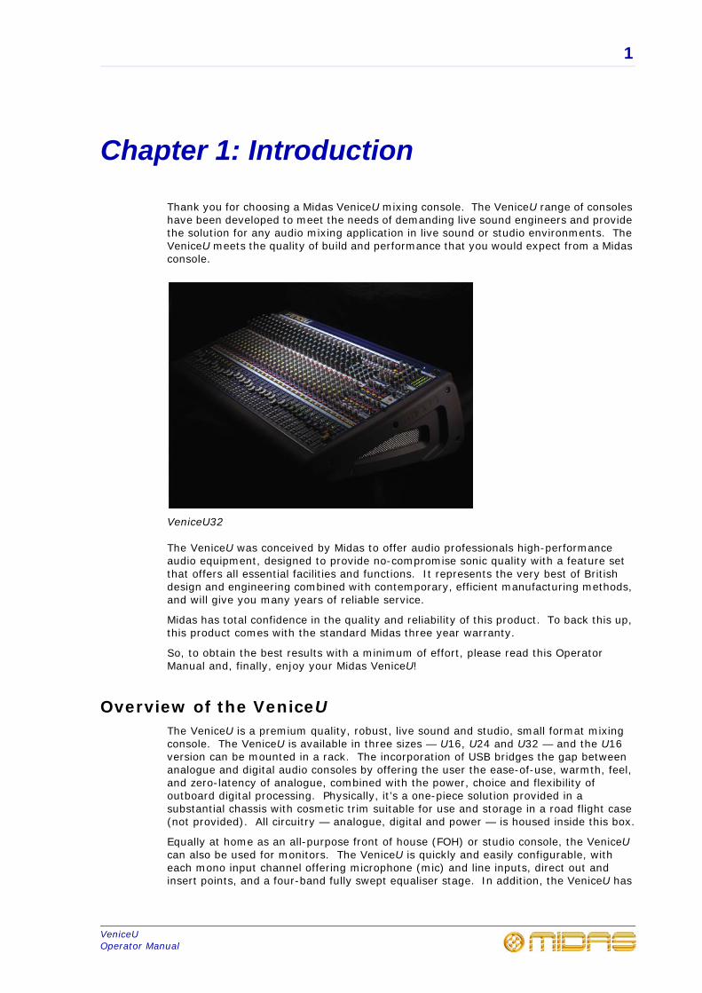
Thank you for choosing a Midas VeniceU mixing console. The VeniceU range of consoles have been developed to meet the needs of demanding live sound engineers and provide the solution for any audio mixing application in live sound or studio environments. The VeniceU meets the quality of build and performance that you would expect from a Midas console.
VeniceU32
The VeniceU was conceived by Midas to offer audio professionals high-performance audio equipment, designed to provide no-compromise sonic quality with a feature set that offers all essential facilities and functions. It represents the very best of British design and engineering combined with contemporary, efficient manufacturing methods, and will give you many years of reliable service.
Midas has total confidence in the quality and reliability of this product. To back this up, this product comes with the standard Midas three year warranty.
So, to obtain the best results with a minimum of effort, please read this Operator Manual and, finally, enjoy your Midas VeniceU!
Overview of the VeniceUThe VeniceU is a premium quality, robust, live sound and studio, small format mixing console. The VeniceU is available in three sizes — U16, U24 and U32 — and the U16 version can be mounted in a rack. The incorporation of USB bridges the gap between analogue and digital audio consoles by offering the user the ease-of-use, warmth, feel, and zero-latency of analogue, combined with the power, choice and flexibility of outboard digital processing. Physically, it’s a one-piece solution provided in a substantial chassis with cosmetic trim suitable for use and storage in a road flight case (not provided). All circuitry — analogue, digital and power — is housed inside this box.
Equally at home as an all-purpose front of house (FOH) or studio console, the VeniceU can also be used for monitors. The VeniceU is quickly and easily configurable, with each mono input channel offering microphone (mic) and line inputs, direct out and insert points, and a four-band fully swept equaliser stage. In addition, the VeniceU has
2 Chapter 1: Introduction
VeniceUOperator Manual
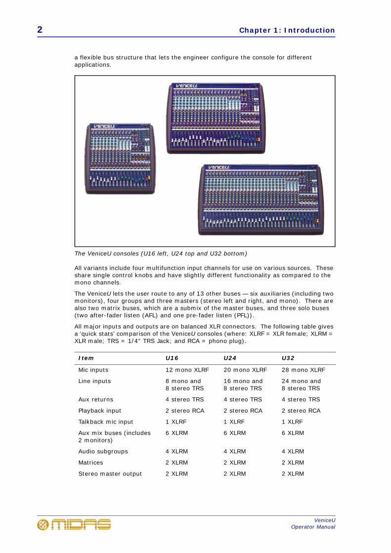
a flexible bus structure that lets the engineer configure the console for different applications.
The VeniceU consoles (U16 left, U24 top and U32 bottom)
All variants include four multifunction input channels for use on various sources. These share single control knobs and have slightly different functionality as compared to the mono channels.
The VeniceU lets the user route to any of 13 other buses — six auxiliaries (including two monitors), four groups and three masters (stereo left and right, and mono). There are also two matrix buses, which are a submix of the master buses, and three solo buses (two after-fader listen (AFL) and one pre-fader listen (PFL)).
All major inputs and outputs are on balanced XLR connectors. The following table gives a ‘quick stats’ comparison of the VeniceU consoles (where: XLRF = XLR female; XLRM = XLR male; TRS = 1/4” TRS Jack; and RCA = phono plug).
Item U16 U24 U32
Mic inputs 12 mono XLRF 20 mono XLRF 28 mono XLRF
Line inputs 8 mono and 8 stereo TRS
16 mono and 8 stereo TRS
24 mono and 8 stereo TRS
Aux returns 4 stereo TRS 4 stereo TRS 4 stereo TRS
Playback input 2 stereo RCA 2 stereo RCA 2 stereo RCA
Talkback mic input 1 XLRF 1 XLRF 1 XLRF
Aux mix buses (includes 2 monitors)
6 XLRM 6 XLRM 6 XLRM
Audio subgroups 4 XLRM 4 XLRM 4 XLRM
Matrices 2 XLRM 2 XLRM 2 XLRM
Stereo master output 2 XLRM 2 XLRM 2 XLRM
Key features 3
VeniceUOperator Manual
The USB interface can be used with any personal computer (PC) fitted with a standard USB 2.0 port, and is effectively a digital multi-channel cable (up to 8 in and 8 out channels) for connecting the PC to the console. USB lets you use any third party audio processing software in conjunction with the console, and applications include multi-track recording, software-generated effects processors and “plug-ins” inserted on input dual stereo channel USB send/returns.
Key featuresThe VeniceU consoles include the following key features:
• Sizes — available in 16, 24 and 32 input channel frame sizes.
• Midas mic preamps — 12/20/28 overload-tolerant Midas mic preamps (the lastfour being on four stereo modules), which accept +32dBu.
• EQ — each mono channel has a 4-band swept EQ (treble, hi mid, lo mid and bass).
• 4-band EQs on stereo channels — 4-band fixed frequency EQs on stereochannels.
• Ease of use — easy to store, prep, configure, maintain, repair, transport,set up/down and clean.
• Hybrid technology — analogue technology for sound processing and mixing, anddigital connectivity provided by USB. Analogue or digital (USB) input and analogueor digital (USB) output.
• USB — up to 8 in and 8 out channel USB interface (USB type B socket) that providesI/O connectivity to the multifunction input channels. The USB inputs feed the buses,while the USB outputs are sourced from the buses and are selectable using thechangeover switches. Allows the use of external DAW-based effects and recording.
• Mono input channels — mic/line in, insert and direct out per channel. Eachchannel mic pre-amp has +48V phantom volt, +20dB pad, 80Hz high pass filter andpolarity switches.
• Multifunction input channels — mono mic in, left (or mono) and right line in, andstereo USB in (same mic pre-amp functions as the mono inputs).
• Master channels — mono, left and right master channels, each with an insert.
• 15 Buses — 6 aux sends (includes 2 monitor (foldback) sends that are globallyswitchable pre-/post-fader), 4 groups, 3 masters (2 stereo and a mono) and 2matrices, all with hardware outputs.
• Returns — 2 stereo returns with flexible routing options.
• Local outputs — 2 local outputs (left and right).
• Routing — individual switch routing to stereo, mono and two pairs of groups.
• Metering — 4-LED meter per mono and stereo input channels, and per group, and3 x 12-LED master/solo meters.
• Faders — high-precision 100 mm faders.
• 48V phantom power — all analogue audio I/O is tolerant of 48V connection.
• I/O connectors — all main inputs and outputs are on balanced XLR connectors.
Mono master output XLRM XLRM XLRM
USB I/O 4 stereo channel, Type B
4 stereo channel, Type B
4 stereo channel, Type B
Item U16 U24 U32
4 Chapter 1: Introduction
VeniceUOperator Manual
• Mains power supply — universal switch mode power supply unit (PSU) with mainsinput socket and on/off switch.
• Lamps — socket(s) for fitting lamps.
• Playback/record I/Os — input/output sockets for playback and recording.
• Warranty — standard Midas 3-year warranty.
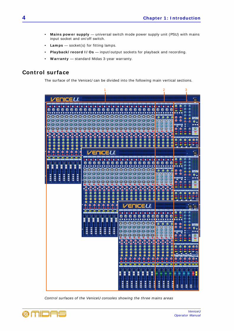
Control surfaceThe surface of the VeniceU can be divided into the following main vertical sections.
Control surfaces of the VeniceU consoles showing the three mains areas
321
Control surface 5
VeniceUOperator Manual
Item Description
1 See Chapter 5 "Mono Input Channel" on page 37
2 See Chapter 6 "Multifunction Input Channel" on page 47
3 See Chapter 7 "Output Section" on page 57
6 Chapter 1: Introduction
VeniceUOperator Manual
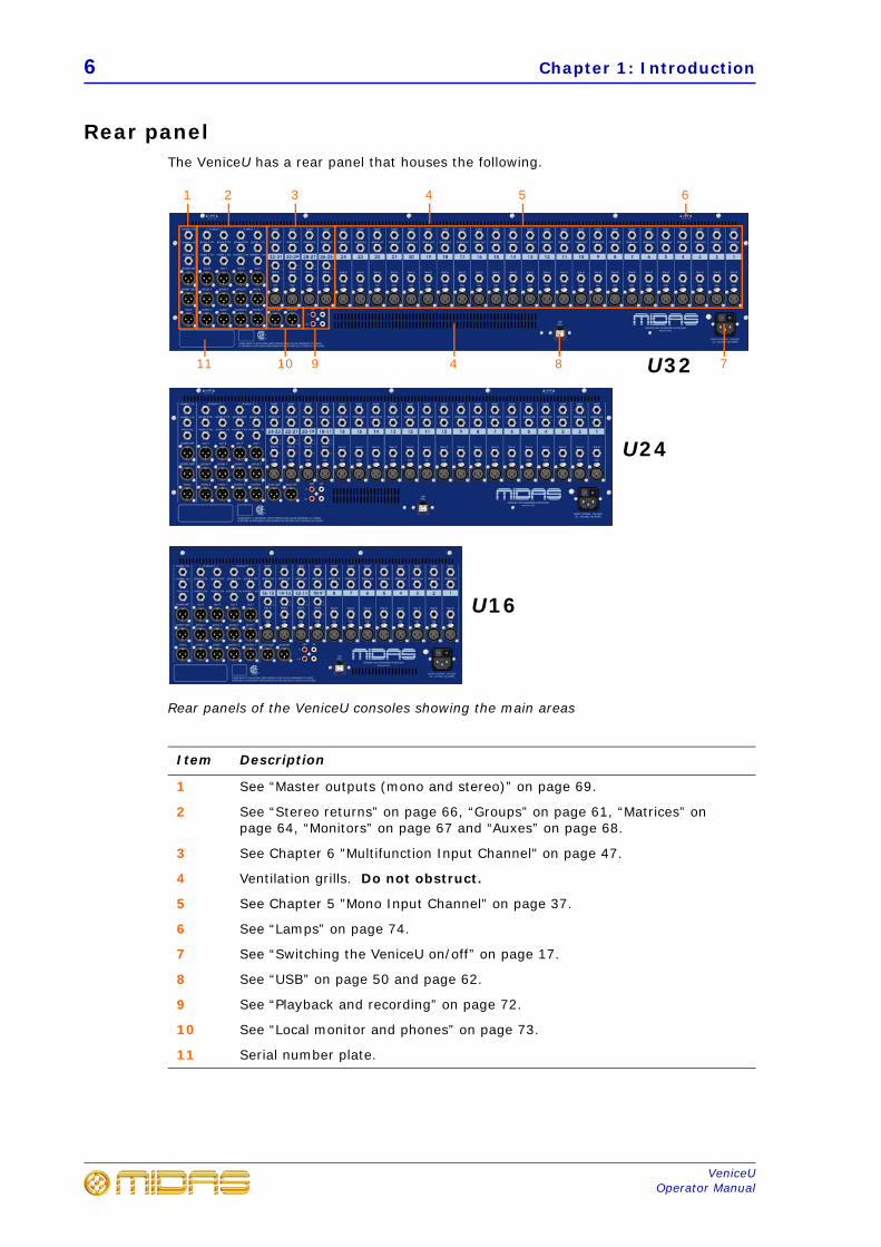
Rear panelThe VeniceU has a rear panel that houses the following.
Rear panels of the VeniceU consoles showing the main areas
Item Description
1 See “Master outputs (mono and stereo)” on page 69.
2 See “Stereo returns” on page 66, “Groups” on page 61, “Matrices” on page 64, “Monitors” on page 67 and “Auxes” on page 68.
3 See Chapter 6 "Multifunction Input Channel" on page 47.
4 Ventilation grills. Do not obstruct.
5 See Chapter 5 "Mono Input Channel" on page 37.
6 See “Lamps” on page 74.
7 See “Switching the VeniceU on/off” on page 17.
8 See “USB” on page 50 and page 62.
9 See “Playback and recording” on page 72.
10 See “Local monitor and phones” on page 73.
11 Serial number plate.
U16
89
1
7
2 3 54
1011
U24
U32
6
4
External connections 7
VeniceUOperator Manual
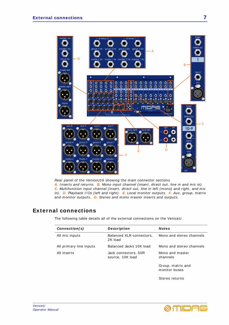
Rear panel of the VeniceU16 showing the main connector sectionsA. Inserts and returns. B. Mono input channel (insert, direct out, line in and mic in). C. Multifunction input channel (insert, direct out, line in left (mono) and right, and mic in). D. Playback I/Os (left and right). E. Local monitor outputs. F. Aux, group, matrix and monitor outputs. G. Stereo and mono master inserts and outputs.
External connectionsThe following table details all of the external connections on the VeniceU.
Connection(s) Description Notes
All mic inputs Balanced XLR connectors, 2K load
Mono and stereo channels
All primary line inputs Balanced Jacks 10K load Mono and stereo channels
All inserts Jack connectors, 50R source, 10K load
Mono and master channels
Group, matrix and monitor buses
Stereo returns
A
B
C
DEF
G
8 Chapter 1: Introduction
VeniceUOperator Manual
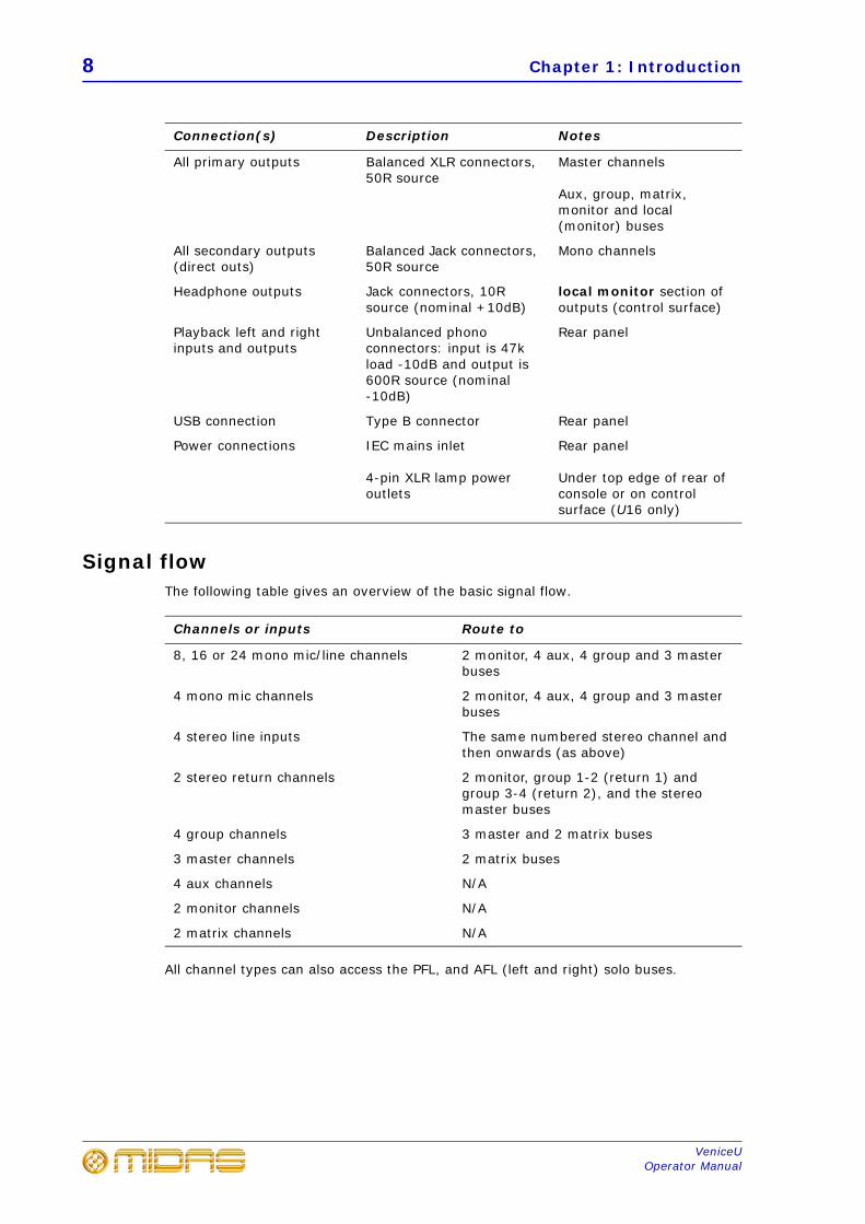
Signal flowThe following table gives an overview of the basic signal flow.
All channel types can also access the PFL, and AFL (left and right) solo buses.
All primary outputs Balanced XLR connectors, 50R source
Master channels
Aux, group, matrix, monitor and local (monitor) buses
All secondary outputs (direct outs)
Balanced Jack connectors, 50R source
Mono channels
Headphone outputs Jack connectors, 10R source (nominal +10dB)
local monitor section of outputs (control surface)
Playback left and right inputs and outputs
Unbalanced phono connectors: input is 47k load -10dB and output is 600R source (nominal -10dB)
Rear panel
USB connection Type B connector Rear panel
Power connections IEC mains inlet
4-pin XLR lamp power outlets
Rear panel
Under top edge of rear of console or on control surface (U16 only)
Channels or inputs Route to
8, 16 or 24 mono mic/line channels 2 monitor, 4 aux, 4 group and 3 master buses
4 mono mic channels 2 monitor, 4 aux, 4 group and 3 master buses
4 stereo line inputs The same numbered stereo channel and then onwards (as above)
2 stereo return channels 2 monitor, group 1-2 (return 1) and group 3-4 (return 2), and the stereo master buses
4 group channels 3 master and 2 matrix buses
3 master channels 2 matrix buses
4 aux channels N/A
2 monitor channels N/A
2 matrix channels N/A
Connection(s) Description Notes
Signal flow 9
VeniceUOperator Manual
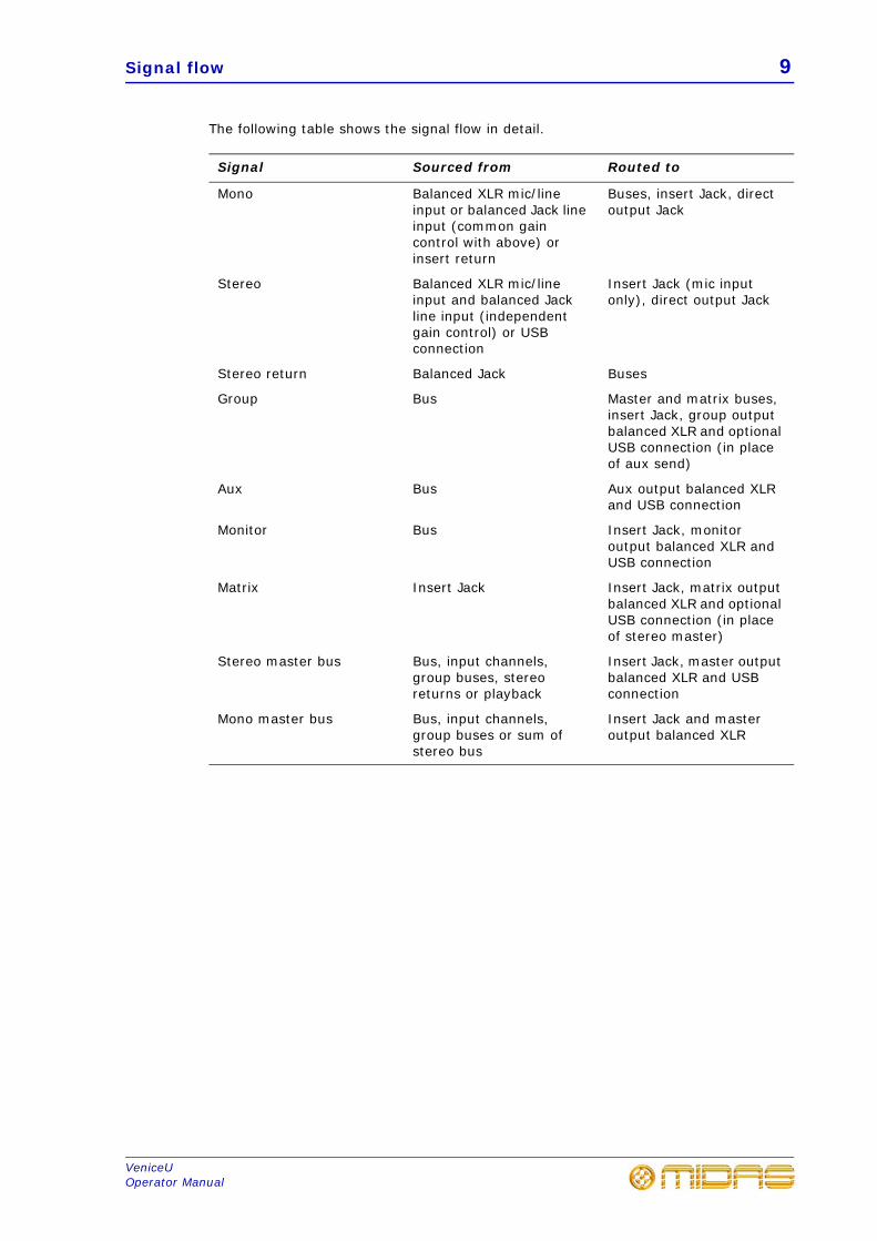
The following table shows the signal flow in detail.
Signal Sourced from Routed to
Mono Balanced XLR mic/line input or balanced Jack line input (common gain control with above) or insert return
Buses, insert Jack, direct output Jack
Stereo Balanced XLR mic/line input and balanced Jack line input (independent gain control) or USB connection
Insert Jack (mic input only), direct output Jack
Stereo return Balanced Jack Buses
Group Bus Master and matrix buses, insert Jack, group output balanced XLR and optional USB connection (in place of aux send)
Aux Bus Aux output balanced XLR and USB connection
Monitor Bus Insert Jack, monitor output balanced XLR and USB connection
Matrix Insert Jack Insert Jack, matrix output balanced XLR and optional USB connection (in place of stereo master)
Stereo master bus Bus, input channels, group buses, stereo returns or playback
Insert Jack, master output balanced XLR and USB connection
Mono master bus Bus, input channels, group buses or sum of stereo bus
Insert Jack and master output balanced XLR
10 Chapter 1: Introduction
VeniceUOperator Manual
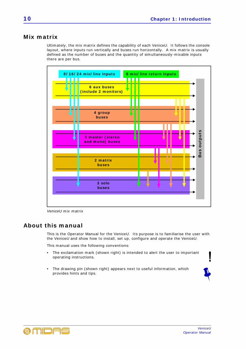
Mix matrixUltimately, the mix matrix defines the capability of each VeniceU. It follows the console layout, where inputs run vertically and buses run horizontally. A mix matrix is usually defined as the number of buses and the quantity of simultaneously-mixable inputs there are per bus.
VeniceU mix matrix
About this manualThis is the Operator Manual for the VeniceU. Its purpose is to familiarise the user with the VeniceU and show how to install, set up, configure and operate the VeniceU.
This manual uses the following conventions:
• The exclamation mark (shown right) is intended to alert the user to important operating instructions.
• The drawing pin (shown right) appears next to useful information, which provides hints and tips.
6 aux buses (include 2 monitors)
3 master (stereo and mono) buses
4 groupbuses
8/16/24 mic/line inputs 8 mic/line return inputs
2 matrix buses
Bu
s o
utp
uts
3 solo buses
Service and support 11
VeniceUOperator Manual
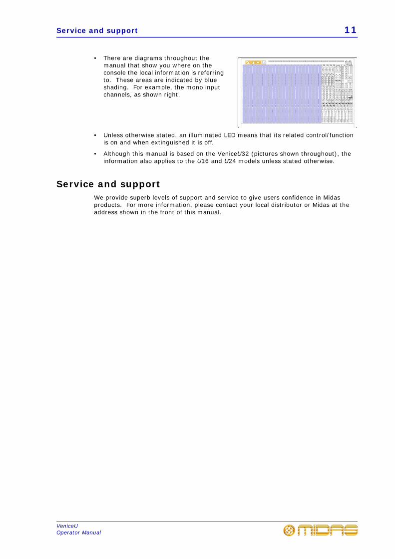
• There are diagrams throughout the manual that show you where on the console the local information is referring to. These areas are indicated by blue shading. For example, the mono input channels, as shown right.
• Unless otherwise stated, an illuminated LED means that its related control/function is on and when extinguished it is off.
• Although this manual is based on the VeniceU32 (pictures shown throughout), the information also applies to the U16 and U24 models unless stated otherwise.
Service and supportWe provide superb levels of support and service to give users confidence in Midas products. For more information, please contact your local distributor or Midas at the address shown in the front of this manual.
12 Chapter 1: Introduction
VeniceUOperator Manual
13
VeniceUOperator Manual
Chapter 2: Getting Started
This chapter shows you how to prepare the VeniceU for operation, which includes:
• Installation
• Connecting up
• Setting up
• Powering up
Before installing, setting up or operating this equipment make sure you have read and fully understand all of the “IMPORTANT SAFETY INSTRUCTIONS” at the front of this document and observe the following precautions.
InstallationThe position of the console will vary from venue to venue. When installing the console, take the following into consideration.
• Before installing and operating this Class 1 equipment, make sure it is correctly connected to the protective earth conductor of the mains voltage supply socket outlet through the mains lead.
• When positioning the console for FOH use it is worth placing the console in a position where the sound system used can be heard properly from the mix position. Try to avoid placing the console behind pillars or large objects, or mixing from a level above the speaker position (for example, from a balcony).
• The console should be located in a convenient space commensurate with the use to which the console is being put.
• Ideally a cool area is preferred, away from power distribution equipment or other potential sources of interference.
• Do not install the equipment in places of poor ventilation.
• Do not install this equipment in a location subjected to excessive heat, dust or mechanical vibration. Allow for adequate ventilation around the equipment, making sure that its fans and vents are not obstructed. Whenever possible, keep the equipment out of direct sunlight.
• Do not place the equipment in an unstable condition where it might accidentally fall over.
• Provision should be made for some flat surface surrounding the console to prevent people using it as a table top.
Handling the equipment
When lifting or moving the equipment, always take its size and weight into consideration. If necessary, use suitable lifting equipment or transporting gear, or sufficient additional personnel.
Completely isolate the equipment electrically and disconnect all cables from the equipment before moving it.
Do not insert your fingers or hands in any gaps or openings on the equipment, for example, vents.
14 Chapter 2: Getting Started
VeniceUOperator Manual
Electric fields
Should this product be used in an electromagnetic field that is amplitude modulated by an audio frequency signal (20Hz to 20kHz), the signal to noise ratio may be degraded. Degradation of up to 60dB at a frequency corresponding to the modulation signal may be experienced under extreme conditions (3V/m, 90% modulation).
Connecting upTo ensure the correct and reliable operation of your equipment, only high quality, balanced, screened, twisted pair audio cable should be used.
XLR connector shells should be of metal construction so that they provide a screen when connected to the console and, where appropriate, they should have Pin 1 connected to the cable screen.
All Jack connector shells should be connected to the cable screen.
Audio connections
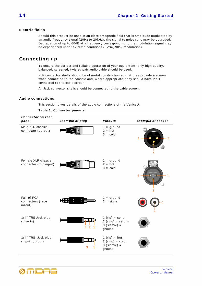
This section gives details of the audio connections of the VeniceU.
Table 1: Connector pinouts
Connector on rear panel Example of plug Pinouts Example of socket
Male XLR chassis connector (output)
1 = ground2 = hot3 = cold
Female XLR chassis connector (mic input)
1 = ground2 = hot3 = cold
Pair of RCA connectors (tape in/out)
1 = ground2 = signal
1/4” TRS Jack plug (inserts)
1 (tip) = send2 (ring) = return3 (sleeve) = ground
1/4” TRS Jack plug (input, output)
1 (tip) = hot2 (ring) = cold3 (sleeve) = ground
2
3
1
1
3
2
1
2
123
13
Connecting up 15
VeniceUOperator Manual
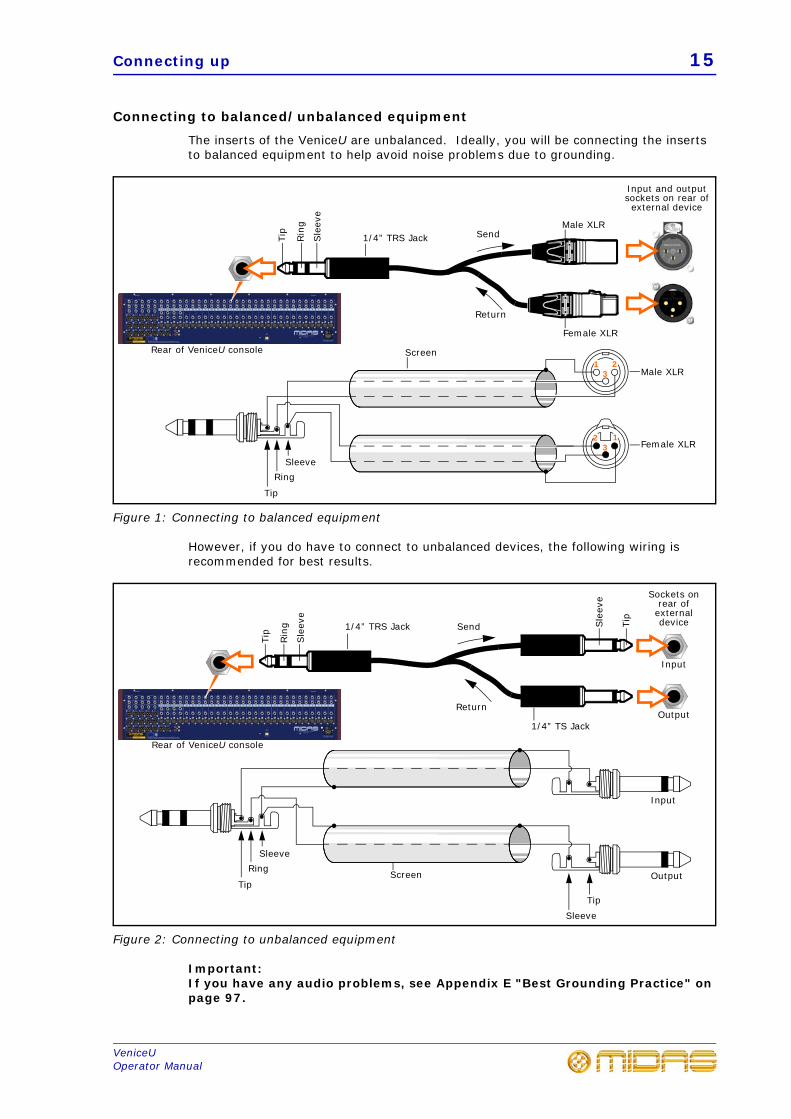
Connecting to balanced/unbalanced equipment
The inserts of the VeniceU are unbalanced. Ideally, you will be connecting the inserts to balanced equipment to help avoid noise problems due to grounding.
Figure 1: Connecting to balanced equipment
However, if you do have to connect to unbalanced devices, the following wiring is recommended for best results.
Figure 2: Connecting to unbalanced equipment
Important:If you have any audio problems, see Appendix E "Best Grounding Practice" on page 97.
3
Female XLR
Male XLR
3
21
2 1
SleeveRing
Tip
Male XLR
Tip
Sle
eve
Rin
g
Female XLR
Input and output sockets on rear of external device
Rear of VeniceU console
1/4” TRS Jack
Screen
Send
Return
Send
Return
Tip
Sle
eve
Rin
g
Sockets on rear of
external device
Rear of VeniceU console
SleeveRing
Tip
1/4” TRS Jack Sle
eve
Tip
Input
Output
SleeveTip
Screen
Input
Output
1/4” TS Jack
16 Chapter 2: Getting Started
VeniceUOperator Manual
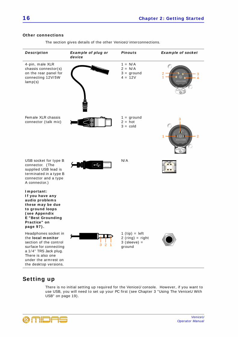
Other connections
The section gives details of the other VeniceU interconnections.
Setting upThere is no initial setting up required for the VeniceU console. However, if you want to use USB, you will need to set up your PC first (see Chapter 3 "Using The VeniceU With USB" on page 19).
Description Example of plug or device
Pinouts Example of socket
4-pin, male XLR chassis connector(s) on the rear panel for connecting 12V/5W lamp(s)
1 = N/A2 = N/A3 = ground4 = 12V
Female XLR chassis connector (talk mic)
1 = ground2 = hot3 = cold
USB socket for type B connector. (The supplied USB lead is terminated in a type B connector and a type A connector.)
Important:If you have any audio problems these may be due to ground loops (see Appendix E "Best Grounding Practice" on page 97).
N/A
Headphones socket in the local monitor section of the control surface for connecting a 1/4” TRS Jack plug. There is also one under the armrest on the desktop versions.
1 (tip) = left2 (ring) = right3 (sleeve) = ground
4132
21
3
123
Switching the VeniceU on/off 17
VeniceUOperator Manual
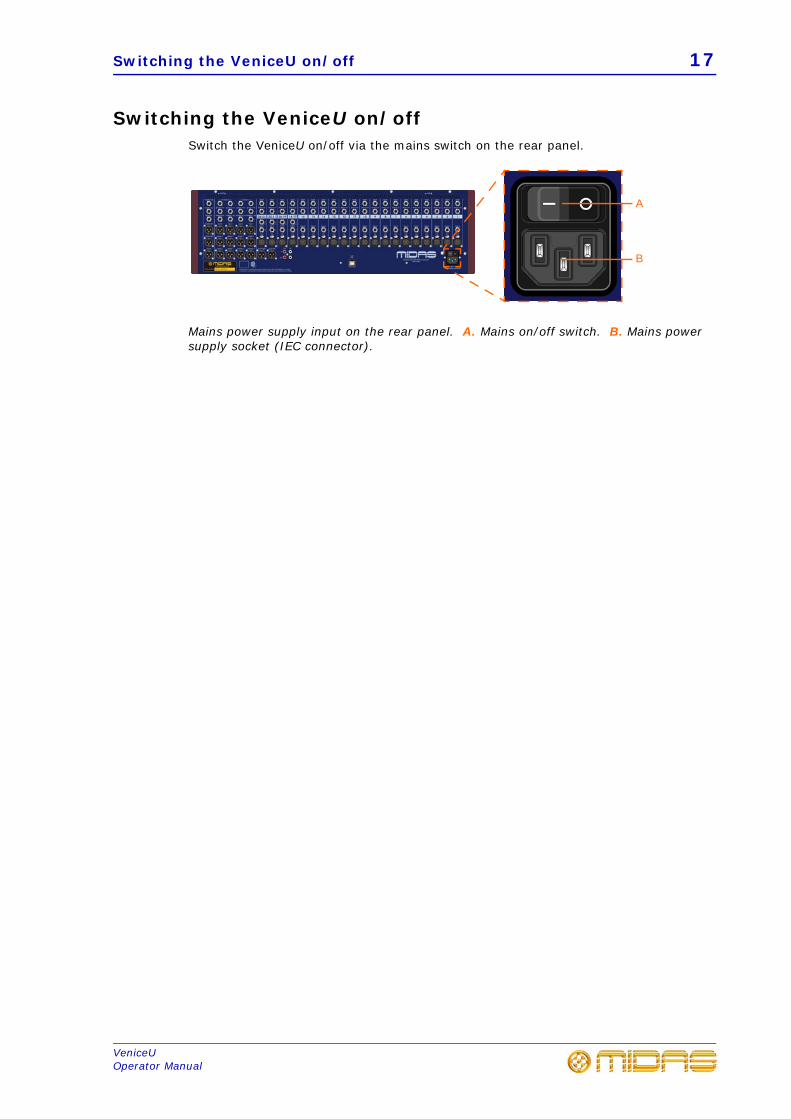
Switching the VeniceU on/offSwitch the VeniceU on/off via the mains switch on the rear panel.
Mains power supply input on the rear panel. A. Mains on/off switch. B. Mains power supply socket (IEC connector).
A
B
18 Chapter 2: Getting Started
VeniceUOperator Manual
19
VeniceUOperator Manual
Chapter 3: Using The VeniceU With USB
This chapter shows you how to prepare your PC/Mac® for USB operation. The VeniceU console has been tested and verified for USB use with the following computer operating systems: a PC running Windows® 7 and a Mac running OS® X (version 10.7 or later). However, we cannot guarantee correct USB operation on any other computer operating system.
All of the files that you should need for USB operation on the VeniceU, such as, drivers, recording templates, demos, etc., can be downloaded from the MIDAS website.
Windows 7 operating systemThis section shows how to install and set up USB on a PC running the Windows 7 operating system.
>> To install the USB device driver on your PC
Do not connect the USB cable to the PC before installing the device driver.
Important:Before installing the USB device driver, we recommend that you make sure it is the latest version by checking the www.midasconsoles.com website. This is important, as you may not be able to use USB operation properly with an older version of the device driver.
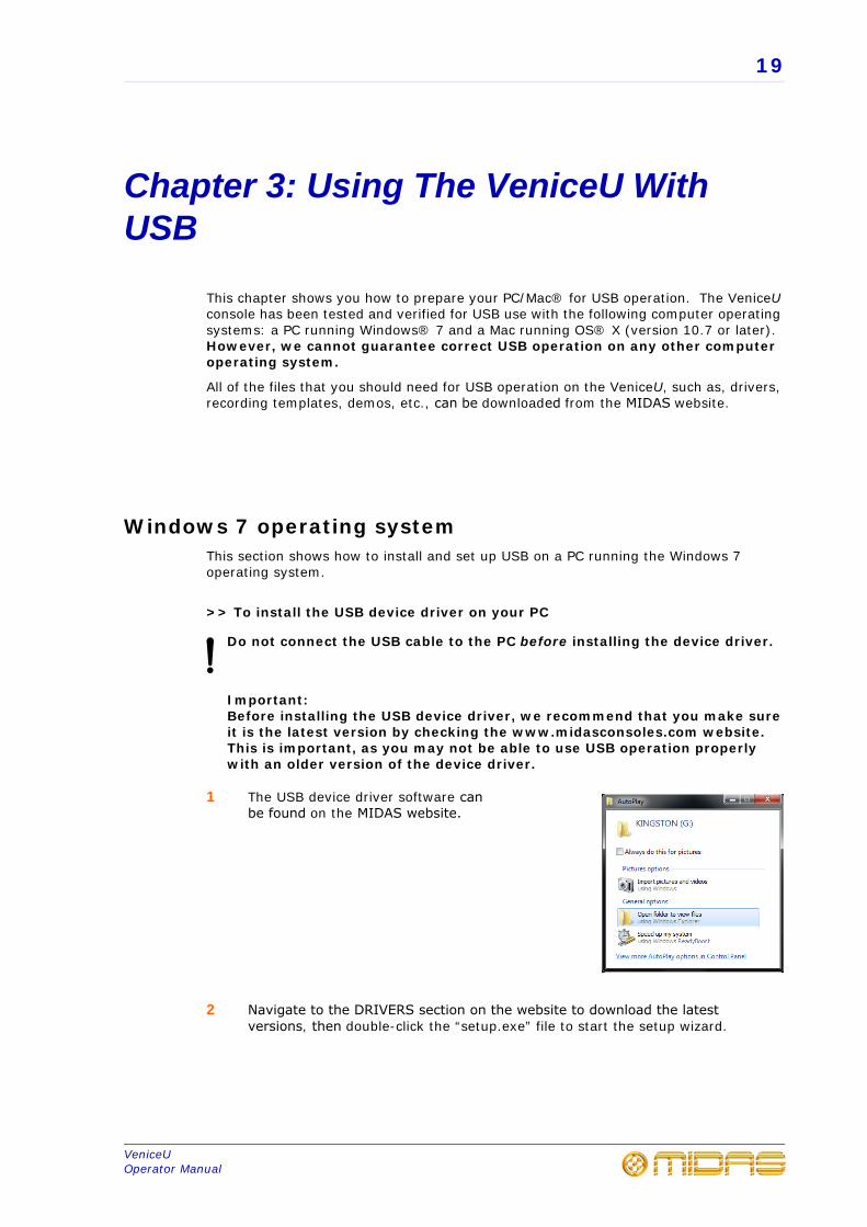
1 The USB device driver software can be found on the MIDAS website.
2 Navigate to the DRIVERS section on the website to download the latest versions, then double-click the “setup.exe” file to start the setup wizard.
20 Chapter 3: Using The VeniceU With USB
VeniceUOperator Manual
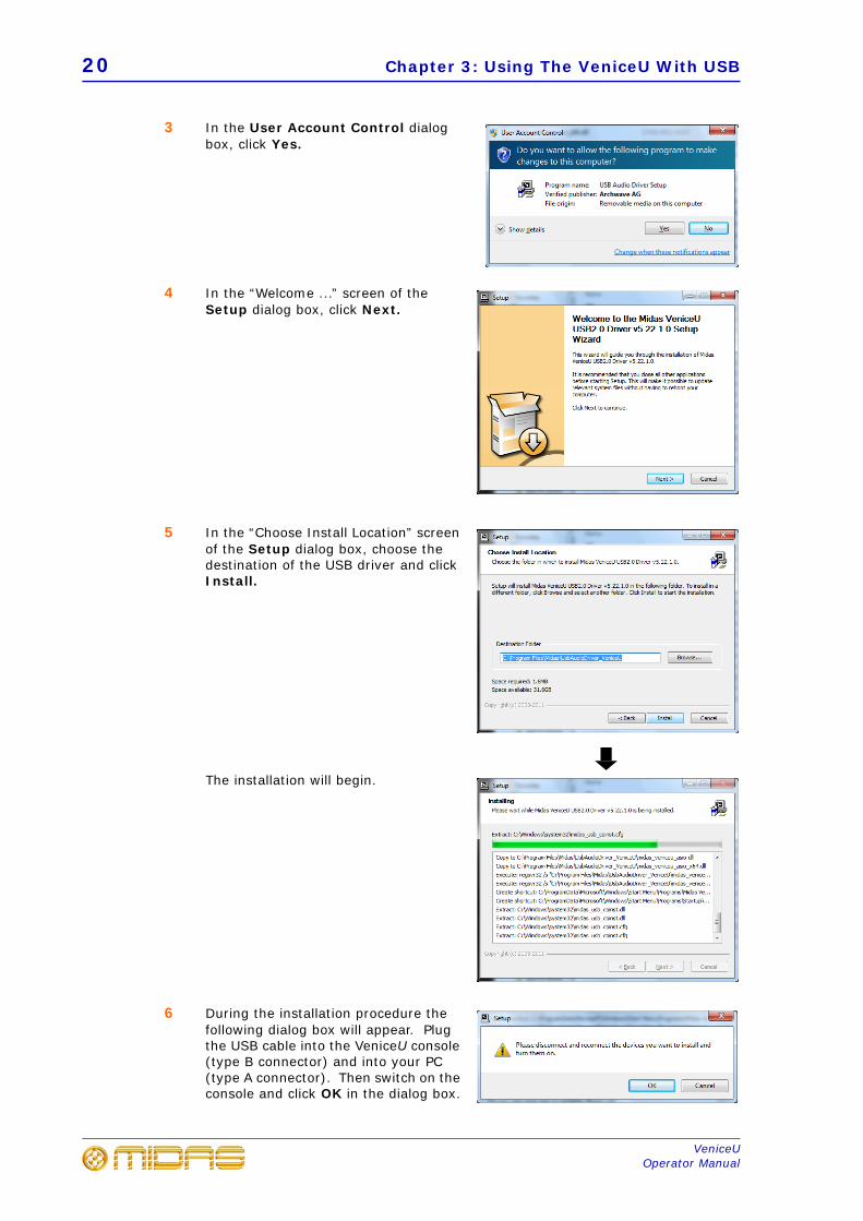
3 In the User Account Control dialog box, click Yes.
4 In the “Welcome ...” screen of the Setup dialog box, click Next.
5 In the “Choose Install Location” screen of the Setup dialog box, choose the destination of the USB driver and click Install.
The installation will begin.
6 During the installation procedure the following dialog box will appear. Plug the USB cable into the VeniceU console (type B connector) and into your PC (type A connector). Then switch on the console and click OK in the dialog box.
Windows 7 operating system 21
VeniceUOperator Manual
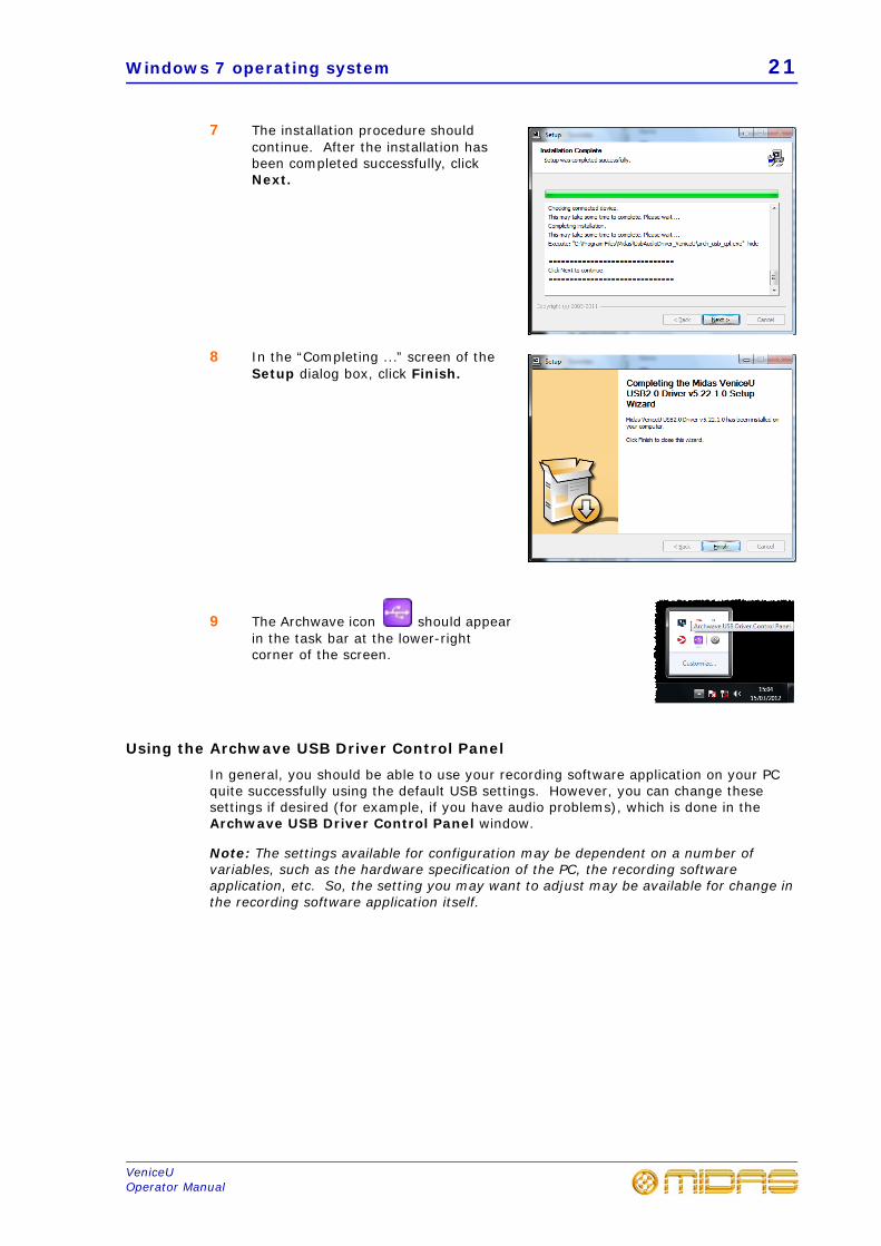
7 The installation procedure should continue. After the installation has been completed successfully, click Next.
8 In the “Completing ...” screen of the Setup dialog box, click Finish.
9 The Archwave icon should appear in the task bar at the lower-right corner of the screen.
Using the Archwave USB Driver Control Panel
In general, you should be able to use your recording software application on your PC quite successfully using the default USB settings. However, you can change these settings if desired (for example, if you have audio problems), which is done in the Archwave USB Driver Control Panel window.
Note: The settings available for configuration may be dependent on a number of variables, such as the hardware specification of the PC, the recording software application, etc. So, the setting you may want to adjust may be available for change in the recording software application itself.
22 Chapter 3: Using The VeniceU With USB
VeniceUOperator Manual
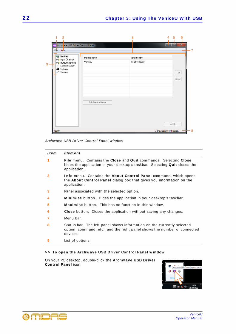
Archwave USB Driver Control Panel window
>> To open the Archwave USB Driver Control Panel window
On your PC desktop, double-click the Archwave USB Driver Control Panel icon.
Item Element
1 File menu. Contains the Close and Quit commands. Selecting Close hides the application in your desktop’s taskbar. Selecting Quit closes the application.
2 Info menu. Contains the About Control Panel command, which opens the About Control Panel dialog box that gives you information on the application.
3 Panel associated with the selected option.
4 Minimise button. Hides the application in your desktop’s taskbar.
5 Maximise button. This has no function in this window.
6 Close button. Closes the application without saving any changes.
7 Menu bar.
8 Status bar. The left panel shows information on the currently selected option, command, etc., and the right panel shows the number of connected devices.
9 List of options.
1 2
9
5 64
7
8
3
Windows 7 operating system 23
VeniceUOperator Manual
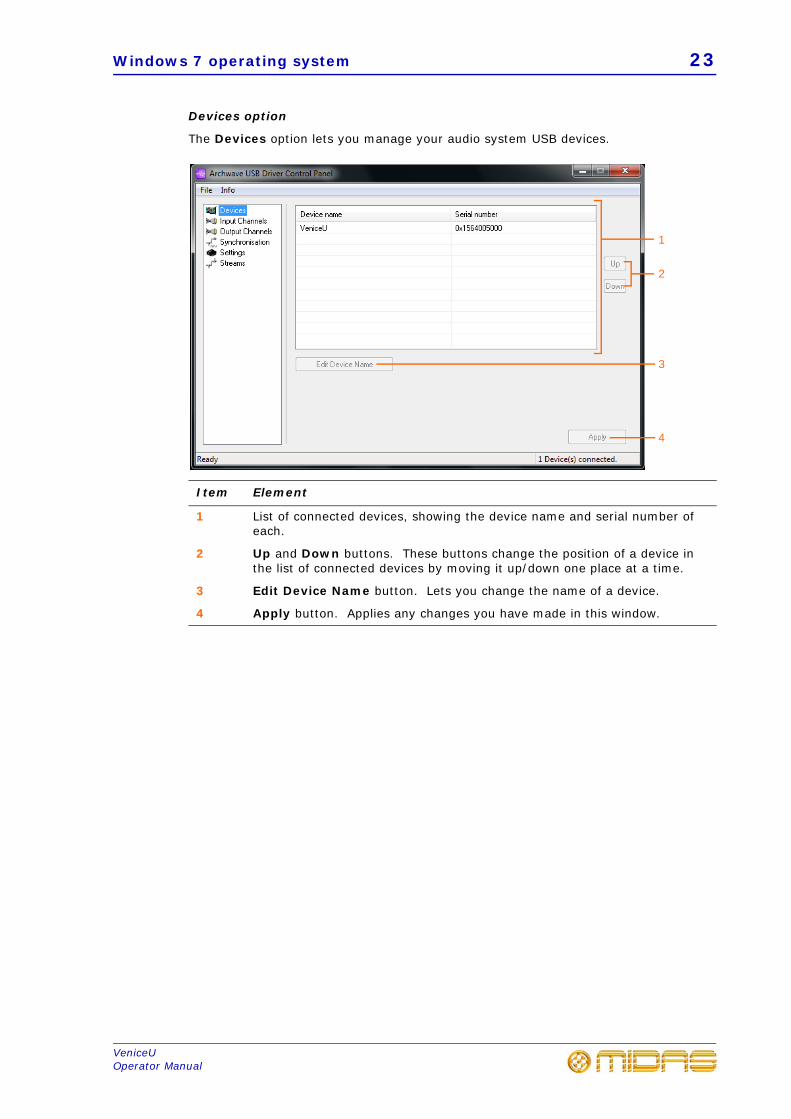
Devices option
The Devices option lets you manage your audio system USB devices.
Item Element
1 List of connected devices, showing the device name and serial number of each.
2 Up and Down buttons. These buttons change the position of a device in the list of connected devices by moving it up/down one place at a time.
3 Edit Device Name button. Lets you change the name of a device.
4 Apply button. Applies any changes you have made in this window.
2
4
1
3
24 Chapter 3: Using The VeniceU With USB
VeniceUOperator Manual
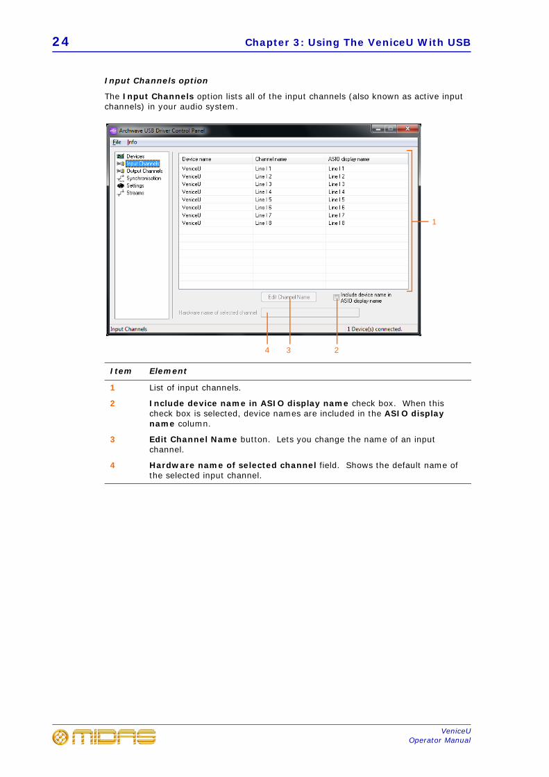
Input Channels option
The Input Channels option lists all of the input channels (also known as active input channels) in your audio system.
Item Element
1 List of input channels.
2 Include device name in ASIO display name check box. When this check box is selected, device names are included in the ASIO display name column.
3 Edit Channel Name button. Lets you change the name of an input channel.
4 Hardware name of selected channel field. Shows the default name of the selected input channel.
2
1
34
Windows 7 operating system 25
VeniceUOperator Manual
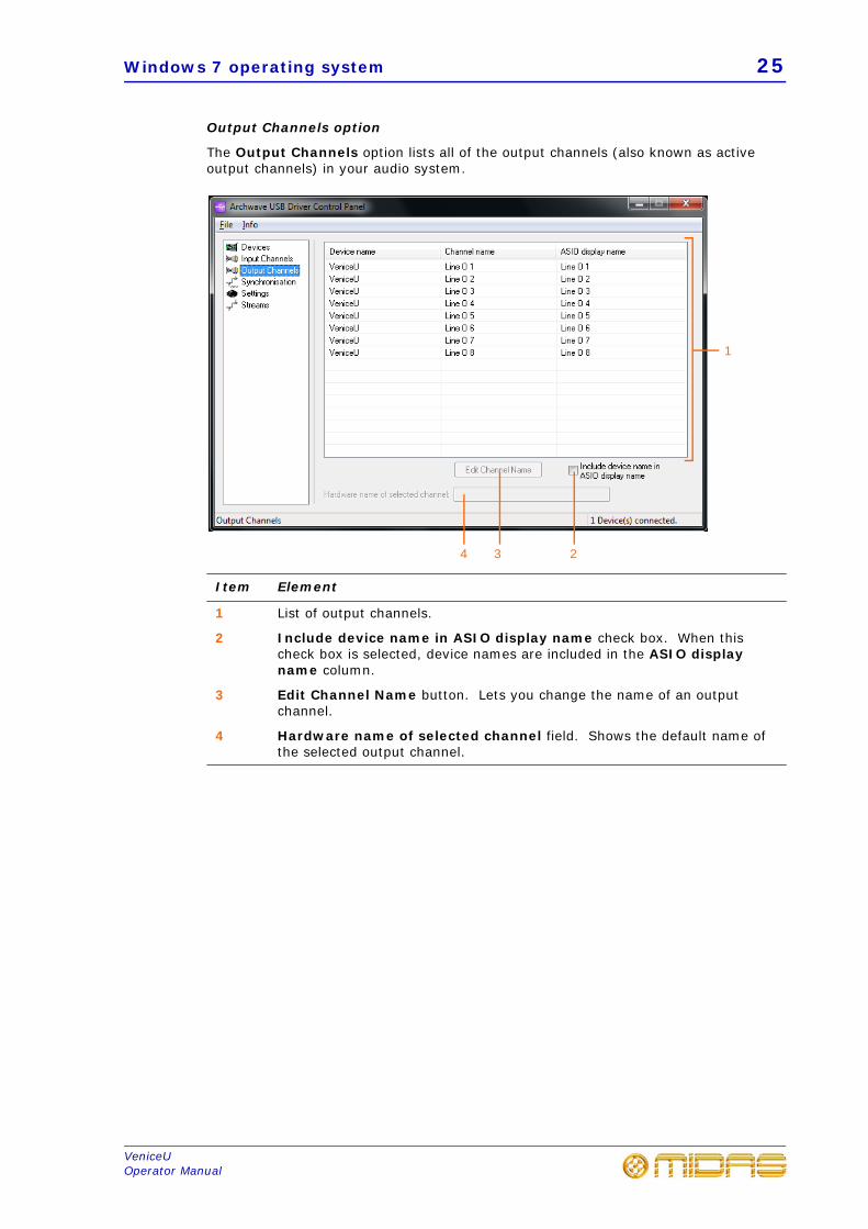
Output Channels option
The Output Channels option lists all of the output channels (also known as active output channels) in your audio system.
Item Element
1 List of output channels.
2 Include device name in ASIO display name check box. When this check box is selected, device names are included in the ASIO display name column.
3 Edit Channel Name button. Lets you change the name of an output channel.
4 Hardware name of selected channel field. Shows the default name of the selected output channel.
2
1
34
26 Chapter 3: Using The VeniceU With USB
VeniceUOperator Manual
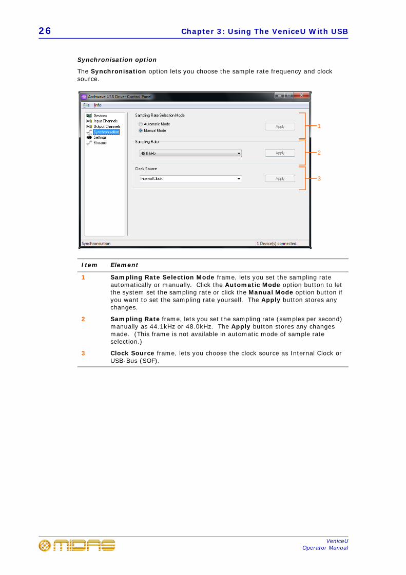
Synchronisation option
The Synchronisation option lets you choose the sample rate frequency and clock source.
Item Element
1 Sampling Rate Selection Mode frame, lets you set the sampling rate automatically or manually. Click the Automatic Mode option button to let the system set the sampling rate or click the Manual Mode option button if you want to set the sampling rate yourself. The Apply button stores any changes.
2 Sampling Rate frame, lets you set the sampling rate (samples per second) manually as 44.1kHz or 48.0kHz. The Apply button stores any changes made. (This frame is not available in automatic mode of sample rate selection.)
3 Clock Source frame, lets you choose the clock source as Internal Clock or USB-Bus (SOF).
1
2
3
Windows 7 operating system 27
VeniceUOperator Manual
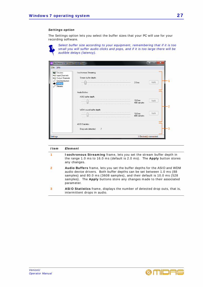
Settings option
The Settings option lets you select the buffer sizes that your PC will use for your recording software.
Select buffer size according to your equipment, remembering that if it is too small you will suffer audio clicks and pops, and if it is too large there will be audible delays (latency).
Item Element
1 Isochronous Streaming frame, lets you set the stream buffer depth in the range 1.0 ms to 16.0 ms (default is 2.0 ms). The Apply button stores any changes.
2 Audio Buffers frame, lets you set the buffer depths for the ASIO and WDM audio device drivers. Both buffer depths can be set between 1.0 ms (88 samples) and 80.0 ms (3608 samples), and their default is 10.0 ms (528 samples). The Apply buttons store any changes made to their associated parameter.
3 ASIO Statistics frame, displays the number of detected drop outs, that is, intermittent drops in audio.
1
2
3
28 Chapter 3: Using The VeniceU With USB
VeniceUOperator Manual
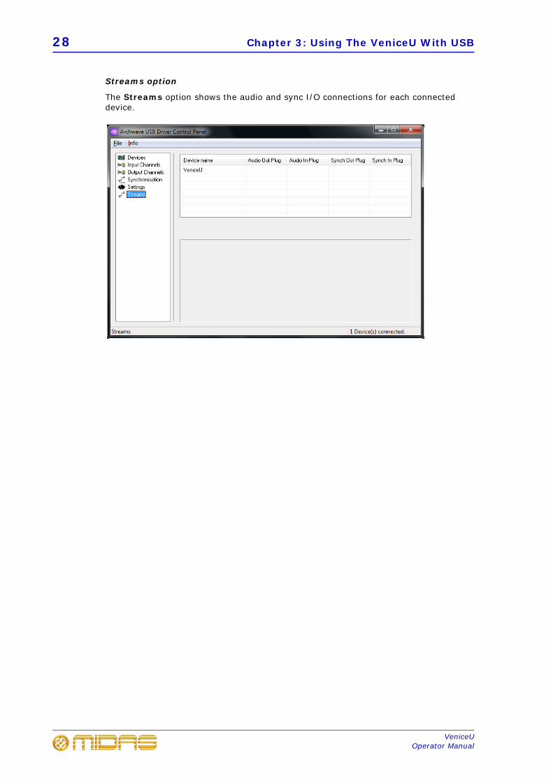
Streams option
The Streams option shows the audio and sync I/O connections for each connected device.
Mac operating system 29
VeniceUOperator Manual
Mac operating systemUSB, when used with a Mac running OS® X (version 10.7 or later), is a ‘plug and play’ device. So, unlike on a PC running Windows® 7, there is no need to install a USB device driver.
Note: The settings available for configuration may be dependent on a number of variables, such as the hardware specification of the Mac, the recording software application, etc. So, the setting you may want to adjust may be available for change in the recording software application itself.
30 Chapter 3: Using The VeniceU With USB
VeniceUOperator Manual
Updating the VeniceU firmware 31
VeniceUOperator Manual
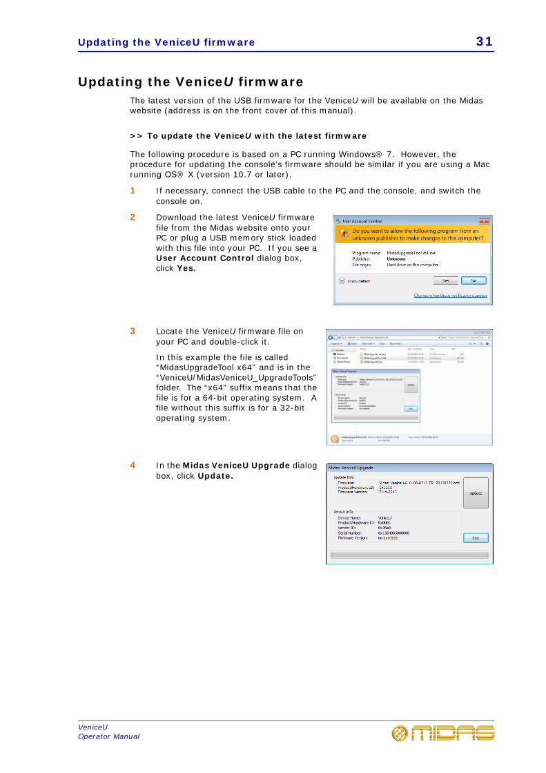
Updating the VeniceU firmwareThe latest version of the USB firmware for the VeniceU will be available on the Midas website (address is on the front cover of this manual).
>> To update the VeniceU with the latest firmware
The following procedure is based on a PC running Windows® 7. However, the procedure for updating the console’s firmware should be similar if you are using a Mac running OS® X (version 10.7 or later).
1 If necessary, connect the USB cable to the PC and the console, and switch the console on.
2 Download the latest VeniceU firmware file from the Midas website onto your PC or plug a USB memory stick loaded with this file into your PC. If you see a User Account Control dialog box, click Yes.
3 Locate the VeniceU firmware file on your PC and double-click it.
In this example the file is called “MidasUpgradeTool x64” and is in the “VeniceU/MidasVeniceU_UpgradeTools” folder. The “x64” suffix means that the file is for a 64-bit operating system. A file without this suffix is for a 32-bit operating system.
4 In the Midas VeniceU Upgrade dialog box, click Update.
32 Chapter 3: Using The VeniceU With USB
VeniceUOperator Manual
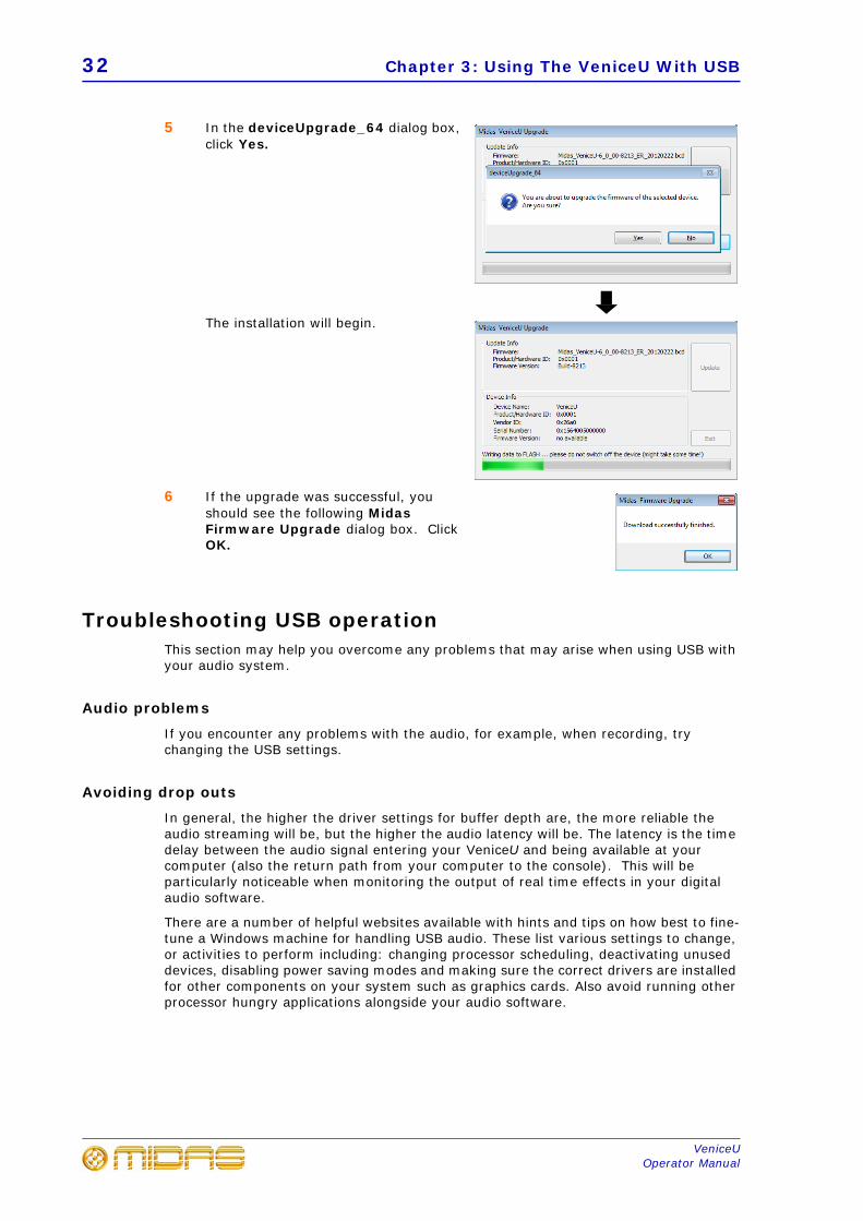
5 In the deviceUpgrade_64 dialog box, click Yes.
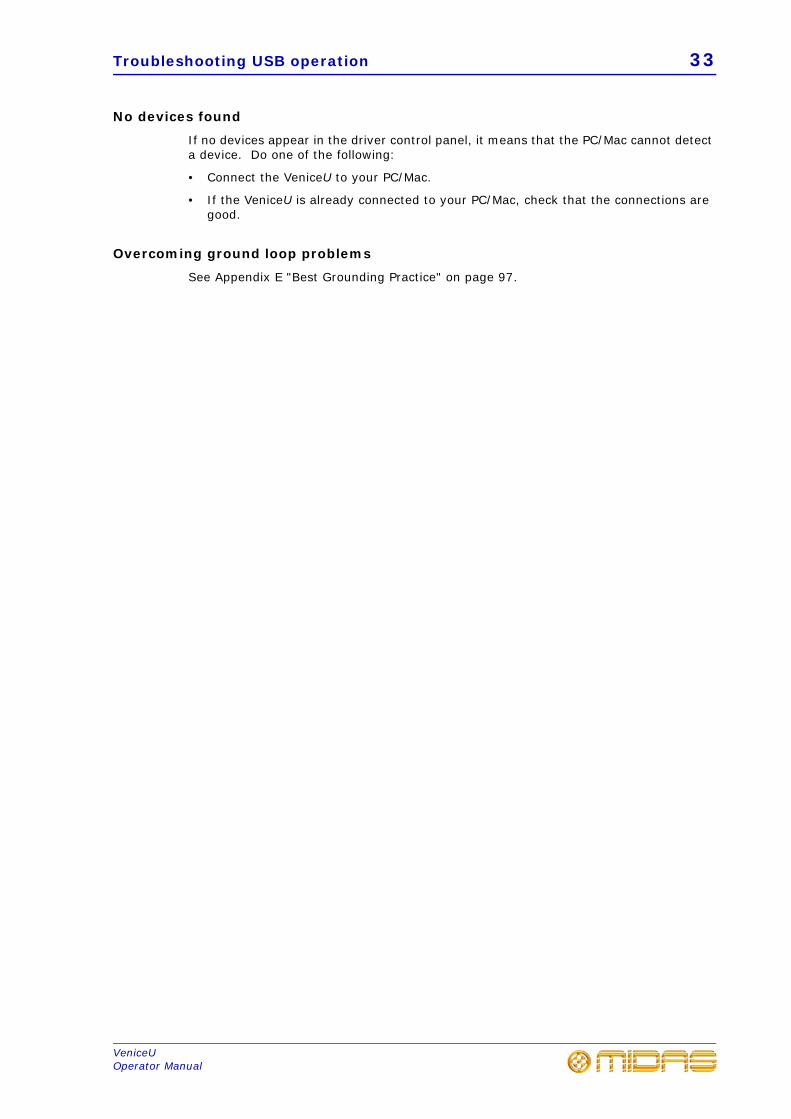
The installation will begin.
6 If the upgrade was successful, you should see the following Midas Firmware Upgrade dialog box. Click OK.
Troubleshooting USB operationThis section may help you overcome any problems that may arise when using USB with your audio system.
Audio problems
If you encounter any problems with the audio, for example, when recording, try changing the USB settings.
Avoiding drop outs
In general, the higher the driver settings for buffer depth are, the more reliable the audio streaming will be, but the higher the audio latency will be. The latency is the time delay between the audio signal entering your VeniceU and being available at your computer (also the return path from your computer to the console). This will be particularly noticeable when monitoring the output of real time effects in your digital audio software.
There are a number of helpful websites available with hints and tips on how best to fine-tune a Windows machine for handling USB audio. These list various settings to change, or activities to perform including: changing processor scheduling, deactivating unused devices, disabling power saving modes and making sure the correct drivers are installed for other components on your system such as graphics cards. Also avoid running other processor hungry applications alongside your audio software.
Troubleshooting USB operation 33
VeniceUOperator Manual
No devices found
If no devices appear in the driver control panel, it means that the PC/Mac cannot detect a device. Do one of the following:
• Connect the VeniceU to your PC/Mac.
• If the VeniceU is already connected to your PC/Mac, check that the connections aregood.
Overcoming ground loop problems
See Appendix E "Best Grounding Practice" on page 97.
34 Chapter 3: Using The VeniceU With USB
VeniceUOperator Manual
35
VeniceUOperator Manual
Chapter 4: Working With The Console
The following chapters give a description of the controls on the console surface and include useful operating information.
• Chapter 5 "Mono Input Channel" on page 37
• Chapter 6 "Multifunction Input Channel" on page 47
• Chapter 7 "Output Section" on page 57
Before using USB, read Chapter 3 “Using The VeniceU With USB”.
Ground loop problemsIn the event of ground loop problems, disconnect the signal screen at one end of the connecting cables. Note that this can only be done when the equipment is used with balanced cable systems. For more information, see Appendix E "Best Grounding Practice" on page 97.

36 Chapter 4: Working With The Console
VeniceUOperator Manual
37
VeniceUOperator Manual
Chapter 5: Mono Input Channel
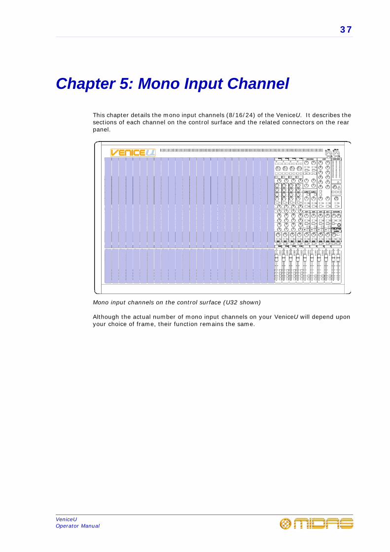
This chapter details the mono input channels (8/16/24) of the VeniceU. It describes the sections of each channel on the control surface and the related connectors on the rear panel.
Mono input channels on the control surface (U32 shown)
Although the actual number of mono input channels on your VeniceU will depend upon your choice of frame, their function remains the same.
38 Chapter 5: Mono Input Channel
VeniceUOperator Manual
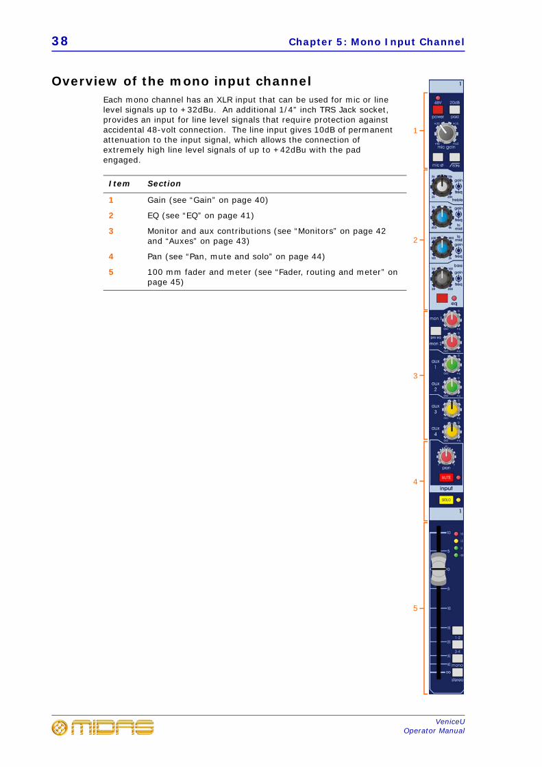
Overview of the mono input channelEach mono channel has an XLR input that can be used for mic or line level signals up to +32dBu. An additional 1/4” inch TRS Jack socket, provides an input for line level signals that require protection against accidental 48-volt connection. The line input gives 10dB of permanent attenuation to the input signal, which allows the connection of extremely high line level signals of up to +42dBu with the pad engaged.
Item Section
1 Gain (see “Gain” on page 40)
2 EQ (see “EQ” on page 41)
3 Monitor and aux contributions (see “Monitors” on page 42 and “Auxes” on page 43)
4 Pan (see “Pan, mute and solo” on page 44)
5 100 mm fader and meter (see “Fader, routing and meter” on page 45)
1
2
3
4
5
Rear panel 39
VeniceUOperator Manual
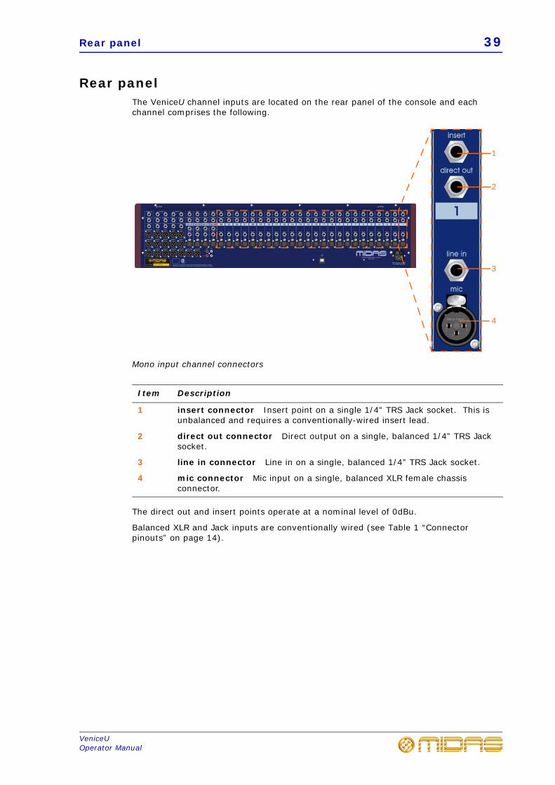
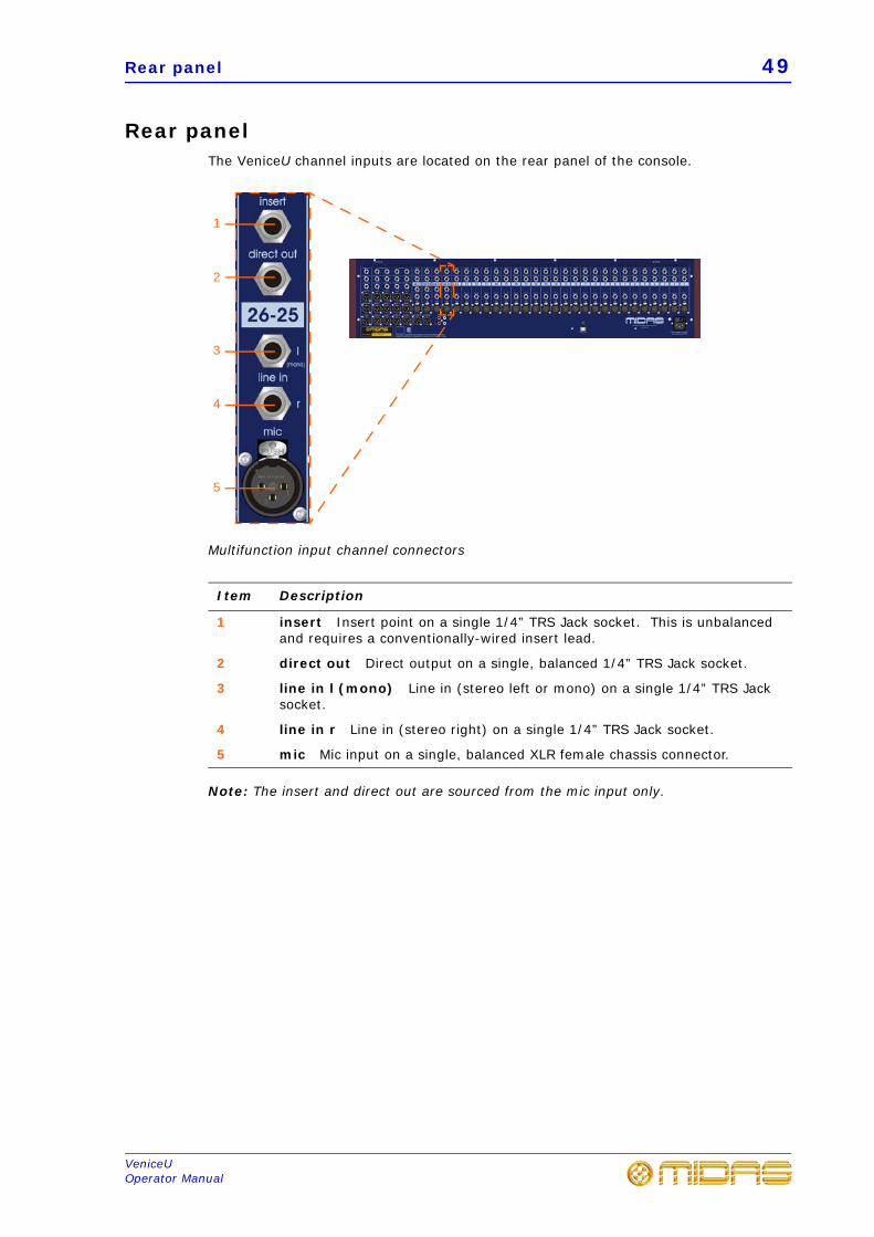
Rear panelThe VeniceU channel inputs are located on the rear panel of the console and each channel comprises the following.
Mono input channel connectors
The direct out and insert points operate at a nominal level of 0dBu.
Balanced XLR and Jack inputs are conventionally wired (see Table 1 “Connector pinouts” on page 14).
Item Description
1 insert connector Insert point on a single 1/4” TRS Jack socket. This is unbalanced and requires a conventionally-wired insert lead.
2 direct out connector Direct output on a single, balanced 1/4” TRS Jack socket.
3 line in connector Line in on a single, balanced 1/4” TRS Jack socket.
4 mic connector Mic input on a single, balanced XLR female chassis connector.
1
2
3
4
40 Chapter 5: Mono Input Channel
VeniceUOperator Manual
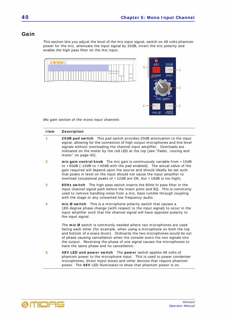
GainThis section lets you adjust the level of the mic input signal, switch on 48 volts phantom power for the mic, attenuate the input signal by 20dB, invert the mic polarity and enable the high pass filter on the mic input.
Mic gain section of the mono input channels
Item Description
1 20dB pad switch This pad switch provides 20dB attenuation to the input signal, allowing for the connection of high output microphones and line level signals without overloading the channel input amplifier. Overloads are indicated on the meter by the red LED at the top (see “Fader, routing and meter” on page 45).
2 mic gain control knob The mic gain is continuously variable from +10dB to +60dB (-10dB to +40dB with the pad enabled). The actual value of the gain required will depend upon the source and should ideally be set such that peaks in level on the input should not cause the input amplifier to overload (occasional peaks of +12dB are OK, but +18dB is too high).
3 80Hz switch The high pass switch inserts the 80Hz hi pass filter in the input channel signal path before the insert point and EQ. This is commonly used to remove handling noise from a mic, bass rumble through coupling with the stage or any unwanted low frequency audio.
4 mic Ø switch This is a microphone polarity switch that causes a 180-degree phase change (with respect to the input signal) to occur in the input amplifier such that the channel signal will have opposite polarity to the input signal.
The mic Ø switch is commonly needed where two microphones are used facing each other (for example, when using a microphone on both the top and bottom of a snare drum). Ordinarily the two microphones would be out of phase causing cancellation when the console sums the two signals into the output. Reversing the phase of one signal causes the microphones to have the same phase and no cancellation.
5 48V LED and power switch The power switch applies 48 volts of phantom power to the microphone input. This is used to power condenser microphones, direct inject boxes and other devices that require phantom power. The 48V LED illuminates to show that phantom power is on.
1
2
34
5
EQ 41
VeniceUOperator Manual
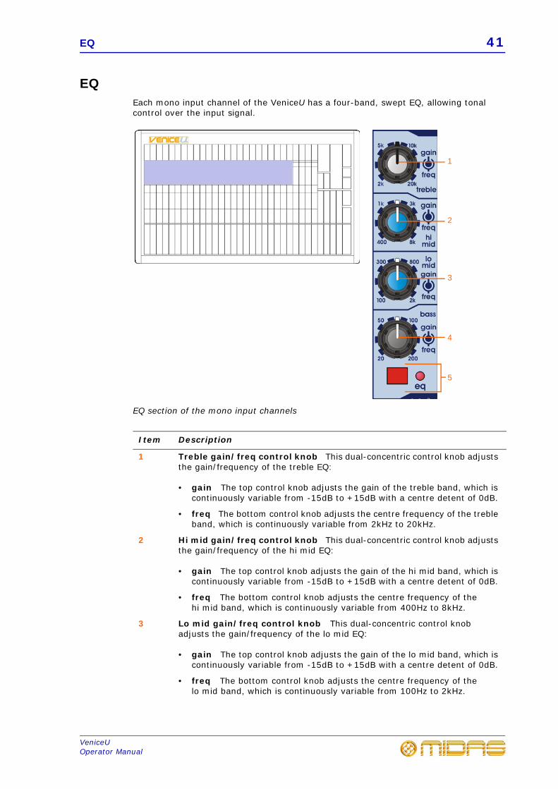
EQEach mono input channel of the VeniceU has a four-band, swept EQ, allowing tonal control over the input signal.
EQ section of the mono input channels
Item Description
1 Treble gain/freq control knob This dual-concentric control knob adjusts the gain/frequency of the treble EQ:
• gain The top control knob adjusts the gain of the treble band, which iscontinuously variable from -15dB to +15dB with a centre detent of 0dB.
• freq The bottom control knob adjusts the centre frequency of the trebleband, which is continuously variable from 2kHz to 20kHz.
2 Hi mid gain/freq control knob This dual-concentric control knob adjusts the gain/frequency of the hi mid EQ:
• gain The top control knob adjusts the gain of the hi mid band, which iscontinuously variable from -15dB to +15dB with a centre detent of 0dB.
• freq The bottom control knob adjusts the centre frequency of thehi mid band, which is continuously variable from 400Hz to 8kHz.
3 Lo mid gain/freq control knob This dual-concentric control knob adjusts the gain/frequency of the lo mid EQ:
• gain The top control knob adjusts the gain of the lo mid band, which iscontinuously variable from -15dB to +15dB with a centre detent of 0dB.
• freq The bottom control knob adjusts the centre frequency of thelo mid band, which is continuously variable from 100Hz to 2kHz.
1
2
3
4
5
42 Chapter 5: Mono Input Channel
VeniceUOperator Manual
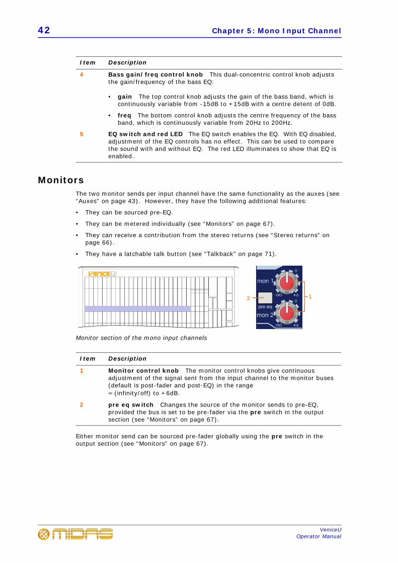
MonitorsThe two monitor sends per input channel have the same functionality as the auxes (see “Auxes” on page 43). However, they have the following additional features:
• They can be sourced pre-EQ.
• They can be metered individually (see “Monitors” on page 67).
• They can receive a contribution from the stereo returns (see “Stereo returns” onpage 66).
• They have a latchable talk button (see “Talkback” on page 71).
Monitor section of the mono input channels
Either monitor send can be sourced pre-fader globally using the pre switch in the output section (see “Monitors” on page 67).
4 Bass gain/freq control knob This dual-concentric control knob adjusts the gain/frequency of the bass EQ:
• gain The top control knob adjusts the gain of the bass band, which iscontinuously variable from -15dB to +15dB with a centre detent of 0dB.
• freq The bottom control knob adjusts the centre frequency of the bassband, which is continuously variable from 20Hz to 200Hz.
5 EQ switch and red LED The EQ switch enables the EQ. With EQ disabled, adjustment of the EQ controls has no effect. This can be used to compare the sound with and without EQ. The red LED illuminates to show that EQ is enabled.
Item Description
1 Monitor control knob The monitor control knobs give continuous adjustment of the signal sent from the input channel to the monitor buses (default is post-fader and post-EQ) in the range 4 (infinity/off) to +6dB.
2 pre eq switch Changes the source of the monitor sends to pre-EQ, provided the bus is set to be pre-fader via the pre switch in the output section (see “Monitors” on page 67).
Item Description
12
Auxes 43
VeniceUOperator Manual
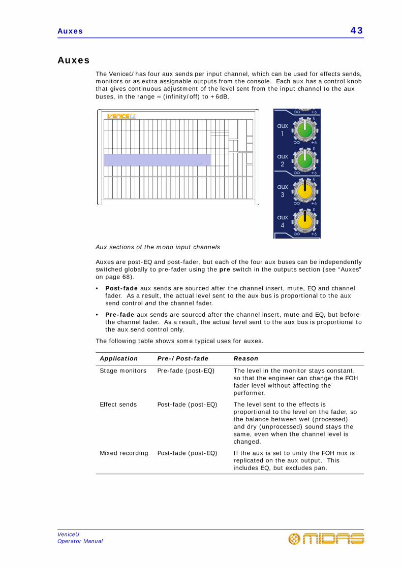
AuxesThe VeniceU has four aux sends per input channel, which can be used for effects sends, monitors or as extra assignable outputs from the console. Each aux has a control knob that gives continuous adjustment of the level sent from the input channel to the aux buses, in the range 4 (infinity/off) to +6dB.
Aux sections of the mono input channels
Auxes are post-EQ and post-fader, but each of the four aux buses can be independently switched globally to pre-fader using the pre switch in the outputs section (see “Auxes” on page 68).
• Post-fade aux sends are sourced after the channel insert, mute, EQ and channelfader. As a result, the actual level sent to the aux bus is proportional to the auxsend control and the channel fader.
• Pre-fade aux sends are sourced after the channel insert, mute and EQ, but beforethe channel fader. As a result, the actual level sent to the aux bus is proportional tothe aux send control only.
The following table shows some typical uses for auxes.
Application Pre-/Post-fade Reason
Stage monitors Pre-fade (post-EQ) The level in the monitor stays constant, so that the engineer can change the FOH fader level without affecting the performer.
Effect sends Post-fade (post-EQ) The level sent to the effects is proportional to the level on the fader, so the balance between wet (processed) and dry (unprocessed) sound stays the same, even when the channel level is changed.
Mixed recording Post-fade (post-EQ) If the aux is set to unity the FOH mix is replicated on the aux output. This includes EQ, but excludes pan.
44 Chapter 5: Mono Input Channel
VeniceUOperator Manual
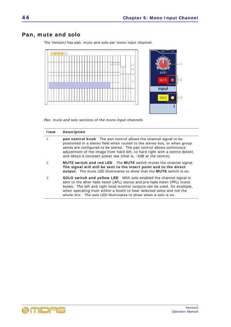
Pan, mute and soloThe VeniceU has pan, mute and solo per mono input channel.
Pan, mute and solo sections of the mono input channels
Item Description
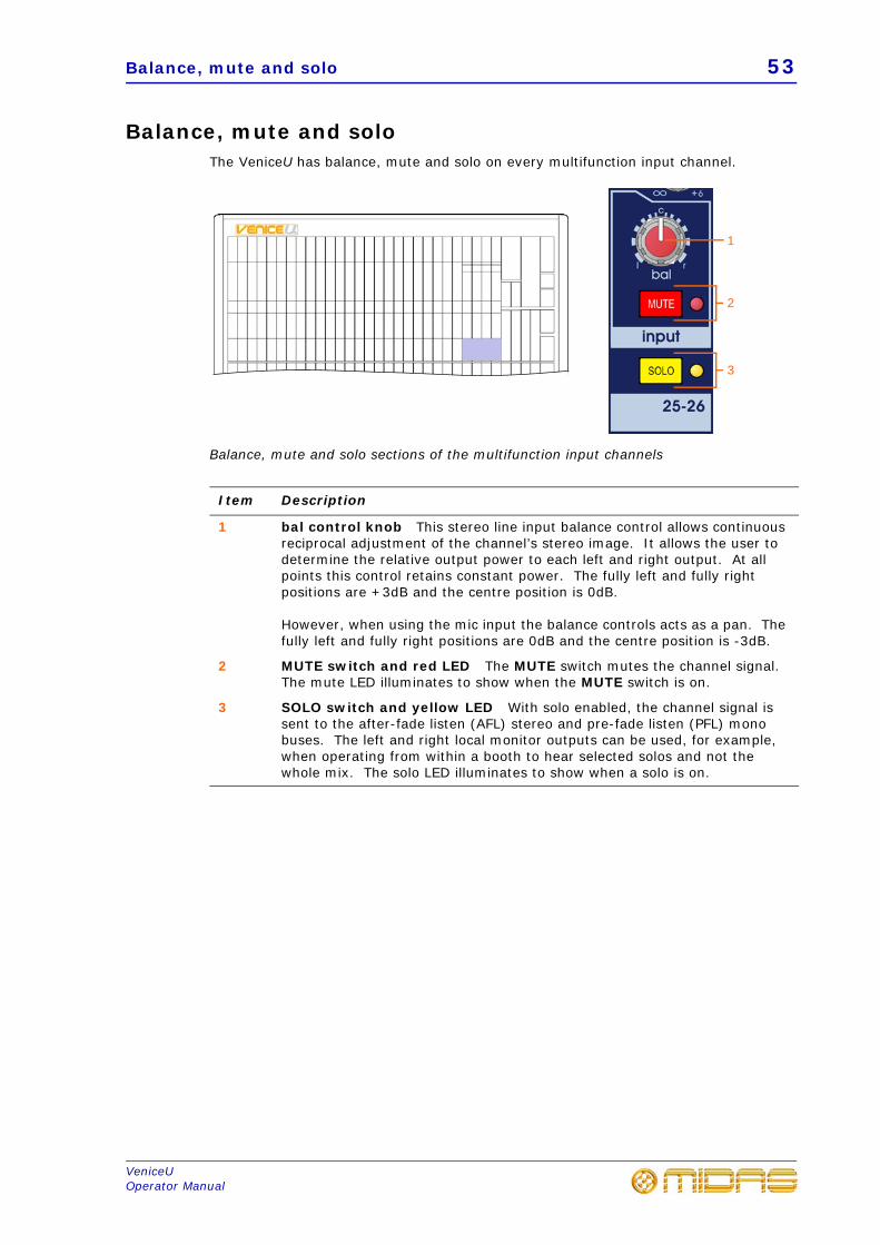
1 pan control knob The pan control allows the channel signal to be positioned in a stereo field when routed to the stereo bus, or when group sends are configured to be stereo. The pan control allows continuous adjustment of the image from hard left, to hard right with a centre detent, and obeys a constant power law (that is, -3dB at the centre).
2 MUTE switch and red LED The MUTE switch mutes the channel signal. The signal will still be sent to the insert point and to the direct output. The mute LED illuminates to show that the MUTE switch is on.
3 SOLO switch and yellow LED With solo enabled the channel signal is sent to the after-fade listen (AFL) stereo and pre-fade listen (PFL) mono buses. The left and right local monitor outputs can be used, for example, when operating from within a booth to hear selected solos and not the whole mix. The solo LED illuminates to show when a solo is on.
1
2
3
Fader, routing and meter 45
VeniceUOperator Manual
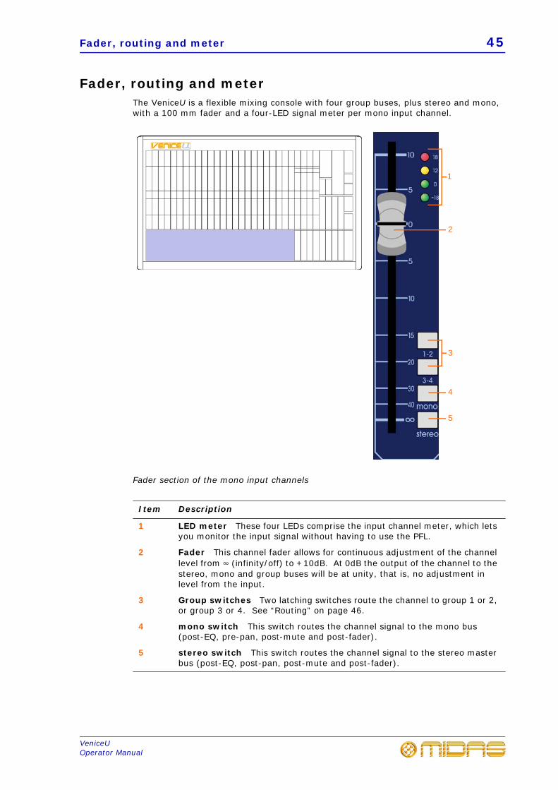
Fader, routing and meterThe VeniceU is a flexible mixing console with four group buses, plus stereo and mono, with a 100 mm fader and a four-LED signal meter per mono input channel.
Fader section of the mono input channels
Item Description
1 LED meter These four LEDs comprise the input channel meter, which lets you monitor the input signal without having to use the PFL.
2 Fader This channel fader allows for continuous adjustment of the channel level from 4 (infinity/off) to +10dB. At 0dB the output of the channel to the stereo, mono and group buses will be at unity, that is, no adjustment in level from the input.
3 Group switches Two latching switches route the channel to group 1 or 2, or group 3 or 4. See “Routing” on page 46.
4 mono switch This switch routes the channel signal to the mono bus (post-EQ, pre-pan, post-mute and post-fader).
5 stereo switch This switch routes the channel signal to the stereo master bus (post-EQ, post-pan, post-mute and post-fader).
1
2
3
4
5
46 Chapter 5: Mono Input Channel
VeniceUOperator Manual
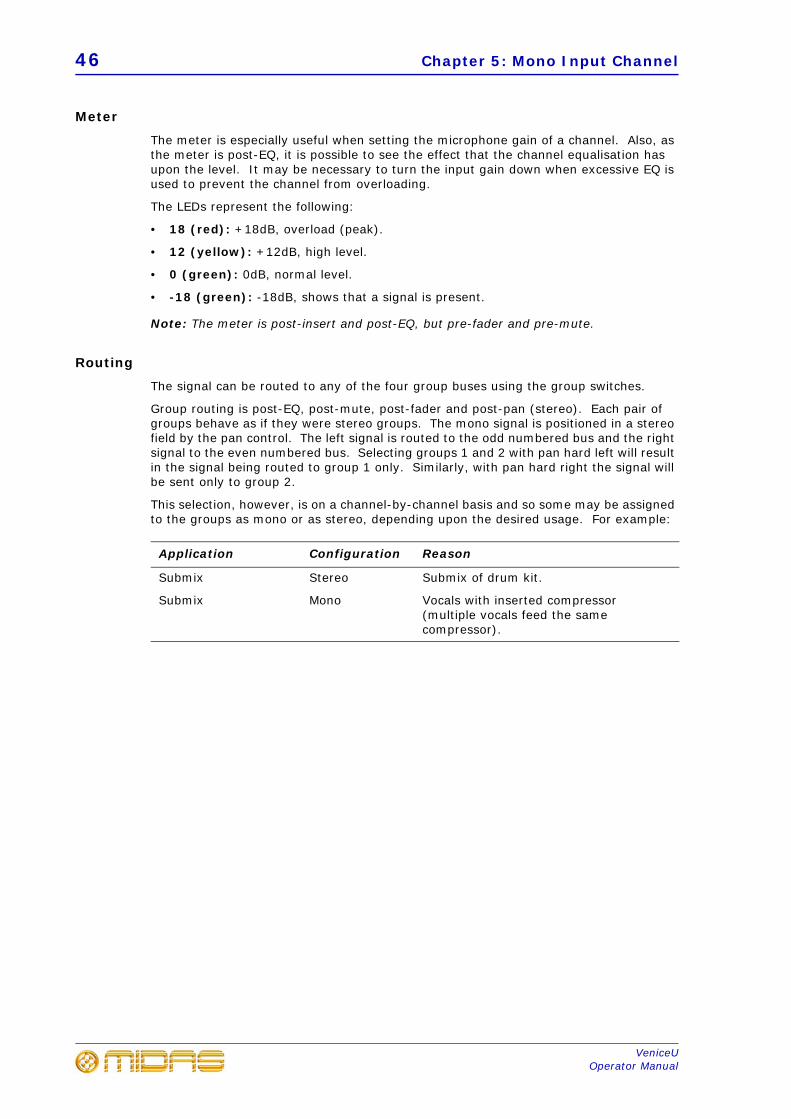
Meter
The meter is especially useful when setting the microphone gain of a channel. Also, as the meter is post-EQ, it is possible to see the effect that the channel equalisation has upon the level. It may be necessary to turn the input gain down when excessive EQ is used to prevent the channel from overloading.
The LEDs represent the following:
• 18 (red): +18dB, overload (peak).
• 12 (yellow): +12dB, high level.
• 0 (green): 0dB, normal level.
• -18 (green): -18dB, shows that a signal is present.
Note: The meter is post-insert and post-EQ, but pre-fader and pre-mute.
Routing
The signal can be routed to any of the four group buses using the group switches.
Group routing is post-EQ, post-mute, post-fader and post-pan (stereo). Each pair of groups behave as if they were stereo groups. The mono signal is positioned in a stereo field by the pan control. The left signal is routed to the odd numbered bus and the right signal to the even numbered bus. Selecting groups 1 and 2 with pan hard left will result in the signal being routed to group 1 only. Similarly, with pan hard right the signal will be sent only to group 2.
This selection, however, is on a channel-by-channel basis and so some may be assigned to the groups as mono or as stereo, depending upon the desired usage. For example:
Application Configuration Reason
Submix Stereo Submix of drum kit.
Submix Mono Vocals with inserted compressor (multiple vocals feed the same compressor).
47
VeniceUOperator Manual
Chapter 6: Multifunction Input Channel
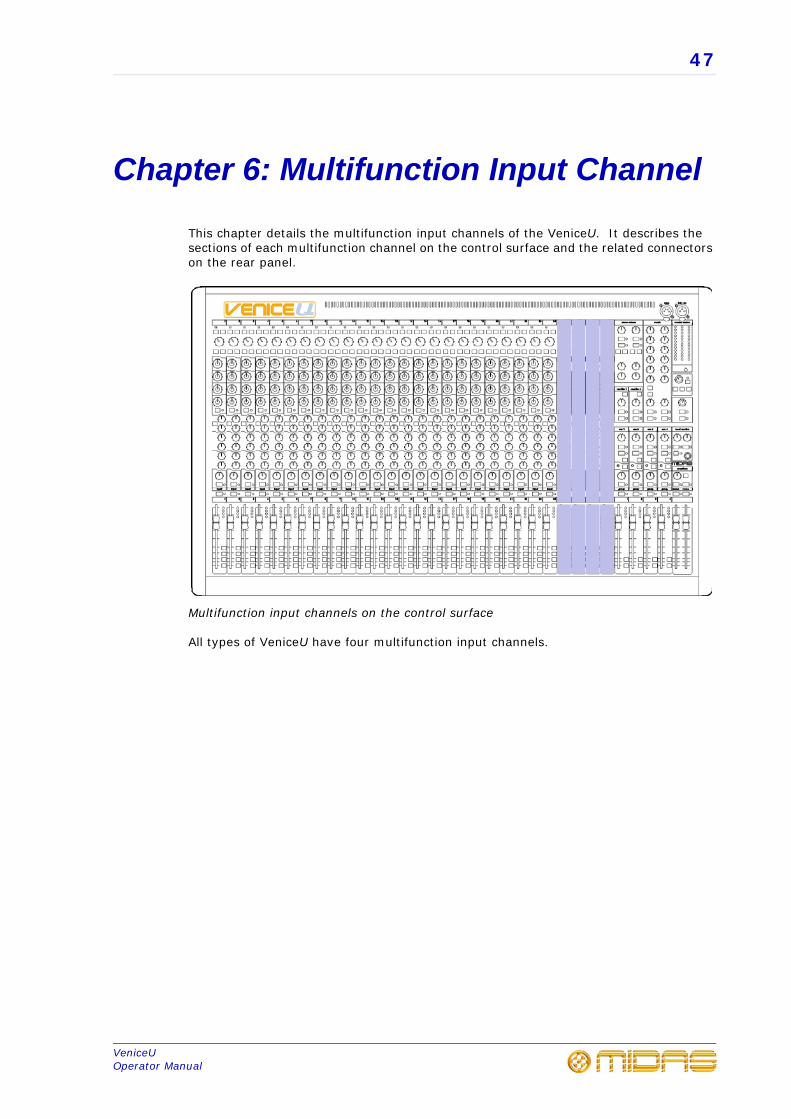
This chapter details the multifunction input channels of the VeniceU. It describes the sections of each multifunction channel on the control surface and the related connectors on the rear panel.
Multifunction input channels on the control surface
All types of VeniceU have four multifunction input channels.
48 Chapter 6: Multifunction Input Channel
VeniceUOperator Manual
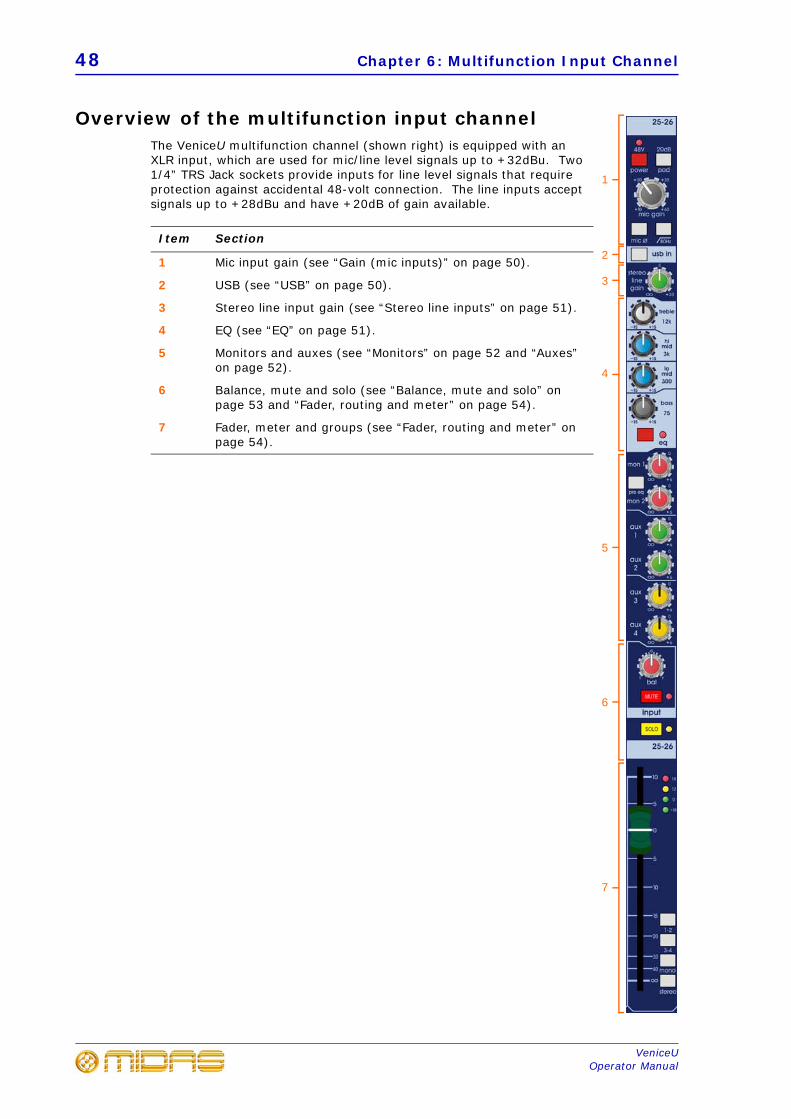
Overview of the multifunction input channelThe VeniceU multifunction channel (shown right) is equipped with an XLR input, which are used for mic/line level signals up to +32dBu. Two 1/4” TRS Jack sockets provide inputs for line level signals that require protection against accidental 48-volt connection. The line inputs accept signals up to +28dBu and have +20dB of gain available.
Item Section
1 Mic input gain (see “Gain (mic inputs)” on page 50).
2 USB (see “USB” on page 50).
3 Stereo line input gain (see “Stereo line inputs” on page 51).
4 EQ (see “EQ” on page 51).
5 Monitors and auxes (see “Monitors” on page 52 and “Auxes” on page 52).
6 Balance, mute and solo (see “Balance, mute and solo” on page 53 and “Fader, routing and meter” on page 54).
7 Fader, meter and groups (see “Fader, routing and meter” on page 54).
1
5
6
7
4
2
3
Rear panel 49
VeniceUOperator Manual
Rear panelThe VeniceU channel inputs are located on the rear panel of the console.
Multifunction input channel connectors
Note: The insert and direct out are sourced from the mic input only.
Item Description
1 insert Insert point on a single 1/4” TRS Jack socket. This is unbalanced and requires a conventionally-wired insert lead.
2 direct out Direct output on a single, balanced 1/4” TRS Jack socket.
3 line in l (mono) Line in (stereo left or mono) on a single 1/4” TRS Jack socket.
4 line in r Line in (stereo right) on a single 1/4” TRS Jack socket.
5 mic Mic input on a single, balanced XLR female chassis connector.
1
2
4
5
3
50 Chapter 6: Multifunction Input Channel
VeniceUOperator Manual
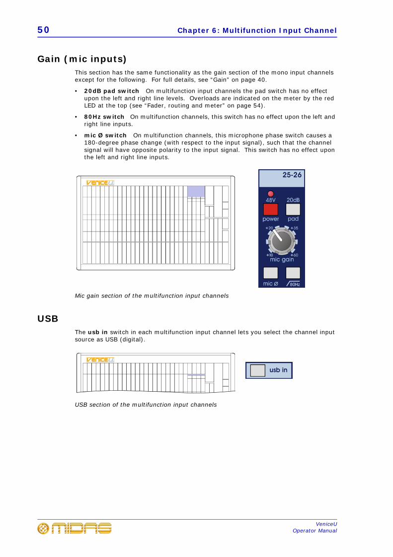
Gain (mic inputs)This section has the same functionality as the gain section of the mono input channels except for the following. For full details, see “Gain” on page 40.
• 20dB pad switch On multifunction input channels the pad switch has no effectupon the left and right line levels. Overloads are indicated on the meter by the redLED at the top (see “Fader, routing and meter” on page 54).
• 80Hz switch On multifunction channels, this switch has no effect upon the left andright line inputs.
• mic Ø switch On multifunction channels, this microphone phase switch causes a180-degree phase change (with respect to the input signal), such that the channelsignal will have opposite polarity to the input signal. This switch has no effect uponthe left and right line inputs.
Mic gain section of the multifunction input channels
USBThe usb in switch in each multifunction input channel lets you select the channel input source as USB (digital).
USB section of the multifunction input channels
Stereo line inputs 51
VeniceUOperator Manual
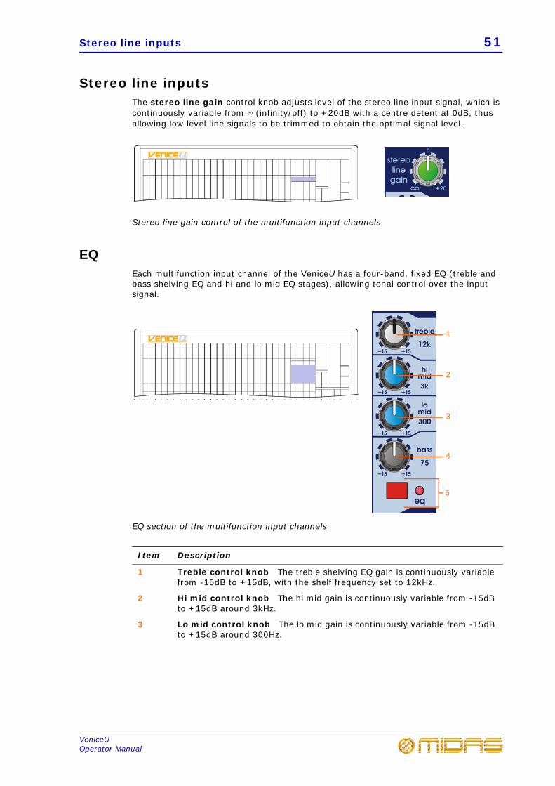
Stereo line inputsThe stereo line gain control knob adjusts level of the stereo line input signal, which is continuously variable from 4 (infinity/off) to +20dB with a centre detent at 0dB, thus allowing low level line signals to be trimmed to obtain the optimal signal level.
Stereo line gain control of the multifunction input channels
EQEach multifunction input channel of the VeniceU has a four-band, fixed EQ (treble and bass shelving EQ and hi and lo mid EQ stages), allowing tonal control over the input signal.
EQ section of the multifunction input channels
Item Description
1 Treble control knob The treble shelving EQ gain is continuously variable from -15dB to +15dB, with the shelf frequency set to 12kHz.
2 Hi mid control knob The hi mid gain is continuously variable from -15dB to +15dB around 3kHz.
3 Lo mid control knob The lo mid gain is continuously variable from -15dB to +15dB around 300Hz.
1
2
3
4
5
52 Chapter 6: Multifunction Input Channel
VeniceUOperator Manual
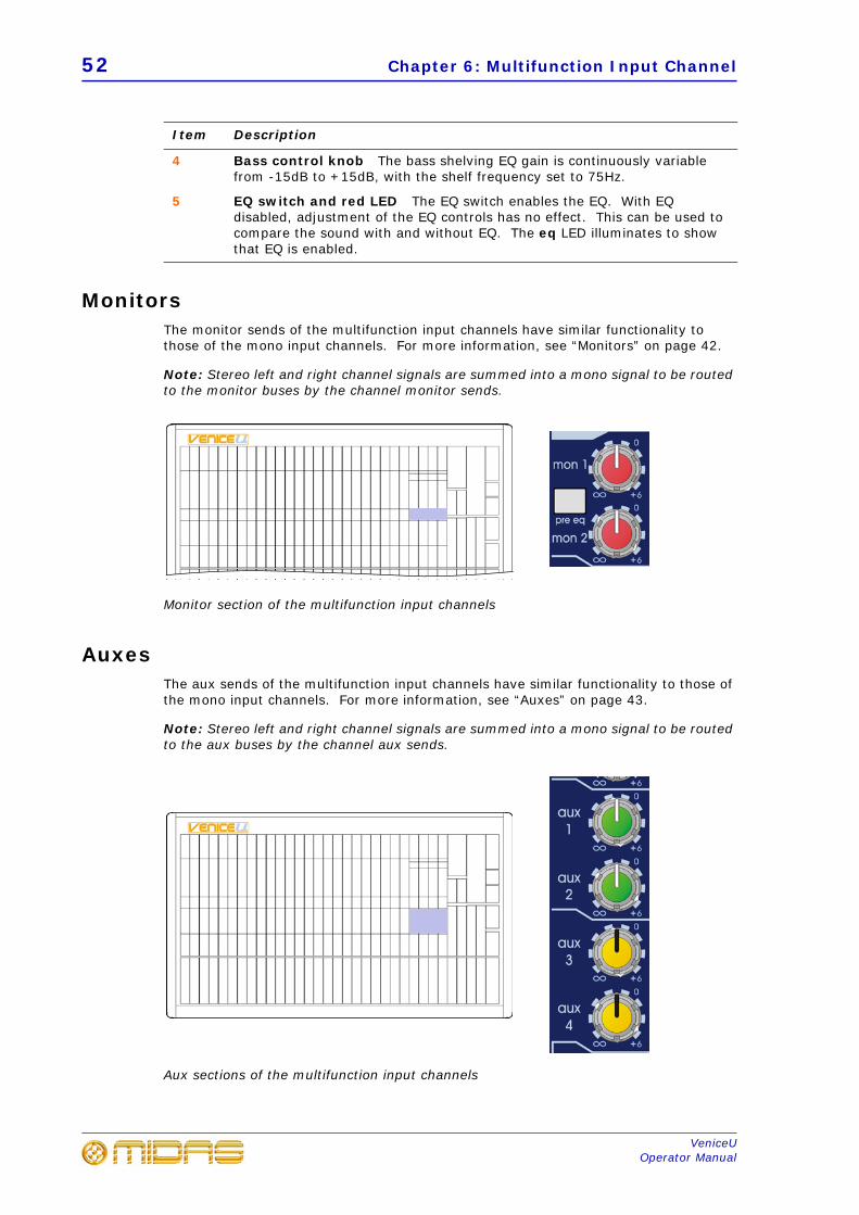
MonitorsThe monitor sends of the multifunction input channels have similar functionality to those of the mono input channels. For more information, see “Monitors” on page 42.
Note: Stereo left and right channel signals are summed into a mono signal to be routed to the monitor buses by the channel monitor sends.
Monitor section of the multifunction input channels
AuxesThe aux sends of the multifunction input channels have similar functionality to those of the mono input channels. For more information, see “Auxes” on page 43.
Note: Stereo left and right channel signals are summed into a mono signal to be routed to the aux buses by the channel aux sends.
Aux sections of the multifunction input channels
4 Bass control knob The bass shelving EQ gain is continuously variable from -15dB to +15dB, with the shelf frequency set to 75Hz.
5 EQ switch and red LED The EQ switch enables the EQ. With EQ disabled, adjustment of the EQ controls has no effect. This can be used to compare the sound with and without EQ. The eq LED illuminates to show that EQ is enabled.
Item Description
Balance, mute and solo 53
VeniceUOperator Manual
Balance, mute and soloThe VeniceU has balance, mute and solo on every multifunction input channel.
Balance, mute and solo sections of the multifunction input channels
Item Description
1 bal control knob This stereo line input balance control allows continuous reciprocal adjustment of the channel’s stereo image. It allows the user to determine the relative output power to each left and right output. At all points this control retains constant power. The fully left and fully right positions are +3dB and the centre position is 0dB.
However, when using the mic input the balance controls acts as a pan. The fully left and fully right positions are 0dB and the centre position is -3dB.
2 MUTE switch and red LED The MUTE switch mutes the channel signal. The mute LED illuminates to show when the MUTE switch is on.
3 SOLO switch and yellow LED With solo enabled, the channel signal is sent to the after-fade listen (AFL) stereo and pre-fade listen (PFL) mono buses. The left and right local monitor outputs can be used, for example, when operating from within a booth to hear selected solos and not the whole mix. The solo LED illuminates to show when a solo is on.
1
2
3
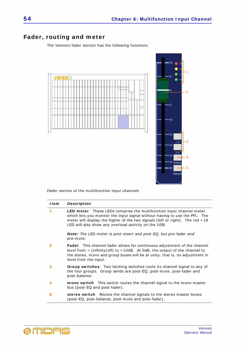
54 Chapter 6: Multifunction Input Channel
VeniceUOperator Manual
Fader, routing and meterThe VeniceU fader section has the following functions.
Fader section of the multifunction input channels
Item Description
1 LED meter These LEDs comprise the multifunction input channel meter, which lets you monitor the input signal without having to use the PFL. The meter will display the higher of the two signals (left or right). The red +18 LED will also show any overload activity on the USB.
Note: The LED meter is post-insert and post-EQ, but pre-fader and pre-mute.
2 Fader This channel fader allows for continuous adjustment of the channel level from 4 (infinity/off) to +10dB. At 0dB, the output of the channel to the stereo, mono and group buses will be at unity, that is, no adjustment in level from the input.
3 Group switches Two latching switches route its channel signal to any of the four groups. Group sends are post-EQ, post-mute, post-fader and post-balance.
4 mono switch This switch routes the channel signal to the mono master bus (post-EQ and post-fader).
5 stereo switch Routes the channel signals to the stereo master buses (post-EQ, post-balance, post-mute and post-fader).
2
1
4
5
3
Fader, routing and meter 55
VeniceUOperator Manual
Meter
The meter is especially useful when setting the microphone gain of a channel. Also, as the meter is post-EQ, it is possible to see the effect that the channel equalisation has upon the level. It may be necessary to turn the input gain down when excessive EQ is used to prevent the channel from overloading.
The LEDs represent the following:
• 18 (red): +18dB, overload (peak)
• 12 (yellow): +12dB, high level
• 0 (green): 0dB, normal level
• -18 (green): -18dB, shows signal is present
56 Chapter 6: Multifunction Input Channel
VeniceUOperator Manual
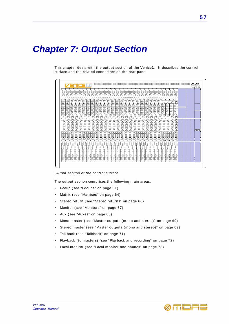
57
VeniceUOperator Manual
Chapter 7: Output Section
This chapter deals with the output section of the VeniceU. It describes the control surface and the related connectors on the rear panel.
Output section of the control surface
The output section comprises the following main areas:
• Group (see “Groups” on page 61)
• Matrix (see “Matrices” on page 64)
• Stereo return (see “Stereo returns” on page 66)
• Monitor (see “Monitors” on page 67)
• Aux (see “Auxes” on page 68)
• Mono master (see “Master outputs (mono and stereo)” on page 69)
• Stereo master (see “Master outputs (mono and stereo)” on page 69)
• Talkback (see “Talkback” on page 71)
• Playback (to masters) (see “Playback and recording” on page 72)
• Local monitor (see “Local monitor and phones” on page 73)
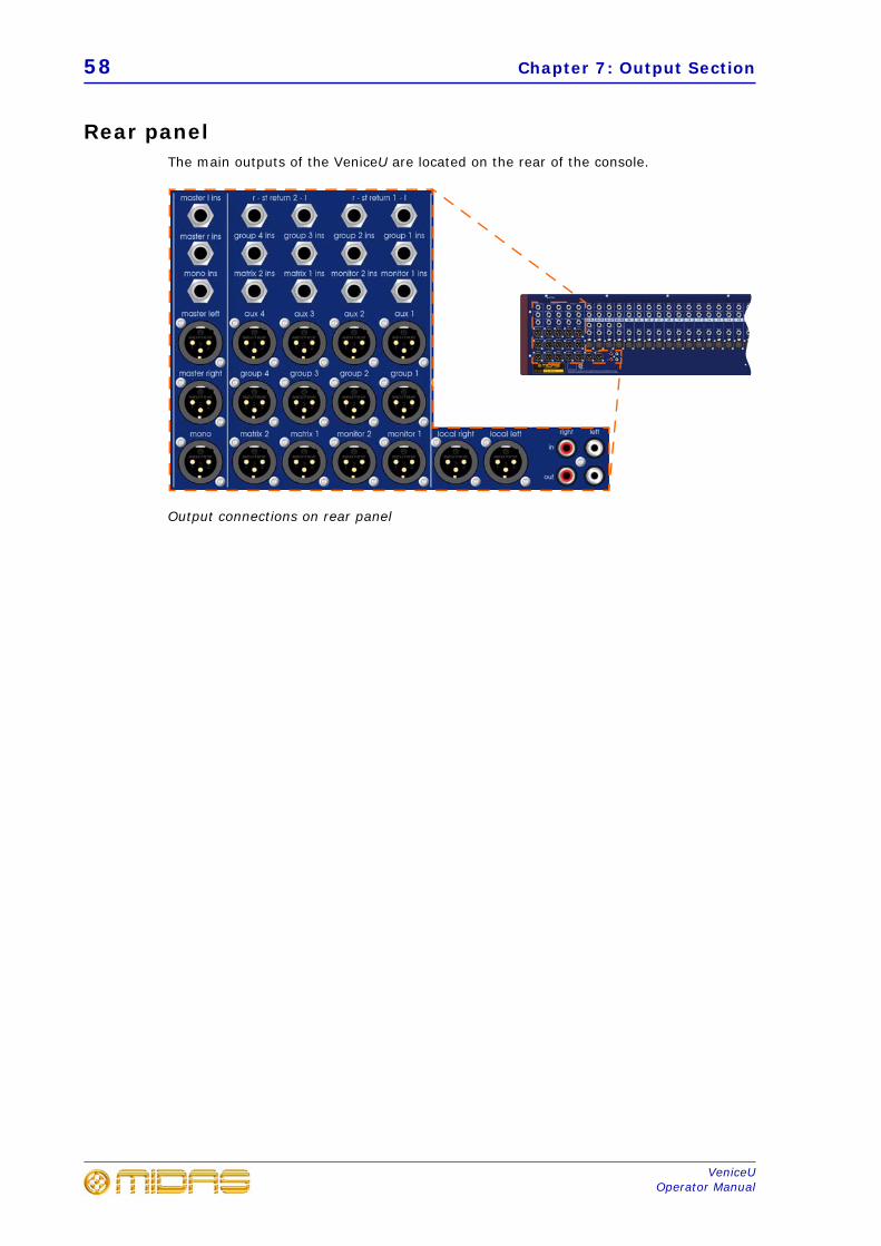
58 Chapter 7: Output Section
VeniceUOperator Manual
Rear panelThe main outputs of the VeniceU are located on the rear of the console.
Output connections on rear panel
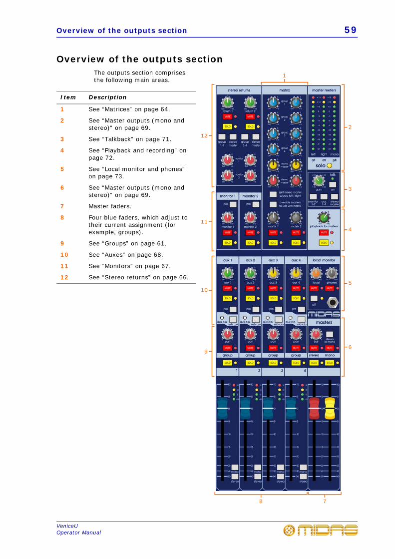
Overview of the outputs section 59
VeniceUOperator Manual
Overview of the outputs sectionThe outputs section comprises the following main areas.
Item Description
1 See “Matrices” on page 64.
2 See “Master outputs (mono and stereo)” on page 69.
3 See “Talkback” on page 71.
4 See “Playback and recording” on page 72.
5 See “Local monitor and phones” on page 73.
6 See “Master outputs (mono and stereo)” on page 69.
7 Master faders.
8 Four blue faders, which adjust to their current assignment (for example, groups).
9 See “Groups” on page 61.
10 See “Auxes” on page 68.
11 See “Monitors” on page 67.
12 See “Stereo returns” on page 66.
1
122
3
4
5
78
11
10
96
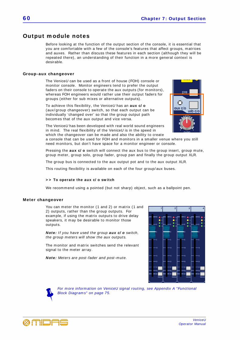
60 Chapter 7: Output Section
VeniceUOperator Manual
Output module notesBefore looking at the function of the output section of the console, it is essential that you are comfortable with a few of the console’s features that affect groups, matrices and auxes. Rather than discuss these features in each section (although they will be repeated there), an understanding of their function in a more general context is desirable.
Group-aux changeover
The VeniceU can be used as a front of house (FOH) console or monitor console. Monitor engineers tend to prefer the output faders on their console to operate the aux outputs (for monitors), whereas FOH engineers would rather use their output faders for groups (either for sub mixes or alternative outputs).
To achieve this flexibility, the VeniceU has an aux c/o (aux/group changeover) switch, so that each output can be individually ‘changed over’ so that the group output path becomes that of the aux output and vice versa.
The VeniceU has been developed with real world sound engineers in mind. The real flexibility of the VeniceU is in the speed in which the changeover can be made and also the ability to create a console that can be used for FOH and monitors in a smaller venue where you still need monitors, but don’t have space for a monitor engineer or console.
Pressing the aux c/o switch will connect the aux bus to the group insert, group mute, group meter, group solo, group fader, group pan and finally the group output XLR.
The group bus is connected to the aux output pot and to the aux output XLR.
This routing flexibility is available on each of the four group/aux buses.
>> To operate the aux c/o switch
We recommend using a pointed (but not sharp) object, such as a ballpoint pen.
Meter changeover
You can meter the monitor (1 and 2) or matrix (1 and 2) outputs, rather than the group outputs. Forexample, if using the matrix outputs to drive delay speakers, it may be desirable to monitor those outputs.
Note: If you have used the group aux c/o switch, the group meters will show the aux outputs.
The monitor and matrix switches send the relevant signal to the meter array.
Note: Meters are post-fader and post-mute.
For more information on VeniceU signal routing, see Appendix A "Functional Block Diagrams" on page 75.
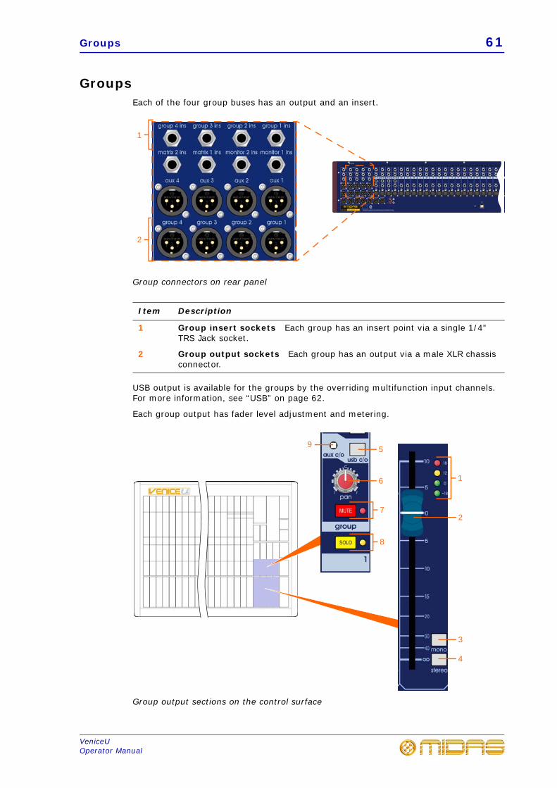
Groups 61
VeniceUOperator Manual
GroupsEach of the four group buses has an output and an insert.
Group connectors on rear panel
USB output is available for the groups by the overriding multifunction input channels. For more information, see “USB” on page 62.
Each group output has fader level adjustment and metering.
Group output sections on the control surface
Item Description
1 Group insert sockets Each group has an insert point via a single 1/4” TRS Jack socket.
2 Group output sockets Each group has an output via a male XLR chassis connector.
1
2
5
6
7
8
9
1
2
3
4
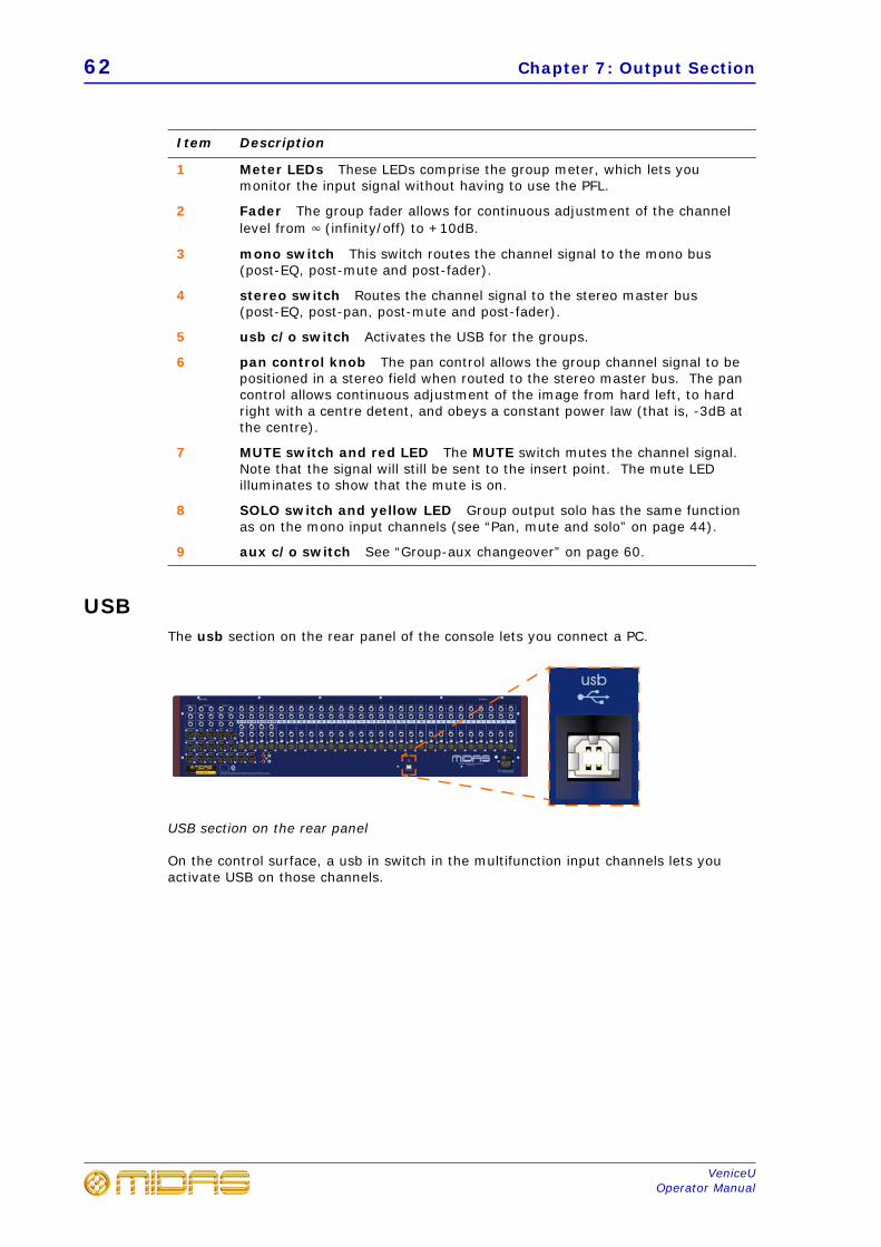
62 Chapter 7: Output Section
VeniceUOperator Manual
USBThe usb section on the rear panel of the console lets you connect a PC.
USB section on the rear panel
On the control surface, a usb in switch in the multifunction input channels lets you activate USB on those channels.
Item Description
1 Meter LEDs These LEDs comprise the group meter, which lets you monitor the input signal without having to use the PFL.
2 Fader The group fader allows for continuous adjustment of the channel level from 4 (infinity/off) to +10dB.
3 mono switch This switch routes the channel signal to the mono bus (post-EQ, post-mute and post-fader).
4 stereo switch Routes the channel signal to the stereo master bus (post-EQ, post-pan, post-mute and post-fader).
5 usb c/o switch Activates the USB for the groups.
6 pan control knob The pan control allows the group channel signal to be positioned in a stereo field when routed to the stereo master bus. The pan control allows continuous adjustment of the image from hard left, to hard right with a centre detent, and obeys a constant power law (that is, -3dB at the centre).
7 MUTE switch and red LED The MUTE switch mutes the channel signal. Note that the signal will still be sent to the insert point. The mute LED illuminates to show that the mute is on.
8 SOLO switch and yellow LED Group output solo has the same function as on the mono input channels (see “Pan, mute and solo” on page 44).
9 aux c/o switch See “Group-aux changeover” on page 60.
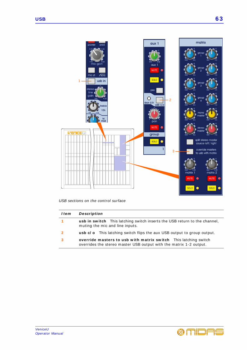
USB 63
VeniceUOperator Manual
USB sections on the control surface
Item Description
1 usb in switch This latching switch inserts the USB return to the channel, muting the mic and line inputs.
2 usb c/o This latching switch flips the aux USB output to group output.
3 override masters to usb with matrix switch This latching switch overrides the stereo master USB output with the matrix 1-2 output.
2
1
3
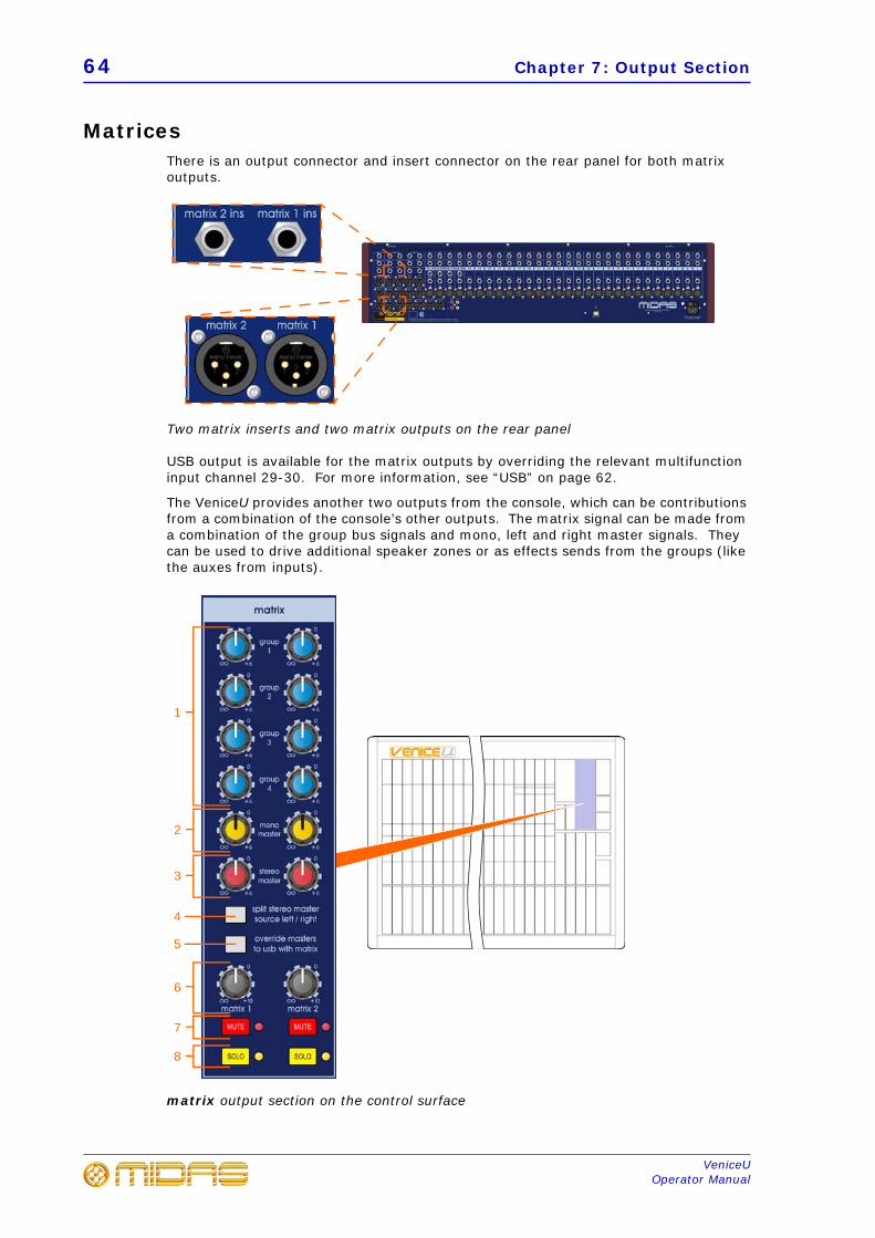
64 Chapter 7: Output Section
VeniceUOperator Manual
MatricesThere is an output connector and insert connector on the rear panel for both matrix outputs.
Two matrix inserts and two matrix outputs on the rear panel
USB output is available for the matrix outputs by overriding the relevant multifunction input channel 29-30. For more information, see “USB” on page 62.
The VeniceU provides another two outputs from the console, which can be contributions from a combination of the console’s other outputs. The matrix signal can be made from a combination of the group bus signals and mono, left and right master signals. They can be used to drive additional speaker zones or as effects sends from the groups (like the auxes from inputs).
matrix output section on the control surface
1
4
7
8
6
2
3
5
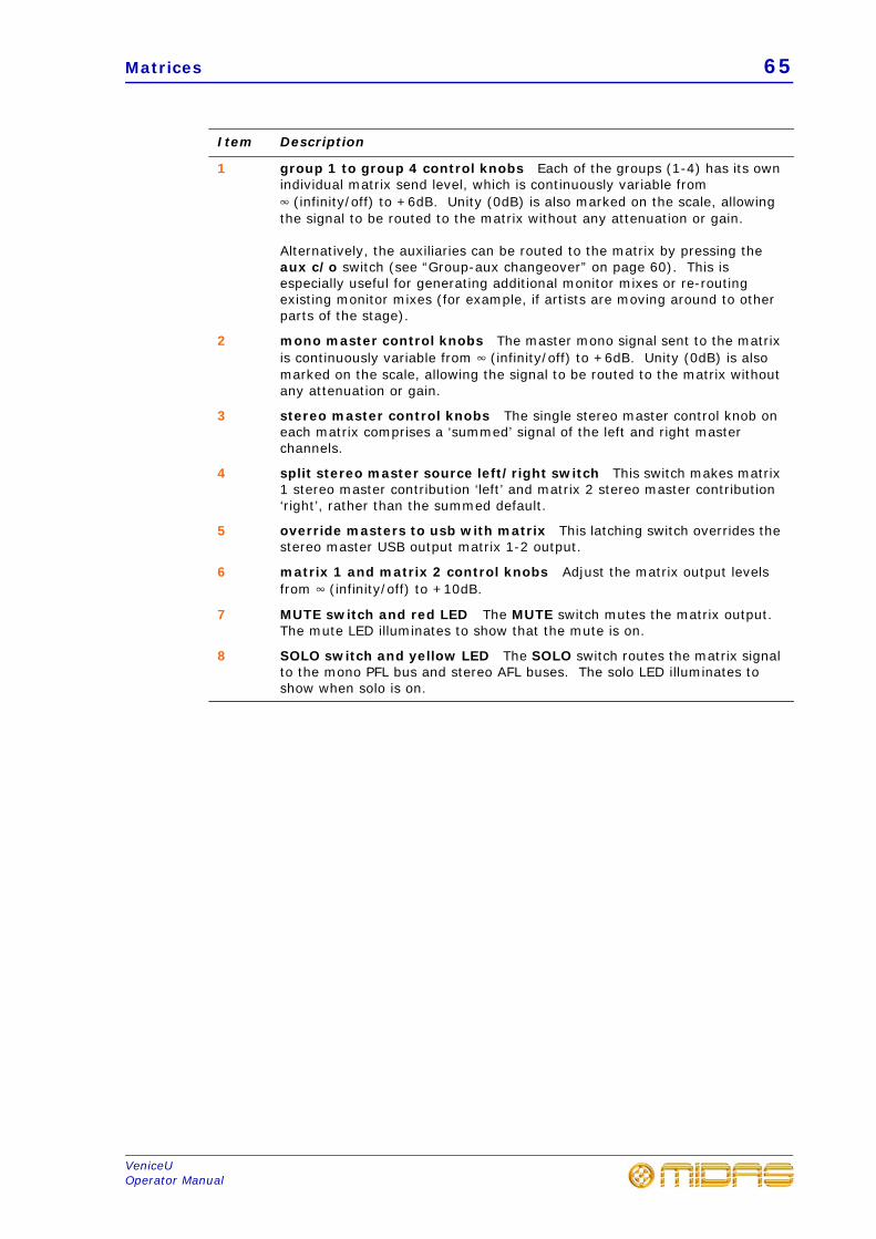
Matrices 65
VeniceUOperator Manual
Item Description
1 group 1 to group 4 control knobs Each of the groups (1-4) has its own individual matrix send level, which is continuously variable from 4 (infinity/off) to +6dB. Unity (0dB) is also marked on the scale, allowing the signal to be routed to the matrix without any attenuation or gain.
Alternatively, the auxiliaries can be routed to the matrix by pressing the aux c/o switch (see “Group-aux changeover” on page 60). This is especially useful for generating additional monitor mixes or re-routing existing monitor mixes (for example, if artists are moving around to other parts of the stage).
2 mono master control knobs The master mono signal sent to the matrix is continuously variable from 4 (infinity/off) to +6dB. Unity (0dB) is also marked on the scale, allowing the signal to be routed to the matrix without any attenuation or gain.
3 stereo master control knobs The single stereo master control knob on each matrix comprises a ‘summed’ signal of the left and right master channels.
4 split stereo master source left/right switch This switch makes matrix 1 stereo master contribution ‘left’ and matrix 2 stereo master contribution ‘right’, rather than the summed default.
5 override masters to usb with matrix This latching switch overrides the stereo master USB output matrix 1-2 output.
6 matrix 1 and matrix 2 control knobs Adjust the matrix output levels from 4 (infinity/off) to +10dB.
7 MUTE switch and red LED The MUTE switch mutes the matrix output. The mute LED illuminates to show that the mute is on.
8 SOLO switch and yellow LED The SOLO switch routes the matrix signal to the mono PFL bus and stereo AFL buses. The solo LED illuminates to show when solo is on.
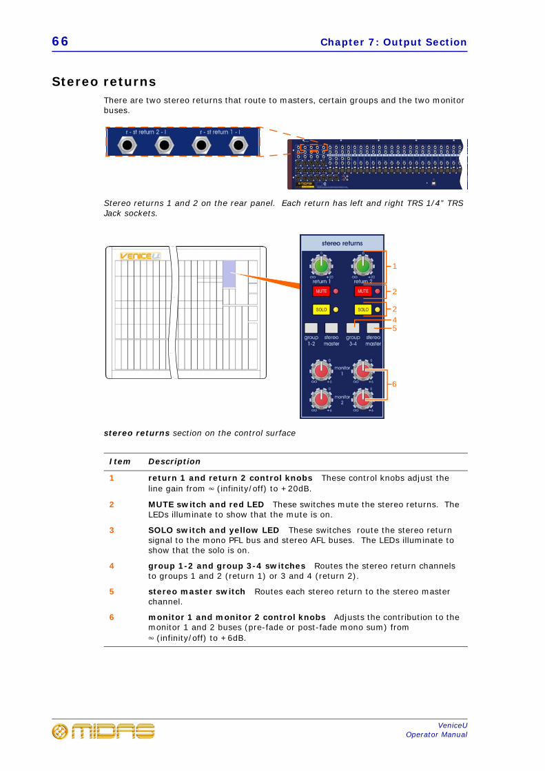
66 Chapter 7: Output Section
VeniceUOperator Manual
Stereo returnsThere are two stereo returns that route to masters, certain groups and the two monitor buses.
Stereo returns 1 and 2 on the rear panel. Each return has left and right TRS 1/4” TRS Jack sockets.
stereo returns section on the control surface
Item Description
1 return 1 and return 2 control knobs These control knobs adjust the line gain from 4 (infinity/off) to +20dB.
2 MUTE switch and red LED These switches mute the stereo returns. The LEDs illuminate to show that the mute is on.
3 SOLO switch and yellow LED These switches route the stereo return signal to the mono PFL bus and stereo AFL buses. The LEDs illuminate to show that the solo is on.
4 group 1-2 and group 3-4 switches Routes the stereo return channels to groups 1 and 2 (return 1) or 3 and 4 (return 2).
5 stereo master switch Routes each stereo return to the stereo master channel.
6 monitor 1 and monitor 2 control knobs Adjusts the contribution to the monitor 1 and 2 buses (pre-fade or post-fade mono sum) from 4 (infinity/off) to +6dB.
1
2
54
6
2
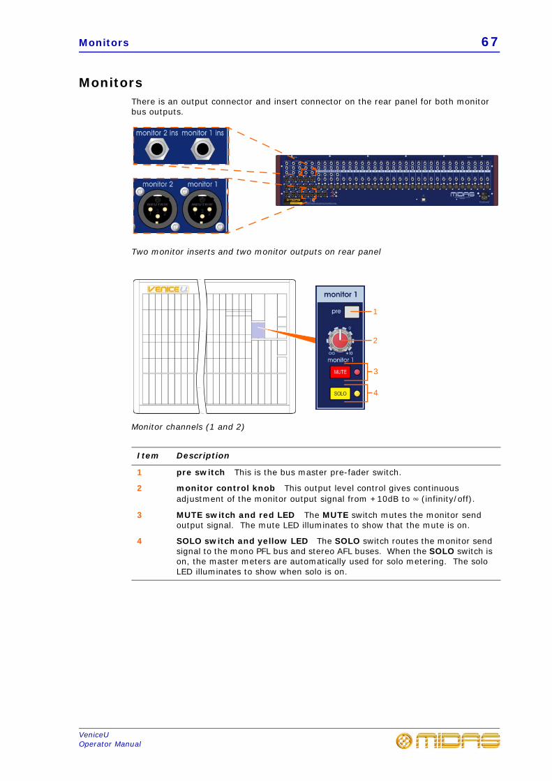
Monitors 67
VeniceUOperator Manual
MonitorsThere is an output connector and insert connector on the rear panel for both monitor bus outputs.
Two monitor inserts and two monitor outputs on rear panel
Monitor channels (1 and 2)
Item Description
1 pre switch This is the bus master pre-fader switch.
2 monitor control knob This output level control gives continuous adjustment of the monitor output signal from +10dB to 4 (infinity/off).
3 MUTE switch and red LED The MUTE switch mutes the monitor send output signal. The mute LED illuminates to show that the mute is on.
4 SOLO switch and yellow LED The SOLO switch routes the monitor send signal to the mono PFL bus and stereo AFL buses. When the SOLO switch is on, the master meters are automatically used for solo metering. The solo LED illuminates to show when solo is on.
1
2
4
3
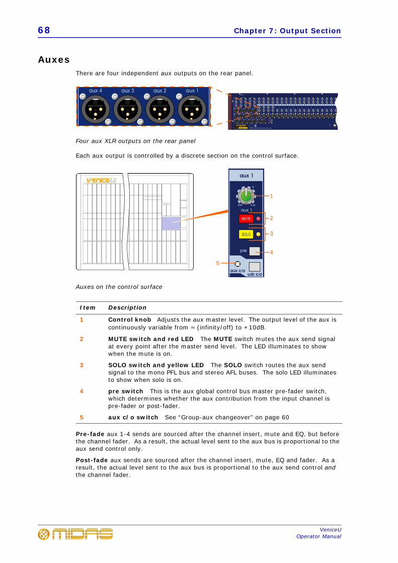
68 Chapter 7: Output Section
VeniceUOperator Manual
AuxesThere are four independent aux outputs on the rear panel.
Four aux XLR outputs on the rear panel
Each aux output is controlled by a discrete section on the control surface.
Auxes on the control surface
Pre-fade aux 1-4 sends are sourced after the channel insert, mute and EQ, but before the channel fader. As a result, the actual level sent to the aux bus is proportional to the aux send control only.
Post-fade aux sends are sourced after the channel insert, mute, EQ and fader. As a result, the actual level sent to the aux bus is proportional to the aux send control and the channel fader.
Item Description
1 Control knob Adjusts the aux master level. The output level of the aux is continuously variable from 4 (infinity/off) to +10dB.
2 MUTE switch and red LED The MUTE switch mutes the aux send signal at every point after the master send level. The LED illuminates to show when the mute is on.
3 SOLO switch and yellow LED The SOLO switch routes the aux send signal to the mono PFL bus and stereo AFL buses. The solo LED illuminates to show when solo is on.
4 pre switch This is the aux global control bus master pre-fader switch, which determines whether the aux contribution from the input channel is pre-fader or post-fader.
5 aux c/o switch See “Group-aux changeover” on page 60
1
2
3
4
5
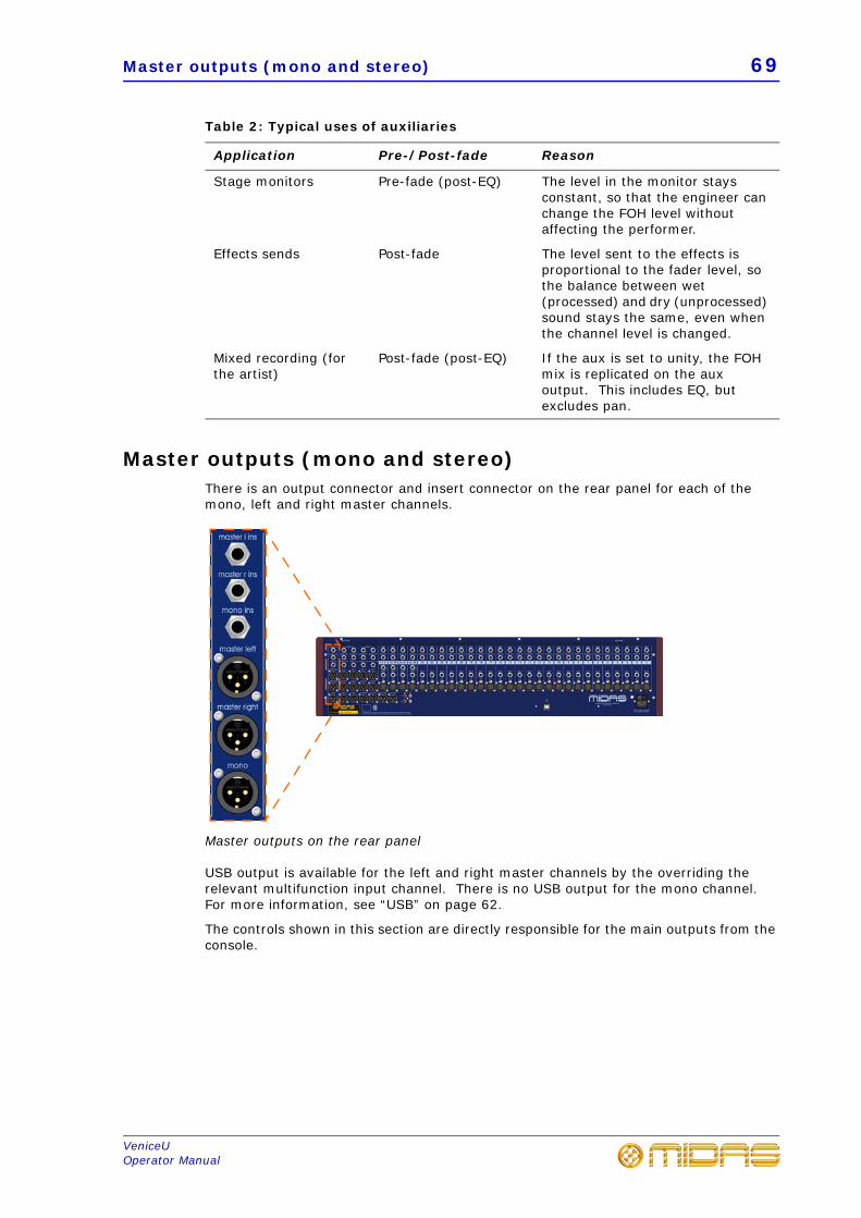
Master outputs (mono and stereo) 69
VeniceUOperator Manual
Table 2: Typical uses of auxiliaries
Master outputs (mono and stereo)There is an output connector and insert connector on the rear panel for each of the mono, left and right master channels.
Master outputs on the rear panel
USB output is available for the left and right master channels by the overriding the relevant multifunction input channel. There is no USB output for the mono channel. For more information, see “USB” on page 62.
The controls shown in this section are directly responsible for the main outputs from the console.
Application Pre-/Post-fade Reason
Stage monitors Pre-fade (post-EQ) The level in the monitor stays constant, so that the engineer can change the FOH level without affecting the performer.
Effects sends Post-fade The level sent to the effects is proportional to the fader level, so the balance between wet (processed) and dry (unprocessed) sound stays the same, even when the channel level is changed.
Mixed recording (for the artist)
Post-fade (post-EQ) If the aux is set to unity, the FOH mix is replicated on the aux output. This includes EQ, but excludes pan.
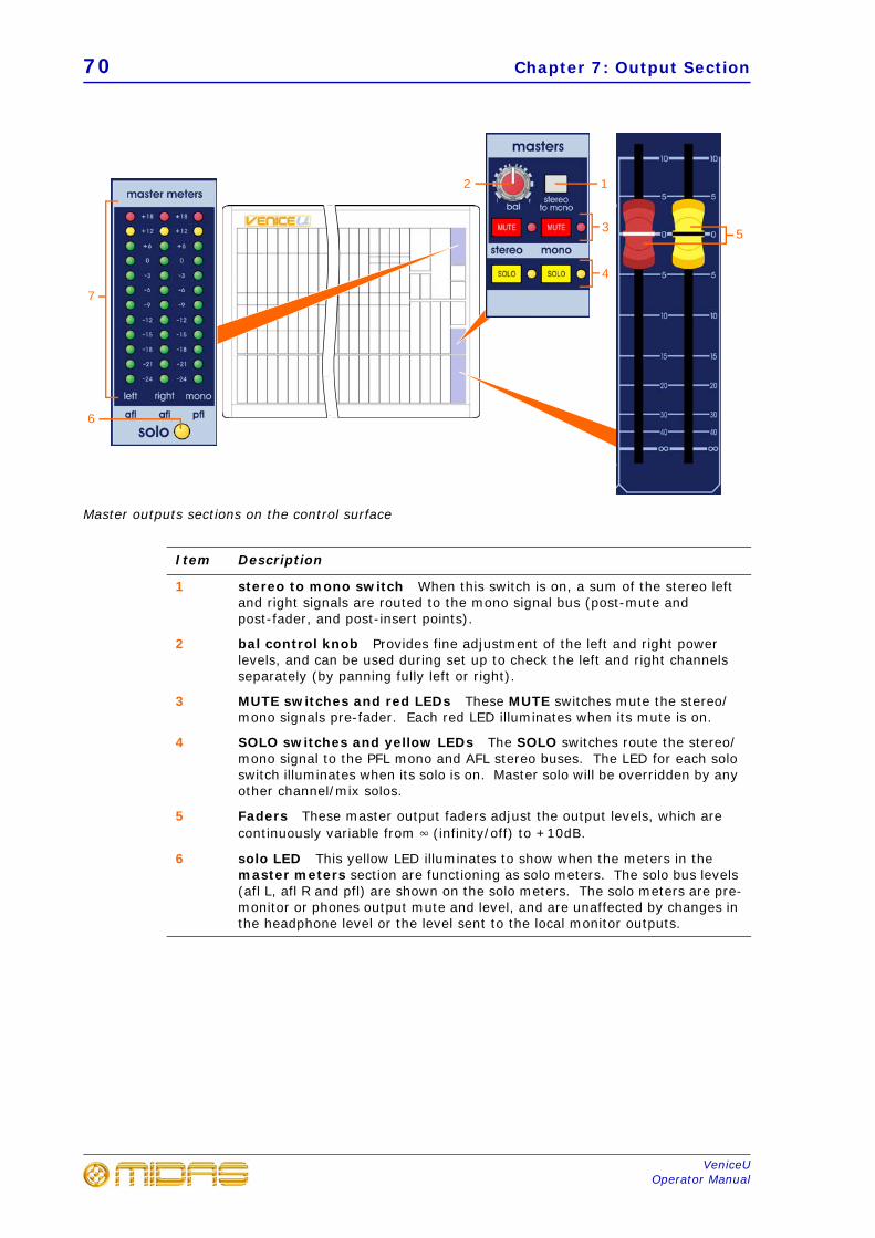
70 Chapter 7: Output Section
VeniceUOperator Manual
Master outputs sections on the control surface
Item Description
1 stereo to mono switch When this switch is on, a sum of the stereo left and right signals are routed to the mono signal bus (post-mute and post-fader, and post-insert points).
2 bal control knob Provides fine adjustment of the left and right power levels, and can be used during set up to check the left and right channels separately (by panning fully left or right).
3 MUTE switches and red LEDs These MUTE switches mute the stereo/mono signals pre-fader. Each red LED illuminates when its mute is on.
4 SOLO switches and yellow LEDs The SOLO switches route the stereo/mono signal to the PFL mono and AFL stereo buses. The LED for each solo switch illuminates when its solo is on. Master solo will be overridden by any other channel/mix solos.
5 Faders These master output faders adjust the output levels, which are continuously variable from 4 (infinity/off) to +10dB.
6 solo LED This yellow LED illuminates to show when the meters in the master meters section are functioning as solo meters. The solo bus levels (afl L, afl R and pfl) are shown on the solo meters. The solo meters are pre-monitor or phones output mute and level, and are unaffected by changes in the headphone level or the level sent to the local monitor outputs.
5
7
6
3
12
4
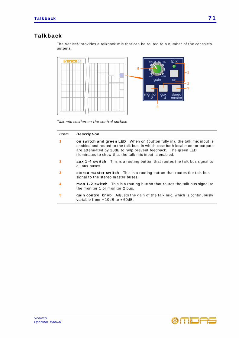
Talkback 71
VeniceUOperator Manual
TalkbackThe VeniceU provides a talkback mic that can be routed to a number of the console’s outputs.
Talk mic section on the control surface
Item Description
1 on switch and green LED When on (button fully in), the talk mic input is enabled and routed to the talk bus, in which case both local monitor outputs are attenuated by 20dB to help prevent feedback. The green LED illuminates to show that the talk mic input is enabled.
2 aux 1-4 switch This is a routing button that routes the talk bus signal to all aux buses.
3 stereo master switch This is a routing button that routes the talk bus signal to the stereo master buses.
4 mon 1-2 switch This is a routing button that routes the talk bus signal to the monitor 1 or monitor 2 bus.
5 gain control knob Adjusts the gain of the talk mic, which is continuously variable from +10dB to +60dB.
5
4
32
1
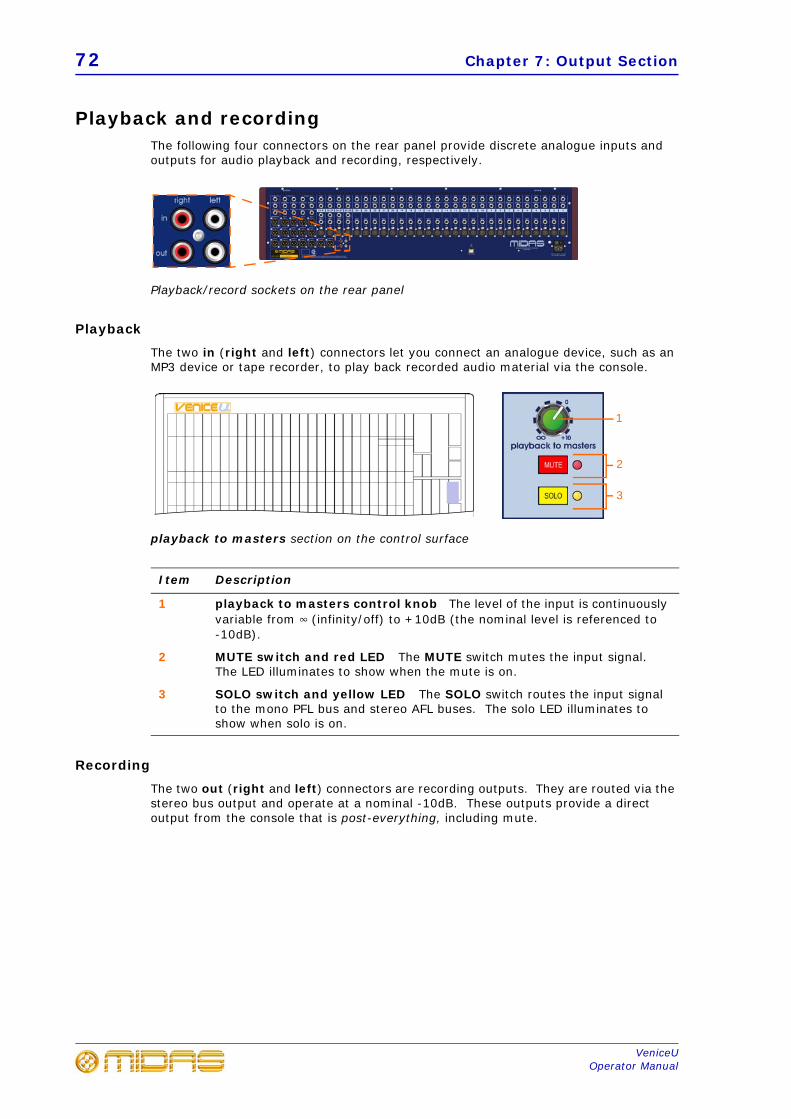
72 Chapter 7: Output Section
VeniceUOperator Manual
Playback and recordingThe following four connectors on the rear panel provide discrete analogue inputs and outputs for audio playback and recording, respectively.
Playback/record sockets on the rear panel
Playback
The two in (right and left) connectors let you connect an analogue device, such as an MP3 device or tape recorder, to play back recorded audio material via the console.
playback to masters section on the control surface
Recording
The two out (right and left) connectors are recording outputs. They are routed via the stereo bus output and operate at a nominal -10dB. These outputs provide a direct output from the console that is post-everything, including mute.
Item Description
1 playback to masters control knob The level of the input is continuously variable from 4 (infinity/off) to +10dB (the nominal level is referenced to -10dB).
2 MUTE switch and red LED The MUTE switch mutes the input signal. The LED illuminates to show when the mute is on.
3 SOLO switch and yellow LED The SOLO switch routes the input signal to the mono PFL bus and stereo AFL buses. The solo LED illuminates to show when solo is on.
1
2
3
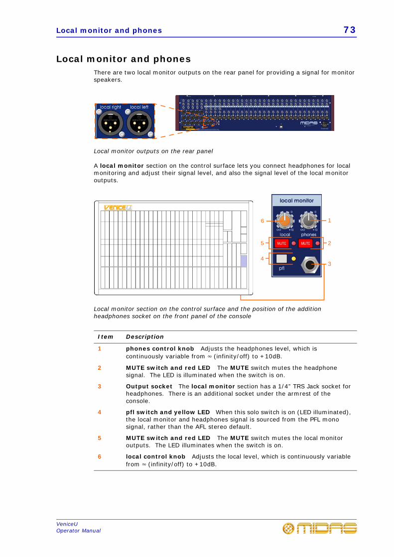
Local monitor and phones 73
VeniceUOperator Manual
Local monitor and phonesThere are two local monitor outputs on the rear panel for providing a signal for monitor speakers.
Local monitor outputs on the rear panel
A local monitor section on the control surface lets you connect headphones for local monitoring and adjust their signal level, and also the signal level of the local monitor outputs.
Local monitor section on the control surface and the position of the addition headphones socket on the front panel of the console
Item Description
1 phones control knob Adjusts the headphones level, which is continuously variable from 4 (infinity/off) to +10dB.
2 MUTE switch and red LED The MUTE switch mutes the headphone signal. The LED is illuminated when the switch is on.
3 Output socket The local monitor section has a 1/4” TRS Jack socket for headphones. There is an additional socket under the armrest of the console.
4 pfl switch and yellow LED When this solo switch is on (LED illuminated), the local monitor and headphones signal is sourced from the PFL mono signal, rather than the AFL stereo default.
5 MUTE switch and red LED The MUTE switch mutes the local monitor outputs. The LED illuminates when the switch is on.
6 local control knob Adjusts the local level, which is continuously variable from 4 (infinity/off) to +10dB.
1
3
6
25
4

74 Chapter 7: Output Section
VeniceUOperator Manual
LampsThere are sockets towards the top of the console’s rear panel for connecting 12V desk lamps. They accept 4-pin female XLR connectors. The power rating of 5W is the maximum rating per output and must not be exceeded.
Position of the lamp sockets on the VeniceUs
75
VeniceUOperator Manual
Appendix A: Functional Block Diagrams
This chapter contains the VeniceU signal path diagrams.
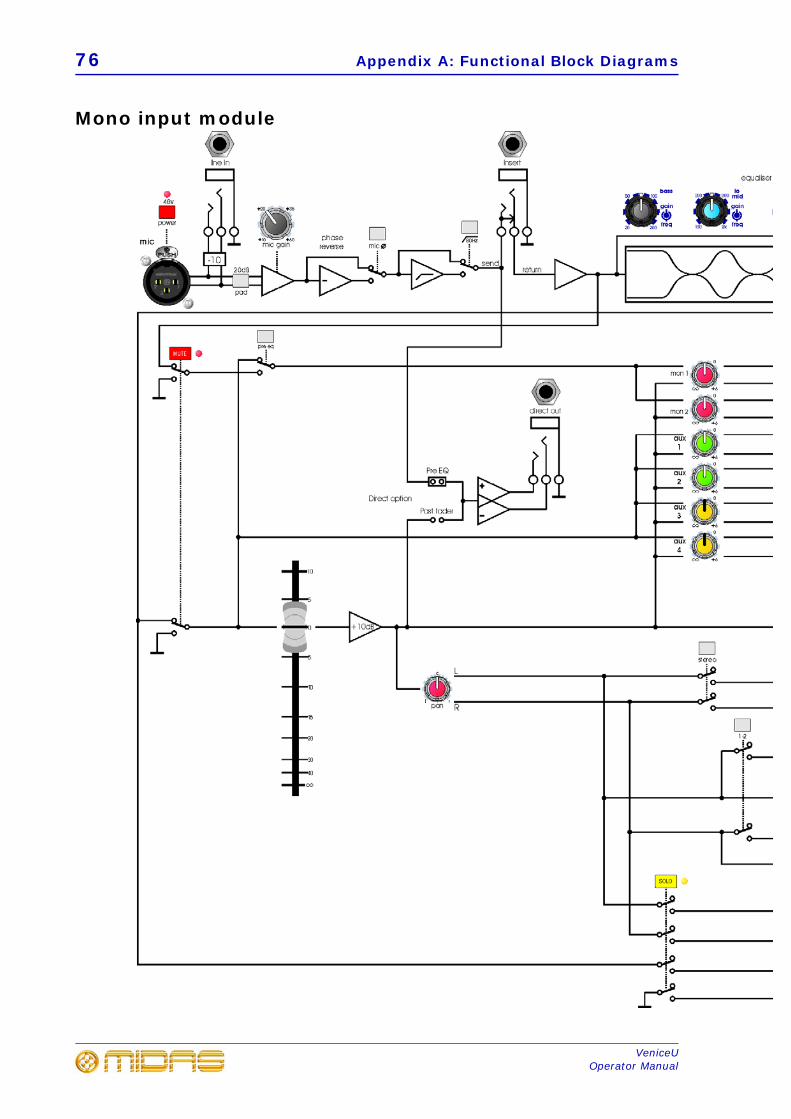
76 Appendix A: Functional Block Diagrams
VeniceUOperator Manual
Mono input module
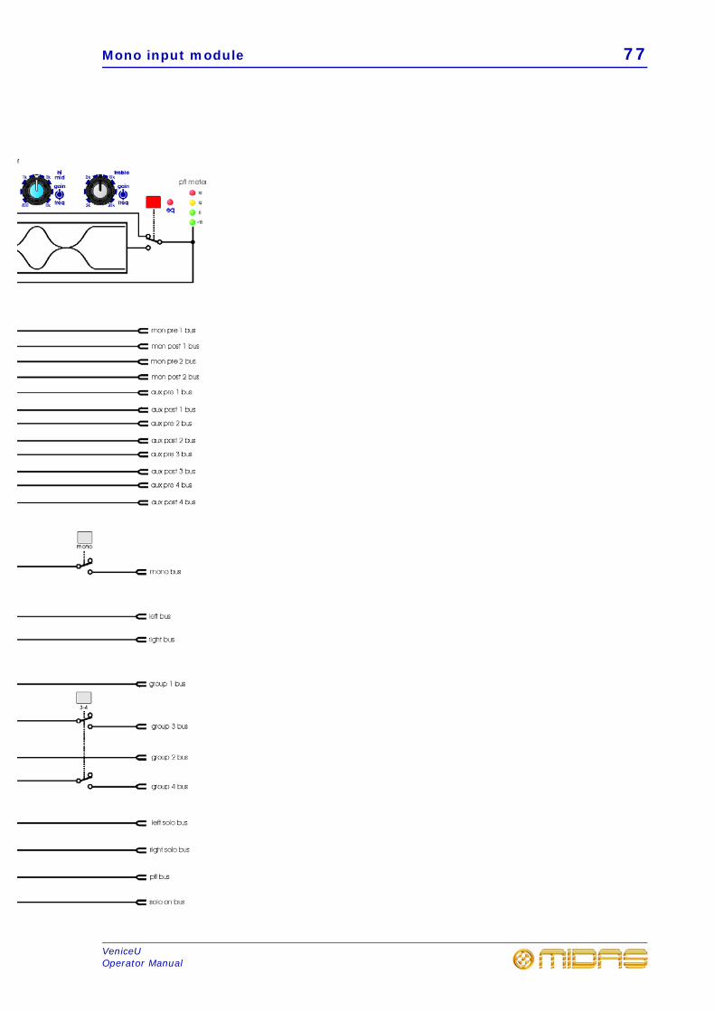
Mono input module 77
VeniceUOperator Manual
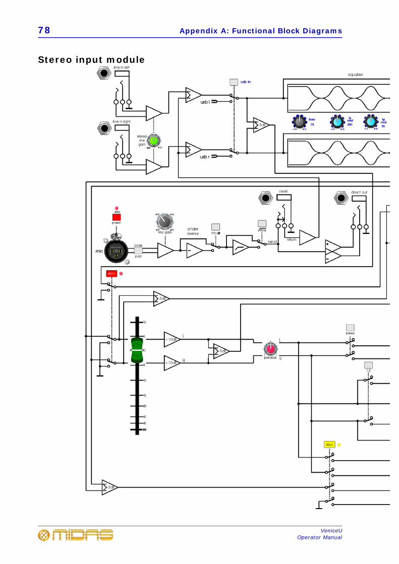
78 Appendix A: Functional Block Diagrams
VeniceUOperator Manual
Stereo input module
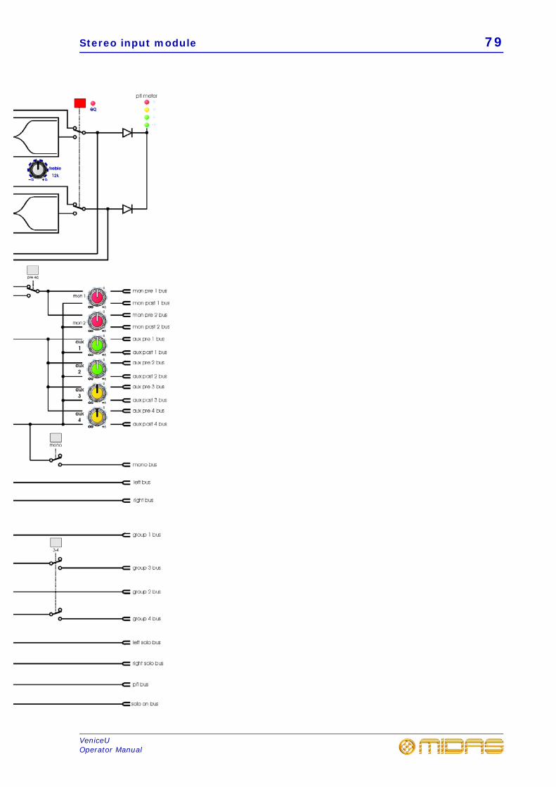
Stereo input module 79
VeniceUOperator Manual
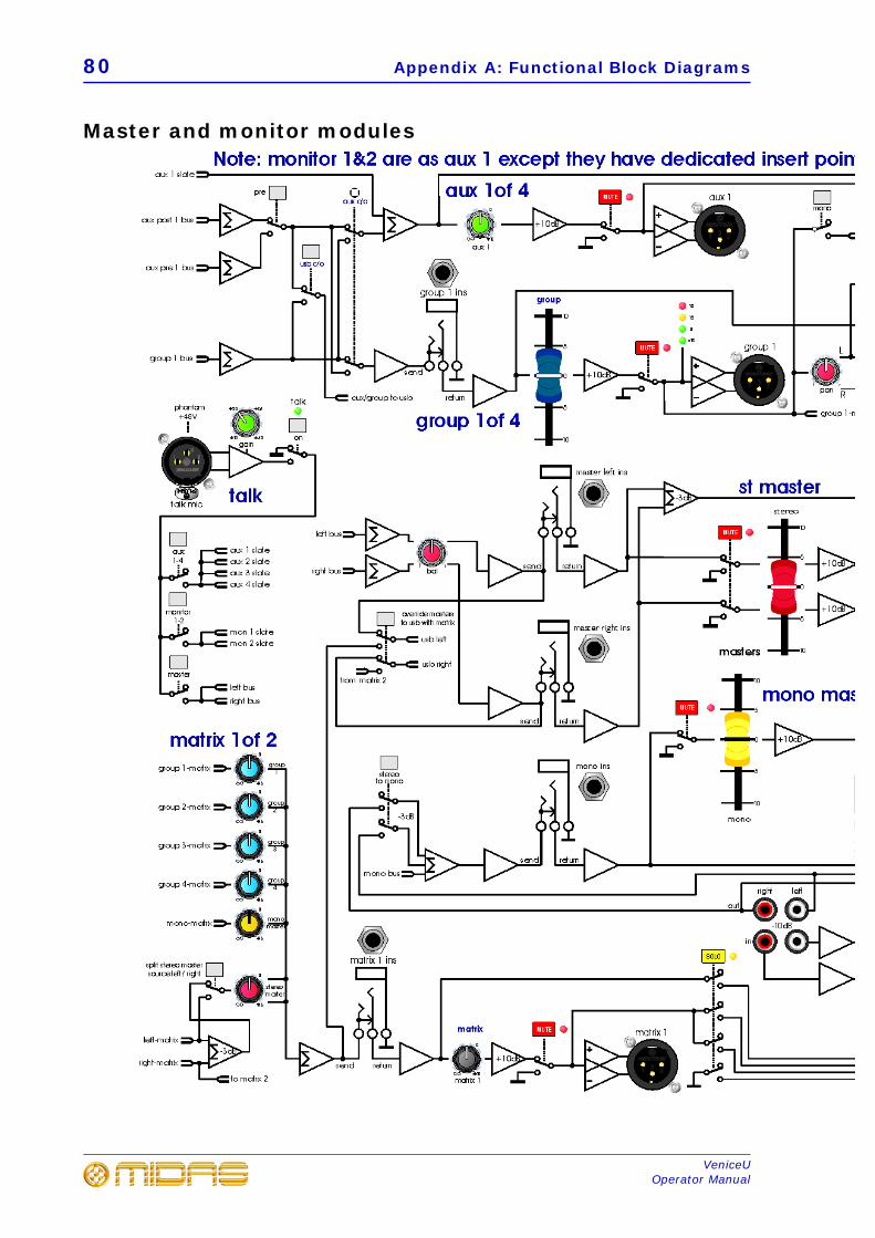
80 Appendix A: Functional Block Diagrams
VeniceUOperator Manual
Master and monitor modules
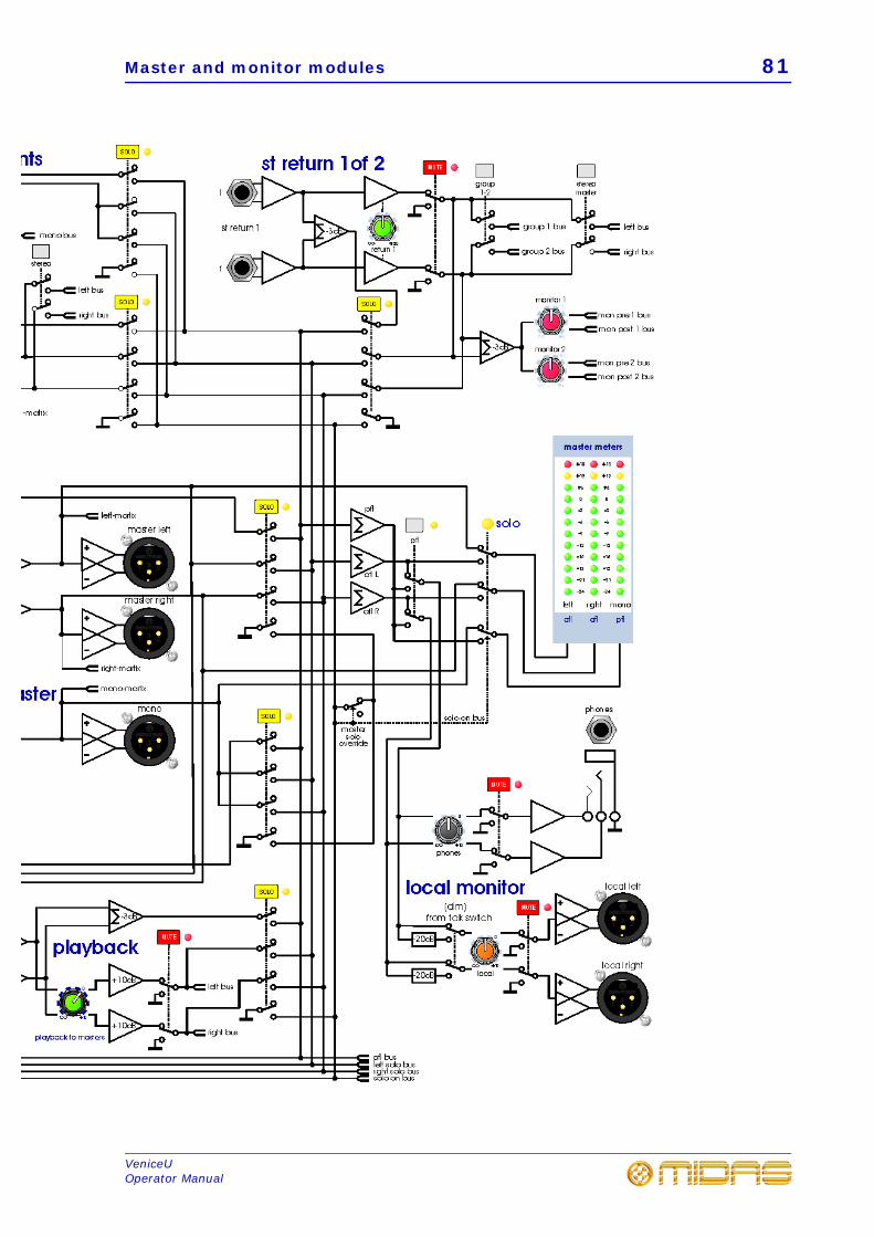
Master and monitor modules 81
VeniceUOperator Manual

82 Appendix A: Functional Block Diagrams
VeniceUOperator Manual
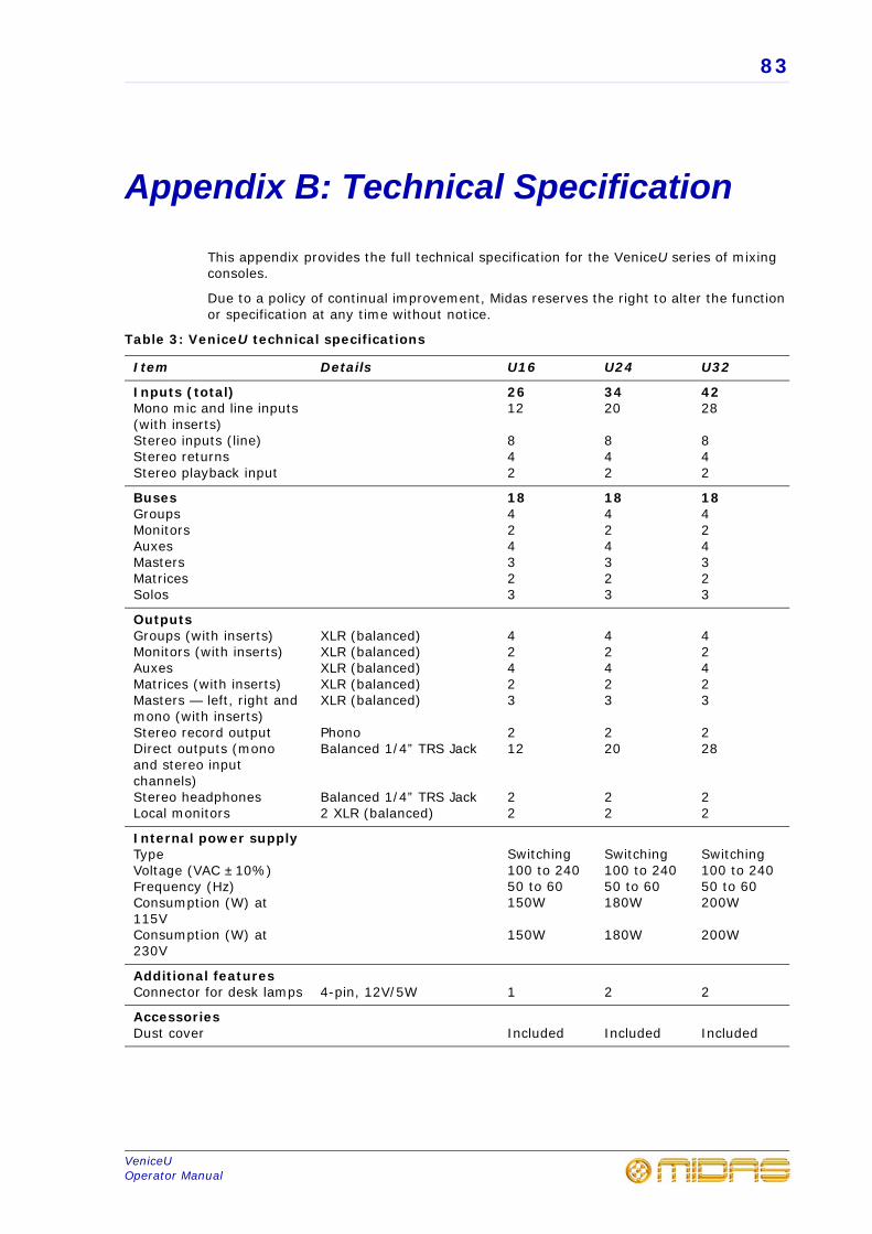
83
VeniceUOperator Manual
Appendix B: Technical Specification
This appendix provides the full technical specification for the VeniceU series of mixing consoles.
Due to a policy of continual improvement, Midas reserves the right to alter the function or specification at any time without notice.
Table 3: VeniceU technical specifications
Item Details U16 U24 U32
Inputs (total)Mono mic and line inputs (with inserts)Stereo inputs (line)Stereo returnsStereo playback input
2612
842
3420
842
4228
842
BusesGroupsMonitorsAuxesMastersMatricesSolos
18424323
18424323
18424323
OutputsGroups (with inserts)Monitors (with inserts)AuxesMatrices (with inserts)Masters — left, right and mono (with inserts)Stereo record outputDirect outputs (mono and stereo input channels)Stereo headphonesLocal monitors
XLR (balanced)XLR (balanced)XLR (balanced)XLR (balanced)XLR (balanced)
PhonoBalanced 1/4” TRS Jack
Balanced 1/4” TRS Jack2 XLR (balanced)
42423
212
22
42423
220
22
42423
228
22
Internal power supplyTypeVoltage (VAC ±10%)Frequency (Hz)Consumption (W) at 115VConsumption (W) at 230V
Switching100 to 24050 to 60150W
150W
Switching100 to 24050 to 60180W
180W
Switching100 to 24050 to 60200W
200W
Additional featuresConnector for desk lamps 4-pin, 12V/5W 1 2 2
AccessoriesDust cover Included Included Included
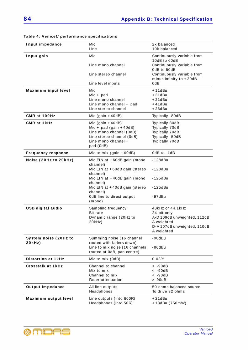
84 Appendix B: Technical Specification
VeniceUOperator Manual
Table 4: VeniceU performance specifications
Input impedance MicLine
2k balanced10k balanced
Input gain Mic
Line mono channel
Line stereo channel
Line level inputs
Continuously variable from 10dB to 60dBContinuously variable from 0dB to 50dBContinuously variable from minus infinity to +20dB0dB
Maximum input level MicMic + padLine mono channelLine mono channel + padLine stereo channel
+11dBu+31dBu+21dBu+41dBu+26dBu
CMR at 100Hz Mic (gain +40dB) Typically -80dB
CMR at 1kHz Mic (gain +40dB)Mic + pad (gain +40dB)Line mono channel (0dB)Line stereo channel (0dB)Line mono channel + pad (0dB)
Typically 80dBTypically 70dBTypically 70dBTypically -50dBTypically 70dB
Frequency response Mic to mix (gain +60dB) 0dB to -1dB
Noise (20Hz to 20kHz) Mic EIN at +60dB gain (mono channel)Mic EIN at +60dB gain (stereo channel)Mic EIN at +40dB gain (mono channel)Mic EIN at +40dB gain (stereo channel)0dB line to direct output (mono)
-128dBu
-128dBu
-125dBu
-125dBu
-97dBu
USB digital audio Sampling frequencyBit rateDynamic range (20Hz to 20kHz)
48kHz or 44.1kHz24-bit onlyA-D 109dB unweighted, 112dB A weightedD-A 107dB unweighted, 110dB A weighted
System noise (20Hz to 20kHz)
Summing noise (16 channel routed with faders down)Line to mix noise (16 channels routed at 0dB, pan centre)
-90dBu
-86dBu
Distortion at 1kHz Mic to mix (0dB) 0.03%
Crosstalk at 1kHz Channel to channelMix to mixChannel to mixFader attenuation
< -90dB< -90dB< -90dB> 90dB
Output impedance All line outputsHeadphones
50 ohms balanced sourceTo drive 32 ohms
Maximum output level Line outputs (into 600R)Headphones (into 50R)
+21dBu+18dBu (750mW)
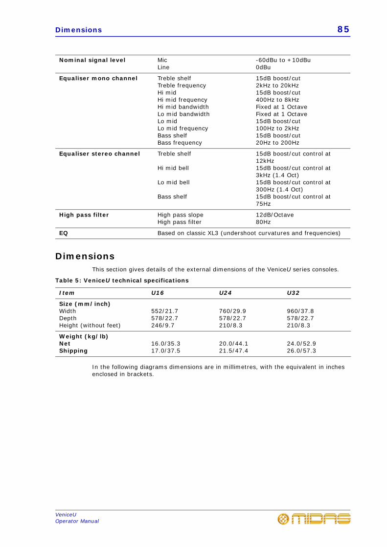
Dimensions 85
VeniceUOperator Manual
DimensionsThis section gives details of the external dimensions of the VeniceU series consoles.
Table 5: VeniceU technical specifications
In the following diagrams dimensions are in millimetres, with the equivalent in inches enclosed in brackets.
Nominal signal level MicLine
-60dBu to +10dBu0dBu
Equaliser mono channel Treble shelfTreble frequencyHi midHi mid frequencyHi mid bandwidthLo mid bandwidthLo midLo mid frequencyBass shelfBass frequency
15dB boost/cut2kHz to 20kHz15dB boost/cut400Hz to 8kHzFixed at 1 OctaveFixed at 1 Octave15dB boost/cut100Hz to 2kHz15dB boost/cut20Hz to 200Hz
Equaliser stereo channel Treble shelf
Hi mid bell
Lo mid bell
Bass shelf
15dB boost/cut control at 12kHz15dB boost/cut control at 3kHz (1.4 Oct)15dB boost/cut control at 300Hz (1.4 Oct)15dB boost/cut control at 75Hz
High pass filter High pass slopeHigh pass filter
12dB/Octave80Hz
EQ Based on classic XL3 (undershoot curvatures and frequencies)
Item U16 U24 U32
Size (mm/inch)WidthDepthHeight (without feet)
552/21.7578/22.7246/9.7
760/29.9578/22.7210/8.3
960/37.8578/22.7210/8.3
Weight (kg/lb)NetShipping
16.0/35.317.0/37.5
20.0/44.121.5/47.4
24.0/52.926.0/57.3
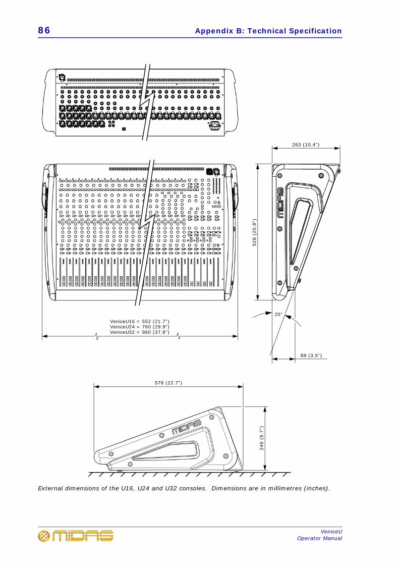
86 Appendix B: Technical Specification
VeniceUOperator Manual
External dimensions of the U16, U24 and U32 consoles. Dimensions are in millimetres (inches).
VeniceU16 = 552 (21.7”)VeniceU24 = 760 (29.9”)VeniceU32 = 960 (37.8”)
528
(20.
8”)
263 (10.4”)
89 (3.5”)
20°
246
(9.7
”)
578 (22.7”)
87
VeniceUOperator Manual
Appendix C: Application Notes
This appendix provides application notes as a guide to help you with VeniceU console operation. With its flexible routing and functionality, the VeniceU was designed with real-world sound engineers in mind, working in the real world. So, for engineers that haven’t got a great deal of experience in live sound engineering, the following subsections may provide a few helpful guidelines.
GainThe VeniceU has two types of input channel — mono and multifunction — both of which also have microphone inputs. Gain is provided on these channels to allow the operator to obtain the optimal signal for the system:
• Microphone gain — range is +10dB to +60dB (-10dB to +40dB with pad switchenabled).
• Mono channel line gain — range is 0dB to +50dB (-20dB to 30dB with pad switchenabled).
• Stereo channel line gain — range is -4 (minus infinity) to +20dB.
Each channel of the VeniceU includes an LED meter, which indicates the channel level (measured after the channel insert and EQ but before the channel fader). With the insert and EQ disabled, the meter shows the level at the input in the following four stages:
• -18dB: signal present
• 0dB: normal operating level
• +12dB: high signal level
• +18dB: 3dB before channel overload (clipping)
The input gain of the channel can be used to obtain the best operating level for the console. Too small a signal level (too little gain) and the best signal to noise ratio will not be achieved; too high a signal level (too much gain) and there is the chance of overloading the channel, causing distortion.
Clearly, the gain should be positioned between these two points to gain an optimal signal to noise ratio without overloading the channel. The ideal level for input channels would be around +6dB with occasional illumination of +12dB.
HeadroomA channel signal is only permitted to swing high and low by an amount fixed by the power supply. If the maximum output of the VeniceU channel strip is +21dBu (0dBu = 0.775 volts RMS) then imagine the following situation:
Headroom is the amount of spare ‘swing’ available to the system. If 9dB headroom was desired at all times, a maximum level of +12dB is required to retain the headroom.
To prevent overload the gain must be set to a point that even the highest output from the microphone during sound check has some headroom left to prevent any surprises during the show!
The console’s buses (that is, the left and right main buses) are the point where all channel signals are summed together. In normal operation, it is unlikely that all
88 Appendix C: Application Notes
VeniceUOperator Manual
channels will receive the same signal at the same time so, typically, when 16 channels are summed together a gain of around 5dB to 8dB will be seen. It is important to leave some headroom in the summing amplifiers so that they do not overload, should the sum exceed the maximum level.
The effect of EQChannel equalisation should be used with care. Boosting or cutting equaliser bands can make monitoring your actual input level very difficult. Excessive boosting of EQ (+15dB is available on each band) will have the same effect as applying more gain to the input, taking up valuable headroom. Consider backing off the channel gain when using large amounts of boost (if you have to use large amounts of boost) to retain a sensible level at the output.
Excessive EQ cut can have a similarly undesirable effect. If a large amount of signal is cut in the equaliser section, gain may be used to ‘make up’ the level lost in the equaliser. However, the input pre-amplifier still has the same amount of available headroom. If gain, added to ‘make up’ the loss in the equaliser, exceeds the maximum level into the microphone pre-amp then the channel won’t appear to be overloaded, but the microphone pre-amp will. Turning off the equaliser will reveal the true story, whereby the microphone pre-amp may be overloaded. It is worth considering whether such large amounts of EQ cut is really required, or whether it is being used rather more as a volume control (in which case the input gain could be set to a normal operating level and the output adjusted on the channel fader).
You can monitor the level pre-EQ and post-EQ using the LED meter by switching the EQ in and out during sound check.
Dynamic processingWhen working with signals that are constantly at a high level the channel gain can accommodate these signals with ease. When working with varying signals, such as from a vocalist, it may be desirable to reduce the dynamic range of the signal so that the loud parts aren’t so loud (and don’t overload your channel input) and the quiet bits aren’t too quiet (so the signal to noise ratio would be increased).
Limiters and compressors have a similar function, which is to reduce the dynamic range of a signal. The means by which they do this won’t be discussed here, but these devices have the ability to reduce the level of loud signals automatically and also raise the gain to ‘make up’ the level as desired. The channel gain can now be set with adequate headroom to accommodate both loud and quiet signals, and the compressor can reduce the dynamic range and ‘make up’ any reduction in level. By inserting such a device into the channel’s insert point you have the ability to remove the guesswork from setting your system gain.
However, there are still sources of potential problems. The VeniceU is able to operate at levels up to +21dBu on both the insert send and return. If the maximum input level of the compressor was less than +21dBu, it is possible to overload the input of the compressor. The only way to resolve this situation would be to drop the channel input gain so that the input level of the compressor was not being overloaded. However, please note that the level returned from the compressor would also be lower than +21dBu and excessive use of the compressor ‘make up’ gain would overload the output of the compressor!
Unity Gain 89
VeniceUOperator Manual
Unity GainUnity gain is a gain of 1, that is, no gain or attenuation is applied to a signal.
If a signal entered a mono line level input of the VeniceU at 0dBu and the gain was set to +10dB (an internal 10dB attenuation sets the net gain to 0dB), then the signal was routed to each output at 0dB, the channel fader was set to 0dB and each output fader was set to 0dB, the output should be 0dBu (or unity). Some console manufacturers mark the 0dB level of their faders and pots ‘U’.
Simple. But that’s just one signal. If we have two 0dBu signals entering the VeniceU (assuming they are coherent, that is, the same level and phase) to be summed in the buses, the output would no longer be 0dBu.
Simply,
0dBu = 0.775 volts0.775 volts + 0.775 volts = 1.55 volts
1.55 volts is 0.775 volts +6dB (or a gain of 2)
To retain an output of 0dBu (our previous unity level) each input must be reduced.
0.775 volts / 2 = 0.3875 volts0.3875 volts is 0.775 volts -6dB (or a gain of 1/2)
So, each fader must be reduced to -6dB to retain the unity gain level of 0dBu on the console output. When using four inputs at 0dBu, the faders must be reduced to -12dB. Real life signals are not continuous, but the principle is the same. If you have a sinusoidal input that is nominally 0dBu on all 32 inputs with the channel faders at 0dB, the output is likely to be well above the 21dBu maximum output of the console and leave no headroom spare. With real world signals, 32 channels summed together will give around 6dB to 9dB gain because it is unlikely that all 32 channels will receive the same signal at the same time. Instead, signals will occur at different times, and there will be cancellation due to phase and frequency differences.
Signal Processing and AmplifiersThe final links in the system tend to be graphic equalisers, loudspeaker processors and finally amplifiers and speakers.
Graphic equalisers have the same problems as the VeniceU’s EQ. If excessive boost is applied to the signal, the graphic equaliser’s output may be overloaded. If the output of the VeniceU is higher than the maximum input level of the graphic, the input of the graphic may be overloaded.
Loudspeaker processors have similar problems. If the input level to the processor is too high, the input may be overloaded and introduce distortion into the outputs (and to the speakers!). In addition to this, any boost on the processor’s outputs (say you want 3dB more bass) will cause that output to overload earlier (in this case 3dB before the other outputs).
Finally, amplifiers can introduce the most interesting results.
An amplifier has a sensitivity. That is, an input signal level that causes the amplifier to produce its maximum output level. For many amps this is 0dBu (0.775 volts RMS), while others use 0dBV (1 volt RMS) and others use different levels. Beyond this sensitivity, the amplifier’s output will not be able to produce any more power and ‘CLIP’ (usually indicated by some serious looking red lights). Sending +21dBu level from the VeniceU will clip the output of most amplifiers causing damage to your loudspeaker system.
90 Appendix C: Application Notes
VeniceUOperator Manual
There are a number of solutions to this problem:
• Reduce the amplifier’s input attenuators to a level where the amplifier andconsole clip at the same point.
For example, the input sensitivity is 0dBu, setting the input attenuator on theamplifier to -21dB would mean that the console would clip at the same time as theamplifier. So, operating the console sensibly the amplifier should never be clipped.The console LED meters will also accurately show the available headroom left in theentire system.
-21dB may not be a sensible level to set as many operators choose not to run theoutput of the console so high. That is personal choice.
• Run the output of the console at a level below 0dBu.
This solution means that you won’t get full benefit of the console, and may suffer areduced signal to noise ratio, especially when running over long signal cables. Butthe amplifiers should be saved from clipping.
As with many things in the audio world, use your ears. If something sounds distorted, do the following:
RoutingThe flexible routing of the VeniceU allows the console to operate as both a FOH and monitor console, or as a combination of both. For operators that haven’t got a great deal of experience, here are a few helpful guidelines.
FOH mode
The group-aux changeover switch on each group (see “Group-aux changeover” on page 60) should be released (in the off position) so that the group fader controls the group bus signal.
Uses for groups vary, but include:
• Submixes Submixes are a common way of saving time (and possiblyembarrassment) when using a large number of microphones at once. For example,multiple microphones for choirs, drum kits/percussion, orchestras, etc.
The channel to be submixed should be routed to the group and any aux sends ONLY(that is, not to the master L-M-R). The fader is, as normal, used to set the relativelevel between the channels in the submix. The group chosen for the submix shouldthen be routed to the master L-M-R and panned as required.
Problem Action
Input gain is too high Lower input gain
EQ has too much boost Disable EQ
EQ has too much cut and has a high input gain
Disable EQ
There is too high a level entering the inserted processor
Disable insert
The loudspeaker controller or amplifiers are clipping
Check clipping indicators on amplifiers, etc.
Routing 91
VeniceUOperator Manual
The submix is now set up. The group level can be used to control the overall level of the channels (retaining their relative levels), mute the submix output or solo the submix signal.
Note: Muting the submix is not the same as muting the channels. Aux sends and other group sends will remain active.
• Common EQ/processing Often, it is either too expensive or undesirable to applyprocessing to each channel individually (for example, compression on a whole choir,graphic EQ on a number of microphones, etc.). Setting up a submix as above, thesignal is grouped together. Now the desired processor can be inserted into the groupinserts applying the processing to all of the submix channels (in their relative levels).
• Alternative outputs For example, you were mixing a number of speakers in avenue and each needed a different level and processing.
Route the desired channels to any group or master output as necessary. Make surethe group is not routed to the main outputs. The group outputs should be wired intothe necessary amplification and the insert points into any necessary processing (forexample, delay, EQ, etc.).
The levels are now individually controllable.
MON mode
The group-aux changeover switch on each group (see “Group-aux changeover” on page 60) should be depressed (in the on position) so that the group fader controls the aux bus signal.
Channel signal should be sent to the aux, as required, and the aux sends should usually be configured to pre-fader. The console group output sockets should be wired into the necessary amplification and the insert points into any necessary processing (for example, EQ, etc.).
The monitor levels are now individually controllable on the group faders.
Dual FOH/MON Mode
The group-aux changeover switch on each group (see “Group-aux changeover” on page 60) should be depressed (in the on position) so that the group fader controls the aux bus signal for monitors or released (in the off position) so that the group fader controls the group bus signal for FOH. The usage in this split mode can be any combination of the above!
Note: When the group-aux changeover switch is depressed, control over the groups is performed by the aux controls and hence, and group outputs may still be used. Submixes could be used by connecting the aux output sockets on the rear of the console to four unused stereo input channels and routed to the left and right master buses.

92 Appendix C: Application Notes
VeniceUOperator Manual
93
VeniceUOperator Manual
Appendix D: Crib Sheets
This appendix provides you with a template each for the mono and multifunction input channels. These will help you keep a record of your most important settings and make notes. If necessary, you can make copies of these pages if you need more records.
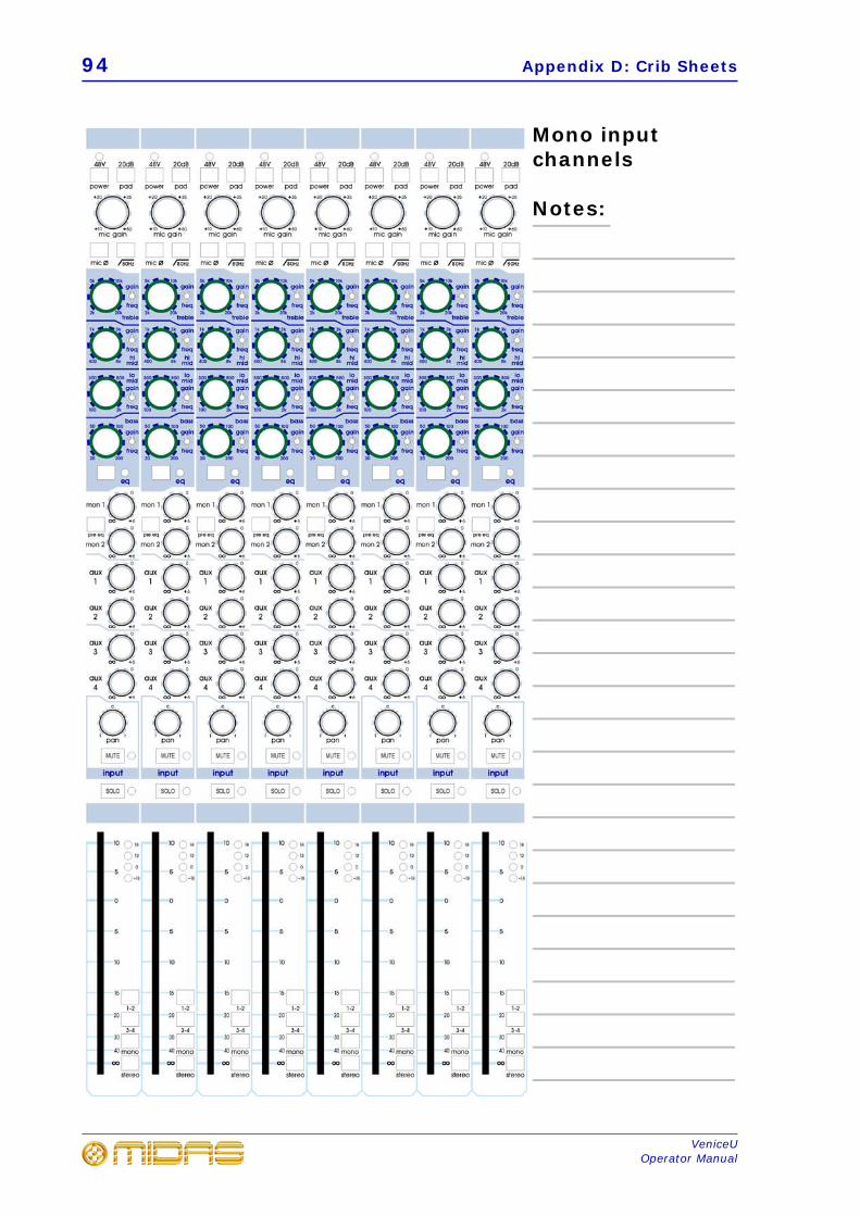
94 Appendix D: Crib Sheets
VeniceUOperator Manual
Mono input channels
Notes:
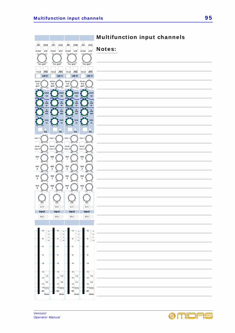
Multifunction input channels 95
VeniceUOperator Manual
Multifunction input channels
Notes:

96 Appendix D: Crib Sheets
VeniceUOperator Manual
97
VeniceUOperator Manual
Appendix E: Best Grounding Practice
This appendix gives details of the best grounding practices for the VeniceU console in order to get the optimum performance out of it.
Safety firstThe VeniceU is classified as a class 1 device and as such there is a safety requirement for the power cable to provide an earth connection to the console. This connection is bonded to all external metal parts such that in the event of a failure within the AC power systems it is impossible for any external parts of the product to become live. When connecting other equipment to the VeniceF to form an audio system, it is likely that some of these additional devices will also be class 1, so they will require a safety earth too. For your own safety, the safety of others and to comply with the law, it is important that none of these earth connections are tampered with in any way.
Ground loopsWhen connecting audio signals or data between devices within an audio system, a signal ground connection must be provided that screens the signals from electromagnetic interference. This ground connection, combined with the safety earth, produces a ring of conductors often referred to as a “ground loop”. Typically, this gives rise to induced currents within the components of the loop, namely the ground conductors, the chassis of the equipment and the safety earth conductors. This is not dangerous, but if the grounds are used as a reference for audio signals, as occurs with unbalanced connections, the ground currents may generate small voltages that corrupt the signal integrity. The audible results are noise added to the intended signal. Typically, this sounds like hum (from the power AC voltage), buzzing or whistles (from power supply diodes or switch mode power supplies), or digital noise (from computers).
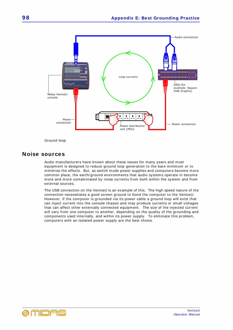
98 Appendix E: Best Grounding Practice
VeniceUOperator Manual
Ground loop
Noise sourcesAudio manufacturers have known about these issues for many years and most equipment is designed to reduce ground loop generation to the bare minimum or to minimise the effects. But, as switch mode power supplies and computers become more common place, the earth/ground environments that audio systems operate in become more and more contaminated by noise currents from both within the system and from external sources.
The USB connection on the VeniceU is an example of this. The high speed nature of the connection necessitates a good screen ground to bond the computer to the VeniceU. However, if the computer is grounded via its power cable a ground loop will exist that can inject current into the console chassis and may produce currents or small voltages that can affect other externally connected equipment. The size of the injected current will vary from one computer to another, depending on the quality of the grounding and components used internally, and within its power supply. To eliminate this problem, computers with an isolated power supply are the best choice.
Power distribution unit (PDU)
Midas VeniceU console
GEQ (for example, Square ONE Graphic)
Audio connection
Loop currents
Power connection
Powerconnection
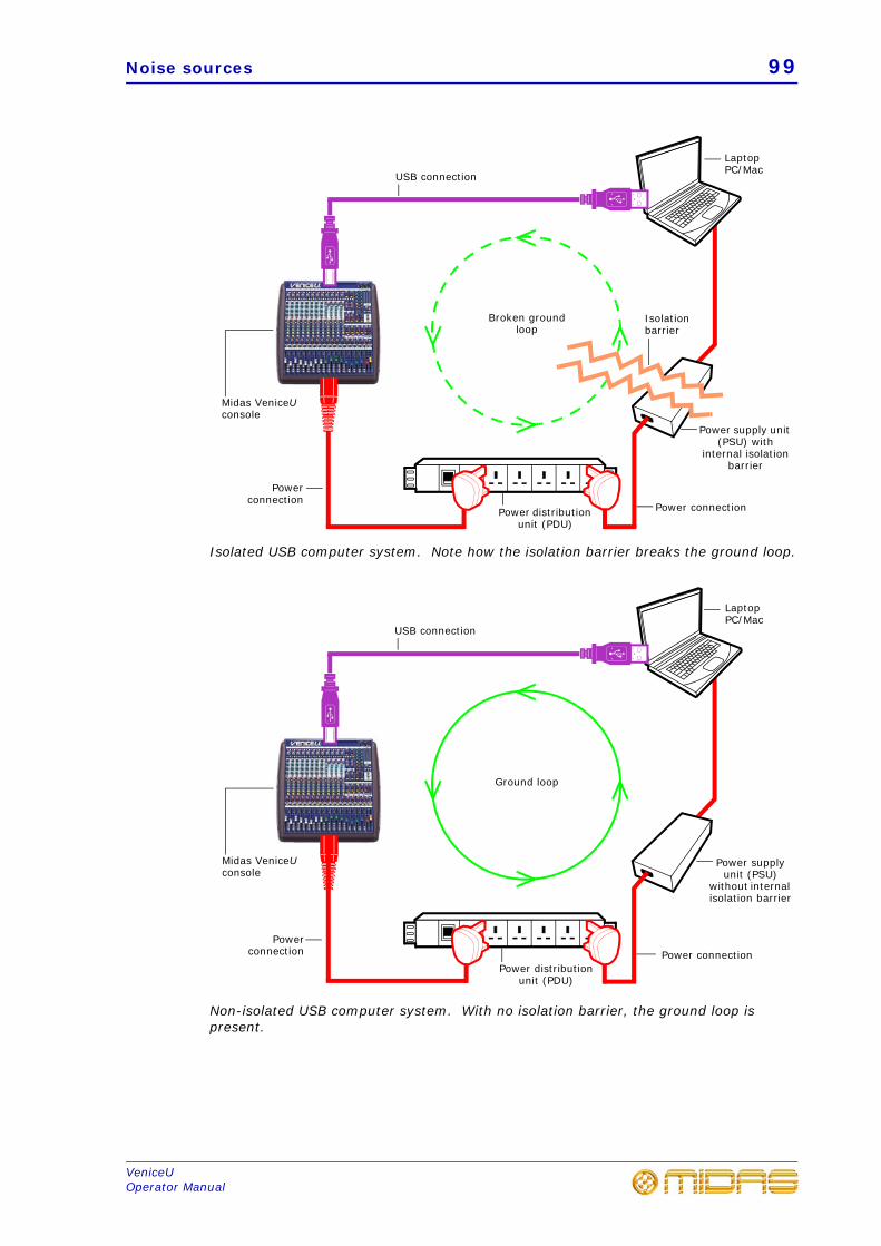
Noise sources 99
VeniceUOperator Manual
Isolated USB computer system. Note how the isolation barrier breaks the ground loop.
Non-isolated USB computer system. With no isolation barrier, the ground loop is present.
Midas VeniceU console
Power distribution unit (PDU)
Power supply unit (PSU) with
internal isolation barrier
USB connection
Broken ground loop
Powerconnection
Laptop PC/Mac
Power connection
Isolation barrier
Midas VeniceU console
USB connection
Power distribution unit (PDU)
Power supply unit (PSU)
without internal isolation barrier
Ground loop
Powerconnection
Laptop PC/Mac
Power connection
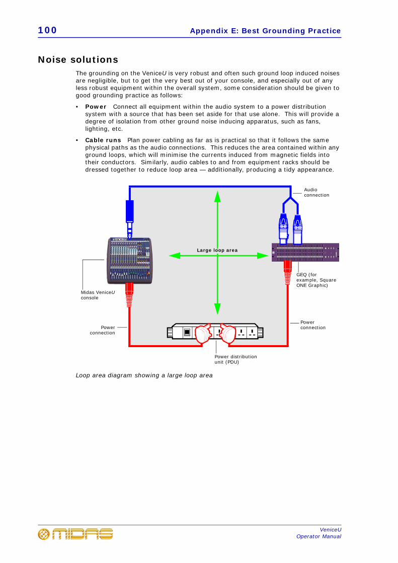
100 Appendix E: Best Grounding Practice
VeniceUOperator Manual
Noise solutionsThe grounding on the VeniceU is very robust and often such ground loop induced noises are negligible, but to get the very best out of your console, and especially out of any less robust equipment within the overall system, some consideration should be given to good grounding practice as follows:
• Power Connect all equipment within the audio system to a power distributionsystem with a source that has been set aside for that use alone. This will provide adegree of isolation from other ground noise inducing apparatus, such as fans,lighting, etc.
• Cable runs Plan power cabling as far as is practical so that it follows the samephysical paths as the audio connections. This reduces the area contained within anyground loops, which will minimise the currents induced from magnetic fields intotheir conductors. Similarly, audio cables to and from equipment racks should bedressed together to reduce loop area — additionally, producing a tidy appearance.
Loop area diagram showing a large loop area
Midas VeniceU console
Power distributionunit (PDU)
GEQ (for example, Square ONE Graphic)
Large loop area
Power connectionPower
connection
Audio connection
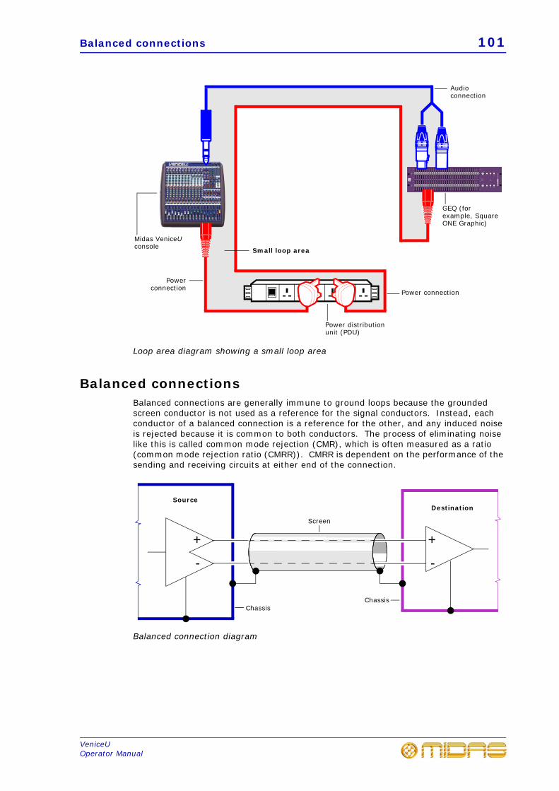
Balanced connections 101
VeniceUOperator Manual
Loop area diagram showing a small loop area
Balanced connectionsBalanced connections are generally immune to ground loops because the grounded screen conductor is not used as a reference for the signal conductors. Instead, each conductor of a balanced connection is a reference for the other, and any induced noise is rejected because it is common to both conductors. The process of eliminating noise like this is called common mode rejection (CMR), which is often measured as a ratio (common mode rejection ratio (CMRR)). CMRR is dependent on the performance of the sending and receiving circuits at either end of the connection.
Balanced connection diagram
Power distributionunit (PDU)
GEQ (for example, Square ONE Graphic)
Audio connection
Power connection
Powerconnection
Small loop area
Midas VeniceU console
+
-
+
-
Screen
ChassisChassis
SourceDestination
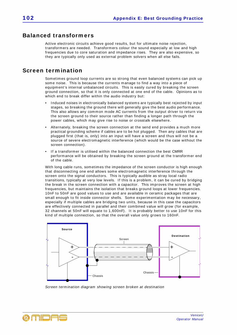
102 Appendix E: Best Grounding Practice
VeniceUOperator Manual
Balanced transformersActive electronic circuits achieve good results, but for ultimate noise rejection, transformers are needed. Transformers colour the sound especially at low and high frequencies due to core saturation and impedance rises. They are also expensive, so they are typically only used as external problem solvers when all else fails.
Screen terminationSometimes ground loop currents are so strong that even balanced systems can pick up some noise. This is because the currents manage to find a way into a piece of equipment’s internal unbalanced circuits. This is easily cured by breaking the screen ground connection, so that it is only connected at one end of the cable. Opinions as to which end to break differ within the audio industry but:
• Induced noises in electronically balanced systems are typically best rejected by inputstages, so breaking the ground there will generally give the best audio performance.This also allows any common mode AC currents from the output driver to return viathe screen ground to their source rather than finding a longer path through thepower cables, which may give rise to noise or crosstalk elsewhere.
• Alternately, breaking the screen connection at the send end provides a much morepractical grounding scheme if cables are to be hot plugged. Then any cables that areplugged first (that is, only) into an input will have a screen and thus will not be asource of severe electromagnetic interference (which would be the case without thescreen connection).
• If a transformer is utilised within the balanced connection the best CMRRperformance will be obtained by breaking the screen ground at the transformer endof the cable.
With long cable runs, sometimes the impedance of the screen conductor is high enough that disconnecting one end allows some electromagnetic interference through the screen onto the signal conductors. This is typically audible as stray local radio transitions, typically at very low levels. If this is a problem, it can be cured by bridging the break in the screen connection with a capacitor. This improves the screen at high frequencies, but maintains the isolation that breaks ground loops at lower frequencies. 10nF to 50nF are good values to use and are available in ceramic packages that are small enough to fit inside connector shells. Some experimentation may be necessary, especially if multiple cables are bridging two units, because in this case the capacitors are effectively connected in parallel and their combined value will grow (for example, 32 channels at 50nF will equate to 1,600nF). It is probably better to use 10nF for this kind of multiple connection, so that the overall value only grows to 160nF.
Screen termination diagram showing screen broken at destination
ChassisChassis
+
-
+
-
Screen
Source
Destination
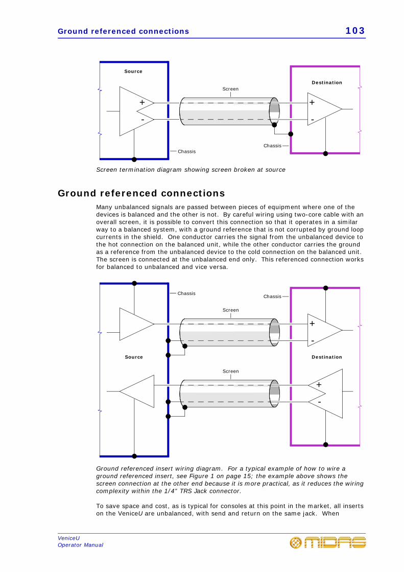
Ground referenced connections 103
VeniceUOperator Manual
Screen termination diagram showing screen broken at source
Ground referenced connectionsMany unbalanced signals are passed between pieces of equipment where one of the devices is balanced and the other is not. By careful wiring using two-core cable with an overall screen, it is possible to convert this connection so that it operates in a similar way to a balanced system, with a ground reference that is not corrupted by ground loop currents in the shield. One conductor carries the signal from the unbalanced device to the hot connection on the balanced unit, while the other conductor carries the ground as a reference from the unbalanced device to the cold connection on the balanced unit. The screen is connected at the unbalanced end only. This referenced connection works for balanced to unbalanced and vice versa.
Ground referenced insert wiring diagram. For a typical example of how to wire a ground referenced insert, see Figure 1 on page 15; the example above shows the screen connection at the other end because it is more practical, as it reduces the wiring complexity within the 1/4” TRS Jack connector.
To save space and cost, as is typical for consoles at this point in the market, all inserts on the VeniceU are unbalanced, with send and return on the same jack. When
ChassisChassis
Source
Destination
+
-
+
-
Screen
+
-
Screen
Chassis Chassis
Source Destination
+
-
Screen
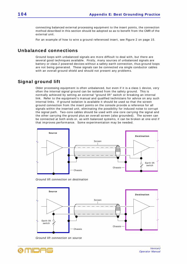
104 Appendix E: Best Grounding Practice
VeniceUOperator Manual
connecting balanced external processing equipment to the insert points, the connection method described in this section should be adopted so as to benefit from the CMR of the external unit.
For an example of how to wire a ground referenced insert, see Figure 2 on page 15.
Unbalanced connectionsGround loops with unbalanced signals are more difficult to deal with, but there are several good techniques available. Firstly, many sources of unbalanced signals are battery or class 2 powered devices without a safety earth connection, thus ground loops are not being generated. These signals can be connected via single conductor cables with an overall ground shield and should not present any problems.
Signal ground liftOlder processing equipment is often unbalanced, but even if it is a class 1 device, very often the internal signal ground can be isolated from the safety ground. This is normally achieved by setting an external "ground lift" switch or breaking an internal link. Refer to the equipment’s manual and qualified technicians for advice on any such internal links. If ground isolation is available it should be used so that the screen ground connection from the insert points on the console provide a reference for all signals within the inserted unit, eliminating the possibility for induced noise to corrupt the signal path. Two-core cables should be used with one core carrying the signal and the other carrying the ground plus an overall screen (also grounded). The screen can be connected at both ends or, as with balanced systems, it can be broken at one end if that improves performance. Some experimentation may be needed.
Ground lift connection on destination
Ground lift connection on source
ChassisChassis
Earth lift switch
SourceDestination
Screen
ChassisChassis
Earth lift switch
SourceDestination
Screen
XLR shells 105
VeniceUOperator Manual
XLR shellsXLR pin 1s should only be used to provide a ground connection for cable screens. The shell (body) of cable XLRs also need to be connected to ground so they provide a screen for the terminals, but they should not be wired internally to the pin 1 terminal. Their ground should be prevented from contact with the panel XLR connector body. This is particularly important for unbalanced connections where an internal connection from pin 1 to the connector shell could compromise ground lifting schemes. With this wiring arrangement, joining XLR cables together to increase the overall length is best avoided, because the joint will not be properly screened. However, if absolutely necessary it is unlikely to cause major problems.
Signal ground bondingIf an unbalanced connection is required to external equipment with signal grounds that cannot be isolated from safety earth it will be difficult to eliminate ground loop currents, but their effects can usually be reduced. The currents within a ground loop will generate small voltages in the cables, including the signal grounds. Any voltages that develop in the signal grounds will appear as noise errors in the audio. If the impedance of the screen cables is reduced, the voltage developed by the ground loop will also be reduced. So, if the impedance can be zero there will be no noise. This is difficult to achieve, but ground bonding the external equipment rack to the chassis of the VeniceU will have a similar effect and will significantly reduce noise in unbalanced connections between the two locations.
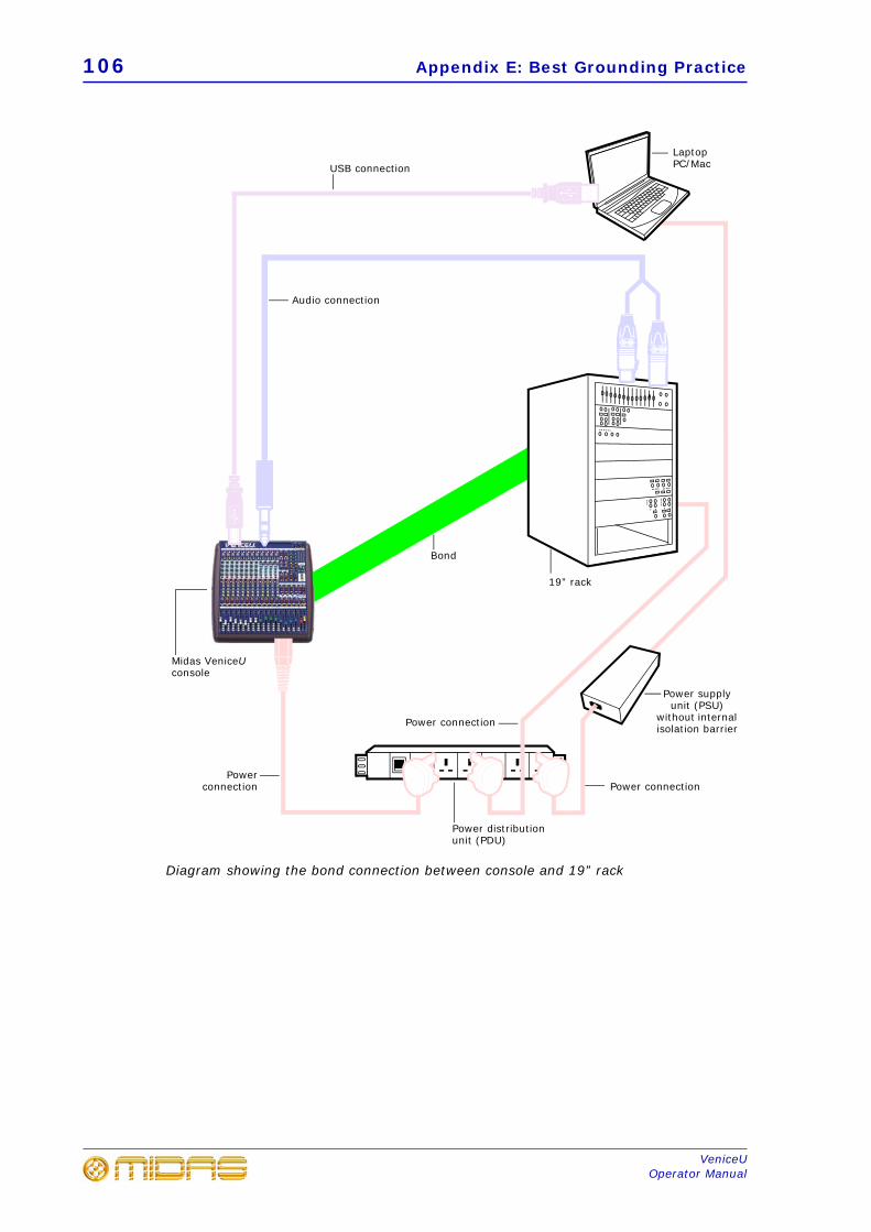
106 Appendix E: Best Grounding Practice
VeniceUOperator Manual
Diagram showing the bond connection between console and 19” rack
Midas VeniceU console
Power distribution unit (PDU)
Power connection
Power supply unit (PSU)
without internal isolation barrier
Laptop PC/Mac
Power connection
USB connection
Powerconnection
19” rack
Audio connection
Bond
Power connection
107
VeniceUOperator Manual
Appendix F: Modification For VeniceU16 Rack Mounting
Use only screws that were loosened during modification or such ones that are contained in the mounting set.
The module is a static-sensitive device. Proper grounding and electrostatic discharge (ESD) precautions are required before handling the module.
This appendix details the modification required to the VeniceU16 console for rack mounting.
Electrostatic discharge (ESD) precautionsObserve full electrostatic discharge (ESD) — also known as “anti-static” — precautions when carrying out procedures in this manual that are accompanied by the ESD Susceptibility Symbol (shown above). This caution symbol shows you that ESD damage may be caused to items
unless proper ESD precautions are taken, which include the following practices:
• Keep the work area free from plastic, vinyl or styrofoam.
• Wear an anti-static wrist strap.
• Discharge personal static before handling devices.
• Ground the work surface.
• Avoid touching ESD-sensitive devices.
Rack mounting partsTo facilitate the rack mounting modification, the U16 is supplied with two rack mounting brackets and eight M4 x 10 mm countersunk screws.
Special tools requiredFor modification you need:
• Allen key: 5 mm
• Torx screwdriver/wrench/bit: T10 and T20
Recommended torque settingsWe recommend the following torques per screw size:
• M3 screws = 0.7Nm
• M4 and M6 screws = 1.6Nm
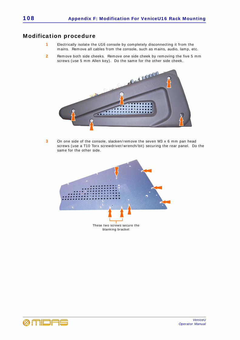
108 Appendix F: Modification For VeniceU16 Rack Mounting
VeniceUOperator Manual
Modification procedure1 Electrically isolate the U16 console by completely disconnecting it from the
mains. Remove all cables from the console, such as mains, audio, lamp, etc.
2 Remove both side cheeks. Remove one side cheek by removing the five 5 mm screws (use 5 mm Allen key). Do the same for the other side cheek.
3 On one side of the console, slacken/remove the seven M3 x 6 mm pan head screws (use a T10 Torx screwdriver/wrench/bit) securing the rear panel. Do the same for the other side.
These two screws secure the blanking bracket
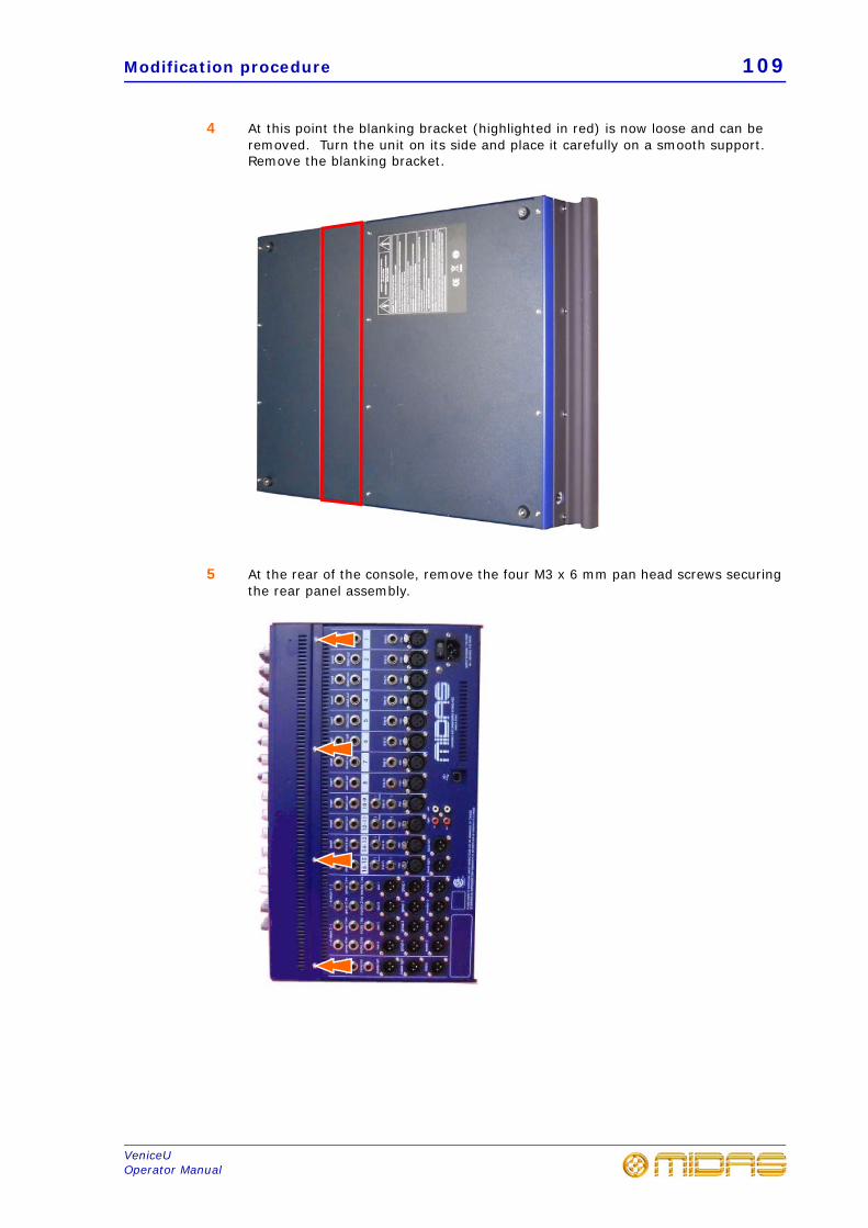
Modification procedure 109
VeniceUOperator Manual
4 At this point the blanking bracket (highlighted in red) is now loose and can be removed. Turn the unit on its side and place it carefully on a smooth support. Remove the blanking bracket.
5 At the rear of the console, remove the four M3 x 6 mm pan head screws securing the rear panel assembly.
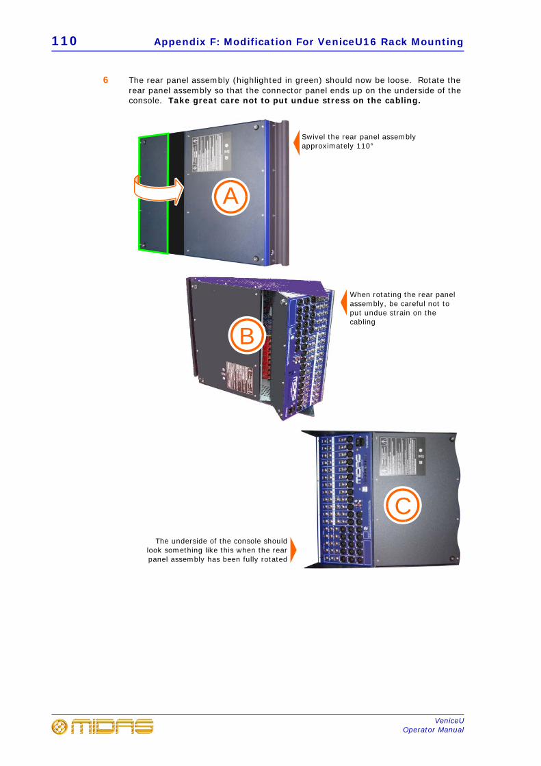
110 Appendix F: Modification For VeniceU16 Rack Mounting
VeniceUOperator Manual
6 The rear panel assembly (highlighted in green) should now be loose. Rotate the rear panel assembly so that the connector panel ends up on the underside of the console. Take great care not to put undue stress on the cabling.
Swivel the rear panel assembly approximately 110°
The underside of the console shouldlook something like this when the rearpanel assembly has been fully rotated
A
C
When rotating the rear panel assembly, be careful not to put undue strain on the cabling
B
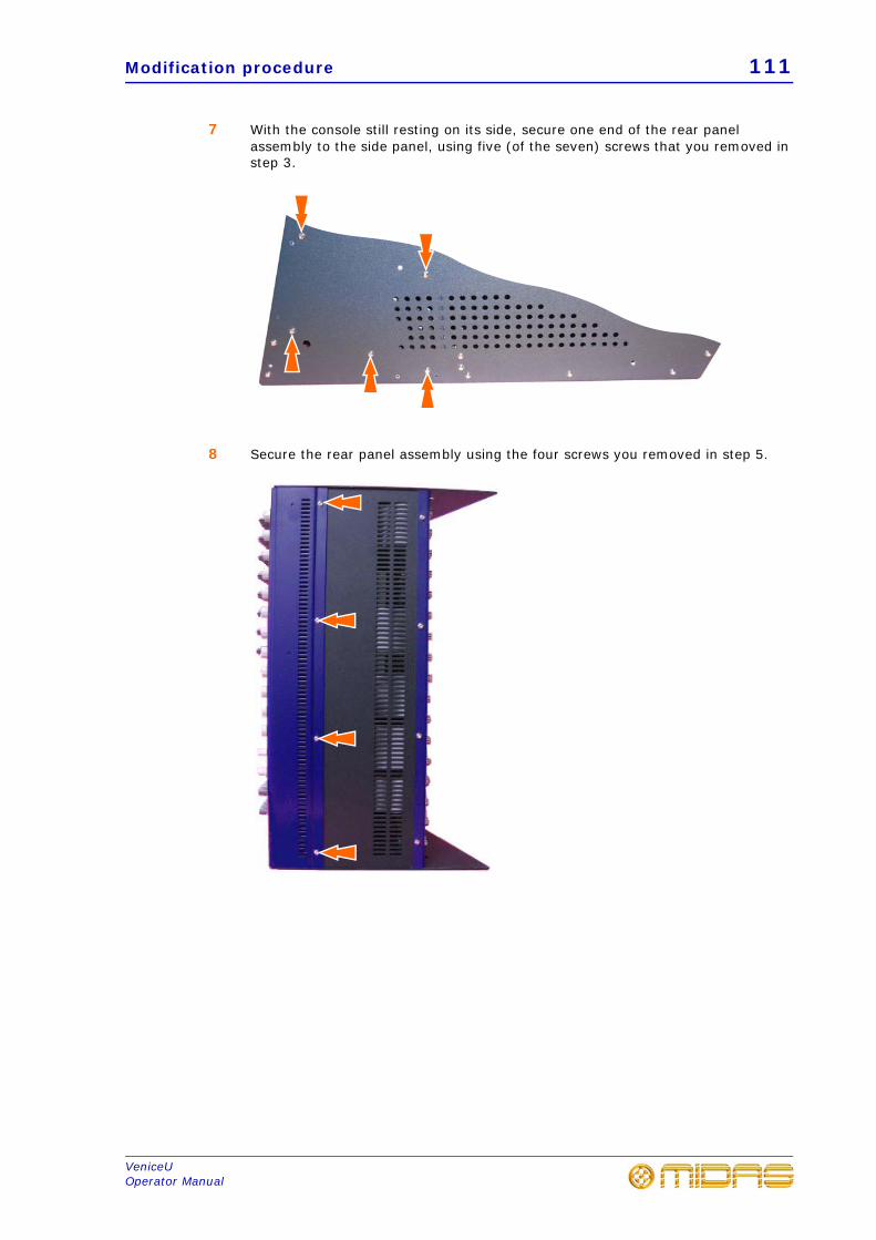
Modification procedure 111
VeniceUOperator Manual
7 With the console still resting on its side, secure one end of the rear panel assembly to the side panel, using five (of the seven) screws that you removed in step 3.
8 Secure the rear panel assembly using the four screws you removed in step 5.
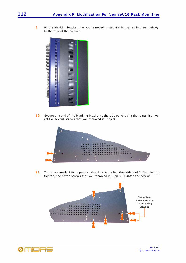
112 Appendix F: Modification For VeniceU16 Rack Mounting
VeniceUOperator Manual
9 Fit the blanking bracket that you removed in step 4 (highlighted in green below) to the rear of the console.
10 Secure one end of the blanking bracket to the side panel using the remaining two (of the seven) screws that you removed in Step 3.
11 Turn the console 180 degrees so that it rests on its other side and fit (but do not tighten) the seven screws that you removed in Step 3. Tighten the screws.
These two screws secure the blanking
bracket
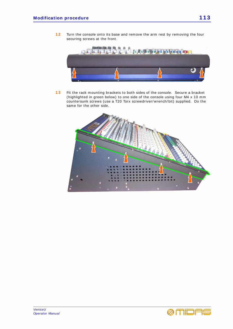
Modification procedure 113
VeniceUOperator Manual
12 Turn the console onto its base and remove the arm rest by removing the four securing screws at the front.
13 Fit the rack mounting brackets to both sides of the console. Secure a bracket (highlighted in green below) to one side of the console using four M4 x 10 mm countersunk screws (use a T20 Torx screwdriver/wrench/bit) supplied. Do the same for the other side.
114 Appendix F: Modification For VeniceU16 Rack Mounting
VeniceUOperator Manual
115
VeniceUOperator Manual
Appendix G: Service Information
This appendix give details of how to look after your VeniceU.
Routine maintenanceTo help keep your VeniceU unit in good working order and to make sure it gives you optimum performance, we recommend that you carry out the following about once every month.
• Clean the console, as detailed in “Cleaning the console” below.
• Check controls for freedom of operation. As the controls are ‘self-cleaning’, thisoperation will help to prevent them from sticking.
• Check the functionality of all controls, that is, control knobs, faders, pushbuttons,LEDs, etc.
• Check the functionality of the equipment.
Cleaning the consoleSwitch off the console and electrically isolate it from the mains before cleaning.
Clean the console using a dry, lint-free cloth. Do not use harsh abrasives or solvents. When cleaning the console, take great care not to damage faders, pushbuttons, etc.
TroubleshootingIf you encounter ground loop problems, see Appendix E "Best Grounding Practice" on page 97.
Special accessoriesTo comply with part 15 of the FCC Rules, any special accessories (that is, items that cannot be readily obtained from multiple retail outlets) supplied with this equipment must be used with this equipment; do not use any alternatives as they may not fulfil the RF requirement.
Optional equipmentUnless advised otherwise, optional equipment must only be installed by service personnel and in accordance with the appropriate assembly and usage regulations.
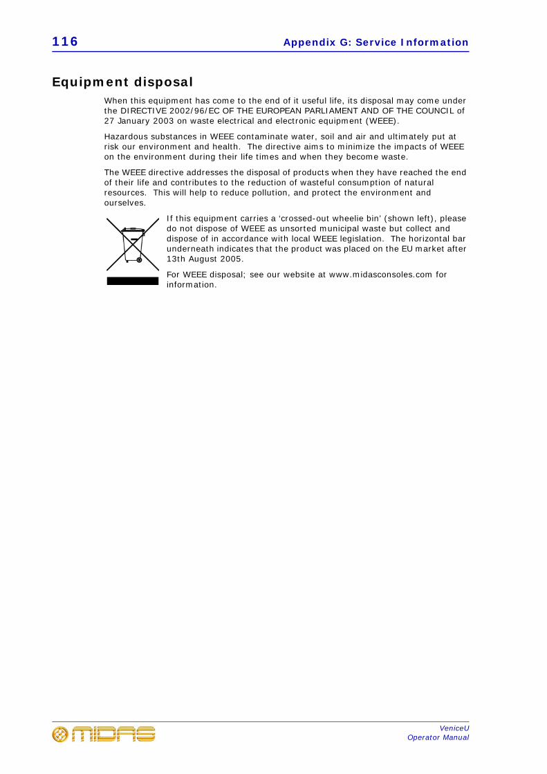
116 Appendix G: Service Information
VeniceUOperator Manual
Equipment disposalWhen this equipment has come to the end of it useful life, its disposal may come under the DIRECTIVE 2002/96/EC OF THE EUROPEAN PARLIAMENT AND OF THE COUNCIL of 27 January 2003 on waste electrical and electronic equipment (WEEE).
Hazardous substances in WEEE contaminate water, soil and air and ultimately put at risk our environment and health. The directive aims to minimize the impacts of WEEE on the environment during their life times and when they become waste.
The WEEE directive addresses the disposal of products when they have reached the end of their life and contributes to the reduction of wasteful consumption of natural resources. This will help to reduce pollution, and protect the environment and ourselves.
If this equipment carries a ‘crossed-out wheelie bin’ (shown left), please do not dispose of WEEE as unsorted municipal waste but collect and dispose of in accordance with local WEEE legislation. The horizontal bar underneath indicates that the product was placed on the EU market after 13th August 2005.
For WEEE disposal; see our website at www.midasconsoles.com for information.

Operator Manual 117
MUSIC Group IP Limited
FEDERAL COMMUNICATIONS COMMISSION COMPLIANCE INFORMATION
VeniceU16/VeniceU24/VeniceU32complies with the FCC rules as mentioned in the following paragraph:
This equipment has been tested and found to comply with the limits for a Class A digital device, pursuant to Part 15 of the FCC Rules. These limits are designed to provide reasonable protection against harmful interference when the equipment is operated in a commercial environment. This equipment generates, uses, and can radiate radio frequency energy and, if not installed and used in accordance with the instruction manual, may cause harmful interference to radio communications. Operation of this equipment in a residential area is likely to cause harmful interference in which case the user will be required to correct the interference at his own expense.
Important information:Changes or modifications to the equipment not expressly approved by MUSIC Group can void the user’s authority to use the equipment.
Responsible party name: MUSIC Group Research UK Limited
Address: Klark Industrial Park, Walter Nash Road, Kidderminster. Worcestershire. DY11 7HJ. England.
Phone/Fax No: Phone: +44 1562 741515Fax: +44 1562 745371
MUSIC Group Research UK LimitedVeniceU16/VeniceU24/VeniceU32

118 VeniceU
MUSIC Group IP Limited
Thank you for reading through this Operator Manual. We hope you found it useful.
Please feel free to send us your comments. Our contact details and website address can be found at
the front of this document.

Klark Industrial Park, Walter Nash Road,Kidderminster. Worcestershire. DY11 7HJ. England.Tel: +44 1562 741515, Fax: +44 1562 745371Email: [email protected]: www.midasconsoles.com
© 2013
MU
SIC
Gro
up I
P Li
mite
d