Embed Size (px)
Citation preview
UDC3500
Universal Digital Controller Product Manual
51-52-25-120
Revision 4
March 2012
Honeywell Process Solutions
ii UDC3500 Universal Digital Controller Product Manual March 2012
Notices and Trademarks
Copyright 2012 by Honeywell Revision 4 March 2012
While this information is presented in good faith and believed to be accurate, Honeywell disclaims the implied warranties of merchantability and fitness for a particular purpose and makes no express warranties except as may be stated in its written agreement with and for its customers.
In no event is Honeywell liable to anyone for any indirect, special or consequential damages. The information and specifications in this document are subject to change without notice.
Honeywell, PlantScape, Experion PKS, and TotalPlant are registered trademarks of Honeywell International Inc.
Other brand or product names are trademarks of their respective owners.
Honeywell Process Solutions
1860 West Rose Garden Lane
Phoenix, Arizona 85027
.
About This Document
Abstract This document provides descriptions and procedures for the Installation, Configuration, Operation, and Troubleshooting of your UDC3500 Controller.
Revision Information
Document Name
UDC3500 Universal Digital Controller Product Manual
Document ID Revision Number
Publication Date
Input Voltage change 51-52-25-120 4 March 2012
References The following list identifies all documents that may be sources of reference for material discussed in this publication.
Document Title
Process Instrument Explorer manual 51-52-25-131
How to Apply Digital Instrumentation in Severe Electrical Noise Environments.
51-52-05-01
Modbus RTU Serial Communications User Manual 51-52-25-66
MODBUS Messaging on TCP/IP Implementation Guide. 51-52-25-121
March 2012 UDC3500 Universal Digital Controller Product Manual iii
Support and Contact info
United States and Canada
Contact: Honeywell Process Solution Global Technical Support - Phone: 001-800-423-9883 Customer Service (HFS) - Phone: 001-800-343-0228 Outside United States - Phone: 001-215-641-3610
Calls are answered by dispatcher between 6:00 am and 4:00 pm Mountain Standard Time. Emergency calls outside normal working hours are received by an answering service and returned within one hour.
Email support: [email protected] Mail: Honeywell Process Solutions
1860 West Rose Garden Lane, Phoenix, Arizona 85027
For more contact details for Europe, Asia, North and South Americas, please see back page.
World Wide Web
Honeywell Process Solutions Support Online:
www.honeywellprocess.com/
Elsewhere
Call your nearest Honeywell office.
Training Classes
Honeywell Automation College:
http://www.automationcollege.com
iv UDC3500 Universal Digital Controller Product Manual March 2012
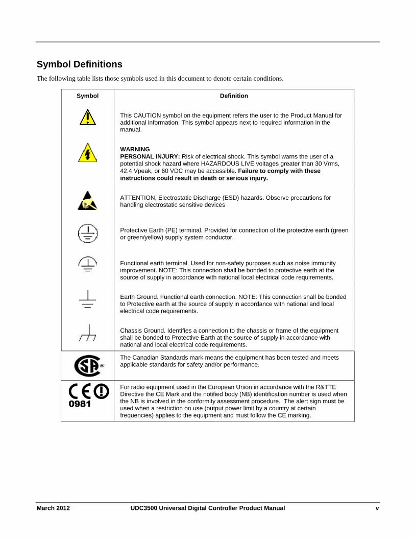
Symbol Definitions The following table lists those symbols used in this document to denote certain conditions.
Symbol Definition
This CAUTION symbol on the equipment refers the user to the Product Manual for additional information. This symbol appears next to required information in the manual.
WARNING PERSONAL INJURY: Risk of electrical shock. This symbol warns the user of a potential shock hazard where HAZARDOUS LIVE voltages greater than 30 Vrms, 42.4 Vpeak, or 60 VDC may be accessible. Failure to comply with these instructions could result in death or serious injury.
ATTENTION, Electrostatic Discharge (ESD) hazards. Observe precautions for handling electrostatic sensitive devices
Protective Earth (PE) terminal. Provided for connection of the protective earth (green or green/yellow) supply system conductor.
Functional earth terminal. Used for non-safety purposes such as noise immunity improvement. NOTE: This connection shall be bonded to protective earth at the source of supply in accordance with national local electrical code requirements.
Earth Ground. Functional earth connection. NOTE: This connection shall be bonded to Protective earth at the source of supply in accordance with national and local electrical code requirements.
Chassis Ground. Identifies a connection to the chassis or frame of the equipment shall be bonded to Protective Earth at the source of supply in accordance with national and local electrical code requirements.
The Canadian Standards mark means the equipment has been tested and meets applicable standards for safety and/or performance.
For radio equipment used in the European Union in accordance with the R&TTE Directive the CE Mark and the notified body (NB) identification number is used when the NB is involved in the conformity assessment procedure. The alert sign must be used when a restriction on use (output power limit by a country at certain frequencies) applies to the equipment and must follow the CE marking.
March 2012 UDC3500 Universal Digital Controller Product Manual v
Contents
1 INTRODUCTION ...................................................................................................1
1.1 Overview.........................................................................................................................................1
1.2 Operator Interface ...........................................................................................................................6 1.2.1 Function of Displays and Keys ............................................................................................7
1.3 Process Instrument Explorer Software............................................................................................8
1.4 CE Conformity (Europe)...............................................................................................................10
2 INSTALLATION...................................................................................................11
2.1 Overview.......................................................................................................................................11
2.2 Condensed Specifications .............................................................................................................13
2.3 Model Number Interpretation .......................................................................................................17
2.4 Control and Alarm Relay Contact Information.............................................................................20
2.5 Mounting.......................................................................................................................................21
2.6 Wiring ...........................................................................................................................................23 2.6.1 Electrical Considerations ...................................................................................................23
2.7 Wiring Diagrams...........................................................................................................................25
3 CONFIGURATION...............................................................................................45
3.1 Overview.......................................................................................................................................45
3.2 Configuration Prompt Hierarchy ..................................................................................................47
3.3 Configuration Procedure...............................................................................................................51
3.4 Loop 1 Tuning Set Up Group .......................................................................................................52
3.5 Loop 2 Tuning Set Up Group .......................................................................................................56
3.6 SP Ramp Set Up Group ................................................................................................................59
3.7 SP Program 2 Set Up Group .........................................................................................................65
3.8 SP Program 3 Set Up Group .........................................................................................................68
3.9 SP Program 4 Set Up Group .........................................................................................................71
3.10 Accutune Set Up Group ............................................................................................................74
3.11 Algorithm Set Up Group ...........................................................................................................79
3.12 Math Set Up Group ...................................................................................................................94
3.13 Logic Gates Set Up Group ......................................................................................................100
3.14 Output Set Up Group...............................................................................................................107
3.15 Input 1 Set Up Group ..............................................................................................................118
3.16 Input 2 Set Up Group ..............................................................................................................122
3.17 Input 3 Set Up Group ..............................................................................................................125
3.18 Input 4 Set Up Group ..............................................................................................................128
vi UDC3500 Universal Digital Controller Product Manual March 2012
3.19 Input 5 Set Up Group ..............................................................................................................131
3.20 Control Set Up Group .............................................................................................................134
3.21 Control 2 Set Up Group ..........................................................................................................143
3.22 Options Set Up Group .............................................................................................................150
3.23 Communications Set Up Group...............................................................................................162
3.24 Alarms Set Up Group ..............................................................................................................166
3.25 Real Time Clock Set Up Group...............................................................................................174
3.26 Maintenance Set Up Group .....................................................................................................175
3.27 Display Set Up Group .............................................................................................................178
3.28 Read Maintenance Set Up Group ............................................................................................180
3.29 Time Events Set Up Group .....................................................................................................181
3.30 P.I.E. Tool Ethernet and Email Configuration Screens...........................................................183
3.31 Configuration Record Sheet ....................................................................................................186
4 MONITORING AND OPERATING THE CONTROLLER...................................194
4.1 Overview.....................................................................................................................................194
4.2 Operator Interface .......................................................................................................................195
4.3 Entering a Security Code ............................................................................................................195
4.4 Lockout Feature ..........................................................................................................................196
4.5 Monitoring Your Controller........................................................................................................198 4.5.1 Annunciators ....................................................................................................................198 4.5.2 Viewing the operating parameters....................................................................................199 4.5.3 Diagnostic Messages........................................................................................................200
4.6 Start Up Procedure for Operation ...............................................................................................201
4.7 Control Modes ............................................................................................................................202 4.7.1 Mode Definitions .............................................................................................................202 4.7.2 What happens when you change modes...........................................................................203
4.8 Setpoints......................................................................................................................................203
4.9 Timer...........................................................................................................................................205
4.10 Accutune III.............................................................................................................................206 4.10.1 Tune for Simplex Outputs ............................................................................................208 4.10.2 Tune for Duplex (Heat/Cool) .......................................................................................209 4.10.3 Using AUTOMATIC TUNE at start-up for Duplex (Heat/Cool).................................210 4.10.4 Using BLENDED TUNE at start-up for Duplex (Heat/Cool)......................................211 4.10.5 Using MANUAL TUNE at start-up for Duplex (Heat/Cool) .......................................212 4.10.6 ACCUTUNE Error Codes ............................................................................................213
4.11 Fuzzy Overshoot Suppression .................................................................................................214
4.12 Using Two Sets of Tuning Constants......................................................................................215
4.13 Input Math Algorithms............................................................................................................217
4.14 Logic Gate Operation ..............................................................................................................219
4.15 Digital Input Option (Remote Switching) ...............................................................................222
March 2012 UDC3500 Universal Digital Controller Product Manual vii
4.16 Auto/Manual Station ...............................................................................................................227
4.17 Two Loops of Control .............................................................................................................231
4.18 Configuring Two Loops of Control.........................................................................................234
4.19 Monitoring Two Loops of Control..........................................................................................235
4.20 Operating Two Loops of Control ............................................................................................236
4.21 Alarm Setpoints.......................................................................................................................237
4.22 Three Position Step Control Algorithm...................................................................................239
4.23 Setting a Failsafe Output Value for Restart After a Power Loss.............................................240
4.24 Setting Failsafe Mode..............................................................................................................241
4.25 Carbon Potential, Oxygen and Dewpoint Algorithms.............................................................241
4.26 Healthwatch.............................................................................................................................244
4.27 Setpoint Rate/Ramp/Program Overview .................................................................................244
4.28 Setpoint Rate ...........................................................................................................................245
4.29 Setpoint Ramp .........................................................................................................................245
4.30 Setpoint Ramp/Soak Programming .........................................................................................247
4.31 P.I.E. Tool Maintenance Screens ............................................................................................262
4.32 Configuring your Ethernet Connection ...................................................................................272
5 INPUT CALIBRATION.......................................................................................279
5.1 Overview.....................................................................................................................................279
5.2 Minimum and Maximum Range Values .....................................................................................280
5.3 Preliminary Information..............................................................................................................282
5.4 Input Set Up Wiring....................................................................................................................284 5.4.1 Thermocouple Inputs Using an Ice Bath..........................................................................284 5.4.2 Thermocouple Inputs Using a Thermocouple Source......................................................285 5.4.3 RTD Inputs.......................................................................................................................286 5.4.4 Radiamatic, Millivolts, Volts, Carbon, Oxygen or Thermocouple Differential Inputs....287 5.4.5 0 to 10 Volts or –1 to 1 Volts...........................................................................................289 5.4.6 Milliamperes ....................................................................................................................290 5.4.7 Dual High Level Voltage Inputs ......................................................................................291 5.4.8 Dual High Level Milliamperes Inputs..............................................................................292
5.5 Input Calibration Procedure ........................................................................................................293
5.6 Restore Input Factory Calibration...............................................................................................295
6 OUTPUT CALIBRATION...................................................................................297
6.1 Overview.....................................................................................................................................297
6.2 First Current Output Calibration .................................................................................................298
6.3 Second Current Output Calibration.............................................................................................300
6.4 Third Current Output Calibration ...............................................................................................302
6.5 Position Proportional and Three Position Step Output Calibration ............................................304
6.6 Restore Factory Output Calibration ............................................................................................307
viii UDC3500 Universal Digital Controller Product Manual March 2012
7 TROUBLESHOOTING/SERVICE......................................................................309
7.1 Overview.....................................................................................................................................309
7.2 Troubleshooting Aids..................................................................................................................310
7.3 Power-up Tests............................................................................................................................312
7.4 Status Tests .................................................................................................................................312
7.5 Background Tests and Diagnostic Messages ..............................................................................313
7.6 Controller Failure Symptoms......................................................................................................318
7.7 Troubleshooting Procedures .......................................................................................................319 7.7.1 Procedure #1 – Power ......................................................................................................320 7.7.2 Procedure #2 – Current Outputs.......................................................................................320 7.7.3 Procedure #3 – Position Proportional ..............................................................................322 7.7.4 Procedure #4 – Time Proportional ...................................................................................325 7.7.5 Procedure #5 – Current/Time or Time Current/Proportional...........................................326 7.7.6 Procedure #6 – Alarm Relays ..........................................................................................327 7.7.7 Procedure #7 – Keyboard.................................................................................................328 7.7.8 Procedure #8 – Analog Input ...........................................................................................329 7.7.9 Procedure #9 – RS-485 ....................................................................................................330 7.7.10 Procedure #10 – Ethernet .............................................................................................332 7.7.11 Procedure #11 – Email .................................................................................................333
7.8 Restoring Factory Configuration ................................................................................................334
7.9 Software Upgrades......................................................................................................................335
8 PARTS LIST ......................................................................................................337
8.1 Exploded View............................................................................................................................337
8.2 Removing the chassis..................................................................................................................339
9 MODBUS RTU FUNCTION CODES..................................................................340
9.1 Overview.....................................................................................................................................340
9.2 General Information....................................................................................................................340
9.3 Function Code 20 (14h) - Read Configuration Reference Data..................................................342 9.3.1 Read Configuration Examples .........................................................................................344
9.4 Function Code 21 (15h) - Write Configuration Reference Data.................................................346 9.4.1 Write Configuration Examples ........................................................................................348
10 MODBUS READ, WRITE AND OVERRIDE PARAMETERS PLUS EXCEPTION CODES........................................................................................................................349
10.1 Overview .................................................................................................................................349
10.2 Reading Control Data..............................................................................................................352
10.3 Read Software Options Status .................................................................................................353
10.4 Miscellaneous Read Onlys ......................................................................................................354 10.4.1 Register Addresses for Read Onlys ..............................................................................354 10.4.2 SetPoint Program Read Only Information....................................................................354
March 2012 UDC3500 Universal Digital Controller Product Manual ix
10.5 Setpoints ..................................................................................................................................355
10.6 Using a Computer Setpoint (Overriding Controller Setpoint) ................................................357
10.7 Configuration Parameters........................................................................................................360 10.7.1 Tuning Loop 1 ..............................................................................................................360 10.7.2 Tuning Loop2 ...............................................................................................................362 10.7.3 SP Ramp/Rate/Program #1...........................................................................................363 10.7.4 Setpoint Program #2 .....................................................................................................369 10.7.5 Setpoint Program #3 .....................................................................................................375 10.7.6 Setpoint Program #4 .....................................................................................................381 10.7.7 Accutune.......................................................................................................................387 10.7.8 Algorithm .....................................................................................................................389 10.7.9 Math..............................................................................................................................394 10.7.10 Logic.............................................................................................................................397 10.7.11 Output Algorithms........................................................................................................401 10.7.12 Input 1...........................................................................................................................403 10.7.13 Input 2...........................................................................................................................405 10.7.14 Input 3...........................................................................................................................407 10.7.15 Input 4...........................................................................................................................409 10.7.16 Input 5...........................................................................................................................411 10.7.17 Control..........................................................................................................................413 10.7.18 Control Loop 2 .............................................................................................................416 10.7.19 Options .........................................................................................................................419 10.7.20 Communications...........................................................................................................423 10.7.21 Alarms ..........................................................................................................................425 10.7.22 Maintenance .................................................................................................................429 10.7.23 Time Event ...................................................................................................................432 10.7.24 Display..........................................................................................................................434 10.7.25 Clock ............................................................................................................................435
10.8 Modbus RTU Exception Codes...............................................................................................436
11 FURTHER INFORMATION................................................................................438
11.1 Modbus RTU Serial Communications ....................................................................................438
11.2 Modbus Messaging on Ethernet TCP/IP .................................................................................438
11.3 How to Apply Digital Instrumentation in Severe Electrical Noise Environments ..................438
12 INDEX................................................................................................................439
13 SALES AND SERVICE.............................. ERROR! BOOKMARK NOT DEFINED.
x UDC3500 Universal Digital Controller Product Manual March 2012
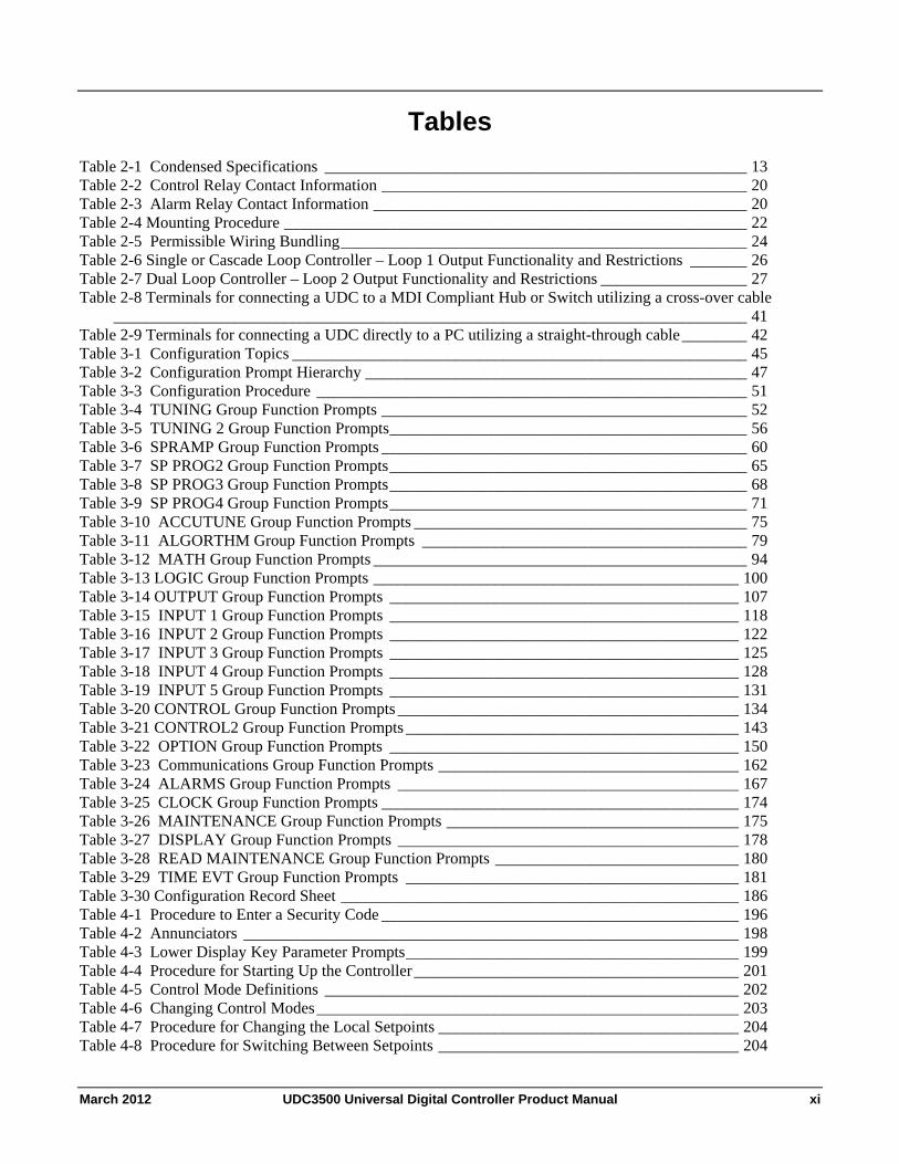
Tables
Table 2-1 Condensed Specifications ____________________________________________________ 13 Table 2-2 Control Relay Contact Information _____________________________________________ 20 Table 2-3 Alarm Relay Contact Information ______________________________________________ 20 Table 2-4 Mounting Procedure _________________________________________________________ 22 Table 2-5 Permissible Wiring Bundling__________________________________________________ 24 Table 2-6 Single or Cascade Loop Controller – Loop 1 Output Functionality and Restrictions _______ 26 Table 2-7 Dual Loop Controller – Loop 2 Output Functionality and Restrictions __________________ 27 Table 2-8 Terminals for connecting a UDC to a MDI Compliant Hub or Switch utilizing a cross-over cable
______________________________________________________________________________ 41 Table 2-9 Terminals for connecting a UDC directly to a PC utilizing a straight-through cable________ 42 Table 3-1 Configuration Topics ________________________________________________________ 45 Table 3-2 Configuration Prompt Hierarchy _______________________________________________ 47 Table 3-3 Configuration Procedure _____________________________________________________ 51 Table 3-4 TUNING Group Function Prompts _____________________________________________ 52 Table 3-5 TUNING 2 Group Function Prompts____________________________________________ 56 Table 3-6 SPRAMP Group Function Prompts _____________________________________________ 60 Table 3-7 SP PROG2 Group Function Prompts____________________________________________ 65 Table 3-8 SP PROG3 Group Function Prompts____________________________________________ 68 Table 3-9 SP PROG4 Group Function Prompts____________________________________________ 71 Table 3-10 ACCUTUNE Group Function Prompts _________________________________________ 75 Table 3-11 ALGORTHM Group Function Prompts ________________________________________ 79 Table 3-12 MATH Group Function Prompts ______________________________________________ 94 Table 3-13 LOGIC Group Function Prompts _____________________________________________ 100 Table 3-14 OUTPUT Group Function Prompts ___________________________________________ 107 Table 3-15 INPUT 1 Group Function Prompts ___________________________________________ 118 Table 3-16 INPUT 2 Group Function Prompts ___________________________________________ 122 Table 3-17 INPUT 3 Group Function Prompts ___________________________________________ 125 Table 3-18 INPUT 4 Group Function Prompts ___________________________________________ 128 Table 3-19 INPUT 5 Group Function Prompts ___________________________________________ 131 Table 3-20 CONTROL Group Function Prompts __________________________________________ 134 Table 3-21 CONTROL2 Group Function Prompts _________________________________________ 143 Table 3-22 OPTION Group Function Prompts ___________________________________________ 150 Table 3-23 Communications Group Function Prompts _____________________________________ 162 Table 3-24 ALARMS Group Function Prompts __________________________________________ 167 Table 3-25 CLOCK Group Function Prompts ____________________________________________ 174 Table 3-26 MAINTENANCE Group Function Prompts ____________________________________ 175 Table 3-27 DISPLAY Group Function Prompts __________________________________________ 178 Table 3-28 READ MAINTENANCE Group Function Prompts ______________________________ 180 Table 3-29 TIME EVT Group Function Prompts _________________________________________ 181 Table 3-30 Configuration Record Sheet _________________________________________________ 186 Table 4-1 Procedure to Enter a Security Code ____________________________________________ 196 Table 4-2 Annunciators _____________________________________________________________ 198 Table 4-3 Lower Display Key Parameter Prompts_________________________________________ 199 Table 4-4 Procedure for Starting Up the Controller________________________________________ 201 Table 4-5 Control Mode Definitions ___________________________________________________ 202 Table 4-6 Changing Control Modes____________________________________________________ 203 Table 4-7 Procedure for Changing the Local Setpoints _____________________________________ 204 Table 4-8 Procedure for Switching Between Setpoints _____________________________________ 204
March 2012 UDC3500 Universal Digital Controller Product Manual xi
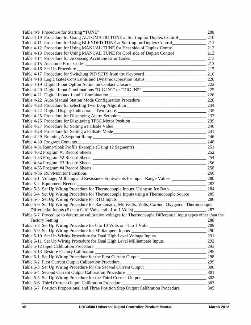
Table 4-9 Procedure for Starting “TUNE”_______________________________________________ 208 Table 4-10 Procedure for Using AUTOMATIC TUNE at Start-up for Duplex Control ____________ 210 Table 4-11 Procedure for Using BLENDED TUNE at Start-up for Duplex Control_______________ 211 Table 4-12 Procedure for Using MANUAL TUNE for Heat side of Duplex Control ______________ 212 Table 4-13 Procedure for Using MANUAL TUNE for Cool side of Duplex Control ______________ 212 Table 4-14 Procedure for Accessing Accutune Error Codes _________________________________ 213 Table 4-15 Accutune Error Codes _____________________________________________________ 213 Table 4-16 Set Up Procedure _________________________________________________________ 215 Table 4-17 Procedure for Switching PID SETS from the Keyboard ___________________________ 216 Table 4-18 Logic Gates Constraints and Dynamic Operation Status ___________________________ 220 Table 4-19 Digital Input Option Action on Contact Closure _________________________________ 222 Table 4-20 Digital Input Combinations “DIG IN1” or “DIG IN2” ____________________________ 225 Table 4-21 Digital Inputs 1 and 2 Combination___________________________________________ 226 Table 4-22 Auto/Manual Station Mode Configuration Procedure _____________________________ 228 Table 4-23 Procedure for selecting Two Loop Algorithm ___________________________________ 234 Table 4-24 Digital Display Indication—Two Loops _______________________________________ 235 Table 4-25 Procedure for Displaying Alarm Setpoints _____________________________________ 237 Table 4-26 Procedure for Displaying TPSC Motor Position _________________________________ 239 Table 4-27 Procedure for Setting a Failsafe Value_________________________________________ 240 Table 4-28 Procedure for Setting a Failsafe Mode_________________________________________ 241 Table 4-29 Running A Setpoint Ramp __________________________________________________ 246 Table 4-30 Program Contents_________________________________________________________ 248 Table 4-31 Ramp/Soak Profile Example (Using 12 Segments) _______________________________ 251 Table 4-32 Program #1 Record Sheets __________________________________________________ 252 Table 4-33 Program #2 Record Sheets __________________________________________________ 254 Table 4-34 Program #3 Record Sheets __________________________________________________ 256 Table 4-35 Program #4 Record Sheets __________________________________________________ 258 Table 4-36 Run/Monitor Functions ____________________________________________________ 260 Table 5-1 Voltage, Milliamp and Resistance Equivalents for Input Range Values _______________ 280 Table 5-2 Equipment Needed_________________________________________________________ 282 Table 5-3 Set Up Wiring Procedure for Thermocouple Inputs Using an Ice Bath ________________ 284 Table 5-4 Set Up Wiring Procedure for Thermocouple Inputs using a Thermocouple Source _______ 285 Table 5-5 Set Up Wiring Procedure for RTD Inputs _______________________________________ 286 Table 5-6 Set Up Wiring Procedure for Radiamatic, Millivolts, Volts, Carbon, Oxygen or Thermocouple
Differential Inputs (Except 0-10 Volts and –1 to 1 Volts)________________________________ 287 Table 5-7 Procedure to determine calibration voltages for Thermocouple Differential input types other than the
Factory Setting _________________________________________________________________ 288 Table 5-8 Set Up Wiring Procedure for 0 to 10 Volts or –1 to 1 Volts _________________________ 289 Table 5-9 Set Up Wiring Procedure for Milliampere Inputs _________________________________ 290 Table 5-10 Set Up Wiring Procedure for Dual High Level Voltage Inputs ______________________ 291 Table 5-11 Set Up Wiring Procedure for Dual High Level Milliampere Inputs __________________ 292 Table 5-12 Input Calibration Procedure _________________________________________________ 293 Table 5-13 Restore Factory Calibration _________________________________________________ 295 Table 6-1 Set Up Wiring Procedure for the First Current Output _____________________________ 298 Table 6-2 First Current Output Calibration Procedure______________________________________ 299 Table 6-3 Set Up Wiring Procedure for the Second Current Output ___________________________ 300 Table 6-4 Second Current Output Calibration Procedure ___________________________________ 301 Table 6-5 Set Up Wiring Procedure for the Third Current Output ____________________________ 302 Table 6-6 Third Current Output Calibration Procedure _____________________________________ 303 Table 6-7 Position Proportional and Three Position Step Output Calibration Procedure ___________ 305
xii UDC3500 Universal Digital Controller Product Manual March 2012
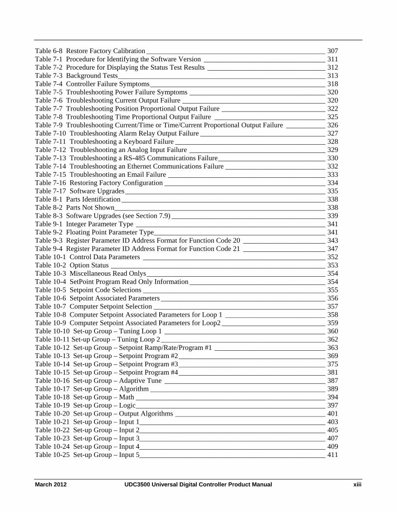
Table 6-8 Restore Factory Calibration __________________________________________________ 307 Table 7-1 Procedure for Identifying the Software Version __________________________________ 311 Table 7-2 Procedure for Displaying the Status Test Results _________________________________ 312 Table 7-3 Background Tests__________________________________________________________ 313 Table 7-4 Controller Failure Symptoms_________________________________________________ 318 Table 7-5 Troubleshooting Power Failure Symptoms ______________________________________ 320 Table 7-6 Troubleshooting Current Output Failure ________________________________________ 320 Table 7-7 Troubleshooting Position Proportional Output Failure _____________________________ 322 Table 7-8 Troubleshooting Time Proportional Output Failure _______________________________ 325 Table 7-9 Troubleshooting Current/Time or Time/Current Proportional Output Failure ___________ 326 Table 7-10 Troubleshooting Alarm Relay Output Failure ___________________________________ 327 Table 7-11 Troubleshooting a Keyboard Failure __________________________________________ 328 Table 7-12 Troubleshooting an Analog Input Failure ______________________________________ 329 Table 7-13 Troubleshooting a RS-485 Communications Failure______________________________ 330 Table 7-14 Troubleshooting an Ethernet Communications Failure ____________________________ 332 Table 7-15 Troubleshooting an Email Failure ____________________________________________ 333 Table 7-16 Restoring Factory Configuration _____________________________________________ 334 Table 7-17 Software Upgrades________________________________________________________ 335 Table 8-1 Parts Identification _________________________________________________________ 338 Table 8-2 Parts Not Shown___________________________________________________________ 338 Table 8-3 Software Upgrades (see Section 7.9) ___________________________________________ 339 Table 9-1 Integer Parameter Type _____________________________________________________ 341 Table 9-2 Floating Point Parameter Type________________________________________________ 341 Table 9-3 Register Parameter ID Address Format for Function Code 20 _______________________ 343 Table 9-4 Register Parameter ID Address Format for Function Code 21 _______________________ 347 Table 10-1 Control Data Parameters ___________________________________________________ 352 Table 10-2 Option Status ____________________________________________________________ 353 Table 10-3 Miscellaneous Read Onlys__________________________________________________ 354 Table 10-4 SetPoint Program Read Only Information ______________________________________ 354 Table 10-5 Setpoint Code Selections ___________________________________________________ 355 Table 10-6 Setpoint Associated Parameters ______________________________________________ 356 Table 10-7 Computer Setpoint Selection ________________________________________________ 357 Table 10-8 Computer Setpoint Associated Parameters for Loop 1 ____________________________ 358 Table 10-9 Computer Setpoint Associated Parameters for Loop2 _____________________________ 359 Table 10-10 Set-up Group – Tuning Loop 1 _____________________________________________ 360 Table 10-11 Set-up Group – Tuning Loop 2______________________________________________ 362 Table 10-12 Set-up Group – Setpoint Ramp/Rate/Program #1 _______________________________ 363 Table 10-13 Set-up Group – Setpoint Program #2_________________________________________ 369 Table 10-14 Set-up Group – Setpoint Program #3_________________________________________ 375 Table 10-15 Set-up Group – Setpoint Program #4_________________________________________ 381 Table 10-16 Set-up Group – Adaptive Tune _____________________________________________ 387 Table 10-17 Set-up Group – Algorithm _________________________________________________ 389 Table 10-18 Set-up Group – Math _____________________________________________________ 394 Table 10-19 Set-up Group – Logic_____________________________________________________ 397 Table 10-20 Set-up Group – Output Algorithms __________________________________________ 401 Table 10-21 Set-up Group – Input 1____________________________________________________ 403 Table 10-22 Set-up Group – Input 2____________________________________________________ 405 Table 10-23 Set-up Group – Input 3____________________________________________________ 407 Table 10-24 Set-up Group – Input 4____________________________________________________ 409 Table 10-25 Set-up Group – Input 5____________________________________________________ 411
March 2012 UDC3500 Universal Digital Controller Product Manual xiii
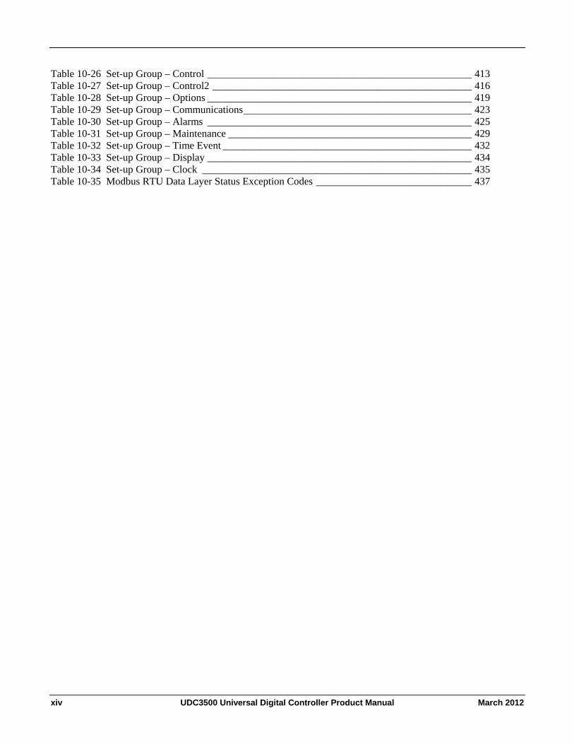
Table 10-26 Set-up Group – Control ___________________________________________________ 413 Table 10-27 Set-up Group – Control2 __________________________________________________ 416 Table 10-28 Set-up Group – Options ___________________________________________________ 419 Table 10-29 Set-up Group – Communications____________________________________________ 423 Table 10-30 Set-up Group – Alarms ___________________________________________________ 425 Table 10-31 Set-up Group – Maintenance _______________________________________________ 429 Table 10-32 Set-up Group – Time Event ________________________________________________ 432 Table 10-33 Set-up Group – Display ___________________________________________________ 434 Table 10-34 Set-up Group – Clock ____________________________________________________ 435 Table 10-35 Modbus RTU Data Layer Status Exception Codes ______________________________ 437
xiv UDC3500 Universal Digital Controller Product Manual March 2012
Figures
Figure 1-1 UDC3500 Operator Interface __________________________________________________ 6 Figure 1-2 Screen capture of Process Instrument Explorer running on a Pocket PC _________________ 8 Figure 1-3 Depiction of infrared communications ___________________________________________ 9 Figure 2-1 Model Number Interpretation _________________________________________________ 17 Figure 2-2 Mounting Dimensions (not to scale)____________________________________________ 21 Figure 2-3 Mounting Methods _________________________________________________________ 22 Figure 2-4 Composite Wiring Diagram___________________________________________________ 28 Figure 2-5 Mains Power Supply ________________________________________________________ 29 Figure 2-6 Input 1 Connections_________________________________________________________ 30 Figure 2-7 Input 2 Connections_________________________________________________________ 31 Figure 2-8 Input 3 Connections_________________________________________________________ 32 Figure 2-9 HLAI Inputs 2 and 4 Connections ______________________________________________ 33 Figure 2-10 HLAI Inputs 3 and 5 Connections _____________________________________________ 34 Figure 2-11 Optional Analog Input Jumper Positions________________________________________ 34 Figure 2-12 First Current Output________________________________________________________ 35 Figure 2-13 Second Current Output _____________________________________________________ 35 Figure 2-14 Output #2 – Electromechanical Relay Output ____________________________________ 36 Figure 2-15 Output #2 – Solid State Relay Output __________________________________________ 36 Figure 2-16 Output #2 – Open Collector Output- Third ______________________________________ 37 Figure 2-17 Output #2 – Third Current Output_____________________________________________ 37 Figure 2-18 Output #2 – Dual Relay Output for Time Duplex _________________________________ 38 Figure 2-19 Output #2 – Dual Relay Output for Position Proportional or Three Position Step Control _ 38 Figure 2-20 RS-422/485 Communications Option Connections________________________________ 39 Figure 2-21 Ethernet Communications Option with Adaptor Board_____________________________ 39 Figure 2-22 Ethernet Communications Option without Adaptor Board __________________________ 40 Figure 2-23 Digital Inputs _____________________________________________________________ 42 Figure 2-24 Optional Electromechanical Relay Outputs______________________________________ 43 Figure 2-25 Transmitter Power for 4-20 mA — 2 wire Transmitter Using Open Collector Output_____ 43 Figure 2-26 Transmitter Power for 4-20 mA — 2 Wire Transmitter Using Second Current Output ____ 44 Figure 3-1 Mass Flow Example ________________________________________________________ 92 Figure 3-2 Example of Eight Segment Characterizer________________________________________ 99 Figure 3-3 Ethernet Configuration Screen _______________________________________________ 183 Figure 3-4 Email Configuration Screen _________________________________________________ 184 Figure 4-1 Operator Interface_________________________________________________________ 195 Figure 4-2 Auto/Manual Station for Loop 1 (Loop 2 similar) ________________________________ 227 Figure 4-3 Functional Overview Block Diagram of a Single Loop (Loop #1) or
Dual Loop Controller (Loop #1 and Loop #2)_________________________________________ 232 Figure 4-4 Functional Overview Block Diagram of Internal Cascade Controller _________________ 233 Figure 4-5 Hi/Lo Override Selector ____________________________________________________ 234 Figure 4-6 Carbon Potential Control ___________________________________________________ 243 Figure 4-7 Ramp/Soak Profile Example_________________________________________________ 251 Figure 4-8 SP Program #1 Record Sheets _______________________________________________ 252 Figure 4-9 SP Program #2 Record Sheets _______________________________________________ 254 Figure 4-10 SP Program #3 Record Sheets ______________________________________________ 256 Figure 4-11 SP Program #4 Record Sheets ______________________________________________ 258 Figure 4-12 Loop Data Maintenance Screen _____________________________________________ 262 Figure 4-13 Alarm Details Maintenance Screen __________________________________________ 263 Figure 4-14 Digital Inputs Details Maintenance Screen_____________________________________ 264
March 2012 UDC3500 Universal Digital Controller Product Manual xv
xvi UDC3500 Universal Digital Controller Product Manual March 2012
Figure 4-15 Status Data Maintenance Screen_____________________________________________ 265 Figure 4-16 Diagnostic History Maintenance Screen_______________________________________ 266 Figure 4-17 Ethernet Status Maintenance Screen__________________________________________ 267 Figure 4-18 Healthwatch Data Maintenance Screen _______________________________________ 268 Figure 4-19 Healthwatch Data Reset Screen _____________________________________________ 269 Figure 4-20 Totalizer Maintenance Screen ______________________________________________ 270 Figure 4-21 Real Time Clock Maintenance Screen ________________________________________ 271 Figure 4-22 IR Communications Address _______________________________________________ 272 Figure 4-23 Configuration Upload in Progress ___________________________________________ 273 Figure 4-24 Ethernet Communications Address __________________________________________ 275 Figure 4-25 Configuration Upload in Progress ___________________________________________ 276 Figure 5-1 Input Wiring Terminals ____________________________________________________ 282 Figure 5-2 Wiring Connections for Thermocouple Inputs Using an Ice Bath ____________________ 284 Figure 5-3 Wiring Connections for Thermocouple Inputs Using a Thermocouple Source __________ 285 Figure 5-4 Wiring Connections for RTD (Resistance Thermometer Device) ____________________ 286 Figure 5-5 Wiring Connections for Radiamatic, Millivolts, Volts, Carbon, Oxygen or
Thermocouple Differential Inputs (Except 0-10 Volts and –1 to 1 Volts)____________________ 287 Figure 5-6 Wiring Connections for 0 to 10 Volts or –1 to 1 Volts_____________________________ 289 Figure 5-7 Wiring Connections for Milliampere Inputs_____________________________________ 290 Figure 5-8 Wiring Connections for Dual High Level Voltage Inputs __________________________ 291 Figure 5-9 Wiring Connections for Dual High Level Milliampere Inputs_______________________ 292 Figure 6-1 Wiring Connections for Calibrating the First Current Output _______________________ 298 Figure 6-2 Wiring Connections for Calibrating the Second Current Output _____________________ 300 Figure 6-3 Wiring Connections for Calibrating Third Current Output _________________________ 302 Figure 8-1 UDC3500 Exploded View __________________________________________________ 337 Figure 10-1 Software Option Status Information__________________________________________ 353
Introduction
1 Introduction
1.1 Overview
Function
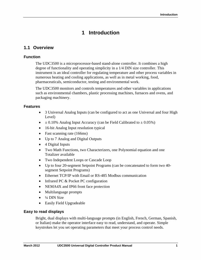
The UDC3500 is a microprocessor-based stand-alone controller. It combines a high degree of functionality and operating simplicity in a 1/4 DIN size controller. This instrument is an ideal controller for regulating temperature and other process variables in numerous heating and cooling applications, as well as in metal working, food, pharmaceuticals, semiconductor, testing and environmental work.
The UDC3500 monitors and controls temperatures and other variables in applications such as environmental chambers, plastic processing machines, furnaces and ovens, and packaging machinery.
Features
3 Universal Analog Inputs (can be configured to act as one Universal and four High Level)
± 0.10% Analog Input Accuracy (can be Field Calibrated to ± 0.05%)
16-bit Analog Input resolution typical
Fast scanning rate (166ms)
Up to 7 Analog and Digital Outputs
4 Digital Inputs
Two Math Functions, two Characterizers, one Polynomial equation and one Totalizer available
Two Independent Loops or Cascade Loop
Up to four 20-segment Setpoint Programs (can be concatenated to form two 40-segment Setpoint Programs)
Ethernet TCP/IP with Email or RS-485 Modbus communication
Infrared PC & Pocket PC configuration
NEMA4X and IP66 front face protection
Multilanguage prompts
¼ DIN Size
Easily Field Upgradeable
Easy to read displays
Bright, dual displays with multi-language prompts (in English, French, German, Spanish, or Italian) make the operator interface easy to read, understand, and operate. Simple keystrokes let you set operating parameters that meet your process control needs.
March 2012 UDC3500 Universal Digital Controller Product Manual 1
Introduction
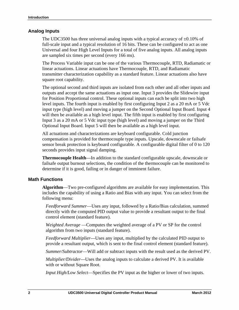
Analog Inputs
The UDC3500 has three universal analog inputs with a typical accuracy of ±0.10% of full-scale input and a typical resolution of 16 bits. These can be configured to act as one Universal and four High Level Inputs for a total of five analog inputs. All analog inputs are sampled six times per second (every 166 ms).
The Process Variable input can be one of the various Thermocouple, RTD, Radiamatic or linear actuations. Linear actuations have Thermocouple, RTD, and Radiamatic transmitter characterization capability as a standard feature. Linear actuations also have square root capability.
The optional second and third inputs are isolated from each other and all other inputs and outputs and accept the same actuations as input one. Input 3 provides the Slidewire input for Position Proportional control. These optional inputs can each be split into two high level inputs. The fourth input is enabled by first configuring Input 2 as a 20 mA or 5 Vdc input type (high level) and moving a jumper on the Second Optional Input Board. Input 4 will then be available as a high level input. The fifth input is enabled by first configuring Input 3 as a 20 mA or 5 Vdc input type (high level) and moving a jumper on the Third Optional Input Board. Input 5 will then be available as a high level input.
All actuations and characterizations are keyboard configurable. Cold junction compensation is provided for thermocouple type inputs. Upscale, downscale or failsafe sensor break protection is keyboard configurable. A configurable digital filter of 0 to 120 seconds provides input signal damping.
Thermocouple Health—In addition to the standard configurable upscale, downscale or failsafe output burnout selections, the condition of the thermocouple can be monitored to determine if it is good, failing or in danger of imminent failure.
Math Functions
Algorithm—Two pre-configured algorithms are available for easy implementation. This includes the capability of using a Ratio and Bias with any input. You can select from the following menu:
Feedforward Summer—Uses any input, followed by a Ratio/Bias calculation, summed directly with the computed PID output value to provide a resultant output to the final control element (standard feature).
Weighted Average —Computes the weighted average of a PV or SP for the control algorithm from two inputs (standard feature).
Feedforward Multiplier—Uses any input, multiplied by the calculated PID output to provide a resultant output, which is sent to the final control element (standard feature).
Summer/Subtractor—Will add or subtract inputs with the result used as the derived PV.
Multiplier/Divider—Uses the analog inputs to calculate a derived PV. It is available with or without Square Root.
Input High/Low Select—Specifies the PV input as the higher or lower of two inputs.
2 UDC3500 Universal Digital Controller Product Manual March 2012
Introduction
8 Segment Characterizers—Two characterizers are available that can be applied to any Analog Input, to Loop 1 Output or to Loop 2 Output. The Characterizers can be combined to produce a single 16-segment characterizer. †
Totalizer—Calculates and displays the total flow volume as measured by any of the analog inputs or as derived by either Math algorithm. Displayed value is eight digits with a configurable scaling factor. The totalizer value may be reset.
Combinational Inputs—Inputs can be combined for use with Relative Humidity, % Oxygen, Carbon Potential, Dewpoint or Math Algorithms. This controller can accept carbon probes from Cambridge, Marathon Monitors, Corning, A.A.A.C, Barber Coleman, MacDhui, Bricesco or Furnace Controls.
Polynomial Curve Characterizer—A fifth order polynomial equation can be used on any one of the analog inputs.
Logic Gates—Five Logic Gates configurable as OR, NOR, AND, NAND, XOR, XNOR, or COMPARATOR. Each Gate has two inputs and one output. The Gates may be linked together to perform more complex functions. † Characterizers are mutually exclusive with Setpoint Program #4.
Digital Inputs
Four isolated digital inputs are provided for remote dry contact closure to select one of 25 actions. Also, two of these digital inputs can allow one of six additional selections to be combined with one of the above selections.
Outputs
Output Types - The UDC3500 may have up to seven of the following outputs:
Current Outputs (4-20 or 0-20 mA)
Electromechanical Relays (5 amps)
Solid State Relay (1 amp)
Dual Electromechanical Relays (2 amps)
Open Collector Output (+30 VDC @ 20 mA)
Alarms
Up to four electromechanical alarm relays are available to activate external equipment when preset alarm setpoints are reached. Each of the four alarms can be set to monitor two independent setpoints. Each alarm setpoint can be either high or low alarm. The alarm type can be selected to be either of the inputs, the Process Variable, Deviation, Output, Shed from communications, PV rate of change, or to alarm on manual mode activation or a Current Output Open failure. It can also be used as an On or Off event at the beginning or end of a Ramp/Soak segment. An individual alarm hysteresis setting is provided for each relay and these are configurable from 0 to 100% of range.
Alarms can be configured as latching or non-latching. continued
March 2012 UDC3500 Universal Digital Controller Product Manual 3
Introduction
Alarm blocking is also available which allows start-up without alarm energized until after it first reaches the operating region.
PV rate of change alarm.
Loop break alarm.
Timer output reset.
Diagnostic Alarm
Communications
A communications link is provided between the UDC3500 and a host computer or PLC via the RS422/485 Modbus® RTU or Ethernet TCP/IP * communications option. An infrared communication link is also available allowing a non-intrusive configuration of the instrument.
Miscellaneous Features
Auxiliary Output * (optional)—All of the three current outputs can function as Auxiliary Outputs which can be scaled from 4-20 ma for 0 to 100% for any range. These can be configured to represent any analog input, PV, active Setpoint, Local SP1, Deviation, or the Control Output for either control loop.
Transmitter Power—This feature provides up to 30 volts dc to power a 2-wire transmit-ter (requires the use of open collector output selection or one of the current outputs).
Four Local and one Remote Setpoints—Can be configured to provide four Local and one Remote Setpoints, which are selectable either via the keyboard or by Digital Input.
Universal Switching Power—Operates on any line voltage from 90 to 250 Vac 50/60 Hz without jumpers. 24 Vac/dc instrument power is available as an option.
Timer—This standard feature provides a configurable time period of 0 to 99 hours, 59 minutes or units of minutes and seconds. It can be started via the keyboard, alarm 2, or by a digital input. The timer output is Alarm 1, which energizes at the end of the Timer Period. Alarm 1 can be automatically reset. The Timer Period can be changed between each batch. Status is shown on the lower display.
Healthwatch—Consists of three timers and three counters, which can each be assigned to track UDC3500 controller functions. Selected Maintenance & Diagnostic data can be accessed from the front panel or via communications. Alarms can be configured to activate when a desired threshold is reached. A security code is required to perform resetting of any of the above listed counter or timer functions.
Real Time Clock—An optional battery-backed clock feature that allows the user to perform such things as starting an SP Program on a specific date and time.
Auto/Manual Station Plus Back-up Control—A UDC3500 can act as both an Auto/Manual Station PLUS as a back-up PID Controller, should the primary loop controller fail. Since the PID control is sometimes implemented via a PLC, this feature provides a very cost-effective way to insure the process does not have to shutdown or
4 UDC3500 Universal Digital Controller Product Manual March 2012
Introduction
remain in manual mode if the PLC should fail. Switching from the Auto/Manual Station to the back-up control mode is accomplished using the Digital Input option.
Moisture Protection—The NEMA4X and IP66 rated front face permits use in applications where it may be subjected to moisture, dust, or hose-down conditions. UL and CSA approved as Type 4 protection.
Setpoint Ramp/Soak Programming (Optional)—Enables you to program and store ten Ramp and ten Soak segments (total of twenty segments) for setpoint programming. Run or Hold of program is keyboard or remote digital switch selectable.
Enhanced Setpoint Programming (Optional) )—Four Setpoint Programs each of ten Ramp and ten Soak Segments. Each pair can be concatenated so as to form a single Setpoint Program of twenty Ramps and twenty Soaks. †
Setpoint Rate—Lets you define a ramp rate to be applied to any local setpoint change. A separate upscale or downscale rate is configurable. A single setpoint ramp is also available as an alternative.
Output Rate Limiter—A maximum output rate may be configured for both the upscale and the downscale output directions.
CE Mark—Conformity with 73/23/EEC, Low Voltage Directive and 89/336/EEC, the EMC Directive as a standard feature.
Approval Body Options—CSA certification and UL listing are available as an option.
Four Sets of Tuning Constants—Four sets of PID parameters can be configured for each loop and automatically or keyboard selected.
Data Security—Five levels of keyboard security protect tuning, configuration, and calibration data, accessed by a configurable 4-digit code. Nonvolatile EEPROM memory assures data integrity during loss of power.
Diagnostic/Failsafe Outputs—Continuous diagnostic routines detect failure modes, trigger a failsafe output value and identify the failure to minimize troubleshooting time.
High Noise Immunity—The controller is designed to provide reliable, error-free performance in industrial environments that often affect highly noise-sensitive digital equipment.
Accutune III™ —This standard feature provides a truly plug and play tuning algorithm, which will, at the touch of a button or through a digital input, accurately identify and tune any process including those with deadtime and integrating processes. This speeds up and simplifies start-up plus allows retuning at any setpoint. The algorithm used is an improved version of the Accutune IITM algorithm found on earlier controllers. Two possibilities are now offered when tuning your process: Fast Tune and Slow Tune.
Fast Tune will tune the process in such a way that the temp is reached faster, a slight overshoot will be allowed.
Slowtune will minimize overshoot, but it will take more time for the process temperature to reach the target setpoint.
March 2012 UDC3500 Universal Digital Controller Product Manual 5
Introduction
Heat/Cool (Duplex Tune) will automatically tune both the heating and cooling sides of the process.
Fuzzy Logic—This standard feature uses fuzzy logic to suppress process variable overshoot due to SP changes or externally induced process disturbances. It operates independently from Accutune III tuning. It does not change the PID constants, but temporarily modifies the internal controller response to suppress overshoot. This allows more aggressive tuning to co-exist with smooth PV response. It can be enabled or disabled depending on the application or the control criteria.
* The Second Current Output option is mutually exclusive with the Ethernet Communications option.
† Characterizers are mutually exclusive with Setpoint Program #4.
1.2 Operator Interface
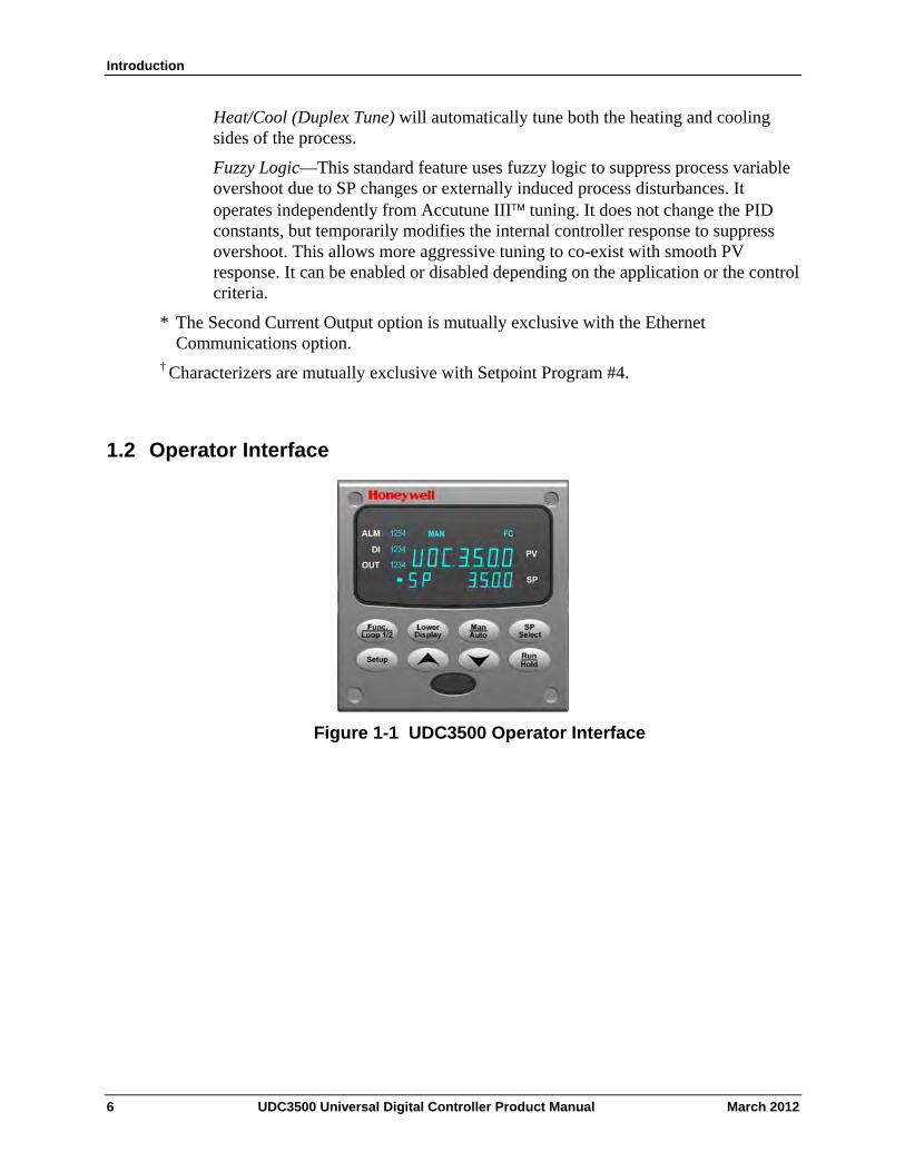
Figure 1-1 UDC3500 Operator Interface
6 UDC3500 Universal Digital Controller Product Manual March 2012
Introduction
March 2012 UDC3500 Universal Digital Controller Product Manual 7
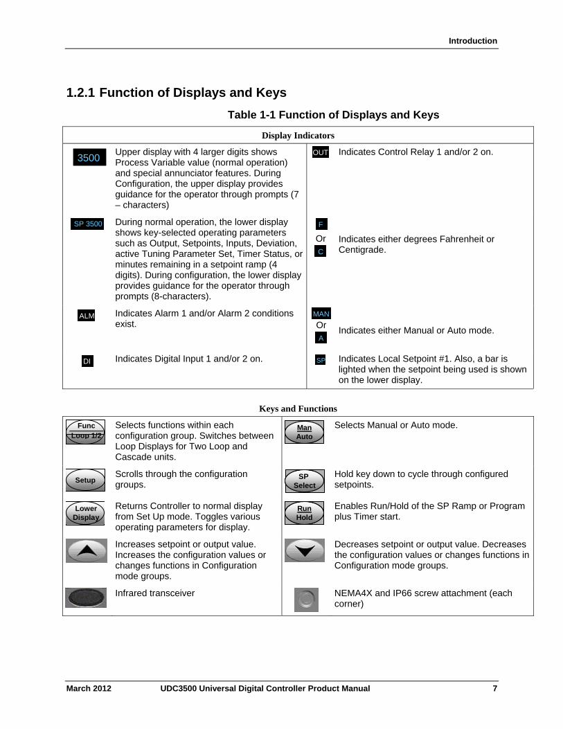
1.2.1 Function of Displays and Keys
Table 1-1 Function of Displays and Keys
Display Indicators
3200 3500
Upper display with 4 larger digits shows Process Variable value (normal operation) and special annunciator features. During Configuration, the upper display provides guidance for the operator through prompts (7 – characters)
OUT Indicates Control Relay 1 and/or 2 on.
SP SP 3500
During normal operation, the lower display shows key-selected operating parameters such as Output, Setpoints, Inputs, Deviation, active Tuning Parameter Set, Timer Status, or minutes remaining in a setpoint ramp (4 digits). During configuration, the lower display provides guidance for the operator through prompts (8-characters).
FF
Or CC
Indicates either degrees Fahrenheit or Centigrade.
ALMALM
Indicates Alarm 1 and/or Alarm 2 conditions exist.
MAN
Or AA
Indicates either Manual or Auto mode.
DIDI
Indicates Digital Input 1 and/or 2 on. SPSP Indicates Local Setpoint #1. Also, a bar is lighted when the setpoint being used is shown on the lower display.
Keys and Functions
Func Loop 1/2
Selects functions within each configuration group. Switches between Loop Displays for Two Loop and Cascade units.
ManAutoManAutoManAuto
Selects Manual or Auto mode.
SetupSetup
Scrolls through the configuration groups.
SP Select
SP Select
SP Select
Hold key down to cycle through configured setpoints.
LowerDisplayLower
DisplayLower
Display
Returns Controller to normal display from Set Up mode. Toggles various operating parameters for display.
RunHoldRunHoldRunHold
Enables Run/Hold of the SP Ramp or Program plus Timer start.
Increases setpoint or output value. Increases the configuration values or changes functions in Configuration mode groups.
Decreases setpoint or output value. Decreases the configuration values or changes functions in Configuration mode groups.
Infrared transceiver
NEMA4X and IP66 screw attachment (each corner)
Introduction
1.3 Process Instrument Explorer Software
Overview
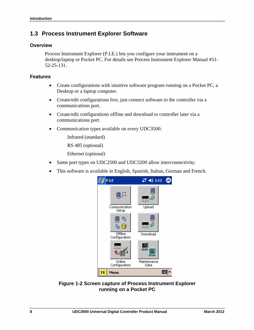
Process Instrument Explorer (P.I.E.) lets you configure your instrument on a desktop/laptop or Pocket PC. For details see Process Instrument Explorer Manual #51-52-25-131.
Features
Create configurations with intuitive software program running on a Pocket PC, a Desktop or a laptop computer.
Create/edit configurations live, just connect software to the controller via a communications port.
Create/edit configurations offline and download to controller later via a communications port.
Communication types available on every UDC3500:
Infrared (standard)
RS 485 (optional)
Ethernet (optional)
Same port types on UDC2500 and UDC3200 allow interconnectivity.
This software is available in English, Spanish, Italian, German and French.
Figure 1-2 Screen capture of Process Instrument Explorer running on a Pocket PC
8 UDC3500 Universal Digital Controller Product Manual March 2012
Introduction
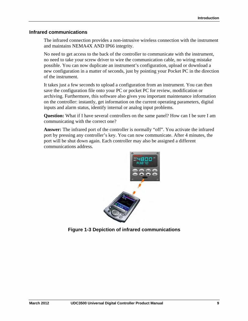
Infrared communications
The infrared connection provides a non-intrusive wireless connection with the instrument and maintains NEMA4X AND IP66 integrity.
No need to get access to the back of the controller to communicate with the instrument, no need to take your screw driver to wire the communication cable, no wiring mistake possible. You can now duplicate an instrument’s configuration, upload or download a new configuration in a matter of seconds, just by pointing your Pocket PC in the direction of the instrument.
It takes just a few seconds to upload a configuration from an instrument. You can then save the configuration file onto your PC or pocket PC for review, modification or archiving. Furthermore, this software also gives you important maintenance information on the controller: instantly, get information on the current operating parameters, digital inputs and alarm status, identify internal or analog input problems.
Question: What if I have several controllers on the same panel? How can I be sure I am communicating with the correct one?
Answer: The infrared port of the controller is normally “off”. You activate the infrared port by pressing any controller’s key. You can now communicate. After 4 minutes, the port will be shut down again. Each controller may also be assigned a different communications address.
Figure 1-3 Depiction of infrared communications
March 2012 UDC3500 Universal Digital Controller Product Manual 9
Introduction
10 UDC3500 Universal Digital Controller Product Manual March 2012
1.4 CE Conformity (Europe)
This product is in conformity with the protection requirements of the following European Council Directives: 73/23/EEC, the Low Voltage Directive, and 89/336/EEC, the EMC Directive. Conformity of this product with any other “CE Mark” Directive(s) shall not be assumed.
Product Classification: Class I: Permanently connected, panel-mounted Industrial Control Equipment with protective earthing (grounding) (EN61010-1).
Enclosure Rating: This controller must be panel-mounted with the rear terminals enclosed within the panel. The front panel of the controller is rated at NEMA4X and IP66 when properly installed.
Installation Category (Overvoltage Category): Category II (EN61010-1)
Pollution Degree: Pollution Degree 2: Normally non-conductive pollution with occasional conductivity caused by condensation. (Ref. IEC 664-1)
EMC Classification: Group 1, Class A, ISM Equipment (EN61326, emissions), Industrial Equipment (EN61326, immunity)
Method of EMC Assessment: Technical File (TF)
Declaration of Conformity: 51453681
Deviation from the installation conditions specified in this manual, and the special conditions for CE conformity in Subsection 2.1, may invalidate this product’s conformity with the Low Voltage and EMC Directives.
ATTENTION
The emission limits of EN61326 are designed to provide reasonable protection against harmful interference when this equipment is operated in an industrial environment. Operation of this equipment in a residential area may cause harmful interference. This equipment generates, uses, and can radiate radio frequency energy and may cause interference to radio and television reception when the equipment is used closer than 30 meters (98 feet) to the antenna(e). In special cases, when highly susceptible apparatus is used in close proximity, the user may have to employ additional mitigating measures to further reduce the electromagnetic emissions of this equipment.
WARNING
If this equipment is used in a manner not specified by the manufacturer, the protection provided by the equipment may be impaired.
Installation
2 Installation
2.1 Overview
Introduction
Installation of the UDC3500 consists of mounting and wiring the controller according to the instructions given in this section. Read the pre-installation information, check the model number interpretation (Subsection 2.3) and become familiar with your model selections, then proceed with installation.
What’s in this section?
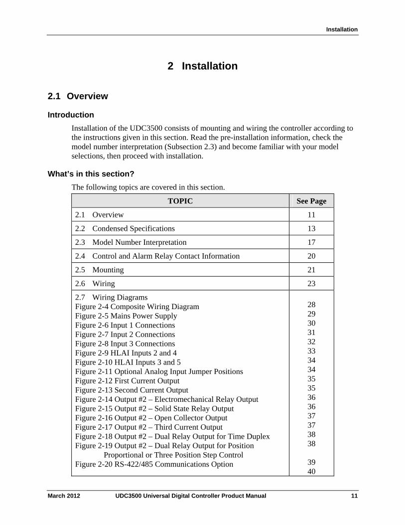
The following topics are covered in this section.
TOPIC See Page
2.1 Overview 11
2.2 Condensed Specifications 13
2.3 Model Number Interpretation 17
2.4 Control and Alarm Relay Contact Information 20
2.5 Mounting 21
2.6 Wiring 23
2.7 Wiring Diagrams Figure 2-4 Composite Wiring Diagram Figure 2-5 Mains Power Supply Figure 2-6 Input 1 Connections Figure 2-7 Input 2 Connections Figure 2-8 Input 3 Connections Figure 2-9 HLAI Inputs 2 and 4 Figure 2-10 HLAI Inputs 3 and 5 Figure 2-11 Optional Analog Input Jumper Positions Figure 2-12 First Current Output Figure 2-13 Second Current Output Figure 2-14 Output #2 – Electromechanical Relay Output Figure 2-15 Output #2 – Solid State Relay Output Figure 2-16 Output #2 – Open Collector Output Figure 2-17 Output #2 – Third Current Output Figure 2-18 Output #2 – Dual Relay Output for Time Duplex Figure 2-19 Output #2 – Dual Relay Output for Position
Proportional or Three Position Step Control Figure 2-20 RS-422/485 Communications Option
28 29 30 31 32 33 34 34 35 35 36 36 37 37 38 38
39 40
March 2012 UDC3500 Universal Digital Controller Product Manual 11
Installation
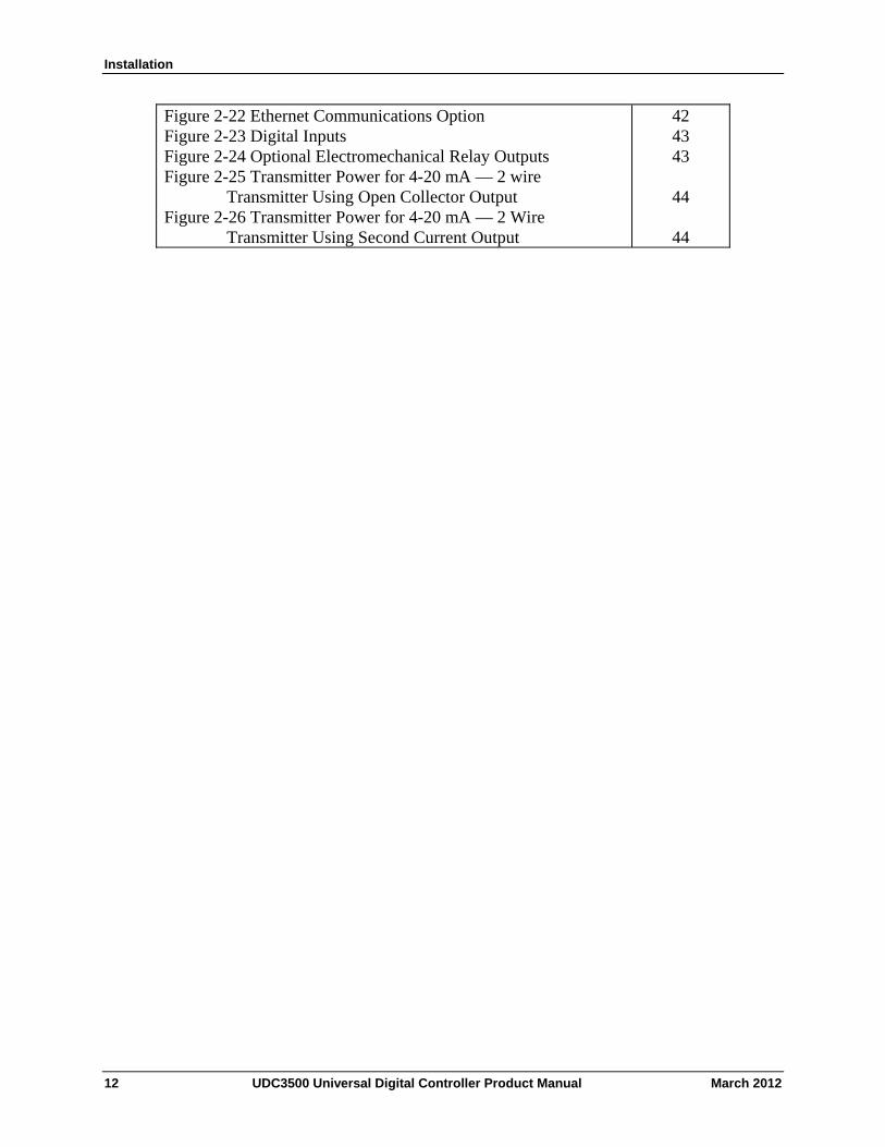
Figure 2-22 Ethernet Communications Option Figure 2-23 Digital Inputs Figure 2-24 Optional Electromechanical Relay Outputs Figure 2-25 Transmitter Power for 4-20 mA — 2 wire
Transmitter Using Open Collector Output Figure 2-26 Transmitter Power for 4-20 mA — 2 Wire
Transmitter Using Second Current Output
42 43 43
44
44
12 UDC3500 Universal Digital Controller Product Manual March 2012
Installation
Pre-installation Information
If the controller has not been removed from its shipping carton, inspect the carton for damage then remove the controller.
Inspect the unit for any obvious shipping damage and report any damage due to transit to the carrier.
Make sure a bag containing mounting hardware is included in the carton with the controller.
Check that the model number shown on the inside of the case agrees with what you have ordered.
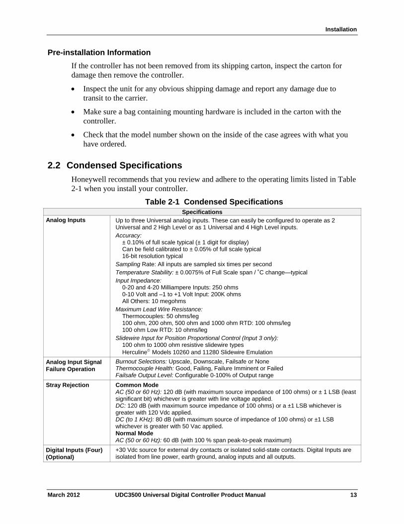
2.2 Condensed Specifications
Honeywell recommends that you review and adhere to the operating limits listed in Table 2-1 when you install your controller.
Table 2-1 Condensed Specifications Specifications
Analog Inputs Up to three Universal analog inputs. These can easily be configured to operate as 2 Universal and 2 High Level or as 1 Universal and 4 High Level inputs. Accuracy:
± 0.10% of full scale typical (± 1 digit for display) Can be field calibrated to ± 0.05% of full scale typical 16-bit resolution typical
Sampling Rate: All inputs are sampled six times per second Temperature Stability: ± 0.0075% of Full Scale span / ˚C change—typical Input Impedance:
0-20 and 4-20 Milliampere Inputs: 250 ohms 0-10 Volt and –1 to +1 Volt Input: 200K ohms All Others: 10 megohms
Maximum Lead Wire Resistance: Thermocouples: 50 ohms/leg 100 ohm, 200 ohm, 500 ohm and 1000 ohm RTD: 100 ohms/leg 100 ohm Low RTD: 10 ohms/leg
Slidewire Input for Position Proportional Control (Input 3 only): 100 ohm to 1000 ohm resistive slidewire types Herculine Models 10260 and 11280 Slidewire Emulation
Analog Input Signal Failure Operation
Burnout Selections: Upscale, Downscale, Failsafe or None Thermocouple Health: Good, Failing, Failure Imminent or Failed Failsafe Output Level: Configurable 0-100% of Output range
Stray Rejection Common Mode AC (50 or 60 Hz): 120 dB (with maximum source impedance of 100 ohms) or ± 1 LSB (least significant bit) whichever is greater with line voltage applied. DC: 120 dB (with maximum source impedance of 100 ohms) or a ±1 LSB whichever is greater with 120 Vdc applied. DC (to 1 KHz): 80 dB (with maximum source of impedance of 100 ohms) or ±1 LSB whichever is greater with 50 Vac applied. Normal Mode AC (50 or 60 Hz): 60 dB (with 100 % span peak-to-peak maximum)
Digital Inputs (Four) (Optional)
+30 Vdc source for external dry contacts or isolated solid-state contacts. Digital Inputs are isolated from line power, earth ground, analog inputs and all outputs.
March 2012 UDC3500 Universal Digital Controller Product Manual 13
Installation
14 UDC3500 Universal Digital Controller Product Manual March 2012
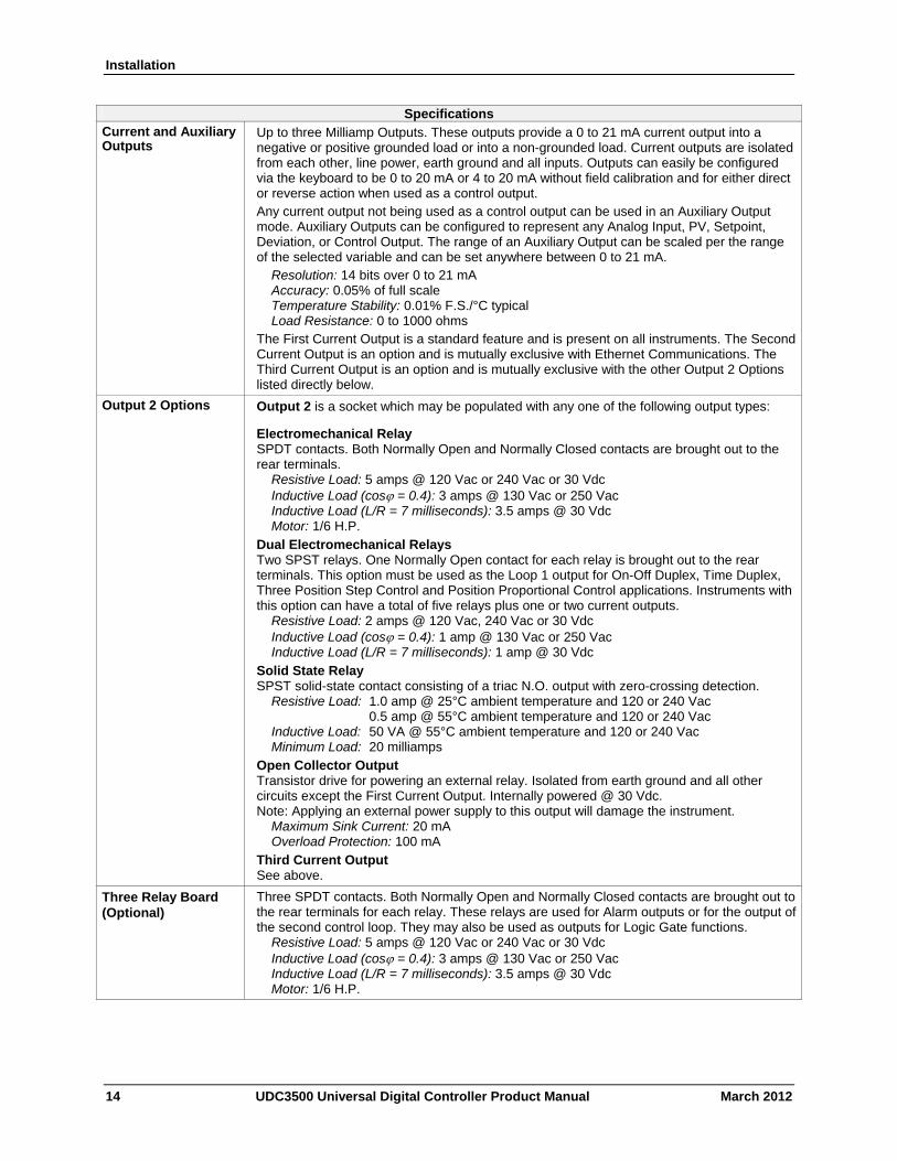
Specifications Current and Auxiliary Outputs
Up to three Milliamp Outputs. These outputs provide a 0 to 21 mA current output into a negative or positive grounded load or into a non-grounded load. Current outputs are isolated from each other, line power, earth ground and all inputs. Outputs can easily be configured via the keyboard to be 0 to 20 mA or 4 to 20 mA without field calibration and for either direct or reverse action when used as a control output. Any current output not being used as a control output can be used in an Auxiliary Output mode. Auxiliary Outputs can be configured to represent any Analog Input, PV, Setpoint, Deviation, or Control Output. The range of an Auxiliary Output can be scaled per the range of the selected variable and can be set anywhere between 0 to 21 mA.
Resolution: 14 bits over 0 to 21 mA Accuracy: 0.05% of full scale Temperature Stability: 0.01% F.S./°C typical Load Resistance: 0 to 1000 ohms
The First Current Output is a standard feature and is present on all instruments. The Second Current Output is an option and is mutually exclusive with Ethernet Communications. The Third Current Output is an option and is mutually exclusive with the other Output 2 Options listed directly below.
Output 2 Options Output 2 is a socket which may be populated with any one of the following output types:
Electromechanical Relay SPDT contacts. Both Normally Open and Normally Closed contacts are brought out to the rear terminals.
Resistive Load: 5 amps @ 120 Vac or 240 Vac or 30 Vdc Inductive Load (cos = 0.4): 3 amps @ 130 Vac or 250 Vac Inductive Load (L/R = 7 milliseconds): 3.5 amps @ 30 Vdc Motor: 1/6 H.P.
Dual Electromechanical Relays Two SPST relays. One Normally Open contact for each relay is brought out to the rear terminals. This option must be used as the Loop 1 output for On-Off Duplex, Time Duplex, Three Position Step Control and Position Proportional Control applications. Instruments with this option can have a total of five relays plus one or two current outputs.
Resistive Load: 2 amps @ 120 Vac, 240 Vac or 30 Vdc Inductive Load (cos = 0.4): 1 amp @ 130 Vac or 250 Vac Inductive Load (L/R = 7 milliseconds): 1 amp @ 30 Vdc
Solid State Relay SPST solid-state contact consisting of a triac N.O. output with zero-crossing detection.
Resistive Load: 1.0 amp @ 25°C ambient temperature and 120 or 240 Vac 0.5 amp @ 55°C ambient temperature and 120 or 240 Vac Inductive Load: 50 VA @ 55°C ambient temperature and 120 or 240 Vac Minimum Load: 20 milliamps
Open Collector Output Transistor drive for powering an external relay. Isolated from earth ground and all other circuits except the First Current Output. Internally powered @ 30 Vdc. Note: Applying an external power supply to this output will damage the instrument.
Maximum Sink Current: 20 mA Overload Protection: 100 mA
Third Current Output See above.
Three Relay Board (Optional)
Three SPDT contacts. Both Normally Open and Normally Closed contacts are brought out to the rear terminals for each relay. These relays are used for Alarm outputs or for the output of the second control loop. They may also be used as outputs for Logic Gate functions.
Resistive Load: 5 amps @ 120 Vac or 240 Vac or 30 Vdc Inductive Load (cos = 0.4): 3 amps @ 130 Vac or 250 Vac Inductive Load (L/R = 7 milliseconds): 3.5 amps @ 30 Vdc Motor: 1/6 H.P.
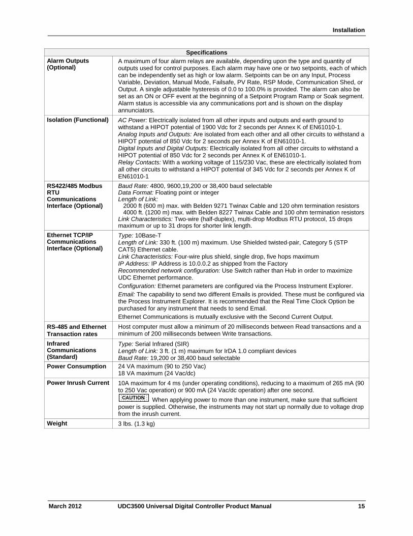
Installation
March 2012 UDC3500 Universal Digital Controller Product Manual 15
Specifications Alarm Outputs (Optional)
A maximum of four alarm relays are available, depending upon the type and quantity of outputs used for control purposes. Each alarm may have one or two setpoints, each of which can be independently set as high or low alarm. Setpoints can be on any Input, Process Variable, Deviation, Manual Mode, Failsafe, PV Rate, RSP Mode, Communication Shed, or Output. A single adjustable hysteresis of 0.0 to 100.0% is provided. The alarm can also be set as an ON or OFF event at the beginning of a Setpoint Program Ramp or Soak segment. Alarm status is accessible via any communications port and is shown on the display annunciators.
Isolation (Functional) AC Power: Electrically isolated from all other inputs and outputs and earth ground to withstand a HIPOT potential of 1900 Vdc for 2 seconds per Annex K of EN61010-1. Analog Inputs and Outputs: Are isolated from each other and all other circuits to withstand a HIPOT potential of 850 Vdc for 2 seconds per Annex K of EN61010-1. Digital Inputs and Digital Outputs: Electrically isolated from all other circuits to withstand a HIPOT potential of 850 Vdc for 2 seconds per Annex K of EN61010-1. Relay Contacts: With a working voltage of 115/230 Vac, these are electrically isolated from all other circuits to withstand a HIPOT potential of 345 Vdc for 2 seconds per Annex K of EN61010-1
RS422/485 Modbus RTU Communications Interface (Optional)
Baud Rate: 4800, 9600,19,200 or 38,400 baud selectable Data Format: Floating point or integer Length of Link: 2000 ft (600 m) max. with Belden 9271 Twinax Cable and 120 ohm termination resistors 4000 ft. (1200 m) max. with Belden 8227 Twinax Cable and 100 ohm termination resistorsLink Characteristics: Two-wire (half-duplex), multi-drop Modbus RTU protocol, 15 drops maximum or up to 31 drops for shorter link length.
Ethernet TCP/IP Communications Interface (Optional)
Type: 10Base-T Length of Link: 330 ft. (100 m) maximum. Use Shielded twisted-pair, Category 5 (STP CAT5) Ethernet cable. Link Characteristics: Four-wire plus shield, single drop, five hops maximum IP Address: IP Address is 10.0.0.2 as shipped from the Factory Recommended network configuration: Use Switch rather than Hub in order to maximize UDC Ethernet performance. Configuration: Ethernet parameters are configured via the Process Instrument Explorer. Email: The capability to send two different Emails is provided. These must be configured via the Process Instrument Explorer. It is recommended that the Real Time Clock Option be purchased for any instrument that needs to send Email. Ethernet Communications is mutually exclusive with the Second Current Output.
RS-485 and Ethernet Transaction rates
Host computer must allow a minimum of 20 milliseconds between Read transactions and a minimum of 200 milliseconds between Write transactions.
Infrared Communications (Standard)
Type: Serial Infrared (SIR) Length of Link: 3 ft. (1 m) maximum for IrDA 1.0 compliant devices Baud Rate: 19,200 or 38,400 baud selectable
Power Consumption 24 VA maximum (90 to 250 Vac) 18 VA maximum (24 Vac/dc)
Power Inrush Current 10A maximum for 4 ms (under operating conditions), reducing to a maximum of 265 mA (90 to 250 Vac operation) or 900 mA (24 Vac/dc operation) after one second. CAUTION When applying power to more than one instrument, make sure that sufficient power is supplied. Otherwise, the instruments may not start up normally due to voltage drop from the inrush current.
Weight 3 lbs. (1.3 kg)
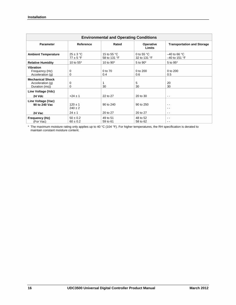
Installation
Environmental and Operating Conditions
Parameter Reference Rated Operative Limits
Transportation and Storage
Ambient Temperature 25 ± 3 °C 77 ± 5 °F
15 to 55 °C 58 to 131 °F
0 to 55 °C 32 to 131 °F
–40 to 66 °C –40 to 151 °F
Relative Humidity 10 to 55* 10 to 90* 5 to 90* 5 to 95*
Vibration Frequency (Hz) Acceleration (g)
0 0
0 to 70 0.4
0 to 200 0.6
0 to 200 0.5
Mechanical Shock Acceleration (g) Duration (ms))
0 0
1 30
5 30
20 30
Line Voltage (Vdc)
24 Vdc
+24 ± 1
22 to 27
20 to 30
- -
Line Voltage (Vac) 90 to 240 Vac
24 Vac
120 ± 1 240 ± 2
24 ± 1
90 to 240
20 to 27
90 to 250
20 to 27
- - - -
- -
Frequency (Hz) (For Vac)
50 ± 0.2 60 ± 0.2
49 to 51 59 to 61
48 to 52 58 to 62
- - - -
* The maximum moisture rating only applies up to 40 °C (104 °F). For higher temperatures, the RH specification is derated to maintain constant moisture content.
16 UDC3500 Universal Digital Controller Product Manual March 2012
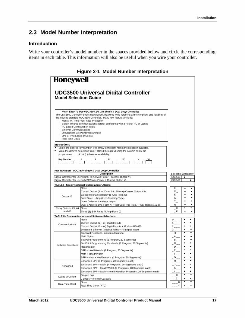
Installation
2.3 Model Number Interpretation
Introduction
Write your controller’s model number in the spaces provided below and circle the corresponding items in each table. This information will also be useful when you wire your controller.
Figure 2-1 Model Number Interpretation
UDC3500 Universal Digital ControllerModel Selection Guide
InstructionsSelect the desired key number. The arrow to the right marks the selection available.Make the desired selections from Tables I through VI using the column below the proper arrow. A dot ( ) denotes availability.
Key Number- - - - _ _ _ _ _ - _
KEY NUMBER - UDC3500 Single & Dual Loop Controller
Selection
Digital Controller for use with 90 to 250Vac Power + Current Output #1 DC3500Digital Controller for use with 24Vac/dc Power + Current Output #1 DC3501
TABLE I - Specify optional Output and/or AlarmsNone
TABLE II - Communications and Software Selections0 _ _ _1 _ _ _2 _ _ _3 _ _ _ _ 0 _ __ A _ __ B _ _
_ C _ _
_ D _ _
_ E _ _
_ F _ _
_ G _ _
Enhanced SPP (4 Programs, 20 Segments each) _ H _ _
Enhanced SPP + Math (4 Programs, 20 Segments each) _ J _ _
Enhanced SPP + HealthWatch (4 Programs, 20 Segments each) _ K _ _
Enhanced SPP + Math + HealthWatch (4 Programs, 20 Segments each) _ L _ _
_ _ 0 _
_ _2 _
_ _ _ 0
_ _ _ C
Enhanced
Communications
Loops of ControlSingle Loop
Real-Time Clock
HealthWatch
Math OptionSet Point Programming (1 Program, 20 Segments)
Software Selections
2 Loops + Internal Cascade
NoneReal-Time Clock (RTC)
IIIII_ _ __ _
VI
Output #2 Solid State 1 Amp (Zero-Crossing Type)
VIIV_ _
_ 0
T _R _
Electro Mechanical Relay (5 Amp Form C)
Description
0 _
Relay Outputs #3, #4 and #5
_ _ _ _ _ _
Dual 2 Amp Relays (Form A) (Heat/Cool, Pos Prop, TPSC, Relays 1 & 2)
Current Output (4 to 20mA, 0 to 20 mA) (Current Output #3) C _E _
_ _ _ _
Availability
NoneThree (3) E-M Relay (5 Amp Form C)
Standard Functions, Includes Accutune
Math + HealthWatch
Set Point Programming Plus Math (1 Program, 20 Segments)
Current Output #2 + (4) Digital Inputs + Modbus RS-48510 Base-T Ethernet (Modbus RTU) + (4) Digital Inputs
NoneCurrent Output #2 + (4) Digital Inputs
A _
Open Collector transistor output
_ E
SPP + Math + HealthWatch (1 Program, 20 Segments)
SPP + HealthWatch (1 Program, 20 Segments)
New! Easy To Use UDC3500 1/4 DIN Single & Dual Loop ControllerThe UDC3500 Controller packs new powerful features while retaining all the simplicity and flexibility of the industry standard UDC3300 Controller. Many new features include: - NEMA 4X, IP66 Front Face Protection - Built-in infrared communications port for configuring with a Pocket PC or Laptop - PC Based Configuration Tools - Ethernet Communications - 20 Segment Set Point Programming - One or Two Loops of Control - Real Time Clock
March 2012 UDC3500 Universal Digital Controller Product Manual 17
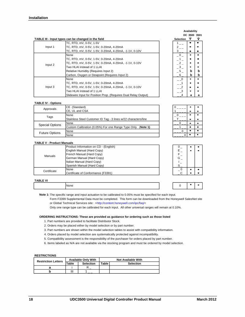
Installation
Availability
DC 3500 3501
TABLE III - Input types can be changed in the field Selection
1 _ _2 _ _3 _ __ 0 __ 1 __ 2 _
Two HLAI instead of 1 LLAI _ 3 __ 5 _ b b_ 6 _ b b_ _0_ _1_ _2
Two HLAI instead of 1 LLAI _ _3Slidewire Input for Position Prop. (Requires Dual Relay Output) _ _4 a a
TABLE IV - Options0 _ _ _ _1 _ _ _ __ 0 _ _ __ T _ _ __ _ 0 _ __ _ 1 _ __ _ _ 0 __ _ _ _ 0
TABLE V - Product ManualsProduct Information on CD - (English) 0 _English Manual (Hard Copy) E _French Manual (Hard Copy) F _German Manual (Hard Copy) G _Italian Manual (Hard Copy) I _Spanish Manual (Hard Copy) S _
_ 0_ C
TABLE VI
None 0
Note 1: The specific range and input actuation to be calibrated to 0.05% must be specified for each input.
Form F3399 Supplemental Data must be completed. This form can be downloaded from the Honeywell SalesNet site
or Global Technical Services site: >http://content.honeywell.com/ipc/faq/<
Only one range type can be calibrated for each input. All other universal ranges will remain at 0.10%.
ORDERING INSTRUCTIONS: These are provided as guidance for ordering such as those listed
1. Part numbers are provided to facilitate Distributor Stock.
2. Orders may be placed either by model selection or by part number.
3. Part numbers are shown within the model selection tables to assist with compatibility information.
4. Orders placed by model selection are systematically protected against incompatibility.
5. Compatibility assessment is the responsibility of the purchaser for orders placed by part number.
6. Items labeled as N/A are not available via the stocking program and must be ordered by model selection.
RESTRICTIONS
Table
Manuals
Certificate
TC, RTD, mV, 0-5V, 1-5V, 0-20mA, 4-20mA
TagsNoneStainless Steel Customer ID Tag - 3 lines w/22 characters/line
None
NoneNone
Input 3
SelectionAvailable Only With Not Available With
TC, RTD, mV, 0-5V, 1-5V, 0-20mA, 4-20mA, -1-1V, 0-10V
None
None
1 _ _
Custom Calibration (0.05%) For one Range Type Only (Note 1)
Selection Table
TC, RTD, mV, 0-5V, 1-5V, 0-20mA, 4-20mA, -1-1V, 0-10V
Relative Humidity (Requires Input 2)
TC, RTD, mV, 0-5V, 1-5V, 0-20mA, 4-20mANone
Certificate of Conformance (F3391)
TC, RTD, mV, 0-5V, 1-5V
Future Options
Special Options
TC, RTD, mV, 0-5V, 1-5V, 0-20mA, 4-20mATC, RTD, mV, 0-5V, 1-5V, 0-20mA, 4-20mA, -1-1V, 0-10V
a I R _
b
Input 1
Input 2
Carbon, Oxygen or Dewpoint (Requires Input 2)
III
ApprovalsCE (Standard)CE, UL and CSA
Restriction Letters
18 UDC3500 Universal Digital Controller Product Manual March 2012
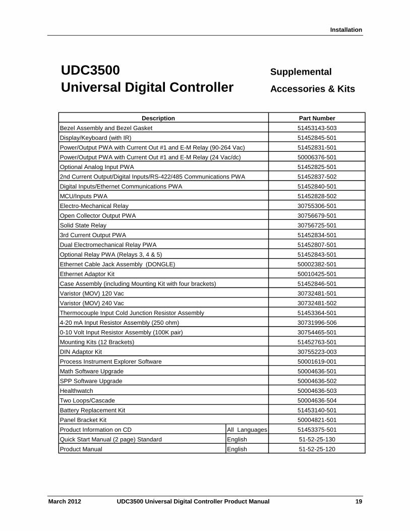
Installation
UDC3500 Supplemental
Universal Digital Controller Accessories & Kits
Description Part Number
Bezel Assembly and Bezel Gasket 51453143-503
Display/Keyboard (with IR) 51452845-501
Power/Output PWA with Current Out #1 and E-M Relay (90-264 Vac) 51452831-501
Power/Output PWA with Current Out #1 and E-M Relay (24 Vac/dc) 50006376-501
Optional Analog Input PWA 51452825-501
2nd Current Output/Digital Inputs/RS-422/485 Communications PWA 51452837-502
Digital Inputs/Ethernet Communications PWA 51452840-501
MCU/Inputs PWA 51452828-502
Electro-Mechanical Relay 30755306-501
Open Collector Output PWA 30756679-501
Solid State Relay 30756725-501
3rd Current Output PWA 51452834-501
Dual Electromechanical Relay PWA 51452807-501
Optional Relay PWA (Relays 3, 4 & 5) 51452843-501
Ethernet Cable Jack Assembly (DONGLE) 50002382-501
Ethernet Adaptor Kit 50010425-501
Case Assembly (including Mounting Kit with four brackets) 51452846-501
Varistor (MOV) 120 Vac 30732481-501
Varistor (MOV) 240 Vac 30732481-502
Thermocouple Input Cold Junction Resistor Assembly 51453364-501
4-20 mA Input Resistor Assembly (250 ohm) 30731996-506
0-10 Volt Input Resistor Assembly (100K pair) 30754465-501
Mounting Kits (12 Brackets) 51452763-501
DIN Adaptor Kit 30755223-003
Process Instrument Explorer Software 50001619-001
Math Software Upgrade 50004636-501
SPP Software Upgrade 50004636-502
Healthwatch 50004636-503
Two Loops/Cascade 50004636-504
Battery Replacement Kit 51453140-501
Panel Bracket Kit 50004821-501
Product Information on CD All Languages
Quick Start Manual (2 page) Standard English
Product Manual English 51-52-25-120
51453375-501
51-52-25-130
March 2012 UDC3500 Universal Digital Controller Product Manual 19
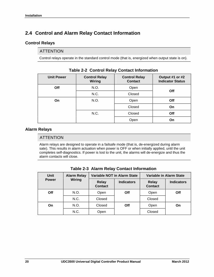
Installation
2.4 Control and Alarm Relay Contact Information
Control Relays
ATTENTION
Control relays operate in the standard control mode (that is, energized when output state is on).
Table 2-2 Control Relay Contact Information
Unit Power Control Relay Wiring
Control Relay Contact
Output #1 or #2 Indicator Status
N.O. Open Off
N.C. Closed
Off
Open Off N.O.
Closed On
Closed Off
On
N.C.
Open On
Alarm Relays
ATTENTION
Alarm relays are designed to operate in a failsafe mode (that is, de-energized during alarm sate). This results in alarm actuation when power is OFF or when initially applied, until the unit completes self-diagnostics. If power is lost to the unit, the alarms will de-energize and thus the alarm contacts will close.
Table 2-3 Alarm Relay Contact Information
Variable NOT in Alarm State Variable in Alarm State Unit Power
Alarm Relay Wiring
Relay Contact
Indicators Relay Contact
Indicators
N.O. Open Open Off
N.C. Closed
Off
Closed
Off
N.O. Closed Open On
N.C. Open
Off
Closed
On
20 UDC3500 Universal Digital Controller Product Manual March 2012
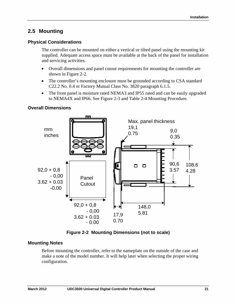
Installation
2.5 Mounting
Physical Considerations
The controller can be mounted on either a vertical or tilted panel using the mounting kit supplied. Adequate access space must be available at the back of the panel for installation and servicing activities.
Overall dimensions and panel cutout requirements for mounting the controller are shown in Figure 2-2.
The controller’s mounting enclosure must be grounded according to CSA standard C22.2 No. 0.4 or Factory Mutual Class No. 3820 paragraph 6.1.5.
The front panel is moisture rated NEMA3 and IP55 rated and can be easily upgraded to NEMA4X and IP66. See Figure 2-3 and Table 2-4 Mounting Procedure.
Overall Dimensions
Max. panel thickness
19,1
0.75
Panel Cutout
92,0 + 0,8
- 0,00
3.62 + 0.03 - 0.00
92,0 + 0,8
- 0,00
3.62 + 0.03
- 0.00
mm
inches
17,9
0.70
148,0
5.81
90,6
3.57 108,6
4.28
9,0
0.35
Figure 2-2 Mounting Dimensions (not to scale)
Mounting Notes
Before mounting the controller, refer to the nameplate on the outside of the case and make a note of the model number. It will help later when selecting the proper wiring configuration.
March 2012 UDC3500 Universal Digital Controller Product Manual 21
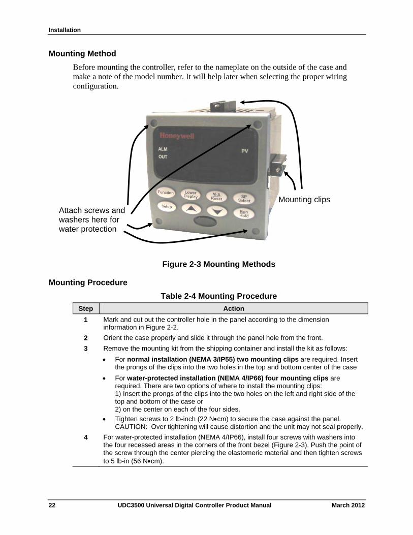
Installation
Mounting Method
Before mounting the controller, refer to the nameplate on the outside of the case and make a note of the model number. It will help later when selecting the proper wiring configuration.
Attach screws and washers here for water protection
Mounting clips
Figure 2-3 Mounting Methods
Mounting Procedure
Table 2-4 Mounting Procedure
Step Action
1 Mark and cut out the controller hole in the panel according to the dimension information in Figure 2-2.
2 Orient the case properly and slide it through the panel hole from the front.
3 Remove the mounting kit from the shipping container and install the kit as follows:
For normal installation (NEMA 3/IP55) two mounting clips are required. Insert the prongs of the clips into the two holes in the top and bottom center of the case
For water-protected installation (NEMA 4/IP66) four mounting clips are required. There are two options of where to install the mounting clips: 1) Insert the prongs of the clips into the two holes on the left and right side of the top and bottom of the case or 2) on the center on each of the four sides.
Tighten screws to 2 lb-inch (22 Ncm) to secure the case against the panel. CAUTION: Over tightening will cause distortion and the unit may not seal properly.
4 For water-protected installation (NEMA 4/IP66), install four screws with washers into the four recessed areas in the corners of the front bezel (Figure 2-3). Push the point of the screw through the center piercing the elastomeric material and then tighten screws to 5 lb-in (56 Ncm).
22 UDC3500 Universal Digital Controller Product Manual March 2012
Installation
2.6 Wiring
2.6.1 Electrical Considerations
Line voltage wiring
This controller is considered “rack and panel mounted equipment” per EN61010-1, Safety Requirements for Electrical Equipment for Measurement, Control, and Laboratory Use, Part 1: General Requirements. Conformity with 72/23/EEC, the Low Voltage Directive requires the user to provide adequate protection against a shock hazard. The user shall install this controller in an enclosure that limits OPERATOR access to the rear terminals.
Mains Power Supply
This equipment is suitable for connection to 90 to 250 Vac or to 24 Vac/dc 50/60 Hz, power supply mains. It is the user’s responsibility to provide a switch and non-time delay (North America), quick-acting, high breaking capacity, Type F (Europe), 1/2A, 250V fuse(s), or circuit breaker for 90-250 Vac applications; or 2 A, 125 V fuse or circuit breaker for 24 Vac/dc applications, as part of the installation. The switch or circuit breaker shall be located in close proximity to the controller, within easy reach of the OPERATOR. The switch or circuit breaker shall be marked as the disconnecting device for the controller.
Applying 90-250 Vac to an instrument rated for 24 Vac/dc will severely damage the instrument and is a fire and smoke hazard.
When applying power to multiple instruments, make certain that sufficient current is supplied. Otherwise, the instruments may not start up normally due to the voltage drop caused by the in-rush current.
Controller Grounding
PROTECTIVE BONDING (grounding) of this controller and the enclosure in which it is installed shall be in accordance with National and Local electrical codes. To minimize electrical noise and transients that may adversely affect the system, supplementary bonding of the controller enclosure to a local ground, using a No. 12 (4 mm2) copper conductor, is recommended.
Control/Alarm Circuit Wiring
The insulation of wires connected to the Control/Alarm terminals shall be rated for the highest voltage involved. Extra Low Voltage (ELV) wiring (input, current output, and low voltage Control/Alarm circuits) shall be separated from HAZARDOUS LIVE (>30 Vac, 42.4 Vpeak, or 60 Vdc) wiring per Permissible Wiring Bundling, Table 2-5.
Electrical Noise Precautions Electrical noise is composed of unabated electrical signals, which produce undesirable effects in measurements and control circuits.
March 2012 UDC3500 Universal Digital Controller Product Manual 23
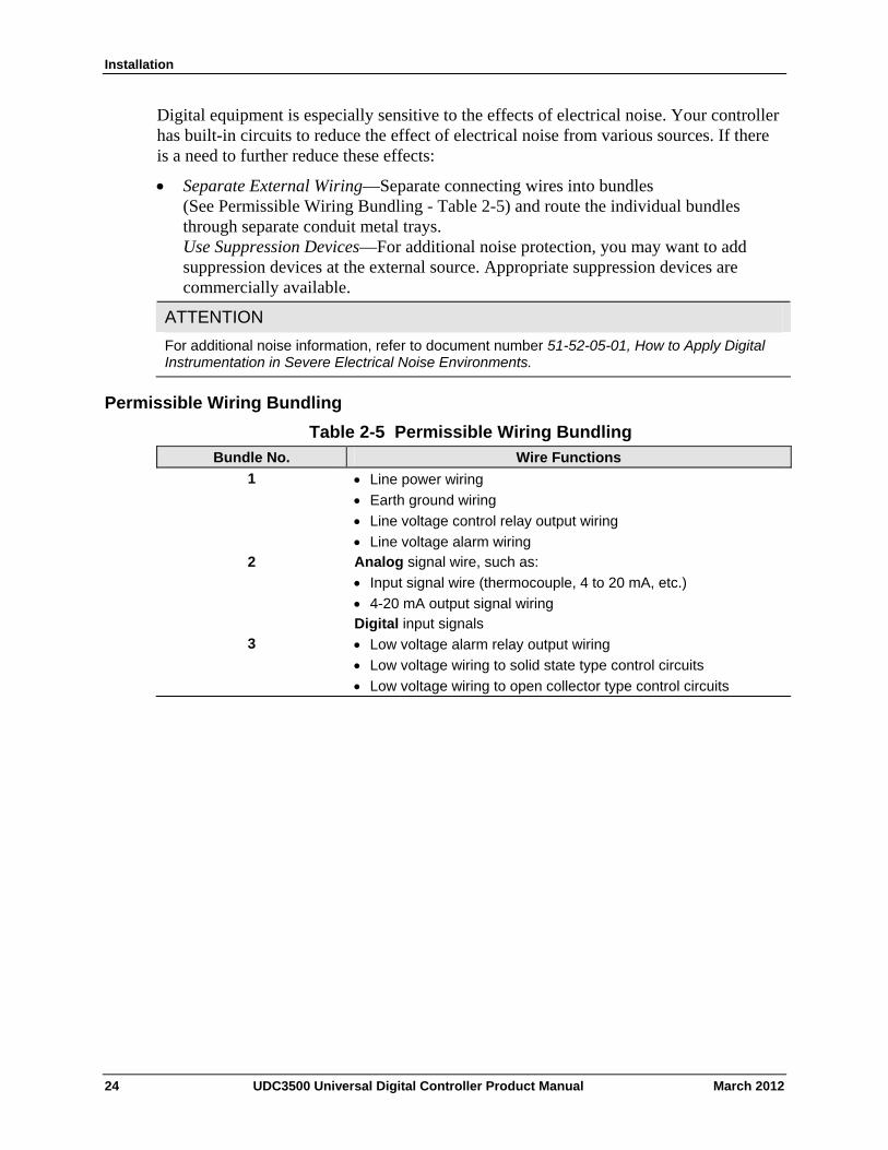
Installation
Digital equipment is especially sensitive to the effects of electrical noise. Your controller has built-in circuits to reduce the effect of electrical noise from various sources. If there is a need to further reduce these effects:
Separate External Wiring—Separate connecting wires into bundles (See Permissible Wiring Bundling - Table 2-5) and route the individual bundles through separate conduit metal trays. Use Suppression Devices—For additional noise protection, you may want to add suppression devices at the external source. Appropriate suppression devices are commercially available.
ATTENTION
For additional noise information, refer to document number 51-52-05-01, How to Apply Digital Instrumentation in Severe Electrical Noise Environments.
Permissible Wiring Bundling
Table 2-5 Permissible Wiring Bundling
Bundle No. Wire Functions
1 Line power wiring
Earth ground wiring
Line voltage control relay output wiring
Line voltage alarm wiring 2 Analog signal wire, such as:
Input signal wire (thermocouple, 4 to 20 mA, etc.)
4-20 mA output signal wiring Digital input signals
3 Low voltage alarm relay output wiring
Low voltage wiring to solid state type control circuits
Low voltage wiring to open collector type control circuits
24 UDC3500 Universal Digital Controller Product Manual March 2012
Installation
2.7 Wiring Diagrams
Identify Your Wiring Requirements
To determine the appropriate diagrams for wiring your controller, refer to the model number interpretation in this section. The model number of the controller is on the outside of the case.
Output Functionality and Restrictions
Table 2-6 and Table 2-7 show the control functionality and number of alarms that are available based upon the installed outputs quantity and type. First, use the left-most column to find the Control Output Algorithm desired for your instrument. Then use the second column to find the Output 2 Option selection installed in your instrument. The rest of the columns will then show how the instrument delivers your desired Output functionality and the quantity of alarms available.
In Table 2-6, “HEAT” is used as meaning Loop 1 Control Output #1 and “COOL” is used as meaning Loop 1 Control Output #2. When Position Proportional or Three Position Step Control (TPSC) is configured, then “HEAT” means OPEN while “COOL” means CLOSE.
In Table 2-7, “Loop 2 HEAT” is used as meaning Loop 2 Control Output #1 and “Loop 2 COOL” is used as meaning Loop 2 Control Output #2.
See Figure 2-4 Composite Wiring Diagram, for information on where the customer terminals are for all of these outputs and alarms.
ATTENTION
The selection for Loop 1 Output takes precedence over the selection for Loop 2 Output. For example, if you select the Loop 1 Output Algorithm as Current Duplex 50%, then you cannot have Current Duplex 50% as the Output Algorithm for Loop 2.
The Output 2 option shown in these tables as “Single Relay” can be any of the following selections: Electro-Mechanical Relay, Solid-State Relay or Open Collector Output.
If the controller is configured to use the same relay for more than one function, then the following priority is used to determine how the relay functions: Control Outputs take precedence over Alarms, which in turn take precedence over Time/Events, which in turn take precedence over Logic Gate Outputs.
For example, if you select the Loop 2 Output Algorithm as Time Simplex (which uses Relay 3), enable Alarm 3 (which also uses Relay 3) and configure a Logic Gate to use Relay 3, then the instrument will use Relay #3 to perform the Time Simplex output and ignore the Alarm and Logic Gate functions.
March 2012 UDC3500 Universal Digital Controller Product Manual 25
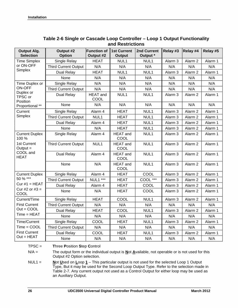
Installation
Table 2-6 Single or Cascade Loop Controller – Loop 1 Output Functionality and Restrictions
Output Alg. Selection
Output #2 Option
Function of Output #2
1st Current Output
2nd Current Output *
Relay #3 Relay #4 Relay #5
Single Relay HEAT NUL1 NUL1 Alarm 3 Alarm 2 Alarm 1
Third Current Output N/A N/A N/A N/A N/A N/A
Dual Relay HEAT NUL1 NUL1 Alarm 3 Alarm 2 Alarm 1
Time Simplex or ON-OFF Simplex
None N/A N/A N/A N/A N/A N/A
Single Relay N/A N/A N/A N/A N/A N/A
Third Current Output N/A N/A N/A N/A N/A N/A
Dual Relay HEAT and COOL
NUL1 NUL1 Alarm 3 Alarm 2 Alarm 1
Time Duplex or ON-OFF Duplex or TPSC or Position Proportional ** None N/A N/A N/A N/A N/A N/A
Single Relay Alarm 4 HEAT NUL1 Alarm 3 Alarm 2 Alarm 1
Third Current Output NUL1 HEAT NUL1 Alarm 3 Alarm 2 Alarm 1
Dual Relay Alarm 4 HEAT NUL1 Alarm 3 Alarm 2 Alarm 1
Current Simplex
None N/A HEAT NUL1 Alarm 3 Alarm 2 Alarm 1
Single Relay Alarm 4 HEAT and COOL
NUL1 Alarm 3 Alarm 2 Alarm 1
Third Current Output NUL1 HEAT and COOL
NUL1 Alarm 3 Alarm 2 Alarm 1
Dual Relay Alarm 4 HEAT and COOL
NUL1 Alarm 3 Alarm 2 Alarm 1
Current Duplex 100 % 1st Current Output = COOL and HEAT
None N/A HEAT and COOL
NUL1 Alarm 3 Alarm 2 Alarm 1
Single Relay Alarm 4 HEAT COOL Alarm 3 Alarm 2 Alarm 1
Third Current Output NUL1 *** HEAT COOL *** Alarm 3 Alarm 2 Alarm 1
Dual Relay Alarm 4 HEAT COOL Alarm 3 Alarm 2 Alarm 1
Current Duplex 50 % *** Cur #1 = HEAT Cur #2 or #3 = COOL
None N/A HEAT COOL Alarm 3 Alarm 2 Alarm 1
Single Relay HEAT COOL NUL1 Alarm 3 Alarm 2 Alarm 1
Third Current Output N/A N/A N/A N/A N/A N/A
Dual Relay HEAT COOL NUL1 Alarm 3 Alarm 2 Alarm 1
Current/Time First Current Out = COOL Time = HEAT None N/A N/A N/A N/A N/A N/A
Single Relay COOL HEAT NUL1 Alarm 3 Alarm 2 Alarm 1
Third Current Output N/A N/A N/A N/A N/A N/A
Dual Relay COOL HEAT NUL1 Alarm 3 Alarm 2 Alarm 1
Time/Current Time = COOL First Current Out = HEAT None N/A N/A N/A N/A N/A N/A
TPSC = Three Position Step Control
N/A = The output form or the individual output is Not Available, not operable or is not used for this Output #2 Option selection.
NUL1 = Not Used on Loop 1 – This particular output is not used for the selected Loop 1 Output Type, But it may be used for the Second Loop Output Type. Refer to the selection made in Table 2-7. Any current output not used as a Control Output for either loop may be used as an Auxiliary Output.
26 UDC3500 Universal Digital Controller Product Manual March 2012
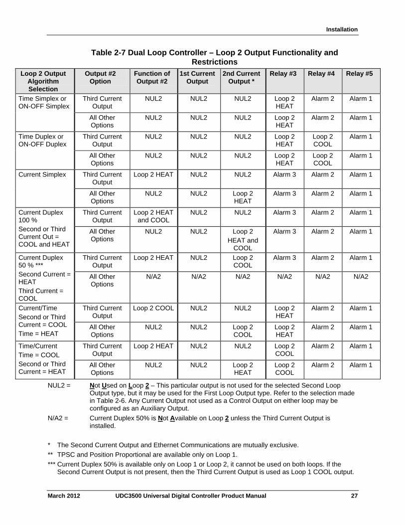
Installation
Table 2-7 Dual Loop Controller – Loop 2 Output Functionality and Restrictions
Loop 2 Output Algorithm Selection
Output #2 Option
Function of Output #2
1st Current Output
2nd Current Output *
Relay #3 Relay #4 Relay #5
Third Current Output
NUL2 NUL2 NUL2 Loop 2 HEAT
Alarm 2 Alarm 1 Time Simplex or ON-OFF Simplex
All Other Options
NUL2 NUL2 NUL2 Loop 2 HEAT
Alarm 2 Alarm 1
Third Current Output
NUL2 NUL2 NUL2 Loop 2 HEAT
Loop 2 COOL
Alarm 1 Time Duplex or ON-OFF Duplex
All Other Options
NUL2 NUL2 NUL2 Loop 2 HEAT
Loop 2 COOL
Alarm 1
Third Current Output
Loop 2 HEAT NUL2 NUL2 Alarm 3 Alarm 2 Alarm 1 Current Simplex
All Other Options
NUL2 NUL2 Loop 2 HEAT
Alarm 3 Alarm 2 Alarm 1
Third Current Output
Loop 2 HEAT and COOL
NUL2 NUL2 Alarm 3 Alarm 2 Alarm 1 Current Duplex 100 % Second or Third Current Out = COOL and HEAT
All Other Options
NUL2 NUL2 Loop 2 HEAT and
COOL
Alarm 3 Alarm 2 Alarm 1
Third Current Output
Loop 2 HEAT NUL2 Loop 2 COOL
Alarm 3 Alarm 2 Alarm 1 Current Duplex 50 % *** Second Current = HEAT Third Current = COOL
All Other Options
N/A2 N/A2 N/A2 N/A2 N/A2 N/A2
Third Current Output
Loop 2 COOL NUL2 NUL2 Loop 2 HEAT
Alarm 2 Alarm 1 Current/Time Second or Third Current = COOL Time = HEAT
All Other Options
NUL2 NUL2 Loop 2 COOL
Loop 2 HEAT
Alarm 2 Alarm 1
Third Current Output
Loop 2 HEAT NUL2 NUL2 Loop 2 COOL
Alarm 2 Alarm 1 Time/Current Time = COOL Second or Third Current = HEAT
All Other Options
NUL2 NUL2 Loop 2 HEAT
Loop 2 COOL
Alarm 2 Alarm 1
NUL2 = Not Used on Loop 2 – This particular output is not used for the selected Second Loop Output type, but it may be used for the First Loop Output type. Refer to the selection made in Table 2-6. Any Current Output not used as a Control Output on either loop may be configured as an Auxiliary Output.
N/A2 = Current Duplex 50% is Not Available on Loop 2 unless the Third Current Output is installed.
* The Second Current Output and Ethernet Communications are mutually exclusive.
** TPSC and Position Proportional are available only on Loop 1.
*** Current Duplex 50% is available only on Loop 1 or Loop 2, it cannot be used on both loops. If the Second Current Output is not present, then the Third Current Output is used as Loop 1 COOL output.
March 2012 UDC3500 Universal Digital Controller Product Manual 27
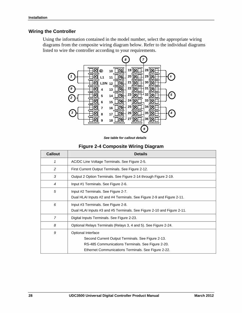
Installation
Wiring the Controller
Using the information contained in the model number, select the appropriate wiring diagrams from the composite wiring diagram below. Refer to the individual diagrams listed to wire the controller according to your requirements.
See table for callout details
4
5
6
7
8
9
10
11
12
13
14
15
16
17
L1
L2/N
22
23
24
25
26
27 18
19
20
21
31
32
33
34
35
36
28
29
30
6
5
4
1
2
3
7 8
9
9
Figure 2-4 Composite Wiring Diagram
Callout Details
1 AC/DC Line Voltage Terminals. See Figure 2-5.
2 First Current Output Terminals. See Figure 2-12.
3 Output 2 Option Terminals. See Figure 2-14 through Figure 2-19.
4 Input #1 Terminals. See Figure 2-6.
5 Input #2 Terminals. See Figure 2-7.
Dual HLAI Inputs #2 and #4 Terminals. See Figure 2-9 and Figure 2-11.
6 Input #3 Terminals. See Figure 2-8.
Dual HLAI Inputs #3 and #5 Terminals. See Figure 2-10 and Figure 2-11.
7 Digital Inputs Terminals. See Figure 2-23.
8 Optional Relays Terminals (Relays 3, 4 and 5). See Figure 2-24.
9 Optional Interface
Second Current Output Terminals. See Figure 2-13.
RS-485 Communications Terminals. See Figure 2-20.
Ethernet Communications Terminals. See Figure 2-22.
28 UDC3500 Universal Digital Controller Product Manual March 2012
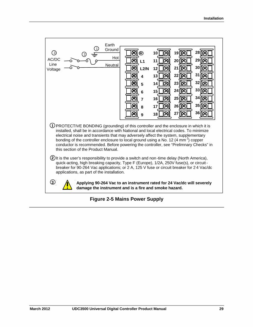
Installation
EarthGround
Hot
NeutralAC/DC Line
Voltage
1
2
PROTECTIVE BONDING (grounding) of this controller and the enclosure in which it is installed, shall be in accordance with National and local electrical codes. To minimize electrical noise and transients that may adversely affect the system, supplementary bonding of the controller enclosure to local ground using a No. 12 (4 mm 2) copper conductor is recommended. Before powering the controller, see “Prelimnary Checks” in this section of the Product Manual.
1
It is the user’s responsibility to provide a switch and non -time delay (North America), quick-acting, high breaking capacity, Type F (Europe), 1/2A, 250V fuse(s), or circuit -breaker for 90-264 Vac applications; or 2 A, 125 V fuse or circuit breaker for 2 4 Vac/dc applications, as part of the installation.
Applying 90-264 Vac to an instrument rated for 24 Vac/dc will severely damage the instrument and is a fire and smoke hazard.
3
2
3
4
5
6
7
8
9
10
11
12
13
14
15
16
17
L1
L2/N
22
23
24
25
26
2718
19
20
21
31
32
33
34
35
36
28
29
30
Figure 2-5 Mains Power Supply
March 2012 UDC3500 Universal Digital Controller Product Manual 29
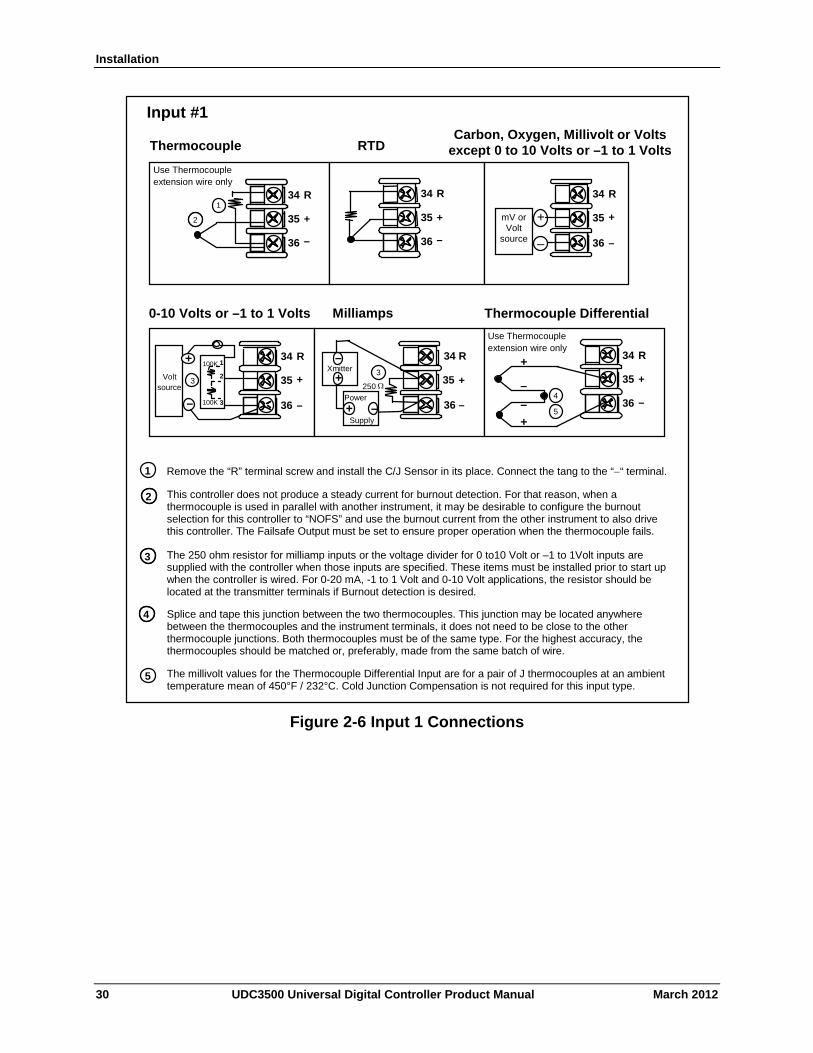
Installation
22
23
24
Use Thermocouple extension wire only
Thermocouple RTD
Milliamps
–
++
R
–
1 2
3 –
Volt source
+ 100K
100K Power
Supply–+
Xmitter+
–
250
22
23
24
+
R
–
22
23
24
+
R
–
1
22
23
24
+
R
–
1
Input #2
mV or Volt
source
22
23
24
Use Thermocouple extension wire only
+
R
–
Thermocouple Differential
+
+
–
–2
3 22
23
24
+
R
–
34
35
36
Use Thermocouple extension wire only
Thermocouple RTD
Milliamps
–
++
R
–
1 2
3 –
Volt source
+ 100K
100K Power
Supply–+
Xmitter+
–
250
34
35
36
+
R
–
34
35
36
+
R
–
3
34
35
36
+
R
–
3
Input #1
mV or Volt
source
34
35
36
Use Thermocouple extension wire only
+
R
–
Thermocouple Differential
+
+
–
–4
1 34
35
36
+
R
–
3
4
1
The millivolt values for the Thermocouple Differential Input are for a pair of J thermocouples at an ambient temperature mean of 450°F / 232°C. Cold Junction Compensation is not required for this input type.
5
2
5
3 2
This controller does not produce a steady current for burnout detection. For that reason, when a thermocouple is used in parallel with another instrument, it may be desirable to configure the burnout selection for this controller to “NOFS” and use the burnout current from the other instrument to also drive this controller. The Failsafe Output must be set to ensure proper operation when the thermocouple fails.
Splice and tape this junction between the two thermocouples. This junction may be located anywhere between the thermocouples and the instrument terminals, it does not need to be close to the other thermocouple junctions. Both thermocouples must be of the same type. For the highest accuracy, the thermocouples should be matched or, preferably, made from the same batch of wire.
Remove the “R” terminal screw and install the C/J Sensor in its place. Connect the tang to the ““ terminal.
The 250 ohm resistor for milliamp inputs or the voltage divider for 0 to10 Volt or –1 to 1Volt inputs are supplied with the controller when those inputs are specified. These items must be installed prior to start up when the controller is wired. For 0-20 mA, -1 to 1 Volt and 0-10 Volt applications, the resistor should be located at the transmitter terminals if Burnout detection is desired.
Carbon, Oxygen, Millivolt or Volts except 0 to 10 Volts or –1 to 1 Volts
0-10 Volts or –1 to 1 Volts
Figure 2-6 Input 1 Connections
30 UDC3500 Universal Digital Controller Product Manual March 2012
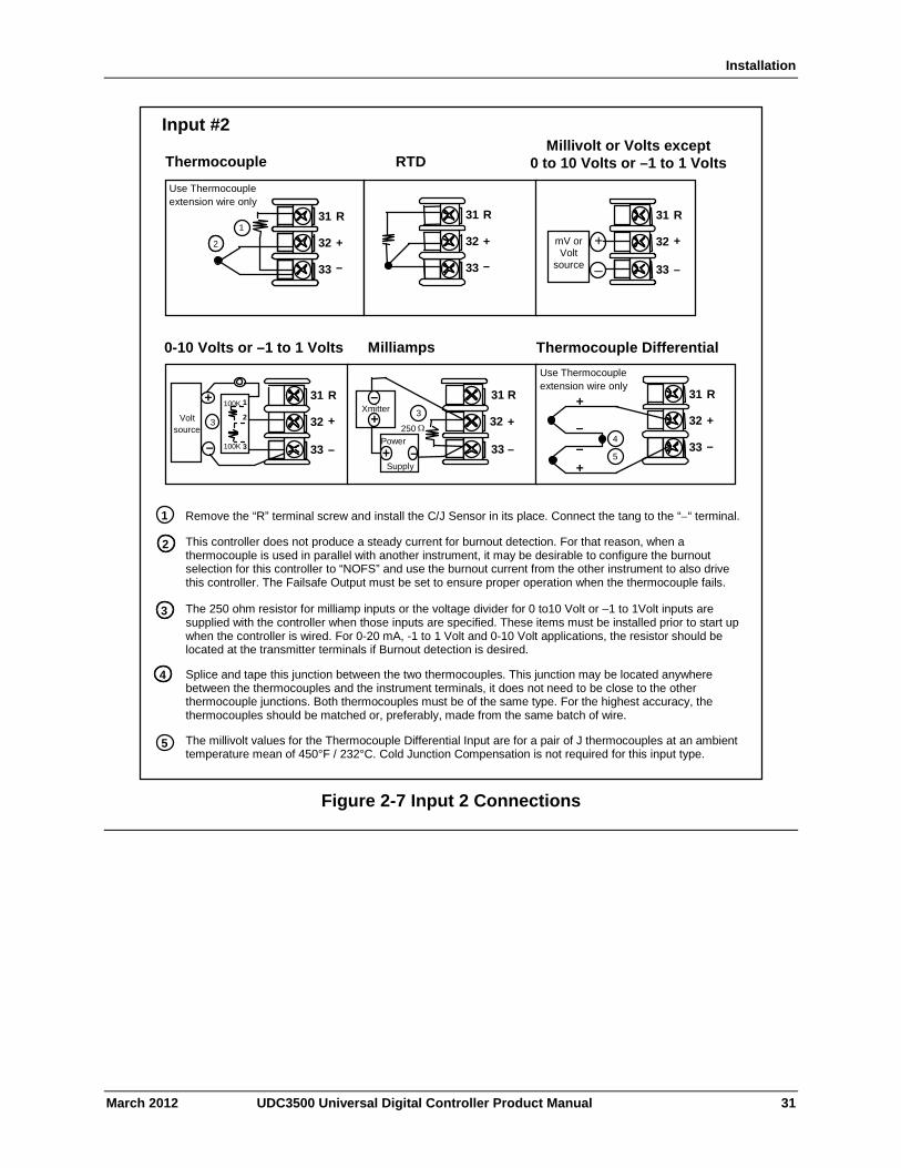
Installation
22
23
24
Use Thermocouple extension wire only
Thermocouple RTD
source
Milliamps
–
++
R
–
1 2
3 –
0 – 10 Volt
source
+ 100K
100K Power
Supply–+
Xmitter+
–
250
22
23
24
+
R
–
22
23
24
+
R
–
1
22
23
24
+
R
–
1
Input #2
mV or Volt
source
22
23
24
Use Thermocouple extension wire only
+
R
–
Thermocouple Differential
+
+
–
–2
3 22
23
24
+
R
–
31
32
33
Use Thermocouple extension wire only
Thermocouple RTD
source
Milliamps
–
++
R
–
1 2
3 –
Volt source
+ 100K
100K Power
Supply–+
Xmitter+
–
250
31
32
33
+
R
–
31
32
33
+
R
–
3
31
32
33
+
R
–
3
Input #2
mV or Volt
source
31
32
33
Use Thermocouple extension wire only
+
R
–
Thermocouple Differential
+
+
–
–4
1 31
32
33
+
R
–
3
4
1
The millivolt values for the Thermocouple Differential Input are for a pair of J thermocouples at an ambient temperature mean of 450°F / 232°C. Cold Junction Compensation is not required for this input type.
5
2
5
3 2
This controller does not produce a steady current for burnout detection. For that reason, when a thermocouple is used in parallel with another instrument, it may be desirable to configure the burnout selection for this controller to “NOFS” and use the burnout current from the other instrument to also drive this controller. The Failsafe Output must be set to ensure proper operation when the thermocouple fails.
Splice and tape this junction between the two thermocouples. This junction may be located anywhere between the thermocouples and the instrument terminals, it does not need to be close to the other thermocouple junctions. Both thermocouples must be of the same type. For the highest accuracy, the thermocouples should be matched or, preferably, made from the same batch of wire.
Remove the “R” terminal screw and install the C/J Sensor in its place. Connect the tang to the ““ terminal.
The 250 ohm resistor for milliamp inputs or the voltage divider for 0 to10 Volt or –1 to 1Volt inputs are supplied with the controller when those inputs are specified. These items must be installed prior to start up when the controller is wired. For 0-20 mA, -1 to 1 Volt and 0-10 Volt applications, the resistor should be located at the transmitter terminals if Burnout detection is desired.
Millivolt or Volts except 0 to 10 Volts or –1 to 1 Volts
0-10 Volts or –1 to 1 Volts
Figure 2-7 Input 2 Connections
March 2012 UDC3500 Universal Digital Controller Product Manual 31
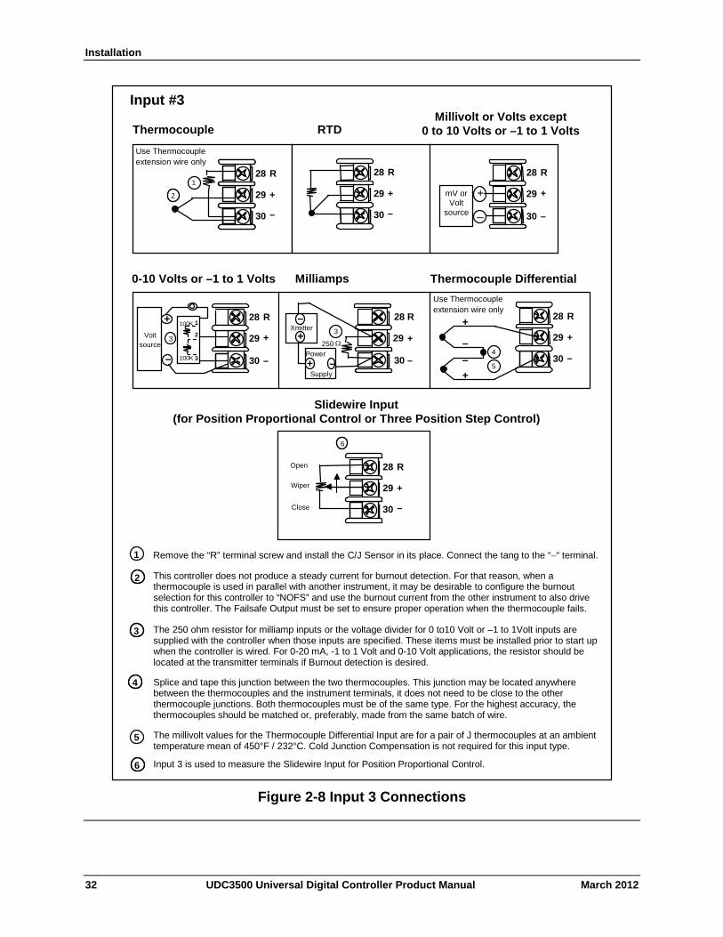
Installation
22
23
24
Use Thermocouple extension wire only
Thermocouple RTD
source
Milliamps
–
++
R
–
1 2
3 –
Volt source
+ 100K
100K Power
Supply–+
Xmitter+
–
250
22
23
24
+
R
–
22
23
24
+
R
–
1
22
23
24
+
R
–
1
Input #2
mV or Volt
source
22
23
24
Use Thermocouple extension wire only
+
R
–
Thermocouple Differential
+
+
–
–2
3 22
23
24
+
R
–
Slidewire Input (for Position Proportional Control or Three Position Step Contro
22
23
24
+
R
–
Open
Wiper
Close
4
xxxx
The 250 ohm resistor for milliamp inputs or the voltage divider for 0-10 Volt inputs are supplied with the controller when those inputs are specified. These items must be installed prior to start up when the controller is wire d. For 0-20 mA applications, the resistor should be located at the transmitter terminals if Burnout detection is desired.
1
Splice and tape this junction between the two thermocouples. Thi s junction may be located anywhere between the thermocouples and the instrument terminals, it does not need to be close to the other thermocou ple junctions. Both thermocouples must be of the same type. For bes t accuracy, the two thermocouples should be matched or, preferably , made from the same batch of wire.
2
This controller does not produce a steady current for burnout detection. For that rea son, when a thermocouple is used in parallel with another instrument, it may be desirable to configure the burnout selection for this controller to “NOFS” and use the burnout current from the other instrument to also drive this controller.
3
28
29
30
Use Thermocouple extension wire only
Thermocouple RTD
source
Milliamps
–
++
R
–
1 2
3 –
Volt source
+ 100K
100K Power
Supply–+
Xmitter+
–
250
28
29
30
+
R
–
28
29
30
+
R
–
3
28
29
30
+
R
–
3
Input #3
mV or Volt
source
28
29
30
Use Thermocouple extension wire only
+
R
–
Thermocouple Differential
+
+
–
–4
1 28
29
30
+
R
–
Slidewire Input (for Position Proportional Control or Three Position Step Control)
28
29
30
+
R
–
Open
Wiper
Close
46
Input 3 is used to measure the Slidewire Input for Position Proportional Control.
5
3 2
6
Millivolt or Volts except 0 to 10 Volts or –1 to 1 Volts
0-10 Volts or –1 to 1 Volts
3
4
1
The millivolt values for the Thermocouple Differential Input are for a pair of J thermocouples at an ambient temperature mean of 450°F / 232°C. Cold Junction Compensation is not required for this input type.
5
2 This controller does not produce a steady current for burnout detection. For that reason, when a thermocouple is used in parallel with another instrument, it may be desirable to configure the burnout selection for this controller to “NOFS” and use the burnout current from the other instrument to also drive this controller. The Failsafe Output must be set to ensure proper operation when the thermocouple fails.
Splice and tape this junction between the two thermocouples. This junction may be located anywhere between the thermocouples and the instrument terminals, it does not need to be close to the other thermocouple junctions. Both thermocouples must be of the same type. For the highest accuracy, the thermocouples should be matched or, preferably, made from the same batch of wire.
Remove the “R” terminal screw and install the C/J Sensor in its place. Connect the tang to the ““ terminal.
The 250 ohm resistor for milliamp inputs or the voltage divider for 0 to10 Volt or –1 to 1Volt inputs are supplied with the controller when those inputs are specified. These items must be installed prior to start up when the controller is wired. For 0-20 mA, -1 to 1 Volt and 0-10 Volt applications, the resistor should be located at the transmitter terminals if Burnout detection is desired.
Figure 2-8 Input 3 Connections
32 UDC3500 Universal Digital Controller Product Manual March 2012
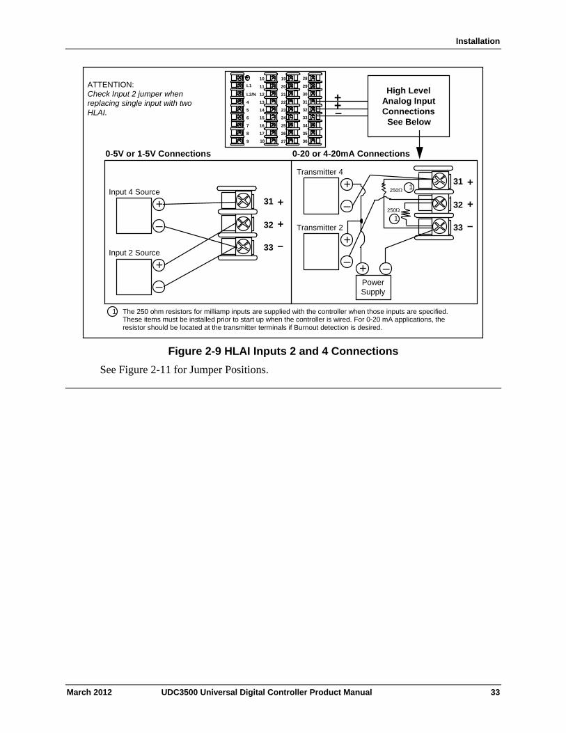
Installation
19
20
21
22
23
24
25
26
27
10
11
12
13
14
15
16
17
L1
L2/N
4
5
6
7
8
9
+ + –
0-5V or 1-5V Connections 0-20 or 4-20mA Connections
250
31
32
33
+
+
–
1
1
31
32
33
+
+
–
High Level Analog Input Connections
See Below
Input 4 Source
Input 2 Source
–
+
–
+
250
Transmitter 4
Transmitter 2
–
+
–
+
Power Supply
1
– +
ATTENTION: Check Input 2 jumper when replacing single input with two HLAI.
28
29
30
31
32
33
34
35
3618
The 250 ohm resistors for milliamp inputs are supplied with the controller when those inputs are specified. These items must be installed prior to start up when the controller is wired. For 0-20 mA applications, the resistor should be located at the transmitter terminals if Burnout detection is desired.
Figure 2-9 HLAI Inputs 2 and 4 Connections
See Figure 2-11 for Jumper Positions.
March 2012 UDC3500 Universal Digital Controller Product Manual 33
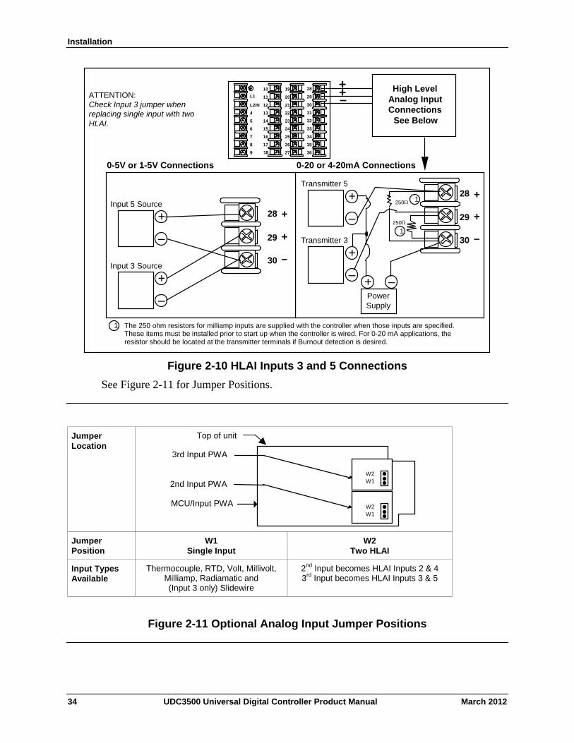
Installation
19
20
21
22
23
24
25
26
27
10
11
12
13
14
15
16
17
L1
L2/N
4
5
6
7
8
9
+ + –
0-5V or 1-5V Connections 0-20 or 4-20mA Connections
250
28
29
30
+
+
–
1
1
28
29
30
+
+
–
High Level Analog Input Connections
See Below
Input 5 Source
Input 3 Source
–
+
–
+
250
Transmitter 5
Transmitter 3
–
+
–
+
Power Supply
1
– +
ATTENTION: Check Input 3 jumper when replacing single input with two HLAI.
28
29
30
31
32
33
34
35
3618
The 250 ohm resistors for milliamp inputs are supplied with the controller when those inputs are specified. These items must be installed prior to start up when the controller is wired. For 0-20 mA applications, the resistor should be located at the transmitter terminals if Burnout detection is desired.
Figure 2-10 HLAI Inputs 3 and 5 Connections
See Figure 2-11 for Jumper Positions.
Jumper Location
W2W1
MCU/Input PWA
2nd Input PWA W2W1
3rd Input PWA
Top of unit
Jumper Position
W1 Single Input
W2 Two HLAI
Input Types Available
Thermocouple, RTD, Volt, Millivolt, Milliamp, Radiamatic and (Input 3 only) Slidewire
2nd Input becomes HLAI Inputs 2 & 4 3rd Input becomes HLAI Inputs 3 & 5
Figure 2-11 Optional Analog Input Jumper Positions
34 UDC3500 Universal Digital Controller Product Manual March 2012
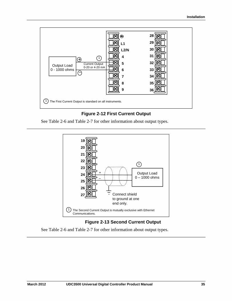
Installation
The First Current Output is standard on all instruments.
+
Output Load 0 - 1000 ohms
–
Current Output 0-20 or 4-20 mA
1
L1
L2/N
4
5
7
8
9
28
29
30
31
32
33
34
35
36
6
1
Figure 2-12 First Current Output
See Table 2-6 and Table 2-7 for other information about output types.
+ _
Output Load 0 – 1000 ohms
Connect shield to ground at one end only.
19
20
21
22
23
24
25
26
27
The Second Current Output is mutually exclusive with Ethernet Communications.
1
1
Figure 2-13 Second Current Output
See Table 2-6 and Table 2-7 for other information about output types.
March 2012 UDC3500 Universal Digital Controller Product Manual 35
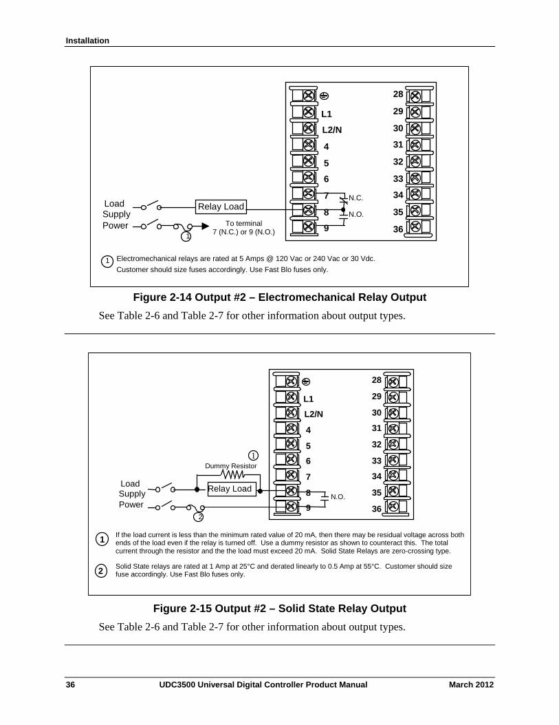
Installation
1 Electromechanical relays are rated at 5 Amps @ 120 Vac or 240 Vac or 30 Vdc.
Customer should size fuses accordingly. Use Fast Blo fuses only.
To terminal 7 (N.C.) or 9 (N.O.)
Relay Load
1
Load Supply Power
L1
L2/N
4
5
7
8
9
28
29
30
31
32
33
34
35
36
6
N.C.
N.O.
Figure 2-14 Output #2 – Electromechanical Relay Output
See Table 2-6 and Table 2-7 for other information about output types.
If the load current is less than the minimum rated value of 20 mA, then there may be residual voltage across both ends of the load even if the relay is turned off. Use a dummy resistor as shown to counteract this. The total current through the resistor and the the load must exceed 20 mA. Solid State Relays are zero-crossing type.
2
1
Solid State relays are rated at 1 Amp at 25°C and derated linearly to 0.5 Amp at 55°C. Customer should size fuse accordingly. Use Fast Blo fuses only.
L1
L2/N
4
5
7
8
9
28
29
30
31
32
33
34
35
36
6
N.O.
2
Relay Load Load Supply Power
Dummy Resistor
1
Figure 2-15 Output #2 – Solid State Relay Output
See Table 2-6 and Table 2-7 for other information about output types.
36 UDC3500 Universal Digital Controller Product Manual March 2012
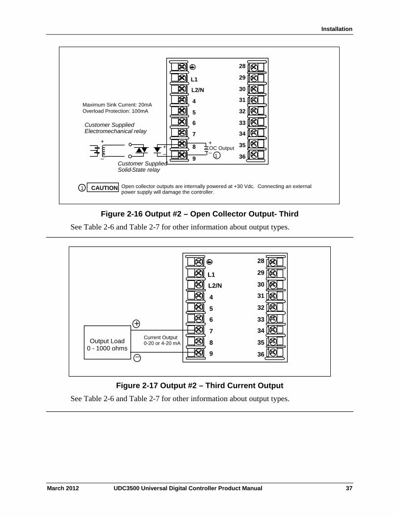
Installation
L1
L2/N
4
5
7
8
9
28
29
30
31
32
33
34
35
36
6
–
++–
OC Output
1
+
–
Customer SuppliedElectromechanical relay
Customer SuppliedSolid-State relay
CAUTION Open collector outputs are internally powered at +30 Vdc. Connecting an external power supply will damage the controller.
1
Maximum Sink Current: 20mAOverload Protection: 100mA
L1
L2/N
4
5
7
8
9
28
29
30
31
32
33
34
35
36
6
–
++–
OC Output
1
+
–
Customer SuppliedElectromechanical relay
Customer SuppliedSolid-State relay
CAUTION Open collector outputs are internally powered at +30 Vdc. Connecting an external power supply will damage the controller.
11
Maximum Sink Current: 20mAOverload Protection: 100mA
Figure 2-16 Output #2 – Open Collector Output- Third
See Table 2-6 and Table 2-7 for other information about output types.
+
Output Load 0 - 1000 ohms
–
L1
L2/N
4
5
7
8
9
28
29
30
31
32
33
34
35
36
6
Current Output 0-20 or 4-20 mA
Figure 2-17 Output #2 – Third Current Output
See Table 2-6 and Table 2-7 for other information about output types.
March 2012 UDC3500 Universal Digital Controller Product Manual 37
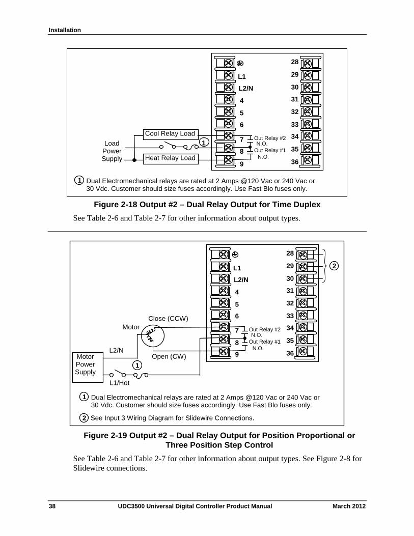
Installation
L1
L2/N
4
5
7
8
9
28
29
30
31
32
33
34
35
36
6 Cool Relay Load
Load Power Supply Heat Relay Load
Out Relay #1 N.O.
N.O.Out Relay #2
1 Dual Electromechanical relays are rated at 2 Amps @120 Vac or 240 Vac or 30 Vdc. Customer should size fuses accordingly. Use Fast Blo fuses only.
1
Figure 2-18 Output #2 – Dual Relay Output for Time Duplex
See Table 2-6 and Table 2-7 for other information about output types.
L1/Hot
1 Dual Electromechanical relays are rated at 2 Amps @120 Vac or 240 Vac or 30 Vdc. Customer should size fuses accordingly. Use Fast Blo fuses only.
See Input 3 Wiring Diagram for Slidewire Connections. 2
L1
L2/N
4
5
7
8
9
28
29
30
31
32
33
34
35
36
6
Motor Power Supply
Close (CCW)
Open (CW) L2/N
1
Out Relay #1 N.O.
N.O.Out Relay #2
2
Motor
Figure 2-19 Output #2 – Dual Relay Output for Position Proportional or Three Position Step Control
See Table 2-6 and Table 2-7 for other information about output types. See Figure 2-8 for Slidewire connections.
38 UDC3500 Universal Digital Controller Product Manual March 2012
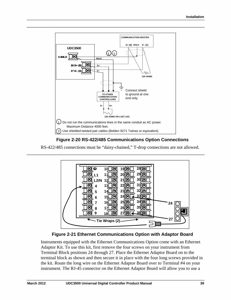
Installation
1 Do not run the communications lines in the same conduit as AC power.
D–
D+
COMMUNICATION MASTER
D+ (B) SHLD D– (A)
120 OHMS
TO OTHER COMMUNICATION
CONTROLLERS
D+D–
120 OHMS ON LAST LEG
Connect shieldto ground at oneend only.
SHLD
2 Use shielded twisted pair cables (Belden 9271 Twinax or equivalent).
21
26 D+ (B)
27 D– (A)
4 SHLD
UDC3500
Maximum Distance 4000 feet.1 Do not run the communications lines in the same conduit as AC power.
D–
D+
COMMUNICATION MASTER
D+ (B) SHLD D– (A)
120 OHMS
TO OTHER COMMUNICATION
CONTROLLERS
D+D–
120 OHMS ON LAST LEG
Connect shieldto ground at oneend only.
SHLD
2 Use shielded twisted pair cables (Belden 9271 Twinax or equivalent).
21
26 D+ (B)
27 D– (A)
4 SHLD
UDC3500
1
26 D+ (B)
27 D– (A)
4 SHLD
UDC3500
26 D+ (B)
27 D– (A)
4 SHLD4 SHLD
UDC3500
Maximum Distance 4000 feet.
Figure 2-20 RS-422/485 Communications Option Connections
RS-422/485 connections must be “daisy-chained,” T-drop connections are not allowed.
Ethernet Adaptor
Ethernet Cable To Hub or
4
5
6
7
8
10
11
12
13
14
15
16
17
L1
L2/N22
23
24
25
26
2718
19
20
2131
32
33
34
35
36
28
29
30
24
27
9
Tie Wraps (2)
Figure 2-21 Ethernet Communications Option with Adaptor Board
Instruments equipped with the Ethernet Communications Option come with an Ethernet Adaptor Kit. To use this kit, first remove the four screws on your instrument from Terminal Block positions 24 through 27. Place the Ethernet Adaptor Board on to the terminal block as shown and then secure it in place with the four long screws provided in the kit. Route the long wire on the Ethernet Adaptor Board over to Terminal #4 on your instrument. The RJ-45 connector on the Ethernet Adaptor Board will allow you to use a
March 2012 UDC3500 Universal Digital Controller Product Manual 39
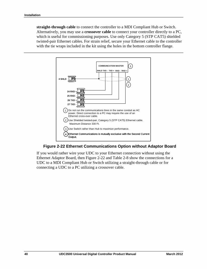
Installation
straight-through cable to connect the controller to a MDI Compliant Hub or Switch. Alternatively, you may use a crossover cable to connect your controller directly to a PC, which is useful for commissioning purposes. Use only Category 5 (STP CAT5) shielded twisted-pair Ethernet cables. For strain relief, secure your Ethernet cable to the controller with the tie wraps included in the kit using the holes in the bottom controller flange.
26 TXD +
4 SHLD
3
25 RXD -
24 RXD +
Do not run the communications lines in the same conduit as AC power. Direct connection to a PC may require the use of an Ethernet cross-over cable.
COMMUNICATION MASTER
RXD +
27 TXD -
Use Shielded twisted-pair, Category 5 (STP CAT5) Ethernet cable.
Use Switch rather than Hub to maximize performance.
RXD -TXD +TXD -SHLD
2
1
3
1
2
4 Ethernet Communications is mutually exclusive with the Second Current Output.
Maximum Distance 330 Ft.
26 TXD +
4 SHLD
3
25 RXD -
24 RXD +
Do not run the communications lines in the same conduit as AC power. Direct connection to a PC may require the use of an Ethernet cross-over cable.
COMMUNICATION MASTER
RXD +
27 TXD -
Use Shielded twisted-pair, Category 5 (STP CAT5) Ethernet cable.
Use Switch rather than Hub to maximize performance.
RXD -TXD +TXD -SHLD
2
1
3
1
2
4 Ethernet Communications is mutually exclusive with the Second Current Output.
4 Ethernet Communications is mutually exclusive with the Second Current Output.
Maximum Distance 330 Ft.
Figure 2-22 Ethernet Communications Option without Adaptor Board
If you would rather wire your UDC to your Ethernet connection without using the Ethernet Adaptor Board, then Figure 2-22 and Table 2-8 show the connections for a UDC to a MDI Compliant Hub or Switch utilizing a straight-through cable or for connecting a UDC to a PC utilizing a crossover cable.
40 UDC3500 Universal Digital Controller Product Manual March 2012
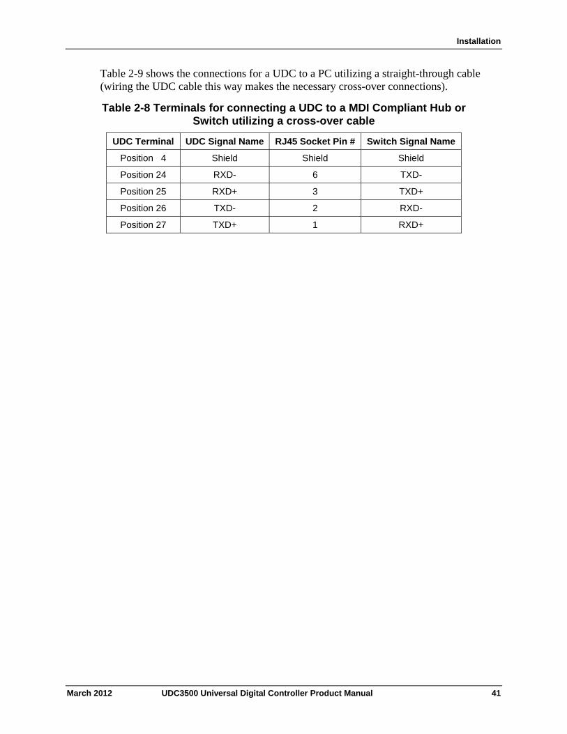
Installation
Table 2-9 shows the connections for a UDC to a PC utilizing a straight-through cable (wiring the UDC cable this way makes the necessary cross-over connections).
Table 2-8 Terminals for connecting a UDC to a MDI Compliant Hub or Switch utilizing a cross-over cable
UDC Terminal UDC Signal Name RJ45 Socket Pin # Switch Signal Name
Position 4 Shield Shield Shield
Position 24 RXD- 6 TXD-
Position 25 RXD+ 3 TXD+
Position 26 TXD- 2 RXD-
Position 27 TXD+ 1 RXD+
March 2012 UDC3500 Universal Digital Controller Product Manual 41
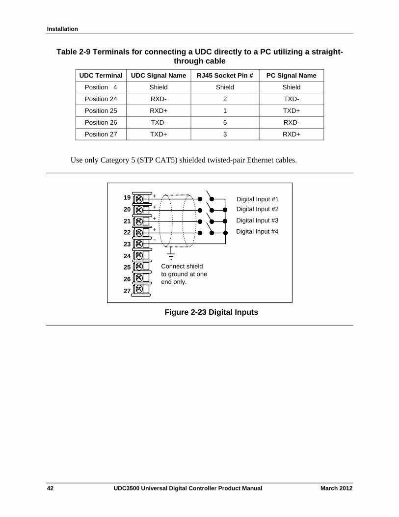
Installation
Table 2-9 Terminals for connecting a UDC directly to a PC utilizing a straight-through cable
UDC Terminal UDC Signal Name RJ45 Socket Pin # PC Signal Name
Position 4 Shield Shield Shield
Position 24 RXD- 2 TXD-
Position 25 RXD+ 1 TXD+
Position 26 TXD- 6 RXD-
Position 27 TXD+ 3 RXD+
Use only Category 5 (STP CAT5) shielded twisted-pair Ethernet cables.
Connect shield to ground at one end only.
_
Digital Input #1 +
Digital Input #2 +
Digital Input #3 +
Digital Input #4 +
19
20
21
22
23
24
25
26
27
Figure 2-23 Digital Inputs
42 UDC3500 Universal Digital Controller Product Manual March 2012
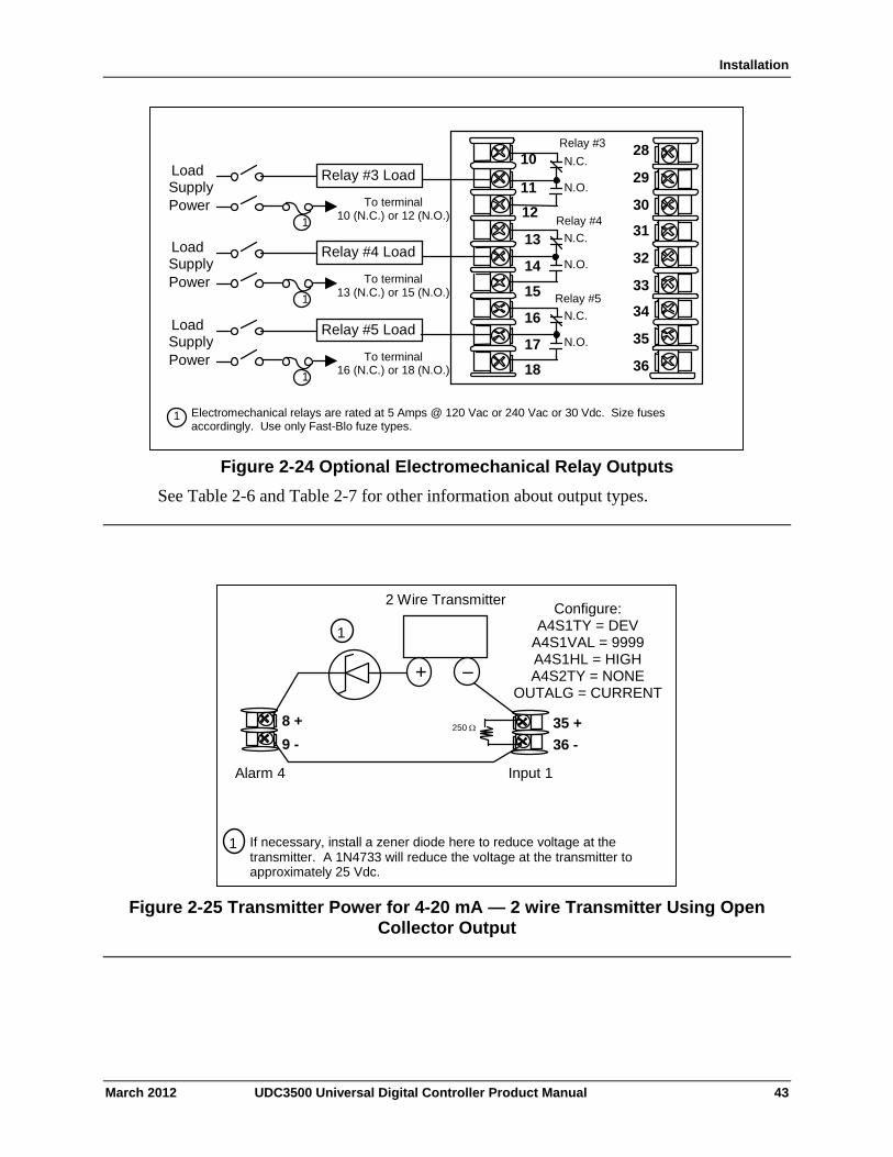
Installation
March 2012 UDC3500 Universal Digital Controller Product Manual 43
1 Electromechanical relays are rated at 5 Amps @ 120 Vac or 240 Vac or 30 Vdc. Size fuses accordingly. Use only Fast-Blo fuze types.
To terminal 16 (N.C.) or 18 (N.O.)
Relay #5 Load
1
Load Supply Power
28
29
30
31
32
33
34
35
36
N.C.
N.O.
11
12
13
14
16
17
18
15
10
To terminal 13 (N.C.) or 15 (N.O.)
Relay #4 Load
1
Load Supply Power
N.C.
N.O.
To terminal 10 (N.C.) or 12 (N.O.)
Relay #3 Load
1
Load Supply Power
N.C.
N.O.
Relay #3
Relay #4
Relay #5
Figure 2-24 Optional Electromechanical Relay Outputs
See Table 2-6 and Table 2-7 for other information about output types.
Configure:A4S1TY = NONE A4S2TY = NONE
2 Wire Transmitter
_ +
Input 1 Alarm 4
250 35 +
36 -
8 +
9 -
If necessary, install a zener diode here to reduce voltage at the transmitter. A 1N4733 will reduce the voltage at the transmitter to approximately 25 Vdc.
1
1
Figure 2-25 Transmitter Power for 4-20 mA — 2 wire Transmitter Using Open Collector Output
Configure: A4S1TY = DEV
A4S1VAL = 9999 A4S1HL = HIGH A4S2TY = NONE
OUTALG = CURRENT
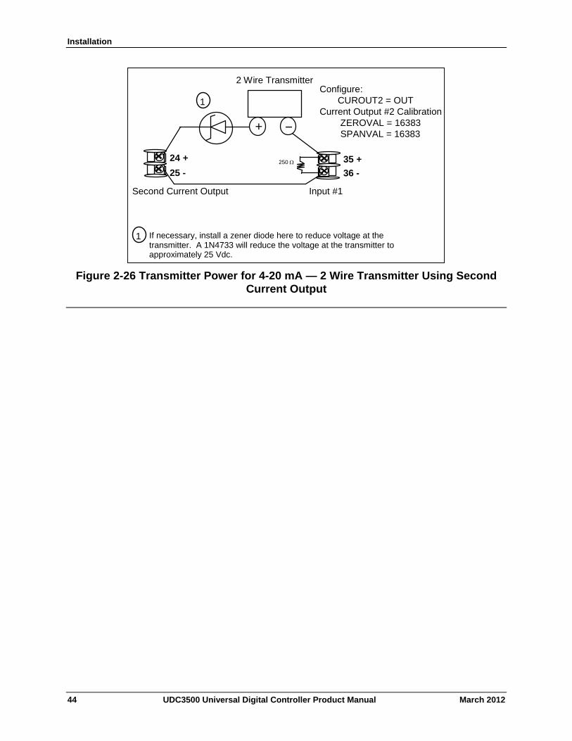
Installation
2 Wire Transmitter
_ +
Input #1 Second Current Output
250 35 +
36 -
24 +
25 -
Configure: CUROUT2 = OUT Current Output #2 Calibration ZEROVAL = 16383 SPANVAL = 16383
If necessary, install a zener diode here to reduce voltage at the transmitter. A 1N4733 will reduce the voltage at the transmitter to approximately 25 Vdc.
1
1
Figure 2-26 Transmitter Power for 4-20 mA — 2 Wire Transmitter Using Second Current Output
44 UDC3500 Universal Digital Controller Product Manual March 2012
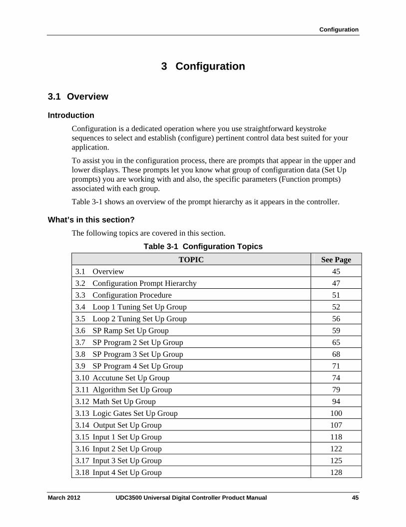
Configuration
3 Configuration
3.1 Overview
Introduction
Configuration is a dedicated operation where you use straightforward keystroke sequences to select and establish (configure) pertinent control data best suited for your application.
To assist you in the configuration process, there are prompts that appear in the upper and lower displays. These prompts let you know what group of configuration data (Set Up prompts) you are working with and also, the specific parameters (Function prompts) associated with each group.
Table 3-1 shows an overview of the prompt hierarchy as it appears in the controller.
What’s in this section?
The following topics are covered in this section.
Table 3-1 Configuration Topics
TOPIC See Page
3.1 Overview 45
3.2 Configuration Prompt Hierarchy 47
3.3 Configuration Procedure 51
3.4 Loop 1 Tuning Set Up Group 52
3.5 Loop 2 Tuning Set Up Group 56
3.6 SP Ramp Set Up Group 59
3.7 SP Program 2 Set Up Group 65
3.8 SP Program 3 Set Up Group 68
3.9 SP Program 4 Set Up Group 71
3.10 Accutune Set Up Group 74
3.11 Algorithm Set Up Group 79
3.12 Math Set Up Group 94
3.13 Logic Gates Set Up Group 100
3.14 Output Set Up Group 107
3.15 Input 1 Set Up Group 118
3.16 Input 2 Set Up Group 122
3.17 Input 3 Set Up Group 125
3.18 Input 4 Set Up Group 128
March 2012 UDC3500 Universal Digital Controller Product Manual 45
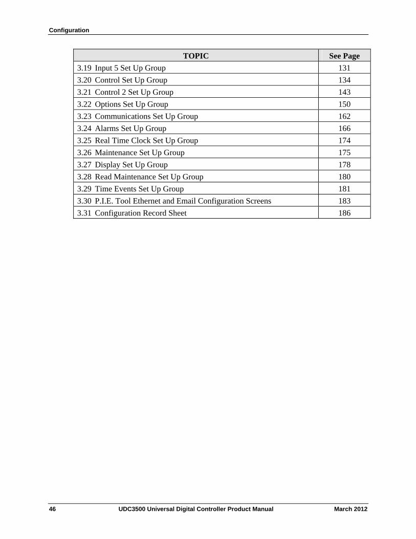
Configuration
46 UDC3500 Universal Digital Controller Product Manual March 2012
TOPIC See Page
3.19 Input 5 Set Up Group 131
3.20 Control Set Up Group 134
3.21 Control 2 Set Up Group 143
3.22 Options Set Up Group 150
3.23 Communications Set Up Group 162
3.24 Alarms Set Up Group 166
3.25 Real Time Clock Set Up Group 174
3.26 Maintenance Set Up Group 175
3.27 Display Set Up Group 178
3.28 Read Maintenance Set Up Group 180
3.29 Time Events Set Up Group 181
3.30 P.I.E. Tool Ethernet and Email Configuration Screens 183
3.31 Configuration Record Sheet 186
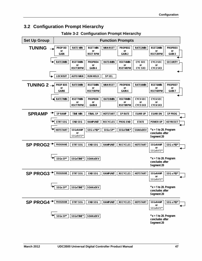
Configuration
3.2 Configuration Prompt Hierarchy
Table 3-2 Configuration Prompt Hierarchy
Set Up Group Function Prompts
TUNING PROP BD or
GAIN
RATE MIN RSET MIN or
RSET RPM
MAN RSET PROPBD2 or
GAIN 2
RATE2MIN RSET2MIN or
RSET2RPM
PROPBD3 or
GAIN 3
RATE3MIN RSET3MIN or
RSET3RPM
PROPBD4 or
GAIN 4
RATE4MIN RSET4MIN or
RSET4RPM
CYC SEC or
CYC SX3
CYC2 SEC or
CYC2 SX3
SECURITY
LOCKOUT AUTO MAN RUN HOLD SP SEL
TUNING 2 PROP BD5 or
GAIN5
RATE5MIN RSET5MIN or
RSET5RPM
MAN RSET PROPBD6 or
GAIN 6
RATE6MIN RSET6MIN or
RSET6RPM
PROPBD7 or
GAIN 7
RATE7MIN RSET7MIN or
RSET7RPM
PROPBD8 or
GAIN 8
RATE8MIN RSET8MIN or
RSET8RPM
CYC5 SEC or
CYC5 SX3
CYC6 SEC or
CYC6 SX3
SPRAMP SP RAMP TIME MIN FINAL SP HOTSTART SP RATE EU/HR UP EU/HR DN SP PROG
STRT SEG END SEG RAMPUNIT RECYCLES PROG END STATE POWER UP KEYRESET
HOTSTART * x = 1 to 20. Program concludes after Segment 20
SEGxRAMP or
SEGxRATE*
SEG x PID* SEGx SP* SEGxTIME* SOAKxDEV
SP PROG2 PROGRAM2 STRT SEG END SEG RAMPUNIT RECYCLES HOTSTART SEGxRAMP or
SEGxRATE*
SEG x PID*
SEGx SP* SEGxTIME* SOAKxDEV * x = 1 to 20. Program concludes after Segment 20
SP PROG3 PROGRAM3 STRT SEG END SEG RAMPUNIT RECYCLES HOTSTART SEGxRAMP or
SEGxRATE*
SEG x PID*
SEGx SP* SEGxTIME* SOAKxDEV * x = 1 to 20. Program concludes after Segment 20
SP PROG4 PROGRAM4 STRT SEG END SEG RAMPUNIT RECYCLES HOTSTART SEGxRAMP or
SEGxRATE*
SEG x PID*
SEGx SP* SEGxTIME* SOAKxDEV * x = 1 to 20. Program concludes after Segment 20
March 2012 UDC3500 Universal Digital Controller Product Manual 47
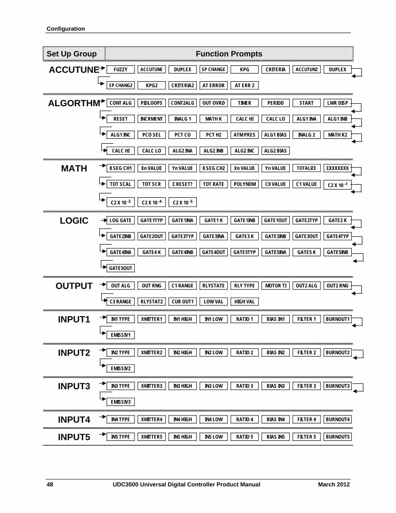
Configuration
48 UDC3500 Universal Digital Controller Product Manual March 2012
Set Up Group Function Prompts
ACCUTUNE FUZZY ACCUTUNE DUPLEX SP CHANGE KPG CRITERIA ACCUTUN2 DUPLEX
SP CHANG2 KPG2 CRITERIA2 AT ERROR AT ERR 2
ALGORTHM CONT ALG PIDLOOPS CONT2ALG OUT OVRD TIMER PERIOD START LWR DISP
RESET INCRMENT INALG 1 MATH K CALC HI CALC LO ALG1 INA ALG1 INB
ALG1 INC PCO SEL PCT CO PCT H2 ATM PRES ALG1 BIAS INALG 2 MATH K2
CALC HI CALC LO ALG2 INA ALG2 INB ALG2 INC ALG2 BIAS
MATH 8 SEG CH1 Xn VALUE Yn VALUE 8 SEG CH2 Xn VALUE Yn VALUE TOTALIZE ΣXXXXXXX
TOT SCAL TOT SCR Σ RESET? TOT RATE POLYNOM C0 VALUE C1 VALUE C2 X 10 -1
C2 X 10 -3 C2 X 10 -4 C2 X 10 -5
LOGIC LOG GATE GATE1TYP GATE1INA GATE1 K GATE1INB GATE1OUT GATE2TYP GATE2 K
GATE2INB GATE2OUT GATE3TYP GATE3INA GATE3 K GATE3INB GATE3OUT GATE4TYP
GATE4INA GATE4 K GATE4INB GATE4OUT GATE5TYP GATE5INA GATE5 K GATE5INB
GATE5OUT
OUTPUT OUT ALG OUT RNG C1 RANGE RLYSTATE RLY TYPE MOTOR TI OUT2 ALG OUT2 RNG
C3 RANGE RLYSTAT2 CUR OUT1 LOW VAL HIGH VAL
INPUT1 IN1 TYPE XMITTER1 IN1 HIGH IN1 LOW RATIO 1 BIAS IN1 FILTER 1 BURNOUT1
EMISSIV1
INPUT2 IN2 TYPE XMITTER2 IN2 HIGH IN2 LOW RATIO 2 BIAS IN2 FILTER 2 BURNOUT2
EMISSIV2
INPUT3 IN3 TYPE XMITTER3 IN3 HIGH IN3 LOW RATIO 3 BIAS IN3 FILTER 3 BURNOUT3
EMISSIV3
INPUT4 IN4 TYPE XMITTER4 IN4 HIGH IN4 LOW RATIO 4 BIAS IN4 FILTER 4 BURNOUT4
INPUT5 IN5 TYPE XMITTER5 IN5 HIGH IN5 LOW RATIO 5 BIAS IN5 FILTER 5 BURNOUT5
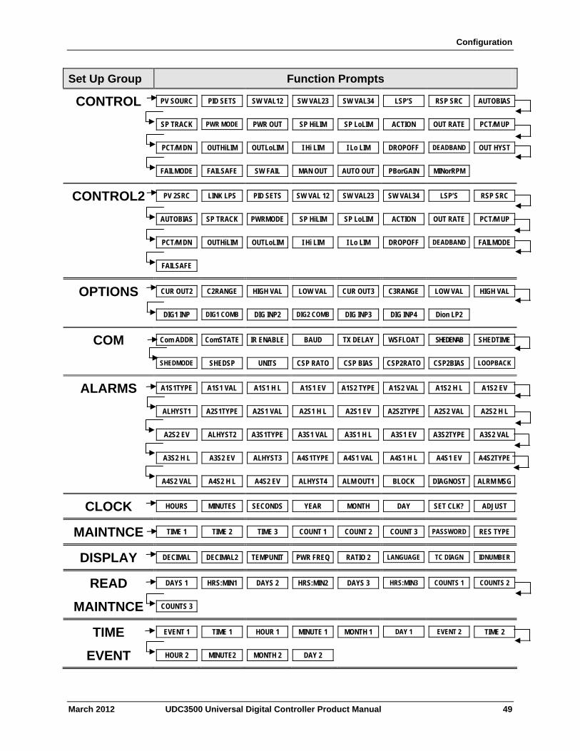
Configuration
Set Up Group Function Prompts
CONTROL PV SOURC PID SETS SW VAL12 SW VAL23 SW VAL34 LSP’S RSP SRC AUTOBIAS
SP TRACK PWR MODE PWR OUT SP HiLIM SP LoLIM ACTION OUT RATE PCT/M UP
PCT/M DN OUTHiLIM OUTLoLIM I Hi LIM I Lo LIM DROPOFF DEADBAND OUT HYST
FAILMODE FAILSAFE SW FAIL MAN OUT AUTO OUT PBorGAIN MINorRPM
CONTROL2 PV 2SRC LINK LPS PID SETS SW VAL 12 SW VAL23 SW VAL34 LSP’S RSP SRC
AUTOBIAS SP TRACK PWRMODE SP HiLIM SP LoLIM ACTION OUT RATE PCT/M UP
PCT/M DN OUTHiLIM OUTLoLIM I Hi LIM I Lo LIM DROPOFF DEADBAND FAILMODE
FAILSAFE
OPTIONS CUR OUT2 C2RANGE HIGH VAL LOW VAL CUR OUT3 C3RANGE LOW VAL HIGH VAL
DIG1 INP DIG1 COMB DIG INP2 DIG2 COMB DIG INP3 DIG INP4 Dion LP2
COM Com ADDR ComSTATE IR ENABLE BAUD TX DELAY WSFLOAT SHEDENAB SHEDTIME
SHEDMODE SHEDSP UNITS CSP RATO CSP BIAS CSP2RATO CSP2BIAS LOOPBACK
ALARMS A1S1TYPE A1S1 VAL A1S1 H L A1S1 EV A1S2 TYPE A1S2 VAL A1S2 H L A1S2 EV
A2S1TYPE A2S1 VAL ALHYST1 A2S1 H L A2S1 EV A2S2TYPE A2S2 VAL A2S2 H L
A2S2 EV ALHYST2 A3S1TYPE A3S1 VAL A3S1 H L A3S1 EV A3S2TYPE A3S2 VAL
A3S2 H L A3S2 EV ALHYST3 A4S1TYPE A4S1 VAL A4S1 H L A4S1 EV A4S2TYPE
A4S2 VAL A4S2 H L A4S2 EV ALHYST4 ALM OUT1 BLOCK DIAGNOST ALRM MSG
CLOCK HOURS MINUTES SECONDS YEAR MONTH DAY SET CLK? ADJUST
MAINTNCE TIME 1 TIME 2 TIME 3 COUNT 1 COUNT 2 COUNT 3 PASSWORD RES TYPE
DISPLAY DECIMAL DECIMAL2 TEMPUNIT PWR FREQ RATIO 2 LANGUAGE TC DIAGN IDNUMBER
READ DAYS 1 HRS:MIN1 DAYS 2 HRS:MIN2 DAYS 3 HRS:MIN3 COUNTS 1 COUNTS 2
MAINTNCE COUNTS 3
TIME EVENT 1 TIME 1 HOUR 1 MINUTE 1 MONTH 1 DAY 1 EVENT 2 TIME 2
EVENT HOUR 2 MINUTE2 MONTH 2 DAY 2
March 2012 UDC3500 Universal Digital Controller Product Manual 49
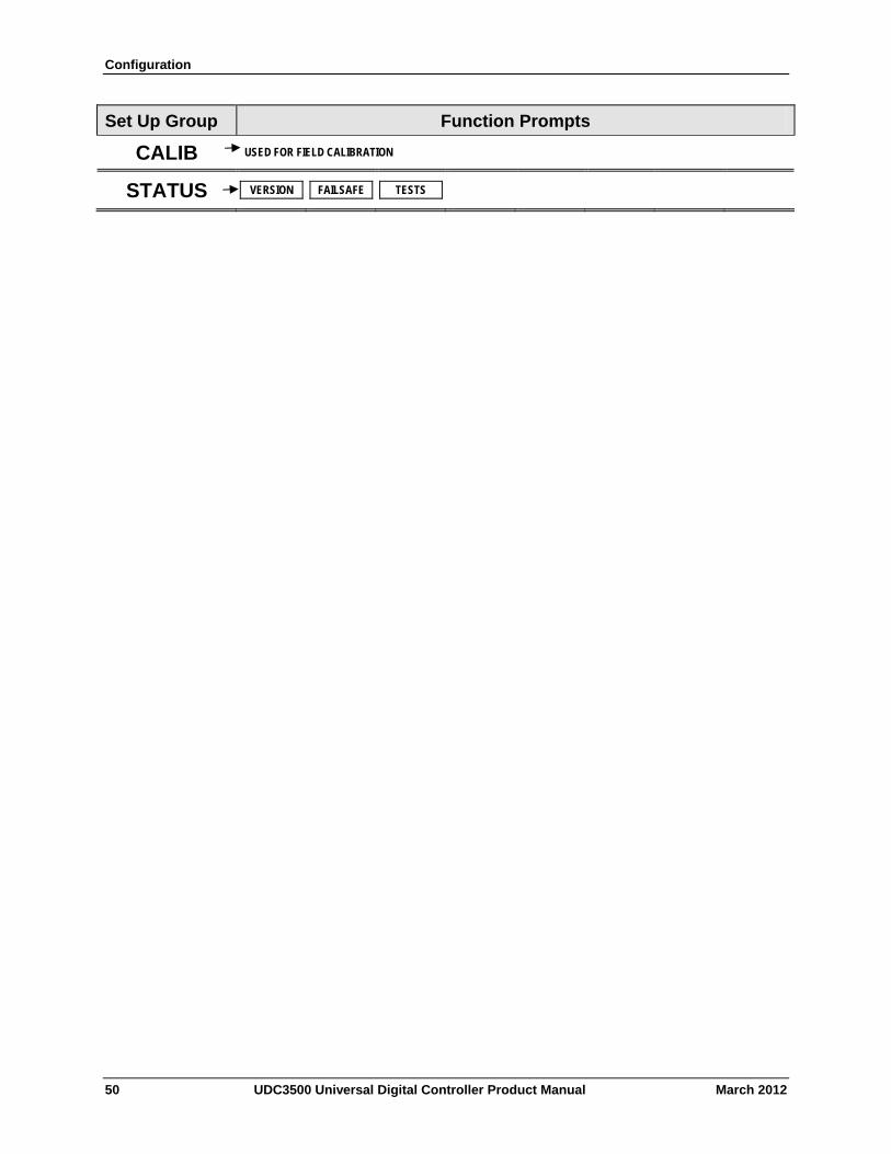
Configuration
Set Up Group Function Prompts
CALIB USED FOR FIELD CALIBRATION
STATUS VERSION FAILSAFE TESTS
50 UDC3500 Universal Digital Controller Product Manual March 2012
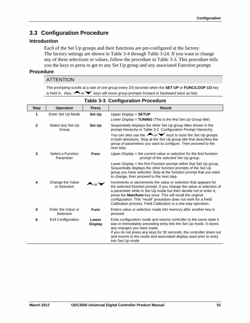
Configuration
3.3 Configuration Procedure Introduction
Each of the Set Up groups and their functions are pre-configured at the factory. The factory settings are shown in Table 3-4 through Table 3-24. If you want to change any of these selections or values, follow the procedure in Table 3-3. This procedure tells you the keys to press to get to any Set Up group and any associated Function prompt.
Procedure
ATTENTION
The prompting scrolls at a rate of one group every 2/3 seconds when the SET UP or FUNC/LOOP 1/2 key
is held in. Also, or keys will move group prompts forward or backward twice as fast.
Table 3-3 Configuration Procedure
Step Operation Press Result
1 Enter Set Up Mode Set Up Upper Display = SETUP
Lower Display = TUNING (This is the first Set Up Group title)
Sequentially displays the other Set Up group titles shown in the prompt hierarchy in Table 3-2 Configuration Prompt Hierarchy.
You can also use the or keys to scan the Set Up groups in both directions. Stop at the Set Up group title that describes the group of parameters you want to configure. Then proceed to the next step.
2 Select any Set Up Group
Set Up
3 Select a Function Parameter
Func Upper Display = the current value or selection for the first function prompt of the selected Set Up group.
Lower Display = the first Function prompt within that Set Up group. Sequentially displays the other function prompts of the Set Up group you have selected. Stop at the function prompt that you want to change, then proceed to the next step.
4 Change the Value or Selection
or Increments or decrements the value or selection that appears for the selected function prompt. If you change the value or selection of a parameter while in Set Up mode but then decide not to enter it, press the Man/Auto key once. This will recall the original configuration. This “recall” procedure does not work for a Field Calibration process. Field Calibration is a one-way operation.
Enters value or selection made into memory after another key is pressed.
5 Enter the Value or Selection
Func
6 Exit Configuration Lower Display
Exits configuration mode and returns controller to the same state it was in immediately preceding entry into the Set Up mode. It stores any changes you have made. If you do not press any keys for 30 seconds, the controller times out and reverts to the mode and associated display used prior to entry into Set Up mode.
March 2012 UDC3500 Universal Digital Controller Product Manual 51
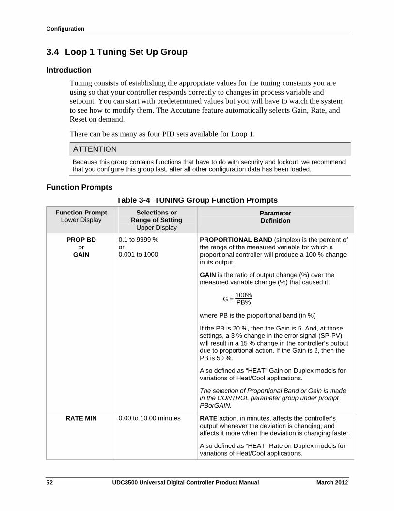
Configuration
3.4 Loop 1 Tuning Set Up Group
Introduction
Tuning consists of establishing the appropriate values for the tuning constants you are using so that your controller responds correctly to changes in process variable and setpoint. You can start with predetermined values but you will have to watch the system to see how to modify them. The Accutune feature automatically selects Gain, Rate, and Reset on demand.
There can be as many as four PID sets available for Loop 1.
ATTENTION
Because this group contains functions that have to do with security and lockout, we recommend that you configure this group last, after all other configuration data has been loaded.
Function Prompts
Table 3-4 TUNING Group Function Prompts
Function Prompt Lower Display
Selections or Range of Setting
Upper Display
Parameter Definition
PROP BD or
GAIN
0.1 to 9999 % or 0.001 to 1000
PROPORTIONAL BAND (simplex) is the percent of the range of the measured variable for which a proportional controller will produce a 100 % change in its output.
GAIN is the ratio of output change (%) over the measured variable change (%) that caused it.
G = 100%PB%
where PB is the proportional band (in %)
If the PB is 20 %, then the Gain is 5. And, at those settings, a 3 % change in the error signal (SP-PV) will result in a 15 % change in the controller’s output due to proportional action. If the Gain is 2, then the PB is 50 %.
Also defined as “HEAT” Gain on Duplex models for variations of Heat/Cool applications.
The selection of Proportional Band or Gain is made in the CONTROL parameter group under prompt PBorGAIN.
RATE MIN 0.00 to 10.00 minutes
RATE action, in minutes, affects the controller’s output whenever the deviation is changing; and affects it more when the deviation is changing faster.
Also defined as “HEAT” Rate on Duplex models for variations of Heat/Cool applications.
52 UDC3500 Universal Digital Controller Product Manual March 2012
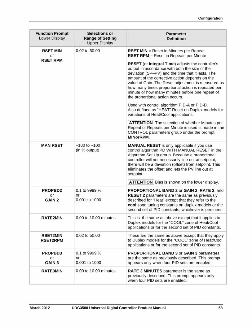
Configuration
March 2012 UDC3500 Universal Digital Controller Product Manual 53
Function Prompt Lower Display
Selections or Range of Setting
Upper Display
Parameter Definition
RSET MIN or
RSET RPM
0.02 to 50.00 RSET MIN = Reset in Minutes per Repeat RSET RPM = Reset in Repeats per Minute
RESET (or Integral Time) adjusts the controller’s output in accordance with both the size of the deviation (SP–PV) and the time that it lasts. The amount of the corrective action depends on the value of Gain. The Reset adjustment is measured as how many times proportional action is repeated per minute or how many minutes before one repeat of the proportional action occurs.
Used with control algorithm PID-A or PID-B. Also defined as “HEAT” Reset on Duplex models for variations of Heat/Cool applications.
ATTENTION The selection of whether Minutes per Repeat or Repeats per Minute is used is made in the CONTROL parameters group under the prompt MINorRPM.
MAN RSET –100 to +100 (in % output)
MANUAL RESET is only applicable if you use control algorithm PD WITH MANUAL RESET in the Algorithm Set Up group. Because a proportional controller will not necessarily line out at setpoint, there will be a deviation (offset) from setpoint. This eliminates the offset and lets the PV line out at setpoint.
ATTENTION Bias is shown on the lower display.
PROPBD2 or
GAIN 2
0.1 to 9999 % or 0.001 to 1000
PROPORTIONAL BAND 2 or GAIN 2, RATE 2, and RESET 2 parameters are the same as previously described for “Heat” except that they refer to the cool zone tuning constants on duplex models or the second set of PID constants, whichever is pertinent.
RATE2MIN 0.00 to 10.00 minutes
This is the same as above except that it applies to Duplex models for the “COOL” zone of Heat/Cool applications or for the second set of PID constants.
RSET2MIN RSET2RPM
0.02 to 50.00 These are the same as above except that they apply to Duplex models for the “COOL” zone of Heat/Cool applications or for the second set of PID constants.
PROPBD3 or
GAIN 3
0.1 to 9999 % or 0.001 to 1000
PROPORTIONAL BAND 3 or GAIN 3 parameters are the same as previously described. This prompt appears only when four PID sets are enabled.
RATE3MIN 0.00 to 10.00 minutes
RATE 3 MINUTES parameter is the same as previously described. This prompt appears only when four PID sets are enabled.
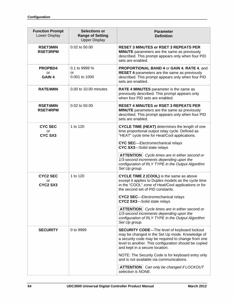
Configuration
54 UDC3500 Universal Digital Controller Product Manual March 2012
Function Prompt Lower Display
Selections or Range of Setting
Upper Display
Parameter Definition
RSET3MIN RSET3RPM
0.02 to 50.00 RESET 3 MINUTES or RSET 3 REPEATS PER MINUTE parameters are the same as previously described. This prompt appears only when four PID sets are enabled.
PROPBD4 or
GAIN 4
0.1 to 9999 % or 0.001 to 1000
PROPORTIONAL BAND 4 or GAIN 4, RATE 4, and RESET 4 parameters are the same as previously described. This prompt appears only when four PID sets are enabled.
RATE4MIN 0.00 to 10.00 minutes
RATE 4 MINUTES parameter is the same as previously described. This prompt appears only when four PID sets are enabled.
RSET4MIN RSET4RPM
0.02 to 50.00 RESET 4 MINUTES or RSET 3 REPEATS PER MINUTE parameters are the same as previously described. This prompt appears only when four PID sets are enabled.
CYC SEC or
CYC SX3
1 to 120 CYCLE TIME (HEAT) determines the length of one time proportional output relay cycle. Defined as “HEAT” cycle time for Heat/Cool applications.
CYC SEC—Electromechanical relays CYC SX3—Solid state relays
ATTENTION Cycle times are in either second or 1/3-second increments depending upon the configuration of RLY TYPE in the Output Algorithm Set Up group.
CYC2 SEC or
CYC2 SX3
1 to 120 CYCLE TIME 2 (COOL) is the same as above except it applies to Duplex models as the cycle time in the “COOL” zone of Heat/Cool applications or for the second set of PID constants.
CYC2 SEC—Electromechanical relays CYC2 SX3—Solid state relays
ATTENTION Cycle times are in either second or 1/3-second increments depending upon the configuration of RLY TYPE in the Output Algorithm Set Up group.
SECURITY 0 to 9999 SECURITY CODE—The level of keyboard lockout may be changed in the Set Up mode. Knowledge of a security code may be required to change from one level to another. This configuration should be copied and kept in a secure location.
NOTE: The Security Code is for keyboard entry only and is not available via communications.
ATTENTION Can only be changed if LOCKOUT selection is NONE.
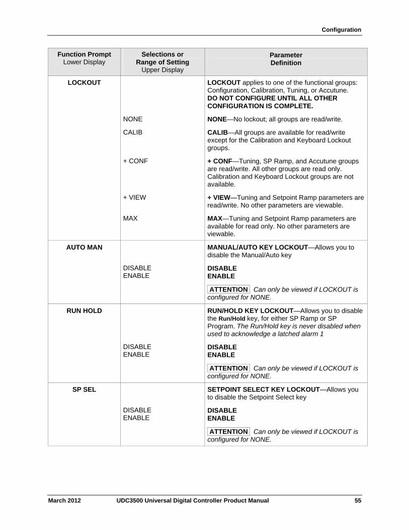
Configuration
March 2012 UDC3500 Universal Digital Controller Product Manual 55
Function Prompt Lower Display
Selections or Range of Setting
Upper Display
Parameter Definition
LOCKOUT LOCKOUT applies to one of the functional groups: Configuration, Calibration, Tuning, or Accutune. DO NOT CONFIGURE UNTIL ALL OTHER CONFIGURATION IS COMPLETE.
NONE NONE—No lockout; all groups are read/write.
CALIB CALIB—All groups are available for read/write except for the Calibration and Keyboard Lockout groups.
+ CONF + CONF—Tuning, SP Ramp, and Accutune groups are read/write. All other groups are read only. Calibration and Keyboard Lockout groups are not available.
+ VIEW + VIEW—Tuning and Setpoint Ramp parameters are read/write. No other parameters are viewable.
MAX MAX—Tuning and Setpoint Ramp parameters are available for read only. No other parameters are viewable.
AUTO MAN
DISABLE ENABLE
MANUAL/AUTO KEY LOCKOUT—Allows you to disable the Manual/Auto key
DISABLE ENABLE
ATTENTION Can only be viewed if LOCKOUT is configured for NONE.
RUN HOLD
DISABLE ENABLE
RUN/HOLD KEY LOCKOUT—Allows you to disable the Run/Hold key, for either SP Ramp or SP Program. The Run/Hold key is never disabled when used to acknowledge a latched alarm 1
DISABLE ENABLE
ATTENTION Can only be viewed if LOCKOUT is configured for NONE.
SP SEL
DISABLE ENABLE
SETPOINT SELECT KEY LOCKOUT—Allows you to disable the Setpoint Select key
DISABLE ENABLE
ATTENTION Can only be viewed if LOCKOUT is configured for NONE.
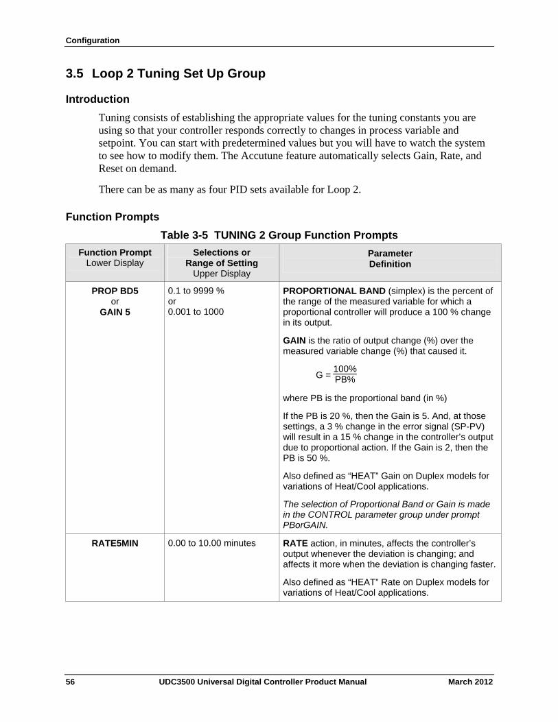
Configuration
3.5 Loop 2 Tuning Set Up Group
Introduction
Tuning consists of establishing the appropriate values for the tuning constants you are using so that your controller responds correctly to changes in process variable and setpoint. You can start with predetermined values but you will have to watch the system to see how to modify them. The Accutune feature automatically selects Gain, Rate, and Reset on demand.
There can be as many as four PID sets available for Loop 2.
Function Prompts
Table 3-5 TUNING 2 Group Function Prompts
Function Prompt Lower Display
Selections or Range of Setting
Upper Display
Parameter Definition
PROP BD5 or
GAIN 5
0.1 to 9999 % or 0.001 to 1000
PROPORTIONAL BAND (simplex) is the percent of the range of the measured variable for which a proportional controller will produce a 100 % change in its output.
GAIN is the ratio of output change (%) over the measured variable change (%) that caused it.
G = 100%PB%
where PB is the proportional band (in %)
If the PB is 20 %, then the Gain is 5. And, at those settings, a 3 % change in the error signal (SP-PV) will result in a 15 % change in the controller’s output due to proportional action. If the Gain is 2, then the PB is 50 %.
Also defined as “HEAT” Gain on Duplex models for variations of Heat/Cool applications.
The selection of Proportional Band or Gain is made in the CONTROL parameter group under prompt PBorGAIN.
RATE5MIN 0.00 to 10.00 minutes
RATE action, in minutes, affects the controller’s output whenever the deviation is changing; and affects it more when the deviation is changing faster.
Also defined as “HEAT” Rate on Duplex models for variations of Heat/Cool applications.
56 UDC3500 Universal Digital Controller Product Manual March 2012

Configuration
March 2012 UDC3500 Universal Digital Controller Product Manual 57
Function Prompt Lower Display
Selections or Range of Setting
Upper Display
Parameter Definition
RSET5MIN or
RSET5RPM
0.02 to 50.00 RSET5MIN = Reset in Minutes per Repeat RSET5RPM = Reset in Repeats per Minute
RESET (or Integral Time) adjusts the controller’s output in accordance with both the size of the deviation (SP–PV) and the time that it lasts. The amount of the corrective action depends on the value of Gain. The Reset adjustment is measured as how many times proportional action is repeated per minute or how many minutes before one repeat of the proportional action occurs.
Used with control algorithm PID-A or PID-B. Also defined as “HEAT” Reset on Duplex models for variations of Heat/Cool applications.
ATTENTION The selection of whether Minutes per Repeat or Repeats per Minute is used is made in the CONTROL2 parameters group under the prompt MINorRPM.
MAN5RSET –100 to +100 (in % output)
MANUAL5RESET is only applicable if you use control algorithm PD WITH MANUAL RESET for Loop 2 in the Algorithm Set Up group. Because a proportional controller will not necessarily line out at setpoint, there will be a deviation (offset) from setpoint. This eliminates the offset and lets the PV line out at setpoint.
ATTENTION Bias is shown on the lower display.
PROPBD6 or
GAIN 6
0.1 to 9999 % or 0.001 to 1000
PROPORTIONAL BAND 6 or GAIN 6, RATE 6 and RESET 6 parameters are the same as previously described for “Heat” except that they refer to the cool zone tuning constants on duplex models or the second set of PID constants, whichever is pertinent.
RATE6MIN 0.00 to 10.00 minutes
This is the same as above except that it applies to Duplex models for the “COOL” zone of Heat/Cool applications or for the second set of PID constants.
RSET6MIN RSET6RPM
0.02 to 50.00 These are the same as above except that they apply to Duplex models for the “COOL” zone of Heat/Cool applications or for the second set of PID constants.
PROPBD7 or
GAIN 7
0.1 to 9999 % or 0.001 to 1000
PROPORTIONAL BAND 7 or GAIN 7 parameters are the same as previously described. This prompt appears only when four PID sets are enabled.
RATE7MIN 0.00 to 10.00 minutes
RATE 7 MINUTES parameter is the same as previously described. This prompt appears only when four PID sets are enabled.
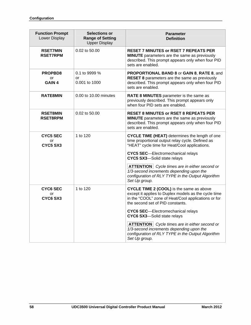
Configuration
58 UDC3500 Universal Digital Controller Product Manual March 2012
Function Prompt Lower Display
Selections or Range of Setting
Upper Display
Parameter Definition
RSET7MIN RSET7RPM
0.02 to 50.00 RESET 7 MINUTES or RSET 7 REPEATS PER MINUTE parameters are the same as previously described. This prompt appears only when four PID sets are enabled.
PROPBD8 or
GAIN 4
0.1 to 9999 % or 0.001 to 1000
PROPORTIONAL BAND 8 or GAIN 8, RATE 8, and RESET 8 parameters are the same as previously described. This prompt appears only when four PID sets are enabled.
RATE8MIN 0.00 to 10.00 minutes
RATE 8 MINUTES parameter is the same as previously described. This prompt appears only when four PID sets are enabled.
RSET8MIN RSET8RPM
0.02 to 50.00 RESET 8 MINUTES or RSET 8 REPEATS PER MINUTE parameters are the same as previously described. This prompt appears only when four PID sets are enabled.
CYC5 SEC or
CYC5 SX3
1 to 120 CYCLE TIME (HEAT) determines the length of one time proportional output relay cycle. Defined as “HEAT” cycle time for Heat/Cool applications.
CYC5 SEC—Electromechanical relays CYC5 SX3—Solid state relays
ATTENTION Cycle times are in either second or 1/3-second increments depending upon the configuration of RLY TYPE in the Output Algorithm Set Up group.
CYC6 SEC or
CYC6 SX3
1 to 120 CYCLE TIME 2 (COOL) is the same as above except it applies to Duplex models as the cycle time in the “COOL” zone of Heat/Cool applications or for the second set of PID constants.
CYC6 SEC—Electromechanical relays CYC6 SX3—Solid state relays
ATTENTION Cycle times are in either second or 1/3-second increments depending upon the configuration of RLY TYPE in the Output Algorithm Set Up group.
Configuration
3.6 SP Ramp Set Up Group
Introduction
Set Point Ramp, Set Point Programs and Set Point Rates can be configured in this group.
A single Setpoint Ramp [SP RAMP] can be configured to occur between the current local setpoint and a final local setpoint over a time interval of from 1 to 255 minutes.
A Set Point Rate [SPRATE] lets you configure a specific rate of change for any local setpoint change.
A single Set Point Program [SP PROG] with up to 20 segments can be configured.
For more information on Set Point Rate, Ramp and Programming, see Sections 4.27 through 4.30.
You can start and stop the ramp/program using the RUN/HOLD key.
PV Hot Start is a configurable feature and means that, at initialization, the setpoint is set to the current PV value and the Ramp or Rate or Program then starts from this value.
Added Features not found in other UDC products:
Up to Four SP Programs rather than one
20 segments instead of 12 in each program
SP Programs 1 and 2 can be linked to give a SP Program of up to 40 segments
SP Programs 3 and 4 can be linked to give a SP Program of up to 40 segments
Guaranteed Soak Settings for each Soak Segment
PID Set selection for each Segment
Function Prompts
ATTENTION
Please note that the configurations used in SP Program #1 for Program End, Program State, Power Up and Key Reset affect all other SP Programs. For this reason, Program #1 must always be enabled in order to enable Programs #2, 3 and/or 4.
March 2012 UDC3500 Universal Digital Controller Product Manual 59
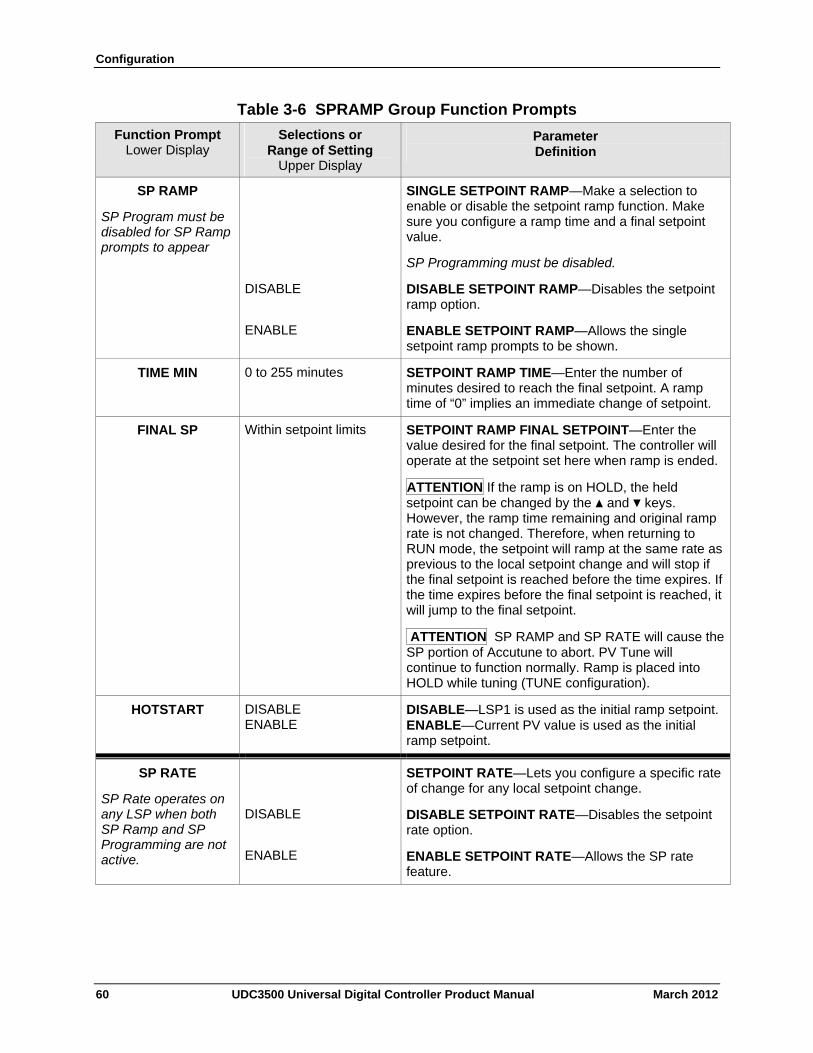
Configuration
Table 3-6 SPRAMP Group Function Prompts
Function Prompt Lower Display
Selections or Range of Setting
Upper Display
Parameter Definition
SP RAMP
SP Program must be disabled for SP Ramp prompts to appear
SINGLE SETPOINT RAMP—Make a selection to enable or disable the setpoint ramp function. Make sure you configure a ramp time and a final setpoint value.
SP Programming must be disabled.
DISABLE
ENABLE
DISABLE SETPOINT RAMP—Disables the setpoint ramp option.
ENABLE SETPOINT RAMP—Allows the single setpoint ramp prompts to be shown.
TIME MIN 0 to 255 minutes SETPOINT RAMP TIME—Enter the number of minutes desired to reach the final setpoint. A ramp time of “0” implies an immediate change of setpoint.
FINAL SP Within setpoint limits SETPOINT RAMP FINAL SETPOINT—Enter the value desired for the final setpoint. The controller will operate at the setpoint set here when ramp is ended.
ATTENTION If the ramp is on HOLD, the held setpoint can be changed by the ▲ and ▼ keys. However, the ramp time remaining and original ramp rate is not changed. Therefore, when returning to RUN mode, the setpoint will ramp at the same rate as previous to the local setpoint change and will stop if the final setpoint is reached before the time expires. If the time expires before the final setpoint is reached, it will jump to the final setpoint.
ATTENTION SP RAMP and SP RATE will cause the SP portion of Accutune to abort. PV Tune will continue to function normally. Ramp is placed into HOLD while tuning (TUNE configuration).
HOTSTART DISABLE ENABLE
DISABLE—LSP1 is used as the initial ramp setpoint.ENABLE—Current PV value is used as the initial ramp setpoint.
SP RATE
SP Rate operates on any LSP when both SP Ramp and SP Programming are not active.
DISABLE
ENABLE
SETPOINT RATE—Lets you configure a specific rate of change for any local setpoint change.
DISABLE SETPOINT RATE—Disables the setpoint rate option.
ENABLE SETPOINT RATE—Allows the SP rate feature.
60 UDC3500 Universal Digital Controller Product Manual March 2012
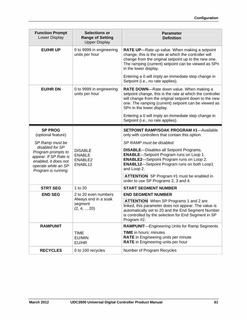
Configuration
March 2012 UDC3500 Universal Digital Controller Product Manual 61
Function Prompt Lower Display
Selections or Range of Setting
Upper Display
Parameter Definition
EU/HR UP 0 to 9999 in engineering units per hour
RATE UP—Rate up value. When making a setpoint change, this is the rate at which the controller will change from the original setpoint up to the new one. The ramping (current) setpoint can be viewed as SPn in the lower display.
Entering a 0 will imply an immediate step change in Setpoint (i.e., no rate applies).
EU/HR DN 0 to 9999 in engineering units per hour
RATE DOWN—Rate down value. When making a setpoint change, this is the rate at which the controller will change from the original setpoint down to the new one. The ramping (current) setpoint can be viewed as SPn in the lower display.
Entering a 0 will imply an immediate step change in Setpoint (i.e., no rate applies).
SP PROG (optional feature)
SP Ramp must be disabled for SP
Program prompts to appear. If SP Rate is enabled, it does not operate while an SP Program is running.
DISABLE ENABLE ENABLE2 ENABL12
SETPOINT RAMP/SOAK PROGRAM #1—Available only with controllers that contain this option.
SP RAMP must be disabled.
DISABLE—Disables all Setpoint Programs. ENABLE—Setpoint Program runs on Loop 1. ENABLE2—Setpoint Program runs on Loop 2. ENABL12—Setpoint Program runs on both Loop1 and Loop 2.
ATTENTION SP Program #1 must be enabled in order to use SP Programs 2, 3 and 4.
STRT SEG 1 to 20 START SEGMENT NUMBER
END SEG 2 to 20 even numbers Always end in a soak segment (2, 4, ... 20)
END SEGMENT NUMBER
ATTENTION When SP Programs 1 and 2 are linked, this parameter does not appear. The value is automatically set to 20 and the End Segment Number is controlled by the selection for End Segment in SP Program #2.
RAMPUNIT
TIME EU/MIN EU/HR
RAMPUNIT—Engineering Units for Ramp Segments
TIME in hours: minutes RATE in Engineering units per minute RATE in Engineering units per hour
RECYCLES 0 to 100 recycles Number of Program Recycles
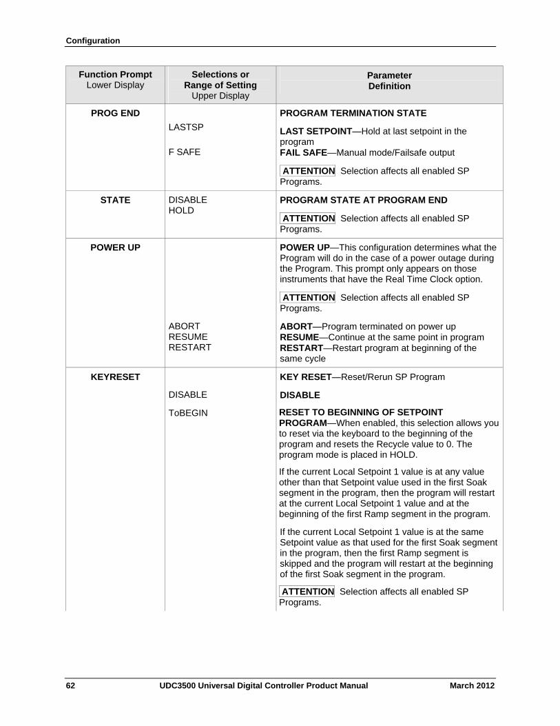
Configuration
62 UDC3500 Universal Digital Controller Product Manual March 2012
Function Prompt Lower Display
Selections or Range of Setting
Upper Display
Parameter Definition
PROG END
LASTSP
F SAFE
PROGRAM TERMINATION STATE
LAST SETPOINT—Hold at last setpoint in the program FAIL SAFE—Manual mode/Failsafe output
ATTENTION Selection affects all enabled SP Programs.
STATE DISABLE HOLD
PROGRAM STATE AT PROGRAM END
ATTENTION Selection affects all enabled SP Programs.
POWER UP POWER UP—This configuration determines what the Program will do in the case of a power outage during the Program. This prompt only appears on those instruments that have the Real Time Clock option.
ATTENTION Selection affects all enabled SP Programs.
ABORT RESUME RESTART
ABORT—Program terminated on power up RESUME—Continue at the same point in program RESTART—Restart program at beginning of the same cycle
KEYRESET
DISABLE
KEY RESET—Reset/Rerun SP Program
DISABLE
ToBEGIN RESET TO BEGINNING OF SETPOINT PROGRAM—When enabled, this selection allows you to reset via the keyboard to the beginning of the program and resets the Recycle value to 0. The program mode is placed in HOLD.
If the current Local Setpoint 1 value is at any value other than that Setpoint value used in the first Soak segment in the program, then the program will restart at the current Local Setpoint 1 value and at the beginning of the first Ramp segment in the program.
If the current Local Setpoint 1 value is at the same Setpoint value as that used for the first Soak segment in the program, then the first Ramp segment is skipped and the program will restart at the beginning of the first Soak segment in the program.
ATTENTION Selection affects all enabled SP Programs.
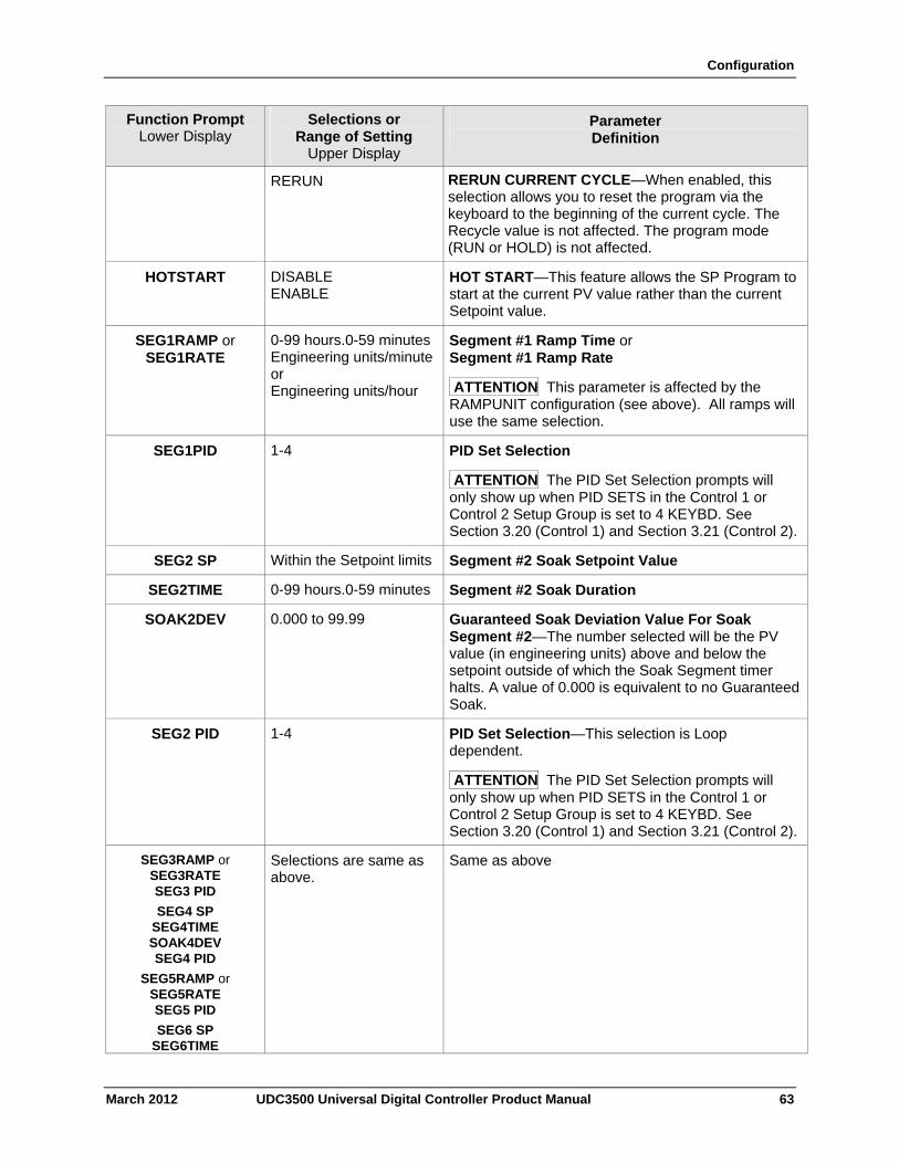
Configuration
March 2012 UDC3500 Universal Digital Controller Product Manual 63
Function Prompt Lower Display
Selections or Range of Setting
Upper Display
Parameter Definition
RERUN RERUN CURRENT CYCLE—When enabled, this selection allows you to reset the program via the keyboard to the beginning of the current cycle. The Recycle value is not affected. The program mode (RUN or HOLD) is not affected.
HOTSTART DISABLE ENABLE
HOT START—This feature allows the SP Program to start at the current PV value rather than the current Setpoint value.
SEG1RAMP or SEG1RATE
0-99 hours.0-59 minutesEngineering units/minute or Engineering units/hour
Segment #1 Ramp Time or Segment #1 Ramp Rate
ATTENTION This parameter is affected by the RAMPUNIT configuration (see above). All ramps will use the same selection.
SEG1PID 1-4 PID Set Selection
ATTENTION The PID Set Selection prompts will only show up when PID SETS in the Control 1 or Control 2 Setup Group is set to 4 KEYBD. See Section 3.20 (Control 1) and Section 3.21 (Control 2).
SEG2 SP Within the Setpoint limits Segment #2 Soak Setpoint Value
SEG2TIME 0-99 hours.0-59 minutes Segment #2 Soak Duration
SOAK2DEV
0.000 to 99.99 Guaranteed Soak Deviation Value For Soak Segment #2—The number selected will be the PV value (in engineering units) above and below the setpoint outside of which the Soak Segment timer halts. A value of 0.000 is equivalent to no Guaranteed Soak.
SEG2 PID 1-4 PID Set Selection—This selection is Loop dependent.
ATTENTION The PID Set Selection prompts will only show up when PID SETS in the Control 1 or Control 2 Setup Group is set to 4 KEYBD. See Section 3.20 (Control 1) and Section 3.21 (Control 2).
SEG3RAMP or SEG3RATE SEG3 PID
SEG4 SP SEG4TIME SOAK4DEV SEG4 PID
SEG5RAMP or SEG5RATE SEG5 PID
SEG6 SP SEG6TIME
Selections are same as above.
Same as above
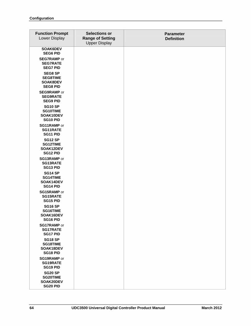
Configuration
64 UDC3500 Universal Digital Controller Product Manual March 2012
Function Prompt Lower Display
Selections or Range of Setting
Upper Display
Parameter Definition
SOAK6DEV SEG6 PID
SEG7RAMP or SEG7RATE SEG7 PID
SEG8 SP SEG8TIME SOAK8DEV SEG8 PID
SEG9RAMP or SEG9RATE SEG9 PID
SG10 SP SG10TIME
SOAK10DEV SG10 PID
SG11RAMP or SG11RATE SG11 PID
SG12 SP SG12TIME
SOAK12DEV SG12 PID
SG13RAMP or SG13RATE SG13 PID
SG14 SP SG14TIME
SOAK14DEV SG14 PID
SG15RAMP or SG15RATE SG15 PID
SG16 SP SG16TIME
SOAK16DEV SG16 PID
SG17RAMP or SG17RATE SG17 PID
SG18 SP SG18TIME
SOAK18DEV SG18 PID
SG19RAMP or SG19RATE SG19 PID
SG20 SP SG20TIME
SOAK20DEV SG20 PID
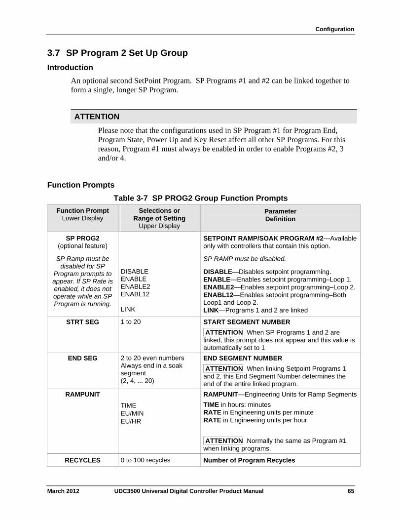
Configuration
3.7 SP Program 2 Set Up Group
Introduction
An optional second SetPoint Program. SP Programs #1 and #2 can be linked together to form a single, longer SP Program.
ATTENTION
Please note that the configurations used in SP Program #1 for Program End, Program State, Power Up and Key Reset affect all other SP Programs. For this reason, Program #1 must always be enabled in order to enable Programs #2, 3 and/or 4.
Function Prompts
Table 3-7 SP PROG2 Group Function Prompts
Function Prompt Lower Display
Selections or Range of Setting
Upper Display
Parameter Definition
SP PROG2 (optional feature)
SP Ramp must be disabled for SP
Program prompts to appear. If SP Rate is enabled, it does not operate while an SP Program is running.
DISABLE ENABLE ENABLE2 ENABL12 LINK
SETPOINT RAMP/SOAK PROGRAM #2—Available only with controllers that contain this option.
SP RAMP must be disabled.
DISABLE—Disables setpoint programming. ENABLE—Enables setpoint programming–Loop 1. ENABLE2—Enables setpoint programming–Loop 2. ENABL12—Enables setpoint programming–Both Loop1 and Loop 2. LINK—Programs 1 and 2 are linked
STRT SEG 1 to 20 START SEGMENT NUMBER
ATTENTION When SP Programs 1 and 2 are linked, this prompt does not appear and this value is automatically set to 1
END SEG 2 to 20 even numbers Always end in a soak segment (2, 4, ... 20)
END SEGMENT NUMBER
ATTENTION When linking Setpoint Programs 1 and 2, this End Segment Number determines the end of the entire linked program.
RAMPUNIT
TIME EU/MIN EU/HR
RAMPUNIT—Engineering Units for Ramp Segments
TIME in hours: minutes RATE in Engineering units per minute RATE in Engineering units per hour
ATTENTION Normally the same as Program #1 when linking programs.
RECYCLES 0 to 100 recycles Number of Program Recycles
March 2012 UDC3500 Universal Digital Controller Product Manual 65
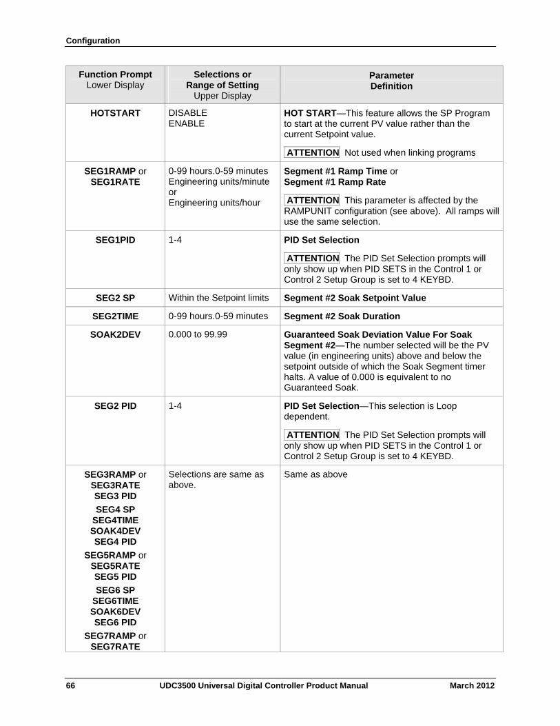
Configuration
66 UDC3500 Universal Digital Controller Product Manual March 2012
Function Prompt Lower Display
Selections or Range of Setting
Upper Display
Parameter Definition
HOTSTART DISABLE ENABLE
HOT START—This feature allows the SP Program to start at the current PV value rather than the current Setpoint value.
ATTENTION Not used when linking programs
SEG1RAMP or SEG1RATE
0-99 hours.0-59 minutes Engineering units/minute or Engineering units/hour
Segment #1 Ramp Time or Segment #1 Ramp Rate
ATTENTION This parameter is affected by the RAMPUNIT configuration (see above). All ramps will use the same selection.
SEG1PID 1-4 PID Set Selection
ATTENTION The PID Set Selection prompts will only show up when PID SETS in the Control 1 or Control 2 Setup Group is set to 4 KEYBD.
SEG2 SP Within the Setpoint limits Segment #2 Soak Setpoint Value
SEG2TIME 0-99 hours.0-59 minutes Segment #2 Soak Duration
SOAK2DEV
0.000 to 99.99 Guaranteed Soak Deviation Value For Soak Segment #2—The number selected will be the PV value (in engineering units) above and below the setpoint outside of which the Soak Segment timer halts. A value of 0.000 is equivalent to no Guaranteed Soak.
SEG2 PID 1-4 PID Set Selection—This selection is Loop dependent.
ATTENTION The PID Set Selection prompts will only show up when PID SETS in the Control 1 or Control 2 Setup Group is set to 4 KEYBD.
SEG3RAMP or SEG3RATE SEG3 PID
SEG4 SP SEG4TIME SOAK4DEV SEG4 PID
SEG5RAMP or SEG5RATE SEG5 PID
SEG6 SP SEG6TIME SOAK6DEV SEG6 PID
SEG7RAMP or SEG7RATE
Selections are same as above.
Same as above
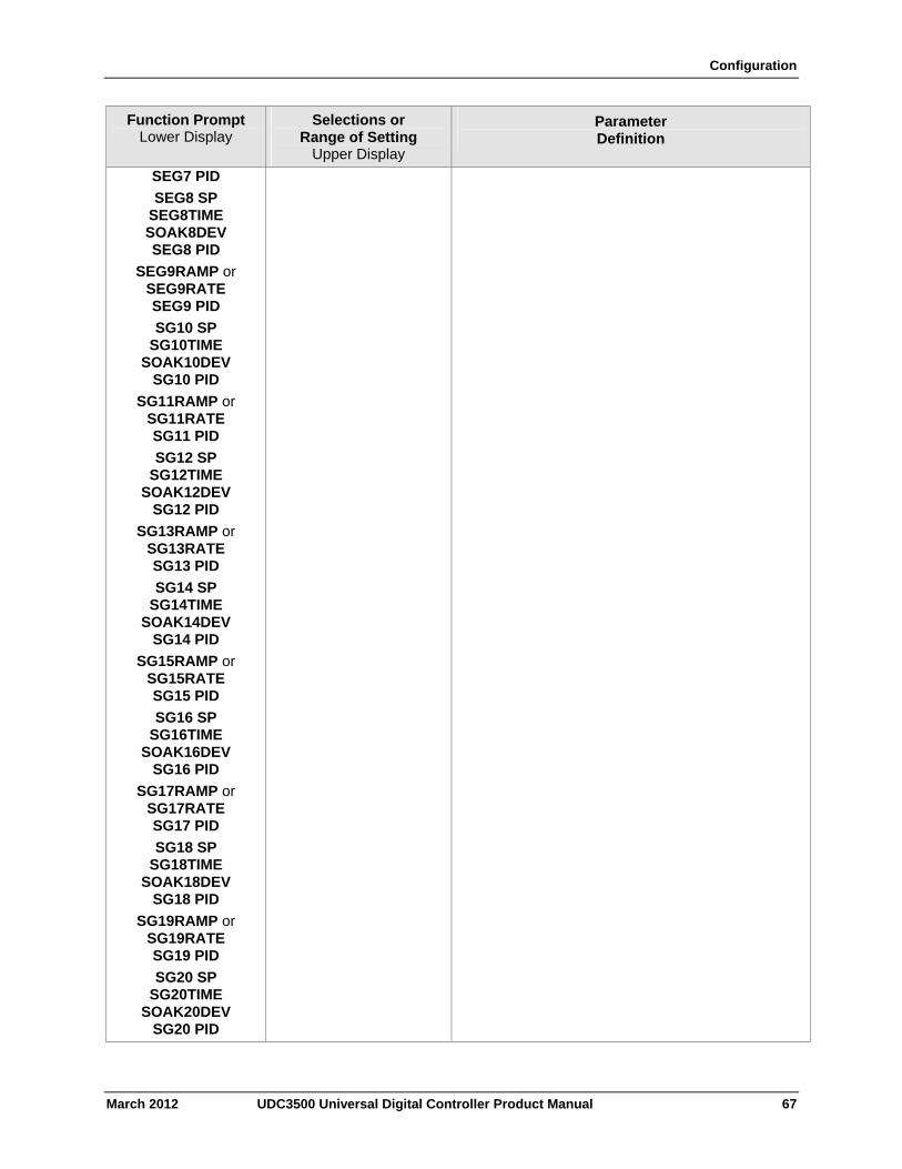
Configuration
March 2012 UDC3500 Universal Digital Controller Product Manual 67
Function Prompt Lower Display
Selections or Range of Setting
Upper Display
Parameter Definition
SEG7 PID
SEG8 SP SEG8TIME SOAK8DEV SEG8 PID
SEG9RAMP or SEG9RATE SEG9 PID
SG10 SP SG10TIME
SOAK10DEV SG10 PID
SG11RAMP or SG11RATE SG11 PID
SG12 SP SG12TIME
SOAK12DEV SG12 PID
SG13RAMP or SG13RATE SG13 PID
SG14 SP SG14TIME
SOAK14DEV SG14 PID
SG15RAMP or SG15RATE SG15 PID
SG16 SP SG16TIME
SOAK16DEV SG16 PID
SG17RAMP or SG17RATE SG17 PID
SG18 SP SG18TIME
SOAK18DEV SG18 PID
SG19RAMP or SG19RATE SG19 PID
SG20 SP SG20TIME
SOAK20DEV SG20 PID
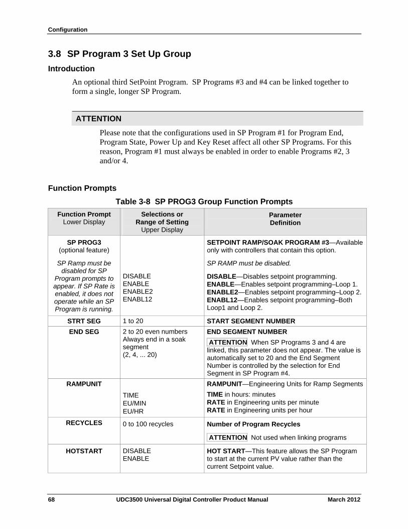
Configuration
3.8 SP Program 3 Set Up Group
Introduction
An optional third SetPoint Program. SP Programs #3 and #4 can be linked together to form a single, longer SP Program.
ATTENTION
Please note that the configurations used in SP Program #1 for Program End, Program State, Power Up and Key Reset affect all other SP Programs. For this reason, Program #1 must always be enabled in order to enable Programs #2, 3 and/or 4.
Function Prompts
Table 3-8 SP PROG3 Group Function Prompts
Function Prompt Lower Display
Selections or Range of Setting
Upper Display
Parameter Definition
SP PROG3 (optional feature)
SP Ramp must be disabled for SP
Program prompts to appear. If SP Rate is enabled, it does not operate while an SP Program is running.
DISABLE ENABLE ENABLE2 ENABL12
SETPOINT RAMP/SOAK PROGRAM #3—Available only with controllers that contain this option.
SP RAMP must be disabled.
DISABLE—Disables setpoint programming. ENABLE—Enables setpoint programming–Loop 1. ENABLE2—Enables setpoint programming–Loop 2. ENABL12—Enables setpoint programming–Both Loop1 and Loop 2.
STRT SEG 1 to 20 START SEGMENT NUMBER
END SEG 2 to 20 even numbers Always end in a soak segment (2, 4, ... 20)
END SEGMENT NUMBER
ATTENTION When SP Programs 3 and 4 are linked, this parameter does not appear. The value is automatically set to 20 and the End Segment Number is controlled by the selection for End Segment in SP Program #4.
RAMPUNIT
TIME EU/MIN EU/HR
RAMPUNIT—Engineering Units for Ramp Segments
TIME in hours: minutes RATE in Engineering units per minute RATE in Engineering units per hour
RECYCLES
0 to 100 recycles Number of Program Recycles
ATTENTION Not used when linking programs
HOTSTART DISABLE ENABLE
HOT START—This feature allows the SP Program to start at the current PV value rather than the current Setpoint value.
68 UDC3500 Universal Digital Controller Product Manual March 2012
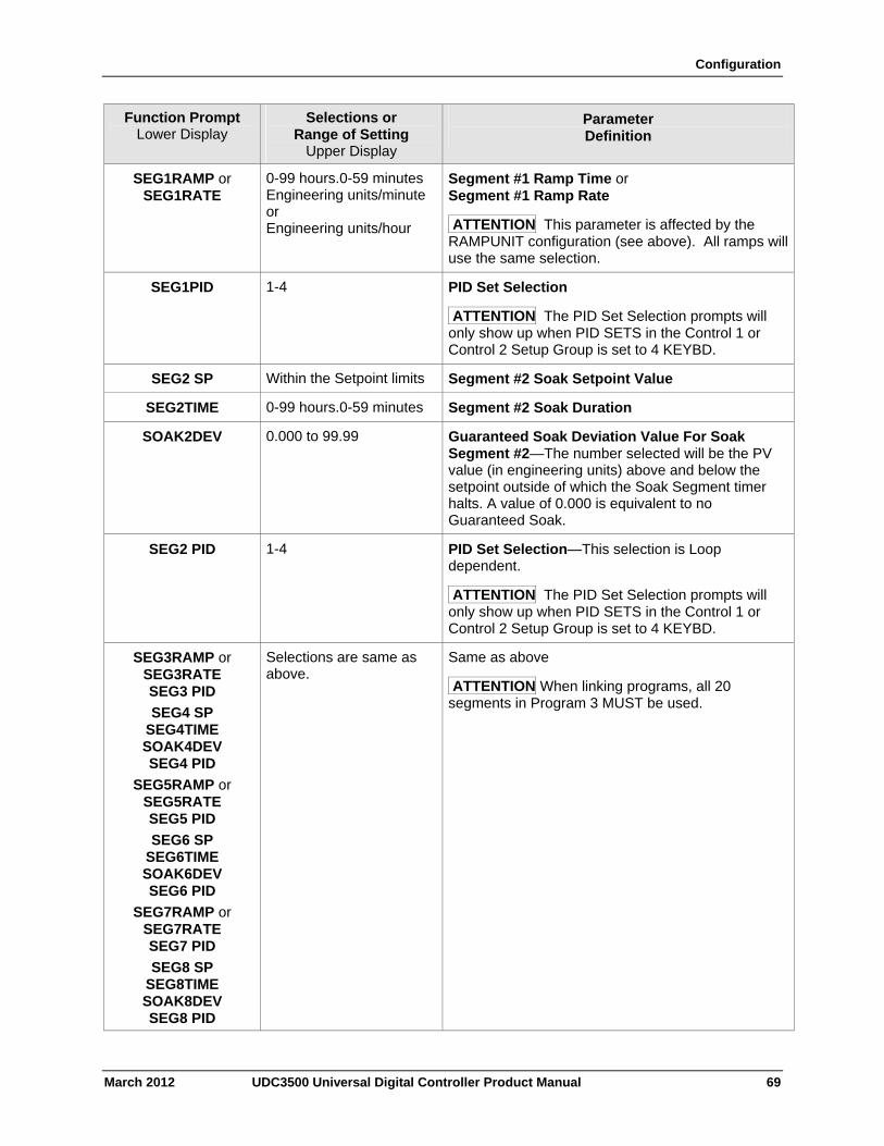
Configuration
March 2012 UDC3500 Universal Digital Controller Product Manual 69
Function Prompt Lower Display
Selections or Range of Setting
Upper Display
Parameter Definition
SEG1RAMP or SEG1RATE
0-99 hours.0-59 minutes Engineering units/minute or Engineering units/hour
Segment #1 Ramp Time or Segment #1 Ramp Rate
ATTENTION This parameter is affected by the RAMPUNIT configuration (see above). All ramps will use the same selection.
SEG1PID
1-4 PID Set Selection
ATTENTION The PID Set Selection prompts will only show up when PID SETS in the Control 1 or Control 2 Setup Group is set to 4 KEYBD.
SEG2 SP Within the Setpoint limits Segment #2 Soak Setpoint Value
SEG2TIME 0-99 hours.0-59 minutes Segment #2 Soak Duration
SOAK2DEV
0.000 to 99.99 Guaranteed Soak Deviation Value For Soak Segment #2—The number selected will be the PV value (in engineering units) above and below the setpoint outside of which the Soak Segment timer halts. A value of 0.000 is equivalent to no Guaranteed Soak.
SEG2 PID
1-4 PID Set Selection—This selection is Loop dependent.
ATTENTION The PID Set Selection prompts will only show up when PID SETS in the Control 1 or Control 2 Setup Group is set to 4 KEYBD.
SEG3RAMP or SEG3RATE SEG3 PID
SEG4 SP SEG4TIME SOAK4DEV SEG4 PID
SEG5RAMP or SEG5RATE SEG5 PID
SEG6 SP SEG6TIME SOAK6DEV SEG6 PID
SEG7RAMP or SEG7RATE SEG7 PID
SEG8 SP SEG8TIME SOAK8DEV SEG8 PID
Selections are same as above.
Same as above
ATTENTION When linking programs, all 20 segments in Program 3 MUST be used.
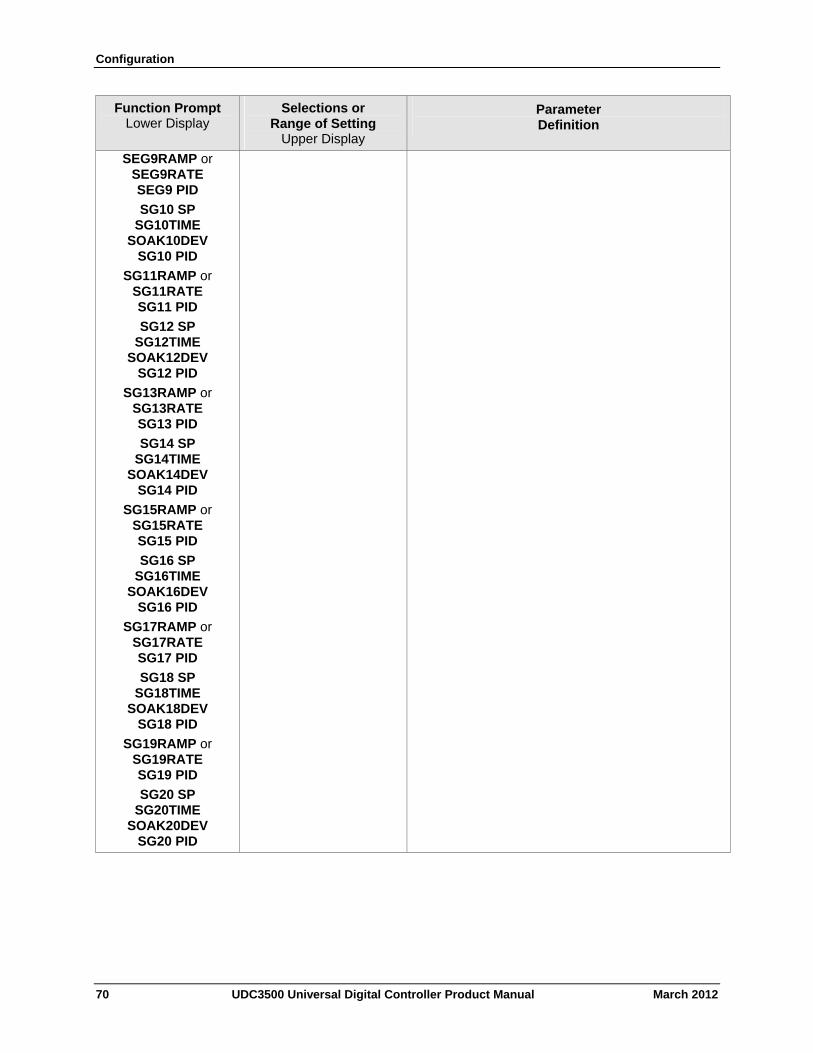
Configuration
70 UDC3500 Universal Digital Controller Product Manual March 2012
Function Prompt Lower Display
Selections or Range of Setting
Upper Display
Parameter Definition
SEG9RAMP or SEG9RATE SEG9 PID
SG10 SP SG10TIME
SOAK10DEV SG10 PID
SG11RAMP or SG11RATE SG11 PID
SG12 SP SG12TIME
SOAK12DEV SG12 PID
SG13RAMP or SG13RATE SG13 PID
SG14 SP SG14TIME
SOAK14DEV SG14 PID
SG15RAMP or SG15RATE SG15 PID
SG16 SP SG16TIME
SOAK16DEV SG16 PID
SG17RAMP or SG17RATE SG17 PID
SG18 SP SG18TIME
SOAK18DEV SG18 PID
SG19RAMP or SG19RATE SG19 PID
SG20 SP SG20TIME
SOAK20DEV SG20 PID
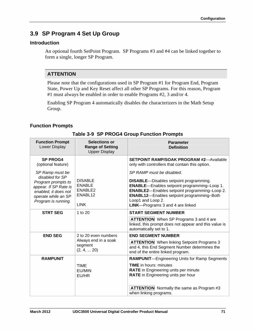
Configuration
3.9 SP Program 4 Set Up Group
Introduction
An optional fourth SetPoint Program. SP Programs #3 and #4 can be linked together to form a single, longer SP Program.
ATTENTION
Please note that the configurations used in SP Program #1 for Program End, Program State, Power Up and Key Reset affect all other SP Programs. For this reason, Program #1 must always be enabled in order to enable Programs #2, 3 and/or 4.
Enabling SP Program 4 automatically disables the characterizers in the Math Setup Group.
Function Prompts
Table 3-9 SP PROG4 Group Function Prompts
Function Prompt Lower Display
Selections or Range of Setting
Upper Display
Parameter Definition
SP PROG4 (optional feature)
SP Ramp must be disabled for SP
Program prompts to appear. If SP Rate is enabled, it does not operate while an SP Program is running.
DISABLE ENABLE ENABLE2 ENABL12 LINK
SETPOINT RAMP/SOAK PROGRAM #2—Available only with controllers that contain this option.
SP RAMP must be disabled.
DISABLE—Disables setpoint programming. ENABLE—Enables setpoint programming–Loop 1. ENABLE2—Enables setpoint programming–Loop 2. ENABL12—Enables setpoint programming–Both Loop1 and Loop 2. LINK—Programs 3 and 4 are linked
STRT SEG
1 to 20 START SEGMENT NUMBER
ATTENTION When SP Programs 3 and 4 are linked, this prompt does not appear and this value is automatically set to 1.
END SEG 2 to 20 even numbers Always end in a soak segment (2, 4, ... 20)
END SEGMENT NUMBER
ATTENTION When linking Setpoint Programs 3 and 4, this End Segment Number determines the end of the entire linked program.
RAMPUNIT
TIME EU/MIN EU/HR
RAMPUNIT—Engineering Units for Ramp Segments
TIME in hours: minutes RATE in Engineering units per minute RATE in Engineering units per hour
ATTENTION Normally the same as Program #3 when linking programs.
March 2012 UDC3500 Universal Digital Controller Product Manual 71
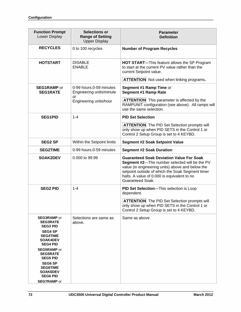
Configuration
72 UDC3500 Universal Digital Controller Product Manual March 2012
Function Prompt Lower Display
Selections or Range of Setting
Upper Display
Parameter Definition
RECYCLES
0 to 100 recycles Number of Program Recycles
HOTSTART DISABLE ENABLE
HOT START—This feature allows the SP Program to start at the current PV value rather than the current Setpoint value.
ATTENTION Not used when linking programs.
SEG1RAMP or SEG1RATE
0-99 hours.0-59 minutes Engineering units/minute or Engineering units/hour
Segment #1 Ramp Time or Segment #1 Ramp Rate
ATTENTION This parameter is affected by the RAMPUNIT configuration (see above). All ramps will use the same selection.
SEG1PID
1-4 PID Set Selection
ATTENTION The PID Set Selection prompts will only show up when PID SETS in the Control 1 or Control 2 Setup Group is set to 4 KEYBD.
SEG2 SP Within the Setpoint limits Segment #2 Soak Setpoint Value
SEG2TIME 0-99 hours.0-59 minutes Segment #2 Soak Duration
SOAK2DEV
0.000 to 99.99 Guaranteed Soak Deviation Value For Soak Segment #2—The number selected will be the PV value (in engineering units) above and below the setpoint outside of which the Soak Segment timer halts. A value of 0.000 is equivalent to no Guaranteed Soak.
SEG2 PID
1-4 PID Set Selection—This selection is Loop dependent.
ATTENTION The PID Set Selection prompts will only show up when PID SETS in the Control 1 or Control 2 Setup Group is set to 4 KEYBD.
SEG3RAMP or SEG3RATE SEG3 PID
SEG4 SP SEG4TIME SOAK4DEV SEG4 PID
SEG5RAMP or SEG5RATE SEG5 PID
SEG6 SP SEG6TIME SOAK6DEV SEG6 PID
SEG7RAMP or
Selections are same as above.
Same as above
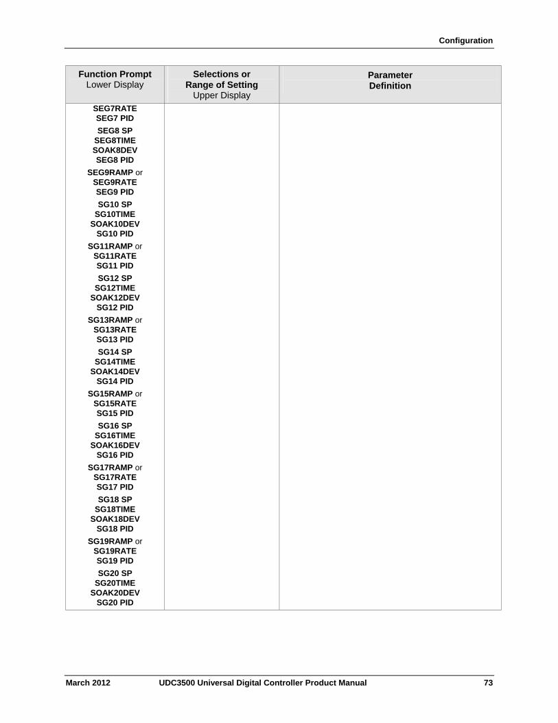
Configuration
March 2012 UDC3500 Universal Digital Controller Product Manual 73
Function Prompt Lower Display
Selections or Range of Setting
Upper Display
Parameter Definition
SEG7RATE SEG7 PID
SEG8 SP SEG8TIME SOAK8DEV SEG8 PID
SEG9RAMP or SEG9RATE SEG9 PID
SG10 SP SG10TIME
SOAK10DEV SG10 PID
SG11RAMP or SG11RATE SG11 PID
SG12 SP SG12TIME
SOAK12DEV SG12 PID
SG13RAMP or SG13RATE SG13 PID
SG14 SP SG14TIME
SOAK14DEV SG14 PID
SG15RAMP or SG15RATE SG15 PID
SG16 SP SG16TIME
SOAK16DEV SG16 PID
SG17RAMP or SG17RATE SG17 PID
SG18 SP SG18TIME
SOAK18DEV SG18 PID
SG19RAMP or SG19RATE SG19 PID
SG20 SP SG20TIME
SOAK20DEV SG20 PID
Configuration
3.10 Accutune Set Up Group
Introduction
Accutune III automatically calculates GAIN, RATE, and RESET TIME (PID) tuning constants for your control loop. When initiated on demand, the Accutune algorithm measures a process step response and automatically generates the PID tuning constants needed for no overshoot on your process.
The Accutune III set up group offers these selections:
Fuzzy, Fuzzy Overshoot Suppression: When enabled, this configuration will suppress or eliminate any overshoot that may occur as a result of the existing tuning parameters, as the PV approaches the setpoint.
Tune, Demand Tuning: This tuning cycles the output to the output limits causing the PV to oscillate around the SP value. This tuning does not require the process to be at lineout (stabilized) and may be moving. The tuning process is initiated through the operator interface keys or via a digital input (if configured). The algorithm then calculates new tuning parameters and enters them in the tuning group. Tune will operate with PIDA, PIDB, PD+MR and Three Position Step Control algorithms.
SP, SP Tuning: When activated in automatic control, the output makes an output step in the direction of the SP and starts measurement activities to calculate the tuning parameters based on the PV response. In order to work properly, this tuning requires that the process be at lineout (stabilized) for a period before SP Tune is initiated.
SP tuning continuously adjusts the PID parameters in response to setpoint changes. You can select tuning on minimum setpoint changes of 5 % up to 15 % span. Perform SP tuning after you have configured the controller. SP Tuning does not operate with the Three Position Step Control algorithm.
Tune + PV or SP + PV, PV Tuning: The (TUNE) Demand Tuning or the (SP) Setpoint Tuning portions of these selections work as stated above. PV Adapt will occur during Process Variable (PV) disturbances (0.3% span or larger) which result from non-linearities, process dynamics, load changes, or other operating conditions. When this condition exists, the controller monitors the process response for 1 and 1/2 process cycles around the setpoint to determine whether there has been a true process change or a momentary upset. Process retuning occurs as the process dynamics are learned. When the process is being learned with possible retune, a “t” is shown in the upper left display digit.
Simplex Tuning is used when a Simplex Control Algorithm is configured and uses the current SP value and alters the output over the Output Limit Range.
Duplex Tuning is used when a Duplex Control Algorithm is configured. To perform a Duplex Tune, Two Local Setpoints must be configured per the Control Group in Section 3.20.
See Section 4.10 for additional information.
74 UDC3500 Universal Digital Controller Product Manual March 2012
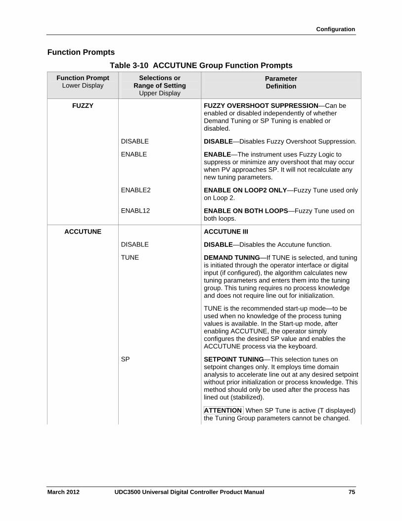
Configuration
Function Prompts
Table 3-10 ACCUTUNE Group Function Prompts
Function Prompt Lower Display
Selections or Range of Setting
Upper Display
Parameter Definition
FUZZY FUZZY OVERSHOOT SUPPRESSION—Can be enabled or disabled independently of whether Demand Tuning or SP Tuning is enabled or disabled.
DISABLE DISABLE—Disables Fuzzy Overshoot Suppression.
ENABLE ENABLE—The instrument uses Fuzzy Logic to suppress or minimize any overshoot that may occur when PV approaches SP. It will not recalculate any new tuning parameters.
ENABLE2 ENABLE ON LOOP2 ONLY—Fuzzy Tune used only on Loop 2.
ENABL12 ENABLE ON BOTH LOOPS—Fuzzy Tune used on both loops.
ACCUTUNE ACCUTUNE III
DISABLE DISABLE—Disables the Accutune function.
TUNE DEMAND TUNING—If TUNE is selected, and tuning is initiated through the operator interface or digital input (if configured), the algorithm calculates new tuning parameters and enters them into the tuning group. This tuning requires no process knowledge and does not require line out for initialization.
TUNE is the recommended start-up mode—to be used when no knowledge of the process tuning values is available. In the Start-up mode, after enabling ACCUTUNE, the operator simply configures the desired SP value and enables the ACCUTUNE process via the keyboard.
SP SETPOINT TUNING—This selection tunes on setpoint changes only. It employs time domain analysis to accelerate line out at any desired setpoint without prior initialization or process knowledge. This method should only be used after the process has lined out (stabilized).
ATTENTION When SP Tune is active (T displayed) the Tuning Group parameters cannot be changed.
March 2012 UDC3500 Universal Digital Controller Product Manual 75
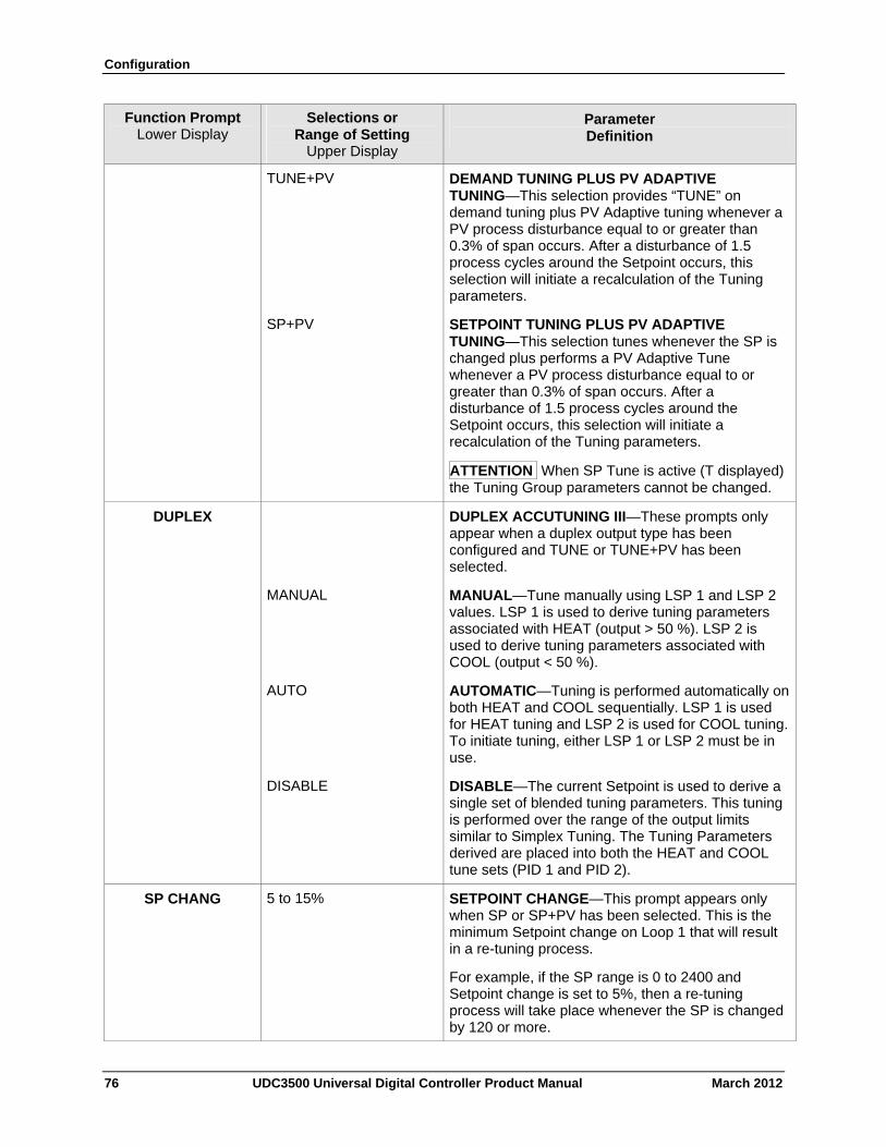
Configuration
76 UDC3500 Universal Digital Controller Product Manual March 2012
Function Prompt Lower Display
Selections or Range of Setting
Upper Display
Parameter Definition
TUNE+PV DEMAND TUNING PLUS PV ADAPTIVE TUNING—This selection provides “TUNE” on demand tuning plus PV Adaptive tuning whenever a PV process disturbance equal to or greater than 0.3% of span occurs. After a disturbance of 1.5 process cycles around the Setpoint occurs, this selection will initiate a recalculation of the Tuning parameters.
SP+PV SETPOINT TUNING PLUS PV ADAPTIVE TUNING—This selection tunes whenever the SP is changed plus performs a PV Adaptive Tune whenever a PV process disturbance equal to or greater than 0.3% of span occurs. After a disturbance of 1.5 process cycles around the Setpoint occurs, this selection will initiate a recalculation of the Tuning parameters.
ATTENTION When SP Tune is active (T displayed) the Tuning Group parameters cannot be changed.
DUPLEX
DUPLEX ACCUTUNING III—These prompts only appear when a duplex output type has been configured and TUNE or TUNE+PV has been selected.
MANUAL MANUAL—Tune manually using LSP 1 and LSP 2 values. LSP 1 is used to derive tuning parameters associated with HEAT (output > 50 %). LSP 2 is used to derive tuning parameters associated with COOL (output < 50 %).
AUTO AUTOMATIC—Tuning is performed automatically on both HEAT and COOL sequentially. LSP 1 is used for HEAT tuning and LSP 2 is used for COOL tuning. To initiate tuning, either LSP 1 or LSP 2 must be in use.
DISABLE DISABLE—The current Setpoint is used to derive a single set of blended tuning parameters. This tuning is performed over the range of the output limits similar to Simplex Tuning. The Tuning Parameters derived are placed into both the HEAT and COOL tune sets (PID 1 and PID 2).
SP CHANG 5 to 15% SETPOINT CHANGE—This prompt appears only when SP or SP+PV has been selected. This is the minimum Setpoint change on Loop 1 that will result in a re-tuning process.
For example, if the SP range is 0 to 2400 and Setpoint change is set to 5%, then a re-tuning process will take place whenever the SP is changed by 120 or more.
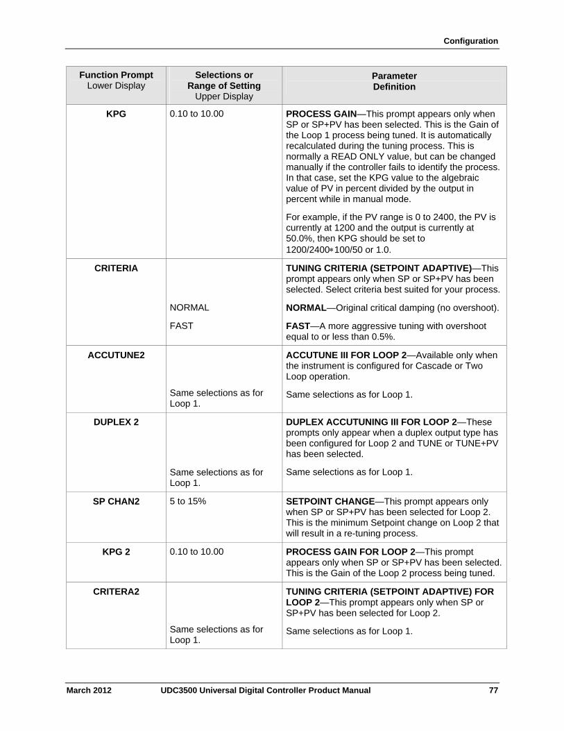
Configuration
March 2012 UDC3500 Universal Digital Controller Product Manual 77
Function Prompt Lower Display
Selections or Range of Setting
Upper Display
Parameter Definition
KPG 0.10 to 10.00 PROCESS GAIN—This prompt appears only when SP or SP+PV has been selected. This is the Gain of the Loop 1 process being tuned. It is automatically recalculated during the tuning process. This is normally a READ ONLY value, but can be changed manually if the controller fails to identify the process. In that case, set the KPG value to the algebraic value of PV in percent divided by the output in percent while in manual mode.
For example, if the PV range is 0 to 2400, the PV is currently at 1200 and the output is currently at 50.0%, then KPG should be set to 1200/2400100/50 or 1.0.
CRITERIA TUNING CRITERIA (SETPOINT ADAPTIVE)—This prompt appears only when SP or SP+PV has been selected. Select criteria best suited for your process.
NORMAL NORMAL—Original critical damping (no overshoot).
FAST FAST—A more aggressive tuning with overshoot equal to or less than 0.5%.
ACCUTUNE2
Same selections as for Loop 1.
ACCUTUNE III FOR LOOP 2—Available only when the instrument is configured for Cascade or Two Loop operation.
Same selections as for Loop 1.
DUPLEX 2
Same selections as for Loop 1.
DUPLEX ACCUTUNING III FOR LOOP 2—These prompts only appear when a duplex output type has been configured for Loop 2 and TUNE or TUNE+PV has been selected.
Same selections as for Loop 1.
SP CHAN2 5 to 15% SETPOINT CHANGE—This prompt appears only when SP or SP+PV has been selected for Loop 2. This is the minimum Setpoint change on Loop 2 that will result in a re-tuning process.
KPG 2 0.10 to 10.00 PROCESS GAIN FOR LOOP 2—This prompt appears only when SP or SP+PV has been selected. This is the Gain of the Loop 2 process being tuned.
CRITERA2
Same selections as for Loop 1.
TUNING CRITERIA (SETPOINT ADAPTIVE) FOR LOOP 2—This prompt appears only when SP or SP+PV has been selected for Loop 2.
Same selections as for Loop 1.
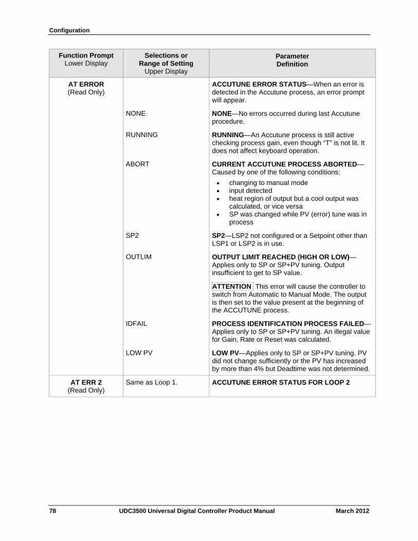
Configuration
78 UDC3500 Universal Digital Controller Product Manual March 2012
Function Prompt Lower Display
Selections or Range of Setting
Upper Display
Parameter Definition
AT ERROR (Read Only)
ACCUTUNE ERROR STATUS—When an error is detected in the Accutune process, an error prompt will appear.
NONE NONE—No errors occurred during last Accutune procedure.
RUNNING RUNNING—An Accutune process is still active checking process gain, even though “T” is not lit. It does not affect keyboard operation.
ABORT CURRENT ACCUTUNE PROCESS ABORTED—Caused by one of the following conditions:
changing to manual mode input detected heat region of output but a cool output was
calculated, or vice versa SP was changed while PV (error) tune was in
process
SP2 SP2—LSP2 not configured or a Setpoint other than LSP1 or LSP2 is in use.
OUTLIM OUTPUT LIMIT REACHED (HIGH OR LOW)—Applies only to SP or SP+PV tuning. Output insufficient to get to SP value.
ATTENTION This error will cause the controller to switch from Automatic to Manual Mode. The output is then set to the value present at the beginning of the ACCUTUNE process.
IDFAIL PROCESS IDENTIFICATION PROCESS FAILED—Applies only to SP or SP+PV tuning. An illegal value for Gain, Rate or Reset was calculated.
LOW PV LOW PV—Applies only to SP or SP+PV tuning. PV did not change sufficiently or the PV has increased by more than 4% but Deadtime was not determined.
AT ERR 2 (Read Only)
Same as Loop 1. ACCUTUNE ERROR STATUS FOR LOOP 2
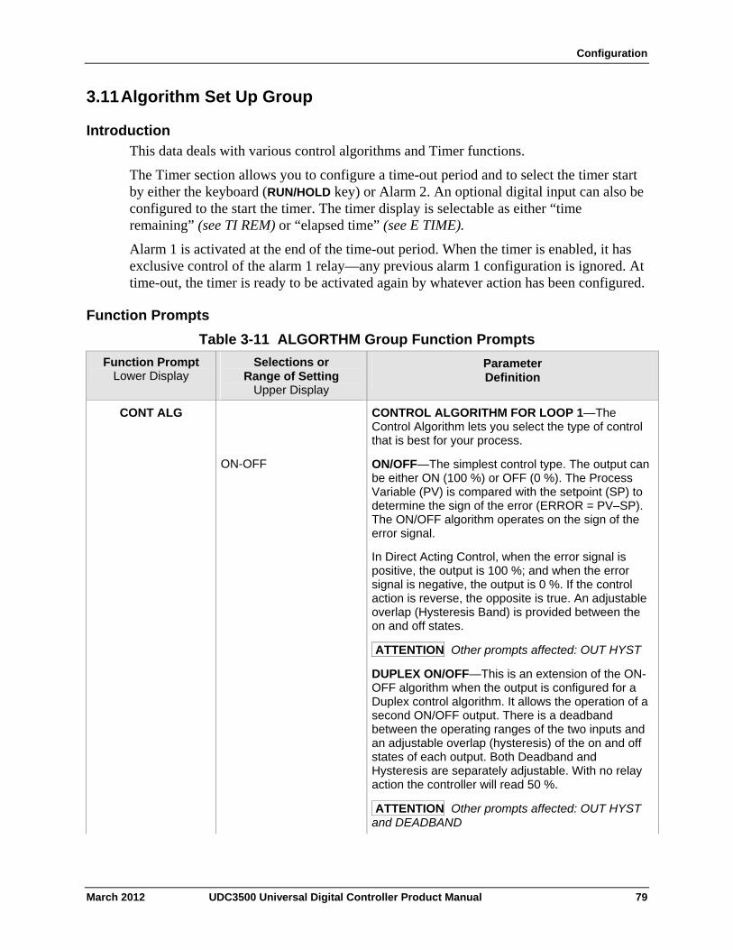
Configuration
3.11 Algorithm Set Up Group
Introduction
This data deals with various control algorithms and Timer functions.
The Timer section allows you to configure a time-out period and to select the timer start by either the keyboard (RUN/HOLD key) or Alarm 2. An optional digital input can also be configured to the start the timer. The timer display is selectable as either “time remaining” (see TI REM) or “elapsed time” (see E TIME).
Alarm 1 is activated at the end of the time-out period. When the timer is enabled, it has exclusive control of the alarm 1 relay—any previous alarm 1 configuration is ignored. At time-out, the timer is ready to be activated again by whatever action has been configured.
Function Prompts
Table 3-11 ALGORTHM Group Function Prompts
Function Prompt Lower Display
Selections or Range of Setting
Upper Display
Parameter Definition
CONT ALG CONTROL ALGORITHM FOR LOOP 1—The Control Algorithm lets you select the type of control that is best for your process.
ON-OFF ON/OFF—The simplest control type. The output can be either ON (100 %) or OFF (0 %). The Process Variable (PV) is compared with the setpoint (SP) to determine the sign of the error (ERROR = PV–SP). The ON/OFF algorithm operates on the sign of the error signal.
In Direct Acting Control, when the error signal is positive, the output is 100 %; and when the error signal is negative, the output is 0 %. If the control action is reverse, the opposite is true. An adjustable overlap (Hysteresis Band) is provided between the on and off states.
ATTENTION Other prompts affected: OUT HYST
DUPLEX ON/OFF—This is an extension of the ON-OFF algorithm when the output is configured for a Duplex control algorithm. It allows the operation of a second ON/OFF output. There is a deadband between the operating ranges of the two inputs and an adjustable overlap (hysteresis) of the on and off states of each output. Both Deadband and Hysteresis are separately adjustable. With no relay action the controller will read 50 %.
ATTENTION Other prompts affected: OUT HYST and DEADBAND
March 2012 UDC3500 Universal Digital Controller Product Manual 79
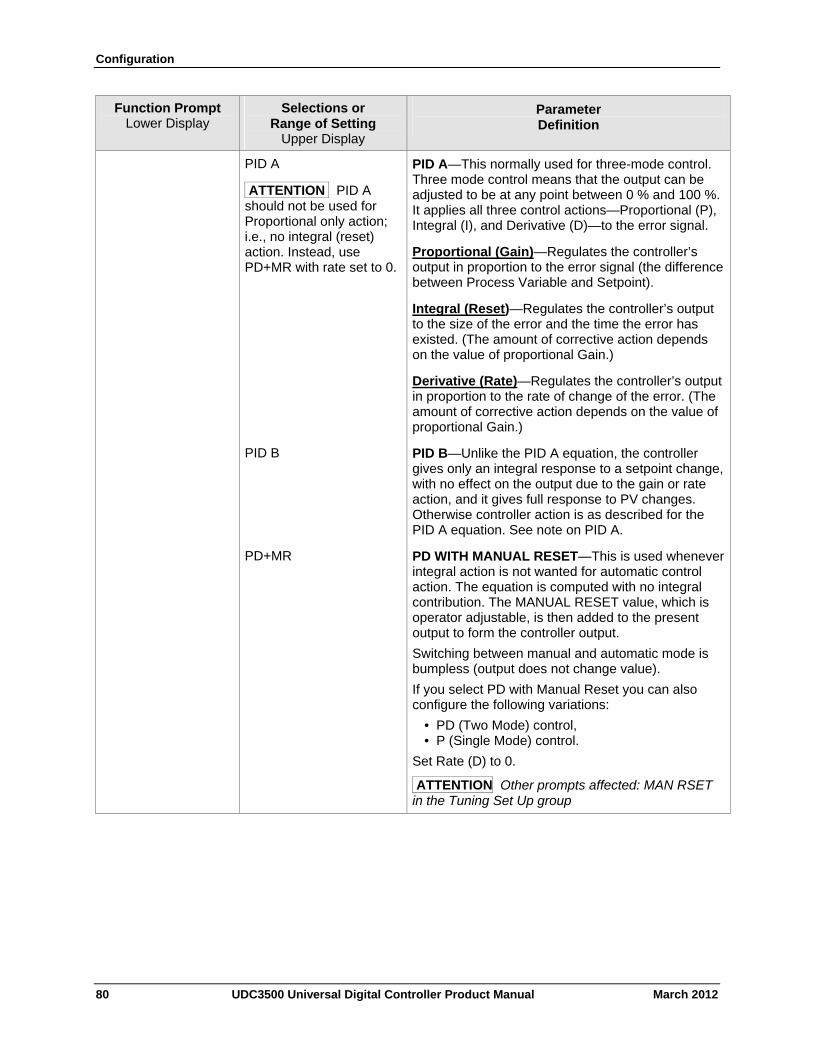
Configuration
80 UDC3500 Universal Digital Controller Product Manual March 2012
Function Prompt Lower Display
Selections or Range of Setting
Upper Display
Parameter Definition
PID A
ATTENTION PID A should not be used for Proportional only action; i.e., no integral (reset) action. Instead, use PD+MR with rate set to 0.
PID A—This normally used for three-mode control. Three mode control means that the output can be adjusted to be at any point between 0 % and 100 %. It applies all three control actions—Proportional (P), Integral (I), and Derivative (D)—to the error signal.
Proportional (Gain)—Regulates the controller’s output in proportion to the error signal (the difference between Process Variable and Setpoint).
Integral (Reset)—Regulates the controller’s output to the size of the error and the time the error has existed. (The amount of corrective action depends on the value of proportional Gain.)
Derivative (Rate)—Regulates the controller’s output in proportion to the rate of change of the error. (The amount of corrective action depends on the value of proportional Gain.)
PID B PID B—Unlike the PID A equation, the controller gives only an integral response to a setpoint change, with no effect on the output due to the gain or rate action, and it gives full response to PV changes. Otherwise controller action is as described for the PID A equation. See note on PID A.
PD+MR PD WITH MANUAL RESET—This is used whenever integral action is not wanted for automatic control action. The equation is computed with no integral contribution. The MANUAL RESET value, which is operator adjustable, is then added to the present output to form the controller output.
Switching between manual and automatic mode is bumpless (output does not change value).
If you select PD with Manual Reset you can also configure the following variations:
• PD (Two Mode) control, • P (Single Mode) control.
Set Rate (D) to 0.
ATTENTION Other prompts affected: MAN RSET in the Tuning Set Up group
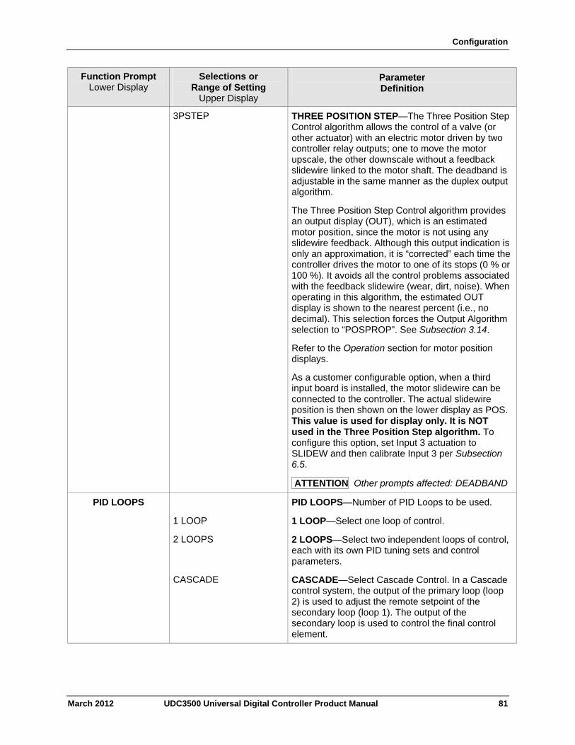
Configuration
March 2012 UDC3500 Universal Digital Controller Product Manual 81
Function Prompt Lower Display
Selections or Range of Setting
Upper Display
Parameter Definition
3PSTEP THREE POSITION STEP—The Three Position Step Control algorithm allows the control of a valve (or other actuator) with an electric motor driven by two controller relay outputs; one to move the motor upscale, the other downscale without a feedback slidewire linked to the motor shaft. The deadband is adjustable in the same manner as the duplex output algorithm.
The Three Position Step Control algorithm provides an output display (OUT), which is an estimated motor position, since the motor is not using any slidewire feedback. Although this output indication is only an approximation, it is “corrected” each time the controller drives the motor to one of its stops (0 % or 100 %). It avoids all the control problems associated with the feedback slidewire (wear, dirt, noise). When operating in this algorithm, the estimated OUT display is shown to the nearest percent (i.e., no decimal). This selection forces the Output Algorithm selection to “POSPROP”. See Subsection 3.14.
Refer to the Operation section for motor position displays.
As a customer configurable option, when a third input board is installed, the motor slidewire can be connected to the controller. The actual slidewire position is then shown on the lower display as POS. This value is used for display only. It is NOT used in the Three Position Step algorithm. To configure this option, set Input 3 actuation to SLIDEW and then calibrate Input 3 per Subsection 6.5.
ATTENTION Other prompts affected: DEADBAND
PID LOOPS PID LOOPS—Number of PID Loops to be used.
1 LOOP 1 LOOP—Select one loop of control.
2 LOOPS 2 LOOPS—Select two independent loops of control, each with its own PID tuning sets and control parameters.
CASCADE CASCADE—Select Cascade Control. In a Cascade control system, the output of the primary loop (loop 2) is used to adjust the remote setpoint of the secondary loop (loop 1). The output of the secondary loop is used to control the final control element.
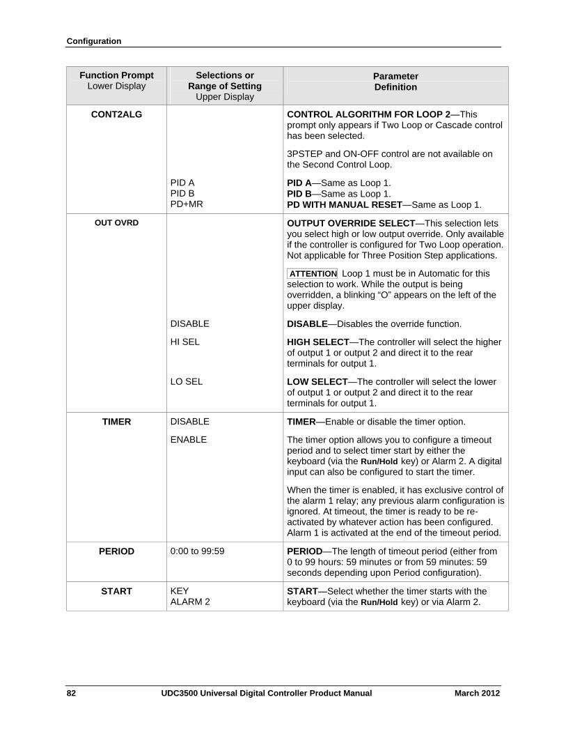
Configuration
82 UDC3500 Universal Digital Controller Product Manual March 2012
Function Prompt Lower Display
Selections or Range of Setting
Upper Display
Parameter Definition
CONT2ALG CONTROL ALGORITHM FOR LOOP 2—This prompt only appears if Two Loop or Cascade control has been selected.
3PSTEP and ON-OFF control are not available on the Second Control Loop.
PID A PID B PD+MR
PID A—Same as Loop 1. PID B—Same as Loop 1. PD WITH MANUAL RESET—Same as Loop 1.
OUT OVRD
OUTPUT OVERRIDE SELECT—This selection lets you select high or low output override. Only available if the controller is configured for Two Loop operation. Not applicable for Three Position Step applications.
ATTENTION Loop 1 must be in Automatic for this selection to work. While the output is being overridden, a blinking “O” appears on the left of the upper display.
DISABLE DISABLE—Disables the override function.
HI SEL HIGH SELECT—The controller will select the higher of output 1 or output 2 and direct it to the rear terminals for output 1.
LO SEL LOW SELECT—The controller will select the lower of output 1 or output 2 and direct it to the rear terminals for output 1.
TIMER DISABLE
ENABLE
TIMER—Enable or disable the timer option.
The timer option allows you to configure a timeout period and to select timer start by either the keyboard (via the Run/Hold key) or Alarm 2. A digital input can also be configured to start the timer.
When the timer is enabled, it has exclusive control of the alarm 1 relay; any previous alarm configuration is ignored. At timeout, the timer is ready to be re-activated by whatever action has been configured. Alarm 1 is activated at the end of the timeout period.
PERIOD 0:00 to 99:59 PERIOD—The length of timeout period (either from 0 to 99 hours: 59 minutes or from 59 minutes: 59 seconds depending upon Period configuration).
START KEY ALARM 2
START—Select whether the timer starts with the keyboard (via the Run/Hold key) or via Alarm 2.
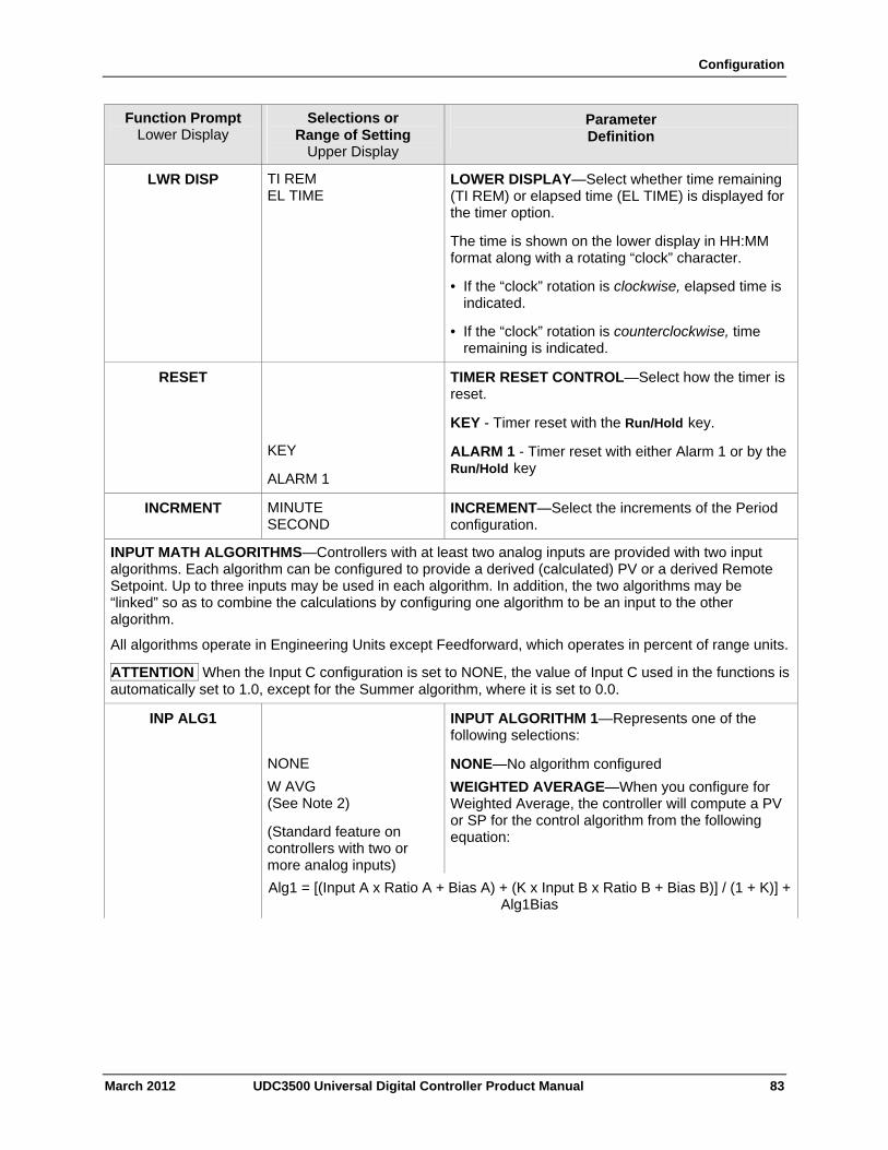
Configuration
March 2012 UDC3500 Universal Digital Controller Product Manual 83
Function Prompt Lower Display
Selections or Range of Setting
Upper Display
Parameter Definition
LWR DISP TI REM EL TIME
LOWER DISPLAY—Select whether time remaining (TI REM) or elapsed time (EL TIME) is displayed for the timer option.
The time is shown on the lower display in HH:MM format along with a rotating “clock” character.
• If the “clock” rotation is clockwise, elapsed time is indicated.
• If the “clock” rotation is counterclockwise, time remaining is indicated.
RESET
KEY
ALARM 1
TIMER RESET CONTROL—Select how the timer is reset.
KEY - Timer reset with the Run/Hold key.
ALARM 1 - Timer reset with either Alarm 1 or by the Run/Hold key
INCRMENT MINUTE SECOND
INCREMENT—Select the increments of the Period configuration.
INPUT MATH ALGORITHMS—Controllers with at least two analog inputs are provided with two input algorithms. Each algorithm can be configured to provide a derived (calculated) PV or a derived Remote Setpoint. Up to three inputs may be used in each algorithm. In addition, the two algorithms may be “linked” so as to combine the calculations by configuring one algorithm to be an input to the other algorithm.
All algorithms operate in Engineering Units except Feedforward, which operates in percent of range units.
ATTENTION When the Input C configuration is set to NONE, the value of Input C used in the functions is automatically set to 1.0, except for the Summer algorithm, where it is set to 0.0.
INP ALG1 INPUT ALGORITHM 1—Represents one of the following selections:
NONE NONE—No algorithm configured
W AVG (See Note 2)
(Standard feature on controllers with two or more analog inputs)
WEIGHTED AVERAGE—When you configure for Weighted Average, the controller will compute a PV or SP for the control algorithm from the following equation:
Alg1 = [(Input A x Ratio A + Bias A) + (K x Input B x Ratio B + Bias B)] / (1 + K)] + Alg1Bias
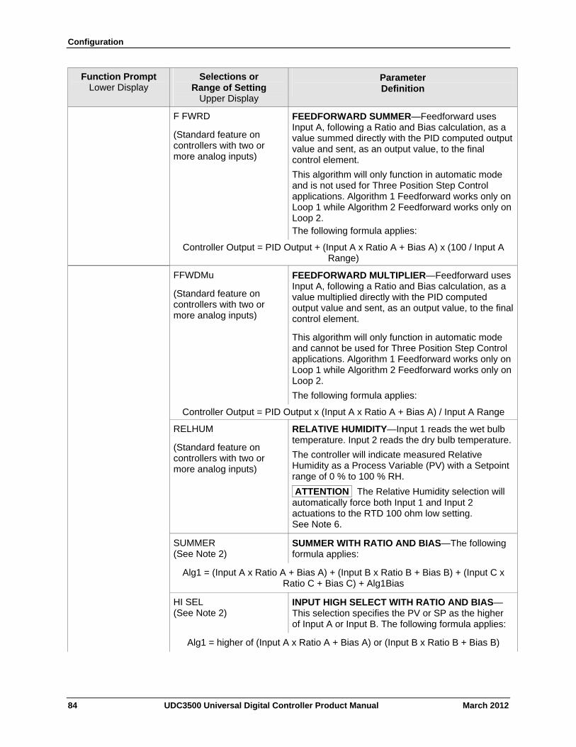
Configuration
84 UDC3500 Universal Digital Controller Product Manual March 2012
Function Prompt Lower Display
Selections or Range of Setting
Upper Display
Parameter Definition
F FWRD
(Standard feature on controllers with two or more analog inputs)
FEEDFORWARD SUMMER—Feedforward uses Input A, following a Ratio and Bias calculation, as a value summed directly with the PID computed output value and sent, as an output value, to the final control element.
This algorithm will only function in automatic mode and is not used for Three Position Step Control applications. Algorithm 1 Feedforward works only on Loop 1 while Algorithm 2 Feedforward works only on Loop 2. The following formula applies:
Controller Output = PID Output + (Input A x Ratio A + Bias A) x (100 / Input A Range)
FFWDMu
(Standard feature on controllers with two or more analog inputs)
FEEDFORWARD MULTIPLIER—Feedforward uses Input A, following a Ratio and Bias calculation, as a value multiplied directly with the PID computed output value and sent, as an output value, to the final control element.
This algorithm will only function in automatic mode and cannot be used for Three Position Step Control applications. Algorithm 1 Feedforward works only on Loop 1 while Algorithm 2 Feedforward works only on Loop 2.
The following formula applies:
Controller Output = PID Output x (Input A x Ratio A + Bias A) / Input A Range
RELHUM
(Standard feature on controllers with two or more analog inputs)
RELATIVE HUMIDITY—Input 1 reads the wet bulb temperature. Input 2 reads the dry bulb temperature.
The controller will indicate measured Relative Humidity as a Process Variable (PV) with a Setpoint range of 0 % to 100 % RH.
ATTENTION The Relative Humidity selection will automatically force both Input 1 and Input 2 actuations to the RTD 100 ohm low setting. See Note 6.
SUMMER (See Note 2)
SUMMER WITH RATIO AND BIAS—The following formula applies:
Alg1 = (Input A x Ratio A + Bias A) + (Input B x Ratio B + Bias B) + (Input C x Ratio C + Bias C) + Alg1Bias
HI SEL (See Note 2)
INPUT HIGH SELECT WITH RATIO AND BIAS—This selection specifies the PV or SP as the higher of Input A or Input B. The following formula applies:
Alg1 = higher of (Input A x Ratio A + Bias A) or (Input B x Ratio B + Bias B)
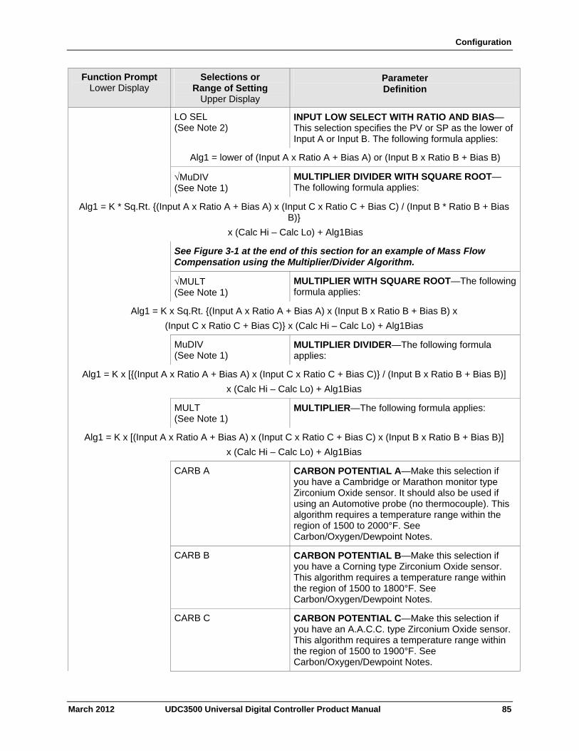
Configuration
March 2012 UDC3500 Universal Digital Controller Product Manual 85
Function Prompt Lower Display
Selections or Range of Setting
Upper Display
Parameter Definition
LO SEL (See Note 2)
INPUT LOW SELECT WITH RATIO AND BIAS—This selection specifies the PV or SP as the lower of Input A or Input B. The following formula applies:
Alg1 = lower of (Input A x Ratio A + Bias A) or (Input B x Ratio B + Bias B)
MuDIV (See Note 1)
MULTIPLIER DIVIDER WITH SQUARE ROOT—The following formula applies:
Alg1 = K * Sq.Rt. {(Input A x Ratio A + Bias A) x (Input C x Ratio C + Bias C) / (Input B * Ratio B + Bias B)}
x (Calc Hi – Calc Lo) + Alg1Bias
See Figure 3-1 at the end of this section for an example of Mass Flow Compensation using the Multiplier/Divider Algorithm.
MULT (See Note 1)
MULTIPLIER WITH SQUARE ROOT—The following formula applies:
Alg1 = K x Sq.Rt. {(Input A x Ratio A + Bias A) x (Input B x Ratio B + Bias B) x
(Input C x Ratio C + Bias C)} x (Calc Hi – Calc Lo) + Alg1Bias
MuDIV (See Note 1)
MULTIPLIER DIVIDER—The following formula applies:
Alg1 = K x [{(Input A x Ratio A + Bias A) x (Input C x Ratio C + Bias C)} / (Input B x Ratio B + Bias B)]
x (Calc Hi – Calc Lo) + Alg1Bias
MULT (See Note 1)
MULTIPLIER—The following formula applies:
Alg1 = K x [(Input A x Ratio A + Bias A) x (Input C x Ratio C + Bias C) x (Input B x Ratio B + Bias B)]
x (Calc Hi – Calc Lo) + Alg1Bias
CARB A CARBON POTENTIAL A—Make this selection if you have a Cambridge or Marathon monitor type Zirconium Oxide sensor. It should also be used if using an Automotive probe (no thermocouple). This algorithm requires a temperature range within the region of 1500 to 2000°F. See Carbon/Oxygen/Dewpoint Notes.
CARB B CARBON POTENTIAL B—Make this selection if you have a Corning type Zirconium Oxide sensor. This algorithm requires a temperature range within the region of 1500 to 1800°F. See Carbon/Oxygen/Dewpoint Notes.
CARB C CARBON POTENTIAL C—Make this selection if you have an A.A.C.C. type Zirconium Oxide sensor. This algorithm requires a temperature range within the region of 1500 to 1900°F. See Carbon/Oxygen/Dewpoint Notes.
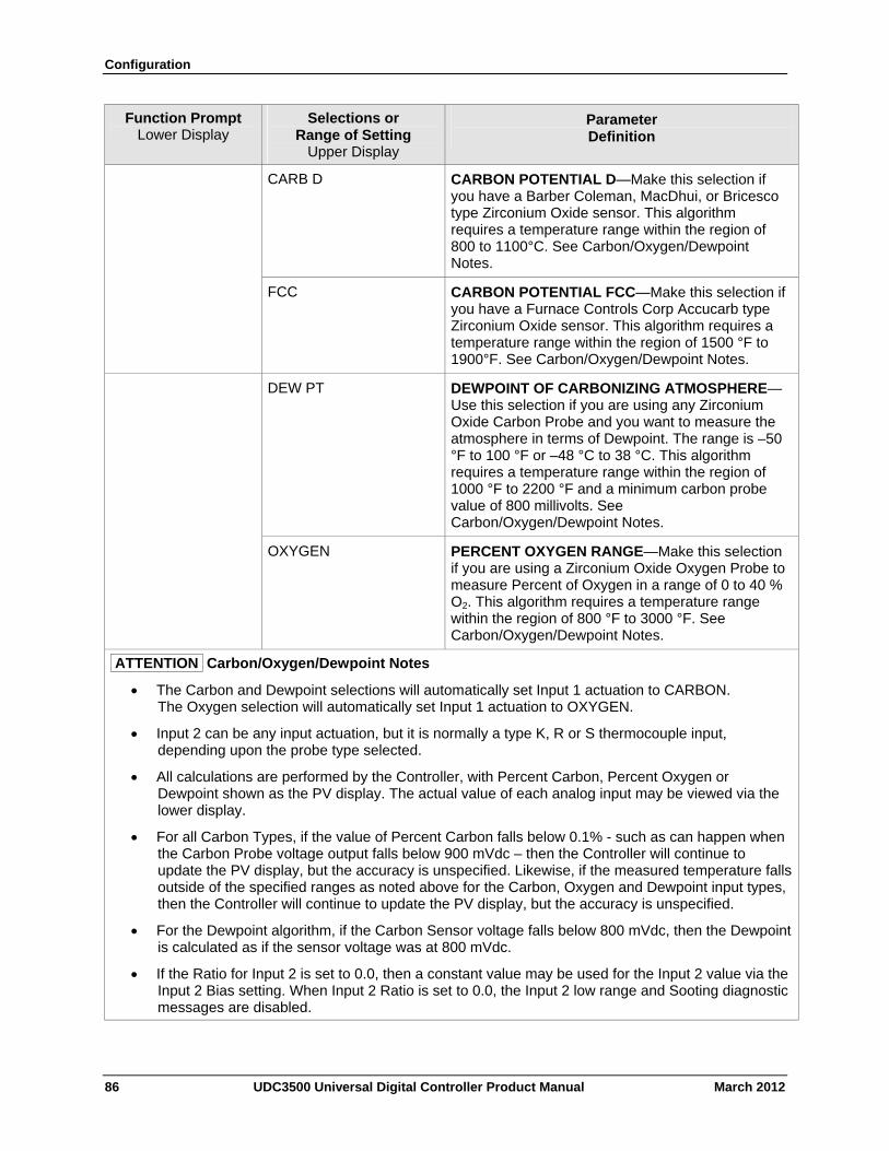
Configuration
86 UDC3500 Universal Digital Controller Product Manual March 2012
Function Prompt Lower Display
Selections or Range of Setting
Upper Display
Parameter Definition
CARB D CARBON POTENTIAL D—Make this selection if you have a Barber Coleman, MacDhui, or Bricesco type Zirconium Oxide sensor. This algorithm requires a temperature range within the region of 800 to 1100°C. See Carbon/Oxygen/Dewpoint Notes.
FCC CARBON POTENTIAL FCC—Make this selection if you have a Furnace Controls Corp Accucarb type Zirconium Oxide sensor. This algorithm requires a temperature range within the region of 1500 °F to 1900°F. See Carbon/Oxygen/Dewpoint Notes.
DEW PT DEWPOINT OF CARBONIZING ATMOSPHERE—Use this selection if you are using any Zirconium Oxide Carbon Probe and you want to measure the atmosphere in terms of Dewpoint. The range is –50 °F to 100 °F or –48 °C to 38 °C. This algorithm requires a temperature range within the region of 1000 °F to 2200 °F and a minimum carbon probe value of 800 millivolts. See Carbon/Oxygen/Dewpoint Notes.
OXYGEN PERCENT OXYGEN RANGE—Make this selection if you are using a Zirconium Oxide Oxygen Probe to measure Percent of Oxygen in a range of 0 to 40 % O2. This algorithm requires a temperature range within the region of 800 °F to 3000 °F. See Carbon/Oxygen/Dewpoint Notes.
ATTENTION Carbon/Oxygen/Dewpoint Notes
The Carbon and Dewpoint selections will automatically set Input 1 actuation to CARBON. The Oxygen selection will automatically set Input 1 actuation to OXYGEN.
Input 2 can be any input actuation, but it is normally a type K, R or S thermocouple input, depending upon the probe type selected.
All calculations are performed by the Controller, with Percent Carbon, Percent Oxygen or Dewpoint shown as the PV display. The actual value of each analog input may be viewed via the lower display.
For all Carbon Types, if the value of Percent Carbon falls below 0.1% - such as can happen when the Carbon Probe voltage output falls below 900 mVdc – then the Controller will continue to update the PV display, but the accuracy is unspecified. Likewise, if the measured temperature falls outside of the specified ranges as noted above for the Carbon, Oxygen and Dewpoint input types, then the Controller will continue to update the PV display, but the accuracy is unspecified.
For the Dewpoint algorithm, if the Carbon Sensor voltage falls below 800 mVdc, then the Dewpoint is calculated as if the sensor voltage was at 800 mVdc.
If the Ratio for Input 2 is set to 0.0, then a constant value may be used for the Input 2 value via the Input 2 Bias setting. When Input 2 Ratio is set to 0.0, the Input 2 low range and Sooting diagnostic messages are disabled.
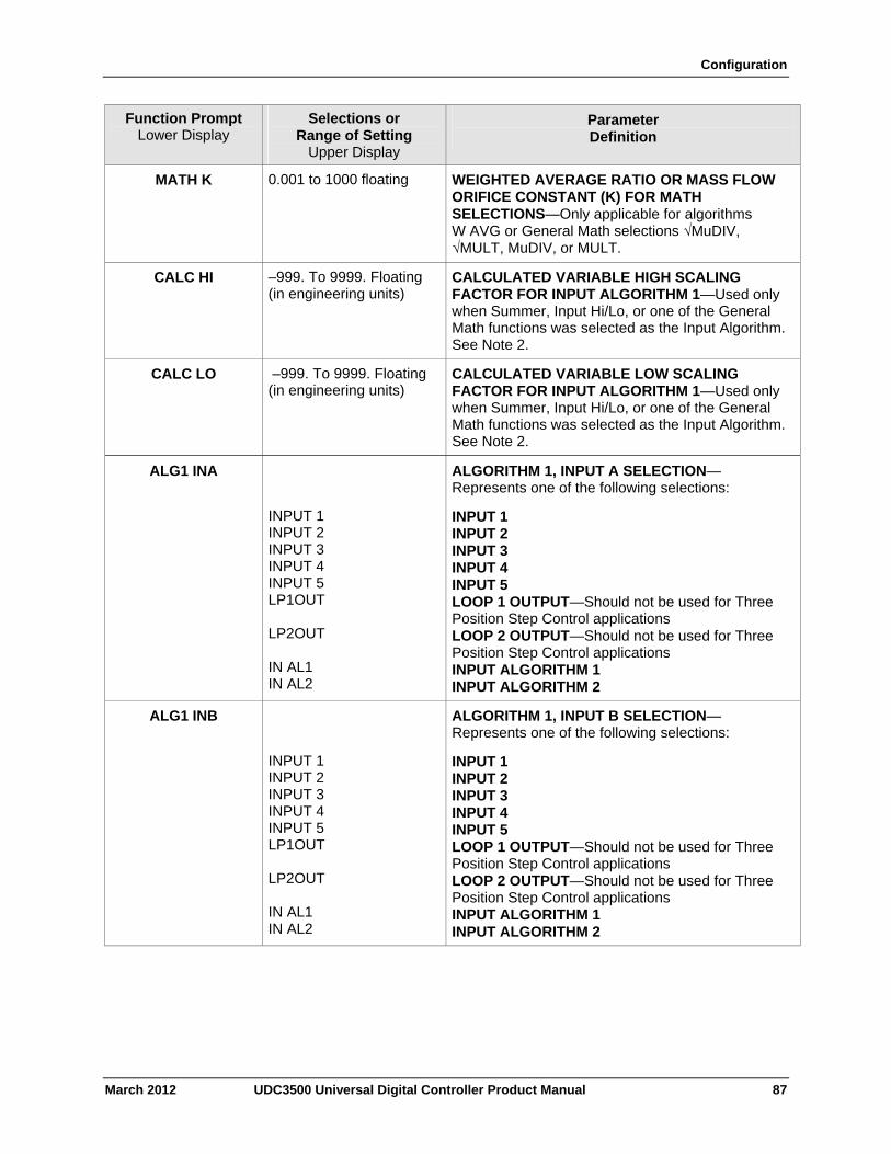
Configuration
March 2012 UDC3500 Universal Digital Controller Product Manual 87
Function Prompt Lower Display
Selections or Range of Setting
Upper Display
Parameter Definition
MATH K 0.001 to 1000 floating WEIGHTED AVERAGE RATIO OR MASS FLOW ORIFICE CONSTANT (K) FOR MATH SELECTIONS—Only applicable for algorithms W AVG or General Math selections √MuDIV, √MULT, MuDIV, or MULT.
CALC HI –999. To 9999. Floating (in engineering units)
CALCULATED VARIABLE HIGH SCALING FACTOR FOR INPUT ALGORITHM 1—Used only when Summer, Input Hi/Lo, or one of the General Math functions was selected as the Input Algorithm. See Note 2.
CALC LO –999. To 9999. Floating (in engineering units)
CALCULATED VARIABLE LOW SCALING FACTOR FOR INPUT ALGORITHM 1—Used only when Summer, Input Hi/Lo, or one of the General Math functions was selected as the Input Algorithm. See Note 2.
ALG1 INA
INPUT 1 INPUT 2 INPUT 3 INPUT 4 INPUT 5 LP1OUT LP2OUT IN AL1 IN AL2
ALGORITHM 1, INPUT A SELECTION—Represents one of the following selections:
INPUT 1 INPUT 2 INPUT 3 INPUT 4 INPUT 5 LOOP 1 OUTPUT—Should not be used for Three Position Step Control applications LOOP 2 OUTPUT—Should not be used for Three Position Step Control applications INPUT ALGORITHM 1 INPUT ALGORITHM 2
ALG1 INB
INPUT 1 INPUT 2 INPUT 3 INPUT 4 INPUT 5 LP1OUT LP2OUT IN AL1 IN AL2
ALGORITHM 1, INPUT B SELECTION—Represents one of the following selections:
INPUT 1 INPUT 2 INPUT 3 INPUT 4 INPUT 5 LOOP 1 OUTPUT—Should not be used for Three Position Step Control applications LOOP 2 OUTPUT—Should not be used for Three Position Step Control applications INPUT ALGORITHM 1 INPUT ALGORITHM 2
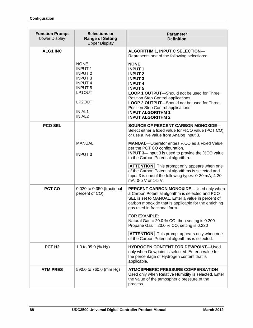
Configuration
88 UDC3500 Universal Digital Controller Product Manual March 2012
Function Prompt Lower Display
Selections or Range of Setting
Upper Display
Parameter Definition
ALG1 INC
NONE INPUT 1 INPUT 2 INPUT 3 INPUT 4 INPUT 5 LP1OUT LP2OUT IN AL1 IN AL2
ALGORITHM 1, INPUT C SELECTION—Represents one of the following selections:
NONE INPUT 1 INPUT 2 INPUT 3 INPUT 4 INPUT 5 LOOP 1 OUTPUT—Should not be used for Three Position Step Control applications LOOP 2 OUTPUT—Should not be used for Three Position Step Control applications INPUT ALGORITHM 1 INPUT ALGORITHM 2
PCO SEL SOURCE OF PERCENT CARBON MONOXIDE—Select either a fixed value for %CO value (PCT CO) or use a live value from Analog Input 3.
MANUAL
INPUT 3
MANUAL—Operator enters %CO as a Fixed Value per the PCT CO configuration. INPUT 3—Input 3 is used to provide the %CO value to the Carbon Potential algorithm.
ATTENTION This prompt only appears when one of the Carbon Potential algorithms is selected and Input 3 is one of the following types: 0-20 mA, 4-20 mA, 0-5 V or 1-5 V.
PCT CO 0.020 to 0.350 (fractional percent of CO)
PERCENT CARBON MONOXIDE—Used only when a Carbon Potential algorithm is selected and PCO SEL is set to MANUAL. Enter a value in percent of carbon monoxide that is applicable for the enriching gas used in fractional form.
FOR EXAMPLE: Natural Gas = 20.0 % CO, then setting is 0.200 Propane Gas = 23.0 % CO, setting is 0.230
ATTENTION This prompt appears only when one of the Carbon Potential algorithms is selected.
PCT H2 1.0 to 99.0 (% H2) HYDROGEN CONTENT FOR DEWPOINT—Used only when Dewpoint is selected. Enter a value for the percentage of Hydrogen content that is applicable.
ATM PRES 590.0 to 760.0 (mm Hg) ATMOSPHERIC PRESSURE COMPENSATION—Used only when Relative Humidity is selected. Enter the value of the atmospheric pressure of the process.
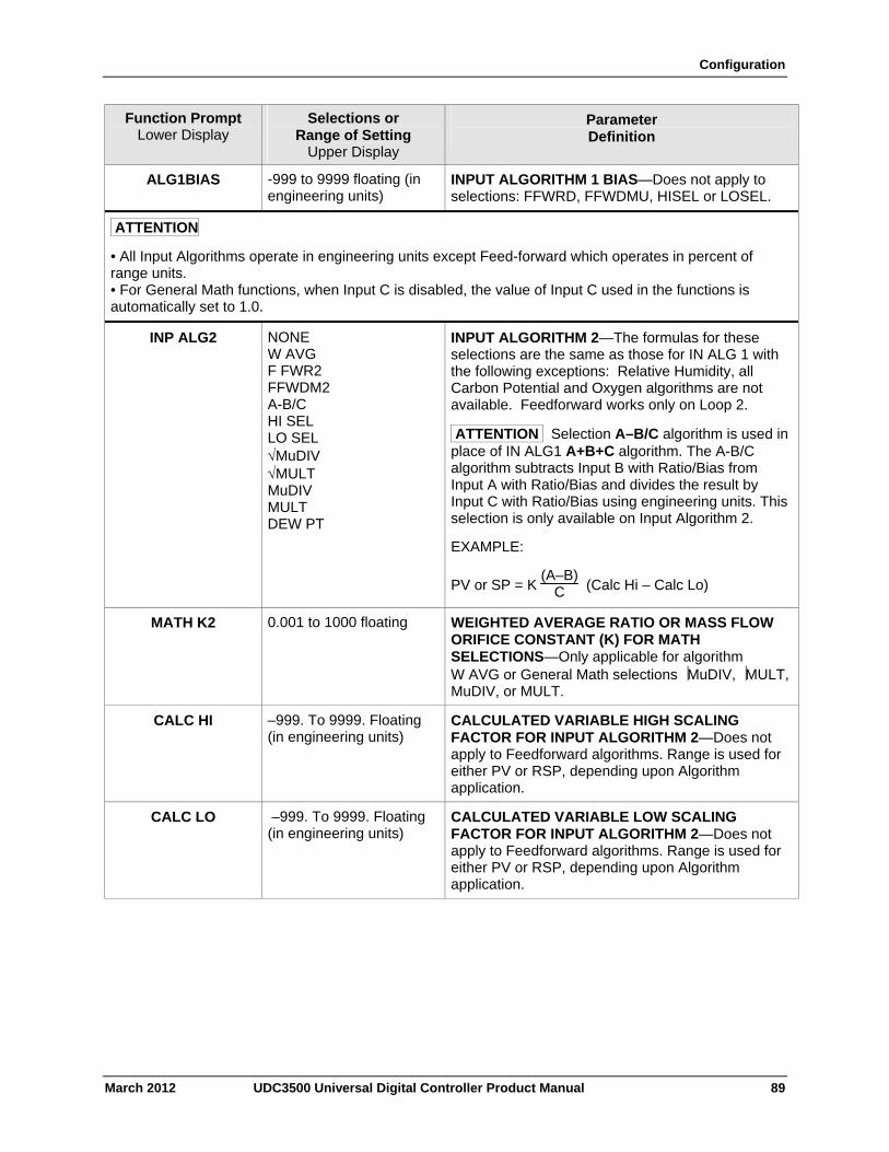
Configuration
March 2012 UDC3500 Universal Digital Controller Product Manual 89
Function Prompt Lower Display
Selections or Range of Setting
Upper Display
Parameter Definition
ALG1BIAS -999 to 9999 floating (in engineering units)
INPUT ALGORITHM 1 BIAS—Does not apply to selections: FFWRD, FFWDMU, HISEL or LOSEL.
ATTENTION
• All Input Algorithms operate in engineering units except Feed-forward which operates in percent of range units. • For General Math functions, when Input C is disabled, the value of Input C used in the functions is automatically set to 1.0.
INP ALG2
NONE W AVG F FWR2 FFWDM2 A-B/C HI SEL LO SEL MuDIV MULT MuDIV MULT DEW PT
INPUT ALGORITHM 2—The formulas for these selections are the same as those for IN ALG 1 with the following exceptions: Relative Humidity, all Carbon Potential and Oxygen algorithms are not available. Feedforward works only on Loop 2.
ATTENTION Selection A–B/C algorithm is used in place of IN ALG1 A+B+C algorithm. The A-B/C algorithm subtracts Input B with Ratio/Bias from Input A with Ratio/Bias and divides the result by Input C with Ratio/Bias using engineering units. This selection is only available on Input Algorithm 2.
EXAMPLE:
PV or SP = K (A–B)
C (Calc Hi – Calc Lo)
MATH K2 0.001 to 1000 floating WEIGHTED AVERAGE RATIO OR MASS FLOW ORIFICE CONSTANT (K) FOR MATH SELECTIONS—Only applicable for algorithm W AVG or General Math selections MuDIV, MULT, MuDIV, or MULT.
CALC HI –999. To 9999. Floating (in engineering units)
CALCULATED VARIABLE HIGH SCALING FACTOR FOR INPUT ALGORITHM 2—Does not apply to Feedforward algorithms. Range is used for either PV or RSP, depending upon Algorithm application.
CALC LO –999. To 9999. Floating (in engineering units)
CALCULATED VARIABLE LOW SCALING FACTOR FOR INPUT ALGORITHM 2—Does not apply to Feedforward algorithms. Range is used for either PV or RSP, depending upon Algorithm application.
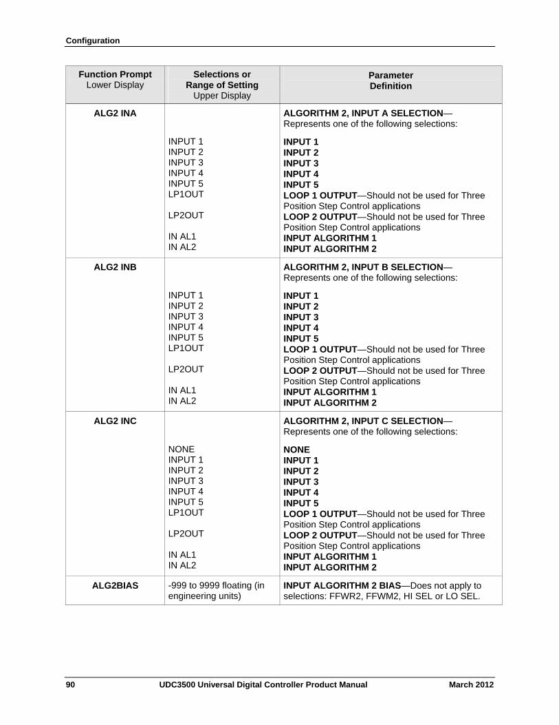
Configuration
90 UDC3500 Universal Digital Controller Product Manual March 2012
Function Prompt Lower Display
Selections or Range of Setting
Upper Display
Parameter Definition
ALG2 INA
INPUT 1 INPUT 2 INPUT 3 INPUT 4 INPUT 5 LP1OUT LP2OUT IN AL1 IN AL2
ALGORITHM 2, INPUT A SELECTION—Represents one of the following selections:
INPUT 1 INPUT 2 INPUT 3 INPUT 4 INPUT 5 LOOP 1 OUTPUT—Should not be used for Three Position Step Control applications LOOP 2 OUTPUT—Should not be used for Three Position Step Control applications INPUT ALGORITHM 1 INPUT ALGORITHM 2
ALG2 INB
INPUT 1 INPUT 2 INPUT 3 INPUT 4 INPUT 5 LP1OUT LP2OUT IN AL1 IN AL2
ALGORITHM 2, INPUT B SELECTION—Represents one of the following selections:
INPUT 1 INPUT 2 INPUT 3 INPUT 4 INPUT 5 LOOP 1 OUTPUT—Should not be used for Three Position Step Control applications LOOP 2 OUTPUT—Should not be used for Three Position Step Control applications INPUT ALGORITHM 1 INPUT ALGORITHM 2
ALG2 INC
NONE INPUT 1 INPUT 2 INPUT 3 INPUT 4 INPUT 5 LP1OUT LP2OUT IN AL1 IN AL2
ALGORITHM 2, INPUT C SELECTION—Represents one of the following selections:
NONE INPUT 1 INPUT 2 INPUT 3 INPUT 4 INPUT 5 LOOP 1 OUTPUT—Should not be used for Three Position Step Control applications LOOP 2 OUTPUT—Should not be used for Three Position Step Control applications INPUT ALGORITHM 1 INPUT ALGORITHM 2
ALG2BIAS -999 to 9999 floating (in engineering units)
INPUT ALGORITHM 2 BIAS—Does not apply to selections: FFWR2, FFWM2, HI SEL or LO SEL.
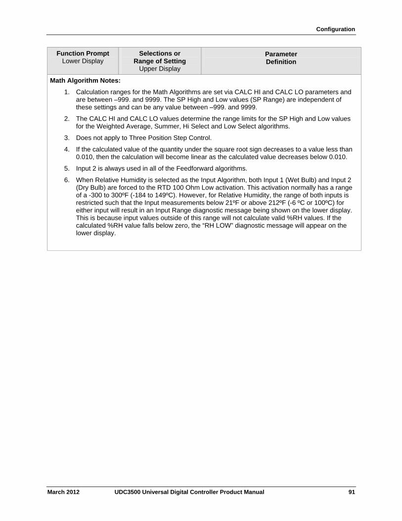
Configuration
March 2012 UDC3500 Universal Digital Controller Product Manual 91
Function Prompt Lower Display
Selections or Range of Setting
Upper Display
Parameter Definition
Math Algorithm Notes:
1. Calculation ranges for the Math Algorithms are set via CALC HI and CALC LO parameters and are between –999. and 9999. The SP High and Low values (SP Range) are independent of these settings and can be any value between –999. and 9999.
2. The CALC HI and CALC LO values determine the range limits for the SP High and Low values for the Weighted Average, Summer, Hi Select and Low Select algorithms.
3. Does not apply to Three Position Step Control.
4. If the calculated value of the quantity under the square root sign decreases to a value less than 0.010, then the calculation will become linear as the calculated value decreases below 0.010.
5. Input 2 is always used in all of the Feedforward algorithms.
6. When Relative Humidity is selected as the Input Algorithm, both Input 1 (Wet Bulb) and Input 2 (Dry Bulb) are forced to the RTD 100 Ohm Low activation. This activation normally has a range of a -300 to 300ºF (-184 to 149ºC). However, for Relative Humidity, the range of both inputs is restricted such that the Input measurements below 21ºF or above 212ºF (-6 ºC or 100ºC) for either input will result in an Input Range diagnostic message being shown on the lower display. This is because input values outside of this range will not calculate valid %RH values. If the calculated %RH value falls below zero, the “RH LOW” diagnostic message will appear on the lower display.
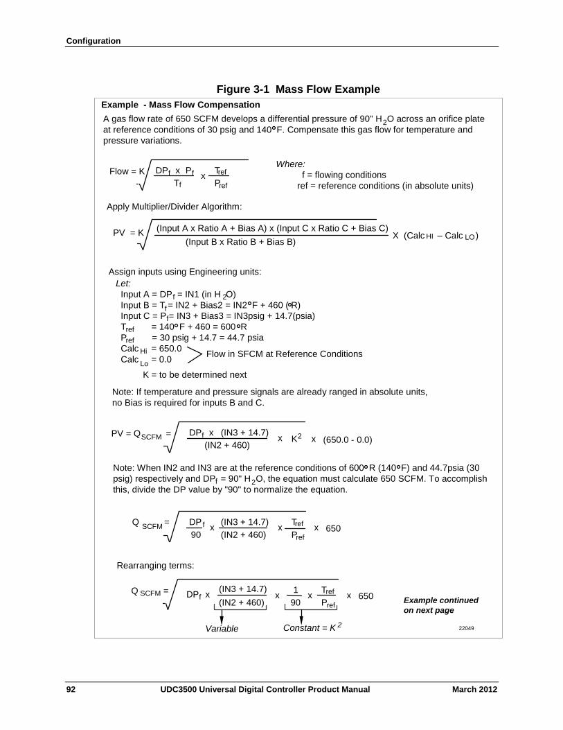
Configuration
Figure 3-1 Mass Flow Example Example - Mass Flow Compensation
A gas flow rate of 650 SCFM develops a differential pressure of 90" H O across an orifice plate at reference conditions of 30 psig and 140 F. Compensate this gas flow for temperature and pressure variations.
Apply Multiplier/Divider Algorithm:
Flow = K DP f x P f T f
T refx P ref
PV = K (Input B x Ratio B + Bias B)
(Input A x Ratio A + Bias A) x (Input C x Ratio C + Bias C) X (Calc – Calc ) HI LO
Where: f = flowing conditions
ref = reference conditions (in absolute units)
Note: If temperature and pressure signals are already ranged in absolute units, no Bias is required for inputs B and C.
Assign inputs using Engineering units: Let: Input A = DP = IN1 (in H O) Input B = T = IN2 + Bias2 = IN2 F + 460 ( R) Input C = P = IN3 + Bias3 = IN3psig + 14.7(psia) T = 140 F + 460 = 600 R P = 30 psig + 14.7 = 44.7 psia Calc = 650.0 Calc = 0.0
2
f f
ref ref
Hi
Lo Flow in SFCM at Reference Conditions
K = to be determined next
f
2
22049
Example continued on next page
PV = Q = DP f (IN3 + 14.7) x SCFM (IN2 + 460)
K2x (650.0 - 0.0) x
DP f 90
(IN3 + 14.7) x
(IN2 + 460)
T refxPref
SCFM Q = x 650
Note: When IN2 and IN3 are at the reference conditions of 600 R (140 F) and 44.7psia (30 psig) respectively and DP = 90" H O, the equation must calculate 650 SCFM. To accomplish this, divide the DP value by "90" to normalize the equation.
2f
Rearranging terms:
Variable Constant = K 2
DP f (IN3 + 14.7)
x (IN2 + 460)
x1
90
T ref
Prefx x 650 SCFM Q =
92 UDC3500 Universal Digital Controller Product Manual March 2012
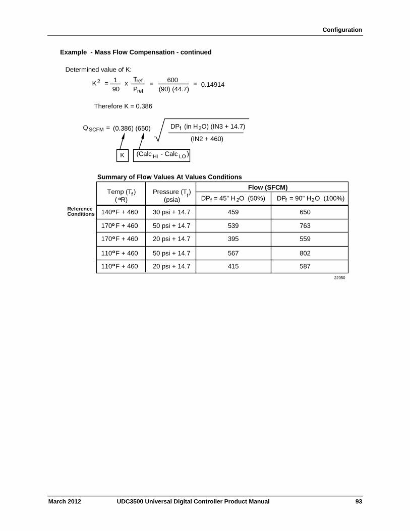
Configuration
Example - Mass Flow Compensation - continued
Determined value of K:
K 2 = x 1
90
T ref P ref
= = 0.14914 600
(90) (44.7)
Therefore K = 0.386
SCFM Q = (0.386) (650)
(Calc - Calc ) HI LOK
DPf (in H O) (IN3 + 14.7)
(IN2 + 460)
2
140 F + 460
170 F + 460
170 F + 460
110 F + 460
110 F + 460
30 psi + 14.7
50 psi + 14.7
20 psi + 14.7
50 psi + 14.7
20 psi + 14.7
459
539
395
567
415
Flow (SFCM)
DP = 45" H O (50%) f 2
650
763
559
802
587
DP = 90" H O (100%) f 2 Temp (T )
( R) f
Summary of Flow Values At Values Conditions
Pressure (T ) (psia)
f
Reference Conditions
22050
March 2012 UDC3500 Universal Digital Controller Product Manual 93
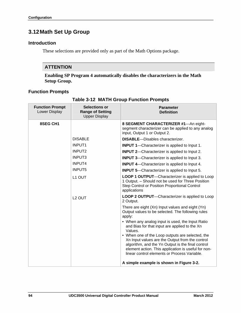
Configuration
3.12 Math Set Up Group
Introduction
These selections are provided only as part of the Math Options package.
ATTENTION
Enabling SP Program 4 automatically disables the characterizers in the Math Setup Group.
Function Prompts
Table 3-12 MATH Group Function Prompts
Function Prompt Lower Display
Selections or Range of Setting
Upper Display
Parameter Definition
8SEG CH1
DISABLE
INPUT1
INPUT2
INPUT3
INPUT4
INPUT5
L1 OUT
L2 OUT
8 SEGMENT CHARACTERIZER #1—An eight-segment characterizer can be applied to any analog input, Output 1 or Output 2.
DISABLE—Disables characterizer.
INPUT 1—Characterizer is applied to Input 1.
INPUT 2—Characterizer is applied to Input 2.
INPUT 3—Characterizer is applied to Input 3.
INPUT 4—Characterizer is applied to Input 4.
INPUT 5—Characterizer is applied to Input 5.
LOOP 1 OUTPUT—Characterizer is applied to Loop 1 Output. – Should not be used for Three Position Step Control or Position Proportional Control applications
LOOP 2 OUTPUT—Characterizer is applied to Loop 2 Output.
There are eight (Xn) Input values and eight (Yn) Output values to be selected. The following rules apply: • When any analog input is used, the Input Ratio
and Bias for that input are applied to the Xn Values.
• When one of the Loop outputs are selected, the Xn Input values are the Output from the control algorithm, and the Yn Output is the final control element action. This application is useful for non-linear control elements or Process Variable.
A simple example is shown in Figure 3-2.
94 UDC3500 Universal Digital Controller Product Manual March 2012
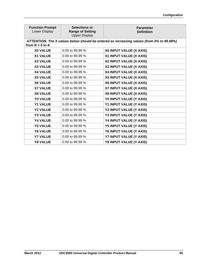
Configuration
March 2012 UDC3500 Universal Digital Controller Product Manual 95
Function Prompt Lower Display
Selections or Range of Setting
Upper Display
Parameter Definition
ATTENTION The X values below should be entered as increasing values (from 0% to 99.99%) from N = 0 to 8.
X0 VALUE 0.00 to 99.99 % X0 INPUT VALUE (X AXIS)
X1 VALUE 0.00 to 99.99 % X1 INPUT VALUE (X AXIS)
X2 VALUE 0.00 to 99.99 % X2 INPUT VALUE (X AXIS)
X3 VALUE 0.00 to 99.99 % X3 INPUT VALUE (X AXIS)
X4 VALUE 0.00 to 99.99 % X4 INPUT VALUE (X AXIS)
X5 VALUE 0.00 to 99.99 % X5 INPUT VALUE (X AXIS)
X6 VALUE 0.00 to 99.99 % X6 INPUT VALUE (X AXIS)
X7 VALUE 0.00 to 99.99 % X7 INPUT VALUE (X AXIS)
X8 VALUE 0.00 to 99.99 % X8 INPUT VALUE (X AXIS)
Y0 VALUE 0.00 to 99.99 % Y0 INPUT VALUE (Y AXIS)
Y1 VALUE 0.00 to 99.99 % Y1 INPUT VALUE (Y AXIS)
Y2 VALUE 0.00 to 99.99 % Y2 INPUT VALUE (Y AXIS)
Y3 VALUE 0.00 to 99.99 % Y3 INPUT VALUE (Y AXIS)
Y4 VALUE 0.00 to 99.99 % Y4 INPUT VALUE (Y AXIS)
Y5 VALUE 0.00 to 99.99 % Y5 INPUT VALUE (Y AXIS)
Y6 VALUE 0.00 to 99.99 % Y6 INPUT VALUE (Y AXIS)
Y7 VALUE 0.00 to 99.99 % Y7 INPUT VALUE (Y AXIS)
Y8 VALUE 0.00 to 99.99 % Y8 INPUT VALUE (Y AXIS)
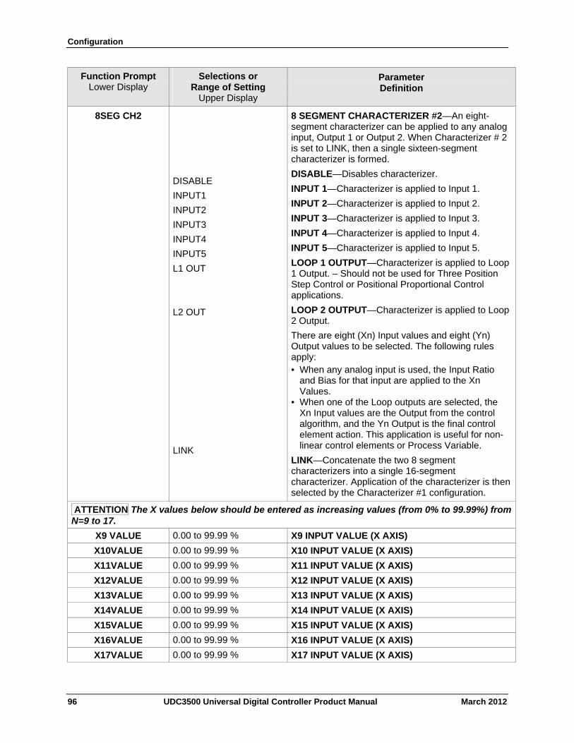
Configuration
96 UDC3500 Universal Digital Controller Product Manual March 2012
Function Prompt Lower Display
Selections or Range of Setting
Upper Display
Parameter Definition
8SEG CH2
DISABLE
INPUT1
INPUT2
INPUT3
INPUT4
INPUT5
L1 OUT
L2 OUT
LINK
8 SEGMENT CHARACTERIZER #2—An eight-segment characterizer can be applied to any analog input, Output 1 or Output 2. When Characterizer # 2 is set to LINK, then a single sixteen-segment characterizer is formed.
DISABLE—Disables characterizer.
INPUT 1—Characterizer is applied to Input 1.
INPUT 2—Characterizer is applied to Input 2.
INPUT 3—Characterizer is applied to Input 3.
INPUT 4—Characterizer is applied to Input 4.
INPUT 5—Characterizer is applied to Input 5.
LOOP 1 OUTPUT—Characterizer is applied to Loop 1 Output. – Should not be used for Three Position Step Control or Positional Proportional Control applications.
LOOP 2 OUTPUT—Characterizer is applied to Loop 2 Output.
There are eight (Xn) Input values and eight (Yn) Output values to be selected. The following rules apply: • When any analog input is used, the Input Ratio
and Bias for that input are applied to the Xn Values.
• When one of the Loop outputs are selected, the Xn Input values are the Output from the control algorithm, and the Yn Output is the final control element action. This application is useful for non-linear control elements or Process Variable.
LINK—Concatenate the two 8 segment characterizers into a single 16-segment characterizer. Application of the characterizer is then selected by the Characterizer #1 configuration.
ATTENTION The X values below should be entered as increasing values (from 0% to 99.99%) from N=9 to 17.
X9 VALUE 0.00 to 99.99 % X9 INPUT VALUE (X AXIS)
X10VALUE 0.00 to 99.99 % X10 INPUT VALUE (X AXIS)
X11VALUE 0.00 to 99.99 % X11 INPUT VALUE (X AXIS)
X12VALUE 0.00 to 99.99 % X12 INPUT VALUE (X AXIS)
X13VALUE 0.00 to 99.99 % X13 INPUT VALUE (X AXIS)
X14VALUE 0.00 to 99.99 % X14 INPUT VALUE (X AXIS)
X15VALUE 0.00 to 99.99 % X15 INPUT VALUE (X AXIS)
X16VALUE 0.00 to 99.99 % X16 INPUT VALUE (X AXIS)
X17VALUE 0.00 to 99.99 % X17 INPUT VALUE (X AXIS)
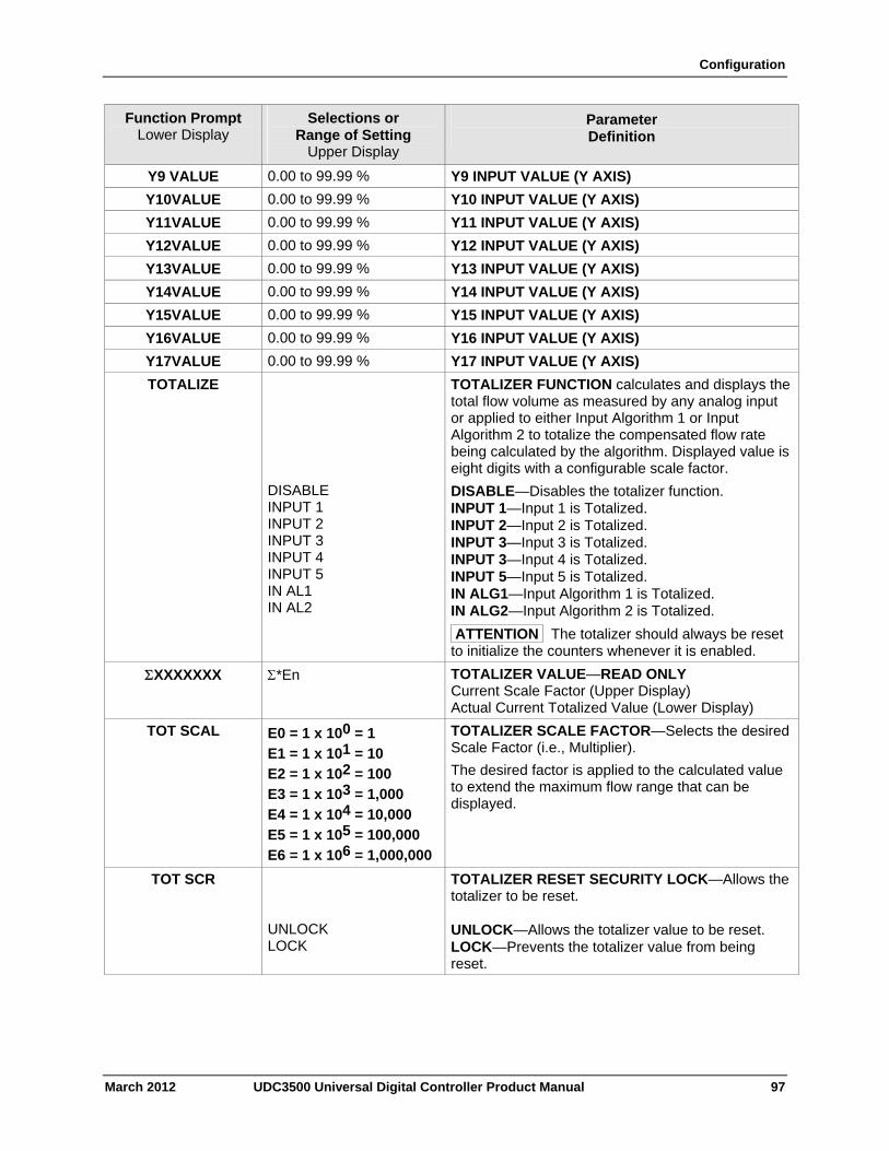
Configuration
March 2012 UDC3500 Universal Digital Controller Product Manual 97
Function Prompt Lower Display
Selections or Range of Setting
Upper Display
Parameter Definition
Y9 VALUE 0.00 to 99.99 % Y9 INPUT VALUE (Y AXIS)
Y10VALUE 0.00 to 99.99 % Y10 INPUT VALUE (Y AXIS)
Y11VALUE 0.00 to 99.99 % Y11 INPUT VALUE (Y AXIS)
Y12VALUE 0.00 to 99.99 % Y12 INPUT VALUE (Y AXIS)
Y13VALUE 0.00 to 99.99 % Y13 INPUT VALUE (Y AXIS)
Y14VALUE 0.00 to 99.99 % Y14 INPUT VALUE (Y AXIS)
Y15VALUE 0.00 to 99.99 % Y15 INPUT VALUE (Y AXIS)
Y16VALUE 0.00 to 99.99 % Y16 INPUT VALUE (Y AXIS)
Y17VALUE 0.00 to 99.99 % Y17 INPUT VALUE (Y AXIS)
TOTALIZE
DISABLE INPUT 1 INPUT 2 INPUT 3 INPUT 4 INPUT 5 IN AL1 IN AL2
TOTALIZER FUNCTION calculates and displays the total flow volume as measured by any analog input or applied to either Input Algorithm 1 or Input Algorithm 2 to totalize the compensated flow rate being calculated by the algorithm. Displayed value is eight digits with a configurable scale factor.
DISABLE—Disables the totalizer function. INPUT 1—Input 1 is Totalized. INPUT 2—Input 2 is Totalized. INPUT 3—Input 3 is Totalized. INPUT 3—Input 4 is Totalized. INPUT 5—Input 5 is Totalized. IN ALG1—Input Algorithm 1 is Totalized. IN ALG2—Input Algorithm 2 is Totalized.
ATTENTION The totalizer should always be reset to initialize the counters whenever it is enabled.
XXXXXXX *En TOTALIZER VALUE—READ ONLY Current Scale Factor (Upper Display) Actual Current Totalized Value (Lower Display)
TOT SCAL E0 = 1 x 100 = 1 E1 = 1 x 101 = 10 E2 = 1 x 102 = 100 E3 = 1 x 103 = 1,000 E4 = 1 x 104 = 10,000 E5 = 1 x 105 = 100,000 E6 = 1 x 106 = 1,000,000
TOTALIZER SCALE FACTOR—Selects the desired Scale Factor (i.e., Multiplier).
The desired factor is applied to the calculated value to extend the maximum flow range that can be displayed.
TOT SCR UNLOCK LOCK
TOTALIZER RESET SECURITY LOCK—Allows the totalizer to be reset. UNLOCK—Allows the totalizer value to be reset. LOCK—Prevents the totalizer value from being reset.
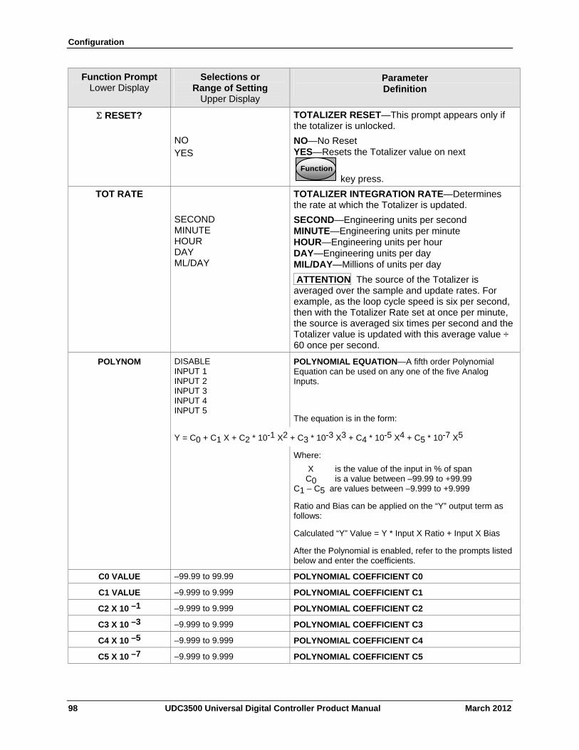
Configuration
98 UDC3500 Universal Digital Controller Product Manual March 2012
Function Prompt Lower Display
Selections or Range of Setting
Upper Display
Parameter Definition
RESET?
NO YES
TOTALIZER RESET—This prompt appears only if the totalizer is unlocked.
NO—No Reset YES—Resets the Totalizer value on next
FunctionFunctionFunction
key press.
TOT RATE
SECOND MINUTE HOUR DAY ML/DAY
TOTALIZER INTEGRATION RATE—Determines the rate at which the Totalizer is updated.
SECOND—Engineering units per second MINUTE—Engineering units per minute HOUR—Engineering units per hour DAY—Engineering units per day MIL/DAY—Millions of units per day
ATTENTION The source of the Totalizer is averaged over the sample and update rates. For example, as the loop cycle speed is six per second, then with the Totalizer Rate set at once per minute, the source is averaged six times per second and the Totalizer value is updated with this average value ÷ 60 once per second.
POLYNOM DISABLE INPUT 1 INPUT 2 INPUT 3 INPUT 4 INPUT 5
POLYNOMIAL EQUATION—A fifth order Polynomial Equation can be used on any one of the five Analog Inputs.
The equation is in the form:
Y = C0 + C1 X + C2 * 10-1 X2 + C3 * 10-3 X3 + C4 * 10-5 X4 + C5 * 10-7 X5
Where:
X is the value of the input in % of span C0 is a value between –99.99 to +99.99 C1 – C5 are values between –9.999 to +9.999
Ratio and Bias can be applied on the “Y” output term as follows:
Calculated “Y” Value = Y * Input X Ratio + Input X Bias
After the Polynomial is enabled, refer to the prompts listed below and enter the coefficients.
C0 VALUE –99.99 to 99.99 POLYNOMIAL COEFFICIENT C0
C1 VALUE –9.999 to 9.999 POLYNOMIAL COEFFICIENT C1
C2 X 10 –1 –9.999 to 9.999 POLYNOMIAL COEFFICIENT C2
C3 X 10 –3 –9.999 to 9.999 POLYNOMIAL COEFFICIENT C3
C4 X 10 –5 –9.999 to 9.999 POLYNOMIAL COEFFICIENT C4
C5 X 10 –7 –9.999 to 9.999 POLYNOMIAL COEFFICIENT C5
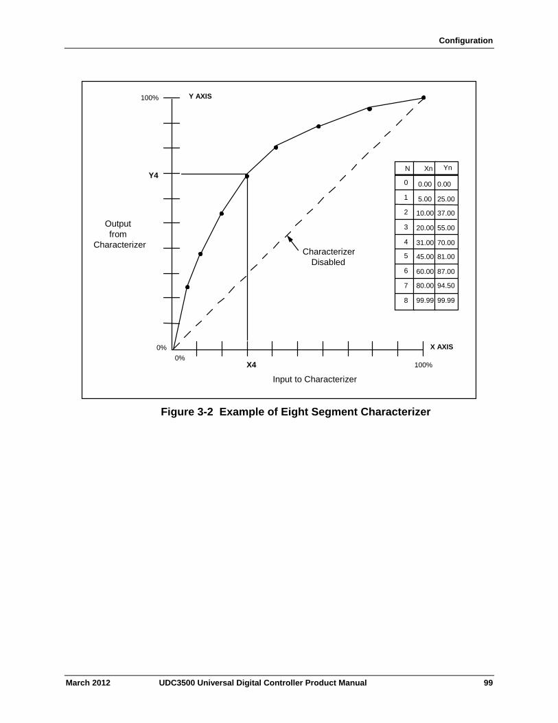
Configuration
N Xn Yn
0
1
2
3
4
5
6
7
8
0.00
5.00
10.00
20.00
31.00
45.00
60.00
80.00
99.99
0.00
25.00
37.00
55.00
70.00
81.00
87.00
94.50
99.99
100% Y AXIS
Y4
Output from
Characterizer
0% 0%
X4
Input to Characterizer
100%
X AXIS
Characterizer Disabled
Figure 3-2 Example of Eight Segment Characterizer
March 2012 UDC3500 Universal Digital Controller Product Manual 99
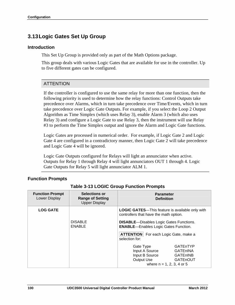
Configuration
3.13 Logic Gates Set Up Group
Introduction
This Set Up Group is provided only as part of the Math Options package.
This group deals with various Logic Gates that are available for use in the controller. Up to five different gates can be configured.
ATTENTION
If the controller is configured to use the same relay for more than one function, then the following priority is used to determine how the relay functions: Control Outputs take precedence over Alarms, which in turn take precedence over Time/Events, which in turn take precedence over Logic Gate Outputs. For example, if you select the Loop 2 Output Algorithm as Time Simplex (which uses Relay 3), enable Alarm 3 (which also uses Relay 3) and configure a Logic Gate to use Relay 3, then the instrument will use Relay #3 to perform the Time Simplex output and ignore the Alarm and Logic Gate functions.
Logic Gates are processed in numerical order. For example, if Logic Gate 2 and Logic Gate 4 are configured in a contradictory manner, then Logic Gate 2 will take precedence and Logic Gate 4 will be ignored.
Logic Gate Outputs configured for Relays will light an annunciator when active. Outputs for Relay 1 through Relay 4 will light annunciators OUT 1 through 4. Logic Gate Outputs for Relay 5 will light annunciator ALM 1.
Function Prompts
Table 3-13 LOGIC Group Function Prompts
Function Prompt Lower Display
Selections or Range of Setting
Upper Display
Parameter Definition
LOG GATE
DISABLE ENABLE
LOGIC GATES—This feature is available only with controllers that have the math option.
DISABLE—Disables Logic Gates Functions. ENABLE—Enables Logic Gates Function.
ATTENTION For each Logic Gate, make a selection for:
Gate Type GATEnTYP Input A Source GATEnINA Input B Source GATEnINB Output Use GATEnOUT where n = 1, 2, 3, 4 or 5
100 UDC3500 Universal Digital Controller Product Manual March 2012
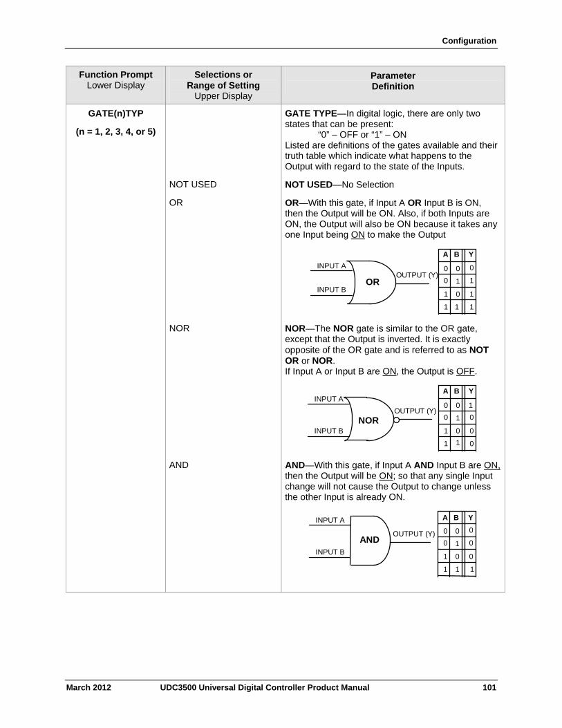
Configuration
March 2012 UDC3500 Universal Digital Controller Product Manual 101
Function Prompt Lower Display
Selections or Range of Setting
Upper Display
Parameter Definition
GATE(n)TYP
(n = 1, 2, 3, 4, or 5)
GATE TYPE—In digital logic, there are only two states that can be present: “0” – OFF or “1” – ON Listed are definitions of the gates available and their truth table which indicate what happens to the Output with regard to the state of the Inputs.
NOT USED NOT USED—No Selection
OR OR—With this gate, if Input A OR Input B is ON, then the Output will be ON. Also, if both Inputs are ON, the Output will also be ON because it takes any one Input being ON to make the Output
INPUT A
INPUT BOR
A B Y
0
1
OUTPUT (Y) 0
0
0
0
1
1 1
1
1
1
NOR NOR—The NOR gate is similar to the OR gate, except that the Output is inverted. It is exactly opposite of the OR gate and is referred to as NOT OR or NOR. If Input A or Input B are ON, the Output is OFF.
INPUT A
INPUT BNOR
A B Y
0
1
OUTPUT (Y) 0
0
0
0
1
1
1
0
01
AND AND—With this gate, if Input A AND Input B are ON, then the Output will be ON; so that any single Input change will not cause the Output to change unless the other Input is already ON.
AND
INPUT A
INPUT B
OUTPUT (Y)
A B Y
0
1
0 0
0
0
1
1
1
0
0
1
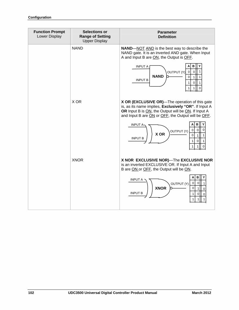
Configuration
102 UDC3500 Universal Digital Controller Product Manual March 2012
Function Prompt Lower Display
Selections or Range of Setting
Upper Display
Parameter Definition
NAND NAND—NOT AND is the best way to describe the NAND gate. It is an inverted AND gate. When Input A and Input B are ON, the Output is OFF.
NAND
INPUT A
INPUT B
OUTPUT (Y)
A B Y
0
1
0 0
0
1
1
1
01
1
1
X OR X OR (EXCLUSIVE OR)—The operation of this gate is, as its name implies, Exclusively “OR”. If Input A OR Input B is ON, the Output will be ON. If Input A and Input B are ON or OFF, the Output will be OFF.
X OR
INPUT A
INPUT B
OUTPUT (Y)
A B Y
0
1
0
0
0
1
1
0
01
1
1
XNOR X NOR EXCLUSIVE NOR)—The EXCLUSIVE NOR is an inverted EXCLUSIVE OR. If Input A and Input B are ON or OFF, the Output will be ON.
XNOR
INPUT A
INPUT B
OUTPUT (Y)
A B Y
0
1
0
0
0
1
1 0
0
1 1
1
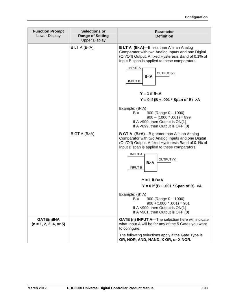
Configuration
March 2012 UDC3500 Universal Digital Controller Product Manual 103
Function Prompt Lower Display
Selections or Range of Setting
Upper Display
Parameter Definition
B LT A (B<A) B LT A (B<A)—B less than A is an Analog Comparator with two Analog Inputs and one Digital (On/Off) Output. A fixed Hysteresis Band of 0.1% of Input B span is applied to these comparators.
INPUT A
INPUT B
OUTPUT (Y) B<A
Y = 1 if B<A
Y = 0 if (B + .001 * Span of B) >A
Example: (B<A) B = 900 (Range 0 – 1000) 900 – (1000 * .001) = 899 If A >900, then Output is ON(1) If A <899, then Output is OFF (0)
B GT A (B>A) B GT A (B>A)—B greater than A is an Analog Comparator with two Analog Inputs and one Digital (On/Off) Output. A fixed Hysteresis Band of 0.1% of Input B span is applied to these comparators.
INPUT A
INPUT B
OUTPUT (Y) B>A
Y = 1 if B>A
Y = 0 if (B + .001 * Span of B) <A
Example: (B>A) B = 900 (Range 0 – 1000) 900 +(1000 * .001) = 901 If A <900, then Output is ON(1) If A >901, then Output is OFF (0)
GATE(n)INA (n = 1, 2, 3, 4, or 5)
GATE (n) INPUT A—The selection here will indicate what Input A will be for any of the 5 Gates you want to configure.
The following selections apply if the Gate Type is OR, NOR, AND, NAND, X OR, or X NOR.
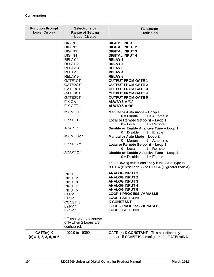
Configuration
104 UDC3500 Universal Digital Controller Product Manual March 2012
Function Prompt Lower Display
Selections or Range of Setting
Upper Display
Parameter Definition
DIG IN1 DIG IN2 DIG IN3 DIG IN4 RELAY 1 RELAY 2 RELAY 3 RELAY 4 RELAY 5 GATE1OT GATE2OT GATE3OT GATE4OT GATE5OT FIX ON FIX OFF
DIGITAL INPUT 1 DIGITAL INPUT 2 DIGITAL INPUT 3 DIGITAL INPUT 4 RELAY 1 RELAY 2 RELAY 3 RELAY 4 RELAY 5 OUTPUT FROM GATE 1 OUTPUT FROM GATE 2 OUTPUT FROM GATE 3 OUTPUT FROM GATE 4 OUTPUT FROM GATE 5 ALWAYS A “1” ALWAYS A “0”
MA MODE LR SPL1 ADAPT 1 MA MOD2 * LR SPL2 * ADAPT 2 *
Manual or Auto mode – Loop 1 0 = Manual 1 = Automatic Local or Remote Setpoint – Loop 1 0 = Local 1 = Remote Disable or Enable Adaptive Tune – Loop 1 0 = Disable 1 = Enable Manual or Auto Mode – Loop 2 0 = Manual 1 = Automatic Local or Remote Setpoint – Loop 2 0 = Local 1 = Remote Disable or Enable Adaptive Tune – Loop 2 0 = Disable 1 = Enable
INPUT 1 INPUT 2 INPUT 3 INPUT 4 INPUT 5 L1 PV L1 SP CONST K L2 PV * L2 SP * * These prompts appear only when 2 Loops are configured.
The following selections apply if the Gate Type is B LT A (B less than A) or B GT A (B greater than A).
ANALOG INPUT 1 ANALOG INPUT 2 ANALOG INPUT 3 ANALOG INPUT 4 ANALOG INPUT 5 LOOP 1 PROCESS VARIABLE LOOP 1 SETPOINT K CONSTANT LOOP 2 PROCESS VARIABLE LOOP 2 SETPOINT
GATE(n) K (n) = 1, 2, 3, 4, or 5
–999.0 to +9999 GATE (n) K CONSTANT—This selection only appears if CONST K is configured for GATE(n)INA.
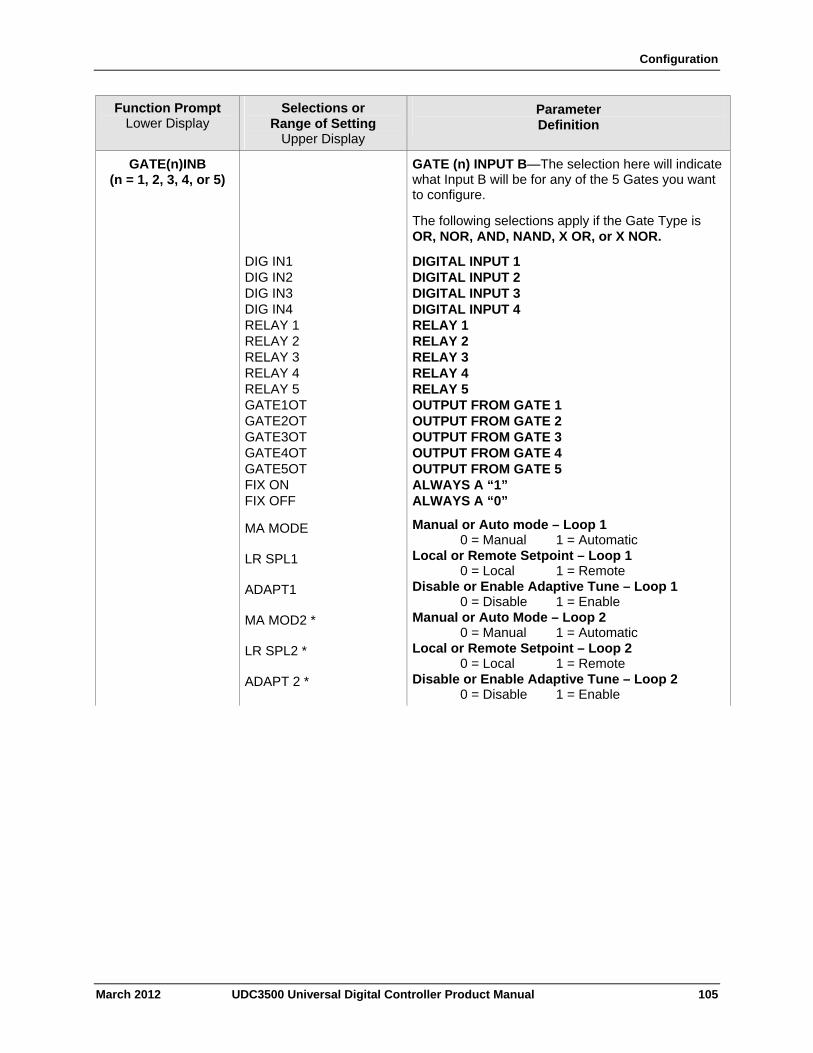
Configuration
March 2012 UDC3500 Universal Digital Controller Product Manual 105
Function Prompt Lower Display
Selections or Range of Setting
Upper Display
Parameter Definition
GATE(n)INB (n = 1, 2, 3, 4, or 5)
GATE (n) INPUT B—The selection here will indicate what Input B will be for any of the 5 Gates you want to configure.
The following selections apply if the Gate Type is OR, NOR, AND, NAND, X OR, or X NOR.
DIG IN1 DIG IN2 DIG IN3 DIG IN4 RELAY 1 RELAY 2 RELAY 3 RELAY 4 RELAY 5 GATE1OT GATE2OT GATE3OT GATE4OT GATE5OT FIX ON FIX OFF
DIGITAL INPUT 1 DIGITAL INPUT 2 DIGITAL INPUT 3 DIGITAL INPUT 4 RELAY 1 RELAY 2 RELAY 3 RELAY 4 RELAY 5 OUTPUT FROM GATE 1 OUTPUT FROM GATE 2 OUTPUT FROM GATE 3 OUTPUT FROM GATE 4 OUTPUT FROM GATE 5 ALWAYS A “1” ALWAYS A “0”
MA MODE LR SPL1 ADAPT1 MA MOD2 * LR SPL2 * ADAPT 2 *
Manual or Auto mode – Loop 1 0 = Manual 1 = Automatic Local or Remote Setpoint – Loop 1 0 = Local 1 = Remote Disable or Enable Adaptive Tune – Loop 1 0 = Disable 1 = Enable Manual or Auto Mode – Loop 2 0 = Manual 1 = Automatic Local or Remote Setpoint – Loop 2 0 = Local 1 = Remote Disable or Enable Adaptive Tune – Loop 2 0 = Disable 1 = Enable
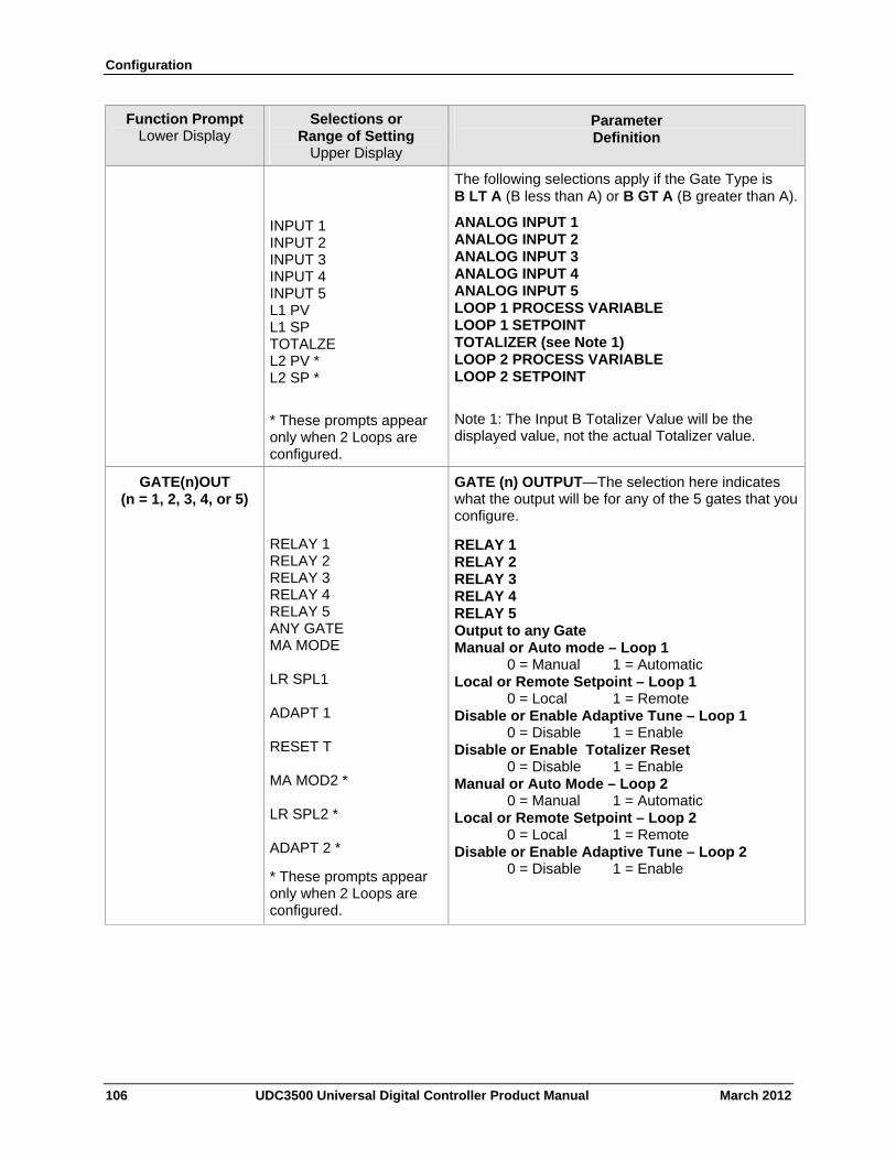
Configuration
106 UDC3500 Universal Digital Controller Product Manual March 2012
Function Prompt Lower Display
Selections or Range of Setting
Upper Display
Parameter Definition
INPUT 1 INPUT 2 INPUT 3 INPUT 4 INPUT 5 L1 PV L1 SP TOTALZE L2 PV * L2 SP *
* These prompts appear only when 2 Loops are configured.
The following selections apply if the Gate Type is B LT A (B less than A) or B GT A (B greater than A).
ANALOG INPUT 1 ANALOG INPUT 2 ANALOG INPUT 3 ANALOG INPUT 4 ANALOG INPUT 5 LOOP 1 PROCESS VARIABLE LOOP 1 SETPOINT TOTALIZER (see Note 1) LOOP 2 PROCESS VARIABLE LOOP 2 SETPOINT
Note 1: The Input B Totalizer Value will be the displayed value, not the actual Totalizer value.
GATE(n)OUT (n = 1, 2, 3, 4, or 5)
RELAY 1 RELAY 2 RELAY 3 RELAY 4 RELAY 5 ANY GATE MA MODE LR SPL1 ADAPT 1 RESET T MA MOD2 * LR SPL2 * ADAPT 2 *
* These prompts appear only when 2 Loops are configured.
GATE (n) OUTPUT—The selection here indicates what the output will be for any of the 5 gates that you configure.
RELAY 1 RELAY 2 RELAY 3 RELAY 4 RELAY 5 Output to any Gate Manual or Auto mode – Loop 1 0 = Manual 1 = Automatic Local or Remote Setpoint – Loop 1 0 = Local 1 = Remote Disable or Enable Adaptive Tune – Loop 1 0 = Disable 1 = Enable Disable or Enable Totalizer Reset 0 = Disable 1 = Enable Manual or Auto Mode – Loop 2 0 = Manual 1 = Automatic Local or Remote Setpoint – Loop 2 0 = Local 1 = Remote Disable or Enable Adaptive Tune – Loop 2 0 = Disable 1 = Enable
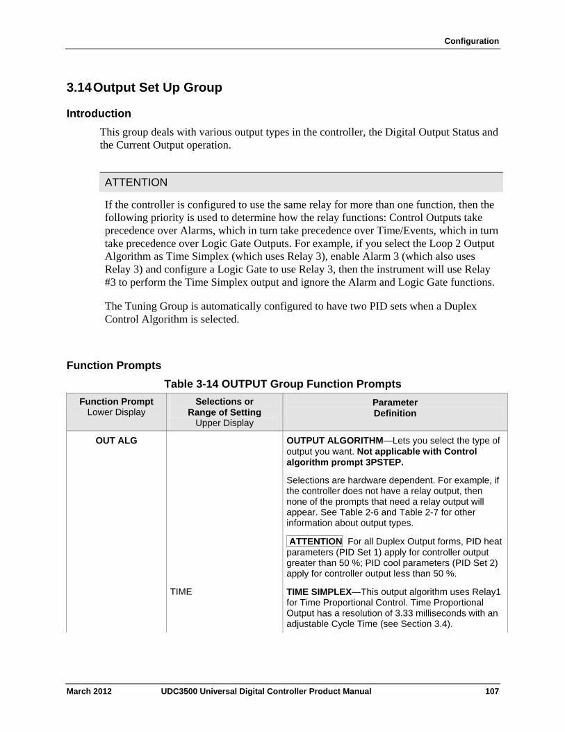
Configuration
3.14 Output Set Up Group
Introduction
This group deals with various output types in the controller, the Digital Output Status and the Current Output operation.
ATTENTION
If the controller is configured to use the same relay for more than one function, then the following priority is used to determine how the relay functions: Control Outputs take precedence over Alarms, which in turn take precedence over Time/Events, which in turn take precedence over Logic Gate Outputs. For example, if you select the Loop 2 Output Algorithm as Time Simplex (which uses Relay 3), enable Alarm 3 (which also uses Relay 3) and configure a Logic Gate to use Relay 3, then the instrument will use Relay #3 to perform the Time Simplex output and ignore the Alarm and Logic Gate functions.
The Tuning Group is automatically configured to have two PID sets when a Duplex Control Algorithm is selected.
Function Prompts
Table 3-14 OUTPUT Group Function Prompts
Function Prompt Lower Display
Selections or Range of Setting
Upper Display
Parameter Definition
OUT ALG OUTPUT ALGORITHM—Lets you select the type of output you want. Not applicable with Control algorithm prompt 3PSTEP.
Selections are hardware dependent. For example, if the controller does not have a relay output, then none of the prompts that need a relay output will appear. See Table 2-6 and Table 2-7 for other information about output types.
ATTENTION For all Duplex Output forms, PID heat parameters (PID Set 1) apply for controller output greater than 50 %; PID cool parameters (PID Set 2) apply for controller output less than 50 %.
TIME TIME SIMPLEX—This output algorithm uses Relay1 for Time Proportional Control. Time Proportional Output has a resolution of 3.33 milliseconds with an adjustable Cycle Time (see Section 3.4).
March 2012 UDC3500 Universal Digital Controller Product Manual 107
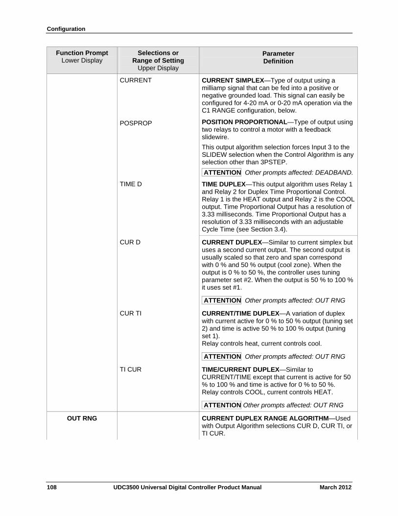
Configuration
108 UDC3500 Universal Digital Controller Product Manual March 2012
Function Prompt Lower Display
Selections or Range of Setting
Upper Display
Parameter Definition
CURRENT CURRENT SIMPLEX—Type of output using a milliamp signal that can be fed into a positive or negative grounded load. This signal can easily be configured for 4-20 mA or 0-20 mA operation via the C1 RANGE configuration, below.
POSPROP POSITION PROPORTIONAL—Type of output using two relays to control a motor with a feedback slidewire.
This output algorithm selection forces Input 3 to the SLIDEW selection when the Control Algorithm is any selection other than 3PSTEP.
ATTENTION Other prompts affected: DEADBAND.
TIME D TIME DUPLEX—This output algorithm uses Relay 1 and Relay 2 for Duplex Time Proportional Control. Relay 1 is the HEAT output and Relay 2 is the COOL output. Time Proportional Output has a resolution of 3.33 milliseconds. Time Proportional Output has a resolution of 3.33 milliseconds with an adjustable Cycle Time (see Section 3.4).
CUR D CURRENT DUPLEX—Similar to current simplex but uses a second current output. The second output is usually scaled so that zero and span correspond with 0 % and 50 % output (cool zone). When the output is 0 % to 50 %, the controller uses tuning parameter set #2. When the output is 50 % to 100 % it uses set #1.
ATTENTION Other prompts affected: OUT RNG
CUR TI CURRENT/TIME DUPLEX—A variation of duplex with current active for 0 % to 50 % output (tuning set 2) and time is active 50 % to 100 % output (tuning set 1). Relay controls heat, current controls cool.
ATTENTION Other prompts affected: OUT RNG
TI CUR TIME/CURRENT DUPLEX—Similar to CURRENT/TIME except that current is active for 50 % to 100 % and time is active for 0 % to 50 %. Relay controls COOL, current controls HEAT.
ATTENTION Other prompts affected: OUT RNG
OUT RNG CURRENT DUPLEX RANGE ALGORITHM—Used with Output Algorithm selections CUR D, CUR TI, or TI CUR.
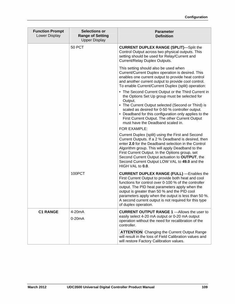
Configuration
March 2012 UDC3500 Universal Digital Controller Product Manual 109
Function Prompt Lower Display
Selections or Range of Setting
Upper Display
Parameter Definition
50 PCT CURRENT DUPLEX RANGE (SPLIT)—Split the Control Output across two physical outputs. This setting should be used for Relay/Current and Current/Relay Duplex Outputs.
This setting should also be used when Current/Current Duplex operation is desired. This enables one current output to provide heat control and another current output to provide cool control. To enable Current/Current Duplex (split) operation:
• The Second Current Output or the Third Current in the Options Set Up group must be selected for Output.
• The Current Output selected (Second or Third) is scaled as desired for 0-50 % controller output.
• Deadband for this configuration only applies to the First Current Output. The other Current Output must have the Deadband scaled in.
FOR EXAMPLE:
Current Duplex (split) using the First and Second Current Outputs. If a 2 % Deadband is desired, then enter 2.0 for the Deadband selection in the Control Algorithm group. This will apply Deadband to the First Current Output. In the Options group, set Second Current Output actuation to OUTPUT, the Second Current Output LOW VAL to 49.0 and the HIGH VAL to 0.0.
100PCT CURRENT DUPLEX RANGE (FULL) —Enables the First Current Output to provide both heat and cool functions for control over 0-100 % of the controller output. The PID heat parameters apply when the output is greater than 50 % and the PID cool parameters apply when the output is less than 50 %. A second current output is not required for this type of duplex operation.
C1 RANGE 4-20mA
0-20mA
CURRENT OUTPUT RANGE 1 —Allows the user to easily select 4-20 mA output or 0-20 mA output operation without the need for recalibration of the controller.
ATTENTION Changing the Current Output Range will result in the loss of Field Calibration values and will restore Factory Calibration values.
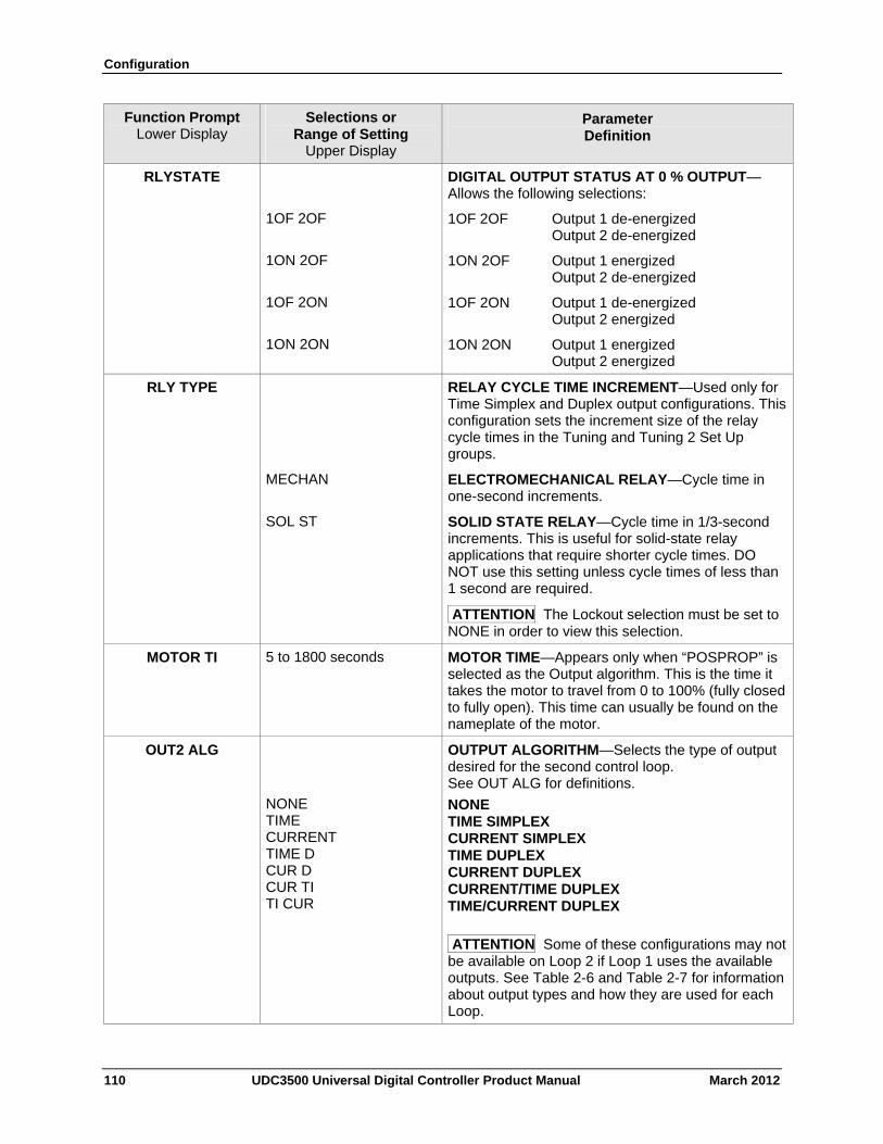
Configuration
110 UDC3500 Universal Digital Controller Product Manual March 2012
Function Prompt Lower Display
Selections or Range of Setting
Upper Display
Parameter Definition
RLYSTATE
1OF 2OF
1ON 2OF
1OF 2ON
1ON 2ON
DIGITAL OUTPUT STATUS AT 0 % OUTPUT—Allows the following selections:
1OF 2OF Output 1 de-energized Output 2 de-energized
1ON 2OF Output 1 energized Output 2 de-energized
1OF 2ON Output 1 de-energized Output 2 energized
1ON 2ON Output 1 energized Output 2 energized
RLY TYPE RELAY CYCLE TIME INCREMENT—Used only for Time Simplex and Duplex output configurations. This configuration sets the increment size of the relay cycle times in the Tuning and Tuning 2 Set Up groups.
MECHAN ELECTROMECHANICAL RELAY—Cycle time in one-second increments.
SOL ST SOLID STATE RELAY—Cycle time in 1/3-second increments. This is useful for solid-state relay applications that require shorter cycle times. DO NOT use this setting unless cycle times of less than 1 second are required.
ATTENTION The Lockout selection must be set to NONE in order to view this selection.
MOTOR TI 5 to 1800 seconds MOTOR TIME—Appears only when “POSPROP” is selected as the Output algorithm. This is the time it takes the motor to travel from 0 to 100% (fully closed to fully open). This time can usually be found on the nameplate of the motor.
OUT2 ALG
NONE TIME CURRENT TIME D CUR D CUR TI TI CUR
OUTPUT ALGORITHM—Selects the type of output desired for the second control loop. See OUT ALG for definitions.
NONE TIME SIMPLEX CURRENT SIMPLEX TIME DUPLEX CURRENT DUPLEX CURRENT/TIME DUPLEX TIME/CURRENT DUPLEX
ATTENTION Some of these configurations may not be available on Loop 2 if Loop 1 uses the available outputs. See Table 2-6 and Table 2-7 for information about output types and how they are used for each Loop.
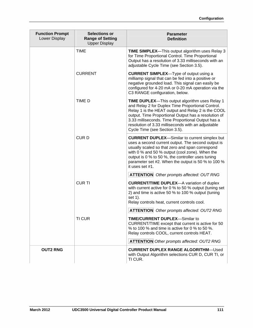
Configuration
March 2012 UDC3500 Universal Digital Controller Product Manual 111
Function Prompt Lower Display
Selections or Range of Setting
Upper Display
Parameter Definition
TIME TIME SIMPLEX—This output algorithm uses Relay 3 for Time Proportional Control. Time Proportional Output has a resolution of 3.33 milliseconds with an adjustable Cycle Time (see Section 3.5).
CURRENT CURRENT SIMPLEX—Type of output using a milliamp signal that can be fed into a positive or negative grounded load. This signal can easily be configured for 4-20 mA or 0-20 mA operation via the C3 RANGE configuration, below.
TIME D TIME DUPLEX—This output algorithm uses Relay 1 and Relay 2 for Duplex Time Proportional Control. Relay 1 is the HEAT output and Relay 2 is the COOL output. Time Proportional Output has a resolution of 3.33 milliseconds. Time Proportional Output has a resolution of 3.33 milliseconds with an adjustable Cycle Time (see Section 3.5).
CUR D CURRENT DUPLEX—Similar to current simplex but uses a second current output. The second output is usually scaled so that zero and span correspond with 0 % and 50 % output (cool zone). When the output is 0 % to 50 %, the controller uses tuning parameter set #2. When the output is 50 % to 100 % it uses set #1.
ATTENTION Other prompts affected: OUT RNG
CUR TI CURRENT/TIME DUPLEX—A variation of duplex with current active for 0 % to 50 % output (tuning set 2) and time is active 50 % to 100 % output (tuning set 1). Relay controls heat, current controls cool.
ATTENTION Other prompts affected: OUT2 RNG
TI CUR TIME/CURRENT DUPLEX—Similar to CURRENT/TIME except that current is active for 50 % to 100 % and time is active for 0 % to 50 %. Relay controls COOL, current controls HEAT.
ATTENTION Other prompts affected: OUT2 RNG
OUT2 RNG CURRENT DUPLEX RANGE ALGORITHM—Used with Output Algorithm selections CUR D, CUR TI, or TI CUR.
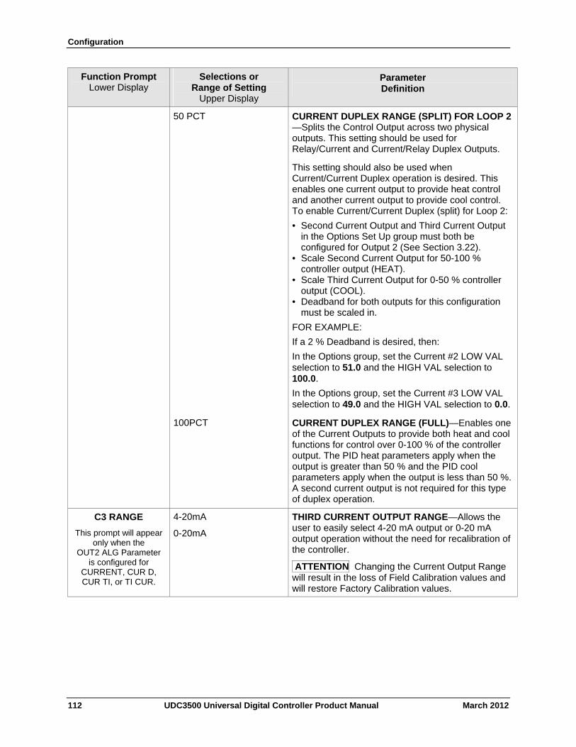
Configuration
112 UDC3500 Universal Digital Controller Product Manual March 2012
Function Prompt Lower Display
Selections or Range of Setting
Upper Display
Parameter Definition
50 PCT CURRENT DUPLEX RANGE (SPLIT) FOR LOOP 2 —Splits the Control Output across two physical outputs. This setting should be used for Relay/Current and Current/Relay Duplex Outputs.
This setting should also be used when Current/Current Duplex operation is desired. This enables one current output to provide heat control and another current output to provide cool control. To enable Current/Current Duplex (split) for Loop 2:
• Second Current Output and Third Current Output in the Options Set Up group must both be configured for Output 2 (See Section 3.22).
• Scale Second Current Output for 50-100 % controller output (HEAT).
• Scale Third Current Output for 0-50 % controller output (COOL).
• Deadband for both outputs for this configuration must be scaled in.
FOR EXAMPLE:
If a 2 % Deadband is desired, then:
In the Options group, set the Current #2 LOW VAL selection to 51.0 and the HIGH VAL selection to 100.0.
In the Options group, set the Current #3 LOW VAL selection to 49.0 and the HIGH VAL selection to 0.0.
100PCT CURRENT DUPLEX RANGE (FULL)—Enables one of the Current Outputs to provide both heat and cool functions for control over 0-100 % of the controller output. The PID heat parameters apply when the output is greater than 50 % and the PID cool parameters apply when the output is less than 50 %. A second current output is not required for this type of duplex operation.
C3 RANGE
This prompt will appear only when the
OUT2 ALG Parameter is configured for
CURRENT, CUR D, CUR TI, or TI CUR.
4-20mA
0-20mA
THIRD CURRENT OUTPUT RANGE—Allows the user to easily select 4-20 mA output or 0-20 mA output operation without the need for recalibration of the controller.
ATTENTION Changing the Current Output Range will result in the loss of Field Calibration values and will restore Factory Calibration values.
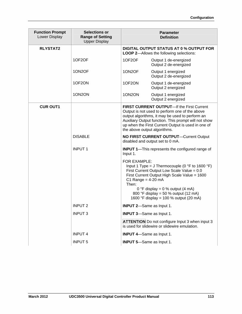
Configuration
March 2012 UDC3500 Universal Digital Controller Product Manual 113
Function Prompt Lower Display
Selections or Range of Setting
Upper Display
Parameter Definition
RLYSTAT2
1OF2OF
1ON2OF
1OF2ON
1ON2ON
DIGITAL OUTPUT STATUS AT 0 % OUTPUT FOR LOOP 2—Allows the following selections:
1OF2OF Output 1 de-energized Output 2 de-energized
1ON2OF Output 1 energized Output 2 de-energized
1OF2ON Output 1 de-energized Output 2 energized
1ON2ON Output 1 energized Output 2 energized
CUR OUT1 FIRST CURRENT OUTPUT—If the First Current Output is not used to perform one of the above output algorithms, it may be used to perform an Auxiliary Output function. This prompt will not show up when the First Current Output is used in one of the above output algorithms.
DISABLE NO FIRST CURRENT OUTPUT—Current Output disabled and output set to 0 mA.
INPUT 1 INPUT 1—This represents the configured range of Input 1.
FOR EXAMPLE: Input 1 Type = J Thermocouple (0 °F to 1600 °F) First Current Output Low Scale Value = 0.0 First Current Output High Scale Value = 1600 C1 Range = 4-20 mA Then: 0 °F display = 0 % output (4 mA) 800 °F display = 50 % output (12 mA) 1600 °F display = 100 % output (20 mA)
INPUT 2 INPUT 2—Same as Input 1.
INPUT 3 INPUT 3—Same as Input 1.
ATTENTION Do not configure Input 3 when input 3 is used for slidewire or slidewire emulation.
INPUT 4 INPUT 4—Same as Input 1.
INPUT 5 INPUT 5—Same as Input 1.
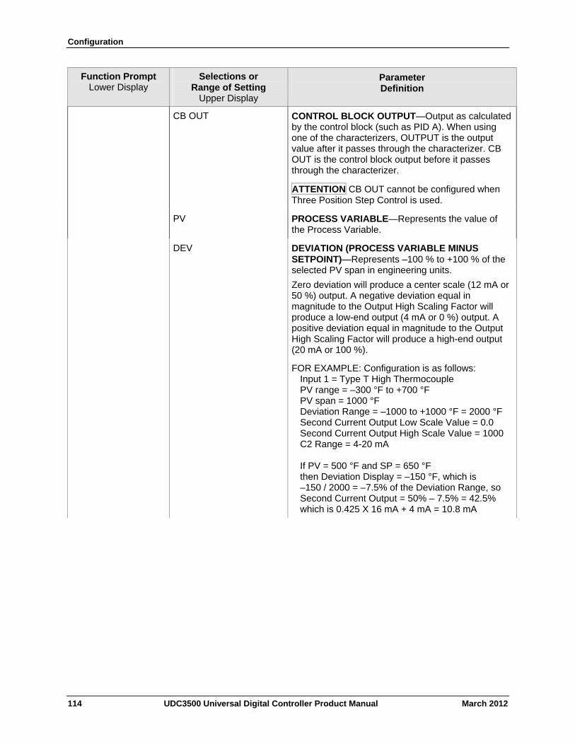
Configuration
114 UDC3500 Universal Digital Controller Product Manual March 2012
Function Prompt Lower Display
Selections or Range of Setting
Upper Display
Parameter Definition
CB OUT CONTROL BLOCK OUTPUT—Output as calculated by the control block (such as PID A). When using one of the characterizers, OUTPUT is the output value after it passes through the characterizer. CB OUT is the control block output before it passes through the characterizer.
ATTENTION CB OUT cannot be configured when Three Position Step Control is used.
PV PROCESS VARIABLE—Represents the value of the Process Variable.
DEV DEVIATION (PROCESS VARIABLE MINUS SETPOINT)—Represents –100 % to +100 % of the selected PV span in engineering units.
Zero deviation will produce a center scale (12 mA or 50 %) output. A negative deviation equal in magnitude to the Output High Scaling Factor will produce a low-end output (4 mA or 0 %) output. A positive deviation equal in magnitude to the Output High Scaling Factor will produce a high-end output (20 mA or 100 %).
FOR EXAMPLE: Configuration is as follows: Input 1 = Type T High Thermocouple PV range = –300 °F to +700 °F PV span = 1000 °F Deviation Range = –1000 to +1000 °F = 2000 °F Second Current Output Low Scale Value = 0.0 Second Current Output High Scale Value = 1000 C2 Range = 4-20 mA If PV = 500 °F and SP = 650 °F then Deviation Display = –150 °F, which is –150 / 2000 = –7.5% of the Deviation Range, so Second Current Output = 50% – 7.5% = 42.5% which is 0.425 X 16 mA + 4 mA = 10.8 mA
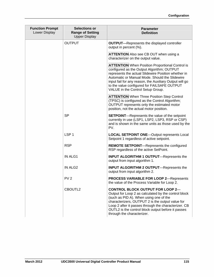
Configuration
March 2012 UDC3500 Universal Digital Controller Product Manual 115
Function Prompt Lower Display
Selections or Range of Setting
Upper Display
Parameter Definition
OUTPUT OUTPUT—Represents the displayed controller output in percent (%).
ATTENTION Also see CB OUT when using a characterizer on the output value.
ATTENTION When Position Proportional Control is configured as the Output Algorithm; OUTPUT represents the actual Slidewire Position whether in Automatic or Manual Mode. Should the Slidewire input fail for any reason, the Auxiliary Output will go to the value configured for FAILSAFE OUTPUT VALUE in the Control Setup Group.
ATTENTION When Three Position Step Control (TPSC) is configured as the Control Algorithm; OUTPUT represents only the estimated motor position, not the actual motor position.
SP SETPOINT—Represents the value of the setpoint currently in use (LSP1, LSP2, LSP3, RSP or CSP) and is shown in the same units as those used by the PV.
LSP 1 LOCAL SETPOINT ONE—Output represents Local Setpoint 1 regardless of active setpoint.
RSP REMOTE SETPOINT—Represents the configured RSP regardless of the active SetPoint.
IN ALG1 INPUT ALGORITHM 1 OUTPUT—Represents the output from input algorithm 1.
IN ALG2
INPUT ALGORITHM 2 OUTPUT—Represents the output from input algorithm 2.
PV 2 PROCESS VARIABLE FOR LOOP 2—Represents the value of the Process Variable for Loop 2.
CBOUTL2 CONTROL BLOCK OUTPUT FOR LOOP 2—Output for Loop 2 as calculated by the control block (such as PID A). When using one of the characterizers, OUTPUT 2 is the output value for Loop 2 after it passes through the characterizer. CB OUTL2 is the control block output before it passes through the characterizer.
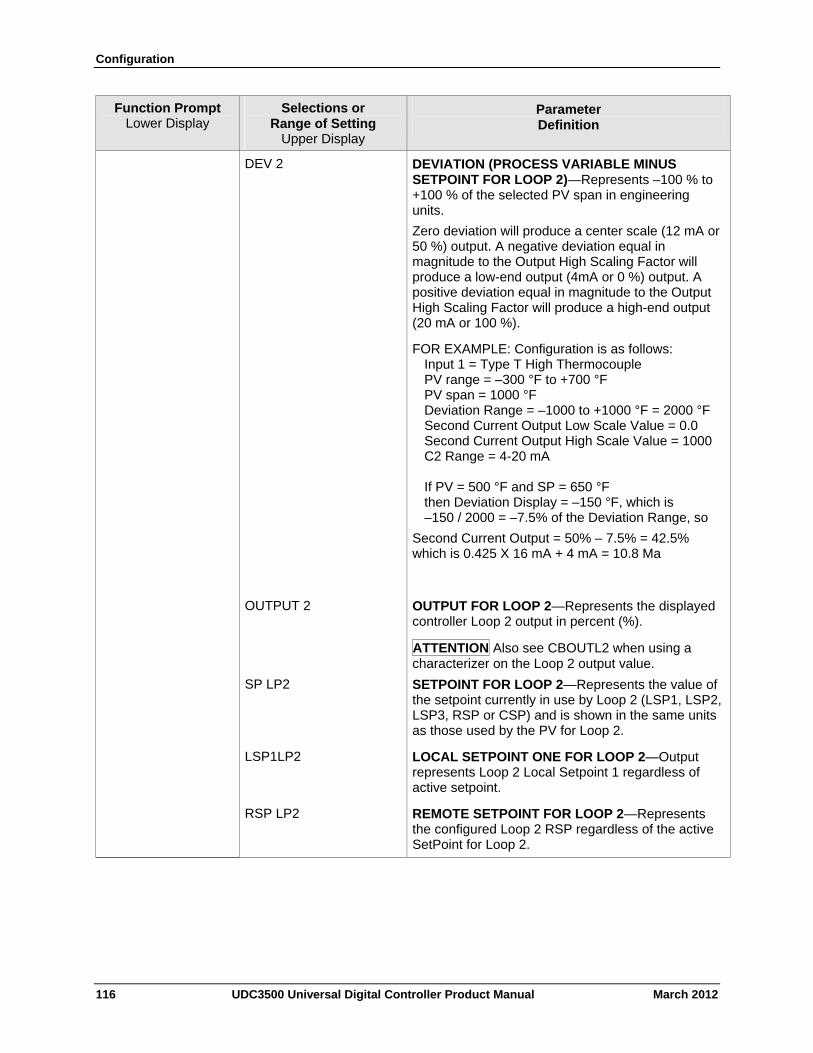
Configuration
116 UDC3500 Universal Digital Controller Product Manual March 2012
Function Prompt Lower Display
Selections or Range of Setting
Upper Display
Parameter Definition
DEV 2 DEVIATION (PROCESS VARIABLE MINUS SETPOINT FOR LOOP 2)—Represents –100 % to +100 % of the selected PV span in engineering units.
Zero deviation will produce a center scale (12 mA or 50 %) output. A negative deviation equal in magnitude to the Output High Scaling Factor will produce a low-end output (4mA or 0 %) output. A positive deviation equal in magnitude to the Output High Scaling Factor will produce a high-end output (20 mA or 100 %).
FOR EXAMPLE: Configuration is as follows: Input 1 = Type T High Thermocouple PV range = –300 °F to +700 °F PV span = 1000 °F Deviation Range = –1000 to +1000 °F = 2000 °F Second Current Output Low Scale Value = 0.0 Second Current Output High Scale Value = 1000 C2 Range = 4-20 mA If PV = 500 °F and SP = 650 °F then Deviation Display = –150 °F, which is –150 / 2000 = –7.5% of the Deviation Range, so
Second Current Output = 50% – 7.5% = 42.5% which is 0.425 X 16 mA + 4 mA = 10.8 Ma
OUTPUT 2 OUTPUT FOR LOOP 2—Represents the displayed controller Loop 2 output in percent (%).
ATTENTION Also see CBOUTL2 when using a characterizer on the Loop 2 output value.
SP LP2 SETPOINT FOR LOOP 2—Represents the value of the setpoint currently in use by Loop 2 (LSP1, LSP2, LSP3, RSP or CSP) and is shown in the same units as those used by the PV for Loop 2.
LSP1LP2 LOCAL SETPOINT ONE FOR LOOP 2—Output represents Loop 2 Local Setpoint 1 regardless of active setpoint.
RSP LP2 REMOTE SETPOINT FOR LOOP 2—Represents the configured Loop 2 RSP regardless of the active SetPoint for Loop 2.
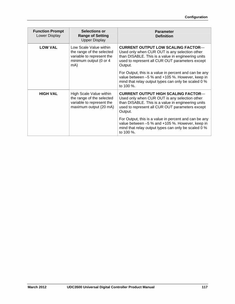
Configuration
March 2012 UDC3500 Universal Digital Controller Product Manual 117
Function Prompt Lower Display
Selections or Range of Setting
Upper Display
Parameter Definition
LOW VAL Low Scale Value within the range of the selected variable to represent the minimum output (0 or 4 mA)
CURRENT OUTPUT LOW SCALING FACTOR—Used only when CUR OUT is any selection other than DISABLE. This is a value in engineering units used to represent all CUR OUT parameters except Output.
For Output, this is a value in percent and can be any value between –5 % and +105 %. However, keep in mind that relay output types can only be scaled 0 % to 100 %.
HIGH VAL High Scale Value within the range of the selected variable to represent the maximum output (20 mA)
CURRENT OUTPUT HIGH SCALING FACTOR—Used only when CUR OUT is any selection other than DISABLE. This is a value in engineering units used to represent all CUR OUT parameters except Output.
For Output, this is a value in percent and can be any value between –5 % and +105 %. However, keep in mind that relay output types can only be scaled 0 % to 100 %.
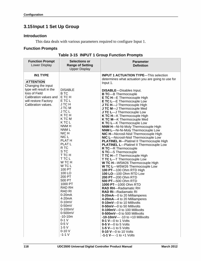
Configuration
3.15 Input 1 Set Up Group
Introduction
This data deals with various parameters required to configure Input 1.
Function Prompts
Table 3-15 INPUT 1 Group Function Prompts
Function Prompt Lower Display
Selections or Range of Setting
Upper Display
Parameter Definition
IN1 TYPE
ATTENTION Changing the input type will result in the loss of Field Calibration values and will restore Factory Calibration values.
DISABLE B TC E TC H E TC L J TC H J TC M J TC L K TC H K TC M K TC L NNM H NNM L NIC H NIC L PLAT H PLAT L R TC S TC T TC H T TC L W TC H W TC L 100 PT 100 LO 200 PT 500 PT 1000 PT RAD RH RAD RI 0-20mA 4-20mA 0-10mV 0-50mV 0-100mV 0-500mV -10-10m 0-1 V 0-5 V 1-5 V 0-10 V -1-1 V
INPUT 1 ACTUATION TYPE—This selection determines what actuation you are going to use for Input 1.
DISABLE—Disables Input. B TC—B Thermocouple E TC H—E Thermocouple High E TC L—E Thermocouple Low J TC H—J Thermocouple High J TC M—J Thermocouple Med J TC L—J Thermocouple Low K TC H—K Thermocouple High K TC M—K Thermocouple Med K TC L—K Thermocouple Low NNM H—Ni-Ni-Moly Thermocouple High NNM L—Ni-Ni-Moly Thermocouple Low NIC H—Nicrosil-Nisil Thermocouple High NIC L—Nicrosil-Nisil Thermocouple Low PLATINEL H—Platinel II Thermocouple High PLATINEL L—Platinel II Thermocouple Low R TC—R Thermocouple S TC—S Thermocouple T TC H—T Thermocouple High T TC L—T Thermocouple Low W TC H—W5W26 Thermocouple High W TC L—W5W26 Thermocouple Low 100 PT—100 Ohm RTD High 100 LO—100 Ohm RTD Low 200 PT—200 Ohm RTD 500 PT—500 Ohm RTD 1000 PT—1000 Ohm RTD RAD RH—Radiamatic RH RAD RI—Radiamatic RI 0-20mA—0 to 20 Milliamperes 4-20mA—4 to 20 Milliamperes 0-10mV—0 to 10 Millivolts 0-50mV—0 to 50 Millivolts 0-100mV—0 to 100 Millivolts 0-500mV—0 to 500 Millivolts -10-10mV— -10 to +10 Millivolts 0-1 V—0 to 1 Volts 0-5 V—0 to 5 Volts 1-5 V—1 to 5 Volts 0-10 V—0 to 10 Volts -1-1 V— -1 to +1 Volts
118 UDC3500 Universal Digital Controller Product Manual March 2012
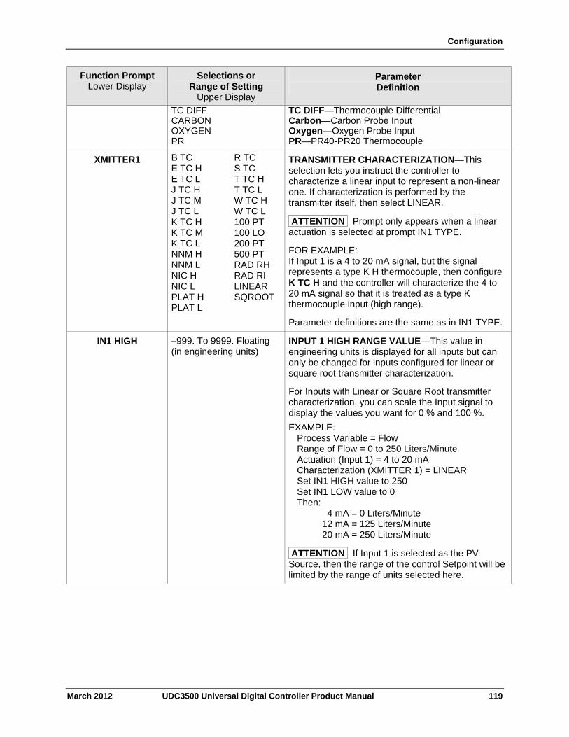
Configuration
March 2012 UDC3500 Universal Digital Controller Product Manual 119
Function Prompt Lower Display
Selections or Range of Setting
Upper Display
Parameter Definition
TC DIFF CARBON OXYGEN PR
TC DIFF—Thermocouple Differential Carbon—Carbon Probe Input Oxygen—Oxygen Probe Input PR—PR40-PR20 Thermocouple
XMITTER1 B TC E TC H E TC L J TC H J TC M J TC L K TC H K TC M K TC L NNM H NNM L NIC H NIC L PLAT H PLAT L
R TC S TC T TC H T TC L W TC H W TC L 100 PT 100 LO 200 PT 500 PT RAD RH RAD RI LINEAR SQROOT
TRANSMITTER CHARACTERIZATION—This selection lets you instruct the controller to characterize a linear input to represent a non-linear one. If characterization is performed by the transmitter itself, then select LINEAR.
ATTENTION Prompt only appears when a linear actuation is selected at prompt IN1 TYPE.
FOR EXAMPLE: If Input 1 is a 4 to 20 mA signal, but the signal represents a type K H thermocouple, then configure K TC H and the controller will characterize the 4 to 20 mA signal so that it is treated as a type K thermocouple input (high range).
Parameter definitions are the same as in IN1 TYPE.
IN1 HIGH –999. To 9999. Floating (in engineering units)
INPUT 1 HIGH RANGE VALUE—This value in engineering units is displayed for all inputs but can only be changed for inputs configured for linear or square root transmitter characterization.
For Inputs with Linear or Square Root transmitter characterization, you can scale the Input signal to display the values you want for 0 % and 100 %.
EXAMPLE: Process Variable = Flow Range of Flow = 0 to 250 Liters/Minute Actuation (Input 1) = 4 to 20 mA Characterization (XMITTER 1) = LINEAR Set IN1 HIGH value to 250 Set IN1 LOW value to 0 Then: 4 mA = 0 Liters/Minute 12 mA = 125 Liters/Minute 20 mA = 250 Liters/Minute
ATTENTION If Input 1 is selected as the PV Source, then the range of the control Setpoint will be limited by the range of units selected here.
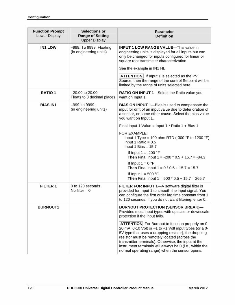
Configuration
120 UDC3500 Universal Digital Controller Product Manual March 2012
Function Prompt Lower Display
Selections or Range of Setting
Upper Display
Parameter Definition
IN1 LOW –999. To 9999. Floating (in engineering units)
INPUT 1 LOW RANGE VALUE—This value in engineering units is displayed for all inputs but can only be changed for inputs configured for linear or square root transmitter characterization.
See the example in IN1 HI.
ATTENTION If Input 1 is selected as the PV Source, then the range of the control Setpoint will be limited by the range of units selected here.
RATIO 1 –20.00 to 20.00 Floats to 3 decimal places
RATIO ON INPUT 1—Select the Ratio value you want on Input 1.
BIAS IN1 –999. to 9999. (in engineering units)
BIAS ON INPUT 1—Bias is used to compensate the input for drift of an input value due to deterioration of a sensor, or some other cause. Select the bias value you want on Input 1.
Final Input 1 Value = Input 1 * Ratio 1 + Bias 1
FOR EXAMPLE: Input 1 Type = 100 ohm RTD (-300 °F to 1200 °F) Input 1 Ratio = 0.5 Input 1 Bias = 15.7
If Input 1 = -200 °F Then Final Input 1 = -200 * 0.5 + 15.7 = -84.3
If Input 1 = 0 °F Then Final Input 1 = 0 * 0.5 + 15.7 = 15.7
If Input 1 = 500 °F Then Final Input 1 = 500 * 0.5 + 15.7 = 265.7
FILTER 1 0 to 120 seconds No filter = 0
FILTER FOR INPUT 1—A software digital filter is provided for Input 1 to smooth the input signal. You can configure the first order lag time constant from 1 to 120 seconds. If you do not want filtering, enter 0.
BURNOUT1 BURNOUT PROTECTION (SENSOR BREAK)—Provides most input types with upscale or downscale protection if the input fails.
ATTENTION For Burnout to function properly on 0-20 mA, 0-10 Volt or –1 to +1 Volt input types (or a 0-5V type that uses a dropping resistor), the dropping resistor must be remotely located (across the transmitter terminals). Otherwise, the input at the instrument terminals will always be 0 (i.e., within the normal operating range) when the sensor opens.
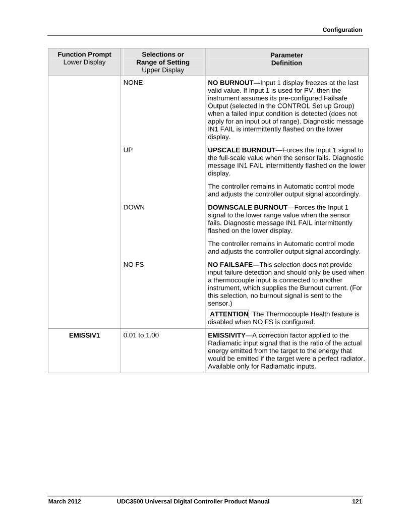
Configuration
March 2012 UDC3500 Universal Digital Controller Product Manual 121
Function Prompt Lower Display
Selections or Range of Setting
Upper Display
Parameter Definition
NONE NO BURNOUT—Input 1 display freezes at the last valid value. If Input 1 is used for PV, then the instrument assumes its pre-configured Failsafe Output (selected in the CONTROL Set up Group) when a failed input condition is detected (does not apply for an input out of range). Diagnostic message IN1 FAIL is intermittently flashed on the lower display.
UP UPSCALE BURNOUT—Forces the Input 1 signal to the full-scale value when the sensor fails. Diagnostic message IN1 FAIL intermittently flashed on the lower display.
The controller remains in Automatic control mode and adjusts the controller output signal accordingly.
DOWN DOWNSCALE BURNOUT—Forces the Input 1 signal to the lower range value when the sensor fails. Diagnostic message IN1 FAIL intermittently flashed on the lower display.
The controller remains in Automatic control mode and adjusts the controller output signal accordingly.
NO FS NO FAILSAFE—This selection does not provide input failure detection and should only be used when a thermocouple input is connected to another instrument, which supplies the Burnout current. (For this selection, no burnout signal is sent to the sensor.)
ATTENTION The Thermocouple Health feature is disabled when NO FS is configured.
EMISSIV1 0.01 to 1.00 EMISSIVITY—A correction factor applied to the Radiamatic input signal that is the ratio of the actual energy emitted from the target to the energy that would be emitted if the target were a perfect radiator.Available only for Radiamatic inputs.

Configuration
3.16 Input 2 Set Up Group
Introduction
This data deals with various parameters required to configure Input 2.
Function Prompts
Table 3-16 INPUT 2 Group Function Prompts
Function Prompt Lower Display
Selections or Range of Setting
Upper Display
Parameter Definition
IN2 TYPE
ATTENTION Changing the input type will result in the loss of Field Calibration values and will restore Factory Calibration values.
DISABLE B TC E TC H E TC L J TC H J TC M J TC L K TC H K TC M K TC L NNM H NNM L NIC H NIC L PLAT H PLAT L R TC S TC T TC H T TC L W TC H W TC L 100 PT 100 LO 200 PT 500 PT 1000 PT RAD RH RAD RI 0-20mA 4-20mA 0-10mV 0-50mV 0-100mV 0-500mV -10-10m 0-1 V 0-5 V 1-5 V 0-10 V -1-1 V
INPUT 2 ACTUATION TYPE— This selection determines what actuation you are going to use for Input 2.
DISABLE—Disables Input. B TC—B Thermocouple E TC H—E Thermocouple High E TC L—E Thermocouple Low J TC H—J Thermocouple High J TC M—J Thermocouple Med J TC L—J Thermocouple Low K TC H—K Thermocouple High K TC M—K Thermocouple Med K TC L—K Thermocouple Low NNM H—Ni-Ni-Moly Thermocouple High NNM L—Ni-Ni-Moly Thermocouple Low NIC H—Nicrosil-Nisil Thermocouple High NIC L—Nicrosil-Nisil Thermocouple Low PLATINEL H—Platinel II Thermocouple High PLATINEL L—Platinel II Thermocouple Low R TC—R Thermocouple S TC—S Thermocouple T TC H—T Thermocouple High T TC L—T Thermocouple Low W TC H—W5W26 Thermocouple High W TC L—W5W26 Thermocouple Low 100 PT—100 Ohm RTD High 100 LO—100 Ohm RTD Low 200 PT—200 Ohm RTD 500 PT—500 Ohm RTD 1000 PT—1000 Ohm RTD RAD RH—Radiamatic RH RAD RI—Radiamatic RI 0-20mA—0 to 20 Milliamperes 4-20mA—4 to 20 Milliamperes 0-10mV—0 to 10 Millivolts 0-50mV—0 to 50 Millivolts 0-100mV—0 to 100 Millivolts 0-500mV—0 to 500 Millivolts -10-10mV— -10 to +10 Millivolts 0-1 V—0 to 1 Volts 0-5 V—0 to 5 Volts 1-5 V—1 to 5 Volts 0-10 V—0 to 10 Volts -1-1 V— -1 to +1 Volts
122 UDC3500 Universal Digital Controller Product Manual March 2012
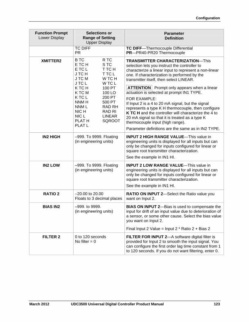
Configuration
March 2012 UDC3500 Universal Digital Controller Product Manual 123
Function Prompt Lower Display
Selections or Range of Setting
Upper Display
Parameter Definition
TC DIFF PR
TC DIFF—Thermocouple Differential PR—PR40-PR20 Thermocouple
XMITTER2 B TC E TC H E TC L J TC H J TC M J TC L K TC H K TC M K TC L NNM H NNM L NIC H NIC L PLAT H PLAT L
R TC S TC T TC H T TC L W TC H W TC L 100 PT 100 LO 200 PT 500 PT RAD RH RAD RI LINEAR SQROOT
TRANSMITTER CHARACTERIZATION—This selection lets you instruct the controller to characterize a linear input to represent a non-linear one. If characterization is performed by the transmitter itself, then select LINEAR.
ATTENTION Prompt only appears when a linear actuation is selected at prompt IN1 TYPE.
FOR EXAMPLE: If Input 2 is a 4 to 20 mA signal, but the signal represents a type K H thermocouple, then configure K TC H and the controller will characterize the 4 to 20 mA signal so that it is treated as a type K thermocouple input (high range).
Parameter definitions are the same as in IN2 TYPE.
IN2 HIGH –999. To 9999. Floating (in engineering units)
INPUT 2 HIGH RANGE VALUE—This value in engineering units is displayed for all inputs but can only be changed for inputs configured for linear or square root transmitter characterization.
See the example in IN1 HI.
IN2 LOW –999. To 9999. Floating (in engineering units)
INPUT 2 LOW RANGE VALUE—This value in engineering units is displayed for all inputs but can only be changed for inputs configured for linear or square root transmitter characterization.
See the example in IN1 HI.
RATIO 2 –20.00 to 20.00 Floats to 3 decimal places
RATIO ON INPUT 2—Select the Ratio value you want on Input 2.
BIAS IN2 –999. to 9999. (in engineering units)
BIAS ON INPUT 2—Bias is used to compensate the input for drift of an input value due to deterioration of a sensor, or some other cause. Select the bias value you want on Input 2.
Final Input 2 Value = Input 2 * Ratio 2 + Bias 2
FILTER 2 0 to 120 seconds No filter = 0
FILTER FOR INPUT 2—A software digital filter is provided for Input 2 to smooth the input signal. You can configure the first order lag time constant from 1 to 120 seconds. If you do not want filtering, enter 0.
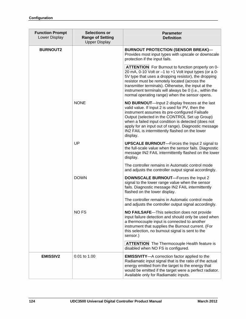
Configuration
124 UDC3500 Universal Digital Controller Product Manual March 2012
Function Prompt Lower Display
Selections or Range of Setting
Upper Display
Parameter Definition
BURNOUT2 BURNOUT PROTECTION (SENSOR BREAK)—Provides most input types with upscale or downscale protection if the input fails.
ATTENTION For Burnout to function properly on 0-20 mA, 0-10 Volt or –1 to +1 Volt input types (or a 0-5V type that uses a dropping resistor), the dropping resistor must be remotely located (across the transmitter terminals). Otherwise, the input at the instrument terminals will always be 0 (i.e., within the normal operating range) when the sensor opens.
NONE NO BURNOUT—Input 2 display freezes at the last valid value. If Input 2 is used for PV, then the instrument assumes its pre-configured Failsafe Output (selected in the CONTROL Set up Group) when a failed input condition is detected (does not apply for an input out of range). Diagnostic message IN2 FAIL is intermittently flashed on the lower display.
UP UPSCALE BURNOUT—Forces the Input 2 signal to the full-scale value when the sensor fails. Diagnostic message IN2 FAIL intermittently flashed on the lower display.
The controller remains in Automatic control mode and adjusts the controller output signal accordingly.
DOWN DOWNSCALE BURNOUT—Forces the Input 2 signal to the lower range value when the sensor fails. Diagnostic message IN2 FAIL intermittently flashed on the lower display.
The controller remains in Automatic control mode and adjusts the controller output signal accordingly.
NO FS NO FAILSAFE—This selection does not provide input failure detection and should only be used when a thermocouple input is connected to another instrument that supplies the Burnout current. (For this selection, no burnout signal is sent to the sensor.)
ATTENTION The Thermocouple Health feature is disabled when NO FS is configured.
EMISSIV2 0.01 to 1.00 EMISSIVITY—A correction factor applied to the Radiamatic input signal that is the ratio of the actual energy emitted from the target to the energy that would be emitted if the target were a perfect radiator.Available only for Radiamatic inputs.
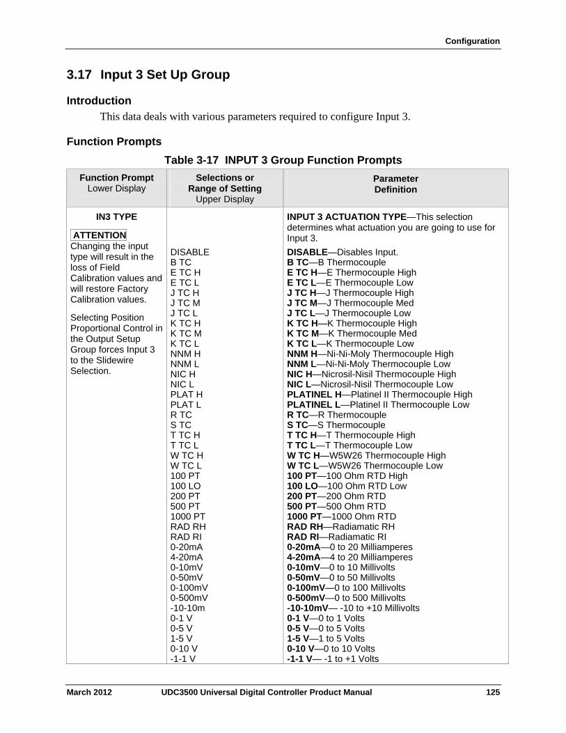
Configuration
March 2012 UDC3500 Universal Digital Controller Product Manual 125
3.17 Input 3 Set Up Group
Introduction
This data deals with various parameters required to configure Input 3.
Function Prompts
Table 3-17 INPUT 3 Group Function Prompts
Function Prompt Lower Display
Selections or Range of Setting
Upper Display
Parameter Definition
IN3 TYPE
ATTENTION Changing the input type will result in the loss of Field Calibration values and will restore Factory Calibration values.
Selecting Position Proportional Control in the Output Setup Group forces Input 3 to the Slidewire Selection.
DISABLE B TC E TC H E TC L J TC H J TC M J TC L K TC H K TC M K TC L NNM H NNM L NIC H NIC L PLAT H PLAT L R TC S TC T TC H T TC L W TC H W TC L 100 PT 100 LO 200 PT 500 PT 1000 PT RAD RH RAD RI 0-20mA 4-20mA 0-10mV 0-50mV 0-100mV 0-500mV -10-10m 0-1 V 0-5 V 1-5 V 0-10 V -1-1 V
INPUT 3 ACTUATION TYPE—This selection determines what actuation you are going to use for Input 3.
DISABLE—Disables Input. B TC—B Thermocouple E TC H—E Thermocouple High E TC L—E Thermocouple Low J TC H—J Thermocouple High J TC M—J Thermocouple Med J TC L—J Thermocouple Low K TC H—K Thermocouple High K TC M—K Thermocouple Med K TC L—K Thermocouple Low NNM H—Ni-Ni-Moly Thermocouple High NNM L—Ni-Ni-Moly Thermocouple Low NIC H—Nicrosil-Nisil Thermocouple High NIC L—Nicrosil-Nisil Thermocouple Low PLATINEL H—Platinel II Thermocouple High PLATINEL L—Platinel II Thermocouple Low R TC—R Thermocouple S TC—S Thermocouple T TC H—T Thermocouple High T TC L—T Thermocouple Low W TC H—W5W26 Thermocouple High W TC L—W5W26 Thermocouple Low 100 PT—100 Ohm RTD High 100 LO—100 Ohm RTD Low 200 PT—200 Ohm RTD 500 PT—500 Ohm RTD 1000 PT—1000 Ohm RTD RAD RH—Radiamatic RH RAD RI—Radiamatic RI 0-20mA—0 to 20 Milliamperes 4-20mA—4 to 20 Milliamperes 0-10mV—0 to 10 Millivolts 0-50mV—0 to 50 Millivolts 0-100mV—0 to 100 Millivolts 0-500mV—0 to 500 Millivolts -10-10mV— -10 to +10 Millivolts 0-1 V—0 to 1 Volts 0-5 V—0 to 5 Volts 1-5 V—1 to 5 Volts 0-10 V—0 to 10 Volts -1-1 V— -1 to +1 Volts
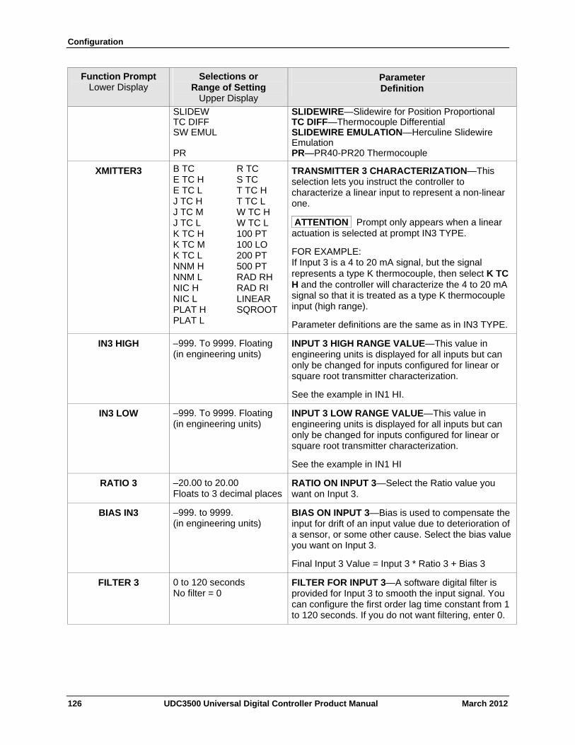
Configuration
126 UDC3500 Universal Digital Controller Product Manual March 2012
Function Prompt Lower Display
Selections or Range of Setting
Upper Display
Parameter Definition
SLIDEW TC DIFF SW EMUL PR
SLIDEWIRE—Slidewire for Position Proportional TC DIFF—Thermocouple Differential SLIDEWIRE EMULATION—Herculine Slidewire Emulation PR—PR40-PR20 Thermocouple
XMITTER3 B TC E TC H E TC L J TC H J TC M J TC L K TC H K TC M K TC L NNM H NNM L NIC H NIC L PLAT H PLAT L
R TC S TC T TC H T TC L W TC H W TC L 100 PT 100 LO 200 PT 500 PT RAD RH RAD RI LINEAR SQROOT
TRANSMITTER 3 CHARACTERIZATION—This selection lets you instruct the controller to characterize a linear input to represent a non-linear one.
ATTENTION Prompt only appears when a linear actuation is selected at prompt IN3 TYPE.
FOR EXAMPLE: If Input 3 is a 4 to 20 mA signal, but the signal represents a type K thermocouple, then select K TC H and the controller will characterize the 4 to 20 mA signal so that it is treated as a type K thermocouple input (high range).
Parameter definitions are the same as in IN3 TYPE.
IN3 HIGH –999. To 9999. Floating (in engineering units)
INPUT 3 HIGH RANGE VALUE—This value in engineering units is displayed for all inputs but can only be changed for inputs configured for linear or square root transmitter characterization.
See the example in IN1 HI.
IN3 LOW –999. To 9999. Floating (in engineering units)
INPUT 3 LOW RANGE VALUE—This value in engineering units is displayed for all inputs but can only be changed for inputs configured for linear or square root transmitter characterization.
See the example in IN1 HI
RATIO 3 –20.00 to 20.00 Floats to 3 decimal places
RATIO ON INPUT 3—Select the Ratio value you want on Input 3.
BIAS IN3 –999. to 9999. (in engineering units)
BIAS ON INPUT 3—Bias is used to compensate the input for drift of an input value due to deterioration of a sensor, or some other cause. Select the bias value you want on Input 3.
Final Input 3 Value = Input 3 * Ratio 3 + Bias 3
FILTER 3 0 to 120 seconds No filter = 0
FILTER FOR INPUT 3—A software digital filter is provided for Input 3 to smooth the input signal. You can configure the first order lag time constant from 1 to 120 seconds. If you do not want filtering, enter 0.
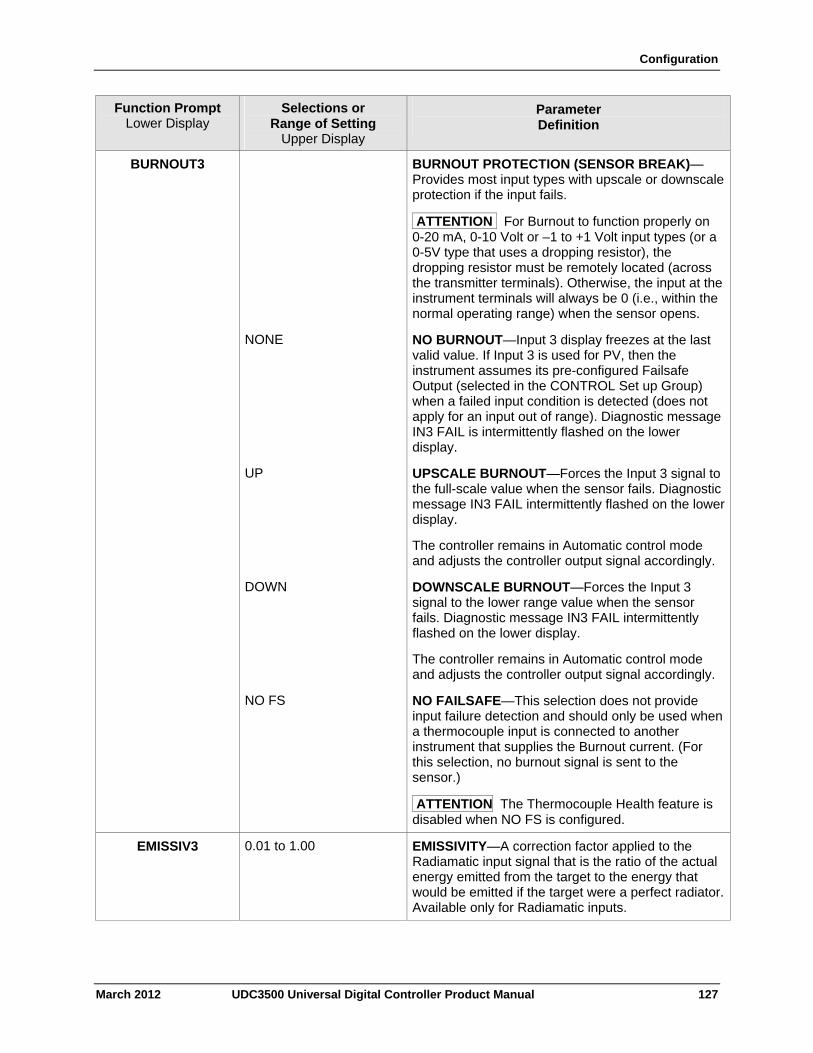
Configuration
March 2012 UDC3500 Universal Digital Controller Product Manual 127
Function Prompt Lower Display
Selections or Range of Setting
Upper Display
Parameter Definition
BURNOUT3 BURNOUT PROTECTION (SENSOR BREAK)—Provides most input types with upscale or downscale protection if the input fails.
ATTENTION For Burnout to function properly on 0-20 mA, 0-10 Volt or –1 to +1 Volt input types (or a 0-5V type that uses a dropping resistor), the dropping resistor must be remotely located (across the transmitter terminals). Otherwise, the input at the instrument terminals will always be 0 (i.e., within the normal operating range) when the sensor opens.
NONE NO BURNOUT—Input 3 display freezes at the last valid value. If Input 3 is used for PV, then the instrument assumes its pre-configured Failsafe Output (selected in the CONTROL Set up Group) when a failed input condition is detected (does not apply for an input out of range). Diagnostic message IN3 FAIL is intermittently flashed on the lower display.
UP UPSCALE BURNOUT—Forces the Input 3 signal to the full-scale value when the sensor fails. Diagnostic message IN3 FAIL intermittently flashed on the lower display.
The controller remains in Automatic control mode and adjusts the controller output signal accordingly.
DOWN DOWNSCALE BURNOUT—Forces the Input 3 signal to the lower range value when the sensor fails. Diagnostic message IN3 FAIL intermittently flashed on the lower display.
The controller remains in Automatic control mode and adjusts the controller output signal accordingly.
NO FS NO FAILSAFE—This selection does not provide input failure detection and should only be used when a thermocouple input is connected to another instrument that supplies the Burnout current. (For this selection, no burnout signal is sent to the sensor.)
ATTENTION The Thermocouple Health feature is disabled when NO FS is configured.
EMISSIV3 0.01 to 1.00 EMISSIVITY—A correction factor applied to the Radiamatic input signal that is the ratio of the actual energy emitted from the target to the energy that would be emitted if the target were a perfect radiator.Available only for Radiamatic inputs.
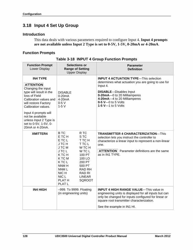
Configuration
128 UDC3500 Universal Digital Controller Product Manual March 2012
3.18 Input 4 Set Up Group
Introduction
This data deals with various parameters required to configure Input 4. Input 4 prompts are not available unless Input 2 Type is set to 0-5V, 1-5V, 0-20mA or 4-20mA.
Function Prompts
Table 3-18 INPUT 4 Group Function Prompts
Function Prompt Lower Display
Selections or Range of Setting
Upper Display
Parameter Definition
IN4 TYPE
ATTENTION Changing the input type will result in the loss of Field Calibration values and will restore Factory Calibration values.
Input 4 prompts will not be available unless Input 2 Type is set to 0-5V, 1-5V, 0-20mA or 4-20mA.
DISABLE 0-20mA 4-20mA 0-5 V 1-5 V
INPUT 4 ACTUATION TYPE—This selection determines what actuation you are going to use for Input 4.
DISABLE—Disables Input 0-20mA—0 to 20 Milliamperes 4-20mA—4 to 20 Milliamperes 0-5 V—0 to 5 Volts 1-5 V—1 to 5 Volts
XMITTER4 B TC E TC H E TC L J TC H J TC M J TC L K TC H K TC M K TC L NNM H NNM L NIC H NIC L PLAT H PLAT L
R TC S TC T TC H T TC L W TC H W TC L 100 PT 100 LO 200 PT 500 PT RAD RH RAD RI LINEAR SQROOT
TRANSMITTER 4 CHARACTERIZATION—This selection lets you instruct the controller to characterize a linear input to represent a non-linear one.
ATTENTION Parameter definitions are the same as in IN1 TYPE.
IN4 HIGH –999. To 9999. Floating (in engineering units)
INPUT 4 HIGH RANGE VALUE—This value in engineering units is displayed for all inputs but can only be changed for inputs configured for linear or square root transmitter characterization.
See the example in IN1 HI.
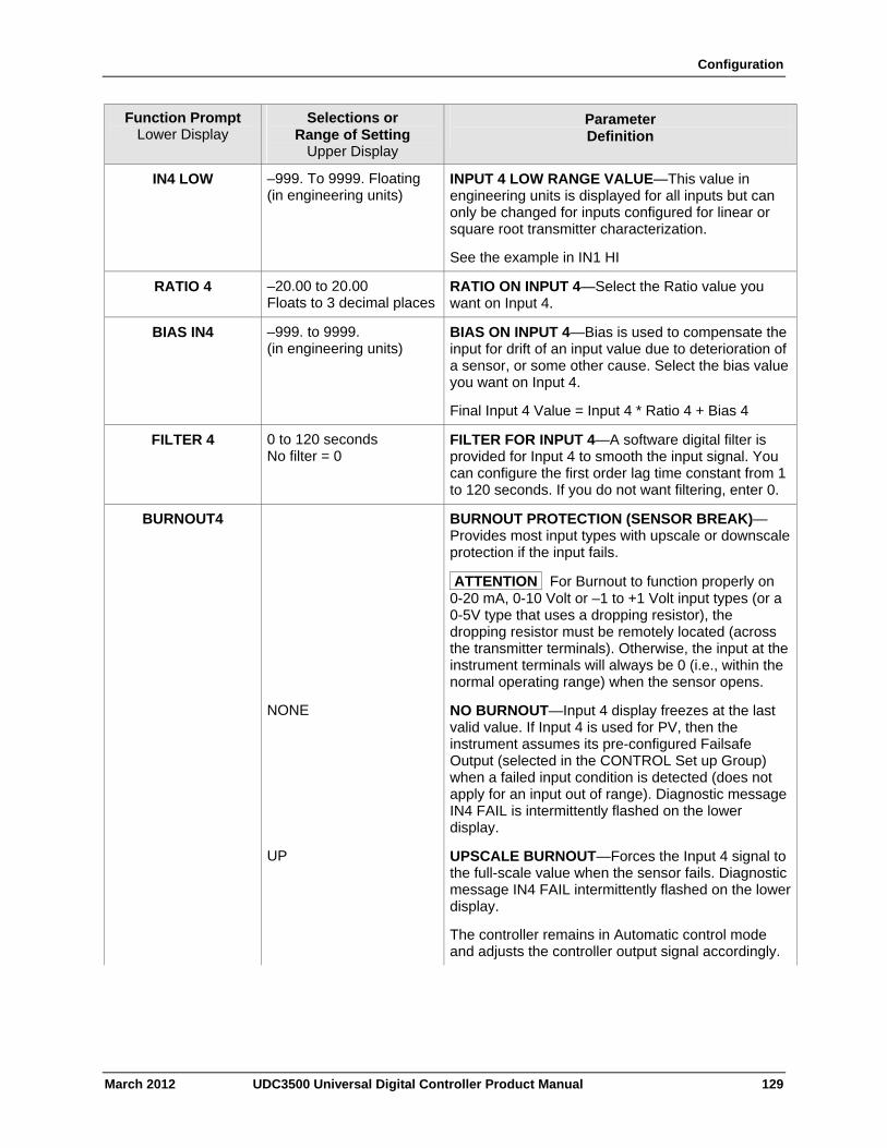
Configuration
Function Prompt Lower Display
Selections or Range of Setting
Upper Display
Parameter Definition
–999. To 9999. Floating (in engineering units)
INPUT 4 LOW RANGE VALUE—This value in engineering units is displayed for all inputs but can only be changed for inputs configured for linear or square root transmitter characterization.
See the example in IN1 HI
IN4 LOW
–20.00 to 20.00 Floats to 3 decimal places
RATIO ON INPUT 4—Select the Ratio value you want on Input 4.
RATIO 4
–999. to 9999. (in engineering units)
BIAS IN4 BIAS ON INPUT 4—Bias is used to compensate the input for drift of an input value due to deterioration of a sensor, or some other cause. Select the bias value you want on Input 4.
Final Input 4 Value = Input 4 * Ratio 4 + Bias 4
0 to 120 seconds No filter = 0
FILTER 4 FILTER FOR INPUT 4—A software digital filter is provided for Input 4 to smooth the input signal. You can configure the first order lag time constant from 1 to 120 seconds. If you do not want filtering, enter 0.
BURNOUT4 BURNOUT PROTECTION (SENSOR BREAK)—Provides most input types with upscale or downscale protection if the input fails.
ATTENTION For Burnout to function properly on 0-20 mA, 0-10 Volt or –1 to +1 Volt input types (or a 0-5V type that uses a dropping resistor), the dropping resistor must be remotely located (across the transmitter terminals). Otherwise, the input at the instrument terminals will always be 0 (i.e., within the normal operating range) when the sensor opens.
NONE NO BURNOUT—Input 4 display freezes at the last valid value. If Input 4 is used for PV, then the instrument assumes its pre-configured Failsafe Output (selected in the CONTROL Set up Group) when a failed input condition is detected (does not apply for an input out of range). Diagnostic message IN4 FAIL is intermittently flashed on the lower display.
UP UPSCALE BURNOUT—Forces the Input 4 signal to the full-scale value when the sensor fails. Diagnostic message IN4 FAIL intermittently flashed on the lower display.
The controller remains in Automatic control mode and adjusts the controller output signal accordingly.
March 2012 UDC3500 Universal Digital Controller Product Manual 129
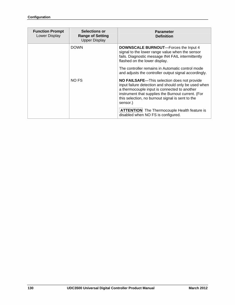
Configuration
Function Prompt Lower Display
Selections or Range of Setting
Upper Display
Parameter Definition
DOWN DOWNSCALE BURNOUT—Forces the Input 4 signal to the lower range value when the sensor fails. Diagnostic message IN4 FAIL intermittently flashed on the lower display.
The controller remains in Automatic control mode and adjusts the controller output signal accordingly.
NO FS NO FAILSAFE—This selection does not provide input failure detection and should only be used when a thermocouple input is connected to another instrument that supplies the Burnout current. (For this selection, no burnout signal is sent to the sensor.)
ATTENTION The Thermocouple Health feature is disabled when NO FS is configured.
130 UDC3500 Universal Digital Controller Product Manual March 2012
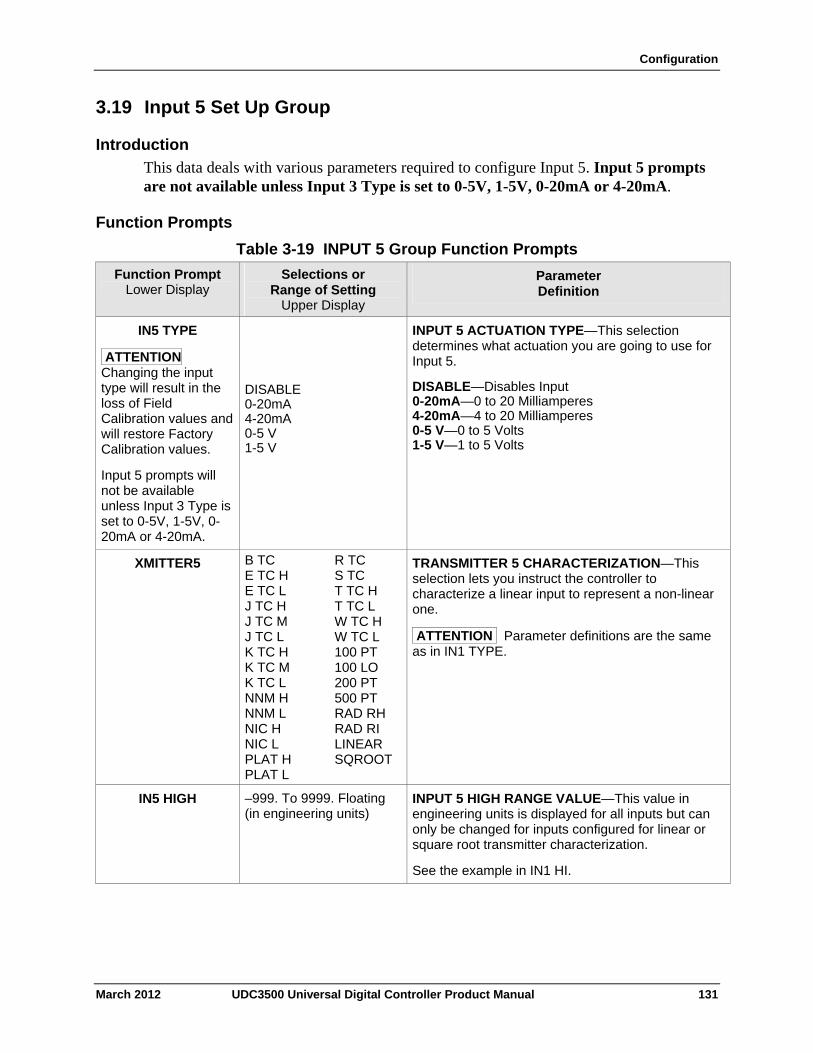
Configuration
3.19 Input 5 Set Up Group
Introduction
This data deals with various parameters required to configure Input 5. Input 5 prompts are not available unless Input 3 Type is set to 0-5V, 1-5V, 0-20mA or 4-20mA.
Function Prompts
Table 3-19 INPUT 5 Group Function Prompts
Function Prompt Lower Display
Selections or Range of Setting
Upper Display
Parameter Definition
IN5 TYPE
ATTENTION Changing the input type will result in the loss of Field Calibration values and will restore Factory Calibration values.
Input 5 prompts will not be available unless Input 3 Type is set to 0-5V, 1-5V, 0-20mA or 4-20mA.
DISABLE 0-20mA 4-20mA 0-5 V 1-5 V
INPUT 5 ACTUATION TYPE—This selection determines what actuation you are going to use for Input 5.
DISABLE—Disables Input 0-20mA—0 to 20 Milliamperes 4-20mA—4 to 20 Milliamperes 0-5 V—0 to 5 Volts 1-5 V—1 to 5 Volts
XMITTER5 B TC E TC H E TC L J TC H J TC M J TC L K TC H K TC M K TC L NNM H NNM L NIC H NIC L PLAT H PLAT L
R TC S TC T TC H T TC L W TC H W TC L 100 PT 100 LO 200 PT 500 PT RAD RH RAD RI LINEAR SQROOT
TRANSMITTER 5 CHARACTERIZATION—This selection lets you instruct the controller to characterize a linear input to represent a non-linear one.
ATTENTION Parameter definitions are the same as in IN1 TYPE.
IN5 HIGH –999. To 9999. Floating (in engineering units)
INPUT 5 HIGH RANGE VALUE—This value in engineering units is displayed for all inputs but can only be changed for inputs configured for linear or square root transmitter characterization.
See the example in IN1 HI.
March 2012 UDC3500 Universal Digital Controller Product Manual 131
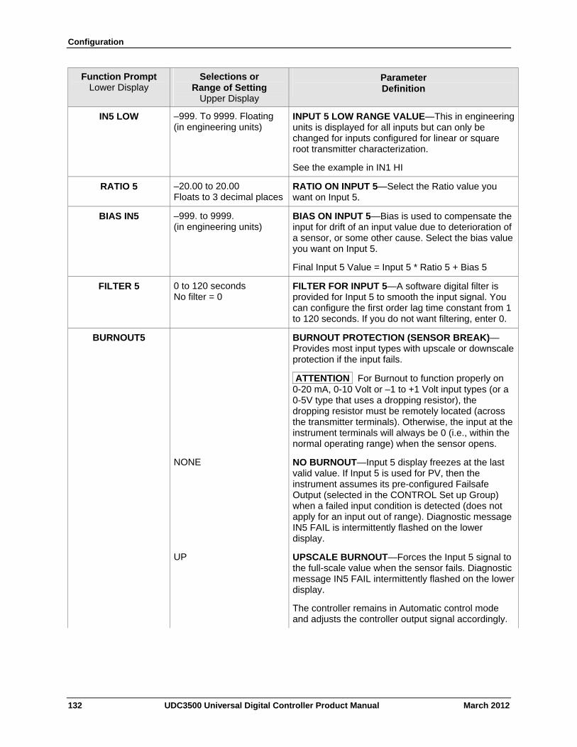
Configuration
132 UDC3500 Universal Digital Controller Product Manual March 2012
Function Prompt Lower Display
Selections or Range of Setting
Upper Display
Parameter Definition
IN5 LOW –999. To 9999. Floating (in engineering units)
INPUT 5 LOW RANGE VALUE—This in engineering units is displayed for all inputs but can only be changed for inputs configured for linear or square root transmitter characterization.
See the example in IN1 HI
RATIO 5 –20.00 to 20.00 Floats to 3 decimal places
RATIO ON INPUT 5—Select the Ratio value you want on Input 5.
BIAS IN5 –999. to 9999. (in engineering units)
BIAS ON INPUT 5—Bias is used to compensate the input for drift of an input value due to deterioration of a sensor, or some other cause. Select the bias value you want on Input 5.
Final Input 5 Value = Input 5 * Ratio 5 + Bias 5
FILTER 5 0 to 120 seconds No filter = 0
FILTER FOR INPUT 5—A software digital filter is provided for Input 5 to smooth the input signal. You can configure the first order lag time constant from 1 to 120 seconds. If you do not want filtering, enter 0.
BURNOUT5 BURNOUT PROTECTION (SENSOR BREAK)—Provides most input types with upscale or downscale protection if the input fails.
ATTENTION For Burnout to function properly on 0-20 mA, 0-10 Volt or –1 to +1 Volt input types (or a 0-5V type that uses a dropping resistor), the dropping resistor must be remotely located (across the transmitter terminals). Otherwise, the input at the instrument terminals will always be 0 (i.e., within the normal operating range) when the sensor opens.
NONE NO BURNOUT—Input 5 display freezes at the last valid value. If Input 5 is used for PV, then the instrument assumes its pre-configured Failsafe Output (selected in the CONTROL Set up Group) when a failed input condition is detected (does not apply for an input out of range). Diagnostic message IN5 FAIL is intermittently flashed on the lower display.
UP UPSCALE BURNOUT—Forces the Input 5 signal to the full-scale value when the sensor fails. Diagnostic message IN5 FAIL intermittently flashed on the lower display.
The controller remains in Automatic control mode and adjusts the controller output signal accordingly.
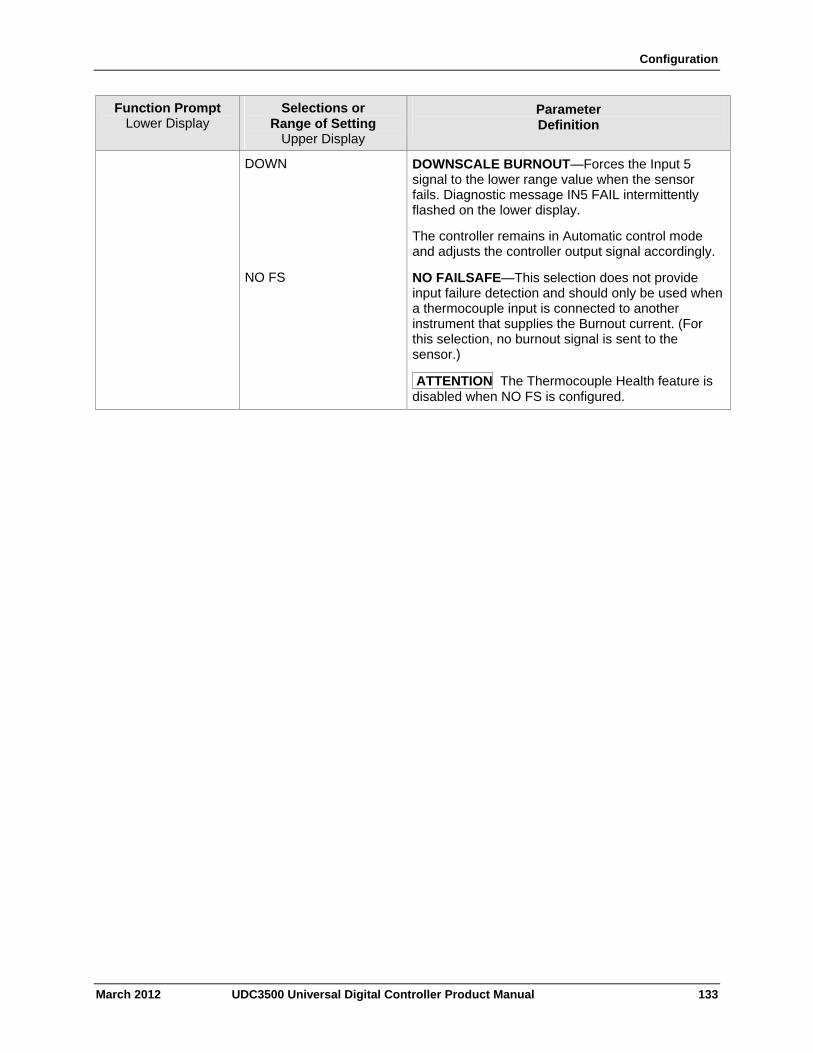
Configuration
March 2012 UDC3500 Universal Digital Controller Product Manual 133
Function Prompt Lower Display
Selections or Range of Setting
Upper Display
Parameter Definition
DOWN DOWNSCALE BURNOUT—Forces the Input 5 signal to the lower range value when the sensor fails. Diagnostic message IN5 FAIL intermittently flashed on the lower display.
The controller remains in Automatic control mode and adjusts the controller output signal accordingly.
NO FS NO FAILSAFE—This selection does not provide input failure detection and should only be used when a thermocouple input is connected to another instrument that supplies the Burnout current. (For this selection, no burnout signal is sent to the sensor.)
ATTENTION The Thermocouple Health feature is disabled when NO FS is configured.
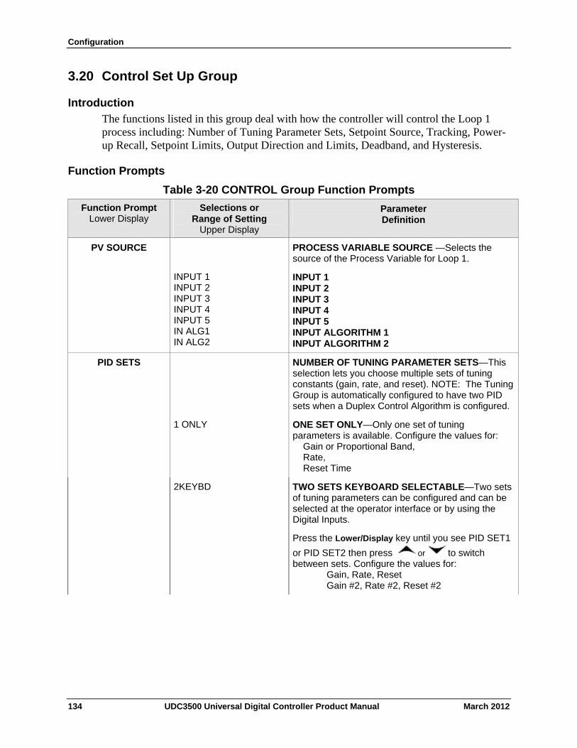
Configuration
3.20 Control Set Up Group
Introduction
The functions listed in this group deal with how the controller will control the Loop 1 process including: Number of Tuning Parameter Sets, Setpoint Source, Tracking, Power-up Recall, Setpoint Limits, Output Direction and Limits, Deadband, and Hysteresis.
Function Prompts
Table 3-20 CONTROL Group Function Prompts
Function Prompt Lower Display
Selections or Range of Setting
Upper Display
Parameter Definition
PV SOURCE
INPUT 1 INPUT 2 INPUT 3 INPUT 4 INPUT 5 IN ALG1 IN ALG2
PROCESS VARIABLE SOURCE —Selects the source of the Process Variable for Loop 1.
INPUT 1 INPUT 2 INPUT 3 INPUT 4 INPUT 5 INPUT ALGORITHM 1 INPUT ALGORITHM 2
PID SETS NUMBER OF TUNING PARAMETER SETS—This selection lets you choose multiple sets of tuning constants (gain, rate, and reset). NOTE: The Tuning Group is automatically configured to have two PID sets when a Duplex Control Algorithm is configured.
1 ONLY ONE SET ONLY—Only one set of tuning parameters is available. Configure the values for: Gain or Proportional Band, Rate, Reset Time
2KEYBD TWO SETS KEYBOARD SELECTABLE—Two sets of tuning parameters can be configured and can be selected at the operator interface or by using the Digital Inputs.
Press the Lower/Display key until you see PID SET1
or PID SET2 then press or to switch between sets. Configure the values for: Gain, Rate, Reset Gain #2, Rate #2, Reset #2
134 UDC3500 Universal Digital Controller Product Manual March 2012
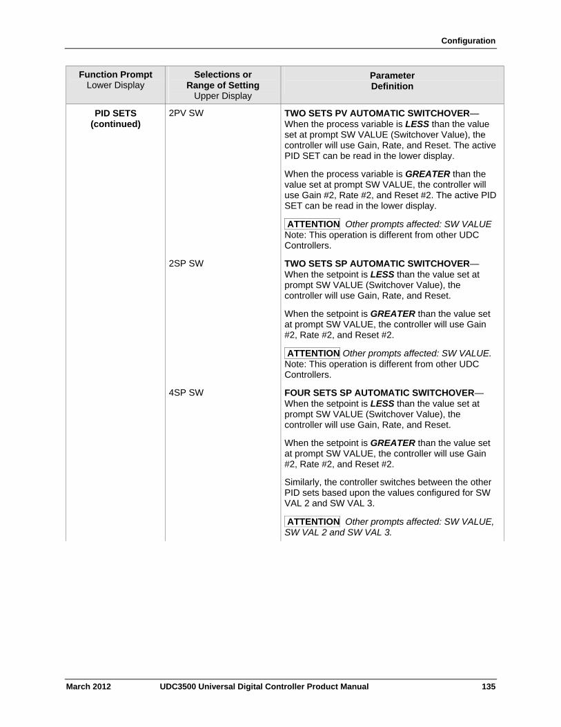
Configuration
March 2012 UDC3500 Universal Digital Controller Product Manual 135
Function Prompt Lower Display
Selections or Range of Setting
Upper Display
Parameter Definition
PID SETS (continued)
2PV SW TWO SETS PV AUTOMATIC SWITCHOVER—When the process variable is LESS than the value set at prompt SW VALUE (Switchover Value), the controller will use Gain, Rate, and Reset. The active PID SET can be read in the lower display.
When the process variable is GREATER than the value set at prompt SW VALUE, the controller will use Gain #2, Rate #2, and Reset #2. The active PID SET can be read in the lower display.
ATTENTION Other prompts affected: SW VALUE Note: This operation is different from other UDC Controllers.
2SP SW TWO SETS SP AUTOMATIC SWITCHOVER—When the setpoint is LESS than the value set at prompt SW VALUE (Switchover Value), the controller will use Gain, Rate, and Reset.
When the setpoint is GREATER than the value set at prompt SW VALUE, the controller will use Gain #2, Rate #2, and Reset #2.
ATTENTION Other prompts affected: SW VALUE. Note: This operation is different from other UDC Controllers.
4SP SW FOUR SETS SP AUTOMATIC SWITCHOVER—When the setpoint is LESS than the value set at prompt SW VALUE (Switchover Value), the controller will use Gain, Rate, and Reset.
When the setpoint is GREATER than the value set at prompt SW VALUE, the controller will use Gain #2, Rate #2, and Reset #2.
Similarly, the controller switches between the other PID sets based upon the values configured for SW VAL 2 and SW VAL 3.
ATTENTION Other prompts affected: SW VALUE, SW VAL 2 and SW VAL 3.
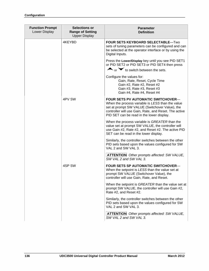
Configuration
136 UDC3500 Universal Digital Controller Product Manual March 2012
Function Prompt Lower Display
Selections or Range of Setting
Upper Display
Parameter Definition
4KEYBD FOUR SETS KEYBOARD SELECTABLE—Two sets of tuning parameters can be configured and can be selected at the operator interface or by using the Digital Inputs.
Press the Lower/Display key until you see PID SET1 or PID SET2 or PID SET3 or PID SET4 then press
or to switch between the sets.
Configure the values for: Gain, Rate, Reset, Cycle Time Gain #2, Rate #2, Reset #2 Gain #3, Rate #3, Reset #3 Gain #4, Rate #4, Reset #4
4PV SW FOUR SETS PV AUTOMATIC SWITCHOVER—When the process variable is LESS than the value set at prompt SW VALUE (Switchover Value), the controller will use Gain, Rate, and Reset. The active PID SET can be read in the lower display.
When the process variable is GREATER than the value set at prompt SW VALUE, the controller will use Gain #2, Rate #2, and Reset #2. The active PID SET can be read in the lower display.
Similarly, the controller switches between the other PID sets based upon the values configured for SW VAL 2 and SW VAL 3.
ATTENTION Other prompts affected: SW VALUE, SW VAL 2 and SW VAL 3.
4SP SW FOUR SETS SP AUTOMATIC SWITCHOVER—When the setpoint is LESS than the value set at prompt SW VALUE (Switchover Value), the controller will use Gain, Rate, and Reset.
When the setpoint is GREATER than the value set at prompt SW VALUE, the controller will use Gain #2, Rate #2, and Reset #2.
Similarly, the controller switches between the other PID sets based upon the values configured for SW VAL 2 and SW VAL 3.
ATTENTION Other prompts affected: SW VALUE, SW VAL 2 and SW VAL 3.
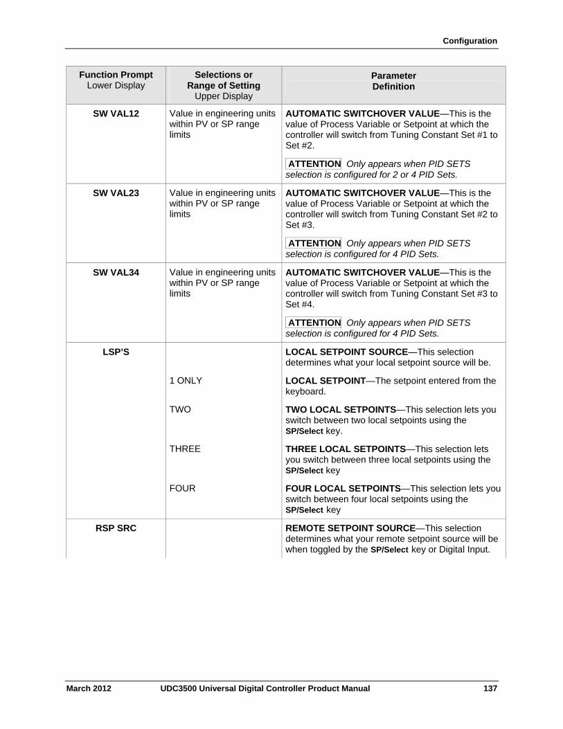
Configuration
March 2012 UDC3500 Universal Digital Controller Product Manual 137
Function Prompt Lower Display
Selections or Range of Setting
Upper Display
Parameter Definition
SW VAL12 Value in engineering units within PV or SP range limits
AUTOMATIC SWITCHOVER VALUE—This is the value of Process Variable or Setpoint at which the controller will switch from Tuning Constant Set #1 to Set #2.
ATTENTION Only appears when PID SETS selection is configured for 2 or 4 PID Sets.
SW VAL23 Value in engineering units within PV or SP range limits
AUTOMATIC SWITCHOVER VALUE—This is the value of Process Variable or Setpoint at which the controller will switch from Tuning Constant Set #2 to Set #3.
ATTENTION Only appears when PID SETS selection is configured for 4 PID Sets.
SW VAL34 Value in engineering units within PV or SP range limits
AUTOMATIC SWITCHOVER VALUE—This is the value of Process Variable or Setpoint at which the controller will switch from Tuning Constant Set #3 to Set #4.
ATTENTION Only appears when PID SETS selection is configured for 4 PID Sets.
LSP’S LOCAL SETPOINT SOURCE—This selection determines what your local setpoint source will be.
1 ONLY LOCAL SETPOINT—The setpoint entered from the keyboard.
TWO TWO LOCAL SETPOINTS—This selection lets you switch between two local setpoints using the SP/Select key.
THREE THREE LOCAL SETPOINTS—This selection lets you switch between three local setpoints using the SP/Select key
FOUR FOUR LOCAL SETPOINTS—This selection lets you switch between four local setpoints using the SP/Select key
RSP SRC REMOTE SETPOINT SOURCE—This selection determines what your remote setpoint source will be when toggled by the SP/Select key or Digital Input.
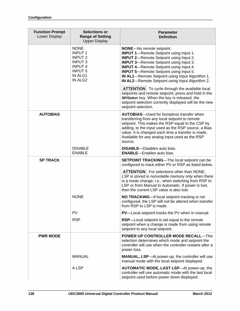
Configuration
138 UDC3500 Universal Digital Controller Product Manual March 2012
Function Prompt Lower Display
Selections or Range of Setting
Upper Display
Parameter Definition
NONE INPUT 1 INPUT 2 INPUT 3 INPUT 4 INPUT 5 IN ALG1 IN ALG2
NONE—No remote setpoint. INPUT 1—Remote Setpoint using Input 1. INPUT 2—Remote Setpoint using Input 2. INPUT 3—Remote Setpoint using Input 3. INPUT 4—Remote Setpoint using Input 4. INPUT 5—Remote Setpoint using Input 5. IN AL1—Remote Setpoint using Input Algorithm 1. IN AL2—Remote Setpoint using Input Algorithm 2.
ATTENTION To cycle through the available local setpoints and remote setpoint, press and hold in the SP/Select key. When the key is released, the setpoint selection currently displayed will be the new setpoint selection.
AUTOBIAS AUTOBIAS—Used for bumpless transfer when transferring from any local setpoint to remote setpoint. This makes the RSP equal to the CSP by adding, to the input used as the RSP source, a Bias value. It is changed each time a transfer is made. Available for any analog input used as the RSP source.
DISABLE ENABLE
DISABLE—Disables auto bias. ENABLE—Enables auto bias.
SP TRACK SETPOINT TRACKING—The local setpoint can be configured to track either PV or RSP as listed below.
ATTENTION For selections other than NONE, LSP is stored in nonvolatile memory only when there is a mode change; i.e., when switching from RSP to LSP or from Manual to Automatic. If power is lost, then the current LSP value is also lost.
NONE NO TRACKING—If local setpoint tracking is not configured, the LSP will not be altered when transfer from RSP to LSP is made.
PV PV—Local setpoint tracks the PV when in manual.
RSP RSP—Local setpoint is set equal to the remote setpoint when a change is made from using remote setpoint to any local setpoint.
PWR MODE POWER UP CONTROLLER MODE RECALL—This selection determines which mode and setpoint the controller will use when the controller restarts after a power loss.
MANUAL MANUAL, LSP—At power-up, the controller will use manual mode with the local setpoint displayed.
A LSP AUTOMATIC MODE, LAST LSP—At power-up, the controller will use automatic mode with the last local setpoint used before power down displayed.
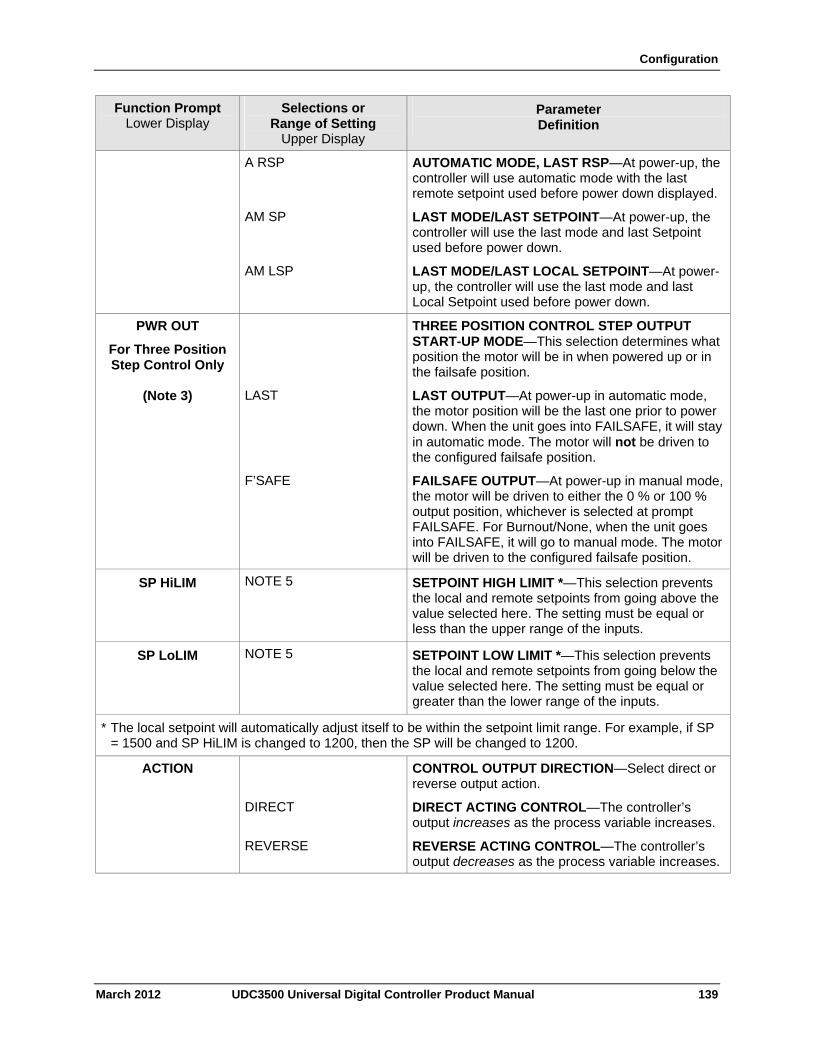
Configuration
March 2012 UDC3500 Universal Digital Controller Product Manual 139
Function Prompt Lower Display
Selections or Range of Setting
Upper Display
Parameter Definition
A RSP AUTOMATIC MODE, LAST RSP—At power-up, the controller will use automatic mode with the last remote setpoint used before power down displayed.
AM SP LAST MODE/LAST SETPOINT—At power-up, the controller will use the last mode and last Setpoint used before power down.
AM LSP LAST MODE/LAST LOCAL SETPOINT—At power-up, the controller will use the last mode and last Local Setpoint used before power down.
PWR OUT
For Three Position Step Control Only
THREE POSITION CONTROL STEP OUTPUT START-UP MODE—This selection determines what position the motor will be in when powered up or in the failsafe position.
(Note 3) LAST LAST OUTPUT—At power-up in automatic mode, the motor position will be the last one prior to power down. When the unit goes into FAILSAFE, it will stay in automatic mode. The motor will not be driven to the configured failsafe position.
F’SAFE FAILSAFE OUTPUT—At power-up in manual mode, the motor will be driven to either the 0 % or 100 % output position, whichever is selected at prompt FAILSAFE. For Burnout/None, when the unit goes into FAILSAFE, it will go to manual mode. The motor will be driven to the configured failsafe position.
SP HiLIM NOTE 5 SETPOINT HIGH LIMIT *—This selection prevents the local and remote setpoints from going above the value selected here. The setting must be equal or less than the upper range of the inputs.
SP LoLIM NOTE 5 SETPOINT LOW LIMIT *—This selection prevents the local and remote setpoints from going below the value selected here. The setting must be equal or greater than the lower range of the inputs.
* The local setpoint will automatically adjust itself to be within the setpoint limit range. For example, if SP = 1500 and SP HiLIM is changed to 1200, then the SP will be changed to 1200.
ACTION CONTROL OUTPUT DIRECTION—Select direct or reverse output action.
DIRECT DIRECT ACTING CONTROL—The controller’s output increases as the process variable increases.
REVERSE REVERSE ACTING CONTROL—The controller’s output decreases as the process variable increases.
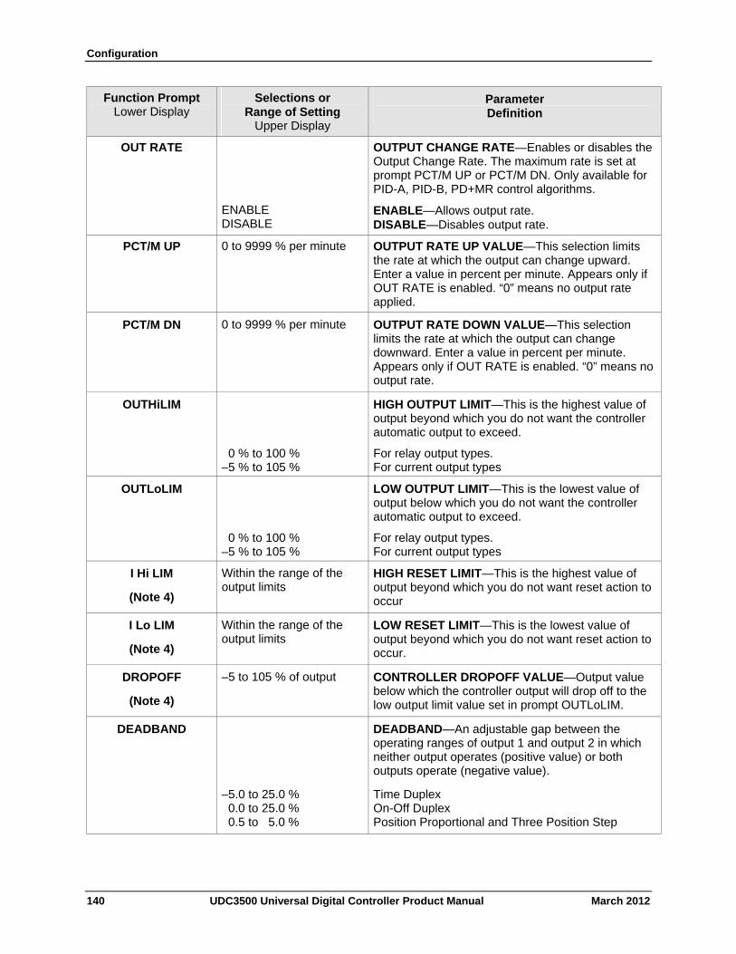
Configuration
140 UDC3500 Universal Digital Controller Product Manual March 2012
Function Prompt Lower Display
Selections or Range of Setting
Upper Display
Parameter Definition
OUT RATE
ENABLE DISABLE
OUTPUT CHANGE RATE—Enables or disables the Output Change Rate. The maximum rate is set at prompt PCT/M UP or PCT/M DN. Only available for PID-A, PID-B, PD+MR control algorithms.
ENABLE—Allows output rate. DISABLE—Disables output rate.
PCT/M UP 0 to 9999 % per minute OUTPUT RATE UP VALUE—This selection limits the rate at which the output can change upward. Enter a value in percent per minute. Appears only if OUT RATE is enabled. “0” means no output rate applied.
PCT/M DN 0 to 9999 % per minute OUTPUT RATE DOWN VALUE—This selection limits the rate at which the output can change downward. Enter a value in percent per minute. Appears only if OUT RATE is enabled. “0” means no output rate.
OUTHiLIM HIGH OUTPUT LIMIT—This is the highest value of output beyond which you do not want the controller automatic output to exceed.
0 % to 100 % –5 % to 105 %
For relay output types. For current output types
OUTLoLIM LOW OUTPUT LIMIT—This is the lowest value of output below which you do not want the controller automatic output to exceed.
0 % to 100 % –5 % to 105 %
For relay output types. For current output types
I Hi LIM
(Note 4)
Within the range of the output limits
HIGH RESET LIMIT—This is the highest value of output beyond which you do not want reset action to occur
I Lo LIM
(Note 4)
Within the range of the output limits
LOW RESET LIMIT—This is the lowest value of output beyond which you do not want reset action to occur.
DROPOFF
(Note 4)
–5 to 105 % of output CONTROLLER DROPOFF VALUE—Output value below which the controller output will drop off to the low output limit value set in prompt OUTLoLIM.
DEADBAND DEADBAND—An adjustable gap between the operating ranges of output 1 and output 2 in which neither output operates (positive value) or both outputs operate (negative value).
–5.0 to 25.0 % 0.0 to 25.0 % 0.5 to 5.0 %
Time Duplex On-Off Duplex Position Proportional and Three Position Step
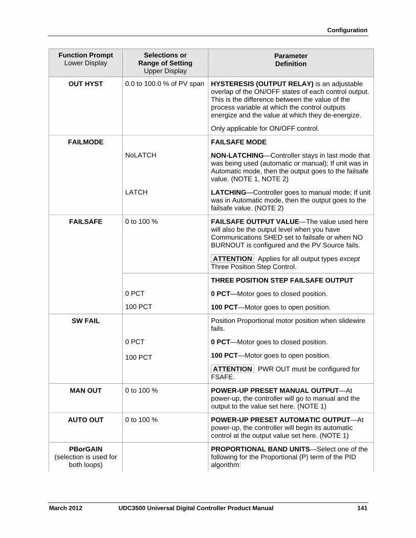
Configuration
March 2012 UDC3500 Universal Digital Controller Product Manual 141
Function Prompt Lower Display
Selections or Range of Setting
Upper Display
Parameter Definition
OUT HYST 0.0 to 100.0 % of PV span HYSTERESIS (OUTPUT RELAY) is an adjustable overlap of the ON/OFF states of each control output. This is the difference between the value of the process variable at which the control outputs energize and the value at which they de-energize.
Only applicable for ON/OFF control.
FAILMODE
NoLATCH
FAILSAFE MODE
NON-LATCHING—Controller stays in last mode that was being used (automatic or manual); If unit was in Automatic mode, then the output goes to the failsafe value. (NOTE 1, NOTE 2)
LATCH LATCHING—Controller goes to manual mode; If unit was in Automatic mode, then the output goes to the failsafe value. (NOTE 2)
FAILSAFE 0 to 100 % FAILSAFE OUTPUT VALUE—The value used here will also be the output level when you have Communications SHED set to failsafe or when NO BURNOUT is configured and the PV Source fails.
ATTENTION Applies for all output types except Three Position Step Control.
0 PCT
100 PCT
THREE POSITION STEP FAILSAFE OUTPUT
0 PCT—Motor goes to closed position.
100 PCT—Motor goes to open position.
SW FAIL
0 PCT 100 PCT
Position Proportional motor position when slidewire fails.
0 PCT—Motor goes to closed position.
100 PCT—Motor goes to open position.
ATTENTION PWR OUT must be configured for FSAFE.
MAN OUT 0 to 100 % POWER-UP PRESET MANUAL OUTPUT—At power-up, the controller will go to manual and the output to the value set here. (NOTE 1)
AUTO OUT 0 to 100 % POWER-UP PRESET AUTOMATIC OUTPUT—At power-up, the controller will begin its automatic control at the output value set here. (NOTE 1)
PBorGAIN (selection is used for
both loops)
PROPORTIONAL BAND UNITS—Select one of the following for the Proportional (P) term of the PID algorithm:
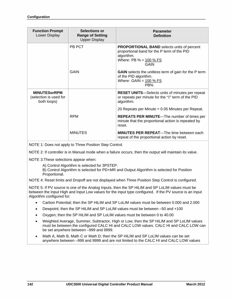
Configuration
142 UDC3500 Universal Digital Controller Product Manual March 2012
Function Prompt Lower Display
Selections or Range of Setting
Upper Display
Parameter Definition
PB PCT PROPORTIONAL BAND selects units of percent proportional band for the P term of the PID algorithm. Where: PB % = 100 % FS GAIN
GAIN GAIN selects the unitless term of gain for the P term of the PID algorithm. Where: GAIN = 100 % FS PB%
MINUTESorRPM (selection is used for
both loops)
RESET UNITS—Selects units of minutes per repeat or repeats per minute for the “I” term of the PID algorithm.
20 Repeats per Minute = 0.05 Minutes per Repeat.
RPM REPEATS PER MINUTE—The number of times per minute that the proportional action is repeated by reset.
MINUTES MINUTES PER REPEAT—The time between each repeat of the proportional action by reset.
NOTE 1: Does not apply to Three Position Step Control.
NOTE 2: If controller is in Manual mode when a failure occurs, then the output will maintain its value.
NOTE 3:These selections appear when:
A) Control Algorithm is selected for 3PSTEP. B) Control Algorithm is selected for PD+MR and Output Algorithm is selected for Position Proportional.
NOTE 4: Reset limits and Dropoff are not displayed when Three Position Step Control is configured.
NOTE 5: If PV source is one of the Analog Inputs, then the SP HiLIM and SP LoLIM values must be between the Input High and Input Low values for the input type configured. If the PV source is an Input Algorithm configured for:
Carbon Potential; then the SP HiLIM and SP LoLIM values must be between 0.000 and 2.000
Dewpoint; then the SP HiLIM and SP LoLIM values must be between –50 and +100
Oxygen; then the SP HiLIM and SP LoLIM values must be between 0 to 40.00
Weighted Average, Summer, Subtractor, High or Low; then the SP HiLIM and SP LoLIM values must be between the configured CALC HI and CALC LOW values. CALC HI and CALC LOW can be set anywhere between –999 and 9999.
Math A, Math B, Math C or Math D; then the SP HiLIM and SP LoLIM values can be set anywhere between –999 and 9999 and are not limited to the CALC HI and CALC LOW values
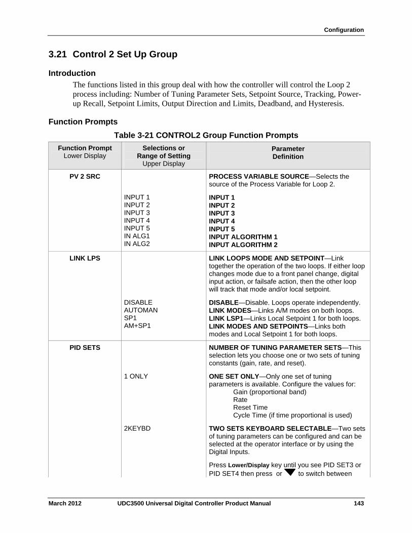
Configuration
3.21 Control 2 Set Up Group
Introduction
The functions listed in this group deal with how the controller will control the Loop 2 process including: Number of Tuning Parameter Sets, Setpoint Source, Tracking, Power-up Recall, Setpoint Limits, Output Direction and Limits, Deadband, and Hysteresis.
Function Prompts
Table 3-21 CONTROL2 Group Function Prompts
Function Prompt Lower Display
Selections or Range of Setting
Upper Display
Parameter Definition
PV 2 SRC
INPUT 1 INPUT 2 INPUT 3 INPUT 4 INPUT 5 IN ALG1 IN ALG2
PROCESS VARIABLE SOURCE—Selects the source of the Process Variable for Loop 2.
INPUT 1 INPUT 2 INPUT 3 INPUT 4 INPUT 5 INPUT ALGORITHM 1 INPUT ALGORITHM 2
LINK LOOPS MODE AND SETPOINT—Link together the operation of the two loops. If either loop changes mode due to a front panel change, digital input action, or failsafe action, then the other loop will track that mode and/or local setpoint.
LINK LPS
DISABLE AUTOMAN SP1 AM+SP1
DISABLE—Disable. Loops operate independently. LINK MODES—Links A/M modes on both loops. LINK LSP1—Links Local Setpoint 1 for both loops. LINK MODES AND SETPOINTS—Links both modes and Local Setpoint 1 for both loops.
NUMBER OF TUNING PARAMETER SETS—This selection lets you choose one or two sets of tuning constants (gain, rate, and reset).
PID SETS
1 ONLY ONE SET ONLY—Only one set of tuning parameters is available. Configure the values for: Gain (proportional band) Rate Reset Time Cycle Time (if time proportional is used)
2KEYBD TWO SETS KEYBOARD SELECTABLE—Two sets of tuning parameters can be configured and can be selected at the operator interface or by using the Digital Inputs.
Press Lower/Display key until you see PID SET3 or PID SET4 then press or to switch between
March 2012 UDC3500 Universal Digital Controller Product Manual 143
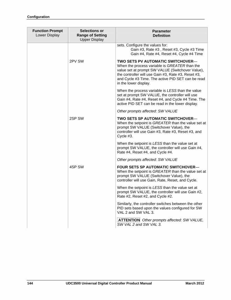
Configuration
144 UDC3500 Universal Digital Controller Product Manual March 2012
Function Prompt Lower Display
Selections or Range of Setting
Upper Display
Parameter Definition
sets. Configure the values for: Gain #3, Rate #3 , Reset #3, Cycle #3 Time Gain #4, Rate #4, Reset #4, Cycle #4 Time
2PV SW TWO SETS PV AUTOMATIC SWITCHOVER—When the process variable is GREATER than the value set at prompt SW VALUE (Switchover Value), the controller will use Gain #3, Rate #3, Reset #3, and Cycle #3 Time. The active PID SET can be read in the lower display.
When the process variable is LESS than the value set at prompt SW VALUE, the controller will use Gain #4, Rate #4, Reset #4, and Cycle #4 Time. The active PID SET can be read in the lower display.
Other prompts affected: SW VALUE
2SP SW TWO SETS SP AUTOMATIC SWITCHOVER—When the setpoint is GREATER than the value set at prompt SW VALUE (Switchover Value), the controller will use Gain #3, Rate #3, Reset #3, and Cycle #3.
When the setpoint is LESS than the value set at prompt SW VALUE, the controller will use Gain #4, Rate #4, Reset #4, and Cycle #4.
Other prompts affected: SW VALUE
4SP SW FOUR SETS SP AUTOMATIC SWITCHOVER—When the setpoint is GREATER than the value set at prompt SW VALUE (Switchover Value), the controller will use Gain, Rate, Reset, and Cycle.
When the setpoint is LESS than the value set at prompt SW VALUE, the controller will use Gain #2, Rate #2, Reset #2, and Cycle #2.
Similarly, the controller switches between the other PID sets based upon the values configured for SW VAL 2 and SW VAL 3.
ATTENTION Other prompts affected: SW VALUE, SW VAL 2 and SW VAL 3.
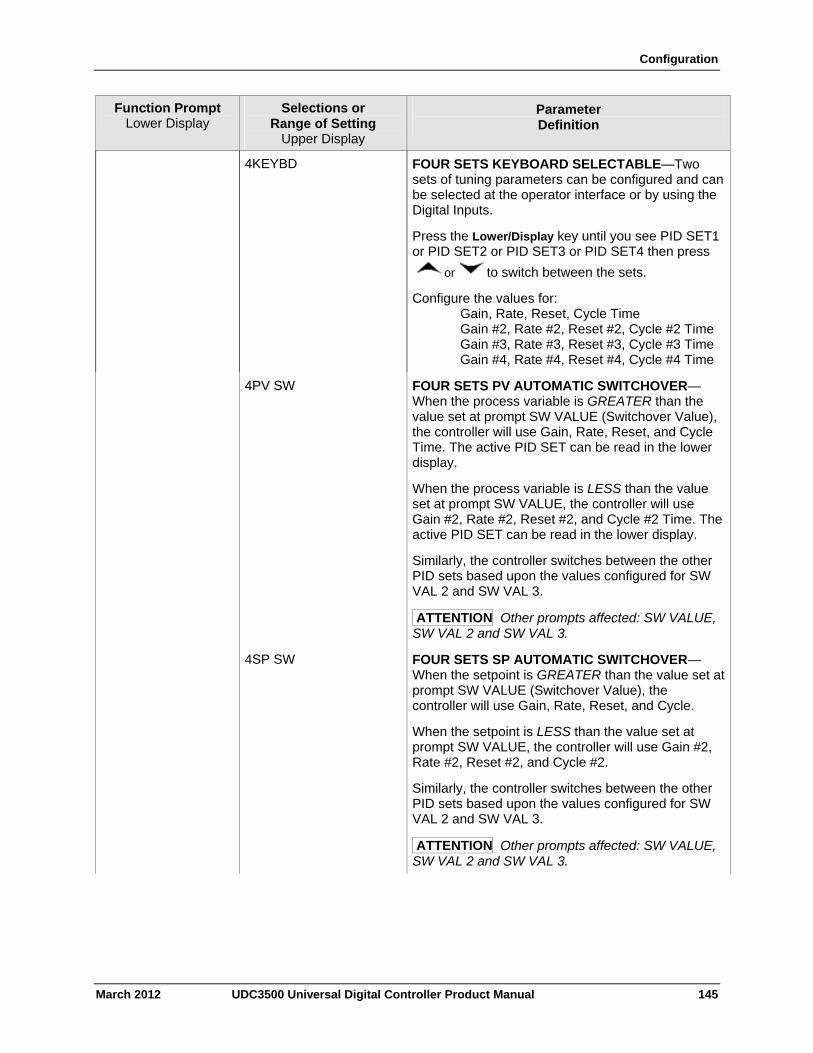
Configuration
March 2012 UDC3500 Universal Digital Controller Product Manual 145
Function Prompt Lower Display
Selections or Range of Setting
Upper Display
Parameter Definition
4KEYBD FOUR SETS KEYBOARD SELECTABLE—Two sets of tuning parameters can be configured and can be selected at the operator interface or by using the Digital Inputs.
Press the Lower/Display key until you see PID SET1 or PID SET2 or PID SET3 or PID SET4 then press
or to switch between the sets.
Configure the values for: Gain, Rate, Reset, Cycle Time Gain #2, Rate #2, Reset #2, Cycle #2 Time Gain #3, Rate #3, Reset #3, Cycle #3 Time Gain #4, Rate #4, Reset #4, Cycle #4 Time
4PV SW FOUR SETS PV AUTOMATIC SWITCHOVER—When the process variable is GREATER than the value set at prompt SW VALUE (Switchover Value), the controller will use Gain, Rate, Reset, and Cycle Time. The active PID SET can be read in the lower display.
When the process variable is LESS than the value set at prompt SW VALUE, the controller will use Gain #2, Rate #2, Reset #2, and Cycle #2 Time. The active PID SET can be read in the lower display.
Similarly, the controller switches between the other PID sets based upon the values configured for SW VAL 2 and SW VAL 3.
ATTENTION Other prompts affected: SW VALUE, SW VAL 2 and SW VAL 3.
4SP SW FOUR SETS SP AUTOMATIC SWITCHOVER—When the setpoint is GREATER than the value set at prompt SW VALUE (Switchover Value), the controller will use Gain, Rate, Reset, and Cycle.
When the setpoint is LESS than the value set at prompt SW VALUE, the controller will use Gain #2, Rate #2, Reset #2, and Cycle #2.
Similarly, the controller switches between the other PID sets based upon the values configured for SW VAL 2 and SW VAL 3.
ATTENTION Other prompts affected: SW VALUE, SW VAL 2 and SW VAL 3.
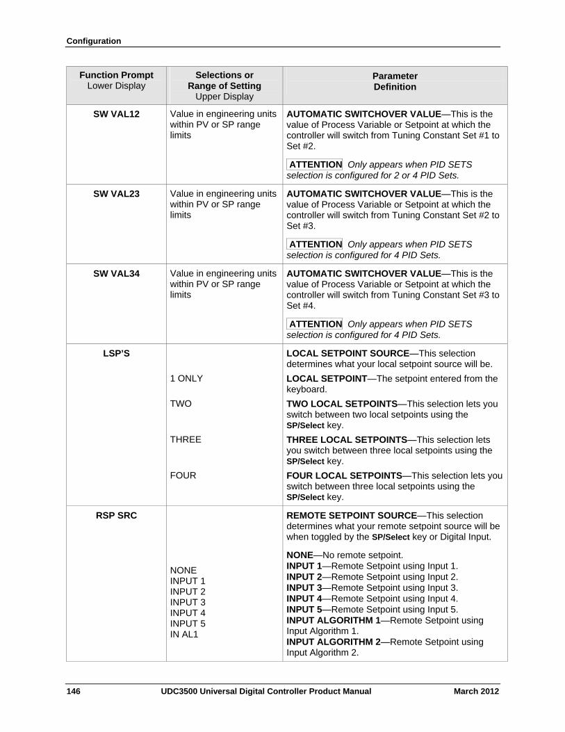
Configuration
146 UDC3500 Universal Digital Controller Product Manual March 2012
Function Prompt Lower Display
Selections or Range of Setting
Upper Display
Parameter Definition
SW VAL12 Value in engineering units within PV or SP range limits
AUTOMATIC SWITCHOVER VALUE—This is the value of Process Variable or Setpoint at which the controller will switch from Tuning Constant Set #1 to Set #2.
ATTENTION Only appears when PID SETS selection is configured for 2 or 4 PID Sets.
SW VAL23 Value in engineering units within PV or SP range limits
AUTOMATIC SWITCHOVER VALUE—This is the value of Process Variable or Setpoint at which the controller will switch from Tuning Constant Set #2 to Set #3.
ATTENTION Only appears when PID SETS selection is configured for 4 PID Sets.
SW VAL34 Value in engineering units within PV or SP range limits
AUTOMATIC SWITCHOVER VALUE—This is the value of Process Variable or Setpoint at which the controller will switch from Tuning Constant Set #3 to Set #4.
ATTENTION Only appears when PID SETS selection is configured for 4 PID Sets.
LSP’S LOCAL SETPOINT SOURCE—This selection determines what your local setpoint source will be.
1 ONLY LOCAL SETPOINT—The setpoint entered from the keyboard.
TWO TWO LOCAL SETPOINTS—This selection lets you switch between two local setpoints using the SP/Select key.
THREE THREE LOCAL SETPOINTS—This selection lets you switch between three local setpoints using the SP/Select key.
FOUR FOUR LOCAL SETPOINTS—This selection lets you switch between three local setpoints using the SP/Select key.
RSP SRC NONE INPUT 1 INPUT 2 INPUT 3 INPUT 4 INPUT 5 IN AL1
REMOTE SETPOINT SOURCE—This selection determines what your remote setpoint source will be when toggled by the SP/Select key or Digital Input.
NONE—No remote setpoint. INPUT 1—Remote Setpoint using Input 1. INPUT 2—Remote Setpoint using Input 2. INPUT 3—Remote Setpoint using Input 3. INPUT 4—Remote Setpoint using Input 4. INPUT 5—Remote Setpoint using Input 5. INPUT ALGORITHM 1—Remote Setpoint using Input Algorithm 1. INPUT ALGORITHM 2—Remote Setpoint using Input Algorithm 2.
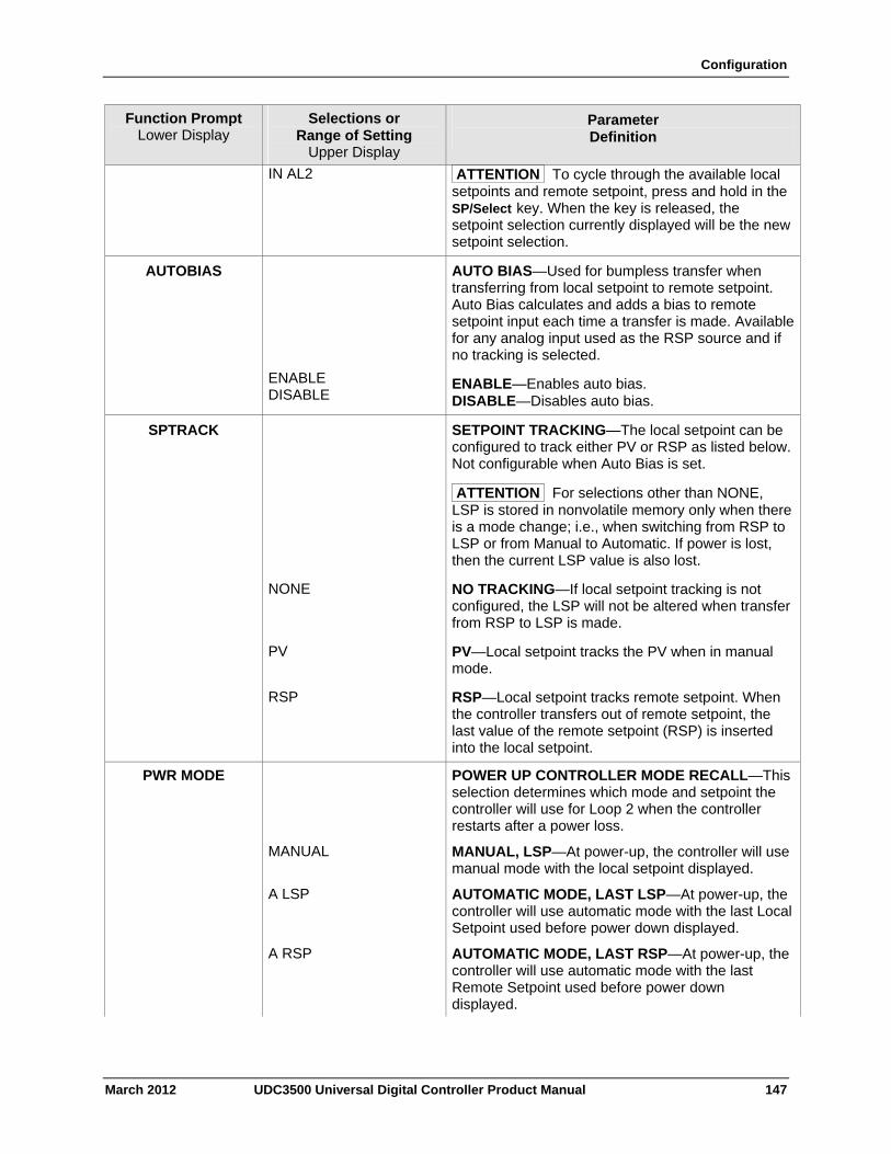
Configuration
March 2012 UDC3500 Universal Digital Controller Product Manual 147
Function Prompt Lower Display
Selections or Range of Setting
Upper Display
Parameter Definition
IN AL2 ATTENTION To cycle through the available local setpoints and remote setpoint, press and hold in the SP/Select key. When the key is released, the setpoint selection currently displayed will be the new setpoint selection.
AUTOBIAS
ENABLE DISABLE
AUTO BIAS—Used for bumpless transfer when transferring from local setpoint to remote setpoint. Auto Bias calculates and adds a bias to remote setpoint input each time a transfer is made. Available for any analog input used as the RSP source and if no tracking is selected.
ENABLE—Enables auto bias. DISABLE—Disables auto bias.
SPTRACK SETPOINT TRACKING—The local setpoint can be configured to track either PV or RSP as listed below. Not configurable when Auto Bias is set.
ATTENTION For selections other than NONE, LSP is stored in nonvolatile memory only when there is a mode change; i.e., when switching from RSP to LSP or from Manual to Automatic. If power is lost, then the current LSP value is also lost.
NONE NO TRACKING—If local setpoint tracking is not configured, the LSP will not be altered when transfer from RSP to LSP is made.
PV PV—Local setpoint tracks the PV when in manual mode.
RSP RSP—Local setpoint tracks remote setpoint. When the controller transfers out of remote setpoint, the last value of the remote setpoint (RSP) is inserted into the local setpoint.
PWR MODE POWER UP CONTROLLER MODE RECALL—This selection determines which mode and setpoint the controller will use for Loop 2 when the controller restarts after a power loss.
MANUAL MANUAL, LSP—At power-up, the controller will use manual mode with the local setpoint displayed.
A LSP AUTOMATIC MODE, LAST LSP—At power-up, the controller will use automatic mode with the last Local Setpoint used before power down displayed.
A RSP AUTOMATIC MODE, LAST RSP—At power-up, the controller will use automatic mode with the last Remote Setpoint used before power down displayed.
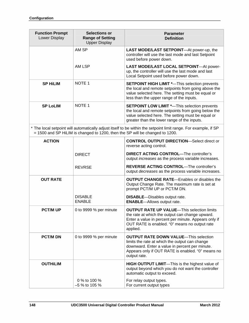
Configuration
148 UDC3500 Universal Digital Controller Product Manual March 2012
Function Prompt Lower Display
Selections or Range of Setting
Upper Display
Parameter Definition
AM SP LAST MODE/LAST SETPOINT—At power-up, the controller will use the last mode and last Setpoint used before power down.
AM LSP LAST MODE/LAST LOCAL SETPOINT—At power-up, the controller will use the last mode and last Local Setpoint used before power down.
SP HiLIM NOTE 1 SETPOINT HIGH LIMIT *—This selection prevents the local and remote setpoints from going above the value selected here. The setting must be equal or less than the upper range of the inputs.
SP LoLIM NOTE 1 SETPOINT LOW LIMIT *—This selection prevents the local and remote setpoints from going below the value selected here. The setting must be equal or greater than the lower range of the inputs.
* The local setpoint will automatically adjust itself to be within the setpoint limit range. For example, if SP = 1500 and SP HiLIM is changed to 1200, then the SP will be changed to 1200.
ACTION CONTROL OUTPUT DIRECTION—Select direct or reverse acting control.
DIRECT DIRECT ACTING CONTROL—The controller’s output increases as the process variable increases.
REVRSE REVERSE ACTING CONTROL—The controller’s output decreases as the process variable increases.
OUT RATE
DISABLE ENABLE
OUTPUT CHANGE RATE—Enables or disables the Output Change Rate. The maximum rate is set at prompt PCT/M UP or PCT/M DN.
DISABLE—Disables output rate. ENABLE—Allows output rate.
PCT/M UP 0 to 9999 % per minute OUTPUT RATE UP VALUE—This selection limits the rate at which the output can change upward. Enter a value in percent per minute. Appears only if OUT RATE is enabled. “0” means no output rate applied.
PCT/M DN 0 to 9999 % per minute OUTPUT RATE DOWN VALUE—This selection limits the rate at which the output can change downward. Enter a value in percent per minute. Appears only if OUT RATE is enabled. “0” means no output rate.
OUTHiLIM HIGH OUTPUT LIMIT—This is the highest value of output beyond which you do not want the controller automatic output to exceed.
0 % to 100 % –5 % to 105 %
For relay output types. For current output types
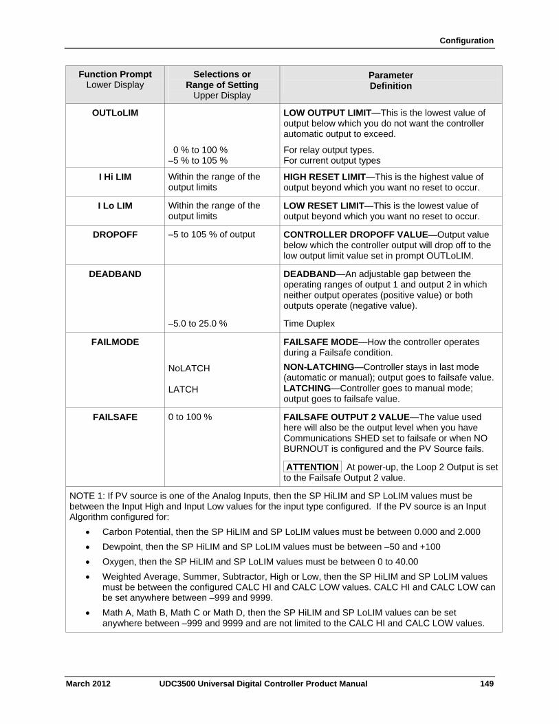
Configuration
March 2012 UDC3500 Universal Digital Controller Product Manual 149
Function Prompt Lower Display
Selections or Range of Setting
Upper Display
Parameter Definition
OUTLoLIM LOW OUTPUT LIMIT—This is the lowest value of output below which you do not want the controller automatic output to exceed.
0 % to 100 % –5 % to 105 %
For relay output types. For current output types
I Hi LIM Within the range of the output limits
HIGH RESET LIMIT—This is the highest value of output beyond which you want no reset to occur.
I Lo LIM Within the range of the output limits
LOW RESET LIMIT—This is the lowest value of output beyond which you want no reset to occur.
DROPOFF –5 to 105 % of output CONTROLLER DROPOFF VALUE—Output value below which the controller output will drop off to the low output limit value set in prompt OUTLoLIM.
DEADBAND DEADBAND—An adjustable gap between the operating ranges of output 1 and output 2 in which neither output operates (positive value) or both outputs operate (negative value).
–5.0 to 25.0 % Time Duplex
FAILMODE
NoLATCH LATCH
FAILSAFE MODE—How the controller operates during a Failsafe condition.
NON-LATCHING—Controller stays in last mode (automatic or manual); output goes to failsafe value. LATCHING—Controller goes to manual mode; output goes to failsafe value.
FAILSAFE 0 to 100 % FAILSAFE OUTPUT 2 VALUE—The value used here will also be the output level when you have Communications SHED set to failsafe or when NO BURNOUT is configured and the PV Source fails.
ATTENTION At power-up, the Loop 2 Output is set to the Failsafe Output 2 value.
NOTE 1: If PV source is one of the Analog Inputs, then the SP HiLIM and SP LoLIM values must be between the Input High and Input Low values for the input type configured. If the PV source is an Input Algorithm configured for:
Carbon Potential, then the SP HiLIM and SP LoLIM values must be between 0.000 and 2.000
Dewpoint, then the SP HiLIM and SP LoLIM values must be between –50 and +100
Oxygen, then the SP HiLIM and SP LoLIM values must be between 0 to 40.00
Weighted Average, Summer, Subtractor, High or Low, then the SP HiLIM and SP LoLIM values must be between the configured CALC HI and CALC LOW values. CALC HI and CALC LOW can be set anywhere between –999 and 9999.
Math A, Math B, Math C or Math D, then the SP HiLIM and SP LoLIM values can be set anywhere between –999 and 9999 and are not limited to the CALC HI and CALC LOW values.
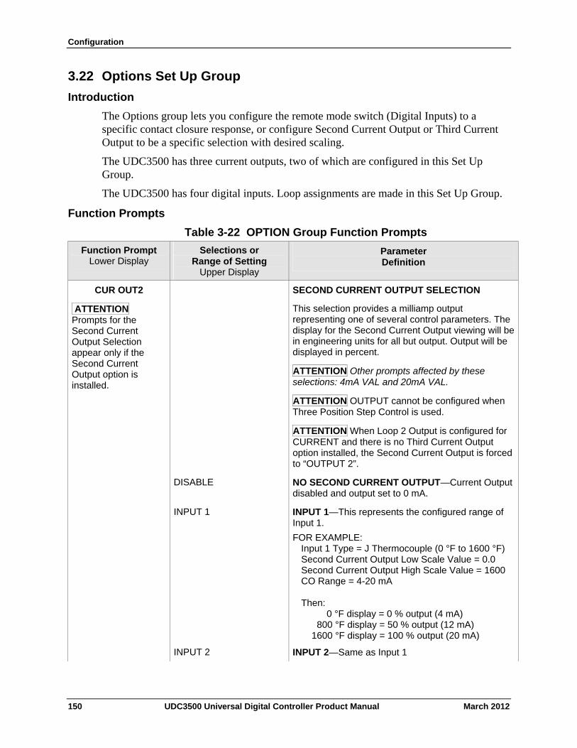
Configuration
3.22 Options Set Up Group
Introduction
The Options group lets you configure the remote mode switch (Digital Inputs) to a specific contact closure response, or configure Second Current Output or Third Current Output to be a specific selection with desired scaling.
The UDC3500 has three current outputs, two of which are configured in this Set Up Group.
The UDC3500 has four digital inputs. Loop assignments are made in this Set Up Group.
Function Prompts
Table 3-22 OPTION Group Function Prompts
Selections or Range of Setting
Upper Display
Parameter Definition
Function Prompt Lower Display
CUR OUT2
ATTENTION Prompts for the Second Current Output Selection appear only if the Second Current Output option is installed.
SECOND CURRENT OUTPUT SELECTION
This selection provides a milliamp output representing one of several control parameters. The display for the Second Current Output viewing will be in engineering units for all but output. Output will be displayed in percent.
ATTENTION Other prompts affected by these selections: 4mA VAL and 20mA VAL.
ATTENTION OUTPUT cannot be configured when Three Position Step Control is used.
ATTENTION When Loop 2 Output is configured for CURRENT and there is no Third Current Output option installed, the Second Current Output is forced to “OUTPUT 2”.
DISABLE NO SECOND CURRENT OUTPUT—Current Output disabled and output set to 0 mA.
INPUT 1 INPUT 1—This represents the configured range of Input 1.
FOR EXAMPLE: Input 1 Type = J Thermocouple (0 °F to 1600 °F) Second Current Output Low Scale Value = 0.0 Second Current Output High Scale Value = 1600 CO Range = 4-20 mA Then: 0 °F display = 0 % output (4 mA) 800 °F display = 50 % output (12 mA) 1600 °F display = 100 % output (20 mA)
INPUT 2 INPUT 2—Same as Input 1
150 UDC3500 Universal Digital Controller Product Manual March 2012
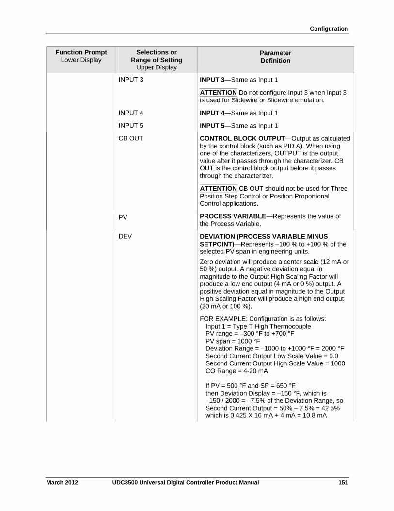
Configuration
March 2012 UDC3500 Universal Digital Controller Product Manual 151
Function Prompt Lower Display
Selections or Range of Setting
Upper Display
Parameter Definition
INPUT 3 INPUT 3—Same as Input 1
ATTENTION Do not configure Input 3 when Input 3 is used for Slidewire or Slidewire emulation.
INPUT 4 INPUT 4—Same as Input 1
INPUT 5 INPUT 5—Same as Input 1
CB OUT CONTROL BLOCK OUTPUT—Output as calculated by the control block (such as PID A). When using one of the characterizers, OUTPUT is the output value after it passes through the characterizer. CB OUT is the control block output before it passes through the characterizer.
ATTENTION CB OUT should not be used for Three Position Step Control or Position Proportional Control applications.
PV PROCESS VARIABLE—Represents the value of the Process Variable.
DEV DEVIATION (PROCESS VARIABLE MINUS SETPOINT)—Represents –100 % to +100 % of the selected PV span in engineering units.
Zero deviation will produce a center scale (12 mA or 50 %) output. A negative deviation equal in magnitude to the Output High Scaling Factor will produce a low end output (4 mA or 0 %) output. A positive deviation equal in magnitude to the Output High Scaling Factor will produce a high end output (20 mA or 100 %).
FOR EXAMPLE: Configuration is as follows: Input 1 = Type T High Thermocouple PV range = –300 °F to +700 °F PV span = 1000 °F Deviation Range = –1000 to +1000 °F = 2000 °F Second Current Output Low Scale Value = 0.0 Second Current Output High Scale Value = 1000 CO Range = 4-20 mA If PV = 500 °F and SP = 650 °F then Deviation Display = –150 °F, which is –150 / 2000 = –7.5% of the Deviation Range, so Second Current Output = 50% – 7.5% = 42.5% which is 0.425 X 16 mA + 4 mA = 10.8 mA
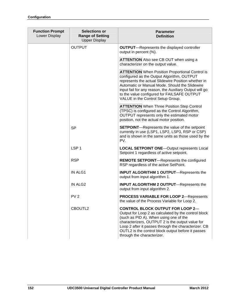
Configuration
152 UDC3500 Universal Digital Controller Product Manual March 2012
Function Prompt Lower Display
Selections or Range of Setting
Upper Display
Parameter Definition
OUTPUT OUTPUT—Represents the displayed controller output in percent (%).
ATTENTION Also see CB OUT when using a characterizer on the output value.
ATTENTION When Position Proportional Control is configured as the Output Algorithm, OUTPUT represents the actual Slidewire Position whether in Automatic or Manual Mode. Should the Slidewire input fail for any reason, the Auxiliary Output will go to the value configured for FAILSAFE OUTPUT VALUE in the Control Setup Group.
ATTENTION When Three Position Step Control (TPSC) is configured as the Control Algorithm, OUTPUT represents only the estimated motor position, not the actual motor position.
SP SETPOINT—Represents the value of the setpoint currently in use (LSP1, LSP2, LSP3, RSP or CSP) and is shown in the same units as those used by the PV.
LSP 1 LOCAL SETPOINT ONE—Output represents Local Setpoint 1 regardless of active setpoint.
RSP REMOTE SETPOINT—Represents the configured RSP regardless of the active SetPoint.
IN ALG1 INPUT ALGORITHM 1 OUTPUT—Represents the output from input algorithm 1.
IN ALG2 INPUT ALGORITHM 2 OUTPUT—Represents the output from input algorithm 2.
PV 2 PROCESS VARIABLE FOR LOOP 2—Represents the value of the Process Variable for Loop 2.
CBOUTL2 CONTROL BLOCK OUTPUT FOR LOOP 2—Output for Loop 2 as calculated by the control block (such as PID A). When using one of the characterizers, OUTPUT 2 is the output value for Loop 2 after it passes through the characterizer. CB OUTL2 is the control block output before it passes through the characterizer.
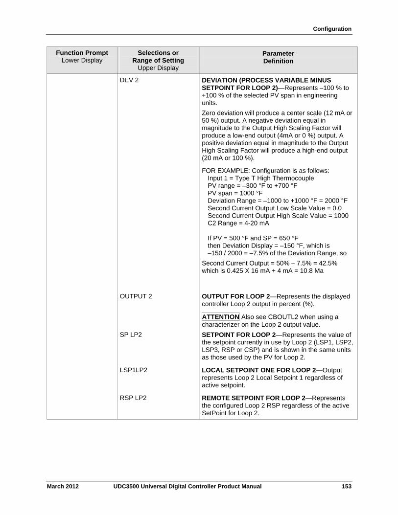
Configuration
March 2012 UDC3500 Universal Digital Controller Product Manual 153
Function Prompt Lower Display
Selections or Range of Setting
Upper Display
Parameter Definition
DEV 2 DEVIATION (PROCESS VARIABLE MINUS SETPOINT FOR LOOP 2)—Represents –100 % to +100 % of the selected PV span in engineering units.
Zero deviation will produce a center scale (12 mA or 50 %) output. A negative deviation equal in magnitude to the Output High Scaling Factor will produce a low-end output (4mA or 0 %) output. A positive deviation equal in magnitude to the Output High Scaling Factor will produce a high-end output (20 mA or 100 %).
FOR EXAMPLE: Configuration is as follows: Input 1 = Type T High Thermocouple PV range = –300 °F to +700 °F PV span = 1000 °F Deviation Range = –1000 to +1000 °F = 2000 °F Second Current Output Low Scale Value = 0.0 Second Current Output High Scale Value = 1000 C2 Range = 4-20 mA If PV = 500 °F and SP = 650 °F then Deviation Display = –150 °F, which is –150 / 2000 = –7.5% of the Deviation Range, so
Second Current Output = 50% – 7.5% = 42.5% which is 0.425 X 16 mA + 4 mA = 10.8 Ma
OUTPUT 2 OUTPUT FOR LOOP 2—Represents the displayed controller Loop 2 output in percent (%).
ATTENTION Also see CBOUTL2 when using a characterizer on the Loop 2 output value.
SP LP2 SETPOINT FOR LOOP 2—Represents the value of the setpoint currently in use by Loop 2 (LSP1, LSP2, LSP3, RSP or CSP) and is shown in the same units as those used by the PV for Loop 2.
LSP1LP2 LOCAL SETPOINT ONE FOR LOOP 2—Output represents Loop 2 Local Setpoint 1 regardless of active setpoint.
RSP LP2 REMOTE SETPOINT FOR LOOP 2—Represents the configured Loop 2 RSP regardless of the active SetPoint for Loop 2.
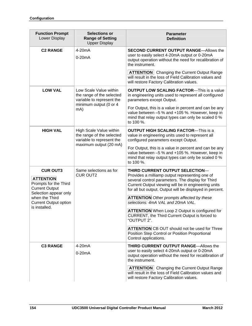
Configuration
154 UDC3500 Universal Digital Controller Product Manual March 2012
Function Prompt Lower Display
Selections or Range of Setting
Upper Display
Parameter Definition
C2 RANGE 4-20mA
0-20mA
SECOND CURRENT OUTPUT RANGE—Allows the user to easily select 4-20mA output or 0-20mA output operation without the need for recalibration of the instrument.
ATTENTION Changing the Current Output Range will result in the loss of Field Calibration values and will restore Factory Calibration values.
LOW VAL Low Scale Value within the range of the selected variable to represent the minimum output (0 or 4 mA)
OUTPUT LOW SCALING FACTOR—This is a value in engineering units used to represent all configured parameters except Output.
For Output, this is a value in percent and can be any value between –5 % and +105 %. However, keep in mind that relay output types can only be scaled 0 % to 100 %.
HIGH VAL High Scale Value within the range of the selected variable to represent the maximum output (20 mA)
OUTPUT HIGH SCALING FACTOR—This is a value in engineering units used to represent all configured parameters except Output.
For Output, this is a value in percent and can be any value between –5 % and +105 %. However, keep in mind that relay output types can only be scaled 0 % to 100 %.
CUR OUT3
ATTENTION Prompts for the Third Current Output Selection appear only when the Third Current Output option is installed.
Same selections as for CUR OUT2
THIRD CURRENT OUTPUT SELECTION—Provides a milliamp output representing one of several control parameters. The display for Third Current Output viewing will be in engineering units for all but output. Output will be displayed in percent.
ATTENTION Other prompts affected by these selections: 4mA VAL and 20mA VAL.
ATTENTION When Loop 2 Output is configured for CURRENT, the Third Current Output is forced to “OUTPUT 2”.
ATTENTION CB OUT should not be used for Three Position Step Control or Position Proportional Control applications.
C3 RANGE 4-20mA
0-20mA
THIRD CURRENT OUTPUT RANGE—Allows the user to easily select 4-20mA output or 0-20mA output operation without the need for recalibration of the instrument.
ATTENTION Changing the Current Output Range will result in the loss of Field Calibration values and will restore Factory Calibration values.
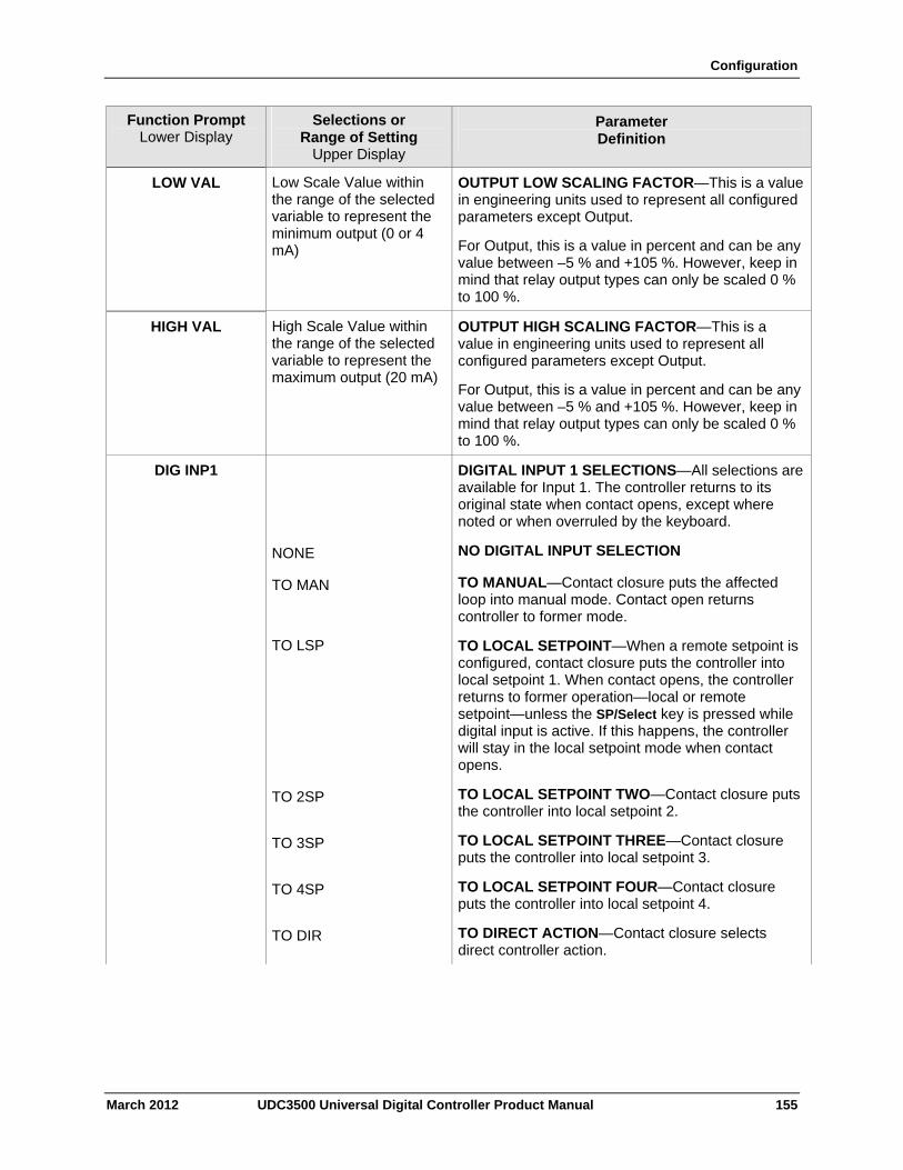
Configuration
March 2012 UDC3500 Universal Digital Controller Product Manual 155
Function Prompt Lower Display
Selections or Range of Setting
Upper Display
Parameter Definition
LOW VAL Low Scale Value within the range of the selected variable to represent the minimum output (0 or 4 mA)
OUTPUT LOW SCALING FACTOR—This is a value in engineering units used to represent all configured parameters except Output.
For Output, this is a value in percent and can be any value between –5 % and +105 %. However, keep in mind that relay output types can only be scaled 0 % to 100 %.
HIGH VAL High Scale Value within the range of the selected variable to represent the maximum output (20 mA)
OUTPUT HIGH SCALING FACTOR—This is a value in engineering units used to represent all configured parameters except Output.
For Output, this is a value in percent and can be any value between –5 % and +105 %. However, keep in mind that relay output types can only be scaled 0 % to 100 %.
DIG INP1 DIGITAL INPUT 1 SELECTIONS—All selections are available for Input 1. The controller returns to its original state when contact opens, except where noted or when overruled by the keyboard.
NONE NO DIGITAL INPUT SELECTION
TO MAN TO MANUAL—Contact closure puts the affected loop into manual mode. Contact open returns controller to former mode.
TO LSP TO LOCAL SETPOINT—When a remote setpoint is configured, contact closure puts the controller into local setpoint 1. When contact opens, the controller returns to former operation—local or remote setpoint—unless the SP/Select key is pressed while digital input is active. If this happens, the controller will stay in the local setpoint mode when contact opens.
TO 2SP TO LOCAL SETPOINT TWO—Contact closure puts the controller into local setpoint 2.
TO 3SP TO LOCAL SETPOINT THREE—Contact closure puts the controller into local setpoint 3.
TO 4SP TO LOCAL SETPOINT FOUR—Contact closure puts the controller into local setpoint 4.
TO DIR TO DIRECT ACTION—Contact closure selects direct controller action.
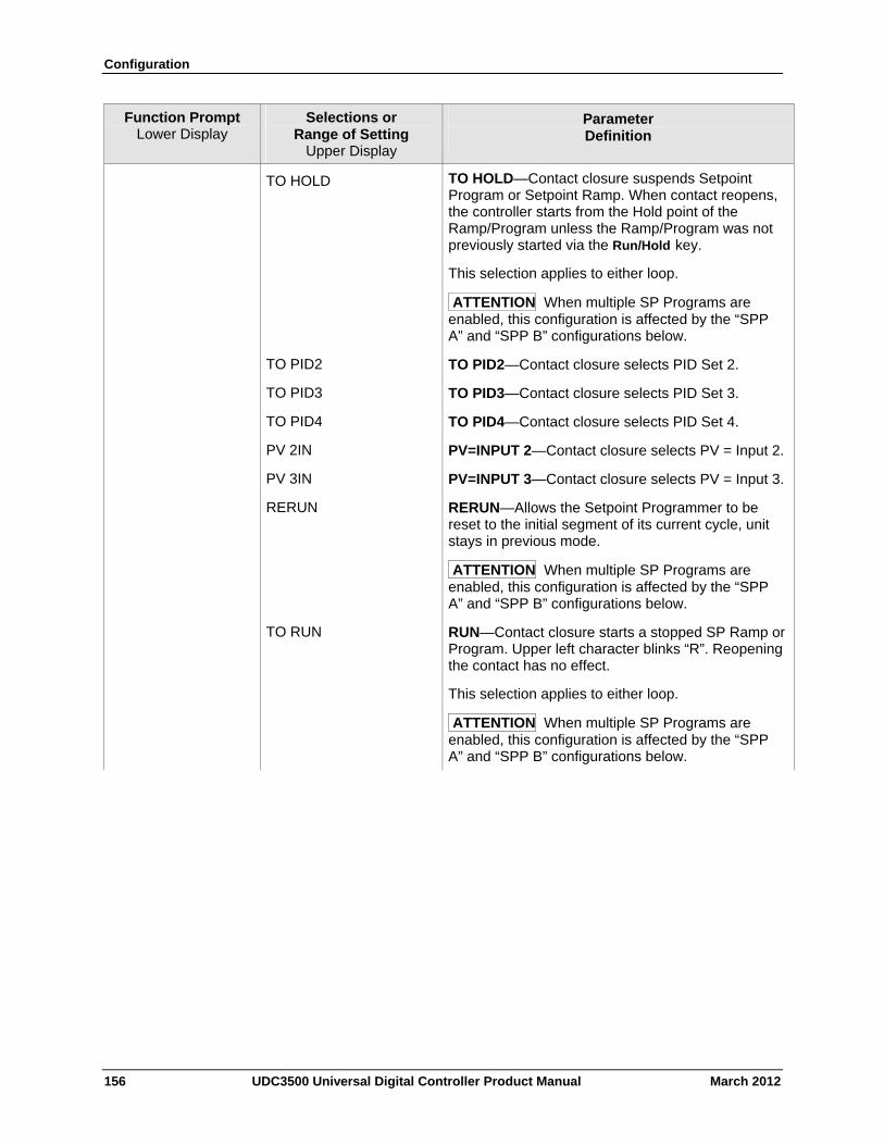
Configuration
156 UDC3500 Universal Digital Controller Product Manual March 2012
Function Prompt Lower Display
Selections or Range of Setting
Upper Display
Parameter Definition
TO HOLD TO HOLD—Contact closure suspends Setpoint Program or Setpoint Ramp. When contact reopens, the controller starts from the Hold point of the Ramp/Program unless the Ramp/Program was not previously started via the Run/Hold key.
This selection applies to either loop.
ATTENTION When multiple SP Programs are enabled, this configuration is affected by the “SPP A” and “SPP B” configurations below.
TO PID2 TO PID2—Contact closure selects PID Set 2.
TO PID3 TO PID3—Contact closure selects PID Set 3.
TO PID4 TO PID4—Contact closure selects PID Set 4.
PV 2IN PV=INPUT 2—Contact closure selects PV = Input 2.
PV 3IN PV=INPUT 3—Contact closure selects PV = Input 3.
RERUN RERUN—Allows the Setpoint Programmer to be reset to the initial segment of its current cycle, unit stays in previous mode.
ATTENTION When multiple SP Programs are enabled, this configuration is affected by the “SPP A” and “SPP B” configurations below.
TO RUN RUN—Contact closure starts a stopped SP Ramp or Program. Upper left character blinks “R”. Reopening the contact has no effect.
This selection applies to either loop.
ATTENTION When multiple SP Programs are enabled, this configuration is affected by the “SPP A” and “SPP B” configurations below.
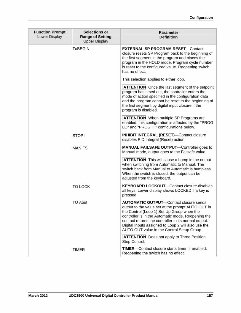
Configuration
March 2012 UDC3500 Universal Digital Controller Product Manual 157
Function Prompt Lower Display
Selections or Range of Setting
Upper Display
Parameter Definition
ToBEGIN EXTERNAL SP PROGRAM RESET—Contact closure resets SP Program back to the beginning of the first segment in the program and places the program in the HOLD mode. Program cycle number is reset to the configured value. Reopening switch has no effect.
This selection applies to either loop.
ATTENTION Once the last segment of the setpoint program has timed out, the controller enters the mode of action specified in the configuration data and the program cannot be reset to the beginning of the first segment by digital input closure if the program is disabled.
ATTENTION When multiple SP Programs are enabled, this configuration is affected by the “PROG LO” and “PROG HI” configurations below.
STOP I INHIBIT INTEGRAL (RESET)—Contact closure disables PID Integral (Reset) action.
MAN FS MANUAL FAILSAFE OUTPUT—Controller goes to Manual mode, output goes to the Failsafe value.
ATTENTION This will cause a bump in the output when switching from Automatic to Manual. The switch back from Manual to Automatic is bumpless. When the switch is closed, the output can be adjusted from the keyboard.
TO LOCK KEYBOARD LOCKOUT—Contact closure disables all keys. Lower display shows LOCKED if a key is pressed.
TO Aout AUTOMATIC OUTPUT—Contact closure sends output to the value set at the prompt AUTO OUT in the Control (Loop 1) Set Up Group when the controller is in the Automatic mode. Reopening the contact returns the controller to its normal output. Digital Inputs assigned to Loop 2 will also use the AUTO OUT value in the Control Setup Group.
ATTENTION Does not apply to Three Position Step Control.
TIMER TIMER—Contact closure starts timer, if enabled. Reopening the switch has no effect.
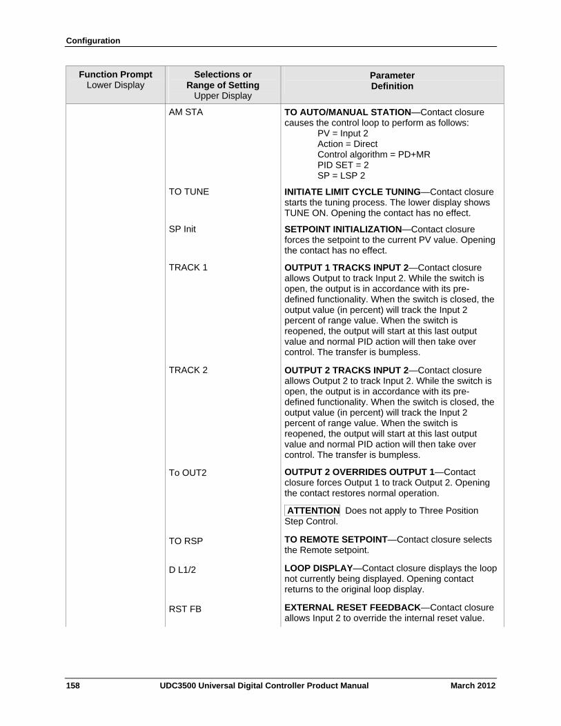
Configuration
158 UDC3500 Universal Digital Controller Product Manual March 2012
Function Prompt Lower Display
Selections or Range of Setting
Upper Display
Parameter Definition
AM STA TO AUTO/MANUAL STATION—Contact closure causes the control loop to perform as follows: PV = Input 2 Action = Direct Control algorithm = PD+MR PID SET = 2 SP = LSP 2
TO TUNE INITIATE LIMIT CYCLE TUNING—Contact closure starts the tuning process. The lower display shows TUNE ON. Opening the contact has no effect.
SP Init SETPOINT INITIALIZATION—Contact closure forces the setpoint to the current PV value. Opening the contact has no effect.
TRACK 1 OUTPUT 1 TRACKS INPUT 2—Contact closure allows Output to track Input 2. While the switch is open, the output is in accordance with its pre-defined functionality. When the switch is closed, the output value (in percent) will track the Input 2 percent of range value. When the switch is reopened, the output will start at this last output value and normal PID action will then take over control. The transfer is bumpless.
TRACK 2 OUTPUT 2 TRACKS INPUT 2—Contact closure allows Output 2 to track Input 2. While the switch is open, the output is in accordance with its pre-defined functionality. When the switch is closed, the output value (in percent) will track the Input 2 percent of range value. When the switch is reopened, the output will start at this last output value and normal PID action will then take over control. The transfer is bumpless.
To OUT2 OUTPUT 2 OVERRIDES OUTPUT 1—Contact closure forces Output 1 to track Output 2. Opening the contact restores normal operation.
ATTENTION Does not apply to Three Position Step Control.
TO RSP TO REMOTE SETPOINT—Contact closure selects the Remote setpoint.
D L1/2 LOOP DISPLAY—Contact closure displays the loop not currently being displayed. Opening contact returns to the original loop display.
RST FB EXTERNAL RESET FEEDBACK—Contact closure allows Input 2 to override the internal reset value.
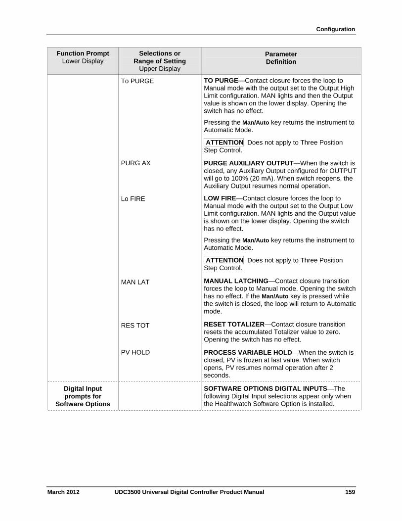
Configuration
March 2012 UDC3500 Universal Digital Controller Product Manual 159
Function Prompt Lower Display
Selections or Range of Setting
Upper Display
Parameter Definition
To PURGE TO PURGE—Contact closure forces the loop to Manual mode with the output set to the Output High Limit configuration. MAN lights and then the Output value is shown on the lower display. Opening the switch has no effect.
Pressing the Man/Auto key returns the instrument to Automatic Mode.
ATTENTION Does not apply to Three Position Step Control.
PURG AX PURGE AUXILIARY OUTPUT—When the switch is closed, any Auxiliary Output configured for OUTPUT will go to 100% (20 mA). When switch reopens, the Auxiliary Output resumes normal operation.
Lo FIRE LOW FIRE—Contact closure forces the loop to Manual mode with the output set to the Output Low Limit configuration. MAN lights and the Output value is shown on the lower display. Opening the switch has no effect.
Pressing the Man/Auto key returns the instrument to Automatic Mode.
ATTENTION Does not apply to Three Position Step Control.
MAN LAT MANUAL LATCHING—Contact closure transition forces the loop to Manual mode. Opening the switch has no effect. If the Man/Auto key is pressed while the switch is closed, the loop will return to Automatic mode.
RES TOT RESET TOTALIZER—Contact closure transition resets the accumulated Totalizer value to zero. Opening the switch has no effect.
PV HOLD PROCESS VARIABLE HOLD—When the switch is closed, PV is frozen at last value. When switch opens, PV resumes normal operation after 2 seconds.
Digital Input prompts for
Software Options
SOFTWARE OPTIONS DIGITAL INPUTS—The following Digital Input selections appear only when the Healthwatch Software Option is installed.
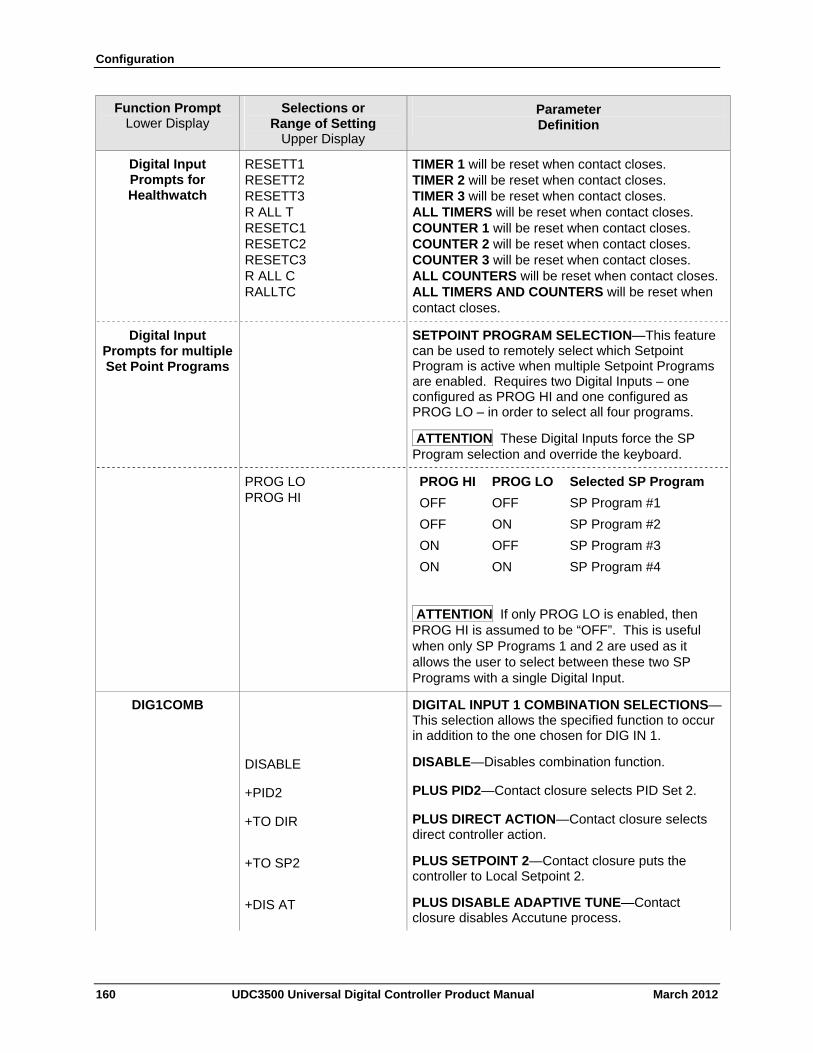
Configuration
160 UDC3500 Universal Digital Controller Product Manual March 2012
Function Prompt Lower Display
Selections or Range of Setting
Upper Display
Parameter Definition
Digital Input Prompts for Healthwatch
RESETT1 RESETT2 RESETT3 R ALL T RESETC1 RESETC2 RESETC3 R ALL C RALLTC
TIMER 1 will be reset when contact closes. TIMER 2 will be reset when contact closes. TIMER 3 will be reset when contact closes. ALL TIMERS will be reset when contact closes. COUNTER 1 will be reset when contact closes. COUNTER 2 will be reset when contact closes. COUNTER 3 will be reset when contact closes. ALL COUNTERS will be reset when contact closes.ALL TIMERS AND COUNTERS will be reset when contact closes.
Digital Input Prompts for multiple Set Point Programs
SETPOINT PROGRAM SELECTION—This feature can be used to remotely select which Setpoint Program is active when multiple Setpoint Programs are enabled. Requires two Digital Inputs – one configured as PROG HI and one configured as PROG LO – in order to select all four programs.
ATTENTION These Digital Inputs force the SP Program selection and override the keyboard.
PROG LO PROG HI
PROG HI PROG LO Selected SP Program
OFF OFF SP Program #1
OFF ON SP Program #2
ON OFF SP Program #3
ON ON SP Program #4
ATTENTION If only PROG LO is enabled, then PROG HI is assumed to be “OFF”. This is useful when only SP Programs 1 and 2 are used as it allows the user to select between these two SP Programs with a single Digital Input.
DIG1COMB DIGITAL INPUT 1 COMBINATION SELECTIONS—This selection allows the specified function to occur in addition to the one chosen for DIG IN 1.
DISABLE DISABLE—Disables combination function.
+PID2 PLUS PID2—Contact closure selects PID Set 2.
+TO DIR PLUS DIRECT ACTION—Contact closure selects direct controller action.
+TO SP2 PLUS SETPOINT 2—Contact closure puts the controller to Local Setpoint 2.
+DIS AT PLUS DISABLE ADAPTIVE TUNE—Contact closure disables Accutune process.
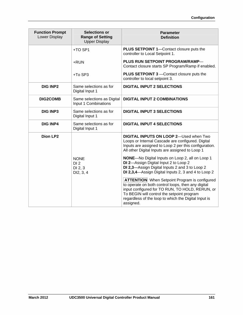
Configuration
March 2012 UDC3500 Universal Digital Controller Product Manual 161
Function Prompt Lower Display
Selections or Range of Setting
Upper Display
Parameter Definition
+TO SP1 PLUS SETPOINT 1—Contact closure puts the controller to Local Setpoint 1.
+RUN PLUS RUN SETPOINT PROGRAM/RAMP—Contact closure starts SP Program/Ramp if enabled.
+To SP3 PLUS SETPOINT 3 —Contact closure puts the controller to local setpoint 3.
DIG INP2 Same selections as for Digital Input 1
DIGITAL INPUT 2 SELECTIONS
DIG2COMB Same selections as Digital Input 1 Combinations
DIGITAL INPUT 2 COMBINATIONS
DIG INP3 Same selections as for Digital Input 1
DIGITAL INPUT 3 SELECTIONS
DIG INP4 Same selections as for Digital Input 1
DIGITAL INPUT 4 SELECTIONS
Dion LP2 DIGITAL INPUTS ON LOOP 2—Used when Two Loops or Internal Cascade are configured. Digital Inputs are assigned to Loop 2 per this configuration. All other Digital Inputs are assigned to Loop 1
NONE DI 2 DI 2, 3 DI2, 3, 4
NONE—No Digital Inputs on Loop 2, all on Loop 1 DI 2—Assign Digital Input 2 to Loop 2 DI 2,3—Assign Digital Inputs 2 and 3 to Loop 2 DI 2,3,4—Assign Digital Inputs 2, 3 and 4 to Loop 2
ATTENTION When Setpoint Program is configured to operate on both control loops, then any digital input configured for TO RUN, TO HOLD, RERUN, or To BEGIN will control the setpoint program regardless of the loop to which the Digital Input is assigned.
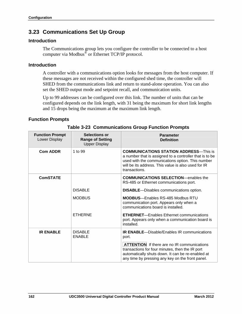
Configuration
3.23 Communications Set Up Group
Introduction
The Communications group lets you configure the controller to be connected to a host computer via Modbus® or Ethernet TCP/IP protocol.
Introduction
A controller with a communications option looks for messages from the host computer. If these messages are not received within the configured shed time, the controller will SHED from the communications link and return to stand-alone operation. You can also set the SHED output mode and setpoint recall, and communication units.
Up to 99 addresses can be configured over this link. The number of units that can be configured depends on the link length, with 31 being the maximum for short link lengths and 15 drops being the maximum at the maximum link length.
Function Prompts
Table 3-23 Communications Group Function Prompts
Selections or Range of Setting
Upper Display
Parameter Definition
Function Prompt Lower Display
1 to 99 COMMUNICATIONS STATION ADDRESS—This is a number that is assigned to a controller that is to be used with the communications option. This number will be its address. This value is also used for IR transactions.
Com ADDR
COMMUNICATIONS SELECTION—enables the RS-485 or Ethernet communications port.
ComSTATE
DISABLE DISABLE—Disables communications option.
MODBUS
ETHERNE
MODBUS—Enables RS-485 Modbus RTU communication port. Appears only when a communications board is installed.
ETHERNET—Enables Ethernet communications port. Appears only when a communication board is installed.
IR ENABLE DISABLE ENABLE
IR ENABLE—Disable/Enables IR communications port.
ATTENTION If there are no IR communications transactions for four minutes, then the IR port automatically shuts down. It can be re-enabled at any time by pressing any key on the front panel.
162 UDC3500 Universal Digital Controller Product Manual March 2012
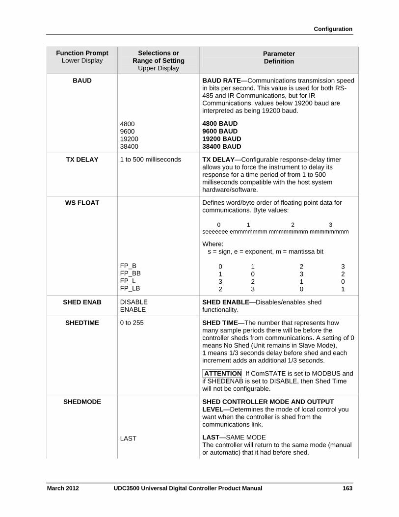
Configuration
March 2012 UDC3500 Universal Digital Controller Product Manual 163
Function Prompt Lower Display
Selections or Range of Setting
Upper Display
Parameter Definition
BAUD
4800 9600 19200 38400
BAUD RATE—Communications transmission speed in bits per second. This value is used for both RS-485 and IR Communications, but for IR Communications, values below 19200 baud are interpreted as being 19200 baud.
4800 BAUD 9600 BAUD 19200 BAUD 38400 BAUD
TX DELAY 1 to 500 milliseconds TX DELAY—Configurable response-delay timer allows you to force the instrument to delay its response for a time period of from 1 to 500 milliseconds compatible with the host system hardware/software.
WS FLOAT
FP_B FP_BB FP_L FP_LB
Defines word/byte order of floating point data for communications. Byte values: 0 1 2 3 seeeeeee emmmmmmm mmmmmmmm mmmmmmmm
Where: s = sign, e = exponent, m = mantissa bit 0 1 2 3 1 0 3 2 3 2 1 0 2 3 0 1
SHED ENAB DISABLE ENABLE
SHED ENABLE—Disables/enables shed functionality.
SHEDTIME 0 to 255 SHED TIME—The number that represents how many sample periods there will be before the controller sheds from communications. A setting of 0 means No Shed (Unit remains in Slave Mode), 1 means 1/3 seconds delay before shed and each increment adds an additional 1/3 seconds.
ATTENTION If ComSTATE is set to MODBUS and if SHEDENAB is set to DISABLE, then Shed Time will not be configurable.
SHEDMODE
SHED CONTROLLER MODE AND OUTPUT LEVEL—Determines the mode of local control you want when the controller is shed from the communications link.
LAST LAST—SAME MODE The controller will return to the same mode (manual or automatic) that it had before shed.
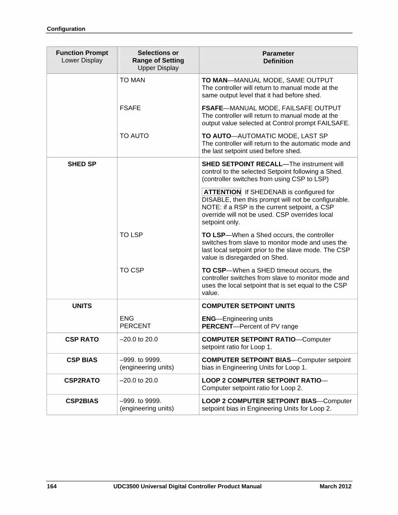
Configuration
164 UDC3500 Universal Digital Controller Product Manual March 2012
Function Prompt Lower Display
Selections or Range of Setting
Upper Display
Parameter Definition
TO MAN TO MAN—MANUAL MODE, SAME OUTPUT The controller will return to manual mode at the same output level that it had before shed.
FSAFE FSAFE—MANUAL MODE, FAILSAFE OUTPUT The controller will return to manual mode at the output value selected at Control prompt FAILSAFE.
TO AUTO TO AUTO—AUTOMATIC MODE, LAST SP The controller will return to the automatic mode and the last setpoint used before shed.
SHED SP SHED SETPOINT RECALL—The instrument will control to the selected Setpoint following a Shed. (controller switches from using CSP to LSP)
ATTENTION If SHEDENAB is configured for DISABLE, then this prompt will not be configurable. NOTE: if a RSP is the current setpoint, a CSP override will not be used. CSP overrides local setpoint only.
TO LSP TO LSP—When a Shed occurs, the controller switches from slave to monitor mode and uses the last local setpoint prior to the slave mode. The CSP value is disregarded on Shed.
TO CSP TO CSP—When a SHED timeout occurs, the controller switches from slave to monitor mode and uses the local setpoint that is set equal to the CSP value.
UNITS
ENG PERCENT
COMPUTER SETPOINT UNITS
ENG—Engineering units PERCENT—Percent of PV range
CSP RATO –20.0 to 20.0 COMPUTER SETPOINT RATIO—Computer setpoint ratio for Loop 1.
CSP BIAS –999. to 9999. (engineering units)
COMPUTER SETPOINT BIAS—Computer setpoint bias in Engineering Units for Loop 1.
CSP2RATO –20.0 to 20.0 LOOP 2 COMPUTER SETPOINT RATIO—Computer setpoint ratio for Loop 2.
CSP2BIAS –999. to 9999. (engineering units)
LOOP 2 COMPUTER SETPOINT BIAS—Computer setpoint bias in Engineering Units for Loop 2.
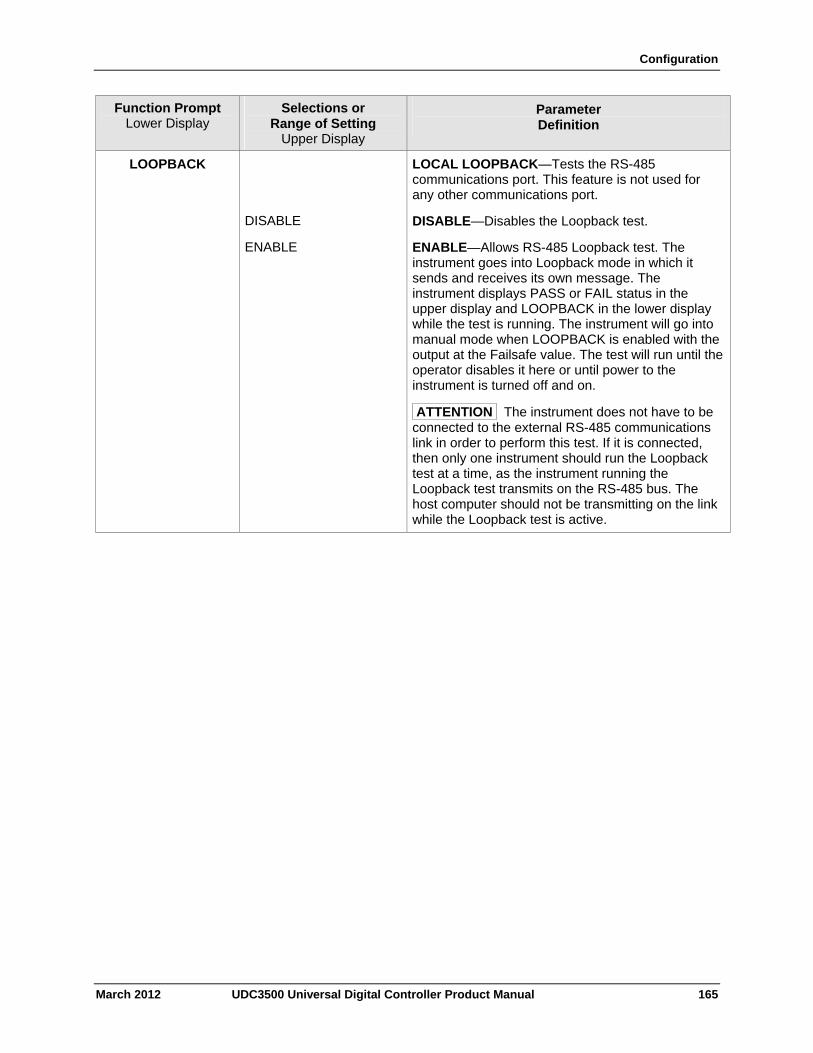
Configuration
March 2012 UDC3500 Universal Digital Controller Product Manual 165
Function Prompt Lower Display
Selections or Range of Setting
Upper Display
Parameter Definition
LOOPBACK
LOCAL LOOPBACK—Tests the RS-485 communications port. This feature is not used for any other communications port.
DISABLE DISABLE—Disables the Loopback test.
ENABLE ENABLE—Allows RS-485 Loopback test. The instrument goes into Loopback mode in which it sends and receives its own message. The instrument displays PASS or FAIL status in the upper display and LOOPBACK in the lower display while the test is running. The instrument will go into manual mode when LOOPBACK is enabled with the output at the Failsafe value. The test will run until the operator disables it here or until power to the instrument is turned off and on.
ATTENTION The instrument does not have to be connected to the external RS-485 communications link in order to perform this test. If it is connected, then only one instrument should run the Loopback test at a time, as the instrument running the Loopback test transmits on the RS-485 bus. The host computer should not be transmitting on the link while the Loopback test is active.
Configuration
3.24 Alarms Set Up Group
Introduction
The UDC3500 has four alarms and eight alarm setpoints. Each alarm has its own hysteresis configuration.
An alarm is an indication that an event that you have configured (for example—Process Variable) has exceeded one or more alarm limits. There are up to four alarms available. Each alarm has two setpoints. You can configure each of these two setpoints to alarm on various controller parameters.
There are two alarm output selections for each alarm setpoint, High and Low. These allow you to choose whether the alarm activates when the measured value is above (High) or below (Low) the alarm setpoint. You can also configure the two setpoints to alarm on the same event and to alarm for both high and low conditions.
An adjustable Hysteresis of 0 % to 100 % is provided for each alarm.
Alarms may be conveniently broken up into four types:
1. Analog – These are alarms, which monitor selections that use analog values, such as Process Variable, Set Points or analog inputs. These alarms require a hysteresis value.
2. Digital – These are alarms which monitor status that are either ON or OFF, such as Mode (e.g., Manual), Digital Input status. These alarms do not use a hysteresis value.
3. Events – The alarms are only used with Set Point Programming and may be configured to operate at the beginning or end of a particular segment.
4. Loop Break – Loop Break is a special kind of alarm, which monitors the control loop. Although this is a digital alarm (i.e., the alarm is either broken or it is not), it requires that an analog value to be configured in order to operate properly.
See Table 2-3 in the Installation section for Alarm relay contact information.
ATTENTION
If the controller is configured to use the same relay for more than one function, then the following priority is used to determine how the relay functions: Control Outputs take precedence over Alarms, which in turn take precedence over Time/Events, which in turn take precedence over Logic Gate Outputs. For example, if you select the Loop 2 Output Algorithm as Time Simplex (which uses Relay 3), enable Alarm 3 (which also uses Relay 3) and configure a Logic Gate to use Relay 3, then the instrument will use Relay #3 to perform the Time Simplex output and ignore the Alarm and Logic Gate functions.
The prompts for the Alarm Outputs appear whether or not the alarm relays are physically present or used for some other function. This allows the Alarm status to be shown on the display and/or sent via communications to a host computer.
166 UDC3500 Universal Digital Controller Product Manual March 2012
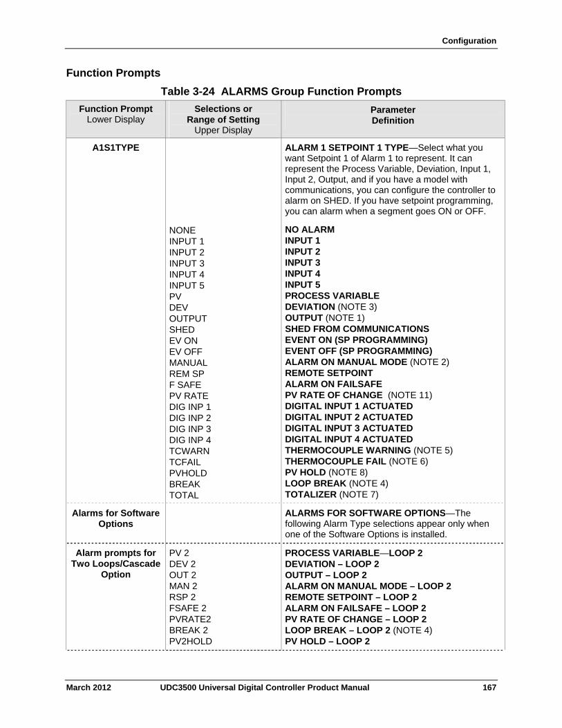
Configuration
Function Prompts
Table 3-24 ALARMS Group Function Prompts
Selections or Range of Setting
Upper Display
Parameter Definition
Function Prompt Lower Display
A1S1TYPE ALARM 1 SETPOINT 1 TYPE—Select what you want Setpoint 1 of Alarm 1 to represent. It can represent the Process Variable, Deviation, Input 1, Input 2, Output, and if you have a model with communications, you can configure the controller to alarm on SHED. If you have setpoint programming, you can alarm when a segment goes ON or OFF.
NONE INPUT 1 INPUT 2 INPUT 3 INPUT 4 INPUT 5 PV DEV OUTPUT SHED EV ON EV OFF MANUAL REM SP F SAFE PV RATE DIG INP 1 DIG INP 2 DIG INP 3 DIG INP 4 TCWARN TCFAIL PVHOLD BREAK TOTAL
NO ALARM INPUT 1 INPUT 2 INPUT 3 INPUT 4 INPUT 5 PROCESS VARIABLE DEVIATION (NOTE 3) OUTPUT (NOTE 1) SHED FROM COMMUNICATIONS EVENT ON (SP PROGRAMMING) EVENT OFF (SP PROGRAMMING) ALARM ON MANUAL MODE (NOTE 2) REMOTE SETPOINT ALARM ON FAILSAFE PV RATE OF CHANGE (NOTE 11) DIGITAL INPUT 1 ACTUATED DIGITAL INPUT 2 ACTUATED DIGITAL INPUT 3 ACTUATED DIGITAL INPUT 4 ACTUATED THERMOCOUPLE WARNING (NOTE 5) THERMOCOUPLE FAIL (NOTE 6) PV HOLD (NOTE 8) LOOP BREAK (NOTE 4) TOTALIZER (NOTE 7)
Alarms for Software Options
ALARMS FOR SOFTWARE OPTIONS—The following Alarm Type selections appear only when one of the Software Options is installed.
Alarm prompts for Two Loops/Cascade
Option
PV 2 DEV 2 OUT 2 MAN 2 RSP 2 FSAFE 2 PVRATE2 BREAK 2 PV2HOLD
PROCESS VARIABLE—LOOP 2 DEVIATION – LOOP 2 OUTPUT – LOOP 2 ALARM ON MANUAL MODE – LOOP 2 REMOTE SETPOINT – LOOP 2 ALARM ON FAILSAFE – LOOP 2 PV RATE OF CHANGE – LOOP 2 LOOP BREAK – LOOP 2 (NOTE 4) PV HOLD – LOOP 2
March 2012 UDC3500 Universal Digital Controller Product Manual 167
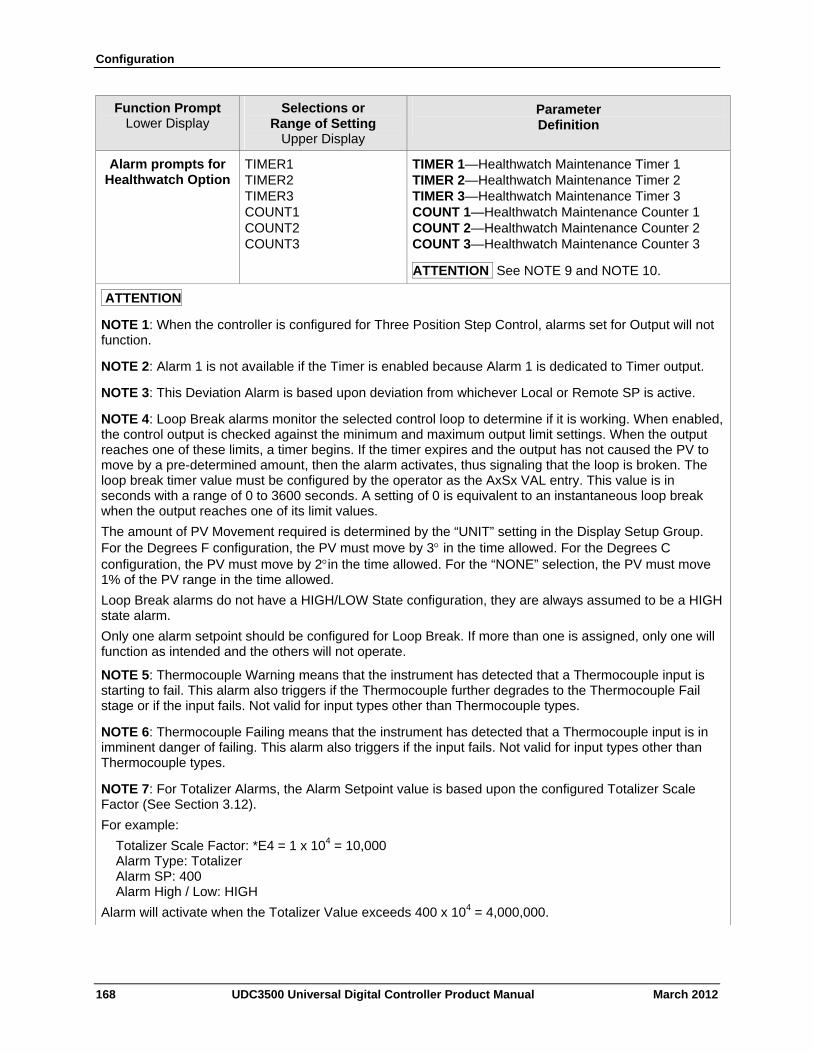
Configuration
168 UDC3500 Universal Digital Controller Product Manual March 2012
Function Prompt Lower Display
Selections or Range of Setting
Upper Display
Parameter Definition
Alarm prompts for Healthwatch Option
TIMER1 TIMER2 TIMER3 COUNT1 COUNT2 COUNT3
TIMER 1—Healthwatch Maintenance Timer 1 TIMER 2—Healthwatch Maintenance Timer 2 TIMER 3—Healthwatch Maintenance Timer 3 COUNT 1—Healthwatch Maintenance Counter 1 COUNT 2—Healthwatch Maintenance Counter 2 COUNT 3—Healthwatch Maintenance Counter 3
ATTENTION See NOTE 9 and NOTE 10.
ATTENTION
NOTE 1: When the controller is configured for Three Position Step Control, alarms set for Output will not function.
NOTE 2: Alarm 1 is not available if the Timer is enabled because Alarm 1 is dedicated to Timer output.
NOTE 3: This Deviation Alarm is based upon deviation from whichever Local or Remote SP is active.
NOTE 4: Loop Break alarms monitor the selected control loop to determine if it is working. When enabled, the control output is checked against the minimum and maximum output limit settings. When the output reaches one of these limits, a timer begins. If the timer expires and the output has not caused the PV to move by a pre-determined amount, then the alarm activates, thus signaling that the loop is broken. The loop break timer value must be configured by the operator as the AxSx VAL entry. This value is in seconds with a range of 0 to 3600 seconds. A setting of 0 is equivalent to an instantaneous loop break when the output reaches one of its limit values.
The amount of PV Movement required is determined by the “UNIT” setting in the Display Setup Group. For the Degrees F configuration, the PV must move by 3 in the time allowed. For the Degrees C configuration, the PV must move by 2in the time allowed. For the “NONE” selection, the PV must move 1% of the PV range in the time allowed.
Loop Break alarms do not have a HIGH/LOW State configuration, they are always assumed to be a HIGH state alarm.
Only one alarm setpoint should be configured for Loop Break. If more than one is assigned, only one will function as intended and the others will not operate.
NOTE 5: Thermocouple Warning means that the instrument has detected that a Thermocouple input is starting to fail. This alarm also triggers if the Thermocouple further degrades to the Thermocouple Fail stage or if the input fails. Not valid for input types other than Thermocouple types.
NOTE 6: Thermocouple Failing means that the instrument has detected that a Thermocouple input is in imminent danger of failing. This alarm also triggers if the input fails. Not valid for input types other than Thermocouple types.
NOTE 7: For Totalizer Alarms, the Alarm Setpoint value is based upon the configured Totalizer Scale Factor (See Section 3.12).
For example:
Totalizer Scale Factor: *E4 = 1 x 104 = 10,000 Alarm Type: Totalizer Alarm SP: 400 Alarm High / Low: HIGH
Alarm will activate when the Totalizer Value exceeds 400 x 104 = 4,000,000.
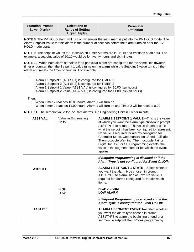
Configuration
March 2012 UDC3500 Universal Digital Controller Product Manual 169
Function Prompt Lower Display
Selections or Range of Setting
Upper Display
Parameter Definition
NOTE 8: The PV HOLD alarm will turn on whenever the instrument is put into the PV HOLD mode. The Alarm Setpoint Value for this alarm is the number of seconds before the alarm turns on after the PV HOLD mode starts.
NOTE 9: The setpoint values for Healthwatch Timer Alarms are in Hours and fractions of an hour. For example, a setpoint value of 20.10 would be for twenty hours and six minutes.
NOTE 10: When both alarm setpoints for a particular alarm are configured for the same Healthwatch timer or counter, then the Setpoint 1 value turns on the alarm while the Setpoint 2 value turns off the alarm and resets the timer or counter. For example:
If: Alarm 1 Setpoint 1 (AL1 SP1) is configured for TIMER 2 Alarm 1 Setpoint 2 (AL1 SP2) is configured for TIMER 2 Alarm 1 Setpoint 1 Value (A1S1 VAL) is configured for 10.00 (ten hours) Alarm 1 Setpoint 2 Value (A1S2 VAL) is configured for 11.00 (eleven hours) Then: When Timer 2 reaches 10.00 hours, Alarm 1 will turn on When Timer 2 reaches 11.00 hours, Alarm 1 will turn off and Timer 2 will be reset to 0.00
NOTE 11: The setpoint value for PV Rate alarms is in Engineering Units (EU) per minute.
A1S1 VAL Value in Engineering Units
ALARM 1 SETPOINT 1 VALUE—This is the value at which you want the alarm type chosen in prompt A1S1TYPE to actuate. The value depends upon what the setpoint has been configured to represent. No value is required for alarms configured for Controller Mode, Communications Shed, Failsafe, Thermocouple Warning, Thermocouple Fail or Digital Inputs. For SP Programming events, the value is the segment number for which the event applies.
A1S1 H L
If Setpoint Programming is disabled or if the Alarm Type is not configured for Event On/Off:
ALARM 1 SETPOINT 1 STATE—Select whether you want the alarm type chosen in prompt A1S1TYPE to alarm High or Low. No value is required for alarms configured for Healthwatch items.
HIGH LOW
HIGH ALARM LOW ALARM
A1S1 EV
If Setpoint Programming is enabled and if the Alarm Type is configured for Event On/Off:
ALARM 1 SEGMENT EVENT 1—Select whether you want the alarm type chosen in prompt A1S1TYPE to alarm the beginning or end of a segment in setpoint Ramp/Soak programming.
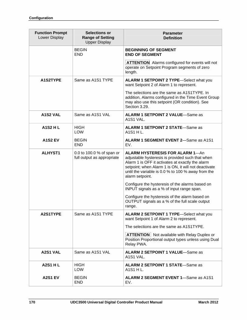
Configuration
170 UDC3500 Universal Digital Controller Product Manual March 2012
Function Prompt Lower Display
Selections or Range of Setting
Upper Display
Parameter Definition
BEGIN END
BEGINNING OF SEGMENT END OF SEGMENT
ATTENTION Alarms configured for events will not operate on Setpoint Program segments of zero length.
A1S2TYPE Same as A1S1 TYPE ALARM 1 SETPOINT 2 TYPE—Select what you want Setpoint 2 of Alarm 1 to represent.
The selections are the same as A1S1TYPE. In addition, Alarms configured in the Time Event Group may also use this setpoint (OR condition). See Section 3.29.
A1S2 VAL Same as A1S1 VAL ALARM 1 SETPOINT 2 VALUE—Same as A1S1 VAL.
A1S2 H L HIGH LOW
ALARM 1 SETPOINT 2 STATE—Same as A1S1 H L.
A1S2 EV BEGIN END
ALARM 1 SEGMENT EVENT 2—Same as A1S1 EV.
ALHYST1 0.0 to 100.0 % of span or full output as appropriate
ALARM HYSTERESIS FOR ALARM 1—An adjustable hysteresis is provided such that when Alarm 1 is OFF it activates at exactly the alarm setpoint; when Alarm 1 is ON, it will not deactivate until the variable is 0.0 % to 100 % away from the alarm setpoint.
Configure the hysteresis of the alarms based on INPUT signals as a % of input range span.
Configure the hysteresis of the alarm based on OUTPUT signals as a % of the full scale output range.
A2S1TYPE Same as A1S1 TYPE ALARM 2 SETPOINT 1 TYPE—Select what you want Setpoint 1 of Alarm 2 to represent.
The selections are the same as A1S1TYPE.
ATTENTION Not available with Relay Duplex or Position Proportional output types unless using Dual Relay PWA.
A2S1 VAL Same as A1S1 VAL ALARM 2 SETPOINT 1 VALUE—Same as A1S1 VAL.
A2S1 H L HIGH LOW
ALARM 2 SETPOINT 1 STATE—Same as A1S1 H L.
A2S1 EV BEGIN END
ALARM 2 SEGMENT EVENT 1—Same as A1S1 EV.
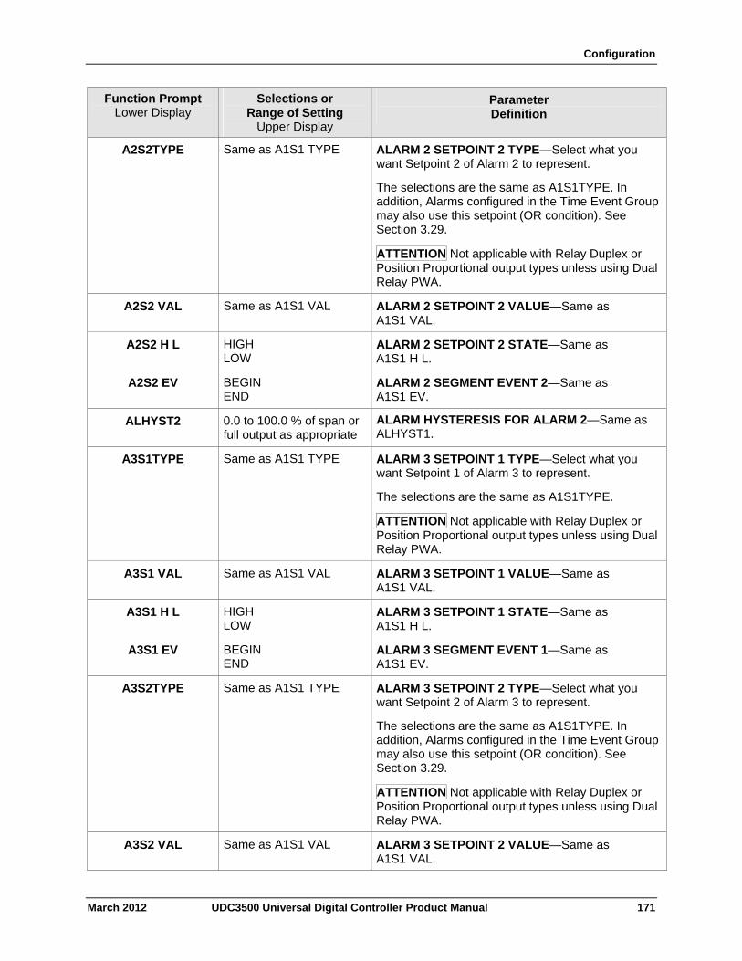
Configuration
March 2012 UDC3500 Universal Digital Controller Product Manual 171
Function Prompt Lower Display
Selections or Range of Setting
Upper Display
Parameter Definition
A2S2TYPE Same as A1S1 TYPE ALARM 2 SETPOINT 2 TYPE—Select what you want Setpoint 2 of Alarm 2 to represent.
The selections are the same as A1S1TYPE. In addition, Alarms configured in the Time Event Group may also use this setpoint (OR condition). See Section 3.29.
ATTENTION Not applicable with Relay Duplex or Position Proportional output types unless using Dual Relay PWA.
A2S2 VAL Same as A1S1 VAL ALARM 2 SETPOINT 2 VALUE—Same as A1S1 VAL.
A2S2 H L
HIGH LOW
ALARM 2 SETPOINT 2 STATE—Same as A1S1 H L.
A2S2 EV BEGIN END
ALARM 2 SEGMENT EVENT 2—Same as A1S1 EV.
ALHYST2 0.0 to 100.0 % of span or full output as appropriate
ALARM HYSTERESIS FOR ALARM 2—Same as ALHYST1.
A3S1TYPE Same as A1S1 TYPE ALARM 3 SETPOINT 1 TYPE—Select what you want Setpoint 1 of Alarm 3 to represent.
The selections are the same as A1S1TYPE.
ATTENTION Not applicable with Relay Duplex or Position Proportional output types unless using Dual Relay PWA.
A3S1 VAL Same as A1S1 VAL ALARM 3 SETPOINT 1 VALUE—Same as A1S1 VAL.
A3S1 H L HIGH LOW
ALARM 3 SETPOINT 1 STATE—Same as A1S1 H L.
A3S1 EV BEGIN END
ALARM 3 SEGMENT EVENT 1—Same as A1S1 EV.
A3S2TYPE Same as A1S1 TYPE ALARM 3 SETPOINT 2 TYPE—Select what you want Setpoint 2 of Alarm 3 to represent.
The selections are the same as A1S1TYPE. In addition, Alarms configured in the Time Event Group may also use this setpoint (OR condition). See Section 3.29.
ATTENTION Not applicable with Relay Duplex or Position Proportional output types unless using Dual Relay PWA.
A3S2 VAL Same as A1S1 VAL ALARM 3 SETPOINT 2 VALUE—Same as A1S1 VAL.
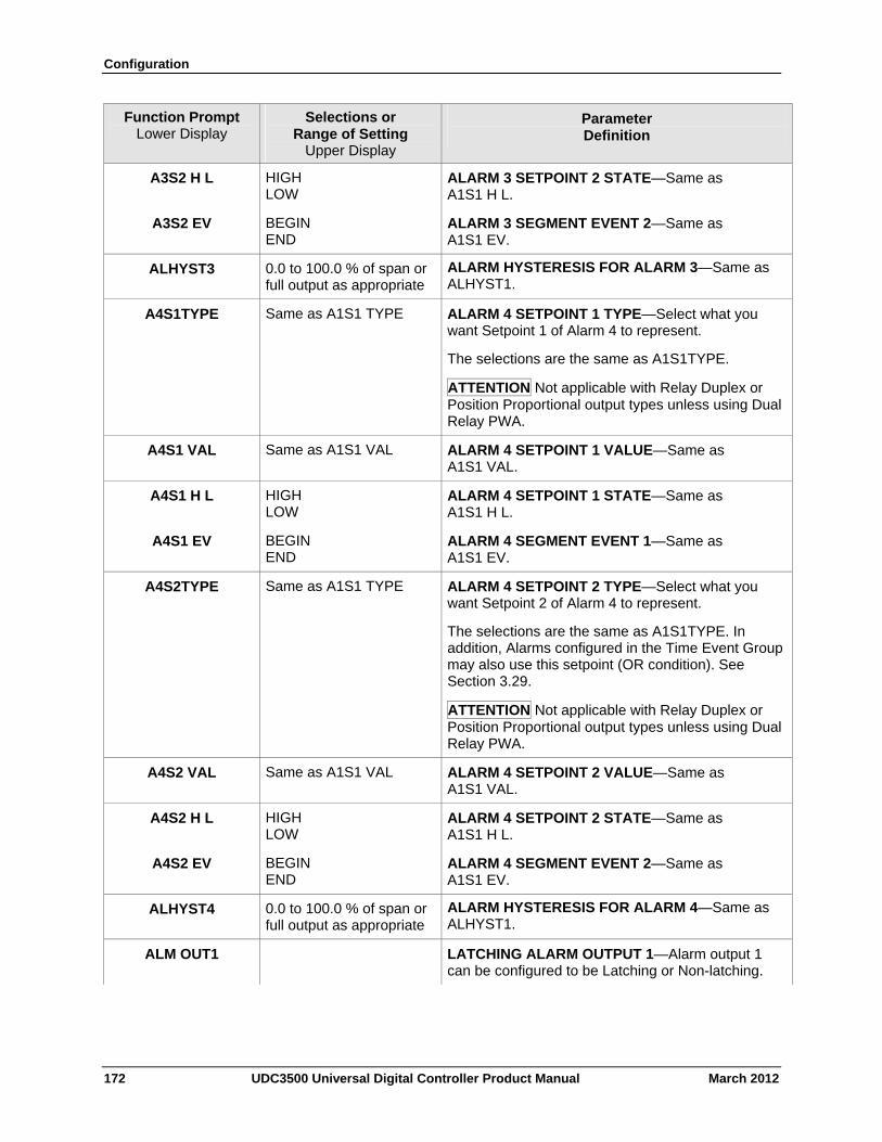
Configuration
172 UDC3500 Universal Digital Controller Product Manual March 2012
Function Prompt Lower Display
Selections or Range of Setting
Upper Display
Parameter Definition
A3S2 H L
HIGH LOW
ALARM 3 SETPOINT 2 STATE—Same as A1S1 H L.
A3S2 EV BEGIN END
ALARM 3 SEGMENT EVENT 2—Same as A1S1 EV.
ALHYST3 0.0 to 100.0 % of span or full output as appropriate
ALARM HYSTERESIS FOR ALARM 3—Same as ALHYST1.
A4S1TYPE Same as A1S1 TYPE ALARM 4 SETPOINT 1 TYPE—Select what you want Setpoint 1 of Alarm 4 to represent.
The selections are the same as A1S1TYPE.
ATTENTION Not applicable with Relay Duplex or Position Proportional output types unless using Dual Relay PWA.
A4S1 VAL Same as A1S1 VAL ALARM 4 SETPOINT 1 VALUE—Same as A1S1 VAL.
A4S1 H L
HIGH LOW
ALARM 4 SETPOINT 1 STATE—Same as A1S1 H L.
A4S1 EV BEGIN END
ALARM 4 SEGMENT EVENT 1—Same as A1S1 EV.
A4S2TYPE Same as A1S1 TYPE ALARM 4 SETPOINT 2 TYPE—Select what you want Setpoint 2 of Alarm 4 to represent.
The selections are the same as A1S1TYPE. In addition, Alarms configured in the Time Event Group may also use this setpoint (OR condition). See Section 3.29.
ATTENTION Not applicable with Relay Duplex or Position Proportional output types unless using Dual Relay PWA.
A4S2 VAL Same as A1S1 VAL ALARM 4 SETPOINT 2 VALUE—Same as A1S1 VAL.
A4S2 H L
HIGH LOW
ALARM 4 SETPOINT 2 STATE—Same as A1S1 H L.
A4S2 EV BEGIN END
ALARM 4 SEGMENT EVENT 2—Same as A1S1 EV.
ALHYST4 0.0 to 100.0 % of span or full output as appropriate
ALARM HYSTERESIS FOR ALARM 4—Same as ALHYST1.
ALM OUT1 LATCHING ALARM OUTPUT 1—Alarm output 1 can be configured to be Latching or Non-latching.
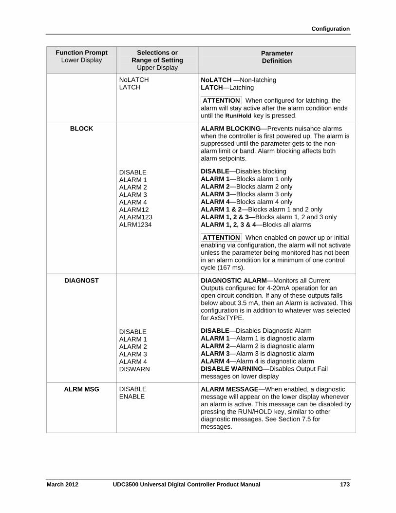
Configuration
March 2012 UDC3500 Universal Digital Controller Product Manual 173
Function Prompt Lower Display
Selections or Range of Setting
Upper Display
Parameter Definition
NoLATCH LATCH
NoLATCH —Non-latching LATCH—Latching
ATTENTION When configured for latching, the alarm will stay active after the alarm condition ends until the Run/Hold key is pressed.
BLOCK ALARM BLOCKING—Prevents nuisance alarms when the controller is first powered up. The alarm is suppressed until the parameter gets to the non-alarm limit or band. Alarm blocking affects both alarm setpoints.
DISABLE ALARM 1 ALARM 2 ALARM 3 ALARM 4 ALARM12 ALARM123 ALRM1234
DISABLE—Disables blocking ALARM 1—Blocks alarm 1 only ALARM 2—Blocks alarm 2 only ALARM 3—Blocks alarm 3 only ALARM 4—Blocks alarm 4 only ALARM 1 & 2—Blocks alarm 1 and 2 only ALARM 1, 2 & 3—Blocks alarm 1, 2 and 3 only ALARM 1, 2, 3 & 4—Blocks all alarms
ATTENTION When enabled on power up or initial enabling via configuration, the alarm will not activate unless the parameter being monitored has not been in an alarm condition for a minimum of one control cycle (167 ms).
DIAGNOST DIAGNOSTIC ALARM—Monitors all Current Outputs configured for 4-20mA operation for an open circuit condition. If any of these outputs falls below about 3.5 mA, then an Alarm is activated. This configuration is in addition to whatever was selected for AxSxTYPE.
DISABLE ALARM 1 ALARM 2 ALARM 3 ALARM 4 DISWARN
DISABLE—Disables Diagnostic Alarm ALARM 1—Alarm 1 is diagnostic alarm ALARM 2—Alarm 2 is diagnostic alarm ALARM 3—Alarm 3 is diagnostic alarm ALARM 4—Alarm 4 is diagnostic alarm DISABLE WARNING—Disables Output Fail messages on lower display
ALRM MSG DISABLE ENABLE
ALARM MESSAGE—When enabled, a diagnostic message will appear on the lower display whenever an alarm is active. This message can be disabled by pressing the RUN/HOLD key, similar to other diagnostic messages. See Section 7.5 for messages.
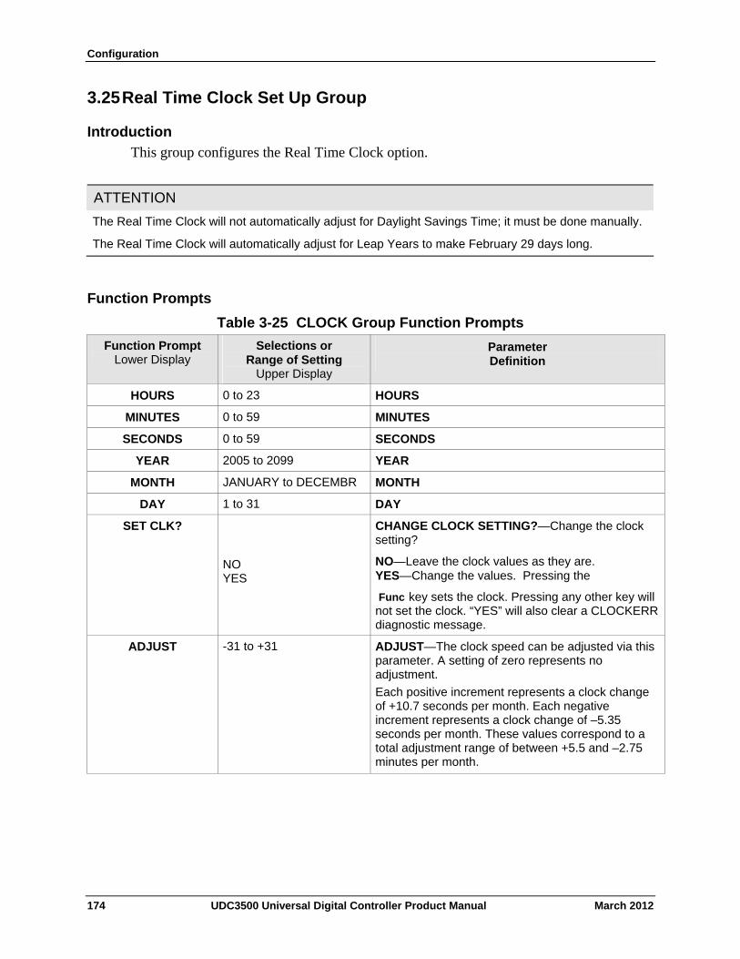
Configuration
3.25 Real Time Clock Set Up Group
Introduction
This group configures the Real Time Clock option.
ATTENTION
The Real Time Clock will not automatically adjust for Daylight Savings Time; it must be done manually.
The Real Time Clock will automatically adjust for Leap Years to make February 29 days long.
Function Prompts
Table 3-25 CLOCK Group Function Prompts
Selections or Range of Setting
Upper Display
Parameter Definition
Function Prompt Lower Display
0 to 23 HOURS HOURS
0 to 59 MINUTES MINUTES
0 to 59 SECONDS SECONDS
2005 to 2099 YEAR YEAR
JANUARY to DECEMBR MONTH MONTH
1 to 31 DAY DAY
NO YES
CHANGE CLOCK SETTING?—Change the clock setting?
NO—Leave the clock values as they are. YES—Change the values. Pressing the
Func key sets the clock. Pressing any other key will not set the clock. “YES” will also clear a CLOCKERR diagnostic message.
SET CLK?
-31 to +31 ADJUST—The clock speed can be adjusted via this parameter. A setting of zero represents no adjustment.
Each positive increment represents a clock change of +10.7 seconds per month. Each negative increment represents a clock change of –5.35 seconds per month. These values correspond to a total adjustment range of between +5.5 and –2.75 minutes per month.
ADJUST
174 UDC3500 Universal Digital Controller Product Manual March 2012
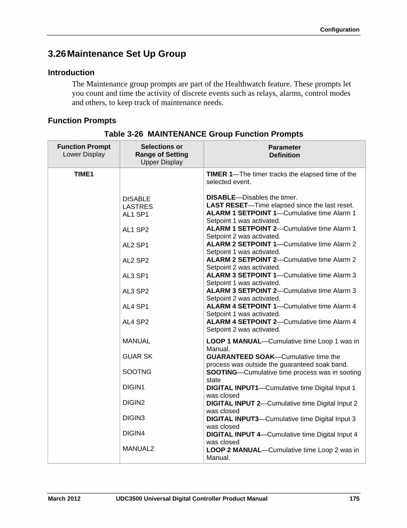
Configuration
3.26 Maintenance Set Up Group
Introduction
The Maintenance group prompts are part of the Healthwatch feature. These prompts let you count and time the activity of discrete events such as relays, alarms, control modes and others, to keep track of maintenance needs.
Function Prompts
Table 3-26 MAINTENANCE Group Function Prompts
Selections or Range of Setting
Upper Display
Parameter Definition
Function Prompt Lower Display
TIME1 DISABLE LASTRES AL1 SP1 AL1 SP2 AL2 SP1 AL2 SP2 AL3 SP1 AL3 SP2 AL4 SP1 AL4 SP2
TIMER 1—The timer tracks the elapsed time of the selected event. DISABLE—Disables the timer. LAST RESET—Time elapsed since the last reset. ALARM 1 SETPOINT 1—Cumulative time Alarm 1 Setpoint 1 was activated. ALARM 1 SETPOINT 2—Cumulative time Alarm 1 Setpoint 2 was activated. ALARM 2 SETPOINT 1—Cumulative time Alarm 2 Setpoint 1 was activated. ALARM 2 SETPOINT 2—Cumulative time Alarm 2 Setpoint 2 was activated. ALARM 3 SETPOINT 1—Cumulative time Alarm 3 Setpoint 1 was activated. ALARM 3 SETPOINT 2—Cumulative time Alarm 3 Setpoint 2 was activated. ALARM 4 SETPOINT 1—Cumulative time Alarm 4 Setpoint 1 was activated. ALARM 4 SETPOINT 2—Cumulative time Alarm 4 Setpoint 2 was activated.
MANUAL GUAR SK SOOTNG DIGIN1 DIGIN2 DIGIN3 DIGIN4 MANUAL2
LOOP 1 MANUAL—Cumulative time Loop 1 was in Manual. GUARANTEED SOAK—Cumulative time the process was outside the guaranteed soak band. SOOTING—Cumulative time process was in sooting state DIGITAL INPUT1—Cumulative time Digital Input 1 was closed DIGITAL INPUT 2—Cumulative time Digital Input 2 was closed DIGITAL INPUT3—Cumulative time Digital Input 3 was closed DIGITAL INPUT 4—Cumulative time Digital Input 4 was closed LOOP 2 MANUAL—Cumulative time Loop 2 was in Manual.
March 2012 UDC3500 Universal Digital Controller Product Manual 175
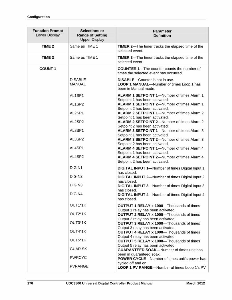
Configuration
176 UDC3500 Universal Digital Controller Product Manual March 2012
Function Prompt Lower Display
Selections or Range of Setting
Upper Display
Parameter Definition
TIME 2 Same as TIME 1 TIMER 2—The timer tracks the elapsed time of the selected event.
TIME 3 Same as TIME 1 TIMER 3—The timer tracks the elapsed time of the selected event.
COUNT 1 COUNTER 1—The counter counts the number of times the selected event has occurred.
DISABLE MANUAL
DISABLE—Counter is not in use. LOOP 1 MANUAL—Number of times Loop 1 has been in Manual mode.
AL1SP1 AL1SP2 AL2SP1 AL2SP2 AL3SP1 AL3SP2 AL4SP1 AL4SP2
ALARM 1 SETPOINT 1—Number of times Alarm 1 Setpoint 1 has been activated. ALARM 1 SETPOINT 2—Number of times Alarm 1 Setpoint 2 has been activated. ALARM 2 SETPOINT 1—Number of times Alarm 2 Setpoint 1 has been activated. ALARM 2 SETPOINT 2—Number of times Alarm 2 Setpoint 2 has been activated. ALARM 3 SETPOINT 1—Number of times Alarm 3 Setpoint 1 has been activated. ALARM 3 SETPOINT 2—Number of times Alarm 3 Setpoint 2 has been activated. ALARM 4 SETPOINT 1—Number of times Alarm 4 Setpoint 1 has been activated. ALARM 4 SETPOINT 2—Number of times Alarm 4 Setpoint 2 has been activated.
DIGIN1 DIGIN2 DIGIN3 DIGIN4
DIGITAL INPUT 1—Number of times Digital Input 1 has closed. DIGITAL INPUT 2—Number of times Digital Input 2 has closed. DIGITAL INPUT 3—Number of times Digital Input 3 has closed. DIGITAL INPUT 4—Number of times Digital Input 4 has closed.
OUT1*1K OUT2*1K OUT3*1K OUT4*1K OUT5*1K GUAR SK PWRCYC PVRANGE
OUTPUT 1 RELAY x 1000—Thousands of times Output 1 relay has been activated. OUTPUT 2 RELAY x 1000—Thousands of times Output 2 relay has been activated. OUTPUT 3 RELAY x 1000—Thousands of times Output 3 relay has been activated. OUTPUT 4 RELAY x 1000—Thousands of times Output 4 relay has been activated. OUTPUT 5 RELAY x 1000—Thousands of times Output 5 relay has been activated. GUARANTEED SOAK—Number of times unit has been in guaranteed soak. POWER CYCLE—Number of times unit’s power has cycled off and on. LOOP 1 PV RANGE—Number of times Loop 1’s PV
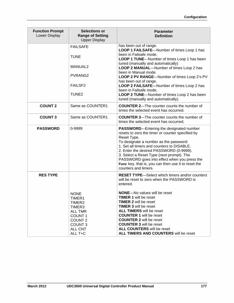
Configuration
March 2012 UDC3500 Universal Digital Controller Product Manual 177
Function Prompt Lower Display
Selections or Range of Setting
Upper Display
Parameter Definition
FAILSAFE
TUNE
MANUAL2 PVRANG2
FAILSF2 TUNE2
has been out of range. LOOP 1 FAILSAFE—Number of times Loop 1 has been in Failsafe mode. LOOP 1 TUNE—Number of times Loop 1 has been tuned (manually and automatically) LOOP 2 MANUAL—Number of times Loop 2 has been in Manual mode. LOOP 2 PV RANGE—Number of times Loop 2’s PV has been out of range. LOOP 2 FAILSAFE—Number of times Loop 2 has been in Failsafe mode. LOOP 2 TUNE—Number of times Loop 2 has been tuned (manually and automatically).
COUNT 2 Same as COUNTER1 COUNTER 2—The counter counts the number of times the selected event has occurred.
COUNT 3 Same as COUNTER1 COUNTER 3—The counter counts the number of times the selected event has occurred.
PASSWORD 0-9999 PASSWORD—Entering the designated number resets to zero the timer or counter specified by Reset Type. To designate a number as the password: 1. Set all timers and counters to DISABLE. 2. Enter the desired PASSWORD (0-9999). 3. Select a Reset Type (next prompt). The PASSWORD goes into effect when you press the Func key, that is, you can then use it to reset the counters and timers.
RES TYPE
NONE TIMER1 TIMER2 TIMER3 ALL TMR COUNT 1 COUNT 2 COUNT 3 ALL CNT ALL T+C
RESET TYPE—Select which timers and/or counters will be reset to zero when the PASSWORD is entered. NONE—No values will be reset TIMER 1 will be reset TIMER 2 will be reset TIMER 3 will be reset ALL TIMERS will be reset COUNTER 1 will be reset COUNTER 2 will be reset COUNTER 3 will be reset ALL COUNTERS will be reset ALL TIMERS AND COUNTERS will be reset
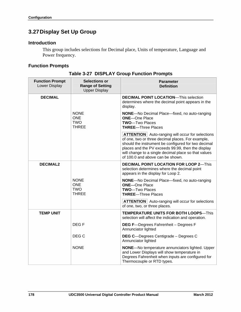
Configuration
3.27 Display Set Up Group
Introduction
This group includes selections for Decimal place, Units of temperature, Language and Power frequency.
Function Prompts
Table 3-27 DISPLAY Group Function Prompts
Selections or Range of Setting
Upper Display
Parameter Definition
Function Prompt Lower Display
DECIMAL POINT LOCATION—This selection determines where the decimal point appears in the display.
DECIMAL
NONE ONE TWO THREE
NONE—No Decimal Place—fixed, no auto-ranging ONE—One Place TWO—Two Places THREE—Three Places
ATTENTION Auto-ranging will occur for selections of one, two or three decimal places. For example, should the instrument be configured for two decimal places and the PV exceeds 99.99, then the display will change to a single decimal place so that values of 100.0 and above can be shown.
NONE ONE TWO THREE
DECIMAL POINT LOCATION FOR LOOP 2—This selection determines where the decimal point appears in the display for Loop 2.
NONE—No Decimal Place—fixed, no auto-ranging ONE—One Place TWO—Two Places THREE—Three Places
ATTENTION Auto-ranging will occur for selections of one, two, or three places.
DECIMAL2
TEMPERATURE UNITS FOR BOTH LOOPS—This selection will affect the indication and operation.
TEMP UNIT
DEG F DEG F—Degrees Fahrenheit – Degrees F Annunciator lighted
DEG C DEG C—Degrees Centigrade – Degrees C Annunciator lighted
NONE NONE—No temperature annunciators lighted. Upper and Lower Displays will show temperature in Degrees Fahrenheit when inputs are configured for Thermocouple or RTD types.
178 UDC3500 Universal Digital Controller Product Manual March 2012
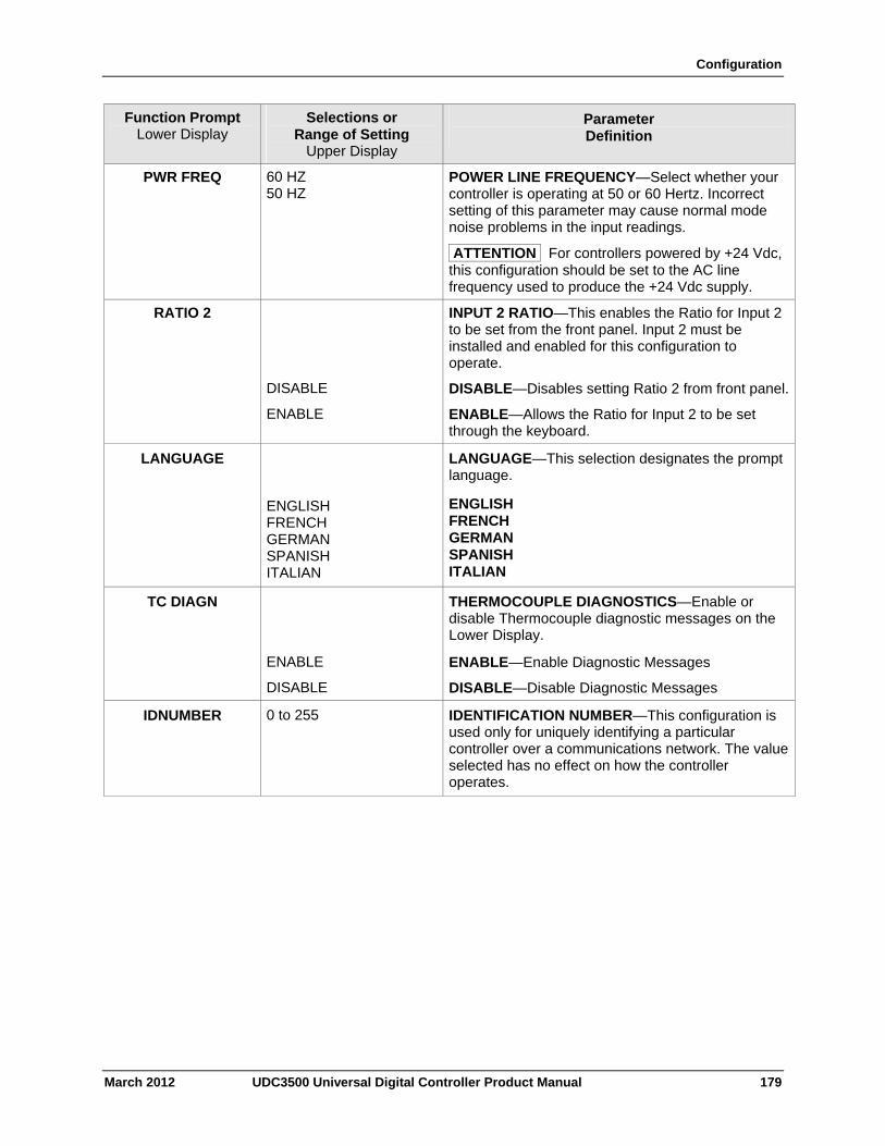
Configuration
March 2012 UDC3500 Universal Digital Controller Product Manual 179
Function Prompt Lower Display
Selections or Range of Setting
Upper Display
Parameter Definition
PWR FREQ 60 HZ 50 HZ
POWER LINE FREQUENCY—Select whether your controller is operating at 50 or 60 Hertz. Incorrect setting of this parameter may cause normal mode noise problems in the input readings.
ATTENTION For controllers powered by +24 Vdc, this configuration should be set to the AC line frequency used to produce the +24 Vdc supply.
RATIO 2 INPUT 2 RATIO—This enables the Ratio for Input 2 to be set from the front panel. Input 2 must be installed and enabled for this configuration to operate.
DISABLE DISABLE—Disables setting Ratio 2 from front panel.
ENABLE ENABLE—Allows the Ratio for Input 2 to be set through the keyboard.
LANGUAGE
ENGLISH FRENCH GERMAN SPANISH ITALIAN
LANGUAGE—This selection designates the prompt language.
ENGLISH FRENCH GERMAN SPANISH ITALIAN
TC DIAGN THERMOCOUPLE DIAGNOSTICS—Enable or disable Thermocouple diagnostic messages on the Lower Display.
ENABLE ENABLE—Enable Diagnostic Messages
DISABLE DISABLE—Disable Diagnostic Messages
IDNUMBER 0 to 255 IDENTIFICATION NUMBER—This configuration is used only for uniquely identifying a particular controller over a communications network. The value selected has no effect on how the controller operates.
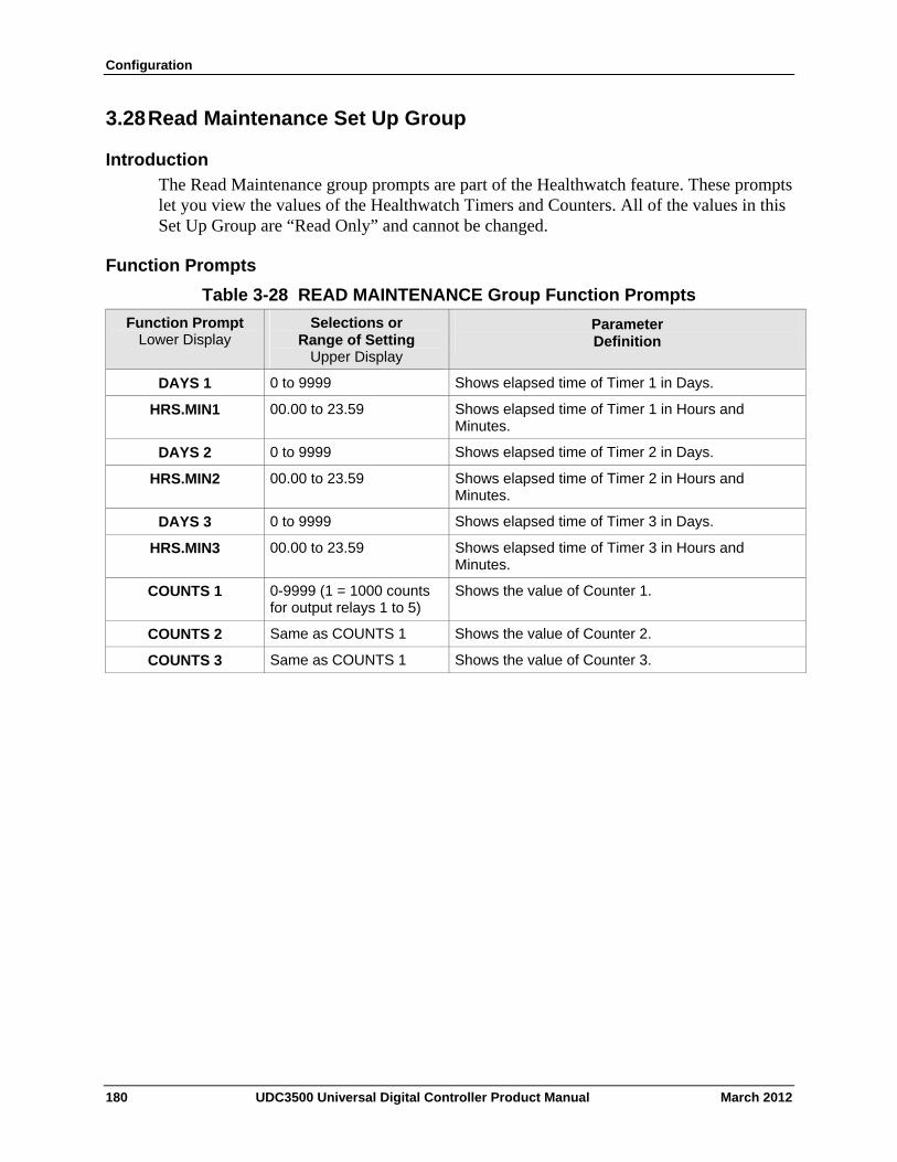
Configuration
3.28 Read Maintenance Set Up Group
Introduction
The Read Maintenance group prompts are part of the Healthwatch feature. These prompts let you view the values of the Healthwatch Timers and Counters. All of the values in this Set Up Group are “Read Only” and cannot be changed.
Function Prompts
Table 3-28 READ MAINTENANCE Group Function Prompts
Selections or Range of Setting
Upper Display
Parameter Definition
Function Prompt Lower Display
0 to 9999 Shows elapsed time of Timer 1 in Days. DAYS 1
00.00 to 23.59 Shows elapsed time of Timer 1 in Hours and Minutes.
HRS.MIN1
0 to 9999 Shows elapsed time of Timer 2 in Days. DAYS 2
00.00 to 23.59 Shows elapsed time of Timer 2 in Hours and Minutes.
HRS.MIN2
0 to 9999 Shows elapsed time of Timer 3 in Days. DAYS 3
00.00 to 23.59 Shows elapsed time of Timer 3 in Hours and Minutes.
HRS.MIN3
0-9999 (1 = 1000 counts for output relays 1 to 5)
Shows the value of Counter 1. COUNTS 1
Same as COUNTS 1 Shows the value of Counter 2. COUNTS 2
Same as COUNTS 1 Shows the value of Counter 3. COUNTS 3
180 UDC3500 Universal Digital Controller Product Manual March 2012
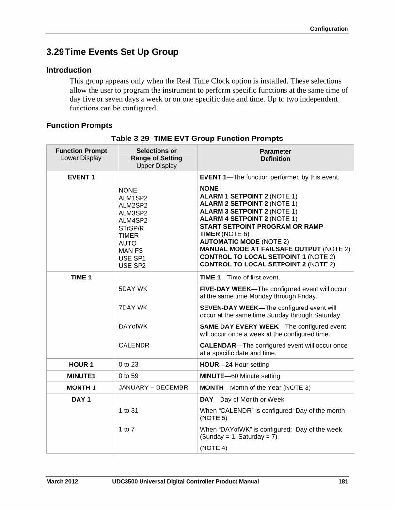
Configuration
3.29 Time Events Set Up Group
Introduction
This group appears only when the Real Time Clock option is installed. These selections allow the user to program the instrument to perform specific functions at the same time of day five or seven days a week or on one specific date and time. Up to two independent functions can be configured.
Function Prompts
Table 3-29 TIME EVT Group Function Prompts
Selections or Range of Setting
Upper Display
Parameter Definition
Function Prompt Lower Display
EVENT 1—The function performed by this event. EVENT 1
NONE ALM1SP2 ALM2SP2 ALM3SP2 ALM4SP2 STrSP/R TIMER AUTO MAN FS USE SP1 USE SP2
NONE ALARM 1 SETPOINT 2 (NOTE 1) ALARM 2 SETPOINT 2 (NOTE 1) ALARM 3 SETPOINT 2 (NOTE 1) ALARM 4 SETPOINT 2 (NOTE 1) START SETPOINT PROGRAM OR RAMP TIMER (NOTE 6) AUTOMATIC MODE (NOTE 2) MANUAL MODE AT FAILSAFE OUTPUT (NOTE 2) CONTROL TO LOCAL SETPOINT 1 (NOTE 2) CONTROL TO LOCAL SETPOINT 2 (NOTE 2)
TIME 1—Time of first event. TIME 1
5DAY WK FIVE-DAY WEEK—The configured event will occur at the same time Monday through Friday.
7DAY WK SEVEN-DAY WEEK—The configured event will occur at the same time Sunday through Saturday.
DAYofWK SAME DAY EVERY WEEK—The configured event will occur once a week at the configured time.
CALENDR CALENDAR—The configured event will occur once at a specific date and time.
0 to 23 HOUR—24 Hour setting HOUR 1
0 to 59 MINUTE—60 Minute setting MINUTE1
JANUARY – DECEMBR MONTH—Month of the Year (NOTE 3) MONTH 1
DAY 1
1 to 31
1 to 7
DAY—Day of Month or Week
When “CALENDR” is configured: Day of the month (NOTE 5)
When “DAYofWK” is configured: Day of the week (Sunday = 1, Saturday = 7)
(NOTE 4)
March 2012 UDC3500 Universal Digital Controller Product Manual 181
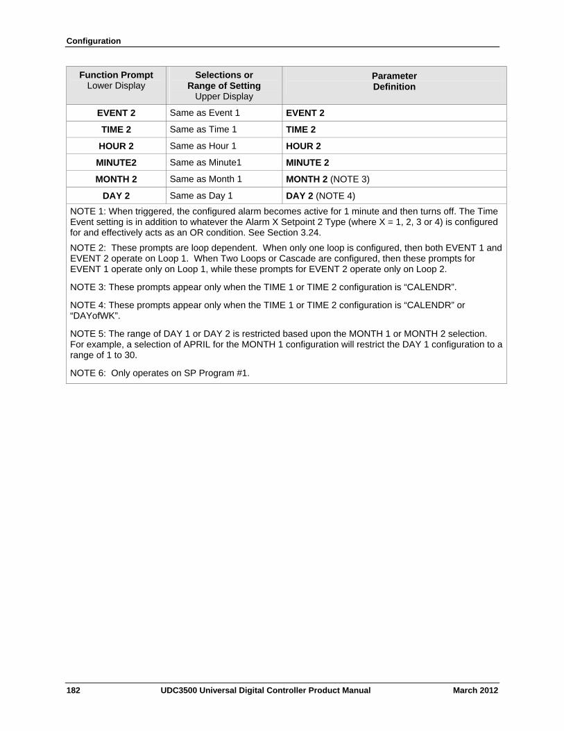
Configuration
182 UDC3500 Universal Digital Controller Product Manual March 2012
Function Prompt Lower Display
Selections or Range of Setting
Upper Display
Parameter Definition
EVENT 2 Same as Event 1 EVENT 2
TIME 2 Same as Time 1 TIME 2
HOUR 2 Same as Hour 1 HOUR 2
MINUTE2 Same as Minute1 MINUTE 2
MONTH 2 Same as Month 1 MONTH 2 (NOTE 3)
DAY 2 Same as Day 1 DAY 2 (NOTE 4)
NOTE 1: When triggered, the configured alarm becomes active for 1 minute and then turns off. The Time Event setting is in addition to whatever the Alarm X Setpoint 2 Type (where X = 1, 2, 3 or 4) is configured for and effectively acts as an OR condition. See Section 3.24.
NOTE 2: These prompts are loop dependent. When only one loop is configured, then both EVENT 1 and EVENT 2 operate on Loop 1. When Two Loops or Cascade are configured, then these prompts for EVENT 1 operate only on Loop 1, while these prompts for EVENT 2 operate only on Loop 2.
NOTE 3: These prompts appear only when the TIME 1 or TIME 2 configuration is “CALENDR”.
NOTE 4: These prompts appear only when the TIME 1 or TIME 2 configuration is “CALENDR” or “DAYofWK”.
NOTE 5: The range of DAY 1 or DAY 2 is restricted based upon the MONTH 1 or MONTH 2 selection. For example, a selection of APRIL for the MONTH 1 configuration will restrict the DAY 1 configuration to a range of 1 to 30.
NOTE 6: Only operates on SP Program #1.
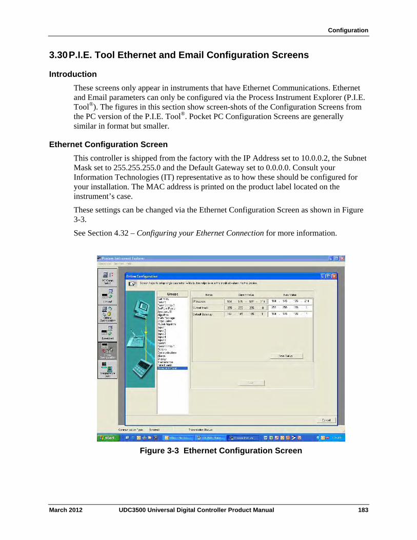
Configuration
3.30 P.I.E. Tool Ethernet and Email Configuration Screens
Introduction
These screens only appear in instruments that have Ethernet Communications. Ethernet and Email parameters can only be configured via the Process Instrument Explorer (P.I.E. Tool®). The figures in this section show screen-shots of the Configuration Screens from the PC version of the P.I.E. Tool®. Pocket PC Configuration Screens are generally similar in format but smaller.
Ethernet Configuration Screen
This controller is shipped from the factory with the IP Address set to 10.0.0.2, the Subnet Mask set to 255.255.255.0 and the Default Gateway set to 0.0.0.0. Consult your Information Technologies (IT) representative as to how these should be configured for your installation. The MAC address is printed on the product label located on the instrument’s case.
These settings can be changed via the Ethernet Configuration Screen as shown in Figure 3-3.
See Section 4.32 – Configuring your Ethernet Connection for more information.
Figure 3-3 Ethernet Configuration Screen
March 2012 UDC3500 Universal Digital Controller Product Manual 183
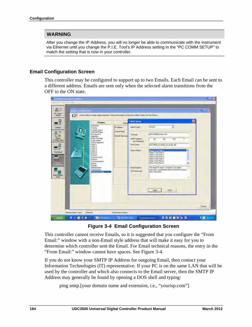
Configuration
WARNING
After you change the IP Address, you will no longer be able to communicate with the instrument via Ethernet until you change the P.I.E. Tool’s IP Address setting in the “PC COMM SETUP” to match the setting that is now in your controller.
Email Configuration Screen
This controller may be configured to support up to two Emails. Each Email can be sent to a different address. Emails are sent only when the selected alarm transitions from the OFF to the ON state.
Figure 3-4 Email Configuration Screen
This controller cannot receive Emails, so it is suggested that you configure the “From Email:” window with a non-Email style address that will make it easy for you to determine which controller sent the Email. For Email technical reasons, the entry in the “From Email:” window cannot have spaces. See Figure 3-4.
If you do not know your SMTP IP Address for outgoing Email, then contact your Information Technologies (IT) representative. If your PC is on the same LAN that will be used by the controller and which also connects to the Email server, then the SMTP IP Address may generally be found by opening a DOS shell and typing:
ping smtp.[your domain name and extension, i.e., “yourisp.com”]
184 UDC3500 Universal Digital Controller Product Manual March 2012
Configuration
The content of the Emails sent by this controller contains the Alarm that triggered the Email, its settings and the current value (if applicable) of the monitored variable. For example, the content of an Email triggered by Alarm 1 Setpoint 1 that is configured to monitor Input 1 would look something like this:
Name: Alarm 1 SP1, Type: INPUT1, Event: HIGH/END, Value = 500.00, Actual = 712.69
The content of an Email triggered by Alarm 2 Setpoint 1 that is configured to monitor Digital Input 1 would look something like this:
Name: Alarm 2 SP1, Type: DIG IN1, Event: HIGH/END, Value = 0.00, Actual = 0.00
ATTENTION
Instruments that do not have the Real Time Clock option will always send Email time-stamped with the date that the Ethernet Software in the instrument was last modified. Instruments with the Real Time Clock option will send Email time-stamped with the current time in the controller.
If the SMTP address on your network is changed, such as can happen when a server is replaced, then you must reconfigure the Email SMTP IP address in this instrument to match.
March 2012 UDC3500 Universal Digital Controller Product Manual 185
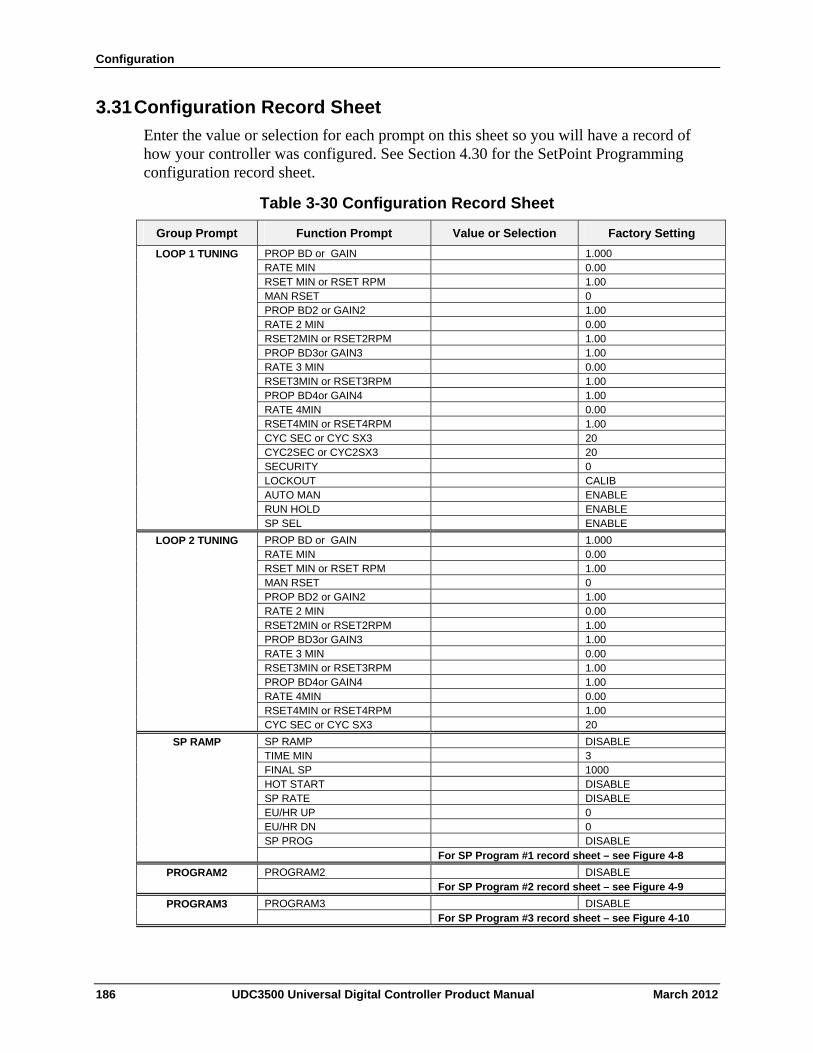
Configuration
3.31 Configuration Record Sheet
Enter the value or selection for each prompt on this sheet so you will have a record of how your controller was configured. See Section 4.30 for the SetPoint Programming configuration record sheet.
Table 3-30 Configuration Record Sheet
Group Prompt Function Prompt Value or Selection Factory Setting
PROP BD or GAIN 1.000 RATE MIN 0.00
LOOP 1 TUNING
RSET MIN or RSET RPM 1.00 MAN RSET 0 PROP BD2 or GAIN2 1.00 RATE 2 MIN 0.00 RSET2MIN or RSET2RPM 1.00 PROP BD3or GAIN3 1.00 RATE 3 MIN 0.00 RSET3MIN or RSET3RPM 1.00 PROP BD4or GAIN4 1.00 RATE 4MIN 0.00 RSET4MIN or RSET4RPM 1.00 CYC SEC or CYC SX3 20 CYC2SEC or CYC2SX3 20 SECURITY 0 LOCKOUT CALIB AUTO MAN ENABLE RUN HOLD ENABLE SP SEL ENABLE
PROP BD or GAIN 1.000 RATE MIN 0.00
LOOP 2 TUNING
RSET MIN or RSET RPM 1.00 MAN RSET 0 PROP BD2 or GAIN2 1.00 RATE 2 MIN 0.00 RSET2MIN or RSET2RPM 1.00 PROP BD3or GAIN3 1.00 RATE 3 MIN 0.00 RSET3MIN or RSET3RPM 1.00 PROP BD4or GAIN4 1.00 RATE 4MIN 0.00 RSET4MIN or RSET4RPM 1.00 CYC SEC or CYC SX3 20
SP RAMP DISABLE TIME MIN 3
SP RAMP
FINAL SP 1000 HOT START DISABLE SP RATE DISABLE EU/HR UP 0 EU/HR DN 0 SP PROG DISABLE For SP Program #1 record sheet – see Figure 4-8
PROGRAM2 DISABLE PROGRAM2 For SP Program #2 record sheet – see Figure 4-9
PROGRAM3 DISABLE PROGRAM3 For SP Program #3 record sheet – see Figure 4-10
186 UDC3500 Universal Digital Controller Product Manual March 2012
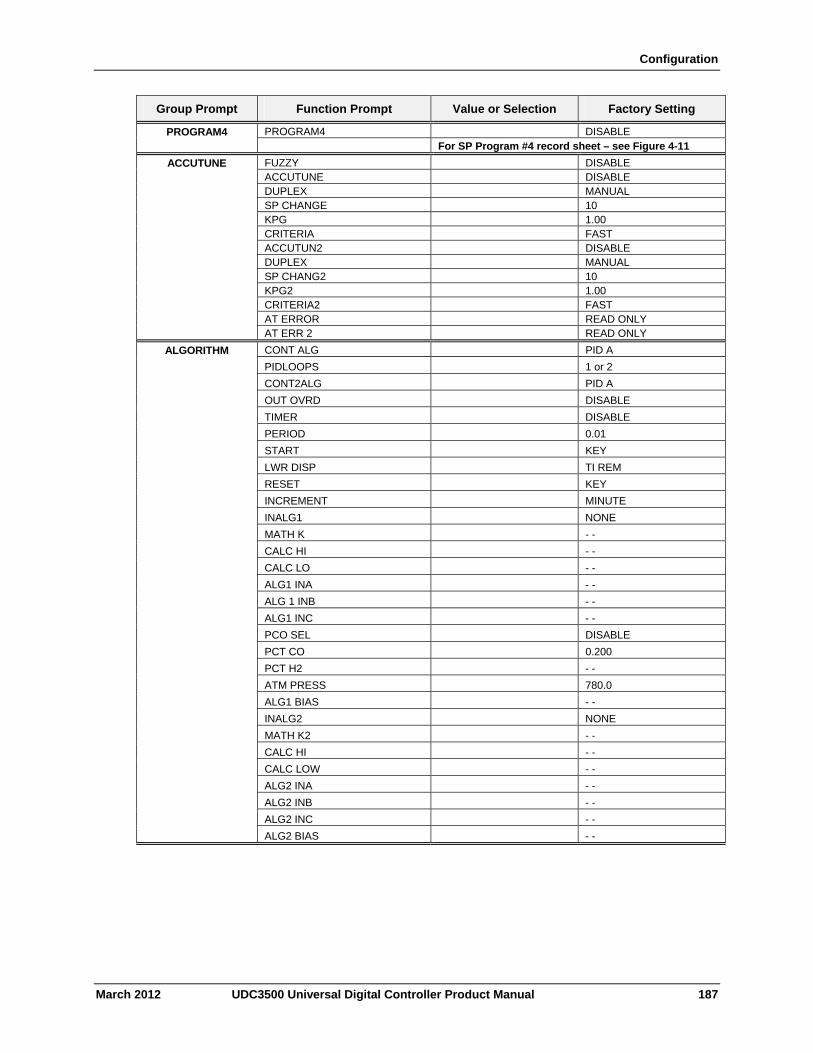
Configuration
March 2012 UDC3500 Universal Digital Controller Product Manual 187
Group Prompt Function Prompt Value or Selection Factory Setting
PROGRAM4 DISABLE PROGRAM4 For SP Program #4 record sheet – see Figure 4-11
FUZZY DISABLE ACCUTUNE DISABLE DUPLEX MANUAL SP CHANGE 10 KPG 1.00 CRITERIA FAST ACCUTUN2 DISABLE DUPLEX MANUAL SP CHANG2 10 KPG2 1.00 CRITERIA2 FAST AT ERROR READ ONLY
ACCUTUNE
AT ERR 2 READ ONLY
CONT ALG PID A
PIDLOOPS 1 or 2
CONT2ALG PID A
OUT OVRD DISABLE
TIMER DISABLE
PERIOD 0.01
START KEY
LWR DISP TI REM
RESET KEY
INCREMENT MINUTE
INALG1 NONE
MATH K - -
CALC HI - -
CALC LO - -
ALG1 INA - -
ALG 1 INB - -
ALG1 INC - -
PCO SEL DISABLE
PCT CO 0.200
PCT H2 - -
ATM PRESS 780.0
ALG1 BIAS - -
INALG2 NONE
MATH K2 - -
CALC HI - -
CALC LOW - -
ALG2 INA - -
ALG2 INB - -
ALG2 INC - -
ALGORITHM
ALG2 BIAS - -
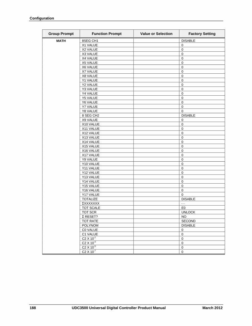
Configuration
Group Prompt Function Prompt Value or Selection Factory Setting
8SEG CH1 DISABLE X1 VALUE 0 X2 VALUE 0
MATH
X3 VALUE 0 X4 VALUE 0 X5 VALUE 0 X6 VALUE 0 X7 VALUE 0 X8 VALUE 0 Y1 VALUE 0 Y2 VALUE 0 Y3 VALUE 0 Y4 VALUE 0 Y5 VALUE 0 Y6 VALUE 0 Y7 VALUE 0 Y8 VALUE 0 8 SEG CH2 DISABLE X9 VALUE 0 X10 VALUE 0 X11 VALUE 0 X12 VALUE 0 X13 VALUE 0 X14 VALUE 0 X15 VALUE 0 X16 VALUE 0 X17 VALUE 0 Y9 VALUE 0 Y10 VALUE 0 Y11 VALUE 0 Y12 VALUE 0 Y13 VALUE 0 Y14 VALUE 0 Y15 VALUE 0 Y16 VALUE 0 Y17 VALUE 0 TOTALIZE DISABLE ΣXXXXXXX - - TOT SCALE E0 TOT SCR UNLOCK Σ RESET? NO TOT RATE SECOND POLYNOM DISABLE C0 VALUE 0 C1 VALUE 0 C2 X 10-1 0 C2 X 10-3 0 C2 X 10-5 0 C2 X 10-7 0
188 UDC3500 Universal Digital Controller Product Manual March 2012
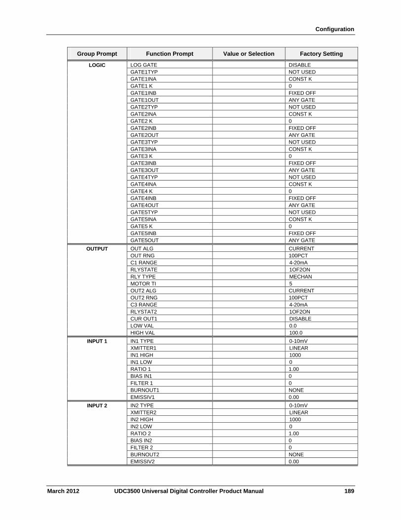
Configuration
Group Prompt Function Prompt Value or Selection Factory Setting
LOG GATE DISABLE GATE1TYP NOT USED
LOGIC
GATE1INA CONST K GATE1 K 0 GATE1INB FIXED OFF GATE1OUT ANY GATE GATE2TYP NOT USED GATE2INA CONST K GATE2 K 0 GATE2INB FIXED OFF GATE2OUT ANY GATE GATE3TYP NOT USED GATE3INA CONST K GATE3 K 0 GATE3INB FIXED OFF GATE3OUT ANY GATE GATE4TYP NOT USED GATE4INA CONST K GATE4 K 0 GATE4INB FIXED OFF GATE4OUT ANY GATE GATE5TYP NOT USED GATE5INA CONST K GATE5 K 0 GATE5INB FIXED OFF GATE5OUT ANY GATE
OUT ALG CURRENT OUT RNG 100PCT
OUTPUT
C1 RANGE 4-20mA RLYSTATE 1OF2ON RLY TYPE MECHAN MOTOR TI 5 OUT2 ALG CURRENT OUT2 RNG 100PCT C3 RANGE 4-20mA RLYSTAT2 1OF2ON CUR OUT1 DISABLE LOW VAL 0.0 HIGH VAL 100.0
IN1 TYPE 0-10mV XMITTER1 LINEAR
INPUT 1
IN1 HIGH 1000 IN1 LOW 0 RATIO 1 1.00 BIAS IN1 0 FILTER 1 0 BURNOUT1 NONE EMISSIV1 0.00
IN2 TYPE 0-10mV XMITTER2 LINEAR
INPUT 2
IN2 HIGH 1000 IN2 LOW 0 RATIO 2 1.00 BIAS IN2 0 FILTER 2 0 BURNOUT2 NONE EMISSIV2 0.00
March 2012 UDC3500 Universal Digital Controller Product Manual 189
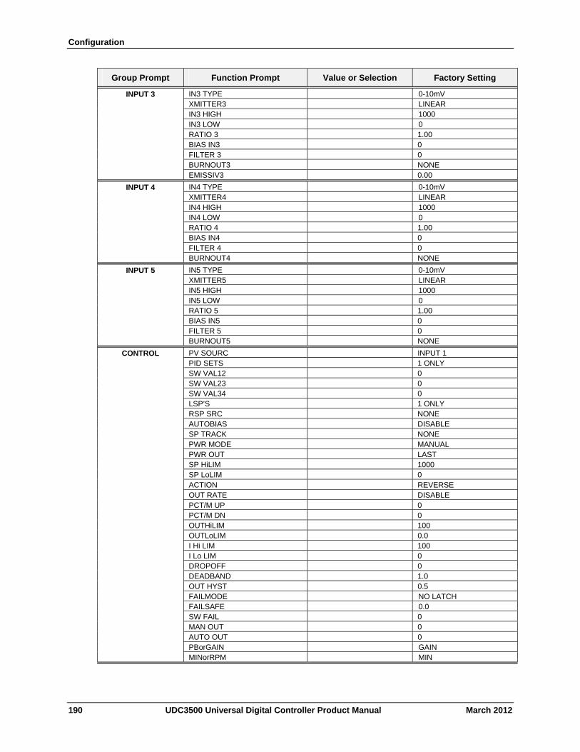
Configuration
Group Prompt Function Prompt Value or Selection Factory Setting
IN3 TYPE 0-10mV XMITTER3 LINEAR
INPUT 3
IN3 HIGH 1000 IN3 LOW 0 RATIO 3 1.00 BIAS IN3 0 FILTER 3 0 BURNOUT3 NONE EMISSIV3 0.00
IN4 TYPE 0-10mV XMITTER4 LINEAR
INPUT 4
IN4 HIGH 1000 IN4 LOW 0 RATIO 4 1.00 BIAS IN4 0 FILTER 4 0 BURNOUT4 NONE
IN5 TYPE 0-10mV XMITTER5 LINEAR
INPUT 5
IN5 HIGH 1000 IN5 LOW 0 RATIO 5 1.00 BIAS IN5 0 FILTER 5 0 BURNOUT5 NONE
PV SOURC INPUT 1 PID SETS 1 ONLY
CONTROL
SW VAL12 0 SW VAL23 0 SW VAL34 0 LSP’S 1 ONLY RSP SRC NONE AUTOBIAS DISABLE SP TRACK NONE PWR MODE MANUAL PWR OUT LAST SP HiLIM 1000 SP LoLIM 0 ACTION REVERSE OUT RATE DISABLE PCT/M UP 0 PCT/M DN 0 OUTHiLIM 100 OUTLoLIM 0.0 I Hi LIM 100 I Lo LIM 0 DROPOFF 0 DEADBAND 1.0 OUT HYST 0.5 FAILMODE NO LATCH FAILSAFE 0.0 SW FAIL 0 MAN OUT 0 AUTO OUT 0 PBorGAIN GAIN MINorRPM MIN
190 UDC3500 Universal Digital Controller Product Manual March 2012
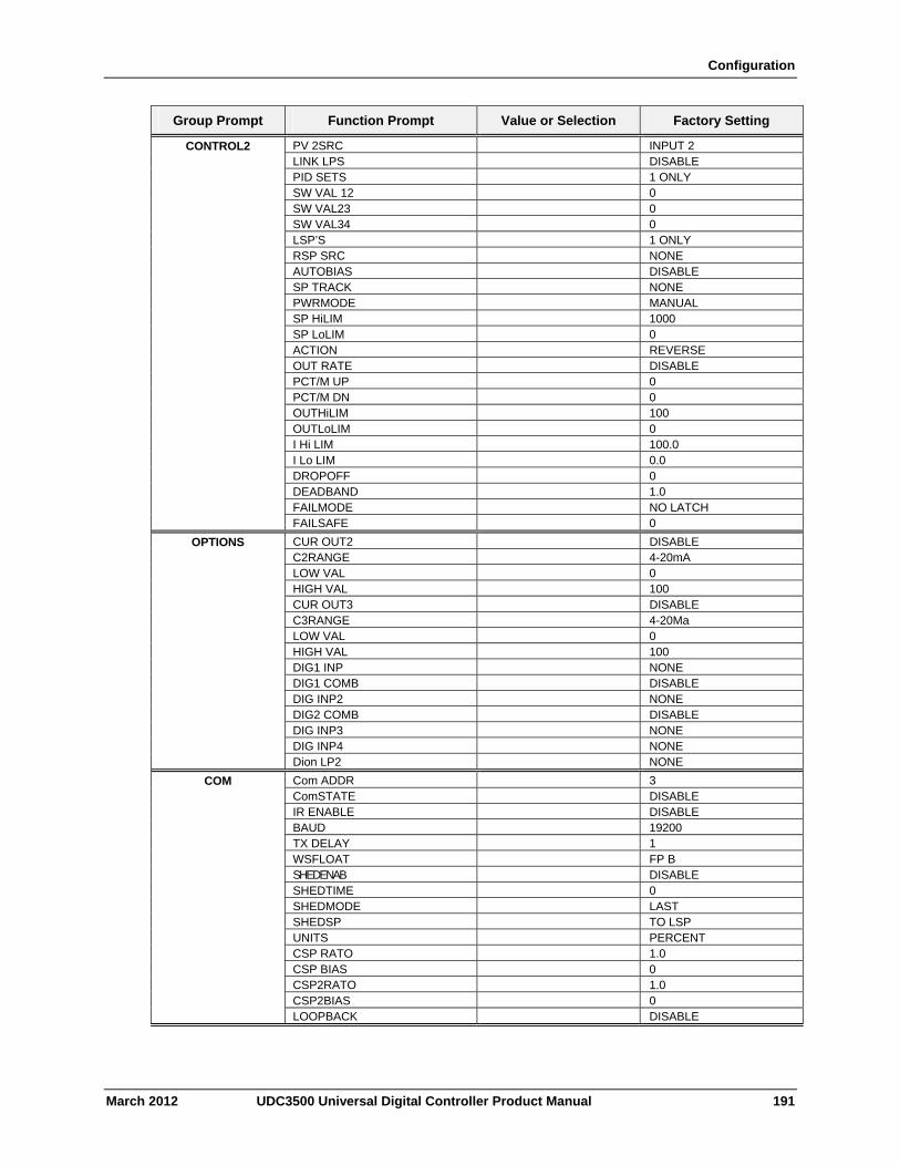
Configuration
Group Prompt Function Prompt Value or Selection Factory Setting
PV 2SRC INPUT 2 LINK LPS DISABLE
CONTROL2
PID SETS 1 ONLY SW VAL 12 0 SW VAL23 0 SW VAL34 0 LSP’S 1 ONLY RSP SRC NONE AUTOBIAS DISABLE SP TRACK NONE PWRMODE MANUAL SP HiLIM 1000 SP LoLIM 0 ACTION REVERSE OUT RATE DISABLE PCT/M UP 0 PCT/M DN 0 OUTHiLIM 100 OUTLoLIM 0 I Hi LIM 100.0 I Lo LIM 0.0 DROPOFF 0 DEADBAND 1.0 FAILMODE NO LATCH FAILSAFE 0
CUR OUT2 DISABLE C2RANGE 4-20mA
OPTIONS
LOW VAL 0 HIGH VAL 100 CUR OUT3 DISABLE C3RANGE 4-20Ma LOW VAL 0 HIGH VAL 100 DIG1 INP NONE DIG1 COMB DISABLE DIG INP2 NONE DIG2 COMB DISABLE DIG INP3 NONE DIG INP4 NONE Dion LP2 NONE
Com ADDR 3 ComSTATE DISABLE
COM
IR ENABLE DISABLE BAUD 19200 TX DELAY 1 WSFLOAT FP B SHEDENAB DISABLE SHEDTIME 0 SHEDMODE LAST SHEDSP TO LSP UNITS PERCENT CSP RATO 1.0 CSP BIAS 0 CSP2RATO 1.0 CSP2BIAS 0 LOOPBACK DISABLE
March 2012 UDC3500 Universal Digital Controller Product Manual 191
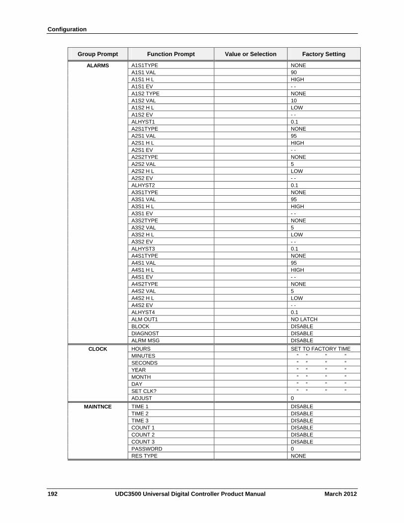
Configuration
Group Prompt Function Prompt Value or Selection Factory Setting
A1S1TYPE NONE A1S1 VAL 90
ALARMS
A1S1 H L HIGH A1S1 EV - - A1S2 TYPE NONE A1S2 VAL 10 A1S2 H L LOW A1S2 EV - - ALHYST1 0.1 A2S1TYPE NONE A2S1 VAL 95 A2S1 H L HIGH A2S1 EV - - A2S2TYPE NONE A2S2 VAL 5 A2S2 H L LOW A2S2 EV - - ALHYST2 0.1 A3S1TYPE NONE A3S1 VAL 95 A3S1 H L HIGH A3S1 EV - - A3S2TYPE NONE A3S2 VAL 5 A3S2 H L LOW A3S2 EV - - ALHYST3 0.1 A4S1TYPE NONE A4S1 VAL 95 A4S1 H L HIGH A4S1 EV - - A4S2TYPE NONE A4S2 VAL 5 A4S2 H L LOW A4S2 EV - - ALHYST4 0.1 ALM OUT1 NO LATCH BLOCK DISABLE DIAGNOST DISABLE ALRM MSG DISABLE
HOURS SET TO FACTORY TIME MINUTES “ “ “ “
CLOCK
SECONDS “ “ “ “ YEAR “ “ “ “ MONTH “ “ “ “ DAY “ “ “ “ SET CLK? “ “ “ “ ADJUST 0
TIME 1 DISABLE TIME 2 DISABLE
MAINTNCE
TIME 3 DISABLE COUNT 1 DISABLE COUNT 2 DISABLE COUNT 3 DISABLE PASSWORD 0 RES TYPE NONE
192 UDC3500 Universal Digital Controller Product Manual March 2012
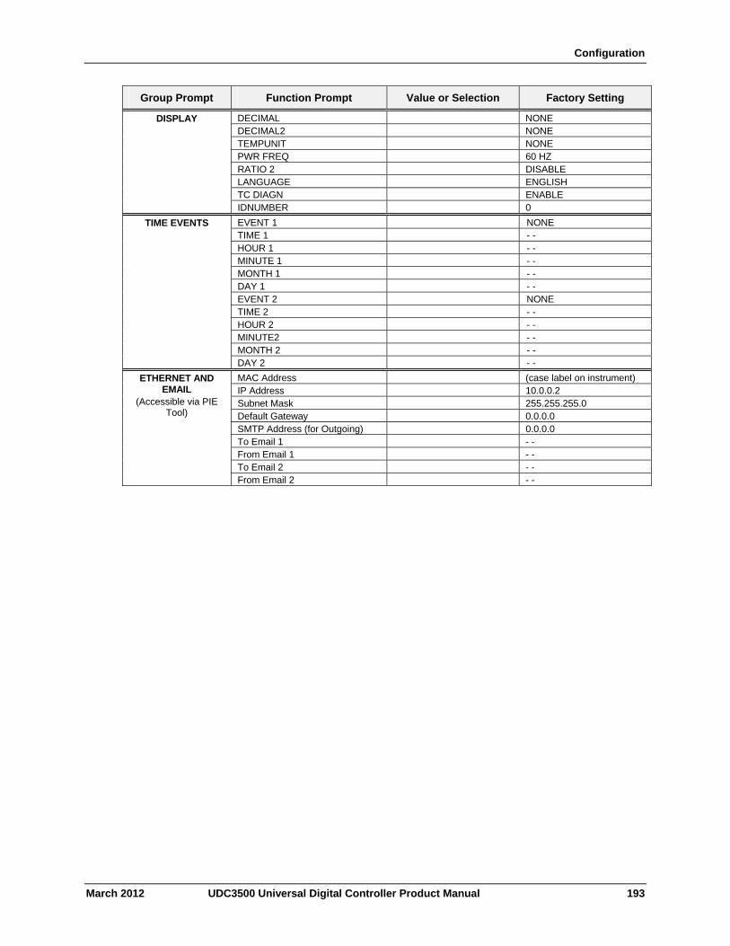
Configuration
March 2012 UDC3500 Universal Digital Controller Product Manual 193
Group Prompt Function Prompt Value or Selection Factory Setting
DECIMAL NONE DECIMAL2 NONE TEMPUNIT NONE PWR FREQ 60 HZ RATIO 2 DISABLE LANGUAGE ENGLISH TC DIAGN ENABLE
DISPLAY
IDNUMBER 0
EVENT 1 NONE TIME 1 - - HOUR 1 - - MINUTE 1 - - MONTH 1 - - DAY 1 - - EVENT 2 NONE TIME 2 - - HOUR 2 - - MINUTE2 - - MONTH 2 - -
TIME EVENTS
DAY 2 - -
MAC Address (case label on instrument) IP Address 10.0.0.2 Subnet Mask 255.255.255.0 Default Gateway 0.0.0.0 SMTP Address (for Outgoing) 0.0.0.0 To Email 1 - - From Email 1 - - To Email 2 - -
ETHERNET AND EMAIL
(Accessible via PIE Tool)
From Email 2 - -
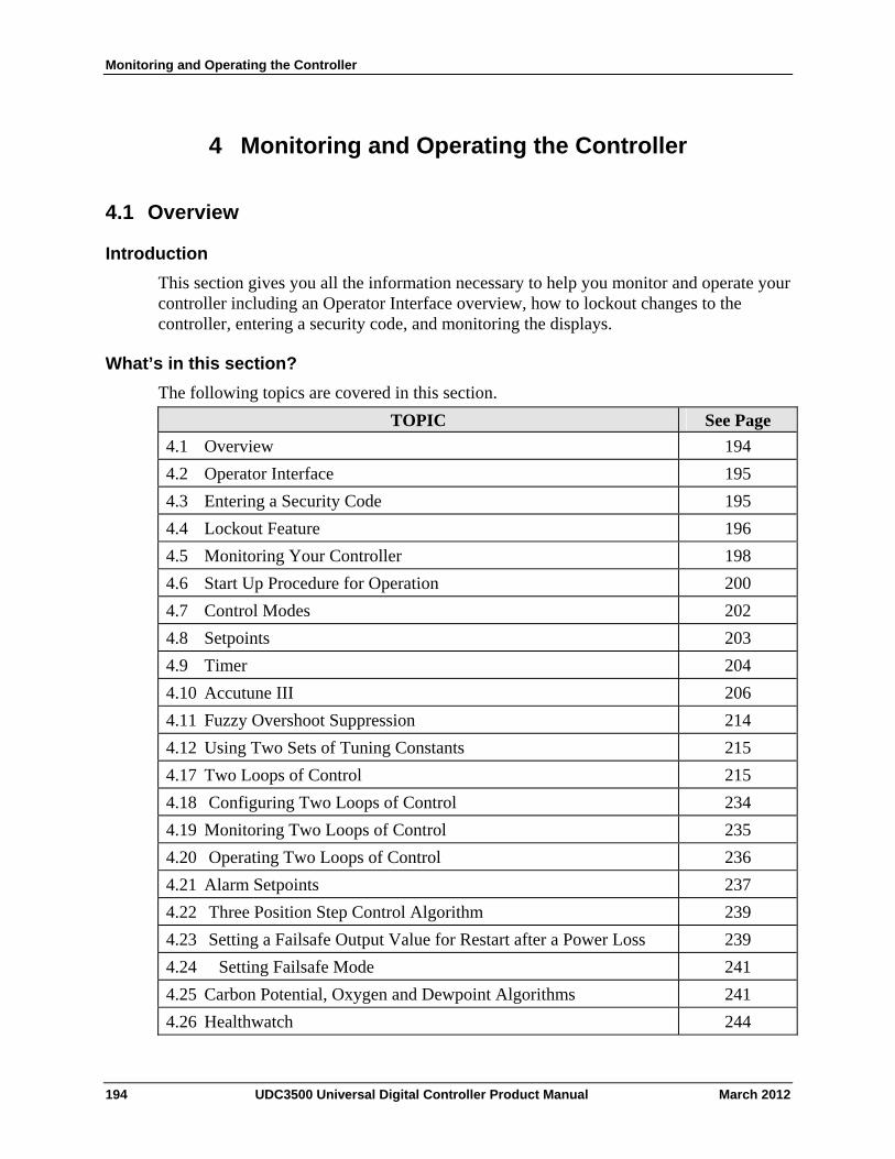
Monitoring and Operating the Controller
4 Monitoring and Operating the Controller
4.1 Overview
Introduction
This section gives you all the information necessary to help you monitor and operate your controller including an Operator Interface overview, how to lockout changes to the controller, entering a security code, and monitoring the displays.
What’s in this section?
The following topics are covered in this section.
TOPIC See Page
4.1 Overview 194
4.2 Operator Interface 195
4.3 Entering a Security Code 195
4.4 Lockout Feature 196
4.5 Monitoring Your Controller 198
4.6 Start Up Procedure for Operation 200
4.7 Control Modes 202
4.8 Setpoints 203
4.9 Timer 204
4.10 Accutune III 206
4.11 Fuzzy Overshoot Suppression 214
4.12 Using Two Sets of Tuning Constants 215
4.17 Two Loops of Control 215
4.18 Configuring Two Loops of Control 234
4.19 Monitoring Two Loops of Control 235
4.20 Operating Two Loops of Control 236
4.21 Alarm Setpoints 237
4.22 Three Position Step Control Algorithm 239
4.23 Setting a Failsafe Output Value for Restart after a Power Loss 239
4.24 Setting Failsafe Mode 241
4.25 Carbon Potential, Oxygen and Dewpoint Algorithms 241
4.26 Healthwatch 244
194 UDC3500 Universal Digital Controller Product Manual March 2012
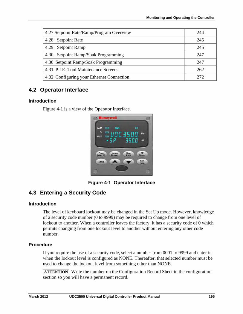
Monitoring and Operating the Controller
4.27 Setpoint Rate/Ramp/Program Overview 244
4.28 Setpoint Rate 245
4.29 Setpoint Ramp 245
4.30 Setpoint Ramp/Soak Programming 247
4.30 Setpoint Ramp/Soak Programming 247
4.31 P.I.E. Tool Maintenance Screens 262
4.32 Configuring your Ethernet Connection 272
4.2 Operator Interface
Introduction
Figure 4-1 is a view of the Operator Interface.
Figure 4-1 Operator Interface
4.3 Entering a Security Code
Introduction
The level of keyboard lockout may be changed in the Set Up mode. However, knowledge of a security code number (0 to 9999) may be required to change from one level of lockout to another. When a controller leaves the factory, it has a security code of 0 which permits changing from one lockout level to another without entering any other code number.
Procedure
If you require the use of a security code, select a number from 0001 to 9999 and enter it when the lockout level is configured as NONE. Thereafter, that selected number must be used to change the lockout level from something other than NONE.
ATTENTION Write the number on the Configuration Record Sheet in the configuration section so you will have a permanent record.
March 2012 UDC3500 Universal Digital Controller Product Manual 195
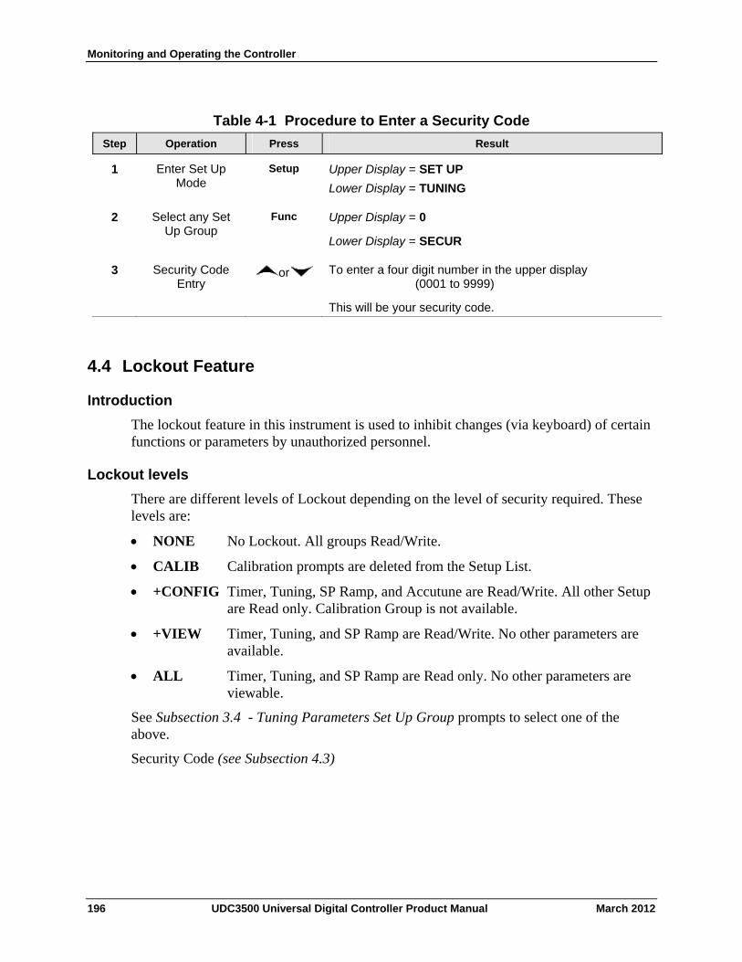
Monitoring and Operating the Controller
Table 4-1 Procedure to Enter a Security Code
Operation Press Result Step
Enter Set Up Mode
Setup Upper Display = SET UP
Lower Display = TUNING
1
Select any Set Up Group
Func Upper Display = 0
Lower Display = SECUR
2
Security Code Entry
or To enter a four digit number in the upper display (0001 to 9999)
This will be your security code.
3
4.4 Lockout Feature
Introduction
The lockout feature in this instrument is used to inhibit changes (via keyboard) of certain functions or parameters by unauthorized personnel.
Lockout levels
There are different levels of Lockout depending on the level of security required. These levels are:
NONE No Lockout. All groups Read/Write.
CALIB Calibration prompts are deleted from the Setup List.
+CONFIG Timer, Tuning, SP Ramp, and Accutune are Read/Write. All other Setup are Read only. Calibration Group is not available.
+VIEW Timer, Tuning, and SP Ramp are Read/Write. No other parameters are available.
ALL Timer, Tuning, and SP Ramp are Read only. No other parameters are viewable.
See Subsection 3.4 - Tuning Parameters Set Up Group prompts to select one of the above.
Security Code (see Subsection 4.3)
196 UDC3500 Universal Digital Controller Product Manual March 2012
Monitoring and Operating the Controller
Individual key lockout
There are three keys that can be disabled to prevent unauthorized changes to the parameters associated with these keys. First set the “Lock” prompt to NONE.
These keys are:
Run/Hold Key - you can disable the Run/Hold key for Set Point Programming at configuration Set Up group prompt “Tuning,” function prompt “RN HLD.”
Man/Auto Key - you can disable the Auto/Manual key at configuration Set Up, group prompt “Tuning”, function prompt “AUTOMA”
SP Select Key - you can disable the Set Point Select function key at configuration Set Up group prompt “Tuning,” function prompt “SP SEL.”
See Subsection 3.4 - Tuning Parameters Set Up Group prompts to enable or disable these keys.
Key error
When a key is pressed and the prompt “Key Error” appears in the lower display, it will be for one of the following reasons:
• Parameter not available or locked out • Not in setup mode, press SET UP key first • Individual key locked out.
March 2012 UDC3500 Universal Digital Controller Product Manual 197
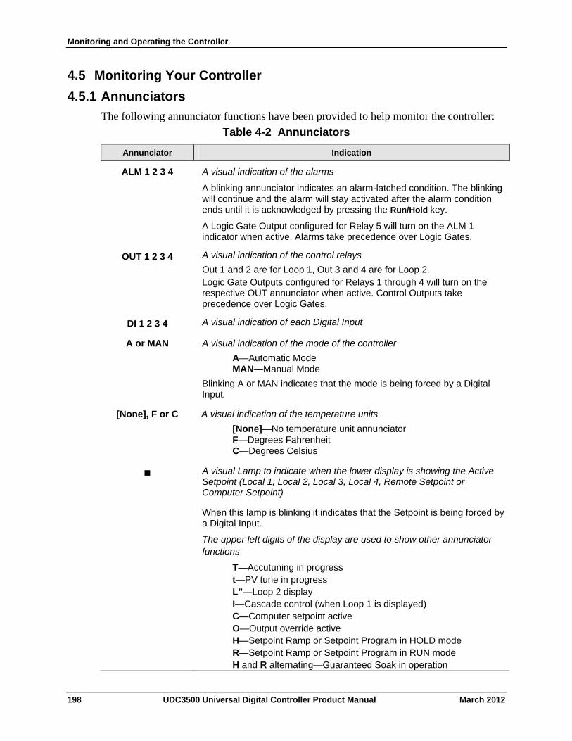
Monitoring and Operating the Controller
4.5 Monitoring Your Controller
4.5.1 Annunciators
The following annunciator functions have been provided to help monitor the controller:
Table 4-2 Annunciators
Annunciator Indication
ALM 1 2 3 4
A visual indication of the alarms
A blinking annunciator indicates an alarm-latched condition. The blinking will continue and the alarm will stay activated after the alarm condition ends until it is acknowledged by pressing the Run/Hold key.
A Logic Gate Output configured for Relay 5 will turn on the ALM 1 indicator when active. Alarms take precedence over Logic Gates.
A visual indication of the control relays
Out 1 and 2 are for Loop 1, Out 3 and 4 are for Loop 2. Logic Gate Outputs configured for Relays 1 through 4 will turn on the respective OUT annunciator when active. Control Outputs take precedence over Logic Gates.
OUT 1 2 3 4
A visual indication of each Digital Input DI 1 2 3 4
A or MAN A visual indication of the mode of the controller
A—Automatic Mode MAN—Manual Mode
Blinking A or MAN indicates that the mode is being forced by a Digital Input.
[None], F or C A visual indication of the temperature units
[None]—No temperature unit annunciator F—Degrees Fahrenheit
C—Degrees Celsius
A visual Lamp to indicate when the lower display is showing the Active Setpoint (Local 1, Local 2, Local 3, Local 4, Remote Setpoint or Computer Setpoint)
When this lamp is blinking it indicates that the Setpoint is being forced by a Digital Input.
The upper left digits of the display are used to show other annunciator functions
T—Accutuning in progress t—PV tune in progress L”—Loop 2 display I—Cascade control (when Loop 1 is displayed) C—Computer setpoint active O—Output override active H—Setpoint Ramp or Setpoint Program in HOLD mode R—Setpoint Ramp or Setpoint Program in RUN mode H and R alternating—Guaranteed Soak in operation
198 UDC3500 Universal Digital Controller Product Manual March 2012

Monitoring and Operating the Controller
March 2012 UDC3500 Universal Digital Controller Product Manual 199
Annunciator Indication
2I—PV = Input 2 via a Digital Input activation 3I—PV = Input 3 via a Digital Input activation Blinking indicates that the activity is being forced by a Digital Input.
4.5.2 Viewing the operating parameters
Press the LOWER DISPLAY key to scroll through the operating parameters listed in Table 4-3. The lower display will show only those parameters and their values that apply to your specific model and configuration.
Table 4-3 Lower Display Key Parameter Prompts
Lower Display Description
OUT XX.X OUTPUT—Output value is shown in percent with one decimal point for all output types except Three Position Step Control (TPSC). For TPSC, when no slidewire is connected, this display is an estimated motor position and is shown with no decimal point. For Position Proportional Control, if the slidewire fails, then the instrument automatically switches over to TPSC and the OUT display changes with it.
SP XXXX LOCAL SETPOINT #1—Also the current setpoint when using SP Ramp.
2SP XXXX LOCAL SETPOINT #2
3SP XXXX LOCAL SETPOINT #3
4SP XXXX LOCAL SETPOINT #4
RSP XXXX REMOTE SETPOINT
1IN XXXX INPUT 1—Used only with combinational input algorithms.
2IN XXXX INPUT 2
3IN XXXX INPUT 3
4IN XXXX INPUT 4
5IN XXXX INPUT 5
POS XX SLIDEWIRE POSITION—Used only with TPSC applications that use a slidewire input.
CSP XXXX COMPUTER SETPOINT—When SP is in override.
DEV XXXX DEVIATION—Maximum negative display is –999.9.
PIDSET X TUNING PARAMETER —where X is 1 to 4.
ET HR.MN ELAPSED TIME—Time that has elapsed on the Timer in Hours.Minutes.
ØTR HR.MN TIME REMAINING—Time remaining on the Timer in Hours.Minutes. The “Ø” is a rotating clock face.
RAMPXXXM SETPOINT RAMP TIME—Time remaining in the Setpoint Ramp in minutes.
SPn XXXX SETPOINT NOW—Current Setpoint when SP Rate is enabled. The SP XXXX display shows the “target” or final setpoint value.
PROGRAMX SETPOINT PROGRAM NUMBER— Set Point Programming display. X is the current program number (1 to 4). When a Setpoint Program is initiated va the RUN/HOLD key, the Setpoint Program Number can be incremented/decremented via the keyboard. Digital Input Selections “PROG LO” and “PROG HI” override the keyboard and force the Program selection per their status (open or closed). When running linked programs, the Setpoint Program Number can be incremented/decremented when in the “HOLD” mode.
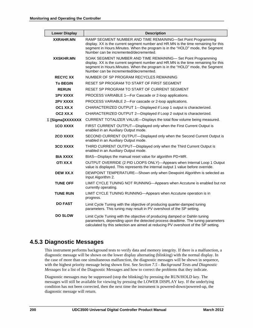
Monitoring and Operating the Controller
200 UDC3500 Universal Digital Controller Product Manual March 2012
Lower Display Description
XXRAHR.MN RAMP SEGMENT NUMBER AND TIME REMAINING—Set Point Programming display. XX is the current segment number and HR.MN is the time remaining for this segment in Hours.Minutes. When the program is in the “HOLD” mode, the Segment Number can be incremented/decremented.
XXSKHR.MN SOAK SEGMENT NUMBER AND TIME REMAINING— Set Point Programming display. XX is the current segment number and HR.MN is the time remaining for this segment in Hours.Minutes. When the program is in the “HOLD” mode, the Segment Number can be incremented/decremented.
RECYC XX NUMBER OF SP PROGRAM RECYCLES REMAINING
To BEGIN RESET SP PROGRAM TO START OF FIRST SEGMENT
RERUN RESET SP PROGRAM TO START OF CURRENT SEGMENT
1PV XXXX PROCESS VARIABLE 1—For Cascade or 2-loop applications.
2PV XXXX PROCESS VARIABLE 2—For cascade or 2-loop applications.
OC1 XX.X CHARACTERIZED OUTPUT 1—Displayed if Loop 1 output is characterized.
OC2 XX.X CHARACTERIZED OUTPUT 2—Displayed if Loop 2 output is characterized.
[Sigma]XXXXXXX CURRENT TOTALIZER VALUE—Displays the total flow volume being measured.
1CO XXXX FIRST CURRENT OUTPUT—Displayed only when the First Current Output is enabled in an Auxiliary Output mode.
2CO XXXX SECOND CURRENT OUTPUT—Displayed only when the Second Current Output is enabled in an Auxiliary Output mode.
3CO XXXX THIRD CURRENT OUTPUT—Displayed only when the Third Current Output is enabled in an Auxiliary Output mode.
BIA XXXX BIAS—Displays the manual reset value for algorithm PD+MR.
OTI XX.X OUTPUT OVERRIDE (2 PID LOOPS ONLY)—Appears when Internal Loop 1 Output value is displayed. This represents the internal output 1 value before override.
DEW XX.X DEWPOINT TEMPERATURE—Shown only when Dewpoint Algorithm is selected as Input Algorithm 2.
TUNE OFF LIMIT CYCLE TUNING NOT RUNNING—Appears when Accutune is enabled but not currently operating.
TUNE RUN LIMIT CYCLE TUNING RUNNING—Appears when Accutune operation is in progress.
DO FAST Limit Cycle Tuning with the objective of producing quarter-damped tuning parameters. This tuning may result in PV overshoot of the SP setting.
DO SLOW Limit Cycle Tuning with the objective of producing damped or Dahlin tuning parameters, depending upon the detected process deadtime. The tuning parameters calculated by this selection are aimed at reducing PV overshoot of the SP setting.
4.5.3 Diagnostic Messages This instrument performs background tests to verify data and memory integrity. If there is a malfunction, a diagnostic message will be shown on the lower display alternating (blinking) with the normal display. In the case of more than one simultaneous malfunction, the diagnostic messages will be shown in sequence, with the highest priority message being shown first. See Section 7.5 - Background Tests and Diagnostic Messages for a list of the Diagnostic Messages and how to correct the problems that they indicate.
Diagnostic messages may be suppressed (stop the blinking) by pressing the RUN/HOLD key. The messages will still be available for viewing by pressing the LOWER DISPLAY key. If the underlying condition has not been corrected, then the next time the instrument is powered-down/powered-up, the diagnostic message will return.
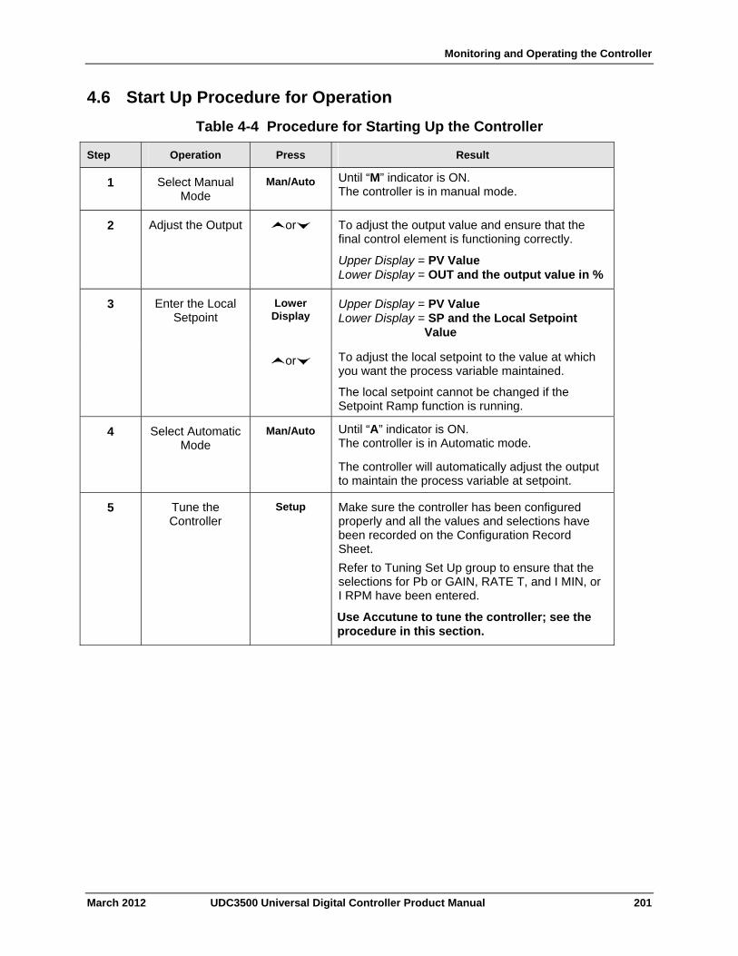
Monitoring and Operating the Controller
4.6 Start Up Procedure for Operation
Table 4-4 Procedure for Starting Up the Controller
Operation Press Result Step
Select Manual Mode
Man/Auto Until “M” indicator is ON. The controller is in manual mode.
1
Adjust the Output or To adjust the output value and ensure that the final control element is functioning correctly.
Upper Display = PV Value Lower Display = OUT and the output value in %
2
Enter the Local Setpoint
Lower Display
Upper Display = PV Value Lower Display = SP and the Local Setpoint
Value
3
or To adjust the local setpoint to the value at which you want the process variable maintained.
The local setpoint cannot be changed if the Setpoint Ramp function is running.
Select Automatic Mode
Man/Auto Until “A” indicator is ON. The controller is in Automatic mode.
The controller will automatically adjust the output to maintain the process variable at setpoint.
4
Tune the Controller
Setup Make sure the controller has been configured properly and all the values and selections have been recorded on the Configuration Record Sheet.
Refer to Tuning Set Up group to ensure that the selections for Pb or GAIN, RATE T, and I MIN, or I RPM have been entered.
Use Accutune to tune the controller; see the procedure in this section.
5
March 2012 UDC3500 Universal Digital Controller Product Manual 201
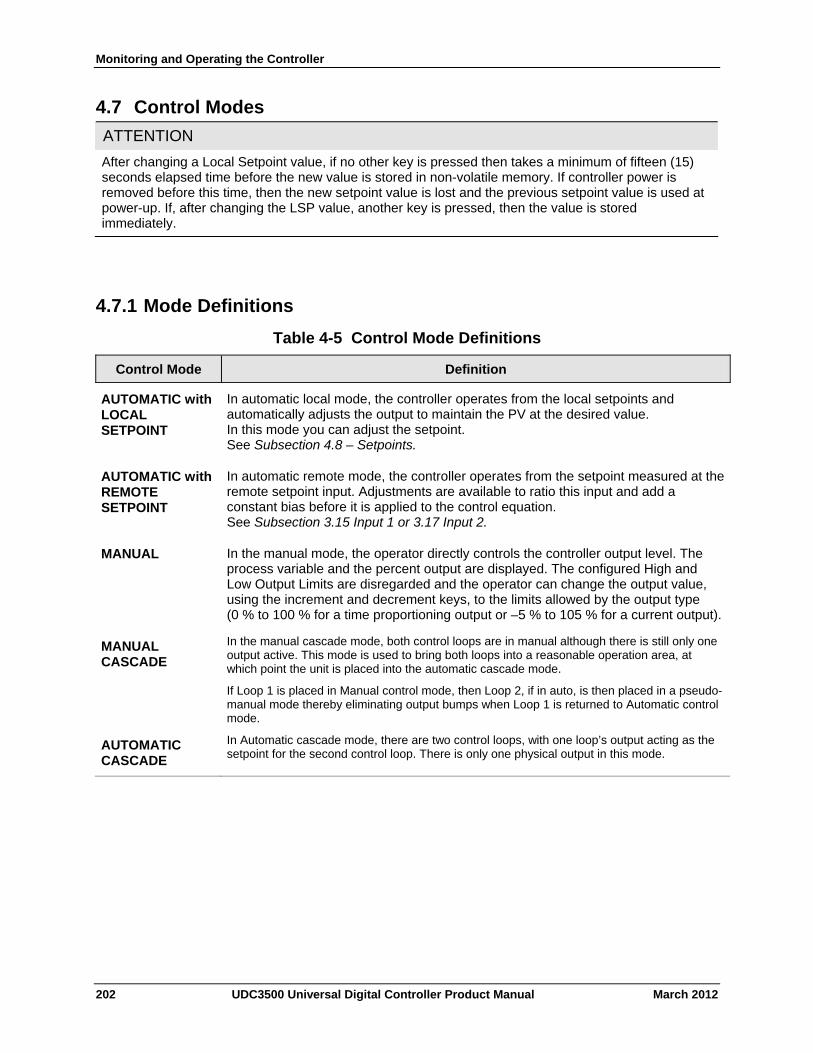
Monitoring and Operating the Controller
4.7 Control Modes
ATTENTION
After changing a Local Setpoint value, if no other key is pressed then takes a minimum of fifteen (15) seconds elapsed time before the new value is stored in non-volatile memory. If controller power is removed before this time, then the new setpoint value is lost and the previous setpoint value is used at power-up. If, after changing the LSP value, another key is pressed, then the value is stored immediately.
4.7.1 Mode Definitions
Table 4-5 Control Mode Definitions
Control Mode Definition
In automatic local mode, the controller operates from the local setpoints and automatically adjusts the output to maintain the PV at the desired value. In this mode you can adjust the setpoint. See Subsection 4.8 – Setpoints.
AUTOMATIC with LOCAL SETPOINT
In automatic remote mode, the controller operates from the setpoint measured at the remote setpoint input. Adjustments are available to ratio this input and add a constant bias before it is applied to the control equation. See Subsection 3.15 Input 1 or 3.17 Input 2.
AUTOMATIC with REMOTE SETPOINT
In the manual mode, the operator directly controls the controller output level. The process variable and the percent output are displayed. The configured High and Low Output Limits are disregarded and the operator can change the output value, using the increment and decrement keys, to the limits allowed by the output type (0 % to 100 % for a time proportioning output or –5 % to 105 % for a current output).
MANUAL
In the manual cascade mode, both control loops are in manual although there is still only one output active. This mode is used to bring both loops into a reasonable operation area, at which point the unit is placed into the automatic cascade mode.
If Loop 1 is placed in Manual control mode, then Loop 2, if in auto, is then placed in a pseudo-manual mode thereby eliminating output bumps when Loop 1 is returned to Automatic control mode.
MANUAL CASCADE
In Automatic cascade mode, there are two control loops, with one loop’s output acting as the setpoint for the second control loop. There is only one physical output in this mode.
AUTOMATIC CASCADE
202 UDC3500 Universal Digital Controller Product Manual March 2012
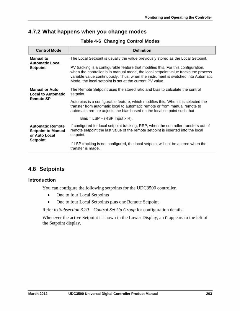
Monitoring and Operating the Controller
4.7.2 What happens when you change modes
Table 4-6 Changing Control Modes
Control Mode Definition
The Local Setpoint is usually the value previously stored as the Local Setpoint. PV tracking is a configurable feature that modifies this. For this configuration, when the controller is in manual mode, the local setpoint value tracks the process variable value continuously. Thus, when the instrument is switched into Automatic Mode, the local setpoint is set at the current PV value.
Manual to Automatic Local Setpoint
The Remote Setpoint uses the stored ratio and bias to calculate the control setpoint.
Auto bias is a configurable feature, which modifies this. When it is selected the transfer from automatic local to automatic remote or from manual remote to automatic remote adjusts the bias based on the local setpoint such that
Bias = LSP – (RSP Input x R).
Manual or Auto Local to Automatic Remote SP
If configured for local setpoint tracking, RSP, when the controller transfers out of remote setpoint the last value of the remote setpoint is inserted into the local setpoint. If LSP tracking is not configured, the local setpoint will not be altered when the transfer is made.
Automatic Remote Setpoint to Manual or Auto Local Setpoint
4.8 Setpoints
Introduction
You can configure the following setpoints for the UDC3500 controller.
One to four Local Setpoints
One to four Local Setpoints plus one Remote Setpoint
Refer to Subsection 3.20 – Control Set Up Group for configuration details.
Whenever the active Setpoint is shown in the Lower Display, an n appears to the left of the Setpoint display.
March 2012 UDC3500 Universal Digital Controller Product Manual 203
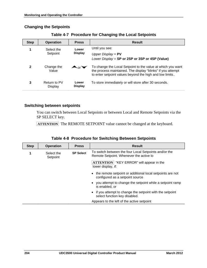
Monitoring and Operating the Controller
Changing the Setpoints
Table 4-7 Procedure for Changing the Local Setpoints
Operation Press Result Step
Select the Setpoint
Lower Display
Until you see:
Upper Display = PV Lower Display = SP or 2SP or 3SP or 4SP (Value)
1
Change the Value
or To change the Local Setpoint to the value at which you want the process maintained. The display “blinks” if you attempt to enter setpoint values beyond the high and low limits..
2
Return to PV Display
Lower Display
To store immediately or will store after 30 seconds. 3
Switching between setpoints
You can switch between Local Setpoints or between Local and Remote Setpoints via the SP SELECT key.
ATTENTION The REMOTE SETPOINT value cannot be changed at the keyboard.
Table 4-8 Procedure for Switching Between Setpoints
Operation Press Result Step
Select the Setpoint
SP Select To switch between the four Local Setpoints and/or the Remote Setpoint. Whenever the active lo
ATTENTION “KEY ERROR” will appear in the lower display, if:
the remote setpoint or additional local setpoints are not configured as a setpoint source
you attempt to change the setpoint while a setpoint ramp is enabled, or
if you attempt to change the setpoint with the setpoint select function key disabled.
Appears to the left of the active setpoint
1
204 UDC3500 Universal Digital Controller Product Manual March 2012
Monitoring and Operating the Controller
4.9 Timer
Introduction
The Timer provides a configurable Time-out period of from 0 to 99 hours:59 minutes or 0 to 99 minutes:99 seconds.
Timer “Start” is selectable as either the RUN/HOLD key or Alarm 2.
The Timer display can be either “Time Remaining” or “Elapsed Time”.
Configuration check
Make sure:
TIMER is enabled
A TIMEOUT period has been selected (in hours and minutes or minutes and seconds)
A TIMER FUNCTION START has been selected (KEY or AL2)
A TIMER display has been selected (Time remaining or Elapsed time)
A timer increment selected
Timer reset selected (KEY or AL1) KEY means that the RUN/HOLD key is used to start and/or reset the timer. AL1 means that either Alarm 1 or the RUN/HOLD key is used to start and/or reset the timer.
Refer to Subsection 3.11 Algorithm Set Up Group for details.
Viewing Times
The times are viewed on the lower display as follows:
TIME REMAINING will show as a decreasing Hrs:Min value (HH:MM) or Min:Sec value (MM:SS) plus a counterclockwise rotating clock face.
ELAPSED TIME will show as an increasing Hrs:Min value(HH:MM) or Min:Sec value (MM:SS) plus a clockwise rotating clock face.
Operation
When the Timer is enabled (RUN/HOLD key or ALARM 2), it has exclusive control of Alarm 1 relay.
At “TIME-OUT:
Alarm 1 is active
The clock character has stopped moving
The Time display shows either 00:00 or the time-out period depending on the configuration selection
March 2012 UDC3500 Universal Digital Controller Product Manual 205
Monitoring and Operating the Controller
The Timer is ready to be reset either via the RUN/HOLD key or by activating Alarm 1.
When the Timer is “RESET”:
Alarm 1 relay is inactive
The timer display shows the configured timer period
The time-out period can be changed at this time using the or keys.
The Timer is ready for the next activation.
4.10 Accutune III
Introduction
Accutune III (TUNE) may be used for self-regulating and single integrating processes. This autotuning method is initiated on-demand, typically at initial start-up.
There are no other requirements necessary, such as prior knowledge to the process dynamics or initial or post tune process line-out to setpoint or manual output.
Also, the setpoint value is not required to change in order to initiate the tuning process, but the controller must be in the Automatic mode to start tuning. The process need not be in a static (lined out) state and may be dynamic (changing with a steady output).
Configuration check
Make sure:
TUNE has been enabled see to Subsection 3.10 – Accutune Set Up Group for details.
Tuning indicators
A “T” will show in the leftmost alphanumeric of the upper display until tuning is completed.
Operation
The Accutune III algorithm provides user-friendly, on-demand tuning in this controller. No knowledge of the process is required at start-up. The operator simply initiates the tuning while in the automatic mode.
Once Accutune III has been enabled in the TUNE setup group, either “SLOW” or “FAST” tuning may be used. Which one is used is selected via the lower display during normal operation.
For the SLOW selection, the controller calculates conservative tuning constants with the objective of minimizing overshoot. If the controller determines that the process has appreciable dead time, it will automatically default to use Dahlin Tuning, which produces very conservative tuning constants. The SLOW selection may be useful for TPSC and
206 UDC3500 Universal Digital Controller Product Manual March 2012
Monitoring and Operating the Controller
Position Proportional applications, as it reduces “hunt” problems for the motor. This selection is also recommended for applications that have significant deadtimes.
For the FAST selection, the controller calculates aggressive tuning constants with the objective of producing quarter-damped response. Depending upon the process, this selection will usually result in some overshoot. For this reason, it may be desirable to enable the FUZZY tune selection. See Section 4.11. When Fuzzy tune is enabled, it will work to suppress or eliminate any overshoot that may occur as a result of the calculated tuning parameters as the PV approaches the setpoint. This selection is best suited for processes with a single lag or for those that do not have any appreciable deadtime. FUZZY tuning does not work well for processes that have appreciable deadtime.
The Accutune III tuning process will cycle the controller’s output two full cycles between the low and high output limits while allowing only a very small Process Variable change above and below the SP during each cycle. A “T” shows in the upper display until tuning is completed.
At the end of the tuning process, the controller immediately calculates the tuning constants and enters them into the Tuning group, and begins PID control with the correct tuning parameters. This works with any process, including integrating type processes, and allows retuning at a fixed setpoint.
March 2012 UDC3500 Universal Digital Controller Product Manual 207
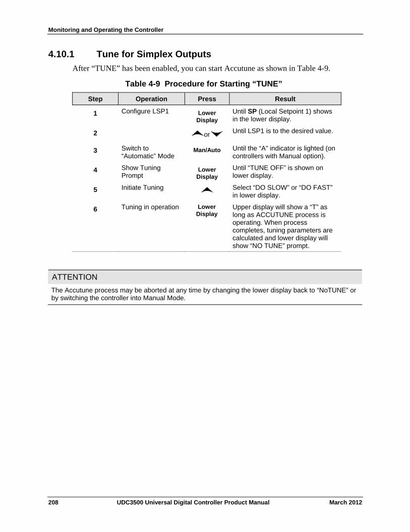
Monitoring and Operating the Controller
4.10.1 Tune for Simplex Outputs
After “TUNE” has been enabled, you can start Accutune as shown in Table 4-9.
Table 4-9 Procedure for Starting “TUNE”
Operation Press Result Step
Configure LSP1 Lower Display
Until SP (Local Setpoint 1) shows in the lower display.
1
or Until LSP1 is to the desired value. 2
Switch to “Automatic” Mode
Man/Auto Until the “A” indicator is lighted (on controllers with Manual option).
3
Show Tuning Prompt
Lower Display
Until “TUNE OFF” is shown on lower display.
4
Initiate Tuning Select “DO SLOW” or “DO FAST” in lower display.
5
Tuning in operation Lower Display
Upper display will show a “T” as long as ACCUTUNE process is operating. When process completes, tuning parameters are calculated and lower display will show “NO TUNE” prompt.
6
ATTENTION
The Accutune process may be aborted at any time by changing the lower display back to “NoTUNE” or by switching the controller into Manual Mode.
208 UDC3500 Universal Digital Controller Product Manual March 2012
Monitoring and Operating the Controller
4.10.2 Tune for Duplex (Heat/Cool)
Accutune for applications using Duplex (Heat/Cool) control.
The controller must be configured to have two local setpoints unless Blended Tuning is desired (see below). See Subsection 3.20- Control Set Up Group for details on configuring two local setpoints. During tuning, the Accutune III process assumes that Local Setpoint 1 will cause a Heating demand (output above 50%), and the tuning parameters calculated for that setpoint are automatically entered as PID SET 1. Likewise, Accutune III assumes that Local Setpoint 2 will cause a Cooling demand (output less than 50%), and the tuning parameters calculated for that setpoint are automatically entered as PID SET 2.
Configuration Check for Duplex
See Subsection 3.10 – Accutune Set Up Group for details.
Make sure:
TUNE has been enabled
DUPLEX has been configured to Manual, Automatic or Disabled
March 2012 UDC3500 Universal Digital Controller Product Manual 209
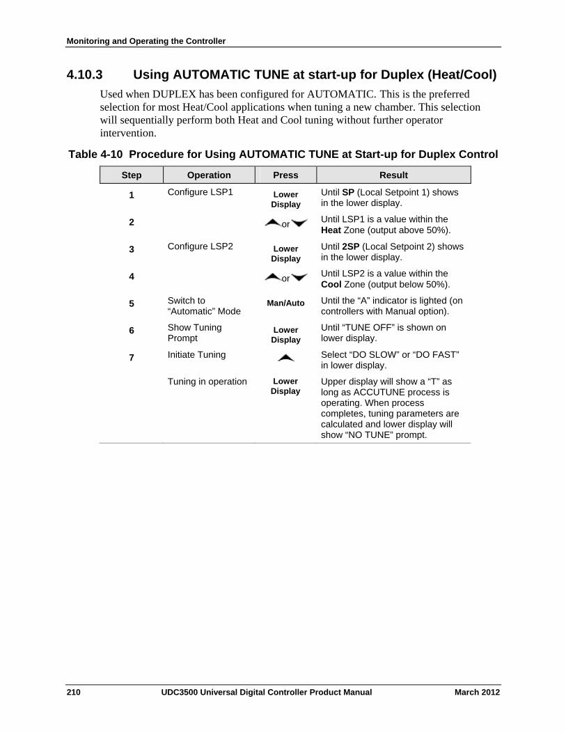
Monitoring and Operating the Controller
4.10.3 Using AUTOMATIC TUNE at start-up for Duplex (Heat/Cool)
Used when DUPLEX has been configured for AUTOMATIC. This is the preferred selection for most Heat/Cool applications when tuning a new chamber. This selection will sequentially perform both Heat and Cool tuning without further operator intervention.
Table 4-10 Procedure for Using AUTOMATIC TUNE at Start-up for Duplex Control
Operation Press Result Step
Configure LSP1 Lower Display
Until SP (Local Setpoint 1) shows in the lower display.
1
or Until LSP1 is a value within the Heat Zone (output above 50%).
2
Configure LSP2 Lower Display
Until 2SP (Local Setpoint 2) shows in the lower display.
3
or Until LSP2 is a value within the Cool Zone (output below 50%).
4
Switch to “Automatic” Mode
Man/Auto Until the “A” indicator is lighted (on controllers with Manual option).
5
Show Tuning Prompt
Lower Display
Until “TUNE OFF” is shown on lower display.
6
Initiate Tuning Select “DO SLOW” or “DO FAST” in lower display.
7
Tuning in operation Lower Display
Upper display will show a “T” as long as ACCUTUNE process is operating. When process completes, tuning parameters are calculated and lower display will show “NO TUNE” prompt.
210 UDC3500 Universal Digital Controller Product Manual March 2012
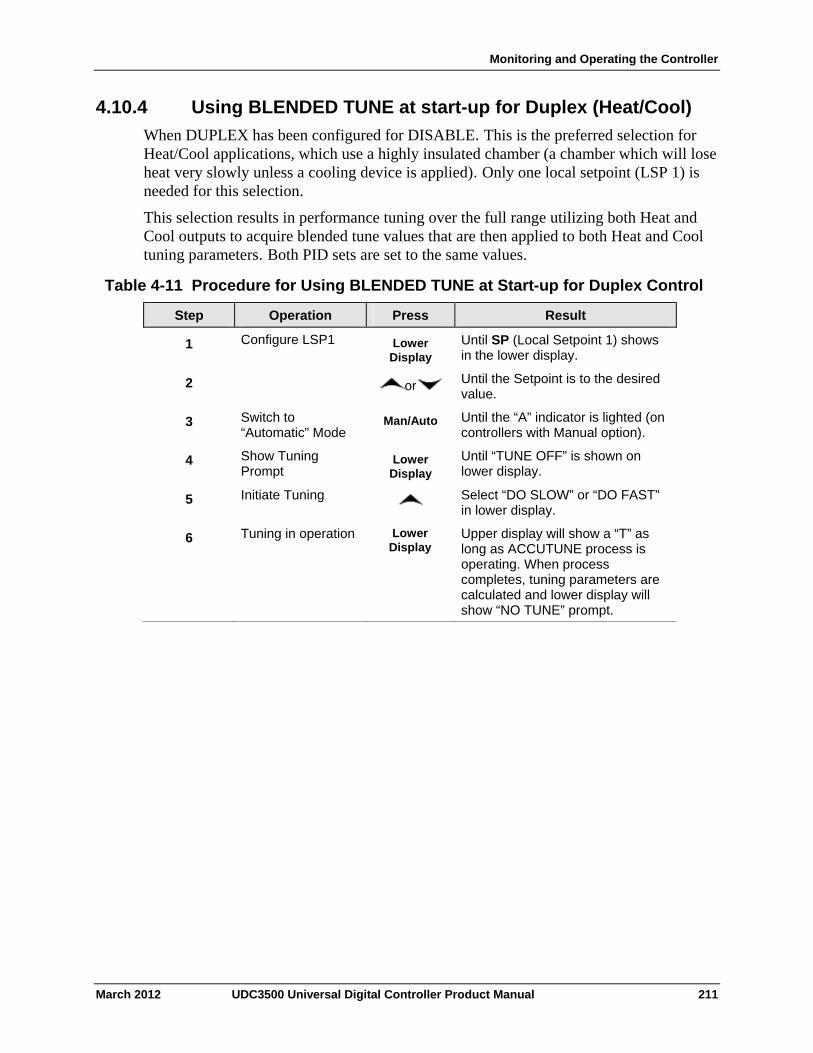
Monitoring and Operating the Controller
4.10.4 Using BLENDED TUNE at start-up for Duplex (Heat/Cool)
When DUPLEX has been configured for DISABLE. This is the preferred selection for Heat/Cool applications, which use a highly insulated chamber (a chamber which will lose heat very slowly unless a cooling device is applied). Only one local setpoint (LSP 1) is needed for this selection.
This selection results in performance tuning over the full range utilizing both Heat and Cool outputs to acquire blended tune values that are then applied to both Heat and Cool tuning parameters. Both PID sets are set to the same values.
Table 4-11 Procedure for Using BLENDED TUNE at Start-up for Duplex Control
Operation Press Result Step
Configure LSP1 Lower Display
Until SP (Local Setpoint 1) shows in the lower display.
1
or Until the Setpoint is to the desired value.
2
Switch to “Automatic” Mode
Man/Auto Until the “A” indicator is lighted (on controllers with Manual option).
3
Show Tuning Prompt
Lower Display
Until “TUNE OFF” is shown on lower display.
4
Initiate Tuning Select “DO SLOW” or “DO FAST” in lower display.
5
6 Tuning in operation Lower Display
Upper display will show a “T” as long as ACCUTUNE process is operating. When process completes, tuning parameters are calculated and lower display will show “NO TUNE” prompt.
March 2012 UDC3500 Universal Digital Controller Product Manual 211
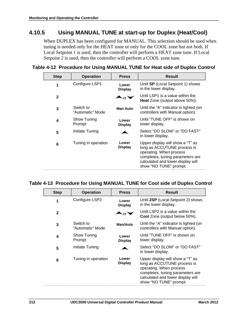
Monitoring and Operating the Controller
4.10.5 Using MANUAL TUNE at start-up for Duplex (Heat/Cool)
When DUPLEX has been configured for MANUAL. This selection should be used when tuning is needed only for the HEAT zone or only for the COOL zone but not both. If Local Setpoint 1 is used, then the controller will perform a HEAT zone tune. If Local Setpoint 2 is used, then the controller will perform a COOL zone tune.
Table 4-12 Procedure for Using MANUAL TUNE for Heat side of Duplex Control
Operation Press Result Step
Configure LSP1 Lower Display
Until SP (Local Setpoint 1) shows in the lower display.
1
or Until LSP1 is a value within the Heat Zone (output above 50%).
2
Switch to “Automatic” Mode
Man Auto Until the “A” indicator is lighted (on controllers with Manual option).
3
Show Tuning Prompt
Lower Display
Until “TUNE OFF” is shown on lower display.
4
Initiate Tuning Select “DO SLOW” or “DO FAST” in lower display.
5
Tuning in operation Lower Display
Upper display will show a “T” as long as ACCUTUNE process is operating. When process completes, tuning parameters are calculated and lower display will show “NO TUNE” prompt.
6
Table 4-13 Procedure for Using MANUAL TUNE for Cool side of Duplex Control
Operation Press Result Step
Configure LSP2 Lower Display
Until 2SP (Local Setpoint 2) shows in the lower display.
1
or Until LSP2 is a value within the Cool Zone (output below 50%).
2
Switch to “Automatic” Mode
Man/Auto Until the “A” indicator is lighted (on controllers with Manual option).
3
Show Tuning Prompt
Lower Display
Until “TUNE OFF” is shown on lower display.
4
Initiate Tuning Select “DO SLOW” or “DO FAST” in lower display.
5
6 Tuning in operation Lower Display
Upper display will show a “T” as long as ACCUTUNE process is operating. When process completes, tuning parameters are calculated and lower display will show “NO TUNE” prompt.
212 UDC3500 Universal Digital Controller Product Manual March 2012
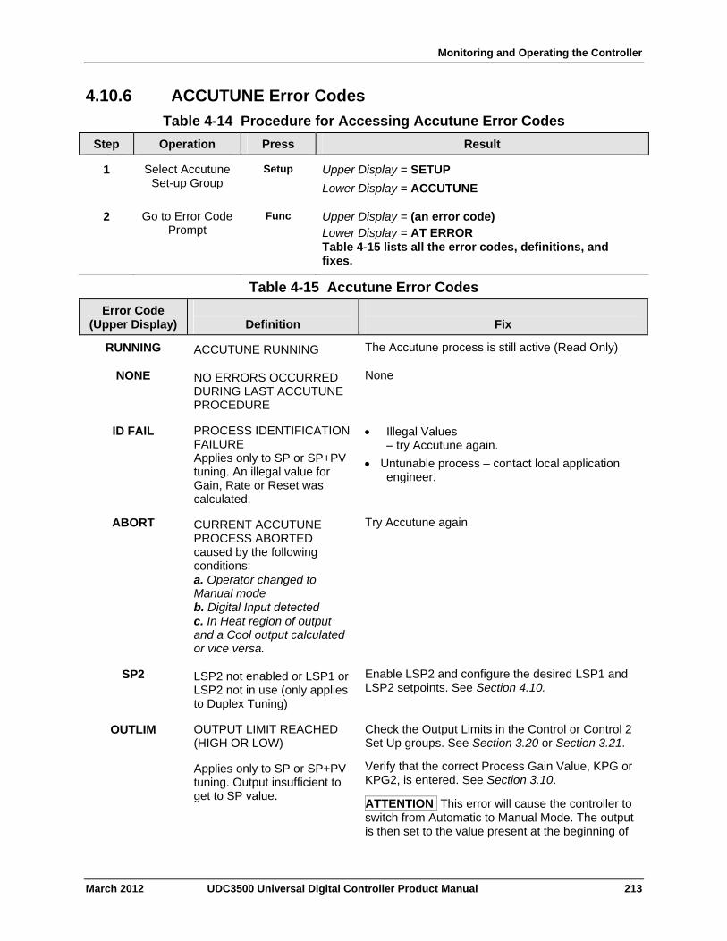
Monitoring and Operating the Controller
4.10.6 ACCUTUNE Error Codes
Table 4-14 Procedure for Accessing Accutune Error Codes
Operation Press Result Step
Select Accutune Set-up Group
Setup Upper Display = SETUP
Lower Display = ACCUTUNE
1
Go to Error Code Prompt
Func Upper Display = (an error code) Lower Display = AT ERROR Table 4-15 lists all the error codes, definitions, and fixes.
2
Table 4-15 Accutune Error Codes
Definition
Fix
Error Code (Upper Display)
ACCUTUNE RUNNING The Accutune process is still active (Read Only) RUNNING
NO ERRORS OCCURRED DURING LAST ACCUTUNE PROCEDURE
None NONE
PROCESS IDENTIFICATION FAILURE Applies only to SP or SP+PV tuning. An illegal value for Gain, Rate or Reset was calculated.
Illegal Values – try Accutune again.
Untunable process – contact local application engineer.
ID FAIL
CURRENT ACCUTUNE PROCESS ABORTED caused by the following conditions: a. Operator changed to Manual mode b. Digital Input detected c. In Heat region of output and a Cool output calculated or vice versa.
Try Accutune again ABORT
LSP2 not enabled or LSP1 or LSP2 not in use (only applies to Duplex Tuning)
Enable LSP2 and configure the desired LSP1 and LSP2 setpoints. See Section 4.10.
SP2
OUTPUT LIMIT REACHED (HIGH OR LOW)
Applies only to SP or SP+PV tuning. Output insufficient to get to SP value.
Check the Output Limits in the Control or Control 2 Set Up groups. See Section 3.20 or Section 3.21.
Verify that the correct Process Gain Value, KPG or KPG2, is entered. See Section 3.10.
ATTENTION This error will cause the controller to switch from Automatic to Manual Mode. The output is then set to the value present at the beginning of
OUTLIM
March 2012 UDC3500 Universal Digital Controller Product Manual 213
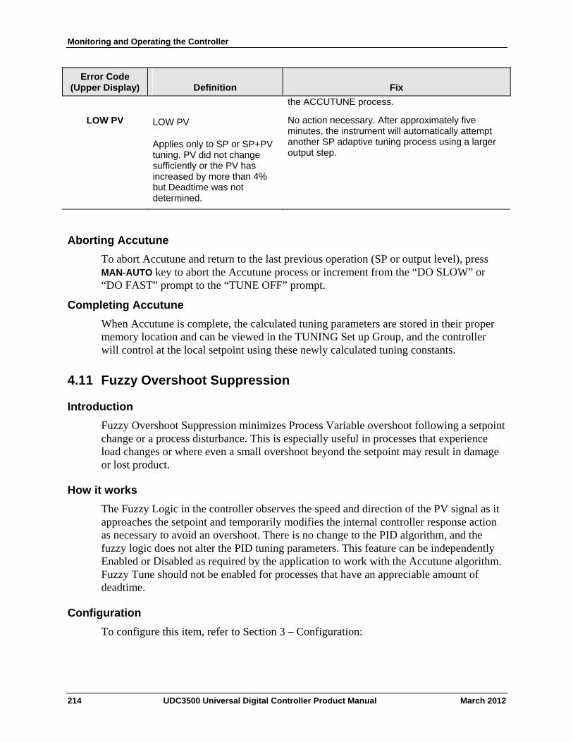
Monitoring and Operating the Controller
214 UDC3500 Universal Digital Controller Product Manual March 2012
Error Code (Upper Display)
Definition
Fix
the ACCUTUNE process.
LOW PV LOW PV
Applies only to SP or SP+PV tuning. PV did not change sufficiently or the PV has increased by more than 4% but Deadtime was not determined.
No action necessary. After approximately five minutes, the instrument will automatically attempt another SP adaptive tuning process using a larger output step.
Aborting Accutune
To abort Accutune and return to the last previous operation (SP or output level), press MAN-AUTO key to abort the Accutune process or increment from the “DO SLOW” or “DO FAST” prompt to the “TUNE OFF” prompt.
Completing Accutune
When Accutune is complete, the calculated tuning parameters are stored in their proper memory location and can be viewed in the TUNING Set up Group, and the controller will control at the local setpoint using these newly calculated tuning constants.
4.11 Fuzzy Overshoot Suppression
Introduction
Fuzzy Overshoot Suppression minimizes Process Variable overshoot following a setpoint change or a process disturbance. This is especially useful in processes that experience load changes or where even a small overshoot beyond the setpoint may result in damage or lost product.
How it works
The Fuzzy Logic in the controller observes the speed and direction of the PV signal as it approaches the setpoint and temporarily modifies the internal controller response action as necessary to avoid an overshoot. There is no change to the PID algorithm, and the fuzzy logic does not alter the PID tuning parameters. This feature can be independently Enabled or Disabled as required by the application to work with the Accutune algorithm. Fuzzy Tune should not be enabled for processes that have an appreciable amount of deadtime.
Configuration
To configure this item, refer to Section 3 – Configuration:
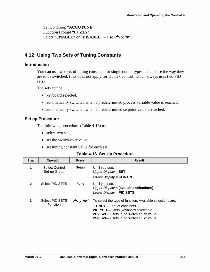
Monitoring and Operating the Controller
Set Up Group “ACCUTUNE” Function Prompt “FUZZY” Select “ENABLE” or “DISABLE” – Use or .
4.12 Using Two Sets of Tuning Constants
Introduction
You can use two sets of tuning constants for single output types and choose the way they are to be switched. (this does not apply for Duplex control, which always uses two PID sets).
The sets can be:
keyboard selected,
automatically switched when a predetermined process variable value is reached,
automatically switched when a predetermined setpoint value is reached.
Set up Procedure
The following procedure (Table 4-16) to:
select two sets,
set the switch-over value,
set tuning constant value for each set.
Table 4-16 Set Up Procedure
Operation Press Result Step
Select Control Set-up Group
Setup Until you see: Upper Display = SET
Lower Display = CONTROL
1
Select PID SETS Func Until you see: Upper Display = (available selections) Lower Display = PID SETS
2
Select PID SETS Function
or To select the type of function. Available selections are:
1 ONLY—1 set of constants 2KEYBD—2 sets, keyboard selectable 2PV SW—2 sets, auto switch at PV value 2SP SW—2 sets, auto switch at SP value
3
March 2012 UDC3500 Universal Digital Controller Product Manual 215
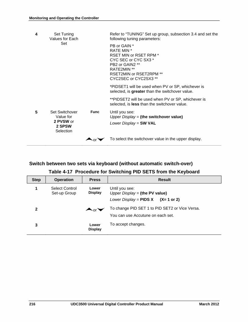
Monitoring and Operating the Controller
Set Tuning Values for Each
Set
Refer to “TUNING” Set up group, subsection 3.4 and set the following tuning parameters:
PB or GAIN * RATE MIN * RSET MIN or RSET RPM * CYC SEC or CYC SX3 * PB2 or GAIN2 ** RATE2MIN ** RSET2MIN or RSET2RPM ** CYC2SEC or CYC2SX3 **
*PIDSET1 will be used when PV or SP, whichever is selected, is greater than the switchover value.
**PIDSET2 will be used when PV or SP, whichever is selected, is less than the switchover value.
4
Set Switchover Value for
2 PVSW or 2 SPSW Selection
Func Until you see: Upper Display = (the switchover value)
Lower Display = SW VAL
5
or To select the switchover value in the upper display.
Switch between two sets via keyboard (without automatic switch-over)
Table 4-17 Procedure for Switching PID SETS from the Keyboard
Operation Press Result Step
Select Control Set-up Group
Lower Display
Until you see: Upper Display = (the PV value)
Lower Display = PIDS X (X= 1 or 2)
1
or To change PID SET 1 to PID SET2 or Vice Versa.
You can use Accutune on each set.
2
3 Lower Display
To accept changes.
216 UDC3500 Universal Digital Controller Product Manual March 2012
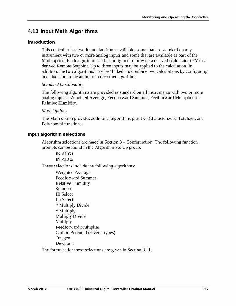
Monitoring and Operating the Controller
4.13 Input Math Algorithms
Introduction
This controller has two input algorithms available, some that are standard on any instrument with two or more analog inputs and some that are available as part of the Math option. Each algorithm can be configured to provide a derived (calculated) PV or a derived Remote Setpoint. Up to three inputs may be applied to the calculation. In addition, the two algorithms may be “linked” to combine two calculations by configuring one algorithm to be an input to the other algorithm.
Standard functionality
The following algorithms are provided as standard on all instruments with two or more analog inputs: Weighted Average, Feedforward Summer, Feedforward Multiplier, or Relative Humidity.
Math Options
The Math option provides additional algorithms plus two Characterizers, Totalizer, and Polynomial functions.
Input algorithm selections
Algorithm selections are made in Section 3 – Configuration. The following function prompts can be found in the Algorithm Set Up group:
IN ALG1 IN ALG2
These selections include the following algorithms:
Weighted Average Feedforward Summer Relative Humidity Summer Hi Select Lo Select Multiply Divide Multiply Multiply Divide Multiply Feedforward Multiplier Carbon Potential (several types) Oxygen Dewpoint
The formulas for these selections are given in Section 3.11.
March 2012 UDC3500 Universal Digital Controller Product Manual 217
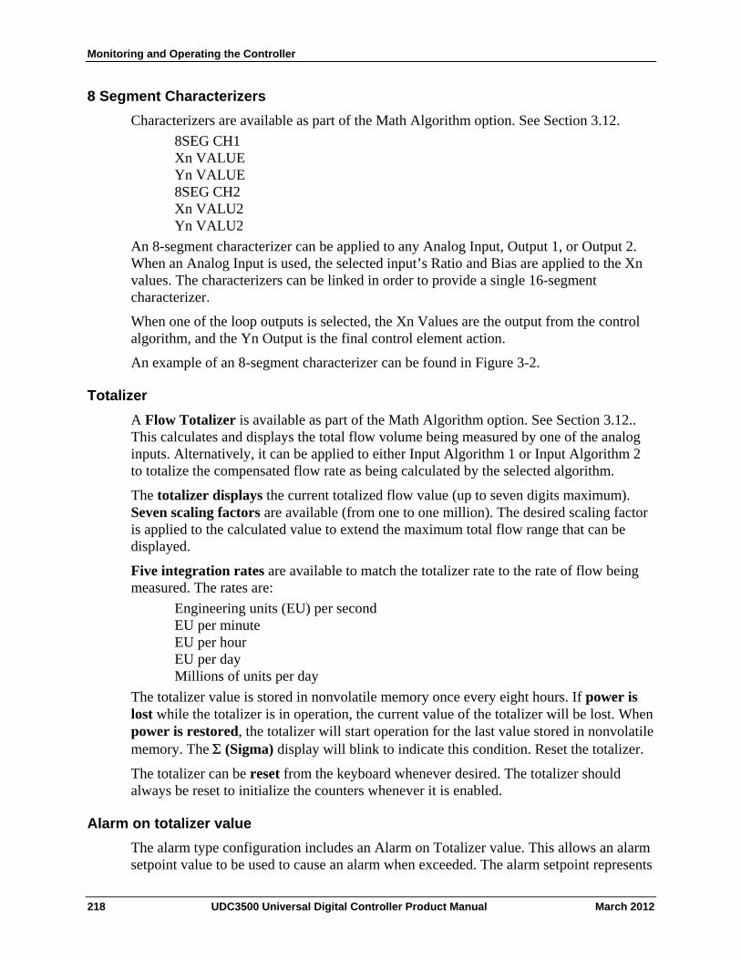
Monitoring and Operating the Controller
8 Segment Characterizers
Characterizers are available as part of the Math Algorithm option. See Section 3.12.
8SEG CH1 Xn VALUE Yn VALUE 8SEG CH2 Xn VALU2 Yn VALU2
An 8-segment characterizer can be applied to any Analog Input, Output 1, or Output 2. When an Analog Input is used, the selected input’s Ratio and Bias are applied to the Xn values. The characterizers can be linked in order to provide a single 16-segment characterizer.
When one of the loop outputs is selected, the Xn Values are the output from the control algorithm, and the Yn Output is the final control element action.
An example of an 8-segment characterizer can be found in Figure 3-2.
Totalizer
A Flow Totalizer is available as part of the Math Algorithm option. See Section 3.12.. This calculates and displays the total flow volume being measured by one of the analog inputs. Alternatively, it can be applied to either Input Algorithm 1 or Input Algorithm 2 to totalize the compensated flow rate as being calculated by the selected algorithm.
The totalizer displays the current totalized flow value (up to seven digits maximum). Seven scaling factors are available (from one to one million). The desired scaling factor is applied to the calculated value to extend the maximum total flow range that can be displayed.
Five integration rates are available to match the totalizer rate to the rate of flow being measured. The rates are:
Engineering units (EU) per second EU per minute EU per hour EU per day Millions of units per day
The totalizer value is stored in nonvolatile memory once every eight hours. If power is lost while the totalizer is in operation, the current value of the totalizer will be lost. When power is restored, the totalizer will start operation for the last value stored in nonvolatile memory. The (Sigma) display will blink to indicate this condition. Reset the totalizer.
The totalizer can be reset from the keyboard whenever desired. The totalizer should always be reset to initialize the counters whenever it is enabled.
Alarm on totalizer value
The alarm type configuration includes an Alarm on Totalizer value. This allows an alarm setpoint value to be used to cause an alarm when exceeded. The alarm setpoint represents
218 UDC3500 Universal Digital Controller Product Manual March 2012
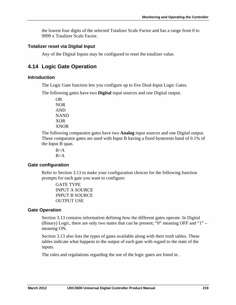
Monitoring and Operating the Controller
the lowest four digits of the selected Totalizer Scale Factor and has a range from 0 to 9999 x Totalizer Scale Factor.
Totalizer reset via Digital Input
Any of the Digital Inputs may be configured to reset the totalizer value.
4.14 Logic Gate Operation
Introduction
The Logic Gate function lets you configure up to five Dual-Input Logic Gates.
The following gates have two Digital input sources and one Digital output.
OR NOR AND NAND XOR XNOR
The following comparator gates have two Analog input sources and one Digital output. These comparator gates are used with Input B having a fixed hysteresis band of 0.1% of the Input B span.
B<A B>A
Gate configuration
Refer to Section 3.13 to make your configuration choices for the following function prompts for each gate you want to configure:
GATE TYPE INPUT A SOURCE INPUT B SOURCE OUTPUT USE
Gate Operation
Section 3.13 contains information defining how the different gates operate. In Digital (Binary) Logic, there are only two states that can be present; “0” meaning OFF and “1” –meaning ON.
Section 3.13 also lists the types of gates available along with their truth tables. These tables indicate what happens to the output of each gate with regard to the state of the inputs.
The rules and regulations regarding the use of the logic gates are listed in .
March 2012 UDC3500 Universal Digital Controller Product Manual 219

Monitoring and Operating the Controller
Table 4-18.
220 UDC3500 Universal Digital Controller Product Manual March 2012
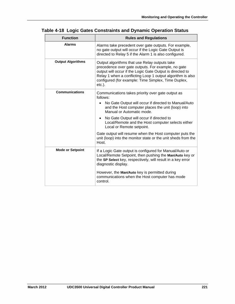
Monitoring and Operating the Controller
Table 4-18 Logic Gates Constraints and Dynamic Operation Status
Function Rules and Regulations
Alarms Alarms take precedent over gate outputs. For example, no gate output will occur if the Logic Gate Output is directed to Relay 5 if the Alarm 1 is also configured.
Output Algorithms Output algorithms that use Relay outputs take precedence over gate outputs. For example, no gate output will occur if the Logic Gate Output is directed to Relay 1 when a conflicting Loop 1 output algorithm is also configured (for example: Time Simplex, Time Duplex, etc.).
Communications Communications takes priority over gate output as follows:
No Gate Output will occur if directed to Manual/Auto and the Host computer places the unit (loop) into Manual or Automatic mode.
No Gate Output will occur if directed to Local/Remote and the Host computer selects either Local or Remote setpoint.
Gate output will resume when the Host computer puts the unit (loop) into the monitor state or the unit sheds from the Host.
Mode or Setpoint If a Logic Gate output is configured for Manual/Auto or Local/Remote Setpoint, then pushing the Man/Auto key or the SP Select key, respectively, will result in a key error diagnostic display.
However, the Man/Auto key is permitted during communications when the Host computer has mode control.
March 2012 UDC3500 Universal Digital Controller Product Manual 221
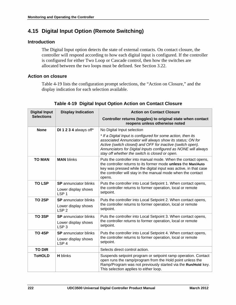
Monitoring and Operating the Controller
222 UDC3500 Universal Digital Controller Product Manual March 2012
4.15 Digital Input Option (Remote Switching)
Introduction
The Digital Input option detects the state of external contacts. On contact closure, the controller will respond according to how each digital input is configured. If the controller is configured for either Two Loop or Cascade control, then how the switches are allocated between the two loops must be defined. See Section 3.22.
Action on closure
Table 4-19 lists the configuration prompt selections, the “Action on Closure,” and the display indication for each selection available.
Table 4-19 Digital Input Option Action on Contact Closure
Digital Input Selections
Display Indication Action on Contact Closure
Controller returns (toggles) to original state when contact reopens unless otherwise noted
None DI 1 2 3 4 always off* No Digital Input selection
* If a Digital Input is configured for some action, then its associated Annunciator will always show its status; ON for Active (switch closed) and OFF for inactive (switch open). Annunciators for Digital Inputs configured as NONE will always stay off whether the switch is closed or open.
TO MAN MAN blinks Puts the controller into manual mode. When the contact opens, the controller returns to its former mode unless the Man/Auto key was pressed while the digital input was active, in that case the controller will stay in the manual mode when the contact opens.
TO LSP SP annunciator blinks
Lower display shows LSP 1
Puts the controller into Local Setpoint 1. When contact opens, the controller returns to former operation, local or remote setpoint.
TO 2SP SP annunciator blinks
Lower display shows LSP 2
Puts the controller into Local Setpoint 2. When contact opens, the controller returns to former operation, local or remote setpoint.
TO 3SP SP annunciator blinks
Lower display shows LSP 3
Puts the controller into Local Setpoint 3. When contact opens, the controller returns to former operation, local or remote setpoint.
TO 4SP SP annunciator blinks
Lower display shows LSP 4
Puts the controller into Local Setpoint 4. When contact opens, the controller returns to former operation, local or remote setpoint.
TO DIR Selects direct control action.
ToHOLD H blinks Suspends setpoint program or setpoint ramp operation. Contact open runs the ramp/program from the Hold point unless the Ramp/Program was not previously started via the Run/Hold key. This selection applies to either loop.
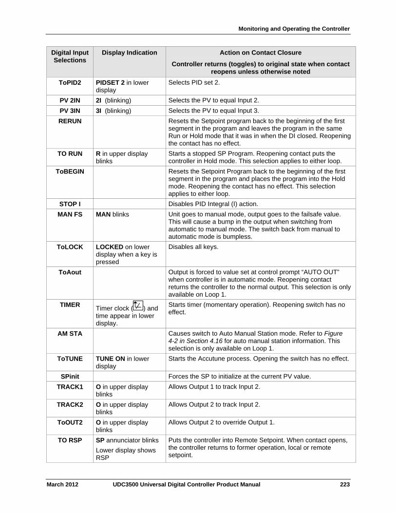
Monitoring and Operating the Controller
Digital Input Selections
Display Indication Action on Contact Closure
Controller returns (toggles) to original state when contact reopens unless otherwise noted
ToPID2 PIDSET 2 in lower display
Selects PID set 2.
PV 2IN 2I (blinking) Selects the PV to equal Input 2.
PV 3IN 3I (blinking) Selects the PV to equal Input 3.
RERUN Resets the Setpoint program back to the beginning of the first segment in the program and leaves the program in the same Run or Hold mode that it was in when the DI closed. Reopening the contact has no effect.
TO RUN R in upper display blinks
Starts a stopped SP Program. Reopening contact puts the controller in Hold mode. This selection applies to either loop.
ToBEGIN Resets the Setpoint Program back to the beginning of the first segment in the program and places the program into the Hold mode. Reopening the contact has no effect. This selection applies to either loop.
STOP I Disables PID Integral (I) action.
MAN FS MAN blinks Unit goes to manual mode, output goes to the failsafe value. This will cause a bump in the output when switching from automatic to manual mode. The switch back from manual to automatic mode is bumpless.
ToLOCK LOCKED on lower display when a key is pressed
Disables all keys.
ToAout Output is forced to value set at control prompt “AUTO OUT” when controller is in automatic mode. Reopening contact returns the controller to the normal output. This selection is only available on Loop 1.
TIMER Timer clock (
) and time appear in lower display.
Starts timer (momentary operation). Reopening switch has no effect.
AM STA Causes switch to Auto Manual Station mode. Refer to Figure 4-2 in Section 4.16 for auto manual station information. This selection is only available on Loop 1.
ToTUNE TUNE ON in lower display
Starts the Accutune process. Opening the switch has no effect.
SPinit Forces the SP to initialize at the current PV value.
TRACK1 O in upper display blinks
Allows Output 1 to track Input 2.
TRACK2 O in upper display blinks
Allows Output 2 to track Input 2.
ToOUT2 O in upper display blinks
Allows Output 2 to override Output 1.
TO RSP SP annunciator blinks
Lower display shows RSP
Puts the controller into Remote Setpoint. When contact opens, the controller returns to former operation, local or remote setpoint.
March 2012 UDC3500 Universal Digital Controller Product Manual 223
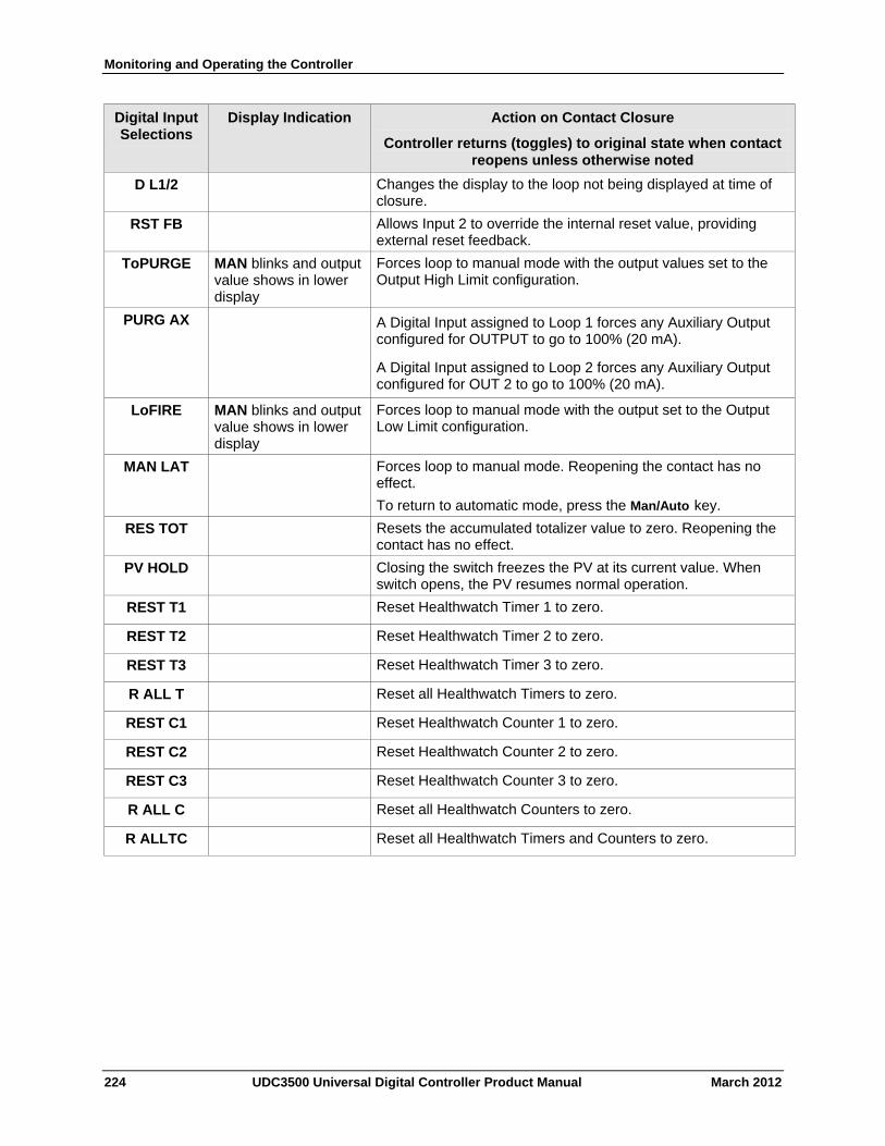
Monitoring and Operating the Controller
Digital Input Selections
Display Indication Action on Contact Closure
Controller returns (toggles) to original state when contact reopens unless otherwise noted
Changes the display to the loop not being displayed at time of closure.
D L1/2
Allows Input 2 to override the internal reset value, providing external reset feedback.
RST FB
ToPURGE MAN blinks and output value shows in lower display
Forces loop to manual mode with the output values set to the Output High Limit configuration.
PURG AX A Digital Input assigned to Loop 1 forces any Auxiliary Output configured for OUTPUT to go to 100% (20 mA).
A Digital Input assigned to Loop 2 forces any Auxiliary Output configured for OUT 2 to go to 100% (20 mA).
LoFIRE MAN blinks and output value shows in lower display
Forces loop to manual mode with the output set to the Output Low Limit configuration.
Forces loop to manual mode. Reopening the contact has no effect.
To return to automatic mode, press the Man/Auto key.
MAN LAT
Resets the accumulated totalizer value to zero. Reopening the contact has no effect.
RES TOT
Closing the switch freezes the PV at its current value. When switch opens, the PV resumes normal operation.
PV HOLD
Reset Healthwatch Timer 1 to zero. REST T1
Reset Healthwatch Timer 2 to zero. REST T2
Reset Healthwatch Timer 3 to zero. REST T3
Reset all Healthwatch Timers to zero. R ALL T
Reset Healthwatch Counter 1 to zero. REST C1
Reset Healthwatch Counter 2 to zero. REST C2
Reset Healthwatch Counter 3 to zero. REST C3
Reset all Healthwatch Counters to zero. R ALL C
Reset all Healthwatch Timers and Counters to zero. R ALLTC
224 UDC3500 Universal Digital Controller Product Manual March 2012
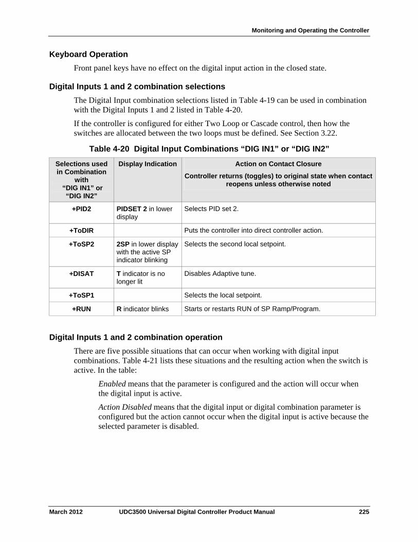
Monitoring and Operating the Controller
Keyboard Operation
Front panel keys have no effect on the digital input action in the closed state.
Digital Inputs 1 and 2 combination selections
The Digital Input combination selections listed in Table 4-19 can be used in combination with the Digital Inputs 1 and 2 listed in Table 4-20.
If the controller is configured for either Two Loop or Cascade control, then how the switches are allocated between the two loops must be defined. See Section 3.22.
Table 4-20 Digital Input Combinations “DIG IN1” or “DIG IN2”
Display Indication Action on Contact Closure
Controller returns (toggles) to original state when contact reopens unless otherwise noted
Selections used in Combination
with “DIG IN1” or
“DIG IN2”
+PID2 PIDSET 2 in lower display
Selects PID set 2.
Puts the controller into direct controller action. +ToDIR
+ToSP2 2SP in lower display with the active SP indicator blinking
Selects the second local setpoint.
+DISAT T indicator is no longer lit
Disables Adaptive tune.
Selects the local setpoint. +ToSP1
+RUN R indicator blinks Starts or restarts RUN of SP Ramp/Program.
Digital Inputs 1 and 2 combination operation
There are five possible situations that can occur when working with digital input combinations. Table 4-21 lists these situations and the resulting action when the switch is active. In the table:
Enabled means that the parameter is configured and the action will occur when the digital input is active.
Action Disabled means that the digital input or digital combination parameter is configured but the action cannot occur when the digital input is active because the selected parameter is disabled.
March 2012 UDC3500 Universal Digital Controller Product Manual 225
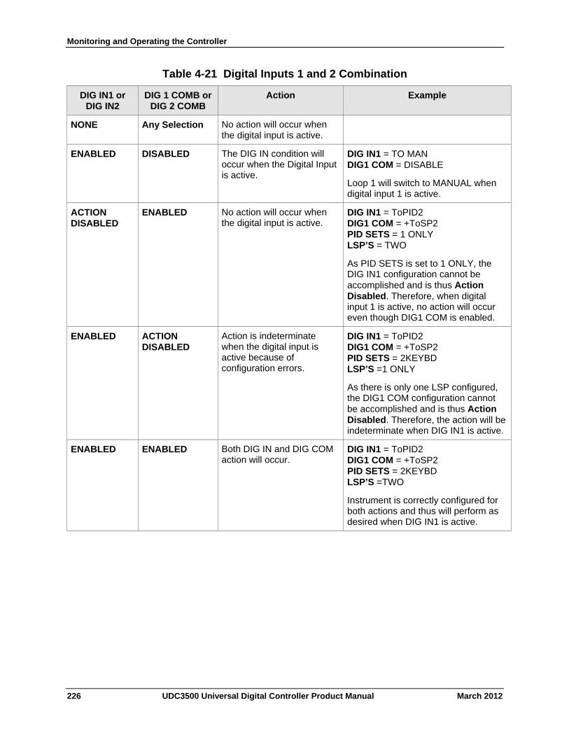
Monitoring and Operating the Controller
Table 4-21 Digital Inputs 1 and 2 Combination
DIG 1 COMB or DIG 2 COMB
Action Example DIG IN1 or DIG IN2
NONE Any Selection No action will occur when the digital input is active.
ENABLED DISABLED The DIG IN condition will occur when the Digital Input is active.
DIG IN1 = TO MAN DIG1 COM = DISABLE
Loop 1 will switch to MANUAL when digital input 1 is active.
ENABLED No action will occur when the digital input is active.
DIG IN1 = ToPID2 DIG1 COM = +ToSP2 PID SETS = 1 ONLY LSP’S = TWO
As PID SETS is set to 1 ONLY, the DIG IN1 configuration cannot be accomplished and is thus Action Disabled. Therefore, when digital input 1 is active, no action will occur even though DIG1 COM is enabled.
ACTION DISABLED
ENABLED ACTION DISABLED
Action is indeterminate when the digital input is active because of configuration errors.
DIG IN1 = ToPID2 DIG1 COM = +ToSP2 PID SETS = 2KEYBD LSP’S =1 ONLY
As there is only one LSP configured, the DIG1 COM configuration cannot be accomplished and is thus Action Disabled. Therefore, the action will be indeterminate when DIG IN1 is active.
ENABLED ENABLED Both DIG IN and DIG COM action will occur.
DIG IN1 = ToPID2 DIG1 COM = +ToSP2 PID SETS = 2KEYBD LSP’S =TWO
Instrument is correctly configured for both actions and thus will perform as desired when DIG IN1 is active.
226 UDC3500 Universal Digital Controller Product Manual March 2012
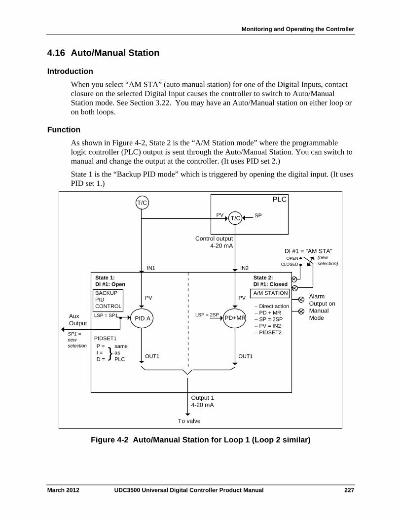
Monitoring and Operating the Controller
4.16 Auto/Manual Station
Introduction
When you select “AM STA” (auto manual station) for one of the Digital Inputs, contact closure on the selected Digital Input causes the controller to switch to Auto/Manual Station mode. See Section 3.22. You may have an Auto/Manual station on either loop or on both loops.
Function
As shown in Figure 4-2, State 2 is the “A/M Station mode” where the programmable logic controller (PLC) output is sent through the Auto/Manual Station. You can switch to manual and change the output at the controller. (It uses PID set 2.)
State 1 is the “Backup PID mode” which is triggered by opening the digital input. (It uses PID set 1.)
T/C
T/C
PLC
PV SP
IN1 IN2
PID A
OUT1 OUT1
Output 1 4-20 mA
To valve
Aux Output
SP1 = new selection
DI #1 = "AM STA" (new selection)
State 1: DI #1: Open
BACKUP PID CONTROL
State 2: DI #1: Closed
A/M STATION
LSP = SP1 LSP = 2SP
– Direct action – PD + MR – SP = 2SP – PV = IN2 – PIDSET2
PIDSET1 P = I = D =
same as PLC
Control output 4-20 mA
PVPV Alarm Output on Manual Mode PD+MR
}
OPEN CLOSED
Figure 4-2 Auto/Manual Station for Loop 1 (Loop 2 similar)
March 2012 UDC3500 Universal Digital Controller Product Manual 227
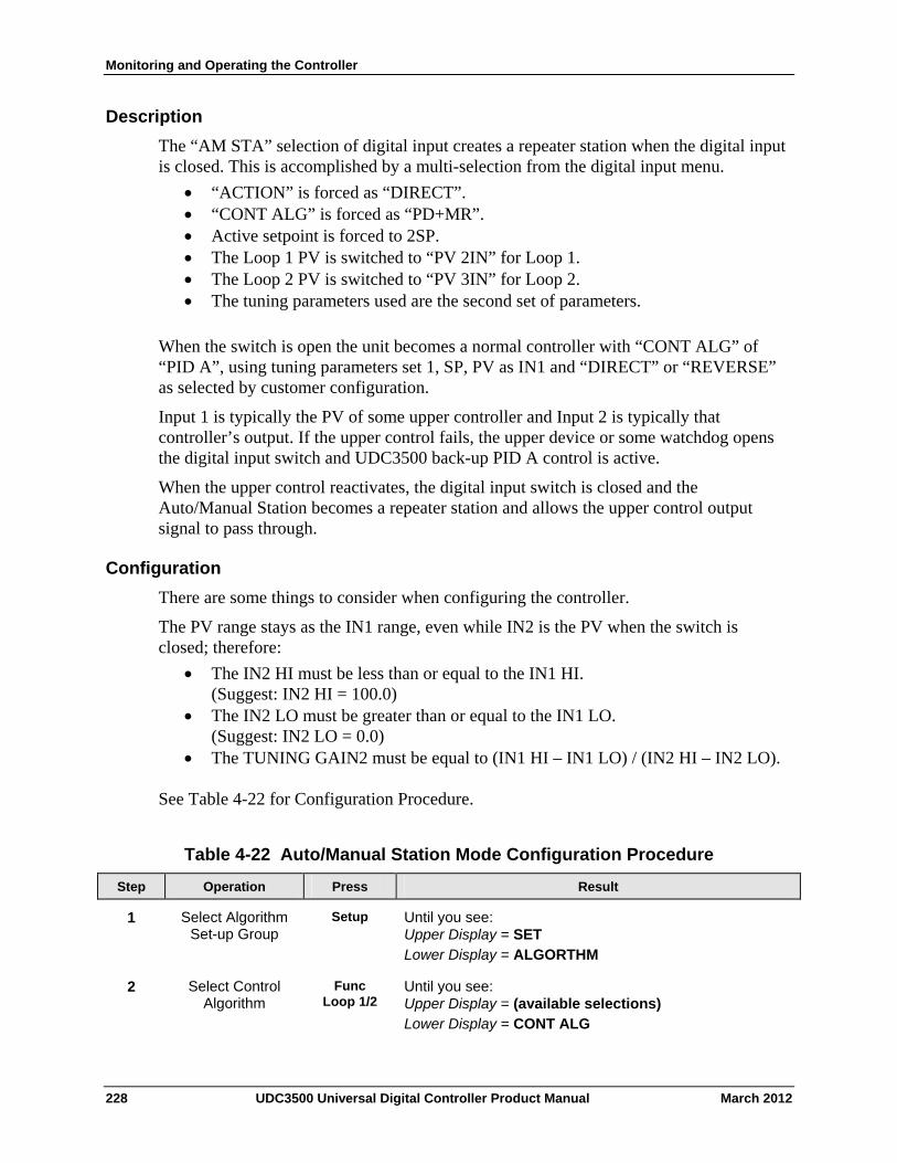
Monitoring and Operating the Controller
Description
The “AM STA” selection of digital input creates a repeater station when the digital input is closed. This is accomplished by a multi-selection from the digital input menu.
“ACTION” is forced as “DIRECT”. “CONT ALG” is forced as “PD+MR”. Active setpoint is forced to 2SP. The Loop 1 PV is switched to “PV 2IN” for Loop 1. The Loop 2 PV is switched to “PV 3IN” for Loop 2. The tuning parameters used are the second set of parameters.
When the switch is open the unit becomes a normal controller with “CONT ALG” of “PID A”, using tuning parameters set 1, SP, PV as IN1 and “DIRECT” or “REVERSE” as selected by customer configuration.
Input 1 is typically the PV of some upper controller and Input 2 is typically that controller’s output. If the upper control fails, the upper device or some watchdog opens the digital input switch and UDC3500 back-up PID A control is active.
When the upper control reactivates, the digital input switch is closed and the Auto/Manual Station becomes a repeater station and allows the upper control output signal to pass through.
Configuration
There are some things to consider when configuring the controller.
The PV range stays as the IN1 range, even while IN2 is the PV when the switch is closed; therefore:
The IN2 HI must be less than or equal to the IN1 HI. (Suggest: IN2 HI = 100.0)
The IN2 LO must be greater than or equal to the IN1 LO. (Suggest: IN2 LO = 0.0)
The TUNING GAIN2 must be equal to (IN1 HI – IN1 LO) / (IN2 HI – IN2 LO).
See Table 4-22 for Configuration Procedure.
Table 4-22 Auto/Manual Station Mode Configuration Procedure
Operation Press Result Step
Select Algorithm Set-up Group
Setup Until you see: Upper Display = SET Lower Display = ALGORTHM
1
Select Control Algorithm
Func Loop 1/2
Until you see: Upper Display = (available selections) Lower Display = CONT ALG
2
228 UDC3500 Universal Digital Controller Product Manual March 2012
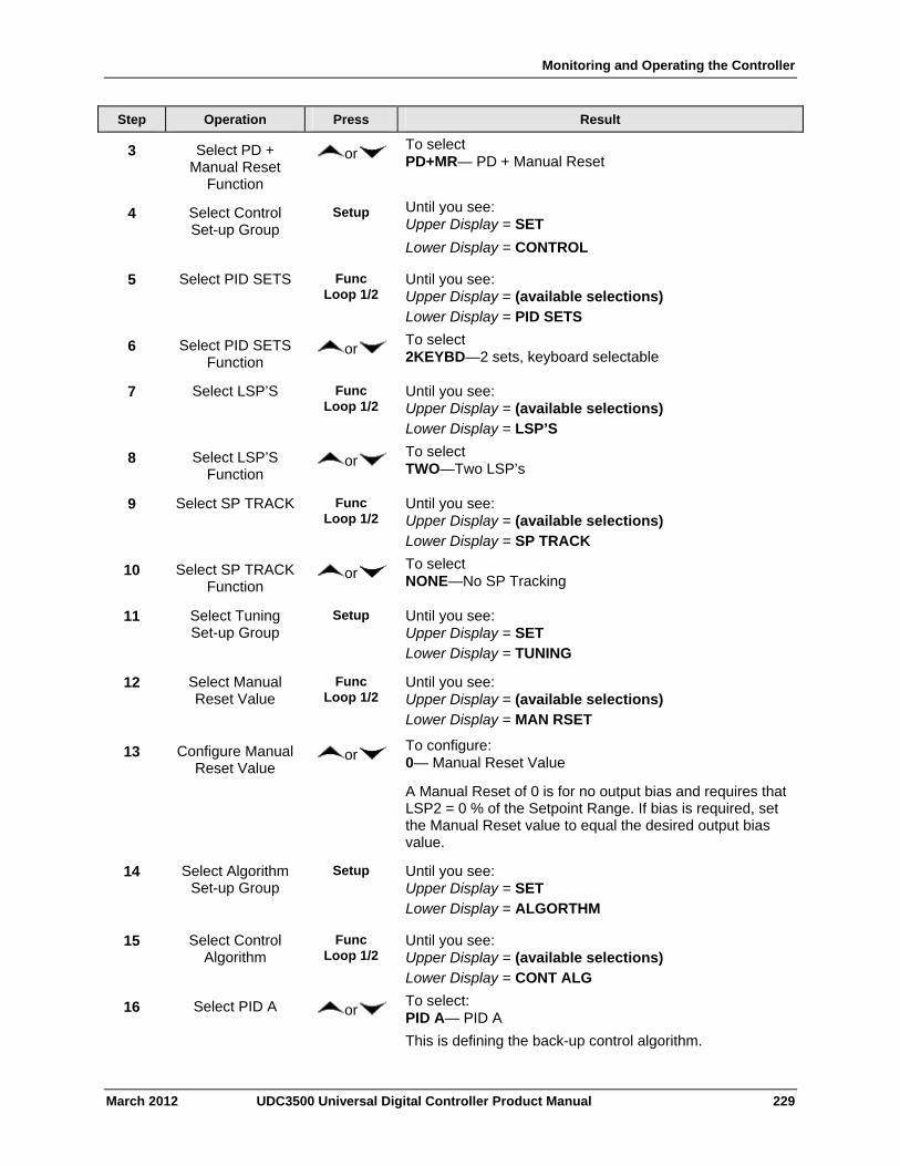
Monitoring and Operating the Controller
March 2012 UDC3500 Universal Digital Controller Product Manual 229
Step Operation Press Result
3 Select PD + Manual Reset
Function
or To select PD+MR— PD + Manual Reset
4 Select Control Set-up Group
Setup Until you see: Upper Display = SET
Lower Display = CONTROL
5 Select PID SETS Func Loop 1/2
Until you see: Upper Display = (available selections) Lower Display = PID SETS
6 Select PID SETS Function
or To select 2KEYBD—2 sets, keyboard selectable
7 Select LSP’S Func Loop 1/2
Until you see: Upper Display = (available selections) Lower Display = LSP’S
8 Select LSP’S Function
or To select TWO—Two LSP’s
9 Select SP TRACK Func Loop 1/2
Until you see: Upper Display = (available selections) Lower Display = SP TRACK
10 Select SP TRACK Function
or To select NONE—No SP Tracking
11 Select Tuning Set-up Group
Setup Until you see: Upper Display = SET Lower Display = TUNING
12 Select Manual Reset Value
Func Loop 1/2
Until you see: Upper Display = (available selections) Lower Display = MAN RSET
13 Configure Manual Reset Value
or To configure: 0— Manual Reset Value
A Manual Reset of 0 is for no output bias and requires that LSP2 = 0 % of the Setpoint Range. If bias is required, set the Manual Reset value to equal the desired output bias value.
14 Select Algorithm Set-up Group
Setup Until you see: Upper Display = SET Lower Display = ALGORTHM
15 Select Control Algorithm
Func Loop 1/2
Until you see: Upper Display = (available selections) Lower Display = CONT ALG
16 Select PID A or To select: PID A— PID A
This is defining the back-up control algorithm.
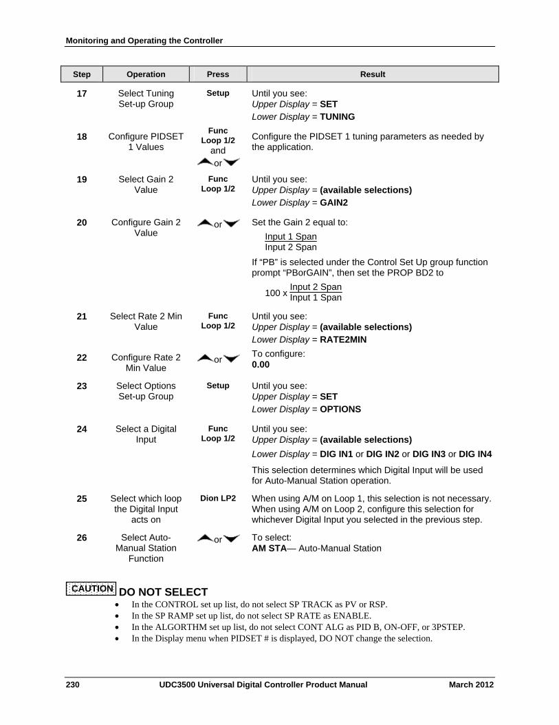
Monitoring and Operating the Controller
230 UDC3500 Universal Digital Controller Product Manual March 2012
Step Operation Press Result
17 Select Tuning Set-up Group
Setup Until you see: Upper Display = SET Lower Display = TUNING
18 Configure PIDSET 1 Values
Func Loop 1/2
and or
Configure the PIDSET 1 tuning parameters as needed by the application.
19 Select Gain 2 Value
Func Loop 1/2
Until you see: Upper Display = (available selections) Lower Display = GAIN2
20 Configure Gain 2 Value
or Set the Gain 2 equal to:
Input 1 SpanInput 2 Span
If “PB” is selected under the Control Set Up group function prompt “PBorGAIN”, then set the PROP BD2 to
100 x Input 2 SpanInput 1 Span
21 Select Rate 2 Min Value
Func Loop 1/2
Until you see: Upper Display = (available selections) Lower Display = RATE2MIN
22 Configure Rate 2 Min Value
or To configure: 0.00
23 Select Options Set-up Group
Setup Until you see: Upper Display = SET Lower Display = OPTIONS
24 Select a Digital Input
Func Loop 1/2
Until you see: Upper Display = (available selections)
Lower Display = DIG IN1 or DIG IN2 or DIG IN3 or DIG IN4
This selection determines which Digital Input will be used for Auto-Manual Station operation.
25 Select which loop the Digital Input
acts on
Dion LP2 When using A/M on Loop 1, this selection is not necessary. When using A/M on Loop 2, configure this selection for whichever Digital Input you selected in the previous step.
26 Select Auto-Manual Station
Function
or To select: AM STA— Auto-Manual Station
CAUTION DO NOT SELECT In the CONTROL set up list, do not select SP TRACK as PV or RSP. In the SP RAMP set up list, do not select SP RATE as ENABLE. In the ALGORTHM set up list, do not select CONT ALG as PID B, ON-OFF, or 3PSTEP. In the Display menu when PIDSET # is displayed, DO NOT change the selection.
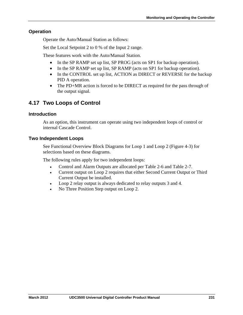
Monitoring and Operating the Controller
Operation
Operate the Auto/Manual Station as follows:
Set the Local Setpoint 2 to 0 % of the Input 2 range.
These features work with the Auto/Manual Station.
In the SP RAMP set up list, SP PROG (acts on SP1 for backup operation). In the SP RAMP set up list, SP RAMP (acts on SP1 for backup operation). In the CONTROL set up list, ACTION as DIRECT or REVERSE for the backup
PID A operation. The PD+MR action is forced to be DIRECT as required for the pass through of
the output signal.
4.17 Two Loops of Control
Introduction
As an option, this instrument can operate using two independent loops of control or internal Cascade Control.
Two Independent Loops
See Functional Overview Block Diagrams for Loop 1 and Loop 2 (Figure 4-3) for selections based on these diagrams.
The following rules apply for two independent loops:
Control and Alarm Outputs are allocated per Table 2-6 and Table 2-7. Current output on Loop 2 requires that either Second Current Output or Third
Current Output be installed. Loop 2 relay output is always dedicated to relay outputs 3 and 4. No Three Position Step output on Loop 2.
March 2012 UDC3500 Universal Digital Controller Product Manual 231
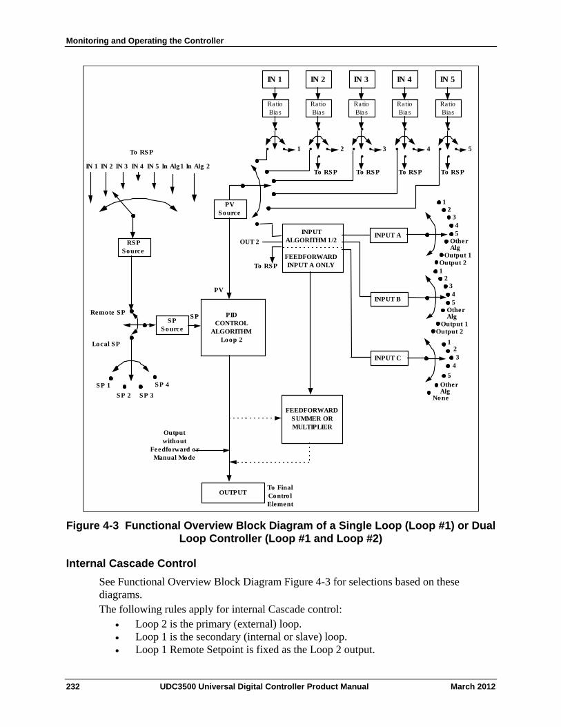
Monitoring and Operating the Controller
IN 1
Ra tio Bias
•
• •
IN 2
Ratio Bias
•
• •
IN 3
Ratio Bias
•
• •
IN 4
Ratio Bias
•
• •
IN 5
Ratio Bias
•
• • 1 2 3 4 5
PV Source
IN 2 In Alg 2 IN 3 In Alg1 IN 4
RSP Source
123
4
5
INPUT A
INPUT B
INPUT C
INPUT ALGORITHM 1/2
FEEDFORWARD INPUT A ONLYTo RSP
SP Source
SP
PV
Remote SP
Local SP
SP 1 SP 2 SP 3
To RSP • • • •
To RSP To RSP To RSP To RSP
PID CONTROL
ALGORITHM Loop 2
FEEDFORWARD SUMMER OR MULTIPLIER
OUTPUT
Output without
Feedforward or Manual Mode
To Final Contro l Element
OtherAlg
None
1 2
345
OtherAlg
Output 1Output 21
2 345
OtherAlg
Output 1Output 2
OUT 2
SP 4
IN 1 IN 5
Figure 4-3 Functional Overview Block Diagram of a Single Loop (Loop #1) or Dual Loop Controller (Loop #1 and Loop #2)
Internal Cascade Control
See Functional Overview Block Diagram Figure 4-3 for selections based on these diagrams. The following rules apply for internal Cascade control:
Loop 2 is the primary (external) loop. Loop 1 is the secondary (internal or slave) loop. Loop 1 Remote Setpoint is fixed as the Loop 2 output.
232 UDC3500 Universal Digital Controller Product Manual March 2012
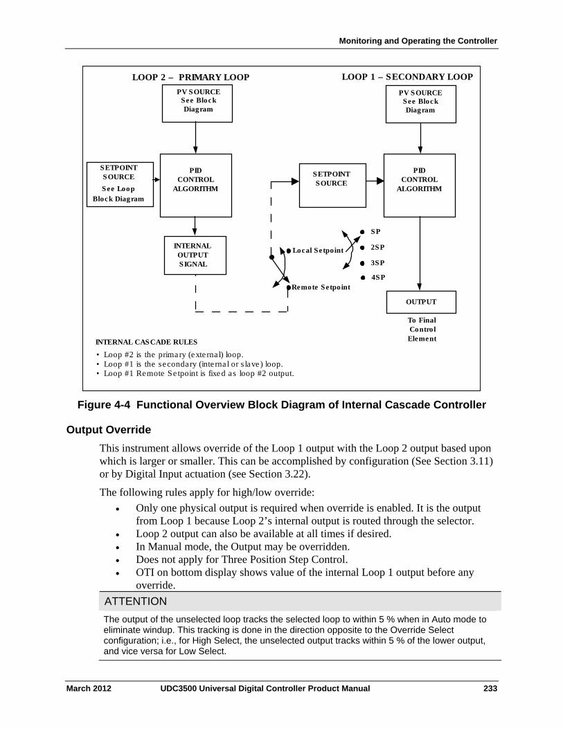
Monitoring and Operating the Controller
PID CONTROL
ALGORITHM
OUTPUT
To Final Control
Element
PV SOURCE See Block Diagram
LOOP 2 – PRIMARY LOOP LOOP 1 – SECONDARY LOOP
PID CONTROL
ALGORITHM
SETPOINT SOURCE
INTERNAL OUTPUT SIGNAL
SETPOINT SOURCE
Block Diagram
INTERNAL CASCADE RULES
• Loop #2 is the primary (exte rna l) loop. • Loop #1 is the secondary (inte rna l or s lave) loop. • Loop #1 Remote Se tpoint is fixed as loop #2 output.
Remote Setpoint
Local Setpoint
SP
2SP
3SP
4SP
See Loop
PV SOURCE See Block Diagram
Figure 4-4 Functional Overview Block Diagram of Internal Cascade Controller
Output Override
This instrument allows override of the Loop 1 output with the Loop 2 output based upon which is larger or smaller. This can be accomplished by configuration (See Section 3.11) or by Digital Input actuation (see Section 3.22).
The following rules apply for high/low override:
Only one physical output is required when override is enabled. It is the output from Loop 1 because Loop 2’s internal output is routed through the selector.
Loop 2 output can also be available at all times if desired. In Manual mode, the Output may be overridden. Does not apply for Three Position Step Control. OTI on bottom display shows value of the internal Loop 1 output before any
override.
ATTENTION
The output of the unselected loop tracks the selected loop to within 5 % when in Auto mode to eliminate windup. This tracking is done in the direction opposite to the Override Select configuration; i.e., for High Select, the unselected output tracks within 5 % of the lower output, and vice versa for Low Select.
March 2012 UDC3500 Universal Digital Controller Product Manual 233
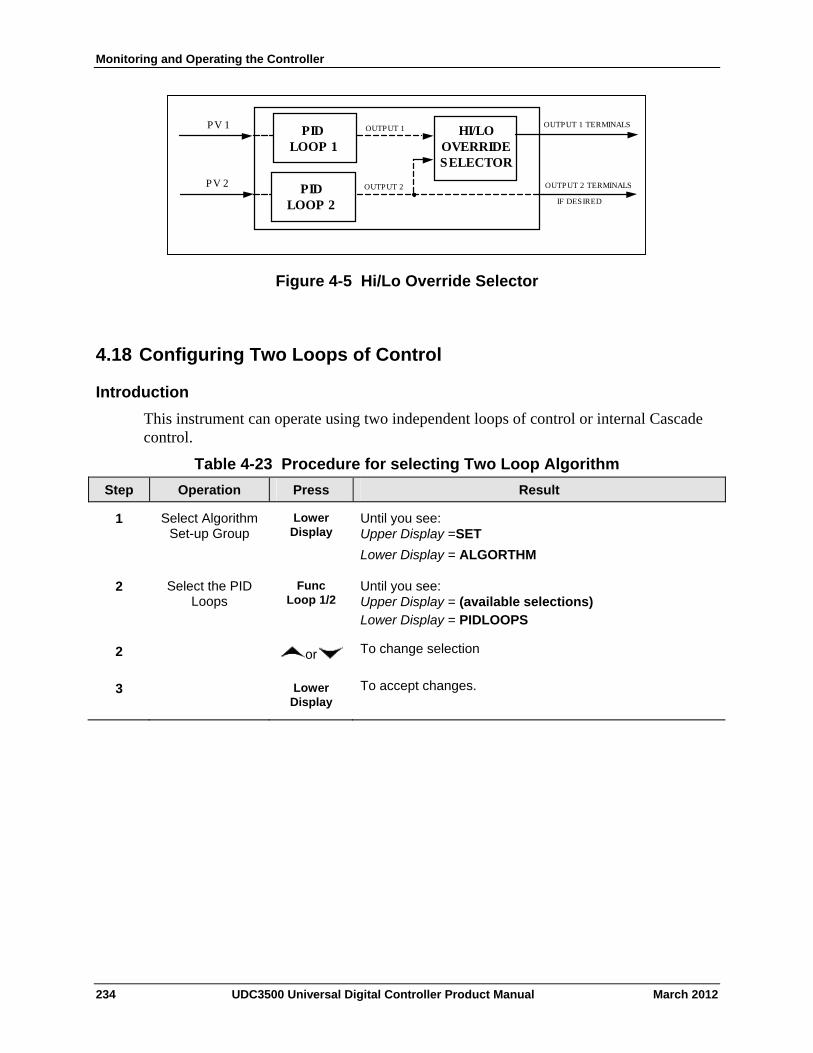
Monitoring and Operating the Controller
HI/LO OVERRIDE SELECTOR
PID LOOP 1
PID LOOP 2
PV 1
PV 2
OUTPUT 1
OUTPUT 2
OUTPUT 1 TERMINALS
OUTPUT 2 TERMINALS IF DESIRED
Figure 4-5 Hi/Lo Override Selector
4.18 Configuring Two Loops of Control
Introduction
This instrument can operate using two independent loops of control or internal Cascade control.
Table 4-23 Procedure for selecting Two Loop Algorithm
Operation Press Result Step
Select Algorithm Set-up Group
Lower Display
Until you see: Upper Display =SET
Lower Display = ALGORTHM
1
Select the PID Loops
Func Loop 1/2
Until you see: Upper Display = (available selections) Lower Display = PIDLOOPS
2
or To change selection 2
Lower Display
To accept changes. 3
234 UDC3500 Universal Digital Controller Product Manual March 2012
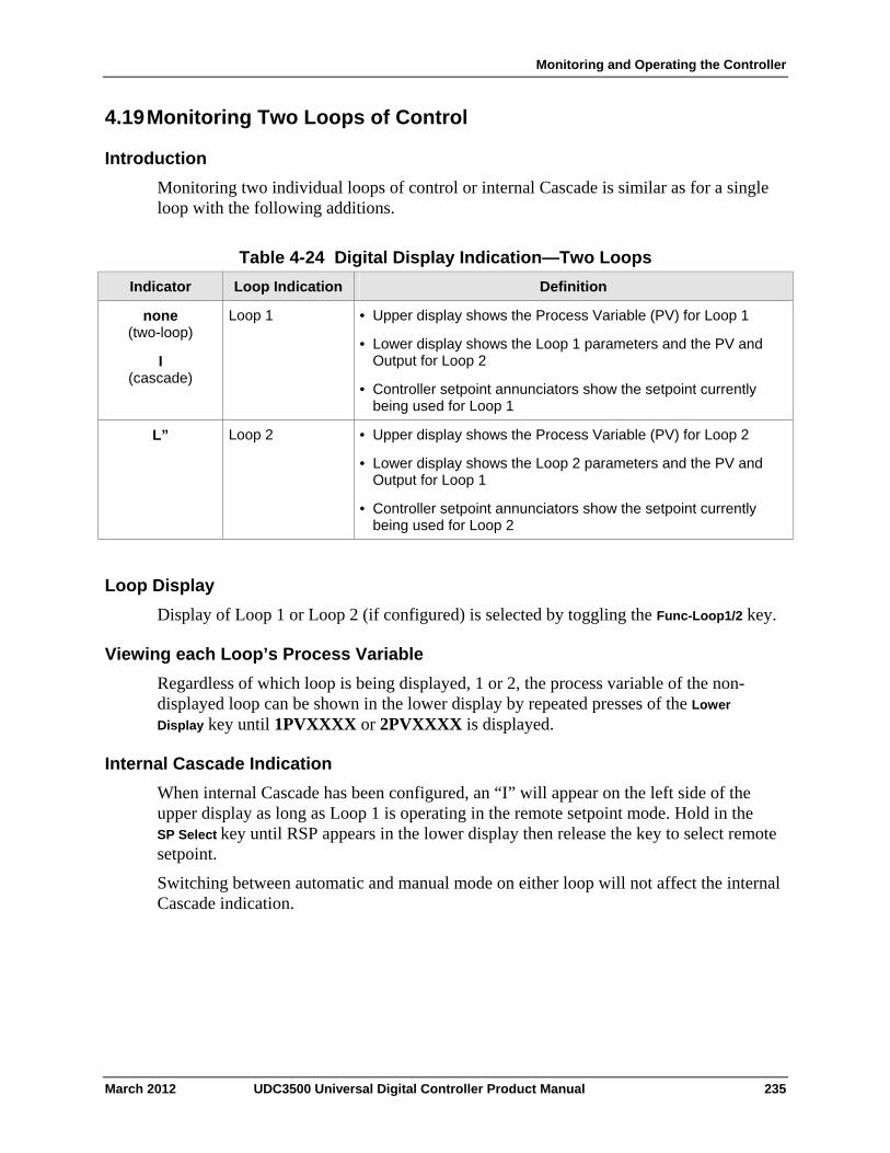
Monitoring and Operating the Controller
4.19 Monitoring Two Loops of Control
Introduction
Monitoring two individual loops of control or internal Cascade is similar as for a single loop with the following additions.
Table 4-24 Digital Display Indication—Two Loops
Loop Indication Definition Indicator
none (two-loop)
I (cascade)
Loop 1 • Upper display shows the Process Variable (PV) for Loop 1
• Lower display shows the Loop 1 parameters and the PV and Output for Loop 2
• Controller setpoint annunciators show the setpoint currently being used for Loop 1
Loop 2 • Upper display shows the Process Variable (PV) for Loop 2
• Lower display shows the Loop 2 parameters and the PV and Output for Loop 1
• Controller setpoint annunciators show the setpoint currently being used for Loop 2
L”
Loop Display
Display of Loop 1 or Loop 2 (if configured) is selected by toggling the Func-Loop1/2 key.
Viewing each Loop’s Process Variable
Regardless of which loop is being displayed, 1 or 2, the process variable of the non-displayed loop can be shown in the lower display by repeated presses of the Lower
Display key until 1PVXXXX or 2PVXXXX is displayed.
Internal Cascade Indication
When internal Cascade has been configured, an “I” will appear on the left side of the upper display as long as Loop 1 is operating in the remote setpoint mode. Hold in the SP Select key until RSP appears in the lower display then release the key to select remote setpoint.
Switching between automatic and manual mode on either loop will not affect the internal Cascade indication.
March 2012 UDC3500 Universal Digital Controller Product Manual 235
Monitoring and Operating the Controller
4.20 Operating Two Loops of Control
Introduction
Operation of two individual loops of control is identical to operating a single loop of control except that TUNING 2 group applies to Loop 2 only and four PID sets, 5 through 8, are available. TUNING group applies to Loop 1 with PID sets 1 through 4 applicable.
Operating modes and setpoint source
The rules for Auto/Manual modes and changing setpoint sources are the same as single loop operation.
Keyboard operation
Note that the loop being displayed is the only loop affected by normal keyboard operation. However, either loop can be reconfigured when in the Set Up mode regardless of which is being displayed during normal operation.
Accutune III
Two independent loops or cascaded loops can be tuned at the same time, if so configured.
Setpoint Ramp or SP Programming
Either loop or both loops can be configured for a single setpoint ramp operation by enabling the desired loop or loops (see Section 3 – Configuration)
An “H” or “R” will appear in the upper display when applicable, depending upon which loop is being displayed.
Digital Inputs (remote mode switching)
Digital Input 1 is dedicated to Loop 1 when two loops or Cascade control is configured. The other digital inputs may be configured to work on either loop.
Output Override Hi/Lo select
Output Override allows you to select the higher of Output 1 and Output 2 (Hi Select) or the lower of Output 1 and Output 2 (Lo Select) to appear at Output 1 terminals to drive the final control element. Refer to Section 5.12 for Override rules and block diagram.
Override prompts appear under the Algorithm Set Up group, function prompt OUT OVRD.
236 UDC3500 Universal Digital Controller Product Manual March 2012
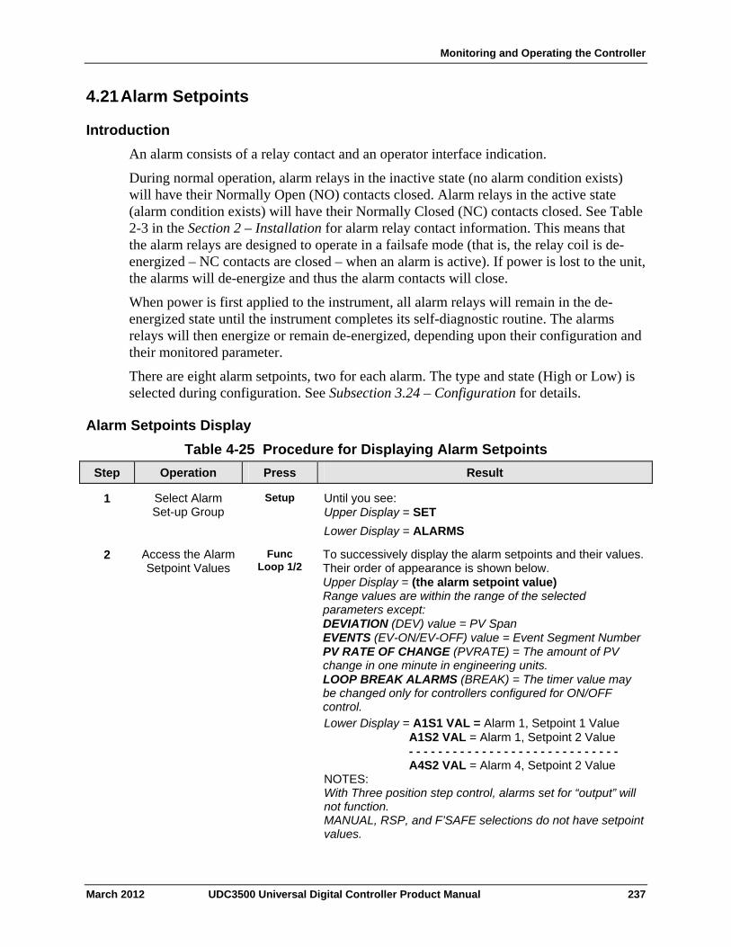
Monitoring and Operating the Controller
4.21 Alarm Setpoints
Introduction
An alarm consists of a relay contact and an operator interface indication.
During normal operation, alarm relays in the inactive state (no alarm condition exists) will have their Normally Open (NO) contacts closed. Alarm relays in the active state (alarm condition exists) will have their Normally Closed (NC) contacts closed. See Table 2-3 in the Section 2 – Installation for alarm relay contact information. This means that the alarm relays are designed to operate in a failsafe mode (that is, the relay coil is de-energized – NC contacts are closed – when an alarm is active). If power is lost to the unit, the alarms will de-energize and thus the alarm contacts will close.
When power is first applied to the instrument, all alarm relays will remain in the de-energized state until the instrument completes its self-diagnostic routine. The alarms relays will then energize or remain de-energized, depending upon their configuration and their monitored parameter.
There are eight alarm setpoints, two for each alarm. The type and state (High or Low) is selected during configuration. See Subsection 3.24 – Configuration for details.
Alarm Setpoints Display
Table 4-25 Procedure for Displaying Alarm Setpoints
Operation Press Result Step
Select Alarm Set-up Group
Setup Until you see: Upper Display = SET
Lower Display = ALARMS
1
Access the Alarm Setpoint Values
Func Loop 1/2
To successively display the alarm setpoints and their values. Their order of appearance is shown below. Upper Display = (the alarm setpoint value) Range values are within the range of the selected parameters except: DEVIATION (DEV) value = PV Span EVENTS (EV-ON/EV-OFF) value = Event Segment Number PV RATE OF CHANGE (PVRATE) = The amount of PV change in one minute in engineering units. LOOP BREAK ALARMS (BREAK) = The timer value may be changed only for controllers configured for ON/OFF control. Lower Display = A1S1 VAL = Alarm 1, Setpoint 1 Value A1S2 VAL = Alarm 1, Setpoint 2 Value - - - - - - - - - - - - - - - - - - - - - - - - - - - - - A4S2 VAL = Alarm 4, Setpoint 2 Value NOTES: With Three position step control, alarms set for “output” will not function. MANUAL, RSP, and F’SAFE selections do not have setpoint values.
2
March 2012 UDC3500 Universal Digital Controller Product Manual 237
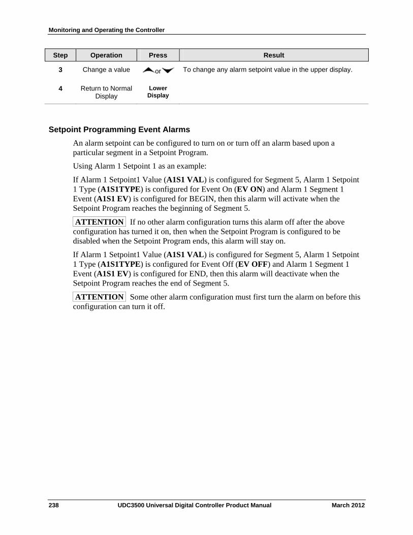
Monitoring and Operating the Controller
238 UDC3500 Universal Digital Controller Product Manual March 2012
Step Operation Press Result
3 Change a value or To change any alarm setpoint value in the upper display.
4 Return to Normal Display
Lower Display
Setpoint Programming Event Alarms
An alarm setpoint can be configured to turn on or turn off an alarm based upon a particular segment in a Setpoint Program.
Using Alarm 1 Setpoint 1 as an example:
If Alarm 1 Setpoint1 Value (A1S1 VAL) is configured for Segment 5, Alarm 1 Setpoint 1 Type (A1S1TYPE) is configured for Event On (EV ON) and Alarm 1 Segment 1 Event (A1S1 EV) is configured for BEGIN, then this alarm will activate when the Setpoint Program reaches the beginning of Segment 5.
ATTENTION If no other alarm configuration turns this alarm off after the above configuration has turned it on, then when the Setpoint Program is configured to be disabled when the Setpoint Program ends, this alarm will stay on.
If Alarm 1 Setpoint1 Value (A1S1 VAL) is configured for Segment 5, Alarm 1 Setpoint 1 Type (A1S1TYPE) is configured for Event Off (EV OFF) and Alarm 1 Segment 1 Event (A1S1 EV) is configured for END, then this alarm will deactivate when the Setpoint Program reaches the end of Segment 5.
ATTENTION Some other alarm configuration must first turn the alarm on before this configuration can turn it off.
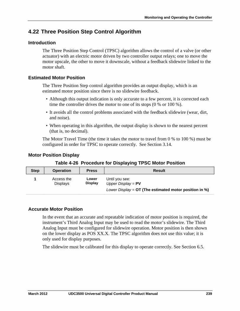
Monitoring and Operating the Controller
4.22 Three Position Step Control Algorithm
Introduction
The Three Position Step Control (TPSC) algorithm allows the control of a valve (or other actuator) with an electric motor driven by two controller output relays; one to move the motor upscale, the other to move it downscale, without a feedback slidewire linked to the motor shaft.
Estimated Motor Position
The Three Position Step control algorithm provides an output display, which is an estimated motor position since there is no slidewire feedback.
• Although this output indication is only accurate to a few percent, it is corrected each time the controller drives the motor to one of its stops (0 % or 100 %).
• It avoids all the control problems associated with the feedback slidewire (wear, dirt, and noise).
• When operating in this algorithm, the output display is shown to the nearest percent (that is, no decimal).
The Motor Travel Time (the time it takes the motor to travel from 0 % to 100 %) must be configured in order for TPSC to operate correctly. See Section 3.14.
Motor Position Display
Table 4-26 Procedure for Displaying TPSC Motor Position
Operation Press Result Step
Access the Displays
Lower Display
Until you see: Upper Display = PV
Lower Display = OT (The estimated motor position in %)
1
Accurate Motor Position
In the event that an accurate and repeatable indication of motor position is required, the instrument’s Third Analog Input may be used to read the motor’s slidewire. The Third Analog Input must be configured for slidewire operation. Motor position is then shown on the lower display as POS XX.X. The TPSC algorithm does not use this value; it is only used for display purposes.
The slidewire must be calibrated for this display to operate correctly. See Section 6.5.
March 2012 UDC3500 Universal Digital Controller Product Manual 239
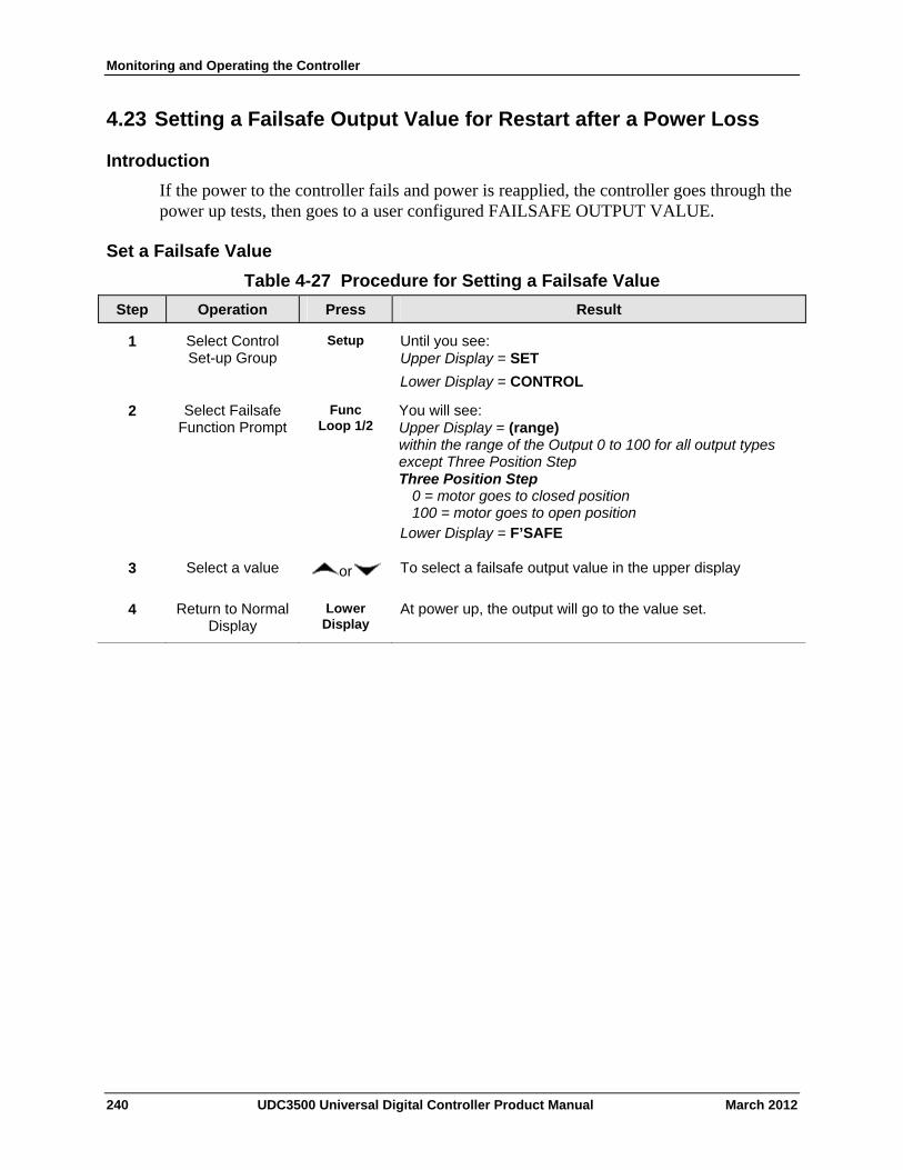
Monitoring and Operating the Controller
4.23 Setting a Failsafe Output Value for Restart after a Power Loss
Introduction
If the power to the controller fails and power is reapplied, the controller goes through the power up tests, then goes to a user configured FAILSAFE OUTPUT VALUE.
Set a Failsafe Value
Table 4-27 Procedure for Setting a Failsafe Value
Operation Press Result Step
Select Control Set-up Group
Setup Until you see: Upper Display = SET
Lower Display = CONTROL
1
Select Failsafe Function Prompt
Func Loop 1/2
You will see: Upper Display = (range) within the range of the Output 0 to 100 for all output types except Three Position Step Three Position Step 0 = motor goes to closed position 100 = motor goes to open position Lower Display = F’SAFE
2
Select a value or To select a failsafe output value in the upper display 3
Return to Normal Display
Lower Display
At power up, the output will go to the value set. 4
240 UDC3500 Universal Digital Controller Product Manual March 2012
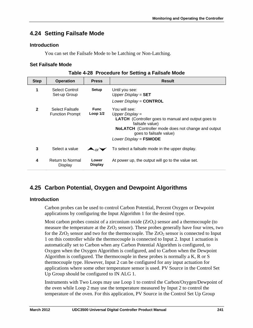
Monitoring and Operating the Controller
4.24 Setting Failsafe Mode
Introduction
You can set the Failsafe Mode to be Latching or Non-Latching.
Set Failsafe Mode
Table 4-28 Procedure for Setting a Failsafe Mode
Operation Press Result Step
Select Control Set-up Group
Setup Until you see: Upper Display = SET
Lower Display = CONTROL
1
Select Failsafe Function Prompt
Func Loop 1/2
You will see: Upper Display = LATCH (Controller goes to manual and output goes to failsafe value) NoLATCH (Controller mode does not change and output goes to failsafe value) Lower Display = FSMODE
2
Select a value or To select a failsafe mode in the upper display. 3
Return to Normal Display
Lower Display
At power up, the output will go to the value set. 4
4.25 Carbon Potential, Oxygen and Dewpoint Algorithms
Introduction
Carbon probes can be used to control Carbon Potential, Percent Oxygen or Dewpoint applications by configuring the Input Algorithm 1 for the desired type.
Most carbon probes consist of a zirconium oxide (ZrO2) sensor and a thermocouple (to measure the temperature at the ZrO2 sensor). These probes generally have four wires, two for the ZrO2 sensor and two for the thermocouple. The ZrO2 sensor is connected to Input 1 on this controller while the thermocouple is connected to Input 2. Input 1 actuation is automatically set to Carbon when any Carbon Potential Algorithm is configured, to Oxygen when the Oxygen Algorithm is configured, and to Carbon when the Dewpoint Algorithm is configured. The thermocouple in these probes is normally a K, R or S thermocouple type. However, Input 2 can be configured for any input actuation for applications where some other temperature sensor is used. PV Source in the Control Set Up Group should be configured to IN ALG 1.
Instruments with Two Loops may use Loop 1 to control the Carbon/Oxygen/Dewpoint of the oven while Loop 2 may use the temperature measured by Input 2 to control the temperature of the oven. For this application, PV Source in the Control Set Up Group
March 2012 UDC3500 Universal Digital Controller Product Manual 241
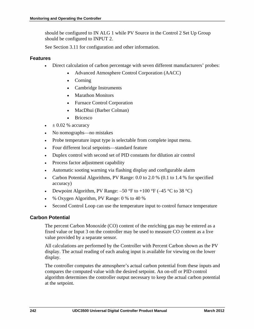
Monitoring and Operating the Controller
should be configured to IN ALG 1 while PV Source in the Control 2 Set Up Group should be configured to INPUT 2.
See Section 3.11 for configuration and other information.
Features
Direct calculation of carbon percentage with seven different manufacturers’ probes:
Advanced Atmosphere Control Corporation (AACC)
Corning
Cambridge Instruments
Marathon Monitors
Furnace Control Corporation
MacDhui (Barber Colman)
Bricesco
± 0.02 % accuracy
No nomographs—no mistakes
Probe temperature input type is selectable from complete input menu.
Four different local setpoints—standard feature
Duplex control with second set of PID constants for dilution air control
Process factor adjustment capability
Automatic sooting warning via flashing display and configurable alarm
Carbon Potential Algorithms, PV Range: 0.0 to 2.0 % (0.1 to 1.4 % for specified accuracy)
Dewpoint Algorithm, PV Range: –50 °F to +100 °F (–45 °C to 38 °C)
% Oxygen Algorithm, PV Range: 0 % to 40 %
Second Control Loop can use the temperature input to control furnace temperature
Carbon Potential
The percent Carbon Monoxide (CO) content of the enriching gas may be entered as a fixed value or Input 3 on the controller may be used to measure CO content as a live value provided by a separate sensor.
All calculations are performed by the Controller with Percent Carbon shown as the PV display. The actual reading of each analog input is available for viewing on the lower display.
The controller computes the atmosphere’s actual carbon potential from these inputs and compares the computed value with the desired setpoint. An on-off or PID control algorithm determines the controller output necessary to keep the actual carbon potential at the setpoint.
242 UDC3500 Universal Digital Controller Product Manual March 2012
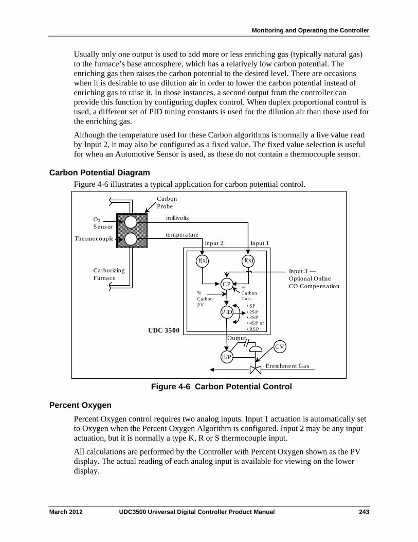
Monitoring and Operating the Controller
Usually only one output is used to add more or less enriching gas (typically natural gas) to the furnace’s base atmosphere, which has a relatively low carbon potential. The enriching gas then raises the carbon potential to the desired level. There are occasions when it is desirable to use dilution air in order to lower the carbon potential instead of enriching gas to raise it. In those instances, a second output from the controller can provide this function by configuring duplex control. When duplex proportional control is used, a different set of PID tuning constants is used for the dilution air than those used for the enriching gas.
Although the temperature used for these Carbon algorithms is normally a live value read by Input 2, it may also be configured as a fixed value. The fixed value selection is useful for when an Automotive Sensor is used, as these do not contain a thermocouple sensor.
Carbon Potential Diagram
Figure 4-6 illustrates a typical application for carbon potential control.
f(x) f(x)
PID
E/P
CV
Carbon Probe
O 2 Sensor
Carburizing Furnace
% Carbon PV
% Carbon Calc.
Output
Enrichment Gas
• SP • 2SP
• 4SP or • RSP
Input 2 Input 1
UDC 3500
millivolts
CP
Input 3 — Optional Online CO Compensa tion
• 3SP
tempera tureThermocouple
Figure 4-6 Carbon Potential Control
Percent Oxygen
Percent Oxygen control requires two analog inputs. Input 1 actuation is automatically set to Oxygen when the Percent Oxygen Algorithm is configured. Input 2 may be any input actuation, but it is normally a type K, R or S thermocouple input.
All calculations are performed by the Controller with Percent Oxygen shown as the PV display. The actual reading of each analog input is available for viewing on the lower display.
March 2012 UDC3500 Universal Digital Controller Product Manual 243
Monitoring and Operating the Controller
Dewpoint
The Dewpoint Algorithm is used for controlling the Dewpoint in endothermic atmospheres. Furnace Control’s Accucarb ZrO2 sensor is used on Input 1. Input 1 actuation is automatically set to Carbon when the Dew Point Algorithm is configured. Input 2 may be any input actuation, but it is normally a type K, R or S thermocouple input.
The percent Hydrogen (H2) atmospheric content is entered as a fixed value.
All calculations are performed by the Controller with the Dewpoint temperature shown as the PV display. The actual reading of each analog input is available for viewing on the lower display.
The availability of Dewpoint on Input Algorithm 2 provides the capability of controlling Carbon Potential on Loop 1 while also being able to calculate the Dewpoint value from the same probe. For this configuration, “DEW XX.X” may be viewed on the lower display, where “XX.X” is the Dewpoint temperature.
4.26 Healthwatch
Introduction
The Healthwatch feature puts diagnostic data at your fingertips so you can monitor vital performance status to improve your process, predict failures, and minimize downtime.
Valuable data regarding maintenance and diagnostic selections can be read by operator-accessed displays. Alarms can be configured to activate when the desired threshold is reached.
See Section 4.18 Maintenance for details on using the various Healthwatch timers and counters. See Section 4.15 Alarms for details on Healthwatch maintenance alarms.
4.27 Setpoint Rate/Ramp/Program Overview
Introduction
The Setpoint Ramp configuration group lets you enable and configure any of the following:
SP RATE – a specific rate of change for any local setpoint change. (Subsection 4.28)
SP RAMP – a single setpoint ramp that occurs between the current local setpoint and a final local setpoint over a time interval of 1 to 255 minutes. (Subsection 4.29)
SP PROG – a ramp/soak profile in a 20-segment program. (Subsection 4.30)
This section explains the operation of each selection and configuration reference where necessary.
244 UDC3500 Universal Digital Controller Product Manual March 2012
Monitoring and Operating the Controller
PV Hot Start
This is a standard feature. At power-up, the setpoint is set to the current PV value and the Rate or Ramp or Program then starts from this value.
RUN/HOLD key
You can start or stop the Ramp or Program using the RUN/HOLD key.
4.28 Setpoint Rate
Introduction
When you have configured a SETPOINT RATE, it will apply immediately to local setpoint change.
Configuration check
Make sure:
SPRATE is enabled
A Rate Up (EUHRUP) or Rate Down (EUHRDN) value has been configured in Engineering units per hour.
ATTENTION
A value of 0 will imply an immediate change in setpoint, that is, NO RATE applies. See Subsection 3.6 – Configuration group “SPRAMP” for details.)
Operation
When a change to local setpoint is made, this controller will ramp from the original setpoint to the “target” setpoint at the rate specified.
The current setpoint value is shown as SPn XXXX on the lower display while the “target” setpoint is shown as SP XXXX on the lower display.
Power outages
If power is lost before the “target” setpoint is reached, upon power recovery, the controller powers up with Sn = Current PV value and it automatically “Restarts” from Sn = current PV value up to the original “target” setpoint.
4.29 Setpoint Ramp
Introduction
When you have configured a SETPOINT RAMP, the ramp will occur between the current local setpoint and a final local setpoint over a time interval of from 1 to 255 minutes. You can RUN or HOLD the ramp at any time.
March 2012 UDC3500 Universal Digital Controller Product Manual 245
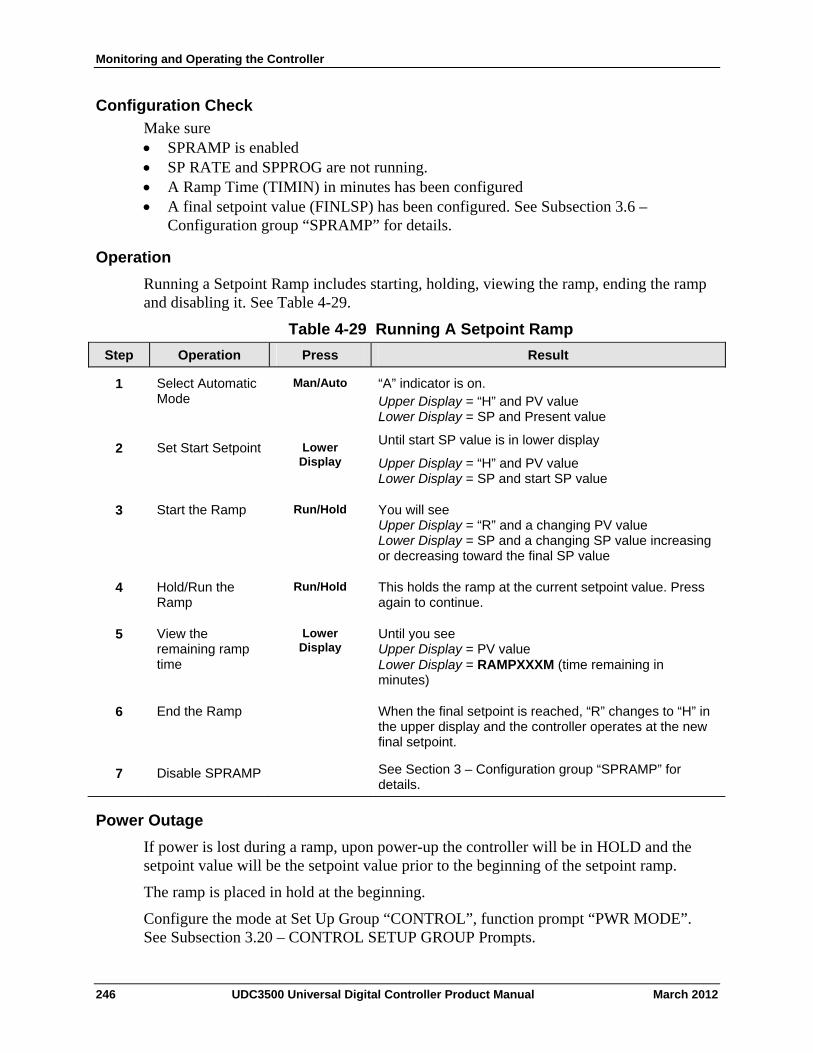
Monitoring and Operating the Controller
Configuration Check
Make sure SPRAMP is enabled SP RATE and SPPROG are not running. A Ramp Time (TIMIN) in minutes has been configured A final setpoint value (FINLSP) has been configured. See Subsection 3.6 –
Configuration group “SPRAMP” for details.
Operation
Running a Setpoint Ramp includes starting, holding, viewing the ramp, ending the ramp and disabling it. See Table 4-29.
Table 4-29 Running A Setpoint Ramp
Operation Press Result Step
Select Automatic Mode
Man/Auto “A” indicator is on. Upper Display = “H” and PV value Lower Display = SP and Present value
1
Set Start Setpoint Lower Display
Until start SP value is in lower display
Upper Display = “H” and PV value Lower Display = SP and start SP value
2
Start the Ramp Run/Hold You will see Upper Display = “R” and a changing PV value Lower Display = SP and a changing SP value increasing or decreasing toward the final SP value
3
Hold/Run the Ramp
Run/Hold This holds the ramp at the current setpoint value. Press again to continue.
4
View the remaining ramp time
Lower Display
Until you see Upper Display = PV value Lower Display = RAMPXXXM (time remaining in minutes)
5
End the Ramp When the final setpoint is reached, “R” changes to “H” in the upper display and the controller operates at the new final setpoint.
6
Disable SPRAMP See Section 3 – Configuration group “SPRAMP” for details.
7
Power Outage
If power is lost during a ramp, upon power-up the controller will be in HOLD and the setpoint value will be the setpoint value prior to the beginning of the setpoint ramp.
The ramp is placed in hold at the beginning.
Configure the mode at Set Up Group “CONTROL”, function prompt “PWR MODE”. See Subsection 3.20 – CONTROL SETUP GROUP Prompts.
246 UDC3500 Universal Digital Controller Product Manual March 2012
Monitoring and Operating the Controller
4.30 Setpoint Ramp/Soak Programming
Introduction
The term “programming” is used here to identify the process for selecting and entering the individual ramp and soak segment data needed to generate the required setpoint versus time profile (also called a program).
There are new features in this group that do not appear in previous NGC products:
Up to Four SP Programs rather than one
20 segments instead of 12 in each program
SP Programs 1 and 2 can be linked to give a SP Program of up to 40 segments
SP Programs 3 and 4 can be linked to give a SP Program of up to 40 segments
Guaranteed Soak Settings for each Soak Segment
PID Set selection for each Segment
A segment is a ramp or soak function which together make up a setpoint program. Setpoint Ramp/Soak Programming lets you configure 10 ramp and 10 soak segments to be stored for use as one program or several small programs. You designate the beginning and end segments to determine where the program is to start and stop.
ATTENTION
Please note that the configurations used in SP Program #1 for Program End, Program State, Power Up and Key Reset affect all other SP Programs. For this reason, Program #1 must always be enabled in order to enable Programs #2, 3 and/or 4.
Review program data and configuration
While the procedure for programming is straightforward, and aided by prompts, we suggest you read “Program Contents”. Table 4-30 lists the program contents and an explanation of each to aid you in configuration. Then refer to Subsection 3.6– Configuration to do the setpoint program.
Make sure SPRAMP is disabled.
Fill out the worksheet
Refer to the example in Figure 4-7. For each SP Program, draw a Ramp/Soak Profile on the worksheets provided and fill in the information for each segment. This will give you a record of how the programs were developed.
Operation
Refer to Table 4-36 Run/Monitor the program.
March 2012 UDC3500 Universal Digital Controller Product Manual 247
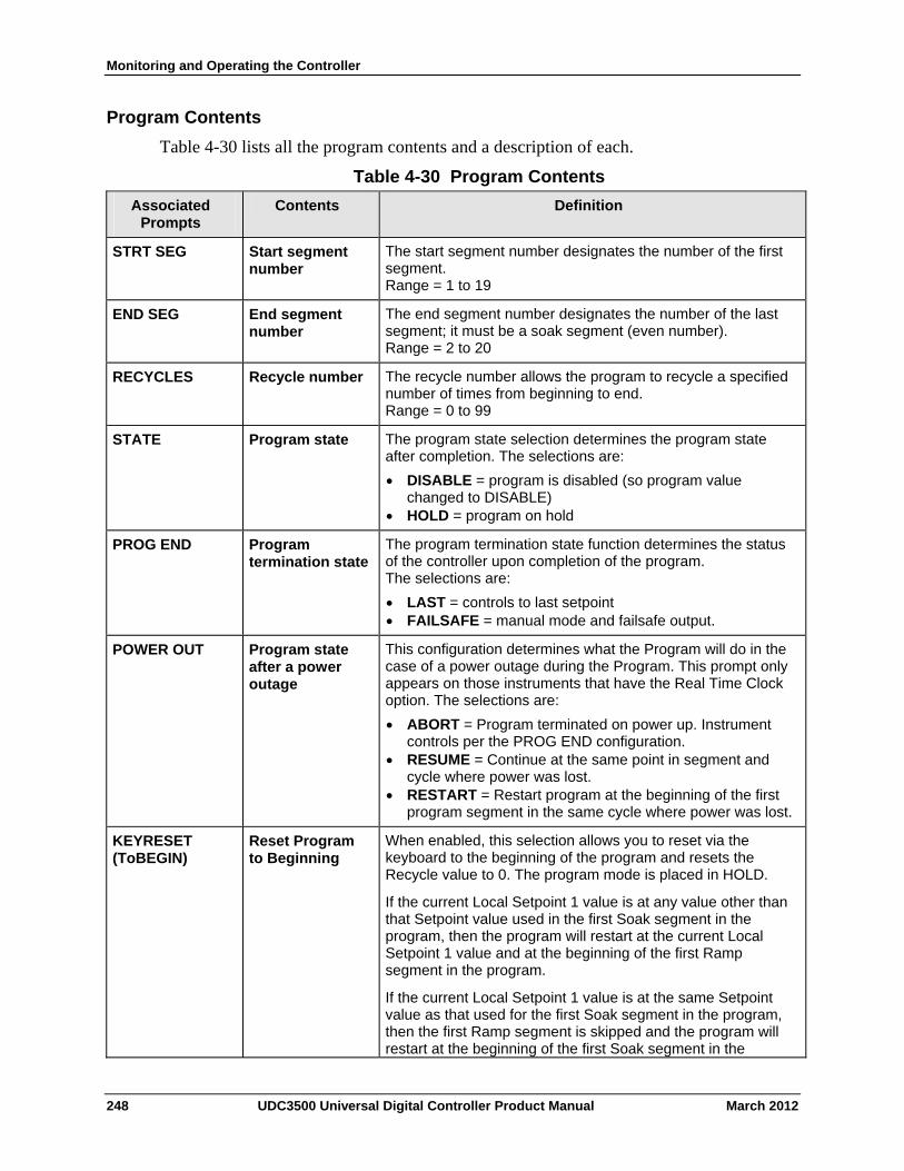
Monitoring and Operating the Controller
Program Contents
Table 4-30 lists all the program contents and a description of each.
Table 4-30 Program Contents
Contents Definition Associated Prompts
Start segment number
The start segment number designates the number of the first segment. Range = 1 to 19
STRT SEG
End segment number
The end segment number designates the number of the last segment; it must be a soak segment (even number). Range = 2 to 20
END SEG
RECYCLES Recycle number The recycle number allows the program to recycle a specified number of times from beginning to end. Range = 0 to 99
STATE Program state The program state selection determines the program state after completion. The selections are:
DISABLE = program is disabled (so program value changed to DISABLE)
HOLD = program on hold
Program termination state
The program termination state function determines the status of the controller upon completion of the program. The selections are:
LAST = controls to last setpoint FAILSAFE = manual mode and failsafe output.
PROG END
Program state after a power outage
This configuration determines what the Program will do in the case of a power outage during the Program. This prompt only appears on those instruments that have the Real Time Clock option. The selections are:
ABORT = Program terminated on power up. Instrument controls per the PROG END configuration.
RESUME = Continue at the same point in segment and cycle where power was lost.
RESTART = Restart program at the beginning of the first program segment in the same cycle where power was lost.
POWER OUT
KEYRESET (ToBEGIN)
Reset Program to Beginning
When enabled, this selection allows you to reset via the keyboard to the beginning of the program and resets the Recycle value to 0. The program mode is placed in HOLD.
If the current Local Setpoint 1 value is at any value other than that Setpoint value used in the first Soak segment in the program, then the program will restart at the current Local Setpoint 1 value and at the beginning of the first Ramp segment in the program.
If the current Local Setpoint 1 value is at the same Setpoint value as that used for the first Soak segment in the program, then the first Ramp segment is skipped and the program will restart at the beginning of the first Soak segment in the
248 UDC3500 Universal Digital Controller Product Manual March 2012
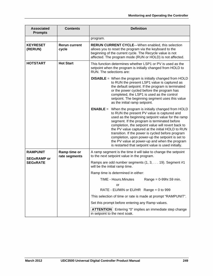
Monitoring and Operating the Controller
March 2012 UDC3500 Universal Digital Controller Product Manual 249
Associated Prompts
Contents Definition
program.
KEYRESET (RERUN)
Rerun current cycle
RERUN CURRENT CYCLE—When enabled, this selection allows you to reset the program via the keyboard to the beginning of the current cycle. The Recycle value is not affected. The program mode (RUN or HOLD) is not affected.
HOTSTART Hot Start This function determines whether LSP1 or PV is used as the setpoint when the program is initially changed from HOLD to RUN. The selections are:
DISABLE = When the program is initially changed from HOLD to RUN the present LSP1 value is captured as the default setpoint. If the program is terminated or the power cycled before the program has completed, the LSP1 is used as the control setpoint. The beginning segment uses this value as the initial ramp setpoint.
ENABLE = When the program is initially changed from HOLD to RUN the present PV value is captured and used as the beginning setpoint value for the ramp segment. If the program is terminated before completion, the setpoint value will revert back to the PV value captured at the initial HOLD to RUN transition. If the power is cycled before program completion, upon power-up the setpoint is set to the PV value at power-up and when the program is restarted that setpoint value is used initially.
RAMPUNIT
SEGxRAMP or SEGxRATE
Ramp time or rate segments
A ramp segment is the time it will take to change the setpoint to the next setpoint value in the program.
Ramps are odd number segments (1, 3, . . . 19). Segment #1 will be the initial ramp time.
Ramp time is determined in either:
TIME - Hours.Minutes Range = 0-99hr.59 min.
or
RATE - EU/MIN or EU/HR Range = 0 to 999
This selection of time or rate is made at prompt “RAMPUNIT”.
Set this prompt before entering any Ramp values.
ATTENTION Entering “0” implies an immediate step change in setpoint to the next soak.
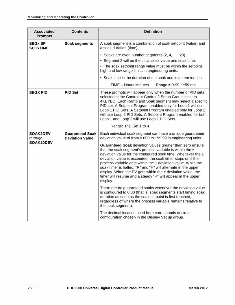
Monitoring and Operating the Controller
250 UDC3500 Universal Digital Controller Product Manual March 2012
Associated Prompts
Contents Definition
SEGx SP SEGxTIME
Soak segments A soak segment is a combination of soak setpoint (value) and a soak duration (time).
• Soaks are even number segments (2, 4, . . . 20).
• Segment 2 will be the initial soak value and soak time.
• The soak setpoint range value must be within the setpoint high and low range limits in engineering units.
• Soak time is the duration of the soak and is determined in:
TIME – Hours:Minutes Range = 0-99 hr:59 min.
SEGX PID PID Set These prompts will appear only when the number of PID sets selected in the Control or Control 2 Setup Group is set to 4KEYBD. Each Ramp and Soak segment may select a specific PID set. A Setpoint Program enabled only for Loop 1 will use Loop 1 PID Sets. A Setpoint Program enabled only for Loop 2 will use Loop 2 PID Sets. A Setpoint Program enabled for both Loop 1 and Loop 2 will use Loop 1 PID Sets.
Range: PID Set 1 to 4
SOAK2DEV through SOAK20DEV
Guaranteed SoakDeviation Value
Each individual soak segment can have a unique guaranteed deviation value of from 0.000 to ±99.99 in engineering units.
Guaranteed Soak deviation values greater than zero ensure that the soak segment’s process variable is within the ± deviation value for the configured soak time. Whenever the ± deviation value is exceeded, the soak timer stops until the process variable gets within the ± deviation value. While the soak timer is halted, “R” and “H” will alternate in the upper display. When the PV gets within the ± deviation value, the timer will resume and a steady “R” will appear in the upper display.
There are no guaranteed soaks whenever the deviation value is configured to 0.00 (that is, soak segments start timing soak duration as soon as the soak setpoint is first reached, regardless of where the process variable remains relative to the soak segment).
The decimal location used here corresponds decimal configuration chosen in the Display Set up group.
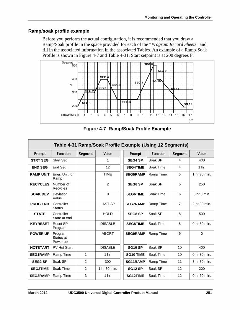
Monitoring and Operating the Controller
Ramp/soak profile example
Before you perform the actual configuration, it is recommended that you draw a Ramp/Soak profile in the space provided for each of the “Program Record Sheets” and fill in the associated information in the associated Tables. An example of a Ramp-Soak Profile is shown in Figure 4-7 and Table 4-31. Start setpoint is at 200 degrees F.
500
400
200
300
°
Time/Hours 0 1 2 3 4 5 6 7 8 9 10 11 12 13 14 15 16 17
SEG 2 SEG 3
SEG 4
SEG 5
SEG 6
SEG 7
SEG 8
SEG 9
SG 10
SG 11
SG 12 SEG 1
F
20765
Setpoint
Figure 4-7 Ramp/Soak Profile Example
Table 4-31 Ramp/Soak Profile Example (Using 12 Segments)
Function Segment Value Prompt Function Segment Value Prompt
Start Seg. 1 SEG4 SP Soak SP 4 400 STRT SEG
End Seg. 12 SEG4TIME Soak Time 4 1 hr. END SEG
Engr. Unit for Ramp
TIME SEG5RAMP Ramp Time 5 1 hr:30 min. RAMP UNIT
Number of Recycles
2 SEG6 SP Soak SP 6 250 RECYCLES
Deviation Value
0 SEG6TIME Soak Time 6 3 hr:0 min. SOAK DEV
Controller Status
LAST SP SEG7RAMP Ramp Time 7 2 hr:30 min. PROG END
Controller State at end
HOLD SEG8 SP Soak SP 8 500 STATE
Reset SP Program
DISABLE SEG8TIME Soak Time 8 0 hr:30 min. KEYRESET
Program Status at Power up
ABORT SEG9RAMP Ramp Time 9 0 POWER UP
PV Hot Start DISABLE SG10 SP Soak SP 10 400 HOTSTART
Ramp Time 1 1 hr. SG10 TIME Soak Time 10 0 hr:30 min. SEG1RAMP
Soak SP 2 300 SG11RAMP Ramp Time 11 3 hr:30 min. SEG2 SP
Soak Time 2 1 hr:30 min. SG12 SP Soak SP 12 200 SEG2TIME
SEG3RAMP Ramp Time 3 1 hr. SG12TIME Soak Time 12 0 hr:30 min.
March 2012 UDC3500 Universal Digital Controller Product Manual 251
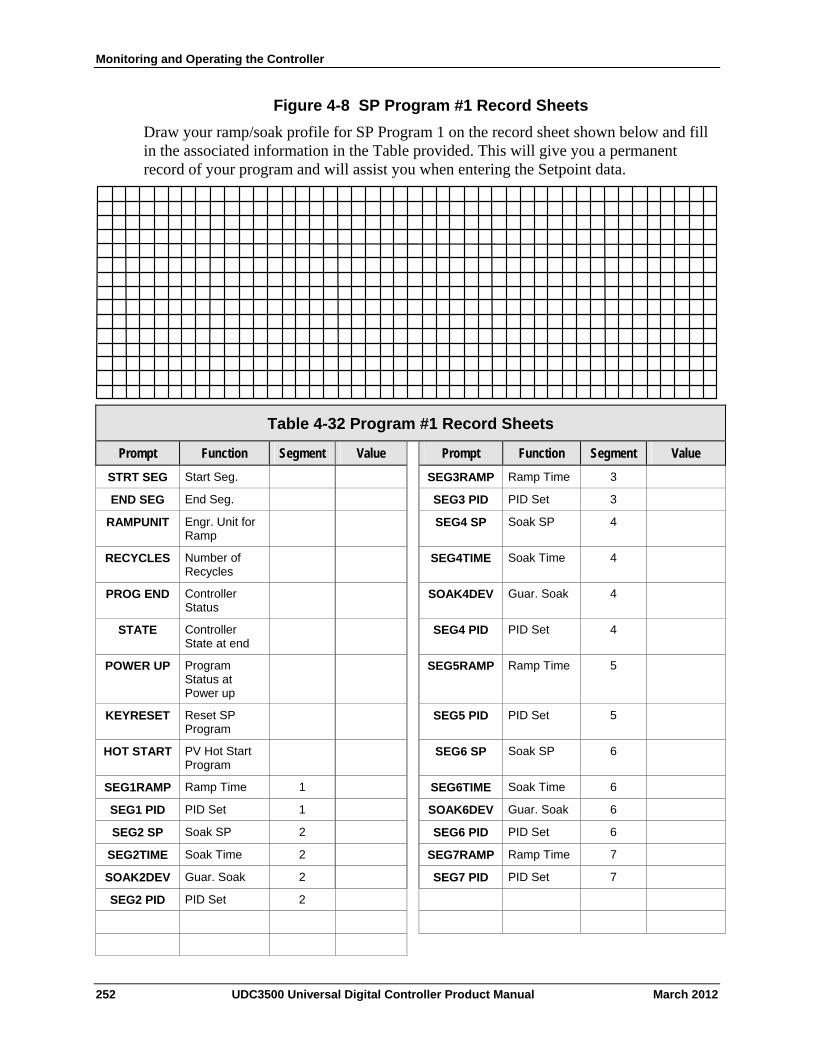
Monitoring and Operating the Controller
Figure 4-8 SP Program #1 Record Sheets
Draw your ramp/soak profile for SP Program 1 on the record sheet shown below and fill in the associated information in the Table provided. This will give you a permanent record of your program and will assist you when entering the Setpoint data.
Table 4-32 Program #1 Record Sheets
Function Segment Value Prompt Function Segment Value Prompt
Start Seg. SEG3RAMP Ramp Time 3 STRT SEG
End Seg. SEG3 PID PID Set 3 END SEG
Engr. Unit for Ramp
SEG4 SP Soak SP 4 RAMPUNIT
Number of Recycles
SEG4TIME Soak Time 4 RECYCLES
Controller Status
SOAK4DEV Guar. Soak 4 PROG END
Controller State at end
SEG4 PID PID Set 4 STATE
Program Status at Power up
SEG5RAMP Ramp Time 5 POWER UP
Reset SP Program
SEG5 PID PID Set 5 KEYRESET
PV Hot Start Program
SEG6 SP Soak SP 6 HOT START
Ramp Time 1 SEG6TIME Soak Time 6 SEG1RAMP
PID Set 1 SOAK6DEV Guar. Soak 6 SEG1 PID
Soak SP 2 SEG6 PID PID Set 6 SEG2 SP
Soak Time 2 SEG7RAMP Ramp Time 7 SEG2TIME
Guar. Soak 2 SEG7 PID PID Set 7 SOAK2DEV
PID Set 2 SEG2 PID
252 UDC3500 Universal Digital Controller Product Manual March 2012
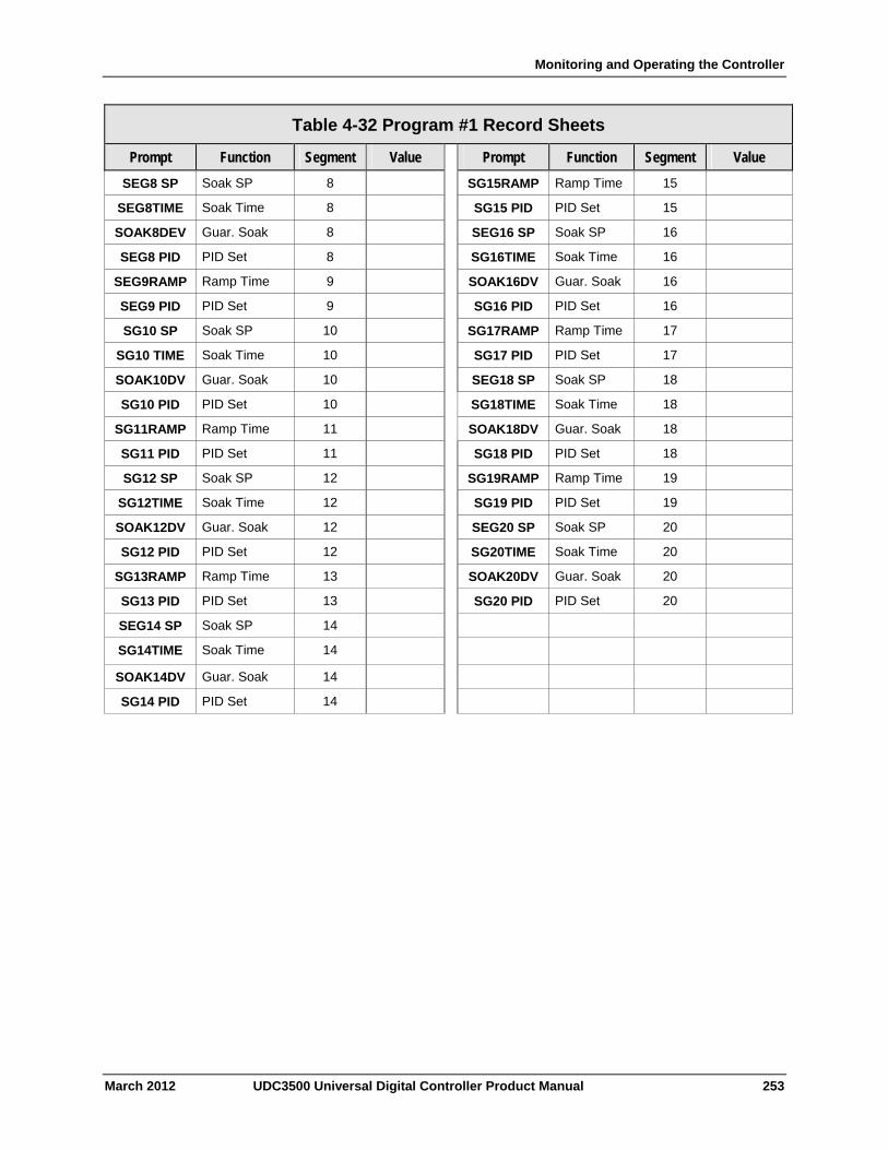
Monitoring and Operating the Controller
March 2012 UDC3500 Universal Digital Controller Product Manual 253
Table 4-32 Program #1 Record Sheets
Prompt Function Segment Value Prompt Function Segment Value
SEG8 SP Soak SP 8 SG15RAMP Ramp Time 15
SEG8TIME Soak Time 8 SG15 PID PID Set 15
SOAK8DEV Guar. Soak 8 SEG16 SP Soak SP 16
SEG8 PID PID Set 8 SG16TIME Soak Time 16
SEG9RAMP Ramp Time 9 SOAK16DV Guar. Soak 16
SEG9 PID PID Set 9 SG16 PID PID Set 16
SG10 SP Soak SP 10 SG17RAMP Ramp Time 17
SG10 TIME Soak Time 10 SG17 PID PID Set 17
SOAK10DV Guar. Soak 10 SEG18 SP Soak SP 18
SG10 PID PID Set 10 SG18TIME Soak Time 18
SG11RAMP Ramp Time 11 SOAK18DV Guar. Soak 18
SG11 PID PID Set 11 SG18 PID PID Set 18
SG12 SP Soak SP 12 SG19RAMP Ramp Time 19
SG12TIME Soak Time 12 SG19 PID PID Set 19
SOAK12DV Guar. Soak 12 SEG20 SP Soak SP 20
SG12 PID PID Set 12 SG20TIME Soak Time 20
SG13RAMP Ramp Time 13 SOAK20DV Guar. Soak 20
SG13 PID PID Set 13 SG20 PID PID Set 20
SEG14 SP Soak SP 14
SG14TIME Soak Time 14
SOAK14DV Guar. Soak 14
SG14 PID PID Set 14
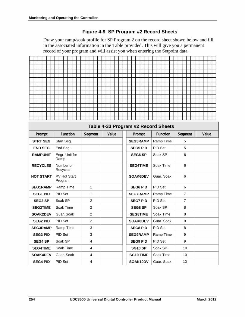
Monitoring and Operating the Controller
Figure 4-9 SP Program #2 Record Sheets
Draw your ramp/soak profile for SP Program 2 on the record sheet shown below and fill in the associated information in the Table provided. This will give you a permanent record of your program and will assist you when entering the Setpoint data.
Table 4-33 Program #2 Record Sheets
Function Segment Value Prompt Function Segment Value Prompt
Start Seg. SEG5RAMP Ramp Time 5 STRT SEG
End Seg. SEG5 PID PID Set 5 END SEG
Engr. Unit for Ramp
SEG6 SP Soak SP 6 RAMPUNIT
Number of Recycles
SEG6TIME Soak Time 6 RECYCLES
PV Hot Start Program
SOAK6DEV Guar. Soak 6 HOT START
Ramp Time 1 SEG6 PID PID Set 6 SEG1RAMP
PID Set 1 SEG7RAMP Ramp Time 7 SEG1 PID
Soak SP 2 SEG7 PID PID Set 7 SEG2 SP
Soak Time 2 SEG8 SP Soak SP 8 SEG2TIME
Guar. Soak 2 SEG8TIME Soak Time 8 SOAK2DEV
PID Set 2 SOAK8DEV Guar. Soak 8 SEG2 PID
Ramp Time 3 SEG8 PID PID Set 8 SEG3RAMP
PID Set 3 SEG9RAMP Ramp Time 9 SEG3 PID
Soak SP 4 SEG9 PID PID Set 9 SEG4 SP
Soak Time 4 SG10 SP Soak SP 10 SEG4TIME
Guar. Soak 4 SG10 TIME Soak Time 10 SOAK4DEV
SEG4 PID PID Set 4 SOAK10DV Guar. Soak 10
254 UDC3500 Universal Digital Controller Product Manual March 2012
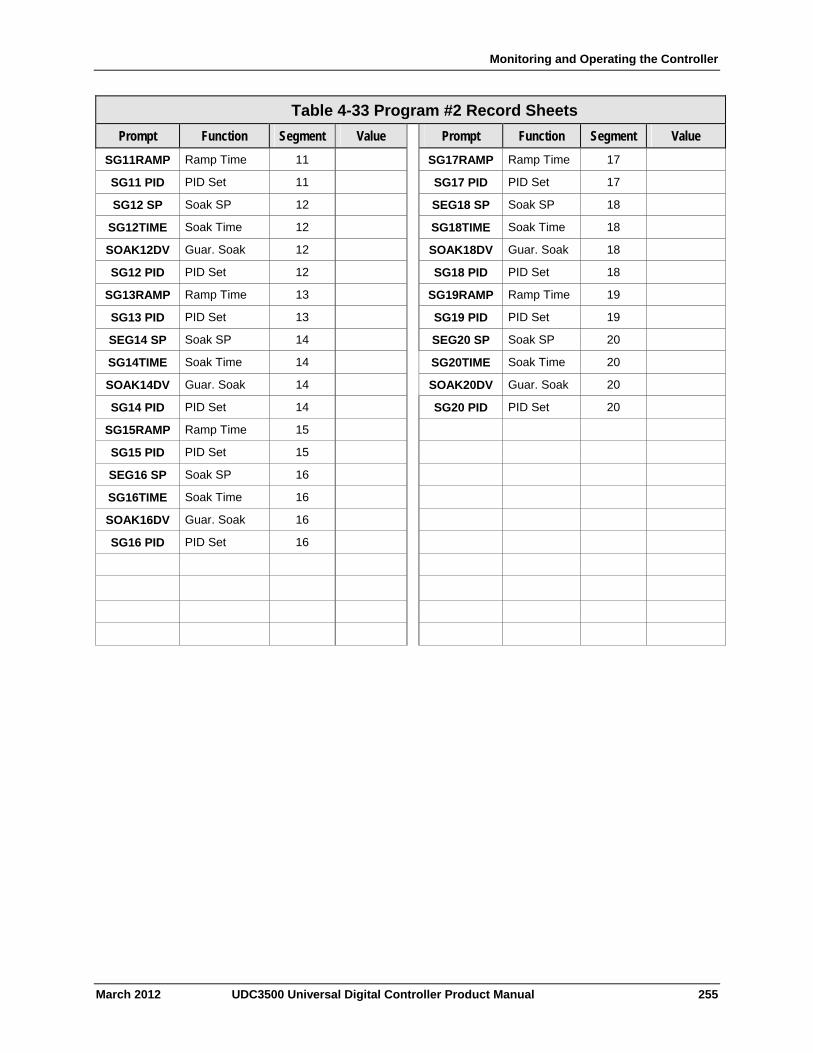
Monitoring and Operating the Controller
March 2012 UDC3500 Universal Digital Controller Product Manual 255
Table 4-33 Program #2 Record Sheets
Prompt Function Segment Value Prompt Function Segment Value
SG11RAMP Ramp Time 11 SG17RAMP Ramp Time 17
SG11 PID PID Set 11 SG17 PID PID Set 17
SG12 SP Soak SP 12 SEG18 SP Soak SP 18
SG12TIME Soak Time 12 SG18TIME Soak Time 18
SOAK12DV Guar. Soak 12 SOAK18DV Guar. Soak 18
SG12 PID PID Set 12 SG18 PID PID Set 18
SG13RAMP Ramp Time 13 SG19RAMP Ramp Time 19
SG13 PID PID Set 13 SG19 PID PID Set 19
SEG14 SP Soak SP 14 SEG20 SP Soak SP 20
SG14TIME Soak Time 14 SG20TIME Soak Time 20
SOAK14DV Guar. Soak 14 SOAK20DV Guar. Soak 20
SG14 PID PID Set 14 SG20 PID PID Set 20
SG15RAMP Ramp Time 15
SG15 PID PID Set 15
SEG16 SP Soak SP 16
SG16TIME Soak Time 16
SOAK16DV Guar. Soak 16
SG16 PID PID Set 16

Monitoring and Operating the Controller
Figure 4-10 SP Program #3 Record Sheets
Draw your ramp/soak profile for SP Program 3 on the record sheet shown below and fill in the associated information in the Table provided. This will give you a permanent record of your program and will assist you when entering the Setpoint data.
Table 4-34 Program #3 Record Sheets
Function Segment Value Prompt Function Segment Value Prompt
Start Seg. SEG5RAMP Ramp Time 5 STRT SEG
End Seg. SEG5 PID PID Set 5 END SEG
Engr. Unit for Ramp
SEG6 SP Soak SP 6 RAMPUNIT
Number of Recycles
SEG6TIME Soak Time 6 RECYCLES
PV Hot Start Program
SOAK6DEV Guar. Soak 6 HOT START
Ramp Time 1 SEG6 PID PID Set 6 SEG1RAMP
PID Set 1 SEG7RAMP Ramp Time 7 SEG1 PID
Soak SP 2 SEG7 PID PID Set 7 SEG2 SP
Soak Time 2 SEG8 SP Soak SP 8 SEG2TIME
Guar. Soak 2 SEG8TIME Soak Time 8 SOAK2DEV
PID Set 2 SOAK8DEV Guar. Soak 8 SEG2 PID
Ramp Time 3 SEG8 PID PID Set 8 SEG3RAMP
PID Set 3 SEG9RAMP Ramp Time 9 SEG3 PID
Soak SP 4 SEG9 PID PID Set 9 SEG4 SP
Soak Time 4 SG10 SP Soak SP 10 SEG4TIME
Guar. Soak 4 SG10 TIME Soak Time 10 SOAK4DEV
SEG4 PID PID Set 4 SOAK10DV Guar. Soak 10
256 UDC3500 Universal Digital Controller Product Manual March 2012
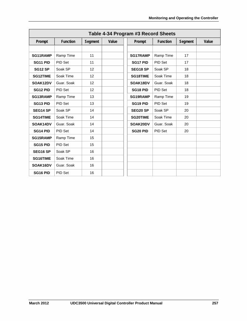
Monitoring and Operating the Controller
March 2012 UDC3500 Universal Digital Controller Product Manual 257
Table 4-34 Program #3 Record Sheets
Prompt Function Segment Value Prompt Function Segment Value
SG11RAMP Ramp Time 11 SG17RAMP Ramp Time 17
SG11 PID PID Set 11 SG17 PID PID Set 17
SG12 SP Soak SP 12 SEG18 SP Soak SP 18
SG12TIME Soak Time 12 SG18TIME Soak Time 18
SOAK12DV Guar. Soak 12 SOAK18DV Guar. Soak 18
SG12 PID PID Set 12 SG18 PID PID Set 18
SG13RAMP Ramp Time 13 SG19RAMP Ramp Time 19
SG13 PID PID Set 13 SG19 PID PID Set 19
SEG14 SP Soak SP 14 SEG20 SP Soak SP 20
SG14TIME Soak Time 14 SG20TIME Soak Time 20
SOAK14DV Guar. Soak 14 SOAK20DV Guar. Soak 20
SG14 PID PID Set 14 SG20 PID PID Set 20
SG15RAMP Ramp Time 15
SG15 PID PID Set 15
SEG16 SP Soak SP 16
SG16TIME Soak Time 16
SOAK16DV Guar. Soak 16
SG16 PID PID Set 16

Monitoring and Operating the Controller
Figure 4-11 SP Program #4 Record Sheets
Draw your ramp/soak profile for SP Program 4 on the record sheet shown below and fill in the associated information in the Table provided. This will give you a permanent record of your program and will assist you when entering the Setpoint data.
Table 4-35 Program #4 Record Sheets
Function Segment Value Prompt Function Segment Value Prompt
Start Seg. SEG5RAMP Ramp Time 5 STRT SEG
End Seg. SEG5 PID PID Set 5 END SEG
Engr. Unit for Ramp
SEG6 SP Soak SP 6 RAMPUNIT
Number of Recycles
SEG6TIME Soak Time 6 RECYCLES
PV Hot Start Program
SOAK6DEV Guar. Soak 6 HOT START
Ramp Time 1 SEG6 PID PID Set 6 SEG1RAMP
PID Set 1 SEG7RAMP Ramp Time 7 SEG1 PID
Soak SP 2 SEG7 PID PID Set 7 SEG2 SP
Soak Time 2 SEG8 SP Soak SP 8 SEG2TIME
Guar. Soak 2 SEG8TIME Soak Time 8 SOAK2DEV
PID Set 2 SOAK8DEV Guar. Soak 8 SEG2 PID
Ramp Time 3 SEG8 PID PID Set 8 SEG3RAMP
PID Set 3 SEG9RAMP Ramp Time 9 SEG3 PID
Soak SP 4 SEG9 PID PID Set 9 SEG4 SP
Soak Time 4 SG10 SP Soak SP 10 SEG4TIME
Guar. Soak 4 SG10 TIME Soak Time 10 SOAK4DEV
SEG4 PID PID Set 4 SOAK10DV Guar. Soak 10
258 UDC3500 Universal Digital Controller Product Manual March 2012
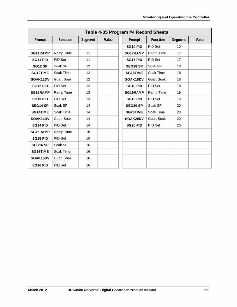
Monitoring and Operating the Controller
Table 4-35 Program #4 Record Sheets
Function Segment Value Prompt Prompt Function Segment Value
SG10 PID PID Set 10
Ramp Time 11 SG17RAMP Ramp Time 17 SG11RAMP
PID Set 11 PID Set SG11 PID SG17 PID 17
SG12 SP Soak SP 12 SEG18 SP Soak SP 18
Soak Time 12 Soak Time SG12TIME SG18TIME 18
SOAK12DV Guar. Soak 12 Guar. Soak SOAK18DV 18
SG12 PID PID Set 12 PID Set 18 SG18 PID
Ramp Time 13 SG19RAMP Ramp Time 19 SG13RAMP
PID Set 13 PID Set 19 SG13 PID SG19 PID
SEG14 SP Soak SP 14 SEG20 SP Soak SP 20
SG14TIME Soak Time 14 SG20TIME Soak Time 20
Guar. Soak 14 SOAK20DV Guar. Soak 20 SOAK14DV
PID Set 14 SG20 PID PID Set 20 SG14 PID
Ramp Time 15 SG15RAMP
PID Set 15 SG15 PID
Soak SP 16 SEG16 SP
Soak Time 16 SG16TIME
Guar. Soak 16 SOAK16DV
PID Set 16 SG16 PID
March 2012 UDC3500 Universal Digital Controller Product Manual 259
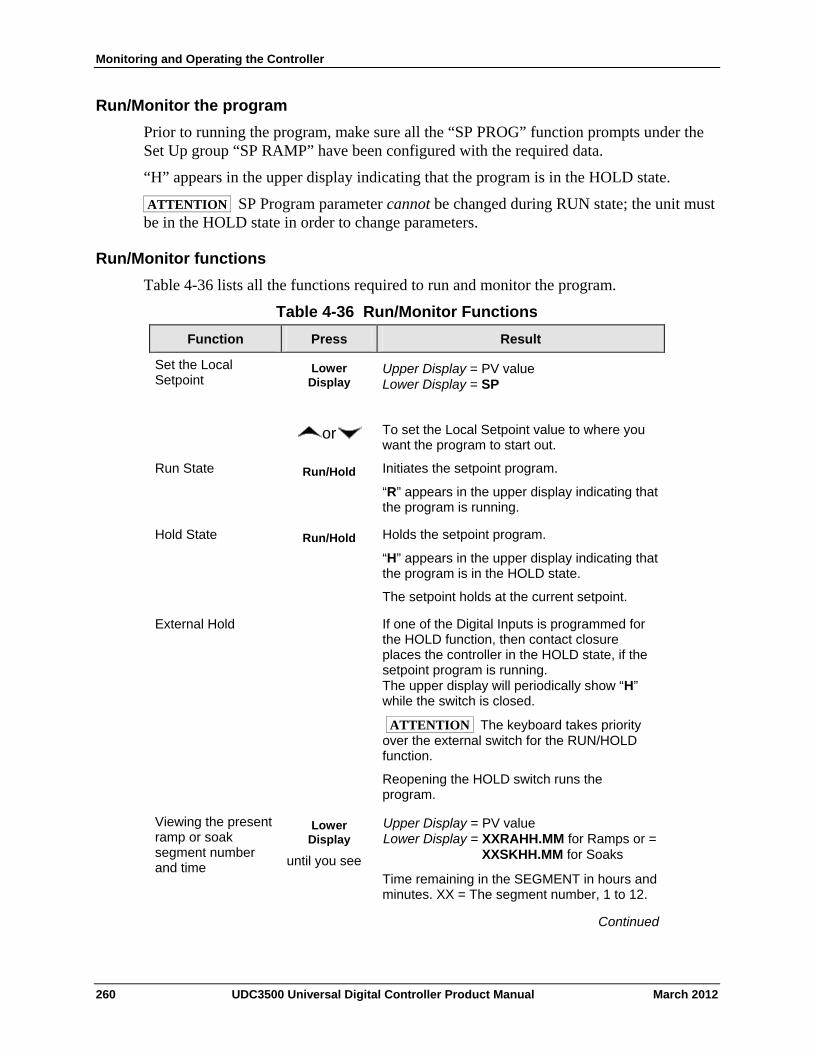
Monitoring and Operating the Controller
Run/Monitor the program
Prior to running the program, make sure all the “SP PROG” function prompts under the Set Up group “SP RAMP” have been configured with the required data.
“H” appears in the upper display indicating that the program is in the HOLD state.
ATTENTION SP Program parameter cannot be changed during RUN state; the unit must be in the HOLD state in order to change parameters.
Run/Monitor functions
Table 4-36 lists all the functions required to run and monitor the program.
Table 4-36 Run/Monitor Functions
Press Result Function
Set the Local Setpoint
Lower Display
Upper Display = PV value Lower Display = SP
or To set the Local Setpoint value to where you want the program to start out.
Run State Run/Hold Initiates the setpoint program.
“R” appears in the upper display indicating that the program is running.
Run/Hold Holds the setpoint program.
“H” appears in the upper display indicating that the program is in the HOLD state.
The setpoint holds at the current setpoint.
Hold State
External Hold If one of the Digital Inputs is programmed for the HOLD function, then contact closure places the controller in the HOLD state, if the setpoint program is running. The upper display will periodically show “H” while the switch is closed.
ATTENTION The keyboard takes priority over the external switch for the RUN/HOLD function.
Reopening the HOLD switch runs the program.
Viewing the present ramp or soak segment number and time
Lower Display
until you see
Upper Display = PV value Lower Display = XXRAHH.MM for Ramps or = XXSKHH.MM for Soaks
Time remaining in the SEGMENT in hours and minutes. XX = The segment number, 1 to 12.
Continued
260 UDC3500 Universal Digital Controller Product Manual March 2012
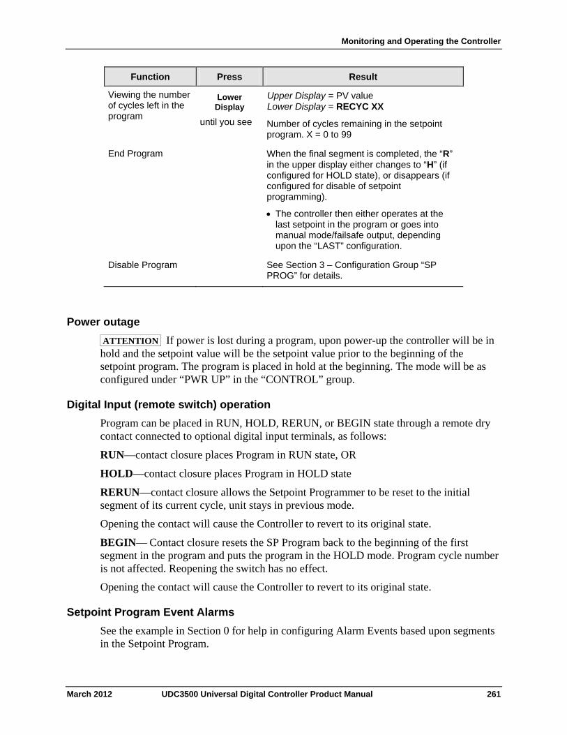
Monitoring and Operating the Controller
March 2012 UDC3500 Universal Digital Controller Product Manual 261
Function Press Result
Viewing the number of cycles left in the program
Lower Display
until you see
Upper Display = PV value Lower Display = RECYC XX
Number of cycles remaining in the setpoint program. X = 0 to 99
End Program When the final segment is completed, the “R” in the upper display either changes to “H” (if configured for HOLD state), or disappears (if configured for disable of setpoint programming).
The controller then either operates at the last setpoint in the program or goes into manual mode/failsafe output, depending upon the “LAST” configuration.
Disable Program See Section 3 – Configuration Group “SP PROG” for details.
Power outage
ATTENTION If power is lost during a program, upon power-up the controller will be in hold and the setpoint value will be the setpoint value prior to the beginning of the setpoint program. The program is placed in hold at the beginning. The mode will be as configured under “PWR UP” in the “CONTROL” group.
Digital Input (remote switch) operation
Program can be placed in RUN, HOLD, RERUN, or BEGIN state through a remote dry contact connected to optional digital input terminals, as follows:
RUN—contact closure places Program in RUN state, OR
HOLD—contact closure places Program in HOLD state
RERUN—contact closure allows the Setpoint Programmer to be reset to the initial segment of its current cycle, unit stays in previous mode.
Opening the contact will cause the Controller to revert to its original state.
BEGIN— Contact closure resets the SP Program back to the beginning of the first segment in the program and puts the program in the HOLD mode. Program cycle number is not affected. Reopening the switch has no effect.
Opening the contact will cause the Controller to revert to its original state.
Setpoint Program Event Alarms
See the example in Section 0 for help in configuring Alarm Events based upon segments in the Setpoint Program.
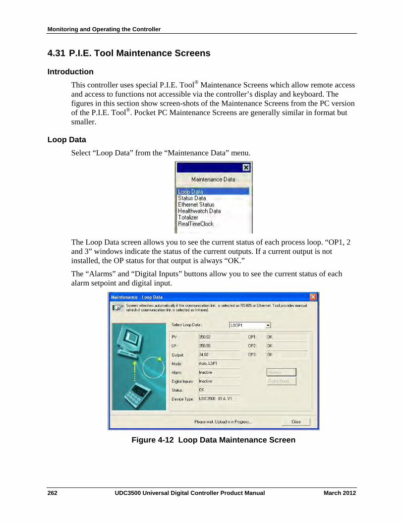
Monitoring and Operating the Controller
4.31 P.I.E. Tool Maintenance Screens
Introduction
This controller uses special P.I.E. Tool® Maintenance Screens which allow remote access and access to functions not accessible via the controller’s display and keyboard. The figures in this section show screen-shots of the Maintenance Screens from the PC version of the P.I.E. Tool®. Pocket PC Maintenance Screens are generally similar in format but smaller.
Loop Data
Select “Loop Data” from the “Maintenance Data” menu.
The Loop Data screen allows you to see the current status of each process loop. “OP1, 2 and 3” windows indicate the status of the current outputs. If a current output is not installed, the OP status for that output is always “OK.”
The “Alarms” and “Digital Inputs” buttons allow you to see the current status of each alarm setpoint and digital input.
Figure 4-12 Loop Data Maintenance Screen
262 UDC3500 Universal Digital Controller Product Manual March 2012
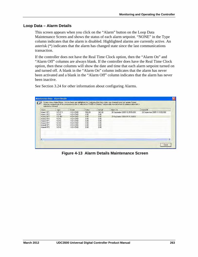
Monitoring and Operating the Controller
Loop Data – Alarm Details
This screen appears when you click on the “Alarm” button on the Loop Data Maintenance Screen and shows the status of each alarm setpoint. “NONE” in the Type column indicates that the alarm is disabled. Highlighted alarms are currently active. An asterisk (*) indicates that the alarm has changed state since the last communications transaction.
If the controller does not have the Real Time Clock option, then the “Alarm On” and “Alarm Off” columns are always blank. If the controller does have the Real Time Clock option, then these columns will show the date and time that each alarm setpoint turned on and turned off. A blank in the “Alarm On” column indicates that the alarm has never been activated and a blank in the “Alarm Off” column indicates that the alarm has never been inactive.
See Section 3.24 for other information about configuring Alarms.
Figure 4-13 Alarm Details Maintenance Screen
March 2012 UDC3500 Universal Digital Controller Product Manual 263
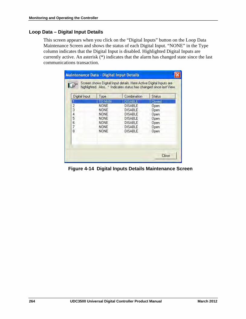
Monitoring and Operating the Controller
Loop Data – Digital Input Details
This screen appears when you click on the “Digital Inputs” button on the Loop Data Maintenance Screen and shows the status of each Digital Input. “NONE” in the Type column indicates that the Digital Input is disabled. Highlighted Digital Inputs are currently active. An asterisk (*) indicates that the alarm has changed state since the last communications transaction.
Figure 4-14 Digital Inputs Details Maintenance Screen
264 UDC3500 Universal Digital Controller Product Manual March 2012
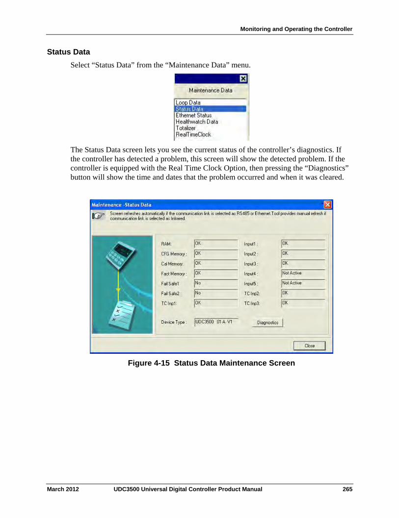
Monitoring and Operating the Controller
Status Data
Select “Status Data” from the “Maintenance Data” menu.
The Status Data screen lets you see the current status of the controller’s diagnostics. If the controller has detected a problem, this screen will show the detected problem. If the controller is equipped with the Real Time Clock Option, then pressing the “Diagnostics” button will show the time and dates that the problem occurred and when it was cleared.
Figure 4-15 Status Data Maintenance Screen
March 2012 UDC3500 Universal Digital Controller Product Manual 265
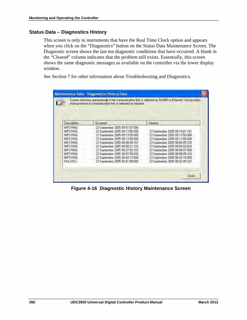
Monitoring and Operating the Controller
Status Data – Diagnostics History
This screen is only in instruments that have the Real Time Clock option and appears when you click on the “Diagnostics” button on the Status Data Maintenance Screen. The Diagnostic screen shows the last ten diagnostic conditions that have occurred. A blank in the “Cleared” column indicates that the problem still exists. Essentially, this screen shows the same diagnostic messages as available on the controller via the lower display window.
See Section 7 for other information about Troubleshooting and Diagnostics.
Figure 4-16 Diagnostic History Maintenance Screen
266 UDC3500 Universal Digital Controller Product Manual March 2012
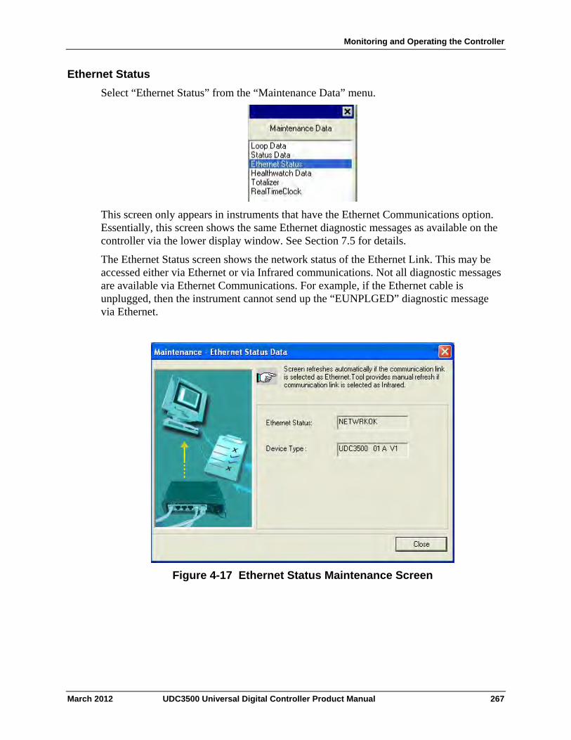
Monitoring and Operating the Controller
Ethernet Status
Select “Ethernet Status” from the “Maintenance Data” menu.
This screen only appears in instruments that have the Ethernet Communications option. Essentially, this screen shows the same Ethernet diagnostic messages as available on the controller via the lower display window. See Section 7.5 for details.
The Ethernet Status screen shows the network status of the Ethernet Link. This may be accessed either via Ethernet or via Infrared communications. Not all diagnostic messages are available via Ethernet Communications. For example, if the Ethernet cable is unplugged, then the instrument cannot send up the “EUNPLGED” diagnostic message via Ethernet.
Figure 4-17 Ethernet Status Maintenance Screen
March 2012 UDC3500 Universal Digital Controller Product Manual 267
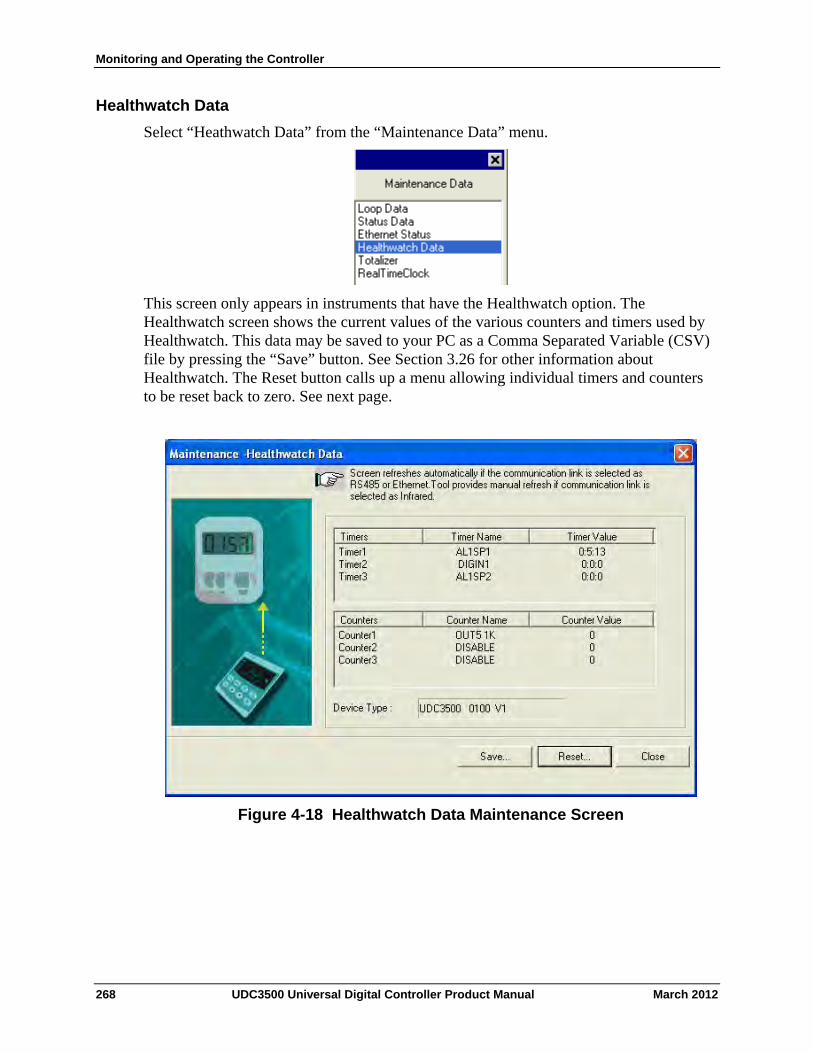
Monitoring and Operating the Controller
Healthwatch Data
Select “Heathwatch Data” from the “Maintenance Data” menu.
This screen only appears in instruments that have the Healthwatch option. The Healthwatch screen shows the current values of the various counters and timers used by Healthwatch. This data may be saved to your PC as a Comma Separated Variable (CSV) file by pressing the “Save” button. See Section 3.26 for other information about Healthwatch. The Reset button calls up a menu allowing individual timers and counters to be reset back to zero. See next page.
Figure 4-18 Healthwatch Data Maintenance Screen
268 UDC3500 Universal Digital Controller Product Manual March 2012
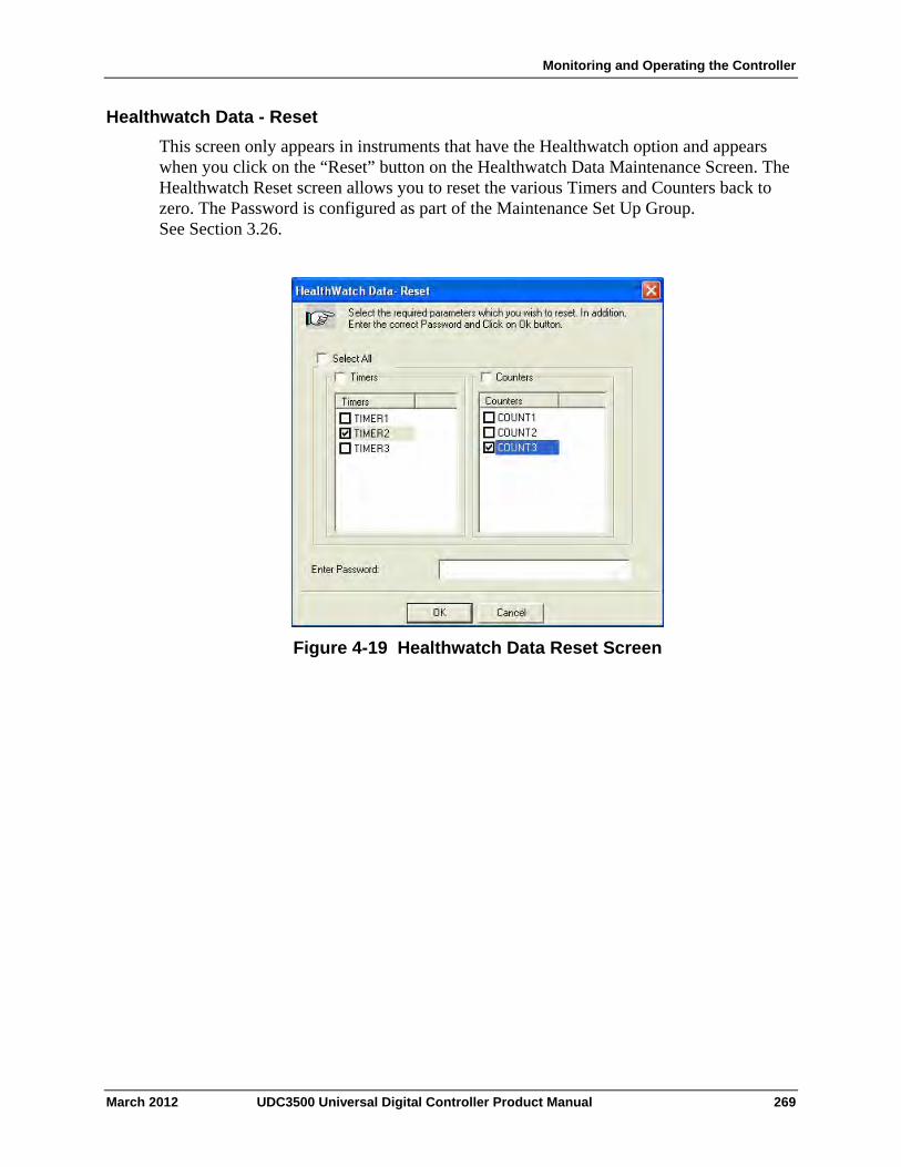
Monitoring and Operating the Controller
Healthwatch Data - Reset
This screen only appears in instruments that have the Healthwatch option and appears when you click on the “Reset” button on the Healthwatch Data Maintenance Screen. The Healthwatch Reset screen allows you to reset the various Timers and Counters back to zero. The Password is configured as part of the Maintenance Set Up Group. See Section 3.26.
Figure 4-19 Healthwatch Data Reset Screen
March 2012 UDC3500 Universal Digital Controller Product Manual 269
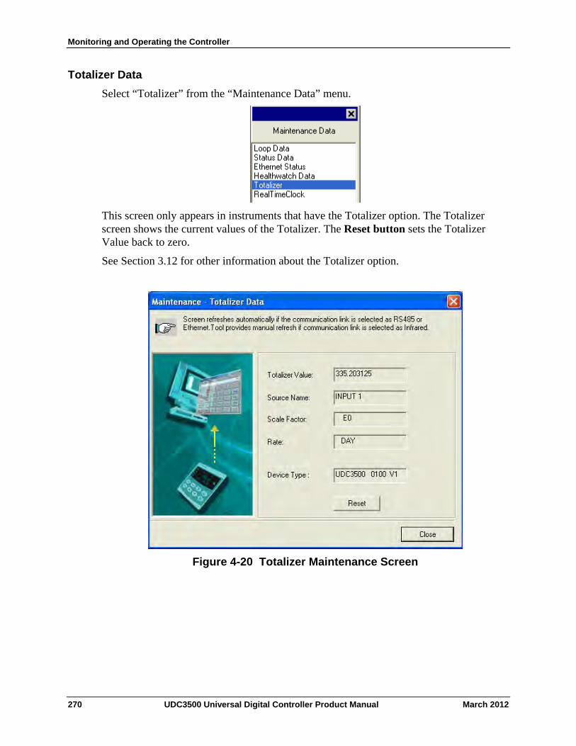
Monitoring and Operating the Controller
Totalizer Data
Select “Totalizer” from the “Maintenance Data” menu.
This screen only appears in instruments that have the Totalizer option. The Totalizer screen shows the current values of the Totalizer. The Reset button sets the Totalizer Value back to zero.
See Section 3.12 for other information about the Totalizer option.
Figure 4-20 Totalizer Maintenance Screen
270 UDC3500 Universal Digital Controller Product Manual March 2012
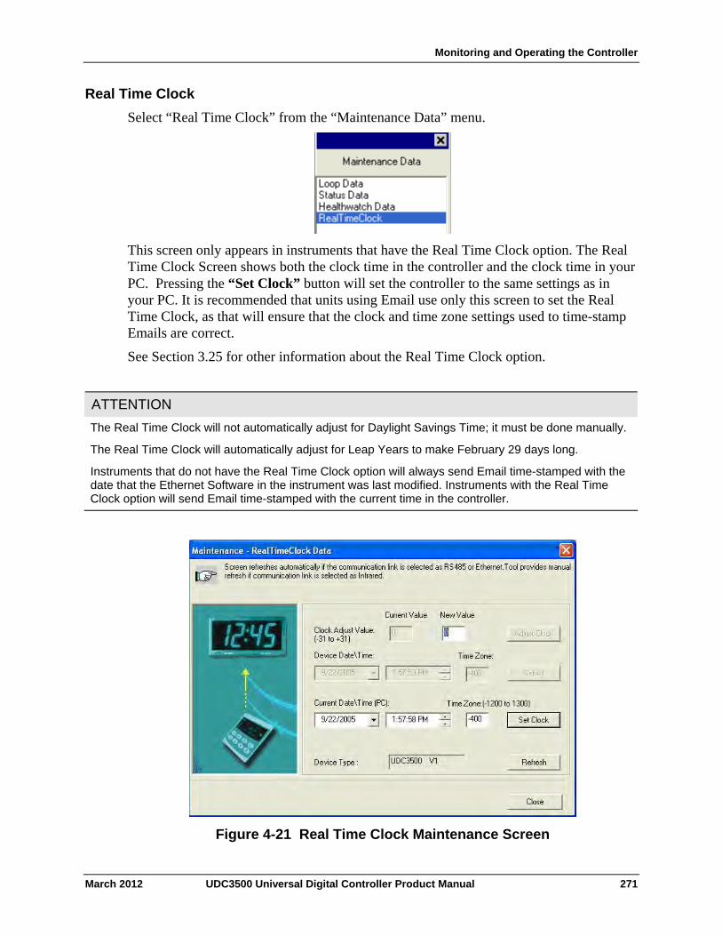
Monitoring and Operating the Controller
Real Time Clock
Select “Real Time Clock” from the “Maintenance Data” menu.
This screen only appears in instruments that have the Real Time Clock option. The Real Time Clock Screen shows both the clock time in the controller and the clock time in your PC. Pressing the “Set Clock” button will set the controller to the same settings as in your PC. It is recommended that units using Email use only this screen to set the Real Time Clock, as that will ensure that the clock and time zone settings used to time-stamp Emails are correct.
See Section 3.25 for other information about the Real Time Clock option.
ATTENTION
The Real Time Clock will not automatically adjust for Daylight Savings Time; it must be done manually.
The Real Time Clock will automatically adjust for Leap Years to make February 29 days long.
Instruments that do not have the Real Time Clock option will always send Email time-stamped with the date that the Ethernet Software in the instrument was last modified. Instruments with the Real Time Clock option will send Email time-stamped with the current time in the controller.
Figure 4-21 Real Time Clock Maintenance Screen
March 2012 UDC3500 Universal Digital Controller Product Manual 271
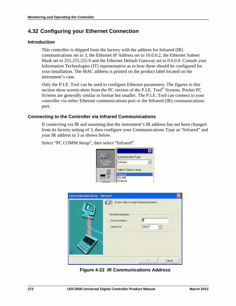
Monitoring and Operating the Controller
4.32 Configuring your Ethernet Connection
Introduction
This controller is shipped from the factory with the address for Infrared (IR) communications set to 3, the Ethernet IP Address set to 10.0.0.2, the Ethernet Subnet Mask set to 255.255.255.0 and the Ethernet Default Gateway set to 0.0.0.0. Consult your Information Technologies (IT) representative as to how these should be configured for your installation. The MAC address is printed on the product label located on the instrument’s case.
Only the P.I.E. Tool can be used to configure Ethernet parameters. The figures in this section show screen-shots from the PC version of the P.I.E. Tool® Screens. Pocket PC Screens are generally similar in format but smaller. The P.I.E. Tool can connect to your controller via either Ethernet communications port or the Infrared (IR) communications port.
Connecting to the Controller via Infrared Communications
If connecting via IR and assuming that the instrument’s IR address has not been changed from its factory setting of 3, then configure your Communications Type as “Infrared” and your IR address to 3 as shown below.
Select “PC COMM Setup”, then select “Infrared”.
Figure 4-22 IR Communications Address
272 UDC3500 Universal Digital Controller Product Manual March 2012
Monitoring and Operating the Controller
Close the IR configuration window and then single click on the “Online Configuration” button.
Press any button on the controller’s keyboard to activate the controller’s IR port. Point your IR dongle (if using PC) or your Pocket PC’s IR port (if using Pocket PC) at the IR window on the front of the controller and then click on the “Start” button. The P.I.E. Tool® should start uploading the configuration information from the controller as shown below:
Figure 4-23 Configuration Upload in Progress
Once the upload is complete, click on the “Ethernet & Email” Group. Configure your Ethernet and Email parameters per Section 3.30.
Once you have changed the Ethernet settings and downloaded them to your controller, you will now be able to communicate with it via Ethernet.
March 2012 UDC3500 Universal Digital Controller Product Manual 273
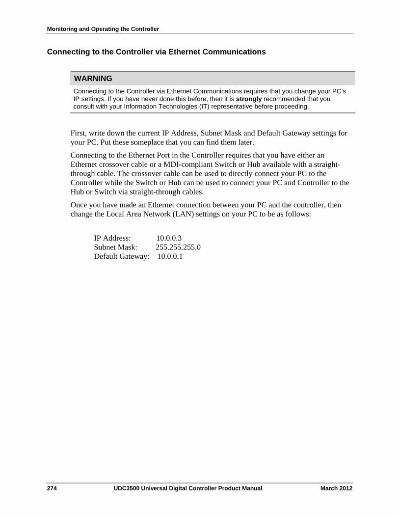
Monitoring and Operating the Controller
Connecting to the Controller via Ethernet Communications
WARNING
Connecting to the Controller via Ethernet Communications requires that you change your PC’s IP settings. If you have never done this before, then it is strongly recommended that you consult with your Information Technologies (IT) representative before proceeding.
First, write down the current IP Address, Subnet Mask and Default Gateway settings for your PC. Put these someplace that you can find them later.
Connecting to the Ethernet Port in the Controller requires that you have either an Ethernet crossover cable or a MDI-compliant Switch or Hub available with a straight-through cable. The crossover cable can be used to directly connect your PC to the Controller while the Switch or Hub can be used to connect your PC and Controller to the Hub or Switch via straight-through cables.
Once you have made an Ethernet connection between your PC and the controller, then change the Local Area Network (LAN) settings on your PC to be as follows:
IP Address: 10.0.0.3 Subnet Mask: 255.255.255.0 Default Gateway: 10.0.0.1
274 UDC3500 Universal Digital Controller Product Manual March 2012
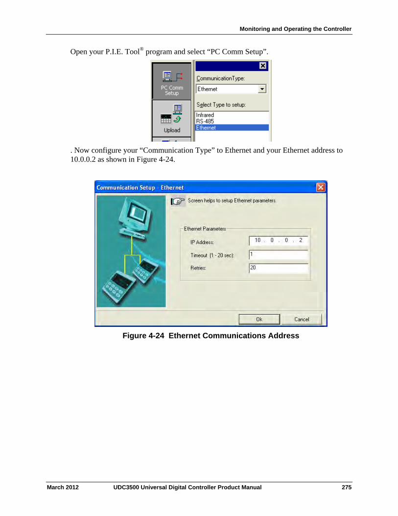
Monitoring and Operating the Controller
Open your P.I.E. Tool® program and select “PC Comm Setup”.
. Now configure your “Communication Type” to Ethernet and your Ethernet address to 10.0.0.2 as shown in Figure 4-24.
Figure 4-24 Ethernet Communications Address
March 2012 UDC3500 Universal Digital Controller Product Manual 275
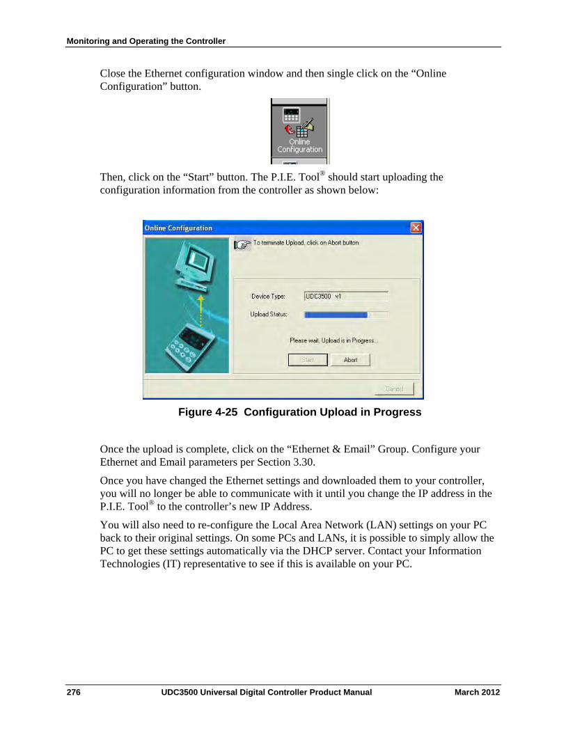
Monitoring and Operating the Controller
Close the Ethernet configuration window and then single click on the “Online Configuration” button.
Then, click on the “Start” button. The P.I.E. Tool® should start uploading the configuration information from the controller as shown below:
Figure 4-25 Configuration Upload in Progress
Once the upload is complete, click on the “Ethernet & Email” Group. Configure your Ethernet and Email parameters per Section 3.30.
Once you have changed the Ethernet settings and downloaded them to your controller, you will no longer be able to communicate with it until you change the IP address in the P.I.E. Tool® to the controller’s new IP Address.
You will also need to re-configure the Local Area Network (LAN) settings on your PC back to their original settings. On some PCs and LANs, it is possible to simply allow the PC to get these settings automatically via the DHCP server. Contact your Information Technologies (IT) representative to see if this is available on your PC.
276 UDC3500 Universal Digital Controller Product Manual March 2012

Monitoring and Operating the Controller
March 2012 UDC3500 Universal Digital Controller Product Manual 277

Input Calibration
March 2012 UDC3500 Universal Digital Controller Product Manual 279
5 Input Calibration
WARNING—SHOCK HAZARD
INPUT CALIBRATION MAY REQUIRE ACCESS TO HAZARDOUS LIVE CIRCUITS, AND SHOULD ONLY BE PERFORMED BY QUALIFIED SERVICE PERSONNEL. MORE THAN ONE SWITCH MAY BE REQUIRED TO DE-ENERGIZE UNIT BEFORE CALIBRATION.
5.1 Overview
Introduction
This section describes the field calibration procedures for Analog Inputs 1 through 5.
All input actuations in every controller are fully factory-calibrated and are ready for configuration by the user.
Field Calibration can improve the accuracy of the Controller if necessary for a particular application.
CAUTION
The field calibration will be lost if a change in input type configuration is implemented at a later time. The original factory calibration data remains available for later use after a field calibration is done. See Section 5.6 if you want to restore factory calibration values.
What’s in this section?
The following topics are covered in this section.
TOPIC See Page
5.1 Overview 279
5.2 Minimum and Maximum Range Values 280
5.3 Preliminary Information 282
5.4 Input Set Up Wiring 284
5.5 Input Calibration Procedure 293
5.6 Restore Input Factory Calibration 295
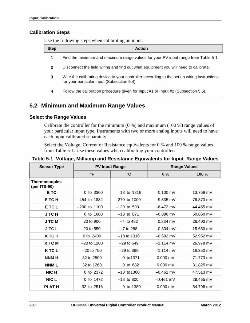
Input Calibration
Calibration Steps
Use the following steps when calibrating an input.
Step Action
Find the minimum and maximum range values for your PV input range from Table 5-1. 1
Disconnect the field wiring and find out what equipment you will need to calibrate. 2
Wire the calibrating device to your controller according to the set up wiring instructions for your particular input (Subsection 5.4)
3
Follow the calibration procedure given for Input #1 or Input #2 (Subsection 5.5). 4
5.2 Minimum and Maximum Range Values
Select the Range Values
Calibrate the controller for the minimum (0 %) and maximum (100 %) range values of your particular input type. Instruments with two or more analog inputs will need to have each input calibrated separately.
Select the Voltage, Current or Resistance equivalents for 0 % and 100 % range values from Table 5-1. Use these values when calibrating your controller.
Table 5-1 Voltage, Milliamp and Resistance Equivalents for Input Range Values
PV Input Range Range Values Sensor Type
°F °C 0 % 100 %
Thermocouples (per ITS-90)
0 to 3300 –18 to 1816 –0.100 mV 13.769 mV B TC
–454 to 1832 –270 to 1000 –9.835 mV 76.373 mV E TC H
–200 to 1100 –129 to 593 –6.472 mV 44.455 mV E TC L
0 to 1600 –18 to 871 –0.886 mV 50.060 mV J TC H
20 to 900 –7 to 482 –0.334 mV 26.400 mV J TC M
20 to 550 –7 to 288 –0.334 mV 15.650 mV J TC L
0 to 2400 –18 to 1316 –0.692 mV 52.952 mV K TC H
–20 to 1200 –29 to 649 –1.114 mV 26.978 mV K TC M
–20 to 750 –29 to 399 –1.114 mV 16.350 mV K TC L
32 to 2500 0 to 1371 0.000 mV 71.773 mV NNM H
32 to 1260 0 to 682 0.000 mV 31.825 mV NNM L
0 to 2372 –18 to 1300 –0.461 mV 47.513 mV NIC H
0 to 1472 –18 to 800 -0.461 mV 28.455 mV NIC L
PLAT H 32 to 2516 0 to 1380 0.000 mV 54.798 mV
280 UDC3500 Universal Digital Controller Product Manual March 2012
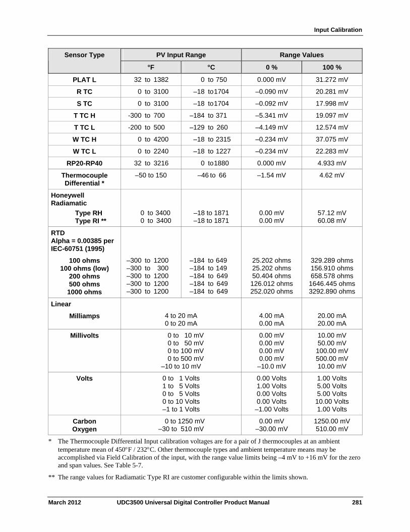
Input Calibration
March 2012 UDC3500 Universal Digital Controller Product Manual 281
PV Input Range Range Values Sensor Type
°F °C 0 % 100 %
PLAT L 32 to 1382 0 to 750 0.000 mV 31.272 mV
R TC 0 to 3100 –18 to 1704 –0.090 mV 20.281 mV
S TC 0 to 3100 –18 to 1704 –0.092 mV 17.998 mV
T TC H -300 to 700 –184 to 371 –5.341 mV 19.097 mV
T TC L -200 to 500 –129 to 260 –4.149 mV 12.574 mV
W TC H 0 to 4200 –18 to 2315 –0.234 mV 37.075 mV
W TC L 0 to 2240 –18 to 1227 –0.234 mV 22.283 mV
RP20-RP40 32 to 3216 0 to 1880 0.000 mV 4.933 mV
Thermocouple Differential *
–50 to 150 –46 to 66 –1.54 mV 4.62 mV
Honeywell Radiamatic
Type RH Type RI **
0 to 3400 0 to 3400
–18 to 1871 –18 to 1871
0.00 mV 0.00 mV
57.12 mV 60.08 mV
RTD Alpha = 0.00385 per IEC-60751 (1995)
100 ohms 100 ohms (low)
200 ohms 500 ohms 1000 ohms
–300 to 1200 –300 to 300 –300 to 1200 –300 to 1200 –300 to 1200
–184 to 649 –184 to 149 –184 to 649 –184 to 649 –184 to 649
25.202 ohms25.202 ohms 50.404 ohms 126.012 ohms252.020 ohms
329.289 ohms 156.910 ohms 658.578 ohms
1646.445 ohms 3292.890 ohms
Linear
Milliamps
4 to 20 mA 0 to 20 mA
4.00 mA 0.00 mA
20.00 mA 20.00 mA
Millivolts 0 to 10 mV 0 to 50 mV 0 to 100 mV 0 to 500 mV –10 to 10 mV
0.00 mV 0.00 mV 0.00 mV 0.00 mV
–10.0 mV
10.00 mV 50.00 mV 100.00 mV 500.00 mV 10.00 mV
Volts 0 to 1 Volts 1 to 5 Volts 0 to 5 Volts 0 to 10 Volts –1 to 1 Volts
0.00 Volts 1.00 Volts 0.00 Volts 0.00 Volts –1.00 Volts
1.00 Volts 5.00 Volts 5.00 Volts 10.00 Volts 1.00 Volts
Carbon Oxygen
0 to 1250 mV –30 to 510 mV
0.00 mV –30.00 mV
1250.00 mV 510.00 mV
* The Thermocouple Differential Input calibration voltages are for a pair of J thermocouples at an ambient temperature mean of 450F / 232C. Other thermocouple types and ambient temperature means may be accomplished via Field Calibration of the input, with the range value limits being –4 mV to +16 mV for the zero and span values. See Table 5-7.
** The range values for Radiamatic Type RI are customer configurable within the limits shown.
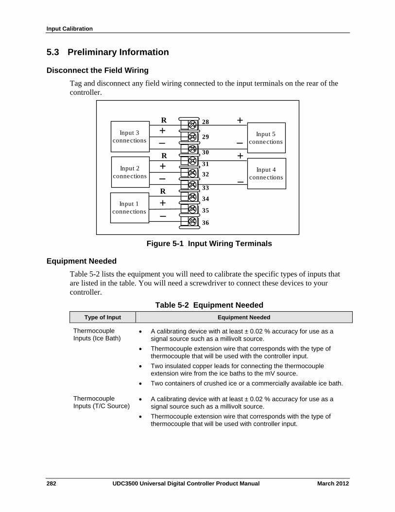
Input Calibration
282 UDC3500 Universal Digital Controller Product Manual March 2012
5.3 Preliminary Information
Disconnect the Field Wiring
Tag and disconnect any field wiring connected to the input terminals on the rear of the controller.
R
+
–
+
–
Input 1 connections
R
Input 2 connections
Input 4 connections
+
–
30
29
31
32
33
34
35
36
28
Input 5 connections
+
+
–
R
Input 3 connections –
Figure 5-1 Input Wiring Terminals
Equipment Needed
Table 5-2 lists the equipment you will need to calibrate the specific types of inputs that are listed in the table. You will need a screwdriver to connect these devices to your controller.
Table 5-2 Equipment Needed
Type of Input Equipment Needed
Thermocouple Inputs (Ice Bath)
A calibrating device with at least ± 0.02 % accuracy for use as a signal source such as a millivolt source.
Thermocouple extension wire that corresponds with the type of thermocouple that will be used with the controller input.
Two insulated copper leads for connecting the thermocouple extension wire from the ice baths to the mV source.
Two containers of crushed ice or a commercially available ice bath.
Thermocouple Inputs (T/C Source)
A calibrating device with at least ± 0.02 % accuracy for use as a signal source such as a millivolt source.
Thermocouple extension wire that corresponds with the type of thermocouple that will be used with controller input.
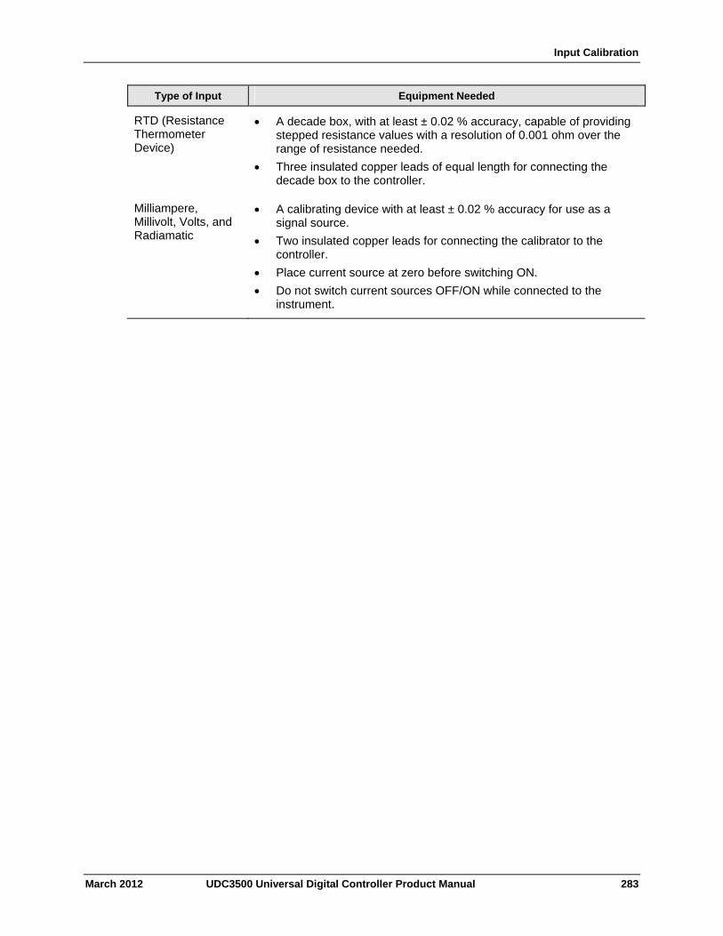
Input Calibration
March 2012 UDC3500 Universal Digital Controller Product Manual 283
Type of Input Equipment Needed
RTD (Resistance Thermometer Device)
A decade box, with at least ± 0.02 % accuracy, capable of providing stepped resistance values with a resolution of 0.001 ohm over the range of resistance needed.
Three insulated copper leads of equal length for connecting the decade box to the controller.
Milliampere, Millivolt, Volts, and Radiamatic
A calibrating device with at least ± 0.02 % accuracy for use as a signal source.
Two insulated copper leads for connecting the calibrator to the controller.
Place current source at zero before switching ON.
Do not switch current sources OFF/ON while connected to the instrument.
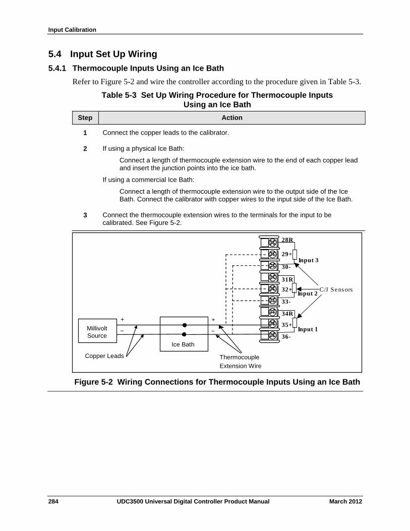
Input Calibration
5.4 Input Set Up Wiring
5.4.1 Thermocouple Inputs Using an Ice Bath
Refer to Figure 5-2 and wire the controller according to the procedure given in Table 5-3.
Table 5-3 Set Up Wiring Procedure for Thermocouple Inputs Using an Ice Bath
Step Action
Connect the copper leads to the calibrator. 1
If using a physical Ice Bath:
Connect a length of thermocouple extension wire to the end of each copper lead and insert the junction points into the ice bath.
If using a commercial Ice Bath:
Connect a length of thermocouple extension wire to the output side of the Ice Bath. Connect the calibrator with copper wires to the input side of the Ice Bath.
2
Connect the thermocouple extension wires to the terminals for the input to be calibrated. See Figure 5-2.
3
_ Millivolt Source
Ice Bath
Copper Leads Thermocouple
Extension Wire
+
30-
29+
31R
32+
33-
34R
35+
36-
28R
Input 1
Input 2
Input 3
C/J Sensors
_
+
Figure 5-2 Wiring Connections for Thermocouple Inputs Using an Ice Bath
284 UDC3500 Universal Digital Controller Product Manual March 2012
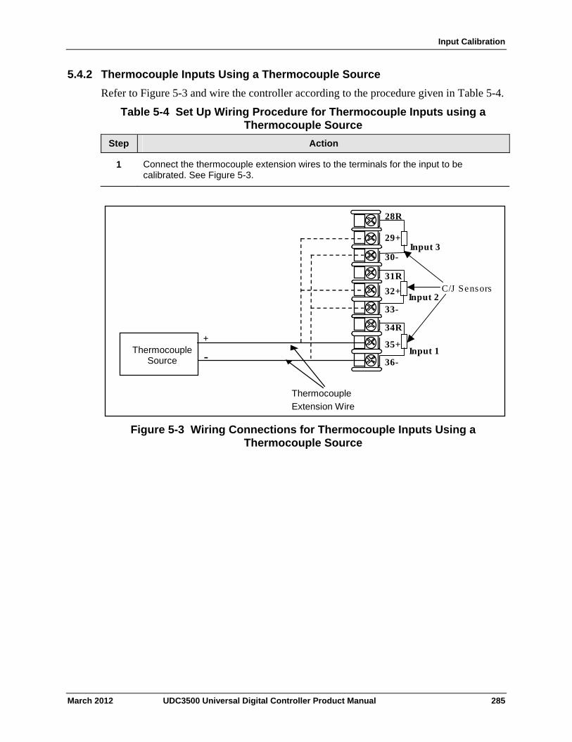
Input Calibration
5.4.2 Thermocouple Inputs Using a Thermocouple Source
Refer to Figure 5-3 and wire the controller according to the procedure given in Table 5-4.
Table 5-4 Set Up Wiring Procedure for Thermocouple Inputs using a Thermocouple Source
Step Action
Connect the thermocouple extension wires to the terminals for the input to be calibrated. See Figure 5-3.
1
_ Thermocouple Source
Thermocouple
Extension Wire
+
-
30-
29+
31R
32+
33-
34R
35+
36-
28R
Input 1
Input 2
Input 3
C/J Sensors
Figure 5-3 Wiring Connections for Thermocouple Inputs Using a Thermocouple Source
March 2012 UDC3500 Universal Digital Controller Product Manual 285
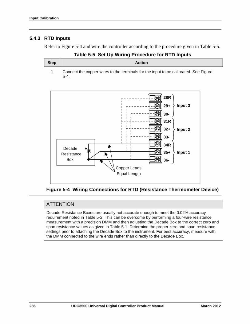
Input Calibration
5.4.3 RTD Inputs
Refer to Figure 5-4 and wire the controller according to the procedure given in Table 5-5.
Table 5-5 Set Up Wiring Procedure for RTD Inputs
Step Action
Connect the copper wires to the terminals for the input to be calibrated. See Figure 5-4.
1
Decade Resistance
Box
Copper Leads
Equal Length
30-
29+
31R
32+
33-
34R
35+
36-
28R
Input 1
Input 2
Input 3
Figure 5-4 Wiring Connections for RTD (Resistance Thermometer Device)
ATTENTION
Decade Resistance Boxes are usually not accurate enough to meet the 0.02% accuracy requirement noted in Table 5-2. This can be overcome by performing a four-wire resistance measurement with a precision DMM and then adjusting the Decade Box to the correct zero and span resistance values as given in Table 5-1. Determine the proper zero and span resistance settings prior to attaching the Decade Box to the instrument. For best accuracy, measure with the DMM connected to the wire ends rather than directly to the Decade Box.
286 UDC3500 Universal Digital Controller Product Manual March 2012
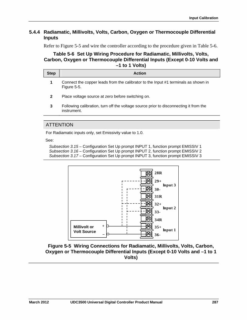
Input Calibration
5.4.4 Radiamatic, Millivolts, Volts, Carbon, Oxygen or Thermocouple Differential Inputs
Refer to Figure 5-5 and wire the controller according to the procedure given in Table 5-6.
Table 5-6 Set Up Wiring Procedure for Radiamatic, Millivolts, Volts, Carbon, Oxygen or Thermocouple Differential Inputs (Except 0-10 Volts and
–1 to 1 Volts)
Step Action
Connect the copper leads from the calibrator to the Input #1 terminals as shown in Figure 5-5.
1
Place voltage source at zero before switching on. 2
Following calibration, turn off the voltage source prior to disconnecting it from the instrument.
3
ATTENTION
For Radiamatic inputs only, set Emissivity value to 1.0.
See:
Subsection 3.15 – Configuration Set Up prompt INPUT 1, function prompt EMISSIV 1 Subsection 3.16 – Configuration Set Up prompt INPUT 2, function prompt EMISSIV 2 Subsection 3.17 – Configuration Set Up prompt INPUT 3, function prompt EMISSIV 3
Millivolt or Volt Source
+
_
30-
29+
31R
32+
33-
34R
35+
36-
28R
Input 1
Input 2
Input 3
Figure 5-5 Wiring Connections for Radiamatic, Millivolts, Volts, Carbon, Oxygen or Thermocouple Differential Inputs (Except 0-10 Volts and –1 to 1
Volts)
March 2012 UDC3500 Universal Digital Controller Product Manual 287
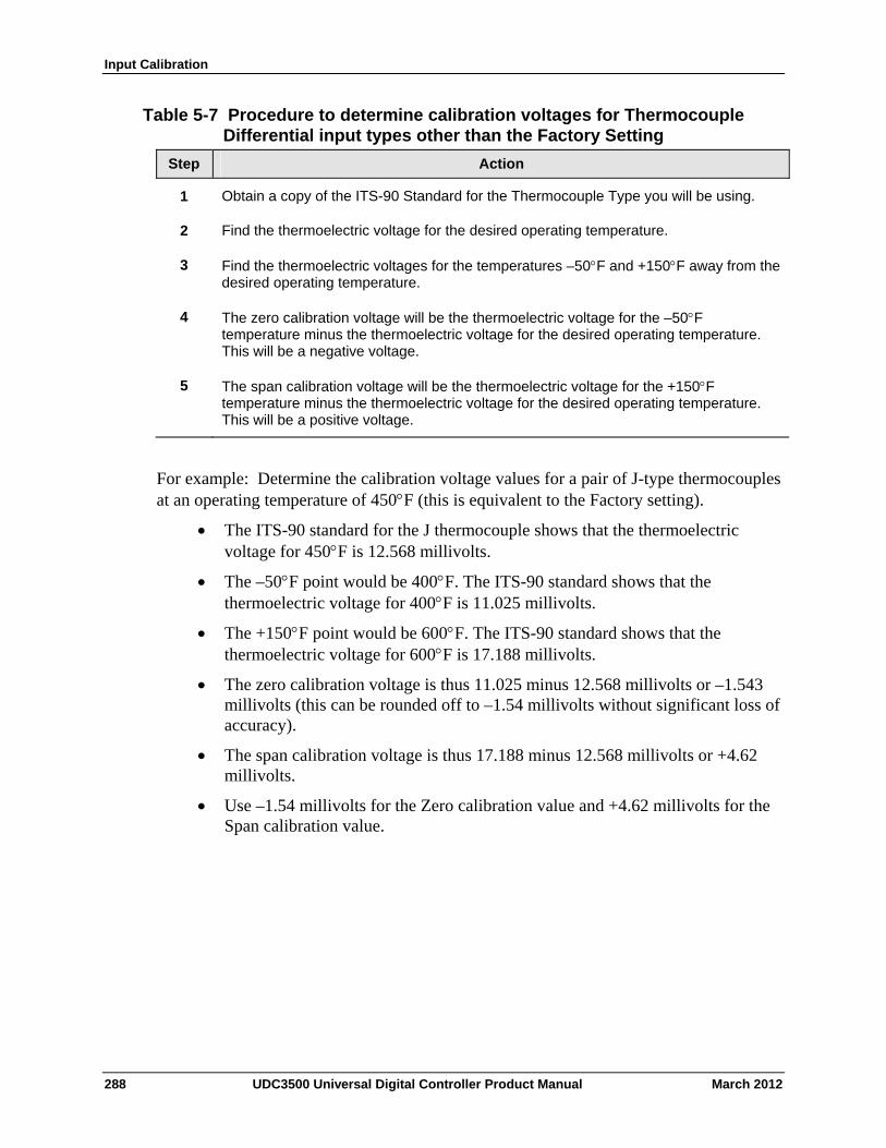
Input Calibration
Table 5-7 Procedure to determine calibration voltages for Thermocouple Differential input types other than the Factory Setting
Step Action
Obtain a copy of the ITS-90 Standard for the Thermocouple Type you will be using. 1
Find the thermoelectric voltage for the desired operating temperature. 2
3 Find the thermoelectric voltages for the temperatures –50F and +150F away from the desired operating temperature.
4 The zero calibration voltage will be the thermoelectric voltage for the –50F temperature minus the thermoelectric voltage for the desired operating temperature. This will be a negative voltage.
5 The span calibration voltage will be the thermoelectric voltage for the +150F temperature minus the thermoelectric voltage for the desired operating temperature. This will be a positive voltage.
For example: Determine the calibration voltage values for a pair of J-type thermocouples at an operating temperature of 450F (this is equivalent to the Factory setting).
The ITS-90 standard for the J thermocouple shows that the thermoelectric voltage for 450F is 12.568 millivolts.
The –50F point would be 400F. The ITS-90 standard shows that the thermoelectric voltage for 400F is 11.025 millivolts.
The +150F point would be 600F. The ITS-90 standard shows that the thermoelectric voltage for 600F is 17.188 millivolts.
The zero calibration voltage is thus 11.025 minus 12.568 millivolts or –1.543 millivolts (this can be rounded off to –1.54 millivolts without significant loss of accuracy).
The span calibration voltage is thus 17.188 minus 12.568 millivolts or +4.62 millivolts.
Use –1.54 millivolts for the Zero calibration value and +4.62 millivolts for the Span calibration value.
288 UDC3500 Universal Digital Controller Product Manual March 2012
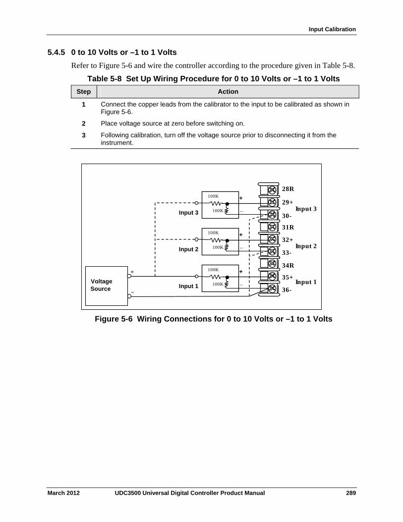
Input Calibration
5.4.5 0 to 10 Volts or –1 to 1 Volts
Refer to Figure 5-6 and wire the controller according to the procedure given in Table 5-8.
Table 5-8 Set Up Wiring Procedure for 0 to 10 Volts or –1 to 1 Volts
Step Action
Connect the copper leads from the calibrator to the input to be calibrated as shown in Figure 5-6.
1
Place voltage source at zero before switching on. 2
Following calibration, turn off the voltage source prior to disconnecting it from the instrument.
3
Voltage Source _
+
30-
29+
31R
32+
33-
34R
35+
36-
28R
Input 1
Input 2
Input 3
100KInput 1
+
_
100K
100KInput 2
+
_
100K
100KInput 3
+
_
100K
Figure 5-6 Wiring Connections for 0 to 10 Volts or –1 to 1 Volts
March 2012 UDC3500 Universal Digital Controller Product Manual 289
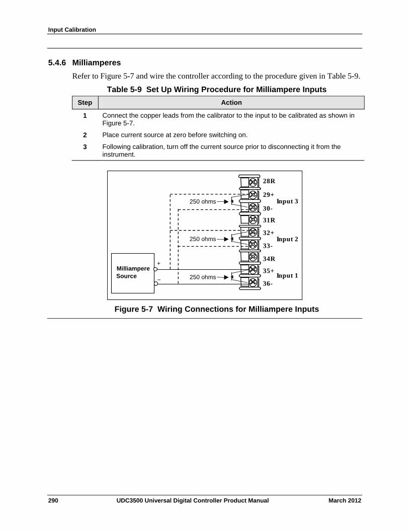
Input Calibration
5.4.6 Milliamperes
Refer to Figure 5-7 and wire the controller according to the procedure given in Table 5-9.
Table 5-9 Set Up Wiring Procedure for Milliampere Inputs
Step Action
Connect the copper leads from the calibrator to the input to be calibrated as shown in Figure 5-7.
1
Place current source at zero before switching on. 2
Following calibration, turn off the current source prior to disconnecting it from the instrument.
3
30-
29+
31R
32+
33-
34R
35+
36-
28R
Input 1
Input 2
Input 3
250 ohms
Milliampere Source _
+
250 ohms
250 ohms
Figure 5-7 Wiring Connections for Milliampere Inputs
290 UDC3500 Universal Digital Controller Product Manual March 2012
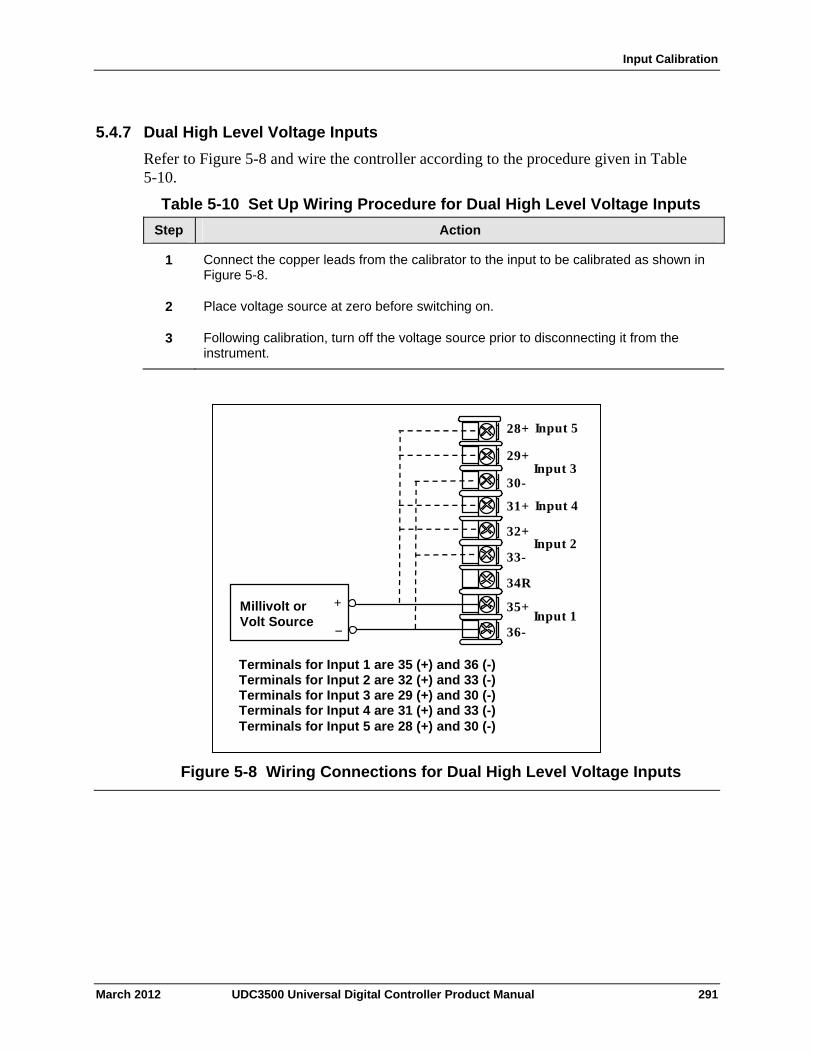
Input Calibration
5.4.7 Dual High Level Voltage Inputs
Refer to Figure 5-8 and wire the controller according to the procedure given in Table 5-10.
Table 5-10 Set Up Wiring Procedure for Dual High Level Voltage Inputs
Step Action
Connect the copper leads from the calibrator to the input to be calibrated as shown in Figure 5-8.
1
Place voltage source at zero before switching on. 2
Following calibration, turn off the voltage source prior to disconnecting it from the instrument.
3
Input 5
Terminals for Input 1 are 35 (+) and 36 (-)Terminals for Input 2 are 32 (+) and 33 (-) Terminals for Input 3 are 29 (+) and 30 (-) Terminals for Input 4 are 31 (+) and 33 (-) Terminals for Input 5 are 28 (+) and 30 (-)
Millivolt or Volt Source
+
_
30-
29+
31+
32+
33-
34R
35+
36-
28+
Input 1
Input 2
Input 3
Input 4
Figure 5-8 Wiring Connections for Dual High Level Voltage Inputs
March 2012 UDC3500 Universal Digital Controller Product Manual 291
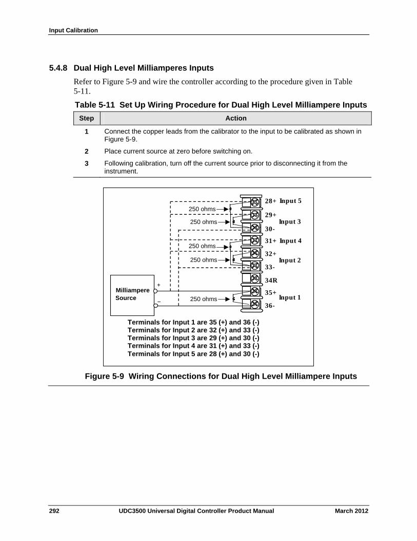
Input Calibration
5.4.8 Dual High Level Milliamperes Inputs
Refer to Figure 5-9 and wire the controller according to the procedure given in Table 5-11.
Table 5-11 Set Up Wiring Procedure for Dual High Level Milliampere Inputs
Step Action
Connect the copper leads from the calibrator to the input to be calibrated as shown in Figure 5-9.
1
Place current source at zero before switching on. 2
Following calibration, turn off the current source prior to disconnecting it from the instrument.
3
30-
29+
31+
32+
33-
34R
35+
36-
28+
Input 1
Input 2
Input 3
250 ohms
Milliampere Source _
+
250 ohms
250 ohms
250 ohms
250 ohms
Input 5
Input 4
Terminals for Input 1 are 35 (+) and 36 (-)Terminals for Input 2 are 32 (+) and 33 (-) Terminals for Input 3 are 29 (+) and 30 (-) Terminals for Input 4 are 31 (+) and 33 (-) Terminals for Input 5 are 28 (+) and 30 (-)
Figure 5-9 Wiring Connections for Dual High Level Milliampere Inputs
292 UDC3500 Universal Digital Controller Product Manual March 2012
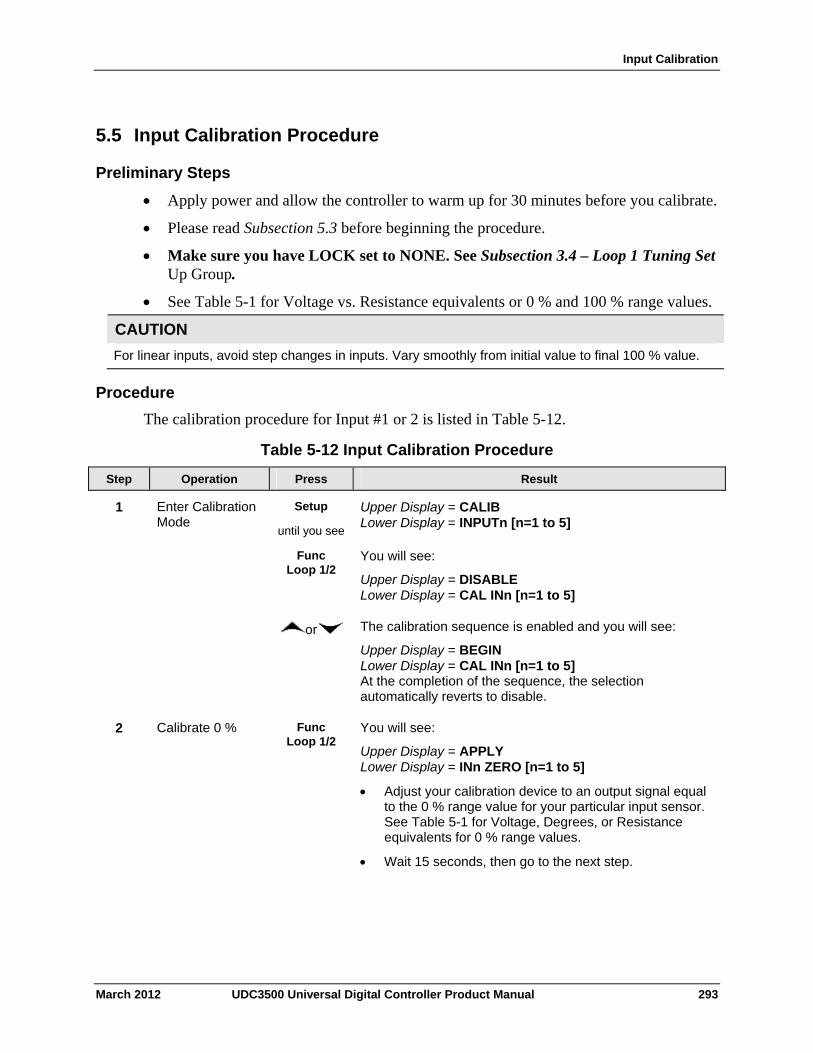
Input Calibration
March 2012 UDC3500 Universal Digital Controller Product Manual 293
5.5 Input Calibration Procedure
Preliminary Steps
Apply power and allow the controller to warm up for 30 minutes before you calibrate.
Please read Subsection 5.3 before beginning the procedure.
Make sure you have LOCK set to NONE. See Subsection 3.4 – Loop 1 Tuning Set Up Group.
See Table 5-1 for Voltage vs. Resistance equivalents or 0 % and 100 % range values.
CAUTION
For linear inputs, avoid step changes in inputs. Vary smoothly from initial value to final 100 % value.
Procedure
The calibration procedure for Input #1 or 2 is listed in Table 5-12.
Table 5-12 Input Calibration Procedure
Step Operation Press Result
1 Enter Calibration Mode
Setup
until you see
Upper Display = CALIB Lower Display = INPUTn [n=1 to 5]
Func Loop 1/2
You will see:
Upper Display = DISABLE Lower Display = CAL INn [n=1 to 5]
or The calibration sequence is enabled and you will see:
Upper Display = BEGIN Lower Display = CAL INn [n=1 to 5] At the completion of the sequence, the selection automatically reverts to disable.
2 Calibrate 0 % Func Loop 1/2
You will see:
Upper Display = APPLY Lower Display = INn ZERO [n=1 to 5]
Adjust your calibration device to an output signal equal to the 0 % range value for your particular input sensor. See Table 5-1 for Voltage, Degrees, or Resistance equivalents for 0 % range values.
Wait 15 seconds, then go to the next step.
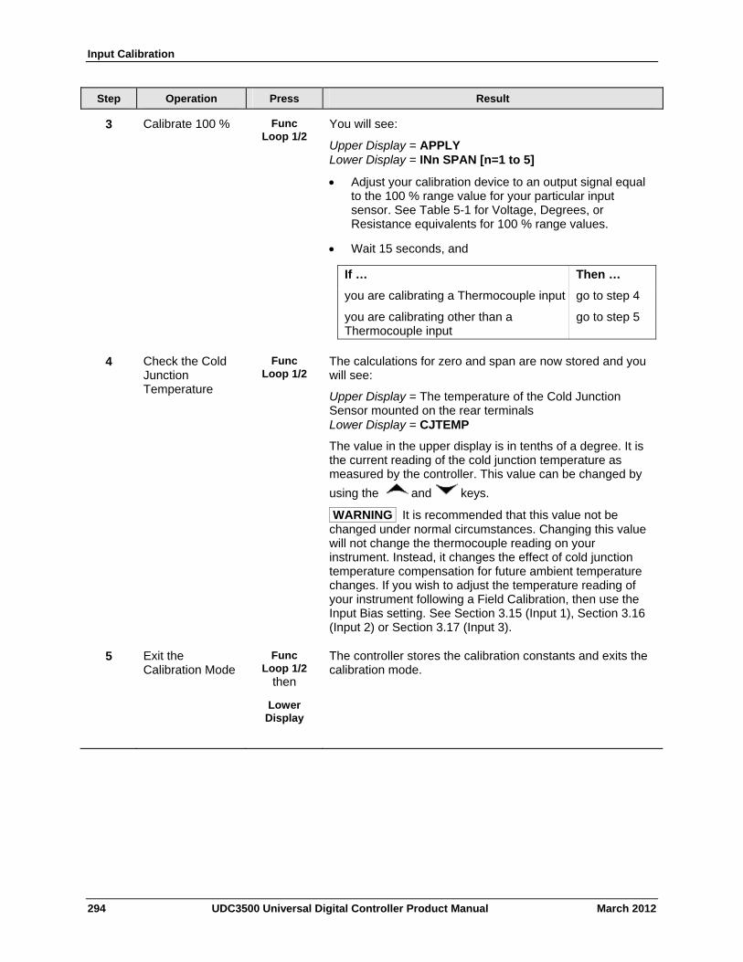
Input Calibration
294 UDC3500 Universal Digital Controller Product Manual March 2012
Step Operation Press Result
3 Calibrate 100 % Func Loop 1/2
You will see:
Upper Display = APPLY Lower Display = INn SPAN [n=1 to 5]
Adjust your calibration device to an output signal equal to the 100 % range value for your particular input sensor. See Table 5-1 for Voltage, Degrees, or Resistance equivalents for 100 % range values.
Wait 15 seconds, and
If … Then …
you are calibrating a Thermocouple input go to step 4
you are calibrating other than a go to step 5 Thermocouple input
4 Check the Cold Junction Temperature
Func Loop 1/2
The calculations for zero and span are now stored and you will see:
Upper Display = The temperature of the Cold Junction Sensor mounted on the rear terminals Lower Display = CJTEMP
The value in the upper display is in tenths of a degree. It is the current reading of the cold junction temperature as measured by the controller. This value can be changed by
using the and keys.
WARNING It is recommended that this value not be changed under normal circumstances. Changing this value will not change the thermocouple reading on your instrument. Instead, it changes the effect of cold junction temperature compensation for future ambient temperature changes. If you wish to adjust the temperature reading of your instrument following a Field Calibration, then use the Input Bias setting. See Section 3.15 (Input 1), Section 3.16 (Input 2) or Section 3.17 (Input 3).
5 Exit the Calibration Mode
Func Loop 1/2
then
The controller stores the calibration constants and exits the calibration mode.
Lower Display
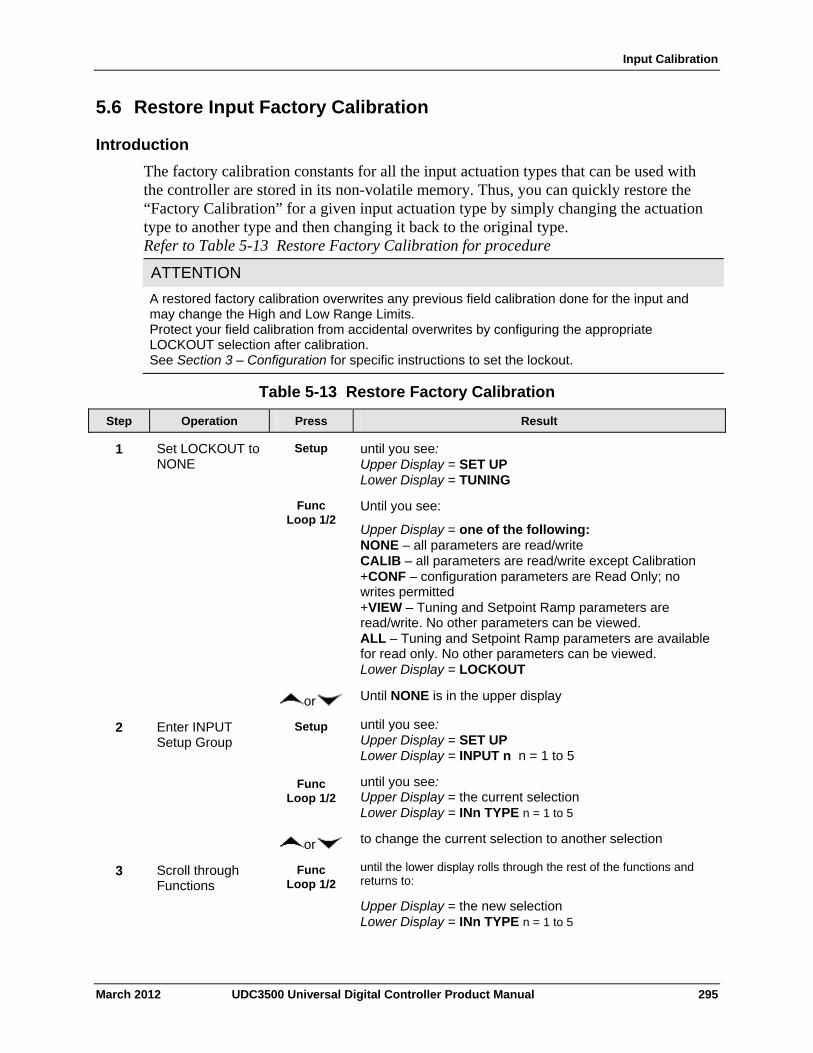
Input Calibration
5.6 Restore Input Factory Calibration
Introduction
The factory calibration constants for all the input actuation types that can be used with the controller are stored in its non-volatile memory. Thus, you can quickly restore the “Factory Calibration” for a given input actuation type by simply changing the actuation type to another type and then changing it back to the original type. Refer to Table 5-13 Restore Factory Calibration for procedure
ATTENTION
A restored factory calibration overwrites any previous field calibration done for the input and may change the High and Low Range Limits. Protect your field calibration from accidental overwrites by configuring the appropriate LOCKOUT selection after calibration. See Section 3 – Configuration for specific instructions to set the lockout.
Table 5-13 Restore Factory Calibration
Operation Press Result Step
Set LOCKOUT to NONE
Setup until you see: Upper Display = SET UP Lower Display = TUNING
1
Func Loop 1/2
Until you see:
Upper Display = one of the following: NONE – all parameters are read/write CALIB – all parameters are read/write except Calibration +CONF – configuration parameters are Read Only; no writes permitted +VIEW – Tuning and Setpoint Ramp parameters are read/write. No other parameters can be viewed. ALL – Tuning and Setpoint Ramp parameters are available for read only. No other parameters can be viewed. Lower Display = LOCKOUT
or Until NONE is in the upper display
Enter INPUT Setup Group
Setup until you see: Upper Display = SET UP Lower Display = INPUT n n = 1 to 5
2
Func Loop 1/2
until you see: Upper Display = the current selection Lower Display = INn TYPE n = 1 to 5
or to change the current selection to another selection
Scroll through Functions
Func Loop 1/2
until the lower display rolls through the rest of the functions and returns to:
Upper Display = the new selection Lower Display = INn TYPE n = 1 to 5
3
March 2012 UDC3500 Universal Digital Controller Product Manual 295
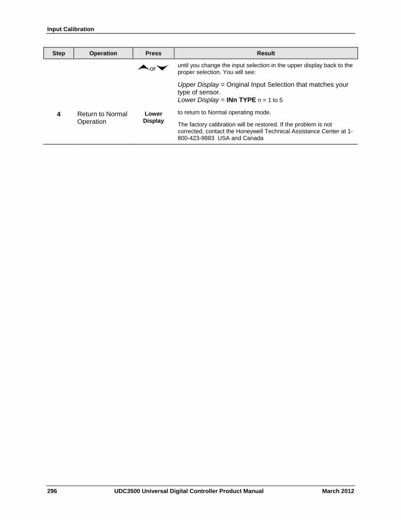
Input Calibration
Step Operation Press Result
or until you change the input selection in the upper display back to the proper selection. You will see:
Upper Display = Original Input Selection that matches your type of sensor. Lower Display = INn TYPE n = 1 to 5
4 Return to Normal Operation
Lower Display
to return to Normal operating mode.
The factory calibration will be restored. If the problem is not corrected, contact the Honeywell Technical Assistance Center at 1-800-423-9883 USA and Canada
296 UDC3500 Universal Digital Controller Product Manual March 2012
Output Calibration
March 2012 UDC3500 Universal Digital Controller Product Manual 297
6 Output Calibration
6.1 Overview
Introduction
This section describes the field calibration procedures for the following types of outputs:
Current Outputs
Position Proportional Output and Three Position Step Output
What’s in this section?
The following topics are covered in this section.
TOPIC See Page
6.1 Overview 297
6.2 First Current Output Calibration 298
6.3 Second Current Output Calibration 300
6.4 Third Current Output Calibration 302
6.5 Position Proportional and Three Position Step Output Calibration 304
6.6 Restore Factory Output Calibration 307
WARNING—SHOCK HAZARD
OUTPUT CALIBRATION MAY REQUIRE ACCESS TO HAZARDOUS LIVE CIRCUITS, AND SHOULD ONLY BE PERFORMED BY QUALIFIED SERVICE PERSONNEL. MORE THAN ONE SWITCH MAY BE REQUIRED TO DE-ENERGIZE UNIT BEFORE CALIBRATION.
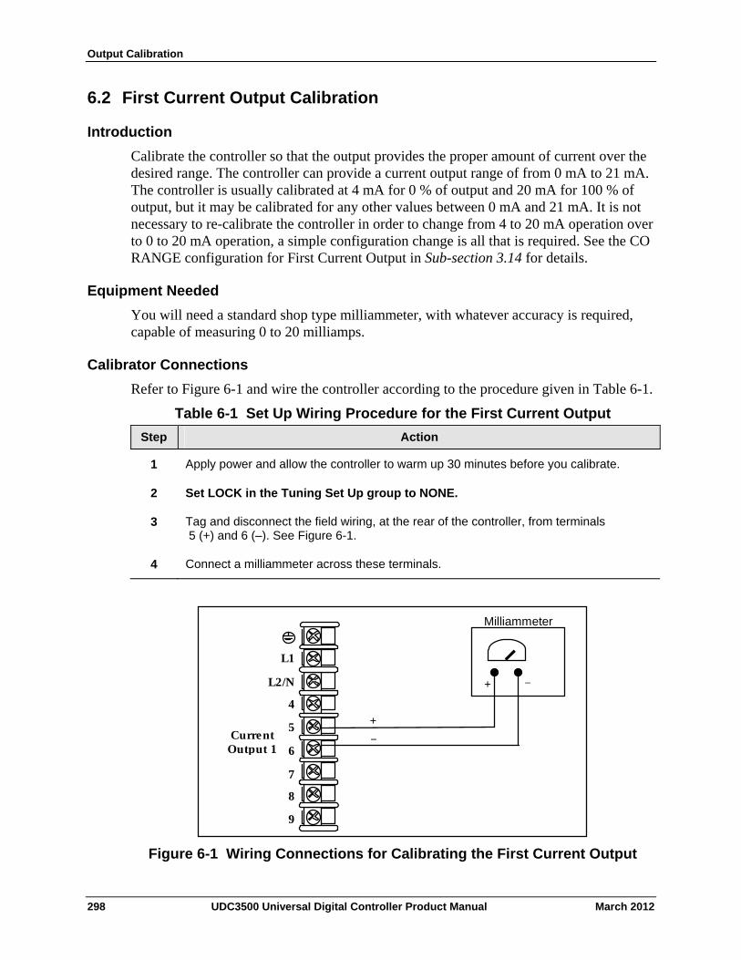
Output Calibration
6.2 First Current Output Calibration
Introduction
Calibrate the controller so that the output provides the proper amount of current over the desired range. The controller can provide a current output range of from 0 mA to 21 mA. The controller is usually calibrated at 4 mA for 0 % of output and 20 mA for 100 % of output, but it may be calibrated for any other values between 0 mA and 21 mA. It is not necessary to re-calibrate the controller in order to change from 4 to 20 mA operation over to 0 to 20 mA operation, a simple configuration change is all that is required. See the CO RANGE configuration for First Current Output in Sub-section 3.14 for details.
Equipment Needed
You will need a standard shop type milliammeter, with whatever accuracy is required, capable of measuring 0 to 20 milliamps.
Calibrator Connections
Refer to Figure 6-1 and wire the controller according to the procedure given in Table 6-1.
Table 6-1 Set Up Wiring Procedure for the First Current Output
Step Action
Apply power and allow the controller to warm up 30 minutes before you calibrate. 1
2 Set LOCK in the Tuning Set Up group to NONE.
Tag and disconnect the field wiring, at the rear of the controller, from terminals 5 (+) and 6 (–). See Figure 6-1.
3
Connect a milliammeter across these terminals. 4
Milliammeter
+ _
+_
L2/N
L1
4
5
6
7
8
9
Current Output 1
Figure 6-1 Wiring Connections for Calibrating the First Current Output
298 UDC3500 Universal Digital Controller Product Manual March 2012
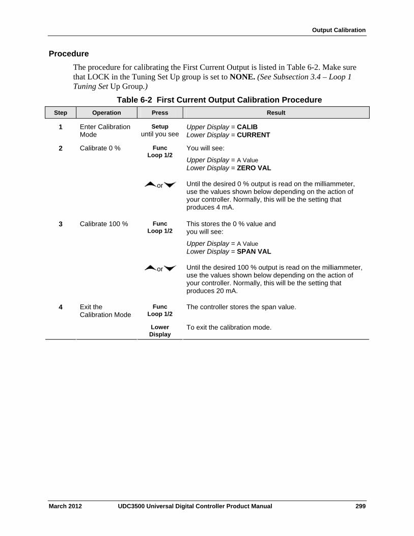
Output Calibration
Procedure
The procedure for calibrating the First Current Output is listed in Table 6-2. Make sure that LOCK in the Tuning Set Up group is set to NONE. (See Subsection 3.4 – Loop 1 Tuning Set Up Group.)
Table 6-2 First Current Output Calibration Procedure
Operation Press Result Step
Enter Calibration Mode
Setup until you see
Upper Display = CALIB Lower Display = CURRENT
1
Calibrate 0 % Func Loop 1/2
You will see:
Upper Display = A Value Lower Display = ZERO VAL
2
or Until the desired 0 % output is read on the milliammeter, use the values shown below depending on the action of your controller. Normally, this will be the setting that produces 4 mA.
Calibrate 100 % Func Loop 1/2
This stores the 0 % value and you will see:
Upper Display = A Value Lower Display = SPAN VAL
3
or Until the desired 100 % output is read on the milliammeter, use the values shown below depending on the action of your controller. Normally, this will be the setting that produces 20 mA.
Func Loop 1/2
The controller stores the span value.
Exit the Calibration Mode
4
To exit the calibration mode. Lower Display
March 2012 UDC3500 Universal Digital Controller Product Manual 299
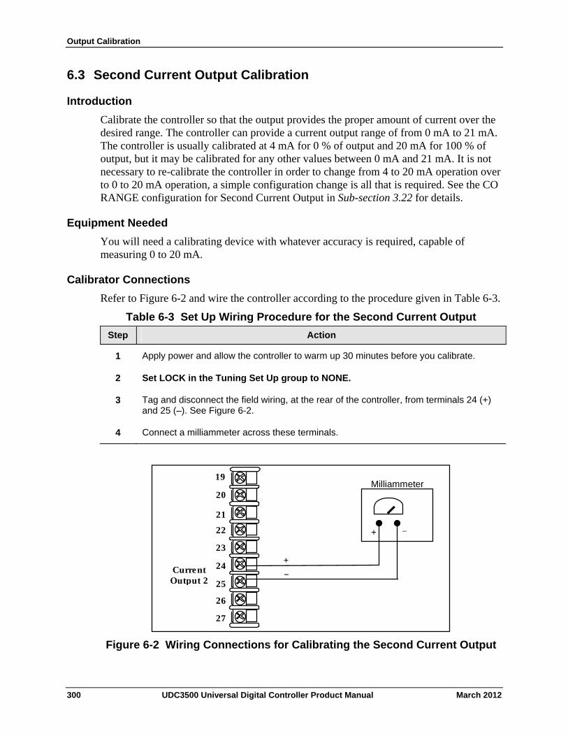
Output Calibration
6.3 Second Current Output Calibration
Introduction
Calibrate the controller so that the output provides the proper amount of current over the desired range. The controller can provide a current output range of from 0 mA to 21 mA. The controller is usually calibrated at 4 mA for 0 % of output and 20 mA for 100 % of output, but it may be calibrated for any other values between 0 mA and 21 mA. It is not necessary to re-calibrate the controller in order to change from 4 to 20 mA operation over to 0 to 20 mA operation, a simple configuration change is all that is required. See the CO RANGE configuration for Second Current Output in Sub-section 3.22 for details.
Equipment Needed
You will need a calibrating device with whatever accuracy is required, capable of measuring 0 to 20 mA.
Calibrator Connections
Refer to Figure 6-2 and wire the controller according to the procedure given in Table 6-3.
Table 6-3 Set Up Wiring Procedure for the Second Current Output
Step Action
Apply power and allow the controller to warm up 30 minutes before you calibrate. 1
2 Set LOCK in the Tuning Set Up group to NONE.
Tag and disconnect the field wiring, at the rear of the controller, from terminals 24 (+) and 25 (–). See Figure 6-2.
3
Connect a milliammeter across these terminals. 4
Milliammeter
+ _
+_
21
20
22
23
24
25
26
27
19
Current Output 2
Figure 6-2 Wiring Connections for Calibrating the Second Current Output
300 UDC3500 Universal Digital Controller Product Manual March 2012

Output Calibration
Procedure
The procedure for calibrating the Second Current Output is listed in Table 6-4.
Make sure that “LOCK” in the Tuning Set Up group is set to “NONE” (see Subsection 3.4).
Table 6-4 Second Current Output Calibration Procedure
Operation Press Result Step
Enter Calibration Mode
Setup until you see
Upper Display = CALIB Lower Display = CUR OUT2
1
Calibrate 0 % Func Loop 1/2
You will see:
Upper Display = A Value Lower Display = ZERO VAL
2
or until the desired 0 % output is read on the milliammeter. Normally, this will be the setting that produces 4 mA.
Calibrate 100 % Func Loop 1/2
To store the 0 % value you will see:
Upper Display = A Value Lower Display = SPAN VAL
3
or until the desired 100 % output is read on the milliammeter. Normally, this will be the setting that produces 20 mA.
Func Loop 1/2
The controller stores the span value.
Exit the Calibration Mode
4
To exit the calibration mode. Lower Display
March 2012 UDC3500 Universal Digital Controller Product Manual 301
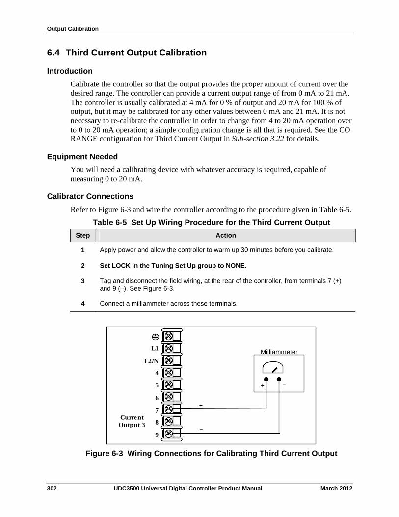
Output Calibration
6.4 Third Current Output Calibration
Introduction
Calibrate the controller so that the output provides the proper amount of current over the desired range. The controller can provide a current output range of from 0 mA to 21 mA. The controller is usually calibrated at 4 mA for 0 % of output and 20 mA for 100 % of output, but it may be calibrated for any other values between 0 mA and 21 mA. It is not necessary to re-calibrate the controller in order to change from 4 to 20 mA operation over to 0 to 20 mA operation; a simple configuration change is all that is required. See the CO RANGE configuration for Third Current Output in Sub-section 3.22 for details.
Equipment Needed
You will need a calibrating device with whatever accuracy is required, capable of measuring 0 to 20 mA.
Calibrator Connections
Refer to Figure 6-3 and wire the controller according to the procedure given in Table 6-5.
Table 6-5 Set Up Wiring Procedure for the Third Current Output
Step Action
Apply power and allow the controller to warm up 30 minutes before you calibrate. 1
2 Set LOCK in the Tuning Set Up group to NONE.
Tag and disconnect the field wiring, at the rear of the controller, from terminals 7 (+) and 9 (–). See Figure 6-3.
3
Connect a milliammeter across these terminals. 4
Milliammeter
+ _
+
_
L2/N
L1
4
5
6
7
8
9
Current Output 3
Figure 6-3 Wiring Connections for Calibrating Third Current Output
302 UDC3500 Universal Digital Controller Product Manual March 2012
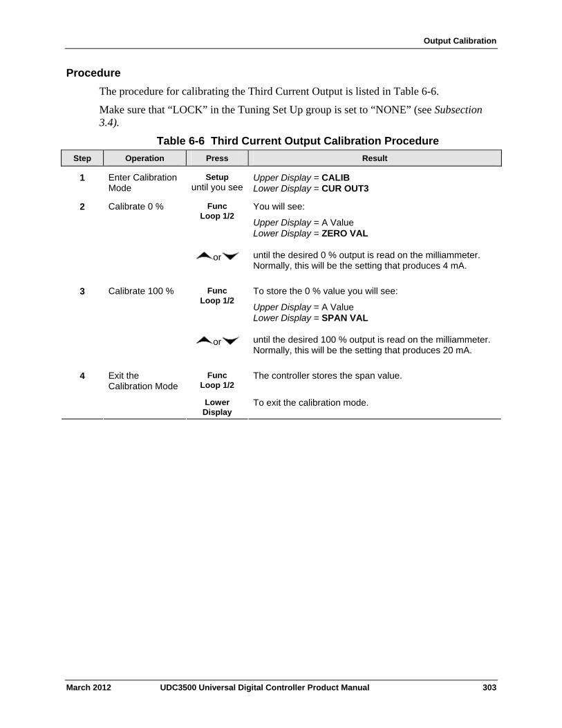
Output Calibration
Procedure
The procedure for calibrating the Third Current Output is listed in Table 6-6.
Make sure that “LOCK” in the Tuning Set Up group is set to “NONE” (see Subsection 3.4).
Table 6-6 Third Current Output Calibration Procedure
Operation Press Result Step
Enter Calibration Mode
Setup until you see
Upper Display = CALIB Lower Display = CUR OUT3
1
Calibrate 0 % Func Loop 1/2
You will see:
Upper Display = A Value Lower Display = ZERO VAL
2
or until the desired 0 % output is read on the milliammeter. Normally, this will be the setting that produces 4 mA.
Calibrate 100 % Func Loop 1/2
To store the 0 % value you will see:
Upper Display = A Value Lower Display = SPAN VAL
3
or until the desired 100 % output is read on the milliammeter. Normally, this will be the setting that produces 20 mA.
Func Loop 1/2
The controller stores the span value.
Exit the Calibration Mode
4
To exit the calibration mode. Lower Display
March 2012 UDC3500 Universal Digital Controller Product Manual 303
Output Calibration
6.5 Position Proportional and Three Position Step Output Calibration
Position Proportional control
Position Proportional Control Output Models
Enter the “Motor Time” as shown in Section 3.14. This model must have its output calibrated per the entire procedure to ensure the displayed output (slidewire position) agrees with the final control element position.
Three position step control
Three Position Step Control Output Models not using slidewire feedback.
This model only requires that the “Motor Time” be entered as shown in Section 3.14.
Three Position Step Control Models using slidewire feedback.
Enter the “Motor Time” as shown in Section 3.14. This model must have its output calibrated per the entire procedure to ensure the displayed output (slidewire position) agrees with the final control element position.
Equipment needed
None.
Connections
Apply power and leave all field wiring connected to the rear terminals.
Procedure
The procedure for calibrating the Three Position Step or Position Proportional control is listed in Table 6-7.
Make sure LOCKOUT in Tuning Set Up group is set to NONE. See Subsection 3.4.
ATTENTION For Three Position Step Control (TPSC), these prompts only appear when “SLIDEW” or “SW EMUL” is selected in the INPUT 3 Setup group. For Position Proportional Control, the Output algorithm must also be configured for “POSPROP”. The Motor Time must be entered in the Output Algorithm Group for both Position Proportional or for Three Position Step control. See Section 3.14 for details.
304 UDC3500 Universal Digital Controller Product Manual March 2012
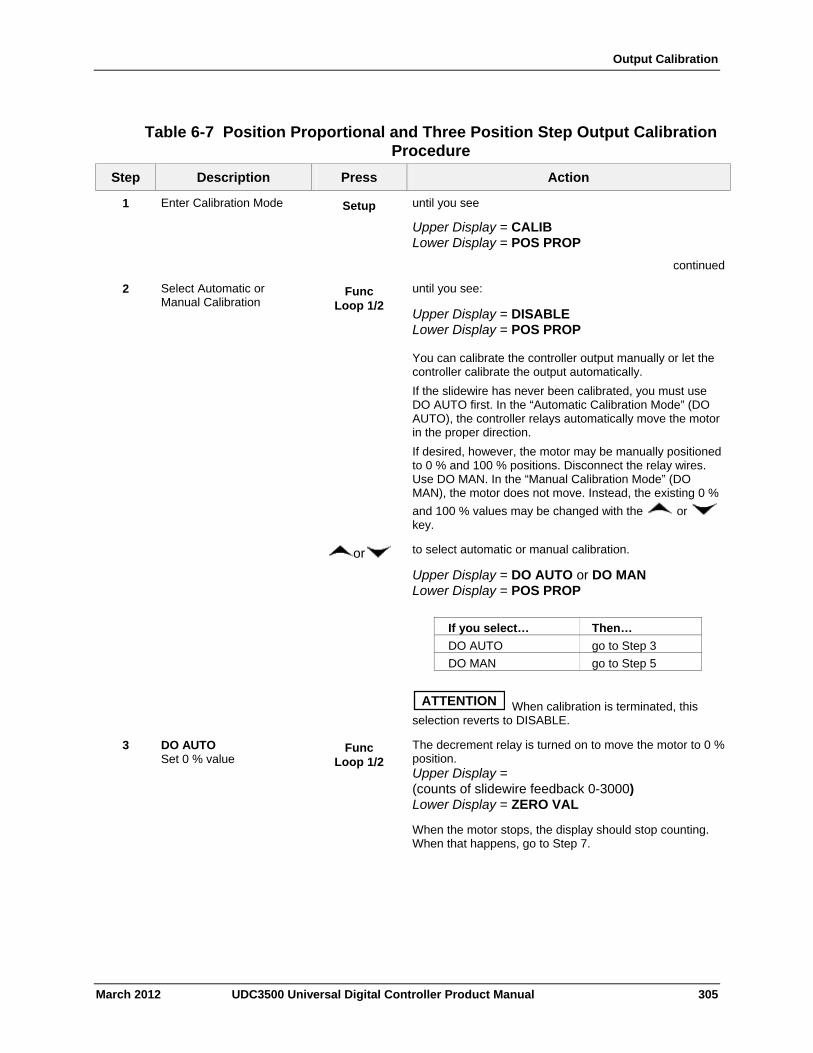
Output Calibration
Table 6-7 Position Proportional and Three Position Step Output Calibration Procedure
Description Press Action Step
Enter Calibration Mode Setup until you see
Upper Display = CALIB Lower Display = POS PROP
continued
1
Select Automatic or Manual Calibration
Func Loop 1/2
until you see:
Upper Display = DISABLE Lower Display = POS PROP You can calibrate the controller output manually or let the controller calibrate the output automatically.
If the slidewire has never been calibrated, you must use DO AUTO first. In the “Automatic Calibration Mode” (DO AUTO), the controller relays automatically move the motor in the proper direction.
If desired, however, the motor may be manually positioned to 0 % and 100 % positions. Disconnect the relay wires. Use DO MAN. In the “Manual Calibration Mode” (DO MAN), the motor does not move. Instead, the existing 0 %
and 100 % values may be changed with the or key.
2
or to select automatic or manual calibration.
Upper Display = DO AUTO or DO MAN Lower Display = POS PROP
If you select… Then…
DO AUTO go to Step 3
DO MAN go to Step 5
ATTENTION When calibration is terminated, this selection reverts to DISABLE.
3 DO AUTO Set 0 % value
Func Loop 1/2
The decrement relay is turned on to move the motor to 0 % position. Upper Display = (counts of slidewire feedback 0-3000) Lower Display = ZERO VAL
When the motor stops, the display should stop counting. When that happens, go to Step 7.
March 2012 UDC3500 Universal Digital Controller Product Manual 305
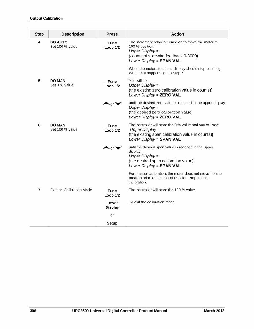
Output Calibration
306 UDC3500 Universal Digital Controller Product Manual March 2012
Step Description Press Action
4 DO AUTO Set 100 % value
Func Loop 1/2
The increment relay is turned on to move the motor to 100 % position. Upper Display = (counts of slidewire feedback 0-3000) Lower Display = SPAN VAL
When the motor stops, the display should stop counting. When that happens, go to Step 7.
5 DO MAN Set 0 % value
Func Loop 1/2
You will see: Upper Display = (the existing zero calibration value in counts)) Lower Display = ZERO VAL
or until the desired zero value is reached in the upper display.Upper Display = (the desired zero calibration value) Lower Display = ZERO VAL
6 DO MAN Set 100 % value
Func Loop 1/2
The controller will store the 0 % value and you will see: Upper Display = (the existing span calibration value in counts)) Lower Display = SPAN VAL
or until the desired span value is reached in the upper display. Upper Display = (the desired span calibration value) Lower Display = SPAN VAL
For manual calibration, the motor does not move from its position prior to the start of Position Proportional calibration.
7 Exit the Calibration Mode Func Loop 1/2
The controller will store the 100 % value.
Lower Display
or
Setup
To exit the calibration mode
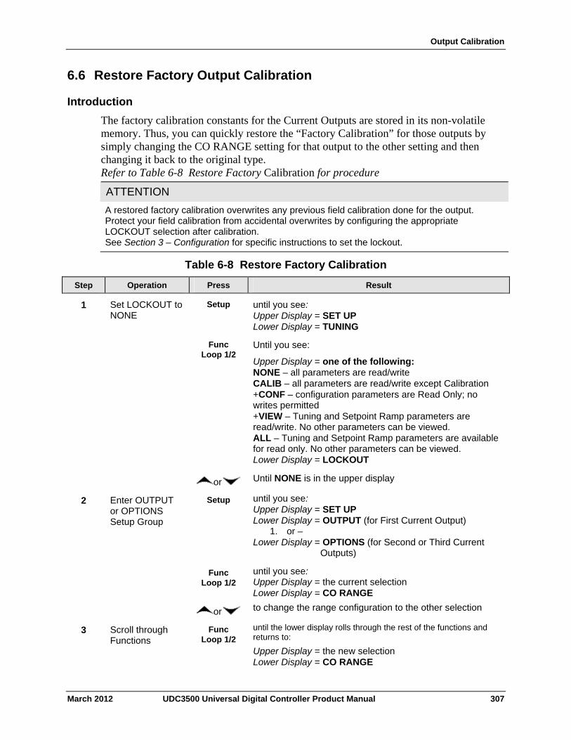
Output Calibration
6.6 Restore Factory Output Calibration
Introduction
The factory calibration constants for the Current Outputs are stored in its non-volatile memory. Thus, you can quickly restore the “Factory Calibration” for those outputs by simply changing the CO RANGE setting for that output to the other setting and then changing it back to the original type. Refer to Table 6-8 Restore Factory Calibration for procedure
ATTENTION
A restored factory calibration overwrites any previous field calibration done for the output. Protect your field calibration from accidental overwrites by configuring the appropriate LOCKOUT selection after calibration. See Section 3 – Configuration for specific instructions to set the lockout.
Table 6-8 Restore Factory Calibration
Operation Press Result Step
Set LOCKOUT to NONE
Setup until you see: Upper Display = SET UP Lower Display = TUNING
1
Func Loop 1/2
Until you see:
Upper Display = one of the following: NONE – all parameters are read/write CALIB – all parameters are read/write except Calibration +CONF – configuration parameters are Read Only; no writes permitted +VIEW – Tuning and Setpoint Ramp parameters are read/write. No other parameters can be viewed. ALL – Tuning and Setpoint Ramp parameters are available for read only. No other parameters can be viewed. Lower Display = LOCKOUT
or Until NONE is in the upper display
Enter OUTPUT or OPTIONS Setup Group
Setup until you see: Upper Display = SET UP Lower Display = OUTPUT (for First Current Output)
1. or – Lower Display = OPTIONS (for Second or Third Current
Outputs)
2
Func Loop 1/2
until you see: Upper Display = the current selection Lower Display = CO RANGE
or to change the range configuration to the other selection
Scroll through Functions
Func Loop 1/2
until the lower display rolls through the rest of the functions and returns to:
Upper Display = the new selection Lower Display = CO RANGE
3
March 2012 UDC3500 Universal Digital Controller Product Manual 307
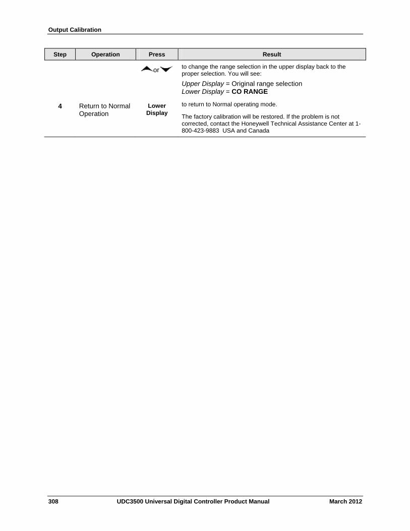
Output Calibration
Step Operation Press Result
or to change the range selection in the upper display back to the proper selection. You will see:
Upper Display = Original range selection Lower Display = CO RANGE
Return to Normal Operation
Lower Display
to return to Normal operating mode.
The factory calibration will be restored. If the problem is not corrected, contact the Honeywell Technical Assistance Center at 1-800-423-9883 USA and Canada
4
308 UDC3500 Universal Digital Controller Product Manual March 2012
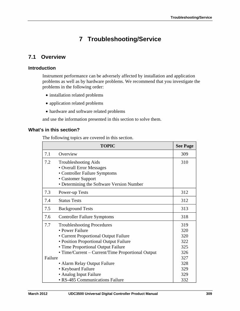
Troubleshooting/Service
7 Troubleshooting/Service
7.1 Overview
Introduction
Instrument performance can be adversely affected by installation and application problems as well as by hardware problems. We recommend that you investigate the problems in the following order:
installation related problems
application related problems
hardware and software related problems
and use the information presented in this section to solve them.
What’s in this section?
The following topics are covered in this section.
TOPIC See Page
7.1 Overview 309
7.2 Troubleshooting Aids • Overall Error Messages • Controller Failure Symptoms • Customer Support • Determining the Software Version Number
310
7.3 Power-up Tests 312
7.4 Status Tests 312
7.5 Background Tests 313
7.6 Controller Failure Symptoms 318
7.7 Troubleshooting Procedures • Power Failure • Current Proportional Output Failure • Position Proportional Output Failure • Time Proportional Output Failure • Time/Current – Current/Time Proportional Output Failure • Alarm Relay Output Failure • Keyboard Failure • Analog Input Failure • RS-485 Communications Failure
319 320 320 322 325 326 327 328 329 329 332
March 2012 UDC3500 Universal Digital Controller Product Manual 309
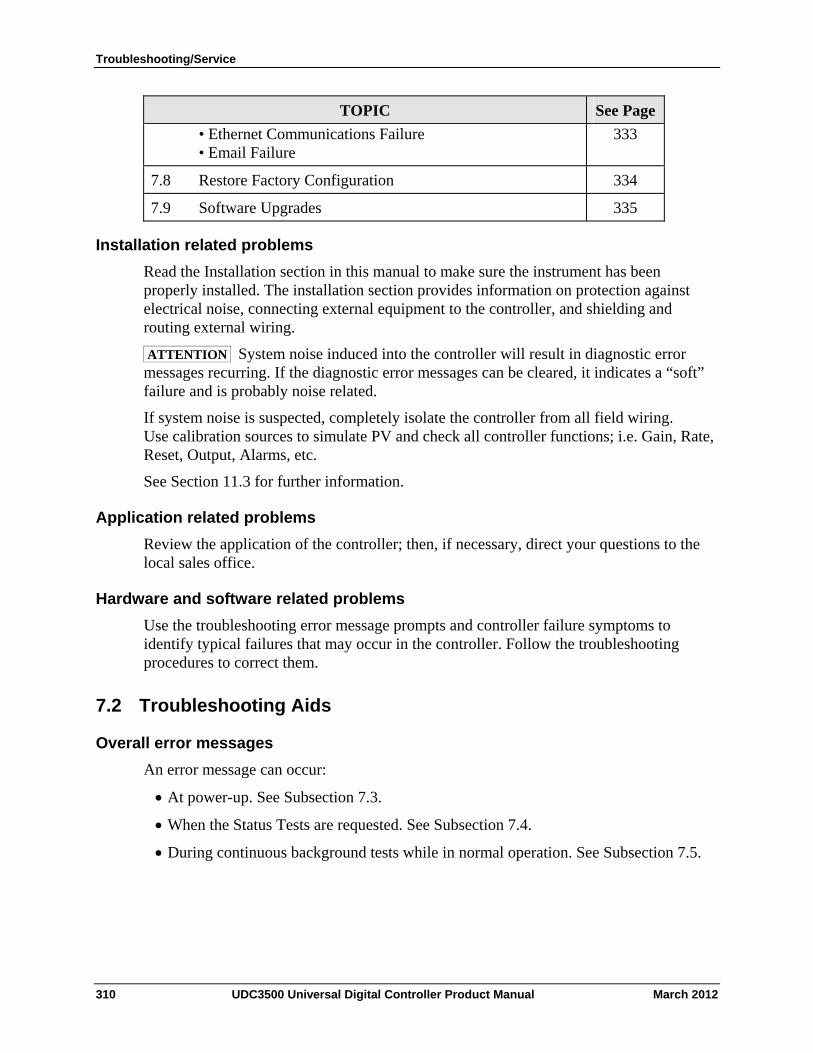
Troubleshooting/Service
310 UDC3500 Universal Digital Controller Product Manual March 2012
TOPIC See Page
• Ethernet Communications Failure • Email Failure
333
7.8 Restore Factory Configuration 334
7.9 Software Upgrades 335
Installation related problems
Read the Installation section in this manual to make sure the instrument has been properly installed. The installation section provides information on protection against electrical noise, connecting external equipment to the controller, and shielding and routing external wiring.
ATTENTION System noise induced into the controller will result in diagnostic error messages recurring. If the diagnostic error messages can be cleared, it indicates a “soft” failure and is probably noise related.
If system noise is suspected, completely isolate the controller from all field wiring. Use calibration sources to simulate PV and check all controller functions; i.e. Gain, Rate, Reset, Output, Alarms, etc.
See Section 11.3 for further information.
Application related problems
Review the application of the controller; then, if necessary, direct your questions to the local sales office.
Hardware and software related problems
Use the troubleshooting error message prompts and controller failure symptoms to identify typical failures that may occur in the controller. Follow the troubleshooting procedures to correct them.
7.2 Troubleshooting Aids
Overall error messages
An error message can occur:
At power-up. See Subsection 7.3.
When the Status Tests are requested. See Subsection 7.4.
During continuous background tests while in normal operation. See Subsection 7.5.
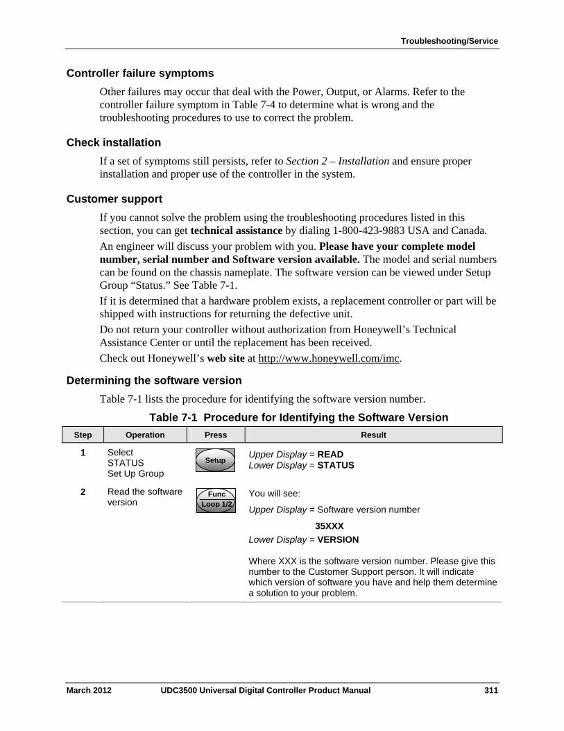
Troubleshooting/Service
Controller failure symptoms
Other failures may occur that deal with the Power, Output, or Alarms. Refer to the controller failure symptom in Table 7-4 to determine what is wrong and the troubleshooting procedures to use to correct the problem.
Check installation
If a set of symptoms still persists, refer to Section 2 – Installation and ensure proper installation and proper use of the controller in the system.
Customer support
If you cannot solve the problem using the troubleshooting procedures listed in this section, you can get technical assistance by dialing 1-800-423-9883 USA and Canada.
An engineer will discuss your problem with you. Please have your complete model number, serial number and Software version available. The model and serial numbers can be found on the chassis nameplate. The software version can be viewed under Setup Group “Status.” See Table 7-1.
If it is determined that a hardware problem exists, a replacement controller or part will be shipped with instructions for returning the defective unit.
Do not return your controller without authorization from Honeywell’s Technical Assistance Center or until the replacement has been received.
Check out Honeywell’s web site at http://www.honeywell.com/imc.
Determining the software version
Table 7-1 lists the procedure for identifying the software version number.
Table 7-1 Procedure for Identifying the Software Version
Operation Press Result Step
Select STATUS Set Up Group
SetupSetup
Upper Display = READ Lower Display = STATUS
1
Read the software version
Func Loop 1/2
You will see:
Upper Display = Software version number
35XXX
Lower Display = VERSION Where XXX is the software version number. Please give this number to the Customer Support person. It will indicate which version of software you have and help them determine a solution to your problem.
2
March 2012 UDC3500 Universal Digital Controller Product Manual 311
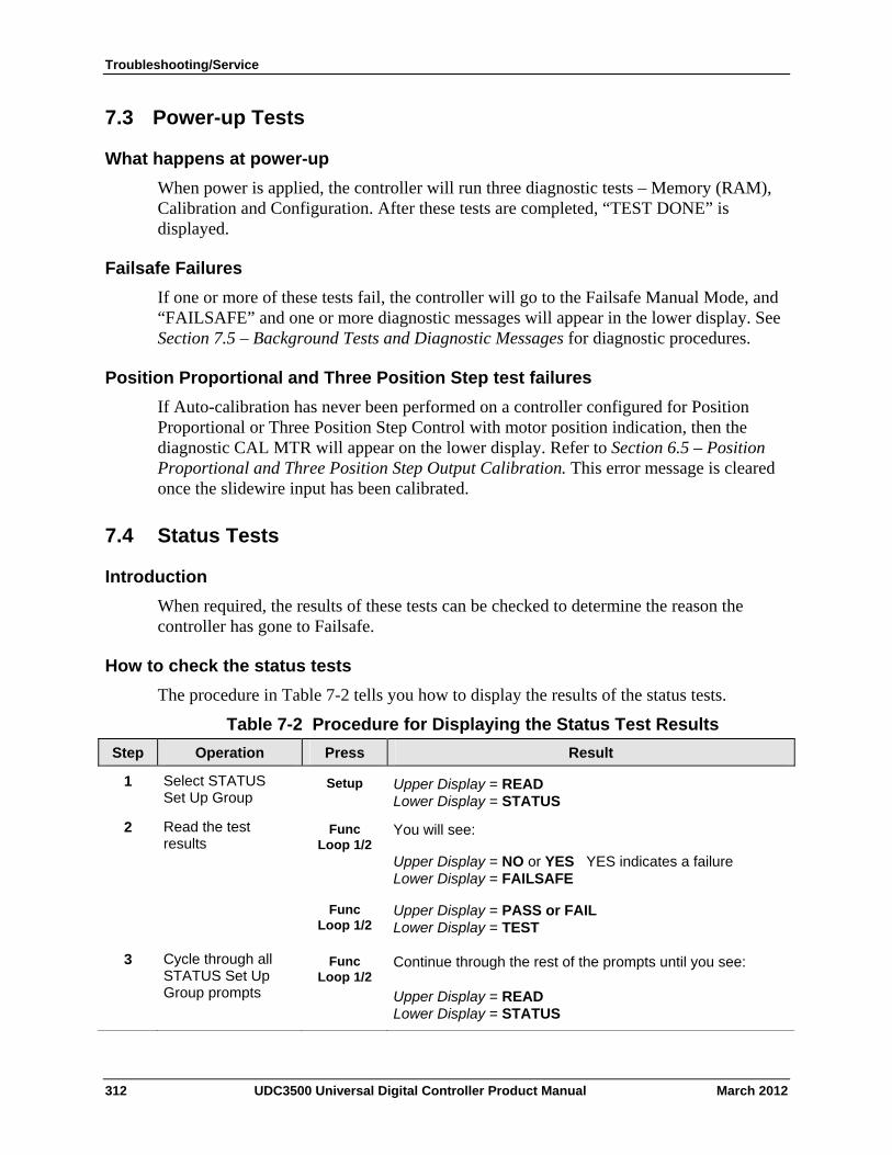
Troubleshooting/Service
7.3 Power-up Tests
What happens at power-up
When power is applied, the controller will run three diagnostic tests – Memory (RAM), Calibration and Configuration. After these tests are completed, “TEST DONE” is displayed.
Failsafe Failures
If one or more of these tests fail, the controller will go to the Failsafe Manual Mode, and “FAILSAFE” and one or more diagnostic messages will appear in the lower display. See Section 7.5 – Background Tests and Diagnostic Messages for diagnostic procedures.
Position Proportional and Three Position Step test failures
If Auto-calibration has never been performed on a controller configured for Position Proportional or Three Position Step Control with motor position indication, then the diagnostic CAL MTR will appear on the lower display. Refer to Section 6.5 – Position Proportional and Three Position Step Output Calibration. This error message is cleared once the slidewire input has been calibrated.
7.4 Status Tests
Introduction
When required, the results of these tests can be checked to determine the reason the controller has gone to Failsafe.
How to check the status tests
The procedure in Table 7-2 tells you how to display the results of the status tests.
Table 7-2 Procedure for Displaying the Status Test Results
Operation Press Result Step
Select STATUS Set Up Group
Setup Upper Display = READ Lower Display = STATUS
1
Read the test results
Func Loop 1/2
You will see:
Upper Display = NO or YES YES indicates a failure Lower Display = FAILSAFE
2
Func Loop 1/2
Upper Display = PASS or FAIL Lower Display = TEST
3 Cycle through all STATUS Set Up Group prompts
Func Loop 1/2
Continue through the rest of the prompts until you see:
Upper Display = READ Lower Display = STATUS
312 UDC3500 Universal Digital Controller Product Manual March 2012
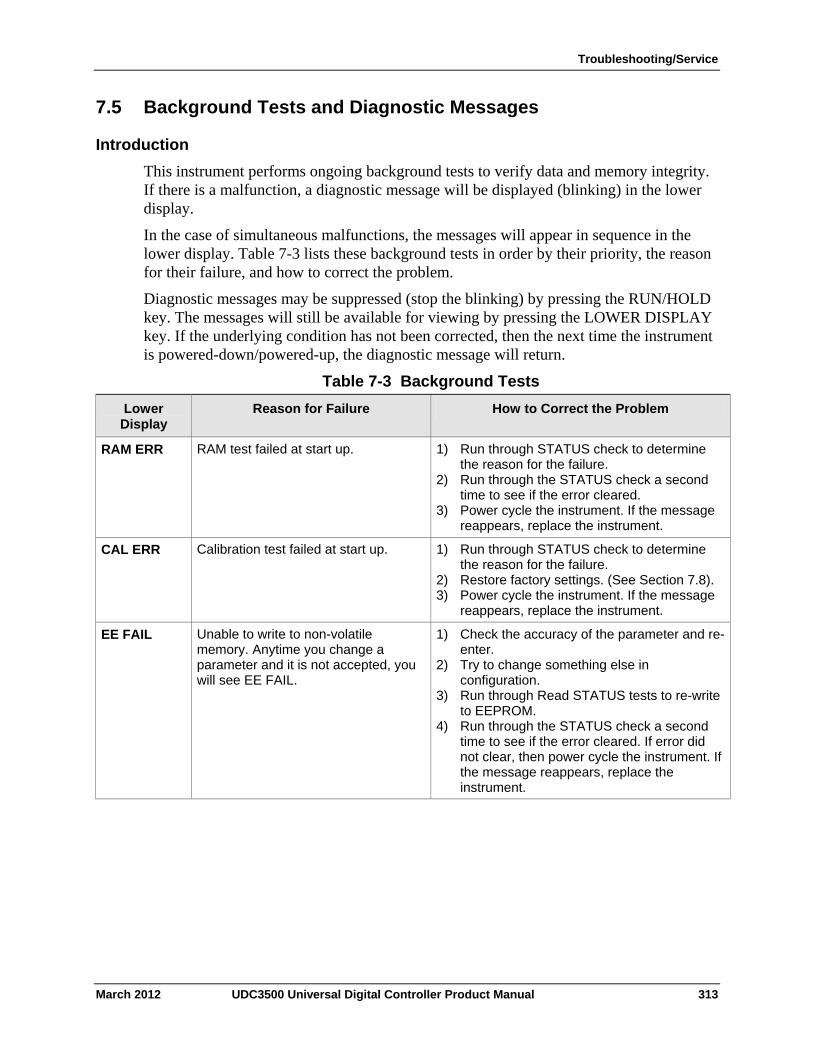
Troubleshooting/Service
7.5 Background Tests and Diagnostic Messages
Introduction
This instrument performs ongoing background tests to verify data and memory integrity. If there is a malfunction, a diagnostic message will be displayed (blinking) in the lower display.
In the case of simultaneous malfunctions, the messages will appear in sequence in the lower display. Table 7-3 lists these background tests in order by their priority, the reason for their failure, and how to correct the problem.
Diagnostic messages may be suppressed (stop the blinking) by pressing the RUN/HOLD key. The messages will still be available for viewing by pressing the LOWER DISPLAY key. If the underlying condition has not been corrected, then the next time the instrument is powered-down/powered-up, the diagnostic message will return.
Table 7-3 Background Tests
Reason for Failure How to Correct the Problem Lower Display
RAM test failed at start up. 1) Run through STATUS check to determine the reason for the failure.
2) Run through the STATUS check a second time to see if the error cleared.
3) Power cycle the instrument. If the message reappears, replace the instrument.
RAM ERR
Calibration test failed at start up. 1) Run through STATUS check to determine the reason for the failure.
2) Restore factory settings. (See Section 7.8). 3) Power cycle the instrument. If the message
reappears, replace the instrument.
CAL ERR
EE FAIL Unable to write to non-volatile memory. Anytime you change a parameter and it is not accepted, you will see EE FAIL.
1) Check the accuracy of the parameter and re-enter.
2) Try to change something else in configuration.
3) Run through Read STATUS tests to re-write to EEPROM.
4) Run through the STATUS check a second time to see if the error cleared. If error did not clear, then power cycle the instrument. If the message reappears, replace the instrument.
March 2012 UDC3500 Universal Digital Controller Product Manual 313
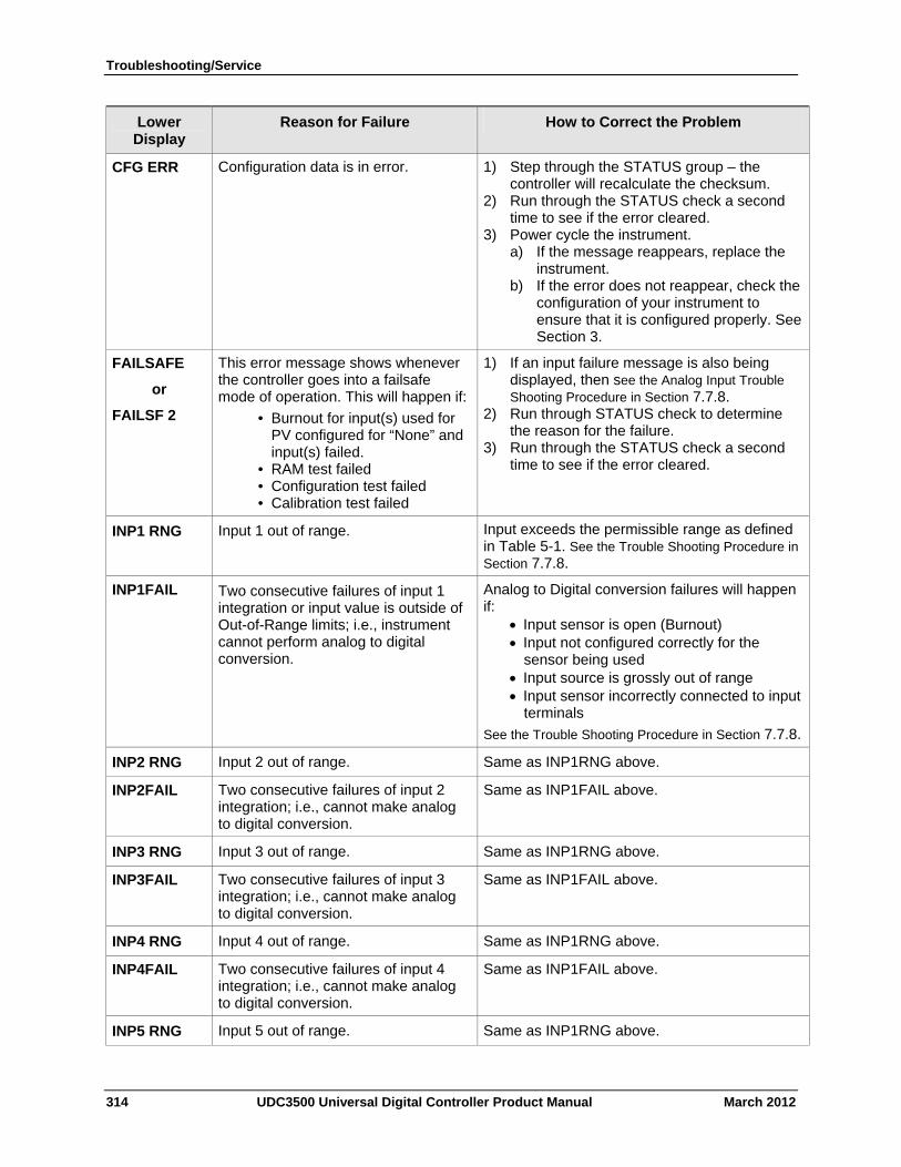
Troubleshooting/Service
314 UDC3500 Universal Digital Controller Product Manual March 2012
Lower Display
Reason for Failure How to Correct the Problem
CFG ERR Configuration data is in error. 1) Step through the STATUS group – the controller will recalculate the checksum.
2) Run through the STATUS check a second time to see if the error cleared.
3) Power cycle the instrument. a) If the message reappears, replace the
instrument. b) If the error does not reappear, check the
configuration of your instrument to ensure that it is configured properly. See Section 3.
FAILSAFE
or
FAILSF 2
This error message shows whenever the controller goes into a failsafe mode of operation. This will happen if:
• Burnout for input(s) used for PV configured for “None” and input(s) failed.
• RAM test failed • Configuration test failed • Calibration test failed
1) If an input failure message is also being displayed, then see the Analog Input Trouble Shooting Procedure in Section 7.7.8.
2) Run through STATUS check to determine the reason for the failure.
3) Run through the STATUS check a second time to see if the error cleared.
INP1 RNG Input 1 out of range.
Input exceeds the permissible range as defined in Table 5-1. See the Trouble Shooting Procedure in Section 7.7.8.
INP1FAIL Two consecutive failures of input 1 integration or input value is outside of Out-of-Range limits; i.e., instrument cannot perform analog to digital conversion.
Analog to Digital conversion failures will happen if:
Input sensor is open (Burnout) Input not configured correctly for the
sensor being used Input source is grossly out of range Input sensor incorrectly connected to input
terminals
See the Trouble Shooting Procedure in Section 7.7.8.
INP2 RNG Input 2 out of range. Same as INP1RNG above.
INP2FAIL Two consecutive failures of input 2 integration; i.e., cannot make analog to digital conversion.
Same as INP1FAIL above.
INP3 RNG Input 3 out of range. Same as INP1RNG above.
INP3FAIL Two consecutive failures of input 3 integration; i.e., cannot make analog to digital conversion.
Same as INP1FAIL above.
INP4 RNG Input 4 out of range. Same as INP1RNG above.
INP4FAIL Two consecutive failures of input 4 integration; i.e., cannot make analog to digital conversion.
Same as INP1FAIL above.
INP5 RNG Input 5 out of range. Same as INP1RNG above.
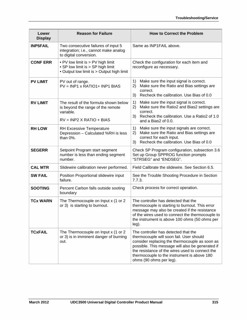
Troubleshooting/Service
March 2012 UDC3500 Universal Digital Controller Product Manual 315
Lower Display
Reason for Failure How to Correct the Problem
INP5FAIL Two consecutive failures of input 5 integration; i.e., cannot make analog to digital conversion.
Same as INP1FAIL above.
CONF ERR • PV low limit is > PV high limit • SP low limit is > SP high limit • Output low limit is > Output high limit
Check the configuration for each item and reconfigure as necessary.
PV LIMIT PV out of range. PV = INP1 x RATIO1+ INP1 BIAS
1) Make sure the input signal is correct. 2) Make sure the Ratio and Bias settings are
correct. 3) Recheck the calibration. Use Bias of 0.0
RV LIMIT The result of the formula shown below is beyond the range of the remote variable.
RV = INP2 X RATIO + BIAS
1) Make sure the input signal is correct. 2) Make sure the Ratio2 and Bias2 settings are
correct. 3) Recheck the calibration. Use a Ratio2 of 1.0
and a Bias2 of 0.0.
RH LOW RH Excessive Temperature Depression – Calculated %RH is less than 0%.
1) Make sure the input signals are correct. 2) Make sure the Ratio and Bias settings are
correct for each input. 3) Recheck the calibration. Use Bias of 0.0
SEGERR Setpoint Program start segment number is less than ending segment number.
Check SP Program configuration, subsection 3.6 Set up Group SPPROG function prompts “STRSEG” and “ENDSEG”.
CAL MTR Slidewire calibration never performed. Field Calibrate the slidewire. See Section 6.5.
SW FAIL Position Proportional slidewire input failure.
See the Trouble Shooting Procedure in Section 7.7.3.
SOOTING Percent Carbon falls outside sooting boundary
Check process for correct operation.
TCx WARN The Thermocouple on Input x (1 or 2 or 3) is starting to burnout.
The controller has detected that the thermocouple is starting to burnout. This error message may also be created if the resistance of the wires used to connect the thermocouple to the instrument is above 100 ohms (50 ohms per leg).
TCxFAIL The Thermocouple on Input x (1 or 2 or 3) is in imminent danger of burning out.
The controller has detected that the thermocouple will soon fail. User should consider replacing the thermocouple as soon as possible. This message will also be generated if the resistance of the wires used to connect the thermocouple to the instrument is above 180 ohms (90 ohms per leg).
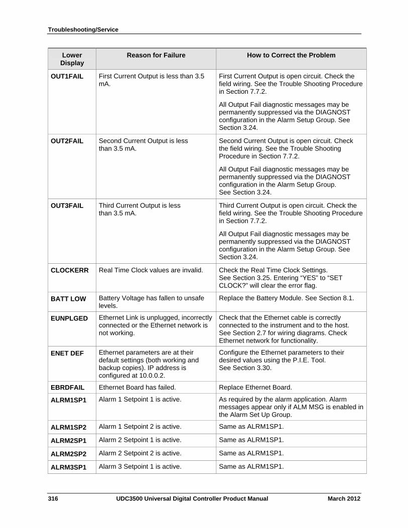
Troubleshooting/Service
316 UDC3500 Universal Digital Controller Product Manual March 2012
Lower Display
Reason for Failure How to Correct the Problem
OUT1FAIL First Current Output is less than 3.5 mA.
First Current Output is open circuit. Check the field wiring. See the Trouble Shooting Procedure in Section 7.7.2.
All Output Fail diagnostic messages may be permanently suppressed via the DIAGNOST configuration in the Alarm Setup Group. See Section 3.24.
OUT2FAIL Second Current Output is less than 3.5 mA.
Second Current Output is open circuit. Check the field wiring. See the Trouble Shooting Procedure in Section 7.7.2.
All Output Fail diagnostic messages may be permanently suppressed via the DIAGNOST configuration in the Alarm Setup Group. See Section 3.24.
OUT3FAIL Third Current Output is less than 3.5 mA.
Third Current Output is open circuit. Check the field wiring. See the Trouble Shooting Procedure in Section 7.7.2.
All Output Fail diagnostic messages may be permanently suppressed via the DIAGNOST configuration in the Alarm Setup Group. See Section 3.24.
CLOCKERR Real Time Clock values are invalid. Check the Real Time Clock Settings. See Section 3.25. Entering “YES” to “SET CLOCK?” will clear the error flag.
BATT LOW Battery Voltage has fallen to unsafe levels.
Replace the Battery Module. See Section 8.1.
EUNPLGED Ethernet Link is unplugged, incorrectly connected or the Ethernet network is not working.
Check that the Ethernet cable is correctly connected to the instrument and to the host. See Section 2.7 for wiring diagrams. Check Ethernet network for functionality.
ENET DEF Ethernet parameters are at their default settings (both working and backup copies). IP address is configured at 10.0.0.2.
Configure the Ethernet parameters to their desired values using the P.I.E. Tool. See Section 3.30.
EBRDFAIL Ethernet Board has failed. Replace Ethernet Board.
ALRM1SP1 Alarm 1 Setpoint 1 is active. As required by the alarm application. Alarm messages appear only if ALM MSG is enabled in the Alarm Set Up Group.
ALRM1SP2 Alarm 1 Setpoint 2 is active. Same as ALRM1SP1.
ALRM2SP1 Alarm 2 Setpoint 1 is active. Same as ALRM1SP1.
ALRM2SP2 Alarm 2 Setpoint 2 is active. Same as ALRM1SP1.
ALRM3SP1 Alarm 3 Setpoint 1 is active. Same as ALRM1SP1.
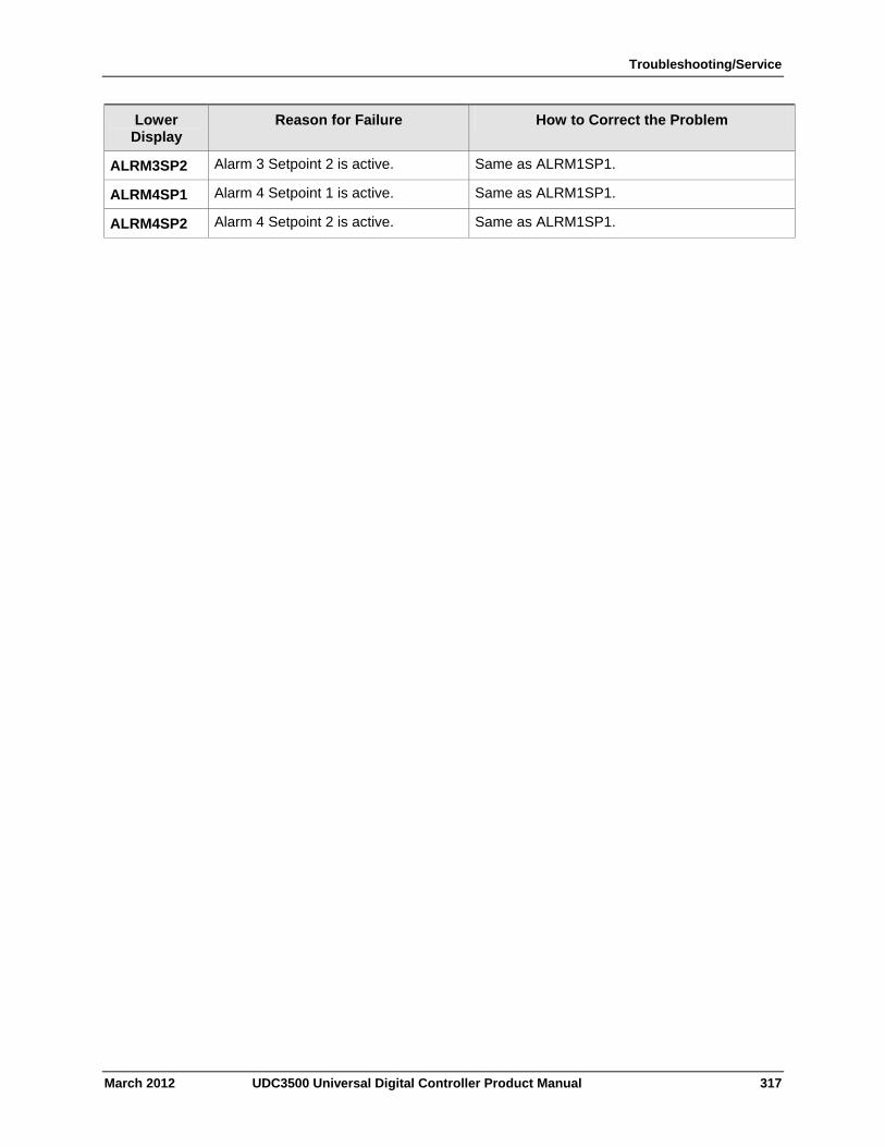
Troubleshooting/Service
March 2012 UDC3500 Universal Digital Controller Product Manual 317
Lower Display
Reason for Failure How to Correct the Problem
ALRM3SP2 Alarm 3 Setpoint 2 is active. Same as ALRM1SP1.
ALRM4SP1 Alarm 4 Setpoint 1 is active. Same as ALRM1SP1.
ALRM4SP2 Alarm 4 Setpoint 2 is active. Same as ALRM1SP1.
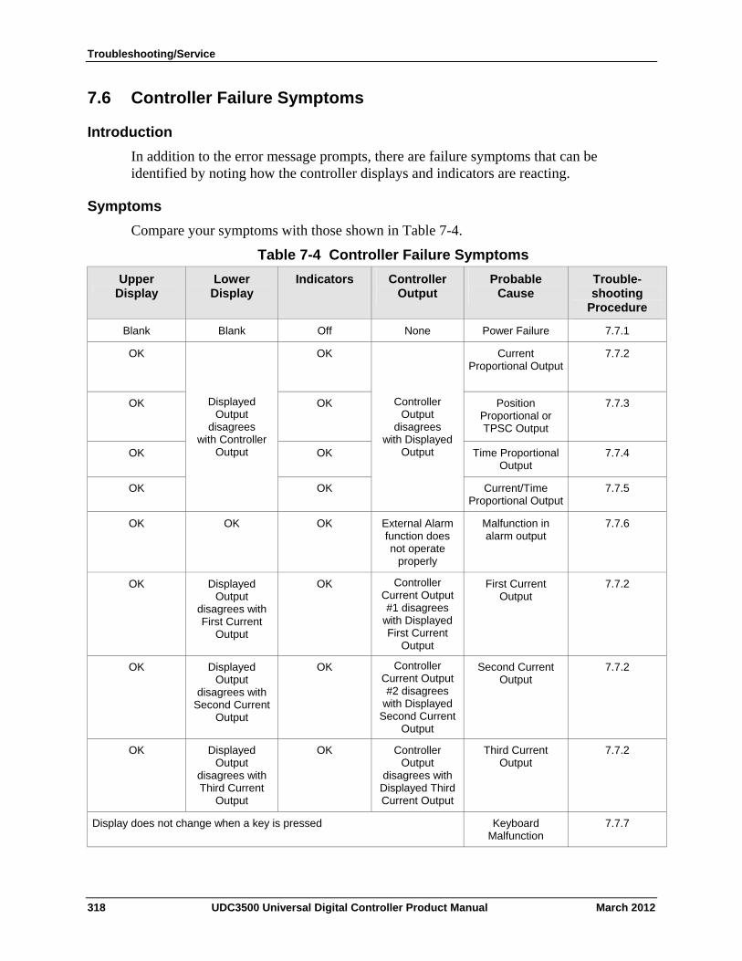
Troubleshooting/Service
7.6 Controller Failure Symptoms
Introduction
In addition to the error message prompts, there are failure symptoms that can be identified by noting how the controller displays and indicators are reacting.
Symptoms
Compare your symptoms with those shown in Table 7-4.
Table 7-4 Controller Failure Symptoms
Lower Display
Indicators Controller Output
Probable Cause
Trouble- shooting
Procedure
Upper Display
Blank Blank Off None Power Failure 7.7.1
OK OK Current Proportional Output
7.7.2
OK OK Position Proportional or TPSC Output
7.7.3
OK OK Time Proportional Output
7.7.4
Controller Output
disagrees with Displayed
Output
Displayed Output
disagrees with Controller
Output
Current/Time Proportional Output
OK OK 7.7.5
OK OK OK External Alarm function does not operate
properly
Malfunction in alarm output
7.7.6
OK Displayed Output
disagrees with First Current
Output
OK Controller Current Output #1 disagrees
with Displayed First Current
Output
First Current Output
7.7.2
OK Displayed Output
disagrees with Second Current
Output
OK Controller Current Output #2 disagrees
with Displayed Second Current
Output
Second Current Output
7.7.2
OK Displayed Output
disagrees with Third Current
Output
OK Controller Output
disagrees with Displayed Third Current Output
Third Current Output
7.7.2
Display does not change when a key is pressed Keyboard Malfunction
7.7.7
318 UDC3500 Universal Digital Controller Product Manual March 2012
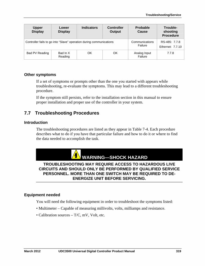
Troubleshooting/Service
March 2012 UDC3500 Universal Digital Controller Product Manual 319
Upper Display
Lower Display
Indicators Controller Output
Probable Cause
Trouble- shooting
Procedure
Controller fails to go into “Slave” operation during communications Communications Failure
RS-485: 7.7.8
Ethernet: 7.7.10
Bad PV Reading Bad In X Reading
OK OK Analog Input Failure
7.7.8
Other symptoms
If a set of symptoms or prompts other than the one you started with appears while troubleshooting, re-evaluate the symptoms. This may lead to a different troubleshooting procedure.
If the symptom still persists, refer to the installation section in this manual to ensure proper installation and proper use of the controller in your system.
7.7 Troubleshooting Procedures
Introduction
The troubleshooting procedures are listed as they appear in Table 7-4. Each procedure describes what to do if you have that particular failure and how to do it or where to find the data needed to accomplish the task.
WARNING—SHOCK HAZARD
TROUBLESHOOTING MAY REQUIRE ACCESS TO HAZARDOUS LIVE CIRCUITS AND SHOULD ONLY BE PERFORMED BY QUALIFIED SERVICE
PERSONNEL. MORE THAN ONE SWITCH MAY BE REQUIRED TO DE-ENERGIZE UNIT BEFORE SERVICING.
Equipment needed
You will need the following equipment in order to troubleshoot the symptoms listed:
• Multimeter – Capable of measuring millivolts, volts, milliamps and resistance.
• Calibration sources – T/C, mV, Volt, etc.
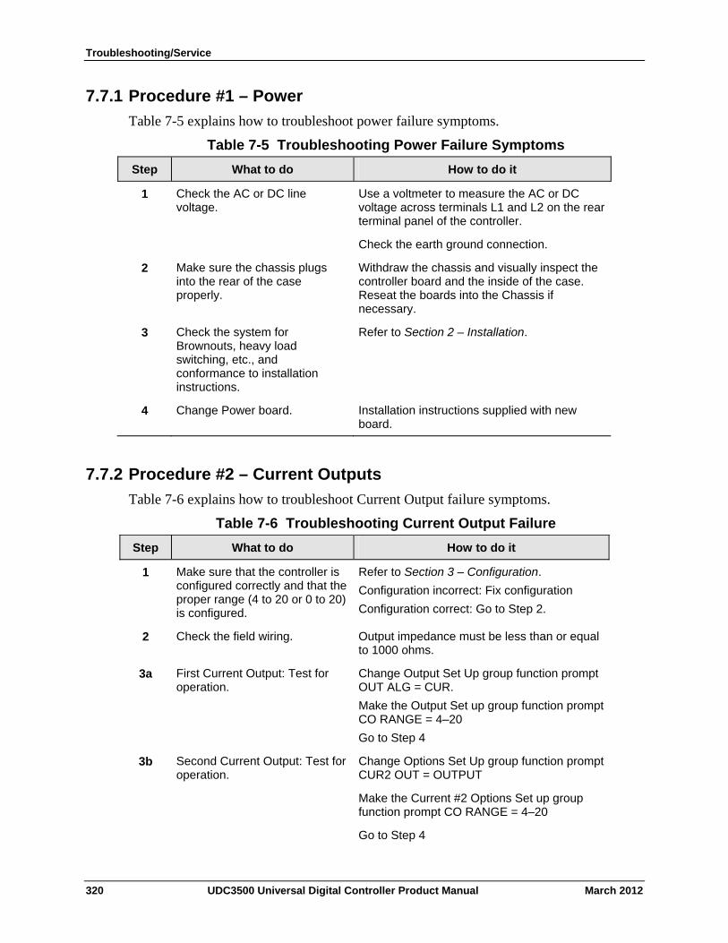
Troubleshooting/Service
7.7.1 Procedure #1 – Power
Table 7-5 explains how to troubleshoot power failure symptoms.
Table 7-5 Troubleshooting Power Failure Symptoms
Step What to do How to do it
Check the AC or DC line voltage.
Use a voltmeter to measure the AC or DC voltage across terminals L1 and L2 on the rear terminal panel of the controller.
Check the earth ground connection.
1
Make sure the chassis plugs into the rear of the case properly.
Withdraw the chassis and visually inspect the controller board and the inside of the case. Reseat the boards into the Chassis if necessary.
2
Check the system for Brownouts, heavy load switching, etc., and conformance to installation instructions.
Refer to Section 2 – Installation. 3
Change Power board. Installation instructions supplied with new board.
4
7.7.2 Procedure #2 – Current Outputs
Table 7-6 explains how to troubleshoot Current Output failure symptoms.
Table 7-6 Troubleshooting Current Output Failure
Step What to do How to do it
Make sure that the controller is configured correctly and that the proper range (4 to 20 or 0 to 20) is configured.
Refer to Section 3 – Configuration.
Configuration incorrect: Fix configuration
Configuration correct: Go to Step 2.
1
Check the field wiring. Output impedance must be less than or equal to 1000 ohms.
2
First Current Output: Test for operation.
Change Output Set Up group function prompt OUT ALG = CUR.
Make the Output Set up group function prompt CO RANGE = 4–20
Go to Step 4
3a
Second Current Output: Test for operation.
Change Options Set Up group function prompt CUR2 OUT = OUTPUT
Make the Current #2 Options Set up group function prompt CO RANGE = 4–20
Go to Step 4
3b
320 UDC3500 Universal Digital Controller Product Manual March 2012
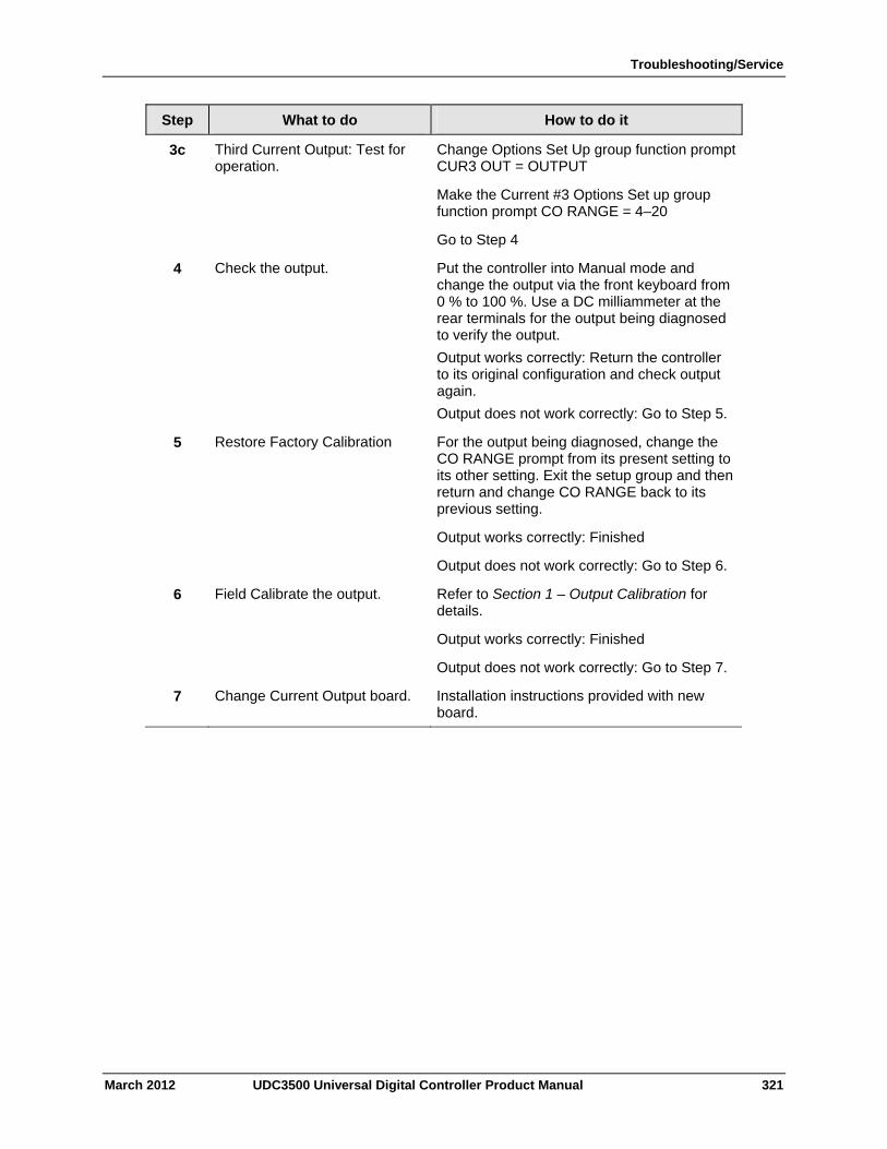
Troubleshooting/Service
March 2012 UDC3500 Universal Digital Controller Product Manual 321
Step What to do How to do it
3c Third Current Output: Test for operation.
Change Options Set Up group function prompt CUR3 OUT = OUTPUT
Make the Current #3 Options Set up group function prompt CO RANGE = 4–20
Go to Step 4
4 Check the output. Put the controller into Manual mode and change the output via the front keyboard from 0 % to 100 %. Use a DC milliammeter at the rear terminals for the output being diagnosed to verify the output.
Output works correctly: Return the controller to its original configuration and check output again.
Output does not work correctly: Go to Step 5.
5 Restore Factory Calibration For the output being diagnosed, change the CO RANGE prompt from its present setting to its other setting. Exit the setup group and then return and change CO RANGE back to its previous setting.
Output works correctly: Finished
Output does not work correctly: Go to Step 6.
6 Field Calibrate the output. Refer to Section 1 – Output Calibration for details.
Output works correctly: Finished
Output does not work correctly: Go to Step 7.
7 Change Current Output board. Installation instructions provided with new board.
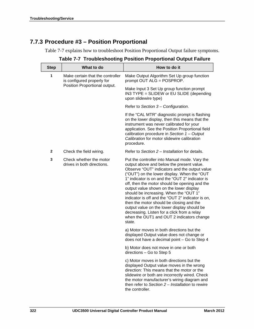
Troubleshooting/Service
7.7.3 Procedure #3 – Position Proportional
Table 7-7 explains how to troubleshoot Position Proportional Output failure symptoms.
Table 7-7 Troubleshooting Position Proportional Output Failure
Step What to do How to do it
Make certain that the controller is configured properly for Position Proportional output.
Make Output Algorithm Set Up group function prompt OUT ALG = POSPROP.
Make Input 3 Set Up group function prompt IN3 TYPE = SLIDEW or EU SLIDE (depending upon slidewire type)
Refer to Section 3 – Configuration.
If the “CAL MTR” diagnostic prompt is flashing on the lower display, then this means that the instrument was never calibrated for your application. See the Position Proportional field calibration procedure in Section 1 – Output Calibration for motor slidewire calibration procedure.
1
Check the field wiring. Refer to Section 2 – Installation for details. 2
Check whether the motor drives in both directions.
Put the controller into Manual mode. Vary the output above and below the present value. Observe “OUT” indicators and the output value (“OUT”) on the lower display. When the “OUT 1” indicator is on and the “OUT 2” indicator is off, then the motor should be opening and the output value shown on the lower display should be increasing. When the “OUT 1” indicator is off and the “OUT 2” indicator is on, then the motor should be closing and the output value on the lower display should be decreasing. Listen for a click from a relay when the OUT1 and OUT 2 indicators change state.
a) Motor moves in both directions but the displayed Output value does not change or does not have a decimal point – Go to Step 4
b) Motor does not move in one or both directions – Go to Step 5
c) Motor moves in both directions but the displayed Output value moves in the wrong direction: This means that the motor or the slidewire or both are incorrectly wired. Check the motor manufacturer’s wiring diagram and then refer to Section 2 – Installation to rewire the controller.
3
322 UDC3500 Universal Digital Controller Product Manual March 2012
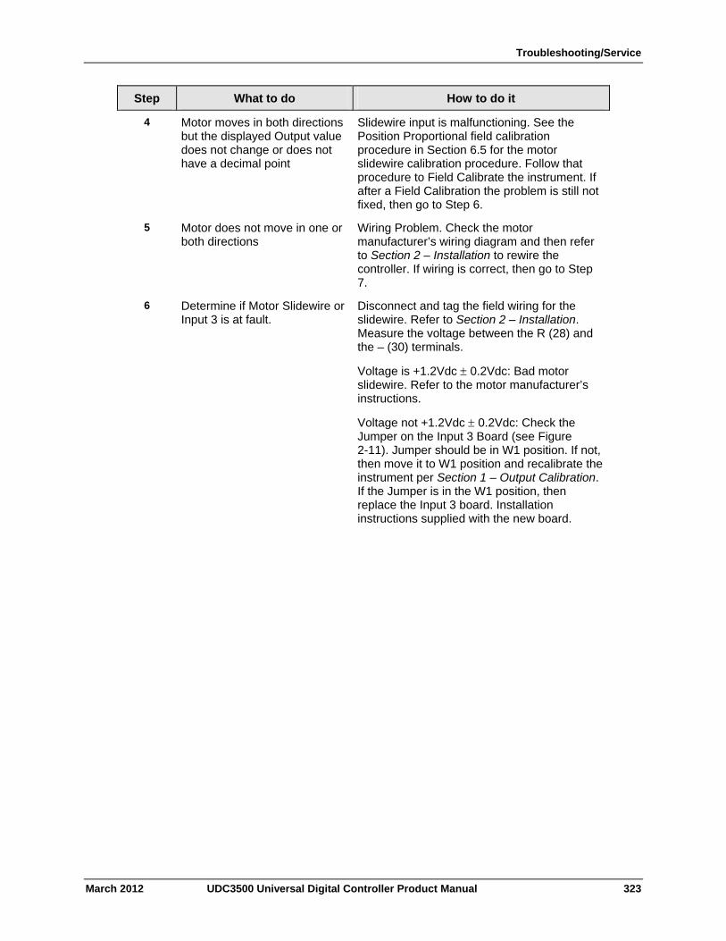
Troubleshooting/Service
March 2012 UDC3500 Universal Digital Controller Product Manual 323
Step What to do How to do it
4 Motor moves in both directions but the displayed Output value does not change or does not have a decimal point
Slidewire input is malfunctioning. See the Position Proportional field calibration procedure in Section 6.5 for the motor slidewire calibration procedure. Follow that procedure to Field Calibrate the instrument. If after a Field Calibration the problem is still not fixed, then go to Step 6.
5 Motor does not move in one or both directions
Wiring Problem. Check the motor manufacturer’s wiring diagram and then refer to Section 2 – Installation to rewire the controller. If wiring is correct, then go to Step 7.
6 Determine if Motor Slidewire or Input 3 is at fault.
Disconnect and tag the field wiring for the slidewire. Refer to Section 2 – Installation. Measure the voltage between the R (28) and the – (30) terminals.
Voltage is +1.2Vdc 0.2Vdc: Bad motor slidewire. Refer to the motor manufacturer’s instructions.
Voltage not +1.2Vdc 0.2Vdc: Check the Jumper on the Input 3 Board (see Figure 2-11). Jumper should be in W1 position. If not, then move it to W1 position and recalibrate the instrument per Section 1 – Output Calibration. If the Jumper is in the W1 position, then replace the Input 3 board. Installation instructions supplied with the new board.
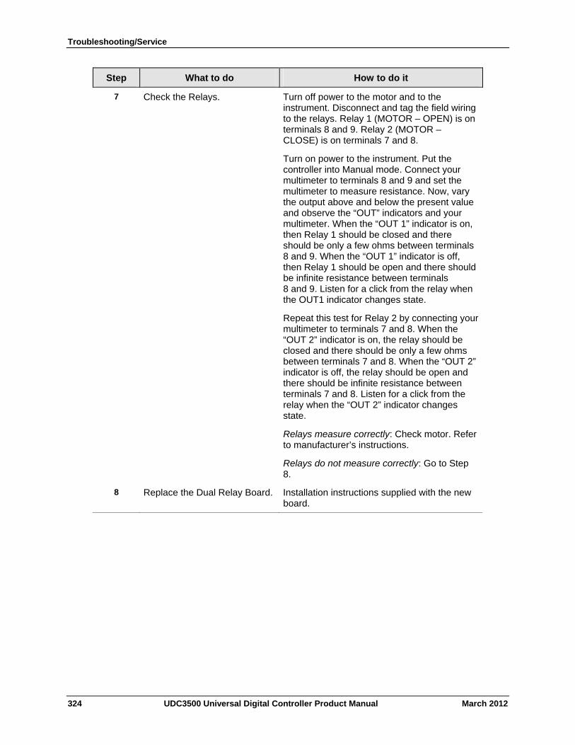
Troubleshooting/Service
324 UDC3500 Universal Digital Controller Product Manual March 2012
Step What to do How to do it
7 Check the Relays. Turn off power to the motor and to the instrument. Disconnect and tag the field wiring to the relays. Relay 1 (MOTOR – OPEN) is on terminals 8 and 9. Relay 2 (MOTOR – CLOSE) is on terminals 7 and 8.
Turn on power to the instrument. Put the controller into Manual mode. Connect your multimeter to terminals 8 and 9 and set the multimeter to measure resistance. Now, vary the output above and below the present value and observe the “OUT” indicators and your multimeter. When the “OUT 1” indicator is on, then Relay 1 should be closed and there should be only a few ohms between terminals 8 and 9. When the “OUT 1” indicator is off, then Relay 1 should be open and there should be infinite resistance between terminals 8 and 9. Listen for a click from the relay when the OUT1 indicator changes state.
Repeat this test for Relay 2 by connecting your multimeter to terminals 7 and 8. When the “OUT 2” indicator is on, the relay should be closed and there should be only a few ohms between terminals 7 and 8. When the “OUT 2” indicator is off, the relay should be open and there should be infinite resistance between terminals 7 and 8. Listen for a click from the relay when the “OUT 2” indicator changes state.
Relays measure correctly: Check motor. Refer to manufacturer’s instructions.
Relays do not measure correctly: Go to Step 8.
8 Replace the Dual Relay Board. Installation instructions supplied with the new board.
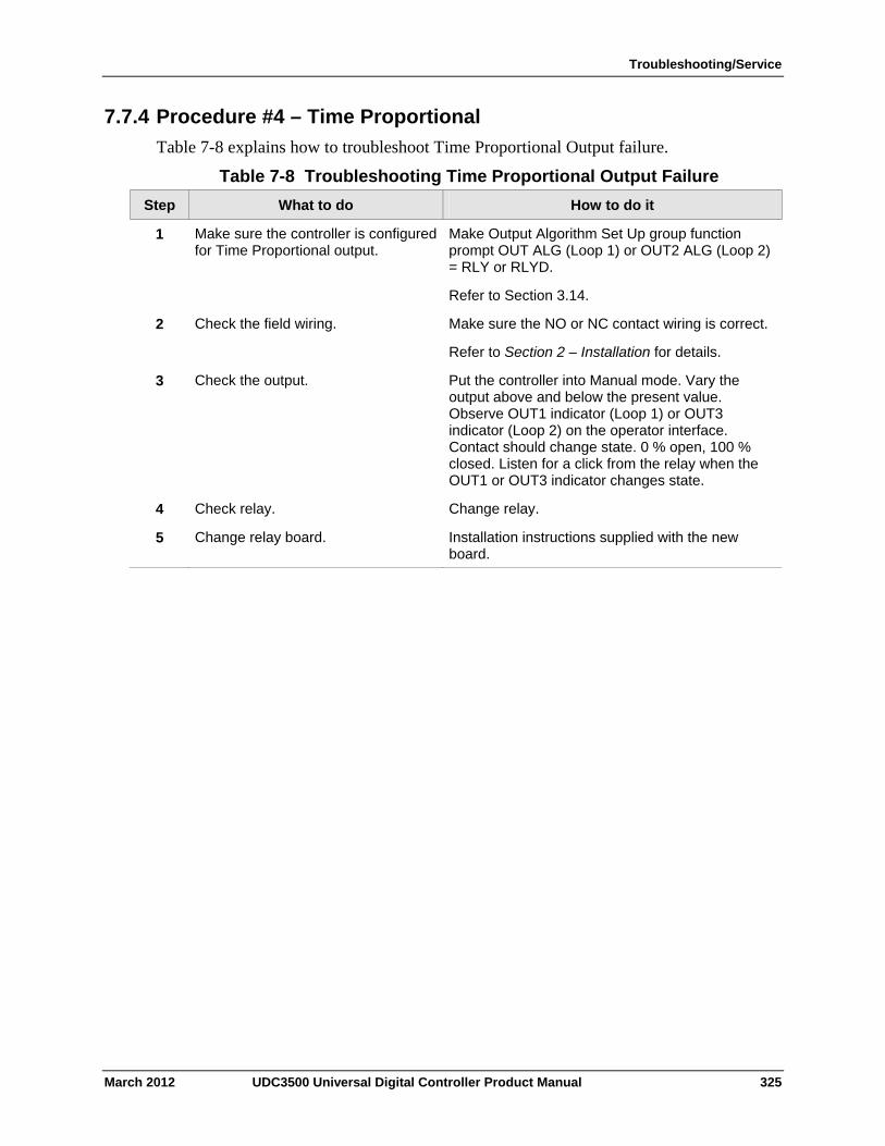
Troubleshooting/Service
7.7.4 Procedure #4 – Time Proportional
Table 7-8 explains how to troubleshoot Time Proportional Output failure.
Table 7-8 Troubleshooting Time Proportional Output Failure
Step What to do How to do it
Make sure the controller is configured for Time Proportional output.
Make Output Algorithm Set Up group function prompt OUT ALG (Loop 1) or OUT2 ALG (Loop 2) = RLY or RLYD.
Refer to Section 3.14.
1
Check the field wiring. Make sure the NO or NC contact wiring is correct.
Refer to Section 2 – Installation for details.
2
Check the output. Put the controller into Manual mode. Vary the output above and below the present value. Observe OUT1 indicator (Loop 1) or OUT3 indicator (Loop 2) on the operator interface. Contact should change state. 0 % open, 100 % closed. Listen for a click from the relay when the OUT1 or OUT3 indicator changes state.
3
Check relay. Change relay. 4
Change relay board. Installation instructions supplied with the new board.
5
March 2012 UDC3500 Universal Digital Controller Product Manual 325
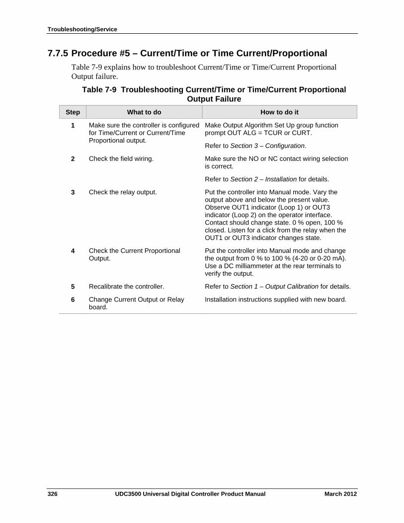
Troubleshooting/Service
7.7.5 Procedure #5 – Current/Time or Time Current/Proportional
Table 7-9 explains how to troubleshoot Current/Time or Time/Current Proportional Output failure.
Table 7-9 Troubleshooting Current/Time or Time/Current Proportional Output Failure
Step What to do How to do it
Make sure the controller is configured for Time/Current or Current/Time Proportional output.
Make Output Algorithm Set Up group function prompt OUT ALG = TCUR or CURT.
Refer to Section 3 – Configuration.
1
Check the field wiring. Make sure the NO or NC contact wiring selection is correct.
Refer to Section 2 – Installation for details.
2
Check the relay output. Put the controller into Manual mode. Vary the output above and below the present value. Observe OUT1 indicator (Loop 1) or OUT3 indicator (Loop 2) on the operator interface. Contact should change state. 0 % open, 100 % closed. Listen for a click from the relay when the OUT1 or OUT3 indicator changes state.
3
Check the Current Proportional Output.
Put the controller into Manual mode and change the output from 0 % to 100 % (4-20 or 0-20 mA). Use a DC milliammeter at the rear terminals to verify the output.
4
Recalibrate the controller. Refer to Section 1 – Output Calibration for details. 5
Change Current Output or Relay board.
Installation instructions supplied with new board. 6
326 UDC3500 Universal Digital Controller Product Manual March 2012
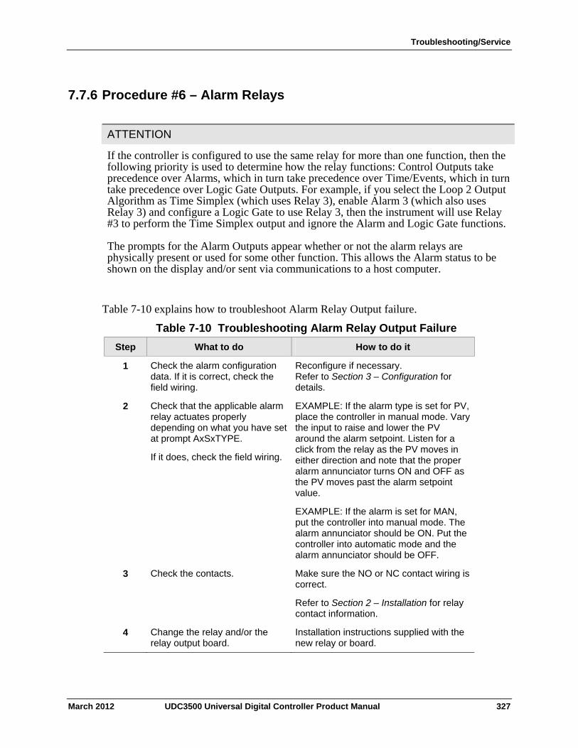
Troubleshooting/Service
7.7.6 Procedure #6 – Alarm Relays
ATTENTION
If the controller is configured to use the same relay for more than one function, then the following priority is used to determine how the relay functions: Control Outputs take precedence over Alarms, which in turn take precedence over Time/Events, which in turn take precedence over Logic Gate Outputs. For example, if you select the Loop 2 Output Algorithm as Time Simplex (which uses Relay 3), enable Alarm 3 (which also uses Relay 3) and configure a Logic Gate to use Relay 3, then the instrument will use Relay #3 to perform the Time Simplex output and ignore the Alarm and Logic Gate functions.
The prompts for the Alarm Outputs appear whether or not the alarm relays are physically present or used for some other function. This allows the Alarm status to be shown on the display and/or sent via communications to a host computer.
Table 7-10 explains how to troubleshoot Alarm Relay Output failure.
Table 7-10 Troubleshooting Alarm Relay Output Failure
What to do How to do it Step
Check the alarm configuration data. If it is correct, check the field wiring.
Reconfigure if necessary. Refer to Section 3 – Configuration for details.
1
Check that the applicable alarm relay actuates properly depending on what you have set at prompt AxSxTYPE.
If it does, check the field wiring.
EXAMPLE: If the alarm type is set for PV, place the controller in manual mode. Vary the input to raise and lower the PV around the alarm setpoint. Listen for a click from the relay as the PV moves in either direction and note that the proper alarm annunciator turns ON and OFF as the PV moves past the alarm setpoint value.
EXAMPLE: If the alarm is set for MAN, put the controller into manual mode. The alarm annunciator should be ON. Put the controller into automatic mode and the alarm annunciator should be OFF.
2
Check the contacts. Make sure the NO or NC contact wiring is correct.
Refer to Section 2 – Installation for relay contact information.
3
Change the relay and/or the relay output board.
Installation instructions supplied with the new relay or board.
4
March 2012 UDC3500 Universal Digital Controller Product Manual 327
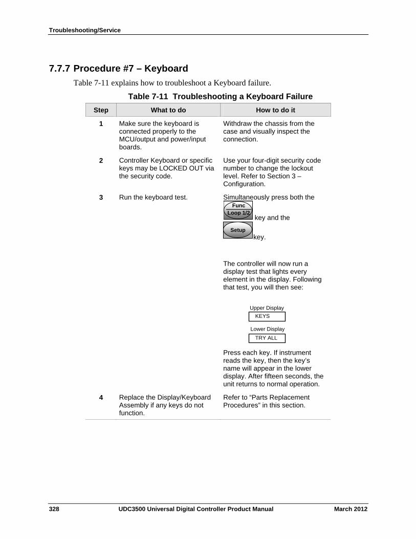
Troubleshooting/Service
7.7.7 Procedure #7 – Keyboard
Table 7-11 explains how to troubleshoot a Keyboard failure.
Table 7-11 Troubleshooting a Keyboard Failure
Step What to do How to do it
Make sure the keyboard is connected properly to the MCU/output and power/input boards.
Withdraw the chassis from the case and visually inspect the connection.
1
Controller Keyboard or specific keys may be LOCKED OUT via the security code.
Use your four-digit security code number to change the lockout level. Refer to Section 3 – Configuration.
2
Run the keyboard test. Simultaneously press both the Func
Loop 1/2 key and the
SetupSetupkey.
The controller will now run a display test that lights every element in the display. Following that test, you will then see:
TRY ALL
Lower Display
KEYS
Upper Display
Press each key. If instrument reads the key, then the key’s name will appear in the lower display. After fifteen seconds, the unit returns to normal operation.
3
Replace the Display/Keyboard Assembly if any keys do not function.
Refer to “Parts Replacement Procedures” in this section.
4
328 UDC3500 Universal Digital Controller Product Manual March 2012
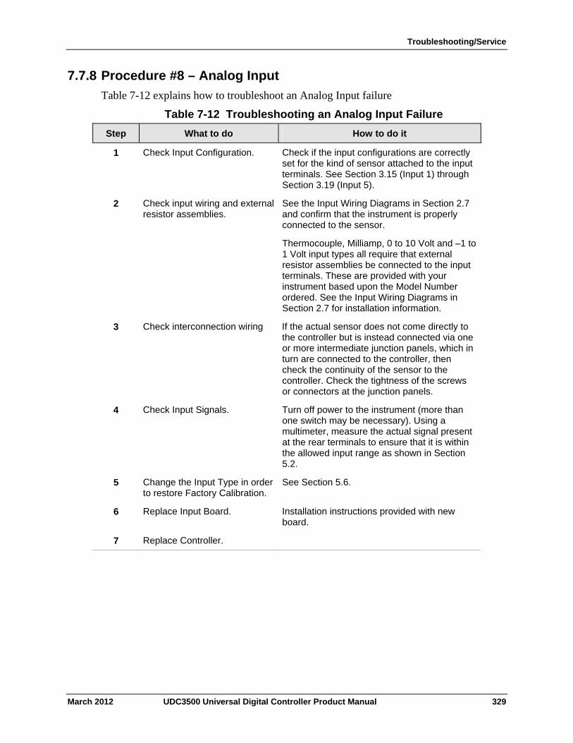
Troubleshooting/Service
7.7.8 Procedure #8 – Analog Input
Table 7-12 explains how to troubleshoot an Analog Input failure
Table 7-12 Troubleshooting an Analog Input Failure
Step What to do How to do it
Check Input Configuration. Check if the input configurations are correctly set for the kind of sensor attached to the input terminals. See Section 3.15 (Input 1) through Section 3.19 (Input 5).
1
Check input wiring and external resistor assemblies.
See the Input Wiring Diagrams in Section 2.7 and confirm that the instrument is properly connected to the sensor.
Thermocouple, Milliamp, 0 to 10 Volt and –1 to 1 Volt input types all require that external resistor assemblies be connected to the input terminals. These are provided with your instrument based upon the Model Number ordered. See the Input Wiring Diagrams in Section 2.7 for installation information.
2
Check interconnection wiring If the actual sensor does not come directly to the controller but is instead connected via one or more intermediate junction panels, which in turn are connected to the controller, then check the continuity of the sensor to the controller. Check the tightness of the screws or connectors at the junction panels.
3
Check Input Signals. Turn off power to the instrument (more than one switch may be necessary). Using a multimeter, measure the actual signal present at the rear terminals to ensure that it is within the allowed input range as shown in Section 5.2.
4
Change the Input Type in order to restore Factory Calibration.
See Section 5.6. 5
Replace Input Board. Installation instructions provided with new board.
6
Replace Controller. 7
March 2012 UDC3500 Universal Digital Controller Product Manual 329

Troubleshooting/Service
7.7.9 Procedure #9 – RS-485
Table 7-13 explains how to troubleshoot a RS 485 Communications failure.
Table 7-13 Troubleshooting a RS-485 Communications Failure
Step What to do How to do it
Check the Address Number, ComState and Baud Rate settings.
See Section 3.23. 1
Check if the controller is wired correctly to the Network.
See Section 2.7 for wiring diagrams. 2
Determine if the Communications board is faulty by running a LOCAL LOOPBACK TEST.
If the test fails, replace the board. If the test passes, the problem is most likely elsewhere in the communications network.
Disconnect the communications cable from the rear terminals. Run the Local Loopback Test.
Press Setup key until you see:
COM
Lower Display
SET UP
Upper Display
Press Func-Loop 1/2 key until you see:
LOOPBACK
Lower Display
DISABLEUpper Display
Press or and you will see:
LOOPBACK
Lower Display
ENABLE
Upper Display
Press Lower Display key and you will see:
LOOPBACK
Lower Display
START
Upper Display
Then you will see either PASS or FAIL in the Upper Display. The test will run until the operator disables it or until the unit is power-cycled.
If you see FAIL, go to Step 4. If you see PASS, then the problem is most likely not in the instrument, but somewhere else in the network. Reconnect the communications cable and then go to Step 7.
3
330 UDC3500 Universal Digital Controller Product Manual March 2012
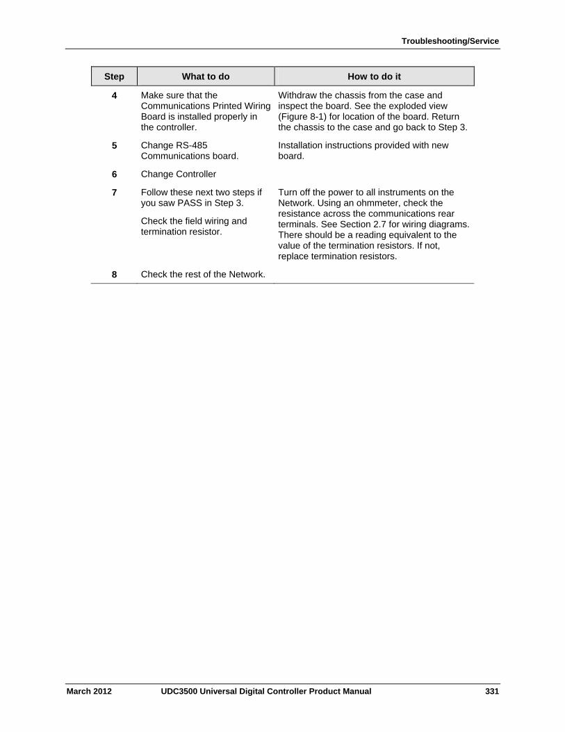
Troubleshooting/Service
March 2012 UDC3500 Universal Digital Controller Product Manual 331
Step What to do How to do it
4 Make sure that the Communications Printed Wiring Board is installed properly in the controller.
Withdraw the chassis from the case and inspect the board. See the exploded view (Figure 8-1) for location of the board. Return the chassis to the case and go back to Step 3.
5 Change RS-485 Communications board.
Installation instructions provided with new board.
6 Change Controller
7 Follow these next two steps if you saw PASS in Step 3.
Check the field wiring and termination resistor.
Turn off the power to all instruments on the Network. Using an ohmmeter, check the resistance across the communications rear terminals. See Section 2.7 for wiring diagrams. There should be a reading equivalent to the value of the termination resistors. If not, replace termination resistors.
8 Check the rest of the Network.
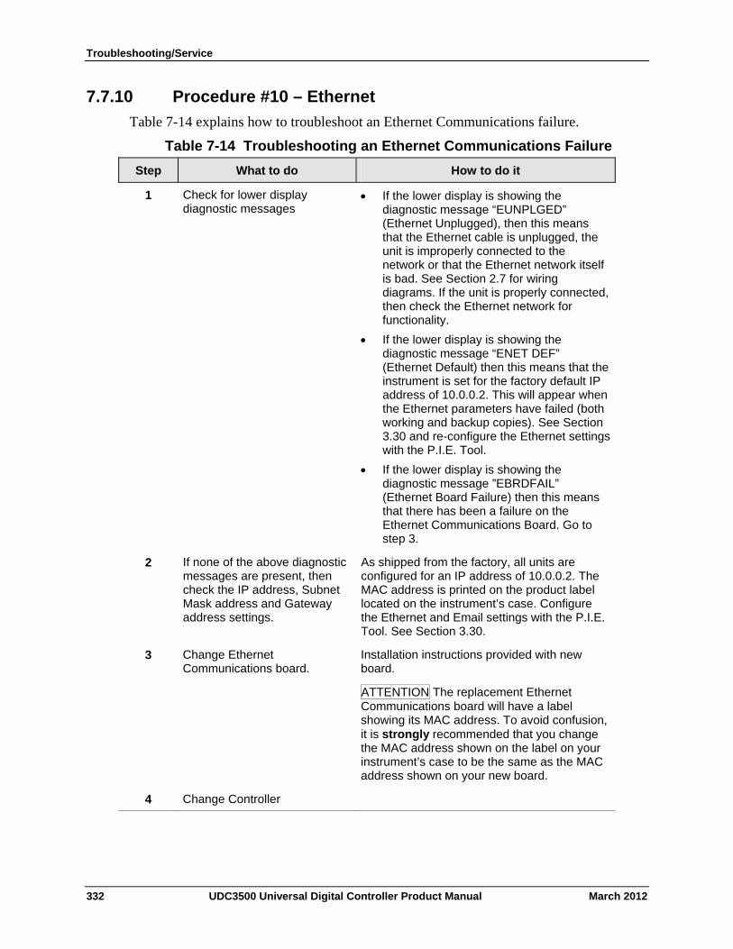
Troubleshooting/Service
7.7.10 Procedure #10 – Ethernet
Table 7-14 explains how to troubleshoot an Ethernet Communications failure.
Table 7-14 Troubleshooting an Ethernet Communications Failure
Step What to do How to do it
Check for lower display diagnostic messages
If the lower display is showing the diagnostic message “EUNPLGED” (Ethernet Unplugged), then this means that the Ethernet cable is unplugged, the unit is improperly connected to the network or that the Ethernet network itself is bad. See Section 2.7 for wiring diagrams. If the unit is properly connected, then check the Ethernet network for functionality.
If the lower display is showing the diagnostic message “ENET DEF” (Ethernet Default) then this means that the instrument is set for the factory default IP address of 10.0.0.2. This will appear when the Ethernet parameters have failed (both working and backup copies). See Section 3.30 and re-configure the Ethernet settings with the P.I.E. Tool.
If the lower display is showing the diagnostic message ”EBRDFAIL” (Ethernet Board Failure) then this means that there has been a failure on the Ethernet Communications Board. Go to step 3.
1
If none of the above diagnostic messages are present, then check the IP address, Subnet Mask address and Gateway address settings.
As shipped from the factory, all units are configured for an IP address of 10.0.0.2. The MAC address is printed on the product label located on the instrument’s case. Configure the Ethernet and Email settings with the P.I.E. Tool. See Section 3.30.
2
Change Ethernet Communications board.
Installation instructions provided with new board.
ATTENTION The replacement Ethernet Communications board will have a label showing its MAC address. To avoid confusion, it is strongly recommended that you change the MAC address shown on the label on your instrument’s case to be the same as the MAC address shown on your new board.
3
Change Controller 4
332 UDC3500 Universal Digital Controller Product Manual March 2012
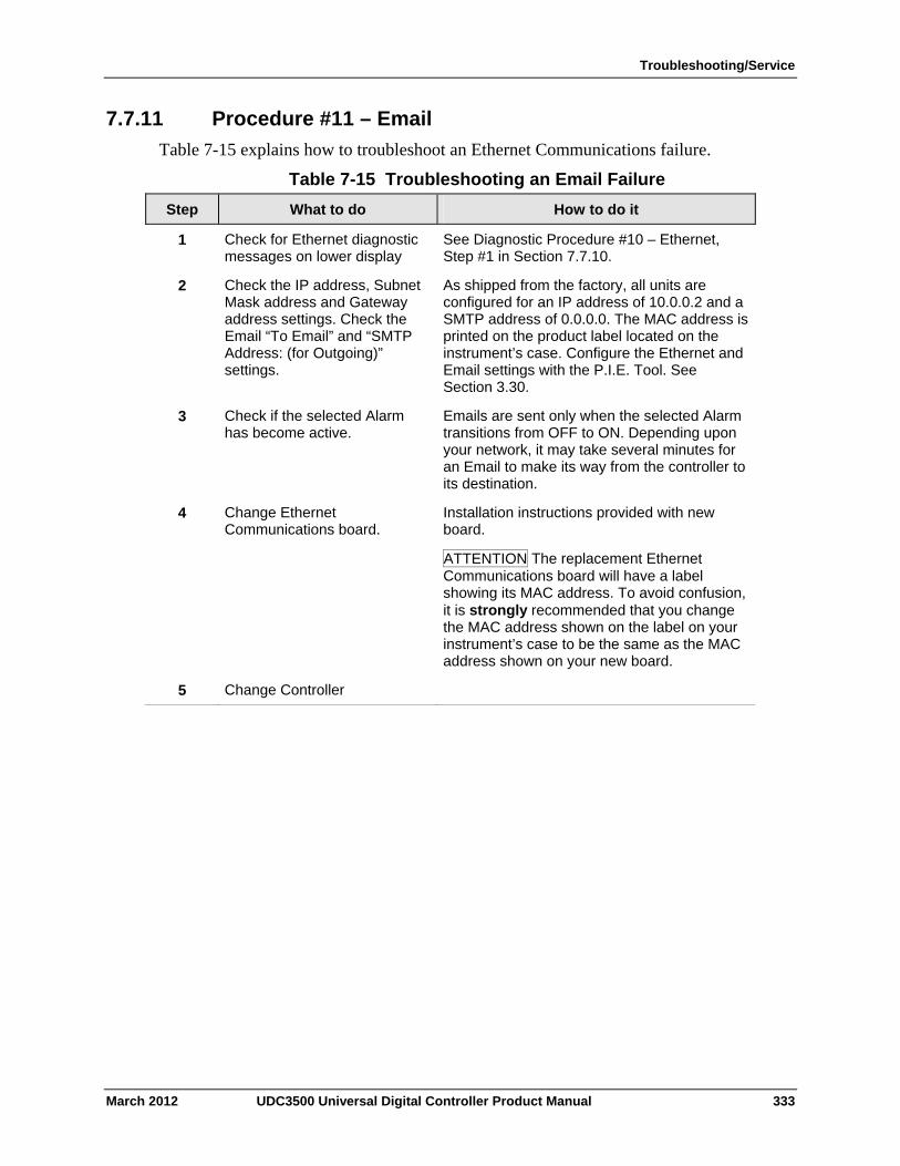
Troubleshooting/Service
7.7.11 Procedure #11 – Email
Table 7-15 explains how to troubleshoot an Ethernet Communications failure.
Table 7-15 Troubleshooting an Email Failure
Step What to do How to do it
Check for Ethernet diagnostic messages on lower display
See Diagnostic Procedure #10 – Ethernet, Step #1 in Section 7.7.10.
1
Check the IP address, Subnet Mask address and Gateway address settings. Check the Email “To Email” and “SMTP Address: (for Outgoing)” settings.
As shipped from the factory, all units are configured for an IP address of 10.0.0.2 and a SMTP address of 0.0.0.0. The MAC address is printed on the product label located on the instrument’s case. Configure the Ethernet and Email settings with the P.I.E. Tool. See Section 3.30.
2
Check if the selected Alarm has become active.
Emails are sent only when the selected Alarm transitions from OFF to ON. Depending upon your network, it may take several minutes for an Email to make its way from the controller to its destination.
3
Change Ethernet Communications board.
Installation instructions provided with new board.
ATTENTION The replacement Ethernet Communications board will have a label showing its MAC address. To avoid confusion, it is strongly recommended that you change the MAC address shown on the label on your instrument’s case to be the same as the MAC address shown on your new board.
4
Change Controller 5
March 2012 UDC3500 Universal Digital Controller Product Manual 333
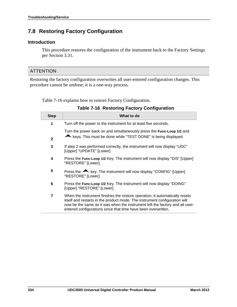
Troubleshooting/Service
7.8 Restoring Factory Configuration
Introduction
This procedure restores the configuration of the instrument back to the Factory Settings per Section 3.31.
ATTENTION
Restoring the factory configuration overwrites all user-entered configuration changes. This procedure cannot be undone; it is a one-way process.
Table 7-16 explains how to restore Factory Configuration.
Table 7-16 Restoring Factory Configuration
Step What to do
Turn off the power to the instrument for at least five seconds. 1
2
Turn the power back on and simultaneously press the Func-Loop 1/2 and
keys. This must be done while “TEST DONE” is being displayed.
If step 2 was performed correctly, the instrument will now display “UDC” [Upper] “UPDATE” [Lower].
3
Press the Func-Loop 1/2 Key. The instrument will now display “DIS” [Upper] “RESTORE” [Lower].
4
5 Press the key. The instrument will now display “CONFIG” [Upper] “RESTORE” [Lower].
Press the Func-Loop 1/2 Key. The instrument will now display “DOING” [Upper] “RESTORE” [Lower].
6
When the instrument finishes the restore operation, it automatically resets itself and restarts in the product mode. The instrument configuration will now be the same as it was when the instrument left the factory and all user-entered configurations since that time have been overwritten.
7
334 UDC3500 Universal Digital Controller Product Manual March 2012
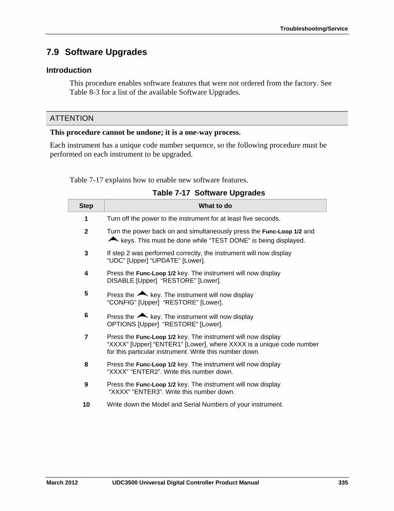
Troubleshooting/Service
7.9 Software Upgrades
Introduction
This procedure enables software features that were not ordered from the factory. See Table 8-3 for a list of the available Software Upgrades.
ATTENTION
This procedure cannot be undone; it is a one-way process.
Each instrument has a unique code number sequence, so the following procedure must be performed on each instrument to be upgraded.
Table 7-17 explains how to enable new software features.
Table 7-17 Software Upgrades
Step What to do
Turn off the power to the instrument for at least five seconds. 1
Turn the power back on and simultaneously press the Func-Loop 1/2 and
keys. This must be done while “TEST DONE” is being displayed. 2
If step 2 was performed correctly, the instrument will now display “UDC” [Upper] “UPDATE” [Lower].
3
Press the Func-Loop 1/2 key. The instrument will now display DISABLE [Upper] “RESTORE” [Lower].
4
5 Press the key. The instrument will now display “CONFIG” [Upper] “RESTORE” [Lower].
6 Press the key. The instrument will now display OPTIONS [Upper] “RESTORE” [Lower].
Press the Func-Loop 1/2 key. The instrument will now display “XXXX” [Upper] “ENTER1” [Lower], where XXXX is a unique code number for this particular instrument. Write this number down.
7
Press the Func-Loop 1/2 key. The instrument will now display “XXXX” “ENTER2”. Write this number down.
8
Press the Func-Loop 1/2 key. The instrument will now display “XXXX” “ENTER3”. Write this number down.
9
Write down the Model and Serial Numbers of your instrument. 10
March 2012 UDC3500 Universal Digital Controller Product Manual 335
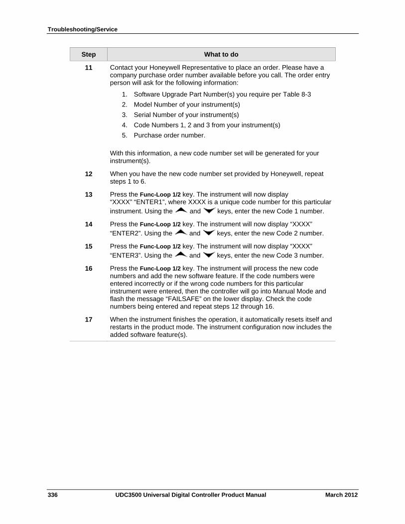
Troubleshooting/Service
336 UDC3500 Universal Digital Controller Product Manual March 2012
Step What to do
11 Contact your Honeywell Representative to place an order. Please have a company purchase order number available before you call. The order entry person will ask for the following information:
1. Software Upgrade Part Number(s) you require per Table 8-3
2. Model Number of your instrument(s)
3. Serial Number of your instrument(s)
4. Code Numbers 1, 2 and 3 from your instrument(s)
5. Purchase order number.
With this information, a new code number set will be generated for your instrument(s).
12 When you have the new code number set provided by Honeywell, repeat steps 1 to 6.
13 Press the Func-Loop 1/2 key. The instrument will now display “XXXX” “ENTER1”, where XXXX is a unique code number for this particular instrument. Using the and keys, enter the new Code 1 number.
14 Press the Func-Loop 1/2 key. The instrument will now display “XXXX” “ENTER2”. Using the and keys, enter the new Code 2 number.
15 Press the Func-Loop 1/2 key. The instrument will now display “XXXX” “ENTER3”. Using the and keys, enter the new Code 3 number.
16 Press the Func-Loop 1/2 key. The instrument will process the new code numbers and add the new software feature. If the code numbers were entered incorrectly or if the wrong code numbers for this particular instrument were entered, then the controller will go into Manual Mode and flash the message “FAILSAFE” on the lower display. Check the code numbers being entered and repeat steps 12 through 16.
17 When the instrument finishes the operation, it automatically resets itself and restarts in the product mode. The instrument configuration now includes the added software feature(s).
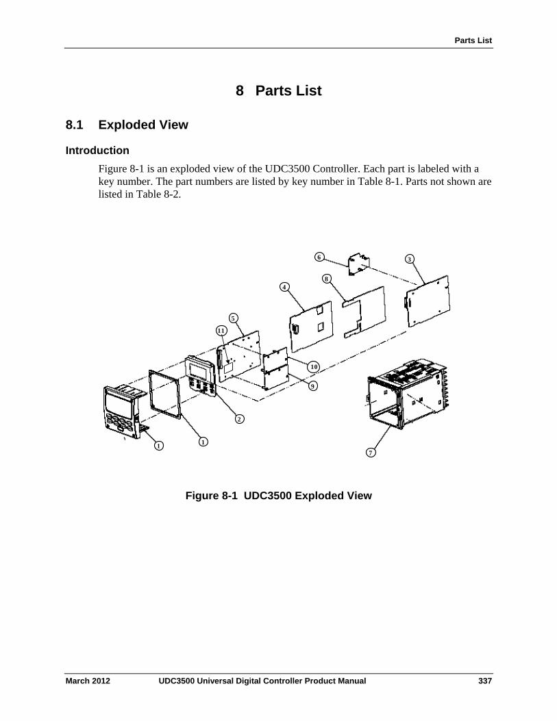
Parts List
8 Parts List
8.1 Exploded View
Introduction
Figure 8-1 is an exploded view of the UDC3500 Controller. Each part is labeled with a key number. The part numbers are listed by key number in Table 8-1. Parts not shown are listed in Table 8-2.
1 1
2
3
4
5
6
7
8
10
9
11
Figure 8-1 UDC3500 Exploded View
March 2012 UDC3500 Universal Digital Controller Product Manual 337
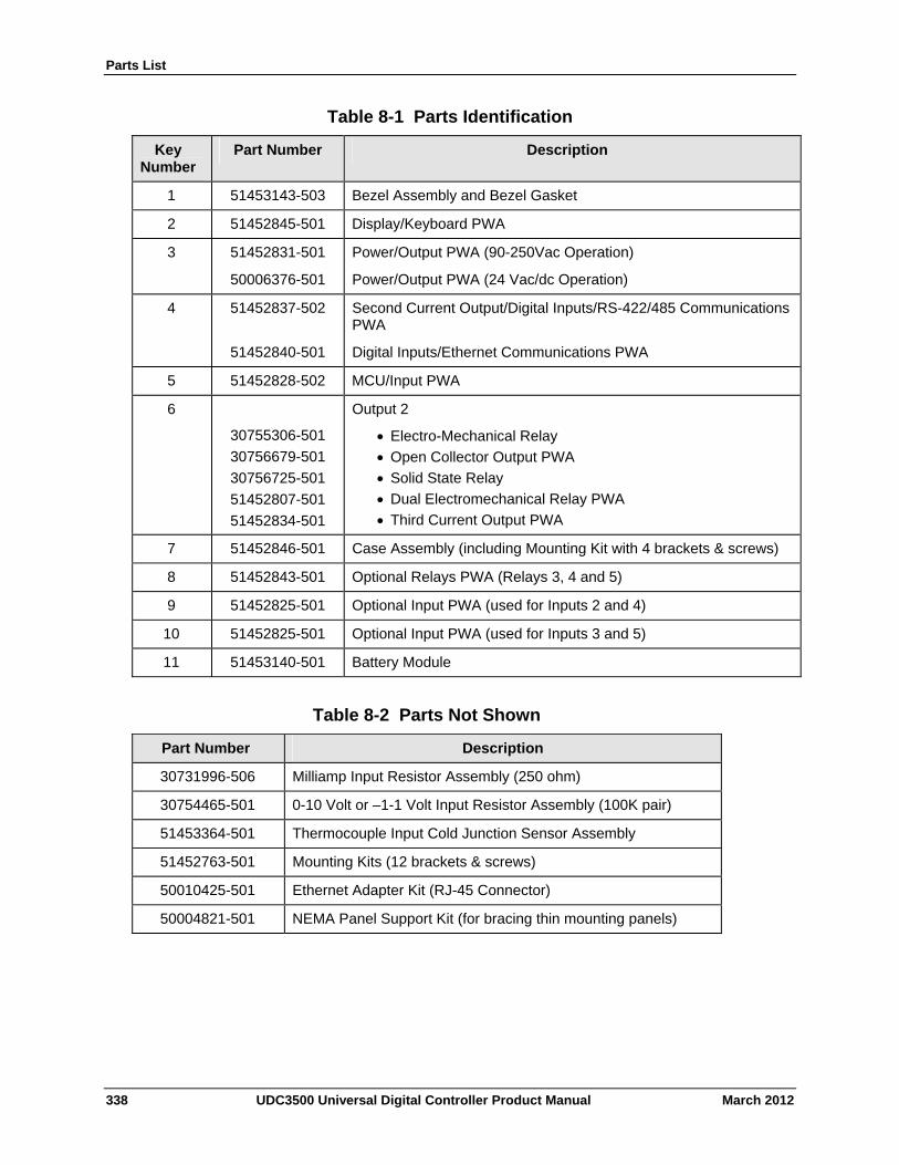
Parts List
338 UDC3500 Universal Digital Controller Product Manual March 2012
Table 8-1 Parts Identification
Key Number
Part Number Description
1 51453143-503 Bezel Assembly and Bezel Gasket
2 51452845-501 Display/Keyboard PWA
3 51452831-501
50006376-501
Power/Output PWA (90-250Vac Operation)
Power/Output PWA (24 Vac/dc Operation)
4 51452837-502
51452840-501
Second Current Output/Digital Inputs/RS-422/485 Communications PWA
Digital Inputs/Ethernet Communications PWA
5 51452828-502 MCU/Input PWA
6 30755306-501
30756679-501
30756725-501
51452807-501
51452834-501
Output 2
Electro-Mechanical Relay
Open Collector Output PWA
Solid State Relay
Dual Electromechanical Relay PWA
Third Current Output PWA
7 51452846-501 Case Assembly (including Mounting Kit with 4 brackets & screws)
8 51452843-501 Optional Relays PWA (Relays 3, 4 and 5)
9 51452825-501 Optional Input PWA (used for Inputs 2 and 4)
10 51452825-501 Optional Input PWA (used for Inputs 3 and 5)
11 51453140-501 Battery Module
Table 8-2 Parts Not Shown
Part Number Description
30731996-506 Milliamp Input Resistor Assembly (250 ohm)
30754465-501 0-10 Volt or –1-1 Volt Input Resistor Assembly (100K pair)
51453364-501 Thermocouple Input Cold Junction Sensor Assembly
51452763-501 Mounting Kits (12 brackets & screws)
50010425-501 Ethernet Adapter Kit (RJ-45 Connector)
50004821-501 NEMA Panel Support Kit (for bracing thin mounting panels)
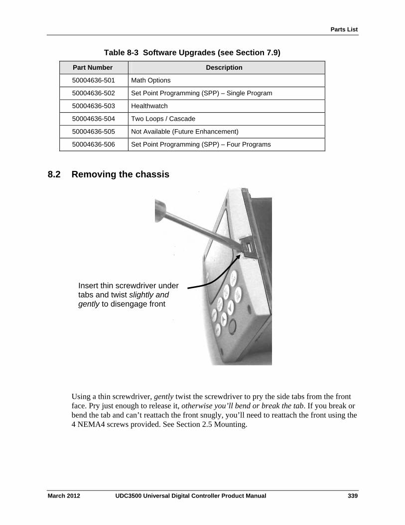
Parts List
Table 8-3 Software Upgrades (see Section 7.9)
Part Number Description
50004636-501 Math Options
50004636-502 Set Point Programming (SPP) – Single Program
50004636-503 Healthwatch
50004636-504 Two Loops / Cascade
50004636-505 Not Available (Future Enhancement)
50004636-506 Set Point Programming (SPP) – Four Programs
8.2 Removing the chassis
Using a thin screwdriver, gently twist the screwdriver to pry the side tabs from the front face. Pry just enough to release it, otherwise you’ll bend or break the tab. If you break or bend the tab and can’t reattach the front snugly, you’ll need to reattach the front using the 4 NEMA4 screws provided. See Section 2.5 Mounting.
Insert thin screwdriver under tabs and twist slightly and gently to disengage front
March 2012 UDC3500 Universal Digital Controller Product Manual 339
Modbus RTU Function Codes
9 Modbus RTU Function Codes
9.1 Overview
This section describes the function codes needed to upload and download the configuration from a host computer into the instrument.
What's in this section?
The following topics are covered in this section.
TOPIC See Page
9.1 Overview 340
9.2 General Information 340
9.3 Function Code 20 342
9.4 Function Code 21 346
9.2 General Information
This instrument uses a subset of the standard Modbus RTU function codes to provide access to process-related information. Several MODICON function codes are implemented. It is appropriate to define instrument-specific "user-defined" function codes. Where differences occur between the two protocols it will be noted. Several standard Modbus RTU function codes are supported.
Configuration ID Tags
Function codes 20 and 21 use the RS422/485 tag IDs for accessing configuration and process-related data. These tags are fully explained in Section 10.
The tag IDs represent the register addresses used in the Request Message.
340 UDC3500 Universal Digital Controller Product Manual March 2012
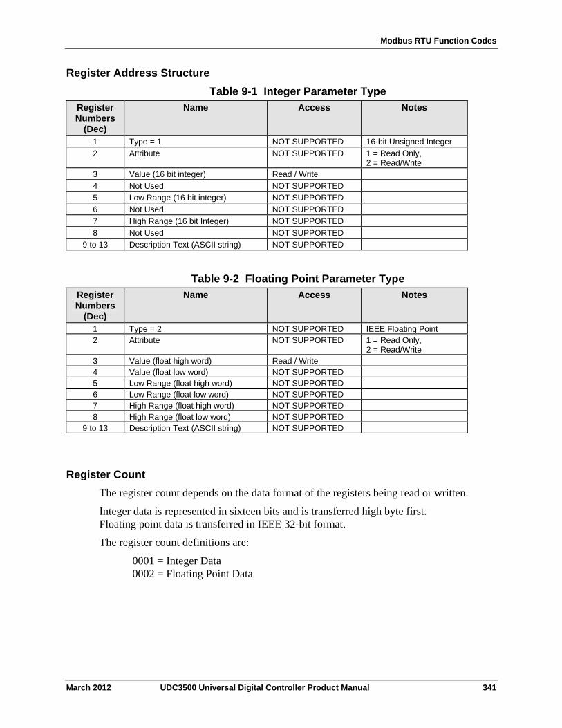
Modbus RTU Function Codes
Register Address Structure
Table 9-1 Integer Parameter Type
Name Access Notes Register Numbers
(Dec) 1 Type = 1 NOT SUPPORTED 16-bit Unsigned Integer
2 Attribute NOT SUPPORTED 1 = Read Only, 2 = Read/Write
3 Value (16 bit integer) Read / Write
4 Not Used NOT SUPPORTED
5 Low Range (16 bit integer) NOT SUPPORTED
6 Not Used NOT SUPPORTED
7 High Range (16 bit Integer) NOT SUPPORTED
8 Not Used NOT SUPPORTED
9 to 13 Description Text (ASCII string) NOT SUPPORTED
Table 9-2 Floating Point Parameter Type
Name Access Notes Register Numbers
(Dec) 1 Type = 2 NOT SUPPORTED IEEE Floating Point 2 Attribute NOT SUPPORTED 1 = Read Only,
2 = Read/Write 3 Value (float high word) Read / Write 4 Value (float low word) NOT SUPPORTED 5 Low Range (float high word) NOT SUPPORTED 6 Low Range (float low word) NOT SUPPORTED 7 High Range (float high word) NOT SUPPORTED 8 High Range (float low word) NOT SUPPORTED
9 to 13 Description Text (ASCII string) NOT SUPPORTED
Register Count
The register count depends on the data format of the registers being read or written.
Integer data is represented in sixteen bits and is transferred high byte first. Floating point data is transferred in IEEE 32-bit format.
The register count definitions are:
0001 = Integer Data 0002 = Floating Point Data
March 2012 UDC3500 Universal Digital Controller Product Manual 341
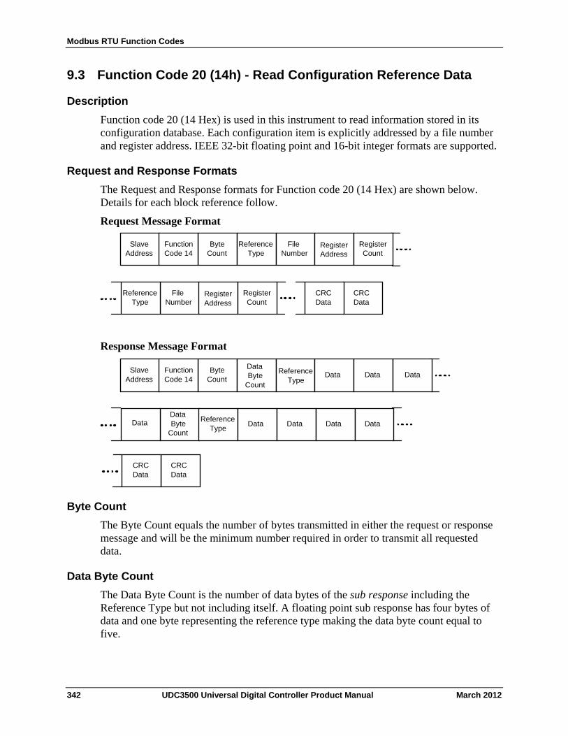
Modbus RTU Function Codes
9.3 Function Code 20 (14h) - Read Configuration Reference Data
Description
Function code 20 (14 Hex) is used in this instrument to read information stored in its configuration database. Each configuration item is explicitly addressed by a file number and register address. IEEE 32-bit floating point and 16-bit integer formats are supported.
Request and Response Formats
The Request and Response formats for Function code 20 (14 Hex) are shown below. Details for each block reference follow.
Request Message Format
Slave Address
Byte Count
Reference Type
Function Code 14
Reference Type
File Number
Register Count
Register Address
Reference Type
File Number
Register Count
Register Address
CRC Data
CRC Data
Response Message Format
Slave Address
Byte Count
Reference Type
Function Code 14
Reference Type
Data
Reference Type
Data Byte
CountData Data
DataData Byte
CountData Data Data Data
CRC Data
CRC Data
Byte Count
The Byte Count equals the number of bytes transmitted in either the request or response message and will be the minimum number required in order to transmit all requested data.
Data Byte Count
The Data Byte Count is the number of data bytes of the sub response including the Reference Type but not including itself. A floating point sub response has four bytes of data and one byte representing the reference type making the data byte count equal to five.
342 UDC3500 Universal Digital Controller Product Manual March 2012
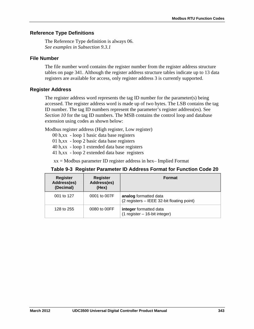
Modbus RTU Function Codes
Reference Type Definitions
The Reference Type definition is always 06. See examples in Subsection 9.3.1
File Number
The file number word contains the register number from the register address structure tables on page 341. Although the register address structure tables indicate up to 13 data registers are available for access, only register address 3 is currently supported.
Register Address
The register address word represents the tag ID number for the parameter(s) being accessed. The register address word is made up of two bytes. The LSB contains the tag ID number. The tag ID numbers represent the parameter’s register address(es). See Section 10 for the tag ID numbers. The MSB contains the control loop and database extension using codes as shown below:
Modbus register address (High register, Low register) 00 h,xx - loop 1 basic data base registers 01 h,xx - loop 2 basic data base registers 40 h,xx - loop 1 extended data base registers 41 h,xx - loop 2 extended data base registers
xx = Modbus parameter ID register address in hex– Implied Format
Table 9-3 Register Parameter ID Address Format for Function Code 20
Register Address(es)
(Hex)
Format Register Address(es)
(Decimal)
001 to 127 0001 to 007F analog formatted data (2 registers – IEEE 32-bit floating point)
128 to 255 0080 to 00FF integer formatted data (1 register – 16-bit integer)
March 2012 UDC3500 Universal Digital Controller Product Manual 343
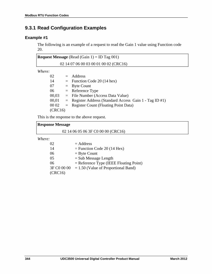
Modbus RTU Function Codes
9.3.1 Read Configuration Examples
Example #1
The following is an example of a request to read the Gain 1 value using Function code 20.
Request Message (Read (Gain 1) = ID Tag 001)
02 14 07 06 00 03 00 01 00 02 (CRC16)
Where: 02 = Address 14 = Function Code 20 (14 hex) 07 = Byte Count 06 = Reference Type 00,03 = File Number (Access Data Value) 00,01 = Register Address (Standard Access Gain 1 - Tag ID #1) 00 02 = Register Count (Floating Point Data) (CRC16)
This is the response to the above request.
Response Message
02 14 06 05 06 3F C0 00 00 (CRC16)
Where: 02 = Address 14 = Function Code 20 (14 Hex) 06 = Byte Count 05 = Sub Message Length 06 = Reference Type (IEEE Floating Point) 3F C0 00 00 = 1.50 (Value of Proportional Band) (CRC16)
344 UDC3500 Universal Digital Controller Product Manual March 2012
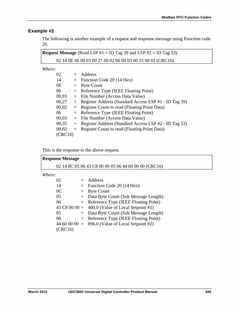
Modbus RTU Function Codes
Example #2
The following is another example of a request and response message using Function code 20.
Request Message (Read LSP #1 = ID Tag 39 and LSP #2 = ID Tag 53)
02 14 0E 06 00 03 00 27 00 02 06 00 03 00 35 00 02 (CRC16)
Where: 02 = Address 14 = Function Code 20 (14 Hex) 0E = Byte Count 06 = Reference Type (IEEE Floating Point) 00,03 = File Number (Access Data Value) 00,27 = Register Address (Standard Access LSP #1 - ID Tag 39) 00,02 = Register Count to read (Floating Point Data) 06 = Reference Type (IEEE Floating Point) 00,03 = File Number (Access Data Value) 00,35 = Register Address (Standard Access LSP #2 - ID Tag 53) 00,02 = Register Count to read (Floating Point Data) (CRC16)
This is the response to the above request.
Response Message
02 14 0C 05 06 43 C8 00 00 05 06 44 60 00 00 (CRC16)
Where: 02 = Address 14 = Function Code 20 (14 Hex) 0C = Byte Count 05 = Data Byte Count (Sub Message Length) 06 = Reference Type (IEEE Floating Point) 43 C8 00 00 = 400.0 (Value of Local Setpoint #1) 05 = Data Byte Count (Sub Message Length) 06 = Reference Type (IEEE Floating Point) 44 60 00 00 = 896.0 (Value of Local Setpoint #2) (CRC16)
March 2012 UDC3500 Universal Digital Controller Product Manual 345
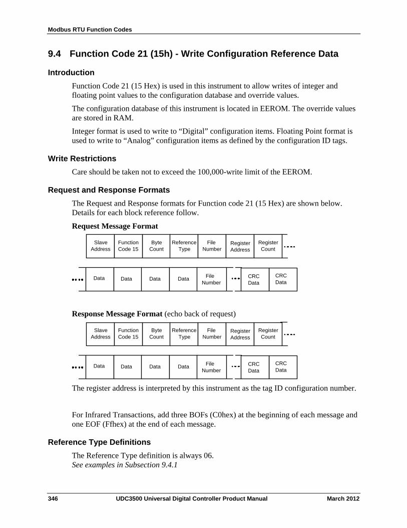
Modbus RTU Function Codes
9.4 Function Code 21 (15h) - Write Configuration Reference Data
Introduction
Function Code 21 (15 Hex) is used in this instrument to allow writes of integer and floating point values to the configuration database and override values.
The configuration database of this instrument is located in EEROM. The override values are stored in RAM.
Integer format is used to write to “Digital” configuration items. Floating Point format is used to write to “Analog” configuration items as defined by the configuration ID tags.
Write Restrictions
Care should be taken not to exceed the 100,000-write limit of the EEROM.
Request and Response Formats
The Request and Response formats for Function code 21 (15 Hex) are shown below. Details for each block reference follow.
Request Message Format
Slave Address
Byte Count
Function Code 15
Reference Type
File Number
Register Count
Register Address
CRC Data
CRC Data
Data Data Data Data File Number
Response Message Format (echo back of request)
Slave Address
Byte Count
Function Code 15
Reference Type
File Number
Register Count
Register Address
CRC Data
CRC Data
Data Data Data Data File Number
The register address is interpreted by this instrument as the tag ID configuration number.
For Infrared Transactions, add three BOFs (C0hex) at the beginning of each message and one EOF (Ffhex) at the end of each message.
Reference Type Definitions
The Reference Type definition is always 06. See examples in Subsection 9.4.1
346 UDC3500 Universal Digital Controller Product Manual March 2012
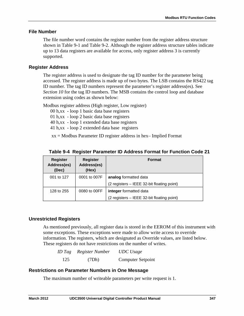
Modbus RTU Function Codes
File Number
The file number word contains the register number from the register address structure shown in Table 9-1 and Table 9-2. Although the register address structure tables indicate up to 13 data registers are available for access, only register address 3 is currently supported.
Register Address
The register address is used to designate the tag ID number for the parameter being accessed. The register address is made up of two bytes. The LSB contains the RS422 tag ID number. The tag ID numbers represent the parameter’s register address(es). See Section 10 for the tag ID numbers. The MSB contains the control loop and database extension using codes as shown below:
Modbus register address (High register, Low register) 00 h,xx - loop 1 basic data base registers 01 h,xx - loop 2 basic data base registers 40 h,xx - loop 1 extended data base registers 41 h,xx - loop 2 extended data base registers
xx = Modbus Parameter ID register address in hex– Implied Format
Table 9-4 Register Parameter ID Address Format for Function Code 21
Register Address(es)
(Hex)
Format Register Address(es)
(Dec)
0001 to 007F analog formatted data
(2 registers – IEEE 32-bit floating point)
001 to 127
128 to 255
0080 to 00FF
integer formatted data
(2 registers – IEEE 32-bit floating point)
Unrestricted Registers
As mentioned previously, all register data is stored in the EEROM of this instrument with some exceptions. These exceptions were made to allow write access to override information. The registers, which are designated as Override values, are listed below. These registers do not have restrictions on the number of writes.
ID Tag Register Number UDC Usage
125 (7Dh) Computer Setpoint
Restrictions on Parameter Numbers in One Message
The maximum number of writeable parameters per write request is 1.
March 2012 UDC3500 Universal Digital Controller Product Manual 347
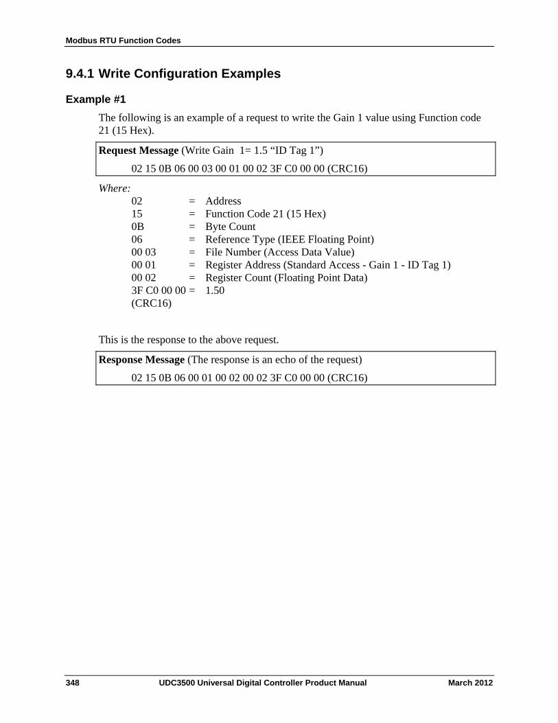
Modbus RTU Function Codes
348 UDC3500 Universal Digital Controller Product Manual March 2012
9.4.1 Write Configuration Examples
Example #1
The following is an example of a request to write the Gain 1 value using Function code 21 (15 Hex).
Request Message (Write Gain 1= 1.5 “ID Tag 1”)
02 15 0B 06 00 03 00 01 00 02 3F C0 00 00 (CRC16)
Where: 02 = Address 15 = Function Code 21 (15 Hex) 0B = Byte Count 06 = Reference Type (IEEE Floating Point) 00 03 = File Number (Access Data Value) 00 01 = Register Address (Standard Access - Gain 1 - ID Tag 1) 00 02 = Register Count (Floating Point Data) 3F C0 00 00 = 1.50 (CRC16)
This is the response to the above request.
Response Message (The response is an echo of the request)
02 15 0B 06 00 01 00 02 00 02 3F C0 00 00 (CRC16)
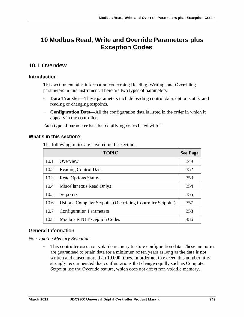
Modbus Read, Write and Override Parameters plus Exception Codes
10 Modbus Read, Write and Override Parameters plus Exception Codes
10.1 Overview
Introduction
This section contains information concerning Reading, Writing, and Overriding parameters in this instrument. There are two types of parameters:
• Data Transfer—These parameters include reading control data, option status, and reading or changing setpoints.
• Configuration Data—All the configuration data is listed in the order in which it appears in the controller.
Each type of parameter has the identifying codes listed with it.
What's in this section?
The following topics are covered in this section.
TOPIC See Page
10.1 Overview 349
10.2 Reading Control Data 352
10.3 Read Options Status 353
10.4 Miscellaneous Read Onlys 354
10.5 Setpoints 355
10.6 Using a Computer Setpoint (Overriding Controller Setpoint) 357
10.7 Configuration Parameters 358
10.8 Modbus RTU Exception Codes 436
General Information
Non-volatile Memory Retention
• This controller uses non-volatile memory to store configuration data. These memories are guaranteed to retain data for a minimum of ten years as long as the data is not written and erased more than 10,000 times. In order not to exceed this number, it is strongly recommended that configurations that change rapidly such as Computer Setpoint use the Override feature, which does not affect non-volatile memory.
March 2012 UDC3500 Universal Digital Controller Product Manual 349
Modbus Read, Write and Override Parameters plus Exception Codes
Analog Parameters
• Whenever analog register addresses xx01 through xx7F (those that can be changed via communications) are changed, a Write cycle occurs after receipt of the message and the response is returned.
Override Parameters
• Override analog register address xx7D (computer setpoint) is not stored in non-volatile memory. It can be changed as frequently as desired with no effect on non-volatile memory retentivity, but the controller must remain in the slave mode.
Digital Parameters
• Whenever digital configuration register addresses xx80 through xxFF are updated via communications, the non-volatile memory is updated as soon as the message is received.
Communications Transfer Rates
• The Host Computer must allow a minimum of 20 milliseconds between Read transactions and a minimum 200 milliseconds between Write transactions.
Supported Function Codes
• IR port 20 and 21
• RS485 and Ethernet ports 1,2,3,4,6,8,16,17,20,21
Communications Modes of Operation
• When the Shed Timer is enabled and a write or override occurs the controller will enter Slave Mode. The keypad is locked from the operator. The purpose of this mode is that if communications is lost and the shed timer times out then the controller will enter a known state of operation. The configuration of the “Shed Mode and Output” and Shed Setpoint Recall are used to configure the controller’s shed state. While in
Slave Mode pushing the
ManAutoManAutoManAuto
key enters Emergency Manual mode. The local operator then has control of the output. The controller is in Monitor Mode if the Shed timer is disabled.
EEROM Access
• All setpoints and configuration values are maintained in EEROM (Electrically Erasable Read Only Memory). To prevent unintended controller operation, the setpoint and configuration values stored in EEROM may only be altered by one source at a time, either via the Keyboard or via one of the Communications Ports (IR, RS-485 or Ethernet). Keyboard alterations take priority over all other communications methods. Therefore, whenever an operator initiates any change of value to a setpoint or to any other analog configuration value via the keyboard, the controller will then respond with a BUSY exception response to any MODBUS WRITE communications transaction initiated by the Host Computer until the operator completes accessing the EEROM. This only affects WRITE commands, READ commands will still be processed normally. Also, if the operator changes a setpoint value via the keyboard but does not save this
350 UDC3500 Universal Digital Controller Product Manual March 2012
Modbus Read, Write and Override Parameters plus Exception Codes
value into EEROM by pressing some key other than the Increment or Decrement keys, then there is an additional 15 second timeout delay after which time the changed value is automatically saved into EEROM. During this 15 second period, the controller will continue to respond with a BUSY exception message to any MODBUS WRITE communications transaction, as the controller is waiting for the operator to finish making changes to the setpoint via the keyboard. To minimize this busy period, the operator should always end a setpoint change by pressing any key other than the Increment or Decrement keys. This will reduce the time that the controller sends back busy exception messages to the host computer. MODBUS READ communication transactions are not affected, the controller will respond with a normal message to any READ command during the 15 second period.
March 2012 UDC3500 Universal Digital Controller Product Manual 351
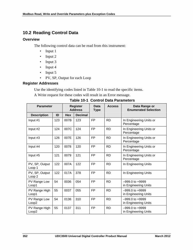
Modbus Read, Write and Override Parameters plus Exception Codes
10.2 Reading Control Data
Overview
The following control data can be read from this instrument:
• Input 1
• Input 2
• Input 3
• Input 4
• Input 5
• PV, SP, Output for each Loop
Register Addresses
Use the identifying codes listed in Table 10-1 to read the specific items.
A Write request for these codes will result in an Error message.
Table 10-1 Control Data Parameters
Register Address
Data Type
Access Data Range or Enumerated Selection
Parameter
ID Hex Decimal Description
Input #1 123 007B 123 FP RD In Engineering Units or Percentage
Input #2 124 007C 124 FP RD In Engineering Units or Percentage
Input #3 126 007E 126 FP RD In Engineering Units or Percentage
Input #4 120 0078 120 FP RD In Engineering Units or Percentage
Input #5 121 0079 121 FP RD In Engineering Units or Percentage
PV, SP, Output Loop 1
122 007A 122 FP RD In Engineering Units
PV, SP, Output Loop 2
122 017A 378 FP RD In Engineering Units
PV Range Low Loop1
54 0036 054 FP RD –999.0 to +9999 in Engineering Units
PV Range High Loop1
55 0037 055 FP RD –999.0 to +9999 in Engineering Units
PV Range Low Loop2
54 0136 310 FP RD –999.0 to +9999 in Engineering Units
PV Range High Loop2
55 0137 311 FP RD –999.0 to +9999 in Engineering Units
352 UDC3500 Universal Digital Controller Product Manual March 2012
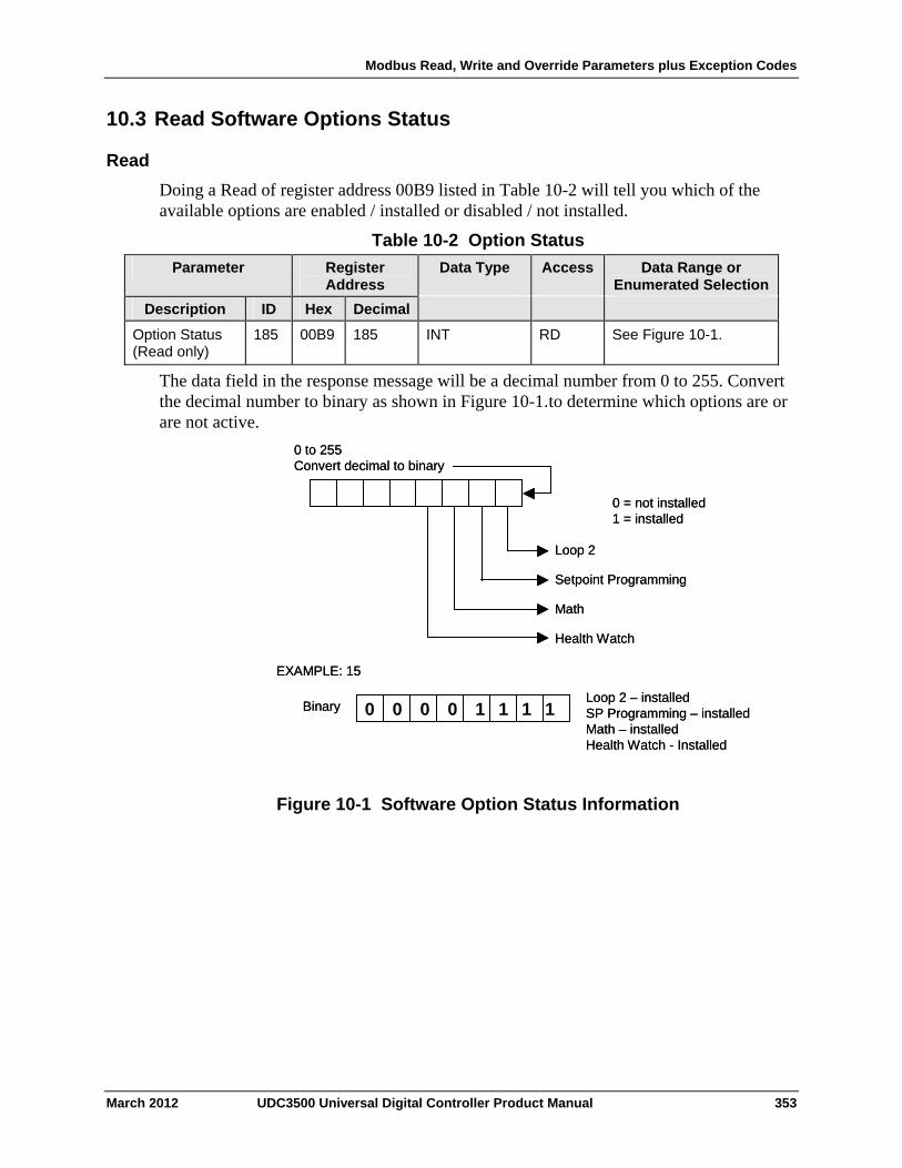
Modbus Read, Write and Override Parameters plus Exception Codes
10.3 Read Software Options Status
Read
Doing a Read of register address 00B9 listed in Table 10-2 will tell you which of the available options are enabled / installed or disabled / not installed.
Table 10-2 Option Status
Register Address
Data Type Access Data Range or Enumerated Selection
Parameter
ID Hex Decimal Description
Option Status (Read only)
185 00B9 185 INT RD See Figure 10-1.
The data field in the response message will be a decimal number from 0 to 255. Convert the decimal number to binary as shown in Figure 10-1.to determine which options are or are not active.
0 0 0 0 1 1 1 1
0 to 255Convert decimal to binary
0 = not installed1 = installed
Loop 2
Setpoint Programming
Math
Health Watch
EXAMPLE: 15
BinaryLoop 2 – installedSP Programming – installedMath – installedHealth Watch - Installed
0 0 0 0 1 1 1 10 0 0 0 1 1 1 1
0 to 255Convert decimal to binary
0 = not installed1 = installed
Loop 2
Setpoint Programming
Math
Health Watch
EXAMPLE: 15
BinaryLoop 2 – installedSP Programming – installedMath – installedHealth Watch - Installed
Figure 10-1 Software Option Status Information
March 2012 UDC3500 Universal Digital Controller Product Manual 353
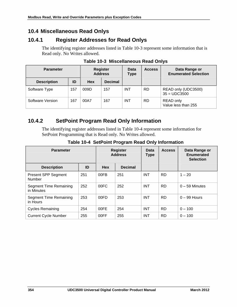
Modbus Read, Write and Override Parameters plus Exception Codes
10.4 Miscellaneous Read Onlys
10.4.1 Register Addresses for Read Onlys
The identifying register addresses listed in Table 10-3 represent some information that is Read only. No Writes allowed.
Table 10-3 Miscellaneous Read Onlys
Parameter
Register Address
Data Type
Access Data Range or Enumerated Selection
ID Hex Decimal Description
Software Type 157 009D 157 INT RD READ only (UDC3500) 35 = UDC3500
Software Version 167 00A7 167 INT RD READ only Value less than 255
10.4.2 SetPoint Program Read Only Information
The identifying register addresses listed in Table 10-4 represent some information for SetPoint Programming that is Read only. No Writes allowed.
Table 10-4 SetPoint Program Read Only Information
Parameter
Register Address
Data Type
Access Data Range or Enumerated
Selection
ID Hex Decimal Description
Present SPP Segment Number
251 00FB 251 INT RD 1 – 20
Segment Time Remaining in Minutes
252 00FC 252 INT RD 0 – 59 Minutes
Segment Time Remaining in Hours
253 00FD 253 INT RD 0 – 99 Hours
Cycles Remaining 254 00FE 254 INT RD 0 – 100
Current Cycle Number 255 00FF 255 INT RD 0 – 100
354 UDC3500 Universal Digital Controller Product Manual March 2012
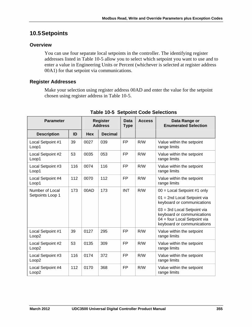
Modbus Read, Write and Override Parameters plus Exception Codes
10.5 Setpoints
Overview
You can use four separate local setpoints in the controller. The identifying register addresses listed in Table 10-5 allow you to select which setpoint you want to use and to enter a value in Engineering Units or Percent (whichever is selected at register address 00A1) for that setpoint via communications.
Register Addresses
Make your selection using register address 00AD and enter the value for the setpoint chosen using register address in Table 10-5.
Table 10-5 Setpoint Code Selections
Register Address
Data Type
Access Data Range or Enumerated Selection
Parameter
ID Hex Decimal Description
Local Setpoint #1 Loop1
39 0027 039 FP R/W Value within the setpoint range limits
Local Setpoint #2 Loop1
53 0035 053 FP R/W Value within the setpoint range limits
Local Setpoint #3 Loop1
116 0074 116 FP R/W Value within the setpoint range limits
Local Setpoint #4 Loop1
112 0070 112 FP R/W Value within the setpoint range limits
Number of Local Setpoints Loop 1
173 00AD 173 INT R/W 00 = Local Setpoint #1 only
01 = 2nd Local Setpoint via keyboard or communications
03 = 3rd Local Setpoint via keyboard or communications 04 = four Local Setpoint via keyboard or communications
Local Setpoint #1 Loop2
39 0127 295 FP R/W Value within the setpoint range limits
Local Setpoint #2 Loop2
53 0135 309 FP R/W Value within the setpoint range limits
Local Setpoint #3 Loop2
116 0174 372 FP R/W Value within the setpoint range limits
Local Setpoint #4 Loop2
112 0170 368 FP R/W Value within the setpoint range limits
March 2012 UDC3500 Universal Digital Controller Product Manual 355
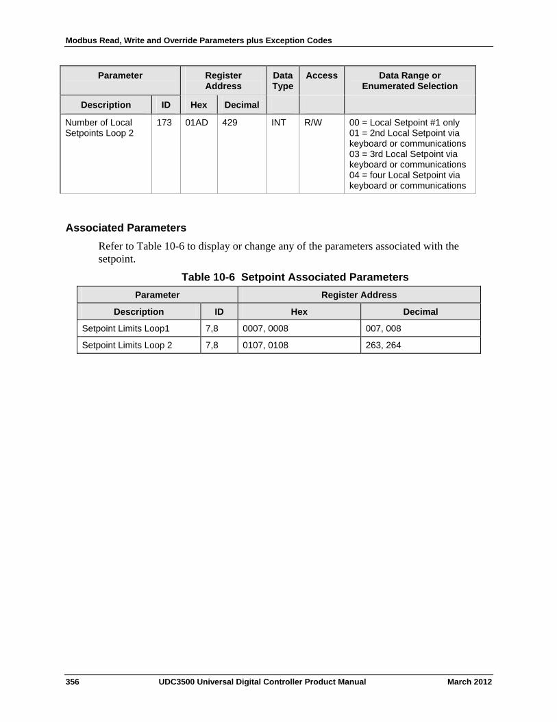
Modbus Read, Write and Override Parameters plus Exception Codes
356 UDC3500 Universal Digital Controller Product Manual March 2012
Parameter
Register Address
Data Type
Access Data Range or Enumerated Selection
Description ID Hex Decimal
Number of Local Setpoints Loop 2
173 01AD 429 INT R/W 00 = Local Setpoint #1 only 01 = 2nd Local Setpoint via keyboard or communications 03 = 3rd Local Setpoint via keyboard or communications 04 = four Local Setpoint via keyboard or communications
Associated Parameters
Refer to Table 10-6 to display or change any of the parameters associated with the setpoint.
Table 10-6 Setpoint Associated Parameters
Parameter Register Address
Description ID Hex Decimal
Setpoint Limits Loop1 7,8 0007, 0008 007, 008
Setpoint Limits Loop 2 7,8 0107, 0108 263, 264
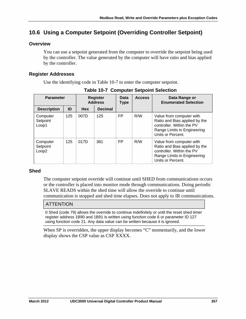
Modbus Read, Write and Override Parameters plus Exception Codes
10.6 Using a Computer Setpoint (Overriding Controller Setpoint)
Overview
You can use a setpoint generated from the computer to override the setpoint being used by the controller. The value generated by the computer will have ratio and bias applied by the controller.
Register Addresses
Use the identifying code in Table 10-7 to enter the computer setpoint.
Table 10-7 Computer Setpoint Selection
Register Address
Data Type
Access Data Range or Enumerated Selection
Parameter
ID Hex Decimal Description
Computer Setpoint Loop1
125 007D 125 FP R/W Value from computer with Ratio and Bias applied by the controller. Within the PV Range Limits in Engineering Units or Percent.
Computer Setpoint Loop2
125 017D 381 FP R/W Value from computer with Ratio and Bias applied by the controller. Within the PV Range Limits in Engineering Units or Percent.
Shed
The computer setpoint override will continue until SHED from communications occurs or the controller is placed into monitor mode through communications. Doing periodic SLAVE READS within the shed time will allow the override to continue until communication is stopped and shed time elapses. Does not apply to IR communications.
ATTENTION
0 Shed (code 79) allows the override to continue indefinitely or until the reset shed timer register address 1B90 and 1B91 is written using function code 6 or parameter ID 127 using function code 21. Any data value can be written because it is ignored.
When SP is overridden, the upper display becomes “C” momentarily, and the lower display shows the CSP value as CSP XXXX.
March 2012 UDC3500 Universal Digital Controller Product Manual 357
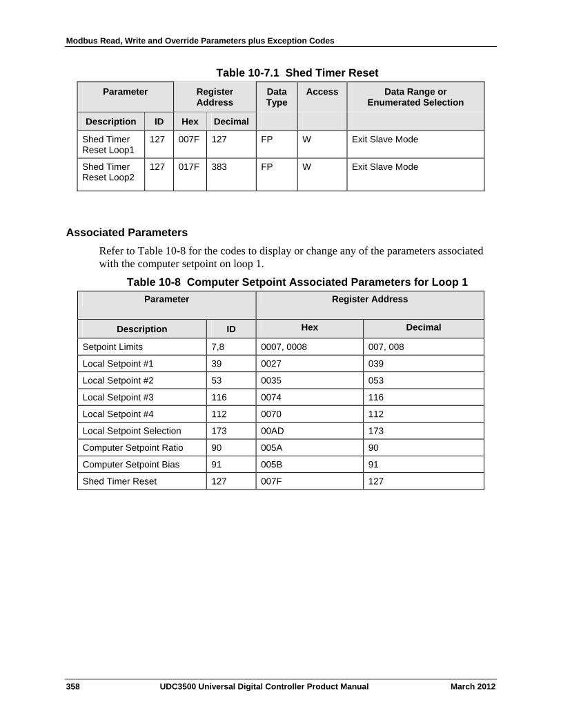
Modbus Read, Write and Override Parameters plus Exception Codes
Table 10-7.1 Shed Timer Reset
Register Address
Data Type
Access Data Range or Enumerated Selection
Parameter
ID Hex Decimal Description
Shed Timer Reset Loop1
127 007F 127 FP W Exit Slave Mode
Shed Timer Reset Loop2
127 017F 383 FP W Exit Slave Mode
Associated Parameters
Refer to Table 10-8 for the codes to display or change any of the parameters associated with the computer setpoint on loop 1.
Table 10-8 Computer Setpoint Associated Parameters for Loop 1
Parameter Register Address
ID Hex Decimal Description
Setpoint Limits 7,8 0007, 0008 007, 008
Local Setpoint #1 39 0027 039
Local Setpoint #2 53 0035 053
Local Setpoint #3 116 0074 116
Local Setpoint #4 112 0070 112
Local Setpoint Selection 173 00AD 173
Computer Setpoint Ratio 90 005A 90
Computer Setpoint Bias 91 005B 91
Shed Timer Reset 127 007F 127
358 UDC3500 Universal Digital Controller Product Manual March 2012
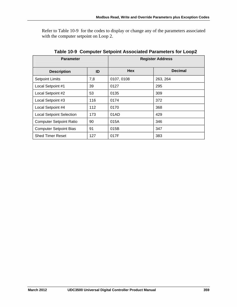
Modbus Read, Write and Override Parameters plus Exception Codes
Refer to Table 10-9 for the codes to display or change any of the parameters associated with the computer setpoint on Loop 2.
Table 10-9 Computer Setpoint Associated Parameters for Loop2
Parameter
Register Address
ID Hex Decimal Description
Setpoint Limits 7,8 0107, 0108 263, 264
Local Setpoint #1 39 0127 295
Local Setpoint #2 53 0135 309
Local Setpoint #3 116 0174 372
Local Setpoint #4 112 0170 368
Local Setpoint Selection 173 01AD 429
Computer Setpoint Ratio 90 015A 346
Computer Setpoint Bias 91 015B 347
Shed Timer Reset 127 017F 383
March 2012 UDC3500 Universal Digital Controller Product Manual 359
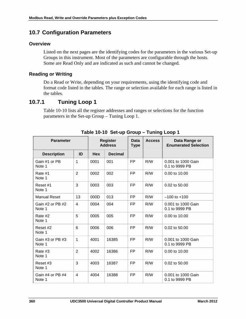
Modbus Read, Write and Override Parameters plus Exception Codes
10.7 Configuration Parameters
Overview
Listed on the next pages are the identifying codes for the parameters in the various Set-up Groups in this instrument. Most of the parameters are configurable through the hosts. Some are Read Only and are indicated as such and cannot be changed.
Reading or Writing
Do a Read or Write, depending on your requirements, using the identifying code and format code listed in the tables. The range or selection available for each range is listed in the tables.
10.7.1 Tuning Loop 1
Table 10-10 lists all the register addresses and ranges or selections for the function parameters in the Set-up Group – Tuning Loop 1.
Table 10-10 Set-up Group – Tuning Loop 1
Parameter
Register Address
Data Type
Access Data Range or Enumerated Selection
ID Hex Decimal Description
Gain #1 or PB Note 1
1 0001 001 FP R/W 0.001 to 1000 Gain 0.1 to 9999 PB
Rate #1 Note 1
2 0002 002 FP R/W 0.00 to 10.00
Reset #1 Note 1
3 0003 003 FP R/W 0.02 to 50.00
Manual Reset 13 000D 013 FP R/W –100 to +100
Gain #2 or PB #2 Note 1
4 0004 004 FP R/W 0.001 to 1000 Gain 0.1 to 9999 PB
Rate #2 Note 1
5 0005 005 FP R/W 0.00 to 10.00
Reset #2 Note 1
6 0006 006 FP R/W 0.02 to 50.00
Gain #3 or PB #3 Note 1
1 4001 16385 FP R/W 0.001 to 1000 Gain 0.1 to 9999 PB
Rate #3 Note 1
2 4002 16386 FP R/W 0.00 to 10.00
Reset #3 Note 1
3 4003 16387 FP R/W 0.02 to 50.00
Gain #4 or PB #4 Note 1
4 4004 16388 FP R/W 0.001 to 1000 Gain 0.1 to 9999 PB
360 UDC3500 Universal Digital Controller Product Manual March 2012
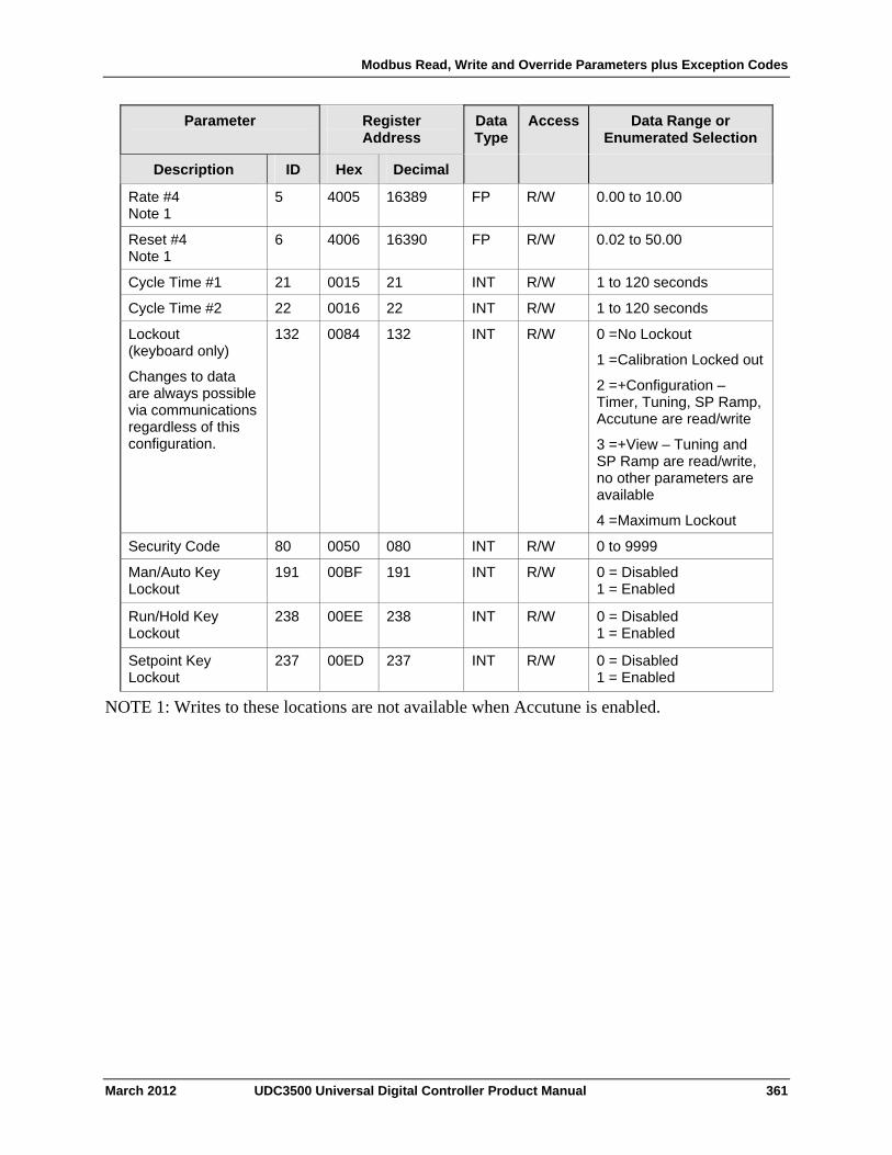
Modbus Read, Write and Override Parameters plus Exception Codes
March 2012 UDC3500 Universal Digital Controller Product Manual 361
Parameter
Register Address
Data Type
Access Data Range or Enumerated Selection
Description ID Hex Decimal
Rate #4 Note 1
5 4005 16389 FP R/W 0.00 to 10.00
Reset #4 Note 1
6 4006 16390 FP R/W 0.02 to 50.00
Cycle Time #1 21 0015 21 INT R/W 1 to 120 seconds
Cycle Time #2 22 0016 22 INT R/W 1 to 120 seconds
Lockout (keyboard only)
Changes to data are always possible via communications regardless of this configuration.
132 0084 132 INT R/W 0 = No Lockout
1 = Calibration Locked out
2 = +Configuration – Timer, Tuning, SP Ramp, Accutune are read/write
3 = +View – Tuning and SP Ramp are read/write, no other parameters are available
4 = Maximum Lockout
Security Code 80 0050 080 INT R/W 0 to 9999
Man/Auto Key Lockout
191 00BF 191 INT R/W 0 = Disabled 1 = Enabled
Run/Hold Key Lockout
238 00EE 238 INT R/W 0 = Disabled 1 = Enabled
Setpoint Key Lockout
237 00ED 237 INT R/W 0 = Disabled 1 = Enabled
NOTE 1: Writes to these locations are not available when Accutune is enabled.
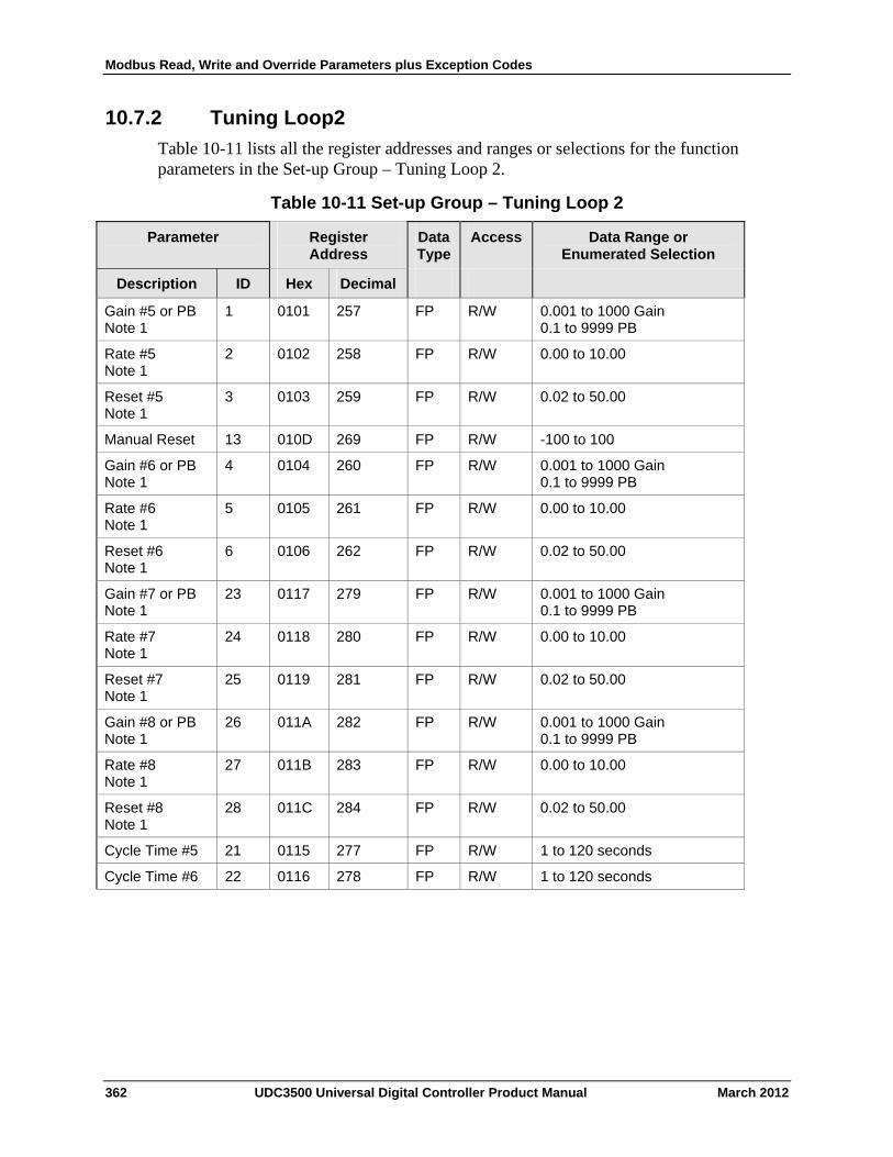
Modbus Read, Write and Override Parameters plus Exception Codes
10.7.2 Tuning Loop2
Table 10-11 lists all the register addresses and ranges or selections for the function parameters in the Set-up Group – Tuning Loop 2.
Table 10-11 Set-up Group – Tuning Loop 2
Register Address
Data Type
Access Data Range or Enumerated Selection
Parameter
ID Hex Decimal Description
Gain #5 or PB Note 1
1 0101 257 FP R/W 0.001 to 1000 Gain 0.1 to 9999 PB
Rate #5 Note 1
2 0102 258 FP R/W 0.00 to 10.00
Reset #5 Note 1
3 0103 259 FP R/W 0.02 to 50.00
Manual Reset 13 010D 269 FP R/W -100 to 100
Gain #6 or PB Note 1
4 0104 260 FP R/W 0.001 to 1000 Gain 0.1 to 9999 PB
Rate #6 Note 1
5 0105 261 FP R/W 0.00 to 10.00
Reset #6 Note 1
6 0106 262 FP R/W 0.02 to 50.00
Gain #7 or PB Note 1
23 0117 279 FP R/W 0.001 to 1000 Gain 0.1 to 9999 PB
Rate #7 Note 1
24 0118 280 FP R/W 0.00 to 10.00
Reset #7 Note 1
25 0119 281 FP R/W 0.02 to 50.00
Gain #8 or PB Note 1
26 011A 282 FP R/W 0.001 to 1000 Gain 0.1 to 9999 PB
Rate #8 Note 1
27 011B 283 FP R/W 0.00 to 10.00
Reset #8 Note 1
28 011C 284 FP R/W 0.02 to 50.00
Cycle Time #5 21 0115 277 FP R/W 1 to 120 seconds
Cycle Time #6 22 0116 278 FP R/W 1 to 120 seconds
362 UDC3500 Universal Digital Controller Product Manual March 2012
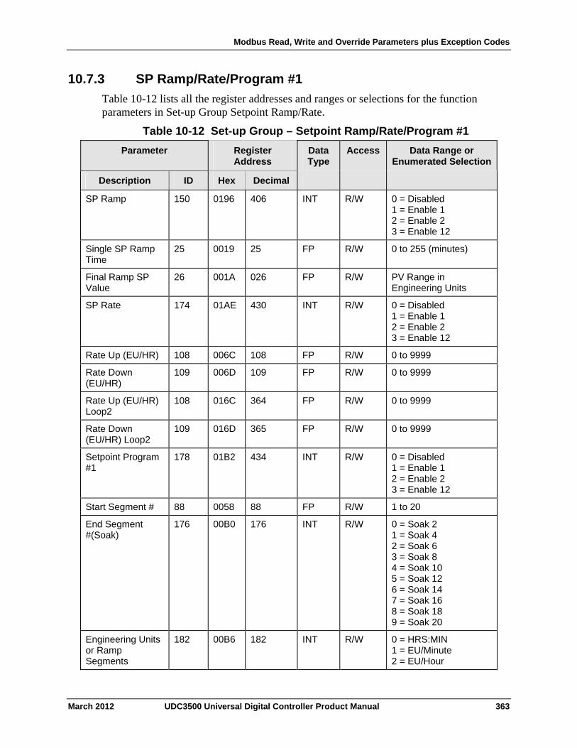
Modbus Read, Write and Override Parameters plus Exception Codes
10.7.3 SP Ramp/Rate/Program #1
Table 10-12 lists all the register addresses and ranges or selections for the function parameters in Set-up Group Setpoint Ramp/Rate.
Table 10-12 Set-up Group – Setpoint Ramp/Rate/Program #1
Parameter
Register Address
Data Type
Access Data Range or Enumerated Selection
ID Hex Decimal Description
SP Ramp 150 0196 406 INT R/W 0 = Disabled 1 = Enable 1 2 = Enable 2 3 = Enable 12
Single SP Ramp Time
25 0019 25 FP R/W 0 to 255 (minutes)
Final Ramp SP Value
26 001A 026 FP R/W PV Range in Engineering Units
SP Rate 174 01AE 430 INT R/W 0 = Disabled 1 = Enable 1 2 = Enable 2 3 = Enable 12
Rate Up (EU/HR) 108 006C 108 FP R/W 0 to 9999
Rate Down (EU/HR)
109 006D 109 FP R/W 0 to 9999
Rate Up (EU/HR) Loop2
108 016C 364 FP R/W 0 to 9999
Rate Down (EU/HR) Loop2
109 016D 365 FP R/W 0 to 9999
Setpoint Program #1
178 01B2 434 INT R/W 0 = Disabled 1 = Enable 1 2 = Enable 2 3 = Enable 12
Start Segment # 88 0058 88 FP R/W 1 to 20
End Segment #(Soak)
176
00B0 176 INT R/W 0 = Soak 2 1 = Soak 4 2 = Soak 6 3 = Soak 8 4 = Soak 10 5 = Soak 12 6 = Soak 14 7 = Soak 16 8 = Soak 18 9 = Soak 20
Engineering Units or Ramp Segments
182 00B6 182 INT R/W 0 = HRS:MIN 1 = EU/Minute 2 = EU/Hour
March 2012 UDC3500 Universal Digital Controller Product Manual 363
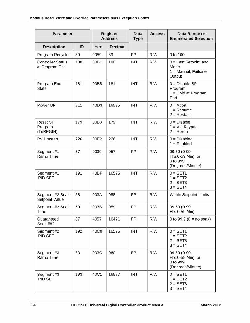
Modbus Read, Write and Override Parameters plus Exception Codes
364 UDC3500 Universal Digital Controller Product Manual March 2012
Parameter
Register Address
Data Type
Access Data Range or Enumerated Selection
Description ID Hex Decimal
Program Recycles 89 0059 89 FP R/W 0 to 100
Controller Status at Program End
180 00B4 180 INT R/W 0 = Last Setpoint and Mode 1 = Manual, Failsafe Output
Program End State
181 00B5 181 INT R/W 0 = Disable SP Program 1 = Hold at Program End
Power UP 211 40D3 16595 INT R/W 0 = Abort 1 = Resume 2 = Restart
Reset SP Program (ToBEGIN)
179 00B3 179 INT R/W 0 = Disable 1 = Via Keypad 2 = Rerun
PV Hotstart 226 00E2 226 INT R/W 0 = Disabled 1 = Enabled
Segment #1 Ramp Time
57 0039 057 FP R/W 99.59 (0-99 Hrs:0-59 Min) or 0 to 999 (Degrees/Minute)
Segment #1 PID SET
191 40BF 16575 INT R/W 0 = SET1 1 = SET2 2 = SET3 3 = SET4
Segment #2 Soak Setpoint Value
58 003A 058 FP R/W Within Setpoint Limits
Segment #2 Soak Time
59 003B 059 FP R/W 99.59 (0-99 Hrs:0-59 Min)
Guaranteed Soak ##2
87 4057 16471 FP R/W 0 to 99.9 (0 = no soak)
Segment #2 PID SET
192 40C0 16576 INT R/W 0 = SET1 1 = SET2 2 = SET3 3 = SET4
Segment #3 Ramp Time
60 003C 060 FP R/W 99.59 (0-99 Hrs:0-59 Min) or 0 to 999 (Degrees/Minute)
Segment #3 PID SET
193 40C1 16577 INT R/W 0 = SET1 1 = SET2 2 = SET3 3 = SET4

Modbus Read, Write and Override Parameters plus Exception Codes
March 2012 UDC3500 Universal Digital Controller Product Manual 365
Parameter
Register Address
Data Type
Access Data Range or Enumerated Selection
Description ID Hex Decimal
Segment #4 Soak Setpoint Value
61 003D 061 FP R/W Within Setpoint Limits
Segment #4 Soak Time
62 003E 062 FP R/W 99.59 (0-99 Hrs:0-59 Min)
Guaranteed Soak ##4
89 4058 16472 FP R/W 0 to 99.9 (0 = no soak)
Segment #4 PID SET
194 40C2 16578 INT R/W 0 = SET1 1 = SET2 2 = SET3 3 = SET4
Segment #5 Ramp Time
63 003F 063 FP R/W 99.59 (0-99 Hrs:0-59 Min) or 0 to 999 (Degrees/Minute)
Segment #5 PID SET
195 40C3 16579 INT R/W 0 = SET1 1 = SET2 2 = SET3 3 = SET4
Segment #6 Soak Setpoint Value
64 0040 064 FP R/W Within Setpoint Limits
Segment #6 Soak Time
65 0041 065 FP R/W 99.59 (0-99 Hrs:0-59 Min)
Guaranteed Soak ##6
89 4059 16473 FP R/W 0 to 99.9 (0 = no soak)
Segment #6 PID SET
196 40C4 16580 INT R/W 0 = SET1 1 = SET2 2 = SET3 3 = SET4
Segment #7 Ramp Time
66 0042 066 FP R/W 99.59 (0-99 Hrs:0-59 Min) or 0 to 999 (Degrees/Minute)
Segment #7 PID SET
197 40C5 16581 INT R/W 0 = SET1 1 = SET2 2 = SET3 3 = SET4
Segment #8 Soak Setpoint Value
67 0043 067 FP R/W Within Setpoint Limits
Segment #8 Soak Time
68 0044 068 FP R/W 99.59 (0-99 Hrs:0-59 Min)
Guaranteed Soak ##8
90 405A 16474 FP R/W 0 to 99.9 (0 = no soak)
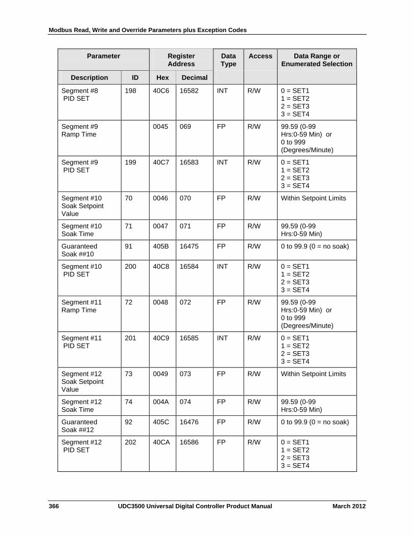
Modbus Read, Write and Override Parameters plus Exception Codes
366 UDC3500 Universal Digital Controller Product Manual March 2012
Parameter
Register Address
Data Type
Access Data Range or Enumerated Selection
Description ID Hex Decimal
Segment #8 PID SET
198 40C6 16582 INT R/W 0 = SET1 1 = SET2 2 = SET3 3 = SET4
Segment #9 Ramp Time
0045 069 FP R/W 99.59 (0-99 Hrs:0-59 Min) or 0 to 999 (Degrees/Minute)
Segment #9 PID SET
199 40C7 16583 INT R/W 0 = SET1 1 = SET2 2 = SET3 3 = SET4
Segment #10 Soak Setpoint Value
70 0046 070 FP R/W Within Setpoint Limits
Segment #10 Soak Time
71 0047 071 FP R/W 99.59 (0-99 Hrs:0-59 Min)
Guaranteed Soak ##10
91 405B 16475 FP R/W 0 to 99.9 (0 = no soak)
Segment #10 PID SET
200 40C8 16584 INT R/W 0 = SET1 1 = SET2 2 = SET3 3 = SET4
Segment #11 Ramp Time
72 0048 072 FP R/W 99.59 (0-99 Hrs:0-59 Min) or 0 to 999 (Degrees/Minute)
Segment #11 PID SET
201 40C9 16585 INT R/W 0 = SET1 1 = SET2 2 = SET3 3 = SET4
Segment #12 Soak Setpoint Value
73 0049 073 FP R/W Within Setpoint Limits
Segment #12 Soak Time
74 004A 074 FP R/W 99.59 (0-99 Hrs:0-59 Min)
Guaranteed Soak ##12
92 405C 16476 FP R/W 0 to 99.9 (0 = no soak)
Segment #12 PID SET
202 40CA 16586 FP R/W 0 = SET1 1 = SET2 2 = SET3 3 = SET4
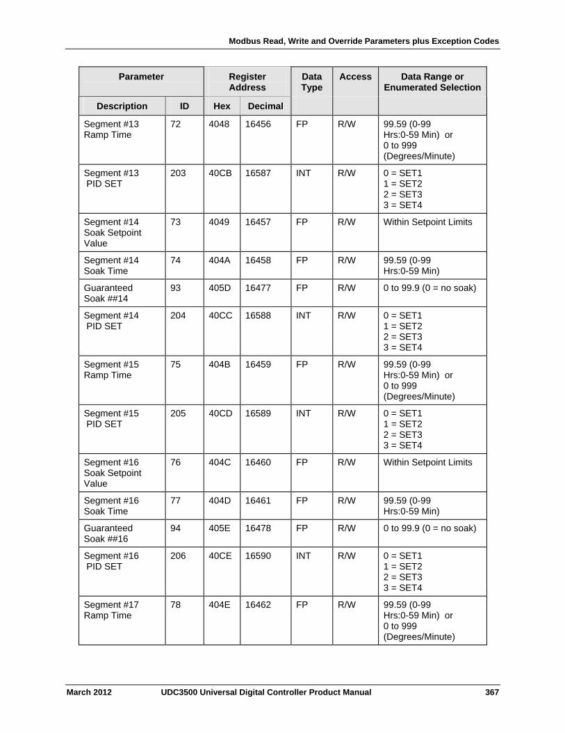
Modbus Read, Write and Override Parameters plus Exception Codes
March 2012 UDC3500 Universal Digital Controller Product Manual 367
Parameter
Register Address
Data Type
Access Data Range or Enumerated Selection
Description ID Hex Decimal
Segment #13 Ramp Time
72 4048 16456 FP R/W 99.59 (0-99 Hrs:0-59 Min) or 0 to 999 (Degrees/Minute)
Segment #13 PID SET
203 40CB 16587 INT R/W 0 = SET1 1 = SET2 2 = SET3 3 = SET4
Segment #14 Soak Setpoint Value
73 4049 16457 FP R/W Within Setpoint Limits
Segment #14 Soak Time
74 404A 16458 FP R/W 99.59 (0-99 Hrs:0-59 Min)
Guaranteed Soak ##14
93 405D 16477 FP R/W 0 to 99.9 (0 = no soak)
Segment #14 PID SET
204 40CC 16588 INT R/W 0 = SET1 1 = SET2 2 = SET3 3 = SET4
Segment #15 Ramp Time
75 404B 16459 FP R/W 99.59 (0-99 Hrs:0-59 Min) or 0 to 999 (Degrees/Minute)
Segment #15 PID SET
205 40CD 16589 INT R/W 0 = SET1 1 = SET2 2 = SET3 3 = SET4
Segment #16 Soak Setpoint Value
76 404C 16460 FP R/W Within Setpoint Limits
Segment #16 Soak Time
77 404D 16461 FP R/W 99.59 (0-99 Hrs:0-59 Min)
Guaranteed Soak ##16
94 405E 16478 FP R/W 0 to 99.9 (0 = no soak)
Segment #16 PID SET
206 40CE 16590 INT R/W 0 = SET1 1 = SET2 2 = SET3 3 = SET4
Segment #17 Ramp Time
78 404E 16462 FP R/W 99.59 (0-99 Hrs:0-59 Min) or 0 to 999 (Degrees/Minute)
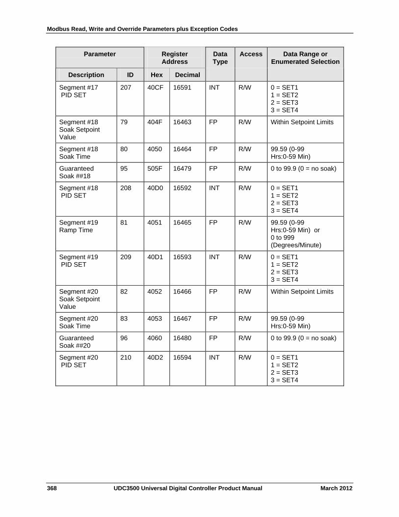
Modbus Read, Write and Override Parameters plus Exception Codes
368 UDC3500 Universal Digital Controller Product Manual March 2012
Parameter
Register Address
Data Type
Access Data Range or Enumerated Selection
Description ID Hex Decimal
Segment #17 PID SET
207 40CF 16591 INT R/W 0 = SET1 1 = SET2 2 = SET3 3 = SET4
Segment #18 Soak Setpoint Value
79 404F 16463 FP R/W Within Setpoint Limits
Segment #18 Soak Time
80 4050 16464 FP R/W 99.59 (0-99 Hrs:0-59 Min)
Guaranteed Soak ##18
95 505F 16479 FP R/W 0 to 99.9 (0 = no soak)
Segment #18 PID SET
208 40D0 16592 INT R/W 0 = SET1 1 = SET2 2 = SET3 3 = SET4
Segment #19 Ramp Time
81 4051 16465 FP R/W 99.59 (0-99 Hrs:0-59 Min) or 0 to 999 (Degrees/Minute)
Segment #19 PID SET
209 40D1 16593 INT R/W 0 = SET1 1 = SET2 2 = SET3 3 = SET4
Segment #20 Soak Setpoint Value
82 4052 16466 FP R/W Within Setpoint Limits
Segment #20 Soak Time
83 4053 16467 FP R/W 99.59 (0-99 Hrs:0-59 Min)
Guaranteed Soak ##20
96 4060 16480 FP R/W 0 to 99.9 (0 = no soak)
Segment #20 PID SET
210 40D2 16594 INT R/W 0 = SET1 1 = SET2 2 = SET3 3 = SET4
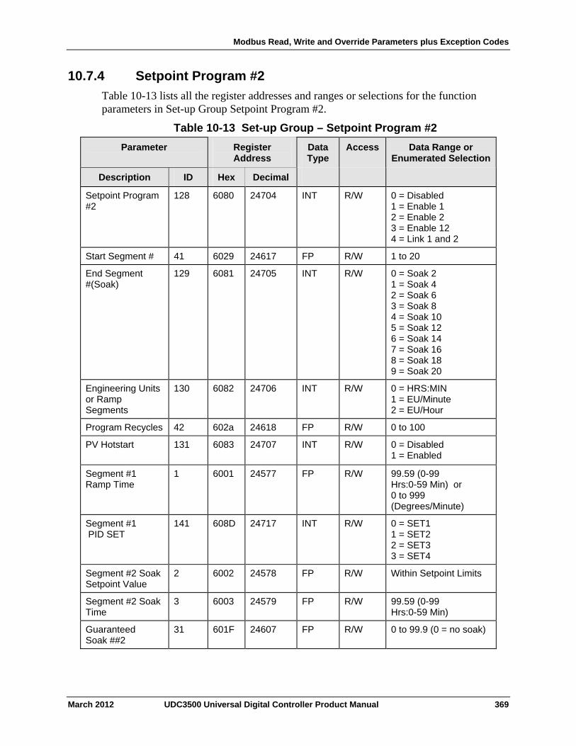
Modbus Read, Write and Override Parameters plus Exception Codes
10.7.4 Setpoint Program #2
Table 10-13 lists all the register addresses and ranges or selections for the function parameters in Set-up Group Setpoint Program #2.
Table 10-13 Set-up Group – Setpoint Program #2
Parameter
Register Address
Data Type
Access Data Range or Enumerated Selection
ID Hex Decimal Description
Setpoint Program #2
128 6080 24704 INT R/W 0 = Disabled 1 = Enable 1 2 = Enable 2 3 = Enable 12 4 = Link 1 and 2
Start Segment # 41 6029 24617 FP R/W 1 to 20
End Segment #(Soak)
129
6081 24705 INT R/W 0 = Soak 2 1 = Soak 4 2 = Soak 6 3 = Soak 8 4 = Soak 10 5 = Soak 12 6 = Soak 14 7 = Soak 16 8 = Soak 18 9 = Soak 20
Engineering Units or Ramp Segments
130 6082 24706 INT R/W 0 = HRS:MIN 1 = EU/Minute 2 = EU/Hour
Program Recycles 42 602a 24618 FP R/W 0 to 100
PV Hotstart 131 6083 24707 INT R/W 0 = Disabled 1 = Enabled
Segment #1 Ramp Time
1 6001 24577 FP R/W 99.59 (0-99 Hrs:0-59 Min) or 0 to 999 (Degrees/Minute)
Segment #1 PID SET
141 608D 24717 INT R/W 0 = SET1 1 = SET2 2 = SET3 3 = SET4
Segment #2 Soak Setpoint Value
2 6002 24578 FP R/W Within Setpoint Limits
Segment #2 Soak Time
3 6003 24579 FP R/W 99.59 (0-99 Hrs:0-59 Min)
Guaranteed Soak ##2
31 601F 24607 FP R/W 0 to 99.9 (0 = no soak)
March 2012 UDC3500 Universal Digital Controller Product Manual 369
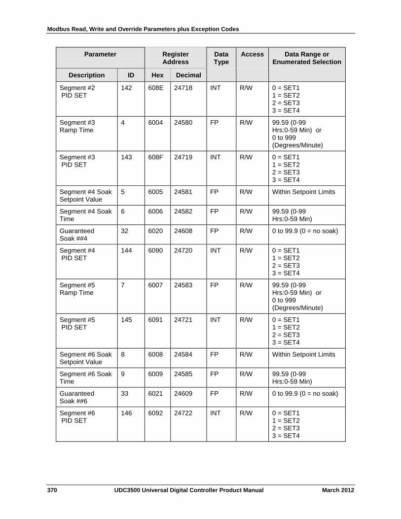
Modbus Read, Write and Override Parameters plus Exception Codes
370 UDC3500 Universal Digital Controller Product Manual March 2012
Parameter
Register Address
Data Type
Access Data Range or Enumerated Selection
Description ID Hex Decimal
Segment #2 PID SET
142 608E 24718 INT R/W 0 = SET1 1 = SET2 2 = SET3 3 = SET4
Segment #3 Ramp Time
4 6004 24580 FP R/W 99.59 (0-99 Hrs:0-59 Min) or 0 to 999 (Degrees/Minute)
Segment #3 PID SET
143 608F 24719 INT R/W 0 = SET1 1 = SET2 2 = SET3 3 = SET4
Segment #4 Soak Setpoint Value
5 6005 24581 FP R/W Within Setpoint Limits
Segment #4 Soak Time
6 6006 24582 FP R/W 99.59 (0-99 Hrs:0-59 Min)
Guaranteed Soak ##4
32 6020 24608 FP R/W 0 to 99.9 (0 = no soak)
Segment #4 PID SET
144 6090 24720 INT R/W 0 = SET1 1 = SET2 2 = SET3 3 = SET4
Segment #5 Ramp Time
7 6007 24583 FP R/W 99.59 (0-99 Hrs:0-59 Min) or 0 to 999 (Degrees/Minute)
Segment #5 PID SET
145 6091 24721 INT R/W 0 = SET1 1 = SET2 2 = SET3 3 = SET4
Segment #6 Soak Setpoint Value
8 6008 24584 FP R/W Within Setpoint Limits
Segment #6 Soak Time
9 6009 24585 FP R/W 99.59 (0-99 Hrs:0-59 Min)
Guaranteed Soak ##6
33 6021 24609 FP R/W 0 to 99.9 (0 = no soak)
Segment #6 PID SET
146 6092 24722 INT R/W 0 = SET1 1 = SET2 2 = SET3 3 = SET4

Modbus Read, Write and Override Parameters plus Exception Codes
March 2012 UDC3500 Universal Digital Controller Product Manual 371
Parameter
Register Address
Data Type
Access Data Range or Enumerated Selection
Description ID Hex Decimal
Segment #7 Ramp Time
10 600A 24586 FP R/W 99.59 (0-99 Hrs:0-59 Min) or 0 to 999 (Degrees/Minute)
Segment #7 PID SET
147 6093 24723 INT R/W 0 = SET1 1 = SET2 2 = SET3 3 = SET4
Segment #8 Soak Setpoint Value
11 600B 24587 FP R/W Within Setpoint Limits
Segment #8 Soak Time
12 600C 24588 FP R/W 99.59 (0-99 Hrs:0-59 Min)
Guaranteed Soak ##8
34 6022 24610 FP R/W 0 to 99.9 (0 = no soak)
Segment #8 PID SET
148 6094 24724 INT R/W 0 = SET1 1 = SET2 2 = SET3 3 = SET4
Segment #9 Ramp Time
13 600D 24589 FP R/W 99.59 (0-99 Hrs:0-59 Min) or 0 to 999 (Degrees/Minute)
Segment #9 PID SET
149 6095 24725 INT R/W 0 = SET1 1 = SET2 2 = SET3 3 = SET4
Segment #10 Soak Setpoint Value
14 600E 24590 FP R/W Within Setpoint Limits
Segment #10 Soak Time
15 600F 24591 FP R/W 99.59 (0-99 Hrs:0-59 Min)
Guaranteed Soak ##10
35 6023 24611 FP R/W 0 to 99.9 (0 = no soak)
Segment #10 PID SET
150 6096 24726 INT R/W 0 = SET1 1 = SET2 2 = SET3 3 = SET4
Segment #11 Ramp Time
16 6010 24592 FP R/W 99.59 (0-99 Hrs:0-59 Min) or 0 to 999 (Degrees/Minute)

Modbus Read, Write and Override Parameters plus Exception Codes
372 UDC3500 Universal Digital Controller Product Manual March 2012
Parameter
Register Address
Data Type
Access Data Range or Enumerated Selection
Description ID Hex Decimal
Segment #11 PID SET
151 6097 24727 INT R/W 0 = SET1 1 = SET2 2 = SET3 3 = SET4
Segment #12 Soak Setpoint Value
17 6011 24593 FP R/W Within Setpoint Limits
Segment #12 Soak Time
18 6012 24594 FP R/W 99.59 (0-99 Hrs:0-59 Min)
Guaranteed Soak ##12
36 6024 24612 FP R/W 0 to 99.9 (0 = no soak)
Segment #12 PID SET
152 6098 24728 FP R/W 0 = SET1 1 = SET2 2 = SET3 3 = SET4
Segment #13 Ramp Time
19 6013 24595 FP R/W 99.59 (0-99 Hrs:0-59 Min) or 0 to 999 (Degrees/Minute)
Segment #13 PID SET
153 6099 24729 INT R/W 0 = SET1 1 = SET2 2 = SET3 3 = SET4
Segment #14 Soak Setpoint Value
20 6014 24596 FP R/W Within Setpoint Limits
Segment #14 Soak Time
21 6015 24597 FP R/W 99.59 (0-99 Hrs:0-59 Min)
Guaranteed Soak ##14
37 6025 24613 FP R/W 0 to 99.9 (0 = no soak)
Segment #14 PID SET
154 609A 24730 INT R/W 0 = SET1 1 = SET2 2 = SET3 3 = SET4
Segment #15 Ramp Time
22 6016 24598 FP R/W 99.59 (0-99 Hrs:0-59 Min) or 0 to 999 (Degrees/Minute)
Segment #15 PID SET
155 609B 24731 INT R/W 0 = SET1 1 = SET2 2 = SET3 3 = SET4
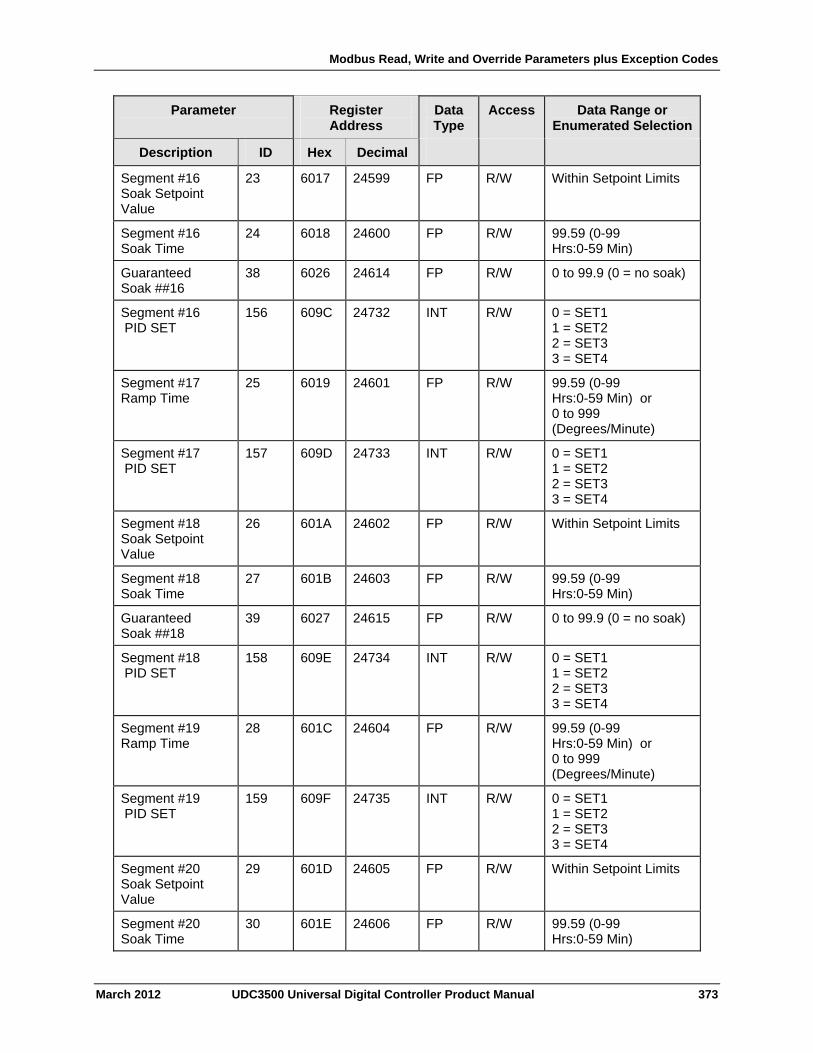
Modbus Read, Write and Override Parameters plus Exception Codes
March 2012 UDC3500 Universal Digital Controller Product Manual 373
Parameter
Register Address
Data Type
Access Data Range or Enumerated Selection
Description ID Hex Decimal
Segment #16 Soak Setpoint Value
23 6017 24599 FP R/W Within Setpoint Limits
Segment #16 Soak Time
24 6018 24600 FP R/W 99.59 (0-99 Hrs:0-59 Min)
Guaranteed Soak ##16
38 6026 24614 FP R/W 0 to 99.9 (0 = no soak)
Segment #16 PID SET
156 609C 24732 INT R/W 0 = SET1 1 = SET2 2 = SET3 3 = SET4
Segment #17 Ramp Time
25 6019 24601 FP R/W 99.59 (0-99 Hrs:0-59 Min) or 0 to 999 (Degrees/Minute)
Segment #17 PID SET
157 609D 24733 INT R/W 0 = SET1 1 = SET2 2 = SET3 3 = SET4
Segment #18 Soak Setpoint Value
26 601A 24602 FP R/W Within Setpoint Limits
Segment #18 Soak Time
27 601B 24603 FP R/W 99.59 (0-99 Hrs:0-59 Min)
Guaranteed Soak ##18
39 6027 24615 FP R/W 0 to 99.9 (0 = no soak)
Segment #18 PID SET
158 609E 24734 INT R/W 0 = SET1 1 = SET2 2 = SET3 3 = SET4
Segment #19 Ramp Time
28 601C 24604 FP R/W 99.59 (0-99 Hrs:0-59 Min) or 0 to 999 (Degrees/Minute)
Segment #19 PID SET
159 609F 24735 INT R/W 0 = SET1 1 = SET2 2 = SET3 3 = SET4
Segment #20 Soak Setpoint Value
29 601D 24605 FP R/W Within Setpoint Limits
Segment #20 Soak Time
30 601E 24606 FP R/W 99.59 (0-99 Hrs:0-59 Min)
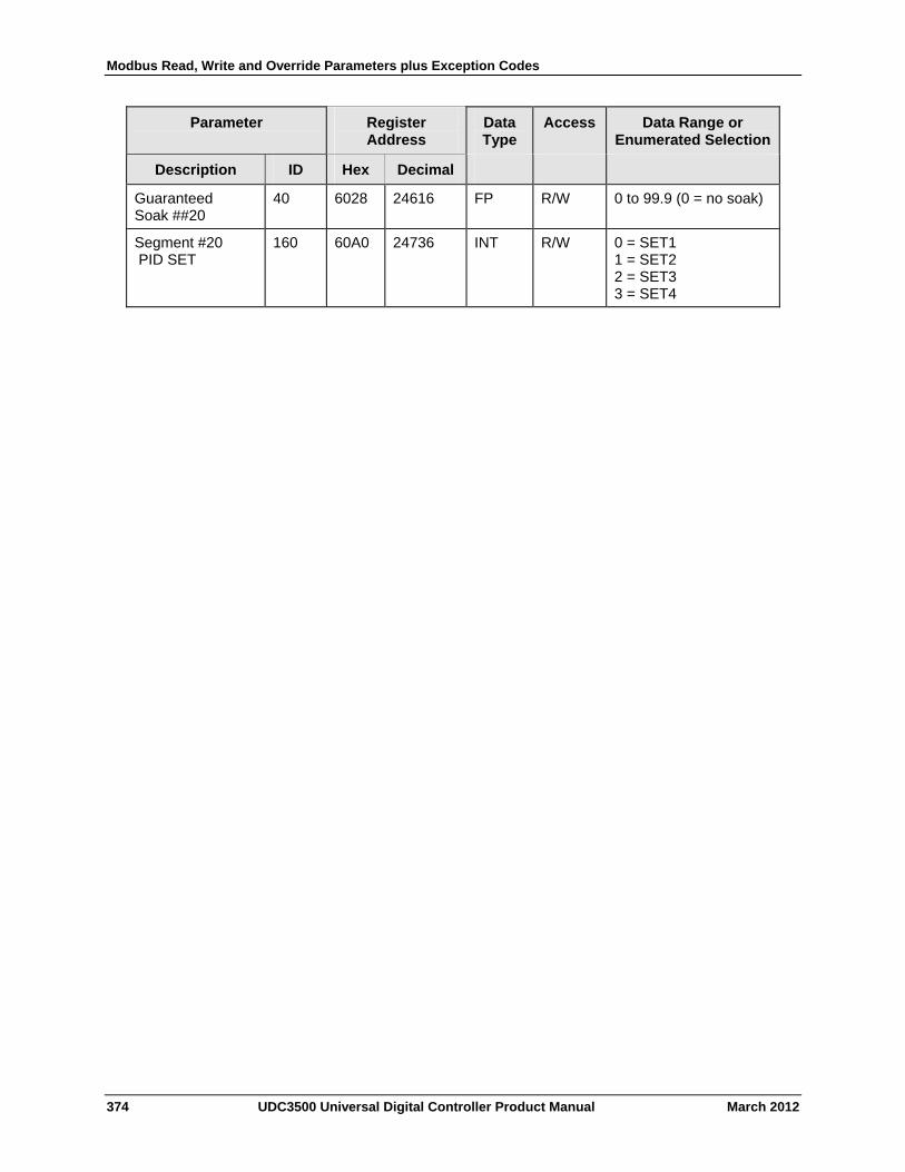
Modbus Read, Write and Override Parameters plus Exception Codes
374 UDC3500 Universal Digital Controller Product Manual March 2012
Parameter
Register Address
Data Type
Access Data Range or Enumerated Selection
Description ID Hex Decimal
Guaranteed Soak ##20
40 6028 24616 FP R/W 0 to 99.9 (0 = no soak)
Segment #20 PID SET
160 60A0 24736 INT R/W 0 = SET1 1 = SET2 2 = SET3 3 = SET4
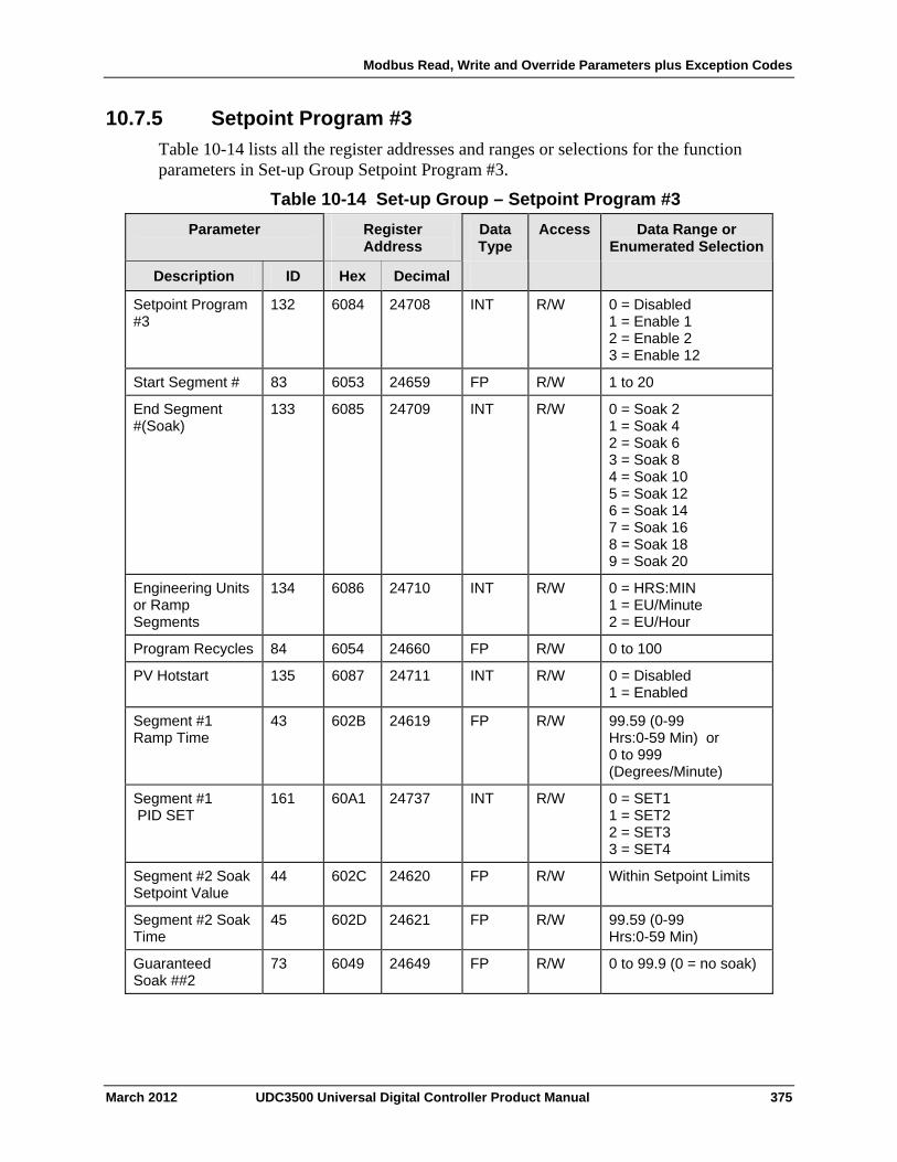
Modbus Read, Write and Override Parameters plus Exception Codes
10.7.5 Setpoint Program #3
Table 10-14 lists all the register addresses and ranges or selections for the function parameters in Set-up Group Setpoint Program #3.
Table 10-14 Set-up Group – Setpoint Program #3
Parameter
Register Address
Data Type
Access Data Range or Enumerated Selection
ID Hex Decimal Description
Setpoint Program #3
132 6084 24708 INT R/W 0 = Disabled 1 = Enable 1 2 = Enable 2 3 = Enable 12
Start Segment # 83 6053 24659 FP R/W 1 to 20
End Segment #(Soak)
133 6085 24709 INT R/W 0 = Soak 2 1 = Soak 4 2 = Soak 6 3 = Soak 8 4 = Soak 10 5 = Soak 12 6 = Soak 14 7 = Soak 16 8 = Soak 18 9 = Soak 20
Engineering Units or Ramp Segments
134 6086 24710 INT R/W 0 = HRS:MIN 1 = EU/Minute 2 = EU/Hour
Program Recycles 84 6054 24660 FP R/W 0 to 100
PV Hotstart 135 6087 24711 INT R/W 0 = Disabled 1 = Enabled
Segment #1 Ramp Time
43 602B 24619 FP R/W 99.59 (0-99 Hrs:0-59 Min) or 0 to 999 (Degrees/Minute)
Segment #1 PID SET
161 60A1 24737 INT R/W 0 = SET1 1 = SET2 2 = SET3 3 = SET4
Segment #2 Soak Setpoint Value
44 602C 24620 FP R/W Within Setpoint Limits
Segment #2 Soak Time
45 602D 24621 FP R/W 99.59 (0-99 Hrs:0-59 Min)
Guaranteed Soak ##2
73 6049 24649 FP R/W 0 to 99.9 (0 = no soak)
March 2012 UDC3500 Universal Digital Controller Product Manual 375
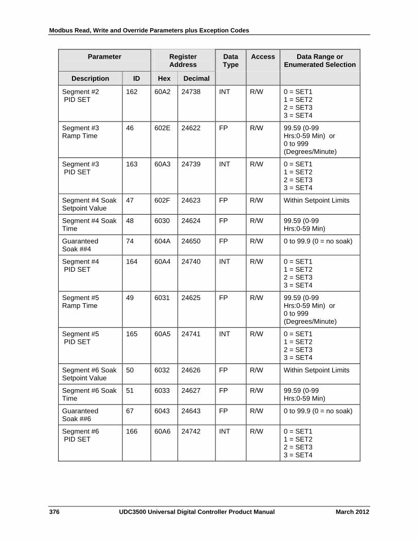
Modbus Read, Write and Override Parameters plus Exception Codes
Parameter
Register Address
Data Type
Access Data Range or Enumerated Selection
Description ID Hex Decimal
Segment #2 PID SET
162 60A2 24738 INT R/W 0 = SET1 1 = SET2 2 = SET3 3 = SET4
Segment #3 Ramp Time
46 602E 24622 FP R/W 99.59 (0-99 Hrs:0-59 Min) or 0 to 999 (Degrees/Minute)
Segment #3 PID SET
163 60A3 24739 INT R/W 0 = SET1 1 = SET2 2 = SET3 3 = SET4
Segment #4 Soak Setpoint Value
47 602F 24623 FP R/W Within Setpoint Limits
Segment #4 Soak Time
48 6030 24624 FP R/W 99.59 (0-99 Hrs:0-59 Min)
Guaranteed Soak ##4
74 604A 24650 FP R/W 0 to 99.9 (0 = no soak)
Segment #4 PID SET
164 60A4 24740 INT R/W 0 = SET1 1 = SET2 2 = SET3 3 = SET4
Segment #5 Ramp Time
49 6031 24625 FP R/W 99.59 (0-99 Hrs:0-59 Min) or 0 to 999 (Degrees/Minute)
Segment #5 PID SET
165 60A5 24741 INT R/W 0 = SET1 1 = SET2 2 = SET3 3 = SET4
Segment #6 Soak Setpoint Value
50 6032 24626 FP R/W Within Setpoint Limits
Segment #6 Soak Time
51 6033 24627 FP R/W 99.59 (0-99 Hrs:0-59 Min)
Guaranteed Soak ##6
67 6043 24643 FP R/W 0 to 99.9 (0 = no soak)
Segment #6 PID SET
166 60A6 24742 INT R/W 0 = SET1 1 = SET2 2 = SET3 3 = SET4
376 UDC3500 Universal Digital Controller Product Manual March 2012
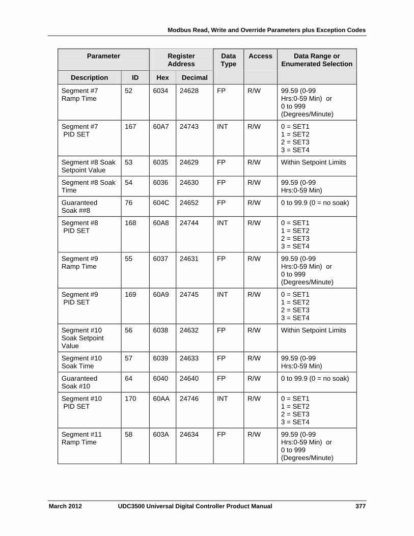
Modbus Read, Write and Override Parameters plus Exception Codes
Parameter
Register Address
Data Type
Access Data Range or Enumerated Selection
Description ID Hex Decimal
Segment #7 Ramp Time
52 6034 24628 FP R/W 99.59 (0-99 Hrs:0-59 Min) or 0 to 999 (Degrees/Minute)
Segment #7 PID SET
167 60A7 24743 INT R/W 0 = SET1 1 = SET2 2 = SET3 3 = SET4
Segment #8 Soak Setpoint Value
53 6035 24629 FP R/W Within Setpoint Limits
Segment #8 Soak Time
54 6036 24630 FP R/W 99.59 (0-99 Hrs:0-59 Min)
Guaranteed Soak ##8
76 604C 24652 FP R/W 0 to 99.9 (0 = no soak)
Segment #8 PID SET
168 60A8 24744 INT R/W 0 = SET1 1 = SET2 2 = SET3 3 = SET4
Segment #9 Ramp Time
55 6037 24631 FP R/W 99.59 (0-99 Hrs:0-59 Min) or 0 to 999 (Degrees/Minute)
Segment #9 PID SET
169 60A9 24745 INT R/W 0 = SET1 1 = SET2 2 = SET3 3 = SET4
Segment #10 Soak Setpoint Value
56 6038 24632 FP R/W Within Setpoint Limits
Segment #10 Soak Time
57 6039 24633 FP R/W 99.59 (0-99 Hrs:0-59 Min)
Guaranteed Soak #10
64 6040 24640 FP R/W 0 to 99.9 (0 = no soak)
Segment #10 PID SET
170 60AA 24746 INT R/W 0 = SET1 1 = SET2 2 = SET3 3 = SET4
Segment #11 Ramp Time
58 603A 24634 FP R/W 99.59 (0-99 Hrs:0-59 Min) or 0 to 999 (Degrees/Minute)
March 2012 UDC3500 Universal Digital Controller Product Manual 377

Modbus Read, Write and Override Parameters plus Exception Codes
Parameter
Register Address
Data Type
Access Data Range or Enumerated Selection
Description ID Hex Decimal
Segment #11 PID SET
171 60AB 24747 INT R/W 0 = SET1 1 = SET2 2 = SET3 3 = SET4
Segment #12 Soak Setpoint Value
59 603B 24635 FP R/W Within Setpoint Limits
Segment #12 Soak Time
60 603C 24636 FP R/W 99.59 (0-99 Hrs:0-59 Min)
Guaranteed Soak #12
78 604E 24654 FP R/W 0 to 99.9 (0 = no soak)
Segment #12 PID SET
172 60AC 24748 FP R/W 0 = SET1 1 = SET2 2 = SET3 3 = SET4
Segment #13 Ramp Time
61 603D 24637 FP R/W 99.59 (0-99 Hrs:0-59 Min) or 0 to 999 (Degrees/Minute)
Segment #13 PID SET
173 60AD 24749 INT R/W 0 = SET1 1 = SET2 2 = SET3 3 = SET4
Segment #14 Soak Setpoint Value
62 603E 24638 FP R/W Within Setpoint Limits
Segment #14 Soak Time
63 603F 24639 FP R/W 99.59 (0-99 Hrs:0-59 Min)
Guaranteed Soak #14
79 604F 24655 FP R/W 0 to 99.9 (0 = no soak)
Segment #14 PID SET
174 60AE 24750 INT R/W 0 = SET1 1 = SET2 2 = SET3 3 = SET4
Segment #15 Ramp Time
64 6040 24640 FP R/W 99.59 (0-99 Hrs:0-59 Min) or 0 to 999 (Degrees/Minute)
Segment #15 PID SET
175 60AF 24751 INT R/W 0 = SET1 1 = SET2 2 = SET3 3 = SET4
378 UDC3500 Universal Digital Controller Product Manual March 2012

Modbus Read, Write and Override Parameters plus Exception Codes
Parameter
Register Address
Data Type
Access Data Range or Enumerated Selection
Description ID Hex Decimal
Segment #16 Soak Setpoint Value
65 6041 24641 FP R/W Within Setpoint Limits
Segment #16 Soak Time
66 6042 24642 FP R/W 99.59 (0-99 Hrs:0-59 Min)
Guaranteed Soak #16
80 6050 24656 FP R/W 0 to 99.9 (0 = no soak)
Segment #16 PID SET
176 60B0 24752 INT R/W 0 = SET1 1 = SET2 2 = SET3 3 = SET4
Segment #17 Ramp Time
67 6043 24643 FP R/W 99.59 (0-99 Hrs:0-59 Min) or 0 to 999 (Degrees/Minute)
Segment #17 PID SET
177 60B1 24753 INT R/W 0 = SET1 1 = SET2 2 = SET3 3 = SET4
Segment #18 Soak Setpoint Value
68 6044 24644 FP R/W Within Setpoint Limits
Segment #18 Soak Time
69 6045 24645 FP R/W 99.59 (0-99 Hrs:0-59 Min)
Guaranteed Soak #18
81 6051 24657 FP R/W 0 to 99.9 (0 = no soak)
Segment #18 PID SET
178 60B2 24754 INT R/W 0 = SET1 1 = SET2 2 = SET3 3 = SET4
Segment #19 Ramp Time
70 6046 24646 FP R/W 99.59 (0-99 Hrs:0-59 Min) or 0 to 999 (Degrees/Minute)
Segment #19 PID SET
179 60B3 24755 INT R/W 0 = SET1 1 = SET2 2 = SET3 3 = SET4
Segment #20 Soak Setpoint Value
71 6047 24647 FP R/W Within Setpoint Limits
Segment #20 Soak Time
72 6048 24648 FP R/W 99.59 (0-99 Hrs:0-59 Min)
March 2012 UDC3500 Universal Digital Controller Product Manual 379
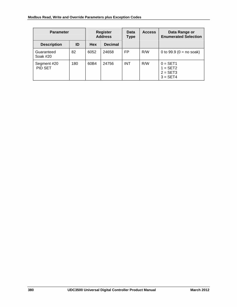
Modbus Read, Write and Override Parameters plus Exception Codes
Parameter
Register Address
Data Type
Access Data Range or Enumerated Selection
Description ID Hex Decimal
Guaranteed Soak #20
82 6052 24658 FP R/W 0 to 99.9 (0 = no soak)
Segment #20 PID SET
180 60B4 24756 INT R/W 0 = SET1 1 = SET2 2 = SET3 3 = SET4
380 UDC3500 Universal Digital Controller Product Manual March 2012
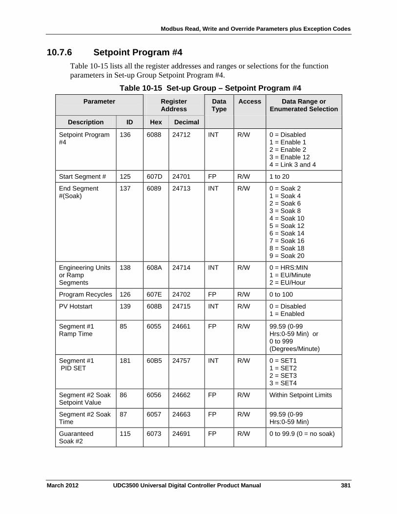
Modbus Read, Write and Override Parameters plus Exception Codes
10.7.6 Setpoint Program #4
Table 10-15 lists all the register addresses and ranges or selections for the function parameters in Set-up Group Setpoint Program #4.
Table 10-15 Set-up Group – Setpoint Program #4
Parameter
Register Address
Data Type
Access Data Range or Enumerated Selection
ID Hex Decimal Description
Setpoint Program #4
136 6088 24712 INT R/W 0 = Disabled 1 = Enable 1 2 = Enable 2 3 = Enable 12 4 = Link 3 and 4
Start Segment # 125 607D 24701 FP R/W 1 to 20
End Segment #(Soak)
137 6089 24713 INT R/W 0 = Soak 2 1 = Soak 4 2 = Soak 6 3 = Soak 8 4 = Soak 10 5 = Soak 12 6 = Soak 14 7 = Soak 16 8 = Soak 18 9 = Soak 20
Engineering Units or Ramp Segments
138 608A 24714 INT R/W 0 = HRS:MIN 1 = EU/Minute 2 = EU/Hour
Program Recycles 126 607E 24702 FP R/W 0 to 100
PV Hotstart 139 608B 24715 INT R/W 0 = Disabled 1 = Enabled
Segment #1 Ramp Time
85 6055 24661 FP R/W 99.59 (0-99 Hrs:0-59 Min) or 0 to 999 (Degrees/Minute)
Segment #1 PID SET
181 60B5 24757 INT R/W 0 = SET1 1 = SET2 2 = SET3 3 = SET4
Segment #2 Soak Setpoint Value
86 6056 24662 FP R/W Within Setpoint Limits
Segment #2 Soak Time
87 6057 24663 FP R/W 99.59 (0-99 Hrs:0-59 Min)
Guaranteed Soak #2
115 6073 24691 FP R/W 0 to 99.9 (0 = no soak)
March 2012 UDC3500 Universal Digital Controller Product Manual 381

Modbus Read, Write and Override Parameters plus Exception Codes
382 UDC3500 Universal Digital Controller Product Manual March 2012
Parameter
Register Address
Data Type
Access Data Range or Enumerated Selection
Description ID Hex Decimal
Segment #2 PID SET
182 60B6 24758 INT R/W 0 = SET1 1 = SET2 2 = SET3 3 = SET4
Segment #3 Ramp Time
88 6058 24664 FP R/W 99.59 (0-99 Hrs:0-59 Min) or 0 to 999 (Degrees/Minute)
Segment #3 PID SET
183 60B7 24759 INT R/W 0 = SET1 1 = SET2 2 = SET3 3 = SET4
Segment #4 Soak Setpoint Value
89 6059 24665 FP R/W Within Setpoint Limits
Segment #4 Soak Time
90 605A 24666 FP R/W 99.59 (0-99 Hrs:0-59 Min)
Guaranteed Soak #4
116 6074 24692 FP R/W 0 to 99.9 (0 = no soak)
Segment #4 PID SET
184 60B8 24760 INT R/W 0 = SET1 1 = SET2 2 = SET3 3 = SET4
Segment #5 Ramp Time
91 605B 24667 FP R/W 99.59 (0-99 Hrs:0-59 Min) or 0 to 999 (Degrees/Minute)
Segment #5 PID SET
185 60B9 24761 INT R/W 0 = SET1 1 = SET2 2 = SET3 3 = SET4
Segment #6 Soak Setpoint Value
92 605C 24668 FP R/W Within Setpoint Limits
Segment #6 Soak Time
93 605D 24669 FP R/W 99.59 (0-99 Hrs:0-59 Min)
Guaranteed Soak #6
117 6075 24693 FP R/W 0 to 99.9 (0 = no soak)
Segment #6 PID SET
186 60BA 24762 INT R/W 0 = SET1 1 = SET2 2 = SET3 3 = SET4
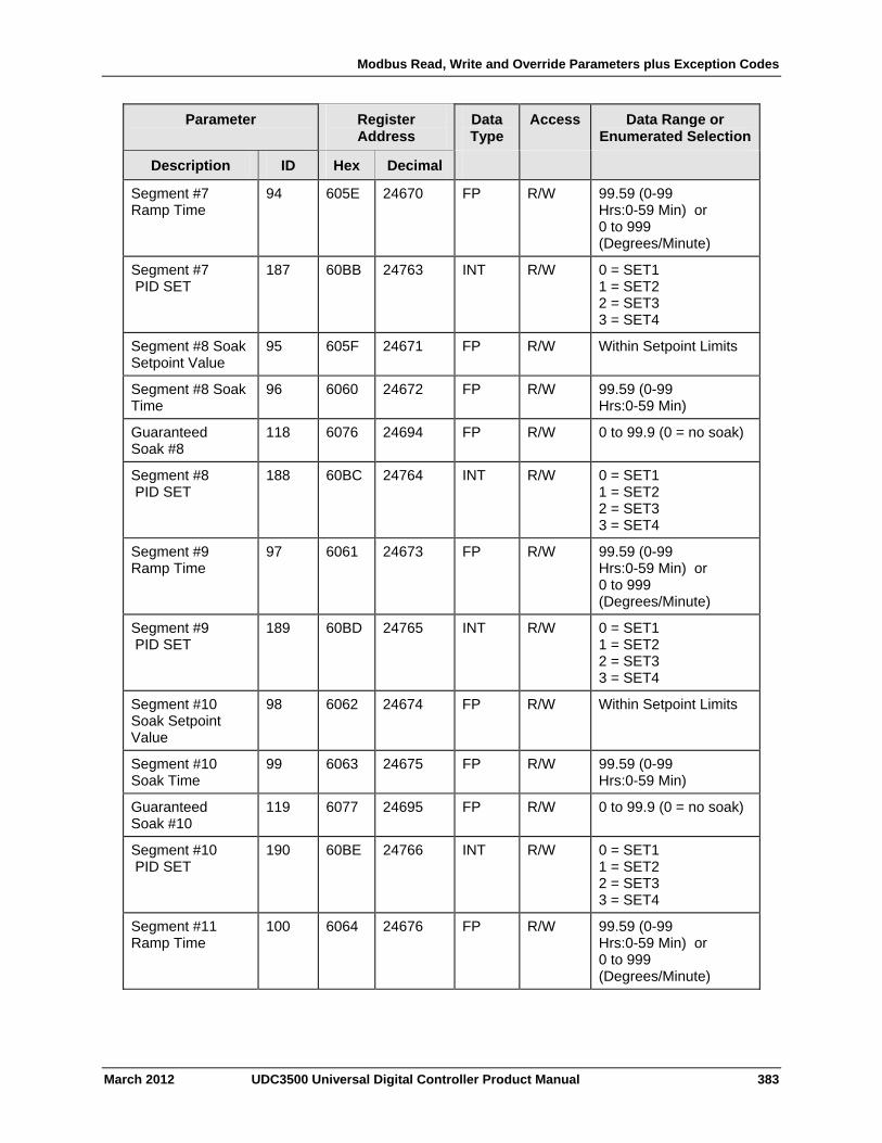
Modbus Read, Write and Override Parameters plus Exception Codes
March 2012 UDC3500 Universal Digital Controller Product Manual 383
Parameter
Register Address
Data Type
Access Data Range or Enumerated Selection
Description ID Hex Decimal
Segment #7 Ramp Time
94 605E 24670 FP R/W 99.59 (0-99 Hrs:0-59 Min) or 0 to 999 (Degrees/Minute)
Segment #7 PID SET
187 60BB 24763 INT R/W 0 = SET1 1 = SET2 2 = SET3 3 = SET4
Segment #8 Soak Setpoint Value
95 605F 24671 FP R/W Within Setpoint Limits
Segment #8 Soak Time
96 6060 24672 FP R/W 99.59 (0-99 Hrs:0-59 Min)
Guaranteed Soak #8
118 6076 24694 FP R/W 0 to 99.9 (0 = no soak)
Segment #8 PID SET
188 60BC 24764 INT R/W 0 = SET1 1 = SET2 2 = SET3 3 = SET4
Segment #9 Ramp Time
97 6061 24673 FP R/W 99.59 (0-99 Hrs:0-59 Min) or 0 to 999 (Degrees/Minute)
Segment #9 PID SET
189 60BD 24765 INT R/W 0 = SET1 1 = SET2 2 = SET3 3 = SET4
Segment #10 Soak Setpoint Value
98 6062 24674 FP R/W Within Setpoint Limits
Segment #10 Soak Time
99 6063 24675 FP R/W 99.59 (0-99 Hrs:0-59 Min)
Guaranteed Soak #10
119 6077 24695 FP R/W 0 to 99.9 (0 = no soak)
Segment #10 PID SET
190 60BE 24766 INT R/W 0 = SET1 1 = SET2 2 = SET3 3 = SET4
Segment #11 Ramp Time
100 6064 24676 FP R/W 99.59 (0-99 Hrs:0-59 Min) or 0 to 999 (Degrees/Minute)
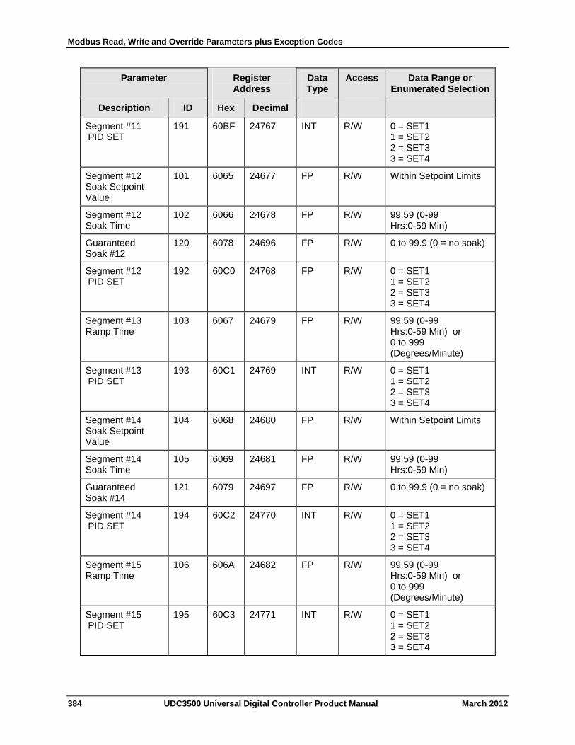
Modbus Read, Write and Override Parameters plus Exception Codes
384 UDC3500 Universal Digital Controller Product Manual March 2012
Parameter
Register Address
Data Type
Access Data Range or Enumerated Selection
Description ID Hex Decimal
Segment #11 PID SET
191 60BF 24767 INT R/W 0 = SET1 1 = SET2 2 = SET3 3 = SET4
Segment #12 Soak Setpoint Value
101 6065 24677 FP R/W Within Setpoint Limits
Segment #12 Soak Time
102 6066 24678 FP R/W 99.59 (0-99 Hrs:0-59 Min)
Guaranteed Soak #12
120 6078 24696 FP R/W 0 to 99.9 (0 = no soak)
Segment #12 PID SET
192 60C0 24768 FP R/W 0 = SET1 1 = SET2 2 = SET3 3 = SET4
Segment #13 Ramp Time
103 6067 24679 FP R/W 99.59 (0-99 Hrs:0-59 Min) or 0 to 999 (Degrees/Minute)
Segment #13 PID SET
193 60C1 24769 INT R/W 0 = SET1 1 = SET2 2 = SET3 3 = SET4
Segment #14 Soak Setpoint Value
104 6068 24680 FP R/W Within Setpoint Limits
Segment #14 Soak Time
105 6069 24681 FP R/W 99.59 (0-99 Hrs:0-59 Min)
Guaranteed Soak #14
121 6079 24697 FP R/W 0 to 99.9 (0 = no soak)
Segment #14 PID SET
194 60C2 24770 INT R/W 0 = SET1 1 = SET2 2 = SET3 3 = SET4
Segment #15 Ramp Time
106 606A 24682 FP R/W 99.59 (0-99 Hrs:0-59 Min) or 0 to 999 (Degrees/Minute)
Segment #15 PID SET
195 60C3 24771 INT R/W 0 = SET1 1 = SET2 2 = SET3 3 = SET4

Modbus Read, Write and Override Parameters plus Exception Codes
March 2012 UDC3500 Universal Digital Controller Product Manual 385
Parameter
Register Address
Data Type
Access Data Range or Enumerated Selection
Description ID Hex Decimal
Segment #16 Soak Setpoint Value
107 606B 24683 FP R/W Within Setpoint Limits
Segment #16 Soak Time
108 606C 24684 FP R/W 99.59 (0-99 Hrs:0-59 Min)
Guaranteed Soak #16
122 607A 24698 FP R/W 0 to 99.9 (0 = no soak)
Segment #16 PID SET
196 60C4 24772 INT R/W 0 = SET1 1 = SET2 2 = SET3 3 = SET4
Segment #17 Ramp Time
109 606D 24685 FP R/W 99.59 (0-99 Hrs:0-59 Min) or 0 to 999 (Degrees/Minute)
Segment #17 PID SET
197 60C5 24773 INT R/W 0 = SET1 1 = SET2 2 = SET3 3 = SET4
Segment #18 Soak Setpoint Value
110 606E 24686 FP R/W Within Setpoint Limits
Segment #18 Soak Time
111 606F 24687 FP R/W 99.59 (0-99 Hrs:0-59 Min)
Guaranteed Soak #18
123 607B 24699 FP R/W 0 to 99.9 (0 = no soak)
Segment #18 PID SET
198 60C6 24774 INT R/W 0 = SET1 1 = SET2 2 = SET3 3 = SET4
Segment #19 Ramp Time
112 6070 24688 FP R/W 99.59 (0-99 Hrs:0-59 Min) or 0 to 999 (Degrees/Minute)
Segment #19 PID SET
199 60C7 24775 INT R/W 0 = SET1 1 = SET2 2 = SET3 3 = SET4
Segment #20 Soak Setpoint Value
113 6071 24689 FP R/W Within Setpoint Limits
Segment #20 Soak Time
114 6072 24690 FP R/W 99.59 (0-99 Hrs:0-59 Min)

Modbus Read, Write and Override Parameters plus Exception Codes
386 UDC3500 Universal Digital Controller Product Manual March 2012
Parameter
Register Address
Data Type
Access Data Range or Enumerated Selection
Description ID Hex Decimal
Guaranteed Soak #20
124 607C 24700 FP R/W 0 to 99.9 (0 = no soak)
Segment #20 PID SET
200 60C8 24776 INT R/W 0 = SET1 1 = SET2 2 = SET3 3 = SET4
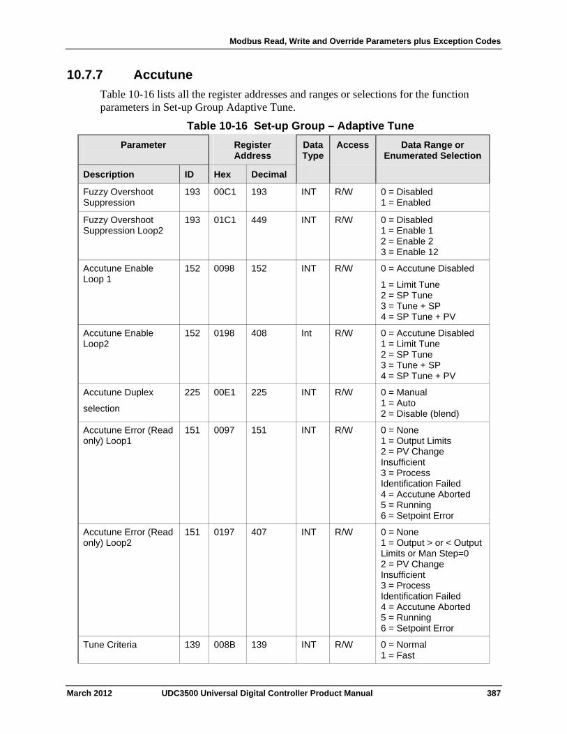
Modbus Read, Write and Override Parameters plus Exception Codes
10.7.7 Accutune
Table 10-16 lists all the register addresses and ranges or selections for the function parameters in Set-up Group Adaptive Tune.
Table 10-16 Set-up Group – Adaptive Tune
Parameter
Register Address
Data Type
Access Data Range or Enumerated Selection
ID Hex Decimal Description
Fuzzy Overshoot Suppression
193 00C1 193 INT R/W 0 = Disabled 1 = Enabled
Fuzzy Overshoot Suppression Loop2
193 01C1 449 INT R/W 0 = Disabled 1 = Enable 1 2 = Enable 2 3 = Enable 12
Accutune Enable Loop 1
152 0098 152 INT R/W 0 = Accutune Disabled
1 = Limit Tune 2 = SP Tune 3 = Tune + SP 4 = SP Tune + PV
Accutune Enable Loop2
152 0198 408 Int R/W 0 = Accutune Disabled 1 = Limit Tune 2 = SP Tune 3 = Tune + SP 4 = SP Tune + PV
Accutune Duplex
selection
225 00E1 225 INT R/W 0 = Manual 1 = Auto 2 = Disable (blend)
Accutune Error (Read only) Loop1
151 0097 151 INT R/W 0 = None 1 = Output Limits 2 = PV Change Insufficient 3 = Process Identification Failed 4 = Accutune Aborted 5 = Running 6 = Setpoint Error
Accutune Error (Read only) Loop2
151 0197 407 INT R/W 0 = None 1 = Output > or < Output Limits or Man Step=0 2 = PV Change Insufficient 3 = Process Identification Failed 4 = Accutune Aborted 5 = Running 6 = Setpoint Error
Tune Criteria 139 008B 139 INT R/W 0 = Normal 1 = Fast
March 2012 UDC3500 Universal Digital Controller Product Manual 387
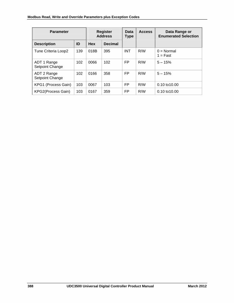
Modbus Read, Write and Override Parameters plus Exception Codes
388 UDC3500 Universal Digital Controller Product Manual March 2012
Parameter
Register Address
Data Type
Access Data Range or Enumerated Selection
Description ID Hex Decimal
Tune Criteria Loop2 139 018B 395 INT R/W 0 = Normal 1 = Fast
ADT 1 Range Setpoint Change
102 0066 102 FP R/W 5 – 15%
ADT 2 Range Setpoint Change
102 0166 358 FP R/W 5 – 15%
KPG1 (Process Gain) 103 0067 103 FP R/W 0.10 to10.00
KPG2(Process Gain) 103 0167 359 FP R/W 0.10 to10.00
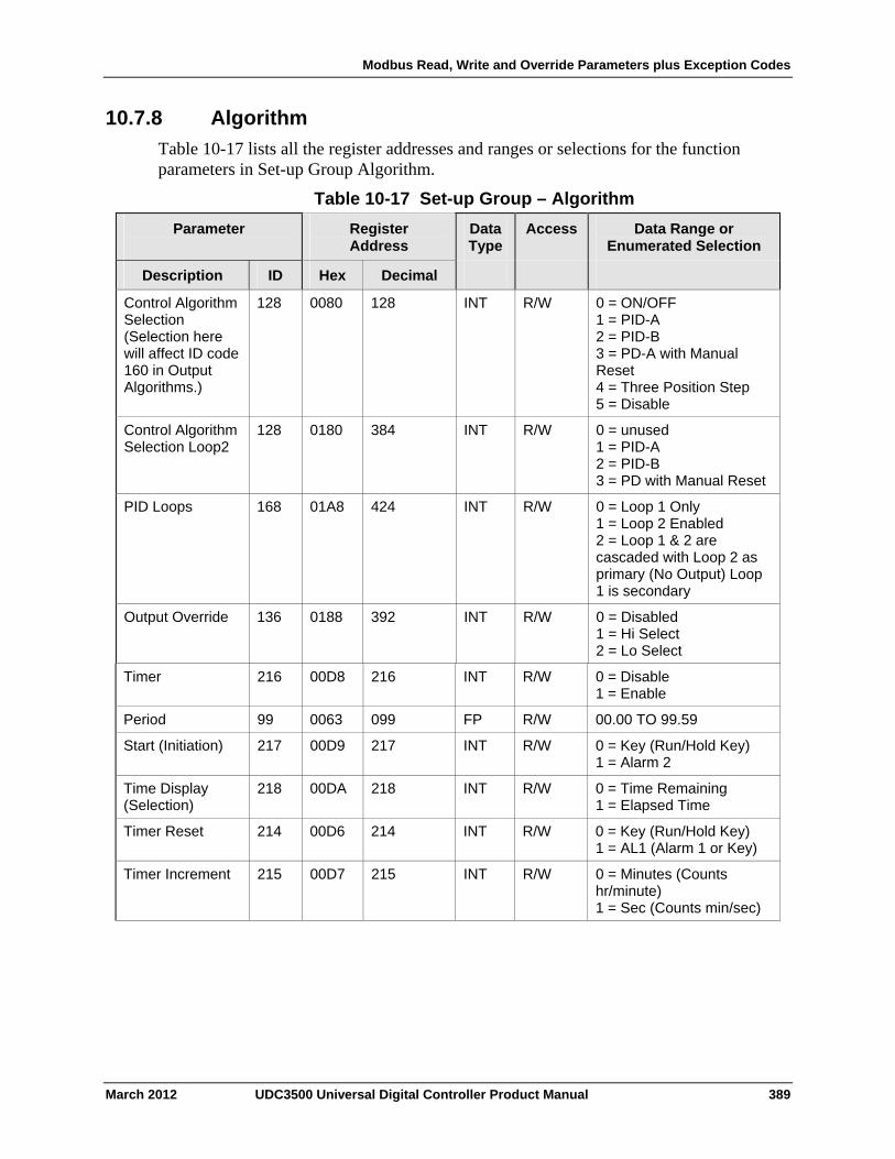
Modbus Read, Write and Override Parameters plus Exception Codes
10.7.8 Algorithm
Table 10-17 lists all the register addresses and ranges or selections for the function parameters in Set-up Group Algorithm.
Table 10-17 Set-up Group – Algorithm
Parameter
Register Address
Data Type
Access Data Range or Enumerated Selection
ID Hex Decimal Description
Control Algorithm Selection (Selection here will affect ID code 160 in Output Algorithms.)
128 0080 128 INT R/W 0 = ON/OFF 1 = PID-A 2 = PID-B 3 = PD-A with Manual Reset 4 = Three Position Step 5 = Disable
Control Algorithm Selection Loop2
128 0180 384 INT R/W 0 = unused 1 = PID-A 2 = PID-B 3 = PD with Manual Reset
PID Loops 168 01A8 424 INT R/W 0 = Loop 1 Only 1 = Loop 2 Enabled 2 = Loop 1 & 2 are cascaded with Loop 2 as primary (No Output) Loop 1 is secondary
Output Override 136 0188 392 INT R/W 0 = Disabled 1 = Hi Select 2 = Lo Select
Timer 216 00D8 216 INT R/W 0 = Disable 1 = Enable
Period 99 0063 099 FP R/W 00.00 TO 99.59
Start (Initiation) 217 00D9 217 INT R/W 0 = Key (Run/Hold Key) 1 = Alarm 2
Time Display (Selection)
218 00DA 218 INT R/W 0 = Time Remaining 1 = Elapsed Time
Timer Reset 214 00D6 214 INT R/W 0 = Key (Run/Hold Key) 1 = AL1 (Alarm 1 or Key)
Timer Increment 215 00D7 215 INT R/W 0 = Minutes (Counts hr/minute) 1 = Sec (Counts min/sec)
March 2012 UDC3500 Universal Digital Controller Product Manual 389
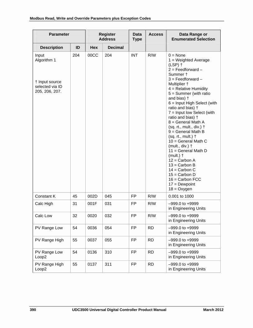
Modbus Read, Write and Override Parameters plus Exception Codes
390 UDC3500 Universal Digital Controller Product Manual March 2012
Parameter
Register Address
Data Type
Access Data Range or Enumerated Selection
Description ID Hex Decimal
Input Algorithm 1
† Input source selected via ID 205, 206, 207.
204 00CC 204 INT R/W 0 = None 1 = Weighted Average (LSP) † 2 = Feedforward – Summer † 3 = Feedforward – Multiplier † 4 = Relative Humidity 5 = Summer (with ratio and bias) † 6 = Input High Select (with ratio and bias) † 7 = Input low Select (with ratio and bias) † 8 = General Math A (sq. rt., mult., div.) † 9 = General Math B (sq. rt., mult.) † 10 = General Math C (mult., div.) † 11 = General Math D (mult.) † 12 = Carbon A 13 = Carbon B 14 = Carbon C 15 = Carbon D 16 = Carbon FCC 17 = Dewpoint 18 = Oxygen
Constant K 45 002D 045 FP R/W 0.001 to 1000
Calc High 31 001F 031 FP R/W –999.0 to +9999 in Engineering Units
Calc Low 32 0020 032 FP R/W –999.0 to +9999 in Engineering Units
PV Range Low 54 0036 054 FP RD –999.0 to +9999 in Engineering Units
PV Range High 55 0037 055 FP RD –999.0 to +9999 in Engineering Units
PV Range Low Loop2
54 0136 310 FP RD –999.0 to +9999 in Engineering Units
PV Range High Loop2
55 0137 311 FP RD –999.0 to +9999 in Engineering Units
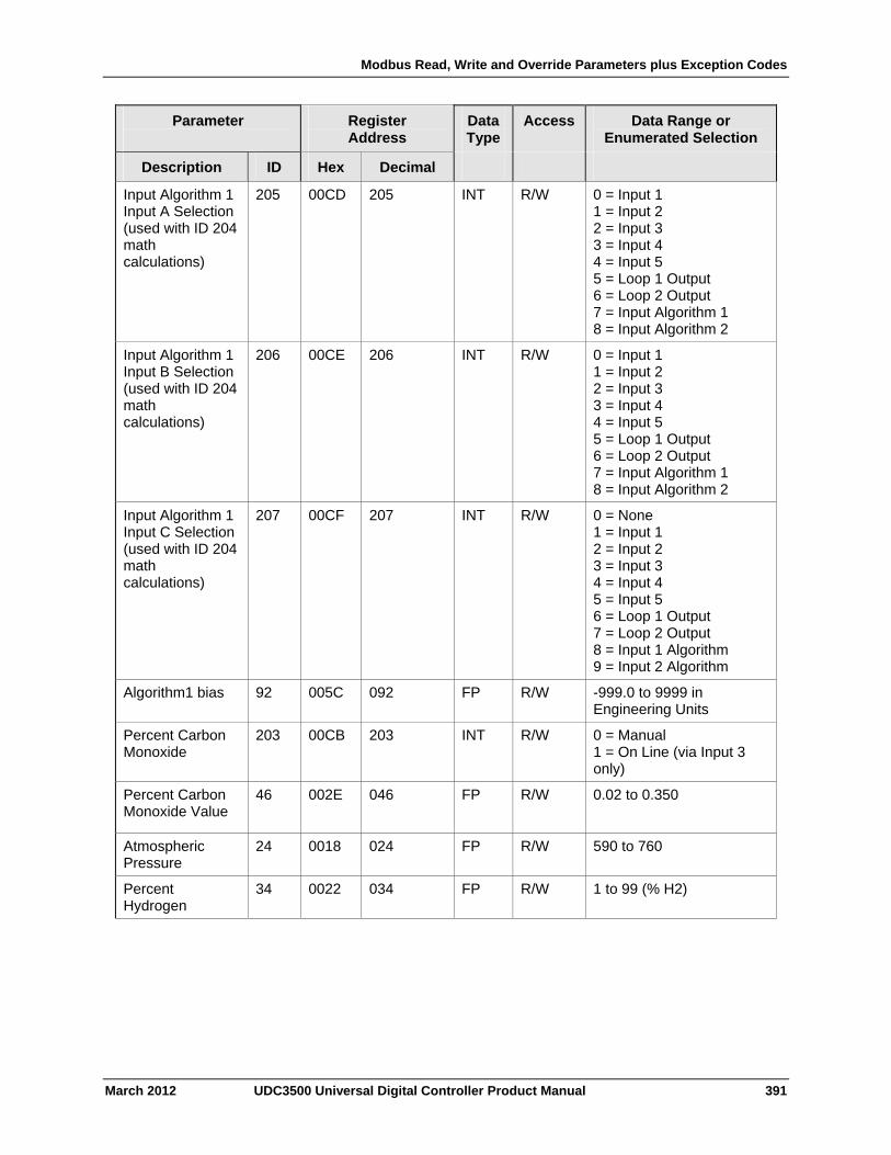
Modbus Read, Write and Override Parameters plus Exception Codes
March 2012 UDC3500 Universal Digital Controller Product Manual 391
Parameter
Register Address
Data Type
Access Data Range or Enumerated Selection
Description ID Hex Decimal
Input Algorithm 1 Input A Selection (used with ID 204 math calculations)
205 00CD 205 INT R/W 0 = Input 1 1 = Input 2 2 = Input 3 3 = Input 4 4 = Input 5 5 = Loop 1 Output 6 = Loop 2 Output 7 = Input Algorithm 1 8 = Input Algorithm 2
Input Algorithm 1 Input B Selection (used with ID 204 math calculations)
206 00CE 206 INT R/W 0 = Input 1 1 = Input 2 2 = Input 3 3 = Input 4 4 = Input 5 5 = Loop 1 Output 6 = Loop 2 Output 7 = Input Algorithm 1 8 = Input Algorithm 2
Input Algorithm 1 Input C Selection (used with ID 204 math calculations)
207 00CF 207 INT R/W 0 = None 1 = Input 1 2 = Input 2 3 = Input 3 4 = Input 4 5 = Input 5 6 = Loop 1 Output 7 = Loop 2 Output 8 = Input 1 Algorithm 9 = Input 2 Algorithm
Algorithm1 bias 92 005C 092 FP R/W -999.0 to 9999 in Engineering Units
Percent Carbon Monoxide
203 00CB 203 INT R/W 0 = Manual 1 = On Line (via Input 3 only)
Percent Carbon Monoxide Value
46
002E 046 FP R/W 0.02 to 0.350
Atmospheric Pressure
24 0018 024 FP R/W 590 to 760
Percent Hydrogen
34 0022 034 FP R/W 1 to 99 (% H2)
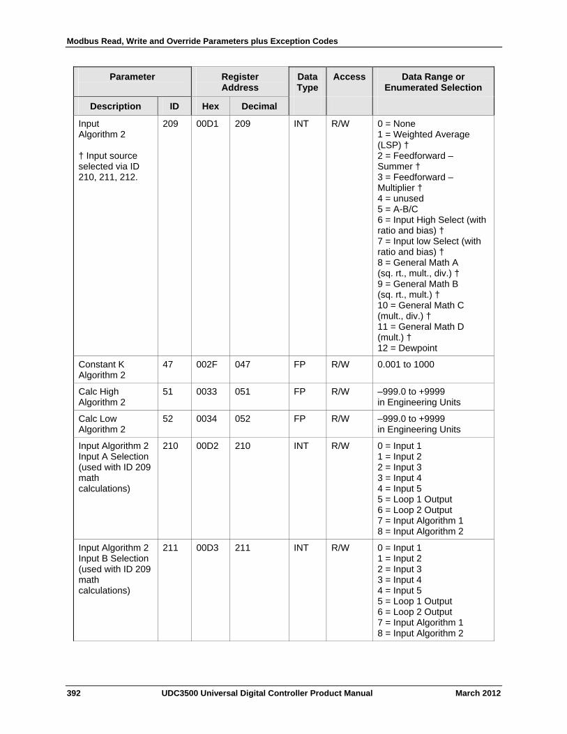
Modbus Read, Write and Override Parameters plus Exception Codes
392 UDC3500 Universal Digital Controller Product Manual March 2012
Parameter
Register Address
Data Type
Access Data Range or Enumerated Selection
Description ID Hex Decimal
Input Algorithm 2 † Input source selected via ID 210, 211, 212.
209 00D1 209 INT R/W 0 = None 1 = Weighted Average (LSP) † 2 = Feedforward – Summer † 3 = Feedforward – Multiplier † 4 = unused 5 = A-B/C 6 = Input High Select (with ratio and bias) † 7 = Input low Select (with ratio and bias) † 8 = General Math A (sq. rt., mult., div.) † 9 = General Math B (sq. rt., mult.) † 10 = General Math C (mult., div.) † 11 = General Math D (mult.) † 12 = Dewpoint
Constant K Algorithm 2
47 002F 047 FP R/W 0.001 to 1000
Calc High Algorithm 2
51 0033 051 FP R/W –999.0 to +9999 in Engineering Units
Calc Low Algorithm 2
52 0034 052 FP R/W –999.0 to +9999 in Engineering Units
Input Algorithm 2 Input A Selection (used with ID 209 math calculations)
210 00D2 210 INT R/W 0 = Input 1 1 = Input 2 2 = Input 3 3 = Input 4 4 = Input 5 5 = Loop 1 Output 6 = Loop 2 Output 7 = Input Algorithm 1 8 = Input Algorithm 2
Input Algorithm 2 Input B Selection (used with ID 209 math calculations)
211 00D3 211 INT R/W 0 = Input 1 1 = Input 2 2 = Input 3 3 = Input 4 4 = Input 5 5 = Loop 1 Output 6 = Loop 2 Output 7 = Input Algorithm 1 8 = Input Algorithm 2
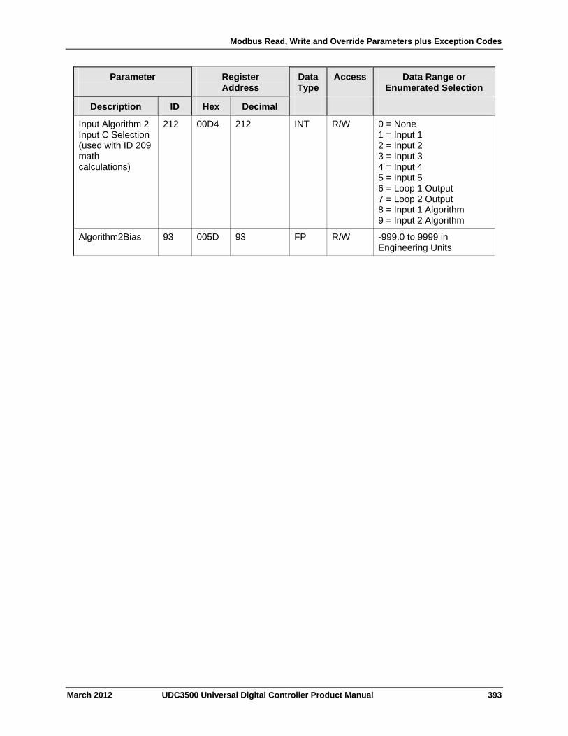
Modbus Read, Write and Override Parameters plus Exception Codes
March 2012 UDC3500 Universal Digital Controller Product Manual 393
Parameter
Register Address
Data Type
Access Data Range or Enumerated Selection
Description ID Hex Decimal
Input Algorithm 2 Input C Selection (used with ID 209 math calculations)
212 00D4 212 INT R/W 0 = None 1 = Input 1 2 = Input 2 3 = Input 3 4 = Input 4 5 = Input 5 6 = Loop 1 Output 7 = Loop 2 Output 8 = Input 1 Algorithm 9 = Input 2 Algorithm
Algorithm2Bias 93 005D 93 FP R/W -999.0 to 9999 in Engineering Units
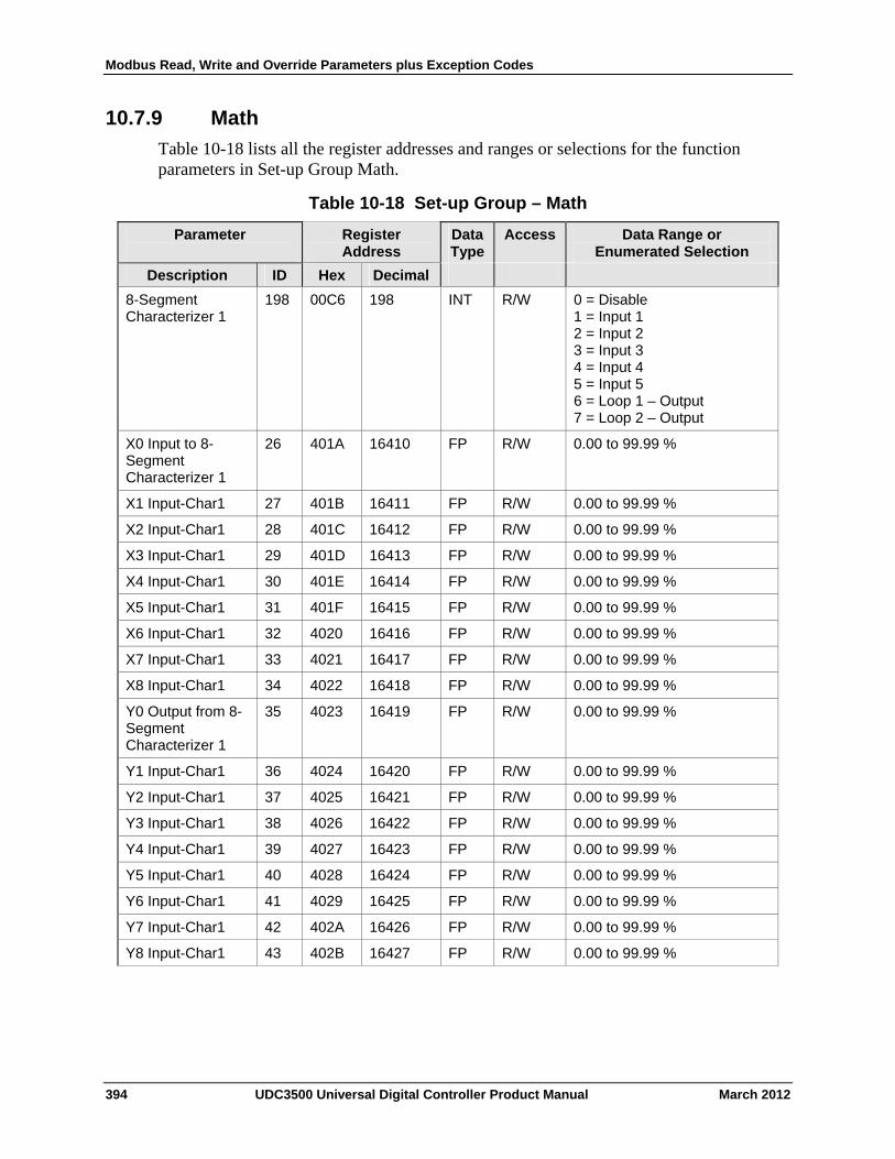
Modbus Read, Write and Override Parameters plus Exception Codes
10.7.9 Math
Table 10-18 lists all the register addresses and ranges or selections for the function parameters in Set-up Group Math.
Table 10-18 Set-up Group – Math
Register Address
Data Type
Access Data Range or Enumerated Selection
Parameter
ID Hex Decimal Description
8-Segment Characterizer 1
198 00C6 198 INT R/W 0 = Disable 1 = Input 1 2 = Input 2 3 = Input 3 4 = Input 4 5 = Input 5 6 = Loop 1 – Output 7 = Loop 2 – Output
X0 Input to 8-Segment Characterizer 1
26 401A 16410 FP R/W 0.00 to 99.99 %
X1 Input-Char1 27 401B 16411 FP R/W 0.00 to 99.99 %
X2 Input-Char1 28 401C 16412 FP R/W 0.00 to 99.99 %
X3 Input-Char1 29 401D 16413 FP R/W 0.00 to 99.99 %
X4 Input-Char1 30 401E 16414 FP R/W 0.00 to 99.99 %
X5 Input-Char1 31 401F 16415 FP R/W 0.00 to 99.99 %
X6 Input-Char1 32 4020 16416 FP R/W 0.00 to 99.99 %
X7 Input-Char1 33 4021 16417 FP R/W 0.00 to 99.99 %
X8 Input-Char1 34 4022 16418 FP R/W 0.00 to 99.99 %
Y0 Output from 8-Segment Characterizer 1
35 4023 16419 FP R/W 0.00 to 99.99 %
Y1 Input-Char1 36 4024 16420 FP R/W 0.00 to 99.99 %
Y2 Input-Char1 37 4025 16421 FP R/W 0.00 to 99.99 %
Y3 Input-Char1 38 4026 16422 FP R/W 0.00 to 99.99 %
Y4 Input-Char1 39 4027 16423 FP R/W 0.00 to 99.99 %
Y5 Input-Char1 40 4028 16424 FP R/W 0.00 to 99.99 %
Y6 Input-Char1 41 4029 16425 FP R/W 0.00 to 99.99 %
Y7 Input-Char1 42 402A 16426 FP R/W 0.00 to 99.99 %
Y8 Input-Char1 43 402B 16427 FP R/W 0.00 to 99.99 %
394 UDC3500 Universal Digital Controller Product Manual March 2012
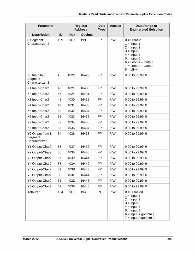
Modbus Read, Write and Override Parameters plus Exception Codes
March 2012 UDC3500 Universal Digital Controller Product Manual 395
Parameter
Register Address
Data Type
Access Data Range or Enumerated Selection
Description ID Hex Decimal
8-Segment Characterizer 2
199 00C7 199 FP R/W 0 = Disable 1 = Input 1 2 = Input 2 3 = Input 3 4 = Input 4 5 = Input 5 6 = Loop 1 – Output 7 = Loop 2 – Output 8 = LINK
X0 Input to 8-Segment Characterizer 2
45 402D 16429 FP R/W 0.00 to 99.99 %
X1 Input-Char2 46 402E 16430 FP R/W 0.00 to 99.99 %
X2 Input-Char2 47 402F 16431 FP R/W 0.00 to 99.99 %
X3 Input-Char2 48 4030 16432 FP R/W 0.00 to 99.99 %
X4 Input-Char2 49 4031 16433 FP R/W 0.00 to 99.99 %
X5 Input-Char2 50 4032 16434 FP R/W 0.00 to 99.99 %
X6 Input-Char2 51 4033 16435 FP R/W 0.00 to 99.99 %
X7 Input-Char2 52 4034 16436 FP R/W 0.00 to 99.99 %
X8 Input-Char2 53 4035 16437 FP R/W 0.00 to 99.99 %
Y0 Output from 8-Segment Characterizer 2
54 4036 16438 FP R/W 0.00 to 99.99 %
Y1 Output-Char2 55 4037 16439 FP R/W 0.00 to 99.99 %
Y2 Output-Char2 56 4038 16440 FP R/W 0.00 to 99.99 %
Y3 Output-Char2 57 4039 16441 FP R/W 0.00 to 99.99 %
Y4 Output-Char2 58 403A 16442 FP R/W 0.00 to 99.99 %
Y5 Output-Char2 59 403B 16443 FP R/W 0.00 to 99.99 %
Y6 Output-Char2 60 403C 16444 FP R/W 0.00 to 99.99 %
Y7 Output-Char2 61 403D 16445 FP R/W 0.00 to 99.99 %
Y8 Output-Char2 62 403E 16446 FP R/W 0.00 to 99.99 %
Totalizer 194 00C2 194 INT R/W 0 = Disabled 1 = Input 1 2 = Input 2 3 = Input 3 4 = Input 4 5 = Input 5 6 = Input Algorithm 1 7 = Input Algorithm 2
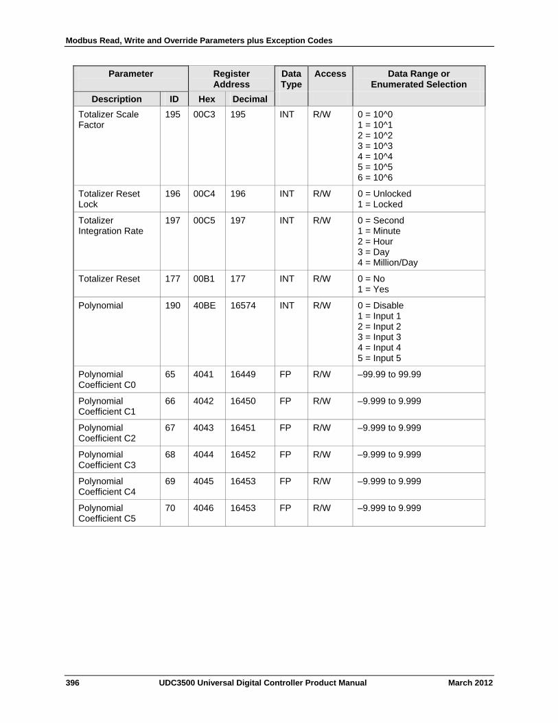
Modbus Read, Write and Override Parameters plus Exception Codes
396 UDC3500 Universal Digital Controller Product Manual March 2012
Parameter
Register Address
Data Type
Access Data Range or Enumerated Selection
Description ID Hex Decimal
Totalizer Scale Factor
195 00C3 195 INT R/W 0 = 10^0 1 = 10^1 2 = 10^2 3 = 10^3 4 = 10^4 5 = 10^5 6 = 10^6
Totalizer Reset Lock
196 00C4 196 INT R/W 0 = Unlocked 1 = Locked
Totalizer Integration Rate
197 00C5 197 INT R/W 0 = Second 1 = Minute 2 = Hour 3 = Day 4 = Million/Day
Totalizer Reset 177 00B1 177 INT R/W 0 = No 1 = Yes
Polynomial 190 40BE 16574 INT R/W 0 = Disable 1 = Input 1 2 = Input 2 3 = Input 3 4 = Input 4 5 = Input 5
Polynomial Coefficient C0
65 4041 16449 FP R/W –99.99 to 99.99
Polynomial Coefficient C1
66 4042 16450 FP R/W –9.999 to 9.999
Polynomial Coefficient C2
67 4043 16451 FP R/W –9.999 to 9.999
Polynomial Coefficient C3
68 4044 16452 FP R/W –9.999 to 9.999
Polynomial Coefficient C4
69 4045 16453 FP R/W –9.999 to 9.999
Polynomial Coefficient C5
70 4046 16453 FP R/W –9.999 to 9.999
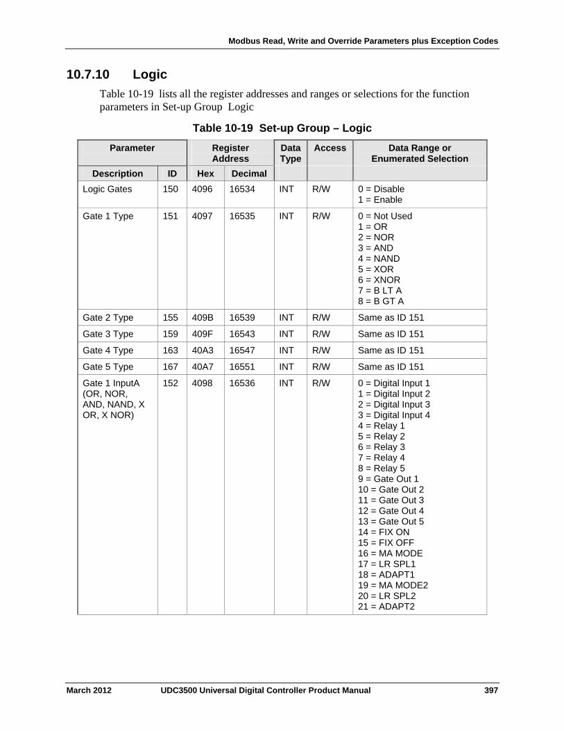
Modbus Read, Write and Override Parameters plus Exception Codes
10.7.10 Logic
Table 10-19 lists all the register addresses and ranges or selections for the function parameters in Set-up Group Logic
Table 10-19 Set-up Group – Logic
Register Address
Data Type
Access Data Range or Enumerated Selection
Parameter
ID Hex Decimal Description
Logic Gates 150 4096 16534 INT R/W 0 = Disable 1 = Enable
Gate 1 Type 151 4097 16535 INT R/W 0 = Not Used 1 = OR 2 = NOR 3 = AND 4 = NAND 5 = XOR 6 = XNOR 7 = B LT A 8 = B GT A
Gate 2 Type 155 409B 16539 INT R/W Same as ID 151
Gate 3 Type 159 409F 16543 INT R/W Same as ID 151
Gate 4 Type 163 40A3 16547 INT R/W Same as ID 151
Gate 5 Type 167 40A7 16551 INT R/W Same as ID 151
Gate 1 InputA (OR, NOR, AND, NAND, X OR, X NOR)
152 4098 16536 INT R/W 0 = Digital Input 1 1 = Digital Input 2 2 = Digital Input 3 3 = Digital Input 4 4 = Relay 1 5 = Relay 2 6 = Relay 3 7 = Relay 4 8 = Relay 5 9 = Gate Out 1 10 = Gate Out 2 11 = Gate Out 3 12 = Gate Out 4 13 = Gate Out 5 14 = FIX ON 15 = FIX OFF 16 = MA MODE 17 = LR SPL1 18 = ADAPT1 19 = MA MODE2 20 = LR SPL2 21 = ADAPT2
March 2012 UDC3500 Universal Digital Controller Product Manual 397
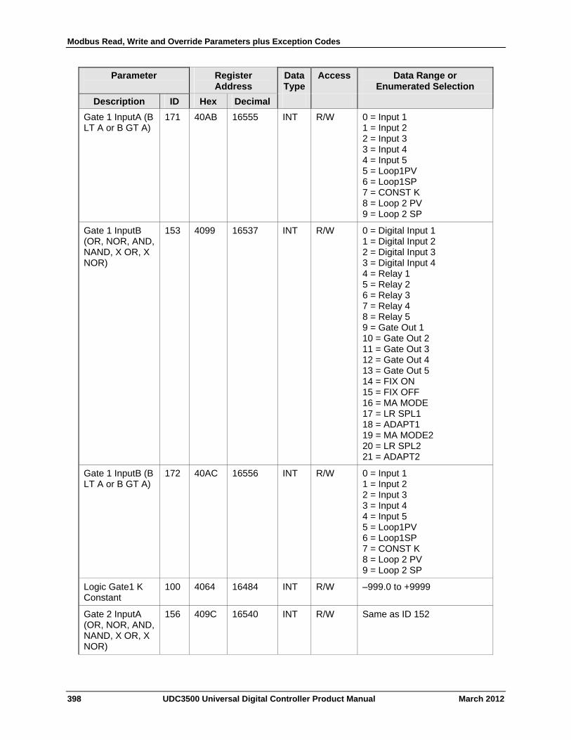
Modbus Read, Write and Override Parameters plus Exception Codes
398 UDC3500 Universal Digital Controller Product Manual March 2012
Parameter
Register Address
Data Type
Access Data Range or Enumerated Selection
Description ID Hex Decimal
Gate 1 InputA (B LT A or B GT A)
171 40AB 16555 INT R/W 0 = Input 1 1 = Input 2 2 = Input 3 3 = Input 4 4 = Input 5 5 = Loop1PV 6 = Loop1SP 7 = CONST K 8 = Loop 2 PV 9 = Loop 2 SP
Gate 1 InputB (OR, NOR, AND, NAND, X OR, X NOR)
153 4099 16537 INT R/W 0 = Digital Input 1 1 = Digital Input 2 2 = Digital Input 3 3 = Digital Input 4 4 = Relay 1 5 = Relay 2 6 = Relay 3 7 = Relay 4 8 = Relay 5 9 = Gate Out 1 10 = Gate Out 2 11 = Gate Out 3 12 = Gate Out 4 13 = Gate Out 5 14 = FIX ON 15 = FIX OFF 16 = MA MODE 17 = LR SPL1 18 = ADAPT1 19 = MA MODE2 20 = LR SPL2 21 = ADAPT2
Gate 1 InputB (B LT A or B GT A)
172 40AC 16556 INT R/W 0 = Input 1 1 = Input 2 2 = Input 3 3 = Input 4 4 = Input 5 5 = Loop1PV 6 = Loop1SP 7 = CONST K 8 = Loop 2 PV 9 = Loop 2 SP
Logic Gate1 K Constant
100 4064 16484 INT R/W –999.0 to +9999
Gate 2 InputA (OR, NOR, AND, NAND, X OR, X NOR)
156 409C 16540 INT R/W Same as ID 152
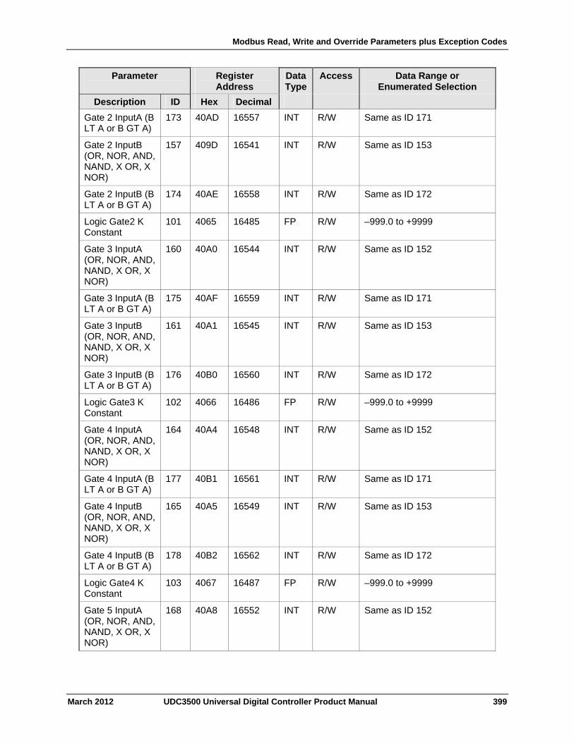
Modbus Read, Write and Override Parameters plus Exception Codes
March 2012 UDC3500 Universal Digital Controller Product Manual 399
Parameter
Register Address
Data Type
Access Data Range or Enumerated Selection
Description ID Hex Decimal
Gate 2 InputA (B LT A or B GT A)
173 40AD 16557 INT R/W Same as ID 171
Gate 2 InputB (OR, NOR, AND, NAND, X OR, X NOR)
157 409D 16541 INT R/W Same as ID 153
Gate 2 InputB (B LT A or B GT A)
174 40AE 16558 INT R/W Same as ID 172
Logic Gate2 K Constant
101 4065 16485 FP R/W –999.0 to +9999
Gate 3 InputA (OR, NOR, AND, NAND, X OR, X NOR)
160 40A0 16544 INT R/W Same as ID 152
Gate 3 InputA (B LT A or B GT A)
175 40AF 16559 INT R/W Same as ID 171
Gate 3 InputB (OR, NOR, AND, NAND, X OR, X NOR)
161 40A1 16545 INT R/W Same as ID 153
Gate 3 InputB (B LT A or B GT A)
176 40B0 16560 INT R/W Same as ID 172
Logic Gate3 K Constant
102 4066 16486 FP R/W –999.0 to +9999
Gate 4 InputA (OR, NOR, AND, NAND, X OR, X NOR)
164 40A4 16548 INT R/W Same as ID 152
Gate 4 InputA (B LT A or B GT A)
177 40B1 16561 INT R/W Same as ID 171
Gate 4 InputB (OR, NOR, AND, NAND, X OR, X NOR)
165 40A5 16549 INT R/W Same as ID 153
Gate 4 InputB (B LT A or B GT A)
178 40B2 16562 INT R/W Same as ID 172
Logic Gate4 K Constant
103 4067 16487 FP R/W –999.0 to +9999
Gate 5 InputA (OR, NOR, AND, NAND, X OR, X NOR)
168 40A8 16552 INT R/W Same as ID 152
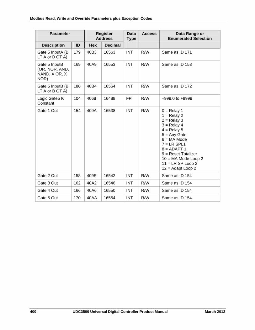
Modbus Read, Write and Override Parameters plus Exception Codes
400 UDC3500 Universal Digital Controller Product Manual March 2012
Parameter
Register Address
Data Type
Access Data Range or Enumerated Selection
Description ID Hex Decimal
Gate 5 InputA (B LT A or B GT A)
179 40B3 16563 INT R/W Same as ID 171
Gate 5 InputB (OR, NOR, AND, NAND, X OR, X NOR)
169 40A9 16553 INT R/W Same as ID 153
Gate 5 InputB (B LT A or B GT A)
180 40B4 16564 INT R/W Same as ID 172
Logic Gate5 K Constant
104 4068 16488 FP R/W –999.0 to +9999
Gate 1 Out 154 409A 16538 INT R/W 0 = Relay 1 1 = Relay 2 2 = Relay 3 3 = Relay 4 4 = Relay 5 5 = Any Gate 6 = MA Mode 7 = LR SPL1 8 = ADAPT 1 9 = Reset Totalizer 10 = MA Mode Loop 2 11 = LR SP Loop 2 12 = Adapt Loop 2
Gate 2 Out 158 409E 16542 INT R/W Same as ID 154
Gate 3 Out 162 40A2 16546 INT R/W Same as ID 154
Gate 4 Out 166 40A6 16550 INT R/W Same as ID 154
Gate 5 Out 170 40AA 16554 INT R/W Same as ID 154
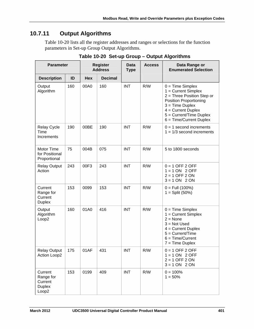
Modbus Read, Write and Override Parameters plus Exception Codes
10.7.11 Output Algorithms
Table 10-20 lists all the register addresses and ranges or selections for the function parameters in Set-up Group Output Algorithms.
Table 10-20 Set-up Group – Output Algorithms
Parameter
Register Address
Data Type
Access Data Range or Enumerated Selection
ID Hex Decimal Description
Output Algorithm
160 00A0 160 INT R/W 0 = Time Simplex 1 = Current Simplex 2 = Three Position Step or Position Proportioning 3 = Time Duplex 4 = Current Duplex 5 = Current/Time Duplex 6 = Time/Current Duplex
Relay Cycle Time Increments
190
00BE 190 INT R/W 0 = 1 second increments 1 = 1/3 second increments
Motor Time for Positional Proportional
75 004B 075 INT R/W 5 to 1800 seconds
Relay Output Action
243 00F3 243 INT R/W 0 = 1 OFF 2 OFF 1 = 1 ON 2 OFF 2 = 1 OFF 2 ON 3 = 1 ON 2 ON
Current Range for Current Duplex
153 0099 153 INT R/W 0 = Full (100%) 1 = Split (50%)
Output Algorithm Loop2
160 01A0 416 INT R/W 0 = Time Simplex 1 = Current Simplex 2 = None 3 = Not Used 4 = Current Duplex 5 = Current/Time 6 = Time/Current 7 = Time Duplex
Relay Output Action Loop2
175 01AF 431 INT R/W 0 = 1 OFF 2 OFF 1 = 1 ON 2 OFF 2 = 1 OFF 2 ON 3 = 1 ON 2 ON
Current Range for Current Duplex Loop2
153 0199 409 INT R/W 0 = 100% 1 = 50%
March 2012 UDC3500 Universal Digital Controller Product Manual 401
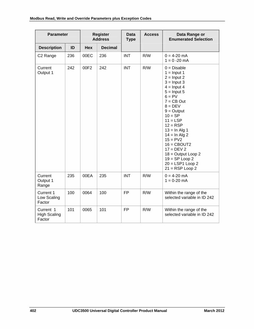
Modbus Read, Write and Override Parameters plus Exception Codes
402 UDC3500 Universal Digital Controller Product Manual March 2012
Parameter
Register Address
Data Type
Access Data Range or Enumerated Selection
Description ID Hex Decimal
C2 Range 236 00EC 236 INT R/W 0 = 4-20 mA 1 = 0 -20 mA
Current Output 1
242 00F2 242 INT R/W 0 = Disable 1 = Input 1 2 = Input 2 3 = Input 3 4 = Input 4 5 = Input 5 6 = PV 7 = CB Out 8 = DEV 9 = Output 10 = SP 11 = LSP 12 = RSP 13 = In Alg 1 14 = In Alg 2 15 = PV2 16 = CBOUT2 17 = DEV 2 18 = Output Loop 2 19 = SP Loop 2 20 = LSP1 Loop 2 21 = RSP Loop 2
Current Output 1 Range
235 00EA 235 INT R/W 0 = 4-20 mA 1 = 0-20 mA
Current 1 Low Scaling Factor
100 0064 100 FP R/W Within the range of the selected variable in ID 242
Current 1 High Scaling Factor
101 0065 101 FP R/W Within the range of the selected variable in ID 242
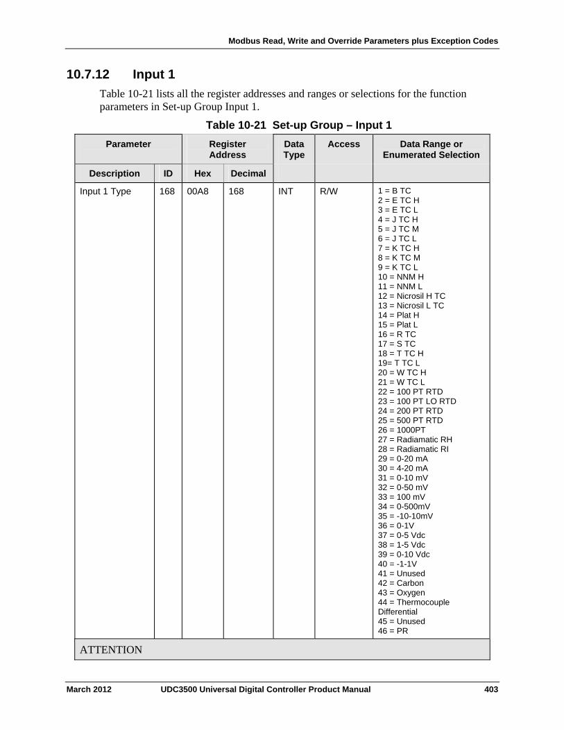
Modbus Read, Write and Override Parameters plus Exception Codes
10.7.12 Input 1
Table 10-21 lists all the register addresses and ranges or selections for the function parameters in Set-up Group Input 1.
Table 10-21 Set-up Group – Input 1
Parameter
Register Address
Data Type
Access Data Range or Enumerated Selection
ID Hex Decimal Description
Input 1 Type 168 00A8 168 INT R/W 1 = B TC 2 = E TC H 3 = E TC L 4 = J TC H 5 = J TC M 6 = J TC L 7 = K TC H 8 = K TC M 9 = K TC L 10 = NNM H 11 = NNM L 12 = Nicrosil H TC 13 = Nicrosil L TC 14 = Plat H 15 = Plat L 16 = R TC 17 = S TC 18 = T TC H 19= T TC L 20 = W TC H 21 = W TC L 22 = 100 PT RTD 23 = 100 PT LO RTD 24 = 200 PT RTD 25 = 500 PT RTD 26 = 1000PT 27 = Radiamatic RH 28 = Radiamatic RI 29 = 0-20 mA 30 = 4-20 mA 31 = 0-10 mV 32 = 0-50 mV 33 = 100 mV 34 = 0-500mV 35 = -10-10mV 36 = 0-1V 37 = 0-5 Vdc 38 = 1-5 Vdc 39 = 0-10 Vdc 40 = -1-1V 41 = Unused 42 = Carbon 43 = Oxygen 44 = Thermocouple Differential 45 = Unused 46 = PR
ATTENTION
March 2012 UDC3500 Universal Digital Controller Product Manual 403
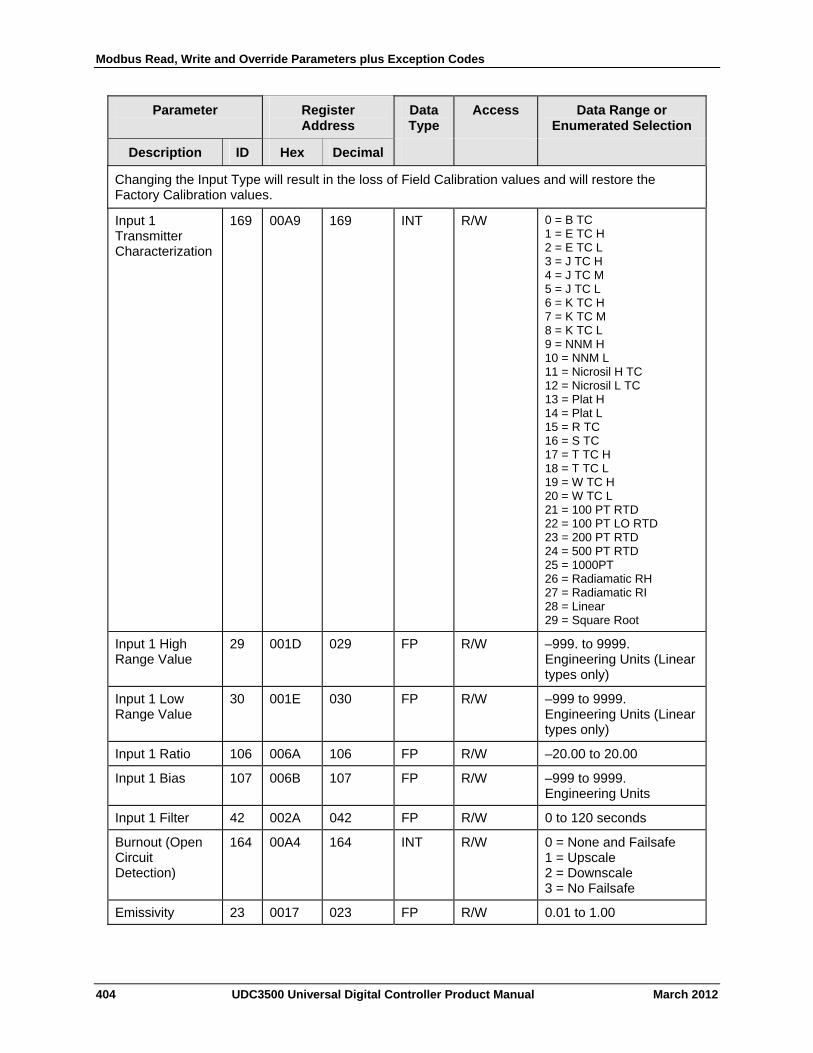
Modbus Read, Write and Override Parameters plus Exception Codes
404 UDC3500 Universal Digital Controller Product Manual March 2012
Parameter
Register Address
Data Type
Access Data Range or Enumerated Selection
Description ID Hex Decimal
Changing the Input Type will result in the loss of Field Calibration values and will restore the Factory Calibration values.
Input 1 Transmitter Characterization
169 00A9 169 INT R/W 0 = B TC 1 = E TC H 2 = E TC L 3 = J TC H 4 = J TC M 5 = J TC L 6 = K TC H 7 = K TC M 8 = K TC L 9 = NNM H 10 = NNM L 11 = Nicrosil H TC 12 = Nicrosil L TC 13 = Plat H 14 = Plat L 15 = R TC 16 = S TC 17 = T TC H 18 = T TC L 19 = W TC H 20 = W TC L 21 = 100 PT RTD 22 = 100 PT LO RTD 23 = 200 PT RTD 24 = 500 PT RTD 25 = 1000PT 26 = Radiamatic RH 27 = Radiamatic RI 28 = Linear 29 = Square Root
Input 1 High Range Value
29 001D 029 FP R/W –999. to 9999. Engineering Units (Linear types only)
Input 1 Low Range Value
30 001E 030 FP R/W –999 to 9999. Engineering Units (Linear types only)
Input 1 Ratio 106 006A 106 FP R/W –20.00 to 20.00
Input 1 Bias 107 006B 107 FP R/W –999 to 9999. Engineering Units
Input 1 Filter 42 002A 042 FP R/W 0 to 120 seconds
Burnout (Open Circuit Detection)
164 00A4 164 INT R/W 0 = None and Failsafe 1 = Upscale 2 = Downscale 3 = No Failsafe
Emissivity 23 0017 023 FP R/W 0.01 to 1.00
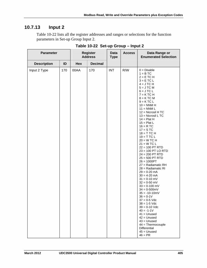
Modbus Read, Write and Override Parameters plus Exception Codes
10.7.13 Input 2
Table 10-22 lists all the register addresses and ranges or selections for the function parameters in Set-up Group Input 2.
Table 10-22 Set-up Group – Input 2
Parameter Register Address
Data Type
Access Data Range or Enumerated Selection
ID Hex Decimal Description
Input 2 Type 170 00AA 170 INT R/W 0 = Disable 1 = B TC 2 = E TC H 3 = E TC L 4 = J TC H 5 = J TC M 6 = J TC L 7 = K TC H 8 = K TC M 9 = K TC L 10 = NNM H 11 = NNM L 12 = Nicrosil H TC 13 = Nicrosil L TC 14 = Plat H 15 = Plat L 16 = R TC 17 = S TC 18 = T TC H 19 = T TC L 20 = W TC H 21 = W TC L 22 = 100 PT RTD 23 = 100 PT LO RTD 24 = 200 PT RTD 25 = 500 PT RTD 26 = 1000PT 27 = Radiamatic RH 28 = Radiamatic RI 29 = 0-20 mA 30 = 4-20 mA 31 = 0-10 mV 32 = 0-50 mV 33 = 0-100 mV 34 = 0-500mV 35 = -10-10mV 36 = 0-1V 37 = 0-5 Vdc 38 = 1-5 Vdc 39 = 0-10 Vdc 40 = -1-1V 41 = Unused 42 = Unused 43 = Unused 44 = Thermocouple Differential 45 = Unused 46 = PR
March 2012 UDC3500 Universal Digital Controller Product Manual 405
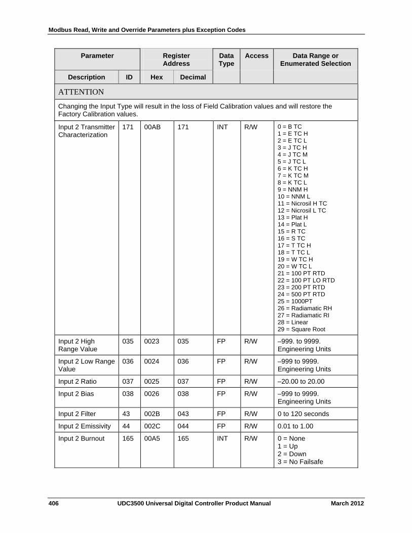
Modbus Read, Write and Override Parameters plus Exception Codes
406 UDC3500 Universal Digital Controller Product Manual March 2012
Parameter Register Address
Data Type
Access Data Range or Enumerated Selection
Description ID Hex Decimal
ATTENTION
Changing the Input Type will result in the loss of Field Calibration values and will restore the Factory Calibration values.
Input 2 Transmitter Characterization
171 00AB 171 INT R/W 0 = B TC 1 = E TC H 2 = E TC L 3 = J TC H 4 = J TC M 5 = J TC L 6 = K TC H 7 = K TC M 8 = K TC L 9 = NNM H 10 = NNM L 11 = Nicrosil H TC 12 = Nicrosil L TC 13 = Plat H 14 = Plat L 15 = R TC 16 = S TC 17 = T TC H 18 = T TC L 19 = W TC H 20 = W TC L 21 = 100 PT RTD 22 = 100 PT LO RTD 23 = 200 PT RTD 24 = 500 PT RTD 25 = 1000PT 26 = Radiamatic RH 27 = Radiamatic RI 28 = Linear 29 = Square Root
Input 2 High Range Value
035 0023 035 FP R/W –999. to 9999. Engineering Units
Input 2 Low Range Value
036 0024 036 FP R/W –999 to 9999. Engineering Units
Input 2 Ratio 037 0025 037 FP R/W –20.00 to 20.00
Input 2 Bias 038 0026 038 FP R/W –999 to 9999. Engineering Units
Input 2 Filter 43 002B 043 FP R/W 0 to 120 seconds
Input 2 Emissivity 44 002C 044 FP R/W 0.01 to 1.00
Input 2 Burnout 165 00A5 165 INT R/W 0 = None 1 = Up 2 = Down 3 = No Failsafe
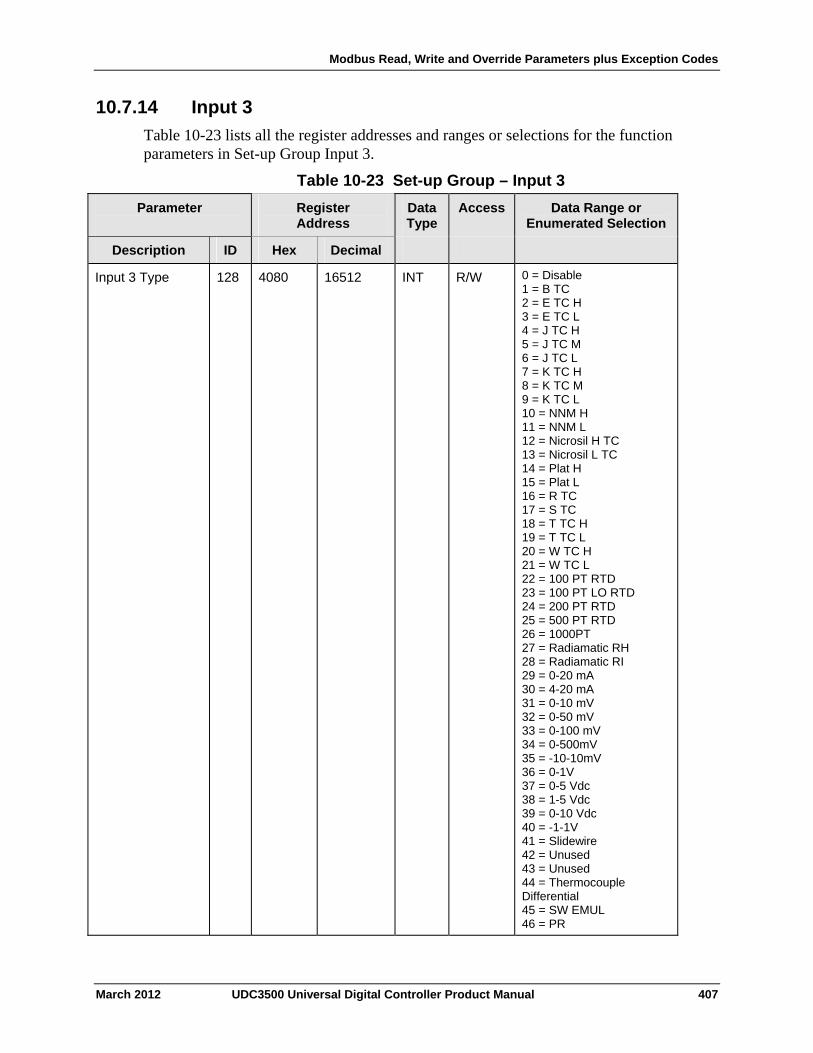
Modbus Read, Write and Override Parameters plus Exception Codes
March 2012 UDC3500 Universal Digital Controller Product Manual 407
10.7.14 Input 3
Table 10-23 lists all the register addresses and ranges or selections for the function parameters in Set-up Group Input 3.
Table 10-23 Set-up Group – Input 3
Parameter
Register Address
Data Type
Access Data Range or Enumerated Selection
Description ID Hex Decimal
Input 3 Type 128 4080 16512 INT R/W 0 = Disable 1 = B TC 2 = E TC H 3 = E TC L 4 = J TC H 5 = J TC M 6 = J TC L 7 = K TC H 8 = K TC M 9 = K TC L 10 = NNM H 11 = NNM L 12 = Nicrosil H TC 13 = Nicrosil L TC 14 = Plat H 15 = Plat L 16 = R TC 17 = S TC 18 = T TC H 19 = T TC L 20 = W TC H 21 = W TC L 22 = 100 PT RTD 23 = 100 PT LO RTD 24 = 200 PT RTD 25 = 500 PT RTD 26 = 1000PT 27 = Radiamatic RH 28 = Radiamatic RI 29 = 0-20 mA 30 = 4-20 mA 31 = 0-10 mV 32 = 0-50 mV 33 = 0-100 mV 34 = 0-500mV 35 = -10-10mV 36 = 0-1V 37 = 0-5 Vdc 38 = 1-5 Vdc 39 = 0-10 Vdc 40 = -1-1V 41 = Slidewire 42 = Unused 43 = Unused 44 = Thermocouple Differential 45 = SW EMUL 46 = PR
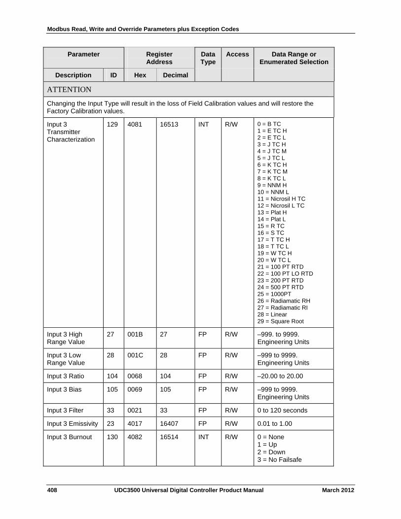
Modbus Read, Write and Override Parameters plus Exception Codes
Parameter
Register Address
Data Type
Access Data Range or Enumerated Selection
Description ID Hex Decimal
ATTENTION
Changing the Input Type will result in the loss of Field Calibration values and will restore the Factory Calibration values.
Input 3 Transmitter Characterization
129 4081 16513 INT R/W 0 = B TC 1 = E TC H 2 = E TC L 3 = J TC H 4 = J TC M 5 = J TC L 6 = K TC H 7 = K TC M 8 = K TC L 9 = NNM H 10 = NNM L 11 = Nicrosil H TC 12 = Nicrosil L TC 13 = Plat H 14 = Plat L 15 = R TC 16 = S TC 17 = T TC H 18 = T TC L 19 = W TC H 20 = W TC L 21 = 100 PT RTD 22 = 100 PT LO RTD 23 = 200 PT RTD 24 = 500 PT RTD 25 = 1000PT 26 = Radiamatic RH 27 = Radiamatic RI 28 = Linear 29 = Square Root
Input 3 High Range Value
27 001B 27 FP R/W –999. to 9999. Engineering Units
Input 3 Low Range Value
28 001C 28 FP R/W –999 to 9999. Engineering Units
Input 3 Ratio 104 0068 104 FP R/W –20.00 to 20.00
Input 3 Bias 105 0069 105 FP R/W –999 to 9999. Engineering Units
Input 3 Filter 33 0021 33 FP R/W 0 to 120 seconds
Input 3 Emissivity 23 4017 16407 FP R/W 0.01 to 1.00
Input 3 Burnout 130 4082 16514 INT R/W 0 = None 1 = Up 2 = Down 3 = No Failsafe
408 UDC3500 Universal Digital Controller Product Manual March 2012
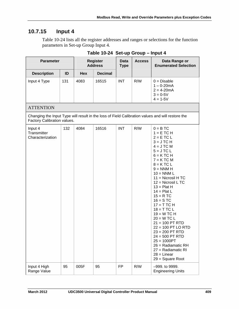
Modbus Read, Write and Override Parameters plus Exception Codes
10.7.15 Input 4
Table 10-24 lists all the register addresses and ranges or selections for the function parameters in Set-up Group Input 4.
Table 10-24 Set-up Group – Input 4
Parameter
Register Address
Data Type
Access Data Range or Enumerated Selection
ID Hex Decimal Description
Input 4 Type 131 4083 16515 INT R/W 0 = Disable 1 – 0-20mA 2 = 4-20mA 3 = 0-5V 4 = 1-5V
ATTENTION
Changing the Input Type will result in the loss of Field Calibration values and will restore the Factory Calibration values.
Input 4 Transmitter Characterization
132 4084 16516 INT R/W 0 = B TC 1 = E TC H 2 = E TC L 3 = J TC H 4 = J TC M 5 = J TC L 6 = K TC H 7 = K TC M 8 = K TC L 9 = NNM H 10 = NNM L 11 = Nicrosil H TC 12 = Nicrosil L TC 13 = Plat H 14 = Plat L 15 = R TC 16 = S TC 17 = T TC H 18 = T TC L 19 = W TC H 20 = W TC L 21 = 100 PT RTD 22 = 100 PT LO RTD 23 = 200 PT RTD 24 = 500 PT RTD 25 = 1000PT 26 = Radiamatic RH 27 = Radiamatic RI 28 = Linear 29 = Square Root
Input 4 High Range Value
95 005F 95 FP R/W –999. to 9999. Engineering Units
March 2012 UDC3500 Universal Digital Controller Product Manual 409
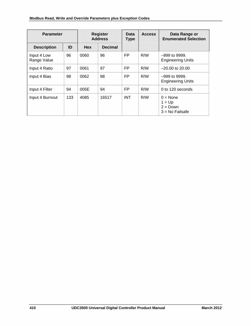
Modbus Read, Write and Override Parameters plus Exception Codes
410 UDC3500 Universal Digital Controller Product Manual March 2012
Parameter
Register Address
Data Type
Access Data Range or Enumerated Selection
Description ID Hex Decimal
Input 4 Low Range Value
96 0060 96 FP R/W –999 to 9999. Engineering Units
Input 4 Ratio 97 0061 97 FP R/W –20.00 to 20.00
Input 4 Bias 98 0062 98 FP R/W –999 to 9999. Engineering Units
Input 4 Filter 94 005E 94 FP R/W 0 to 120 seconds
Input 4 Burnout 133 4085 16517 INT R/W 0 = None 1 = Up 2 = Down 3 = No Failsafe

Modbus Read, Write and Override Parameters plus Exception Codes
10.7.16 Input 5
Table 10-25 lists all the register addresses and ranges or selections for the function parameters in Set-up Group Input 5.
Table 10-25 Set-up Group – Input 5
Parameter
Register Address
Data Type
Access Data Range or Enumerated Selection
ID Hex Decimal Description
Input 5 Type 134 4086 16518 INT R/W 0 = Disable 1 = 0-20mA 2 = 4-20mA 3 = 0-5V 4 = 1-5V
ATTENTION
Changing the Input Type will result in the loss of Field Calibration values and will restore the Factory Calibration values.
Input 5 Transmitter Characterization
135 4087 16519 INT R/W 0 = B TC 1 = E TC H 2 = E TC L 3 = J TC H 4 = J TC M 5 = J TC L 6 = K TC H 7 = K TC M 8 = K TC L 9 = NNM H 10 = NNM L 11 = Nicrosil H TC 12 = Nicrosil L TC 13 = Plat H 14 = Plat L 15 = R TC 16 = S TC 17 = T TC H 18 = T TC L 19 = W TC H 20 = W TC L 21 = 100 PT RTD 22 = 100 PT LO RTD 23 = 200 PT RTD 24 = 500 PT RTD 25 = 1000PT 26 = Radiamatic RH 27 = Radiamatic RI 28 = Linear 29 = Square Root
Input 5 High Range Value
82 0052 82 FP R/W –999. to 9999. Engineering Units
March 2012 UDC3500 Universal Digital Controller Product Manual 411
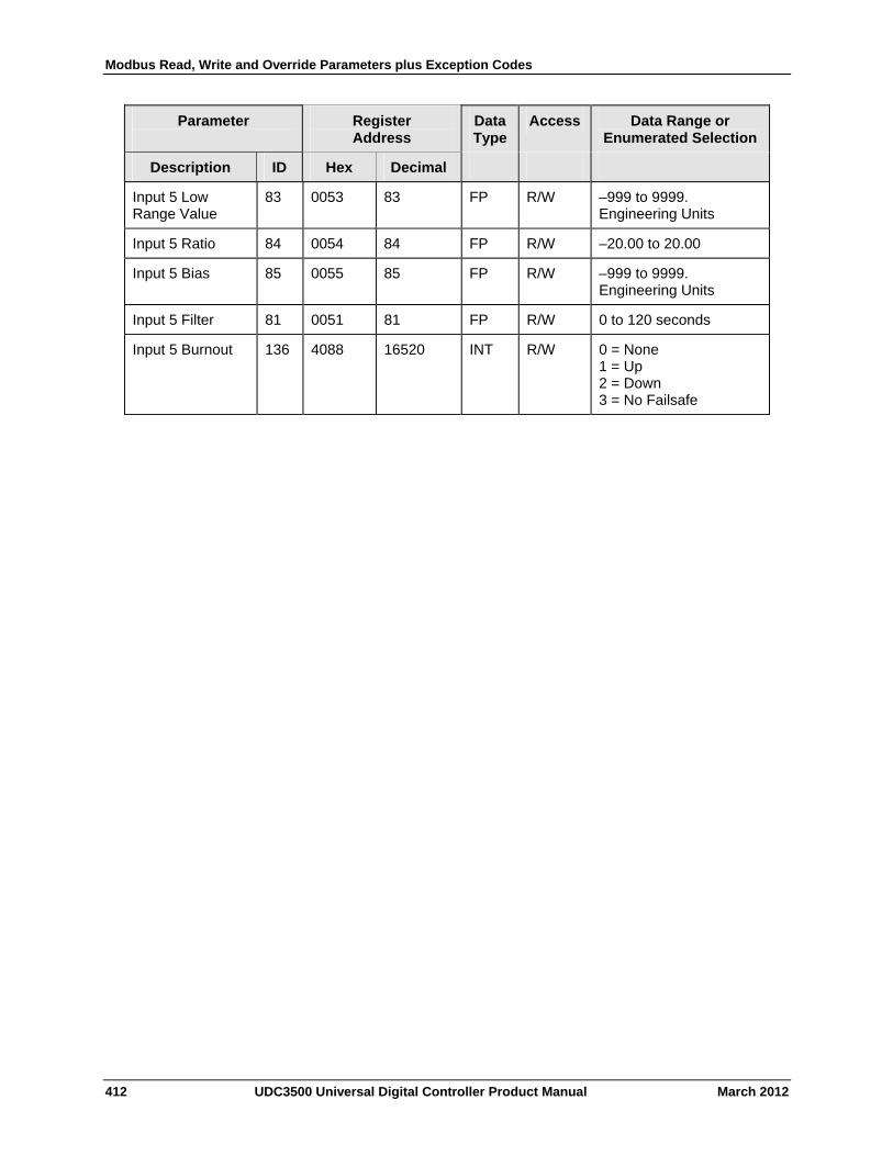
Modbus Read, Write and Override Parameters plus Exception Codes
412 UDC3500 Universal Digital Controller Product Manual March 2012
Parameter
Register Address
Data Type
Access Data Range or Enumerated Selection
Description ID Hex Decimal
Input 5 Low Range Value
83 0053 83 FP R/W –999 to 9999. Engineering Units
Input 5 Ratio 84 0054 84 FP R/W –20.00 to 20.00
Input 5 Bias 85 0055 85 FP R/W –999 to 9999. Engineering Units
Input 5 Filter 81 0051 81 FP R/W 0 to 120 seconds
Input 5 Burnout 136 4088 16520 INT R/W 0 = None 1 = Up 2 = Down 3 = No Failsafe
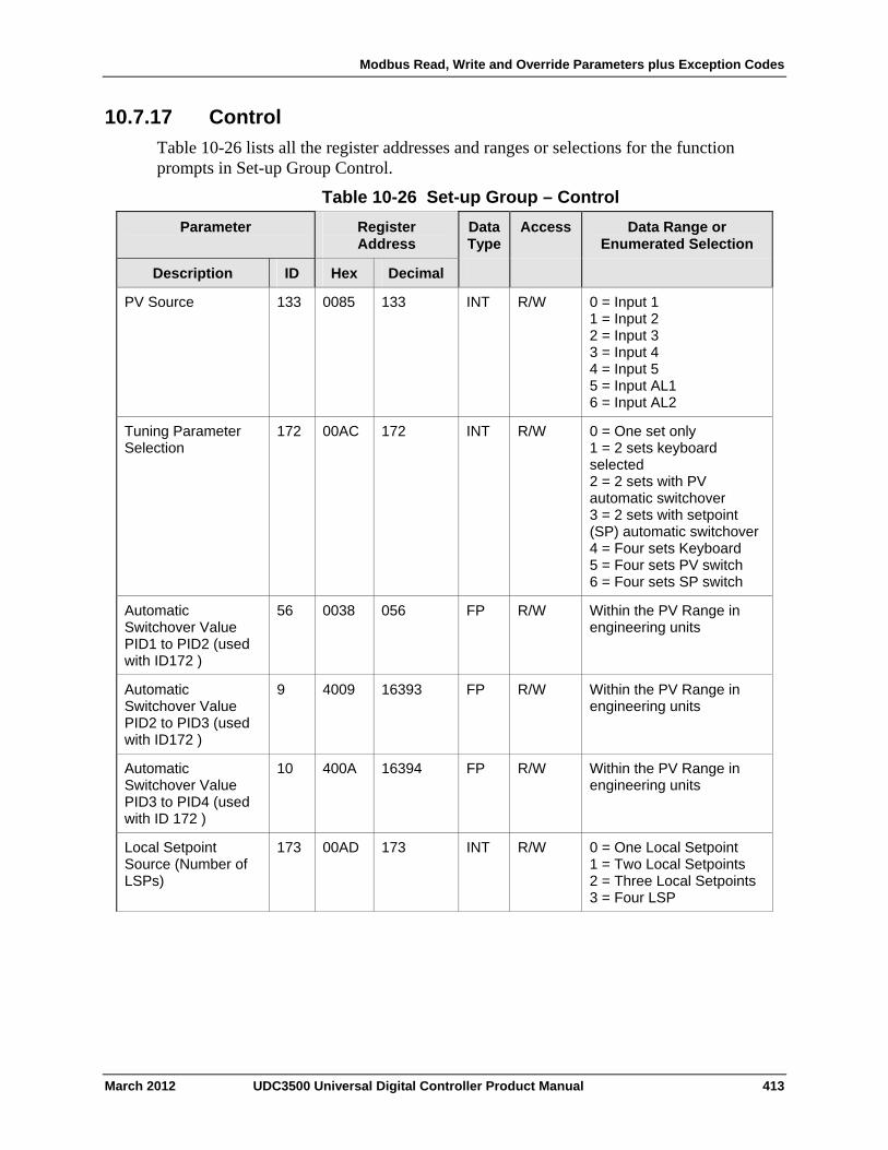
Modbus Read, Write and Override Parameters plus Exception Codes
10.7.17 Control
Table 10-26 lists all the register addresses and ranges or selections for the function prompts in Set-up Group Control.
Table 10-26 Set-up Group – Control
Parameter
Register Address
Data Type
Access Data Range or Enumerated Selection
ID Hex Decimal Description
PV Source 133 0085 133 INT R/W 0 = Input 1 1 = Input 2 2 = Input 3 3 = Input 4 4 = Input 5 5 = Input AL1 6 = Input AL2
Tuning Parameter Selection
172 00AC 172 INT R/W 0 = One set only 1 = 2 sets keyboard selected 2 = 2 sets with PV automatic switchover 3 = 2 sets with setpoint (SP) automatic switchover 4 = Four sets Keyboard 5 = Four sets PV switch 6 = Four sets SP switch
Automatic Switchover Value PID1 to PID2 (used with ID172 )
56 0038 056 FP R/W Within the PV Range in engineering units
Automatic Switchover Value PID2 to PID3 (used with ID172 )
9 4009 16393 FP R/W Within the PV Range in engineering units
Automatic Switchover Value PID3 to PID4 (used with ID 172 )
10 400A 16394 FP R/W Within the PV Range in engineering units
Local Setpoint Source (Number of LSPs)
173 00AD 173 INT R/W 0 = One Local Setpoint 1 = Two Local Setpoints 2 = Three Local Setpoints 3 = Four LSP
March 2012 UDC3500 Universal Digital Controller Product Manual 413
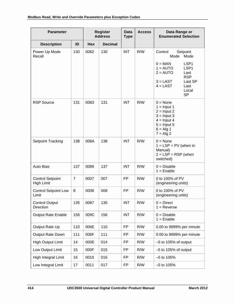
Modbus Read, Write and Override Parameters plus Exception Codes
414 UDC3500 Universal Digital Controller Product Manual March 2012
Parameter
Register Address
Data Type
Access Data Range or Enumerated Selection
Description ID Hex Decimal
Power Up Mode Recall
130 0082 130 INT R/W Control Setpoint Mode Mode
0 = MAN LSP1 1 = AUTO LSP1 2 = AUTO Last RSP 3 = LAST Last SP 4 = LAST Last Local SP
RSP Source 131 0083 131 INT R/W 0 = None 1 = Input 1 2 = Input 2 3 = Input 3 4 = Input 4 5 = Input 5 6 = Alg 1 7 = Alg 2
Setpoint Tracking 138 008A 138 INT R/W 0 = None 1 = LSP = PV (when in Manual) 2 = LSP = RSP (when switched)
Auto Bias 137 0089 137 INT R/W 0 = Disable 1 = Enable
Control Setpoint High Limit
7 0007 007 FP R/W 0 to 100% of PV (engineering units)
Control Setpoint Low Limit
8 0008 008 FP R/W 0 to 100% of PV (engineering units)
Control Output Direction
135 0087 135 INT R/W 0 = Direct 1 = Reverse
Output Rate Enable 156 009C 156 INT R/W 0 = Disable 1 = Enable
Output Rate Up 110 006E 110 FP R/W 0.00 to 9999% per minute
Output Rate Down 111 006F 111 FP R/W 0.00 to 9999% per minute
High Output Limit 14 000E 014 FP R/W –5 to 105% of output
Low Output Limit 15 000F 015 FP R/W –5 to 105% of output
High Integral Limit 16 0010 016 FP R/W –5 to 105%
Low Integral Limit 17 0011 017 FP R/W –5 to 105%
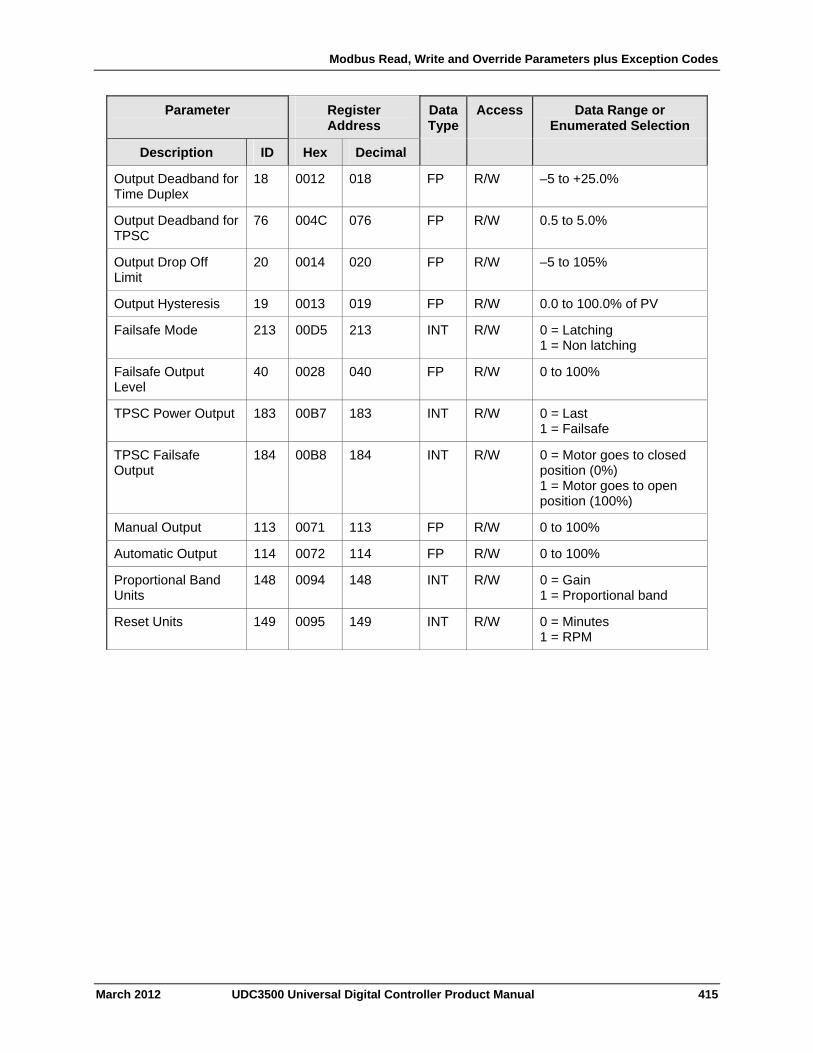
Modbus Read, Write and Override Parameters plus Exception Codes
March 2012 UDC3500 Universal Digital Controller Product Manual 415
Parameter
Register Address
Data Type
Access Data Range or Enumerated Selection
Description ID Hex Decimal
Output Deadband for Time Duplex
18 0012 018 FP R/W –5 to +25.0%
Output Deadband for TPSC
76 004C 076 FP R/W 0.5 to 5.0%
Output Drop Off Limit
20 0014 020 FP R/W –5 to 105%
Output Hysteresis 19 0013 019 FP R/W 0.0 to 100.0% of PV
Failsafe Mode 213 00D5 213 INT R/W 0 = Latching 1 = Non latching
Failsafe Output Level
40 0028 040 FP R/W 0 to 100%
TPSC Power Output 183 00B7 183 INT R/W 0 = Last 1 = Failsafe
TPSC Failsafe Output
184 00B8 184 INT R/W 0 = Motor goes to closed position (0%) 1 = Motor goes to open position (100%)
Manual Output 113 0071 113 FP R/W 0 to 100%
Automatic Output 114 0072 114 FP R/W 0 to 100%
Proportional Band Units
148 0094 148 INT R/W 0 = Gain 1 = Proportional band
Reset Units 149 0095 149 INT R/W 0 = Minutes 1 = RPM
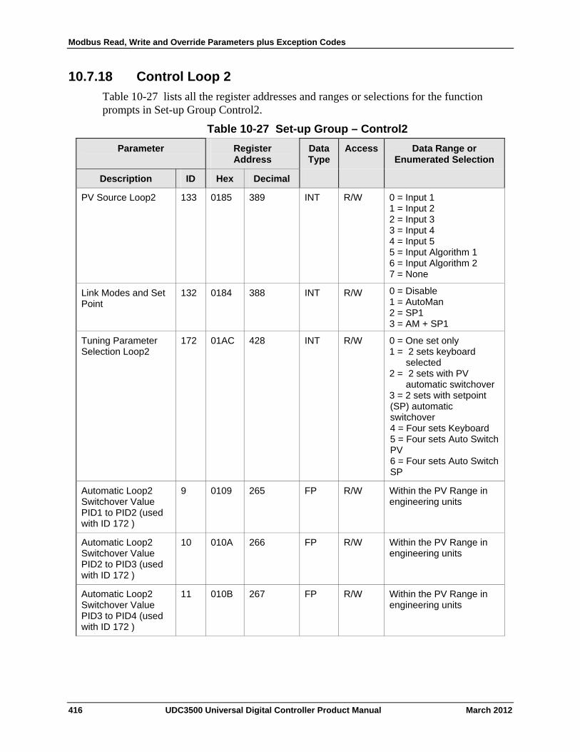
Modbus Read, Write and Override Parameters plus Exception Codes
10.7.18 Control Loop 2
Table 10-27 lists all the register addresses and ranges or selections for the function prompts in Set-up Group Control2.
Table 10-27 Set-up Group – Control2
Parameter
Register Address
Data Type
Access Data Range or Enumerated Selection
ID Hex Decimal Description
PV Source Loop2 133 0185 389 INT R/W 0 = Input 1 1 = Input 2 2 = Input 3 3 = Input 4 4 = Input 5 5 = Input Algorithm 1 6 = Input Algorithm 2 7 = None
132 0184 388 INT R/W 0 = Disable 1 = AutoMan 2 = SP1 3 = AM + SP1
Link Modes and Set Point
Tuning Parameter Selection Loop2
172 01AC 428 INT R/W 0 = One set only 1 = 2 sets keyboard
selected 2 = 2 sets with PV
automatic switchover 3 = 2 sets with setpoint (SP) automatic switchover 4 = Four sets Keyboard 5 = Four sets Auto Switch PV 6 = Four sets Auto Switch SP
Automatic Loop2 Switchover Value PID1 to PID2 (used with ID 172 )
9 0109 265 FP R/W Within the PV Range in engineering units
Automatic Loop2 Switchover Value PID2 to PID3 (used with ID 172 )
10 010A 266 FP R/W Within the PV Range in engineering units
Automatic Loop2 Switchover Value PID3 to PID4 (used with ID 172 )
11 010B 267 FP R/W Within the PV Range in engineering units
416 UDC3500 Universal Digital Controller Product Manual March 2012
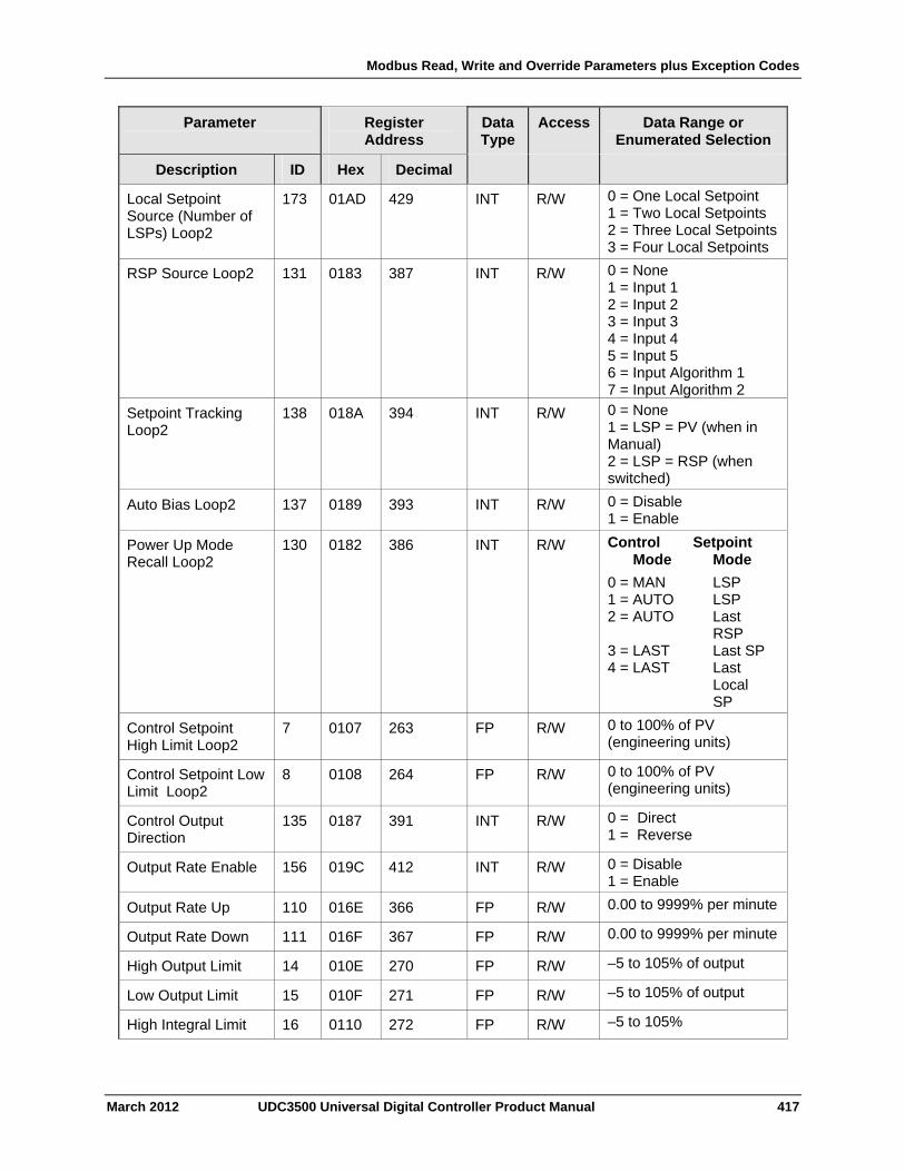
Modbus Read, Write and Override Parameters plus Exception Codes
March 2012 UDC3500 Universal Digital Controller Product Manual 417
Parameter
Register Address
Data Type
Access Data Range or Enumerated Selection
Description ID Hex Decimal
Local Setpoint Source (Number of LSPs) Loop2
173 01AD 429 INT R/W 0 = One Local Setpoint 1 = Two Local Setpoints 2 = Three Local Setpoints3 = Four Local Setpoints
RSP Source Loop2 131 0183 387 INT R/W 0 = None 1 = Input 1 2 = Input 2 3 = Input 3 4 = Input 4 5 = Input 5 6 = Input Algorithm 1 7 = Input Algorithm 2
Setpoint Tracking Loop2
138 018A 394 INT R/W 0 = None 1 = LSP = PV (when in Manual) 2 = LSP = RSP (when switched)
Auto Bias Loop2 137 0189 393 INT R/W 0 = Disable 1 = Enable
Power Up Mode Recall Loop2
130 0182 386 INT R/W Control Setpoint Mode Mode
0 = MAN LSP 1 = AUTO LSP 2 = AUTO Last RSP 3 = LAST Last SP 4 = LAST Last Local SP
Control Setpoint High Limit Loop2
7 0107 263 FP R/W 0 to 100% of PV (engineering units)
Control Setpoint Low Limit Loop2
8 0108 264 FP R/W 0 to 100% of PV (engineering units)
Control Output Direction
135 0187 391 INT R/W 0 = Direct 1 = Reverse
Output Rate Enable 156 019C 412 INT R/W 0 = Disable 1 = Enable
Output Rate Up 110 016E 366 FP R/W 0.00 to 9999% per minute
Output Rate Down 111 016F 367 FP R/W 0.00 to 9999% per minute
High Output Limit 14 010E 270 FP R/W –5 to 105% of output
Low Output Limit 15 010F 271 FP R/W –5 to 105% of output
High Integral Limit 16 0110 272 FP R/W –5 to 105%
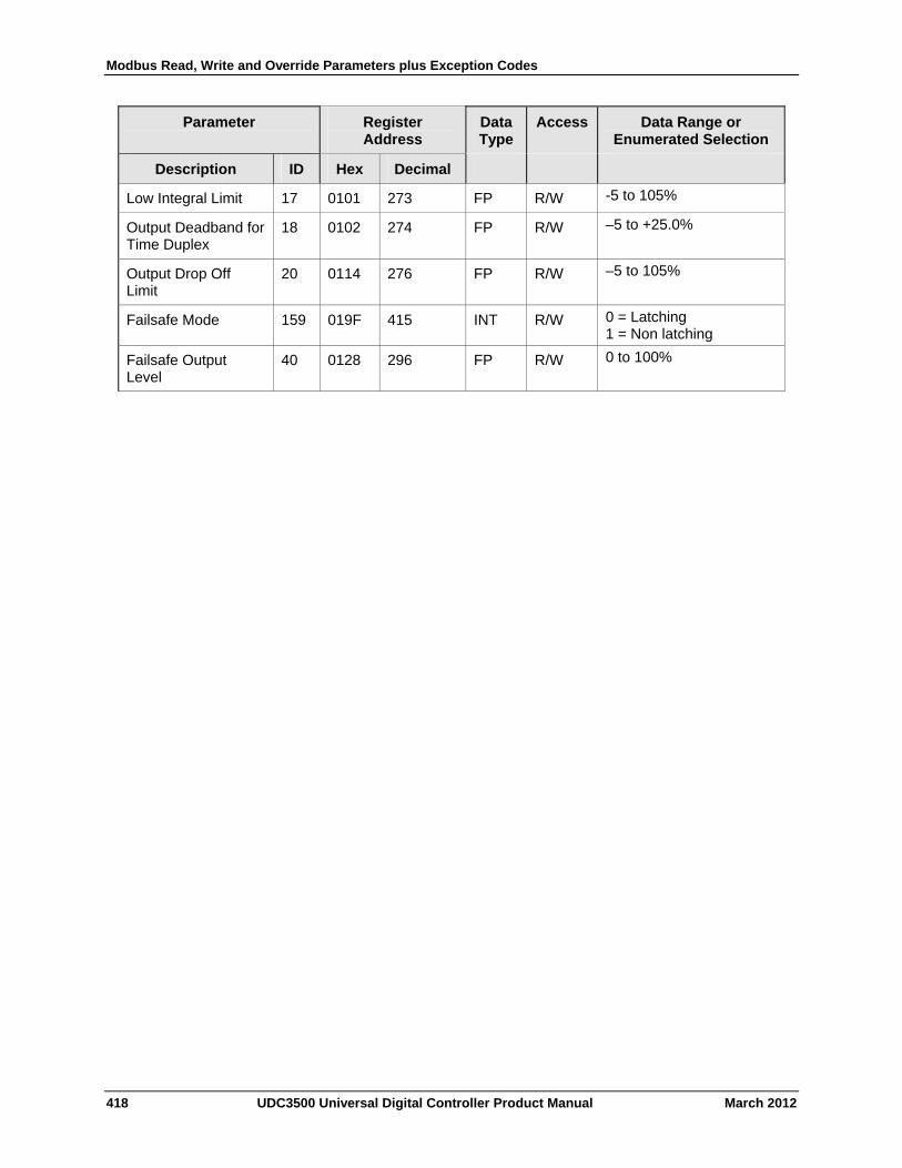
Modbus Read, Write and Override Parameters plus Exception Codes
418 UDC3500 Universal Digital Controller Product Manual March 2012
Parameter
Register Address
Data Type
Access Data Range or Enumerated Selection
Description ID Hex Decimal
Low Integral Limit 17 0101 273 FP R/W -5 to 105%
Output Deadband for Time Duplex
18 0102 274 FP R/W –5 to +25.0%
Output Drop Off Limit
20 0114 276 FP R/W –5 to 105%
Failsafe Mode 159 019F 415 INT R/W 0 = Latching 1 = Non latching
Failsafe Output Level
40 0128 296 FP R/W 0 to 100%
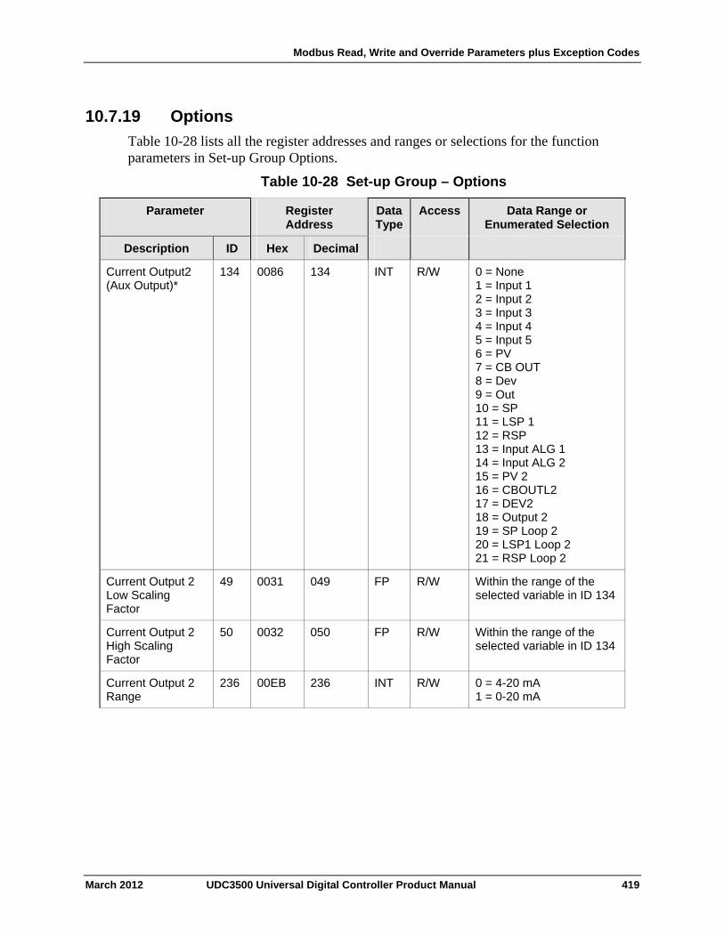
Modbus Read, Write and Override Parameters plus Exception Codes
10.7.19 Options
Table 10-28 lists all the register addresses and ranges or selections for the function parameters in Set-up Group Options.
Table 10-28 Set-up Group – Options
Register Address
Data Type
Access Data Range or Enumerated Selection
Parameter
ID Hex Decimal Description
Current Output2 (Aux Output)*
134 0086 134 INT R/W 0 = None 1 = Input 1 2 = Input 2 3 = Input 3 4 = Input 4 5 = Input 5 6 = PV 7 = CB OUT 8 = Dev 9 = Out 10 = SP 11 = LSP 1 12 = RSP 13 = Input ALG 1 14 = Input ALG 2 15 = PV 2 16 = CBOUTL2 17 = DEV2 18 = Output 2 19 = SP Loop 2 20 = LSP1 Loop 2 21 = RSP Loop 2
Current Output 2 Low Scaling Factor
49 0031 049 FP R/W Within the range of the selected variable in ID 134
Current Output 2 High Scaling Factor
50 0032 050 FP R/W Within the range of the selected variable in ID 134
Current Output 2 Range
236 00EB 236 INT R/W 0 = 4-20 mA 1 = 0-20 mA
March 2012 UDC3500 Universal Digital Controller Product Manual 419
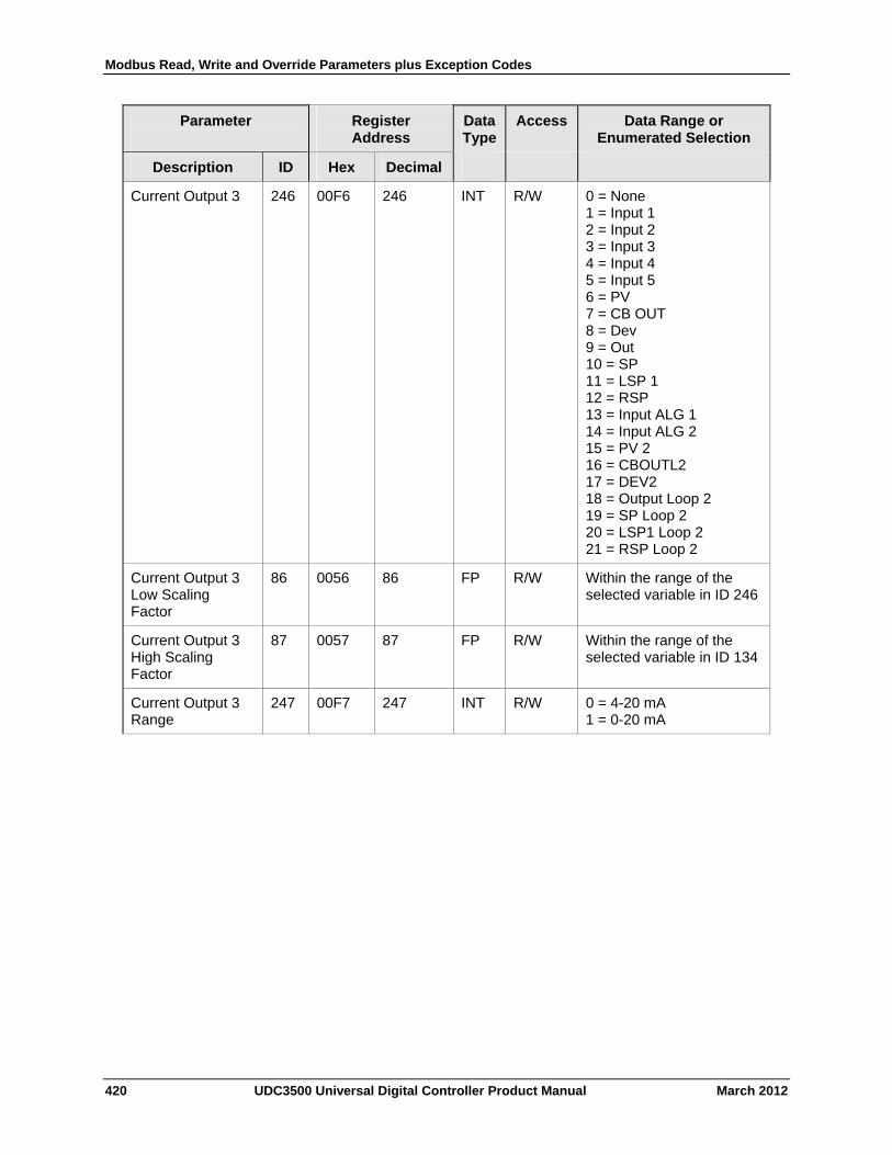
Modbus Read, Write and Override Parameters plus Exception Codes
420 UDC3500 Universal Digital Controller Product Manual March 2012
Parameter
Register Address
Data Type
Access Data Range or Enumerated Selection
Description ID Hex Decimal
Current Output 3 246 00F6 246 INT R/W 0 = None 1 = Input 1 2 = Input 2 3 = Input 3 4 = Input 4 5 = Input 5 6 = PV 7 = CB OUT 8 = Dev 9 = Out 10 = SP 11 = LSP 1 12 = RSP 13 = Input ALG 1 14 = Input ALG 2 15 = PV 2 16 = CBOUTL2 17 = DEV2 18 = Output Loop 2 19 = SP Loop 2 20 = LSP1 Loop 2 21 = RSP Loop 2
Current Output 3 Low Scaling Factor
86 0056 86 FP R/W Within the range of the selected variable in ID 246
Current Output 3 High Scaling Factor
87 0057 87 FP R/W Within the range of the selected variable in ID 134
Current Output 3 Range
247 00F7 247 INT R/W 0 = 4-20 mA 1 = 0-20 mA
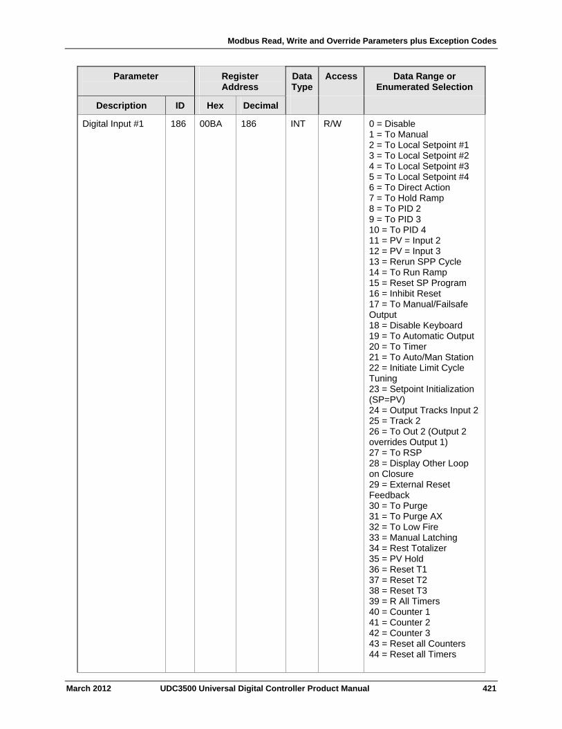
Modbus Read, Write and Override Parameters plus Exception Codes
March 2012 UDC3500 Universal Digital Controller Product Manual 421
Parameter
Register Address
Data Type
Access Data Range or Enumerated Selection
Description ID Hex Decimal
Digital Input #1 186 00BA 186 INT R/W 0 = Disable 1 = To Manual 2 = To Local Setpoint #1 3 = To Local Setpoint #2 4 = To Local Setpoint #3 5 = To Local Setpoint #4 6 = To Direct Action 7 = To Hold Ramp 8 = To PID 2 9 = To PID 3 10 = To PID 4 11 = PV = Input 2 12 = PV = Input 3 13 = Rerun SPP Cycle 14 = To Run Ramp 15 = Reset SP Program 16 = Inhibit Reset 17 = To Manual/Failsafe Output 18 = Disable Keyboard 19 = To Automatic Output 20 = To Timer 21 = To Auto/Man Station 22 = Initiate Limit Cycle Tuning 23 = Setpoint Initialization (SP=PV) 24 = Output Tracks Input 2 25 = Track 2 26 = To Out 2 (Output 2 overrides Output 1) 27 = To RSP 28 = Display Other Loop on Closure 29 = External Reset Feedback 30 = To Purge 31 = To Purge AX 32 = To Low Fire 33 = Manual Latching 34 = Rest Totalizer 35 = PV Hold 36 = Reset T1 37 = Reset T2 38 = Reset T3 39 = R All Timers 40 = Counter 1 41 = Counter 2 42 = Counter 3 43 = Reset all Counters 44 = Reset all Timers
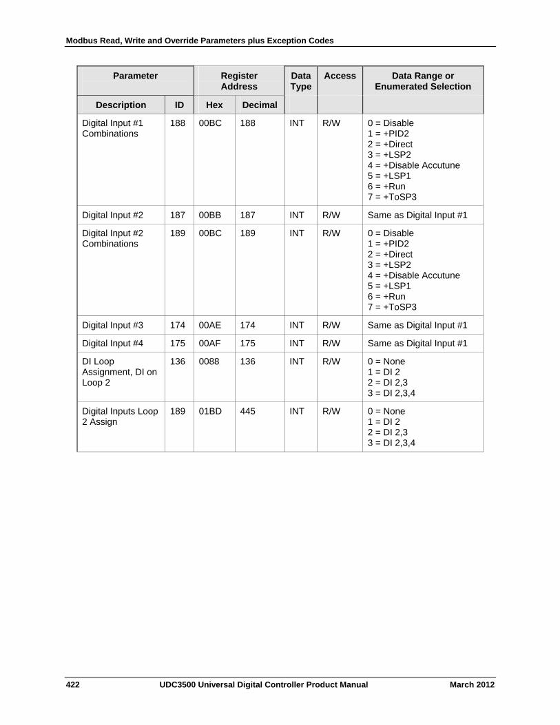
Modbus Read, Write and Override Parameters plus Exception Codes
422 UDC3500 Universal Digital Controller Product Manual March 2012
Parameter
Register Address
Data Type
Access Data Range or Enumerated Selection
Description ID Hex Decimal
Digital Input #1 Combinations
188 00BC 188 INT R/W 0 = Disable 1 = +PID2 2 = +Direct 3 = +LSP2 4 = +Disable Accutune 5 = +LSP1 6 = +Run 7 = +ToSP3
Digital Input #2 187 00BB 187 INT R/W Same as Digital Input #1
Digital Input #2 Combinations
189 00BC 189 INT R/W 0 = Disable 1 = +PID2 2 = +Direct 3 = +LSP2 4 = +Disable Accutune 5 = +LSP1 6 = +Run 7 = +ToSP3
Digital Input #3 174 00AE 174 INT R/W Same as Digital Input #1
Digital Input #4 175 00AF 175 INT R/W Same as Digital Input #1
DI Loop Assignment, DI on Loop 2
136 0088 136 INT R/W 0 = None 1 = DI 2 2 = DI 2,3 3 = DI 2,3,4
Digital Inputs Loop 2 Assign
189 01BD 445 INT R/W 0 = None 1 = DI 2 2 = DI 2,3 3 = DI 2,3,4
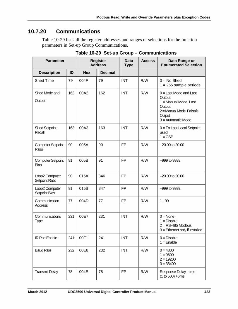
Modbus Read, Write and Override Parameters plus Exception Codes
10.7.20 Communications
Table 10-29 lists all the register addresses and ranges or selections for the function parameters in Set-up Group Communications.
Table 10-29 Set-up Group – Communications
Parameter
Register Address
Data Type
Access Data Range or Enumerated Selection
ID Hex Decimal Description
Shed Time 79 004F 79 INT R/W 0 = No Shed 1 = 255 sample periods
Shed Mode and
Output
162 00A2 162 INT R/W 0 = Last Mode and Last Output 1 = Manual Mode, Last Output 2 = Manual Mode, Failsafe Output 3 = Automatic Mode
Shed Setpoint Recall
163
00A3 163 INT R/W 0 = To Last Local Setpoint used 1 = CSP
Computer Setpoint Ratio
90
005A 90 FP R/W –20.00 to 20.00
Computer Setpoint Bias
91
005B 91 FP R/W –999 to 9999.
Loop2 Computer Setpoint Ratio
90 015A 346 FP R/W –20.00 to 20.00
Loop2 Computer Setpoint Bias
91 015B 347 FP R/W –999 to 9999.
Communication Address
77
004D 77 FP R/W 1 - 99
Communications Type
231 00E7 231 INT R/W 0 = None 1 = Disable 2 = RS-485 Modbus 3 = Ethernet only if installed
IR Port Enable 241 00F1 241 INT R/W 0 = Disable 1 = Enable
Baud Rate 232 00E8 232 INT R/W 0 = 4800 1 = 9600 2 = 19200 3 = 38400
Transmit Delay 78 004E 78 FP R/W Response Delay in ms (1 to 500) +6ms
March 2012 UDC3500 Universal Digital Controller Product Manual 423
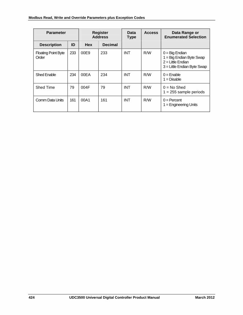
Modbus Read, Write and Override Parameters plus Exception Codes
424 UDC3500 Universal Digital Controller Product Manual March 2012
Parameter
Register Address
Data Type
Access Data Range or Enumerated Selection
Description ID Hex Decimal
Floating Point Byte Order
233
00E9 233 INT R/W 0 = Big Endian 1 = Big Endian Byte Swap 2 = Little Endian 3 = Little Endian Byte Swap
Shed Enable 234 00EA 234 INT R/W 0 = Enable 1 = Disable
Shed Time 79 004F 79 INT R/W 0 = No Shed 1 = 255 sample periods
Comm Data Units 161
00A1 161 INT R/W 0 = Percent 1 = Engineering Units
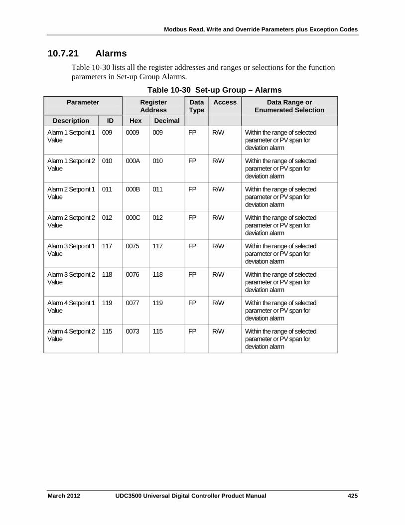
Modbus Read, Write and Override Parameters plus Exception Codes
10.7.21 Alarms
Table 10-30 lists all the register addresses and ranges or selections for the function parameters in Set-up Group Alarms.
Table 10-30 Set-up Group – Alarms
Parameter
Register Address
Data Type
Access Data Range or Enumerated Selection
ID Hex Decimal Description
Alarm 1 Setpoint 1 Value
009 0009 009 FP R/W Within the range of selected parameter or PV span for deviation alarm
Alarm 1 Setpoint 2 Value
010 000A 010 FP R/W Within the range of selected parameter or PV span for deviation alarm
Alarm 2 Setpoint 1 Value
011 000B 011 FP R/W Within the range of selected parameter or PV span for deviation alarm
Alarm 2 Setpoint 2 Value
012 000C 012 FP R/W Within the range of selected parameter or PV span for deviation alarm
Alarm 3 Setpoint 1 Value
117 0075 117 FP R/W Within the range of selected parameter or PV span for deviation alarm
Alarm 3 Setpoint 2 Value
118 0076 118 FP R/W Within the range of selected parameter or PV span for deviation alarm
Alarm 4 Setpoint 1 Value
119 0077 119 FP R/W Within the range of selected parameter or PV span for deviation alarm
Alarm 4 Setpoint 2 Value
115 0073 115 FP R/W Within the range of selected parameter or PV span for deviation alarm
March 2012 UDC3500 Universal Digital Controller Product Manual 425
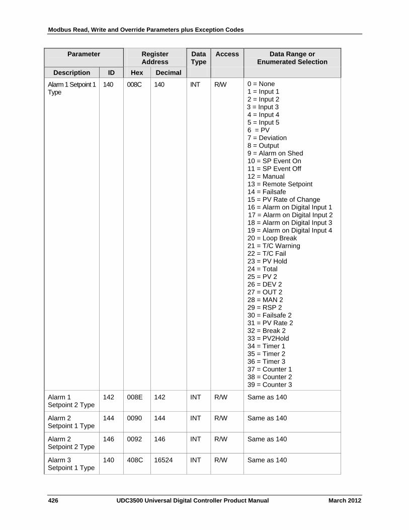
Modbus Read, Write and Override Parameters plus Exception Codes
426 UDC3500 Universal Digital Controller Product Manual March 2012
Parameter
Register Address
Data Type
Access Data Range or Enumerated Selection
Description ID Hex Decimal
Alarm 1 Setpoint 1 Type
140 008C 140 INT R/W 0 = None 1 = Input 1 2 = Input 2 3 = Input 3 4 = Input 4 5 = Input 5 6 = PV 7 = Deviation 8 = Output 9 = Alarm on Shed 10 = SP Event On 11 = SP Event Off 12 = Manual 13 = Remote Setpoint 14 = Failsafe 15 = PV Rate of Change 16 = Alarm on Digital Input 1 17 = Alarm on Digital Input 2 18 = Alarm on Digital Input 3 19 = Alarm on Digital Input 4 20 = Loop Break 21 = T/C Warning 22 = T/C Fail 23 = PV Hold 24 = Total 25 = PV 2 26 = DEV 2 27 = OUT 2 28 = MAN 2 29 = RSP 2 30 = Failsafe 2 31 = PV Rate 2 32 = Break 2 33 = PV2Hold 34 = Timer 1 35 = Timer 2 36 = Timer 3 37 = Counter 1 38 = Counter 2 39 = Counter 3
Alarm 1 Setpoint 2 Type
142 008E 142 INT R/W Same as 140
Alarm 2 Setpoint 1 Type
144 0090 144 INT R/W Same as 140
Alarm 2 Setpoint 2 Type
146 0092 146 INT R/W Same as 140
Alarm 3 Setpoint 1 Type
140 408C 16524 INT R/W Same as 140
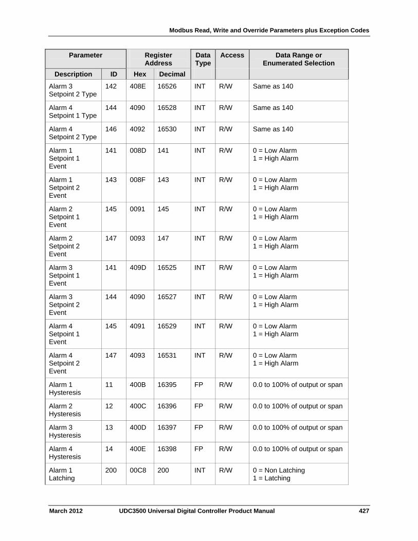
Modbus Read, Write and Override Parameters plus Exception Codes
March 2012 UDC3500 Universal Digital Controller Product Manual 427
Parameter
Register Address
Data Type
Access Data Range or Enumerated Selection
Description ID Hex Decimal
Alarm 3 Setpoint 2 Type
142 408E 16526 INT R/W Same as 140
Alarm 4 Setpoint 1 Type
144 4090 16528 INT R/W Same as 140
Alarm 4 Setpoint 2 Type
146 4092 16530 INT R/W Same as 140
Alarm 1 Setpoint 1 Event
141 008D 141 INT R/W 0 = Low Alarm 1 = High Alarm
Alarm 1 Setpoint 2 Event
143 008F 143 INT R/W 0 = Low Alarm 1 = High Alarm
Alarm 2 Setpoint 1 Event
145 0091 145 INT R/W 0 = Low Alarm 1 = High Alarm
Alarm 2 Setpoint 2 Event
147 0093 147 INT R/W 0 = Low Alarm 1 = High Alarm
Alarm 3 Setpoint 1 Event
141 409D 16525 INT R/W 0 = Low Alarm 1 = High Alarm
Alarm 3 Setpoint 2 Event
144 4090 16527 INT R/W 0 = Low Alarm 1 = High Alarm
Alarm 4 Setpoint 1 Event
145 4091 16529 INT R/W 0 = Low Alarm 1 = High Alarm
Alarm 4 Setpoint 2 Event
147 4093 16531 INT R/W 0 = Low Alarm 1 = High Alarm
Alarm 1 Hysteresis
11 400B 16395 FP R/W 0.0 to 100% of output or span
Alarm 2 Hysteresis
12 400C 16396 FP R/W 0.0 to 100% of output or span
Alarm 3 Hysteresis
13 400D 16397 FP R/W 0.0 to 100% of output or span
Alarm 4 Hysteresis
14 400E 16398 FP R/W 0.0 to 100% of output or span
Alarm 1 Latching
200 00C8 200 INT R/W 0 = Non Latching 1 = Latching
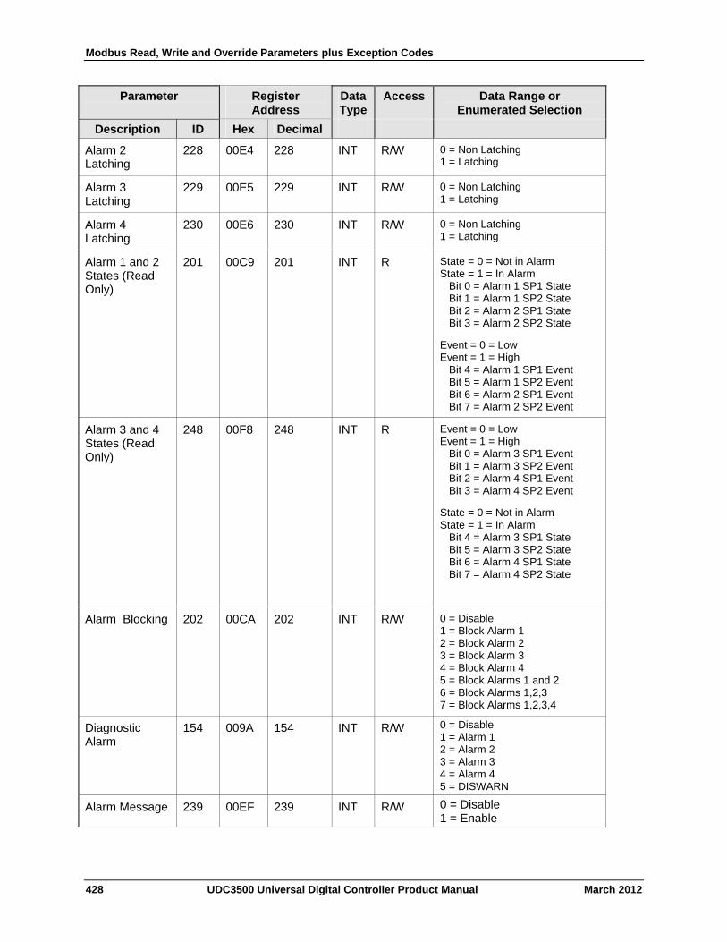
Modbus Read, Write and Override Parameters plus Exception Codes
428 UDC3500 Universal Digital Controller Product Manual March 2012
Parameter
Register Address
Data Type
Access Data Range or Enumerated Selection
Description ID Hex Decimal
Alarm 2 Latching
228 00E4 228 INT R/W 0 = Non Latching 1 = Latching
Alarm 3 Latching
229 00E5 229 INT R/W 0 = Non Latching 1 = Latching
Alarm 4 Latching
230 00E6 230 INT R/W 0 = Non Latching 1 = Latching
Alarm 1 and 2 States (Read Only)
201 00C9 201 INT R State = 0 = Not in Alarm State = 1 = In Alarm Bit 0 = Alarm 1 SP1 State Bit 1 = Alarm 1 SP2 State Bit 2 = Alarm 2 SP1 State Bit 3 = Alarm 2 SP2 State
Event = 0 = Low Event = 1 = High Bit 4 = Alarm 1 SP1 Event Bit 5 = Alarm 1 SP2 Event Bit 6 = Alarm 2 SP1 Event Bit 7 = Alarm 2 SP2 Event
Alarm 3 and 4 States (Read Only)
248 00F8 248 INT R Event = 0 = Low Event = 1 = High Bit 0 = Alarm 3 SP1 Event Bit 1 = Alarm 3 SP2 Event Bit 2 = Alarm 4 SP1 Event Bit 3 = Alarm 4 SP2 Event
State = 0 = Not in Alarm State = 1 = In Alarm Bit 4 = Alarm 3 SP1 State Bit 5 = Alarm 3 SP2 State Bit 6 = Alarm 4 SP1 State Bit 7 = Alarm 4 SP2 State
Alarm Blocking 202 00CA 202 INT R/W 0 = Disable 1 = Block Alarm 1 2 = Block Alarm 2 3 = Block Alarm 3 4 = Block Alarm 4 5 = Block Alarms 1 and 2 6 = Block Alarms 1,2,3 7 = Block Alarms 1,2,3,4
Diagnostic Alarm
154 009A 154 INT R/W 0 = Disable 1 = Alarm 1 2 = Alarm 2 3 = Alarm 3 4 = Alarm 4 5 = DISWARN
Alarm Message 239 00EF 239 INT R/W 0 = Disable 1 = Enable
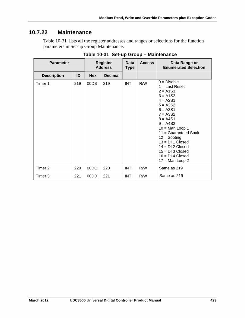
Modbus Read, Write and Override Parameters plus Exception Codes
10.7.22 Maintenance
Table 10-31 lists all the register addresses and ranges or selections for the function parameters in Set-up Group Maintenance.
Table 10-31 Set-up Group – Maintenance
Parameter
Register Address
Data Type
Access Data Range or Enumerated Selection
ID Hex Decimal Description
219 00DB 219 INT R/W 0 = Disable 1 = Last Reset 2 = A1S1 3 = A1S2 4 = A2S1 5 = A2S2 6 = A3S1 7 = A3S2 8 = A4S1 9 = A4S2 10 = Man Loop 1 11 = Guaranteed Soak 12 = Sooting 13 = DI 1 Closed 14 = DI 2 Closed 15 = DI 3 Closed 16 = DI 4 Closed 17 = Man Loop 2
Timer 1
Timer 2 220 00DC 220 INT R/W Same as 219
Timer 3 221 00DD 221 INT R/W Same as 219
March 2012 UDC3500 Universal Digital Controller Product Manual 429
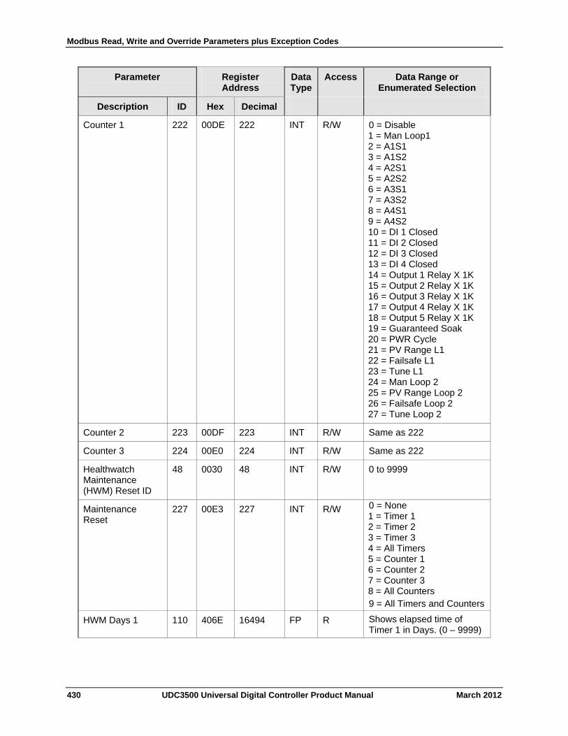
Modbus Read, Write and Override Parameters plus Exception Codes
430 UDC3500 Universal Digital Controller Product Manual March 2012
Parameter
Register Address
Data Type
Access Data Range or Enumerated Selection
Description ID Hex Decimal
Counter 1 222 00DE 222 INT R/W 0 = Disable 1 = Man Loop1 2 = A1S1 3 = A1S2 4 = A2S1 5 = A2S2 6 = A3S1 7 = A3S2 8 = A4S1 9 = A4S2 10 = DI 1 Closed 11 = DI 2 Closed 12 = DI 3 Closed 13 = DI 4 Closed 14 = Output 1 Relay X 1K 15 = Output 2 Relay X 1K 16 = Output 3 Relay X 1K 17 = Output 4 Relay X 1K 18 = Output 5 Relay X 1K 19 = Guaranteed Soak 20 = PWR Cycle 21 = PV Range L1 22 = Failsafe L1 23 = Tune L1 24 = Man Loop 2 25 = PV Range Loop 2 26 = Failsafe Loop 2 27 = Tune Loop 2
Counter 2 223 00DF 223 INT R/W Same as 222
Counter 3 224 00E0 224 INT R/W Same as 222
Healthwatch Maintenance (HWM) Reset ID
48 0030 48 INT R/W 0 to 9999
Maintenance Reset
227 00E3 227 INT R/W 0 = None 1 = Timer 1 2 = Timer 2 3 = Timer 3 4 = All Timers 5 = Counter 1 6 = Counter 2 7 = Counter 3 8 = All Counters 9 = All Timers and Counters
HWM Days 1 110 406E 16494 FP R Shows elapsed time of Timer 1 in Days. (0 – 9999)
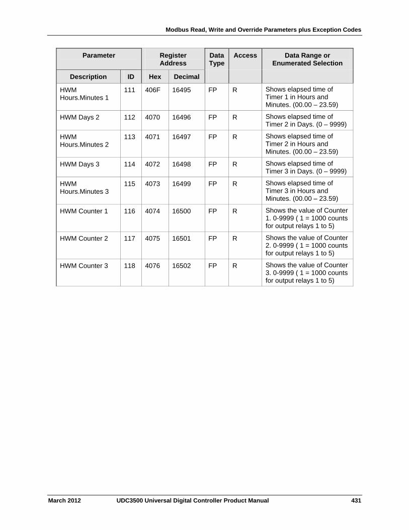
Modbus Read, Write and Override Parameters plus Exception Codes
March 2012 UDC3500 Universal Digital Controller Product Manual 431
Parameter
Register Address
Data Type
Access Data Range or Enumerated Selection
Description ID Hex Decimal
HWM Hours.Minutes 1
111 406F 16495 FP R Shows elapsed time of Timer 1 in Hours and Minutes. (00.00 – 23.59)
HWM Days 2 112 4070 16496 FP R Shows elapsed time of Timer 2 in Days. (0 – 9999)
HWM Hours.Minutes 2
113 4071 16497 FP R Shows elapsed time of Timer 2 in Hours and Minutes. (00.00 – 23.59)
HWM Days 3 114 4072 16498 FP R Shows elapsed time of Timer 3 in Days. (0 – 9999)
HWM Hours.Minutes 3
115 4073 16499 FP R Shows elapsed time of Timer 3 in Hours and Minutes. (00.00 – 23.59)
HWM Counter 1 116 4074 16500 FP R Shows the value of Counter 1. 0-9999 ( 1 = 1000 counts for output relays 1 to 5)
HWM Counter 2 117 4075 16501 FP R Shows the value of Counter 2. 0-9999 ( 1 = 1000 counts for output relays 1 to 5)
HWM Counter 3 118 4076 16502 FP R Shows the value of Counter 3. 0-9999 ( 1 = 1000 counts for output relays 1 to 5)
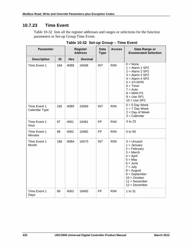
Modbus Read, Write and Override Parameters plus Exception Codes
10.7.23 Time Event
Table 10-32 lists all the register addresses and ranges or selections for the function parameters in Set-up Group Time Event.
Table 10-32 Set-up Group – Time Event
Parameter
Register Address
Data Type
Access Data Range or Enumerated Selection
ID Hex Decimal Description
184 40B8 16568 INT R/W 0 = None 1 = Alarm 1 SP2 2 = Alarm 2 SP2 3 = Alarm 3 SP2 4 = Alarm 4 SP2 5 = STrSP/R 6 = Timer 7 = Auto 8 = MAN FS 9 = Use SP1 10 = Use SP2
Time Event 1
185 40B9 16569 INT R/W 0 = 5 Day Week 1 = 7 Day Week 2 = Day of Week 3 = Calendar
Time Event 1 Calendar Type
97 4061 16481 FP R/W 0 to 23 Time Event 1 Hour
Time Event 1 Minutes
98 4062 16482 FP R/W 0 to 59
Time Event 1 Month
186 40BA 16570 INT R/W 0 = Unused 1 = January 2 = February 3 = March 4 = April 5 = May 6 = June 7 = July 8 = August 9 = September 10 = October 11 = November 12 = December
Time Event 1 Days
99 4063 16483 FP R/W 1 to 31
432 UDC3500 Universal Digital Controller Product Manual March 2012
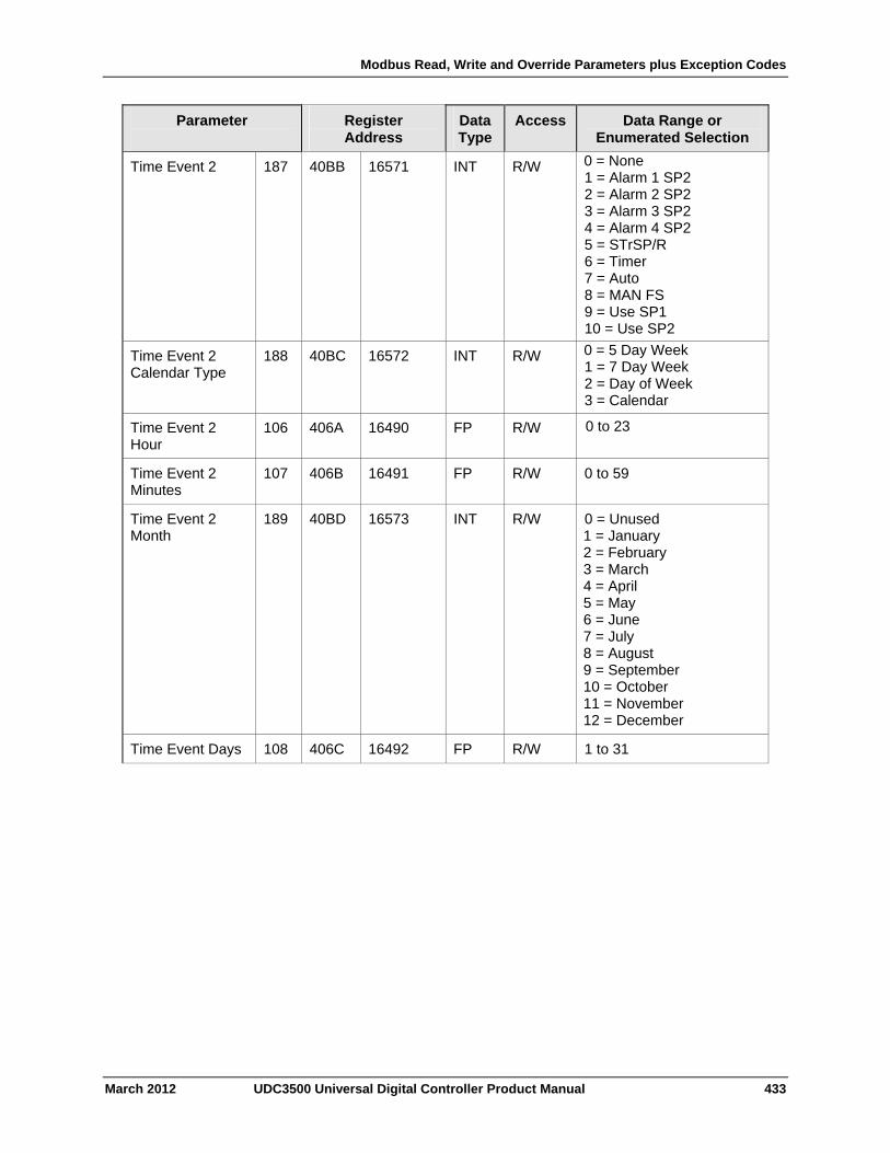
Modbus Read, Write and Override Parameters plus Exception Codes
March 2012 UDC3500 Universal Digital Controller Product Manual 433
Parameter
Register Address
Data Type
Access Data Range or Enumerated Selection
Time Event 2 187 40BB 16571 INT R/W 0 = None 1 = Alarm 1 SP2 2 = Alarm 2 SP2 3 = Alarm 3 SP2 4 = Alarm 4 SP2 5 = STrSP/R 6 = Timer 7 = Auto 8 = MAN FS 9 = Use SP1 10 = Use SP2
Time Event 2 Calendar Type
188 40BC 16572 INT R/W 0 = 5 Day Week 1 = 7 Day Week 2 = Day of Week 3 = Calendar
Time Event 2 Hour
106 406A 16490 FP R/W 0 to 23
Time Event 2 Minutes
107 406B 16491 FP R/W 0 to 59
Time Event 2 Month
189 40BD 16573 INT R/W 0 = Unused 1 = January 2 = February 3 = March 4 = April 5 = May 6 = June 7 = July 8 = August 9 = September 10 = October 11 = November 12 = December
Time Event Days 108 406C 16492 FP R/W 1 to 31
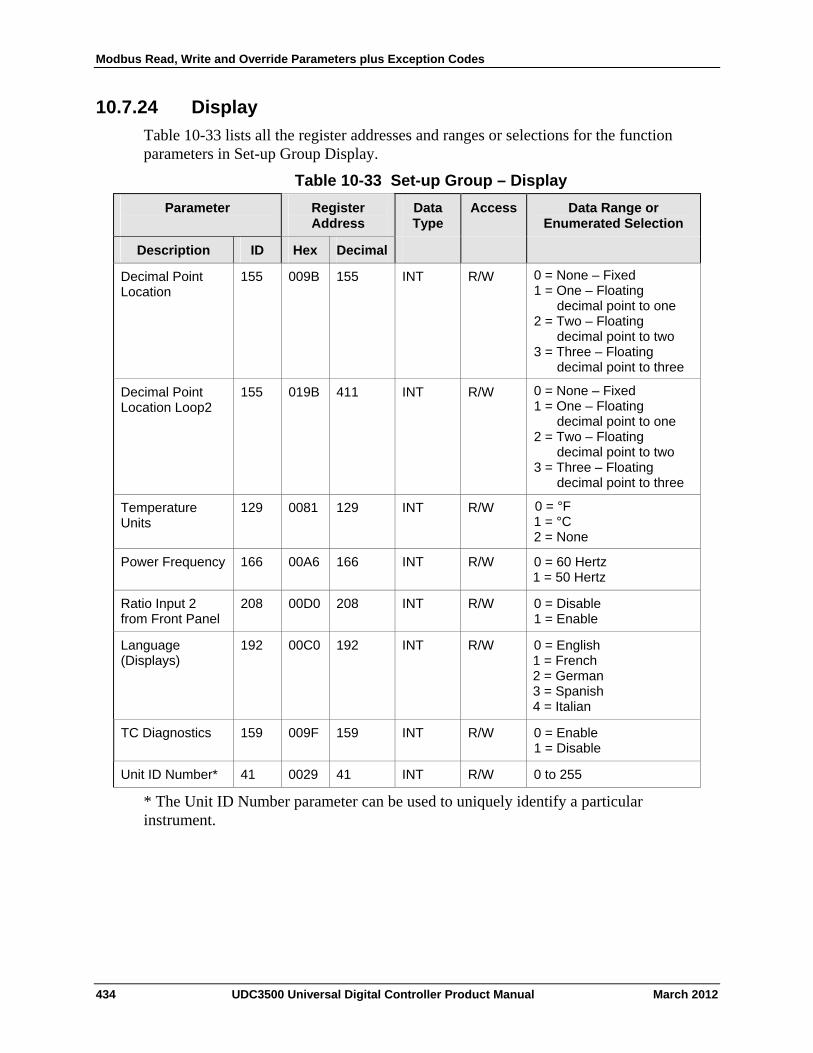
Modbus Read, Write and Override Parameters plus Exception Codes
10.7.24 Display
Table 10-33 lists all the register addresses and ranges or selections for the function parameters in Set-up Group Display.
Table 10-33 Set-up Group – Display
Parameter
Register Address
Data Type
Access Data Range or Enumerated Selection
ID Hex Decimal Description
155 009B 155 INT R/W 0 = None – Fixed 1 = One – Floating
decimal point to one 2 = Two – Floating
decimal point to two 3 = Three – Floating
decimal point to three
Decimal Point Location
155 019B 411 INT R/W 0 = None – Fixed 1 = One – Floating
decimal point to one 2 = Two – Floating
decimal point to two 3 = Three – Floating
decimal point to three
Decimal Point Location Loop2
129 0081 129 INT R/W 0 = °F 1 = °C 2 = None
Temperature Units
Power Frequency 166 00A6 166 INT R/W 0 = 60 Hertz 1 = 50 Hertz
Ratio Input 2 from Front Panel
208 00D0 208 INT R/W 0 = Disable 1 = Enable
Language (Displays)
192 00C0 192 INT R/W 0 = English 1 = French 2 = German 3 = Spanish 4 = Italian
TC Diagnostics 159 009F 159 INT R/W 0 = Enable 1 = Disable
Unit ID Number* 41 0029 41 INT R/W 0 to 255
* The Unit ID Number parameter can be used to uniquely identify a particular instrument.
434 UDC3500 Universal Digital Controller Product Manual March 2012
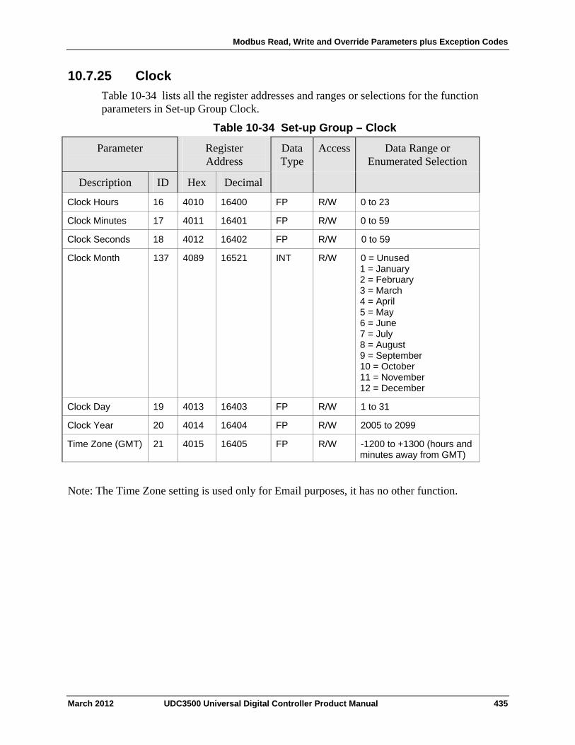
Modbus Read, Write and Override Parameters plus Exception Codes
10.7.25 Clock
Table 10-34 lists all the register addresses and ranges or selections for the function parameters in Set-up Group Clock.
Table 10-34 Set-up Group – Clock
Parameter
Register Address
Data Type
Access Data Range or Enumerated Selection
ID Hex Decimal Description
Clock Hours 16 4010 16400 FP R/W 0 to 23
Clock Minutes 17 4011 16401 FP R/W 0 to 59
Clock Seconds 18 4012 16402 FP R/W 0 to 59
Clock Month 137 4089 16521 INT R/W 0 = Unused 1 = January 2 = February 3 = March 4 = April 5 = May 6 = June 7 = July 8 = August 9 = September 10 = October 11 = November 12 = December
Clock Day 19 4013 16403 FP R/W 1 to 31
Clock Year 20 4014 16404 FP R/W 2005 to 2099
Time Zone (GMT) 21 4015 16405 FP R/W -1200 to +1300 (hours and minutes away from GMT)
Note: The Time Zone setting is used only for Email purposes, it has no other function.
March 2012 UDC3500 Universal Digital Controller Product Manual 435
Modbus Read, Write and Override Parameters plus Exception Codes
10.8 Modbus RTU Exception Codes
Introduction
When a master device sends a query to a slave device it expects a normal response. One of four possible events can occur from the master’s query:
Slave device receives the query without a communication error and can handle the query normally. It returns a normal response.
Slave does not receive the query due to a communication error. No response is returned. The master program will eventually process a time-out condition for the query.
Slave receives the query but detects a communication error (parity, LRC or CRC). No response is returned. The master program will eventually process a time-out condition for the query.
Slave receives the query without a communication error but cannot handle it (i.e., request is to a non-existent coil or register). The slave will return with an exception response informing the master of the nature of the error (Illegal Data Address.)
The exception response message has two fields that differentiate it from a normal response:
Function Code Field: In a normal response, the slave echoes the function code of the original query in the function code field of the response. All function codes have a most-significant bit (MSB) of 0 (their values are below 80 hex). In an exception response, the slave sets the MSB of the function code to 1. This makes the function code value in an exception response exactly 80 hex higher than the value would be for a normal response.
With the function code’s MSB set, the master’s application program can recognize the exception response and can examine the data field for the exception code.
Data Field: In a normal response, the slave may return data or statistics in the data field. In an exception response, the slave returns an exception code in the data field. This defines the slave condition that caused the exception.
436 UDC3500 Universal Digital Controller Product Manual March 2012
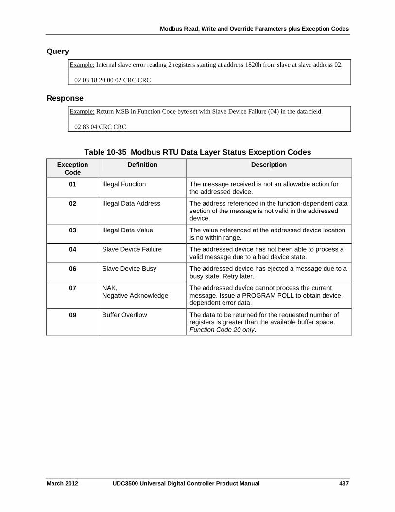
Modbus Read, Write and Override Parameters plus Exception Codes
March 2012 UDC3500 Universal Digital Controller Product Manual 437
Query
Example: Internal slave error reading 2 registers starting at address 1820h from slave at slave address 02. 02 03 18 20 00 02 CRC CRC
Response
Example: Return MSB in Function Code byte set with Slave Device Failure (04) in the data field. 02 83 04 CRC CRC
Table 10-35 Modbus RTU Data Layer Status Exception Codes
Exception Code
Definition Description
01 Illegal Function The message received is not an allowable action for the addressed device.
02 Illegal Data Address The address referenced in the function-dependent data section of the message is not valid in the addressed device.
03 Illegal Data Value The value referenced at the addressed device location is no within range.
04 Slave Device Failure The addressed device has not been able to process a valid message due to a bad device state.
06 Slave Device Busy The addressed device has ejected a message due to a busy state. Retry later.
07 NAK, Negative Acknowledge
The addressed device cannot process the current message. Issue a PROGRAM POLL to obtain device-dependent error data.
09 Buffer Overflow The data to be returned for the requested number of registers is greater than the available buffer space. Function Code 20 only.
Further information
11 Further information
11.1 Modbus RTU Serial Communications
Refer to Honeywell document 51-52-25-66 Modbus RTU Serial Communications User Manual.
11.2 Modbus Messaging on Ethernet TCP/IP
Refer to Honeywell document 51-52-25-121 MODBUS Messaging on Ethernet TCP/IP Implementation Guide.
11.3 How to Apply Digital Instrumentation in Severe Electrical Noise Environments
Refer to Honeywell document 51-52-05-01 How to Apply Digital Instrumentation in Severe Electrical Noise Environments.
438 UDC3500 Universal Digital Controller Product Manual March 2012
Index
12 Index
8 Segment Characterizers ..........................3, 216
A Aborting Accutune...........................................212 Accutune – Register Addresses......................383 Accutune Error Codes.....................................211 Accutune III .................................................5, 204 Accutune Set Up Group ....................................72 Alarm Blocking ................................................171 Alarm Hysteresis .............................................168 Alarm Outputs ...................................................15 Alarm Prompts For Healthwatch Option..........166 Alarm Prompts For Two Loops/Cascade Option
....................................................................165 Alarm Relay Output Failure.............................323 Alarm Relays.....................................................19 Alarm Setpoints...............................................234 Alarm Setpoints Display ..................................234 Alarms.................................................................3 Alarms – Register Addresses..........................421 Alarms For Software Options ..........................165 Alarms Set Up Group......................................164 Algorithm – Register Addresses......................385 Algorithm Set Up Group....................................77 Ambient Temperature .......................................16 Analog Input Failure........................................325 Analog Input Signal Failure Operation ..............13 Analog Inputs ................................................2, 13 Annunciators ...................................................196 Application Related Problems .........................306 Approval Body Options .......................................5 Atmospheric Pressure Compensation...............86 Auto Bias.........................................................145 Auto/Manual Key.............................................195 Auto/Manual Station............................................4 Auto/Manual Station Mode..............................224 Automatic Cascade.........................................200 Automatic Tune...............................................208 Automatic With Local Setpoint ........................200 Automatic With Remote Setpoint ....................200 Autotune Is Complete......................................212 Auxiliary Output...................................................4 Auxiliary Output Range ...................................152
B Background Tests ...........................................309 Baud Rate .......................................................161 Bias................................. 118, 121, 124, 127, 130 Blended Tune..................................................209 Burnout Protection .......... 118, 122, 125, 127, 130
C Calibration Mode.....................................291, 303 Calibration Steps.............................................276 Carbon Potential ...............................86, 240, 241 Carbon Potential .....................................192, 238 Carbon Potential Selections..............................83 Cascade Control .............................................228 CE Conformity (Europe)....................................10
CE Mark ............................................................. 5 Changing Control Modes.................................201 Changing The Local Setpoints ........................202 Characterizer...............................................92, 94 Clock – Register Addresses ............................431 Combinational Inputs ......................................... 3 Communications ................................................ 4 Communications – Register Addresses ..........419 Communications Failure..................................326 Communications Selection..............................160 Communications Set Up Group.......................160 Comparator Gates...........................................217 Computer Setpoint ..........................................353 Computer Setpoint Bias ..................................162 Computer Setpoint Ratio .................................162 Computer Setpoint Units .................................162 Configuration.....................................................43 Configuration Data ..........................................345 Configuration Parameters ...............................356 Configuration Procedure ...................................49 Configuration Prompt Hierarchy ........................45 Configuration Record Sheet ............................184 Control – Register Addresses .........................409 Control 2 Set Up Group...................................141 Control Algorithm ..............................................77 Control And Alarm Relay Contact Information...19 Control Loop 2 – Register Addresses..............412 Control Mode Definitions .................................200 Control Modes.................................................200 Control Relays...................................................19 Control Set Up Group......................................132 Control/Alarm Circuit Wiring ..............................22 Controller Dropoff Value..........................138, 147 Controller Failure Symptoms...........................314 Controller Grounding.........................................22 Controller Output Types ....................................14 Counter ...........................................................174 Current Duplex ........................................106, 109 Current Output ....................................34, 36, 111 Current Output 2 .............................................148 Current Output 3 .............................................152 Current Output Calibration ..............294, 296, 298 Current Output Failure Symptoms...................316 Current Simplex ......................................106, 109 Current/Time Duplex ...............................106, 109 Current/Time Or Time/Current Proportional
Output Failure .............................................322 Customer Support ...........................................307 Cycle Number .................................................350 Cycle Time (Cool) .......................................52, 56 Cycle Time (Heat) .......................................52, 56 Cycles Remaining ...........................................350
March 2012 UDC3500 Universal Digital Controller Product Manual 439
Index
D Data Security ......................................................5 Data Transfer ..................................................345 Deadband ...............................................138, 147 Decimal Point Location ...................................176 Declaration Of Conformity.................................10 Demand Tuning ................................................72 Dewpoint ...........................................84, 192, 238 Diagnostic .......................................................171 Diagnostic Alarm.............................................171 Diagnostic Messages ......................................198 Diagnostic/Failsafe Outputs ................................5 Digital Input (Remote) Operation ....................258 Digital Input Combinations ..............................158 Digital Input Option .........................................219 Digital Input Prompts For Multiple Set Point
Programs ....................................................158 Digital Input Selections....................................153 Digital Inputs .................................................3, 13 Digital Inputs Option Connections.....................40 Digital Output Status ...............................108, 111 Dimensions .......................................................20 Direct Acting Control ...............................137, 146 Display – Register Addresses .........................430 Display Indicators................................................7 Display Set Up Group .....................................176 Dual Relay Output For Time Duplex .................37
E Eight Segment Characterizer ......................92, 94 Elapsed Time ..................................................203 Electrical Considerations...................................22 Electrical Noise Precautions .............................22 Electromechanical Relay Output .................35, 41 Email Configuration Screen ............................182 EMC Classification............................................10 Emissivity ........................................119, 122, 125 Enclosure Rating...............................................10 End Segment Number.....................................245 Environmental And Operating Conditions .........16 Equipment You Will Need To Calibrate...........278 Error Codes.....................................................211 Error Messages...............................................198 Estimated Motor Position ................................236 Ethernet ..............................................................8 Ethernet Communications Address.................272 Ethernet Communications Failure...........328, 329 Ethernet Communications Option With Adaptor
Board ............................................................38 Ethernet Communications Option Without
Adaptor Board...............................................39 Ethernet Configuration Screen........................181 Ethernet Connection .......................................269 Ethernet Status ...............................................264 Ethernet TCP/IP Communications Interface .....15 Ethernet TCP/IP Protocol................................160 External Interface Option Connections..............40 External Setpoint Program Reset....................155 External Wiring..................................................23
F Factory Calibration ..................................291, 303 Failsafe Function Prompt ........................237, 238 Failsafe Manual Mode.....................................308 Failsafe Mode..........................................139, 147 Failsafe Mode..................................................238 Failsafe Output Value..............................139, 147 Failsafe Output Value......................................237 Failsafe Output Value For Restart After A Power
Loss ............................................................237 Failure Modes .................................................... 5 Fast Tune........................................................... 5 Feedforward Multiplier.......................................82 Feedforward Multiplier........................................ 2 Feedforward Summer........................................82 Feedforward Summer......................................... 2 Field Wiring .....................................................278 Filter ................................118, 121, 124, 127, 130 First Current Output Calibration Procedure .....295 Flow Totalizer..................................................216 Frequency (Hz) .................................................16 Function Code 20............................................338 Function Code 21............................................342 Function Codes 20 And 21..............................336 Function Prompts ..............................................45 Fuzzy Logic ........................................................ 6 Fuzzy Overshoot Suppression ..................72, 212
G Gain ............................................................50, 54 Gain 2 .............................................51, 52, 55, 56 Guaranteed Soak ............................................247
H Healthwatch ................................................4, 241 Healthwatch Data............................................265 Healthwatch Data - Reset ...............................266 Healthwatch Timers And Counters..................178 Heat/Cool (Duplex Tune).................................... 6 High Scaling Factor...........................................85 High Select........................................................82 Hlai Inputs 2 And 4 Connections .......................32 Hlai Inputs 3 And 5 Connections .......................33 Hot Start ..................................61, 64, 66, 70, 246 Hydrogen Content .............................................86 Hysteresis (Output Relay) ...............................139
I Identification Number ......................................177 Infrared............................................................... 8 Infrared Communications ................................... 9 Infrared Communications ..................................15 Input 1 – Register Addresses ..........................399 Input 1 Actuation Type ....................................116 Input 1 Calibration Procedure..........................289 Input 1 Connections ..........................................29 Input 1 High Range Value ...............................117 Input 1 Low Range Value ........................118, 121 Input 1 Set Up Group ......................................116 Input 2 – Register Addresses ..........................401 Input 2 Connections ..........................................30 Input 2 Set Up Group ......................................120 Input 3 – Register Addresses ..........................403
440 UDC3500 Universal Digital Controller Product Manual March 2012
Index
Input 3 Actuation Type ....................................123 Input 3 Connections ..........................................31 Input 3 Set Up Group ......................................123 Input 4 – Register Addresses..........................405 Input 4 Actuation Type ....................................126 Input 4 Set Up Group ......................................126 Input 5.............................................................407 Input 5 Actuation Type ....................................129 Input 5 Set Up Group ......................................129 Input Algorithm Selections ..............................215 Input Calibration..............................................275 Input High/Low Select .........................................2 Input Math Algorithms .....................................215 Input Wiring Terminals ....................................278 Installation.........................................................11 Installation Category .........................................10 Installation Related Problems .........................306 Integration Rates.............................................216 Internal Cascade Control: ...............................229 IR Communications Port .................................160 Isolation.............................................................15
J Jumper Positions ..............................................33
K Key Error.........................................................195 Key Lockout ....................................................195 Key Lockout ......................................................53 Keyboard Failure.............................................324 Keys And Functions ............................................7
L Latching ..........................................................238 Line Voltage Wiring...........................................22 Local Area Network (Lan) Settings..................271 Local Setpoint Source.............................135, 144 Lockout .............................................................53 Lockout Feature ..............................................194 Lockout Levels ................................................194 Logic – Register Addresses ............................393 Logic Gate Function........................................217 Logic Gates.........................................................3 Logic Gates Constraints..................................217 Logic Gates Set Up Group ................................98 Loop 2 Output Functionality And Restrictions ...26 Loop Break......................................................165 Loop Data – Alarm Details ..............................260 Loop Data – Digital Input Details.....................261 Loop Data Screen ...........................................259 Loopback Test. ...............................................163 Low Fire ..........................................................157 Low Scaling Factor............................................85 Low Select ........................................................83 Lower Display Key Parameter Prompts...........197
M Mains Power Supply ...................................22, 28 Maintenance
Counters .....................................................173 Timers.........................................................173
Maintenance – Register Addresses ................425 Maintenance Set Up Group.............................173 Manual ............................................................200
Manual Cascade .............................................200 Manual Latching..............................................157 Manual Reset ..............................................51, 55 Manual Tune ...................................................210 Mass Flow Example ..........................................90 Mass Flow Orifice Constant (K) For Math
Selections......................................................85 Math – Register Addresses .............................390 Math Functions................................................... 2 Math Set Up Group ...........................................92 Mechanical Shock .............................................16 Minimum And Maximum Range Values ..........276 Modbus ...........................................................160 Modbus Read, Write And Override Parameters
....................................................................345 Modbus RTU Exception Codes .......................432 Modbus RTU Function Codes .........................336 Model Number Interpretation.............................17 Moisture Protection ............................................ 5 Monitoring And Operating The Controller........192 Monitoring Two-Loop Control ..........................232 Motor Position Display.....................................236 Motor Time......................................................300 Motor Time......................................................108 Mounting ...........................................................20 Mounting Method ..............................................21 Mounting Procedure..........................................21 Multiplier............................................................83 Multiplier Divider................................................83 Multiplier Divider With Square Root ..................83 Multiplier With Square Root...............................83 Multiplier/Divider................................................. 2
N Noise Immunity .................................................. 5 Non-Latching...................................................238
O On/Off Algorithm ...............................................77 Open Collector Output ......................................36 Operating Parameters.....................................197 Operation Of Two-Loop Control ......................233 Operator Interface .......................................6, 193 Option Status ..................................................349 Options – Register Addresses.........................415 Options Set Up Group.....................................148 Output 2 Options ...............................................14 Output Algorithm .....................................105, 108 Output Algorithms – Register Addresses ........397 Output Calibration ...........................................293 Output Change Rate ...............................138, 146 Output Override...............................................233 Output Override (2 Pid Loops Only) ................198 Output Rate Down Value.........................138, 146 Output Rate Limiter ............................................ 5 Output Rate Up Value .............................138, 146 Output Set Up Group ......................................105 Output Types...................................................... 3 Overriding Controller Setpoint .........................353 Oxygen..............................................84, 192, 238
March 2012 UDC3500 Universal Digital Controller Product Manual 441
Index
P,Q P.I.E. Tool .......................................................269 P.I.E. Tool Ethernet And Email Configuration
Screens.......................................................181 P.I.E. Tool Maintenance Screens....................259 Parts Identification ..........................................334 Parts List .........................................................333 Password ........................................................175 Pd With Manual Reset ......................................78 Permissible Wiring Bundling .............................23 Physical Considerations....................................20 PID A ................................................................78 PID B ................................................................78 Pollution Degree ...............................................10 Polynomial Curve Characterizer..........................3 Polynomial Equation .........................................96 Position Proportional Connections ..............11, 37 Position Proportional Control ..........................300 Position Proportional Output Failure ...............318 Position Proportional Simplex .........................106 Power Consumption..........................................15 Power Failure Symptoms ................................316 Power Inrush Current ........................................15 Power Line Frequency ....................................177 Power Outage .................................................258 Power Outage .................................................243 Power Outages ...............................................242 Power-Up Tests ..............................................308 Pre-Installation Information ...............................13 Process Instrument Explorer...............................8 Program Contents...........................................245 Program Record Sheet – Program #1.............249 Program Record Sheet – Program #2.............251 Program Record Sheet – Program #3.............253 Program Record Sheet – Program #4.............255 Program State.................................................245 Program Termination State .............................245 Proportional Band .......................................50, 54 Proportional Band 2 ........................51, 52, 55, 56 Proportional Band Units ..................................139 Purge ..............................................................157 PV Hot Start ....................................................242 PV Tuning .........................................................72
R Ramp Time Or Rate Segments.......................246 Ramp/Soak Profile Example ...........................248 Rate ............................................................50, 54 Rate 2 .............................................51, 52, 55, 56 Rate Down Value ..............................................59 Rate Up Value...................................................59 Ratio ...............................118, 121, 124, 127, 130 Read Maintenance Set Up Group ...................178 Read Onlys .....................................................350 Read Software Options Status........................349 Reading Control Data......................................348 Real Time Clock..........................................4, 268 Real Time Clock Set Up Group.......................172 Recycle Number..............................................245 Register Address Structure .............................337 Register Count ................................................337 Relative Humidity ........................................82, 86
Relative Humidity ..............................................16 Remote Setpoint Source .................................144 Remote Switching ...........................................219 Removing The Chassis ...................................335 Rerun Current Segment ..................................246 Reset...........................................................51, 55 Reset 2............................................51, 52, 55, 56 Reset Program To Beginning ..........................245 Reset Totalizer ................................................157 Reset Totalizer Value......................................221 Reset Type......................................................175 Reset Units......................................................140 Restore Factory Calibration.............................291 Restore Factory Output Calibration.................303 Restoring Factory Configuration......................330 Reverse Acting Control ...........................137, 146 RS 485 ............................................................... 8 RS-422/485 Communications Option
Connections ..................................................38 RS422/485 Modbus Rtu Communications
Interface ........................................................15 RS-485 And Ethernet Transaction Rates ..........15 RTD Inputs......................................................282 Run/Hold Key ..................................................195 Run/Hold Key ..................................................242 Run/Monitor The Program...............................257
S Second Current Output Calibration Procedure297 Second Current Output Range........................152 Security .............................................................. 5 Security Code............................................52, 193 Segment Time Remaining In Hours ................350 Set Point Select Function Key.........................195 Set Up Group ....................................................45 Set Up Wiring Procedure For Auxiliary Output 296 Set Up Wiring Procedure For Third Current
Output .........................................................298 Setpoint Code Selections ................................351 Setpoint High Limit ..................................137, 146 Setpoint Low Limit ...................................137, 146 Setpoint Program Event Alarms ......................258 Setpoint Program Number...............................197 Setpoint Program Read Only ..........................350 Setpoint Program Selection.............................158 Setpoint Programming Event Alarms ..............235 Setpoint Programming-Enhanced ...................... 5 Setpoint Ramp ..................................................58 Setpoint Ramp ................................................242 Setpoint Ramp Final Setpoint............................58 Setpoint Ramp Time .........................................58 Setpoint Ramp/Soak Programming.............5, 244 Setpoint Rate ....................................................58 Setpoint Rate ..............................................5, 242 Setpoint Tracking ............................................145 Setpoints .............................................4, 201, 351 Shed Time.......................................................161 Shed Timer Reset ...........................................354 Slowtune ............................................................ 5 Soak Segments...............................................247 Software Type .................................................350 Software Upgrade Part Number ......................332 Software Upgrades..................................331, 335
442 UDC3500 Universal Digital Controller Product Manual March 2012
Index
March 2012 UDC3500 Universal Digital Controller Product Manual 443
Software Version.............................................350 Software Version Number ...............................307 Solid State Relay Output...................................35 SP Ramp Set Up Group..................57, 63, 66, 69 SP Ramp/Rate/Program#1 – Register Addresses
....................................................................359 SP Ramp/Rate/Program#2 – Register Addresses
....................................................................365 SP Ramp/Rate/Program#3 – Register Addresses
....................................................................371 SP Ramp/Rate/Program#4 – Register Addresses
....................................................................377 SP Tuning .........................................................72 Specifications....................................................13 Start Segment Number ...................................245 Start Up Procedure For Operation ..................199 Status Data .....................................................262 Status Data – Diagnostics History...................263 Status Tests ....................................................308 Stray Rejection..................................................13 Summer With Ratio And Bias............................82 Summer/Subtractor .............................................2 Suppression Devices ........................................23 Switch Between Two Sets Via Keyboard ........214 Switching Between Setpoints ..........................202 Switchover Value ............................................144
T Temperature Units ..........................................176 Test Failures ...................................................308 Thermocouple Diagnostic Messages ..............177 Thermocouple Health..........................................2 Thermocouple Inputs Using A Thermocouple
Source.........................................................281 Thermocouple Inputs Using An Ice Bath.........280 Third Current Output Calibration Procedure....299 Third Current Output Range............................152 Three Position Control Step Output Start-Up
Mode...........................................................137 Three Position Step ..........................................79 Three Position Step Control ......................37, 300 Three Position Step Control Algorithm............236 Three Position Step Test Failures...................308 Three Relay Board............................................14 Time Current Duplex...............................106, 109 Time Duplex............................................106, 109 Time Event – Register Addresses...................428 Time Events Set Up Group .............................179 Time Proportional Output ................105, 106, 109 Time Proportional Output Failure ....................321 Time Remaining..............................................203 Time Simplex ..........................................105, 109 Time-Out .........................................................203 Timer.............................................4, 80, 173, 203 Totalizer ..............................................................3 Totalizer Data..................................................267 Totalizer Displays............................................216
Totalizer Function........................................80, 95 Totalizer Reset Via Digital Input ......................217 Transmitter Characterization ..117, 121, 124, 126,
129 Transmitter Power.............................................. 4 Transmitter Power For 4-20 Ma ............11, 41, 42 Troubleshooting Aids ......................................306 Troubleshooting Procedures ...........................315 Troubleshooting/Service..................................305 Tune................................................................205 Tune For Duplex (Heat/Cool) ..........................207 Tune For Simplex Outputs ..............................206 Tuning .........................................................50, 54 Tuning Constants ............................................... 5 Tuning Indicators.............................................204 Tuning Loop 1 – Register Addresses ..............356 Tuning Loop 2 – Register Addresses ..............358 Tuning Parameter Sets ...................................132 Tuning Parameter Sets—Loop 2.....................141 Tuning Set Up Group ..................................50, 54 Two Loops Of Control .....................................228 Two Sets Of Tuning Constants .......................213 TX Delay .........................................................161
U Universal Output Functionality And Restrictions
................................................................24, 25 Universal Switching Power ................................. 4
V Vibration............................................................16 Voltage And Resistance Equivalents For 0% And
100% Range Values....................................276
W,X,Y,Z Weight...............................................................15 Weighted Average.............................................. 2 Weighted Average Ratio ...................................85 Wiring................................................................22 Wiring Bundling .................................................23 Wiring Connections For Calibrating The First
Current Output ............................................294 Wiring Connections For Calibrating The Second
Current Output ............................................296 Wiring Connections For Calibrating Third Current
Output .........................................................298 Wiring Connections For Dual High Level
Milliampere Inputs .......................................288 Wiring Connections For Radiamatic, Milliampere,
Millivolts, Or Volts (Except 0 To 10 Volts) ..283, 286, 287
Wiring Connections For RTD (Resistance Thermometer Device) .................................282
Wiring Diagrams................................................24 Wiring The Controller ........................................27 Worksheet .......................................................244 WS Float .........................................................161

Index
444 UDC3500 Universal Digital Controller Product Manual March 2012
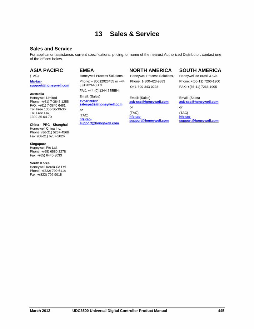
13 Sales & Service
Sales and Service For application assistance, current specifications, pricing, or name of the nearest Authorized Distributor, contact one of the offices below.
ASIA PACIFIC (TAC)
Australia Honeywell Limited Phone: +(61) 7-3846 1255 FAX: +(61) 7-3840 6481 Toll Free 1300-36-39-36 Toll Free Fax: 1300-36-04-70 China – PRC - Shanghai Honeywell China Inc. Phone: (86-21) 5257-4568 Fax: (86-21) 6237-2826 Singapore Honeywell Pte Ltd. Phone: +(65) 6580 3278 Fax: +(65) 6445-3033 South Korea Honeywell Korea Co Ltd Phone: +(822) 799 6114 Fax: +(822) 792 9015
EMEA Honeywell Process Solutions,
Phone: + 80012026455 or +44 (0)1202645583
FAX: +44 (0) 1344 655554
Email: (Sales) [email protected]
or
(TAC) [email protected]
NORTH AMERICA Honeywell Process Solutions,
Phone: 1-800-423-9883
Or 1-800-343-0228
Email: (Sales) [email protected]
or
(TAC) [email protected]
SOUTH AMERICA Honeywell do Brasil & Cia
Phone: +(55-11) 7266-1900
FAX: +(55-11) 7266-1905
Email: (Sales) [email protected]
or
(TAC) [email protected]
March 2012 UDC3500 Universal Digital Controller Product Manual 445

Honeywell Process Solutions 1860 West Rose Garden Lane 51-52-25-120 Revision 4 Phoenix, Arizona 85027 March 2012 www.honeywellprocess.com 2012 Honeywell International Inc.