Embed Size (px)
DESCRIPTION
Design of Underground Power Distribution Systems
Citation preview
Underground Distribution Schemes
Fifth Edition
Revision 2
August 2007

Underground Distribution Schemes Fifth Edition - Revision 2 August 2007
BLANK PAGE
Underground Distribution Schemes Fifth Edition - Revision 2 August 2007
Page i
This electronic media based document is uncontrolled when printed.
To ensure you are using the most current version, please refer to the web based document.
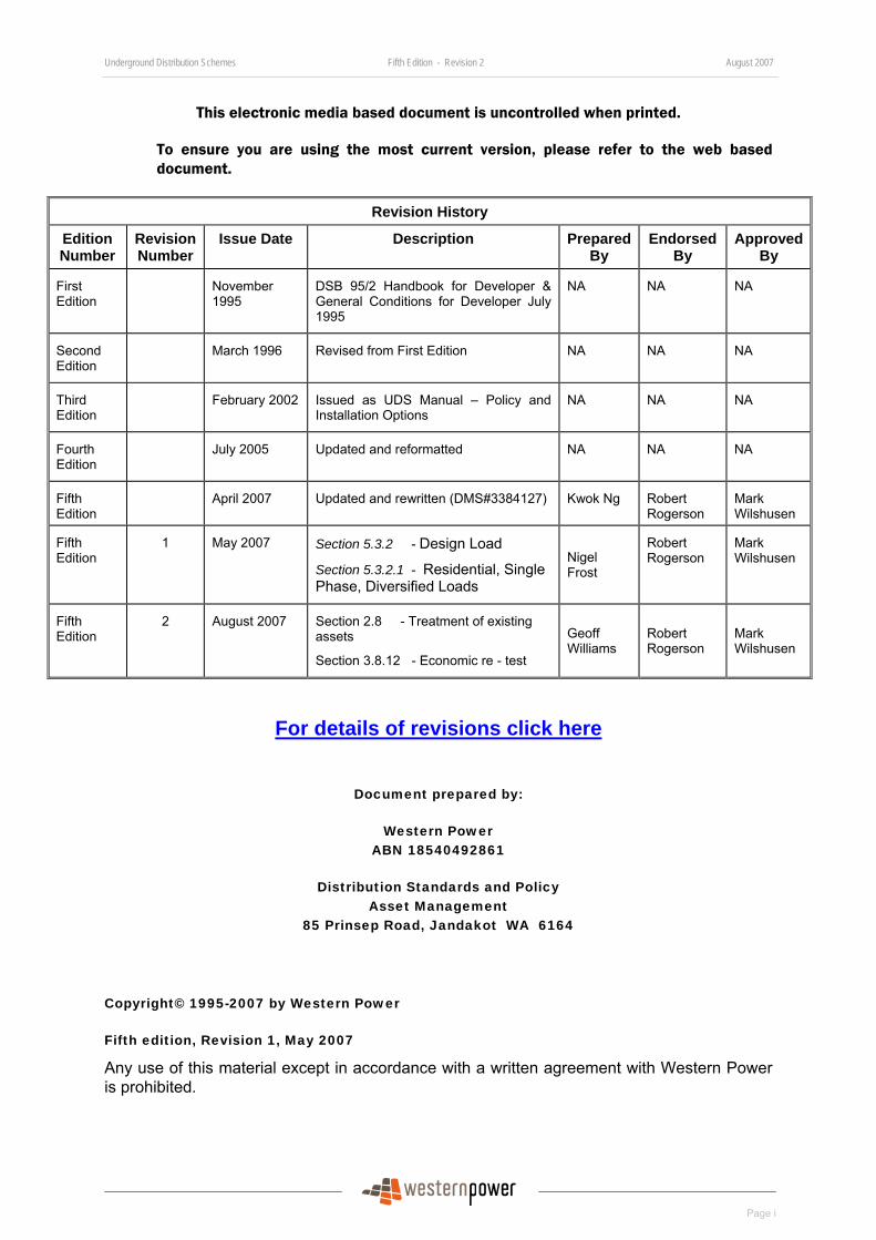
Revision History
Edition Number
Revision Number
Issue Date Description Prepared By
Endorsed By
Approved By
First Edition
November 1995
DSB 95/2 Handbook for Developer & General Conditions for Developer July 1995
NA NA
NA
Second Edition
March 1996 Revised from First Edition NA NA NA
Third Edition
February 2002 Issued as UDS Manual – Policy and Installation Options
NA NA NA
Fourth Edition
July 2005 Updated and reformatted NA NA NA
Fifth Edition
April 2007 Updated and rewritten (DMS#3384127) Kwok Ng Robert Rogerson
Mark Wilshusen
Fifth Edition
1 May 2007 Section 5.3.2 - Design Load
Section 5.3.2.1 - Residential, Single Phase, Diversified Loads
Nigel Frost
Robert Rogerson
Mark Wilshusen
Fifth Edition
2 August 2007 Section 2.8 - Treatment of existing assets
Section 3.8.12 - Economic re - test
Geoff Williams
Robert Rogerson
Mark Wilshusen
For details of revisions click here
Document prepared by:
Western Power ABN 18540492861
Distribution Standards and Policy Asset Management
85 Prinsep Road, Jandakot WA 6164
Copyright© 1995-2007 by Western Power
Fifth edition, Revision 1, May 2007
Any use of this material except in accordance with a written agreement with Western Power is prohibited.

Underground Distribution Schemes Fifth Edition - Revision 2 August 2007
Page ii
BLANK PAGE
Underground Distribution Schemes Fifth Edition - Revision 2 August 2007
Page iii
FOREWORD
Welcome to the fifth edition of Western Power’s Underground Distribution Schemes (UDS) Manual.
There have been significant changes to the land subdivision process since the UDS Manual was first issued in November 1995. Western Power and industry recognised the need for a major revision to align the manual with these changes. As a result, this latest edition is the most significant revision since the manual was first released and reflects all aspects of Western Power’s involvement in the land development process – for both large and small subdivisions.
This new edition is designed to provide flexibility and allow easy inclusion of any future changes. The Manual has independent stand-alone sections for policies, processes, design requirements, installation requirements and materials and is now supported by Western Power’s web page. This allows the user to quickly access other Western Power documents referenced including our Distribution Design Catalogue (DDC), Distribution Substation Manual (DSM), Testing and Commissioning Standard (NS 07) and Underground Cable Installation Standard (NS 14).
In developing this latest edition Western Power has worked closely with industry groups to ensure it meets their needs. I would like to acknowledge the valuable input from such groups, including the Urban Development Institute of Australia, the Civil Contractors Federation, the Subdivision Designers Forum, and the Western Australian Planning Commission.
The information in the new edition is intended to be useful to all stakeholders and I hope you find it easy to read and understand. It reflects Western Power’s commitment to continuous improvement and our desire to work closely with all participants in the land development industry. In keeping with this, I would value your feedback on any aspect of this manual.
Mark Wilshusen Manager Standards, Policy and Data Quality Western Power

Underground Distribution Schemes Fifth Edition - Revision 2 August 2007
Page iv
BLANK PAGE
Underground Distribution Schemes Fifth Edition - Revision 2 August 2007
Page v
Table of Contents
1 Introduction ..................................................................................................................... 1
1.1 Purpose ................................................................................................................. 1 1.2 Definitions .............................................................................................................. 1 1.3 Scope ................................................................................................................. 4 1.4 Roles and Responsibilities of Developers ............................................................. 4 1.5 Roles and Responsibilities of Western Power ....................................................... 5 1.6 Types of Subdivisions............................................................................................ 5
1.6.1 Subdivision Types based on Land Use and Classification...................................5 1.6.2 Subdivision Groupings..........................................................................................5
1.7 The Land Development Process with reference to Western Power and WAPC.... 6 1.7.1 High Level Land Development Process for Subdivisions that require WAPC
Clearance .............................................................................................................6 1.8 Non-WAPC Referred Subdivisions ........................................................................ 9
2 General Design Policies................................................................................................ 10
2.1 Western Power’s Policy and Design Principles of Network Extension in Subdivision ............................................................................................................... 10
2.1.1 Safety..................................................................................................................10 2.1.2 Extension of High Voltage Feeders for Now and Future....................................10 2.1.3 Power Quality .....................................................................................................11 2.1.4 Network Reliability ..............................................................................................12 2.1.5 Network Maintainability.......................................................................................12 2.1.6 Environmental Management ..............................................................................12 2.1.7 Meeting Community Expectation........................................................................12
2.2 Underground Power............................................................................................. 12 2.3 Three Phase Power ............................................................................................. 13 2.4 Headworks to Subdivisions.................................................................................. 13 2.5 Increasing Overhead Transformers and Switchgear ........................................... 13 2.6 Network Capacity Augmentation ......................................................................... 13 2.7 Future Transmission Power Equipment............................................................... 14 2.8 Treatment of Existing Assets within or adjacent to a Subdivision.............................. 14
2.8.1 Transmission Power Lines (i.e. operating at 66KV or above)............................14 2.8.2 Distribution power lines that traverse lots of size 10 hectares or less ...............15 2.8.3 Distribution Power Lines that traverse lot of sizes greater than 10 hectares .....17 2.8.4 Cost Responsibilities ..........................................................................................17 2.8.5 Basis/Philosophy ................................................................................................17
2.9 Associated Publications....................................................................................... 18
Underground Distribution Schemes Fifth Edition - Revision 2 August 2007
Page vi
3 General Charging Policies ............................................................................................ 19
3.1 Headworks Extension, Removal, Relocation or Upgrades .................................. 19 3.2 Small Residential Subdivision in Existing Underground Areas (not more than four lots of any sizes) ........................................................................................................... 19 3.3 Small Residential Subdivision in Existing Overhead Areas (not more than 4 lots) ............................................................................................................... 19 3.4 Large Subdivision of Residential Lots of size of 1000m² or Less in Urban Area ............................................................................................................... 20 3.5 Large Subdivision of Residential Lots of Size Greater than 1000m² in Urban Area and Area Zoned “Rural” or “Special Rural” (Broadacre Subdivision)............................ 20 3.6 Commercial and Industrial Subdivisions.............................................................. 21 3.7 Changes to Existing Assets that need to be Altered............................................ 21 3.8 High Voltage Pool Policy and Operation.............................................................. 21
3.8.1 Background History ............................................................................................21 3.8.2 High Voltage Pool Administration.......................................................................22 3.8.3 System Charge...................................................................................................22 3.8.4 Subdivision Design Load....................................................................................22 3.8.5 Schedule of Rates ..............................................................................................23 3.8.6 HV Pool Charge..................................................................................................23 3.8.7 HV Pool Payment ...............................................................................................23 3.8.8 High Voltage Pool Mechanism ...........................................................................23 3.8.9 Subdivisions and Assets included in HV Pool....................................................24 3.8.10 Subdivisions and Assets excluded from HV Pool ..............................................24 3.8.11 Economic Test....................................................................................................25 3.8.12 Economic Re-Test ..............................................................................................26
4 Land Development Process.......................................................................................... 27
4.1 Western Australian Planning Commission Subdivision Process ......................... 27 4.1.1 WAPC Subdivision Process ...............................................................................27 4.1.2 Conditions of Subdivision Development.............................................................28 4.1.3 When will Western Power issue a Clearance Certificate on WAPC
Applications? ......................................................................................................29 4.1.4 How can Western Power Conditions be met?....................................................29 4.1.5 Clearance Request Submission .........................................................................30 4.1.6 Clearance of Special Subdivision Lots ...............................................................31 4.1.7 Clearance Charges.............................................................................................32 4.1.8 Electronic Land Development Process (eLDP)..................................................32
4.2 Development of Small Subdivision up to Four Lots ............................................. 32 4.2.1 Process Detail ....................................................................................................34 4.2.2 Western Power’s responsibility ..........................................................................34
Underground Distribution Schemes Fifth Edition - Revision 2 August 2007
Page vii
4.2.3 Developer’s responsibility...................................................................................35 4.3 Development of Large Subdivision of more than Four Lots................................. 35
4.3.1 Process...............................................................................................................36 4.3.2 Process Detail ....................................................................................................37 4.3.3 Developer’s Responsibilities ..............................................................................39 4.3.4 Western Power’s Responsibilities ......................................................................41 4.3.5 Charges and Refunds.........................................................................................41
4.4 Western Power Designer Information.................................................................. 43 4.4.1 Request for Design Information Package...........................................................43 4.4.2 Design Information Package (DIP).....................................................................43 4.4.3 Information for Feasibility Studies ......................................................................44 4.4.4 Submission Requirements of Design for Design Conformance Review ............45 4.4.5 Revision of Design Due to Major and Minor Changes While Under
Construction .......................................................................................................46 4.5 Submission for DCR with Approved Non Standard Equipment ........................... 47
4.5.1 Prior to DCR and Quote Issued by Western Power ...........................................47 4.5.2 After DCR and Quote Issued by Western Power ...............................................48
4.6 Dispute Resolution Process................................................................................. 48
5 Design Policy and Requirements.................................................................................. 50
5.1 Designer qualification and experience................................................................. 50 5.1.1 Engineer .............................................................................................................50 5.1.2 Designer .............................................................................................................50 5.1.3 Designer Organisation........................................................................................50
5.2 Engineer’s, Designer’s and Designer Organisation’s Responsibilities................. 51 5.2.1 Engineer’s Responsibility ...................................................................................51 5.2.2 Designer’s Responsibility ...................................................................................51 5.2.3 Designer Organisation’s Responsibilities ...........................................................51
5.3 Design Requirements .......................................................................................... 52 5.3.1 Environmental and Aboriginal Considerations ...................................................52 5.3.2 Design Load .......................................................................................................52 5.3.3 General Locations of all above Ground Asset....................................................54 5.3.4 Point of Supply ...................................................................................................54 5.3.5 Service Pillar Location........................................................................................55 5.3.6 Service Pillar Exclusion Zone.............................................................................55 5.3.7 HV Cables ..........................................................................................................55 5.3.8 LV Cables ...........................................................................................................56 5.3.9 Cable Alignment .................................................................................................56 5.3.10 Number of Cables Permitted within Nominal Cable Alignment in Green Field
Areas ..................................................................................................................56 5.3.11 Ducts...................................................................................................................57
Underground Distribution Schemes Fifth Edition - Revision 2 August 2007
Page viii
5.3.12 Cables and Electrical Services in Access Lanes and Laneways .......................57 5.3.13 Cable Near to Retaining Walls ...........................................................................58 5.3.14 Cable Easement .................................................................................................58 5.3.15 Water Course and Drains...................................................................................59 5.3.16 Transformers and Size .......................................................................................59 5.3.17 HV Breech Joints................................................................................................60 5.3.18 Substation Site ...................................................................................................60 5.3.19 HV Earths Near to Telstra Equipment ................................................................61 5.3.20 HV Cables and Earths in Proximity of Steel Gas Pipes .....................................61 5.3.21 Low Voltage Feeder Design Criteria ..................................................................61 5.3.22 Uni-pillars in Low Voltage Feeder ......................................................................62 5.3.23 Load and Network Connection on a LV Spur.....................................................62 5.3.24 Electrical Requirements for Motor/Pump Starting ..............................................63 5.3.25 Streetlighting.......................................................................................................63 5.3.26 Underground Transmission Protection Pilot Cables ..........................................66 5.3.27 Existing Customers and Affected Parties...........................................................66 5.3.28 Subdivision Design Drawing Requirements .......................................................67 5.3.29 Published Design Requirements and Guidelines...............................................67 5.3.30 Variations to WP Designs or Standards .............................................................67
5.4 Design for 63KV, 3 Phase, Ground Mounted Transformer.................................. 68 5.4.1 Application ..........................................................................................................68 5.4.2 Design Aspects and Philosophy.........................................................................68 5.4.3 HV Connection ...................................................................................................68 5.4.4 LV Connection ....................................................................................................69
5.5 Single Phase Underground Distribution System (SPUDS).................................. 70 5.6 Design Documents .............................................................................................. 71
5.6.1 WP Design Manual/Policy (available online)......................................................71 5.6.2 WP Design Manual/Policy ..................................................................................71 5.6.3 WP Design Software ..........................................................................................72 5.6.4 Associated Publications......................................................................................72
6 Installation Policy and Requirements............................................................................ 73
6.1 Small Subdivision (i.e. not more than four Lots) .................................................. 73 6.1.1 Installation Policy................................................................................................73 6.1.2 Installation Process and Responsibilities ...........................................................73
6.2 Large Subdivision (i.e. more than Four Lots)....................................................... 73 6.2.1 Installation Option A Process and Responsibilities ............................................74 6.2.2 Installation Option B Process and Responsibilities ............................................76 6.2.3 UDS Workplace ..................................................................................................77 6.2.4 Construction Administration ...............................................................................77
Underground Distribution Schemes Fifth Edition - Revision 2 August 2007
Page ix
6.2.5 Time of Completion of Installation Option B Subdivision Where Early Clearance is Provided..........................................................................................................84
6.2.6 Warranty .............................................................................................................84 6.2.7 Ownership and Responsibilities for Equipment..................................................85 6.2.8 Tests ...................................................................................................................85 6.2.9 Installer Requirements, Qualifications and Responsibilities...............................85 6.2.10 Construction Requirements and Standards .......................................................89 6.2.11 Installation Document .........................................................................................98
7 Materials and Equipment .............................................................................................. 99
7.1 Materials & Equipment for Installation Option A .................................................. 99 7.1.1 Process of Option A Material Collection.............................................................99 7.1.2 Pick Up ...............................................................................................................99 7.1.3 Materials Collection Authority...........................................................................100 7.1.4 Return of Unused Cables .................................................................................100 7.1.5 Responsibility for Security and Damage ..........................................................100
7.2 Materials & Equipment for Installation Option B ................................................ 100 7.2.1 Direct Purchase from WP Logistic....................................................................100 7.2.2 Process for Ordering from WP Logistic ............................................................100 7.2.3 Process of Option B Material Collection...........................................................101 7.2.4 Responsibility for Security and Damage ..........................................................101
7.3 Materials Hotline ................................................................................................ 101 7.4 Standard Streetlight Materials List..................................................................... 102 7.5 Alternative Materials and Equipment for Installation Option B........................... 102
7.5.1 Process Overview.............................................................................................102 7.5.2 Approval Review Process.................................................................................103 7.5.3 Application for equipment approval ..................................................................103 7.5.4 Certificate of Approval of Equipment................................................................103 7.5.5 Notification of use of approved alternative equipment for Subdivision ..........103 7.5.6 Spares for Alternative Materials and Equipment in Subdivision ......................104 7.5.7 List of Existing Approved Alternative Equipment .............................................104
Underground Distribution Schemes Fifth Edition - Revision 2 August 2007
Page x
List of Appendices Appendix 1 - Map of the South West Interconnected System............................................................. 106
Appendix 2 - Developer’s Authorisation and Design Information Package Request .......................... 107
Appendix 3 - Request for Variation to Western Power Design or Standard ....................................... 110
Appendix 4 -Design Information Package Check List ......................................................................... 111
Appendix 5 - Conformance Checklist .................................................................................................. 114
Appendix 6 - Subdivision Design Submission NPER Engineer Certification ...................................... 117
Appendix 7 - Subdivision Design Drawing Minimum Requirements ................................................... 119
Appendix 8 - Decorative Street Lights Approval Form ........................................................................ 122
Appendix 9 - Cable Duct Specification ................................................................................................ 124
Appendix 10 - Placement of Duct where Cable crosses Water Course or Open Drains .................... 125
Appendix 11 - Cross Section Details of Cable Encasement ............................................................... 126
Appendix 12 - Installer Identification Tag ............................................................................................ 127
Appendix 13 - Sample Operational Label............................................................................................ 128
Appendix 14 - HV Cable Joint Schedule ............................................................................................. 129
Appendix 15 - Test Schedules ............................................................................................................ 130
Appendix 16 - Site Inspection Schedule.............................................................................................. 136
Appendix 17 - Site Inspection Reports ................................................................................................ 137
Appendix 18 - Completion Check List ................................................................................................. 145
Appendix 19 - Handover Certificate .................................................................................................... 146
Appendix 20 - Terms & Conditions of Sale of Materials...................................................................... 147
Appendix 21 - Material Collections Authority....................................................................................... 150
Appendix 22 - Equipment Drawings .................................................................................................... 151
Underground Distribution Schemes Fifth Edition - Revision 2 August 2007
Page xi
List of Figures Figure 1: Land Development Process .................................................................................................... 7
Figure 2: Small Subdivision Process WAPC Approval Not Required .................................................... 9
Figure 3: Y Split and non Y Split Feeder Configurations....................................................................... 11
Figure 4: Development Process for Small Subdivisions ....................................................................... 33
Figure 5: Development Process for Large Subdivisions ....................................................................... 37
Figure 6: Dispute Resolution Process ................................................................................................... 49
Figure 7: Option A Material Delivery ..................................................................................................... 99
Figure 8: Option B Materials Delivery.................................................................................................. 101
Figure 9: Map of the South West Interconnected System................................................................... 106
Figure 10: Placement of Duct where Cable crosses Water Course or Open Drain ............................ 125
Figure 11: Cross Section Details of Cable Encasement ..................................................................... 126
Figure 12: Installer Identification Tag .................................................................................................. 127
Figure 13: Sample Operational Label.................................................................................................. 128
Figure 14: URD Mini Pillar Installation Guide...................................................................................... 153
Figure 15: Mini Pillar Wavecon Working End...................................................................................... 154
Figure 16: UDS Universal Pillar Installation Detailsj ........................................................................... 155
Figure 17: Cable to LV Isolators Crossarm & Cable Length ............................................................... 156
Figure 18: Cable to LV Bare Direct Connected................................................................................... 157
Figure 19: ABC Fused Connection to Cable ....................................................................................... 158
Figure 20: LV Cable to Fuse Switch.................................................................................................... 159
Figure 21: Substation Ducting Cross Section – Civil Requirements ................................................... 162
Figure 22: Substation Ducting Cross Section – Civil Requirements (Sheet 2) ................................... 163
Figure 23: Street Light Cutout, Single Phase Supply.......................................................................... 165
Figure 24: Street Light Cutout, Single Phase Supply for Class II Luminaires..................................... 166
Figure 25: Street Light Cutout Connection Arrangement for Electrical Attachment............................ 167
Figure 26: Fusing Arrangement for Street Light Columns................................................................... 168
Figure 27: Mini Pillar Terminal Block Termination Details (Street Light)............................................. 169
Figure 28: Cable Trench Layout (Sheets 1 to 7) ................................................................................. 171
Figure 29 - Cable and Duct Placements on Truncations: ................................................................... 178
Underground Distribution Schemes Fifth Edition - Revision 2 August 2007
Page xii
List of Tables
Table 1: Summary of Conditions of Subdivision Development ............................................................. 28
Table 2 - Process Detail for Small Subdivisions.................................................................................... 34
Table 3: Required DIP Request Information ......................................................................................... 43
Table 4: Design Information Package ................................................................................................... 44
Table 5: Submission Requirements of Design for DCR ........................................................................ 45
Table 6: Minimum ADMD Values (kVA) ................................................................................................ 53
Table 7: Cable Duct Sizes..................................................................................................................... 57
Table 8: Transformers and Sizes .......................................................................................................... 59
Table 9: Design Aspects and Philosophy of 63kVA Transformer ......................................................... 68
Table 10: Option A Process & Responsibilities..................................................................................... 75
Table 11: Option B Process & Responsibilities..................................................................................... 76
Table 12: Partial Bond Refund Milestones............................................................................................ 84
Table 13 - UDS Installer Qualification Requirement ............................................................................ 88
Table 14: Approval Review Process for Non-Standard Equipment .................................................... 103
Underground Distribution Schemes Fifth Edition - Revision 2 August 2007
Page xiii
Enquiries and Contacts
Western Power welcomes any comments you may have to help us maintain and improve this document.
If you have any comments or queries please contact the Customer Service Centre on 13 10 87 or make an enquiry on-line through:
http://www.westernpower.com.au/mainContent/connectionsUpgrades/policiesRegulations/udsFeedback.html.
Subscribe On-Line
Any person who wishes to receive an e-mail advice whenever this on-line manual is updated, can register with the Documentation Subscription Service at:
http://www.westernpower.com.au/mainContent/connectionsUpgrades/policiesRegulations/technicalDocumentation.html.

Underground Distribution Schemes Fifth Edition - Revision 2 August 2007
Page xiv
BLANK PAGE
Underground Distribution Schemes Fifth Edition - Revision 2 August 2007
Page 1
1 Introduction 1.1 Purpose This manual sets out the procedure for every Underground Distribution Scheme (UDS) relating to a subdivision that is to be supplied with electricity from Western Power’s network; and governs the relationship, between:
• Western Power (WP) as network operator, whose network a UDS will become a part of it; and
• Every Developer, as the proponent of a subdivision, who requires a UDS to provide a reticulated supply of electricity to the lots in a subdivision.
This manual also informs land developers, designers and installation contractors of the policies, processes, practices and requirements and equipment relating to the provision of electricity services in all new subdivisions on WP’s network.
1.2 Definitions In this document the following words and expressions have the meanings given to them below:
Acceptance of Quote This is the acceptance by the Developer of the Quote made by WP to provide Electricity Infrastructure. This normally takes place upon receipt of payment from the Developer.
Cable Jointer A person approved by WP to undertake the type of cable jointing and termination described.
Cable Laying Supervisor A person approved by WP to supervise cable installation work described.
Contract The formal agreement between the Developer and the Contractor for the execution of the works.
Contractor The person or organisation that has contracted with the Developer for the execution of construction works.
Construction Manager (CM) The officer appointed by WP as WP’s representative to whom all site contractual and technical matters are referred.
Distribution Design Catalogue (DDC)
This catalogue identifies how the majority of distribution structures are assembled.
Design Conformance Review (DCR)
Review by WP to ensure all design document and certificates are included in the Engineer’s submission; and all design parameters provided by WP through the Design Information Package have been incorporated into the UDS design.
Design Information Package (DIP)
A package of distribution network information unique to a UDS or development that a developer must use in the preparation of its design for Electricity Infrastructure.
Designer The person engaged by the Developer or employed by a Designer organization to design Electricity Infrastructure for a UDS.
Designer Organisation The organization engaged by the Developer to design Electricity Infrastructure for a UDS.
Underground Distribution Schemes Fifth Edition - Revision 2 August 2007
Page 2
Developer The person or organisation that develops land as owner or by any other authority and provides Electricity Infrastructure for a UDS.
District Substation A substation that has LV connections to the street mains. WP owns and is responsible for all electrical equipment within the substation.
Distribution Quotation Management System (DQM)
A system to enable entry and tracking of customer work requests, in addition to the calculation and generation of quotes for the resultant work.
Electricity Infrastructure Means all works and apparatus required for any extension and reinforcement of WP’s network.
Engineer A person who is eligible for corporate membership with Chartered status of Engineers Australia and is a professional electrical engineer registered on National Professional Engineer Register (NPER).
Flick A WP program to calculate the percentage of voltage flickering on the network, caused by large motor starts and other disturbing loads.
Headworks Means Electricity Infrastructure outside a subdivision that is required to provide electricity capacity to that subdivision.
LV Design A WP program to calculate voltage drops, line loads, kilowatt losses, transformer loads and fuse reach in underground and overhead low voltage radial networks.
MEN Multiple Earthed Neutral Installation.
MPS Modular Package Substation.
Must A mandatory requirement.
Offer, Quote Means an offer by WP to the Developer setting out the costs, terms and conditions upon which the Electricity Infrastructure of a subdivision will be constructed in a conformed design.
Practical Completion Is the completion of works such that they can be used for the purpose for which they were designed, without restriction.
Prefer A choice to be adopted unless circumstances justify a variation.
Scheme All equipment and components associated with distribution electricity services within a subdivision.
Service Pillar Distribution enclosure owned by WP provided on a customer’s property which provides a connection point to the electricity network for the customer’s electrical installation.
Service Connection The final part of the electricity network owned by WP provided on a customer’s property to which the customer’s electrical installation is connected.
Shall A mandatory requirement.
Underground Distribution Schemes Fifth Edition - Revision 2 August 2007
Page 3
Should A requirement to be adopted unless circumstances justify a variation.
Site The Developer’s workplace which includes all parts of the development that are the subject of the offer and acceptance between WP and the Developer for the provision of Electricity Infrastructure for a subdivision.
Site Superintendent/Project Engineer
The person appointed by the Developer to direct and administer the contract and site construction work on his behalf.
SWIS The electricity network in the South West corner of Western Australia as shown on the map in Figure 9 of the manual.
SPUD Single Phase Underground Distribution.
SPURS Single Phase Underground Rural Supply
Subdivision The total area of land to be developed, including all stages. It includes the amalgamation of lots.
Substation A collection of switchgear and/or a transformer/s on a single site (which may or may not be screened or enclosed).
Supervisor The person employed by the Construction Contractor to be responsible for the supervision of the works. This person’s qualifications shall satisfy the requirements of the “Electricity Act of Western Australia 1947” and “Electricity (Licensing) Regulations 1991”.
UDIA Urban Development Institute of Australia.
UDS Underground Distribution Scheme
WAPC Western Australian Planning Commission.
Will A mandatory requirement.
Working Day Any day from Monday to Friday excluding public holidays but including Western Power’s rostered day off.
Works The electricity works associated with the provision of Electricity Infrastructure to the development that are the subject of the offer and acceptance.
Underground Distribution Schemes Fifth Edition - Revision 2 August 2007
Page 4
1.3 Scope This manual explains the administrative, design and installation requirements of the provision of Electricity Infrastructure for subdivisions that to be integrated into WP’s network and taken over by WP.
The Electricity Infrastructure works consist of but are not limited to the following:
• Low voltage electricity reticulation within a subdivision.
• High voltage network extension within a subdivision.
• Streetlights within a subdivision.
• Distribution substations within a subdivision.
• High voltage headworks extension outside a subdivision.
• Low voltage headworks extension outside a subdivision.
• Upgrade of existing distribution substations outside a subdivision for that subdivision.
1.4 Roles and Responsibilities of Developers The Developer is the applicant of the Electricity Infrastructure works and pays WP the quoted price plus GST to carry out WP’s part of works on the developer’s subdivision site that is the developer’s workplace to create serviced lots that the developer can sell to prospective land purchasers.
The developer is responsible for:
• Carrying out the requirements of this UDS Manual for Electricity Infrastructure works.
• Requesting DIP from WP.
• Appointing and authorizing an Engineer, a Designer Organisation, Cable Laying Contractor, a licensed Electrical Contractor and a Site Superintendent/Project Engineer to carry out the Electricity Infrastructure works in accordance with this manual.
• Installing Electricity Infrastructure for the provision of reticulated supply of electricity to subdivision developments.
• Ensuring a reliable and quality electricity network is designed and constructed for end user customers of electricity for the life of the asset. The life expectancy of the asset is 50 years.
• Site safety for the whole subdivision site.
Underground Distribution Schemes Fifth Edition - Revision 2 August 2007
Page 5
1.5 Roles and Responsibilities of Western Power Western Power is responsible for:
• Advising the WAPC and the Developer of the requirements of Electricity Infrastructure works needed to provide reticulated supply of electricity to each lot of a subdivision.
• Carrying out WP’s part of works in accordance with the Quote.
• Site safety at locations where Electricity Infrastructure works are being carried out by WP.
• Carrying out quality assurance work in accordance with this manual. When WP carries out quality assurance work, it will work on the Developer’s workplace in accordance with the Developer’s site safety requirements and will comply with the directions of the Developer’s site safety manager.
1.6 Types of Subdivisions
1.6.1 Subdivision Types based on Land Use and Classification
Subdivisions in general can be categorised into residential, rural residential, commercial and industrial subdivisions. Rural-residential subdivision developments are generally approved on land zoned “Rural” or “Special Rural”.
These categories can be further broken down to classifications of:
• Green title (freehold) lot subdivision
• Vacant and survey strata subdivision
• Built or building strata subdivision
The subdivision of green title and survey-strata lots requires the approval of the Western Australian Planning Commission (WAPC).
Built or building strata lots do not require the approval of the WAPC if the appropriate local government certifies that a given strata plan is exempt from the need to obtain the WAPC’s approval. (Reference: WAPC Policy No. DC 1.3 Strata Titles).
It is common to have a mixture of residential, commercial and/or industrial freehold lots in a subdivision development. Multi-storey (vertical) vacant strata subdivisions, with a mixture of commercial units at lower levels and residential apartments on upper levels, are also becoming popular.
1.6.2 Subdivision Groupings
WP classifies the above subdivision types into two groups that have different processes and responsibilities. The groups are small subdivisions and large subdivisions.
Underground Distribution Schemes Fifth Edition - Revision 2 August 2007
Page 6
1.6.2.1 Small Subdivision
The following subdivision developments, referred to in this manual, are classified as small subdivisions:
Subdivisions that require WAPC clearance:
• Where the number of freehold lots being created is not more than four.
• Vacant strata or survey-strata lots in a strata plan/scheme.
• The re-alignment of lot boundaries and the amalgamation of lots into one single lot.
Subdivisions that do not require WAPC clearance:
• Built strata titles in a strata scheme/plan which are exempt from the need to obtain WAPC approval.
The design and installation of Electricity Infrastructure will be carried out by WP. However, for multiple lots only, the Developer may choose to carry out the trenching and cable laying themselves, in accordance with the construction requirements (see Section 6.2.10).
1.6.2.2 Large Subdivision
Large Subdivisions for the purposes of this manual are subdivision developments where the number of freehold lots being created is more than four.
The design of the Electricity Infrastructure of a UDS must be carried out by an external Designer, which the Developer must engage.
The Developer can choose to have the Electricity Infrastructure installed by WP or they can install it themselves.
1.7 The Land Development Process with reference to Western Power and WAPC
1.7.1 High Level Land Development Process for Subdivisions that require WAPC Clearance
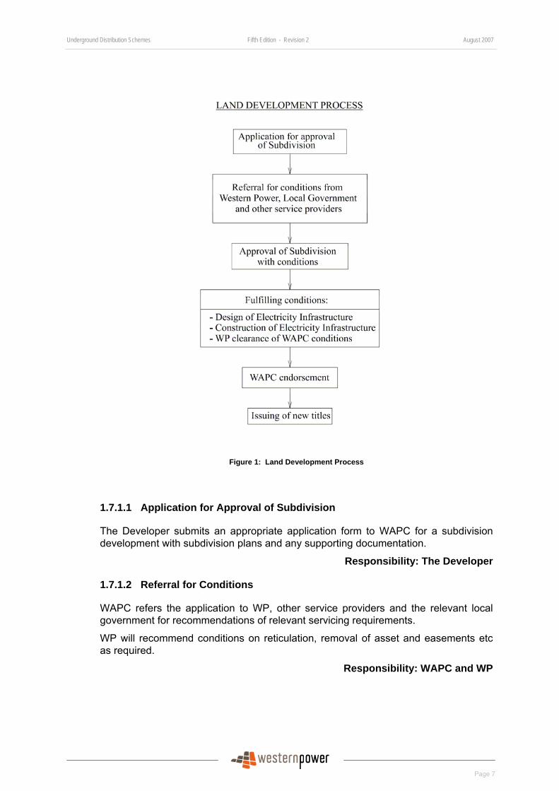
The high level land development process for subdivisions that requires WAPC clearance is given in Figure 1.
Note: For both small and large subdivisions the WAPC process is identical. However, as discussed in Section 1.6.2, the responsibilities and internal WP processes are different.
The process and WP’s involvement in the process are described overleaf.
Underground Distribution Schemes Fifth Edition - Revision 2 August 2007
Page 7
Figure 1: Land Development Process
1.7.1.1 Application for Approval of Subdivision
The Developer submits an appropriate application form to WAPC for a subdivision development with subdivision plans and any supporting documentation.
Responsibility: The Developer
1.7.1.2 Referral for Conditions
WAPC refers the application to WP, other service providers and the relevant local government for recommendations of relevant servicing requirements.
WP will recommend conditions on reticulation, removal of asset and easements etc as required.
Responsibility: WAPC and WP
Underground Distribution Schemes Fifth Edition - Revision 2 August 2007
Page 8
1.7.1.3 Approval of Subdivision with Conditions
WAPC issues a consolidated set of conditions, including WP’s for the subdivision to proceed. The approval period is four years for subdivisions creating more than five lots and three years for subdivisions of five lots or less.
Responsibility: WAPC
1.7.1.4 Fulfilling Conditions
The Developer is responsible for fulfilling all conditions in the WAPC approval, including those associated with WP.
Design of Electricity Infrastructure of a UDS The Developer engages an electrical Designer to design Electricity Infrastructure to serve the subdivision development in accordance with the requirements of WP. The Developer engages an Engineer to oversee the design and certify the UDS design complies with the requirements of this manual. The Engineer or the Designer will submit the design drawing to WP for Design Conformance Review (DCR).
Responsibility: Developer, Designer and Engineer
Construction of Network When the design drawing is confirmed as conforming, the Developer will proceed to construction of the network asset. The Developer can choose to install the asset using either Installation Option A or Installation Option B (see Section 6.2)
Responsibility: Developer
WP Clearance of Conditions When all WP conditions have been met, the Developer then sends a request for clearance to WP who will confirm conditions as being met and then issue a clearance certificate.
Responsibility: Developer, Developer’s Surveyor and WP
1.7.1.5 WAPC Endorsement
The Developer will submit deposited plan(s) to WAPC after collecting clearance certificates from WP, other service providers and the relevant local government authority (LGA). The WAPC will endorse its approval on submitted deposited plans if satisfied those deposited plans are in accordance with the approved plans and the conditions are met.
Responsibility: Developer and WAPC
1.7.1.6 Issuing of New Title
With the endorsement of the WAPC, the Developer can then apply to Department of Land Information (DLI) for new titles.
Responsibility: Developer and DLI
Underground Distribution Schemes Fifth Edition - Revision 2 August 2007
Page 9
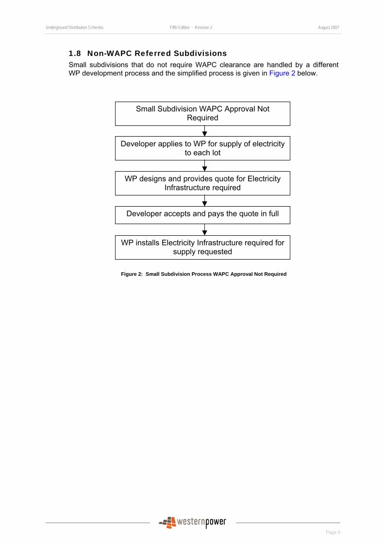
1.8 Non-WAPC Referred Subdivisions Small subdivisions that do not require WAPC clearance are handled by a different WP development process and the simplified process is given in Figure 2 below.
Figure 2: Small Subdivision Process WAPC Approval Not Required
Developer applies to WP for supply of electricity to each lot
WP designs and provides quote for Electricity Infrastructure required
WP installs Electricity Infrastructure required for supply requested
Small Subdivision WAPC Approval Not Required
Developer accepts and pays the quote in full
Underground Distribution Schemes Fifth Edition - Revision 2 August 2007
Page 10
2 General Design Policies 2.1 Western Power’s Policy and Design Principles of Network
Extension in Subdivision WP is required to ensure that its network is safe, fit to supply electricity to consumers and the quality of supply meets statutory requirements.
In order to fulfil the statutory requirements, the design of network extension and electricity reticulation for subdivisions must comply with the following major design principles:
2.1.1 Safety
Safety is WP’s priority value. WP’s network must be designed, constructed, maintained and operated to ensure safety of consumers, the public and WP personnel.
The Developer must ensure the design and construction of all Electricity Infrastructure meets the following requirements:
Electrical Safety The design scheme of a subdivision must provide a safe and efficient connection of all consumers’ installations to WP’s network. It must meet the requirements of Western Australia Electrical Requirements, AS/NZ Standard 3000-Australian/New Zealand Wiring Rules and all applicable written laws and standards.
Construction Safety
Subdivision construction work must be carried out in a safe manner and conform to the Occupational Safety and Health Act and Regulations and all applicable written laws and standards.
Operational Safety
All subdivision Electricity Infrastructure design and construction must conform to the Occupational Safety and Health Act and Regulations and all applicable written laws and standards to enable WP employees to carry out operation and maintenance in a safe manner.
2.1.2 Extension of High Voltage Feeders for Now and Future
The HV network is not only extended or reinforced to meet the requirement of a subdivision, but also to meet any planned future growth. HV feeder cables must be extended to meet the requirements of WP distribution development plans.
The Developer must install HV feeder cables according to the WP specified plan provided to meet the long term planning requirement.
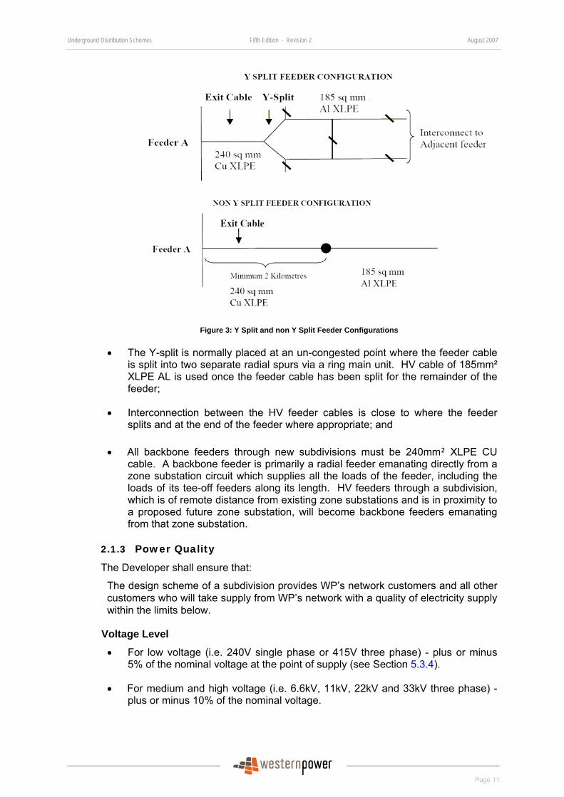
HV feeder cables must also be designed either in a ‘Y’ or ‘radial’ configuration (see Figure 3 below) so that:
• Within a minimum length of exit cable from the zone substation or upstream of the Y split, the HV feeder cable must be 240m² XLPE CU cable. The minimum length of exit cable and the location of the Y-split from the zone substation are dependent of the type of feeder, load size, distance of the load centre from the zone substation and the surrounding network configuration. It must not be less than 2Km.
Underground Distribution Schemes Fifth Edition - Revision 2 August 2007
Page 11
Figure 3: Y Split and non Y Split Feeder Configurations
• The Y-split is normally placed at an un-congested point where the feeder cable is split into two separate radial spurs via a ring main unit. HV cable of 185mm² XLPE AL is used once the feeder cable has been split for the remainder of the feeder;
• Interconnection between the HV feeder cables is close to where the feeder splits and at the end of the feeder where appropriate; and
• All backbone feeders through new subdivisions must be 240mm² XLPE CU cable. A backbone feeder is primarily a radial feeder emanating directly from a zone substation circuit which supplies all the loads of the feeder, including the loads of its tee-off feeders along its length. HV feeders through a subdivision, which is of remote distance from existing zone substations and is in proximity to a proposed future zone substation, will become backbone feeders emanating from that zone substation.
2.1.3 Power Quality
The Developer shall ensure that:
The design scheme of a subdivision provides WP’s network customers and all other customers who will take supply from WP’s network with a quality of electricity supply within the limits below.
Voltage Level
• For low voltage (i.e. 240V single phase or 415V three phase) - plus or minus 5% of the nominal voltage at the point of supply (see Section 55.3.4).
• For medium and high voltage (i.e. 6.6kV, 11kV, 22kV and 33kV three phase) - plus or minus 10% of the nominal voltage.
Underground Distribution Schemes Fifth Edition - Revision 2 August 2007
Page 12
Voltage Fluctuations
• The voltage fluctuation which occurs at the customer’s point of supply shall be within 70% of the Threshold of Irritability curve and 50% of the Threshold of Perceptibility curve in Australian Standard AS2279 Part 4 – Limitation of Voltage Fluctuations Caused by Industrial Equipment.
The Australian Standard AS2279 series is being replaced by the Australian/New Zealand Standard AS/NZS 61000 series on Electromagnetic Compatibility (EMC). Designers shall continue to assess the voltage fluctuation and flicker for motor starting in accordance with AS2279 until WP adopts the AS/NZS 61000.
The Designer can use WP’s LV Design and Flick Plus software to evaluate and assess the low voltage level variations and voltage fluctuations of the design scheme. The Designer may choose to use other methods or software to carry out the evaluation and assessment, so long as they are approved by WP.
2.1.4 Network Reliability
The Developer shall ensure the subdivision Electricity Infrastructure is designed to provide WP’s network customers with a reliable supply of electricity by:
• providing interconnections with other feeders both the HV and LV feeders of the subdivision, so that in the event of loss of one feeder, the other feeders can continue to supply customers and ensure a high level of reliability and expectations are maintained; and
• including interconnection of HV feeders for every 860 customers or for each two MVA loads.
2.1.5 Network Maintainability
The Developer shall ensure that all Electricity Infrastructure is designed and constructed to minimize cost of maintaining of its life.
2.1.6 Environmental Management
The Developer must ensure the network in the subdivision is designed and constructed to comply with all written laws that govern environmental and WP requirements etc. This includes but is not limited to noise, clearing, soil, management, rare flora, fauna, fire safety etc.
2.1.7 Meeting Community Expectation
The Developer must ensure the network in the subdivision is designed and constructed to meet all formal and informal community expectations, such as visual and physical impact of Electricity Infrastructure.
2.2 Underground Power It is WP’s policy that all new subdivisions are required to have underground power.
Underground electricity reticulation is mandatory in all new subdivisions with lot sizes up to 10 hectares and applies to all subdivisions, including residential, rural residential, commercial and industrial.
Subdivisions with lot sizes between 10 hectares and 50 hectares may have overhead electricity reticulation but the service connection for each lot must be from an underground service pillar. Underground reticulation is preferred.
Underground Distribution Schemes Fifth Edition - Revision 2 August 2007
Page 13
Subdivisions in which all lot sizes are over 50 hectares may be sold without any electricity reticulation. When electricity reticulation is to be installed, underground service connections are preferred although overhead service connection will be allowed.
WP’s Distribution Subdivision Policy is available at:
http://www.westernpower.com.au/mainContent/connectionsUpgrades/policiesRegulations/technicalDocumentation.html.
2.3 Three Phase Power Due to increasing demand for three phase power to supply high power use equipment, it is a requirement that, wherever practicable, all new subdivisions supply three phase power to each lot.
Where single phase power is the closest to the subdivision, but three phase power is available within 500m of a subdivision, the Developer must extend that three phase power to each lot of the subdivision.
Where single phase power is the closest and three phase power is no more than one kilometre away from the subdivision, WP may elect to extend its three phase system to within 500m of a subdivision. The Developer will then be required to extend the last 500m to the subdivision.
However, in some urban fringe and country areas it may be impracticable to obtain three phase power. In these situations, a single phase power supply is allowed.
2.4 Headworks to Subdivisions The community recognizes the benefits of underground power reticulation include improved aesthetics, and a safer and more reliable power supply. To meet community expectations, WP will extend new headworks in underground in urban and urban fringe areas. However, WP will consider the extension of the overhead distribution network on a short term basis across vacant land to the subdivision, provided that the vacant land will be developed into a subdivision in the near future (within five years).
2.5 Increasing Overhead Transformers and Switchgear WP will not increase the capacity of existing aerial transformers to meet the needs of subdivisions in urban areas. This means underground cables, ground mounted switchgear and transformers will be installed to supply the subdivision.
The extension or augmentation of underground Electricity Infrastructure will be done to meet the subdivision’s power requirement and any planned or logical future growth.
2.6 Network Capacity Augmentation Network capacity at each lot of a subdivision may be limited by the existing capacity of the network. The Developer may be required to reinforce the network to achieve the design capacity of its proposed Electricity Infrastructure in the subdivision.
Major subdivisions, e.g. multiple stage large residential subdivisions and large industrial subdivisions for resources processing plants, may have substantial power requirements of over 4 MVA. These subdivisions may require new transmission and distribution infrastructure, including a new zone substation and new transmission lines to provide the network capacity needed to supply the subdivision. The Developer must ensure the site for the zone substation is provided at no cost to WP. Additionally, major upgrade to the existing HV network (e.g. construction of a new feeder) may be required to service these subdivisions. Typically, WP will pay for the
Underground Distribution Schemes Fifth Edition - Revision 2 August 2007
Page 14
Transmission works, i.e. 66kV and above lines and zone substation. The Developer will have to pay for all the distribution augmentation.
The Developer must consult WP at the subdivision development planning stage to ensure Transmission and Distribution infrastructure reinforcement is considered. It should be noted that the need for a new zone substation will vary with different subdivisions and their locations.
Note, in urban fringe, remote and country areas, there may be constraints on the existing network such as network capacity and geographical distance from a zone substation. These can have a significant effect on the cost of extending and reinforcing distribution network. These costs can be substantially higher than would be experienced for a similar level of reinforcement within a metropolitan network. The Developer is advised to consider these additional costs in the feasibility study stage of developments.
2.7 Future Transmission Power Equipment Currently, the installation of underground Electricity Infrastructure is limited to the distribution system. While the technology exists for underground transmission power lines, i.e. power lines operated at 66kV and above, it is generally cost prohibitive.
An area built with the distribution network underground may need to route an overhead transmission line through or install new zone substation in the area. WP will normally advise the Developer of the potential line corridor and zone substation at the time of subdividing. The Developer must inform prospective land purchasers of WP’s future development. Where WP has advised of future transmission equipment the Developer must ensure this is shown on all marketing documents and other materials for prospective land purchasers.
2.8 Treatment of Existing Assets within or adjacent to a Subdivision
This policy applies to all land development proposals, including but not restricted to all subdivisions, amalgamations and strata title developments
The treatment of existing Western Power overhead power lines that traverse or are adjacent to such development proposals shall be as below.
2.8.1 Transmission Power Lines (i.e. operating at 66KV or above)
Transmission power lines are those that operate at 66,000 volts and above.
For an overhead transmission power line that traverses or is adjacent to the development, generally the power line can remain in situ. However, an Easement in Gross is to be provided for the power line at the proponent’s cost. The power line is to be considered adjacent to the development if the development is within the prescribed safety clearance zone (the easement) applicable to the particular transmission line. This is determined in accordance with ENA’s HB C (b)1 guidelines. The ENA guidelines are the design code that has been established for use throughout Australia for the design and maintenance of distribution and transmission lines.
There may be circumstances where it is impractical for the overhead transmission power line to remain in situ. Each case will be dealt with on its merits.
Underground Distribution Schemes Fifth Edition - Revision 2 August 2007
Page 15
2.8.2 Distribution power lines that traverse lots of size 10 hectares or less
For an overhead distribution power line that traverses lots of 10 hectares or less within the development, the following options are available:
2.8.2.1 Rebuild Underground through the Development in Road Reserves
The overhead distribution power line can be rebuilt in underground construction in gazetted road reserves through the development.
2.8.2.2 Relocate off the Development
If no gazetted road reserves are created in the development or, at Western Power’s discretion, the gazetted road reserves that are created are deemed not suitable for rebuilding the line in, then the overhead distribution power line can be relocated entirely off the development. In this case, the power line must be rebuilt in underground construction. However, provided none of the following circumstances exist, then the power line can be rebuilt in overhead construction:
• Where the surrounding Electricity Infrastructure is already installed underground;
• Where the local government authority has a requirement for underground electricity in the area;
• Where there is an underground scheme proposed or in place for the area;
• Where clearing required for overhead construction would cause unacceptable environmental impact or excessive maintenance costs to WP; or
• Where an objection has been made by an affected member of the community and has not been resolved.
• Note, that whenever a power line is to be relocated off the development, it is the responsibility of the proponent to perform all negotiations with all affected members of the community and relevant departments and bodies. Western Power will not be an active participant in these negotiations.
2.8.2.3 Rebuild Underground through the Development outside of Road Reserves
In circumstances where, in Western Power’s opinion, it is impractical to achieve one of the previous two options, the overhead distribution power line can be rebuilt in underground construction through the development outside of gazetted road reserves. However, in such circumstances, the rebuilt underground power line must be installed within one metre of a property boundary if the area of the lot is less than 2 hectares. Where the area of the lot is 2 hectares or greater then the underground power line may be installed away from the boundary provided all of the following conditions are met.
a. A local government authority has restricted the construction of buildings on the lot to a local government authority nominated building envelope;
b. The building envelope is at least two metres from the underground power line easement;
c. The cable is installed in ducts to Western Power’s requirements;
Underground Distribution Schemes Fifth Edition - Revision 2 August 2007
Page 16
d. A spare duct is installed to Western Power’s requirements; e. Permanent above ground markers are installed along the cable route to
Western Power’s requirements; and f. Cable pulling pits are installed to Western Power’s requirements along the
spare duct route if the duct length is in excess of the cable drum length.
In all cases a PDA section 167 easement is to be provided at the proponent’s cost. The section/s of the power line installed underground through the development off gazetted road reserves is to be kept to an absolute minimum.
To minimise the impact of undergrounding the overhead line on adjacent landowners, the line to cable transition pole and its stay may be located within the development. The transition pole will also be located within the subdivision to minimise the impact on future landowners, ie not block driveways, PAWs, etc. In general, the transition pole shall be located within 0.5m of the lot boundary.
2.8.2.4 Rebuild Overhead through the Development outside of Road Reserves
In circumstances where in Western Power’s opinion it is impractical to achieve one of the previous three options, the overhead distribution power line can be rebuilt in overhead construction through the development outside of gazetted road reserves provided:
None of the following circumstances exists:
• Where any appropriate Authority has a requirement for new electricity lines in the property to be underground;
• Where clearing required for overhead construction would cause an unacceptable environmental impact;
• Where an objection has been made by an affected member of the community and has not been resolved; and
All of the following conditions are met:
• The lot size is 4 hectares or larger;
• The edge of any existing or proposed building or building envelope for the lot is at least 10 metres from the centre line of the overhead line;
• Ongoing ready access will be provided to the line for construction, operation and maintenance; and
• Vegetation will be cleared and kept clear from the line in accordance with Western Power Network’s requirements
And either:
• The overhead line runs parallel to a roadside boundary;
• The overhead line is within 10 metres of the roadside boundary; or
Underground Distribution Schemes Fifth Edition - Revision 2 August 2007
Page 17
• The overhead line runs parallel to the lot boundary;
• The local government authority requires a firebreak of minimum width 3 metres in the lot along the boundary, and
• The line located between the lot boundary and the firebreak;
Note that whenever a power line is to be relocated within a property, it is the responsibility of the proponent to perform all negotiations with, and obtain the approval of, all affected members of the community and relevant departments and bodies. Western Power will not be an active participant in these negotiations.
2.8.2.5 Leave In-situ
In circumstances where, in Western Power’s opinion, it is impractical to achieve one of the options 2.8.2.1, 2.8.2.2 or 2.8.2.3 then the existing overhead distribution power line can remain in situ provided it meets the conditions stated in Clause 2.8.2.4.
2.8.3 Distribution Power Lines that traverse lot of sizes greater than 10 hectares
For an overhead distribution power line that traverses lots of greater than 10 hectares within the development, generally the power line can remain in situ provided that no building envelope or structure is proposed underneath or near the line. There may be circumstances where it is impractical for the overhead distribution power line to remain in situ. Each case will be dealt with on its merits.
2.8.4 Cost Responsibilities
The cost of all work associated with relocating or undergrounding distribution power lines, including vegetation clearing and the cost for provision of easements etc, is the responsibility of the proponent. However, in some cases the replacement of an aging overhead line with underground construction may result in a partial cost benefit to Western Power. Where Western Power determines that this is the case it will contribute to the cost of underground construction, equivalent to the partial cost benefit.
2.8.5 Basis/Philosophy
This policy formalises the long-standing practice that has been embodied in land development clearance conditions that have been agreed between Western Power and DPI and in use for a considerable period of time.
The basic philosophy behind this policy is that as land is developed, there is an increase in the pressure to maximize utilisation of the available area. Where an overhead line is permitted to remain over such land, the end result is often conflict between future landowners’ land use requirements and the overhead power line. The principal problems that arise, which this policy is intended to mitigate are:
• Risk to public safety and security of supply. Pressure to maximize land usage can result in unregulated construction under or close to overhead power lines (e.g., metal sheds, sea containers and stored equipment). These often breach safety clearances from overhead power lines, which not only jeopardizes the security of the supply, but also more importantly, poses a serious risk to public safety.
Underground Distribution Schemes Fifth Edition - Revision 2 August 2007
Page 18
• In built-up areas, building setback requirements have been progressively relaxed since the introduction of “R Codes”. This allows construction of buildings much closer to property boundaries than was previously permitted. In many cases, new setbacks would permit buildings to be constructed within the safety clearance zone (easement) of transmission lines that are located on their normal road reserve alignment. The conditions imposed by the easement would require such buildings to be located outside of this zone.
• Increased difficulty of access for operation and maintenance. Development of land usually results in the construction of fences, gardens, walls and other improvements. These can cause difficulty in gaining access to the power line for operational or maintenance purposes if not properly managed.
• Satisfaction of public expectations. There is a growing public expectation that overhead power lines will be removed from properties or placed underground – particularly at the distribution voltage level. Implementing this at the subdivision stage simplifies this and ensures that the user pays.
The reasons for the difference in policy for transmission and distribution power lines are summarised as follows:
In the case of transmission power lines, it is generally cost prohibitive to relocate or underground them. The only alternative is to protect them with an easement. Because they are significantly fewer in number (and more important in terms of the network) compared to distribution lines it is practical to patrol them on a regular basis to ensure that easement conditions are being complied with.
In the case of distribution power lines, easements are a limited practical deterrent but are required in order to give Western Power the legal right to have infrastructure removed. With such a vast network of distribution power lines throughout the state, it is not possible to patrol them all to ensure that easement conditions are being complied with. Easements are often forgotten about or ignored by property owners, – hence the need for relocation or undergrounding of the power lines. A lot size of 10 hectares has been chosen as the area below which the pressure to maximise the available land begins to jeopardise the integrity of an overhead distribution power line.
2.9 Associated Publications • ENA C(b)1 – Guidelines for Design and Maintenance of Overhead Distribution
and Transmission Line (Can be ordered from SAI Global Limited. Please visit SAI Web site at http://www.saiglobal.com/.)
• AS/NZS 3000 – Australian/New Zealand Wiring Rules –Published by Standard Australia
• AS2279.4 – Disturbances in Mains Supply Networks Part 4, Limitation of Voltage Fluctuations Caused by Industrial Equipment – Published by Standard Australia.
• Supply Extension Policy of Western Power
• Western Power Policy Statement “Deciding Between Distribution Overhead and Underground Constructions in Road Reserve”.
Underground Distribution Schemes Fifth Edition - Revision 2 August 2007
Page 19
3 General Charging Policies 3.1 Headworks Extension, Removal, Relocation or Upgrades All headworks extensions, removals, moving or upgrades to the network external to subdivision are fully funded by the Developer. The headworks extension can include the construction of a new HV feeder from a zone substation, distribution transformers, LV networks etc for a subdivision. The moving of network includes the relocation of transmission line protection pilot cables affected by the subdivision.
3.2 Small Residential Subdivision in Existing Underground Areas (not more than four lots of any sizes)
The Developer will be charged with the estimated full cost of the design and construction of all Electricity Infrastructure installations, including trenching and laying of cable. If the Developer elects to do its own trenching and cable laying, WP’s cost for this work will be deducted from its quote.
3.3 Small Residential Subdivision in Existing Overhead Areas (not more than 4 lots)
For small subdivision developments located in overhead reticulated power areas, the Developer will be charged at full cost of all design and construction of Electricity Infrastructure, including headworks, trenching and laying of cables.
However, a Pole-to-Pillar fee will apply if the subdivision meets the following requirements:
1. No more than three dwellings require connection. This includes any existing overhead connections.
2. No more than three lots are being created.
3. The dwelling(s) supply is standard.
4. The lot is located in an overhead reticulated power area.
5. The proposed pillar must be installed in WP’s network preferred or acceptable location. (WP selects locations that maximise the existing and future use of the pillar.) The pillar location must be on a front property boundary, between adjacent lots. The pillar must be located on the requestor’s property unless one already exists on the adjacent property.
6. There must be no need to remove or relocate an existing overhead line.
7. Suitable low voltage overhead mains must exist within 60m of the lot boundary where the pillar is to be installed.
8. The route from the existing low voltage overhead mains to the proposed pillar location must be considered suitable by WP for the installation of low voltage underground cable or low voltage aerial bundled conductor as required.
9. The lots must be residential and less than 1000m2. Special rural/residential lots are not included.
10. The same Developer/owner must not have submitted a Pole-to-Pillar application for an adjacent lot within the previous three years.
11. A company, organisation, person or group of persons must not be progressively seeking Pole-to-Pillar connections for an area that should be developed as a standard underground residential subdivision in WP’s opinion.
Underground Distribution Schemes Fifth Edition - Revision 2 August 2007
Page 20
12. Supply Extension Scheme (SES) charging is not applicable.
13. Where applicable, common property must be created to allow consumer mains to be connected to the pillar. At W P’s sole discretion, a service easement may be substituted.
14. The site must be made ready and pegged by the Developer for immediate installation of the pillar.
The Developer is advised to obtain the latest “Pole-to-Pillar” charge from:
http://www.westernpower.com.au/mainContent/connectionsUpgrades/Network_Charges.html.
3.4 Large Subdivision of Residential Lots of size of 1000m² or Less in Urban Area
The Developer will be charged the estimated full cost of Electricity Infrastructure excluding trenching, laying of cable and civil works. The Developer is responsible for trenching, cable laying and civil works in accordance with the installation requirements (Section 6) in the manual.
In order to provide equity between developments, a Residential Subdivision High Voltage Pool has been established (see Section 3.8). This pool is mandatory for all residential subdivisions with lot sizes of 1000m² or less.
For each lot in an applicable residential subdivision, a system charge per kVA of the After Diversity Maximum Demand (ADMD) is levied to the Developer and paid into a pool. This pool then reimburses the cost of the high voltage infrastructure required for all applicable subdivisions.
The latest HV system charge is published on WP’s website and is available at:
http://www.westernpower.com.au/mainContent/connectionsUpgrades/Professional_Developers/HV_Subdivision_Pool.html.
The provision and installation of Low Voltage (LV) Infrastructure and street lighting is not part of the HV Pool Mechanism and is to be paid for in full by the Developer.
The Residential Subdivision HV Pool does not include 33kV subdivisions. Design and construction of all 33kV infrastructures must be fully funded by the Developer.
The operation of the HV Pool policy is explained in detail in Section 3.8.
3.5 Large Subdivision of Residential Lots of Size Greater than 1000m² in Urban Area and Area Zoned “Rural” or “Special Rural” (Broadacre Subdivision)
The subdivision HV Pool does not apply to residential subdivisions with lots larger than 1000m² as they are too variable for a pool to operate. The Developer will be charged the estimated full cost of Electricity Infrastructure excluding trenching, laying of cable and civil works. The Developer is responsible for trenching, cable laying and civil works in accordance with the installation requirements (Section 6).
Underground Distribution Schemes Fifth Edition - Revision 2 August 2007
Page 21
3.6 Commercial and Industrial Subdivisions The subdivision HV Pool does not apply to industrial and commercial subdivisions. For these subdivisions, the full cost of all Electricity Infrastructure is charged directly to the Developer. The Developer is also responsible for trenching, cable laying and civil works.
When a subdivision has a mixture of residential, commercial and industrial freehold lots, the subdivision is considered as a commercial and industrial subdivision, if the total design load of the commercial and industrial lots is greater than 50% of the total design load of the subdivision. It is considered as a residential subdivision when the total design load of the residential lots is not less than 50% of the total design load of the subdivision.
3.7 Changes to Existing Assets that need to be Altered The cost of all work associated with removing, relocating or undergrounding transmission or distribution assets including zone substations, distribution substations, power lines, vegetation clearing and the cost for provision of easements etc, is to be fully funded the Developer.
However, in residential subdivisions with lot size not more than 1000m² the subdivision HV Pool will apply to the undergrounding of one HV overhead distribution line that traverses the subdivision. The undergrounding of any additional overhead distribution line will be fully funded by the Developer.
3.8 High Voltage Pool Policy and Operation
3.8.1 Background History
The High Voltage (HV) Pool was introduced by WP in 1999. The mechanism of the HV Pool was developed as a joint initiative between The Urban Development Industry of Australia (UDIA) and WP.
Due to the use of standard size components and for network planning purposes, the HV Electricity Infrastructure of a subdivision often provides capacity in excess of that required by the subdivision.
It was often the case that the first Developer in an area paid for the entire HV Electricity Infrastructure required to service the area. The excess capacity was then utilised by subsequent Developers without contribution to its cost.
The cost of low voltage (LV) Electricity Infrastructure of a particular subdivision is generally closely linked to the need of that subdivision; and its capacity is mostly used by that subdivision.
The HV Pool mechanism was introduced as part of WP pricing strategy to address inequities between Developers in the application of the WP’s full cost policy for providing Electricity Infrastructure in subdivisions.
Initially, two HV Pools were established, viz. Residential HV Pool for residential subdivisions of lot sizes not more than 1000m² and Commercial/Industrial HV Pool for commercial and industrial subdivisions. The Commercial/Industrial HV Pool failed to achieve an equitable result and it was subsequently agreed with UDIA to discontinue its use.
The Residential HV Pool provides the land development industry with a cost equalising mechanism for Electricity Infrastructure for a UDS for residential subdivisions.
Underground Distribution Schemes Fifth Edition - Revision 2 August 2007
Page 22
The provision of Electricity Infrastructure to new subdivisions remains a full cost policy, however, WP has agreed to operate the Residential HV Pool for residential subdivisions provided it remains cost neutral to WP.
3.8.2 High Voltage Pool Administration
WP administers the Residential HV Pool and, by agreement with UDIA, recovers the cost of administering the HV Pool by recouping 4% of the HV Pool Charge (see Section 3.8.6) of each proposed subdivision.
WP’s administering work on the HV Pool includes:
• Day-to-day administration.
• Training of HV pool administrators and industry users.
• Management of the pool integrity including auditing.
• Financing the inherent lagging nature of the HV Pool income, and
• Information technology supports to develop and maintain technology systems.
The administration fee is collected by adding 4% to the system charge each time it is reset. This fee is not to be included in the HV Pool but is directed to a separate account to pay for WP’s administration of the HV Pool.
The operation of the HV Pool does not create the relationship of:
• employer and employee;
• principal and contractor;
• partnership, or
• Joint venture,
between WP and the Developer, in respect of a UDS.
3.8.3 System Charge
The system charge is the cost per kVA ($/kVA) to fund HV Pool Payments (see Section 3.8.7).
The System Charge in $/kVA is inclusive of the 4% HV Pool administration fee. The latest HV system charge is published on Western Power’s Web site and is available at:
http://www.westernpower.com.au/mainContent/connectionsUpgrades/Professional_Developers/HV_Subdivision_Pool.html.
The system charge is required to be reset either every six months or when the HV Pool balance is moving towards a large deficit.
3.8.4 Subdivision Design Load
The design load used to calculate the system charge for the proposed subdivision includes all residential and commercial/industrial design loads within the WAPC subdivision boundary. The design load requirements are in Section 5.3.2.
Underground Distribution Schemes Fifth Edition - Revision 2 August 2007
Page 23
3.8.5 Schedule of Rates
The WP design process and cost estimating package is based upon a suite of compatible units (CU). Each CU is a physical network component broken down into its individual parts with associated estimated material cost and estimated installation costs.
The schedule of rates (SOR) of each CU in the HV Pool is estimated using the WP material costs and industry installation rates. The WP material costs are automatically updated weekly and the industry installation rates are updated by industry representatives annually.
The schedule of rates is used to calculate the HV Pool Payment of each subdivision (see Section 3.8.7).
3.8.6 HV Pool Charge
The HV Pool Charge of a proposed subdivision is the system charge multiplied by the proposed Design Load of that subdivision ($/kVA x Design Load).
The HV Pool Charge is the amount paid into the Pool by the Developer for the provision of HV Electricity Infrastructure of a UDS for a proposed subdivision based on the “Design Load” of that subdivision.
3.8.7 HV Pool Payment
The HV Pool Payment is the amount paid to the Developer by the HV Pool for the provision of the HV Electricity Infrastructure of a UDS for a proposed subdivision.
The HV Pool Payment is estimated by adding up the schedule of rates of all the CUs required for the HV Electricity Infrastructure of the UDS of the proposed subdivision.
3.8.8 High Voltage Pool Mechanism
The HV Pool mechanism is independent of the cost of Installations Option A and Option B.
The HV Pool mechanism equalises the HV Electricity Infrastructure costs by requiring Developers to pay the HV Pool Charge into the HV Pool and the HV Pool then pays the Developer the HV Pool Payment.
The net result is that the Pool collects funds from Developers who contribute under their share of HV Electricity Infrastructure and compensates Developers who pay over their share, with the objective of keeping the HV Pool in balance.
A complying residential subdivision that meets the economic criteria can participate in the HV Pool (see Section 3.8.11).
For Installation Option A the Developer pays WP to carry out the installation works. The payment to WP from the Developer includes the following:
• The payment from the Developer to WP to carry out all the HV and LV Electricity Infrastructure installation works excluding civil works.
• The payment from the Developer to WP to carry out other works such as network interfacing work, additional work requested by the Developer and DCR.
• The net difference between the HV Pool Payment paid to the Developer by HV Pool and the HV Pool Charge paid into the Pool by the Developer.
{Option A Payment = (HV costs + LV costs + other costs) +($/kVA x Design Load – Total of SOR of CUs)}.
Underground Distribution Schemes Fifth Edition - Revision 2 August 2007
Page 24
For Installation Option B the Developer will install both the HV and LV Electricity Infrastructure at its own cost. However, the Developer pays WP to carry out other works. The payment to WP includes the following:
• The payment from the Developer to carry out other works such as network interfacing work, additional work requested by the Developer and DCR.
• The net difference between the HV Pool Payment paid to the Developer by HV Pool and the HV Pool Charge paid into the Pool by the Developer.
{Option B Payment = Other costs + ($/kVA x Design Load – Total of SOR of CUs)}
A balance of HV Pool Payment will exist when the amount of payment is negative. The balance of HV Pool Payment is available to the Developer only upon successful completion of handover inspection of the subdivision.
3.8.9 Subdivisions and Assets included in HV Pool
The following subdivisions and assets are included in the Residential HV Pool:
• Large subdivisions of residential freehold lots of size not exceeding 1000m² processed through the WAPC land development process.
• The provision of the high voltage overhead and underground headworks necessary for the proposed subdivision, provided they are carried out in accordance with WP’s Policy Statement, “Deciding Between Distribution Overhead and Underground Constructions in Road Reserves”.
• The provision of underground HV Electricity Infrastructure within the proposed subdivision boundaries.
• The removal of one HV overhead distribution line with transformers and pole top switches is included in the HV Pool. However, the relocation or removal of any additional HV Electricity Infrastructure is not part of the HV Pool.
3.8.10 Subdivisions and Assets excluded from HV Pool
The following subdivisions and assets are excluded from the Residential HV Pool;
• Small subdivisions of residential lots.
• Large subdivisions of residential lots of size exceeding 1000m².
• Subdivisions supplied from the 33kV distribution network.
• HV Infrastructure that is not associated with the permanent supply of the Design Load such as more than one HV Electricity Infrastructure relocation, temporary installations or additional works required by WP for network reinforcement purposes.
• The provision of Low Voltage (LV) Electricity Infrastructure is not part of the HV Pool mechanism and is paid for in full by the Developer outside the HV Pool process.
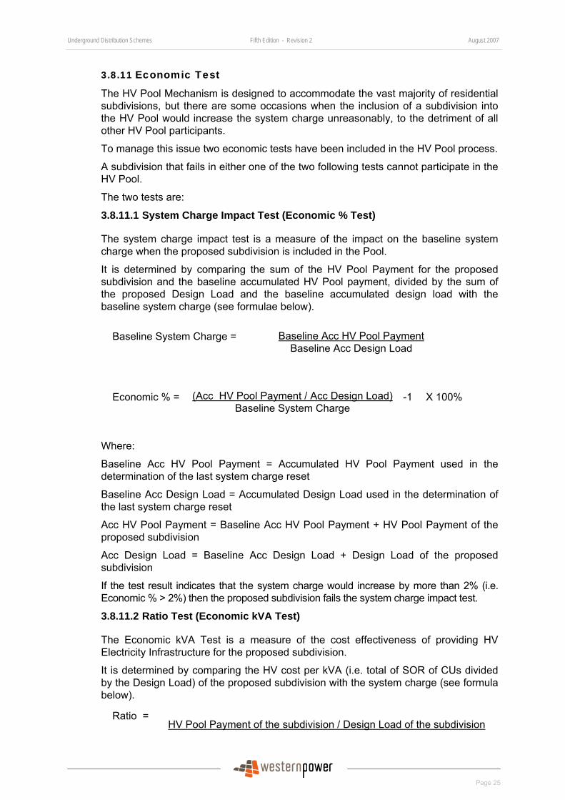
Underground Distribution Schemes Fifth Edition - Revision 2 August 2007
Page 25
3.8.11 Economic Test
The HV Pool Mechanism is designed to accommodate the vast majority of residential subdivisions, but there are some occasions when the inclusion of a subdivision into the HV Pool would increase the system charge unreasonably, to the detriment of all other HV Pool participants.
To manage this issue two economic tests have been included in the HV Pool process.
A subdivision that fails in either one of the two following tests cannot participate in the HV Pool.
The two tests are:
3.8.11.1 System Charge Impact Test (Economic % Test)
The system charge impact test is a measure of the impact on the baseline system charge when the proposed subdivision is included in the Pool.
It is determined by comparing the sum of the HV Pool Payment for the proposed subdivision and the baseline accumulated HV Pool payment, divided by the sum of the proposed Design Load and the baseline accumulated design load with the baseline system charge (see formulae below).
Baseline Acc HV Pool Payment Baseline System Charge = Baseline Acc Design Load
(Acc HV Pool Payment / Acc Design Load)Economic % = Baseline System Charge
-1 X 100%
Where:
Baseline Acc HV Pool Payment = Accumulated HV Pool Payment used in the determination of the last system charge reset
Baseline Acc Design Load = Accumulated Design Load used in the determination of the last system charge reset
Acc HV Pool Payment = Baseline Acc HV Pool Payment + HV Pool Payment of the proposed subdivision
Acc Design Load = Baseline Acc Design Load + Design Load of the proposed subdivision
If the test result indicates that the system charge would increase by more than 2% (i.e. Economic % > 2%) then the proposed subdivision fails the system charge impact test.
3.8.11.2 Ratio Test (Economic kVA Test)
The Economic kVA Test is a measure of the cost effectiveness of providing HV Electricity Infrastructure for the proposed subdivision.
It is determined by comparing the HV cost per kVA (i.e. total of SOR of CUs divided by the Design Load) of the proposed subdivision with the system charge (see formula below).
Ratio = HV Pool Payment of the subdivision / Design Load of the subdivision
Underground Distribution Schemes Fifth Edition - Revision 2 August 2007
Page 26
System Charge
If the result is equal to or greater than four times (i.e. Ratio ≥ 4), then the proposed subdivision fails the ratio test.
3.8.12 Economic Re-Test
When the first stage of a subdivision development in an area or any stage of a large subdivision development scheme fails the economic tests, that stage cannot participate in the HV Pool.
If within three years of the Acceptance of Quote of that stage the Developer does further stages of the subdivision development, or other developers do subdivisions that are adjacent to the original subdivision, the economic tests will be redone by using the combined HV Pool Payment and Design Load for all stages.
If the subdivision with the combined stages or subdivisions subsequently passes the tests, the HV Pool pays the Developer the HV Pool Payment and the Developer pays the HV Pool the HV Pool Charge for the subdivision under re-test.
When the system charge is reset, no subdivisions that previously failed the economic tests are eligible for an economic re-test until a further stage of subdivision or another subdivision is connected to them. The economic re-test will be done using the SOR appropriate at the time when the connection of a further stage of subdivision or another subdivision takes place.
Underground Distribution Schemes Fifth Edition - Revision 2 August 2007
Page 27
4 Land Development Process This section details the Developer’s and WP’s involvement in the WAPC’s land development process. It then details WP’s processes and responsibilities for both small and large subdivisions.
4.1 Western Australian Planning Commission Subdivision Process
The Planning and Development Act 2005 requires plans of subdivisions to be approved by the WAPC. Under the Act, the Registrar of Titles shall not create or register a Certificate of Title for land within a subdivision plan unless it has been endorsed with the approval of the WAPC. The high level process from the application of subdivision development through to issuing new titles has been described in Section 1.7
4.1.1 WAPC Subdivision Process
• The Developer submits an application for a freehold (green title) subdivision or survey strata to WAPC.
• WAPC refers the application to WP, other services providers and the relevant local government to determine its conditions for a subdivision development.
• WP reviews the present network (both distribution and transmission) to determine the conditions that will be applied to the subdivision application.
• WP then replies to the WAPC with the recommended conditions. WP also advises the applicant that it has processed the application and forwarded its recommendations to the WAPC.
• WAPC approves the application and issues a consolidated set of conditions, including those from WP, for the subdivision to proceed.
• Developers obtain a Quote from WP for the work required to fulfil the conditions. For small subdivisions (see Section 4.2.1) the applicant must complete and return the form “Request for Quote on work associated with WAPC application” to WP.
• All conditions are fulfilled.
• The surveyor representing the Developer requests clearance of the conditions from WP.
• WP issues a clearance certificate when WAPC’s conditions are met.
• The Developer submits deposited plan(s) to WAPC after collecting all clearance certificates. The WAPC endorses its approval on submitted deposited plans if satisfied the deposited plans are in accordance with the approved plans and the conditions are met.
• The Developer applies to the DLI for new Titles.
An application guide for approval of freehold subdivisions or survey strata is available at WAPC’s web site: http://www.wapc.wa.gov.au/Applications/default.aspx.
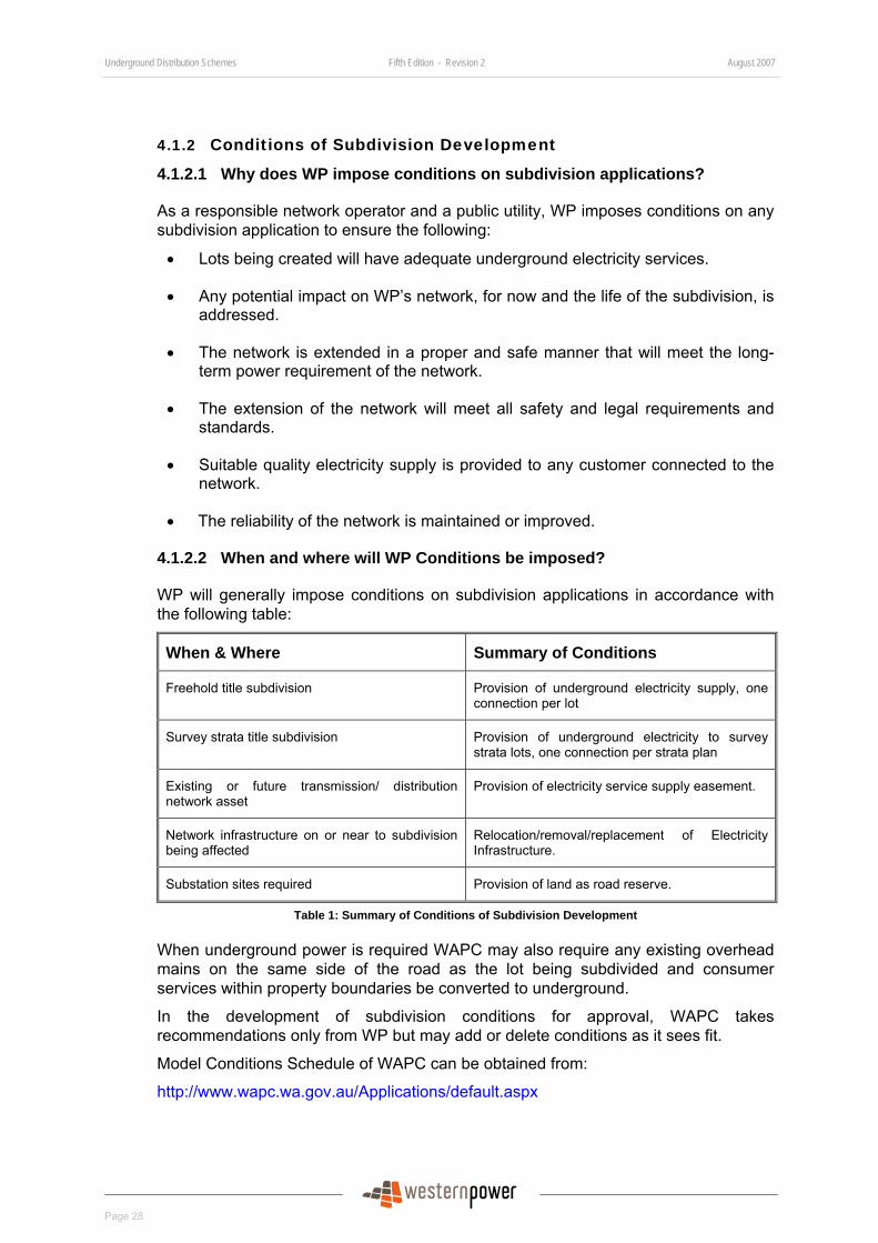
Underground Distribution Schemes Fifth Edition - Revision 2 August 2007
Page 28
4.1.2 Conditions of Subdivision Development
4.1.2.1 Why does WP impose conditions on subdivision applications?
As a responsible network operator and a public utility, WP imposes conditions on any subdivision application to ensure the following:
• Lots being created will have adequate underground electricity services.
• Any potential impact on WP’s network, for now and the life of the subdivision, is addressed.
• The network is extended in a proper and safe manner that will meet the long-term power requirement of the network.
• The extension of the network will meet all safety and legal requirements and standards.
• Suitable quality electricity supply is provided to any customer connected to the network.
• The reliability of the network is maintained or improved.
4.1.2.2 When and where will WP Conditions be imposed?
WP will generally impose conditions on subdivision applications in accordance with the following table:
When & Where Summary of Conditions
Freehold title subdivision Provision of underground electricity supply, one connection per lot
Survey strata title subdivision Provision of underground electricity to survey strata lots, one connection per strata plan
Existing or future transmission/ distribution network asset
Provision of electricity service supply easement.
Network infrastructure on or near to subdivision being affected
Relocation/removal/replacement of Electricity Infrastructure.
Substation sites required Provision of land as road reserve.
Table 1: Summary of Conditions of Subdivision Development
When underground power is required WAPC may also require any existing overhead mains on the same side of the road as the lot being subdivided and consumer services within property boundaries be converted to underground.
In the development of subdivision conditions for approval, WAPC takes recommendations only from WP but may add or delete conditions as it sees fit.
Model Conditions Schedule of WAPC can be obtained from:
http://www.wapc.wa.gov.au/Applications/default.aspx
Underground Distribution Schemes Fifth Edition - Revision 2 August 2007
Page 29
4.1.3 When will Western Power issue a Clearance Certificate on WAPC Applications?
WP will issue a clearance certificate when:
• a clearance request is received from the Developer or the Developer’s surveyor;
• all WP conditions have been met;
• other conditions as required based on the situation of each subdivision application that has potential impact on WP’s network, e.g. road widening, are addressed to the satisfaction of WP;
• all WP’s requirements in the DIP are met; and
• Overhead services which are part of the subdivision or affected by the subdivision are converted to underground.
4.1.4 How can Western Power Conditions be met?
4.1.4.1 Small Subdivisions
For small subdivisions of not more than four lots, the following items need to be completed to meet WP’s conditions:
• The applicant/Developer of a subdivision completes and returns to WP the “Request for Quote on work associated with WAPC application”, which can be obtained from WP’s web site.
• WP will provide a design and Quote for the work required to meet the conditions.
• The Developer pays for the Quote and completes its work in accordance with the terms and conditions in the Quote.
• Overhead services are converted underground.
• Other conditions as required, based on the situation of each subdivision application, that have potential impact on WP’s network, e.g. road widening, are addressed to the satisfaction of WP.
4.1.4.2 Large Subdivisions
For large subdivisions of more than four lots, the following items need to be completed to meet WP’s conditions:
• A Developer will request a Design Information Package (DIP) from WP.
• The Developer will need to engage a Designer to develop an electrical design for the subdivision.
• The Developer will submit the electrical design in accordance with the requirement in the DIP and this manual to WP for Design Conformance Review (DCR).
• WP will issue a Quote for Option A and Option B installation.
Underground Distribution Schemes Fifth Edition - Revision 2 August 2007
Page 30
• The Developer pays for the Quote (either option) and completes its work in accordance with the terms and conditions in the Quote and the requirements of this manual.
• Overhead services are converted underground.
• Other conditions as required, based on the situation of each subdivision application that have potential impact on WP’s network, e.g. road widening, are addressed to the satisfaction of WP.
4.1.5 Clearance Request Submission
Once the financial and installation requirements have been met, the Developer’s surveyor can submit a request of clearance to WP. All clearance requests should be submitted to
Western Power
Locked Bag 2511
Perth WA 6000
4.1.5.1 Requirements
WAPC conditions on approved subdivision plans are only cleared after the following requirements are met:
• Submission of two copies of the deposited plan of the subdivision showing substation sites and easement required.
• Compliance with other easement and/or special requirements.
And for large subdivisions: If Option A is selected:
• Payment of Installation Option A Quote amount; and
• Acceptance of Cable Handover Certificate by WP.
If Option B is selected:
either,
• Acceptance of Handover Certificates by WP;
or,
• Successful completion of Handover inspection by WP;
Underground Distribution Schemes Fifth Edition - Revision 2 August 2007
Page 31
or,
• For early clearance, a bond in the form of an unconditional bank guarantee, cash, or cheque for the full cost of completion of work as quoted for installation Option A. Both the bond payment and the deposited plans must be received by WP before early clearance can be given. The subdivision Option B bond terms and conditions can be found at:
http://www.westernpower.com.au/mainContent/connectionsUpgrades/policiesRegulations/technicalDocumentation.html.
4.1.5.2 Clearance
WP will approve clearance and endorse the submitted deposited plans provided all conditions and requirements are met. A clearance certificate letter, along with the endorsed deposited plans, will be forwarded to the Developer’s surveyor. In a case where clearance is not provided, the surveyor will be advised of the reasons by WP.
4.1.6 Clearance of Special Subdivision Lots
Developers will usually develop subdivisions in progressive stages. The creation of new lots in stages will result in balance lots of substantial size without underground power supply.
4.1.6.1 Balance lots in residential subdivision
Residential balance lots that can be used "as is" must be serviced and Electricity Infrastructure installed. These lots are of a similar size to those within the subdivision. Design drawings must show servicing and payment for the Electricity Infrastructure must be made.
Where lots are substantially bigger and in WP’s opinion will not be sold as is, a Letter of Undertaking from the Developer stating its intention for further subdivision and development for any balance lot that is not to be serviced must be submitted to WP.
4.1.6.2 Balance lots in commercial/industrial subdivision
All commercial and industrial balance lots require financial provision for an appropriate supply as determined by WP’s Policy. (e.g. 200kVA per hectare).
In situations where specific supply requirements are unknown, WP will only require the cables installed for clearance (where appropriate1). Transformers, switchgear and other infrastructure will not be installed until the customer’s requirements are known and they are ready to construct their premise.
4.1.6.3 Homestead Lots
Homestead lots are part of a proposed residential subdivision development. They are usually being serviced with overhead electricity supply. In general, they should only be cleared with the whole subdivision as they will obtain underground supply via the network that will be constructed in that subdivision.
In some instances, a Developer may require the clearance of homestead lots prior to the construction of the subdivision. WP will provide clearance to homestead lots subject to the following conditions being met:
1 Cable will not be installed in situations where a high degree of uncertainty exists regarding the suitable location and size of the cable
Underground Distribution Schemes Fifth Edition - Revision 2 August 2007
Page 32
• The homestead lots front an existing road where existing network connection is available.
• A DIP request for the subdivision has been received by WP.
• The Developer provides a letter of undertaking that the underground supply of the homestead lot will be incorporated into the design of the subdivision and converted as part of the subdivision.
• The Developer is to provide an undertaking as in Section 4.1.6.1 for the balance of lot.
• The existing aerial supply of the homestead lot must be converted to underground power at full cost to Developers prior to clearance being issued.
4.1.7 Clearance Charges
There is no charge on the initial submission of a request for clearance. However, re-submission of a request for clearance, resulting from insufficient or incorrect detail in the original application, will incur a charge in accordance with the network services charge published on:
http://www.westernpower.com.au/mainContent/connectionsUpgrades/Network_Charges.html.
4.1.8 Electronic Land Development Process (eLDP)
Electronic Land Development Process (eLDP) is one of the activities of the Shared Land Information Platform (SLIP) initiated by the Department of the Premier and Cabinet. The eLDP being developed by DLI is an “end to end”, case-managed system encompassing the whole of the land development process, from lodgement of the application of subdivision approval, to the issue of new titles.
4.1.8.1 Project Aim
The project aim is to develop an electronic, automated process based on best practice that will facilitate harmonisation and integration of agencies of differing roles and objectives within the land development process. The process (when fully developed) will be implemented by DPI, WAPC, referral authorities (e.g. WP) and local government. Developers are out of scope of the electronic process being developed.
4.1.8.2 Pilot Process and Role of Western Power
WP is actively participating in the scoping, analysis and design phases. A pilot process “WAPC Short Track Referrals” on simple subdivision applications subdividing one lot into two has been running since the end of October 2005. In the pilot process, WAPC advises WP via e-mail of any new referrals of subdivision applications. WP’s Work Administration will login to the DPI Short Track Referral web page to download applications into WP’s system for work administration purposes. WP’s Work Administration will submit WP’s conditions to WAPC through the Short Track Referral web page.
4.2 Development of Small Subdivision up to Four Lots Small subdivisions are defined in Section 1.6.2. Essentially there are two processes to provide power. The processes vary slightly depending on whether or not they need
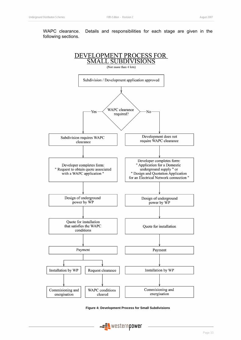
Underground Distribution Schemes Fifth Edition - Revision 2 August 2007
Page 33
WAPC clearance. Details and responsibilities for each stage are given in the following sections.
Figure 4: Development Process for Small Subdivisions
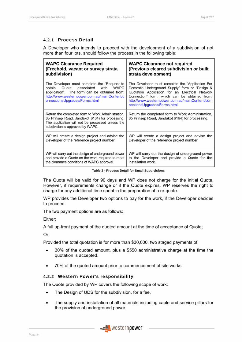
Underground Distribution Schemes Fifth Edition - Revision 2 August 2007
Page 34
4.2.1 Process Detail
A Developer who intends to proceed with the development of a subdivision of not more than four lots, should follow the process in the following table:
WAPC Clearance Required (Freehold, vacant or survey strata subdivision)
WAPC Clearance not required (Previous cleared subdivision or built strata development)
The Developer must complete the “Request to obtain Quote associated with WAPC application”. The form can be obtained from: http://www.westernpower.com.au/mainContent/connectionsUpgrades/Forms.html
The Developer must complete the “Application For Domestic Underground Supply” form or “Design & Quotation Application for an Electrical Network Connection” form, which can be obtained from: http://www.westernpower.com.au/mainContent/connectionsUpgrades/Forms.html
Return the completed form to Work Administration, 85 Prinsep Road, Jandakot 6164) for processing. The application will not be processed unless the subdivision is approved by WAPC.
Return the completed form to Work Administration, 85 Prinsep Road, Jandakot 6164) for processing.
WP will create a design project and advise the Developer of the reference project number.
WP will create a design project and advise the Developer of the reference project number.
WP will carry out the design of underground power and provide a Quote on the work required to meet the clearance conditions of WAPC approval.
WP will carry out the design of underground power to the Developer and provide a Quote for the installation work.
Table 2 - Process Detail for Small Subdivisions
The Quote will be valid for 90 days and WP does not charge for the initial Quote. However, if requirements change or if the Quote expires, WP reserves the right to charge for any additional time spent in the preparation of a re-quote.
WP provides the Developer two options to pay for the work, if the Developer decides to proceed.
The two payment options are as follows:
Either:
A full up-front payment of the quoted amount at the time of acceptance of Quote;
Or:
Provided the total quotation is for more than $30,000, two staged payments of:
• 30% of the quoted amount, plus a $550 administrative charge at the time the quotation is accepted.
• 70% of the quoted amount prior to commencement of site works.
4.2.2 Western Power’s responsibility
The Quote provided by WP covers the following scope of work:
• The Design of UDS for the subdivision, for a fee.
• The supply and installation of all materials including cable and service pillars for the provision of underground power.
Underground Distribution Schemes Fifth Edition - Revision 2 August 2007
Page 35
• The supply and installation of streetlights, if required.
• The trenching and laying of cables.
• WP will provide a service connection point in the form of a service pillar at property boundaries. Any electrical installation beyond service pillars is the responsibility of landowners or the Developer.
4.2.3 Developer’s responsibility
The Developer/customer’s scope of work and expenses include the following:
• The accurate pegging of all subdivision and lot boundaries.
• Providing land for the installation of a substation (transformers and switchgear) if required. The land must be incorporated as part of public road reserves, at no cost to WP.
• Prior to the commencement of any work, the Developer must ensure the finished levels at each service pillar and substation site are set and all final survey boundaries pegs are in place.
• Any verge reinstatement, the clearing or pruning of vegetation to WP’s required safety profiles and relocation of other services, such as gas or water. Developers should liaise directly with the local council or service utility with regard to the cost of this work or repairs.
• Obtain all necessary and relevant clearances required, including environmental clearance, native title, aboriginal heritage, etc.
• Where an easement is required by WP, the Developer must provide the easement at no cost to WP.
• Advise potential land purchasers of all easement locations and their proposed use and restrictions.
• Notify all affected parties, including other WP customers affected by the development. Where existing aerial mains are to be removed as part of the subdivision work, the Developer will also be responsible for the reconnection of existing WP connected customers to underground power and the cost to carry out the work.
• Electrical installations beyond service pillars including consumers’ main cables between service pillars and meter boards.
• Coordination of all other services work.
• Ensure the site is safe, in accordance with the Occupational Health Act 1984 and Occupational and Health Regulations 1996 and other Acts of Parliament, during the construction phase.
4.3 Development of Large Subdivision of more than Four Lots Developers intending to proceed with the development of a subdivision of more than four lots shall engage a Designer organisation to produce designs in accordance with this manual.
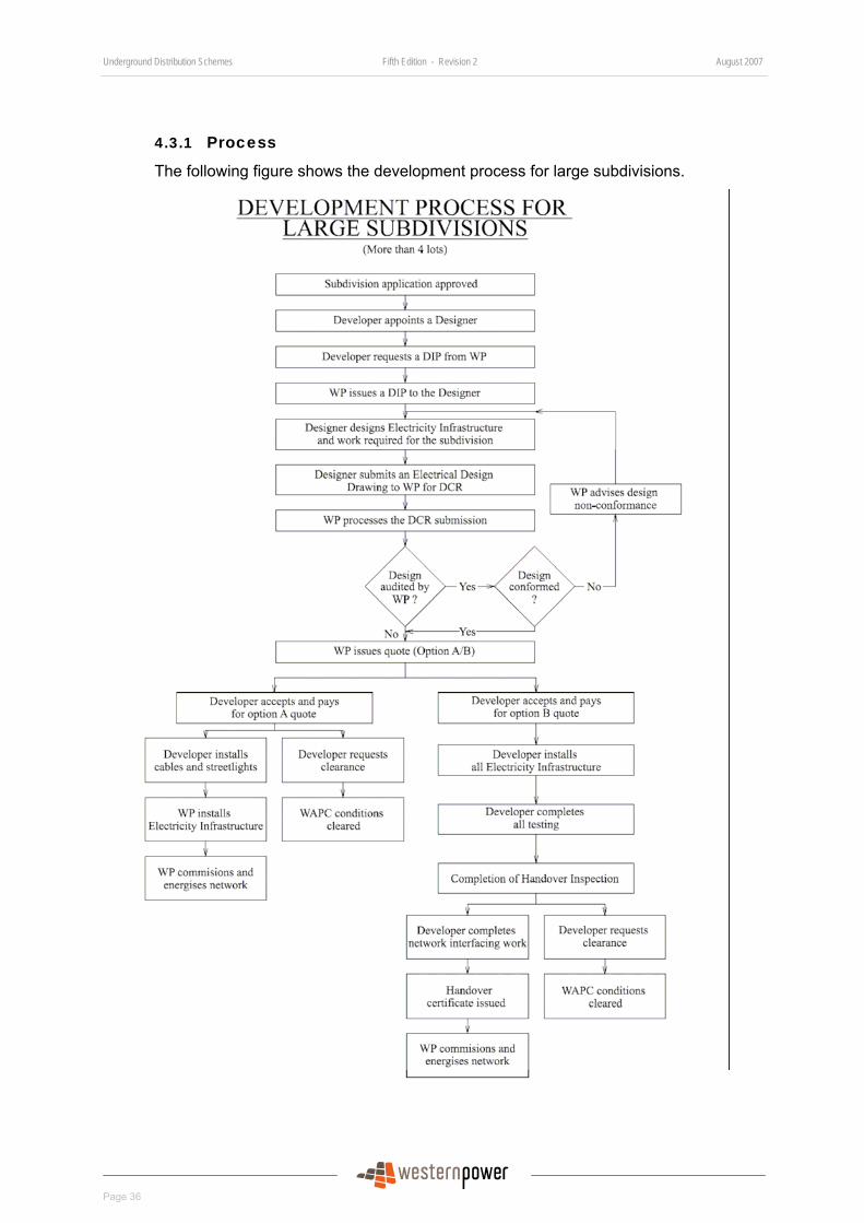
Underground Distribution Schemes Fifth Edition - Revision 2 August 2007
Page 36
4.3.1 Process
The following figure shows the development process for large subdivisions.
Underground Distribution Schemes Fifth Edition - Revision 2 August 2007
Page 37
Figure 5: Development Process for Large Subdivisions
4.3.2 Process Detail
4.3.2.1 Designs for Underground Distribution Schemes
Developers are responsible for providing UDS designs by engaging Designers to develop them. The Developer must appoint an Engineer to check and certify that UDS designs meet the requirements of this Manual. WP will:
• Provide the Designer Organisations with DIP appropriate to the developments and their locations.
• Provide a site visit service, if required, to confirm the location of any Western Power equipment.
• Audit the UDS designs certified by Engineers on random basis to ensure they conform to WP’s design requirements, planning criteria and construction practices.
4.3.2.2 Developer Requests a DIP from WP (DIP Request)
The Developer will contact WP to register responsibility for the design of an UDS for a subdivision and request a WP DIP through the electronic mailbox [email protected], in accordance with the requirements in Section 4.4.1. This contact may follow feasibility studies undertaken by the Developer based on information provided by WP.
The Developer must complete the “Subdivision Developer’s Authorisation and DIP Request” form in Appendix 2 that provides details of the appointment of the Design Organisation, the Designer and the Engineer of the UDS design; and authorises WP to directly deal with them. This form is available for download from WP’s website at:
http://www.westernpower.com.au/mainContent/connectionsUpgrades/Professional_Developers/Specialised_Forms.html.
At this point, the Developer will provide information/documentation shown in Section 4.4.1.
4.3.2.3 WP Issues a DIP to Designer Organisation
WP will review the proposed subdivision, prepare the DIP, containing the information outlined in Section 4.4.2, and issue it electronically to the Designer Organisation.
For any changes to the information contained in the DIP, written approval from WP must be obtained before they can be included in design.
The information contained in the DIP will be valid for a period of six months from date of issue.
4.3.2.4 Designer Designs UDS
On receipt of the DIP, the Designer will proceed to prepare the UDS design. At this stage, if Installation Option B is selected, it may be necessary for the Developer to negotiate with WP to specify which, if any, part of the work is to be undertaken by WP, e.g. headwork extensions. The Designer will then incorporate this into the design and capture it on the Bill of Materials. This work will be reflected in the final Quote from WP.

Underground Distribution Schemes Fifth Edition - Revision 2 August 2007
Page 38
4.3.2.5 Engineer Submits Design for Design Conformance Review (DCR)
When the UDS design is completed, the Engineer will check and certify that it meets the requirements of this manual and all applicable written laws. The Engineer or Designer will then electronically submit the design to WP for a DCR in accordance with Section 4.4.4 and quote through [email protected].
4.3.2.6 WP Processes DCR Submission
WP will perform a DCR to ensure all design parameters have been incorporated into the design process and all required design documents and certificates have been submitted.
Note that this review does not constitute approval of the design. WP takes no responsibility for the accuracy or correctness of the UDS design or associated Bill of Materials.
WP will carry out a conformance audit on the UDS designs at random. WP reserves the right to carry out a conformance audit on every UDS design by WP or WP appointed person.
When a UDS design is audited by WP, WP will advise the Designer whether the design is accepted or rejected due to non-conformance. If it is rejected, WP will give the reasons of non-conformance and advise the Designer of the re-conformance review fee. The Designer may then redesign and resubmit the scheme with the required re-conformance review fee.
4.3.2.7 Quote Issue
WP will issue a Quote for both Installations Option A & B to the Developer of the UDS design except those which fail the conformance audit. These Quotes will include standard charges, DIP and DCR fees, network interface work costs and quality assurance charges.
4.3.2.8 Formal Offer Validity
The formal offer from WP in the form of a Quote is valid for a period of three months from the date of official correspondence. If payment has not been made within that three month validity period, the project file will be cancelled unless agreement in writing is received from W P to extend. Should the project be re-established at a later date, it will be treated as a new subdivision and subject to charges.
4.3.2.9 Developer Accepts and Pays Quote
If the Developer accepts the Quote, the process will proceed in accordance with the selected Installation Option A or B.
The Developer is responsible for advising all other authorities or groups involved in the underground services e.g. Telstra, local councils, etc, and issuing drawings as necessary.
Installation will be coordinated through the nominated WP resource centre.
WP will order the materials that it is to provide after payment of the quotation.
The order will be based on the Bill of Materials provided by the Designer. WP takes no responsibility for the accuracy or correctness of the Bill of Materials. A copy of materials to be ordered will be forwarded with the quotation letter for verification.

Underground Distribution Schemes Fifth Edition - Revision 2 August 2007
Page 39
Under Installation Option B, the Developer will be responsible for purchasing materials, excepting those required for the work agreed to be undertaken by WP.
Errors in design or Bill of Quantities which result in under-ordering of materials and under-quoting for the installation of equipment will result in WP issuing an amended Quote or additional quotation to the Developer.
4.3.2.10 Payment of Quote
Installation Option “A” Two payment options are available to the customer as follows:
Either:
• A full up-front payment of the quoted amount at time of Acceptance of Quote.
Or;
• Provided the total quotation is for more than $30,000, three staged payments of:
30% of the quoted amount, plus a $550 administrative charge at the time the quotation is accepted.
40% of the quoted amount prior to commencement of site works.
30% of the quoted amount prior to clearance of subdivision survey diagram.
Installation Option “B” A full up-front payment of all charges applicable.
4.3.3 Developer’s Responsibilities
Developers shall fulfil the following responsibilities in accordance with the requirements of Installation Option A or Installation Option B (see Section 6.2).
The Developer’s scope of work and expenses include the following:
• The Developer shall engage and appoint a Designer Organisation to design the electrical reticulation of the subdivision and represent them in all matters relating to the design.
• The Developer shall appoint an Engineer, who must have professional indemnity insurance of no less than $5 million, to oversee the design of the UDS and to certify the UDS design meets the requirements of this manual and all applicable written laws.
• The Developer shall appoint a Site Superintendent/Project Engineer.
• The Developer shall engage contractors to carry out construction of the subdivision.
• The Developer is fully responsible for ensuring that the Designer and Designer Organisation, the Site Superintendent/Project Engineer and installation contractors fulfil their responsibilities during the design and construction phases. The Developer has the ultimate responsibility for meeting WP’s requirements.
Underground Distribution Schemes Fifth Edition - Revision 2 August 2007
Page 40
• Providing land for the installation of a substation (transformers and switchgear), if required. The land must be incorporated as part of public road reserves or public open space (POS) at no cost to WP.
• Where an easement is required by WP, the Developer must provide the easement at no cost to WP.
• All necessary and required civil works.
• Advise potential land purchasers of all easement locations and their proposed use and restrictions.
• The Developer is responsible for notifying, negotiating with and obtaining agreement and approval from all parties, including other WP customers affected by the subdivision work. Where existing aerial mains are to be removed as part of the subdivision work, the Developer is responsible for reconnecting existing WP customers to underground power and associated costs. Where Electricity Infrastructure is to be installed in a road reserve, the Developer must obtain the approval of the relevant road authority.
• The Developer must notify, negotiate with and obtain agreement of the parties affected on the removing of vegetation from neighbouring properties and/or road reserves arising from the work associated with a UDS in a subdivision.
• Providing WP with ”As Constructed” drawings and “As Constructed” records.
For Installation Option A subdivision, the Developer shall also responsible for the following additional work:
• Providing WP with a Bill of Quantities for equipment.
• Installing WP supplied streetlights.
• Supplying and installing private streetlighting.
• Installing and testing all cables including streetlighting cables and streetlighting standards in accordance with this manual.
• Ensuring the security of cable and other equipment delivered to site.
• Providing WP with a 12 month warrantee on all cables installations and civil works.
For Installation Option B subdivision, the Developer shall also responsible for the following additional work:
• Supplying, installing and testing all cables and equipment and jointing cables, including jointing and termination on to existing WP cables and equipment, in accordance with this manual.
• Providing equipment that meets WP’s technical requirements.
• Supplying and installing streetlights.
Underground Distribution Schemes Fifth Edition - Revision 2 August 2007
Page 41
• Providing WP with a 12 month warrantee for all equipment, installations and civil works.
The Developer is ultimately responsible to ensure that all design and construction works of a UDS meet the requirements of this Manual.
4.3.4 Western Power’s Responsibilities
WP is responsible for:
• Providing a DIP (and if appropriate, information for preliminary feasibility studies) necessary to allow the Developer’s Designer to design the UDS scheme.
• Reviewing the Developer’s DCR submission. This is not an approval or endorsement of the design. That is the responsibility of the Engineer.
• Handling technical and construction matters with the Developer’s representatives through the Construction Manager (CM).
For Installation Option A subdivision, WP will also responsible for:
• Supplying all cables for the Developer to lay.
• Jointing and terminating cables.
• Supplying and installing all other equipment.
• Carrying out quality assurance of the installation and testing of equipment excluding cables.
For Installation Option B subdivision, WP will also responsible for:
• Carrying out quality assurance audits at key stages of installation and testing.
• WP may witness any tests performed by the Developer’s installation contractor and/or perform its own tests prior to take over of the works.
4.3.5 Charges and Refunds
4.3.5.1 Charges General
The charges contained in the formal offer are provided on the basis that all necessary information has been provided by the Developer and unless otherwise specified, the following assumptions have been made on work to be carried out by WP:
• All WP work will be undertaken within normal working hours unless otherwise specifically stated in the Quote. The Developer may request WP to carry out quality assurance inspections and witness any tests after hours (additional costs will apply).
• The site is readily accessible by a two wheel drive vehicle.
• Site plans without contours marked shall be assumed to be level.
• Site access is on a continuous basis. Site access and conditions are not detrimental to WP employees’ or contractors’ ability to work in an efficient, productive and safe manner.
Underground Distribution Schemes Fifth Edition - Revision 2 August 2007
Page 42
• The work-site is a greenfield site and clear access is available to trench on the allocated alignment without obstruction from other services, vegetation, etc.
• All trenching is carried out in sandy soils free of rock.
• All trenching is able to be carried out by machine.
• Reinstatement is based on minimum greenfield reinstatement.
• Trenches are level and accurately follow the allocated alignment resulting in minimum cable lengths.
• All survey information, including boundaries, is accurate.
• Lot boundaries as shown on the pre-calculated plan are correct.
• Electrical demand allocations are as shown on the design drawings. These are calculated on the basis of either information provided by the Developer or WP standard values.
Any additional costs arising from deviations in these assumptions will be charged to the Developer. If any of the above assumptions are not applicable, WP must be informed to enable the calculation of new charges and avoid delays.
Changes to the subdivision layout, land use, zoning or the project staging may result in design changes and may incur additional charges.
4.3.5.2 Subdivision Charges for Individual Installation Options A and B Schemes
The latest subdivision charges are shown at:
http://www.westernpower.com.au/mainContent/connectionsUpgrades/policiesRegulations/technicalDocumentation.html.
The charges indicated in the above document are minimum charges assuming Designers use WP’s software and standard presentation of designs. WP reserves the right to charge additional sums for designs, drawings, and calculations and study results not presented in the format as given in Table 5.
4.3.5.3 Charges Arising from Redesign
The amount of additional expenses incurred by WP due to design revisions will vary. Hence the Developer should refer to the appropriate WP contact as soon as possible to determine any change to the total project cost. If installation has already commenced when a revision is requested, WP may also charge “stand-down” expenses.
Design changes which result in the need for WP to reissue DIPs or repeat conformance reviews will incur additional charges.
4.3.5.4 Refunds
If a project is cancelled at the Developer’s request during construction, full payment made will be refunded less all non-recoverable costs (including material and/or labour) incurred by WP.
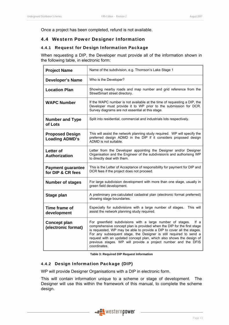
Underground Distribution Schemes Fifth Edition - Revision 2 August 2007
Page 43
Once a project has been completed, refund is not available.
4.4 Western Power Designer Information
4.4.1 Request for Design Information Package
When requesting a DIP, the Developer must provide all of the information shown in the following table, in electronic form:
Project Name Name of the subdivision, e.g. Thomson’s Lake Stage 1
Developer’s Name Who is the Developer?
Location Plan Showing nearby roads and map number and grid reference from the StreetSmart street directory.
WAPC Number If the WAPC number is not available at the time of requesting a DIP, the Developer must provide it to WP prior to the submission for DCR. Survey diagrams are not essential at this stage.
Number and Type of Lots
Split into residential, commercial and industrials lots respectively.
Proposed Design Loading ADMD’s
This will assist the network planning study required. WP will specify the preferred design ADMD in the DIP if it considers proposed design ADMD is not suitable.
Letter of Authorization
Letter from the Developer appointing the Designer and/or Designer Organisation and the Engineer of the subdivision/s and authorising WP to directly deal with them.
Payment guarantee for DIP & CR fees
This is the Letter of Acceptance of responsibility for payment for DIP and DCR fees if the project does not proceed.
Number of stages For large subdivision development with more than one stage, usually in green field development.
Stage plan A preliminary pre-calculated cadastral plan (electronic format preferred) showing stage boundaries.
Time frame of development
Especially for subdivisions with a large number of stages. This will assist the network planning study required.
Concept plan (electronic format)
For greenfield subdivisions with a large number of stages. If a comprehensive concept plan is provided when the DIP for the first stage is requested, WP may be able to provide a DIP to cover all the stages. For any subsequent stage, the Designer is still required to send a request with an updated concept plan, which also shows the design of previous stages. WP will provide a project number and the DFIS coordinates.
Table 3: Required DIP Request Information
4.4.2 Design Information Package (DIP)
WP will provide Designer Organisations with a DIP in electronic form.
This will contain information unique to a scheme or stage of development. The Designer will use this within the framework of this manual, to complete the scheme design.
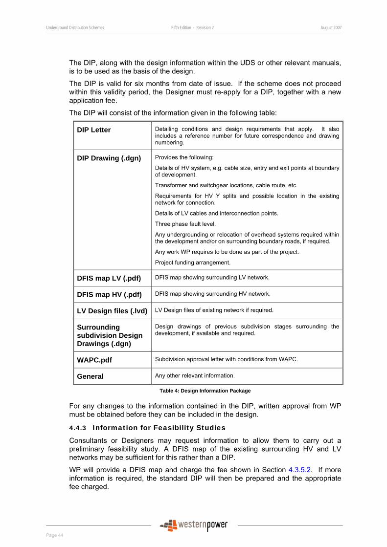
Underground Distribution Schemes Fifth Edition - Revision 2 August 2007
Page 44
The DIP, along with the design information within the UDS or other relevant manuals, is to be used as the basis of the design.
The DIP is valid for six months from date of issue. If the scheme does not proceed within this validity period, the Designer must re-apply for a DIP, together with a new application fee.
The DIP will consist of the information given in the following table:
DIP Letter Detailing conditions and design requirements that apply. It also includes a reference number for future correspondence and drawing numbering.
DIP Drawing (.dgn) Provides the following:
Details of HV system, e.g. cable size, entry and exit points at boundary of development.
Transformer and switchgear locations, cable route, etc.
Requirements for HV Y splits and possible location in the existing network for connection.
Details of LV cables and interconnection points.
Three phase fault level.
Any undergrounding or relocation of overhead systems required within the development and/or on surrounding boundary roads, if required.
Any work WP requires to be done as part of the project.
Project funding arrangement.
DFIS map LV (.pdf) DFIS map showing surrounding LV network.
DFIS map HV (.pdf) DFIS map showing surrounding HV network.
LV Design files (.lvd) LV Design files of existing network if required.
Surrounding subdivision Design Drawings (.dgn)
Design drawings of previous subdivision stages surrounding the development, if available and required.
WAPC.pdf Subdivision approval letter with conditions from WAPC.
General Any other relevant information.
Table 4: Design Information Package
For any changes to the information contained in the DIP, written approval from WP must be obtained before they can be included in the design.
4.4.3 Information for Feasibility Studies
Consultants or Designers may request information to allow them to carry out a preliminary feasibility study. A DFIS map of the existing surrounding HV and LV networks may be sufficient for this rather than a DIP.
WP will provide a DFIS map and charge the fee shown in Section 4.3.5.2. If more information is required, the standard DIP will then be prepared and the appropriate fee charged.
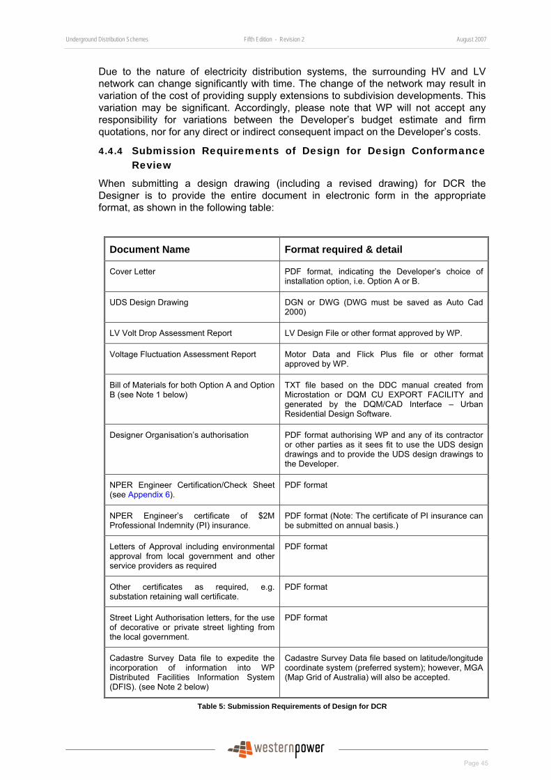
Underground Distribution Schemes Fifth Edition - Revision 2 August 2007
Page 45
Due to the nature of electricity distribution systems, the surrounding HV and LV network can change significantly with time. The change of the network may result in variation of the cost of providing supply extensions to subdivision developments. This variation may be significant. Accordingly, please note that WP will not accept any responsibility for variations between the Developer’s budget estimate and firm quotations, nor for any direct or indirect consequent impact on the Developer’s costs.
4.4.4 Submission Requirements of Design for Design Conformance Review
When submitting a design drawing (including a revised drawing) for DCR the Designer is to provide the entire document in electronic form in the appropriate format, as shown in the following table:
Document Name Format required & detail
Cover Letter PDF format, indicating the Developer’s choice of installation option, i.e. Option A or B.
UDS Design Drawing DGN or DWG (DWG must be saved as Auto Cad 2000)
LV Volt Drop Assessment Report LV Design File or other format approved by WP.
Voltage Fluctuation Assessment Report Motor Data and Flick Plus file or other format approved by WP.
Bill of Materials for both Option A and Option B (see Note 1 below)
TXT file based on the DDC manual created from Microstation or DQM CU EXPORT FACILITY and generated by the DQM/CAD Interface – Urban Residential Design Software.
Designer Organisation’s authorisation PDF format authorising WP and any of its contractor or other parties as it sees fit to use the UDS design drawings and to provide the UDS design drawings to the Developer.
NPER Engineer Certification/Check Sheet (see Appendix 6).
PDF format
NPER Engineer’s certificate of $2M Professional Indemnity (PI) insurance.
PDF format (Note: The certificate of PI insurance can be submitted on annual basis.)
Letters of Approval including environmental approval from local government and other service providers as required
PDF format
Other certificates as required, e.g. substation retaining wall certificate.
PDF format
Street Light Authorisation letters, for the use of decorative or private street lighting from the local government.
PDF format
Cadastre Survey Data file to expedite the incorporation of information into WP Distributed Facilities Information System (DFIS). (see Note 2 below)
Cadastre Survey Data file based on latitude/longitude coordinate system (preferred system); however, MGA (Map Grid of Australia) will also be accepted.
Table 5: Submission Requirements of Design for DCR
Underground Distribution Schemes Fifth Edition - Revision 2 August 2007
Page 46
Note 1: The Bill of Materials must cover the materials which WP is to provide, i.e. for Option A all materials, and for Option B only the materials for the work agreed to be undertaken by WP. It is to be based on compatible units contained in WP’s DDC. It shall be in a format suitable for direct loading into WP’s DQM.
Note 2:
• The Cadastre Survey Data (CSD) file should only include the pre-calculated cadastral plan of the current subdivision stage where WP asset are to be installed.
• If the CSD file is not provided with the submission for DCR, it is to be provided to WP through the electronic mail box [email protected] at least five working days prior to Handover inspection for Option B subdivisions or at least 20 working days prior to energisation for Option A subdivisions.
The CSD file is required to be input into WP’s GIS data base so that the necessary switching and commissioning program can be produced for the energisation of the subdivision.
4.4.5 Revision of Design Due to Major and Minor Changes While Under Construction
During the construction of the subdivision there may be changes to the requirements of the subdivision which will require changes in the electrical design.
4.4.5.1 Major Changes in Design
If major changes are made to a design after design conformance and payment has been received from the Developer, the Designer must submit the revised design drawing to WP for a DCR of revision while under construction.
The following changes are considered major and a DCR of revision while under construction is required.
• Encroachment on any easements.
• Relocation of uni-pillars.
• Addition or deletion of pillars
• Installation of cables (HV or LV cables) to the 2.7m pole alignment, other than to avoid trees and rocks.
• Change of cable route.
• Change of status of switching points.
• Relocation of switchgear or transformer substation.
• Addition or deletion of lots in the subdivision.
• Addition or deletion of streetlights.
Underground Distribution Schemes Fifth Edition - Revision 2 August 2007
Page 47
4.4.5.2 Minor changes in Design
If the changes are minor and not significant enough to warrant a review of the design, they can be approved by the CM. However, the changes must be shown on the “As Constructed” drawing.
The following changes are considered minor changes and can be approved by CM on site.
• Minor adjustment of cable truncation.
• Minor relocation of streetlights of not more than 20m within the streetlighting alignment (outside transmission line easement) and the design continues to comply with relevant standards and requirements.
• Relocation of pillar for reticulation pump along the same LV feeder towards the district substation.
• Relocation of mini pillars across side lot boundary from the corner of a lot to the corner of the adjacent lot.
• Installation of cables (HV or LV cables) to the 2.7m pole alignment to avoid trees and rocks only.
4.5 Submission for DCR with Approved Non Standard Equipment
Approved non-standard equipment can only be used in Installation Option B subdivisions where the Developers are responsible for supplying and installing materials and equipment. A Developer must notify WP when it intends to use approved non-standard equipment in subdivisions, according to the following process.
To gain approval for non-standard equipment or find out what non standard equipment has been approved see Section 7.5.
4.5.1 Prior to DCR and Quote Issued by Western Power
Where the Developer knows that they are going to use non-standard equipment, prior to submission to WP:
• The Designer shall show on the design drawing the detail of approved equipment to be installed when the design is submitted for DCR.
• For approved non-standard switchgear, the make and equipment part number must be shown on the drawing.
• For approved non-standard transformers, the make and WP dummy stock code must be shown on the drawing. The Developer must also stencil the dummy stock code on the external surface of the transformer tank.
• For all other approved non-standard equipment, details will be stated on the Letter of Approval.
• WP will carry out the DCR.
• When the design is submitted as conforming, WP will only issue a Quote for Installation Option B.
Underground Distribution Schemes Fifth Edition - Revision 2 August 2007
Page 48
Note: The equipment part number or the dummy stock code of non-standard equipment will be provided on the ‘Certificate of Approval’ of the equipment.
4.5.2 After DCR and Quote Issued by Western Power
Where the Developer decides to use non-standard equipment after DCR:
• The Designer shall revise the design drawing to include details of approved non-standard equipment to be used.
• For approved non-standard switchgear, the make and equipment part number shall be shown on the drawing.
• For approved non-standard transformers, the make and WP dummy stock code must be shown on the drawing. The Developer must also stencil the dummy stock code on the external surface of the transformer tank.
• For all other approved non-standard equipment, details will be stated on the Letter of Approval.
• The Designer must submit the revised design drawing as a revision for DCR.
• The Developer shall also sign and return the Installation Option B Acceptance of Quote form, together with any payment required to WP within two working days of the submission of a revision for DCR to avoid any revision charges.
• WP will review the revised design for conformance.
• When the revised design is submitted as conforming, it will proceed to installation.
Note: The equipment part number or the dummy stock code of non-standard equipment will be provided on the ‘Certificate of Approval’ of the equipment.
4.6 Dispute Resolution Process A formal issue resolution path was established and announced in July 2005 through the Urban Power Bulletin. It provides a mechanism allowing Developers/Designers to raise issues about specific subdivision projects. It also provides a higher channel to raise the issue if Developers/Designers feel it has not been satisfactorily resolved. The process has been enhanced by appointing a Market Segment Manager who will act as the customer advocate and is shown in the following figure:
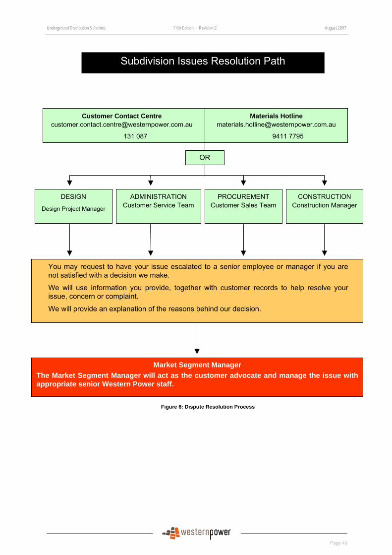
Underground Distribution Schemes Fifth Edition - Revision 2 August 2007
Page 49
Figure 6: Dispute Resolution Process
Customer Contact Centre [email protected]
131 087
Materials Hotline [email protected]
9411 7795
DESIGN
Design Project Manager
ADMINISTRATION Customer Service Team
PROCUREMENT Customer Sales Team
CONSTRUCTION Construction Manager
OR
You may request to have your issue escalated to a senior employee or manager if you are not satisfied with a decision we make.
We will use information you provide, together with customer records to help resolve your issue, concern or complaint.
We will provide an explanation of the reasons behind our decision.
Market Segment Manager The Market Segment Manager will act as the customer advocate and manage the issue withappropriate senior Western Power staff.
Subdivision Issues Resolution Path

Underground Distribution Schemes Fifth Edition - Revision 2 August 2007
Page 50
5 Design Policy and Requirements This section informs Designers of WP’s policies and requirements for the design of the Electricity Infrastructure in underground distribution network in subdivisional developments.
5.1 Designer qualification and experience Designer organisations must employ or engage Engineers and Designers with the following minimum qualifications and experience:
5.1.1 Engineer
The Engineer
• Must be in the discipline of Electrical Engineering with proven experience in subdivision electrical distribution design and must be registered as a professional engineer on the National Professional Engineer Register (NPER).
• Must be appointed by and responsible to the Developer.
• Must have Professional Indemnity (PI) insurance of no less than $2 million. Where the Engineer’s PI insurance is already covered by the policies of professional liability insurance of the Designer Organisation a separate PI insurance is not required.
5.1.2 Designer
A Designer must have the following qualification and experience:
• Formal training in electrical engineering with at least a certificate in Electrical Engineering from a nationally accredited institute in Australia or suitable electrical trade qualification.
• Experienced in electrical distribution design.
• Proficient in drafting skills, preferably Microstation.
• Must also be competent in the application of WP design software of LV Design and Flicker.
5.1.3 Designer Organisation
The Designer Organisation:
• Must employ an Engineer and Designer/s to design the electrical reticulation of subdivisions.
• Must be authorised in writing by the Developer to represent it in all matters relating to the design of Electricity Infrastructure for subdivisions.
• Is responsible to the Developer.
Underground Distribution Schemes Fifth Edition - Revision 2 August 2007
Page 51
5.2 Engineer’s, Designer’s and Designer Organisation’s Responsibilities
5.2.1 Engineer’s Responsibility
The Engineer is responsible for:
• Overseeing the design of all Electricity Infrastructure in each UDS.
• Approving the design of all Electricity Infrastructure in each UDS.
• Certifying UDS designs comply with the requirements of this manual and all applicable written laws, and
• Ensuring that a UDS design is safe to construct and connect to WP’s network.
5.2.2 Designer’s Responsibility
The Designer is responsible for:
• Designing the UDS in accordance with all applicable written laws and the requirements of this manual.
• Providing any information required by WP to process the DIP and DCR, including site formation and design information from the Developer’s Civil Engineer and Surveyor.
• Preferably attend pre-start meeting on site and resolve any site issues arising from the construction of UDS in a subdivision development.
5.2.3 Designer Organisation’s Responsibilities
This section has been written so that either the Designer or Engineer can perform the design of Electricity Infrastructure of a UDS. This includes:
• Representing the Developer of a subdivision development in all matters relating to the design and construction of UDS. This authorisation must be signed by the Developer.
• Inspecting the site prior to designing the UDS to check any particular site requirements are included in the UDS design.
• Communicating the requirements of the Developer to WP.
• Communicating the requirements of WP to the Developer.
• Notifying all concerned parties, including other WP customers affected by the development of a subdivision.
• Obtaining all relevant clearances and approvals required for the UDS, including environmental, native title, Aboriginal heritage etc., and providing them to WP.
• Obtaining approval from local government, other service providers (such as Main Roads WA and Telstra) and other affected parties (such as other WP customers).
• Providing WP with electronic “As Constructed” drawings of the UDS.
Underground Distribution Schemes Fifth Edition - Revision 2 August 2007
Page 52
5.3 Design Requirements All UDS designs must comply with the Electricity (Supply Standards and System Safety) Regulations 2001, WP’s requirements, this manual, any other relevant standards and information given in the DIP.
5.3.1 Environmental and Aboriginal Considerations
The Developer must investigate and manage environmental impacts and Aboriginal issues associated with a subdivision. The issues associated with a subdivision may include but not be limited to those given in Section 7 of Network Standard NS 14.2-2003 Underground Cable Installation Manual Part 2 –Technical Requirements which is available at:
http://www.westernpower.com.au/mainContent/connectionsUpgrades/policiesRegulations/technicalDocumentation.html.
If WP is to undertake work within or for the subdivision, the Developer is to provide copies of its environmental approvals where those approvals may cover WP work.
Information on WP’s Environmental Policy is available at:
http://www.westernpower.com.au/mainContent/environment/OurNetworkEnvironment.htm.
5.3.2 Design Load
The maximum demand on a transformer or a LV feeder, when divided by the number of loads supplied, provides a value which is in essence the “average contribution per customer”, or simply the “average demand” for a typical customer.
The maximum demand on a transformer or a LV feeder is determined by using following the formula:
Maximum Demand = (N+1)/N x ADMD per lot x number of lots,
where N = Number of lots and
ADMD = “After Diversity Maximum Demand”
For practical purposes, groups of 50 or more loads (i.e. N ≥ 50) on a transformer or a LV feeder, N x ADMD are considered to produce a figure sufficiently close to the ultimate maximum demand. The effect of ADMD will diminish when N is reduced substantially below 50.
Hence, ADMD is the average load per customer determined by dividing the group maximum demand by the number of customers in the group when the group size is at least 50.
The Developer must use design loads for all UDS subdivision designs defined below.
5.3.2.1 Residential, Single Phase, Diversified Loads
For these loads, the load kVA is to be equal to the recommended After Diversity Maximum Demand (ADMD) value in the following table:
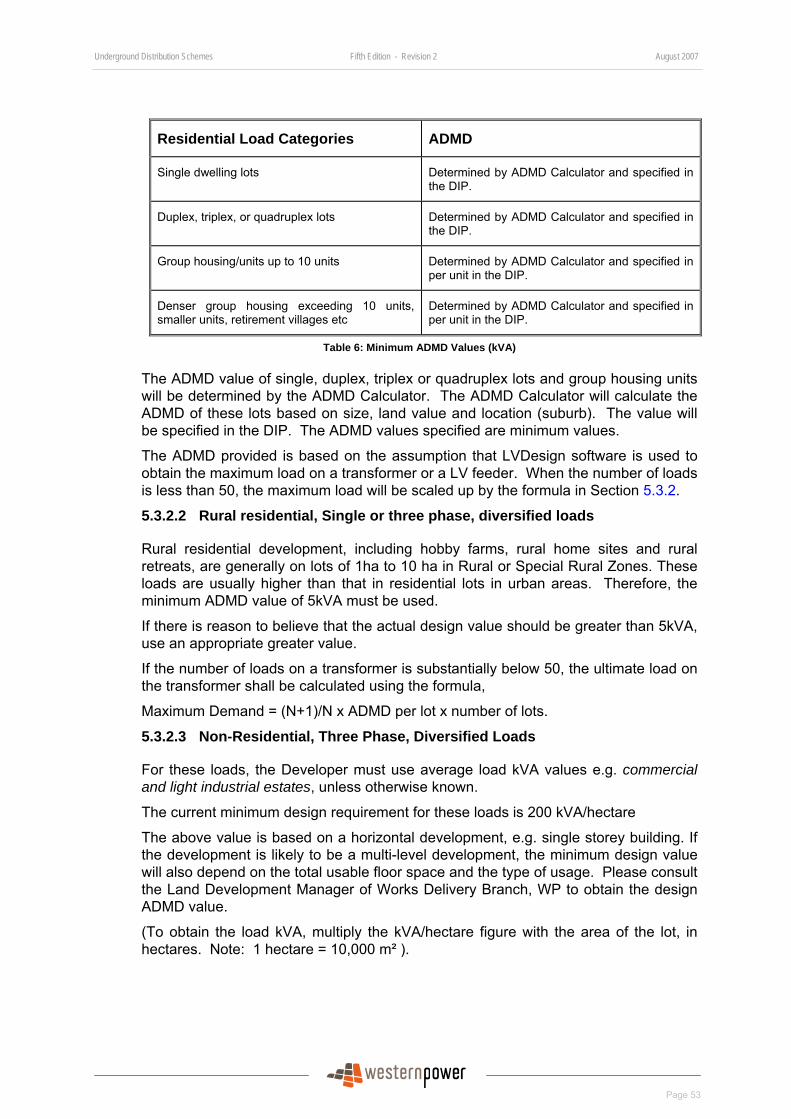
Underground Distribution Schemes Fifth Edition - Revision 2 August 2007
Page 53
Residential Load Categories ADMD
Single dwelling lots Determined by ADMD Calculator and specified in the DIP.
Duplex, triplex, or quadruplex lots Determined by ADMD Calculator and specified in the DIP.
Group housing/units up to 10 units Determined by ADMD Calculator and specified in per unit in the DIP.
Denser group housing exceeding 10 units, smaller units, retirement villages etc
Determined by ADMD Calculator and specified in per unit in the DIP.
Table 6: Minimum ADMD Values (kVA)
The ADMD value of single, duplex, triplex or quadruplex lots and group housing units will be determined by the ADMD Calculator. The ADMD Calculator will calculate the ADMD of these lots based on size, land value and location (suburb). The value will be specified in the DIP. The ADMD values specified are minimum values.
The ADMD provided is based on the assumption that LVDesign software is used to obtain the maximum load on a transformer or a LV feeder. When the number of loads is less than 50, the maximum load will be scaled up by the formula in Section 5.3.2.
5.3.2.2 Rural residential, Single or three phase, diversified loads
Rural residential development, including hobby farms, rural home sites and rural retreats, are generally on lots of 1ha to 10 ha in Rural or Special Rural Zones. These loads are usually higher than that in residential lots in urban areas. Therefore, the minimum ADMD value of 5kVA must be used.
If there is reason to believe that the actual design value should be greater than 5kVA, use an appropriate greater value.
If the number of loads on a transformer is substantially below 50, the ultimate load on the transformer shall be calculated using the formula,
Maximum Demand = (N+1)/N x ADMD per lot x number of lots.
5.3.2.3 Non-Residential, Three Phase, Diversified Loads
For these loads, the Developer must use average load kVA values e.g. commercial and light industrial estates, unless otherwise known.
The current minimum design requirement for these loads is 200 kVA/hectare
The above value is based on a horizontal development, e.g. single storey building. If the development is likely to be a multi-level development, the minimum design value will also depend on the total usable floor space and the type of usage. Please consult the Land Development Manager of Works Delivery Branch, WP to obtain the design ADMD value.
(To obtain the load kVA, multiply the kVA/hectare figure with the area of the lot, in hectares. Note: 1 hectare = 10,000 m² ).
Underground Distribution Schemes Fifth Edition - Revision 2 August 2007
Page 54
5.3.2.4 Single Phase, Non-Diversified, Discrete Loads
For these loads, the Developer must use maximum load kVA values, e.g. from the name-plate rating, equipment specifications or by measurement.
(e.g. Street lights, pumps, and other significant single phase loads).
To obtain the maximum kVA value for a single phase load, use either:
Single Phase kVA = rpowerfacto
kW ;
or Single Phase kVA =VI= 1000240 * I
5.3.2.5 Three Phase, Non-Diversified, Discrete Loads
For these loads, the Developer must only use maximum load kVA values calculated in accordance with the guidance given in AS/NZS 3000, e.g.:
• High schools: as specified by designer or electrical consultant and a minimum of 600kVA.
• Primary schools: as specified by designer or electrical consultant and a minimum of 250kVA.
• Neighbourhood shopping centres: obtain the load kVA based on a minimum load density of 200 kVA/hectare; or as specified by designer or electrical consultant with a minimum of 200kVA/hectare.
• Large shops/business centres: as specified by designer or electrical consultant.
• Pumps and other large 3-phase fixed equipment: obtain from equipment name-plate or specifications.
5.3.3 General Locations of all above Ground Asset
The Developer must ensure that all above ground assets including service pillars, streetlights and low voltage (LV) frames are located on ground level 300mm above 100 year flood level and not in a precarious position. High voltage equipment and substations must be located one metre above the 100 year flood level.
5.3.4 Point of Supply
Point of supply is where electricity is supplied and is the W P network and customer interface. It is also called point of connection.
WP will only provide one point of supply per freehold title lot and the point of supply will usually be in the form of a service pillar, a LV frame or a transformer at lot boundary.
WP will only provide one point of supply to service all the survey-strata lots that may include “common property lot” shown on a strata plan.
For residential lots, one mini-pillar will be installed to serve two lots. If Developers intend to install one service pillar per lot due to special circumstances, such as parapet walls built to property boundary or retaining walls higher than 300mm, they must provide justifications to WP and obtain the approval of WP.
Underground Distribution Schemes Fifth Edition - Revision 2 August 2007
Page 55
A uni-pillar should be provided for any group housing lot (building strata or survey strata) with more than four dwelling units or where loads exceed 63A.
Each industrial or commercial lot must be provided with a fused supply, either from a direct transformer connection or a uni-pillar.
5.3.5 Service Pillar Location
When lots face gazetted public road, service pillars must be located within the lot boundaries at the corner, as shown on drawing No. UDS-6-1P in the Appendix of Network Standard NS 14.2 Underground Cable Installation Manual Part 2 – Technical Requirements which is available at:
http://www.westernpower.com.au/mainContent/connectionsUpgrades/policiesRegulations/technicalDocumentation.html.
Service pillars will only be permitted in gazetted laneways where there are no other roads in the vicinity, or it is necessary because of high retaining walls along front property boundary prevent a safe access for operational and maintenance purposes.
5.3.6 Service Pillar Exclusion Zone
It is preferred no other utility services shall pass through or be located within the service pillar exclusion zone.
If the service pillar is a uni-pillar, the exclusion zone is the area of 1000mm x 1000mm at the property corner where the pillar is to be installed.
If a mini-pillar is to be installed, the exclusion zone is the area of 800mm (L) x 900mm (D) at the property corner where the pillar is to be installed. L is measured along street boundary and D is measured along common property boundary.
5.3.7 HV Cables
The Developer must ensure that the following high voltage cables are used as a minimum for all UDS works, as indicated below unless otherwise specified in the DIP.
Cables used on 6 to 22KV 3-phase systems between RMUs 240mm² copper XLPE insulated, PVC/HDPE sheathed cables used on 6.6KV, 11KV and 22KV systems before Y-split or the exit cable of not less than two km from zone substations.
3x1 core 185mm² aluminium XLPE insulated, PVC/HDPE sheathed cables after Y-split.
Note: WP will specify the size of HV cables to be used for specific situation in the DIP.
Cables used on 33KV 3 phase systems between RMUs 3x1 core 185mm² aluminium XLPE insulated PVC/HDPE sheathed cables.
Cables used on 6KV, 11KV and 22KV 3-phase between RMUs and Transformers or down stream of DOFs 3x1 core 35mm² aluminium XLPE insulated PVC/HDPE sheathed cables.
Cables 33KV 3-phase between RMUs and transformers or down stream of DOFs 3x1 core 50mm² aluminium XLPE insulated PVC/HDPE sheathed cables.
SPUD Transformer Cables 12.7/22KV 1 core 35mm² aluminium XLPE insulated PVC/HDPE sheathed cables.
Underground Distribution Schemes Fifth Edition - Revision 2 August 2007
Page 56
5.3.8 LV Cables
The Developer must ensure that the following low voltage cables are used for all UDS works as a minimum, unless otherwise specified.
Feeder Cables 240mm², 3 core, solid aluminium conductor, copper screen neutral (wave wound), 0.6/1 KV, XLPE insulated, PVC sheathed cables.
120mm² cables can only be used for a spur feeder with not more than six residential lots connected or for rural lots connected to a 63kVA 3-phase transformer where the feeder length is not exceeding 500m.
Mini-pillar Connection Cables 25mm², 3 core, stranded copper conductor, helical wound stranded copper neutral screen, 0.6/1KV, XPLE insulated Orange PVC sheath cables.
Streetlighting Cables Single core 10mm² or 16mm² stranded copper, XLPE insulated, helical copper wire neutral screen, PVC sheathed cables.
25mm², 3 core, stranded copper conductor, helical wound stranded copper neutral screen, 0.6/1KV, XPLE insulated Orange PVC sheath cables.
5.3.9 Cable Alignment
WP requires cables to be installed on proper alignment within gazetted public road reserves. Designers intending to install cables through private properties, Public Open Space (POS) and Public Access Way (PAW), must seek prior approval from WP and the Local Government Authority.
All cables, including streetlighting cables, are to be installed on the nominal alignment of 0 to 500mm from property boundary lines along gazetted public road reserve (Reference: Utility Providers Code of Practice for Western Australia http://www.mainroads.wa.gov.au)
Any variation to the cable alignment, i.e. outside the 0-500mm alignment to the 2.7m alignment, requires the prior approval of WP. If the variation of the cable alignment affects other utility services, it must also be approved by all the affected utility providers.
Where existing cable alignment is not available, the cable alignment on the opposite side of the road is to be used.
Where the cable is out of the nominal 0 to 500mm alignment, heavy duty ducts are to be used for mechanical protection (see Section 5.3.11).
Where WP permits Streetlighting cables to be installed on the 2.7m alignment, the cables must be installed in heavy duty ducts.
5.3.10 Number of Cables Permitted within Nominal Cable Alignment in Green Field Areas
The Designer is to determine the number of cables that can be installed in the nominal cable alignment in accordance with the requirements on Drawing No. UDS-6-2 in Figure 28.. The minimum depth of cover of cables is 750mm, however, the depth of cover of cables in nominal cable alignment shall be increased as required so that cables joints will have the necessary depth of cover.
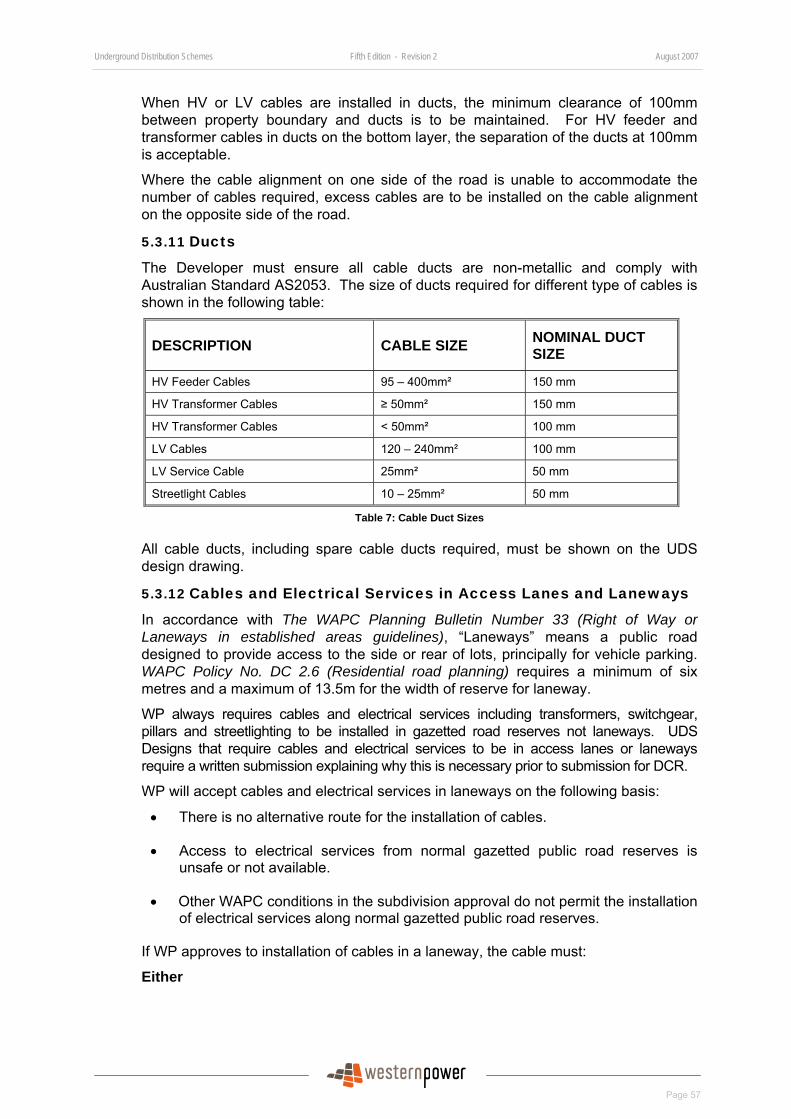
Underground Distribution Schemes Fifth Edition - Revision 2 August 2007
Page 57
When HV or LV cables are installed in ducts, the minimum clearance of 100mm between property boundary and ducts is to be maintained. For HV feeder and transformer cables in ducts on the bottom layer, the separation of the ducts at 100mm is acceptable.
Where the cable alignment on one side of the road is unable to accommodate the number of cables required, excess cables are to be installed on the cable alignment on the opposite side of the road.
5.3.11 Ducts
The Developer must ensure all cable ducts are non-metallic and comply with Australian Standard AS2053. The size of ducts required for different type of cables is shown in the following table:
DESCRIPTION CABLE SIZE NOMINAL DUCT SIZE
HV Feeder Cables 95 – 400mm² 150 mm
HV Transformer Cables ≥ 50mm² 150 mm
HV Transformer Cables < 50mm² 100 mm
LV Cables 120 – 240mm² 100 mm
LV Service Cable 25mm² 50 mm
Streetlight Cables 10 – 25mm² 50 mm
Table 7: Cable Duct Sizes
All cable ducts, including spare cable ducts required, must be shown on the UDS design drawing.
5.3.12 Cables and Electrical Services in Access Lanes and Laneways
In accordance with The WAPC Planning Bulletin Number 33 (Right of Way or Laneways in established areas guidelines), “Laneways” means a public road designed to provide access to the side or rear of lots, principally for vehicle parking. WAPC Policy No. DC 2.6 (Residential road planning) requires a minimum of six metres and a maximum of 13.5m for the width of reserve for laneway.
WP always requires cables and electrical services including transformers, switchgear, pillars and streetlighting to be installed in gazetted road reserves not laneways. UDS Designs that require cables and electrical services to be in access lanes or laneways require a written submission explaining why this is necessary prior to submission for DCR.
WP will accept cables and electrical services in laneways on the following basis:
• There is no alternative route for the installation of cables.
• Access to electrical services from normal gazetted public road reserves is unsafe or not available.
• Other WAPC conditions in the subdivision approval do not permit the installation of electrical services along normal gazetted public road reserves.
If WP approves to installation of cables in a laneway, the cable must:
Either
Underground Distribution Schemes Fifth Edition - Revision 2 August 2007
Page 58
Be installed in the 0-500mm alignment from property boundary in cable ducts with a minimum of one spare duct,
Or; Be direct buried in soil, provided 300mm of clean sand is installed below the cables and clean sand is installed above the cables all the way up to the road base with a minimum of one spare duct.
Note: Clean sand must meet the selection criteria of sand for bedding in Subdivision Design Guideline – Number 4, Bedding sand and backfill sand around cables and general backfill for cable trench – material selection guidelines which is available at:
http://www.westernpower.com.au/mainContent/connectionsUpgrades/Professional_Developers/Technical_Documentation.html.
5.3.13 Cable Near to Retaining Walls
Cables near to retaining walls must be installed in ducts. Please refer to Section 6.2.10.13 for construction requirements.
The location of all retaining walls and their civil design details must be shown on the UDS design drawing submitted for DCR.
5.3.14 Cable Easement
If both WP and the local government authority approve the installation of cables in private properties, POS or PAW, they must be protected by an easement. The Developer must create the easement required in favour of WP at no cost to WP and shall be responsible for advising all potential land purchasers of the easement locations and its use and restrictions.
The minimum width of an easement for the installation of underground electrical cables shall be 1.0m.
“Easement in Gross” is an easement that is used for service authorities to protect their interests over Crown and freehold land. An easement in gross is an easement without a dominant tenement.
WP usually requires one of the following types of easement in gross.
Section 167 Easement (Previously Section 27A Easement) This is an easement created automatically on new subdivision plans under Section 167 of the Planning and Development Act 2005 (previously Section 27A of the Town Planning and Development Act, 1928).
It is created when new Titles of lots or POS within the subdivision are created. The easement must be shown on the deposited plans submitted to the DLI for the issuing of land titles.
Easement on plans An easement created on both existing Crown and freehold titles (survey plans) under Section 136C of the Transfer of Land Act 1893. It can be created by the registration of a deed signed by the grantor and grantee and witnessed.
This easement is not created on newly created lots within the subdivision, but on existing titles.
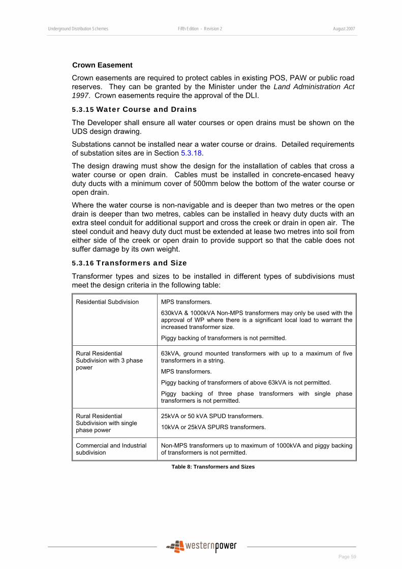
Underground Distribution Schemes Fifth Edition - Revision 2 August 2007
Page 59
Crown Easement Crown easements are required to protect cables in existing POS, PAW or public road reserves. They can be granted by the Minister under the Land Administration Act 1997. Crown easements require the approval of the DLI.
5.3.15 Water Course and Drains
The Developer shall ensure all water courses or open drains must be shown on the UDS design drawing.
Substations cannot be installed near a water course or drains. Detailed requirements of substation sites are in Section 5.3.18.
The design drawing must show the design for the installation of cables that cross a water course or open drain. Cables must be installed in concrete-encased heavy duty ducts with a minimum cover of 500mm below the bottom of the water course or open drain.
Where the water course is non-navigable and is deeper than two metres or the open drain is deeper than two metres, cables can be installed in heavy duty ducts with an extra steel conduit for additional support and cross the creek or drain in open air. The steel conduit and heavy duty duct must be extended at lease two metres into soil from either side of the creek or open drain to provide support so that the cable does not suffer damage by its own weight.
5.3.16 Transformers and Size
Transformer types and sizes to be installed in different types of subdivisions must meet the design criteria in the following table:
Residential Subdivision MPS transformers.
630kVA & 1000kVA Non-MPS transformers may only be used with the approval of WP where there is a significant local load to warrant the increased transformer size.
Piggy backing of transformers is not permitted.
Rural Residential Subdivision with 3 phase power
63kVA, ground mounted transformers with up to a maximum of five transformers in a string.
MPS transformers.
Piggy backing of transformers of above 63kVA is not permitted.
Piggy backing of three phase transformers with single phase transformers is not permitted.
Rural Residential Subdivision with single phase power
25kVA or 50 kVA SPUD transformers.
10kVA or 25kVA SPURS transformers.
Commercial and Industrial subdivision
Non-MPS transformers up to maximum of 1000kVA and piggy backing of transformers is not permitted.
Table 8: Transformers and Sizes
Underground Distribution Schemes Fifth Edition - Revision 2 August 2007
Page 60
5.3.17 HV Breech Joints
A high voltage ring main unit (RMU) must be used where a HV feeder splits into two or more branches and/or feeds transformers. Standard RMUs available are of size 2+1, 2+2, 2+3, 3+0, 3+1, 3+2 and 4+0.
HV breech joints may only be used in the following situation:
• The currently available range of switchgear is not adequate, e.g. a 4+2 is required; and
• The breech joint must have a switch on each of the three sides so that isolation can occur if there is a joint problem; and
• None of the three sides of the breech joint must form part of a major interconnection between adjacent HV feeders.
5.3.18 Substation Site
When the installation of a substation (including package substations, transformers and switchgear) is required, the relevant clauses contained in the WP document Substation Installation Requirements - DSB95/6 shall apply. The Substation Installation Requirements – DSB95/6 can be found at:
http://www.westernpower.com.au/mainContent/connectionsUpgrades/policiesRegulations/technicalDocumentation.html.
The Developer is responsible for advising potential land purchasers of all substation sites and their proposed use. As a minimum, substation sites must be shown on the Developer’s sales brochures.
Substation sites are to be located on public owned land (e.g. road reserve extension or public open space). The Developer is responsible for providing all substation sites. Substation sites must also be located in the kink of road reserve and as close as possible to the road boundary line extension along normal gazetted public road reserve. Where the Developer chooses to locate substation sites on POS, it shall take the following into consideration:
• Suitable location of sites within POS.
• Size, shape, contour and dimensions of POS.
• Community standards of health, safety and amenity.
Each substation site is to be located one metre above the 100-year flood level and must be on level and stable ground. The site cannot be lower than the finished level of both the subdivision lots and the adjacent road carriageway so that water cannot drain towards the substation. Note that in rural areas, the finished level of road carriageway is usually higher than that of the surrounding areas to allow natural draining of water from the carriageway.
If the site is higher than the finished level of the subdivision, retaining walls with access steps that meet the appropriate Australian Standard and the requirements of the LGA must be provided by the Developer at no cost to WP. Where retaining walls are required, the land requirement of the site is to be increased to include retaining walls.
Underground Distribution Schemes Fifth Edition - Revision 2 August 2007
Page 61
The civil site level and retaining walls details are to be shown by the Designer on the UDS design drawing for DCR. A signed certificate of verification by a professional Civil Engineer registered on the National Professional Engineers Register (NPER) verifying that the substation retaining walls are structural sound for their purposes is required.
Substation sites cannot be located in the vicinity of a water course or open drains.
Substation sites cannot be located on a transmission easement or distribution cable easement.
The substation site civil and land requirements are shown on drawings in the “Distribution Substation Manual” which can be found at:
http://www.westernpower.com.au/mainContent/connectionsUpgrades/policiesRegulations/technicalDocumentation.html.
WP may specify the location of substation sites of a subdivision based on strategic operational requirements in the DIP.
5.3.19 HV Earths Near to Telstra Equipment
No HV earths (e.g., substation and HV cable pole terminations) shall be located within 15m of any Telstra equipment pits.
Where this is not possible, Telstra’s written approval to allow HV earths to be installed within 15m of their equipment pits must be obtained by the Developer and must be provided to WP.
5.3.20 HV Cables and Earths in Proximity of Steel Gas Pipes
Earth Potential Rise (EPR) between the HV earth and steel pipeline can occur for an earth fault. Alternating current on a HV cable can induce a low frequency voltage on a parallel steel gas pipeline and is called Low Frequency Induction (LFI).
Where HV cables and earths are to be installed in proximity of steel gas pipeline, the Designer must assess EPR and LFI on the pipeline in accordance with WP’s policy on “Constructing Distribution Power Lines in the Vicinity of Pipelines” (http://www.westernpower.com.au/mainContent/connectionsUpgrades/policiesRegulations/technicalDocumentation.html#constructing) and obtain approval from pipeline owner (e.g., Alinta ) of the locations of HV cables and earths. The Designer must provide the assessment report and the pipeline owner’s approval to WP.
Potential electrical hazards are to be assessed in accordance with the Australian Standard AS4853. Pipelines assessed in the EPR and LFI study are classified as Category B pipelines in accordance with the Standard. These pipelines are located completely underground with facilities that are only accessible to authorized personnel.
5.3.21 Low Voltage Feeder Design Criteria
The Developer must ensure its Designer uses the following design parameters to design each LV feeder in a UDS design:
• Voltage variations at the customer’s point of attachment (i.e. service pillar) must be within the allowable limit of plus or minus 5% of the nominal voltage of 240V single phase or 415V three phase under normal conditions.
• Conductor current carrying capacity to be adequate under normal operating conditions.
• The sum of current of all outgoing feeders of a transformer does not exceed the name plate continuous rated current of the transformer.
Underground Distribution Schemes Fifth Edition - Revision 2 August 2007
Page 62
• LV feeders must be protected by LV fuses installed immediately after the transformer, e.g. transformer fuseboard or contiguous panel with the transformer. The fuse rating for residential street circuits cannot exceed 315 amps at any substation. Down stream fusing must not be used to extend the length of a feeder backbone.
• Blocking in of LV feeders must be done when feeders are separated by not more than two lots that are outside the subdivision but will be developed in the future. They must be interconnected by underground cables running in proper cable alignment along the road boundary of the undeveloped lots via suitable open points.
Designers are to use the LVDESIGN software package to ensure the voltage drop, line currents and fuse protection are adequate for each circuit and must include the LVDESIGN file in the submission for DCR. Designers may choose to use other methods or software to carry out the evaluation and assessment, provided they are approved by Western Power.
5.3.22 Uni-pillars in Low Voltage Feeder
In order to provide operational flexibility, uni-pillars must be installed for every 16 lots along the complete length of every LV feeder.
5.3.23 Load and Network Connection on a LV Spur
In the design of LV feeder network, spur LV feeders are unavoidable in the following situations and Designers must give specific consideration to ensure power reliability and qualities are maintained in the future.
Short LV spur feeder
For a short LV feeder that will not be extended because there is no possibility of further subdivisions at the end of the feeder WP requires a uni-pillar to be installed on the last lot where the total of more than six lots is connected to the spur feeder. This uni-pillar will be used for interconnection in the future.
LV feeder in Cul-de-sac
The cul-de-sac exists in a short street and canal block layout. For LV feeder stops at the end of a cul-de-sac where there is no possibility of any future interconnection at the end of the LV feeder, the following design principle should be followed.
• If the number of lots in the cul-de-sac does not exceed 16, a uni-pillar must be installed at the entrance.
• If the number of lots is more 16, a uni-pillar must be installed for every 16 lots of the Cul-de-sac;
• A second LV feeder shall be made available at the entrance of the cul-de-sac. The second feeder shall be a feeder with either no load connected or spare capacity which can pick up not less than 25% of the design load of the cul de-sac feeder.
Underground Distribution Schemes Fifth Edition - Revision 2 August 2007
Page 63
5.3.24 Electrical Requirements for Motor/Pump Starting
Dependent upon the size and location of the electrical motor, starting restrictions may apply and the installation must comply with Section 3.5 of Office of Energy Safety’s “WA Electrical Requirements” that is available from the office of Energy Safety’s Web site http://www.energysafety.wa.gov.au and clauses below.
For the connection of electric motors to the WP Low Voltage Network (415V), the permissible voltage depression on starting must be limited to 70% of the "Threshold of Irritability" curve contained in AS2279 Pt4.
For the connection of electric motors to the WP High Voltage Network, the permissible voltage depression on starting must be limited to 50% of the "Threshold of Perceptibility" curve contained in AS2279 Pt4.
The Australian Standard AS2279 series is being replaced by the Australian/New Zealand Standard As/NZS 61000 series on Electromagnetic Compatibility (EMC). Designers shall continue to assess the voltage fluctuation and flicker for motor starting in accordance with AS2279 until WP adopts the AS/NZS 61000.
The Developer's Designer/Consultant must ensure the proposed motor starting requirements are acceptable, prior to the connection of the motor.
Where the subdivision affects the existing and/or proposed pumps of Water Corporation, the Designer must obtain actual pump starting and full load operating details from Water Corporation. The Designer is to provide this data to WP for verification.
Designers are to work out the voltage fluctuations of the network in the subdivision and are to include the result in the submission for DCR. The Designer can use the Flick Plus software package and submit the result in the Flick Plus file.
5.3.25 Streetlighting
5.3.25.1 General
Streetlighting must be designed to comply with the requirements of the local government authority. The streetlights will either be WP’s standard streetlights or non-WP streetlights (private streetlights).
WP-standard streetlights include non-decorative steel standard and decorative streetlights.
The method of supplying the streetlights will be dependent on the local government’s policies. Where “dusk-to-dawn” lighting is approved, each streetlight must be supplied from the nearest mini pillar with a fuse at the mini pillar and a link at the streetlight column. Where “dusk-to-dawn” lighting is not approved, streetlights must be supplied from separate street lighting cables run from substations.
The Developer shall ensure its Designer liaises with the LGA to establish the streetlighting requirements and designs an appropriate lighting design.
If a style of WP Supplied decorative street lighting range is selected, the Developer must provide the written approval from the LGA, as this range carries a premium tariff.
5.3.25.2 Streetlights near to Existing Overhead Power lines
The Developer shall ensure its UDS design meets all safe clearances in accordance with ENA C(b)1 – Guidelines for design and maintenance of overhead distribution and transmission lines are maintained between existing power lines and streetlights in the subdivision. The Designer must show the clearances of streetlights from any existing overhead power lines on the UDS design drawing to be submitted for DCR.

Underground Distribution Schemes Fifth Edition - Revision 2 August 2007
Page 64
Streetlight standards must not be installed on the same side of a road where existing overhead transmission and/or distribution (HV and LV) mains will remain.
5.3.25.3 Streetlights Location
All streetlights, not mounted on wood poles, is to be installed along extension of common property boundary line on the 2.7M alignment unless prior written approval is obtained from WP.
Where the road reserve has a verge wider than 3700mm, streetlights can be installed at a minimum set back from the kerb line in accordance with the following WP Policy Statements, however, the Developer is required to obtain the approval of the LGA, road authority and other utility providers.
• Placing of power poles within road reserves in built up areas.
• Placing of poles along roads with speed limits not exceeding 70 kMH
• Placing of rigid poles along roads with speed limits exceeding 70 kMH.
The above policy statements can be found at:
http://www.westernpower.com.au/mainContent/workingWithPower/roadsidePowerpoles.html
The Designer must show the setback on the scheme design drawing for DCR where it is not on the 2.7m alignment.
Where a road terminates at a tee junction at end of a terminating road, streetlights must be installed close to the centre or along a property boundary extension.
Streetlights must be provided and installed at the end of cul-de-sac.
Streetlights must not be installed in water course or drains.
5.3.25.4 Western Power’s Standard Streetlights
WP has two types of standard streetlights as follow:
• WP Non-decorative streetlights
• WP Decorative streetlights
If one of WP’s standard streetlights is installed, the same arrangements will apply as for all other equipment supply/installation work under the installation option chosen.
WP will own, operate and maintain the streetlight system in this case.
5.3.25.5 Approval of WP Supplied Decorative Streetlights in Subdivision
Developers will generally install either WP non-decorative streetlights or WP decorative streetlights.
Energy consumption on WP non-decorative streetlights will be charged to LGAs as per gazetted streetlighting tariffs.
Energy consumption on WP decorative streetlights will be charged to LGAs at a rate usually higher than the gazetted tariff. Developers can only install decorative streetlights in subdivisions where the LGA is on an appropriate contract, e.g. StreetVision of Synergy or
Underground Distribution Schemes Fifth Edition - Revision 2 August 2007
Page 65
similar. Therefore, Developers are required to seek the approval of LGAs if they intend to install WP decorative streetlights in subdivision developments.
Subdivisions will usually be developed progressively in multiple stages and it will reduce process time for all parties involved if LGA can provide blanket approval for decorative streetlights for the complete development instead of individual stages. LGAs may also consider providing blanket approval for all the subdivision developments within a suburb or the whole city/town to WP directly. LGA should specify the streetlight standard colour and the type of luminaries.
A decorative streetlights approval form is available at:
http://www.westernpower.com.au/mainContent/connectionsUpgrades/Professional_Developers/Specialised_Forms.html.
5.3.25.6 Non Western Power Supplied Streetlights (Private Streetlighting)
The Developer is responsible for all work associated with the installation of a special non-WP streetlighting system. The LGA is responsible for the ongoing operation and maintenance of the system and payment of the applicable tariff charges.
In this case, the LGA may choose an un-metered or metered supply.
Notes: Un-metered supplies are only available to statutory authorities.
The total load connected to each point of supply is limited to 4.8kW single phase.
WP’s un-metered supply policy can be found at:
http://www.westernpower.com.au/mainContent/connectionsUpgrades/policiesRegulations/technicalDocumentation.html.
The following additional conditions apply:
• The Designer must provide WP with a letter from the applicable LGA accepting:
• that it will own, operate and maintain the streetlight system and pay the applicable tariff charge, and
• that, in addition to any advice through an electrical contractor’s submission of statutory forms, it will advise WP of any increases or reductions in the loads connected to the supply.
• The installation cannot be connected to WP’s streetlighting system and cabling cannot be run in WP’s cable alignment. The Developer is responsible for all installation work, including cabling, which must be run in the 2.7m alignment.
• The installation must comply with AS/NZS 3000 including earthing and protection. The installation must also be provided with a main switchboard and main control in accordance with Australian/New Zealand Wiring Rules, Rule 2.8.3.3.1 (for each point of supply). The main switch must be a miniature circuit breaker, sized to match the load current.
Alternatively, in the case of un-metered supplies, a single light standard can be supplied through a fuse from the nearest pillar with appropriate labelling, without the need for a switchboard.
• Where a switchboard is required, a weatherproof durable label will be installed by the Developer adjacent to the main switch, reading “Main Switch – Un-
Underground Distribution Schemes Fifth Edition - Revision 2 August 2007
Page 66
metered Supply - Installation Maintained by City/Shire of <Insert City/Shire Name> - Isolate supply at all times before commencing work”.
• Each light standard must be equipped with a means of isolation located in the base.
• Each light standard shall be identified as belonging to the City/Shire of <Insert City/Shire Name>, and include instructions for maintenance and repairs to be referred to the City and not WP.
• Preliminary Notice and Notice of Completion will be submitted to WP to initiate the issue of a service ruling and final inspection of the installation as appropriate. In addition to normal information, please advise your electrical contractor to endorse the Preliminary Notice and the Notice of Completion in the following terms if it is an un-metered supply,
“Un-metered Supply
“Total Load kW ....”
5.3.25.7 Streetlighting Outside Gazetted Public Road Reserve
WP’s streetlights, including decorative streetlights under Synergy’s StreetVision scheme, can only be installed in gazetted public road reserve.
If the LGA or other authorities require lights on POS, PAW and Crown Reserve, private streetlighting must be installed.
5.3.26 Underground Transmission Protection Pilot Cables
Where existing transmission protection aerial pilot cables are to be relocated underground, the underground pilot cables must be shown on the UDS design drawing.
The underground pilot cables must be designed to meet the requirements in the DIP.
Underground pilot cables shall not be installed with high voltage cables, and an alternative cable route for pilot cables must be planned unless as otherwise specified in the DIP. In situation where it is not possible to provide an alternative route, the Designer must seek the approval of WP.
Where more than one underground pilot cable is to be installed they shall be installed in separate routes. Shared trench arrangements for multiple underground pilot cables shall not be used unless prior approval is obtained from WP.
5.3.27 Existing Customers and Affected Parties
Where existing aerial mains are to be removed as part of the subdivision work, the Developer is responsible for the reconnection of existing WP aerial-connected customers to the underground system at their cost.
The reconnection services to existing customers can be one of the following:
• A normal service pillar at the front boundary.
• A wall mounted pillar, or
• Retaining the existing overhead service via a service pole.
The Designer is to include the appropriate design on the UDS design drawing to be submitted for DCR.

Underground Distribution Schemes Fifth Edition - Revision 2 August 2007
Page 67
5.3.28 Subdivision Design Drawing Requirements
The Developer must ensure that the design drawing submitted for DCR shall comply with the “Subdivision Design Drawing Minimum Requirements” in Appendix 7.
Failure to meet the above minimum requirements will result in non-conformance.
5.3.29 Published Design Requirements and Guidelines
Developers must ensure that the UDS design of a subdivision meets all existing and future published “Subdivision Design Requirement” and “Subdivision Design Guidelines”. These requirements and guidelines can be found at:
http://www.westernpower.com.au/mainContent/connectionsUpgrades/Professional_Developers/Technical_Documentation.html.
Existing “Subdivision Design Requirements” at the time of publication are as follows:
• SUBDIVISION DESIGN REQUIREMENT- NUMBER 01 (Revision 1, 27/10/2005) Land and earthing requirements for pre-approved non-standard Schneider RM6 switchgear in Option B subdivision
• SUBDIVISION DESIGN REQUIREMENT- NUMBER 02 (Revision 1, 27/10/2005) Substation/switchgear layout requirements on subdivision design drawing submitted for Design Conformance Review
• SUBDIVISION DESIGN REQUIREMENT- NUMBER 03 (Revision 1, 27/10/2005) Installation requirement of culvert for 63kVA padmount 3-phase transformer
Existing “Subdivision Design Guidelines” at the time of publication are as follows:
• SUBDIVISION DESIGN GUIDELINE - NUMBER 01 (Revision 1, 27/10/2005) Guideline for Ordering Cable End Caps and Working End Pillars
• SUBDIVISION DESIGN GUIDELINE - NUMBER 02 (Revision 1, 27/10/2005) Guideline for Requesting Design Information Package (DIP)
• SUBDIVISION DESIGN GUIDELINE - NUMBER 03 (Revision 1, 27/10/05) Guideline For Completing Transformer Load Tables on Design Drawings
• SUBDIVISION DESIGN GUIDELINE – NUMBER 04 (Revision 0, 04/01/06) Bedding Sand And Backfill Sand Around Cables And General Backfill For Cable Trench – Material Selection Guidelines
• SUBDIVISION DESIGN GUIDELINE – NUMBER 05 (Revision 0, 05/01/06) Guideline for the Approval of Major or Minor Changes During Construction.
5.3.30 Variations to WP Designs or Standards
WP will consider requests for variations in design or standard practice. These must be made by the Developer or his representative in writing on a Request for Variation to WP Design or standard form shown in Appendix 3 or similar. The request must include a marked up plan showing proposed changes and the Developer must include sufficient documentation to justify the changes.
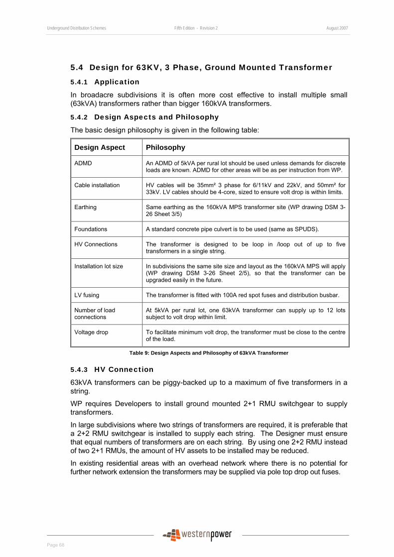
Underground Distribution Schemes Fifth Edition - Revision 2 August 2007
Page 68
5.4 Design for 63KV, 3 Phase, Ground Mounted Transformer
5.4.1 Application
In broadacre subdivisions it is often more cost effective to install multiple small (63kVA) transformers rather than bigger 160kVA transformers.
5.4.2 Design Aspects and Philosophy
The basic design philosophy is given in the following table:
Design Aspect Philosophy
ADMD An ADMD of 5kVA per rural lot should be used unless demands for discrete loads are known. ADMD for other areas will be as per instruction from WP.
Cable installation HV cables will be 35mm² 3 phase for 6/11kV and 22kV, and 50mm² for 33kV. LV cables should be 4-core, sized to ensure volt drop is within limits.
Earthing Same earthing as the 160kVA MPS transformer site (WP drawing DSM 3-26 Sheet 3/5)
Foundations A standard concrete pipe culvert is to be used (same as SPUDS).
HV Connections The transformer is designed to be loop in /loop out of up to five transformers in a single string.
Installation lot size In subdivisions the same site size and layout as the 160kVA MPS will apply (WP drawing DSM 3-26 Sheet 2/5), so that the transformer can be upgraded easily in the future.
LV fusing The transformer is fitted with 100A red spot fuses and distribution busbar.
Number of load connections
At 5kVA per rural lot, one 63kVA transformer can supply up to 12 lots subject to volt drop within limit.
Voltage drop To facilitate minimum volt drop, the transformer must be close to the centre of the load.
Table 9: Design Aspects and Philosophy of 63kVA Transformer
5.4.3 HV Connection
63kVA transformers can be piggy-backed up to a maximum of five transformers in a string.
WP requires Developers to install ground mounted 2+1 RMU switchgear to supply transformers.
In large subdivisions where two strings of transformers are required, it is preferable that a 2+2 RMU switchgear is installed to supply each string. The Designer must ensure that equal numbers of transformers are on each string. By using one 2+2 RMU instead of two 2+1 RMUs, the amount of HV assets to be installed may be reduced.
In existing residential areas with an overhead network where there is no potential for further network extension the transformers may be supplied via pole top drop out fuses.

Underground Distribution Schemes Fifth Edition - Revision 2 August 2007
Page 69
5.4.4 LV Connection
The transformer low voltage side is fitted with 3-phase 100A fuses and distribution bar. A maximum of two LV feeder cables can be connected back-to-back to the distribution bar and a maximum of 4 x 25mm² service cable can also be connected to the distribution bar.
WP prefers the connection of one 240mm² LV feeder cable from the distribution bar to a nearby uni-pillar and then splitting into 2 x 120mm² LV feeder cables for reticulation where LV feeder length is not exceeding 500m (see Section 5.3.8). The cabling cost will be greatly reduced by using 120mm² cables.
The Developer will not be permitted to connect consumer’s main cables directly to the distribution bar. They must always be connected via service pillars at the property boundaries.
Underground Distribution Schemes Fifth Edition - Revision 2 August 2007
Page 70
5.5 Single Phase Underground Distribution System (SPUDS) The Single Phase Underground Distribution System (SPUDS) is designed for rural subdivision in areas zoned “Rural” or “Special Rural” with lots sizes of between one and four hectares. It is cost competitive with the overhead systems traditionally offered for those subdivisions.
The HV reticulation in this system is designed as a single phase Screen Wire Earth Return (SWER) system, operated at 12.7kV. This HV voltage level is adopted for both the 22kV and 33kV systems to allow standard equipment to be used throughout WP.
The system is based on servicing the residential lots using several 25kVA single phase padmounted transformers, each serving up to four customers (see Section 55.3.2.2). Each transformer is internally fused to protect the system from internal transformer faults.
The single phase SWER supply is provided by a single core 35mm² HV underground cable with a heavy duty copper screen to provide the earth return path. The single core cable loops in and out of a string of 25kVA transformers using separable, non-load break connectors.
The SPUDS will be supplied from one of the following system:
• Metropolitan 22kV 3-wire system with no running earth.
• Country 22kV 4-wire system with running earth.
• Country 33kV 4-wire system with running earth.
The structure of the SPUDS to be used depends on the size of the subdivision, the configuration and the voltage level of the HV overhead system and can be broadly categorised into four systems as follows:
1. Metro 22kV or Country 33kV, 2-phase with pole top or ground mounted isolating transformer and a string of 25kVA, 1-phase, 12.7kV, 2- bushing or 3- bushing tee off transformers.
2. Country 22kV, 1-phase (with running earth) HV direct connected via DOF and up to a maximum of 8 x 25kVA, 1-phase, 12.7kV, 2- bushing or 3- bushing tee off transformers.
3. Metro 22kV or Country 33kV, 3 x 2-phase padmounted isolating transformers (loop in & loop out) and each with a string of 25kVA 1-phase, 12.7kV, 2- bushing or 3- bushing Tee off transformers.
4. Metro 22kV, 2-phase HV direct connected via DOF and a string of 25kVA, 1-phase, 22kV, 4-bushing transformers.
Each SPUD transformer reticulates the LV supply to service pillars through a three core 25mm² XLPE cable. Customers’ main cables are not permitted to connect directly to the transformer. They must always be connected via services pillars at property boundary.
The details of the SPUDS arrangement and design are in WP’s SPUDS Manual.
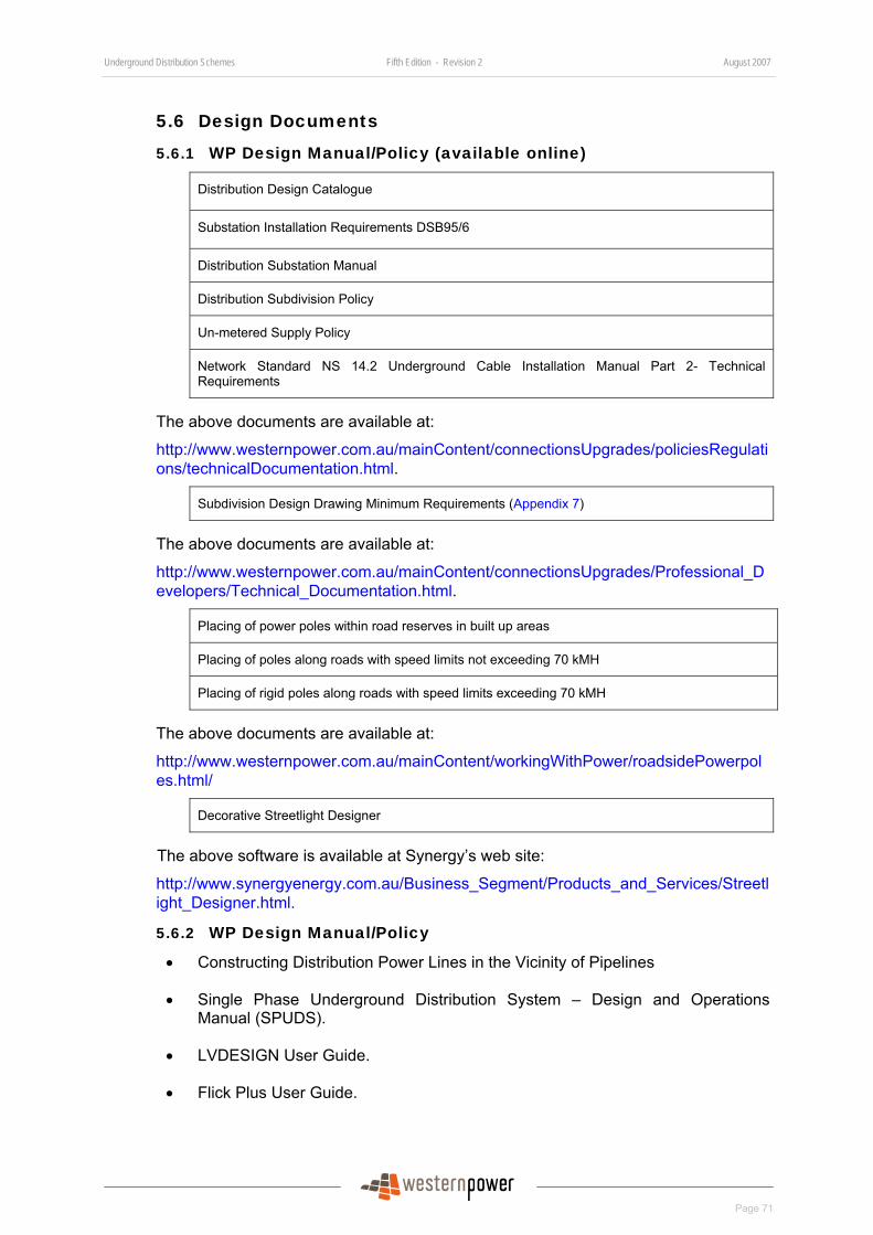
Underground Distribution Schemes Fifth Edition - Revision 2 August 2007
Page 71
5.6 Design Documents
5.6.1 WP Design Manual/Policy (available online)
Distribution Design Catalogue
Substation Installation Requirements DSB95/6
Distribution Substation Manual
Distribution Subdivision Policy
Un-metered Supply Policy
Network Standard NS 14.2 Underground Cable Installation Manual Part 2- Technical Requirements
The above documents are available at:
http://www.westernpower.com.au/mainContent/connectionsUpgrades/policiesRegulations/technicalDocumentation.html.
Subdivision Design Drawing Minimum Requirements (Appendix 7)
The above documents are available at:
http://www.westernpower.com.au/mainContent/connectionsUpgrades/Professional_Developers/Technical_Documentation.html.
Placing of power poles within road reserves in built up areas
Placing of poles along roads with speed limits not exceeding 70 kMH
Placing of rigid poles along roads with speed limits exceeding 70 kMH
The above documents are available at:
http://www.westernpower.com.au/mainContent/workingWithPower/roadsidePowerpoles.html/
Decorative Streetlight Designer
The above software is available at Synergy’s web site:
http://www.synergyenergy.com.au/Business_Segment/Products_and_Services/Streetlight_Designer.html.
5.6.2 WP Design Manual/Policy
• Constructing Distribution Power Lines in the Vicinity of Pipelines
• Single Phase Underground Distribution System – Design and Operations Manual (SPUDS).
• LVDESIGN User Guide.
• Flick Plus User Guide.
Underground Distribution Schemes Fifth Edition - Revision 2 August 2007
Page 72
• DQM/CAD Interface Urban Residential Design User Guide.
• Project Designs Using CAD For Microstation Manual.
5.6.3 WP Design Software
• LVDESIGN.
• Flick Plus.
• DQM/CAD Interface software (includes DQM/CAD Interface for Underground Distribution Designs and Project Designs Using CAD For Microstation).
For enquiries about purchasing the above design software, please contact
Business Development Officer
Customer Solutions Branch
Asset Management Division
Western Power
Phone: (08) 9326 4149
Fax: (08) 9326 6566
5.6.4 Associated Publications
• Electricity (Supply Standards and System Safety) Regulations 2001.
• Utility Providers Code of Practice for Western Australia – produced by Utility Providers Services Committee
• Western Australian Electrical Requirements (WAER) – Published by Office of Energy Safety
• AS/NZ 3000 - Australian/New Zealand Wiring Rules – Published by Standard Australia
• AS/NZS AS2053 Conduits and Fittings for Electrical Installations
• AS/NZS AS2279.4-1991 Disturbances in Mains Supply Networks – Limitation of Voltage Fluctuations Caused by Industrial Equipment.
• AS/NZS 4853 – Electrical Hazards on Metallic Pipelines
• ENA C(b)1 – Guidelines for Design and Maintenance of Overhead Distribution And Transmission Lines – Published by Energy Networks Association
• WAPC Planning Bulletin Number 33, July 1999 – Rights of Way or Laneways in Established Areas-Guidelines
• WAPC Policy DC 2.6, June 1998 – Residential Road Planning
• Western Power Supply Extension Policy Manual
Underground Distribution Schemes Fifth Edition - Revision 2 August 2007
Page 73
6 Installation Policy and Requirements This section outlines the installation options available to a Developer and defines the processes, policies and requirements governing the construction of the underground distribution network in subdivision developments.
The installation process cannot commence until the Developer’s UDS design conforms to WP’s requirements and the Developer has accepted either Option A or Option B quotation.
6.1 Small Subdivision (i.e. not more than four Lots)
6.1.1 Installation Policy
Where the proposed subdivision is for four lots or less, or if it is an amalgamation of lots into four lots or less WP will design and construct the UDS.
The Developer can elect to carry out trenching and laying of cable in accordance with the requirements in Section 6.2.10. The Developer should advise WP of its intention to carry out trenching and laying of cable when requesting a Quote.
6.1.2 Installation Process and Responsibilities
• WP generally requires 12 weeks from receipt of payment for the work before starting work.
• Once payment is received, WP will issue payment acknowledgment and appoint a CM to schedule and oversee the construction work.
• The Developer must contact the CM within 12 working days of receipt of payment about the construction program.
• The Developer is required to complete its work in accordance with Section 4.2.3.
• If the Developer is to carry out trenching and laying of cable, it must complete the handover certificate for the cable and forward it to the CM before WP begins its work.
6.2 Large Subdivision (i.e. more than Four Lots) For large subdivisions of more than four lots, WP offers the Developer two installation options:
Installation Option A, where the Developer engages WP to provide all materials and carry out the construction works.
The Developer will be responsible for the following:
• Trenching.
• Supply and installation of ducts.
• Laying of cables.
• Installing streetlight standards.
Underground Distribution Schemes Fifth Edition - Revision 2 August 2007
Page 74
or:
Installation Option B, where the Developer purchases approved materials and engages its own installation contractors to carry out the construction work and engages WP to carry out interfacing work required to connect the Electricity Infrastructure of a subdivision to WP’s network.
In both Option A or Option B, the Developer pays WP the quoted price plus GST to carry out construction works on the Developer’s subdivision site that is the Developer’s workplace to create serviced lots that the Developer can sell to prospective land purchasers.
Both of these Options are described in more detail in the following sections.
6.2.1 Installation Option A Process and Responsibilities
The following table summarises the process and the responsibilities of the Developer and WP.
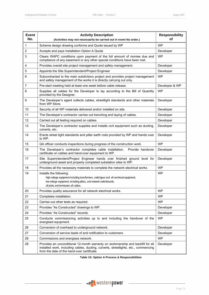
Underground Distribution Schemes Fifth Edition - Revision 2 August 2007
Page 75
Event No.
Activity Description (Activities may not necessarily be carried out in event No order.)
Responsibility of
1 Scheme design drawing conforms and Quote issued by WP WP
2 Accepts and pays Installation Option A Quote Developer
3 Clears WAPC conditions upon payment of the full amount of monies due and compliance of any easement or any other special conditions have been met.
WP
4 Provides overall site project management and safety management. Developer
5 Appoints the Site Superintendent/Project Engineer Developer
6 Subcontracted to the main subdivision project and provides project management and safety management of the works it is directly carrying out only.
WP
7 Pre-start meeting held at least one week before cable release. Developer & WP
8 Supplies all cables for the Developer to lay according to the Bill of Quantity provided by the Designer.
WP
9 The Developer’s agent collects cables, streetlight standards and other materials from WP Store.
Developer
10 Security of all WP materials delivered and/or installed on site. Developer
11 The Developer’s contractor carries out trenching and laying of cables. Developer
12 Carried out all testing required on cables. Developer
13 The Developer’s contractor supplies and installs civil equipment such as ducting, culverts, etc.
Developer
14 Erects street light standards and pillar earth rods provided by WP and hands over to WP.
Developer
15 QA officer conducts inspections during progress of the construction work. WP
16 The Developer’s contractor completes cable installation. Provide handover certificate on cables and hand-over equipment to WP.
Developer
17 Site Superintendent/Project Engineer hands over finished ground level for underground asset and properly completed substation sites to WP.
Developer
18 Provides all the necessary materials to complete the network electrical works. WP
19 Installs the following: high voltage equipment including transformers, switchgear and all overhead equipment; low voltage equipment, including pillars, and network switchboards; all joints and terminates all cables.
WP
20 Provides quality assurance for all network electrical works. WP
21 Completes installation. WP
22 Carries out other tests as required. WP
23 Provides ”As Constructed” drawings to WP. Developer
24 Provides “As Constructed” records. Developer
25 Conducts commissioning activities up to and including the handover of the energised equipment.
WP
26 Conversion of overhead to underground network. Developer
27 Conversion of service leads of and notification to customers. Developer
28 Commissions and energises network. WP
29 Provides an unconditional 12-month warranty on workmanship and backfill for all installed work, including cables, ducting, culverts, streetlights, etc., commencing from the date of the hand-over certificate.
Developer
Table 10: Option A Process & Responsibilities
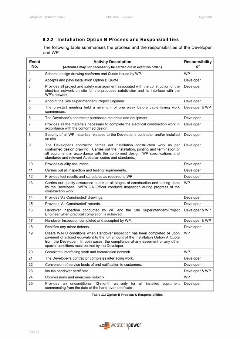
Underground Distribution Schemes Fifth Edition - Revision 2 August 2007
Page 76
6.2.2 Installation Option B Process and Responsibilities
The following table summarises the process and the responsibilities of the Developer and WP.
Event No.
Activity Description (Activities may not necessarily be carried out in event No order.)
Responsibility of
1 Scheme design drawing conforms and Quote issued by WP. WP
2 Accepts and pays Installation Option B Quote. Developer
3 Provides all project and safety management associated with the construction of the electrical network on site for the proposed subdivision and its interface with the WP’s network.
Developer
4 Appoint the Site Superintendent/Project Engineer. Developer
5 The pre-start meeting held a minimum of one week before cable laying work commences.
Developer & WP
6 The Developer’s contractor purchases materials and equipment. Developer
7 Provides all the materials necessary to complete the electrical construction work in accordance with the conformed design.
Developer
8 Security of all WP materials released to the Developer’s contractor and/or installed on site.
Developer
9 The Developer’s contractor carries out installation construction work as per conformed design drawing. Carries out the installation, jointing and termination of all equipment in accordance with the conformed design, WP specifications and standards and relevant Australian codes and standards.
Developer
10 Provides quality assurance. Developer
11 Carries out all inspection and testing requirements. Developer
12 Provides test results and schedules as required to WP Developer
13 Carries out quality assurance audits at all stages of construction and testing done by the Developer. WP’s QA Officer conducts inspection during progress of the construction work
WP
14 Provides ‘As Constructed’ drawings. Developer
15 Provides ‘As Constructed’ records. Developer
16 Handover inspection conducted by WP and the Site Superintendent/Project Engineer when practical completion is achieved.
Developer & WP
17 Handover Inspection completed and accepted by WP. Developer & WP
18 Rectifies any minor defects. Developer
19 Clears WAPC conditions when Handover inspection has been completed or upon payment of a bond equivalent to the full amount of the Installation Option A Quote from the Developer. In both cases, the compliance of any easement or any other special conditions must be met by the Developer.
WP
20 Completes interfacing work and commission network. WP
21 The Developer’s contractor completes interfacing work. Developer
22 Conversion of service leads of and notification to customers. Developer
23 Issues handover certificate. Developer & WP
24 Commissions and energises network. WP
25 Provides an unconditional 12-month warranty for all installed equipment commencing from the date of the hand-over certificate
Developer
Table 11: Option B Process & Responsibilities
Underground Distribution Schemes Fifth Edition - Revision 2 August 2007
Page 77
6.2.3 UDS Workplace
6.2.3.1 Developer’s Site
The Developer is responsible for the workplace created by all work undertaken on or in connection with a Development and the UDS for that Development.
Before any works are undertaken on the Development Site in connection with a UDS, the Developer must:-
• prepare and approve a Site Safety Management Plan for its Development. This Plan must incorporate WP’s “Contractor Safety Guidelines”, available at:
http://www.westernpower.com.au/mainContent/workingWithPower/industryContractors/ContractorGuidelines.html.
and
• give the CM a copy of its Site Safety Management Plan prior to or at the pre-start meeting.
WP’s CM will liaise with the Developer’s Site Superintendent to ensure all WP’s personnel who will come onto the Developer’s site are inducted according to the Developer’s Site Safety Management Plan.
The CM will ensure that WP’s personnel and contractors follow the Developer’s Site Safety Plan and all lawful directions given by the Site Superintendent in connection with site safety.
To the extent that WP’s own work safety practices and procedures are:
• more specific to the UDS works to be undertaken; or
• more exhaustive than those of the Developer’s Site Safety Management Plan,
The CM will ensure WP’s personnel and contractors follow those practices and procedures.
6.2.3.2 Liaison and Cooperation for Site Safety
The Developer must ensure that W P’s personnel have uninterrupted access to that part of the Development Site reasonably required for the UDS works to be undertaken by WP.
The Developer’s Site Superintendent and the CM will liaise and cooperate to:
• identify the extent of WP’s site for UDS works;
• fix the date and times for access to the WP site; and
• ensure that as far as reasonably practicable, WP will have continuous, uninterrupted and exclusive access to that site at all times while it completes the UDS works.
6.2.4 Construction Administration
6.2.4.1 Pre-Start Meeting
Upon receipt of the completed Acceptance of Quote form, accompanied by payment of the quoted price and GST, the installation phase will commence. WP will appoint
Underground Distribution Schemes Fifth Edition - Revision 2 August 2007
Page 78
the CM and send a letter to the Developer acknowledging payment and advising the name of the CM.
The Developer must contact the CM within ten working days of the date on the letter to arrange a date and time for a pre-start meeting. Those who must attend the pre-start meeting with the CM are:
• The Developer or the Developer’s representative (Consultant Engineer).
• Site Superintendent/Project Engineer.
• Civil Engineer.
• Civil contractor.
• Cable laying contractor; and
• Preferably, the electrical Designer.
The pre-start meeting must be held at least one week before cable is released for an Installation Option A subdivision or one week before cable laying for an Installation Option B subdivision. The meeting should be held as early as possible to raise any materials or resource issues that may impact the proposed programme.
The Developer shall provide the following information to the CM at least two working days prior to the pre-start meeting:
• The name of the Site Superintendent/Project Engineer.
• The name of Civil Engineer.
• The name of the cable laying contractor.
• The name of electrical contractors/workers for Installation Option B.
• A letter authorising the above people to carry out work in the subdivision and to hand over their work to WP.
• Confirmation of the latest design revision.
• Commencement date of the construction works, and
• An up-to-date construction project programme and schedule of site meetings.
At the pre-start meeting the following matters will be addressed:
• Site access and security arrangements.
• Site safety risk assessment.
• Materials availability and timing of materials release.
• Project construction timetable and schedule of site visits, and
• QA requirements for the civil works, cable laying and electrical works.
Underground Distribution Schemes Fifth Edition - Revision 2 August 2007
Page 79
6.2.4.2 Key Project Personnel
Site Superintendent/Project Engineer WP requires the Developer to appoint a Site Superintendent/Project Engineer as the site representative for the installation of electrical services. In addition to the functions given by the Developer, the Site Superintendent is the Developer’s representative for the following purposes in connection with a UDS namely:
• Liaising and cooperating with the CM to ensure site safety.
• Arranging site meetings.
• Communications regarding the works programme and advising resource and material availability.
• Ensuring WP receives the signed-off electrical cable test schedules.
• Ensuring WP receives the signed-off Material & Equipment Schedule for Option B subdivisions.
• Ensuring WP receives the signed-off ”As Constructed” drawings.
• Preparation and sign-off for handover inspection.
• Accepting warranty commitments on behalf of the Developer, and
• Handover inspection and Handover.
None of the Developer’s personnel or contractors who undertake UDS works is eligible to be the Site Superintendent.
Construction Manager (CM) The CM is appointed by WP as its site representative to whom all technical and contract issues must be directed.
The Developer should refer all technical and contractual matters to the CM.
Quality Assurance Officer The Quality Assurance (QA) Officer is appointed by WP as its inspector to monitor electrical equipment installation standards on subdivision developments.
The QA Officer will conduct periodic inspections during the progress of the installation construction work. At the Handover inspection stage of an Option B subdivision, the QA Officer conducts a final check to ensure all requirements have been met and advises the CM that handover can proceed.
The QA Officer can also be the CM or can be a person or organisation independent of the construction contractors and/or WP.
6.2.4.3 Project Programme
The Developer must submit the Project Programme to the CM at least seven working days prior to the pre-start meeting to enable the CM to confirm availability of resources and materials at that meeting.
Underground Distribution Schemes Fifth Edition - Revision 2 August 2007
Page 80
6.2.4.4 Inspection
A QA Officer will conduct periodic inspections during the progress of the Electricity Infrastructure installation. The Developer must give the QA Officer site and equipment access to conduct all inspections required.
The QA Officer will accordingly inform the Site Superintendent/Project Engineer of any defect.
With at least one working day’s notice of the following key milestones, the Developer must provide the QA Officer and the CM notice of:
• The commencement of any cable pull to enable inspection of equipment and methodology.
• Trenches being backfilled to enable inspection of duct/cable alignment and separation and check the suitability of backfill.
• Testing of high voltage cables, switchgear, transformers and substation earthing.
The Site Superintendent/Project Engineer must allow one working day for the QA Officer to inspect trenches prior to being backfilled. In case trenches are backfilled before the expiry of inspection duration, the Developer is responsible for providing inspection pot holes, and associated costs, as required by the QA Officer for inspection.
6.2.4.5 Testing
The Developer must conduct tests to prove the integrity of Electricity Infrastructure installed and to ensure all technical requirements are met at least four weeks prior to handover of the asset and equipment to WP. The tests to be carried out are listed in Section 6.2.8.
The Developer must provide WP a schedule of proposed tests at least three working days in advance of the tests being carried out and WP reserves the right to witness any test or to require tests to be repeated or equipment to be opened up or trenches pot holed for inspection.
The Developer must give WP access to the site and equipment necessary to undertake any tests it deems necessary to test the integrity of any part of the network installed by the Developer. The Developer is responsible to clear the site, provide access to equipment, provide pot holes, remove and replace any panels etc as required by WP.
The Developer is responsible to repair or correct any equipment or workmanship issues which are found by test to be unsatisfactory.
6.2.4.6 As Constructed Drawings
Upon completion of all work of the UDS for a subdivision, the Developer must provide WP with an ‘As Constructed’ drawing of the UDS.
The Developer must ensure that the “As Constructed” drawing:
• Is certified “As–constructed”, signed and dated by a surveyor who is eligible for membership of the Institution of Engineering and Mining Surveyor Australia (IEMSA) or the Institute of Surveyor, Australia (ISA). A certificate from the
Underground Distribution Schemes Fifth Edition - Revision 2 August 2007
Page 81
surveyor is acceptable. The surveyor will certify that all asset including cables, transformers, switchgear, pillars, streetlights and etc, are physically installed as shown on the “As-constructed” drawing.
• Is in DGN or DWG format. If in DWG format, it must be saved as Auto Cad 2000.
• Includes revision number, revision date and “As Constructed” details, including any changes in design or W P standard requirements.
• Includes locations of all underground in-line and breeches joints and all off-alignment cables are detailed using standard symbols.
• Is submitted electronically to WP with the certificates of the Site Superintendent and the surveyor via [email protected], at least two working days prior to the scheduled date of the handover inspection.
The “As Constructed” drawing will be processed by WP and forwarded to the CM prior to Handover inspection. The CM will not accept any “As Constructed” drawing on site from the construction contractor.
6.2.4.7 As Constructed Records
Upon completion of all the UDS work of a subdivision, the Developer must provide WP with the following ‘As Constructed’ records:
• Cable installation records of alignment and depth, location of cable joints and road crossings. The cable installation records must be signed off by a surveyor who is eligible for membership of IEMSA or ISA.
• Electrical cable test schedules signed off by the licensed Electrical Worker who has carried out the tests or by an accredited cable jointer if tests have been carried out by such person.
• For Option B subdivisions an HV cable joint schedule signed off by an accredited cable jointer who has carried out the work.
• For Option B subdivisions, a material and equipment schedule must be completed and signed off by the Cable Laying Contractor.
The Developer must ensure that the “As constructed” records are provided to the CM at least two working days prior to the scheduled date of the handover inspection.
Standard forms for Electrical Test Schedules, HV cable Joint Schedule and Material and Equipment Schedule are available for download from WP’s web site at:
http://www.westernpower.com.au/mainContent/connectionsUpgrades/Professional_Developers/Specialised_Forms.html.
6.2.4.8 Cable Handover for Installation Option A
When Installation Option A applies, all cable must be installed and tested by the Developer’s cable contractor who will backfill trenches leaving the joint holes open.
The cable contractor must then test the cable in accordance with the requirements and complete test schedules in accordance with Section 6.2.8 Tests.
The cable contractor must make the area safe to leave joint holes open and then formally hand over the cable to WP by a handover certificate, as shown in Appendix 19.
Underground Distribution Schemes Fifth Edition - Revision 2 August 2007
Page 82
WP will make arrangement for cable jointing and will notify the cable contractor once jointing is complete to allow the cable contractor to backfill joint holes.
If WP does not joint the cables within 15 working days from the date of the cable handover certificate, the Developer can fill the joint holes. WP will pay to have joint holes re-excavated.
The Developer will pay to have joint holes re-excavated if they are filled within 15 working days from the date of the cables handover certificate.
6.2.4.9 Handover Inspection for Installation Option B
The handover inspection is a key milestone for Installation Option B subdivisions for the following reasons;
• the provision of WAPC clearance,
• the transfer of ownership and operational control of the equipment to WP to enable connection to its network and live commissioning checks to be conducted.
Handover inspection occurs when, in the CM’s opinion, all Electricity Infrastructure in the UDS is substantially completed (i.e. practical completion is achieved) to permit connection of the UDS. Connection works include interfacing works carried out by the Developer’s contractor and those carried out by WP.
During the handover inspection, the CM will indicate to the Site Superintendent/Project Engineer any defects or outstanding items to be rectified. The Site Superintendent/Project Engineer is responsible for recording any defects or outstanding items.
The handover inspection is deemed to be completed only when all electrical connections are completed and tested, all covers and safety equipment and signs are in place and any remaining minor works can be carried out without removing safety covers or access to electrical connections. An example of such further works would be the repair of paint damage on pad-mounted equipment or the replacing of a temporary label with a permanent one.
The CM will endorse the Completion Check List in Appendix 18 and will certify completion of handover inspection when the Developer has satisfied the following conditions:
• All works associated with the UDS subdivision or stage have been completed, except interface works and commissioning.
• All inspection certificates are completed satisfactorily by the Developer and endorsed by W P.
• All tests have been carried out by the Developer and endorsed by WP.
• WP has received all ”As Constructed” drawings in electronic format and all the “AS constructed” records.
• WP has received the Cadastre Survey Data (CSD) file at least five working days prior to handover inspection.
Underground Distribution Schemes Fifth Edition - Revision 2 August 2007
Page 83
• All high voltage switches have been locked in the open position. All high voltage fuse switches are fitted with the correct size fuse and are locked in an open position, and high voltage earth switches are locked in the closed position.
• All links and fused links of the low voltage network have been handed over to the CM and all LV switches are in the open position.
• All equipment or partial equipment included in the handover inspection is clearly marked with a label signifying that the equipment is operational and is/can be energised. (See sample label in Appendix 13), and
• The Site Superintendent /Project Engineer must be aware of that upon completion of handover inspection all equipment in the subdivision is part of WP’s operational network and no site contractor can access it unless authorised by the CM.
6.2.4.10 Handover for Installation Option B
The handover of Installation Option B UDS subdivision occurs when all works associated with the UDS subdivision or stage electrical works have been completed.
The handover certificate in Appendix 19 is the official acknowledgement by the Developer that the ownership of all Electricity Infrastructure associated with the UDS in the subdivision has passed to WP and has been constructed in accordance with this UDS manual.
The handover certificate is also an acknowledgement by the Developer that it, and any other parties under its control, no longer have access to the Electricity Infrastructure.
Upon handover WP owns the network and access can be obtained only through WP’s Networks Operational Control Centre (NOCC).
The Developer unconditionally warrants the design and installation and all Electricity Infrastructure in the UDS for a period of 12 months from the date of the handover certificate.
6.2.4.11 Commissioning
Commissioning involves the energisation of equipment and can commence only after handover and all electrical permits are relinquished.
WP carries out all commissioning of installed equipment. The Developer is responsible for any pre-commissioning of equipment (if required) which must be witnessed by the CM.
6.2.4.12 Early Clearance and Partial Bond Refund for Installation Option B Project
In accordance with Section 4.1.5, the Developer can request early clearance of Installation Option B subdivisions from WP.
Early clearance will be provided when the Option B Bond Terms and Conditions have been satisfied. These can be found at:
http://www.westernpower.com.au/mainContent/connectionsUpgrades/Professional_Developers/Technical_Documentation.html.
The bond will usually be discharged once the handover inspection is completed.
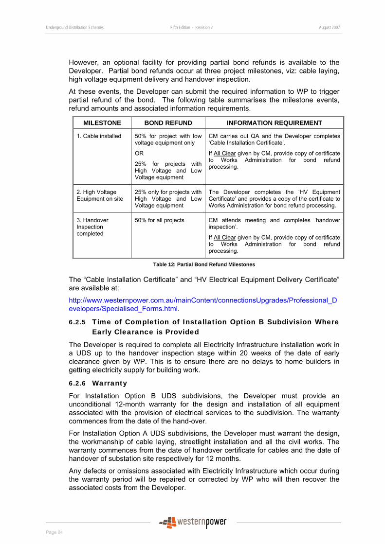
Underground Distribution Schemes Fifth Edition - Revision 2 August 2007
Page 84
However, an optional facility for providing partial bond refunds is available to the Developer. Partial bond refunds occur at three project milestones, viz: cable laying, high voltage equipment delivery and handover inspection.
At these events, the Developer can submit the required information to WP to trigger partial refund of the bond. The following table summarises the milestone events, refund amounts and associated information requirements.
MILESTONE BOND REFUND INFORMATION REQUIREMENT
1. Cable installed 50% for project with low voltage equipment only
OR
25% for projects with High Voltage and Low Voltage equipment
CM carries out QA and the Developer completes ‘Cable Installation Certificate’.
If All Clear given by CM, provide copy of certificate to Works Administration for bond refund processing.
2. High Voltage Equipment on site
25% only for projects with High Voltage and Low Voltage equipment
The Developer completes the ‘HV Equipment Certificate’ and provides a copy of the certificate to Works Administration for bond refund processing.
3. Handover Inspection completed
50% for all projects CM attends meeting and completes ‘handover inspection’.
If All Clear given by CM, provide copy of certificate to Works Administration for bond refund processing.
Table 12: Partial Bond Refund Milestones
The “Cable Installation Certificate” and “HV Electrical Equipment Delivery Certificate” are available at:
http://www.westernpower.com.au/mainContent/connectionsUpgrades/Professional_Developers/Specialised_Forms.html.
6.2.5 Time of Completion of Installation Option B Subdivision Where Early Clearance is Provided
The Developer is required to complete all Electricity Infrastructure installation work in a UDS up to the handover inspection stage within 20 weeks of the date of early clearance given by WP. This is to ensure there are no delays to home builders in getting electricity supply for building work.
6.2.6 Warranty
For Installation Option B UDS subdivisions, the Developer must provide an unconditional 12-month warranty for the design and installation of all equipment associated with the provision of electrical services to the subdivision. The warranty commences from the date of the hand-over.
For Installation Option A UDS subdivisions, the Developer must warrant the design, the workmanship of cable laying, streetlight installation and all the civil works. The warranty commences from the date of handover certificate for cables and the date of handover of substation site respectively for 12 months.
Any defects or omissions associated with Electricity Infrastructure which occur during the warranty period will be repaired or corrected by WP who will then recover the associated costs from the Developer.
Underground Distribution Schemes Fifth Edition - Revision 2 August 2007
Page 85
6.2.7 Ownership and Responsibilities for Equipment
When the Developer supplies and installs all the Electricity Infrastructure associated with the UDS, the Developer owns all equipment and is responsible for its security up until the completion of handover inspection, at which time ownership passes to WP.
When WP supplies equipment to the Developer for the Developer’s subcontractor to install, the equipment remains the property of WP but its control and security is the responsibility of the Developer until it is installed and formally handed over to WP. Any loss due to damage or theft is the responsibility of the Developer until handover.
When WP supplies and installs equipment, ownership of all materials remains the property of WP, both during and at the completion of the project.
6.2.8 Tests
For Installation Option B UDS subdivisions, the Developer must carry out all tests specified below and complete and submit the relevant test schedule to the CM.
For Installation Option A UDS subdivisions, the Developer must carry out all the cable tests and complete and submit the relevant test schedule to the CM. WP will carry out other tests.
The tests include:
• Low voltage XLPX cable testing.
• LV continuity and phasing testing.
• High voltage XLPE cable testing.
• High voltage mixed cable testing.
• Earthing testing.
• LV switchgear inspection and testing; and
• High voltage switchgear testing.
Testing is to be carried out in accordance with the WP “Network Standard NS 07-2003, Testing & Commissioning” which is at:
http://www.westernpower.com.au/mainContent/connectionsUpgrades/policiesRegulations/technicalDocumentation.html.
All electrical testing of Electricity Infrastructure shall be carried out by a electrical worker licensed under the Electricity (Licensing) Regulations 1991 and/or an accredited cable jointer as permitted under Section 66.2.9.6.
The electrical worker or the accredited cable jointer who carries out the tests is to complete and sign off the testing schedules shown on Appendix 15 and forward them to the QA Officer to be received at least two working day prior to the hand-over inspection.
6.2.9 Installer Requirements, Qualifications and Responsibilities
All persons who undertake work associated with a UDS in subdivisions must be accredited and approved by WP and hold all necessary licences and authorisations for that work.
The Developer must ensure that all work associated with a UDS is carried out by qualified persons as required by the applicable written laws.

Underground Distribution Schemes Fifth Edition - Revision 2 August 2007
Page 86
6.2.9.1 Cable Laying Contractor
The cable laying contractor must employ accredited cable laying supervisors and/or nationally accredited cable layers in the installation of underground cables and streetlight columns.
6.2.9.2 Cable Laying Supervisor
A person supervising the installation of underground cables and streetlight columns, including the pulling-in of cables into enclosure housing electrical apparatus that is completely disconnected from source of electricity supply, must hold Category A accreditation under WP’s Accreditation System.
Nationally accredited Australian Qualifications Framework (AQF) standard training is required for any person who lays underground electrical supply cables. Category A accreditation – Cable Laying Supervisor will no longer be issued. Existing Category A accredited cable laying supervisors can continue to install underground cables and their accreditation will be updated or transferred to the new accreditation by a scheme to be announced by Power Training Services.
6.2.9.3 Cable Layer
A person installing underground cables and streetlight columns, including the pulling-in of cables into enclosure housing electrical apparatus that is completely disconnected from source of electricity supply must have successfully completed the nationally accredited course “Lay Underground Electrical Supply Cables”. A person who has successfully completed this course will be issued a certificate and can apply to WP to become an ‘Accredited Cable Layer’.
The “Lay Underground Electrical Supply Cables” course conducted by Power Training Services (PTS) of WP consists of two parts as follows:
• Part 1 - A three-day classroom lecture on laying underground cables. Participants who have successfully completed Part 1 will be issued an ‘Attendance Certificate’.
• Part 2 – An on-the-job competency assessment program which must be completed and certified within 12 months from the date of issue of the ‘Attendance Certificate’ of Part 1.
A person who has completed Part 1 with an ‘Attendance Certificate can, for a maximum period of 12 months, lay underground cables under the supervision of either a Category A accredited cable laying supervisor or an accredited cable layer.
6.2.9.4 Cable Jointer
Nationally accredited Australian Qualifications Framework (AQF) standard training is required for any person who carries out cable jointing work.
A person engaged in carrying out cable jointing work must hold AQF Certificate III in Cable Jointing and must be accredited by WP. This applies to all jointing and termination work on low and high voltage cables up to 33KV in underground where cables are completely disconnected from the source of electricity supply.
Persons who hold the following accreditation under the Accreditation System of WP can continue to install underground cables and their accreditation will be updated or
Underground Distribution Schemes Fifth Edition - Revision 2 August 2007
Page 87
transferred to the new accreditation by a scheme which to be announced by Power Training Services.
• Category D – Cable jointer underground HV up to 33kV (XLPE). This category applies to all jointing and termination work on low and high voltage cables in underground where cables are completely disconnected from the source of electricity supply.
• Category E – Cable jointer underground LV to 600Volts (XLPE). This category applies to all jointing and termination work carried out on low voltage cables underground where cables are completely disconnected from the source of electricity supply.
Accredited cable jointers may perform cable insulation testing, continuity and core-to-core testing of underground cables, provided they have completed the necessary training as required by WP (Power Training Services (PTS) 290 Low Voltage Cable Jointing and PTS 289 High Voltage Cable Jointing).
6.2.9.5 Electrical Worker
The following work must be carried out by electrical workers licensed under the Electricity (Licensing) Regulations 1991:
• The final connection of all underground cables and circuits, including switchgear, transformers, earthing and streetlights.
• The wiring of circuits, including streetlight circuits.
• The testing of cables and circuits, except where the testing of cables is permitted under Section 6.2.9.4 Cable Jointer.
• The installation of substation equipment, including transformers and switchgear, excluding the unloading and positioning of substation equipment onto their supporting bases.
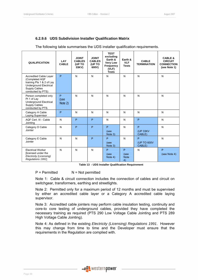
Underground Distribution Schemes Fifth Edition - Revision 2 August 2007
Page 88
6.2.9.6 UDS Subdivision Installer Qualification Matrix
The following table summarises the UDS installer qualification requirements.
QUALIFICATION LAY CABLE
JOINT CABLES (UP TO 33KV)
JOINT CABLES (UP TO 600V)
TEST excluding Earth &
Very Low Frequency
(VLF) Tests
Earth & VLF
Tests
CABLE TERMINATION
CABLE & CIRCUIT
CONNECTION (see Note 1)
Accredited Cable Layer (Completed AQF training Pts 1 & 2 of Lay Underground Electrical Supply Cables conducted by PTS)
P N N N N N N
Person completed only Pt 1 of Lay Underground Electrical Supply Cables conducted by PTS.
P (see Note 2)
N N N N N N
Category A Cable Laying Supervisor
P N N N N N N
AQF Cert. III - Cable Jointing
N P P N N P N
Category D Cable Jointer
N P P P (see Note 3)
N P (UP 33KV CABLE)
N
Category E Cable Jointer
N N P P (see Note 3)
N P (UP TO 600V CABLE)
N
Electrical Worker [licensed under the Electricity (Licensing) Regulations 1991]
N N N P (see Note 4)
P (see Note 4)
N P (see Note 4)
Table 13 - UDS Installer Qualification Requirement
P = Permitted N = Not permitted
Note 1: Cable & circuit connection includes the connection of cables and circuit on switchgear, transformers, earthing and streetlights.
Note 2: Permitted only for a maximum period of 12 months and must be supervised by either an accredited cable layer or a Category A accredited cable laying supervisor.
Note 3: Accredited cable jointers may perform cable insulation testing, continuity and core-to core testing of underground cables, provided they have completed the necessary training as required (PTS 290 Low Voltage Cable Jointing and PTS 289 High Voltage Cable Jointing).
Note 4: As defined in the existing Electricity (Licensing) Regulations 1991. However this may change from time to time and the Developer must ensure that the requirements in the Regulation are complied with.

Underground Distribution Schemes Fifth Edition - Revision 2 August 2007
Page 89
6.2.9.7 Enquires on Accreditation and Training
The Developer can find out whether a contractor is a WP preferred contractor (vendor), or whether a person is accredited or authorised to carry out work in subdivisions, by contacting Power Training Services or by visiting:
http://www.westernpower.com.au/mainContent/workingWithPower/industryContractors/BecomingAuthorisedAccreditedContractor.html.
For any enquiries about gaining accreditation, please contact Power Training Services or visit the above web site
Power Training Services can be contacted at:
Power Training Services WA Training Place, Jandakot WA 6164 Phone (08) 9411 7888 Fax (08) 9411 7887 Email: [email protected]
6.2.10 Construction Requirements and Standards
6.2.10.1 General Requirements
The Developer shall ensure that the UDS in the subdivision is constructed in a safe and efficient manner with minimal disruption to the public and in accordance with:
• The Construction Requirements and Standards described in this manual,
• WP’s Network Standard NS 14.2– Underground Cable Installation Manual, Part 2, which is available at:
http://www.westernpower.com.au/mainContent/connectionsUpgrades/policiesRegulations/technicalDocumentation.html.
• All regulatory standards and the requirements shown in Section 6.2.11.
• All statutory requirements, and
• Satisfies WP’s Environmental Policy, which is available at:
http://www.westernpower.com.au/mainContent/environment/Environment.
6.2.10.2 Site Safety
The Developer is responsible to ensure that the site is safe in accordance to the Occupational Safety and Health Act 1984 and the Occupational Safety and Health Regulations 1996.
The Developer must also comply with all lawful decisions from the CM relating to the safety of WP’s personnel or assets.
6.2.10.3 Installation Drawings
The Developer shall ensure all Electricity Infrastructure, including substation, earthing and streetlights, is installed in accordance with drawings and diagrams shown in Appendix 22 and in the following:
Underground Distribution Schemes Fifth Edition - Revision 2 August 2007
Page 90
• Distribution Substation Manual (DSM).
• Distribution Design Catalogue (DDC).
The above documents are available from:
http://www.westernpower.com.au/mainContent/connectionsUpgrades/policiesRegulations/technicalDocumentation.html.
6.2.10.4 Finished Ground Level
The Developer must ensure:
• Prior to the commencement of any electrical work, including cable laying, the finished ground levels are established by the Site Superintendent/ Project Engineer.
• Where the road reserves have not been constructed or formed, the Site Superintendent/Project Engineer will ascertain and agree with the CM the required depth of cover of cables before excavation upon such road reserves.
• Pillars and pad-mount transformers and switchgear are not be installed unless the sites are completed with finished ground level.
6.2.10.5 Survey Pegs
The Developer shall ensure:
• The Site Superintendent/Project Engineer has accurately pegged all subdivision and lot boundaries. Any additional costs incurred by WP as a result of boundaries being pegged incorrectly will be charged to the Developer.
• Prior to the commencement of trenching and cable laying work, all final survey pegs are in place and maintained in-situ throughout trenching and cable laying until the CM has completed inspections.
• The Site Superintend/Project Engineer replaces any moved or missing pegs.
• Where there are large curves or long lot frontages, sufficient peg positions are in place to enable accurate placement of cables in the allocated alignment.
An offset peg at an agreed distance from the property boundary prior to trench excavation is acceptable. However, final boundary pegs must be installed by the Developer upon completion of ground work and prior to the installation of pillars. Offset pegs must be agreed with the CM at the pre-start meeting.
6.2.10.6 Trenching
The Developer shall ensure that excavation of trenches is carried out as shown on the conformed scheme design drawing and complies with WP’S Network Standard NS 14.2 – Underground Cable Installation Manual Part 2 and Drawing No. UDS-6-2 shown in Appendix 22, with particular care taken to ensure that there is sufficient cover over the cables.
When crossing a road reserve, the trenching must be such that a minimum of 750mm of cover is maintained over the cable at all points, with a maximum depth, if

Underground Distribution Schemes Fifth Edition - Revision 2 August 2007
Page 91
required, of 1100mm at the crown of the road. The trenching must be such that the final contour of the road reserve is followed.
Where the presence of structures, existing services or plant in the road reserve will not allow the installation of cables with these minimum specified covers, the Site Superintendent/Project Engineer must bring the matter to WP’s attention and seek direction prior to proceeding further.
Machine excavation of trenches shall not be used where there are existing cables within one metre.
Where there are existing cables in the cable alignment, hand digging must be used to excavate for the installation of new cables.
The Site Superintendent/Project Engineer must coordinate joint trenching requirements and the Developer must make all necessary arrangement with other utilities to achieve this.
Trenching works must also comply with the recommendations of the Electricity Supply Association of Australia Publication Number C(b)2 “Guide to the Installation of Cables Underground”.
6.2.10.7 Cable Ducts
The Developer shall ensure that all ducts are installed in accordance with the conformed design drawings and as indicated in Appendix 9, Appendix 10, Appendix 11 and Appendix 22.
6.2.10.8 Cable laying
The Developer shall ensure that all cable laying works comply with WP’s Network Standard NS 14.2 – Underground Cable Installation Manual Part 2 and the recommendations of the Electricity Supply Association of Australia Publication Number C(b)2 –“Guide to the Installation of Cables Underground”.
Cables must be installed in WP’s standard alignment and in accordance with the “Utility Providers Code of Practice for Western Australia” and Drawing No.UDS-6-2 described in Appendix 22. Other services are not permitted in the power cable alignment without written permission from WP.
During the installation, underground straight joints in HV or LV cables must be kept to a minimum. The number of HV or LV cable joints permitted is to be calculated by the following formula:
N < 1 + L1/L2 for L1 > 150m
N = 0 for L1 ≤ 150m
Where,
N = Number of joints permitted
L1 = Total Cable route length between terminals (metres)
L2 = 250m (Standard cable drum length)
All cables shall be marked or tagged as they are laid, to individually identify them, prior to jointing.
Underground Distribution Schemes Fifth Edition - Revision 2 August 2007
Page 92
The ends of cut cable must be capped with mastic lined, heat shrink caps immediately after cutting to prevent water ingress.
The preferred method of installing cable is to mount the cable drum on jacks, cable trailer or cable stand and unroll the cable from the drum into the trench. If it is necessary to pull in the cable, then cables must be fully supported by suitable proprietary cable rollers during cable laying. At no stage may the cable be permitted to drag on the ground or be subjected to treatment which could damage the outer sheath.
Any damage to the cable will lead to WP rejecting the affected part of the installation and new cable will need to be laid.
6.2.10.9 Road, Railway and Vehicle Crossing
The Developer shall ensure that all cables crossing roads and vehicle cross-overs are installed to meet the requirements of WP’s Network Standard NS 14.2 – Underground Cable Installation Manual Part 2- Technical Requirements.
6.2.10.10 Backfilling
The Developer shall ensure:
• Backfilling does not commence until approved by the CM.
• Bedding and backfilling meets the requirements of WP’s Network Standard NS 14.2 – Underground Cable Installation.
• Backfilling complies with the published “Subdivision Design Guideline – Number 4, Bedding Sand and Backfill Sand around Cables and General Backfill for Cable Trenches – Material Selection Guidelines”. It can be found at:
http://www.westernpower.com.au/mainContent/connectionsUpgrades/Professional_Developers/Technical_Documentation.html.
• Where cable joints or terminations are performed by WP, the appropriate portions of the trench are not backfilled until the WP work is completed. Additional charges will be incurred for any extra work required by WP.
• All backfill and reinstatement is completed so that water run-off, or collection, will not cause soil erosion
6.2.10.11 Reinstatement
The Developer shall ensure:
• Reinstatement is based on minimum greenfield reinstatement.
• The reinstatement meets the LGA’s requirements.
6.2.10.12 Cable and Duct Placement at Road Truncations
The Developer shall ensure:
• All cables and ducts crossing roads at truncations are to be installed in accordance with drawing No. UDS-6-3, shown in Appendix 22.
• The ducts are installed from edge to edge of the cable alignment.
Underground Distribution Schemes Fifth Edition - Revision 2 August 2007
Page 93
6.2.10.13 Cable Installed near to Retaining Walls
Where cable is to be installed near to retaining walls, the Developer shall ensure that the cable is installed in and protected by cable ducts. Cable ducts must be installed prior to the construction of retaining walls.
Retaining walls and footings must not encroach on the nominal cable alignment of 0-500mm.
6.2.10.14 Cable Installed in Laneway
In accordance with Section 5.3.12 the Developer must obtain WP’s prior approval for the installation of underground cables in a laneway.
Where approval is given by WP the cable must be:
either:
Installed in the 0-500mm alignment from property boundary in cable ducts with a minimum of one spare duct,
or:
Direct buried in soil, provided 300mm of clean sand is installed below the cables and clean sand is installed above the cables all the way up to the road base with a minimum of one spare duct.
Note: Clean sand must meet the selection criteria of sand for bedding in Subdivision Design Guideline – Number 4, Bedding Sand and Backfill Sand around Cables and General Backfill for Cable Trench – Material Selection Guidelines, available at:
http://www.westernpower.com.au/mainContent/connectionsUpgrades/Professional_Developers/Technical_Documentation.html.
6.2.10.15 Cable Installed in Easement
Where cable is to be installed in an easement, the Developer must supply and install the cable ducts as detailed in the conformed design drawing with the cross-section details of cable easement in Appendix 11.
6.2.10.16 Cable Installed off Nominal Alignment
If WP approves installation of cables outside the 0-500mm alignment, the Developer must ensure each cable is installed in duct with PVC marker tape.
Where approval is given by WP to install cables in the 2.4m to 3.0m alignment, it must be installed in cable duct with PVC marker tape.
The Developer must comply with Section 5.3.9 in regard to the approval of cable off nominal alignment of 0-500mm.
6.2.10.17 LV Cable Joints and Terminations
The Developer shall ensure that low voltage cables are jointed and/or terminated only by WP accredited cable jointers using techniques and work practices as detailed from time-to-time by the manufacturer or by WP.
When terminating low voltage three phase cables the core numbers and colours must always match each other and cores one, two and three must be terminated red, white, blue respectively.
Underground Distribution Schemes Fifth Edition - Revision 2 August 2007
Page 94
6.2.10.18 HV Cable Joints and Terminations
The Developer shall ensure that HV cables are jointed and/or terminated only by WP accredited cable jointers using techniques and work practices as detailed from time-to-time by the manufacturer or by WP. All cable joints must be installed in accordance with the manufacturer’s instructions supplied with the cable joint kit.
Particular care should be taken to ensure correct phase connection occurs. Sufficient slack through extra depth or looping is to be left to enable re-termination if required.
The cable jointer must complete and label the installer identification tag and fit the tag to each joint or termination in accordance to the drawing in Appendix 12.
The cable jointer must also complete the “HV Cable Joint Schedule” as shown in Appendix 14 and provide the schedule to the QA Officer prior to handover inspection. The “HV Cable Schedule” form is available from:
http://www.westernpower.com.au/mainContent/connectionsUpgrades/Professional_Developers/Specialised_Forms.html.
6.2.10.19 Service Pillars
The Developer shall ensure that services pillars are installed and located within lot boundaries along public road reserves in accordance with Drawing No. UDS-6-1P in with WP’s Network Standard NS 14.2 – Underground Cable Installation Manual Part 2.
Where retaining or boundary walls exist along the boundary, the service pillar shall be installed as per the following:
• If a side retaining or boundary wall exists and this stops short of the front boundary, the pillar may be located the end of the wall. Please note, this may affect the installation of boundary fence.
• If front and side retaining walls exist, then the pillar is to be located 500mm from the inside of each wall as shown on the above drawing and ducts must be provided under each wall for both the WP supply cable and the neighbour’s consumer’s main cable.
6.2.10.20 Working End Pillars
Cables for both HV and LV may be extended to the subdivision scheme boundary for future extension into the next stage. The Developer shall ensure these cables are terminated into working end pillars.
Working end pillars must not be installed inside any lot boundaries (including POS lots) and must be painted white and labelled “Working end only – not for connection”.
6.2.10.21 Western Power Streetlights
Under Installation Option A, the Developer is responsible for trenching and laying streetlight cabling, the erection of the steel standards and wiring standard and luminaries. WP will connect the street light cable to the standard.
Under Installation Option B, the Developer is responsible for all work associated with the installation of streetlights.
Underground Distribution Schemes Fifth Edition - Revision 2 August 2007
Page 95
WP streetlights are to be installed in the positions nominated on the conformed scheme design drawing on the 2.7m alignment and to the depth shown on the drawings in the relevant section of the Distribution Design Catalogue.
Where the road reserve has a verge wider than 3700mm, street lights can be installed at a minimum set back from the kerb line shown on the conformed scheme design drawing (also see Section 5.3.25.3). The Developer is required to obtain the approval of LGA and other Utility Providers.
After installation of the column the hole is to be back-filled and well tamped to provide a secure foundation.
6.2.10.22 Substation
The Developer must ensure that each substation site is prepared and constructed in accordance with:
• Section 5.3.18.
• The requirements shown on the conformed design drawing.
• The Distribution Substation Manual.
• DSB 95/5 Substation Installation Requirements of WP available from:
http://www.westernpower.com.au/mainContent/connectionsUpgrades/policiesRegulations/technicalDocumentation.html.
The Developer must ensure that all substation equipment, including transformer and switchgear, is installed by a licensed electrical contractor or a licensed electrical worker, in accordance with the following:
• The manufacturer’s information.
• WP’s requirements as illustrated in drawings of the Distribution Substation Manual and the Distribution Design Catalogue.
6.2.10.23 Substation Ducts
The Developer shall install all substation ducts in accordance with the drawings in the Distribution Substation Manual. The drawings are also available in Appendix 22.
6.2.10.24 Substation Earthing
The Developer shall install all substation earthing in accordance with substation earthing arrangements shown on the relevant compatible unit drawings in the DDC. Appendix 22 shows a list of examples of drawings.
The substation earthing grid must be buried 150mm below finished ground level of the substation.
The substation earthing must also be constructed to comply with the requirement of ‘Combined Earth System’ of Section 7.8.10 of AS/NZS 3000 – Wiring Rules.
All earthing cables must be tagged and labelled at the earth bar end to clearly indicate where they are connected.
Underground Distribution Schemes Fifth Edition - Revision 2 August 2007
Page 96
6.2.10.25 Substation Screening
Where a MPS or non-MPS arrangement is to be installed, WP does not require screening around the substation site. If screening is required, the Developer is responsible for installation. All screening must meet the requirements of WP’s DSB 95/5 Substation Installation Requirements.
Metallic screening is not recommended and is to be avoided in subdivision development. However, if a Developer insists on metallic fencing, it must be constructed with earth grading wire in accordance with WP’s DSB 95/5 Substation Installation Requirements. Where the substation site adjoins a private lot, the Developer must either:
• Increase the substation site by 1000mm on each side with metallic fencing so grading wire remains within the substation site;
or,
• Increase the substation site by 1250mm on each side with metallic fencing and install the fencing at 1250mm from the substation boundary lines without earth bonding and grading ring.
6.2.10.26 Access to Electrical Equipment
The Developer must ensure that all contractors and personnel working on or near WP’s network comply with WP’s “Electrical Safety Instructions Manual”
If the contractor requires access to any equipment that has been commissioned and handed over to WP or equipment bearing an operational label (see Appendix 13), then the contractor must first obtain the appropriate electrical permit from WP.
6.2.10.27 Excavation near to existing asset
The Developer must ensure that when excavation work is to be carried out near WP underground and overhead electrical networks, the contractor complies with the following:
• “Guidelines for Excavation near Western Powers’ Underground and Overhead Electrical Network” published by WP, and can be found at:
http://www.westernpower.com.au/mainContent/workingWithPower/WorkingAroundPowerLines/ProtectingWorkersAroundPowerLines.html
• WorkSafe Western Australia, Code of Practice: Excavations. Information on the Code of Practice: Excavation, which can be found at the WorkSafe Western Australia website at http://www.safetyline.wa.gov.au/.
6.2.10.28 Working in the Vicinity of overhead power lines
The Developer must ensure that when work is to be carried out in the vicinity of WP’s overhead power network, the contractor complies with the requirement of:
• The Occupational Safety and Health Regulations 1996, and
• WorkSafe Western Australia, “Guidelines for Work in the Vicinity of Overhead Power Lines” which can be found at the WorkSafe Western Australia website at http://www.safetyline.wa.gov.au/.
Underground Distribution Schemes Fifth Edition - Revision 2 August 2007
Page 97
When planning above ground work near a power line, the contractor must lodge a Request to Work Near Overhead Power Lines with WP. The application information pack is available at:
http://www.westernpower.com.au/mainContent/workingWithPower/WorkingAroundPowerLines/ProtectingWorkersAroundPowerLines.html
6.2.10.29 Minor Changes during construction
During construction of an underground Electricity Infrastructure, the contractor may need to make minor changes to UDS design to suit site requirements. The following changes are considered minor changes and can be approved by the CM on site.
• Minor adjustment of cable truncation.
• Minor relocation of streetlighting of not more than 20m within the streetlighting alignment (outside transmission line easement) but still meeting other requirements.
• Relocation of pillar for reticulation pump along the same LV feeder towards the district substation.
• Relocation of mini pillars across side lot boundary from the corner of a lot to the corner of the adjacent lot.
• Installation of cables (HV or LV cables) to the 2.7m pole alignment to avoid trees and rocks only.
All minor changes approved by the CM must be shown on the “As Constructed” drawing.
Please refer to Section 4.4.5.1 for the requirements of major changes required during construction.
6.2.10.30 Existing Customers and Affected Parties
The Developer is responsible for notifying all concerned parties, including other WP customers affected by the work associated with a UDS.
Where existing aerial mains are to be removed as part of UDS, the Developer is also responsible for the reconnection of existing WP aerial connected customers to the underground system. The Developer must engage the services of an electrical contractor to undertake these reconnections. All such reconnection work must be completed before the aerial mains in the street can be removed.
There are three options for reconnection of services to existing customers affected, viz:
• Where there is sufficient space at the front boundary of the affected lot for a normal pillar to be installed, as shown in drawing UDS-6-1P in Western Power’s Network Standard NS 14.2 – Underground Cable Installation Manual Part 2, the existing overhead services will be replaced with underground services. WP will provide a pillar at the Developer’s cost. The Developer is responsible for installing the underground service from the pillar to the existing customer.
• In the case where there is insufficient space for a normal pillar to be installed, a wall mounted pillar will be required. WP’s CM will supply the wall mounted pillar to the Developer, who is responsible for having it installed on the facade of the affected building. A minimum of four weeks’ notice is required to enable WP to order the pillar. WP will supply and install the underground service cable up to
Underground Distribution Schemes Fifth Edition - Revision 2 August 2007
Page 98
the facade of the building, allowing sufficient length to reach the wall mounted pillar itself. The Developer must have the cable fixed to the facade of the building, up to the wall mounted pillar. WP will undertake the final connection of the underground service to the wall mounted pillar, in conjunction with the Developer’s electrician.
• Retain the existing overhead service. In this case, a service pole must be installed by the Developer. The service pole must be located so that the existing aerial service cable can be terminated on the pole. A meter enclosure must be mounted on the pole and able to accommodate a standard meter panel (450mm x 225mm) and a customer’s panel (225mm x 225mm). This enclosure will become the new main switchboard for the premises. The service pole must be wired with sufficient lead length to reach the pillar as indicated on the WP drawing.
In all of the above options, the Developer is to inform existing customers affected that all wiring downstream of the WP pillar is their responsibility. That is, if the wiring is damaged (e.g. by storms) they will be responsible for repairs.
6.2.11 Installation Document
• Distribution Substation Manual (Western Power).
• Distribution Design Catalogue (Western Power).
• DSB95/6 Substation Installation Requirements Manual (Western Power).
• Network Standard NS 14.2 – Underground Cable Installation Manual Part 2- Technical Requirements (Western Power).
• Network Standard NS 07-2003 Testing & Commissioning (Western Power).
• Western Power Safety Manual.
• Guidelines for excavation work near Western Power’s underground and overhead electrical networks (Western Power).
• Utility Providers Code of Practice (Utility Providers Service Committee).
• Electricity (Supply Standards and System Safety) Regulations 2001.
• Guidelines for work in the vicinity of overhead power lines (WorkSafe).
• Occupational Safety and Health Act 1984.
• Occupational Safety and Health Regulations 1996.
• Code of Practice: Excavations (WorkSafe).
• Western Australia Electrical Requirements (Office of Energy Safety).
• AS/NZI Standard 3000 Australian/New Zealand Wiring Rules.
• ESAA C(b)2 “Guide to Installation of Cables Underground”
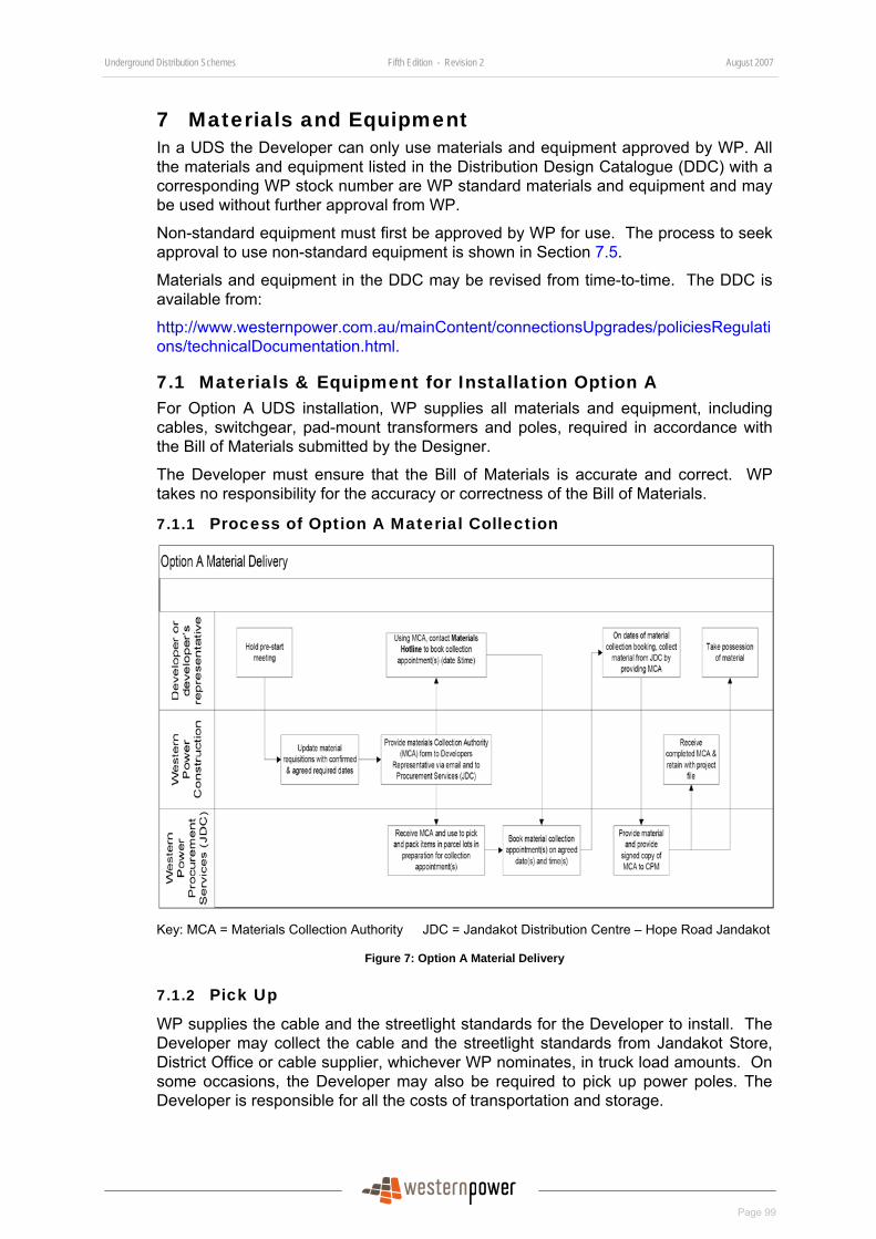
Underground Distribution Schemes Fifth Edition - Revision 2 August 2007
Page 99
7 Materials and Equipment In a UDS the Developer can only use materials and equipment approved by WP. All the materials and equipment listed in the Distribution Design Catalogue (DDC) with a corresponding WP stock number are WP standard materials and equipment and may be used without further approval from WP.
Non-standard equipment must first be approved by WP for use. The process to seek approval to use non-standard equipment is shown in Section 67.5.
Materials and equipment in the DDC may be revised from time-to-time. The DDC is available from:
http://www.westernpower.com.au/mainContent/connectionsUpgrades/policiesRegulations/technicalDocumentation.html.
7.1 Materials & Equipment for Installation Option A For Option A UDS installation, WP supplies all materials and equipment, including cables, switchgear, pad-mount transformers and poles, required in accordance with the Bill of Materials submitted by the Designer.
The Developer must ensure that the Bill of Materials is accurate and correct. WP takes no responsibility for the accuracy or correctness of the Bill of Materials.
7.1.1 Process of Option A Material Collection
Key: MCA = Materials Collection Authority JDC = Jandakot Distribution Centre – Hope Road Jandakot
Figure 7: Option A Material Delivery
7.1.2 Pick Up
WP supplies the cable and the streetlight standards for the Developer to install. The Developer may collect the cable and the streetlight standards from Jandakot Store, District Office or cable supplier, whichever WP nominates, in truck load amounts. On some occasions, the Developer may also be required to pick up power poles. The Developer is responsible for all the costs of transportation and storage.
Underground Distribution Schemes Fifth Edition - Revision 2 August 2007
Page 100
A minimum of seven working days is required after site pre-start meeting before cable can be collected.
WP also requires a minimum of three working days prior notice before material can be collected.
All other equipment, e.g. switchgear, pad-mount transformers, poles etc. required for the UDS subdivision will be trucked to site by WP.
7.1.3 Materials Collection Authority
The Developer’s contractor must obtain the completed the Material Collection Authority (MCA) form and have it authorized by the CM prior to materials pick up. The MCA is normally obtained at the pre-start meeting. Before materials are released from Jandakot Stores the MCA form must be provided to WP Logistics by the Developer’s collecting agent.
The Developer’s collecting agent must sign off all materials collected in good condition at the time of pick up. The Developer is responsible for all loss and damage to the materials after collection.
The MCA form is shown in Appendix 21 and is also available at:
http://www.westernpower.com.au/mainContent/connectionsUpgrades/Professional_Developers/Specialised_Forms.html.
7.1.4 Return of Unused Cables
The Developer must return all unused cable to the Jandakot store, clearly indicating the project number/Work Request number used to book out the cable. The minimum reusable length of any cable is 20m. Anything less than 20m is to be returned to Jandakot for scrap.
7.1.5 Responsibility for Security and Damage
The Developer is responsible for the security of all materials and equipment supplied by WP.
Whenever dedicated or joint trenching is being used, the Developer is liable for any costs incurred due to any cable loss or damage from the time the cable is handed over to the Developer until the trenches are fully backfilled.
Damage to WP materials and equipment by other contractors or utilities working on-site under the main subdivision contract, or by any other party, will be paid for by the Developer.
7.2 Materials & Equipment for Installation Option B
7.2.1 Direct Purchase from WP Logistic
WP holds stock of approved materials and equipment (listed in DDC) for UDS developments at Jandakot Stores. Developers may purchase this material for Installation Option B schemes.
7.2.2 Process for Ordering from WP Logistic
The process of ordering material from WP’s Logistics is described below:
• Contractors must request a Quote by sending in a Bill of Quantity with the list of stock items and the UDS subdivision project number. Usually more than one contractor will request a Quote as they will tender for work from Developers.
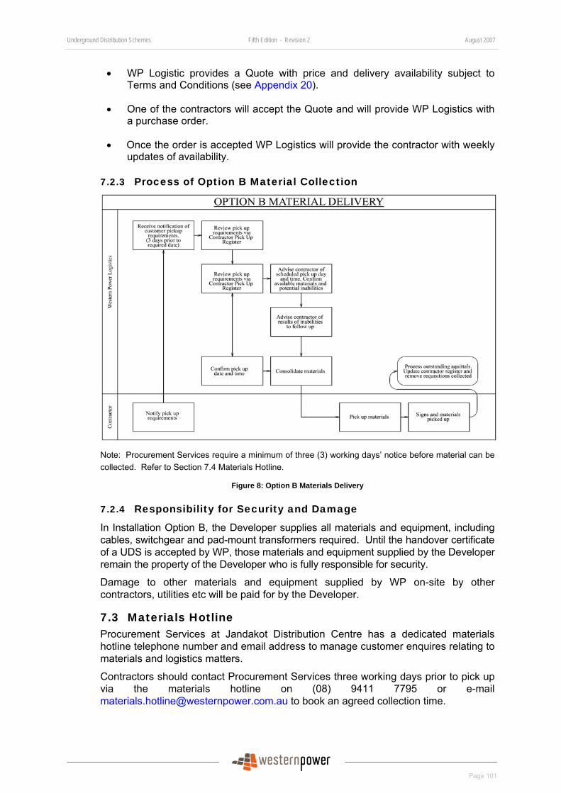
Underground Distribution Schemes Fifth Edition - Revision 2 August 2007
Page 101
• WP Logistic provides a Quote with price and delivery availability subject to Terms and Conditions (see Appendix 20).
• One of the contractors will accept the Quote and will provide WP Logistics with a purchase order.
• Once the order is accepted WP Logistics will provide the contractor with weekly updates of availability.
7.2.3 Process of Option B Material Collection
Note: Procurement Services require a minimum of three (3) working days’ notice before material can be collected. Refer to Section 7.4 Materials Hotline.
Figure 8: Option B Materials Delivery
7.2.4 Responsibility for Security and Damage
In Installation Option B, the Developer supplies all materials and equipment, including cables, switchgear and pad-mount transformers required. Until the handover certificate of a UDS is accepted by WP, those materials and equipment supplied by the Developer remain the property of the Developer who is fully responsible for security.
Damage to other materials and equipment supplied by WP on-site by other contractors, utilities etc will be paid for by the Developer.
7.3 Materials Hotline Procurement Services at Jandakot Distribution Centre has a dedicated materials hotline telephone number and email address to manage customer enquires relating to materials and logistics matters.
Contractors should contact Procurement Services three working days prior to pick up via the materials hotline on (08) 9411 7795 or e-mail [email protected] to book an agreed collection time.
Underground Distribution Schemes Fifth Edition - Revision 2 August 2007
Page 102
Contractors can also contact the materials hotline to check delivery status and/or negotiate an early delivery.
Details of the material hotline can be found at:
http://www.westernpower.com.au/mainContent/connectionsUpgrades/Professional_Developers/Technical_Documentation.html.
7.4 Standard Streetlight Materials List Steel standards and some decorative streetlights are normally available within two to three weeks of ordering. However, other non-decorative streetlights, may take up to 16 weeks to procure.
Developers and Designers can check the availability of streetlights from the Standard Streetlight Materials List that designates the streetlight items held in stock for land development work at:
http://www.westernpower.com.au/mainContent/connectionsUpgrades/Professional_Developers/Technical_Documentation.html.
7.5 Alternative Materials and Equipment for Installation Option B
7.5.1 Process Overview
If a Developer has selected Option B installation, it can use non-standard equipment provided it complies with WP’s technical requirements and is approved by WP before installation.
The process requires a formal submission of application for equipment approval with a minimum lead time of four weeks prior to use of the equipment. Longer periods are required where a number of different types of equipment will be used.
An application fee of $500 per item of non-standard equipment must be paid upon application. This allows for a preliminary review of the application and an estimate of the time required to undertake the evaluation. WP charges for each evaluation undertaken at rate of $95 per hour plus GST.
An implementation cost will be advised when the evaluation has been completed. The implementation cost will include items such as expenses for creating new drawings, updating systems, training for Designers and constructors, etc., if required.
For approval, the applicant must show how the proposed equipment meets or exceed all WP’s requirements.
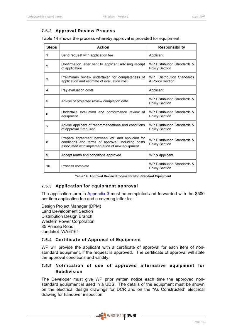
Underground Distribution Schemes Fifth Edition - Revision 2 August 2007
Page 103
7.5.2 Approval Review Process
Table 14 shows the process whereby approval is provided for equipment.
Steps Action Responsibility
1 Send request with application fee Applicant
2 Confirmation letter sent to applicant advising receipt of application
WP Distribution Standards & Policy Section
3 Preliminary review undertaken for completeness of application and estimate of evaluation cost
WP Distribution Standards & Policy Section
4 Pay evaluation costs Applicant
5 Advise of projected review completion date WP Distribution Standards & Policy Section
6 Undertake evaluation and conformance review of equipment
WP Distribution Standards & Policy Section
7 Advise applicant of recommendations and conditions of approval if required
WP Distribution Standards & Policy Section
8 Prepare agreement between WP and applicant for conditions and terms of approval, including costs associated with implementation of new equipment.
WP Distribution Standards & Policy Section
9 Accept terms and conditions approved. WP & applicant
10 Process complete WP Distribution Standards & Policy Section
Table 14: Approval Review Process for Non-Standard Equipment
7.5.3 Application for equipment approval
The application form in Appendix 3 must be completed and forwarded with the $500 per item application fee and a covering letter to:
Design Project Manager (DPM) Land Development Section Distribution Design Branch Western Power Corporation 85 Prinsep Road Jandakot WA 6164
7.5.4 Certificate of Approval of Equipment
WP will provide the applicant with a certificate of approval for each item of non-standard equipment, if the request is approved. The certificate of approval will state the approval conditions and validity.
7.5.5 Notification of use of approved alternative equipment for Subdivision
The Developer must give WP prior written notice each time the approved non-standard equipment is used in a UDS. The details of the equipment must be shown on the electrical design drawings for DCR and on the “As Constructed” electrical drawing for handover inspection.

Underground Distribution Schemes Fifth Edition - Revision 2 August 2007
Page 104
Where a Developer chooses to use an approved non-standard item, it will be responsible for its use for a period of 12 months from handover.
Developers and Designers should refer to Section 4.5 for details of the process for providing notification to WP.
7.5.6 Spares for Alternative Materials and Equipment in Subdivision
Approved alternative equipment is non-standard for WP and spares are not held within WP stores. The Developer should make appropriate arrangements to provide spares for replacement to WP’s satisfaction.
A guarantee of availability of spares by the equipment manufacturer or providing spare equipment to WP at the Developer’s own cost is an arrangement acceptable to WP.
7.5.7 List of Existing Approved Alternative Equipment
A list of approved alternative equipment that can be used in Installation Option B subdivision can be found at:
http://www.westernpower.com.au/mainContent/connectionsUpgrades/Professional_Developers/Technical_Documentation.html.
Each time an alternative type of equipment is approved it will be added to this list.

Underground Distribution Schemes Fifth Edition - Revision 1 May 2007
Page 105
APPENDICES
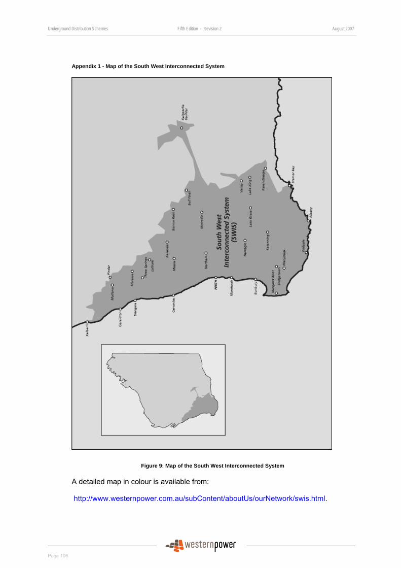
Underground Distribution Schemes Fifth Edition - Revision 2 August 2007
Page 106
Appendix 1 - Map of the South West Interconnected System
Figure 9: Map of the South West Interconnected System
A detailed map in colour is available from:
http://www.westernpower.com.au/subContent/aboutUs/ourNetwork/swis.html.
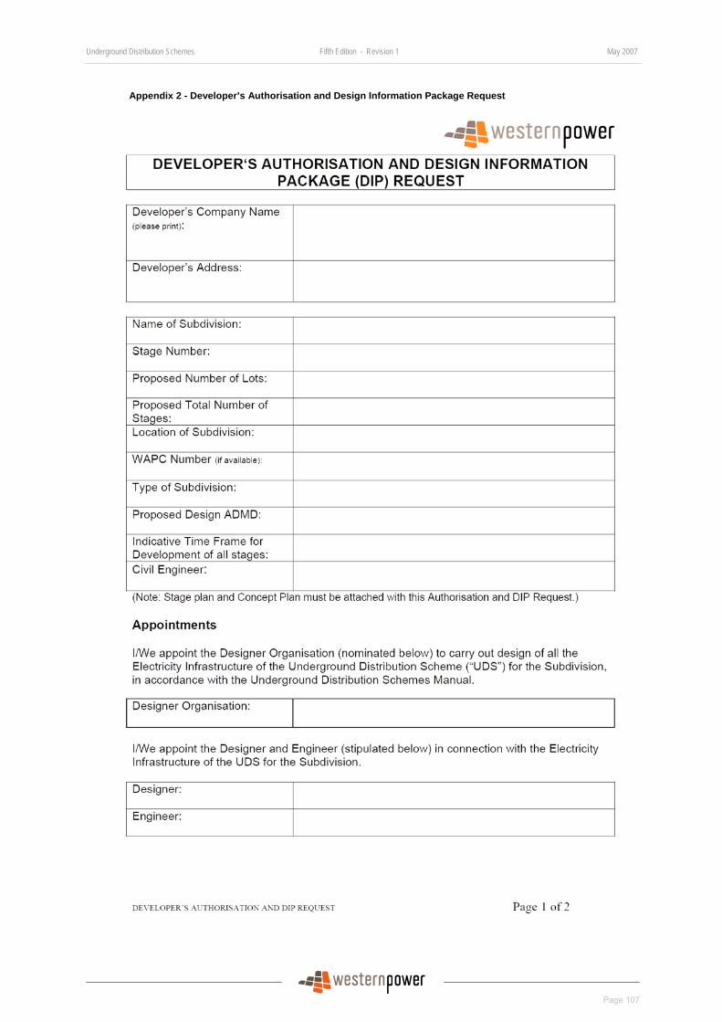
Underground Distribution Schemes Fifth Edition - Revision 1 May 2007
Page 107
Appendix 2 - Developer’s Authorisation and Design Information Package Request

Underground Distribution Schemes Fifth Edition - Revision 2 August 2007
Page 108

Underground Distribution Schemes Fifth Edition - Revision 1 May 2007
Page 109

Underground Distribution Schemes Fifth Edition - Revision 2 August 2007
Page 110
Appendix 3 - Request for Variation to Western Power Design or Standard
UDS NUMBER:
STAGE:
DEVELOPER:
CONSULTANT:
VARIATION REQUEST:
SUPPORTING DOCUMENTS:
REQUESTED BY:
Signed Date
REQUEST APPROVED/NOT APPROVED
Signed Western Power Engineer Date
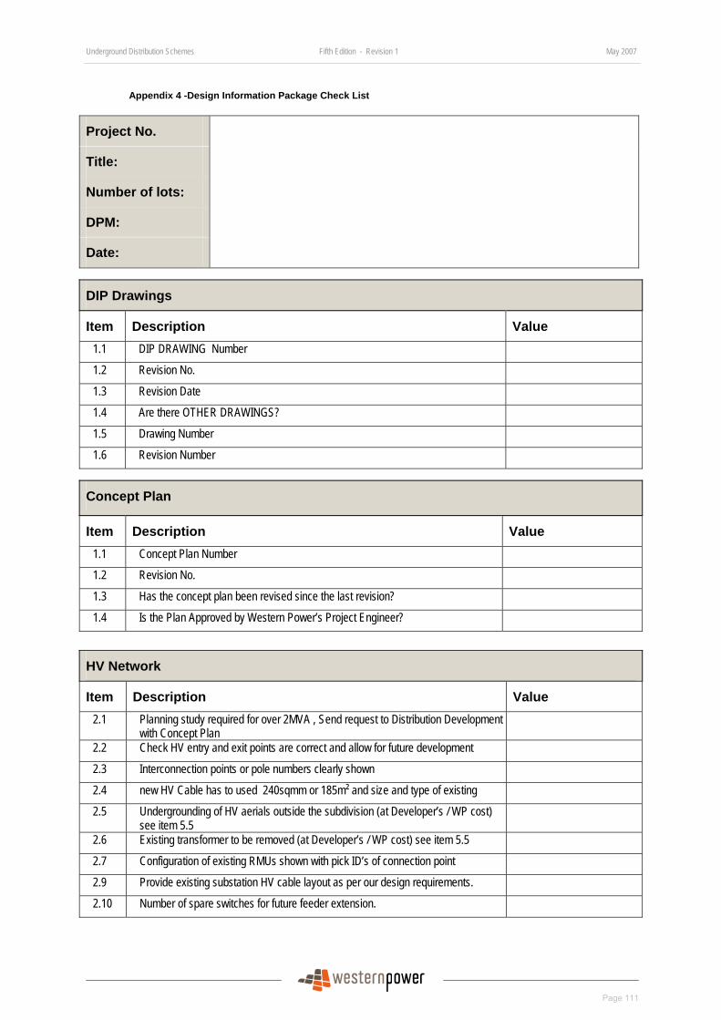
Underground Distribution Schemes Fifth Edition - Revision 1 May 2007
Page 111
Appendix 4 -Design Information Package Check List
Project No.
Title:
Number of lots:
DPM:
Date:
DIP Drawings
Item Description Value 1.1 DIP DRAWING Number
1.2 Revision No.
1.3 Revision Date
1.4 Are there OTHER DRAWINGS?
1.5 Drawing Number
1.6 Revision Number
Concept Plan
Item Description Value 1.1 Concept Plan Number
1.2 Revision No.
1.3 Has the concept plan been revised since the last revision?
1.4 Is the Plan Approved by Western Power’s Project Engineer?
HV Network
Item Description Value 2.1 Planning study required for over 2MVA , Send request to Distribution Development
with Concept Plan
2.2 Check HV entry and exit points are correct and allow for future development
2.3 Interconnection points or pole numbers clearly shown
2.4 new HV Cable has to used 240sqmm or 185m² and size and type of existing
2.5 Undergrounding of HV aerials outside the subdivision (at Developer’s / WP cost) see item 5.5
2.6 Existing transformer to be removed (at Developer’s / WP cost) see item 5.5
2.7 Configuration of existing RMUs shown with pick ID’s of connection point
2.9 Provide existing substation HV cable layout as per our design requirements.
2.10 Number of spare switches for future feeder extension.
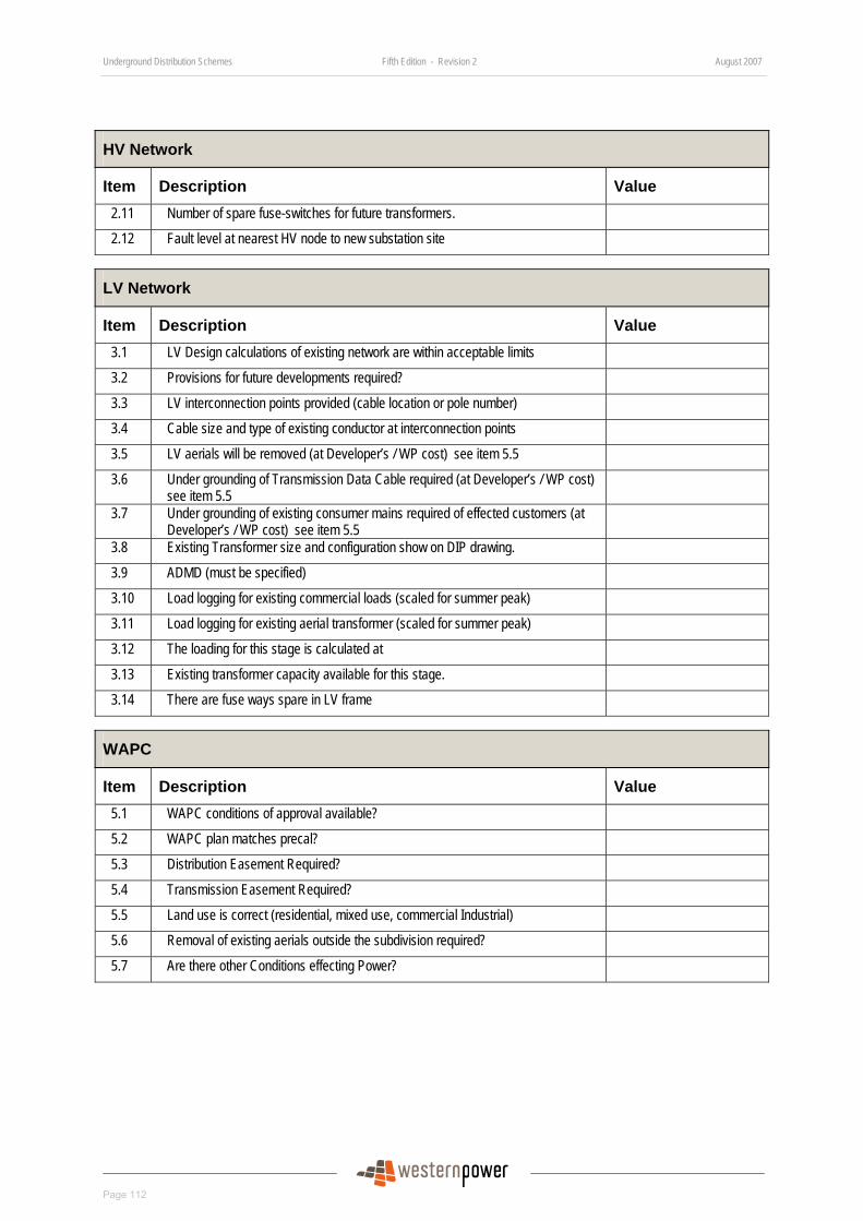
Underground Distribution Schemes Fifth Edition - Revision 2 August 2007
Page 112
HV Network
Item Description Value 2.11 Number of spare fuse-switches for future transformers.
2.12 Fault level at nearest HV node to new substation site
LV Network
Item Description Value 3.1 LV Design calculations of existing network are within acceptable limits
3.2 Provisions for future developments required?
3.3 LV interconnection points provided (cable location or pole number)
3.4 Cable size and type of existing conductor at interconnection points
3.5 LV aerials will be removed (at Developer’s / WP cost) see item 5.5
3.6 Under grounding of Transmission Data Cable required (at Developer’s / WP cost) see item 5.5
3.7 Under grounding of existing consumer mains required of effected customers (at Developer’s / WP cost) see item 5.5
3.8 Existing Transformer size and configuration show on DIP drawing.
3.9 ADMD (must be specified)
3.10 Load logging for existing commercial loads (scaled for summer peak)
3.11 Load logging for existing aerial transformer (scaled for summer peak)
3.12 The loading for this stage is calculated at
3.13 Existing transformer capacity available for this stage.
3.14 There are fuse ways spare in LV frame
WAPC
Item Description Value 5.1 WAPC conditions of approval available?
5.2 WAPC plan matches precal?
5.3 Distribution Easement Required?
5.4 Transmission Easement Required?
5.5 Land use is correct (residential, mixed use, commercial Industrial)
5.6 Removal of existing aerials outside the subdivision required?
5.7 Are there other Conditions effecting Power?
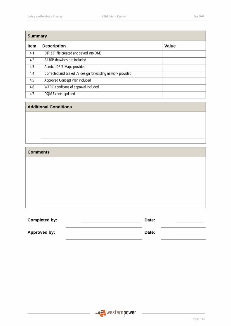
Underground Distribution Schemes Fifth Edition - Revision 1 May 2007
Page 113
Summary
Item Description Value 4.1 DIP ZIP file created and saved into DMS
4.2 All DIP drawings are included
4.3 Acrobat DFIS Maps provided
4.4 Corrected and scaled LV design for existing network provided
4.5 Approved Concept Plan included
4.6 WAPC conditions of approval included
4.7 DQM Events updated
Additional Conditions
Comments
Completed by: Date:
Approved by: Date:
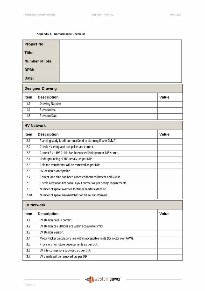
Underground Distribution Schemes Fifth Edition - Revision 2 August 2007
Page 114
Appendix 5 - Conformance Checklist
Project No.
Title:
Number of lots:
DPM:
Date:
Designer Drawing
Item Description Value 1.1 Drawing Number
1.2 Revision No.
1.3 Revision Date
HV Network
Item Description Value 2.1 Planning study is still current (Send to planning if over 2MVA)
2.2 Check HV entry and exit points are correct.
2.3 Correct Size HV Cable has been used 240sqmm or 185 sqmm.
2.4 Undergrounding of HV aerials, as per DIP
2.5 Pole top transformer will be removed as per DIP.
2.6 HV design is acceptable.
2.7 Correct land size has been allocated for transformers and RMUs.
2.8 Check substation HV cable layout correct as per design requirements.
2.9 Number of spare switches for future feeder extension.
2.10 Number of spare fuse-switches for future transformers.
LV Network
Item Description Value 3.1 LV Design data is correct.
3.2 LV Design calculations are within acceptable limits.
3.3 LV Design Version.
3.4 Motor Flicker calculations are within acceptable limits (for motor over 6kW).
3.5 Provisions for future developments as per DIP.
3.6 LV interconnections provided as per DIP.
3.7 LV aerials will be removed, as per DIP.
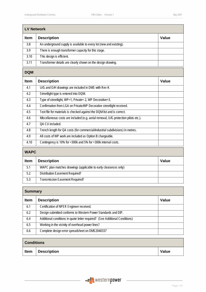
Underground Distribution Schemes Fifth Edition - Revision 1 May 2007
Page 115
LV Network
Item Description Value 3.8 An underground supply is available to every lot (new and existing).
3.9 There is enough transformer capacity for this stage.
3.10 This design is efficient.
3.11 Transformer details are clearly shown on the design drawing.
DQM
Item Description Value 4.1 U/G and O/H drawings are included in DMS with Rev #.
4.2 Streetlight type is entered into DQM.
4.3 Type of streetlight, WP=1, Private= 2, WP Decorative=3.
4.4 Confirmation from LGA on Private/WP Decorative streetlight received.
4.5 Text file for materials is checked against the DQM list and is correct.
4.6 Miscellaneous costs are included (e.g. aerial removal, U/G protection pilots etc.).
4.7 QA CU included.
4.8 Trench length for QA costs (for commercial/industrial subdivisions) in metres.
4.9 All costs of WP work are included as Option B chargeable.
4.10 Contingency is 10% for <300k and 5% for >300k internal costs.
WAPC
Item Description Value 5.1 WAPC plan matches drawings (applicable to early clearances only)
5.2 Distribution Easement Required?
5.3 Transmission Easement Required?
Summary
Item Description Value 6.1 Certification of NPER Engineer received.
6.2 Design submitted conforms to Western Power Standards and DIP.
6.4 Additional conditions in quote letter required? (See Additional Conditions)
6.5 Working in the vicinity of overhead power lines?
6.6 Complete design error spreadsheet on DMS2040337
Conditions
Item Description Value
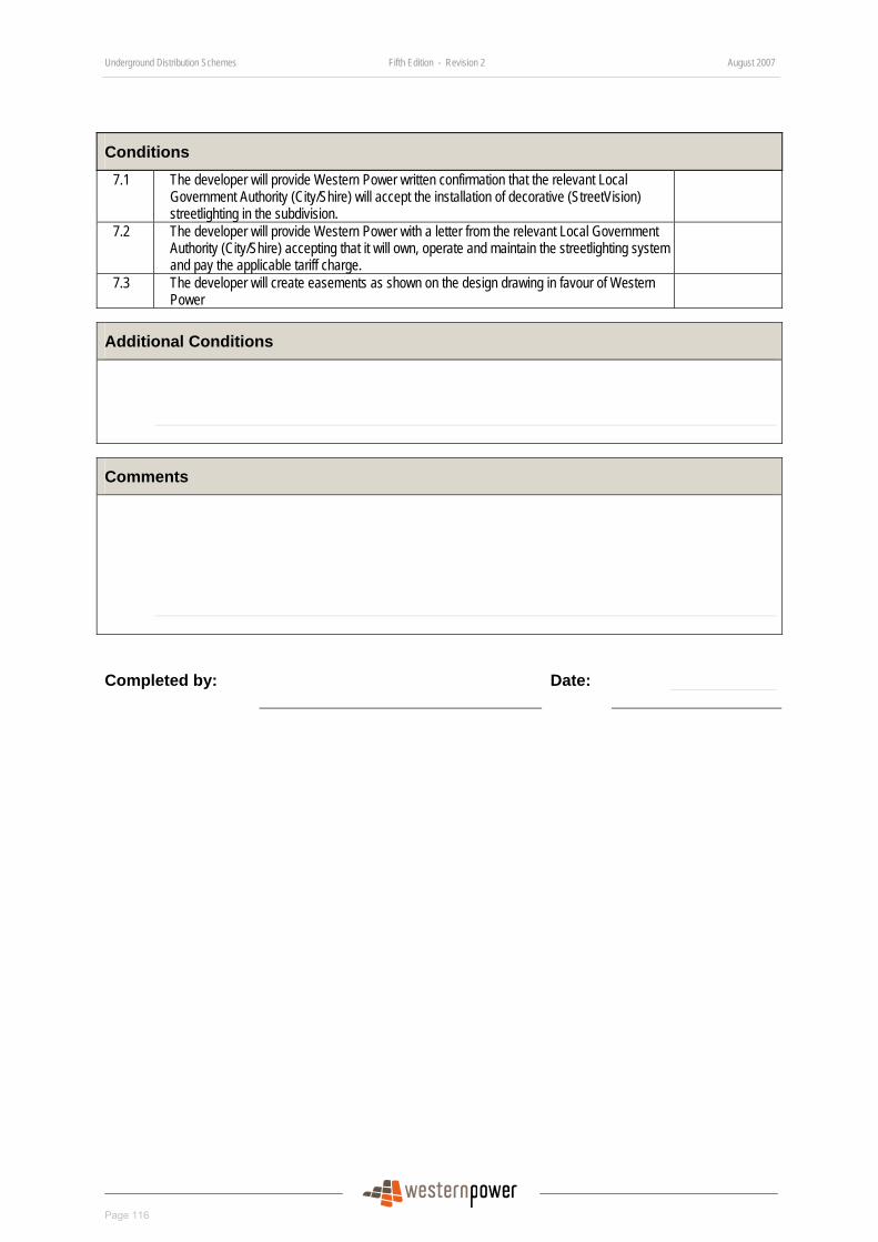
Underground Distribution Schemes Fifth Edition - Revision 2 August 2007
Page 116
Conditions 7.1 The developer will provide Western Power written confirmation that the relevant Local
Government Authority (City/Shire) will accept the installation of decorative (StreetVision) streetlighting in the subdivision.
7.2 The developer will provide Western Power with a letter from the relevant Local Government Authority (City/Shire) accepting that it will own, operate and maintain the streetlighting system and pay the applicable tariff charge.
7.3 The developer will create easements as shown on the design drawing in favour of Western Power
Additional Conditions
Comments
Completed by: Date:
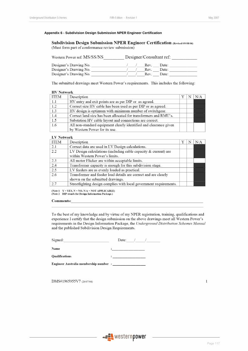
Underground Distribution Schemes Fifth Edition - Revision 1 May 2007
Page 117
Appendix 6 - Subdivision Design Submission NPER Engineer Certification

Underground Distribution Schemes Fifth Edition - Revision 2 August 2007
Page 118
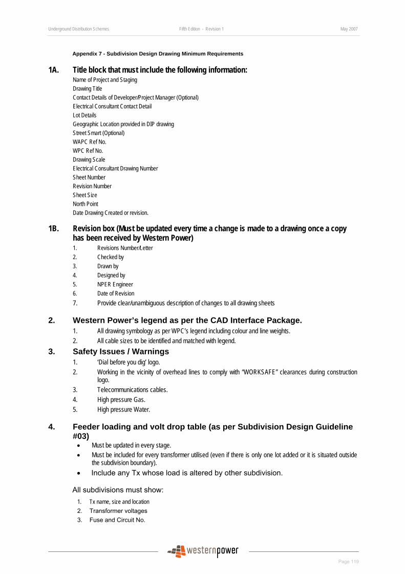
Underground Distribution Schemes Fifth Edition - Revision 1 May 2007
Page 119
Appendix 7 - Subdivision Design Drawing Minimum Requirements
1A. Title block that must include the following information: Name of Project and Staging Drawing Title Contact Details of Developer/Project Manager (Optional) Electrical Consultant Contact Detail Lot Details Geographic Location provided in DIP drawing Street Smart (Optional) WAPC Ref No. WPC Ref No. Drawing Scale Electrical Consultant Drawing Number Sheet Number Revision Number Sheet Size North Point Date Drawing Created or revision.
1B. Revision box (Must be updated every time a change is made to a drawing once a copy has been received by Western Power) 1. Revisions Number/Letter 2. Checked by 3. Drawn by 4. Designed by 5. NPER Engineer 6. Date of Revision 7. Provide clear/unambiguous description of changes to all drawing sheets
2. Western Power’s legend as per the CAD Interface Package. 1. All drawing symbology as per WPC’s legend including colour and line weights. 2. All cable sizes to be identified and matched with legend.
3. Safety Issues / Warnings 1. ‘Dial before you dig’ logo. 2. Working in the vicinity of overhead lines to comply with “WORKSAFE” clearances during construction
logo. 3. Telecommunications cables. 4. High pressure Gas. 5. High pressure Water.
4. Feeder loading and volt drop table (as per Subdivision Design Guideline #03)
• Must be updated in every stage. • Must be included for every transformer utilised (even if there is only one lot added or it is situated outside
the subdivision boundary). • Include any Tx whose load is altered by other subdivision.
All subdivisions must show: 1. Tx name, size and location 2. Transformer voltages 3. Fuse and Circuit No.

Underground Distribution Schemes Fifth Edition - Revision 2 August 2007
Page 120
4. Amp rating of fuses 5. Cable size in mm² 6. Accurate Circuit Description 7. Maximum volt drop on each feeder 8. Maximum current on each LV feeder 9. Total current on Tx 10. ADMD specified
NOTE: Max current is to be calculated by the LV Design package and not determined arithmetically by adding individual customer loads.
5. Street Lighting must show: 1. Type of lighting 2. Location and orientation. 3. If Decorative Lighting is installed, indicate colour and CU unit 4. Indicate if lighting is Private or Western Power. If private streetlight is installed, a separate drawing
must be submitted to Western Power prior to handover.
6. Substation and Switchgear land requirements drawing (as per Subdivision Design Requirement #02)
1. Show substation detail with dimensions of land 2. Location from lot boundaries and adjacent lot numbers must be shown 3. Civil requirements (1m above the 100 year flood level, retaining walls) 4. Duct requirements (if set back in POS or private property) 5. If non standard equipment is to be used, all equipment shall be evaluated to the current technical
requirements as determined by Asset Management. The process requires a formal submission of application for equipment approval.
6. This approval from Asset Management is required prior to submitting the design for conformance review. Submission of non standard equipment must comply with Design Requirement #1 and #2.
7. Pole numbers and location 1. Pole numbers or pick ID for all poles as part of the subdivision must be shown on the design drawing. 2. All pole locations need to be surveyed.
8. HV and LV open points 1. Unipillar (LU11) must be shown as ‘on’ or ‘off’ with arrow point indicating cable terminated on the
top bar of the unipillar. 2. LV Blades (LU9) or LV Cable termination to LV ABC switch (LU37) must be shown as ‘on’ or ‘off’. 3. Switch point status on the HV of the RMU must be shown on drawing.
9. Stage boundary 1. Must cover scope of all works, including working ends. 2. Must include all lots that are provided with a LV supply in this stage and exclude those lots that do
not have a supply for this stage. 3. Must include all cables, substations, pillars, street lights and any other assets being installed or
having their ON/OFF status changed in this stage. 4. Must include removal, relocation or modification to any existing Western Power assets. This
information will be provided in the DIP.
NOTE: Boundaries can be discontinuous, i.e. there can be a boundary around the entire subdivision and then a small separate boxed boundary around a uni pillar a distance away that requires its status changed from OFF to ON.
10. Easements 1. Any existing or future transmission easements and assets must be shown. 2. Any existing or future distribution easements and assets must be shown. 3. Any existing or future easements for other utilities must be shown. 4. For underground cable easement, a cross section detail must be shown.
Underground Distribution Schemes Fifth Edition - Revision 1 May 2007
Page 121
5. Type of easement must be shown (27A easement or easement in gross).
11. Design drawing must include: 1. All relevant sections and dependent equipment from previous stages must be included if the same
transformer is being utilised. 2. Previous stages adjacent to the subdivision must be shown having the equipment and cables at a
line weight of 0 and using the same styles and colours. 3. HV and LV interconnection points and sources of all feeders. 4. Any existing transformer which was installed in the previous stage if its capacity is being utilised
for the proposed subdivision. 5. Location of RMU / drop out fuses if transformer is being installed or upgraded. 6. A detail of location and clearances of all equipment to be installed in the vicinity of aerial lines,
easements and structures, only where applicable. 7. HV and LV working end pillars. 8. Retaining wall detail showing minimum distance of pillar to wall.
9. All pre-negotiated and pre-approved work partially or fully funded by Western Power as a note, including all material that Western Power is subsidising.
12. Commercial, industrial and mixed use sites 1. Lot size in m. 2. ADMD listed on each lot. 3. For group housing, the number of units and total load must be shown.
13. When submitting the drawing for conformance review (as per Electronic Submission Procedure)
1. All files should be placed into a zip file for every submission. 2. Regardless if any of the file(s) have had their content changed or not, they should all be included
into one zip file for a complete submission each time. 3. Western Power’s standard NPER certification letter and check sheet must also be included for
every submission, unless a ‘minor change notification’ has previously been received in which case designer certification is required.

Underground Distribution Schemes Fifth Edition - Revision 2 August 2007
Page 122
Appendix 8 - Decorative Street Lights Approval Form
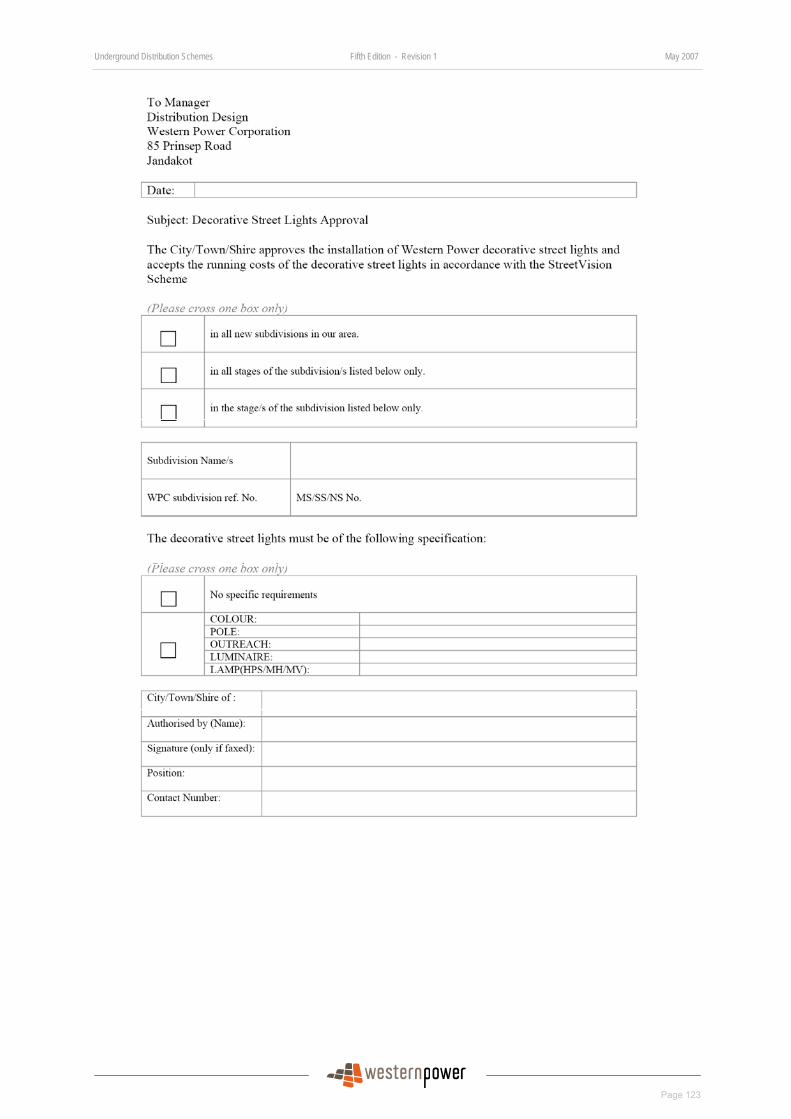
Underground Distribution Schemes Fifth Edition - Revision 1 May 2007
Page 123
DRAFT

Underground Distribution Schemes Fifth Edition - Revision 1 May 2007
Page 124
DRAFT
Appendix 9 - Cable Duct Specification
INTRODUCTION This specification applies to the supply and installation of ducts for electric cables. Unless otherwise specified, the Developer shall be responsible for the supply and installation of all cable ducts and concrete encasement (where required) as shown on the subdivision design drawings.
MATERIALS All cable ducts must comply with AS 2053.1:2001 – Conduits and Fittings for electrical installations – general requirements.
They shall be heavy duty (HD) category and either light orange in colour or black with an orange stripe in colour. In addition, all ducts must be non-metallic and comply with AS2053.
SIZE OF DUCTS There are numerous sizes available and they are 40mm, 50mm, 80mm, 100mm and 125mm, for rigid ducts and 50mm, 90mm, 110mm and 140mm for flexible duct, e.g. polypipe. The appropriate size determined in Section 5 of UDS Manual must be selected. However, for 33kV subdivisions, 150mm duct must be used for the high voltage cable.
INSTALLATION OF DUCTS All ducts shall have a minimum cover of 750mm to the top of the duct and be bedded in sand for a minimum distance of 150mm below the lowest duct, and 150mm above the highest duct. No ducts shall be installed with more than 1100mm cover, unless approved by Western Power.
Where ducts are installed in the nominal cable alignment, those for low voltage are to be laid in horizontal formation up to four in number and those for HV feeder cables The length of the ducts is to be the road width plus 1000mm minimum projection either side of kerb.
Where ducts are installed for distribution substations, they shall meet the requirements of Distribution Substation Manual (DSM).
All ducts shall be plugged with suitable end caps. Draw wires shall be provided in all ducts. When the ducts are installed prior to the main cable trenching, marker tape shall be installed 300mm below ground level and above the duct, and brought out to ground level at each end with a marker peg at one end.
SUPERVISION OF INSTALLATION The Developer shall be fully responsible for the supervision of the duct installation. Any remedial works required by Western Power’s Construction Manager shall be carried out promptly. Actual extra costs incurred by Western Power, as a result of such remedial works causing a delay to the Western Power contractor’s work, may be charged to the Developer.
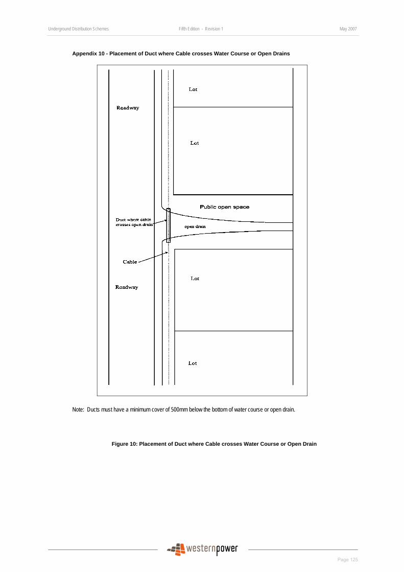
Underground Distribution Schemes Fifth Edition - Revision 1 May 2007
Page 125
DRAFT
Appendix 10 - Placement of Duct where Cable crosses Water Course or Open Drains
Note: Ducts must have a minimum cover of 500mm below the bottom of water course or open drain.
Figure 10: Placement of Duct where Cable crosses Water Course or Open Drain
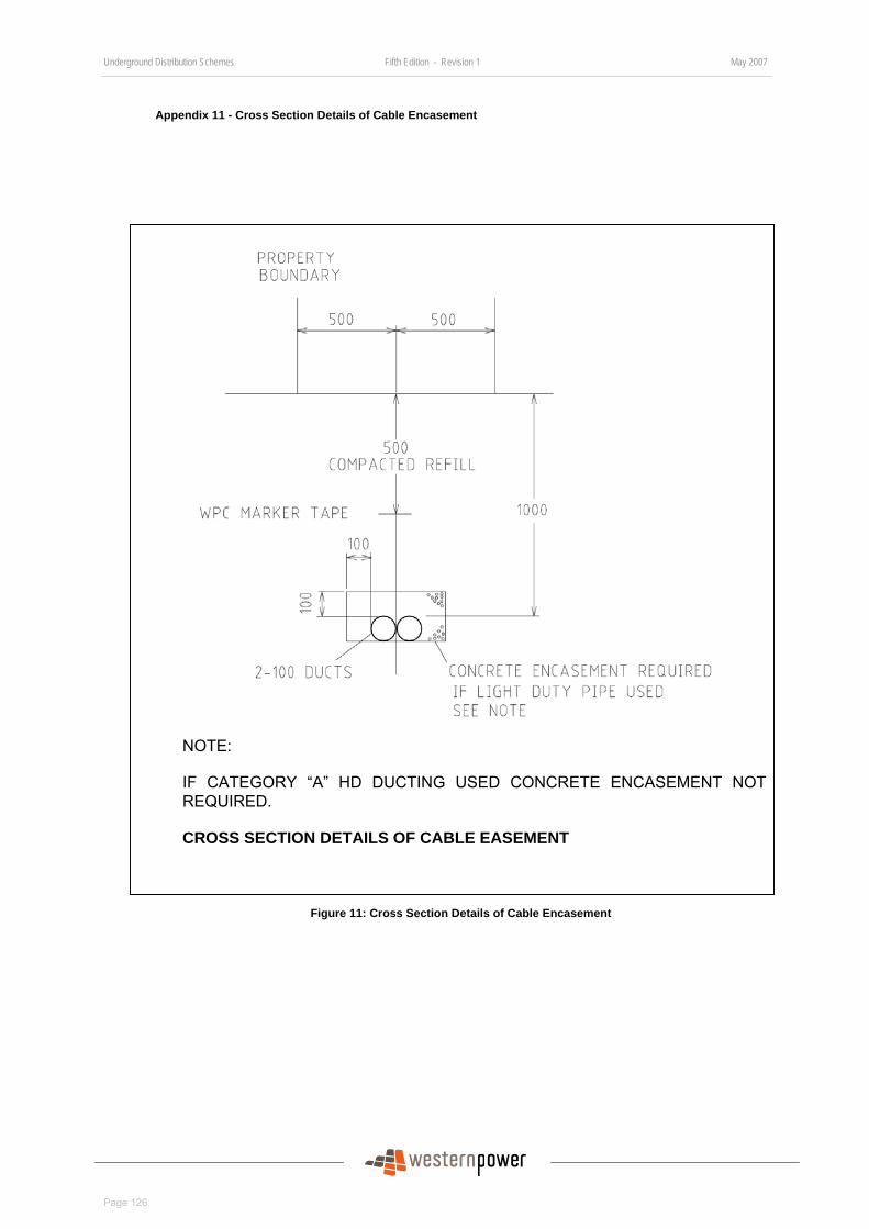
Underground Distribution Schemes Fifth Edition - Revision 1 May 2007
Page 126
DRAFT
Appendix 11 - Cross Section Details of Cable Encasement
NOTE:
IF CATEGORY “A” HD DUCTING USED CONCRETE ENCASEMENT NOT REQUIRED.
CROSS SECTION DETAILS OF CABLE EASEMENT
Figure 11: Cross Section Details of Cable Encasement
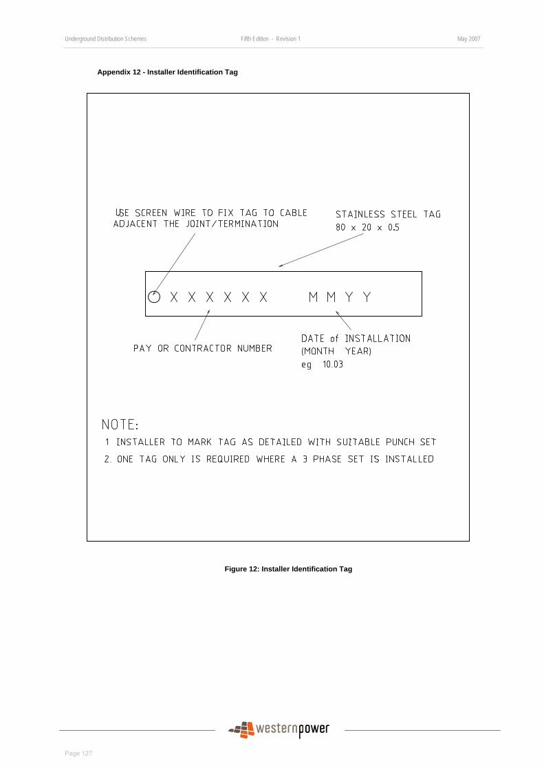
Underground Distribution Schemes Fifth Edition - Revision 1 May 2007
Page 127
DRAFT
Appendix 12 - Installer Identification Tag
Figure 12: Installer Identification Tag
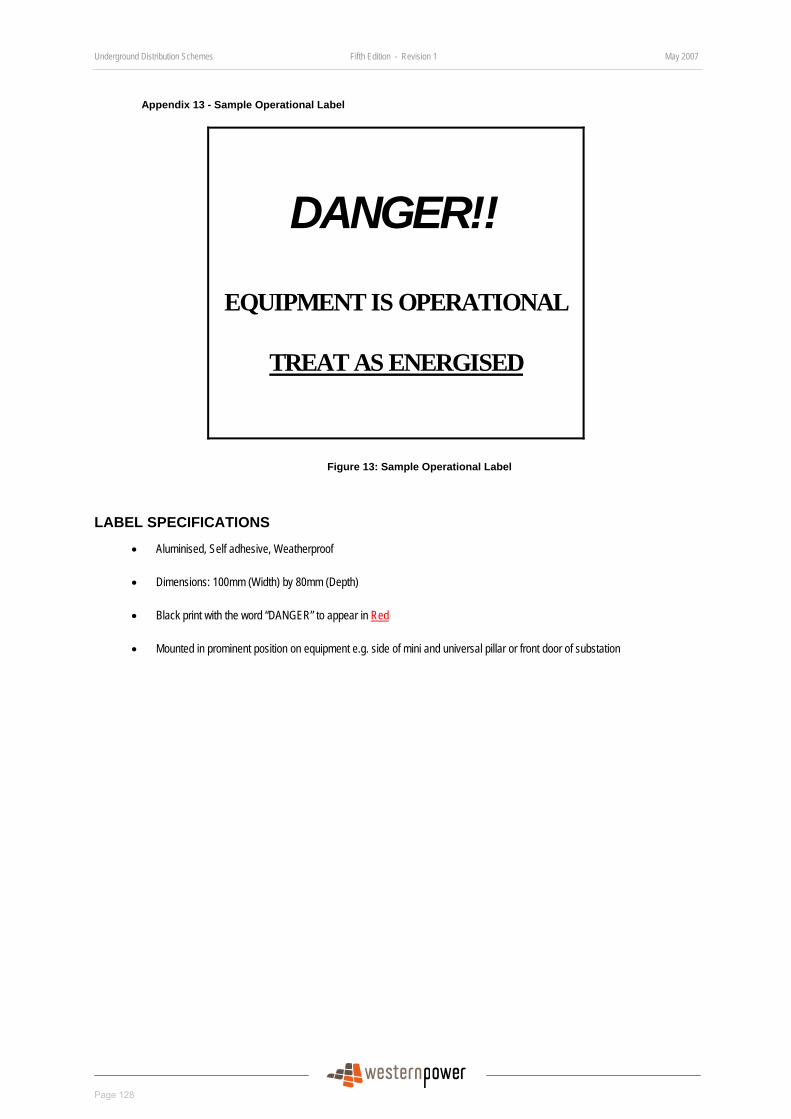
Underground Distribution Schemes Fifth Edition - Revision 1 May 2007
Page 128
DRAFT
Appendix 13 - Sample Operational Label
DANGER!!
EQUIPMENT IS OPERATIONAL
TREAT AS ENERGISED
Figure 13: Sample Operational Label
LABEL SPECIFICATIONS
• Aluminised, Self adhesive, Weatherproof
• Dimensions: 100mm (Width) by 80mm (Depth)
• Black print with the word “DANGER” to appear in Red
• Mounted in prominent position on equipment e.g. side of mini and universal pillar or front door of substation

Underground Distribution Schemes Fifth Edition - Revision 1 May 2007
Page 129
DRAFT
Appendix 14 - HV Cable Joint Schedule
Subdivision Name: Stage:
Subdivision No. : Date:
LOCATION (Lot Number)
Type of Joint (Straight or Breech) Manufacturer Manufacturer’s
Cat. No. Date of Installation
Cable Jointer or Cable Jointer-in-Charge : Western Power Rep :
Accreditation No. : Pay No :
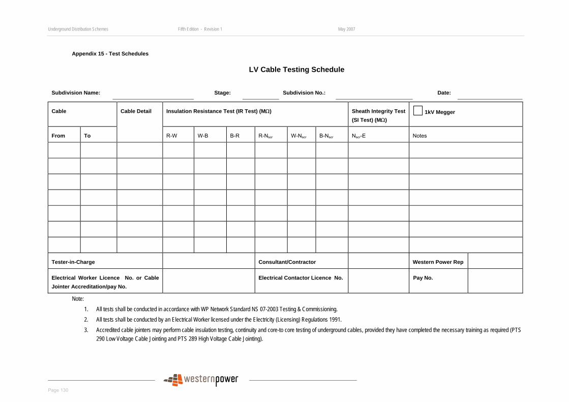
Underground Distribution Schemes Fifth Edition - Revision 1 May 2007
Page 130
DRAFT
Appendix 15 - Test Schedules
LV Cable Testing Schedule
Subdivision Name: Stage: Subdivision No.: Date:
Cable Insulation Resistance Test (IR Test) (MΩ) Sheath Integrity Test (SI Test) (MΩ)
1kV Megger
From To
Cable Detail
R-W W-B B-R R-Nscr W-Nscr B-Nscr Nscr-E Notes
Tester-in-Charge Consultant/Contractor Western Power Rep
Electrical Worker Licence No. or Cable Jointer Accreditation/pay No.
Electrical Contactor Licence No. Pay No.
Note: 1. All tests shall be conducted in accordance with WP Network Standard NS 07-2003 Testing & Commissioning. 2. All tests shall be conducted by an Electrical Worker licensed under the Electricity (Licensing) Regulations 1991. 3. Accredited cable jointers may perform cable insulation testing, continuity and core-to core testing of underground cables, provided they have completed the necessary training as required (PTS
290 Low Voltage Cable Jointing and PTS 289 High Voltage Cable Jointing).
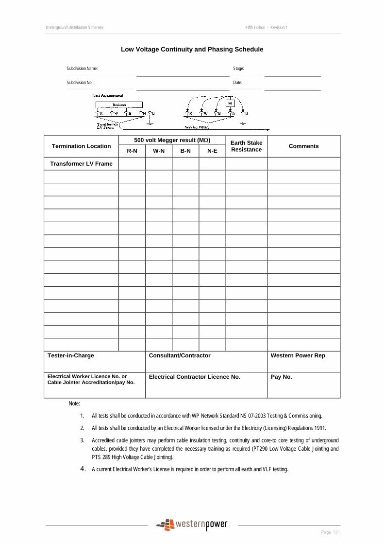
Underground Distribution Schemes Fifth Edition - Revision 1
Page 131
DRAFT
Low Voltage Continuity and Phasing Schedule
Subdivision Name: Stage:
Subdivision No. : Date:
500 volt Megger result (MΩ) Termination Location
R-N W-N B-N N-E Earth Stake Resistance Comments
Transformer LV Frame
Tester-in-Charge Consultant/Contractor Western Power Rep
Electrical Worker Licence No. or Cable Jointer Accreditation/pay No.
Electrical Contractor Licence No. Pay No.
Note:
1. All tests shall be conducted in accordance with WP Network Standard NS 07-2003 Testing & Commissioning.
2. All tests shall be conducted by an Electrical Worker licensed under the Electricity (Licensing) Regulations 1991.
3. Accredited cable jointers may perform cable insulation testing, continuity and core-to core testing of underground cables, provided they have completed the necessary training as required (PT290 Low Voltage Cable Jointing and PTS 289 High Voltage Cable Jointing).
4. A current Electrical Worker’s License is required in order to perform all earth and VLF testing.
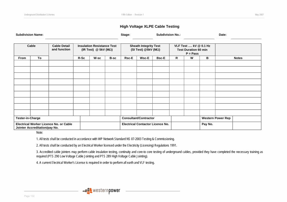
Underground Distribution Schemes Fifth Edition - Revision 1 May 2007
Page 132
DRAFT
High Voltage XLPE Cable Testing
Subdivision Name: Stage: Subdivision No.: Date:
Cable Insulation Resistance Test
(IR Test) @ 5kV (MΩ) Sheath Integrity Test (SI Test) @5kV (MΩ)
VLF Test …. kV @ 0.1 Hz Test Duration 60 min
P = Pass
From To
Cable Detail and function
R-Sc W-sc B-sc Rsc-E Wsc-E Bsc-E R W B Notes
Tester-in-Charge Consultant/Contractor Western Power Rep
Electrical Worker Licence No. or Cable Jointer Accreditation/pay No.
Electrical Contactor Licence No. Pay No.
Note:
1. All tests shall be conducted in accordance with WP Network Standard NS 07-2003 Testing & Commissioning.
2. All tests shall be conducted by an Electrical Worker licensed under the Electricity (Licensing) Regulations 1991.
3. Accredited cable jointers may perform cable insulation testing, continuity and core-to core testing of underground cables, provided they have completed the necessary training as required (PTS 290 Low Voltage Cable Jointing and PTS 289 High Voltage Cable Jointing).
4. A current Electrical Worker’s License is required in order to perform all earth and VLF testing.
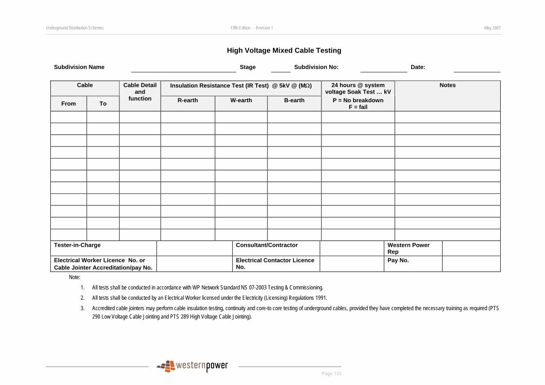
Underground Distribution Schemes Fifth Edition - Revision 1 May 2007
Page 133
DRAFT
High Voltage Mixed Cable Testing
Subdivision Name Stage Subdivision No: Date:
Cable Insulation Resistance Test (IR Test) @ 5kV @ (MΩ) 24 hours @ system voltage Soak Test … kV
From To
Cable Detail and
function R-earth W-earth B-earth P = No breakdown F = fail
Notes
Tester-in-Charge Consultant/Contractor Western Power
Rep
Electrical Worker Licence No. or Cable Jointer Accreditation/pay No.
Electrical Contactor Licence No.
Pay No.
Note:
1. All tests shall be conducted in accordance with WP Network Standard NS 07-2003 Testing & Commissioning.
2. All tests shall be conducted by an Electrical Worker licensed under the Electricity (Licensing) Regulations 1991.
3. Accredited cable jointers may perform cable insulation testing, continuity and core-to core testing of underground cables, provided they have completed the necessary training as required (PTS 290 Low Voltage Cable Jointing and PTS 289 High Voltage Cable Jointing).
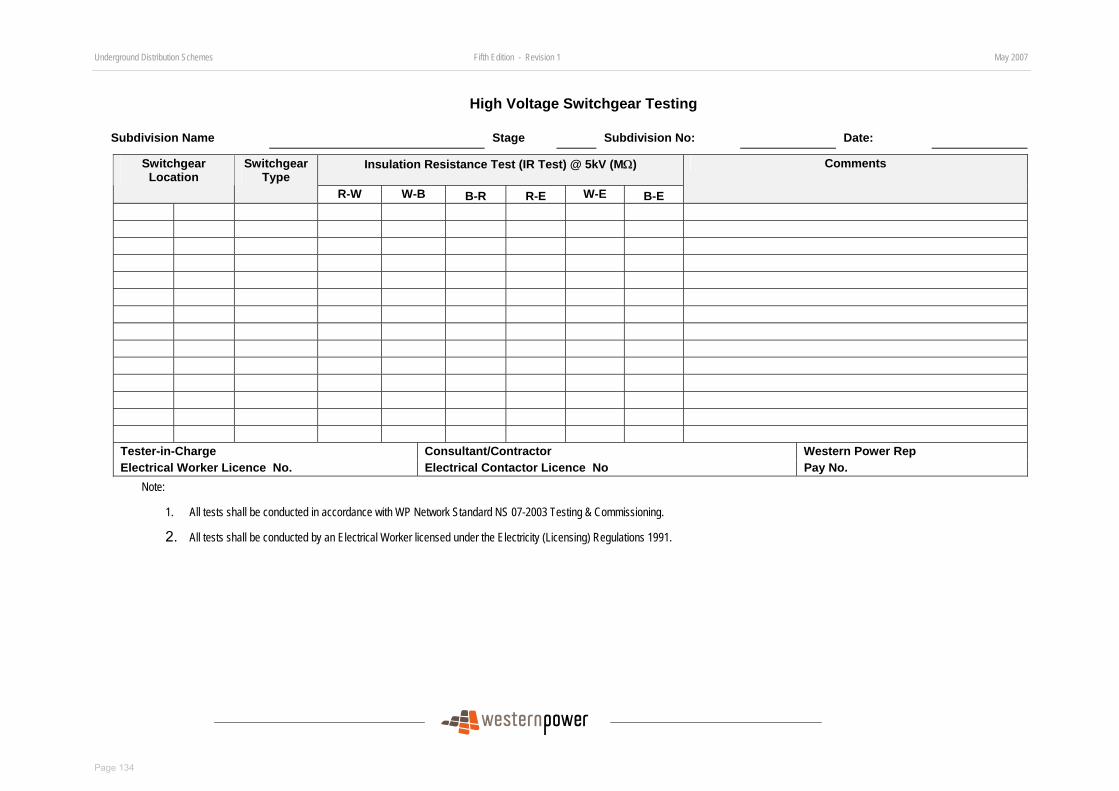
Underground Distribution Schemes Fifth Edition - Revision 1 May 2007
Page 134
DRAFT
High Voltage Switchgear Testing
Subdivision Name Stage Subdivision No: Date:
Insulation Resistance Test (IR Test) @ 5kV (MΩ) Switchgear Location
Switchgear Type
R-W W-B B-R R-E W-E B-E
Comments
Tester-in-Charge Consultant/Contractor Western Power Rep Electrical Worker Licence No. Electrical Contactor Licence No Pay No.
Note:
1. All tests shall be conducted in accordance with WP Network Standard NS 07-2003 Testing & Commissioning.
2. All tests shall be conducted by an Electrical Worker licensed under the Electricity (Licensing) Regulations 1991.

Underground Distribution Schemes Fifth Edition - Revision 1 May 2007
Page 135
DRAFT
EARTHING TEST SCHEDULE
Subdivision Name Stage
Subdivision No. Date:
LOCATION EQUIPMENT OHMS Notes
Tester-in-Charge Consultant/Contractor Western Power Rep
Electrical Worker Licence No. Electrical Contactor Licence No. Pay No.
Note:
1. All tests shall be conducted in accordance with WP Network Standard NS 07-2003 Test & Commissioning.
2. All tests shall be conducted by an Electrical Worker licensed under the Electricity (Licensing) Regulations 1991.

Underground Distribution Schemes Fifth Edition - Revision 1 May 2007
Page 136
DRAFT
Appendix 16 - Site Inspection Schedule
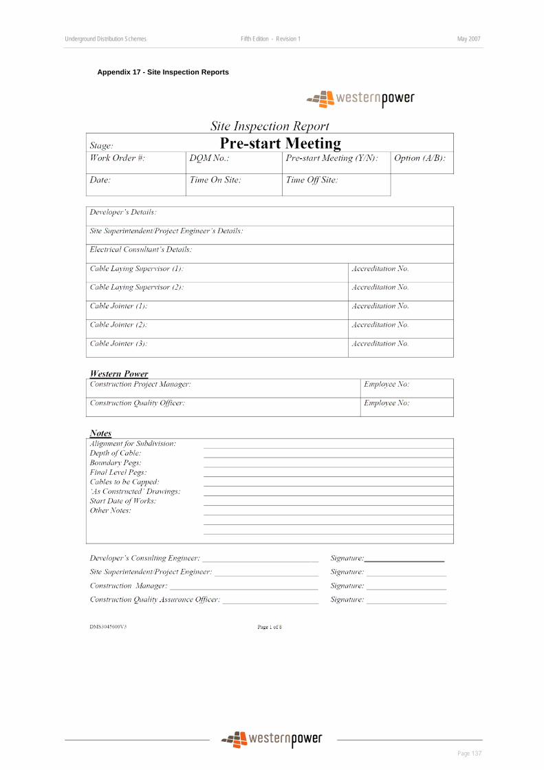
Underground Distribution Schemes Fifth Edition - Revision 1 May 2007
Page 137
DRAFT
Appendix 17 - Site Inspection Reports
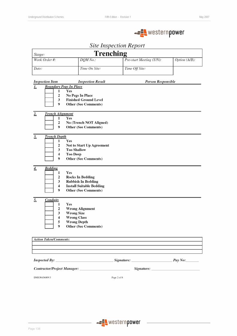
Underground Distribution Schemes Fifth Edition - Revision 1 May 2007
Page 138
DRAFT
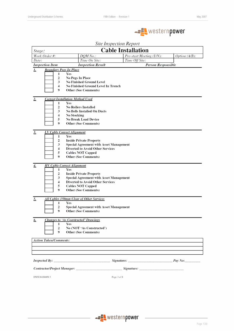
Underground Distribution Schemes Fifth Edition - Revision 1 May 2007
Page 139
DRAFT
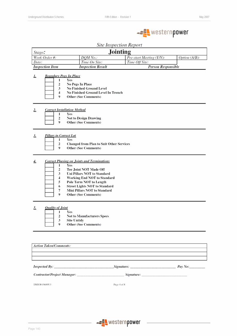
Underground Distribution Schemes Fifth Edition - Revision 1 May 2007
Page 140
DRAFT
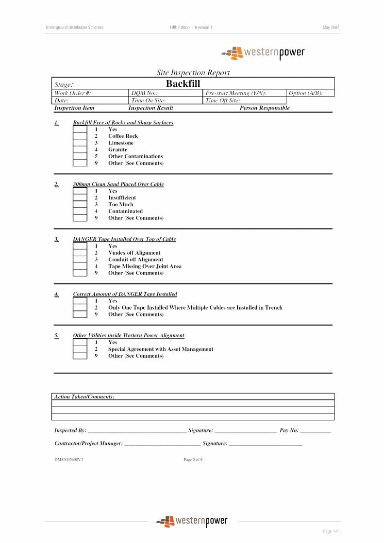
Underground Distribution Schemes Fifth Edition - Revision 1 May 2007
Page 141
DRAFT
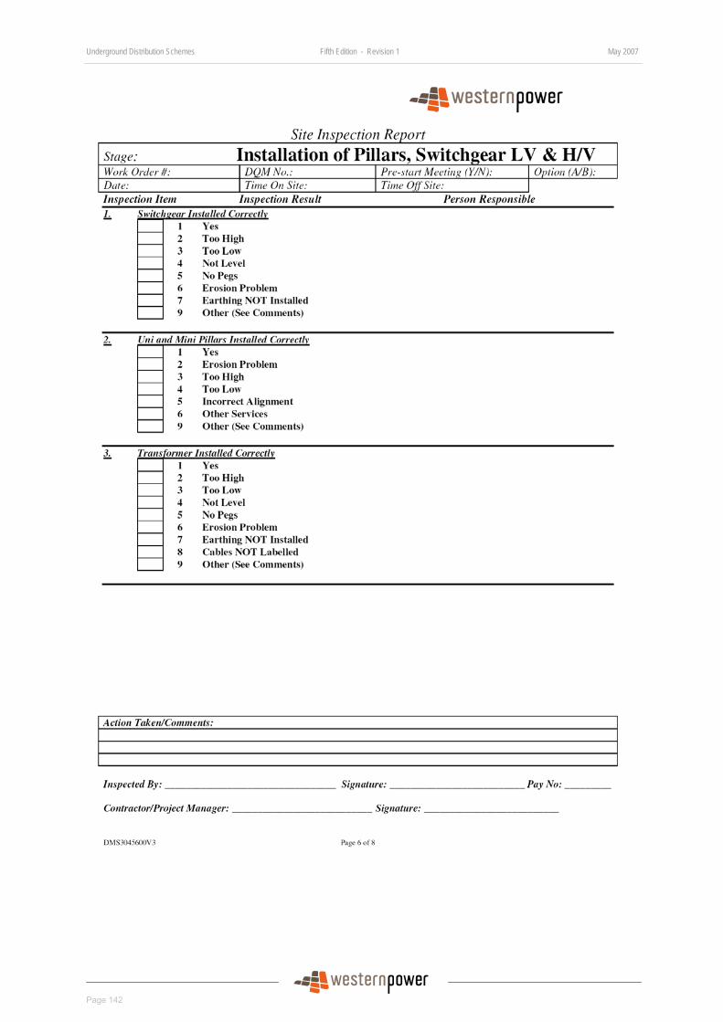
Underground Distribution Schemes Fifth Edition - Revision 1 May 2007
Page 142
DRAFT
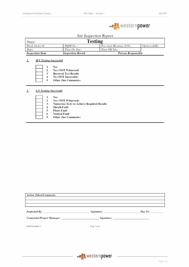
Underground Distribution Schemes Fifth Edition - Revision 1 May 2007
Page 143
DRAFT
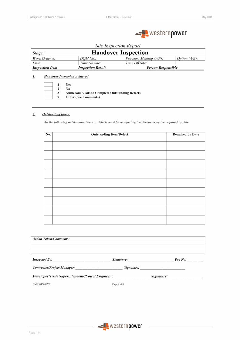
Underground Distribution Schemes Fifth Edition - Revision 1 May 2007
Page 144
DRAFT
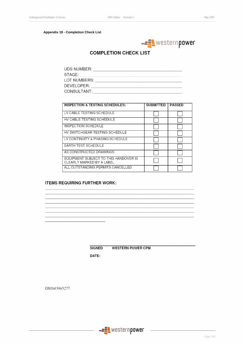
Underground Distribution Schemes Fifth Edition - Revision 1 May 2007
Page 145
DRAFT
Appendix 18 - Completion Check List

Underground Distribution Schemes Fifth Edition - Revision 1 May 2007
Page 146
DRAFT
Appendix 19 - Handover Certificate
Handover Certificate
Western Power Corporation, 363 Wellington Street, Perth, Western Australia, 6000.
Please note that from the date and time stated the apparatus detailed below which has previously been controlled
by: _________________________________________________________________________________________(name)
of: _________________________________________________________________________________________
is now handed over to: _________________________________________________________________________(name)
of: _________________________________________________________________________________________
Date: ___________________________________________ Time: ______________________________________
Project No. (where applicable) ___________________________________________________________________
Location: ____________________________________________________________________________________
Apparatus being handed over ___________________________________________________________________
____________________________________________________________________________________________
____________________________________________________________________________________________
with the following exceptions and comments: _______________________________________________________
____________________________________________________________________________________________
____________________________________________________________________________________________
____________________________________________________________________________________________
Any further work on the apparatus can only be carried out with the permission of the appropriate Authority andsubject to the issue of an appropriate permit to work authorisation. (Refer to clause 3.9 of the Electrical SafetyInstructions).
Handed over by: ________________________________ Accepted by: ______________________________(sign) (sign)
Please sign in the space provided below that you understand and acknowledge the changed conditions which nowapply to the apparatus.
Name Signature Narne Signature
NOTE: In the case of Contractors the above should be signed by the Contractor and forwarded to theWestern Power Project Manager stating that all relevant Contractors employees have been advised,
Distribution: Green copy - Accepting officer; Yellow copy - Project Manager; Pink copy - Handing Over Officer, White copy - Spare UA 1986 3/97
SAMPLE ONLY
Underground Distribution Schemes Fifth Edition - Revision 1 May 2007
Page 147
DRAFT
Appendix 20 - Terms & Conditions of Sale of Materials
Underground Distribution Schemes Fifth Edition - Revision 1 May 2007
Page 148
DRAFT
Underground Distribution Schemes Fifth Edition - Revision 1 May 2007
Page 149
DRAFT
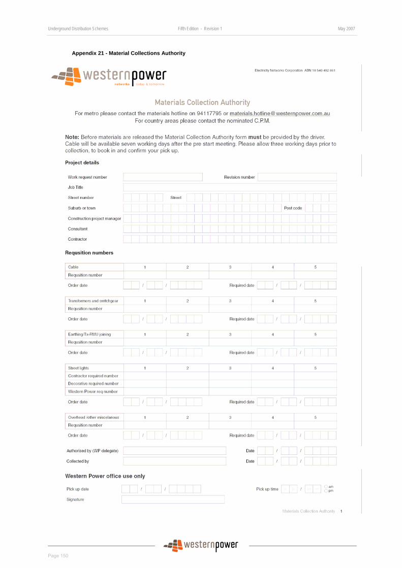
Underground Distribution Schemes Fifth Edition - Revision 1 May 2007
Page 150
DRAFT
Appendix 21 - Material Collections Authority

Underground Distribution Schemes Fifth Edition - Revision 1 May 2007
Page 151
DRAFT
Appendix 22 - Equipment Drawings
This appendix contains additional drawings for key equipment used by Western Power in the construction of Underground Distribution Schemes (UDS)
The drawings are separated as follows:
• Low Voltage Equipment
• Substation Earthing Arrangement
• Substation Ducts Arrangement
• Streetlights
• Cable Trench Arrangement.
Underground Distribution Schemes Fifth Edition - Revision 1 May 2007
Page 152
DRAFT
Low voltage Equipment Drawings Index of Drawings Drawing Number Drawing Title
U8 URD Mini Pillar Installation Guide
R33 Mini Pillar Wavecon Working End
U9 UDS Universal Pillar Installation Details
U15 Cable to LV Isolators Crossarm & Cable Length
U16 Cable to LV Bare Direct connected
U17 ABC Fused Connection to Cable
U27-1 LV Cable to Fuse Switch
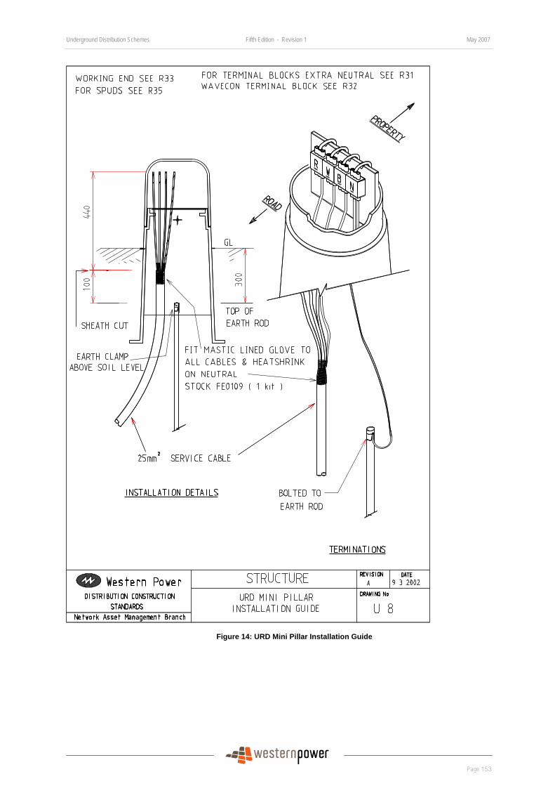
Underground Distribution Schemes Fifth Edition - Revision 1 May 2007
Page 153
DRAFT
Figure 14: URD Mini Pillar Installation Guide
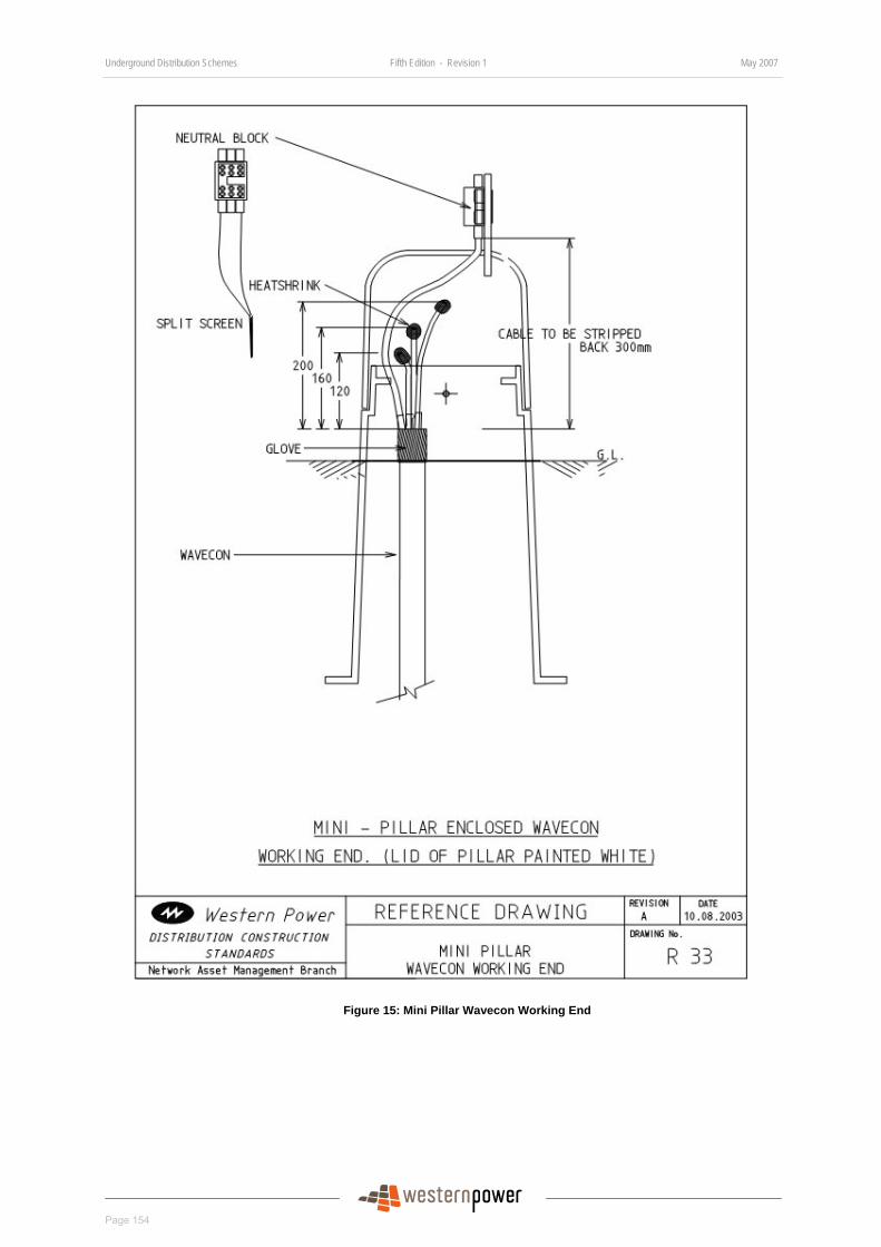
Underground Distribution Schemes Fifth Edition - Revision 1 May 2007
Page 154
DRAFT
Figure 15: Mini Pillar Wavecon Working End
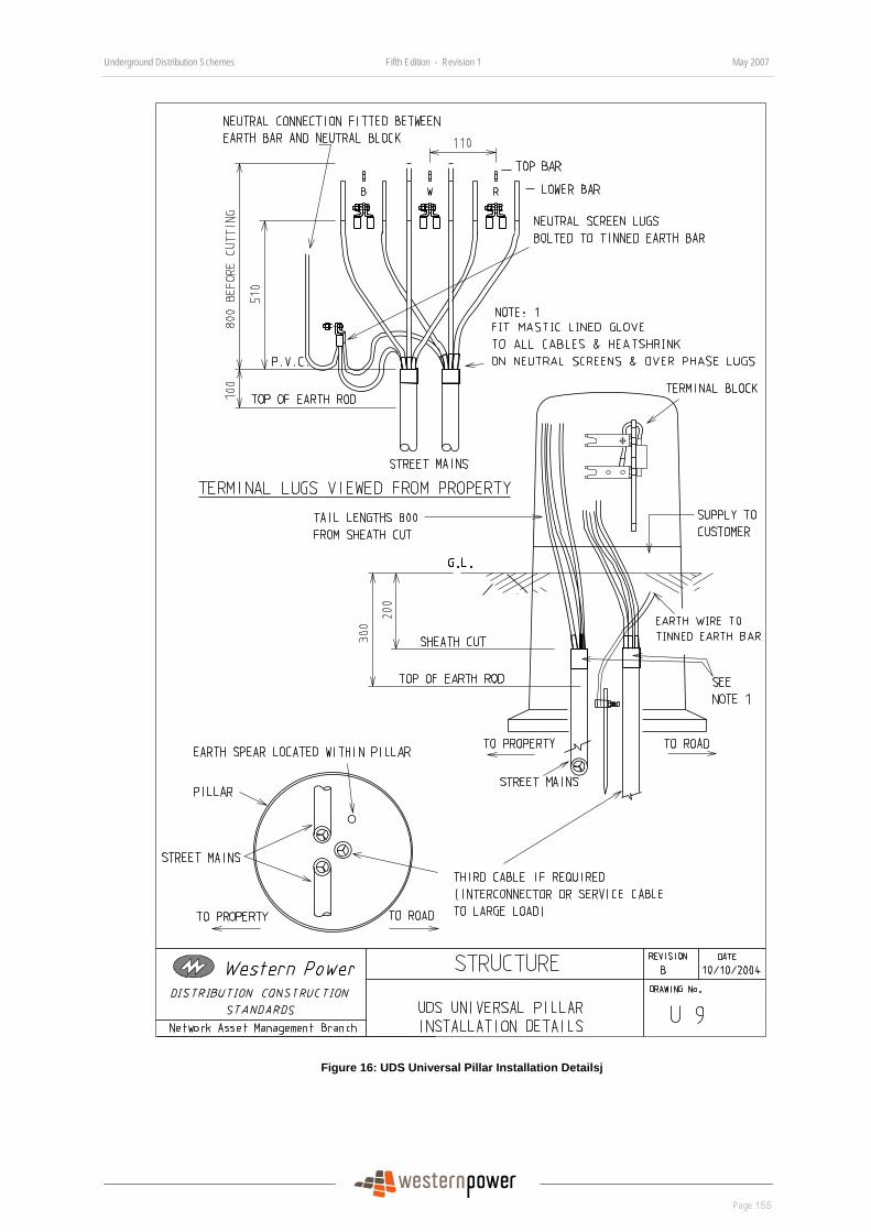
Underground Distribution Schemes Fifth Edition - Revision 1 May 2007
Page 155
DRAFT
Figure 16: UDS Universal Pillar Installation Detailsj
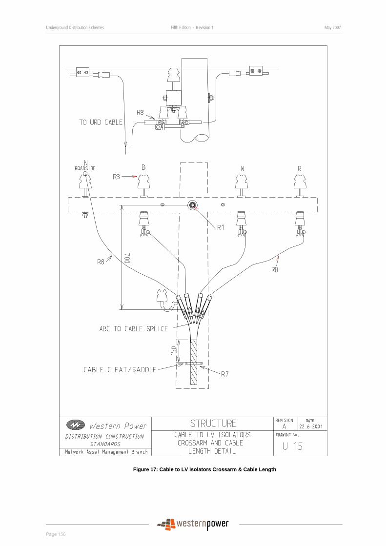
Underground Distribution Schemes Fifth Edition - Revision 1 May 2007
Page 156
DRAFT
Figure 17: Cable to LV Isolators Crossarm & Cable Length
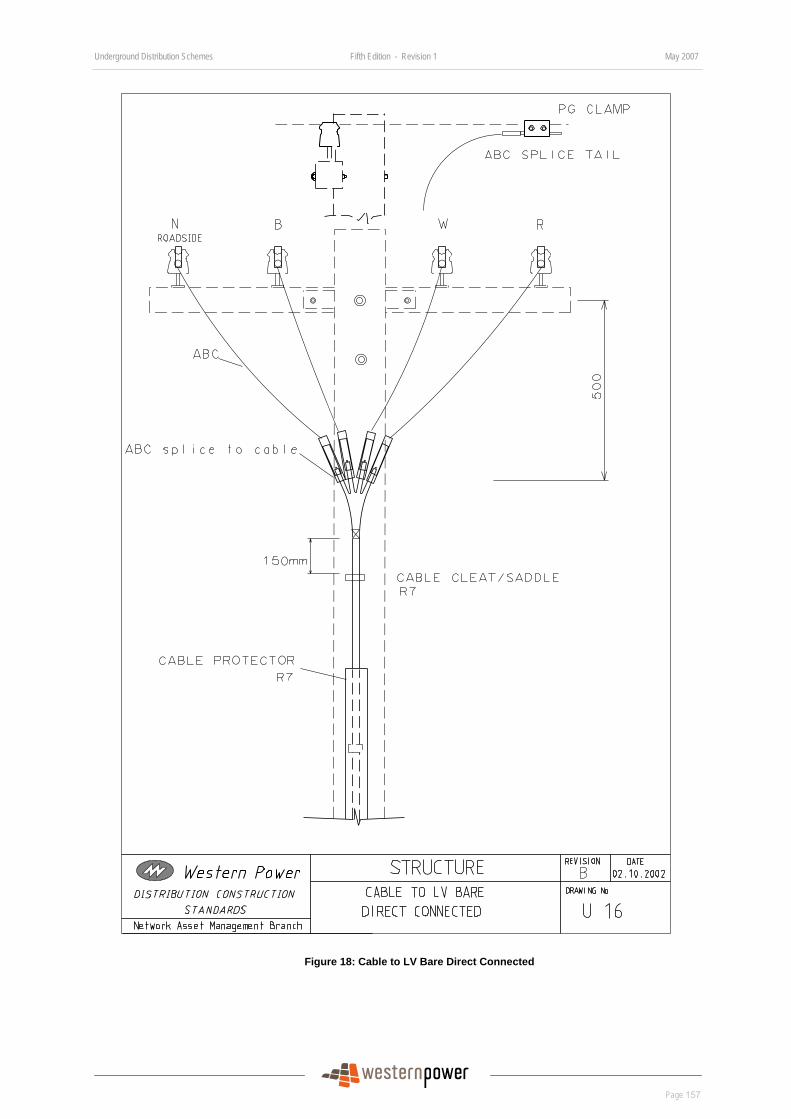
Underground Distribution Schemes Fifth Edition - Revision 1 May 2007
Page 157
DRAFT
Figure 18: Cable to LV Bare Direct Connected
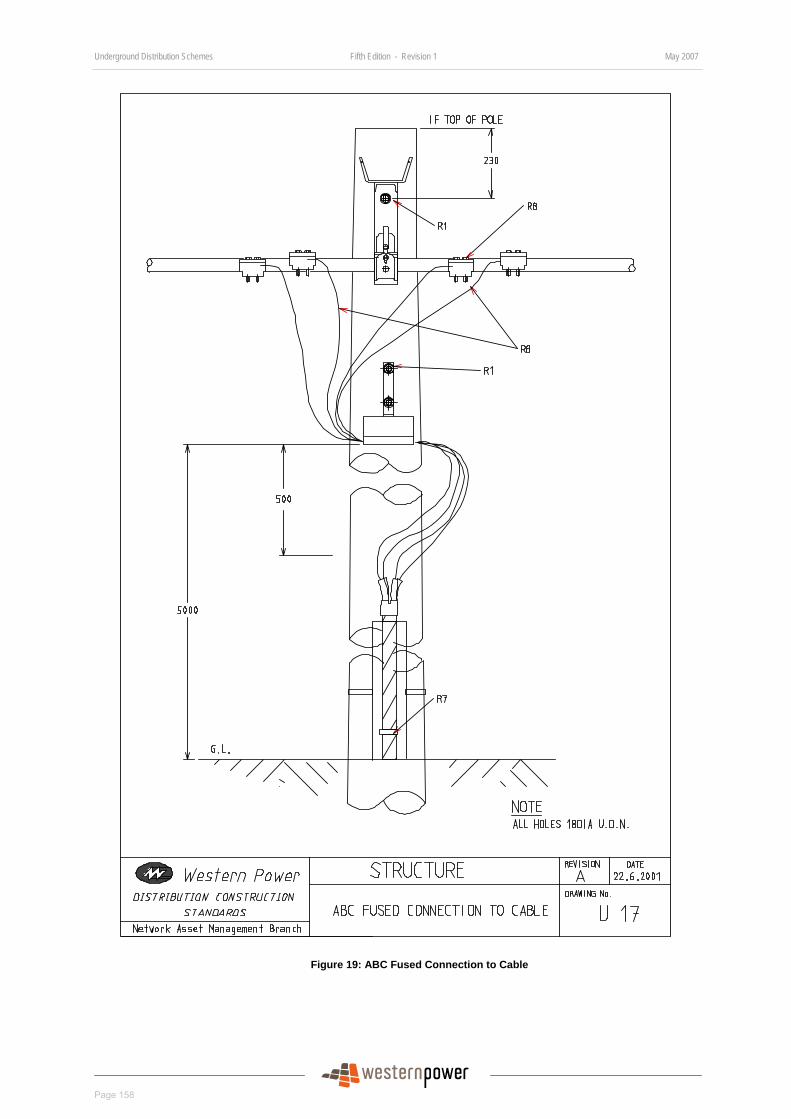
Underground Distribution Schemes Fifth Edition - Revision 1 May 2007
Page 158
DRAFT
Figure 19: ABC Fused Connection to Cable
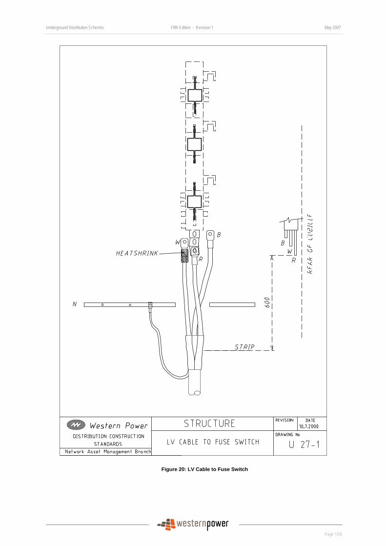
Underground Distribution Schemes Fifth Edition - Revision 1 May 2007
Page 159
DRAFT
Figure 20: LV Cable to Fuse Switch
Underground Distribution Schemes Fifth Edition - Revision 1 May 2007
Page 160
DRAFT
Substation Earthing Arrangement Drawings All substation earthing shall be installed in accordance with the relevant compatible unit (CU) drawings under ‘HU – High Voltage Underground’ in the Distribution Design Catalogue (DDC) at:
http://www.westernpower.com.au/mainContent/connectionsUpgrades/policiesRegulations/technicalDocumentation.html.
Listed below are examples of the drawings.
Index of Drawings
Drawing Number Drawing Title
HU 5 Switchgear kiosk 3+0
HU 6 Switchgear.kiosk 2+1
HU 7 Switchgear kiosk 2+2
HU 8 Switchgear kiosk 3+1
HU 9 Switchgear kiosk 4+0
HU 27 SPUD isolation transformer
HU 63 SPURS transformer 1 phase 10kVA
HU 64 SPURS transformer 1 phase 25kVA
HU 31 SPUD transformer 1 phase 2 bush
HU 34 SPUD transformer 1 phase 3 bush
HU 35 SPUD transformer 1 phase 4 bush
HU 59A Non-MPS transformer district outside installation
HU 61 MPS district transformer
HU81 Switchgear kiosk 3+2
HU82 63kVA 3 phase transformer

Underground Distribution Schemes Fifth Edition - Revision 1 May 2007
Page 161
DRAFT
Substation Ducts Arrangement Drawings Index of Drawings
Drawing Number Drawing Title
DSM 6-01 Substation Ducting Cross Section – Civil Requirements
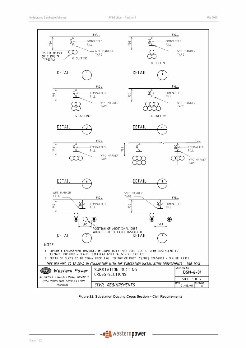
Underground Distribution Schemes Fifth Edition - Revision 1 May 2007
Page 162
DRAFT
Figure 21: Substation Ducting Cross Section – Civil Requirements
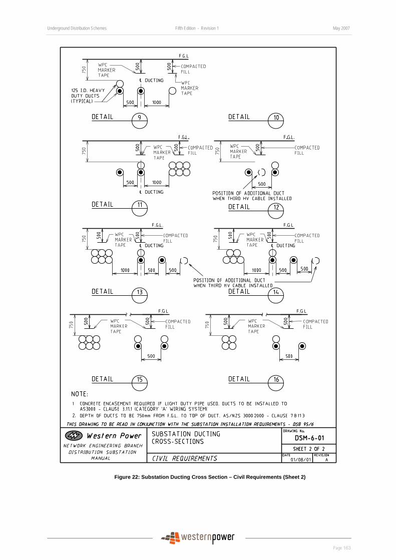
Underground Distribution Schemes Fifth Edition - Revision 1 May 2007
Page 163
DRAFT
Figure 22: Substation Ducting Cross Section – Civil Requirements (Sheet 2)
Underground Distribution Schemes Fifth Edition - Revision 1 May 2007
Page 164
DRAFT
Street Lights Drawings Index of Drawings
Drawing Number Drawing Title
R 26/1 Street Light Cutout, Single Phase Supply
R 26/2 Street Light Cutout, Single Phase Supply for Class II Luminaires
R 26/3 Street Light Cutout Connection Arrangement for Electrical Attachment
R 27 Fusing Arrangement for Street Light Columns
R32 Mini Pillar Terminal Block Termination Details (Street Light)
All Western Power standard streetlighting (non-decorative) equipment drawings are available at:
http://www.westernpower.com.au/documents/distributionDesignCa/SECTION_12_-_STREETLIGHTS.pdf
All Western Power standard decorative streetlighting equipment is available at:
http://www.westernpower.com.au/documents/distributionDesignCa/Section_13_Decorative_Materials.pdf
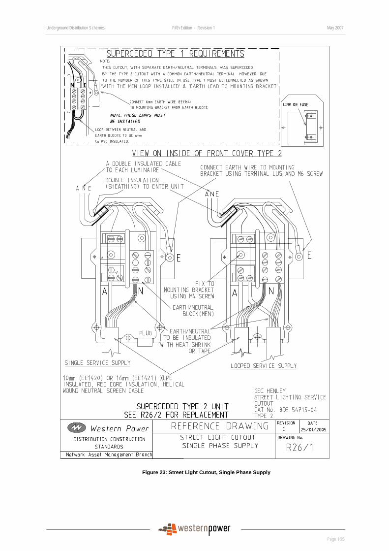
Underground Distribution Schemes Fifth Edition - Revision 1 May 2007
Page 165
DRAFT
Figure 23: Street Light Cutout, Single Phase Supply
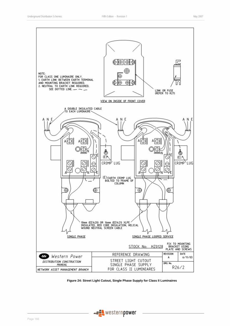
Underground Distribution Schemes Fifth Edition - Revision 1 May 2007
Page 166
DRAFT
Figure 24: Street Light Cutout, Single Phase Supply for Class II Luminaires
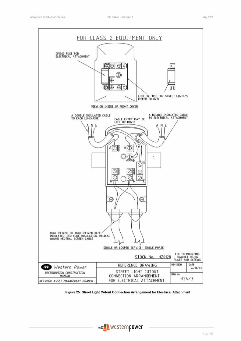
Underground Distribution Schemes Fifth Edition - Revision 1 May 2007
Page 167
DRAFT
Figure 25: Street Light Cutout Connection Arrangement for Electrical Attachment
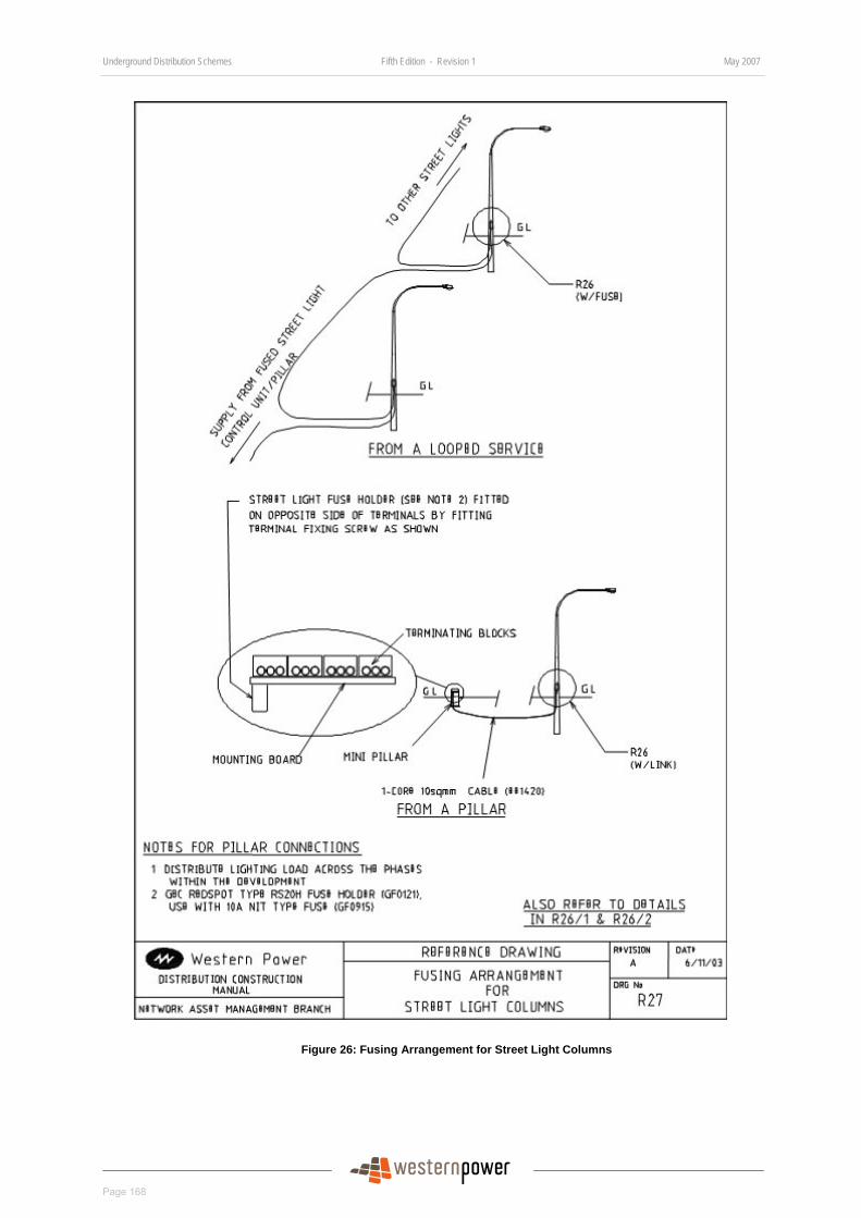
Underground Distribution Schemes Fifth Edition - Revision 1 May 2007
Page 168
DRAFT
Figure 26: Fusing Arrangement for Street Light Columns
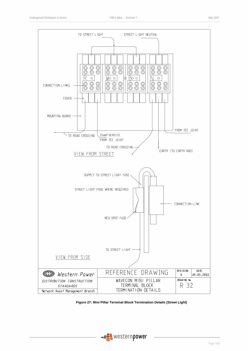
Underground Distribution Schemes Fifth Edition - Revision 1 May 2007
Page 169
DRAFT
Figure 27: Mini Pillar Terminal Block Termination Details (Street Light)

Underground Distribution Schemes Fifth Edition - Revision 1 May 2007
Page 170
DRAFT
Cable Trench Arrangements
Index of Drawings
Drawing Number Drawing Title
UDS-6-2 Cable Trench Layout (Sheets 1 to 7) (DMS#3147919)
UDS-6-3 Cable and Duct Placements on Truncations (DMS#3058457)
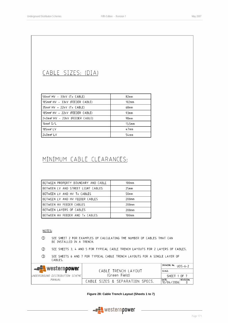
Underground Distribution Schemes Fifth Edition - Revision 1 May 2007
Page 171
DRAFT
Figure 28: Cable Trench Layout (Sheets 1 to 7)
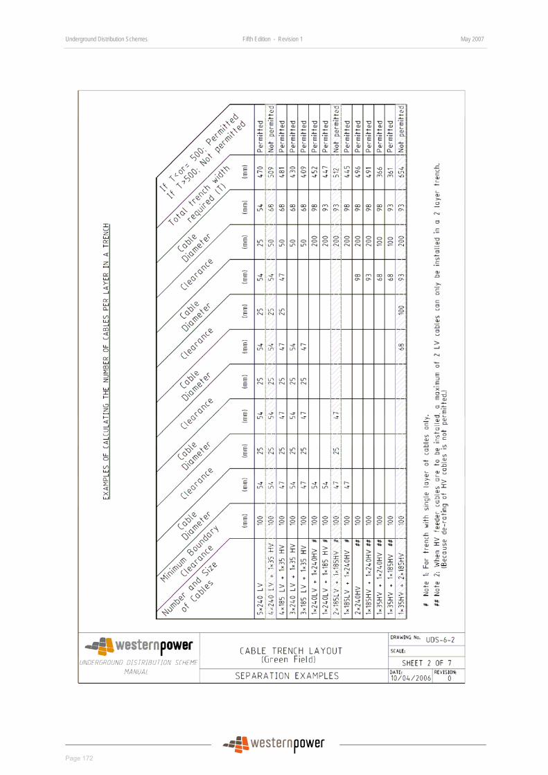
Underground Distribution Schemes Fifth Edition - Revision 1 May 2007
Page 172
DRAFT
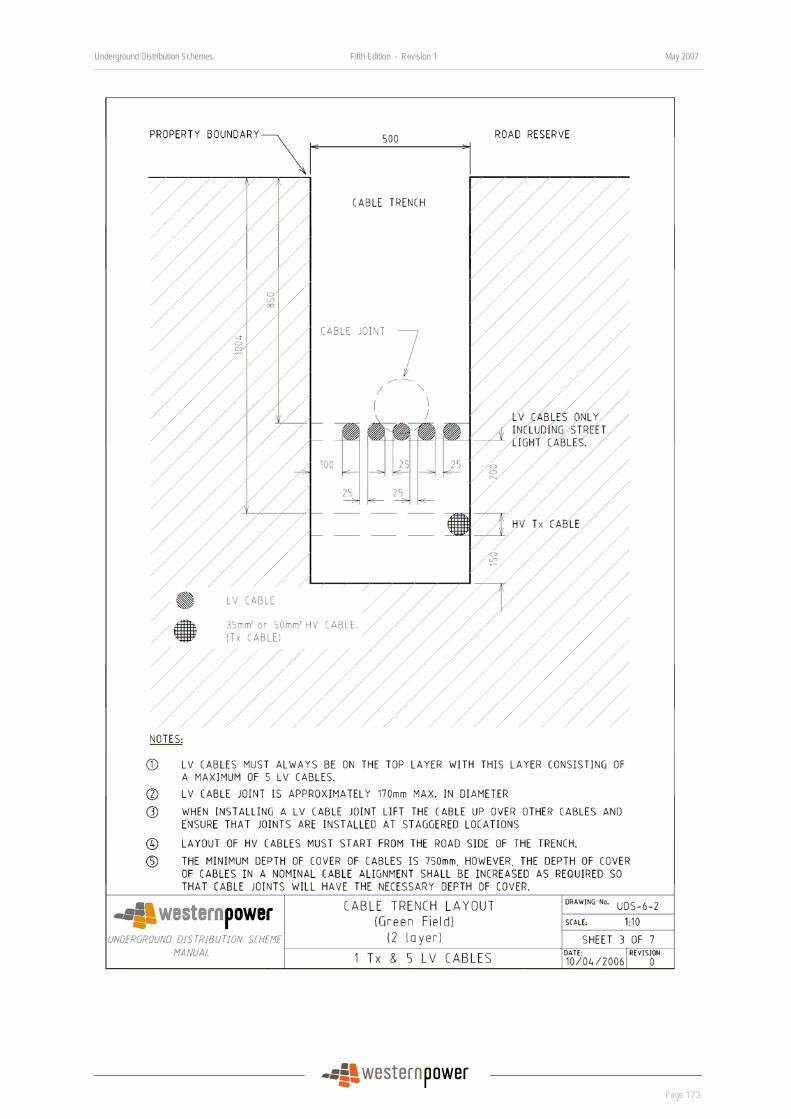
Underground Distribution Schemes Fifth Edition - Revision 1 May 2007
Page 173
DRAFT
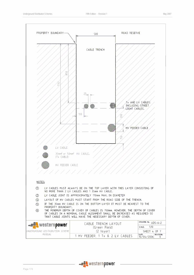
Underground Distribution Schemes Fifth Edition - Revision 1 May 2007
Page 174
DRAFT
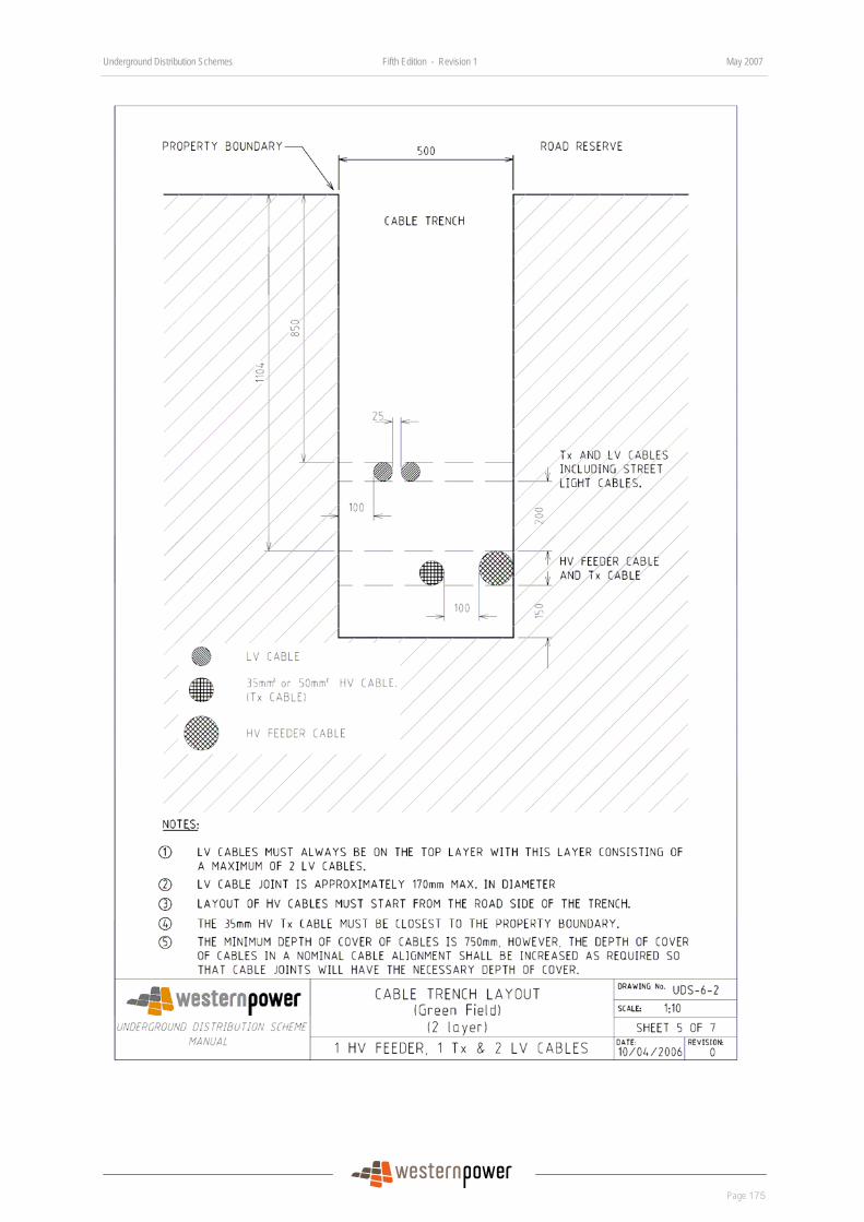
Underground Distribution Schemes Fifth Edition - Revision 1 May 2007
Page 175
DRAFT
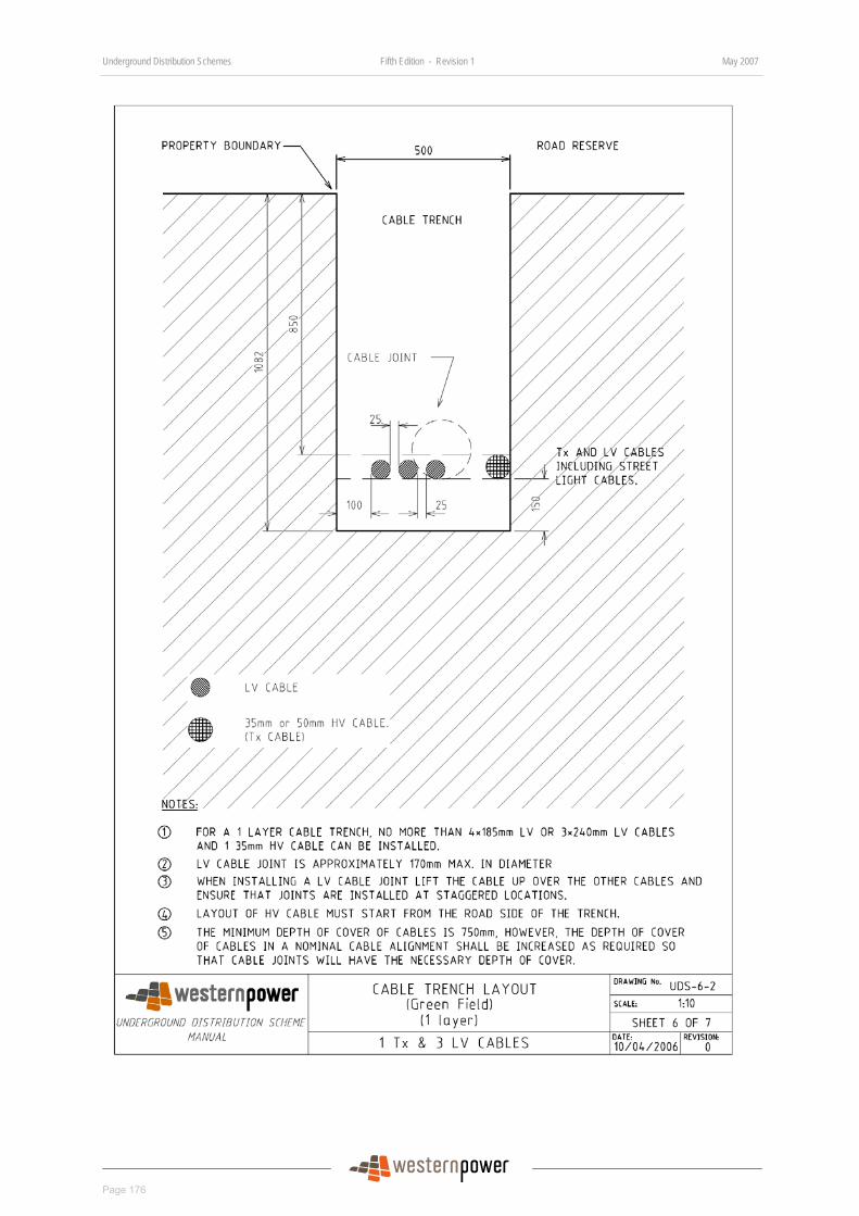
Underground Distribution Schemes Fifth Edition - Revision 1 May 2007
Page 176
DRAFT
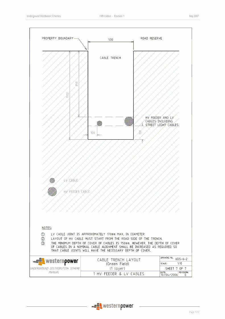
Underground Distribution Schemes Fifth Edition - Revision 1 May 2007
Page 177
DRAFT
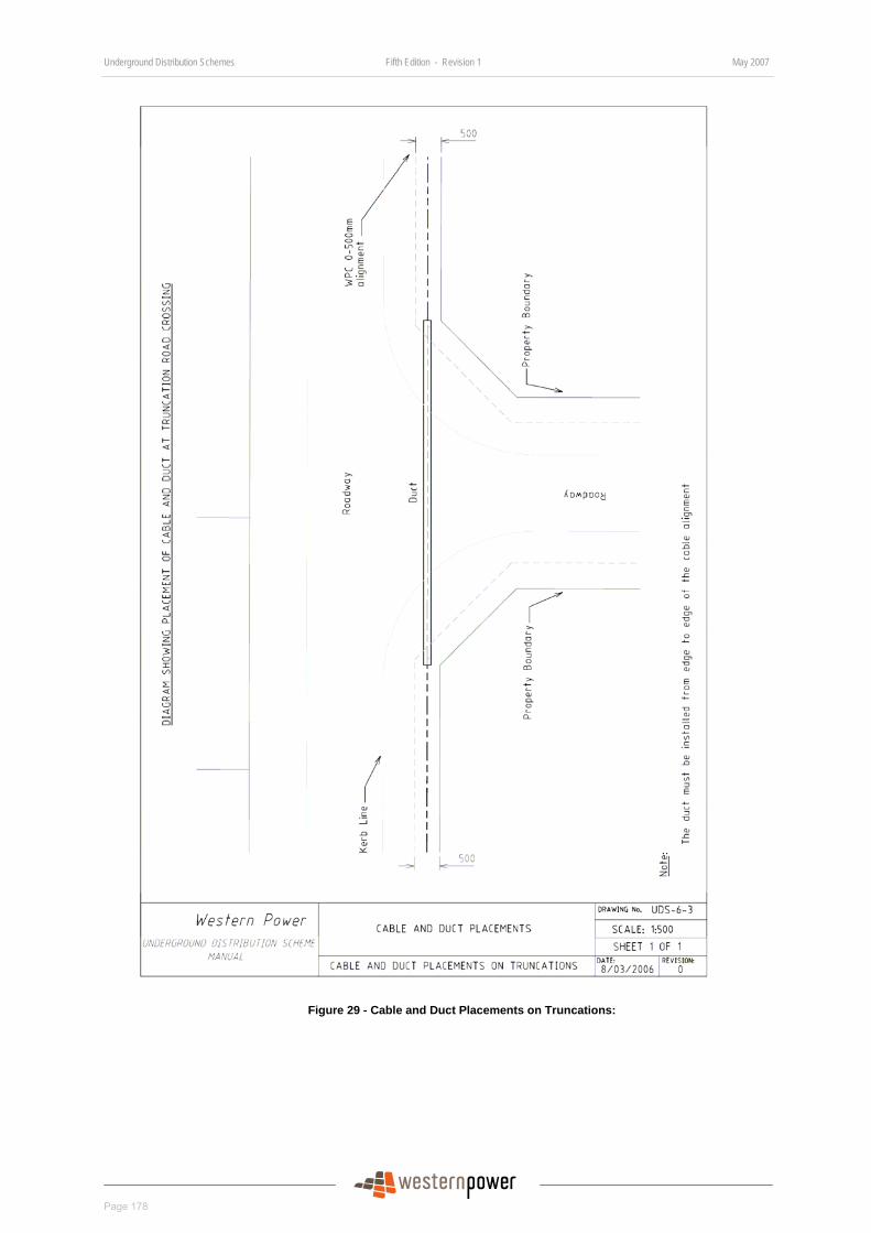
Underground Distribution Schemes Fifth Edition - Revision 1 May 2007
Page 178
DRAFT
Figure 29 - Cable and Duct Placements on Truncations:

Underground Distribution Schemes Fifth Edition - Revision 1 May 2007
Page 179
DRAFT
BLANK PAGE