Embed Size (px)
Citation preview
**************************************************************************USACE / NAVFAC / AFCEC / NASA UFGS- 26 32 15. 00 10 ( Oct ober 2007) - - - - - - - - - - - - - - - - - - - - - - - - - - - - - - - - - -Pr epar i ng Act i v i t y: USACE Super sedi ng UFGS- 26 32 15. 00 10 ( Apr i l 2006)
UNI FI ED FACI LI TI ES GUI DE SPECI FI CATI ONS
Ref er ences ar e i n agr eement wi t h UMRL dat ed Apr i l 2018**************************************************************************
SECTI ON TABLE OF CONTENTS
DI VI SI ON 26 - ELECTRI CAL
SECTI ON 26 32 15. 00 10
DI ESEL- GENERATOR SET STATI ONARY 100- 2500 KW, WI TH AUXI LI ARI ES
10/07
PART 1 GENERAL
1. 1 REFERENCES 1. 2 SUBMI TTALS 1. 3 QUALI TY ASSURANCE 1. 3. 1 Conf or mance t o Codes and St andar ds 1. 3. 2 Si t e Wel di ng 1. 3. 3 Vi br at i on Li mi t at i on 1. 3. 4 Sei smi c Requi r ement s 1. 3. 5 Exper i ence 1. 3. 6 Fi el d Engi neer 1. 3. 7 Det ai l ed Dr awi ngs 1. 4 DELI VERY, STORAGE, AND HANDLI NG 1. 5 EXTRA MATERI ALS
PART 2 PRODUCTS
2. 1 SYSTEM REQUI REMENTA 2. 1. 1 Engi ne- Gener at or Par amet er Schedul e 2. 1. 2 Rat ed Out put Capaci t y 2. 1. 3 Power Rat i ngs 2. 1. 4 Tr ansi ent Response 2. 1. 5 Rel i abi l i t y and Dur abi l i t y 2. 1. 6 Par al l el Oper at i on 2. 1. 7 Load Shar i ng 2. 1. 8 Engi ne- Gener at or Set Encl osur e 2. 1. 9 Vi br at i on I sol at i on 2. 1. 10 Fuel Consumpt i on 2. 1. 11 Fuel - Consumpt i on Rebat es 2. 1. 12 Har moni c Requi r ement s 2. 1. 13 St ar t i ng Ti me Requi r ement s 2. 2 NAMEPLATES 2. 3 SAFETY DEVI CES 2. 4 MATERI ALS AND EQUI PMENT 2. 4. 1 Fi l t er El ement s 2. 4. 2 I nst r ument Tr ansf or mer s
SECTI ON 26 32 15. 00 10 Page 1
2. 4. 3 Revenue Met er i ng 2. 4. 4 Pi pe ( Fuel / Lube- Oi l , Compr essed Ai r , Cool ant , and Exhaust ) 2. 4. 4. 1 Fl anges and Fl anged Fi t t i ngs 2. 4. 4. 2 Pi pe Wel di ng Fi t t i ngs 2. 4. 4. 3 Thr eaded Fi t t i ngs 2. 4. 4. 4 Val ves 2. 4. 4. 5 Gasket s 2. 4. 5 Pi pe Hanger s 2. 4. 6 El ect r i cal Encl osur es 2. 4. 6. 1 Power Swi t chgear Assembl i es 2. 4. 6. 2 Swi t chboar ds 2. 4. 6. 3 Panel boar ds 2. 4. 7 El ect r i c Mot or s 2. 4. 8 Mot or Cont r ol l er s 2. 5 ENGI NE 2. 6 FUEL SYSTEM 2. 6. 1 Pumps 2. 6. 1. 1 Mai n Pump 2. 6. 1. 2 Auxi l i ar y Fuel Pump 2. 6. 2 Fuel Fi l t er 2. 6. 3 Rel i ef / Bypass Val ve 2. 6. 4 I nt egr al Mai n Fuel St or age Tank 2. 6. 4. 1 Capaci t y 2. 6. 4. 2 Local Fuel Fi l l 2. 6. 4. 3 Fuel Level Cont r ol s 2. 6. 4. 4 Ar r angement 2. 6. 5 Day Tank 2. 6. 5. 1 Capaci t y, Pr i me 2. 6. 5. 2 Capaci t y, St andby 2. 6. 5. 3 Dr ai n Li ne 2. 6. 5. 4 Local Fuel Fi l l 2. 6. 5. 5 Fuel Level Cont r ol s 2. 6. 5. 6 Ar r angement 2. 6. 6 Fuel Suppl y Syst em 2. 7 LUBRI CATI ON 2. 7. 1 Lube- Oi l Fi l t er 2. 7. 2 Lube- Oi l Sensor s 2. 7. 3 Pr eci r cul at i on Pump 2. 8 COOLI NG SYSTEM 2. 8. 1 Cool ant Pumps 2. 8. 2 Heat Exchanger 2. 8. 2. 1 Fi n- Tube- Type Heat Exchanger ( Radi at or ) 2. 8. 2. 2 Shel l and U- Tube Type Heat Exchanger 2. 8. 3 Expansi on Tank 2. 8. 4 Ther most at i c Cont r ol Val ve 2. 8. 5 Duct wor k 2. 8. 6 Temper at ur e Sensor s 2. 9 SOUND LI MI TATI ONS 2. 10 AI R I NTAKE EQUI PMENT 2. 11 EXHAUST SYSTEM 2. 11. 1 Fl exi bl e Sect i ons and Expansi on Joi nt s 2. 11. 2 Exhaust Muf f l er 2. 11. 3 Exhaust Pi pi ng 2. 12 PYROMETER 2. 13 EMI SSI ONS 2. 14 STARTI NG SYSTEM 2. 14. 1 Cont r ol s 2. 14. 2 Capaci t y 2. 14. 3 El ect r i cal St ar t i ng
SECTI ON 26 32 15. 00 10 Page 2
2. 14. 3. 1 Bat t er y 2. 14. 3. 2 Bat t er y Char ger 2. 14. 4 Pneumat i c 2. 14. 4. 1 Ai r Dr i ven Mot or s 2. 14. 4. 2 Cyl i nder I nj ect i on 2. 14. 5 St ar t i ng Ai ds 2. 14. 5. 1 Gl ow Pl ugs 2. 14. 5. 2 Jacket - Cool ant Heat er s 2. 14. 5. 2. 1 Pr i me Rat ed Set s 2. 14. 5. 2. 2 St andby Rat ed Set s 2. 14. 5. 3 Lubr i cat i ng- Oi l Heat er s 2. 14. 6 Exer ci ser 2. 15 GOVERNOR 2. 16 GENERATOR 2. 16. 1 Cur r ent Bal ance 2. 16. 2 Vol t age Bal ance 2. 16. 3 Wavef or m 2. 17 EXCI TER 2. 18 VOLTAGE REGULATOR 2. 19 GENERATOR I SOLATI ON AND PROTECTI ON 2. 19. 1 Swi t chboar ds 2. 19. 2 Devi ces 2. 20 SAFETY SYSTEM 2. 20. 1 Audi bl e Si gnal 2. 20. 2 Vi sual Si gnal 2. 20. 3 Al ar ms and Act i on Logi c 2. 20. 3. 1 Shut down 2. 20. 3. 2 Pr obl em 2. 20. 4 Local Al ar m Panel 2. 20. 5 Ti me- Del ay on Al ar ms 2. 20. 6 Remot e Al ar m Panel 2. 21 ENGI NE GENERATOR SET CONTROLS AND I NSTRUMENTATI ON 2. 21. 1 Cont r ol s 2. 21. 2 Engi ne Gener at or Set Met er i ng and St at us I ndi cat i on 2. 22 SYNCHRONI ZI NG PANEL 2. 23 PANELS 2. 23. 1 Encl osur es 2. 23. 2 Anal og 2. 23. 3 El ect r oni c 2. 23. 4 Par amet er Di spl ay 2. 24 AUTOMATI C ENGI NE- GENERATOR- SET SYSTEM OPERATI ON 2. 24. 1 Aut omat i c Tr ansf er Swi t ch 2. 24. 2 Moni t or i ng and Tr ansf er 2. 24. 3 Aut omat i c Par al l el i ng and Loadi ng of Engi ne- Gener at or Set s 2. 25 MANUAL ENGI NE- GENERATOR- SET SYSTEM OPERATI ON 2. 26 STATI ON BATTERY SYSTEM 2. 26. 1 Bat t er y 2. 26. 2 Bat t er y Capaci t y 2. 26. 3 Bat t er y Char ger 2. 27 BASE 2. 28 THERMAL I NSULATI ON 2. 29 PAI NTI NG AND FI NI SHI NG 2. 30 FACTORY I NSPECTI ON AND TESTS 2. 30. 1 Fact or y I nspect i on 2. 30. 2 Fact or y Test s
PART 3 EXECUTI ON
3. 1 EXAMI NATI ON
SECTI ON 26 32 15. 00 10 Page 3
3. 2 GENERAL I NSTALLATI ON 3. 3 PI PI NG I NSTALLATI ON 3. 3. 1 Suppor t 3. 3. 1. 1 Cei l i ng and Roof 3. 3. 1. 2 Wal l 3. 3. 2 Fl anged Joi nt s 3. 3. 3 Cl eani ng 3. 3. 4 Pi pe Sl eeves 3. 4 ELECTRI CAL I NSTALLATI ON 3. 5 FI ELD PAI NTI NG 3. 6 ONSI TE I NSPECTI ON AND TESTS 3. 6. 1 Test Condi t i ons 3. 6. 1. 1 Dat a 3. 6. 1. 2 Power Fact or 3. 6. 1. 3 Cont r act or Suppl i ed I t ems 3. 6. 1. 4 I nst r ument s 3. 6. 1. 5 Sequence 3. 6. 2 Const r uct i on Test s 3. 6. 2. 1 Pi pi ng Test 3. 6. 2. 2 El ect r i cal Equi pment Test s 3. 6. 3 I nspect i ons 3. 6. 4 Pr e- oper at i onal Test s 3. 6. 4. 1 Pr ot ect i ve Rel ays 3. 6. 4. 2 I nsul at i on Test 3. 6. 4. 3 Engi ne- Gener at or Connect i on Coupl i ng Test 3. 6. 5 Saf et y Run Test 3. 6. 6 Per f or mance Test s 3. 6. 6. 1 Cont i nuous Engi ne Load Run Test 3. 6. 6. 2 Vol t age and Fr equency Dr oop Test 3. 6. 6. 3 Vol t age Regul at or Range Test 3. 6. 6. 4 Gover nor Adj ust ment Range Test 3. 6. 6. 5 Fr equency and Vol t age St abi l i t y and Tr ansi ent Response 3. 6. 7 Par al l el Oper at i on Test 3. 6. 7. 1 Combi nat i ons 3. 6. 7. 2 Mul t i pl e Combi nat i ons 3. 6. 8 Par al l el Oper at i on Test ( Commer ci al Sour ce) 3. 6. 9 Aut omat i c Oper at i on Test s 3. 6. 10 Aut omat i c Oper at i on Test s f or St and- Al one Oper at i on 3. 6. 11 Fuel Consumpt i on Test s 3. 7 ONSI TE TRAI NI NG 3. 8 FI NAL TESTI NG AND I NSPECTI ON 3. 9 POSTED DATA AND I NSTRUCTI ONS 3. 10 ACCEPTANCE
- - End of Sect i on Tabl e of Cont ent s - -
SECTI ON 26 32 15. 00 10 Page 4
**************************************************************************USACE / NAVFAC / AFCEC / NASA UFGS- 26 32 15. 00 10 ( Oct ober 2007) - - - - - - - - - - - - - - - - - - - - - - - - - - - - - - - - - -Pr epar i ng Act i v i t y: USACE Super sedi ng UFGS- 26 32 15. 00 10 ( Apr i l 2006)
UNI FI ED FACI LI TI ES GUI DE SPECI FI CATI ONS
Ref er ences ar e i n agr eement wi t h UMRL dat ed Apr i l 2018**************************************************************************
SECTI ON 26 32 15. 00 10
DI ESEL- GENERATOR SET STATI ONARY 100- 2500 KW, WI TH AUXI LI ARI ES10/07
**************************************************************************NOTE: Thi s gui de speci f i cat i on cover s t he r equi r ement s f or st at i onar y di esel - dr i ven gener at or set s i n t he 100 t o 2500 ki l owat t capaci t y.
Adher e t o UFC 1- 300- 02 Uni f i ed Faci l i t i es Gui de Speci f i cat i ons ( UFGS) For mat St andar d when edi t i ng t hi s gui de speci f i cat i on or pr epar i ng new pr oj ect speci f i cat i on sect i ons. Edi t t hi s gui de speci f i cat i on f or pr oj ect speci f i c r equi r ement s by addi ng, del et i ng, or r evi s i ng t ext . For br acket ed i t ems, choose appl i cabl e i t em( s) or i nser t appr opr i at e i nf or mat i on.
Remove i nf or mat i on and r equi r ement s not r equi r ed i n r espect i ve pr oj ect , whet her or not br acket s ar e present.
Comment s, suggest i ons and r ecommended changes f or t hi s gui de speci f i cat i on ar e wel come and shoul d be submi t t ed as a Cr i t er i a Change Request ( CCR) .
**************************************************************************
PART 1 GENERAL
**************************************************************************NOTE: Thi s Speci f i cat i on i s not f or Pr ocur ement of Gas- f uel ed Engi ne- gener at or Set s.
Tr ansi ent - l oad- r esponse per f or mance char act er i st i cs of nat ur al gas, di gest er gas, pr opane, and l i quef i ed pet r ol eum gas engi nes di f f er s i gni f i cant l y f r om t hose of di esel engi nes because of t he f uel di f f er ences. Consul t manuf act ur er s f or sampl e specifications.
Sel ect t he f eat ur es and f i l l i n bl anks wi t h val ues appr opr i at e f or t he desi gn condi t i on. Thi s speci f i cat i on does not appl y t o 400 Hz appl i cat i ons.
**************************************************************************
SECTI ON 26 32 15. 00 10 Page 5
1. 1 REFERENCES
**************************************************************************NOTE: Thi s par agr aph i s used t o l i s t t he publ i cat i ons c i t ed i n t he t ext of t he gui de speci f i cat i on. The publ i cat i ons ar e r ef er r ed t o i n t he t ext by basi c desi gnat i on onl y and l i s t ed i n t hi s par agr aph by or gani zat i on, desi gnat i on, dat e, and t i t l e.
Use t he Ref er ence Wi zar d' s Check Ref er ence f eat ur e when you add a Ref er ence I dent i f i er ( RI D) out s i de of t he Sect i on' s Ref er ence Ar t i c l e t o aut omat i cal l y pl ace t he r ef er ence i n t he Ref er ence Ar t i c l e. Al so use t he Ref er ence Wi zar d' s Check Ref er ence f eat ur e t o updat e t he i ssue dat es.
Ref er ences not used i n t he t ext wi l l aut omat i cal l y be del et ed f r om t hi s sect i on of t he pr oj ect speci f i cat i on when you choose t o r econci l e r ef er ences i n t he publ i sh pr i nt pr ocess.
**************************************************************************
The publ i cat i ons l i s t ed bel ow f or m a par t of t hi s speci f i cat i on t o t he ext ent r ef er enced. The publ i cat i ons ar e r ef er r ed t o wi t hi n t he t ext by t he basi c desi gnat i on onl y.
AMERI CAN NATI ONAL STANDARDS I NSTI TUTE ( ANSI )
ANSI C39. 1 ( 1981; R 1992) Requi r ement s f or El ect r i cal Anal og I ndi cat i ng I nst r ument s
ASME I NTERNATI ONAL ( ASME)
ASME B16. 11 ( 2016) For ged Fi t t i ngs, Socket - Wel di ng and Threaded
ASME B16. 3 ( 2011) Mal l eabl e I r on Thr eaded Fi t t i ngs, Cl asses 150 and 300
ASME B16. 5 ( 2017) Pi pe Fl anges and Fl anged Fi t t i ngs NPS 1/ 2 Thr ough NPS 24 Met r i c/ I nch St andar d
ASME B31. 1 ( 2016; Er r at a 2016) Power Pi pi ng
ASME BPVC SEC I X ( 2010) BPVC Sect i on I X- Wel di ng and Br azi ng Qualifications
ASME BPVC SEC VI I I D1 ( 2015) BPVC Sect i on VI I I - Rul es f or Const r uct i on of Pr essur e Vessel s Di v i s i on 1
ASSOCI ATI ON OF EDI SON I LLUMI NATI NG COMPANI ES ( AEI C)
AEI C CS8 ( 2013) Speci f i cat i on f or Ext r uded Di el ect r i c Shi el ded Power Cabl es Rat ed 5 Thr ough 46 kV
SECTI ON 26 32 15. 00 10 Page 6
ASTM I NTERNATI ONAL ( ASTM)
ASTM A106/ A106M ( 2014) St andar d Speci f i cat i on f or Seaml ess Car bon St eel Pi pe f or Hi gh- Temper at ur e Service
ASTM A181/ A181M ( 2014) St andar d Speci f i cat i on f or Car bon St eel For gi ngs, f or Gener al - Pur pose Pi pi ng
ASTM A234/ A234M ( 2017) St andar d Speci f i cat i on f or Pi pi ng Fi t t i ngs of Wr ought Car bon St eel and Al l oy St eel f or Moder at e and Hi gh Temper at ur e Service
ASTM A53/ A53M ( 2012) St andar d Speci f i cat i on f or Pi pe, St eel , Bl ack and Hot - Di pped, Zi nc- Coat ed, Wel ded and Seaml ess
ASTM B395/ B395M ( 2013) St andar d Speci f i cat i on f or U- Bend Seaml ess Copper and Copper Al l oy Heat Exchanger and Condenser Tubes
ASTM D975 ( 2017a) St andar d Speci f i cat i on f or Di esel Fuel Oi l s
ELECTRI CAL GENERATI NG SYSTEMS ASSOCI ATI ON ( EGSA)
EGSA 101P ( 1995) Per f or mance St andar d f or Engi ne Dr i ven Gener at or Set s
I NSTI TUTE OF ELECTRI CAL AND ELECTRONI CS ENGI NEERS ( I EEE)
I EEE 1 ( 2000; R 2011) Gener al Pr i nci pl es f or Temper at ur e Li mi t s i n t he Rat i ng of El ect r i c Equi pment and f or t he Eval uat i on of El ect r i cal I nsul at i on
I EEE 115 ( 2009) Gui de f or Test Pr ocedur es f or Synchr onous Machi nes: Par t I Accept ance and Per f or mance Test i ng; Par t I I Test Pr ocedur es and Par amet er Det er mi nat i on f or Dynami c Anal ysi s
I EEE 120 ( 1989; R 2007) Mast er Test Gui de f or El ect r i cal Measur ement s i n Power Ci r cui t s
I EEE 404 ( 2012) St andar d f or Ext r uded and Lami nat ed Di el ect r i c Shi el ded Cabl e Joi nt s Rat ed 2500 V t o 500, 000 V
I EEE 43 ( 2013) Recommended Pr act i ce f or Test i ng I nsul at i on Resi st ance of Rot at i ng Machi ner y
I EEE 48 ( 2009) St andar d f or Test Pr ocedur es and Requi r ement s f or Al t er nat i ng- Cur r ent Cabl e Ter mi nat i ons Used on Shi el ded Cabl es Havi ng Lami nat ed I nsul at i on Rat ed 2. 5 kV t hr ough 765 kV or Ext r uded I nsul at i on Rat ed 2. 5 kV t hr ough 500 kV
SECTI ON 26 32 15. 00 10 Page 7
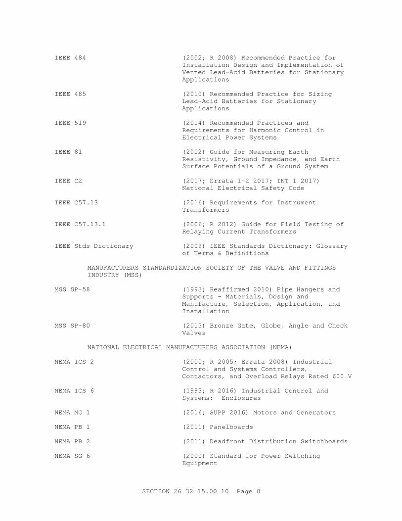
I EEE 484 ( 2002; R 2008) Recommended Pr act i ce f or I nst al l at i on Desi gn and I mpl ement at i on of Vent ed Lead- Aci d Bat t er i es f or St at i onar y Applications
I EEE 485 ( 2010) Recommended Pr act i ce f or Si z i ng Lead- Aci d Bat t er i es f or St at i onar y Applications
I EEE 519 ( 2014) Recommended Pr act i ces and Requi r ement s f or Har moni c Cont r ol i n El ect r i cal Power Syst ems
I EEE 81 ( 2012) Gui de f or Measur i ng Ear t h Resi st i v i t y, Gr ound I mpedance, and Ear t h Sur f ace Pot ent i al s of a Gr ound Syst em
I EEE C2 ( 2017; Er r at a 1- 2 2017; I NT 1 2017) Nat i onal El ect r i cal Saf et y Code
I EEE C57. 13 ( 2016) Requi r ement s f or I nst r ument Transformers
I EEE C57. 13. 1 ( 2006; R 2012) Gui de f or Fi el d Test i ng of Rel ayi ng Cur r ent Tr ansf or mer s
I EEE St ds Di ct i onar y ( 2009) I EEE St andar ds Di ct i onar y: Gl ossar y of Ter ms & Def i ni t i ons
MANUFACTURERS STANDARDI ZATI ON SOCI ETY OF THE VALVE AND FI TTI NGS I NDUSTRY ( MSS)
MSS SP- 58 ( 1993; Reaf f i r med 2010) Pi pe Hanger s and Suppor t s - Mat er i al s, Desi gn and Manuf act ur e, Sel ect i on, Appl i cat i on, and Installation
MSS SP- 80 ( 2013) Br onze Gat e, Gl obe, Angl e and Check Valves
NATI ONAL ELECTRI CAL MANUFACTURERS ASSOCI ATI ON ( NEMA)
NEMA I CS 2 ( 2000; R 2005; Er r at a 2008) I ndust r i al Cont r ol and Syst ems Cont r ol l er s, Cont act or s, and Over l oad Rel ays Rat ed 600 V
NEMA I CS 6 ( 1993; R 2016) I ndust r i al Cont r ol and Syst ems: Encl osur es
NEMA MG 1 ( 2016; SUPP 2016) Mot or s and Gener at or s
NEMA PB 1 ( 2011) Panel boar ds
NEMA PB 2 ( 2011) Deadf r ont Di st r i but i on Swi t chboar ds
NEMA SG 6 ( 2000) St andar d f or Power Swi t chi ng Equipment
SECTI ON 26 32 15. 00 10 Page 8
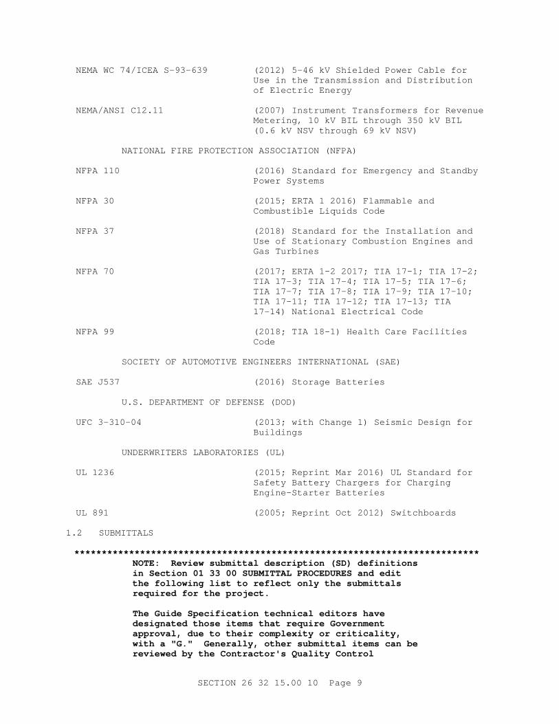
NEMA WC 74/ I CEA S- 93- 639 ( 2012) 5- 46 kV Shi el ded Power Cabl e f or Use i n t he Tr ansmi ssi on and Di st r i but i on of El ect r i c Ener gy
NEMA/ ANSI C12. 11 ( 2007) I nst r ument Tr ansf or mer s f or Revenue Met er i ng, 10 kV BI L t hr ough 350 kV BI L ( 0. 6 kV NSV t hr ough 69 kV NSV)
NATI ONAL FI RE PROTECTI ON ASSOCI ATI ON ( NFPA)
NFPA 110 ( 2016) St andar d f or Emer gency and St andby Power Syst ems
NFPA 30 ( 2015; ERTA 1 2016) Fl ammabl e and Combust i bl e Li qui ds Code
NFPA 37 ( 2018) St andar d f or t he I nst al l at i on and Use of St at i onar y Combust i on Engi nes and Gas Tur bi nes
NFPA 70 ( 2017; ERTA 1- 2 2017; TI A 17- 1; TI A 17- 2; TI A 17- 3; TI A 17- 4; TI A 17- 5; TI A 17- 6; TI A 17- 7; TI A 17- 8; TI A 17- 9; TI A 17- 10; TI A 17- 11; TI A 17- 12; TI A 17- 13; TI A 17- 14) Nat i onal El ect r i cal Code
NFPA 99 ( 2018; TI A 18- 1) Heal t h Car e Faci l i t i es Code
SOCI ETY OF AUTOMOTI VE ENGI NEERS I NTERNATI ONAL ( SAE)
SAE J537 ( 2016) St or age Bat t er i es
U. S. DEPARTMENT OF DEFENSE ( DOD)
UFC 3- 310- 04 ( 2013; wi t h Change 1) Sei smi c Desi gn f or Buildings
UNDERWRI TERS LABORATORI ES ( UL)
UL 1236 ( 2015; Repr i nt Mar 2016) UL St andar d f or Saf et y Bat t er y Char ger s f or Char gi ng Engi ne- St ar t er Bat t er i es
UL 891 ( 2005; Repr i nt Oct 2012) Swi t chboar ds
1. 2 SUBMITTALS
**************************************************************************NOTE: Revi ew submi t t al descr i pt i on ( SD) def i ni t i ons i n Sect i on 01 33 00 SUBMI TTAL PROCEDURES and edi t t he f ol l owi ng l i s t t o r ef l ect onl y t he submi t t al s r equi r ed f or t he pr oj ect .
The Gui de Speci f i cat i on t echni cal edi t or s have desi gnat ed t hose i t ems t hat r equi r e Gover nment appr oval , due t o t hei r compl exi t y or cr i t i cal i t y , wi t h a " G. " Gener al l y, ot her submi t t al i t ems can be r evi ewed by t he Cont r act or ' s Qual i t y Cont r ol
SECTI ON 26 32 15. 00 10 Page 9
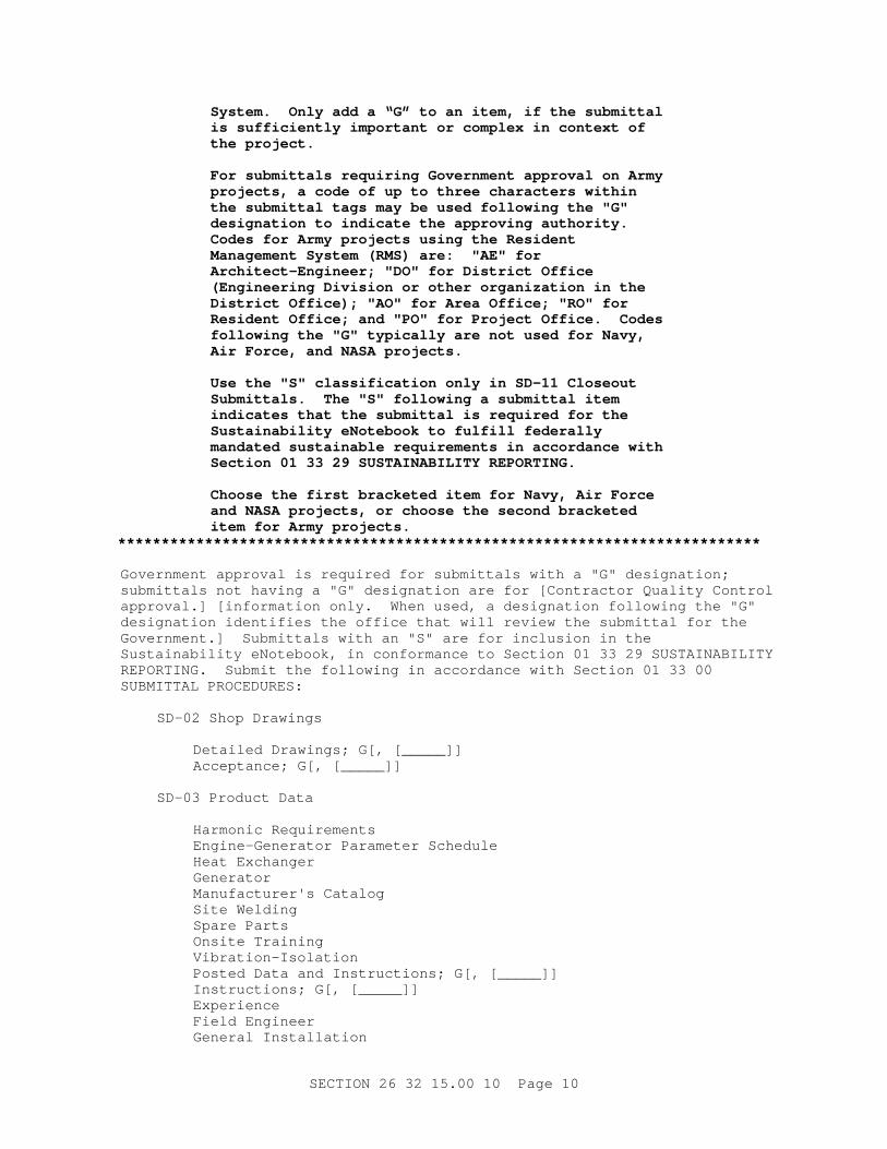
Syst em. Onl y add a “ G” t o an i t em, i f t he submi t t al i s suf f i c i ent l y i mpor t ant or compl ex i n cont ext of t he pr oj ect .
For submi t t al s r equi r i ng Gover nment appr oval on Ar my pr oj ect s, a code of up t o t hr ee char act er s wi t hi n t he submi t t al t ags may be used f ol l owi ng t he " G" desi gnat i on t o i ndi cat e t he appr ovi ng aut hor i t y. Codes f or Ar my pr oj ect s usi ng t he Resi dent Management Syst em ( RMS) ar e: " AE" f or Ar chi t ect - Engi neer ; " DO" f or Di st r i c t Of f i ce ( Engi neer i ng Di v i s i on or ot her or gani zat i on i n t he Di st r i c t Of f i ce) ; " AO" f or Ar ea Of f i ce; " RO" f or Resi dent Of f i ce; and " PO" f or Pr oj ect Of f i ce. Codes f ol l owi ng t he " G" t ypi cal l y ar e not used f or Navy, Ai r For ce, and NASA pr oj ect s.
Use t he " S" c l assi f i cat i on onl y i n SD- 11 Cl oseout Submi t t al s. The " S" f ol l owi ng a submi t t al i t em i ndi cat es t hat t he submi t t al i s r equi r ed f or t he Sust ai nabi l i t y eNot ebook t o f ul f i l l f eder al l y mandat ed sust ai nabl e r equi r ement s i n accor dance wi t h Sect i on 01 33 29 SUSTAI NABI LI TY REPORTI NG.
Choose t he f i r st br acket ed i t em f or Navy, Ai r For ce and NASA pr oj ect s, or choose t he second br acket ed i t em f or Ar my pr oj ect s.
**************************************************************************
Gover nment appr oval i s r equi r ed f or submi t t al s wi t h a " G" desi gnat i on; submi t t al s not havi ng a " G" desi gnat i on ar e f or [ Cont r act or Qual i t y Cont r ol appr oval . ] [ i nf or mat i on onl y. When used, a desi gnat i on f ol l owi ng t he " G" desi gnat i on i dent i f i es t he of f i ce t hat wi l l r evi ew t he submi t t al f or t he Gover nment . ] Submi t t al s wi t h an " S" ar e f or i ncl usi on i n t he Sust ai nabi l i t y eNot ebook, i n conf or mance t o Sect i on 01 33 29 SUSTAI NABI LI TY REPORTI NG. Submi t t he f ol l owi ng i n accor dance wi t h Sect i on 01 33 00 SUBMI TTAL PROCEDURES:
SD- 02 Shop Dr awi ngs
Det ai l ed Dr awi ngs; G[ , [ _____] ]Accept ance; G[ , [ _____] ]
SD- 03 Pr oduct Dat a
Har moni c Requi r ement sEngi ne- Gener at or Par amet er Schedul eHeat ExchangerGeneratorManuf act ur er ' s Cat al ogSi t e Wel di ngSpar e Par t sOnsi t e Tr ai ni ngVibration-IsolationPost ed Dat a and I nst r uct i ons; G[ , [ _____] ]I nst r uct i ons; G[ , [ _____] ]ExperienceFi el d Engi neerGener al I nst al l at i on
SECTI ON 26 32 15. 00 10 Page 10
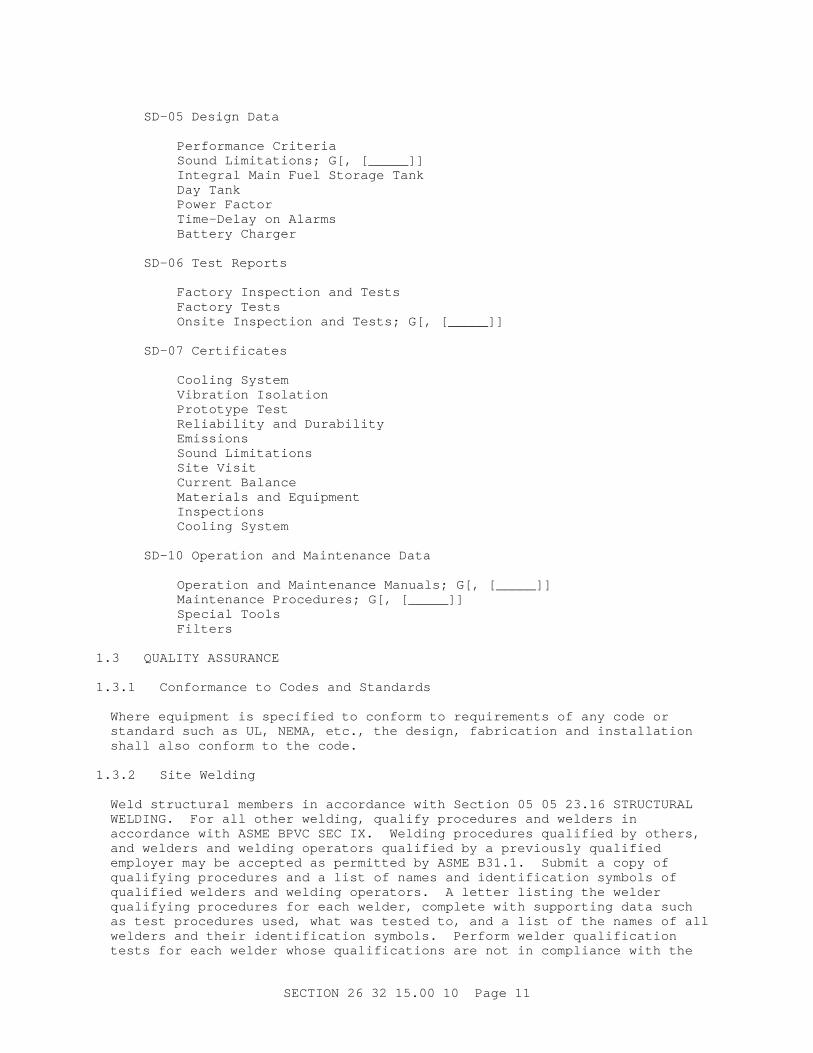
SD- 05 Desi gn Dat a
Per f or mance Cr i t er i aSound Li mi t at i ons; G[ , [ _____] ]I nt egr al Mai n Fuel St or age TankDay TankPower Fact orTi me- Del ay on Al ar msBat t er y Char ger
SD- 06 Test Repor t s
Fact or y I nspect i on and Test sFact or y Test sOnsi t e I nspect i on and Test s; G[ , [ _____] ]
SD- 07 Cer t i f i cat es
Cool i ng Syst emVi br at i on I sol at i onPr ot ot ype TestRel i abi l i t y and Dur abi l i t yEmissionsSound Li mi t at i onsSi t e Vi s i tCur r ent Bal anceMat er i al s and Equi pmentInspectionsCool i ng Syst em
SD- 10 Oper at i on and Mai nt enance Dat a
Oper at i on and Mai nt enance Manual s; G[ , [ _____] ]Mai nt enance Pr ocedur es; G[ , [ _____] ]Speci al Tool sFilters
1. 3 QUALI TY ASSURANCE
1. 3. 1 Conf or mance t o Codes and St andar ds
Wher e equi pment i s speci f i ed t o conf or m t o r equi r ement s of any code or st andar d such as UL, NEMA, et c. , t he desi gn, f abr i cat i on and i nst al l at i on shal l al so conf or m t o t he code.
1. 3. 2 Si t e Wel di ng
Wel d st r uct ur al member s i n accor dance wi t h Sect i on 05 05 23. 16 STRUCTURAL WELDI NG. For al l ot her wel di ng, qual i f y pr ocedur es and wel der s i n accor dance wi t h ASME BPVC SEC I X. Wel di ng pr ocedur es qual i f i ed by ot her s, and wel der s and wel di ng oper at or s qual i f i ed by a pr evi ousl y qual i f i ed empl oyer may be accept ed as per mi t t ed by ASME B31. 1. Submi t a copy of qual i f y i ng pr ocedur es and a l i s t of names and i dent i f i cat i on symbol s of qual i f i ed wel der s and wel di ng oper at or s. A l et t er l i s t i ng t he wel der qual i f y i ng pr ocedur es f or each wel der , compl et e wi t h suppor t i ng dat a such as t est pr ocedur es used, what was t est ed t o, and a l i s t of t he names of al l wel der s and t hei r i dent i f i cat i on symbol s. Per f or m wel der qual i f i cat i on t est s f or each wel der whose qual i f i cat i ons ar e not i n compl i ance wi t h t he
SECTI ON 26 32 15. 00 10 Page 11
r ef er enced st andar ds. Not i f y t he Cont r act i ng Of f i cer 24 hour s i n advance of qual i f i cat i on t est s whi ch shal l be per f or med at t he wor k s i t e, i f pr act i cal . The wel der or wel di ng oper at or shal l appl y t he per sonal l y assi gned symbol near each wel d made as a per manent r ecor d.
1. 3. 3 Vi br at i on Li mi t at i on
The maxi mum engi ne- gener at or set v i br at i on i n t he hor i zont al , ver t i cal , and axi al di r ect i ons shal l be l i mi t ed t o 0. 15 mm 6 mi l s ( peak- peak RMS) , wi t h an over al l vel oci t y l i mi t of 24 mm/ second 0. 95 i nches/ second RMS, f or al l speeds t hr ough 110 per cent of r at ed speed.
1. 3. 4 Sei smi c Requi r ement s
**************************************************************************NOTE: Pr ovi de sei smi c r equi r ement s, i f a Gover nment desi gner ( ei t her Cor ps of f i ce or A/ E) i s t he Engi neer of Recor d, and show on t he dr awi ngs. Del et e t he br acket ed phr ase i f sei smi c det ai l s ar e not pr ovi ded. Per t i nent por t i ons of UFC 3- 310- 04 and Sect i ons 13 48 00, 23 05 48. 19, and 26 05 48. 00 10, pr oper l y edi t ed, must be i ncl uded i n t he cont r act document s.
**************************************************************************
[ Sei smi c r equi r ement s shal l be i n accor dance wi t h UFC 3- 310- 04 and Sect i ons 13 48 00 [ SEI SMI C] BRACI NG FOR MI SCELLANEOUS EQUI PMENT, 23 05 48. 19 [ SEI SMI C] BRACI NG FOR HVAC and 26 05 48. 00 10 SEI SMI C PROTECTI ON FOR ELECTRI CAL EQUI PMENT] [ as shown on t he dr awi ngs] .
1. 3. 5 Experience
Each component manuf act ur er shal l have exper i ence i n t he manuf act ur e, assembl y and sal e of component s used wi t h st at i onar y di esel engi ne- gener at or set s f or commer ci al and i ndust r i al use. The engi ne- gener at or set manuf act ur er / assembl er shal l have a mi ni mum of 3 year s exper i ence i n t he manuf act ur e, assembl y and sal e of st at i onar y di esel engi ne- gener at or set s. Submi t a st at ement showi ng t hat each component manuf act ur er has a mi ni mum of 3 year s exper i ence i n t he manuf act ur e, assembl y and sal e of component s used wi t h st at i onar y di esel engi ne- gener at or set s. The engi ne- gener at or set manuf act ur er / assembl er has a mi ni mum of 3 year s exper i ence i n t he manuf act ur e, assembl y and sal e of st at i onar y di esel engi ne- gener at or set s f or commer ci al and i ndust r i al use.
1. 3. 6 Fi el d Engi neer
The engi ne- gener at or set manuf act ur er or assembl er shal l f ur ni sh a qual i f i ed f i el d engi neer t o super vi se t he compl et e i nst al l at i on of t he engi ne- gener at or set , assi st i n t he per f or mance of t he onsi t e t est s, and i nst r uct per sonnel as t o t he oper at i onal and mai nt enance f eat ur es of t he equi pment . Submi t a l et t er l i s t i ng t he qual i f i cat i ons, school s, f or mal t r ai ni ng, and exper i ence of t he f i el d engi neer . The f i el d engi neer shal l have at t ended t he engi ne gener at or manuf act ur er ' s t r ai ni ng cour ses on i nst al l at i on and oper at i on and mai nt enance of engi ne gener at or set s.
1. 3. 7 Det ai l ed Dr awi ngs
Submi t det ai l ed dr awi ngs showi ng t he f ol l owi ng:
SECTI ON 26 32 15. 00 10 Page 12
a. Base- mount ed equi pment , compl et e wi t h base and at t achment s, i nc l udi ng anchor bol t t empl at e and r ecommended cl ear ances f or mai nt enance and operation.
b. Compl et e st ar t i ng syst em.
c. Compl et e f uel syst em.
d. Compl et e cool i ng syst em.
e. Compl et e exhaust syst em.
f . Layout of r el ays, br eaker s, pr ogr ammabl e cont r ol l er s, swi t chgear , and swi t ches i ncl udi ng appl i cabl e s i ngl e l i ne and wi r i ng di agr ams wi t h wr i t t en descr i pt i on of sequence of oper at i on and t he i nst r ument at i on provided.
g. The compl et e l ubr i cat i on syst em, i ncl udi ng pi pi ng, pumps, st r ai ner s, f i l t er s, [ heat exchanger s f or l ube oi l and t ur bochar ger cool i ng, ] [ el ect r i c heat er , ] cont r ol s and wi r i ng.
h. Locat i on, t ype, and descr i pt i on of v i br at i on i sol at i on devi ces f or al l applications.
i . The saf et y syst em, t oget her wi t h a det ai l ed descr i pt i on of how i t i s t o wor k. Wi r i ng schemat i cs, saf et y devi ces wi t h a l i s t i ng of t hei r nor mal r anges, al ar m and shut down val ues ( t o i ncl ude oper at i on par amet er s such as pr essur es, t emper at ur es vol t ages, cur r ent s, and speeds) shal l be included.
j . One- l i ne schemat i c and wi r i ng di agr ams of t he gener at or , exci t er , r egul at or , gover nor , and i nst r ument at i on.
k. Layout of each panel .
l . Mount i ng and suppor t f or each panel and maj or pi ece of el ect r i cal equipment.
m. Engi ne- gener at or set l i f t i ng poi nt s and r i ggi ng i nst r uct i ons.
1. 4 DELI VERY, STORAGE, AND HANDLI NG
Pr oper l y pr ot ect mat er i al and equi pment , i n accor dance wi t h t he manuf act ur er s r ecommended st or age pr ocedur es, bef or e, dur i ng, and af t er i nst al l at i on. Pr ot ect st or ed i t ems f r om t he weat her and cont ami nat i on. Dur i ng i nst al l at i on, pi pi ng and s i mi l ar openi ngs shal l be capped t o keep out di r t and ot her f or ei gn mat t er .
1. 5 EXTRA MATERI ALS
Submi t a compl et e l i s t of spar e par t s f or each pi ece of equi pment and a compl et e l i s t of al l mat er i al and suppl i es needed f or cont i nued oper at i on. Li st s shal l i ncl ude suppl y sour ce and cur r ent pr i ces. Separ at e each l i s t i nt o t wo par t s, t hose el ement s r ecommended by t he manuf act ur er t o be r epl aced af t er 3 year s of ser vi ce, and t he r emai ni ng el ement s.
SECTI ON 26 32 15. 00 10 Page 13
PART 2 PRODUCTS
2. 1 SYSTEM REQUI REMENTA
**************************************************************************NOTE: Engi ne Gener at or Par amet er Schedul e. Wher e mul t i pl e engi ne- gener at or set s of di f f er ent s i zes or appl i cat i ons ar e t o be pr ovi ded, a Par amet er Schedul e shoul d be shown on t he cont r act dr awi ngs ( one f or each engi ne- gener at or set t o be i nst al l ed) . I f onl y one engi ne- gener at or set i s pr ovi ded ( or mul t i pl es of t he same t ype, s i ze, et c. ) , t he schedul e may be i n t he body of t he speci f i cat i on. Not e t hat t he speci f i cat i ons r ef er t o t he Engi ne Gener at or Par amet er Schedul e and t he desi gner must pr ovi de one each by t hat name.
Some l oad appl i cat i ons r equi r e pr eci se gener at or out put f r equency, vol t age, l evel wavef or m char act er i st i cs and cont r ol of t r ansi ent r esponse. Most l oads do not r equi r e st r i c t er cont r ol t han most of f - t he- shel f engi ne gener at or set s can pr ovi de. The cr i t i cal i t y of t he out put and r esponse char act er i st i cs can af f ect : sel ect i on of t he gover nor t ype, whet her i t i s t o be i sochr onous or dr oop, and i t s st eady st at e bandwi dt h; sel ect i on of t he vol t age r egul at or par amet er s; t r ansi ent r ecover y t i me f or f r equency and vol t age; maxi mum vol t age and f r equency devi at i on f or a t r ansi ent event ; and because of t he maxi mum devi at i ons and t r ansi ent r ecover y t i mes, t he s i z i ng or over si z i ng of t he engi ne and gener at or . The not es bel ow ar e i ncl uded t o assi st t he desi gner i n maki ng i nf or med choi ces when f i l l i ng i n t he Engi ne Gener at or Par amet er Schedule.
Power Rat i ngs and I ndust r y Ter mi nol ogy. The f ol l owi ng def i ni t i ons ar e f r om t he El ect r i cal Gener at i ng Syst ems Associ at i on St andar d 101P, Engi ne Dr i ven Gener at i ng Set s. St at i onar y di esel - engi ne- dr i ven el ect r i c gener at or set s ar e di v i ded i nt o t he f ol l owi ng f our r at i ng cat egor i es: EMERGENCY STANDBY, LI MI TED RUNNI NG TI ME, PRI ME POWER, and I NDUSTRI AL.
" EMERGENCY STANDBY RATI NG means t he power t hat t he gener at or set wi l l del i ver cont i nuousl y under nor mal var yi ng l oad f act or s f or t he dur at i on of a power out age. " I t must be under st ood t hat t hi s def i ni t i on uses t he t er m " nor mal var yi ng l oad condi t i ons" . Most manuf act ur er s use t hi s t er mi nol ogy t o i ndi cat e t hat t hei r uni t s t ypi cal l y ar e not r at ed f or cont i nuous oper at i on at t he namepl at e r at i ng, but r at her t hat t he uni t s pr ovi ded ar e r at ed f or cont i nuous oper at i on at 70 t o 80 per cent of t hei r namepl at e r at i ng, wi t h per i odi c l oadi ng up t o 100 per cent of t he namepl at e r at i ng f or shor t ( cycl i cal ) per i ods dur i ng a power out age. When speci f y i ng a genset be sur e t o speci f y what t he peak l oad i s and
SECTI ON 26 32 15. 00 10 Page 14
how much i s cont i nuous.
" LI MI TED RUNNI NG TI ME RATI NG means t he power t hat t he gener at or set wi l l del i ver when used as a ut i l i t y t ype power sour ce, t ypi cal l y i n l oad cur t ai l ment t ype ser vi ce, f or a l i mi t ed number of hour s, wher e t her e ar e non- var yi ng l oad f act or s and/ or const ant dedi cat ed l oads. "
" PRI ME POWER RATI NG means t he power t hat t he gener at or set wi l l del i ver when used as a ut i l i t y t ype power pl ant under nor mal var yi ng l oad f act or s t o r un cont i nuousl y. Thi s r at i ng r equi r es a mi ni mum moment ar y over l oad capabi l i t y of 10 per cent . "
" I NDUSTRI AL RATI NG means t he power t hat t he gener at or set wi l l del i ver 24 hour s per day when used as a ut i l i t y t ype power pl ant wher e t her e ar e non- var yi ng l oad f act or s and/ or const ant dedi cat ed loads."
Over l oad Capaci t y. Over l oad capaci t y i s onl y f or PRI ME r at ed uni t s. Del et e f or st andby appl i cat i ons.
Power Fact or . Commer ci al genset power r at i ngs ar e usual l y based on 0. 8 power f act or . Sel ect 0. 8 unl ess t he appl i cat i on r equi r es one mor e st r i ngent .
Loadi ng. When speci f y i ng engi ne- gener at or set s t he desi gner wi l l anal yze t he l oad char act er i st i cs and pr of i l es of t he l oad t o be ser ved t o det er mi ne t he peak demand, maxi mum st ep l oad i ncr ease and decr ease, mot or st ar t i ng r equi r ement s r epr esent ed as st ar t i ng kVA, cont i nuous and non- cont i nuous ( cycl i cal / per i odi c) , and t he non- l i near l oads t o be ser ved. Thi s i nf or mat i on shoul d be i ncl uded i n t he engi ne- gener at or set par amet er schedul e or on t he dr awi ngs f or each di f f er ent uni t pr ovi ded. For t hi s appl i cat i on, ser vi ce l oad i s t he peak est i mat ed l oadi ng ( cont i nuous pl us non- cont i nuous) t o be pl aced on t he engi ne gener at or set .
Peak demand cal cul at i on pr ovi des a f i gur e f r om whi ch t o det er mi ne t he ser vi ce l oad. For pr i me appl i cat i ons t he ser vi ce l oad shoul d i ncl ude spar e capaci t y f or f ut ur e l oad gr owt h and spi nni ng r eser ve ( r eser ve gener at i on beyond t hat r equi r ed t o sat i sf y i mmedi at e needs and/ or syst em peak demands) . Spar e capaci t y f or pr i me appl i cat i ons shoul d be based on t he f aci l i t y mast er pl an l oad pr oj ect i ons.
Mot or St ar t i ng Load. Mot or st ar t i ng r equi r ement s ar e i mpor t ant t o pr oper l y s i ze engi ne gener at or set s because t he st ar t i ng cur r ent f or mot or s can be as much as s i x t i mes t he r unni ng cur r ent , and can cause gener at or out put vol t age and f r equency t o dr op, even t hough t he genset has been si zed t o car r y t he r unni ng l oad. The desi gner must anal yze t he mot or l oads t o det er mi ne i f t he st ar t i ng char act er i st i cs
SECTI ON 26 32 15. 00 10 Page 15
of a mot or or a gr oup of mot or s t o be st ar t ed s i mul t aneousl y wi l l cause obj ect i onabl e genset per f or mance. Pr ovi de a mot or st ar t i ng kVA val ue f or t he l ar gest mot or or combi nat i on of mot or s t o be st ar t ed s i mul t aneousl y. An i ncr ease i n t he s i ze r at i ng of t he genset may be necessar y t o compensat e f or t he i nr ush cur r ent . Thi s assi st s t he genset suppl i er i n pr oper l y s i z i ng t he engi ne gener at or set .
Maxi mum Speed. The maxi mum al l owabl e speed i s 1800 RPM. I f t her e i s not speci f i c r equi r ement or user r equi r ement f or s l ower speed machi nes, sel ect 1800 RPM. Sel ect i on of t he maxi mum 1800 RPM does not pr ecl ude pr ovi s i on of s l ower speed machi nes, f or exampl e, i n t he l ar ger s i zes ( above 2000 kW) , wher e 1800 RPM machi nes may not be avai l abl e.
Heat Exchanger Type. Fi n- t ube heat exchanger s ( r adi at or s) ar e t he pr edomi nat e met hod of cool i ng. Speci f y ei t her a f i n- t ube or a shel l - t ube heat exchanger f or each engi ne- gener at or set . Heat exchanger s l ocat ed r emot e f r om t he engi ne- gener at or set ( i . e. , . not mount ed on t he engi ne- gener at or set base) wi l l be shown on t he pr oj ect pl ans, i ncl udi ng t he power sour ce f or associ at ed f ans and pumps.
Gover nor . The t ype of gover nor t o be used on each engi ne gener at or set shoul d be i dent i f i ed as i sochr onous or dr oop on t he engi ne- gener at or set par amet er schedul e. I sochr onous gover nor s hol d f r equency at t he set poi nt f r equency ( wi t hi n bandwi dt h) f or al l s t eady st at e l oads f r om 0 t o 100 per cent l oad and ar e r equi r ed f or appl i cat i ons wher e sever e demands ar e made on vol t age and f r equency r egul at i on. Dr oop gover nor s al l ow f r equency t o dr oop t o t he speci f i ed per cent age pr opor t i onal t o st eady st at e l oads f r om 0 t o 100 per cent l oad and ar e gener al l y accept abl e f or gener al pur pose and commer ci al appl i cat i ons.
Engi ne- gener at or set s i n st and al one ser vi ce ( i sol at ed bus) may ut i l i ze ei t her dr oop or i sochr onous gover nor s. The desi gner shoul d anal yze t he appl i cat i on and l oads t o det er mi ne i f t he mor e expensi ve i sochr onous uni t i s act ual l y r equi r ed. Dr oop uni t s pr ovi de added st abi l i t y ( l ess engi ne cycl i ng) i n s i ngl e uni t appl i cat i ons wher e const ant speeds ar e not cr i t i cal and ar e l ess expensi ve t han i sochr onous gover nor s.
Engi ne- gener at or set s i n par al l el ( on an i sol at ed bus) may al so ut i l i ze ei t her dr oop or i sochr onous gover nor s. Load swi ngs ar e shar ed pr opor t i onal l y based on t he gover nor dr oop set t i ngs. The l oad wi l l be spl i t equal l y among t he uni t s f or al l uni t s equi pped wi t h i sochr onous gover nor s wi t h l oad shar i ng cont r ol s, or i f al l uni t s have dr oop gover nor s t hat ar e set wi t h t he same dr oop. " Lead uni t s" ar e of t en desi gnat ed i n mul t i pl e uni t
SECTI ON 26 32 15. 00 10 Page 16

appl i cat i ons f or t i ght er f r equency cont r ol by set t i ng one gover nor at a much l ower dr oop t han t he ot her s. A " l ead uni t " can be desi gnat ed f or genset s equi pped wi t h i sochr onous gover nor s i f al l uni t s have gover nor s wi t h l oad shar i ng cont r ol s. I n t hi s case t he " l ead uni t " wi l l accept al l l oad swi ngs and t he ot her uni t s wi l l r emai n at a const ant l oad. When al l uni t s have dr oop gover nor s, t he " l ead uni t s" wi l l accept most of t he l oad swi ngs and t he ot her uni t s wi l l equal l y spl i t a smal l por t i on of t he l oad. I f i sochr onous gover nor s ar e speci f i ed f or t wo or mor e uni t s t o be par al l el ed on an i sol at ed bus, t he gover nor s must be speci f i ed wi t h l oad shar i ng cont r ol s. For appl i cat i ons i nvol v i ng uni t s i n par al l el oper at i on whi ch ar e not oper at or super vi sed t he desi gner shoul d speci f y a l oad- shar i ng syst em whi ch can pr opor t i onal l y l oad t wo or mor e set s i n par al l el , each havi ng i sochr onous gover nor s. Gener at or s f or use wi t h exi st i ng gener at or s i n par al l el appl i cat i ons must have si mi l ar char act er i st i cs. Dr oop par al l el i ng i s speci f i ed f or el ect r i cal and el ect r o- hydr aul i c gover nor s wher e i nt er connect i on of al l cont r ol s i s not possi bl e such as when par al l el i ng t o a l ar ge el ect r i cal ut i l i t y gr i d net wor k. When par al l el i ng t wo or mor e dr oop uni t s wi t h a ut i l i t y gr i d ( or wi t h ot her dr oop uni t s) , t o achi eve l oad shar i ng, t he uni t gover nor s must be compat i bl e, t hei r speed set t i ngs must be mat ched, and t he dr oop must be set t he same on al l uni t s. Dr oop adj ust ment r ange of 0 t o 7 per cent i s t ypi cal f or mechani cal - hydr aul i c gover nor s, and 0 t o 10 per cent i s t ypi cal f or el ect r o- hydr aul i c gover nor s. I sochr onous uni t s shoul d not be par al l el ed wi t h an i nf i ni t e bus ( ut i l i t y gr i d syst em) wi t hout al so speci f y i ng synchr oni z i ng and gover nor - l oad shar i ng cont r ol s. Del et e speed dr oop adj ust ment f or i sochr onous gover nor s i n non- par al l el appl i cat i ons.
Fr equency Bandwi dt h. Gover nor f r equency bandwi dt h def i nes t he al l owabl e st eady st at e var i at i on i n f r equency as i s t ypi cal l y qui t e smal l f or commer ci al l y avai l abl e gover nor s ( t ypi cal l y l ess than + 0. 4 per cent wi t h + 0. 25 per cent r eadi l y avai l abl e) . The pr edomi nant t ype of devi ce l oads whi ch ar e suscept i bl e t o st eady st at e f r equency devi at i ons l ess t han + 0. 4 per cent ar e t hose whi ch empl oy swi t chi ng power suppl i es ( comput er s and var i abl e f r equency dr i ves) . The desi gner shoul d sel ect t he l east r est r i c t i ve val ue f or bandwi dt h f or t he appl i cat i on.
Vol t age Regul at or s. Sol i d st at e r egul at or s ar e r eadi l y avai l abl e whi ch mai nt ai n t he vol t age l evel ( r egul at i on or vol t age dr oop) t o + 2 per cent f r om no l oad t o f ul l l oad, whi l e some manuf act ur er s of f er r egul at or s whi ch l i mi t t he dr oop t o + 0. 5 per cent . Vol t age r egul at or bandwi dt h i s i mpor t ant r el at i ve pr i mar i l y t o t r ansi ent r esponse. EGSA St andar d
SECTI ON 26 32 15. 00 10 Page 17
100R- 1992 def i nes t hr ee per f or mance cl asses f or vol t age r egul at or s: st andar d ( 2 per cent bandwi dt h) ; hi gh ( 1 per cent bandwi dt h) ; and pr eci s i on ( 0. 5 per cent bandwi dt h) . Sel ect t he l east r est r i c t i ve bandwi dt h necessar y t o sat i sf y t he appl i cat i on requirement.
Gener at or f r equency and vol t age shoul d be shown on t he engi ne- gener at or set schedul e. ( For exampl e: 208Y/ 120 vol t s, 3- phase, 4- wi r e) .
Subt r ansi ent React ance. The subt r ansi ent r eact ance of a gener at or i s t he i mpedance char act er i st i c whi ch det er mi nes cur r ent dur i ng t he f i r st cycl e af t er a syst em shor t c i r cui t condi t i on i s pr esent ed t o t he gener at or . Ther ef or e, i t i s used t o det er mi ne t he necessar y i nt er r upt i ng capaci t y of t he genset c i r cui t i nt er r upt i ng devi ce. I t al so i s ut i l i zed t o pr edi ct gener at or r esponse t o non- l i near l oads. Typi cal val ues f or gener at or subt r ansi ent r eact ance ar e f ound i n I EEE St d 141. Subt r ansi ent r eact ance i s speci f i ed i n per uni t of t he gener at or r at ed kVA. Al so, see t he f ol l owi ng di scussi on on non- l i near l oads.
Non- l i near Loads: Non- l i near l oads ar e addr essed i n I EEE 519. They ar e l oads t hat dr aw a non- si nusoi dal cur r ent wavef or m when suppl i ed by a s i nusoi dal vol t age sour ce. Typi cal non- l i near l oads i ncl ude sol i d st at e swi t chi ng power suppl i es, comput er power suppl i es ( i ncl udi ng t hose f ound i n deskt op PC' s, uni nt er r upt i bl e power suppl i es, var i abl e f r equency dr i ves, r adar power suppl i es, and sol i d st at e bal l ast s i n f l uor escent l i ght f i x t ur es. They cause di st or t i on of t he sour ce vol t age and cur r ent wavef or ms t hat can have har mf ul ef f ect s on many t ypes of el ect r i cal equi pment and el ect r oni cs, i ncl udi ng gener at or s. Non- l i near l oads ar e s i mi l ar t o shor t c i r cui t s i n t hat t hey pr ovi de moment ar y, sub- cycl e- dur at i on, shor t - c i r cui t i ng of t wo phases. Swi t chi ng power suppl i es consi st of SCR/ t hyr i st or - cont r ol l ed r ect i f i er br i dges whi ch act as t hr ee s i ngl e- phase l oads, each connect ed acr oss t wo phases of t he power syst em. When t he SCR/ t hyr i st or s ar e swi t ched on and of f a not ch i n t he vol t age wavef or m wi l l occur as a r esul t of an i nst ant aneous phase- phase shor t - c i r cui t dur i ng t he commut at i on of cur r ent . A l ow gener at or subt r ansi ent r eact ance mi ni mi zes t he vol t age wavef or m di st or t i on i n t he pr esence of such l oads. For t hi s r eason when t he non- l i near l oads compr i se 25 per cent or mor e of t he l oads ser ved, t he gener at or subt r ansi ent r eact ance shoul d be l i mi t ed t o no mor e t han 0. 12.
Del et e Subt r ansi ent React ance f r om t he Engi ne- Gener at or Par amet er Schedul e wher e t he genset manuf act ur er i s r esponsi bl e f or s i z i ng t he gener at or br eaker and wher e t he non- l i near l oads ser ved ar e
SECTI ON 26 32 15. 00 10 Page 18
l ess t han 25 per cent .
Gener at or s ar e par t i cul ar l y vul ner abl e t o cont r ol pr obl ems and i nst abi l i t y , excessi ve wi ndi ng heat i ng, neut r al over heat i ng, r educed ef f i c i ency, r educed t or que, shaf t f at i gue, accel er at ed agi ng, and i nduced mechani cal osci l l at i ons when non- l i near l oads ar e appl i ed wi t hout car ef ul consi der at i on of t he gener at or ' s capabi l i t y t o suppl y t hem. Measur es whi ch can be used t o mi t i gat e t he ef f ect s of non- l i near l oads on gener at or s i ncl ude: pr ocur ement of l ow i mpedance gener at or s wi t h speci al wi ndi ngs t o compensat e f or t he addi t i onal heat i ng; i nst al l at i on of har moni c f i l t er t r aps; avoi dance of sel f - exci t ed gener at or s; use of 2/ 3 pi t ch f act or ( r at her t han 5/ 6 pi t ch) gener at or wi ndi ngs; and gener at or der at i ng wi t h over si zed neut r al s.
For l ar ge non- l i near l oads, f i l t er t r aps whi ch ar e t uned t o t he domi nant har moni c f r equenci es of t he non- l i near l oads shoul d be pr ocur ed/ pr ovi ded wi t h t he l oad component . Thi s appr oach i s nor mal l y l ess cost l y t han pr ocur ement of speci al l y desi gned or der at ed gener at or s.
For combi nat i ons of l i near and non- l i near l oads wher e t he per cent age of non- l i near l oads i s smal l r el at i ve t o t he capaci t y r at i ng of t he gener at or ( 25 per cent or l ess) , st andar d gener at or conf i gur at i ons ar e nor mal l y accept abl e.
Pr ovi de a l i s t of t he non- l i near l oads i n t he par amet er schedul e, ei t her on t he dr awi ngs ( and denot ed on t he s i ngl e- l i ne di agr am) or i n t abul ar f or m i n t he speci f i cat i on sect i on. The l i s t shoul d cont ai n a descr i pt i on of t he l oad i ncl udi ng equi pment t ype, whet her t he r ect i f i er i s 6- pul se or 12- pul se, kVA r at i ng, and f r equency. Pr ovi de a l i near l oad val ue ( kVA @ PF) whi ch r epr esent s t he maxi mum l i near l oad demand when non- l i near l oads wi l l al so be i n use. The gener at or manuf act ur er wi l l be r equi r ed t o meet t he t ot al har moni c di st or t i on l i mi t s est abl i shed i n I EEE 519. Del et e t he non- l i near l oad par agr aph when non- l i near l oads ar e not ser ved f r om t he engi ne- gener at or set .
Maxi mum St ep Load I ncr ease. Maxi mum st ep l oad i ncr ease i s used t o account f or t he addi t i on of bl ock l oads. These af f ect engi ne- gener at or set f r equency and vol t age out put and usual l y i ni t i at e gover nor and r egul at or r esponse. The change i n engi ne- gener at or set out put and t he r esponse of t he gover nor and r egul at or def i nes t he t r ansi ent l oadi ng r esponse. The desi gner shoul d pr ovi de t he act ual l oads t o be appl i ed t o t he engi ne- gener at or set because speci f i cat i on of maxi mum st ep l oad i ncr eases of 75 or 100 per cent r equi r es s i gni f i cant over si z i ng of engi nes and gener at or s and/ or addi t i on of mass t o f l y- wheel , al l of whi ch add cost . Addi t i onal l y,
SECTI ON 26 32 15. 00 10 Page 19
over si z i ng of engi nes causes mai nt enance pr obl ems and i ncr eases oper at i ng cost s. The f ol l owi ng per cent ages may be used when t he act ual l oad acqui s i t i on r at e cannot be det er mi ned. A maxi mum st ep l oad i ncr ease of 25 per cent shoul d be used f or pr i me r at ed set s, 50 per cent f or opt i onal st andby r at ed set s wi t h st ep l oadi ng, and 100 per cent f or l egal l y r equi r ed st andby ( emer gency) ser vi ce wi t h no st ep l oadi ng.
Tr ansi ent Response Cr i t er i a ( shor t t i me dur at i on) . Genset - set r esponse and r ecover y t i mes var y accor di ng t o t he s i ze of t he set , t he bl ock l oad, and t he cont r ol s speci f i ed. Nor mal r esponse t o addi t i on of a bl ock l oad wi l l i nc l ude di ps i n ei t her out put vol t age or f r equency or bot h and possi bl e " over shoot " as t he gover nor and vol t age r egul at or r espond t o br i ng t he vol t age and f r equency back wi t hi n bandwi dt h. Nor mal r esponse t o l oss of a bl ock l oad wi l l i nc l ude an upwar d spi ke i n out put vol t age or f r equency back wi t hi n bandwi dt h. The Maxi mum Vol t age and Fr equency Devi at i on appl y t o under vol t age/ under f r equency ( " di ps" ) f r om t he addi t i on of bl ock l oads and any under shoot r esul t i ng f r om t he r ecover y of an upwar d spi ke, as wel l as over vol t age/ over f r equency ( upwar d spi kes) f r om t he l oss of bl ock l oads and any over shoot r esul t i ng f r om t he r ecover y of a di p.
Cost I mpact . I f s t r i ngent t r ansi ent - r esponse r equi r ement s ar e speci f i ed, t he manuf act ur er may sel ect engi ne and gener at or model s whi ch have nomi nal r at i ng much l ar ger t han t he ser vi ce l oad; may use an unnecessar i l y expensi ve gover nor ; and may use a hi gher i ner t i a f l ywheel . The desi gner shoul d i nvest i gat e what may act ual l y be pr ovi ded so t hat t he cost est i mat e wi l l be r easonabl y accur at e and t o conf i r m t he sel ect ed t r ansi ent r equi r ement s ar e not unnecessar i l y st r i ngent . A maxi mum si ze f or t he engi ne- gener at or set may be needed t o avoi d t he pr obl ems associ at ed wi t h a smal l l oad on a l ar ge capaci t y set .
The desi gner must det er mi ne t he cost benef i t s of pr ovi di ng an uni nt er r upt i bl e power syst em f or t r ansi ent r i de- t hr ough ver sus pur chasi ng a gener at or wi t h st r i ngent t r ansi ent r esponse r equi r ement s. I n det er mi ni ng t he al l owabl e vol t age and f r equency var i at i on and r ecover y t i mes, anal yze t he ef f ect s on equi pment per f or mance and r ecover y. Consul t t he NEMA ut i l i zat i on equi pment st andar ds t o det er mi ne t he maxi mum al l owabl e vol t age di ps/ over shoot s (excursions).
Maxi mum Vol t age Devi at i on. Sel ect t he 5 per cent Maxi mum Vol t age Devi at i on opt i on onl y i f communi cat i on equi pment or ot her sensi t i ve el ect r oni c equi pment ar e a cr i t i cal par t of t he l oad, and t her e i s no UPS pr ovi ded. Fl uor escent
SECTI ON 26 32 15. 00 10 Page 20
l i ght s can t ol er at e a maxi mum of 10 per cent vol t age var i at i on. NEMA i nduct i on mot or s and cont r ol r el ays can t ol er at e a maxi mum of 10 per cent var i at i on, f or 30 cycl es and one cycl e r espect i vel y. Sol enoi ds ( br akes, val ves, c l ut ches) and ac & dc st ar t er coi l s can t ol er at e a maxi mum of mi nus 30 per cent var i at i on, f or 1/ 2 cycl e, 2 cycl es ( dr opout ) , and 5 - 10 cycl es ( dr opout ) r espect i vel y. ( The t i mes l i s t ed i n cycl es ar e not gi ven t o def i ne t he r ecover y t i me back t o bandwi dt h, but t o assi st t he desi gner i n def i ni ng t he maxi mum al l owabl e vol t age devi at i on. ) The desi gner shoul d r eal i st i cal l y asses t he need f or l i mi t i ng t he t r ansi ent vol t age di p t o l ess t han 30 per cent .
Maxi mum Fr equency Devi at i on. Comput er s can usual l y t ol er at e onl y + 0. 5 Hz var i at i on, so an UPS i s nor mal l y r equi r ed wher e comput er ser vi ces shoul d not be i nt er r upt ed, or wher e syst em r ecover y t i mes ar e cr i t i cal . I nver t er s can t ol er at e + 2 Hz var i at i on. NEMA i nduct i on mot or s and cont r ol r el ays can t ol er at e a maxi mum of 5 per cent f r equency var i at i on. ( The t i mes l i s t ed i n cycl es ar e not gi ven t o def i ne t he r ecover y t i me back t o bandwi dt h, but t o assi st t he desi gner i n def i ni ng t he maxi mum al l owabl e f r equency devi at i on. ) The desi gner must be r eal i st i c i n assessi ng t he needs of t he f aci l i t y t o be ser ved so t hat unnecessar i l y st r i ngent r equi r ement s ar e not speci f i ed.
Recover y Ti me Back t o Bandwi dt h. The desi gner shoul d det er mi ne t he r equi r ed r ecover y t i me f or t he l oads ser ved. The r ecover y t i me t o bandwi dt h i s not cr i t i cal t o oper at i on of most equi pment i f t he vol t age and f r equency do not devi at e f r om t he cr i t i cal l i mi t s, or i f moment ar y i nt er r upt i on i s accept abl e t o t he l oads bei ng ser ved. The pr i mar y i mpor t ance of t hi s r equi r ement i s t o ensur e t hat t he engi ne gener at or set r ecover s and st abi l i zes af t er l oad changes. Most engi ne gener at or set s can r espond t o 100 per cent bl ock l oads and r et ur n t o vol t age and f r equency bandwi dt hs wi t hi n 15 - 20 seconds, dependi ng on t he s i ze of t he machi ne ( RPM, r el at i ve mass of t he r ot at i ng el ement s, and ambi ent conditions).
Maxi mum St ep Load Decr ease ( wi t hout shut down) . An engi ne gener at or set shoul d be capabl e of bei ng unl oaded i n a s i ngl e st ep wi t hout t r i ppi ng of f l i ne. I n t hese si t uat i ons t he vol t age and f r equency t r ansi ent s ar e of no concer n because t her e i s no l oad bei ng ser ved.
Nomi nal St ep Load Decr ease. St ep l oad decr ease i s used t o account f or dr oppi ng of bl ock l oads. Thi s af f ect s engi ne- gener at or set f r equency and vol t age out put and usual l y i ni t i at es gover nor and r egul at or r esponse. The change i n engi ne- gener at or set out put and t he r esponse of t he gover nor and r egul at or
SECTI ON 26 32 15. 00 10 Page 21
def i nes t he t r ansi ent l oadi ng r esponse. Wher e t he l oad ser ved may be sensi t i ve t o vol t age and f r equency var i at i on due t o s i gni f i cant l oad decr ease, i ncl ude t he i t ems bel ow i n t he Par amet er Schedul e. The Nomi nal St ep Load Decr ease pr ovi des t he genset manuf act ur er wi t h t he i nf or mat i on necessar y t o set t he gover nor r esponse f or l oad decr eases such t han an over speed ( over - f r equency) condi t i on does not occur . The cost of engi ne- gener at or set s i ncr ease by l ar ge per cent ages f or smal l er f r equency and vol t age devi at i ons f r om bandwi dt h and i mpr oved r ecover t i mes. Car ef ul l y anal yze t he user ' s need f or r est r i c t i ons on f r equency, vol t age, and wavef or m char act er i st i cs.
Nomi nal St ep Load Decr ease [ 25] [ 50] [ 75] per cent of Ser vi ce Load at [ _____] PF
Tr ansi ent Recover y Ti me wi t h St ep Load Decr ease ( Vol t age)
[ _____] seconds
Tr ansi ent Recover y Ti me wi t h St ep Load Decr ease ( Fr equency)
[ _____] seconds
Maxi mum Vol t age Devi at i on wi t h St ep Load Decr ease
[ 5] [ 10] [ 30] [ _____] per cent of r at ed vol t age
Maxi mum Fr equency Devi at i on wi t h St ep Load Decr ease
[ 2. 5] [ 5] [ _____] per cent of r at ed f r equency
Maxi mum Ti me To St ar t and Assume Load. Choose 10 seconds f or emer gency- st andby appl i cat i ons ( cr i t i cal f or l i f e saf et y) . NFPA 70 r equi r es t hat st andby engi ne- gener at or set s used i n emer gency appl i cat i ons st ar t and assume l oad i n 10 seconds. Most commer ci al l y avai l abl e engi ne gener at or set s ar e capabl e of st ar t i ng and assumi ng l oad wi t hi n 10 seconds, however , a def aul t val ue of 20 second i s non- r est r i c t i ve and pr ovi des a r easonabl e maxi mum val ue f or non- cr i t i cal appl i cat i ons.
Temper at ur e Management . The desi gner i s r esponsi bl e f or t emper at ur e cont r ol i n t he space occupi ed by t he engi ne gener at or set . However , because t he genset suppl i er nor mal l y pr ovi des t he engi ne cool i ng syst em ( and bl ock heat er s wher e r equi r ed) , t he desi gner must pr ovi de ambi ent condi t i ons under whi ch t he engi ne gener at or must oper at e, so t hat t he suppl i er can s i ze t he equi pment . Typi cal l y , hi gh t emper at ur e pr ovi des t he most r est r i c t i ve condi t i on, t her ef or e t he desi gner must desi gn ai r - f l ow of adequat e t emper at ur e and suf f i c i ent quant i t y t o mai nt ai n t he t emper at ur e of t he gener at or and engi ne space wi t hi n accept abl e l i mi t s. Thi s r equi r es t he desi gner t o consul t manuf act ur er s l i t er at ur e and/ or r epr esent at i ves t o det er mi ne t he nomi nal heat
SECTI ON 26 32 15. 00 10 Page 22
r ej ect i on t o t he sur r oundi ngs at r at ed genset capaci t y ( f r om al l heat sour ces) t o det er mi ne t he r equi r ed cool i ng or ai r f l ow t hr ough t he engi ne gener at or set r oom or encl osur e. I n t ur n t he manuf act ur er must submi t t he speci f i c oper at i ng dat a i n or der f or t he cont r act i ng of f i cer / desi gner t o ver i f y t hat t he pr oposed equi pment meet s t he desi gn parameters.
**************************************************************************
a. Pr ovi de and i nst al l each engi ne- gener at or set compl et e and t ot al l y f unct i onal , wi t h al l necessar y anci l l ar y equi pment t o i ncl ude: ai r f i l t r at i on; st ar t i ng syst em; gener at or cont r ol s, pr ot ect i on, and i sol at i on; i nst r ument at i on; l ubr i cat i on; f uel syst em; cool i ng syst em; and engi ne exhaust syst em. Each engi ne- gener at or set shal l sat i sf y t he r equi r ement s speci f i ed i n t he Engi ne- Gener at or Par amet er Schedul e.
b. Each set shal l consi st of one engi ne, one gener at or , and one exci t er mount ed, assembl ed, and al i gned on one base; and ot her necessar y anci l l ar y equi pment whi ch may be mount ed separ at el y. Set s havi ng a capaci t y of 750 kW or smal l er shal l be assembl ed and at t ached t o t he base pr i or t o shi ppi ng. Set s over 750 kW capaci t y may be shi pped i n sect i ons. Each set component shal l be envi r onment al l y sui t abl e f or t he l ocat i on shown and shal l be t he manuf act ur er ' s st andar d pr oduct of f er ed i n cat al ogs f or commer ci al or i ndust r i al use. Any nonst andar d pr oduct s or component s and t he r eason f or t hei r use shal l be speci f i cal l y identified.
2. 1. 1 Engi ne- Gener at or Par amet er Schedul e
Submi t descr i pt i on of t he gener at or f eat ur es whi ch mi t i gat e t he ef f ect s of t he non- l i near l oads l i s t ed.
ENGI NE- GENERATOR PARAMETER SCHEDULE
Power Rat i ng [ Pr i me] [ Li mi t ed Runni ng Ti me] [ Emer gency St andby] [ I ndust r i al ]
Over l oad Capaci t y ( Pr i me appl i cat i ons only)
110 per cent of Ser vi ce Load f or 1 hour i n 12 consecut i ve hour s
Ser vi ce Load [ _____] kVA ( maxi mum)
[ _____] kVA ( cont i nuous
Mot or St ar t i ng kVA ( Max. ) [ _____] kVA
Power Fact or [ 0. 8] [ _____] l aggi ng
Engi ne- Gener at or Appl i cat i ons [ st and- al one] [ par al l el wi t h i nf i ni t e bus] [ par al l el wi t h ot her gener at or s on an i sol at ed bus] [ par al l el wi t h ot her gener at or s on an i nf i ni t e bus]
Maxi mum Speed [ _____] [ 900] [ 1200] [ 1800] r pm
Heat Exchanger Type [ f i n- t ube ( r adi at or ) ] [ shel l - t ube]
SECTI ON 26 32 15. 00 10 Page 23
ENGI NE- GENERATOR PARAMETER SCHEDULE
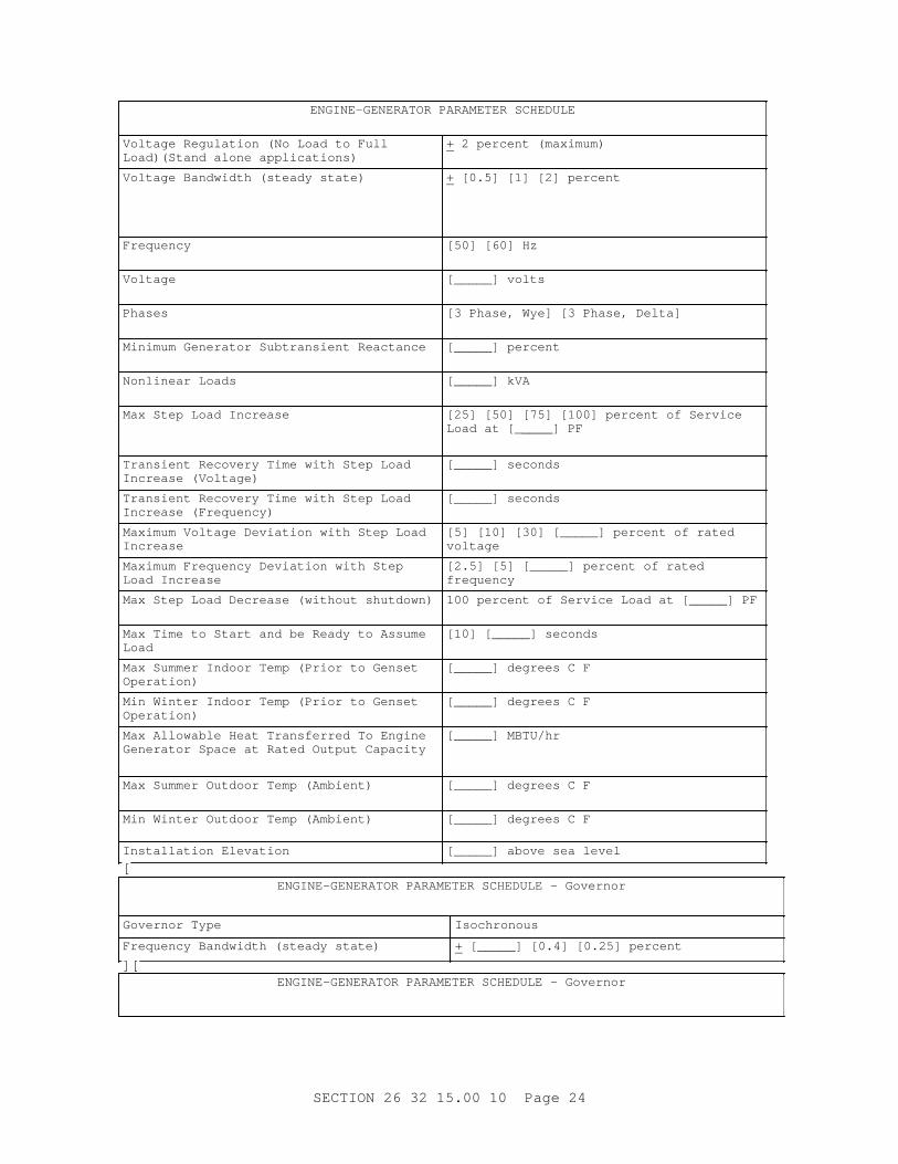
Vol t age Regul at i on ( No Load t o Ful l Load) ( St and al one appl i cat i ons)
+ 2 per cent ( maxi mum)
Vol t age Bandwi dt h ( st eady st at e) + [ 0. 5] [ 1] [ 2] per cent
Frequency [ 50] [ 60] Hz
Voltage [ _____] vol t s
Phases [ 3 Phase, Wye] [ 3 Phase, Del t a]
Mi ni mum Gener at or Subt r ansi ent React ance [ _____] per cent
Nonl i near Loads [ _____] kVA
Max St ep Load I ncr ease [ 25] [ 50] [ 75] [ 100] per cent of Ser vi ce Load at [ _____] PF
Tr ansi ent Recover y Ti me wi t h St ep Load I ncr ease ( Vol t age)
[ _____] seconds
Tr ansi ent Recover y Ti me wi t h St ep Load I ncr ease ( Fr equency)
[ _____] seconds
Maxi mum Vol t age Devi at i on wi t h St ep Load Increase
[ 5] [ 10] [ 30] [ _____] per cent of r at ed voltage
Maxi mum Fr equency Devi at i on wi t h St ep Load I ncr ease
[ 2. 5] [ 5] [ _____] per cent of r at ed frequency
Max St ep Load Decr ease ( wi t hout shut down) 100 per cent of Ser vi ce Load at [ _____] PF
Max Ti me t o St ar t and be Ready t o Assume Load
[ 10] [ _____] seconds
Max Summer I ndoor Temp ( Pr i or t o Genset Operation)
[ _____] degr ees C F
Mi n Wi nt er I ndoor Temp ( Pr i or t o Genset Operation)
[ _____] degr ees C F
Max Al l owabl e Heat Tr ansf er r ed To Engi ne Gener at or Space at Rat ed Out put Capaci t y
[ _____] MBTU/ hr
Max Summer Out door Temp ( Ambi ent ) [ _____] degr ees C F
Mi n Wi nt er Out door Temp ( Ambi ent ) [ _____] degr ees C F
I nst al l at i on El evat i on [ _____] above sea l evel
[ENGI NE- GENERATOR PARAMETER SCHEDULE - Gover nor
Gover nor Type Isochronous
Fr equency Bandwi dt h ( st eady st at e) + [ _____] [ 0. 4] [ 0. 25] per cent
][ENGI NE- GENERATOR PARAMETER SCHEDULE - Gover nor
SECTI ON 26 32 15. 00 10 Page 24
Gover nor Type Droop
Fr equency Regul at i on ( dr oop) ( No Load t o Ful l Load)
[ 3] [ _____] per cent ( maxi mum)
Fr equency Bandwi dt h ( st eady st at e) + [ _____] [ 0. 4] [ 0. 25] per cent
]2. 1. 2 Rat ed Out put Capaci t y
**************************************************************************NOTE: The ser vi ce l oad f or each genset shoul d be shown on t he Engi ne- Gener at or Par amet er Schedul e. The desi gner must det er mi ne t he ser vi ce l oad. The Cont r act or , t hr ough t he suppl i er ' s manuf act ur er / assembl er , det er mi nes t he ef f i c i ency and associ at ed anci l l ar y equi pment l oads. The desi gner must exami ne spar e capaci t y r equi r ement s f or spi nni ng r eser ve.
**************************************************************************
Each engi ne- gener at or - set shal l pr ovi de power equal t o t he sum of Ser vi ce Load pl us t he machi ne' s ef f i c i ency l oss and associ at ed anci l l ar y equi pment l oads. Rat ed out put capaci t y shal l al so consi der engi ne and/ or gener at or over si z i ng r equi r ed t o meet r equi r ement s i n par agr aph Engi ne- Gener at or Par amet er Schedul e.
2. 1. 3 Power Rat i ngs
Power r at i ngs shal l be i n accor dance wi t h EGSA 101P.
2. 1. 4 Tr ansi ent Response
The engi ne- gener at or set gover nor and vol t age r egul at or shal l cause t he engi ne- gener at or set t o r espond t o t he maxi mum st ep l oad changes such t hat out put vol t age and f r equency r ecover t o and st abi l i ze wi t hi n t he oper at i onal bandwi dt h wi t hi n t he t r ansi ent r ecover y t i me. The engi ne- gener at or set shal l r espond t o maxi mum st ep l oad changes such t hat t he maxi mum vol t age and f r equency devi at i ons f r om bandwi dt h ar e not exceeded.
2. 1. 5 Rel i abi l i t y and Dur abi l i t y
**************************************************************************NOTE: Mean t i me bet ween over haul s descr i bes t he aver age number of oper at i ng hour s t hat t he engi ne wi l l oper at e sat i sf act or i l y wi t hout over haul . Over haul i s a nat ur al consequence of t he engi ne i n oper at i on due t o wor n out par t s af t er t he i ndi cat ed oper at i ng hour s.
**************************************************************************
[ Each pr i me engi ne- gener at or set shal l have bot h an engi ne and a gener at or capabl e of del i ver i ng t he speci f i ed power on a pr i me basi s wi t h an ant i c i pat ed mean t i me bet ween over haul s of not l ess t han 10, 000 hour s oper at i ng wi t h a 70 per cent l oad f act or . Two l i ke engi nes and t wo l i ke gener at or s shal l be c i t ed t hat have per f or med sat i sf act or i l y i n a st at i onar y power pl ant , i ndependent f r om t he physi cal l ocat i on of t he manuf act ur er ' s and assembl er ' s f aci l i t i es. The engi ne and gener at or s shoul d have been i n oper at i on f or a mi ni mum of 8000 act ual hour s at a mi ni mum l oad of 70 per cent of t he r at ed out put capaci t y. Dur i ng t wo consecut i ve year s of ser vi ce, t he uni t s shoul d not have exper i enced any
SECTI ON 26 32 15. 00 10 Page 25
f ai l ur e r esul t i ng i n a downt i me i n excess of 72 hour s. Li ke engi nes shal l be of t he same model , speed, bor e, st r oke, number and conf i gur at i on of cyl i nder s and r at ed out put capaci t y. Li ke gener at or s shal l be of t he same model , speed, pi t ch, cool i ng, exci t er , vol t age r egul at or and r at ed out put capaci t y. ] [ Each st andby engi ne- gener at or set shal l have bot h an engi ne and a gener at or capabl e of del i ver i ng t he speci f i ed power on a st andby basi s wi t h an ant i c i pat ed mean t i me bet ween over haul s of no l ess t han 5, 000 hour s oper at i ng wi t h a l oad f act or of 70 per cent . Two l i ke engi nes and t wo l i ke gener at or s shal l be c i t ed t hat have per f or med sat i sf act or i l y i n a st at i onar y power pl ant , i ndependent and separ at e f r om t he physi cal l ocat i on of t he manuf act ur er ' s and assembl er ' s f aci l i t i es, f or st andby wi t hout any f ai l ur e t o st ar t , i ncl udi ng al l per i odi c exer ci se. Each l i ke engi ne and gener at or shal l have had no f ai l ur es r esul t i ng i n downt i me f or r epai r s i n excess of 72 hour s dur i ng t wo consecut i ve year s of ser vi ce. Li ke engi nes shal l be of t he same model , speed, bor e, st r oke, number and conf i gur at i on of cyl i nder s, and r at ed out put capaci t y. Li ke gener at or s shal l be of t he same model , speed, pi t ch, cool i ng, exci t er , vol t age r egul at or and r at ed out put capaci t y. ]
Submi t a r el i abi l i t y and dur abi l i t y cer t i f i cat i on l et t er f r om t he manuf act ur er and assembl er t o pr ove t hat exi st i ng f aci l i t i es ar e and have been successf ul l y ut i l i z i ng t he same component s pr oposed t o meet t hi s speci f i cat i on, i n s i mi l ar ser vi ce. Cer t i f i cat i on may be based on component s, i . e. engi nes used wi t h di f f er ent model s of gener at or s and gener at or s used wi t h di f f er ent engi nes, and does not excl ude annual t echnol ogi cal i mpr ovement s made by a manuf act ur er i n t he basi c st andar d- model component on whi ch exper i ence was obt ai ned, pr ovi ded par t s i nt er changeabi l i t y has not been subst ant i al l y af f ect ed and t he cur r ent st andar d model meet s t he per f or mance r equi r ement s speci f i ed. Pr ovi de a l i s t wi t h t he name of t he i nst al l at i ons, compl et i on dat es, and name and t el ephone number of a poi nt of cont act .
2. 1. 6 Par al l el Oper at i on
**************************************************************************NOTE: Speci f i cat i on of an engi ne- gener at or set capabl e of par al l el oper at i on wi t h a ut i l i t y r equi r es a 2/ 3 pi t ch gener at or wi ndi ng and speci al coor di nat i on of pr ot ect i ve devi ces wi t h t he ut i l i t y syst em pr ot ect i on scheme. Do not speci f y t hi s opt i on wi t hout al so pr ovi di ng a desi gn f or t he pr ot ect i ve devi ce coor di nat i on whi ch has been appr oved by t he ut i l i t y i nvol ved.
**************************************************************************
Each engi ne- gener at or set speci f i ed f or par al l el oper at i on shal l be conf i gur ed f or [ aut omat i c] [ manual ] par al l el oper at i on. Each set shal l be capabl e of par al l el oper at i on wi t h [ a commer ci al power sour ce on an i nf i ni t e bus] [ one or mor e set s on an i sol at ed bus] [ a commer ci al power sour ce on an i nf i ni t e bus and wi t h one or mor e set s on an i sol at ed bus] .
2. 1. 7 Load Shar i ng
**************************************************************************NOTE: Coor di nat e wi t h par agr aph Engi ne Gener at or par amet er Schedul e.
**************************************************************************
Each engi ne- gener at or set speci f i ed f or par al l el oper at i on shal l be
SECTI ON 26 32 15. 00 10 Page 26
conf i gur ed t o [ manual l y l oad shar e wi t h ot her set s. ] [ aut omat i cal l y l oad shar e wi t h ot her set s by pr opor t i onal l oadi ng. Pr opor t i onal l oadi ng shal l l oad each set t o wi t hi n 5 per cent of i t s f ai r shar e. A set ' s f ai r shar e i s i t s namepl at e- r at ed capaci t y t i mes t he t ot al l oad, di v i ded by t he sum of al l namepl at e- r at ed capaci t i es of on- l i ne set s. Load shar i ng shal l i ncor por at e bot h t he r eal and r eact i ve component s of t he l oad. ]
2. 1. 8 Engi ne- Gener at or Set Encl osur e
**************************************************************************NOTE: I f t he engi ne- gener at or set i s t o be i nst al l ed out door s i ncl ude r equi r ement s f or t he weat her pr oof encl osur e i n t he engi ne- gener at or set schedul e. Def i ne cor r osi on r esi st ance and/ or mat er i al r equi r ed f or t he envi r onment . Pr ovi de st r uct ur al l oadi ng r equi r ed f or t he geogr aphi c ar ea ( wi nd l oads, snow l oads, et c. ) . A gener at or set encl osur e may al so be needed t o mi t i gat e excessi ve noi se caused by t he engi ne gener at or set mechani cal component s. Del et e t he r ef er ence t o mechani cal noi se l i mi t at i ons i f an encl osur e i s not needed t o mi t i gat e sound emi ssi ons. I f a sound encl osur e i s not pr ovi ded, t he desi gner must pr ovi de a desi gn t o pr event excessi ve noi se ( meet OSHA r equi r ement s) . Del et e t hi s par agr aph i f no engi ne- gener at or set encl osur e i s needed.
**************************************************************************
The engi ne- gener at or set encl osur e shal l be cor r osi on r esi st ant and f ul l y weat her r esi st ant . The encl osur e shal l cont ai n al l set component s and pr ovi de vent i l at i on t o per mi t oper at i on at Ser vi ce Load under secur ed condi t i ons. Door s shal l be pr ovi ded f or access t o cont r ol s and equi pment r equi r i ng per i odi c mai nt enance or adj ust ment . Removabl e panel s shal l be pr ovi ded f or access t o component s r equi r i ng per i odi c r epl acement . The encl osur e shal l be capabl e of bei ng r emoved wi t hout di sassembl y of t he engi ne- gener at or set or r emoval of component s ot her t han t he exhaust syst em. The encl osur e shal l r educe t he noi se of t he gener at or set t o wi t hi n t he l i mi t s speci f i ed i n t he par agr aph SOUND LI MI TATI ONS.
2. 1. 9 Vi br at i on I sol at i on
**************************************************************************NOTE: See UFC 3- 450- 02, Power Pl ant Acoust i cs, and UFC 3- 450- 01, Noi se and Vi br at i on Cont r ol For Mechani cal Equi pment f or v i br at i on cr i t er i a. Vi br at i on i sol at i on syst ems shoul d be appl i ed wher e v i br at i on t r ansmi t t ed t hr ough t he genset suppor t st r uct ur e pr oduces ( ei t her di r ect l y or by r esonant f r equenci es of s t r uct ur al member s) annoyi ng or damagi ng v i br at i on i n t he sur r oundi ng envi r onment . Sel ect t he manuf act ur er ' s st andar d or pr ovi de t he maxi mum al l owabl e v i br at i on f or ce wher e necessar y t o l i mi t t he maxi mum vi br at i on. Del et e t he v i br at i on i sol at i on r equi r ement f or appl i cat i ons wher e v i br at i on does not af f ect t he f l oor or f oundat i on.
**************************************************************************
[ A v i br at i on- i sol at i on syst em shal l be i nst al l ed bet ween t he f l oor and t he base. The vi br at i on- i sol at i on syst em shal l l i mi t t he maxi mum vi br at i on
SECTI ON 26 32 15. 00 10 Page 27
t r ansmi t t ed t o t he f l oor at al l f r equenci es t o a maxi mum of [ _____] ( peak f or ce) . ] [ The engi ne- gener at or set shal l be pr ovi ded wi t h a v i br at i on- i sol at i on syst em i n accor dance wi t h t he manuf act ur er ' s st andar d r ecommendat i on. ] Submi t v i br at i on i sol at i on syst em per f or mance dat a f or t he r ange of f r equenci es gener at ed by t he engi ne- gener at or set dur i ng oper at i on f r om no l oad t o f ul l l oad and t he maxi mum vi br at i on t r ansmi t t ed t o t he f l oor pl us descr i pt i on of sei smi c qual i f i cat i on of t he engi ne- gener at or mount i ng, base, and vi br at i on i sol at i on. Submi t t or s i onal anal ysi s i ncl udi ng pr ot ot ype t est i ng or and cal cul at i ons whi ch cer t i f y and demonst r at e t hat no damagi ng or danger ous t or s i onal v i br at i ons wi l l occur when t he pr i me mover i s connect ed t o t he gener at or , at synchr onous speeds, + 10 per cent . Vi br at i on- i sol at i on syst ems shal l be desi gned and qual i f i ed ( as an i nt egr al par t of t he base and mount i ng syst em i n accor dance wi t h t he sei smi c par amet er s speci f i ed. Wher e t he v i br at i on- i sol at i on syst em does not secur e t he base t o t he st r uct ur e f l oor or uni t f oundat i on, sei smi c r est r ai nt s shal l be pr ovi ded i n accor dance wi t h t he sei smi c par amet er s specified.
2. 1. 10 Fuel Consumpt i on
**************************************************************************NOTE: Del et e t hi s par agr aph f or st andby appl i cat i ons. For pr i me appl i cat i ons t he desi gner shoul d di scuss t hi s r equi r ement wi t h t he i nst al l at i on t o det er mi ne i f i t i s r equi r ed.
**************************************************************************
Engi ne f uel consumpt i on shal l not exceed t he f ol l owi ng maxi mum l i mi t s based on t he condi t i ons l i s t ed bel ow.
Si ze Range Net kW Per cent of Rat ed Out put Capacity
Fuel Usage kg/ kWH l bs/ kWH
100 - 299 75 and 100 0.2720.600
50 0.2920.643
300 - 999 75 and 100 0.2610.575
50 0.2720.600
1000 - 2500 75 and 100 0.2430.536
50 0.2600.573
Conditions:
a. Net kW of t he Set cor r ect ed f or engi ne auxi l i ar i es t hat ar e el ect r i cal l y dr i ven, wher e kW i s el ect r i cal k i l owat t hour s.
b. 45 MJ/ kg ( 19, 350 Bt u/ pound) 19, 350 Bt u/ pound hi gh- heat val ue f or f uel used.
c. Sea l evel oper at i on.
d. I nt ake- ai r t emper at ur e not over 32 degr ees C 90 degr ees F.
e. Bar omet r i c pr essur e of i nt ake ai r not l ess t han 95. 7 kPa 28- 1/ 4 i nches of mer cur y.
SECTI ON 26 32 15. 00 10 Page 28
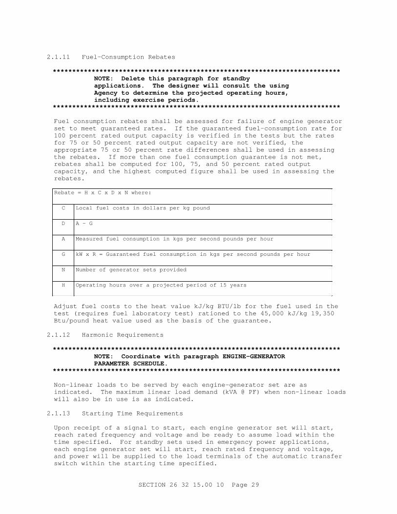
2. 1. 11 Fuel - Consumpt i on Rebat es
**************************************************************************NOTE: Del et e t hi s par agr aph f or st andby appl i cat i ons. The desi gner wi l l consul t t he usi ng Agency t o det er mi ne t he pr oj ect ed oper at i ng hour s, i ncl udi ng exer ci se per i ods.
**************************************************************************
Fuel consumpt i on r ebat es shal l be assessed f or f ai l ur e of engi ne gener at or set t o meet guar ant eed r at es. I f t he guar ant eed f uel - consumpt i on r at e f or 100 per cent r at ed out put capaci t y i s ver i f i ed i n t he t est s but t he r at es f or 75 or 50 per cent r at ed out put capaci t y ar e not ver i f i ed, t he appr opr i at e 75 or 50 per cent r at e di f f er ences shal l be used i n assessi ng t he r ebat es. I f mor e t han one f uel consumpt i on guar ant ee i s not met , r ebat es shal l be comput ed f or 100, 75, and 50 per cent r at ed out put capaci t y, and t he hi ghest comput ed f i gur e shal l be used i n assessi ng t he rebates.
Rebat e = H x C x D x N wher e:
C Local f uel cost s i n dol l ar s per kg pound
D A - G
A Measur ed f uel consumpt i on i n kgs per second pounds per hour
G kW x R = Guar ant eed f uel consumpt i on i n kgs per second pounds per hour
N Number of gener at or set s pr ovi ded
H Oper at i ng hour s over a pr oj ect ed per i od of 15 year s
Adj ust f uel cost s t o t he heat val ue kJ/ kg BTU/ l b f or t he f uel used i n t he t est ( r equi r es f uel l abor at or y t est ) r at i oned t o t he 45, 000 kJ/ kg 19, 350 Bt u/ pound heat val ue used as t he basi s of t he guar ant ee.
2. 1. 12 Har moni c Requi r ement s
**************************************************************************NOTE: Coor di nat e wi t h par agr aph ENGI NE- GENERATOR PARAMETER SCHEDULE.
**************************************************************************
Non- l i near l oads t o be ser ved by each engi ne- gener at or set ar e as i ndi cat ed. The maxi mum l i near l oad demand ( kVA @ PF) when non- l i near l oads wi l l al so be i n use i s as i ndi cat ed.
2. 1. 13 St ar t i ng Ti me Requi r ement s
Upon r ecei pt of a s i gnal t o st ar t , each engi ne gener at or set wi l l s t ar t , r each r at ed f r equency and vol t age and be r eady t o assume l oad wi t hi n t he t i me speci f i ed. For st andby set s used i n emer gency power appl i cat i ons, each engi ne gener at or set wi l l s t ar t , r each r at ed f r equency and vol t age, and power wi l l be suppl i ed t o t he l oad t er mi nal s of t he aut omat i c t r ansf er swi t ch wi t hi n t he st ar t i ng t i me speci f i ed.
SECTI ON 26 32 15. 00 10 Page 29
2. 2 NAMEPLATES
**************************************************************************NOTE: Del et e any equi pment not appl i cabl e t o t he project.
**************************************************************************
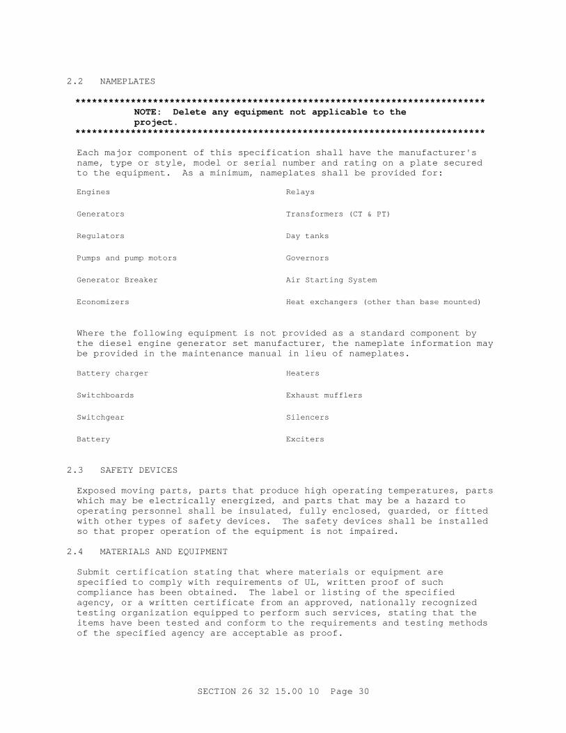
Each maj or component of t hi s speci f i cat i on shal l have t he manuf act ur er ' s name, t ype or st y l e, model or ser i al number and r at i ng on a pl at e secur ed t o t he equi pment . As a mi ni mum, namepl at es shal l be pr ovi ded f or :
Engines Relays
Generators Tr ansf or mer s ( CT & PT)
Regulators Day t anks
Pumps and pump mot or s Governors
Gener at or Br eaker Ai r St ar t i ng Syst em
Economizers Heat exchanger s ( ot her t han base mount ed)
Wher e t he f ol l owi ng equi pment i s not pr ovi ded as a st andar d component by t he di esel engi ne gener at or set manuf act ur er , t he namepl at e i nf or mat i on may be pr ovi ded i n t he mai nt enance manual i n l i eu of namepl at es.
Bat t er y char ger Heaters
Switchboards Exhaust muf f l er s
Switchgear Silencers
Battery Exciters
2. 3 SAFETY DEVI CES
Exposed movi ng par t s, par t s t hat pr oduce hi gh oper at i ng t emper at ur es, par t s whi ch may be el ect r i cal l y ener gi zed, and par t s t hat may be a hazar d t o oper at i ng per sonnel shal l be i nsul at ed, f ul l y encl osed, guar ded, or f i t t ed wi t h ot her t ypes of saf et y devi ces. The saf et y devi ces shal l be i nst al l ed so t hat pr oper oper at i on of t he equi pment i s not i mpai r ed.
2. 4 MATERI ALS AND EQUI PMENT
Submi t cer t i f i cat i on st at i ng t hat wher e mat er i al s or equi pment ar e speci f i ed t o compl y wi t h r equi r ement s of UL, wr i t t en pr oof of such compl i ance has been obt ai ned. The l abel or l i s t i ng of t he speci f i ed agency, or a wr i t t en cer t i f i cat e f r om an appr oved, nat i onal l y r ecogni zed t est i ng or gani zat i on equi pped t o per f or m such ser v i ces, st at i ng t hat t he i t ems have been t est ed and conf or m t o t he r equi r ement s and t est i ng met hods of t he speci f i ed agency ar e accept abl e as pr oof .
SECTI ON 26 32 15. 00 10 Page 30
2. 4. 1 Fi l t er El ement s
Fuel - oi l , l ubr i cat i ng- oi l , and combust i on- ai r f i l t er el ement s shal l be manuf act ur er ' s st andar d.
2. 4. 2 I nst r ument Tr ansf or mer s
NEMA/ ANSI C12. 11.
2. 4. 3 Revenue Met er i ng
I EEE C57. 13.
2. 4. 4 Pi pe ( Fuel / Lube- Oi l , Compr essed Ai r , Cool ant , and Exhaust )
ASTM A53/ A53M, or ASTM A106/ A106M st eel pi pe. Pi pe smal l er t han 50 mm 2 i nches shal l be Schedul e 80. Pi pe 50 mm 2 i nches and l ar ger shal l be Schedul e 40.
2. 4. 4. 1 Fl anges and Fl anged Fi t t i ngs
ASTM A181/ A181M, Cl ass 60, or ASME B16. 5, Gr ade 1, Cl ass 150.
2. 4. 4. 2 Pi pe Wel di ng Fi t t i ngs
ASTM A234/ A234M, Gr ade WPB or WPC, Cl ass 150 or ASME B16. 11, 1360. 7 kg 3000 lb.
2. 4. 4. 3 Thr eaded Fi t t i ngs
ASME B16. 3, Cl ass 150.
2. 4. 4. 4 Valves
MSS SP- 80, Cl ass 150.
2. 4. 4. 5 Gaskets
Manuf act ur er ' s st andar d.
2. 4. 5 Pi pe Hanger s
MSS SP- 58.
2. 4. 6 El ect r i cal Encl osur es
NEMA I CS 6.
2. 4. 6. 1 Power Swi t chgear Assembl i es
NEMA SG 6.
2. 4. 6. 2 Switchboards
NEMA PB 2.
2. 4. 6. 3 Panelboards
NEMA PB 1.
SECTI ON 26 32 15. 00 10 Page 31
2. 4. 7 El ect r i c Mot or s
El ect r i c mot or s shal l conf or m t o t he r equi r ement s of NEMA MG 1. Mot or s shal l have seal ed bal l bear i ngs and a maxi mum speed of 1800 r pm. Mot or s used i ndoor s shal l have dr i p- pr oof f r ames; t hose used out s i de shal l be t ot al l y encl osed. Al t er nat i ng cur r ent mot or s l ar ger t han 373 W 1/ 2 Hp shal l be of t he squi r r el - cage i nduct i on t ype f or oper at i on on 208 vol t s or hi gher , [ 50] [ 60] Hz, and t hr ee- phase power . Al t er nat i ng cur r ent mot or s 373 W 1/ 2 Hp or smal l er , shal l be sui t abl e f or oper at i on on 120 vol t s, [ 50] [ 60] Hz, and si ngl e- phase power . Di r ect cur r ent mot or s shal l be sui t abl e f or oper at i on on [ 125] [ _____] vol t s.
2. 4. 8 Mot or Cont r ol l er s
Mot or cont r ol l er s and st ar t er s shal l conf or m t o t he r equi r ement s of NFPA 70 and NEMA I CS 2.
2. 5 ENGINE
**************************************************************************NOTE: Speci f y f uel t ype i f di f f er ent t han No. 2 diesel.
I f uni t s ar e r equi r ed t o oper at e on mor e t han one f uel t he desi gner must edi t t he component s, per f or mance r equi r ement s, and t est i ng r equi r ement s of t hi s speci f i cat i on t o def i ne t he r equi r ement s f or t he f uel s speci f i ed. I f f ul l per f or mance i s r equi r ed f or t he weakest or poor est bur ni ng f uel s, t hen t he uni t s wi l l be over r at ed f or ot her f uel s.
**************************************************************************
Each engi ne shal l oper at e on No. 2- D di esel f uel conf or mi ng t o ASTM D975, shal l be desi gned f or st at i onar y appl i cat i ons and shal l be compl et e wi t h anci l l ar i es. The engi ne shal l be a st andar d pr oduct i on model shown i n t he manuf act ur er ' s cat al og descr i bi ng and depi ct i ng each engi ne- gener at or set and al l anci l l ar y equi pment i n suf f i c i ent det ai l t o demonst r at e compl et e speci f i cat i on compl i ance. The engi ne shal l be nat ur al l y aspi r at ed, super char ged, or t ur bochar ged. The engi ne shal l be 2- or 4- st r oke- cycl e and compr essi on- i gni t i on t ype. The engi ne shal l be ver t i cal i n- l i ne, V- or opposed- pi st on t ype, wi t h a sol i d cast bl ock or i ndi v i dual l y cast cyl i nder s. The engi ne shal l have a mi ni mum of t wo cyl i nder s. Opposed- pi st on t ype engi nes shal l have not l ess t han f our cyl i nder s. Each bl ock shal l have a cool ant dr ai n por t . Each engi ne shal l be equi pped wi t h an over speed sensor .
2. 6 FUEL SYSTEM
The ent i r e f uel syst em f or each engi ne- gener at or set shal l conf or m t o t he r equi r ement s of NFPA 30 and NFPA 37 and cont ai n t he f ol l owi ng el ement s.
2. 6. 1 Pumps
2. 6. 1. 1 Mai n Pump
Each engi ne shal l be pr ovi ded wi t h an engi ne dr i ven pump. The pump shal l suppl y f uel at a mi ni mum r at e suf f i c i ent t o pr ovi de t he amount of f uel r equi r ed t o meet t he per f or mance i ndi cat ed wi t hi n t he par amet er schedul e.
SECTI ON 26 32 15. 00 10 Page 32
The f uel f l ow r at e shal l be based on meet i ng t he l oad r equi r ement s and al l necessar y r eci r cul at i on.
2. 6. 1. 2 Auxi l i ar y Fuel Pump
**************************************************************************NOTE: The auxi l i ar y f uel pump i s r equi r ed t o suppor t t he mai n pump i f t he l engt h of pi pe f r om t he day t ank t o t he mai n pump i s gr eat er t han t he val ue r ecommended by t he engi ne manuf act ur er . Thi s val ue may be appr oxi mat el y 12 m 40 f eet ; however , engi ne manuf act ur er s shoul d be consul t ed dur i ng desi gn t o ver i f y t he pumpi ng r equi r ement s.
**************************************************************************
Pr ovi de auxi l i ar y f uel pumps t o mai nt ai n t he r equi r ed engi ne f uel pr essur e, i f ei t her r equi r ed by t he i nst al l at i on or i ndi cat ed on t he dr awi ngs. The auxi l i ar y pump shal l be dr i ven by a dc el ect r i c mot or power ed by t he st ar t i ng/ st at i on bat t er i es. The auxi l i ar y pump shal l be aut omat i cal l y act uat ed by a pr essur e- det ect i ng devi ce.
2. 6. 2 Fuel Fi l t er
Pr ovi de a mi ni mum of one f ul l - f l ow f uel f i l t er f or each engi ne. The f i l t er shal l be r eadi l y accessi bl e and capabl e of bei ng changed wi t hout di sconnect i ng t he pi pi ng or di st ur bi ng ot her component s. The f i l t er shal l have i nl et and out l et connect i ons pl ai nl y mar ked.
2. 6. 3 Rel i ef / Bypass Val ve
Pr ovi de a r el i ef / bypass val ve t o r egul at e pr essur e i n t he f uel suppl y l i ne, r et ur n excess f uel t o a r et ur n l i ne and pr event t he bui l d- up of excessi ve pr essur e i n t he f uel syst em.
2. 6. 4 I nt egr al Mai n Fuel St or age Tank
**************************************************************************NOTE: Del et e t hi s par agr aph i f an i nt egr al mai n f uel st or age t ank i s not desi r ed.
An i nt egr al mai n f uel st or age t ank wi l l be t he onl y f uel sour ce f or t he engi ne. These t anks may be usef ul f or appl i cat i ons t hat r equi r e a mi ni mal f uel st or age capaci t y .
Due t o t he mi ni mal st or age capaci t y, i nt egr al mai n f uel st or age t anks ar e not pr act i cal f or pr i me power usage. They ar e al so not pr act i cal f or st andby uni t s t hat r equi r e l ar ge f uel quant i t i es. The desi gner shoul d consi der t he avai l abi l i t y and ant i c i pat ed f r equency of f uel t r uck del i ver i es when deci di ng whet her or not t o use an i nt egr al mai n f uel st or age t ank. These t anks shoul d al so not be used i n l ocat i ons wher e a t r uck f uel i ng hose can not r each t he di esel gener at or set .
See NFPA 99 and NFPA 110 f or gui dance on f uel t ank sizes.
SECTI ON 26 32 15. 00 10 Page 33
See NFPA 37 r est r i c t i ons on al l owabl e t ank s i zes and encl osur es. I nt egr al t anks al l ow f or 1 t o 8 hour s of oper at i on dependi ng on di esel gener at or s i ze and conf i gur at i on. Consul t gener at or set manuf act ur er f or t he pr oper hour s of oper at i on f or t he appl i cat i on of i nt egr al t anks. St andby appl i cat i ons f or use wi t h f i r e pumps wi l l have t anks s i zed f or 8 hour s dur at i on. The t ank can be s i zed by t he desi gner or t he Cont r act or . The si ze of t he t ank shoul d be based on a f uel f l ow r at e t hat i s equal t o t he val ue of a t ypi cal engi ne manuf act ur er f or t he i ndi cat ed engi ne gener at or s i ze. A val ue of 200 per cent of t he expect ed f uel consumpt i on of t he engi ne i s not unusual f or t he f l ow r at e of t he mai n f uel pump. Si nce t he excess f uel wi l l be r et ur ned t o t he t ank, t he desi gner shoul d consi der t he i mpact of heat bui l dup when si z i ng t he t ank. I f a f uel oi l cool er i s not used, t he day t ank s i ze may need t o be i ncr eased t o pr oper l y di ssi pat e t he heat absor bed by t he f uel .
**************************************************************************
Pr ovi de each engi ne wi t h an i nt egr al mai n f uel t ank. Each t ank shal l be f act or y i nst al l ed and pr ovi ded as an i nt egr al par t of t he di esel gener at or manuf act ur er ' s pr oduct . Each t ank shal l be pr ovi ded wi t h connect i ons f or f uel suppl y l i ne, f uel r et ur n l i ne, l ocal f uel f i l l por t , gauge, vent l i ne, and f l oat swi t ch assembl y. A f uel r et ur n l i ne cool er shal l be pr ovi ded as r ecommended by t he manuf act ur er and assembl er . The t emper at ur e of t he f uel r et ur ni ng t o t he t ank shal l be bel ow t he f l ash poi nt of t he f uel . Each engi ne- gener at or set pr ovi ded wi t h weat her pr oof encl osur es shal l have i t s t ank mount ed wi t hi n t he encl osur e. The f uel f i l l l i ne shal l be accessi bl e wi t hout openi ng t he encl osur e.
2. 6. 4. 1 Capacity
Each t ank shal l have capaci t y [ as shown] [ t o suppl y f uel t o t he engi ne f or an uni nt er r upt ed [ 4- hour ] [ _____] per i od] at 100 per cent r at ed l oad wi t hout bei ng r ef i l l ed.
2. 6. 4. 2 Local Fuel Fi l l
Each l ocal f uel f i l l por t on t he day t ank shal l be pr ovi ded wi t h a scr ew- on cap.
2. 6. 4. 3 Fuel Level Cont r ol s
Each t ank shal l have a f l oat - swi t ch assembl y t o per f or m t he f ol l owi ng functions:
a. Act i vat e t he " Low Fuel Level " al ar m at 70 per cent of t he r at ed t ank capacity.
b. Act i vat e t he " Over f i l l Fuel Level " al ar m at 95 per cent of t he r at ed t ank capaci t y.
2. 6. 4. 4 Arrangement
I nt egr al t anks may al l ow gr avi t y f l ow i nt o t he engi ne. Gr avi t y f l ow t anks and any t ank t hat al l ows a f uel l evel above t he f uel i nj ect or s shal l be
SECTI ON 26 32 15. 00 10 Page 34
pr ovi ded wi t h an i nt er nal or ext er nal f act or y i nst al l ed val ve l ocat ed as near as possi bl e t o t he shel l of t he t ank. The val ve shal l c l ose when t he engi ne i s not oper at i ng. I nt egr al day t anks shal l be pr ovi ded wi t h any necessar y pumps t o suppl y f uel t o t he engi ne as r ecommended by t he gener at or set manuf act ur er . The f uel suppl y l i ne f r om t he t ank t o t he manuf act ur er ' s st andar d engi ne connect i on shal l be wel ded pi pe.
2. 6. 5 Day Tank
**************************************************************************NOTE: Del et e t hi s par agr aph i f an i nt egr al mai n f uel st or age t ank i s used.
See NFPA 99 and NFPA 110 f or gui dance on f uel t ank sizes.
See NFPA 37 r est r i c t i ons on al l owabl e day t ank s i zes and encl osur es. Sel ect ei t her sel f - suppor t i ng or i nt egr al day t ank. Sel ect t he f i r st opt i on bel ow f or appl i cat i ons wher e f uel i s r et ur ned t o t he day t ank. Sel ect t he second opt i on bel ow f or appl i cat i ons wher e f uel i s r et ur ned t o t he mai n t ank. I nt egr al day t anks al l ow f or 1 t o 8 hour s of oper at i on. Consul t gener at or set manuf act ur er f or t he pr oper hour s of oper at i on f or t he appl i cat i on of i nt egr al day t anks. St andby appl i cat i ons f or use wi t h f i r e pumps wi l l have day t anks s i zed f or 8 hour s dur at i on. Sel ect day t ank capaci t y f or ei t her pr i me or st andby appl i cat i on. The day t ank can be s i zed by t he desi gner or t he Cont r act or . The si ze of t he day t ank shoul d be based on a f uel f l ow r at e t hat i s equal t o t he val ue of a t ypi cal engi ne manuf act ur er f or t he i ndi cat ed engi ne gener at or s i ze. A val ue of 200 per cent of t he expect ed f uel consumpt i on of t he engi ne i s not unusual f or t he f l ow r at e of t he mai n f uel pump. The excess f uel may be r et ur ned t o t he day t ank or mai n f uel t ank. The desi gner shoul d al so consi der t he i mpact of heat bui l dup when si z i ng t he day t ank. I f a f uel oi l cool er i s not used or i f f uel i s r et ur ned t o t he day t ank, t he day t ank s i ze may need t o be i ncr eased t o pr oper l y di ssi pat e t he heat absor bed by t he f uel .
**************************************************************************
Each engi ne shal l be pr ovi ded wi t h [ a separ at e sel f - suppor t i ng] [ i nt egr al ] day t ank. Submi t cal cul at i ons f or t he capaci t y of each day t ank, i ncl udi ng al l owances f or r eci r cul at ed f uel , usabl e t ank capaci t y, and dur at i on of f uel suppl y. Each day t ank shal l be pr ovi ded wi t h connect i ons f or f uel suppl y l i ne, [ f uel r et ur n l i ne, f uel over f l ow l i ne, l ocal f uel f i l l por t , gauge, vent l i ne, dr ai n l i ne, and f l oat swi t ch assembl y f or cont r ol . A f uel r et ur n l i ne cool er shal l be pr ovi ded as r ecommended by t he manuf act ur er and assembl er . The t emper at ur e of t he f uel r et ur ni ng t o t he day t ank shal l be bel ow t he f l ash poi nt of t he f uel . A t emper at ur e sensi ng devi ce shal l be i nst al l ed i n t he f uel suppl y l i ne] , [ f uel over f l ow l i ne, l ocal f uel f i l l por t , gauge, vent l i ne, dr ai n l i ne, and f l oat swi t ch assembl y f or cont r ol ] . Each engi ne- gener at or set pr ovi ded wi t h weat her pr oof encl osur es shal l have i t s day t ank mount ed wi t hi n t he encl osur e. The f uel f i l l l i ne shal l be accessi bl e wi t hout openi ng t he enclosure.
SECTI ON 26 32 15. 00 10 Page 35
2. 6. 5. 1 Capaci t y, Pr i me
Each day t ank shal l have capaci t y [ as shown] [ t o suppl y f uel t o t he engi ne f or an uni nt er r upt ed [ 8- hour ] [ _____] per i od at 100 per cent r at ed l oad wi t hout bei ng r ef i l l ed, pl us any f uel whi ch may be r et ur ned t o t he mai n f uel st or age t ank. The cal cul at i on of t he capaci t y of each day t ank shal l i ncor por at e t he r equi r ement t o st op t he suppl y of f uel i nt o t he day t ank at a " Hi gh" l evel mar k of 90 per cent of t he ul t i mat e vol ume of t he t ank] .
2. 6. 5. 2 Capaci t y, St andby
Each day t ank shal l have capaci t y [ as shown] [ t o suppl y f uel t o t he engi ne f or an uni nt er r upt ed [ 4- hour ] [ _____] per i od at 100 per cent r at ed l oad wi t hout bei ng r ef i l l ed, pl us any f uel whi ch may be r et ur ned t o t he mai n f uel st or age t ank. The cal cul at i on of t he capaci t y of each day t ank shal l i ncor por at e t he r equi r ement t o st op t he suppl y of f uel i nt o t he day t ank at 90 per cent of t he ul t i mat e vol ume of t he t ank] .
2. 6. 5. 3 Dr ai n Li ne
Each day t ank dr ai n l i ne shal l be accessi bl e and equi pped wi t h a shut of f val ve. Sel f - suppor t i ng day t anks shal l be ar r anged t o al l ow dr ai nage i nt o a 305 mm 12 i nch t al l bucket .
2. 6. 5. 4 Local Fuel Fi l l
Each l ocal f uel f i l l por t on t he day t ank shal l be pr ovi ded wi t h a scr ew- on cap.
2. 6. 5. 5 Fuel Level Cont r ol s
Each day t ank shal l have a f l oat - swi t ch assembl y t o per f or m t he f ol l owi ng functions:
a. [ When t he mai n st or age t ank i s l ocat ed hi gher t han t he day t ank, open t he sol enoi d val ve l ocat ed on t he f uel suppl y l i ne ent er i ng t he day t ank and st ar t t he suppl y of f uel i nt o t he day t ank] [ St ar t t he suppl y of f uel i nt o t he day t ank] when t he f uel l evel i s at t he " Low" l evel mar k, 75 per cent of t he r at ed t ank capaci t y.
b. [ When t he mai n st or age t ank i s l ocat ed hi gher t han t he day t ank, st op t he suppl y of f uel i nt o t he day t ank and cl ose t he sol enoi d val ve l ocat ed on t he f uel suppl y l i ne ent er i ng t he day t ank] [ St op t he suppl y of f uel i nt o t he day t ank] when t he f uel l evel i s at 90 per cent of t he r at ed t ank capaci t y.
c. Act i vat e t he " Over f i l l Fuel Level " al ar m at 95 per cent of t he r at ed t ank capaci t y.
d. Act i vat e t he " Low Fuel Level " al ar m at 70 per cent of t he r at ed t ank capacity.
e. Act i vat e t he aut omat i c f uel suppl y shut - of f val ve l ocat ed on t he f i l l l i ne of t he day t ank and shut down t he f uel pump whi ch suppl i es f uel t o t he day t ank at 95 per cent of t he r at ed t ank capaci t y. The f l ow of f uel shal l be st opped bef or e any f uel can be f or ced i nt o t he f uel over f l ow l i ne.
SECTI ON 26 32 15. 00 10 Page 36
2. 6. 5. 6 Arrangement
**************************************************************************NOTE: Sel ect bet ween i nt egr al and sel f suppor t i ng day t anks. Al so, sel ect bet ween appl i cat i ons wher e t he mai n f uel st or age t ank i s l ocat ed above t he day t ank and appl i cat i ons wher e t he mai n f uel st or age t ank i s l ocat ed bel ow t he day t ank. The l ocat i on of al l t anks, pi pi ng, and val ves shoul d al so be i ndi cat ed on t he dr awi ngs.
**************************************************************************
[ I nt egr al day t anks may al l ow gr avi t y f l ow i nt o t he engi ne. Gr avi t y f l ow t anks shal l be pr ovi ded wi t h an i nt er nal or ext er nal val ve l ocat ed as near as possi bl e t o t he shel l of t he t ank. The val ve shal l c l ose when t he engi ne i s not oper at i ng. I nt egr al day t anks shal l be pr ovi ded wi t h any necessar y pumps t o suppl y f uel t o t he engi ne as r ecommended by t he gener at or set manuf act ur er . The over f l ow connect i on and t he f uel suppl y l i ne f or i nt egr al day t anks whi ch do not r el y upon gr avi t y f l ow shal l be ar r anged so t hat t he hi ghest possi bl e f uel l evel i s bel ow t he f uel i nj ect or s. ] [ Sel f - suppor t i ng day t anks shal l ei t her be ar r anged so t hat t he f uel l evel i n t he day t ank r emai ns above t he suct i on por t of t he engi ne dr i ven f uel pump or be pr ovi ded wi t h a t r ansf er pump t o pr ovi de f uel t o t he engi ne dr i ven pump. The over f l ow connect i on and f uel suppl y l i ne shal l be ar r anged so t hat t he hi ghest possi bl e f uel l evel i s bel ow t he f uel i nj ect or s. ] [ When t he mai n f uel st or age t anks ar e l ocat ed bel ow t he day t ank, a check val ve shal l be pr ovi ded i n t he f uel suppl y l i ne ent er i ng t he day t ank. ] [ When t he mai n f uel s t or age t anks ar e l ocat ed above t he day t ank, a sol enoi d val ve shal l be i nst al l ed i n t he f uel suppl y l i ne ent er i ng t he day t ank. The sol enoi d val ve shal l be i n addi t i on t o t he aut omat i c f uel shut of f val ve. ] The f uel suppl y l i ne f r om t he day t ank t o t he manuf act ur er ' s st andar d engi ne connect i on shal l be wel ded pi pe.
2. 6. 6 Fuel Suppl y Syst em
The f uel suppl y f r om t he mai n st or age of f uel t o t he day t ank shal l be as speci f i ed i n Sect i on 33 56 10 FACTORY- FABRI CATED FUEL STORAGE TANKS.
2. 7 LUBRICATION
**************************************************************************NOTE: Del et e t he adj ust abl e r equi r ement f or pr essur e r egul at i on on set s smal l er t han 1000 kW. Set s l ar ger t han 500 kW wi l l ut i l i ze a pr essur e- r el i ef val ve on t he cr ankcase. Show cr ankcase vent pi pi ng f or i ndoor i nst al l at i ons.
**************************************************************************
Each engi ne shal l have a separ at e l ube- oi l syst em conf or mi ng t o NFPA 30 and NFPA 37. Each syst em shal l be pr essur i zed by engi ne- dr i ven pumps. Syst em pr essur e shal l be r egul at ed as r ecommended by t he engi ne manuf act ur er . A pr essur e r el i ef val ve shal l be pr ovi ded on t he cr ankcase f or c l osed syst ems. The cr ankcase shal l be vent ed i n accor dance wi t h t he manuf act ur er ' s r ecommendat i on except t hat i t shal l not be vent ed t o t he engi ne exhaust syst em. Cr ankcase br eat her s, i f pr ovi ded on engi nes i nst al l ed i n bui l di ngs or encl osur es, shal l be pi ped t o vent t o t he out s i de. The syst em shal l be r eadi l y accessi bl e f or ser vi ce such as dr ai ni ng, r ef i l l i ng, et c. Each syst em shal l per mi t addi t i on of oi l and have oi l - l evel i ndi cat i on wi t h t he set oper at i ng. The syst em shal l ut i l i ze
SECTI ON 26 32 15. 00 10 Page 37
an oi l cool er as r ecommended by t he engi ne manuf act ur er .
2. 7. 1 Lube- Oi l Fi l t er
Pr ovi de one f ul l - f l ow f i l t er f or each pump. The f i l t er shal l be r eadi l y accessi bl e and capabl e of bei ng changed wi t hout di sconnect i ng t he pi pi ng or di st ur bi ng ot her component s. The f i l t er shal l have i nl et and out l et connect i ons pl ai nl y mar ked.
2. 7. 2 Lube- Oi l Sensor s
Equi p each engi ne wi t h l ube- oi l pr essur e sensor s l ocat ed downst r eam of t he f i l t er s and pr ovi de s i gnal s f or r equi r ed i ndi cat i on and al ar ms. Submi t t wo compl et e set s of f i l t er s, r equi r ed f or mai nt enance, suppl i ed i n a sui t abl e st or age box. These f i l t er s shal l be i n addi t i on t o f i l t er s r epl aced af t er testing.
2. 7. 3 Pr eci r cul at i on Pump
Pr ovi de a mot or - dr i ven pr eci r cul at i on pump power ed by t he st at i on bat t er y, compl et e wi t h mot or st ar t er , i f r ecommended by t he engi ne manuf act ur er .
2. 8 COOLI NG SYSTEM
**************************************************************************NOTE: Coor di nat e wi t h par agr aph SYSTEM DESCRI PTI ON.
**************************************************************************
Pr ovi de each engi ne wi t h i t s own cool i ng syst em t o oper at e aut omat i cal l y whi l e i t s engi ne i s r unni ng. The cool i ng syst em cool ant shal l use a combi nat i on of wat er and et hyl ene- gl ycol suf f i c i ent f or f r eeze pr ot ect i on at t he mi ni mum wi nt er out door t emper at ur e speci f i ed. The maxi mum t emper at ur e r i se of t he cool ant acr oss each engi ne shal l not exceed t hat r ecommended bel ow. Submi t a l et t er whi ch cer t i f i es t hat t he engi ne- gener at or set and cool i ng syst em f unct i on pr oper l y i n t he ambi ent t emper at ur e speci f i ed, st at i ng t he f ol l owi ng val ues:
a. The maxi mum al l owabl e i nl et t emper at ur e of t he cool ant f l ui d.
b. The mi ni mum al l owabl e i nl et t emper at ur e of t he cool ant f l ui d.
c. The maxi mum al l owabl e t emper at ur e r i se i n t he cool ant f l ui d t hr ough t he engine.
2. 8. 1 Cool ant Pumps
**************************************************************************NOTE: Del et e r aw- wat er pump f or c l osed- l oop syst ems.
**************************************************************************
Cool ant pumps shal l be t he cent r i f ugal t ype. Each engi ne shal l have an engi ne- dr i ven pr i mar y pump. Secondar y pumps shal l be el ect r i c mot or dr i ven and have aut omat i c cont r ol l er s. Raw- wat er c i r cul at i ng pump shal l be cont r ol l ed by manual - of f - aut omat i c cont r ol l er s and shal l be [ el ect r i c mot or ] [ engi ne] dr i ven.
2. 8. 2 Heat Exchanger
Each heat exchanger shal l be of a s i ze and capaci t y t o l i mi t t he maxi mum
SECTI ON 26 32 15. 00 10 Page 38
al l owabl e t emper at ur e r i se i n t he cool ant acr oss t he engi ne t o t hat r ecommended and submi t t ed f or t he maxi mum summer out door desi gn t emper at ur e and si t e el evat i on. Submi t manuf act ur er ' s dat a t o quant i f y heat r ej ect ed t o t he space wi t h t he engi ne gener at or set at r at ed capaci t y. Each heat exchanger shal l be cor r osi on r esi st ant , sui t abl e f or ser vi ce i n ambi ent condi t i ons of appl i cat i on.
2. 8. 2. 1 Fi n- Tube- Type Heat Exchanger ( Radi at or )
**************************************************************************NOTE: Ret ai n t hi s par agr aph and r emove t he next one as r equi r ed by t he pr oj ect .
**************************************************************************
Heat exchanger may be f act or y coat ed wi t h cor r osi ve r esi st ant f i l m, pr ovi ded t hat cor r ect i on measur es ar e t aken t o r est or e t he heat r ej ect i on capabi l i t y of t he r adi at or t o t he i ni t i al desi gn r equi r ement v i a over s i z i ng, or ot her compensat i ng met hods. I nt er nal sur f aces shal l be compat i bl e wi t h l i qui d f l ui d cool ant used. Mat er i al s and cool ant ar e subj ect t o appr oval by t he Cont r act i ng Of f i cer . Heat exchanger s shal l be pr essur e t ype i ncor por at i ng a pr essur e val ve, vacuum val ve and a cap. Caps shal l be desi gned f or pr essur e r el i ef pr i or t o r emoval . Each heat exchanger and t he ent i r e cool i ng syst em shal l be capabl e of wi t hst andi ng a mi ni mum pr essur e of 48 kPa 7 psi and shal l be pr ot ect ed wi t h a st r ong gr i l l e or scr een guar d. Each heat exchanger shal l have at l east t wo t apped hol es; one t apped hol e shal l be equi pped wi t h a dr ai n cock, t he r est shal l be pl ugged.
2. 8. 2. 2 Shel l and U- Tube Type Heat Exchanger
**************************************************************************NOTE: Ret ai n t hi s par agr aph and r emove t he one above as r equi r ed by t he pr oj ect .
**************************************************************************
Heat exchanger shal l be mul t i pl e pass shel l and U- t ube t ype. Exchanger shal l oper at e wi t h l ow t emper at ur e wat er i n t he shel l and hi gh t emper at ur e wat er i n t he t ubes. Exchanger s shal l be const r uct ed i n accor dance wi t h ASME BPVC SEC VI I I D1 and cer t i f i ed wi t h ASME st amp secur ed t o t he uni t . U- t ube bundl es shal l be compl et el y r emovabl e f or c l eani ng and t ube r epl acement and shal l be f r ee t o expand wi t h t he shel l . Shel l s shal l be const r uct ed of seaml ess st eel pi pe or wel ded st eel . Tubes shal l be cupr oni ckel or i nhi bi t ed admi r al t y, const r uct ed i n accor dance wi t h ASTM B395/ B395M, sui t abl e f or t he t emper at ur es and pr essur es speci f i ed. Tubes shal l not be l ess t han 19 mm 3/ 4 i nch unl ess ot her wi se i ndi cat ed. Shel l s i de and t ube si de shal l be desi gned f or 1. 03 MPa 150 psi g wor ki ng pr essur e and f act or y t est ed at 2. 06 MPa 300 psi g. Hi gh and l ow t emper at ur e wat er and pr essur e r el i ef connect i ons shal l be l ocat ed i n accor dance wi t h t he manuf act ur er s st andar d pr act i ce. Wat er connect i ons l ar ger t han 75 mm 3 i nches shal l be ASME Cl ass 150 f l anged. Wat er pr essur e l oss t hr ough cl ean t ubes shal l be as r ecommended by t he engi ne manuf act ur er . Mi ni mum wat er vel oci t y t hr ough t ubes shal l be 300 mm/ sec 1 f ps and assur e t ur bul ent f l ow. One or mor e pr essur e r el i ef val ves shal l be pr ovi ded f or each heat exchanger i n accor dance wi t h ASME BPVC SEC VI I I D1. The aggr egat e r el i evi ng capaci t y of t he r el i ef val ves shal l be not l ess t han t hat r equi r ed by t he above code. Di schar ge f r om t he val ves shal l be i nst al l ed as i ndi cat ed. The r el i ef val ves shal l be i nst al l ed on t he heat exchanger shel l . A dr ai n connect i on wi t h 19 mm 3/ 4 i nch hose bi b shal l be i nst al l ed at t he l owest poi nt i n t he syst em near t he heat exchanger . Addi t i onal
SECTI ON 26 32 15. 00 10 Page 39
dr ai n connect i on wi t h t hr eaded cap or pl ug shal l be i nst al l ed wher ever r equi r ed f or t hor ough dr ai ni ng of t he syst em.
2. 8. 3 Expansi on Tank
**************************************************************************NOTE: Del et e t hi s par agr aph i f a shel l and U- t ube t ype heat exchanger i s not needed.
**************************************************************************
The cool i ng syst em shal l i ncl ude an ai r expansi on t ank whi ch wi l l accommodat e t he expanded wat er of t he syst em gener at ed wi t hi n t he nor mal oper at i ng t emper at ur e r ange, l i mi t i ng t he pr essur e i ncr ease at al l component s i n t he syst em t o t he maxi mum al l owabl e pr essur e at t hose component s. The t ank shal l be sui t abl e f or oper at i ng t emper at ur e of 121 degr ees C 250 degr ees F and a wor ki ng pr essur e of 0. 86 MPa 125 psi . The t ank shal l be const r uct ed of wel ded st eel , t est ed and st amped i n accor dance with ASME BPVC SEC VI I I D1 f or t he st at ed wor ki ng pr essur e. A bl adder t ype t ank shal l not used. The t ank shal l be suppor t ed by st eel l egs or bases f or ver t i cal or st eel saddl es f or hor i zont al i nst al l at i on.
2. 8. 4 Ther most at i c Cont r ol Val ve
A modul at i ng t ype, t her most at i c cont r ol val ve shal l be pr ovi ded i n t he cool ant syst em t o mai nt ai n t he cool ant t emper at ur e r ange submi t t ed i n par agr aph SUBMI TTALS.
2. 8. 5 Ductwork
Duct wor k shal l be as speci f i ed i n Sect i on 23 00 00 AI R SUPPLY, DI STRI BUTI ON, VENTI LATI ON, AND EXHAUST SYSTEM except t hat a f l exi bl e connect i on shal l be used t o connect t he duct t o t he di esel engi ne r adi at or . Mat er i al f or t he connect i on shal l be wi r e- r ei nf or ced gl ass. The connect i on shal l be r ender ed as ai r t i ght as possi bl e.
2. 8. 6 Temper at ur e Sensor s
Each engi ne shal l be equi pped wi t h cool ant t emper at ur e sensor s. Temper at ur e sensor s shal l pr ovi de s i gnal s f or pr e- hi gh and hi gh i ndi cat i on and al ar ms.
2. 9 SOUND LI MI TATI ONS
**************************************************************************NOTE: The desi gner must per f or m an anal ysi s i n accor dance wi t h UFC 3- 450- 01 NOI SE AND VI BRATI ON CONTROL and UFC 3- 450- 02 POWER PLANT ACOUSTI CS. The desi gner must consi der ai r i nt ake, exhaust , and di esel gener at or casi ng noi se. The desi gner must al so coor di nat e wi t h t he ar chi t ect f or pr oper mat er i al sel ect i ons f or t he sound t r ansmi t t ance char act er i st i cs of t he mechani cal equi pment r oom and adj acent ar eas. The desi gner shoul d consi der sound wi t hi n t he equi pment r oom, adj acent ar eas and bui l di ng ext er i or . Accept abl e sound l evel s wi l l var y dependi ng on t he f unct i on of t he space. As a mi ni mum t he desi gn shoul d compl y wi t h t he f ol l owi ng OSHA saf et y r equi r ement s; however , mor e st r i ngent sound r est r i c t i ons may be r equi r ed t o met t he
SECTI ON 26 32 15. 00 10 Page 40
f unct i onal r equi r ement s of t he occupi ed spaces.
Fr equency Band ( Hz) Maxi mum Accept abl e Sound Level(Decibels)
Industrial Residential
20-75 87 81
75-150 77 71
150-300 70 64
300-600 64 58
600-1,200 61 55
1,200-2,400 60 54
2,400-4,800 60 54
4,800-10,000 62 56
Typi cal l y, t he di esel gener at or manuf act ur er can pr ovi de i nf or mat i on concer ni ng t he noi se gener at ed by t he di esel gener at or i n a f r ee f i el d envi r onment . The manuf act ur er does not have cont r ol over any ot her bui l di ng par amet er s or addi t i onal mechani cal equi pment noi se. Ther ef or e t he desi gner shoul d i ndi cat e t he r equi r ed sound l i mi t s f or each of t he i ndi cat ed oct ave bands f or t he sound pr essur e l evel of t he di esel gener at or set oper at i ng at 100 per cent l oad i n a f r ee f i el d. The desi gner shoul d devel op t hese number s based on t he desi r ed sound l evel s t hat shoul d exi st at var i ous l ocat i ons af t er t he gener at or i s i nst al l ed. Thi s i nf or mat i on shoul d be based on t he val ues used i n t he acoust i cal anal ysi s and ver i f i ed by coor di nat i on wi t h equi pment manuf act ur er s dur i ng desi gn. I n some cases, a sound at t enuat ed encl osur e may be needed t o achi eve t he desi r ed r esul t .
The desi gner shoul d al so i ndi cat e t he desi r ed sound pr essur e l evel s t hat wi l l be measur ed i n t he f i el d. The pr essur e l evel s shoul d be based on t he acoust i cal anal ysi s and shoul d consi der t he speci f i ed oper at i ng condi t i ons of t he di esel gener at or oper at i ng i n a f r ee f i el d, ot her mechani cal equi pment , t he bui l di ng' s sound absor pt i on char act er i st i cs, OSHA r equi r ement s, and t he bui l di ng' s f unct i onal r equi r ement s. The l ocat i on of t he measur ement poi nt s f or t he i nst al l ed di esel gener at or shoul d be coor di nat ed wi t h t he SAFETY RUN TEST par agr aph. Modi f y t he r adi al di st ance r equi r ement f r om t he engi ne, exhaust , and ai r - i nt ake t o account f or obst r uct i ons, var i at i ons i n s i t e condi t i ons, bui l di ng conf i gur at i ons or
SECTI ON 26 32 15. 00 10 Page 41
i ndi cat e poi nt s on t he cont r act dr awi ngs at whi ch measur ement s ar e t o be made.
**************************************************************************
Submi t sound power l evel dat a f or t he packaged uni t oper at i ng at 100 per cent l oad i n a f r ee f i el d envi r onment . The dat a shoul d demonst r at e compl i ance wi t h t he sound l i mi t at i on r equi r ement s of t hi s speci f i cat i on. Submi t cer t i f i cat i on f r om t he manuf act ur er st at i ng t hat t he sound emi ssi ons meet t he speci f i cat i on. The noi se gener at ed by t he di esel gener at or set oper at i ng at 100 per cent l oad shal l not exceed t he f ol l owi ng sound pr essur e l evel s i n any of t he i ndi cat ed f r equenci es when measur ed i n a f r ee f i el d at a r adi al di st ance of 22. 9 f eet 7 met er s at 45 degr ees apar t i n al l directions.
Fr equency Band ( Hz) Maxi mum Accept abl e Sound Level ( Deci bel s)
31 [_____]
63 [_____]
125 [_____]
250 [_____]
500 [_____]
1,000 [_____]
2,000 [_____]
4,000 [_____]
8,000 [_____]
The noi se gener at ed by t he i nst al l ed di esel gener at or set oper at i ng at 100 per cent l oad shal l not exceed t he f ol l owi ng sound pr essur e l evel s i n any of t he i ndi cat ed f r equenci es when measur ed at a di st ance of [ 22. 9] [ _____] m [ 75] [ _____] f eet f r om t he end of t he exhaust and ai r i nt ake pi pi ng di r ect l y al ong t he pat h of i nt ake and di schar ge f or hor i zont al pi pi ng; or at a r adi us of [ 22. 9] [ 10. 7] [ _____] m [ 75] [ 35] [ _____] f eet f r om t he engi ne at 45 degr ees apar t i n al l di r ect i ons f or ver t i cal pi pi ng.
FrequencyBand ( Hz)
Maxi mum Accept abl e Sound Level(Decibels)
31 [_____]
63 [_____]
125 [_____]
250 [_____]
500 [_____]
SECTI ON 26 32 15. 00 10 Page 42
FrequencyBand ( Hz)
Maxi mum Accept abl e Sound Level(Decibels)
1,000 [_____]
2,000 [_____]
4,000 [_____]
8,000 [_____]
2. 10 AI R I NTAKE EQUI PMENT
Fi l t er s and si l encer s shal l be pr ovi ded i n l ocat i ons t hat ar e conveni ent f or ser vi c i ng. The si l encer shal l be of t he hi gh- f r equency f i l t er t ype, l ocat ed i n t he ai r i nt ake syst em as r ecommended by t he engi ne manuf act ur er . Si l encer shal l be capabl e of r educi ng t he noi se l evel at t he ai r i nt ake so t hat t he i ndi cat ed pr essur e l evel s speci f i ed i n par agr aph SOUND LI MI TATI ONS wi l l not be exceeded. A combi ned f i l t er - s i l encer uni t meet i ng r equi r ement s f or t he separ at e f i l t er and s i l encer i t ems may be pr ovi ded. Expansi on el ement s i n ai r - i nt ake l i nes shal l be [ copper ] [rubber].
2. 11 EXHAUST SYSTEM
**************************************************************************NOTE: I ncl ude on t he dr awi ngs a det ai l of t he exhaust pi pi ng t hat penet r at es const r uct i on such as wal l s or r oof .
**************************************************************************
The syst em shal l be separ at e and compl et e f or each engi ne. Pi pi ng shal l be suppor t ed t o mi ni mi ze v i br at i on. Wher e a V- t ype engi ne i s pr ovi ded, a V- t ype connect or , wi t h necessar y f l exi bl e sect i ons and har dwar e, shal l connect t he engi ne exhaust out l et s.
2. 11. 1 Fl exi bl e Sect i ons and Expansi on Joi nt s
A f l exi bl e sect i on shal l be pr ovi ded at each engi ne and an expansi on j oi nt at each muf f l er . Fl exi bl e sect i ons and expansi on j oi nt s shal l have f l anged connect i ons. Fl exi bl e sect i ons shal l be made of convol ut ed seaml ess t ube wi t hout j oi nt s or packi ng. Expansi on j oi nt s shal l be t he bel l ows t ype. Expansi on and f l exi bl e el ement s shal l be st ai nl ess st eel sui t abl e f or di esel - engi ne exhaust gas at t he maxi mum exhaust t emper at ur e t hat i s speci f i ed by t he engi ne manuf act ur er . Expansi on and f l exi bl e el ement s shal l be capabl e of absor bi ng v i br at i on f r om t he engi ne and compensat i on f or t her mal expansi on and cont r act i on.
2. 11. 2 Exhaust Muf f l er
**************************************************************************NOTE: Muf f l er l ocat i ons and mount i ngs shoul d be shown on t he dr awi ngs.
**************************************************************************
A chamber t ype exhaust muf f l er shal l be pr ovi ded. The muf f l er shal l be const r uct ed of wel ded st eel and desi gned f or [ out s i de] [ i nsi de] [ ver t i cal ] [ hor i zont al ] mount i ng. Eyebol t s, l ugs, f l anges, or ot her i t ems shal l be pr ovi ded as necessar y f or suppor t i n t he l ocat i on and posi t i on i ndi cat ed.
SECTI ON 26 32 15. 00 10 Page 43
Pr essur e dr op t hr ough t he muf f l er shal l not exceed t he r ecommendat i ons of t he engi ne manuf act ur er . Out si de muf f l er s shal l be z i nc coat ed or pai nt ed wi t h hi gh t emper at ur e [ _____] degr ees r esi st i ng pai nt . The muf f l er and exhaust pi pi ng t oget her shal l r educe t he noi se l evel t o l ess t han t he maxi mum accept abl e l evel l i s t ed f or sound l i mi t at i ons i n par agr aph SOUND LI MI TATI ONS. The muf f l er shal l have a dr ai n val ve, ni ppl e, and cap at t he l ow- poi nt of t he muf f l er .
2. 11. 3 Exhaust Pi pi ng
**************************************************************************NOTE: Exhaust pi pi ng wi l l be s i zed at a gas vel oci t y of l ess t han 25. 4 met er s per second 5000 f pm. Show pi pi ng on t he dr awi ngs.
**************************************************************************
Hor i zont al sect i ons of exhaust pi pi ng shal l be s l oped downwar d away f r om t he engi ne t o a dr i p l eg f or col l ect i on of condensat e wi t h dr ai n val ve and cap. Changes i n di r ect i on shal l be l ong r adi us. Exhaust pi pi ng, muf f l er s and si l encer s i nst al l ed i nsi de any bui l di ng shal l be i nsul at ed i n accor dance wi t h par agr aph THERMAL I NSULATI ON and cover ed t o pr ot ect per sonnel . Ver t i cal exhaust pi pi ng shal l be pr ovi ded wi t h a hi nged, gr avi t y- oper at ed, sel f - c l osi ng, r ai n cover .
2. 12 PYROMETER
**************************************************************************NOTE: For set s smal l er t han 200 kW del et e t hi s par agr aph. Pyr omet er s wi t h i ndi v i dual t her mocoupl es ar e not nor mal l y avai l abl e and shoul d not be speci f i ed f or uni t s smal l er t han 1000 kW.
**************************************************************************
A pyr omet er , [ mul t i - poi nt sel ect or swi t ch, and i ndi v i dual t her mocoupl es] [ and t her mocoupl e] wi t h cal i br at ed l eads shal l be pr ovi ded t o show t he t emper at ur e [ i n each engi ne cyl i nder and t he combi ned exhaust ] [ of t he combi ned exhaust ] . For a super char ged engi ne, addi t i onal poi nt s, t her mocoupl es and l eads shal l be pr ovi ded t o show t he t emper at ur e i n t he t ur bochar ger exhaust gas out l et and combust i on ai r di schar ge passages. Gr aduat ed scal e l engt h shal l be not l ess t han 150 mm 6 i nches. The sel ect or swi t ch shal l be doubl e pol e, wi t h an " of f " posi t i on, one set of poi nt s f or each t her mocoupl e, and sui t abl e i ndi cat i ng di al . The pyr omet er , t her mocoupl es, l eads and compensat i ng devi ces shal l be cal i br at ed t o show t r ue exhaust t emper at ur e wi t hi n pl us or mi nus 1 per cent above t he hi ghest t emper at ur e encount er ed at 110 per cent l oad condi t i ons.
2. 13 EMISSIONS
**************************************************************************NOTE: The desi gner wi l l coor di nat e emi ssi ons r equi r ement s wi t h t he i nst al l at i on ( base/ post ) envi r onment al of f i ce and pr ovi de a l i s t i ng of t he r equi r ement s. The i dent i f i cat i on of envi r onment al r equi r ement s shoul d be i dent i f i ed at t he begi nni ng of t he pr oj ect as a speci al st udy ef f or t whi ch r equi r es f undi ng separ at e f r om t he nor mal desi gn.
**************************************************************************
The f i ni shed i nst al l at i on shal l compl y wi t h Feder al , st at e, and l ocal
SECTI ON 26 32 15. 00 10 Page 44
r egul at i ons and r est r i c t i ons r egar di ng t he l i mi t s of emi ssi ons, as l i s t ed her e: [ _____] . Submi t cer t i f i cat i on f r om t he engi ne manuf act ur er st at i ng t hat t he engi ne exhaust emi ssi ons meet t he f eder al , st at e, and l ocal r egul at i ons and r est r i c t i ons speci f i ed. At a mi ni mum t hi s cer t i f i cat i on shal l i ncl ude emi ssi on f act or s f or cr i t er i a pol l ut ant s i ncl udi ng ni t r ogen oxi des, car bon monoxi de, par t i cul at e mat t er , sul f ur di oxi de, non- met hane hydr ocar bon, and f or hazar dous ai r pol l ut ant s ( HPAs) .
2. 14 STARTI NG SYSTEM
**************************************************************************NOTE: Ei t her el ect r i cal or pneumat i c st ar t i ng syst em shoul d be used and t he ot her par agr aphs del et ed. El ect r i cal st ar t i ng wi l l be used f or most appl i cat i ons. Engi nes up t o 750 kW shoul d be equi pped f or el ect r i c st ar t i ng. See manuf act ur er s l i t er at ur e t o det er mi ne avai l abi l i t y f or s i zes above 750 kW. For uni t s used i n emer gency appl i cat i ons, sel ect t he f i r st opt i on and del et e al l ot her st ar t i ng syst em par agr aphs.
**************************************************************************
The st ar t i ng syst em f or [ st andby engi ne gener at or set s used i n emer gency appl i cat i ons shal l be i n accor dance wi t h NFPA 99 and NFPA 110and as f ol l ows. ] [ engi ne gener at or set s used i n non- emer gency appl i cat i ons shal l be as f ol l ows. ]
2. 14. 1 Controls
An engi ne cont r ol swi t ch shal l be pr ovi ded wi t h f unct i ons i ncl udi ng: r un/ st ar t ( manual ) , of f / r eset , and, aut omat i c mode. St ar t - st op l ogi c shal l be pr ovi ded f or adj ust abl e cycl e cr anki ng and cool down oper at i on. The l ogi c shal l be ar r anged f or [ manual st ar t i ng] [ and] [ f ul l y aut omat i c st ar t i ng i n accor dance wi t h par agr aph AUTOMATI C ENGI NE- GENERATOR- SET SYSTEM OPERATI ON] . El ect r i cal st ar t i ng syst ems shal l be pr ovi ded wi t h an adj ust abl e cr anki ng l i mi t devi ce t o l i mi t cr anki ng per i ods f r om 1 second up t o t he maxi mum dur at i on.
2. 14. 2 Capacity
The st ar t i ng syst em shal l be of suf f i c i ent capaci t y, at t he maxi mum [ out door ] [ i ndoor ] summer t emper at ur e speci f i ed t o cr ank t he engi ne wi t hout damage or over heat i ng. The syst em shal l be capabl e of pr ovi di ng a mi ni mum of t hr ee cr anki ng per i ods wi t h 15 second i nt er val s bet ween cr anks. Each cr anki ng per i od shal l have a maxi mum dur at i on of 15 seconds.
2. 14. 3 El ect r i cal St ar t i ng
Manuf act ur er s r ecommended dc syst em, ut i l i z i ng a negat i ve c i r cui t gr ound.
2. 14. 3. 1 Battery
**************************************************************************NOTE: Sel ect ni ckel - cadmi um onl y when t he bat t er y t emper at ur e cannot be mai nt ai ned above mi nus 6 degr ees C 22 degr ees F.
**************************************************************************
A st ar t i ng bat t er y syst em shal l be pr ovi ded and shal l i ncl ude t he bat t er y,
SECTI ON 26 32 15. 00 10 Page 45
bat t er y r ack, i nt er cel l connect or s, spacer s, aut omat i c bat t er y char ger wi t h over cur r ent pr ot ect i on, met er i ng and r el ayi ng. The bat t er y shal l be i n accor dance wi t h SAE J537. Cr i t i cal syst em component s ( r ack, pr ot ect i on, et c. ) shal l be s i zed t o wi t hst and t he sei smi c accel er at i on f or ces speci f i ed. The bat t er y shal l be [ l ead- aci d] [ ni ckel - cadmi um] , wi t h suf f i c i ent capaci t y, at t he mi ni mum [ out door ] [ i ndoor ] and maxi mum [ out door ] [ i ndoor ] t emper at ur e speci f i ed, t o pr ovi de t he speci f i ed cr anki ng per i ods. Val ve- r egul at ed l ead- aci d bat t er i es ar e not accept abl e.
2. 14. 3. 2 Bat t er y Char ger
A cur r ent - l i mi t i ng bat t er y char ger , conf or mi ng t o UL 1236, shal l be pr ovi ded and shal l aut omat i cal l y r echar ge t he bat t er i es. Submi t bat t er y char ger s i z i ng cal cul at i ons. The char ger shal l be capabl e of an equal i ze- char gi ng r at e [ f or r echar gi ng f ul l y depl et ed bat t er i es wi t hi n [ 24] [ _____] hour s] [ whi ch i s manual l y adj ust abl e i n a cont i nuous r ange] and a f l oat i ng char ge r at e f or mai nt ai ni ng t he bat t er i es at f ul l y char ged condi t i on. An ammet er shal l be pr ovi ded t o i ndi cat e char gi ng r at e. A vol t met er shal l be pr ovi ded t o i ndi cat e char gi ng vol t age. A t i mer shal l be pr ovi ded f or t he equal i ze- char gi ng- r at e set t i ng. A bat t er y i s consi der ed t o be f ul l y depl et ed when t he out put vol t age f al l s t o a val ue whi ch wi l l not oper at e t he engi ne gener at or set and i t s component s.
2. 14. 4 Pneumatic
**************************************************************************NOTE: Pneumat i c st ar t i ng shoul d be used on set s 750 kW and l ar ger .
The compl et e compr essed ai r syst em shoul d be shown on t he dr awi ngs. Two r ecei ver s, r edundant pi pi ng, and t wo compr essor s may be r equi r ed so t hat st ar t i ng capabi l i t y i s not l ost when t ank mai nt enance i s r equi r ed. Val ve ar r angement shal l per mi t any r ecei ver t o be r emoved f r om ser vi ce, dr ai ned, r epai r ed, or r epl aced wi t hout l oss of st ar t i ng ai r f r om t he syst em. The desi gner must anal yze t he st ar t i ng scenar i os and det er mi ne t he necessi t y t o pr ovi de a gasol i ne or di esel - engi ne- dr i ven compr essor f or a " bl ack- pl ant " ( no el ect r i cal sour ces avai l abl e) st ar t up.
Each compr essor shal l be s i zed t o r est or e i n 15 mi nut es t he ai r used i n one engi ne st ar t .
Each r ecei ver shal l be s i zed t o pr ovi de suf f i c i ent capaci t y t o cr ank t he l ar gest engi ne f or 60 seconds at an ambi ent t emper at ur e of 21 degr ees C 70 degr ees F wi t hout r echar gi ng.
2068. 5 kPa ( gauge) 300 psi g f or cyl i nder i nj ect i on, 1034. 2 kPa ( gauge) 150 psi g f or ai r - mot or st ar t i ng i s r ecommended f or wor ki ng pr essur es.
Ei t her mot or s or cyl i nder i nj ect i on shoul d be used and t he ot her par agr aph del et ed.
**************************************************************************
Pr ovi de a pneumat i c st ar t i ng syst em. The compr essed ai r syst em shal l be as
SECTI ON 26 32 15. 00 10 Page 46
speci f i ed i n Sect i on 22 00 00 PLUMBI NG, GENERAL PURPOSE, f or a wor k i ng pr essur e of [ 2. 07 MPa 300 psi ] [ 1. 03 MPa 150 psi ] .
2. 14. 4. 1 Ai r Dr i ven Mot or s
Ai r dr i ven mot or s shal l be compl et e wi t h sol enoi d val ve, st r ai ner , and lubricator.
2. 14. 4. 2 Cyl i nder I nj ect i on
St ar t i ng shal l be accompl i shed by admi t t i ng compr essed ai r i nt o t wo or mor e engi ne cyl i nder s t hr ough a t i mi ng val ve, or t hr ough a di st r i but or i nt o a suf f i c i ent number of cyl i nder s t o assur e successf ul st ar t i ng r egar dl ess of pi st on posi t i ons.
2. 14. 5 St ar t i ng Ai ds
**************************************************************************NOTE: Jacket cool ant and/ or l ube- oi l heat er s ar e nor mal l y pr ovi ded f or most appl i cat i ons t o ai d st ar t i ng. Some manuf act ur er s may r equi r e gl ow pl ugs f or combust i on ai r t emper at ur es s i gni f i cant l y bel ow 0 degr ees C 32 degr ees F. Consul t manuf act ur er s f or avai l abi l i t y i n t he appl i cat i on s i ze r ange.
**************************************************************************
The manuf act ur er shal l pr ovi de one or mor e of ot her f ol l owi ng met hods t o assi st engi ne st ar t i ng.
2. 14. 5. 1 Gl ow Pl ugs
Gl ow pl ugs shal l be desi gned t o pr ovi de suf f i c i ent heat f or combust i on of f uel wi t hi n t he cyl i nder s t o guar ant ee st ar t i ng at an ambi ent t emper at ur e of - 32 degr ees C - 25 degr ees F.
2. 14. 5. 2 Jacket - Cool ant Heat er s
A t her most at i cal l y cont r ol l ed el ect r i c heat er shal l be mount ed i n t he engi ne cool ant j acket i ng t o aut omat i cal l y mai nt ai n t he cool ant wi t hi n pl us or mi nus 1. 7 degr ees C 3 degr ees F of t he cont r ol t emper at ur e. The heat er shal l oper at e i ndependent l y of engi ne oper at i on so t hat st ar t i ng t i mes ar e mi ni mi zed. Power f or t he heat er s shal l be [ _____] vol t s ac.
2. 14. 5. 2. 1 Pr i me Rat ed Set s
The cont r ol t emper at ur e shal l be t he hi gher of t he manuf act ur er ' s r ecommended t emper at ur e or t he mi ni mum cool ant i nl et t emper at ur e of t he engi ne r ecommended i n par agr aph SUBMI TTALS.
2. 14. 5. 2. 2 St andby Rat ed Set s
The cont r ol t emper at ur e shal l be t he t emper at ur e r ecommended by t he engi ne manuf act ur er t o meet t he st ar t i ng t i me speci f i ed at t he mi ni mum wi nt er out door t emper at ur e.
2. 14. 5. 3 Lubr i cat i ng- Oi l Heat er s
A t her most at i cal l y cont r ol l ed el ect r i c heat er shal l be mount ed i n t he engi ne l ubr i cat i ng- oi l syst em t o aut omat i cal l y mai nt ai n t he oi l t emper at ur e
SECTI ON 26 32 15. 00 10 Page 47
wi t hi n pl us or mi nus 1. 7 degr ees C 3 degr ees F of t he cont r ol t emper at ur e. The heat er shal l oper at e i ndependent l y of engi ne oper at i on so t hat st ar t i ng t i mes ar e mi ni mi zed. Power f or t he heat er s shal l be [ _____] vol t s ac.
2. 14. 6 Exerciser
**************************************************************************NOTE: Coor di nat e t he need f or an exer ci ser wi t h t he user . The pl ant exer ci ser i s r equi r ed f or st and- by r at ed set s onl y, so del et e t hi s par agr aph f or pr i me appl i cat i ons. Ensur e t hat t he exer ci ser i s compat i bl e wi t h t he aut omat i c t r ansf er scheme ( see r eset pr ovi s i ons) . I t i s usual l y desi r abl e t o ut i l i ze syst em l oads f or genset exer ci se l oads. Coor di nat e r equi r ement wi t h t he user . The desi gner shal l ensur e t hat t he desi gn pr ovi des war ni ng s i gns i n ar eas wher e t he engi ne gener at or can st ar t automatically.
**************************************************************************
The exer ci ser shal l be i n accor dance wi t h Sect i on 26 36 00. 00 10 AUTOMATI C TRANSFER SWI TCH AND BY- PASS/ I SOLATI ON SWI TCH.
2. 15 GOVERNOR
**************************************************************************NOTE: Coor di nat e wi t h par agr aph ENGI NE GENERATOR PARAMETER SCHEDULE.
**************************************************************************
Each engi ne shal l be pr ovi ded wi t h a gover nor whi ch mai nt ai ns t he f r equency wi t hi n a bandwi dt h of t he r at ed f r equency, over a st eady- st at e l oad r ange of zer o t o 100 per cent of r at ed out put capaci t y. The gover nor shal l be conf i gur ed f or saf e manual adj ust ment of t he speed/ f r equency dur i ng oper at i on of t he engi ne- gener at or set , wi t hout speci al t ool s, f r om 90 t o 110 per cent of t he r at ed speed/ f r equency, over a st eady st at e l oad r ange of 0 t o 100 per cent or r at ed capaci t y. Submi t t wo compl et e set s of speci al t ool s r equi r ed f or mai nt enance ( except f or el ect r oni c gover nor handset ) . Speci al t ool s ar e t hose t hat onl y t he manuf act ur er pr ovi des, f or speci al pur poses, or t o r each ot her wi se i naccessi bl e par t s. The t ool s shal l be suppl i ed compl et e wi t h a sui t abl e t ool box. One handset shal l be pr ovi ded f or each el ect r oni c gover nor when r equi r ed t o i ndi cat e and/ or change gover nor r esponse set t i ngs. [ I sochr onous gover nor s shal l mai nt ai n t he mi dpoi nt of t he f r equency bandwi dt h at t he same val ue f or st eady- st at e l oads over t he r ange of zer o t o 100 per cent of r at ed out put capaci t y. ] [ Dr oop gover nor s shal l mai nt ai n t he mi dpoi nt of t he f r equency bandwi dt h l i near l y f or st eady- st at e l oads over t he r ange of zer o t o 100 per cent of r at ed out put capaci t y, [ wi t h 3 per cent dr oop] [ conf i gur ed f or saf e, manual , ext er nal adj ust ment of t he dr oop f r om zer o t o [ 7] [ _____] per cent ] . ]
2. 16 GENERATOR
**************************************************************************NOTE: Ar mat ur e and f i el d wi ndi ng i nsul at i on c l asses ar e speci f i ed based on t he al l owabl e t emper at ur e r i se ( t he t emper at ur e i n t he wi ndi ngs above t he t emper at ur e of t he ai r used t o cool t he wi ndi ngs) . See NEMA MG 1 f or a di scussi on of t he c l asses wi t h r espect t o s i ze r ange, el evat i on, met hod of
SECTI ON 26 32 15. 00 10 Page 48
measur ement , and ambi ent t emper at ur e. Sel ect t he c l ass i nsul at i on f or each appl i cat i on based on oper at i ng condi t i ons. Cl ass F i s consi der ed i ndust r y st andar d. I f a di f f er ent c l ass i s r equi r ed f or di f f er ent machi nes, speci f y t he one f or each appl i cat i on i n t he Par amet er Schedul e f or t he r espect i ve genset .
**************************************************************************
Each gener at or shal l be of t he synchr onous t ype, one or t wo bear i ng, conf or mi ng t o t he per f or mance cr i t er i a i n NEMA MG 1, equi pped wi t h wi ndi ng t er mi nal housi ngs i n accor dance wi t h NEMA MG 1, equi pped wi t h an amor t i sseur wi ndi ng, and di r ect l y connect ed t o t he engi ne. Submi t cal cul at i ons of t he engi ne and gener at or out put power capabi l i t y , i ncl udi ng ef f i c i ency and par asi t i c l oad dat a. I nsul at i on shal l be [ Cl ass H] [ Cl ass F].
a. Gener at or desi gn shal l pr ot ect agai nst mechani cal , el ect r i cal and t her mal damage due t o v i br at i on, 25 per cent over speeds, or vol t ages and t emper at ur es at a r at ed out put capaci t y of 110 per cent f or pr i me appl i cat i ons and 100 per cent f or st andby appl i cat i ons.
b. Gener at or anci l l ar y equi pment shal l meet t he shor t c i r cui t r equi r ement s of NEMA MG 1. Fr ames shal l be t he dr i p- pr oof t ype.
c. Submi t manuf act ur er ' s st andar d dat a f or each gener at or ( pr ot ot ype dat a at t he speci f i ed r at i ng or above i s accept abl e) , l i s t i ng t he f ol l owi ng information:
( 1) Di r ect - Axi s subt r ansi ent r eact ance ( per uni t ) .
( 2) The gener at or kW r at i ng and shor t c i r cui t cur r ent capaci t y ( bot h symmet r i c and asymmet r i c) .
2. 16. 1 Cur r ent Bal ance
At 100 per cent r at ed out put capaci t y, and l oad i mpedance equal f or each of t he 3 phases, t he per mi ssi bl e cur r ent di f f er ence bet ween any 2 phases shal l not exceed 2 per cent of t he l ar gest cur r ent on ei t her of t he 2 phases. Submi t cer t i f i cat i on st at i ng t hat t he f l ywheel has been st at i cal l y and dynami cal l y bal anced and i s capabl e of bei ng r ot at ed at 125 per cent of r at ed speed wi t hout v i br at i on or damage.
2. 16. 2 Vol t age Bal ance
At any bal anced l oad bet ween 75 and 100 per cent of r at ed out put capaci t y, t he di f f er ence i n l i ne- t o- neut r al vol t age among t he 3 phases shal l not exceed 1 per cent of t he aver age l i ne- t o- neut r al vol t age. For a s i ngl e- phase l oad condi t i on, consi st i ng of 25 per cent l oad at uni t y power f act or pl aced bet ween any phase and neut r al wi t h no l oad on t he ot her 2 phases, t he maxi mum si mul t aneous di f f er ence i n l i ne- t o- neut r al vol t age bet ween t he phases shal l not exceed 3 per cent of r at ed l i ne t o neut r al vol t age. The si ngl e- phase l oad r equi r ement shal l be val i d ut i l i z i ng nor mal exci t er and r egul at or cont r ol . The i nt er pr et at i on of t he 25 per cent l oad f or s i ngl e phase l oad condi t i ons means 25 per cent of r at ed cur r ent at r at ed phase vol t age and uni t y power f act or .
SECTI ON 26 32 15. 00 10 Page 49
2. 16. 3 Waveform
The devi at i on f act or of t he l i ne- t o- l i ne vol t age at zer o l oad and at bal anced r at ed out put capaci t y shal l not exceed 10 per cent . The RMS of al l har moni cs shal l be l ess t han 5. 0 per cent and t hat of any one har moni c l ess t han 3. 0 per cent of t he f undament al at r at ed out put capaci t y. Each engi ne- gener at or shal l be desi gned and conf i gur ed t o meet t he t ot al har moni c di st or t i on l i mi t s of I EEE 519.
2. 17 EXCITER
The gener at or exci t er shal l be of t he br ushl ess t ype. Semi conduct or r ect i f i er s shal l have a mi ni mum saf et y f act or of 300 per cent f or peak i nver se vol t age and f or war d cur r ent r at i ngs f or al l oper at i ng condi t i ons, i ncl udi ng 110 per cent gener at or out put at 4O degr ees C 104 degr ees F ambi ent . The exci t er and r egul at or i n combi nat i on shal l mai nt ai n gener at or - out put vol t age wi t hi n t he l i mi t s speci f i ed.
2. 18 VOLTAGE REGULATOR
**************************************************************************NOTE: Del et e r eact i ve dr oop/ di f f er ent i al compensat i on f or non- par al l el conf i gur at i on.
**************************************************************************
Each gener at or shal l be pr ovi ded wi t h a sol i d- st at e vol t age r egul at or , separ at e f r om t he exci t er . The r egul at or shal l mai nt ai n t he vol t age wi t hi n a bandwi dt h of t he r at ed vol t age, over a st eady- st at e l oad r ange of zer o t o 100 per cent of r at ed out put capaci t y. Regul at or shal l be conf i gur ed f or saf e manual adj ust ment of t he engi ne- gener at or vol t age out put wi t hout speci al t ool s, dur i ng oper at i on, f r om 90 t o 110 per cent of t he r at ed vol t age over t he st eady st at e l oad r ange of 0 t o 100 per cent of r at ed out put capaci t y. Regul at i on dr i f t shal l not exceed pl us or mi nus 0. 5 per cent f or an ambi ent t emper at ur e change of 20 degr ees C 68 degr ees F. React i ve dr oop compensat i on or r eact i ve di f f er ent i al compensat i on shal l l oad shar e t he r eact i ve l oad pr opor t i onal l y bet ween set s dur i ng par al l el oper at i on. The vol t age r egul at or shal l have a maxi mum dr oop of 2 per cent of r at ed vol t age over a l oad r ange f r om 0 t o 100 per cent of r at ed out put capaci t y and aut omat i cal l y mai nt ai n t he gener at or out put vol t age wi t hi n t he speci f i ed oper at i onal bandwi dt h.
2. 19 GENERATOR I SOLATI ON AND PROTECTI ON
**************************************************************************NOTE: Gener at or pr ot ect i on shoul d be based on t he appl i cat i on and si ze of t he gener at or and shoul d compl y wi t h t he r ecommendat i ons of I EEE 242 and I EEE St d 446 f or bot h gener at or br eaker f eat ur es and pr ot ect i on schemes. See AFMAN 32- 1077 f or r ecommended pr ot ect i on schemes f or Ai r For ce pr oj ect s. The desi gner must per f or m a power syst em coor di nat i on st udy ( r ef er ence UFC 3- 520- 01, Coor di nat ed Power Syst em Pr ot ect i on) t o speci f y t he br eaker r at i ngs, br eaker t r i p uni t f eat ur es and set t i ngs, r el ay pr ot ect i on scheme, and r el ay set t i ngs f or coor di nat i on f or each genset i nst al l ed. The conf i gur at i on shoul d al ways i ncl ude a di sconnect i ng means f or i sol at i on of t he gener at or f or mai nt enance pur poses. I f t he scope of
SECTI ON 26 32 15. 00 10 Page 50
pr ot ect i on i s smal l t he desi gner may el ect t o i ncor por at e t he appr opr i at e Sect i on 26 28 01. 00 10 COORDI NATED POWER SYSTEM PROTECTI ON, par agr aphs i n t hi s sect i on. Show panel boar d, swi t chboar d, and swi t chgear r at i ngs on t he cont r act dr awi ngs f or each genset . Rat i ng i nf or mat i on shoul d i ncl ude vol t age, phase, bus cont i nuous capaci t y ( amper es) , and bus wi t hst and capaci t y ( amper es) ( see NEMA PB 1 and NEMA PB 2 f or necessar y r at i ng i nf or mat i on) . Show br eaker f r ame, t r i p, and i nt er r upt i ng r at i ngs on t he cont r act dr awi ngs.
Sur ge capaci t or s and sur ge ar r est er s shoul d be pr ovi ded when t he set s ar e t o be connect ed t o exposed over head l i nes di r ect l y or t hr ough t r ansf or mer s, even t hough connect i on may be onl y f or t r ansf er of l oad wi t hout ser vi ce i nt er r upt i on. Sur ge ar r est er pr ot ect i on i s not r equi r ed f or separ at el y der i ved set s whi ch ser ve s i ngl e bui l di ngs i sol at ed f r om over head l i nes by aut omat i c or manual t r ansf er swi t ches, wher e pr ovi s i on has been made t o pr event s i mul t aneous connect i on t o bot h sour ces. The desi gner wi l l speci f y t he sur ge ar r est er r at i ng.
**************************************************************************
Devi ces necessar y f or el ect r i cal pr ot ect i on and i sol at i on of each engi ne- gener at or set and i t s anci l l ar y equi pment shal l be pr ovi ded. The gener at or c i r cui t br eaker ( I EEE Devi ce 52) r at i ngs shal l be consi st ent wi t h t he gener at or r at ed vol t age and f r equency, wi t h cont i nuous, shor t c i r cui t wi t hst and, and i nt er r upt i ng cur r ent r at i ngs t o mat ch t he gener at or capaci t y. The gener at or c i r cui t br eaker shal l be [ manual l y oper at ed] [ el ect r i cal l y oper at ed] [ oper at ed as i ndi cat ed] . A set of sur ge capaci t or s, t o be mount ed at t he gener at or t er mi nal s shal l be pr ovi ded. Moni t or i ng and cont r ol devi ces shal l be as speci f i ed i n par agr aph GENERATOR PANEL.
2. 19. 1 Switchboards
Swi t chboar ds shal l be f r ee- st andi ng, met al - encl osed, gener al pur pose, 3- phase, 4- wi r e, [ 600] [ _____] vol t r at ed, wi t h neut r al bus and cont i nuous gr ound bus, conf or mi ng t o NEMA PB 2 and UL 891. Neut r al bus and gr ound bus capaci t y shal l be [ as shown] [ f ul l capaci t y] . Panel boar ds shal l conf or m t o NEMA PB 1. Encl osur e desi gns, const r uct i on, mat er i al s and coat i ngs shal l be [ as i ndi cat ed] [ sui t abl e f or t he appl i cat i on and envi r onment ] . Bus cont i nuous cur r ent r at i ng shal l be [ at l east equal t o t he gener at or r at i ng and cor r espond t o t he UL l i s t ed cur r ent r at i ngs speci f i ed f or panel boar ds and swi t chboar ds] [ as i ndi cat ed] . Cur r ent wi t hst and ( shor t c i r cui t r at i ng) shal l be [ equal t o t he br eaker i nt er r upt i ng r at i ng] [ as i ndi cat ed] . Buses shal l be copper .
2. 19. 2 Devices
Swi t ches, c i r cui t br eaker s, swi t chgear , f uses, r el ays, and ot her pr ot ect i ve devi ces shal l be as speci f i ed i n Sect i on 26 28 01. 00 10 COORDI NATED POWER SYSTEM PROTECTI ON.
2. 20 SAFETY SYSTEM
Devi ces, wi r i ng, r emot e panel s, l ocal panel s, et c. shal l be pr ovi ded and
SECTI ON 26 32 15. 00 10 Page 51
i nst al l ed as a compl et e syst em t o aut omat i cal l y act i vat e t he appr opr i at e s i gnal s and i ni t i at e t he appr opr i at e act i ons. The saf et y syst em shal l be pr ovi ded wi t h a sel f - t est met hod t o ver i f y i t s oper abi l i t y . Al ar m si gnal s shal l have manual acknowl edgment and r eset devi ces. The al ar m si gnal syst ems shal l r eact i vat e f or new si gnal s af t er acknowl edgment i s gi ven t o any s i gnal . The syst ems shal l be conf i gur ed so t hat l oss of any moni t or i ng devi ce shal l be deal t wi t h as an al ar m on t hat syst em el ement .
2. 20. 1 Audi bl e Si gnal
**************************************************************************NOTE: Hi gh dB l evel s ar e r equi r ed f or al ar ms l ocat ed near engi ne. Speci f y over 100 dB f or engi ne r oom appl i cat i on and show al ar m l ocat i on.
**************************************************************************
The audi bl e al ar m si gnal shal l sound at a f r equency of [ 70] [ _____] Hz at a vol ume of [ _____] [ 75] dB at 3. 1 m 10 f eet . The sound shal l be cont i nuousl y act i vat ed upon al ar m and si l enced upon acknowl edgment . Si gnal devi ces shal l be l ocat ed as shown.
2. 20. 2 Vi sual Si gnal
The vi sual al ar m si gnal shal l be a panel l i ght . The l i ght shal l be nor mal l y of f , act i vat ed t o be bl i nki ng upon al ar m. The l i ght shal l change t o cont i nuousl y l i t upon acknowl edgement . I f aut omat i c shut down occur s, t he di spl ay shal l mai nt ai n act i vat ed st at us t o i ndi cat e t he cause of f ai l ur e and shal l not be r eset unt i l cause of al ar m has been cl ear ed and/ or r est or ed t o nor mal condi t i on. Shut down al ar ms shal l be r ed; al l ot her al ar ms shal l be amber .
2. 20. 3 Al ar ms and Act i on Logi c
2. 20. 3. 1 Shutdown
Si mul t aneous act i vat i on of t he audi bl e s i gnal , act i vat i on of t he v i sual s i gnal , st oppi ng t he engi ne, and openi ng t he gener at or mai n c i r cui t br eaker s shal l be accompl i shed.
2. 20. 3. 2 Problem
Act i vat i on of t he v i sual s i gnal shal l be accompl i shed.
2. 20. 4 Local Al ar m Panel
**************************************************************************NOTE: The desi gner must pr ovi de desi gn f eat ur es i n accor dance wi t h t he r equi r ement s of NFPA 70, and NFPA 99 f or medi cal f aci l i t i es. The desi gner must pr ovi de desi gn f eat ur es i n accor dance wi t h t he r equi r ement s of NFPA 70 and NFPA 110 f or emer gency and st andby appl i cat i ons, For emer gency and st andby appl i cat i ons sel ect ei t her Level 1 or Level 2. Level 1 def i nes t he most st r i ngent equi pment per f or mance r equi r ement s f or appl i cat i ons wher e t he f ai l ur e of t he equi pment t o per f or m coul d r esul t i n l oss of human l i f e or ser i ous i nj ur y. Level 2 def i nes equi pment per f or mance wher e f ai l ur e of t he equi pment t o oper at e i s l ess cr i t i cal t o human
SECTI ON 26 32 15. 00 10 Page 52
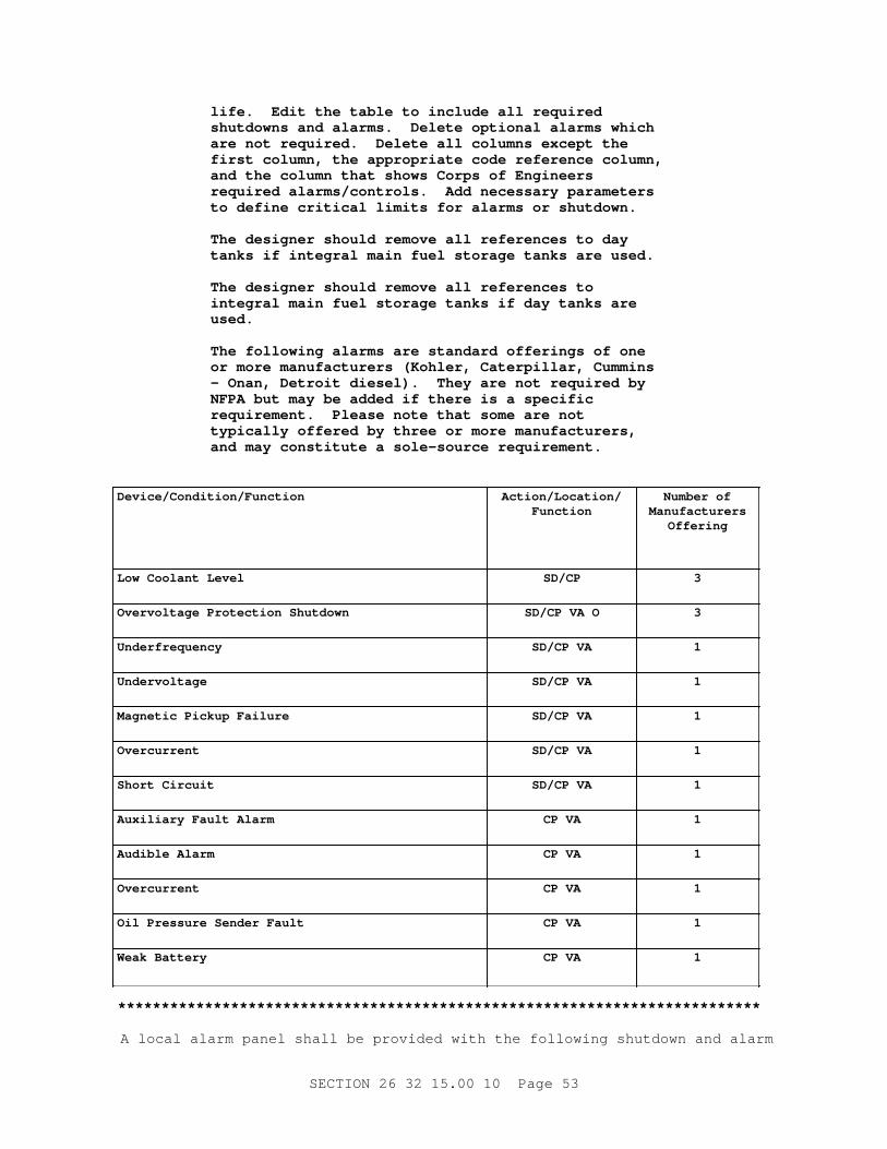
l i f e. Edi t t he t abl e t o i ncl ude al l r equi r ed shut downs and al ar ms. Del et e opt i onal al ar ms whi ch ar e not r equi r ed. Del et e al l col umns except t he f i r st col umn, t he appr opr i at e code r ef er ence col umn, and t he col umn t hat shows Cor ps of Engi neer s r equi r ed al ar ms/ cont r ol s. Add necessar y par amet er s t o def i ne cr i t i cal l i mi t s f or al ar ms or shut down.
The desi gner shoul d r emove al l r ef er ences t o day t anks i f i nt egr al mai n f uel st or age t anks ar e used.
The desi gner shoul d r emove al l r ef er ences t o i nt egr al mai n f uel st or age t anks i f day t anks ar e used.
The f ol l owi ng al ar ms ar e st andar d of f er i ngs of one or mor e manuf act ur er s ( Kohl er , Cat er pi l l ar , Cummi ns - Onan, Det r oi t di esel ) . They ar e not r equi r ed by NFPA but may be added i f t her e i s a speci f i c r equi r ement . Pl ease not e t hat some ar e not t ypi cal l y of f er ed by t hr ee or mor e manuf act ur er s, and may const i t ut e a sol e- sour ce r equi r ement .
Device/Condition/Function Action/Location/Function
Number ofManufacturers
Offering
Low Cool ant Level SD/CP 3
Over vol t age Pr ot ect i on Shut down SD/ CP VA O 3
Underfrequency SD/ CP VA 1
Undervoltage SD/ CP VA 1
Magnet i c Pi ckup Fai l ur e SD/ CP VA 1
Overcurrent SD/ CP VA 1
Shor t Ci r cui t SD/ CP VA 1
Auxi l i ar y Faul t Al ar m CP VA 1
Audi bl e Al ar m CP VA 1
Overcurrent CP VA 1
Oi l Pr essur e Sender Faul t CP VA 1
Weak Bat t er y CP VA 1
**************************************************************************
A l ocal al ar m panel shal l be pr ovi ded wi t h t he f ol l owi ng shut down and al ar m
SECTI ON 26 32 15. 00 10 Page 53
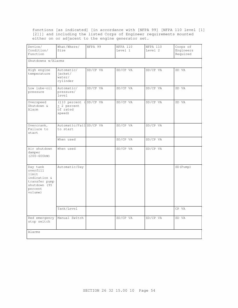
f unct i ons [ as i ndi cat ed] [ i n accor dance wi t h [ NFPA 99] [ NFPA 110 l evel [ 1] [ 2] ] ] and i ncl udi ng t he l i s t ed Cor ps of Engi neer r equi r ement s mount ed ei t her on or adj acent t o t he engi ne gener at or set .
Device/ Condition/ Function
What/Where/ Size
NFPA 99 NFPA 110 Level 1
NFPA 110 Level 2
Cor ps of Engineers Required
Shut downs w/ Al ar ms
Hi gh engi ne temperature
Automatic/ jacket/ water/ cylinder
SD/ CP VA SD/ CP VA SD/ CP VA SD VA
Low l ube- oi l pressure
Automatic/ pressure/ level
SD/ CP VA SD/ CP VA SD/ CP VA SD VA
Overspeed Shut down & Alarm
( 110 per cent (+ 2 per cent of r at ed speed)
SD/ CP VA SD/ CP VA SD/ CP VA SD VA
Overcrank, Fai l ur e t o start
Automatic/Failure t o st ar t
SD/ CP VA SD/ CP VA SD/ CP VA
When used SD/ CP VA SD/ CP VA
Ai r shut down damper (200-600kW)
When used SD/ CP VA SD/ CP VA
Day t ank overfill limit i ndi cat i on & t r ansf er pump shut down ( 95 percent volume)
Automatic/Day SD(Pump)
Tank/Level CP VA
Red emer gency st op swi t ch
Manual Swi t ch SD/ CP VA SD/ CP VA SD VA
Alarms
SECTI ON 26 32 15. 00 10 Page 54
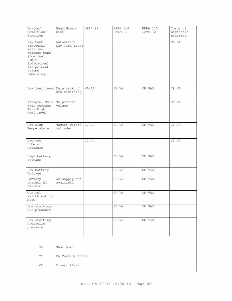
Device/ Condition/ Function
What/Where/ Size
NFPA 99 NFPA 110 Level 1
NFPA 110 Level 2
Cor ps of Engineers Required
Day Tank [integral mai n f uel st or age t ank] ( Low f uel Limit indication) ( 70 per cent volume remaining)
Automatic/ Day Tank Level
CP VA
Low f uel l evel Mai n t ank, 3 hr s r emai ni ng
VA/AA CP VA CP VAO CP VA
I nt egr al Mai n Fuel St or age Tank Hi gh Fuel Level
95 per cent volume
CP VA
Pre-High Temperature
j acket wat er / cylinder
CP VA CP VA CP VAO CP VA
Pre-Low Lube-oil Pressure
CP VA CP VA
Hi gh bat t er y Voltage
CP VA CP VAO
Low bat t er y Voltage
CP VA CP VAO
Battery char ger AC Failure
AC suppl y not available
CP VA CP VAO
Control swi t ch not i n AUTO
CP VA CP VAO
Low st ar t i ng Ai r pr essur e
CP VA CP VAO
Low st ar t i ng hydraulic pressure
CP VA CP VAO
SD Shut Down
CP On Cont r ol Panel
VA Vi sual Al ar m
SECTI ON 26 32 15. 00 10 Page 55
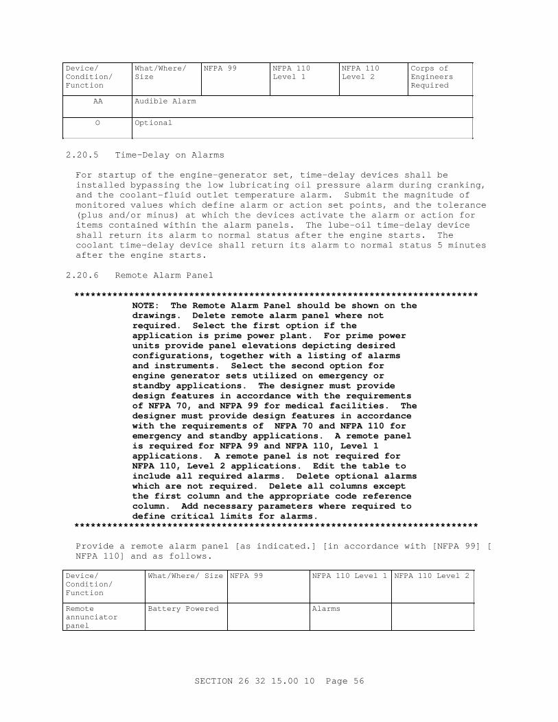
Device/ Condition/ Function
What/Where/ Size
NFPA 99 NFPA 110 Level 1
NFPA 110 Level 2
Cor ps of Engineers Required
AA Audi bl e Al ar m
O Optional
2. 20. 5 Ti me- Del ay on Al ar ms
For st ar t up of t he engi ne- gener at or set , t i me- del ay devi ces shal l be i nst al l ed bypassi ng t he l ow l ubr i cat i ng oi l pr essur e al ar m dur i ng cr anki ng, and t he cool ant - f l ui d out l et t emper at ur e al ar m. Submi t t he magni t ude of moni t or ed val ues whi ch def i ne al ar m or act i on set poi nt s, and t he t ol er ance ( pl us and/ or mi nus) at whi ch t he devi ces act i vat e t he al ar m or act i on f or i t ems cont ai ned wi t hi n t he al ar m panel s. The l ube- oi l t i me- del ay devi ce shal l r et ur n i t s al ar m t o nor mal st at us af t er t he engi ne st ar t s. The cool ant t i me- del ay devi ce shal l r et ur n i t s al ar m t o nor mal st at us 5 mi nut es af t er t he engi ne st ar t s.
2. 20. 6 Remot e Al ar m Panel
**************************************************************************NOTE: The Remot e Al ar m Panel shoul d be shown on t he dr awi ngs. Del et e r emot e al ar m panel wher e not r equi r ed. Sel ect t he f i r st opt i on i f t he appl i cat i on i s pr i me power pl ant . For pr i me power uni t s pr ovi de panel el evat i ons depi ct i ng desi r ed conf i gur at i ons, t oget her wi t h a l i s t i ng of al ar ms and i nst r ument s. Sel ect t he second opt i on f or engi ne gener at or set s ut i l i zed on emer gency or st andby appl i cat i ons. The desi gner must pr ovi de desi gn f eat ur es i n accor dance wi t h t he r equi r ement s of NFPA 70, and NFPA 99 f or medi cal f aci l i t i es. The desi gner must pr ovi de desi gn f eat ur es i n accor dance wi t h t he r equi r ement s of NFPA 70 and NFPA 110 f or emer gency and st andby appl i cat i ons. A r emot e panel i s r equi r ed f or NFPA 99 and NFPA 110, Level 1 appl i cat i ons. A r emot e panel i s not r equi r ed f or NFPA 110, Level 2 appl i cat i ons. Edi t t he t abl e t o i ncl ude al l r equi r ed al ar ms. Del et e opt i onal al ar ms whi ch ar e not r equi r ed. Del et e al l col umns except t he f i r st col umn and t he appr opr i at e code r ef er ence col umn. Add necessar y par amet er s wher e r equi r ed t o def i ne cr i t i cal l i mi t s f or al ar ms.
**************************************************************************
Pr ovi de a r emot e al ar m panel [ as i ndi cat ed. ] [ i n accor dance wi t h [ NFPA 99] [NFPA 110] and as f ol l ows.
Device/ Condition/ Function
What / Wher e/ Si ze NFPA 99 NFPA 110 Level 1 NFPA 110 Level 2
Remote annunciator panel
Bat t er y Power ed Alarms
SECTI ON 26 32 15. 00 10 Page 56
Device/ Condition/ Function
What / Wher e/ Si ze NFPA 99 NFPA 110 Level 1 NFPA 110 Level 2
Loads on genset VA
Bat t er y char ger malfunction
VA
Low l ube- oi l Pressure/level VA/AA AA AAO
Low t emper at ur e Jacket wat er VA/AA AA AAO
Hi gh t emper at ur e Jacket wat er / cylinder
VA/AA AA AAO
Low f uel l evel Mai n t ank, 3 hr s r emai ni ng
VA/AA AA AAO
Overcrank Fai l ur e t o st ar t VA/AA AA AAO
Overspeed VA/AA AA AAO
Pre-high temperature
Jacket wat er / cylinder
AA
Cont r ol swi t ch not i n AUTO
AA
Common al ar m cont act s f or l ocal & r emot e common al ar m
X X
Audi bl e al ar m si l enci ng swi t ch
X O
Ai r shut down damper
When used AA AAO
Common f aul t alarm
AA
X Required
SD Shutdown
CP On Cont r ol Panel
VA Vi sual Al ar m
AA Audi bl e Al ar m
O Otional
]2. 21 ENGI NE GENERATOR SET CONTROLS AND I NSTRUMENTATI ON
Devi ces, wi r i ng, r emot e panel s, l ocal panel s, et c. shal l be pr ovi ded and i nst al l ed as a compl et e syst em t o aut omat i cal l y act i vat e t he appr opr i at e s i gnal s and i ni t i at e t he appr opr i at e act i ons.
SECTI ON 26 32 15. 00 10 Page 57
2. 21. 1 Controls
**************************************************************************NOTE: Del et e t he r emot e cont r ol ( cont r ol r oom) panel i f t he appl i cat i on i s not a pr i me power appl i cat i on. Pr ovi de pl an and el evat i on dr awi ngs of t he r emot e cont r ol panel s f or pr i me power appl i cat i ons, depi ct i ng speci f i c devi ces, i nst r ument , and met er s, i ncl udi ng l ayout s. Gener at or c i r cui t br eaker cont r ol s wi t h posi t i on i ndi cat i on may be added i f r equi r ed ( Not avai l abl e f or st andar d mol ded- case br eaker s. Use onl y f or power c i r cui t br eaker s or swi t chgear . )
Edi t t he t abl e t o i ncl ude al l r equi r ed devi ces. Del et e al l col umns except t he f i r st col umn and t he appr opr i at e r ef er ence col umns ( al ways del et e t he " MFG Of f er i ng" col umn) .
A r emot e st op swi t ch i s r equi r ed by NFPA 37 f or 100 hp and above engi nes, and by NFPA 110 f or bot h Level 1 and Level 2 appl i cat i ons. A r emot e f uel shut of f swi t ch, and a r emot e l ube- oi l shut of f swi t ch ar e r equi r ed by NFPA 37 f or 100 hp and above engi nes. Del et e t he r emot e f uel shut of f swi t ch, and a r emot e l ube- oi l shut of f swi t ch wher e not r equi r ed.
**************************************************************************
Pr ovi de a l ocal cont r ol panel wi t h cont r ol s [ as i ndi cat ed] [ i n accor dance wi t h [ NFPA 110 l evel [ 1] [ 2] ] ] [ and as f ol l ows] mount ed [ ei t her on or adj acent t o t he engi ne gener at or set ] [ as i ndi cat ed] . Pr ovi de a r emot e cont r ol panel [ wi t h devi ces as i ndi cat ed] [ f ul l y r edundant t o t he l ocal cont r ol panel ] .
Device/ Condition/ Function
Cor ps of Engineers Requirements
NFPA 110 Level 1 NFPA 110 Level 2 Manufacturer Offering
Swi t ch: r un/ st ar t - of f / r eset - aut o
CP CP/STD
Emer gency st op swi t ch & al ar m
CP CP/STD
Lamp t est / i ndi cat or t est
CP CP VA CP VA CP/STD
Common al ar m cont act s/ f aul t relay
X X CP/O
Panel l i ght i ng CP CP/STD
SECTI ON 26 32 15. 00 10 Page 58
Device/ Condition/ Function
Cor ps of Engineers Requirements
NFPA 110 Level 1 NFPA 110 Level 2 Manufacturer Offering
Audi bl e al ar m & silencing/ r eset swi t ch
CP
Vol t age adj ust f or vol t age regulator
CP CP/STD
Pyrometer display w/selector switch
CP
Remote emer gency st op switch
CP VA CP VA
Remot e f uel shut of f swi t ch
Remot e l ube- oi l shut of f swi t ch
X Required
STD Manuf act ur er s St andar d Of f er i ng
CP On Cont r ol Panel
VA Vi sual Al ar m
O Otional
2. 21. 2 Engi ne Gener at or Set Met er i ng and St at us I ndi cat i on
**************************************************************************NOTE: Del et e t he r emot e ( cont r ol r oom) panel i f t he appl i cat i on i s not a pr i me power appl i cat i on. Pr ovi de pl an and el evat i on dr awi ngs of t he r emot e panel s f or pr i me power appl i cat i ons, depi ct i ng speci f i c devi ces, i nst r ument , and met er s, i ncl udi ng l ayout s. Edi t t he t abl e t o i ncl ude al l r equi r ed devi ces. Del et e opt i onal devi ces t hat ar e not r equi r ed f or t he appl i cat i on. Del et e al l col umns except t he f i r st col umn and t he appr opr i at e r ef er ence col umn ( al ways del et e t he " MFG. Of f er i ng" col umn) . Add any necessar y par amet er s t o def i ne devi ces r equi r ed. A f uel met er di spl ay shoul d be added f or pr i me r at ed appl i cat i ons. A f uel header pr essur e di spl ay shoul d be added f or pr i me r at ed appl i cat i ons. Del et e t he pyr omet er devi ces f or set s smal l er t han 200 kW. kWh, kVAR, power f act or ,
SECTI ON 26 32 15. 00 10 Page 59
met er s and r ever se power i ndi cat i on may be added as required.
The f ol l owi ng i nst r ument s may be added as r equi r ed.
I ndi cat i ng VAR met er . Power - f act or met er , i ndi cat i ng. ( Speci f y one of t hese. They ar e nor mal l y used onl y f or pr i me appl i cat i ons, however can be speci f i ed f or st andby uni t s as r equi r ed. )
I ndi cat i ng wat t met er . ( Nor mal l y used onl y f or pr i me appl i cat i ons, however can be speci f i ed f or st andby uni t s as r equi r ed.
Tot al i z i ng Ki l owat t - hour met er wi t h 15 or 30 mi nut e demand r egi st er . ( Nor mal l y used onl y f or pr i me appl i cat i ons, however can be speci f i ed f or st andby uni t s as r equi r ed. )
Recor di ng Ki l owat t - hour / demand met er . ( Nor mal l y used onl y f or pr i me appl i cat i ons, however can be speci f i ed f or st andby uni t s as r equi r ed. )
The 15- mi nut e demand r egi st er i s pr ef er r ed t o t he 30- mi nut e r egi st er i n most cases, because i t per mi t s mor e accur at e t i mi ng of f aci l i t y peak l oad occurrence.
Del et e Fr equency and Vol t met er s i f a Synchr oni z i ng Panel i s pr ovi ded.
**************************************************************************
Pr ovi de a l ocal panel wi t h devi ces [ as i ndi cat ed] [ i n accor dance wi t h [NFPA 110 l evel [ 1] [ 2] ] ] [ and as f ol l ows] mount ed [ ei t her on or adj acent t o t he engi ne gener at or set ] [ as i ndi cat ed] . A r emot e cont r ol panel shal l be pr ovi ded [ wi t h devi ces as i ndi cat ed] [ f ul l y r edundant t o t he l ocal cont r ol panel].
Device/ Condition/ Function
Cor ps ofEngineers
Requirements
NFPA 110 Level 1 NFPA 110 Level 2 ManufacturerOffering
Genset St at us & Met er i ng
Genset suppl yi ng l oad
CP VA CP VAO CP VAO
Syst em r eady CP/STD
Engi ne oi l pressure
CP CP/STD
Engi ne cool ant temperature
CP CP/STD
SECTI ON 26 32 15. 00 10 Page 60
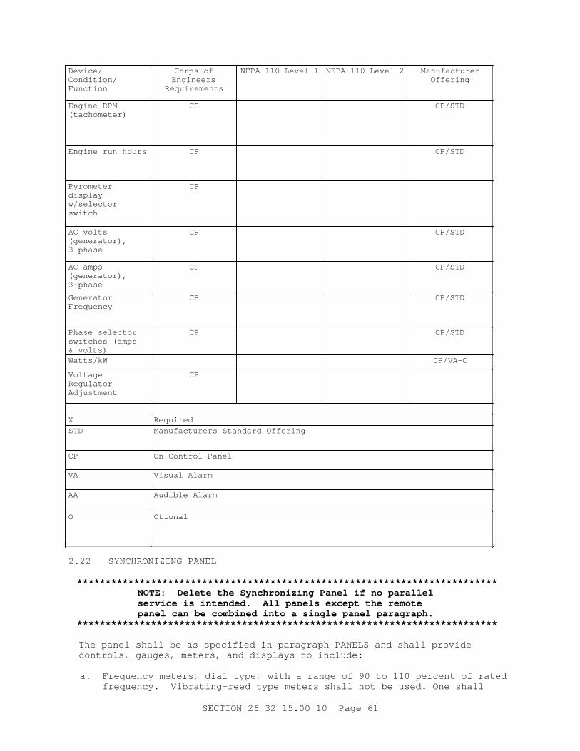
Device/ Condition/ Function
Cor ps ofEngineers
Requirements
NFPA 110 Level 1 NFPA 110 Level 2 ManufacturerOffering
Engi ne RPM (tachometer)
CP CP/STD
Engi ne r un hour s CP CP/STD
Pyrometer display w/selector switch
CP
AC vol t s (generator), 3-phase
CP CP/STD
AC amps (generator), 3-phase
CP CP/STD
Generator Frequency
CP CP/STD
Phase sel ect or swi t ches ( amps & vol t s)
CP CP/STD
Watts/kW CP/VA-O
Voltage Regulator Adjustment
CP
X Required
STD Manuf act ur er s St andar d Of f er i ng
CP On Cont r ol Panel
VA Vi sual Al ar m
AA Audi bl e Al ar m
O Otional
2. 22 SYNCHRONI ZI NG PANEL
**************************************************************************NOTE: Del et e t he Synchr oni z i ng Panel i f no par al l el ser vi ce i s i nt ended. Al l panel s except t he r emot e panel can be combi ned i nt o a s i ngl e panel par agr aph.
**************************************************************************
The panel shal l be as speci f i ed i n par agr aph PANELS and shal l pr ovi de cont r ol s, gauges, met er s, and di spl ays t o i ncl ude:
a. Fr equency met er s, di al t ype, wi t h a r ange of 90 t o 110 per cent of r at ed f r equency. Vi br at i ng- r eed t ype met er s shal l not be used. One shal l
SECTI ON 26 32 15. 00 10 Page 61
moni t or gener at or out put f r equency ( " Gener at or Fr equency Met er " ) and t he ot her shal l moni t or t he f r equency of t he par al l el sour ce ( " Bus Fr equency Met er " ) .
b. Vol t met er s, ac, di al t ype, 3- phase, wi t h 4- posi t i on sel ect or swi t ch f or t he gener at or out put ( " Gener at or Vol t Met er " ) and f or t he par al l el power sour ce ( " Bus vol t met er " ) .
c. Aut omat i c synchr oni zer .
d. Manual synchr oni z i ng cont r ol s.
e. I ndi cat i ng l i ght s f or suppl ement ar y i ndi cat i on of synchr oni zat i on.
f . Synchr oscope.
g. Wat t met er , i ndi cat i ng.
2. 23 PANELS
**************************************************************************NOTE: Al l panel s except t he r emot e panel can be combi ned i nt o a s i ngl e panel par agr aph.
Pr ovi de a panel - mount i ng l ocat i on and det ai l f or panel s not mount ed on t he genset base. The desi gner may el ect ot her l ocat i ons such as adj acent t o engi ne- gener at or set , i n t he gener at or encl osur e, i n or on t he exci t er - r egul at or cabi net , or i n or on t he swi t chgear encl osur e. Pr ovi de panel namepl at e and i nst r ument namepl at e uni que i dent i f i er s or user pr ef er r ed i dent i f i er s. Pr ovi de s i zes, mat er i al s and at t achment pr ef er ences.
Del et e ei t her t he " anal og" or " el ect r oni c i nst r ument s" par agr aph.
**************************************************************************
Each panel shal l be of t he t ype and ki nd necessar y t o pr ovi de speci f i ed f unct i ons. Panel s shal l be mount ed [ on t he engi ne- gener at or set base by v i br at i on/ shock absor bi ng t ype mount i ngs] [ as shown] . I nst r ument s shal l be mount ed f l ush or semi f l ush. Conveni ent access t o t he back of panel s shal l be pr ovi ded t o f aci l i t at e mai nt enance. I nst r ument s shal l be cal i br at ed usi ng r ecogni zed i ndust r y cal i br at i on st andar ds. Each panel shal l be pr ovi ded wi t h a panel i dent i f i cat i on pl at e whi ch c l ear l y i dent i f i es t he panel f unct i on. Each i nst r ument and devi ce on t he panel shal l be pr ovi ded wi t h a pl at e whi ch c l ear l y i dent i f i es t he devi ce and i t s f unct i on as i ndi cat ed. Swi t ch pl at es shal l c l ear l y i dent i f y t he swi t ch- posi t i on function.
2. 23. 1 Enclosures
Encl osur es shal l be desi gned f or t he appl i cat i on and envi r onment , conf or mi ng t o NEMA I CS 6. Locki ng mechani sms [ ar e opt i onal . ] [ shal l be keyed al i ke. ]
2. 23. 2 Analog
Anal og el ect r i cal i ndi cat i ng i nst r ument s shal l be i n accor dance wi t h
SECTI ON 26 32 15. 00 10 Page 62
ANSI C39. 1 wi t h semi f l ush mount i ng. Swi t chboar d, swi t chgear , and cont r ol - r oom panel - mount ed i nst r ument s shal l have 250 degr ee scal es wi t h an accur acy of not l ess t han 99 per cent . Uni t - mount ed i nst r ument s shal l [ be t he manuf act ur er ' s st andar d] [ have 100 degr ee scal es] wi t h an accur acy of not l ess t han 98 per cent . The i nst r ument ' s oper at i ng t emper at ur e r ange shal l be mi nus 20 t o pl us 65 degr ees C mi nus 4 t o pl us 158 degr ees F. Di st or t ed gener at or out put vol t age wavef or m of a cr est f act or l ess t han 5 shal l not af f ect met er i ng accur acy f or phase vol t ages, her t z and amps.
2. 23. 3 Electronic
El ect r oni c i ndi cat i ng i nst r ument s shal l be t r ue RMS i ndi cat i ng i nst r ument s, 100 per cent sol i d st at e, st at e- of - t he- ar t , mi cr opr ocessor cont r ol l ed t o pr ovi de speci f i ed f unct i ons. Cont r ol , l ogi c, and f unct i on devi ces shal l be compat i bl e as a syst em, seal ed, dust and wat er t i ght , and shal l ut i l i ze modul ar component s wi t h met al housi ngs and di gi t al i nst r ument at i on. An i nt er f ace modul e shal l be pr ovi ded t o decode ser i al l i nk dat a f r om t he el ect r oni c panel and t r ansl at e al ar m, f aul t and st at us condi t i ons t o set of r el ay cont act s. I nst r ument accur acy shal l be not l ess t han 98 per cent f or uni t mount ed devi ces and 99 per cent f or cont r ol r oom, panel mount ed devi ces, t hr oughout a t emper at ur e r ange of mi nus 20 t o pl us 65 degr ees C mi nus 4 t o 158 degr ees F. Dat a di spl ay shal l ut i l i ze LED or back l i t LCD. Addi t i onal l y, t he di spl ay shal l pr ovi de i ndi cat i on of cycl e pr ogr ammi ng and di agnost i c codes f or t r oubl eshoot i ng. Numer al hei ght shal l be [ 13 mm 0. 5 i nch] [ _____] .
2. 23. 4 Par amet er Di spl ay
I ndi cat i on or r eadout s of t he t achomet er , l ubr i cat i ng- oi l pr essur e, ac vol t met er , ac ammet er , f r equency met er , and saf et y syst em par amet er s shal l be pr ovi ded. A moment ar y swi t ch shal l be speci f i ed f or ot her panel s.
2. 24 AUTOMATI C ENGI NE- GENERATOR- SET SYSTEM OPERATI ON
**************************************************************************NOTE: Aut omat i c oper at i on i s f or st andby. For hospi t al emer gency/ st andby r equi r ement s, r ef er t o UFC 3- 540- 02N. Del et e aut omat i c par al l el i ng and l oadi ng wher e not r equi r ed. Adapt t o f i t appl i cat i on and pr ovi de desi r ed act uat i on sequence.
**************************************************************************
Ful l y aut omat i c oper at i on shal l be pr ovi ded f or t he f ol l owi ng oper at i ons: engi ne- gener at or set st ar t i ng and l oad t r ansf er upon l oss of [ nor mal ] [ pr ef er r ed] sour ce; r et r ansf er upon r est or at i on of t he [ nor mal ] [ pr ef er r ed] sour ce; sequent i al st ar t i ng; par al l el i ng, and l oad- shar i ng f or mul t i pl e engi ne- gener at or set s; and st oppi ng of each engi ne- gener at or set af t er cool - down. Devi ces shal l aut omat i cal l y r eset af t er t er mi nat i on of t hei r function.
2. 24. 1 Aut omat i c Tr ansf er Swi t ch
Aut omat i c t r ansf er swi t ches shal l be i n accor dance wi t h Sect i on 26 36 00. 00 10AUTOMATI C TRANSFER SWI TCH AND BY- PASS/ I SOLATI ON SWI TCH.
2. 24. 2 Moni t or i ng and Tr ansf er
Devi ces shal l be pr ovi ded t o moni t or vol t age and f r equency f or t he [ nor mal ] [ pr ef er r ed] power sour ce and each engi ne- gener at or set , and cont r ol
SECTI ON 26 32 15. 00 10 Page 63
t r ansf er f r om t he [ nor mal ] [ pr ef er r ed] sour ce and r et r ansf er upon r est or at i on of t he [ nor mal ] [ pr ef er r ed] sour ce. Funct i ons, act uat i on, and t i me del ays shal l be as descr i bed i n Sect i on 26 36 00. 00 10 AUTOMATI C TRANSFER SWI TCH AND BY- PASS/ I SOLATI ON SWI TCH.
2. 24. 3 Aut omat i c Par al l el i ng and Loadi ng of Engi ne- Gener at or Set s
An aut omat i c l oadi ng syst em shal l be pr ovi ded t o l oad and unl oad engi ne- gener at or set s i n t he sequence i ndi cat ed. The l oadi ng syst em shal l moni t or t he syst em l oad and cause addi t i onal engi ne- gener at or set s t o st ar t , synchr oni ze, and be connect ed i n par al l el wi t h t he syst em bus wi t h i ncr easi ng l oad. Act uat i on of t he addi t i onal engi ne- gener at or set st ar t l ogi c shal l occur when t he l oad exceeds a per cent age set poi nt of t he oper at i ng set ' s r at i ng f or a per i od of appr oxi mat el y 10 seconds. The devi ce shal l pr ovi de an adj ust abl e set poi nt r ange f r om 50 t o 100 per cent . When t he syst em l oad f al l s bel ow t he per cent age set poi nt of t he oper at i ng set ' s r at i ng f or a per i od of appr oxi mat el y [ _____] , t he cont r ol l er shal l unl oad and di sconnect engi ne- gener at or set s f r om t he syst em, st oppi ng each engi ne- gener at or set af t er cool - down.
2. 25 MANUAL ENGI NE- GENERATOR- SET SYSTEM OPERATI ON
**************************************************************************NOTE: Del et e synchr oni zat i on f or non- par al l el operation.
**************************************************************************
Compl et e f aci l i t i es shal l be pr ovi ded f or manual s t ar t i ng and t est i ng of each set wi t hout l oad, l oadi ng and unl oadi ng of each set , and synchr oni zat i on of each set wi t h an ener gi zed bus.
2. 26 STATI ON BATTERY SYSTEM
**************************************************************************NOTE: The st at i on bat t er y syst em shoul d be shown on t he dr awi ngs.
Del et e t hi s r equi r ement when not needed. A st at i on bat t er y i s r equi r ed onl y when dc- oper at ed devi ces ot her t han engi ne st ar t i ng mot or s ar e pr ovi ded. The st at i on bat t er y and st ar t i ng bat t er y may be combi ned wher e al l dc- oper at ed devi ces ar e t he same vol t age l evel and ar e not af f ect ed by t he vol t age dr op caused by engi ne st ar t i ng. Because l ead cal c i um bat t er i es ar e mor e economi cal and r equi r e l ess mai nt enance, ni ckel cadmi um bat t er i es shoul d be speci f i ed onl y wher e ver y hi gh di schar ge r at e wi t h const ant vol t age over a shor t per i od of t i me i s r equi r ed, or f or appl i cat i ons wher e t he bat t er y t emper at ur e cannot be mai nt ai ned above mi nus 6 degr ees C 22 degr ees F. Sl ush does not begi n t o f or m i n l ead aci d bat t er i es unt i l t he t emper at ur e r eaches mi nus 29 degr ees C mi nus 20 degr ees F, but t he bat t er y vol t age out put and cur r ent capaci t y f al l bel ow usef ul val ues at mi nus mi nus 6 degr ees C 22 degr ees F. The desi gner shoul d pr ovi de measur es t o mai nt ai n bat t er y t emper at ur e bet ween 16 and 32 degr ees C 60 and 90 degr ees F; 25 degr ees C 77 degr ees F i s t he t ar get t emper at ur e f or opt i mum
SECTI ON 26 32 15. 00 10 Page 64
ser vi ce l i f e and per f or mance. The engi ne st ar t i ng bat t er y f or smal l er s i ze set s i s suf f i c i ent f or dc r equi r ement s and a st at i on bat t er y i s not r equi r ed.
Def i ne l oads whi ch ar e t o be ser ved by t he st at i on battery.
Cal cul at i ons of bat t er y capaci t y ut i l i ze a medi an t emper at ur e of 25 degr ees C 77 degr ees F. I f t he pr edomi nat e bat t er y oper at i ng t emper at ur e var i es by mor e t han + 2. 5 degr ees C + 5 degr ees F f r om 25 degr ees C 77 degr ees F, speci f y t he medi an oper at i ng temperature.
**************************************************************************
A st at i on bat t er y syst em shal l be pr ovi ded t o i ncl ude t he bat t er y, bat t er y r ack, spacer s, aut omat i c bat t er y char ger and di st r i but i on panel boar d wi t h over cur r ent pr ot ect i on, met er i ng and r el ayi ng. Component s shal l be s i zed t o wi t hst and t he sei smi c accel er at i on f or ces speci f i ed. The bat t er i es shal l have a r at ed l i f e of 20 year s and a manuf act ur er ' s 5- year , no cost r epl acement guar ant ee.
2. 26. 1 Battery
The bat t er y shal l be [ l ead- aci d] [ ni ckel - cadmi um] , s i zed i n accor dance wi t h I EEE 485 and conf or m t o t he r equi r ement s of I EEE 484. Val ve- r egul at ed l ead- aci d bat t er i es ar e not accept abl e. The bat t er y envi r onment t emper at ur e shal l r ange bet ween [ _____] and [ _____] degr ees. The bat t er y shal l be r at ed f or at l east [ _____] amper e hour s at t he 8- hour r at e.
2. 26. 2 Bat t er y Capaci t y
**************************************************************************NOTE: Del et e l oads whi ch ar e not t o be ser ved f r om t he St at i on Bat t er y Syst em. Add t he f ol l owi ng l oad f or genset s 1000 kW and l ar ger : pr eci r cul at i ng l ube- oi l pumps f or di esel s f or [ _____] mi nut es.
**************************************************************************
The bat t er y shal l be r at ed f or at l east [ _____] amper e hour s at t he 8- hour r at e, and shal l have suf f i c i ent capaci t y t o ser ve t he f ol l owi ng l oads wi t hout r echar gi ng f or a per i od of [ _____] hour s. At t he end of t he di schar ge per i od, t he bat t er y shal l have t he capaci t y t o s i mul t aneousl y c l ose and t r i p al l t he c i r cui t br eaker s pr ovi ded, based on a 1- mi nut e l oad t o f i nal vol t age of [ _____] vol t s per cel l .
a. Di esel - gener at or saf et y c i r cui t s.
b. Swi t chgear i ndi cat i ng l i ght s, cont r ol r el ays, pr ot ect i ve r el ays, and ot her swi t chgear dc component s as r equi r ed f or 24 hour s.
c. Vol t age r egul at or ( dc power suppl i es) .
d. Emer gency- l i ght i ng and power l oad at [ _____] wat t s f or [ _____] hour s.
2. 26. 3 Bat t er y Char ger
A cur r ent - l i mi t i ng, [ _____] - vol t bat t er y char ger shal l be f ur ni shed t o aut omat i cal l y r echar ge t he bat t er i es. The char ger shal l be capabl e of an
SECTI ON 26 32 15. 00 10 Page 65
equal i ze char gi ng r at e [ f or r echar gi ng f ul l y depl et ed bat t er i es wi t hi n [ 8] [ _____] hour s] [ whi ch i s cont i nuousl y adj ust abl e] and a f l oat i ng- char ge r at e f or mai nt ai ni ng t he bat t er i es i n a f ul l y char ged condi t i on. The char ger shal l be equi pped wi t h a l ow- vol t age al ar m r el ay, 0- t o 24- hour equal i z i ng t i mer , an ammet er t o i ndi cat e char gi ng r at e, and necessar y c i r cui t br eaker s. The char ger shal l conf or m t o t he r equi r ement s of UL 1236. A bat t er y i s consi der ed t o be f ul l y depl et ed when t he vol t age f al l s t o a l evel i ncapabl e of oper at i ng t he equi pment l oads ser ved by t he bat t er y.
2. 27 BASE
The base shal l be const r uct ed of st eel . The base shal l be desi gned t o r i gi dl y suppor t t he engi ne- gener at or set , ensur e per manent al i gnment of r ot at i ng par t s, be ar r anged t o pr ovi de easy access t o al l ow changi ng of l ube- oi l , and ensur e t hat al i gnment i s mai nt ai ned dur i ng shi ppi ng and nor mal oper at i on. The base shal l per mi t ski ddi ng i n any di r ect i on dur i ng i nst al l at i on and shal l wi t hst and and mi t i gat e t he af f ect s of synchr onous v i br at i on of t he engi ne and gener at or . The base shal l be pr ovi ded wi t h [ sui t abl e hol es f or anchor bol t s] [ [ _____] di amet er hol es f or anchor bol t s] and j acki ng scr ews f or l evel i ng.
2. 28 THERMAL I NSULATI ON
Ther mal i nsul at i on shal l be as speci f i ed i n Sect i on 23 07 00 THERMAL I NSULATI ON FOR MECHANI CAL SYSTEMS.
2. 29 PAI NTI NG AND FI NI SHI NG
The engi ne- gener at or set shal l be c l eaned, pr i med and pai nt ed i n accor dance wi t h t he manuf act ur er ' s st andar d col or and pr act i ce.
2. 30 FACTORY I NSPECTI ON AND TESTS
Submi t [ s i x] [ _____] compl et e r epr oduci bl e copi es of t he f act or y i nspect i on r esul t on t he checkl i st f or mat speci f i ed bel ow. Per f or m t he f act or y t est s on each engi ne- gener at or set . The component manuf act ur er ' s pr oduct i on l i ne t est i s accept abl e as not ed. Each engi ne- gener at or set shal l be r un not l ess t han 1 hour at r at ed out put capaci t y pr i or t o i nspect i ons. I nspect i ons shal l be compl et ed and al l necessar y r epai r s made, pr i or t o t est i ng. Engi ne gener at or cont r ol s and pr ot ect i ve devi ces t hat ar e pr ovi ded by t he gener at or set manuf act ur er as par t of t he st andar d package shal l be used f or f act or y t est s. When cont r ol s and swi t chgear ar e not pr ovi ded as par t of t he gener at or set manuf act ur er ' s st andar d package, t he act ual cont r ol s and pr ot ect i ve devi ces pr ovi ded f or t he pr oj ect ar e not r equi r ed t o be used dur i ng t he f act or y t est . The Cont r act i ng Of f i cer may pr ovi de one or mor e r epr esent at i ves t o wi t ness i nspect i ons and t est s.
2. 30. 1 Fact or y I nspect i on
**************************************************************************NOTE: Del et e i nappl i cabl e i nspect i on i t ems.
**************************************************************************
Per f or m i nspect i ons pr i or t o begi nni ng and af t er compl et i on of t est i ng of t he assembl ed engi ne- gener at or set . I nspect or s shal l l ook f or l eaks, l ooseness, def ect s i n component s, pr oper assembl y, et c. and not e any i t em f ound t o be i n need of cor r ect i on as a necessar y r epai r . The f ol l owi ng checkl i st shal l be used f or t he i nspect i on:
SECTI ON 26 32 15. 00 10 Page 66
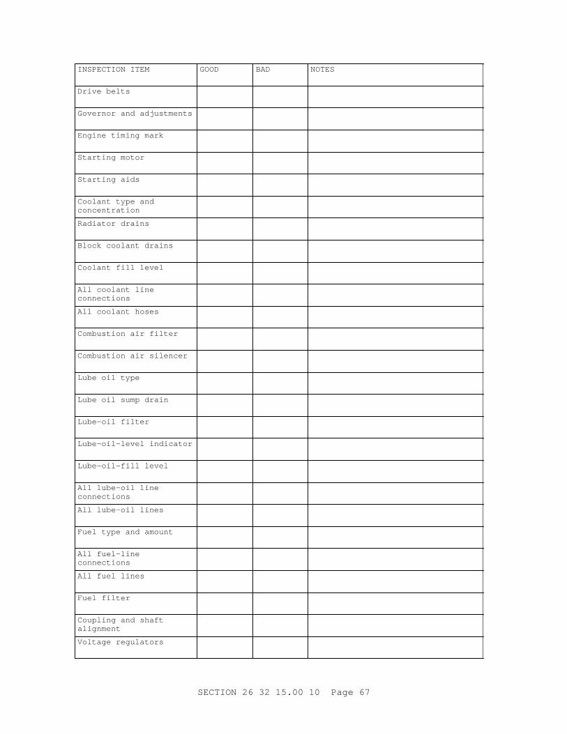
I NSPECTI ON I TEM GOOD BAD NOTES
Dr i ve bel t s
Gover nor and adj ust ment s
Engi ne t i mi ng mar k
St ar t i ng mot or
St ar t i ng ai ds
Cool ant t ype and concentration
Radi at or dr ai ns
Bl ock cool ant dr ai ns
Cool ant f i l l l evel
Al l cool ant l i ne connections
Al l cool ant hoses
Combust i on ai r f i l t er
Combust i on ai r si l encer
Lube oi l t ype
Lube oi l sump dr ai n
Lube- oi l f i l t er
Lube- oi l - l evel i ndi cat or
Lube- oi l - f i l l l evel
Al l l ube- oi l l i ne connections
Al l l ube- oi l l i nes
Fuel t ype and amount
Al l f uel - l i ne connections
Al l f uel l i nes
Fuel f i l t er
Coupl i ng and shaf t alignment
Vol t age r egul at or s
SECTI ON 26 32 15. 00 10 Page 67
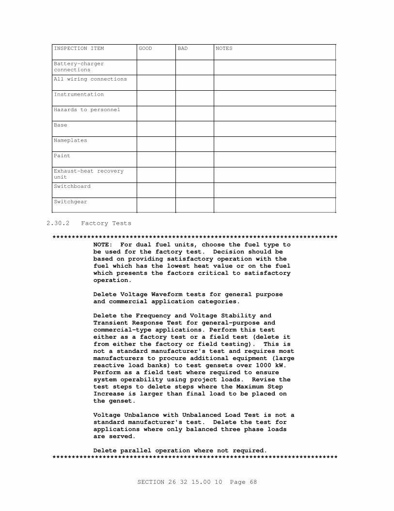
I NSPECTI ON I TEM GOOD BAD NOTES
Battery-charger connections
Al l wi r i ng connect i ons
Instrumentation
Hazar ds t o per sonnel
Base
Nameplates
Paint
Exhaust - heat r ecover y unit
Switchboard
Switchgear
2. 30. 2 Fact or y Test s
**************************************************************************NOTE: For dual f uel uni t s, choose t he f uel t ype t o be used f or t he f act or y t est . Deci s i on shoul d be based on pr ovi di ng sat i sf act or y oper at i on wi t h t he f uel whi ch has t he l owest heat val ue or on t he f uel whi ch pr esent s t he f act or s cr i t i cal t o sat i sf act or y operation.
Del et e Vol t age Wavef or m t est s f or gener al pur pose and commer ci al appl i cat i on cat egor i es.
Del et e t he Fr equency and Vol t age St abi l i t y and Tr ansi ent Response Test f or gener al - pur pose and commer ci al - t ype appl i cat i ons. Per f or m t hi s t est ei t her as a f act or y t est or a f i el d t est ( del et e i t f r om ei t her t he f act or y or f i el d t est i ng) . Thi s i s not a st andar d manuf act ur er ' s t est and r equi r es most manuf act ur er s t o pr ocur e addi t i onal equi pment ( l ar ge r eact i ve l oad banks) t o t est genset s over 1000 kW. Per f or m as a f i el d t est wher e r equi r ed t o ensur e syst em oper abi l i t y usi ng pr oj ect l oads. Revi se t he t est st eps t o del et e st eps wher e t he Maxi mum St ep I ncr ease i s l ar ger t han f i nal l oad t o be pl aced on t he genset .
Vol t age Unbal ance wi t h Unbal anced Load Test i s not a st andar d manuf act ur er ' s t est . Del et e t he t est f or appl i cat i ons wher e onl y bal anced t hr ee phase l oads ar e ser ved.
Del et e par al l el oper at i on wher e not r equi r ed.**************************************************************************
SECTI ON 26 32 15. 00 10 Page 68
Submi t a l et t er gi v i ng not i ce of t he pr oposed dat es of f act or y i nspect i ons and t est s at l east 14 days pr i or t o begi nni ng t est s, i ncl udi ng:
a. A det ai l ed descr i pt i on of t he manuf act ur er ' s pr ocedur es f or f act or y t est s at l east [ 14] [ _____] days pr i or t o begi nni ng t est s.
b. [ Si x] [ _____] copi es of t he Fact or y Test dat a descr i bed bel ow i n 216 by 279 mm 8- 1/ 2 by 11 i nch bi nder s havi ng a mi ni mum of 3 r i ngs f r om whi ch mat er i al may r eadi l y be r emoved and r epl aced, i ncl udi ng a separ at e sect i on f or each t est . Sect i ons shal l be separ at ed by heavy pl ast i c di v i der s wi t h t abs. Dat a pl ot s shal l be f ul l s i ze ( 216 by 279 mm 8- 1/ 2 by 11 i nch mi ni mum) , showi ng gr i d l i nes, wi t h f ul l r esol ut i on.
( 1) A det ai l ed descr i pt i on of t he pr ocedur es f or f act or y t est s.
( 2) A l i s t of equi pment used, wi t h cal i br at i on cer t i f i cat i ons.
( 3) A copy of measur ement s t aken, wi t h r equi r ed pl ot s and gr aphs.
( 4) The dat e of t est i ng.
( 5) A l i s t of t he par amet er s ver i f i ed.
( 6) The condi t i on speci f i ed f or t he par amet er .
( 7) The t est r esul t s, s i gned and dat ed.
( 8) A descr i pt i on of adj ust ment s made.
On engi ne- gener at or set t est s wher e t he engi ne and gener at or ar e r equi r ed t o be connect ed and oper at ed t oget her , t he l oad power f act or shal l be [ t he power f act or speci f i ed i n t he engi ne gener at or set par amet er schedul e] [ [ _____] power f act or ] . For engi ne- gener at or set wi t h dual - f uel oper at i ng capabi l i t y t he f ol l owi ng t est s shal l be per f or med usi ng [ t he pr i mar y f uel t ype] [ [ _____] t ype f uel ] . El ect r i cal measur ement s shal l be per f or med i n accor dance wi t h I EEE 120. Def i ni t i ons of t er ms ar e i n accor dance wi t h I EEE St ds Di ct i onar y. Temper at ur e l i mi t s i n t he r at i ng of el ect r i cal equi pment and f or t he eval uat i on of el ect r i cal i nsul at i on shal l be i n accor dance wi t h I EEE 1. I n t he f ol l owi ng t est s wher e measur ement s ar e t o be r ecor ded af t er st abi l i zat i on of an engi ne- gener at or set par amet er ( vol t age, f r equency, cur r ent , t emper at ur e, et c. ) , st abi l i zat i on i s consi der ed t o have occur r ed when measur ement s ar e mai nt ai ned wi t hi n t he speci f i ed bandwi dt hs or t ol er ances, f or a mi ni mum of f our consecut i ve r eadi ngs. Test s speci f i cal l y f or t he gener at or may be per f or med ut i l i z i ng any pr i me mover .
a. I nsul at i on Resi st ance f or St at or and Exci t er Test , I EEE 115 and I EEE 43, t o t he per f or mance cr i t er i a i n NEMA MG 1, Par t 22. Gener at or manuf act ur er ' s pr oduct i on l i ne t est i s accept abl e.
b. Hi gh Pot ent i al Test , i n accor dance wi t h I EEE 115 and NEMA MG 1, t est vol t age i n accor dance wi t h NEMA MG 1. Gener at or manuf act ur er ' s pr oduct i on l i ne t est i s accept abl e.
c. Wi ndi ng Resi st ance Test , St at or and Exci t er , i n accor dance wi t h I EEE 115. Gener at or manuf act ur er ' s pr oduct i on l i ne t est i s accept abl e.
d. Over speed Vi br at i on Test , i n accor dance wi t h I EEE 115 t o t he per f or mance cr i t er i a i n NEMA MG 1. The t est shal l be per f or med at 110
SECTI ON 26 32 15. 00 10 Page 69
per cent of r at ed speed f or 5 mi nut es. The vi br at i on shal l be measur ed at t he end bear i ngs ( f r ont and back of engi ne, out boar d end of gener at or ) i n t he hor i zont al , ver t i cal , and axi al di r ect i ons. Vi br at i on ampl i t ude and speed shal l be r ecor ded at one mi nut e i nt er val s.
e. Phase Bal ance Vol t age Test , t o t he per f or mance cr i t er i a speci f i ed i n par agr aph GENERATOR. Thi s t est can be per f or med wi t h any pr i me mover . Gener at or manuf act ur er ' s pr oduct i on l i ne t est r esul t s ar e accept abl e.
( 1) St ar t and oper at e t he gener at or at no l oad.
( 2) Adj ust a r egul at ed phase vol t age ( l i ne- t o- neut r al ) t o r at ed voltage.
( 3) Read and r ecor d t he gener at or f r equency, l i ne- t o- neut r al vol t ages, and t he l i ne- t o- l i ne vol t ages.
( 4) Appl y 75 per cent r at ed l oad and r ecor d t he gener at or f r equency, l i ne- t o- neut r al vol t ages, and t he l i ne- t o- l i ne vol t ages.
( 5) Appl y r at ed l oad and r ecor d t he gener at or f r equency, l i ne- t o- neut r al vol t ages, and t he l i ne- t o- l i ne vol t ages.
( 6) Cal cul at e aver age l i ne- neut r al vol t age and per cent devi at i on of i ndi v i dual l i ne- neut r al vol t ages f r om aver age f or each l oad condition.
f . Cur r ent Bal ance on St at or Wi ndi ng Test , by measur i ng t he cur r ent on each phase of t he wi ndi ng wi t h t he gener at or oper at i ng at 100 per cent of Rat ed Out put Capaci t y, wi t h t he l oad i mpedance equal f or each of t he t hr ee phases: t o t he per f or mance cr i t er i a speci f i ed i n par agr aph GENERATOR.
g. Vol t age Wavef or m Devi at i on and Di st or t i on Test i n accor dance wi t h I EEE 115 t o t he per f or mance cr i t er i a speci f i ed i n par agr aph GENERATOR. Hi gh- speed r ecor di ng i nst r ument s capabl e of r ecor di ng vol t age wavef or m devi at i on and al l di st or t i on, i nc l udi ng har moni c di st or t i on shal l be used. Repr esent at i on of r esul t s shal l i ncl ude appr opr i at e scal es t o pr ovi de a means t o measur e and i nt er pr et r esul t s.
h. Vol t age and Fr equency Dr oop Test . Ver i f y t hat t he out put vol t age and f r equency ar e wi t hi n t he speci f i ed par amet er s as f ol l ows:
( 1) Wi t h t he gener at or oper at i ng at no l oad, adj ust vol t age and f r equency t o r at ed vol t age and f r equency. Recor d t he gener at or out put f r equency and l i ne- l i ne and l i ne- neut r al vol t ages.
( 2) I ncr ease l oad t o Rat ed Out put Capaci t y. Recor d t he gener at or out put f r equency and l i ne- l i ne and l i ne- neut r al vol t ages.
( 3) Cal cul at e t he per cent dr oop f or vol t age and f r equency wi t h t he f ol l owi ng equat i ons:
Vol t age dr oop per cent = ( No- Load Vol t s) - ( Rat ed Capaci t y Vol t s)---------------------------------------- ( Ser vi ce- Load Vol t s)
x 100
SECTI ON 26 32 15. 00 10 Page 70
Fr equency dr oop per cent = ( No- Load Her t z) - ( Rat ed Capaci t y Her t z)---------------------------------------- ( Ser vi ce- Load Her t z)
x 100
( 4) Repeat st eps 1 t hr ough 3 t wo addi t i onal t i mes wi t hout maki ng any adjustments.
i . Fr equency and Vol t age St abi l i t y and Tr ansi ent Response. Ver i f y t hat t he engi ne- gener at or set r esponds t o addi t i on and dr oppi ng of bl ocks of l oad i n accor dance wi t h t he t r ansi ent r esponse r equi r ement s. Document maxi mum vol t age and f r equency var i at i on f r om bandwi dt h and ver i f y t hat vol t age and f r equency r et ur n t o and st abi l i ze wi t hi n t he speci f i ed bandwi dt h, wi t hi n t he speci f i ed r esponse t i me per i od. Document r esul t s i n t abul ar f or m and wi t h hi gh r esol ut i on, hi gh speed st r i p char t r ecor der s or compar abl e di gi t al r ecor der s, as appr oved by t he Cont r act i ng Of f i cer . Tabul ar dat a shal l i ncl ude t he f ol l owi ng:
( 1) Ambi ent t emper at ur e ( at 15 mi nut e i nt er val s) .
( 2) Gener at or out put cur r ent ( bef or e and af t er l oad changes) .
( 3) Gener at or out put vol t age ( bef or e and af t er l oad changes) .
( 4) Fr equency ( bef or e and af t er l oad changes) .
( 5) Gener at or out put power ( bef or e and af t er l oad changes) .
( 6) Gr aphi c r epr esent at i ons shal l i ncl ude t he act ual i nst r ument t r ace of vol t age and f r equency showi ng: char t s mar ked at st ar t of t est ; obser ved st eady- st at e band; mean of obser ved band; moment ar y over shoot and under shoot ( gener at or t er mi nal vol t age and f r equency) and r ecover y t i me f or each l oad change t oget her wi t h t he vol t age and f r equency maxi mum and mi ni mum t r ace excur si ons f or each st eady st at e l oad condi t i on pr i or t o and i mmedi at el y f ol l owi ng each l oad change. Gener at or t er mi nal vol t age and f r equency t r ansi ent r ecover y t i me f or each st ep l oad i ncr ease and decrease.
( a) Per f or m and r ecor d engi ne manuf act ur er ' s r ecommended pr est ar t i ng checks and i nspect i ons.
( b) St ar t t he engi ne, make and r ecor d engi ne manuf act ur er ' s af t er - st ar t i ng checks and i nspect i ons dur i ng a r easonabl e war m- up per i od and no l oad. Ver i f y st abi l i zat i on of vol t age and f r equency wi t hi n speci f i ed bandwi dt hs.
( c) Wi t h t he uni t at no l oad, appl y t he Maxi mum St ep Load Increase.
**************************************************************************NOTE: For appl i cat i ons wher e t he Maxi mum St ep Load I ncr ease i s 100 per cent , del et e st eps 4. , 5. , and 6.
**************************************************************************
( d) Appl y l oad i n st eps equal t o t he Maxi mum St ep Load I ncr ease unt i l t he addi t i on of one mor e st ep i ncr ease wi l l exceed t he Ser vi ce Load.
SECTI ON 26 32 15. 00 10 Page 71
( e) Decr ease l oad t o t he uni t such t hat addi t i on of t he Maxi mum St ep Load I ncr ease wi l l l oad t he uni t t o 100 per cent of Ser vi ce Load.
( f ) Appl y t he Maxi mum St ep Load I ncr ease.
( g) Decr ease l oad t o zer o per cent i n st eps equal t o t he Maxi mum St ep Load Decr ease.
( h) Repeat st eps ( c) t hr ough ( g) .
j . Test Vol t age Unbal ance wi t h Unbal anced Load ( Li ne- t o- Neut r al ) t o t he per f or mance cr i t er i a speci f i ed i n par agr aph GENERATOR. Pr ot ot ype t est dat a i s accept abl e i n l i eu of t he act ual t est . Submi t manuf act ur er ' s st andar d cer t i f i cat i on t hat pr ot ot ype t est s wer e per f or med f or t he gener at or model pr oposed. Thi s t est may be per f or med usi ng any pr i me mover.
( 1) St ar t and oper at e t he gener at or set at r at e vol t age, no l oad, r at ed f r equency, and under cont r ol of t he vol t age r egul at or . Read and r ecor d t he gener at or f r equency, l i ne- t o- neut r al vol t ages, and t he l i ne- t o- l i ne vol t ages.
( 2) Appl y t he speci f i ed l oad bet ween t er mi nal s L1-L 2, L2-L 0, and L3-L 0 i n t ur n. Recor d al l i nst r ument r eadi ngs at each l i ne- neut r al condition.
( 3) Expr ess t he gr eat est di f f er ence bet ween any t wo of t he l i ne- t o- l i ne vol t ages and any t wo of t he l i ne- t o- neut r al vol t ages as a per cent of r at ed vol t age.
( 4) Compar e t he l ar gest di f f er ences expr essed i n per cent wi t h t he maxi mum al l owabl e di f f er ence speci f i ed.
PART 3 EXECUTI ON
**************************************************************************NOTE: Pr ovi de an equi pment l ayout on t he pl ans, whi ch pr ovi des t he c l ear space f or oper at i on and mai nt enance i n accor dance wi t h NFPA 70 and I EEE C2. I ncl ude r equi r ement s f or a st agi ng/ l aydown ar ea f or di sassembl y or r emoval and r epl acement of maj or par t s of t he genset . Addi t i onal l y, i t i s advi sabl e t o pr ovi de access t o r emove t he uni t and/ or maj or par t s of equi pment f r om t he r oom and bui l di ng ei t her t hr ough door s/ passageways or equi pment hat ches.
**************************************************************************
3. 1 EXAMINATION
Af t er becomi ng f ami l i ar wi t h al l det ai l s of t he j ob, per f or m a Si t e Vi s i t t o ver i f y t he i nf or mat i on shown on t he dr awi ngs, bef or e per f or mi ng any wor k. Submi t a l et t er st at i ng t he dat e t he s i t e was v i s i t ed and l i s t i ng di scr epanci es f ound. Not i f y t he Cont r act i ng Of f i cer i n wr i t i ng of any discrepancies.
3. 2 GENERAL I NSTALLATI ON
I nst al l at i on shal l pr ovi de c l ear space f or oper at i on and mai nt enance i n
SECTI ON 26 32 15. 00 10 Page 72
accor dance wi t h NFPA 70 and I EEE C2. Submi t a copy of t he manuf act ur er ' s i nst al l at i on pr ocedur es and a det ai l ed descr i pt i on of t he manuf act ur er ' s r ecommended br eak- i n pr ocedur e. I nst al l at i on of pi pe, duct , condui t , and anci l l ar y equi pment shal l be conf i gur ed t o f aci l i t at e easy r emoval and r epl acement of maj or component s and par t s of t he engi ne- gener at or set .
3. 3 PI PI NG I NSTALLATI ON
Pi pi ng shal l be wel ded. Connect i ons at val ves shal l be f l anged. Connect i ons at equi pment shal l be f l anged except t hat connect i ons t o t he di esel engi ne may be t hr eaded i f t he di esel - engi ne manuf act ur er s st andar d connect i on i s t hr eaded. Except wher e ot her wi se speci f i ed, wel ded f l anged f i t t i ngs shal l be ut i l i zed t o al l ow f or compl et e di smant l i ng and r emoval of each pi pi ng syst em f r om t he f aci l i t y wi t hout di sconnect i ng or r emovi ng any por t i on of any ot her syst em' s equi pment or pi pi ng. Connect i ons t o equi pment shal l be made wi t h v i br at i on- i sol at i on- t ype f l exi bl e connect or s. Pi pi ng and t ubi ng shal l be suppor t ed and al i gned t o pr event st r essi ng of f l exi bl e hoses and connect or s. Pi pes ext endi ng t hr ough t he r oof shal l be pr oper l y f l ashed. Pi pi ng shal l be i nst al l ed c l ear of wi ndows, door s and openi ngs, t o per mi t t her mal expansi on and cont r act i on wi t hout damage t o j oi nt s or hanger s, and shal l be i nst al l ed wi t h a 13 mm 1/ 2 i nch dr ai n val ve wi t h cap at each l ow poi nt .
3. 3. 1 Support
Hanger s, i nser t s, and suppor t s shal l be of suf f i c i ent s i ze t o accommodat e any i nsul at i on and shal l conf or m t o MSS SP- 58. Suppor t s shal l be spaced not mor e t han 2. 1 m 7 f eet on cent er f or pi pes 50 mm 2 i nches i n di amet er or l ess, not mor e t han 3. 6 m 12 f eet on cent er f or pi pes l ar ger t han 50 mm 2 i nches but smal l er t han 100 mm 4 i nches i n di amet er , and not mor e t han 5. 2 m 17 f eet on cent er f or pi pes l ar ger t han 100 mm 4 i nches i n di amet er . Suppor t s shal l be pr ovi ded at pi pe bends or change of di r ect i on.
3. 3. 1. 1 Cei l i ng and Roof
Exhaust pi pi ng shal l be suppor t ed wi t h appr opr i at el y s i zed Type 41 s i ngl e pi pe r ol l and t hr eaded r ods; al l ot her pi pi ng shal l be suppor t ed wi t h appr opr i at el y s i zed Type 1 c l evi s and t hr eaded r ods.
3. 3. 1. 2 Wall
Wal l suppor t s f or pi pe shal l be made by suspendi ng t he pi pe f r om appr opr i at el y s i zed Type 33 br acket s wi t h t he appr opr i at e cei l i ng and r oof pi pe suppor t s.
3. 3. 2 Fl anged Joi nt s
Fl anges shal l be Cl ass 125 t ype, dr i l l ed, and of t he pr oper s i ze and conf i gur at i on t o mat ch t he equi pment and di esel engi ne connect i ons. Fl anged j oi nt s shal l be gasket ed and made up squar e and t i ght .
3. 3. 3 Cleaning
Af t er f abr i cat i on and bef or e assembl y, pi pi ng i nt er i or s shal l be manual l y wi ped cl ean of debr i s.
3. 3. 4 Pi pe Sl eeves
Pi pes passi ng t hr ough const r uct i on such as cei l i ngs, f l oor s, or wal l s shal l
SECTI ON 26 32 15. 00 10 Page 73
be f i t t ed wi t h s l eeves. Each sl eeve shal l ext end t hr ough and be secur el y f ast ened i n i t s r espect i ve st r uct ur e and shal l be cut f l ush wi t h each sur f ace. The st r uct ur e shal l be bui l t t i ght l y t o t he s l eeve. The i nsi de di amet er of each sl eeve shal l be mi ni mum 13 mm 1/ 2 i nch, and wher e pi pes pass t hr ough combust i bl e mat er i al s 25 mm 1 i nch l ar ger t han t he out s i de di amet er of t he passi ng pi pe or pi pe i nsul at i on/ cover i ng.
3. 4 ELECTRI CAL I NSTALLATI ON
El ect r i cal i nst al l at i on shal l compl y wi t h NFPA 70, I EEE C2, and Sect i on 26 20 00 I NTERI OR DI STRI BUTI ON SYSTEM. For v i br at i on i sol at i on, f l exi bl e f i t t i ngs shal l be pr ovi ded f or condui t , cabl e t r ays, and r aceways at t ached t o engi ne- gener at or set s; met al l i c conduct or cabl es i nst al l ed on t he engi ne gener at or set and f r om t he engi ne gener at or set t o equi pment not mount ed on t he engi ne gener at or set shal l be f l exi bl e st r anded conduct or ; and t er mi nat i ons of conduct or s on t he engi ne gener at or set shal l be cr i mp- t ype t er mi nal s or l ugs.
3. 5 FI ELD PAI NTI NG
**************************************************************************NOTE: For Ai r For ce wor k, add t hat t he ext er i or of al l equi pment shal l be f i ni shed i n t he base st andar d color.
**************************************************************************
Fi el d pai nt i ng shal l be as speci f i ed i n Sect i on 09 90 00 PAI NTS AND COATINGS.
3. 6 ONSI TE I NSPECTI ON AND TESTS
Submi t a l et t er gi v i ng not i ce of t he pr oposed dat es of onsi t e i nspect i ons and t est s at l east [ 14] [ _____] days pr i or t o begi nni ng t est s.
a. Submi t a det ai l ed descr i pt i on of t he Cont r act or ' s pr ocedur es f or onsi t e t est s i ncl udi ng t he t est pl an and a l i s t i ng of equi pment necessar y t o per f or m t he t est s. Submi ssi on shal l be at l east [ _____] days pr i or t o begi nni ng t est s.
b. Submi t [ s i x] [ _____] copi es of t he onsi t e t est dat a descr i bed bel ow i n 216 by 279 mm 8- 1/ 2 by 11 i nch bi nder s havi ng a mi ni mum of 3 r i ngs f r om whi ch mat er i al may r eadi l y be r emoved and r epl aced, i ncl udi ng a separ at e sect i on f or each t est . Sect i ons shal l be separ at ed by heavy pl ast i c di v i der s wi t h t abs. Dat a pl ot s shal l be f ul l s i ze ( 216 by 279 mm 8- 1/ 2 by 11 i nch mi ni mum) , showi ng gr i d l i nes, wi t h f ul l r esol ut i on.
( 1) A det ai l ed descr i pt i on of t he pr ocedur es f or onsi t e t est s.
( 2) A l i s t of equi pment used, wi t h cal i br at i on cer t i f i cat i ons.
( 3) A copy of measur ement s t aken, wi t h r equi r ed pl ot s and gr aphs.
( 4) The dat e of t est i ng.
( 5) A l i s t of t he par amet er s ver i f i ed.
( 6) The condi t i on speci f i ed f or t he par amet er .
( 7) The t est r esul t s, s i gned and dat ed.
SECTI ON 26 32 15. 00 10 Page 74
( 8) A descr i pt i on of adj ust ment s made.
3. 6. 1 Test Condi t i ons
3. 6. 1. 1 Data
Measur ement s shal l be made and r ecor ded of al l par amet er s necessar y t o ver i f y t hat each set meet s speci f i ed par amet er s. I f t he r esul t s of any t est st ep ar e not sat i sf act or y, adj ust ment s, r epl acement s, or r epai r s shal l be made and t he st ep r epeat ed unt i l sat i sf act or y r esul t s ar e obt ai ned. Unl ess ot her wi se i ndi cat ed, dat a shal l be r ecor ded i n 15 mi nut e i nt er val s dur i ng engi ne- gener at or set oper at i on and shal l i ncl ude: r eadi ngs of al l engi ne- gener at or set met er s and gauges f or el ect r i cal and power par amet er s; oi l pr essur e; ambi ent t emper at ur e; and engi ne t emper at ur es avai l abl e f r om met er s and gauges suppl i ed as per manent equi pment on t he engi ne- gener at or set . El ect r i cal measur ement s shal l be per f or med i n accor dance wi t h I EEE 120. Def i ni t i ons of t er ms ar e i n accor dance wi t h I EEE St ds Di ct i onar y. Temper at ur e l i mi t s i n t he r at i ng of el ect r i cal equi pment and f or t he eval uat i on of el ect r i cal i nsul at i ons shal l be i n accor dance wi t h I EEE 1.
3. 6. 1. 2 Power Fact or
Submi t t he gener at or capabi l i t y cur ve showi ng gener at or kVA out put capabi l i t y ( kW vs. kvar ) f or bot h l eadi ng and l aggi ng power f act or s r angi ng f r om 0 t o 1. 0. For al l engi ne- gener at or set oper at i ng t est s t he l oad power f act or shal l be [ t he power f act or speci f i ed i n t he engi ne- gener at or set par amet er schedul e] [ [ _____] power f act or ] .
3. 6. 1. 3 Cont r act or Suppl i ed I t ems
Pr ovi de equi pment and suppl i es r equi r ed f or i nspect i ons and t est s i ncl udi ng f uel , t est i nst r ument s, and l oadbanks at t he speci f i ed power f act or s.
3. 6. 1. 4 Instruments
Readi ngs of panel gauges, met er s, di spl ays, and i nst r ument s pr ovi ded as per manent equi pment shal l be ver i f i ed dur i ng t est r uns, usi ng t est i nst r ument s of gr eat er pr eci s i on and accur acy. Test i nst r ument accur acy shal l be wi t hi n t he f ol l owi ng: cur r ent pl us or mi nus 1. 5 per cent , vol t age pl us or mi nus 1. 5 per cent , r eal power pl us or mi nus 1. 5 per cent , r eact i ve power pl us or mi nus 1. 5 per cent , power f act or pl us or mi nus 3 per cent , f r equency pl us or mi nus 0. 5 per cent . Test i nst r ument s shal l be cal i br at ed by a r ecogni zed st andar ds l abor at or y wi t hi n 30 days pr i or t o t est i ng.
3. 6. 1. 5 Sequence
The sequence of t est i ng shal l be as speci f i ed i n t he appr oved t est i ng pl an unl ess var i ance i s aut hor i zed by t he Cont r act i ng Of f i cer . Fi el d t est i ng shal l be per f or med i n t he pr esence of t he Cont r act i ng Of f i cer . Test s may be schedul ed and sequenced i n or der t o opt i mi ze r un- t i me per i ods; however , t he f ol l owi ng gener al or der of t est i ng shal l be f ol l owed: Const r uct i on Test s; I nspect i ons; Pr e- oper at i onal Test s; Saf et y Run Test s; Per f or mance Test s; and Fi nal I nspect i on.
3. 6. 2 Const r uct i on Test s
**************************************************************************NOTE: Coor di nat e t he const r uct i on t est r equi r ement s
SECTI ON 26 32 15. 00 10 Page 75
wi t h t he ot her speci f i cat i on sect i ons t o el i mi nat e r edundant t est s and pr ovi de addi t i onal r ef er ence t o necessar y t est s.
**************************************************************************
I ndi v i dual component and equi pment f unct i onal t est s f or f uel pi pi ng, cool ant pi pi ng, and l ubr i cat i ng- oi l pi pi ng, el ect r i cal c i r cui t cont i nui t y, i nsul at i on r esi st ance, c i r cui t pr ot ect i ve devi ces, and equi pment not pr ovi ded by t he engi ne- gener at or set manuf act ur er shal l be per f or med pr i or t o connect i on t o t he engi ne- gener at or set .
3. 6. 2. 1 Pi pi ng Test
a. Lube- oi l and f uel - oi l pi pi ng shal l be f l ushed wi t h t he same t ype of f l ui d i nt ended t o f l ow t hr ough t he pi pi ng, unt i l t he out f l owi ng f l ui d has no obvi ous sedi ment or emul si on.
b. Fuel pi pi ng whi ch i s ext er nal t o t he engi ne- gener at or set shal l be t est ed i n accor dance wi t h NFPA 30. Al l r emai ni ng pi pi ng whi ch i s ext er nal t o t he engi ne- gener at or set shal l be pr essur e t est ed wi t h ai r pr essur e at 150 per cent of t he maxi mum ant i c i pat ed wor ki ng pr essur e, but not l ess t han 1. 03 MPa 150 psi , f or a per i od of 2 hour s t o pr ove t he pi pi ng has no l eaks. I f pi pi ng i s t o be i nsul at ed, t he t est shal l be per f or med bef or e t he i nsul at i on i s appl i ed.
3. 6. 2. 2 El ect r i cal Equi pment Test s
**************************************************************************NOTE: Del et e gr ound r esi st ance t est s wher e cover ed by ot her pr oj ect speci f i cat i ons, or wher e no gr ounds ar e i nst al l ed.
**************************************************************************
a. Low- vol t age cabl e i nsul at i on i nt egr i t y t est s shal l be per f or med f or cabl es connect i ng t he gener at or br eaker t o t he [ aut omat i c t r ansf er swi t ch] [ panel boar d] [ mai n di sconnect swi t ch] [ di s t r i but i on bus] [ _____] . Low- vol t age cabl e, compl et e wi t h spl i ces, shal l be t est ed f or i nsul at i on r esi st ance af t er t he cabl es ar e i nst al l ed, i n t hei r f i nal conf i gur at i on, r eady f or connect i on t o t he equi pment , and pr i or t o ener gi zat i on. The t est vol t age shal l be 500 vol t s dc, appl i ed f or one mi nut e bet ween each conduct or and gr ound and bet ween al l possi bl e combi nat i ons conduct or s i n t he same t r ench, duct , or cabl e, wi t h al l ot her conduct or s i n t he same t r ench, duct , or condui t . The mi ni mum val ue of i nsul at i on shal l be:
( 1) R i n megohms = ( r at ed vol t age i n kV + 1) x 304. 8/ ( l engt h of cabl e i n met er s)
( 2) R i n megohms = ( r at ed vol t age i n kV + 1) x 1000/ ( l engt h of cabl e i n f eet )
( 3) Each cabl e f ai l i ng t hi s t est shal l be r epai r ed or r epl aced. The r epai r cabl e shal l be r et est ed unt i l f ai l ur es have been el i mi nat ed.
b. Medi um- vol t age cabl e i nsul at i on i nt egr i t y t est s shal l be per f or med f or cabl es connect i ng t he gener at or br eaker t o t he [ gener at or swi t chgear ] [ mai n di sconnect swi t ch] [ di st r i but i on bus] . Af t er i nst al l at i on and bef or e t he oper at i ng t est or connect i on t o an exi st i ng syst em, t he medi um- vol t age cabl e syst em shal l be gi ven a hi gh pot ent i al t est .
SECTI ON 26 32 15. 00 10 Page 76
Di r ect - cur r ent vol t age shal l be appl i ed on each phase conduct or of t he syst em by connect i ng conduct or s as one t er mi nal and connect i ng gr ounds of met al l i c shi el di ngs or sheat hs of t he cabl e as t he ot her t er mi nal f or each t est . Pr i or t o maki ng t he t est , t he cabl es shal l be i sol at ed by openi ng appl i cabl e pr ot ect i ve devi ces and di sconnect i ng equi pment . The t est shal l be conduct ed wi t h al l spl i ces, connect or s, and t er mi nat i ons i n pl ace. The met hod, vol t age, l engt h of t i me, and ot her char act er i st i cs of t he t est f or i ni t i al i nst al l at i on shal l be i n accor dance wi t h [ NEMA WC 74/ I CEA S- 93- 639] [ _____] f or t he par t i cul ar t ype of cabl e i nst al l ed, except t hat 28kV and 35kV i nsul at i on t est vol t ages shal l be i n accor dance wi t h ei t her AEI C CS8 or AEI C CS8 as appl i cabl e, and shal l not exceed t he r ecommendat i ons of I EEE 404 cabl e j oi nt s and I EEE 48 f or cabl e t er mi nat i ons unl ess t he cabl e and accessor y manuf act ur er s i ndi cat e hi gher vol t ages ar e accept abl e f or t est i ng. Shoul d any cabl e f ai l due t o a weakness of conduct or i nsul at i on or due t o def ect s or i nj ur i es i nci dent al t o t he i nst al l at i on or because of i mpr oper i nst al l at i on of cabl e, cabl e j oi nt s, t er mi nat i ons, or ot her connect i ons, make necessar y r epai r s or r epl ace cabl es as di r ect ed. Repai r ed or r epl aced cabl es shal l be r et est ed.
c. Gr ound- Resi st ance Test s. The r esi st ance of [ each gr oundi ng el ect r ode] [ each gr oundi ng el ect r ode syst em] [ t he gr ound mat ] [ t he gr ound r i ng] shal l be measur ed usi ng t he f al l - of - pot ent i al met hod def i ned i n I EEE 81. Gr ound r esi st ance measur ement s shal l be made bef or e t he el ect r i cal di st r i but i on syst em i s ener gi zed and shal l be made i n nor mal l y dr y condi t i ons not l ess t han 48 hour s af t er t he l ast r ai nf al l . Resi st ance measur ement s of separ at e gr oundi ng el ect r ode syst ems shal l be made bef or e t he syst ems ar e bonded t oget her bel ow gr ade. The combi ned r esi st ance of separ at e syst ems may be used t o meet t he r equi r ement s r esi st ance, but t he speci f i ed number of el ect r odes must st i l l be pr ovi ded as f ol l ows:
( 1) Si ngl e r od el ect r ode - [ 25] [ _____] ohms.
( 2) Mul t i pl e r od el ect r odes - [ _____] ohms.
( 3) Gr ound mat - [ _____] ohms.
d. Ci r cui t br eaker s and swi t chgear shal l be exami ned and t est ed i n accor dance wi t h t he manuf act ur er ' s publ i shed i nst r uct i ons f or f unct i onal t est i ng.
3. 6. 3 Inspections
Per f or m t he f ol l owi ng i nspect i ons j oi nt l y by t he Cont r act i ng Of f i cer and t he Cont r act or , af t er compl et e i nst al l at i on of each engi ne- gener at or set and i t s associ at ed equi pment , and pr i or t o st ar t up of t he engi ne- gener at or set . Submi t a l et t er cer t i f y i ng t hat al l f aci l i t i es ar e compl et e and f unct i onal ; t hat each syst em i s f ul l y f unct i onal ; and t hat each i t em of equi pment i s compl et e, f r ee f r om damage, adj ust ed, and r eady f or benef i c i al use. Checks appl i cabl e t o t he i nst al l at i on shal l be per f or med. The r esul t s of t hose whi ch ar e physi cal i nspect i ons ( I ) shal l be document ed and submi t t ed i n accor dance wi t h par agr aph SUBMI TTALS. Pr esent manuf act ur er ' s dat a f or t he i nspect i ons desi gnat ed ( D) at t he t i me of i nspect i on. I nspect i ons shal l ver i f y t hat equi pment t ype, f eat ur es, accessi bi l i t y , i nst al l at i on and condi t i on ar e i n accor dance wi t h t he cont r act speci f i cat i on. Manuf act ur er ' s st at ement s shal l cer t i f y pr ovi s i on of f eat ur es whi ch cannot be ver i f i ed v i sual l y.
SECTI ON 26 32 15. 00 10 Page 77
Dr i ve bel t s I
Gover nor t ype and f eat ur es I
Engi ne t i mi ng mar k I
St ar t i ng mot or I
St ar t i ng ai ds I
Cool ant t ype and concent r at i on D
Radi at or dr ai ns I
Bl ock cool ant dr ai ns I
Cool ant f i l l l evel I
Cool ant l i ne connect i ons I
Cool ant hoses I
Combust i on ai r f i l t er I
I nt ake ai r s i l encer I
Lube oi l t ype D
Lube oi l sump dr ai n I
Lube- oi l f i l t er I
Lube- oi l l evel i ndi cat or I
Lube- oi l f i l l l evel I
Lube- oi l l i ne connect i ons I
Lube- oi l l i nes I
Fuel t ype D
Fuel l evel I
Fuel - l i ne connect i ons I
Fuel l i nes I
Fuel f i l t er I
Access f or mai nt enance I
Vol t age r egul at or I
SECTI ON 26 32 15. 00 10 Page 78
Bat t er y- char ger connect i ons I
Wi r i ng and t er mi nat i ons I
Instrumentation I
Hazar ds t o per sonnel I
Base I
Nameplates I
Paint I
Exhaust - heat syst em I
Exhaust muf f l er I
Switchboard I
Switchgear I
Access pr ovi ded t o cont r ol s I
Encl osur e i s weat her r esi st ant I
Engi ne and gener at or mount i ng bol t s ( appl i cat i on)
I
3. 6. 4 Pr e- oper at i onal Test s
**************************************************************************NOTE: Speci f y t he pr ot ect i ve devi ces t o be t est ed. Devi ces whi ch shut down t he engi ne because of an abnor mal el ect r i cal or gener at or condi t i on shoul d be det ai l ed under Saf et y Run Test s. Del et e cur r ent t r ansf or mer t est s when none ar e t o be i nst al l ed.
**************************************************************************
3. 6. 4. 1 Pr ot ect i ve Rel ays
**************************************************************************NOTE: Del et e t he pr ot ect i ve devi ces coor di nat i on st udy r ef er ence i f t he pr oj ect does not r equi r e one. See UFC 3- 520- 01 and Sect i on 26 20 00 I NTERI OR DI STRI BUTI ON SYSTEM, Sect i on 33 71 02 UNDERGROUND ELECTRI CAL DI STRI BUTI ON, and Sect i on 26 28 01. 00 10 COORDI NATED POWER SYSTEM PROTECTI ON, f or gui dance.
**************************************************************************
Pr ot ect i ve r el ays shal l be v i sual l y and mechani cal l y i nspect ed, adj ust ed, t est ed, and cal i br at ed i n accor dance wi t h t he manuf act ur er ' s publ i shed i nst r uct i ons. Test s shal l i ncl ude pi ck- up, t i mi ng, cont act act i on, r est r ai nt , and ot her aspect s necessar y t o ensur e pr oper cal i br at i on and oper at i on. Rel ay set t i ngs shal l be i mpl ement ed i n accor dance wi t h t he i nst al l at i on coor di nat i on st udy. Rel ay cont act s shal l be manual l y or el ect r i cal l y oper at ed t o ver i f y t hat t he pr oper br eaker s and al ar ms
SECTI ON 26 32 15. 00 10 Page 79
i ni t i at e. Rel ayi ng cur r ent t r ansf or mer s shal l be f i el d t est ed i n accor dance wi t h I EEE C57. 13. 1.
3. 6. 4. 2 I nsul at i on Test
Gener at or and exci t er c i r cui t s i nsul at i on r esi st ance shal l be t est ed i n accor dance wi t h I EEE 43. St at or r eadi ngs shal l be t aken at t he c i r cui t br eaker , t o i ncl ude gener at or l eads t o [ swi t chgear ] [ swi t chboar d] . Resul t s of i nsul at i on r esi st ance t est s shal l be r ecor ded. Readi ngs shal l be wi t hi n l i mi t s speci f i ed by t he manuf act ur er . Mechani cal oper at i on, i nsul at i on r esi st ance, pr ot ect i ve r el ay cal i br at i on and oper at i on, and wi r i ng cont i nui t y of [ swi t chgear ] [ swi t chboar d] assembl y shal l be ver i f i ed. Pr ecaut i ons shal l be t aken t o pr ecl ude damagi ng gener at or component s dur i ng test.
3. 6. 4. 3 Engi ne- Gener at or Connect i on Coupl i ng Test
When t he gener at or pr ovi ded i s a t wo- bear i ng machi ne, t he engi ne- gener at or connect i on coupl i ng shal l be i nspect ed and checked by di al i ndi cat or t o pr ove t hat no mi sal i gnment has occur r ed. The di al i ndi cat or shal l measur e var i at i on i n r adi al posi t i oni ng and axi al c l ear ance bet ween t he coupl i ng hal ves. Readi ngs shal l be t aken at f our poi nt s, spaced 90 degr ees apar t . Sol i d coupl i ngs and pi n- t ype f l ex i bl e coupl i ngs shal l be al i gned wi t hi n a t ot al i ndi cat or r eadi ng of 0. 012 t o 0. 025 mm 0. 0005 t o 0. 001 i nch f or bot h par al l el and angul ar mi sal i gnment . For gear - t ype or gr i d- t ype coupl i ngs, 0. 05 mm 0. 002 i nch wi l l be accept abl e.
3. 6. 5 Saf et y Run Test
**************************************************************************NOTE: For t he sound l evel t est s, modi f y t he r adi al di st ance r equi r ement f r om t he engi ne i nt ake and exhaust t o account f or obst r uct i ons, var i at i ons i n s i t e condi t i ons, bui l di ng conf i gur at i ons, or i ndi cat e poi nt s on t he cont r act dr awi ngs at whi ch measur ement s ar e t o be made. Add i t em x. t o t he l i s t bel ow when a t est f or over / under f r equency al ar ms ar e pr ovi ded. Coor di nat e t he r equi r ement wi t h par agr aph Al ar m Panel s. I t em x. shoul d be i ncl uded as f ol l ows:
x. Manual l y adj ust t he gover nor t o speed up t he engi ne t o a l evel beyond t he over f r equency al ar m set poi nt and r ecor d t he f r equency when t he audi bl e al ar m sounds. Ret ur n t he speed t o t he r at ed val ue. Shut down t he engi ne- gener at or set .
**************************************************************************
For t he f ol l owi ng t est s, i f any par t s ar e changed, or adj ust ment s made t o t he gener at or set , i t s cont r ol s, or auxi l i ar i es, t he associ at ed saf et y t est s shal l be r epeat ed.
a. Per f or m and r ecor d engi ne manuf act ur er ' s r ecommended pr est ar t i ng checks and i nspect i ons.
b. St ar t t he engi ne, r ecor d t he st ar t i ng t i me, make and r ecor d engi ne manuf act ur er ' s af t er - st ar t i ng checks and i nspect i ons dur i ng a r easonabl e war m- up per i od.
SECTI ON 26 32 15. 00 10 Page 80
c. Act i vat e t he manual emer gency st op swi t ch and ver i f y t hat t he engi ne stops.
d. Remove t he hi gh and pr e- hi gh l ubr i cat i ng oi l t emper at ur e sensi ng el ement s f r om t he engi ne and t empor ar i l y i nst al l a t emper at ur e gauge i n t hei r nor mal l ocat i ons on t he engi ne ( r equi r ed f or saf et y, not f or r ecor ded dat a) . Wher e necessar y pr ovi de t empor ar y wi r i ng har ness t o connect t he sensi ng el ement s t o t hei r per manent el ect r i cal l eads.
e. St ar t t he engi ne, r ecor d t he st ar t i ng t i me, make and r ecor d engi ne manuf act ur er ' s af t er - st ar t i ng checks and i nspect i ons dur i ng a r easonabl e war m- up per i od. Oper at e t he engi ne- gener at or set at no l oad unt i l t he out put vol t age and f r equency st abi l i ze. Moni t or t he t empor ar i l y i nst al l ed t emper at ur e gauges. I f ei t her t emper at ur e r eadi ng exceeds t he val ue r equi r ed f or an al ar m condi t i on, act i vat e t he manual emer gency st op swi t ch.
f . I mmer se t he el ement s i n a vessel cont ai ni ng cont r ol l ed- t emper at ur e hot oi l and r ecor d t he t emper at ur e at whi ch t he pr e- hi gh al ar m act i vat es and t he t emper at ur e at whi ch t he engi ne shut s down. Remove t he t empor ar y t emper at ur e gauges and r ei nst al l t he t emper at ur e sensor s on t he engi ne.
g. Remove t he hi gh and pr e- hi gh cool ant t emper at ur e sensi ng el ement s f r om t he engi ne and t empor ar i l y i nst al l a t emper at ur e gauge i n t hei r nor mal l ocat i ons on t he engi ne ( r equi r ed f or saf et y, not f or r ecor ded dat a) . Wher e necessar y pr ovi de t empor ar y wi r i ng har ness t o connect t he sensi ng el ement s t o t hei r per manent el ect r i cal l eads.
h. St ar t t he engi ne, r ecor d t he st ar t i ng t i me, make and r ecor d engi ne manuf act ur er ' s af t er - st ar t i ng checks and i nspect i ons dur i ng a r easonabl e war m- up per i od. Oper at e t he engi ne gener at or - set at no l oad unt i l t he out put vol t age and f r equency st abi l i ze.
i . I mmer se t he el ement s i n a vessel cont ai ni ng cont r ol l ed- t emper at ur e hot oi l and r ecor d t he t emper at ur e at whi ch t he pr e- hi gh al ar m act i vat es and t he t emper at ur e at whi ch t he engi ne shut s down. Remove t he t empor ar y t emper at ur e gauges and r ei nst al l t he t emper at ur e sensor s on t he engi ne.
j . St ar t t he engi ne, r ecor d t he st ar t i ng t i me, make and r ecor d engi ne manuf act ur er ' s af t er - st ar t i ng checks and i nspect i ons dur i ng a r easonabl e war m- up per i od.
k. Oper at e t he engi ne gener at or - set f or at l east 2 hour s at 75 per cent of Ser vi ce Load.
l . Ver i f y pr oper oper at i on and set poi nt s of gauges and i nst r ument s.
m. Ver i f y pr oper oper at i on of anci l l ar y equi pment .
n. Manual l y adj ust t he gover nor t o i ncr ease engi ne speed past t he over speed l i mi t . Recor d t he RPM at whi ch t he engi ne shut s down.
o. St ar t t he engi ne, r ecor d t he st ar t i ng t i me, make and r ecor d engi ne manuf act ur er ' s af t er - st ar t i ng checks and i nspect i ons and oper at e t he engi ne gener at or - set f or at l east 15 mi nut es at 75 per cent of Ser vi ce Load.
SECTI ON 26 32 15. 00 10 Page 81
p. Manual l y adj ust t he gover nor t o i ncr ease engi ne speed t o wi t hi n 2 per cent of t he over speed t r i p speed pr evi ousl y det er mi ned and oper at e at t hat poi nt f or 5 mi nut es. Manual l y adj ust t he gover nor t o t he r at ed frequency.
q. Manual l y f i l l t he day t ank t o a l evel above t he over f i l l l i mi t . Recor d t he l evel at whi ch t he over f i l l al ar m sounds. Ver i f y shut down of t he f uel t r ansf er pump. Dr ai n t he day t ank down bel ow t he over f i l l l i mi t .
r . Shut down t he engi ne. Remove t he t i me- del ay l ow l ube oi l pr essur e al ar m bypass and t r y t o st ar t t he engi ne.
s. At t ach a mani f ol d t o t he engi ne oi l syst em ( at t he oi l pr essur e sensor por t ) t hat cont ai ns a shut of f val ve i n ser i es wi t h a connect i on f or t he engi ne' s oi l pr essur e sensor f ol l owed by an oi l pr essur e gauge endi ng wi t h a bl eed val ve. The engi ne' s oi l pr essur e sensor shal l be moved f r om t he engi ne t o t he mani f ol d. The mani f ol d shut of f val ve shal l be open and bl eed val ve c l osed.
t . St ar t t he engi ne, r ecor d t he st ar t i ng t i me, make and r ecor d engi ne manuf act ur er ' s af t er - st ar t i ng checks and i nspect i ons and oper at e t he engi ne gener at or - set f or at l east 15 mi nut es at 75 per cent of Ser vi ce Load.
u. Cl ose t he mani f ol d shut of f val ve. Sl owl y al l ow t he pr essur e i n t he mani f ol d t o bl eed of f t hr ough t he bl eed val ve whi l e wat chi ng t he pr essur e gauge. Recor d t he pr essur e at whi ch t he engi ne shut s down. Cat ch oi l spi l l age f r om t he bl eed val ve i n a cont ai ner . Add t he oi l f r om t he cont ai ner back t o t he engi ne, r emove t he mani f ol d, and r ei nst al l t he engi ne' s oi l pr essur e sensor on t he engi ne.
v. St ar t t he engi ne, r ecor d t he st ar t i ng t i me, make and r ecor d engi ne manuf act ur er ' s af t er - st ar t i ng checks and i nspect i ons and oper at e t he engi ne gener at or - set f or at l east 15 mi nut es at 100 per cent of Ser v i ce Load. Recor d t he maxi mum sound l evel i n each f r equency band at a di st ance of [ 22. 9] [ _____] m [ 75] [ _____] f eet f r om t he end of t he exhaust and ai r i nt ake pi pi ng di r ect l y al ong t he pat h of i nt ake and di schar ge f or hor i zont al pi pi ng; or at a r adi us of [ 22. 9] [ 10. 7] [ _____] m [ 75] [ 35] [ _____] f eet f r om t he engi ne at 45 degr ees apar t i n al l di r ect i ons f or ver t i cal pi pi ng. [ I f a sound l i mi t i ng encl osur e i s pr ovi ded, t he encl osur e, t he muf f l er , and i nt ake s i l encer shal l be modi f i ed or r epl aced as r equi r ed t o meet t he sound r equi r ement s cont ai ned wi t hi n t hi s speci f i cat i on] [ I f a sound l i mi t i ng encl osur e i s not pr ovi ded, t he muf f l er and ai r i nt ake s i l encer shal l be modi f i ed or r epl aced as r equi r ed t o meet t he sound l i mi t at i ons of t hi s speci f i cat i on. I f t he sound l i mi t at i ons can not be obt ai ned by modi f y i ng or r epl aci ng t he muf f l er and ai r i nt ake s i l encer , not i f y t he Cont r act i ng Of f i cer s Repr esent at i ve and pr ovi de a r ecommendat i on f or meet i ng t he sound l i mi t at i ons. ]
w. Manual l y dr ai n of f f uel s l owl y f r om t he day t ank t o empt y i t t o bel ow t he l ow f uel l evel l i mi t and r ecor d t he l evel at whi ch t he audi bl e al ar m sounds. Add f uel back t o t he day t ank t o f i l l i t above l ow l evel al ar m l i mi t s.
3. 6. 6 Per f or mance Test s
**************************************************************************NOTE: The onsi t e t est s have been devel oped f r om
SECTI ON 26 32 15. 00 10 Page 82
MI L- STD 705 met hods wi t h i nput f r om many sour ces i ncl udi ng i ndust r y. Each desi gner must ver i f y t he adequacy of t he t est s t hat ar e needed f or each appl i cat i on. Modi f i cat i ons t o t hese speci f i cat i ons may be necessar y beyond t he r emoval of br acket s.
Del et e t he Fr equency and Vol t age, St abi l i t y and Tr ansi ent Response Test and t he Vol t age Regul at or and Gover nor Range Test f or gener al - pur pose and commer ci al - t ype appl i cat i ons. Per f or m t hi s t est ei t her as a f act or y t est or a f i el d t est ( del et e i t f r om ei t her t he f act or y or f i el d t est s) . Per f or m as a f i el d t est wher e r equi r ed t o ensur e syst em oper abi l i t y usi ng pr oj ect l oads. Revi se t he t est st eps t o del et e st eps wher e t he Maxi mum St ep I ncr ease i s l ar ger t han f i nal l oad t o be pl aced on t he genset .
I f possi bl e, speci f y an ambi ent t emper at ur e f or t he l oad r un t est whi ch i s t ypi cal f or t he aver age maxi mum t emper at ur e. Thi s i s most st r enuous oper at i ng condi t i on. Speci f y a mont h whi ch t ypi cal l y pr ovi des t he most r est r i c t i ve oper at i ng condition.
Del et e al l 110 per cent l oad r ef er ences f r om t est i ng r equi r ement s f or st andby appl i cat i ons.
**************************************************************************
I n t he f ol l owi ng t est s, wher e measur ement s ar e t o be r ecor ded af t er st abi l i zat i on of an engi ne- gener at or set par amet er ( vol t age, f r equency, cur r ent , t emper at ur e, et c. ) , st abi l i zat i on i s consi der ed t o have occur r ed when measur ement s ar e mai nt ai ned wi t hi n t he speci f i ed bandwi dt hs or t ol er ances, f or a mi ni mum of f our consecut i ve r eadi ngs. For t he f ol l owi ng t est s, i f any par t s ar e changed, or adj ust ment s made t o t he gener at or set , i t s cont r ol s, or auxi l i ar i es, t he associ at ed t est s shal l be r epeat ed.
3. 6. 6. 1 Cont i nuous Engi ne Load Run Test
Test t he engi ne- gener at or set and anci l l ar y syst ems at ser vi ce l oad t o demonst r at e dur abi l i t y ; ver i f y t hat heat of ext ended oper at i on does not adver sel y af f ect or cause f ai l ur e i n any par t of t he syst em; and check al l par t s of t he syst em. I f t he engi ne l oad r un t est i s i nt er r upt ed f or any r eason, t he ent i r e t est shal l be r epeat ed. The engi ne l oad r un t est shal l be accompl i shed pr i nci pal l y dur i ng dayl i ght hour s, wi t h an aver age ambi ent t emper at ur e of [ _____] degr ees C F, dur i ng t he mont h of [ _____] . Af t er each change i n l oad i n t he f ol l owi ng t est , measur e t he v i br at i on at t he end bear i ngs ( f r ont and back of engi ne, out boar d end of gener at or ) i n t he hor i zont al , ver t i cal , and axi al di r ect i ons. Ver i f y t hat t he v i br at i on i s wi t hi n t he al l owabl e r ange. Dat a t aken at 15 mi nut e i nt er val s shal l i ncl ude t he f ol l owi ng:
El ect r i cal : Out put amper es, vol t age, r eal and r eact i ve power , power f act or , f r equency.
Pr essur e: Lube- oi l .
Temper at ur e: Cool ant , Lube- oi l , Exhaust , Ambi ent .
SECTI ON 26 32 15. 00 10 Page 83
a. Per f or m and r ecor d engi ne manuf act ur er ' s r ecommended pr est ar t i ng checks and i nspect i ons. I ncl ude as a mi ni mum checki ng of cool ant f l ui d, f uel , and l ube- oi l l evel s.
b. St ar t t he engi ne, make and r ecor d engi ne manuf act ur er ' s af t er - st ar t i ng checks and i nspect i ons dur i ng a r easonabl e war mup per i od.
c. Oper at e t he engi ne gener at or - set f or 2 hour s at 75 per cent of Ser vi ce Load.
d. I ncr ease l oad t o 100 per cent of Ser vi ce Load and oper at e t he engi ne gener at or - set f or 4 hour s.
e. For pr i me r at ed uni t s, i ncr ease l oad t o 110 per cent of Ser vi ce Load and oper at e t he engi ne gener at or - set f or 2 hour s.
f . Decr ease l oad t o 100 per cent of Ser vi ce Load and oper at e t he engi ne gener at or - set f or 2 hour s or unt i l al l t emper at ur es have st abi l i zed.
g. Remove l oad f r om t he engi ne- gener at or set .
3. 6. 6. 2 Vol t age and Fr equency Dr oop Test
For t he f ol l owi ng st eps, ver i f y t hat t he out put vol t age and f r equency r et ur n t o and st abi l i ze wi t hi n t he speci f i ed bandwi dt h val ues f ol l owi ng each l oad change. Recor d t he gener at or out put f r equency and l i ne- l i ne and l i ne- neut r al vol t ages f ol l owi ng each l oad change.
a. Wi t h t he gener at or oper at i ng at no l oad, adj ust vol t age and f r equency t o r at ed vol t age and f r equency.
b. I ncr ease l oad t o 100 per cent of Rat ed Out put Capaci t y. Recor d t he gener at or out put f r equency and l i ne- l i ne and l i ne- neut r al vol t ages.
c. Cal cul at e t he per cent dr oop f or vol t age and f r equency wi t h t he f ol l owi ng equat i ons.
Vol t age dr oop per cent = No- l oad vol t s - r at ed out put capaci t y vol t s - - - - - - - - - - - - - - - - - - - - - - - - - - - - - - - - - - - - - - - - - - - x 100 Rat ed out put capaci t y vol t s
Fr equency dr oop per cent = No l oad her t z - r at ed out put capaci t y her t z - - - - - - - - - - - - - - - - - - - - - - - - - - - - - - - - - - - - - - - - - - - x 100 Rat ed out put capaci t y vol t s
d. Repeat st eps a. t hr ough c. t wo addi t i onal t i mes wi t hout maki ng any adjustments.
3. 6. 6. 3 Vol t age Regul at or Range Test
a. Whi l e oper at i ng at no l oad, ver i f y t hat t he vol t age r egul at or adj ust s f r om 90 t o 110 per cent of r at ed vol t age.
b. I ncr ease l oad t o 100 per cent of Rat ed Out put Capaci t y. Ver i f y t hat t he vol t age r egul at or adj ust s f r om 90 t o 110 per cent of r at ed vol t age.
SECTI ON 26 32 15. 00 10 Page 84
3. 6. 6. 4 Gover nor Adj ust ment Range Test
a. Whi l e oper at i ng at no l oad, ver i f y t hat t he gover nor adj ust s f r om 90 t o 110 per cent of r at ed f r equency.
b. I ncr ease l oad t o 100 per cent of Rat ed Out put Capaci t y. Ver i f y t hat t he gover nor adj ust s f r om 90 t o 110 per cent of r at ed f r equency.
3. 6. 6. 5 Fr equency and Vol t age St abi l i t y and Tr ansi ent Response
**************************************************************************NOTE: For appl i cat i ons wher e t he Maxi mum St ep Load I ncr ease i s 100 per cent , del et e st eps d, e, and f .
**************************************************************************
Ver i f y t hat t he engi ne- gener at or set r esponds t o addi t i on and dr oppi ng of bl ocks of l oad i n accor dance wi t h t he t r ansi ent r esponse r equi r ement s. Document maxi mum vol t age and f r equency var i at i on f r om bandwi dt h and ver i f y t hat vol t age and f r equency r et ur n t o and st abi l i ze wi t hi n t he speci f i ed bandwi dt h, wi t hi n t he speci f i ed r esponse t i me per i od. Document r esul t s i n t abul ar f or m and wi t h hi gh r esol ut i on, hi gh speed st r i p char t r ecor der s or compar abl e di gi t al r ecor der s, as appr oved by t he Cont r act i ng Of f i cer . Tabul ar dat a shal l i ncl ude t he f ol l owi ng:
( 1) Ambi ent t emper at ur e ( at 15 mi nut e i nt er val s) .
( 2) Gener at or out put cur r ent ( bef or e and af t er l oad changes) .
( 3) Gener at or out put vol t age ( bef or e and af t er l oad changes) .
( 4) Fr equency ( bef or e and af t er l oad changes) .
( 5) Gener at or out put power ( bef or e and af t er l oad changes.
( 6) Gr aphi c r epr esent at i ons shal l i ncl ude t he act ual i nst r ument t r ace of vol t age and f r equency showi ng:
Char t s mar ked at st ar t of t est ; obser ved st eady- st at e band; mean of obser ved band; moment ar y over shoot and under shoot ( gener at or t er mi nal vol t age and f r equency) and r ecover y t i me f or each l oad change t oget her wi t h t he vol t age and f r equency maxi mum and mi ni mum t r ace excur si ons f or each st eady st at e l oad condi t i on pr i or t o and i mmedi at el y f ol l owi ng each l oad change. Gener at or t er mi nal vol t age and f r equency t r ansi ent r ecover y t i me f or each st ep l oad i ncr ease and decr ease.
a. Per f or m and r ecor d engi ne manuf act ur er ' s r ecommended pr est ar t i ng checks and i nspect i ons.
b. St ar t t he engi ne, make and r ecor d engi ne manuf act ur er ' s af t er - st ar t i ng checks and i nspect i ons dur i ng a r easonabl e war m- up per i od and no l oad. Ver i f y st abi l i zat i on of vol t age and f r equency wi t hi n speci f i ed bandwidths.
c. Wi t h t he uni t at no l oad, appl y t he Maxi mum St ep Load I ncr ease.
d. Appl y l oad i n st eps equal t o t he Maxi mum St ep Load I ncr ease unt i l t he addi t i on of one mor e st ep i ncr ease wi l l exceed t he Ser vi ce Load.
e. Decr ease l oad t o t he uni t such t hat addi t i on of t he Maxi mum St ep Load
SECTI ON 26 32 15. 00 10 Page 85
I ncr ease wi l l l oad t he uni t t o 100 per cent of Ser v i ce Load.
f . Appl y t he Maxi mum St ep Load I ncr ease.
g. Decr ease l oad t o zer o per cent i n st eps equal t o t he Maxi mum St ep Load Decrease.
h. Repeat st eps c. t hr ough g.
3. 6. 7 Par al l el Oper at i on Test
**************************************************************************NOTE: Del et e t he gener at or par al l el i ng/ l oad shar i ng t est i f par al l el set s ar e not i nt ended. Thi s t est must be per f or med at a power f act or ot her t han uni t y t o ver i f y pr opor t i onal r eact i ve power shar i ng.
**************************************************************************
Test t he capabi l i t y of each engi ne- gener at or set t o par al l el and shar e l oad wi t h ot her gener at or set s, i ndi v i dual l y and i n al l combi nat i ons. Thi s t est must be per f or med wi t h t he vol t age r egul at or and gover nor adj ust ment set t i ngs used f or t he Fr equency and Vol t age St abi l i t y and Tr ansi ent Response t est . I f set t i ngs ar e changed dur i ng t he per f or mance of t hi s t est , a vol t age and f r equency st abi l i t y and t r ansi ent r esponse t est must be per f or med f or each engi ne gener at or set usi ng t he set t i ng ut i l i zed i n t hi s t est . Dur i ng oper at i ons r ecor d l oad- shar i ng char act er i st i cs of each set i n par al l el oper at i on. Dat a t aken shal l i ncl ude t he f ol l owi ng:
( 1) Ambi ent t emper at ur e ( at 15 mi nut e i nt er val s) .
( 2) Gener at or out put cur r ent ( bef or e and af t er l oad changes) .
( 3) Gener at or out put vol t age ( bef or e and af t er l oad changes) .
( 4) Power di v i s i on and exchange bet ween gener at or set s.
( 5) Real power ( wat t s) and r eact i ve power ( var s) on each set .
3. 6. 7. 1 Combinations
Connect each set , whi l e oper at i ng at no l oad, par al l el wi t h one ot her set i n t he syst em, oper at i ng at ser vi ce l oad, unt i l al l possi bl e t wo- uni t - i n- par al l el combi nat i ons have been achi eved. Ver i f y st abi l i zat i on of vol t age and f r equency wi t hi n speci f i ed bandwi dt hs and pr opor t i onal shar i ng of r eal and r eact i ve l oads. Document st abi l i zat i on of vol t age and f r equency wi t hi n speci f i ed bandwi dt h, t he act i ve power di v i s i on, act i ve power exchange, r eact i ve power di v i s i on, and vol t age and f r equency st abi l i t y and t r ansi ent r esponse i n t he f ol l owi ng st eps f or each combination.
a. Di v i de t he l oad pr opor t i onal l y bet ween t he set s and oper at e i n par al l el f or 15 mi nut es.
b. I ncr ease t he l oad, i n st eps equal t o t he Maxi mum St ep I ncr ease, unt i l each set i s l oaded t o i t s ser vi ce l oad.
c. Decr ease t he l oad, i n st eps equal t o t he Maxi mum St ep Decr ease, unt i l each set i s l oaded t o appr oxi mat el y 25 per cent of i t s ser vi ce l oad.
SECTI ON 26 32 15. 00 10 Page 86
d. I ncr ease t he l oad, i n st eps equal t o t he Maxi mum St ep I ncr ease, unt i l each set i s l oaded t o appr oxi mat el y 50 per cent of i t s ser vi ce l oad Ver i f y st abi l i zat i on of vol t age and f r equency wi t hi n speci f i ed bandwi dt hs and pr opor t i onal shar i ng of r eal and r eact i ve l oad.
e. Reduce t he sum of t he l oads on bot h set s t o t he out put r at i ng of t he smal l er set .
f . Tr ansf er a l oad equal t o t he out put r at i ng of t he smal l er of t he 2 set s t o and f r om each set . Ver i f y st abi l i zat i on of vol t age and f r equency wi t hi n speci f i ed bandwi dt hs and pr opor t i onal shar i ng of r eal and r eact i ve l oad.
g. Document t he act i ve power di v i s i on, act i ve power exchange, r eact i ve power di v i s i on, and vol t age and f r equency st abi l i t y and t r ansi ent response.
3. 6. 7. 2 Mul t i pl e Combi nat i ons
Connect each set , whi l e oper at i ng at no l oad, par al l el wi t h al l mul t i pl e combi nat i ons of al l ot her set i n t he syst em, whi l e oper at i ng at ser vi ce l oad, unt i l al l mul t i pl e combi nat i ons of par al l el oper at i ons have been achieved.
3. 6. 8 Par al l el Oper at i on Test ( Commer ci al Sour ce)
**************************************************************************NOTE: Del et e t he par al l el t o commer ci al sour ce t est i f set s ar e not t o be par al l el ed wi t h t he commer ci al power sour ce.
**************************************************************************
Connect each set par al l el wi t h t he commer ci al power sour ce. Oper at e i n par al l el f or 15 mi nut es. Ver i f y st abi l i zat i on of vol t age and f r equency wi t hi n speci f i ed bandwi dt hs. Recor d t he out put vol t age, f r equency, and l oadi ng t o demonst r at e abi l i t y t o synchr oni ze wi t h t he commer ci al power source.
3. 6. 9 Aut omat i c Oper at i on Test s
**************************************************************************NOTE: Del et e aut omat i c oper at i on t est wher e not r equi r ed. Adapt t hi s par agr aph based on t he number of engi ne- gener at or set s, t he desi r ed st ar t i ng or der , and l oad sequenci ng. The desi gner wi l l pr ovi de t he sequence of oper at i on ( l oad sequences f or l oad acqui s i t i on and l oad sheddi ng) i n t he desi gn document s.
**************************************************************************
Test t he aut omat i c oper at i ng syst em t o demonst r at e [ aut omat i c st ar t i ng, ] [ l oadi ng and unl oadi ng, ] [ t he r esponse t o l oss of oper at i ng engi ne- gener at or set s, ] and par al l el i ng of each engi ne- gener at or set . The l oads f or t hi s t est shal l ut i l i ze [ l oad banks at t he i ndi cat ed power f act or ] [ and act ual l oads t o be ser ved] , and t he l oadi ng sequence shal l be t he i ndi cat ed sequence. Dur i ng al l oper at i ons l oad- shar i ng char act er i st i cs shal l be r ecor ded. Per f or m t hi s t est f or a mi ni mum of t wo successi ve, successf ul t est s. Dat a t aken shal l i ncl ude t he f ol l owi ng:
SECTI ON 26 32 15. 00 10 Page 87
( 1) Ambi ent t emper at ur e ( at 15 mi nut e i nt er val s) .
( 2) Gener at or out put cur r ent ( bef or e and af t er l oad changes) .
( 3) Gener at or out put vol t age ( bef or e and af t er l oad changes) .
( 4) Gener at or out put f r equency ( bef or e and af t er l oad changes) .
( 5) Power di v i s i on and exchange bet ween gener at or set s.
( 6) Real and r eact i ve power on each set .
a. I ni t i at e l oss of t he pr ef er r ed power sour ce and ver i f y t he speci f i ed sequence of oper at i on.
b. Ver i f y r eset t i ng of aut omat i c st ar t i ng and t r ansf er l ogi c.
3. 6. 10 Aut omat i c Oper at i on Test s f or St and- Al one Oper at i on
**************************************************************************NOTE: Subst i t ut e manual oper at i on and t r ansf er f or aut omat i c oper at i on wher e aut omat i c oper at i on i s not r equi r ed by t he pr oj ect . Del et e aut omat i c l oadi ng syst em wher e not r equi r ed. The desi gner wi l l pr ovi de t he sequence of oper at i on ( l oad sequences f or l oad acqui s i t i on and l oad sheddi ng) i n t he desi gn document s.
**************************************************************************
Test t he aut omat i c l oadi ng syst em t o demonst r at e [ aut omat i c st ar t i ng, ] [ and] [ l oadi ng and unl oadi ng] of each engi ne- gener at or set . The l oads f or t hi s t est shal l ut i l i ze t he act ual l oads t o be ser ved, and t he l oadi ng sequence shal l be t he i ndi cat ed sequence. Per f or m t hi s t est f or a mi ni mum of t wo successi ve, successf ul t est s. Dat a t aken shal l i ncl ude t he following:
( 1) Ambi ent t emper at ur e ( at 15 mi nut e i nt er val s) .
( 2) Gener at or out put cur r ent ( bef or e and af t er l oad changes) .
( 3) Gener at or out put vol t age ( bef or e and af t er l oad changes) .
( 4) Gener at or out put f r equency ( bef or e and af t er l oad changes) .
a. I ni t i at e l oss of t he pr i mar y power sour ce and ver i f y aut omat i c sequence of oper at i on.
b. Rest or e t he pr i mar y power sour ce and ver i f y sequence of oper at i on.
c. Ver i f y r eset t i ng of cont r ol s t o nor mal .
3. 6. 11 Fuel Consumpt i on Test s
**************************************************************************NOTE: Fuel consumpt i on t est s and r ebat es ar e t o be used on pr i me r at ed appl i cat i ons onl y. Del et e f or st andby uni t s.
**************************************************************************
SECTI ON 26 32 15. 00 10 Page 88
Per f or m f uel consumpt i on t est s t o conf i r m t he manuf act ur er ' s cer t i f i ed r at es on engi ne gener at or set and t abul at e and aver age t he r esul t s. Fuel consumpt i on t est s shal l be conduct ed under t he di r ect super vi s i on of t he engi ne manuf act ur er ' s r epr esent at i ve. Fuel consumpt i on r eadi ngs shal l be t aken at 15 mi nut e i nt er val s, over a mi ni mum per i od of 1 hour at 50 per cent Ser vi ce Load, 1 hour at 75 per cent Ser vi ce Load, and 4 hour s at 100 per cent Ser vi ce Load. Fuel consumpt i on dat a may be t aken dur i ng t he 75 per cent l oad t est and 100 per cent l oad t est s. Fuel consumpt i on r eadi ngs at s i t e condi t i ons shal l be cor r el at ed t o t he guar ant ee- basel i ne condi t i ons. Test r epor t shal l cont ai n: r eadi ngs of t he out put f r equency, vol t age, cur r ent , power f act or , and power ; bar omet r i c pr essur e; ambi ent t emper at ur e; i nt ake- ai r t emper at ur e; f uel t emper at ur e; t he s i t e f uel consumpt i on r eadi ngs, adj ust ment cal cul at i ons, f act or s, and sour ce r ef er ences f or cor r el at i on of act ual consumpt i on r at e of t he guar ant eed r at e.
a. St ar t and oper at e t he gener at or set and al l ow i t t o st abi l i ze at r at ed l oad, r at ed vol t age and r at ed f r equency. Dur i ng t hi s per i od, r eadi ngs of al l i nst r ument s i ncl udi ng t her mal i nst r ument at i on shal l be r ecor ded at mi ni mum i nt er val s of 10 mi nut es. I f necessar y, adj ust ment s t o t he l oad, vol t age and f r equency may be made t o mai nt ai n r at ed l oad at r at ed vol t age and r at ed f r equency. However , adj ust ment s t o t he vol t age and f r equency shal l be l i mi t ed t o t hose adj ust ment s avai l abl e t o t he oper at or , speci f i cal l y adj ust ment s t o t he vol t age or f r equency adj ust devi ces. On gener at or set s ut i l i z i ng a dr oop- t ype speed cont r ol syst em as t he pr i me speed cont r ol , t he speed and dr oop por t i ons of t he cont r ol may be adj ust ed. No ot her adj ust ment s t o t he vol t age and f r equency cont r ol syst ems shal l be made unl ess per mi t t ed by t he pr ocur ement document . Adj ust ment s t o t he l oad, vol t age or f r equency cont r ol s shal l be r ecor ded on t he dat a sheet . Unl ess ot her wi se speci f i ed i n t he pr ocur ement document , st abi l i zat i on wi l l be consi der at i on t o have occur r ed when f our consecut i ve vol t age and cur r ent r ecor ded r eadi ngs of t he gener at or ( or exci t er ) f i el d ei t her r emai n unchanged or have onl y mi nor var i at i ons about an equi l i br i um condi t i on wi t h no evi dent cont i nued i ncr ease or decr ease i n val ue af t er t he l ast adj ust ment t o t he l oad, vol t age or f r equency has been made.
b. Per f or m one of t he f ol l owi ng pr ocedur es:
BALANCE SCALE PROCEDURE.
( 1) Suppl y f uel f r om auxi l i ar y cont ai ner mount ed on a bal ance scal e.
( 2) Af t er st abi l i zat i on has occur r ed, set t he bal ance wei ght s at any conveni ent val ue s l i ght l y l ess t han t he t ot al wei ght of t he f uel and cont ai ner .
( 3) St ar t t he st opwat ch when t he bal ance wei ght s f al l and r ecor d t he t ot al wei ght .
( 4) Reduce t he bal ance wei ght a conveni ent amount and r ecor d t he amount of t he wei ght s r emoved.
( 5) St op t he st opwat ch when t he bal ance wei ght s f al l and r ecor d t he t ot al wei ght and t he el apsed t i me.
( 6) Repeat st eps ( 1) t hr u ( 2) above unt i l t he t i med por t i on of t he t est exceeds t he 2 hour s.
( 7) Fr om t he t ot al el apsed t i me and t ot al of t he wei ght s r emoved
SECTI ON 26 32 15. 00 10 Page 89
cal cul at e t he f uel consumpt i on i n t er ms of pounds per hour .
( 8) Usi ng t he val ue obt ai ned i n st ep ( 7) above, comput e t he r at e of f uel consumpt i on per k i l owat t hour , as f ol l ows:
Pounds per kWH = Fuel Consumpt i on i n Pounds per Hour kW Load
( 9) Repeat t he t est f or each l oad condi t i on speci f i ed.
( 10) Det er mi ne t he capaci t y of t he gener at or set f uel t ank i n pounds of f uel .
( 11) For each speci f i ed l oad, comput e t he number of cont i nuous hour s t he gener at or set wi l l oper at e on a f ul l t ank of f uel . The f ol l owi ng f or mul a shal l be used.
Oper at i ng hour s = Fuel Tank Capaci t y ( Pounds) Fuel Consumpt i on ( Pounds per hour )
ALTERNATE PROCEDURE FOR WEI GHI NG FUEL
( 1) Suppl y f uel f r om t he auxi l i ar y f uel cont ai ner , mount ed on a pl at f or m bal ance, or ot her wei ghi ng devi ce.
( 2) Af t er st abi l i zat i on has occur r ed, r ecor d wei ght r eadi ngs ever y one- hal f hour f or a per i od of 2 hour s.
( 3) Cal cul at e t he aver age hour l y f uel consumpt i on r at e i n pounds per hour.
( 4) Usi ng t he aver age hour l y f uel consumpt i on r at e obt ai ned above, comput e t he r at e of f uel consumpt i on per k i l owat t hour , as f ol l ows:
Pounds per kWH = Fuel Consumpt i on kW Load
( 5) Repeat t est f or each l oad condi t i on speci f i ed.
( 6) Det er mi ne t he capaci t y of t he gener at or set f uel t ank i n pounds of f uel .
( 7) f or each speci f i ed l oad t est , comput e t he number of cont i nuous our s t he gener at or set wi l l oper at e on a f ul l t ank of f uel . The f ol l owi ng f or mul a shal l be used:
Oper at i ng Hour s = Fuel Tank Capaci t y ( Pounds) Fuel Consumpt i on ( Pounds per Hour )
ALTERNATE PROCEDURE USI NG FLOWMETER.
Fl owmet er s may be used t o det er mi ne t he f uel r at e. They usual l y ar e cal i br at ed i n ei t her gal l ons per hour , or pounds per hour , f or a f uel of a def i ni t e speci f i c gr avi t y and t emper at ur e.
( 1) Af t er st abi l i zat i on has occur r ed r ecor d t he f uel consumpt i on r at e, and cont i nue t o r ecor d t he f uel consumpt i on r at e at one- hal f hour i nt er val s f or 2 hour s.
SECTI ON 26 32 15. 00 10 Page 90
( 2) Det er mi ne t he aver age of t he r eadi ngs ( cor r ect f or f uel speci f i c gr avi t y and t emper at ur e) . Thi s i s t he f uel consumpt i on r at e and shoul d be conver t ed, i f necessar y, t o pounds per hour .
( 3) Usi ng t he aver age val ue obt ai ned above, cal cul at e t he r at e of f uel consumpt i on per k i l owat t hour .
( 4) Repeat t he t est f or each l oad condi t i on speci f i ed.
( 5) Det er mi ne t he capaci t y of t he gener at or set f uel t ank i n pounds of f uel .
( 6) For each speci f i ed l oad t est , comput e t he number of cont i nuous hour s t he gener at or set wi l l oper at e on a f ul l t ank of f uel . The f ol l owi ng f or mul a shal l be used:
Oper at i ng Hour s = Fuel Tank Capaci t y ( Pounds) Fuel Consumpt i on ( Pounds per Hour )
c. Resul t s. Compar e t he oper at i ng hour s or t he f uel consumpt i on r at e per kWH.
3. 7 ONSI TE TRAI NI NG
**************************************************************************NOTE: Del et e v i deo t api ng i f not r equi r ed.
**************************************************************************
Conduct t r ai ni ng cour se f or oper at i ng st af f as desi gnat ed by t he Cont r act i ng Of f i cer . The t r ai ni ng per i od shal l consi st of a t ot al [ _____] hour s of nor mal wor ki ng t i me and shal l s t ar t af t er t he syst em i s f unct i onal l y compl et ed but pr i or t o f i nal accept ance.
a. Submi t a l et t er gi v i ng t he dat e pr oposed f or conduct i ng t he onsi t e t r ai ni ng cour se, t he agenda of i nst r uct i on, a descr i pt i on of t he v i deo t api ng ser vi ce t o be pr ovi ded, and t he k i nd and qual i t y of t he t ape t o be l ef t wi t h t he Cont r act i ng Of f i cer at t he end of t he i nst r uct i onal period.
b. The cour se i nst r uct i ons shal l cover per t i nent poi nt s i nvol ved i n oper at i ng, st ar t i ng, st oppi ng, ser vi c i ng t he equi pment , as wel l as maj or el ement s of t he oper at i on and mai nt enance manual s. Addi t i onal l y, t he cour se i nst r uct i ons shal l demonst r at e r out i ne mai nt enance pr ocedur es as descr i bed i n t he oper at i on and mai nt enance manual s. Two copi es of a v i deo t ape of t he [ ent i r e t r ai ni ng sessi on] [ manuf act ur er s oper at i ng and mai nt enance t r ai ni ng cour se] shal l be submi t t ed.
c. Submi t [ s i x] [ _____] copi es of t he oper at i on manual ( appr oved pr i or t o commenci ng onsi t e t est s) i n 216 by 279 mm 8- 1/ 2 by 11 i nch bi nder s, havi ng a mi ni mum of 3 r i ngs f r om whi ch mat er i al may r eadi l y be r emoved and r epl aced, i ncl udi ng a separ at e sect i on f or each syst em or subsyst em. Sect i ons shal l be separ at ed by heavy pl ast i c di v i der s wi t h t abs whi ch i dent i f y t he mat er i al i n t he sect i on. Dr awi ngs shal l be f ol ded bl ue l i nes, wi t h t he t i t l e bl ock v i s i bl e, and pl aced i n 216 by 279 mm 8- 1/ 2 by 11 i nch pl ast i c pocket s wi t h r ei nf or ced hol es.
d. One f ul l s i ze r epr oduci bl e myl ar of each dr awi ng shal l accompany t he bookl et s. Myl ar s shal l be r ol l ed and pl aced i n a heavy car dboar d t ube wi t h t hr eaded caps on each end. The manual shal l i ncl ude:
SECTI ON 26 32 15. 00 10 Page 91
st ep- by- st ep pr ocedur es f or syst em st ar t up, oper at i on, and shut down; dr awi ngs, di agr ams, and si ngl e- l i ne schemat i cs t o i l l ust r at e and def i ne t he el ect r i cal , mechani cal , and hydr aul i c syst ems t oget her wi t h t hei r cont r ol s, al ar ms, and saf et y syst ems; t he manuf act ur er ' s name, model number , and a descr i pt i on of equi pment i n t he syst em. The i nst r uct i ons shal l i ncl ude pr ocedur es f or i nt er f ace and i nt er act i on wi t h r el at ed syst ems t o i ncl ude [ aut omat i c t r ansf er swi t ches] [ f i r e al ar m/ suppr essi on syst ems] [ l oad sheddi ng syst ems] [ uni nt er r upt i bl e power suppl i es] [ _____] . Each bookl et shal l i ncl ude a CD cont ai ni ng an ASCI I f i l e of t he pr ocedur es.
e. Al l oper at i on and mai nt enance manual s shal l be appr oved and made avai l abl e f or t he t r ai ni ng cour se. Al l post ed i nst r uct i ons shal l be appr oved and post ed pr i or t o t he begi nni ng dat e of t he t r ai ni ng cour se. The t r ai ni ng cour se schedul e shal l be coor di nat ed wi t h t he Usi ng Ser vi ce' s wor k schedul e, and submi t t ed f or appr oval 14 days pr i or t o begi nni ng dat e of pr oposed begi nni ng dat e of t r ai ni ng.
f . Submi t [ s i x] [ _____] copi es of t he mai nt enance manual cont ai ni ng t he i nf or mat i on descr i bed bel ow i n 216 by 279 mm 8- 1/ 2 by 11 i nch bi nder s havi ng a mi ni mum of t hr ee r i ngs f r om whi ch mat er i al may r eadi l y be r emoved and r epl aced, i ncl udi ng a separ at e sect i on f or each i t em l i s t ed. Each sect i on shal l be separ at ed by a heavy pl ast i c di v i der wi t h t abs. Dr awi ngs shal l be f ol ded, wi t h t he t i t l e bl ock v i s i bl e, and pl aced i n pl ast i c pocket s wi t h r ei nf or ced hol es.
[ ( 1) Pr ocedur es f or each r out i ne mai nt enance i t em.
][ ( 2) Pr ocedur es f or t r oubl eshoot i ng.
][ ( 3) Fact or y- ser vi ce, t ake- down over haul , and r epai r ser vi ce manual s, wi t h par t s l i s t s.
] ( 4) A copy of t he post ed i nst r uct i ons.
( 5) A component l i s t whi ch i ncl udes t he manuf act ur er ' s name, addr ess, t ype or st y l e, model or ser i al number , r at i ng, and cat al og number f or t he maj or component s speci f i ed f or namepl at es.
( 6) Submi t [ s i x ] [ _____] compl et e r epr oduci bl e copi es of t he f i nal r el ay and pr ot ect i ve devi ce set t i ngs. The set t i ngs shal l be r ecor ded wi t h t he name of t he company and i ndi v i dual r esponsi bl e f or t hei r accur acy.
3. 8 FI NAL TESTI NG AND I NSPECTI ON
a. St ar t t he engi ne, r ecor d t he st ar t i ng t i me, make and r ecor d al l engi ne manuf act ur er ' s af t er - st ar t i ng checks and i nspect i ons dur i ng a r easonabl e war m- up per i od.
b. I ncr ease t he l oad i n st eps no gr eat er t han t he Maxi mum St ep Load I ncr ease t o 100 per cent of Ser vi ce Load, and oper at e t he engi ne- gener at or set f or at l east 30 mi nut es. Measur e t he v i br at i on at t he end bear i ngs ( f r ont and back of engi ne, out boar d end of gener at or ) i n t he hor i zont al , ver t i cal , and axi al di r ect i ons. Ver i f y t hat t he v i br at i on i s wi t hi n t he same r ange as pr evi ous measur ement s and i s wi t hi n t he r equi r ed r ange.
c. Remove l oad and shut down t he engi ne- gener at or set af t er t he
SECTI ON 26 32 15. 00 10 Page 92
r ecommended cool down per i od.
d. Remove t he l ube oi l f i l t er and have t he oi l and f i l t er exami ned by t he engi ne manuf act ur er f or excessi ve met al , abr asi ve f or ei gn par t i c l es, et c. Any cor r ect i ve act i on shal l be ver i f i ed f or ef f ect i veness by r unni ng t he engi ne f or 8 hour s at Ser vi ce Load, t hen r e- exami ni ng t he oi l and f i l t er .
e. Remove t he f uel f i l t er and exami ne t he f i l t er f or t r ash, abr asi ve f or ei gn par t i c l es, et c.
f . Vi sual l y i nspect and check engi ne and gener at or mount i ng bol t s f or t i ght ness and vi s i bl e damage.
g. Repl ace ai r , oi l , and f uel f i l t er s wi t h new f i l t er s.
3. 9 POSTED DATA AND I NSTRUCTI ONS
**************************************************************************NOTE: The desi gner shoul d check wi t h t he cust omer t o det er mi ne i f f r amed i nst r uct i ons can be pl aced i n t he pr oj ect ar ea ( r equi r es wal l space) , and wher e t hey ar e t o be pl aced. Sel ect t he 216 X 279 mm 8 1/ 2 X 11 i nch not ebook opt i on wher e i nst r uct i ons wi l l have t o be pl aced i n t he genset encl osur e or a swi t chgear cubi c l e ( or ot her sui t abl e encl osur e) .
**************************************************************************
Post ed Dat a and I nst r uct i ons shal l be post ed pr i or t o f i el d accept ance t est i ng of t he engi ne gener at or set . [ Two set s of i nst r uct i ons/ dat a shal l be t yped and f r amed under weat her pr oof l ami nat ed pl ast i c, and post ed s i de- by- si de wher e di r ect ed. Fi r st set shal l i ncl ude a one- l i ne di agr am, wi r i ng and cont r ol di agr ams and a compl et e l ayout of t he syst em. Second set of shal l i nc l ude t he condensed oper at i ng i nst r uct i ons descr i bi ng manuf act ur er ' s pr e- st ar t checkl i s t and pr ecaut i ons; st ar t up pr ocedur es f or t est - mode, manual - st ar t mode, and aut omat i c- st ar t mode ( as appl i cabl e) ; r unni ng checks, pr ocedur es, and pr ecaut i ons; and shut down pr ocedur es, checks, and pr ecaut i ons. Submi t post ed dat a i ncl udi ng wi r i ng and cont r ol di agr ams showi ng t he key mechani cal and el ect r i cal cont r ol el ement s, and a compl et e l ayout of t he ent i r e syst em.
a. I nst r uct i ons shal l i ncl ude pr ocedur es f or i nt er r el at ed equi pment ( such as heat r ecover y syst ems, co- gener at i on, l oad- sheddi ng, and aut omat i c t r ansf er swi t ches) . ] [ Two set s of i nst r uct i ons/ dat a shal l be t yped i n 216 X 279 mm 8- 1/ 2 x 11 i nch f or mat , l ami nat ed i n weat her pr oof pl ast i c, and pl aced i n t hr ee- r i ng v i nyl bi nder s. The bi nder s shal l be pl aced as di r ect ed by t he Cont r act i ng Of f i cer . The i nst r uct i ons shal l be i n pl ace pr i or t o accept ance of t he engi ne gener at or set i nst al l at i on.
b. Fi r st set shal l i ncl ude a one- l i ne di agr am, wi r i ng and cont r ol di agr ams and a compl et e l ayout of t he syst em. Second set shal l i ncl ude t he condensed oper at i ng i nst r uct i ons descr i bi ng manuf act ur er ' s pr e- st ar t checkl i st and pr ecaut i ons; st ar t up pr ocedur es f or t est - mode, manual - st ar t mode, and aut omat i c- st ar t mode ( as appl i cabl e) ; r unni ng checks, pr ocedur es, and pr ecaut i ons; and shut down pr ocedur es, checks, and pr ecaut i ons. I nst r uct i ons shal l i ncl ude pr ocedur es f or i nt er r el at ed equi pment ( such as heat r ecover y syst ems, co- gener at i on, l oad- sheddi ng, and aut omat i c t r ansf er swi t ches) . ]
SECTI ON 26 32 15. 00 10 Page 93
c. Submi t i nst r uct i ons i ncl udi ng: t he manuf act ur er s pr e- st ar t checkl i st and pr ecaut i ons; st ar t up pr ocedur es f or t est - mode, manual - st ar t mode, and aut omat i c- st ar t mode ( as appl i cabl e) ; r unni ng checks, pr ocedur es, and pr ecaut i ons; and shut down pr ocedur es, checks, and pr ecaut i ons. I nst r uct i ons shal l i ncl ude pr ocedur es f or i nt er r el at ed equi pment ( such as heat r ecover y syst ems, co- gener at i on, l oad- sheddi ng, and aut omat i c t r ansf er swi t ches) . I nst r uct i ons shal l be weat her pr oof , l ami nat ed i n pl ast i c, and post ed wher e di r ect ed.
3. 10 ACCEPTANCE
Submi t dr awi ngs whi ch accur at el y depi ct t he as- bui l t conf i gur at i on of t he i nst al l at i on, upon accept ance of t he di esel - gener at or set i nst al l at i on. Revi se l ayout dr awi ngs t o r ef l ect t he as- bui l t condi t i ons and submi t t hem wi t h t he as- bui l t dr awi ngs. Fi nal accept ance of t he engi ne- gener at or set wi l l not be gi ven unt i l t he Cont r act or has successf ul l y compl et ed al l t est s and al l def ect s i n i nst al l at i on mat er i al or oper at i on have been cor r ect ed.
- - End of Sect i on - -
SECTI ON 26 32 15. 00 10 Page 94


![Implicit Finite Element Schemes for the Stationary Compressible … · Implicit Finite Element Schemes for the Stationary Compressible ... [32] overwrite the boundary integral by](https://img.pdfslide.net/doc/110x75/5b83ed847f8b9a315b8e3072/implicit-finite-element-schemes-for-the-stationary-compressible-implicit-finite.jpg)