Embed Size (px)
Citation preview
Comp. by: PG0036 Stage : Revises2 ChapterID: 9780521857277ttl Date:28/12/09Time:16:04:04 Filepath:H:/01_CUP/3B2/Sarpehskar-9780521857277/Applications/3B2/Proof/9780521857277ttl.3d
Ultra Low Power Bioelectronics
Fundamentals, Biomedical Applications,and Bio-inspired Systems
RAHUL SARPESHKARMassachusetts Institute of Technology
Comp. by: PG0963 Stage : Revises2 ChapterID: 9780521857277c01 Date:24/12/09Time:18:03:13 Filepath:G:/01_CUP/3B2/Sarpehskar-9780521857277/Applications/3B2/Proof/9780521857277c01.3d
1 The big picture
It is the harmony of the diverse parts, their symmetry, their happy balance; in a word it is all
that introduces order, all that gives unity, that permits us to see clearly and to comprehend
at once both the ensemble and the details.
It is through science that we prove, but through intuition that we discover.
Henri Poincare
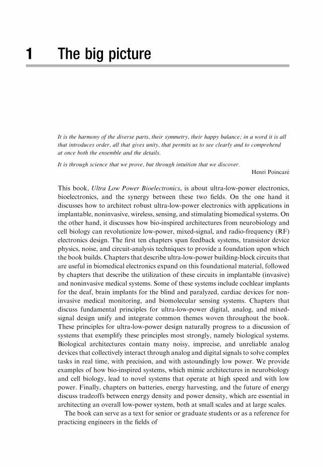
This book, Ultra Low Power Bioelectronics, is about ultra-low-power electronics,
bioelectronics, and the synergy between these two fields. On the one hand it
discusses how to architect robust ultra-low-power electronics with applications in
implantable, noninvasive, wireless, sensing, and stimulating biomedical systems. On
the other hand, it discusses how bio-inspired architectures from neurobiology and
cell biology can revolutionize low-power, mixed-signal, and radio-frequency (RF)
electronics design. The first ten chapters span feedback systems, transistor device
physics, noise, and circuit-analysis techniques to provide a foundation upon which
the book builds. Chapters that describe ultra-low-power building-block circuits that
are useful in biomedical electronics expand on this foundational material, followed
by chapters that describe the utilization of these circuits in implantable (invasive)
and noninvasive medical systems. Some of these systems include cochlear implants
for the deaf, brain implants for the blind and paralyzed, cardiac devices for non-
invasive medical monitoring, and biomolecular sensing systems. Chapters that
discuss fundamental principles for ultra-low-power digital, analog, and mixed-
signal design unify and integrate common themes woven throughout the book.
These principles for ultra-low-power design naturally progress to a discussion of
systems that exemplify these principles most strongly, namely biological systems.
Biological architectures contain many noisy, imprecise, and unreliable analog
devices that collectively interact through analog and digital signals to solve complex
tasks in real time, with precision, and with astoundingly low power. We provide
examples of how bio-inspired systems, which mimic architectures in neurobiology
and cell biology, lead to novel systems that operate at high speed and with low
power. Finally, chapters on batteries, energy harvesting, and the future of energy
discuss tradeoffs between energy density and power density, which are essential in
architecting an overall low-power system, both at small scales and at large scales.
The book can serve as a text for senior or graduate students or as a reference for
practicing engineers in the fields of
Comp. by: PG0963 Stage : Revises2 ChapterID: 9780521857277c01 Date:24/12/09Time:18:03:14 Filepath:G:/01_CUP/3B2/Sarpehskar-9780521857277/Applications/3B2/Proof/9780521857277c01.3d
� Ultra-low-power Electronics: Chapters 1 through 22, 25, and 26.� Biomedical Electronics: Chapters 1 through 22, 25, and 26.� Bio-inspired Electronics: Chapters 1 through 18, 21 through 26.� Analog and Mixed-Signal Electronics: Chapters 1 through 24.
In this busy day and age, many people with an interest in these fields may not
have the time to read a whole book, especially one of this size. Therefore, the book
has been written so that a reader interested in only a chapter or two can read the
chapter and delve deeper if he/she would like. There is a slight amount of
redundancy in each chapter to enable such sampling, with interconnections among
the various chapters outlined throughout every chapter. The index should also be
useful in this regard. Every reader should read Chapter 1 (this chapter). Chapter 2
on the fundamentals of feedback is also essential for a deeper understanding of
many chapters. Chapters 1 through 10 provide a firm foundation, necessary for a
deep understanding of the whole book.
Throughout this book, intuitive, geometric, and physical thinking are empha-
sized over formal, algebraic, and symbolic thinking. Physical intuition is extremely
important in getting systems to work in the world since they do not always behave
like they do in simulations or as the mathematical idealizations suggest they do.
When the mathematics becomes intractable, usually the case in all but the simplest
linear and idealized systems, intuitive and physical thinking can still yield powerful
insights about a problem, insights that allow one to build high-performance
circuits. Practice in physical thinking can lead to a lightning-fast understanding
of a new circuit that lots of tedious algebra simply can never provide. Neverthe-
less, one must attempt to be as quantitative as possible for a deep understanding of
any system and for theory and experiment to agree well. Thus, the book does not
aim to substitute qualitative understanding for quantitative understanding; rather
it attempts to maximize insight and minimize algebraic manipulations. We will
always aim to look at problems in a physically insightful and original way such
that the answer is intuitive and can be obtained exactly and quickly because the
picture in our heads is clear.
Feedback is so fundamental to a deep understanding of how circuits work and
how biology works that we shall begin this book with a review of feedback systems
in Chapter 2. We shall see in this chapter that feedback is ubiquitous in physical,
chemical, biological, and engineering systems even though the importance of
feedback has been largely unappreciated. Throughout the book, we shall draw
on our knowledge of feedback systems to derive or interpret results in a simple
way that would not be possible without the use of this knowledge. For example,
our discussion of physics in anMOS transistor will often use feedback analogies to
understand the physics of their operation intuitively in Chapters 3 and 4. The
equations of electron velocity saturation in anMOS transistor will be represented as
a feedback loop in Chapter 6. We shall often avoid tedious Kirchoff’s current law
algebraic equations by simply drawing a feedback loop to provide all the answers
for any transfer function, noise or offset analysis, robustness analysis, or dynamic
4 The big picture
Comp. by: PG0963 Stage : Revises2 ChapterID: 9780521857277c01 Date:24/12/09Time:18:03:15 Filepath:G:/01_CUP/3B2/Sarpehskar-9780521857277/Applications/3B2/Proof/9780521857277c01.3d
analysis that we may need. We shall use feedback interpretations to understand how
the noise in a transistor is affected by internal feedback within it. A deep under-
standing of feedback and circuits can enable a unified understanding of several
systems in the world.
In both biomedical and bio-inspired electronics, it is important to deeply
understand the biology. To understand and mimic biological systems in this book,
we shall use circuits as a primary language rather than mathematics. Several
nonlinear partial differential equations and structures in biology then translate
into simple intuitive, lumped or distributed circuits. For example, we use such
circuits to mimic the inner ear or cochlea, to understand the retina in the eye, to
understand and mimic the heart, to mimic the vocal tract, to mimic spiking
(pulsatile) neurons in the brain, and to understand and mimic biochemical gene–
protein and protein–protein molecular networks within cells. Such circuits can
help make engineers and physicists more comfortable with biology because it is
described in a familiar language. Distributed circuits will help us understand
Maxwell’s equations and antennas intuitively. Circuits will help us quickly under-
stand chemical reactions. Circuits will even help us understand the energy
efficiency of cars.
In the rest of this chapter, we shall summarize some themes, ideas, principles, and
biomedical and bio-inspired system examples that are discussed in depth elsewhere
in the book. In this introductory chapter, the aim is to provide an intuitive
‘big picture’ without getting caught up in details, citations, proofs, mathematical
equations and definitions, subtleties, and exceptions, which are addressed in the
remaining chapters of the book. We shall start by discussing the importance of
ultra-low-power electronics. We shall describe a power-efficient regime of transistor
operation known as the subthreshold regime, which is enabling in low-power
design. We shall then discuss important connections between information, energy,
and power. We shall highlight some key themes for designing ultra-low-power
mixed-signal systems that have analog and digital parts. We shall discuss examples
of biomedical application contexts for low-power design, and fundamental prin-
ciples of low-power design that are applicable to all systems, analog or digital,
electronic or biological. After providing some numbers for the amazing energy
efficiency of biological systems, we shall briefly discuss examples of systems inspired
by neurobiology and by cell biology. Then, we provide a discussion of batteries
and other energy sources, highly important components of low-power systems at
small scales and at large scales. Finally, we shall conclude with a summary of the
book’s sections and some notes on conventions followed in the book.
1.1 Importance of ultra-low-power electronics
Ultra-low-power electronics in this book usually refers to systems that operate
anywhere from a pico- to a milliwatt. However, the principles of ultra-low-power
design are useful in all kinds of systems, even in low-power microprocessors, that
51.1 Importance of ultra-low-power electronics
Comp. by: PG0963 Stage : Revises2 ChapterID: 9780521857277c01 Date:24/12/09Time:18:03:15 Filepath:G:/01_CUP/3B2/Sarpehskar-9780521857277/Applications/3B2/Proof/9780521857277c01.3d
dissipate 1W, say, rather than 30W,without compromising performance. In general,
ultra-low-power electronic design is important in five different kinds of systems:
1. Systems that need to be portable or mobile and therefore operate with a battery
or other energy source of reasonable size with a long lifetime or long time
between recharges. The more miniature the system, the smaller the energy
source, and the more stringent is the power constraint.
2. Systems that function by harvesting relatively small amounts of energy from
their environment.
3. Systems that need to minimize heat dissipation.
4. Complex systems with many devices whose complexity simply will not scale
unless the power and consequently heat dissipation of each of their components
is kept within check.
5. Systems where the overall cost is a strong function of the size of the system or
the cost of the battery in the system.
Biomedical systems are examples of systems where ultra-low-power electronics
is paramount for multiple reasons. For example, biomedical systems that are
implanted within the body need to be small and lightweight with minimal heat
dissipation in the tissue that surrounds them. In some systems like cardiac pace-
makers, the implanted units are often powered by a non-rechargeable battery. In
others, like cochlear implants, the implants are traditionally constantly powered
by rectified wireless energy provided by a unit outside the body. In either case,
power dissipation dictates the size of the needed receiving coil, antenna, or battery,
and therefore sets a minimal size constraint on the system. Size is important to
ensure that there is space within the body for the implant and that surgical
procedures are viable. Implant-grade batteries need conservative short-circuit-
protection mechanisms to mitigate concerns about battery shorting and resultant
tissue heating within the body. They are relatively expensive and the cost of
implanted systems is strongly impacted by the costs of the battery. The costs of
hermetic sealing and bio-compatibility of electronic implants are size dependent as
well. A fully implanted system with a battery that has a limited number of wireless
recharges must operate under stringent low-power constraints such that constant
surgery is not needed to change the battery in a patient. The system must ideally
function for 10 to 30 years without the need for a battery replacement. Implanted
systems with ultra capacitors are capable of more recharges than batteries, but
they have low energy densities such that more frequent recharging is necessary.
Thus, ultra-low-power operation will always be paramount in implantable
biomedical systems.
Noninvasive biomedical systems like cardiac medical tags are attached to
the skin or to clothing for patient monitoring. They are powered by received
RF energy or by a battery and also need to operate in an ultra-low-power fashion.
In certain lab-on-a-chip or biomolecular-sensing instrumentation, ultra-low-noise
and precision electronics is often more important than ultra-low-power operation.
Fortunately, a good ultra-low-power designer is also a good ultra-low-noise
6 The big picture

Comp. by: PG0963 Stage : Revises2 ChapterID: 9780521857277c01 Date:24/12/09Time:18:03:16 Filepath:G:/01_CUP/3B2/Sarpehskar-9780521857277/Applications/3B2/Proof/9780521857277c01.3d
designer, since both kinds of designers need to be skilled in the management
of circuit noise. Therefore, many of the techniques for ultra-low-power design
that we discuss in this book will also enable the reader to become a skilled ultra-
low-noise designer. For example, we will discuss how to architect electronics for
a micro-electro-mechanical-system (MEMS) vibration sensor with 0.125 parts-
per-million sensitivity (23-bit precision), and for ultra-low-noise and micropower
neural and cardiac amplifiers in the book.
This book will, in large part, use biomedical systems as examples. However, the
principles, techniques, and circuits that we describe in this book are general and
are applicable in several other portable systems such as in cell phones, next-
generation radios, sensor networks, space, and military hardware. In fact, many
of the principles of ultra-low-power design that we shall explicitly and implicitly
discuss, e.g., energy recycling, apply to non-electrical systems and at much larger
power scales as well. They can and already are being exploited in the design of
low-power mechanical systems such as next-generation cars. Cars, which operate
on average at nearly 42 kW when going at 30mph today, cannot afford to operate
with such power consumption in our planet’s future.
1.2 The power-efficient subthreshold regime of transistor operation
Since power is the product of voltage and current, low-power systems must
necessarily operate at low voltages and/or low currents1. Electronic systems that
run on 0.5V power-supply voltages already exist. It is hard to scale the power-
supply voltage of electronic circuits below 0.25V and preserve reliable perfor-
mance in digital circuits, as we discuss in Chapter 21. The performance of analog
circuits significantly degrades at such low power-supply voltages. Thus, power
savings via voltage reduction is inherently limited in both the digital and the
analog domains. For ultra-low-power systems, it is more promising to focus on
currents, which can be scaled from pA to mA levels in modern-dayMOS transistors
with appropriate use of transistor geometries and bias voltages in the subthreshold
regime of transistor operation.
The subthreshold region of operation is present in a transistor when it is
operated below its threshold voltage, a region where digital circuits are sometimes
approximated as being ‘turned off’. In reality, the threshold voltage is merely a
useful approximation to describe transistor operation. Just as the current in a diode
decreases exponentially as the voltage across it is decreased, the current in a
subthreshold transistor decreases exponentially as the magnitude of the transistor’s
gate-to-source voltage is decreased. Nevertheless, just as it is sometimes useful to
1 In non-dissipative devices like ideal inductors or capacitors, current and voltage variables are always
orthogonal to each other, such that power is never dissipated even at high voltages and/or high
currents. However, even in such devices, in practice, finite dissipative losses are minimized with low
voltages and/or low currents.
71.2 The power-efficient subthreshold regime of transistor operation
Comp. by: PG0963 Stage : Revises2 ChapterID: 9780521857277c01 Date:24/12/09Time:18:03:17 Filepath:G:/01_CUP/3B2/Sarpehskar-9780521857277/Applications/3B2/Proof/9780521857277c01.3d
view a diode as having a ‘turn-on threshold’ of 0.6V due to the steep nature of
its exponential current–voltage characteristics, it is sometimes useful to view a
transistor as having an abrupt threshold voltage at which it turns on.
The ‘leakage current’ in a transistor that is turned off in a digital system is
dominated by the transistor’s subthreshold current. Such leakage current can be
considerable in large digital systems. For example, 100million transistors� 1 nA
of leakage current per transistor yields 100mA of standby leakage current. Due to
the lowering of the threshold voltage of the transistor in advanced transistor
processes, the absolute value of the subthreshold leakage current increases as
MOS technologies progress towards ever-smaller dimensions. Subthreshold opera-
tion also occupies an increasingly larger fraction of the range of power-supply
operation as transistor sizes get progressively smaller. For all of these reasons, there
has been a great renewal of interest in the subthreshold regime of operation.
Subthreshold operation in both analog and digital circuits has almost become
a necessity.
The maximal frequency of operation possible in diffusion-current-determined
subthreshold operation scales inversely with the square of the transistor’s channel
length. In contrast, the maximal speed of velocity-saturated above-threshold
operation only scales inversely with the channel length. Thus, subthreshold opera-
tion is rapidly allowing faster speeds of operation and may no longer be viewed
as a ‘slow regime’ of operation of the transistor. For example, 1GHz analog
preamplifiers with all-subthreshold operation can now be built in a 0.18 mmprocess and digital circuits can be made to operate at such speeds as well.
The subthreshold region of operation is a region where the bandwidth avail-
able per ampere of current consumed in the transistor is maximal. The power-
supply voltage needed for subthreshold operation is also minimal since the
saturation voltage of a transistor in subthreshold is only 0.1 V. Due to the high
bandwidth-per-ampere ratio and the ability to use small power-supply voltages,
the bandwidth per watt of power consumed in the transistor is maximized in its
subthreshold regime. Consequently, subthreshold operation is the most power-
efficient regime of operation in a transistor.
For all these reasons, this book focuses heavily on the use of subthreshold
circuits for ultra-low-power electronic design in the analog and the digital
domains. In the subthreshold region of operation, often also referred to as the
weak-inversion region of operation, it is important to ensure that systems are
robust to transistor mismatch, power-supply-voltage noise, and temperature
variations. Hence, circuit biasing and feedback techniques for ensuring robustness
are important. We shall discuss them in various contexts in the book, but parti-
cularly in Chapter 19, where we discuss the design of ultra-low-power biomedical
system chips for implantable applications, and in Chapter 22 on ultra-low-power
digital design. Furthermore, the subthreshold regime is characterized by relatively
high levels of noise, since there are few electrons per unit time to average over.
Thus, throughout the book, we shall discuss device noise, how to mitigate it, how
to analyze it, how to design around it, and, in some cases, how to even exploit it.
8 The big picture
Comp. by: PG0963 Stage : Revises2 ChapterID: 9780521857277c01 Date:24/12/09Time:18:03:17 Filepath:G:/01_CUP/3B2/Sarpehskar-9780521857277/Applications/3B2/Proof/9780521857277c01.3d
Since ultra-energy-efficient biological systems also operate with Boltzmann
exponential devices, subthreshold operation is highly useful in mimicking their
operation. Thus, subthreshold operation is enabling in bio-inspired systems as well.
1.3 Information, energy, and power
Information is always represented by the states of variables in a physical system,
whether that system is a sensing, actuating, communicating, controlling, or com-
puting system or a combination of all types. It costs energy to change or to
maintain the states of physical variables. These states can be in the voltage of a
piezoelectric sensor, in the mechanical displacement of a robot arm, in the current
of an antenna, in the chemical concentration of a regulating enzyme in a cell, or in
the voltage on a capacitor in a digital processor. Hence, it costs energy to process
information, whether that energy is used by enzymes in biology to copy a strand of
DNA or in electronics to filter an input.2 To save energy, one must then reduce the
amount of information that one wants to process. The higher the output precision
and the higher the temporal bandwidth or speed at which the information needs to
be processed, the higher is the rate of energy consumption, i.e., power. To save
power, one must then reduce the rate of information processing. The information
may be represented by analog state variables, digital state variables, or by both.
The information processing can use analog processing, digital processing, or both.
The art of low-power design consists of decomposing the task to be solved in an
intelligent fashion such that the rate of information processing is reduced as far as is
possible without compromising the performance of the system. Intelligent
decomposition of the task involves good architectural system decomposition, a
good choice of topological circuits needed to implement various functions in the
architecture, and a good choice of technological devices for implementing the
circuits. Thus, low-power design requires a deep knowledge of devices, circuits,
and systems. This book shall discuss principles and examples of low-power design
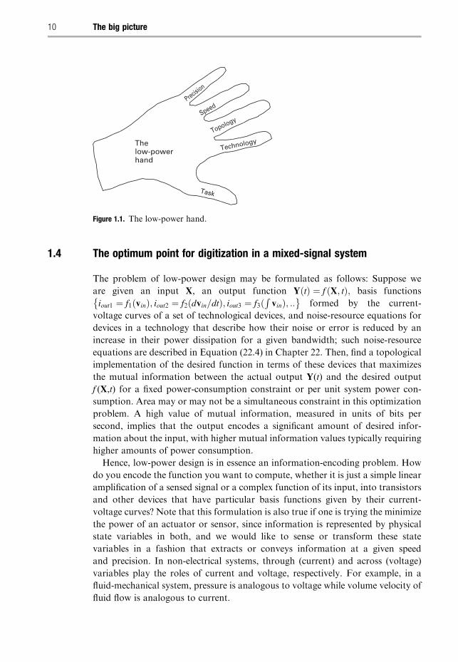
at all of these levels. Figure 1.1 shows the “low-power hand”. The low-power hand
reminds us that the power consumption of a system is always defined by five
considerations, which are represented by the five fingers of the hand: 1) the task
that it performs; 2) the technology (or technologies) that it is implemented in; 3) the
topology or architecture used to solve the task; 4) the speed or temporal bandwidth
of the task; and, 5) the output precision of the task. As the complexity, speed, and
output precision of a task increase, the rate of information processing is increased,
and the power consumption of the devices implementing that task increases.
2 In Chapter 22, we shall see that, technically, if one operates infinitely slowly and in a manner that
allows the states of physical variables to be recovered even after they have been transformed, energy
need not be dissipated. In practice, in both natural and artificial systems, which cannot compute
infinitely slowly, and which always have finite losses, there is always an energy cost to changing or
maintaining the states of physical variables.
91.3 Information, energy, and power
Comp. by: PG0963 Stage : Revises2 ChapterID: 9780521857277c01 Date:24/12/09Time:18:03:18 Filepath:G:/01_CUP/3B2/Sarpehskar-9780521857277/Applications/3B2/Proof/9780521857277c01.3d
1.4 The optimum point for digitization in a mixed-signal system
The problem of low-power design may be formulated as follows: Suppose we
are given an input X, an output function Y tð Þ ¼ f X; tð Þ; basis functions
iout1 ¼ f1ðvinÞ; iout2 ¼ f2ðdvin=dtÞ; iout3 ¼ f3ðRvinÞ; ::
� �formed by the current-
voltage curves of a set of technological devices, and noise-resource equations for
devices in a technology that describe how their noise or error is reduced by an
increase in their power dissipation for a given bandwidth; such noise-resource
equations are described in Equation (22.4) in Chapter 22. Then, find a topological
implementation of the desired function in terms of these devices that maximizes
the mutual information between the actual output Y(t) and the desired output
f (X,t) for a fixed power-consumption constraint or per unit system power con-
sumption. Area may or may not be a simultaneous constraint in this optimization
problem. A high value of mutual information, measured in units of bits per
second, implies that the output encodes a significant amount of desired infor-
mation about the input, with higher mutual information values typically requiring
higher amounts of power consumption.
Hence, low-power design is in essence an information-encoding problem. How
do you encode the function you want to compute, whether it is just a simple linear
amplification of a sensed signal or a complex function of its input, into transistors
and other devices that have particular basis functions given by their current-
voltage curves? Note that this formulation is also true if one is trying the minimize
the power of an actuator or sensor, since information is represented by physical
state variables in both, and we would like to sense or transform these state
variables in a fashion that extracts or conveys information at a given speed
and precision. In non-electrical systems, through (current) and across (voltage)
variables play the roles of current and voltage, respectively. For example, in a
fluid-mechanical system, pressure is analogous to voltage while volume velocity of
fluid flow is analogous to current.
Precision
Speed
Topology
Technology
Task
Thelow-powerhand
Figure 1.1. The low-power hand.
10 The big picture
Comp. by: PG0963 Stage : Revises2 ChapterID: 9780521857277c01 Date:24/12/09Time:18:03:18 Filepath:G:/01_CUP/3B2/Sarpehskar-9780521857277/Applications/3B2/Proof/9780521857277c01.3d
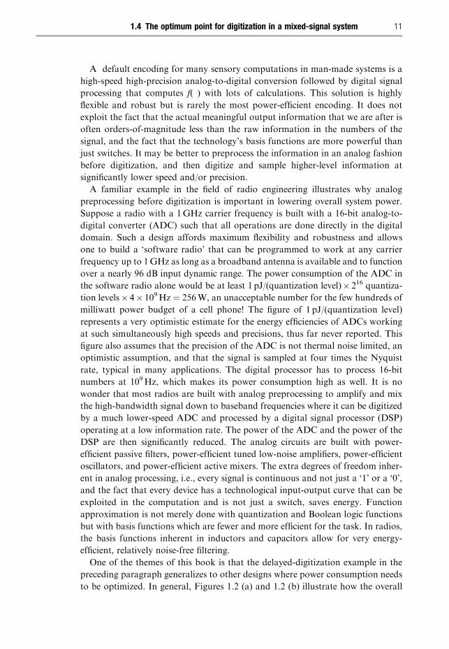
A default encoding for many sensory computations in man-made systems is a
high-speed high-precision analog-to-digital conversion followed by digital signal
processing that computes f( ) with lots of calculations. This solution is highly
flexible and robust but is rarely the most power-efficient encoding. It does not
exploit the fact that the actual meaningful output information that we are after is
often orders-of-magnitude less than the raw information in the numbers of the
signal, and the fact that the technology’s basis functions are more powerful than
just switches. It may be better to preprocess the information in an analog fashion
before digitization, and then digitize and sample higher-level information at
significantly lower speed and/or precision.
A familiar example in the field of radio engineering illustrates why analog
preprocessing before digitization is important in lowering overall system power.
Suppose a radio with a 1GHz carrier frequency is built with a 16-bit analog-to-
digital converter (ADC) such that all operations are done directly in the digital
domain. Such a design affords maximum flexibility and robustness and allows
one to build a ‘software radio’ that can be programmed to work at any carrier
frequency up to 1GHz as long as a broadband antenna is available and to function
over a nearly 96 dB input dynamic range. The power consumption of the ADC in
the software radio alone would be at least 1 pJ/(quantization level)� 216 quantiza-
tion levels� 4� 109Hz ¼ 256W, an unacceptable number for the few hundreds of
milliwatt power budget of a cell phone! The figure of 1 pJ/(quantization level)
represents a very optimistic estimate for the energy efficiencies of ADCs working
at such simultaneously high speeds and precisions, thus far never reported. This
figure also assumes that the precision of the ADC is not thermal noise limited, an
optimistic assumption, and that the signal is sampled at four times the Nyquist
rate, typical in many applications. The digital processor has to process 16-bit
numbers at 109Hz, which makes its power consumption high as well. It is no
wonder that most radios are built with analog preprocessing to amplify and mix
the high-bandwidth signal down to baseband frequencies where it can be digitized
by a much lower-speed ADC and processed by a digital signal processor (DSP)
operating at a low information rate. The power of the ADC and the power of the
DSP are then significantly reduced. The analog circuits are built with power-
efficient passive filters, power-efficient tuned low-noise amplifiers, power-efficient
oscillators, and power-efficient active mixers. The extra degrees of freedom inher-
ent in analog processing, i.e., every signal is continuous and not just a ‘1’ or a ‘0’,
and the fact that every device has a technological input-output curve that can be
exploited in the computation and is not just a switch, saves energy. Function
approximation is not merely done with quantization and Boolean logic functions
but with basis functions which are fewer and more efficient for the task. In radios,
the basis functions inherent in inductors and capacitors allow for very energy-
efficient, relatively noise-free filtering.
One of the themes of this book is that the delayed-digitization example in the
preceding paragraph generalizes to other designs where power consumption needs
to be optimized. In general, Figures 1.2 (a) and 1.2 (b) illustrate how the overall
111.4 The optimum point for digitization in a mixed-signal system
Comp. by: PG0963 Stage : Revises2 ChapterID: 9780521857277c01 Date:24/12/09Time:18:03:18 Filepath:G:/01_CUP/3B2/Sarpehskar-9780521857277/Applications/3B2/Proof/9780521857277c01.3d
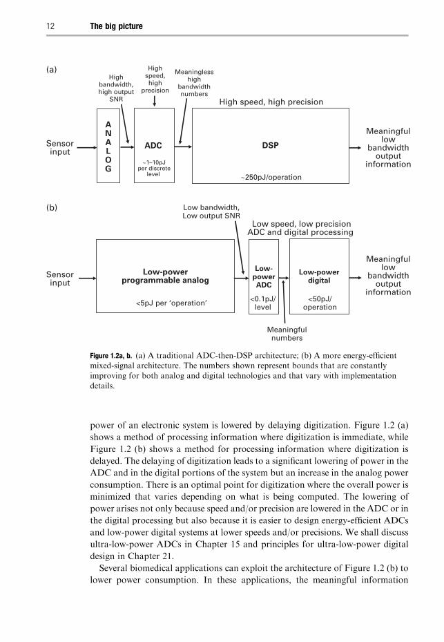
power of an electronic system is lowered by delaying digitization. Figure 1.2 (a)
shows a method of processing information where digitization is immediate, while
Figure 1.2 (b) shows a method for processing information where digitization is
delayed. The delaying of digitization leads to a significant lowering of power in the
ADC and in the digital portions of the system but an increase in the analog power
consumption. There is an optimal point for digitization where the overall power is
minimized that varies depending on what is being computed. The lowering of
power arises not only because speed and/or precision are lowered in the ADC or in
the digital processing but also because it is easier to design energy-efficient ADCs
and low-power digital systems at lower speeds and/or precisions. We shall discuss
ultra-low-power ADCs in Chapter 15 and principles for ultra-low-power digital
design in Chapter 21.
Several biomedical applications can exploit the architecture of Figure 1.2 (b) to
lower power consumption. In these applications, the meaningful information
ADC DSP
High speed, high precision
~1–10pJper discrete
level ~250pJ/operation
Low speed, low precisionADC and digital processing
<5pJ per ‘operation’
(a)
(b)
Highbandwidth,high output
SNR
Highspeed,high
precision
Meaninglesshigh
bandwidthnumbers
Meaningfullow
bandwidthoutput
information
Sensorinput
ANALOG
Meaningfullow
bandwidthoutput
information
Sensorinput
<50pJ/operation
<0.1pJ/level
Low-powerprogrammable analog
Low-powerdigital
Low-powerADC
Low bandwidth,Low output SNR
Meaningfulnumbers
Figure 1.2a, b. (a) A traditional ADC-then-DSP architecture; (b) A more energy-efficientmixed-signal architecture. The numbers shown represent bounds that are constantlyimproving for both analog and digital technologies and that vary with implementation
details.
12 The big picture
Comp. by: PG0963 Stage : Revises2 ChapterID: 9780521857277c01 Date:24/12/09Time:18:03:19 Filepath:G:/01_CUP/3B2/Sarpehskar-9780521857277/Applications/3B2/Proof/9780521857277c01.3d
bandwidth at the output is far less than the information bandwidth at the input
determined by the raw input signal dynamic range and the maximum input
frequency. For example, in cochlear-implant applications, 16-bit speech infor-
mation sampled at 44 kHz, needed for wide-input-dynamic-range and audio
bandwidth operation, yields 704 kb/s of raw input information; the 16-electrode
output information after processing corresponds to 5-bit current-amplitude infor-
mation at a 200Hz sample rate, i.e., 16 kb/s of actual discriminable information by
a subject. In a paralysis prosthetic, 100 neuronal electrodes in the brain may
provide 8-bit, 30 kHz data or 24Mb/s of raw input information; the output
information rate corresponds to 3 output motor-control parameters, updated at
100Hz and 8-bit precision, i.e., 2.4 kb/s, at best. In a pulse-oximetry application,
the input photo-plethysmographic information is about 16 kb/s while the mean-
ingful output information about oxygen saturation may be a few bits per second.
All three of these applications will be discussed in Chapters 19 and 20. In such
applications, the noise and mismatch inherent in analog devices serve to reduce the
information content of the computation during analog preprocessing. However, if
sufficient degrees of freedom are allocated to combat these, the output infor-
mation content, typically significantly less than the raw input information content,
is still robustly preserved. In essence, degrees of freedom in analog processing are
not wasted in making every device and every signal robust but in making the
overall output robust. The book provides concrete examples of systems that are
architected in such a fashion to be robust to thermal noise, transistor mismatch,
1/f noise, temperature variations, power-supply noise, and mixed-signal cross talk.
Chapter 19 discusses an ultra-low-power analog cochlear-implant or bionic-ear
processor in depth to illustrate how such principles are concretely applied and the
various system tradeoffs that are involved in any practical engineering design. In
this processor, 373 digitally programmable bits allow 86 patient parameters to be
changed. Thus, although the architecture of Figure 1.2 (b) is not as flexible as that
of Figure 1.2 (a), enough flexibility is preserved such that the flexibility-efficiency
tradeoff is at a more optimal point [1].
Since the analog preprocessor and the ADC are digitally calibrated or pro-
grammed and output digital bits, they can together appear as an energy-efficient
‘coprocessor’ from the point of view of the digital system. Other designs in the
medical-electronics industry have also used low-power analog preprocessing to
reduce power, for example, in electroencephalogram (EEG) systems [2]. The
reliability of an analog system can be made to be as high as that of any ADC,
and analog systems typically degrade gracefully rather than catastrophically.
Thus, their use in a medical context where graceful degradation is important can
actually be an advantage.
The traditional general-purpose architecture of ADC-then-DSP processing in
Figure 1.2 (a) is highly useful for initial exploration of a system when one desires
maximum flexibility because one does not know exactly what one must do. After
this exploratory stage, when one knows what one must do, the task must be
crafted with a more specialized mixed-signal architecture as in Figure 1.2 (b)
131.4 The optimum point for digitization in a mixed-signal system
Comp. by: PG0963 Stage : Revises2 ChapterID: 9780521857277c01 Date:24/12/09Time:18:03:19 Filepath:G:/01_CUP/3B2/Sarpehskar-9780521857277/Applications/3B2/Proof/9780521857277c01.3d
if power consumption is to be minimized; otherwise, the extra degrees of freedom
inherent in the general-purpose architecture will waste energy without performing
any useful function in the special-purpose task. Even a small amount of analog
preprocessing such as an analog automatic-gain-control system before digitiza-
tion can be advantageous. An option that preserves both flexibility and efficiency
is to have the high-power flexible system only periodically turn on to calibrate
and reprogram parameters in the low-power less-flexible-but-highly-efficient
system.
To architect the low-power system in Figure 1.2 (b), the output after analog
preprocessing must be digitized and then processed digitally. Therefore, low-
power ADC and low-power digital design are also essential. Hence, this book will
discuss ultra-low-power ADC converter design in Chapter 15 and principles
for ultra-low-power digital design in Chapter 21. Low-power electronic systems
today incorporate analog sensors and amplifiers, ADCs, digital processors,
digital-to-analog converters (DACs), radio frequency (RF) transceivers, actuator
electronics, battery recharging and power-electronics circuits, and the battery all
in one package. While much has been written about how the power of digital
systems can be lowered, little attention has been paid to the analog portions of
such systems. In many miniature biomedical and portable systems, the analog and
RF portions can easily dominate the power of the overall system especially if
programmable analog preprocessing reduces digital processing power to insignifi-
cant levels compared with sensor, actuator, or RF power. In this book, ultra-low-
power analog and digital design are both discussed, though more emphasis is
placed on analog and mixed-signal operation. Principles for low-power analog
design do not seem to be commonly known and are extremely important in
lowering the power of an overall system. Hence, several chapters in the book
discuss low-power analog circuits useful for biomedical applications such as filters,
amplifiers, RF inductive recharging circuits, RF energy-harvesting antenna cir-
cuits, RF telemetry circuits, electrode-stimulation circuits, MEMS sensor circuits,
imager circuits, microphone circuits, automatic-gain-control circuits, and energy-
extraction circuits. Some bio-inspired circuits that we discuss are useful in non-
biological applications such as in wireless communication, in speech recognition,
or in image processing.
1.5 Examples of biomedical application contexts
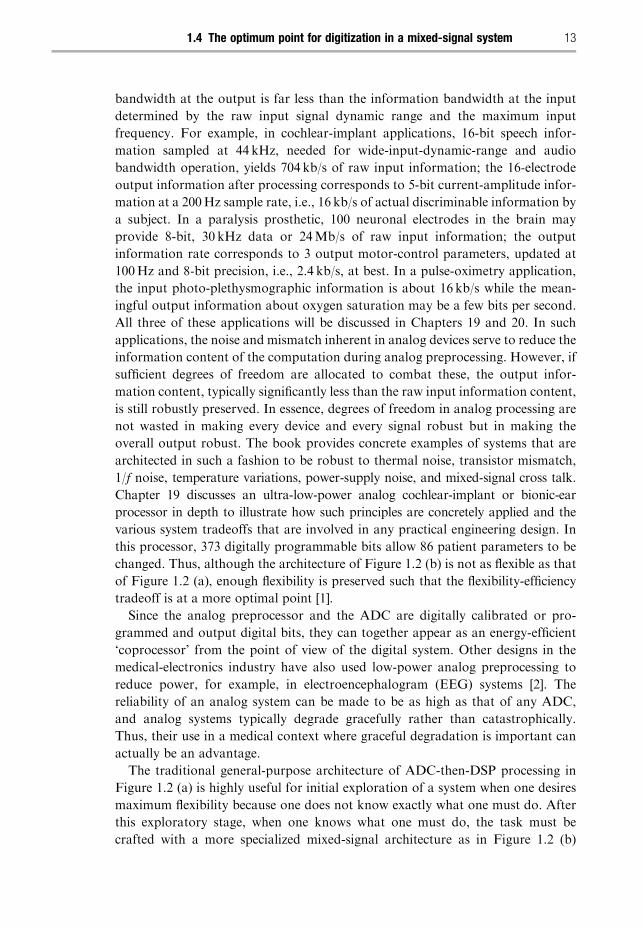
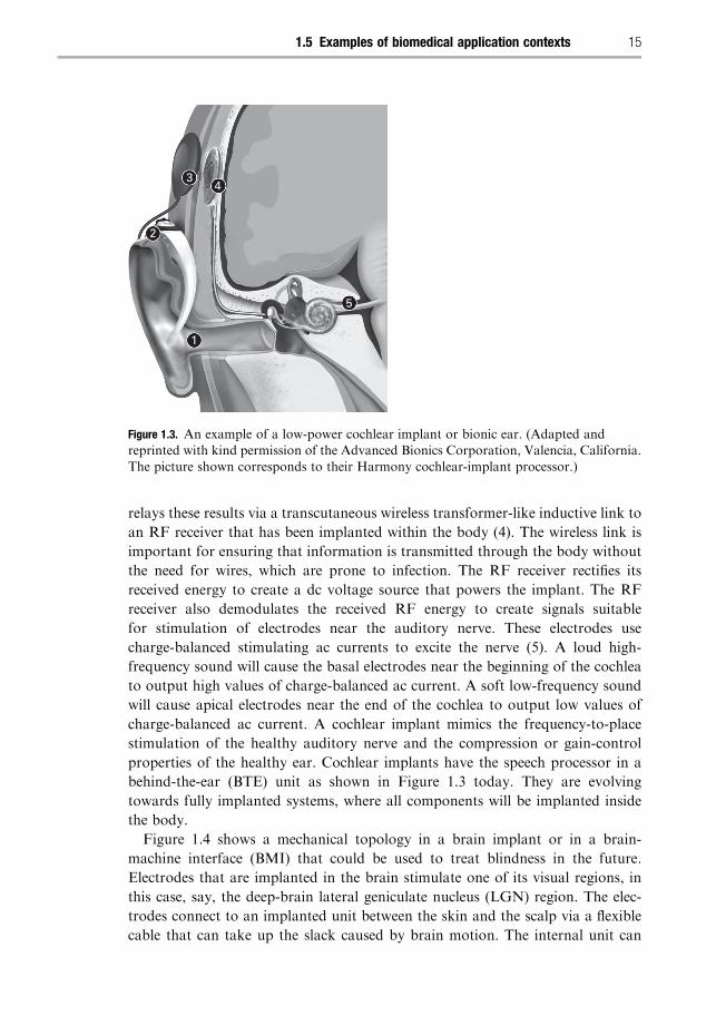
Figure 1.3 shows the mechanical topology of a cochlear implant or bionic ear
whose configuration bears similarity to that in many biomedical implants today.
Such cochlear implants enable profoundly deaf people, for whom a hearing aid is
not beneficial, to hear. In this particular case, a microphone (1) transduces sound
into an electrical signal, which is conveyed via a cable within the ‘hook’ to a speech
processor located behind the ear (2). The speech processor relays the results of
its spectral-analysis and gain-control processing to an RF coil (3). The RF coil
14 The big picture
Comp. by: PG0963 Stage : Revises2 ChapterID: 9780521857277c01 Date:24/12/09Time:18:03:20 Filepath:G:/01_CUP/3B2/Sarpehskar-9780521857277/Applications/3B2/Proof/9780521857277c01.3d
relays these results via a transcutaneous wireless transformer-like inductive link to
an RF receiver that has been implanted within the body (4). The wireless link is
important for ensuring that information is transmitted through the body without
the need for wires, which are prone to infection. The RF receiver rectifies its
received energy to create a dc voltage source that powers the implant. The RF
receiver also demodulates the received RF energy to create signals suitable
for stimulation of electrodes near the auditory nerve. These electrodes use
charge-balanced stimulating ac currents to excite the nerve (5). A loud high-
frequency sound will cause the basal electrodes near the beginning of the cochlea
to output high values of charge-balanced ac current. A soft low-frequency sound
will cause apical electrodes near the end of the cochlea to output low values of
charge-balanced ac current. A cochlear implant mimics the frequency-to-place
stimulation of the healthy auditory nerve and the compression or gain-control
properties of the healthy ear. Cochlear implants have the speech processor in a
behind-the-ear (BTE) unit as shown in Figure 1.3 today. They are evolving
towards fully implanted systems, where all components will be implanted inside
the body.
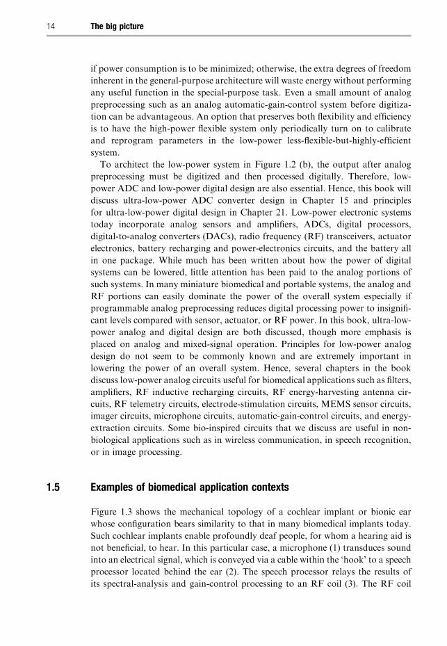
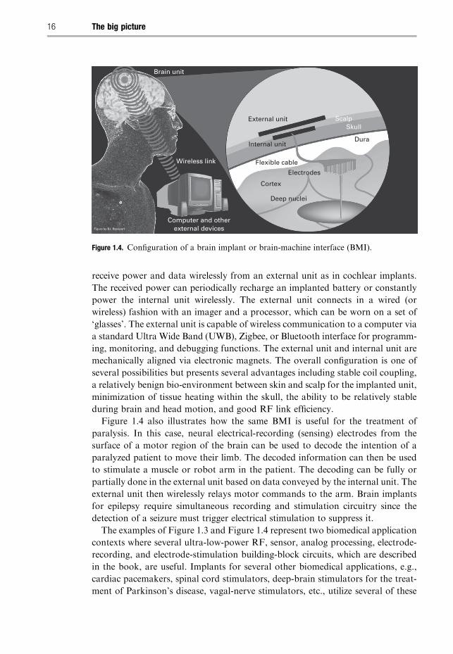
Figure 1.4 shows a mechanical topology in a brain implant or in a brain-
machine interface (BMI) that could be used to treat blindness in the future.
Electrodes that are implanted in the brain stimulate one of its visual regions, in
this case, say, the deep-brain lateral geniculate nucleus (LGN) region. The elec-
trodes connect to an implanted unit between the skin and the scalp via a flexible
cable that can take up the slack caused by brain motion. The internal unit can
1
2
34
5
Figure 1.3. An example of a low-power cochlear implant or bionic ear. (Adapted andreprinted with kind permission of the Advanced Bionics Corporation, Valencia, California.
The picture shown corresponds to their Harmony cochlear-implant processor.)
151.5 Examples of biomedical application contexts
Comp. by: PG0963 Stage : Revises2 ChapterID: 9780521857277c01 Date:24/12/09Time:18:03:20 Filepath:G:/01_CUP/3B2/Sarpehskar-9780521857277/Applications/3B2/Proof/9780521857277c01.3d
receive power and data wirelessly from an external unit as in cochlear implants.
The received power can periodically recharge an implanted battery or constantly
power the internal unit wirelessly. The external unit connects in a wired (or
wireless) fashion with an imager and a processor, which can be worn on a set of
‘glasses’. The external unit is capable of wireless communication to a computer via
a standard Ultra Wide Band (UWB), Zigbee, or Bluetooth interface for programm-
ing, monitoring, and debugging functions. The external unit and internal unit are
mechanically aligned via electronic magnets. The overall configuration is one of
several possibilities but presents several advantages including stable coil coupling,
a relatively benign bio-environment between skin and scalp for the implanted unit,
minimization of tissue heating within the skull, the ability to be relatively stable
during brain and head motion, and good RF link efficiency.
Figure 1.4 also illustrates how the same BMI is useful for the treatment of
paralysis. In this case, neural electrical-recording (sensing) electrodes from the
surface of a motor region of the brain can be used to decode the intention of a
paralyzed patient to move their limb. The decoded information can then be used
to stimulate a muscle or robot arm in the patient. The decoding can be fully or
partially done in the external unit based on data conveyed by the internal unit. The
external unit then wirelessly relays motor commands to the arm. Brain implants
for epilepsy require simultaneous recording and stimulation circuitry since the
detection of a seizure must trigger electrical stimulation to suppress it.
The examples of Figure 1.3 and Figure 1.4 represent two biomedical application
contexts where several ultra-low-power RF, sensor, analog processing, electrode-
recording, and electrode-stimulation building-block circuits, which are described
in the book, are useful. Implants for several other biomedical applications, e.g.,
cardiac pacemakers, spinal cord stimulators, deep-brain stimulators for the treat-
ment of Parkinson’s disease, vagal-nerve stimulators, etc., utilize several of these
Brain unit
External unit
Internal unit
Flexible cable
Electrodes
Cortex
ScalpSkull
Dura
Deep nuclei
Wireless link
Figure by B.I. Rapoport
Computer and otherexternal devices
Figure 1.4. Configuration of a brain implant or brain-machine interface (BMI).
16 The big picture
Comp. by: PG0963 Stage : Revises2 ChapterID: 9780521857277c01 Date:24/12/09Time:18:03:21 Filepath:G:/01_CUP/3B2/Sarpehskar-9780521857277/Applications/3B2/Proof/9780521857277c01.3d
same building-block circuits, to architect slightly different systems that all operate
by and large with the same technology base. In fact, biocompatibility design,
hermetic design, mechanical design, and electrode design share several similarities
in all of these applications as well. We shall also discuss how to architect far-field
energy-harvesting RF circuits for non-invasive cardiac medical applications,
which will make the reader familiar with the basic principles of antenna design.
Antenna-based RF communication systems transmit information through a rela-
tively thick portion of the body, e.g., for deep implants such as electronic pills,
used for diagnosis of gastrointestinal disorders. Chapters 10 through 18 discuss
several circuits useful in low-power biomedical applications.
Chapter 19 focuses on implantable electronics, with an emphasis on cochlear
implants and brain implants. It provides a concrete example of the power savings
possible when analog preprocessing is used to delay digitization. Chapter 20
focuses on noninvasive medical electronics with an emphasis on cardiac devices
and biomolecular sensing.
1.6 Principles for ultra-low-power design
The principles for low-power design discussed in the book apply to all systems that
aim to use power efficiently, independent of their absolute power consumption.
These principles are true for both biological systems and electronic systems. They
include:
1. Encoding the task in the computational basis functions of technology in an
efficient fashion to save power, e.g., the use of exponentials to efficiently
compute logarithms in electronics or the use of chemical binding in biology
to multiply.
2. Using energy-efficient regions of operation of technological devices, e.g., the use
of the exponential subthreshold regime of transistor operation in analog and
digital electronics and the use of exponential Boltzmann relations in biology.
3. Delaying digitization via analog preprocessing to reduce the information band-
width in the computation, e.g., as in the filtering and mixing operations in a
radio today or in the image preprocessing done by the retina in the eye.
4. Decomposing tasks into more energy-efficient slow-and-parallel architectures
rather than fast-and-serial ones, e.g., as in several low-power digital architec-
tures today or in slow-and-parallel computation in the brain.
5. Balancing the costs of computation and communication, e.g., as in a wireless
biomedical system transmitting high-level versus low-level information or in
the division of energy for computation versus communication in the brain’s
neuronal computing cells.
6. Reducing the amount of information that needs to be processed, e.g., as in
automatic-gain-control circuits in analog electronics, in gated-clock circuits
in digital electronics, in event-driven asynchronous analog and digital systems,
171.6 Principles for ultra-low-power design
Comp. by: PG0963 Stage : Revises2 ChapterID: 9780521857277c01 Date:24/12/09Time:18:03:22 Filepath:G:/01_CUP/3B2/Sarpehskar-9780521857277/Applications/3B2/Proof/9780521857277c01.3d
in calcium gain-control circuits in the photoreceptor of the eye, and in gated
bio synthesis cell-regulation circuits.
7. Using feedback, knowledge, and learning to improve the efficiency of the
computation via error-correction, compression, and optimization mechanisms,
e.g., as in digitally calibrated analog-to-digital converters, auto-zeroing analog
systems, negative auto-regulation feedback loops within cells, or in adaptive
power-supply circuits in digital design.
8. Architecting the task such that its circuits do not need to be simultaneously fast
and precise, e.g., as in comparators in electronics or in neuronal comparators
in biology.
9. Operating slowly or ‘adiabatically’ with passive and active components that
consume little power, e.g., as in adiabatically clocked digital circuits in electronics,
in high-quality-factor circuits in electronics, or in high-quality-factor mechani-
cal transmission lines in the biological inner ear or cochlea. The quality factor is
a measure of the ratio of the reactive energy to dissipative energy in a system.
These low-power principles are discussed in detail in Chapter 22. Many of the
low-power principles that we have listed apply to both low-power analog and low-
power digital design although they are often manifested in seemingly different
ways. Low-power digital design is discussed in Chapter 21. Chapter 22 discusses
several similarities between low-power analog and low-power digital design. In
both analog and digital systems, natural or artificial systems, robustness and
flexibility trade off against the efficiency of the architecture. Extra degrees of
freedom are always needed to attain robustness and flexibility, which compromise
its efficiency. A good architecture must be designed to be efficient and robust
without being needlessly flexible. We show in Chapter 22 that biological systems
obey all of the energy-saving principles listed above in an exemplary fashion. They
also obey another important principle that we term collective analog or hybrid
computation and that we explain in Chapter 22 [3], [4]. In addition, they provide us
with clues for building ultra-low-power systems that force us to think outside the
box of traditional engineering designs.
1.7 Ultra-low-power information processing in biology
Biology has designed architectures where many noisy, imprecise, unreliable analog
devices collectively interact through analog and digital signals to solve a task in
real time, precisely, and with astoundingly low power. For example, a single
neuron in the brain performs highly complex real-time pattern recognition, spatio-
temporal filtering, and learning tasks with �0.66 nW of power. The �22 billionneurons of the brain consume only �14.6W of power in an average 65 kg male.
Neurons collectively interact to perform sensorimotor tasks in noisy environments
in real time that no computer can yet match. A single cell in the body performs
�10million energy-consuming biochemical operations per second on its noisy
18 The big picture
Comp. by: PG0963 Stage : Revises2 ChapterID: 9780521857277c01 Date:24/12/09Time:18:03:22 Filepath:G:/01_CUP/3B2/Sarpehskar-9780521857277/Applications/3B2/Proof/9780521857277c01.3d
molecular inputs with �1 pW of average power. Every cell implements a �30,000node gene-protein molecular interaction network within its confines. All the �100trillion cells of the human body consume �80W of power at rest. The average
energy for an elementary energy-consuming operation in a cell is about 20 kT,
where kT is a unit of thermal energy. In deep submicron processes today, switch-
ing energies are nearly 104 – 105 kT for just an elementary 0!1 digital switching
operation. Even at 10 nm, the likely end of business-as-usual transistor scaling in
the future, it is unlikely that we will be able to match such energy efficiency. Unlike
traditional digital computation, biological computation is tolerant to error in
elementary devices and signals. Nature illustrates that it is significantly more
energy efficient to compute with error-prone devices and signals and then correct
for these errors through feedback-and-learning architectures than to make every
device and every signal in a system robust, as in traditional digital paradigms thus far.
We can learn from Nature, for she has had 1 billion years of experimentation
to evolve magnificent nanotechnological, low-power devices, circuits, topologies,
and architectures in environments where food, and consequently energy, was
scarce. What we learn can help inspire the design of novel engineering systems
termed bio-inspired systems. Such inspiration from nature must always be com-
bined with perspiration and rational design from engineering if the final result is to
be useful. In this book, we shall always take an engineering approach and show
that bio-inspired designs can and do result in impressive engineering architectures.
Birds are not airplanes and airplanes are not birds, but one can shed insight into
the operation of the other. A humble, open, and curious mindset toward ideas in
nature is all that is needed for appreciating this field.
We shall find on several occasions that bio-inspired algorithms, architectures,
and circuits frequently have biomedical applications. Not surprisingly, it helps to
mimic how the biology works if one is attempting to fix it. For example, we shall
discuss an asynchronous stochastic sampling strategy inspired by how the audi-
tory-nerve works in Chapter 19 that enables an approximately 6� reduction in
electrode stimulation power while maintaining a high effective rate of sampling.
Bio-inspired systems, which have just scratched the surface of what will likely be
possible in the future, already show that there are several clever ideas in biology
that are useful in engineering, and not just for low-power design. Now, we shall
highlight one example of a neuromorphic electronic system, i.e., an electronic
system inspired by neurobiology. The term neuromorphic electronics was coined
by the founder of the field, Carver Mead. We shall describe an RF cochlea, a fast,
power-efficient radio-frequency spectrum analyzer useful in broadband wireless
communication systems.
1.8 Neuromorphic system example: the RF cochlea
The biological inner ear, or cochlea, performs spectrum analysis on its incoming
sound input through the use of a mechanical transmission-line architecture.
191.8 Neuromorphic system example: the RF cochlea
Comp. by: PG0963 Stage : Revises2 ChapterID: 9780521857277c01 Date:24/12/09Time:18:03:23 Filepath:G:/01_CUP/3B2/Sarpehskar-9780521857277/Applications/3B2/Proof/9780521857277c01.3d
The transmission-line architecture of the cochlea has exponentially tapered time
constants from its beginning or high-frequency base location to its ending or low-
frequency apex location. The net result is that the cochlea separates sounds based
on their frequencies, with high-frequency sounds stimulating the base or beginning
of the cochlea and low-frequency sounds stimulating the apex or end of the
cochlea. Thus, the cochlea functions as a spectrum analyzer that performs a
frequency-to-space or frequency-to-location transformation on its sound input.
It operates over an ultra-broadband 100:1 sound-carrier-frequency range of
�100Hz to 10 kHz with good sensitivity. The cochlea also performs gain control
and compression on its sound input via a distributed amplification system within
the transmission line that is highly energy efficient. Therefore, we can hear over a
120 dB input dynamic range with a minimum detectable signal of 0.05 A at our ear
drums at our most-sensitive frequency of �3 kHz. The power consumption of the
cochlea is �14 mW even though it implements at least �1 billion floating-point
operations per second. Nonlinearity and gain-control in the cochlea are important
for enhancing signals in noisy environments and for our ability to hear speech in
noise. An appendix in Chapter 23 discusses how we can estimate power and/or
information processing rates in the ear, the eye, the brain, and the body.
The ear operates remarkably like an ultra-broadband super-radio for sound
waves with 3,500 output spectral channels operating in parallel. The outer ear or
pinna is a directional antenna. The middle ear is an impedance-matching trans-
former that matches the impedance of the antenna to the impedance of the inner
ear or cochlea. The piezoelectric outer hair cells in the cochlea function like
amplifiers that enhance the passive resonant gain of its membrane-and-fluid
transmission-line structure. The inner hair cells in the cochlea function like
rectifying demodulators that detect modulations of the carrier sound waves
propagating through the cochlea. Finally, the auditory-nerve output spikes or
pulses sample and partially quantize the inner-hair-cell cochlear output for
eventual communication to the brain. Figure 19.1 in Chapter 19 reveals some
of the anatomy of the ear.
We show in Chapter 23 that the exponentially tapered time-constant architec-
ture of the cochlear transmission-line allows the cochlea to implement the fastest
and most-efficient spectrum-analysis architecture that is currently known. For a
spectrum analyzer with N output bins operating over a given input-frequency
range, the cochlear architecture only consumes O(N) resources in time and O(N)
resources in hardware to perform spectrum analysis. In contrast, a constant
fractional-bandwidth analog filter bank spectrum analyzer consumes O(N)
resources in time and O(N2) resources in hardware. A fast-fourier-transform
(FFT) fixed-bandwidth spectrum-analyzer consumes O(Nlog2N) resources in time
and O(Nlog2N) resources in hardware. A traditional swept-sine spectrum analyzer
consumes O(N2) resources in time and O(1) resources in hardware. Thus, the
cochlear architecture has a good tradeoff between the use of temporal resources
and hardware resources, and for a given amount of hardware resources its
architecture for spectrum analysis leads to the quickest performance.
20 The big picture
Comp. by: PG0963 Stage : Revises2 ChapterID: 9780521857277c01 Date:24/12/09Time:18:03:23 Filepath:G:/01_CUP/3B2/Sarpehskar-9780521857277/Applications/3B2/Proof/9780521857277c01.3d
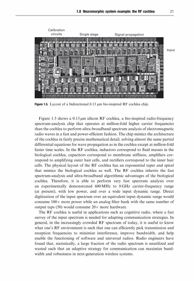
Figure 1.5 shows a 0.13 mm silicon RF cochlea, a bio-inspired radio-frequency
spectrum-analysis chip that operates at million-fold higher carrier frequencies
than the cochlea to perform ultra-broadband spectrum analysis of electromagnetic
radio waves in a fast and power-efficient fashion. The chip mimics the architecture
of the cochlea in fairly precise mathematical detail, solving almost the same partial
differential equations for wave propagation as in the cochlea except at million-fold
faster time scales. In the RF cochlea, inductors correspond to fluid masses in the
biological cochlea, capacitors correspond to membrane stiffness, amplifiers cor-
respond to amplifying outer hair cells, and rectifiers correspond to the inner hair
cells. The physical layout of the RF cochlea has an exponential taper and spiral
that mimics the biological cochlea as well. The RF cochlea inherits the fast
spectrum-analysis and ultra-broadband algorithmic advantages of the biological
cochlea. Therefore, it is able to perform very fast spectrum analysis over
an experimentally demonstrated 600MHz to 8GHz carrier-frequency range
(at present), with low power, and over a wide input dynamic range. Direct
digitization of the input spectrum over an equivalent input dynamic range would
consume 100� more power while an analog filter bank with the same number of
output taps (50) would consume 20� more hardware.
The RF cochlea is useful in applications such as cognitive radio, where a fast
survey of the input spectrum is needed for adapting communication strategies. In
general, in the increasingly crowded RF spectrum of today, it is useful to know
what one’s RF environment is such that one can efficiently pick transmission and
reception frequencies to minimize interference, improve bandwidth, and help
enable the functioning of software and universal radios. Radio engineers have
found that, statistically, a large fraction of the radio spectrum is unutilized and
wasted such that an adaptive strategy for communication can maximize band-
width and robustness in next-generation wireless systems.
Input
Single stageCalibration
circuits Signal propagation
Figure 1.5. Layout of a bidirectional 0.13 mm bio-inspired RF cochlea chip.
211.8 Neuromorphic system example: the RF cochlea
Comp. by: PG0963 Stage : Revises2 ChapterID: 9780521857277c01 Date:24/12/09Time:18:03:24 Filepath:G:/01_CUP/3B2/Sarpehskar-9780521857277/Applications/3B2/Proof/9780521857277c01.3d
The RF cochlea is an extremely recent neuromorphic architecture, which
will undoubtedly evolve over time [5]. However, it has already excited interest
and enthusiasm in the radio-engineering community. In general, inspiration
from the ear and auditory system may lead to revolutionary RF architectures
in the future.
1.9 Cytomorphic electronics
Circuits in cell biology and circuits in electronics may be viewed as being highly
similar with biology using molecules, ions, proteins, and DNA rather than elec-
trons and transistors. Just as neural circuits have led to biologically inspired
neuromorphic electronics, cellular circuits can lead to a novel biologically inspired
field that we introduce in this book and term cytomorphic electronics. We will show
that there are many similarities between spiking-neuron computation and cellular
computation in Chapter 24.
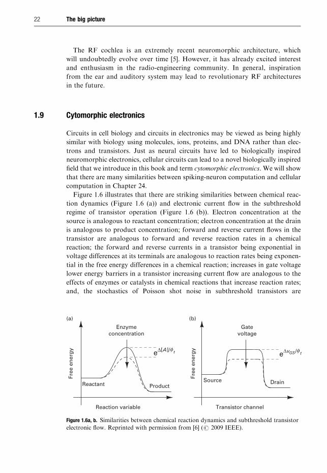
Figure 1.6 illustrates that there are striking similarities between chemical reac-
tion dynamics (Figure 1.6 (a)) and electronic current flow in the subthreshold
regime of transistor operation (Figure 1.6 (b)). Electron concentration at the
source is analogous to reactant concentration; electron concentration at the drain
is analogous to product concentration; forward and reverse current flows in the
transistor are analogous to forward and reverse reaction rates in a chemical
reaction; the forward and reverse currents in a transistor being exponential in
voltage differences at its terminals are analogous to reaction rates being exponen-
tial in the free energy differences in a chemical reaction; increases in gate voltage
lower energy barriers in a transistor increasing current flow are analogous to the
effects of enzymes or catalysts in chemical reactions that increase reaction rates;
and, the stochastics of Poisson shot noise in subthreshold transistors are
Free
en
erg
y
Reaction variable
Enzymeconcentration
(a)
Reactant Product
eΔ[A]/f t eΔvGS/f t
Free
en
erg
y
Transistor channel
(b)
Gatevoltage
Source Drain
Figure 1.6a, b. Similarities between chemical reaction dynamics and subthreshold transistor
electronic flow. Reprinted with permission from [6] (# 2009 IEEE).
22 The big picture
Comp. by: PG0963 Stage : Revises2 ChapterID: 9780521857277c01 Date:24/12/09Time:18:03:25 Filepath:G:/01_CUP/3B2/Sarpehskar-9780521857277/Applications/3B2/Proof/9780521857277c01.3d
analogous to the stochastics of molecular shot noise in reactions. These analogies
suggest that one can mimic and model large-scale chemical-processing systems in
biological and artificial networks very efficiently on an electronic chip at time
scales that could potentially be a million times faster. No one thus far appears to
have exploited the detailed similarity behind the equations of chemistry and the
equations of electronics to build such networks. The single-transistor analogy of
Figure 1.6 is already an exact representation of the chemical reaction A! B
including stochastics, with forward electron flow from source to drain correspond-
ing to the A!B molecular flow and backward electron flow from drain to source
corresponding to the B!A molecular flow. In Chapter 24, we shall build on the
key idea of Figure 1.6 to show how to create current-mode subthreshold transistor
circuits for modeling arbitrary chemical reactions. We can then create large-scale
biochemical reaction networks from such circuits for modeling computation
within and amongst cells.
Since extracellular cell-cell networks also rely on molecular binding and chemi-
cal reactions, networks such as hormonal networks or neuronal networks can be
efficiently modeled using such circuits. Thus, in the future, we can potentially
attempt to simulate cells, organs, and tissues with ultra-fast highly parallel analog
and hybrid analog-digital circuits including molecular stochastics and cell-to-cell
variability on large-scale electronic chips. Such molecular-dynamics simulations
are extremely computationally intensive, especially when the effects of noise,
nonlinearity, network-feedback effects, and cell-to-cell variability are included.
Stochastics and cell-to-cell variability are highly important factors for predicting a
cell’s response to drug treatment, e.g., the response of tumor cells to chemotherapy
treatments. We will show in Chapter 24 that circuit, feedback, and noise-analysis
techniques described in the rest of this book can shed insight into the systems
biology of the cell. For example, flux balance analysis is frequently used to reduce
the search space of parameters in a cell. It is automatically implemented as
Kirchhoff ’s current law in circuits since molecular fluxes map to circuit currents.
Similarly, Kirchhoff’s voltage law automatically implements the laws of thermo-
dynamic energy balance in chemical-reaction loops. Robustness analysis of the
circuit using feedback techniques can shed insight in the future into which genes,
when mutated, will lead to disease in a network, and which will not. Circuit-design
techniques can also be mapped to create synthetic-biology circuits that will
perform useful functions in the future.
1.10 Energy sources
A highly important component of any low-power electronic system is the battery
or energy source. Therefore, the last two chapters of the book are devoted to this
topic. Chapter 25 discusses batteries and electrochemistry in some depth. It shows
how a simple physical interpretation of the equations of electrochemistry lead to
231.10 Energy sources
Comp. by: PG0963 Stage : Revises2 ChapterID: 9780521857277c01 Date:24/12/09Time:18:03:25 Filepath:G:/01_CUP/3B2/Sarpehskar-9780521857277/Applications/3B2/Proof/9780521857277c01.3d
electrical large-signal and small-signal equivalent circuits that make the operation
of batteries intuitive. These equivalent circuits are also useful for modeling
recording and stimulation electrodes in biomedical systems. A new and simple
formula for battery operation that characterizes the loss in battery capacity with
increasing usage and increasing current draw is described. A discussion of how
battery–ultra-capacitor and fuel-cell–battery hybrids can enable advantageous
operation in many systems is presented. We shall see that, in low-power systems,
a battery does not have a longer lifetime only because its power draw is low.
Its lifetime is longer also because it becomes capable of more charge-recharge
cycles and because its geometry within a fixed volume can be architected such that
it has more charge capacity. Furthermore, when the battery supplies current, its
output voltage is higher, increasing its energy efficiency. Thus, the rate of use of
energy is intimately linked to its storage and generation.
Chapter 26 reviews prior work on energy harvesting, including the use of body
motion, body heat, and solar energy in self-powered battery-free biomedical and
portable systems. The fundamental principles of piezoelectric motion-energy
harvesting, thermoelectric body-heat harvesting, and photovoltaic electricity
generation are discussed. Circuit models for energy harvesting are found to be
similar to circuit models for RF energy harvesting discussed in depth in Chapters
16 and 17. We shall find that the principles of low-power electronic design
described in this book apply not just to electronic systems and at small scales,
but are also useful for non-electrical systems and at large scales, e.g., in low-power
cars. An equivalent circuit model of a car can help us understand issues related to
the energy efficiency of transportation. Thus, the transport energy efficiency of,
say, a cheetah versus an electric car or a bicycle, or a bird versus an airplane can be
compared. The current power consumption of the world is largely dominated by
transport, heating, and electricity costs and is a staggering 15TW today. We shall
summarize ideas actively being researched for architecting low-power systems that
function with renewable sources of energy like solar power or biofuels, a highly
likely necessity in our planet’s future.
We shall now conclude our top-down view of some of the book’s contents.
In the next section, we will present a brief bottom-up view of the book’s
organization.
1.11 An overview of the book’s chapters and organization
The book is organized into seven sections, each with several chapters. We shall
discuss each section of the book briefly.
1. The Foundations section of the book contains ten chapters including this
overview chapter, Chapter 1. This section contains a review of feedback
24 The big picture
Comp. by: PG0963 Stage : Revises2 ChapterID: 9780521857277c01 Date:24/12/09Time:18:03:26 Filepath:G:/01_CUP/3B2/Sarpehskar-9780521857277/Applications/3B2/Proof/9780521857277c01.3d
systems in Chapter 2, an in-depth discussion of the device physics of the MOS
transistor in Chapters 3 through 6, and a discussion of noise in devices and
circuits in Chapters 7 and 8, respectively. The section concludes with more
material on feedback systems and feedback-circuit-analysis techniques in
Chapters 9 and 10, respectively.
2. The Low-Power Analog and Biomedical Circuits section of the book is formed
by Chapters 11 through 15. This section contains various circuits that are
useful for low-power biomedical electronics and analog electronic systems in
general. The foundational material from the first section enables design and
analysis of these circuits.
3. The Low-Power RF and Energy-Harvesting Circuits for Biomedical Systems
section of the book is formed by Chapters 16 through 18. It contains a descrip-
tion of energy-efficient power and data radio-frequency (RF) links that are
uniquely suited to biomedical systems.
4. The Biomedical Electronic Systems section of the book contains a chapter on
ultra-low-power implantable electronics, Chapter 19, and a chapter on ultra-
low-power noninvasive medical electronics, Chapter 20. In Chapter 19, exem-
plary systems for cochlear implants for the deaf, brain implants for the blind
and paralyzed, and other implantable systems are discussed. Building-block
low-power circuits from the previous chapters and new circuits unique to
implantable electronics show how large systems can be architected. In Chapter 20,
cardiac devices for noninvasive medical monitoring are discussed. Principles
for biomolecular sensing, such as in bioMEMS and microfluidic systems, are
also discussed.
5. The Principles for Ultra-low-power Analog and Digital Design section of the
book contains one chapter on principles for ultra-low-power digital design,
Chapter 21, and one chapter on principles for ultra-low-power analog and
mixed-signal design, Chapter 22. Similarities in principles for low-power analog
and digital design are discussed. Ten principles for ultra-low-power design are
discussed, all of which are obeyed by ultra-energy-efficient biological systems.
6. The Bio-inspired Systems section of the book comprises two chapters. The first
chapter, Chapter 23, on neuromorphic electronics discusses electronics inspired
by neurobiology. The second chapter, Chapter 24, discusses the novel form of
electronics that we have termed cytomorphic electronics, i.e., electronics inspired
by cell biology. Applications of neuromorphic and cytomorphic electronics to
engineering and medicine are discussed.
7. The Energy Sources section of the book comprises Chapters 25 and 26.
Chapter 25 on batteries and electrochemistry discusses how batteries work
from a unique circuit viewpoint and presents important tradeoffs between
251.11 An overview of the book’s chapters and organization
Comp. by: PG0963 Stage : Revises2 ChapterID: 9780521857277c01 Date:24/12/09Time:18:03:26 Filepath:G:/01_CUP/3B2/Sarpehskar-9780521857277/Applications/3B2/Proof/9780521857277c01.3d
energy density and power density. Chapter 26 discusses energy harvesting
in portable and biomedical systems at small scales and at larger scales. We
show how some of the principles of low-power design that we have studied
apply not only at small scales and in electronics but also at large scales and in
non-electrical systems.
1.12 Some final notes
Problem sets, errata, and instructor material for the book will be available at the
Cambridge University Press website (http://www.cambridge.org/). The author’s
full name will serve as an index term for navigating this site.
The book attempts as far as possible to follow IEEE convention for algebraic
symbols: A dc variable is denoted by IA, a small-signal variable is denoted by ia,
a total-signal variable is denoted by iA, and a frequency-response or Laplace
variable is denoted by Ia( f ) or Ia(s), respectively. Thus, iA=IAþ ia. However, there
are situations in the book where this convention has not been followed to improve
clarity, or where doing so does not matter much in the discussion.
I have tried to write this book such that it is clear, accessible, and rewards the
reader with a broad and deep knowledge in the fields of both ultra-low-power
electronics and bioelectronics. As I have discussed, physically intuitive ways of
thinking are emphasized throughout this book. It is worth noting that it was
Einstein’s impressive physical intuition that enabled him to see that the equations
of special relativity, which had already been stated by Lorenz, had a transparently
simple derivation if one accepted that the speed of light is a constant in nature. It is
no surprise, then, that Einstein said, “The only real valuable thing is intuition.”
While most of us, including the author, do not have Einstein’s physical intuition,
we can take inspiration from Einstein to always strive for his simple intuitive way
of understanding phenomena. It is by developing our scientific intuition that we
can begin to see connections that illuminate the unity of all nature.
References
[1] R. Sarpeshkar, C.D. Salthouse, J. J. Sit, M.W. Baker, S.M. Zhak, T.K. T. Lu,
L. Turicchia and S. Balster. An ultra-low-power programmable analog
bionic ear processor. IEEE Transactions on Biomedical Engineering,
52 (2005), 711–727.
[2] A. T. Avestruz, W. Santa, D. Carlson, R. Jensen, S. Stanslaski, A. Helfenstine and
T. Denison. A 5 mW/channel Spectral Analysis IC for Chronic Bidirectional
Brain-Machine Interfaces. IEEE Journal of Solid-State Circuits, 43 (2008), 3006–3024.
[3] R. Sarpeshkar. Analog versus digital: extrapolating from electronics to neurobiology.
Neural Computation, 10 (1998), 1601–1638.
26 The big picture

Comp. by: PG0963 Stage : Revises2 ChapterID: 9780521857277c01 Date:24/12/09Time:18:03:27 Filepath:G:/01_CUP/3B2/Sarpehskar-9780521857277/Applications/3B2/Proof/9780521857277c01.3d
[4] R. Sarpeshkar and M. O’Halloran. Scalable hybrid computation with spikes.
Neural Computation, 14 (2002), 2003–2038.
[5] S. Mandal, S.M. Zhak and R. Sarpeshkar. A bio-inspired active radio-frequency silicon
cochlea. IEEE Journal of Solid-State Circuits, 44 (2009), 1814–1828.
[6] S. Mandal and R. Sarpeshkar, Log-domain circuit models of chemical reactions.
Proceedings of the IEEE Symposium on Circuits and Systems (ISCAS), Taipei,
Taiwan, 2009.
271.12 Some final notes