Embed Size (px)
Citation preview
Sonus IIUltrasonic Dental Scaler
Instruction ManualEngler Engineering Corporation
1099 East 47th Street, Hialeah, Florida 33013800-445-8581 – 305-688-8581 – FAX 305-685-7671
Web site: www.englerusa.com Support site: www.engler411.com
VER. B 06 / 21 / 2012
Page 1 of 25
Table of ContentsREAD BEFORE YOU START..............................................................................................................3
COMPANY PROFILE...........................................................................................................................4
INTRODUCTION..................................................................................................................................5
INSTALLATION INSTRUCTIONS.......................................................................................................7
SCALER OPERATING INSTRUCTIONS..........................................................................................10
SCALER MAINTENANCE..................................................................................................................12
WATER FILTER CLEANING INSTRUCTIONS.................................................................................16
SADDLE VALVE ASSEMBLY ...........................................................................................................17
WATER TANK INSTRUCTIONS.......................................................................................................20
WATER TANK CARE & MAINTENANCE..........................................................................................21
CARE AND MAINTENANCE OF YOUR PORTABLE WATER TANK...............................................21
TECHNICAL DATA............................................................................................................................22
DIMENSIONS.....................................................................................................................................22
WARRANTY INFORMATION............................................................................................................23
RETURN FOR EVALUATION / REPAIR FORM...............................................................................24
SONUS II LOANER REQUEST FORM ...........................................................................................25
Page 2 of 25
READ BEFORE YOU START
The handpiece, ultrasonic transducer (stack), and tip are water cooled devices and must always have adequate water flow to function properly. The amount of water sent to the handpiece must be regulated according to the power level. If the power level is increased, the amount of water must also be increased. Not having enough water flow throughout the scaling handpiece will cause the handpiece to get hot, degrade transducer life and void the warranty. Remove the stack from handpiece until water flows out, then reinstall stack.
When active, ultrasonic tips vibrate at over a million cycles per minute, if it touches soft tissue or skin it will cause burns due the friction of the vibration. The tip is not normally hot but the ultrasonic vibration will burn you if you touch it, this is due to the friction between the skin and the vibrating tip. This is normal for all ultrasonic scalers. Never let the scaling tip touch soft tissue or skin, Engler Engineering Corporation is not responsible for any damage caused by improper use of this device and / or its accessories.
When using a water bottle, it must be kept pumped to at least 30 PSI. The pressure release valve will slightly move out showing the yellow interior when pressure builds up. As water is used the pressure will decrease and the bottle must be pumped to keep adequate pressure.
Never twist or bend your ultrasonic stack. Be careful not to twist or bend the stack when inserting or removing it from the handpiece. Pull the stack straight out to remove it. Always make sure the stack is properly aligned when inserted into the handpiece. There is a white dot in the handpiece and a hole in the stack, they must be aligned during insertion. Bending the stack or inserting it incorrectly into the handpiece may irreparably damage the stack and degrade it’s ability to vibrate. Improper insertion of the stack may also damage the handpiece as well as cause it to get hot. Damage caused by bending or forcing the stack into the handpiece is not covered by the warranty. A stack removal tool is available from Engler Engineering Corporation, it is part number 47903.
Do not alter the scaling tip. The tip is shaped to deliver the optimum vibrating power level and keep its optimum frequency. Deforming the tip in any way will cause the handpiece to get hot, degrade vibration power and void the warranty.
Dropping the handpiece with the stack and tip may alter or damage your tip causing the handpiece to get hot, degrade vibration power and void your warranty.
Remove the tip from the stack and clean/disinfect after every use.Stack, tips, water filter, and accessories are normal wear and tear items. In order to achieve optimum performance they should be replaced regularly.
The water regulator has multiple turns. Turn the water regulator knob counterclockwise to open and clockwise to close. The amount of turns required is dependent on the supplied water pressure.
The ultrasonic stack normally last six months to a year. To achieve optimum performance replace every six months to a year or as needed. Do not leave the ultrasonic stack inside the ultrasonic handpiece for long periods of time. The O rings may dry out and make it difficult to remove the stack.
Lubricate the stack O rings with an appropriate lubricant for your practice, for example mineral oil or petroleum jelly is appropriate for most practices. A stack removal tool and a maintenance kit are available from Engler Engineering Corporation.
Do not coil tightly, kink or pull the hoses. Kinking the hoses will restrict or cutoff water flow to the unit.
Turn off the unit when not in use. The power switch is on the left side of the unit.
As a safety precaution, all water is purged from the water lines prior to shipping. When installing the unit, no water will come out of the handpiece until the water lines are filled. Remove the stack, turn the water regulator counterclockwise 3 to 4 turns and press on the footswitch until water flows, then reduce water to proper water level and reinstall the stack, nosecone and the tip. Warning the handpiece is water cooled and it will get hot when running with no water.
Page 3 of 25
COMPANY PROFILE
Engler Engineering Corporation has been in business since 1964 and occupies an 8000 square foot facility in Hialeah, Florida (USA). We manufacture ultrasonic dental scalers, polishers and combination units including electro surgery equipment and ultrasonic instruments for the veterinary market as well as a microprocessor controlled anesthesia delivery system and a respiratory monitor for veterinary use only.
We also manufacture dental equipment for the human market. Please visit our website www.englerusa.com for more detailed information or call us at the numbers shown below.
Engler Engineering Corp. acquired the exclusive manufacturing and marketing rights of Dynax products, including stretchers, animal restraint devices, comfort cots, and other products. We also acquired the Alpha-Sonic, Ora-Sonic, and Pro-Sonic line of piezo scalers.
Engler Engineering Corporation’s brand name products proudly include: Son-Mate II dental ultrasonic scaler polisher, Poli-x variable speed polisher, Scale-Aire High speed veterinary dental air unit with ultrasonic scaler / Low speed / high speed / air/water syringe, Excelsior high speed veterinary dental air unit with vacuum / Electrosurgery / ultrasonic scaler / Low speed / high speed / air/water syringe, Tri- Mate scaler / polisher / electro surge (for veterinary use only), and A.D.S. 2000 Anesthesia delivery system / Ventilator (for veterinary use only).
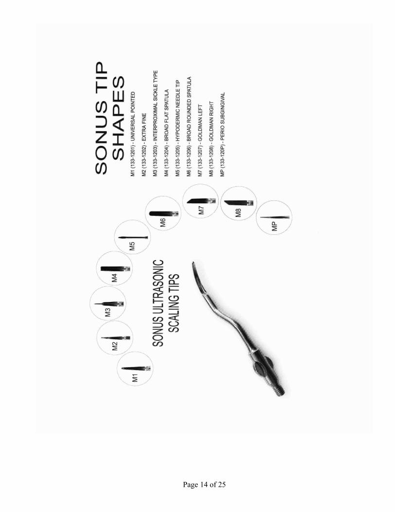
We manufacture all of the inserts and tips used in the Engler products as well as many others on the market today in the 18K, 25K, and 30K frequency range.
Our repair department has the technical knowledge to repair and maintain a number of dental devices manufactured by other companies including Shorline.
Engler Engineering Corporation’s foreign sales are handled through a large and growing network of dental and veterinary distributors. At the present time we are represented throughout the Middle East, Europe, Central and South America, Canada, Asia, New Zealand, Australia, and most other countries.
If you have any questions or comments, please contact us.
Page 4 of 25
INTRODUCTION
Thank you for purchasing an Engler Sonus II Scaler. The design of the Engler Engineering Corporation, Sonus II scaler circuitry uses integrated computer technology along with our Time Remote Feedback Circuitry. This combination produces a powerful and potent tool against periodontal disease. A reinforced solid aluminum chassis surrounds the internal circuit board, providing a very durable and reliable unit. The dental scaler utilizes an ultrasonic principle of operation. The internal circuitry converts ordinary line voltage to an operating frequency of approximately 18,000 Hz. This frequency is then amplified and delivered to the scaling tip. As a result, the tip vibrates at this ultrasonic frequency with an amplitude of 0.001 to 0.004 in. (25.4 um to 102 um). In designing our unique Engler tips, water flows internally through the tip as it vibrates. As the bubbles in the lavage are bactericidal, the energy released collapses and destroys the bacterial cell walls. The water flowing internally through the tip, effectively cools the area and assists in removing any debris from the operative site.This device is equipped with a digital readout that provides an indication of the power that the unit is set at. IMPORTANT:We recommend that ultrasonic scalers should not be used by or in close proximity to anyone who has any electronic implant device (pacemaker, defibrillator, or has any neurological problems).
PLEASE READ VERY CAREFULLY
Engler Engineering Corporation makes every effort to verify that all parts for the device along with any optional accessories ordered were shipped from our facility in Hialeah, Florida and are included in this shipment. It is imperative that you inspect the contents and if you find any pieces missing or damaged, you must notify us immediately. All claims submitted after fifteen days of receipt will not be valid. All devices manufactured and/or sold by Engler Engineering Corporation are built and tested to approved standards. Any modification to the device, cables or hoses, initiated by others nullifies all warranty statements. Engler Engineering Corporation will not be held liable for any loss, damage, injury or death due to non-authorized service and / or improper installation and / or improper use of the device. This manual is not intended to teach dentistry. The information contained herein is intended only as a guide. Individuals not properly trained in dentistry should not use this equipment. It is intended for professional use only.
If you have any questions or comments, please contact us.
Page 5 of 25
Page 6 of 25
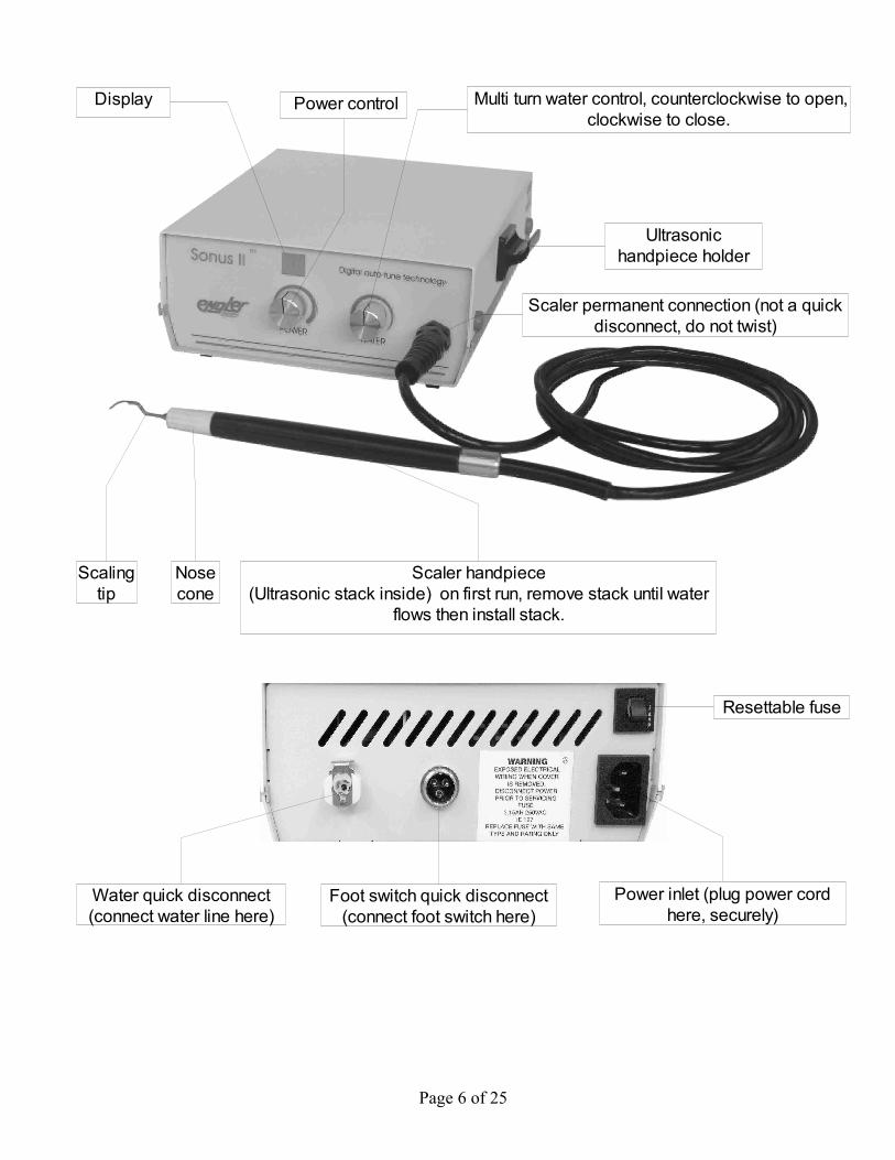
Ultrasonic handpiece holder
Multi turn water control, counterclockwise to open, clockwise to close.
Power control
Scaler handpiece(Ultrasonic stack inside) on first run, remove stack until water
flows then install stack.
Nose cone
Scaling tip
Scaler permanent connection (not a quick disconnect, do not twist)
Display
Water quick disconnect (connect water line here)
Power inlet (plug power cord here, securely)
Resettable fuse
Foot switch quick disconnect (connect foot switch here)
INSTALLATION INSTRUCTIONS
Before installing or operating your new Sonus II, carefully read and follow all of the instructions. IMPORTANT: This device must be connected to a clean, filtered, water supply, capable of delivering 30 to 60 psi (2.0 to 4.2 kg/cm2) of water input pressure. This unit comes with an In-Line water filter (P/N: A52030). When kept clean and free of foreign matter, it will assist in proper water flow to the unit. If the water pressure in your office is above 60 psi, we recommend you install a water pressure regulator on the supply line to your scaler.
CONNECTING WATER SUPPLY:
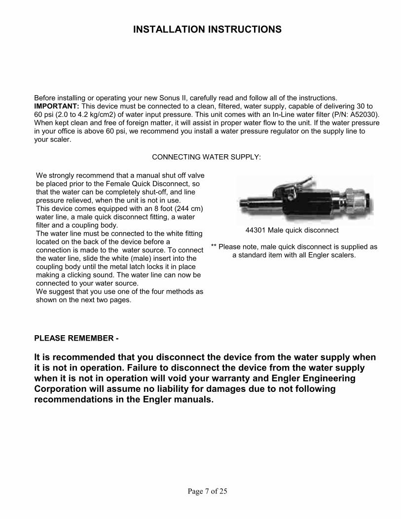
We strongly recommend that a manual shut off valve be placed prior to the Female Quick Disconnect, so that the water can be completely shut-off, and line pressure relieved, when the unit is not in use.This device comes equipped with an 8 foot (244 cm)water line, a male quick disconnect fitting, a water filter and a coupling body. The water line must be connected to the white fitting located on the back of the device before a connection is made to the water source. To connect the water line, slide the white (male) insert into the coupling body until the metal latch locks it in place making a clicking sound. The water line can now be connected to your water source. We suggest that you use one of the four methods as shown on the next two pages.
44301 Male quick disconnect
** Please note, male quick disconnect is supplied as a standard item with all Engler scalers.
PLEASE REMEMBER -
It is recommended that you disconnect the device from the water supply when it is not in operation. Failure to disconnect the device from the water supply when it is not in operation will void your warranty and Engler Engineering Corporation will assume no liability for damages due to not following recommendations in the Engler manuals.
Page 7 of 25
CONNECTING WATER SUPPLY (cont.)
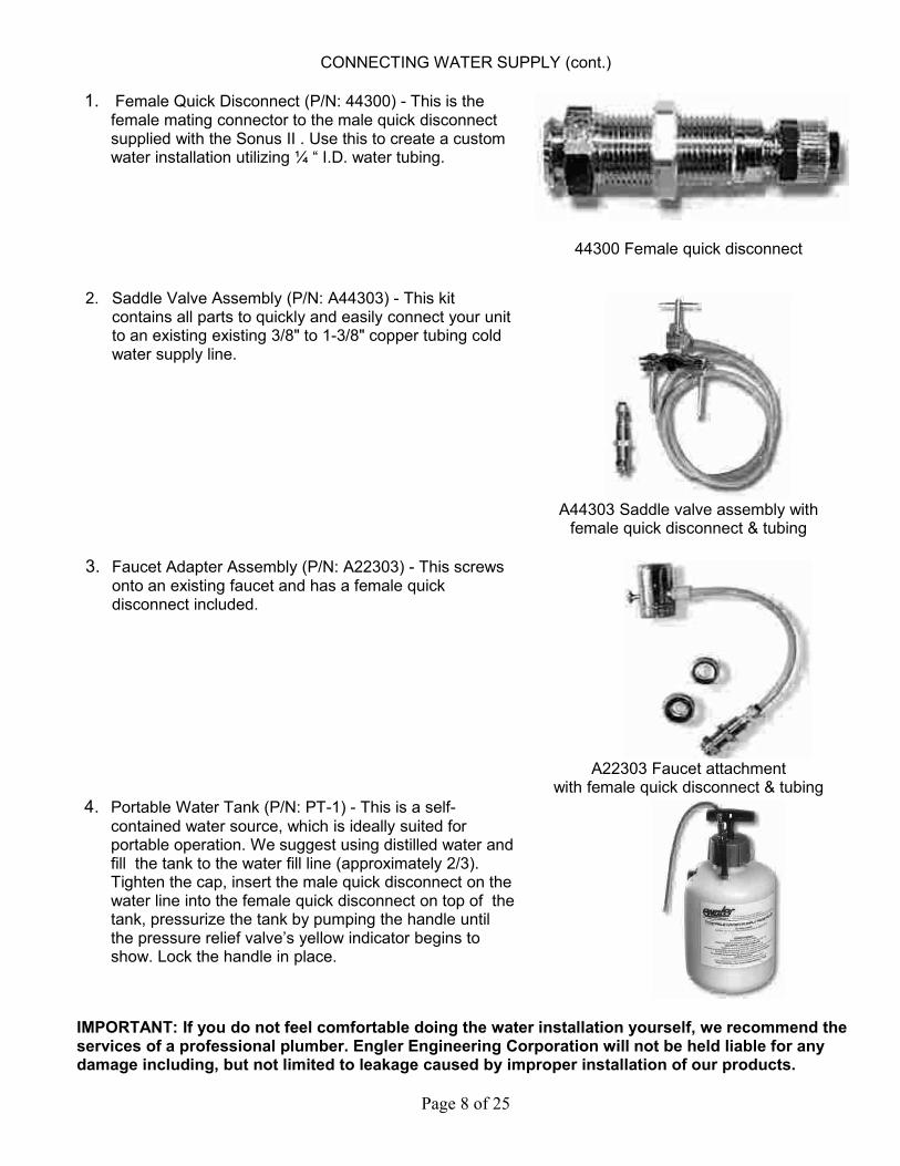
1. Female Quick Disconnect (P/N: 44300) - This is the female mating connector to the male quick disconnect supplied with the Sonus II . Use this to create a custom water installation utilizing ¼ “ I.D. water tubing.
44300 Female quick disconnect
2. Saddle Valve Assembly (P/N: A44303) - This kit contains all parts to quickly and easily connect your unit to an existing existing 3/8" to 1-3/8" copper tubing cold water supply line.
A44303 Saddle valve assembly with female quick disconnect & tubing
3. Faucet Adapter Assembly (P/N: A22303) - This screws onto an existing faucet and has a female quick disconnect included.
A22303 Faucet attachmentwith female quick disconnect & tubing
4. Portable Water Tank (P/N: PT-1) - This is a self-contained water source, which is ideally suited for portable operation. We suggest using distilled water and fill the tank to the water fill line (approximately 2/3). Tighten the cap, insert the male quick disconnect on the water line into the female quick disconnect on top of the tank, pressurize the tank by pumping the handle until the pressure relief valve’s yellow indicator begins to show. Lock the handle in place.
IMPORTANT: If you do not feel comfortable doing the water installation yourself, we recommend the services of a professional plumber. Engler Engineering Corporation will not be held liable for any damage including, but not limited to leakage caused by improper installation of our products.
Page 8 of 25

CONNECTING WATER SUPPLY (cont.)
PLEASE NOTE: Minerals and foreign particles in the water may cause a buildup or blockage of internal hoses and parts. The water filter supplied with this device must be opened and inspected quarterly and we suggest that the filter disc and O ring be changed out at least once a year. See WATER FILTER CLEANING INSTRUCTIONS.
CONNECTING THE FOOT SWITCH: To connect the footswitch to the unit, insert the male quick disconnect into the female quick disconnect on the rear of the device and then tighten the securing nut by turning it clockwise.
CONNECTING POWER SUPPLY: First plug the power cord into the unit and then plug the male end of the power cord into a grounded power outlet. DO NOT remove or bypass the ground pin from the power cord of this device. Doing so will void the warranty.
IMPORTANT: Your Sonus II has been equipped with a universal switching power supply and will not require adjustments in this regard. See technical data for specifications.
Page 9 of 25
SCALER OPERATING INSTRUCTIONS
Initial procedures at the start of every day:1. Make sure the power switch is ON, it is located on the left side of the unit.2. Adjust the power control knob to the minimum power setting fully counter-clockwise. The digital
readout will read 1.
NOTE : The O rings on the stack should be lubricated every week or two with a small amount of petroleum jelly to keep the stack from sticking in the handpiece.
3. With no transducer (stack) in the handpiece (no tip installed), set the water control to its maximum setting by rotating it counterclockwise, (knob will rotate up to 3 and a half turns for maximum water) hold the handpiece over a sink and depress the footswitch until water comes out in a stream. This should take several seconds. This step is done to insure proper operation of the delay cavitation feature by removing air that may be trapped in the water lines.
4. Insert the transducer (stack), install nosecone and then install a sterile tip into the nosecone, and rotate the nosecone in a clockwise direction. Then firmly tighten by hand.
IMPORTANT: It is important that you DO NOT over-tighten the tips, as this will damage the Stack and / or tip and void your warranty.
5. Always keep the power control at the lowest setting and the water control to a level where you have a fine mist at the tip. Higher power settings will result in hotter water.
NOTE: Tips sent from our facility are not pre-sterilized.
IMPORTANT: If you find that tightening the nosecone by hand is not successful, you may lightly tighten the nosecone with the tip wrench. Since the tip wrench is designed to remove the tips, it is important that you DO NOT over-tighten the tips with the tip wrench, as this will damage the Stack and / or the tip and void your warranty.
IMPORTANT: Keep in mind that higher power levels tend to heat the out-flowing water. Temperature control can be achieved by balancing the power with water flow volume. Thus, high power settings require high water flow rates and conversely low power requires low water flow rates.
6. The scaler is now ready for use.
IMPORTANT: Operating this device with hot water may cause damage to gums, lips and tongue. If the handpiece begins to get warm, stop and check water temperature. If it is hot, make sure that the power is at the lowest setting and the water is set at a high enough setting to provide a lukewarm mist. Engler Engineering Corporation will not be liable for damage due to improper use of this device. Do not use this device if the water temperature is too hot. Call Engler Engineering Corporation technical support for further help.
Page 10 of 25
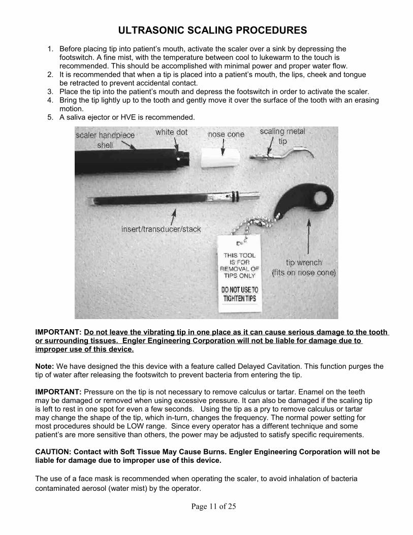
ULTRASONIC SCALING PROCEDURES
1. Before placing tip into patient’s mouth, activate the scaler over a sink by depressing the footswitch. A fine mist, with the temperature between cool to lukewarm to the touch is recommended. This should be accomplished with minimal power and proper water flow.
2. It is recommended that when a tip is placed into a patient’s mouth, the lips, cheek and tongue be retracted to prevent accidental contact.
3. Place the tip into the patient’s mouth and depress the footswitch in order to activate the scaler. 4. Bring the tip lightly up to the tooth and gently move it over the surface of the tooth with an erasing
motion.5. A saliva ejector or HVE is recommended.
IMPORTANT: Do not leave the vibrating tip in one place as it can cause serious damage to the tooth or surrounding tissues. Engler Engineering Corporation will not be liable for damage due to improper use of this device.
Note: We have designed the this device with a feature called Delayed Cavitation. This function purges the tip of water after releasing the footswitch to prevent bacteria from entering the tip.
IMPORTANT: Pressure on the tip is not necessary to remove calculus or tartar. Enamel on the teeth may be damaged or removed when using excessive pressure. It can also be damaged if the scaling tip is left to rest in one spot for even a few seconds. Using the tip as a pry to remove calculus or tartar may change the shape of the tip, which in-turn, changes the frequency. The normal power setting for most procedures should be LOW range. Since every operator has a different technique and some patient’s are more sensitive than others, the power may be adjusted to satisfy specific requirements.
CAUTION: Contact with Soft Tissue May Cause Burns. Engler Engineering Corporation will not be liable for damage due to improper use of this device.
The use of a face mask is recommended when operating the scaler, to avoid inhalation of bacteria contaminated aerosol (water mist) by the operator.
Page 11 of 25
SCALER MAINTENANCE
FINAL PROCEDURES AT THE END OF EACH DAY: 1. Make sure the unit is turned off.2. Detach the tip and nose cone and sterilize. 3. Disconnect the unit from its water source or turn off the water supply. 4. Clean and disinfect all surfaces.
Scaling Tips:IMPORTANT: The scaling tips should be thoroughly cleaned and free of blood, tissue, or anyother debris before sterilization.
The scaling tips, nosecone and stack may be sterilized by autoclave or chemiclave, alwaysfollowing the manufacturer’s instructions and recommendations. Do not autoclave over 270degrees F or more than twenty (20) minutes..It is recommended that you do not leave tips screwed into the handpiece for several days,as water and sediment may make it difficult to remove, causing possible damage to thestack.
Transducer / Stack: The stack may be sterilized using the same methods as listed above. Do not sterilize the entire stack, tip and nosecone assembly as one piece. Separate the tip from the stack before sterilization.To re-install stack into handpiece, follow correct procedures on the next page. Note: To achieve optimum performance of your equipment, we recommend that the stack, tip and nosecone be replaced every 6 months to a year.
Chassis: The chassis of your unit should be cleaned at the end of every operating day with a chemical sterilization solution. This procedure could be done by spraying a fine mist of sterilization solution on the unit, allowing it to remain on the chassis for the length of time recommended by the manufacturer. The surface should be wiped with a clean damp cloth or as suggested by the chemiclave manufacturer. Dry completely. IMPORTANT: In using any chemical sterilization solution please follow the manufacturer’s suggested procedures.
HANDPIECE, FOOTSWITCH AND POWER CABLES: After each procedure, or at least once a day, it is suggested that the handpiece and its cable be thoroughly cleaned and sterilized. The recommended procedure is as follows:
1. Remove tip, and nosecone - sterilize these items as listed above. 2. Clean the outer surface of the handpiece and its cable with an antiseptic soap, rinse off with water
and sterilize with a chemical sterilization solution. Note: If any chemicals are allowed to get into the handpiece you must flush it out with clean water.
3. Place cleaned tip and nosecone into handpiece for next patient. 4. The footswitch and power cables should be cleaned periodically by spraying a fine mist of
sterilization or cleaning solution on the cables. It should remain on the cables for the length of time recommended by the manufacturer. Wipe the surface with a damp cloth and dry the cables completely.
Page 12 of 25
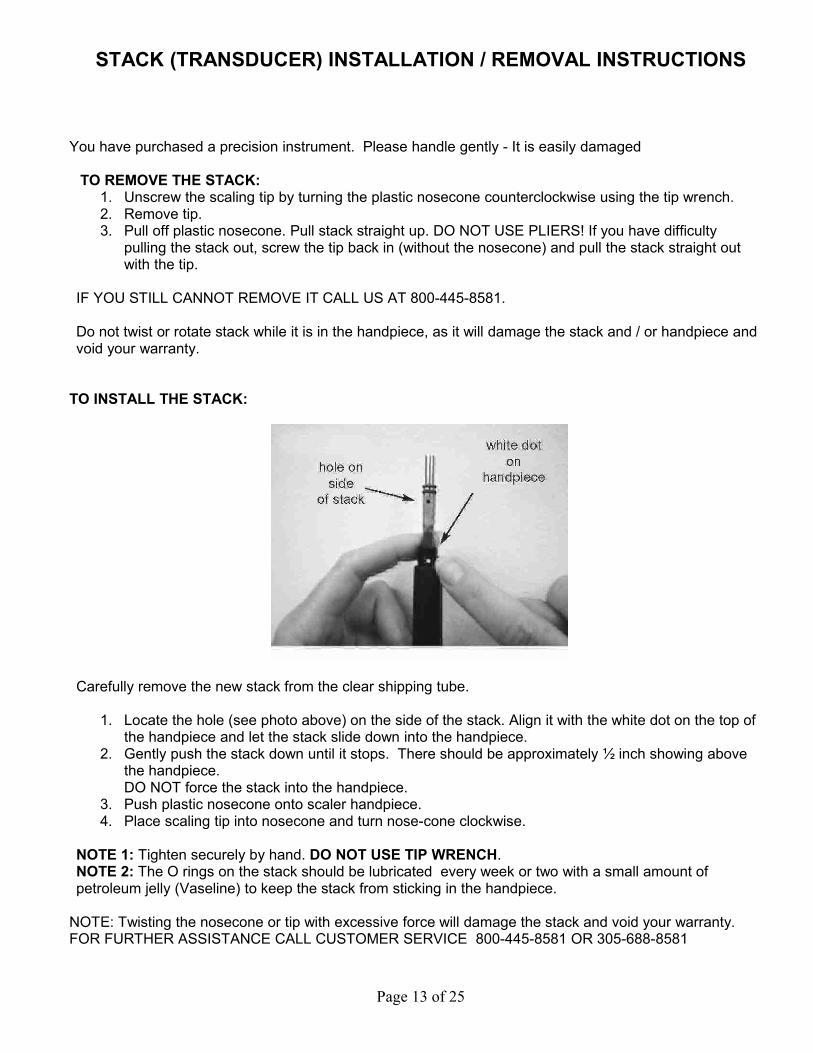
STACK (TRANSDUCER) INSTALLATION / REMOVAL INSTRUCTIONS
You have purchased a precision instrument. Please handle gently - It is easily damaged
TO REMOVE THE STACK: 1. Unscrew the scaling tip by turning the plastic nosecone counterclockwise using the tip wrench. 2. Remove tip. 3. Pull off plastic nosecone. Pull stack straight up. DO NOT USE PLIERS! If you have difficulty
pulling the stack out, screw the tip back in (without the nosecone) and pull the stack straight out with the tip.
IF YOU STILL CANNOT REMOVE IT CALL US AT 800-445-8581.
Do not twist or rotate stack while it is in the handpiece, as it will damage the stack and / or handpiece and void your warranty.
TO INSTALL THE STACK:
Carefully remove the new stack from the clear shipping tube.
1. Locate the hole (see photo above) on the side of the stack. Align it with the white dot on the top of the handpiece and let the stack slide down into the handpiece.
2. Gently push the stack down until it stops. There should be approximately ½ inch showing above the handpiece. DO NOT force the stack into the handpiece.
3. Push plastic nosecone onto scaler handpiece.4. Place scaling tip into nosecone and turn nose-cone clockwise.
NOTE 1: Tighten securely by hand. DO NOT USE TIP WRENCH.NOTE 2: The O rings on the stack should be lubricated every week or two with a small amount of petroleum jelly (Vaseline) to keep the stack from sticking in the handpiece.
NOTE: Twisting the nosecone or tip with excessive force will damage the stack and void your warranty.FOR FURTHER ASSISTANCE CALL CUSTOMER SERVICE 800-445-8581 OR 305-688-8581
Page 13 of 25
Page 14 of 25
SCALER TROUBLESHOOTING
DISPLAY DOES NOT LIGHT UP: 1. Verify that unit is switched ON, the ON / OFF switch is located on the right hand side.2. The unit is not plugged in to a power outlet: verify that the unit is plugged in. 3. Power Outlet not active: try another outlet. 4. The power cord is not connected to the device.5. Contact Engler Engineering Corporation.
DISPLAY LIGHTS UP, NO WATER FLOW: 1. Verify water line is connected and water is flowing to unit. 2. Verify that the waterline is correctly connected to the coupling insert at the back of the unit. 3. Check if water line is kinked or twisted. 4. Check Water Filter and disk: clean disk with plain water and a toothbrush. If clogged, replace O ring
and disc. 5. If using Portable Water Tank: Verify you have the correct water level and sufficient pressure.6. Water blockage in tip: replace the tip. (Clean with # 3 (0.012”) piano wire) 7. Contact Engler Engineering Corporation.
DISPLAY LIGHTS UP, LITTLE OR NO VIBRATION / CAVITATION ON TIP: 1. Tip loose: tighten the tip. 2. Tip damaged: replace the tip. 3. Old or damaged stack: replace the stack. 4. Contact Engler Engineering Corporation.
HOT WATER COMING OUT OF SCALING HANDPIECE: The Stack requires a constant cool water flow in order to maintain tip water temperature below 100 degrees F. You may correct the problem by:
1. Adjusting water flow knob higher (counter clockwise). 2. Tip clogged. Replace tip. 3. Check and / or replace O ring and disc in the inline filter. 4. Water restriction in unit: contact Engler Engineering Corporation repair department. 5. If using a Portable Water Bottle, check water level then pump to pressurize the bottle.
INTERMITTENT OPERATION: I. Tip vibrates / cavitates and then stops:
1. Tip loose: tighten tip. 2. Foot switch damaged: Contact Engler Engineering Corporation. 3. Handpiece / cable damaged: Contact Engler Engineering Corporation.
II Tip action ceases abruptly during operating procedure. 1. Tip not tightened: tighten tip. 2. Transducer broken: replace. 3. Handpiece / cable damaged: Contact Engler Engineering Corporation.
Page 15 of 25
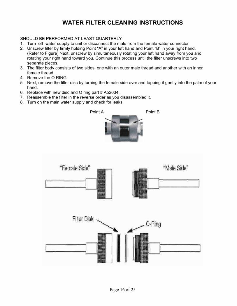
WATER FILTER CLEANING INSTRUCTIONS
SHOULD BE PERFORMED AT LEAST QUARTERLY1. Turn off water supply to unit or disconnect the male from the female water connector 2. Unscrew filter by firmly holding Point “A” in your left hand and Point “B” in your right hand.
(Refer to Figure) Next, unscrew by simultaneously rotating your left hand away from you and rotating your right hand toward you. Continue this process until the filter unscrews into two separate pieces.
3. The filter body consists of two sides, one with an outer male thread and another with an inner female thread.
4. Remove the O RING. 5. Next, remove the filter disc by turning the female side over and tapping it gently into the palm of your
hand. 6. Replace with new disc and O ring part # A52034.7. Reassemble the filter in the reverse order as you disassembled it.8. Turn on the main water supply and check for leaks.
Point A Point B
Page 16 of 25
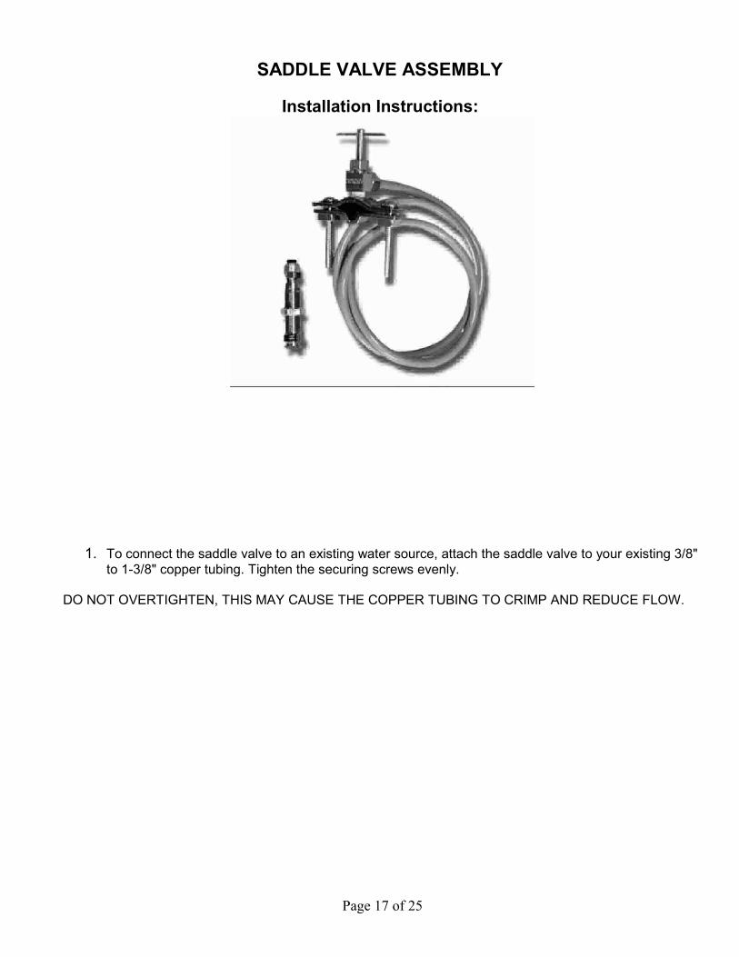
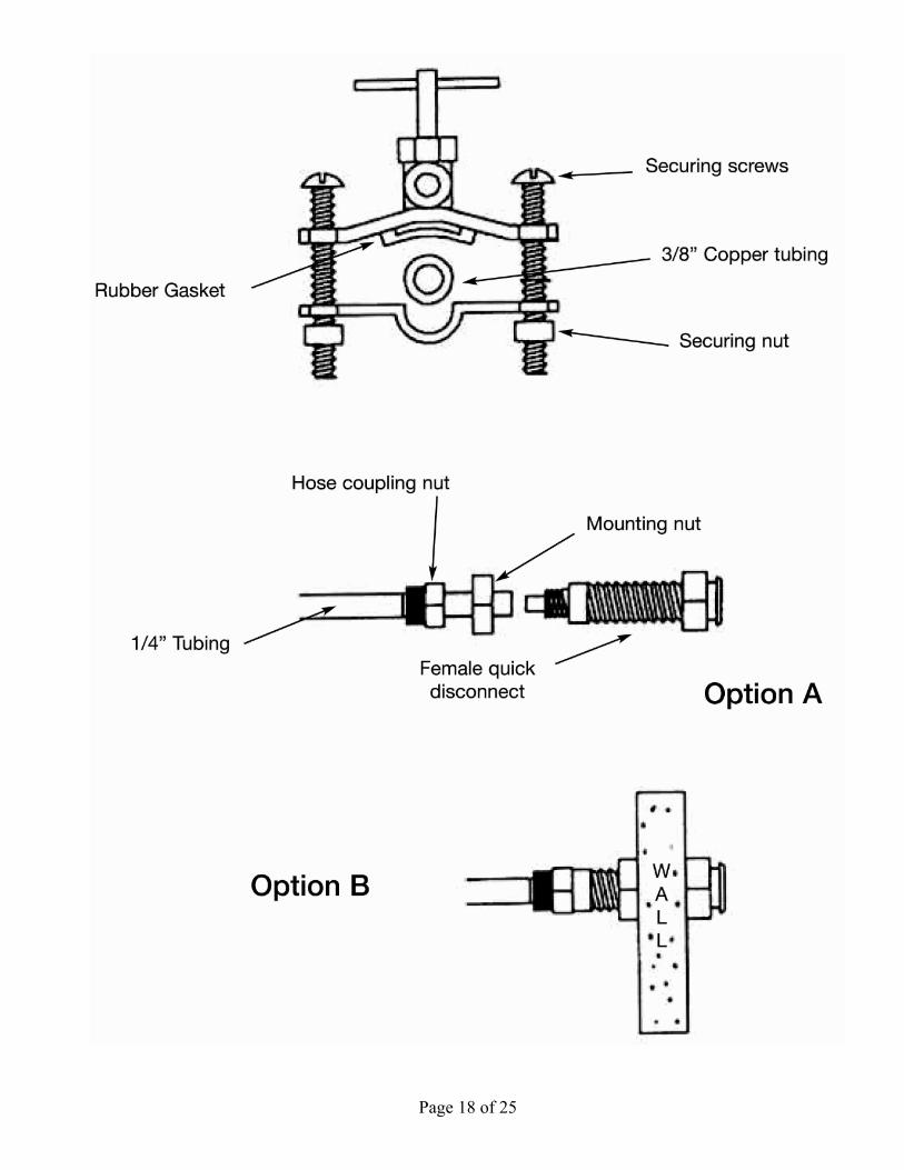
SADDLE VALVE ASSEMBLY
Installation Instructions:
1. To connect the saddle valve to an existing water source, attach the saddle valve to your existing 3/8" to 1-3/8" copper tubing. Tighten the securing screws evenly.
DO NOT OVERTIGHTEN, THIS MAY CAUSE THE COPPER TUBING TO CRIMP AND REDUCE FLOW.
Page 17 of 25
Page 18 of 25
2.To mount the female quick disconnect, there are two options.
Option “A” (Unmounted Assy.)
Take the free end of the ¼” water tubing that comes from the saddle valve and connect it to the female quick disconnect. This is done by placing the hose coupling nut over the water tubing and placing the hose into the back of the female quick disconnect, then tightening the coupling nut. A44303 Saddle valve assembly w/female connector & tubing
Option “B” (Mounted Assy.)
If you wish, the female quick disconnect may be mounted directly through the sink top or vanity counter. If you choose this way, you must first drill a 1/2” diameter hole through the surface in the space desired. (see next page) Then mount the female quick disconnect and tighten the mounting nut to securely hold it in place. Then proceed to place the hose coupling nut over the 1/4” water tubing. Place this tubing into the back of the female quick disconnect and tighten the hose coupling nut securely.
The copper tube is ready to be pierced.
Confirm that the saddle valve assembly is tightened snuggly to the copper tube and the female quick disconnect is properly connected to the water line. Turn the “T” handle of the saddle valve in a CLOCKWISE direction until it will go no further. Next, turn the “T” handle in a COUNTERCLOCKWISE direction until resistance is felt. Water will now flow to your dental unit. Check for leaks.
You may now connect the water line to the dental unit.
NOTE: The “T” handle on the saddle valve does not shut water to the dental unit. It is only used to pierce the copper tube. It is very important that you mount the saddle valve after a shut off valve.
Engler Engineering Corporation will not be held liable for any damage including, but not limited to leakage caused by improper installation of our products. It is suggested that a professional plumber make any necessary installations or connections.
Page 19 of 25
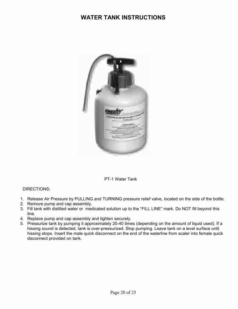
WATER TANK INSTRUCTIONS
PT-1 Water Tank
DIRECTIONS:
1. Release Air Pressure by PULLING and TURNING pressure relief valve, located on the side of the bottle.2. Remove pump and cap assembly. 3. Fill tank with distilled water or medicated solution up to the “FILL LINE” mark. Do NOT fill beyond this
line.4. Replace pump and cap assembly and tighten securely.5. Pressurize tank by pumping it approximately 20-40 times (depending on the amount of liquid used). If a
hissing sound is detected, tank is over-pressurized. Stop pumping. Leave tank on a level surface until hissing stops. Insert the male quick disconnect on the end of the waterline from scaler into female quick disconnect provided on tank.
Page 20 of 25

WATER TANK CARE & MAINTENANCE
1. Release air pressure by pulling and turning knob of pressure relief valve. Pull out fully and allow air to escape.
2. Loosen cap slowly. Remove pump & cap assembly. Pour out any remaining liquid & rinse all parts thoroughly with clean water.
3. Always store tank empty and with tank cap loose.
TROUBLESHOOTING WATER TANK:
PROBLEM: TANK FAILS TO PRESSURIZE.
1. Be sure cap is tight. 2. Check to see if pressure relief valve is in safety position. 3. Remove the pump from the tank. Turn pump handle counterclockwise and lift handle to unlock.
On top of the pump cap there is an opening that says “oil here”. Place 3-5 drops of mineral oil into the opening. Pump several times to work the oil into the walls of the pump until it moves freely. Repeat if necessary. Screw the pump back into the tank and resume normal operations. This process should be repeated often as necessary and depending on usage, or when pump starts to work harder.
4. Black particles found in water bottle indicates that the pump assembly is deteriorating. Order new pump assembly from Engler Engineering.
Pump assembly has been pre-lubricated.
WARNING:READ AND FOLLOW ALL INSTRUCTIONS.ALWAYS INSPECT your pump before each use.ALWAYS RELEASE AIR pressure before removing pump or servicing tank, by pullingpressure relief valve knob out fully.DO NOT use mechanical devices to pressurize the tank .They can create excessive anddangerous pressure which could cause the tank to explode.DO NOT STAND over pressurized tank while using it or pumping itDO NOT USE solutions warmer than 105F.D0 NOT damage or alter the functions of the pressure relief valve or plug the pressure reliefvalve hole, as this could cause the tank to explodeDO NOT pressurize the tank until ready for use.DO NOT lift or carry the tank by waterline, extension rod or pump handle unless it is securelylocked in place.
CARE AND MAINTENANCE OF YOUR PORTABLE WATER TANK
TO KEEP SLIME FROM FORMING INSIDE THE TANK AND EVENTUALLY GETTING INTO THE DENTAL UNIT CAUSING IRREVERSIBLE DAMAGE: 1. Every two weeks dispose of water in tank. Pour ½ gallon of hot water and 1 ounce of bleach into tank
and swirl the liquid thoroughly inside the tank.2. Dispose of bleach mixture and rinse tank with clean water thoroughly and completely.3. Clean the outside of the pump / tank according to your facilities normal cleaning procedures.4. The pump assembly has been pre-lubricated. DO NOT TAKE THIS ASSEMBLY APART.
To help troubleshoot problems, download manuals and see our products, visit us at:www.engler411.com
Page 21 of 25
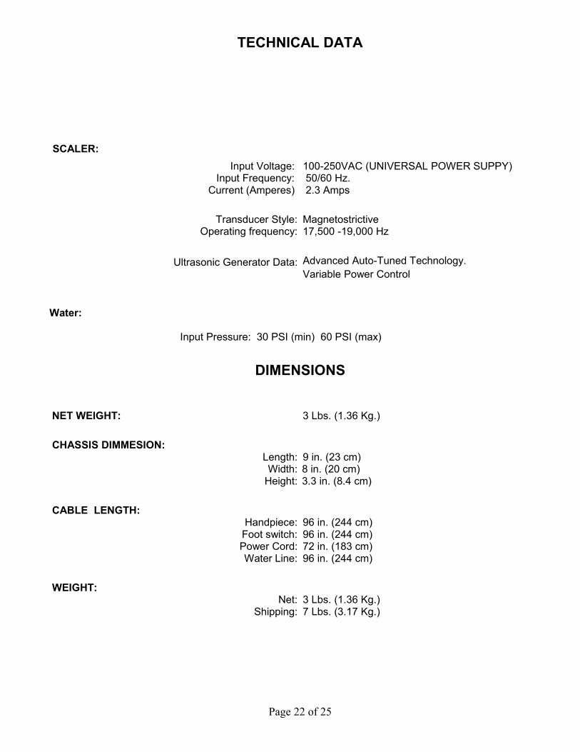
TECHNICAL DATA
SCALER: Input Voltage:
Input Frequency: Current (Amperes)
100-250VAC (UNIVERSAL POWER SUPPY) 50/60 Hz. 2.3 Amps
Transducer Style: Operating frequency:
Magnetostrictive17,500 -19,000 Hz
Ultrasonic Generator Data: Advanced Auto-Tuned Technology. Variable Power Control
Water:
Input Pressure: 30 PSI (min) 60 PSI (max)
DIMENSIONS
NET WEIGHT: 3 Lbs. (1.36 Kg.)
CHASSIS DIMMESION: Length:Width:
Height:
9 in. (23 cm) 8 in. (20 cm) 3.3 in. (8.4 cm)
CABLE LENGTH:Handpiece:
Foot switch:Power Cord:Water Line:
96 in. (244 cm)96 in. (244 cm) 72 in. (183 cm) 96 in. (244 cm)
WEIGHT:Net:
Shipping:
3 Lbs. (1.36 Kg.)7 Lbs. (3.17 Kg.)
Page 22 of 25
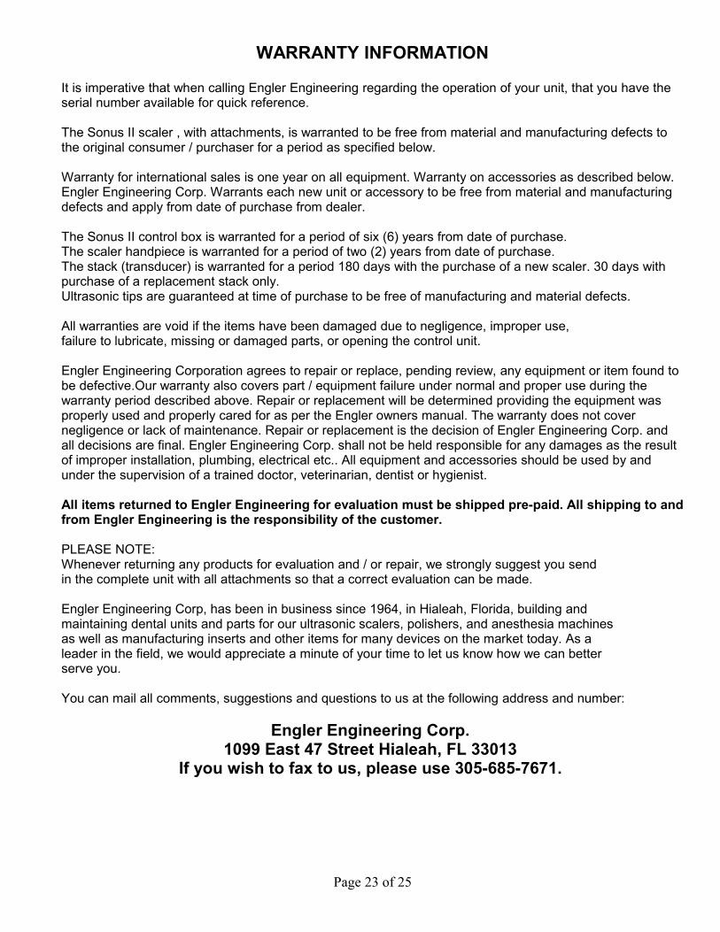
WARRANTY INFORMATION
It is imperative that when calling Engler Engineering regarding the operation of your unit, that you have the serial number available for quick reference.
The Sonus II scaler , with attachments, is warranted to be free from material and manufacturing defects to the original consumer / purchaser for a period as specified below.
Warranty for international sales is one year on all equipment. Warranty on accessories as described below. Engler Engineering Corp. Warrants each new unit or accessory to be free from material and manufacturing defects and apply from date of purchase from dealer.
The Sonus II control box is warranted for a period of six (6) years from date of purchase.The scaler handpiece is warranted for a period of two (2) years from date of purchase.The stack (transducer) is warranted for a period 180 days with the purchase of a new scaler. 30 days with purchase of a replacement stack only.Ultrasonic tips are guaranteed at time of purchase to be free of manufacturing and material defects.
All warranties are void if the items have been damaged due to negligence, improper use, failure to lubricate, missing or damaged parts, or opening the control unit.
Engler Engineering Corporation agrees to repair or replace, pending review, any equipment or item found to be defective.Our warranty also covers part / equipment failure under normal and proper use during the warranty period described above. Repair or replacement will be determined providing the equipment was properly used and properly cared for as per the Engler owners manual. The warranty does not cover negligence or lack of maintenance. Repair or replacement is the decision of Engler Engineering Corp. and all decisions are final. Engler Engineering Corp. shall not be held responsible for any damages as the result of improper installation, plumbing, electrical etc.. All equipment and accessories should be used by and under the supervision of a trained doctor, veterinarian, dentist or hygienist.
All items returned to Engler Engineering for evaluation must be shipped pre-paid. All shipping to and from Engler Engineering is the responsibility of the customer.
PLEASE NOTE: Whenever returning any products for evaluation and / or repair, we strongly suggest you send in the complete unit with all attachments so that a correct evaluation can be made.
Engler Engineering Corp, has been in business since 1964, in Hialeah, Florida, building and maintaining dental units and parts for our ultrasonic scalers, polishers, and anesthesia machines as well as manufacturing inserts and other items for many devices on the market today. As a leader in the field, we would appreciate a minute of your time to let us know how we can better serve you.
You can mail all comments, suggestions and questions to us at the following address and number:
Engler Engineering Corp. 1099 East 47 Street Hialeah, FL 33013
If you wish to fax to us, please use 305-685-7671.
Page 23 of 25
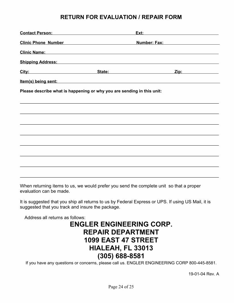
RETURN FOR EVALUATION / REPAIR FORM
Contact Person: Ext:
Clinic Phone Number Number: Fax:
Clinic Name:
Shipping Address:
City: State: Zip:
Item(s) being sent:
Please describe what is happening or why you are sending in this unit:
When returning items to us, we would prefer you send the complete unit so that a proper evaluation can be made.
It is suggested that you ship all returns to us by Federal Express or UPS. If using US Mail, it is suggested that you track and insure the package.
Address all returns as follows: ENGLER ENGINEERING CORP.
REPAIR DEPARTMENT1099 EAST 47 STREET
HIALEAH, FL 33013(305) 688-8581
If you have any questions or concerns, please call us. ENGLER ENGINEERING CORP 800-445-8581.
19-01-04 Rev. A
Page 24 of 25
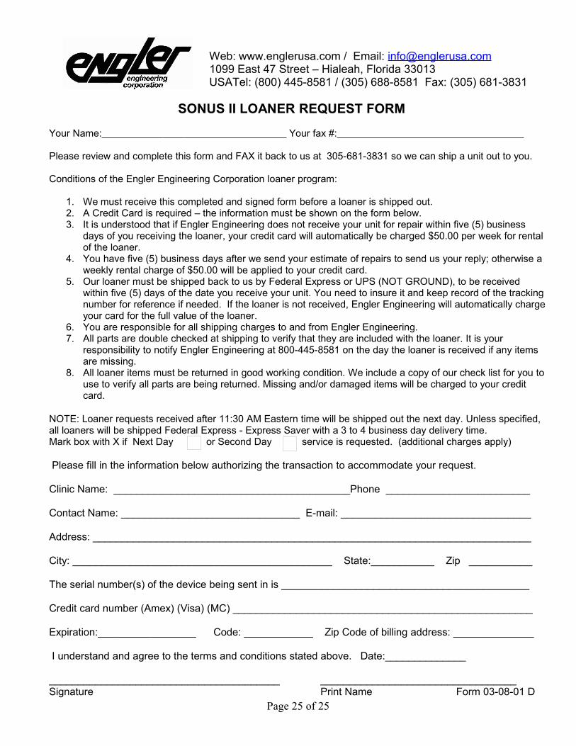
Web: www.englerusa.com / Email: [email protected] East 47 Street – Hialeah, Florida 33013 USATel: (800) 445-8581 / (305) 688-8581 Fax: (305) 681-3831
SONUS II LOANER REQUEST FORM
Your Name: Your fax #: Please review and complete this form and FAX it back to us at 305-681-3831 so we can ship a unit out to you.
Conditions of the Engler Engineering Corporation loaner program:
1. We must receive this completed and signed form before a loaner is shipped out.2. A Credit Card is required – the information must be shown on the form below.3. It is understood that if Engler Engineering does not receive your unit for repair within five (5) business
days of you receiving the loaner, your credit card will automatically be charged $50.00 per week for rental of the loaner.
4. You have five (5) business days after we send your estimate of repairs to send us your reply; otherwise a weekly rental charge of $50.00 will be applied to your credit card.
5. Our loaner must be shipped back to us by Federal Express or UPS (NOT GROUND), to be received within five (5) days of the date you receive your unit. You need to insure it and keep record of the tracking number for reference if needed. If the loaner is not received, Engler Engineering will automatically charge your card for the full value of the loaner.
6. You are responsible for all shipping charges to and from Engler Engineering.7. All parts are double checked at shipping to verify that they are included with the loaner. It is your
responsibility to notify Engler Engineering at 800-445-8581 on the day the loaner is received if any items are missing.
8. All loaner items must be returned in good working condition. We include a copy of our check list for you to use to verify all parts are being returned. Missing and/or damaged items will be charged to your credit card.
NOTE: Loaner requests received after 11:30 AM Eastern time will be shipped out the next day. Unless specified, all loaners will be shipped Federal Express - Express Saver with a 3 to 4 business day delivery time. Mark box with X if Next Day or Second Day service is requested. (additional charges apply)
Please fill in the information below authorizing the transaction to accommodate your request.
Clinic Name: _________________________________________Phone _________________________
Contact Name: _______________________________ E-mail: _________________________________
Address: ____________________________________________________________________________
City: _____________________________________________ State:___________ Zip ___________
The serial number(s) of the device being sent in is ___________________________________________
Credit card number (Amex) (Visa) (MC) ____________________________________________________
Expiration:_________________ Code: ____________ Zip Code of billing address: ______________
I understand and agree to the terms and conditions stated above. Date:______________
________________________________________ __________________________________Signature Print Name Form 03-08-01 D
Page 25 of 25