Embed Size (px)
Citation preview

UML 2.0 Sequence Diagrams' Semantics
Zoltán Micskei1, Hélène Waeselynck2
1Dept. of Measurement and Information Systems, Budapest University of Technology and Economics
2LAAS–CNRS, Université de Toulouse
Abstract: Scenario languages are widely used in software development. Typical usage scenarios, forbidden behaviors, test cases and many more aspects can be depicted with graphical scenarios. Scenario languages were introduced into the Unified Modeling Language (UML) under the name of Sequence Diagrams. The 2.0 version of UML changed Sequence Diagrams significantly, the expressiveness of the language was highly increased. However, it was carried out without defining a precise semantics for the language. This paper presents the semantics defined in the specification, collects and categorizes the problems with the current approach, and gives a survey of proposed formal semantics for Sequence Diagrams.
Keywords: UML 2.0, Sequence Diagrams, semantics
Technical report number: 08389, August 2008.
This work was partially supported by the ReSIST Network of Excellence (IST 026764) funded by the European Union under the Information Society Sixth Framework Programme.
A revised version of this report appeared in: Z. Micskei and H. Waeselynck. The many meanings of UML 2 Sequence Diagrams: a survey, Software and Systems Modeling, Springer, DOI:10.1007/s10270-010-0157-9, 2010,
UML 2.0 Sequence Diagrams' Semantics
2
1 Introduction
Scenario languages are widely used in software development. Typical usage scenarios, forbidden behaviors, test cases and many more aspects can be depicted with graphical scenarios. Several language variants were proposed over the years. The International Telecommunication Union’s (ITU) Message Sequence Chart (MSC) [6] was one of the first of such languages. It is widely used, since its first introduction in 1993 it was updated several times, and the specification defines also a formal semantics for the basic elements of the language based on process theory. Triggered Message Sequence Charts (TMSC) [8] proposed extensions to MSC to express conditions and refinement in a precise way. Live Sequence Charts (LSC) [9] concentrated on distinguishing possible and necessary behaviors. A special technique and a tool, the Play-Engine, were also developed for LSC to specify reactive systems [10].
Scenario languages were introduced into the Object Management Group’s (OMG) Unified Modeling Language (UML) [1] under the name of Sequence Diagrams. The 2.0 version of UML changed Sequence Diagrams significantly. Several elements were borrowed from MSC, many new complex elements were added to the language, the semantics and the underlying metamodel were rewritten. The expressiveness of the language was highly increased. However, this was carried out without defining a precise semantics for the language. This could lead to serious problems, as it is easy to create hard to interpret diagrams, as pointed out by several papers since the publication of the specification.
We are currently working on the definition of testing languages for mobile systems based on UML Sequence Diagrams. When we tried to define the semantics of our extensions, we encountered the problem that there is no complete, formal semantics for Sequence Diagrams. Several approaches were proposed, but as far as we know, no one tried to collect all the reported problems, and there is no semantics, which covers all parts of the language. Thus, our aim with this paper is to (i) categorize the problems we found or have been reported with the current specification, (ii) review the proposed formal semantics and (iii) see how the problems are addressed in the approaches.
The paper is divided into the following parts. Section 2 presents the syntax and semantics as defined in the OMG specification. We tried to highlight those parts, which are usually missing from published overviews about Sequence Diagrams, e.g. the complete abstract syntax or the mapping between the concrete and abstract syntax. Section 3 collects and categorizes the problems with the current specification. Section 4 introduces an example, and gives its semantics using two of the proposed approaches. Later, it presents the proposed formal semantics, and shows which problems were addressed by each approach. Finally, Section 5 collects which UML elements and problems were addressed by Section 4’s methods.
UML 2.0 Sequence Diagrams' Semantics
3
2 Sequence Diagrams' description in the specification
The Unified Modeling Language is described in two specifications, which can be found at [1]:
UML Infrastructure Specification: describes a minimal set of elements that serves as a common base for defining more complex structures.
UML Superstructure specification: contains the user level constructs, like sequence diagrams, of UML.
The second one presents the Sequence Diagrams, the rest of this section summarizes its relevant parts. Scenarios in UML are modeled with Interactions1. Interactions can be illustrated on several diagram types: Sequence Diagrams, Interaction Overview Diagrams, Communication Diagrams, and on the optional diagram notations Timing Diagrams and Interaction Tables. Thus, the syntax and semantics is defined for Interactions, Sequence Diagrams are just a concrete notation to depict them.
2.1 Syntax of Sequence Diagrams
The syntax defined in the specification consists of (i) a concrete syntax defining the graphical notation, and (ii) an abstract syntax given with a metamodel defining the relationships between the elements.
2.1.1 Concrete Syntax
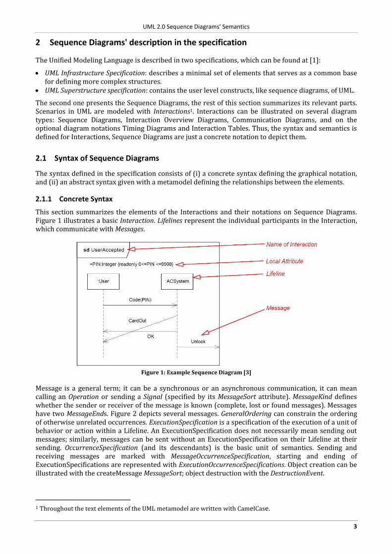
This section summarizes the elements of the Interactions and their notations on Sequence Diagrams. Figure 1 illustrates a basic Interaction. Lifelines represent the individual participants in the Interaction, which communicate with Messages.
Figure 1: Example Sequence Diagram [3]
Message is a general term; it can be a synchronous or an asynchronous communication, it can mean calling an Operation or sending a Signal (specified by its MessageSort attribute). MessageKind defines whether the sender or receiver of the message is known (complete, lost or found messages). Messages have two MessageEnds. Figure 2 depicts several messages. GeneralOrdering can constrain the ordering of otherwise unrelated occurrences. ExecutionSpecification is a specification of the execution of a unit of behavior or action within a Lifeline. An ExecutionSpecification does not necessarily mean sending out messages; similarly, messages can be sent without an ExecutionSpecification on their Lifeline at their sending. OccurrenceSpecification (and its descendants) is the basic unit of semantics. Sending and receiving messages are marked with MessageOccurrenceSpecification, starting and ending of ExecutionSpecifications are represented with ExecutionOccurrenceSpecifications. Object creation can be illustrated with the createMessage MessageSort; object destruction with the DestructionEvent.
1 Throughout the text elements of the UML metamodel are written with CamelCase.
UML 2.0 Sequence Diagrams' Semantics
4
sd example 1
a : A b : B c : C
m3
m4
d : Dm1()
m2
Lost
message
Found
message
Asynchronous
message
Synchronous
callReply message
Execution-
Specification
Message-
Occurrence-
Specification
Execution-
Occurrence-
Specification
General-
OrderingDestructionEvent
Create
message
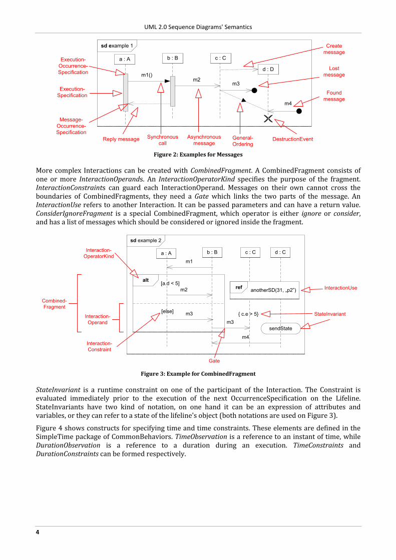
Figure 2: Examples for Messages
More complex Interactions can be created with CombinedFragment. A CombinedFragment consists of one or more InteractionOperands. An InteractionOperatorKind specifies the purpose of the fragment. InteractionConstraints can guard each InteractionOperand. Messages on their own cannot cross the boundaries of CombinedFragments, they need a Gate which links the two parts of the message. An InteractionUse refers to another Interaction. It can be passed parameters and can have a return value. ConsiderIgnoreFragment is a special CombinedFragment, which operator is either ignore or consider, and has a list of messages which should be considered or ignored inside the fragment.
sd example 2
alt
a : A b : B
m1
m2
m3
c : C
m3
[a.d < 5]
[else]StateInvariant
Interaction-
OperatorKind
Interaction-
Constraint
Interaction-
Operand
Combined-
Fragment
Gate
m4
{ c.e > 5}
sendState
d : C
refanotherSD(31, „p2”) InteractionUse
Figure 3: Example for CombinedFragment
StateInvariant is a runtime constraint on one of the participant of the Interaction. The Constraint is evaluated immediately prior to the execution of the next OccurrenceSpecification on the Lifeline. StateInvariants have two kind of notation, on one hand it can be an expression of attributes and variables, or they can refer to a state of the lifeline's object (both notations are used on Figure 3).
Figure 4 shows constructs for specifying time and time constraints. These elements are defined in the SimpleTime package of CommonBehaviors. TimeObservation is a reference to an instant of time, while DurationObservation is a reference to a duration during an execution. TimeConstraints and DurationConstraints can be formed respectively.
UML 2.0 Sequence Diagrams' Semantics
5
Figure 4: Example for time and timing constraints (Fig. 14.26 of [3])
2.1.2 Abstract syntax
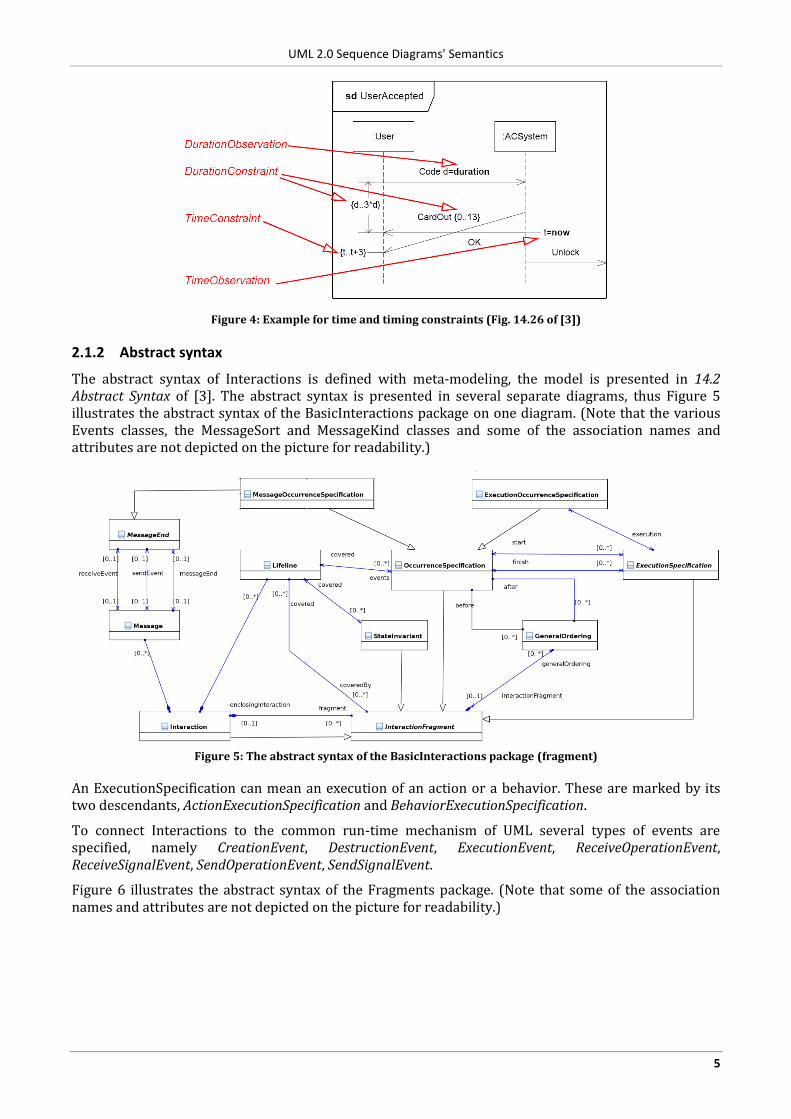
The abstract syntax of Interactions is defined with meta-modeling, the model is presented in 14.2 Abstract Syntax of [3]. The abstract syntax is presented in several separate diagrams, thus Figure 5 illustrates the abstract syntax of the BasicInteractions package on one diagram. (Note that the various Events classes, the MessageSort and MessageKind classes and some of the association names and attributes are not depicted on the picture for readability.)
Figure 5: The abstract syntax of the BasicInteractions package (fragment)
An ExecutionSpecification can mean an execution of an action or a behavior. These are marked by its two descendants, ActionExecutionSpecification and BehaviorExecutionSpecification.
To connect Interactions to the common run-time mechanism of UML several types of events are specified, namely CreationEvent, DestructionEvent, ExecutionEvent, ReceiveOperationEvent, ReceiveSignalEvent, SendOperationEvent, SendSignalEvent.
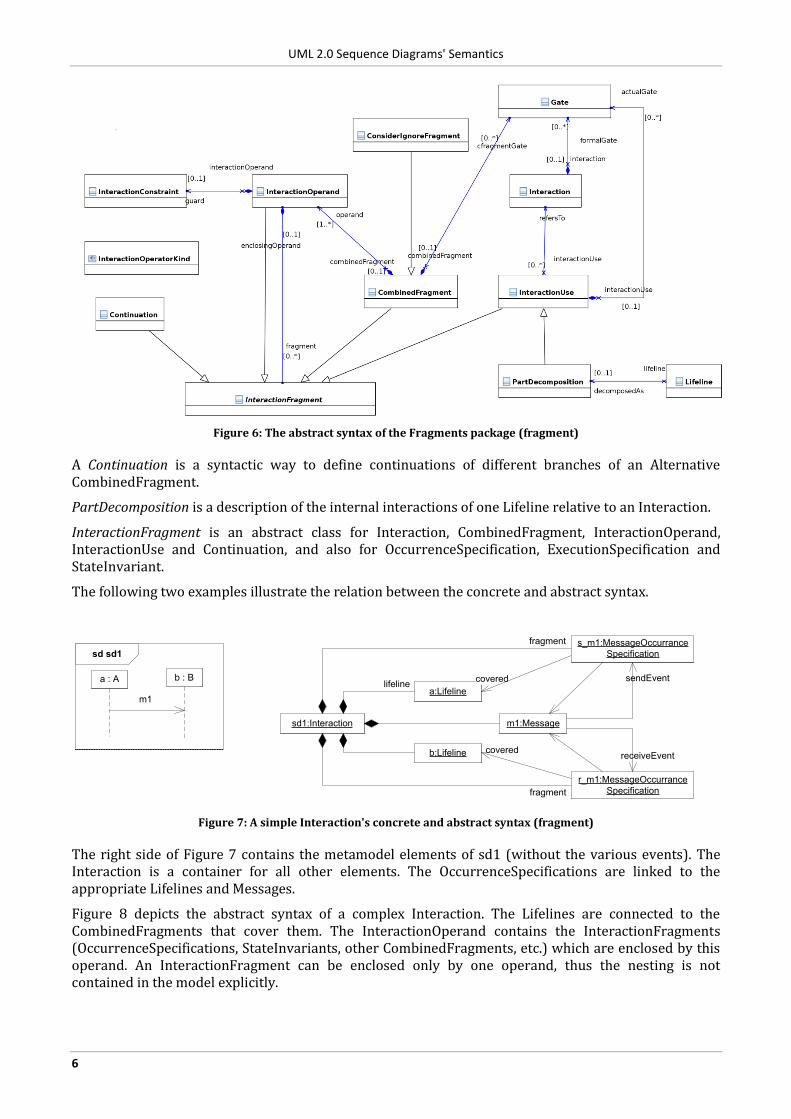
Figure 6 illustrates the abstract syntax of the Fragments package. (Note that some of the association names and attributes are not depicted on the picture for readability.)
UML 2.0 Sequence Diagrams' Semantics
6
Figure 6: The abstract syntax of the Fragments package (fragment)
A Continuation is a syntactic way to define continuations of different branches of an Alternative CombinedFragment.
PartDecomposition is a description of the internal interactions of one Lifeline relative to an Interaction.
InteractionFragment is an abstract class for Interaction, CombinedFragment, InteractionOperand, InteractionUse and Continuation, and also for OccurrenceSpecification, ExecutionSpecification and StateInvariant.
The following two examples illustrate the relation between the concrete and abstract syntax.
sd sd1
a : A b : B
m1
sd1:Interaction
a:Lifeline
b:Lifeline
m1:Message
s_m1:MessageOccurrance
Specification
r_m1:MessageOccurrance
Specification
fragment
fragment
lifelinesendEvent
receiveEvent
covered
covered
Figure 7: A simple Interaction's concrete and abstract syntax (fragment)
The right side of Figure 7 contains the metamodel elements of sd1 (without the various events). The Interaction is a container for all other elements. The OccurrenceSpecifications are linked to the appropriate Lifelines and Messages.
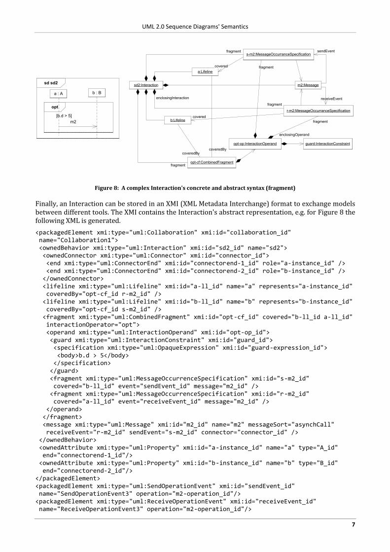
Figure 8 depicts the abstract syntax of a complex Interaction. The Lifelines are connected to the CombinedFragments that cover them. The InteractionOperand contains the InteractionFragments (OccurrenceSpecifications, StateInvariants, other CombinedFragments, etc.) which are enclosed by this operand. An InteractionFragment can be enclosed only by one operand, thus the nesting is not contained in the model explicitly.
UML 2.0 Sequence Diagrams' Semantics
7
sd sd2
opt
a : A b : B
m2
[b.d > 5]
sd2:Interaction
a:Lifeline
b:Lifeline
m2:Message
s-m2:MessageOccurranceSpecification
r-m2:MessageOccurranceSpecification
fragment
enclosingInteraction
fragment
sendEvent
receiveEvent
covered
covered
opt-cf:CombinedFragment
opt-op:InteractionOperand guard:InteractionConstraint
fragment
coveredBycoveredBy
enclosingOperand
fragment
fragment
Figure 8: A complex Interaction's concrete and abstract syntax (fragment)
Finally, an Interaction can be stored in an XMI (XML Metadata Interchange) format to exchange models between different tools. The XMI contains the Interaction's abstract representation, e.g. for Figure 8 the following XML is generated.
<packagedElement xmi:type="uml:Collaboration" xmi:id="collaboration_id" name="Collaboration1"> <ownedBehavior xmi:type="uml:Interaction" xmi:id="sd2_id" name="sd2"> <ownedConnector xmi:type="uml:Connector" xmi:id="connector_id"> <end xmi:type="uml:ConnectorEnd" xmi:id="connectorend-1_id" role="a-instance_id" /> <end xmi:type="uml:ConnectorEnd" xmi:id="connectorend-2_id" role="b-instance_id" /> </ownedConnector> <lifeline xmi:type="uml:Lifeline" xmi:id="a-ll_id" name="a" represents="a-instance_id" coveredBy="opt-cf_id r-m2_id" /> <lifeline xmi:type="uml:Lifeline" xmi:id="b-ll_id" name="b" represents="b-instance_id" coveredBy="opt-cf_id s-m2_id" /> <fragment xmi:type="uml:CombinedFragment" xmi:id="opt-cf_id" covered="b-ll_id a-ll_id" interactionOperator="opt"> <operand xmi:type="uml:InteractionOperand" xmi:id="opt-op_id"> <guard xmi:type="uml:InteractionConstraint" xmi:id="guard_id"> <specification xmi:type="uml:OpaqueExpression" xmi:id="guard-expression_id"> <body>b.d > 5</body> </specification> </guard> <fragment xmi:type="uml:MessageOccurrenceSpecification" xmi:id="s-m2_id" covered="b-ll_id" event="sendEvent_id" message="m2_id" /> <fragment xmi:type="uml:MessageOccurrenceSpecification" xmi:id="r-m2_id" covered="a-ll_id" event="receiveEvent_id" message="m2_id" /> </operand> </fragment> <message xmi:type="uml:Message" xmi:id="m2_id" name="m2" messageSort="asynchCall" receiveEvent="r-m2_id" sendEvent="s-m2_id" connector="connector_id" /> </ownedBehavior> <ownedAttribute xmi:type="uml:Property" xmi:id="a-instance_id" name="a" type="A_id" end="connectorend-1_id"/> <ownedAttribute xmi:type="uml:Property" xmi:id="b-instance_id" name="b" type="B_id" end="connectorend-2_id"/> </packagedElement> <packagedElement xmi:type="uml:SendOperationEvent" xmi:id="sendEvent_id" name="SendOperationEvent3" operation="m2-operation_id"/> <packagedElement xmi:type="uml:ReceiveOperationEvent" xmi:id="receiveEvent_id" name="ReceiveOperationEvent3" operation="m2-operation_id"/>
UML 2.0 Sequence Diagrams' Semantics
8
<packagedElement xmi:type="uml:Class" xmi:id="A_id" name="A"> <ownedOperation xmi:type="uml:Operation" xmi:id="m2-operation_id" name="m2"/> </packagedElement> <packagedElement xmi:type="uml:Class" xmi:id="B_id" name="B"/>
Every element in an XMI file is identified by a unique ID (xmi:id). These IDs were replaced in the above XMI with strings to ease the readability. The relations depicted on Figure 8 are all contained in the XMI, e.g. see coveredBy attribute of the lifeline elements. Moreover, this XMI includes all the related elements which were left out from the figure, e.g., the events triggered by the Message, or the instances represented by the Lifelines.
2.2 Semantics of Sequence Diagrams
There are two major challenges when dealing with the semantics given in the specifications.
The description of the semantics is scattered through the text. Some parts are in the introductory parts of the chapters, while some information is only in the constraints defined in the detailed description of a class.
The specification uses so called semantic variation points [5], i.e. some of the semantics is not specified in detail to allow using UML in many domains. When UML is used in a concrete domain, the modeler has to choose from the different possible variations. To make this even harder, sometimes these variation points are not marked explicitly, just different parts of the text use different variants.
This section summarizes the parts that deal with the semantics of Interactions.
2.2.1 Common Run-time Semantics
The common run-time semantics is given in the following sections.
Section 6.2 of [3] (On the Run-Time Semantics of UML) summarizes the basics. All behavior is caused by actions executed by active objects. It describes also the basic causality model:
"The causality model is quite straightforward: Objects respond to messages that are generated by objects executing communication actions. When these messages arrive, the receiving objects eventually respond by executing the behavior that is matched to that message. (page 12 of [3])"
The CommonBehaviors package (Chapter 13) deals with the fundamentals of behavior. A Behavior describes how the states of the objects, as reflected by their structural features, change over time. Behavior is an abstract metaclass; its subtypes are Interactions (Chapter 14), Activities (Chapter 12), State Machines (Chapter 15) and Use Cases (Chapter 16). These subtypes differ on how they model a behavior, e.g., what level of detail is captured. A Behavior is attached to a BehavioredClassifier (e.g., to a Class or to a Collaboration). A Behavior is the implementation of a BehavioralFeature, which can be an Operation or a Reception of a Signal. Behaviors can be invoked by Actions. An Action (Chapter 11) is the fundamental unit of behavior specification. "An action takes a set of inputs and converts them into a set of outputs, though either or both sets may be empty (page 217)." Examples for actions are CallOperationAction, SendSignalAction or WriteVariableAction. The execution of Actions can result in an Event. Possible Events include CallEvent or SignalEvent. For Events caused by InvocationActions a request (e.g., a Message) is generated and sent, which contains the arguments of the Action and the identities of the sender and receiver object. Similarly, at the receiving of the request an Event will occur. Events, through Triggers, may cause the execution of Behaviors.
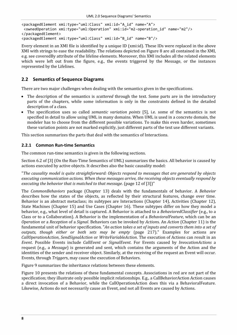
Figure 9 summarizes the inheritance relations between these elements.
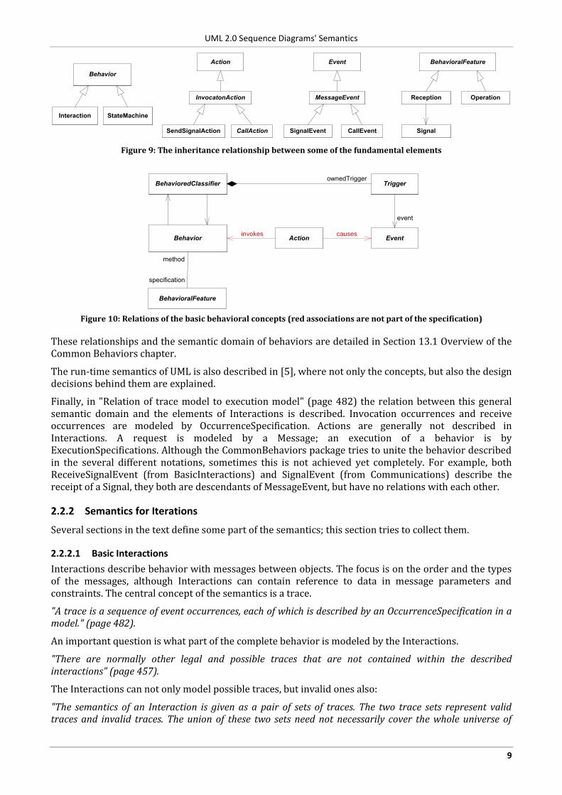
Figure 10 presents the relations of these fundamental concepts. Associations in red are not part of the specification; they illustrate only possible implicit relationships. E.g., a CallBehaviorAction Action causes a direct invocation of a Behavior, while the CallOperationAction does this via a BehavioralFeature. Likewise, Actions do not necessarily cause an Event, and not all Events are caused by Actions.
UML 2.0 Sequence Diagrams' Semantics
9
Behavior
Interaction StateMachine
BehavioralFeature
OperationReception
Signal
Action Event
MessageEvent
CallEventSignalEvent
InvocatonAction
CallActionSendSignalAction
Figure 9: The inheritance relationship between some of the fundamental elements
Behavior
BehavioralFeature
Action Event
method
specification
Trigger
event
BehavioredClassifierownedTrigger
invokes causes
Figure 10: Relations of the basic behavioral concepts (red associations are not part of the specification)
These relationships and the semantic domain of behaviors are detailed in Section 13.1 Overview of the Common Behaviors chapter.
The run-time semantics of UML is also described in [5], where not only the concepts, but also the design decisions behind them are explained.
Finally, in "Relation of trace model to execution model" (page 482) the relation between this general semantic domain and the elements of Interactions is described. Invocation occurrences and receive occurrences are modeled by OccurrenceSpecification. Actions are generally not described in Interactions. A request is modeled by a Message; an execution of a behavior is by ExecutionSpecifications. Although the CommonBehaviors package tries to unite the behavior described in the several different notations, sometimes this is not achieved yet completely. For example, both ReceiveSignalEvent (from BasicInteractions) and SignalEvent (from Communications) describe the receipt of a Signal, they both are descendants of MessageEvent, but have no relations with each other.
2.2.2 Semantics for Iterations
Several sections in the text define some part of the semantics; this section tries to collect them.
2.2.2.1 Basic Interactions
Interactions describe behavior with messages between objects. The focus is on the order and the types of the messages, although Interactions can contain reference to data in message parameters and constraints. The central concept of the semantics is a trace.
"A trace is a sequence of event occurrences, each of which is described by an OccurrenceSpecification in a model." (page 482).
An important question is what part of the complete behavior is modeled by the Interactions.
"There are normally other legal and possible traces that are not contained within the described interactions" (page 457).
The Interactions can not only model possible traces, but invalid ones also:
"The semantics of an Interaction is given as a pair of sets of traces. The two trace sets represent valid traces and invalid traces. The union of these two sets need not necessarily cover the whole universe of
UML 2.0 Sequence Diagrams' Semantics
10
traces. The traces that are not included are not described by this Interaction at all, and we cannot know whether they are valid or invalid" (page 482).
Although it is stated that invalid traces come only from negative CombinedFragments: "The invalid set of traces are associated only with the use of a Negative CombinedInteraction. For simplicity we describe only valid traces for all other constructs" (page 482), in other parts this statement is contradicted, e.g., in StateInvariant, "if the Constraint is false, the trace is an invalid trace" (page 503). Collecting all the similar references yields that invalid traces are defined by assert and negative fragments, and constraints such as StateInvariant, DurationConstraint and TimeConstraint.
The semantics of Interactions is explained with an interleaving semantics, i.e. two events may not occur at exactly the same time.
"By interleaving we mean the merging of two or more traces such that the events from different traces may come in any order in the resulting trace, while events within the same trace retain their order. Interleaving semantics is different from a semantics where it is perceived that two events may occur at exactly the same time. To explain Interactions we apply an Interleaving Semantics." (page 457)
The orders of OccurrenceSpecifications are constrained by the following rules.
Occurrences on the same lifeline must occur in the same order as they are specified, even for receives from different objects (“The order of OccurrenceSpecifications along a Lifeline is significant denoting the order in which these OccurrenceSpecifications will occur.”, page 491).
Receiving a message should occur after the sending of the message (“The semantics of a complete Message is simply the trace <sendEvent, receiveEvent>” page 493).
GeneralOrdering can add further constraints to OccurrenceSpecifications, which are not related. ("A GeneralOrdering is introduced to restrict the set of possible sequences. A partial order of OccurrenceSpecifications is defined by a set of GeneralOrdering" page 481).
Thus, the semantics defines a partial order on OccurrenceSpecifications, and valid traces are those, which can be generated satisfying these orders.
The way to construct the resulting trace for an Interaction from its Fragments is defined by:
"The semantics of Interactions are compositional in the sense that the semantics of an Interaction is mechanically built from the semantics of its constituent InteractionFragments. The constituent InteractionFragments are ordered and combined by the seq operation (weak sequencing) as explained in “Weak Sequencing” on page 468" (page 482).
2.2.2.2 Fragments
If no other operator is present on a diagram, then weak sequencing should be applied to the InteractionFragments. The rules for weak sequencing are the following.
"Weak sequencing is defined by the set of traces with these properties:
1. The ordering of OccurrenceSpecifications within each of the operands is maintained in the result.
2. OccurrenceSpecifications on different lifelines from different operands may come in any order.
3. OccurrenceSpecifications on the same lifeline from different operands are ordered such that an OccurrenceSpecification of the first operand comes before that of the second operand." (page 468)
For the Interactions that use elements from the Fragments package, the semantics is mainly defined in the description of CombinedFragment when detailing the various operators (page 468-470). We grouped the operators into the following categories:
I. Operators that make the representation of diagrams more compact (semantically equivalent diagrams can be created for these with unfolding the loops or splitting the branches of an alternate fragment to multiple diagrams):
Alternatives "The interactionOperator alt designates that the CombinedFragment represents a choice of behavior. At most one of the operands will be chosen. The chosen operand must have an explicit or implicit guard expression that evaluates to true at this point in the interaction. An implicit true guard is implied if the operand has no guard. The set of traces that defines a choice is the union of the (guarded) traces of the
UML 2.0 Sequence Diagrams' Semantics
11
operands. An operand guarded by else designates a guard that is the negation of the disjunction of all other guards in the enclosing CombinedFragment. If none of the operands has a guard that evaluates to true, none of the operands are executed and the remainder of the enclosing InteractionFragment is executed."
Option "The interactionOperator opt designates that the CombinedFragment represents a choice of behavior where either the (sole) operand happens or nothing happens. An option is semantically equivalent to an alternative CombinedFragment where there is one operand with non-empty content and the second operand is empty."
Break "The interactionOperator break designates that the CombinedFragment represents a breaking scenario in the sense that the operand is a scenario that is performed instead of the remainder of the enclosing InteractionFragment. A break operator with a guard is chosen when the guard is true and the rest of the enclosing Interaction Fragment is ignored. When the guard of the break operand is false, the break operand is ignored and the rest of the enclosing InteractionFragment is chosen. The choice between a break operand without a guard and the rest of the enclosing InteractionFragment is done non-deterministically. A CombinedFragment with interactionOperator break should cover all Lifelines of the enclosing InteractionFragment."
Loop "The interactionOperator loop designates that the CombinedFragment represents a loop. The loop operand will be repeated a number of times. The Guard may include a lower and an upper number of iterations of the loop as well as a Boolean expression. The semantics is such that a loop will iterate minimum the ‘minint’ number of times (given by the iteration expression in the guard) and at most the ‘maxint’ number of times. After the minimum number of iterations have executed and the Boolean expression is false the loop will terminate. The loop construct represents a recursive application of the seq operator where the loop operand is sequenced after the result of earlier iterations."
II. Operators that alter the orderings of OccurrenceSpecification:
Parallel "The interactionOperator par designates that the CombinedFragment represents a parallel merge between the behaviors of the operands. The OccurrenceSpecifications of the different operands can be interleaved in any way as long as the ordering imposed by each operand as such is preserved. A parallel merge defines a set of traces that describes all the ways that OccurrenceSpecifications of the operands may be interleaved without obstructing the order of the OccurrenceSpecifications within the operand."
Strict Sequencing "The interactionOperator strict designates that the CombinedFragment represents a strict sequencing between the behaviors of the operands. The semantics of strict sequencing defines a strict ordering of the operands on the first level within the CombinedFragment with interactionOperator strict. Therefore OccurrenceSpecifications within contained CombinedFragment will not directly be compared with other OccurrenceSpecifications of the enclosing CombinedFragment."
Note, the phrasing of this paragraph could raise questions, an example would be useful to clarify what is meant by the last sentence.
Critical Region "The interactionOperator critical designates that the CombinedFragment represents a critical region. A critical region means that the traces of the region cannot be interleaved by other OccurrenceSpecifications (on those Lifelines covered by the region). This means that the region is treated atomically by the enclosing fragment when determining the set of valid traces. Even though enclosing CombinedFragments may imply that some OccurrenceSpecifications may interleave into the region, such as with par-operator, this is prevented by defining a region. Thus the set of traces of enclosing constructs are restricted by critical regions."
III. Operators that alter the conformance relation, i.e., the way a trace is categorized as valid or invalid according to a diagram:
Negative "The interactionOperator neg designates that the CombinedFragment represents traces that are defined to be invalid. The set of traces that defined a CombinedFragment with interactionOperator negative is equal to the set of traces given by its (sole) operand, only that this set is a set of invalid rather than valid traces. All InteractionFragments that are different from Negative are considered positive meaning that they describe traces that are valid and should be possible."
UML 2.0 Sequence Diagrams' Semantics
12
Assertion "The interactionOperator assert designates that the CombinedFragment represents an assertion. The sequences of the operand of the assertion are the only valid continuations. All other continuations result in an invalid trace. Assertions are often combined with Ignore or Consider as shown in Figure 14.24".
Ignore "The interactionOperator ignore designates that there are some message types that are not shown within this combined fragment. These message types can be considered insignificant and are implicitly ignored if they appear in a corresponding execution. Alternatively, one can understand ignore to mean that the message types that are ignored can appear anywhere in the traces" (page 473).
Consider "Conversely, the interactionOperator consider designates which messages should be considered within this combined fragment. This is equivalent to defining every other message to be ignored" (page 473).
A list of messages follows the ignore or consider keywords representing the ignored / considered message types. They have to be exact message names, no wildcarding is allowed.
Other classes defined in the Fragments package are the following.
InteractionConstraint: The InteractionsOperands of a CombinedFragment can have guards on them. The following rules apply to a guard.
"The dynamic variables that take part in the constraint must be owned by the ConnectableElement corresponding to the covered Lifeline" (page 484).
"The constraint may contain references to global data or write-once data" (page 484). What exactly the global data or write-once data should be is not detailed.
"Only InteractionOperands with a guard that evaluates to true at this point in the interaction will be considered for the production of the traces for the enclosing CombinedFragment" (page 486).
InteractionUse: "The InteractionUse is a shorthand for copying the contents of the referred Interaction where the InteractionUse is. To be accurate the copying must take into account substituting parameters with arguments and connect the formal gates with the actual ones. The semantics of the InteractionUse is the set of traces of the semantics of the referred Interaction where the gates have been resolved as well as all generic parts having been bound such as the arguments substituting the parameters" (pages 487-488).
Gate: "The gates and the messages between gates have one purpose, namely to establish the concrete sender and receiver for every message" (page 480).
Gates make possible that messages cross the boundaries of Iterations, InteractionUses and CombinedFragments.
Variables: Although representing data is not the focus of sequence diagrams, several elements can have reference to data and variables.
Local attributes of Interactions: "An Interaction diagram may also include definitions of local attributes with the same syntax as attributes in general are shown within class symbol compartments" (page 483). An Interaction is a Behavior, which is a descendant of Class, thus it can have attributes. However, it is not specified how these variables are stored or who can have access to these attributes.
Parameters of Interactions: They are mentioned in the notation part of Interaction ("The keyword sd followed by the Interaction name and parameters is in a pentagon in the upper left corner of the rectangle." page 483) and in the definition of InteractionUse. It is not specified, who will pass these parameters.
Arguments of Message: “Arguments of a Message must only be: o i) attributes of the sending lifeline. o ii) constants. o iii) symbolic values (which are wildcard values representing any legal value). o iv) explicit parameters of the enclosing Interaction. o v) attributes of the class owning the Interaction.” (page 492).
This section summarized the semantics defined in the specification. As it can be seen from the next section, several issues can be raised regarding this semantics.
UML 2.0 Sequence Diagrams' Semantics
13
3 Semantically Challenging Sequence Diagrams
The previous section provided an overview of the OMG specification. In this specification, the semantics is informally defined as a set of valid and invalid traces that can be generated from the diagram. Having a closer look at the semantics of Interactions, we now summarize issues found by our experience or reported in the literature. We first present the issues reported to OMG through its issue website (Section 3.1). Next, some easy-to-fix issues with the OMG definition are listed (Section 3.2). Then we raise more serious concerns about the ability to compute an ordering of events (Section 3.3), and to assign an interpretation to operators altering the conformance relation (Section 3.4). These concerns should be central to any attempt at defining a semantics for Sequence Diagrams. We show, among other things, that compositionality is problematic with respect to both the ordering of events and the categorization into valid and invalid traces, making it difficult to derive the meaning of a diagram from the meaning of its fragments and the syntactic composition operators. We conclude by a summary of problems (Section 3.5).
When necessary, the discussion is illustrated by examples where it is especially hard to assign a meaning to a diagram. Besides the illustrative purpose, the examples may serve as a set of concrete cases against which candidate formal semantics could be checked. The examples include test traces, and we adopt the usual convention that !m (resp. ?m) denotes the sending (resp. receiving) OccurrenceSpecification of message m.
3.1 Issues reported to OMG
Issues about OMG's specifications can be reported on OMG's website [4]. The following issues were active on 24 January 2008 that concerned Interactions. (Note, because the issue list currently does not offer any search and categorization functionality of issues for non-members, the issues were selected by hand, thus this list may be incomplete.) The titles of the issues have been edited to show their content, because there were original titles like Section 14 or Section Interactions.
Request for new features:
Issue 6082: Add suspension region concept from MSC Issue 6088: Add parameterization of lifelines Issue 7161: UML 2 Super/Interactions/Need constraints that cover multiple Lifelines Issue 7397: add an exception handler interaction fragment Issue 8414: How to show static calls Issue 8700: Allow Lifeline to represent multiple instances Issue 8765: Add xalt operator Issue 9111: Is there a notation for broadcast? Issue 10966: Notation to show whether a Lifeline is covered by a CombinedFragment or not
Typos, minor corrections:
Issue 6409: UML 2 Super/Interactions/missing OCL constraints for some of constraints Issue 8342: Typos in Section: 14.3.18 Issue 8698: CombinedFragment Loop notation of loop condition Issue 8899: Message can display return values and variable assignments but has no attributes for
these properties. Issue 8964: Interaction::lifeline should be ordered Issue 10529: Typo in the definition of InteractionConstraint Issue 10590: Rephrase sentence in InteractionUse Issue 10650: ReceiveSignalEvent is the same as SignalEvent Issue 10967: Typo in MessageSort Issue 11286: Number of operands in a CombinedFragment
Problems, need for clarification:
Issue 6927: UML 2 Super / Interactions / Ambiguous diagram tags.
UML 2.0 Sequence Diagrams' Semantics
14
o Communication and timing diagrams use also the sd tag in the top left corner of the diagram. o see Issue 11273: Rename sd tag to id
Issue 8475: What object receives SendEvent, etc? Issue 8760: Events in Sequence diagram Issue 8761: Arguments of Message (Issue 8786 is a duplicate of this issue) Issue 8788: What is the scope of the variables used in Interactions Issue 8975: Use cases as contexts of Interactions Issue 9923: Some of the concepts of Interactions are more general, and should go into
CommonBehaviors Issue 10591: Problems with InteractionUse's argument Issue 10974: Explanation of Observation notation Issue 11068: Lifeline representing an actor Issue 11092: Timing Diagram: Continuous time axis Issue 11815: InteractionUse on interaction overview diagram Issue 12167: Inability to specify ordering of messages connected to gates is problematic
Already solved:
Issue 7392: Interactions model sequences of events. o (This is solved in the actual version, but the issue was not closed.)
Issue 7406: TimeObservationAction and DurationObservationAction o (This is solved in the actual version, but the issue was not closed.)
Issue 7951: Problem with referenced package is in wrong compliance level o (This is solved in the actual version, but the issue was not closed.)
Issue 9081: Wrong notation on Figure 14.11 o (This is solved in the actual version, but the issue was not closed.)
Issue 9820: Typo in Figure, OccurrenceSpecification is not abstract o (This is solved in the actual version, but the issue was not closed.)
There are quite a few issues, but as it can be seen from the following sections, they only cover a subset of the semantic questions.
3.2 Loose definition of syntactic elements
Among the problems reported to OMG, there are others that affect the abstract syntax in such a way that it allows diagrams that are patently ill-formed. An example is related with the following excerpt from the OMG specification: "If the interactionOperator is opt, loop, break, or neg, there must be exactly one operand" (page 467). For seq, alt, par, strict operators it is obvious that they can have more than one operands. But what is the meaning of a critical, assert, ignore or consider fragment that has multiple operands? (This is asked in OMG's Issue 11286, but only for assert.)
Ill-formedness problems can be less trivial. The case of Gates is worth mentioning. As recalled in Figure 6, Gates allow Messages to go inside and outside of Interactions (formalGate), InteractionUses (actual Gate) and CombinedFragments (cfragmentGate). We focus here on the latter type of Gates, discussion of the former two being delayed to Section 3.2 addressing the ordering of events.
With the cfragmentGate type of Gate, messages can cross the boundaries of CombinedFragments (see Figure 14.10 of the OMG specification document [3]). Since cfragmentGate is allowed for any operator, it can lead to problems.
As reported by Pickin in [14], this will cause issues with loops. If a message goes into a loop, then it will have one sending end, but multiple receiving ones (see Figure 11). The loop operator is defined as a recursive application of the seq operator. Thus if the loop is unfolded, the result is a Message which has more than one receiving MessageEnds, which violates its constraints.
UML 2.0 Sequence Diagrams' Semantics
15
sd p1
loop (0,2)
a : A b : B
m2
c : C
m1
Here the sending
MessageEnd of m1
should be connected to
multiple receiving ends.
Test trace:
!m1, ?m1, !m2, ?m2,
?m1, !m2, ?m2
Figure 11: Message going into a loop
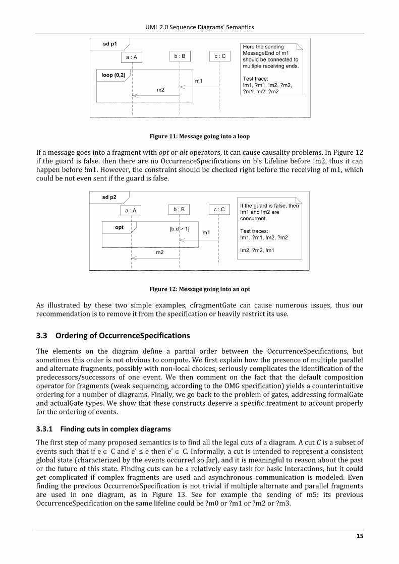
If a message goes into a fragment with opt or alt operators, it can cause causality problems. In Figure 12 if the guard is false, then there are no OccurrenceSpecifications on b's Lifeline before !m2, thus it can happen before !m1. However, the constraint should be checked right before the receiving of m1, which could be not even sent if the guard is false.
sd p2
a : A b : B
m2
opt
c : C
m1
If the guard is false, then
!m1 and !m2 are
concurrent.
Test traces:
!m1, ?m1, !m2, ?m2
!m2, ?m2, !m1
[b.d > 1]
Figure 12: Message going into an opt
As illustrated by these two simple examples, cfragmentGate can cause numerous issues, thus our recommendation is to remove it from the specification or heavily restrict its use.
3.3 Ordering of OccurrenceSpecifications
The elements on the diagram define a partial order between the OccurrenceSpecifications, but sometimes this order is not obvious to compute. We first explain how the presence of multiple parallel and alternate fragments, possibly with non-local choices, seriously complicates the identification of the predecessors/successors of one event. We then comment on the fact that the default composition operator for fragments (weak sequencing, according to the OMG specification) yields a counterintuitive ordering for a number of diagrams. Finally, we go back to the problem of gates, addressing formalGate and actualGate types. We show that these constructs deserve a specific treatment to account properly for the ordering of events.
3.3.1 Finding cuts in complex diagrams
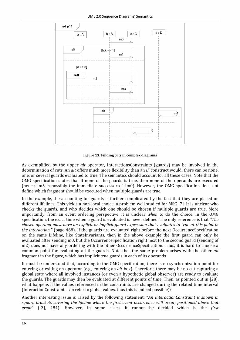
The first step of many proposed semantics is to find all the legal cuts of a diagram. A cut C is a subset of events such that if e C and e' ≤ e then e' C. Informally, a cut is intended to represent a consistent global state (characterized by the events occurred so far), and it is meaningful to reason about the past or the future of this state. Finding cuts can be a relatively easy task for basic Interactions, but it could get complicated if complex fragments are used and asynchronous communication is modeled. Even finding the previous OccurrenceSpecification is not trivial if multiple alternate and parallel fragments are used in one diagram, as in Figure 13. See for example the sending of m5: its previous OccurrenceSpecification on the same lifeline could be ?m0 or ?m1 or ?m2 or ?m3.
UML 2.0 Sequence Diagrams' Semantics
16
sd p11
alt
alt
par
a : A b : B
m2
c : C
m1
[b.k == 1]
[a.l > 3]
d : D
m3
m4
m5
m0
Figure 13: Finding cuts in complex diagrams
As exemplified by the upper alt operator, InteractionsConstraints (guards) may be involved in the determination of cuts. An alt offers much more flexibility than an IF construct would: there can be none, one, or several guards evaluated to true. The semantics should account for all these cases. Note that the OMG specification states that if none of the guards is true, then none of the operands are executed (hence, !m5 is possibly the immediate successor of ?m0). However, the OMG specification does not define which fragment should be executed when multiple guards are true.
In the example, the accounting for guards is further complicated by the fact that they are placed on different lifelines. This yields a non-local choice, a problem well studied for MSC [7]. It is unclear who checks the guards, and who decides which one should be chosen if multiple guards are true. More importantly, from an event ordering perspective, it is unclear when to do the choice. In the OMG specification, the exact time when a guard is evaluated is never defined. The only reference is that "The chosen operand must have an explicit or implicit guard expression that evaluates to true at this point in the interaction." (page 468). If the guards are evaluated right before the next OccurrenceSpecification on the same Lifeline, like StateInvariants, then in the above example the first guard can only be evaluated after sending m0, but the OccurrenceSpecification right next to the second guard (sending of m2) does not have any ordering with the other OccurrenceSpecification. Thus, it is hard to choose a common point for evaluating all the guards. Note that the same problem arises with the other alt fragment in the figure, which has implicit true guards in each of its operands.
It must be understood that, according to the OMG specification, there is no synchronization point for entering or exiting an operator (e.g., entering an alt box). Therefore, there may be no cut capturing a global state where all involved instances (or even a hypothetic global observer) are ready to evaluate the guards. The guards may then be evaluated at different points of time. Then, as pointed out in [28], what happens if the values referenced in the constraints are changed during the related time interval (InteractionConstraints can refer to global values, thus this is indeed possible)?
Another interesting issue is raised by the following statement: “An InteractionConstraint is shown in square brackets covering the lifeline where the first event occurrence will occur, positioned above that event” ([3], 484). However, in some cases, it cannot be decided which is the first
UML 2.0 Sequence Diagrams' Semantics
17
OccurrenceSpecification in the InteractionOperand. E.g., in Figure 13, should the guard before the par be placed on Lifeline a or b?
3.3.2 Counter-intuitive composition of orderings
In our comments on the interpretation of non-local choice, we mentioned that there is no synchronization point for crossing the borders of an operator. Technically, entering or exiting an operator is not an OccurrenceSpecification. As far as we understand the OMG specification, the only OccurrenceSpecifications are (1) sending and receiving of Messages and (2) start and end of an ExecutionSpecification. These are the events that can appear in traces, and ordering constraints are defined for them only. In this section, we show that the lack of synchronization points for borders of boxes, combined with the fact that weak sequencing is the default composition operator for fragments, yields counterintuitive orderings.
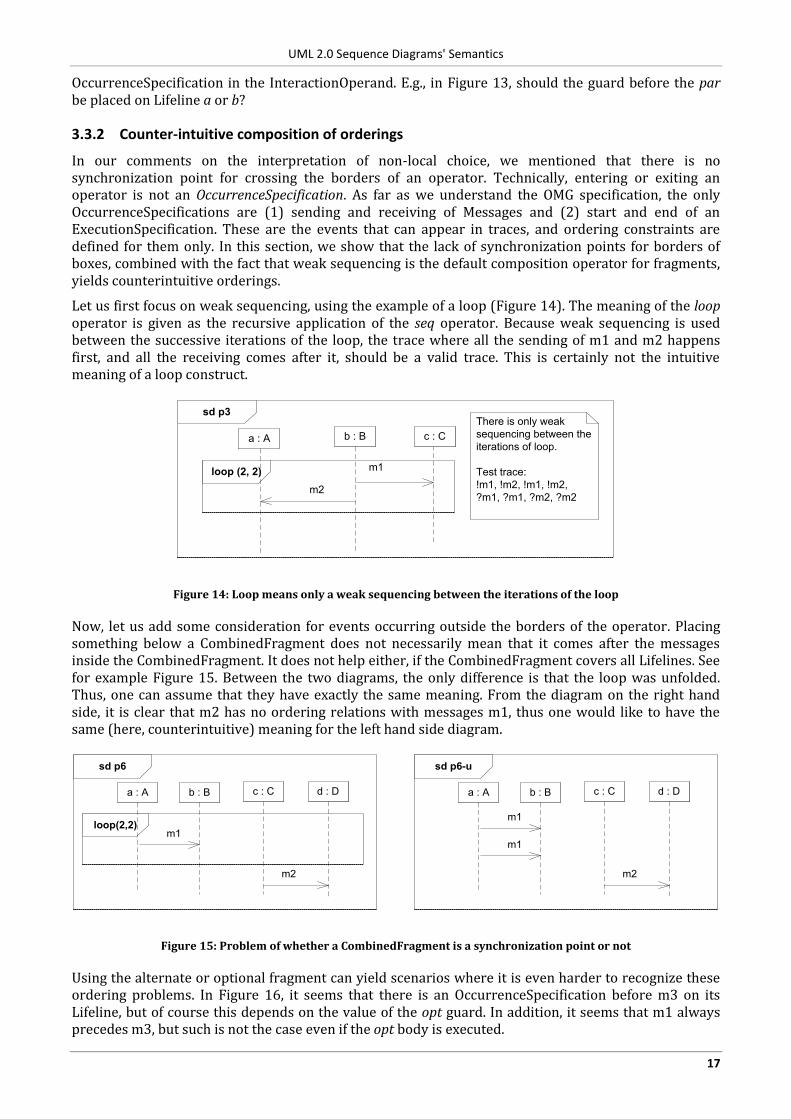
Let us first focus on weak sequencing, using the example of a loop (Figure 14). The meaning of the loop operator is given as the recursive application of the seq operator. Because weak sequencing is used between the successive iterations of the loop, the trace where all the sending of m1 and m2 happens first, and all the receiving comes after it, should be a valid trace. This is certainly not the intuitive meaning of a loop construct.
sd p3
a : A b : B
loop (2, 2)
m2
c : C
m1
There is only weak
sequencing between the
iterations of loop.
Test trace:
!m1, !m2, !m1, !m2,
?m1, ?m1, ?m2, ?m2
Figure 14: Loop means only a weak sequencing between the iterations of the loop
Now, let us add some consideration for events occurring outside the borders of the operator. Placing something below a CombinedFragment does not necessarily mean that it comes after the messages inside the CombinedFragment. It does not help either, if the CombinedFragment covers all Lifelines. See for example Figure 15. Between the two diagrams, the only difference is that the loop was unfolded. Thus, one can assume that they have exactly the same meaning. From the diagram on the right hand side, it is clear that m2 has no ordering relations with messages m1, thus one would like to have the same (here, counterintuitive) meaning for the left hand side diagram.
sd p6
a : A b : B
loop(2,2)m1
c : C
m2
d : D
sd p6-u
a : A b : B
m1
c : C
m2
d : D
m1
Figure 15: Problem of whether a CombinedFragment is a synchronization point or not
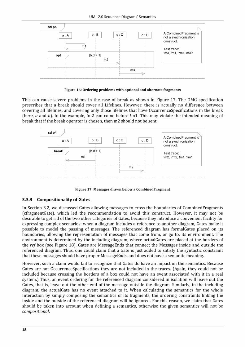
Using the alternate or optional fragment can yield scenarios where it is even harder to recognize these ordering problems. In Figure 16, it seems that there is an OccurrenceSpecification before m3 on its Lifeline, but of course this depends on the value of the opt guard. In addition, it seems that m1 always precedes m3, but such is not the case even if the opt body is executed.
UML 2.0 Sequence Diagrams' Semantics
18
sd p5
a : A b : B
opt
m2
c : C
m3
A CombinedFragment is
not a synchronization
construct.
Test trace:
!m3, !m1, ?m1, m3?
d : D
m1
[b.d > 1]
Figure 16: Ordering problems with optional and alternate fragments
This can cause severe problems in the case of break as shown in Figure 17. The OMG specification prescribes that a break should cover all Lifelines. However, there is actually no difference between covering all lifelines, and covering only those lifelines that have OccurrenceSpecifications in the break (here, a and b). In the example, !m2 can come before !m1. This may violate the intended meaning of break that if the break operator is chosen, then m2 should not be sent.
sd p4
a : A b : B
break
m1
c : C
m2
A CombinedFragment is
not a synchronization
construct.
Test trace:
!m2, ?m2, !m1, ?m1
d : D
[b.d > 1]
Figure 17: Messages drawn below a CombinedFragment
3.3.3 Compositionality of Gates
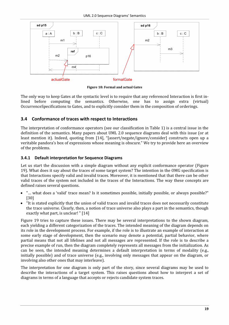
In Section 3.2, we discussed Gates allowing messages to cross the boundaries of CombinedFragments (cfragmentGate), which led the recommendation to avoid this construct. However, it may not be desirable to get rid of the two other categories of Gates, because they introduce a convenient facility for expressing complex scenarios: when a diagram includes a reference to another diagram, Gates make it possible to model the passing of messages. The referenced diagram has formalGates placed on its boundaries, allowing the representation of messages that come from, or go to, its environment. The environment is determined by the including diagram, where actualGates are placed at the borders of the ref box (see Figure 18). Gates are MessageEnds that connect the Messages inside and outside the referenced diagram. Thus, one could claim that a Gate is just added to satisfy the syntactic constraint that these messages should have proper MessageEnds, and does not have a semantic meaning.
However, such a claim would fail to recognize that Gates do have an impact on the semantics. Because Gates are not OccurrenceSpecifications they are not included in the traces. (Again, they could not be included because crossing the borders of a box could not have an event associated with it in a real system.) Thus, an event ordering for the referenced diagram considered in isolation will leave out the Gates, that is, leave out the other end of the message outside the diagram. Similarly, in the including diagram, the actualGate has no event attached to it. When calculating the semantics for the whole Interaction by simply composing the semantics of its fragments, the ordering constraints linking the inside and the outside of the referenced diagram will be ignored. For this reason, we claim that Gates should be taken into account when defining a semantics, otherwise the given semantics will not be compositional.
UML 2.0 Sequence Diagrams' Semantics
19
sd p15
a : A b : B
m1
m2
c : C
ref
p16
sd p16
b : B
m2
c : C
m3
formalGateactualGate
m4
Figure 18: Formal and actual Gates
The only way to keep Gates at the syntactic level is to require that any referenced Interaction is first in-lined before computing the semantics. Otherwise, one has to assign extra (virtual) OccurrenceSpecifications to Gates, and to explicitly consider them in the composition of orderings.
3.4 Conformance of traces with respect to Interactions
The interpretation of conformance operators (see our classification in Table 1) is a central issue in the definition of the semantics. Many papers about UML 2.0 sequence diagrams deal with this issue (or at least mention it). Indeed, quoting from [14], “[assert/negate/ignore/consider] constructs open up a veritable pandora’s box of expressions whose meaning is obscure.” We try to provide here an overview of the problems.
3.4.1 Default interpretation for Sequence Diagrams
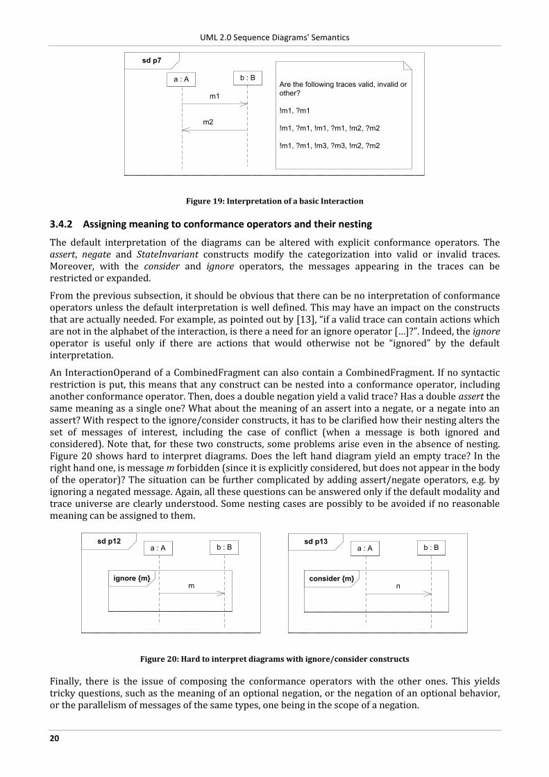
Let us start the discussion with a simple diagram without any explicit conformance operator (Figure 19). What does it say about the traces of some target system? The intention in the OMG specification is that Interactions specify valid and invalid traces. Moreover, it is mentioned that that there can be other valid traces of the system not included in the traces of the Interactions. The way these concepts are defined raises several questions.
"… what does a ‘valid’ trace mean? Is it sometimes possible, initially possible, or always possible?" [30]
"It is stated explicitly that the union of valid traces and invalid traces does not necessarily constitute the trace universe. Clearly, then, a notion of trace universe also plays a part in the semantics, though exactly what part, is unclear! " [14]
Figure 19 tries to capture these issues. There may be several interpretations to the shown diagram, each yielding a different categorization of the traces. The intended meaning of the diagram depends on its role in the development process. For example, if the role is to illustrate an example of interaction at some early stage of development, then the scenario may denote a potential, partial behavior, where partial means that not all lifelines and not all messages are represented. If the role is to describe a precise example of run, then the diagram completely represents all messages from the initialization. As can be seen, the intended meaning determines a default interpretation in terms of modality (e.g., initially possible) and of trace universe (e.g., involving only messages that appear on the diagram, or involving also other ones that may interleave).
The interpretation for one diagram is only part of the story, since several diagrams may be used to describe the interactions of a target system. This raises questions about how to interpret a set of diagrams in terms of a language that accepts or rejects candidate system traces.
UML 2.0 Sequence Diagrams' Semantics
20
sd p7
a : A b : B
m1
m2
Are the following traces valid, invalid or
other?
!m1, ?m1
!m1, ?m1, !m1, ?m1, !m2, ?m2
!m1, ?m1, !m3, ?m3, !m2, ?m2
Figure 19: Interpretation of a basic Interaction
3.4.2 Assigning meaning to conformance operators and their nesting
The default interpretation of the diagrams can be altered with explicit conformance operators. The assert, negate and StateInvariant constructs modify the categorization into valid or invalid traces. Moreover, with the consider and ignore operators, the messages appearing in the traces can be restricted or expanded.
From the previous subsection, it should be obvious that there can be no interpretation of conformance operators unless the default interpretation is well defined. This may have an impact on the constructs that are actually needed. For example, as pointed out by [13], “if a valid trace can contain actions which are not in the alphabet of the interaction, is there a need for an ignore operator […]?”. Indeed, the ignore operator is useful only if there are actions that would otherwise not be “ignored” by the default interpretation.
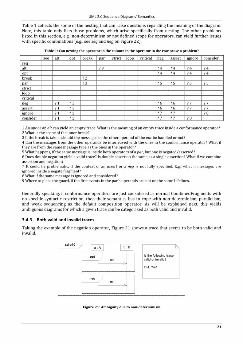
An InteractionOperand of a CombinedFragment can also contain a CombinedFragment. If no syntactic restriction is put, this means that any construct can be nested into a conformance operator, including another conformance operator. Then, does a double negation yield a valid trace? Has a double assert the same meaning as a single one? What about the meaning of an assert into a negate, or a negate into an assert? With respect to the ignore/consider constructs, it has to be clarified how their nesting alters the set of messages of interest, including the case of conflict (when a message is both ignored and considered). Note that, for these two constructs, some problems arise even in the absence of nesting. Figure 20 shows hard to interpret diagrams. Does the left hand diagram yield an empty trace? In the right hand one, is message m forbidden (since it is explicitly considered, but does not appear in the body of the operator)? The situation can be further complicated by adding assert/negate operators, e.g. by ignoring a negated message. Again, all these questions can be answered only if the default modality and trace universe are clearly understood. Some nesting cases are possibly to be avoided if no reasonable meaning can be assigned to them.
sd p12
ignore {m}
a : A b : B
m
sd p13
consider {m}
a : A b : B
n
Figure 20: Hard to interpret diagrams with ignore/consider constructs
Finally, there is the issue of composing the conformance operators with the other ones. This yields tricky questions, such as the meaning of an optional negation, or the negation of an optional behavior, or the parallelism of messages of the same types, one being in the scope of a negation.
UML 2.0 Sequence Diagrams' Semantics
21
Table 1 collects the some of the nesting that can raise questions regarding the meaning of the diagram. Note, this table only lists those problems, which arise specifically from nesting. The other problems listed in this section, e.g., non-determinism or not defined scope for operators, can yield further issues with specific combinations (e.g., see seq and neg on Figure 22).
Table 1: Can nesting the operator in the column in the operator in the row cause a problem?
seq alt opt break par strict loop critical neg assert ignore consider seq alt ? 9 ? 4 ? 4 ? 4 ? 4 opt ? 4 ? 4 ? 4 ? 4 break ? 2 par ? 3 ? 5 ? 5 ? 5 ? 5 strict loop critical neg ? 1 ? 1 ? 6 ? 6 ? 7 ? 7 assert ? 1 ? 1 ? 6 ? 6 ? 7 ? 7 ignore ? 1 ? 1 ? 7 ? 7 ? 8 consider ? 1 ? 1 ? 7 ? 7 ? 8 1 An opt or an alt can yield an empty trace. What is the meaning of an empty trace inside a conformance operator? 2 What is the scope of the inner break? 3 If the break is taken, should the messages in the other operand of the par be handled or not? 4 Can the messages from the other operands be interleaved with the ones in the conformance operator? What if they are from the same message type as the ones in the operator? 5 What happens, if the same message is inside both operators of a par, but one is negated/asserted? 6 Does double negation yield a valid trace? Is double assertion the same as a single assertion? What if we combine assertion and negation? 7 It could be problematic, if the context of an assert or a neg is not fully specified. E.g., what if messages are ignored inside a negate fragment? 8 What if the same message is ignored and considered? 9 Where to place the guard, if the first events in the par's operands are not on the same Lifelines.
Generally speaking, if conformance operators are just considered as normal CombinedFragments with no specific syntactic restriction, then their semantics has to cope with non-determinism, parallelism, and weak sequencing as the default composition operator. As will be explained next, this yields ambiguous diagrams for which a given trace can be categorized as both valid and invalid.
3.4.3 Both valid and invalid traces
Taking the example of the negation operator, Figure 21 shows a trace that seems to be both valid and invalid.
sd p10
neg
opt
a : A b : B
m1
Is the following trace
valid or invalid?
!m1, ?m1
m1
Figure 21: Ambiguity due to non-determinism
UML 2.0 Sequence Diagrams' Semantics
22
This is due to non-determinism. A given event in the trace can be considered as occurring either inside or outside the scope of the conformance operator, depending on some non-deterministic choice. Parallel constructs come with similar ambiguities. Assume a message is ignored in one parallel operand and negated in the other. Will the message occurrence in the trace be considered as valid (that is, inside the scope of ignore) or invalid (inside the scope of negate)?
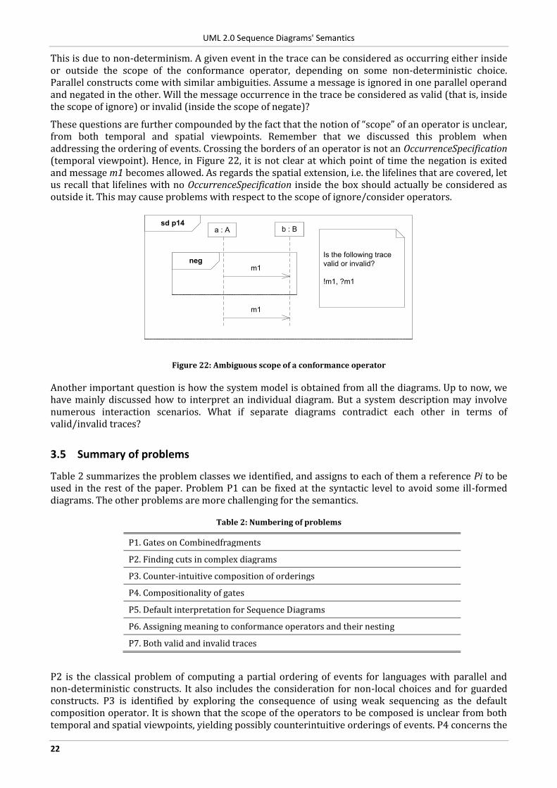
These questions are further compounded by the fact that the notion of “scope” of an operator is unclear, from both temporal and spatial viewpoints. Remember that we discussed this problem when addressing the ordering of events. Crossing the borders of an operator is not an OccurrenceSpecification (temporal viewpoint). Hence, in Figure 22, it is not clear at which point of time the negation is exited and message m1 becomes allowed. As regards the spatial extension, i.e. the lifelines that are covered, let us recall that lifelines with no OccurrenceSpecification inside the box should actually be considered as outside it. This may cause problems with respect to the scope of ignore/consider operators.
sd p14
neg
a : A b : B
m1
Is the following trace
valid or invalid?
!m1, ?m1
m1
Figure 22: Ambiguous scope of a conformance operator
Another important question is how the system model is obtained from all the diagrams. Up to now, we have mainly discussed how to interpret an individual diagram. But a system description may involve numerous interaction scenarios. What if separate diagrams contradict each other in terms of valid/invalid traces?
3.5 Summary of problems
Table 2 summarizes the problem classes we identified, and assigns to each of them a reference Pi to be used in the rest of the paper. Problem P1 can be fixed at the syntactic level to avoid some ill-formed diagrams. The other problems are more challenging for the semantics.
Table 2: Numbering of problems
P1. Gates on Combinedfragments
P2. Finding cuts in complex diagrams
P3. Counter-intuitive composition of orderings
P4. Compositionality of gates
P5. Default interpretation for Sequence Diagrams
P6. Assigning meaning to conformance operators and their nesting
P7. Both valid and invalid traces
P2 is the classical problem of computing a partial ordering of events for languages with parallel and non-deterministic constructs. It also includes the consideration for non-local choices and for guarded constructs. P3 is identified by exploring the consequence of using weak sequencing as the default composition operator. It is shown that the scope of the operators to be composed is unclear from both temporal and spatial viewpoints, yielding possibly counterintuitive orderings of events. P4 concerns the
UML 2.0 Sequence Diagrams' Semantics
23
specific problem of Gates allowing messages to cross ref boxes, and how this affects the computation of a global ordering.
Problems P5-7 are related to the conformance relation used to determine whether or not a candidate trace is valid. P5 involves the definition of a default interpretation for Sequence Diagrams, yielding an implicit conformance relation. P6 is concerned by the modifications induced by explicit conformance operators and how to assign a meaning to their nesting. P7 raises the problem of ambiguous diagrams for which a given trace may be categorized as both valid and invalid. This arises as a consequence of the parallel and non-deterministic constructs, weak sequencing and unclear scope of operators that were also identified as problematic from the perspective of computing a partial ordering.
UML 2.0 Sequence Diagrams' Semantics
24
4 Survey of Proposed Semantics
Several formal semantics were proposed for UML 2.0 Sequence Diagrams over the years. This section collects the ones we are aware of. For the twelve proposed approaches, a short description is given, and the approach's recommendations for Section 3's problems are listed. For some of the approaches the semantics of a common diagram diagram is given.
4.1 Types of semantics
Several approaches exist for defining semantics for languages.
Denotational: in a denotational semantics approach the meaning of the language is mapped to mathematical objects (called denotations).
Operational: in an operational semantics approach the meaning of the language is interpreted as sequences of computational steps.
For communicating processes an important decision is how parallel, independent events are represented [16].
True-concurrency (non-interleaving): two distinct events can happen at the exact same time, the concurrency is visible in the semantic model.
Interleaving: at any moment only one event can happen in the system, i.e. there is a total ordering between the events.
Based on how decision points are modeled two approaches can be distinguished.
Branching time: branching points are visible in the semantics model. Linear time: branching points are not visible in the semantics model.
The categorization of the semantics defined in the OMG specification was analyzed in [19], where it was classified as a linear time, interleaving semantics.
4.2 Proposed semantics for UML Sequence Diagrams
This section gives a summary about the different semantics that were proposed for Sequence Diagrams.
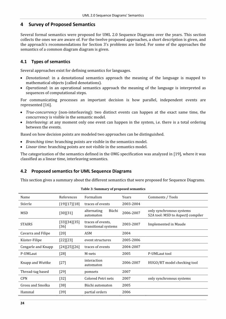
Table 3: Summary of proposed semantics
Name References Formalism Years Comments / Tools
Störrle [19][17][18] traces of events 2003-2004
MSD [30][31] alternating Büchi automaton
2006-2007 only synchronous systems S2A tool: MSD to AspectJ compiler
STAIRS [33][34][35][36]
traces of events, transitional systems
2003-2007 Implemented in Maude
Cavarra and Filipe [20] ASM 2004
Küster-Filipe [22][23] event structures 2005-2006
Cengarle and Knapp [24][25][26] traces of events 2004-2007
P-UMLaut [28] M-nets 2005 P-UMLaut tool
Knapp and Wuttke [27] interaction automaton
2006-2007 HUGO/RT model checking tool
Thread-tag based [29] pomsets 2007
CPN [32] Colored Petri nets 2007 only synchronous systems
Grosu and Smolka [38] Büchi automaton 2005
Hammal [39] partial orders 2006
UML 2.0 Sequence Diagrams' Semantics
25
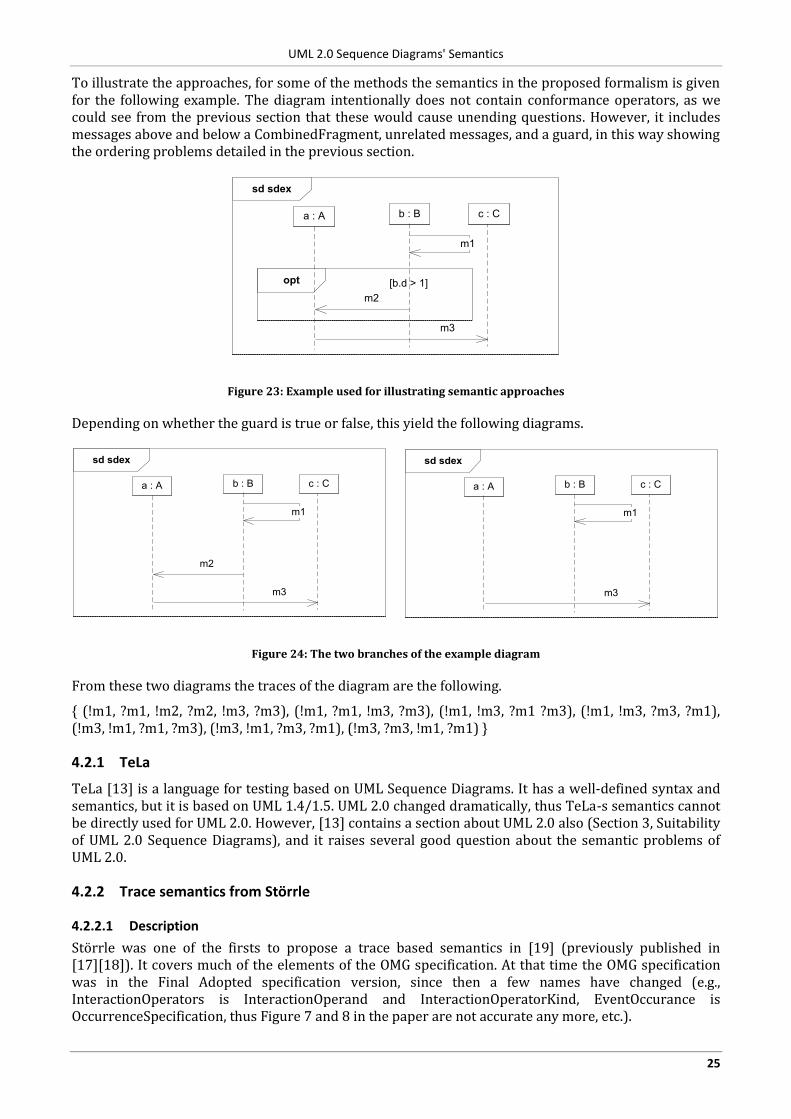
To illustrate the approaches, for some of the methods the semantics in the proposed formalism is given for the following example. The diagram intentionally does not contain conformance operators, as we could see from the previous section that these would cause unending questions. However, it includes messages above and below a CombinedFragment, unrelated messages, and a guard, in this way showing the ordering problems detailed in the previous section.
sd sdex
a : A b : B
opt
m2
c : C
m3
[b.d > 1]
m1
Figure 23: Example used for illustrating semantic approaches
Depending on whether the guard is true or false, this yield the following diagrams.
sd sdex
a : A b : B
m2
c : C
m3
m1
sd sdex
a : A b : B c : C
m3
m1
Figure 24: The two branches of the example diagram
From these two diagrams the traces of the diagram are the following.
{ (!m1, ?m1, !m2, ?m2, !m3, ?m3), (!m1, ?m1, !m3, ?m3), (!m1, !m3, ?m1 ?m3), (!m1, !m3, ?m3, ?m1), (!m3, !m1, ?m1, ?m3), (!m3, !m1, ?m3, ?m1), (!m3, ?m3, !m1, ?m1) }
4.2.1 TeLa
TeLa [13] is a language for testing based on UML Sequence Diagrams. It has a well-defined syntax and semantics, but it is based on UML 1.4/1.5. UML 2.0 changed dramatically, thus TeLa-s semantics cannot be directly used for UML 2.0. However, [13] contains a section about UML 2.0 also (Section 3, Suitability of UML 2.0 Sequence Diagrams), and it raises several good question about the semantic problems of UML 2.0.
4.2.2 Trace semantics from Störrle
4.2.2.1 Description
Störrle was one of the firsts to propose a trace based semantics in [19] (previously published in [17][18]). It covers much of the elements of the OMG specification. At that time the OMG specification was in the Final Adopted specification version, since then a few names have changed (e.g., InteractionOperators is InteractionOperand and InteractionOperatorKind, EventOccurance is OccurrenceSpecification, thus Figure 7 and 8 in the paper are not accurate any more, etc.).
UML 2.0 Sequence Diagrams' Semantics
26
Section 3.1 analyzes the semantic approach used in the OMG specification and finally categorizes it as an interleaving, linear-time semantics of complete traces with abstract real time.
First, the trace semantics is given for "plain InteractionFragments", i.e., ones without CombinedFragment. Later, for CombinedFragment the semantics of each operator is presented. Section 5 deals with assert and negate in detail, and gives several potential meaning for the negate operator. It also points out many issues with the OMG specification.
4.2.2.2 Notes
Störrle states that "Gates are purely syntactic and are thus left out of the semantic considerations of this article". See Section 3.3.3 about our opinion on this topic.
In 2.3 the semantics of Figure 3 is given as a set containing only one trace. However, { (A, snd, t1).(B, rcv, t2).(B, snd, t3).(B, snd, t5).(A, rcv, t4).(A, rcv, t6) } is also a valid trace, because the messages have an asynchronous arrowhead.
It is not explicitly stated how to combine the traces if an Interaction has plain fragments and CombinedFragments also; possibly the weak sequencing operator should be applied between them.
4.2.2.3 Semantics of the example
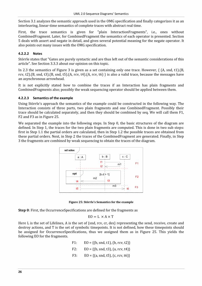
Using Störrle's approach the semantics of the example could be constructed in the following way. The Interaction consists of three parts, two plain fragments and one CombinedFragment. Possibly their trace should be calculated separately, and then they should be combined by seq. We will call them F1, F2 and F3 as in Figure 25.
We separated the example into the following steps. In Step 0, the basic structures of the diagram are defined. In Step 1, the traces for the two plain fragments are computed. This is done in two sub steps: first in Step 1.1 the partial orders are calculated, then in Step 1.2 the possible traces are obtained from these partial orders. Next, in Step 2 the traces of the CombinedFragment are generated. Finally, in Step 3 the fragments are combined by weak sequencing to obtain the traces of the diagram.
sd sdex
a : A b : B
opt
m2
c : C
m3
[b.d > 1]
m1t1
t2
t3t4
t5 t6
F1
F2
F3
Figure 25: Störrle's Semantics for the example
Step 0: First, the OccurrenceSpecifications are defined for the fragments as
EO = L × A × T
Here L is the set of Lifelines, A is the set of {snd, rcv, cr, des} representing the send, receive, create and destroy actions, and T is the set of symbolic timepoints. It is not defined, how these timepoints should be assigned for OccurrenceSpecifications, thus we assigned them as in Figure 25. This yields the following EO for the fragments.
F1: EO = {(b, snd, t1), (b, rcv, t2)}
F2: EO = {(b, snd, t3), (a, rcv, t4)}
F3: EO = {(a, snd, t5), (c, rcv, t6)}
UML 2.0 Sequence Diagrams' Semantics
27
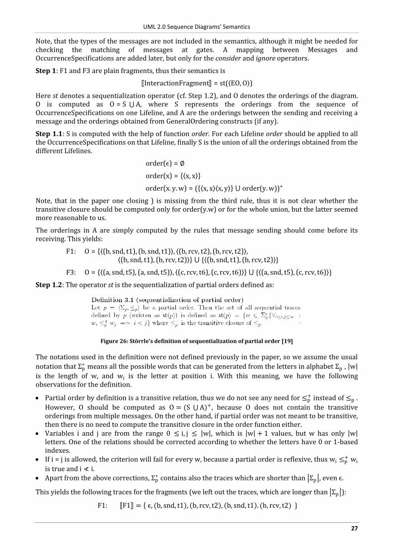
Note, that the types of the messages are not included in the semantics, although it might be needed for checking the matching of messages at gates. A mapping between Messages and OccurrenceSpecifications are added later, but only for the consider and ignore operators.
Step 1: F1 and F3 are plain fragments, thus their semantics is
InteractionFragment = st( EO, O )
Here st denotes a sequentialization operator (cf. Step 1.2), and O denotes the orderings of the diagram. O is computed as O = S A, where S represents the orderings from the sequence of OccurrenceSpecifications on one Lifeline, and A are the orderings between the sending and receiving a message and the orderings obtained from GeneralOrdering constructs (if any).
Step 1.1: S is computed with the help of function order. For each Lifeline order should be applied to all the OccurrenceSpecifications on that Lifeline, finally S is the union of all the orderings obtained from the different Lifelines.
order(ϵ) = ∅
order(x) = x, x
order(x. y. w) = ( x, x x, y ⋃ order(y. w))+
Note, that in the paper one closing ) is missing from the third rule, thus it is not clear whether the transitive closure should be computed only for order(y.w) or for the whole union, but the latter seemed more reasonable to us.
The orderings in A are simply computed by the rules that message sending should come before its receiving. This yields:
F1: O = (b, snd, t1), (b, snd, t1) , (b, rcv, t2), (b, rcv, t2) , (b, snd, t1), (b, rcv, t2) ⋃ { (b, snd, t1), (b, rcv, t2) }
F3: O = (a, snd, t5), (a, snd, t5) , (c, rcv, t6), (c, rcv, t6) ⋃ { (a, snd, t5), (c, rcv, t6) }
Step 1.2: The operator st is the sequentialization of partial orders defined as:
Figure 26: Störrle's definition of sequentialization of partial order [19]
The notations used in the definition were not defined previously in the paper, so we assume the usual
notation that Σp∗ means all the possible words that can be generated from the letters in alphabet Σp , w
is the length of w, and wi is the letter at position i. With this meaning, we have the following observations for the definition.
Partial order by definition is a transitive relation, thus we do not see any need for ≤p+ instead of ≤p .
However, O should be computed as O = (S ⋃A)+, because O does not contain the transitive orderings from multiple messages. On the other hand, if partial order was not meant to be transitive, then there is no need to compute the transitive closure in the order function either.
Variables i and j are from the range 0 ≤ i, j ≤ w , which is w + 1 values, but w has only w letters. One of the relations should be corrected according to whether the letters have 0 or 1-based indexes.
If i = j is allowed, the criterion will fail for every w, because a partial order is reflexive, thus wi ≤p+ wi
is true and i ≮ i. Apart from the above corrections, Σp
∗ contains also the traces which are shorter than Σp , even ϵ.
This yields the following traces for the fragments (we left out the traces, which are longer than Σp ):
F1: F1 = ϵ, (b, snd, t1 , b, rcv, t2 , b, snd, t1 . (b, rcv, t2) }
UML 2.0 Sequence Diagrams' Semantics
28
F3: F3 = ϵ, (a, snd, t5 , c, rcv, t6 , a, snd, t5 . (c, rcv, t6) }
Maybe this was not the intended semantics; it contains traces with just one receiving OccurrenceSpecification in it. For the rest of the example we will use the traces that contain also the sending and receiving:
F1: F1 = { b, snd, t1 . (b, rcv, t2)}
F3: F3 = { a, snd, t5 . (c, rcv, t6)}
Step 2: To compute the semantics of F2, we will use that the semantics of opt is defined as:
opt(P) = P ⋃{ϵ}
Here P stands for the interaction fragment inside the CombinedFragment. Using this definition, the semantics of F2 is the following (the semantics of the InteractionOperand uses the corrected version of the above calculation):
F2: F2 = {ϵ, b, snd, t3 . (a, rcv, t4)}
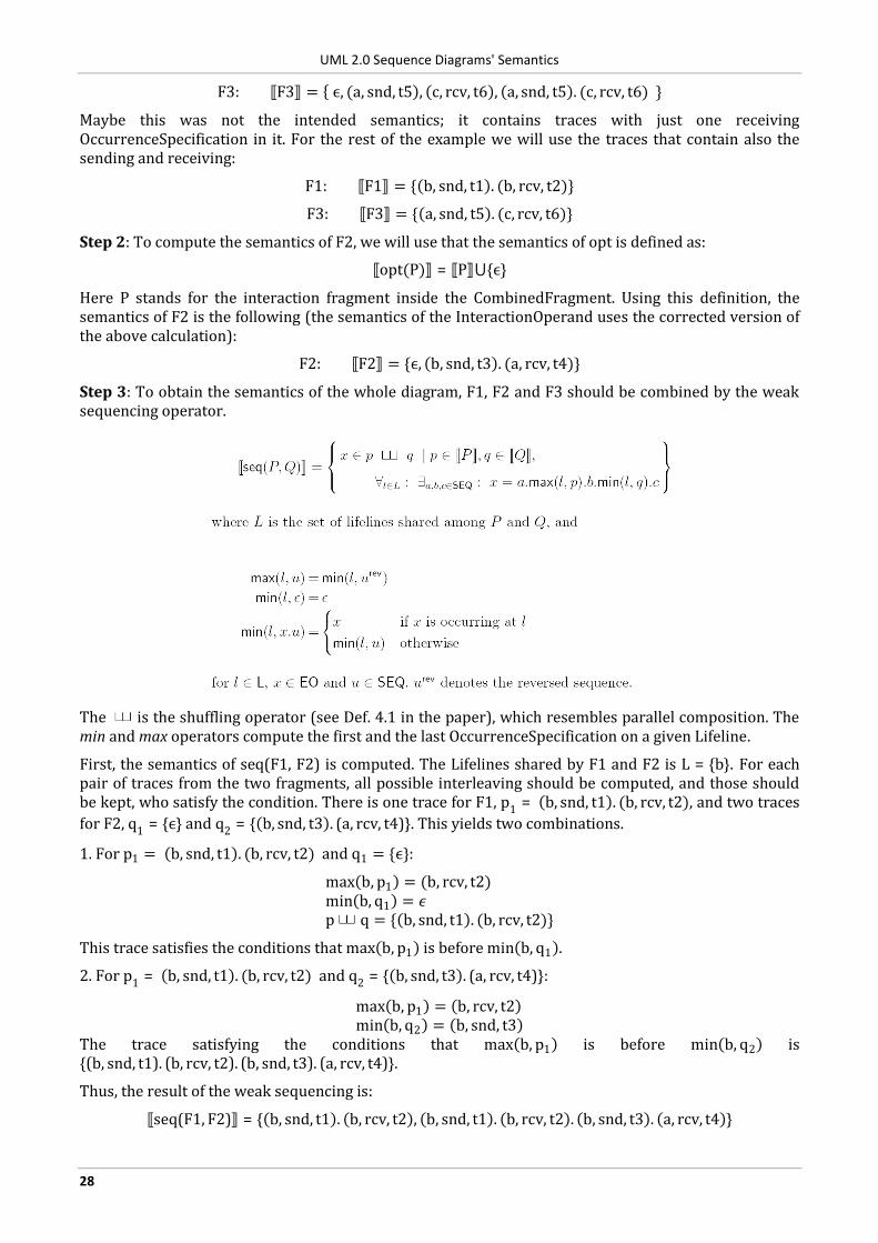
Step 3: To obtain the semantics of the whole diagram, F1, F2 and F3 should be combined by the weak sequencing operator.
The is the shuffling operator (see Def. 4.1 in the paper), which resembles parallel composition. The min and max operators compute the first and the last OccurrenceSpecification on a given Lifeline.
First, the semantics of seq(F1, F2) is computed. The Lifelines shared by F1 and F2 is L = {b}. For each pair of traces from the two fragments, all possible interleaving should be computed, and those should be kept, who satisfy the condition. There is one trace for F1, p1 = b, snd, t1 . (b, rcv, t2), and two traces
for F2, q1 = {ϵ} and q2 = { b, snd, t3 . (a, rcv, t4)}. This yields two combinations.
1. For p1 = b, snd, t1 . (b, rcv, t2) and q1 = {ϵ}:
max b, p1 = (b, rcv, t2) min b, q1 = 𝜖 p q = { b, snd, t1 . (b, rcv, t2)}
This trace satisfies the conditions that max b, p1 is before min b, q1 .
2. For p1 = b, snd, t1 . (b, rcv, t2) and q2 = { b, snd, t3 . (a, rcv, t4)}:
max b, p1 = b, rcv, t2 min b, q2 = b, snd, t3
The trace satisfying the conditions that max b, p1 is before min b, q2 is {(b, snd, t1). (b, rcv, t2). (b, snd, t3). (a, rcv, t4)}.
Thus, the result of the weak sequencing is:
seq(F1, F2) = { b, snd, t1 . b, rcv, t2 , b, snd, t1 . b, rcv, t2 . b, snd, t3 . a, rcv, t4 }
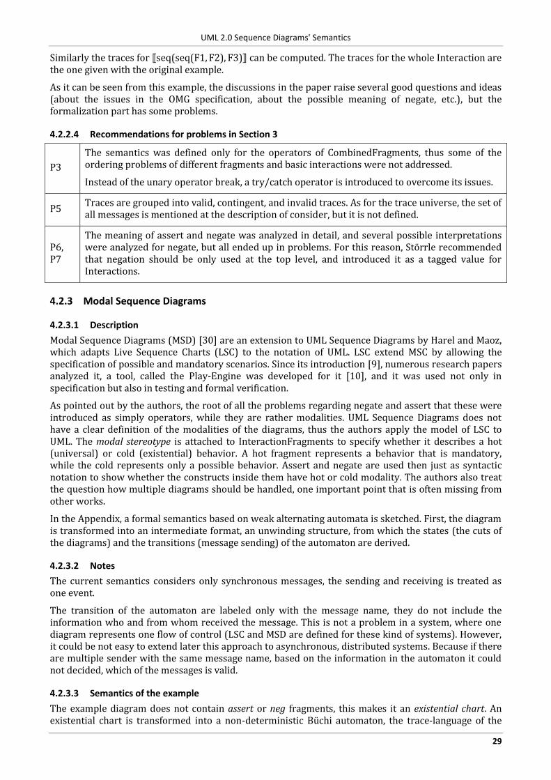
UML 2.0 Sequence Diagrams' Semantics
29
Similarly the traces for seq(seq(F1, F2), F3) can be computed. The traces for the whole Interaction are the one given with the original example.
As it can be seen from this example, the discussions in the paper raise several good questions and ideas (about the issues in the OMG specification, about the possible meaning of negate, etc.), but the formalization part has some problems.
4.2.2.4 Recommendations for problems in Section 3
P3
The semantics was defined only for the operators of CombinedFragments, thus some of the ordering problems of different fragments and basic interactions were not addressed.
Instead of the unary operator break, a try/catch operator is introduced to overcome its issues.
P5 Traces are grouped into valid, contingent, and invalid traces. As for the trace universe, the set of all messages is mentioned at the description of consider, but it is not defined.
P6, P7
The meaning of assert and negate was analyzed in detail, and several possible interpretations were analyzed for negate, but all ended up in problems. For this reason, Störrle recommended that negation should be only used at the top level, and introduced it as a tagged value for Interactions.
4.2.3 Modal Sequence Diagrams
4.2.3.1 Description
Modal Sequence Diagrams (MSD) [30] are an extension to UML Sequence Diagrams by Harel and Maoz, which adapts Live Sequence Charts (LSC) to the notation of UML. LSC extend MSC by allowing the specification of possible and mandatory scenarios. Since its introduction [9], numerous research papers analyzed it, a tool, called the Play-Engine was developed for it [10], and it was used not only in specification but also in testing and formal verification.
As pointed out by the authors, the root of all the problems regarding negate and assert that these were introduced as simply operators, while they are rather modalities. UML Sequence Diagrams does not have a clear definition of the modalities of the diagrams, thus the authors apply the model of LSC to UML. The modal stereotype is attached to InteractionFragments to specify whether it describes a hot (universal) or cold (existential) behavior. A hot fragment represents a behavior that is mandatory, while the cold represents only a possible behavior. Assert and negate are used then just as syntactic notation to show whether the constructs inside them have hot or cold modality. The authors also treat the question how multiple diagrams should be handled, one important point that is often missing from other works.
In the Appendix, a formal semantics based on weak alternating automata is sketched. First, the diagram is transformed into an intermediate format, an unwinding structure, from which the states (the cuts of the diagrams) and the transitions (message sending) of the automaton are derived.
4.2.3.2 Notes
The current semantics considers only synchronous messages, the sending and receiving is treated as one event.
The transition of the automaton are labeled only with the message name, they do not include the information who and from whom received the message. This is not a problem in a system, where one diagram represents one flow of control (LSC and MSD are defined for these kind of systems). However, it could be not easy to extend later this approach to asynchronous, distributed systems. Because if there are multiple sender with the same message name, based on the information in the automaton it could not decided, which of the messages is valid.
4.2.3.3 Semantics of the example
The example diagram does not contain assert or neg fragments, this makes it an existential chart. An existential chart is transformed into a non-deterministic Büchi automaton, the trace-language of the
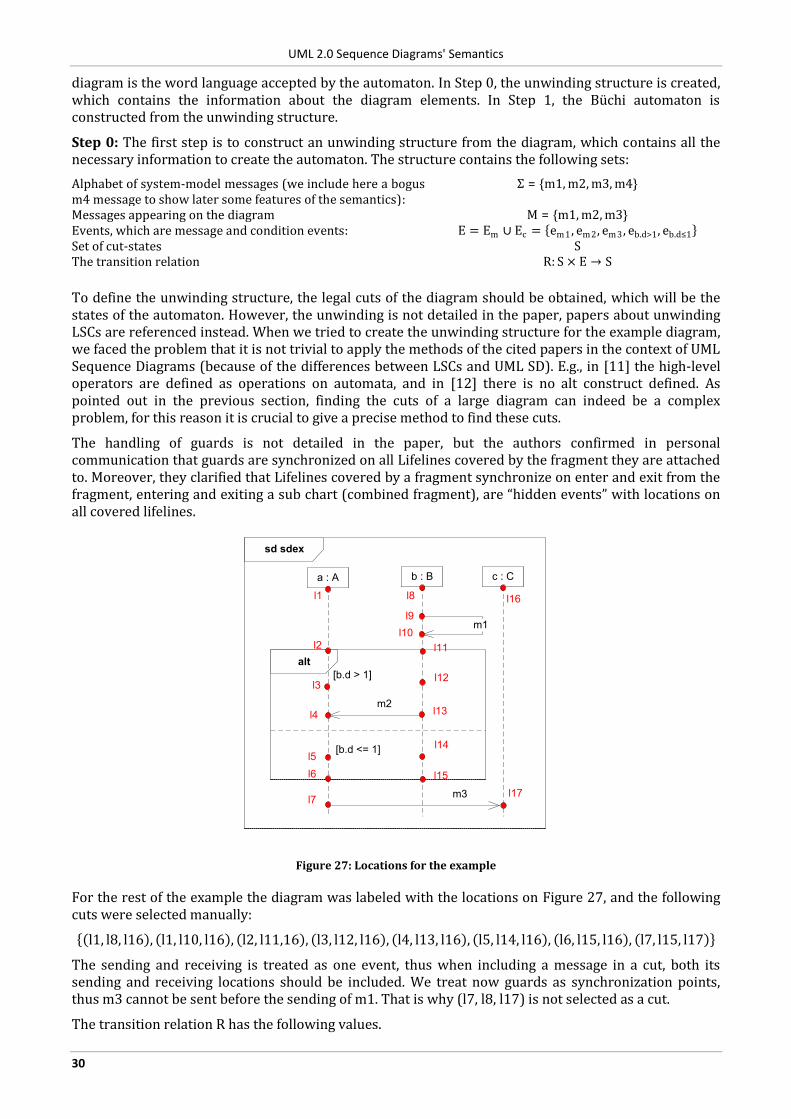
UML 2.0 Sequence Diagrams' Semantics
30
diagram is the word language accepted by the automaton. In Step 0, the unwinding structure is created, which contains the information about the diagram elements. In Step 1, the Büchi automaton is constructed from the unwinding structure.
Step 0: The first step is to construct an unwinding structure from the diagram, which contains all the necessary information to create the automaton. The structure contains the following sets:
Alphabet of system-model messages (we include here a bogus m4 message to show later some features of the semantics):
Σ = {m1, m2, m3, m4}
Messages appearing on the diagram M = {m1, m2, m3} Events, which are message and condition events: E = Em ∪ Ec = em1 , em2, em3 , eb.d>1, eb.d≤1 Set of cut-states S The transition relation R: S × E → S
To define the unwinding structure, the legal cuts of the diagram should be obtained, which will be the states of the automaton. However, the unwinding is not detailed in the paper, papers about unwinding LSCs are referenced instead. When we tried to create the unwinding structure for the example diagram, we faced the problem that it is not trivial to apply the methods of the cited papers in the context of UML Sequence Diagrams (because of the differences between LSCs and UML SD). E.g., in [11] the high-level operators are defined as operations on automata, and in [12] there is no alt construct defined. As pointed out in the previous section, finding the cuts of a large diagram can indeed be a complex problem, for this reason it is crucial to give a precise method to find these cuts.
The handling of guards is not detailed in the paper, but the authors confirmed in personal communication that guards are synchronized on all Lifelines covered by the fragment they are attached to. Moreover, they clarified that Lifelines covered by a fragment synchronize on enter and exit from the fragment, entering and exiting a sub chart (combined fragment), are “hidden events” with locations on all covered lifelines.
sd sdex
a : A b : B
alt
m2
c : C
m3
[b.d > 1]
m1l9
l10
l13
l3
[b.d <= 1]
l8l1
l7
l16
l17
l12
l14
l4
l2
l5
l6
l11
l15
Figure 27: Locations for the example
For the rest of the example the diagram was labeled with the locations on Figure 27, and the following cuts were selected manually:
l1, l8, l16 , l1, l10, l16 , l2, l11,16 , l3, l12, l16 , l4, l13, l16 , l5, l14, l16 , l6, l15, l16 , l7, l15, l17
The sending and receiving is treated as one event, thus when including a message in a cut, both its sending and receiving locations should be included. We treat now guards as synchronization points, thus m3 cannot be sent before the sending of m1. That is why (l7, l8, l17) is not selected as a cut.
The transition relation R has the following values.
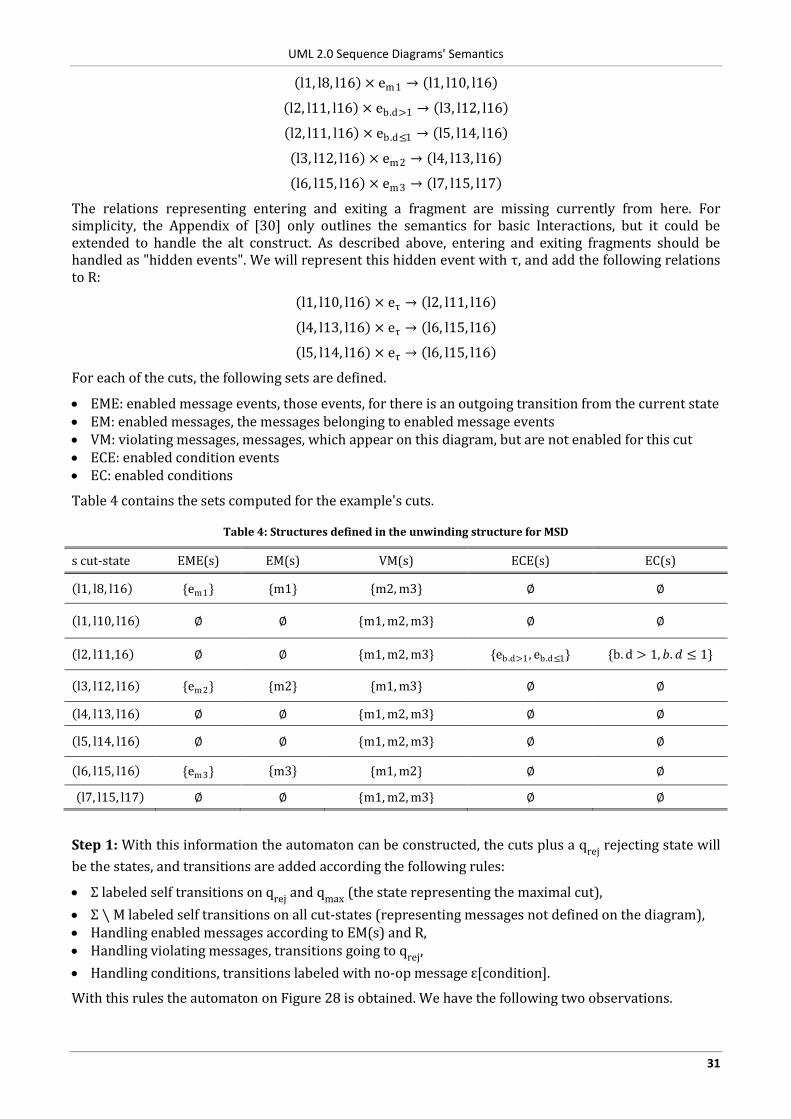
UML 2.0 Sequence Diagrams' Semantics
31
l1, l8, l16 × em1 → l1, l10, l16
l2, l11, l16 × eb.d>1 → l3, l12, l16
l2, l11, l16 × eb.d≤1 → l5, l14, l16
l3, l12, l16 × em2 → l4, l13, l16
l6, l15, l16 × em3 → l7, l15, l17
The relations representing entering and exiting a fragment are missing currently from here. For simplicity, the Appendix of [30] only outlines the semantics for basic Interactions, but it could be extended to handle the alt construct. As described above, entering and exiting fragments should be handled as "hidden events". We will represent this hidden event with τ, and add the following relations to R:
l1, l10, l16 × eτ → l2, l11, l16
l4, l13, l16 × eτ → l6, l15, l16
l5, l14, l16 × eτ → l6, l15, l16
For each of the cuts, the following sets are defined.
EME: enabled message events, those events, for there is an outgoing transition from the current state EM: enabled messages, the messages belonging to enabled message events VM: violating messages, messages, which appear on this diagram, but are not enabled for this cut ECE: enabled condition events EC: enabled conditions
Table 4 contains the sets computed for the example's cuts.
Table 4: Structures defined in the unwinding structure for MSD
s cut-state EME(s) EM(s) VM(s) ECE(s) EC(s)
l1, l8, l16 {em1} {m1} {m2, m3} ∅ ∅
l1, l10, l16 ∅ ∅ {m1, m2, m3} ∅ ∅
l2, l11,16 ∅ ∅ {m1, m2, m3} {eb.d>1 , eb.d≤1} {b. d > 1, 𝑏.𝑑 ≤ 1}
l3, l12, l16 {em2} {m2} {m1, m3} ∅ ∅
l4, l13, l16 ∅ ∅ {m1, m2, m3} ∅ ∅
l5, l14, l16 ∅ ∅ {m1, m2, m3} ∅ ∅
l6, l15, l16 {em3} m3 {m1, m2} ∅ ∅
l7, l15, l17 ∅ ∅ {m1, m2, m3} ∅ ∅
Step 1: With this information the automaton can be constructed, the cuts plus a qrej rejecting state will
be the states, and transitions are added according the following rules:
Σ labeled self transitions on qrej and qmax (the state representing the maximal cut),
Σ ∖ M labeled self transitions on all cut-states (representing messages not defined on the diagram), Handling enabled messages according to EM(s) and R, Handling violating messages, transitions going to qrej,
Handling conditions, transitions labeled with no-op message ε[condition].
With this rules the automaton on Figure 28 is obtained. We have the following two observations.
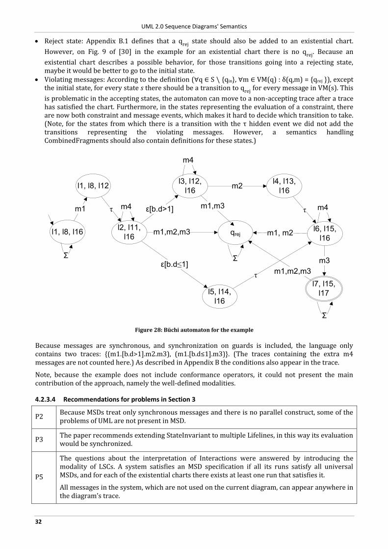
UML 2.0 Sequence Diagrams' Semantics
32
Reject state: Appendix B.1 defines that a qrej state should also be added to an existential chart.
However, on Fig. 9 of [30] in the example for an existential chart there is no qrej. Because an
existential chart describes a possible behavior, for those transitions going into a rejecting state, maybe it would be better to go to the initial state.
Violating messages: According to the definition (∀q ∈ S \ {qin}, ∀m ∈ VM(q) : δ(q,m) = qrej }), except the initial state, for every state s there should be a transition to qrej for every message in VM(s). This
is problematic in the accepting states, the automaton can move to a non-accepting trace after a trace has satisfied the chart. Furthermore, in the states representing the evaluation of a constraint, there are now both constraint and message events, which makes it hard to decide which transition to take. (Note, for the states from which there is a transition with the τ hidden event we did not add the transitions representing the violating messages. However, a semantics handling CombinedFragments should also contain definitions for these states.)
m2
m1
m3
m1,m2,m3
ε[b.d>1]
l2, l11,
l16
m4
l3, l12,
l16
m4
l4, l13,
l16
l1, l8, l16
Σ
l7, l15,
l17
Σ
qrej
Σ
l5, l14,
l16
ε[b.d≤1]
m1,m3
m1,m2,m3
l1, l8, l12
τ
l6, l15,
l16
m4
τ
τ
m1, m2
Figure 28: Büchi automaton for the example
Because messages are synchronous, and synchronization on guards is included, the language only contains two traces: (m1.[b.d>1].m2.m3), (m1.[b.d≤1].m3) . (The traces containing the extra m4 messages are not counted here.) As described in Appendix B the conditions also appear in the trace.
Note, because the example does not include conformance operators, it could not present the main contribution of the approach, namely the well-defined modalities.
4.2.3.4 Recommendations for problems in Section 3
P2 Because MSDs treat only synchronous messages and there is no parallel construct, some of the problems of UML are not present in MSD.
P3 The paper recommends extending StateInvariant to multiple Lifelines, in this way its evaluation would be synchronized.
P5
The questions about the interpretation of Interactions were answered by introducing the modality of LSCs. A system satisfies an MSD specification if all its runs satisfy all universal MSDs, and for each of the existential charts there exists at least one run that satisfies it.
All messages in the system, which are not used on the current diagram, can appear anywhere in the diagram’s trace.
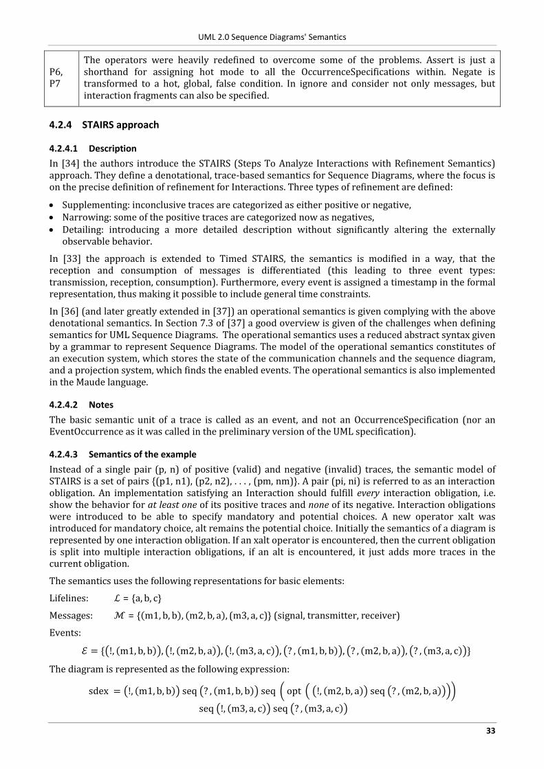
UML 2.0 Sequence Diagrams' Semantics
33
P6, P7
The operators were heavily redefined to overcome some of the problems. Assert is just a shorthand for assigning hot mode to all the OccurrenceSpecifications within. Negate is transformed to a hot, global, false condition. In ignore and consider not only messages, but interaction fragments can also be specified.
4.2.4 STAIRS approach
4.2.4.1 Description
In [34] the authors introduce the STAIRS (Steps To Analyze Interactions with Refinement Semantics) approach. They define a denotational, trace-based semantics for Sequence Diagrams, where the focus is on the precise definition of refinement for Interactions. Three types of refinement are defined:
Supplementing: inconclusive traces are categorized as either positive or negative, Narrowing: some of the positive traces are categorized now as negatives, Detailing: introducing a more detailed description without significantly altering the externally
observable behavior.
In [33] the approach is extended to Timed STAIRS, the semantics is modified in a way, that the reception and consumption of messages is differentiated (this leading to three event types: transmission, reception, consumption). Furthermore, every event is assigned a timestamp in the formal representation, thus making it possible to include general time constraints.
In [36] (and later greatly extended in [37]) an operational semantics is given complying with the above denotational semantics. In Section 7.3 of [37] a good overview is given of the challenges when defining semantics for UML Sequence Diagrams. The operational semantics uses a reduced abstract syntax given by a grammar to represent Sequence Diagrams. The model of the operational semantics constitutes of an execution system, which stores the state of the communication channels and the sequence diagram, and a projection system, which finds the enabled events. The operational semantics is also implemented in the Maude language.
4.2.4.2 Notes
The basic semantic unit of a trace is called as an event, and not an OccurrenceSpecification (nor an EventOccurrence as it was called in the preliminary version of the UML specification).
4.2.4.3 Semantics of the example
Instead of a single pair (p, n) of positive (valid) and negative (invalid) traces, the semantic model of STAIRS is a set of pairs {(p1, n1), (p2, n2), . . . , (pm, nm)}. A pair (pi, ni) is referred to as an interaction obligation. An implementation satisfying an Interaction should fulfill every interaction obligation, i.e. show the behavior for at least one of its positive traces and none of its negative. Interaction obligations were introduced to be able to specify mandatory and potential choices. A new operator xalt was introduced for mandatory choice, alt remains the potential choice. Initially the semantics of a diagram is represented by one interaction obligation. If an xalt operator is encountered, then the current obligation is split into multiple interaction obligations, if an alt is encountered, it just adds more traces in the current obligation.
The semantics uses the following representations for basic elements:
Lifelines: ℒ = {a, b, c}
Messages: ℳ = { m1, b, b , m2, b, a , (m3, a, c)} (signal, transmitter, receiver)
Events:
ℰ = { !, m1, b, b , !, m2, b, a , !, m3, a, c , ? , m1, b, b , ? , m2, b, a , ? , m3, a, c }
The diagram is represented as the following expression:
sdex = !, m1, b, b seq ? , m1, b, b seq opt !, m2, b, a seq ? , m2, b, a
seq !, m3, a, c seq ? , m3, a, c
UML 2.0 Sequence Diagrams' Semantics
34
(Note, in Chapter 19 of [37] the syntax and semantics is extended to handle data, constraints, and guards, however these are not treated in the example to keep it less complex.)
The operational semantics uses two transition systems.
Execution system: [_ , _ ] ∈ ℰ𝒳 where ℰ𝒳 ∈ ℬ × 𝒟 are the possible states of the execution system
Projection system: Π ∈ 𝕡(ℒ) × ℬ ×𝒟
where ℬ represent the state of the communication medium, 𝒟 the set of all syntactically correct sequence diagrams.
The execution system represents the state of the diagram. The execution system can process a single event or a silent event, i.e. an event that represents the resolving of an operator, e.g. choosing a branch in an alt. When processing an event, the update of the communication medium depends on what model is used, [37] defines the following four: one FIFO buffer for each message, one FIFO buffer for each (ordered) pair of lifelines, one FIFO buffer for each lifeline, and one global FIFO buffer. The first one is the most general, it does not imply any further ordering on the messages.
At each step of the execution system, a projection system is created to select the events or silent events that can be executed for the actual set of Lifelines. Which events are executed depends on a meta-strategy defined by a meta-level. The reason for introducing a meta-level is to decouple the creation of the traces and handling negative behaviors from the execution system. In this way, the rules for the execution system are less complex, and several different strategies can be easily tested. In [37] the one random trace and all the possible traces strategies are detailed. For the all traces strategy the diagrams are limited to ones without assert and ones only with finite loop, in this way the resulting structures will be finite.
The meta-system is defined for the all traces strategy in the following way, where ℋis the set of all possible traces.
{|_ , _ , _ |} ∈ ℋ × ℰ𝒳 × 𝕡(ℒ)
The first step is to transform the diagram to a normal form, where the xalt, alt and refuse (which was introduced instead of neg in [35]) operators are pushed to the top. The purpose of this step is to have a fixed order, in which the operators are evaluated, xalt first, alt next, etc. For the sake of simplicity in the forthcoming descriptions, the following shorter names are assigned to the events by us.
sd sdex
a : A b : B
alt
m2
c : C
m3
[b.d > 1]
m1e1
e2
e3e4
[else]
e5e6
Figure 29: Event names used for the example
For the example, the transformation to the normal form is the one depicted on Figure 30 (the transformation consists of three steps, here only the original and the result is displayed).
Thus, the example is represented now by the following expression.
sdex = (e1 seq e2 seq e3 seq e4 seq e5 seq e6) alt (e1 seq e2 seq skip seq e5 seq e6)
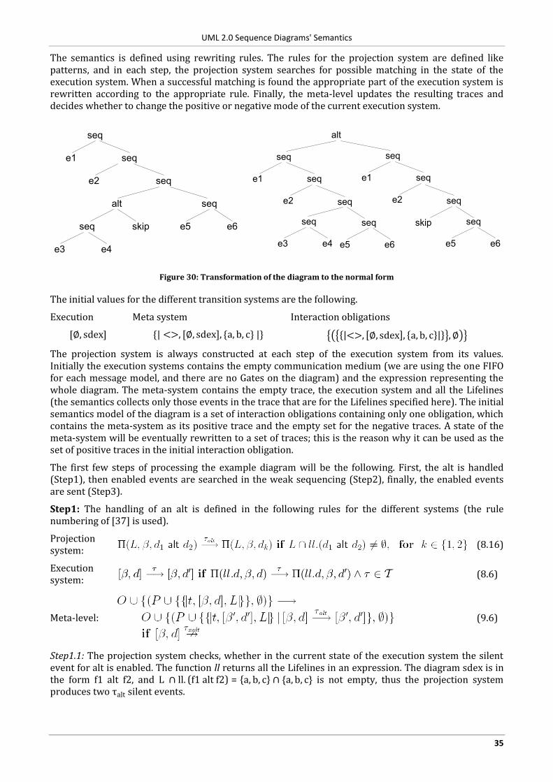
UML 2.0 Sequence Diagrams' Semantics
35
The semantics is defined using rewriting rules. The rules for the projection system are defined like patterns, and in each step, the projection system searches for possible matching in the state of the execution system. When a successful matching is found the appropriate part of the execution system is rewritten according to the appropriate rule. Finally, the meta-level updates the resulting traces and decides whether to change the positive or negative mode of the current execution system.
seq
e1 seq
e2 seq
seq
e5 e6
alt
skipseq
e3 e4
alt
seq
skipseq
e3 e4
seq
e5 e6
seq
e1 seq
e2seq
seq
seq
e1 seq
e2
e5 e6
Figure 30: Transformation of the diagram to the normal form
The initial values for the different transition systems are the following.
Execution Meta system Interaction obligations
[∅, sdex] {| <>, [∅, sdex], {a, b, c} |} <>, ∅, sdex , a, b, c ,∅
The projection system is always constructed at each step of the execution system from its values. Initially the execution systems contains the empty communication medium (we are using the one FIFO for each message model, and there are no Gates on the diagram) and the expression representing the whole diagram. The meta-system contains the empty trace, the execution system and all the Lifelines (the semantics collects only those events in the trace that are for the Lifelines specified here). The initial semantics model of the diagram is a set of interaction obligations containing only one obligation, which contains the meta-system as its positive trace and the empty set for the negative traces. A state of the meta-system will be eventually rewritten to a set of traces; this is the reason why it can be used as the set of positive traces in the initial interaction obligation.
The first few steps of processing the example diagram will be the following. First, the alt is handled (Step1), then enabled events are searched in the weak sequencing (Step2), finally, the enabled events are sent (Step3).
Step1: The handling of an alt is defined in the following rules for the different systems (the rule numbering of [37] is used).
Projection system:
(8.16)
Execution system: (8.6)
Meta-level:
(9.6)
Step1.1: The projection system checks, whether in the current state of the execution system the silent event for alt is enabled. The function ll returns all the Lifelines in an expression. The diagram sdex is in the form f1 alt f2, and L ∩ ll. (f1 alt f2) = a, b, c ∩ {a, b, c} is not empty, thus the projection system produces two τalt silent events.
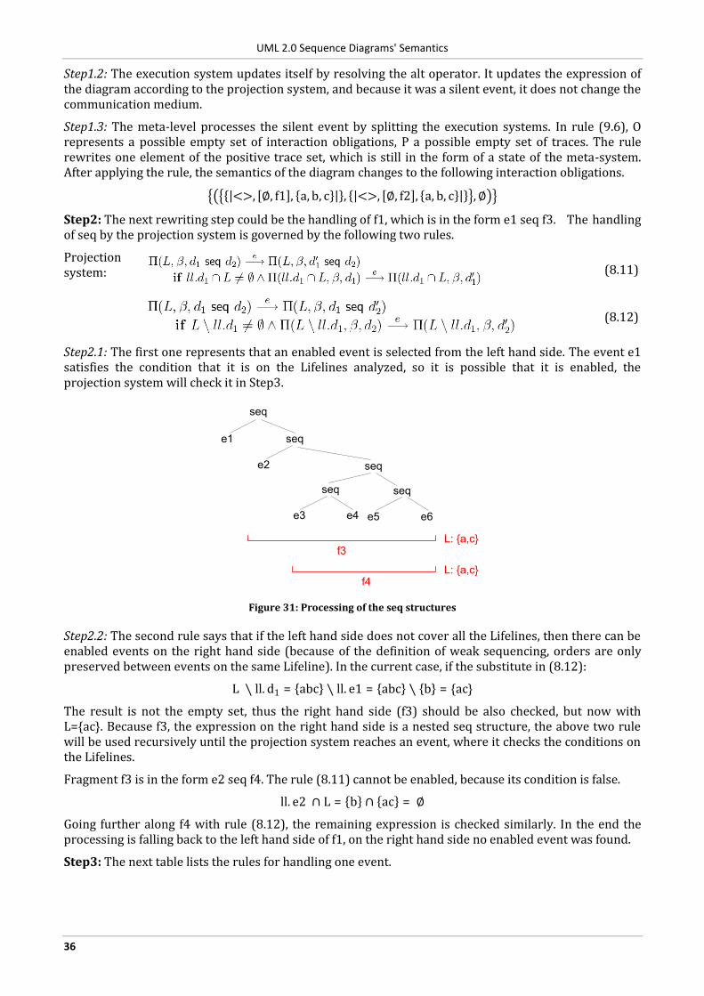
UML 2.0 Sequence Diagrams' Semantics
36
Step1.2: The execution system updates itself by resolving the alt operator. It updates the expression of the diagram according to the projection system, and because it was a silent event, it does not change the communication medium.
Step1.3: The meta-level processes the silent event by splitting the execution systems. In rule (9.6), O represents a possible empty set of interaction obligations, P a possible empty set of traces. The rule rewrites one element of the positive trace set, which is still in the form of a state of the meta-system. After applying the rule, the semantics of the diagram changes to the following interaction obligations.
<>, ∅, f1 , a, b, c , <>, ∅, f2 , a, b, c ,∅
Step2: The next rewriting step could be the handling of f1, which is in the form e1 seq f3. The handling of seq by the projection system is governed by the following two rules.
Projection system:
(8.11)
(8.12)
Step2.1: The first one represents that an enabled event is selected from the left hand side. The event e1 satisfies the condition that it is on the Lifelines analyzed, so it is possible that it is enabled, the projection system will check it in Step3.
seq
e3 e4
seq
seq
e1 seq
e2
e5 e6
seq
f3
f4
L: {a,c}
L: {a,c}
Figure 31: Processing of the seq structures
Step2.2: The second rule says that if the left hand side does not cover all the Lifelines, then there can be enabled events on the right hand side (because of the definition of weak sequencing, orders are only preserved between events on the same Lifeline). In the current case, if the substitute in (8.12):
L ∖ ll. d1 = abc ∖ ll. e1 = abc ∖ b = {ac}
The result is not the empty set, thus the right hand side (f3) should be also checked, but now with L={ac}. Because f3, the expression on the right hand side is a nested seq structure, the above two rule will be used recursively until the projection system reaches an event, where it checks the conditions on the Lifelines.
Fragment f3 is in the form e2 seq f4. The rule (8.11) cannot be enabled, because its condition is false.
ll. e2 ∩ L = b ∩ ac = ∅
Going further along f4 with rule (8.12), the remaining expression is checked similarly. In the end the processing is falling back to the left hand side of f1, on the right hand side no enabled event was found.
Step3: The next table lists the rules for handling one event.
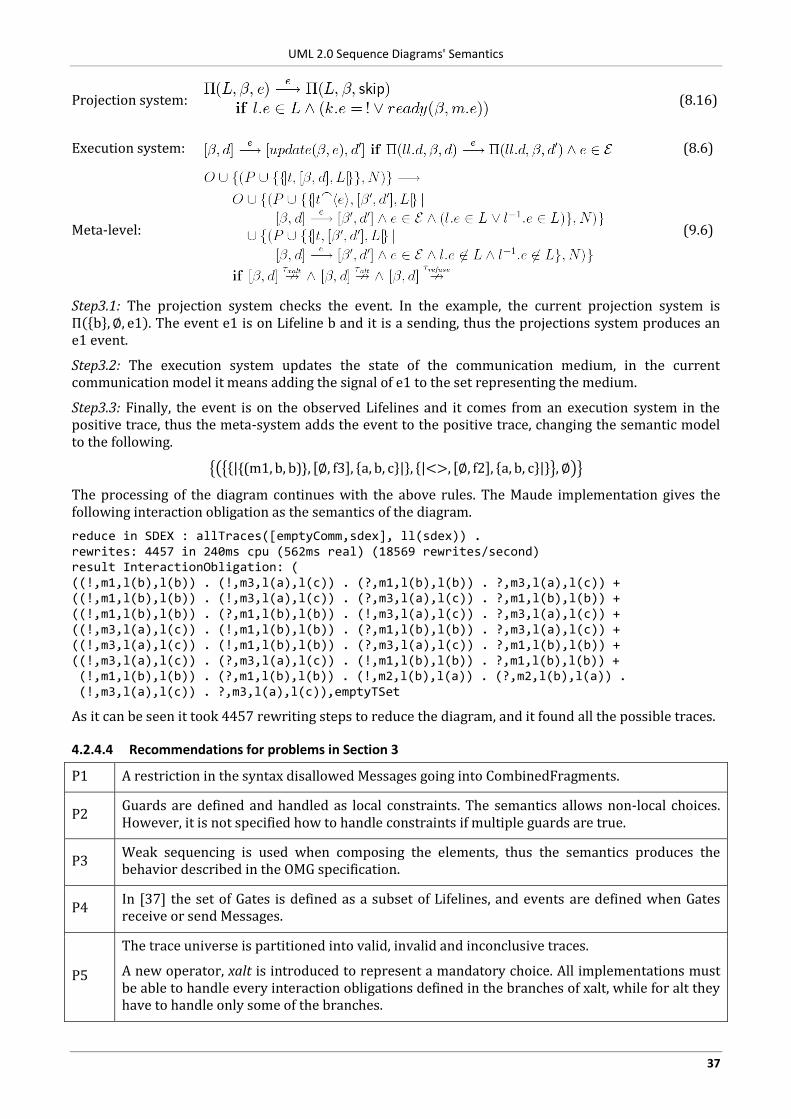
UML 2.0 Sequence Diagrams' Semantics
37
Projection system:
(8.16)
Execution system:
(8.6)
Meta-level:
(9.6)
Step3.1: The projection system checks the event. In the example, the current projection system is Π b ,∅, e1 . The event e1 is on Lifeline b and it is a sending, thus the projections system produces an e1 event.
Step3.2: The execution system updates the state of the communication medium, in the current communication model it means adding the signal of e1 to the set representing the medium.
Step3.3: Finally, the event is on the observed Lifelines and it comes from an execution system in the positive trace, thus the meta-system adds the event to the positive trace, changing the semantic model to the following.
{(m1, b, b)}, ∅, f3 , a, b, c , <>, ∅, f2 , a, b, c ,∅
The processing of the diagram continues with the above rules. The Maude implementation gives the following interaction obligation as the semantics of the diagram.
reduce in SDEX : allTraces([emptyComm,sdex], ll(sdex)) . rewrites: 4457 in 240ms cpu (562ms real) (18569 rewrites/second) result InteractionObligation: ( ((!,m1,l(b),l(b)) . (!,m3,l(a),l(c)) . (?,m1,l(b),l(b)) . ?,m3,l(a),l(c)) + ((!,m1,l(b),l(b)) . (!,m3,l(a),l(c)) . (?,m3,l(a),l(c)) . ?,m1,l(b),l(b)) + ((!,m1,l(b),l(b)) . (?,m1,l(b),l(b)) . (!,m3,l(a),l(c)) . ?,m3,l(a),l(c)) + ((!,m3,l(a),l(c)) . (!,m1,l(b),l(b)) . (?,m1,l(b),l(b)) . ?,m3,l(a),l(c)) + ((!,m3,l(a),l(c)) . (!,m1,l(b),l(b)) . (?,m3,l(a),l(c)) . ?,m1,l(b),l(b)) + ((!,m3,l(a),l(c)) . (?,m3,l(a),l(c)) . (!,m1,l(b),l(b)) . ?,m1,l(b),l(b)) + (!,m1,l(b),l(b)) . (?,m1,l(b),l(b)) . (!,m2,l(b),l(a)) . (?,m2,l(b),l(a)) . (!,m3,l(a),l(c)) . ?,m3,l(a),l(c)),emptyTSet
As it can be seen it took 4457 rewriting steps to reduce the diagram, and it found all the possible traces.
4.2.4.4 Recommendations for problems in Section 3
P1 A restriction in the syntax disallowed Messages going into CombinedFragments.
P2 Guards are defined and handled as local constraints. The semantics allows non-local choices. However, it is not specified how to handle constraints if multiple guards are true.
P3 Weak sequencing is used when composing the elements, thus the semantics produces the behavior described in the OMG specification.
P4 In [37] the set of Gates is defined as a subset of Lifelines, and events are defined when Gates receive or send Messages.
P5
The trace universe is partitioned into valid, invalid and inconclusive traces.
A new operator, xalt is introduced to represent a mandatory choice. All implementations must be able to handle every interaction obligations defined in the branches of xalt, while for alt they have to handle only some of the branches.
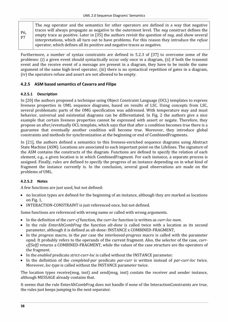
UML 2.0 Sequence Diagrams' Semantics
38
P6, P7
The neg operator and the semantics for other operators are defined in a way that negative traces will always propagate as negative to the outermost level. The neg construct defines the empty trace as positive. Later in [35] the authors revisit the question of neg, and show several interpretations, which all turn out to have problems. For this reason they introduce the refuse operator, which defines all its positive and negative traces as negative.
Furthermore, a number of syntax constraints are defined in 5.2.3 of [37] to overcome some of the problems: (i) a given event should syntactically occur only once in a diagram, (ii) if both the transmit event and the receive event of a message are present in a diagram, they have to be inside the same argument of the same high-level operator, (iii) there is no syntactical repetition of gates in a diagram, (iv) the operators refuse and assert are not allowed to be empty.
4.2.5 ASM based semantics of Cavarra and Filipe
4.2.5.1 Description
In [20] the authors proposed a technique using Object Constraint Language (OCL) templates to express liveness properties in UML sequence diagrams, based on results of LSC. Using concepts from LSC, several problematic parts of the OMG specification was addressed. With temperature may and must behavior, universal and existential diagrams can be differentiated. In Fig. 2 the authors give a nice example that certain liveness properties cannot be expressed with assert or negate. Therefore, they propose an after/eventually OCL template, which says that that after a condition becomes true there is a guarantee that eventually another condition will become true. Moreover, they introduce global constraints and methods for synchronization at the beginning or end of CombinedFragments.
In [21], the authors defined a semantics to this liveness-enriched sequence diagrams using Abstract State Machine (ASM). Locations are associated to each important point on the Lifelines. The signature of the ASM contains the constructs of the diagram. Functions are defined to specify the relation of each element, e.g., a given location is in which CombinedFragment. For each instance, a separate process is assigned. Finally, rules are defined to specify the progress of an instance depending on in what kind of fragment the instance currently is. In the conclusion, several good observations are made on the problems of UML.
4.2.5.2 Notes
A few functions are just used, but not defined:
no location types are defined for the beginning of an instance, although they are marked as locations on Fig. 1,
INTERACTION-CONSTRAINT is just referenced once, but not defined.
Some functions are referenced with wrong name or called with wrong arguments.
In the definition of the curr-cf function, the curr-loc function is written as curr-loc-num. In the rule EnterAltCombFrag the function alt-done is called twice with a location as its second
parameter, although it is defined as alt-done: INSTANCE x COMBINED-FRAGMENT, In the progress macro, in the par case the interleaved-progress macro is called with the parameter
opnd. It probably refers to the operands of the current fragment. Also, the selector of the case, curr-cf(Self) returns a COMBINED-FRAGMENT, while the values of the case structure are the operators of the fragment.
In the enabled predicate strict-curr-loc is called without the INSTANCE parameter. In the definition of the completed-par predicate par-curr is written instead of par-curr-loc twice.
Moreover, loc-type is called without the INSTANCE parameter twice.
The location types receive(msg, inst) and send(msg, inst) contain the receiver and sender instance, although MESSAGE already contains that.
It seems that the rule EnterAltCombFrag does not handle if none of the InteractionConstraints are true, the rules just keeps jumping to the next separator.
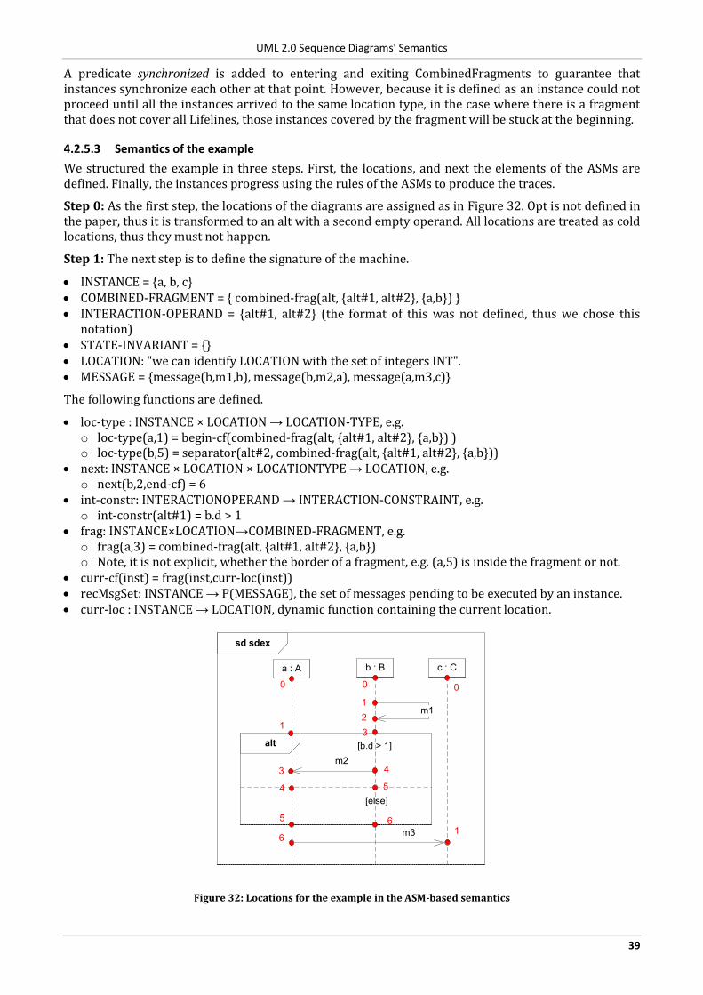
UML 2.0 Sequence Diagrams' Semantics
39
A predicate synchronized is added to entering and exiting CombinedFragments to guarantee that instances synchronize each other at that point. However, because it is defined as an instance could not proceed until all the instances arrived to the same location type, in the case where there is a fragment that does not cover all Lifelines, those instances covered by the fragment will be stuck at the beginning.
4.2.5.3 Semantics of the example
We structured the example in three steps. First, the locations, and next the elements of the ASMs are defined. Finally, the instances progress using the rules of the ASMs to produce the traces.
Step 0: As the first step, the locations of the diagrams are assigned as in Figure 32. Opt is not defined in the paper, thus it is transformed to an alt with a second empty operand. All locations are treated as cold locations, thus they must not happen.
Step 1: The next step is to define the signature of the machine.
INSTANCE = {a, b, c} COMBINED-FRAGMENT = { combined-frag(alt, {alt#1, alt#2}, {a,b}) } INTERACTION-OPERAND = {alt#1, alt#2} (the format of this was not defined, thus we chose this
notation) STATE-INVARIANT = {} LOCATION: "we can identify LOCATION with the set of integers INT". MESSAGE = {message(b,m1,b), message(b,m2,a), message(a,m3,c)}
The following functions are defined.
loc-type : INSTANCE × LOCATION → LOCATION-TYPE, e.g. o loc-type(a,1) = begin-cf(combined-frag(alt, {alt#1, alt#2}, {a,b}) ) o loc-type(b,5) = separator(alt#2, combined-frag(alt, {alt#1, alt#2}, {a,b}))
next: INSTANCE × LOCATION × LOCATIONTYPE → LOCATION, e.g. o next(b,2,end-cf) = 6
int-constr: INTERACTIONOPERAND → INTERACTION-CONSTRAINT, e.g. o int-constr(alt#1) = b.d > 1
frag: INSTANCE×LOCATION→COMBINED-FRAGMENT, e.g. o frag(a,3) = combined-frag(alt, {alt#1, alt#2}, {a,b}) o Note, it is not explicit, whether the border of a fragment, e.g. (a,5) is inside the fragment or not.
curr-cf(inst) = frag(inst,curr-loc(inst)) recMsgSet: INSTANCE → P(MESSAGE), the set of messages pending to be executed by an instance. curr-loc : INSTANCE → LOCATION, dynamic function containing the current location.
sd sdex
a : A b : B
alt
m2
c : C
m3
[b.d > 1]
m11
2
4
1
3
[else]
0
3
6
5
0
5
6
4
0
1
Figure 32: Locations for the example in the ASM-based semantics
UML 2.0 Sequence Diagrams' Semantics
40
The following rules can update the ASM.
SendMessage, ReceiveMessage EnterAltCombFrag, EnterStrictCombFrag, EnterParCombFrag, EnterNegCombFrag, ExitCombFrag StateInvariant
The following macros are used for shorthand:
progress, strict-progress, interleaved-progress
Step 2: The run where the condition is true and all three messages are sent could be obtained with applying the following rules.
Table 5: Applying rules in sdex. The location columns represent the locations after applying the rule
Step Rule curr-loc(a) curr-loc(b) curr-loc(c)
0 0 0 0
1 a: ?, b: ?, c: ? 1 1 1
2 b: SendMessage 1 2 1
3 b: ReceiveMessage 1 3 1
4 a: EnterAltCombFrag, b: EnterAltCombFrag 2 4 1
5 b: SendMessage 2 5 1
6 a: ReceiveMessage 3 5 1
7 ?
In the steps:
0: initial state 1: no messages should be sent or received, no fragment to enter, only the current location of the
instances should be incremented. However, as far as we can understand, there is no rule to start the instances.
2: a could not step, because it has to synchronize at the beginning of the fragment. Instance c is waiting for the receiving of the message, thus only b can progress.
3: after applying the rule, a and b are at the beginning of the same fragment, thus they are allowed to enter it (if we alter the synchronization construct as described in the Notes section).
4: Note, that a and b are evaluating the guard of the operands in their EnterAltCombFrag rules. Now, a is waiting for the receiving of m2 message.
5, 6: sending and receiving of m2. 7: Both a and b are now on the separator of the operand. It seems to us, that they could not proceed:
EnterAltCombFrag cannot be chosen because alt-done is true, there are no messages (ReceiveMessage, SendMessage), no StateInvariants (rule StateInvariant), no fragment to enter (EnterStrictCombFrag, EnterParCombFrag, EnterNegCombFrag) and neither can chose ExitCombFrag, because they are on a separator and not on an end-cf location.
As it can be seen, there are good ideas for handling the problems (locations, explicit synchronization at border of fragments), but in our opinion there are issues with formalization.
4.2.5.4 Recommendations for problems in Section 3
P2 Global OCL constraints were introduced to handle the synchronization of constraints defined for several instances.
P3 The vast majority of the problems with CombinedFragments were solved by introducing explicit synchronization at the beginning of CombinedFragments.
P5 The interpretation of the diagrams was redefined by introducing the modality of LSCs.
UML 2.0 Sequence Diagrams' Semantics
41
4.2.6 True-concurrency semantics from Küster-Filipe
4.2.6.1 Description
Küster-Filipe defined a true-concurrent semantics based on event structures in [22]. In [23] the semantics is extended to handle the InteractionUse construct. It considers only a smaller number of operators and constructs (alt, par, seq and StateInvariant), but gives them a very well defined semantics.
The semantics uses the temperature (hot and cold messages) concept from LSC to express mandatory or possible behavior. Furthermore, it uses LSC's location concept to mark occurrences on a Lifeline.
For every Lifeline a labeled prime event structure is constructed. The model takes into account the possible nesting of CombinedFragments, and gives a very clear definition for the predecessors of every event. Finally, the event structures for the different Lifelines are combined according to the Messages sent between them.
In the end of a paper a two-level temporal logic is presented, which can be used to specify Interactions.
4.2.6.2 Notes
By the time of the writing, the UML Superstructure specification was still in the Final Adopted Specification phase. CombinedFragments are referenced as interaction fragments, but InteractionFragment is a broader term.
It is not exactly defined, what a location is, it can just be seen from the example. Locations are also associated to points for which no OccurrenceSpecifications can be mapped, like StateInvariants or border of boxes.
4.2.6.3 Semantics of the example
The semantics is defined only for the alt operator, thus the opt in the example is converted to an alt with one empty InteractionOperand.
We structured the example in the following steps. In Step 0, a tuple is created for the diagram capturing its elements. In Step 1, a number of helper functions are evaluated for each of the Lifelines. These functions calculate the predecessors of each event, the possible event sequences leading to a given event, etc. They will be summarized in Tables 6-8. The tables are used in Step 2 to create a separate event structure for each Lifeline. Finally, in Step 3 the event structures are combined according to the Messages sent between them.
Step 0: First, a location is associated to every important point on Lifelines. Note, that locations are also created for the borders of the CombinedFragment and guards.
sd sdex
a : A b : B
alt
m2
c : C
m3
[b.d > 1]
m1l1
l2
l5
l10
l11
[else]
l0
l3
l4
l6
l7
l8
l9
l12
l13
l14
l15
l16
l17
Figure 33: Locations of the example
UML 2.0 Sequence Diagrams' Semantics
42
For defining the semantics labeled event structures will be used. An event structure is a triple
E = (Ev,→∗, #)
where Ev is a set of events and →∗, # ⊆ Ev × Ev are binary relations called causality and conflict (see Def. 1 in [22]). A labeled event structure is a pair (E, l : Ev → L), where L is a set of labels and l is a labeling function (see Def. 2 in [22]).
A sequence diagram SD is a tuple. The tuple defined for the example is:
sdex = (I, Loc, Locini , Mes, Edges, Path, XI) where
I = {a, b, c} is the set of instance identifiers; Loc = {l0, l1, l2, l3, l4, l5, l6, l7, l8, l9, l10, l11, l12, l13, l14, l15, l16, l17} is the set of locations; Locini = {l9, l0, l15} is the set of initial locations; Mes = {m1, m2, m3} is the set of message labels; Edges ⊆ Loc × Mes × Loc is the set of edges, Edges = { (l1,m1,l2), (l5,m2,l11), (l13,m3,l16) }; Path is a given set of well-formed path terms for the diagram used to capture the relative positions of
locations within a diagram; XI is a family of I-indexed sets of constraint symbols. A constraint symbol can be a local integer
variable or a state. Thus, the else guard is transformed to b.d ≤ 1. In this way XIntb= {d}, XInta
and
XIntcare the empty set, because they do not have constraints.
Step 1: For each location the following additional functions are evaluated.
time: associates to each location a number according to its visual time on the Lifeline. scope: associates to each location a path term. This path term captures the position of the location in
the diagram, e.g., it is in the main fragment, it is in one of the operands of the alt, etc. pre_loc: calculates which the immediate previous locations of a given location are. On a complex
diagram with multiple alt and par fragments nested, this is not trivial to identify. alt_occ: returns the number of possible alternative scenarios that lead to a given location. l-leading scenario: returns the set of locations building a path across a Lifeline and leading to l.
The values calculated for the diagram’s locations are summarized in Tables 6-8. (For the cells marked with ! or ? see the comments later in this section.)
Table 6: Values for a's locations
l time(l) scope(l) pre_loc(l) alt_loc(l) l-leading scenarios l9 0 sdex ∅ 1 {l9} l10 1 sdex.alt(2) {l9} 1 {l9, l10} l11 2 sdex.alt(2)#1 {l10} 1 {l9, l10, l11} l12 3 sdex.alt 2 . alt(2) {l11} (!) 1 (!) { l9, l10, l11, l12} (!) l13 4 sdex.alt 2 . alt(2) .sdex (?) {l12} 1 (!) { l9, l10, l11, l12, l13} (!) l14 5 sdex.alt(2) . sdex {l13} 1 (!) { l9, l10, l11, l12, l13, l14} (!)
Table 7: Values for b's locations
l time(l) scope(l) pre_loc(l) alt_loc(l) l-leading scenarios l0 0 sdex ∅ 1 {l0} l1 1 sdex {l0} 1 {l0, l1} l2 2 sdex {l1} 1 {l0, l1, l2} l3 3 sdex.alt(2) {l2} 1 {l0, l1, l2, l3} l4 4 sdex.alt(2)#1 {l3} 1 {l0, l1, l2, l3, l4} l5 5 sdex.alt(2)#1 {l4} 1 {l0, l1, l2, l3, l4, l5} l6 6 sdex.alt(2)#2 {l3} 1 {l0, l1, l2, l3, l6} l7 7 sdex.alt 2 . alt(2) {l5, l6} 2 {l0, l1, l2, l3, l4, l5, l7},
{l0, l1, l2, l3, l6, l7} l8 8 sdex.alt(2) . sdex {l7} 2 {l0, l1, l2, l3, l4, l5, l7, l8},
{l0, l1, l2, l3, l6, l7, l8}
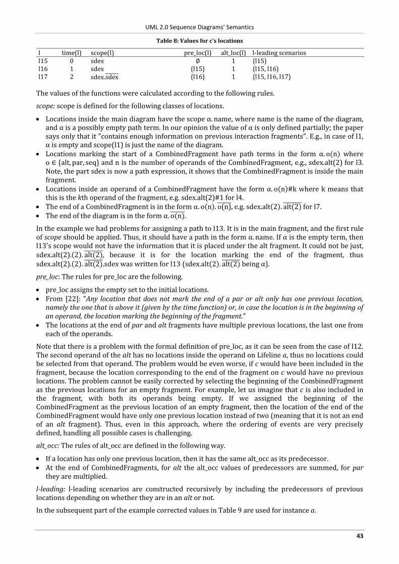
UML 2.0 Sequence Diagrams' Semantics
43
Table 8: Values for c's locations
l time(l) scope(l) pre_loc(l) alt_loc(l) l-leading scenarios l15 0 sdex ∅ 1 {l15} l16 1 sdex {l15} 1 {l15, l16} l17 2 sdex.sdex {l16} 1 {l15, l16, l17}
The values of the functions were calculated according to the following rules.
scope: scope is defined for the following classes of locations.
Locations inside the main diagram have the scope α. name, where name is the name of the diagram, and α is a possibly empty path term. In our opinion the value of α is only defined partially; the paper says only that it "contains enough information on previous interaction fragments". E.g., in case of l1, α is empty and scope(l1) is just the name of the diagram.
Locations marking the start of a CombinedFragment have path terms in the form α. o(n) where o ∈ {alt, par, seq} and n is the number of operands of the CombinedFragment, e.g., sdex.alt(2) for l3. Note, the part sdex is now a path expression, it shows that the CombinedFragment is inside the main fragment.
Locations inside an operand of a CombinedFragment have the form α. o n #k where k means that this is the kth operand of the fragment, e.g. sdex.alt(2)#1 for l4.
The end of a CombinedFragment is in the form α. o n . o(n) , e.g. sdex.alt 2 . alt(2) for l7. The end of the diagram is in the form α. o(n) .
In the example we had problems for assigning a path to l13. It is in the main fragment, and the first rule of scope should be applied. Thus, it should have a path in the form α. name. If α is the empty term, then l13's scope would not have the information that it is placed under the alt fragment. It could not be just, sdex.alt(2). 2 . alt(2) , because it is for the location marking the end of the fragment, thus sdex.alt(2). 2 . alt(2) .sdex was written for l13 (sdex.alt 2 . alt(2) being α).
pre_loc: The rules for pre_loc are the following.
pre_loc assigns the empty set to the initial locations. From [22]: "Any location that does not mark the end of a par or alt only has one previous location,
namely the one that is above it (given by the time function) or, in case the location is in the beginning of an operand, the location marking the beginning of the fragment."
The locations at the end of par and alt fragments have multiple previous locations, the last one from each of the operands.
Note that there is a problem with the formal definition of pre_loc, as it can be seen from the case of l12. The second operand of the alt has no locations inside the operand on Lifeline a, thus no locations could be selected from that operand. The problem would be even worse, if c would have been included in the fragment, because the location corresponding to the end of the fragment on c would have no previous locations. The problem cannot be easily corrected by selecting the beginning of the CombinedFragment as the previous locations for an empty fragment. For example, let us imagine that c is also included in the fragment, with both its operands being empty. If we assigned the beginning of the CombinedFragment as the previous location of an empty fragment, then the location of the end of the CombinedFragment would have only one previous location instead of two (meaning that it is not an end of an alt fragment). Thus, even in this approach, where the ordering of events are very precisely defined, handling all possible cases is challenging.
alt_occ: The rules of alt_occ are defined in the following way.
If a location has only one previous location, then it has the same alt_occ as its predecessor. At the end of CombinedFragments, for alt the alt_occ values of predecessors are summed, for par
they are multiplied.
l-leading: l-leading scenarios are constructed recursively by including the predecessors of previous locations depending on whether they are in an alt or not.
In the subsequent part of the example corrected values in Table 9 are used for instance a.
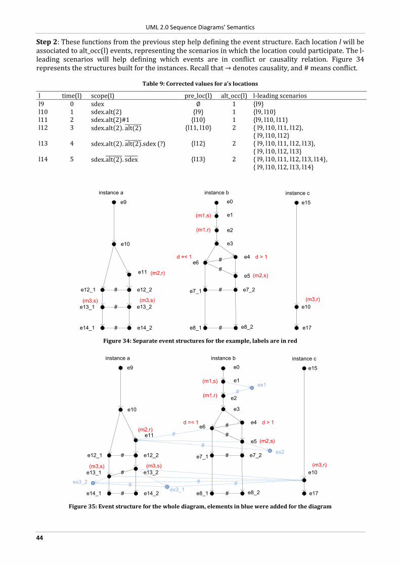
UML 2.0 Sequence Diagrams' Semantics
44
Step 2: These functions from the previous step help defining the event structure. Each location l will be associated to alt_occ(l) events, representing the scenarios in which the location could participate. The l-leading scenarios will help defining which events are in conflict or causality relation. Figure 34 represents the structures built for the instances. Recall that → denotes causality, and # means conflict.
Table 9: Corrected values for a's locations
l time(l) scope(l) pre_loc(l) alt_occ(l) l-leading scenarios l9 0 sdex ∅ 1 {l9} l10 1 sdex.alt(2) {l9} 1 {l9, l10} l11 2 sdex.alt(2)#1 {l10} 1 {l9, l10, l11} l12 3 sdex.alt 2 . alt(2) {l11, l10} 2 { l9, l10, l11, l12},
{ l9, l10, l12} l13 4 sdex.alt 2 . alt(2) .sdex (?) {l12} 2 { l9, l10, l11, l12, l13},
{ l9, l10, l12, l13} l14 5 sdex.alt(2) . sdex {l13} 2 { l9, l10, l11, l12, l13, l14},
{ l9, l10, l12, l13, l14}
instance a
e9
e10
e11
e12_1 e12_2
e13_1 e13_2
e14_1 e14_2
#
#
#
e0
e1
e4e6
e5
e7_1 e7_2
e8_1 e8_2
#
#
instance b
e2
e3
#
#
instance c
e15
e10
e17
(m1,s)
(m1,r)
d > 1
(m2,s)(m2,r)
d =< 1
(m3,s)(m3,s) (m3,r)
Figure 34: Separate event structures for the example, labels are in red
instance a
e9
e10
e11
e12_1 e12_2
e13_1 e13_2
e14_1 e14_2
#
#
#
e0
e1
e4e6
e5
e7_1 e7_2
e8_1 e8_2
#
#
instance b
e2
e3
#
#
instance c
e15
e10
e17
(m1,s)
(m1,r)
d > 1
(m2,s)
(m2,r)
d =< 1
(m3,s)(m3,s) (m3,r)
#
ex1
ex2
ex3_1
ex3_2#
#
#
##
Figure 35: Event structure for the whole diagram, elements in blue were added for the diagram
UML 2.0 Sequence Diagrams' Semantics
45
Step 3: The event structure of the whole diagram (Figure 35) is obtained from the instance's structures. In this approach, asynchronous messages can be lost. This is modeled by the extra events ExLcsend
(ex1,
ex2, ex3_1 and ex3_2 in the example). Causality relations are added between the sending and receiving of messages, e.g., e13_2 → e10. Furthermore, conflict relations are added to events, which are in different operands of an alt fragment, e.g., e11#e6. In this way, different Lifelines select the same operand of an alt. Figure 35 depicts the event structure of the diagram, from which the traces of the diagram can be obtained.
As it can be seen from the example, apart from the problem with the empty operands, the semantics is well defined, and gives for each location, what exactly its scope is.
4.2.6.4 Recommendations for problems in Section 3
P2 By defining precisely the scope and the predecessor of locations, several problems relating the ordering were answered by this semantics.
P3 The borders of CombinedFragments are also locations, but as far as we understand, they do not count as synchronization points, because they are not in causal relations with locations on other instances.
P4 In [23] the semantics is extended to handle the InteractionUse and the Gate constructs.
P5 The approach introduces the universal/potential modality approach from LSC.
4.2.7 Trace-based semantics of Knapp and Cengarle
4.2.7.1 Description
In [24] the authors define a denotational semantics for the traces of Interactions using pomsets (partially ordered multisets [15]). Later, in [25] an operational semantics is given for Sequence Diagrams. The semantics of the positive fragments is similar to the one defined by Störrle. The authors concentrate on the interpretation and definition of negative fragments. Rules are given for each of the operators specifying whether a trace positively or negatively satisfies a fragment with that operator. The authors point out that with the basic interpretation of negative fragments it is easy to construct overspecified Interactions, i.e., an Interaction that can be satisfied positively and negatively from the same trace. For example, the trace for the basic interaction B1 and the interactions strict(neg(B1), B1) or par( assert(B1), neg(B1) ). Later in the paper the operator not is introduced instead of neq and assert to overcome some of the problems with negative satisfaction.
4.2.7.2 Notes
The abstract syntax of Interactions is given with a context-free grammar, which is a bit more restricted than the one in OMG's specification. E.g., it does not allow messages to go into a CombinedFragment or CombinedFragments not covering all Lifelines.
4.2.7.3 Recommendations for problems in Section 3
P1 The abstract syntax defined does not allow Messages to go inside CombinedFragments.
P5
The semantics defines for each operator whether a trace positively or negatively satisfies that fragment. If a trace does neither, it is regarded as inconclusive.
A notation for the universe of messages is used with consider, but it is not defined.
A process I is an implementation of an Interaction S, if there exists at least one trace of I that positively satisfies S, and there exists none that negatively satisfies S.
P6
A new operator not is introduced to replace assert and neg.
For a given interaction, any trace is negative if it completely traverses a negative region, independently of the steps performed afterwards, if any.
UML 2.0 Sequence Diagrams' Semantics
46
P7 Interactions that can be positively and negatively satisfied from the same trace are called overspecified interactions. They are not disallowed, but later they should be refined.
4.2.8 M-nets based semantics of the P-UMLaut project
4.2.8.1 Description
In [28] a semantics is given for sequence diagrams based on M-nets (multivalued nets), which is an algebra based on high level Petri nets. The method handles basic data types (Boolean and integers), thus, it can include the local attributes of Interactions, the arguments of Messages and the evaluation of conditions in the semantics. The M-nets fragments are given for basic constructs, like starting of a Lifeline or sending and receiving of a message. These are then connected by composition operators according to the enclosing CombinedFragment's operator. The semantics defined in the paper assumes that all behavior is explicitly specified in the diagrams, no conformance operator is used.
4.2.8.2 Notes
In the translation part for Actions and EventOccurrences, page 8, the word EventOccurrence (the name for OccurrenceSpecification in the preliminary version of the specification) is used instead of ExecutionOccurrence (the name for ExecutionSpecification in the preliminary version of the specification), cf., "EventOccurrences, denoted as thin rectangles covering the part of the lifeline the activity is running, define a scope".
The operator strict is used as an unary operator in the sense, that it imposes a total ordering for all the OccurrenceSpecifications in the operand as depicted by their vertical positions. In our opinion the OMG specification describes strict as an operator with multiple operands, which restricts that the OccurrenceSpecifications in the operands depicted vertically higher should all occur before the one from a lower operand, but leaves undecided the ordering inside an operand.
4.2.8.3 Recommendations for problems in Section 3
P2, P3
In the translation, entering and exiting a CombinedFragment includes an explicit synchronization between the covered Lifelines, otherwise, the authors argue, the values in the condition can be changed whilst the different Lifelines enter the fragment (see the beginning of Section 4.4 in [28]).
P4 Places representing the Gates are created in the transformation.
4.2.9 Operational Semantics from Knapp and Wuttke
4.2.9.1 Description
In [27] an interaction automaton is produced by unwinding the Interaction. One single interaction automaton is created for the entire Interaction. The authors apply some restrictions to overcome the problems of Sequence Diagrams (e.g., replace neg with a binary logic variant not, restrict the use of not only to basic interactions, restrict loops to only allow basic interactions, etc.). Later, this interaction automaton is used as an observer process in the SPIN model checker to check the communication produced by UML State Machines.
4.2.9.2 Recommendations for problems in Section 3
P2 Evaluating the guards of an alt fragment is done in one step to ensure that only one of the operands is selected.
P3 The operator sloop is introduced, which enforces strict sequencing.
P6 The operator not is used instead of neg. Not fragments can only contain basic Interactions.
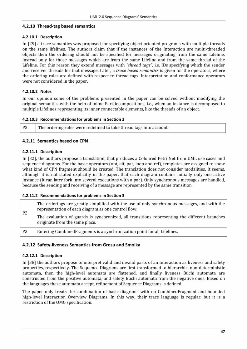
UML 2.0 Sequence Diagrams' Semantics
47
4.2.10 Thread-tag based semantics
4.2.10.1 Description
In [29] a trace semantics was proposed for specifying object oriented programs with multiple threads on the same lifelines. The authors claim that if the instances of the Interaction are multi-threaded objects then the ordering should not be specified for messages originating from the same Lifeline, instead only for those messages which are from the same Lifeline and from the same thread of the Lifeline. For this reason they extend messages with "thread tags", i.e. IDs specifying which the sender and receiver threads for that message. Later, a trace based semantics is given for the operators, where the ordering rules are defined with respect to thread tags. Interpretation and conformance operators were not considered in the paper.
4.2.10.2 Notes
In our opinion some of the problems presented in the paper can be solved without modifying the original semantics with the help of inline PartDecompositions, i.e., when an instance is decomposed to multiple Lifelines representing its inner connectable elements, like the threads of an object.
4.2.10.3 Recommendations for problems in Section 3
P3 The ordering rules were redefined to take thread tags into account.
4.2.11 Semantics based on CPN
4.2.11.1 Description
In [32], the authors propose a translation, that produces a Coloured Petri Net from UML use cases and sequence diagrams. For the basic operators (opt, alt, par, loop and ref), templates are assigned to show what kind of CPN fragment should be created. The translation does not consider modalities. It seems, although it is not stated explicitly in the paper, that each diagram contains initially only one active instance (it can later fork into several executions with a par). Only synchronous messages are handled, because the sending and receiving of a message are represented by the same transition.
4.2.11.2 Recommendations for problems in Section 3
P2
The orderings are greatly simplified with the use of only synchronous messages, and with the representation of each diagram as one control flow.
The evaluation of guards is synchronized, all transitions representing the different branches originate from the same place.
P3 Entering CombinedFragments is a synchronization point for all Lifelines.
4.2.12 Safety-liveness Semantics from Grosu and Smolka
4.2.12.1 Description
In [38] the authors propose to interpret valid and invalid parts of an Interaction as liveness and safety properties, respectively. The Sequence Diagrams are first transformed to hierarchic, non-deterministic automata, then the high-level automata are flattened, and finally liveness Büchi automata are constructed from the positive automata, and safety Büchi automata from the negative ones. Based on the languages these automata accept, refinement of Sequence Diagrams is defined.
The paper only treats the combination of basic diagrams with no CombinedFragment and bounded high-level Interaction Overview Diagrams. In this way, their trace language is regular, but it is a restriction of the OMG specification.
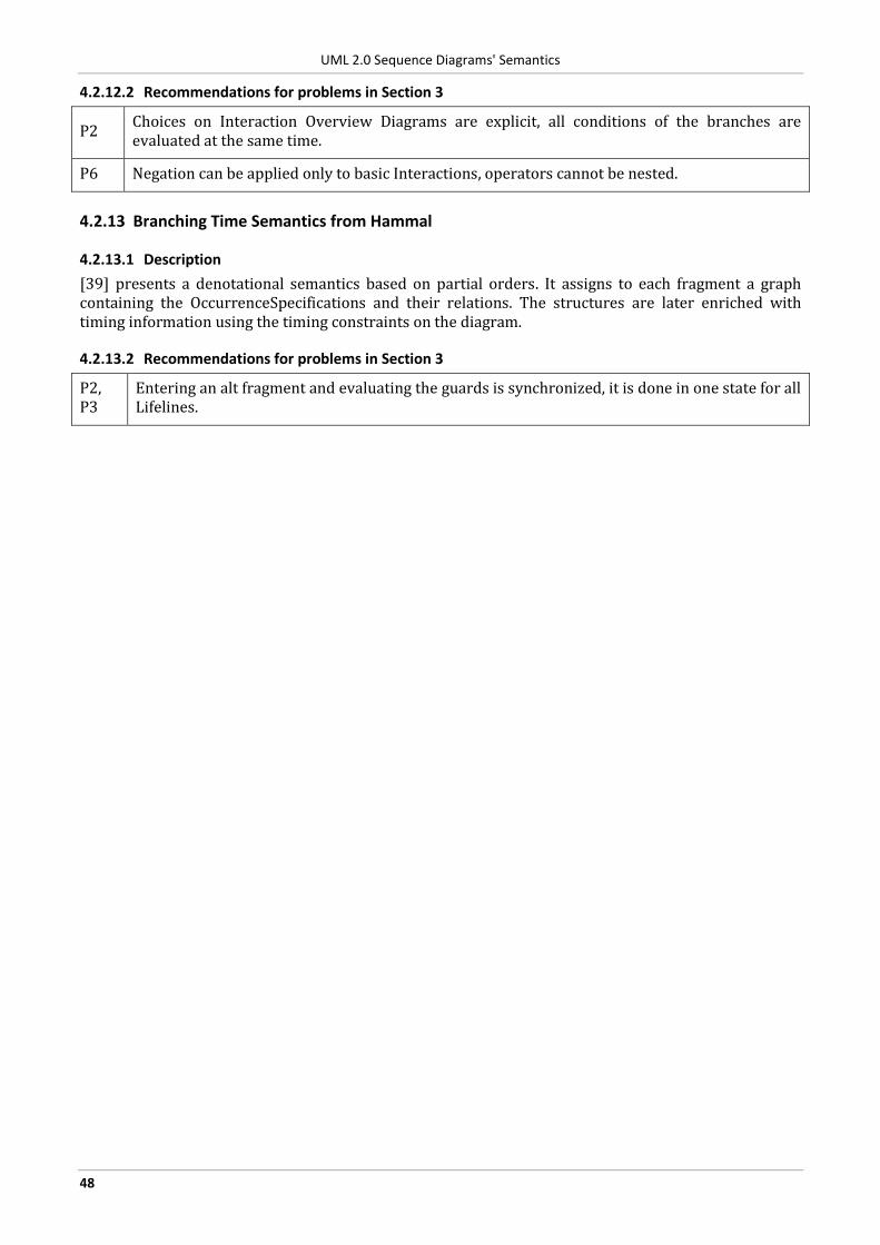
UML 2.0 Sequence Diagrams' Semantics
48
4.2.12.2 Recommendations for problems in Section 3
P2 Choices on Interaction Overview Diagrams are explicit, all conditions of the branches are evaluated at the same time.
P6 Negation can be applied only to basic Interactions, operators cannot be nested.
4.2.13 Branching Time Semantics from Hammal
4.2.13.1 Description
[39] presents a denotational semantics based on partial orders. It assigns to each fragment a graph containing the OccurrenceSpecifications and their relations. The structures are later enriched with timing information using the timing constraints on the diagram.
4.2.13.2 Recommendations for problems in Section 3
P2, P3
Entering an alt fragment and evaluating the guards is synchronized, it is done in one state for all Lifelines.
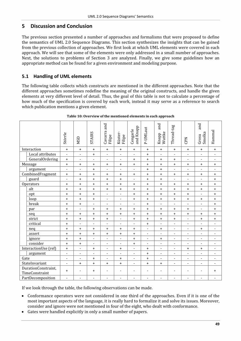
UML 2.0 Sequence Diagrams' Semantics
49
5 Discussion and Conclusion
The previous section presented a number of approaches and formalisms that were proposed to define the semantics of UML 2.0 Sequence Diagrams. This section synthesizes the insights that can be gained from the previous collection of approaches. We first look at which UML elements were covered in each approach. We will see that some of the elements were only addressed in a small number of approaches. Next, the solutions to problems of Section 3 are analyzed. Finally, we give some guidelines how an appropriate method can be found for a given environment and modeling purpose.
5.1 Handling of UML elements
The following table collects which constructs are mentioned in the different approaches. Note that the different approaches sometimes redefine the meaning of the original constructs, and handle the given elements at very different level of detail. Thus, the goal of this table is not to calculate a percentage of how much of the specification is covered by each work, instead it may serve as a reference to search which publication mentions a given element.
Table 10: Overview of the mentioned elements in each approach
Störr
le
MSD
STA
IRS
Cav
arra
an
d
Fil
ipe
Küst
er-
Fil
ipe
Cen
garl
e an
d K
nap
p
P-U
ML
aut
Kn
app
an
d
Wu
ttk
e
Th
read
-tag
CP
N
Gro
su
and
Sm
olk
a
Ham
mal
Interaction + + + + + + + + + + + + Local attributes - - + - - - + - - - - -
GeneralOrdering + - - - - + + + + - - - Message + + + + + + + + + + + + argument - - + - - - + + - - - - CombinedFragment + + + + + + + + + + + + guard - + + + + - + + - - - + Operators + + + + + + + + + + + + alt + + + + + + + + + + + +
opt + + + - - + + + + + - + loop + + + - - + + + + + + + break + + - - - - + - - - - + par + - + + + + + + + + - + seq + + + + + + + + + + + + strict + + + + - + + + + - + + critical + - - - - - + - - - - - neq + + + + + + - + - - + - assert + + + + + + - - - - - - ignore + + - - - + - + - - - - consider + + - - - + - - - - - -
InteractionUse (ref) + - + - + - + - - + + - argument - - - - - - + - - - - - Gate - - + - + - + - - - - - StateInvariant - + + + + - + + - - - - DurationConstraint, TimeConstraint
+ - + - - - - - - - - +
PartDecomposition - - - - - - - - - - - -
If we look through the table, the following observations can be made.
Conformance operators were not considered in one third of the approaches. Even if it is one of the most important aspects of the language, it is really hard to formalize it and solve its issues. Moreover, consider and ignore were not mentioned in four of the eight, who dealt with conformance.
Gates were handled explicitly in only a small number of papers.
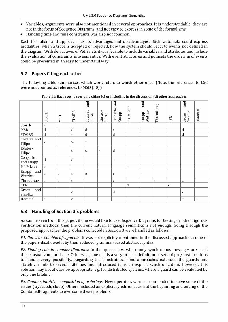
UML 2.0 Sequence Diagrams' Semantics
50
Variables, arguments were also not mentioned in several approaches. It is understandable, they are not in the focus of Sequence Diagrams, and not easy to express in some of the formalisms.
Handling time and time constraints was also not common.
Each formalism and approach has its advantages and disadvantages. Büchi automata could express modalities, when a trace is accepted or rejected, how the system should react to events not defined in the diagram. With derivatives of Petri nets it was feasible to include variables and attributes and include the evaluation of constraints into semantics. With event structures and pomsets the ordering of events could be presented in an easy to understand way.
5.2 Papers Citing each other
The following table summarizes which work refers to which other ones. (Note, the references to LSC were not counted as references to MSD [30].)
Table 11: Each row: paper only citing (c) or including in the discussion (d) other approaches
Störr
le
MSD
STA
IRS
Cav
arra
an
d
Fil
ipe
Küst
er-
Fil
ipe
Cen
garl
e an
d
Kn
app
P-U
ML
aut
Kn
app
an
d
Wu
ttk
e
Th
read
-tag
CP
N
Gro
su
and
Sm
olk
a
Ham
mal
Störrle - MSD d - d d c c d STAIRS d d - d d d Cavarra and Filipe
c d -
Küster- Filipe
d c - d
Cengarle and Knapp
d d -
P-UMLaut c - Knapp and Wuttke
c c c c c -
Thread-tag c c c c - c CPN d - Grosu and Smolka
d d -
Hammal c c c -
5.3 Handling of Section 3’s problems
As can be seen from this paper, if one would like to use Sequence Diagrams for testing or other rigorous verification methods, then the current natural language semantics is not enough. Going through the proposed approaches, the problems collected in Section 3 were handled as follows.
P1. Gates on Combinedfragments: It was not explicitly mentioned in the discussed approaches, some of the papers disallowed it by their reduced, grammar-based abstract syntax.
P2. Finding cuts in complex diagrams: In the approaches, where only synchronous messages are used, this is usually not an issue. Otherwise, one needs a very precise definition of sets of pre/post locations to handle every possibility. Regarding the constraints, some approaches extended the guards and StateInvariants to several Lifelines and introduced it as an explicit synchronization. However, this solution may not always be appropriate, e.g. for distributed systems, where a guard can be evaluated by only one Lifeline.
P3. Counter-intuitive composition of orderings: New operators were recommended to solve some of the issues (try/catch, sloop). Others included an explicit synchronization at the beginning and ending of the CombinedFragments to overcome these problems.
UML 2.0 Sequence Diagrams' Semantics
51
P4. Compositionality of gates: In some approaches, Gates were treated as some kind of OccurrenceSpecification, and they were included in the semantic domain.
P5. Default interpretation for Sequence Diagrams: Several approaches introduced the modalities from LSC instead of the ones defined in the specification. Others kept the original approach, but tried to more precisely define when a trace satisfies positively or negatively a diagram, or when it is inconclusive.
P6. Assigning meaning to conformance operators and their nesting: Some approaches placed syntactic restrictions that prohibited the nesting. Others allowed nesting, but redefined the negate operator that nested negative traces always remain negative.
P7. Both valid and invalid traces: Many papers redefined the operators in the specification to overcome this issue. Several interpretations were published, which each slightly differ from the others. Some of the approaches explicitly accept that, saying that in the early phase of the specification this can happen. Later in the design, these traces should be refined.
5.4 Impact of the modeling domain on the semantics
Looking through all the problems, all the approaches, and all the purposes Sequence Diagrams my be used for, one can conclude that there is no “all-in-one” semantics. Sequence Diagrams can be used just for too many different goals, e.g. partial specification of distributed systems, description of synchronous calls between objects, description of test cases. The current notation is just too rich and too permissive.
Therefore, one should ask questions to characterize the actual environment.
First the default interpretation of diagrams should be fixed (P5). Will the diagrams be a partial specification, are other messages allowed to interleave (consider, ignore)? Do I want to model invalid behaviors (assert, negate)? If the answer to the previous questions is yes, then be prepared for the problems of conformance operators (P6, P7).
Will I model a synchronous or a truly distributed system? Depending on the answer the order of events (P2, P3) could be a complex problem.
What kind of UML elements are used in the diagrams? E.g., do I need variables and data in arguments and constraints? Table 10 could help to search for formalisms, where it was easy to express such elements.
When the goals of the models are fixed, the goal of the semantics should also be classified.
Do I need to generate all the possible traces from a diagram? Is it feasible to generate all the traces? Usually the denotational semantics could generate only all the traces, but could not decide about just one trace.
Do I need to decide whether a given trace is or could be valid, invalid or inconclusive? Do I need to decide it on-the-fly? Some of the semantics consider a trace negative as soon as it traverses a negative region, while others decide after the whole trace is processed.
If a trace can be generated by distinct paths in the diagram, do they need to be differentiated? Usually this is not possible with denotational semantics.
We hope that this paper will help those, who search for a suitable semantics or would like to define a new semantics for Sequence Diagrams in their own problem domain.
Acknowledgements: This report was written while the first author was at CNRS-LAAS, Toulouse.
UML 2.0 Sequence Diagrams' Semantics
52
6 References
6.1 Object Management Group
[1] Object Management Group. Unified Modeling Language (UML) specifications, Available: http://www.omg.org/technology/documents/formal/uml.htm
[2] Object Management Group. "UML 2.1.2 Infrastructure Specification," formal/07-11-04, 2007, Available: http://www.omg.org/cgi-bin/doc?formal/07-11-04
[3] Object Management Group. "UML 2.1.2 Superstructure Specification," formal/07-11-02, 2007, Available: http://www.omg.org/cgi-bin/doc?formal/07-11-02
[4] Object Management Group, Issue list, Available: http://www.omg.org/issues [5] Bran Selic. On the Semantic Foundations of Standard UML 2.0, In SFM-RT 2004, Bertinoro, Italy, September
13-18, 2004, Revised Lectures, pages 181-199, 2004. Springer.
6.2 Other scenario languages
[6] International Telecommunication Union. Recommendation Z.120: Message Sequence Chart (MSC). 2004. [7] Arjan J. Mooij, Nicolae Goga, and Judi M.T. Romijn. Non-local Choice and Beyond: Intricacies of MSC Choice
Nodes. In Fundamental Approaches to Software Engineering, pp 273-288., Springer, 2005. [8] Bikram Sengupta and Rance Cleaveland. Triggered Message Sequence Charts. Transactions on Software
Engineering, 32(8):587-607, Aug. 2006. doi:10.1109/TSE.2006.82
6.2.1 LSC
[9] Werner Damm and David Harel. LSCs: Breathing Life into Message Sequence Charts. Formal Methods in System Design, 19(1):45–80, July 2001. doi: 10.1023/A:1011227529550
[10] David Harel and Rami Marelly. Come, Let's Play: Scenario-Based Programming Using LSCs and the Play-Engine. Springer-Verlag, 2003.
[11] Yves Bontemps and Patrick Heymans. Turning high-level sequence charts into automata. In: Proceedings of the 1st Int. Workshop on Scenarios and State Machines (SCESM’02), 2002.
[12] Jochen Klose, and Hartmut Wittke. An Automata Based Interpretation of Live Sequence Chart. In: Margaria, T., Yi, W. (eds.) Proceedings 7th International Conference on Tools and Algorithms for the Construction and Analysis of Systems (TACAS’01), LNCS, vol. 2031. Springer, Heidelberg (2001)
6.2.2 TeLa
[13] Simon Pickin and Jean-Marc Jézéquel. Using UML Sequence Diagrams as the Basis for a Formal Test Description Language. In Eerke A. Boiten, John Derrick and Graeme Smith, editors, 4th International Conference on Integrated Formal Methods (IFM 2004), pages 481-500, 2004. Springer.
[14] Simon Pickin. PhD thesis. Test des composants logiciels pour les télécommunications. Université de Rennes, France, 2003.
6.3 Theory and Formalisms for Semantics
[15] Vaughan R. Pratt. Modelling concurrency with partial orders. International Journal of Parallel Programming, 15(1):33–71, 1986.
[16] Glynn Winskel and Mogens Nielsen. Models for Concurrency, Handbook of Logic in Computer Science, Semantic Modelling, Vol. 4, Oxford Science Publications, Oxford, 1995, pp. 1–148.
6.4 Proposed semantics for UML 2.0 Sequence diagrams
6.4.1 Trace semantics from Harald Störrle
[17] Harald Störrle. Semantics of interactions in UML 2.0, IEEE Symposium on Human Centric Computing Languages and Environments (HCC 2003), pages 129-136, 2003. IEEE Computer Society.
[18] Harald Störrle. Assert, Negate and Refinement in UML-2 Interactions, Workshop on Critical Systems Development with UML (CSDUML'03), Technical Report TUM-I0317, pages 79–94, 2003. Institut für Informatik, Technische Universität München.
UML 2.0 Sequence Diagrams' Semantics
53
[19] Harald Störrle. Trace Semantics of Interactions in UML 2.0. Technical report. Institut für Informatik, Ludwig-Maximilians-Universität München, 2004.
6.4.2 ASM-based semantics from Alessandra Cavarra and Juliana Küster-Filipe
[20] Alessandra Cavarra and Juliana Küster-Filipe. Combining sequence diagrams and OCL for liveness. In Proceedings of the Semantic Foundations of Engineering Design Languages (SFEDL), ETAPS 2004. Barcelona, Spain, Electronic Notes on Theoretical Computer Science (ENTCS). Elsevire Science, 2004.
[21] Alessandra Cavarra and Juliana Küster Filipe. Formalizing Liveness-Enriched Sequence Diagrams Using ASMs. In Wolf Zimmermann and Bernhard Thalheim, editors, Abstract State Machines, pages 62-77, 2004. Springer.
6.4.3 True-concurrency Semantics from Juliana Küster-Filipe
[22] Juliana Küster-Filipe. Modelling Concurrent Interactions. Theoretical Computer Science, 351(2):203–220, 2006. doi: http://dx.doi.org/10.1016/j.tcs.2005.09.068
[23] Juliana Küster Filipe Bowles. Decomposing Interactions, 11th International Conference on Algebraic Methodology and Software Technology (AMAST 2006), pages 189–203, 2006. Springer. doi:10.1007/11784180
6.4.4 Semantics from María Victoria Cengarle and Alexander Knapp
[24] Maria Victoria Cengarle and Alexander Knapp. UML 2.0 Interactions: Semantics and Refinement. In Jürjens, J., Fernandez, E.B., France, R., Rumpe, B., editors, 3rd Int Workshop on Critical Systems Development with UML (CSDUML’04, Proceedings), Technical Report TUM-I0415, pages 85–99, 2004. Institut für Informatik, Technische Universitat Munchen.
[25] Maria Victoria Cengarle and Alexander Knapp. Operational Semantics of UML 2.0 Interactions. Technical report TUM-I0505. Institut für Informatik, Technische Universitat München, 2005.
[26] María Victoria Cengarle, Peter Graubmann and Stefan Wagner. Semantics of UML 2.0 Interactions with Variabilities. Electr. Notes Theor. Comput. Sci., 160:141-155, 2006.
6.4.5 Semantics from Alexander Knapp and Jochen Wuttke
[27] Alexander Knapp and Jochen Wuttke. Model Checking of UML 2.0 Interactions. In Thomas Kühne, editors, Models in Software Engineering, Workshops and Symposia at MoDELS 2006, pages 42-51, 2006. Springer.
6.4.6 P-UMLaut approach
[28] Christoph Eichner, Hans Fleischhack, Roland Meyer, Ulrik Schrimpf and Christian Stehno. Compositional Semantics for UML 2.0 Sequence Diagrams Using Petri Nets , SDL 2005: Model Driven Systems Design, pages 133–148, 2005. Springer.
6.4.7 Thread-tag based semantics
[29] Haitao Dan, Robert M. Hierons and Steve Counsell. A Thread-tag Based Semantics for Sequence Diagrams, Software Engineering and Formal Methods (SEFM 2007), pages 173-182, 2007. IEEE Computer Society.
6.4.8 Modal Sequence Diagrams from David Harel and Shahar Maoz
[30] David Harel and Shahar Maoz. Assert and negate revisited: Modal semantics for UML sequence diagrams. Software and Systems Modeling, 7(2):237–253, May, 2008.
[31] David Harel, Asaf Kleinbort and Shahar Maoz. S2A: A Compiler for Multi-modal UML Sequence Diagrams. In Proc. of 10th International Conference on Fundamental Approaches to Software Engineering (FASE 2007), pages 121-124, 2007. Springer. doi: http://dx.doi.org/10.1007/978-3-540-71289-3_11
6.4.9 CPN-based approach
[32] Joao M. Fernandes, Simon Tjell, Jens Baek Jorgensen and Oscar Ribeiro. Designing Tool Support for Translating Use Cases and UML 2.0 Sequence Diagrams into a Coloured Petri Net, SCESM '07: Proceedings of the Sixth International Workshop on Scenarios and State Machines, pages 2, Washington, DC, USA, 2007. IEEE Computer Society.
UML 2.0 Sequence Diagrams' Semantics
54
6.4.10 STAIRS approach
[33] Oystein Haugen, Knut Eilif Husa, Ragnhild Kobro Runde and Ketil Stolen. Why Timed Sequence Diagrams Require Three-Event Semantics. Technical Report 309, University of Oslo, Revised December 2006.
[34] Oystein Haugen, Knut Eilif Husa, Ragnhild Kobro Runde and Ketil Stolen. STAIRS towards formal design with sequence diagrams. Software and System Modeling, 4(4):355-357, 2005.
[35] Ragnhild K. Runde, Øystein Haugen, and Ketil Stølen. How to transform UML neg into a useful construct. In Norsk Informatikkonferanse (NIK'05), pages 55--66. Tapir, 2005.
[36] Mass Soldal Lund and Ketil Stolen. A Fully General Operational Semantics for UML 2.0 Sequence Diagrams with Potential and Mandatory Choice. In Jayadev Misra, Tobias Nipkow and Emil Sekerinski, editors, 14th International Symposium on Formal Methods (FM 2006), pages 380-395, 2006. Springer.
[37] Mass Soldal Lund. Operational analysis of sequence diagram specifications. Ph.d. thesis, Faculty of Mathematics and Natural Sciences, University of Oslo, 2008.
6.4.11 Safety-Liveness Semantics of Grosu and Smolka
[38] Radu Grosu and Scott A. Smolka. Safety-Liveness Semantics for UML 2.0 Sequence Diagrams, ACSD '05: Proceedings of the Fifth International Conference on Application of Concurrency to System Design, pages 6–14, Washington, DC, USA, 2005. IEEE Computer Society. doi:http://dx.doi.org/10.1109/ACSD.2005.31
6.4.12 Branching Time Semantics of Hammal
[39] Youcef Hammal. Branching Time Semantics for UML 2.0 Sequence Diagrams In Elie Najm, Jean-Francois Pradat-Peyre and Véronique Donzeau-Gouge, editors, Formal Techniques for Networked and Distributed Systems, pages 259-274, 2006. Springer.