Embed Size (px)
Citation preview
© 2008 Haim Michael. All Rights Reserved.
UML Use Case Diagrams
© 2008 Haim Michael. All Rights Reserved.
Introduction
A UML Use Case diagram shows the relationships among
actors and use cases within a given system.
A Use Case diagram describes a sequence of actions that
produce some value to the customer.
© 2008 Haim Michael. All Rights Reserved.
Introduction
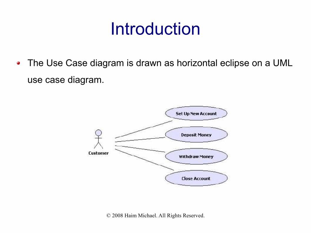
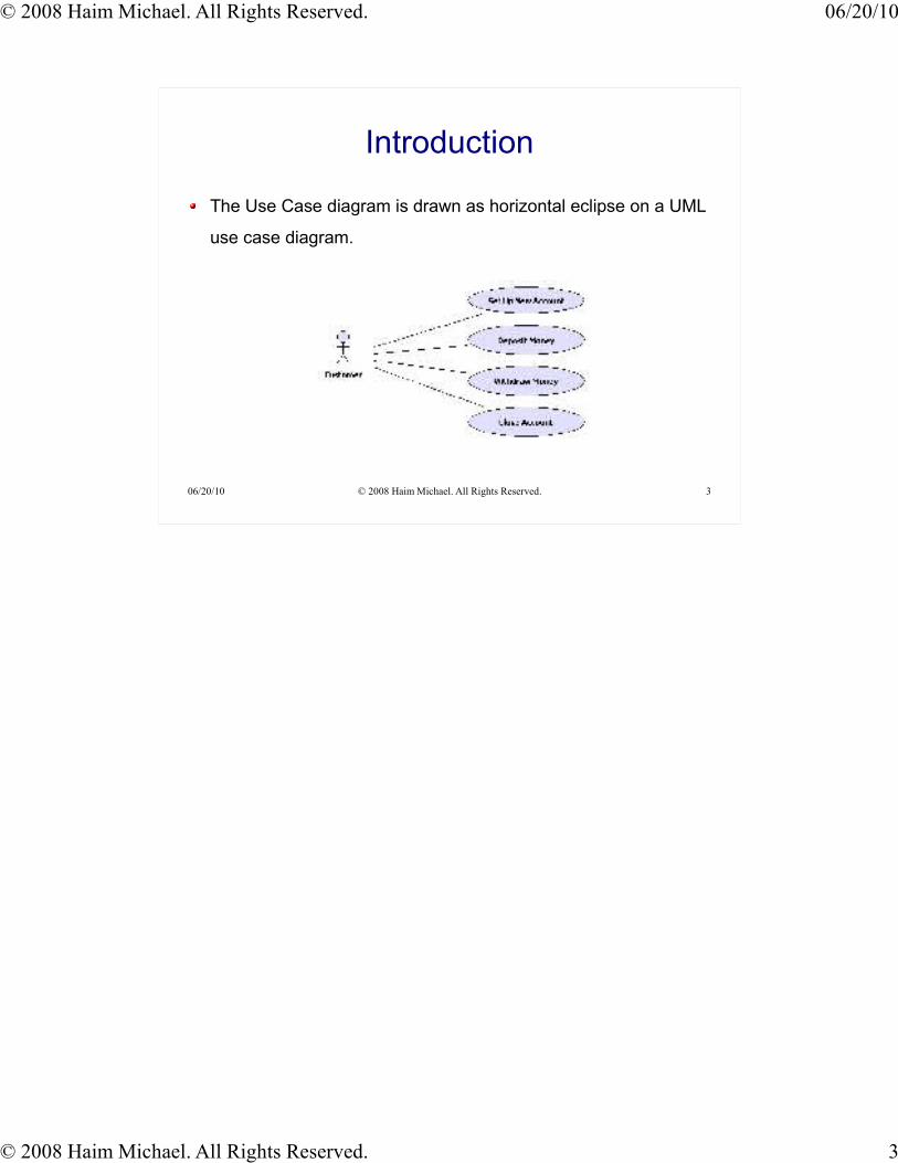
The Use Case diagram is drawn as horizontal eclipse on a UML
use case diagram.
© 2008 Haim Michael. All Rights Reserved.
Diagram Clarity
Include a verb within the use case diagram name. Including “Deposit” within the use case diagram name will improve its clarity and turn
it into a more meaningful one.
A known verb will turn the diagram into a more understandable. Choosing “Process” instead “Deposit” will damage the diagram clarity. Most people
will find “Deposit” a more meaningful verb.
Naming the Use Case diagram using a terminology the diagram
users are familiar with will improve the diagram readability. It is always recommended to prefer a terminology which is more understandable for
those who should use the diagram, even if it seems to be less professional.
© 2008 Haim Michael. All Rights Reserved.
Diagram Clarity
If the Use Case diagram includes several use cases it is
recommended to stack them in accordance with their time line.Placing the first use case on top and the one that follow below it will improve the
diagram readability.
A good UML Use Case diagram focuses on the usability aspect
without getting into the technical aspects. That turns it into an excellent type of diagram to include within the SRS.
The actor is not necessarily a person. It can be an organization,
a local process or even another system. You better think about the actor as about a role and not as about a specific person.
© 2008 Haim Michael. All Rights Reserved.
Diagram Clarity
When the UML Use Case diagram includes more than one user
it is recommended to place the most important one on top left
corner of the diagram. In general, follow the rule of having the more important ones.. the first to execute..
on top left.. and the rest in accordance with their importance.
© 2008 Haim Michael. All Rights Reserved.
Sample
© 2008 Haim Michael. All Rights Reserved.
System Boundaries
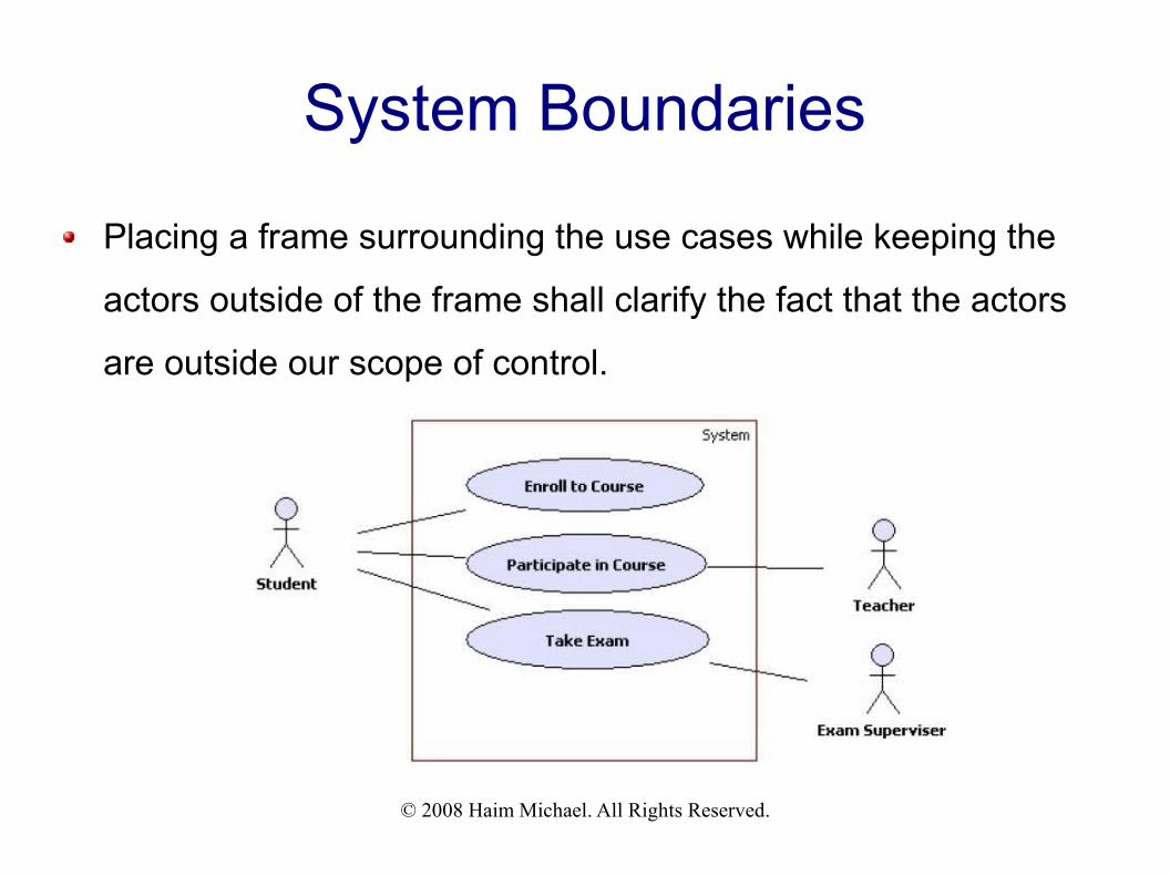
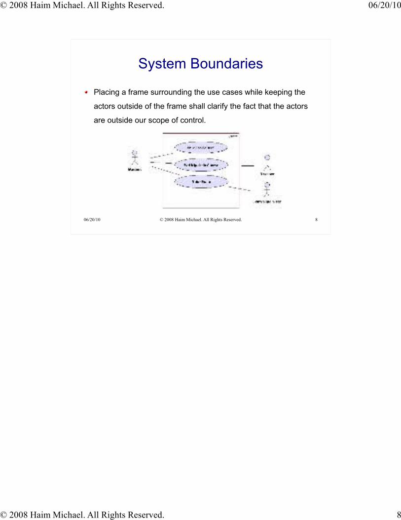
Placing a frame surrounding the use cases while keeping the
actors outside of the frame shall clarify the fact that the actors
are outside our scope of control.
© 2008 Haim Michael. All Rights Reserved.
Actors Names & System Actor
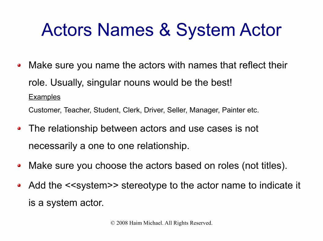
Make sure you name the actors with names that reflect their
role. Usually, singular nouns would be the best!Examples
Customer, Teacher, Student, Clerk, Driver, Seller, Manager, Painter etc.
The relationship between actors and use cases is not
necessarily a one to one relationship.
Make sure you choose the actors based on roles (not titles).
Add the <<system>> stereotype to the actor name to indicate it
is a system actor.
© 2008 Haim Michael. All Rights Reserved.
Sample
© 2008 Haim Michael. All Rights Reserved.
System Actors Interaction
Actors should not interact with each other. The Use Case
diagram focuses on interactions between actors and the
system. Interaction between two actors can be described in the
use case text. Example
In the diagram that is shown on the previous slide the student and the exam
supervisor interact when the exam takes place. We can rename the “take exam” use
case into “take exam (supervised)”.
© 2008 Haim Michael. All Rights Reserved.
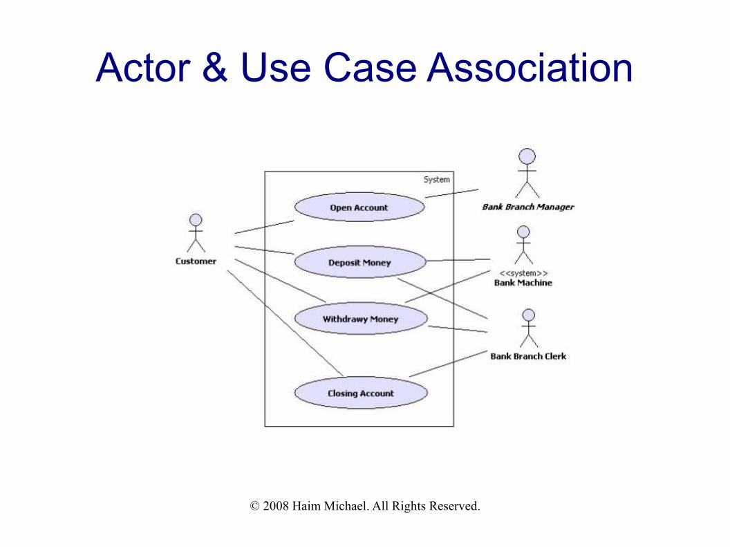
Actor & Use Case Association
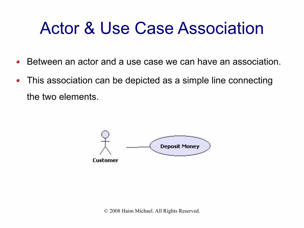
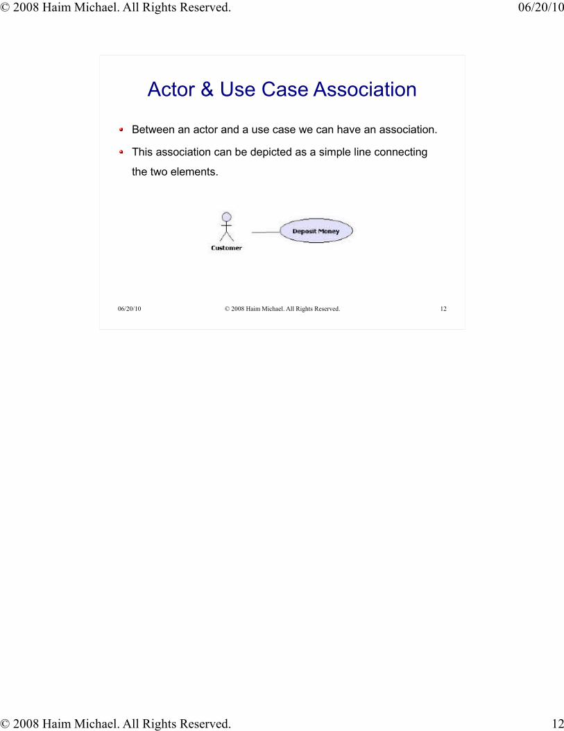
Between an actor and a use case we can have an association.
This association can be depicted as a simple line connecting
the two elements.
© 2008 Haim Michael. All Rights Reserved.
Actor & Use Case Association
© 2008 Haim Michael. All Rights Reserved.
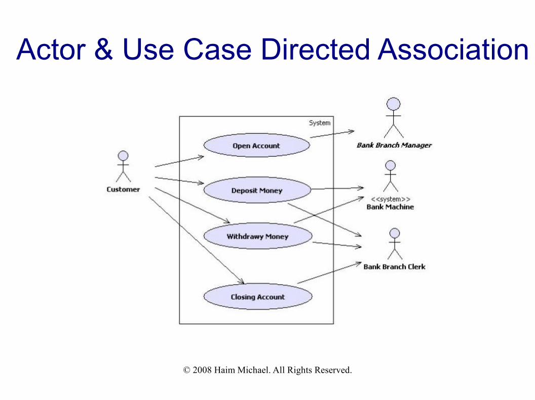
Actor & Use Case Directed Association
In order to indicate whether the actor or the use case initiates
the interaction between the two it is possible to add an arrow
instead of a simple line.
© 2008 Haim Michael. All Rights Reserved.
Actor & Use Case Directed Association
© 2008 Haim Michael. All Rights Reserved.
The <<include>> Association
When the invocation of one use case is done by another use
case the <<include>> association exists between the two.
The <<include>> association usually exists when a common
logic is required by different use cases.
The <<include>> association is common when the logic of one
use case is required by the other use case in a synchronous
manner.
© 2008 Haim Michael. All Rights Reserved.
The <<include>> Association
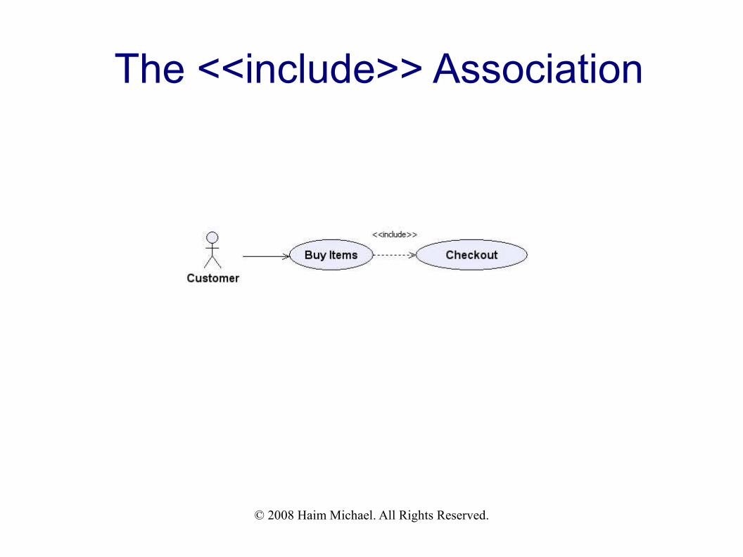
The <<include>> association is depicted using a dashed arrow
line and the <<include>> stereotype aside it. The arrow points
at the included use case, which is the one that is required by
the other.
© 2008 Haim Michael. All Rights Reserved.
The <<include>> Association
© 2008 Haim Michael. All Rights Reserved.
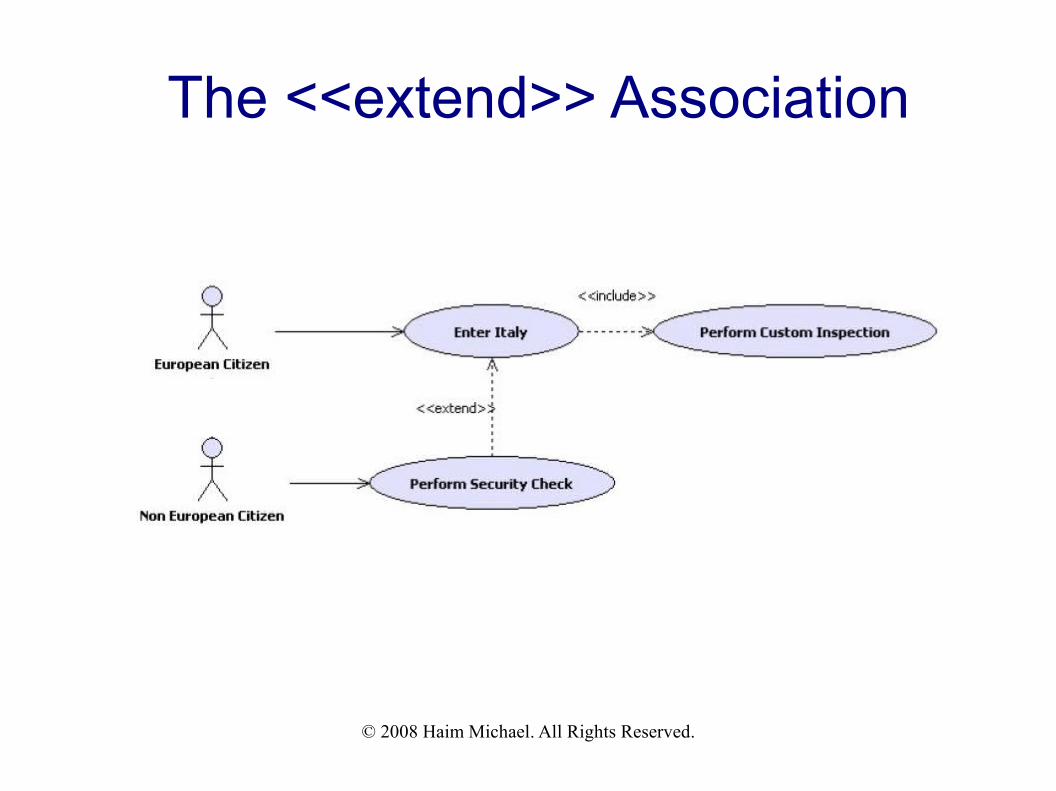
The <<extend>> Association
When the logic of one use case might be required across the
steps that belong to another use case, the <<extend>>
association exists between the two use cases. The use case
that its code is required extends the other one.
The <<extend>> association is depicted using a dashed arrow
line and the <<extend>> stereotype aside it. The arrow points at
the use case that requires the steps of the other one.
© 2008 Haim Michael. All Rights Reserved.
The <<extend>> Association
The <<extend>> association is a generalization one. The
extending use case adds its steps (either asynchronously or
synchronously) to the base use case's steps.
© 2008 Haim Michael. All Rights Reserved.
The <<extend>> Association
© 2008 Haim Michael. All Rights Reserved.
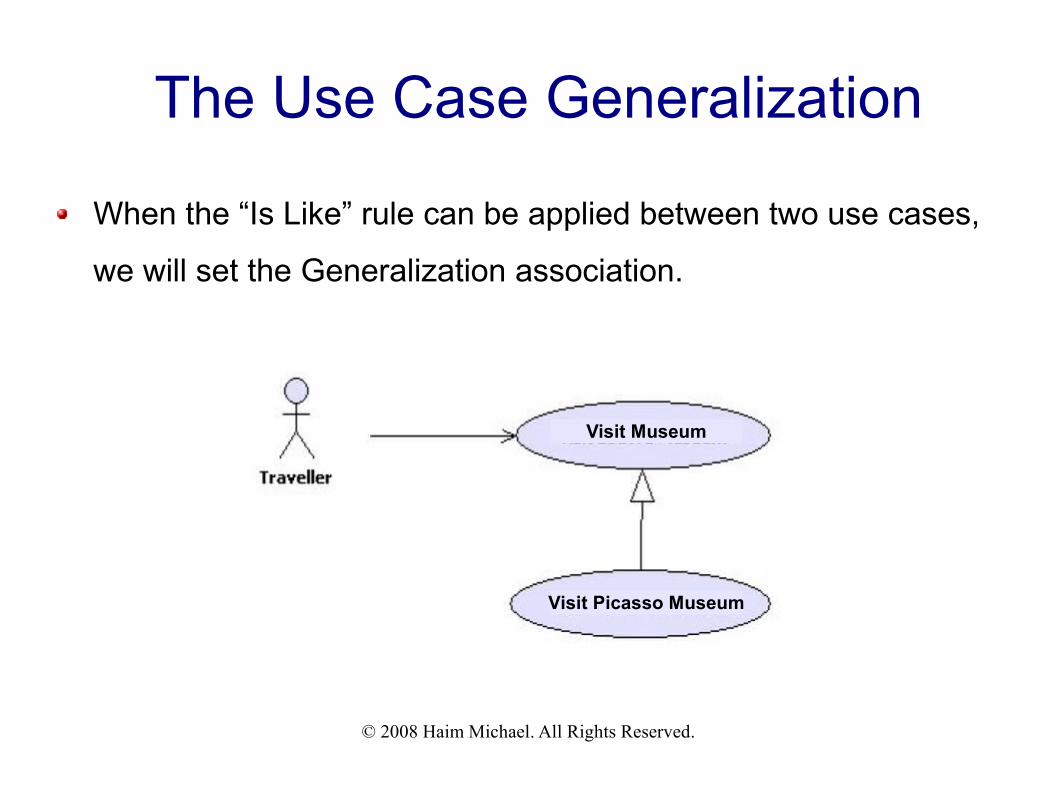
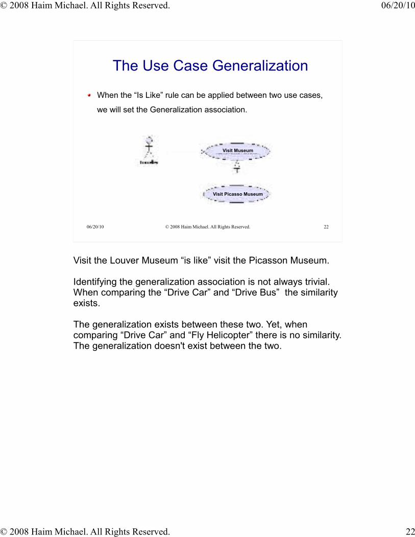
The Use Case Generalization
When the “Is Like” rule can be applied between two use cases,
we will set the Generalization association.
Visit Museum
Visit Picasso Museum
© 2008 Haim Michael. All Rights Reserved.
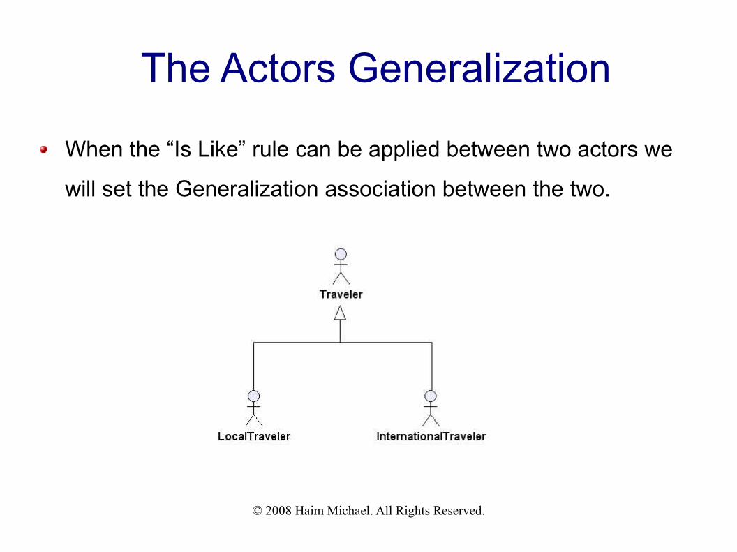
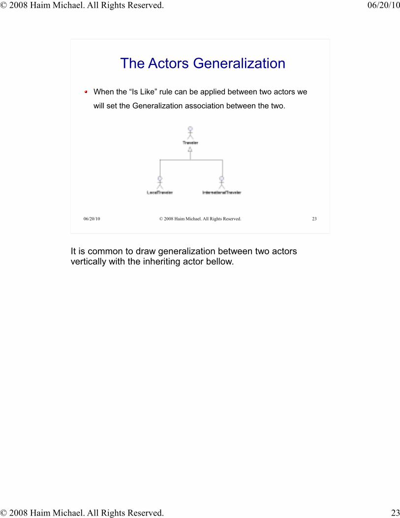
The Actors Generalization
When the “Is Like” rule can be applied between two actors we
will set the Generalization association between the two.
© 2008 Haim Michael. All Rights Reserved.
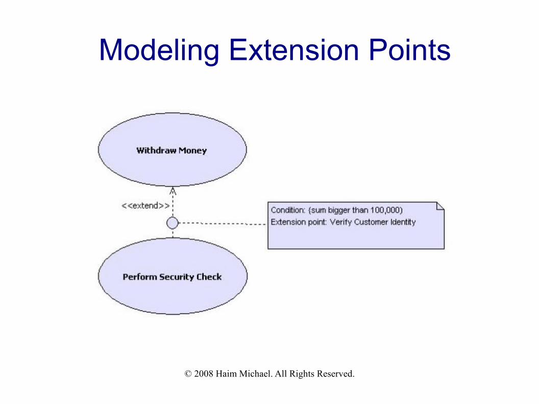
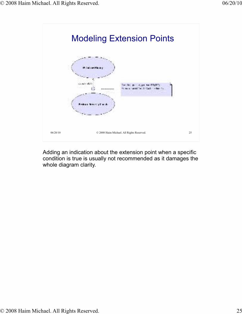
Modeling Extension Points
You can indicate that a specific extension between two use
cases takes place when a specific condition is true by writing a
small note in which the condition is detailed aside the extension
point and connect that note to an empty circle located on the
extension dashed arrow.
© 2008 Haim Michael. All Rights Reserved.
Modeling Extension Points

© 2008 Haim Michael. All Rights Reserved.
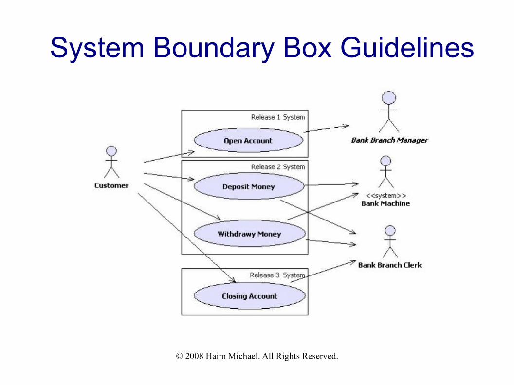
System Boundary Box Guidelines
The System Boundary Box is the rectangle around the use
cases. It indicates the scope of the system that we analyze.
Using the System Boundary Box it is possible to indicate the
release date of our planned system various parts.
© 2008 Haim Michael. All Rights Reserved.
System Boundary Box Guidelines
© 2008 Haim Michael. All Rights Reserved.
The Description Importance
Adding a brief use case description as comments together with
a detailed description in a separated textual analysis assist us
understanding the system we analyze and assist others to
understand our use case diagram.There is a learning curve involved in understanding the use cases correctly, both for
end users and developers. Some of the relations, such as extends, are ambiguous in
interpretation and can be difficult for stakeholders to understand.
© 2008 Haim Michael. All Rights Reserved.
Using The SRS
It is highly common to include use case diagrams within the
System Requirements Specification (SRS) document.
Working on our system use cases diagrams can assist us
finalizing the SRS document. Via the work on our use cases
diagrams our understanding of the required system improved.

© 2008 Haim Michael. All Rights Reserved. 06/20/10
© 2008 Haim Michael. All Rights Reserved. 1
06/20/10 © 2008 Haim Michael. All Rights Reserved. 1
UML Use Case Diagrams
© 2008 Haim Michael. All Rights Reserved. 06/20/10
© 2008 Haim Michael. All Rights Reserved. 2
06/20/10 © 2008 Haim Michael. All Rights Reserved. 2
Introduction
A UML Use Case diagram shows the relationships among
actors and use cases within a given system.
A Use Case diagram describes a sequence of actions that
produce some value to the customer.
© 2008 Haim Michael. All Rights Reserved. 06/20/10
© 2008 Haim Michael. All Rights Reserved. 3
06/20/10 © 2008 Haim Michael. All Rights Reserved. 3
Introduction
The Use Case diagram is drawn as horizontal eclipse on a UML
use case diagram.
© 2008 Haim Michael. All Rights Reserved. 06/20/10
© 2008 Haim Michael. All Rights Reserved. 4
06/20/10 © 2008 Haim Michael. All Rights Reserved. 4
Diagram Clarity
Include a verb within the use case diagram name. Including “Deposit” within the use case diagram name will improve its clarity and turn
it into a more meaningful one.
A known verb will turn the diagram into a more understandable. Choosing “Process” instead “Deposit” will damage the diagram clarity. Most people
will find “Deposit” a more meaningful verb.
Naming the Use Case diagram using a terminology the diagram
users are familiar with will improve the diagram readability. It is always recommended to prefer a terminology which is more understandable for
those who should use the diagram, even if it seems to be less professional.
The Use Case diagram in the previous slide presents several use cases stacked one above the other in accordance with their time line (setting up an account is the first action, deposit money comes before withdrawing it and closing a bank account is the last action).
© 2008 Haim Michael. All Rights Reserved. 06/20/10
© 2008 Haim Michael. All Rights Reserved. 5
06/20/10 © 2008 Haim Michael. All Rights Reserved. 5
Diagram Clarity
If the Use Case diagram includes several use cases it is
recommended to stack them in accordance with their time line.Placing the first use case on top and the one that follow below it will improve the
diagram readability.
A good UML Use Case diagram focuses on the usability aspect
without getting into the technical aspects. That turns it into an excellent type of diagram to include within the SRS.
The actor is not necessarily a person. It can be an organization,
a local process or even another system. You better think about the actor as about a role and not as about a specific person.
© 2008 Haim Michael. All Rights Reserved. 06/20/10
© 2008 Haim Michael. All Rights Reserved. 6
06/20/10 © 2008 Haim Michael. All Rights Reserved. 6
Diagram Clarity
When the UML Use Case diagram includes more than one user
it is recommended to place the most important one on top left
corner of the diagram. In general, follow the rule of having the more important ones.. the first to execute..
on top left.. and the rest in accordance with their importance.
© 2008 Haim Michael. All Rights Reserved. 06/20/10
© 2008 Haim Michael. All Rights Reserved. 7
06/20/10 © 2008 Haim Michael. All Rights Reserved. 7
Sample
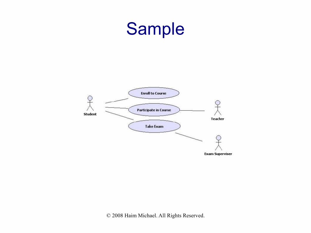
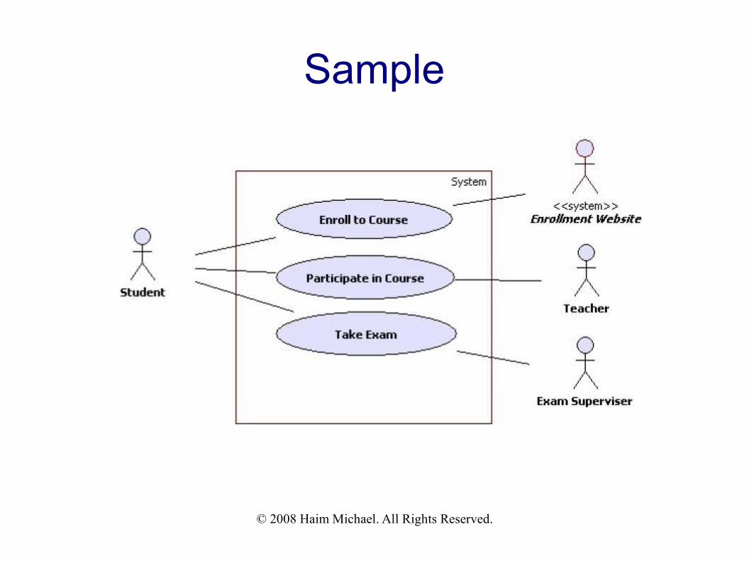
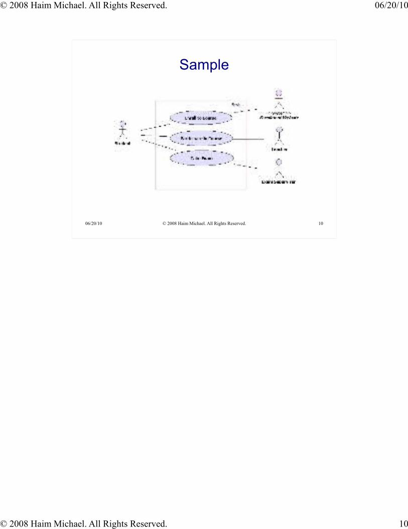
The use case diagram on this page has the student user on the top left corner of the diagram. The student user is the most important one. The student is “today” customer in most colleges/schools/universities.
The use cases are drawn from top to bottom in accordance with their timing.
© 2008 Haim Michael. All Rights Reserved. 06/20/10
© 2008 Haim Michael. All Rights Reserved. 8
06/20/10 © 2008 Haim Michael. All Rights Reserved. 8
System Boundaries
Placing a frame surrounding the use cases while keeping the
actors outside of the frame shall clarify the fact that the actors
are outside our scope of control.
© 2008 Haim Michael. All Rights Reserved. 06/20/10
© 2008 Haim Michael. All Rights Reserved. 9
06/20/10 © 2008 Haim Michael. All Rights Reserved. 9
Actors Names & System Actor
Make sure you name the actors with names that reflect their
role. Usually, singular nouns would be the best!Examples
Customer, Teacher, Student, Clerk, Driver, Seller, Manager, Painter etc.
The relationship between actors and use cases is not
necessarily a one to one relationship.
Make sure you choose the actors based on roles (not titles).
Add the <<system>> stereotype to the actor name to indicate it
is a system actor.
In many cases an actor is involved with more than one use case and every use case is involved with at least one actor. The relationship between use cases and actors is many to many.
© 2008 Haim Michael. All Rights Reserved. 06/20/10
© 2008 Haim Michael. All Rights Reserved. 10
06/20/10 © 2008 Haim Michael. All Rights Reserved. 10
Sample
© 2008 Haim Michael. All Rights Reserved. 06/20/10
© 2008 Haim Michael. All Rights Reserved. 11
06/20/10 © 2008 Haim Michael. All Rights Reserved. 11
System Actors Interaction
Actors should not interact with each other. The Use Case
diagram focuses on interactions between actors and the
system. Interaction between two actors can be described in the
use case text. Example
In the diagram that is shown on the previous slide the student and the exam
supervisor interact when the exam takes place. We can rename the “take exam” use
case into “take exam (supervised)”.
© 2008 Haim Michael. All Rights Reserved. 06/20/10
© 2008 Haim Michael. All Rights Reserved. 12
06/20/10 © 2008 Haim Michael. All Rights Reserved. 12
Actor & Use Case Association
Between an actor and a use case we can have an association.
This association can be depicted as a simple line connecting
the two elements.
© 2008 Haim Michael. All Rights Reserved. 06/20/10
© 2008 Haim Michael. All Rights Reserved. 13
06/20/10 © 2008 Haim Michael. All Rights Reserved. 13
Actor & Use Case Association
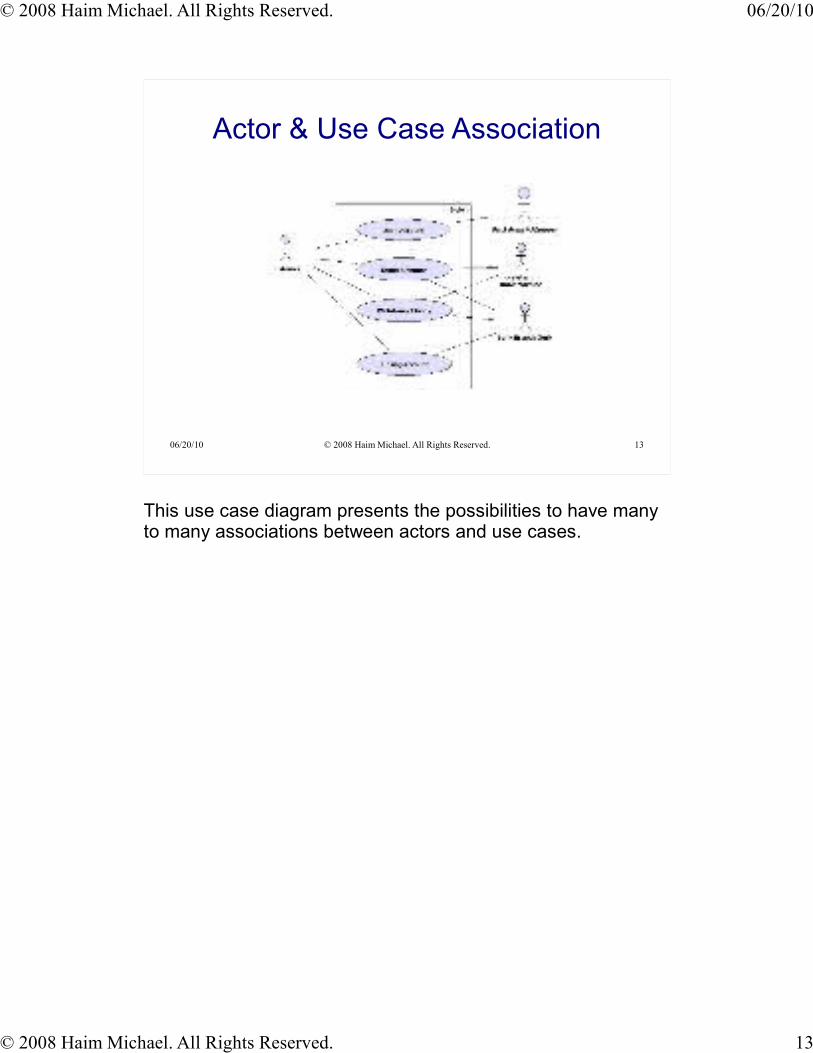
This use case diagram presents the possibilities to have many to many associations between actors and use cases.
© 2008 Haim Michael. All Rights Reserved. 06/20/10
© 2008 Haim Michael. All Rights Reserved. 14
06/20/10 © 2008 Haim Michael. All Rights Reserved. 14
Actor & Use Case Directed Association
In order to indicate whether the actor or the use case initiates
the interaction between the two it is possible to add an arrow
instead of a simple line.
A dding arrows might be confusing. Therefore, make sure those that are going to use the diagrams are well familiar with the arrow possibility. If any doubt you better avoid the arrow and keep the diagram clarity untouched.
© 2008 Haim Michael. All Rights Reserved. 06/20/10
© 2008 Haim Michael. All Rights Reserved. 15
06/20/10 © 2008 Haim Michael. All Rights Reserved. 15
Actor & Use Case Directed Association
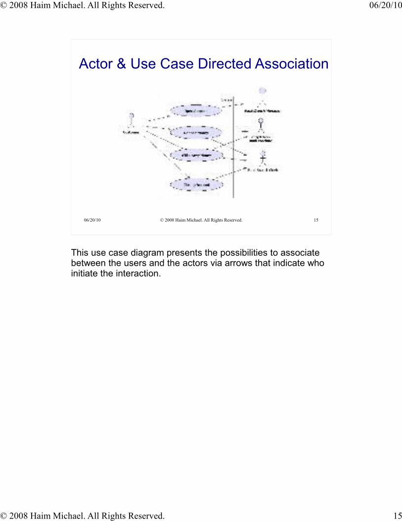
This use case diagram presents the possibilities to associate between the users and the actors via arrows that indicate who initiate the interaction.
© 2008 Haim Michael. All Rights Reserved. 06/20/10
© 2008 Haim Michael. All Rights Reserved. 16
06/20/10 © 2008 Haim Michael. All Rights Reserved. 16
The <<include>> Association
When the invocation of one use case is done by another use
case the <<include>> association exists between the two.
The <<include>> association usually exists when a common
logic is required by different use cases.
The <<include>> association is common when the logic of one
use case is required by the other use case in a synchronous
manner.
© 2008 Haim Michael. All Rights Reserved. 06/20/10
© 2008 Haim Michael. All Rights Reserved. 17
06/20/10 © 2008 Haim Michael. All Rights Reserved. 17
The <<include>> Association
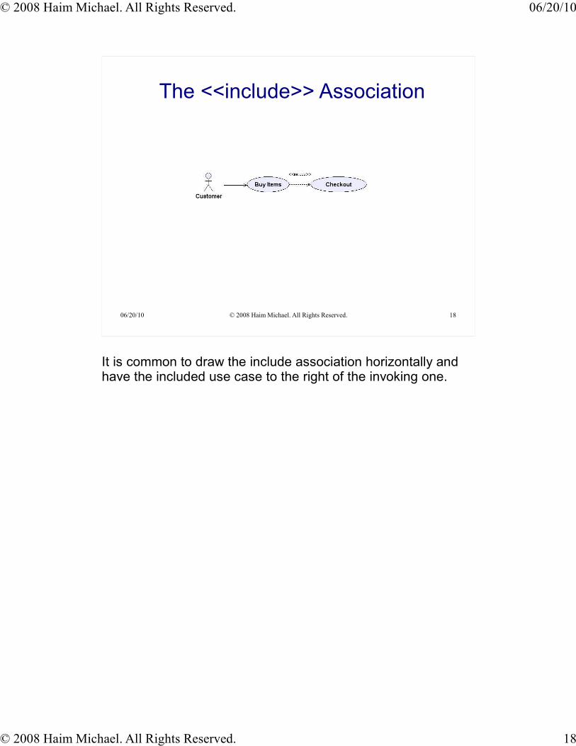
The <<include>> association is depicted using a dashed arrow
line and the <<include>> stereotype aside it. The arrow points
at the included use case, which is the one that is required by
the other.
© 2008 Haim Michael. All Rights Reserved. 06/20/10
© 2008 Haim Michael. All Rights Reserved. 18
06/20/10 © 2008 Haim Michael. All Rights Reserved. 18
The <<include>> Association
It is common to draw the include association horizontally and have the included use case to the right of the invoking one.
© 2008 Haim Michael. All Rights Reserved. 06/20/10
© 2008 Haim Michael. All Rights Reserved. 19
06/20/10 © 2008 Haim Michael. All Rights Reserved. 19
The <<extend>> Association
When the logic of one use case might be required across the
steps that belong to another use case, the <<extend>>
association exists between the two use cases. The use case
that its code is required extends the other one.
The <<extend>> association is depicted using a dashed arrow
line and the <<extend>> stereotype aside it. The arrow points at
the use case that requires the steps of the other one.
© 2008 Haim Michael. All Rights Reserved. 06/20/10
© 2008 Haim Michael. All Rights Reserved. 20
06/20/10 © 2008 Haim Michael. All Rights Reserved. 20
The <<extend>> Association
The <<extend>> association is a generalization one. The
extending use case adds its steps (either asynchronously or
synchronously) to the base use case's steps.
© 2008 Haim Michael. All Rights Reserved. 06/20/10
© 2008 Haim Michael. All Rights Reserved. 21
06/20/10 © 2008 Haim Michael. All Rights Reserved. 21
The <<extend>> Association
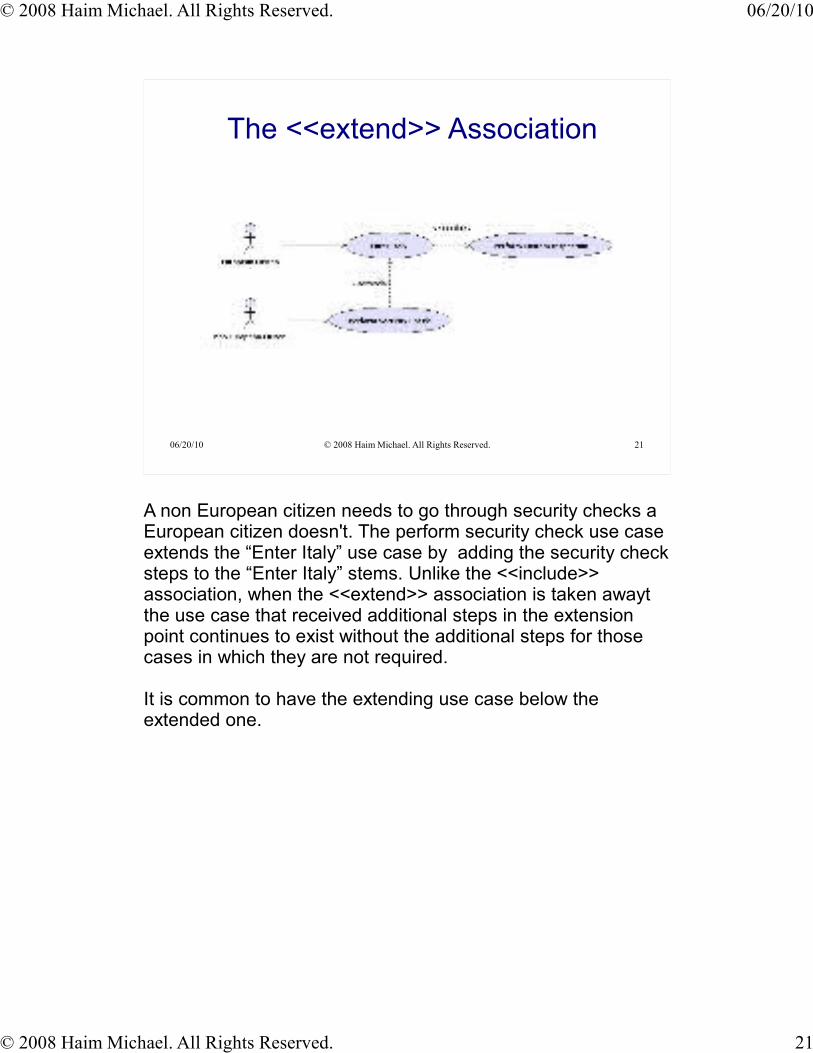
A non European citizen needs to go through security checks a European citizen doesn't. The perform security check use case extends the “Enter Italy” use case by adding the security check steps to the “Enter Italy” stems. Unlike the <<include>> association, when the <<extend>> association is taken awayt the use case that received additional steps in the extension point continues to exist without the additional steps for those cases in which they are not required.
It is common to have the extending use case below the extended one.
© 2008 Haim Michael. All Rights Reserved. 06/20/10
© 2008 Haim Michael. All Rights Reserved. 22
06/20/10 © 2008 Haim Michael. All Rights Reserved. 22
The Use Case Generalization
When the “Is Like” rule can be applied between two use cases,
we will set the Generalization association.
Visit Museum
Visit Picasso Museum
Visit the Louver Museum “is like” visit the Picasson Museum.
Identifying the generalization association is not always trivial. When comparing the “Drive Car” and “Drive Bus” the similarity exists.
The generalization exists between these two. Yet, when comparing “Drive Car” and “Fly Helicopter” there is no similarity. The generalization doesn't exist between the two.
© 2008 Haim Michael. All Rights Reserved. 06/20/10
© 2008 Haim Michael. All Rights Reserved. 23
06/20/10 © 2008 Haim Michael. All Rights Reserved. 23
The Actors Generalization
When the “Is Like” rule can be applied between two actors we
will set the Generalization association between the two.
It is common to draw generalization between two actors vertically with the inheriting actor bellow.
© 2008 Haim Michael. All Rights Reserved. 06/20/10
© 2008 Haim Michael. All Rights Reserved. 24
06/20/10 © 2008 Haim Michael. All Rights Reserved. 24
Modeling Extension Points
You can indicate that a specific extension between two use
cases takes place when a specific condition is true by writing a
small note in which the condition is detailed aside the extension
point and connect that note to an empty circle located on the
extension dashed arrow.
© 2008 Haim Michael. All Rights Reserved. 06/20/10
© 2008 Haim Michael. All Rights Reserved. 25
06/20/10 © 2008 Haim Michael. All Rights Reserved. 25
Modeling Extension Points
Adding an indication about the extension point when a specific condition is true is usually not recommended as it damages the whole diagram clarity.
© 2008 Haim Michael. All Rights Reserved. 06/20/10
© 2008 Haim Michael. All Rights Reserved. 26
06/20/10 © 2008 Haim Michael. All Rights Reserved. 26
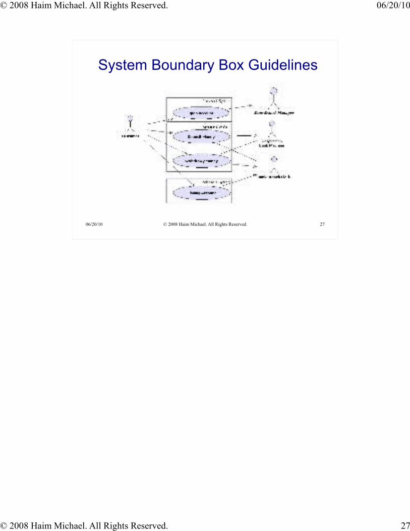
System Boundary Box Guidelines
The System Boundary Box is the rectangle around the use
cases. It indicates the scope of the system that we analyze.
Using the System Boundary Box it is possible to indicate the
release date of our planned system various parts.
© 2008 Haim Michael. All Rights Reserved. 06/20/10
© 2008 Haim Michael. All Rights Reserved. 27
06/20/10 © 2008 Haim Michael. All Rights Reserved. 27
System Boundary Box Guidelines

© 2008 Haim Michael. All Rights Reserved. 06/20/10
© 2008 Haim Michael. All Rights Reserved. 28
06/20/10 © 2008 Haim Michael. All Rights Reserved. 28
The Description Importance
Adding a brief use case description as comments together with
a detailed description in a separated textual analysis assist us
understanding the system we analyze and assist others to
understand our use case diagram.There is a learning curve involved in understanding the use cases correctly, both for
end users and developers. Some of the relations, such as extends, are ambiguous in
interpretation and can be difficult for stakeholders to understand.
© 2008 Haim Michael. All Rights Reserved. 06/20/10
© 2008 Haim Michael. All Rights Reserved. 29
06/20/10 © 2008 Haim Michael. All Rights Reserved. 29
Using The SRS
It is highly common to include use case diagrams within the
System Requirements Specification (SRS) document.
Working on our system use cases diagrams can assist us
finalizing the SRS document. Via the work on our use cases
diagrams our understanding of the required system improved.