Embed Size (px)
Citation preview
Serie ECTAAmphenol
ECTA 133
Connecteurs testés et certifiés selons EN 61984 per VDE N. 6908Steckerbaureihe geprüft und zertifiziert nach DIN EN 61984 unter VDE Reg.Nr. 6908Connectors tested and certified according to EN 61984 per VDE registration number 6908
ums_2611_ailb_bro_ect.411 12.10.2007 8:16 Uhr Seite 1
1Summary / Übersicht / Sommaires
Generalities / Allgemeines / Généralités 2-3
Contact arrangements / Polbilder / Arrangements de contacts 4-7
Shells / Gehäuse / Boitiers 8-10
Backshells / Endgehäuse / Raccords 11-13
Accessories / Zubehör / Accessoires 13-14
Bulkhead / Schottdurchführungen / Traversée de cloison 15
Specific connectors / Sonderstecker / Connecteurs spécifiques 16
Polarisation / Kodierung / Polarisations 17
Technical informations / Technische Daten / Données techniques 18-20
Assembly Instructions / Verarbeitungsanweisung / Procedure du cablage 21-23
How to order / Bestellschlüssel / Référence 24-25
Our products are the subject of continuous development and we reserve the right to introduce changes in their design.
Wir sind bestrebt, unsere Produkte weiter zu entwickeln und behalten uns maßliche oder technische Änderungen anden Steckverbindungen vor.
Ce document n’est pas contractuel. Les informations contenues dans ce catalogue sont susceptible d’évolution.
inh_2611_ailb_bro_ect.411 12.10.2007 8:15 Uhr Seite 1
2 Generalities / Allgemeines / Généralités
Circular connector series ECTA 133:
This connector was especially designed for industrial applications with its rugged design, convenient push-pull operation, wide range of contact sizes and high contact density. It provides an ideal component to use in a wide range of applications:Typical industrial applications such as robotics and laboratory test equipment, the transportation industry (automobile,trucks and railway) and tool interconnection.
serie 1331: power transmission connector (to 125 A) equipped with leading ground contact (and pilot contacts for thearrangement 605 for 100 A current and 706 for 125 A current).
serie 1332: signal transmission connector (to 40 A) for data or signal transmission. The current ratings of the contactsalso permit the connector to be used for low voltage transmission. Layouts 294 and 305 are equippedwith power and additional pilot contacts.
A fiber optic version is available on request (see page 16).Possibility of cabled and overmolded connectors for quantity higher than 500 pieces (see page 16). Possibility of specific development (for example: mixed arrangement, specific shells…..) for quantity higher than 1000 pieces (on request).
The connectors series ECTA133 are designed, produced and certified according to EN 61984. Authoritative for the use of connectors are the respective requirements of the device specifications.
EN61984, Connectors – Safety requirements and testsThis international standard is valid for connectors with and without breaking capacity for ratings from 50V to 1000Vand rated currents up to 125A per contact for which either no type specification exists or which type specificationrefers to this norm.
IEC60529 Degrees of protection provided by enclosures (IP Code)This defines requirements, and checks for the classification in protection classes, so-called IP-Codes. These specifythe protection against foreign objects and liquids. The protection class is composed of the two letters IP (Ingress Protection) and 2 digits the first of which defines protection against contact and the second defines protection againstinvasion of liquids.
We aim at advancing our products and reserve the right to change measures or technical details.The technical details given in this catalogue refer to connectors without breaking capacity.All details concerning IP-Codes are only valid when using the appropriate ECTA133 backshells.
These connectors can’t be connected or disconnected under voltage
Rundsteckverbinder der Serie ECTA 133:
Die Rundsteckverbinder ECTA 133 sind für den Einsatz in der Industrie, im Labor, sowie im Apparate- und Fahrzeug-bau entwickelt. Sie bewähren sich unter harten Betriebs- und Umgebungsbedingungen. Es handelt sich um wasser-dichte Steckverbinder mit Push-Pull Schnellverschluss.
Serie 1331: Netzstecker (bis 125 A) mit voreilendem Massekontakt und zusätzlichen Pilotkontakten für Polbild 605 für 100A Nennstrom und Polbild 706 für 125A Nennstrom.
Serie 1332: Datenübertragungsstecker (bis 40 A) zur Übertragung von Signalen und Daten sowie als Kleinspannungs-Versorgungsstecker geeignet. Polbilder 294 und 305 mit Leistungs- und zusätzlichen Pilotkontakten
Eine LWL-Ausführung ist auf Anfrage lieferbar (siehe Seite 16).Für Mengen größer 500 Stück, besteht die Möglichkeit umspritzte Steckverbindungen zu fertigen (siehe Seite 16). Für Mengen größer 1000 Stück, ist es möglich Stecker in Sonderausführung (zum Beispiel: Mischpolbild, Gehäuse in Sonderausführung....) zu entwickeln.
Die Steckverbinder der Baureihe ECTA133 werden nach EN 61984 konstruiert, gefertigt und geprüft. Verbindlich fürden Einsatz von Steckverbindern sind die jeweiligen Anforderungen der Gerätevorschriften.
inh_2611_ailb_bro_ect.411 12.10.2007 8:15 Uhr Seite 2
3Generalities / Allgemeines / Généralités
EN 61984, Steckverbinder Sicherheitsanforderungen und PrüfungenDiese internationale Norm gilt für Steckverbinder und Steckvorrichtungen für Bemessungsspannungen von 50V bis1000V und Bemessungsströme bis 125A je Kontakt, für die es entweder keine Bauartspezifikation gibt, oder wennsich deren Bauartspezifikation hinsichtlich der Sicherheitsanforderungen auf die vorliegende Norm bezieht.
IEC 60529 Schutzarten durch Gehäuse (IP-Code)Die internationale Norm entspricht der deutschen Norm VDE 0470-1. Hierin werden die Anforderungen und Prüfungenfür die Einteilungen in Schutzarten, sogenannte IP-Codes, festgelegt. Diese beschreiben den Schutz gegen festeFremdkörper und den Schutz gegen Wasser. Die Schutzart setzt sich immer zusammen aus den beiden BuchstabenIP (Ingress protection) und 2 Ziffern, wobei die erste Ziffer für den Berührungsschutz und die zweite Ziffer für denSchutz gegen das Eindringen von Wasser steht.
Wir sind bestrebt unsere Produkte weiterzuentwickeln und behalten uns maßliche und technische Änderungen vor.Die in diesem Katalog gemachten technischen Angaben beziehen sich auf Steckverbinder, also Bauteile, die nichtunter Spannung gesteckt oder getrennt werden dürfen.Angaben zu IP Schutzklassen werden nur unter Verwendung der passenden ECTA133 Endgehäuse garantiert.
Diese Steckverbinder dürfen betriebsmäßig nicht unter Spannung gesteckt oder getrennt werden.
Connecteur circulaire série ECTA 133:
Les connecteurs circulaires ECTA 133 ont été élaborés pour différents secteurs d’activités tel que l’industrie, la robo-tique, les laboratoires, les transports, ainsi que tous les types d’appareillages pouvant faire appel à la connectique.
serie 1331: connecteurs d’alimentation (jusqu’à 125 A) équipés d’un contact de masse avancé (et de contacts pilotespour l’arrangement 605 pour une intensité de 100A et l’arrangement 706 pour une intensité de 125 A).
serie 1332: connecteurs de transmission de données et de signaux (jusqu’à 40 A) ainsi que pour des alimentationsde faible puissance.
Possibilité de version fibre optique sur demande (voir page 16).Possibilité de version surmoulée pour des quantités supérieure à 500 pièces (voir page 16).Pour des quantités supérieure à 1000 pièces, possibilité de développement de connecteur spécifique (exemple: arrangement mixte, boitier spécifiques…).
Les connecteurs Ecta répondent à la norme EN61984 . Pour l´utilisation il est nécessaire de se référer aux normes spécifiques d´application.
EN61984 norme de sécurité et de test.Cette norme internationale est applicable pour des connecteurs d´une tension d´utilisation de 50V à 1000V et de cou-rant par contact allant jusqu´à 125A.
IEC 60529 Norme de protection Code IPCette norme défini le degré de protection selon des codes IP suivis de deux chiffres.Le premier chiffre exprime la protection contre les corps solidesA partir du chiffre 2 contre les contacts directs….Le second chiffre exprime le niveau d´étanchéité soit la protection contre les liquides..
Cette gamme de produits étant susceptible d´évoluer implique que les informations contenues dans ce catalogue ne soient pas contractuelles
Les connecteurs présentés dans ce catalogue ne peuvent être accouplés et désaccouplés sous charge. Ils doivent être manœuvrés Hors tension.
Les indices de protection sont uniquement garantis avec le raccord arrière adéquat.
Ces connecteurs ne doivent en aucun cas être connectés ou déconnectés sous tension.
inh_2611_ailb_bro_ect.411 12.10.2007 8:15 Uhr Seite 3
4 Contact arrangements / Polbilder / Arrangements contacts
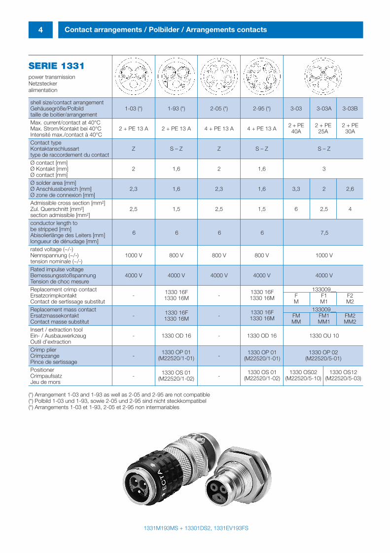
SERIE 1331power transmissionNetzsteckeralimentation
shell size/contact arrangementGehäusegröße/Polbild 1-03 (*) 1-93 (*) 2-05 (*) 2-95 (*) 3-03 3-03A 3-03Btaille de boitier/arrangementMax. current/contact at 40°CMax. Strom/Kontakt bei 40°C 2 + PE 13 A 2 + PE 13 A 4 + PE 13 A 4 + PE 13 AIntensité max./contact à 40°CContact typeKontaktanschlussart Z S – Z Z S – Z S – Ztype de raccordement du contactØ contact [mm]Ø Kontakt [mm] 2 1,6 2 1,6 3Ø contact [mm]Ø solder area [mm]Ø Anschlussbereich [mm] 2,3 1,6 2,3 1,6 3,3 2 2,6Ø zone de connexion [mm]Admissible cross section [mm2]Zul. Querschnitt [mm2] 2,5 1,5 2,5 1,5 6 2,5 4section admissible [mm2]conductor length to be stripped [mm]Abisolierlänge des Leiters [mm]longueur de dénudage [mm]rated voltage (~/-)Nennspannung (~/-) 1000 V 800 V 800 V 800 V 1000 Vtension nominale (~/-)Rated impulse voltageBemessungsstoßspannung 4000 V 4000 V 4000 V 4000 V 4000 VTension de choc mesureReplacement crimp contact 133009__Ersatzcrimpkontakt - - F F1 F2Contact de sertissage substitut M M1 M2Replacement mass contact 133009__Ersatzmassekontakt - - FM FM1 FM2Contact masse substitut MM MM1 MM2Insert / extraction toolEin- / Ausbauwerkzeug - 1330 OD 16 - 1330 OD 16 1330 OU 10Outil d’extractionCrimp plierCrimpzange - -Pince de sertissagePositionerCrimpaufsatz - -Jeu de mors
(*) Arrangement 1-03 and 1-93 as well as 2-05 and 2-95 are not compatible(*) Polbild 1-03 und 1-93, sowie 2-05 und 2-95 sind nicht steckkompatibel(*) Arrangements 1-03 et 1-93, 2-05 et 2-95 non intermariables
1331M193MS + 13301DS2, 1331EV193FS
2 + PE 2 + PE 2 + PE40A 25A 30A
6 6 6 6 7,5
1330 16F1330 16M
1330 16F1330 16M
1330 OP 01(M22520/1-01)
1330 OS 01(M22520/1-02)
1330 16F1330 16M
1330 16F1330 16M
1330 OP 01(M22520/1-01)
1330 OS 01(M22520/1-02)
1330 OS02(M22520/5-10)
1330 OS12(M22520/5-03)
1330 OP 02(M22520/5-01)
inh_2611_ailb_bro_ect.411 12.10.2007 8:15 Uhr Seite 4
5Contact arrangements / Polbilder / Arrangements contacts
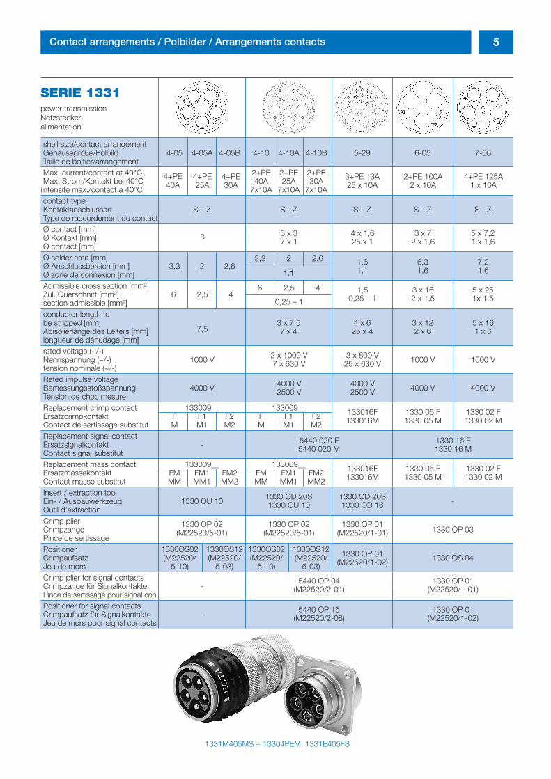
SERIE 1331power transmissionNetzsteckeralimentation
shell size/contact arrangementGehäusegröße/Polbild 4-05 4-05A 4-05B 4-10 4-10A 4-10B 5-29 6-05 7-06Taille de boitier/arrangementMax. current/contact at 40°C 2+PE 2+PE 2+PEMax. Strom/Kontakt bei 40°C 40A 25A 30A
i ntensité max./contact a 40°C 7x10A 7x10A 7x10Acontact typeKontaktanschlussart S – Z S - Z S – Z S – Z S - ZType de raccordement du contactØ contact [mm]Ø Kontakt [mm]Ø contact [mm]Ø solder area [mm]Ø Anschlussbereich [mm] 3,3 2 2,6Ø zone de connexion [mm]Admissible cross section [mm2]Zul. Querschnitt [mm2]section admissible [mm2]conductor length to be stripped [mm] 3 x 7,5 4 x 6 3 x 12 5 x 16Abisolierlänge des Leiters [mm] 7 x 4 25 x 4 2 x 6 1 x 6longueur de dénudage [mm]rated voltage (~/-)Nennspannung (~/-) 1000 V 1000 V 1000 Vtension nominale (~/-)Rated impulse voltageBemessungsstoßspannung 4000 V 4000 V 4000 VTension de choc mesureReplacement crimp contact 133009__ 133009__Ersatzcrimpkontakt F F1 F2 F F1 F2Contact de sertissage substitut M M1 M2 M M1 M2Replacement signal contactErsatzsignalkontakt -Contact signal substitutReplacement mass contact 133009__ 133009__Ersatzmassekontakt FM FM1 FM2 FM FM1 FM2Contact masse substitut MM MM1 MM2 MM MM1 MM2Insert / extraction toolEin- / Ausbauwerkzeug 1330 OU 10 -Outil d’extractionCrimp plierCrimpzange 1330 OP 03Pince de sertissagePositioner 1330OS02 1330OS12 1330OS02 1330OS12Crimpaufsatz (M22520/ (M22520/ (M22520/ (M22520/ 1330 OS 04Jeu de mors 5-10) 5-03) 5-10) 5-03)Crimp plier for signal contactsCrimpzange für Signalkontakte -Pince de sertissage pour signal con.Positioner for signal contactsCrimpaufsatz für Signalkontakte -Jeu de mors pour signal contacts
1331M405MS + 13304PEM, 1331E405FS
4+PE40A
4+PE25A
4+PE30A
3+PE 13A25 x 10A
2+PE 100A2 x 10A
4+PE 125A1 x 10A
3
6 2,5 46 2,5 4
0,25 – 1
3 x 37 x 1
4 x 1,625 x 1
1,50,25 – 1
3 x 162 x 1,5
5 x 251x 1,5
3 x 72 x 1,6
5 x 7,21 x 1,6
3,3 2 2,6 1,61,1
6,31,6
7,21,61,1
7,5
2 x 1000 V7 x 630 V
3 x 800 V25 x 630 V
4000 V2500 V
4000 V2500 V
1330 05 F1330 05 M
1330 02 F1330 02 M
133016F133016M
1330 05 F1330 05 M
1330 02 F1330 02 M
133016F133016M
1330 OD 20S1330 OD 16
1330 OD 20S1330 OU 10
1330 OP 02(M22520/5-01)
1330 OP 02(M22520/5-01)
1330 OP 01(M22520/1-01)
1330 OP 01(M22520/1-02)
5440 OP 04(M22520/2-01)
1330 OP 01(M22520/1-01)
5440 OP 15(M22520/2-08)
1330 OP 01(M22520/1-02)
5440 020 F5440 020 M
1330 16 F1330 16 M
inh_2611_ailb_bro_ect.411 12.10.2007 8:15 Uhr Seite 5
6 Contact arrangenents / Polbilder / Arrangements contacts
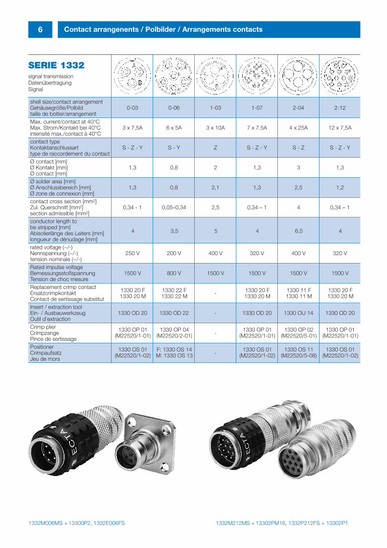
SERIE 1332signal transmissionDatenübertragungSignal
shell size/contact arrangementGehäusegröße/Polbild 0-03 0-06 1-03 1-07 2-04 2-12taille de boitier/arrangementMax. current/contact at 40°CMax. Strom/Kontakt bei 40°C 3 x 7,5A 6 x 5A 3 x 10A 7 x 7.5A 4 x 25A 12 x 7,5Aintensité max./contact à 40°Ccontact typeKontaktanschlussart S - Z - Y S - Y Z S - Z - Y S - Z S - Z - Ytype de raccordement du contactØ contact [mm]Ø Kontakt [mm] 1,3 0,8 2 1,3 3 1,3Ø contact [mm]Ø solder area [mm]Ø Anschlussbereich [mm] 1,3 0,8 2,1 1,3 2,5 1,2Ø zone de connexion [mm]contact cross section [mm2] Zul. Querschnitt [mm2] 0,34 - 1 0,05–0,34 2,5 0,34 – 1 4 0,34 – 1section admissible [mm2]conductor length to be stripped [mm]Abisolierlänge des Leiters [mm]longueur de dénudage [mm]rated voltage (~/-)Nennspannung (~/-) 250 V 200 V 400 V 320 V 400 V 320 Vtension nominale (~/-)Rated impulse voltageBemessungsstoßspannung 1500 V 800 V 1500 V 1500 V 1500 V 1500 VTension de choc mesureReplacement crimp contactErsatzcrimpkontakt -Contact de sertissage substitutInsert / extraction toolEin- / Ausbauwerkzeug 1330 OD 20 1330 OD 22 - 1330 OD 20 1330 OU 14 1330 OD 20Outil d’extractionCrimp plierCrimpzange -Pince de sertissagePositionerCrimpaufsatz -Jeu de mors
1332M006MS + 13300P2, 1332E006FS 1332M212MS + 13302PM16, 1332P212FS + 13302P1
4 3,5 5 4 6,5 4
1330 20 F 1330 22 F 1330 20 F 1330 11 F 1330 20 F1330 20 M 1330 22 M 1330 20 M 1330 11 M 1330 20 M
1330 OP 01 1330 OP 04 1330 OP 01 1330 OP 02 1330 OP 01(M22520/1-01) (M22520/2-01) (M22520/1-01) (M22520/5-01) (M22520/1-01)
1330 OS 01 F: 1330 OS 14 1330 OS 01 1330 OS 11 1330 OS 01(M22520/1-02) M: 1330 OS 13 (M22520/1-02) (M22520/5-08) (M22520/1-02)
inh_2611_ailb_bro_ect.411 12.10.2007 8:15 Uhr Seite 6
7Contact arrangenents / Polbilder / Arrangements contacts
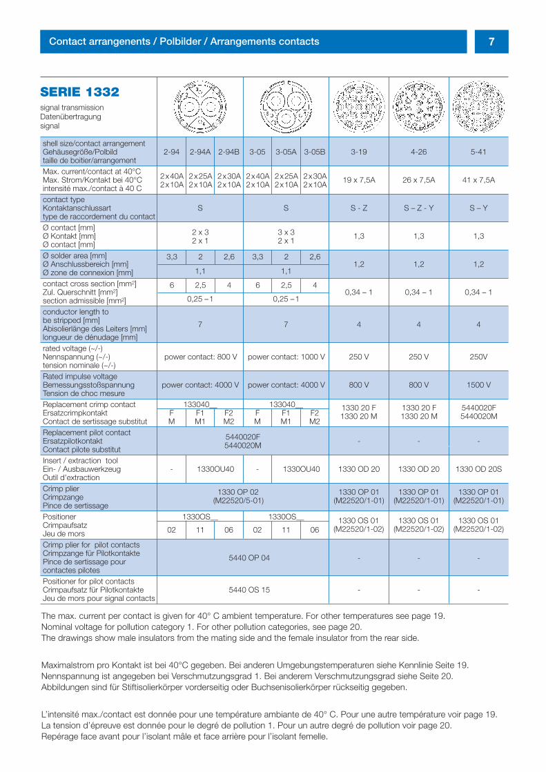
SERIE 1332signal transmissionDatenübertragungsignal
shell size/contact arrangementGehäusegröße/Polbild 2-94 2-94A 2-94B 3-05 3-05A 3-05B 3-19 4-26 5-41taille de boitier/arrangementMax. current/contact at 40°CMax. Strom/Kontakt bei 40°C 19 x 7,5A 26 x 7,5A 41 x 7,5Aintensité max./contact à 40 Ccontact typeKontaktanschlussart S S S - Z S – Z - Y S – Ytype de raccordement du contactØ contact [mm]Ø Kontakt [mm] 1,3 1,3 1,3Ø contact [mm]Ø solder area [mm]Ø Anschlussbereich [mm] 1,2 1,2 1,2Ø zone de connexion [mm]contact cross section [mm2]Zul. Querschnitt [mm2] 0,34 – 1 0,34 – 1 0,34 – 1section admissible [mm2]conductor length to be stripped [mm]Abisolierlänge des Leiters [mm]longueur de dénudage [mm]rated voltage (~/-)Nennspannung (~/-) power contact: 800 V power contact: 1000 V 250 V 250 V 250Vtension nominale (~/-)Rated impulse voltageBemessungsstoßspannung power contact: 4000 V power contact: 4000 V 800 V 800 V 1500 VTension de choc mesureReplacement crimp contact 133040__ 133040__Ersatzcrimpkontakt F F1 F2 F F1 F2Contact de sertissage substitut M M1 M2 M M1 M2Replacement pilot contactErsatzpilotkontakt - - -Contact pilote substitutInsert / extraction toolEin- / Ausbauwerkzeug - 1330OU40 - 1330OU40 1330 OD 20 1330 OD 20 1330 OD 20SOutil d’extractionCrimp plierCrimpzangePince de sertissagePositioner 1330OS__ 1330OS__CrimpaufsatzJeu de morsCrimp plier for pilot contactsCrimpzange für PilotkontaktePince de sertissage pour contactes pilotesPositioner for pilot contactsCrimpaufsatz für Pilotkontakte 5440 OS 15 - - -Jeu de mors pour signal contacts
The max. current per contact is given for 40° C ambient temperature. For other temperatures see page 19.Nominal voltage for pollution category 1. For other pollution categories, see page 20.The drawings show male insulators from the mating side and the female insulator from the rear side.
Maximalstrom pro Kontakt ist bei 40°C gegeben. Bei anderen Umgebungstemperaturen siehe Kennlinie Seite 19.Nennspannung ist angegeben bei Verschmutzungsgrad 1. Bei anderem Verschmutzungsgrad siehe Seite 20. Abbildungen sind für Stiftisolierkörper vorderseitig oder Buchsenisolierkörper rückseitig gegeben.
L’intensité max./contact est donnée pour une température ambiante de 40° C. Pour une autre température voir page 19.La tension d’épreuve est donnée pour le degré de pollution 1. Pour un autre degré de pollution voir page 20. Repérage face avant pour l’isolant mâle et face arrière pour l’isolant femelle.
2x40A 2x25A 2x30A 2x40A 2x25A 2x30A2x10A 2x10A 2x10A 2x10A 2x10A 2x10A
2 x 32 x 1
1,1 1,1
0,25 –1 0,25 –1
3,3 2 2,6 3,3 2 2,6
6 2,5 4 6 2,5 4
3 x 32 x 1
7 7 4 4 4
1330 20 F1330 20 M
1330 OS 01(M22520/1-02)
5440 OP 04 - - -
1330 OS 01(M22520/1-02)
1330 OS 01(M22520/1-02)
5440020F5440020M
1330 20 F1330 20 M
5440020F5440020M
1330 OP 02 1330 OP 01 1330 OP 01 1330 OP 01(M22520/5-01) (M22520/1-01) (M22520/1-01) (M22520/1-01)
02 11 06 02 11 06
inh_2611_ailb_bro_ect.411 12.10.2007 8:15 Uhr Seite 7
8 Shells / Gehäuse / Boitiers
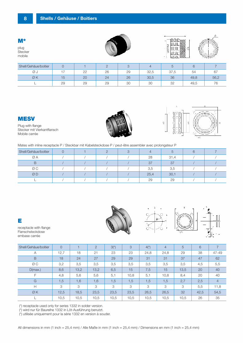
M* plugSteckermobile
Shell/Gehäue/boitier 0 1 2 3 4 5 6 7
Ø J 17 22 26 29 32,5 37,5 54 67
Ø K 15 20 24 26 30,5 36 49,8 56,2
L 29 29 29 30 30 32 49,5 76
MESVPlug with flangeStecker mit VierkantflanschMobile carrée
Mates with inline receptacle P / Steckbar mit Kabelsteckdose P / peut-être assembler avec prolongateur P
Shell/Gehäue/boitier 0 1 2 3 4 5 6 7
Ø A / / / / 28 31,4 / /
B / / / / 37 37 / /
Ø C / / / / 3,5 3,5 / /
Ø D / / / / 25,4 30,1 / /
L / / / / 29 29 / /
Ereceptacle with flange Flanschsteckdoseembase carrée
Shell/Gehäue/boitier 0 1 2 3(*) 3 4(*) 4 5 6 7
A 12,7 18 21 23 23 24,8 24,8 29 38 47-49
B 18 24 27 29 29 31 31 37 47 62
Ø C 3,2 3,5 3,5 3,5 3,5 3,5 3,5 3,5 4,5 5,5
D(max.) 8,6 13,2 13,2 6,5 15 7,5 15 13,5 20 40
F 4,8 5,6 5,6 5,1 10,8 5,1 10,8 8,4 20 40
G 1,5 1,6 1,6 1,5 1,5 1,5 1,5 2,7 2,5 4
H 3 3 3 3 3 3 3 3 5,5 11,8
Ø K 12,5 18,5 23,5 23,5 23,5 26,5 26,5 32 42,5 54,5
L 10,5 10,5 10,5 10,5 10,5 10,5 10,5 10,5 26 35
All dimensions in mm (1 inch = 25,4 mm) / Alle Maße in mm (1 inch = 25,4 mm) / Dimensions en mm (1 inch = 25,4 mm)
(*) receptacle used only for series 1332 in solder version. (*) wird nur für Baureihe 1332 in Löt-Ausführung benutzt. (*) utilisée uniquement pour la série 1332 en version à souder.
øD
øA B
L B
øC
inh_2611_ailb_bro_ect.411 12.10.2007 8:15 Uhr Seite 8
9Shells / Gehäuse / Boitiers
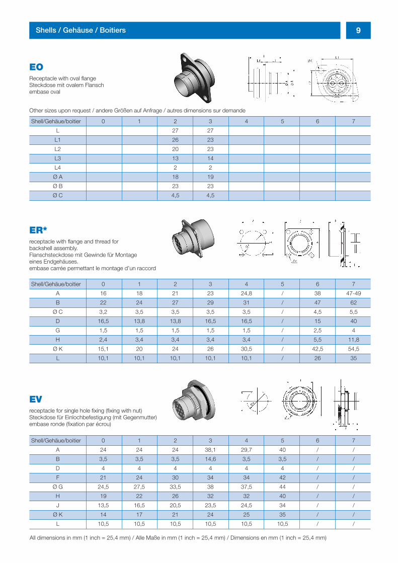
EOReceptacle with oval flangeSteckdose mit ovalem Flanschembase oval
Other sizes upon request / andere Größen auf Anfrage / autres dimensions sur demande
Shell/Gehäue/boitier 0 1 2 3 4 5 6 7
L 27 27
L1 26 23
L2 20 23
L3 13 14
L4 2 2
Ø A 18 19
Ø B 23 23
Ø C 4,5 4,5
ER*receptacle with flange and thread for backshell assembly.Flanschsteckdose mit Gewinde für Montageeines Endgehäuses.embase carrée permettant le montage d’un raccord
Shell/Gehäue/boitier 0 1 2 3 4 5 6 7
A 16 18 21 23 24,8 / 38 47-49
B 22 24 27 29 31 / 47 62
Ø C 3,2 3,5 3,5 3,5 3,5 / 4,5 5,5
D 16,5 13,8 13,8 16,5 16,5 / 15 40
G 1,5 1,5 1,5 1,5 1,5 / 2,5 4
H 2,4 3,4 3,4 3,4 3,4 / 5,5 11,8
Ø K 15,1 20 24 26 30,5 / 42,5 54,5
L 10,1 10,1 10,1 10,1 10,1 / 26 35
EVreceptacle for single hole fixing (fixing with nut)Steckdose für Einlochbefestigung (mit Gegenmutter)embase ronde (fixation par écrou)
Shell/Gehäue/boitier 0 1 2 3 4 5 6 7
A 24 24 24 38,1 29,7 40 / /
B 3,5 3,5 3,5 14,6 3,5 3,5 / /
D 4 4 4 4 4 4 / /
F 21 24 30 34 34 42 / /
Ø G 24,5 27,5 33,5 38 37,5 44 / /
H 19 22 26 32 32 40 / /
J 13,5 16,5 20,5 23,5 24,5 34 / /
Ø K 14 17 21 24 25 35 / /
L 10,5 10,5 10,5 10,5 10,5 10,5 / /
All dimensions in mm (1 inch = 25,4 mm) / Alle Maße in mm (1 inch = 25,4 mm) / Dimensions en mm (1 inch = 25,4 mm)
inh_2611_ailb_bro_ect.411 12.10.2007 8:15 Uhr Seite 9
10 Shells / Gehäuse / Boitiers
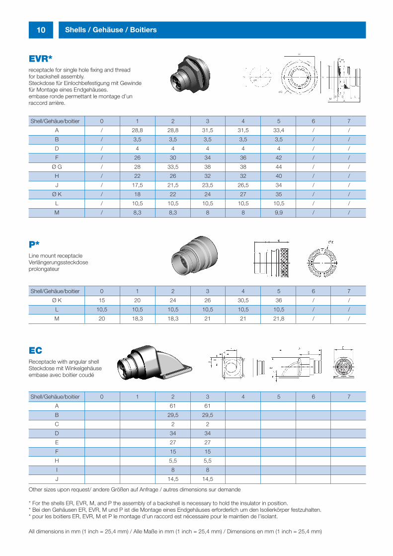
EVR*receptacle for single hole fixing and threadfor backshell assembly.Steckdose für Einlochbefestigung mit Gewinde für Montage eines Endgehäuses.embase ronde permettant le montage d’un raccord arrière.
Shell/Gehäue/boitier 0 1 2 3 4 5 6 7
A / 28,8 28,8 31,5 31,5 33,4 / /
B / 3,5 3,5 3,5 3,5 3,5 / /
D / 4 4 4 4 4 / /
F / 26 30 34 36 42 / /
Ø G / 28 33,5 38 38 44 / /
H / 22 26 32 32 40 / /
J / 17,5 21,5 23,5 26,5 34 / /
Ø K / 18 22 24 27 35 / /
L / 10,5 10,5 10,5 10,5 10,5 / /
M / 8,3 8,3 8 8 9,9 / /
ECReceptacle with angular shellSteckdose mit Winkelgehäuseembase avec boitier coudé
Shell/Gehäue/boitier 0 1 2 3 4 5 6 7
A 61 61
B 29,5 29,5
C 2 2
D 34 34
E 27 27
F 15 15
H 5,5 5,5
I 8 8
J 14,5 14,5
P*Line mount receptacleVerlängerungssteckdoseprolongateur
Shell/Gehäue/boitier 0 1 2 3 4 5 6 7
Ø K 15 20 24 26 30,5 36 / /
L 10,5 10,5 10,5 10,5 10,5 10,5 / /
M 20 18,3 18,3 21 21 21,8 / /
All dimensions in mm (1 inch = 25,4 mm) / Alle Maße in mm (1 inch = 25,4 mm) / Dimensions en mm (1 inch = 25,4 mm)
Other sizes upon request/ andere Größen auf Anfrage / autres dimensions sur demande
* For the shells ER, EVR, M, and P the assembly of a backshell is necessary to hold the insulator in position.* Bei den Gehäusen ER, EVR, M und P ist die Montage eines Endgehäuses erforderlich um den Isolierkörper festzuhalten.* pour les boitiers ER, EVR, M et P le montage d’un raccord est nécessaire pour le maintien de l’isolant.
H
J
MLD
A
B
øQ
øK
F
inh_2611_ailb_bro_ect.411 12.10.2007 8:15 Uhr Seite 10
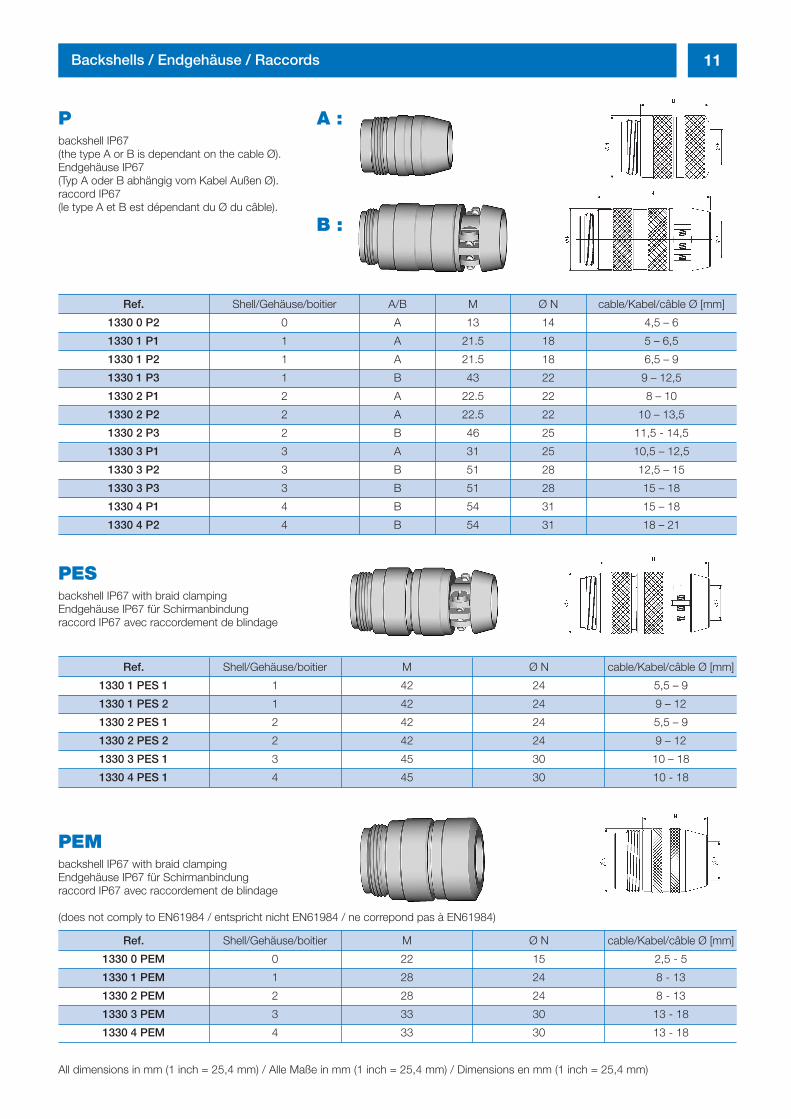
P A :backshell IP67 (the type A or B is dependant on the cable Ø).Endgehäuse IP67 (Typ A oder B abhängig vom Kabel Außen Ø).raccord IP67 (le type A et B est dépendant du Ø du câble).
B :
PEMbackshell IP67 with braid clampingEndgehäuse IP67 für Schirmanbindung raccord IP67 avec raccordement de blindage
(does not comply to EN61984 / entspricht nicht EN61984 / ne correpond pas à EN61984)
11Backshells / Endgehäuse / Raccords
Ref. Shell/Gehäuse/boitier A/B M Ø N cable/Kabel/câble Ø [mm]
1330 0 P2 0 A 13 14 4,5 – 6
1330 1 P1 1 A 21.5 18 5 – 6,5
1330 1 P2 1 A 21.5 18 6,5 – 9
1330 1 P3 1 B 43 22 9 – 12,5
1330 2 P1 2 A 22.5 22 8 – 10
1330 2 P2 2 A 22.5 22 10 – 13,5
1330 2 P3 2 B 46 25 11,5 - 14,5
1330 3 P1 3 A 31 25 10,5 – 12,5
1330 3 P2 3 B 51 28 12,5 – 15
1330 3 P3 3 B 51 28 15 – 18
1330 4 P1 4 B 54 31 15 – 18
1330 4 P2 4 B 54 31 18 – 21
PESbackshell IP67 with braid clampingEndgehäuse IP67 für Schirmanbindung raccord IP67 avec raccordement de blindage
Ref. Shell/Gehäuse/boitier M Ø N cable/Kabel/câble Ø [mm]
1330 1 PES 1 1 42 24 5,5 – 9
1330 1 PES 2 1 42 24 9 – 12
1330 2 PES 1 2 42 24 5,5 – 9
1330 2 PES 2 2 42 24 9 – 12
1330 3 PES 1 3 45 30 10 – 18
1330 4 PES 1 4 45 30 10 - 18
Ref. Shell/Gehäuse/boitier M Ø N cable/Kabel/câble Ø [mm]
1330 0 PEM 0 22 15 2,5 - 5
1330 1 PEM 1 28 24 8 - 13
1330 2 PEM 2 28 24 8 - 13
1330 3 PEM 3 33 30 13 - 18
1330 4 PEM 4 33 30 13 - 18
All dimensions in mm (1 inch = 25,4 mm) / Alle Maße in mm (1 inch = 25,4 mm) / Dimensions en mm (1 inch = 25,4 mm)
inh_2611_ailb_bro_ect.411 12.10.2007 8:15 Uhr Seite 11
12 Backshells / Endgehäuse / Raccords
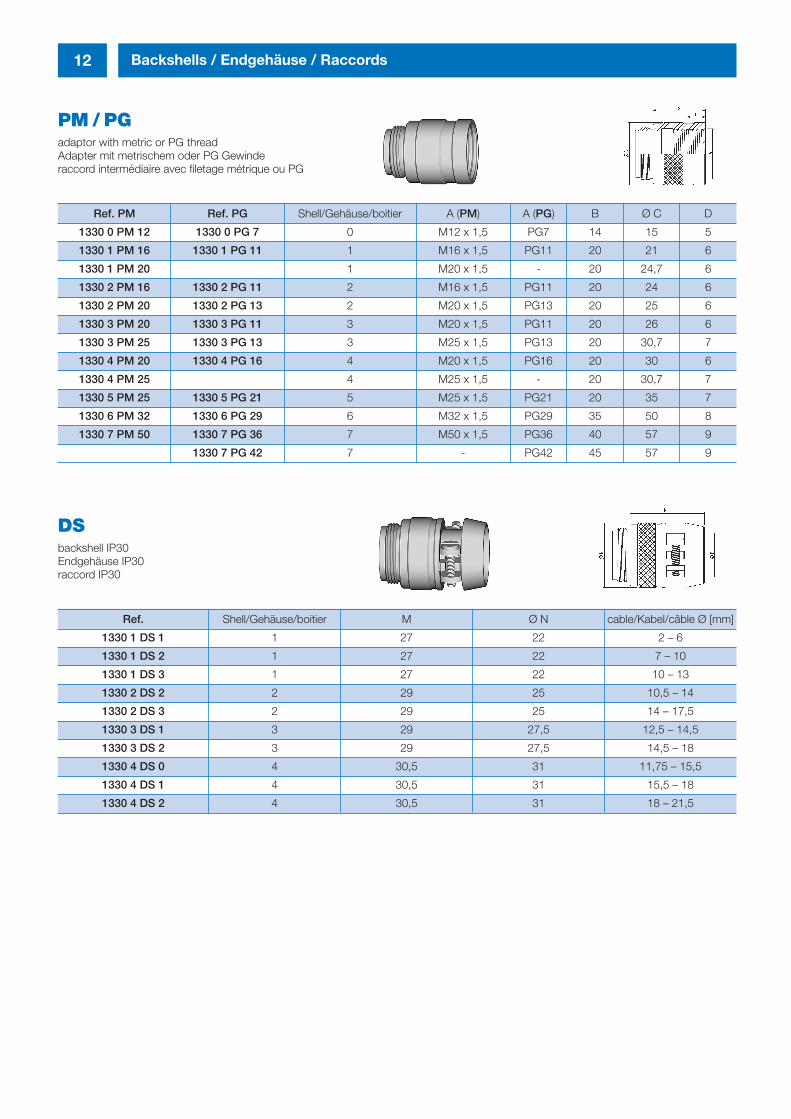
PM / PGadaptor with metric or PG thread Adapter mit metrischem oder PG Gewinderaccord intermédiaire avec filetage métrique ou PG
Ref. PM Ref. PG Shell/Gehäuse/boitier A (PM) A (PG) B Ø C D
1330 0 PM 12 1330 0 PG 7 0 M12 x 1,5 PG7 14 15 5
1330 1 PM 16 1330 1 PG 11 1 M16 x 1,5 PG11 20 21 6
1330 1 PM 20 1 M20 x 1,5 - 20 24,7 6
1330 2 PM 16 1330 2 PG 11 2 M16 x 1,5 PG11 20 24 6
1330 2 PM 20 1330 2 PG 13 2 M20 x 1,5 PG13 20 25 6
1330 3 PM 20 1330 3 PG 11 3 M20 x 1,5 PG11 20 26 6
1330 3 PM 25 1330 3 PG 13 3 M25 x 1,5 PG13 20 30,7 7
1330 4 PM 20 1330 4 PG 16 4 M20 x 1,5 PG16 20 30 6
1330 4 PM 25 4 M25 x 1,5 - 20 30,7 7
1330 5 PM 25 1330 5 PG 21 5 M25 x 1,5 PG21 20 35 7
1330 6 PM 32 1330 6 PG 29 6 M32 x 1,5 PG29 35 50 8
1330 7 PM 50 1330 7 PG 36 7 M50 x 1,5 PG36 40 57 9
1330 7 PG 42 7 - PG42 45 57 9
DSbackshell IP30Endgehäuse IP30raccord IP30
Ref. Shell/Gehäuse/boitier M Ø N cable/Kabel/câble Ø [mm]
1330 1 DS 1 1 27 22 2 – 6
1330 1 DS 2 1 27 22 7 – 10
1330 1 DS 3 1 27 22 10 – 13
1330 2 DS 2 2 29 25 10,5 – 14
1330 2 DS 3 2 29 25 14 – 17,5
1330 3 DS 1 3 29 27,5 12,5 – 14,5
1330 3 DS 2 3 29 27,5 14,5 – 18
1330 4 DS 0 4 30,5 31 11,75 – 15,5
1330 4 DS 1 4 30,5 31 15,5 – 18
1330 4 DS 2 4 30,5 31 18 – 21,5
inh_2611_ailb_bro_ect.411 12.10.2007 8:15 Uhr Seite 12
13Backshells / Endgehäuse / Raccords
Accessories / Zubehör / Accessoires
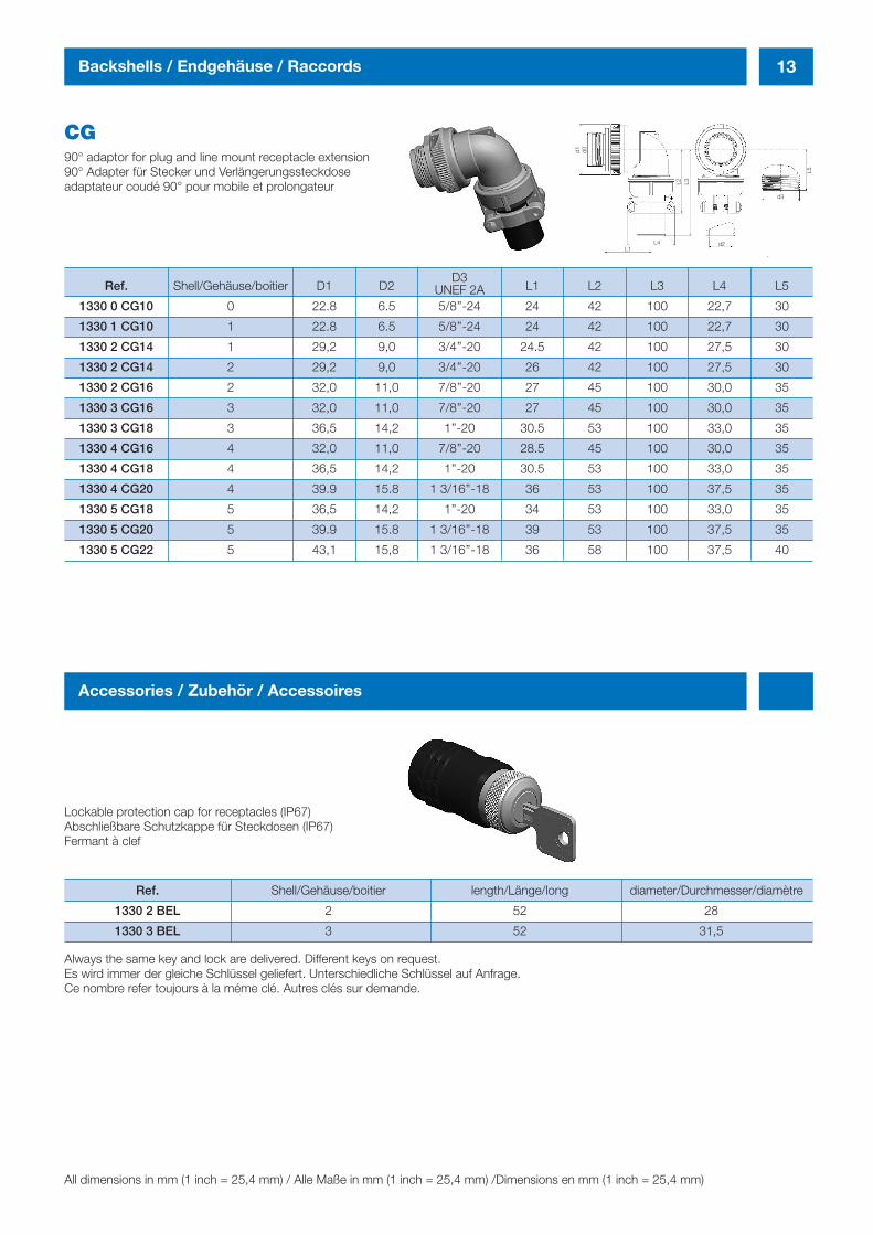
CG90° adaptor for plug and line mount receptacle extension90° Adapter für Stecker und Verlängerungssteckdoseadaptateur coudé 90° pour mobile et prolongateur
Ref. Shell/Gehäuse/boitier D1 D2 L1 L2 L3 L4 L5
1330 0 CG10 0 22.8 6.5 5/8’’-24 24 42 100 22,7 30
1330 1 CG10 1 22.8 6.5 5/8’’-24 24 42 100 22,7 30
1330 2 CG14 1 29,2 9,0 3/4’’-20 24.5 42 100 27,5 30
1330 2 CG14 2 29,2 9,0 3/4’’-20 26 42 100 27,5 30
1330 2 CG16 2 32,0 11,0 7/8’’-20 27 45 100 30,0 35
1330 3 CG16 3 32,0 11,0 7/8’’-20 27 45 100 30,0 35
1330 3 CG18 3 36,5 14,2 1’’-20 30.5 53 100 33,0 35
1330 4 CG16 4 32,0 11,0 7/8’’-20 28.5 45 100 30,0 35
1330 4 CG18 4 36,5 14,2 1’’-20 30.5 53 100 33,0 35
1330 4 CG20 4 39.9 15.8 1 3/16’’-18 36 53 100 37,5 35
1330 5 CG18 5 36,5 14,2 1’’-20 34 53 100 33,0 35
1330 5 CG20 5 39.9 15.8 1 3/16’’-18 39 53 100 37,5 35
1330 5 CG22 5 43,1 15,8 1 3/16’’-18 36 58 100 37,5 40
D3UNEF 2A
Lockable protection cap for receptacles (IP67)Abschließbare Schutzkappe für Steckdosen (IP67)Fermant à clef
Always the same key and lock are delivered. Different keys on request.Es wird immer der gleiche Schlüssel geliefert. Unterschiedliche Schlüssel auf Anfrage.Ce nombre refer toujours à la méme clé. Autres clés sur demande.
Ref. Shell/Gehäuse/boitier length/Länge/long diameter/Durchmesser/diamètre
1330 2 BEL 2 52 28
1330 3 BEL 3 52 31,5
All dimensions in mm (1 inch = 25,4 mm) / Alle Maße in mm (1 inch = 25,4 mm) /Dimensions en mm (1 inch = 25,4 mm)
d1 d0
L1L4 d2
d3
L5
L2 L3
inh_2611_ailb_bro_ect.411 12.10.2007 8:15 Uhr Seite 13
14 Accessories / Zubehör / Accessoires
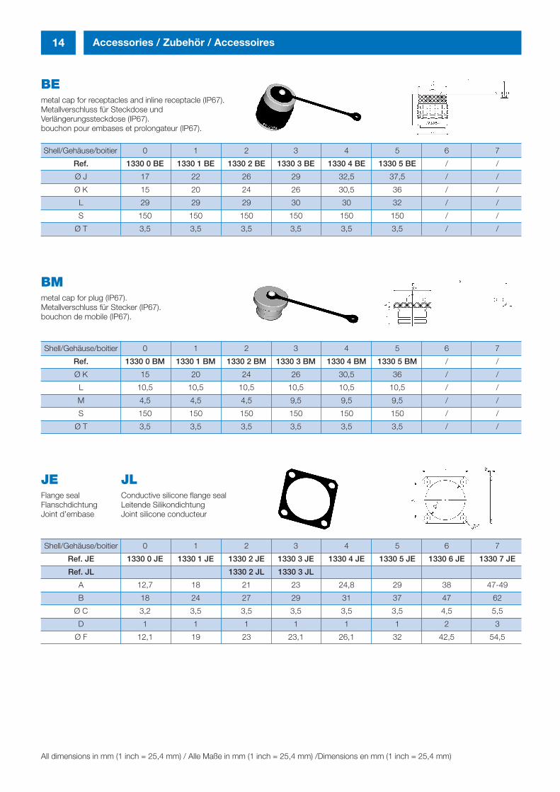
BEmetal cap for receptacles and inline receptacle (IP67).Metallverschluss für Steckdose und Verlängerungssteckdose (IP67).bouchon pour embases et prolongateur (IP67).
Shell/Gehäuse/boitier 0 1 2 3 4 5 6 7
Ref. 1330 0 BE 1330 1 BE 1330 2 BE 1330 3 BE 1330 4 BE 1330 5 BE / /
Ø J 17 22 26 29 32,5 37,5 / /
Ø K 15 20 24 26 30,5 36 / /
L 29 29 29 30 30 32 / /
S 150 150 150 150 150 150 / /
Ø T 3,5 3,5 3,5 3,5 3,5 3,5 / /
BMmetal cap for plug (IP67).Metallverschluss für Stecker (IP67).bouchon de mobile (IP67).
Shell/Gehäuse/boitier 0 1 2 3 4 5 6 7
Ref. 1330 0 BM 1330 1 BM 1330 2 BM 1330 3 BM 1330 4 BM 1330 5 BM / /
Ø K 15 20 24 26 30,5 36 / /
L 10,5 10,5 10,5 10,5 10,5 10,5 / /
M 4,5 4,5 4,5 9,5 9,5 9,5 / /
S 150 150 150 150 150 150 / /
Ø T 3,5 3,5 3,5 3,5 3,5 3,5 / /
JE JLFlange seal Conductive silicone flange sealFlanschdichtung Leitende SilikondichtungJoint d’embase Joint silicone conducteur
Shell/Gehäuse/boitier 0 1 2 3 4 5 6 7
Ref. JE 1330 0 JE 1330 1 JE 1330 2 JE 1330 3 JE 1330 4 JE 1330 5 JE 1330 6 JE 1330 7 JE
Ref. JL 1330 2 JL 1330 3 JL
A 12,7 18 21 23 24,8 29 38 47-49
B 18 24 27 29 31 37 47 62
Ø C 3,2 3,5 3,5 3,5 3,5 3,5 4,5 5,5
D 1 1 1 1 1 1 2 3
Ø F 12,1 19 23 23,1 26,1 32 42,5 54,5
All dimensions in mm (1 inch = 25,4 mm) / Alle Maße in mm (1 inch = 25,4 mm) /Dimensions en mm (1 inch = 25,4 mm)
inh_2611_ailb_bro_ect.411 12.10.2007 8:15 Uhr Seite 14
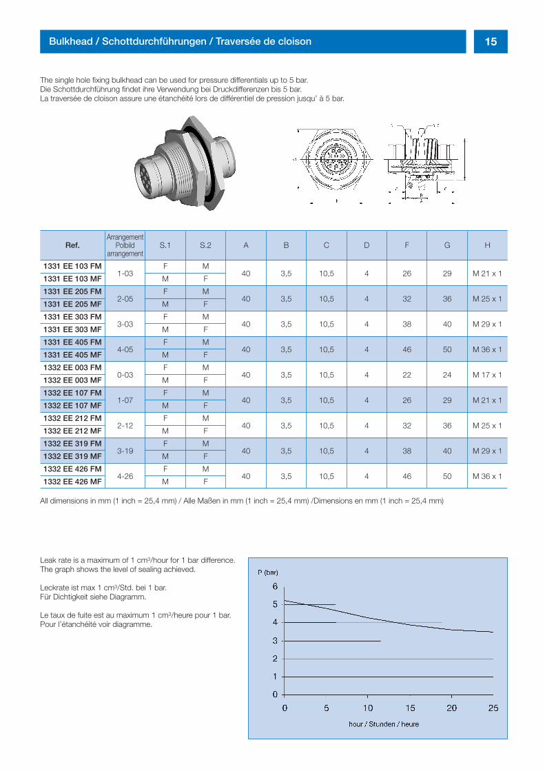
15Bulkhead / Schottdurchführungen / Traversée de cloison
The single hole fixing bulkhead can be used for pressure differentials up to 5 bar.Die Schottdurchführung findet ihre Verwendung bei Druckdifferenzen bis 5 bar.La traversée de cloison assure une étanchéité lors de différentiel de pression jusqu’ à 5 bar.
Leak rate is a maximum of 1 cm3/hour for 1 bar difference.The graph shows the level of sealing achieved.
Leckrate ist max 1 cm3/Std. bei 1 bar.Für Dichtigkeit siehe Diagramm.
Le taux de fuite est au maximum 1 cm3/heure pour 1 bar.Pour l’étanchéité voir diagramme.
ArrangementRef. Polbild S.1 S.2 A B C D F G H
arrangement
1331 EE 103 FM1-03
F M40 3,5 10,5 4 26 29 M 21 x 1
1331 EE 103 MF M F
1331 EE 205 FM2-05
F M40 3,5 10,5 4 32 36 M 25 x 1
1331 EE 205 MF M F
1331 EE 303 FM3-03
F M40 3,5 10,5 4 38 40 M 29 x 1
1331 EE 303 MF M F
1331 EE 405 FM4-05
F M40 3,5 10,5 4 46 50 M 36 x 1
1331 EE 405 MF M F
1332 EE 003 FM0-03
F M40 3,5 10,5 4 22 24 M 17 x 1
1332 EE 003 MF M F
1332 EE 107 FM1-07
F M40 3,5 10,5 4 26 29 M 21 x 1
1332 EE 107 MF M F
1332 EE 212 FM2-12
F M40 3,5 10,5 4 32 36 M 25 x 1
1332 EE 212 MF M F
1332 EE 319 FM3-19
F M40 3,5 10,5 4 38 40 M 29 x 1
1332 EE 319 MF M F
1332 EE 426 FM4-26
F M40 3,5 10,5 4 46 50 M 36 x 1
1332 EE 426 MF M F
All dimensions in mm (1 inch = 25,4 mm) / Alle Maßen in mm (1 inch = 25,4 mm) /Dimensions en mm (1 inch = 25,4 mm)
inh_2611_ailb_bro_ect.411 12.10.2007 8:15 Uhr Seite 15
16 Specific connectors / Sonderstecker / Connecteurs spécifiques
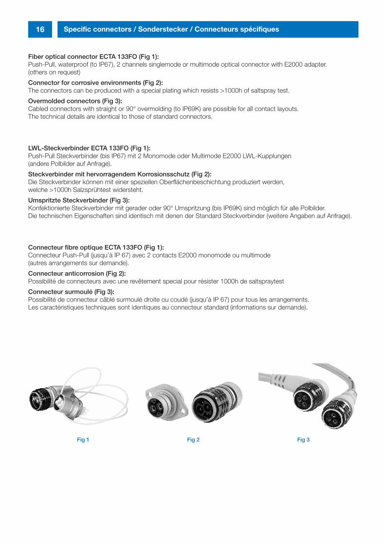
Fiber optical connector ECTA 133FO (Fig 1):Push-Pull, waterproof (to IP67), 2 channels singlemode or multimode optical connector with E2000 adapter. (others on request)
Connector for corrosive environments (Fig 2):The connectors can be produced with a special plating which resists >1000h of saltspray test.
Overmolded connectors (Fig 3):Cabled connectors with straight or 90° overmolding (to IP69K) are possible for all contact layouts. The technical details are identical to those of standard connectors.
LWL-Steckverbinder ECTA 133FO (Fig 1): Push-Pull Steckverbinder (bis IP67) mit 2 Monomode oder Multimode E2000 LWL-Kupplungen (andere Polbilder auf Anfrage).
Steckverbinder mit hervorragendem Korrosionsschutz (Fig 2): Die Steckverbinder können mit einer speziellen Oberflächenbeschichtung produziert werden, welche >1000h Salzsprühtest widersteht.
Umspritzte Steckverbinder (Fig 3):Konfektionierte Steckverbinder mit gerader oder 90° Umspritzung (bis IP69K) sind möglich für alle Polbilder. Die technischen Eigenschaften sind identisch mit denen der Standard Steckverbinder (weitere Angaben auf Anfrage).
Connecteur fibre optique ECTA 133FO (Fig 1):Connecteur Push-Pull (jusqu’à IP 67) avec 2 contacts E2000 monomode ou multimode (autres arrangements sur demande).
Connecteur anticorrosion (Fig 2):Possibilité de connecteurs avec une revêtement special pour résister 1000h de saltspraytest
Connecteur surmoulé (Fig 3):Possibilité de connecteur câblé surmoulé droite ou coudé (jusqu’à IP 67) pour tous les arrangements. Les caractéristiques techniques sont identiques au connecteur standard (informations sur demande).
Fig 1 Fig 2 Fig 3
inh_2611_ailb_bro_ect.411 12.10.2007 8:15 Uhr Seite 16
17Polarisations / Kodierung / Polarisations
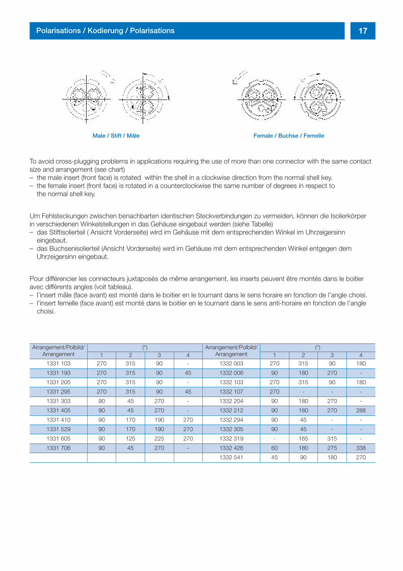
To avoid cross-plugging problems in applications requiring the use of more than one connector with the same contactsize and arrangement (see chart)– the male insert (front face) is rotated within the shell in a clockwise direction from the normal shell key. – the female insert (front face) is rotated in a counterclockwise the same number of degrees in respect to
the normal shell key.
Um Fehlsteckungen zwischen benachbarten identischen Steckverbindungen zu vermeiden, können die Isolierkörper in verschiedenen Winkelstellungen in das Gehäuse eingebaut werden (siehe Tabelle)– das Stiftisolierteil ( Ansicht Vorderseite) wird im Gehäuse mit dem entsprechenden Winkel im Uhrzeigersinn
eingebaut.– das Buchsenisolierteil (Ansicht Vorderseite) wird im Gehäuse mit dem entsprechenden Winkel entgegen dem
Uhrzeigersinn eingebaut.
Pour différencier les connecteurs juxtaposés de même arrangement, les inserts peuvent être montés dans le boitieravec différents angles (voit tableau).– l’insert mâle (face avant) est monté dans le boitier en le tournant dans le sens horaire en fonction de l’angle choisi. – l’insert femelle (face avant) est monté dans le boitier en le tournant dans le sens anti-horaire en fonction de l’angle
choisi.
Male / Stift / Mâle Female / Buchse / Femelle
Arrangement/Polbild/ (°) Arrangement/Polbild/ (°)Arrangement 1 2 3 4 Arrangement 1 2 3 4
1331 103 270 315 90 - 1332 003 270 315 90 180
1331 193 270 315 90 45 1332 006 90 180 270 -
1331 205 270 315 90 - 1332 103 270 315 90 180
1331 295 270 315 90 45 1332 107 270 - - -
1331 303 90 45 270 - 1332 204 90 180 270 -
1331 405 90 45 270 - 1332 212 90 180 270 288
1331 410 90 170 190 270 1332 294 90 45 - -
1331 529 90 170 190 270 1332 305 90 45 - -
1331 605 90 125 225 270 1332 319 - 165 315 -
1331 706 90 45 270 - 1332 426 60 180 275 338
1332 541 45 90 180 270
inh_2611_ailb_bro_ect.411 12.10.2007 8:15 Uhr Seite 17
18 Technical characteristics / Technische Beschreibung / Caractéristiques tehniques
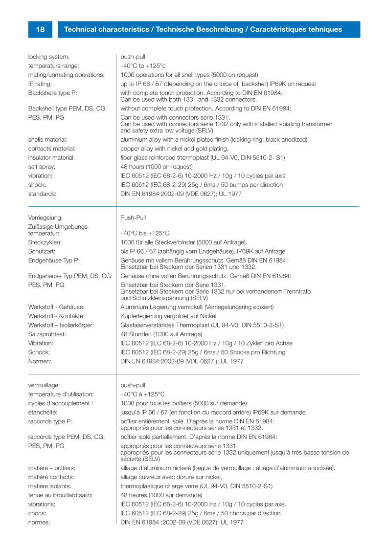
locking system: push-pulltemperature range: -40°C to +125°cmating/unmating operations: 1000 operations for all shell types (5000 on request)IP rating: up to IP 66 / 67 (depending on the choice of backshell) IP69K on requestBackshells type P: with complete touch protection. According to DIN EN 61984:
Can be used with both 1331 and 1332 connectors.Backshell type PEM, DS, CG: without complete touch protection. According to DIN EN 61984:PES, PM, PG Can be used with connectors serie 1331.
Can be used with connectors serie 1332 only with installed isolating transformer and safety extra low voltage (SELV)
shells material: aluminium alloy with a nickel plated finish (locking ring: black anodized)contacts material: copper alloy with nickel and gold plating.insulator material: fiber glass reinforced thermoplast (UL 94-V0, DIN 5510-2- S1)salt spray: 48 hours (1000 on request)vibration: IEC 60512 (IEC 68-2-6) 10-2000 Hz / 10g / 10 cycles per axisshock: IEC 60512 (IEC 68-2-29) 25g / 6ms / 50 bumps per directionstandards: DIN EN 61984:2002-09 (VDE 0627); UL 1977
Verriegelung: Push-PullZulässige Umgebungs-temperatur: -40°C bis +125°CSteckzyklen: 1000 für alle Steckverbinder (5000 auf Anfrage).Schutzart: bis IP 66 / 67 (abhängig vom Endgehäuse), IP69K auf AnfrageEndgehäuse Typ P: Gehäuse mit vollem Berührungsschutz. Gemäß DIN EN 61984:
Einsetzbar bei Steckern der Serien 1331 und 1332. Endgehäuse Typ PEM, DS, CG: Gehäuse ohne vollen Berührungsschutz. Gemäß DIN EN 61984:PES, PM, PG Einsetzbar bei Steckern der Serie 1331.
Einsetzbar bei Steckern der Serie 1332 nur bei vorhandenem Trenntrafo und Schutzkleinspannung (SELV)
Werkstoff - Gehäuse: Aluminium Legierung vernickelt (Verriegelungsring eloxiert)Werkstoff - Kontakte: Kupferlegierung vergoldet auf NickelWerkstoff – Isolierkörper: Glasfaserverstärktes Thermoplast (UL 94-V0, DIN 5510-2-S1)Salzsprühtest: 48 Stunden (1000 auf Anfrage)Vibration: IEC 60512 (IEC 68-2-6) 10-2000 Hz / 10g / 10 Zyklen pro AchseSchock: IEC 60512 (IEC 68-2-29) 25g / 6ms / 50 Shocks pro RichtungNormen: DIN EN 61984:2002-09 (VDE 0627 ); UL 1977
verrouillage: push-pulltempérature d’utilisation: -40°C à +125°Ccycles d’accouplement : 1000 pour tous les boîtiers (5000 sur demande)étanchéité: jusqu’à IP 66 / 67 (en fonction du raccord arrière) IP69K sur demanderaccords type P: boîtier entièrement isolé. D’après la norme DIN EN 61984:
appropriés pour les connecteurs séries 1331 et 1332. raccords type PEM, DS. CG: boîtier isolé partiellement. D’après la norme DIN EN 61984: PES, PM, PG appropriés pour les connecteurs série 1331.
appropriés pour les connecteurs série 1332 uniquement jusqu'à très basse tension desécurité (SELV)
matière – boîtiers: alliage d’aluminium nickelé (bague de verrouillage : alliage d’aluminium anodisée).matière contacts: alliage cuivreux avec dorure sur nickel. matière isolants: thermoplastique chargé verre (UL 94-V0, DIN 5510-2-S1)tenue au brouillard salin: 48 heures.(1000 sur demande)vibrations: IEC 60512 (IEC 68-2-6) 10-2000 Hz / 10g / 10 cycles par axe.chocs: IEC 60512 (IEC 68-2-29) 25g / 6ms / 50 chocs par direction.normes: DIN EN 61984 :2002-09 (VDE 0627); UL 1977
inh_2611_ailb_bro_ect.411 12.10.2007 8:15 Uhr Seite 18
19Technical informations / Technische Daten / Caractéristiques techniques
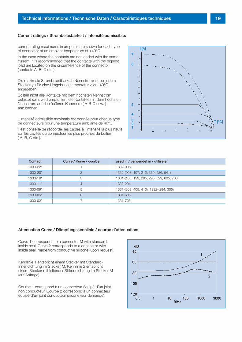
Current ratings / Strombelasbarkeit / intensité admissible:
current rating maximums in amperes are shown for each type of connector at an ambient temperature of +40°C.
In the case where the contacts are not loaded with the same current, it is recommended that the contacts with the highest load are located on the circumference of the connector (contacts A, B, C etc ).
Die maximale Strombelastbarkeit (Nennstrom) ist bei jedem Steckertyp für eine Umgebungstemperatur von +40°C angegeben.
Sollten nicht alle Kontakte mit dem höchsten Nennstrom belastet sein, wird empfohlen, die Kontakte mit dem höchsten Nennstrom auf den äußeren Kammern ( A-B-C usw. ) anzuordnen.
L’intensité admissible maximale est donnée pour chaque type de connecteurs pour une température ambiante de 40°C.
Il est conseillé de raccorder les câbles à l’intensité la plus haute sur les cavités du connecteur les plus proches du boitier ( A, B, C etc ).
Attenuation Curve / Dämpfungskennlinie / courbe d’attenuation:
Curve 1 corresponds to a connector M with standard inside seal. Curve 2 corresponds to a connector with inside seal, made from conductive silicone (upon request).
Kennlinie 1 entspricht einem Stecker mit Standard-Innendichtung im Stecker M. Kennlinie 2 entspricht einem Stecker mit leitender Silikondichtung im Stecker M (auf Anfrage).
Courbe 1 correspond à un connecteur équipé d’un joint non conducteur. Courbe 2 correspond à un connecteur équipé d’un joint conducteur silicone (sur demande).
7
6
5
4
321
T [°C]
Contact Curve / Kurve / courbe used in / verwendet in / utilise en
1330-22* 1 1332-006
1330-20* 2 1332-(003, 107, 212, 319, 426, 541)
1330-16* 3 1331-(103, 193, 205, 295, 529, 605, 706)
1330-11* 4 1332-204
1330-09* 5 1331-(303, 405, 410), 1332-(294, 305)
1330-05* 6 1331-605
1330-02* 7 1331-706
I [A]
2
inh_2611_ailb_bro_ect.411 12.10.2007 8:15 Uhr Seite 19
20 Technical Informations / Technische Erläuterungen / Informations techniques
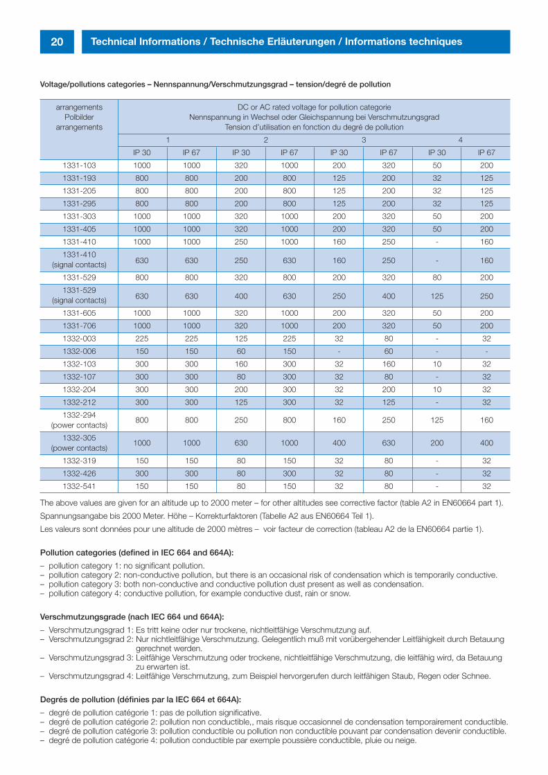
The above values are given for an altitude up to 2000 meter – for other altitudes see corrective factor (table A2 in EN60664 part 1).
Spannungsangabe bis 2000 Meter. Höhe – Korrekturfaktoren (Tabelle A2 aus EN60664 Teil 1).
Les valeurs sont données pour une altitude de 2000 mètres – voir facteur de correction (tableau A2 de la EN60664 partie 1).
Pollution categories (defined in IEC 664 and 664A):
– pollution category 1: no significant pollution.– pollution category 2: non-conductive pollution, but there is an occasional risk of condensation which is temporarily conductive.– pollution category 3: both non-conductive and conductive pollution dust present as well as condensation. – pollution category 4: conductive pollution, for example conductive dust, rain or snow.
Verschmutzungsgrade (nach IEC 664 und 664A):
– Verschmutzungsgrad 1: Es tritt keine oder nur trockene, nichtleitfähige Verschmutzung auf. – Verschmutzungsgrad 2: Nur nichtleitfähige Verschmutzung. Gelegentlich muß mit vorübergehender Leitfähigkeit durch Betauung
gerechnet werden.– Verschmutzungsgrad 3: Leitfähige Verschmutzung oder trockene, nichtleitfähige Verschmutzung, die leitfähig wird, da Betauung
zu erwarten ist. – Verschmutzungsgrad 4: Leitfähige Verschmutzung, zum Beispiel hervorgerufen durch leitfähigen Staub, Regen oder Schnee.
Degrés de pollution (définies par la IEC 664 et 664A):
– degré de pollution catégorie 1: pas de pollution significative.– degré de pollution catégorie 2: pollution non conductible,, mais risque occasionnel de condensation temporairement conductible.– degré de pollution catégorie 3: pollution conductible ou pollution non conductible pouvant par condensation devenir conductible. – degré de pollution catégorie 4: pollution conductible par exemple poussière conductible, pluie ou neige.
Voltage/pollutions categories – Nennspannung/Verschmutzungsgrad – tension/degré de pollution
arrangements DC or AC rated voltage for pollution categoriePolbilder Nennspannung in Wechsel oder Gleichspannung bei Verschmutzungsgrad
arrangements Tension d’utilisation en fonction du degré de pollution
1 2 3 4
IP 30 IP 67 IP 30 IP 67 IP 30 IP 67 IP 30 IP 67
1331-103 1000 1000 320 1000 200 320 50 200
1331-193 800 800 200 800 125 200 32 125
1331-205 800 800 200 800 125 200 32 125
1331-295 800 800 200 800 125 200 32 125
1331-303 1000 1000 320 1000 200 320 50 200
1331-405 1000 1000 320 1000 200 320 50 200
1331-410 1000 1000 250 1000 160 250 - 160
1331-410 (signal contacts) 630 630 250 630 160 250 - 160
1331-529 800 800 320 800 200 320 80 200
1331-529 (signal contacts) 630 630 400 630 250 400 125 250
1331-605 1000 1000 320 1000 200 320 50 200
1331-706 1000 1000 320 1000 200 320 50 200
1332-003 225 225 125 225 32 80 - 32
1332-006 150 150 60 150 - 60 - -
1332-103 300 300 160 300 32 160 10 32
1332-107 300 300 80 300 32 80 - 32
1332-204 300 300 200 300 32 200 10 32
1332-212 300 300 125 300 32 125 - 32
1332-294800 800 250 800 160 250 125 160
(power contacts)
1332-3051000 1000 630 1000 400 630 200 400
(power contacts)
1332-319 150 150 80 150 32 80 - 32
1332-426 300 300 80 300 32 80 - 32
1332-541 150 150 80 150 32 80 - 32
inh_2611_ailb_bro_ect.411 12.10.2007 8:15 Uhr Seite 20
21Assembling
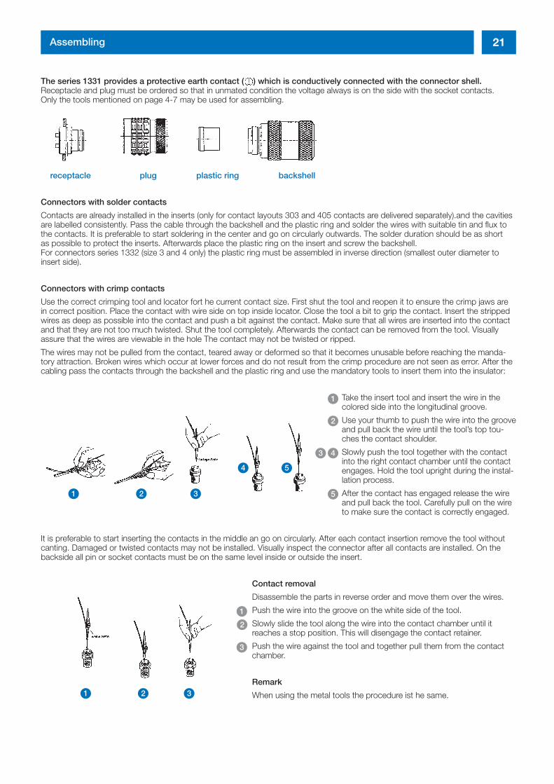
The series 1331 provides a protective earth contact ( ) which is conductively connected with the connector shell.Receptacle and plug must be ordered so that in unmated condition the voltage always is on the side with the socket contacts.Only the tools mentioned on page 4-7 may be used for assembling.
receptacle plug plastic ring backshell
Connectors with solder contacts
Contacts are already installed in the inserts (only for contact layouts 303 and 405 contacts are delivered separately).and the cavitiesare labelled consistently. Pass the cable through the backshell and the plastic ring and solder the wires with suitable tin and flux tothe contacts. It is preferable to start soldering in the center and go on circularly outwards. The solder duration should be as short as possible to protect the inserts. Afterwards place the plastic ring on the insert and screw the backshell.For connectors series 1332 (size 3 and 4 only) the plastic ring must be assembled in inverse direction (smallest outer diameter to insert side).
Connectors with crimp contacts
Use the correct crimping tool and locator fort he current contact size. First shut the tool and reopen it to ensure the crimp jaws arein correct position. Place the contact with wire side on top inside locator. Close the tool a bit to grip the contact. Insert the strippedwires as deep as possible into the contact and push a bit against the contact. Make sure that all wires are inserted into the contactand that they are not too much twisted. Shut the tool completely. Afterwards the contact can be removed from the tool. Visuallyassure that the wires are viewable in the hole The contact may not be twisted or ripped.
The wires may not be pulled from the contact, teared away or deformed so that it becomes unusable before reaching the manda-tory attraction. Broken wires which occur at lower forces and do not result from the crimp procedure are not seen as error. After thecabling pass the contacts through the backshell and the plastic ring and use the mandatory tools to insert them into the insulator:
Take the insert tool and insert the wire in the colored side into the longitudinal groove.
Use your thumb to push the wire into the grooveand pull back the wire until the tool’s top tou-ches the contact shoulder.
Slowly push the tool together with the contact into the right contact chamber until the contactengages. Hold the tool upright during the instal-lation process.
After the contact has engaged release the wire and pull back the tool. Carefully pull on the wire to make sure the contact is correctly engaged.
It is preferable to start inserting the contacts in the middle an go on circularly. After each contact insertion remove the tool withoutcanting. Damaged or twisted contacts may not be installed. Visually inspect the connector after all contacts are installed. On thebackside all pin or socket contacts must be on the same level inside or outside the insert.
Contact removal
Disassemble the parts in reverse order and move them over the wires.
Push the wire into the groove on the white side of the tool.
Slowly slide the tool along the wire into the contact chamber until it reaches a stop position. This will disengage the contact retainer.
Push the wire against the tool and together pull them from the contact chamber.
Remark
When using the metal tools the procedure ist he same.
1
2
4
5
3
1 2 3
4 5
1
1
2
3
2 3
inh_2611_ailb_bro_ect.411 12.10.2007 8:15 Uhr Seite 21
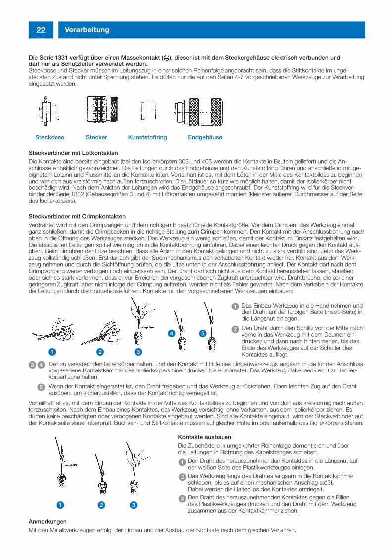
Die Serie 1331 verfügt über einen Massekontakt ( ); dieser ist mit dem Steckergehäuse elektrisch verbunden und darf nur als Schutzleiter verwendet werden.Steckdose und Stecker müssen im Leitungszug in einer solchen Reihenfolge angebracht sein, dass die Stiftkontakte im unge-steckten Zustand nicht unter Spannung stehen. Es dürfen nur die auf den Seiten 4-7 vorgeschriebenen Werkzeuge zur Verarbeitungeingesetzt werden.
Steckdose Stecker Kunststoffring Endgehäuse
Steckverbinder mit LötkontaktenDie Kontakte sind bereits eingebaut (bei den Isolierkörpern 303 und 405 werden die Kontakte in Beuteln geliefert) und die An-schlüsse einheitlich gekennzeichnet. Die Leitungen durch das Endgehäuse und den Kunststoffring führen und anschließend mit ge-eignetem Lötzinn und Flussmittel an die Kontakte löten. Vorteilhaft ist es, mit dem Löten in der Mitte des Kontaktbildes zu beginnenund von dort aus kreisförmig nach außen fortzuschreiten. Die Lötdauer so kurz wie möglich halten, damit der Isolierkörper nichtbeschädigt wird. Nach dem Anlöten der Leitungen wird das Endgehäuse angeschraubt. Der Kunststoffring wird für die Steckver-binder der Serie 1332 (Gehäusegrößen 3 und 4) mit Lötkontakten umgekehrt montiert (kleinster äußerer. Durchmesser auf der Seitedes Isolierkörpers).
Steckverbinder mit CrimpkontaktenVerdrahtet wird mit den Crimpzangen und dem richtigen Einsatz für jede Kontaktgröße. Vor dem Crimpen, das Werkzeug einmalganz schließen, damit die Crimpbacken in die richtige Stellung zum Crimpen kommen. Den Kontakt mit der Anschlussbohrung nachoben in die Öffnung des Werkzeuges stecken. Das Werkzeug ein wenig schließen, damit der Kontakt im Einsatz festgehalten wird.Die abisolierten Leitungen so tief wie möglich in die Kontaktbohrung einführen. Dabei einen leichten Druck gegen den Kontakt aus-üben. Beim Einführen der Litze beachten, dass alle Adern in den Kontakt gelangen und nicht zu stark verdrillt sind. Jetzt das Werk-zeug vollständig schließen. Erst danach gibt der Sperrmechanismus den verkabelten Kontakt wieder frei. Kontakt aus dem Werk-zeug nehmen und durch die Sichtöffnung prüfen, ob die Litze unten in der Anschlussbohrung anliegt. Der Kontakt darf nach demCrimpvorgang weder verbogen noch eingerissen sein. Der Draht darf sich nicht aus dem Kontakt herausziehen lassen, abreißenoder sich so stark verformen, dass er vor Erreichen der vorgeschriebenen Zugkraft unbrauchbar wird. Drahtbrüche, die bei einergeringeren Zugkraft, aber nicht infolge der Crimpung auftreten, werden nicht als Fehler gewertet. Nach dem Verkabeln der Kontakte,die Leitungen durch die Endgehäuse führen. Kontakte mit den vorgeschriebenen Werkzeugen einbauen:
Das Einbau-Werkzeug in die Hand nehmen undden Draht auf der farbigen Seite (Insert-Seite) indie Längsnut einlegen.
Den Draht durch den Schlitz von der Mitte nachvorne in das Werkzeug mit dem Daumen ein-drücken und dann nach hinten ziehen, bis dasEnde des Werkzeuges auf der Schulter desKontaktes aufliegt.
Den zu verkabelnden Isolierkörper halten, und den Kontakt mit Hilfe des Einbauwerkzeugs langsam in die für den Anschlussvorgesehene Kontaktkammer des Isolierkörpers hineindrücken bis er einrastet. Das Werkzeug dabei senkrecht zur Isolier-körperfläche halten.
Wenn der Kontakt eingerastet ist, den Draht freigeben und das Werkzeug zurückziehen. Einen leichten Zug auf den Drahtausüben, um sicherzustellen, dass der Kontakt richtig verriegelt ist.
Vorteilhaft ist es, mit dem Einbau der Kontakte in der Mitte des Kontaktbildes zu beginnen und von dort aus kreisförmig nach außenfortzuschreiten. Nach dem Einbau eines Kontaktes, das Werkzeug vorsichtig, ohne Verkanten, aus dem Isolierkörper ziehen. Es dürfen keine beschädigten oder verbogenen Kontakte eingebaut werden. Sind alle Kontakte eingebaut, wird der Steckverbinder aufder Kontaktseite visuell überprüft. Buchsen- und Stiftkontakte müssen auf gleicher Höhe im oder außerhalb des Isolierkörpers stehen.
Kontakte ausbauenDie Zubehörteile in umgekehrter Reihenfolge demontieren und über die Leitungen in Richtung des Kabelstranges schieben.
Den Draht des herauszunehmenden Kontaktes in die Längsnut auf der weißen Seite des Plastikwerkzeuges einlegen.Das Werkzeug längs des Drahtes langsam in die Kontaktkammerschieben, bis es auf einen mechanischen Anschlag stößt. Dabei werden die Halteclips des Kontaktes entriegelt.Den Draht des herauszunehmenden Kontaktes gegen die Rillen des Plastikwerkzeuges drücken und den Draht mit dem Werkzeugzusammen aus der Kontaktkammer ziehen.
AnmerkungenMit den Metallwerkzeugen erfolgt der Einbau und der Ausbau der Kontakte nach dem gleichen Verfahren.
22 Verarbeitung
1
2
43
5
1 2 3
4 5
1
1
2
32 3
inh_2611_ailb_bro_ect.411 12.10.2007 8:15 Uhr Seite 22
23Procedure de câblage
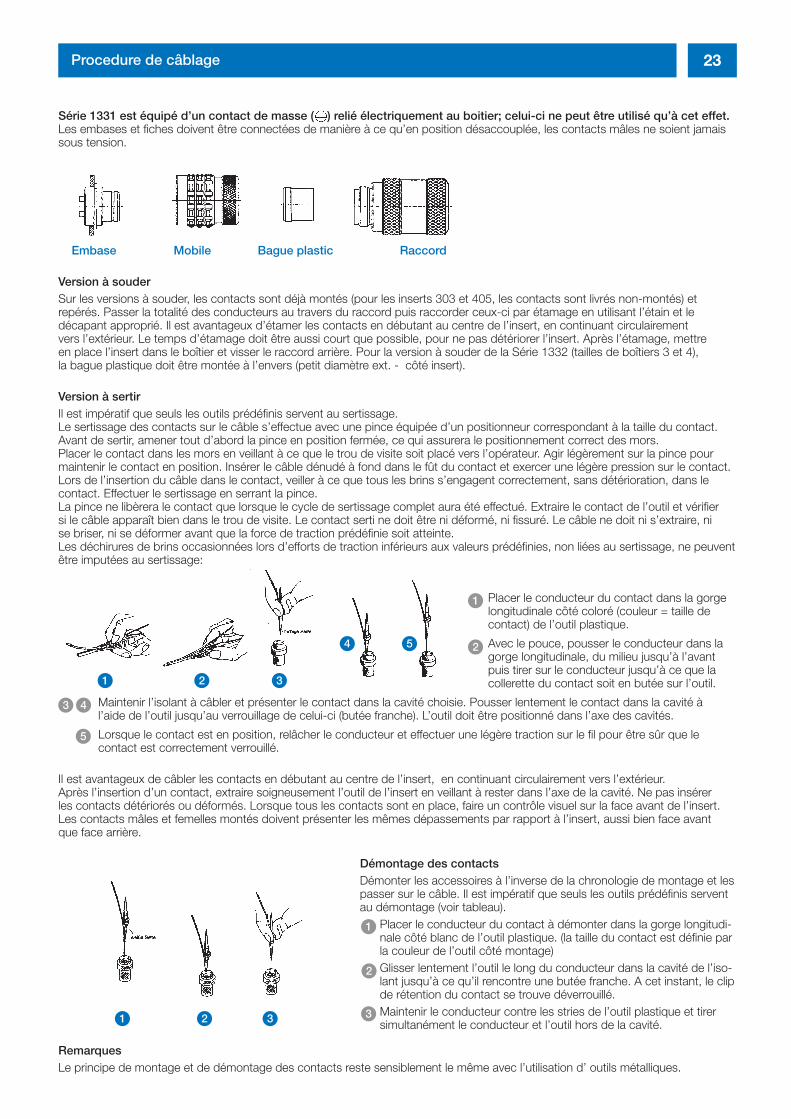
Série 1331 est équipé d’un contact de masse ( ) relié électriquement au boitier; celui-ci ne peut être utilisé qu’à cet effet.Les embases et fiches doivent être connectées de manière à ce qu’en position désaccouplée, les contacts mâles ne soient jamaissous tension.
Embase Mobile Bague plastic Raccord
Version à souderSur les versions à souder, les contacts sont déjà montés (pour les inserts 303 et 405, les contacts sont livrés non-montés) etrepérés. Passer la totalité des conducteurs au travers du raccord puis raccorder ceux-ci par étamage en utilisant l’étain et le décapant approprié. Il est avantageux d’étamer les contacts en débutant au centre de l’insert, en continuant circulairement vers l’extérieur. Le temps d’étamage doit être aussi court que possible, pour ne pas détériorer l’insert. Après l’étamage, mettre en place l’insert dans le boîtier et visser le raccord arrière. Pour la version à souder de la Série 1332 (tailles de boîtiers 3 et 4), la bague plastique doit être montée à l’envers (petit diamètre ext. - côté insert).
Version à sertirIl est impératif que seuls les outils prédéfinis servent au sertissage. Le sertissage des contacts sur le câble s’effectue avec une pince équipée d’un positionneur correspondant à la taille du contact.Avant de sertir, amener tout d’abord la pince en position fermée, ce qui assurera le positionnement correct des mors. Placer le contact dans les mors en veillant à ce que le trou de visite soit placé vers l’opérateur. Agir légèrement sur la pince pourmaintenir le contact en position. Insérer le câble dénudé à fond dans le fût du contact et exercer une légère pression sur le contact.Lors de l’insertion du câble dans le contact, veiller à ce que tous les brins s’engagent correctement, sans détérioration, dans lecontact. Effectuer le sertissage en serrant la pince.La pince ne libèrera le contact que lorsque le cycle de sertissage complet aura été effectué. Extraire le contact de l’outil et vérifier si le câble apparaît bien dans le trou de visite. Le contact serti ne doit être ni déformé, ni fissuré. Le câble ne doit ni s’extraire, ni se briser, ni se déformer avant que la force de traction prédéfinie soit atteinte. Les déchirures de brins occasionnées lors d’efforts de traction inférieurs aux valeurs prédéfinies, non liées au sertissage, ne peuventêtre imputées au sertissage:
Placer le conducteur du contact dans la gorgelongitudinale côté coloré (couleur = taille decontact) de l’outil plastique.
Avec le pouce, pousser le conducteur dans lagorge longitudinale, du milieu jusqu’à l’avantpuis tirer sur le conducteur jusqu’à ce que lacollerette du contact soit en butée sur l’outil.
Maintenir l’isolant à câbler et présenter le contact dans la cavité choisie. Pousser lentement le contact dans la cavité à l’aide de l’outil jusqu’au verrouillage de celui-ci (butée franche). L’outil doit être positionné dans l’axe des cavités.
Lorsque le contact est en position, relâcher le conducteur et effectuer une légère traction sur le fil pour être sûr que lecontact est correctement verrouillé.
Il est avantageux de câbler les contacts en débutant au centre de l’insert, en continuant circulairement vers l’extérieur. Après l’insertion d’un contact, extraire soigneusement l’outil de l’insert en veillant à rester dans l’axe de la cavité. Ne pas insérer les contacts détériorés ou déformés. Lorsque tous les contacts sont en place, faire un contrôle visuel sur la face avant de l’insert.Les contacts mâles et femelles montés doivent présenter les mêmes dépassements par rapport à l’insert, aussi bien face avant que face arrière.
Démontage des contactsDémonter les accessoires à l’inverse de la chronologie de montage et lespasser sur le câble. Il est impératif que seuls les outils prédéfinis serventau démontage (voir tableau).
Placer le conducteur du contact à démonter dans la gorge longitudi-nale côté blanc de l’outil plastique. (la taille du contact est définie parla couleur de l’outil côté montage)Glisser lentement l’outil le long du conducteur dans la cavité de l’iso-lant jusqu’à ce qu’il rencontre une butée franche. A cet instant, le clipde rétention du contact se trouve déverrouillé.Maintenir le conducteur contre les stries de l’outil plastique et tirersimultanément le conducteur et l’outil hors de la cavité.
RemarquesLe principe de montage et de démontage des contacts reste sensiblement le même avec l’utilisation d’ outils métalliques.
1
2
43
5
1 2 3
4 5
1
1
2
32 3
inh_2611_ailb_bro_ect.411 12.10.2007 8:15 Uhr Seite 23
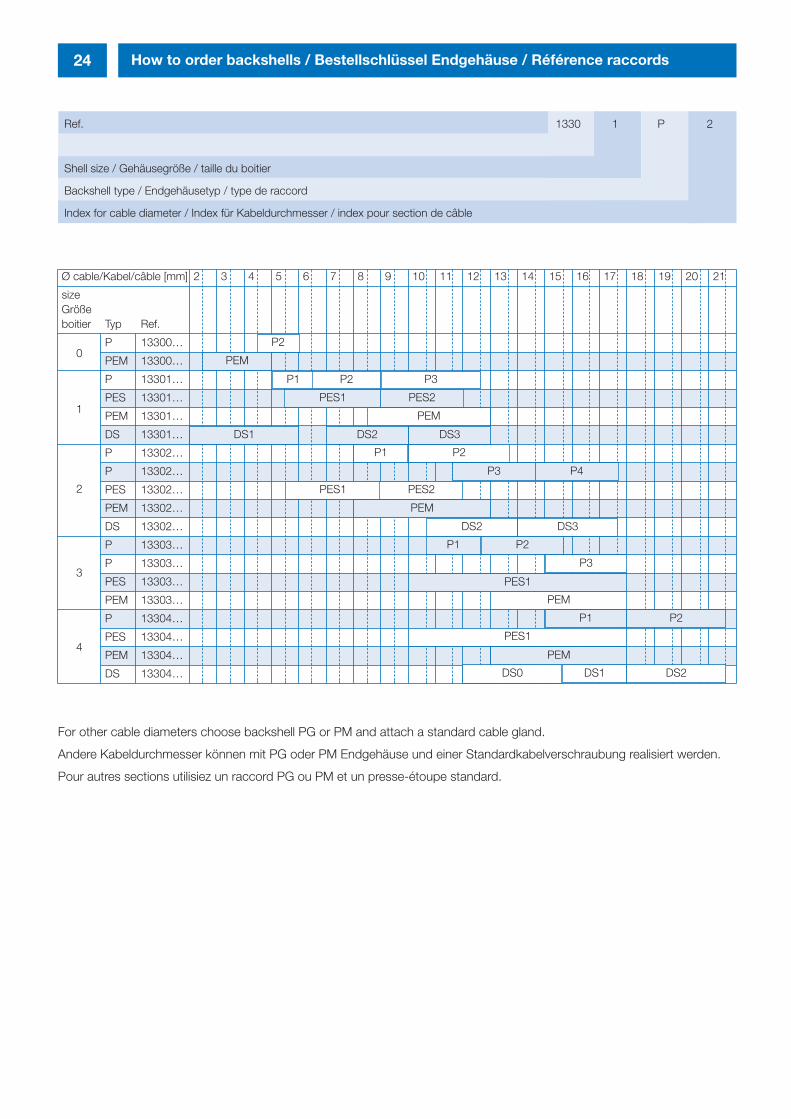
24 How to order backshells / Bestellschlüssel Endgehäuse / Référence raccords
Ref. 1330 1 P 2
Shell size / Gehäusegröße / taille du boitier
Backshell type / Endgehäusetyp / type de raccord
Index for cable diameter / Index für Kabeldurchmesser / index pour section de câble
For other cable diameters choose backshell PG or PM and attach a standard cable gland.
Andere Kabeldurchmesser können mit PG oder PM Endgehäuse und einer Standardkabelverschraubung realisiert werden.
Pour autres sections utilisiez un raccord PG ou PM et un presse-étoupe standard.
Ø cable/Kabel/câble [mm] 2 3 4 5 6 7 8 9 10 11 12 13 14 15 16 17 18 19 20 21
sizeGrößeboitier Typ Ref.
P 13300…
PEM 13300…
P 13301…
PES 13301…
PEM 13301…
DS 13301…
P 13302…
P 13302…
PES 13302…
PEM 13302…
DS 13302…
P 13303…
P 13303…
PES 13303…
PEM 13303…
P 13304…
PES 13304…
PEM 13304…
DS 13304…
0
1
2
3
4
P2
P1
PES1 PES2
P1
P2
P2
DS2 DS3
P3
PEM
DS1DS0 DS2
PES1
P3
PEM
PEM
P3 P4
DS1 DS2 DS3
PES1
PEM
P1
PES1
P1
PEM
P2
P2
PES2
inh_2611_ailb_bro_ect.411 12.10.2007 8:15 Uhr Seite 24
25How to order / Bestellschlüssel / Référence
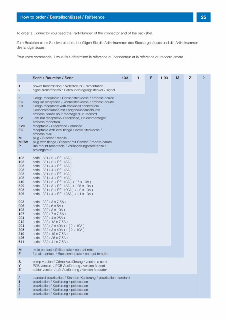
To order a Connector you need the Part-Number of the connector and of the backshell.
Zum Bestellen eines Steckverbinders, benötigen Sie die Artikelnummer des Steckergehäuses und die Artikelnummer des Endgehäuses.
Pour votre commande, il vous faut déterminer la référence du connecteur et la référence du raccord arrière.
Serie / Baureihe / Serie 133 1 E 1 03 M Z 2
1 power transmission / Netzstecker / alimentation 2 signal transmission / Datenübertragungsstecker / signal
E Flange receptacle / Flanschsteckdose / embase carréeEC Angular receptacle / Winkelsteckdose / embase coudéER Flange receptacle with backshell connection/
Flanschsteckdose mit Endgehäuseanschluss/ embase carrée pour montage d’un raccord
EV Jam nut receptacle/ Steckdose, Einlochmontage/embase monotrou
EVR receptacle / Steckdose / embaseEO receptacle with oval flange / ovale Steckdose /
embase ovalM plug / Stecker / mobileMESV plug with flange / Stecker mit Flansch / mobile carréeP line mount receptacle / Verlängerungssteckdose /
prolongateur
103 serie 1331 ( 2 + PE 13A )193 serie 1331 ( 2 + PE 13A )205 serie 1331 ( 4 + PE 13A )295 serie 1331 ( 4 + PE 13A )303 serie 1331 ( 2 + PE 40A )405 serie 1331 ( 4 + PE 40A )410 serie 1331 ( 2 + PE 40A ) + ( 7 x 10A )529 serie 1331 ( 3 + PE 13A ) + ( 25 x 10A )605 serie 1331 ( 2 + PE 100A ) + ( 2 x 13A )706 serie 1331 ( 4 + PE 125A ) + ( 1 x 13A )
003 serie 1332 ( 3 x 7,5A )006 serie 1332 ( 6 x 5A )103 serie 1332 ( 3 x 10A )107 serie 1332 ( 7 x 7,5A )204 serie 1332 ( 4 x 25A )212 serie 1332 ( 12 x 7,5A )294 serie 1332 ( 2 x 40A ) + ( 2 x 10A )305 serie 1332 ( 3 x 40A ) + ( 2 x 10A )319 serie 1332 ( 19 x 7,5A )426 serie 1332 ( 26 x 7,5A )541 serie 1332 ( 41 x 7,5A )
M male contact / Stiftkontakt / contact mâleF female contact / Buchsenkontakt / contact femelle
S crimp version / Crimp Ausführung / version à sertirY PCB version / PCB Ausführung / version à picotZ solder version / Löt Ausführung / version à souder
/ standard polarisation / Standart Kodierung / polarisation standard1 polarisation / Kodierung / polarisation2 polarisation / Kodierung / polarisation3 polarisation / Kodierung / polarisation4 polarisation / Kodierung / polarisation
ums_2611_ailb_bro_ect.411 12.10.2007 8:16 Uhr Seite 3

□ 本社・工場 〒 520-3041 滋賀県栗東市出庭471-1 TEL 077-553-8501(代)・FAX 077-551-2200
□ 横浜オフィス 〒 222-0033 神奈川県横浜市港北区新横浜2-2-8 TEL 045-473-9219(代)・FAX 045-473-9204
http://www.amphenol.co.jp/military
07110001-ITP

Mouser Electronics
Authorized Distributor
Click to View Pricing, Inventory, Delivery & Lifecycle Information: Amphenol:
1332M006MS 13303P2 1332P107FS 1332P319MZ 1330OD16 1332E319FZ 1332M319MZ 1332E212MZ
1331EVR193MS 1331-EVR-405A-MS 1331-M-193-MS 1332E212FS 13300PM12 13300PEM 1332M204MZ
1332M319FS 1332M204FS 1332M204MS 1332M212MS 1331M303MS 1331M405FS 1331M405MS
1331EVR103MZ 1331E410MZ 1332M006FS 1331P103MZ 1332M006MZ1 BAR0731PIP68 BAR0731SIP68
BAR0732PIP68 BAR0732SIP68 BAR0734IP68 BAR0739PIP68 BAR0739SIP68 BAR0740SIP68 BAR0745PIP68
BAR0745SIP68 BAR0746PIP68 BAR0746SIP68 BAR0749SIP68 1330-OU-10