Embed Size (px)
Citation preview
Subject to change – C.Gessner 03.2007 – 1MA111_0E
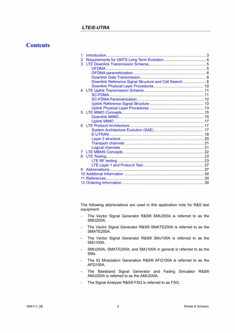
Rohde & Schwarz Products: FSQ, FSQ-K100, FSQ-K101, SMU200A, SMU-K55, SMU-K255, SMATE200A, SMATE-K55, SMATE-K255, SMJ100A, SMJ-K55, SMJ-K255, WinIQSIM2, AFQ100A, AFQ-K255, AMU200A, AMU-K55, AMU-K255
UMTS Long Term Evolution (LTE) Technology Introduction
Application Note 1MA111 Even with the introduction of HSDPA and HSUPA, evolution of UMTS has not reached its end. To ensure the competitiveness of UMTS for the next 10 years and beyond, UMTS Long Term Evolution (LTE) is being specified in 3GPP release 8. LTE, which is also known as Evolved UTRA and Evolved UTRAN, provides new physical layer concepts and protocol architecture for UMTS. This application note introduces LTE technology and testing aspects.
LTE/E-UTRA
1MA111_0E 2 Rohde & Schwarz
Contents 1 Introduction.............................................................................................. 3 2 Requirements for UMTS Long Term Evolution ....................................... 4 3 LTE Downlink Transmission Scheme...................................................... 5
OFDMA .............................................................................................. 5 OFDMA parametrization..................................................................... 6 Downlink Data Transmission.............................................................. 8 Downlink Reference Signal Structure and Cell Search...................... 8 Downlink Physical Layer Procedures ............................................... 10
4 LTE Uplink Transmission Scheme ........................................................ 11 SC-FDMA......................................................................................... 11 SC-FDMA Parametrization............................................................... 12 Uplink Reference Signal Structure ................................................... 13 Uplink Physical Layer Procedures ................................................... 13
5 LTE MIMO Concepts............................................................................. 15 Downlink MIMO................................................................................ 15 Uplink MIMO .................................................................................... 17
6 LTE Protocol Architecture...................................................................... 17 System Architecture Evolution (SAE)............................................... 17 E-UTRAN ......................................................................................... 18 Layer 2 structure .............................................................................. 20 Transport channels .......................................................................... 21 Logical channels .............................................................................. 21
7 LTE MBMS Concepts ............................................................................ 22 8 LTE Testing............................................................................................ 23
LTE RF testing ................................................................................. 23 LTE Layer 1 and Protocol Test ......................................................... 27
9 Abbreviations......................................................................................... 27 10 Additional Information ........................................................................... 30 11 References............................................................................................ 30 12 Ordering Information ............................................................................. 30
The following abbreviations are used in this application note for R&S test equipment:
- The Vector Signal Generator R&S® SMU200A is referred to as the SMU200A.
- The Vector Signal Generator R&S® SMATE200A is referred to as the SMATE200A.
- The Vector Signal Generator R&S® SMJ100A is referred to as the SMJ100A.
- SMU200A, SMATE200A, and SMJ100A in general is referred to as the SMx.
- The IQ Modulation Generation R&S® AFQ100A is referred to as the AFQ100A.
- The Baseband Signal Generator and Fading Simulator R&S® AMU200A is referred to as the AMU200A.
- The Signal Analyzer R&S® FSQ is referred to as FSQ.
LTE/E-UTRA
1MA111_0E 3 Rohde & Schwarz
1 Introduction Currently, UMTS networks worldwide are being upgraded to High Speed Downlink Packet Access (HSDPA) in order to increase data rate and capacity for downlink packet data. In the next step, High Speed Uplink Packet Access (HSUPA) will boost uplink performance in UMTS networks. While HSDPA was introduced as a 3GPP release 5 feature, HSUPA is an important feature of 3GPP release 6. The combination of HSDPA and HSUPA is often referred to as HSPA.
However, even with the introduction of HSPA, evolution of UMTS has not reached its end. HSPA+ will bring significant enhancements in 3GPP release 7. Objective is to enhance performance of HSPA based radio networks in terms of spectrum efficiency, peak data rate and latency, and exploit the full potential of WCDMA based 5 MHz operation. Important features of HSPA+ are downlink MIMO (Multiple Input Multiple Output), higher order modulation for uplink and downlink, improvements of layer 2 protocols, and continuous packet connectivity.
In order to ensure the competitiveness of UMTS for the next 10 years and beyond, concepts for UMTS Long Term Evolution (LTE) have been investigated. Objective is a high-data-rate, low-latency and packet-optimized radio access technology. Therefore, a study item was launched in 3GPP release 7 on E-UTRA (Evolved UMTS Terrestrial Radio Access) and E-UTRAN (Evolved UMTS Terrestrial Radio Access Network). LTE/E-UTRA will then form part of 3GPP release 8 core specifications.
This application note focuses on LTE/E-UTRA technology. In the following, the terms LTE or E-UTRA are used interchangeably.
In the context of the LTE study item, 3GPP work first focused on the definition of requirements, e.g. targets for data rate, capacity, spectrum efficiency, and latency. Also commercial aspects like costs for installing and operating the network were considered. Based on these requirements, technical concepts for the air interface transmission schemes and protocols were studied. Notably, LTE uses new multiple access schemes on the air interface: OFDMA (Orthogonal Frequency Division Multiple Access) in downlink and SC-FDMA (Single Carrier Frequency Division Multiple Access) in uplink. Furthermore, MIMO antenna schemes form an essential part of LTE. In an attempt to simplify protocol architecture, LTE brings some major changes to the existing UMTS protocol concepts. Impact on the overall network architecture including the core network is being investigated in the context of 3GPP System Architecture Evolution (SAE).
This application note gives an introduction to LTE technology.
Chapter 2 outlines requirements for LTE.
Chapter 3 describes the downlink transmission scheme for LTE.
Chapter 4 describes the uplink transmission scheme for LTE.
Chapter 5 outlines LTE MIMO concepts.
Chapter 6 focuses on LTE protocol architecture.
Chapter 7 introduces LTE MBMS (Multimedia Broadcast Multicast Service) concepts.
Chapter 8 explains test requirements for LTE.
Chapters 9-12 provide additional information including literature references.
LTE/E-UTRA
1MA111_0E 4 Rohde & Schwarz
2 Requirements for UMTS Long Term Evolution LTE is focusing on optimum support of Packet Switched (PS) Services. Main requirements for the design of an LTE system have been captured in 3GPP TR 25.913 [1] and can be summarized as follows:
- Data Rate: Peak data rates target 100 Mbps (downlink) and 50 Mbps (uplink) for 20 MHz spectrum allocation, assuming 2 receive antennas and 1 transmit antenna at the terminal.
- Throughput: Target for downlink average user throughput per MHz is 3-4 times better than release 6. Target for uplink average user throughput per MHz is 2-3 times better than release 6.
- Spectrum Efficiency: Downlink target is 3-4 times better than release 6. Uplink target is 2-3 times better than release 6.
- Latency: The one-way transit time between a packet being available at the IP layer in either the UE or radio access network and the availability of this packet at IP layer in the radio access network/UE shall be less than 5 ms. Also C-plane latency shall be reduced, e.g. to allow fast transition times of less than 100 ms from camped state to active state.
- Bandwidth: Scaleable bandwidths of 5, 10, 15, 20 MHz shall be supported. Also bandwidths smaller than 5 MHz shall be supported for more flexibility.
- Interworking: Interworking with existing UTRAN/GERAN systems and non-3GPP systems shall be ensured. Multimode terminals shall support handover to and from UTRAN and GERAN as well as inter-RAT measurements. Interruption time for handover between E-UTRAN and UTRAN/GERAN shall be less than 300 ms for real time services and less than 500 ms for non real time services.
- Multimedia Broadcast Multicast Services (MBMS): MBMS shall be further enhanced and is then referred to as E-MBMS.
- Costs: Reduced CAPEX and OPEX including backhaul shall be achieved. Cost effective migration from release 6 UTRA radio interface and architecture shall be possible. Reasonable system and terminal complexity, cost and power consumption shall be ensured. All the interfaces specified shall be open for multi-vendor equipment interoperability.
- Mobility: The system should be optimized for low mobile speed (0-15 km/h), but higher mobile speeds shall be supported as well including high speed train environment as special case.
- Spectrum allocation: Operation in paired (Frequency Division Duplex / FDD mode) and unpaired spectrum (Time Division Duplex / TDD mode) is possible.
- Co-existence: Co-existence in the same geographical area and co-location with GERAN/UTRAN shall be ensured. Also, co-existence between operators in adjacent bands as well as cross-border co-existence is a requirement.
- Quality of Service: End-to-end Quality of Service (QoS) shall be supported. VoIP should be supported with at least as good radio and
LTE/E-UTRA
1MA111_0E 5 Rohde & Schwarz
backhaul efficiency and latency as voice traffic over the UMTS circuit switched networks
- Network synchronization: Time synchronization of different network sites shall not be mandated.
3 LTE Downlink Transmission Scheme
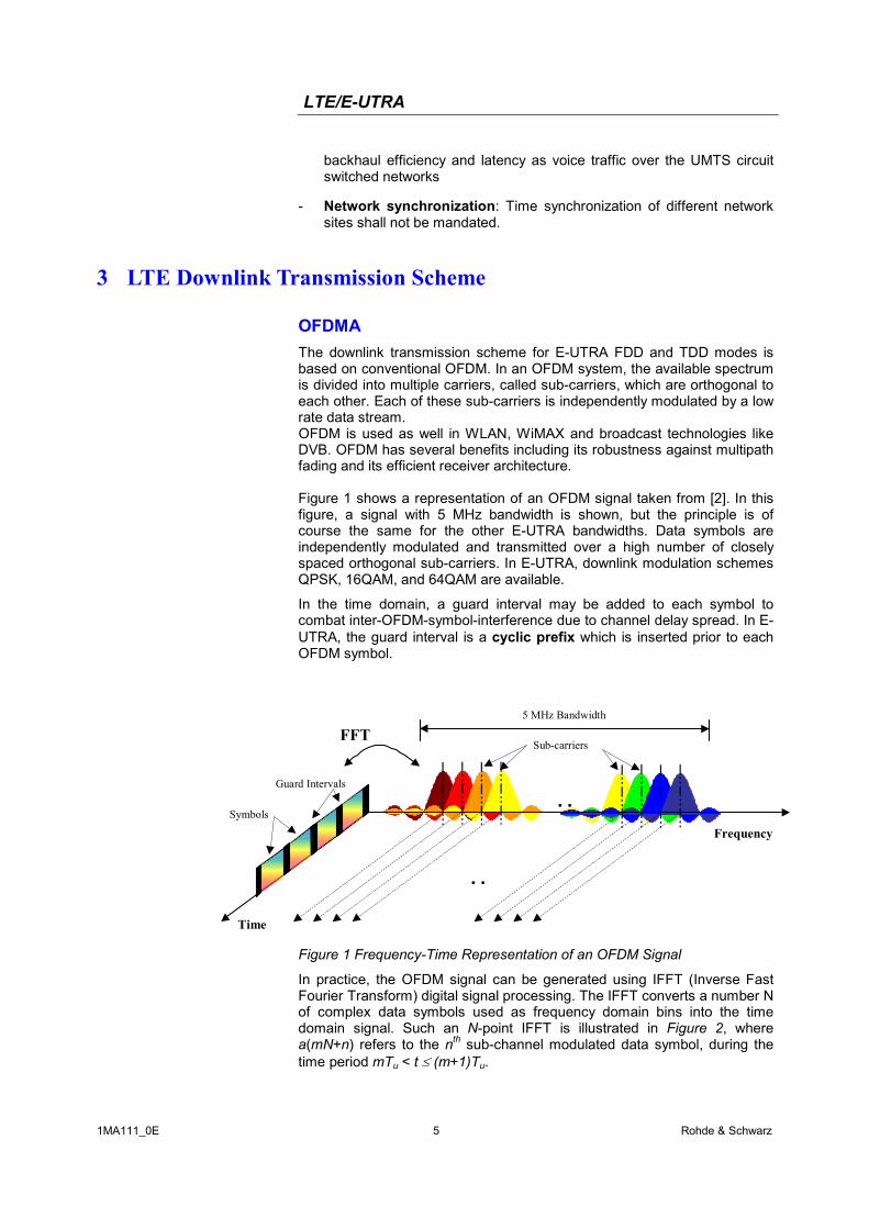
OFDMA The downlink transmission scheme for E-UTRA FDD and TDD modes is based on conventional OFDM. In an OFDM system, the available spectrum is divided into multiple carriers, called sub-carriers, which are orthogonal to each other. Each of these sub-carriers is independently modulated by a low rate data stream. OFDM is used as well in WLAN, WiMAX and broadcast technologies like DVB. OFDM has several benefits including its robustness against multipath fading and its efficient receiver architecture. Figure 1 shows a representation of an OFDM signal taken from [2]. In this figure, a signal with 5 MHz bandwidth is shown, but the principle is of course the same for the other E-UTRA bandwidths. Data symbols are independently modulated and transmitted over a high number of closely spaced orthogonal sub-carriers. In E-UTRA, downlink modulation schemes QPSK, 16QAM, and 64QAM are available.
In the time domain, a guard interval may be added to each symbol to combat inter-OFDM-symbol-interference due to channel delay spread. In E-UTRA, the guard interval is a cyclic prefix which is inserted prior to each OFDM symbol.
…
Sub-carriersFFT
Time
Symbols
5 MHz Bandwidth
Guard Intervals
…Frequency
Figure 1 Frequency-Time Representation of an OFDM Signal
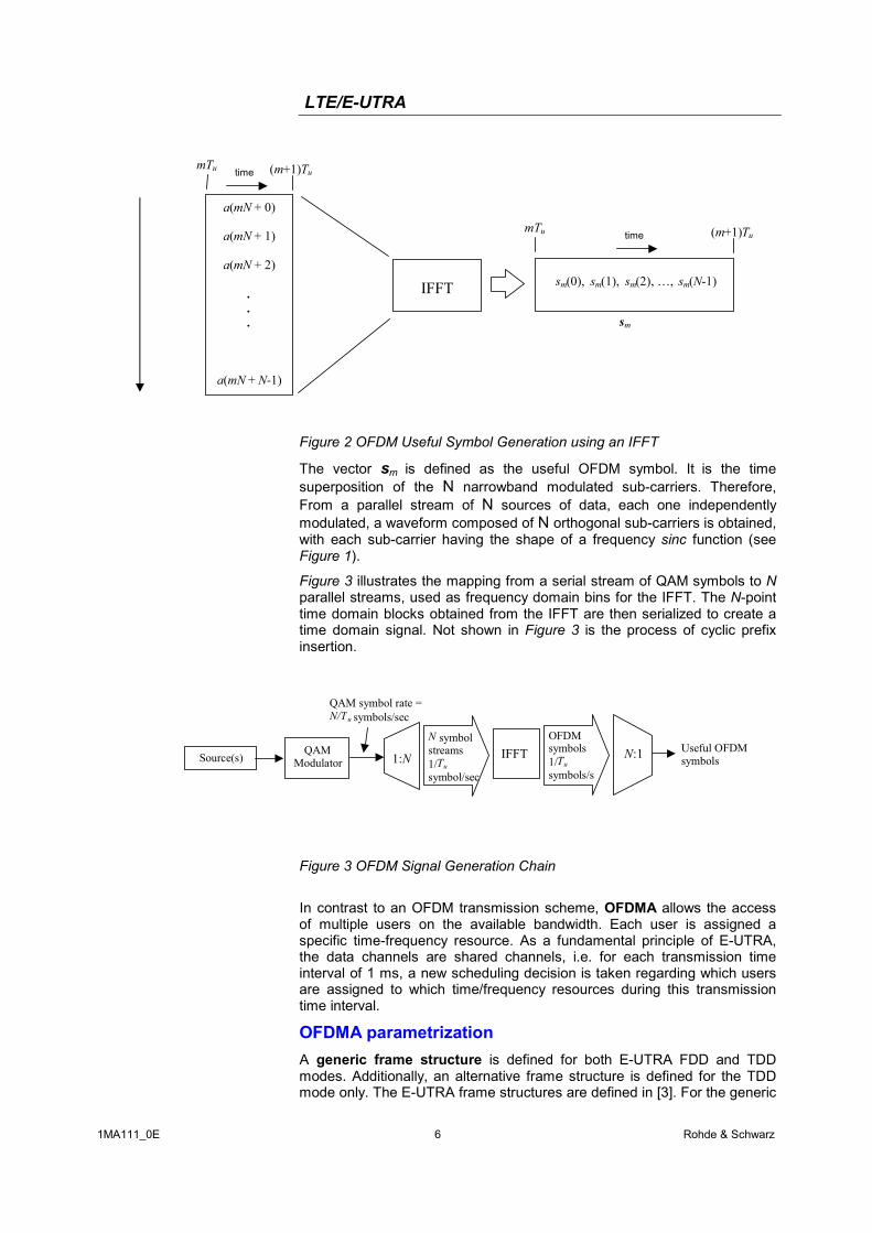
In practice, the OFDM signal can be generated using IFFT (Inverse Fast Fourier Transform) digital signal processing. The IFFT converts a number N of complex data symbols used as frequency domain bins into the time domain signal. Such an N-point IFFT is illustrated in Figure 2, where a(mN+n) refers to the nth sub-channel modulated data symbol, during the time period mTu < t ≤ (m+1)Tu.
LTE/E-UTRA
1MA111_0E 6 Rohde & Schwarz
a(mN + 0)
a(mN + 1)
a(mN + 2)
.
.
.
a(mN + N-1)
time
IFFT sm(0), sm(1), sm(2), …, sm(N-1)
mTu (m+1)Tu
sm
mTu (m+1)Tu
time
Figure 2 OFDM Useful Symbol Generation using an IFFT
The vector sm is defined as the useful OFDM symbol. It is the time superposition of the N narrowband modulated sub-carriers. Therefore, From a parallel stream of N sources of data, each one independently modulated, a waveform composed of N orthogonal sub-carriers is obtained, with each sub-carrier having the shape of a frequency sinc function (see Figure 1).
Figure 3 illustrates the mapping from a serial stream of QAM symbols to Nparallel streams, used as frequency domain bins for the IFFT. The N-point time domain blocks obtained from the IFFT are then serialized to create a time domain signal. Not shown in Figure 3 is the process of cyclic prefix insertion.
Source(s) 1:NQAM
Modulator
QAM symbol rate =N/Tu symbols/sec
N symbolstreams1/Tu
symbol/sec
IFFTOFDMsymbols1/Tu
symbols/s
N:1 Useful OFDMsymbols
Figure 3 OFDM Signal Generation Chain
In contrast to an OFDM transmission scheme, OFDMA allows the access of multiple users on the available bandwidth. Each user is assigned a specific time-frequency resource. As a fundamental principle of E-UTRA, the data channels are shared channels, i.e. for each transmission time interval of 1 ms, a new scheduling decision is taken regarding which users are assigned to which time/frequency resources during this transmission time interval.
OFDMA parametrization A generic frame structure is defined for both E-UTRA FDD and TDD modes. Additionally, an alternative frame structure is defined for the TDD mode only. The E-UTRA frame structures are defined in [3]. For the generic
LTE/E-UTRA
1MA111_0E 7 Rohde & Schwarz
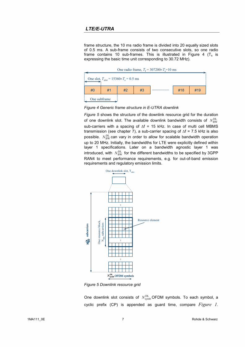
frame structure, the 10 ms radio frame is divided into 20 equally sized slots of 0.5 ms. A sub-frame consists of two consecutive slots, so one radio frame contains 10 sub-frames. This is illustrated in Figure 4 (Ts is expressing the basic time unit corresponding to 30.72 MHz).
#0#0 #1#1 #2#2 #3#3 #19#19
One slot, Tslot = 15360×Ts = 0.5 ms
One radio frame, Tf = 307200×Ts=10 ms
#18#18
One subframe
Figure 4 Generic frame structure in E-UTRA downlink
Figure 5 shows the structure of the downlink resource grid for the duration of one downlink slot. The available downlink bandwidth consists of DL
BWNsub-carriers with a spacing of ∆f = 15 kHz. In case of multi cell MBMS transmission (see chapter 7), a sub-carrier spacing of ∆f = 7.5 kHz is also possible. DL
BWN can vary in order to allow for scalable bandwidth operation up to 20 MHz. Initially, the bandwidths for LTE were explicitly defined within layer 1 specifications. Later on a bandwidth agnostic layer 1 was introduced, with DL
BWN for the different bandwidths to be specified by 3GPP RAN4 to meet performance requirements, e.g. for out-of-band emission requirements and regulatory emission limits. One downlink slot, Tslot
One
reso
urce
bloc
k,N
RB
subc
arrie
rs
subc
arrie
rsN
BWDL
subc
arrie
rsN
BWDL
NBWD
L
Resource element
OFDM symbolsDLsymbN OFDM symbolsDLsymbN
Figure 5 Downlink resource grid
One downlink slot consists of DL
symbN OFDM symbols. To each symbol, a
cyclic prefix (CP) is appended as guard time, compare Figure 1.
LTE/E-UTRA
1MA111_0E 8 Rohde & Schwarz
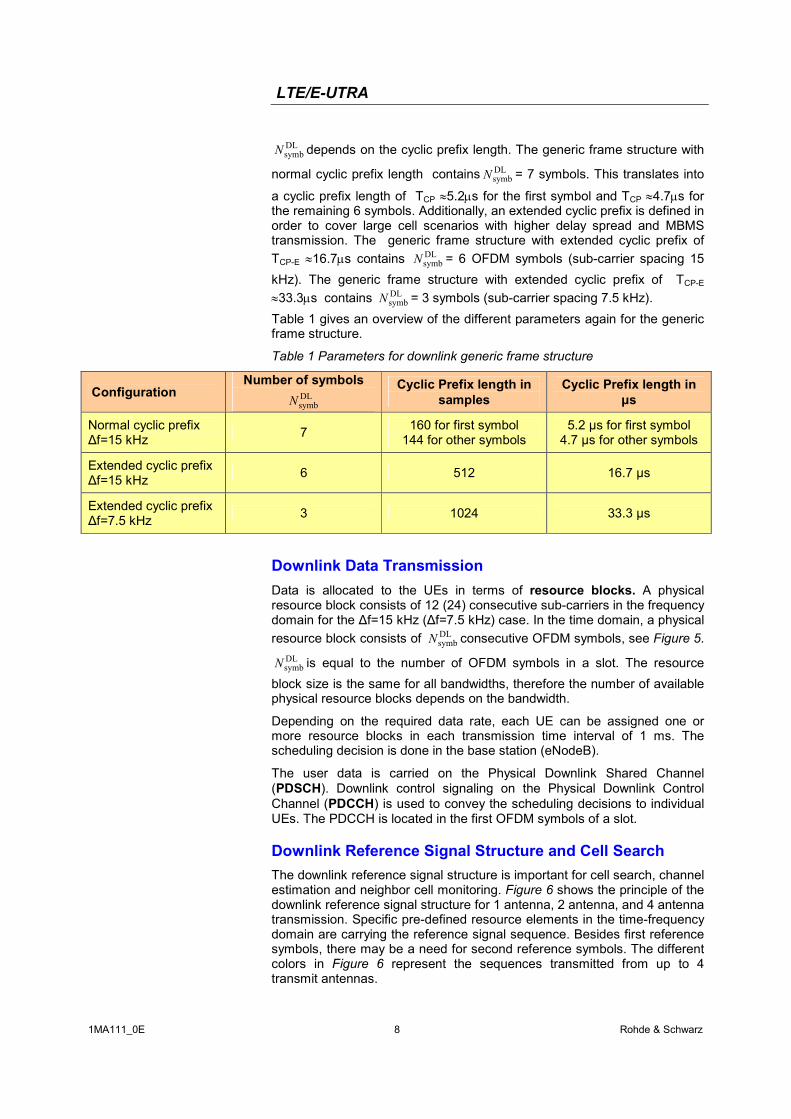
DLsymbN depends on the cyclic prefix length. The generic frame structure with
normal cyclic prefix length contains DLsymbN = 7 symbols. This translates into
a cyclic prefix length of TCP ≈5.2µs for the first symbol and TCP ≈4.7µs for the remaining 6 symbols. Additionally, an extended cyclic prefix is defined in order to cover large cell scenarios with higher delay spread and MBMS transmission. The generic frame structure with extended cyclic prefix of TCP-E ≈16.7µs contains DL
symbN = 6 OFDM symbols (sub-carrier spacing 15 kHz). The generic frame structure with extended cyclic prefix of TCP-E ≈33.3µs contains DL
symbN = 3 symbols (sub-carrier spacing 7.5 kHz). Table 1 gives an overview of the different parameters again for the generic frame structure.
Table 1 Parameters for downlink generic frame structure
Configuration Number of symbols
DLsymbN
Cyclic Prefix length in samples
Cyclic Prefix length in µs
Normal cyclic prefix ∆f=15 kHz 7 160 for first symbol
144 for other symbols 5.2 µs for first symbol
4.7 µs for other symbols
Extended cyclic prefix ∆f=15 kHz 6 512 16.7 µs
Extended cyclic prefix ∆f=7.5 kHz 3 1024 33.3 µs
Downlink Data Transmission Data is allocated to the UEs in terms of resource blocks. A physical resource block consists of 12 (24) consecutive sub-carriers in the frequency domain for the ∆f=15 kHz (∆f=7.5 kHz) case. In the time domain, a physical resource block consists of DL
symbN consecutive OFDM symbols, see Figure 5.DLsymbN is equal to the number of OFDM symbols in a slot. The resource
block size is the same for all bandwidths, therefore the number of available physical resource blocks depends on the bandwidth.
Depending on the required data rate, each UE can be assigned one or more resource blocks in each transmission time interval of 1 ms. The scheduling decision is done in the base station (eNodeB).
The user data is carried on the Physical Downlink Shared Channel (PDSCH). Downlink control signaling on the Physical Downlink Control Channel (PDCCH) is used to convey the scheduling decisions to individual UEs. The PDCCH is located in the first OFDM symbols of a slot.
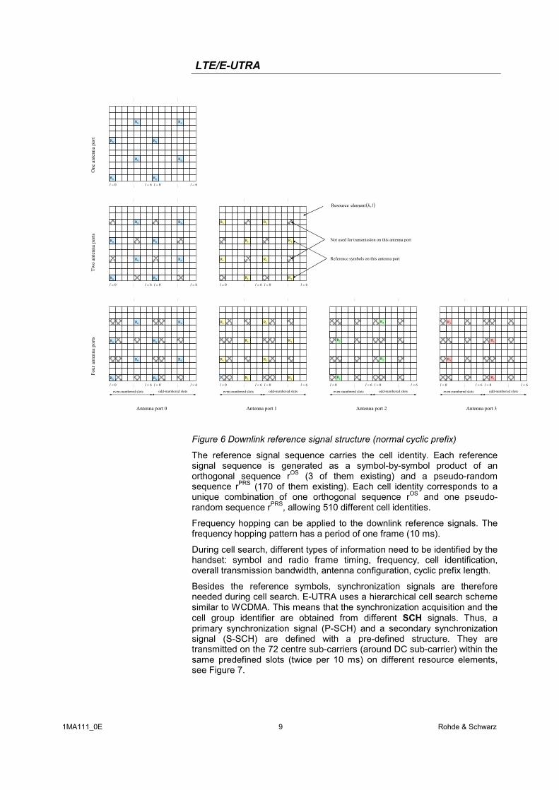
Downlink Reference Signal Structure and Cell Search The downlink reference signal structure is important for cell search, channel estimation and neighbor cell monitoring. Figure 6 shows the principle of the downlink reference signal structure for 1 antenna, 2 antenna, and 4 antenna transmission. Specific pre-defined resource elements in the time-frequency domain are carrying the reference signal sequence. Besides first reference symbols, there may be a need for second reference symbols. The different colors in Figure 6 represent the sequences transmitted from up to 4 transmit antennas.
LTE/E-UTRA
1MA111_0E 9 Rohde & Schwarz
R0
R0
R0
R0
R0
R0
R0
R0
0=l 6=l 0=l 6=l
R0
R0
R0
R0
R0
R0
R0
R0
0=l 6=l 0=l 6=l
R1
R1
R1
R1
R1
R1
R1
R1
0=l 6=l 0=l 6=l
even-numbered slots odd-numbered slots
R3
R3
R3
R3
0=l 6=l 0=l 6=l
R0
R0
R0
R0
even-numbered slots odd-numbered slots
R0
R0
R0
R0
0=l 6=l 0=l 6=l
R1
R1
R1
R1
even-numbered slots odd-numbered slots
R1
R1
R1
R1
0=l 6=l 0=l 6=l
even-numbered slots odd-numbered slots
R2
R2
R2
R2
0=l 6=l 0=l 6=l
One
ante
nna
port
Two
ante
nna
ports
Four
ante
nna
ports
Antenna port 0 Antenna port 1 Antenna port 2 Antenna port 3
Not used for transmission on this antenna port
Reference symbols on this antenna port
( )lk,element Resource
Figure 6 Downlink reference signal structure (normal cyclic prefix)
The reference signal sequence carries the cell identity. Each reference signal sequence is generated as a symbol-by-symbol product of an orthogonal sequence rOS (3 of them existing) and a pseudo-random sequence rPRS (170 of them existing). Each cell identity corresponds to a unique combination of one orthogonal sequence rOS and one pseudo-random sequence rPRS, allowing 510 different cell identities.
Frequency hopping can be applied to the downlink reference signals. The frequency hopping pattern has a period of one frame (10 ms).
During cell search, different types of information need to be identified by the handset: symbol and radio frame timing, frequency, cell identification, overall transmission bandwidth, antenna configuration, cyclic prefix length.
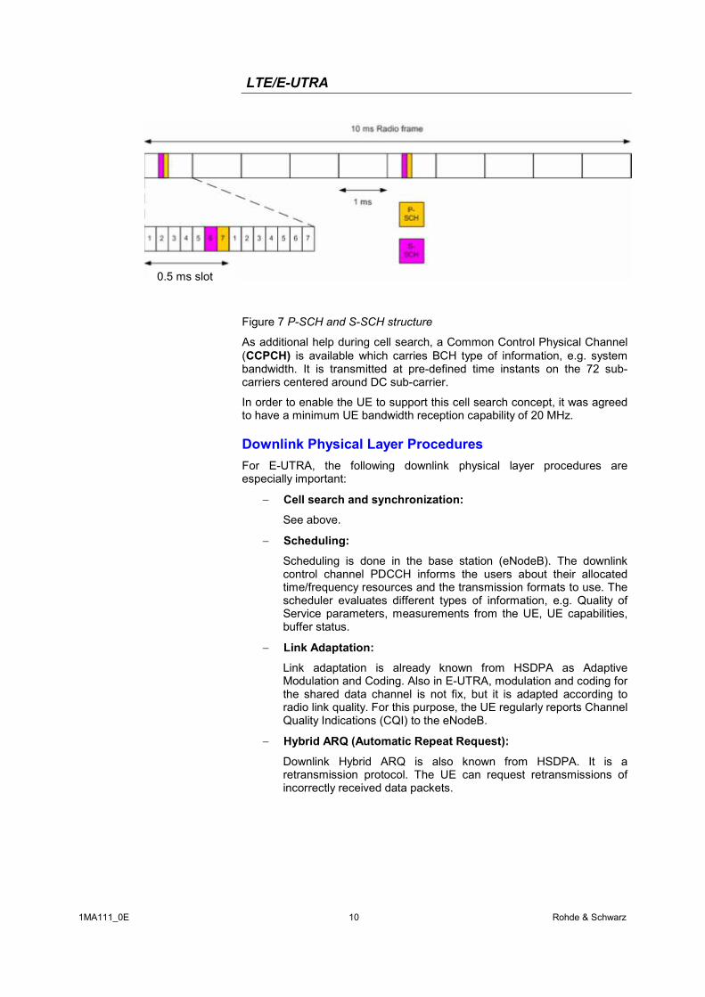
Besides the reference symbols, synchronization signals are therefore needed during cell search. E-UTRA uses a hierarchical cell search scheme similar to WCDMA. This means that the synchronization acquisition and the cell group identifier are obtained from different SCH signals. Thus, a primary synchronization signal (P-SCH) and a secondary synchronization signal (S-SCH) are defined with a pre-defined structure. They are transmitted on the 72 centre sub-carriers (around DC sub-carrier) within the same predefined slots (twice per 10 ms) on different resource elements, see Figure 7.
LTE/E-UTRA
1MA111_0E 10 Rohde & Schwarz
Figure 7 P-SCH and S-SCH structure
As additional help during cell search, a Common Control Physical Channel (CCPCH) is available which carries BCH type of information, e.g. system bandwidth. It is transmitted at pre-defined time instants on the 72 sub-carriers centered around DC sub-carrier.
In order to enable the UE to support this cell search concept, it was agreed to have a minimum UE bandwidth reception capability of 20 MHz.
Downlink Physical Layer Procedures For E-UTRA, the following downlink physical layer procedures are especially important:
− Cell search and synchronization:
See above.
− Scheduling:
Scheduling is done in the base station (eNodeB). The downlink control channel PDCCH informs the users about their allocated time/frequency resources and the transmission formats to use. The scheduler evaluates different types of information, e.g. Quality of Service parameters, measurements from the UE, UE capabilities, buffer status.
− Link Adaptation:
Link adaptation is already known from HSDPA as Adaptive Modulation and Coding. Also in E-UTRA, modulation and coding for the shared data channel is not fix, but it is adapted according to radio link quality. For this purpose, the UE regularly reports Channel Quality Indications (CQI) to the eNodeB.
− Hybrid ARQ (Automatic Repeat Request):
Downlink Hybrid ARQ is also known from HSDPA. It is a retransmission protocol. The UE can request retransmissions of incorrectly received data packets.
0.5 ms slot
LTE/E-UTRA
1MA111_0E 11 Rohde & Schwarz
4 LTE Uplink Transmission Scheme
SC-FDMA During the study item phase of LTE, alternatives for the optimum uplink transmission scheme were investigated. While OFDMA is seen optimum to fulfil the LTE requirements in downlink, OFDMA properties are less favourable for the uplink. This is mainly due to weaker peak-to-average power ratio (PAPR) properties of an OFDMA signal, resulting in worse uplink coverage.
Thus, the LTE uplink transmission scheme for FDD and TDD mode is based on SC-FDMA (Single Carrier Frequency Division Multiple Access) with cyclic prefix. SC-FDMA signals have better PAPR properties compared to an OFDMA signal. This was one of the main reasons for selecting SC-FDMA as LTE uplink access scheme. The PAPR characteristics are important for cost-effective design of UE power amplifiers. Still, SC-FDMA signal processing has some similarities with OFDMA signal processing, so parametrization of downlink and uplink can be harmonized.
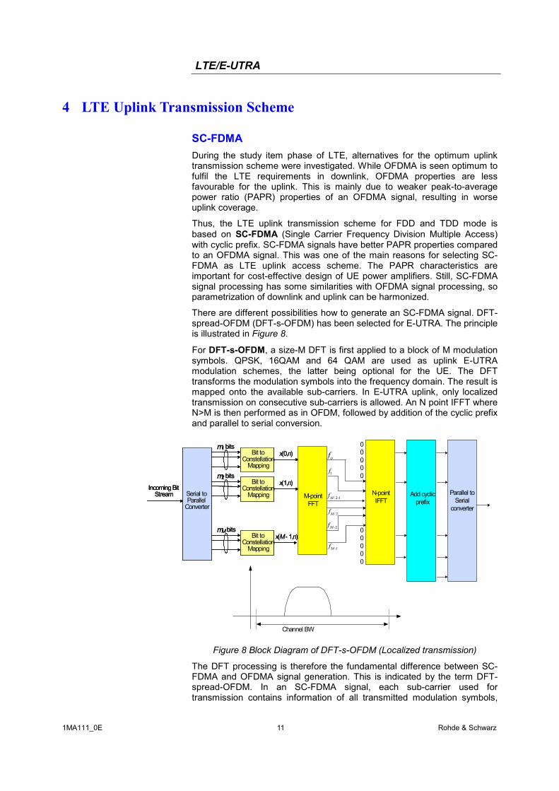
There are different possibilities how to generate an SC-FDMA signal. DFT-spread-OFDM (DFT-s-OFDM) has been selected for E-UTRA. The principle is illustrated in Figure 8.
For DFT-s-OFDM, a size-M DFT is first applied to a block of M modulation symbols. QPSK, 16QAM and 64 QAM are used as uplink E-UTRA modulation schemes, the latter being optional for the UE. The DFT transforms the modulation symbols into the frequency domain. The result is mapped onto the available sub-carriers. In E-UTRA uplink, only localized transmission on consecutive sub-carriers is allowed. An N point IFFT where N>M is then performed as in OFDM, followed by addition of the cyclic prefix and parallel to serial conversion.
Serial toParallel
Converter
Incoming BitStream
m1 bitsBit to
ConstellationMapping
Bit toConstellation
Mapping
Bit toConstellation
Mapping
m2 bits
mMbits
x(0,n)
x(1,n)
x(M- 1,n)
Serial toParallel
Converter
Incoming BitStream
m1 bitsBit to
ConstellationMapping
Bit toConstellation
Mapping
Bit toConstellation
Mapping
m2 bits
mMbits
x(0,n)
x(1,n)
x(M- 1,n)
N-pointIFFT
Add cyclicprefix
Parallel toSerial
converter
M-pointFFT
of
1f
1−Mf
2−Mf
12/ −Mf
2/Mf
00000
00000
Channel BW
Figure 8 Block Diagram of DFT-s-OFDM (Localized transmission)
The DFT processing is therefore the fundamental difference between SC-FDMA and OFDMA signal generation. This is indicated by the term DFT-spread-OFDM. In an SC-FDMA signal, each sub-carrier used for transmission contains information of all transmitted modulation symbols,
LTE/E-UTRA
1MA111_0E 12 Rohde & Schwarz
since the input data stream has been spread by the DFT transform over the available sub-carriers. In contrast to this, each sub-carrier of an OFDMA signal only carries information related to specific modulation symbols.
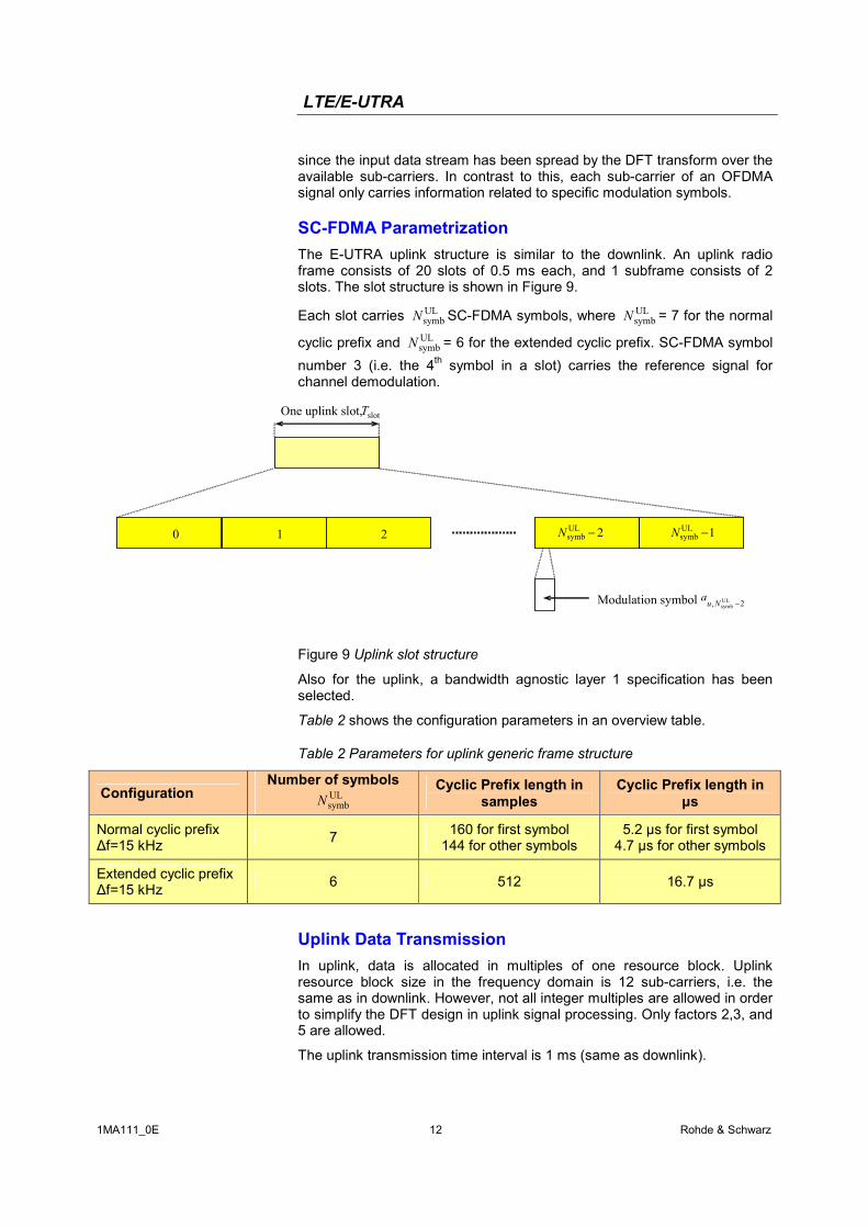
SC-FDMA Parametrization The E-UTRA uplink structure is similar to the downlink. An uplink radio frame consists of 20 slots of 0.5 ms each, and 1 subframe consists of 2 slots. The slot structure is shown in Figure 9.
Each slot carries ULsymbN SC-FDMA symbols, where UL
symbN = 7 for the normal
cyclic prefix and ULsymbN = 6 for the extended cyclic prefix. SC-FDMA symbol
number 3 (i.e. the 4th symbol in a slot) carries the reference signal for channel demodulation.
One uplink slot, Tslot
210
Modulation symbol
2ULsymb −N 1UL
symb −N
2, ULsymb −Nua
Figure 9 Uplink slot structure
Also for the uplink, a bandwidth agnostic layer 1 specification has been selected.
Table 2 shows the configuration parameters in an overview table.
Table 2 Parameters for uplink generic frame structure
Configuration Number of symbols
ULsymbN
Cyclic Prefix length in samples
Cyclic Prefix length in µs
Normal cyclic prefix ∆f=15 kHz 7 160 for first symbol
144 for other symbols 5.2 µs for first symbol
4.7 µs for other symbols
Extended cyclic prefix ∆f=15 kHz 6 512 16.7 µs
Uplink Data Transmission In uplink, data is allocated in multiples of one resource block. Uplink resource block size in the frequency domain is 12 sub-carriers, i.e. the same as in downlink. However, not all integer multiples are allowed in order to simplify the DFT design in uplink signal processing. Only factors 2,3, and 5 are allowed.
The uplink transmission time interval is 1 ms (same as downlink).
LTE/E-UTRA
1MA111_0E 13 Rohde & Schwarz
User data is carried on the Physical Uplink Shared Channel (PUSCH) that is determined by the transmission bandwidth NTx and the frequency hopping pattern k0.
The Physical Uplink Control Channel (PUCCH) carries uplink control information, e.g. CQI reports and ACK/NACK information related to data packets received in the downlink. The PUCCH is transmitted on a reserved frequency region in the uplink.
Uplink Reference Signal Structure Uplink reference signals are used for two different purposes: on the one hand, they are used for channel estimation in the eNodeB receiver in order to demodulate control and data channels. On the other hand, the reference signals provide channel quality information as a basis for scheduling decisions in the base station. The latter purpose is also called channel sounding.
The uplink reference signals are based on CAZAC (Constant Amplitude Zero Auto-Correlation) sequences.
Uplink Physical Layer Procedures For E-UTRA, the following uplink physical layer procedures are especially important:
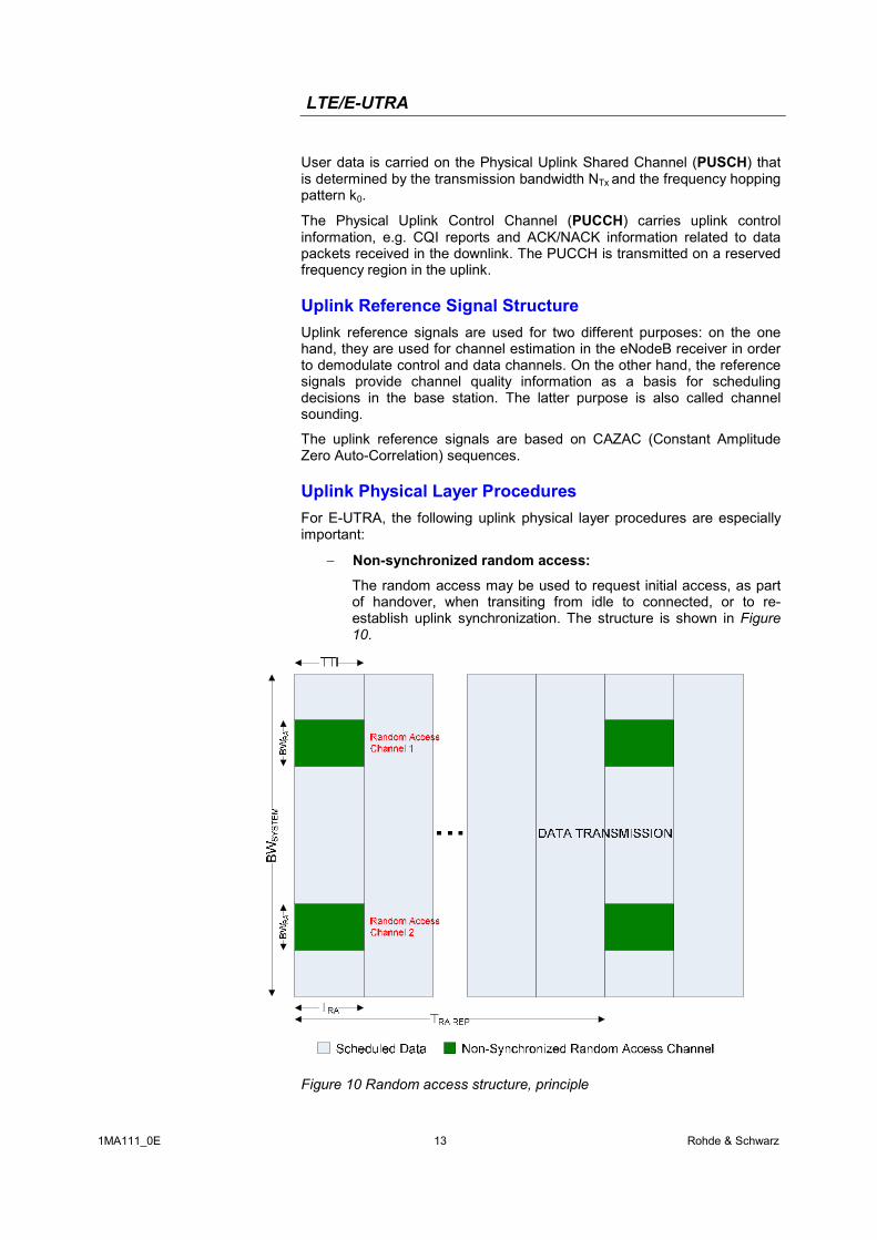
− Non-synchronized random access:
The random access may be used to request initial access, as part of handover, when transiting from idle to connected, or to re-establish uplink synchronization. The structure is shown in Figure 10.
Figure 10 Random access structure, principle
LTE/E-UTRA
1MA111_0E 14 Rohde & Schwarz
Multiple random access channels may be defined in the frequency domain within one access period TRA in order to provide a sufficient number of random access opportunities.
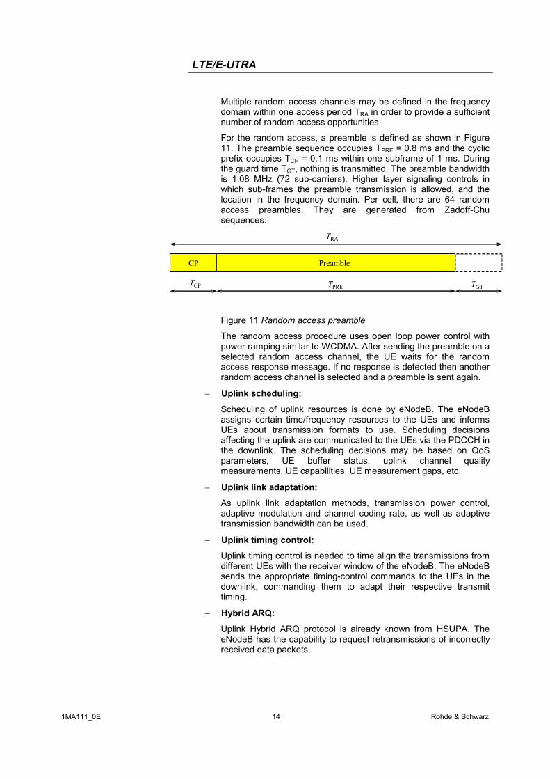
For the random access, a preamble is defined as shown in Figure 11. The preamble sequence occupies TPRE = 0.8 ms and the cyclic prefix occupies TCP = 0.1 ms within one subframe of 1 ms. During the guard time TGT, nothing is transmitted. The preamble bandwidth is 1.08 MHz (72 sub-carriers). Higher layer signaling controls in which sub-frames the preamble transmission is allowed, and the location in the frequency domain. Per cell, there are 64 random access preambles. They are generated from Zadoff-Chu sequences.
PreambleCP
PRETCPT
RAT
GTT
Figure 11 Random access preamble
The random access procedure uses open loop power control with power ramping similar to WCDMA. After sending the preamble on a selected random access channel, the UE waits for the random access response message. If no response is detected then another random access channel is selected and a preamble is sent again.
− Uplink scheduling:
Scheduling of uplink resources is done by eNodeB. The eNodeB assigns certain time/frequency resources to the UEs and informs UEs about transmission formats to use. Scheduling decisions affecting the uplink are communicated to the UEs via the PDCCH in the downlink. The scheduling decisions may be based on QoS parameters, UE buffer status, uplink channel quality measurements, UE capabilities, UE measurement gaps, etc.
− Uplink link adaptation:
As uplink link adaptation methods, transmission power control, adaptive modulation and channel coding rate, as well as adaptive transmission bandwidth can be used.
− Uplink timing control:
Uplink timing control is needed to time align the transmissions from different UEs with the receiver window of the eNodeB. The eNodeB sends the appropriate timing-control commands to the UEs in the downlink, commanding them to adapt their respective transmit timing.
− Hybrid ARQ:
Uplink Hybrid ARQ protocol is already known from HSUPA. The eNodeB has the capability to request retransmissions of incorrectly received data packets.
LTE/E-UTRA
1MA111_0E 15 Rohde & Schwarz
5 LTE MIMO Concepts Multiple Input Multiple Output (MIMO) systems form an essential part of LTE in order to achieve the ambitious requirements for throughput and spectral efficiency. MIMO refers to the use of multiple antennas at transmitter and receiver side.
Downlink MIMO For the LTE downlink, a 2x2 configuration for MIMO is assumed as baseline configuration, i.e. 2 transmit antennas at the base station and 2 receive antennas at the terminal side. Configurations with 4 antennas are also being considered.
Downlink MIMO modes
Different MIMO modes are envisaged. It has to be differentiated between spatial multiplexing and transmit diversity, and it depends on the channel condition which scheme to select.
Spatial Multiplexing
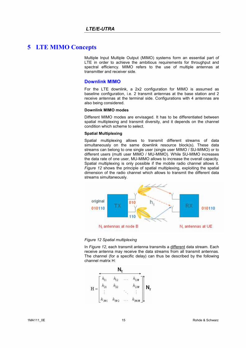
Spatial multiplexing allows to transmit different streams of data simultaneously on the same downlink resource block(s). These data streams can belong to one single user (single user MIMO / SU-MIMO) or to different users (multi user MIMO / MU-MIMO). While SU-MIMO increases the data rate of one user, MU-MIMO allows to increase the overall capacity. Spatial multiplexing is only possible if the mobile radio channel allows it. Figure 12 shows the principle of spatial multiplexing, exploiting the spatial dimension of the radio channel which allows to transmit the different data streams simultaneously.
Figure 12 Spatial multiplexing
In Figure 12, each transmit antenna transmits a different data stream. Each receive antenna may receive the data streams from all transmit antennas. The channel (for a specific delay) can thus be described by the following channel matrix H:
LTE/E-UTRA
1MA111_0E 16 Rohde & Schwarz
In this general description, Nt is the number of transmit antennas, Nr is the number of receive antennas, resulting in a 2x2 matrix for the baseline LTE scenario. The coefficients hij of this matrix are called channel coefficients from transmit antenna j to receive antenna i, thus describing all possible paths between transmitter and receiver side.
The number of data streams that can be transmitted in parallel over the MIMO channel is given by min {Nt, Nr} and is limited by the rank of the matrix H. The transmission quality degrades significantly in case the singular values of matrix H are not sufficiently strong. This can happen in case the 2 antennas are not sufficiently de-correlated, for example in an environment with little scattering or when antennas are too closely spaced.
In LTE, up to 2 code words can be mapped onto different so-called layers. The number of layers for transmission is equal to the rank of the matrix H. There is a fixed mapping between code words to layers.
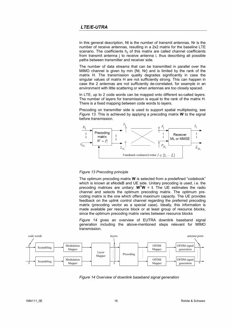
Precoding on transmitter side is used to support spatial multiplexing, see Figure 13. This is achieved by applying a precoding matrix W to the signal before transmission.
Figure 13 Precoding principle
The optimum precoding matrix W is selected from a predefined “codebook” which is known at eNodeB and UE side. Unitary precoding is used, i.e. the precoding matrices are unitary: WHW = I. The UE estimates the radio channel and selects the optimum precoding matrix. The optimum pre-coding matrix is the one which offers maximum capacity. The UE provides feedback on the uplink control channel regarding the preferred precoding matrix (precoding vector as a special case). Ideally, this information is made available per resource block or at least group of resource blocks, since the optimum precoding matrix varies between resource blocks
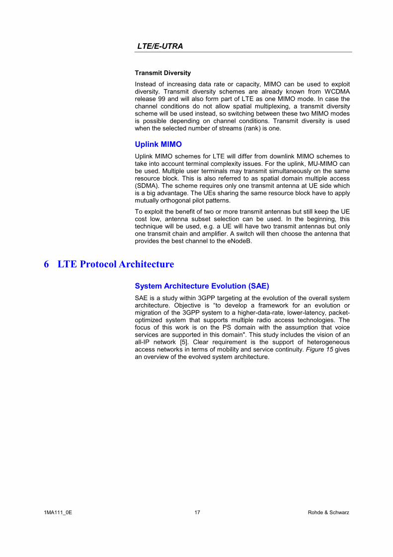
Figure 14 gives an overview of EUTRA downlink baseband signal generation including the above-mentioned steps relevant for MIMO transmission.
OFDM Mapper
OFDM signal generation
Layer Mapper
Scrambling
Precoding
Modulation Mapper
Modulation Mapper
OFDM Mapper
OFDM signal generationScrambling
code words layers antenna ports
Figure 14 Overview of downlink baseband signal generation
LTE/E-UTRA
1MA111_0E 17 Rohde & Schwarz
Transmit Diversity
Instead of increasing data rate or capacity, MIMO can be used to exploit diversity. Transmit diversity schemes are already known from WCDMA release 99 and will also form part of LTE as one MIMO mode. In case the channel conditions do not allow spatial multiplexing, a transmit diversity scheme will be used instead, so switching between these two MIMO modes is possible depending on channel conditions. Transmit diversity is used when the selected number of streams (rank) is one.
Uplink MIMO Uplink MIMO schemes for LTE will differ from downlink MIMO schemes to take into account terminal complexity issues. For the uplink, MU-MIMO can be used. Multiple user terminals may transmit simultaneously on the same resource block. This is also referred to as spatial domain multiple access (SDMA). The scheme requires only one transmit antenna at UE side which is a big advantage. The UEs sharing the same resource block have to apply mutually orthogonal pilot patterns.
To exploit the benefit of two or more transmit antennas but still keep the UE cost low, antenna subset selection can be used. In the beginning, this technique will be used, e.g. a UE will have two transmit antennas but only one transmit chain and amplifier. A switch will then choose the antenna that provides the best channel to the eNodeB.
6 LTE Protocol Architecture
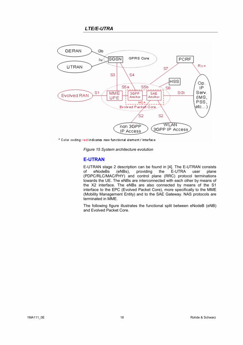
System Architecture Evolution (SAE) SAE is a study within 3GPP targeting at the evolution of the overall system architecture. Objective is “to develop a framework for an evolution or migration of the 3GPP system to a higher-data-rate, lower-latency, packet-optimized system that supports multiple radio access technologies. The focus of this work is on the PS domain with the assumption that voice services are supported in this domain". This study includes the vision of an all-IP network [5]. Clear requirement is the support of heterogeneous access networks in terms of mobility and service continuity. Figure 15 gives an overview of the evolved system architecture.
LTE/E-UTRA
1MA111_0E 18 Rohde & Schwarz
Figure 15 System architecture evolution
E-UTRAN E-UTRAN stage 2 description can be found in [4]. The E-UTRAN consists of eNodeBs (eNBs), providing the E-UTRA user plane (PDPC/RLC/MAC/PHY) and control plane (RRC) protocol terminations towards the UE. The eNBs are interconnected with each other by means of the X2 interface. The eNBs are also connected by means of the S1 interface to the EPC (Evolved Packet Core), more specifically to the MME (Mobility Management Entity) and to the SAE Gateway. NAS protocols are terminated in MME.
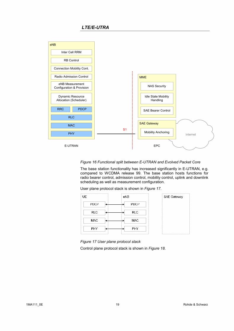
The following figure illustrates the functional split between eNodeB (eNB) and Evolved Packet Core.
LTE/E-UTRA
1MA111_0E 19 Rohde & Schwarz
internet
eNB
RB Control
Connection Mobility Cont.
eNB MeasurementConfiguration & Provision
Dynamic Resource Allocation (Scheduler)
PDCP
PHY
MME
SAE Gateway
S1MAC
Inter Cell RRM
Radio Admission Control
RLC
E-UTRAN EPC
RRC
Mobility Anchoring
SAE Bearer Control
Idle State Mobility Handling
NAS Security
Figure 16 Functional split between E-UTRAN and Evolved Packet Core
The base station functionality has increased significantly in E-UTRAN, e.g. compared to WCDMA release 99. The base station hosts functions for radio bearer control, admission control, mobility control, uplink and downlink scheduling as well as measurement configuration.
User plane protocol stack is shown in Figure 17.
Figure 17 User plane protocol stack
Control plane protocol stack is shown in Figure 18.
LTE/E-UTRA
1MA111_0E 20 Rohde & Schwarz
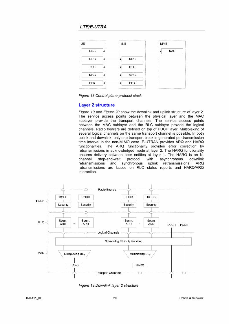
Figure 18 Control plane protocol stack
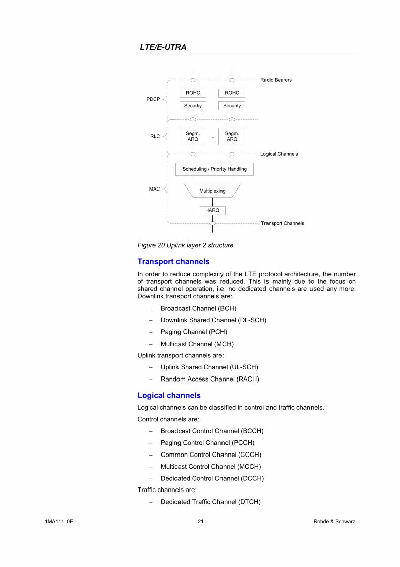
Layer 2 structure Figure 19 and Figure 20 show the downlink and uplink structure of layer 2. The service access points between the physical layer and the MAC sublayer provide the transport channels. The service access points between the MAC sublayer and the RLC sublayer provide the logical channels. Radio bearers are defined on top of PDCP layer. Multiplexing of several logical channels on the same transport channel is possible. In both uplink and downlink, only one transport block is generated per transmission time interval in the non-MIMO case. E-UTRAN provides ARQ and HARQ functionalities. The ARQ functionality provides error correction by retransmissions in acknowledged mode at layer 2. The HARQ functionality ensures delivery between peer entities at layer 1. The HARQ is an N-channel stop-and-wait protocol with asynchronous downlink retransmissions and synchronous uplink retransmissions. ARQ retransmissions are based on RLC status reports and HARQ/ARQ interaction.
Figure 19 Downlink layer 2 structure
LTE/E-UTRA
1MA111_0E 21 Rohde & Schwarz
Multiplexing
...
HARQ
Scheduling / Priority Handling
Transport Channels
MAC
RLC
PDCP
Segm.ARQ
Segm.ARQ
Logical Channels
ROHC ROHC
Radio Bearers
Securtiy Security
Figure 20 Uplink layer 2 structure
Transport channels In order to reduce complexity of the LTE protocol architecture, the number of transport channels was reduced. This is mainly due to the focus on shared channel operation, i.e. no dedicated channels are used any more. Downlink transport channels are:
− Broadcast Channel (BCH)
− Downlink Shared Channel (DL-SCH)
− Paging Channel (PCH)
− Multicast Channel (MCH)
Uplink transport channels are:
− Uplink Shared Channel (UL-SCH)
− Random Access Channel (RACH)
Logical channels Logical channels can be classified in control and traffic channels.
Control channels are:
− Broadcast Control Channel (BCCH)
− Paging Control Channel (PCCH)
− Common Control Channel (CCCH)
− Multicast Control Channel (MCCH)
− Dedicated Control Channel (DCCH)
Traffic channels are:
− Dedicated Traffic Channel (DTCH)
LTE/E-UTRA
1MA111_0E 22 Rohde & Schwarz
− Multicast Traffic Channel (MTCH)
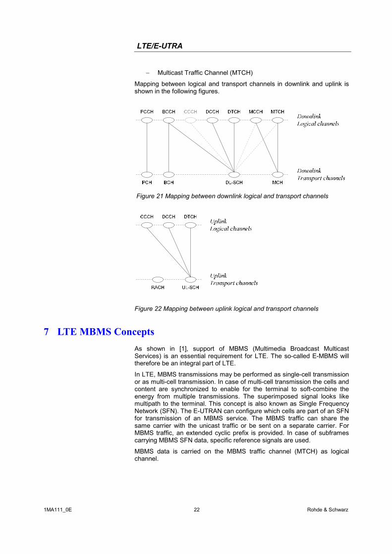
Mapping between logical and transport channels in downlink and uplink is shown in the following figures.
Figure 21 Mapping between downlink logical and transport channels
Figure 22 Mapping between uplink logical and transport channels
7 LTE MBMS Concepts As shown in [1], support of MBMS (Multimedia Broadcast Multicast Services) is an essential requirement for LTE. The so-called E-MBMS will therefore be an integral part of LTE.
In LTE, MBMS transmissions may be performed as single-cell transmission or as multi-cell transmission. In case of multi-cell transmission the cells and content are synchronized to enable for the terminal to soft-combine the energy from multiple transmissions. The superimposed signal looks like multipath to the terminal. This concept is also known as Single Frequency Network (SFN). The E-UTRAN can configure which cells are part of an SFN for transmission of an MBMS service. The MBMS traffic can share the same carrier with the unicast traffic or be sent on a separate carrier. For MBMS traffic, an extended cyclic prefix is provided. In case of subframes carrying MBMS SFN data, specific reference signals are used.
MBMS data is carried on the MBMS traffic channel (MTCH) as logical channel.
LTE/E-UTRA
1MA111_0E 23 Rohde & Schwarz
8 LTE Testing
LTE RF testing This section highlights aspects of testing base station and terminal transmitter and receiver parts and RF components for LTE.
First of all, LTE signal characteristics need to be investigated. While for LTE downlink, developers can leverage from OFDMA expertise gained with technologies like WiMAX and WLAN, this is not so straightforward for the uplink. SC-FDMA technology used in LTE uplink is not known from other standards yet. Thus, uplink signal characteristics need to be investigated with particular caution.
General settings
The following parameters primarily characterize the LTE signal:
- Frequency
- Bandwidth / number of resource blocks of the LTE signal
- Antenna configuration
- Reference signal sequence configuration
- Downlink synchronisation channel configuration
- Cyclic prefix length
- Allocation of user data and modulation schemes
- Configuration of L1/2 control channels
LTE signal generation
For generating an LTE signal, signal generators SMU200A, SMJ100A or SMATE200A are available. Software option SMx-K55 (Digital Standard LTE/EUTRA) provides LTE functionality on these signal generators. Alternatively, simulation software WinIQSIM2 running on a PC can be used to generate waveforms for digitally modulated signals which can be uploaded on the above-mentioned signal generators. This requires software option SMx-K255. WinIQSIM2 is also available for the IQ modulation generator AFQ100A with software option AFQ-K255. The AMU200A baseband signal generator and fading simulator supports LTE with software option AMU-K55 or AMU-K255.
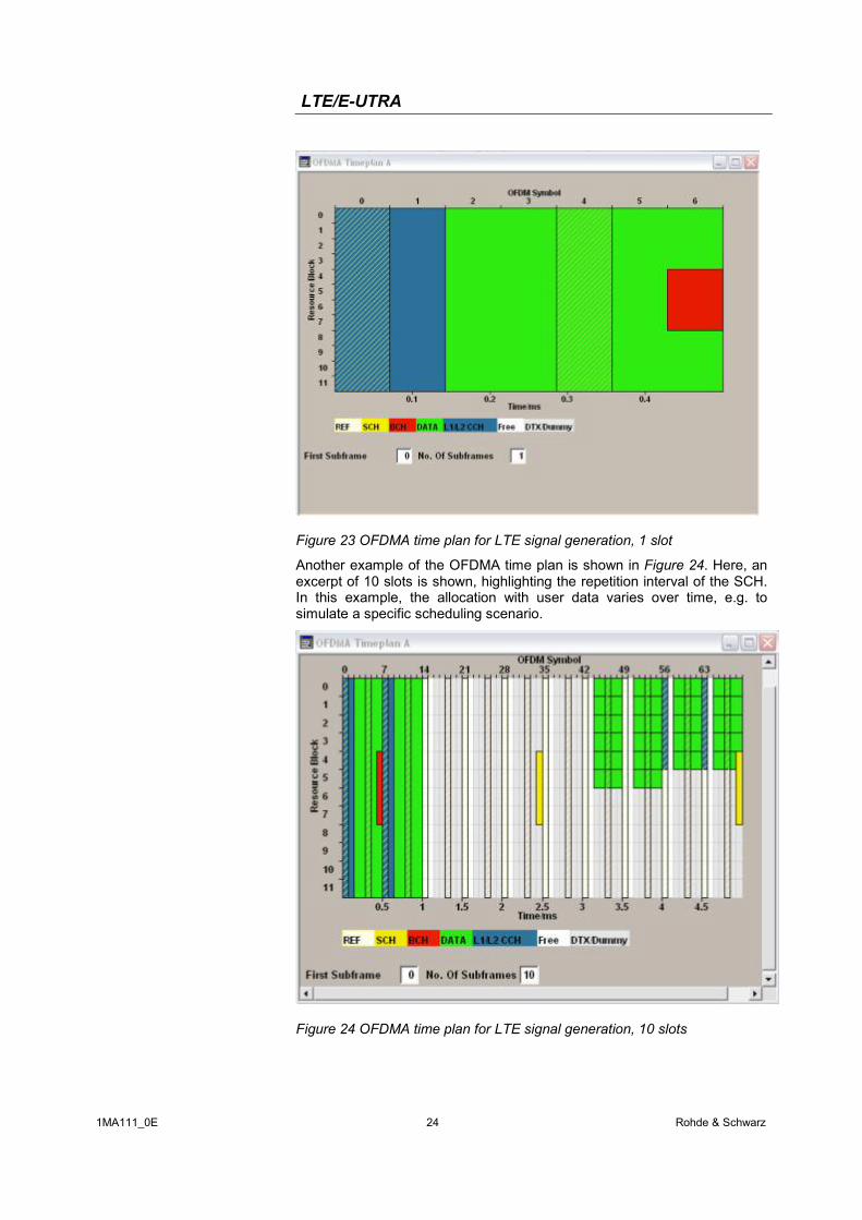
Figure 23 shows the OFDMA time plan used to illustrate the resource allocation within the LTE downlink signal configured by the user. In the example in Figure 23, a 0.5 ms slot of a 5 MHz LTE downlink signal is shown. The x-axis represents OFDM symbols, the y-axis represents resource blocks. In this example, all available resource blocks are allocated with user data. The reference symbols are located in the first and fifth OFDM symbol, and the L1/L2 control channel occupies the first two OFDM symbols. Note that these settings are configurable to create an LTE signal individually.
LTE/E-UTRA
1MA111_0E 24 Rohde & Schwarz
Figure 23 OFDMA time plan for LTE signal generation, 1 slot
Another example of the OFDMA time plan is shown in Figure 24. Here, an excerpt of 10 slots is shown, highlighting the repetition interval of the SCH. In this example, the allocation with user data varies over time, e.g. to simulate a specific scheduling scenario.
Figure 24 OFDMA time plan for LTE signal generation, 10 slots
LTE/E-UTRA
1MA111_0E 25 Rohde & Schwarz
LTE signal analysis
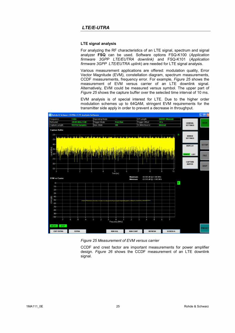
For analyzing the RF characteristics of an LTE signal, spectrum and signal analyzer FSQ can be used. Software options FSQ-K100 (Application firmware 3GPP LTE/EUTRA downlink) and FSQ-K101 (Application firmware 3GPP LTE/EUTRA uplink) are needed for LTE signal analysis.
Various measurement applications are offered: modulation quality, Error Vector Magnitude (EVM), constellation diagram, spectrum measurements, CCDF measurements, frequency error. For example, Figure 25 shows the measurement of EVM versus carrier of an LTE downlink signal. Alternatively, EVM could be measured versus symbol. The upper part of Figure 25 shows the capture buffer over the selected time interval of 10 ms.
EVM analysis is of special interest for LTE. Due to the higher order modulation schemes up to 64QAM, stringent EVM requirements for the transmitter side apply in order to prevent a decrease in throughput.
Figure 25 Measurement of EVM versus carrier
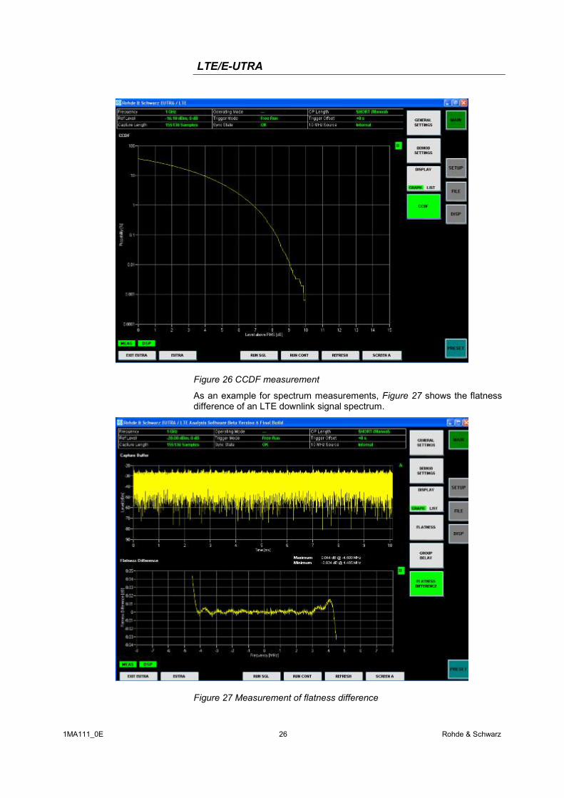
CCDF and crest factor are important measurements for power amplifier design. Figure 26 shows the CCDF measurement of an LTE downlink signal.
LTE/E-UTRA
1MA111_0E 26 Rohde & Schwarz
Figure 26 CCDF measurement
As an example for spectrum measurements, Figure 27 shows the flatness difference of an LTE downlink signal spectrum.
Figure 27 Measurement of flatness difference
LTE/E-UTRA
1MA111_0E 27 Rohde & Schwarz
LTE Layer 1 and Protocol Test LTE layer 1 has significant functionality. This includes layer 1 procedures like cell search, Hybrid ARQ retransmission protocol, scheduling, link adaptation, uplink timing control and power control. Furthermore, these procedures have stringent timing requirements. Therefore thorough testing of layer 1 procedures is needed to guarantee LTE performance.
LTE protocol stack testing is needed to verify signaling functionality like call setup and release, call reconfigurations, state handling, and mobility. Interworking with 2G and 3G systems is a requirement for LTE and needs to be tested carefully. A special focus is put on verification of throughput requirements in order to make sure that the terminal protocol stack and applications are capable of handling high data rates. Flexible test scenarios with individual parametrization possibilities will be needed for R&D purposes already at a very early stage of LTE implementation.
9 Abbreviations 3GPP 3rd Generation Partnership Project
ACK Acknowledgement
ACLR Adjacent Channel Leakage Ratio
ARQ Automatic Repeat Request
AS Access Stratum
BCCH Broadcast Control Channel
BCH Broadcast Channel
CAZAC Constant Amplitude Zero Auto-Correlation
CAPEX Capital Expenditures
CCDF Complementary Cumulative Density Function
CCPCH Common Control Physical Channel
CP Cyclic Prefix
C-plane Control Plane
CQI Channel Quality Indicator
CRC Cyclic Redundancy Check
DCCH Dedicated Control Channel
DFT Discrete Fourier Transform
DL Downlink
DL-SCH Downlink Shared Channel
DRX Discontinuous Reception
DTCH Dedicated Traffic Channel
DTX Discontinuous Transmission
DVB Digital Video Broadcast
eNB E-UTRAN NodeB
EPC Evolved Packet Core
LTE/E-UTRA
1MA111_0E 28 Rohde & Schwarz
E-UTRA Evolved UMTS Terrestrial Radio Access
E-UTRAN Evolved UMTS Terrestrial Radio Access Network
FDD Frequency Division Duplex
FFT Fast Fourier Transform
GERAN GSM EDGE Radio Access Network
GSM Global System for Mobile communication
HARQ Hybrid Automatic Repeat Request
HSDPA High Speed Downlink Packet Access
HSUPA High Speed Uplink Packet Access
IFFT Inverse Fast Fourier Transformation
IP Internet Protocol
LTE Long Term Evolution
MAC Medium Access Control
MBMS Multimedia Broadcast Multicast Service
MCCH Multicast Control Channel
MCH Multicast Channel
MIMO Multiple Input Multiple Output
MME Mobility Management Entity
MTCH MBMS Traffic Channel
MU-MIMO Multi User MIMO
NACK Negative Acknowledgement
NAS Non Access Stratum
OFDM Orthogonal Frequency Division Multiplexing
OFDMA Orthogonal Frequency Division Multiple Access
OPEX Operational Expenditures
PAPR Peak-to-Average Power Ratio
PDCCH Physical Downlink Control Channel
PCCH Paging Control Channel
PCH Paging Channel
PDCP Packet Data Convergence Protocol
PHY Physical Layer
QAM Quadrature Amplitude Modulation
QoS Quality of Service
QPSK Quadrature Phase Shift Keying
PAPR Peak to Average Power Ratio
PDSCH Physical Downlink Shared Channel
PDU Protocol Data Unit
PS Packet Switched
LTE/E-UTRA
1MA111_0E 29 Rohde & Schwarz
PUCCH Physical Uplink Control Channel
PUSCH Physical Uplink Shared Channel
RACH Random Access Channel
RAN Radio Access Network
RAT Radio Access Technology
RB Radio Bearer
RF Radio Frequency
RLC Radio Link Control
RRC Radio Resource Control
RRM Radio Resource Management
RU Resource Unit
S1 Interface between eNB and aGW
S1-C S1-Control plane
S1-U S1-User plane
SAE System Architecture Evolution
SC-FDMA Single Carrier – Frequency Division Multiple Access
SCH Synchronization Channel
SDMA Spatial Domain Multiple Access
SU-MIMO Single User MIMO
TDD Time Division Duplex
TS Technical Specification
TTI Transmission Time Interval
UE User Equipment
UL Uplink
UL-SCH Uplink Shared Channel
UMTS Universal Mobile Telecommunications System
UPE User Plane Entity
U-plane User plane
UTRA UMTS Terrestrial Radio Access
UTRAN UMTS Terrestrial Radio Access Network
VoIP Voice over IP
WCDMA Wideband Code Division Multiple Access
WLAN Wireless Local Area Network
X2 Interface between eNBs
X2-C X2-Control plane
X2-U X2-User plane
LTE/E-UTRA
1MA111_0E 30 Rohde & Schwarz
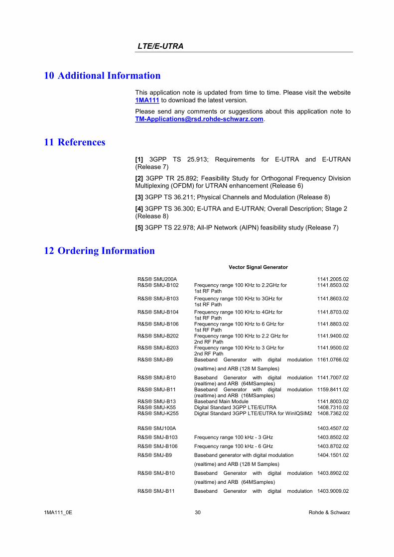
10 Additional Information This application note is updated from time to time. Please visit the website 1MA111 to download the latest version.
Please send any comments or suggestions about this application note to [email protected].
11 References [1] 3GPP TS 25.913; Requirements for E-UTRA and E-UTRAN (Release 7)
[2] 3GPP TR 25.892; Feasibility Study for Orthogonal Frequency Division Multiplexing (OFDM) for UTRAN enhancement (Release 6)
[3] 3GPP TS 36.211; Physical Channels and Modulation (Release 8)
[4] 3GPP TS 36.300; E-UTRA and E-UTRAN; Overall Description; Stage 2 (Release 8)
[5] 3GPP TS 22.978; All-IP Network (AIPN) feasibility study (Release 7)
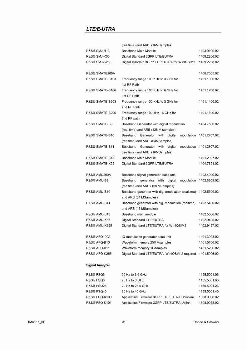
12 Ordering Information Vector Signal Generator R&S® SMU200A 1141.2005.02R&S® SMU-B102 Frequency range 100 KHz to 2.2GHz for
1st RF Path 1141.8503.02
R&S® SMU-B103 Frequency range 100 KHz to 3GHz for 1st RF Path
1141.8603.02
R&S® SMU-B104 Frequency range 100 KHz to 4GHz for 1st RF Path
1141.8703.02
R&S® SMU-B106 Frequency range 100 KHz to 6 GHz for 1st RF Path
1141.8803.02
R&S® SMU-B202 Frequency range 100 KHz to 2.2 GHz for 2nd RF Path
1141.9400.02
R&S® SMU-B203 Frequency range 100 KHz to 3 GHz for 2nd RF Path
1141.9500.02
R&S® SMU-B9 Baseband Generator with digital modulation
(realtime) and ARB (128 M Samples)
1161.0766.02
R&S® SMU-B10 Baseband Generator with digital modulation (realtime) and ARB (64MSamples)
1141.7007.02
R&S® SMU-B11 Baseband Generator with digital modulation (realtime) and ARB (16MSamples)
1159.8411.02
R&S® SMU-B13 Baseband Main Module 1141.8003.02R&S® SMU-K55 Digital Standard 3GPP LTE/EUTRA 1408.7310.02R&S® SMU-K255 Digital Standard 3GPP LTE/EUTRA for WinIQSIM2 1408.7362.02
R&S® SMJ100A 1403.4507.02
R&S® SMJ-B103 Frequency range 100 kHz - 3 GHz 1403.8502.02
R&S® SMJ-B106 Frequency range 100 kHz - 6 GHz 1403.8702.02
R&S® SMJ-B9 Baseband generator with digital modulation
(realtime) and ARB (128 M Samples)
1404.1501.02
R&S® SMJ-B10 Baseband Generator with digital modulation
(realtime) and ARB (64MSamples)
1403.8902.02
R&S® SMJ-B11 Baseband Generator with digital modulation 1403.9009.02
LTE/E-UTRA
1MA111_0E 31 Rohde & Schwarz
(realtime) and ARB (16MSamples)
R&S® SMJ-B13 Baseband Main Module 1403.9109.02
R&S® SMJ-K55 Digital Standard 3GPP LTE/EUTRA 1409.2206.02
R&S® SMJ-K255 Digital standard 3GPP LTE/EUTRA for WinIQSIM2 1409.2258.02
R&S® SMATE200A 1400.7005.02
R&S® SMATE-B103 Frequency range 100 KHz to 3 GHz for
1st RF Path
1401.1000.02
R&S® SMATE-B106 Frequency range 100 KHz to 6 GHz for
1st RF Path
1401.1200.02
R&S® SMATE-B203 Frequency range 100 KHz to 3 GHz for
2nd RF Path
1401.1400.02
R&S® SMATE-B206 Frequency range 100 kHz - 6 GHz for
2nd RF path
1401.1600.02
R&S® SMATE-B9 Baseband Generator with digital modulation
(real time) and ARB (128 M samples)
1404.7500.02
R&S® SMATE-B10 Baseband Generator with digital modulation
(realtime) and ARB (64MSamples)
1401.2707.02
R&S® SMATE-B11 Baseband Generator with digital modulation
(realtime) and ARB (16MSamples)
1401.2807.02
R&S® SMATE-B13 Baseband Main Module 1401.2907.02
R&S® SMATE-K55 Digital Standard 3GPP LTE/EUTRA 1404.7851.02
R&S® AMU200A Baseband signal generator, base unit 1402.4090.02
R&S® AMU-B9 Baseband generator with digital modulation
(realtime) and ARB (128 MSamples)
1402.8809.02
R&S® AMU-B10 Baseband generator with dig. modulation (realtime)
and ARB (64 MSamples)
1402.5300.02
R&S® AMU-B11 Baseband generator with dig. modulation (realtime)
and ARB (16 MSamples)
1402.5400.02
R&S® AMU-B13 Baseband main module 1402.5500.02
R&S® AMU-K55 Digital Standard LTE/EUTRA 1402.9405.02
R&S® AMU-K255 Digital Standard LTE/EUTRA for WInIQSIM2 1402.9457.02
R&S® AFQ100A IQ modulation generator base unit 1401.3003.02
R&S® AFQ-B10 Waveform memory 256 Msamples 1401.5106.02
R&S® AFQ-B11 Waveform memory 1Gsamples 1401.5206.02
R&S® AFQ-K255 Digital Standard LTE/EUTRA, WinIQSIM 2 required 1401.5906.02
Signal Analyzer
R&S® FSQ3 20 Hz to 3.6 GHz 1155.5001.03
R&S® FSQ8 20 Hz to 8 GHz 1155.5001.08
R&S® FSQ26 20 Hz to 26,5 GHz 1155.5001.26
R&S® FSQ40 20 Hz to 40 GHz 1155.5001.40
R&S® FSQ-K100 Application Firmware 3GPP LTE/EUTRA Downlink 1308.9006.02
R&S® FSQ-K101 Application Firmware 3GPP LTE/EUTRA Uplink 1308.9058.02
LTE/E-UTRA
1MA111_0E 32 Rohde & Schwarz
ROHDE & SCHWARZ GmbH & Co. KG . Mühldorfstraße 15 . D-81671 München . Postfach 80 14 69 . D-81614 München .
Tel (089) 4129 -0 . Fax (089) 4129 - 13777 . Internet: http://www.rohde-schwarz.com
This application note and the supplied programs may only be used subject to the conditions of use set forth in the download area of the Rohde & Schwarz website.