Embed Size (px)
Citation preview
UNCLASSIFIED
AD 283 965 ßefMtduced
luf. the
ARMED SERVICES TECHNICAL INFORMATION AGENCY ARLINGTON HALL STATION ARLINGTON 12, VIRGINIA
UNCLASSIFIED
NOTICE: When government or other drawings, speci- fications or other data are used for any purpose other than in connection vith a definitely related government procurement operation, the U. S.. Government thereby incurs no responsibility, nor any obligation whatsoever; and the fact that the Govern- ment may have formulated, furnished, or in any way supplied the said drawings, specifications, or other data Is not to be regarded by implication or other- wise as in any manner licensing the holder or any other person or corporation, or conveying any rights or permission to manufacture, use or sell any patented invention that may in any way be related thereto.
» * <£Z~-4/~£
CO o 00 00
MONTHLY PROGRESS REPORT
COUNTERMEASURES TRANSMITTING SET AN/ALT-22(V)
AND
BARRAGE JAMMER QRC-139A-(T)
MODIFICATIONS TO AN/ALT-6B
/--. O'Contract AF33(604)38334
CD "^
^r '^ PERIODENDING: 31 AUGUST 1962
LMED Requisition 32634
Prepared for
AERONAUTICAL SYSTEMS DIVISION WRIGHT PATTERSON AIR FORCE BASE
OHIO
Prepared by
GENERAL ELECTRIC COMPANY LIGHT MILITARY ELECTRONICS DEPARTMENT
UTICA, NEW YORK
TABLE OF CONTENTS
Section
I
II
Introduction
AN/ALT-22(V) and QRC-139A-(T) Modification to AN/ALT-6B (L-Band)
A. Equipment Description
B. Program Status
C. Problem Area
D. Program. For Next Interval
E. Financial Status
F. Other Project Activity-
Appendix
A BX-1202 Noise Tube Specification (G-E Drawing No. 70606 20, Rev. A)
Page
1
2
2
3
5
5
6
6
A-l
*
SECTION I
INTRODUCTION
This report describes the progress made during August 1962 on the
development of an L-band oscillator group for the QRC-139A-(T) and
AN/ALT-22(V) jamming system. This work includes the development of two
essential microwave components, an L-band barrage magnetron and an
L-band ferrite load isolator.
The construction and bench testing of QRC-139A-(T) systems and the
construction and qualification testing of three L-band AN/ALT-22(V) systems
are also part of the program authorized by letter contract AF33(604)38334.
SECTION II
AN/ALT-22(V) AND QRC-139A-(T) MODIFICATION TO AN/ALT-6B (L-BAND)
A. EQUIPMENT DESCRIPTION.
The equipment being procured under contract AF33(604)38334 consists
of sixty government furnished AN/ALT-6B equipments modified to the QRC-
139A-(T) and AN/ALT-22(V) configurations. Fifty-seven QRC-139A-(T)
equipments complete with L-band QRC-139A-1-(T) oscillator groups are
to be supplied with deliveries starting in August 1962. Three first article
AN/ALT-22(V) equipments complete with L-band oscillator groups are
scheduled to be submitted to first article tests during August and September
1862 and the first article systems delivered to the Air Force by 30 September
1962.
The QRC~139A-(T) equipment supplied on this contract will be identical
to the QRC-139A-(T) equipment delivered on contract AF33(604)36722 with
the exception that the control dials on the control-indicator and magnetron
frequency control units will be designed for L-band and the r-f oscillator
will have an L-band barrage magnetron and load isolator.
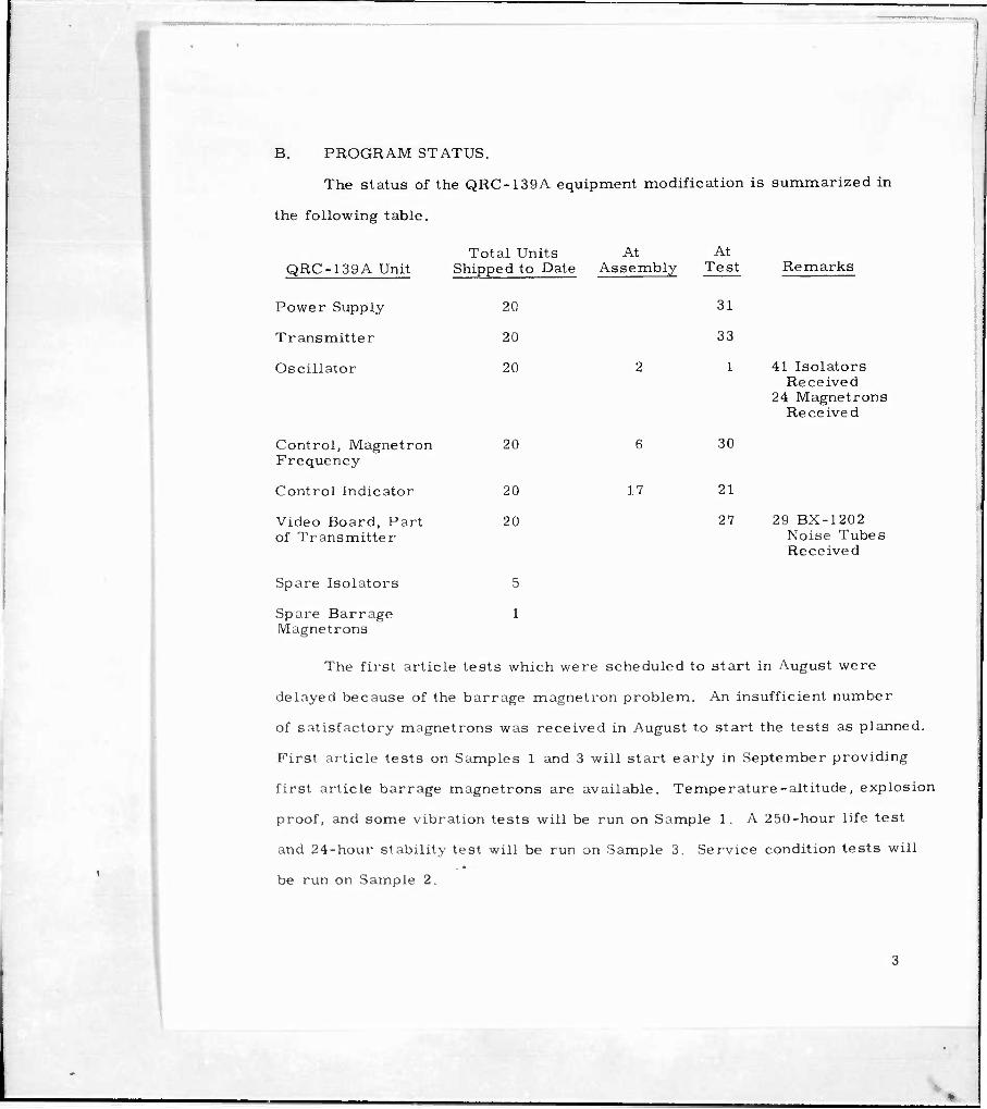
B. PROGRAM STATUS.
The status of the QRC-139A equipment modification is summarized in
the following table.
QRC-139A Unit Total Units At
Shipped to Date Assembly
Power Supply 20
Transmitter 20
Oscillator 20
At Test Remarks
31
33
1 41 Isolators Received
24 Magnetrons Received
Control, Magnetron Frequency
Control Indicator
Video Board, Part of Transmitter
Spare Isolators
Spare Barrage Magnetrons
20
20
20
5
1
6
17
30
21
27 29 BX-1202 Noise Tubes Received
The first article tests which were scheduled to start in August were
delayed because of the barrage magnetron problem. An insufficient number
of satisfactory magnetrons was received in August to start the tests as planned.
First article tests on Samples 1 and 3 will start early in September providing
first article barrage magnetrons are available. Temperature-altitude, explosion
proof, and some vibration tests will be run on Sample 1. A 250-hour life test
and 24-hour stability test will be run on Sample 3. Service condition tests will
be run on Sample 2.
Negotiations are underway with the Air Force to conduct a vibration
survey on one AN/ALT-22 first article system in order to determine how
much vibration the equipment will withstand without failing, and to pinpoint
the areas where failures will occur. Based on the results of this survey,
recommendations can be made regarding ways and means of fixing the equip-
ment so that is will withstand vibration tests conducted in accordance with
MIL-T-5422 (modified). If the Air Force approves the planned survey early
in September, this vibration test will be run on Sample 2. Barry shock mounts
built to Boeing specifications have been received for use in this program. The
AN/ALT-22 power supply and transmitter with the L-band oscillator installed
will be mounted on these shock mounts during part of the vibration survey. The
vibration survey datataking and analysis, and report writingwill require six
weeks.
Parts required for the modification program, with the exception of the
L-3519 barrage magnetron, are being received in large enough quantities to
meet the production schedules. The barrage magnetron remains a problem
area. (See paragraph C. of this section.) The quantities of noise tubes, load
isolators, and barraje magnetrons which have been received are tabulated in l/f
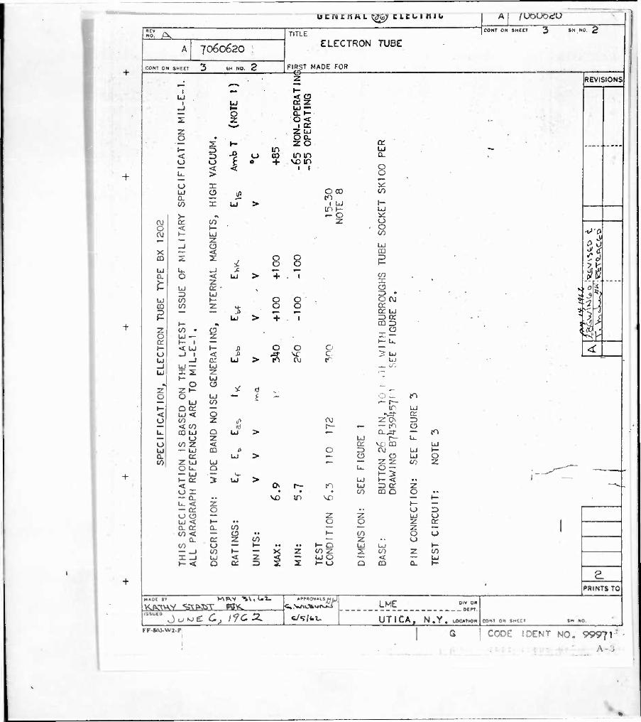
the Remarks colunyrt %)f the table on page 3. The BX-1202 noise tubes are now
being delivered in accordance with the requirements of G-E Drawing No.
7060620, Revision A (see Appendix A) with the exception that the requirements
of notes 9 and 12 of this specification have been waived until such time as the
necessary life test data and shelf life data can be accumulated to determine
that these requirements are realistic. The BX-1202 beam switching tube is
a new noise source. It is being used as a noise generator for the first time
on this contract. For this reason, little is known of its life expectancy or
shelf life characteristics. The Burroughs Corporation has agreed to ac-
cumulate some data so that these tube characteristics can be included as
part of the purchase specification,
c. "PROBLEM AREA.
The barrage magnetron is still the only item limiting the delivery of
L-band QRC-139A-(T) systems to the Air Force. Litton did not deliver as
many tubes as expected during August due to a low yield situation. The low
yield during the first part of the period was caused by slumping and narrow
spectrum bandwidth. To improve the yield, several changes were made inside
the magnetron. To eliminate the slumping problem, the spacing of the pole
pieces from the filament was increased to eliminate possible out-gassing
from the pole pieces due to the heat from the filament. To increase the
spectrum bandwidth, the coupling to the r-f resonant circuit was increased.
These changes were made in the tube design about the middle of the report
period and failures due to slumping and narrow bandwidth were reduced
significantly. However, with the increased coupling, another problem developed
in that the tubes received late in August exhibited a strong tendency to mode
at the high frequency end of the tuning range. Litton has been advised of this
situation and the General Electric Company will work closely with Litton to
resolve this new problem which is reducing the yield from 50 percent to less
than 30 percent.
D. PROGRAM FOR NEXT INTERVAL.
The program for the next interval will consist of conducting first article
tests on the three AN/ALT-22 (L-band) systems and the assembly and test of
at least 27 QRC-139A-(T) systems. The barrage magnetron problem will
have to be resolved early in September if the scheduled September deliveries
are to be accomplished.
E. FINANCIAL STATUS,
The following is an estimate of the monies that have been expended and
committed on Contract AF33(604)38334 as of 31 August 1962:
Expenditures for Engineering Material, Design Effort, Direct Labor, Direct Materials and Support Effort
Gross Commitments and Estimated Liability
$264,361
$257,400
$521,761 Total Expenditures and Commitments
F. OTHER PROJECT ACTIVITY.
Engineering and Material Procurement personnel visited Litton Industries
to convince them to build more tubes per day since the tube yield was lower
than anticipated. As a result of this trip, Litton agreed to increase their tube
starts from three per day to four per day. Additional trips to Litton will be
required until an even flow of L-3519 barrage magnetrons from Litton to
G.E. has been established.
APPENDIX A
BX-1202 NOISE TUBE SPECIFICATION
(G-E Drawing No. 7060620, Rev. A)
A-l
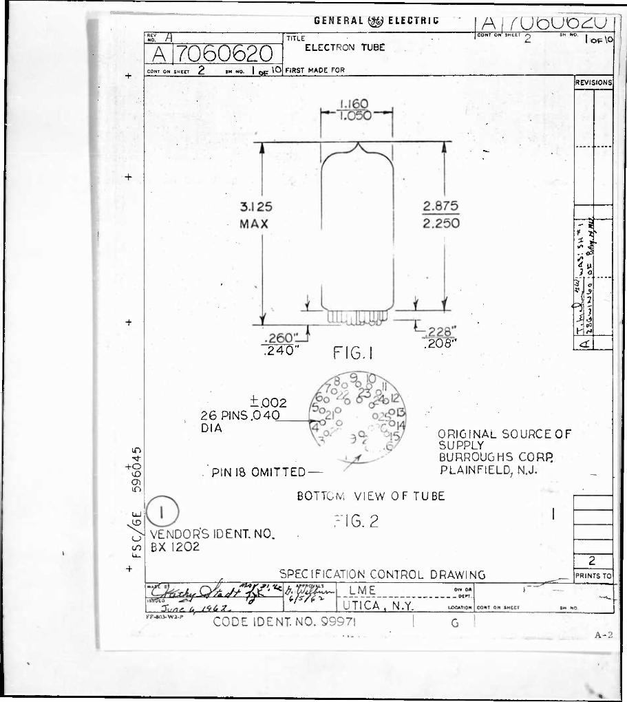
GENERAL ^ ELECTRIC
TT Al rUÖUO^U
NO.
A 7060620 CONT ON SHeCT SH WO. I Qp \0
TITLE
ELECTRON TUBE
FIRST MADE FOR
CONT ON SMtt' I OP^ \0
+o vO
iT»
.240" FIG.I ^OS"
REVISIONS
71' .- 031
3 o
( ff
J.
±.002 26 PINS.0 40 DIA
PIN 18 OMITTED —
B0TTü!V, VIEW OF TUBE
FIG. 2
ORIGINAL SOURCEOF SUPPLY BURROUGHS CORR PLAINFIELD, N.J.
u VENDOR"SIDENT. NO. BX 1202
S^atgag^pF SPECIFICATION CONTROL DRAWING PRINTS TO
itCti LME jfrcA
OtV ON
- Of*T
N.Y. LOCATION CONT ON «MCCT
KF*li-WJ-P CODE IDENT. NO. Q9971
A-;;
■f
u c n c n M L SgQ} CLCU 1 mo Aj lUGUÖeiU
MV " "0. /\, TITLE
ELECTRON
FIRST MADE FOR
COm OH SHCtT 3 *H N0 2
A 7060620 TUBE
CONT ON SHEET 3 SH NO. 2
REVISIONS
T C" *- LJ < C3 .
i LJ or z
o Et- at 2 O < •-
•w^ I cc . Z Z LJ O • . ' O CL
. - 2: »- zo a: (- 3 r. ID y "" < r) -? u co inin o o t 0 + vo in
CL
— < < it Q L- > O
U I s«:
^ 2 Ü 8°° CO
CO X Ui > .u UJ
o: to z id 0 OJ
o < t- • 1- UJ - z _J CJ
0 CO
UJ öS X ca m 5 ^ ^ 8 8 ? u CL
U. _J ^ — — O < UJ > + . 1
UJ ce •
UJ CO 1- OO. B* ••: ^^ CO CO z ^ . 0 O ce 3 g o; UJ » 1 .<
Li > + T 3 o: ^ (- • 00 Z3 ■. mi z o cc
co • a UJ— z »- 1 —
x^ < ̂ h 1- < UJ t— J3 OO O — <i: Ul
_J 1 < JO öt ^ c
-j D: UJ > 10 OJ t^ I? UJ
UJ - - -1 UJ ~ UJ . ^ IT, u x 2: z <—•
»- UJ * «1 0 a , -_ '
2 21- ^ ^ . •— o O UJ - f - O L. tn
UJ CO <- r— ►- 00: — tr UJ < UJ < O -^r 0: o CO Z ^1 OJ z 0 r>
< co *) r— — — t^i 0 u. CO UJ O UJ > — D.^}- — tO
O Z UJ h- Lu o co z < or VC) CO UJ u — UJ CO " O Z3 CM UJ t— Q. cr UJ > — 0 O Ul O trt 2 UJ UJ — — 2 2 CO Z
' ou. o ^ O — -——""'^ — UJ — V f-3 [~-^ t- OC ^ Ul > UJ k- < .' ' < 0^ r— to uj rj a- z -v. ox • • • CO CO Q O •• — CL •• VD m \^) — 1- u. < z — en o
h- — 0 z>
«_> O — Z 2 UJ < h- •• O O
UJ 0 2 o: 1
o- or a. co _ _ 2 - CO < — o •• t- CO
a. o: z to — z 0 u 0
co (J~~^~•••*^—o uj UJ »- — _ico»--><2<oz 2: X _J UJ < z < — UJ 0 — >-< 0 a => 2 2 ►-«-> Q
CO 2 CO < — UJ CD Q. K-
£ PRINTS TO
LME 0"0"
CON? ON tMCCT »M NO ~ juwc 6, /yea. c/T/fcU UTICA, N.Y. MMNWi KF-«(0-> V2-P 1 • CODE IDENT NO. 99971"
\ .
b E N t K A L ^%> t L t L I K I Ü
NO. /-\
Ai 7060620
CONT ON SMCtT
TITLE
ELECTRON TUBE
FIRST MADE FOR
A I (UDUOtiU
CONT ON SHEET l4 iM NO. 3
+
I
CO
<S) X 7. I- < Ü s 2: X 1- O -1 2 75 *• o: s 1— (/) 2: z > — to 2 -j (5 CL UJ
CO > »— 2 UJ 0 — «J U a li. CO UJ 2 -JO — , 0 <v«.
I (y a — ■ CO < •^ rr •
% &| (Y ui UJ (VJ < co O ISI — Q 2 < —00
0 ii CO • UJ 0— — l.i »- < 2 X en MM* a. a 0 in n § ^8^
00 O — or < • »- O i^ LI ■ Cl s O UJ s Q
S »— UJ LJ co 2 a- * Ul — M »- < en UJ H
O C3 2 O O O 1,1 >— 0
< Z : —1 O —1 oc © UJ 1— • 0 <_) • w—
CO UJ g • — —1 z 00 s: uj
< • K cr c: 0 O O < • 1- u B. -3"
< t— co
in co «s _J o *
J3-
< CK CO UJ UJ CL _l OO
>- o 2 ID
< C3 ü: 2 ui — 0 1 2 u> Ul>-
■
• o vo —
o
8
nJ
H- 2 o 5 -■ < O L") O — L
— 1-1 t- 21 CO CO 0. c: t- o ru O Z3 < — CO
O 2 UI IT» X CO •— I- »f> UI C- 2 3
U O CO 2 O-J — a. — •- < o »- u> s
I- o < 00 o a: o in — »- (\J UJ — —
2 o
< cm m > 4>
or o -3 <
L_i 1— O
OCOH- < cr x cx
< ui »- 0. <o: o
O • Q-32 2< O <2:2
» +1 f-
< a Q: ID ZJ
O CO 2^2 o o «o — en X t- — CO O X ^. < n c. 0:00 02 2 — 1 —»- o 3: < <
or UJ O UJ 2 a 2 < o —
o 2
U) U) o o
«n
-in — —
UI UI
o 2
id
o 2
s o
S
< a. (0
o ►- 2 2 — UI ü or ü en < r> -JO
-3- JT • • o o
REVISIONS
•if rfftJ1
«1^
«»0t »i V\»0/ IVvCX »►»•0»»Lii [J
. Ci VwlVj^vj .V^i
w«»/ui
PRINTS TO
g ^ >o^ 6,., /f^2. .uc UTICA, N.Y.
DIV OK _ ocn
CON( ON »MEC1
IF-XIJ-WJ-P CODE IDENT NO. 99971 A-4 -
btNCKAL ^; t LEU i ifib
MO. r-N
7060620
CONT ON SHEET
TITLE ELECTRON TUBE
FIRST MADE FOR
A I (UOUOeiU
CONT ON tHCET K
in
2 3
x
-J2
00
IS) > Z U
UP u
-10 o
o
<
in
in to
< <
OO OJCVJ
V
si I I •
«««
^ .^ 03 w—
* *•- ^ • VO 1^ m 000
A ft ■^ c - ' > > -sr J* •=r 0 >ja-
88 Wk
to in S 0 > 0 tn 0 A ^ «« O 2: VD • ^: + 1 CVJ cu OJ 2: m r>-cuoj 0 •0 • - 1 0 CO CO CO in r—- in u co H- LJ LJ u u
< ^ t- 1- (- 0 a a D ^>- - -c i O C) 0 <^-0O
u; ui z z z U. Lu U UJ UJ z
O ^-, ^-^ ^^ ^^ ►- LJ ^ ru en -sr z Q ^«^ *-* LJ s ►- 1- t- h- o: Zi 3 D Z> Q: l- Q. E a. Q. 3 < t- h- \- (-
t- 0 0
1 u B 8 8 8 </: cr Q: 0 u bj LJ < UJ UJ LJ LJ •- P t- ü CO CO CO CO
. < < < •M
tt ^y ^ 0 z g s i * *
* 41 * »
co — • • o o
J3- J3-
I I
I I
I t
I I
I I
I - I
I 1
I I
co
in
uoco < < * 00 00 > >-a-
i 2 r-Otn o cvj in o »VD •
enm — — — tvjinrvjcvi ü 11 p D a u u 11 co
L. U. L. U. U. U <-»-«l- UJ J>o
'— UJ Z in
3 a UJ CO
o z
co
Q
CL
to
iREViSIONS
V-3
2
I IN/
PRINTS TO «•0E V !V\P^V ^l,»^««^
Ou*JE (Sj l7C tL
»r»»OV«l.J^J^> _LME_
UTICA, N.Y. l0e>T
DIV O« . Of"
CONT ON »MEET
KF-*V>-WJ.p
-
CODE I DENT NO. 99971
'A-5
ucn cnHL ^jfe?' c LEI. i n i b
NO. (-\
7060620
NT ON Sn£ET Ö
TITLE
Ml l\JU\J\J£^V
CONT ON SMEET £j SM NO g
ELECTRON TUBE
FIRST MADE FOR
> CO OO I- CDS O O
X I- < — 2: i I 0310 Z •
^1 ^J?« ' '
■•••
>-
a. ui oo > z UJ
-JQ Ü
d
» z (- m UJ z 00 - o: ui Q <j3-
CO 0 cr o: > > « z 2:000; _ tn
i in 0 0 «OJ Ü
1- • 01- tOV£) — ID f—— UI UI CO 9 00 UI
a a a 0:0 a h- Q < Z -0 vO 0 U.UU.»-<LJUIZ
4 V- if) UI >- tp
-J ill
< Q-
v.
LME
UTlCAy N. Y . tOCAtiQN
Oil 0« _ OErr
rr-«o>-\M-p CONT ON «MECT
REVISIONS
.
PRINTS TO
CODE I DENT NO, 99971
. A B
MO. L-y
■
+ 1
7060620
3NT ON SH£ET f SM NO. ö
TITLE ELECTRON TUBE
FIRST MADE FOR
*^wvww^s
JCONT ON SHEfT
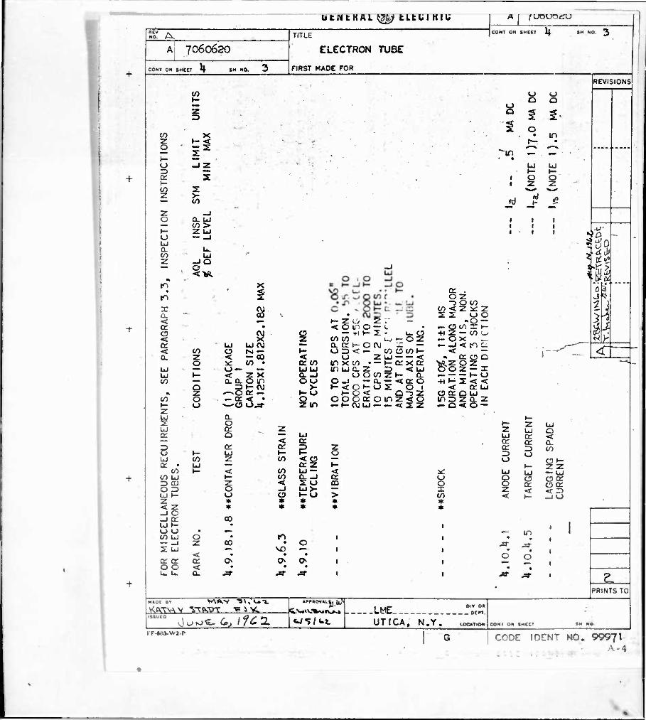
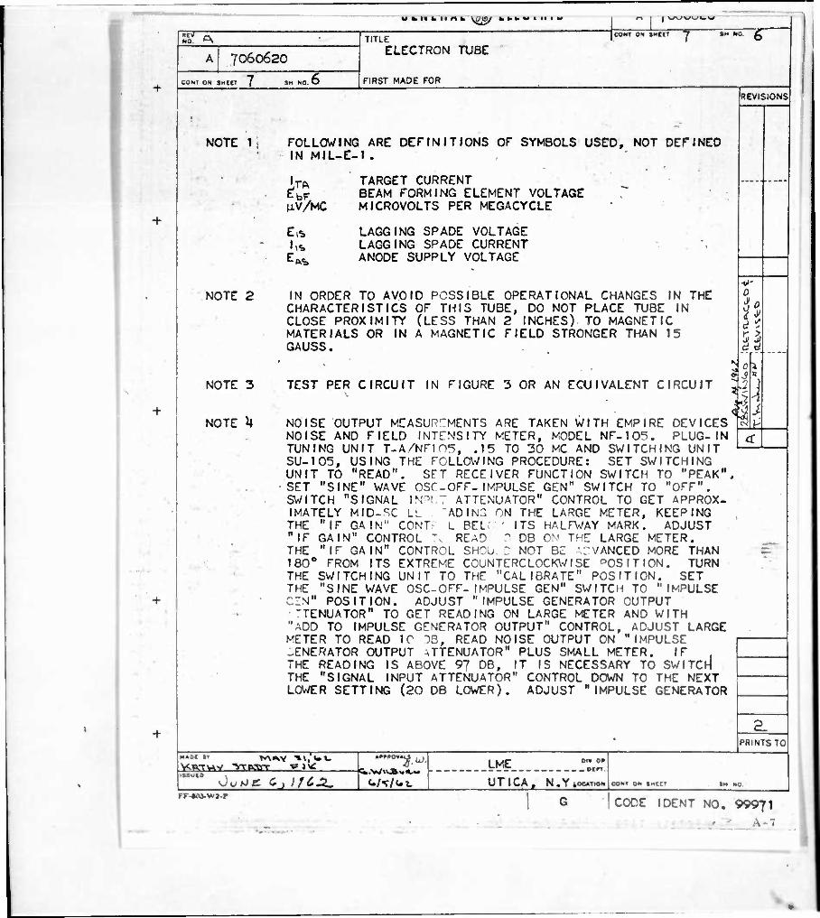
NOTE 1
NOTE 2
NOTE 3
NOTE U
FOLLOWING ARE DEFINITIONS OF SYMBOLS USED, NOT DEFINED IN MIL-E-1.
IT*
UV/MC
TARGET CURRENT BEAM FORMING ELEMENT VOLTAGE MICROVOLTS PER MEGACYCLE
LAGGING SPADE VOLTAGE LAGGING SPADE CURRENT ANODE SUPPLY VOLTAGE
IN ORDER TO AVOID POSSIBLE OPERATIONAL CHANGES IN THE CHARACTERISTICS OF THIS TUBE, DO NOT PLACE TUBE IN CLOSE PROXIMITY (LESS THAN 2 INCHES) TO MAGNETIC MATERIALS OR IN A MAGNETIC FIELD STRONGER THAN 15 GAUSS.
TEST PER CIRCUIT IN FIGURE 3 OR AN EOUIVALENT CIRCUIT
NOISE OUTPUT MEASUREMENTS ARE TAKEN WITH EMPIRE DEVICES NOISE AND FIELD INTENSITY METER, MODEL NF-105. PLUG-IN TUNING UNIT T-A/NFIO^, .15 TO 30 MC AND SWITCHING UNIT SU-105, USING THE FOLLOWING PROCEDURE: SET SWITCHING UNIT TO "READ". SFT RECEIVER FUNCTION SWITCH TO "PEAK", SET "SINE" WAVE OSC-OFF-IMPULSE GEN" SWITCH TO "OFF". SWITCH "SIGNAL INPUT ATTENUATOR" CONTROL TO GET APPROX- IMATELY MID-SC LL "ADING ON THE LARGE METER, KEEPING THE "IF GAIN" CONT- L BEL: ' ITS HALFWAY MARK. ADJUST "IF GAIN" CONTROL T» READ D DB ON THE LARGE METER. THE "IF GAIN" CONTROL SHOü. D NOT BE ADVANCED MORE THAN 180° FROM ITS EXTREME COUNTERCLOCKWISE DOSITION. TURN THE SWITCHING UNIT TO THE "CALIBRATE" POSITION. SET THE "SINE WAVE OSC-OFF- IMPULSE GEN" SWITCH TO "IMPULSE. CZN" POSITION. ADJUST "IMPULSE GENERATOR OUTPUT 'TENUATOR" TO GET READING ON LARGE METER AND WITH
"ADD TO IMPULSE GENERATOR OUTPUT" CONTROL, ADJUST LARGE METER TO READ 10 DB, READ NOISE OUTPUT ON "IMPULSE GENERATOR OUTPUT \TTENUATOR" PLUS SMALL METER. IF . THE READING IS ABOVE 97 DB, IT IS NECESSARY TO SWITCH THE "SIGNAL INPUT ATTENUATOR" CONTROL DOWN TO THE NEXT LOWER SETTING (20 DB LOWER). ADJUST "IMPULSE GENERATOR
REVISIONS
0 A 1 n it u c
13
i
2.
v^u Mg 0 j IfCJL.
Oiv OK . otri
.LME
UTICA, N.YtooT.o.. KF-44-0-WJ-P
-i- PRINTS TO
coot 0» »Mttt
CODE I DENT NO. 99971
1>EN tKAL ^> tLCUl KIU
NO. ^
7060620
CONT ON SHEET 8 NO. T
TITLE
ELECTRON TUBE
FIRST MADE FOR
Al 7060620 ;ONI ON «MEET 8
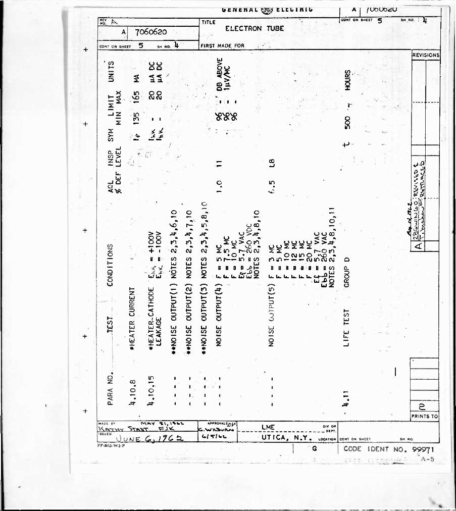
NOTE 5
NOTE 6
NOTE 7
NOTE 8
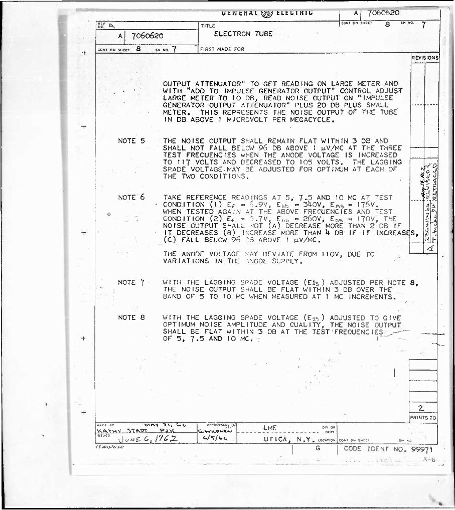
OUTPUT ATTENUATOR" TO GET READING ON LARGE METER AND WITH "ADD TO IMPULSE GENERATOR OUTPUT" CONTROL ADJUST LARGE METER TO 10 DB, READ NOISE OUTPUT ON "IMPULSE GENERATOR OUTPUT ATTENUATOR" PLUS 20 DB PLUS SMALL METER. THIS REPRESENTS THE NOISE OUTPUT OF THE TUBE IN DB ABOVE 1 MICROVOLT PER MEGACYCLE.
THE NOISE OUTPUT SHALL REMAIN FLAT WITHIN 3 DB AND SHALL NOT FALL BELOW 96 DB ABOVE 1 nV/MC AT THE THREE TEST FREQUENCIES WHEN THE ANODE VOLTAGE IS INCREASED TO 117 VOLTS AND DECREASED TO 105 VOLTS. THE LAGGING SPADE VOLTAGE MAY BE ADJUSTED FOR OPTIMUM AT EACH OF THE TWO CONDITIONS.
REVISIONS
TAKE REFERENCE RETADINGS AT 5, 7.5 AND 10 MC AT TEST CONDITION (1) Ef - ^.9V, Ebb - 3U0V, EAS - 176v. WHEN TESTED AGAIN AT THE ABOVE FREOUENCIES AND TEST CONDITION (2) Ef - 5.7V, Ebb " 26OV, EßS - 170V, THE NOISE OUTPUT SHALL ^JOT (A) DECREASE MORE THAN 2 DB IF IT DECREASES (B) INCREASE MORE THAN U DB IF IT INCREASES, (C) FALL BELOW 96 D3 ABOVE 1 uV/MC.
J'O
THE ANODE VOLTAGE MAY DEVIATE FROM 110V, DUE TO VARIATIONS IN THE \NODE SLPPLY.
WITH THE LAGGING SPADE VOLTAGE (EK, ) ADJUSTED PER NOTE 8, THE NOISE OUTPUT SHALL BE FLAT WITHIN 3 DB OVER THE BAND OF 5 TO 10 MC WHEN MEASURED AT 1 MC INCREMENTS.
WITH THE LAGGING SPADE VOLTAGE (Eis) ADJUSTED TO GIVE OPTIMUM NOISE AMPLITUDE AND CUALITY, THE NOISE OUTPUT SHALL BE FLAT WITHIN 3 DB AT THE TEST FREOUENCIES ^—— OF 5, 7.5 AND 10 MC. I"
\h
--i
* '
»»01 •" W«*'* "»v. t-u vsfvm'j aacMB—HAi&—
PRINTS TO
Jc/*£ 0, JftZ- LME
UTICA
OlV OR _ DEfT
N .Y . LOCUTION CONT ON »MCCT
KF-«n>wj.p G CODE I DENT NO. 99971
... \ c.
I u c n c nH L, ^As) c Leo i mi«
7060620
I SHEET V CONT ON SHEE 8
TITLE
ELECTRON TUBE
FIRST MADE FOR
M j /UOUDCU
CONT ON S HEtl ^ SH NO. Q
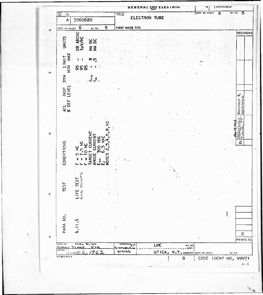
NOTE 9
NOTE 10
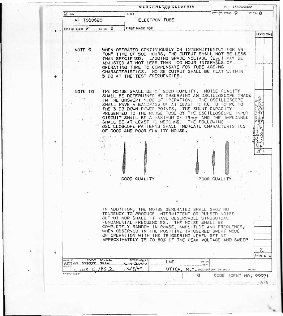
WHEN OPERATED CONTINUOUSLY OR INTERMITTENTLY FOR AN "ON" TIME OF 500 HOURS, THE OUTPUT SHALL NOT BE LESS THAN SPECIFIED. LAGGING SPADE VOLTAGE (E^) MAY BE ADJUSTED AT NOT LESS THAN TOO HOUR INTERVALS OF OPERATING TIME TO COMPENSATE FOR TUBE AGEING CHARACTERISTICS. NOISE OUTPUT SHALL BE FLAT WITHIN 3 DB AT THE TEST FRECUENCIES.
THE NOISE SHALL BE OF GOOD CUALITY. NOISE CUALITY SHALL BE DETERMINED BY OBSERVING AN OSCILLOSCOPE TRACE IN THE UNSWEPT MODE OF roERATION. THE OSCILLOSCOPE SHALL HAVE A BANDPASS OF AT LEAST 10 KC TO 10 MC TO THE 3 DB DOWN POWER POINTS. THE SHUNT CAPACITY PRESENTED TO THE NOISE TUBE BY THE OSCILLOSCOPE INPUT CIRCUIT SHALL BE A MAXIMUM OF 1U pj: AND THE IMPEDANCE SHALL BE AT LEAST 10 MEGOHMS. THE FOLLOWING OSCILLOSCOPE PATTERNS SHALL INDICATE CHARACTERISTICS OF GOOD AND POOR CUALITY NOISE. f < <». - ^ - „
■ ■ ■
GOOD CUALITY POOR CUALITY
IN ADDITION, THE NOISE GENERATED SHALL SHOW NO TENDENCY TO PRODUCE INTERMITTENT OR PULSED NOISE OUTPUT NOR SHALL IT HAVE OBSERVABLE SINUSOIDAL FUNDAMENTAL FRECUENCIES. THE NOISE SHALL BE COMPLETELY RANDOM IN PHASE, AMPLITUDE AND FRECUENCYJ WHEN OBSERVED IN THE POSITIVE TRIGGERED SWEPT MODE ' OF OPERATION WITH THE TRIGGERING LEVEL SET AT APPROXIMATELY 75 TO 80^ OF THE PEAK VOLTAGE AND SWEEP
REVISIONS
3 I iff
t-M<W
.. ■■
KK-«V>-NVJ.P e Cjift-Z-
01» o« . ocrT
LME
UTIQA, N.Y.10CA..0N
PRINTS TO
CONt ON «MCI'
CODE IDENT NO. 99971
A 9
GENERAL W4i ELECTRIC A | 7060620
7060620
COM ON SHEET J 0 »H "O 9
TITLE
ELECTRON TUBE
FIRST MADE FOR
ICONI OK SHEET 10
+
NOTE 11
NOTE 12
NOTE 13
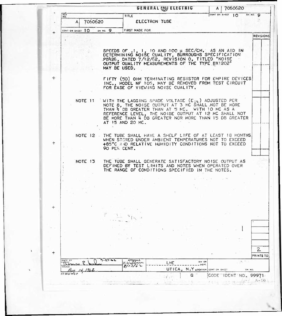
SPEEDS OP .1, 1, 10 AND 100 n SEC/CM. AS AN AID IN DETERMINING NOISE CUALITY, BURROUGHS SPECIFICATION PBU26, DATED 7/12/62, REVISION 0, TITLED "NOISE OUTPUT QUALITY MEASUREMENTS OF THE TYPE 6X1202" MAY BE USED.
REVISIONS
FIFTY (50) OHM TERMINATING RESISTOR FOR INC., MODEL NF 105, MAY BE REMOVED FROM FOR EASE OF VIEWING NOISE QUALITY.
EMPIRE DEVICES TEST CIRCUIT
WITH THE LAGGING SPADE VOLTAGE (E^) ADJUSTED PER NOTE 8, THE NOISE OUTPUT AT 3 MC SHALL -NOT BE MORE THAN U DB GREATER THAN AT 5 MC. WITH 10 MC AS A REFERENCE LEVEL, THE NOISE OUTPUT AT 12 MC SHALL NOT BE MORE THAN k 08 GREATER NOR MORE THAN 15 DB GREATER AT 15 AND 20 MC.
THE TUBE SHALL HAVE A SHELF LIFE OF AT LEAST 18 MONTHS WHEN STORED UNDER AMBIENT TEMPERATURES NOT TO EXCEED +850C ANID RELATIVE HUMIDITY CONDITIONS NOT TO EXCEED 90 PER CENT.
THE TUBE SHALL GENERATE SATISFACTORY NOISE OUTPUT AS DEFINED BY TEST LIMITS AND NOTES WHEN OPERATED OVER THE RANGE OF CONDITIONS SPECIFIED IN THE NOTES.
f .. 1
■
n-Li-ti.
yr-teii-v/2-r
Oiv 0" - OCT LME
UTICA, N.Y4.00T101«
.
PRINTS TO
COHT ON »MCCT
-
CODE I DENT NO. 99971
U t IM c n H L U'iSj t b b U I 11 l w <e&
Al 70606^0 CONT ON SHEET \o
TITLE
ELECTRON TUBE FIRST MADE FOR
/-M I VJ'UKJ^JtL^J CONT ON SHEET SH NO. \ O
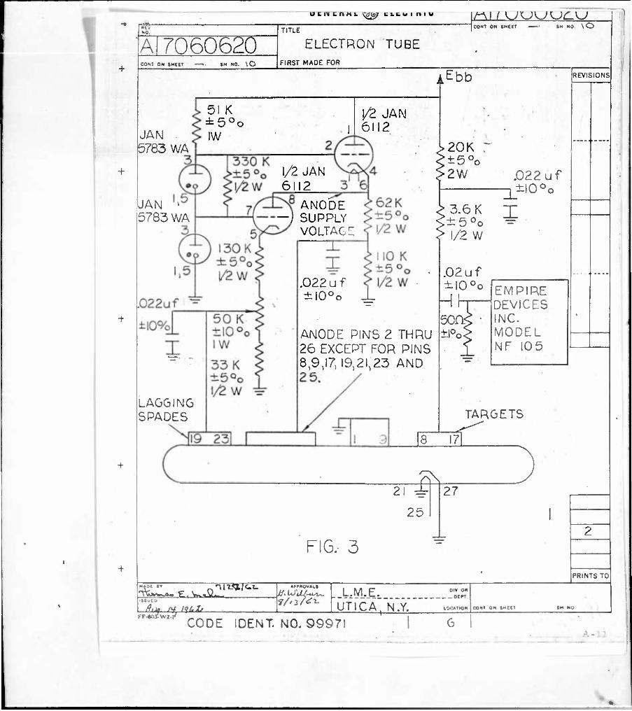
AEbb
51 K ±50o
JAN ^ IW B783 WA
JAN 5783 WA
l/S JAN 6112
1/2 JAN 6112
ANODE -J SUPPLY
VOLTAGE
t50o .022 uf ±l0oo
.022 uf ±i0oo
ANODE PINTS 2 THRU 26 EXCEPT FOR PINS 8,9,17, 19,21,23 AND 2 5.
LAGGING SPADES
3.6 K T :±5oo ±
1/2 W
EMPIRE DEVICES INC. MODEL NF 105
REVISIONS
TARGETS
8 17
ifi 21 i
25
FIG. 3
27
PRINTS TO
£tJt. H, WUle Ml • '
L.M.E. OIV o« _ ocrr
UTICA. N.Y. CONT ON SHttT
FF-»n7vvjr7 CODE IDENT. NO. 99971 1

-—1
UNCLASSIFIED
UNCLASSIFIED