Embed Size (px)
Citation preview
UNIT 3 Friction and Belt Drives 06ME54
Structure
Definitions
Types of Friction
Laws of friction
Friction in Pivot and Collar Bearings
Belt Drives
Flat Belt Drives
Ratio of Belt Tensions
Centrifugal Tension
Power Transmitted
INTRODUCTION
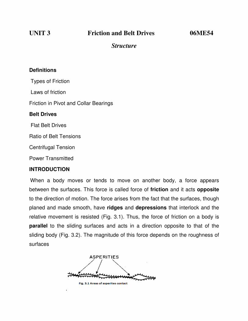
When a body moves or tends to move on another body, a force appears
between the surfaces. This force is called force of friction and it acts opposite
to the direction of motion. The force arises from the fact that the surfaces, though
planed and made smooth, have ridges and depressions that interlock and the
relative movement is resisted (Fig. 3.1). Thus, the force of friction on a body is
parallel to the sliding surfaces and acts in a direction opposite to that of the
sliding body (Fig. 3.2). The magnitude of this force depends on the roughness of
surfaces
.
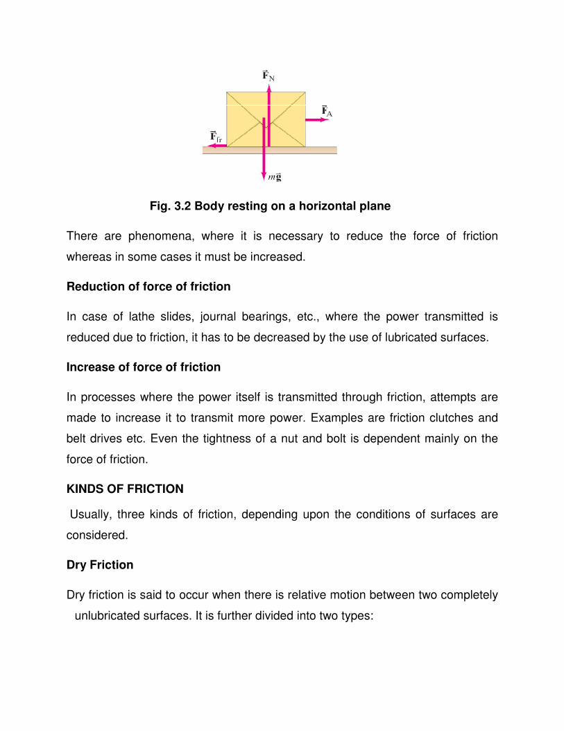
Fig. 3.2 Body resting on a horizontal plane
There are phenomena, where it is necessary to reduce the force of friction
whereas in some cases it must be increased.
Reduction of force of friction
In case of lathe slides, journal bearings, etc., where the power transmitted is
reduced due to friction, it has to be decreased by the use of lubricated surfaces.
Increase of force of friction
In processes where the power itself is transmitted through friction, attempts are
made to increase it to transmit more power. Examples are friction clutches and
belt drives etc. Even the tightness of a nut and bolt is dependent mainly on the
force of friction.
KINDS OF FRICTION
Usually, three kinds of friction, depending upon the conditions of surfaces are
considered.
Dry Friction
Dry friction is said to occur when there is relative motion between two completely
unlubricated surfaces. It is further divided into two types:
(a) Solid Friction: When the two surfaces have a sliding motion relative to each
other, it is called a solid friction.
(b) Rolling Friction: Friction due to rolling of one surface over anothe
and roller bearings) is called rolling friction.
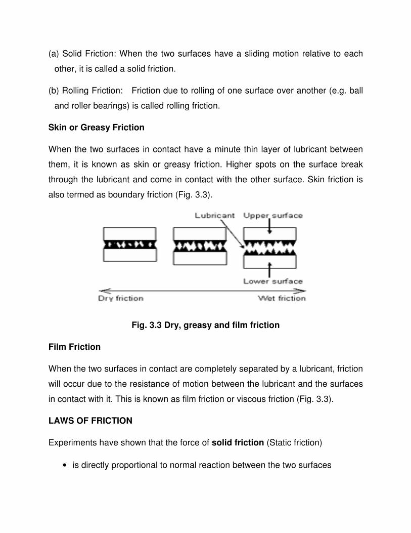
Skin or Greasy Friction
When the two surfaces in contact have a minute thin layer of lubricant between
them, it is known as skin or greasy friction. Higher spots on the surface break
through the lubricant and come in contact with the other surface. Skin friction is
also termed as boundary friction
Fig. 3.3 Dry, greasy and film friction
Film Friction
When the two surfaces in contact are completely separated by a lubricant, friction
will occur due to the resistance of motion between the lubricant and the surfaces
in contact with it. This is known as film friction or viscous friction
LAWS OF FRICTION
Experiments have shown that the force of
• is directly proportional to normal reaction between the two surfaces
(a) Solid Friction: When the two surfaces have a sliding motion relative to each
other, it is called a solid friction.
(b) Rolling Friction: Friction due to rolling of one surface over anothe
and roller bearings) is called rolling friction.
When the two surfaces in contact have a minute thin layer of lubricant between
them, it is known as skin or greasy friction. Higher spots on the surface break
lubricant and come in contact with the other surface. Skin friction is
also termed as boundary friction (Fig. 3.3).
Fig. 3.3 Dry, greasy and film friction
When the two surfaces in contact are completely separated by a lubricant, friction
will occur due to the resistance of motion between the lubricant and the surfaces
in contact with it. This is known as film friction or viscous friction (Fig. 3.3).
Experiments have shown that the force of solid friction (Static friction
is directly proportional to normal reaction between the two surfaces
(a) Solid Friction: When the two surfaces have a sliding motion relative to each
(b) Rolling Friction: Friction due to rolling of one surface over another (e.g. ball
When the two surfaces in contact have a minute thin layer of lubricant between
them, it is known as skin or greasy friction. Higher spots on the surface break
lubricant and come in contact with the other surface. Skin friction is
When the two surfaces in contact are completely separated by a lubricant, friction
will occur due to the resistance of motion between the lubricant and the surfaces
(Fig. 3.3).
(Static friction)
is directly proportional to normal reaction between the two surfaces
• opposes the motion between the surfaces
• depends upon the materials of the two surfaces
• is independent of the area of contact
• is independent of the velocity of sliding
Kinetic friction
• The force of friction always acts in a direction opposite to that in which the
body is moving.
• The magnitude of kinetic friction bears a constant ratio to the normal
reaction between the two surfaces.
• The force of friction is independent of the relative velocity between the two
surfaces in contact, but it decreases slightly with increase in velocity.
• The force of friction increases with reversal of motion.
• The COF changes slightly when the temperature changes.
Fluid friction
• The force of friction is almost independent of the load.
• The force of friction reduces with the increase of temperature of the
lubricant.
• The force of friction depends upon the type and viscosity of the lubricant.
• The force of friction is independent of the nature of surfaces.
• The frictional force increases with the increase in the relative velocity of the
frictional surfaces.
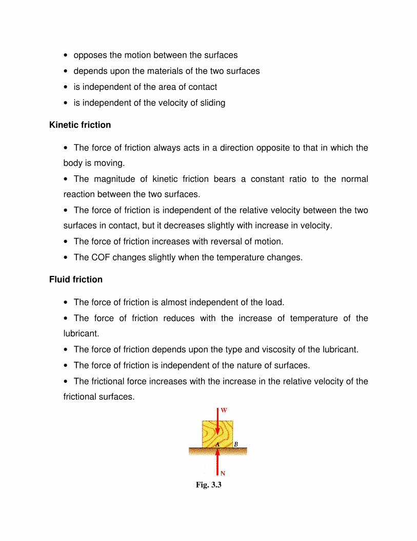
Fig. 3.3
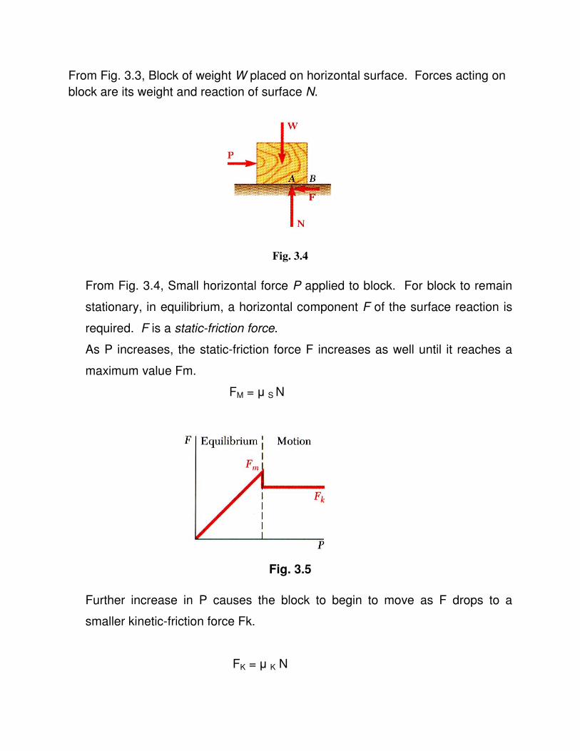
From Fig. 3.3, Block of weight W placed on horizontal surface. Forces acting on
block are its weight and reaction of surface N.
Fig. 3.4
From Fig. 3.4, Small horizontal force P applied to block. For block to remain
stationary, in equilibrium, a horizontal component F of the surface reaction is
required. F is a static-friction force.
As P increases, the static-friction force F increases as well until it reaches a
maximum value Fm.
FM = µ S N
Fig. 3.5
Further increase in P causes the block to begin to move as F drops to a
smaller kinetic-friction force Fk.
FK = µ K N
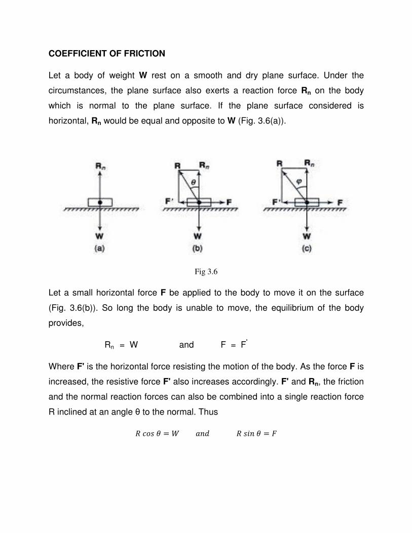
COEFFICIENT OF FRICTION
Let a body of weight W rest on a smooth and dry plane surface. Under the
circumstances, the plane surface also exerts a reaction force Rn on the body
which is normal to the plane surface. If the plane surface considered is
horizontal, Rn would be equal and opposite to W (Fig. 3.6(a)).
Fig 3.6
Let a small horizontal force F be applied to the body to move it on the surface
(Fig. 3.6(b)). So long the body is unable to move, the equilibrium of the body
provides,
Rn = W and F = F'
Where F' is the horizontal force resisting the motion of the body. As the force F is
increased, the resistive force F' also increases accordingly. F' and Rn, the friction
and the normal reaction forces can also be combined into a single reaction force
R inclined at an angle θ to the normal. Thus
����� = ������ =
At a moment, when the force F would just move the body, the value of F' or R sin
θ (equal to F) is called the static force of friction. Angle θ attains the value φ and
the body is in equilibrium under the action of three forces (Fig. 3.6(c))
F, in the horizontal direction
W, in the vertical downward direction, and
R, at an angle φ with the normal (inclined towards the force of friction).
According to the first law of friction,
F' α Rn
= µ Rn
Where µ is known as the coefficient of friction.
Or µ = �′��
Also in fig 8.1 c, tan φ = �′��
Or tan φ = ����� = µ
The angle φ is known as the limiting angle of friction, or simply the angle of
friction.
Now, if the body moves over the plane surface, it is observed that the friction
force will be slightly less than the static friction force. As long as the body moves
with a uniform velocity, the force F required for the motion of the body will be
equal to the force of friction on the body. However, if the velocity is to increase,
additional force will be needed to accelerate the body. "Thus, while the body is in
motion, it can be written that
tan φ = µ
Where φ is approximately the limiting angle of friction.
Also, no movement is possible until the angle of reaction R with the normal
becomes equal to the limiting angle of friction or until tan φ = µ.
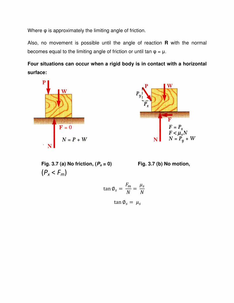
Four situations can occur when a rigid body is in contact with a horizontal
surface:
Fig. 3.7 (a) No friction, (Px = 0) Fig. 3.7 (b) No motion,
(Px < Fm)
tan∅� = �� =���
tan∅� =��
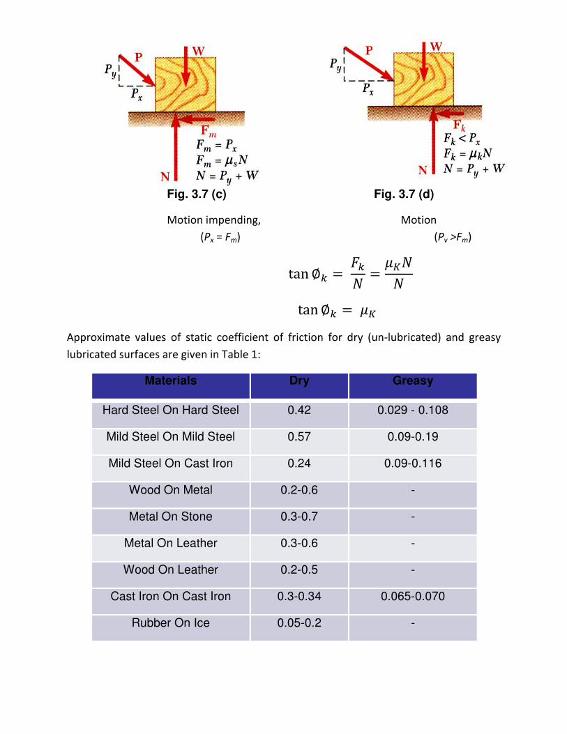
Fig. 3.7 (c) Fig. 3.7 (d)
Motion impending, Motion
(Px = Fm) (Pv >Fm)
tan ∅� = �� = ����
tan ∅� =��
Approximate values of static coefficient of friction for dry (un-lubricated) and greasy
lubricated surfaces are given in Table 1:
Materials Dry Greasy
Hard Steel On Hard Steel 0.42 0.029 - 0.108
Mild Steel On Mild Steel 0.57 0.09-0.19
Mild Steel On Cast Iron 0.24 0.09-0.116
Wood On Metal 0.2-0.6 -
Metal On Stone 0.3-0.7 -
Metal On Leather 0.3-0.6 -
Wood On Leather 0.2-0.5 -
Cast Iron On Cast Iron 0.3-0.34 0.065-0.070
Rubber On Ice 0.05-0.2 -
Pivot and Collar Bearing
The rotating shatfs are frequently subjected to axial thrust. These Shafts, Can be
kept in correct axial position if bearing surfaces are provided. The bearing
surfaces which are flat or conical carry the axial thrust. The bearing surfaces
placed at the end of a shaft are known as pivots.
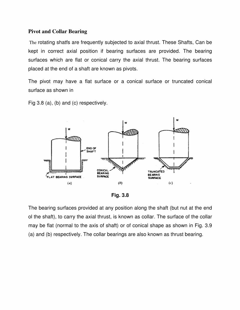
The pivot may have a flat surface or a conical surface or truncated conical
surface as shown in
Fig 3.8 (a), (b) and (c) respectively.
Fig. 3.8
The bearing surfaces provided at any position along the shaft (but nut at the end
ol the shaft), to carry the axial thrust, is known as collar. The surface of the collar
may be flat (normal to the axis of shaft) or of conical shape as shown in Fig. 3.9
(a) and (b) respectively. The collar bearings are also known as thrust bearing.
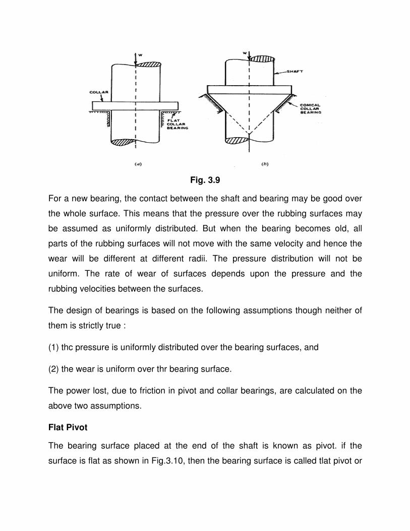
Fig. 3.9
For a new bearing, the contact between the shaft and bearing may be good over
the whole surface. This means that the pressure over the rubbing surfaces may
be assumed as uniformly distributed. But when the bearing becomes old, all
parts of the rubbing surfaces will not move with the same velocity and hence the
wear will be different at different radii. The pressure distribution will not be
uniform. The rate of wear of surfaces depends upon the pressure and the
rubbing velocities between the surfaces.
The design of bearings is based on the following assumptions though neither of
them is strictly true :
(1) thc pressure is uniformly distributed over the bearing surfaces, and
(2) the wear is uniform over thr bearing surface.
The power lost, due to friction in pivot and collar bearings, are calculated on the
above two assumptions.
Flat Pivot
The bearing surface placed at the end of the shaft is known as pivot. if the
surface is flat as shown in Fig.3.10, then the bearing surface is called tlat pivot or
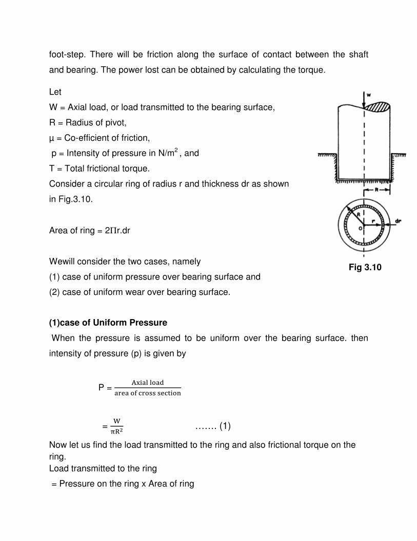
foot-step. There will be friction along the surface of contact between the shaft
and bearing. The power lost can be obtained by calculating the torque.
Let
W = Axial load, or load transmitted to the bearing surface,
R = Radius of pivot,
µ = Co-efficient of friction,
p = Intensity of pressure in N/m2 , and
T = Total frictional torque.
Consider a circular ring of radius r and thickness dr as shown
in Fig.3.10.
Area of ring = 2Πr.dr
Wewill consider the two cases, namely
(1) case of uniform pressure over bearing surface and
(2) case of uniform wear over bearing surface.
(1)case of Uniform Pressure
When the pressure is assumed to be uniform over the bearing surface. then
intensity of pressure (p) is given by
P = �� !""#!$
!%&!#'(%#)))&(* #�
= +
,�- ……. (1)
Now let us find the load transmitted to the ring and also frictional torque on the
ring.
Load transmitted to the ring
= Pressure on the ring x Area of ring
Fig 3.10
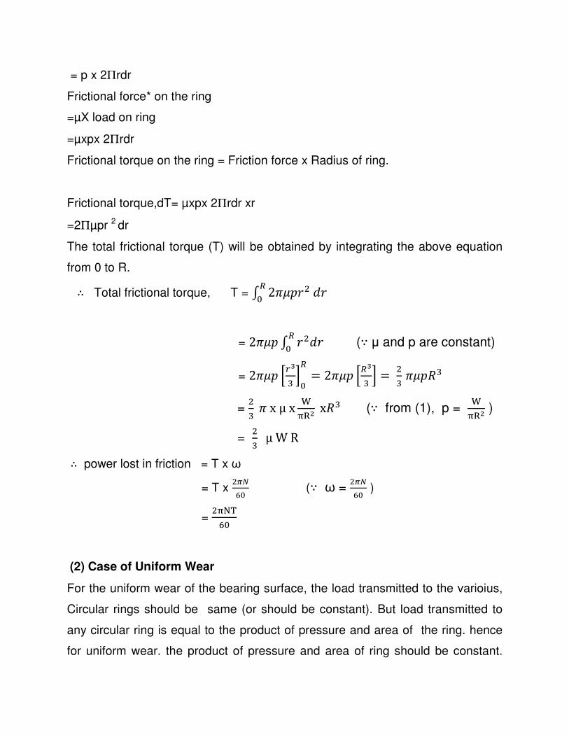
= p x 2Πrdr
Frictional force* on the ring
=µX load on ring
=µxpx 2Πrdr
Frictional torque on the ring = Friction force x Radius of ring.
Frictional torque,dT= µxpx 2Πrdr xr
=2Πµpr 2 dr
The total frictional torque (T) will be obtained by integrating the above equation
from 0 to R.
∴ Total frictional torque, T = / 21�234�3�5
= 21�2 / 34�3�5 (∵ µ and p are constant)
= 21�2 789: ;5
� = 21�2 7�9: ; = 4: 1�2�:
= 4: 1xμx +
,�- x�: (∵ from (1), p = +
,�- )
= 4: μWR
∴ power lost in friction = T x ω
= T x 4@AB5 (∵ ω =
4@AB5 )
= 4,CD
B5
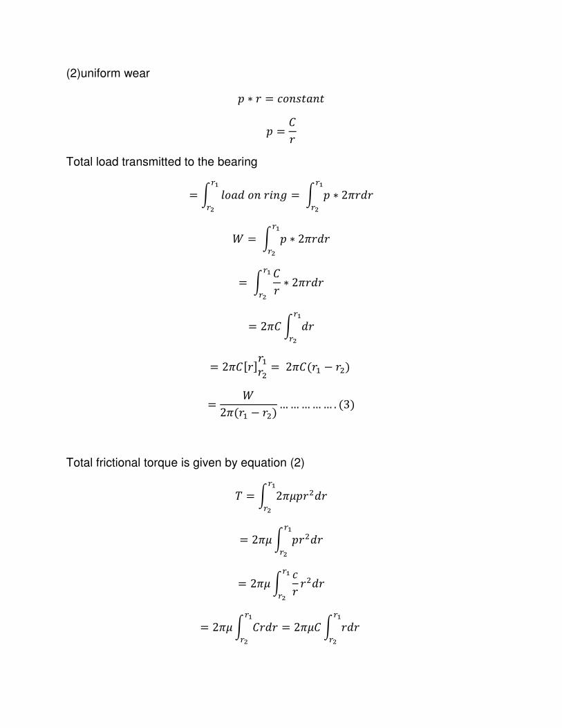
(2) Case of Uniform Wear
For the uniform wear of the bearing surface, the load transmitted to the varioius,
Circular rings should be same (or should be constant). But load transmitted to
any circular ring is equal to the product of pressure and area of the ring. hence
for uniform wear. the product of pressure and area of ring should be constant.
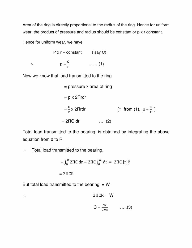
Area of the ring is directly proportional to the radius of the ring. Hence for uniform
wear, the product of pressure and radius should be constant or p x r constant.
Hence for uniform wear, we have
P x r = constant ( say C)
∴ p = E% …… (1)
Now we know that load transmitted to the ring
= pressure x area of ring
= p x 2Пrdr
= E% x 2Пrdr (∵ from (1), p =
E% )
= 2ПC dr …. (2)
Total load transmitted to the bearing, is obtained by integrating the above
equation from 0 to R.
∴ Total load transmitted to the bearing,
= / 2ПCdr�5 = 2ПC/ dr�
5 = 2ПCJrK5�
= 2ПCR
But total load transmitted to the bearing, = W
∴ 2ПCR = W
C = L
MNO …..(3)
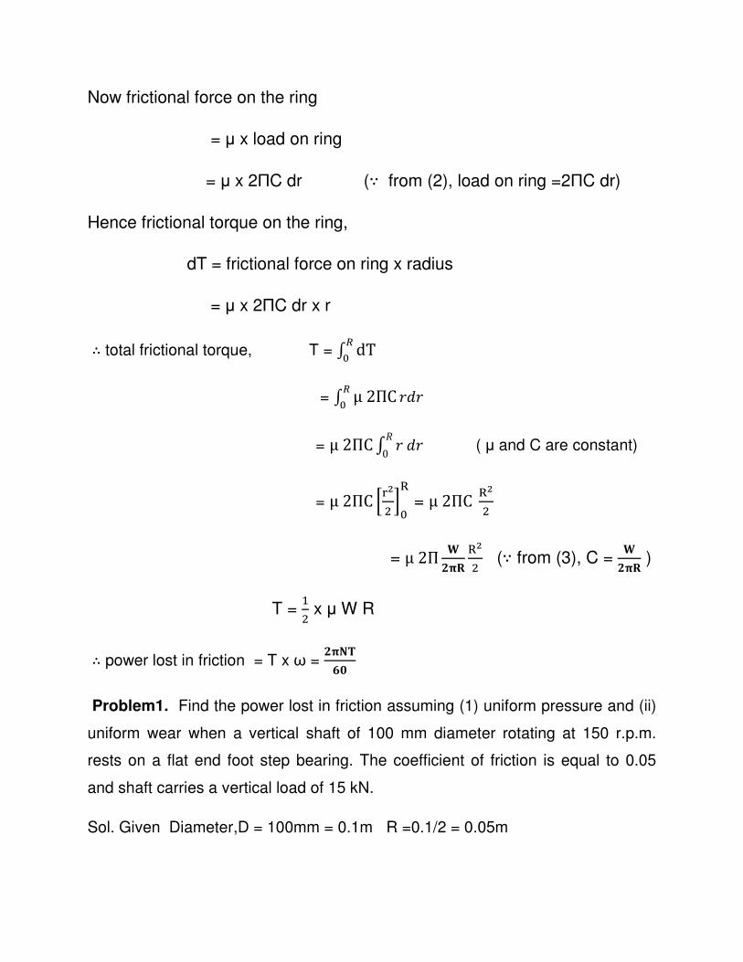
Now frictional force on the ring
= µ x load on ring
= µ x 2ПC dr (∵ from (2), load on ring =2ПC dr)
Hence frictional torque on the ring,
dT = frictional force on ring x radius
= µ x 2ПC dr x r
∴ total frictional torque, T = / dT�5
= / μ2ПC�5 3�3
= μ2ПC/ 3�3�0 ( µ and C are constant)
= μ2ПC 7%-4 ;5
� = μ2ПC �-
4
= μ2П LMNO
�-4 (∵ from (3), C =
LMNO )
T = R4 x µ W R
∴ power lost in friction = T x ω = MNST
UV
Problem1. Find the power lost in friction assuming (1) uniform pressure and (ii)
uniform wear when a vertical shaft of 100 mm diameter rotating at 150 r.p.m.
rests on a flat end foot step bearing. The coefficient of friction is equal to 0.05
and shaft carries a vertical load of 15 kN.
Sol. Given Diameter,D = 100mm = 0.1m R =0.1/2 = 0.05m
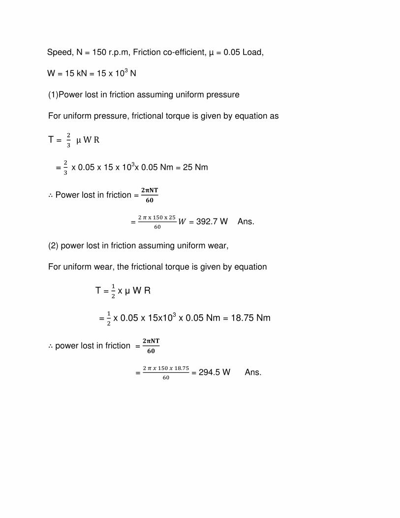
Speed, N = 150 r.p.m, Friction co-efficient, µ = 0.05 Load,
W = 15 kN = 15 x 103 N
(1)Power lost in friction assuming uniform pressure
For uniform pressure, frictional torque is given by equation as
T = 4: μWR
= 4:x 0.05 x 15 x 103x 0.05 Nm = 25 Nm
∴ Power lost in friction = MNST
UV =
4@�RW5�4WB5 � = 392.7 W Ans.
(2) power lost in friction assuming uniform wear,
For uniform wear, the frictional torque is given by equation
T = R4 x µ W R
= R4 x 0.05 x 15x103 x 0.05 Nm = 18.75 Nm
∴ power lost in friction = MNST
UV
= 4@XRW5XRY.[W
B5 = 294.5 W Ans.
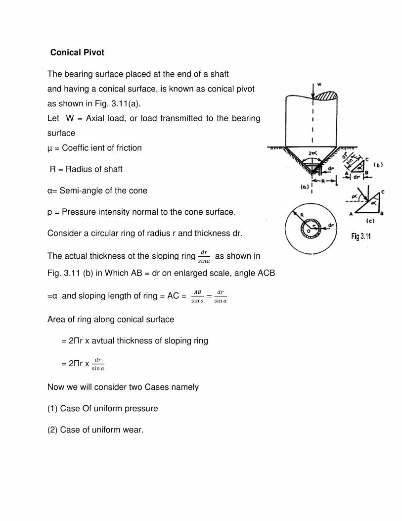
Conical Pivot
The bearing surface placed at the end of a shaft
and having a conical surface, is known as conical pivot
as shown in Fig. 3.11(a).
Let W = Axial load, or load transmitted to the bearing
surface
µ = Coeffic ient of friction
R = Radius of shaft
α= Semi-angle of the cone
p = Pressure intensity normal to the cone surface.
Consider a circular ring of radius r and thickness dr.
The actual thickness ot the sloping ring
Fig. 3.11 (b) in Which AB = dr on enlarged scale, angle ACB
=α and sloping length of ring = AC =
Area of ring along conical surface
= 2Пr x avtual thickness of sloping ring
= 2Пr x \8
) �]
Now we will consider two Cases namely
(1) Case Of uniform pressure
(2) Case of uniform wear.
The bearing surface placed at the end of a shaft
and having a conical surface, is known as conical pivot
Let W = Axial load, or load transmitted to the bearing
p = Pressure intensity normal to the cone surface.
Consider a circular ring of radius r and thickness dr.
The actual thickness ot the sloping ring \8
�^�] as shown in
(b) in Which AB = dr on enlarged scale, angle ACB
and sloping length of ring = AC = _`
) �] = \8) �]
Area of ring along conical surface
r x avtual thickness of sloping ring
Now we will consider two Cases namely
(1) Case Of uniform pressure
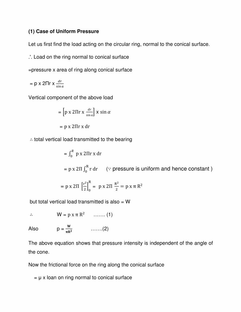
(1) Case of Uniform Pressure
Let us first find the load acting on the circular ring, normal to the conical surface.
.'. Load on the ring normal to conical surface
=pressure x area of ring along conical surface
= p x 2Пr x \8
) �]
Vertical component of the above load
= 7px2Пrx �3sin ; x sin d
= px2Пrxdr ∴ total vertical load transmitted to the bearing
= / px2Пrxdr�5
= px2П / rdr�5 (∵ pressure is uniform and hence constant )
= px2П 7%-4 ;5
� = px2П �-
4 = pxπR4
but total vertical load transmitted is also = W
∴ W = pxπR4 ……. (1)
Also p = L
NOM …….(2)
The above equation shows that pressure intensity is independent of the angle of
the cone.
Now the frictional force on the ring along the conical surface
= µ x loan on ring normal to conical surface
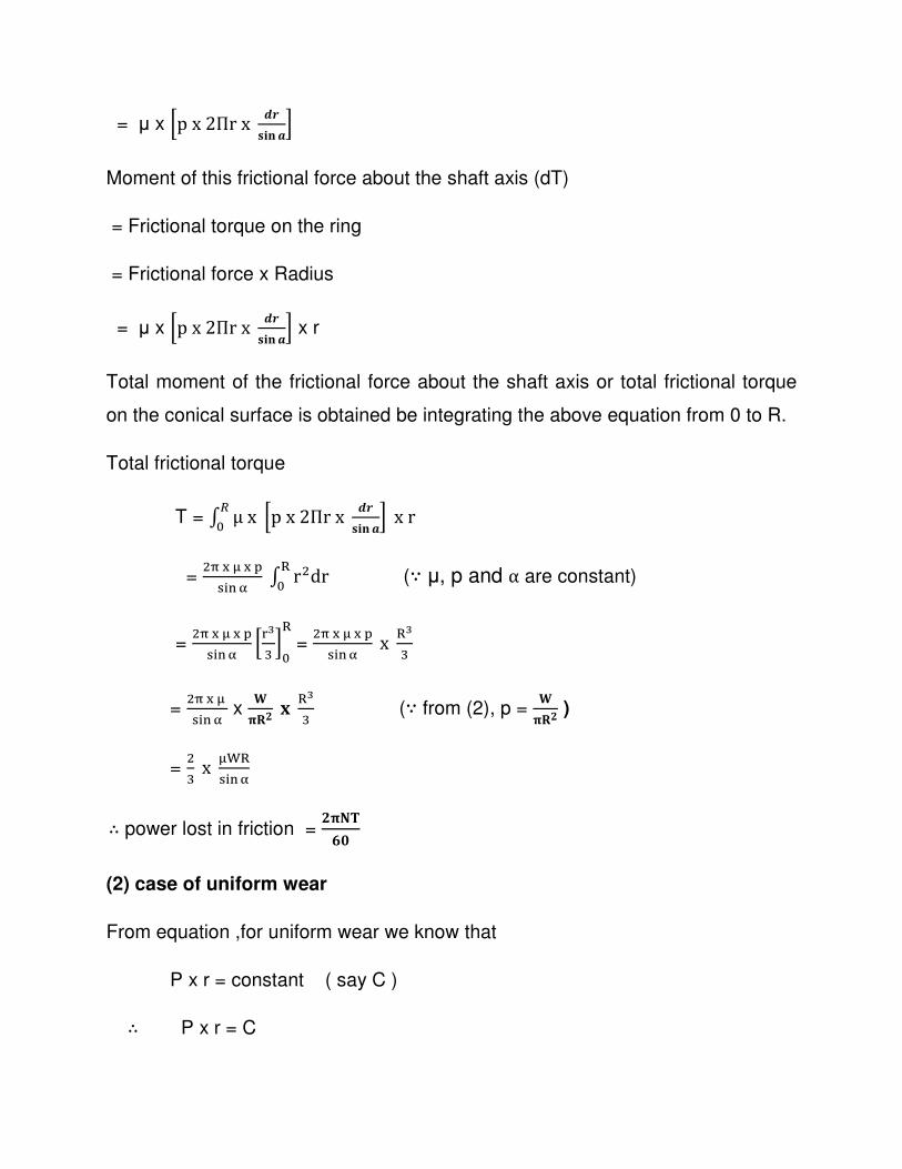
= µ x 7px2Пrx fghij k;
Moment of this frictional force about the shaft axis (dT)
= Frictional torque on the ring
= Frictional force x Radius
= µ x 7px2Пrx fghij k; x r
Total moment of the frictional force about the shaft axis or total frictional torque
on the conical surface is obtained be integrating the above equation from 0 to R.
Total frictional torque
T = / μx 7px2Пrx fghij k; xr�
5
= 4,�l�m
) � n / r4dr�5 (∵ µ, p and α are constant)
= 4,�l�m
) �n 7%9: ;5
�= 4,�l�m
) �n x �9:
= 4,�l) � n x
LNOM p �9
: (∵ from (2), p = L
NOM )
= 4: x l+�
) �n
∴ power lost in friction = MNST
UV
(2) case of uniform wear
From equation ,for uniform wear we know that
P x r = constant ( say C )
∴ P x r = C
Or p = q8
The equation for total vertical load transmitted to the bearing
= / px2Пrxdr�5
= / E% x2Пrxdr�5 (∵p =
q8 )
= 2 П x C / �3�5 = 2 П x C J3K5�
= 2 П x C x R
But total vertical load transmitted to the bearing is also equal to W
∴ W = 2 П x C x R
Or C = r
4@�
Now the frictional torque on the ring is given by the equation
dT = µ x p x 2Пr fg
hij sx r
= µ x tu x 2Пr
fghijsx r (∵p =
q8 for uniform wear)
= 2ПµCxrx vuhij s
= 2Пµ r
4@� rx vuhij s (∵ C =
r4@� )
∴ total frictional torque
T = / �w�5 = / 2Пμ r
4@� rx vuhij s�
5
= 2Пμ �21� x 1
sin α x / rdrR0
= 2Пμ �21� x 1
sin α x =
R4 x l+�
) � n
∴ power lost in friction = MNST
UV
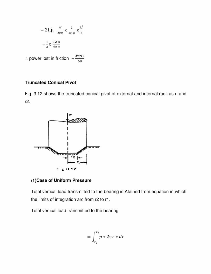
Truncated Conical Pivot
Fig. 3.12 shows the truncated conical pivot of external and internal radii as rl and
r2.
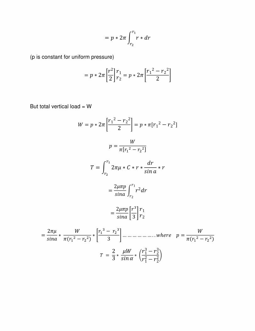
(1)Case of Uniform Pressure
Total vertical load transmitted to the bearing
the limits of integration arc from r2 to r1.
Total vertical load transmitted to the bearing
R22
MNSTUV
shows the truncated conical pivot of external and internal radii as rl and
1)Case of Uniform Pressure
Total vertical load transmitted to the bearing is Atained from equation
the limits of integration arc from r2 to r1.
load transmitted to the bearing
= y 2 ∗ 213 ∗ �38{
8-
shows the truncated conical pivot of external and internal radii as rl and
is Atained from equation in which
= 2 ∗ 21 y 3 ∗ �38{
8-
(p is constant for uniform pressure)
= 2 ∗ 21 |322 } 3132 = 2 ∗ 21 |312 − 322
2 }
But total vertical load = W
� = 2 ∗ 21 |312 − 3222 } = 2 ∗ 1J312 − 322K
2 = �1J3R4 − 344K
w = y 21� ∗ � ∗ 3 ∗ �3��
8{
8-∗ 3
= 2�12�� y 32�331
32
= 2�12�� |3:
3 } 3132
= 21��� ∗ �
1(3R4 − 344) ∗ |3R: −34:3 } … … … … … … . . �ℎ�3�2 = �
1(3R4 − 344)
w = 23 ∗ ����d ∗ �313 − 323312 − 322�
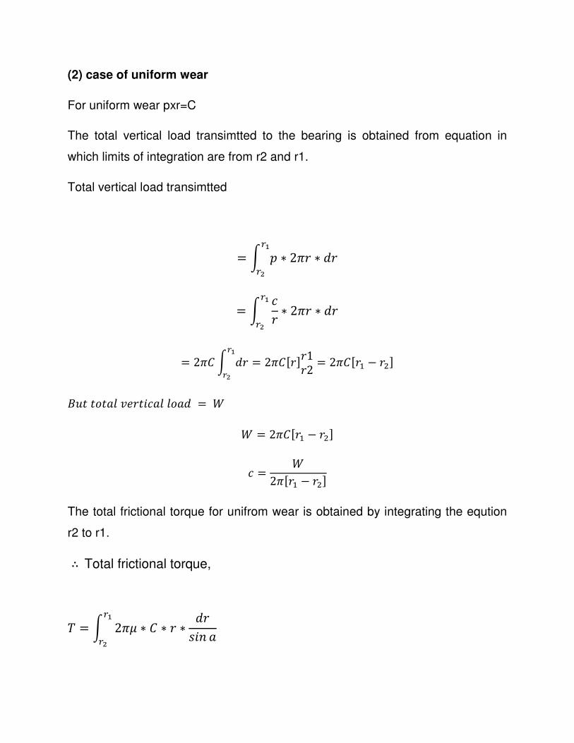
(2) case of uniform wear
For uniform wear pxr=C
The total vertical load transimtted to the bearing is obtained from equation in
which limits of integration are from r2 and r1.
Total vertical load transimtted
= y 2 ∗ 213 ∗ �38{
8-
= y �3 ∗ 213 ∗ �38{
8-
= 21� y �38{
8-= 21�J3K3132 = 21�J3R − 34K
���������3������� = �� = 21�J3R − 34K � = �
21J3R − 34K The total frictional torque for unifrom wear is obtained by integrating the eqution
r2 to r1.
∴Total frictional torque,
w = y 21� ∗ � ∗ 3 ∗ �3��
8{
8-
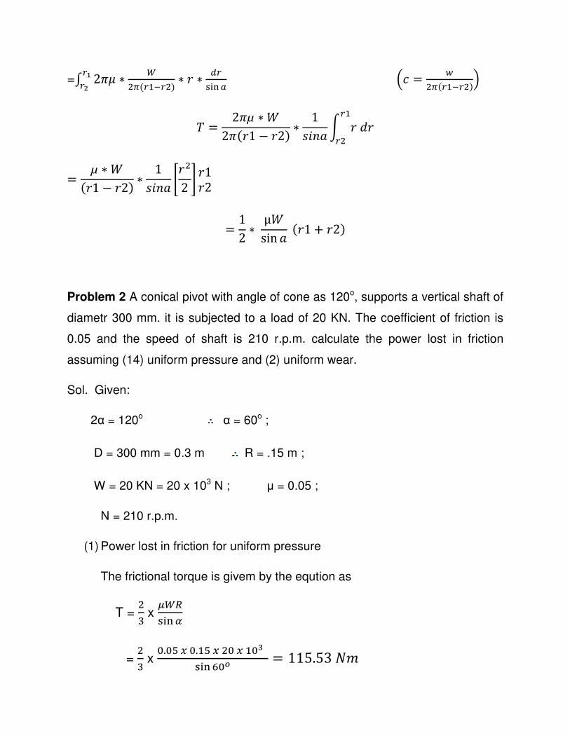
=/ 21� ∗ r4@(8R�84) ∗ 3 ∗ \8
) � ]8{8- �� = �4@(8R�84)�
w = 21µ ∗ �21(31 − 32) ∗ 1
�� y 3�38R84
= µ ∗ �(31 − 32) ∗ 1
�� |342 } 3132
= 12 ∗ μ�
sin (31 + 32)
Problem 2 A conical pivot with angle of cone as 120o, supports a vertical shaft of
diametr 300 mm. it is subjected to a load of 20 KN. The coefficient of friction is
0.05 and the speed of shaft is 210 r.p.m. calculate the power lost in friction
assuming (14) uniform pressure and (2) uniform wear.
Sol. Given:
2α = 120o α = 60o ;
D = 300 mm = 0.3 m R = .15 m ;
W = 20 KN = 20 x 103 N ; µ = 0.05 ;
N = 210 r.p.m.
(1) Power lost in friction for uniform pressure
The frictional torque is givem by the eqution as
T = 4:x
�r�) � �
= 4: x
5.5WX5.RWX45XR59) � B5� = 115.53��
2���3���� = 2�w60
= 4П�4R5�RRW.W:
B5 = 2540.6 W = 2.54 KW Ans.
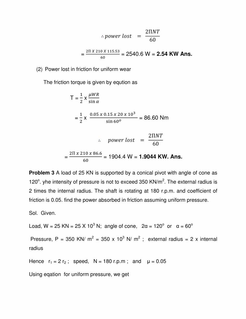
(2) Power lost in friction for uniform wear
The friction torque is given by eqution as
T = R4 x
�r�) � �
= R4 x
5.5WX5.RWX45XR59) � B5� = 86.60 Nm
2���3���� = 2�w60
= 4ПX4R5XYB.B
B5 = 1904.4 W = 1.9044 KW. Ans.
Problem 3 A load of 25 KN is supported by a conical pivot with angle of cone as
120o. yhe intensity of pressure is not to exceed 350 KN/m2. The external radius is
2 times the internal radius. The shaft is rotating at 180 r.p.m. and coefficient of
friction is 0.05. find the power absorbed in friction assuming uniform pressure.
Sol. Given.
Load, W = 25 KN = 25 X 103 N; angle of cone, 2α = 120o or α = 60o
Pressure, P = 350 KN/ m2 = 350 x 103 N/ m2 ; external radius = 2 x internal
radius
Hence r1 = 2 r2 ; speed, N = 180 r.p.m ; and µ = 0.05
Using eqation for uniform pressure, we get
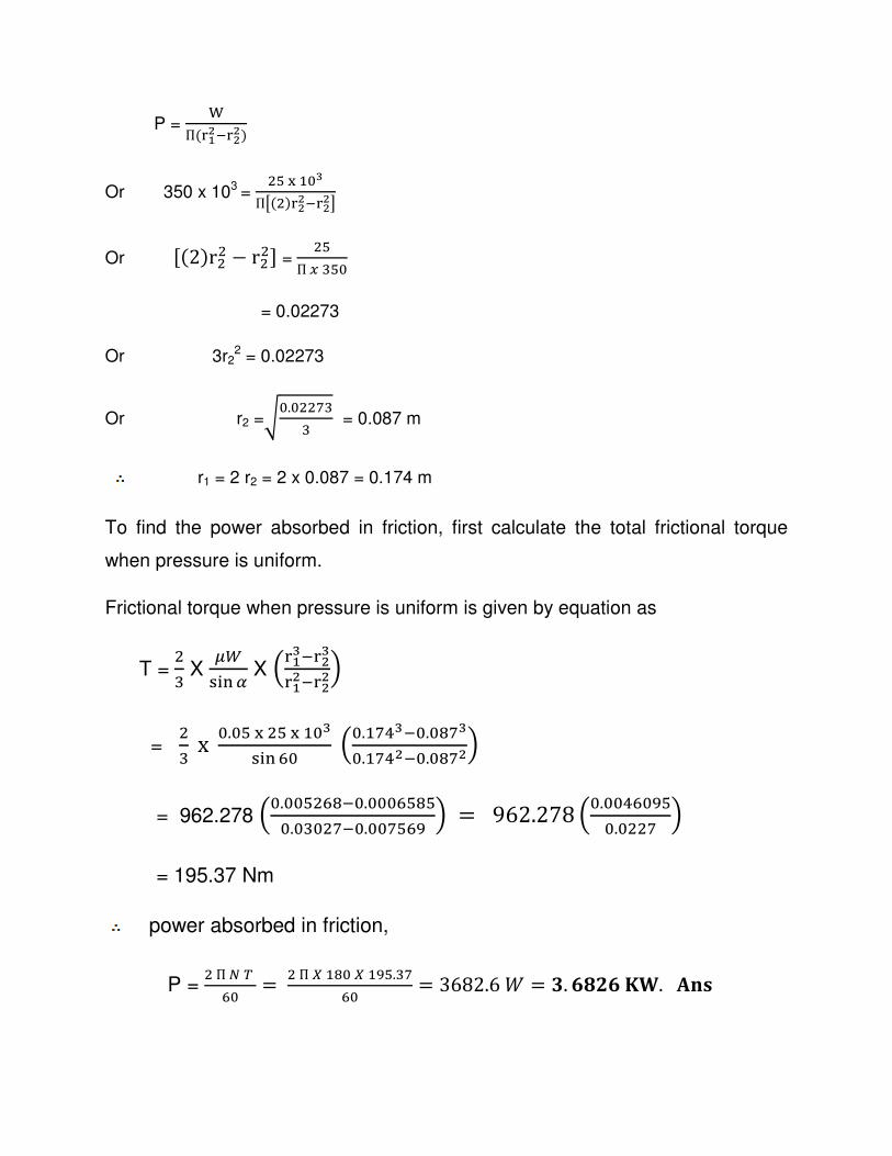
P = +
П(%{-�%--)
Or 350 x 103 = 4W�R59
П�(4)%--�%--�
Or J(2)r44 − r44K = 4WПX:W5
= 0.02273
Or 3r22 = 0.02273
Or r2 =�5.544[:: = 0.087 m
r1 = 2 r2 = 2 x 0.087 = 0.174 m
To find the power absorbed in friction, first calculate the total frictional torque
when pressure is uniform.
Frictional torque when pressure is uniform is given by equation as
T =4: X �r) � � X �%{9�%-9%{-�%--�
= 4: x 5.5W�4W�R59) � B5 �5.R[�9�5.5Y[9
5.R[�-�5.5Y[-�
= 962.278 �5.55W4BY�5.555BWYW5.5:54[�5.55[WB� � = 962.278 �5.55�B5�W
5.544[ �
= 195.37 Nm
power absorbed in friction,
P = 4ПA¡
B5 = 4П�RY5�R�W.:[B5 = 3682.6� = ¢. U£MU¤L.¥jh

Flat collar
The bearing surface provided at any position along the shaft (but not at the end
of the shaft), to carry axial thrust is known as collar which may be flat or conical.
If the surface is flat, then bearing surface is known as flat collar as shown in
fig.3.13 the collar bearings are also known as thrust bearings, the power lost in
friction can be obtained by calculating the torque.
Let r1 = external radius of collar
r2 = internal radius of collar
p = intensity of pressure
W = axial load or total load transmitted to the bearing surface
µ = coefficient of friction
T = total frictional torque
Fig 3.13
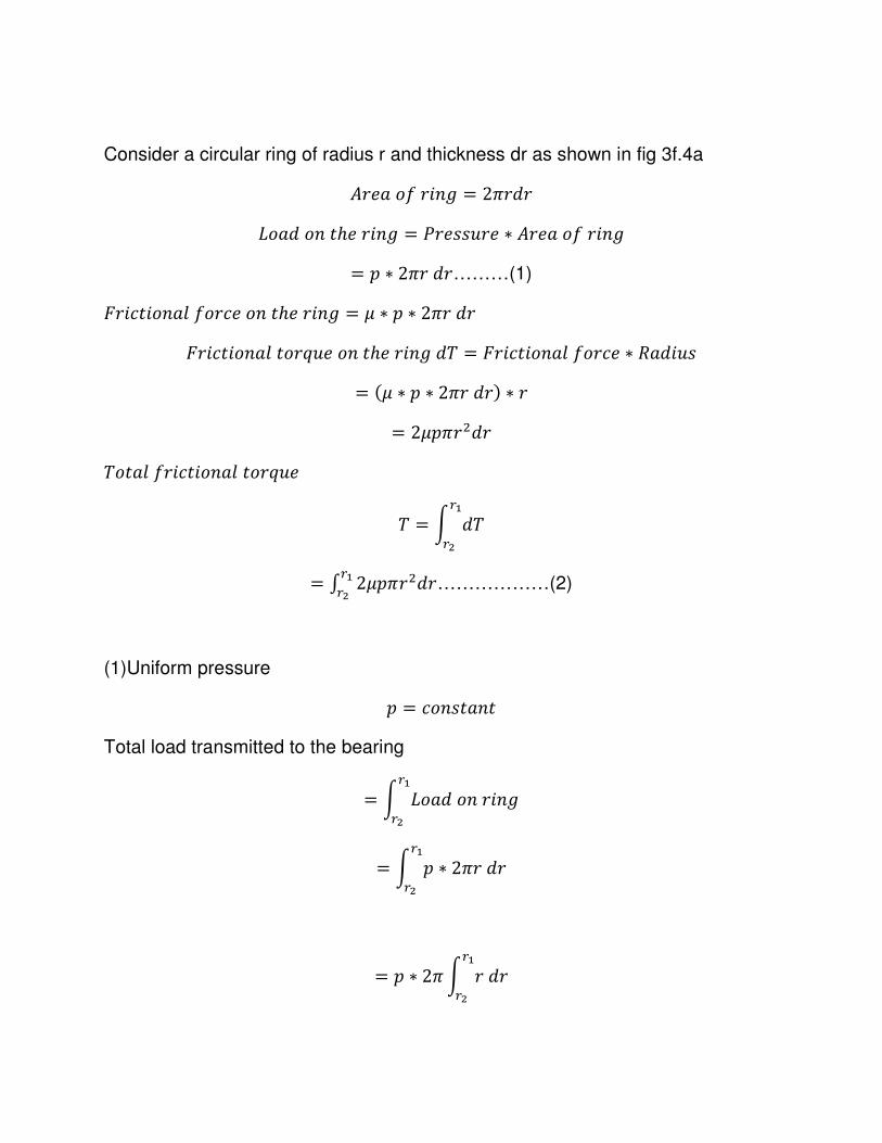
Consider a circular ring of radius r and thickness dr as shown in fig 3f.4a
¦3��§3�¨ = 213�3
©����ℎ�3�¨ = ª3����3� ∗ ¦3��§3�¨
= 2 ∗ 213�3………(1)
3������§�3����ℎ�3�¨ = � ∗ 2 ∗ 213�3
3��������3«����ℎ�3�¨�w = 3������§�3�� ∗ �����
= (� ∗ 2 ∗ 213�3) ∗ 3
= 2�2134�3
w���§3��������3«��
w = y �w8{
8-
= / 2�2134�38{8- ………………(2)
(1)Uniform pressure
2 = ����� Total load transmitted to the bearing
= y ©���3�¨8{
8-
= y 2 ∗ 213�38{
8-
= 2 ∗ 21 y 3�38{
8-
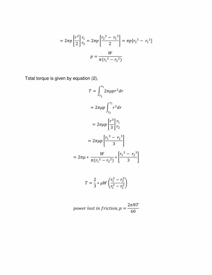
= 212 |342 } 3R34 = 212 |344 −3R4
2 } = 12J344 −3R4K
2 = �1(3R4 − 344)
Total torque is given by equation (2),
w = y 21�234�38{
8-
= 21�2 y 34�38{
8-
= 21�2 |3:3 } 3R34
= 21�2 |3R: −34:3 }
= 21� ∗ �1(3R4 − 344) ∗ |3R: −34:
3 }
w = 23 ∗ �� �3R: − 34:3R4 − 344�
2���3�����§3�����, 2 = 21�w60
(2)uniform wear
2 ∗ 3 = ����� 2 = �
3
Total load transmitted to the bearing
= y ����3�¨ = y 2 ∗ 213�38{
8-
8{
8-
� =y 2 ∗ 213�38{
8-
=y �3 ∗ 213�38{
8-
= 21� y �38{
8-
= 21�J3K3R34 = 21�(3R − 34) = �
21(3R − 34) … … … … … . (3)
Total frictional torque is given by equation (2)
w = y 21�234�38{
8-
= 21� y 234�38{
8-
= 21� y �3 34�38{
8-
= 21� y �3�38{
8-= 21�� y 3�38{
8-
= 21�� |342 } 3R34
= 21�� |344 −3R42 }
= 21� ∗ �21(3R − 34) ∗ |344 −3R4
2 }
= ��2 (3R + 34)
2���3�����§3�����, 2 = 21�w60
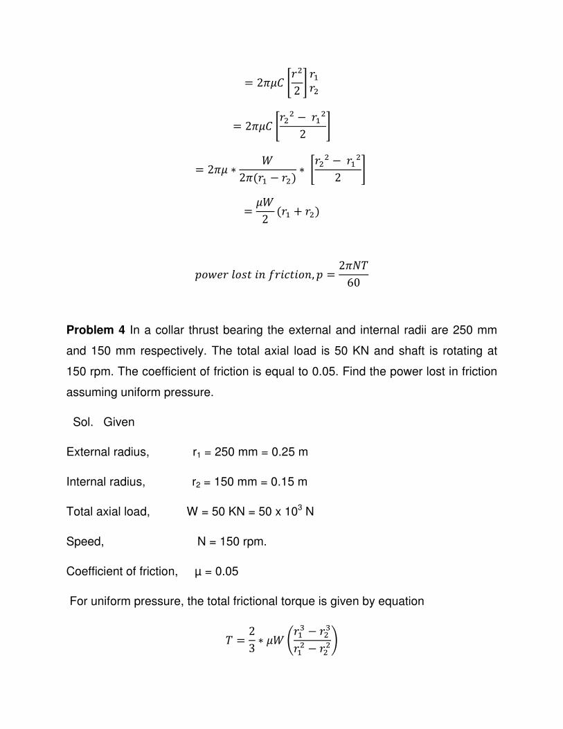
Problem 4 In a collar thrust bearing the external and internal radii are 250 mm
and 150 mm respectively. The total axial load is 50 KN and shaft is rotating at
150 rpm. The coefficient of friction is equal to 0.05. Find the power lost in friction
assuming uniform pressure.
Sol. Given
External radius, r1 = 250 mm = 0.25 m
Internal radius, r2 = 150 mm = 0.15 m
Total axial load, W = 50 KN = 50 x 103 N
Speed, N = 150 rpm.
Coefficient of friction, µ = 0.05
For uniform pressure, the total frictional torque is given by equation
w = 23 ∗ �� �3R: − 34:3R4 − 344�
= 23 ∗ 0.05 ∗ 50 ∗ 10: �0.25: − 0.15:
0.254 − 0.154�
= 510.42��
2���3�����§3�����, 2���3�����§3�����, 2 = 21�w
60
= 21 ∗ 150 ∗ 510.4260 = 8.0176®�. �
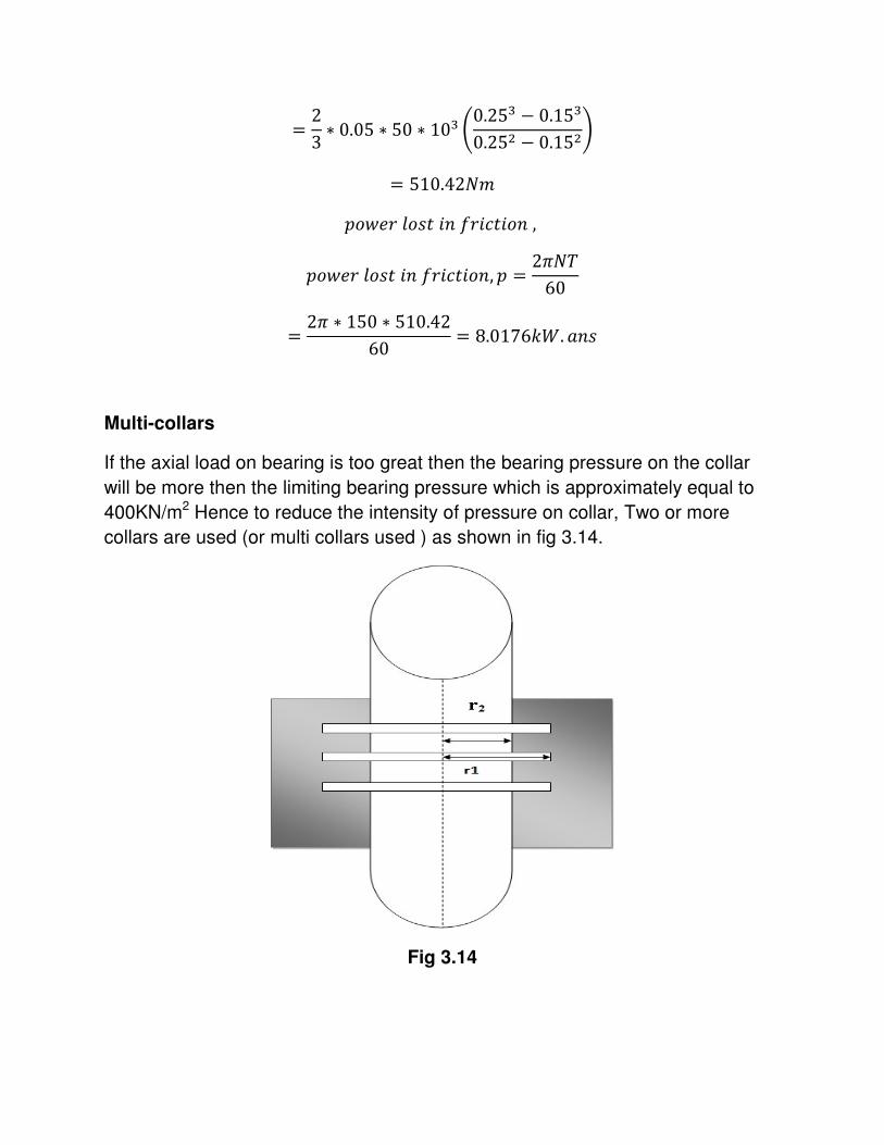
Multi-collars
If the axial load on bearing is too great then the bearing pressure on the collar
will be more then the limiting bearing pressure which is approximately equal to
400KN/m2 Hence to reduce the intensity of pressure on collar, Two or more
collars are used (or multi collars used ) as shown in fig 3.14.
Fig 3.14
(1)n=Number of collars in multi-collar bearing
= w������©��2�3�����¯���������3
(3) p=Intensity of the uniform pressure
= �����¯�3�§����3 ∗ ¦3��§������3
= � ∗ 1(3R4 − 344)
(3) Total torque transmitted remains constant i e…..
w = 23 ∗ �� �3R: − 34:3R4 − 344�
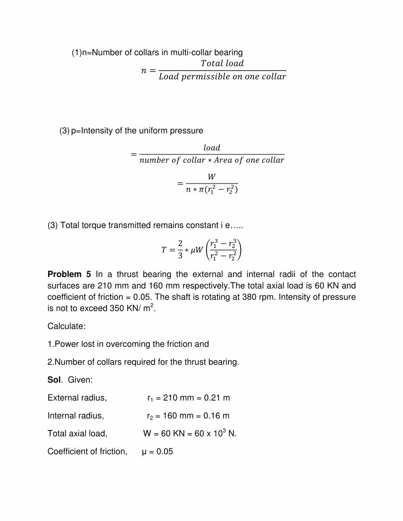
Problem 5 In a thrust bearing the external and internal radii of the contact
surfaces are 210 mm and 160 mm respectively.The total axial load is 60 KN and
coefficient of friction = 0.05. The shaft is rotating at 380 rpm. Intensity of pressure
is not to exceed 350 KN/ m2.
Calculate: 1.Power lost in overcoming the friction and
2.Number of collars required for the thrust bearing.
Sol. Given:
External radius, r1 = 210 mm = 0.21 m
Internal radius, r2 = 160 mm = 0.16 m
Total axial load, W = 60 KN = 60 x 103 N.
Coefficient of friction, µ = 0.05
Speed, N = 380 rpm.
Intensity of pressure, P = 350 KN /m2 = 350 x103 N/m2
Here the power lost in overcoming the friction is to be determined. Also no
assumption is mentioned.
Hence it is safe to assume uniform pressure.
1.Power lost in overcoming friction
For uniform pressure, total frictional torque is given by equation as
w = 23 ∗ �� �3R: − 34:3R4 − 344�
= 23 ∗ 0.05 ∗ 60 ∗ 10: �0.21: − 0.16:
0.214 − 0.164�
= 558.378��2���3�����§3�����, 2 = 21�w
60
= 21 ∗ 380 ∗ 558.37860 = 22.2198°�. �
(2)Numbers of collars required
��¯�3�§����3�, = ����������2�3����3
Now load per collar for uniform pressure is obtained from equation
2 = �∗1(3R4 − 344)
�ℎ�3��∗���ℎ����2�3����3
� = 2 ∗ 1(3R4 − 344) = 350 ∗ 10: ∗ 1(0.214 − 0.164)
= 20341.8�
��¯�3�§����3�, = ����������2�3����3
= ��∗ = 60 ∗ 10:
20341.8 = 2.95 = 3����3��
Belt Drives
Introduction
Usually, power is transmitted from one shaft to another by means of belts, ropes,
chains and gears, the salient features of which are as follows:
1. Belts, ropes and chains are used where the distance between the shafts is
large. For small distances, gears are preferred.
2. Belts, ropes and chains are flexible type of connectors, i.e., they are bent
easily.
3. The flexibility of belts and ropes is due to the property of their materials
whereas chains have a number of small rigid elements having relative motion
between the two elements.
4 Belts and ropes transmit power due to friction between them and the pulleys. If
the power transmitted exceeds the force of friction, the belt or rope slips over the
pulley.
5 Belts and ropes are strained during motion as tensions are developed in them.
6. Owing to slipping and straining action, belts and ropes are not positive type of
drives, i.e. their velocity ratios are not constant. On the other hand, chains and
gears have constant velocity ratios.
BELT DRIVES
To transmit power from one shaft to another, pulleys are mounted on the two
shafts. The pulleys are then connected by an endless belt passing over the
pulleys. The connecting belt is kept in tension so that motion of one pulley is
transferred to the other without slip. The speed of the driven shaft can be varied
by varying the diameters of the two pulleys.
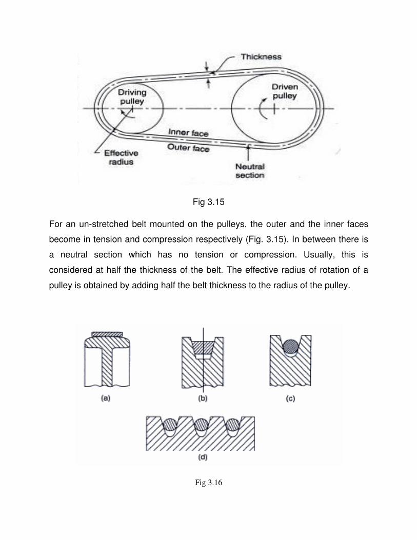
Fig 3.15
For an un-stretched belt mounted on the pulleys, the outer and the inner faces
become in tension and compression respectively (Fig. 3.15). In between there is
a neutral section which has no tension or compression. Usually, this is
considered at half the thickness of the belt. The effective radius of rotation of a
pulley is obtained by adding half the belt thickness to the radius of the pulley.
Fig 3.16
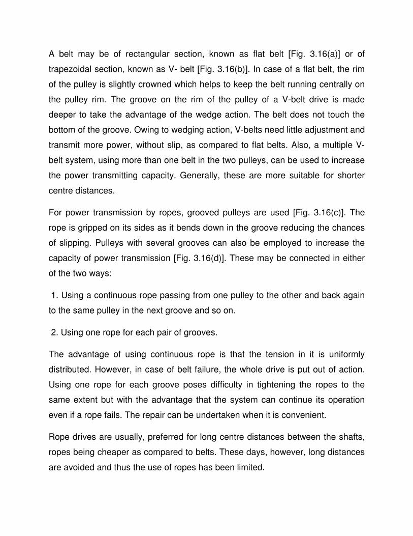
A belt may be of rectangular section, known as flat belt [Fig. 3.16(a)] or of
trapezoidal section, known as V- belt [Fig. 3.16(b)]. In case of a flat belt, the rim
of the pulley is slightly crowned which helps to keep the belt running centrally on
the pulley rim. The groove on the rim of the pulley of a V-belt drive is made
deeper to take the advantage of the wedge action. The belt does not touch the
bottom of the groove. Owing to wedging action, V-belts need little adjustment and
transmit more power, without slip, as compared to flat belts. Also, a multiple V-
belt system, using more than one belt in the two pulleys, can be used to increase
the power transmitting capacity. Generally, these are more suitable for shorter
centre distances.
For power transmission by ropes, grooved pulleys are used [Fig. 3.16(c)]. The
rope is gripped on its sides as it bends down in the groove reducing the chances
of slipping. Pulleys with several grooves can also be employed to increase the
capacity of power transmission [Fig. 3.16(d)]. These may be connected in either
of the two ways:
1. Using a continuous rope passing from one pulley to the other and back again
to the same pulley in the next groove and so on.
2. Using one rope for each pair of grooves.
The advantage of using continuous rope is that the tension in it is uniformly
distributed. However, in case of belt failure, the whole drive is put out of action.
Using one rope for each groove poses difficulty in tightening the ropes to the
same extent but with the advantage that the system can continue its operation
even if a rope fails. The repair can be undertaken when it is convenient.
Rope drives are usually, preferred for long centre distances between the shafts,
ropes being cheaper as compared to belts. These days, however, long distances
are avoided and thus the use of ropes has been limited.
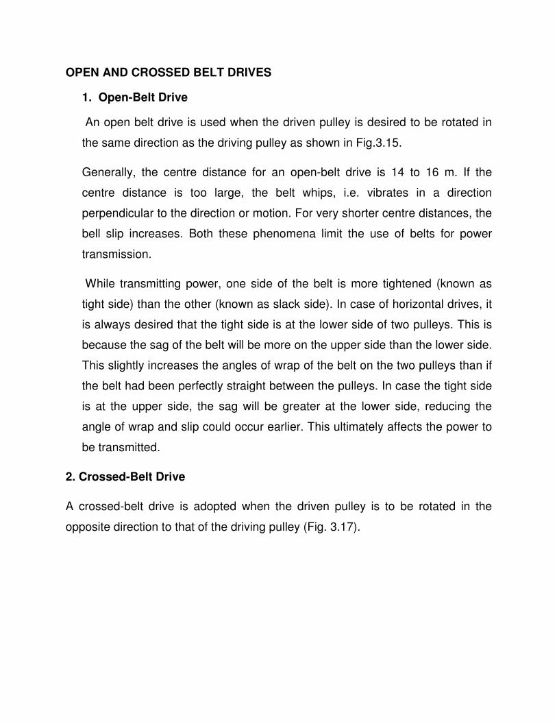
OPEN AND CROSSED BELT DRIVES
1. Open-Belt Drive
An open belt drive is used when the driven pulley is desired to be rotated in
the same direction as the driving pulley as shown in Fig.3.15.
Generally, the centre distance for an open-belt drive is 14 to 16 m. If the
centre distance is too large, the belt whips, i.e. vibrates in a direction
perpendicular to the direction or motion. For very shorter centre distances, the
bell slip increases. Both these phenomena limit the use of belts for power
transmission.
While transmitting power, one side of the belt is more tightened (known as
tight side) than the other (known as slack side). In case of horizontal drives, it
is always desired that the tight side is at the lower side of two pulleys. This is
because the sag of the belt will be more on the upper side than the lower side.
This slightly increases the angles of wrap of the belt on the two pulleys than if
the belt had been perfectly straight between the pulleys. In case the tight side
is at the upper side, the sag will be greater at the lower side, reducing the
angle of wrap and slip could occur earlier. This ultimately affects the power to
be transmitted.
2. Crossed-Belt Drive
A crossed-belt drive is adopted when the driven pulley is to be rotated in the
opposite direction to that of the driving pulley (Fig. 3.17).
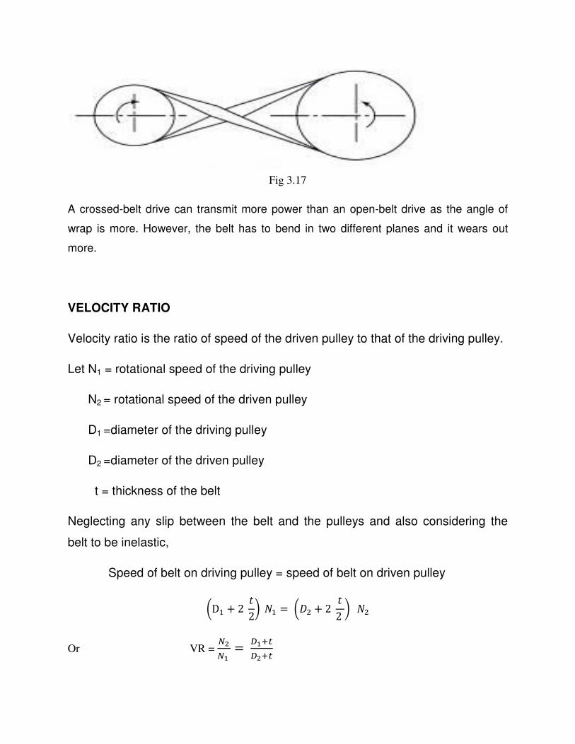
Fig 3.17
A crossed-belt drive can transmit more power than an open-belt drive as the angle of
wrap is more. However, the belt has to bend in two different planes and it wears out
more.
VELOCITY RATIO
Velocity ratio is the ratio of speed of the driven pulley to that of the driving pulley.
Let N1 = rotational speed of the driving pulley
N2 = rotational speed of the driven pulley
D1 =diameter of the driving pulley
D2 =diameter of the driven pulley
t = thickness of the belt
Neglecting any slip between the belt and the pulleys and also considering the
belt to be inelastic,
Speed of belt on driving pulley = speed of belt on driven pulley
±DR + 2 �2³�R =±´4 + 2 �2³�4
Or VR = A-A{ = µ{¶·
µ-¶·
SLIP
The effect of slip is to decrease the speed of belt on the driving shaft and to
decrease the speed of the driven shaft.
Let ¸R = Angular velocity of the driving pulley
¸4 = Angular velocity of the driven pulley
S1 = percentage slip between the driving pulley and the belt
S2 = percentage slip between the driven pulley and the belt
S= total percentage slip,
Peripheral speed of driving pulley = ¸R �´1+�2 �
Speed of belt on the driving pulley =7¸R �´1+�2 �; �R55�¹{
R55 �
This is also the speed of the belt on the driven pulley.
Peripheral speed of driven pulley = º7¸R �´1+�2 �;�100−»1100 � �100−»2100 �¼
As S is the total percentage slip,
Peripheral speed of driven shaft = 7¸R �´1+�2 �; �R55�¹
R55 �
º7¸R �´1+�2 �;�100−»1100 � �100−»2100 �¼ = 7¸R �´1+�
2 �; �R55�¹R55 �
(R55�¹{)(R55�¹-)R55�R55 =
R55�¹R55
Or (100 - S1) (100 – S2) = 100 (100 – S)
Or 10000 = 100 S2 -100 S1 +S1S2 =10000 – 100S
Or 100 S = 100 S1 + 100 S2 – S1 S2
Or S = S1 + S2 -0.01S1 S2
Effect of slip is to reduce the velocity ratio,
VR = C-A{ = �µ{¶·
µ4¶·� �R55�¹R55 �
Also it is to be remembered that slip will first occur on the pulley with smaller
angle of lap i.e. on the smaller pulley.
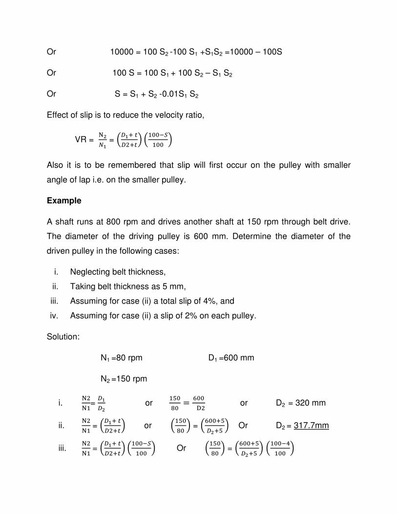
Example
A shaft runs at 800 rpm and drives another shaft at 150 rpm through belt drive.
The diameter of the driving pulley is 600 mm. Determine the diameter of the
driven pulley in the following cases:
i. Neglecting belt thickness,
ii. Taking belt thickness as 5 mm,
iii. Assuming for case (ii) a total slip of 4%, and
iv. Assuming for case (ii) a slip of 2% on each pulley.
Solution:
N1 =80 rpm D1 =600 mm
N2 =150 rpm
i. C4CR=
µ{µ- or
RW5Y5 = B55
½4 or D2 = 320 mm
ii. C4CR= �µ{¶·
µ4¶·� or �RW5Y5 � = �B55¶W
µ-¶W � Or D2 = 317.7mm
iii. C4CR= �µ{¶·
µ4¶·� �R55�¹R55 � Or �RW5
Y5 � = �B55¶Wµ-¶W � �R55��
R55 �
D2 = 304.8mm
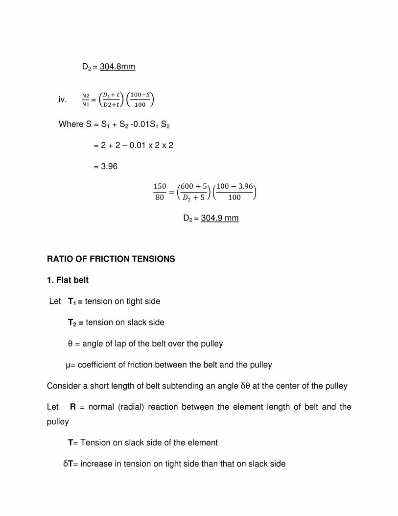
iv. C4CR= �µ{¶·
µ4¶·� �R55�¹R55 �
Where S = S1 + S2 -0.01S1 S2
= 2 + 2 – 0.01 x 2 x 2
= 3.96
15080 = ±600 + 5
´4 + 5 ³ ±100 − 3.96100 ³
D2 = 304.9 mm
RATIO OF FRICTION TENSIONS
1. Flat belt
Let T1 = tension on tight side
T2 = tension on slack side
θ = angle of lap of the belt over the pulley
µ= coefficient of friction between the belt and the pulley
Consider a short length of belt subtending an angle δθ at the center of the pulley
Let R = normal (radial) reaction between the element length of belt and the
pulley
T= Tension on slack side of the element
δT= increase in tension on tight side than that on slack side
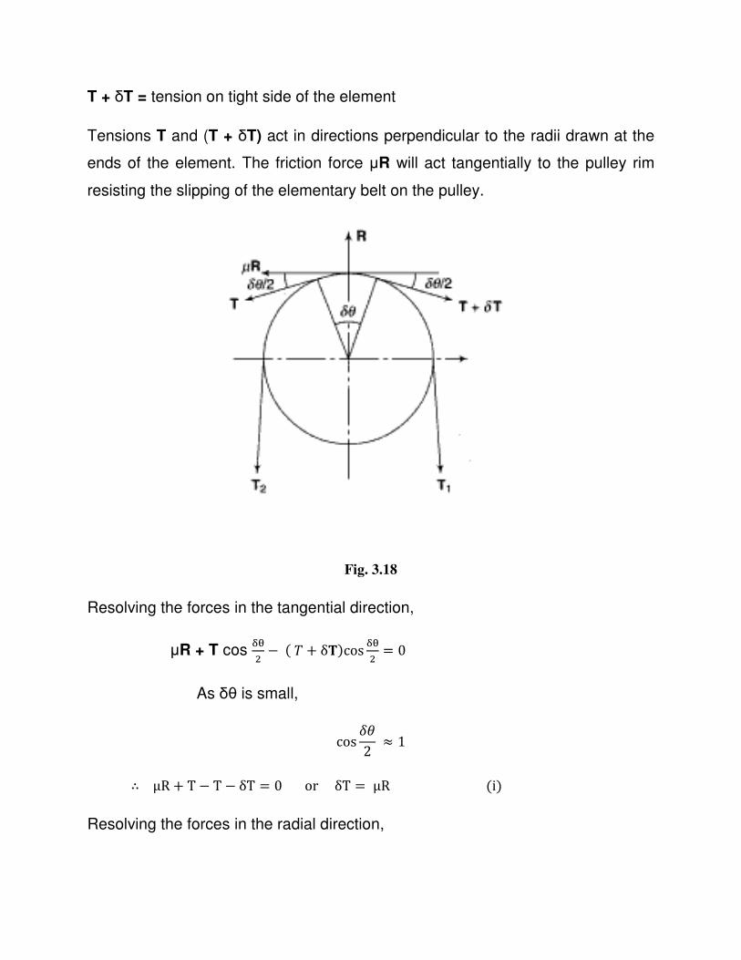
T + δT = tension on tight side of the element
Tensions T and (T + δT) act in directions perpendicular to the radii drawn at the
ends of the element. The friction force µR will act tangentially to the pulley rim
resisting the slipping of the elementary belt on the pulley.
Fig. 3.18
Resolving the forces in the tangential direction,
µR + T cos ¾¿4 −(w + δT)cos ¾¿
4 = 0 As δθ is small,
cos Ã�2 ≈ 1
∴ μR + T − T − δT = 0orδT = μR(i) Resolving the forces in the radial direction,
R- T sin ÅÆ4 - (w + δT) sin
ÅÆ4 = 0
As δθ is small, sin ÅÆ4 ≈ ÅÆ
4
∴ R − T ¾¿4 − T
ÅÆ4 − ¾D¾¿
4 = 0
Neglecting product of two small quantities,
R = T δθ (ii)
From (i) and (ii) , δT = μ Tδθ or Å¡¡ = �Ã�
Integrating between proper limits,
/ \¡¡
¡{¡- =/ ���Æ5
Or logÉ ¡{¡- = ��
Or ¡{¡- = ��Æ
It is to be noted that the above relation is valid only when the belt is on the point
of slipping on the pulleys.
POWER TRANSMITTED
Let T1 = tension on the tight side
T2 = tension on the slack side
v= linear velocity of the belt
p= power transmitted
Then,
P= net force x distance moved/second
= (wR − w4)Ê�
This relation gives the power transmitted irrespective of the fact whether the belt
is on the point of slipping or not. If it is, the relationship between T1 and T2 for a
flat belt is given by
¡{¡- = ��Æ. If it is not, no particular relation is available to calculate T1 and T2.
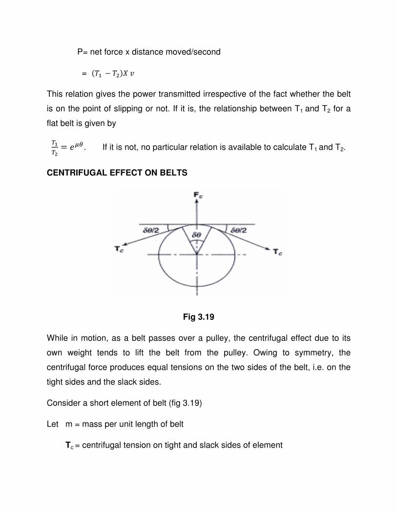
CENTRIFUGAL EFFECT ON BELTS
Fig 3.19
While in motion, as a belt passes over a pulley, the centrifugal effect due to its
own weight tends to lift the belt from the pulley. Owing to symmetry, the
centrifugal force produces equal tensions on the two sides of the belt, i.e. on the
tight sides and the slack sides.
Consider a short element of belt (fig 3.19)
Let m = mass per unit length of belt
Tc = centrifugal tension on tight and slack sides of element
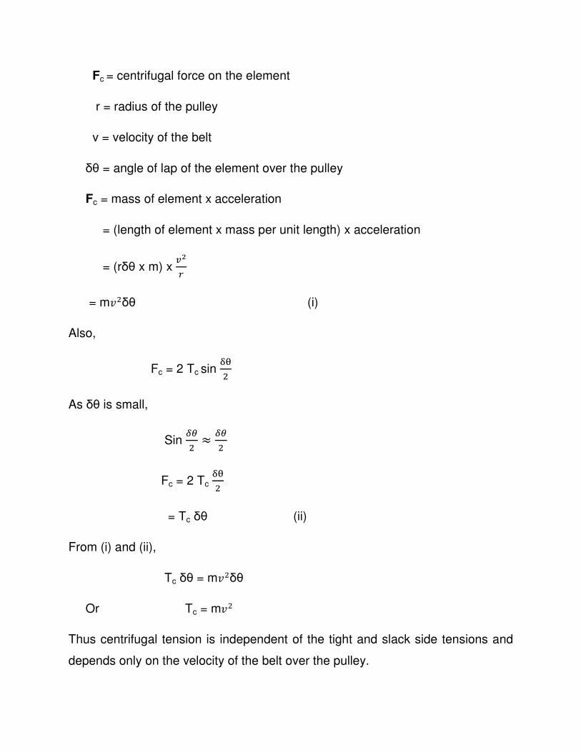
Fc = centrifugal force on the element
r = radius of the pulley
v = velocity of the belt
δθ = angle of lap of the element over the pulley
Fc = mass of element x acceleration
= (length of element x mass per unit length) x acceleration
= (rδθ x m) x Ë-8
= m�4δθ (i)
Also,
Fc = 2 Tc sin ¾¿4
As δθ is small,
Sin ÅÆ4 ≈ ÅÆ
4
Fc = 2 Tc ¾¿4
= Tc δθ (ii)
From (i) and (ii),
Tc δθ = m�4δθ
Or Tc = m�4
Thus centrifugal tension is independent of the tight and slack side tensions and
depends only on the velocity of the belt over the pulley.
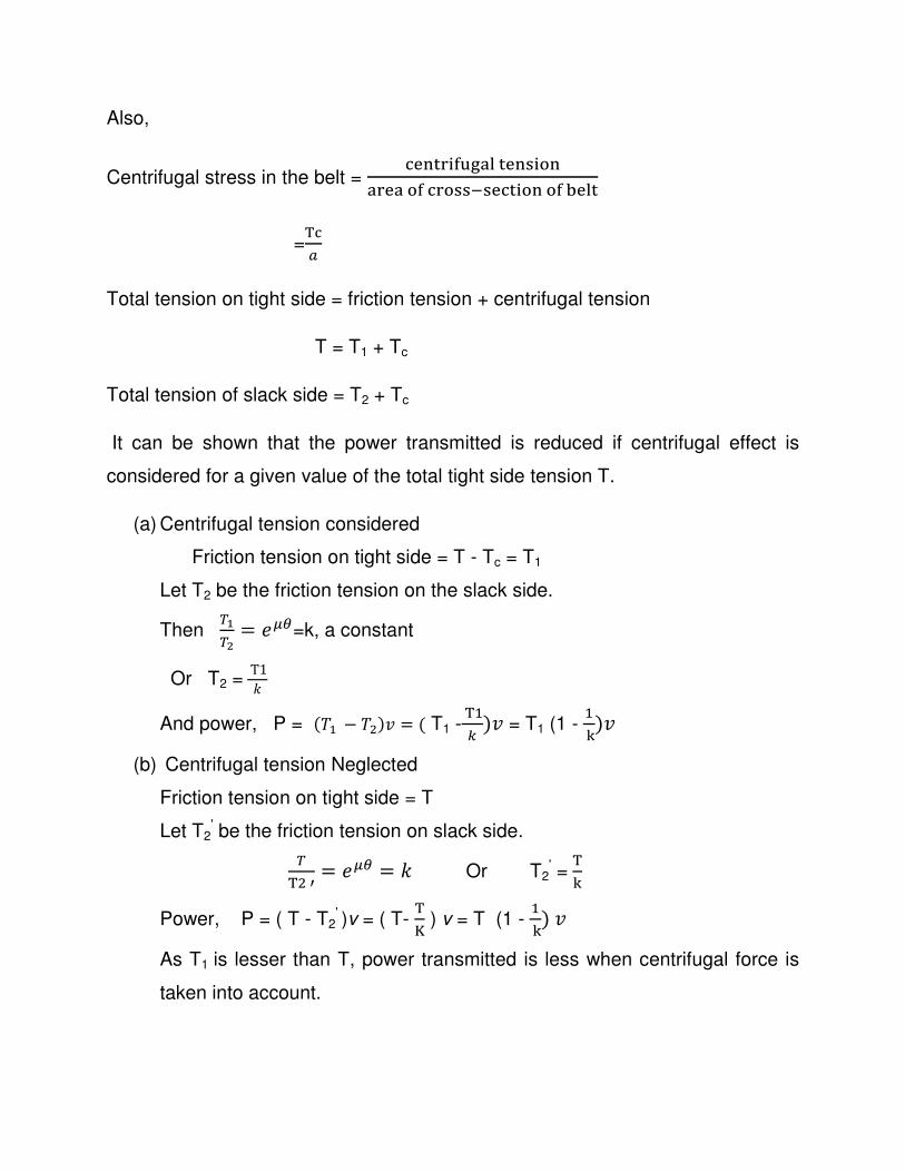
Also,
Centrifugal stress in the belt = (&�*% 'ÌÍ!"*&�) #�
!%&!#'(%#))�)&(* #�#'Î&"*
=D(]
Total tension on tight side = friction tension + centrifugal tension
T = T1 + Tc
Total tension of slack side = T2 + Tc
It can be shown that the power transmitted is reduced if centrifugal effect is
considered for a given value of the total tight side tension T.
(a) Centrifugal tension considered
Friction tension on tight side = T - Tc = T1
Let T2 be the friction tension on the slack side.
Then ¡{¡- = ��Æ=k, a constant
Or T2 =T1®
And power, P = (wR − w4)� = ( T1 -DR� )� = T1 (1 -RÏ)�
(b) Centrifugal tension Neglected
Friction tension on tight side = T
Let T2' be the friction tension on slack side.
¡
D4Ð = ��Æ = ® Or T2' =DÏ
Power, P = ( T - T2' )v = ( T-
DÑ ) v = T (1 -RÏ)�
As T1 is lesser than T, power transmitted is less when centrifugal force is
taken into account.

MAXIMUM POWER TRANSMITTED BY BELT
If it is desired that a belt transmits maximum possible power, two conditions must
be fulfilled simultaneously.
They are
1. Larger tension must reach the maximum permissible value for the belt
2. The belt should be on the point of slipping, i.e. maximum frictional force is
developed in the belt.
Now,
P = (wR − w4)� = T1 (1- D4DR ) v = 1 (1 -
RÉÒÓ) v = 1 k v
Where k = 1 - R
ÉÒÓ = constant
Or P = (T –Tc ) k v
= k T v – k m v2 v
= k T v - k m v3
The maximum tension T in the belt should not exceed the permissible limit.
Hence treating T as constant and differentiating the power with respect to v and
equating the same equal to zero.
\Ô\Ë= k T – 3 k m v
2 = 0
Or T = 3 m v2 = 3Tc
Or Tc = ¡:
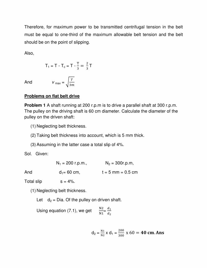
Therefore, for maximum power to be transmitted centrifugal tension in the belt
must be equal to one-third of the maximum allowable belt tension and the belt
should be on the point of slipping.
Also,
T1 = T - Tc = T - D: = 4:T
And v max = � ¡:�
Problems on flat belt drive
Problem 1 A shaft running at 200 r.p.m is to drive a parallel shaft at 300 r.p.m.
The pulley on the driving shaft is 60 cm diameter. Calculate the diameter of the
pulley on the driven shaft:
(1) Neglecting belt thickness.
(2) Taking belt thickness into account, which is 5 mm thick.
(3) Assuming in the latter case a total slip of 4%.
Sol. Given:
N1 = 200 r.p.m., N2 = 300r.p.m,
And d1= 60 cm, t = 5 mm = 0.5 cm
Total slip s = 4%.
(1) Neglecting belt thickness.
Let d2 = Dia. Of the pulley on driven shaft.
Using equation (7.1), we get C4CR=
\{\-
d2 = CRC4 x d1 =
455:55 x60 = ÕVÖ×.¥jh
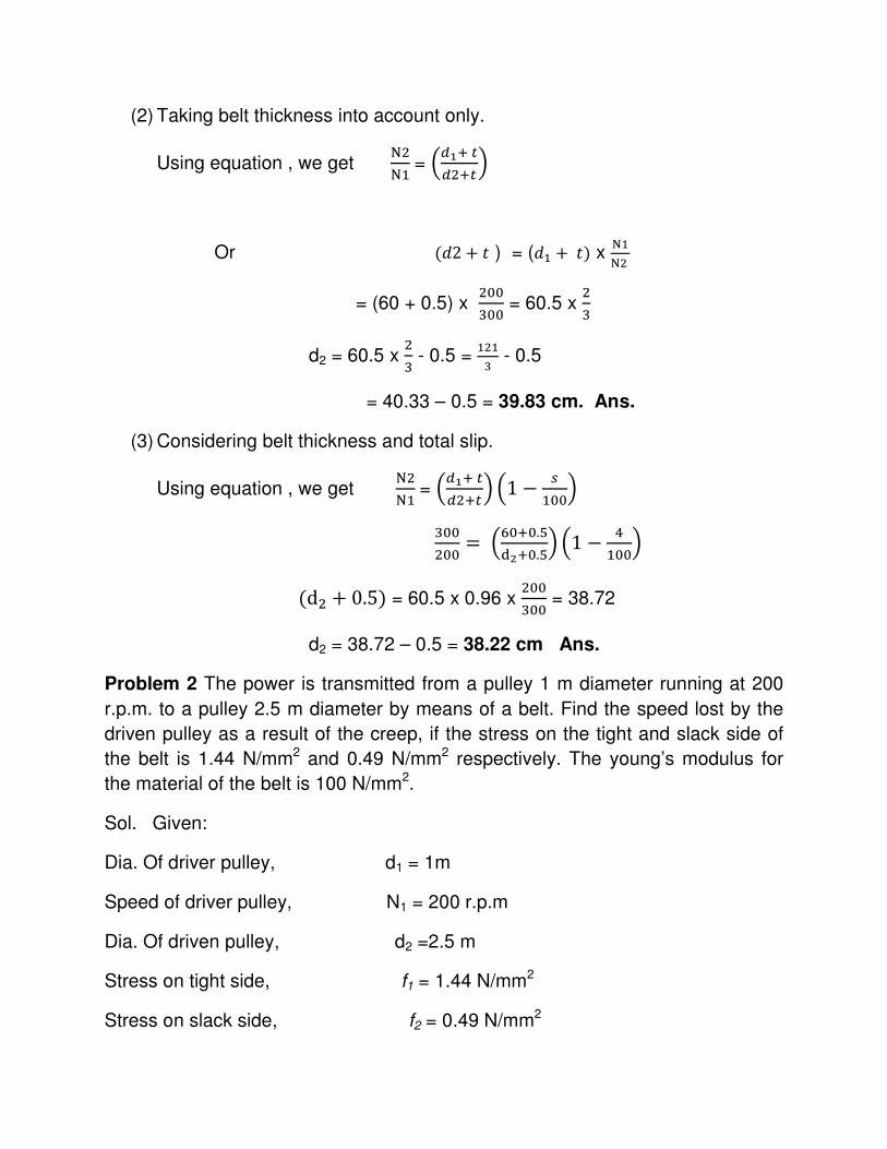
(2) Taking belt thickness into account only.
Using equation , we get C4CR= �\{¶·
\4¶·�
Or (�2 + � ) = (�R + �) x CRC4
= (60 + 0.5) x 455:55 = 60.5 x
4:
d2 = 60.5 x 4: - 0.5 =
R4R: - 0.5
= 40.33 – 0.5 = 39.83 cm. Ans.
(3) Considering belt thickness and total slip.
Using equation , we get C4CR= �\{¶·
\4¶·� �1 − �R55�
:55455 =�B5¶5.W
$-¶5.W� �1 − �R55�
(d4 + 0.5) = 60.5 x 0.96 x 455:55 = 38.72
d2 = 38.72 – 0.5 = 38.22 cm Ans.
Problem 2 The power is transmitted from a pulley 1 m diameter running at 200
r.p.m. to a pulley 2.5 m diameter by means of a belt. Find the speed lost by the
driven pulley as a result of the creep, if the stress on the tight and slack side of
the belt is 1.44 N/mm2 and 0.49 N/mm2 respectively. The young’s modulus for
the material of the belt is 100 N/mm2.
Sol. Given:
Dia. Of driver pulley, d1 = 1m
Speed of driver pulley, N1 = 200 r.p.m
Dia. Of driven pulley, d2 =2.5 m
Stress on tight side, f1 = 1.44 N/mm2
Stress on slack side, f2 = 0.49 N/mm2
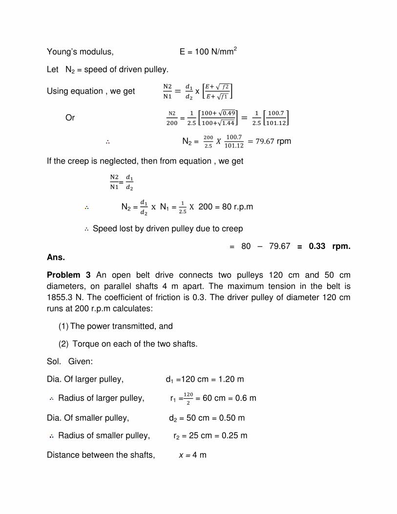
Young’s modulus, E = 100 N/mm2
Let N2 = speed of driven pulley.
Using equation , we get C4CR = \{
\- x 7ض√§2ض√§1 ;
Or N2455 =
R4.W 7R55¶√5.��
R55¶√R.��; = R4.W 7 R55.[
R5R.R4; N2 =
4554.W Ê 100.7
101.12 = 79.67 rpm
If the creep is neglected, then from equation , we get
C4CR=
\{\-
N2 = \{\- x N1 =
R4.W X 200 = 80 r.p.m
∴ Speed lost by driven pulley due to creep
= 80 – 79.67 = 0.33 rpm.
Ans.
Problem 3 An open belt drive connects two pulleys 120 cm and 50 cm
diameters, on parallel shafts 4 m apart. The maximum tension in the belt is
1855.3 N. The coefficient of friction is 0.3. The driver pulley of diameter 120 cm
runs at 200 r.p.m calculates:
(1) The power transmitted, and
(2) Torque on each of the two shafts.
Sol. Given:
Dia. Of larger pulley, d1 =120 cm = 1.20 m
Radius of larger pulley, r1 =R454 = 60 cm = 0.6 m
Dia. Of smaller pulley, d2 = 50 cm = 0.50 m
Radius of smaller pulley, r2 = 25 cm = 0.25 m
Distance between the shafts, x = 4 m
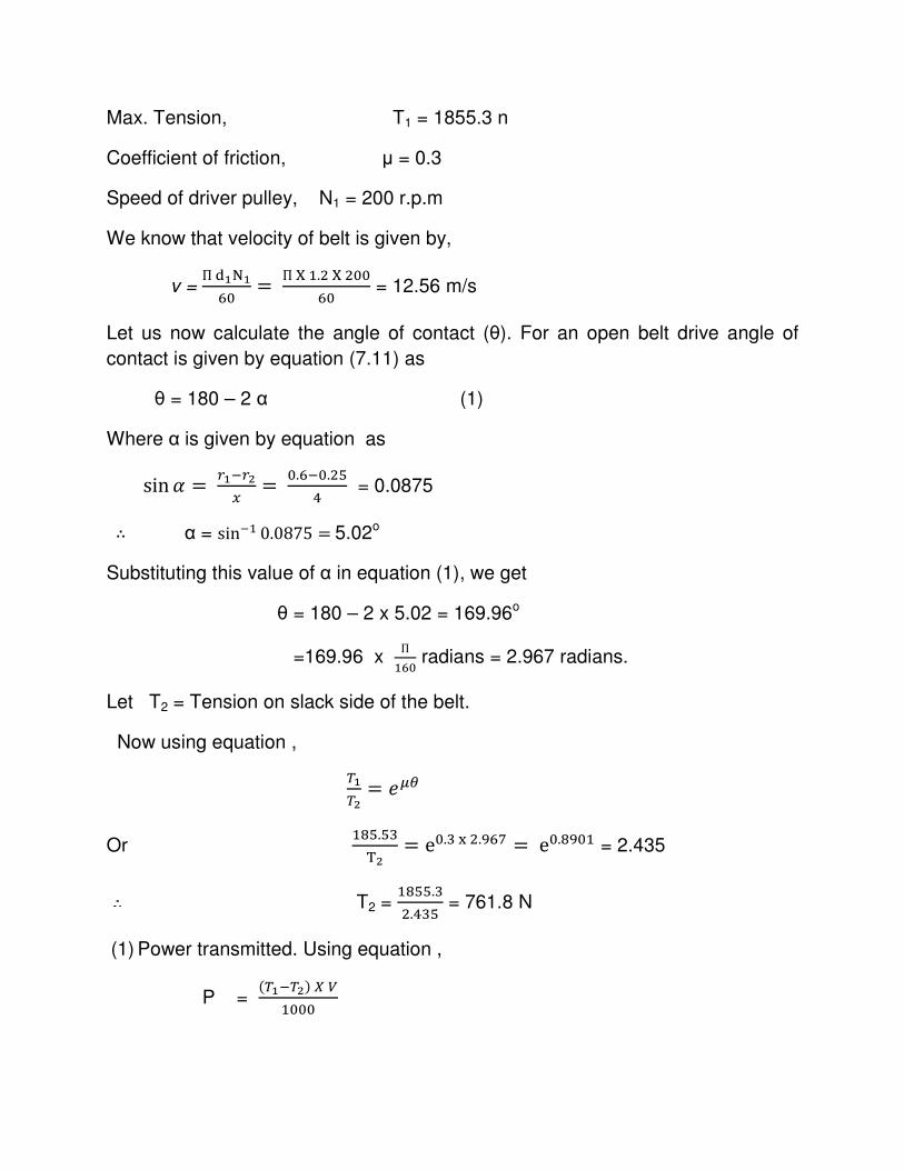
Max. Tension, T1 = 1855.3 n
Coefficient of friction, µ = 0.3
Speed of driver pulley, N1 = 200 r.p.m
We know that velocity of belt is given by,
v = П${C{
B5 = ПÜR.4Ü455B5 = 12.56 m/s
Let us now calculate the angle of contact (θ). For an open belt drive angle of
contact is given by equation (7.11) as
θ = 180 – 2 α (1)
Where α is given by equation as
sin d = 8{�8-X = 5.B�5.4W
� = 0.0875
∴ α = sin�R 0.0875 =5.02o
Substituting this value of α in equation (1), we get
θ = 180 – 2 x 5.02 = 169.96o
=169.96 x П
RB5 radians = 2.967 radians.
Let T2 = Tension on slack side of the belt.
Now using equation ,
¡{¡- = ��Æ
Or RYW.W:
D- = e5.:�4.�B[ =e5.Y�5R = 2.435
T2 = RYWW.:4.�:W = 761.8 N
(1) Power transmitted. Using equation ,
P = (¡{�¡-)�Þ
R555
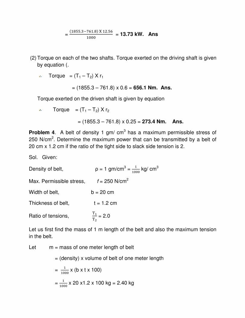
= (RYWW.:�[BR.Y)ÜR4.WB
R555 = 13.73 kW. Ans
(2) Torque on each of the two shafts. Torque exerted on the driving shaft is given
by equation (.
Torque = (T1 – T2) X r1
= (1855.3 – 761.8) x 0.6 = 656.1 Nm. Ans.
Torque exerted on the driven shaft is given by equation
Torque = (T1 – T2) X r2
= (1855.3 – 761.8) x 0.25 = 273.4 Nm. Ans.
Problem 4. A belt of density 1 gm/ cm3 has a maximum permissible stress of
250 N/cm2. Determine the maximum power that can be transmitted by a belt of
20 cm x 1.2 cm if the ratio of the tight side to slack side tension is 2.
Sol. Given:
Density of belt, ρ = 1 gm/cm3 = R
R555 kg/ cm3
Max. Permissible stress, f = 250 N/cm2
Width of belt, b = 20 cm
Thickness of belt, t = 1.2 cm
Ratio of tensions, D{D- = 2.0
Let us first find the mass of 1 m length of the belt and also the maximum tension
in the belt.
Let m = mass of one meter length of belt
= (density) x volume of belt of one meter length
= R
R555 x (b x t x 100)
= R
R555 x 20 x1.2 x 100 kg = 2.40 kg
Using equation,
Tm = maximum tension
= (max. stress) x Area of cross- section of belt
= 250 x b x t = 250 x 20 x 1.2 = 6000 N.
Now for maximum power transmitted, the velocity of the belt is given by equation
as
v = �Dß:à = � B555
:�4.� m/s = 28.86 m/s.
Now power transmitted is given by equation,
P = (¡{�¡-)�Þ
R555 (1)
Let us find the values of T1 and T2.
We know that Tm = T1 + Tc (2)
Where Tc =centrifugal tension, and
T1 = tight side tension.
But for maximum power transmission, Tc = R: w�
Substituting this value in equation (2), we get
Tm = T1 + R: w�
Or T1 = w� − R: w�= 4: w� = 4: x6000 = 4000N
But D{D- = 2.0 (given)
T2 = D{4 = �555
4 = 2000 N
Substituting the values of T1, T2 and v in equation (1), we get
P = (�555�4555)�4Y.YB
R555 = 57.18 kW. Ans.