Embed Size (px)
Citation preview
UNIT – III
DRILLING
SYLLABUS
WORKING PRINCIPLE OF DRILLING
MAIN PARTS OF DRILLING MACHINE
TYPES OF DRILLING MACHINE
OPERATION OF DRILLING MACHINE
• The drilling machine or drill press is one of the most common and useful machine employed in industry for producing forming and
finishing holes in a work piece.
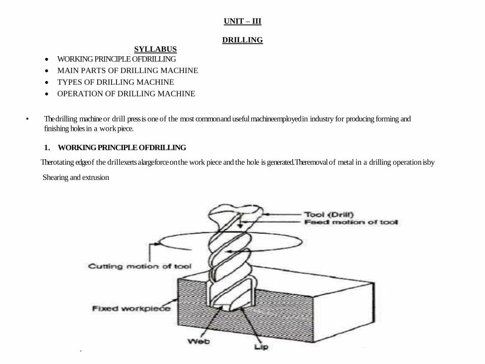
1. WORKING PRINCIPLE OF DRILLING
The rotating edge of the drill exerts a large force on the work piece and the hole is generated. The removal of metal in a drilling operation is by
Shearing and extrusion
.
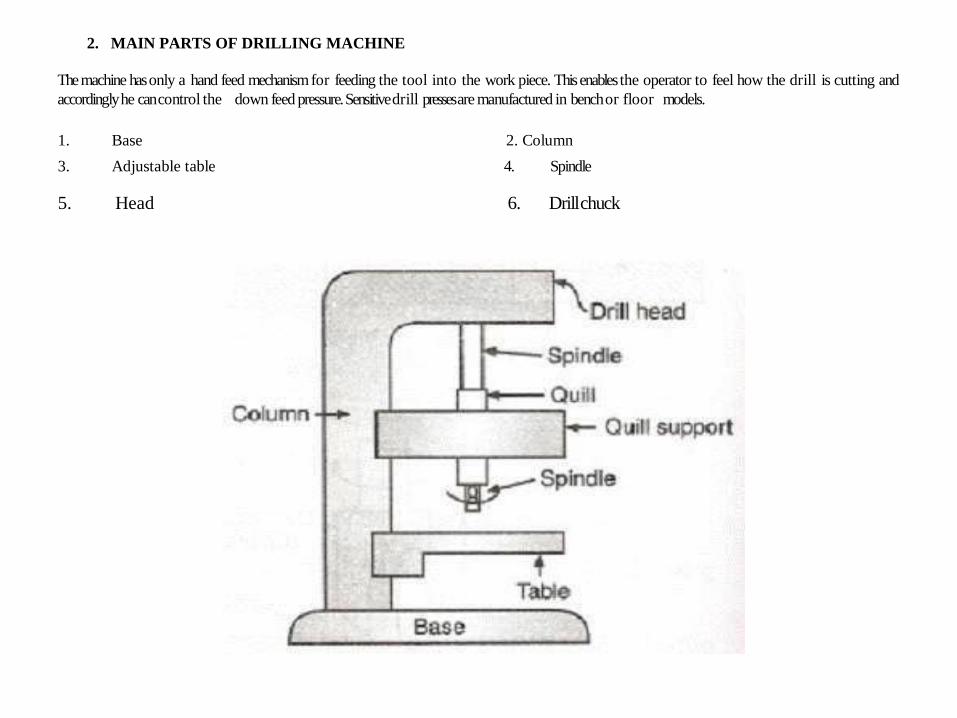
2. MAIN PARTS OF DRILLING MACHINE
The machine has only a hand feed mechanism for feeding the tool into the work piece. This enables the operator to feel how the drill is cutting and
accordingly he can control the down feed pressure. Sensitive drill presses are manufactured in bench or floor models.
1. Base 2. Column
3. Adjustable table 4. Spindle
5. Head 6. Drill chuck
3. TYPES OF DRILLING MACHINE
• Portable Drilling Machine
• Sensitive or Bench Drill
• Upright Drilling Machine(Single Spindle)
• Upright Drilling Machine (Turret Type)
• Radial Drilling Machine
• Multiple Spindle Drilling Machine
• Deep Hole Drilling Machine
• Gang Drilling Machine
• Horizontal Drilling Machine
• Automatic Drilling Machine
4. OPERATION OF DRILLING MACHINE
• Drilling
• Reaming
• Boring
• Counter Boring
• Counter Sinking
• Spot Facing
• Tapping
• Coredrilling
• Buffing
• Stepdrilling
• Grinding
• Countersinking
MCQ QUESTUONS:-
1. Which of the following is not the workholding devices.
a) Direct fitting
b) Sleeve and socket
c) Collet chuck
d) Milling machine
2. How much helix angle is in twist drill
a) 29°
b) 30°
c) 120°
d) 35°
VERY SHORT ANSWER TYPE QUESTIONS:- (2 MARKS)
1. What is drilling?
2. What is hole milling?
3. What is counterboring?
4. What is the function of flat drill?
5. What is countersinking?
SHORT ANSWER TYPE QUESTIONS:- (4 MARKS)
1. What are the various types of drills?
2. List the various drill holding devices.
3. Explain the principle of drilling.
LONG ANSWER TYPE QUESTIONS:- (10 MARKS)
1. Explain the classification of drilling machine.
2. Explain the various operations performed on drill machine.
UNIT – IV
BORING
SYLLABUS
o PRINCIPLE OF BORING
o CLASSIFICATION OF BORING MACHINES
o CUTTING TOOLS FOR BORING
o BORING OPERATIONS
Boring is a process of producing circular internal profiles on a hole made by drilling or another process. It uses single point cutting tool called a boring bar. In boring, the boring bar can be rotated, or the work part can be rotated. Machine tools which rotate the boring bar against a stationary work piece are called boring machines (also boring mills).
Boring can be accomplished on a turning machine with a stationary boring bar positioned in the tool post and rotating work piece held in the lathe chuck as illustrated in the figure. In this section, we will consider only boring on boring machine.
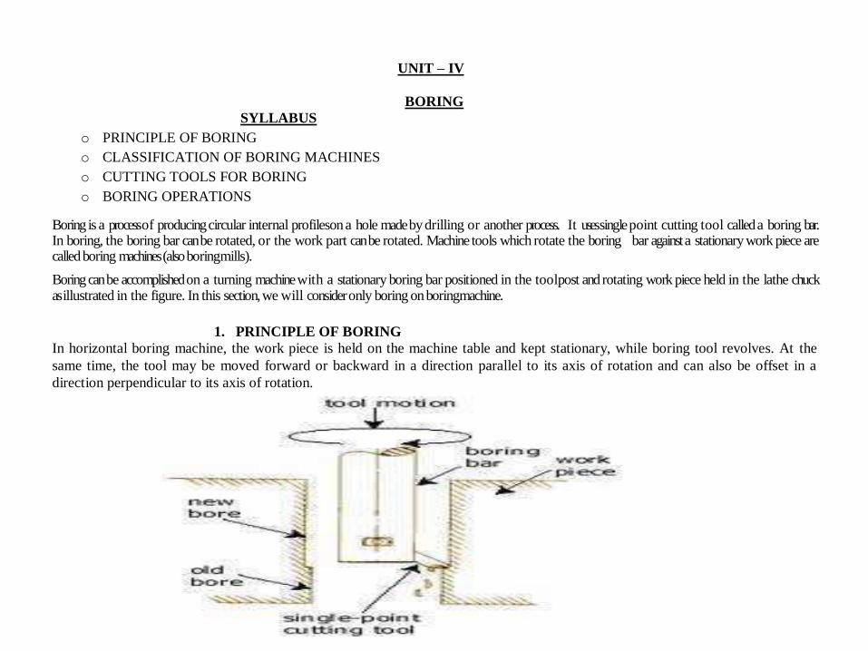
1. PRINCIPLE OF BORING
In horizontal boring machine, the work piece is held on the machine table and kept stationary, while boring tool revolves. At the
same time, the tool may be moved forward or backward in a direction parallel to its axis of rotation and can also be offset in a
direction perpendicular to its axis of rotation.
2. CLASSIFICATION OF BORING MACHINES
1. Horizontal boring machine
2. Vertical boring machine
3. Jigs boring machine
4. Special purpose boring machine
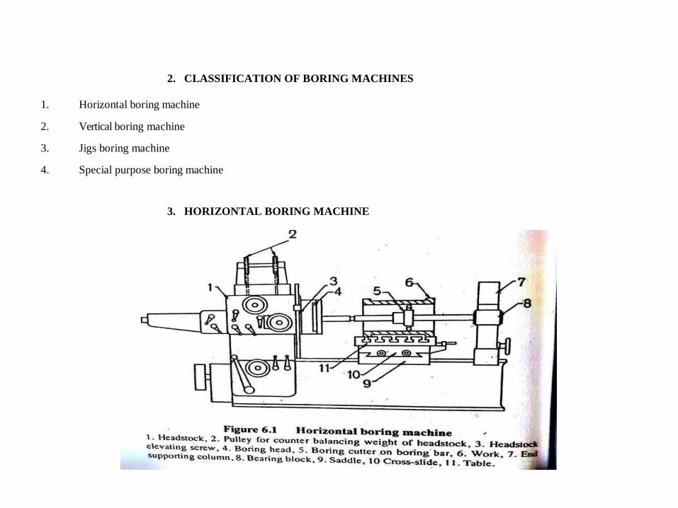
3. HORIZONTAL BORING MACHINE
1. Bed
2. Saddle
3. Table
4. Base
5. Column
6. Headstock
7. End support column
4. VERTICAL BORING MACHINE
A vertical boring mill is used for large, heavy work parts with diameters up to 12 m. The typical boring mill can position and feed several cutting tools simultaneously. The work part may be mounted on a rotating worktable.
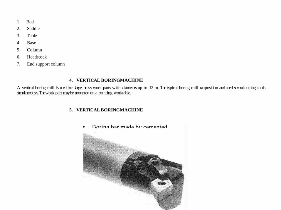
5. VERTICAL BORING MACHINE
• Boring bar made by cemented carbide
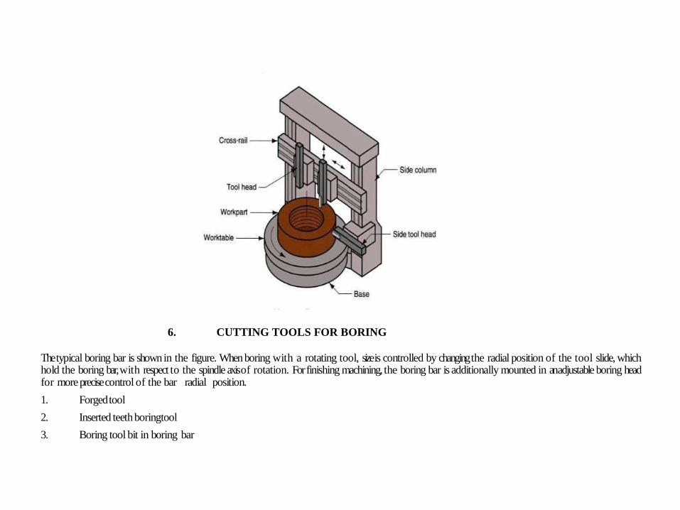
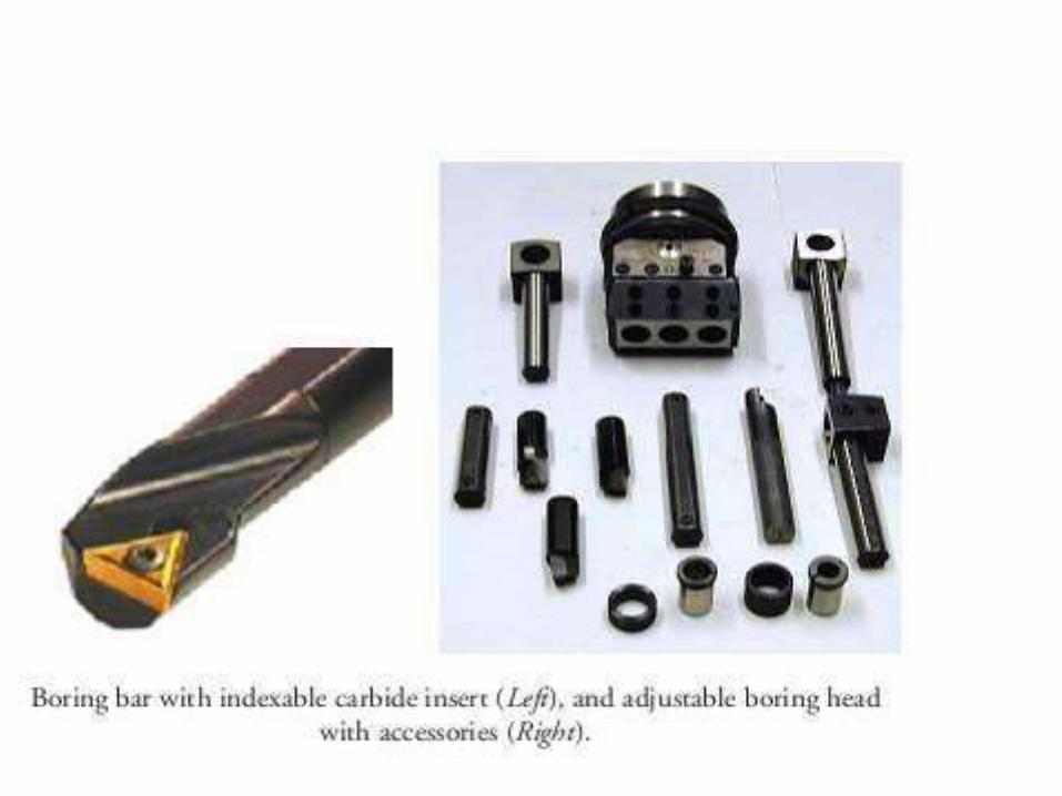
6. CUTTING TOOLS FOR BORING
The typical boring bar is shown in the figure. When boring with a rotating tool, size is controlled by changing the radial position of the tool slide, which hold the boring bar, with respect to the spindle axis of rotation. For finishing machining, the boring bar is additionally mounted in an adjustable boring head for more precise control of the bar radial position.
1. Forged tool
2. Inserted teeth boring tool
3. Boring tool bit in boring bar
7. BORING OPERATIONS
• Internal taper boring
• External taper boring
• Necking or cutting off
• Boring a large diameter
• Boring a small diameter
• Spot facing
• Reaming
• Counter boring
• Threading
• Facing
• Trepanning
• Milling
MCQ QUESTUONS:-
1. Which of the following is not the type of boring machine
a) Horizontal boring machine
b) Vertical boring machine
c) Jig boring machine
d) Mig welding
2. The term ‘V’ in formula of cutting speed of boring machine stands for
a) Diameter of bored hole
b) Distance between centres
c) Maximum diameter
d) Diameter of the work that can be turned over the cross slide.
VERY SHORT ANSWER TYPE QUESTIONS:- (2 MARKS)
1. What are boring bar?
2. What is the function of boring bar?
3. Define boring.
4. Define the feed of boring tool.
5. What is the function of boring bar?
SHORT ANSWER TYPE QUESTIONS:- (4 MARKS)
1. Write four specifications of boring machine.
2. Explain the classification of boring machine
3. Explain principle of boring.
LONG ANSWER TYPE QUESTIONS:- (10 MARKS)
1. Write the short notes on classification of boring machines & their descriptions.
2. Explain ‘boring heads’.

UNIT – V
SHAPING, PLANNING AND SLOTTING
SYLLABUS
working principle of shaper, planer and slotter,
type of shapers ,
type of planers,
types of tools used and their geometry,
speed and feed in above processes.
1. SHAPING
Shaping or shaper machine is a reciprocating type of machine tool used for producing small flat surfaces with the help of a point cutting tool which reciprocates over the stationary work piece.
A shaping machine is used to machine surfaces. It can cut curves, angles and many other shapes. It is a popular machine in a factory workshop because its movement is very simple although it can produce a variety of work. They are less common in school workshops, perhaps because of their moving parts which present a high risk.
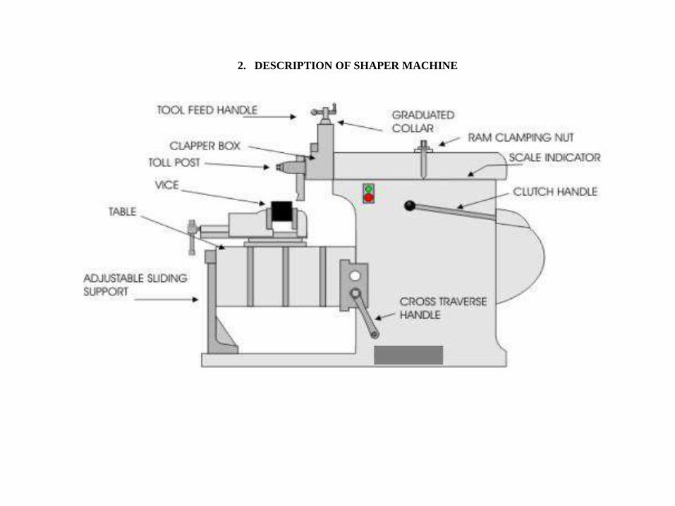
2. DESCRIPTION OF SHAPER MACHINE
3. MAIN PARTS OF SHAPER MACHINE
• Base
• Column
• Cross rail
• Saddle
• Table
• Ram
• Tool head
• Shaper head
4. CLASSIFICATION OF SHAPER MACHINE
• Crank shaper
• Geared shaper
• Hydraulic
• Horizontal shaper
• Vertical shaper
• Travelling head shaper
• Plain shaper
• Universal shaper
• Push cut type shaper
• Draw type shaper
5. WORKS ON SHAPER MACHINE
• Shaping a vertical grooves
• Shaping horizontal flat surfaces
• Shaping a dovetail slide
• Shaping flat inclined surfaces
• Shaping v-block
• Shaping a jib and guide jib
• Shaping a curved surface
6. PLANER
The machine tool for planning is a planer. Cutting speed is achieved by a reciprocating worktable that moves the part past the single-point cutting tool. Construction and motion capability of a planer permit much larger parts to be machined than on a shaper.
7. CLASSIFICATION OF PLANING MACHINE
1. Standard or double housing planer
2. Open side planer
3. Pit type planer
4. Edge or plate planer
5. Divided table planer
6. Universal planer
.
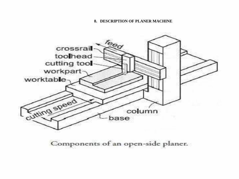
8. DESCRIPTION OF PLANER MACHINE
9. MAIN PARTS OF PLANER MACHINE
• Bed • Table • Housing • Cross rail • Saddle • Tool head
10. WORKS ON PLANER MACHINE
• Bed and slides of all kind of machine • Large structures and frames of different engine • Locomotive frames • Forging hammer die block • Dies , jigs and fixtures • Helical grooves on large valves • Deep slot on large motors • Roll mill bearing • Lathe carriage and way • Pressure plate • Parts of large hydraulic presses
11. DIFFERENCE SHAPER AND PLANER
Planning and shaping are similar operations, which differ in the kinematics of the process. Planning is a machining operation
in which the primary cutting motion is performed by the work piece and feed motion is imparted to the cutting tool. In
shaping, the primary motion is performed by the tool, and feed by the work piece.
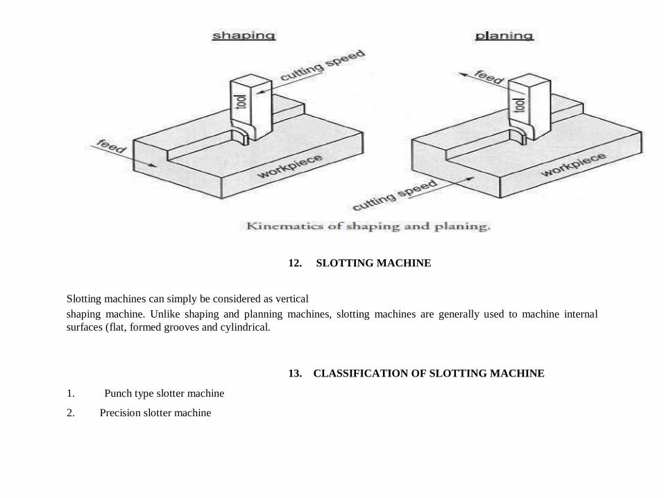
12. SLOTTING MACHINE
Slotting machines can simply be considered as vertical shaping machine. Unlike shaping and planning machines, slotting machines are generally used to machine internal
surfaces (flat, formed grooves and cylindrical.
13. CLASSIFICATION OF SLOTTING MACHINE 1. Punch type slotter machine 2. Precision slotter machine
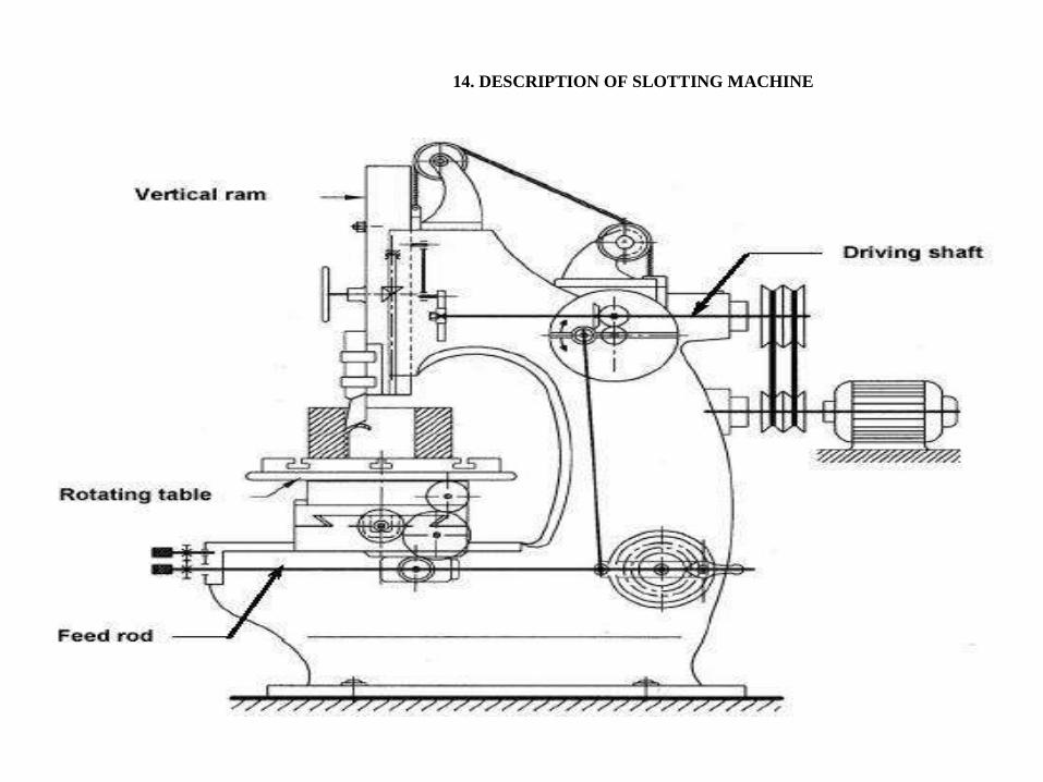
14. DESCRIPTION OF SLOTTING MACHINE
15. MAIN PARTS OF SLOTTING MACHINE
• Base • Column • Saddle • Cross slide • Rotary table • Ram and tool head assembly
16. WORKS ON SLOTTING MACHINE
1. Cutting keyway or spline
2. Cutting serrations
3. Finishing die opening
4. Finishing a punch profile
5. Matching tall or bulky pieces
6. Finishing regular or irregular section
7. Cutting cam profile
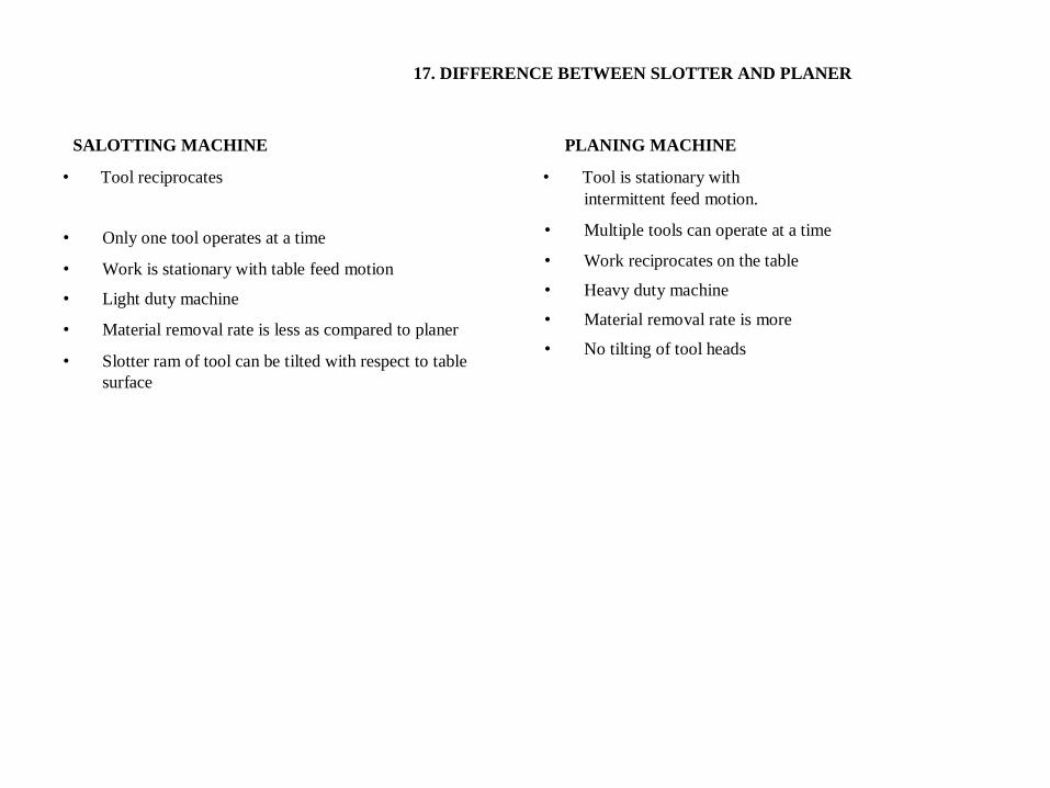
17. DIFFERENCE BETWEEN SLOTTER AND PLANER
SALOTTING MACHINE PLANING MACHINE • Tool reciprocates • Tool is stationary with
intermittent feed motion. • Only one tool operates at a time • Work is stationary with table feed motion • Light duty machine • Material removal rate is less as compared to planer • Slotter ram of tool can be tilted with respect to table
surface
• Multiple tools can operate at a time • Work reciprocates on the table • Heavy duty machine • Material removal rate is more • No tilting of tool heads
MCQ QUESTUONS:-
1. Which of the following is not the type of driving mechanism in shapers.
a) Crank type
b) Engine type
c) Hydraulic type
d) Geared type
2. Which one is the workholding devices used in slotting
a) vices
b) D- blocks
c) V- slot clamps
d) Angle clamps
VERY SHORT ANSWER TYPE QUESTIONS:- (2 MARKS)
1. List the types of planner machine?
2. Write some examples of slotting machine work?
3. Define shaping process.
4. Write the advantages of planner.
5. Enlist the principal parts of planner.
SHORT ANSWER TYPE QUESTIONS:- (4 MARKS)
1. Explain the working principle of a shaper.
2. What is gear type quick return mechanism.
3. How gear are cut on shaper.
LONG ANSWER TYPE QUESTIONS:- (10 MARKS)
1. Explain the construction & working of slotter machine.
2. Explain principle parts of planner with help of neat sketch.
UNIT – VI
BROACHING
SYLLABUS
PRINCIPLE OF BROACHING MACHINE
NOMENCLATURE OF BROCHING TOOL
NOMENCLATURE OF BROCHING TOOL
TYPES OF BROACHES MACHINE
CLASSIFICATION OF BROACHING MACHINE
BROACHING TECHNIQUES
Broaching is a machining operation in which a tool used is called as broach having series of cutting teeth.
In this operation broach is either Pulled or Pushed with the help of broaching machine on the work piece surface.
Parts that is produced by the broaching have good surface finish and dimensional accuracy.
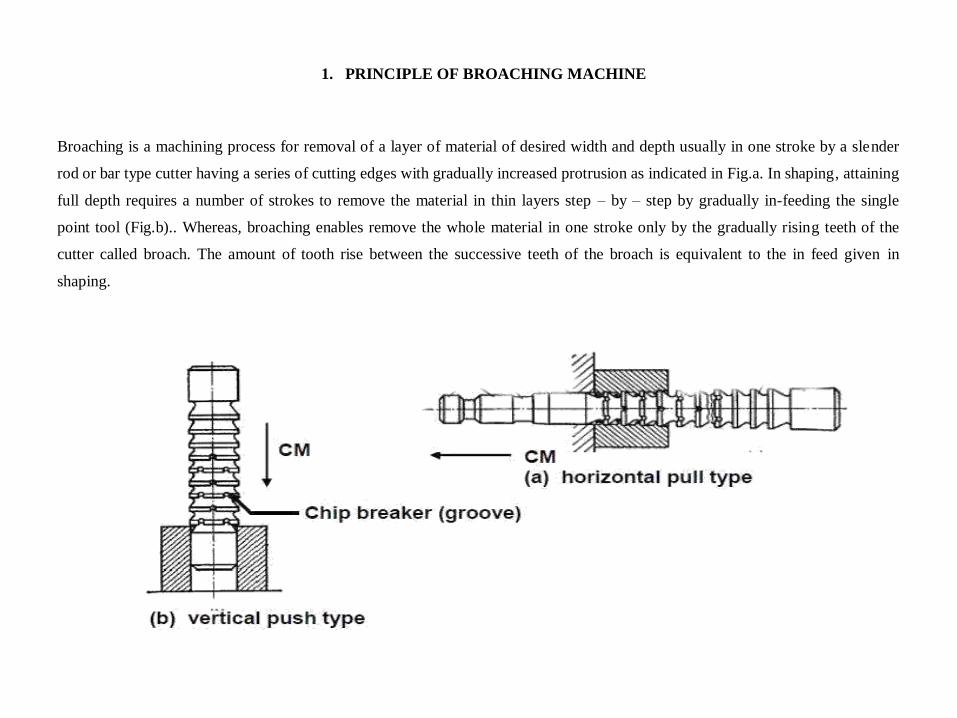
1. PRINCIPLE OF BROACHING MACHINE Broaching is a machining process for removal of a layer of material of desired width and depth usually in one stroke by a slender
rod or bar type cutter having a series of cutting edges with gradually increased protrusion as indicated in Fig.a. In shaping, attaining
full depth requires a number of strokes to remove the material in thin layers step – by – step by gradually in-feeding the single
point tool (Fig.b).. Whereas, broaching enables remove the whole material in one stroke only by the gradually rising teeth of the
cutter called broach. The amount of tooth rise between the successive teeth of the broach is equivalent to the in feed given in
shaping.
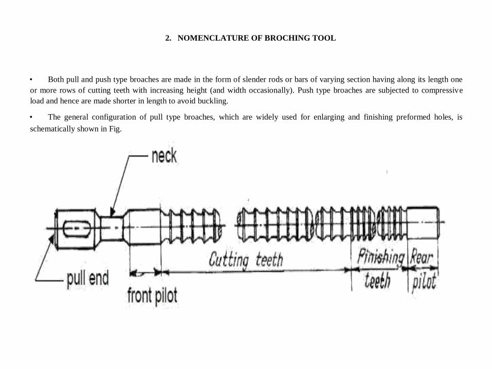
2. NOMENCLATURE OF BROCHING TOOL
• Both pull and push type broaches are made in the form of slender rods or bars of varying section having along its length one
or more rows of cutting teeth with increasing height (and width occasionally). Push type broaches are subjected to compressive
load and hence are made shorter in length to avoid buckling. • The general configuration of pull type broaches, which are widely used for enlarging and finishing preformed holes, is
schematically shown in Fig.
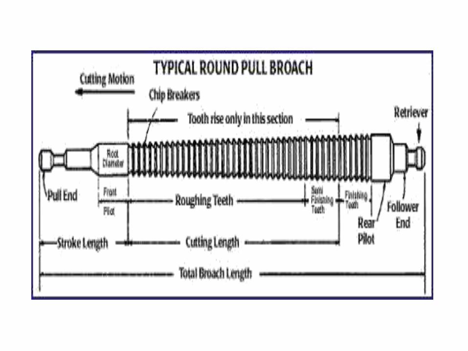
3. NOMENCLATURE OF BROCHING TOOL
• Pull end for engaging the broach in the machine. • Neck of shorter diameter and length, where the broach is allowed to fail, if at all, under overloading. • Front pilot for initial locating the broach in the hole. • Roughing and finishing teeth for metal removal • Finishing and burnishing teeth for fine finishing • Rear pilot and follower rest or retriever
4. TYPES OF BROACHES MACHINE
• According to method of operation Push , pull or stationary broaches. • According to type of operation Internal or external broaches.
• According to shape
Solid , inserted tooth, built up or replaceable. • According to function
Roughing , finishing , keyways , burnishing, sizing and serrating. Internal and external broaches
5. CLASSIFICATION OF BROACHING MACHINE
• Horizontal broaching machine. • Vertical broaching machine. • Duplex head broaching machine. • Surface broaching machine. • Continuous broaching machine.
6. BROACHING TECHNIQUES 1. Internal broaching 2. External broching
MCQ QUESTUONS:-
1. Which of the following is not the type of construction in broaches
a) Solid
b) Built up
c) Inserted tooth
d) Aggressive cut
2. Choose the commonly used broach material.
a) HCS
b) ceramic
c) diamond
d) HSS.
VERY SHORT ANSWER TYPE QUESTIONS:- (2 MARKS)
1. Name the various types of broaching machines.
2. Name the principle elements of broach.
3. Define broaching
4. Define internal broach.
5. Write the function of horizontal broaching machines?
SHORT ANSWER TYPE QUESTIONS:- (4 MARKS)
1. Explain the principle of broaching.
2. Draw the sketch of a broach tool with complete nomenclature.
3. Name the various types of broaches.
LONG ANSWER TYPE QUESTIONS:- (10 MARKS)
1. Explain briefly the types of broaching machine 2. Explain the construction & working of duplex ram type broaching machine in detail.
UNIT – VII
JIGS AND FIXTURES
SYLLABUS
ELEMENT OF JIG AND FIXTURE
USES OF JIGS AND FIXTURES
MATERIALS FOR JIGS AND FIXTURES
PRINCIPLES OF JIG AND FITURE DESIGN
CLAMPING DEVICES
JIG BUSHES
PRINCIPLE OF LOCATION
LOCATING DEVICES
PRINCIPLES OF CLAMPING
TYPES OF CLAMPING
TYPES OF DRILLING JIGS
JIG BUSHES
DIFFERENCE BETWEEN JIGS AND FIXTURE
Jigs and fixtures are special devices used for large scale production. The production of components with the help of jigs and fixtures is based on the concept of interchangeability where components are produced with in established tolerances. Jigs and fixture provide the means of clamping the components rapidly without any additional set up.
JIG : A device that holds the work and locates the path of the tool. FIXTURE: A device fixed to the worktable of a machine and locates the work in an exact position relative to the cutting tool.
1. ELEMENT OF JIG AND FIXTURE
• Locating elements • Clamping elements • A rigid body in to which work piece are loaded • Tool guiding element or tool setting element. • Element for positioning or fastening the jig or fixture on the machine on which it is used.
2. USES OF JIGS AND FIXTURES 1) To reduce production cost 2) To increase production rate 3) To ensure high accuracy in part manufacture 4) To enable heavy and complicated complex shaped parts to be machined by being held rigidly to a machine 5) To provide interchange ability 6) Reduce quality control expenses 7) Less skilled labour & save labour costs 8) Improve work safety
3. MATERIALS FOR JIGS AND FIXTURES
• Timber • Cast iron • Light metals • Brasses and bronzes • Steels
4. PRINCIPLES OF JIG AND FITURE DESIGN
• Reduction of ideal time • Study of component • Study of machine • Production requirement • Rigidity • Location • Loading • Ejection of component • Design for safety • Coolant passage • Swarf clearance • Clamping • Bushes • Burr grooves • Trunnions • Jig base • Spring location • Wear
5. PRINCIPLES OF JIG AND FITURE DESIGN
• Reduction of ideal time • Study of component • Study of machine • Production requirement • Rigidity • Location • Loading • Ejection of component • Design for safety • Coolant passage • Swarf clearance • Clamping • Bushes • Burr grooves • Trunnions • Jig base • Spring location • Wear
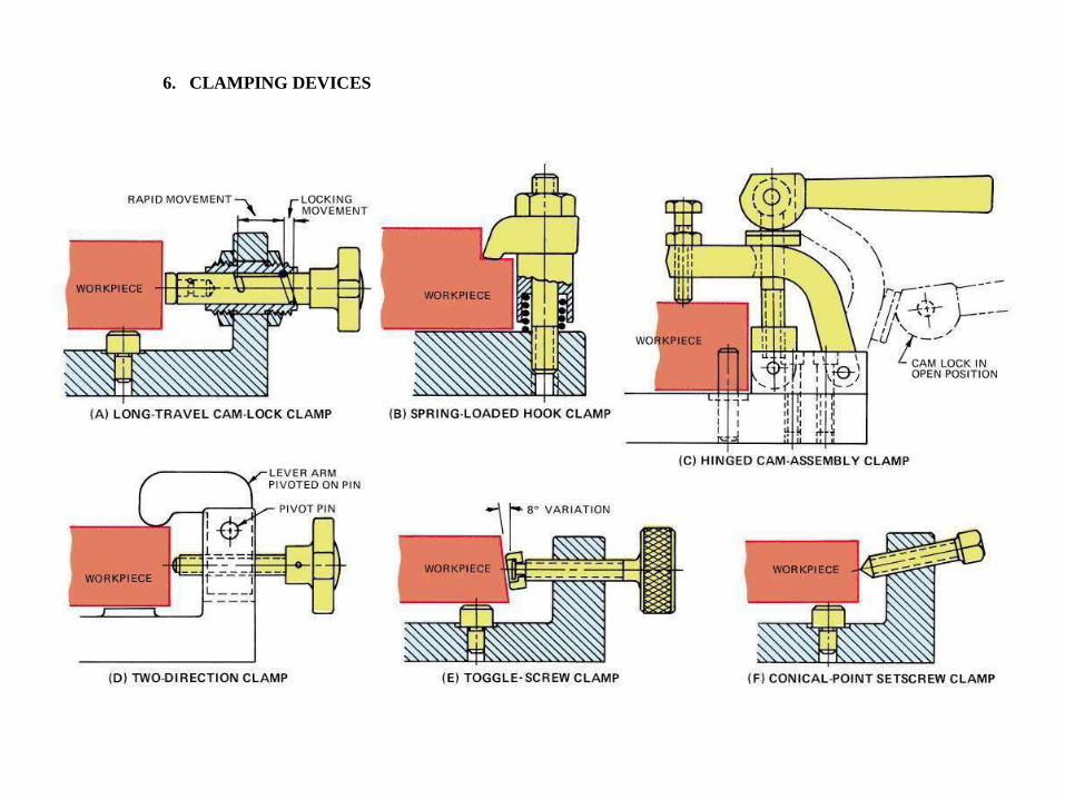
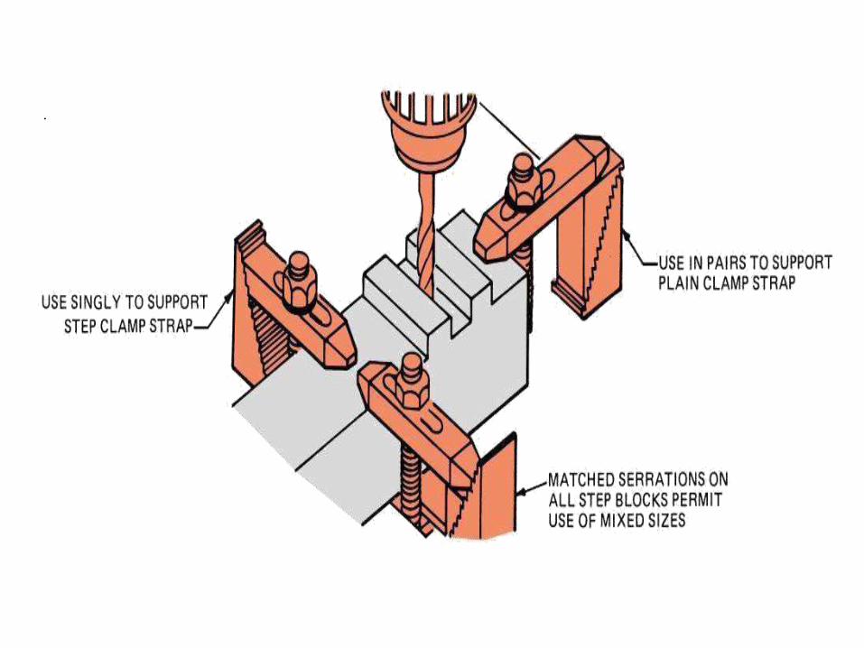
6. CLAMPING DEVICES
.
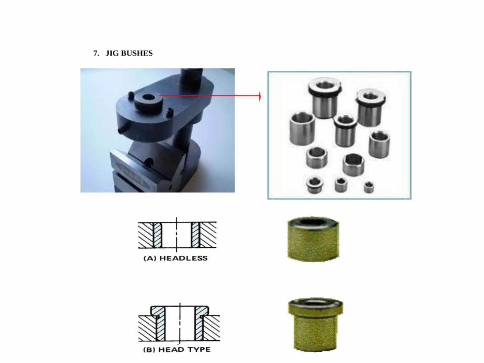
7. JIG BUSHES
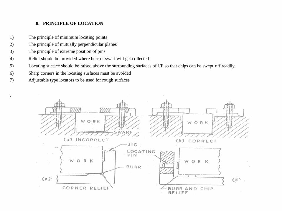
8. PRINCIPLE OF LOCATION 1) The principle of minimum locating points 2) The principle of mutually perpendicular planes 3) The principle of extreme position of pins 4) Relief should be provided where burr or swarf will get collected 5) Locating surface should be raised above the surrounding surfaces of J/F so that chips can be swept off readily. 6) Sharp corners in the locating surfaces must be avoided 7) Adjustable type locators to be used for rough surfaces
.
9. LOCATING DEVICES
• Flat locators • Cylindrical locators • Conical locators • Jack pin locators • Vee locators • Adjustable locators • Flattened locators
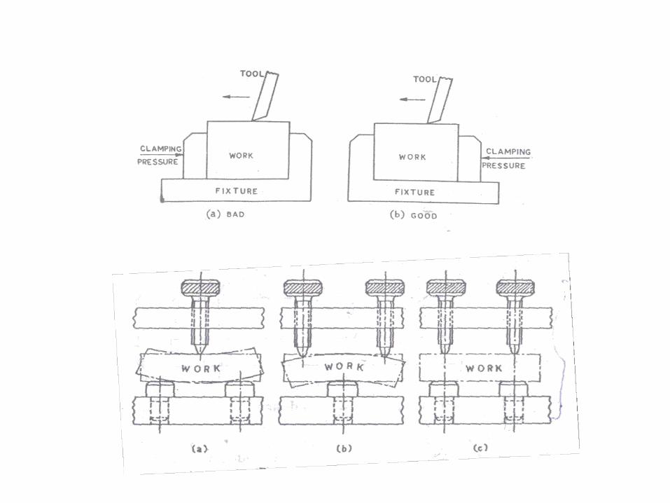
10. PRINCIPLES OF CLAMPING
1) The clamping pressure applied against the work piece must counteract the tool forces 2) The clamping pressure should not be directed towards the cutting operation. Wherever
possible it should be directed parallel to it. 3) The clamping pressure must not damage/deform the work surface. 4) Clamps should be arranged directly above the points supporting the work, otherwise distortion of work may
occur. 5) Clamping pressure should be directed towards the points of support, else the work will tend to rise from
support 6) Clamping should be simple, effective and fool proof. 7) Fibre pads should be riveted to clamp faces to avoid damage to fragile work pieces
11. TYPES OF CLAMPING
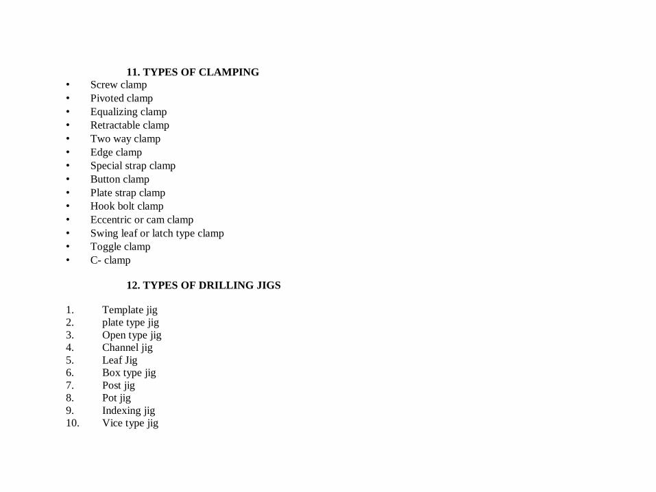
• Screw clamp • Pivoted clamp • Equalizing clamp • Retractable clamp • Two way clamp • Edge clamp • Special strap clamp • Button clamp • Plate strap clamp • Hook bolt clamp • Eccentric or cam clamp • Swing leaf or latch type clamp • Toggle clamp • C- clamp
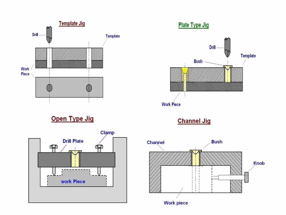
12. TYPES OF DRILLING JIGS
1. Template jig
2. plate type jig
3. Open type jig
4. Channel jig
5. Leaf Jig
6. Box type jig
7. Post jig
8. Pot jig
9. Indexing jig
10. Vice type jig
13. JIG BUSHES
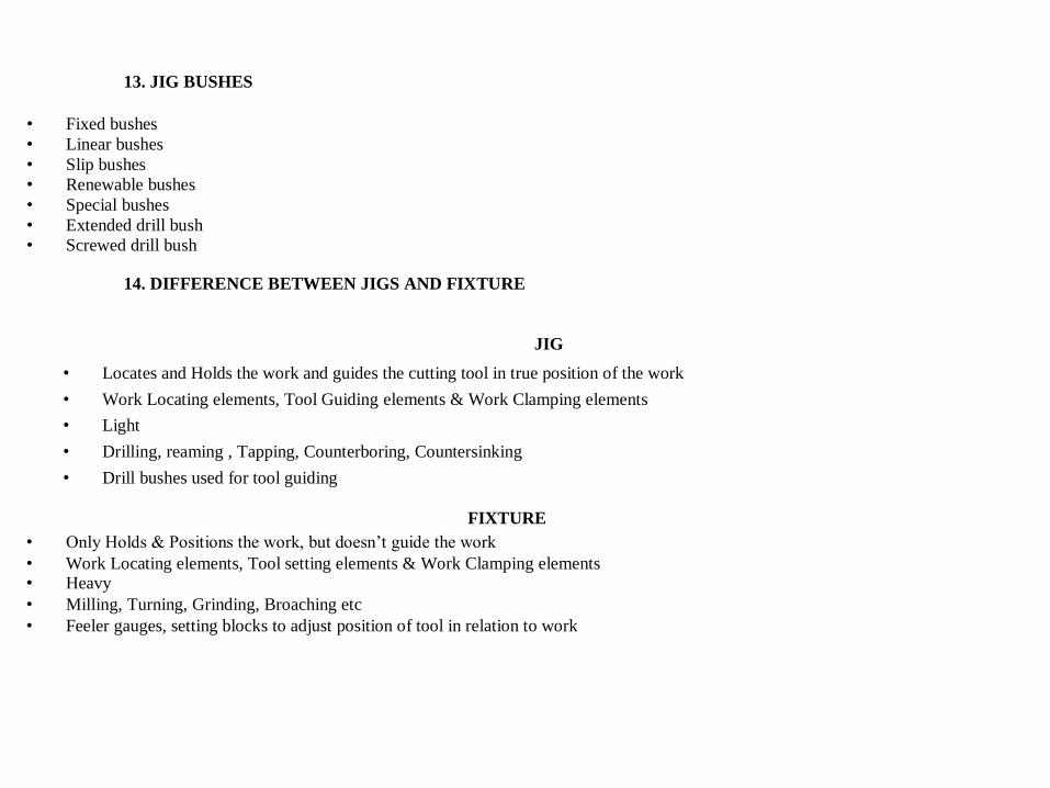
• Fixed bushes • Linear bushes • Slip bushes • Renewable bushes • Special bushes • Extended drill bush • Screwed drill bush
14. DIFFERENCE BETWEEN JIGS AND FIXTURE
JIG
• Locates and Holds the work and guides the cutting tool in true position of the work
• Work Locating elements, Tool Guiding elements & Work Clamping elements
• Light
• Drilling, reaming , Tapping, Counterboring, Countersinking
• Drill bushes used for tool guiding
FIXTURE • Only Holds & Positions the work, but doesn’t guide the work • Work Locating elements, Tool setting elements & Work Clamping elements • Heavy • Milling, Turning, Grinding, Broaching etc • Feeler gauges, setting blocks to adjust position of tool in relation to work
MCQ QUESTUONS:- 1. Which of the following is not the type of locating devices of jigs.
a) Flat locators
b) Cylindrical locators
c) Spherical locators
d) Vee locators
2. Choose the one drilling jig from the following options
a) Template jig
b) Closed jig
c) Stem jig
d) Box type jig
VERY SHORT ANSWER TYPE QUESTIONS:- (2 MARKS) 1. What is jig?
2. Define clamping devices for jigs.
3. Name the locating devices of jigs.
4. Which material is used for guiding bushes.
5. What is fixture?
SHORT ANSWER TYPE QUESTIONS:- (4 MARKS) 1. What is 3-2-1 principle of locating.
2. List the advantages of jigs and fixtures.
3. Differentiate between jigs and fixtures.
LONG ANSWER TYPE QUESTIONS:- (10 MARKS)
1. Sketch and explain the various types of fixtures.
2. Explain the clamping devices.
UNIT – VIII
CUTTING FLUIDS AND LUBRICANTS
SYLLABUS
• CUTTING FLUID
• FUNCTIONS OF CUTTING FLUID
• PROPERTIES OF CUTTING FLUID
• TYPES OF CUTTING FLUIDS
• APPLICATION OF CUTTING FLUIDS
• TYPES OF LUBRICATION
• COMMON METHODS OF LUBRICATION OF MACHINE TOOLS
• LUBRICANT
1. CUTTING FLUID
• Essential in metal-cutting operations to reduce heat and
friction Centuries ago, water used on grindstones
• 100 years ago, tallow used (did not cool) Lard oils came later but turned rancid Early 20th century saw soap added to
water Soluble oils came in 1936 • Chemical cutting fluids introduced in 1944
2. FUNCTIONS OF CUTTING FLUID
• To reduce cutting forces. • To decrease wear and tear of the tool and increase tool life. • To provide lubrication effect to the tool , work piece and chip. • To improve surface finish and machinability. • To protect the finished surface from oxidation and corrosion. • To wash away the chip, scale and dust from and in between the working surfaces.
• To minimize friction at the matting surfaces thus prevent rapid rate increase of temperature
3. PROPERTIES OF CUTTING FLUID
• It should be chemically stable. • It should be non corrosive. • It should be high flash point. • It should cause no skin irritation. • It should prevent the electrochemical effect of corrosion. • It should not deteriorate on storage. • It should be low cost. • It should be readily available in qualities required for use.
4. TYPES OF CUTTING FLUIDS
• Neat cutting oils. • Soluble oils. • Synthetic fluids. • Semi synthetic fluids. • Mineral cutting oils. • Chemical additive oils. • Sulphurised mineral oils.
Chemical compounds
5. APPLICATION OF CUTTING FLUIDS
• By hand or brush • Flood method • Jet method • Mist method
6. LUBRICANT
The function of a lubricant is simple. It The function of a lubricant is simple. It reduces friction between moving metal surfaces. A lubricant coats surfaces and resists being displaced by the pressure, keeping the metal parts separated. Lubricants also prevent corrosion, block contaminants and can serve as a coolant. A good lubricant flows easily under pressure and remains in contact with moving surfaces. It does not leak out from gravitational or centrifugal forces nor does it stiffen in cold temperatures. •
reduces
friction
between moving metal surfaces. A lubricant coats surfaces and resists being displaced by the pressure, keeping
the metalparts separated. Lubricants also prevent corrosion, block contaminants and can serve asa coolant. A good lubricant flows easily under
pressure and remains in contact with coldtemperatures.
moving surfaces. It does not leak out from gravitational or
centrifugal forces nor does i t stiffen in
7. TYPES OF LUBRICATION
• Solid lubrication
Graphite , Zinc oxide , Molybdenum • Semi – solid lubrication Greases • Liquid lubrication
Oils
8. COMMON METHODS OF LUBRICATION OF MACHINE TOOLS
• Grease cup • Gravity feed • Oil can • Force feed • Splash lubrication • Hand oiling
MCQ QUESTUONS:- 1. Which of the following is not the type of cutting fluids
a) Neat cutting oils
b) Engine oils
c) Synthetic oils
d) Chemical compounds
2. The function of cutting fluids is _____________.
a) Add chips to the workpiece.
b) Wash away the chips
c) Fade the colour of job
d) To paint the workpiece.
VERY SHORT ANSWER TYPE QUESTIONS:- (2 MARKS) 1. Why cutting fluid is used?
2. Give the examples of cutting fluids used.
3. Define cutting fluids.
4. Define lubricant.
5. Define viscosity.
SHORT ANSWER TYPE QUESTIONS:- (4 MARKS)
1. Write short notes on mineral oils.
2. List the types of cutting fluids
3. Define flash point and fire point of the lubricant.
LONG ANSWER TYPE QUESTIONS:- (10 MARKS)
1. Differentiate between cutting fluid and lubricant.
2. Explain the methods of lubrication.