Embed Size (px)
Citation preview
1 www.revotechnologies.net
UNIT III
GROUP TECHNOLOGY AND FMS
GROUP TECHNOLOGY
Group technology is a manufacturing technique and philosophy to increase production
efficiency by exploiting the “underlying sameness” of component shape, dimensions, process
route, etc.
WHY GROUP TECHNOLOGY?
1. Average lot size decreasing
2. part variety increasing
3. increased variety of materials
4. with diverse properties
5. requirements for closer
6. Tolerances
PART FAMILIES (Similarity groupings are called Part Families)
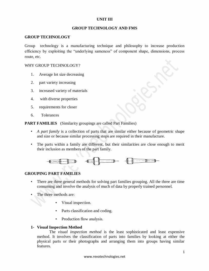
• A part family is a collection of parts that are similar either because of geometric shape
and size or because similar processing steps are required in their manufacture.
• The parts within a family are different, but their similarities are close enough to merit
their inclusion as members of the part family.
GROUPING PART FAMILIES
• There are three general methods for solving part families grouping. All the three are time
consuming and involve the analysis of much of data by properly trained personnel.
• The three methods are:
• Visual inspection.
• Parts classification and coding.
• Production flow analysis.
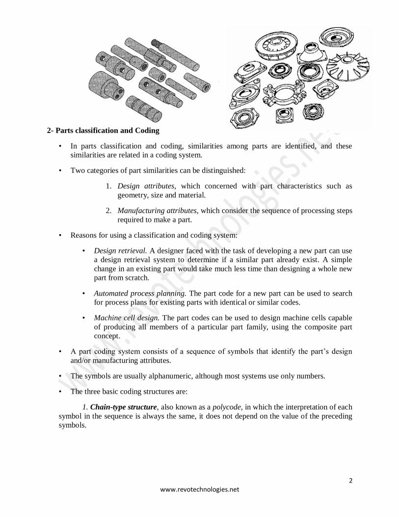
1- Visual Inspection Method
The visual inspection method is the least sophisticated and least expensive
method. It involves the classification of parts into families by looking at either the
physical parts or their photographs and arranging them into groups having similar
features.
2 www.revotechnologies.net
2- Parts classification and Coding
• In parts classification and coding, similarities among parts are identified, and these
similarities are related in a coding system.
• Two categories of part similarities can be distinguished:
1. Design attributes, which concerned with part characteristics such as
geometry, size and material.
2. Manufacturing attributes, which consider the sequence of processing steps
required to make a part.
• Reasons for using a classification and coding system:
• Design retrieval. A designer faced with the task of developing a new part can use
a design retrieval system to determine if a similar part already exist. A simple
change in an existing part would take much less time than designing a whole new
part from scratch.
• Automated process planning. The part code for a new part can be used to search
for process plans for existing parts with identical or similar codes.
• Machine cell design. The part codes can be used to design machine cells capable
of producing all members of a particular part family, using the composite part
concept.
• A part coding system consists of a sequence of symbols that identify the part’s design
and/or manufacturing attributes.
• The symbols are usually alphanumeric, although most systems use only numbers.
• The three basic coding structures are:
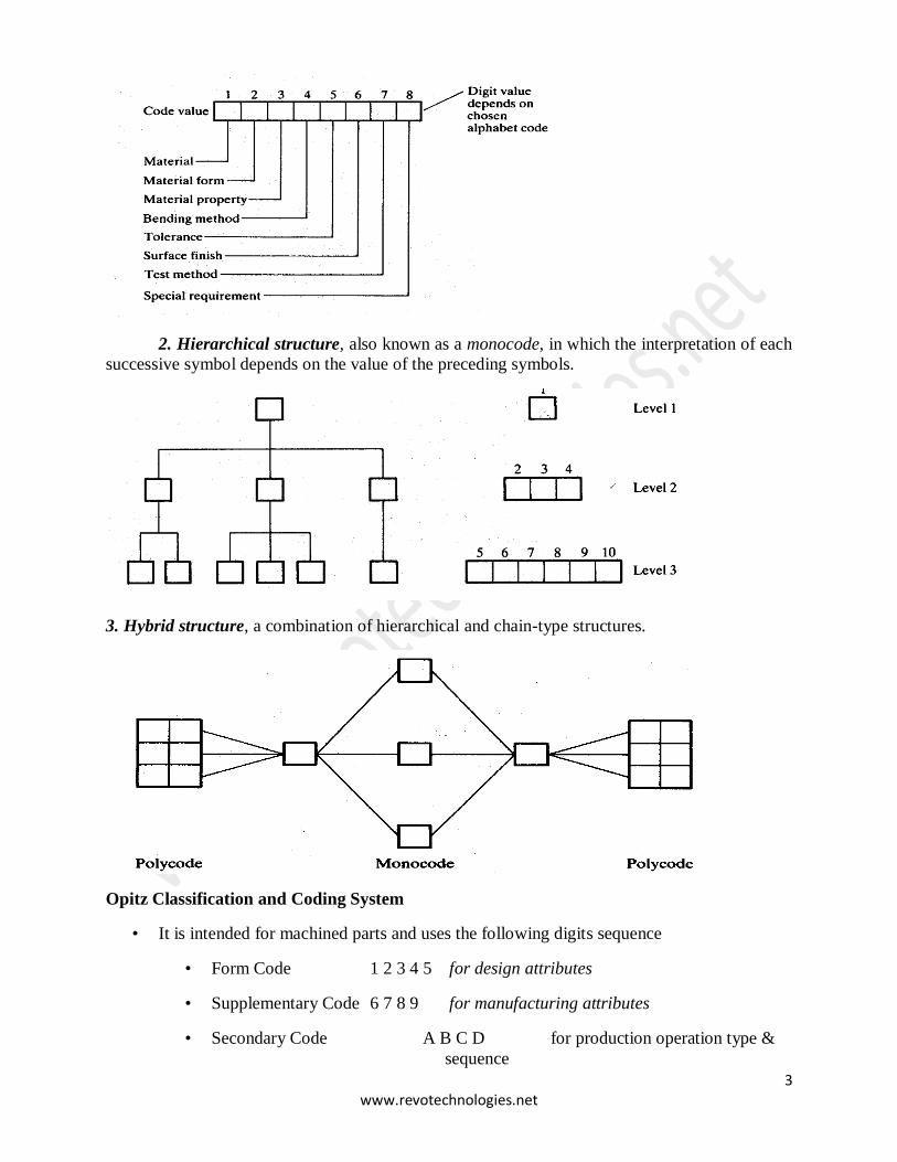
1. Chain-type structure, also known as a polycode, in which the interpretation of each
symbol in the sequence is always the same, it does not depend on the value of the preceding
symbols.
3 www.revotechnologies.net
2. Hierarchical structure, also known as a monocode, in which the interpretation of each
successive symbol depends on the value of the preceding symbols.
3. Hybrid structure, a combination of hierarchical and chain-type structures.
Opitz Classification and Coding System
• It is intended for machined parts and uses the following digits sequence
• Form Code 1 2 3 4 5 for design attributes
• Supplementary Code 6 7 8 9 for manufacturing attributes
• Secondary Code A B C D for production operation type &
sequence
4 www.revotechnologies.net
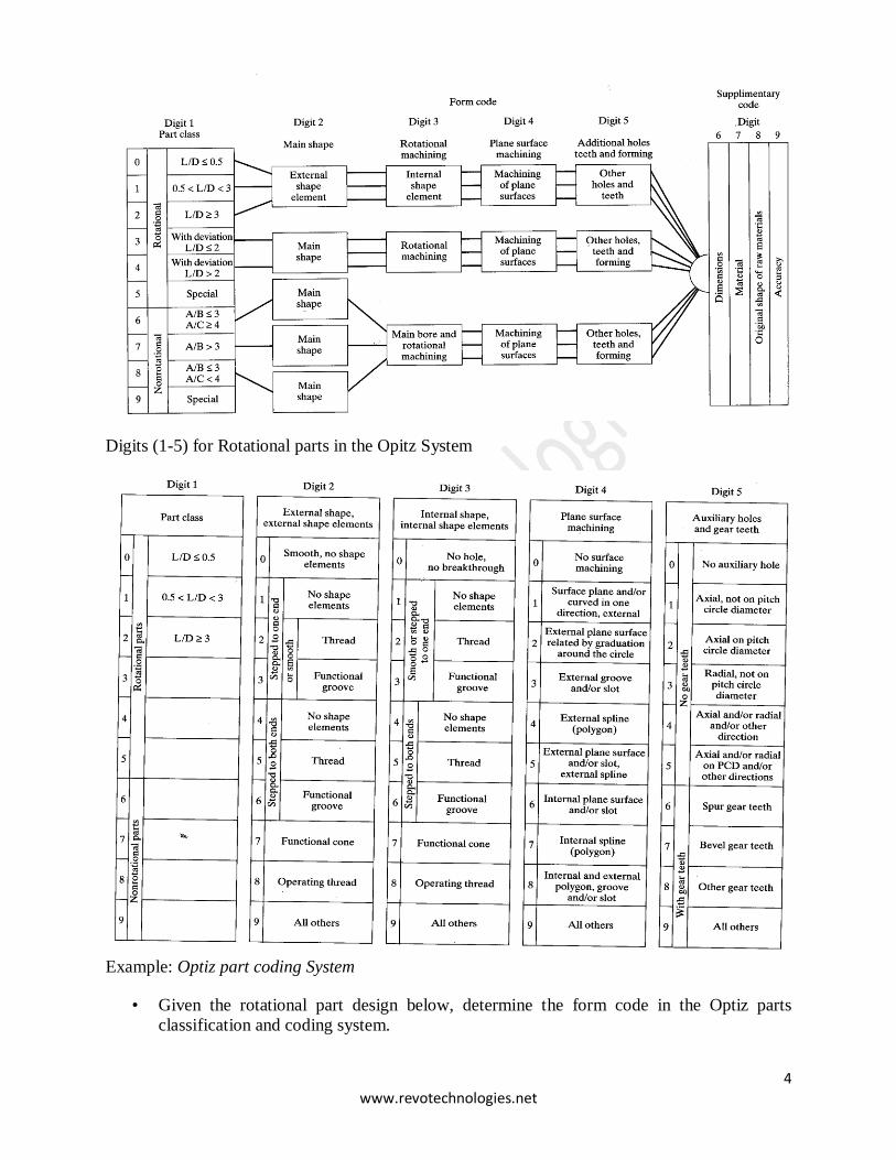
Digits (1-5) for Rotational parts in the Opitz System
Example: Optiz part coding System
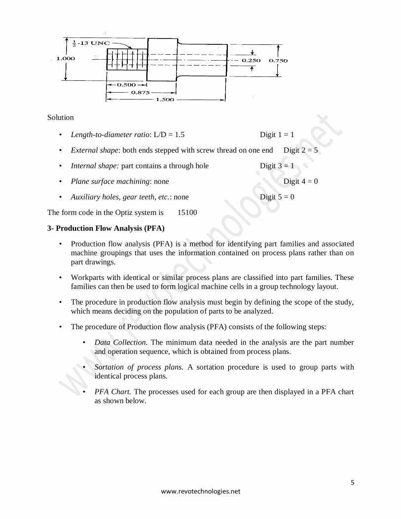
• Given the rotational part design below, determine the form code in the Optiz parts
classification and coding system.
5 www.revotechnologies.net
Solution
• Length-to-diameter ratio: L/D = 1.5 Digit 1 = 1
• External shape: both ends stepped with screw thread on one end Digit 2 = 5
• Internal shape: part contains a through hole Digit 3 = 1
• Plane surface machining: none Digit 4 = 0
• Auxiliary holes, gear teeth, etc.: none Digit 5 = 0
The form code in the Optiz system is 15100
3- Production Flow Analysis (PFA)
• Production flow analysis (PFA) is a method for identifying part families and associated
machine groupings that uses the information contained on process plans rather than on
part drawings.
• Workparts with identical or similar process plans are classified into part families. These
families can then be used to form logical machine cells in a group technology layout.
• The procedure in production flow analysis must begin by defining the scope of the study,
which means deciding on the population of parts to be analyzed.
• The procedure of Production flow analysis (PFA) consists of the following steps:
• Data Collection. The minimum data needed in the analysis are the part number
and operation sequence, which is obtained from process plans.
• Sortation of process plans. A sortation procedure is used to group parts with
identical process plans.
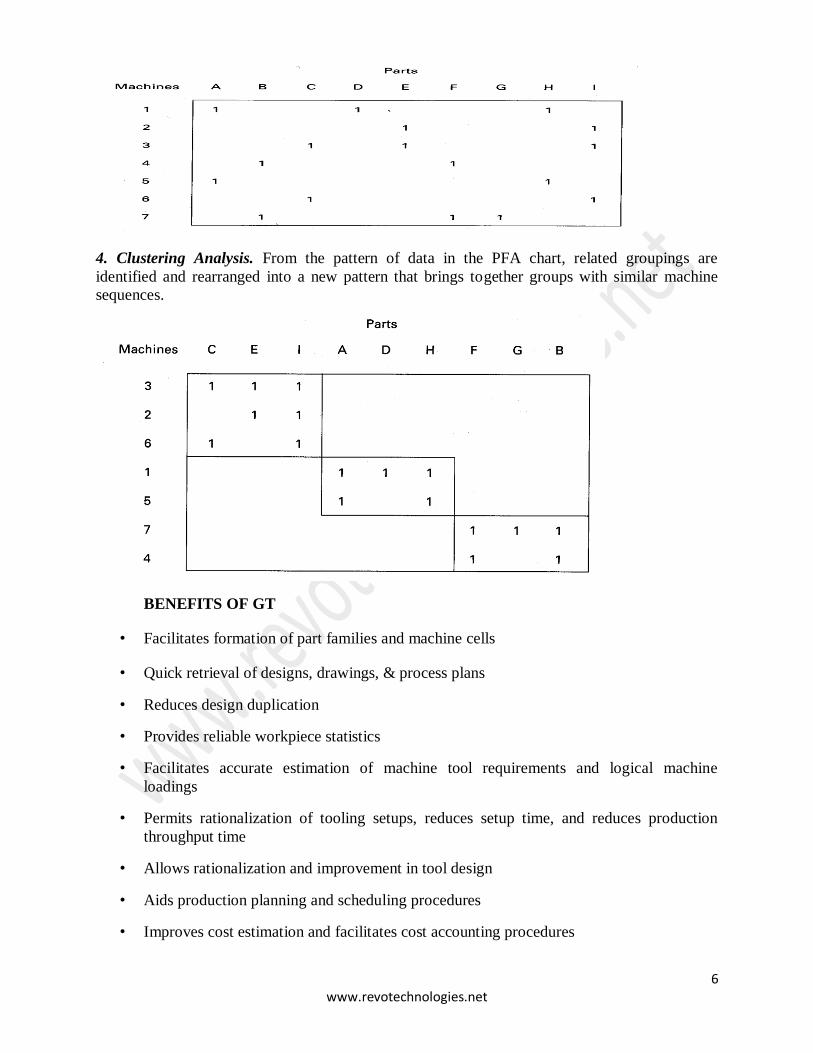
• PFA Chart. The processes used for each group are then displayed in a PFA chart
as shown below.
6 www.revotechnologies.net
4. Clustering Analysis. From the pattern of data in the PFA chart, related groupings are
identified and rearranged into a new pattern that brings together groups with similar machine
sequences.
BENEFITS OF GT
• Facilitates formation of part families and machine cells
• Quick retrieval of designs, drawings, & process plans
• Reduces design duplication
• Provides reliable workpiece statistics
• Facilitates accurate estimation of machine tool requirements and logical machine
loadings
• Permits rationalization of tooling setups, reduces setup time, and reduces production
throughput time
• Allows rationalization and improvement in tool design
• Aids production planning and scheduling procedures
• Improves cost estimation and facilitates cost accounting procedures
7 www.revotechnologies.net
• Provides for better machine tool utilization and better use of tools, fixtures, & people
• Facilitates NC part programming.
INTRODUCTION TO FLEXIBLE MANUFACTURING SYSTEM (FMS)
• A flexible manufacturing system (FMS) is a highly automated GT machine cell,
consisting of a group or processing workstations (usually CNC machine tools),
interconnected by an automated material handling and storage system, and controlled by
a distributed computer system.
• The reason the FMS is called flexible is that it is capable of processing a variety of
different part styles simultaneously at the various workstations, and the mix of part styles
and quantities of production can be adjusted in response to changing demand patterns.
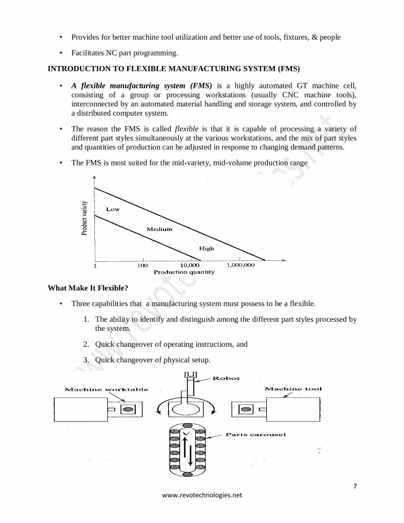
• The FMS is most suited for the mid-variety, mid-volume production range
What Make It Flexible?
• Three capabilities that a manufacturing system must possess to be a flexible.
1. The ability to identify and distinguish among the different part styles processed by
the system.
2. Quick changeover of operating instructions, and
3. Quick changeover of physical setup.
8 www.revotechnologies.net
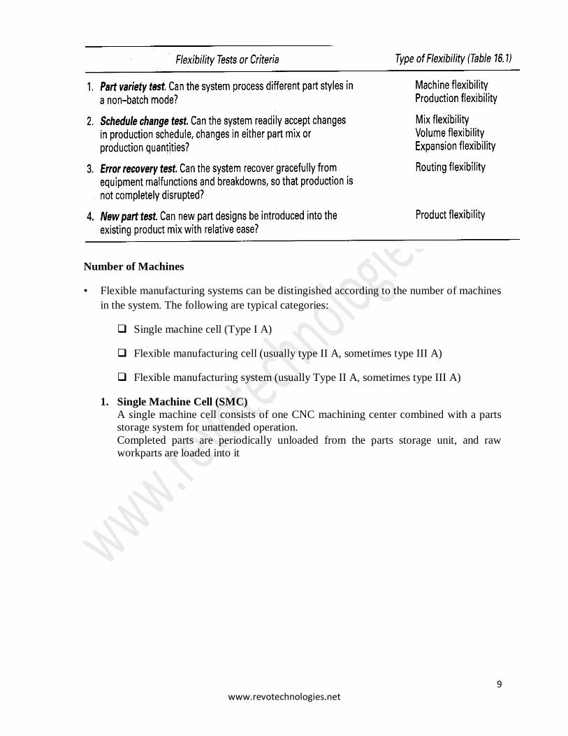
Tests of Flexibility
• To qualify as being flexible, a manufacturing system should satisfy several criteria. The
following are four reasonable tests of flexibility in an automated manufacturing system:
Part variety test. Can the system process different part styles in a nonbatch
mode?.
Schedule change test. Can the system readily accept changes in production
schedule, and changes in either part mix or production quantity.
Error recovery test. Can the system recover quickly from equipment breakdowns,
so that the production is not completely disrupted.
New part test. Can new part designs be introduced into the existing product mix
with relative ease.
• If the answer to all of these questions is “YES” for a given manufacturing system, then
the system can be considered flexible.
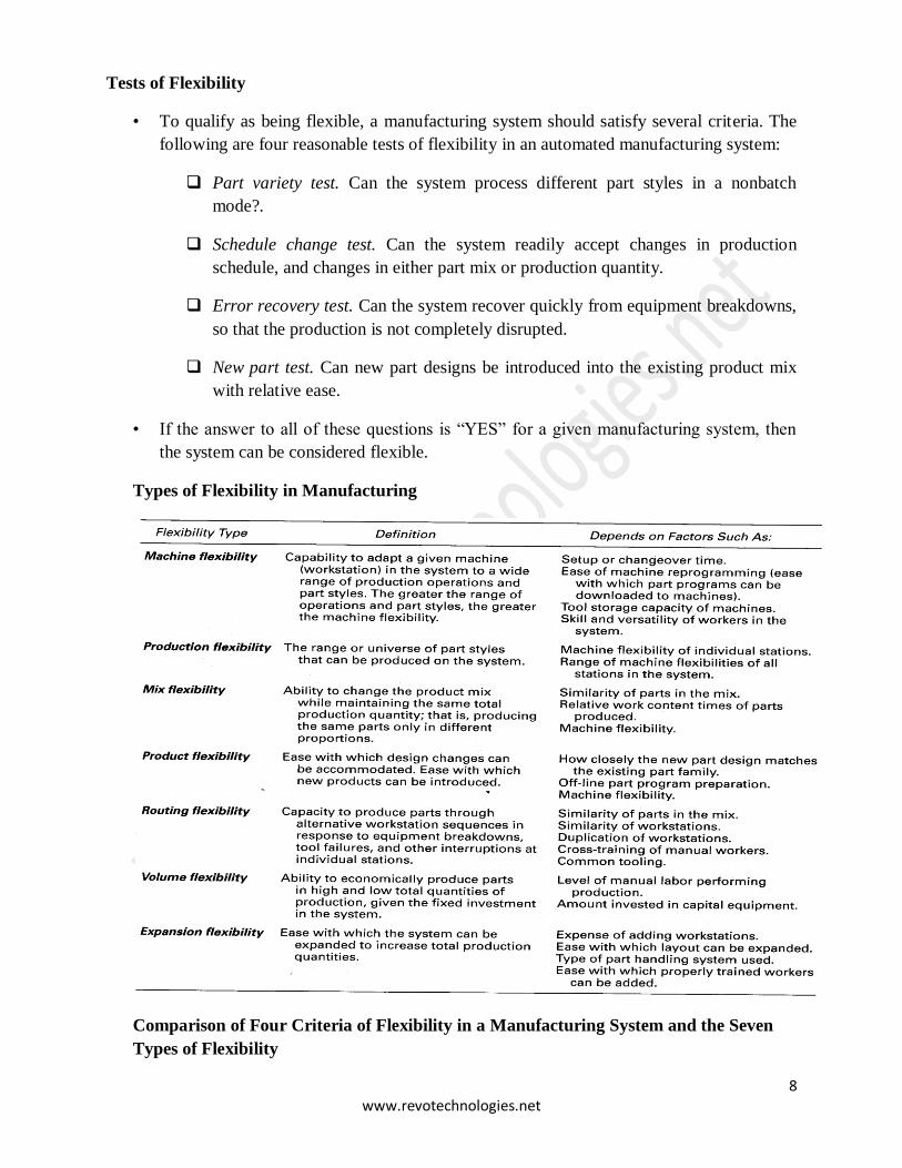
Types of Flexibility in Manufacturing
Comparison of Four Criteria of Flexibility in a Manufacturing System and the Seven
Types of Flexibility
9 www.revotechnologies.net
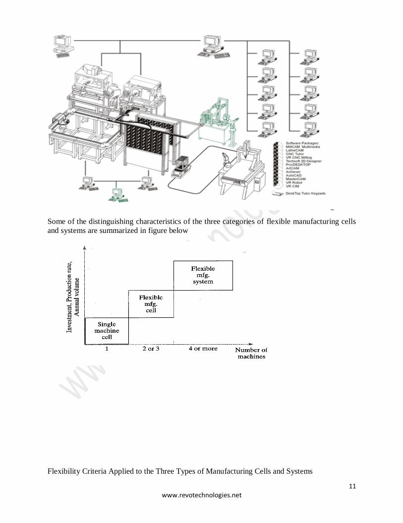
Number of Machines
• Flexible manufacturing systems can be distingished according to the number of machines
in the system. The following are typical categories:
Single machine cell (Type I A)
Flexible manufacturing cell (usually type II A, sometimes type III A)
Flexible manufacturing system (usually Type II A, sometimes type III A)
1. Single Machine Cell (SMC)
A single machine cell consists of one CNC machining center combined with a parts
storage system for unattended operation.
Completed parts are periodically unloaded from the parts storage unit, and raw
workparts are loaded into it

10 www.revotechnologies.net
Flexible Manufacturing Cell (FMC)
• A flexible manufacturing cell consists of two or three processing workstations (typically
CNC machining centers) plus a part handling system.
• The part handling system is connected to a load/unload station.
Flexible Manufacturing System (FMS)
• A flexible manufacturing system has four or more processing workstations connected
mechanically by a common part handling system and electronically by a distributed
computer system.
11 www.revotechnologies.net
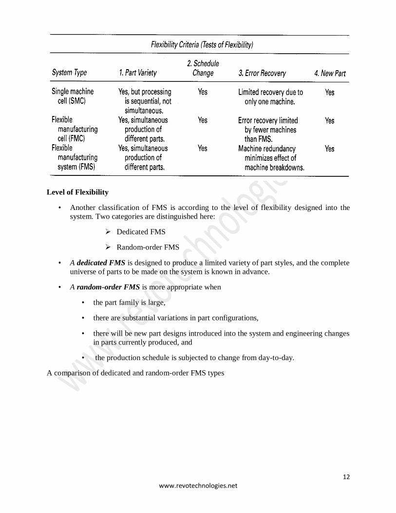
Some of the distinguishing characteristics of the three categories of flexible manufacturing cells
and systems are summarized in figure below
Flexibility Criteria Applied to the Three Types of Manufacturing Cells and Systems
12 www.revotechnologies.net
Level of Flexibility
• Another classification of FMS is according to the level of flexibility designed into the
system. Two categories are distinguished here:
Dedicated FMS
Random-order FMS
• A dedicated FMS is designed to produce a limited variety of part styles, and the complete
universe of parts to be made on the system is known in advance.
• A random-order FMS is more appropriate when
• the part family is large,
• there are substantial variations in part configurations,
• there will be new part designs introduced into the system and engineering changes
in parts currently produced, and
• the production schedule is subjected to change from day-to-day.
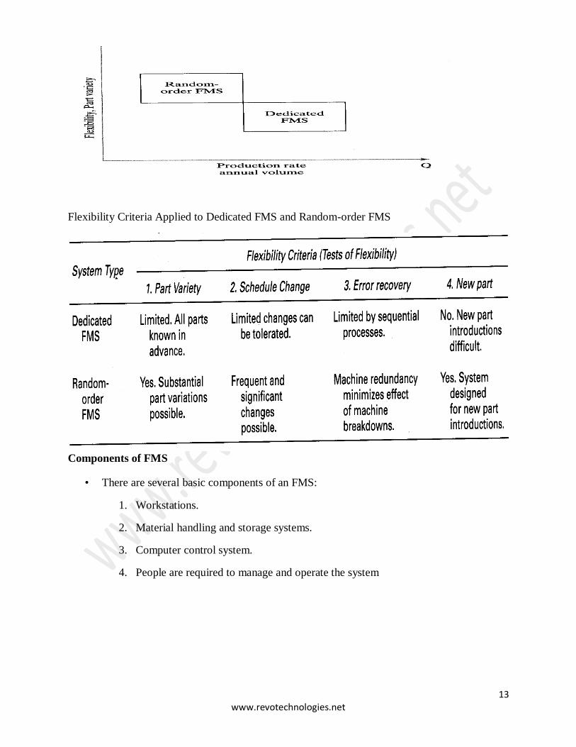
A comparison of dedicated and random-order FMS types
13 www.revotechnologies.net
Flexibility Criteria Applied to Dedicated FMS and Random-order FMS
Components of FMS
• There are several basic components of an FMS:
1. Workstations.
2. Material handling and storage systems.
3. Computer control system.
4. People are required to manage and operate the system
14 www.revotechnologies.net
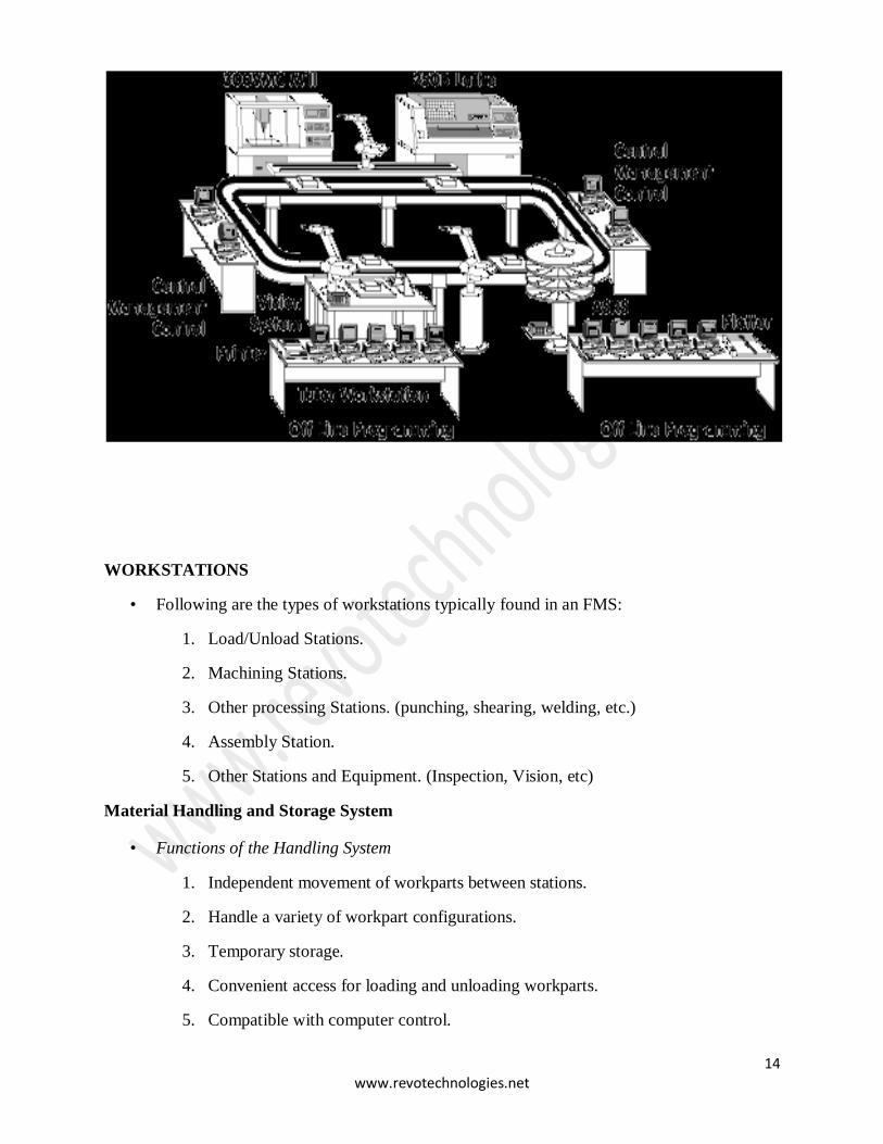
WORKSTATIONS
• Following are the types of workstations typically found in an FMS:
1. Load/Unload Stations.
2. Machining Stations.
3. Other processing Stations. (punching, shearing, welding, etc.)
4. Assembly Station.
5. Other Stations and Equipment. (Inspection, Vision, etc)
Material Handling and Storage System
• Functions of the Handling System
1. Independent movement of workparts between stations.
2. Handle a variety of workpart configurations.
3. Temporary storage.
4. Convenient access for loading and unloading workparts.
5. Compatible with computer control.
15 www.revotechnologies.net
• Material Handling Equipment
The material handling function in an FMS is often shared between two systems:
• Primary handling system establishes the basic layout of the FMS and is
responsible for moving workparts between stations in the system. (Conveyor)
Material Handling and Storage System
2. Secondary handling system consists of transfer devices, automatic pallet changing, and
similar mechanisms located at the workstations in the FMS.
• The function of the secondary handling system is to transfer work from the
primary system to the machine tool or other processing station and to position the
parts with sufficient accuracy and repeatability to perform the process or
assembly operation.
FMS Layout Configurations
The material handling system establishes the FMS layout. Most layout configurations found in
today’s FMS are:
1. In-line layout
2. Loop layout
3. Rectangular layout
4. Ladder Layout
5. Open Field
6. Robot Centred
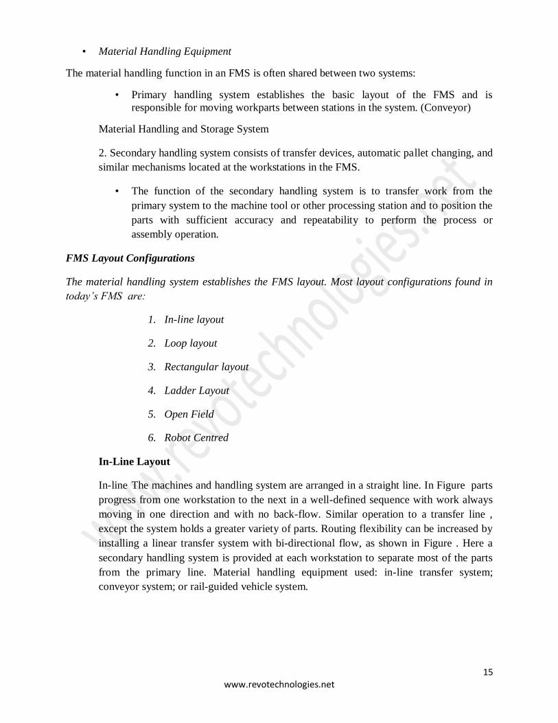
In-Line Layout
In-line The machines and handling system are arranged in a straight line. In Figure parts
progress from one workstation to the next in a well-defined sequence with work always
moving in one direction and with no back-flow. Similar operation to a transfer line ,
except the system holds a greater variety of parts. Routing flexibility can be increased by
installing a linear transfer system with bi-directional flow, as shown in Figure . Here a
secondary handling system is provided at each workstation to separate most of the parts
from the primary line. Material handling equipment used: in-line transfer system;
conveyor system; or rail-guided vehicle system.
16 www.revotechnologies.net
Loop
Workstations are organized in a loop that is served by a looped parts handling system. In
Figure parts usually flow in one direction around the loop with the capability to stop and
be transferred to any station. Each station has secondary handling equipment so that part
can be brought-to and transferred-from the station work head to the material handling
loop. Load/unload stations are usually located at one end of the loop.
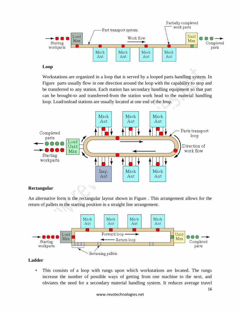
Rectangular
An alternative form is the rectangular layout shown in Figure . This arrangement allows for the
return of pallets to the starting position in a straight line arrangement.
Ladder
• This consists of a loop with rungs upon which workstations are located. The rungs
increase the number of possible ways of getting from one machine to the next, and
obviates the need for a secondary material handling system. It reduces average travel
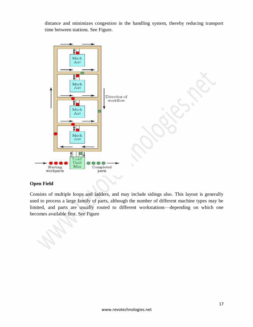
17 www.revotechnologies.net
distance and minimizes congestion in the handling system, thereby reducing transport
time between stations. See Figure.
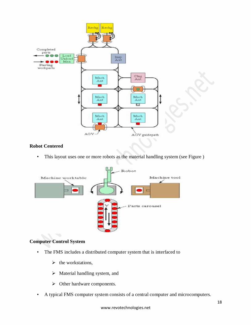
Open Field
Consists of multiple loops and ladders, and may include sidings also. This layout is generally
used to process a large family of parts, although the number of different machine types may be
limited, and parts are usually routed to different workstations—depending on which one
becomes available first. See Figure
18 www.revotechnologies.net
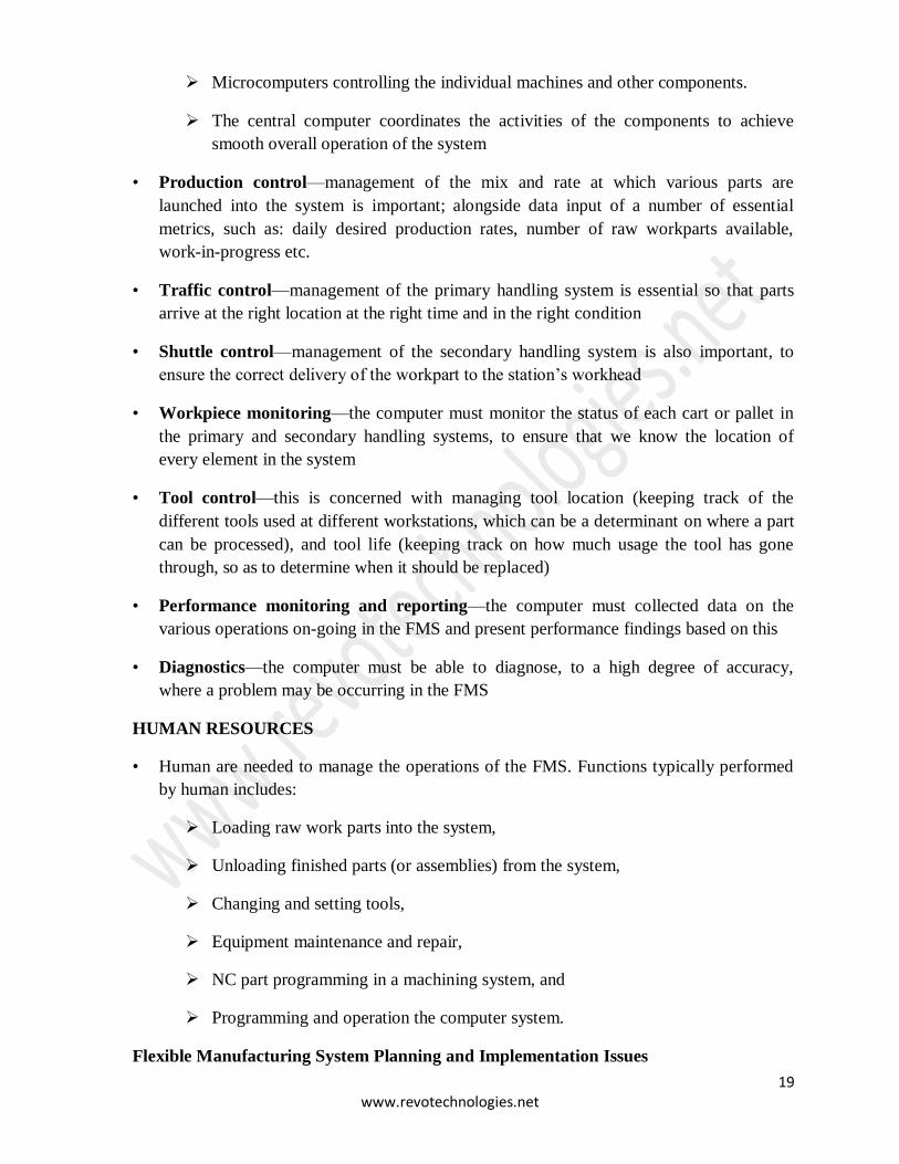
Robot Centered
• This layout uses one or more robots as the material handling system (see Figure )
Computer Control System
• The FMS includes a distributed computer system that is interfaced to
the workstations,
Material handling system, and
Other hardware components.
• A typical FMS computer system consists of a central computer and microcomputers.
19 www.revotechnologies.net
Microcomputers controlling the individual machines and other components.
The central computer coordinates the activities of the components to achieve
smooth overall operation of the system
• Production control—management of the mix and rate at which various parts are
launched into the system is important; alongside data input of a number of essential
metrics, such as: daily desired production rates, number of raw workparts available,
work-in-progress etc.
• Traffic control—management of the primary handling system is essential so that parts
arrive at the right location at the right time and in the right condition
• Shuttle control—management of the secondary handling system is also important, to
ensure the correct delivery of the workpart to the station’s workhead
• Workpiece monitoring—the computer must monitor the status of each cart or pallet in
the primary and secondary handling systems, to ensure that we know the location of
every element in the system
• Tool control—this is concerned with managing tool location (keeping track of the
different tools used at different workstations, which can be a determinant on where a part
can be processed), and tool life (keeping track on how much usage the tool has gone
through, so as to determine when it should be replaced)
• Performance monitoring and reporting—the computer must collected data on the
various operations on-going in the FMS and present performance findings based on this
• Diagnostics—the computer must be able to diagnose, to a high degree of accuracy,
where a problem may be occurring in the FMS
HUMAN RESOURCES
• Human are needed to manage the operations of the FMS. Functions typically performed
by human includes:
Loading raw work parts into the system,
Unloading finished parts (or assemblies) from the system,
Changing and setting tools,
Equipment maintenance and repair,
NC part programming in a machining system, and
Programming and operation the computer system.
Flexible Manufacturing System Planning and Implementation Issues
20 www.revotechnologies.net
We consider FMS planning and implementation under two heading here:
1. Planning and design issues, and
2. Operational issues.
FMS Planning Issues
• Part family considerations
A choice has to be made regarding group technology, and the part family to be produced
on the FMS. The FMS cannot be completely flexible, and so cannot handle any part
whatsoever; there must be some consideration on the creation of a composite part, with all
possible physical attributes of the parts that may be processed in the FMS.
• Processing requirements
Once the entire range of possible parts to be processed are known, we must use this
information to help choose associated processing requirements for each part, and thus the
type of equipment that should be used to process the parts.
• Physical characteristics of the work parts
Size and weight of work parts determine size of the machines required to process the
parts. It also determines the size of the material handling system needed.
• Production volume
Production quantities must be determined, as these tell us how many machines of each
type will be required.
• Design issues for FMSsTypes of workstations
Workstation choices have to be made, depending on part processing requirements. We
must consider position and use of load and unload stations also.
• Variations in process routings and FMS layout
If part processing variations are minimal, we may decide to use an in-line flow; if part
processing variations are high, we may instead opt for a loop flow, or higher still, for an open
field layout.
• Material handling system
We must select an appropriate primary and secondary material handling system to suit
the layout chosen.
• Work-in-process and storage capacity
21 www.revotechnologies.net
Determining an appropriate level of WIP allowed is important, as it affects the level of
utilization and efficiency of the FMS. Storage capacity must be compatible with the level of
WIP chosen.
• Tooling
We must determine the number and type of tools required at each workstation. How
much duplication of tooling should occur at workstations? Duplication allows for efficient re-
routing in the system should breakdowns
• Pallet fixtures
For non-rotational parts, selection of a few types of pallet fixtures is important. Factors
that influence the decision include: levels of WIP chosen, and differences in part style and
size.
Operational Issues
1. Scheduling and dispatching
Scheduling must be considered for the FMS, based upon the Master Production
Schedule. Dispatching is concerning with launching the parts into the system at the
appropriate times.
2. Machine loading
We must choose how to allocate specific parts to specific machines in the system,
based upon their tooling resources and routing considerations of the FMS.
3. Part routing
Routing decisions involve the choice of a route that should be followed by a part
in the system. Consideration should be given to other parts travelling in the system,
traffic management etc.
4. Part grouping
Part types must be grouped for simultaneous production, given limitations on
available tooling and other resources at workstations.
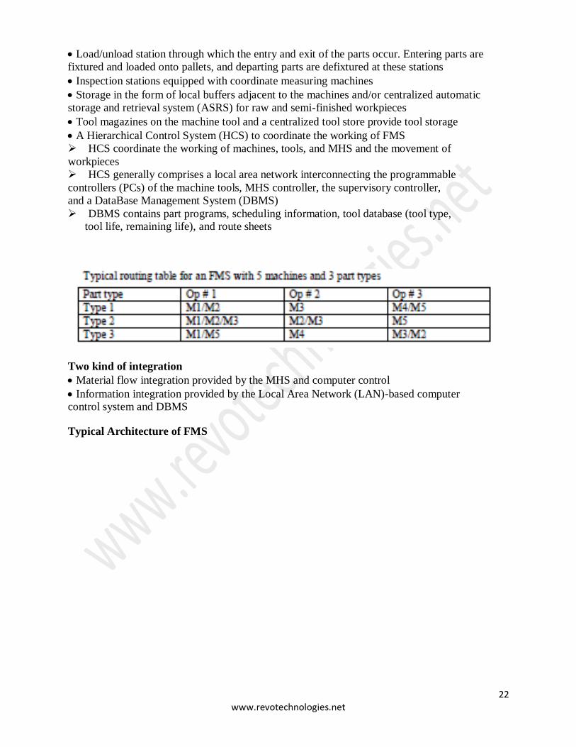
Architecture of FMS
Typical elements of FMS
Versatile NC machines equipped with automatic tool changing and inprocess gauging,
with capability to carry out a variety of operations
An automated Material Handling System (MHS) to move parts and tools under the control
of a central MHS controller. The MHS may comprise conveyers, carts, individual robots,
AGVS, or a combination of these elements
22 www.revotechnologies.net
Load/unload station through which the entry and exit of the parts occur. Entering parts are
fixtured and loaded onto pallets, and departing parts are defixtured at these stations
Inspection stations equipped with coordinate measuring machines
Storage in the form of local buffers adjacent to the machines and/or centralized automatic
storage and retrieval system (ASRS) for raw and semi-finished workpieces
Tool magazines on the machine tool and a centralized tool store provide tool storage
A Hierarchical Control System (HCS) to coordinate the working of FMS
HCS coordinate the working of machines, tools, and MHS and the movement of
workpieces
HCS generally comprises a local area network interconnecting the programmable
controllers (PCs) of the machine tools, MHS controller, the supervisory controller,
and a DataBase Management System (DBMS)
DBMS contains part programs, scheduling information, tool database (tool type, tool life, remaining life), and route sheets
Two kind of integration
Material flow integration provided by the MHS and computer control
Information integration provided by the Local Area Network (LAN)-based computer control system and DBMS
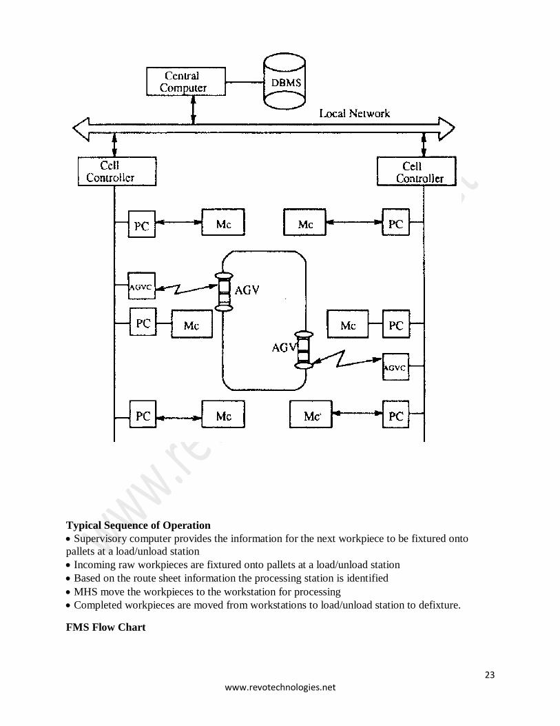
Typical Architecture of FMS
23 www.revotechnologies.net
Typical Sequence of Operation
Supervisory computer provides the information for the next workpiece to be fixtured onto
pallets at a load/unload station
Incoming raw workpieces are fixtured onto pallets at a load/unload station
Based on the route sheet information the processing station is identified
MHS move the workpieces to the workstation for processing
Completed workpieces are moved from workstations to load/unload station to defixture.
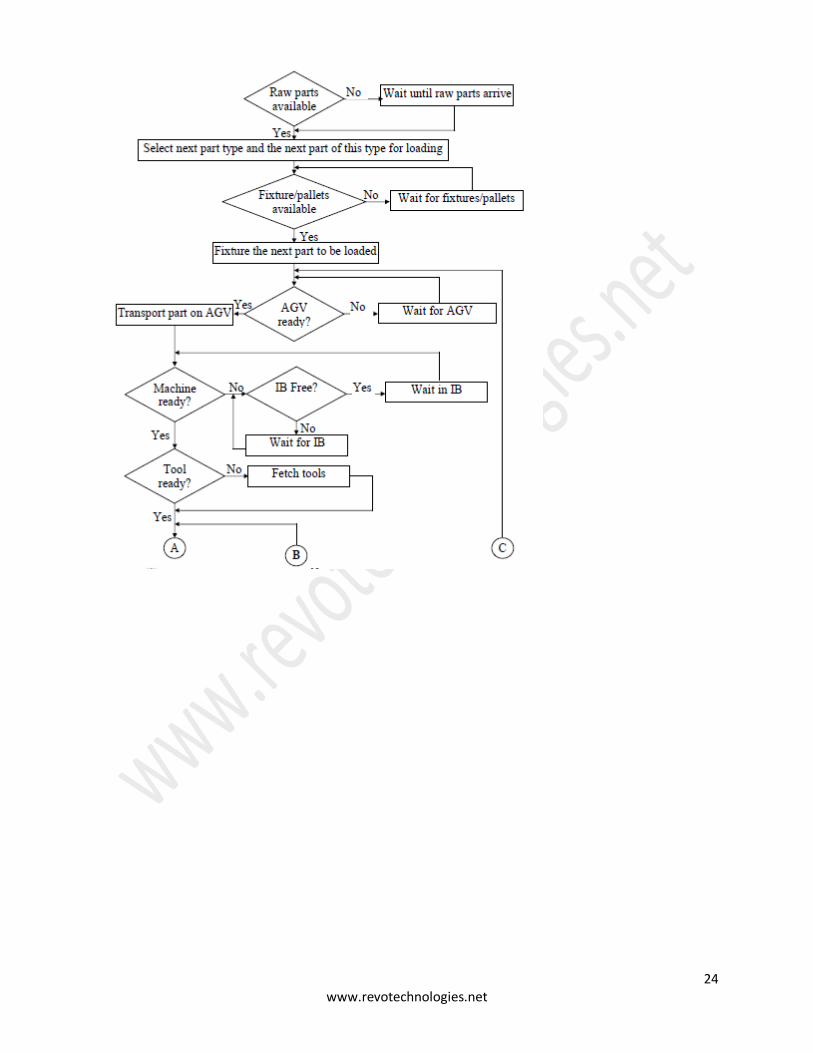
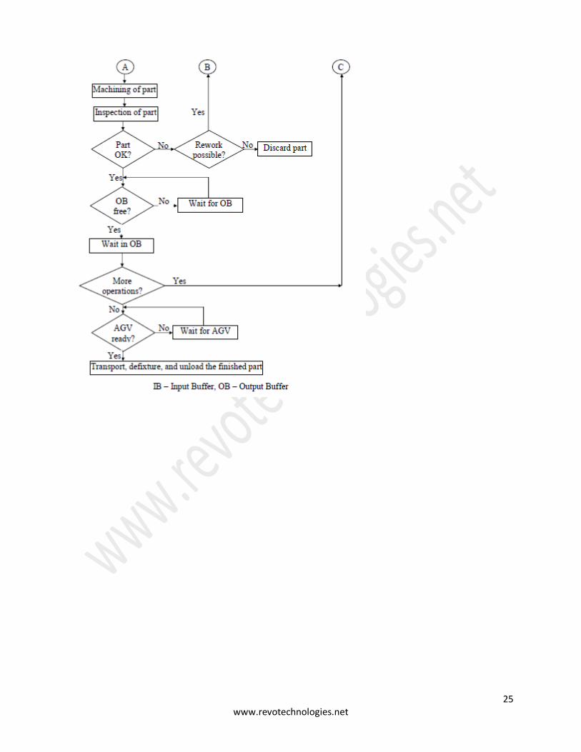
FMS Flow Chart
24 www.revotechnologies.net
25 www.revotechnologies.net