Embed Size (px)
Citation preview
«NOVATEK-ELECTRO» LTD Intelligent industrial electronics
UNIVERSAL AUTOMATIC ELECTRONIC PHASE SWITCHING DEVICE
PEF-319
OPERATING MANUAL
Review the Operating manual before using the unit
www.novatek-electro.in

~ 2 ~
PEF-319 NOVATEK-ELECTRO
Quality control system on the production complies with requirements ISO 9001:2008 Prior the connection of the device to the electric line, keep it for two hours under the exploitation conditions. WARNING
IT IS FORBIDDEN TO USE THE DEVICE WHICH HAS THE MECHANICAL DAMAGES OF THE CASE. IT IS NOT ALLOWED TO LET THE WATER GET INSIDE THE DEVICE AND TO USE IT IN CONDITIONS OF HIGH HUMIDITY.
The device is safe for use when observing the rules of exploitation.

~ 3 ~
NOVATEK-ELECTRO PEF-319
1 DESCRIPTION AND OPERATION 1.1 APPLICATION
The PEF-319 universal automatic electronic phase switching device is designed to supply an industrial and domestic single phase 230/240 V, 50 Hz load from three-phase four-wire mains 3х380+N in order to maintain uninterrupted power supply of essential single-phase loads and protect them against unallowable voltage variations in the mains.
According to the voltage presence and voltage quality on the phases, the PEF-319 will automatically select the optimum phase in limits range set by user and switch the single phase load supply to this phase:
- If power is less than 6,6 kW (30 A), the load is energized directly from the PEF-319; - if power is more than 6,6 kW (30 A), the PEF-319 controls the magnetic starters (MS) single phase coils of the
corresponding power (MS are not included in supply complete package). The maximum and minimum voltage limits are set by user.
1.2 TECHNICAL SPECIFICATION The technical characteristics of phase switch PEF-319 are resulted in the tables 1 and 2.
Table 1 - General information
Feature Unit Description Device scope - Control and distribution device Construction type (installation) - On standard DIN-rail, 35 mm Protection degree of: - device - terminals block
- IP40 IP20
Climatic version - TC 3.1 Working temperature range С from -35 to +55 Storage temperature С from -45 to +60 Pollution rate - III Category of overload - III Cross-section of connection terminal wires mm2 2-4 Maximal screw torque of terminal clams N*m 0,4
Table 2 – Basic technical characteristics
Features, measurement unit Value Nominal phase voltage, V 220/240 Operating capability voltage, on single phase, V 120 Mains frequency, Hz 45 - 55 Trip threshold for UMIN, V 150 - 210 Trip threshold for UMAX, V 230 - 280 Time delay range for return to the priority phase, sec Note – If knob Тr is in position " " there is no return to the priority phase
5- 200
Time delay range of reclosing, Тon, sec 1 - 600 Fixed time delay of switching over (switching off) for UMIN, sec 12 Time of switching over to reserve phases, sec, not more 0.2 Hysteresis (reset coefficient) on voltage, V 5 - 7 Accuracy of threshold trip, V ±3 Maximum switched current (active) of output contacts, A 30 Device operating capability phase voltage, V 400 Short time allowable operating capability maximal phase voltage, V 450 Power consumption (under load), watts, not more than 10 Service life of output contacts:
- Under load 30 A (active voltage), operations, not less than - Under load 5 A, operations, not less than
100 000 1 000 000
Overall dimensions, mm 157 х 91 х 59 Weight, kg, not more than 0.38 Mounting – on standard DIN-rail 35 mm. Mounting position – user defined.
PEF-319 meets the requirements of: IEC 60947-1:2004, ІDТ; ІEC 60947-6-2:1992, ІDT; CISPR 11:2004, IDT; IEC 61000-4-2:2001, IDT. Harmful substances in concentration more than allowed are absent.
~ 4 ~
PEF-319 NOVATEK-ELECTRO
1.3 CONTROLS DESCRIPTION AND DIMENSIONS DIAGRAM
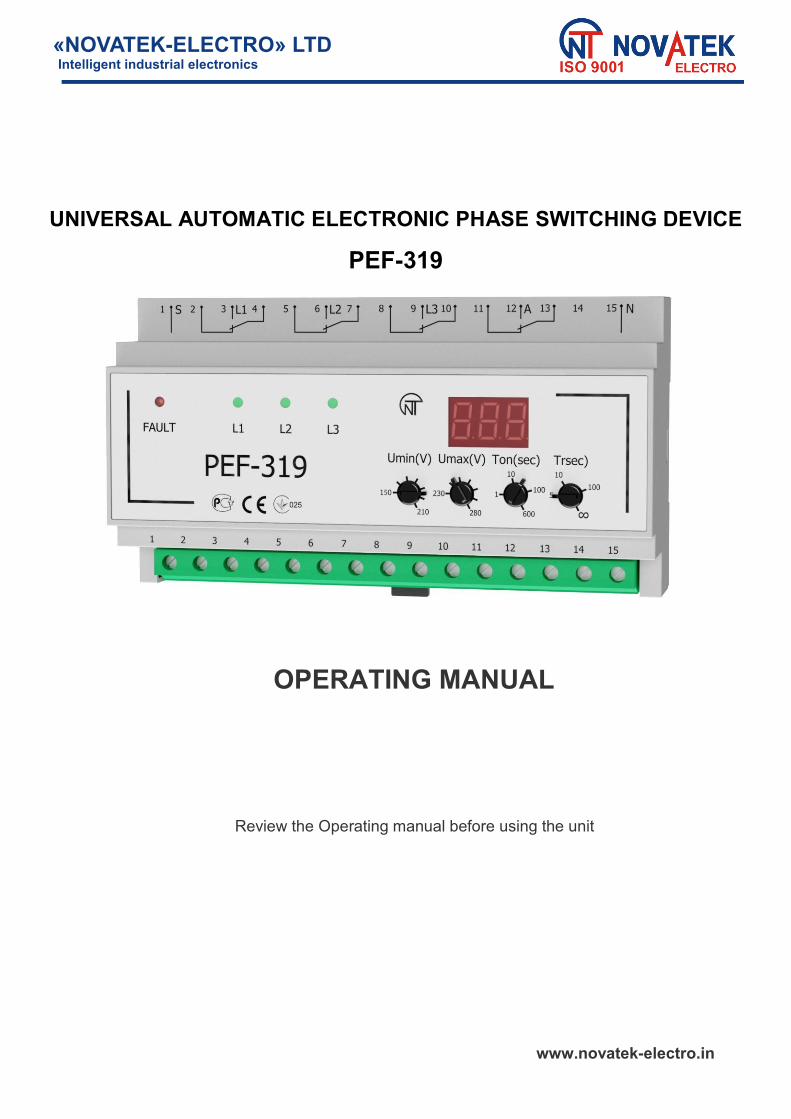
1.3.1 Controls and dimensions of PEF-319 are resulted in figure 1.
1– seven-segment display; 2 – knob for time delay setting of return to the priority phase, Тr; 3 – knob of time setting of automatic re-switching, Тon; 4 – knob for threshold trip setting on maximal voltage, Umax; 5 – knob for threshold trip setting on minimal voltage, Umin; 6 – LED indicator of phase L1; 7 – LED indicator of alarm; 8 – LED indicator of phase L2; 9 – LED indicator of phase L3.
Figure 1 – Controls and dimensions
1.3.2 Function of contact connection terminals:
1 – external starter control; 2 – transit terminal of phase L1 relay; 3 – input of phase L1; 4 – output of phase L1 relay; 5 – транзитный контакт реле фазы L2; 6 – input of phase L2; 7 – output of phase L2 relay; 8 – transit terminal of phase L3 relay; 9 – input of phase L3;
10 – output of phase L3 relay; 11 – closed at switching off terminal of additional relay; 12 – closed at switching on terminal of additional relay; 13 – switching type terminal of additional relay; 14 – not connected; 15 – neutral of main (neutral wire).
1.4 DESIGN AND PRINCIPLE OF OPERATION
The electronic phase switch PEF-319 is a microprocessor-based digital device. User should make setting of trip threshold limits of PEF-319 - the minimal and maximal voltage values at which
PEF-319 trips and switches off the load (or switches over to a reserve phase). Phase L1 is the priority one. It means that at normal parameters of voltage on all phases connected to PEF-319
(L1, L2, L3), the load will always be energized from phase L1. If on L1 the value is out of limits set by user, PEF-319 switches the load to the nearest by priority phase in not more than 0,2 seconds if the its voltage corresponds to the normal level. If the voltage on the reserve phases does not correspond to the trip set limits the load switches off.
Switching to the phases having the unallowable parameters will not be performed. After the load had been switched to the reserve phase and the voltage parameters had been restored on the
priority phase, the load will be switched to the priority phase in return time Тr (from 5 to 200 sec) set by user. During the phase switching there can be a flickering of the red LED indicator ALARM and there will be a short
time indication of alarm code on the display (for example, code “Х 3” means that the switching was performed from the phase L3).
~ 5 ~
NOVATEK-ELECTRO PEF-319
If during count down of Тr the voltage on priority phase goes out of threshold limits, the timer of Тr will be reset.
If Тr is in the position “∞”, the return to the priority phase will be performed only when voltage on the reserve
phase goes out of the threshold limits. In case when the voltage supplied on load goes lower than the minimal threshold limit the load switching over or
switching off should be performed with a time delay of 12 seconds. When the voltage goes higher than the maximal threshold limit or goes 30 V lower than the minimal threshold limit, the load switching over or switching off will be performed with time delay of 0,2 seconds.
During the load switching off the PEF-319 continues to perform the voltage control on all phases. When the voltage normalizes within the limit range on one of the phases the PEF-319 will switch the load to this
phase within the time period of Тon. The additional relay will switch on if the load is connected to any phase and provides the voltage commutation
less than 30 A. The additional relay terminals are insolated and designed for enhancement of device functional possibilities. PEF-319 is designed with an internal blocking system against sealing of relay output inbuilt contacts and with
control of state of magnetic starters power contacts in external circuit (the terminal 1 is used for sealing control, figure 3). If at least one contact is switched on («sealed»), PEF-319 will be blocked, the phase switching over is not performed, the red LED indicator ALARM is flickering and the green LED indicator shows the phase on which the sealing took place, and the digital display will for a short time show the code of alarm and number of relay (MS) of а sealed phase (for example, code “Х2” means a sealed contact on phase L2).
Unblocking of PEF-319 should be made by its de-energizing. NOTE – There will be no switching over in case of energy presence on terminal 1.
2 INTENDED USE 2.1 PRELIMINARY STARTING PROCEDURE
All connections should be made only with the device being de-energized.
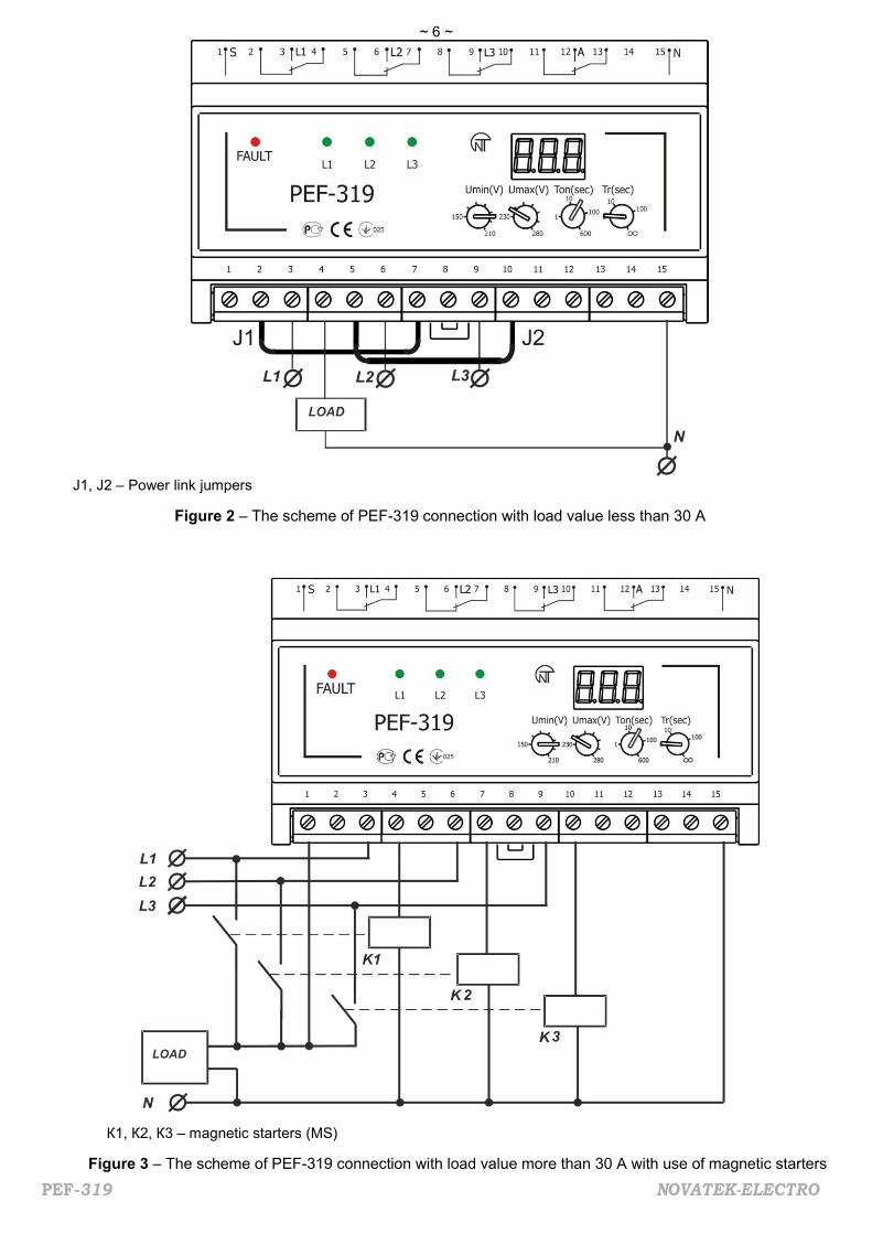
Make connection of PEF-319 to the three-phase line according to the figure 2 (at load value less than 30 A) or according to the figure 3 (at load value more than 30 A with use of magnetic starters).
The limit values should be set after connecting the device to the mains with the load being disconnected: UMIN – the minimal voltage level of relay switching on; UMAX – the maximal voltage level of relay switching on; Тon – time of automatic reset of load after restoring the voltage parameters on one of the phases, and time of
load primary switching on after energizing of the device; Тr - time of return to the priority phase. For the refrigerators, air conditioning devices and other compressor equipment, Тon is recommended to be set
in range of 3 -10 minutes, for other devices – according to their manuals and operating instructions. After the setting of threshold limit values the device is ready for operation with load. It is allowed to change the levels of UMIN, UMAX, Тon, Тr during the device operation with observing the
safety rules.
~ 6 ~
PEF-319 NOVATEK-ELECTRO
J1, J2 – Power link jumpers
Figure 2 – The scheme of PEF-319 connection with load value less than 30 A
К1, К2, К3 – magnetic starters (MS) Figure 3 – The scheme of PEF-319 connection with load value more than 30 A with use of magnetic starters

~ 7 ~
NOVATEK-ELECTRO PEF-319
2.2 INTENDED USE
After connection to power supply and parameters setting the PEF-319 is ready for operation. Green light LED indicators L1, L2, L3 on the front panel show the phase to which the load is connected. With load being connected the digital display shows the voltage of the phase which is connected to the load. With load being disconnected the digital display shows the voltage of the phase which has the value nearest to
the set threshold voltage limits. This phase is indicated by flickering of corresponding LED indicator. If the load is disconnected from all three phases, the red LED indicator ALARM will light on In case when several PEF-319 devices are used in the line, it is recommended to select different phases as a
“priority one” for different groups of consumers to avoid the phase overloading.
3 COMPLETENESS The complete set of delivery is resulted in Table 3
Table 3 - Completeness of delivery set
Item Quantity PEF-319 device 1 pcs Power link jumpers 2 pcs Operating Manual 1 pcs Packing box 1 pcs
4 TECHNICAL MAINTENANCE
4.1 SAFETY RULES
IT IS FORBIDDEN TO MAKE UNAUTHORIZED OPENING AND REPAIRING OF PEF-319. The device elements can be energized with electric power. IT IS FORBIDDEN TO MAKE UNAUTHORIZED OPENING AND REPAIRING OF PROTECTED
EQUIPMENT IF IT IS CONNECTED TO THE OUTPUT TERMINALS OF THE DEVICE. DO NOT use the abrasive substances or organic compounds for cleaning of the device (spirit, gasoline,
solvents etc.). 4.2 TECHNICAL MAINTENANCE PROCEDURE The recommended periodicity of technical maintenance is every six months. Technical maintenance consists of visual inspection during which there is a check of fail-safety of wire
connection to the terminals of PEF-319, absence of damages and cracks on its case.
5 TRANSPORTATION AND STORAGE PEF-319 should be stored in the manufacturer’s packing in enclosed premises at temperature range from
minus 45 to plus 60 С and relative humidity not more than 80%, with no fumes in the air that have a deleterious effect on the package and device material. The Buyer must provide the protection of the device against the mechanical damages during transportation.
6 OPERATION LIFE AND MANUFACTURER’S WARRANTY
The operation life of PEF-319 is 10 years. After expiration of the operation life period the buyer should contact the manufacturer.
The storage period is 3 years. The warranty period is 36 months from the date of sale. During the operation warranty period the manufacturer performs the repair works of PEF-319 free of charge,
provided the user observed the technical requirements, rules of storage, connection and operation. The PEF-319 device is not covered by warranty in the following cases: Expiration of warranty or operation life period; PEF-319 device has mechanical damages (cracks, splits, cuts, deformations etc.), because of very high
or very low temperatures, mechanical stresses, bent structure, breaking etc. Presence of traces of moisture attacks, penetration of foreign matters, dust and dirt inside of the device
(including the insects), beyond the permissible rates specified in the technical passport.

~ 8 ~
PEF-319 NOVATEK-ELECTRO
The repair works of PEF-319 device were performed by the company or individual not authorized by the manufacturer.
The completeness of the PEF-319 does not correspond to “The operational manual” (alteration of electrical scheme, change of device elements nominal);
Damage is caused by electricity or voltage which values are above the specified limits, careless or not correct use of the device, not observing the instructions of installation and operation;
Stroke of lightning, fire, flood, absence of ventilation and other reasons beyond the manufacturer’s
control. Warranty and post warranty maintenance (according to the current price rates) is performed at place of
purchase. Manufacturer’s warranty does not cover the direct or indirect losses, damages and wastes as well as charges
connected with shipping of the device to the service center. It is strongly recommended while none-acceptance or returning the device for warranty or post warranty service
to specify in the reclamation list the detailed reasons of handing back of the device.
7 ACCEPTANCE CERTIFICATE
The phase switching device PEF-319 №________ has been manufactured and accepted according to the
requirements of effective technical documentation and is approved to be ready for operation.
Chief of quality department Date of issue STAMP ______________ _____________
8 INFORMATION ON CLAIMS ___________________________________________________________________________________________ ________________________________________________________________________________________________________________________________________________________________________________ ________________________________________________________________________________________________________________________________________________________________________________ ________________________________________________________________________________________ ________________________________________________________________________________________________________________________________________________________________________________ ________________________________________________________________________________________________________________________________________________________________________________ ________________________________________________________________________________________ ________________________________________________________________________________________ ________________________________________________________________________________________
With all questions contact the manufacturing company:
NOVATEK ELECTRO INDIA PVT LTD C-30, Patparganj Industrial Area, 1st floor, Delhi - 110092, INDIA
tel/fax (+91 11) 42143253, 43010600 www.novatek-electro.in
Date of sale ________________