Embed Size (px)
Citation preview
UNIVERSITI PUTRA MALAYSIA
SOFTWARE DEVELOPMENT OF ACTIVE POWER FILTER DESIGN FOR HARMONIC MITIGATION
RAMDAN EMHEMMED RAJAB
FK 2002 76
SOFTWARE DEVELOPMENT OF ACTIVE POWER FILTER DESIGN FOR HARMONIC MITIGATION
RAMDAN EMHEMMED RAJAB
MASTER OF SCIENCE UNIVERSITI PUTRA MALAYSIA
2002
SOFTWARE DEVELOPMENT OF ACTIVE POWER FILTER DESIGN FOR HARMONIC MITIGATION
By
RAMDAN EMHEMMED RAJAB
Thesis Submitted to the School of Graduate Studies, Universiti Putra Malaysia, in Partial Fulfilment of Requirements for the Degree of Master of Science
June 2002
Abstract of thesis presented to the Senate of Universiti Putra Malaysia in Partial fulfilment of the requirements for the degree of Master of Science
SOFTWARE DEVELOPMENT OF ACTIVE POWER FILTER DESIGN FOR HARMONIC MITIGATION
By
RAMDAN EMHEMMED RAJAB
June 2002
Chairman: Norman Mariun, Ph.D.
Faculty: Engineering
The development of design automation tools for a power electronic circuit has
received a great deal of attention in the last two decades. To provide an optimum
solution for each power electronics application demands the selection of the most
appropriate power electronic devices, power circuit and control philosophy. For a
certain applications, it must be decided which power circuit topology and which
power semiconductor with which control strategy is best suited for it. Their design
and fabrication require extensive knowledge and sophistication that must be
continually updates as the technologies improve. Considerable engineering effort and
knowledge are required to take a power circuit from a laboratory prototype to a
finished product. Other than being an expert in areas as diverse as thermal design,
circuit and system packaging, circuit protection, and safety and electromagnetic
interference regulations.
ii

With such a highly demanding expertise required of power electronic circuits'
designers and with such rapid advancements in the field of circuit topology and
semiconductor devices it is difficult for designers to come up with an optimum
circuit and the right device within a short time. If a design aid system that embraces
all the elements of power circuitry design of products may be achieved in a short
time and quality of the products will be kept on a consistent high level.
The developed system is named AFDAS (Active Filter Design Aid System). The
system characterized as an intermediate object-oriented system connecting the user
with a network of different specialized software packages, without the assumption of
the user familiarity with these packages. The implementation includes developing a
data base circuits library, generation of formatted files to be used as input streams
with the design packages, writing an interface program for each kind of these
software's, and managing the data flow timing and dependency among them. In this
thesis the circuit topology database development based on PSPICE is presented with
examples of single-phase active filter resistive load and three-phase active filter
resistive load.
iii
Abstrak tesis yang dikemukakan Senat Universiti Putra Malaysia sebagai memenuhi sebahagian keperluan untuk ijazah Master Sains
PEMBANGUNAN PERISIAN REKABENTUK PENAPIS AKTIF KUASA UNTUK MENGURANGKAN HARMONIK
Oleh
RAMDAN EMHEMMED RAJAB
June 2002
Pengerusi: Norman Mariun, Ph.D.
Fakulti: Kejuruteraan
Pembangunan perkakasan rekabentuk automasi untuk litar elektronik kuasa telah
mendapat banyak perhatian dalam tempoh dua dekad terakhir. Bagi menyediakan
penyelesaian optimum bagi setiap keperluan aplikasi elektronik kuasa, pemilihan
kebanyakan peranti-peranti elektronik kuasa, litar kuasa dan falsafah kawalan yan
bersesuaian perlu dibuat. Untuk sesetengah aplikasi, penentuan mesti dibuat terhadap
topologi litar kuasa dan semikonduktor kuasa dengan strategi kawalan yang
bersesuaian dengannya. Rekabentuk dan pengilangan perkakasan ini memerlukan
pengetahuan dan pemahaman mendalam yang mesti dikemaskini sesuai dengan
peningkatan teknologi. Pertimbangan pengetahuan dan keupayaan kejuruteraan
diperlukan untuk mengambil litar daripada prototaip makmal kepada produk akhir
selain daripada menjadi pakar dalam bidang yang terbahagi kepada rekabentuk haba,
pembungkusan litar dan sistem, perlindungan litar, dan peraturan-peraturan
keselamatan dan gangguan elektromagnetik.
iv
Dengan peningkatan keperluan kepakaran yang tinggi terhadap perekabentuk
perekabentuk litar elektronik kuasa dan dengan kemajuan yang pantas dalam
topologi litar dan peranti-peranti semikonduktor, adalah sukar bagi mereka untuk
menampilkan litar yang optimum dan peranti yang betul dalam tempoh yang singkat.
Jika dengan satu sistem bantuan rekabentuk yang merangkumi semua elemen Ii tar,
rekabentuk produk boleh dicapai dalam tempoh singkat dan kualiti produk-produk
akan dikekalkan pada tahap tinggi yang konsisten.
Sistem yang dibangunkan dinamakan sebagai SBRPA (Sistem Bantuan Rekabentuk
Penapis Aktif). Sistem ini dikategorikan sebagai sistem berorientasikan objek
menyambungkan pengguna dengan rangkaian pakej-pakej perisian tanpa
menganggap kebiasaan pengguna dengan pakej-pakej ini. Pelaksanaan ini melibatkan
pembangunan pangkalan data sumber Ii tar, penjanaan fail-fail berformat untuk
digunakan sebagai ali ran masukan dengan pakej-pakej rekabentuk, penulisan
program antara muka untuk setiap jenis perisisan ini, dan pengurusan pemasaan dan
penggantungan ali ran data antara perisisan-peroisisan ini. Dalam tesis ini,
pembangunan pangkalan data litar berdasarakan kepada PSPICE dibentangkan
dengan contoh-contoh penapis aktif satu fasa beban rintangan dan penapis turas tiga
fasa beban rintangan.
v

ACKNOWLEDGEMENTS
First of all, I would like to express my greatest thanks and gratitude to Allah the most
gracious and merciful for giving me the ability to carry out this work.
I would like to express my great respect and gratitude to the chairman of the
supervisory committee, Assoc. Prof. Ir. Dr. Norman Mariun, for his support,
excellent supervision, guidance and constructive suggestion and valuable comments
through the duration of the project.
I would like to thank the members of the supervisor committee, Dr. Nasrullah Khan
and Miss Nashiren for their guidance and assistance during the period of this work
I would like also to thank my family and my friends for the encouragement and
support without which is impossible for the success of this project.
VI

I certify that an Examination Committee met on 20 June 2002 to conduct the final examination of Ramdan Emhemmed Rajab on his Master of Science thesis entitled "Software Development of Active Power Filter Design for Harmonic Mitigation" in accordance with Universiti Pertanian Malaysia (Higher Degree) Act 1980 and Universiti Pertanian Malaysia (Higher Degree) Regulations 1981. The Committee recommends that the candidate be awarded the relevant degree. Members of the Examination Committee are as follows:
SYED JA V AID IQBAL, Ph.D. Associate Professor, Department of Electrical and Electronic Engineering, Faculty of Engineering, Universiti Putra Malaysia. (Chairman)
NORMAN MARIUN, Ph.D. Associate Professor, Department of Electrical and Electronic Engineering, Faculty of Engineering, Universiti Putra Malaysia. (Member)
NASRULLAH KHAN, Ph.D. Department of Electrical and Electronic Engineering, Faculty of Engineering, Universiti Putra Malaysia. (Member)
NASIDREN F ARZll..AH BT MAll..AH, M.Sc. Department of Electrical and Electronic Engineering, Faculty of Engineering, Universiti Putra Malaysia. (Member)
SHAMSHER MOHAMAD RAMADILI, Ph.D. Professor / Deputy Dean, School of Graduate Studies, Universiti Putra Malaysia.
Date: 2 7 JUN 2002
VB
The thesis submitted to the S enate of Universiti Putra Malaysia has been accepted as fulfillment of the r equirement for the degree of Master of Science.
viii
AINI IDERIS, Ph.D. Professor / Dean , School of Graduate Studies, Universiti Putra Malaysia.
Date: 08 AUG 2002

DECLARA TION
I hereby declare that the thesis is based on my original work except for equations and citations, which have been duly acknowledged. I also declare that it has not been previously or concurr ently submitted for any other degree at UPM or other institutions.
(RAMADAN EMHEMMED RAJAB)
Date: )/ JtAVl( �(/t-
ix
TABLE OF CONTENTS
ABSTRACT ABSTRAK ACKNOWLEDGEMENTS APPROVAL SHEETS DECLARA TION FORM TABLE OF CONTENTS LIST OF TABLES LIST OF FIGURES LIST OF ABBREVIATIONS
CHAPTER
I
II
INTRODUCTION Hannonics in Power Systems Distorted Waveforms and Hannonics Introduction of Expert System Research Objectives Scope of Work
LITERA TURE REVIEW Power Disturbances Hannonics
History of Hannonics Source of Hannonics Effects of Power System Hannonics
Standards and Recommended Practices Definition and Formula Hannonic Limits on Power Systems
Basic Responsibilities The Hannonic Limits
Voltage Distortion Limits Current Distortion Limits
Point of Common Coupling Assumption Use of Computers in Designing Power Electronics Systems PSPICE Simulation Package An Overview of PSPICE Simulation Simulation of Power Electronics Using PSPICE Programming Languages
History of Programming Languages Machine Language Assembly Language High-level Language Introduction of Windows
Visual Basic
x
Page
ii iv vi vii ix x
xiii xiv xvi
1 1 2 3 4 4
5 5 9 9
11 12 12 14 15 15 17 17 17 19 20 21 21 23 26 26 27 27 27 28 29
III
History of Visual Basic 29 Visual Basic Objects 30 Types of Objects 31 Writing Visual Basic Code 31
Knowledge Base and Object Oriented Systems 32 Hannonic Filters 34
Passi ve Filters 34 Active Filters 34
Classification of Active Filters 35 Classification According to Power Rating and Speed of 36 Response Required in the Compensated System Low-Power Applications 36
Single-Phase Systems 37 Three-Phase Systems 37
Medium-Power Applications 37
High-Power Applications 37 Classification According to the Power-Circuit Configuration and Connections 38
Parallel Active Filters 39 Series Active Filters 41 Other Filter Combinations 41
Classification According to the Compensated Variable 43 Classification Based on the Control Technique 43
Open-Loop Control Systems 43 Closed-Loop Control Systems 44
Classification According to CurrentIV oltage Reference-Estimation Technique 44
CurrentIV oltage-Reference Synthesis Classification According to CurrentIVoltage Reference-Estimation Technique 44 CurrentIVoltage-Reference Calculation 45
Summary 45
METHODOLOGY AND DESIGN Active Power Filters PWM Controller Duty Cycle Inverter Model
Single-Phase Inverter Three-Phase Inverter Types of Static Switches Types of Switching Control
Power MOSFET The knowledge Base Expert System-AFDAS Tool Selection User Interface Circuit Data-Base Module
Interface Design Knowledge Base Design Interface Program
xi
47
48 48 49 50 50 51 52 53 53 55 56 56 57 59 60 61
Design Procedure 61 Input Files 62 Help and Explanation 63 Application and Implementation 64
Single Phase Active Filter Design 64 Three Phase Active Filter Design 66
IV RESULTS AND DISCUSSIONS 68 AFDAS Circuit Topology Selection 69 Examples 74 Single Phase Active Filter d Resistive Load 74 PSPICE Simulation 77 Three Phase Active Filter Resistive Load 81
V CONCLUSION AND FUTURE STUDIES 85
REFERENCES 87 APPENDICES 89
A: Visual Basic Programs 90 B: Input Files 95
BIODATA OF THE AUTHOR 151
xii

Table
2
3
LIST OF TABLES
Classification ofhannonic
Hannonic voltage distortion limits
Hannonic current distortion limits
X1l1
Page
10
17
18
LIST OF FIGURES
Figure Page
1 Typical Voltage Disturbances 5
2 Combination of fundamental and third harmonic 9
3 Selection of the PCC where other customers can be supplied 19
4 Block Diagram of PSPICE 22
5 Generalized block diagram for active power filters 35
6 Subdivision of power system filters according to power rating and speed of response
36
7 Subdivision of power system filters according to power circuit configurations and connections
38
8 Parallel active filter configuration 39
9 Inverter based active filters a) Current fed inverter
39 b) Voltage fed inverter
39
10 Switched capacitor filters 40
11 Lattice structure configuration 40
12 Voltage regulator active filters 40
13 Series acti ve filter configuration 41
14 Combination of parallel and series active filters 42
15 Series active and parallel passive filter combination 42
16 Parallel active and parallel passive filter combination 42
17 Active filter in series with parallel passive filter combination 43
18 Subdivision according to current/voltage estimation techniques 45
19 Block diagram of active power filter 48
20 SPWM waveform 49
21 Single-phase inverter 51
22 Three-phase inverter 52
23 AFDAS Main Window 57
24 Flowchart for Processing the Flow of Information between AFDAS System and PSPICE
58
25 CDB ModulelPSPICE Interface Information Flow 60
xiv
26
27(a)
27(b)
28(a)
28(b)
29(a)
29(b)
29(c)
29(d)
30
31
32(a)
32(b)
32 (c)
32(d)
32(e)
32(f)
33
34
35(a)
35(b)
35(c)
35(d)
Windows for the options and Input Values
Single Phase Resistive Load Active Filter Circuit
Single Phase Inductive Load Active Filter Circuit
Three Phase Resistive Load Active Filter Circuit
Three Phase Inductive Load Active Filter Circuit
Single Phase Resistive Load Window
Single Phase Inductive Load Window
Three Phase Resistive Load Window
Three Phase Inductive Load Window
Single Phase Resistive Load window
Single Phase Active Filter Schematic
Current waveform for single phase resistive load at 100 ohms, 3rd
order, in phase
Current waveform for single phase resistive load at 100 ohms 3rd
order, out of phase
Current waveform for single phase resistive load at 100 ohms 5th
order, in phase
Current waveform for single phase resistive load at 100 ohms 5th
order, out of phase
Current waveform for single phase resistive load at 100 ohms 7th
order, in phase
Current waveform for single phase resistive load at 100 ohms 7th
order, out of phase
Three Phase Resisti ve Load window
Three Phase Active Filter Schematic
Current waveform for Three Phase Resistive Load at 100 ohms 5th
order, in-phase
Current waveform for Three Phase Resistive Load at 100 ohms 5th
order, out of phase
Current waveform for Three Phase Resistive Load at 100 ohms 7th
order, in-phase
Current waveform for Three Phase Resistive Load at 100 ohms 7th
order, out of phase
xv
62
64
65
66
67
70
71
72
73
75
76
77
78
78
79
79
80
81
82
83
83
84
84
AF
AC
ADD
BASIC
BJT
CAD
COBOL
DC
ERC
GUI
h
HZ
IDE
IEEE
IGBT
Ih
IL
Isc
MOSFET
MUL
PC
PCC
PF
PROBE
PSPICE
PWM
LIST OF ABBREVIATIONS
Active filter
Alternating Current
Addition
Beginner's aI-purpose symbolic Instruction Code
Bipolar Junction Transistor
Computer Aided Design
Common basic oriented language
Direct Current
Electrical Rules Check
Graphical User Interface
Harmonic order
Hertz (cycle per second)
Integrated Development Environment
Institute of Electric and Electronic Engineering
Insulated gate bipolar transistor
Magnitude of individual harmonic components (rms amps)
Maximum demand load current (rms amps)
Short circuit current at the point of common coupling
Metal oxide semiconductor field effect transistor
Multiplication
Personal Computer
Point of Common Coupling
Passive Filter
Graphical waveform Analyser
Simulation package
Pulse Width Modulation
xvi
RAD
RMS
RSS
TDD
THD
V
Vh
Vn
AFDAS
CDB
AI
HAES
MOOD
APF
Rapid Application Development
Root Mean Square
The Root of the Sum of the Squares
Total Demand Distortion
Total Harmonic Distortion
General Symbol for the Voltage Measured in (Volt)
Magnitude of individual harmonic components (rms volts)
Nominal system fundamental frequency voltage (rms volt)
Active Filter Design Aid System
Circuit Data Base
Artificial Intelligence
Harmonics Analysis Expert System
Methodology of Object-Oriented Design
Active Power Filter
xvii
CHAPTER I
INTRODUCTION
Harmonics in Power Systems
The cause of hannonic distortion is the presence of non-linear loads in distribution
system. Since the load current at a non-linear load is non-sinusoidal, this current
results in a non-sinusoidal bus voltage due to the non-zero driving point bus
impedance at the load. Consequently harmonic frequencies are injected into the
system causing the distortion of supply wavefonn.
Early studies on power system harmonic distortions pointed to saturable elements
like transfonners as the main source of non-linearity. However with the advent of
solid-state switching employing diodes and thyristors and the increasing use of
domestic electrical appliances such as television receivers, florescent lamps and light
dimmers, harmonic distortions has become an important area of study.
Analysis of harmonics is done by treating the non-linear devices as a generator of
harmonics, which cause a harmonic voltage drop across the power system impedance
and produces amplitude modulations of the power system voltage. The effects of
harmonics on consumers and power systems has been the subject of many extensive
studies and amongst others they have been found to cause:
• malfunctioning of microprocessor-based equipment,
• overheating in neutral conductors, transfonners, or induction motors,
1

• deterioration or failure of power factor correction capacitors,
• erroneous operation of breakers and relays, and
• pronounced magnetic fields near transformers and switchgear.
Utility systems are usually a minor source of power quality problems. Studies
show that 65 to 85 percent of power quality problems originate in customers
homes or businesses. Problems with grounding, neutrals, wiring, and
harmonics generated by equipment, and other sources can interfere with or
damage other equipment in the facility.
Distorted Waveforms and Harmonics
2
Ideally the voltages and currents generated and distributed in an electrical power
system should be sinusoidal at 50 cycle per second. However since the inception of
alternating current power system, distortion on the voltage and current waveforms
have been observed. Generally a non-sinusoidal periodic waveform consists of:
a) a fundamental wave- of the lowest frequency, f = 50 Hz. In the case of power
system voltage, f = 50Hz, and
b) component waves of higher frequencies which are integral mUltiples of the
fundamental, i.e.; 2f, 3f, and 4f etc.

3
The fundamental frequency f is referred to as the first harmonic whilst the
component frequencies 2f, 3f, etc. are referred to as the second and third harmonic
and so forth respectively.
Introduction of Expert System
Expert systems are now being used successfully in many disciplines and practical
environments in different parts of the world. The current trends is that they will be
used in large numbers and greater varieties of applications. Confronted by the ever
increasing range of academic and commercial products, potential users of expert
system technology require systematic and reliable techniques for evaluating expert
systems. Also, as the size and complexity of expert systems increase, the task faced
by the designers and developers to produce quality systems become more
challenging. This situation is further compounded by the lack of detailed and precise
requirement specifications of expert systems especially those which involve a
number of human experts specialized in different functions of the expert system.
Hence compared with other types of systems, expert systems by nature stand in a
special need of rigorous and systematic evaluation of their performance. For
potential users, this process can be conducted on a finished product. But for their
designers and developers, the evaluation process is a continuous one, which should
be carried out throughout the life cycle of the expert systems, which they are building

4
Research Objectives
The aim of this research work is to develop software of active filter design for
harmonic mitigation. To achieve this, the following objectives are accomplished.
• Developing a data base circuits library.
• Generation of formatted files to be used as input streams for the
design package.
• Writing an interface program for the system.
• Interface the circuit database (CDB) module with simulator package
PSPICE.
Scope of the Work
This thesis consists of five chapters. Chapter I give a brief introduction to harmonics
in power systems and expert systems. Chapter II is developed to literature and what
others have done in this area. In chapter III the methodology and design of the circuit
database is described in details. Chapter IV illustrated the results obtained from the
output of the active power filter circuits that was described in this work. Finally,
Chapter V concludes the thesis and the recommendations for future work that can be
carried out.
CHAPTER II
LITERA TURE REVIEW
Power Disturbances
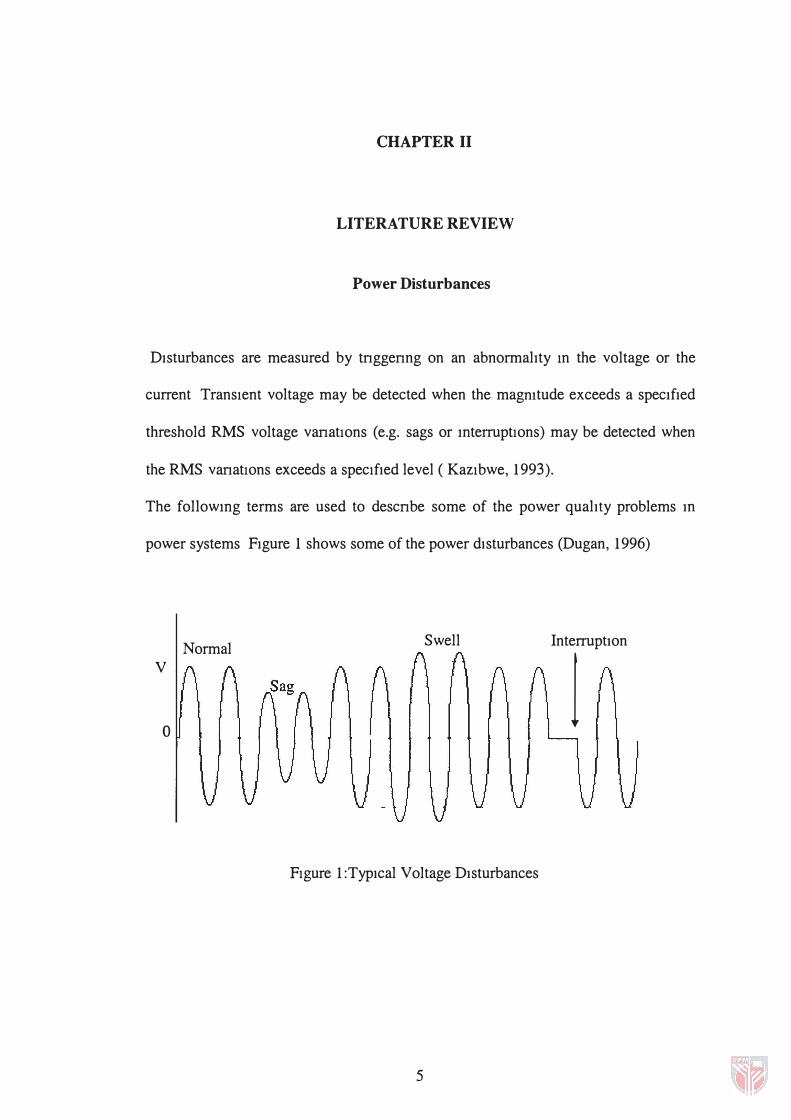
DIsturbances are measured by tnggenng on an abnormalIty In the voltage or the
current TransIent voltage may be detected when the magmtude exceeds a specIfIed
threshold RMS voltage vanatIOns (e.g. sags or mterruptIOns) may be detected when
the RMS vanatIOns exceeds a specIfIed level ( KazIbwe, 1993).
The followmg terms are used to descnbe some of the power qualIty problems In
power systems FIgure 1 shows some of the power dIsturbances (Dugan, 1996)
o
Normal Swell InterruptIon
1 V
FIgure 1 :TypIcal Voltage DIsturbances
5

6
a) Surge
A surge is defined as sudden increase in voltage of a short-duration
(microsecond to millisecond). Also known as impulse or spike . Lightning, power
system faults, and the switching of heavy loads cause surges.
b) Voltage sag
Voltage sag is defined as a momentary (less than a few seconds) decrease in
voltage outside the normal tolerance . The starting of heavy loads, lightning, and
power system faults cause voltage sages.
c) Voltage swell
A voltage swell is a momentary increase in voltage outside the normal tolerance .
The turning off of heavy electric equipment causes voltage swells.
d) Undervoltage
Undervoltage is a sustained condition (lasting, more than a few seconds)
condition of low voltage outside the normal tolerance . Undervoltages are caused
by circuit overloads, power voltage regulation, and international reductions by
the utility.