Embed Size (px)
Citation preview
UNIVERSITI TEKNIKAL MALAYSIA MELAKA
GRAPHENE AND CARBON NANOTUBE BASED
ELECTROCHEMICAL CAPACITOR IN AQUEOUS
ELECTROLYTE
This report submitted in accordance with requirement of the Universiti Teknikal
Malaysia Melaka (UTeM) for the Bachelor Degree of Manufacturing Engineering
(Engineering Materials) (Hons.)
by
NURUL HAZIMAH BINTI JANTAN
B051110077
891105-04-5240
FACULTY OF MANUFACTURING ENGINEERING
2014
DECLARATION
I hereby, declared this report entitled “Graphene and Carbon Nanotube Based
Electrochemical Capacitor in Aqueous Electrolyte” is the result of my own research
except as cited in references.
Signature : ……………………………………….
Author‟s Name : NURUL HAZIMAH BTE JANTAN
Date :
APPROVAL
This report is submitted to the Faculty of Manufacturing Engineering of UTeM as a
partial fulfillment of the requirements for the degree of Bachelor of Manufacturing
Engineering (Engineering Materials) (Hons.). The members of the supervisory
committee are as follow :
………………………………
(DR MOHD ASYADI AZAM BIN MOHD ABID)
i
ABSTRAK
Kapasitor elektrokimia (EC) adalah alat penyimpanan elektrokimia yang mempunyai
kepadatan tenaga dan ketumpatan kuasa yang melengkapi peranan sebagai bateri
(tenaga yang tinggi) dan kapasitor konvensional (kuasa yang tinggi) untuk
menyimpan tenaga dan mengalirkan kuasa. Menariknya terdapat daya tarikan yang
besar daripada penyelidik mengenai penggunaan bahan-bahan berasaskan karbon
bagi menghasilkan elektrod untuk EC . Ini adalah kerana, karbon mempunyai banyak
kebaikan antaranya ialah ianya mudah dihasilkan, mesra alam, konduksi elektrik
yang bagus, luas permukaan yang tinggi dan kos yang agak rendah. Dalam kajian
ini, EC telah dihasilkan dengan menggunakan graphene dan nanotiub karbon
menjajar pelbagai dinding (MWCNTs) sebagai bahan elektrod dan juga campuran
bahan pengikat dengan nisbah 47.5:47.5:5. 6M KOH dan 1M H2SO4 juga telah
digunakan sebagai elektrolit. Ukuran voltammetri berkitar (CV) telah dijalankan
untuk menentukan nilai kapasiti, kitaran hayat dan penentuan jenis EC. Prestasi
cemerlang oleh EC, boleh dikaitkan dengan struktur fizikal dan kekonduksian
intrinsik yang terdapat pada graphene dan MWCNT sebagai bahan elektrod. Nilai
kapasitan tertentu yang diperolehi daripada eksperimen adalah 12.07 F/g (6M KOH
elekrolit) dan 4.34 F/g (1M H2SO4).
ii
ABSTRACT
Electrochemical capacitors (ECs) are electrochemical storage devices which possess
the energy densities and power densities which complement the role of batteries
(high energy) and conventional capacitors (high power) for storing energy and
delivering power. Interestingly there are of great interest from researchers about
using carbon materials based electrode for ECs due to their accessibility, an easy
processability, environmental friendly, good electrical conductivity, high surface
area, and relatively low cost. In this study, ECs were fabricated by using graphene
and multiwalled carbon nanotubes (MWCNTs) as EC electrode material as well as
binder with ratio 47.5:47.5:5. Also, 6M KOH and 1M H2SO4 were used as
electrolyte. Electrochemical measurements such as cyclic voltammetry (CV) were
performed to determine the capacitance value, lifecycle and determination of
fabricated EC. The excellent performance can be attributed to the physical structures
and the intrinsic conductivity owing by the EDLC graphene and MWCNT electrode.
The specific capacitance value gained from the experiment was 12.07 F/g (6M KOH
electrolyte) and 4.34 F/g (1M H2SO4).

iii
DEDICATION
I dedicated this entire work to my beloved family especially to my husband, my
father and mother and also to my fellow friends, supervisor and lecturers for their
support and encouragement throughout this project

iv
ACKNOWLEDGEMENT
First and foremost, I would like to thank God for giving me the strength to carry out
this course of research. Then, I would like to express my sincere thanks and
appreciation to the following people and organization who have directly or indirectly
given generous contributions towards the success of this academic study.
First in the list, I would like to express my sincere appreciation to my respectful
supervisor, Dr. Mohd Asyadi „Azam b. Mohd Abid for his guidance, advice and
encouragement throughout this project. I would like also to take this opportunity to
thank my beloved parents and family members for their support, cares and kindness
throughout the period study.
Last but not least, I would like to acknowledge my colleagues for their support and
commitment in helping me throughout the completion of this report. Without those
helps, this research report would not have been completed successfully.
v
TABLE OF CONTENT
Abstrak i
Abstract ii
Dedication iii
Acknowledgement iv
Table of Content v
List of Tables viii
List of Figures ix
List Abbreviations, Symbols and Nomenclatures xi
CHAPTER 1 : INTRODUCTION 1
1.1 Background 1
1.2 Problem Statement 4
1.3 Objectives 5
1.4 Scope of Research 6
CHAPTER 2 : LITERATURE REVIEW 7
2.1 Electrochemical Capacitor 7
2.1.1 Electrochemical Double Layer Capacitor (EDLC) 8
2.1.2 Pseudocapacitor 9
2.2 Electrode Material 10
2.2.1 Carbon as Electrode Material 10
2.2.1.1 Graphene 11
2.2.1.2 Carbon Nanotube (CNT) 13
2.2.1.3 Other Carbon Materials 16
2.3 Electrolyte 17
2.3.1 Aqueous Electrolyte 18
2.3.2 Non Aqueous Electrolyte 19
2.4 Characterization Techniques 20
2.4.1 Electrode Characterization 21
2.4.1.1 Scanning Electron Microscope (SEM) 21
vi
2.4.2 Electrochemical Measurements 22
2.4.2.1 Cyclic Voltammetry (CV) 22
2.4.2.1.1 CV of Non-Faradaic Process 24
2.4.2.1.2 CV of Faradaic Process 24
CHAPTER 3 : METHODOLOGY 26
3.1 Electrochemical Capacitor Construction 28
3.2 Electrode Material Preparation 29
3.3 Fabrication Process to Produce the EC 35
3.4 Electrode Characteristic 35
3.5 Experimental Set up for CV Analysis 36
3.6 Set up for Prototype Development 37
CHAPTER 4 : RESULT AND DISCUSSION 40
4.1 Result of EC fabrication 40
4.2 Surface Morphology Analysis by SEM 42
4.2.1 EDX Analysis 44
4.3 Cyclic Voltammetry Analysis of The Fabricated EC 45
4.3.1 Specific Capacitance Value 45
4.3.2 Type of Fabricated EC 47
4.3.3 The performance of The EC by Varying The Value 48
of Scan Rate
4.3.4 Csp for Multiple Cycles 51
4.3.4.1 Graphene and MWCNT 52
4.3.4.1.1 6M KOH Electrolyte 52
4.3.4.1.2 1M H2SO4 Electrolyte 54
4.3.4.2 Activated Carbon and SWCNT 56
4.3.4.2.1 6M KOH Electrolyte 57
4.3.5 Problem during CV Testing 59
4.4 Prototype Development 60
4.4.1 Fabrication of EC in the Coin Cell 60
4.4.2 EC Coin Cell Testing 62

vii
CHAPTER 5 : CONCLUSION AND RECOMMENDATION 64
5.1 Conclusion 64
5.2 Recommendation for Future Work 65
REFERENCES 66
APPENDIX A
Academic Achievement
APPENDIX B
Gantt Chart
viii
LIST OF TABLES
Table Title Page
1.1 Comparison of Batteries, ECs and Conventional Capacitors 2
2.1 Properties of Graphene 11
2.2 The Summary of Graphene 12
2.3 The Summary of CNT 14
2.4 Properties of Various Materials used in EC electrode materials 16
(Simon, 2008)
2.5 The Type of The Electrolytes and it Charge of the Ions 17
2.6 Comparison between Aqueous and Non Aqueous 19
2.7 Properties of Various Electrolyte (Simon, 2008) 20
3.1 Materials and its Function 29
3.2 Apparatus and Its Function 31
3.3 Materials used and its Weight 34
3.4 The Component to Produce Circuit 38
4.1 The Composition of Materials used in the Electrode Fabrication 40
4.2 The Composition of Materials used in the Electrode Fabrication 41
4.3 Mass of Different Electrode Materials 42
4.4 The Csp Result with Different Scan Rate 49
4.5 The Value of Csp for Different cycle 51
ix
LIST OF FIGURES
Figure Title Page
1.1 Plot of Power Density (Wkg-1
) versus Energy Density (Whkg-1
) of 2
Different Storage Devices (Rolison et al, 2009)
2.1 The Schematic EDLC (Retrieved from http://www.murata .com/) 8
2.2 The Operating Principle in Electrical Double-layer Capacitors 9
(Retrieved from http://www.murata .com/)
2.3 Schematic of Pseudocapacitor (Josie,2011) 9
2.4 A CV Potential Waveform with Switching Potentials 23
(Wang et al. 2000)
2.5 The Expected Response of Reversible Redox Couple during a Single 23
Potential Cycle (Wang et al. 2000)
2.6 A Schematic Cyclic Voltammogram of a Reversible Redox Process 25
(Si et al, 2008)
3.1 Flow Chart of Methodology 27
3.2 Example of EC Construction 28
3.3 Slurry Preparation 34
3.4 SEM Model EVO50 ZEISS 36
3.5 WonATech (WBCS3000) Voltammetry System 36
3.6 The Circuit for Testing EC 37
3.7 The Circuit for Testing EC 39
4.1 The Electrode with Carbon Material on Stainless Steel Mesh 41
4.2 Surface Morphology of Graphene and MWCNT as Electrode Material 43
4.3 Surface Morphology of Activated Carbon and SWCNT as Electrode 43
Material
4.4 EDX Analysis of Electrode Before use 44
4.5 EDX Analysis of Electrode after Immersed in 6M KOH Electrolyte 45
x
for 4 Hours
4.6 CV Curve with different Scan Rate 46
4.7 The Curve of EC in CV Analysis 48
4.8 The Shape of CV Curve with Different Scan Rate (Hsia et. al, 2014) 49
4.9 The Graph Csp versus Scan Rate 50
4.10 The CV Curve for 5 Cycles with Scan Rate 54
4.11 The CV Curve for 5 Cycles with Scan Rate 56
4.12 The CV Curve for 5 Cycles with Scan Rate 58
4.13 The Failed Shape in CV Curve 59
4.14 The Jig use in CV Testing 59
4.15 The Material and Equipment to Fabricate the EC 60
4.16 The Arrangement of EC in the Coin Cell Battery 61
4.17 The Crimping Process in the Glove Box 61
4.18 The Completed EC in the Coin Cell Battery 61
4.19 LED Circuit Model to Testing the EC 62
4.20 Common Adapter Charger 62
4.21 3V EC with 6M KOH Electrolyte 63
4.22 The Successfully of EC Testing 63
xi
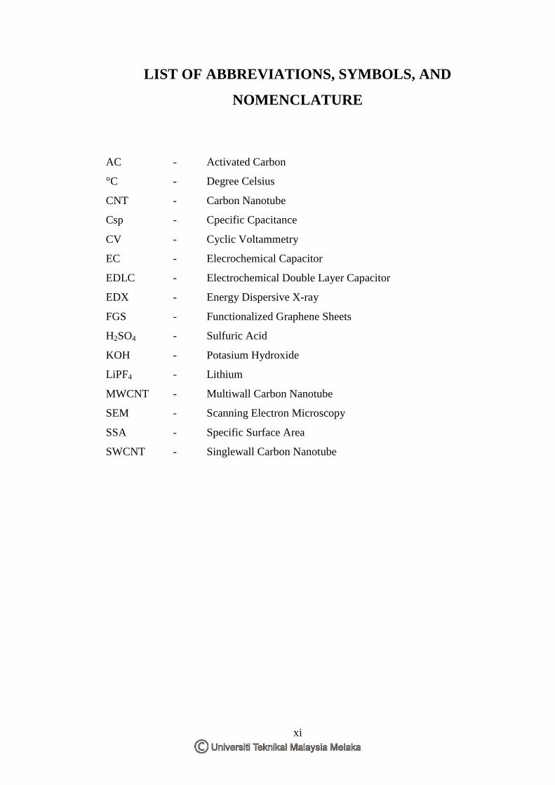
LIST OF ABBREVIATIONS, SYMBOLS, AND
NOMENCLATURE
AC - Activated Carbon
°C - Degree Celsius
CNT - Carbon Nanotube
Csp - Cpecific Cpacitance
CV - Cyclic Voltammetry
EC - Elecrochemical Capacitor
EDLC - Electrochemical Double Layer Capacitor
EDX - Energy Dispersive X-ray
FGS - Functionalized Graphene Sheets
H2SO4 - Sulfuric Acid
KOH - Potasium Hydroxide
LiPF4 - Lithium
MWCNT - Multiwall Carbon Nanotube
SEM - Scanning Electron Microscopy
SSA - Specific Surface Area
SWCNT - Singlewall Carbon Nanotube
1
CHAPTER 1
INTRODUCTION
1.1 Background
Nowadays, the need of energy has become increasing because both of households
and industries require large amounts of power. Due to a lot of problems in
environmental pollution, there is a need for green and clean renewable energy to
assure the sustainable growth of communities As a result, the electrochemical
capacitors (ECs) have become as an alternative to conventional electric energy
storage device.
ECs, also known as supercapacitors or ultracapacitors are energy storage devices that
combine the high energy storage capability of batteries with the high power delivery
capability of capacitors (Burke, 2000). Basically, ECs can be classified into three
types which are electrochemical double layer capacitors (EDLCs), pseudocapacitors,
and hybrid capacitors. Among them, the EDLCs are the most common type for ECs
because of the least cost to manufacture.
In addition, it have to tend great attention not only for the established applications as
backup power for mobile devices and electronic equipments, but also for high power
applications in pulsed lasers and electric vehicles.
2
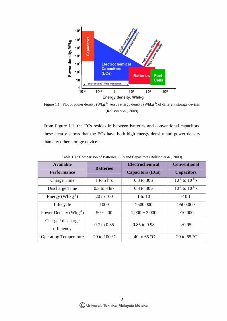
Figure 1.1 : Plot of power density (Wkg-1
) versus energy density (Whkg-1
) of different storage devices
(Rolison et al., 2009)
From Figure 1.1, the ECs resides in between batteries and conventional capacitors,
these clearly shows that the ECs have both high energy density and power density
than any other storage device.
Table 1.1 : Comparison of Batteries, ECs and Capacitors (Rolison et al., 2009)
Available
Performance Batteries
Electrochemical
Capacitors (ECs)
Conventional
Capacitors
Charge Time 1 to 5 hrs 0.3 to 30 s 10-3
to 10-6
s
Discharge Time 0.3 to 3 hrs 0.3 to 30 s 10-3
to 10-6
s
Energy (Whkg-1
) 20 to 100 1 to 10 < 0.1
Lifecycle 1000 >500,000 >500,000
Power Density (Wkg-1
) 50 ~ 200 1,000 ~ 2,000 >10,000
Charge / discharge
efficiency 0.7 to 0.85 0.85 to 0.98 >0.95
Operating Temperature -20 to 100 °C -40 to 65 °C -20 to 65 °C
3
Table 1.1 shows the comparison between the batteries, ECs can store large amount of
amount of energy and power compared to conventional capacitors and battery
compared to conventional capacitors. Furthermore, it also can be recharged in
seconds rather than hours, it can withstand with cold temperature, shocks, and
vibrations and it can be charged and discharged hundreds of thousands of times
before they wear out. The EC is much easier on the environment than batteries,
because the ECs contain earth abundant and nontoxic materials.
Although all the above devices have different mechanism, but there are also
electrochemical similarities of these three systems. The common features are the
energy providing processes that take place at the phase boundary of the electrode
interface and the separation of electron and ion during the transportation processes.
In this study, graphene and carbon nanotube (CNT) were used as electrode materials
because graphene has been known as one of the most promising active material for
ECs which posses outstanding electrical conductivity and large surface area. Since
the CNT is known as a porous material, it becomes a potential candidates to fabricate
EC. All of the carbon atoms are surface atoms is consequently and extremely large
surface areas may be obtainable if the CNTs can be assembled in a manner that
maximizes the surface area by minimizing CNT bundling and optimizing the
porosity of the CNT electrode.
4
1.2 Problem Statement
The production of energy by using the conventional method will leads to the global
warming problems such as environmental pollution, petroleum exhaustion, climate
change and the greenhouse effect. In response to reduce the output of carbon dioxide,
the several countries have been decided to shut down the old nuclear power plants
and not to build it with new ones. Apart from that, the energy demand has risen and
the price of conventional energy sources has increased dramatically. This situation
makes the reliance of national economies on a continuous and undistorted supply of
such sources has become critical.
Thus, the old energy production method need to be replaced with new ones which
include the concepts that enriching the life style, diminishing wasteful energy and
environment friendly. These new method including solar power, wind power, and
hydroelectricity in its many forms, but these new methods have the disadvantages
compared to the older methods. The output of the older methods is easy to adjust
based on the power requirements. The new energy production method is more
directly by using the power of the nature and as their peak power outputs may not
match with the power requirement. These may result to large volatilities the power
output in monthly or even annual cycles and also the demand can vary monthly or
annually.
Therefore, the energy storage is a very important factor to make these new sources to
become completely reliable as the main sources of energy. Essentially, when the
production level is less than the required need, the energy from these sources must be
stored when extra is produced and then released. These energy storage technologies
show the largeness of an important part of efficient and effective renewable and
distributed generation unit. It is important to develop low cost, high performance and
environmental friendly energy conversion and storage systems in order to make the
effective use of renewable energy. Fuel cells, batteries, ECs and conventional
capacitors are the system required for promising electrochemical energy conversion
and storage. Nowadays, researchers focus on the EC to improve their energy density
since its power density and lifecycle had been already higher than batteries.
5
In order to increase energy storage, EC must use the porous materials as electrode in
order to store ions in the pores at an atomic level. Usually the activated carbon is
used to fabricate the EC‟s electrodes. The fact that activated carbon is not suitable as
electrode material due to the charge carriers are larger size to the pores in the
material and some of them cannot fit into smaller pores. As a result, it will reduce the
storage capacity in the EC performance.
There are many factors that need to take as consideration in order to improve the
energy density of the ECs such as type of electrode and electrolyte material. In this
report, carbon material (graphene and carbon nanotube) will be used as electrode
material because of its contributed to a high value capacitance. This is due to their
special characteristic which is a porous material. The cyclic voltammetry (CV) will
be used to measure the value of capacitance and to determine whether the fabricated
EC is EDLC or pseudocapacitor, and lifecycle. If EC can increase its energy density
in the future, then the use of the battery can be replaced.
1.3 Objectives
In this study, there are two parameters were made constant throughout the
experiment which are the substrate (stainless steel mesh) and electrode material
(graphene and CNT). The main objectives of this research are :
(i) To fabricate the EC by using graphene and CNT as the electrode
material.
(ii) To analyze the fabricated electrochemical capacitor by using cyclic
voltammetry.
6
1.4 Scope of Research
In this study, the major scope will be focused on the fabrication of EC and analyze
the fabricated EC by using CV. The experiment was conducted at the Ionic Materials
& Devices Research Laboratory (iMade) Faculty of Applied Science, University
Teknologi Mara (UiTM) Shah alam and Material Laboratory Faculty of
Manufacturing, Universiti Teknikal Malaysia Melaka (UTeM). Fabrication and
analyze of EC was carried out in UiTM Shah Alam before it is testing by using
model development in the Material Laboratory in UTeM. In this experiment, carbon
materials use as an electrode are graphene and CNT. 1M H2SO4 and 6M KOH was
used as an electrolyte material. Then, the electrode are characterized by using SEM
to obtain the morphology of electrode material. The CV was used to measure to
obtain the capacitance value, lifecycle, and determination of the fabricated EC. The
result obtained was compared to the previous research to see the difference.
7
CHAPTER 2
LITERATURE REVIEW
2.1 Electrochemical Capacitors (ECs)
Basically ECs can be categorized into two parts which are electrochemical double
layer capacitors (EDLCs) and pseudocapacitors. The difference between these
capacitors are their storage principle, which is for EDLC, the electrostatic storage of
the electrical energy can be achieved by separation of charge in a Helmholtz double
layer at the interface between the electrode and electrolyte surface. The distance of
the static separation of charge in a double-layer is of the order of a few Å (0.3–
0.8 nm) which is extremely small. Meanwhile for pseudocapacitor, the
electrochemical storage of the electrical energy with electron transfer was achieved
by a redox reaction with specifically adsorbed ions from the electrolyte, The
intercalation of atoms in the layer lattice or electrosorption, under potential
deposition of hydrogen or metal adatoms in surface lattice sites which result in a
reversible faradaic charge-transfer (Namisny, 2013).
8
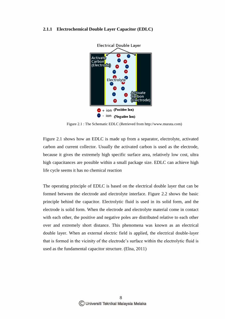
2.1.1 Electrochemical Double Layer Capacitor (EDLC)
Figure 2.1 : The Schematic EDLC (Retrieved from http://www.murata.com)
Figure 2.1 shows how an EDLC is made up from a separator, electrolyte, activated
carbon and current collector. Usually the activated carbon is used as the electrode,
because it gives the extremely high specific surface area, relatively low cost, ultra
high capacitances are possible within a small package size. EDLC can achieve high
life cycle seems it has no chemical reaction
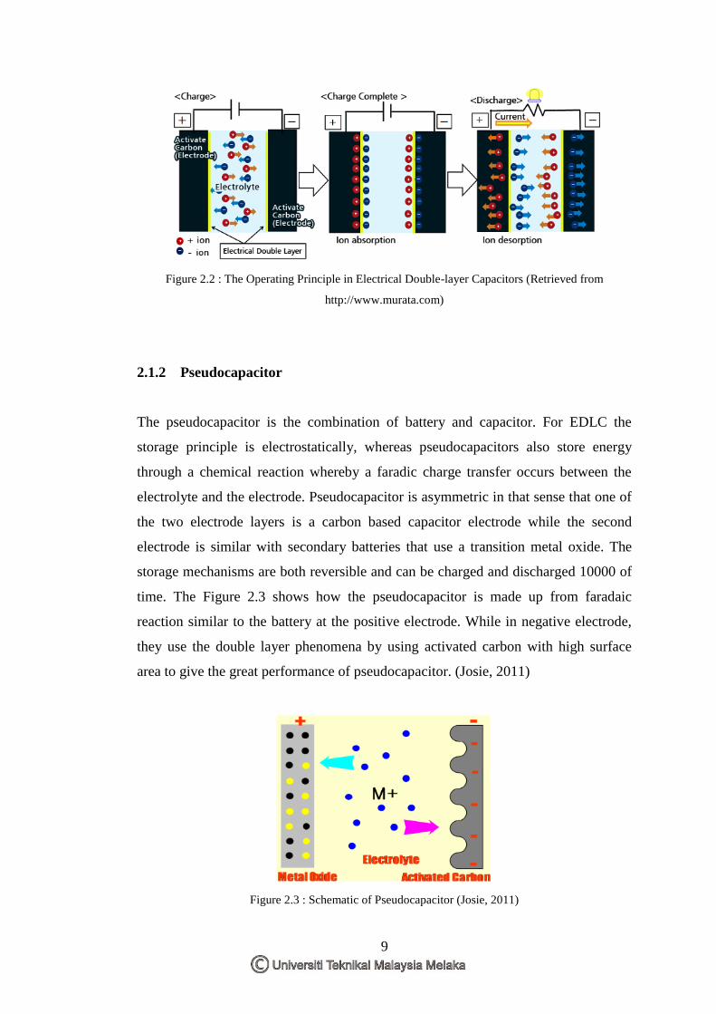
The operating principle of EDLC is based on the electrical double layer that can be
formed between the electrode and electrolyte interface. Figure 2.2 shows the basic
principle behind the capacitor. Electrolytic fluid is used in its solid form, and the
electrode is solid form. When the electrode and electrolyte material come in contact
with each other, the positive and negative poles are distributed relative to each other
over and extremely short distance. This phenomena was known as an electrical
double layer. When an external electric field is applied, the electrical double-layer
that is formed in the vicinity of the electrode‟s surface within the electrolytic fluid is
used as the fundamental capacitor structure. (Elna, 2011)
9
Figure 2.2 : The Operating Principle in Electrical Double-layer Capacitors (Retrieved from
http://www.murata.com)
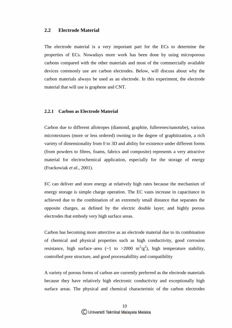
2.1.2 Pseudocapacitor
The pseudocapacitor is the combination of battery and capacitor. For EDLC the
storage principle is electrostatically, whereas pseudocapacitors also store energy
through a chemical reaction whereby a faradic charge transfer occurs between the
electrolyte and the electrode. Pseudocapacitor is asymmetric in that sense that one of
the two electrode layers is a carbon based capacitor electrode while the second
electrode is similar with secondary batteries that use a transition metal oxide. The
storage mechanisms are both reversible and can be charged and discharged 10000 of
time. The Figure 2.3 shows how the pseudocapacitor is made up from faradaic
reaction similar to the battery at the positive electrode. While in negative electrode,
they use the double layer phenomena by using activated carbon with high surface
area to give the great performance of pseudocapacitor. (Josie, 2011)
Figure 2.3 : Schematic of Pseudocapacitor (Josie, 2011)
10
2.2 Electrode Material
The electrode material is a very important part for the ECs to determine the
properties of ECs. Nowadays more work has been done by using microporous
carbons compared with the other materials and most of the commercially available
devices commonly use are carbon electrodes. Below, will discuss about why the
carbon materials always be used as an electrode. In this experiment, the electrode
material that will use is graphene and CNT.
2.2.1 Carbon as Electrode Material
Carbon due to different allotropes (diamond, graphite, fullerenes/nanotube), various
microtextures (more or less ordered) owning to the degree of graphitization, a rich
variety of dimensionality from 0 to 3D and ability for existence under different forms
(from powders to fibres, foams, fabrics and composite) represents a very attractive
material for electrochemical application, especially for the storage of energy
(Frackowiak et al., 2001).
EC can deliver and store energy at relatively high rates because the mechanism of
energy storage is simple charge operation. The EC vasts increase in capacitance in
achieved due to the combination of an extremely small distance that separates the
opposite charges, as defined by the electric double layer; and highly porous
electrodes that embody very high surface areas.
Carbon has becoming more atterctive as an electrode material due to its combination
of chemical and physical properties such as high conductivity, good corrosion
resistance, high surface–area (~1 to >2000 m2/g
2), high temperature stability,
controlled pore structure, and good processabillity and compatibility
A variety of porous forms of carbon are currently preferred as the electrode materials
because they have relatively high electronic conductivity and exceptionally high
surface areas. The physical and chemical characteristic of the carbon electrodes