Embed Size (px)
Citation preview
UNIVERSITI TEKNIKAL MALAYSIA MELAKA
DEVELOPMENT OF VACUUM CLEANER ROBOT USING PIC
MICROCONTROLLER
This report submitted in accordance with requirement of the Universiti Teknikal
Malaysia Melaka (UTeM) for the Bachelor of Electrical Engineering Technology
(Industrial Automation and Robotics) with Honours
by
MUHAMMAD FAHMI BIN YUSOF
B071210190
910329-14-5911
FACULTY OF ENGINEERING TECHNOLOGY
2015
UNIVERSITI TEKNIKAL MALAYSIA MELAKA
BORANG PENGESAHAN STATUS LAPORAN PROJEK SARJANA MUDA
TAJUK: Development of Vacuum Cleaner Robot using PIC Microcontroller
SESI PENGAJIAN: 2015/16 Semester 1
Saya MUHAMMAD FAHMI BIN YUSOF
Mengaku membenarkan Laporan PSM ini disimpan di Perpustakaan Universiti
Teknikal Malaysia Melaka (UTeM) dengan syarat-syarat kegunaan seperti berikut:
1. Laporan PSM adalah hak milik Universiti Teknikal Malaysia Melaka dan penulis. 2. Perpustakaan Universiti Teknikal Malaysia Melaka dibenarkan membuat salinan
untuk tujuan pengajian sahaja dengan izin penulis. 3. Perpustakaan dibenarkan membuat salinan laporan PSM ini sebagai bahan
pertukaran antara institusi pengajian tinggi.
4. **Sila tandakan ( )
SULIT
TERHAD
TIDAK TERHAD
(Mengandung imaklumat yang berdarjah keselamatan
atau kepentingan Malaysia sebagaimana yang termaktub
dalam AKTA RAHSIA RASMI 1972)
(Mengandungi maklumat TERHAD yang telah ditentukan
oleh organisasi/badan di mana penyelidikan dijalankan)
(TANDATANGAN PENULIS)
Alamat Tetap:
09-03-15 PPR SERI ALAM 1/78
JALAN ISTANA OFF JALAN SG
BESI 57100 KUALA LUMPUR
Tarikh: ________________________
Disahkan oleh:
(TANDATANGAN PENYELIA)
Cop Rasmi:
Tarikh: _______________________
** Jika Laporan PSM ini SULIT atau TERHAD, sila lampirkan surat daripada pihakberkuasa/organisasi
berkenaan dengan menyatakan sekali sebab dan tempoh laporan PSM ini perlu dikelaskan sebagai
SULIT atau TERHAD.
iii
DECLARATION
I hereby, declared this report entitled “Development of Vacuum Cleaner Robot using
PIC Microcontroller” is the results of my own research except as cited in references.
Signature :………………………
Name : MUHAMMAD FAHMI BIN YUSOF
Date : ………………………
iv
APPROVAL
This report is submitted to the Faculty of Technology Engineering of UTeM as a
partial fulfillment of the requirements for the Bachelor of Electrical Engineering
Technology (Industrial Automation and Robotics) with Honours. The member of
the supervisory is as follow:
……………………………………
(Khalil Azha Bin Mohd Annuar)
v
ABSTRACT
In today's reality, time is cash. Most families comprise of youthful kids and
working folks. In such a situation, cleaning turns into a period devouring and debilitating
undertaking, particularly in bigger homes. A robotic vacuum cleaner may all do the job
alone without individual guidance. By buying one of these models, you possibly can
escape considerable time as well as effort. The principle purpose of this kind of
undertaking would be to develop a preliminary understanding to create as well as apply
a vacuum cleaner robot designed to help to make cleanup method come to be simpler in
contrast by using manual vacuum. This vacuum robot battery powered system compared
to manual vacuum which consume electricity. An addition, we can save our money to
pay the electricity. The operation of this project is basically by having the sensor to
detect any object and send the output to a PIC that will control the Vacuum Robot
movement. By utilizing vacuum cleaner robot, person could merely first turn on the
actual vacuum cleaner robot to clean without having to work the actual cleaner. This
methodology as well as opportunity regarding study are usually conducted simply by
accomplishing books opinions as well as research about various sensor, motor, PIC,
programming for PIC. A crucial illustration regarding vacuum cleaner robot will have
numerous standards which might be useful, structured as well as user-friendly, which
usually fulfills individual needs.
vi
ABSTRAK
Dalam realiti hari ini, masa adalah sangat berharga. Kebanyakan keluarga
terdiri daripada orang dewasa dan orang bekerja. Dalam keadaan seperti ini, kebersihan
bertukar menjadi tempoh memakan dan memenatkan, terutamanya di rumah-rumah yang
lebih besar. Seterusnya, pembersih vakum robot boleh melakukan kerja dengan sendiri
tanpa pengawasan. Dengan membeli salah satu daripada model-model ini, anda mungkin
dapat menjimatkan masa dan tenaga. Tujuan perlaksanaan projek ini adalah untuk
pemahaman yang awal untuk mencipta serta menggunakan vakum pembersih vakum
robot. Robot pembersih yang direka untuk membantu untuk membuat kaedah
pembersihan menjadi lebih mudah berbanding dengan menggunakan manual vakum.
Sistem robot vakum menggunakan bateri berbanding vakum manual yang menggunakan
elektrik .Selain itu, kita boleh menjimatkan wang untuk membayar elektrik. Terdapat
beberapa prosedur yang diambil kira oleh pengesan untuk mengetahui hanya beberapa
perkara dan juga menghantar hasil akhir yang sebenar kepada PIC yang akan
menguruskan pergerakan robot vakum. Dengan menggunakan vakum robot pembersih,
dengan hanya menghidupkan vakum robot pembersih untuk membersihkan tanpa perlu
mengawasi vakum robot. Metodologi adalah mengenai kajian biasanya dijalankan hanya
dengan mencapai buku pendapat serta penyelidikan mengenai pelbagai sensor, motor,
PIC, pengaturcaraan untuk PIC. Salah satu contoh penting mengenai pembersih vakum
robot mempunyai banyak standard yang mungkin berguna, berstruktur dan juga mesra
pengguna, yang biasanya memenuhi keperluan individu.
vii
DEDICATION
Dedicate in thankful appreciation for support, encouragement and understandings to my
beloved mother, father, lecturers and brothers.
viii
ACKNOWLEDGEMENT
First of all, I would like to express my deepest gratitude to my supervisor, Khalil
Azha Bin Mohd Annuar, for accept and giving me this wonderful and yet interesting
final year project. His supervision both aided me to channel and specify the discussed
ideas and at the same time provided much appreciated freedom and support to explore
new concepts. However, his endless drives for new and better results is highly
appreciated, instead of willing to share her own experience and spend her free time to
supervise me throughout the implementation of this project.
My appreciation also goes to my parents who bore immense difficulties to
educate their children at the highest level. Their affection and love has brought
happiness and joy to my life and therefore made this task becomes much easier to be
implemented.
Nevertheless, my great appreciation dedicated to my friend Muhammad Faiq ,
who gave technical support and suggestion in this project. I am grateful to my
classmates and those whom involve directly or indirectly with this project. Finally, I
hope that all the knowledge and experience gained through this project can be shared
and bring benefit to all. Thank you.
ix
TABLE OF CONTENTS
DECLARATION ............................................................................................................. iii
APPROVAL ...................................................................................................................... iv
ABSTRACT ....................................................................................................................... v
ABSTRAK ........................................................................................................................ vi
DEDICATION ................................................................................................................ vii
ACKNOWLEDGEMENT ............................................................................................. viii
TABLE OF CONTENTS .................................................................................................. ix
LIST OF FIGURES ........................................................................................................ xii
LIST OF TABLES .......................................................................................................... xiv
LIST OF SYMBOLS AND ABBREVIATIONS ............................................................ xv
CHAPTER 1 ...................................................................................................................... 1
1.1 Background ........................................................................................................ 1
1.2 Problem statement .............................................................................................. 2
1.3 Objective ............................................................................................................. 2
1.4 Scope ................................................................................................................... 2
CHAPTER 2 ...................................................................................................................... 4
2.1 Introduction ......................................................................................................... 4
2.2 Literature review ................................................................................................. 4
2.2.1 Cleaning robot ....................................................................................................... 4
2.2.2 Microcontroller ..................................................................................................... 6
2.2.3 Distance sensor ..................................................................................................... 8
2.2.4 Motor ................................................................................................................... 11
x
2.2.5 Power supply ........................................................................................................ 13
CHAPTER 3 .................................................................................................................... 16
3.1 Introduction ....................................................................................................... 16
3.2 Block diagram ................................................................................................... 17
3.3 Flowchart ........................................................................................................... 18
3.4 Project development .......................................................................................... 19
3.5 Mechanism development ................................................................................... 19
3.6 Mechanism system design ................................................................................. 20
3.6.1 3D Printing ........................................................................................................... 20
3.7 Software development ...................................................................................... 26
3.7.1 Construct the movement coding .......................................................................... 26
3.7.2 PIC programming fundamental ........................................................................... 26
3.7.3 VSM proteus ( Isis 8 Professional ) ..................................................................... 28
3.7.4 PICkit 2 programmer........................................................................................... 28
3.8 Hardware development ...................................................................................... 29
3.8.1 Controller ............................................................................................................ 29
3.8.2 PIC brain board (SK40C) .................................................................................... 31
3.8.3 USB ICSP PIC programmer V2010 (UIC00B) .................................................. 32
3.8.4 Ultrasonic sensor ................................................................................................. 33
3.8.5 DC geared motor (12V) ...................................................................................... 35
CHAPTER 4 .................................................................................................................... 37
4.1 Introduction ....................................................................................................... 37
4.2 Ultrasonic sensor analysis ................................................................................. 37
4.2.1 HC-SR04 ultrasonic module working .................................................................. 37
4.2.2 Distance calculation ............................................................................................. 40
4.2.3 Experiment of ultrasonic range versus obstacles ................................................. 40
4.2.4 Ultrasonic sensor angle of detection .................................................................... 42
4.3 Capacity of dustbin ............................................................................................ 43
xi
4.4 Experiment types of dust can suck by vacuum cleaner robot ........................... 43
4.5 DC motor driver ................................................................................................ 44
4.6 Experiment of speed versus obstacles ............................................................... 46
4.7 Microcontroller PIC16F877A pin description................................................... 47
4.8 The motion of vacuum cleaner robot ................................................................ 48
CHAPTER 5 .................................................................................................................... 51
5.1 Introduction ...................................................................................................... 51
5.2 Conclusion ......................................................................................................... 51
5.3 Future work and recommendation ..................................................................... 52
5.4 Project commercialization potential .................................................................. 53
APPENDIX A .................................................................................................................. 55
APPENDIX B .................................................................................................................. 56
APPENDIX C .................................................................................................................. 57
REFERENCES ................................................................................................................. 58
xii
LIST OF FIGURES
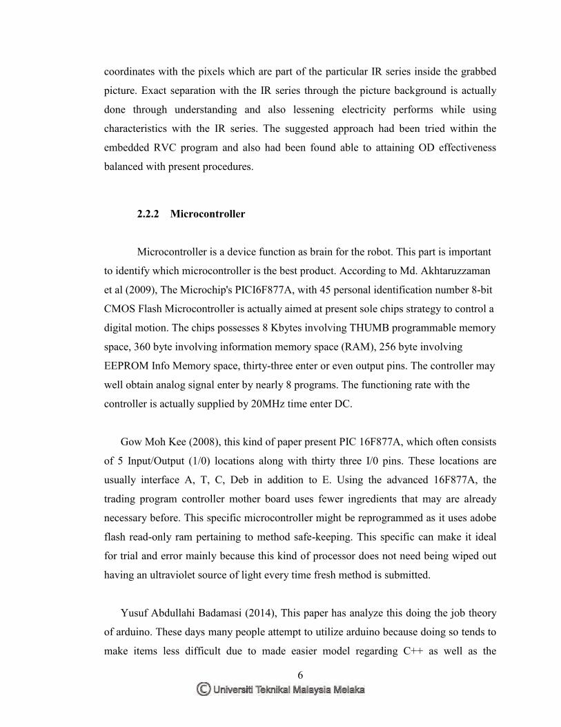
Figure 2.1: PIC 16F877A ................................................................................................... 7
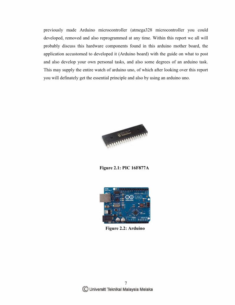
Figure 2.2: Arduino ............................................................................................................ 7
Figure 2.3: Positional adjacent ultrasonic sensors ............................................................. 9
Figure 2.4: Ultrasonic sensor ............................................................................................. 9
Figure 2.5: Infrared sensor ............................................................................................... 10
Figure 2.6: Servo motor .................................................................................................. 12
Figure 2.7: DC geared motor .......................................................................................... 13
Figure 2.8: LiPo battery 11.1 V ....................................................................................... 14
Figure 2.9: Lead acid battery 12 V .................................................................................. 14
Figure 3.1: Vacuum cleaner robot block diagram ............................................................ 17
Figure 3.2: Flowchart ....................................................................................................... 18
Figure 3.3: Solid works 2013 ........................................................................................... 19
Figure 3.4: Appearances of 3D printing ........................................................................... 20
Figure 3.5: Part of body ................................................................................................... 22
Figure 3.6: Assembles of body ........................................................................................ 23
Figure 3.7: Part of cover................................................................................................... 23
Figure 3.8: Assembles part of cover ................................................................................ 24
Figure 3.9: Wheel part...................................................................................................... 24
Figure 3.11: UP driver ..................................................................................................... 25
Figure 3.10: DC motor bracket ....................................................................................... 25
Figure 3.12: Example of printing ..................................................................................... 26
Figure 3.13: Main windows to design the program code ................................................. 27
Figure 3.14: VSM proteus (Isis 8 Professional ) .............................................................. 28
Figure 3.15: PICkit 2 programmer ................................................................................... 29
Figure 3.16: PIC 16F877A .............................................................................................. 30
Figure 3.17: PIC 16F877A pin diagram ........................................................................... 30
Figure 3.18: SK40C brain board layout .......................................................................... 32
Figure 3.19: USB ICSP PIC programmer V2010‟s broad layout ................................... 33
xiii
Figure 3.20: Ultrasonic ranging module HC - SR04 Sensor ........................................... 34
Figure 4.1: Ultrasonic module operation ......................................................................... 38
Figure 4.2: Working of HC-SR04 ultrasonic sensor ........................................................ 38
Figure 4.3: Simulation of ultrasonic sensor HC-SR 04.................................................... 39
Figure 4.4: Ultrasonic sensor angles ................................................................................ 42
Figure 4.5: Capacity of dustbin ........................................................................................ 43
Figure 4.6: Simulation motor circuit using motor driver ................................................. 44
Figure 4.7: H Bridge driver motor ................................................................................... 45
Figure 4.8: PIC16F877A pin used ................................................................................... 47
Figure 4.9: Sensor position .............................................................................................. 48
Figure 4.10: Sensor 1 sense obstacles .............................................................................. 49
Figure 4.11: Sensor 2 sense obstacles .............................................................................. 49
Figure 4.12: Bottom part of vacuum cleaner robot .......................................................... 52
Figure 4.13: Comparison between automatic and manual vacuum ................................. 54
xiv
LIST OF TABLES
Table 2.1: Comparison of distance sensor ....................................................................... 10
Table 2.2: Comparison of power supply .......................................................................... 14
Table 3.1 Printer physical characteristics........................................................................ 21
Table 3.2: Specifications .................................................................................................. 21
Table 3.3: Electric parameter ........................................................................................... 35
Table 3.4: Specification of DC geared motor .................................................................. 36
Table 4.1: Experiment of ultrasonic range versus obstacles ............................................ 41
Table 4.2: Summary of experiment types of dust can suck by vacuum ........................... 43
Table 4.3: Robot motion using simple motor motion ...................................................... 45
Table 4.4: Summary experiment speed versus obstacles ................................................. 46
Table 4.5: PIC16F877A pin used ..................................................................................... 48
xv
LIST OF SYMBOLS AND ABBREVIATIONS
PWM = Pulse Width Modulation
PIC = Peripheral Interface Controller
DC = Direct current
TX = Transmitter
RX = Receiver
MCU = Microcontroller Unit
GND = Ground
VCC = Collector Supply Voltage
VSS = Source Supply
VDD = Drain Supply
VEE = Emitter supply
LCD = Liquid Crystal Display
LED = Light-Emitting Diode
ABS = Acrylonitrile Butadiene Styrene
PLA = Polylactic acid
3D = 3 Dimensional
I/0 = Input Output
IC = Integrated Circuit
IR = Infrared
ICSP = In-Circuit Serial Programming
RVC = Robot Vacuum Cleaner
1
CHAPTER 1 INTRODUCTION
1.1 Background
Cleaning a house can be exhausting in daily routine. Nowadays, time is valuable.
But with this smart cleaning machine, you can vacuum your home with less energy. You
can just turn on this robotic vacuum cleaner to clean up your floor without human
guidance. By getting this modern vacuum cleaner, you can save a lot of energy and time.
Smart Vacuum Cleaner Robot is very popular in Korea and Japan with cleaning function
almost 90 % of citizen using this smart vacuum cleaner robot.
Vacuum Cleaner Robot design to generate clean-up practice come to be much
easier regarding human being task and needs. This kind of undertaking comprise
software package along with equipment. The key component of this undertaking will be
the microcontroller, type of sensors, ability of motor and power distribution. Software,
Micro C is used to write the programming and for simulate the circuit design used
Proteus. Modeling the project is using the solid works software. PIC‟s microcontroller
16F877A would make as brain of this system.
This project is programmed to clean up the dust on the floor. The movement of
this robot by turns left and right for collecting the dust. It used ultrasonic sensor to
avoid the obstacle and wall. The range of ultrasonic sensor is between 2cm-400cm. In
Addition, ultrasonic produce analog signal which can use in microcontroller coding.
2
1.2 Problem statement
These days, part of individuals utilized manual vacuum cleaner to do their
cleaning at home. At the same time, manual vacuum are utilized power utilization. As
we probably aware, that is squandering cash and need human vitality to moving. So
that's, it not handy for working individual to handle with manual vacuum and did not
have enough time to clean.
An addition, many of a designations regarding vacuum robot for the market are
generally costly and significant within size. Therefore this really is tricky for you to
clean anywhere, under beds, and also kitchen baseboards. It also exhausting task for
human. So design the vacuum cleaner robot to make human task become easier and save
time. It also had a minimal maintenance and use green technology. Therefore, the actual
project is actually created to be single of an introduction for human for you to clean your
current floor inside small period and also added effective.
1.3 Objective
i. To build and design a working Vacuum Cleaner Robot prototype
ii. To test the functionality of Vacuum Cleaner Robot.
iii. To analyze the performance of the Vacuum Cleaner Robot.
1.4 Scope
i. This project using microcontroller PIC16F877A.
ii. The sensor use is ultrasonic sensor. The total sensor used is 3 sensors. It will
place in front of body vacuum cleaner robot to detect obstacle. The range of
detection obstacle between 25 cm.
iii. The suitable area for vacuum cleaner robot is on flat area.
3
iv. The design of vacuum cleaner robot is round shaped.
v. Area covers only 3m x 3m.
vi. Vacuum cleaner robot dimension is 180mm x 180mm.
vii. Battery LiPo 11.1 V with capacity 2200mAh is used for the robot.
4
CHAPTER 2 LITERATURE REVIEW
2.1 Introduction
This chapter about to give the overview points concerning the research previous
robot continues to be set up. This study is important to avoid errors during the project
and understanding the design, sensor, motor and microcontroller configuration and get
the best decisions are made to implement to the project. Further, the comparisons of all
journals need to be made as a reference.
2.2 Literature review
2.2.1 Cleaning robot
The study of vacuum cleaner robot should be done before the project started.
According to Rodrigo Montu'far-Chaveznava and Yazid L. Fernafndez (2005), created
the present perform purchases because of the design and also structure associated with
an educational interior cleaner automatic robot: Crabot. The restrictions the distinct
automatic robot symbolize a great problem due to the fact the duty relating to Crabot is
actually clean-up the bedroom staying away from rooms along with pieces of furniture
however That is certainly working. Crabot is really a Lego centered autonomous cell
phone automatic robot, which symbolizes the particular prototype in the specific
5
automatic robot with regard to home cleaning, through which involves at least
intelligence. Crabot is actually supplied using essential items created for floorboards
clean-up these types of to be a little vacuum cleaner in addition to a brush. The control
approach might be centered with the subsumption architectural mastery within memory
space along with provides the particular repertoire of conducts with regards to course-
plotting together with clean-up. This particular manage approach will allow for pairing
real-time allocated manage during conducts activated through automatic robot receptors.
kinds processing is actually finished with a number of Lego RCX microcomputers.
Crabot accredited inside of an unnatural world and in addition inside of competition
where the functionality ended up being extremely suited.
In a follow-up study, Kazi Mahmud Hasan et al (2014) found that a vacuum
cleaner automatic robot, usually termed any robovac, is surely an autonomous automatic
robot that's controlled through wise method. Autonomous cleaner washing automatic
robot will certainly execute activity like capturing as well as a vacuum in one cross. The
DVR-1 cleaner washing automatic robot involves 2 DC power plant handled trolley
wheels which make it possible for 360 level revolving, any castor tire, side spinning
brushes, any entry bumper as well as a little cleaner push. Sensors in the bumper are
widely-used regarding producing binary data involving hurdle discovery chances are
they'll are generally refined through some curbing algorithms. These kind of algorithms
are widely-used regarding way setting up as well as routing This particular robot's
bumper stops these by means of thumping in dividers along with furnishings simply by
fixing along with adjusting way as a result.
According to Mun-Cheon Kang et al (2014), This paper provides the powerful
obstacles detection (OD) approach while using triangulation theory with regard to
RVCs(robot vacuum cleaner cleaner) running in numerous residence environments. The
suggested approach utilizes the particular IR emitter with the RVC to be able to
undertaking the side to side IR column to a floor, next that your RVC‟s wide-angle
vision digital reflects a graphic that includes the particular IR series resembled by the
bottom or maybe a great barrier. Limitations usually are recognized by using the picture
6
coordinates with the pixels which are part of the particular IR series inside the grabbed
picture. Exact separation with the IR series through the picture background is actually
done through understanding and also lessening electricity performs while using
characteristics with the IR series. The suggested approach had been tried within the
embedded RVC program and also had been found able to attaining OD effectiveness
balanced with present procedures.
2.2.2 Microcontroller
Microcontroller is a device function as brain for the robot. This part is important
to identify which microcontroller is the best product. According to Md. Akhtaruzzaman
et al (2009), The Microchip's PICI6F877A, with 45 personal identification number 8-bit
CMOS Flash Microcontroller is actually aimed at present sole chips strategy to control a
digital motion. The chips possesses 8 Kbytes involving THUMB programmable memory
space, 360 byte involving information memory space (RAM), 256 byte involving
EEPROM Info Memory space, thirty-three enter or even output pins. The controller may
well obtain analog signal enter by nearly 8 programs. The functioning rate with the
controller is actually supplied by 20MHz time enter DC.
Gow Moh Kee (2008), this kind of paper present PIC 16F877A, which often consists
of 5 Input/Output (1/0) locations along with thirty three I/0 pins. These locations are
usually interface A, T, C, Deb in addition to E. Using the advanced 16F877A, the
trading program controller mother board uses fewer ingredients that may are already
necessary before. This specific microcontroller might be reprogrammed as it uses adobe
flash read-only ram pertaining to method safe-keeping. This specific can make it ideal
for trial and error mainly because this kind of processor does not need being wiped out
having an ultraviolet source of light every time fresh method is submitted.
Yusuf Abdullahi Badamasi (2014), This paper has analyze this doing the job theory
of arduino. These days many people attempt to utilize arduino because doing so tends to
make items less difficult due to made easier model regarding C++ as well as the
7
previously made Arduino microcontroller (atmega328 microcontroller you could
developed, removed and also reprogrammed at any time. Within this report we all will
probably discuss this hardware components found in this arduino mother board, the
application accustomed to developed it (Arduino board) with the guide on what to post
and also develop your own personal tasks, and also some degrees of an arduino task.
This may supply the entire watch of arduino uno, of which after looking over this report
you will definately get the essential principle and also by using an arduino uno.
Figure 2.1: PIC 16F877A Figure 2.1: PIC 16F877A Figure 2.1: PIC 16F877A
Figure 2.2: Arduino
Figure 2.1: PIC 16F877A
Figure 2.2: Arduino
8
After compare between the microcontroller, PIC 16F877A will be more desirable
to work with in this particular project considering that the overall performance on the
microcontroller throughout speed benefits. It's also simple carry out to this project.
2.2.3 Distance sensor
This study of distance sensor is very importance in this project, which is used to
sense the obstacles in front and end of the floor. Before that, there are several
specification need to consider such as sensitivity of sensor, range of sensor and
reliability of sensor. An useful examples are of distance sensor in a market such as
ultrasonic sensor and infrared sensor.
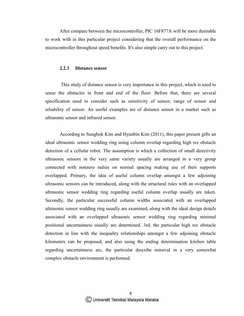
According to Sungbok Kim and Hyunbin Kim (2011), this paper present gifts an
ideal ultrasonic sensor wedding ring using column overlap regarding high res obstacle
detection of a cellular robot. The assumption is which a collection of small directivity
ultrasonic sensors in the very same variety usually are arranged in a very group
connected with nonzero radius on normal spacing making use of their supports
overlapped. Primary, the idea of useful column overlap amongst a few adjoining
ultrasonic sensors can be introduced, along with the structural rules with an overlapped
ultrasonic sensor wedding ring regarding useful column overlap usually are taken.
Secondly, the particular successful column widths associated with an overlapped
ultrasonic sensor wedding ring usually are examined, along with the ideal design details
associated with an overlapped ultrasonic sensor wedding ring regarding minimal
positional uncertainness usually are determined. 3rd, the particular high res obstacle
detection in line with the inequality relationships amongst a few adjoining obstacle
kilometers can be proposed, and also using the ending determination kitchen table
regarding uncertainness arc, the particular describe removal in a very somewhat
complex obstacle environment is performed.
9
Figure 2.3: Positional adjacent ultrasonic sensors
According to Danilo Navarro (2008) Infrared sensors are typically used in
obstacle staying away from techniques because they're quickly and low-cost, and
demand only uncomplicated signal digesting a challenge together with such a sensor is
actually their brief variety. This kind of IR sensor is utilized pertaining to line-based
guide developing purposes, therefore many of us additionally present a new technique
pertaining to line extraction, variety information clustering and line segmentation.
Infrared sensors are trusted while area sensors and pertaining to obstacle avoidance in
robotics.
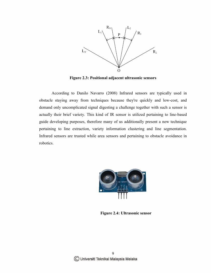
Figure 2.4: Ultrasonic sensor