Embed Size (px)
Citation preview
Perle IDS-105GPP (XT) Unmanaged 10/100/1000 PoE/PoE+ Ethernet Switches
P/N 5500342-10 (Rev G)
Installation Guide
IDS-105GPP Installation Guide 2
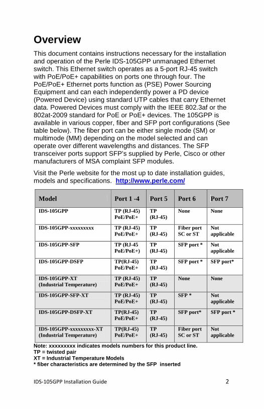
Overview This document contains instructions necessary for the installation and operation of the Perle IDS-105GPP unmanaged Ethernet switch. This Ethernet switch operates as a 5-port RJ-45 switch with PoE/PoE+ capabilities on ports one through four. The PoE/PoE+ Ethernet ports function as (PSE) Power Sourcing Equipment and can each independently power a PD device (Powered Device) using standard UTP cables that carry Ethernet data. Powered Devices must comply with the IEEE 802.3af or the 802at-2009 standard for PoE or PoE+ devices. The 105GPP is available in various copper, fiber and SFP port configurations (See table below). The fiber port can be either single mode (SM) or multimode (MM) depending on the model selected and can operate over different wavelengths and distances. The SFP transceiver ports support SFP’s supplied by Perle, Cisco or other manufacturers of MSA complaint SFP modules.
Visit the Perle website for the most up to date installation guides, models and specifications. http://www.perle.com/
Note: xxxxxxxxx indicates models numbers for this p roduct line. TP = twisted pair XT = Industrial Temperature Models * fiber characteristics are determined by the SFP inserted
Model Port 1 -4 Port 5 Port 6 Port 7
IDS-105GPP TP (RJ-45) PoE/PoE+
TP (RJ-45)
None None
IDS-105GPP-xxxxxxxxx TP (RJ-45) PoE/PoE+
TP (RJ-45)
Fiber port SC or ST
Not applicable
IDS-105GPP-SFP TP (RJ-45 PoE/PoE+)
TP (RJ-45)
SFP port * Not applicable
IDS-105GPP-DSFP TP(RJ-45) PoE/PoE+
TP (RJ-45)
SFP port * SFP port*
IDS-105GPP-XT (Industrial Temperature)
TP (RJ-45) PoE/PoE+
TP (RJ-45)
None None
IDS-105GPP-SFP-XT TP (RJ-45) PoE/PoE+
TP (RJ-45)
SFP * Not applicable
IDS-105GPP-DSFP-XT TP(RJ-45) PoE/PoE+
TP (RJ-45)
SFP port* SFP port *
IDS-105GPP-xxxxxxxxx-XT (Industrial Temperature)
TP(RJ-45) PoE/PoE+
TP (RJ-45)
Fiber port SC or ST
Not applicable
IDS-105GPP Installation Guide 3
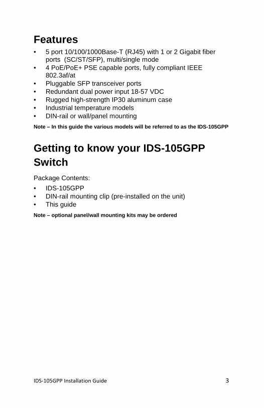
Features • 5 port 10/100/1000Base-T (RJ45) with 1 or 2 Gigabit fiber
ports (SC/ST/SFP), multi/single mode • 4 PoE/PoE+ PSE capable ports, fully compliant IEEE
802.3af/at • Pluggable SFP transceiver ports • Redundant dual power input 18-57 VDC • Rugged high-strength IP30 aluminum case • Industrial temperature models • DIN-rail or wall/panel mounting
Note – In this guide the various models will be ref erred to as the IDS-105GPP
Getting to know your IDS-105GPP Switch Package Contents:
• IDS-105GPP • DIN-rail mounting clip (pre-installed on the unit) • This guide
Note – optional panel/wall mounting kits may be ord ered
IDS-105GPP Installation Guide 4
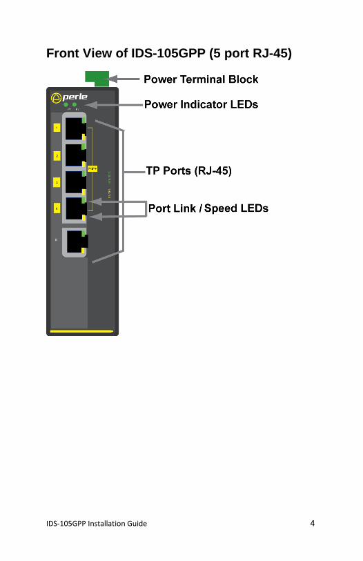
Front View of IDS-105GPP (5 port RJ-45)
IDS-105GPP Installation Guide 5
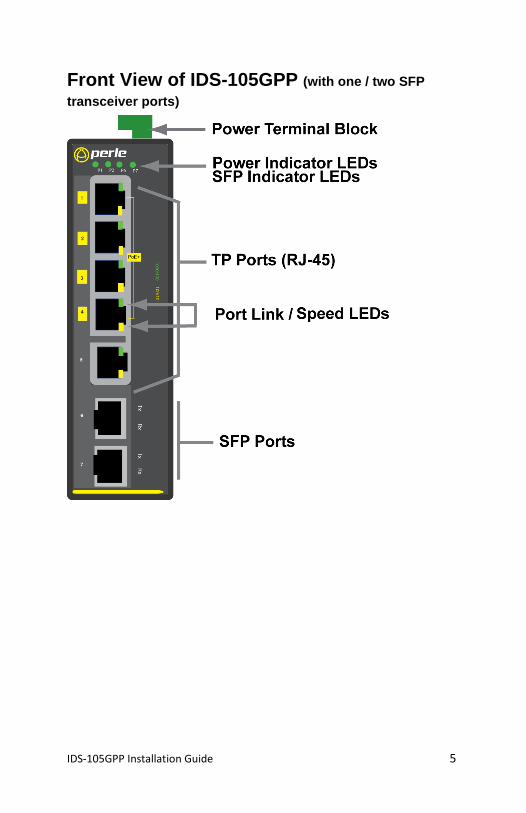
Front View of IDS-105GPP (with one / two SFP
transceiver ports)
IDS-105GPP Installation Guide 6
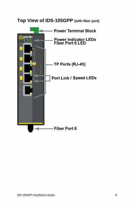
Top View of IDS-105GPP (with fiber port)
IDS-105GPP Installation Guide 7
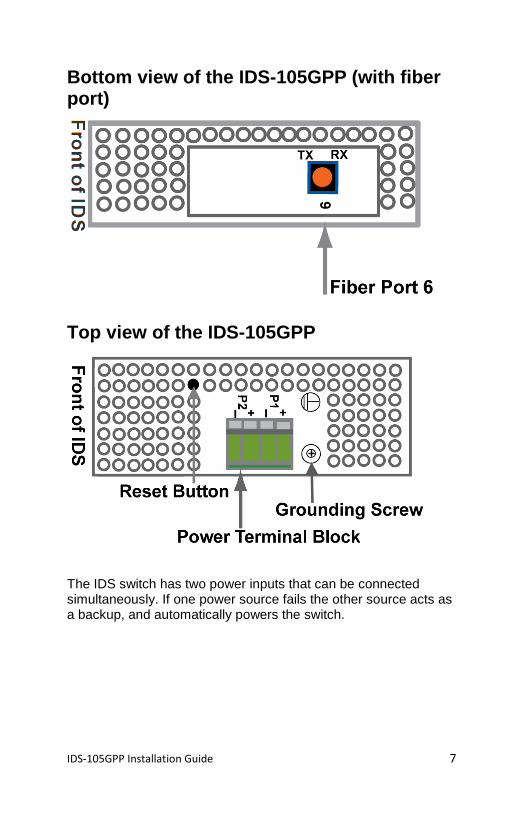
Bottom view of the IDS-105GPP (with fiber port)
Top view of the IDS-105GPP
The IDS switch has two power inputs that can be connected simultaneously. If one power source fails the other source acts as a backup, and automatically powers the switch.
IDS-105GPP Installation Guide 8
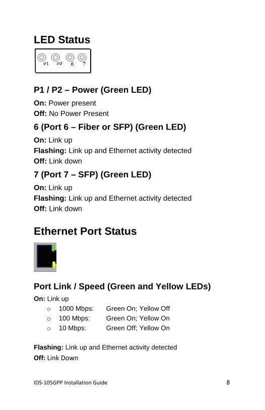
LED Status
P1 / P2 – Power (Green LED) On: Power present Off: No Power Present
6 (Port 6 – Fiber or SFP) (Green LED) On: Link up Flashing: Link up and Ethernet activity detected Off: Link down
7 (Port 7 – SFP) (Green LED) On: Link up Flashing: Link up and Ethernet activity detected Off: Link down
Ethernet Port Status
Port Link / Speed (Green and Yellow LEDs) On: Link up
o 1000 Mbps: Green On; Yellow Off
o 100 Mbps: Green On; Yellow On
o 10 Mbps: Green Off; Yellow On
Flashing: Link up and Ethernet activity detected
Off: Link Down
IDS-105GPP Installation Guide 9
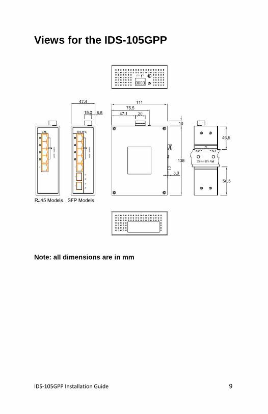
Views for the IDS-105GPP
Note: all dimensions are in mm
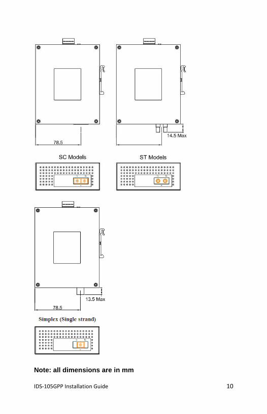
IDS-105GPP Installation Guide 10
Note: all dimensions are in mm
IDS-105GPP Installation Guide 11
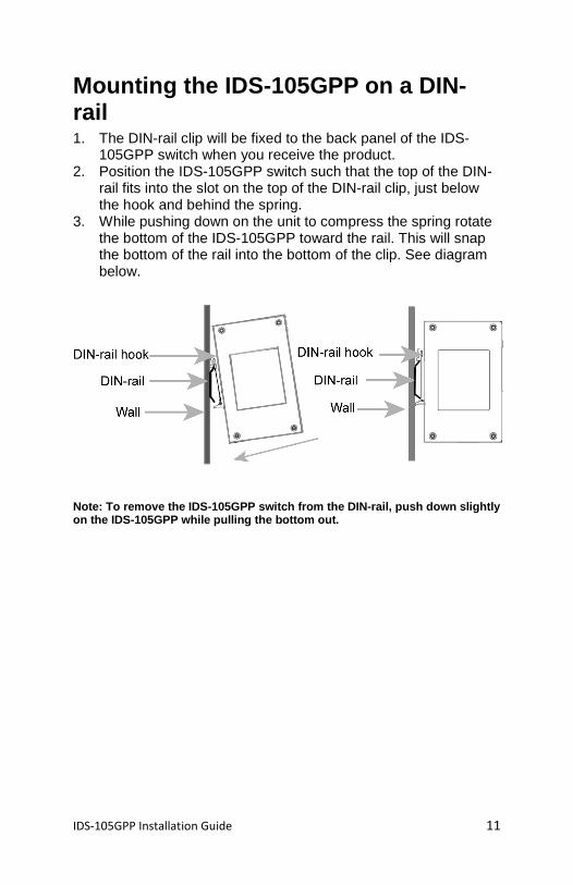
Mounting the IDS-105GPP on a DIN-rail 1. The DIN-rail clip will be fixed to the back panel of the IDS-
105GPP switch when you receive the product. 2. Position the IDS-105GPP switch such that the top of the DIN-
rail fits into the slot on the top of the DIN-rail clip, just below the hook and behind the spring.
3. While pushing down on the unit to compress the spring rotate the bottom of the IDS-105GPP toward the rail. This will snap the bottom of the rail into the bottom of the clip. See diagram below.
Note: To remove the IDS-105GPP switch from the DIN- rail, push down slightly on the IDS-105GPP while pulling the bottom out.
IDS-105GPP Installation Guide 12
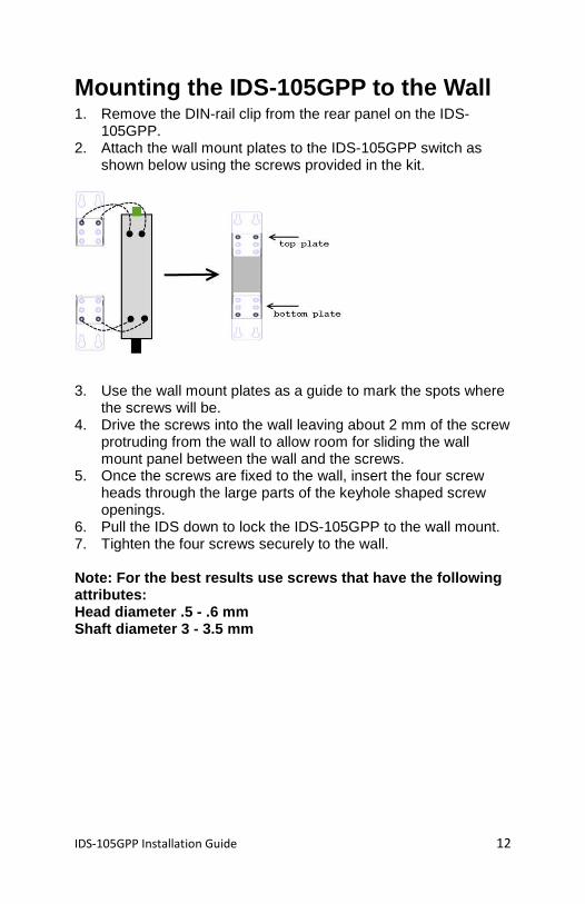
Mounting the IDS-105GPP to the Wall 1. Remove the DIN-rail clip from the rear panel on the IDS-
105GPP. 2. Attach the wall mount plates to the IDS-105GPP switch as
shown below using the screws provided in the kit.
3. Use the wall mount plates as a guide to mark the spots where
the screws will be. 4. Drive the screws into the wall leaving about 2 mm of the screw
protruding from the wall to allow room for sliding the wall mount panel between the wall and the screws.
5. Once the screws are fixed to the wall, insert the four screw heads through the large parts of the keyhole shaped screw openings.
6. Pull the IDS down to lock the IDS-105GPP to the wall mount. 7. Tighten the four screws securely to the wall.
Note: For the best results use screws that have the following attributes: Head diameter .5 - .6 mm Shaft diameter 3 - 3.5 mm
IDS-105GPP Installation Guide 13
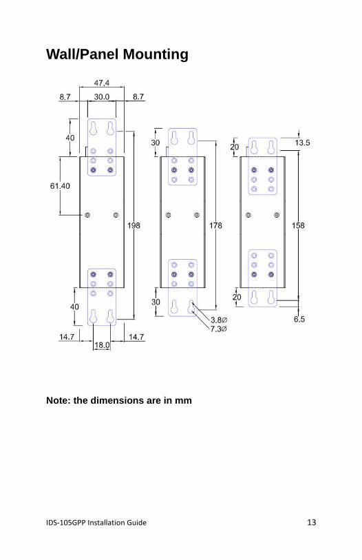
Wall/Panel Mounting
Note: the dimensions are in mm
IDS-105GPP Installation Guide 14
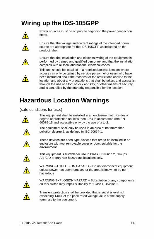
Wiring up the IDS-105GPP
Power sources must be off prior to beginning the power connection steps.
Ensure that the voltage and current ratings of the intended power source are appropriate for the IDS-105GPP as indicated on the product label.
Ensure that the installation and electrical wiring of the equipment is performed by trained and qualified personnel and that the installation complies with all local and national electrical codes
This unit should be installed in a restricted access location where access can only be gained by service personnel or users who have been instructed about the reasons for the restrictions applied to the location and about any precautions that shall be taken; and access is through the use of a tool or lock and key, or other means of security, and is controlled by the authority responsible for the location.
Hazardous Location Warnings (safe conditions for use:)
This equipment shall be installed in an enclosure that provides a degree of protection not less then IP54 in accordance with EN 60079-15 and accessible only by the use of a tool.
The equipment shall only be used in an area of not more than pollution degree 2, as defined in IEC 60664-1.
These devices are open-type devices that are to be installed in an enclosure with tool removable cover or door, suitable for the environment.
This equipment is suitable for use in Class I, Division 2, Groups A,B,C,D or only non hazardous locations only.
WARNING –EXPLOSION HAZARD – Do not disconnect equipment unless power has been removed or the area is known to be non-hazardous
WARNING EXPLOSION HAZARD – Substitution of any components on this switch may impair suitability for Class I, Division 2.
Transient protection shall be provided that is set at a level not exceeding 140% of the peak rated voltage value at the supply terminals to the equipment.
IDS-105GPP Installation Guide 15
Connecting the IDS-105GPP to ground If your installation requires additional grounding, follow this procedure.
Grounding the chassis requires the following items:
• One grounding lug (not provided)
• One 12AWG wire (not provided)
1. Follow the manufacturer’s instructions for attaching the ground wire to grounding lug.
2. Attach the grounding lug to the chassis and secure with the grounding screw provided.
IDS-105GPP Installation Guide 16
Connecting Power to the IDS-105GPP 1. Conductors suitable for use in an ambient temperature of
98°C must be used for the Power Supply Terminal. 2. Ensure the power source is off prior to connection. 3. Strip both (12AWG) wires 5 mm (3/16th inch). 4. Loosen the terminal block screws and connect positive (+) /
negative (-) wires into the -/+ terminals. 5. Tighten terminals screws (0.51Nm torque). 6. Ensure the wires are securely fastened. 7. Re-insert the Terminal block connector if removed. 8. Turn on power source. 9. Check that the P1 LED is On. 10. If desired connect P2 (power source 2, beginning at Step 1). 11. One individual conductor for each clamping point.
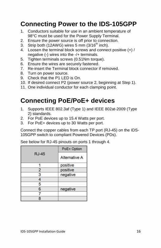
Connecting PoE/PoE+ devices 1. Supports IEEE 802.3af (Type 1) and IEEE 802at-2009 (Type
2) standards. 2. For PoE devices up to 15.4 Watts per port. 3. For PoE+ devices up to 30 Watts per port.
Connect the copper cables from each TP port (RJ-45) on the IDS-105GPP switch to compliant Powered Devices (PDs).
See below for RJ-45 pinouts on ports 1 through 4.
IDS-105GPP Installation Guide 17
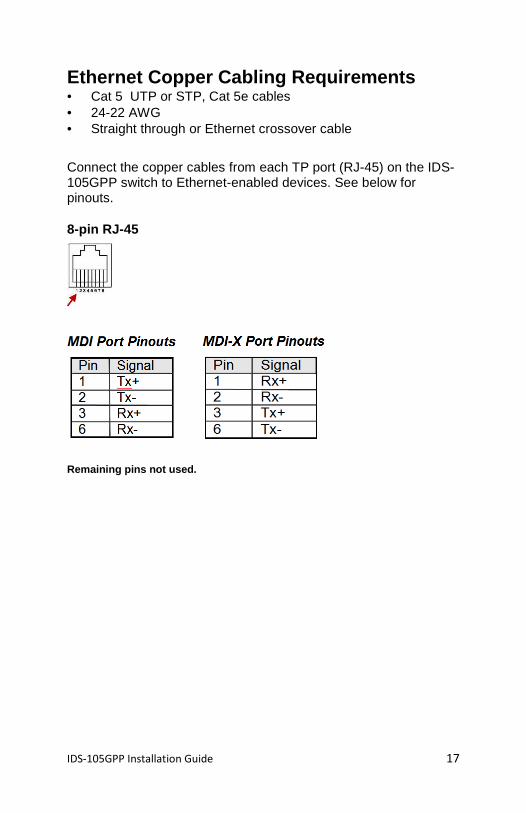
Ethernet Copper Cabling Requirements • Cat 5 UTP or STP, Cat 5e cables • 24-22 AWG • Straight through or Ethernet crossover cable
Connect the copper cables from each TP port (RJ-45) on the IDS-105GPP switch to Ethernet-enabled devices. See below for pinouts.
8-pin RJ-45
Remaining pins not used.
IDS-105GPP Installation Guide 18
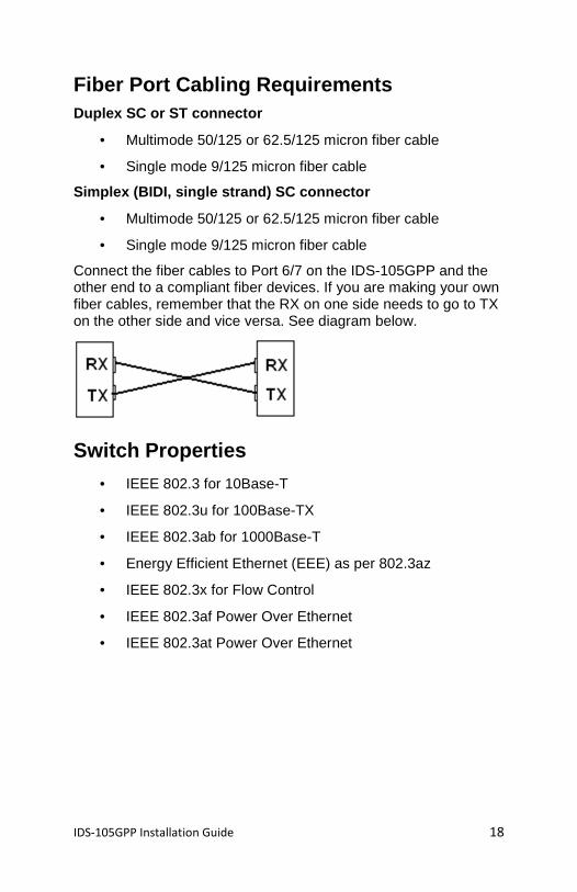
Fiber Port Cabling Requirements Duplex SC or ST connector
• Multimode 50/125 or 62.5/125 micron fiber cable
• Single mode 9/125 micron fiber cable
Simplex (BIDI, single strand) SC connector
• Multimode 50/125 or 62.5/125 micron fiber cable
• Single mode 9/125 micron fiber cable
Connect the fiber cables to Port 6/7 on the IDS-105GPP and the other end to a compliant fiber devices. If you are making your own fiber cables, remember that the RX on one side needs to go to TX on the other side and vice versa. See diagram below.
Switch Properties
• IEEE 802.3 for 10Base-T
• IEEE 802.3u for 100Base-TX
• IEEE 802.3ab for 1000Base-T
• Energy Efficient Ethernet (EEE) as per 802.3az
• IEEE 802.3x for Flow Control
• IEEE 802.3af Power Over Ethernet
• IEEE 802.3at Power Over Ethernet
IDS-105GPP Installation Guide 19
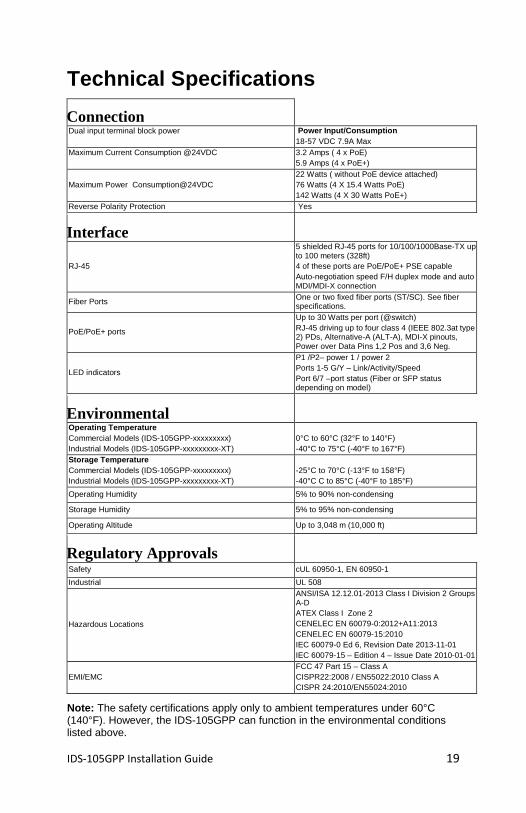
Technical Specifications
Connection Dual input terminal block power
Power Input/Consumption 18-57 VDC 7.9A Max
Maximum Current Consumption @24VDC
3.2 Amps ( 4 x PoE) 5.9 Amps (4 x PoE+)
Maximum Power Consumption@24VDC 22 Watts ( without PoE device attached) 76 Watts (4 X 15.4 Watts PoE) 142 Watts (4 X 30 Watts PoE+)
Reverse Polarity Protection Yes
Interface
RJ-45
5 shielded RJ-45 ports for 10/100/1000Base-TX up to 100 meters (328ft) 4 of these ports are PoE/PoE+ PSE capable Auto-negotiation speed F/H duplex mode and auto MDI/MDI-X connection
Fiber Ports One or two fixed fiber ports (ST/SC). See fiber specifications.
PoE/PoE+ ports
Up to 30 Watts per port (@switch) RJ-45 driving up to four class 4 (IEEE 802.3at type 2) PDs, Alternative-A (ALT-A), MDI-X pinouts, Power over Data Pins 1,2 Pos and 3,6 Neg.
LED indicators
P1 /P2– power 1 / power 2 Ports 1-5 G/Y – Link/Activity/Speed Port 6/7 –port status (Fiber or SFP status depending on model)
Environmental Operating Temperature Commercial Models (IDS-105GPP-xxxxxxxxx) Industrial Models (IDS-105GPP-xxxxxxxxx-XT)
0°C to 60°C (32°F to 140°F) -40°C to 75°C (-40°F to 167°F)
Storage Temperature Commercial Models (IDS-105GPP-xxxxxxxxx) Industrial Models (IDS-105GPP-xxxxxxxxx-XT)
-25°C to 70°C (-13°F to 158°F) -40°C C to 85°C (-40°F to 185°F)
Operating Humidity 5% to 90% non-condensing
Storage Humidity 5% to 95% non-condensing
Operating Altitude Up to 3,048 m (10,000 ft)
Regulatory Approvals Safety cUL 60950-1, EN 60950-1
Industrial UL 508
Hazardous Locations
ANSI/ISA 12.12.01-2013 Class I Division 2 Groups A-D ATEX Class I Zone 2 CENELEC EN 60079-0:2012+A11:2013 CENELEC EN 60079-15:2010 IEC 60079-0 Ed 6, Revision Date 2013-11-01 IEC 60079-15 – Edition 4 – Issue Date 2010-01-01
EMI/EMC FCC 47 Part 15 – Class A CISPR22:2008 / EN55022:2010 Class A CISPR 24:2010/EN55024:2010
Note: The safety certifications apply only to ambient temperatures under 60°C (140°F). However, the IDS-105GPP can function in the environmental conditions listed above.
IDS-105GPP Installation Guide 20
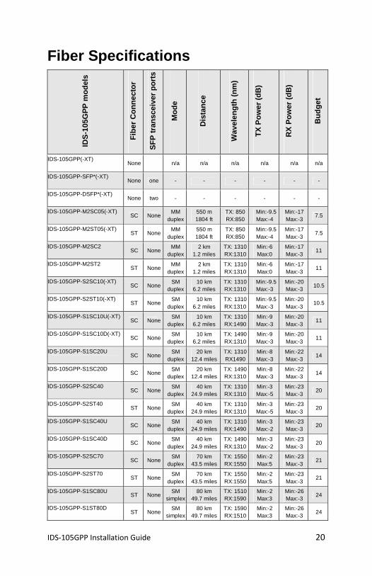
Fiber Specifications
IDS
-105
GP
P m
odel
s
Fib
er C
onne
ctor
SF
P tr
ansc
eive
r po
rts
Mod
e
Dis
tanc
e
Wav
elen
gth
(nm
)
TX
Pow
er (
dB)
RX
Pow
er (
dB)
Bud
get
IDS-105GPP(-XT) None n/a n/a n/a n/a n/a n/a
IDS-105GPP-SFP*(-XT) None one - - - - - -
IDS-105GPP-DSFP*(-XT) None two - - - - - -
IDS-105GPP-M2SC05(-XT) SC None
MM duplex
550 m 1804 ft
TX: 850 RX:850
Min:-9.5 Max:-4
Min:-17 Max:-3
7.5
IDS-105GPP-M2ST05(-XT) ST None
MM duplex
550 m 1804 ft
TX: 850 RX:850
Min:-9.5 Max:-4
Min:-17 Max:-3
7.5
IDS-105GPP-M2SC2 SC None
MM duplex
2 km 1.2 miles
TX: 1310 RX:1310
Min:-6 Max:0
Min:-17 Max:-3
11
IDS-105GPP-M2ST2 ST None
MM duplex
2 km 1.2 miles
TX: 1310 RX:1310
Min:-6 Max:0
Min:-17 Max:-3
11
IDS-105GPP-S2SC10(-XT) SC None
SM duplex
10 km 6.2 miles
TX: 1310 RX:1310
Min:-9.5 Max:-3
Min:-20 Max:-3
10.5
IDS-105GPP-S2ST10(-XT) ST None
SM duplex
10 km 6.2 miles
TX: 1310 RX:1310
Min:-9.5 Max:-3
Min:-20 Max:-3
10.5
IDS-105GPP-S1SC10U(-XT) SC None
SM duplex
10 km 6.2 miles
TX: 1310 RX:1490
Min:-9 Max:-3
Min:-20 Max:-3
11
IDS-105GPP-S1SC10D(-XT) SC None
SM duplex
10 km 6.2 miles
TX: 1490 RX:1310
Min:-9 Max:-3
Min:-20 Max:-3
11
IDS-105GPP-S1SC20U SC None
SM duplex
20 km 12.4 miles
TX: 1310 RX1490
Min:-8 Max:-3
Min:-22 Max:-3
14
IDS-105GPP-S1SC20D SC None
SM duplex
20 km 12.4 miles
TX: 1490 RX:1310
Min:-8 Max:-3
Min:-22 Max:-3
14
IDS-105GPP-S2SC40 SC None
SM duplex
40 km 24.9 miles
TX: 1310 RX:1310
Min:-3 Max:-5
Min:-23 Max:-3
20
IDS-105GPP-S2ST40 ST None
SM duplex
40 km 24.9 miles
TX: 1310 RX:1310
Min:-3 Max:-5
Min:-23 Max:-3
20
IDS-105GPP-S1SC40U SC None
SM duplex
40 km 24.9 miles
TX: 1310 RX:1490
Min:-3 Max:-2
Min:-23 Max:-3
20
IDS-105GPP-S1SC40D SC None
SM duplex
40 km 24.9 miles
TX: 1490 RX:1310
Min:-3 Max:-2
Min:-23 Max:-3
20
IDS-105GPP-S2SC70 SC None
SM duplex
70 km 43.5 miles
TX: 1550 RX:1550
Min:-2 Max:5
Min:-23 Max:-3
21
IDS-105GPP-S2ST70 ST None
SM duplex
70 km 43.5 miles
TX: 1550 RX:1550
Min:-2 Max:5
Min:-23 Max:-3
21
IDS-105GPP-S1SC80U ST None
SM simplex
80 km 49.7 miles
TX: 1510 RX:1590
Min:-2 Max:3
Min:-26 Max:-3
24
IDS-105GPP-S1ST80D ST None
SM simplex
80 km 49.7 miles
TX: 1590 RX:1510
Min:-2 Max:3
Min:-26 Max:-3
24
IDS-105GPP Installation Guide 21
IDS
-105
GP
P m
odel
s
Fib
er C
onne
ctor
SF
P tr
ansc
eive
r po
rts
Mod
e
Dis
tanc
e
Wav
elen
gth
(nm
)
TX
Pow
er (
dB)
RX
Pow
er (
dB)
Bud
get
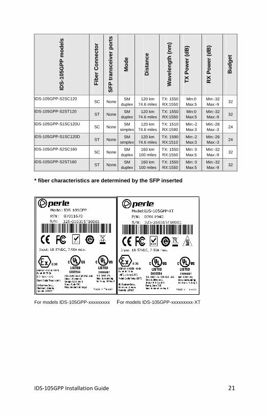
IDS-105GPP-S2SC120 SC None
SM duplex
120 km 74.6 miles
TX: 1550 RX:1550
Min:0 Max:5
Min:-32 Max:-9
32
IDS-105GPP-S2ST120 ST None
SM duplex
120 km 74.6 miles
TX: 1550 RX:1550
Min:0 Max:5
Min:-32 Max:-9
32
IDS-105GPP-S1SC120U SC None
SM simplex
120 km 74.6 miles
TX: 1510 RX:1590
Min:-2 Max:3
Min:-26 Max:-3
24
IDS-105GPP-S1SC120D ST None
SM simplex
120 km 74.6 miles
TX: 1590 RX:1510
Min:-2 Max:3
Min:-26 Max:-3
24
IDS-105GPP-S2SC160 SC None
SM duplex
160 km 100 miles
TX: 1550 RX:1550
Min: 0 Max:5
Min:-32 Max:-9
32
IDS-105GPP-S2ST160 ST None
SM duplex
160 km 100 miles
TX: 1550 RX:1550
Min: 0 Max:5
Min:-32 Max:-9
32
* fiber characteristics are determined by the SFP i nserted
For models IDS-105GPP-xxxxxxxxx For models IDS-105GPP-xxxxxxxxx-XT
IDS-105GPP Installation Guide 22
Contacting Technical Support Contact information for the Perle Technical Assista nce Center (PTAC) can be found at the link below. A Technical Support Query may be made via this web page. www.perle.com/support_services/support_request.shtm l Warranty / Registration This product is covered by the Perle Ethernet Switc hes Warranty. Details can be found at: http://www.perle.com/support_services/lifetime_warr anty_countries.shtml Copyright © 2015 Perle Systems Limited All rights r eserved. No part of this document may be reproduced or used in any form without written perm ission from Perle Systems Limited.