Embed Size (px)
Citation preview
Knowledge Base
Article Type: Instructions
Vibrator Shakershaft and Upper
Vibrator Components
Troubleshooting for: Models
22HF, 16HF, 1600.
WARNING Never work on, clean or service this unit, control panel or any machine or open or remove any protective cover, guard, grate, door, or maintenance panel until the power or energy sources has been turned off, locked out / tagged out, and all moving parts have come to a complete stop and or blocked to prevent movement. Machinery is dangerous – avoid personal injury and or death by following manufacture, Local, and OHSA safety procedures. Contact Columbia Machine for safety decals, guards, horns and beacons.
Description: Instructions on “How to” properly setup and align Upper Vibrator components, Shakershaft, Die Supports, Guide Bars. For Models 22HF, 16HF, and 1600 machines.
VIBRATOR / SHAKERSHAFT TROUBLESHOOTING & SETUP
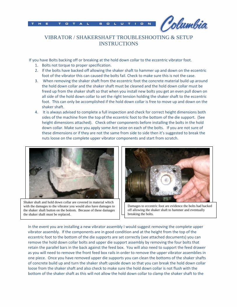
INSTRUCTIONS If you have Bolts backing off or breaking at the hold down collar to the eccentric vibrator foot.
1. Bolts not torque to proper specification.
2. If the bolts have backed off allowing the shaker shaft to hammer up and down on the eccentric
foot of the vibrator this can caused the bolts fail. Check to make sure this is not the case.
3. When removing the shaker shaft from the eccentric foot the concrete material build up around
the hold down collar and the shaker shaft must be cleaned and the hold down collar must be
freed up from the shaker shaft so that when you install new bolts you get an even pull down on
all side of the hold down collar to set the right tension holding the shaker shaft to the eccentric
foot. This can only be accomplished if the hold down collar is free to move up and down on the
shaker shaft.
4. It is always advised to complete a full inspection and check for correct height dimensions both
sides of the machine from the top of the eccentric foot to the bottom of the die support. (See
height dimensions attached). Check other components before installing the bolts in the hold
down collar. Make sure you apply some Ant seize on each of the bolts. If you are not sure of
these dimensions or if they are not the same from side to side then it’s suggested to break the
nuts loose on the complete upper vibrator components and start from scratch.
In the event you are installing a new vibrator assembly I would suggest removing the complete upper
vibrator assembly. If the components are in good condition and at the height from the top of the
eccentric foot to the bottom of the die supports are set correctly (see attached documents) you can
remove the hold down collar bolts and upper die support assembly by removing the four bolts that
retain the parallel bars in the back against the feed box. You will also need to support the feed drawer
as you will need to remove the front feed box rails in order to remove the upper vibrator assemblies in
one piece. Once you have removed upper die supports you can clean the bottoms of the shaker shafts
of concrete build up and turn the shaker shaft upside down so that you can break the hold down collar
loose from the shaker shaft and also check to make sure the hold down collar is not flush with the
bottom of the shaker shaft as this will not allow the hold down collar to clamp the shaker shaft to the
Damages to eccentric foot are evidence the bolts had backed off allowing the shaker shaft to hammer and eventually breaking the bolts.
Shaker shaft and hold down collar are covered in material which with the damages to the vibrator you would also have damages to the shaker shaft button on the bottom. Because of these damages the shaker shaft must be replaced.
eccentric foot. To break the hold down collar loose this can be accomplished by use a piece of pipe large
enough to go over the bottom of the shaker shaft and tall enough so that you can support a block of
wood on top of the pipe without contacting the bottom of the shaker shaft. Using the block of wood
placed on top of the section of pipe strike the block of wood held against the pipe driving the hold down
collar free of the shaker shaft. Also inspect the hold down collar to insure they are not cracked and are
in good condition.
After you have the upper die support assembly cleaned and installed back on the machine install the
bolts, lockwashers & nuts back in the parallel bars at the rear supports against the feed box on both
sides, but do not lock the bolts down at this time. Install the feed box side rails that the feed drawer
wheels ride on. If you have loosened up the nuts on the upper vibrator components and need to set
your heights install the shaker shafts in the eccentric feet and just start the bolts in by hand to hold the
shaker shafts in place. Again follow the height adjustments for setting the heights from the eccentric
feet to the bottom of the die support (see attached document for height settings). Height adjustments
should be made using the lower large nut on the shaker shaft. Also you should have both your die
support fixture and shaker shaft fixture to complete the alignment. (See attached documents)
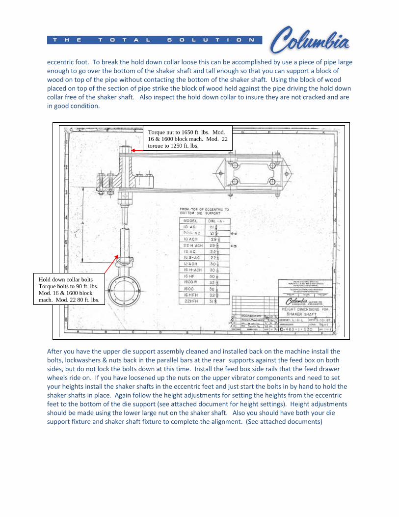
Torque nut to 1650 ft. lbs. Mod. 16 & 1600 block mach. Mod. 22 torque to 1250 ft. lbs.
Hold down collar bolts Torque bolts to 90 ft. lbs. Mod. 16 & 1600 block mach. Mod. 22 80 ft. lbs.
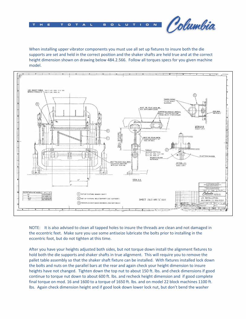
When installing upper vibrator components you must use all set up fixtures to insure both the die
supports are set and held in the correct position and the shaker shafts are held true and at the correct
height dimension shown on drawing below 484.2.566. Follow all torques specs for you given machine
model.
NOTE: It is also advised to clean all tapped holes to insure the threads are clean and not damaged in
the eccentric feet. Make sure you use some antiseize lubricate the bolts prior to installing in the
eccentric foot, but do not tighten at this time.
After you have your heights adjusted both sides, but not torque down install the alignment fixtures to
hold both the die supports and shaker shafts in true alignment. This will require you to remove the
pallet table assembly so that the shaker shaft fixture can be installed. With fixtures installed lock down
the bolts and nuts on the parallel bars at the rear and again check your height dimension to insure
heights have not changed. Tighten down the top nut to about 150 ft. lbs. and check dimensions if good
continue to torque nut down to about 600 ft. lbs. and recheck height dimension and if good complete
final torque on mod. 16 and 1600 to a torque of 1650 ft. lbs. and on model 22 block machines 1100 ft.
lbs. Again check dimension height and if good look down lower lock nut, but don’t bend the washer
flanges over opposed top and bottom nut until all alignments have been completed. Insert uhmw and
set screw and lock down on lower larger nut. (See attached document).
To confirm shaker shaft bottom pin alignment to eccentric foot remove the shaker shaft fixture and die
support fixture first. Then using a large hook bar or crow bar across the main box setting the bar under
the die support lift the shaker shaft up out of the pocket just enough to see it come up out of the
eccentric foot and then lower it back down. The shaker shaft should lift up and set back down in the
pocket without forcing the shaker shaft. (Make sure you are lifting straight up with the bar). If the
shaker shaft springs to either side or front to back and you cannot get the shaker shaft pin to set back
down without forcing it you can loosen the bolts in the rear of the parallel bar on that side and see if this
allows the shaft to align. Again you also may need to install the fixture again and lock the bolts down. If
you continue to have problems with the alignment you may be required to loosen up the upper nut on
the shaker shaft and turn the shaft slightly which will require readjustment of the lower nuts. If all
checks out then with the shaker shafts seated on the eccentric feet install bolts in the hold down collar
and using a cross hatch pattern begin to draw down the bolts. This will require three torque settings
starting with 30 ft. lbs. you may need to continue three to four times using this setting again using the
cross hatch pattern until you can put the torque wrench on each of the 4 bolts and when you apply
torque the torque wrench clicks to the specified torque setting without the bolt drawing down more.
Move to the next torque setting of 60 ft. lbs. and again follow the same sequence. Again set the torque
to 90 ft. lbs. (Mod. 16 & 1600 block machines) and following the same sequence cross hatch pattern and
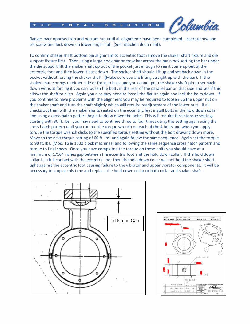
torque to final specs. Once you have completed the torque on these bolts you should have at a
minimum of 1/16” inches gap between the eccentric foot and the hold down collar. If the hold down
collar is in full contact with the eccentric foot then the hold down collar will not hold the shaker shaft
tight against the eccentric foot causing failure to the vibrator and upper vibrator components. It will be
necessary to stop at this time and replace the hold down collar or both collar and shaker shaft.
1/16 min. Gap
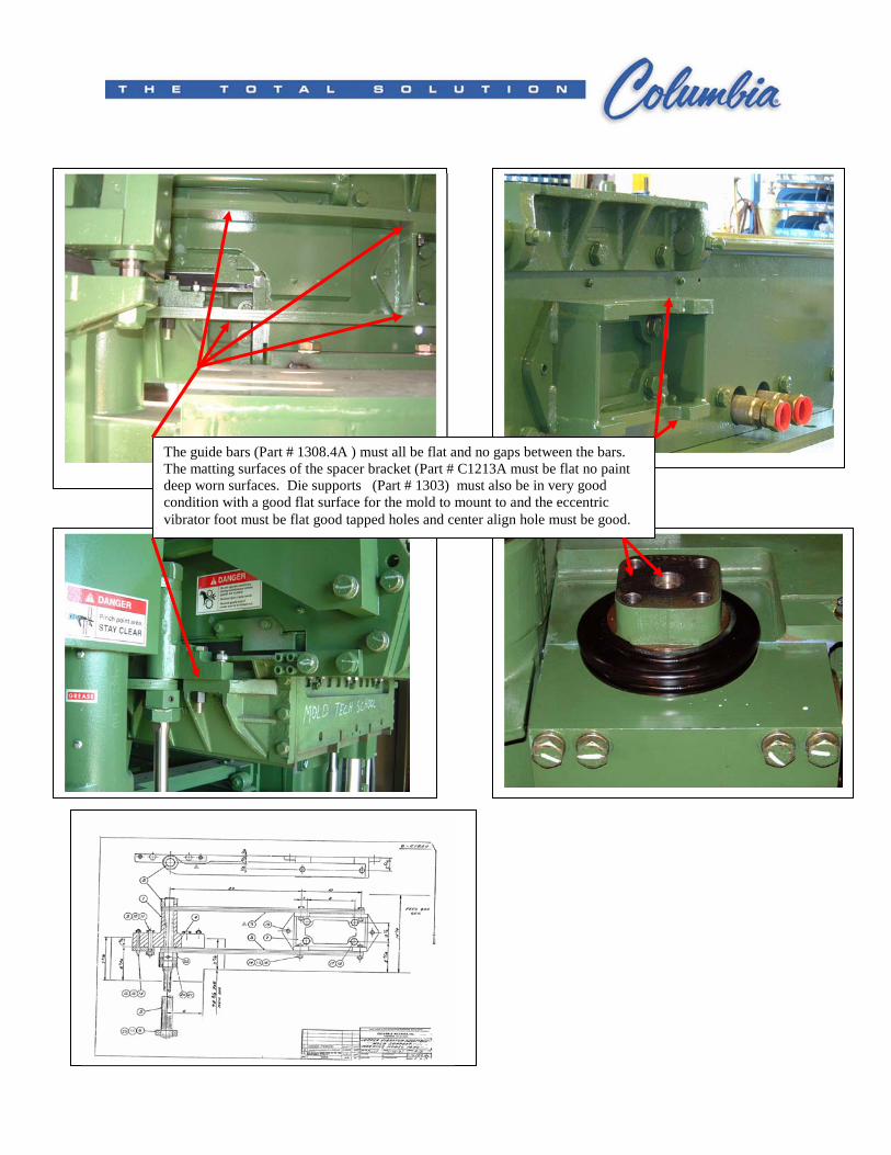
The guide bars (Part # 1308.4A ) must all be flat and no gaps between the bars. The matting surfaces of the spacer bracket (Part # C1213A must be flat no paint deep worn surfaces. Die supports (Part # 1303) must also be in very good condition with a good flat surface for the mold to mount to and the eccentric vibrator foot must be flat good tapped holes and center align hole must be good.
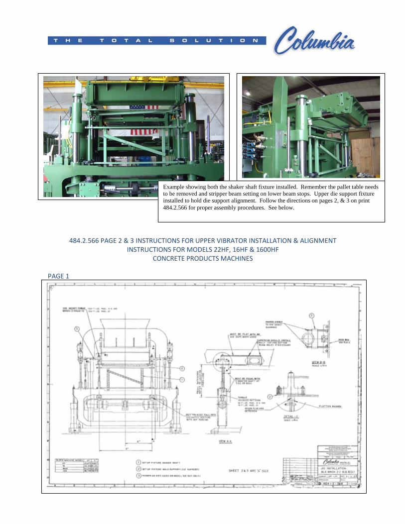
484.2.566 PAGE 2 & 3 INSTRUCTIONS FOR UPPER VIBRATOR INSTALLATION & ALIGNMENT
INSTRUCTIONS FOR MODELS 22HF, 16HF & 1600HF
CONCRETE PRODUCTS MACHINES
PAGE 1
Example showing both the shaker shaft fixture installed. Remember the pallet table needs to be removed and stripper beam setting on lower beam stops. Upper die support fixture installed to hold die support alignment. Follow the directions on pages 2, & 3 on print 484.2.566 for proper assembly procedures. See below.
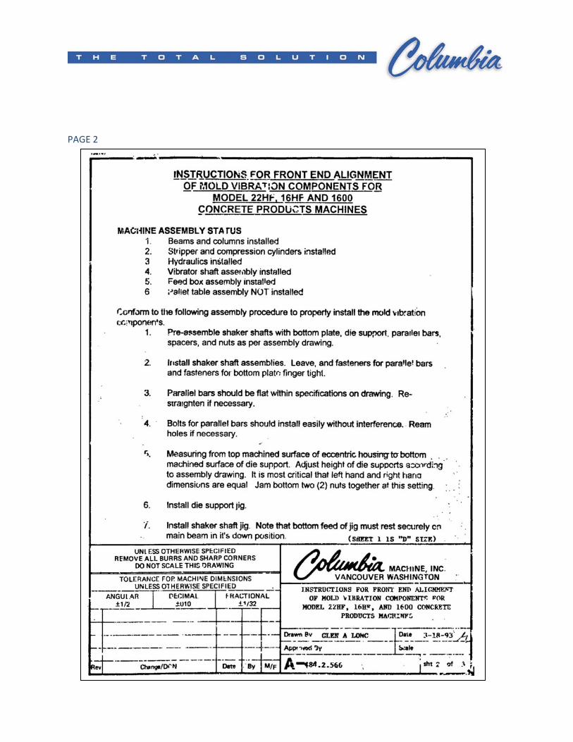
PAGE 2
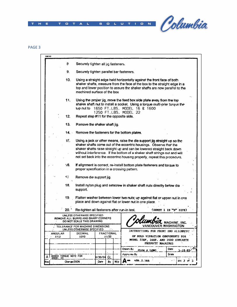
PAGE 3
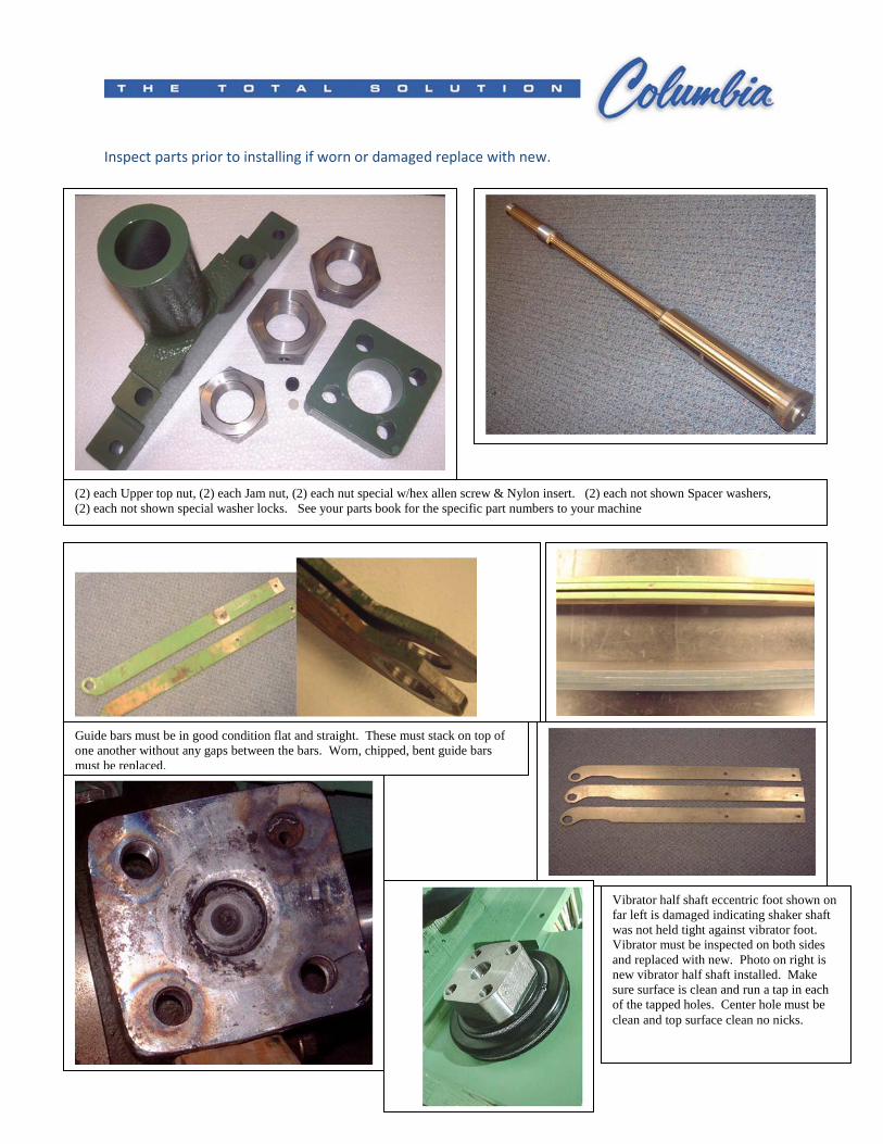
Inspect parts prior to installing if worn or damaged replace with new.
Shaker shaft
(2) each Upper top nut, (2) each Jam nut, (2) each nut special w/hex allen screw & Nylon insert. (2) each not shown Spacer washers, (2) each not shown special washer locks. See your parts book for the specific part numbers to your machine
Guide bars must be in good condition flat and straight. These must stack on top of one another without any gaps between the bars. Worn, chipped, bent guide bars must be replaced.
Vibrator half shaft eccentric foot shown on far left is damaged indicating shaker shaft was not held tight against vibrator foot. Vibrator must be inspected on both sides and replaced with new. Photo on right is new vibrator half shaft installed. Make sure surface is clean and run a tap in each of the tapped holes. Center hole must be clean and top surface clean no nicks.
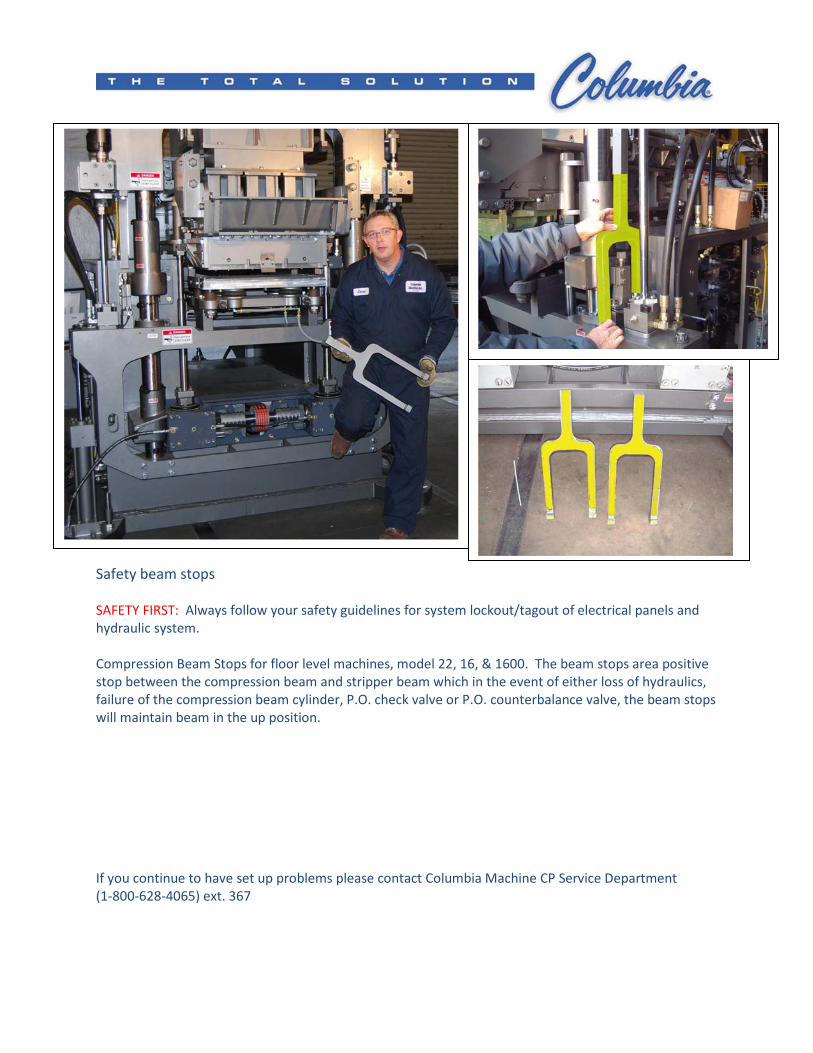
Safety beam stops
SAFETY FIRST: Always follow your safety guidelines for system lockout/tagout of electrical panels and
hydraulic system.
Compression Beam Stops for floor level machines, model 22, 16, & 1600. The beam stops area positive
stop between the compression beam and stripper beam which in the event of either loss of hydraulics,
failure of the compression beam cylinder, P.O. check valve or P.O. counterbalance valve, the beam stops
will maintain beam in the up position.
If you continue to have set up problems please contact Columbia Machine CP Service Department
(1-800-628-4065) ext. 367


![Pneumatisk Stempel Vibrator NTK · Pneumatisk Stempel Vibrator NTK Telefon +45 56 87 07 23 Vibrator Variant Arbejdsmoment [cmkg] - Nominel Frekvens [min1] Centrifugalkraft](https://img.pdfslide.net/doc/110x75/5e5efb86cf6a1b09186c81a8/pneumatisk-stempel-vibrator-ntk-pneumatisk-stempel-vibrator-ntk-telefon-45-56-87.jpg)