Embed Size (px)
Citation preview
Sigtronics UltraSound Emergency Intercom System
US-45D, US-45S, US-67D, and US-67SINSTALLATION AND OPERATING INSTRUCTIONS
Specialists in “SOUND” Management178 East Arrow Highway, San Dimas, CA 91773 (909) 305-9399
igtronics ®S
INTRODUCTION
ATTENTION INSTALLER: To assure a trouble free installation, please read these entire instructions through once before beginning.
The Sigtronics UltraSound Emergency Intercom System, when used with Sigtronics noise attenuating headsets provides the emergency apparatus crew with clear, hands free, voice activated (VOX) intercom. The system also allows full radio monitoring at all headset positions as well as radio transmit capability from selected headsets via Push-To-Talk (PTT) switches.
Applications: The unit is designed for fire apparatus, rescue and ambulance vehicles, marine emergency equipment, airport ground vehicles, and mobile emergency command centers.
Voice Activated Intercom (VOX) feature allows “hands free” com-munication between headsets connected to the UltraSound unit. Start speaking and the intercom turns on instantly to relay your message clearly to the other headsets. Stop talking and it turns off to reduce background noise.
Up to Four Headset Positions can be connected to the UltraSound unit models US-45S and US-45D. Up to six for models US-67S and US-67D. More headset positions can be achieved by wiring additional jacks in parallel. Only one headset, however, can be plugged into paralleled jacks at one time. This paralleled jack scheme is most commonly used on pumper trucks at the pump panel. In this case, the Driver plugs his headset into his jack while driving. He then unplugs and plugs into the pump panel when he arrives on scene.
US-45D
US-45S
Page 2 SigtronicS UltraSoUnd US-45 and US-67 intercomS www.SigtronicS.com
Headphone Output:
The UltraSound system is designed to easily drive six or more 300 to 1000 ohm headsets. Noise attenuating, full cushion headsets, such as the Sigtronics SE-8, or SE-48 are recommended for best results. The UltraSound system incorporates an automatic headphone limiting circuit to eliminate the possibility of painful spurious radio or noise spikes from getting to the headsets and into your ears.
Universal Radio Interface is designed to accommodate virtually any type of communication radio. Adjustments for radio receive level and transmit microphone level are provided to perfectly match the UltraSound system to your particular radio.
Automatic Sidetone Generation allows everyone on the vehicle to hear both sides of the radio conversations.
Excellent RF Immunity guarantees clean, clear, radio communi-cations.
Standardized for use with Sigtronics single plug headsets (ie. SE-8, SE-48, SE-18).
Model Differences:
The US-45S is used in applications requiring up to four persons at one time on intercom. Two of the four have radio transmit capa-bility. The US-45S is designed for use with a single vehicle radio. The US-45D is identical to the US-45S but can accommodate two separate vehicle radios.
The US-67S is for single radio operations and can intercom up to six people at one time. Three of the six can transmit on the vehicle radio. Similarly, the US-67D is just like the US-67S, but with dual radio capability.
CONTROL FUNCTIONS
VOLUME — Intercom Volume: Adjusts intercom volume level. Does not affect radio volume.
SQUELCH — Intercom Squelch: Adjusts VOX operation of the inter-com for variations in background noise levels.
RADIO 1/RADIO 2 (TALK) — Transmit Select (US-45D and US-67D units only): Used to select which radio to talk on – Radio 1 or Radio 2.
AUTO/BOTH (LISTEN) — Receive Select (US-45D and US-67D units only): Used to select which radio is heard. In “BOTH” position, you hear both Radio 1 and the Radio 2. In “AUTO” position, only the radio selected by the RADIO 1/RADIO 2 switch is heard.
RADIO MIC TRANSMIT GAIN — Located on the back of the unit: Sets the transmit mic audio level for the radio(s).
RADIO VOLUME — Located on the back of the unit: Sets the range of receive audio from the radio(s).
ULTRASOUND INSTALLATION
Standard Equipment Included
Besides the Intercom unit, each UltraSound system comes complete with the following:
US-45S/45D US-67S/67D
Intercom Mounting Bracket .............................. 1 ..................... 1
Headset Jack Box and Cover with Pre-mounted Headset Jack .................... 4 ..................... 6 with Pre-mounted Headset Jack & Splash Cover ...................................................... 1 ..................... 1 PTT Switch Pre mounted in PTT Box and Cover ......................................... 3 ..................... 3 Headset Hooks ...................................................... 4 ..................... 6 Jack Box Cover Screws ....................................... 16 .................. 20 Jack Box and Bracket Mounting Screws ...... 28 .................. 36
Wire Grommets ..................................................... 8 .................... 10
Jack Insulator Washer, Flat ................................. 5 ..................... 7 Jack Insulator Washer, Shoulder ...................... 5 ..................... 7
4 ft. Headset Jack and PTT Switch Cable ..... 1 ..................... 1 4 ft. Radio 1 Interface Cable .............................. 1 ..................... 1 4 conductor hook-up wire (Roll) ..................... 1 ..................... 1
4 ft. Radio 2 Interface Cable ............................. 1* ................... 1*
* Supplied with US-45D and US-67D (dual radio) units only.
Installation Overview:
Sigtronics has simplified the installation process, to assure perfect operation. Refer to the UltraSound Wiring Diagram. For US-45S or US-67S see Figure 4; for US-45D or US-67D see Figure 5. If you have any installation questions or problems that are not addressed in this manual, feel free to call our installation hot line number located on the last page of this manual.
Installation of the Sigtronics UltraSound System is a four step process:
I. Mount the intercom unit.
(INTERCOM CHASSIS INSTALLATION)
II. Install the headset jacks and PTT switches.
(HEADSET JACK AND PTT SWITCH INSTALLATION)
III. Wire the jacks and PTT switches.
(HEADSET JACK AND PTT SWITCH WIRING)
IV. Wire the radio(s).
(RADIO HOOK UP)
I. INTERCOM CHASSIS INSTALLATION
Intercom Placement:
There are a few factors to consider when selecting a mounting location for the UltraSound Intercom chassis:
1. The unit should be placed in such a way that the controls on the front of the unit can be easily seen and operated. Most commonly, this will be near the vehicle’s communication radio controls.
2. The Intercom unit is primarily designed to be dash mounted. It can be mounted on top of the dash or hang below the dash or vehicle ceiling. The mounting bracket is adjustable to allow for various mounting angles.
www.SigtronicS.com SigtronicS UltraSoUnd US-45 and US-67 intercomS Page 3
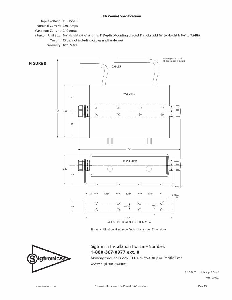
3. The location selected requires a minimum area of 2 5⁄16 inches high by 7 7⁄8 inches wide by 4 inches deep. Verify that the intercom unit and cables will not interfere with the normal operation of any vehicle controls or the operation of vehicle compartment doors.
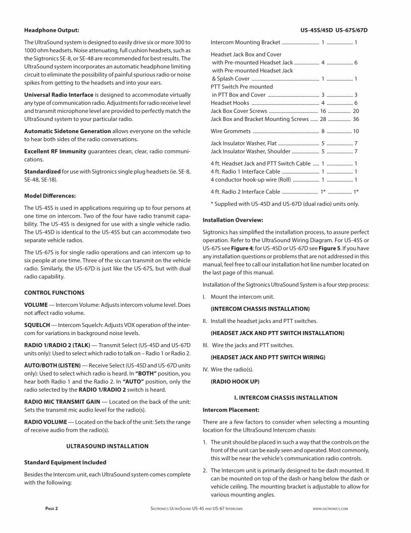
Mounting Intercom Unit: See Figures 1 and 8
1. Once the location is selected, remove the mounting bracket from the intercom unit by unscrewing the two large knobs. Be careful not to lose any of the four ratchet washers.
2. Set the mounting bracket in the selected area and mount with four of the hex head self drilling screws. For most applications* these screws can be installed with no pre drilling. Just power in the screws with a standard electric driver with a 5⁄16 inch hex bit. * No pre drilling required for aluminum and steel. A 1⁄8 inch pilot hole will still be required with some stainless steels.
3. Place the intercom back into the bracket and replace the four washers and two knobs. Set the Intercom to the desired angle before tightening down the knobs.
II. HEADSET JACK AND PTT SWITCH INSTALLATION
Headset Jack Placement:
It is assumed that it has already been determined which positions on the vehicle will have headsets. At this stage, it is helpful to have a headset handy to physically gauge the best place for a particular jack. There are several things to consider when selecting a place to mount the headset jacks:
1. In general, for headset positions inside the vehicle, the jacks should be placed towards the middle between the user’s posi-tions. They should also be placed up above and towards the back of the user’s head. This will assure that the headset cord will not hang between the user and the vehicle door.
2. The headset jack should be out of the way so that the headset plug can’t be hit during use or when entering or exiting the vehicle.
3. The jack position should also take into account how the headset cord will hang when the headset is in use. The cord should hang out of the way and should not interfere with vehicle controls.
4. Verify that the jack placement and headset cable do not interfere with the normal operation of vehicle doors or compartments.
5. In vehicles with intercom headset positions installed in open jump seat locations, the combination of wind, road, and engine noise, picked up by these jump seat headsets, can in some cases produce excessive background noise in the intercom system. Additionally, wide variations in engine noise (from idle to high RPM) can falsely trigger the intercom VOX (voice activated) feature. This is especially true for older vehicles with open jump seats located next to the vehicle engine. There are two solutions for this situation. The first one is the recommended one:
a) Order an additional Push-To-Talk (PTT) switch (and mount-ing box if needed) for each open jump seat position. These switches can be conveniently mounted at each jump seat location and wired so that the jump seat headset microphone is disabled until the switch is pressed. See Figure 2 below. The user then presses his PTT button to talk on the intercom. PTT buttons wired in this way only activate the intercom. They do not let the jump seat locations talk on the vehicle radio(s).
b) Order Sigtronics headsets (Models SE-8P, SE-48P, or SE-18P) with the intercom PTT switch already mounted on the ear cup for the open jump seat positions. The user then presses the PTT button on his headset ear cup to talk on the intercom. The advantage of this method is that it eliminates having to mount and wire in additional PTT buttons for the jump seats. Note, however, most departments prefer to have all the headsets on the vehicle(s) the same so that any headset can be used in any position. The headsets with intercom PTT switches on them cannot easily be used in a position that has radio transmit capability such as the Driver or Officer position.
Sigtronics provides two ways to mount the headset jacks for the UltraSound unit:
1. Mount the jacks in the supplied blue jack boxes.
Advantages:
a) Little or no “behind the panel” space required.
b) No vehicle panel thickness limitation.
c) No large holes are required to be drilled - a real advantage on vehicles with thick metal panels.
d) Complete electrical isolation of the jacks from the vehicles chassis, because the jack box is fabricated out of non con-ductive high impact plastic.
VOLUMESQUELCHINTERCOM
SEE TEXT
UltraSound
FIGURE 1
TANTIPRING
BARREL
HEADSET JACK
INTERCOM PTT SWITCHBLUE
BLACK
TAN
Headset Jack
GREEN TIP
BLACK BARREL
GREEN
BLACK(BLACK)
(BLUE)
RINGRED
ATO
BTO
4 ConductorHook-up Wire
OPEN JUMP SEAT WIRING DIAGRAM
Intercom PTT Switch
RED
REDWHITE
WHITE
RED
FIGURE 2
Page 4 SigtronicS UltraSoUnd US-45 and US-67 intercomS www.SigtronicS.com
2. Mount the jacks directly on the vehicle with a “through the panel” mounting scheme. Advantages:
a) Smaller space requirement. (Only slightly larger than the jack itself).
b) Only one hole to drill per jack ( ½ inch).
c) Most of jack is behind panel and out of the way.
Sigtronics recommends that you use the jack box mounting method, but either approach can be used as well as a combination of both.
If required, additional headset jacks, PTT switches, mounting boxes, and hardware are available through your Sigtronics dealer.
Splash Cover:
If a jack is to be mounted outside the vehicle (ie. on or near a fire engines pump panel), a splash cover should be used to keep excess moisture out of the jack when it is not in use. Every UltraSound system comes with one such splash cover already pre-mounted on a jack in a mounting box. On other positions, where the headset is always plugged in, a splash cover is not required.
Jack Box Mounting:
Set the jack box on the mounting surface in the selected area and mount with two of the hex head self drilling screws. For most appli-cations* these screws can be installed with no pre drilling. Just power in the screws with a standard electric driver with a 5⁄16 inch hex bit.
* No pre drilling required for aluminum and steel. A 1⁄8 inch pilot hole will still be required with some stainless steels.
For most installations the wiring for the headset jack will come out the back of the jack box. A hole is already provided in the jack box for this purpose. Of course, you will also have to drill a similar hole into the vehicle. Use a 5⁄16 inch drill for this.
Alternately, the wire can come out of the side of the jack box if desired. You will have to drill the hole where required. Use a 5⁄16 inch drill. Rubber wire grommets are provided for the wire going through the jack box hole.
Through the Panel Mounting:
For direct mounting of headset jacks on the vehicle panel you will need to remove the jack from the jack box cover with a ½ inch wrench. For normal jack mounting (no splash cover), the maximum panel thickness is 0.10 inches or a little less than 1⁄8 of an inch. If you need the splash cover (optional), the maximum panel thickness is 0.062 inches or 1⁄16 of an inch. NOTE: Longer headset jacks that can accommodate thicker panels are available from your Sigtronics dealer (order part number 100418 - maximum panel thickness 0.155 inches with splash cover and 0.195 inches without).
Mounting on the panel requires that you insert the jack from the back of the panel. Test jack(s) for clearance and fit. Leave room behind - the jack expands when headset plug is inserted. Make sure the back of the jack does not interfere with any moving parts of the vehicle.
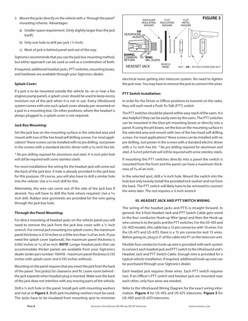
Drill a ½ inch hole in the panel. Install jack with mounting washers and nut as in Figure 3. Both jack insulating washers must be used. The Jacks have to be insulated from mounting spot to minimize
electrical noise getting into intercom system. No need to tighten the jack now. You may have to remove the jack to connect the wires.
PTT Switch Installation:
In order for the Driver or Officer positions to transmit on the radio, they will each need a Push-To-Talk (PTT) switch.
The PTT switches should be placed within easy reach of the users. It is also helpful if they can be easily seen by the users. The PTT switches can be mounted in the blue ptt mounting boxes or directly into a panel. If using the ptt boxes, set the box on the mounting surface in the selected area and mount with two of the hex head self drilling screws. For most applications* these screws can be installed with no pre drilling. Just power in the screws with a standard electric driver with a 5⁄16 inch hex bit. * No pre drilling required for aluminum and steel. A 1⁄8 inch pilot hole will still be required with some stainless steels.
If mounting the PTT switches directly into a panel the switch is mounted from the front and the panel can have a maximum thick-ness of 3⁄16 of an inch.
In the selected spot, drill a 5⁄8 inch hole. Mount the switch into the hole but only loosely install the provided lock washer and nut from the back. The PTT switch will likely have to be removed to connect the wires later. The nut requires a 7⁄8 inch wrench
III. HEADSET JACK AND PTT SWITCH WIRING
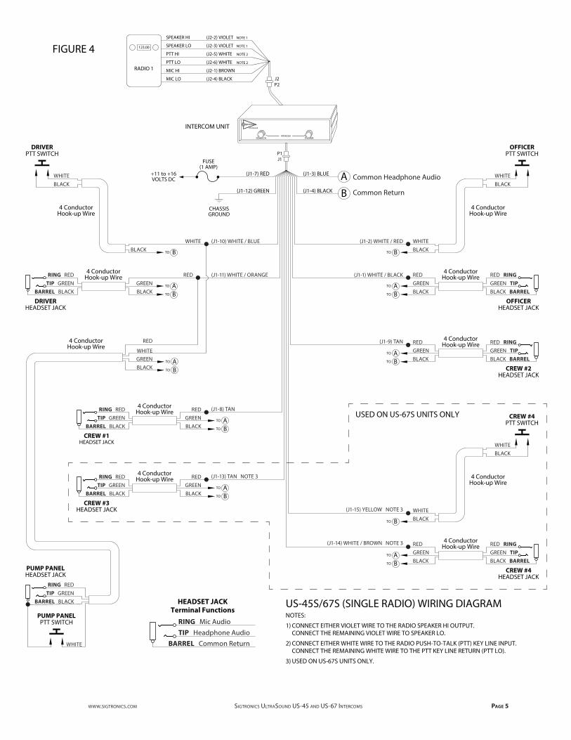
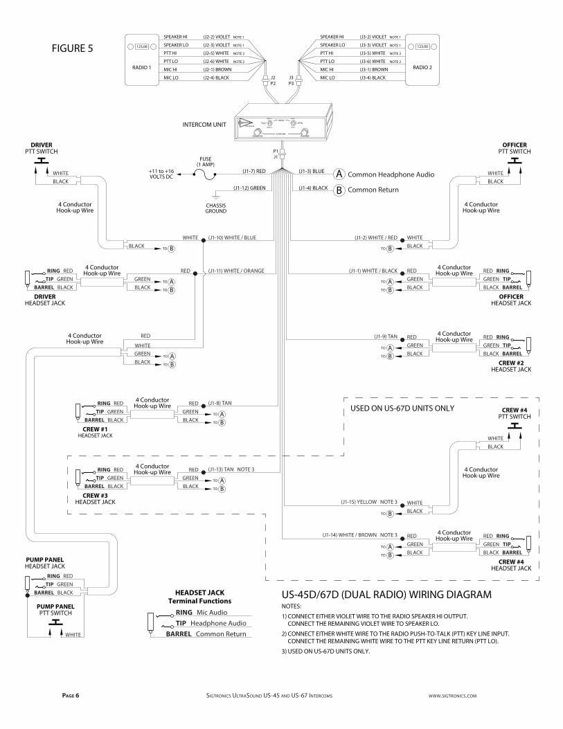
The wiring of the headset jacks and PTTs is straight forward. In general, the 4 foot Headset Jack and PTT Switch Cable gets wired to the four conductor Hook-up Wire (gray) and then the Hook-up wire connects to the jacks and the PTT switches. For the US-45S and US-45D models, this cable has a 12 pin connector with 10 wires. For the US-67S and US-67D, there is a 15 pin connector and 13 wires. Before going on, plug in J1 of the cable into P1 on the Intercom unit.
Flexible four conductor hook-up wire is provided with each system to connect each headset jack and PTT switch to the UltraSound unit’s Headset Jack and PTT Switch Cable. Enough wire is provided for a typical vehicle installation. If required, additional hook-up wire can be purchased through your Sigtronics dealer.
Each headset jack requires three wires. Each PTT switch requires two. If an Officer’s PTT switch and headset jack are mounted near each other, only four wires are needed.
Refer to the UltraSound Wiring Diagram for the exact wiring infor-mation. Figure 4 for US-45S and US-67S intercoms. Figure 5 for US-45D and US-67D intercoms.
RINGMIC AUDIO
BARRELCOMMONRETURN
SHOULDERINSULATING
WASHER
FLATINSULATING
WASHER
FLATMETAL
WASHER
VEHICLEPANELHEADSET JACK
TIPHEADPHONE
AUDIO
NUT – OR – SPLASH COVER AND NUT
FIGURE 3
www.SigtronicS.com SigtronicS UltraSoUnd US-45 and US-67 intercomS Page 5
VOLUMESQUELCH
R
UltraSound
INTERCOM
FIGURE 4 123.00
RADIO 1
J1P1
J2P2
SPEAKER HI (J2-2) VIOLET NOTE 1
SPEAKER LO (J2-3) VIOLET NOTE 1
PTT HI (J2-5) WHITE NOTE 2
MIC LO (J2-4) BLACK
MIC HI (J2-1) BROWN
PTT LO (J2-6) WHITE NOTE 2
INTERCOM UNIT
US-45S/67S (SINGLE RADIO) WIRING DIAGRAMNOTES:
1) CONNECT EITHER VIOLET WIRE TO THE RADIO SPEAKER HI OUTPUT. CONNECT THE REMAINING VIOLET WIRE TO SPEAKER LO.
2) CONNECT EITHER WHITE WIRE TO THE RADIO PUSH-TO-TALK (PTT) KEY LINE INPUT. CONNECT THE REMAINING WHITE WIRE TO THE PTT KEY LINE RETURN (PTT LO).
3) USED ON US-67S UNITS ONLY.
(J1-7) RED
(J1-12) GREEN
+11 to +16VOLTS DC
FUSE(1 AMP)
CHASSISGROUND
(J1-4) BLACK
(J1-3) BLUE
(J1-10) WHITE / BLUE
(J1-11) WHITE / ORANGE
A
B
(J1-2) WHITE / RED
(J1-1) WHITE / BLACK
RED
WHITEGREENBLACK
ATO
BTO
(J1-9) TAN
(J1-15) YELLOW NOTE 3
(J1-14) WHITE / BROWN NOTE 3
(J1-8) TAN
(J1-13) TAN NOTE 3
BTOBLACKWHITE
DRIVERPTT SWITCH
BLACKWHITE
4 ConductorHook-up Wire
DRIVERHEADSET JACK
TIP GREENBARREL BLACK
GREENBLACK
RING RED RED
ATO
BTO
4 ConductorHook-up Wire
4 ConductorHook-up Wire
HEADSET JACKTerminal Functions
TIP Headphone AudioBARREL Common Return
RING Mic Audio
CREW #1HEADSET JACK
TIP GREENBARREL BLACK
GREENBLACK
RING RED RED
ATO
BTO
4 ConductorHook-up Wire
CREW #3HEADSET JACK
TIP GREENBARREL BLACK
GREENBLACK
RING RED RED
ATO
BTO
4 ConductorHook-up Wire
BTO BLACKWHITE
OFFICERPTT SWITCH
BLACKWHITE
4 ConductorHook-up Wire
OFFICERHEADSET JACK
GREEN TIPBLACK BARREL
GREENBLACK
RED RINGRED
ATO
BTO
4 ConductorHook-up Wire
CREW #2HEADSET JACK
GREEN TIPBLACK BARREL
GREENBLACK
RED RINGRED
ATO
BTO
4 ConductorHook-up Wire
BTO BLACKWHITE
CREW #4PTT SWITCH
BLACKWHITE
4 ConductorHook-up Wire
CREW #4HEADSET JACK
GREEN TIPBLACK BARREL
GREENBLACK
RED RINGRED
ATO
BTO
4 ConductorHook-up Wire
USED ON US-67S UNITS ONLY
Common Headphone Audio
Common Return
PUMP PANELHEADSET JACK
TIP GREENBARREL BLACK
RING RED
PUMP PANELPTT SWITCH
WHITE
Page 6 SigtronicS UltraSoUnd US-45 and US-67 intercomS www.SigtronicS.com
123.00
RADIO 2
VOLUMESQUELCH
R TALK LISTEN
RADIO 1
RADIO 2
AUTO
BOTHUltraSound
RADIO
INTERCOM
FIGURE 5 123.00
RADIO 1
P3J3J2
P2
SPEAKER HI (J2-2) VIOLET NOTE 1
SPEAKER LO (J2-3) VIOLET NOTE 1
PTT HI (J2-5) WHITE NOTE 2
MIC LO (J2-4) BLACK
MIC HI (J2-1) BROWN
PTT LO (J2-6) WHITE NOTE 2
SPEAKER HI (J3-2) VIOLET NOTE 1
SPEAKER LO (J3-3) VIOLET NOTE 1
PTT HI (J3-5) WHITE NOTE 2
MIC LO (J3-4) BLACK
MIC HI (J3-1) BROWN
PTT LO (J3-6) WHITE NOTE 2
INTERCOM UNIT
J1P1
(J1-7) RED
(J1-12) GREEN
+11 to +16VOLTS DC
FUSE(1 AMP)
CHASSISGROUND
(J1-4) BLACK
(J1-3) BLUE
(J1-10) WHITE / BLUE
(J1-11) WHITE / ORANGE
A
B
(J1-2) WHITE / RED
(J1-1) WHITE / BLACK
RED
WHITEGREENBLACK
ATO
BTO
(J1-9) TAN
(J1-15) YELLOW NOTE 3
(J1-14) WHITE / BROWN NOTE 3
(J1-8) TAN
(J1-13) TAN NOTE 3
BTOBLACKWHITE
DRIVERPTT SWITCH
BLACKWHITE
4 ConductorHook-up Wire
DRIVERHEADSET JACK
TIP GREENBARREL BLACK
GREENBLACK
RING RED RED
ATO
BTO
4 ConductorHook-up Wire
4 ConductorHook-up Wire
CREW #1HEADSET JACK
TIP GREENBARREL BLACK
GREENBLACK
RING RED RED
ATO
BTO
4 ConductorHook-up Wire
CREW #3HEADSET JACK
TIP GREENBARREL BLACK
GREENBLACK
RING RED RED
ATO
BTO
4 ConductorHook-up Wire
BTO BLACKWHITE
OFFICERPTT SWITCH
BLACKWHITE
4 ConductorHook-up Wire
OFFICERHEADSET JACK
GREEN TIPBLACK BARREL
GREENBLACK
RED RINGRED
ATO
BTO
4 ConductorHook-up Wire
CREW #2HEADSET JACK
GREEN TIPBLACK BARREL
GREENBLACK
RED RINGRED
ATO
BTO
4 ConductorHook-up Wire
BTO BLACKWHITE
CREW #4PTT SWITCH
BLACKWHITE
4 ConductorHook-up Wire
CREW #4HEADSET JACK
GREEN TIPBLACK BARREL
GREENBLACK
RED RINGRED
ATO
BTO
4 ConductorHook-up Wire
US-45D/67D (DUAL RADIO) WIRING DIAGRAMNOTES:
1) CONNECT EITHER VIOLET WIRE TO THE RADIO SPEAKER HI OUTPUT. CONNECT THE REMAINING VIOLET WIRE TO SPEAKER LO.
2) CONNECT EITHER WHITE WIRE TO THE RADIO PUSH-TO-TALK (PTT) KEY LINE INPUT. CONNECT THE REMAINING WHITE WIRE TO THE PTT KEY LINE RETURN (PTT LO).
3) USED ON US-67D UNITS ONLY.
USED ON US-67D UNITS ONLY
HEADSET JACKTerminal Functions
TIP Headphone AudioBARREL Common Return
RING Mic Audio
Common Headphone Audio
Common Return
PUMP PANELHEADSET JACK
TIP GREENBARREL BLACK
RING RED
PUMP PANELPTT SWITCH
WHITE
www.SigtronicS.com SigtronicS UltraSoUnd US-45 and US-67 intercomS Page 7
The connections between the Headset Jack and PTT Switch Cable and the hook-up wire should be soldered and insulated for reliability. Do not use crimp type splices. They can become intermittent over time. Use a good quality electrical tape, or better yet, use heat shrink tubing to cover the soldered connections. The connections to the headset jacks and PTT switches will also have to be soldered. See Figure 3 for jack terminal identification.
We also do not recommend using screw type terminal strips for intercom connections. There have been several instances where terminal strips introduced high levels of electrical noise like alter-nator whine into the intercom system. It is acceptable however to tie the intercom red and green power wires to existing vehicle terminal strips.
The best place to run the wiring between the unit and the jack and PTT switches is out of sight. It should be run behind vehicle panels and/or up in the headliner. This will reduce the chance of personnel or equipment catching on or damaging the wiring. Wire routing should take into account normal vehicle operations. Wires should not interfere with any of the vehicle’s controls, compartments, or doors. If the vehicle’s cab tilts up for engine servicing, run wiring along the existing vehicle wiring bundle. Make sure that wiring does not interfere or restrict the tilting operation. Also, make sure that the tilting operation will not cut or sever the wiring.
Make sure that the wiring does not rest on sharp edges. Over time the vehicle’s vibration may cause a sharp edge to cut into the wire. Use the provided wire grommets wherever the four conductor wire goes through the hole into a jack box. Use wire ties or tie wraps to secure and strain relieve the wire.
At this time do not put the covers on the jack boxes or tighten up the PTT switches. You will need to verify the correct operation of the system before you close everything up.
Power Connections:
The UltraSound unit will run on 11-16 VDC. CAUTION: UltraSound units are designed for negative ground vehicles only. They can be used on positive ground vehicles only if a Sigtronics Positive Ground Adapter is used. Contact your Sigtronics dealer on pricing and availability.
Make sure that the vehicle power is turned off before connecting the UltraSound power wire. The power for the UltraSound unit comes in on the red and green wires on the Headset Jack and PTT Switch Cable.
Connect the red wire to vehicle power. (Try not to use a power buss that also runs electrical motors such as fans or light bars with rotat-ing lights.) Connect the green wire to the vehicle chassis ground.
INTERCOM WIRING CHECK OUT
System Setup:
Before you connect the vehicle’s radios, check out the system oper-ation. Do the following without the vehicle’s engine running:
First plug all headsets into the respective headset jacks. Put on one of the headsets and position the boom mic close to the mouth, as is the practice with hand-held microphones. Voice clarity is best when
the mic is about 1/4 inch away and slightly off center from the lips. Turn the volume control on the headset, all the way up (clockwise).
On the UltraSound unit, set both the intercom VOLUME control and SQUELCH control to full clockwise position.
Now turn vehicle power on. Verify that you can now hear yourself in your headset. Verify also that you can hear all the other headsets and that they can hear you. If everything is OK, skip to the “PTT Test” section. Otherwise, if something is not working right, see the following troubleshooting guide to find and fix the problem before going on with the installation:
NO INTERCOM IN ANY OF THE HEADSETS:
1. Make sure the UltraSound VOLUME and SQUELCH controls are set to full clockwise position.
2. Make sure the vehicle power is on.
3. Check the in-line fuse in the UltraSound Headset Jack and PTT switch Cable.
4. Check the power connection – red wire.
5. Check the ground connection – green wire.
6. Check for a short or open on the headphone wire (Blue wire on the Headset Jack and PTT Switch Cable). The problem could be anywhere along the blue wire connection between the headset jacks and the UltraSound unit.
INTERCOM IN SOME HEADSETS BUT NOT IN OTHERS:
1. Make sure that UltraSound controls are set as above.
2. Make sure that none of the PTT buttons are pressed.
3. Make sure that none of the PTT wires (white/red, white/blue, or yellow if applicable) are shorted to ground.
4. Check specific “bad” headset jack wiring for:
a) Microphone wire (jack ring terminal) open or shorted to ground.
b) Headphone wire (jack tip wire) open or shorted to ground.
c) Incorrect wiring - wires switched either at the jack or at the point where the hookup wire connects to the Headset Jack and PTT Switch Cable.
LOUD SQUEAL IN THE HEADSETS ALL THE TIME:
1. First make sure all headset plugs are plugged in all the way and that no part of any headset jack is physically touching any metal.
2. Check headset jack wiring at all jacks. For example, incorrect wiring such as reversing the jack tip and ring wires will cause a squeal.
3. Check for open headset jack barrel connection (black wire). The open could be anywhere along the black wire connection between the jack and the UltraSound unit.
Page 8 SigtronicS UltraSoUnd US-45 and US-67 intercomS www.SigtronicS.com
4. Check for a microphone line (white/black, white/orange, tan or white/brown wires) shorted to the headphone line (blue wire). The short could be at one of the headset jacks or in the wiring between the unit and a jack.
Note that for 2 and 3 above, it will only squeal if a headset is actually plugged into the specific jack that is wired incorrectly.
PTT Test:
If all above is good, make sure all headsets are plugged into their respective jacks. Put on the Driver’s headset and position the micro-phone as usual. Press the Driver’s PTT switch. While continuing to hold down the switch, talk into the mic and verify that you can still hear yourself. Also, while holding down the PTT switch, verify that none of the other headset microphones are active. Release the PTT switch.
Now put on the Officer’s headset, position the microphone, and press the Officer’s PTT switch. Verify that only the Officer’s headset microphone is active as his switch is held down.
If the system has a jack and PTT wired up at the vehicles pump panel, unplug the headset from the Drivers position and plug it into the pump panels jack. Press and hold down the pump panel PTT switch. Verify that only the pump panel headset microphone is active.
If all works fine, skip down to “Electrical Noise Test” section. If anything does not work as above, you have one of three possible PTT switch wiring errors:
1. PTT line (white/red, white/blue or yellow wires) open or not connected between a PTT switch and the UltraSound unit.
2. Open or missing return line (black wire) to a PTT switch.
3. Reversed PTT lines. The Drivers PTT line connected to the Officer’s PTT switch and vise versa.
Electrical Noise Test:
The last thing to do before the radios are hooked up to the unit is a simple noise test to verify system wiring as well as vehicle electrical system integrity.
1. Unplug all intercom headsets except for the Drivers.
2. Make sure all the UltraSound panel controls and switches are set as in “System Setup” section.
3. Start the vehicles engine and let it idle a bit. This is a stationary test — the vehicle should not be moving and should be in “PARK” or “NEUTRAL” with brakes set.
4. Close all vehicle windows and doors to eliminate as much back-ground noise as possible.
5. Turn on as much vehicle electrical equipment as possible. This usually means all lights and strobes. Do not turn on sirens or horns.
6. Put on the Driver’s headset, position the mic, and make sure the headset volume control is set to maximum.
7. With the vehicle still in “PARK” or “NEUTRAL” and brakes set, slowly increase the vehicle engine rpm from idle to about 1500 RPM and
back again. While doing this, listen for any whine or hum in the headsets. Except for some possible engine background noise being picked up from the headset microphone you should not hear any “Electrical” whine or hum in the headset.
8. Shut off the vehicle engine as well as the lights, strobes, etc. If, while the engine was running, there was no electrical noise, skip down to “Radio Hook Up” section. If you did hear electrical noise, use the following to track down the problem:
Turn the vehicle power off and disconnect the UltraSound ground connection (green wire) from ground. Turn on the vehicle power (engine off), put on the Driver’s headset and see if the intercom part of the UltraSound unit is working.
IF YOU CAN HEAR YOURSELF IN THE HEADSET:
1. Then the UltraSound intercom return wire (black) is incorrectly grounded to the vehicle chassis. Look for:
a) A headset jack barrel touching the vehicle chassis. Most common when a headset jack is mounted directly into the vehicle’s panel without using the supplied insulating washers or incorrectly installing the washers.
b) The black wire pinched or cut and shorting to the vehicle chassis. This can be anywhere along the intercom wiring as the black wire goes to all headset jacks and PTT switches.
2. Once the problem has been found and fixed, again make sure that the intercom now does not work with the green wire dis-connected. You could have the black wire grounded in more than one spot.
3. The next step is to reconnect the green wire and do the electrical noise test again to assure that you have fixed all possible noise problems.
IF YOU CANNOT HEAR YOURSELF IN THE HEADSET:
The intercom wiring is correct, but excessive electrical noise from the vehicle’s power system is affecting the UltraSound unit oper-ation. This noise is getting into the unit on the UltraSound power wires (red and green). There are basically two types of power line electrical noise sources:
1. Noise generated directly by the vehicle’s electrical / charging system — most commonly known as alternator whine. This is only present when the vehicle’s engine is running and recognized by the fact that the pitch or frequency of the whine changes directly with the change in engine rpm. (Higher frequency at higher engine rpm’s and lower frequency at lower rpm’s.)
The preferred way to solve this type of problem is to have the vehicle’s electrical / charging system serviced. The most common cause of this type of noise is bad diodes in the vehicle’s alternator. Other possible causes are: Bad vehicle voltage regulator; Bad alternator or battery cable connections; Missing or bad engine or alternator grounding straps.
If servicing the vehicle’s charging system is impractical, installing a good alternator whine power line filter between the vehicle power and the UltraSound red wire will usually accomplish the same thing. Do not use the type of filter that installs on or near
www.SigtronicS.com SigtronicS UltraSoUnd US-45 and US-67 intercomS Page 9
the alternator. NOTE: This solution should not be considered a permanent fix. Vehicle charging system problems of this type will eventually cause other equipment failure as well as shorten the life of the vehicle’s batteries.
2. The other type of noise is that generated by equipment that uses the vehicle’s power. This type of noise is usually constant and does not vary with engine rpm. It does, however, go away completely if the offending equipment is shut off or disconnected. Electrical motors in fans or light bars with rotating lights are two common examples.
Several things can be done to rectify this type of electrical noise:
a) Find a better (less noisy) vehicle power source for the Ultra-Sound unit. Move the UltraSound red wire to another power buss. Try not to use a power buss that also runs electrical motors such as fans or light bars with rotating lights.
b) Move the UltraSound ground connection (green wire) to another ground point on the vehicle.
c) Install an electrical noise filter on the power line going to the equipment causing the noise. Contact the company that makes the offending equipment for a recommendation on the type of filter to use.
If something does not work as described, go back over the wiring and correct before going on. If all is well, you can tighten all headset jacks and secure all jack box covers with the supplied hardware. Also, tighten and secure all PTT switches. On the UltraSound unit, turn down the intercom VOLUME control to approximately the 10 o’clock position.
IV. RADIO HOOK UP
The connection of the UltraSound unit to the vehicle’s radio(s) should be done by someone familiar with the radio(s) such as your radio installer. Refer to the UltraSound Wiring Diagram - Figure 4 for US-45S and US-67S units or Figure 5 for US-45D and US-67D units. Only the radio functions are shown for the radio end of the UltraSound Radio Interface Cable. Because the connector(s) used by radio manufacturers varies widely, you will have to consult the radio manual or manufacturer for the connector(s) and pin assignments used. Sigtronics has extensive radio interface experience and can assist with any question you might have concerning this or any other aspect of the UltraSound system. See our installation hot line number located on the last page of this manual.
First plug J2 of the Radio 1 Interface Cable into P2 of the Intercom. Then using the radio manuals and the UltraSound Wiring Diagram, identify the correct signal wires or connector pins to attach the respective UltraSound wires. For most radios, these connections are at the back of the radio or radio control head. For some radios, the only place to connect the MIC HI and LO and PTT HI and LO wires is to the hand-held microphone connector.* It is best to wire in such a way that the radio hand microphone can still be used as normal. Make sure that you do not physically tie the UltraSound MIC LO and SPEAKER LO wires to the same pin on the radio, even if they are tied together inside the radio. As in the headset wiring, the connections between the UltraSound and radios should be soldered and insulated for reliability. Do not use crimp type splices.
Use a good quality electrical tape or heat shrink tubing to cover the soldered connections.
* For the more popular radios of this type Sigtronics manufactures plug in “Y” adapters to make these connections easy. Contact your Sigtronics dealer for pricing and availability.
For dual radio units (US-45D or US-67D), hook up Radio 1 first and test before moving on to Radio 2.
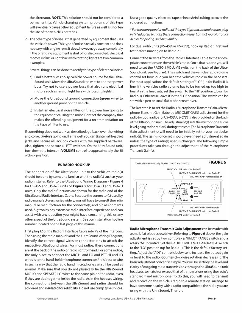
Connect the six wires from the Radio 1 Interface Cable to the appro-priate connections on the vehicle’s radio. Once that is done you will need to set the RADIO 1 VOLUME switch on the back of the Ultra-Sound unit. See Figure 6. This switch and the vehicles radio volume control set how loud you hear the vehicles radio in the headsets. For most applications the default setting of “LO” (up for Radio 1) is fine. If the vehicles radio volume has to be turned up too high to hear it in the headsets, set this switch to the “HI” position (down for Radio 1). Otherwise leave it in the “LO” position. The switch can be set with a pen or small flat blade screwdriver.
The last step is to set the Radio 1 Microphone Transmit Gain. Micro-phone Transmit Gain (labeled MIC XMIT GAIN) adjustment for the radio (or both radios for US-45D, US-67D) is also provided on the back of the UltraSound unit. The adjustment(s) sets the microphone audio level going to the radio(s) during transmit. The Microphone Transmit Gain adjustment(s) will need to be initially set to your particular radio(s). The gain(s) once set, should never need adjustment again unless the type of radio(s) used is changed. The following simple procedures take you through the adjustment of the Microphone Transmit Gain(s).
Radio Microphone Transmit Gain Adjustment can be made with a small, flat blade screwdriver. Referring to Figure 6 above, the gain adjustment is set by two controls - a “HI/LO” RANGE switch and a rotary “ADJ” control. Set the RADIO 1 MIC XMIT GAIN RANGE switch to the “LO” position (up for Radio 1). This is the default factory set-ting. Adjust the “ADJ” control clockwise to increase the output gain or level to the radio. Counter-clockwise rotation decreases it. The basic adjustment concept is simple. You will be setting the level and clarity of outgoing radio transmissions through the UltraSound unit headsets, to match or exceed that of transmissions using the radio’s standard hand microphone. To do this, you will need to transmit and receive on the vehicle’s radio to a remote station. Arrange to have someone nearby with a radio compatible to the radio you are using with the UltraSound. Then . . .
RADIO VOLUME switch for Radio 2*
MIC XMIT GAIN RANGE switch for Radio 2*MIC XMIT GAIN ADJ for Radio 2*
MIC XMIT GAIN ADJ for Radio 1
MIC XMIT GAIN RANGE switch for Radio 1
RADIO VOLUME switch for Radio 1
RADIOVOLUME LO
HI
RADIO 2
RADIO 1
HI
LO MICXMIT
RANGE
MIC XMITGAIN ADJ
*
*On Dual Radio units only. Models US-45D and US-67D. FIGURE 6
Page 10 SigtronicS UltraSoUnd US-45 and US-67 intercomS www.SigtronicS.com
1. Plug a headset into the Officer’s jack. Make sure that the volume control on the headset is turned up to full. It is not necessary to connect the other headsets (or Radio 2 on US-45D / US-67D units) for this adjustment. On dual radio units (US-45D / US-67D), set RADIO 1/ RADIO 2 switch to “RADIO 1” and the AUTO / BOTH switch to “AUTO”.
2. Put on the Officer’s headset and position the headset microphone as normal. Turn the UltraSound VOLUME control all the way down (counter-clockwise). You should not be able to hear yourself in the headset.
3. With the radio’s hand mic, transmit as normal, to the remote station. Transmit long enough so that the receiving station can get “calibrated” to your transmission (voice) level.
4. Verify radio reception. If OK, use Officer’s PTT to transmit to your receiving party. If receiving station reports weak transmission, use the screwdriver to turn the RADIO 1 MIC XMIT GAIN ADJ clockwise a small amount. If they report garbled, broken, or noisy transmissions, turn the RADIO 1 MIC XMIT GAIN ADJ counter-clockwise a small amount. Repeat as necessary until the receiving party reports that transmissions through the Ultra-Sound sound as good or better than when using the radio hand microphone.
5. If the receiving party reports that your transmissions are still weak with the MIC XMIT GAIN ADJ at the full clockwise position, then switch the RADIO 1 MIC XMIT GAIN RANGE switch to the “HI” position (down for Radio 1) and repeat steps 3 and 4 above. That’s all there is to it!
Once the gain is set, also check radio operation with the vehicles engine running. If radio reception and transmission through the UltraSound unit are fine, for US-45S / US-67S units this completes the installation. Skip to the “System Operation” section. If everything is OK for US-45D / US-67D units, skip to the “Radio 2 Hook Up” section. If something does not work correctly, check the following troubleshooting guide:
Radio Troubleshooting Guide:
NOTE: For dual radio units (US-45D / US-67D) it is far easier to trou-bleshoot with only one radio connected to the Sigtronics UltraSound unit at a time.
First determine if the trouble occurs with the vehicle engine running.
VEHICLE ENGINE OFF:
1. Can’t hear radio in headset:
a) Turn up radio volume at the radio as normal. Make sure how-ever, you are not picking up the radio through the headset microphones by briefly turning down (counter-clockwise) the intercom VOLUME control all the way.
b) Check violet wire (SPEAKER HI and LO) connections from the UltraSound to the radio.
c) Set the appropriate RADIO VOLUME switch on the back of the UltraSound unit to the “HI” position.
d) For US-45D or US-67D units, make sure that RADIO 1/RADIO 2 switch is set to the radio you want to hear.
2. Can’t talk to dispatch (transmit) on radio through the headset:
a) Check the connections between UltraSound unit and the radio. Both white wires (PTT HI and LO) and the Brown and Black wires (MIC HI and LO).
b) Check the UltraSound Radio Mic Transmit Gain adjustment.
c) For US-45D or US-67D units, make sure the RADIO 1/RADIO 2 switch is set to the radio you want to transmit on.
VEHICLE ENGINE ON:
1. Electrical noise (alternator whine) in headsets when receiving on radio, or ...
Dispatch reports that they hear electrical noise (alternator whine) when transmitting from vehicle through the headsets.
a) First make sure that the problem is only related to the radio hook up. Make sure that you did the “Electrical Noise Test” for the intercom (without the radios connected) and fixed any problems there before you go further. If OK then:
b) Check all six radio interface wires between the UltraSound unit and the radio — MIC HI, MIC LO, PTT HI, PTT LO, SPEAKER HI, and LO. Make sure that you have the correct pin numbers for the radio you are hooking to. Make sure that MIC LO and SPEAKER LO are not physically tied to the same pin on the radio; even if they are tied together inside the radio.
c) If the wiring is OK, then noise is coming from radio:
i) Possible bad radio wiring, (Check radio power and ground connections for loose or corroded connections) or. . .
ii) Excessive noise is generated directly by the vehicle’s electrical / charging system - most commonly known as alternator whine. This is only present when the vehicle’s engine is running and recognized by the fact that the pitch or fre-quency of the whine changes directly with the change in engine rpm.
The preferred way to solve this type of problem is to have the vehicle’s electrical / charging system serviced. The most common cause of this type of noise is bad diodes in the vehicles alternator. Other possible causes are: Bad vehicle voltage regulator; Bad alternator or battery cable connec-tions; Missing or bad engine or alternator grounding straps.
If servicing the vehicle’s charging system is impractical, installing a good alternator whine power line filter in-line with the radio power wire(s) will usually accomplish the same thing. All radio power wires will have to be filtered. Some radios have more than one wire that hooks to vehicle power. Contact the radio manufacturer for a recommendation on the best filter for the particular radio. NOTE: This solution should not be considered a permanent fix. Vehicle charging system problems of this type will eventually cause other equipment failure as well as shorten the life of the vehicle’s batteries.
2. Dispatch says too much background noise or unclear or weak transmissions.
www.SigtronicS.com SigtronicS UltraSoUnd US-45 and US-67 intercomS Page 11
a) Check to see if a radio hand mic on the vehicle is also active or “live” when transmitting through the UltraSound unit. Check this while not wearing a headset and by talking directly into the radio hand mic and pressing either UltraSound PTT switches. Do not press the PTT button on the hand mic itself. If dispatch can hear you loud and clear, then the background noise pick up is coming from this active hand mic. If you have this type of hand mic, then it is best to contact the radio manufacturer for instructions on a possible microphone modification to fix the problem. Some radio manufacturers can supply a compatible microphone that does not have this problem.
b) Adjust the UltraSound Radio Mic Transmit Gain controls. If the mic level is set too low, you will get reports of weak transmissions. If the mic level is too high, you will get reports of noisy or garbled transmissions. See “Radio Mic Transmit Gain Adjustment”.
Radio 2 Hook Up:
Plug in J3 of the Radio 2 Interface Cable into P3 of the UltraSound unit. Using the radio manual and Figure 5, connect the six wires to the appropriate connections on the vehicle’s radio. Once that is done you will need to set the RADIO 2 VOLUME switch on the back of the UltraSound unit. See Figure 6. For most applications use the default setting of “LO” (down - which is the reverse of the Radio 1 switch). If the vehicles radio volume has to be turned up too high to hear it in the headsets, set this switch to the “HI” position.
Next, set the Radio 2 Microphone Transmit Gain. The Radio 2 Microphone Transmit Gain Adjustments are the top set of the two located on the back of the UltraSound unit. The adjustment procedure is very similar to that of the Radio 1 Mic Transmit Gain adjustment. First set the RADIO 2 MIC XMIT GAIN RANGE switch to the “LO” position (default setting). NOTE: the HI and LO switch positions for Radio 2 are upside-down from that of Radio 1. Arrange to have someone nearby with a radio compatible with your Radio 2. Then, proceed as follows:
1. Again, plug in a headset into Officer’s jack. Make sure that the volume control on the headset is turned up to full. (Radio 1 and the other headsets are not needed for this adjustment.) Set the RADIO 1/RADIO 2 switch to “RADIO 2” and the AUTO/BOTH switch to “AUTO”.
2. Put on the Officer’s headset and position the headset microphone as normal. Turn the UltraSound VOLUME control all the way down (counter-clockwise). You should not be able to hear yourself in the headset.
3. With the radio’s hand mic, transmit as normal, to the remote station. Transmit long enough so that the receiving station can get “calibrated” to your transmission (voice) level.
4. Verify Radio 2 reception. If OK, use Officer’s PTT to transmit to your receiving party. If receiving station reports weak transmission, use the screwdriver to turn the RADIO 2 MIC XMIT GAIN ADJ clockwise a small amount. If they report garbled, broken, or noisy transmis-sions, turn the RADIO 2 MIC XMIT GAIN ADJ counter-clockwise a small amount. Repeat as necessary until the receiving party reports that transmissions through the UltraSound sound as good or better then when using the radio hand micro-phone.
5. If the receiving party reports that your transmissions are still weak with the MIC XMIT GAIN ADJ at the full clockwise position, then switch the RADIO 2 MIC XMIT GAIN RANGE switch to the “HI” position and repeat steps 3 and 4 above.
If Radio 2 does not operate as it should, use the “Radio Trouble-shooting Guide” to find and fix the problem. This completes the UltraSound installation.
HEADSET HOOK INSTRUCTIONS
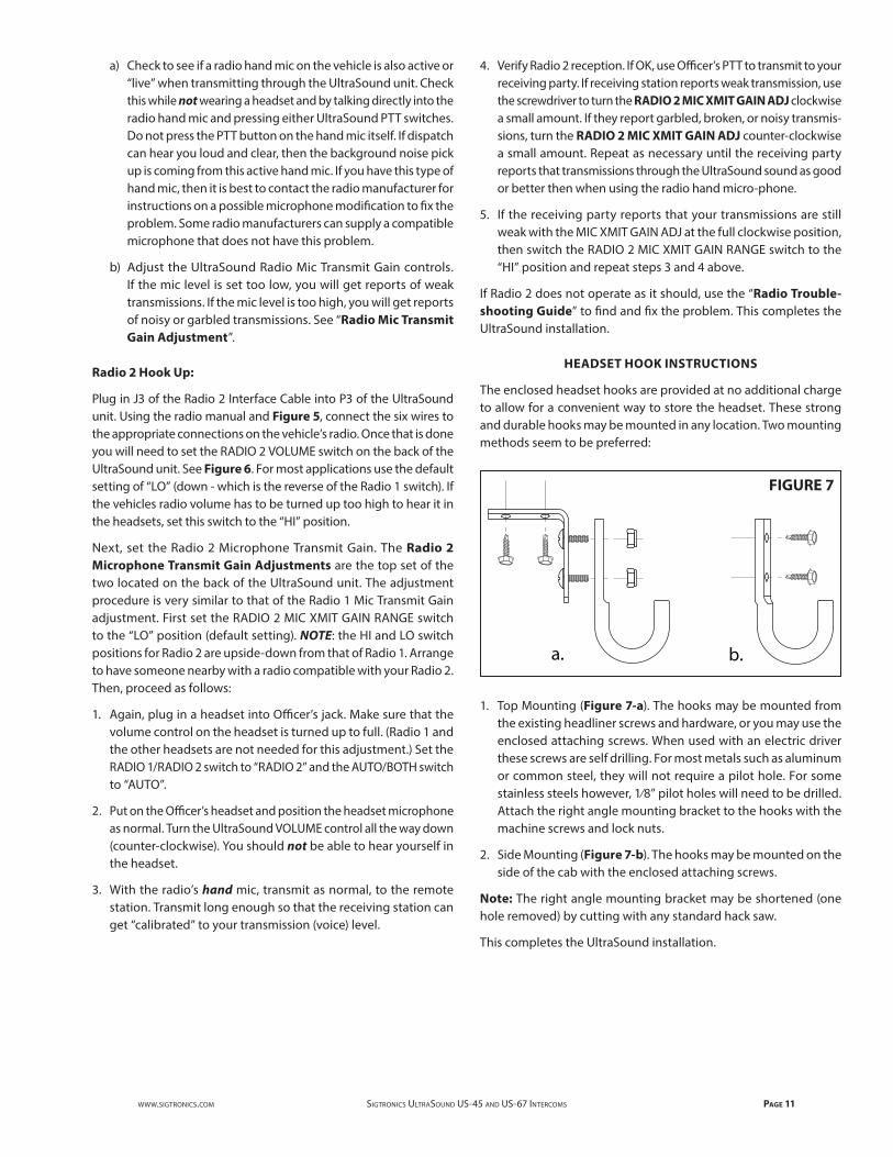
The enclosed headset hooks are provided at no additional charge to allow for a convenient way to store the headset. These strong and durable hooks may be mounted in any location. Two mounting methods seem to be preferred:
1. Top Mounting (Figure 7-a). The hooks may be mounted from the existing headliner screws and hardware, or you may use the enclosed attaching screws. When used with an electric driver these screws are self drilling. For most metals such as aluminum or common steel, they will not require a pilot hole. For some stainless steels however, 1⁄8” pilot holes will need to be drilled. Attach the right angle mounting bracket to the hooks with the machine screws and lock nuts.
2. Side Mounting (Figure 7-b). The hooks may be mounted on the side of the cab with the enclosed attaching screws.
Note: The right angle mounting bracket may be shortened (one hole removed) by cutting with any standard hack saw.
This completes the UltraSound installation.
b.a.
FIGURE 7
Page 12 SigtronicS UltraSoUnd US-45 and US-67 intercomS www.SigtronicS.com
SYSTEM OPERATION
The following describes how to use the UltraSound System as well as adjust the UltraSound controls. It also explains exactly how the UltraSound unit operates. This will allow you to easily set all unit functions to your specific needs. If you are not familiar with the UltraSound operation, perform the next few steps while the vehicle is not in motion.
Headsets
Put on the headset(s) and position the boom mike close to the mouth, as is the practice with a hand-held mike. For best voice clarity, the headset microphone must be positioned to one side of the mouth and ¼ inch from the lips. Turn the volume control on the headset ear cup to maximum. Turn down for individual hearing needs if necessary only after intercom and radio volumes have been set correctly. (see below)
Intercom operation and adjustment can be performed by the following procedure:
1. Turn the intercom SQUELCH control to the maximum clockwise position. For best system performance set the intercom VOLUME control as low as possible. On most systems this will be approxi-mately the 10 o’clock position. NOTE: the intercom volume control only adjusts the volume of conversation between the headsets inside the vehicle. It does not affect the level at which you hear the dispatch radio. See “Radio Operation” below. You should now hear yourself and others on the intercom.
2. To adjust the Intercom SQUELCH for voice activated operation (VOX), it is helpful to have some background noise (truck engine or…). Turn intercom SQUELCH control all the way counter-clock-wise. Now, without speaking, rotate the SQUELCH control clock-wise until you hear the background noise in your headset. Next, rotate it counter-clockwise in small amounts until the background noise disappears. Finally, make small adjustments until your voice triggers the unit at comfortable speaking levels. This procedure is necessary because the squelch is a “Fast-on, Slow-off” system.
When you speak, your voice will be heard in the headsets but the sound will cut off about a second after you stop speaking. Minor readjustment of the squelch may be necessary if the background noise level changes significantly (engine idling to cruise power with siren on).
Radio Operation
With the UltraSound System, your radio(s) are heard through the headsets as well. Adjust the volume level of the dispatch radio(s) in the headsets with the volume control on the radio as normal. NOTE that the radio volume does not effect the intercom volume and vise versa.
Transmitting (talking to dispatch) from the selected headset posi-tions is possible on a one-at-a-time basis. For a typical UltraSound installation the Driver, Officer, or Crew #4 positions can transmit at any time simply by pressing their PTT switch. The other positions cannot transmit on the radios. When one position transmits, several things take place automatically:
— All headset microphones, except for the transmitting position, are muted.
— The selected radio is put into transmit mode.
— The headset microphone audio (your voice) is sent to the selected radio.
— Sidetone is generated and sent to your headphones.*
* Sidetone is a portion of the transmitted voice signal sent back into your headset so that you can hear what you are saying while transmitting. The intercom VOLUME control adjusts the volume level of the sidetone that you hear in your headset. The other headsets will also hear the transmission sidetone. Of course, when the PTT switch is released, (stop transmitting) all functions return to normal, instantly and automatically.
For Dual Radio Units - US-45D and US-67D:
The operation of the dual radio UltraSound units are identical to that of the single radio units except for the addition of radio selection:
Radio Selection of both Radio 1 and Radio 2 radios are provided by two switches.
1. RADIO 1/RADIO 2 (TALK) determines the radio you wish to transmit on.
2. AUTO/BOTH (LISTEN) selects which radio(s) you receive or hear in your headset.
a) “AUTO” position allows you to hear the radio that the RADIO 1/RADIO 2 switch is set to.
b) “BOTH” position permits you to hear both the radios at the same time.
www.SigtronicS.com SigtronicS UltraSoUnd US-45 and US-67 intercomS Page 13
Sigtronics Installation Hot Line Number:1-800-367-0977 ext. 8Monday through Friday, 8:00 a.m. to 4:30 p.m. Pacific Timewww.sigtronics.com
1-17-2020 ultrinst.pdf Rev J
P/N 700062
igtronics ®S
0.250.50
6.7
0.2 DIA+ 0.01- 0
4.05
2.025
2.025
6.0
7.85
2.35
1.5
0.50
CABLES
TOP VIEW
FRONT VIEW
MOUNTING BRACKET BOTTOM VIEW
Sigtronics UltraSound Intercom Typical Installation Dimensions
7-18-2011 UltraSound_Installation_Dimensions.pdf
1.0
Drawing Not Full SizeAll dimensions in inches.
.85 1.667 1.667 1.667
FIGURE 8
UltraSound SpecificationsInput Voltage: 11 - 16 VDC
Nominal Current: 0.06 AmpsMaximum Current: 0.10 AmpsIntercom Unit Size: 13⁄4˝ Height x 6 1⁄8˝ Width x 4˝ Depth (Mounting bracket & knobs add 9⁄16˝ to Height & 13⁄4˝ to Width)
Weight: 15 oz. (not including cables and hardware)Warranty: Two Years