Embed Size (px)
Citation preview
·.·US Army Corps of Engineers · Kansas City District
Final Quality Assurance Project Plan
for Early Actions -Test Pj,t Investigation
Remedial Investigation/ Feasibility Study Raritan Bay Slag Superfund Site
. Old Bri4ge/ Sayreville, New Jersey
USACE Contract No. W914DQ-08-D-0018 Task Order No. 018
April 2010
Final Quality Assurance Project Plan
for Early Actions – Test Pit Investigation Raritan Bay Slag Superfund Site
Remedial Investigation/ Feasibility Study Old Bridge/ Sayreville, New Jersey
USACE CONTRACT No. W912DQ-08-D-0018
TASK ORDER No. 018
April 12, 2010
Prepared for: U.S. Army Corps of Engineers
Kansas City District
Prepared by: CDM
110 Fieldcrest Ave. 6th Floor
Edison, NJ 08837
CDIVI 110 Fieldcrest Avenue, 6'" Floor
Edison, New Jersey 08837
tel: 732 -225-7000
fax: 732- 225-7851
April 12, 2010
Kansas City District Corps of Engineers
CENWK-PM-ED Kristine Stein 700 Federal Building 601East12th Street Kansas City, Missouri 64106-2896
Project: Contract No. W912DQ-08-D-0018
Subject: Final Quality Assurance Project Plan for Early Actions -Test Pit Investigation Remedial Investigation/Feasibility Study Raritan Bay Slag Superfund Site Old Bridge/Sayreville, New Jersey
Dear Ms. Stein:
CDM is pleased to submit the enclosed Final Quality Assurance Project Plan for the Raritan Bay Slag Superfund Site in Old Bridge/ Sayreville, New Jersey.
Please feel free to contact me at (732) 590-4695 should you require additional information.
Very truly yours,
CDM FEDERAL PROGRAMS CORPORATION
~~~vd_ Edward Leonard, CHMM Task Order Manager
Enclosures
cc: L. Mauel, EPA (1 copy) J. Oxford, CDM (1 copy) J. Mayo, CDM (1 copy)
T. Mitchell, EPA (1 copy) J. Mosher, CDM (letter only) Project File (1 copy)
Raritan Bay Slag - Final QAPP Cover Letter.doc
Raritan Bay Slag Site Revision: 0
April 12, 2010 Page i of v
A Final Quality Assurance Project Plan
TABLE OF CONTENTS
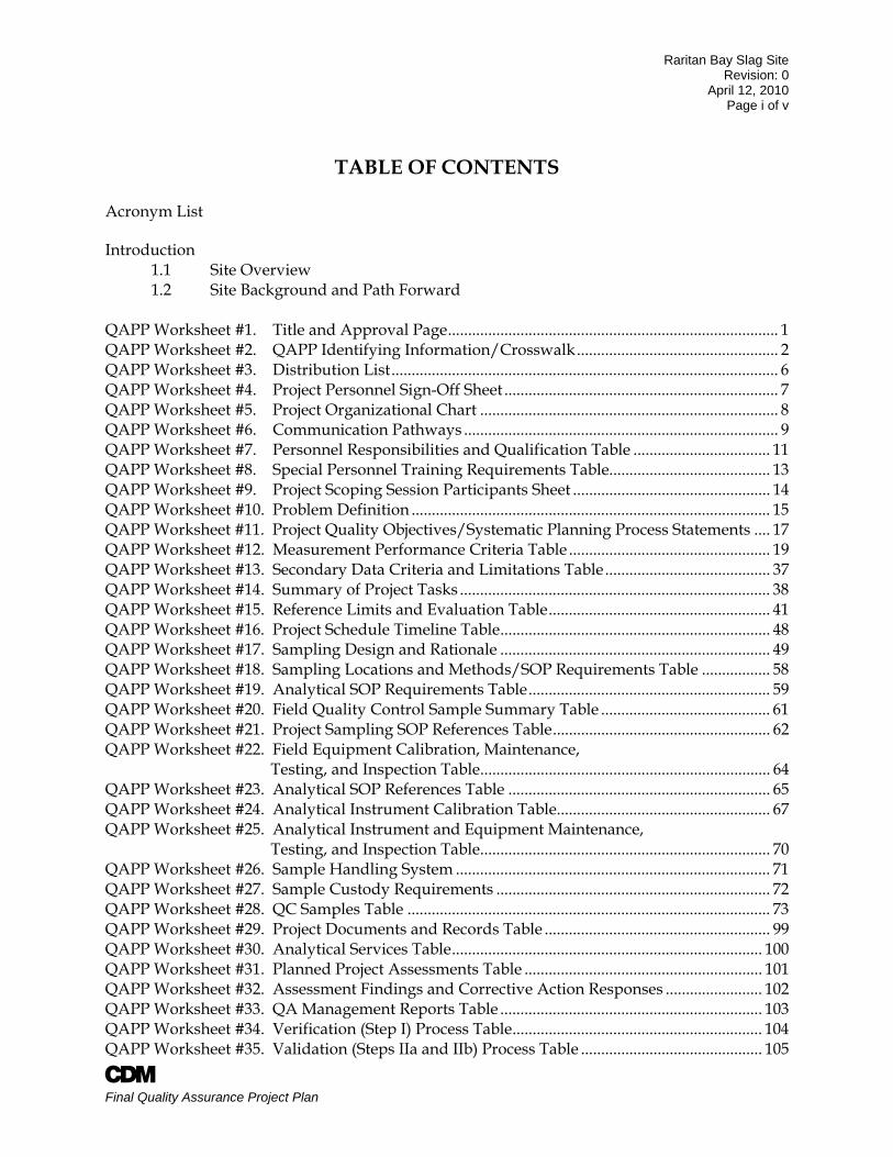
Acronym List Introduction 1.1 Site Overview 1.2 Site Background and Path Forward QAPP Worksheet #1. Title and Approval Page .................................................................................. 1 QAPP Worksheet #2. QAPP Identifying Information/Crosswalk .................................................. 2 QAPP Worksheet #3. Distribution List ................................................................................................ 6 QAPP Worksheet #4. Project Personnel Sign-Off Sheet .................................................................... 7 QAPP Worksheet #5. Project Organizational Chart .......................................................................... 8 QAPP Worksheet #6. Communication Pathways .............................................................................. 9 QAPP Worksheet #7. Personnel Responsibilities and Qualification Table .................................. 11 QAPP Worksheet #8. Special Personnel Training Requirements Table........................................ 13 QAPP Worksheet #9. Project Scoping Session Participants Sheet ................................................. 14 QAPP Worksheet #10. Problem Definition ......................................................................................... 15 QAPP Worksheet #11. Project Quality Objectives/Systematic Planning Process Statements .... 17 QAPP Worksheet #12. Measurement Performance Criteria Table .................................................. 19 QAPP Worksheet #13. Secondary Data Criteria and Limitations Table ......................................... 37 QAPP Worksheet #14. Summary of Project Tasks ............................................................................. 38 QAPP Worksheet #15. Reference Limits and Evaluation Table ....................................................... 41 QAPP Worksheet #16. Project Schedule Timeline Table ................................................................... 48 QAPP Worksheet #17. Sampling Design and Rationale ................................................................... 49 QAPP Worksheet #18. Sampling Locations and Methods/SOP Requirements Table ................. 58 QAPP Worksheet #19. Analytical SOP Requirements Table ............................................................ 59 QAPP Worksheet #20. Field Quality Control Sample Summary Table .......................................... 61 QAPP Worksheet #21. Project Sampling SOP References Table ...................................................... 62 QAPP Worksheet #22. Field Equipment Calibration, Maintenance, Testing, and Inspection Table ........................................................................ 64 QAPP Worksheet #23. Analytical SOP References Table ................................................................. 65 QAPP Worksheet #24. Analytical Instrument Calibration Table..................................................... 67 QAPP Worksheet #25. Analytical Instrument and Equipment Maintenance, Testing, and Inspection Table ........................................................................ 70 QAPP Worksheet #26. Sample Handling System .............................................................................. 71 QAPP Worksheet #27. Sample Custody Requirements .................................................................... 72 QAPP Worksheet #28. QC Samples Table .......................................................................................... 73 QAPP Worksheet #29. Project Documents and Records Table ........................................................ 99 QAPP Worksheet #30. Analytical Services Table ............................................................................. 100 QAPP Worksheet #31. Planned Project Assessments Table ........................................................... 101 QAPP Worksheet #32. Assessment Findings and Corrective Action Responses ........................ 102 QAPP Worksheet #33. QA Management Reports Table ................................................................. 103 QAPP Worksheet #34. Verification (Step I) Process Table .............................................................. 104 QAPP Worksheet #35. Validation (Steps IIa and IIb) Process Table ............................................. 105
Raritan Bay Slag Site Revision: 0
April 12, 2010 Page ii of v
A Final Quality Assurance Project Plan
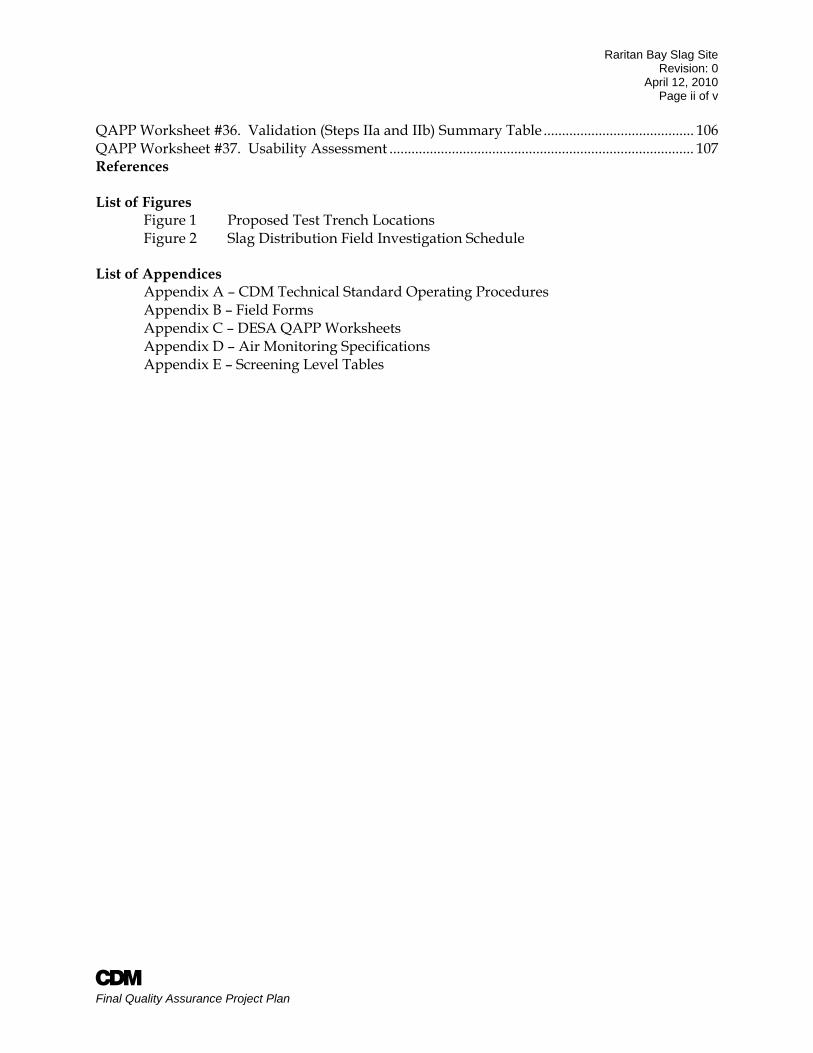
QAPP Worksheet #36. Validation (Steps IIa and IIb) Summary Table ......................................... 106 QAPP Worksheet #37. Usability Assessment ................................................................................... 107 References List of Figures
Figure 1 Proposed Test Trench Locations Figure 2 Slag Distribution Field Investigation Schedule
List of Appendices Appendix A – CDM Technical Standard Operating Procedures Appendix B – Field Forms Appendix C – DESA QAPP Worksheets Appendix D – Air Monitoring Specifications Appendix E – Screening Level Tables
Raritan Bay Slag Site Revision: 0
April 12, 2010 Page iii of v
A Final Quality Assurance Project Plan
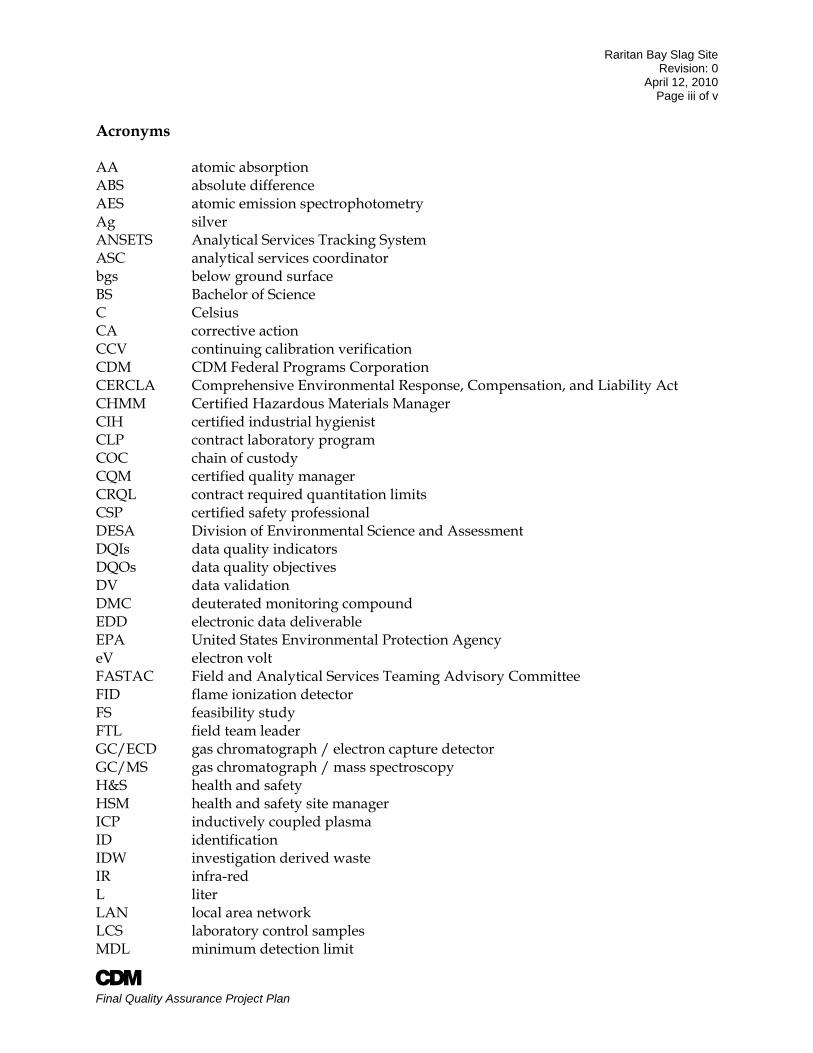
Acronyms AA atomic absorption ABS absolute difference AES atomic emission spectrophotometry Ag silver ANSETS Analytical Services Tracking System ASC analytical services coordinator bgs below ground surface BS Bachelor of Science C Celsius CA corrective action CCV continuing calibration verification CDM CDM Federal Programs Corporation CERCLA Comprehensive Environmental Response, Compensation, and Liability Act CHMM Certified Hazardous Materials Manager CIH certified industrial hygienist CLP contract laboratory program COC chain of custody CQM certified quality manager CRQL contract required quantitation limits CSP certified safety professional DESA Division of Environmental Science and Assessment DQIs data quality indicators DQOs data quality objectives DV data validation DMC deuterated monitoring compound EDD electronic data deliverable EPA United States Environmental Protection Agency eV electron volt FASTAC Field and Analytical Services Teaming Advisory Committee FID flame ionization detector FS feasibility study FTL field team leader GC/ECD gas chromatograph / electron capture detector GC/MS gas chromatograph / mass spectroscopy H&S health and safety HSM health and safety site manager ICP inductively coupled plasma ID identification IDW investigation derived waste IR infra-red L liter LAN local area network LCS laboratory control samples MDL minimum detection limit
Raritan Bay Slag Site Revision: 0
April 12, 2010 Page iv of v
A Final Quality Assurance Project Plan
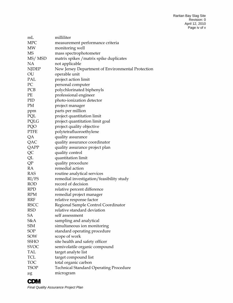
mL milliliter MPC measurement performance criteria MW monitoring well MS mass spectrophotometer MS/ MSD matrix spikes /matrix spike duplicates NA not applicable NJDEP New Jersey Department of Environmental Protection OU operable unit PAL project action limit PC personal computer PCB polychlorinated biphenyls PE professional engineer PID photo-ionization detector PM project manager ppm parts per million PQL project quantitation limit PQLG project quantitation limit goal PQO project quality objective PTFE polytetrafluoroethylene QA quality assurance QAC quality assurance coordinator QAPP quality assurance project plan QC quality control QL quantitation limit QP quality procedure RA remedial action RAS routine analytical services RI/FS remedial investigation/feasibility study ROD record of decision RPD relative percent difference RPM remedial project manager RRF relative response factor RSCC Regional Sample Control Coordinator RSD relative standard deviation SA self assessment S&A sampling and analytical SIM simultaneous ion monitoring SOP standard operating procedure SOW scope of work SSHO site health and safety officer SVOC semivolatile organic compound TAL target analyte list TCL target compound list TOC total organic carbon TSOP Technical Standard Operating Procedure µg microgram
Raritan Bay Slag Site Revision: 0
April 12, 2010 Page v of v
A Final Quality Assurance Project Plan
µg/kg microgram per kilogram µg/L microgram per liter VOC volatile organic compound VTSR verified time of sample receipt oC degrees Celsius % percent %D percent difference %R percent recovery
Raritan Bay Slag Site Revision: 0
April 12, 2010 Page 1 of 1
A Final Quality Assurance Project Plan
1.0 Introduction Under U.S. Army Corps of Engineers (USACE) Contract No. W912DQ-08-0018, Task Order No. 0018, CDM Federal Programs Corporation (CDM) is performing a Remedial Investigation/Feasibility Study (RI/FS) at the Raritan Bay Slag (RBS) Superfund Site (the “Site”). As part of the RI/FS for the RBS Site, the USACE has requested that CDM perform initial field activities to facilitate potential early actions at the site and to support subsequent RI/FS activities. For clarity, the initial field activities will be referred to as Stage I of the RI/FS. Stage I will be performed separately from Stage II, which will be performed at a later date and under a separate work plan. Stage I consists of the following major activities:
Investigate slag distribution in soils in the vicinity of the Seawall (Areas 1, 2 and 4)
This project-specific QAPP has been prepared in accordance with the UFP-QAPP manual (EPA 2005) and is compliant with EPA’s QAPP guidance document EPA QA/R-5 (EPA 2002). This project will be implemented in accordance with the quality procedures in CDM’s QA Manual (CDM 2007) as modified by the USACE contract Quality Implementation Plan (CDM 2009) and this QAPP. This QAPP and the Health and Safety Plan (HASP) for the Stage I field activities are the governing documents for execution of this work. 1.1 Site Overview The Raritan Bay Slag site consists of a sea wall and jetty of lead-contaminated slag deposition located along the southern shore of the Raritan Bay in Old Bridge Township and Sayreville, Middlesex County, New Jersey. Metallic slag waste from blast furnace and blast furnace rubble were disposed and used as fill material at the site. QAPP Worksheet #10 provides more information on the site description and history. 1.2 Site Background and Path Forward Previous geophysical investigations by EPA’s Environmental Response Team (ERT) indicated the potential for buried slag in areas adjacent to the seawall and the beach (Area 2) and recommended that additional investigation activities be performed to determine if buried slag is present in these areas. A slag distribution study will be performed along the seawall (Areas 1 and 4) and the beach area adjacent to the seawall (Area 2). Test excavations will be used to conduct visual observation of slag and targeted soil sampling to verify whether buried slag materials exist in Areas 1, 2, and 4 and to determine the distribution of the buried slag. The samples will be analyzed for full target compound list organics, and inorganics. Twenty percent of the samples (24 samples) will be analyzed for total organic carbon (TOC), pH, and grain size. Materials other than slag or fill may be encountered during the investigation. Slag and any other fill or waste materials encountered will be identified and noted in the test pit logs and field logbooks. Field notes will include estimates of the quantity and characteristics of materials found. If large objects are found they will be handled in accordance with the procedures described in QAPP worksheet 17b.
QAPP Worksheet #1 Title and Approval Page
Raritan Bay Slag Site Revision: O
April 12, 2010 Page 1 of 109
FINAL QUALITY ASSURANCE PROJECT PLAN (QAPP)
for Early Actions - Test Pit Investigation
Raritan Bay Slag Superfund Site Old Bridge/ Sayreville, New Jersey
Prepared by: COM Federal Programs Corporation (COM) 125 Maiden Lane, 51
" Floor New York, NY 10038 (212) 785-9123
Date: April 12, 2010
COM Task Order Manager: _<~! Signature.--'{__.._l~-~-4"~=-----'=~--"""""'---COM QA Manager:
EPA Project Manager:
Signature _____________ _
USACE Project Manager: Kristine Stein
Signature _____________ _
EPA QA Officer: William Sy
Signature _____________ _
CDM Final Quality Assurance Project Plan
Raritan Bay Slag Site Revision: 0
April 12, 2010 Page 2 of 109
A Final Quality Assurance Project Plan
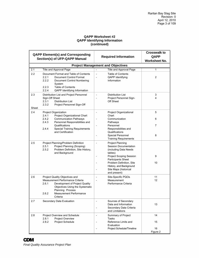
QAPP Worksheet #2 QAPP Identifying Information
Site Name/Project: Raritan Bay Slag Superfund Site Site Location: Old Bridge/ Sayreville, New Jersey Operable Unit: NA Site Number/Code: NJN000206276 Contractor Name: CDM Contractor Number: W912DQ-08-D-0018 Contract Title: Unrestricted Indefinite Delivery/Indefinite Quantity, Multiple Award
Contract, for Architect-Engineer (AE) Environmental Services for EPA Region 2 and the Corps of Engineers Northwestern Division
Task Order Number: 018 Guidance used to prepare QAPP: Uniform Federal Policy for QAPPs and EPA QA/R-5 Regulatory Program: CERCLA Approval Entity: EPA Region 2, USACE-Kansas City District Is QAPP Generic or Project Specific: Project-Specific QAPP for Test Pit Investigation Dates of scoping sessions: February and March 2010 (See worksheet #9)
Dates and Titles of QAPP Documents Written for Previous Site Work, if Applicable: NA Organizational Partners (stakeholders) and Connection with Lead Organization: USACE, EPA
Data Users: CDM, EPA Region 2, and USACE
Required QAPP elements and required information that are not applicable to the project, and an explanation for their exclusions: N/A
Raritan Bay Slag Site Revision: 0
April 12, 2010 Page 3 of 109
A Final Quality Assurance Project Plan
QAPP Worksheet #2 QAPP Identifying Information
(continued)
QAPP Element(s) and Corresponding Section(s) of UFP-QAPP Manual Required Information
Crosswalk to QAPP
Worksheet No. Project Management and Objectives
2.1 Title and Approval Page - Title and Approval Page 1 2.2 Document Format and Table of Contents 2.2.1 Document Control Format 2.2.2 Document Control Numbering System 2.2.3 Table of Contents 2.2.4 QAPP Identifying Information
- Table of Contents - QAPP Identifying Information
2
2.3 Distribution List and Project Personnel Sign-Off Sheet 2.3.1 Distribution List 2.3.2 Project Personnel Sign-Off Sheet
- Distribution List - Project Personnel Sign- Off Sheet
3 4
2.4 Project Organization 2.4.1 Project Organizational Chart
2.4.2 Communication Pathways 2.4.3 Personnel Responsibilities and
Qualifications 2.4.4 Special Training Requirements
and Certification
- Project Organizational Chart - Communication Pathways - Personnel Responsibilities and Qualifications - Special Personnel Training Requirements
5
6
7
8
2.5 Project Planning/Problem Definition 2.5.1 Project Planning (Scoping) 2.5.2 Problem Definition, Site History,
and Background
- Project Planning Session Documentation (including Data Needs tables) - Project Scoping Session Participants Sheet - Problem Definition, Site History, and Background - Site Maps (historical and present)
9
10
2.6 Project Quality Objectives and Measurement Performance Criteria
2.6.1 Development of Project Quality Objectives Using the Systematic Planning Process
2.6.2 Measurement Performance Criteria
- Site-Specific PQOs - Measurement Performance Criteria
11 12
2.7 Secondary Data Evaluation - Sources of Secondary Data and Information - Secondary Data Criteria and Limitations
13
2.8 Project Overview and Schedule 2.8.1 Project Overview 2.8.2 Project Schedule
- Summary of Project Tasks - Reference Limits and Evaluation - Project Schedule/Timeline
14
15
16 Figure 2
Raritan Bay Slag Site Revision: 0
April 12, 2010 Page 4 of 109
A Final Quality Assurance Project Plan
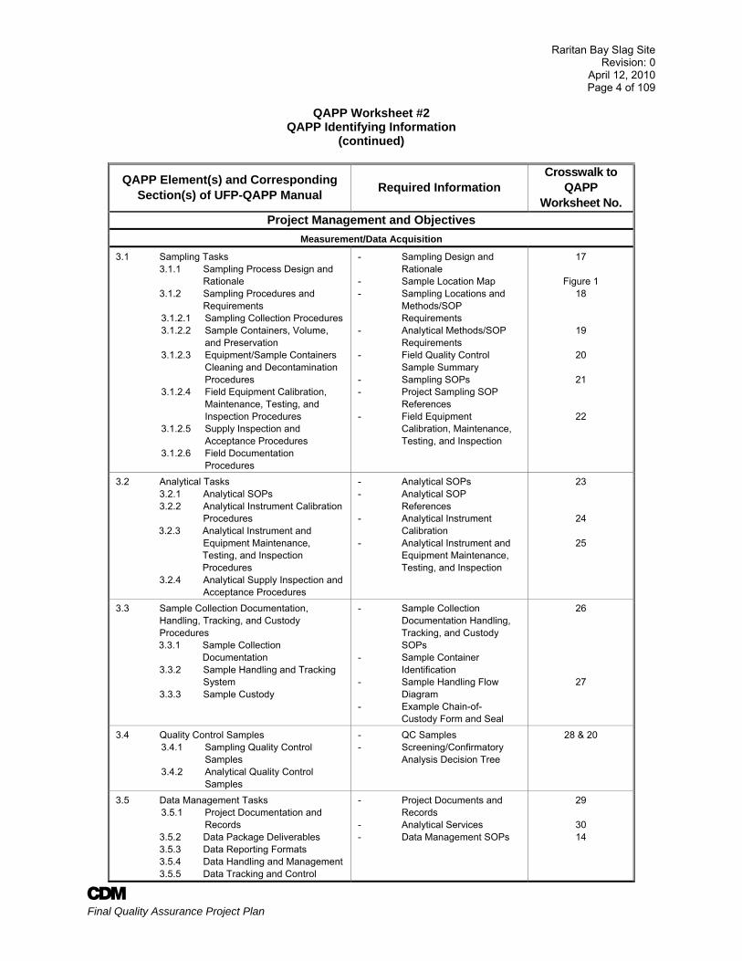
QAPP Worksheet #2 QAPP Identifying Information
(continued)
QAPP Element(s) and Corresponding Section(s) of UFP-QAPP Manual Required Information
Crosswalk to QAPP
Worksheet No. Project Management and Objectives
Measurement/Data Acquisition
3.1 Sampling Tasks 3.1.1 Sampling Process Design and Rationale 3.1.2 Sampling Procedures and Requirements
3.1.2.1 Sampling Collection Procedures 3.1.2.2 Sample Containers, Volume,
and Preservation 3.1.2.3 Equipment/Sample Containers
Cleaning and Decontamination Procedures
3.1.2.4 Field Equipment Calibration, Maintenance, Testing, and Inspection Procedures
3.1.2.5 Supply Inspection and Acceptance Procedures
3.1.2.6 Field Documentation Procedures
- Sampling Design and Rationale - Sample Location Map - Sampling Locations and Methods/SOP Requirements - Analytical Methods/SOP Requirements - Field Quality Control Sample Summary - Sampling SOPs - Project Sampling SOP References - Field Equipment Calibration, Maintenance, Testing, and Inspection
17
Figure 1 18
19
20
21
22
3.2 Analytical Tasks 3.2.1 Analytical SOPs 3.2.2 Analytical Instrument Calibration Procedures
3.2.3 Analytical Instrument and Equipment Maintenance, Testing, and Inspection Procedures
3.2.4 Analytical Supply Inspection and Acceptance Procedures
- Analytical SOPs - Analytical SOP References - Analytical Instrument Calibration - Analytical Instrument and Equipment Maintenance, Testing, and Inspection
23
24
25
3.3 Sample Collection Documentation, Handling, Tracking, and Custody Procedures
3.3.1 Sample Collection Documentation
3.3.2 Sample Handling and Tracking System 3.3.3 Sample Custody
- Sample Collection Documentation Handling, Tracking, and Custody SOPs - Sample Container Identification - Sample Handling Flow Diagram - Example Chain-of- Custody Form and Seal
26
27
3.4 Quality Control Samples 3.4.1 Sampling Quality Control
Samples 3.4.2 Analytical Quality Control
Samples
- QC Samples - Screening/Confirmatory Analysis Decision Tree
28 & 20
3.5 Data Management Tasks 3.5.1 Project Documentation and
Records 3.5.2 Data Package Deliverables 3.5.3 Data Reporting Formats 3.5.4 Data Handling and Management 3.5.5 Data Tracking and Control
- Project Documents and Records - Analytical Services - Data Management SOPs
29
30 14
Raritan Bay Slag Site Revision: 0
April 12, 2010 Page 5 of 109
A Final Quality Assurance Project Plan
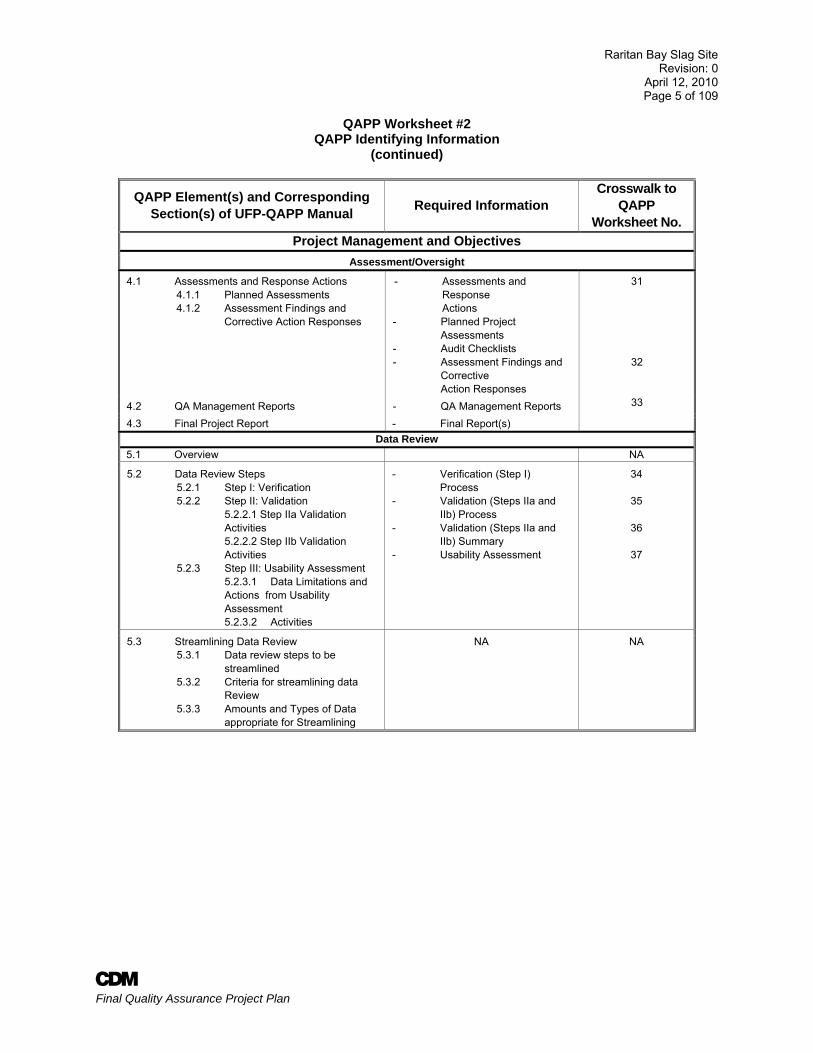
QAPP Worksheet #2 QAPP Identifying Information
(continued)
QAPP Element(s) and Corresponding Section(s) of UFP-QAPP Manual Required Information
Crosswalk to QAPP
Worksheet No. Project Management and Objectives
Assessment/Oversight
4.1 Assessments and Response Actions 4.1.1 Planned Assessments 4.1.2 Assessment Findings and
Corrective Action Responses
- Assessments and Response Actions
- Planned Project Assessments - Audit Checklists - Assessment Findings and Corrective Action Responses
31
32
33 4.2 QA Management Reports - QA Management Reports 4.3 Final Project Report - Final Report(s)
Data Review 5.1 Overview NA
5.2 Data Review Steps 5.2.1 Step I: Verification 5.2.2 Step II: Validation 5.2.2.1 Step IIa Validation
Activities 5.2.2.2 Step IIb Validation
Activities 5.2.3 Step III: Usability Assessment 5.2.3.1 Data Limitations and
Actions from Usability Assessment
5.2.3.2 Activities
- Verification (Step I) Process - Validation (Steps IIa and IIb) Process - Validation (Steps IIa and IIb) Summary - Usability Assessment
34
35
36
37
5.3 Streamlining Data Review 5.3.1 Data review steps to be
streamlined 5.3.2 Criteria for streamlining data
Review 5.3.3 Amounts and Types of Data
appropriate for Streamlining
NA NA
Raritan Bay Slag Site Revision: 0
April 12, 2010 Page 6 of 109
A Final Quality Assurance Project Plan
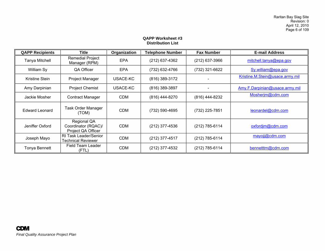
QAPP Worksheet #3 Distribution List
QAPP Recipients Title Organization Telephone Number Fax Number E-mail Address
Tanya Mitchell Remedial Project Manager (RPM) EPA (212) 637-4362 (212) 637-3966 [email protected]
William Sy QA Officer EPA (732) 632-4766 (732) 321-6622 [email protected]
Kristine Stein Project Manager USACE-KC (816) 389-3172 - [email protected]
Amy Darpinian Project Chemist USACE-KC (816) 389-3897 - [email protected]
Jackie Mosher Contract Manager CDM (816) 444-8270 (816) 444-8232 [email protected]
Edward Leonard Task Order Manager (TOM) CDM (732) 590-4695 (732) 225-7851 [email protected]
Jeniffer Oxford Regional QA
Coordinator (RQAC)/ Project QA Officer
CDM (212) 377-4536 (212) 785-6114 [email protected]
Joseph Mayo RI Task Leader/Senior Technical Reviewer CDM (212) 377-4517 (212) 785-6114 [email protected]
Tonya Bennett Field Team Leader (FTL) CDM (212) 377-4532 (212) 785-6114 [email protected]
Raritan Bay Slag Site Revision: 0
April 12, 2010 Page 7 of 109
A Final Quality Assurance Project Plan
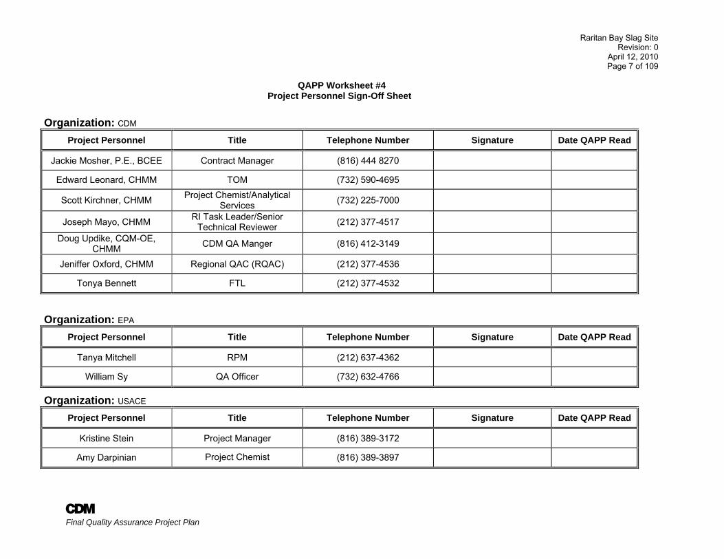
QAPP Worksheet #4 Project Personnel Sign-Off Sheet
Organization: CDM Project Personnel Title Telephone Number Signature Date QAPP Read
Jackie Mosher, P.E., BCEE Contract Manager (816) 444 8270
Edward Leonard, CHMM TOM (732) 590-4695
Scott Kirchner, CHMM Project Chemist/Analytical Services (732) 225-7000
Joseph Mayo, CHMM RI Task Leader/Senior Technical Reviewer (212) 377-4517
Doug Updike, CQM-OE, CHMM CDM QA Manger (816) 412-3149
Jeniffer Oxford, CHMM Regional QAC (RQAC) (212) 377-4536
Tonya Bennett FTL (212) 377-4532
Organization: EPA Project Personnel Title Telephone Number Signature Date QAPP Read
Tanya Mitchell RPM (212) 637-4362
William Sy QA Officer (732) 632-4766
Organization: USACE Project Personnel Title Telephone Number Signature Date QAPP Read
Kristine Stein Project Manager (816) 389-3172
Amy Darpinian Project Chemist (816) 389-3897
Raritan Bay Slag Site Revision: 0
April 12, 2010 Page 8 of 109
A Final Quality Assurance Project Plan
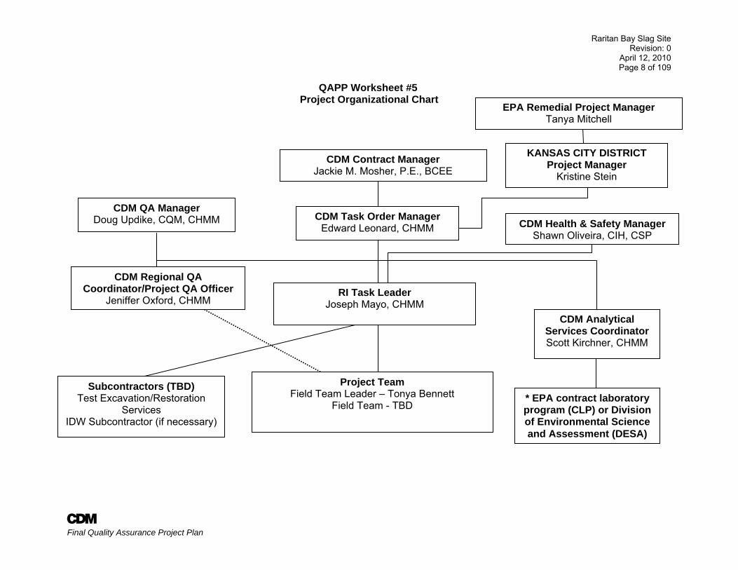
QAPP Worksheet #5 Project Organizational Chart
CDM Task Order Manager Edward Leonard, CHMM
Project Team Field Team Leader – Tonya Bennett
Field Team - TBD
Subcontractors (TBD) Test Excavation/Restoration
Services IDW Subcontractor (if necessary)
CDM Analytical Services Coordinator Scott Kirchner, CHMM
* EPA contract laboratory program (CLP) or Division of Environmental Science and Assessment (DESA)
RI Task Leader Joseph Mayo, CHMM
CDM Contract Manager Jackie M. Mosher, P.E., BCEE
CDM Regional QA Coordinator/Project QA Officer
Jeniffer Oxford, CHMM
CDM QA Manager Doug Updike, CQM, CHMM CDM Health & Safety Manager
Shawn Oliveira, CIH, CSP
KANSAS CITY DISTRICT Project Manager
Kristine Stein
EPA Remedial Project Manager Tanya Mitchell
Raritan Bay Slag Site Revision: 0
April 12, 2010 Page 9 of 109
A Final Quality Assurance Project Plan
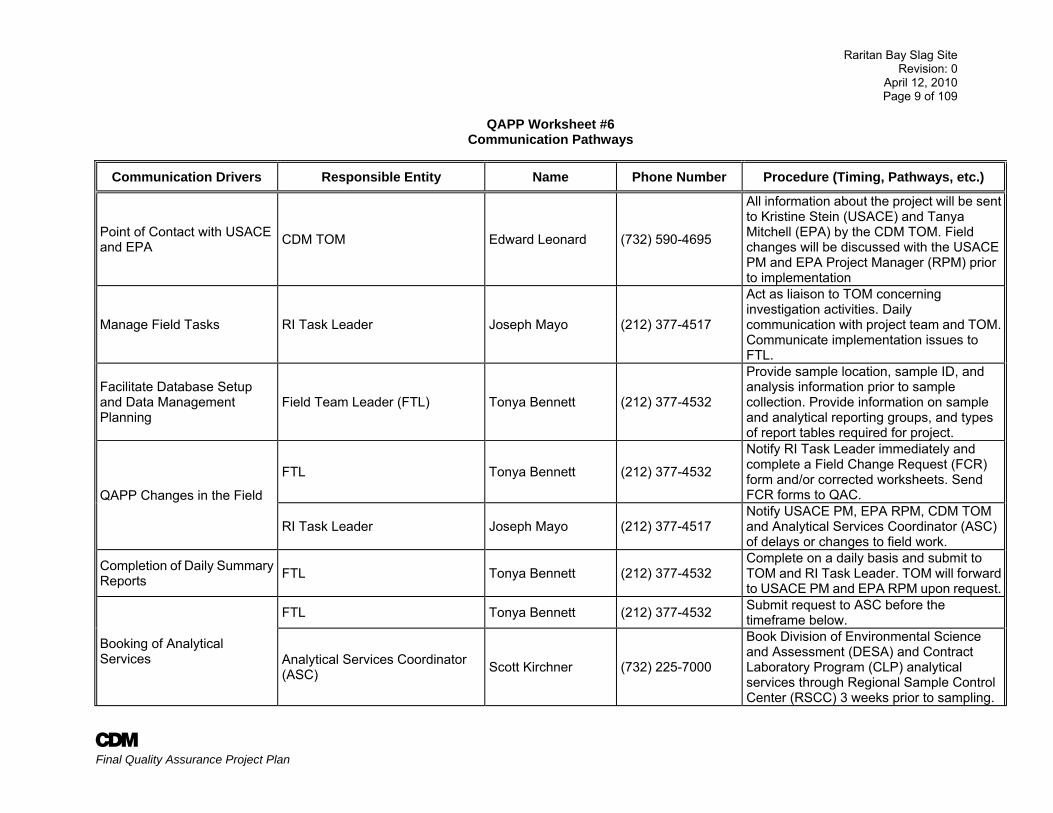
QAPP Worksheet #6 Communication Pathways
Communication Drivers Responsible Entity Name Phone Number Procedure (Timing, Pathways, etc.)
Point of Contact with USACE and EPA CDM TOM Edward Leonard (732) 590-4695
All information about the project will be sent to Kristine Stein (USACE) and Tanya Mitchell (EPA) by the CDM TOM. Field changes will be discussed with the USACE PM and EPA Project Manager (RPM) prior to implementation
Manage Field Tasks RI Task Leader Joseph Mayo (212) 377-4517
Act as liaison to TOM concerning investigation activities. Daily communication with project team and TOM. Communicate implementation issues to FTL.
Facilitate Database Setup and Data Management Planning
Field Team Leader (FTL) Tonya Bennett (212) 377-4532
Provide sample location, sample ID, and analysis information prior to sample collection. Provide information on sample and analytical reporting groups, and types of report tables required for project.
QAPP Changes in the Field
FTL Tonya Bennett (212) 377-4532
Notify RI Task Leader immediately and complete a Field Change Request (FCR) form and/or corrected worksheets. Send FCR forms to QAC.
RI Task Leader Joseph Mayo (212) 377-4517 Notify USACE PM, EPA RPM, CDM TOM and Analytical Services Coordinator (ASC) of delays or changes to field work.
Completion of Daily Summary Reports FTL Tonya Bennett (212) 377-4532
Complete on a daily basis and submit to TOM and RI Task Leader. TOM will forward to USACE PM and EPA RPM upon request.
Booking of Analytical Services
FTL Tonya Bennett (212) 377-4532 Submit request to ASC before the timeframe below.
Analytical Services Coordinator (ASC) Scott Kirchner (732) 225-7000
Book Division of Environmental Science and Assessment (DESA) and Contract Laboratory Program (CLP) analytical services through Regional Sample Control Center (RSCC) 3 weeks prior to sampling.
Raritan Bay Slag Site Revision: 0
April 12, 2010 Page 10 of 109
A Final Quality Assurance Project Plan
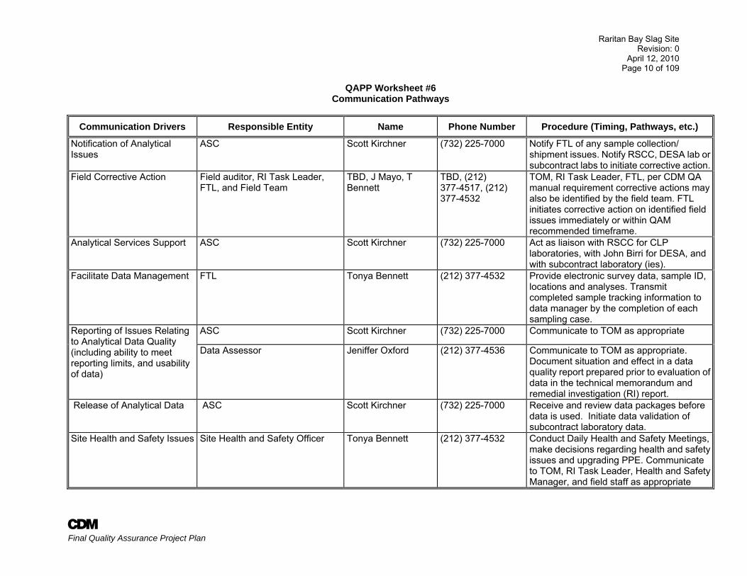
QAPP Worksheet #6 Communication Pathways
Communication Drivers Responsible Entity Name Phone Number Procedure (Timing, Pathways, etc.)
Notification of Analytical Issues
ASC Scott Kirchner (732) 225-7000 Notify FTL of any sample collection/ shipment issues. Notify RSCC, DESA lab or subcontract labs to initiate corrective action.
Field Corrective Action Field auditor, RI Task Leader, FTL, and Field Team
TBD, J Mayo, T Bennett
TBD, (212) 377-4517, (212) 377-4532
TOM, RI Task Leader, FTL, per CDM QA manual requirement corrective actions may also be identified by the field team. FTL initiates corrective action on identified field issues immediately or within QAM recommended timeframe.
Analytical Services Support ASC Scott Kirchner (732) 225-7000 Act as liaison with RSCC for CLP laboratories, with John Birri for DESA, and with subcontract laboratory (ies).
Facilitate Data Management FTL Tonya Bennett (212) 377-4532 Provide electronic survey data, sample ID, locations and analyses. Transmit completed sample tracking information to data manager by the completion of each sampling case.
Reporting of Issues Relating to Analytical Data Quality (including ability to meet reporting limits, and usability of data)
ASC Scott Kirchner (732) 225-7000 Communicate to TOM as appropriate
Data Assessor Jeniffer Oxford (212) 377-4536 Communicate to TOM as appropriate. Document situation and effect in a data quality report prepared prior to evaluation of data in the technical memorandum and remedial investigation (RI) report.
Release of Analytical Data ASC Scott Kirchner (732) 225-7000 Receive and review data packages before data is used. Initiate data validation of subcontract laboratory data.
Site Health and Safety Issues Site Health and Safety Officer Tonya Bennett (212) 377-4532 Conduct Daily Health and Safety Meetings, make decisions regarding health and safety issues and upgrading PPE. Communicate to TOM, RI Task Leader, Health and Safety Manager, and field staff as appropriate
Raritan Bay Slag Site Revision: 0
April 12, 2010 Page 11 of 109
A Final Quality Assurance Project Plan
QAPP Worksheet #7 Personnel Responsibilities and Qualification Table
Name Title Organizational Affiliation Responsibilities Education and Experience
Qualifications
Edward Leonard, CHMM TOM CDM Oversee project and responds
to EPA RPM. Manages subcontractors.
B.S., Biology; M.S., Environmental Science; 25 years of experience in environmental programs.
Joseph Mayo, CHMM RI Task Leader CDM
Oversees Remedial Investigation Tasks Provide
guidance on the drilling program and analyze the
geologic data, responsible for implementing the field activities
B.S., Biology; MS. Environmental Science; 26 years experience in environmental investigations
Jeniffer Oxford, CHMM QA Coordinator/ Project Chemist CDM Oversee adherence to QA
requirements
B.S., Natural Sciences; 7 years experience in analytical chemistry; 16 years experience in environmental science; American Society for Quality (ASQ) Certified QA auditor
Thomas Matthew, P.E. FS Task Manager CDM Oversees Feasibility Study Tasks
B.S. Civil Engineering; M.S. Sanitary/Water Resources Engineerig P.E.; 16 years experience in Environmental Engineering
Scott Kirchner, CHMM ASC, Database Manager CDM
Communicate with EPA RSCC, DESA laboratory and
subcontract laboratories; oversee data management,
validation and data packages.
B.S. Chemistry, Environmental Science Certified Hazardous Materials Manager, 20 years experience.
John Dougherty, PG Project Hydrogeologist CDM Oversee and provide guidance
on the drilling program and analyze the geologic data
B.S. Geosciences; P.G.; 24 years experience in hydrogeology
Tonya Bennett FTL CDM Oversee all field investigation activities
B.S. Geology; 6 years field experience
Raritan Bay Slag Site Revision: 0
April 12, 2010 Page 12 of 109
A Final Quality Assurance Project Plan
QAPP Worksheet #7 Personnel Responsibilities and Qualification Table
Name Title Organizational Affiliation Responsibilities Education and Experience
Qualifications
Nai-chia Luke, PhD Project Ecologist CDM Performs ecological risk assessment
M.S. Plant Physiology; Ph.D. Plant Physiology; 29 years of experience in directing, managing, and performing environmental projects with emphasis on human health and ecological risk assessments.
Nai-chia Luke, PhD Project Human Health Risk Assessor CDM Performs human health risk assessment
M.S. Plant Physiology; Ph.D. Plant Physiology; 29 years of experience in directing, managing, and performing environmental projects with emphasis on human health and ecological risk assessments.
TBD Field Geologist CDM Performs field investigations TBD
TBD Field Sampler CDM Performs field investigations TBD
Christopher Koerner, P.E. Staff Scientist/Engineer CDM Performs feasibility study
B.S. Civil Engineering; MBA; M.S. International Political Economy, Technology, and Industry; P.E., BCEE; 30 years of experience in environmental field.
Jonathan Lee Staff Engineer CDM Performs feasibility study B.S. Chemical Engineering; 6 years experience
Note: 1. An individual can fill as many roles as he or she is qualified.
Raritan Bay Slag Site Revision: 0
April 12, 2010 Page 13 of 109
A Final Quality Assurance Project Plan
QAPP Worksheet #8 Special Personnel Training Requirements Table
Project Function Specialized Training
Training Provider
Training Date
Personnel/Groups Receiving Training
Personnel Titles/
Organizational Affiliation
Location of Training Records/Certificates
All Field Activities
40-hour OSHA Training and Annual 8 hour refresher
40 hour - EPA or vendor;
various All CDM and subcontractor personnel that will be onsite
CDM staff, subcontractors
CDM H&S database and on site
All Field Activities
Site Supervisor Training H&S Manager various Site H&S officer Site H&S officer CDM H&S database and on site
Sample Collection
Trained in EPA CERCLA sampling methods, and field testing procedures
On-site training
various All personnel that performs sample collection
All personnel that performs sample collection
CDM and Onsite
Sample Analysis
Trained in EPA analytical methods
Laboratory on-site and vendor training
various Subcontract laboratory personnel - TBD
Laboratory personnel Laboratory
Data Validation
Data validation RAS and non-RAS data
EPA various Data validators DESA/EPA/CDM Data Validators
CDM DV staff files
Data Review/ Assessment
None, performed by experienced chemists
N/A various CDM chemists All personnel used for project data review
CDM
QA Audits EPA G-7 auditor training CDM various CDM auditors QAC and designated field auditors
CDM
Self Assessments (SA)
SA training CDM Quality Assurance Coordinators (QACs)
various Assigned project personnel
Assigned project personnel
CDM
Other tasks requiring specialized skills and training will be performed by appropriate subcontractors. Training, certification, and permit requirements will be outlined in separate scopes of work for each task and project.
Raritan Bay Slag Site Revision: 0
April 12, 2010 Page 14 of 109
A Final Quality Assurance Project Plan
QAPP Worksheet #9 Project Scoping Session Participants Sheet
Projected Date(s) of Sampling: April 19, 2010 Task Order Manager: Ed Leonard
Site Name: Raritan Bay Slag Site Site Location: Old Bridge/ Sayreville, NJ Operable Unit: NA
Scoping Session Purpose: Stage I of RI/FS
Name
Affiliation
Phone #
E-mail Address
Project Role
Tanya Mitchell EPA (212) 637-4362 [email protected] RPM Kristine Stein USACE (816) 389-3172 [email protected] PM Edward Leonard CDM (732) 590-4695 [email protected] TOM Joseph Mayo CDM (212) 377-4517 [email protected] RI Task Leader
Conference Call/ Email Discussions:
Date Participants/ Email List Topic/Discussion Comments/Decisions 2/9/10 USACE PM, EPA RPM,
CDM TOM & CDM RI Task Leader
CDM developed a list of potential early actions and submitted it to the USACE and EPA for review
USACE and EPA reviewed the list of potential early actions for the site.
2/24/10 USACE PM, EPA RPM and CDM TOM
Verbal direction from USACE/EPA to CDM to move forward with slag distribution study, stock-pile sampling,
and slag reuse/recycling processes/vendors
Per USACE/EPA slag distribution study field activities to begin by 4/22/2010
3/8/10 USACE PM, EPA RPM, CDM TOM, CDM RI
Task Leader
Test pit approach and possible supplement with soil borings to defined the distribution of potential subsurface
slag
EPA agrees test pits are all that is needed as part of Spring 2010 Early Action. After data evaluation, EPA will determine if additional work is needed to further define
slag distribution at the site. 3/10/10 EPA RPM, USACE PM,
CDM TOM and CDM RI Task Leader
Stock-pile sampling USACE/EPA directed CDM to remove stockpiled soil sampling activity from the early action scope. Old Bridge Township no longer has stockpiled soil available for use
at the site.
Raritan Bay Slag Site Revision: 0
April 12, 2010 Page 15 of 109
A Final Quality Assurance Project Plan
QAPP Worksheet #10 Problem Definition
Problem Summary At the request of EPA, the New Jersey Department of Health and Senior Services, in cooperation with the Agency for Toxic Substances and Disease Registry, evaluated the analytical data generated from the samples collected at the Site by EPA (2008) and NJDEP (2007). Their findings concluded that, due to the elevated lead levels, a Public Health Hazard exists at the seawall in Laurence Harbor, the beach between the western end of the seawall and the first jetty, and the western jetty at the Cheesequake Creek Inlet, including the waterfront area immediately west of the inlet. As a result of this determination, EPA restricted access to these areas (by installing fence and posting signs) and provided public outreach to inform residents and those using these areas of the existing health hazard. CDM is tasked to conduct a remedial investigation (RI), preliminary and baseline human health risk assessment, preliminary and final ecological risk assessment, and feasibility study (FS) at the Raritan Slag Site. Previous soil sampling and the results of surface geophysics in the vicinity of the seawall indicate that buried slag may be present at the site. The USACE/EPA directed CDM to conduct field activities to investigate the presence and distribution of buried slag in the vicinity of the seawall. This slag distribution investigation is being performed early in the RI/FS process to support potential early remedial actions at the site. This QAPP covers the slag distribution field investigation and data evaluation. A second QAPP, covering the full range of RI/FS field activities will be prepared at a later date. Site Description The Site spans approximately 1.3 miles in length and consists of the waterfront area between Margaret’s Creek and the area just beyond the western jetty at the Cheesequake Creek Inlet. The portion of the Site that is situated in Laurence Harbor is part of what is now called the Old Bridge Waterfront Park. The park is made up of walking paths, a playground area, several public beaches, and three jetties, not including the two jetties at the Cheesequake Creek Inlet. The park waterfront is protected by a seawall, which is partially constructed with pieces of slag. The western jetty at the Cheesequake Creek Inlet and the adjoining waterfront area west of the jetty are located in Sayreville, contain slag as well. The slag was placed at the Site approximately 40 years ago. The seawall, jetties, beach area east of the Cheesequake Creek Inlet, and the western jetty at the Cheesequake Creek Inlet are popular fishing areas. The beaches east of the Cheesequake Creek Inlet and west of the seawall appear to be the most popular for swimming. Site History Elevated levels of lead, antimony, arsenic, and copper were identified by the New Jersey Department of Environmental Protection (NJDEP) in the soil along the seawall in 2007 and at the edge of the beach near the western end of the seawall. Old Bridge Township placed a temporary “snow” fence in this area, posted “Keep-off” signs in the park along the split rail fence that borders the edge of the seawall, and notified the residents of Laurence Harbor. EPA collected samples at the Site in September 2008, May 2009, and July 2009 as part of an Integrated Assessment. The sampling included the collection of soil, sediment, water, biological, and waste samples along the seawall in Laurence Harbor, the western jetty at the Cheesequake Creek
Raritan Bay Slag Site Revision: 0
April 12, 2010 Page 16 of 109
A Final Quality Assurance Project Plan
QAPP Worksheet #10 Problem Definition
Inlet, the beaches situated near these two locations, and the developed portion of the park. Analytical results generated by both EPA and NJDEP indicate that significantly elevated levels of lead and other heavy metals are present in the soils, sediment, and surface water in and around both the seawall in Laurence Harbor and the western jetty at the Cheesequake Creek Inlet. At the request of EPA, the New Jersey Department of Health and Senior Services, in cooperation with the Agency for Toxic Substances and Disease Registry, evaluated the analytical data generated from the samples collected at the Site. Their findings concluded that, due to the elevated lead levels, a Public Health Hazard exists at the seawall in Laurence Harbor, the beach between the western end of the seawall and the first jetty, and the western jetty at the Cheesequake Creek Inlet, including the waterfront area immediately west of the inlet. As a result of this determination, EPA restricted access to these areas (by installing fence and posting signs) and provided public outreach to inform residents and those using these areas of the health hazard that exist. Project Description As a part of this RI/FS, CDM will perform initial field activities (Stage I) to facilitate potential early actions at the site and to support subsequent RI/FS activities. CDM will evaluate existing data and any additional information provided by the USACE and EPA to determine and identify major data gaps. The sampling activities will generate data to support conceptual site models, define the area and extent of contamination, and focus subsequent field investigation conducted as part of the RI/FS.
Project Decision Conditions 1. If the distribution of buried slag and associated soil contamination exceeding applicable regulatory criteria is defined by the data collected
during the slag distribution investigation defined in this QAPP (Stage I), then no further investigation of the distribution of buried slag will be conducted during subsequent RI field activities and the slag distribution information and soil contamination data will be used to support the RI and FS. If the boundaries of the slag remain undefined, CDM will prepare recommendations and confer with USACE and EPA to determine the course of action for the subsequent RI field activities.
2. If soil samples collected in conjunction with the slag distribution investigation exceeds project action limits (PALs) (see worksheet 15), then additional soil investigation activities will be conducted during subsequent stages of the RI field investigation.
Raritan Bay Slag Site Revision: 0
April 12, 2010 Page 17 of 109
A Final Quality Assurance Project Plan
QAPP Worksheet #11
Project Quality Objectives /Systematic Planning Process Statements
Who Will Use the Data? Data will be used by: EPA, USACE, and CDM. What Will the Data be Used For?
To determine the presence and distribution of buried slag in areas adjacent to the seawall. To define levels of soil contamination in the area near the seawall. To support subsequent RI field activities.
What Type of Data is Needed? Soil Investigation Samples: (See Worksheet #18)
Target Analyte List (TAL) metals including mercury and cyanide Target Compound List (TCL) volatile organic compounds (VOCs), semivolatile organic compounds (SVOCs), pesticides, and polychlorinated biphenyls
(PCBs) Hexavalent Chromium Total Organic Carbon (TOC), pH and grain size (20 percent of the samples).
No aqueous samples will be collected. Only field blank (aqueous) as quality control sample will be collected. How “good” do the data need to be in order to support the environmental decision? The project-specific action limits and quantitation limits for each sampled media are specified on Worksheet #15 for all contaminants of concern (COCs). In addition, data will support risk assessment. EPA’s Field and Analytical Services Teaming Advisory Committee (FASTAC) policy for obtaining laboratory resources will be utilized for sampling events. Data must meet the data quality objectives (DQOs) that have been specified for the site as per Worksheets #12, 15 and 28. Definitive level data will be required for decisions characterizing the site and Stage II of the RI/FS. Where, when, and how should the data be collected? The samples will be collected along the seawall (Areas 1 and 4) and the beach area adjacent to the seawall (Area 2), as indicated on Figure 1. Figure 2 presents the project schedule. Worksheet #17 presents the sampling program design and rationale. Worksheet # 18 presents the sampling locations and methods. Worksheet # 21 provides the SOPs that govern the various types of sampling. Who will collect and generate the data? CDM collect the analytical samples that will be shipped to EPA’s DESA and/or CLP laboratories for analysis. How will the data be reported? Samples analyzed by CLP will be validated by a contractor of the EPA or by EPA staff; EPA DESA staff will validate samples analyzed by the DESA laboratory. Samples will be analyzed by CLP and/or DESA laboratories. DESA and CLP validated analytical data will be forwarded to CDM for evaluation and use in the slag distribution technical memorandum and subsequent RI and FS reports. Analytical data will be received in electronic and hard copy. Following completion of all laboratory analysis and data validation the data will be reported in a Technical Memorandum prepared by CDM. Analytical data will be uploaded to the
Raritan Bay Slag Site Revision: 0
April 12, 2010 Page 18 of 109
A Final Quality Assurance Project Plan
QAPP Worksheet #11 Project Quality Objectives /Systematic Planning Process Statements
Environmental Quality Information Systems (EQuIS) database, version [5.3.2]. The database query and reporting tools will be used to create a project data management system as specified by the project team. The reports will be submitted to EPA for review. CDM will use Geographic Information Systems (GIS) and other graphics software to facilitate spatial analysis of data and to generate figures for reports and presentations. How will the data be archived?
Data (Form 1s) will be faxed or e-mailed to CDM within the specified turnaround time Final CLP/DESA data will be submitted to CDM in electronic format and hard copy consistent with CLP deliverables Electronic data will be input into the project's EQuIS database EPA will archive CLP laboratory raw data in its document control system Hard copies of field data including field logs will be archived in the project files Hard copies of analytical data received by CDM will be archived in the project files for 10 years after contract expiration
Raritan Bay Slag Site Revision: 0
April 12, 2010 Page 19 of 109
A Final Quality Assurance Project Plan
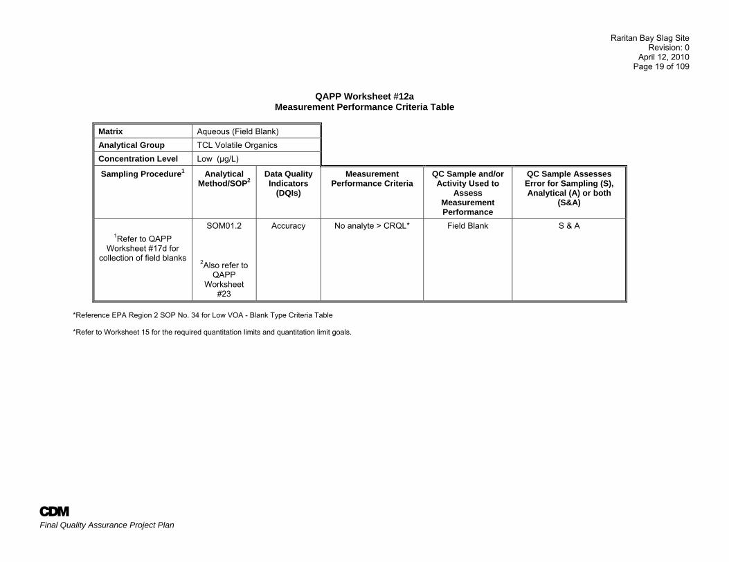
QAPP Worksheet #12a
Measurement Performance Criteria Table
Matrix Aqueous (Field Blank) Analytical Group TCL Volatile Organics Concentration Level Low (µg/L)
Sampling Procedure1 Analytical Method/SOP2
Data Quality Indicators
(DQIs)
Measurement Performance Criteria
QC Sample and/or Activity Used to
Assess Measurement Performance
QC Sample Assesses Error for Sampling (S), Analytical (A) or both
(S&A)
1Refer to QAPP Worksheet #17d for
collection of field blanks
SOM01.2
2Also refer to QAPP
Worksheet #23
Accuracy No analyte > CRQL* Field Blank S & A
*Reference EPA Region 2 SOP No. 34 for Low VOA - Blank Type Criteria Table *Refer to Worksheet 15 for the required quantitation limits and quantitation limit goals.
Raritan Bay Slag Site Revision: 0
April 12, 2010 Page 20 of 109
A Final Quality Assurance Project Plan
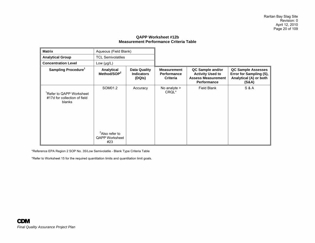
QAPP Worksheet #12b Measurement Performance Criteria Table
Matrix Aqueous (Field Blank) Analytical Group TCL Semivolatiles Concentration Level Low (µg/L)
Sampling Procedure1 Analytical Method/SOP2
Data Quality Indicators
(DQIs)
Measurement Performance
Criteria
QC Sample and/or Activity Used to
Assess Measurement Performance
QC Sample Assesses Error for Sampling (S), Analytical (A) or both
(S&A)
1Refer to QAPP Worksheet #17d for collection of field
blanks
SOM01.2
2Also refer to QAPP Worksheet
#23
Accuracy No analyte > CRQL*
Field Blank S & A
*Reference EPA Region 2 SOP No. 35/Low Semivolatile - Blank Type Criteria Table *Refer to Worksheet 15 for the required quantitation limits and quantitation limit goals.
Raritan Bay Slag Site Revision: 0
April 12, 2010 Page 21 of 109
A Final Quality Assurance Project Plan
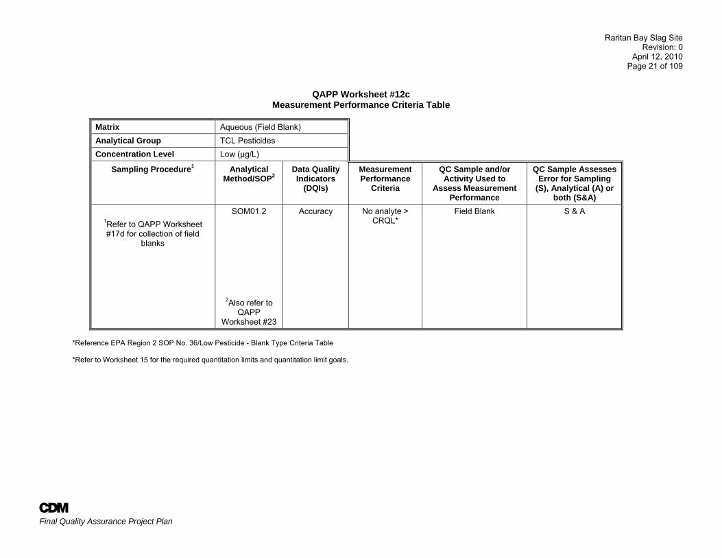
QAPP Worksheet #12c Measurement Performance Criteria Table
Matrix Aqueous (Field Blank) Analytical Group TCL Pesticides Concentration Level Low (µg/L)
Sampling Procedure1 Analytical Method/SOP2
Data Quality Indicators
(DQIs)
Measurement Performance
Criteria
QC Sample and/or Activity Used to
Assess Measurement Performance
QC Sample Assesses Error for Sampling
(S), Analytical (A) or both (S&A)
1Refer to QAPP Worksheet #17d for collection of field
blanks
SOM01.2
2Also refer to QAPP
Worksheet #23
Accuracy No analyte > CRQL*
Field Blank S & A
*Reference EPA Region 2 SOP No. 36/Low Pesticide - Blank Type Criteria Table *Refer to Worksheet 15 for the required quantitation limits and quantitation limit goals.
Raritan Bay Slag Site Revision: 0
April 12, 2010 Page 22 of 109
A Final Quality Assurance Project Plan
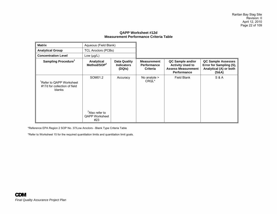
QAPP Worksheet #12d Measurement Performance Criteria Table
Matrix Aqueous (Field Blank) Analytical Group TCL Aroclors (PCBs) Concentration Level Low (µg/L)
Sampling Procedure1 Analytical Method/SOP2
Data Quality Indicators
(DQIs)
Measurement Performance
Criteria
QC Sample and/or Activity Used to
Assess Measurement Performance
QC Sample Assesses Error for Sampling (S), Analytical (A) or both
(S&A)
1Refer to QAPP Worksheet #17d for collection of field
blanks
SOM01.2
2Also refer to QAPP Worksheet
#23
Accuracy No analyte > CRQL*
Field Blank S & A
*Reference EPA Region 2 SOP No. 37/Low Aroclors - Blank Type Criteria Table *Refer to Worksheet 15 for the required quantitation limits and quantitation limit goals.
Raritan Bay Slag Site Revision: 0
April 12, 2010 Page 23 of 109
A Final Quality Assurance Project Plan
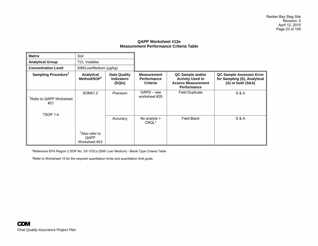
QAPP Worksheet #12e Measurement Performance Criteria Table
Matrix Soil Analytical Group TCL Volatiles Concentration Level SIM/Low/Medium (µg/kg)
Sampling Procedure1 Analytical Method/SOP2
Data Quality Indicators
(DQIs)
Measurement Performance
Criteria
QC Sample and/or Activity Used to
Assess Measurement Performance
QC Sample Assesses Error for Sampling (S), Analytical
(A) or both (S&A)
1Refer to QAPP Worksheet #21
TSOP 1-4
SOM01.2
2Also refer to QAPP
Worksheet #23
Precision %RPD – see worksheet #28
Field Duplicate S & A
Accuracy No analyte > CRQL*
Field Blank S & A
*Reference EPA Region 2 SOP No. 33/ VOCs (SIM/ Low/ Medium) - Blank Type Criteria Table *Refer to Worksheet 15 for the required quantitation limits and quantitation limit goals.
Raritan Bay Slag Site Revision: 0
April 12, 2010 Page 24 of 109
A Final Quality Assurance Project Plan
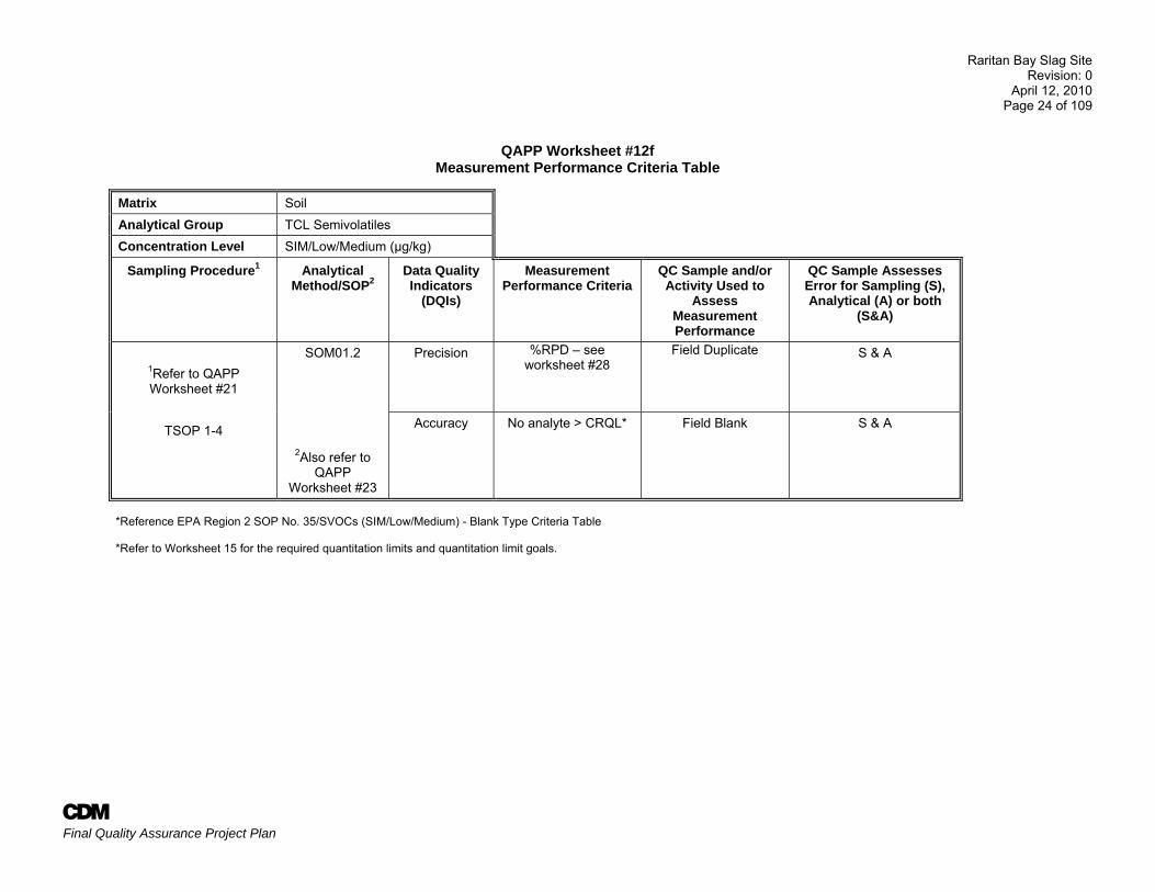
QAPP Worksheet #12f Measurement Performance Criteria Table
Matrix Soil Analytical Group TCL Semivolatiles Concentration Level SIM/Low/Medium (µg/kg)
Sampling Procedure1 Analytical Method/SOP2
Data Quality Indicators
(DQIs)
Measurement Performance Criteria
QC Sample and/or Activity Used to
Assess Measurement Performance
QC Sample Assesses Error for Sampling (S), Analytical (A) or both
(S&A)
1Refer to QAPP Worksheet #21
TSOP 1-4
SOM01.2
2Also refer to QAPP
Worksheet #23
Precision %RPD – see worksheet #28
Field Duplicate S & A
Accuracy No analyte > CRQL* Field Blank S & A
*Reference EPA Region 2 SOP No. 35/SVOCs (SIM/Low/Medium) - Blank Type Criteria Table *Refer to Worksheet 15 for the required quantitation limits and quantitation limit goals.
Raritan Bay Slag Site Revision: 0
April 12, 2010 Page 25 of 109
A Final Quality Assurance Project Plan
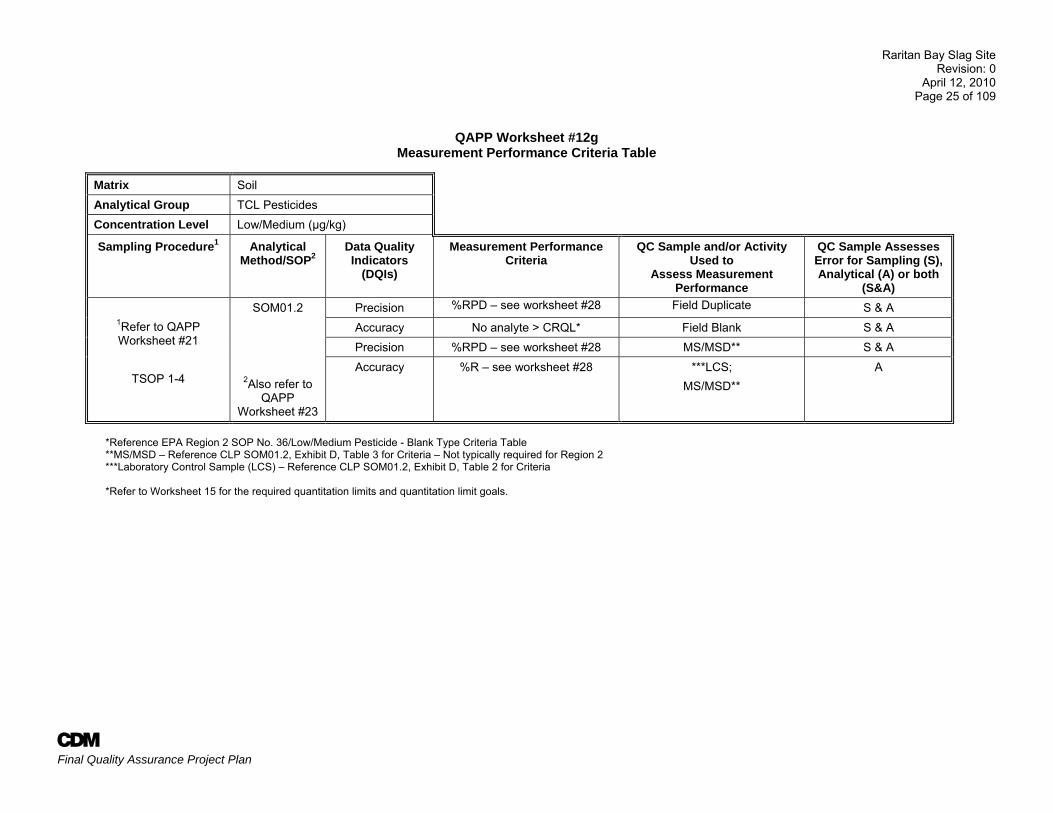
QAPP Worksheet #12g Measurement Performance Criteria Table
Matrix Soil Analytical Group TCL Pesticides Concentration Level Low/Medium (µg/kg)
Sampling Procedure1 Analytical Method/SOP2
Data Quality Indicators
(DQIs)
Measurement Performance Criteria
QC Sample and/or Activity Used to
Assess Measurement Performance
QC Sample Assesses Error for Sampling (S), Analytical (A) or both
(S&A)
1Refer to QAPP Worksheet #21
TSOP 1-4
SOM01.2
2Also refer to QAPP
Worksheet #23
Precision %RPD – see worksheet #28 Field Duplicate S & A Accuracy No analyte > CRQL* Field Blank S & A Precision %RPD – see worksheet #28 MS/MSD** S & A Accuracy %R – see worksheet #28 ***LCS;
MS/MSD** A
*Reference EPA Region 2 SOP No. 36/Low/Medium Pesticide - Blank Type Criteria Table **MS/MSD – Reference CLP SOM01.2, Exhibit D, Table 3 for Criteria – Not typically required for Region 2 ***Laboratory Control Sample (LCS) – Reference CLP SOM01.2, Exhibit D, Table 2 for Criteria *Refer to Worksheet 15 for the required quantitation limits and quantitation limit goals.
Raritan Bay Slag Site Revision: 0
April 12, 2010 Page 26 of 109
A Final Quality Assurance Project Plan
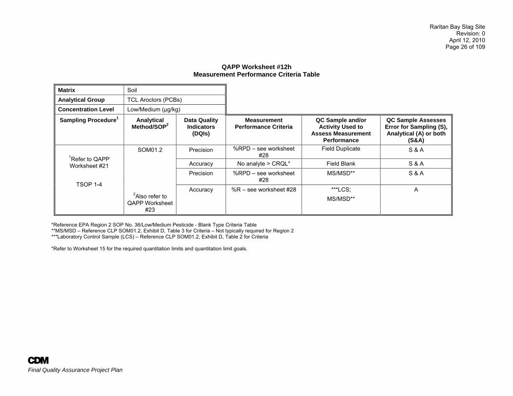
QAPP Worksheet #12h Measurement Performance Criteria Table
Matrix Soil Analytical Group TCL Aroclors (PCBs) Concentration Level Low/Medium (µg/kg)
Sampling Procedure1 Analytical Method/SOP2
Data Quality Indicators
(DQIs)
Measurement Performance Criteria
QC Sample and/or Activity Used to
Assess Measurement Performance
QC Sample Assesses Error for Sampling (S), Analytical (A) or both
(S&A)
1Refer to QAPP Worksheet #21
TSOP 1-4
SOM01.2
2Also refer to QAPP Worksheet
#23
Precision %RPD – see worksheet #28
Field Duplicate S & A
Accuracy No analyte > CRQL* Field Blank S & A Precision %RPD – see worksheet
#28 MS/MSD** S & A
Accuracy %R – see worksheet #28 ***LCS; MS/MSD**
A
*Reference EPA Region 2 SOP No. 36/Low/Medium Pesticide - Blank Type Criteria Table **MS/MSD – Reference CLP SOM01.2, Exhibit D, Table 3 for Criteria – Not typically required for Region 2 ***Laboratory Control Sample (LCS) – Reference CLP SOM01.2, Exhibit D, Table 2 for Criteria *Refer to Worksheet 15 for the required quantitation limits and quantitation limit goals.
Raritan Bay Slag Site Revision: 0
April 12, 2010 Page 27 of 109
A Final Quality Assurance Project Plan
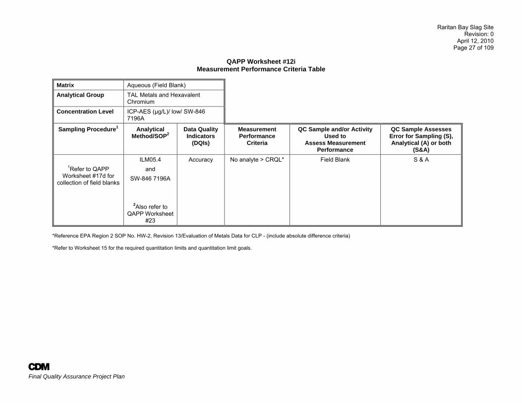
QAPP Worksheet #12i Measurement Performance Criteria Table
Matrix Aqueous (Field Blank) Analytical Group TAL Metals and Hexavalent
Chromium Concentration Level ICP-AES (µg/L)/ low/ SW-846
7196A
Sampling Procedure1 Analytical Method/SOP2
Data Quality Indicators
(DQIs)
Measurement Performance
Criteria
QC Sample and/or Activity Used to
Assess Measurement Performance
QC Sample Assesses Error for Sampling (S), Analytical (A) or both
(S&A)
1Refer to QAPP Worksheet #17d for
collection of field blanks
ILM05.4 and
SW-846 7196A
2Also refer to QAPP Worksheet
#23
Accuracy No analyte > CRQL* Field Blank S & A
*Reference EPA Region 2 SOP No. HW-2, Revision 13/Evaluation of Metals Data for CLP - (include absolute difference criteria) *Refer to Worksheet 15 for the required quantitation limits and quantitation limit goals.
Raritan Bay Slag Site Revision: 0
April 12, 2010 Page 28 of 109
A Final Quality Assurance Project Plan
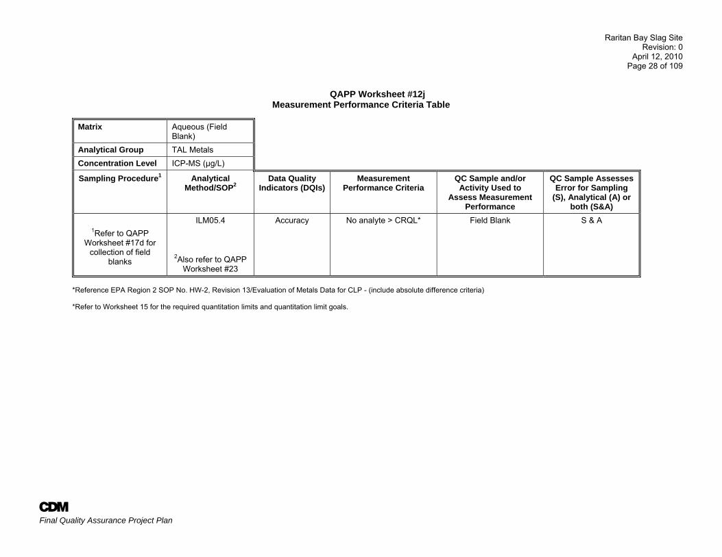
QAPP Worksheet #12j Measurement Performance Criteria Table
Matrix Aqueous (Field Blank)
Analytical Group TAL Metals Concentration Level ICP-MS (µg/L)
Sampling Procedure1 Analytical Method/SOP2
Data Quality Indicators (DQIs)
Measurement Performance Criteria
QC Sample and/or Activity Used to
Assess Measurement Performance
QC Sample Assesses Error for Sampling
(S), Analytical (A) or both (S&A)
1Refer to QAPP Worksheet #17d for
collection of field blanks
ILM05.4
2Also refer to QAPP Worksheet #23
Accuracy No analyte > CRQL* Field Blank S & A
*Reference EPA Region 2 SOP No. HW-2, Revision 13/Evaluation of Metals Data for CLP - (include absolute difference criteria)
*Refer to Worksheet 15 for the required quantitation limits and quantitation limit goals.
Raritan Bay Slag Site Revision: 0
April 12, 2010 Page 29 of 109
A Final Quality Assurance Project Plan
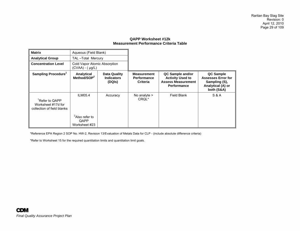
QAPP Worksheet #12k Measurement Performance Criteria Table
Matrix Aqueous (Field Blank) Analytical Group TAL –Total Mercury Concentration Level Cold Vapor Atomic Absorption
(CVAA) - ( µg/L)
Sampling Procedure1 Analytical Method/SOP2
Data Quality Indicators
(DQIs)
Measurement Performance
Criteria
QC Sample and/or Activity Used to
Assess Measurement Performance
QC Sample Assesses Error for
Sampling (S), Analytical (A) or
both (S&A)
1Refer to QAPP Worksheet #17d for
collection of field blanks
ILM05.4
2Also refer to QAPP
Worksheet #23
Accuracy No analyte > CRQL*
Field Blank S & A
*Reference EPA Region 2 SOP No. HW-2, Revision 13/Evaluation of Metals Data for CLP - (include absolute difference criteria) *Refer to Worksheet 15 for the required quantitation limits and quantitation limit goals.
Raritan Bay Slag Site Revision: 0
April 12, 2010 Page 30 of 109
A Final Quality Assurance Project Plan
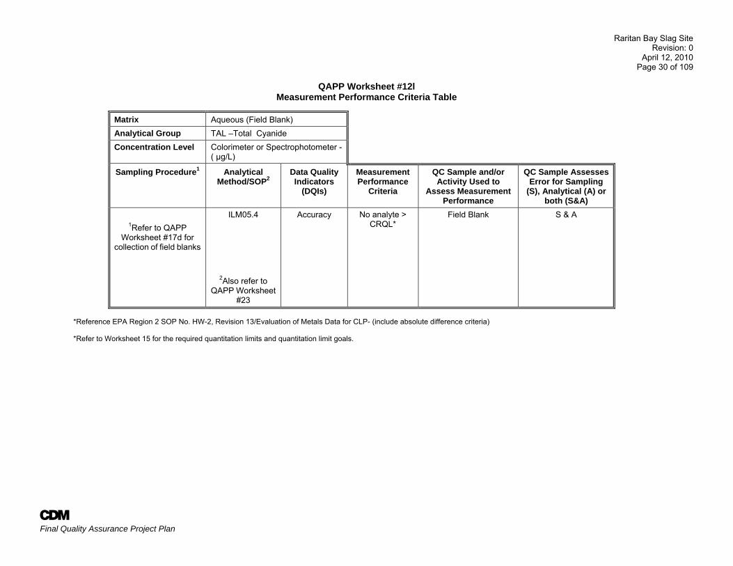
QAPP Worksheet #12l Measurement Performance Criteria Table
Matrix Aqueous (Field Blank) Analytical Group TAL –Total Cyanide Concentration Level Colorimeter or Spectrophotometer -
( µg/L)
Sampling Procedure1 Analytical Method/SOP2
Data Quality Indicators
(DQIs)
Measurement Performance
Criteria
QC Sample and/or Activity Used to
Assess Measurement Performance
QC Sample Assesses Error for Sampling
(S), Analytical (A) or both (S&A)
1Refer to QAPP Worksheet #17d for
collection of field blanks
ILM05.4
2Also refer to QAPP Worksheet
#23
Accuracy No analyte > CRQL*
Field Blank S & A
*Reference EPA Region 2 SOP No. HW-2, Revision 13/Evaluation of Metals Data for CLP- (include absolute difference criteria) *Refer to Worksheet 15 for the required quantitation limits and quantitation limit goals.
Raritan Bay Slag Site Revision: 0
April 12, 2010 Page 31 of 109
A Final Quality Assurance Project Plan
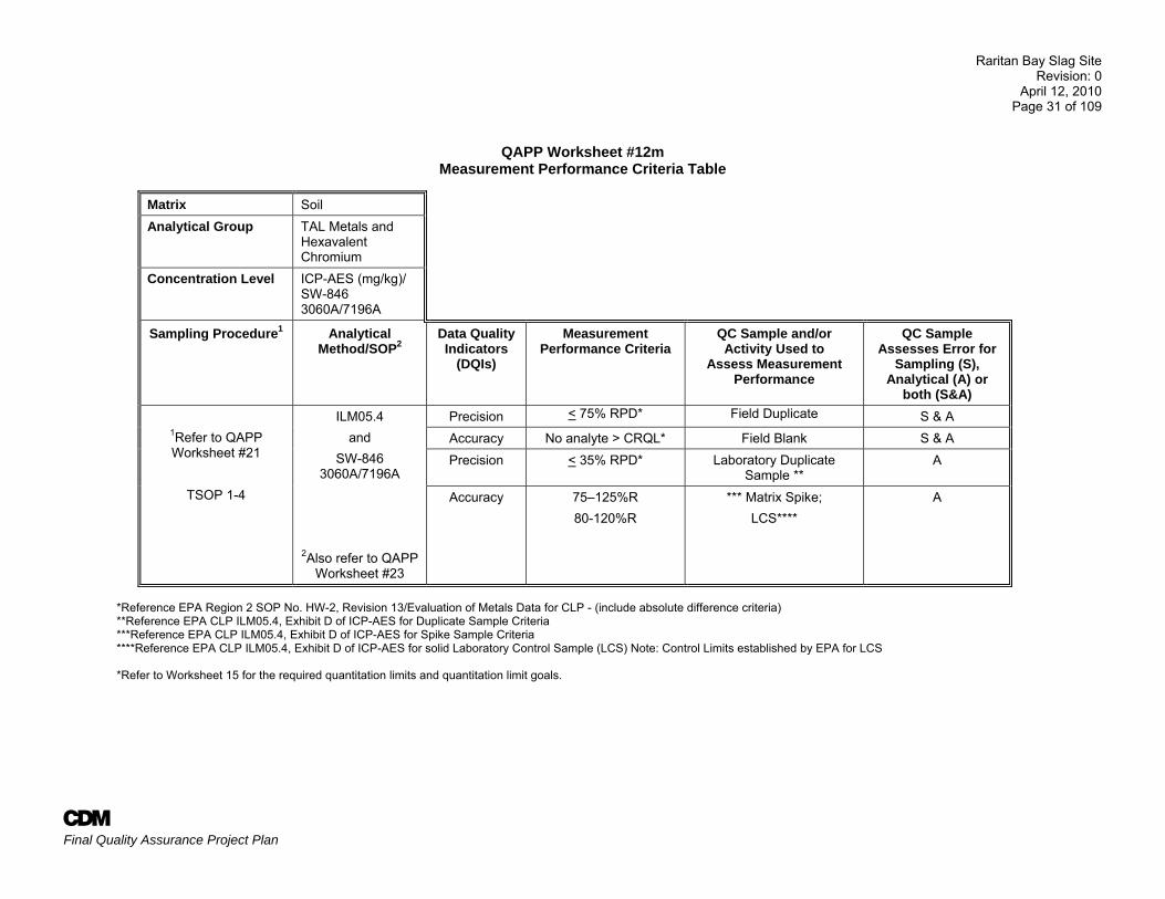
QAPP Worksheet #12m Measurement Performance Criteria Table
Matrix Soil Analytical Group TAL Metals and
Hexavalent Chromium
Concentration Level ICP-AES (mg/kg)/ SW-846 3060A/7196A
Sampling Procedure1 Analytical Method/SOP2
Data Quality Indicators
(DQIs)
Measurement Performance Criteria
QC Sample and/or Activity Used to
Assess Measurement Performance
QC Sample Assesses Error for
Sampling (S), Analytical (A) or
both (S&A)
1Refer to QAPP Worksheet #21
TSOP 1-4
ILM05.4 and
SW-846 3060A/7196A
2Also refer to QAPP Worksheet #23
Precision < 75% RPD* Field Duplicate S & A Accuracy No analyte > CRQL* Field Blank S & A Precision < 35% RPD* Laboratory Duplicate
Sample ** A
Accuracy 75–125%R 80-120%R
*** Matrix Spike; LCS****
A
*Reference EPA Region 2 SOP No. HW-2, Revision 13/Evaluation of Metals Data for CLP - (include absolute difference criteria) **Reference EPA CLP ILM05.4, Exhibit D of ICP-AES for Duplicate Sample Criteria ***Reference EPA CLP ILM05.4, Exhibit D of ICP-AES for Spike Sample Criteria ****Reference EPA CLP ILM05.4, Exhibit D of ICP-AES for solid Laboratory Control Sample (LCS) Note: Control Limits established by EPA for LCS *Refer to Worksheet 15 for the required quantitation limits and quantitation limit goals.
Raritan Bay Slag Site Revision: 0
April 12, 2010 Page 32 of 109
A Final Quality Assurance Project Plan
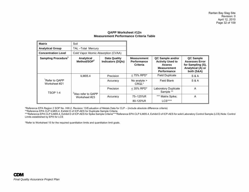
QAPP Worksheet #12n Measurement Performance Criteria Table
Matrix Soil Analytical Group TAL –Total Mercury Concentration Level Cold Vapor Atomic Absorption (CVAA)
Sampling Procedure1 Analytical Method/SOP2
Data Quality Indicators (DQIs)
Measurement Performance
Criteria
QC Sample and/or Activity Used to
Assess Measurement Performance
QC Sample Assesses Error
for Sampling (S), Analytical (A) or
both (S&A)
1Refer to QAPP Worksheet #21
TSOP 1-4
ILM05.4
2Also refer to QAPP Worksheet #23
Precision < 75% RPD* Field Duplicate S & A Accuracy No analyte >
CRQL* Field Blank S & A
Precision < 35% RPD* Laboratory Duplicate Sample **
A
Accuracy 75–125%R 80-120%R
*** Matrix Spike; LCS****
A
*Reference EPA Region 2 SOP No. HW-2, Revision 13/Evaluation of Metals Data for CLP – (include absolute difference criteria) **Reference EPA CLP ILM05.4, Exhibit D of ICP-AES for Duplicate Sample Criteria ***Reference EPA CLP ILM05.4, Exhibit D of ICP-AES for Spike Sample Criteria****Reference EPA CLP ILM05.4, Exhibit D of ICP-AES for solid Laboratory Control Sample (LCS) Note: Control Limits established by EPA for LCS *Refer to Worksheet 15 for the required quantitation limits and quantitation limit goals.
Raritan Bay Slag Site Revision: 0
April 12, 2010 Page 33 of 109
A Final Quality Assurance Project Plan
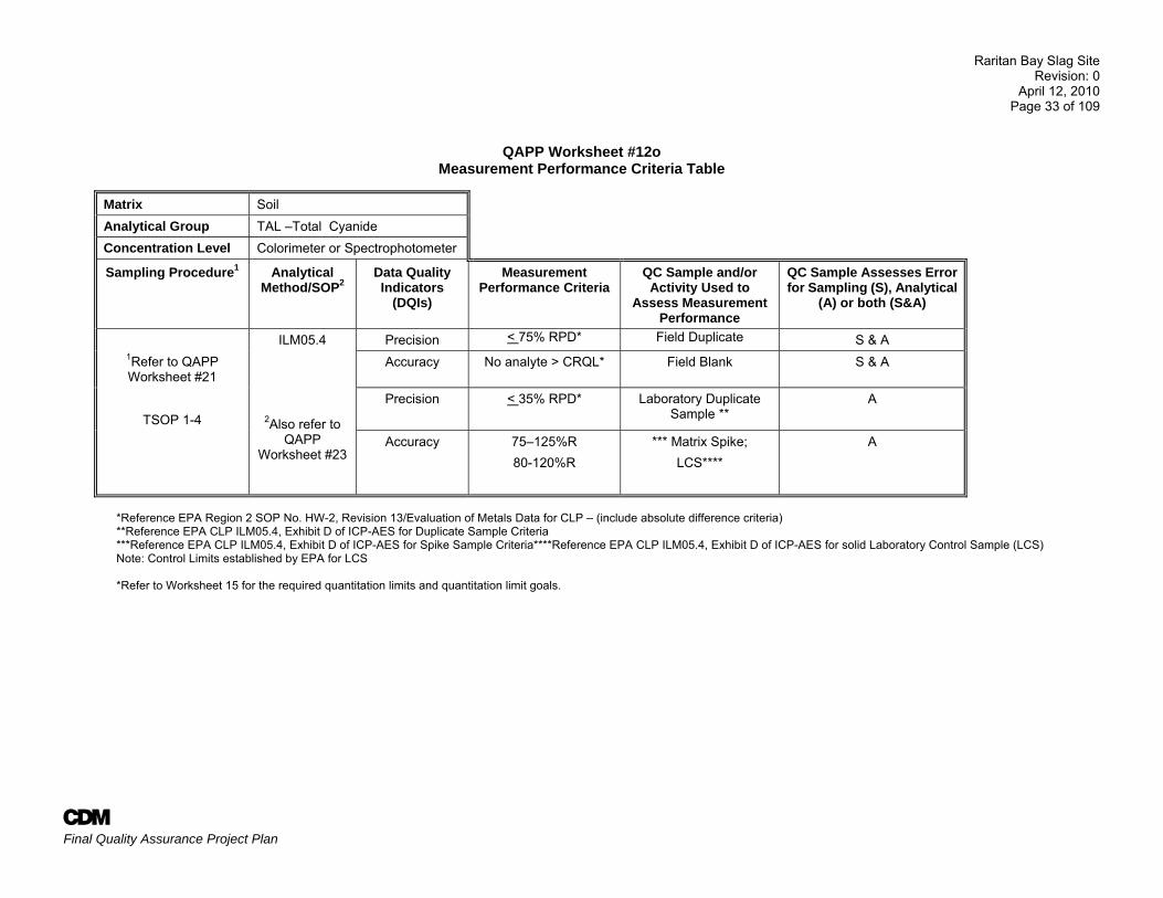
QAPP Worksheet #12o Measurement Performance Criteria Table
Matrix Soil Analytical Group TAL –Total Cyanide Concentration Level Colorimeter or Spectrophotometer
Sampling Procedure1 Analytical Method/SOP2
Data Quality Indicators
(DQIs)
Measurement Performance Criteria
QC Sample and/or Activity Used to
Assess Measurement Performance
QC Sample Assesses Error for Sampling (S), Analytical
(A) or both (S&A)
ILM05.4
2Also refer to QAPP
Worksheet #23
Precision < 75% RPD* Field Duplicate S & A 1Refer to QAPP Worksheet #21
Accuracy No analyte > CRQL* Field Blank S & A
TSOP 1-4
Precision < 35% RPD* Laboratory Duplicate Sample **
A
Accuracy 75–125%R 80-120%R
*** Matrix Spike; LCS****
A
*Reference EPA Region 2 SOP No. HW-2, Revision 13/Evaluation of Metals Data for CLP – (include absolute difference criteria) **Reference EPA CLP ILM05.4, Exhibit D of ICP-AES for Duplicate Sample Criteria ***Reference EPA CLP ILM05.4, Exhibit D of ICP-AES for Spike Sample Criteria****Reference EPA CLP ILM05.4, Exhibit D of ICP-AES for solid Laboratory Control Sample (LCS) Note: Control Limits established by EPA for LCS
*Refer to Worksheet 15 for the required quantitation limits and quantitation limit goals.
Raritan Bay Slag Site Revision: 0
April 12, 2010 Page 34 of 109
A Final Quality Assurance Project Plan
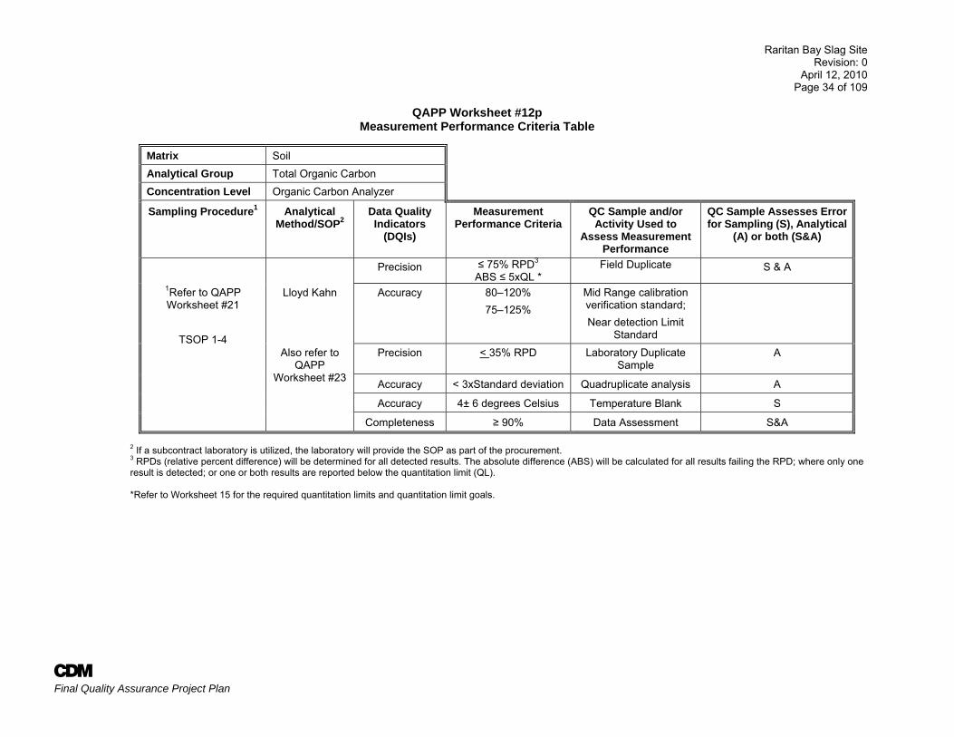
QAPP Worksheet #12p Measurement Performance Criteria Table
Matrix Soil Analytical Group Total Organic Carbon Concentration Level Organic Carbon Analyzer
Sampling Procedure1 Analytical Method/SOP2
Data Quality Indicators
(DQIs)
Measurement Performance Criteria
QC Sample and/or Activity Used to
Assess Measurement Performance
QC Sample Assesses Error for Sampling (S), Analytical
(A) or both (S&A)
Precision ≤ 75% RPD3 ABS ≤ 5xQL *
Field Duplicate S & A
1Refer to QAPP Worksheet #21
TSOP 1-4
Lloyd Kahn Accuracy 80–120% 75–125%
Mid Range calibration verification standard; Near detection Limit
Standard
Also refer to QAPP
Worksheet #23
Precision < 35% RPD Laboratory Duplicate Sample
A
Accuracy < 3xStandard deviation Quadruplicate analysis A
Accuracy 4± 6 degrees Celsius Temperature Blank S
Completeness ≥ 90% Data Assessment S&A
2 If a subcontract laboratory is utilized, the laboratory will provide the SOP as part of the procurement. 3 RPDs (relative percent difference) will be determined for all detected results. The absolute difference (ABS) will be calculated for all results failing the RPD; where only one result is detected; or one or both results are reported below the quantitation limit (QL). *Refer to Worksheet 15 for the required quantitation limits and quantitation limit goals.
Raritan Bay Slag Site Revision: 0
April 12, 2010 Page 35 of 109
A Final Quality Assurance Project Plan
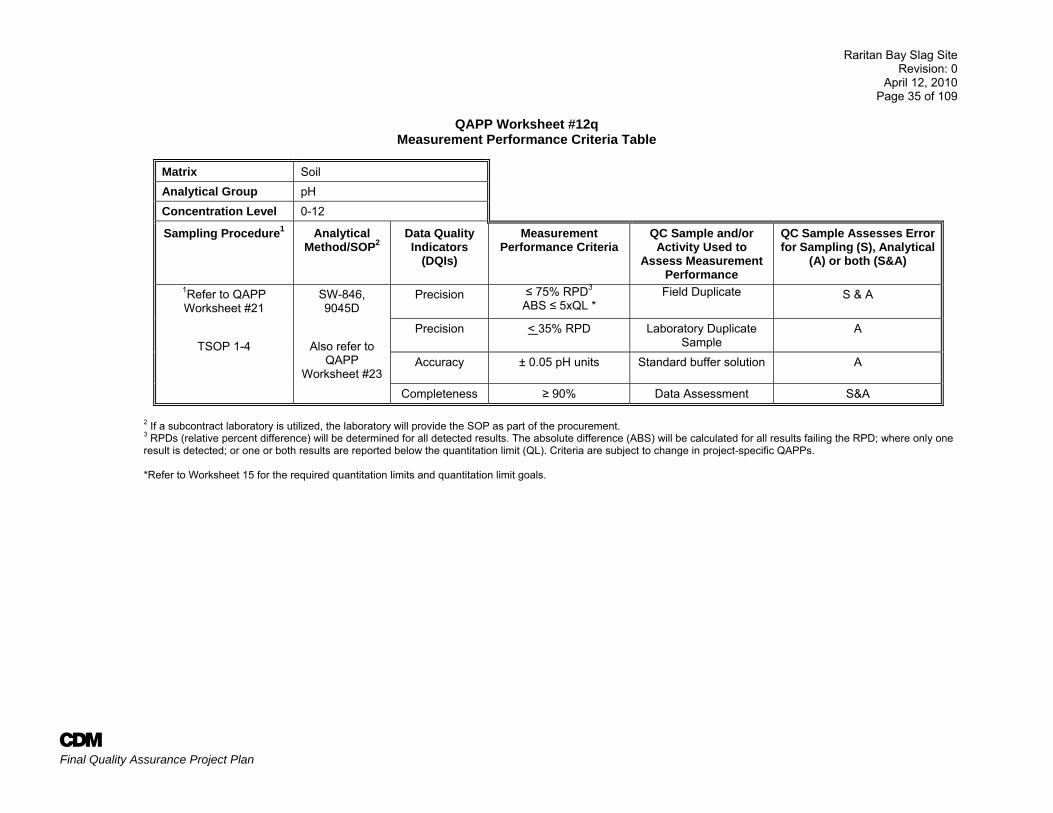
QAPP Worksheet #12q Measurement Performance Criteria Table
Matrix Soil Analytical Group pH Concentration Level 0-12
Sampling Procedure1 Analytical Method/SOP2
Data Quality Indicators
(DQIs)
Measurement Performance Criteria
QC Sample and/or Activity Used to
Assess Measurement Performance
QC Sample Assesses Error for Sampling (S), Analytical
(A) or both (S&A)
1Refer to QAPP Worksheet #21
TSOP 1-4
SW-846, 9045D
Also refer to
QAPP Worksheet #23
Precision ≤ 75% RPD3 ABS ≤ 5xQL *
Field Duplicate S & A
Precision < 35% RPD Laboratory Duplicate Sample
A
Accuracy ± 0.05 pH units Standard buffer solution A
Completeness ≥ 90% Data Assessment S&A
2 If a subcontract laboratory is utilized, the laboratory will provide the SOP as part of the procurement. 3 RPDs (relative percent difference) will be determined for all detected results. The absolute difference (ABS) will be calculated for all results failing the RPD; where only one result is detected; or one or both results are reported below the quantitation limit (QL). Criteria are subject to change in project-specific QAPPs. *Refer to Worksheet 15 for the required quantitation limits and quantitation limit goals.
Raritan Bay Slag Site Revision: 0
April 12, 2010 Page 36 of 109
A Final Quality Assurance Project Plan
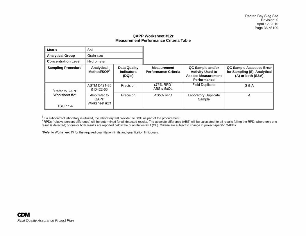
QAPP Worksheet #12r Measurement Performance Criteria Table
Matrix Soil Analytical Group Grain size Concentration Level Hydrometer
Sampling Procedure1 Analytical Method/SOP2
Data Quality Indicators
(DQIs)
Measurement Performance Criteria
QC Sample and/or Activity Used to
Assess Measurement Performance
QC Sample Assesses Error for Sampling (S), Analytical
(A) or both (S&A)
1Refer to QAPP Worksheet #21
TSOP 1-4
ASTM D421-85 & D422-63
Precision ≤75% RPD3 ABS ≤ 5xQL
Field Duplicate S & A
Also refer to QAPP
Worksheet #23
Precision < 35% RPD Laboratory Duplicate Sample
A
. 2 If a subcontract laboratory is utilized, the laboratory will provide the SOP as part of the procurement. 3 RPDs (relative percent difference) will be determined for all detected results. The absolute difference (ABS) will be calculated for all results failing the RPD; where only one result is detected; or one or both results are reported below the quantitation limit (QL). Criteria are subject to change in project-specific QAPPs. *Refer to Worksheet 15 for the required quantitation limits and quantitation limit goals.
Raritan Bay Slag Site Revision: 0
April 12, 2010 Page 37 of 109
A Final Quality Assurance Project Plan
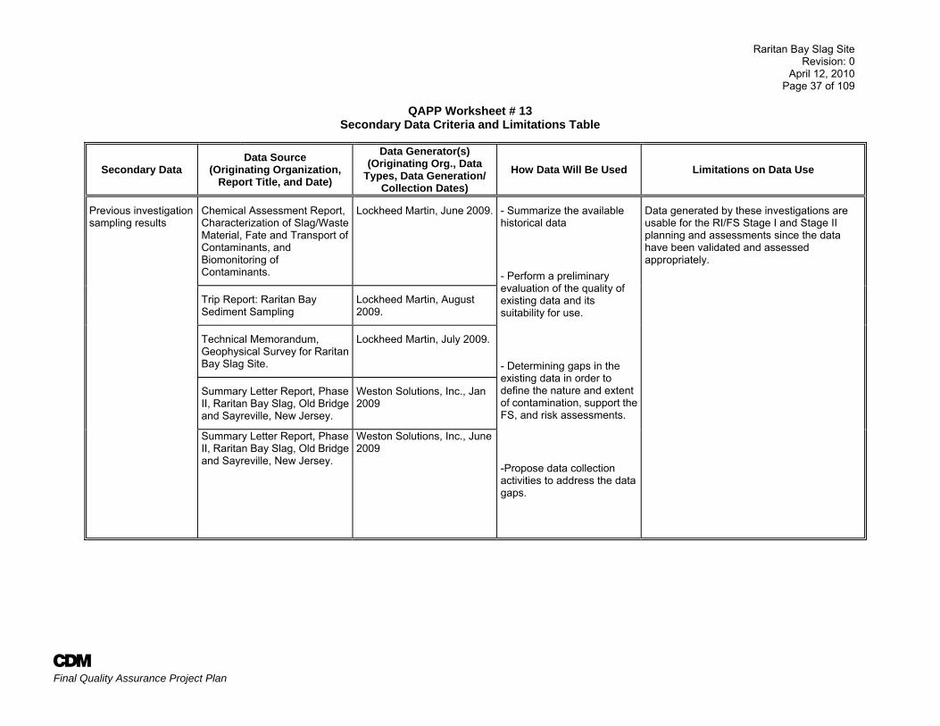
QAPP Worksheet # 13 Secondary Data Criteria and Limitations Table
Secondary Data Data Source
(Originating Organization, Report Title, and Date)
Data Generator(s) (Originating Org., Data
Types, Data Generation/ Collection Dates)
How Data Will Be Used Limitations on Data Use
Previous investigation sampling results
Chemical Assessment Report, Characterization of Slag/Waste Material, Fate and Transport of Contaminants, and Biomonitoring of Contaminants.
Lockheed Martin, June 2009. - Summarize the available historical data
- Perform a preliminary evaluation of the quality of existing data and its suitability for use.
- Determining gaps in the existing data in order to define the nature and extent of contamination, support the FS, and risk assessments.
-Propose data collection activities to address the data gaps.
Data generated by these investigations are usable for the RI/FS Stage I and Stage II planning and assessments since the data have been validated and assessed appropriately.
Trip Report: Raritan Bay Sediment Sampling
Lockheed Martin, August 2009.
Technical Memorandum, Geophysical Survey for Raritan Bay Slag Site.
Lockheed Martin, July 2009.
Summary Letter Report, Phase II, Raritan Bay Slag, Old Bridge and Sayreville, New Jersey.
Weston Solutions, Inc., Jan 2009
Summary Letter Report, Phase II, Raritan Bay Slag, Old Bridge and Sayreville, New Jersey.
Weston Solutions, Inc., June 2009
Raritan Bay Slag Site Revision: 0
April 12, 2010 Page 38 of 109
A Final Quality Assurance Project Plan
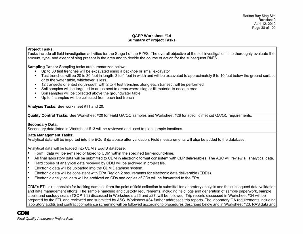
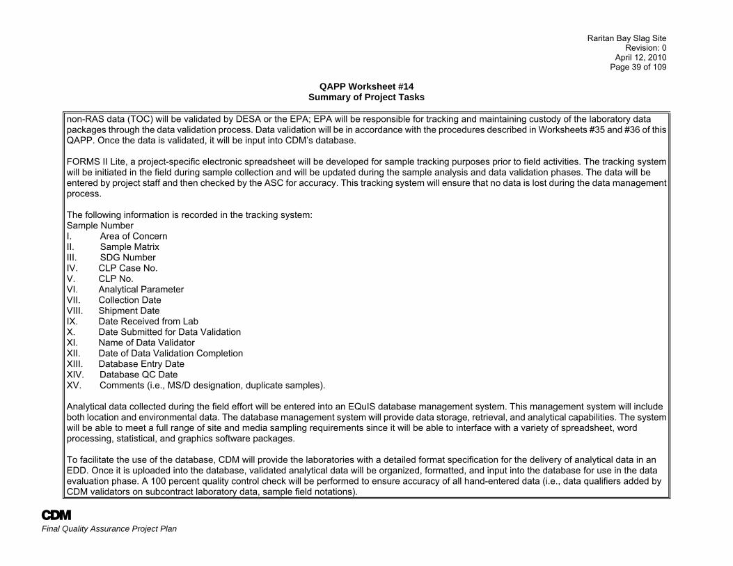
QAPP Worksheet #14 Summary of Project Tasks
Project Tasks: Tasks include all field investigation activities for the Stage I of the RI/FS. The overall objective of the soil investigation is to thoroughly evaluate the amount, type, and extent of slag present in the area and to decide the course of action for the subsequent RI/FS. Sampling Tasks: Sampling tasks are summarized below:
Up to 30 test trenches will be excavated using a backhoe or small excavator Test trenches will be 20 to 30 foot in length, 3 to 4 foot in width and will be excavated to approximately 8 to 10 feet below the ground surface
or to the water table, whichever is less. 12 transects oriented north-south with 2 to 4 test trenches along each transect will be performed Soil samples will be targeted to areas next to areas where slag or fill material is encountered Soil samples will be collected above the groundwater table Up to 4 samples will be collected from each test trench
Analysis Tasks: See worksheet #11 and 20. Quality Control Tasks: See Worksheet #20 for Field QA/QC samples and Worksheet #28 for specific method QA/QC requirements. Secondary Data: Secondary data listed in Worksheet #13 will be reviewed and used to plan sample locations. Data Management Tasks: Analytical data will be imported into the EQuIS database after validation. Field measurements will also be added to the database. Analytical data will be loaded into CDM’s EquIS database. Form I data will be e-mailed or faxed to CDM within the specified turn-around-time. All final laboratory data will be submitted to CDM in electronic format consistent with CLP deliverables. The ASC will review all analytical data. Hard copies of analytical data received by CDM will be archived in project file. Electronic data will be uploaded into the CDM Database system. Electronic data will be consistent with EPA Region 2 requirements for electronic data deliverable (EDDs). Electronic analytical data will be archived on CDs and copies of CDs will be forwarded to the EPA.
CDM’s FTL is responsible for tracking samples from the point of field collection to submittal for laboratory analysis and the subsequent data validation and data management efforts. The sample handling and custody requirements, including field logs and generation of sample paperwork, sample labels and custody seals (TSOP 1-2) discussed in Worksheets #26 and #27, will be followed. Trip reports discussed in Worksheet #34 will be prepared by the FTL and reviewed and submitted by ASC. Worksheet #34 further addresses trip reports. The laboratory QA requirements including laboratory audits and contract compliance screening will be followed according to procedures described below and in Worksheet #23. RAS data and
Raritan Bay Slag Site Revision: 0
April 12, 2010 Page 39 of 109
A Final Quality Assurance Project Plan
QAPP Worksheet #14 Summary of Project Tasks
non-RAS data (TOC) will be validated by DESA or the EPA; EPA will be responsible for tracking and maintaining custody of the laboratory data packages through the data validation process. Data validation will be in accordance with the procedures described in Worksheets #35 and #36 of this QAPP. Once the data is validated, it will be input into CDM’s database. FORMS II Lite, a project-specific electronic spreadsheet will be developed for sample tracking purposes prior to field activities. The tracking system will be initiated in the field during sample collection and will be updated during the sample analysis and data validation phases. The data will be entered by project staff and then checked by the ASC for accuracy. This tracking system will ensure that no data is lost during the data management process. The following information is recorded in the tracking system: Sample Number I. Area of Concern II. Sample Matrix III. SDG Number IV. CLP Case No. V. CLP No. VI. Analytical Parameter VII. Collection Date VIII. Shipment Date IX. Date Received from Lab X. Date Submitted for Data Validation XI. Name of Data Validator XII. Date of Data Validation Completion XIII. Database Entry Date XIV. Database QC Date XV. Comments (i.e., MS/D designation, duplicate samples). Analytical data collected during the field effort will be entered into an EQuIS database management system. This management system will include both location and environmental data. The database management system will provide data storage, retrieval, and analytical capabilities. The system will be able to meet a full range of site and media sampling requirements since it will be able to interface with a variety of spreadsheet, word processing, statistical, and graphics software packages. To facilitate the use of the database, CDM will provide the laboratories with a detailed format specification for the delivery of analytical data in an EDD. Once it is uploaded into the database, validated analytical data will be organized, formatted, and input into the database for use in the data evaluation phase. A 100 percent quality control check will be performed to ensure accuracy of all hand-entered data (i.e., data qualifiers added by CDM validators on subcontract laboratory data, sample field notations).
Raritan Bay Slag Site Revision: 0
April 12, 2010 Page 40 of 109
A Final Quality Assurance Project Plan
QAPP Worksheet #14 Summary of Project Tasks
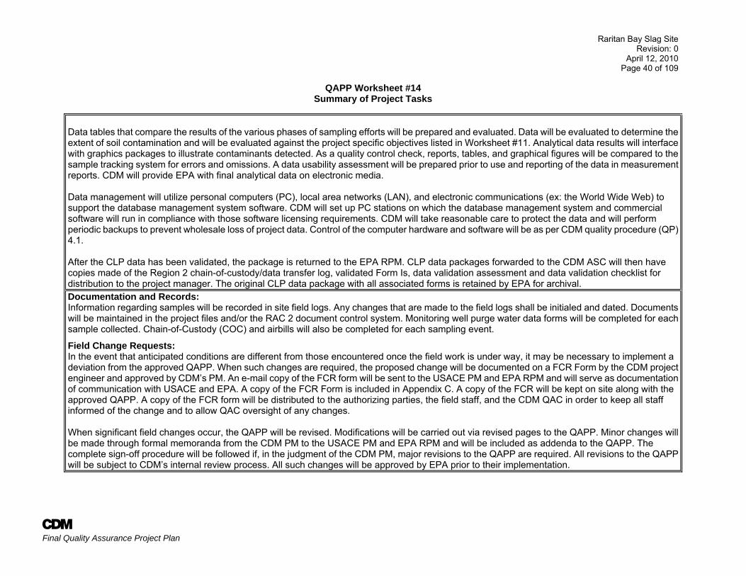
Data tables that compare the results of the various phases of sampling efforts will be prepared and evaluated. Data will be evaluated to determine the extent of soil contamination and will be evaluated against the project specific objectives listed in Worksheet #11. Analytical data results will interface with graphics packages to illustrate contaminants detected. As a quality control check, reports, tables, and graphical figures will be compared to the sample tracking system for errors and omissions. A data usability assessment will be prepared prior to use and reporting of the data in measurement reports. CDM will provide EPA with final analytical data on electronic media. Data management will utilize personal computers (PC), local area networks (LAN), and electronic communications (ex: the World Wide Web) to support the database management system software. CDM will set up PC stations on which the database management system and commercial software will run in compliance with those software licensing requirements. CDM will take reasonable care to protect the data and will perform periodic backups to prevent wholesale loss of project data. Control of the computer hardware and software will be as per CDM quality procedure (QP) 4.1. After the CLP data has been validated, the package is returned to the EPA RPM. CLP data packages forwarded to the CDM ASC will then have copies made of the Region 2 chain-of-custody/data transfer log, validated Form Is, data validation assessment and data validation checklist for distribution to the project manager. The original CLP data package with all associated forms is retained by EPA for archival. Documentation and Records: Information regarding samples will be recorded in site field logs. Any changes that are made to the field logs shall be initialed and dated. Documents will be maintained in the project files and/or the RAC 2 document control system. Monitoring well purge water data forms will be completed for each sample collected. Chain-of-Custody (COC) and airbills will also be completed for each sampling event.
Field Change Requests: In the event that anticipated conditions are different from those encountered once the field work is under way, it may be necessary to implement a deviation from the approved QAPP. When such changes are required, the proposed change will be documented on a FCR Form by the CDM project engineer and approved by CDM’s PM. An e-mail copy of the FCR form will be sent to the USACE PM and EPA RPM and will serve as documentation of communication with USACE and EPA. A copy of the FCR Form is included in Appendix C. A copy of the FCR will be kept on site along with the approved QAPP. A copy of the FCR form will be distributed to the authorizing parties, the field staff, and the CDM QAC in order to keep all staff informed of the change and to allow QAC oversight of any changes. When significant field changes occur, the QAPP will be revised. Modifications will be carried out via revised pages to the QAPP. Minor changes will be made through formal memoranda from the CDM PM to the USACE PM and EPA RPM and will be included as addenda to the QAPP. The complete sign-off procedure will be followed if, in the judgment of the CDM PM, major revisions to the QAPP are required. All revisions to the QAPP will be subject to CDM’s internal review process. All such changes will be approved by EPA prior to their implementation.
Raritan Bay Slag SiteRevision: 0
April 12, 2010Page 41 of 109
SOM01.2 Low Soil
SOM01.2 Medium Soil MDLs QLs
1,1,1-Trichloroethane 71-55-6 200 100 N/A 5 250 0.3 51,1,2,2-Tetrachloroethane 79-34-5 5 5 N/A 5 250 0.4 51,1,2-Trichloro-1,2,2-trifluoroethane 76-13-1 910,000 455,000 N/A 5 250 0.8 51,1,2-Trichloroethane 79-00-5 10 5 N/A 5 250 0.3 51,1-Dichloroethane 75-34-3 200 100 N/A 5 250 0.7 51,1-Dicholoroethene 75-35-4 5 5 N/A 5 250 0.7 51,2,3-Trichlorobenzene 87-61-6 4,890 2445 N/A 5 250 1.5 51,2,4-Trichlorobenzene 120-82-1 400 200 N/A 5 250 1.5 51,2-Dibromo-3-chloropropane 96-12-8 5 5 N/A 5 250 0.5 51,2-Dibromoethane 106-93-4 5 5 N/A 5 250 0.4 51,2-Dichlorobenzene 95-50-1 2,960 1,480 N/A 5 250 1 51,2-Dichloroethane 107-06-2 5 5 N/A 5 250 0.5 51,2-Dichloropropane 78-87-5 5 5 N/A 5 250 0.5 51,3-Dichlorobenzene 541-73-1 12,000 6,000 N/A 5 250 1.1 51,4-Dichlorobenzene 106-46-7 546 273 N/A 5 250 1.2 51,4-Dioxane 123-91-1 44,100 22,050 N/A 100 5,000 NL NL2-Butanone 78-93-3 600 300 N/A 10 500 1.2 102-Hexanone 591-78-6 12,600 6,300 N/A 10 500 0.5 104-Methyl-2-pentanone 108-10-1 443,000 221,500 N/A 10 500 0.6 10Acetone 67-64-1 2,500 1,250 N/A 10 500 4 10Benzene 71-43-2 5 5 N/A 5 250 0.5 5Bromochloromethane 74-97-5 NL NA N/A 5 250 0.6 5Bromodichloromethane 75-27-4 5 5 N/A 5 250 0.5 5Bromoform 75-25-2 20 10 N/A 5 250 0.6 5Bromomethane 74-83-9 30 15 N/A 5 250 1.3 5Carbon Disulfide 75-15-0 94 47.05 N/A 5 250 0.8 5Carbon tetrachloride 56-23-5 5 5 N/A 5 250 1.9 5Chlorobenzene 108-90-7 400 200 N/A 5 250 0.8 5Chloroethane 75-00-3 220,000 110,000 N/A 5 250 0.9 5Chloroform 67-66-3 200 100 N/A 5 250 0.3 5
QAPP Worksheet #15aReference Limits and Evaluation Table - Soil VOCs
Volatile Organic Compounds (All units: μg/kg)
Project Quantitation Limit Goal
(PQLG)
Project- Specific Option
Achievable DESA Laboratory Limits*Project Action
Limit**
Low soil except if
sample results exceed the
upper calibration
limit.
CAS NumberCRQL
Analytical Method
MDLs
AFinal Quality Assurance Project Plan
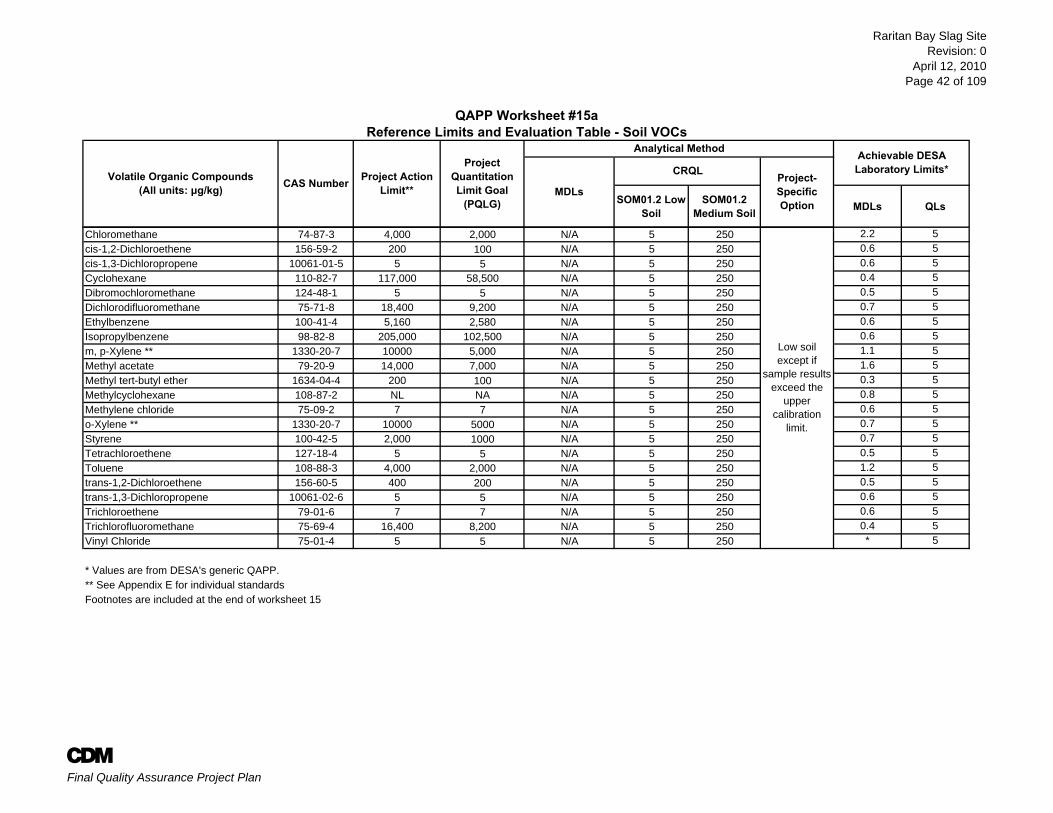
Raritan Bay Slag SiteRevision: 0
April 12, 2010Page 42 of 109
SOM01.2 Low Soil
SOM01.2 Medium Soil MDLs QLs
QAPP Worksheet #15aReference Limits and Evaluation Table - Soil VOCs
Volatile Organic Compounds (All units: μg/kg)
Project Quantitation Limit Goal
(PQLG)
Project- Specific Option
Achievable DESA Laboratory Limits*Project Action
Limit**CAS NumberCRQL
Analytical Method
MDLs
Chloromethane 74-87-3 4,000 2,000 N/A 5 250 2.2 5cis-1,2-Dichloroethene 156-59-2 200 100 N/A 5 250 0.6 5cis-1,3-Dichloropropene 10061-01-5 5 5 N/A 5 250 0.6 5Cyclohexane 110-82-7 117,000 58,500 N/A 5 250 0.4 5Dibromochloromethane 124-48-1 5 5 N/A 5 250 0.5 5Dichlorodifluoromethane 75-71-8 18,400 9,200 N/A 5 250 0.7 5Ethylbenzene 100-41-4 5,160 2,580 N/A 5 250 0.6 5Isopropylbenzene 98-82-8 205,000 102,500 N/A 5 250 0.6 5m, p-Xylene ** 1330-20-7 10000 5,000 N/A 5 250 1.1 5Methyl acetate 79-20-9 14,000 7,000 N/A 5 250 1.6 5Methyl tert-butyl ether 1634-04-4 200 100 N/A 5 250 0.3 5Methylcyclohexane 108-87-2 NL NA N/A 5 250 0.8 5Methylene chloride 75-09-2 7 7 N/A 5 250 0.6 5o-Xylene ** 1330-20-7 10000 5000 N/A 5 250 0.7 5Styrene 100-42-5 2,000 1000 N/A 5 250 0.7 5Tetrachloroethene 127-18-4 5 5 N/A 5 250 0.5 5Toluene 108-88-3 4,000 2,000 N/A 5 250 1.2 5trans-1,2-Dichloroethene 156-60-5 400 200 N/A 5 250 0.5 5trans-1,3-Dichloropropene 10061-02-6 5 5 N/A 5 250 0.6 5Trichloroethene 79-01-6 7 7 N/A 5 250 0.6 5Trichlorofluoromethane 75-69-4 16,400 8,200 N/A 5 250 0.4 5Vinyl Chloride 75-01-4 5 5 N/A 5 250 * 5
* Values are from DESA's generic QAPP.** See Appendix E for individual standardsFootnotes are included at the end of worksheet 15
Low soil except if
sample results exceed the
upper calibration
limit.
AFinal Quality Assurance Project Plan
Raritan Bay Slag SiteRevision: 0
April 12, 2010Page 43 of 109
SOM01.2 Low Soil
SOM01.2 Med. Soil
SOM01.2 Low-SIM MDLs QLs
1,1'-Biphenyl 92-52-4 90,000 45,000 N/A 170 5,000 N/A 1201,2,4,5-Tetrachlorobenzene 95-94-3 1,830 915 N/A 170 5,000 N/A 1202,2'-Oxybis (1-chloropropane) 108-60-1 4,570 2,285 N/A 170 5,000 N/A NL2,3,4,6-Tetrachlorophenol 58-90-2 NL NA N/A 170 5,000 N/A 1202,4,5-Trichlorophenol 95-95-4 9,000 4,500 N/A 170 5,000 N/A 1202,4,6-Trichlorophenol 88-06-2 200 170 N/A 170 5,000 N/A 1202,4-Dichlorophenol 120-83-2 200 170 N/A 170 5,000 N/A 1202,4-Dimethylphenol 105-67-9 10 10 N/A 170 5,000 N/A 1202,4-Dinitrophenol 51-28-5 60.9 60.9 N/A 330 10,000 N/A 8002,4-Dinitrotoluene 121-14-2 200 170 N/A 170 5,000 N/A 1202,6-Dinitrotoluene 606-20-2 32.8 32.8 N/A 170 5,000 N/A 1202-Chloronapthalene 91-58-7 12.2 12.2 N/A 170 5,000 N/A 1202-Chlorophenol 95-57-8 243 243 N/A 170 5,000 N/A 1202-Methylnapthalene 91-57-6 3,240 1,620 N/A 170 5,000 3.3 N/A 1202-Methylphenol 95-48-7 306,000 153,000 N/A 170 5,000 N/A 1202-Nitroaniline 88-74-4 39,000 19,500 N/A 330 10,000 N/A 1202-Nitrophenol 88-75-5 1,600 800 N/A 170 5,000 N/A 1203,3'-Dichlorobenzidine 91-94-1 200 170 N/A 170 5,000 N/A 1203-Nitroaniline 99-09-2 3,160 1,580 N/A 330 10,000 N/A 1204,6-Dinitro-2-methylphenol 534-52-1 144 144 N/A 330 10,000 N/A 4004-Bromophenyl-phenylether 101-55-3 NL NA N/A 170 5,000 N/A 1204-Chloro-3-methylphenol 59-50-7 611,000 305,500 N/A 170 5,000 N/A 1204-Chloroaniline 106-47-8 1,100 550 N/A 170 5,000 N/A 1204-Chlorophenyl-phenyl ether 7005-72-3 NL NA N/A 170 5,000 N/A 1204-Methylphenol 106-44-5 30,600 15,300 N/A 170 5,000 N/A 1204-Nitroaniline 100-01-6 21,900 10,950 N/A 330 10,000 N/A 1204-Nitrophenol 100-02-7 5,120 2,560 N/A 330 10,000 N/A 400Acenaphthene 83-32-9 20,000 10,000 N/A 170 5,000 3.3 N/A 120Acenaphthylene 208-96-8 29,000 14,500 N/A 170 5,000 3.3 N/A 120Acetophenone 98-86-2 2,000 1,000 N/A 170 5,000 N/A 120Anthracene 120-12-7 29,000 14,500 N/A 170 5,000 3.3 N/A 120Atrazine 1912-24-9 200 200 N/A 170 5,000 N/A 120
QAPP Worksheet #15bReference Limits and Evaluation Table - Soil SVOCs
Semi-Volatile Organic Compounds
(All units: μg/kg)
CAS Number
Project Quantitation Limit Goal
(PQLG)
Analytical Method Achievable DESA Laboratory Limits*Project Action
Limit**
Low soil except if sample results
exceed the upper
calibration limit.
Compounds highlighted require SIM
(see footnotes) or
method modification to achieve
the PQLGs.
MDLsCRQL Project-
Specific Option
AFinal Quality Assurance Project Plan
Raritan Bay Slag SiteRevision: 0
April 12, 2010Page 44 of 109
SOM01.2 Low Soil
SOM01.2 Med. Soil
SOM01.2 Low-SIM MDLs QLs
QAPP Worksheet #15bReference Limits and Evaluation Table - Soil SVOCs
Semi-Volatile Organic Compounds
(All units: μg/kg)
CAS Number
Project Quantitation Limit Goal
(PQLG)
Analytical Method Achievable DESA Laboratory Limits*Project Action
Limit** MDLsCRQL Project-
Specific Option
Benzaldehyde 100-52-7 782,000 391,000 N/A 170 5,000 N/A 120Benzo (a) anthracene 56-55-3 148 148 N/A 170 5,000 3.3 N/A 120Benzo (a) pyrene 50-32-8 14.8 14.8 N/A 170 5,000 3.3 N/A 120Benzo (b) fluoranthene 205-99-2 148 148 N/A 170 5,000 3.3 N/A 120Benzo (g,h,i) perylene 191-24-2 1,100 550 N/A 170 5,000 3.3 N/A 120Benzo (k) fluoranthene 207-08-9 1,480 740 N/A 170 5,000 3.3 N/A 120Bis (2-chloroethoxy) methane 111-91-1 302 302 N/A 170 5,000 N/A 120Bis (2-ethylhexyl) phthalate 117-81-7 925 462.5 N/A 170 5,000 N/A 120bis-(2-chloroethyl) ether 111-44-4 200 170 N/A 170 5,000 N/A 120Butylbenzylphthalate 85-68-7 239 239 N/A 170 5,000 N/A 120Caprolactam 105-60-2 8,000 4,000 N/A 170 5,000 N/A 120Carbazole 86-74-8 24,000 12,000 N/A 170 5,000 N/A 120Chrysene 218-01-9 1,100 550 N/A 170 5,000 3.3 N/A 120Dibenzo (a,h)-anthracene 53-70-3 14.8 14.8 N/A 170 5,000 3.3 N/A 120Dibenzofuran 132-64-9 7,820 3,910 N/A 170 5,000 N/A 120Diethylphthalate 84-66-2 24,800 12,400 N/A 170 5,000 N/A 120Dimethylphthalate 131-11-3 734,000 367,000 N/A 170 5,000 N/A 120Di-n-butylphthalate 84-74-2 150 150 N/A 170 5,000 N/A 120Di-n-octylphthalate 117-84-0 709,000 354,500 N/A 170 5,000 N/A 120Fluoranthene 206-44-0 1,100 550 N/A 170 5,000 3.3 N/A 120Fluorene 86-73-7 29,000 14,500 N/A 170 5,000 3.3 N/A 120Hexachlorobenzene 118-74-1 199 199 N/A 170 5,000 N/A 120Hexachlorobutadiene 87-68-3 39.8 39.8 N/A 170 5,000 N/A 120Hexachlorocyclopentadiene 77-47-4 755 377.5 N/A 170 5,000 N/A 120Hexachloroethane 67-72-1 200 170 N/A 170 5,000 N/A 120Indeno (1,2,3-cd)-pyrene 193-39-5 148 148 N/A 170 5,000 3.3 N/A 120Isophorone 78-59-1 200 200 N/A 170 5,000 N/A 120Naphthalene 91-20-3 99.4 99.4 N/A 170 5,000 3.3 N/A 120Nitrobenzene 98-95-3 200 170 N/A 170 5,000 N/A 120N-Nitroso-di-n propylamine 621-64-7 69.4 69.4 N/A 170 5,000 N/A 120N-Nitrosodiphenylamine 86-30-6 200 170 N/A 170 5,000 N/A 120Pentachlorophenol 87-86-5 119 119 N/A 330 10,000 6.7 N/A 400Phenanthrene 85-01-8 29,000 14,500 N/A 170 5,000 3.3 N/A 120Phenol 108-95-2 5,000 2,500 N/A 170 5,000 N/A 120Pyrene 129-00-0 1,100 550 N/A 170 5,000 3.3 N/A 120* Values are from DESA's generic QAPP.** See Appendix E for individual standardsLow SIM analysis required for benzo (a) anthracene, benzo (a) pyrene, benzo (b) fluoranthene, dibenzo (a,h)-anthracene, indeno (1,2,3-cd)-pyrene and pentachlorophenol.Other footnotes are included at the end of worksheet 15.
Low soil except if sample results
exceed the upper
calibration limit.
Compounds highlighted require SIM
(see footnotes) or
method modification to achieve
the PQLGs.
AFinal Quality Assurance Project Plan
Raritan Bay Slag SiteRevision: 0
April 12, 2010Page 45 of 109
CRQLAnalytical Method - SOM01.2
Soil
MDLs QLs
4,4'-DDD 72-54-8 21 11 N/A 3.3 1.35 54,4'-DDE 72-55-9 21 11 N/A 3.3 1.92 54,4'-DDT 50-29-3 3.5 3.5 N/A 3.3 1.52 5Aldrin 309-00-2 3.32 3.3 N/A 1.7 1.66 2.5alpha-BHC 319-84-6 2 2 N/A 1.7 2.15 2.5alpha-Chlordane 5103-71-9 200 100 N/A 1.7 1.01 2.5beta-BHC 319-85-7 2 1.7 N/A 1.7 1.35 2.5delta-BHC 319-86-8 2 1.7 N/A 1.7 1.51 2.5Dieldrin 60-57-1 4.9 4.9 N/A 3.3 1.91 5Endosulfan I 959-98-8 119 60 N/A 1.7 1.16 2.5Endosulfan II 33213-65-9 119 60 N/A 3.3 1.27 5Endosulfan sulfate 1031-07-8 35.8 18 N/A 3.3 1.24 2.5Endrin 72-20-8 10.1 5 N/A 3.3 1.84 5Endrin aldehyde 7421-93-4 10.5 5 N/A 3.3 2.24 5Endrin ketone 53494-70-5 600 300 N/A 3.3 1.18 2.5gamma-BHC (Lindane) 58-89-9 2 2 N/A 1.7 1.89 2.5gamma-Chlordane 5103-74-2 200 100 N/A 1.7 0.96 2.5Heptachlor 76-44-8 5.98 3 N/A 1.7 2.05 2.5Heptachlor epoxide 1024-57-3 53.3 27 N/A 1.7 1.34 2.5Methoxychlor 72-43-5 19.9 20 N/A 17 8 25Toxaphene 8001-35-2 119 119 N/A 170 75.9 190
Aroclor-1016 12674-11-2 0.332 0.33 N/A 33 N/A 31Aroclor-1221 11104-28-2 0.332 0.33 N/A 33 N/A 62Aroclor-1232 11141-16-5 0.332 0.33 N/A 33 N/A 31Aroclor-1242 53469-21-9 0.332 0.33 N/A 33 29.9 31Aroclor-1248 12672-29-6 0.332 0.33 N/A 33 N/A 31Aroclor-1254 11097-69-1 0.332 0.33 N/A 33 N/A 31Aroclor-1260 11096-82-5 0.332 0.33 N/A 33 N/A 31Aroclor-1262 37324-23-5 0.332 0.33 N/A 33 N/A 31Aroclor-1268 11100-14-4 0.332 0.33 N/A 33 N/A 31
* Values are from DESA's generic QAPP.** See Appendix E for individual standardsFootnotes are included at the end of worksheet 15
Analytical Method
QAPP Worksheet #15cReference Limits and Evaluation Table - Soil Pesticides and PCBs
Achievable DESA Laboratory Limits*
MDLsPesticides and PCBs
(All units: μg/kg) CAS Number
Project Quantitation Limit Goal
(PQLG )
Project Action Limit**
AFinal Quality Assurance Project Plan
Raritan Bay Slag SiteRevision: 0
April 12, 2010Page 46 of 109
CRQLILM05.4 ICP-AES for Soil MDLs QLs
Aluminum 7429-90-5 3,900 1,950 N/A 20 ** 100Antimony 7440-36-0 0.142 0.14 N/A 6 0.22 2Arsenic 7440-38-2 0.389 0.39 N/A 1 0.35 0.8Barium 7440-39-3 1.04 1.04 N/A 20 0.24 10Beryllium 7440-41-7 0.5 0.50 N/A 0.5 0.02 0.3Cadmium 7440-43-9 0.00222 0.0022 N/A 0.5 0.02 0.3Calcium 7440-70-2 995 498 N/A 500 12.57 50Chromium 7440-47-3 0.4 0.4 N/A 1 0.34 0.5Cobalt 7440-48-4 0.14 0.1 N/A 5 0.03 2Copper 7440-50-8 5.4 2.7 N/A 2.5 0.26 1Cyanide 57-12-5 1.33 1.3 N/A 2.5 NL NLIron 7439-89-6 5,480 2,740 N/A 10 ** 5Lead 7439-92-1 0.0537 0.05 N/A 1 0.23 0.8Magnesium 7439-95-4 673 337 N/A 500 5.06 50Manganese 7439-96-5 42 21 N/A 1.5 0.33 0.5Mercury 7439-97-6 0.00051 0.0005 N/A 0.1 0.0043 0.05Nickel 7440-02-0 12.3 6 N/A 4 0.09 2Potassium 7440-09-7 1,750 875 N/A 500 12.36 50Selenium 7782-49-2 0.0276 0.03 N/A 3.5 0.22 2Silver 7440-22-4 1 1 N/A 1 0.06 0.5Sodium 7440-23-5 NL N/A N/A 500 22.48 100Thallium 7440-28-0 0.0569 0.06 N/A 2.5 3.14 2Vanadium 7440-62-2 0.548 0.55 N/A 5 0.4 2Zinc 7440-66-6 6.62 3.31 N/A 6 1.57 2
CAS Number Project Action Limit**** PQLG Method MDL Method QL Lab MDL Lab QLChromium (hexavalent) 18540-29-9 0.293 0.3 N/A 2*** N/A N/ATotal Organic Carbon 10-19-5 N/A 100.00 N/A 100 N/A N/ApH (standard units) N/A N/A N/A N/A N/A N/A N/AGrain Size N/A N/A N/A N/A N/A N/A N/A
* Values are from DESA's generic QAPP.** MDL study cannot be successfully performed on these analytes because of high background levels in matrix (sand).*** This is the contractual limit using SW-846 analysis method 7196A or 218.4 after soil digestion by method 3060A**** See Appendix E for individual standardsHistorically high concentrations of metals have been detected on site. The laboratory shall screen the sample for high concentrations. Additional footnotes are included at the end of worksheet 15.
QAPP Worksheet #15dReference Limits and Evaluation Table -Soil Inorganics (Metals)
Inorganics(All units: mg/kg) CAS Number Project Quantitation
Limit Goal (PQLG)
Analytical Method Achievable DESA Laboratory Limits*
MDLsProject Action Limit****
AFinal Quality Assurance Project Plan
Raritan Bay Slag SiteRevision: 0
April 12, 2010Page 47 of 109
Notes:
http://www.state.nj.us/dep/srp/guidance/rs/igw_intro.htm, downloaded February 3, 20094 NJDEP 2003. Ambient Levels of Metals in New Jersey Soils
6 EPA Ecological Soil Screening Levels (EcoSSLs). http://www.epa.gov/ecotox/ecossl/7 Efroymson, R.A., G.W. Suter II, B.E. Sample, and D.S. Jones. 1997. Preliminary Remediation Goals (PRGs) for Ecological Endpoints. Prepared for the U.S. Department of Energy, Office of Environmental Management Contract No. DE-AC05-84OR21401.8 EPA 2003. EPA Region 5 Resource Conservation and Recovery Act (RCRA) Ecological Screening Levels.
C. m-xylene and p-xylene reported as one compound under S0M01.2.
D. Xylene (total) was used for o-xylene and m/p-xylene criteria.
E. This QAPP does not include the MDLs and CRQLs since a subcontract laboratory has not been procured.
µg/kg = microgram per kilogram mg/kg = milligrams per kilogramAES = atomic emission spectroscopy MS = mass spectroscopyCAS = chemical abstract service NA = not applicable or not availableCRQL = contract required quantitation limit NJDEP = New Jersey Department of Environmental ProtectionDAF = dilution attenuation factor NL = not listed or chemical name listed but no value availableDESA = Division of Environmental Science and Assessment PAL= project action limitDL = detection limit PCB = polychlorinated biphenylEPA = United States Environmental Protection Agency QL = quantitation limitMDL = method detection limit SVOC = semivolatile organic compound
Notes for QAPP Worksheet #15Reference Limits and Evaluation Tables - Soil
A. Worksheet 15 was not prepared for aqueous media since the only aqueous samples to be analyzed are field blanks. Field blanks will be analyzed using low level procedures.
3 NJDEP 2008. Guidance Document, Development of Site-Specific Impact to Groundwater Soil Remediation Standards Using the Soil-Water Partition Equation (Revised December 2008);
F. Bolded and highlighted compounds have action limits and quantitation limit goals that are less than the lowest available CRQLs. Steps will be taken to attempt to obtain analytical limits that meet project requirements.
1 NJDEP 2008. Residential Direct Contact Health Based Criteria and Soil Remediation Standards (Last Revised 6/2008); http://www.state.nj.us/dep/srp/guidance/rs/, downloaded November 14, 20082 NJDEP. 2008. Non-Residential Direct Contact Health Based Criteria and Soil Remediation Standards (Last Revised 6/2008); http://www.state.nj.us/dep/srp/guidance/rs/, downloaded November 14, 2008
5 EPA 2009. EPA Regional Screening Level (RSL) for residential soil, based on cancer risk of 1×10⁻⁶ and non-cancer hazard index of 0.1. December. http://www.epa.gov/region09/superfund/prg/index.html
B. The project action limit is the lowest value of the applicable sources listed below (notes 1-8). The individual screening levels and standards are shown on Tables 1 through 4 in Appendix E.
AFinal Qualtiy Assurance Project Plan
Raritan Bay Slag Site Revision: 0
April 12, 2010 Page 48 of 109
A Final Quality Assurance Project Plan
QAPP Worksheet #16
Project Schedule Timeline Table
See Figure 2
Raritan Bay Slag Site Revision: 0
April 12, 2010 Page 49 of 109
A Final Quality Assurance Project Plan
QAPP Worksheet # 17
Sampling Design and Rationale
The overall objective of the field investigation is to collect information sufficient to prepare an RI, SLERA, HHRA, develop alternatives in the FS, and support a ROD. Specifically, the existing data and the field data collected during this stage of RI/FS will support further investigation (Stage II) and decision making. The field program will include:
Mobilization (Worksheet 17a) Surface and Subsurface Soil Investigation (Worksheet 17b) Decontamination Procedures (Worksheet 17c)
Raritan Bay Slag Site Revision: 0
April 12, 2010 Page 50 of 109
A Final Quality Assurance Project Plan
QAPP Worksheet # 17a
Sampling Design and Rationale Mobilization
Site Preparation and Restoration All site workers will become familiar with the target areas (Area 1, 2 and 4) of the Site and the residential neighborhood. Equipment used to monitor the air for particulate matter and organic vapors should be ready to use before commencement of any intrusive site activity. At the completion of site activities, the test excavation areas will be restored, as near as practicable, to existing conditions. Access Support Access to the target areas will be needed to execute the field investigation. USACE will be responsible for obtaining site access. CDM will assist USACE and EPA with site access. Access support is anticipated for the Area 1, 2 and 4 (Figure 1). Once USACE and EPA have established that access has been granted, field work can begin. CDM will contact and coordinate with local officials (for work in public areas) to schedule sampling activities. The mobilization/office areas will be provided by the City. Field Planning Meetings Prior to field activities, each field team member will review all project plans and participate in a field planning meeting, conducted by the CDM TOM, to become familiar with the history of the Site, health and safety requirements, field procedures, and related QC requirements. Field personnel (including the excavation service subcontractor) will also attend an onsite tailgate kick-off meeting immediately prior to the commencement of each stage or step of field activities. All new field personnel will receive comparable briefing if they were not at the initial field planning meeting and/or the tailgate kick-off meeting. Local authorities such as the police and fire departments will be notified prior to the start of field activities. Field Equipment and Supplies Equipment and field supply mobilization, governed by CDM’s Quality Procedures (QP) section 2.1, Procuring Measurement and Test Equipment and section 5.3, Inspection of Items, will entail ordering, renting, and purchasing all equipment and supplies needed for each part of the RI field investigation. This will also include staging and transferring all equipment and supplies to and from the site. Measurement and Test Equipment forms will be completed for rental or purchase of equipment (instruments) that will be utilized to collect field measurements. The field equipment will be inspected for acceptability, and instruments calibrated as required prior to use. This task also involves the construction of a decontamination area for sampling equipment and personnel. A separate decontamination pad will be constructed by the subcontractor for the excavation equipment. Investigation Derived Waste (IDW) All efforts will be made to return excavated soil to the test trench from which it was removed. However, in areas of the site that are landscaped (park area) mounding of the soil on the surface of the trench may not be acceptable since these areas need to be graded and restored with topsoil and seeded. Also, the potential exists that at some locations, large objects may be encountered and require removal from the trench for excavation to proceed. If necessary, provisions will be made to containerize any excess soil or debris and store it on-site in a central location. If necessary, CDM will procure the services of an IDW subcontractor to characterize and dispose of the soil and debris in accordance with applicable federal, state, and
Raritan Bay Slag Site Revision: 0
April 12, 2010 Page 51 of 109
A Final Quality Assurance Project Plan
QAPP Worksheet # 17a Sampling Design and Rationale
Mobilization
local regulations. PPE, plastic sheeting, and disposable sampling equipment will be cleaned to remove any gross soil, bagged, placed in a container (roll-off) and disposed of as municipal solid waste on a weekly basis. Water generated from decontamination of the backhoe bucket (steam cleaning) will be contained and disposed of in the trench. Field Procedures for these Activities are detailed in: ■ TSOP 2-2 Guide to Handling Investigation Derived Waste ■ TSOP 5-1 Control of Measurement and Test Equipment
Raritan Bay Slag Site Revision: 0
April 12, 2010 Page 52 of 109
A Final Quality Assurance Project Plan
QAPP Worksheet # 17b Sampling Design and Rationale
Surface and Subsurface Soil Investigation
A slag distribution study will be performed along the seawall (Areas 1 and 4) and the beach area adjacent to the seawall (Area 2). Previous geophysical investigations by ERT indicated the potential for buried slag in the areas adjacent to the seawall and the beach (Area 2) and recommended that additional investigation activities to be performed to determine if buried slag is present in these areas. The overall objective of the soil investigation is to determine the nature and extent of surface and subsurface soil contamination at the following areas: Area 1, Area 2 and Area 4 (Figure 1). Figure 1 shows the proposed transects along which the 20-30 foot length and 3-4 foot width test excavations will be performed. Depending on the length of individual transects, 2 to 4 test trenches will be performed along each transect. A total of 30 test trenches will be excavated. Excavations will extend to the water table, estimated to be 8 to 10 feet below ground surface (bgs) along the seawall (Areas 1 and 4) and 3 to 4 feet bgs at the beach (Area 2). It is estimated that up to 4 soil samples will be collected from each test trench. A total of 120 samples will be collected (not including QC samples). It is anticipated that large objects may be encountered during excavation of the trenches. The approach for dealing with debris is as follows:
Very large objects will not be removed from the test excavations. If necessary, the test excavation will be moved to an adjacent location. Small to moderate sized objects will be removed only if it is necessary to continue the test excavation, and only if they can be safely removed
using the available equipment. The subcontractor responsible for managing this debris will have the appropriate equipment (front end loader, small dump truck, support trucks, etc.) on site to address this.
Small to moderate sized objects required to be removed from the test excavation will be wrapped in plastic and staged on and covered with plastic at a designated site location for subsequent characterization and disposal.
The location of the sample collected will be defined by Trench start point survey by Global Positioning System (GPS) Measuring the distance and the direction from starting point Depth in feet
Sample Collection Methods In general, soil excavation trenches will be advanced to depths above the groundwater table. A backhoe or a small excavator will be used to perform trenching. Samples will be collected directly from the excavator bucket. Soil samples will be targeted at locations where slag is encountered, locations that are indicative of fill materials, and above the groundwater table. Sampling areas include the sidewalls. Sample locations will depend on the orientation of the slag or fill materials with respect to the excavation. Upon each cut made in the ground, the filled bucket and the trench opening will immediately be screened with a photo-ionization detector (PID); the CDM field geologist will record the values detected by the PID. All soil samples will be collected following the CDM TSOPs listed below. The analytical parameters and numbers of samples to be collected during the soil sampling program are presented in Worksheet #18.
Raritan Bay Slag Site Revision: 0
April 12, 2010 Page 53 of 109
A Final Quality Assurance Project Plan
QAPP Worksheet # 17b Sampling Design and Rationale
Surface and Subsurface Soil Investigation
Sample Analyses Based on previous sampling events, the main contaminants at the site are expected to be TAL metals; however, use of the site for recreation purposes and the close proximity to residential areas will require investigation of full TCL parameters. Twenty percent of the samples will also be analyzed for TOC, pH and grain size to support subsequent use of the data in the RI and FS. These samples will be collected from each transect being sampled for other analytes to serve as a representative location for the soil type(s) present. CDM will comply with EPA’s FASTAC policy for obtaining analytical services. Field Procedures for these Activities are detailed in: TSOP 1-2 Sample Custody TSOP 1-4 Subsurface Soil Sampling, Section 4.5 and Section 5.2.6. Backhoe Sampling TSOP 1-10 Field Measurement of Organic Vapors, Section 5.1 Direct Reading Measurement TSOP 2-1 Packaging and Shipping Environmental Samples TSOP 3-5 Lithologic Logging TSOP 4-1 Field Logbook Content and Control TSOP 4-2 Photographic Documentation of Field Activities, Rev. 7, 3/31/07 Worksheet 17c Decontamination Procedures Worksheet 18 Sampling Locations and Methods/ SOP Requirements Worksheet 21 Project Sampling SOP References
Particulate Monitoring, Response Levels, and Actions EPA requested monitoring of particulate matter to ensure the surrounding community is not being affected from the test pit excavations to be conducted in close proximity to residences. Total particulate concentrations will be monitored continuously at the upwind and onsite perimeters of the exclusion zone at temporary particulate monitoring stations. The particulate monitoring will be performed using real-time monitoring equipment capable of measuring total particulate matter to meet an action level of 1 milligram per meters cubed (mg/m3) over a 5 minute period. The equipment must be equipped with an audible alarm to indicate exceedance of the action level. Total particulate concentrations also will be monitored at the perimeter of each test trench using a hand-held particulate monitoring instrument. Fugitive dust migration should be visually assessed during all work activities.
If the onsite total particulate level is 1 mg/m3 (upwind perimeter) for the 5-minute period or if airborne dust is observed leaving the work area, then
dust suppression techniques must be employed. Work may continue with dust suppression techniques provided that onsite total particulate levels do not exceed 1 mg/m3 above the upwind level and provided that no visible dust is migrating from the work area.
Raritan Bay Slag Site Revision: 0
April 12, 2010 Page 54 of 109
A Final Quality Assurance Project Plan
QAPP Worksheet # 17b Sampling Design and Rationale
Surface and Subsurface Soil Investigation
If, after implementation of dust suppression techniques, onsite total particulate levels are greater than 1 mg/m3, work must be stopped and a re-evaluation of activities initiated. Work can resume provided that dust suppression measures and other controls are successful in reducing the onsite total particulate concentration to within 1 mg/m3 and in preventing visible dust migration.
All air monitoring readings will be recorded and will be available for USACE and EPA personnel to review.
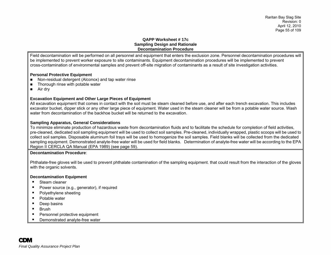
Raritan Bay Slag Site Revision: 0
April 12, 2010 Page 55 of 109
A Final Quality Assurance Project Plan
QAPP Worksheet # 17c Sampling Design and Rationale
Decontamination Procedure Field decontamination will be performed on all personnel and equipment that enters the exclusion zone. Personnel decontamination procedures will be implemented to prevent worker exposure to site contaminants. Equipment decontamination procedures will be implemented to prevent cross-contamination of environmental samples and prevent off-site migration of contaminants as a result of site investigation activities. Personal Protective Equipment
Non-residual detergent (Alconox) and tap water rinse Thorough rinse with potable water Air dry
Excavation Equipment and Other Large Pieces of Equipment All excavation equipment that comes in contact with the soil must be steam cleaned before use, and after each trench excavation. This includes excavator bucket, dipper stick or any other large piece of equipment. Water used in the steam cleaner will be from a potable water source. Wash water from decontamination of the backhoe bucket will be returned to the excavation. Sampling Apparatus, General Considerations To minimize eliminate production of hazardous waste from decontamination fluids and to facilitate the schedule for completion of field activities, pre-cleaned, dedicated soil sampling equipment will be used to collect soil samples. Pre-cleaned, individually wrapped, plastic scoops will be used to collect soil samples. Disposable aluminum foil trays will be used to homogenize the soil samples. Field blanks will be collected from the dedicated sampling equipment. Demonstrated analyte-free water will be used for field blanks. Determination of analyte-free water will be according to the EPA Region II CERCLA QA Manual (EPA 1989) (see page 59). Decontamination Procedure: Phthalate-free gloves will be used to prevent phthalate contamination of the sampling equipment. that could result from the interaction of the gloves with the organic solvents. Decontamination Equipment
Steam cleaner Power source (e.g., generator), if required Polyethylene sheeting Potable water Deep basins Brush Personnel protective equipment Demonstrated analyte-free water
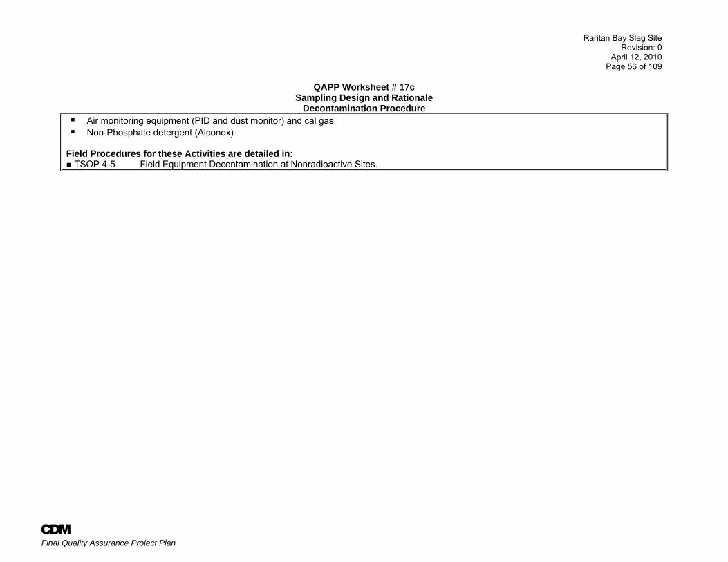
Raritan Bay Slag Site Revision: 0
April 12, 2010 Page 56 of 109
A Final Quality Assurance Project Plan
QAPP Worksheet # 17c Sampling Design and Rationale
Decontamination Procedure Air monitoring equipment (PID and dust monitor) and cal gas Non-Phosphate detergent (Alconox)
Field Procedures for these Activities are detailed in: ■ TSOP 4-5 Field Equipment Decontamination at Nonradioactive Sites.
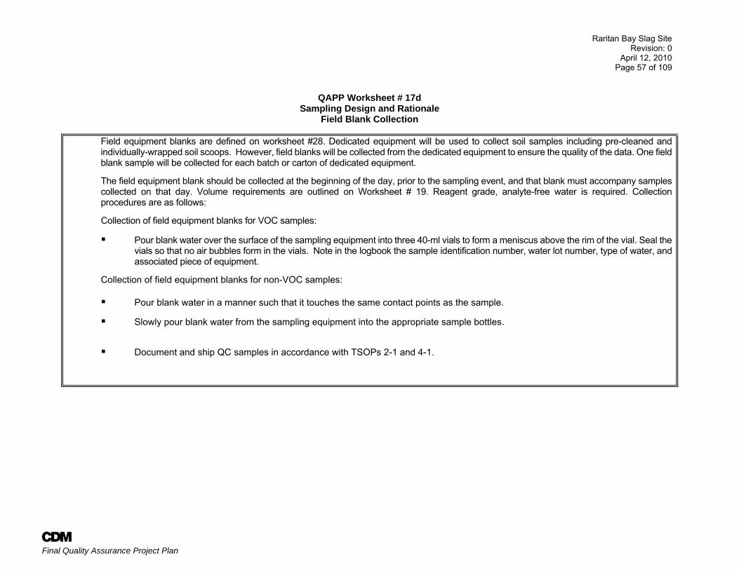
Raritan Bay Slag Site Revision: 0
April 12, 2010 Page 57 of 109
A Final Quality Assurance Project Plan
QAPP Worksheet # 17d
Sampling Design and Rationale Field Blank Collection
Field equipment blanks are defined on worksheet #28. Dedicated equipment will be used to collect soil samples including pre-cleaned and individually-wrapped soil scoops. However, field blanks will be collected from the dedicated equipment to ensure the quality of the data. One field blank sample will be collected for each batch or carton of dedicated equipment.
The field equipment blank should be collected at the beginning of the day, prior to the sampling event, and that blank must accompany samples collected on that day. Volume requirements are outlined on Worksheet # 19. Reagent grade, analyte-free water is required. Collection procedures are as follows:
Collection of field equipment blanks for VOC samples:
Pour blank water over the surface of the sampling equipment into three 40-ml vials to form a meniscus above the rim of the vial. Seal the vials so that no air bubbles form in the vials. Note in the logbook the sample identification number, water lot number, type of water, and associated piece of equipment.
Collection of field equipment blanks for non-VOC samples: Pour blank water in a manner such that it touches the same contact points as the sample.
Slowly pour blank water from the sampling equipment into the appropriate sample bottles.
Document and ship QC samples in accordance with TSOPs 2-1 and 4-1.
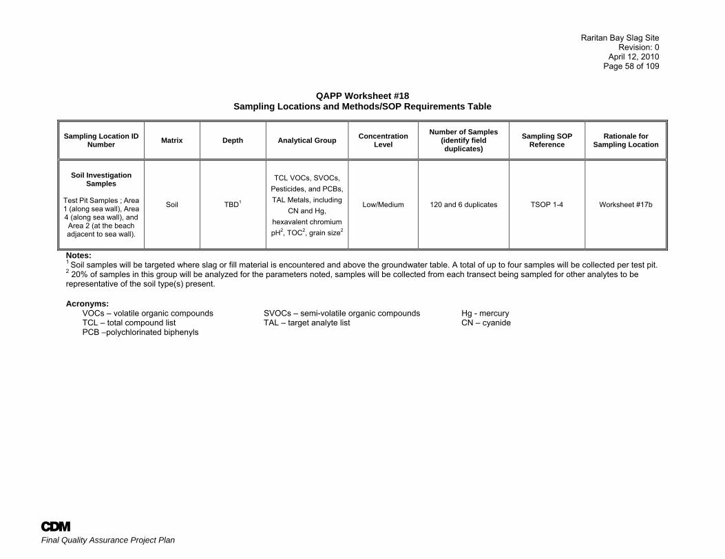
Raritan Bay Slag Site Revision: 0
April 12, 2010 Page 58 of 109
A Final Quality Assurance Project Plan
QAPP Worksheet #18
Sampling Locations and Methods/SOP Requirements Table
Sampling Location ID Number Matrix Depth Analytical Group Concentration
Level Number of Samples
(identify field duplicates)
Sampling SOP Reference
Rationale for Sampling Location
Soil Investigation
Samples
Test Pit Samples ; Area 1 (along sea wall), Area 4 (along sea wall), and Area 2 (at the beach adjacent to sea wall).
Soil TBD1
TCL VOCs, SVOCs,
Pesticides, and PCBs, TAL Metals, including
CN and Hg, hexavalent chromium pH2, TOC2, grain size2
Low/Medium 120 and 6 duplicates TSOP 1-4 Worksheet #17b
Notes: 1 Soil samples will be targeted where slag or fill material is encountered and above the groundwater table. A total of up to four samples will be collected per test pit. 2 20% of samples in this group will be analyzed for the parameters noted, samples will be collected from each transect being sampled for other analytes to be representative of the soil type(s) present. Acronyms:
VOCs – volatile organic compounds SVOCs – semi-volatile organic compounds Hg - mercury TCL – total compound list TAL – target analyte list CN – cyanide PCB –polychlorinated biphenyls
Raritan Bay Slag Site Revision: 0
April 12, 2010 Page 59 of 109
A Final Quality Assurance Project Plan
QAPP Worksheet #19
Analytical SOP Requirements Table
Matrix Analytical Group
Concentration Level
Analytical and Preparation Method/
SOP Reference
Sample Volume
Containers (number, size, and type)
Preservation Requirements
Maximum Holding Time (preparation/
analysis)
Soil for DESA or CLP
VOC Low 5035A/SOM01.2 15 grams (3) 40 mL glass vials with magnetic stir bars and PTFE lined septa/open top screw caps
Cool to 4°C 10 days VTSR; Technical-14 days (Technical is from time of sample collection)
Moisture - include with VOCs samples
Low SOM01.2 15 grams (1) 4 oz. glass jar w/Teflon lined cap
No headspace 48 hours technical
TCL SVOCs
Low SOM01.2 100 grams (1) 8 oz. glass jar w/Teflon lined cap
Cool to 4oC 10 days extract-VTSR; 40 days analyze
TCL Pesticides Low SOM01.2 100 grams (1) 8 oz. glass jar w/Teflon lined cap
Cool to 4oC 10 days extract-VTSR; 40 days analyze Technical 14/40
TCL PCB
Low SOM01.2 100 grams (1) 8 oz. glass jar w/Teflon lined cap
Cool to 4oC
TAL Metals (including Hg and CN)
Low ILM05.4 250 grams (1) 8 oz. glass jar w/Teflon lined cap
Cool to 4oC Technical-180 days (Hg-28 days and cyanide 14 days) VTSR - Subtract 2 days – this allowance for sample receipt by laboratory
Soil for DESA Hexavalent Chromium
Low SW-846 3060A, 7196A 50 g 1-8 oz jar Cool to 4oC 30 days to extraction; 7 days to analyze after extraction
TOC Low Lloyd Kahn 10 g (1) 8-oz glass jar Cool to 4oC 14 days
Grain size Low ASTM D421-85 ASTM D422-63
500 g (1) 8-oz glass jar Cool to 4oC None
pH Low SW-846, 9045D 10 g (1) 8-oz glass jar Cool to 4oC 48 hours
Technical holding time is referenced unless otherwise noted. MS/MSD is not required for TCL VOCs and SVOCs. The field team is encouraged to consolidate the sample volumes in consultation with DESA, RSCC and the subcontract laboratories as appropriate. Additional sample volumes may be required when more than one option of a method is requested, for example Low plus SIM SVOC analysis. Consult the CLP Guidance for Field Samplers and include this information in the project-specific QAPPs.
Raritan Bay Slag Site Revision: 0
April 12, 2010 Page 60 of 109
A Final Quality Assurance Project Plan
QAPP Worksheet #19 Analytical SOP Requirements Table
Matrix Analytical Group [Lab Assignment]
Concentration Level
Analytical and Preparation Method/SOP
Reference
Sample Volume
Containers (number, size, and
type) Preservation
Requirements
Maximum Holding Time (preparation/
analysis)
Aqueous (Equipment Blanks)
TCL VOCs Low SOM01.2 120 ml (3) 40 ml VOA vials w/Teflon lined septum
1:1 HCl to pH<2; cool to 4°C
10 days
TCL SVOCs Low SOM01.2 1000 ml (2) 1L amber glass bottles w/Teflon lined cap
Cool to 4°C 5 days extract, 40 days analyze
TCL Pesticides Low SOM01.2 1000 ml (2) 1L amber glass bottle w/Teflon lined cap
Cool to 4°C 5 days extract, 40 days analyze
TCL Aroclors/PCBs Low SOM01.2 1000 ml Included with Pesticides
Cool to 4°C 5 days extract, 40 days analyze
TAL Metals, Mercury Low ILM05.4 250 ml (1) 1 L polyethylene HNO3 to pH<2;
cool to 4°C
6 months
(Hg-28 days)
Cyanide Low 250 ml (1) 1L HDPE NaOH to pH >12; cool to 4°C
12 days VTSR; 14 days Technical
Hexavalent Chromium
Low SW-846 7196A 500 ml 0.5 L polyethylene bottle
Cool to 4°C 24 hours
Verified time of sample receipt (VTSR) holding time is referenced above. MS/MSD is not required for QC samples. The field team is encouraged to consolidate the sample volumes in consultation with DESA, RSCC and the subcontract laboratories as appropriate.
Raritan Bay Slag Site Revision: 0
April 12, 2010 Page 61 of 109
A Final Quality Assurance Project Plan
QAPP Worksheet #20 Field Quality Control Sample Summary Table1
Matrix Analytical Group
Concentration Level
Analytical and
Preparation SOP
Reference
No. of Sampling
Locations2
No. of Field Duplicate
Pairs
No. of Extra Volume
Laboratory QC (e.g., MS/MSD)
Samples
No. of Equipment
Blanks
No. of Trip.
Blanks No of PE Samples3
Soil/ Sediment TCL VOC Low SOM01.2 302 6 NA 1 per decontamination event NA 0
Percent Moisture NA SOM01.2 302 6 NA NA NA 0
TCL SVOC Low SOM01.2 302 6 NA
1 per decontamination event not to exceed 1
per day
NA 0
TCL Pesticides Low SOM01.2 302 6 See the CLP Guidance for Field
Samplers
NA 0
TCL Aroclors (PCB) Compounds Low SOM01.2 302 6 NA 0
TAL Metals, CN & Hg Low ILM05.4 302 6 1 per SDG NA 0
Hexavalent Chromium Low SW-846 7196A/ 3060A 302 6 NA 1 per decontamination
event NA 0
Grain size, pH, TOC NA Varies 24 2 NA NA NA 0
Aqueous
(Field Blank) TCL VOC Low SOM01.2
NA
NA NA
1 per decon event (approx. 20)
1 per cooler 0
TCL SVOC Low SOM01.2 NA NA NA 0
TCL Pesticides Low SOM01.2 NA See the CLP Guidance for Field
Samplers
NA 0
TCL Aroclors (PCB) Compounds Low SOM01.2 NA NA 0
TAL Metals, CN & Hg Low ILM05.4 NA 1 per SDG NA 0
Hexavalent Chromium Low SW-846 7196A NA NA NA 0
Notes: 1. The frequency of QC samples is outlined above. One field blank will be collected for each batch of dedicated sampling equipment. 2. A total of up to four samples will be collected per test pit location. 3. PE samples may be requested by EPA Region 2.
Raritan Bay Slag Site Revision: 0
April 12, 2010 Page 62 of 109
A Final Quality Assurance Project Plan
QAPP Worksheet #21 Project Sampling SOP References Table
Reference Number Title, Revision Date and/or Number
Originating
Organization Equipment Type*
Modified for Project Work?
(Y/N) Comments 1-2 Sample Custody, Rev. 5, 3/31/07 CDM NA Y Contract clarification applies;
-Sample tags are not required. -Forms II Lite generated COCs will be used. -Use waterproof ink for any handwritten labels.
1-4 Subsurface Sampling, Rev. 6, 3/31/07 CDM TSOP/ trowels and bowls
Y* Contract clarification applies; Section 4.5 and 5.2.6 for Backhoe Sampling
1-10 Field Measurement of Organic Vapors, Rev. 4, 3/31/07 CDM TSOP/ Mini-RAE/Multi-RAE
N
2-1 Packaging and Shipping Environmental Samples, Rev. 3, 3/31/07
CDM TSOP Y Contract clarification applies -Methanol will not be used. -Vermiculite shall not be used. -Metal cans will be used to collect medium level soil samples.
2-2 Guide to Handling of Investigation-Derived Waste, Rev. 5, 3/31/07
CDM NA N
3-5 Lithologic Logging CDM NA N
4-1 Field Logbook Content and Control, Rev. 6, 3/31/07 CDM NA Y Contract clarification applies Logbook notes should include decon procedures used, descriptions of photos taken, problems encountered and notes of conversations with Project Engineer/PM/Project Geologist. Details of samples collected including CLP numbers and visual observations.
4-2 Photographic Documentation of Field Activities, Rev. 7, 3/31/07 CDM Camera N
4-5 Field Equipment Decontamination at Nonradioactive Sites, Rev. 7, 3/31/07
CDM TSOP Y Contract clarification applies See Worksheet #17i -Use phthalate-free gloves
5-1 Control of Measurement and Test Equipment, Rev. 8, 3/31/07 CDM NA Y Contract clarification applies Leased or rented equipment only to be used.
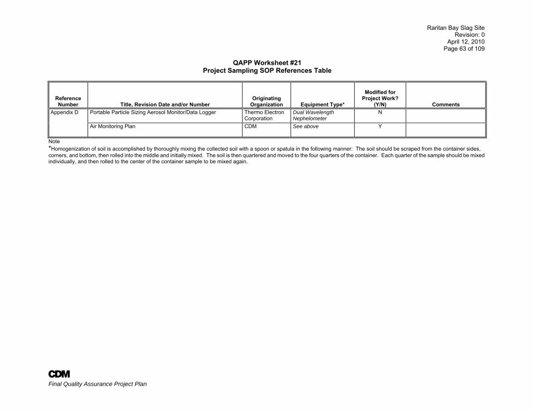
Raritan Bay Slag Site Revision: 0
April 12, 2010 Page 63 of 109
A Final Quality Assurance Project Plan
QAPP Worksheet #21 Project Sampling SOP References Table
Reference Number Title, Revision Date and/or Number
Originating
Organization Equipment Type*
Modified for Project Work?
(Y/N) Comments Appendix D Portable Particle Sizing Aerosol Monitor/Data Logger Thermo Electron
Corporation Dual Wavelength Nephelometer
N
Air Monitoring Plan CDM See above Y
Note *Homogenization of soil is accomplished by thoroughly mixing the collected soil with a spoon or spatula in the following manner: The soil should be scraped from the container sides, corners, and bottom, then rolled into the middle and initially mixed. The soil is then quartered and moved to the four quarters of the container. Each quarter of the sample should be mixed individually, and then rolled to the center of the container sample to be mixed again.
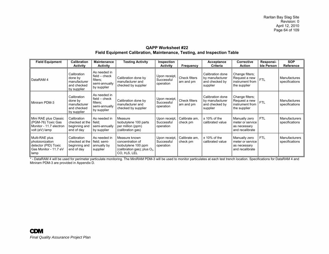
Raritan Bay Slag Site Revision: 0
April 12, 2010 Page 64 of 109
A Final Quality Assurance Project Plan
QAPP Worksheet #22 Field Equipment Calibration, Maintenance, Testing, and Inspection Table
Field Equipment Calibration
Activity Maintenance
Activity Testing Activity Inspection
Activity
Frequency Acceptance
Criteria Corrective
Action Responsi-ble Person
SOP Reference
DataRAM 4
Calibration done by manufacturer and checked by supplier
As needed in field – check filters; semi-annually by supplier
Calibration done by manufacturer and checked by supplier
Upon receipt, Successful operation
Check filters am and pm
Calibration done by manufacturer and checked by supplier
Change filters; Request a new instrument from the supplier
FTL Manufactures specifications
Miniram PDM-3
Calibration done by manufacturer and checked by supplier
As needed in field – check filters; semi-annually by supplier
Calibration done by manufacturer and checked by supplier
Upon receipt, Successful operation
Check filters am and pm
Calibration done by manufacturer and checked by supplier
Change filters; Request a new instrument from the supplier
FTL Manufactures specifications
Mini RAE plus Classic (PGM-76) Toxic Gas Monitor - 11.7 electron volt (eV) lamp
Calibration checked at the beginning and end of day
As needed in field; semi-annually by supplier
Measure Isobutylene 100 parts per million (ppm) (calibration gas)
Upon receipt, Successful operation
Calibrate am, check pm
± 10% of the calibrated value
Manually zero meter or service as necessary and recalibrate
FTL Manufacturers specifications
Multi-RAE plus photoionization detector (PID) Toxic Gas Monitor - 11.7 eV lamp
Calibration checked at the beginning and end of day
As needed in field; semi- annually by supplier
Measure known concentration of Isobutylene 100 ppm (calibration gas); plus O2, CO, H2S, LEL
Upon receipt, Successful operation
Calibrate am, check pm
± 10% of the calibrated value
Manually zero meter or service as necessary and recalibrate
FTL Manufacturers specifications
* - DataRAM 4 will be used for perimeter particulate monitoring. The MiniRAM PDM-3 will be used to monitor particulates at each test trench location. Specifications for DataRAM 4 and Miniram PDM-3 are provided in Appendix D.
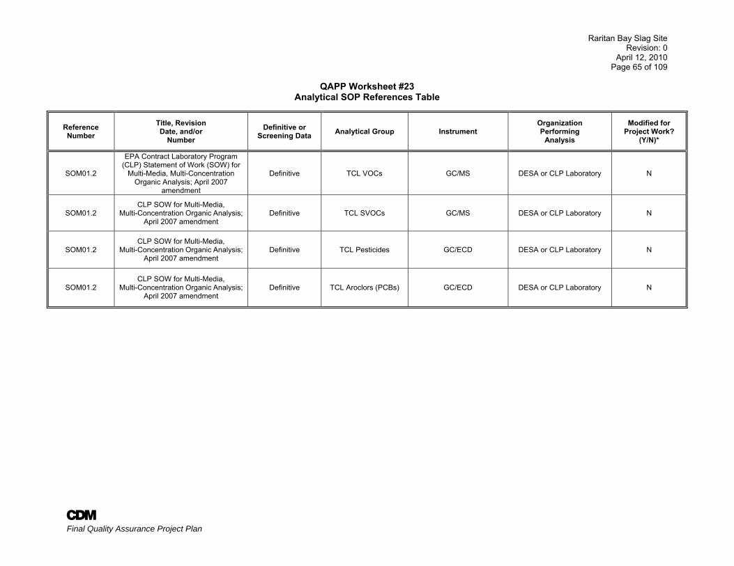
Raritan Bay Slag Site Revision: 0
April 12, 2010 Page 65 of 109
A Final Quality Assurance Project Plan
QAPP Worksheet #23 Analytical SOP References Table
Reference Number
Title, Revision Date, and/or
Number Definitive or
Screening Data Analytical Group Instrument Organization Performing
Analysis
Modified for Project Work?
(Y/N)*
SOM01.2
EPA Contract Laboratory Program (CLP) Statement of Work (SOW) for
Multi-Media, Multi-Concentration Organic Analysis; April 2007
amendment
Definitive TCL VOCs GC/MS DESA or CLP Laboratory N
SOM01.2 CLP SOW for Multi-Media,
Multi-Concentration Organic Analysis; April 2007 amendment
Definitive TCL SVOCs GC/MS DESA or CLP Laboratory N
SOM01.2 CLP SOW for Multi-Media,
Multi-Concentration Organic Analysis; April 2007 amendment
Definitive TCL Pesticides GC/ECD DESA or CLP Laboratory N
SOM01.2 CLP SOW for Multi-Media,
Multi-Concentration Organic Analysis; April 2007 amendment
Definitive TCL Aroclors (PCBs) GC/ECD DESA or CLP Laboratory N
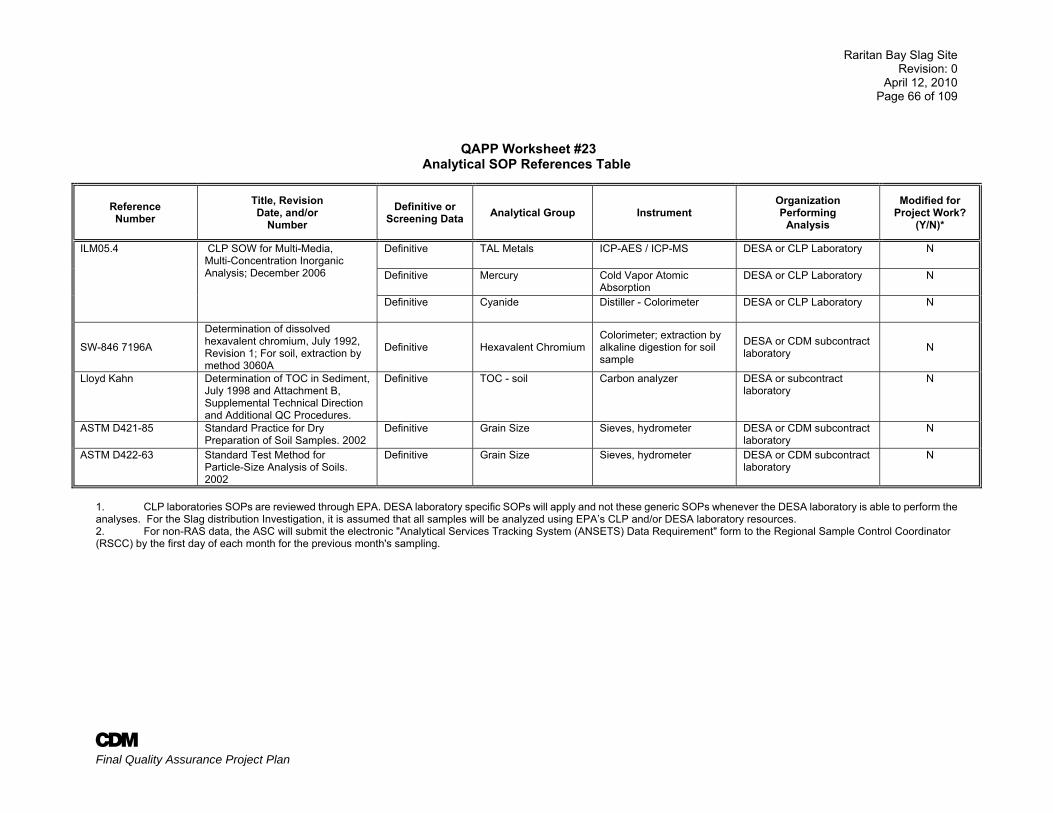
Raritan Bay Slag Site Revision: 0
April 12, 2010 Page 66 of 109
A Final Quality Assurance Project Plan
QAPP Worksheet #23 Analytical SOP References Table
Reference Number
Title, Revision Date, and/or
Number Definitive or
Screening Data Analytical Group Instrument Organization Performing
Analysis
Modified for Project Work?
(Y/N)*
ILM05.4 CLP SOW for Multi-Media, Multi-Concentration Inorganic Analysis; December 2006
Definitive TAL Metals ICP-AES / ICP-MS DESA or CLP Laboratory N
Definitive Mercury Cold Vapor Atomic Absorption
DESA or CLP Laboratory N
Definitive Cyanide Distiller - Colorimeter DESA or CLP Laboratory N
SW-846 7196A
Determination of dissolved hexavalent chromium, July 1992, Revision 1; For soil, extraction by method 3060A
Definitive Hexavalent Chromium Colorimeter; extraction by alkaline digestion for soil sample
DESA or CDM subcontract laboratory N
Lloyd Kahn Determination of TOC in Sediment, July 1998 and Attachment B, Supplemental Technical Direction and Additional QC Procedures.
Definitive TOC - soil Carbon analyzer DESA or subcontract laboratory
N
ASTM D421-85 Standard Practice for Dry Preparation of Soil Samples. 2002
Definitive Grain Size Sieves, hydrometer DESA or CDM subcontract laboratory
N
ASTM D422-63 Standard Test Method for Particle-Size Analysis of Soils. 2002
Definitive Grain Size Sieves, hydrometer DESA or CDM subcontract laboratory
N
1. CLP laboratories SOPs are reviewed through EPA. DESA laboratory specific SOPs will apply and not these generic SOPs whenever the DESA laboratory is able to perform the analyses. For the Slag distribution Investigation, it is assumed that all samples will be analyzed using EPA’s CLP and/or DESA laboratory resources. 2. For non-RAS data, the ASC will submit the electronic "Analytical Services Tracking System (ANSETS) Data Requirement" form to the Regional Sample Control Coordinator (RSCC) by the first day of each month for the previous month's sampling.
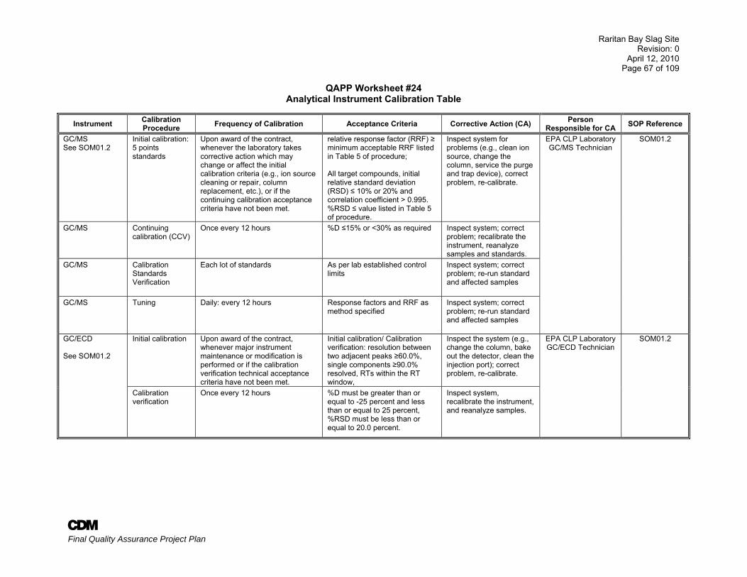
Raritan Bay Slag Site Revision: 0
April 12, 2010 Page 67 of 109
A Final Quality Assurance Project Plan
QAPP Worksheet #24 Analytical Instrument Calibration Table
Instrument Calibration Procedure Frequency of Calibration Acceptance Criteria Corrective Action (CA) Person
Responsible for CA SOP Reference
GC/MS See SOM01.2
Initial calibration: 5 points standards
Upon award of the contract, whenever the laboratory takes corrective action which may change or affect the initial calibration criteria (e.g., ion source cleaning or repair, column replacement, etc.), or if the continuing calibration acceptance criteria have not been met.
relative response factor (RRF) ≥ minimum acceptable RRF listed in Table 5 of procedure; All target compounds, initial relative standard deviation (RSD) ≤ 10% or 20% and correlation coefficient > 0.995. %RSD ≤ value listed in Table 5 of procedure.
Inspect system for problems (e.g., clean ion source, change the column, service the purge and trap device), correct problem, re-calibrate.
EPA CLP Laboratory GC/MS Technician
SOM01.2
GC/MS Continuing calibration (CCV)
Once every 12 hours %D ≤15% or <30% as required Inspect system; correct problem; recalibrate the instrument, reanalyze samples and standards.
GC/MS Calibration Standards Verification
Each lot of standards As per lab established control limits
Inspect system; correct problem; re-run standard and affected samples
GC/MS Tuning Daily: every 12 hours Response factors and RRF as method specified
Inspect system; correct problem; re-run standard and affected samples
GC/ECD See SOM01.2
Initial calibration Upon award of the contract, whenever major instrument maintenance or modification is performed or if the calibration verification technical acceptance criteria have not been met.
Initial calibration/ Calibration verification: resolution between two adjacent peaks ≥60.0%, single components ≥90.0% resolved, RTs within the RT window,
Inspect the system (e.g., change the column, bake out the detector, clean the injection port); correct problem, re-calibrate.
EPA CLP Laboratory GC/ECD Technician
SOM01.2
Calibration verification
Once every 12 hours %D must be greater than or equal to -25 percent and less than or equal to 25 percent, %RSD must be less than or equal to 20.0 percent.
Inspect system, recalibrate the instrument, and reanalyze samples.
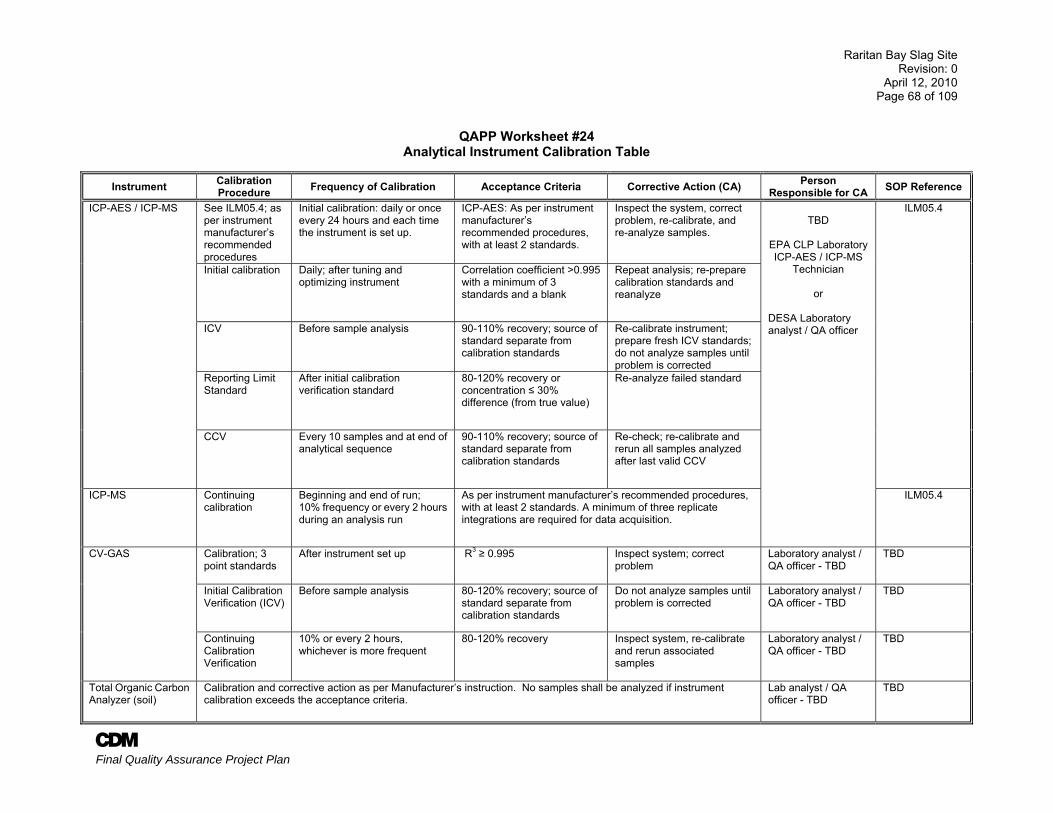
Raritan Bay Slag Site Revision: 0
April 12, 2010 Page 68 of 109
A Final Quality Assurance Project Plan
QAPP Worksheet #24
Analytical Instrument Calibration Table
Instrument Calibration Procedure Frequency of Calibration Acceptance Criteria Corrective Action (CA) Person
Responsible for CA SOP Reference
ICP-AES / ICP-MS See ILM05.4; as per instrument manufacturer’s recommended procedures
Initial calibration: daily or once every 24 hours and each time the instrument is set up.
ICP-AES: As per instrument manufacturer’s recommended procedures, with at least 2 standards.
Inspect the system, correct problem, re-calibrate, and re-analyze samples.
TBD
EPA CLP Laboratory ICP-AES / ICP-MS
Technician
or
DESA Laboratory analyst / QA officer
ILM05.4
Initial calibration Daily; after tuning and optimizing instrument
Correlation coefficient >0.995 with a minimum of 3 standards and a blank
Repeat analysis; re-prepare calibration standards and reanalyze
ICV Before sample analysis 90-110% recovery; source of standard separate from calibration standards
Re-calibrate instrument; prepare fresh ICV standards; do not analyze samples until problem is corrected
Reporting Limit Standard
After initial calibration verification standard
80-120% recovery or concentration ≤ 30% difference (from true value)
Re-analyze failed standard
CCV Every 10 samples and at end of analytical sequence
90-110% recovery; source of standard separate from calibration standards
Re-check; re-calibrate and rerun all samples analyzed after last valid CCV
ICP-MS Continuing calibration
Beginning and end of run; 10% frequency or every 2 hours during an analysis run
As per instrument manufacturer’s recommended procedures, with at least 2 standards. A minimum of three replicate integrations are required for data acquisition.
ILM05.4
CV-GAS Calibration; 3 point standards
After instrument set up R3 ≥ 0.995 Inspect system; correct problem
Laboratory analyst / QA officer - TBD
TBD
Initial Calibration Verification (ICV)
Before sample analysis 80-120% recovery; source of standard separate from calibration standards
Do not analyze samples until problem is corrected
Laboratory analyst / QA officer - TBD
TBD
Continuing Calibration Verification
10% or every 2 hours, whichever is more frequent
80-120% recovery Inspect system, re-calibrate and rerun associated samples
Laboratory analyst / QA officer - TBD
TBD
Total Organic Carbon Analyzer (soil)
Calibration and corrective action as per Manufacturer’s instruction. No samples shall be analyzed if instrument calibration exceeds the acceptance criteria.
Lab analyst / QA officer - TBD
TBD
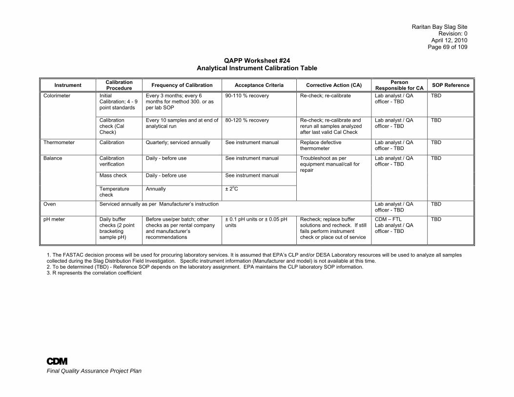
Raritan Bay Slag Site Revision: 0
April 12, 2010 Page 69 of 109
A Final Quality Assurance Project Plan
QAPP Worksheet #24 Analytical Instrument Calibration Table
Instrument Calibration Procedure Frequency of Calibration Acceptance Criteria Corrective Action (CA) Person
Responsible for CA SOP Reference
Colorimeter Initial Calibration; 4 - 9 point standards
Every 3 months; every 6 months for method 300. or as per lab SOP
90-110 % recovery Re-check; re-calibrate Lab analyst / QA officer - TBD
TBD
Calibration check (Cal Check)
Every 10 samples and at end of analytical run
80-120 % recovery Re-check; re-calibrate and rerun all samples analyzed after last valid Cal Check
Lab analyst / QA officer - TBD
TBD
Thermometer Calibration Quarterly; serviced annually See instrument manual Replace defective thermometer
Lab analyst / QA officer - TBD
TBD
Balance Calibration verification
Daily - before use See instrument manual Troubleshoot as per equipment manual/call for repair
Lab analyst / QA officer - TBD
TBD
Mass check Daily - before use See instrument manual
Temperature check
Annually ± 2oC
Oven Serviced annually as per Manufacturer’s instruction Lab analyst / QA officer - TBD
TBD
pH meter Daily buffer checks (2 point bracketing sample pH)
Before use/per batch; other checks as per rental company and manufacturer’s recommendations
± 0.1 pH units or ± 0.05 pH units
Recheck; replace buffer solutions and recheck. If still fails perform instrument check or place out of service
CDM – FTL Lab analyst / QA officer - TBD
TBD
1. The FASTAC decision process will be used for procuring laboratory services. It is assumed that EPA’s CLP and/or DESA Laboratory resources will be used to analyze all samples collected during the Slag Distribution Field Investigation. Specific instrument information (Manufacturer and model) is not available at this time. 2. To be determined (TBD) - Reference SOP depends on the laboratory assignment. EPA maintains the CLP laboratory SOP information. 3. R represents the correlation coefficient
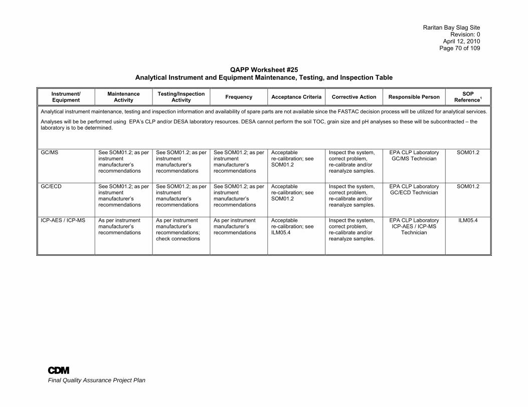
Raritan Bay Slag Site Revision: 0
April 12, 2010 Page 70 of 109
A Final Quality Assurance Project Plan
QAPP Worksheet #25
Analytical Instrument and Equipment Maintenance, Testing, and Inspection Table
Instrument/ Equipment
Maintenance Activity
Testing/Inspection Activity Frequency Acceptance Criteria Corrective Action Responsible Person SOP
Reference1
Analytical instrument maintenance, testing and inspection information and availability of spare parts are not available since the FASTAC decision process will be utilized for analytical services.
Analyses will be be performed using EPA’s CLP and/or DESA laboratory resources. DESA cannot perform the soil TOC, grain size and pH analyses so these will be subcontracted – the laboratory is to be determined.
GC/MS See SOM01.2; as per instrument manufacturer’s recommendations
See SOM01.2; as per instrument manufacturer’s recommendations
See SOM01.2; as per instrument manufacturer’s recommendations
Acceptable re-calibration; see SOM01.2
Inspect the system, correct problem, re-calibrate and/or reanalyze samples.
EPA CLP Laboratory GC/MS Technician
SOM01.2
GC/ECD See SOM01.2; as per instrument manufacturer’s recommendations
See SOM01.2; as per instrument manufacturer’s recommendations
See SOM01.2; as per instrument manufacturer’s recommendations
Acceptable re-calibration; see SOM01.2
Inspect the system, correct problem, re-calibrate and/or reanalyze samples.
EPA CLP Laboratory GC/ECD Technician
SOM01.2
ICP-AES / ICP-MS As per instrument manufacturer’s recommendations
As per instrument manufacturer’s recommendations; check connections
As per instrument manufacturer’s recommendations
Acceptable re-calibration; see ILM05.4
Inspect the system, correct problem, re-calibrate and/or reanalyze samples.
EPA CLP Laboratory ICP-AES / ICP-MS
Technician
ILM05.4
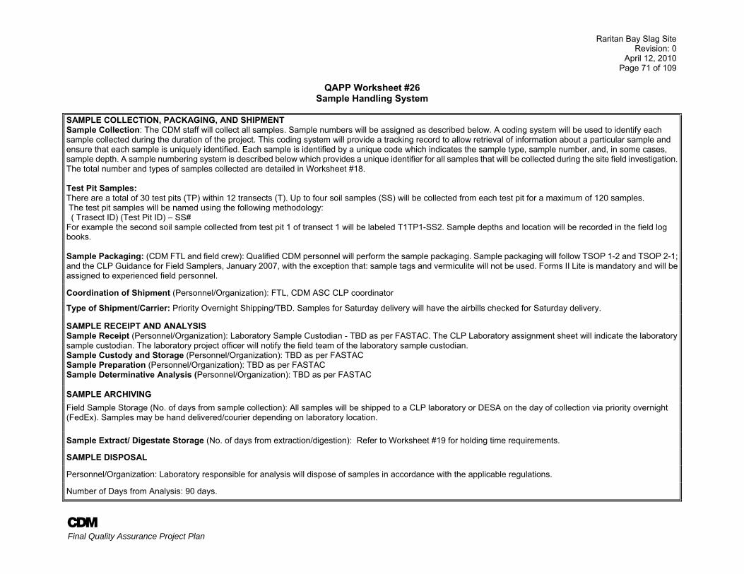
Raritan Bay Slag Site Revision: 0
April 12, 2010 Page 71 of 109
A Final Quality Assurance Project Plan
QAPP Worksheet #26 Sample Handling System
SAMPLE COLLECTION, PACKAGING, AND SHIPMENTSample Collection: The CDM staff will collect all samples. Sample numbers will be assigned as described below. A coding system will be used to identify each sample collected during the duration of the project. This coding system will provide a tracking record to allow retrieval of information about a particular sample and ensure that each sample is uniquely identified. Each sample is identified by a unique code which indicates the sample type, sample number, and, in some cases, sample depth. A sample numbering system is described below which provides a unique identifier for all samples that will be collected during the site field investigation. The total number and types of samples collected are detailed in Worksheet #18. Test Pit Samples: There are a total of 30 test pits (TP) within 12 transects (T). Up to four soil samples (SS) will be collected from each test pit for a maximum of 120 samples. The test pit samples will be named using the following methodology: ( Trasect ID) (Test Pit ID) – SS# For example the second soil sample collected from test pit 1 of transect 1 will be labeled T1TP1-SS2. Sample depths and location will be recorded in the field log books. Sample Packaging: (CDM FTL and field crew): Qualified CDM personnel will perform the sample packaging. Sample packaging will follow TSOP 1-2 and TSOP 2-1; and the CLP Guidance for Field Samplers, January 2007, with the exception that: sample tags and vermiculite will not be used. Forms II Lite is mandatory and will be assigned to experienced field personnel.
Coordination of Shipment (Personnel/Organization): FTL, CDM ASC CLP coordinator
Type of Shipment/Carrier: Priority Overnight Shipping/TBD. Samples for Saturday delivery will have the airbills checked for Saturday delivery.
SAMPLE RECEIPT AND ANALYSIS Sample Receipt (Personnel/Organization): Laboratory Sample Custodian - TBD as per FASTAC. The CLP Laboratory assignment sheet will indicate the laboratory sample custodian. The laboratory project officer will notify the field team of the laboratory sample custodian. Sample Custody and Storage (Personnel/Organization): TBD as per FASTAC Sample Preparation (Personnel/Organization): TBD as per FASTAC Sample Determinative Analysis (Personnel/Organization): TBD as per FASTAC
SAMPLE ARCHIVING Field Sample Storage (No. of days from sample collection): All samples will be shipped to a CLP laboratory or DESA on the day of collection via priority overnight (FedEx). Samples may be hand delivered/courier depending on laboratory location. Sample Extract/ Digestate Storage (No. of days from extraction/digestion): Refer to Worksheet #19 for holding time requirements.
SAMPLE DISPOSAL
Personnel/Organization: Laboratory responsible for analysis will dispose of samples in accordance with the applicable regulations.
Number of Days from Analysis: 90 days.
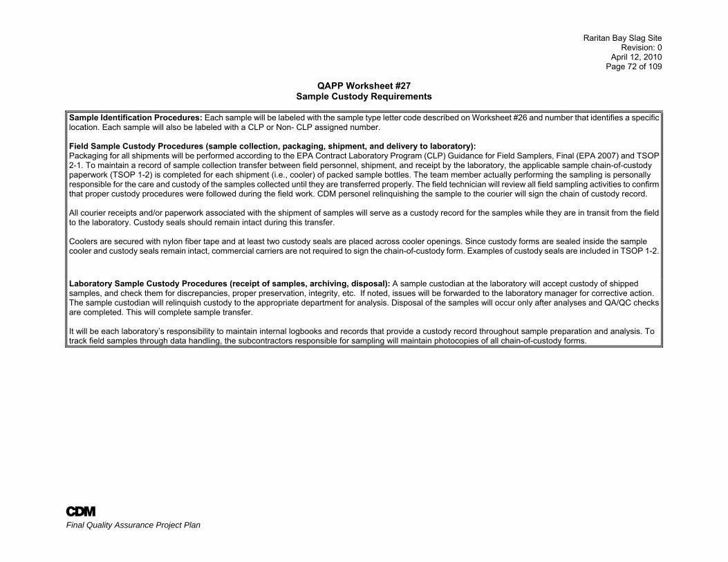
Raritan Bay Slag Site Revision: 0
April 12, 2010 Page 72 of 109
A Final Quality Assurance Project Plan
QAPP Worksheet #27 Sample Custody Requirements
Sample Identification Procedures: Each sample will be labeled with the sample type letter code described on Worksheet #26 and number that identifies a specific location. Each sample will also be labeled with a CLP or Non- CLP assigned number. Field Sample Custody Procedures (sample collection, packaging, shipment, and delivery to laboratory): Packaging for all shipments will be performed according to the EPA Contract Laboratory Program (CLP) Guidance for Field Samplers, Final (EPA 2007) and TSOP 2-1. To maintain a record of sample collection transfer between field personnel, shipment, and receipt by the laboratory, the applicable sample chain-of-custody paperwork (TSOP 1-2) is completed for each shipment (i.e., cooler) of packed sample bottles. The team member actually performing the sampling is personally responsible for the care and custody of the samples collected until they are transferred properly. The field technician will review all field sampling activities to confirm that proper custody procedures were followed during the field work. CDM personel relinquishing the sample to the courier will sign the chain of custody record. All courier receipts and/or paperwork associated with the shipment of samples will serve as a custody record for the samples while they are in transit from the field to the laboratory. Custody seals should remain intact during this transfer. Coolers are secured with nylon fiber tape and at least two custody seals are placed across cooler openings. Since custody forms are sealed inside the sample cooler and custody seals remain intact, commercial carriers are not required to sign the chain-of-custody form. Examples of custody seals are included in TSOP 1-2.
Laboratory Sample Custody Procedures (receipt of samples, archiving, disposal): A sample custodian at the laboratory will accept custody of shipped samples, and check them for discrepancies, proper preservation, integrity, etc. If noted, issues will be forwarded to the laboratory manager for corrective action. The sample custodian will relinquish custody to the appropriate department for analysis. Disposal of the samples will occur only after analyses and QA/QC checks are completed. This will complete sample transfer. It will be each laboratory’s responsibility to maintain internal logbooks and records that provide a custody record throughout sample preparation and analysis. To track field samples through data handling, the subcontractors responsible for sampling will maintain photocopies of all chain-of-custody forms.
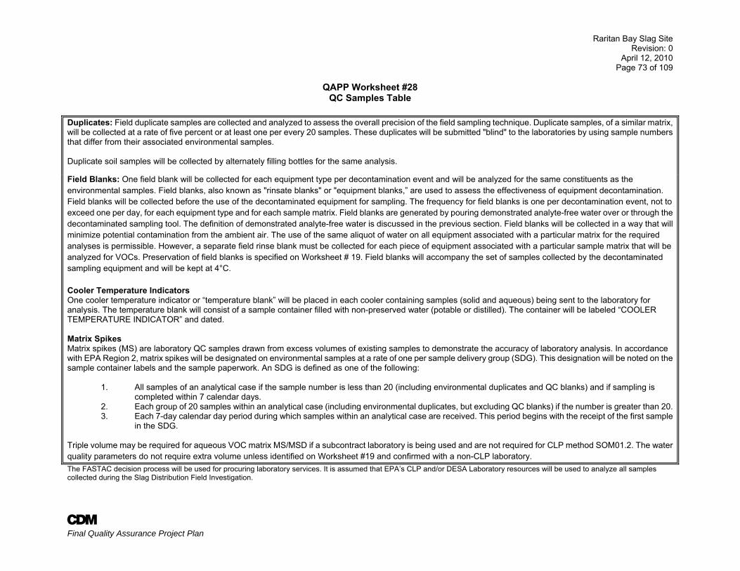
Raritan Bay Slag Site Revision: 0
April 12, 2010 Page 73 of 109
A Final Quality Assurance Project Plan
QAPP Worksheet #28 QC Samples Table
Duplicates: Field duplicate samples are collected and analyzed to assess the overall precision of the field sampling technique. Duplicate samples, of a similar matrix, will be collected at a rate of five percent or at least one per every 20 samples. These duplicates will be submitted "blind" to the laboratories by using sample numbers that differ from their associated environmental samples. Duplicate soil samples will be collected by alternately filling bottles for the same analysis. Field Blanks: One field blank will be collected for each equipment type per decontamination event and will be analyzed for the same constituents as the environmental samples. Field blanks, also known as "rinsate blanks" or "equipment blanks,” are used to assess the effectiveness of equipment decontamination. Field blanks will be collected before the use of the decontaminated equipment for sampling. The frequency for field blanks is one per decontamination event, not to exceed one per day, for each equipment type and for each sample matrix. Field blanks are generated by pouring demonstrated analyte-free water over or through the decontaminated sampling tool. The definition of demonstrated analyte-free water is discussed in the previous section. Field blanks will be collected in a way that will minimize potential contamination from the ambient air. The use of the same aliquot of water on all equipment associated with a particular matrix for the required analyses is permissible. However, a separate field rinse blank must be collected for each piece of equipment associated with a particular sample matrix that will be analyzed for VOCs. Preservation of field blanks is specified on Worksheet # 19. Field blanks will accompany the set of samples collected by the decontaminated sampling equipment and will be kept at 4°C. Cooler Temperature Indicators One cooler temperature indicator or “temperature blank” will be placed in each cooler containing samples (solid and aqueous) being sent to the laboratory for analysis. The temperature blank will consist of a sample container filled with non-preserved water (potable or distilled). The container will be labeled “COOLER TEMPERATURE INDICATOR” and dated. Matrix Spikes Matrix spikes (MS) are laboratory QC samples drawn from excess volumes of existing samples to demonstrate the accuracy of laboratory analysis. In accordance with EPA Region 2, matrix spikes will be designated on environmental samples at a rate of one per sample delivery group (SDG). This designation will be noted on the sample container labels and the sample paperwork. An SDG is defined as one of the following:
1. All samples of an analytical case if the sample number is less than 20 (including environmental duplicates and QC blanks) and if sampling is completed within 7 calendar days.
2. Each group of 20 samples within an analytical case (including environmental duplicates, but excluding QC blanks) if the number is greater than 20.3. Each 7-day calendar day period during which samples within an analytical case are received. This period begins with the receipt of the first sample
in the SDG.
Triple volume may be required for aqueous VOC matrix MS/MSD if a subcontract laboratory is being used and are not required for CLP method SOM01.2. The water quality parameters do not require extra volume unless identified on Worksheet #19 and confirmed with a non-CLP laboratory. The FASTAC decision process will be used for procuring laboratory services. It is assumed that EPA’s CLP and/or DESA Laboratory resources will be used to analyze all samples collected during the Slag Distribution Field Investigation.
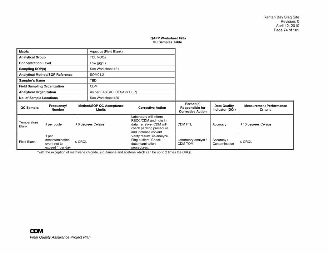
Raritan Bay Slag Site Revision: 0
April 12, 2010 Page 74 of 109
A Final Quality Assurance Project Plan
QAPP Worksheet #28a QC Samples Table
Matrix Aqueous (Field Blank)
Analytical Group TCL VOCs
Concentration Level Low (µg/L)
Sampling SOP(s) See Worksheet #21
Analytical Method/SOP Reference SOM01.2
Sampler’s Name TBD
Field Sampling Organization CDM
Analytical Organization As per FASTAC [DESA or CLP]
No. of Sample Locations See Worksheet #20
QC Sample: Frequency/ Number
Method/SOP QC Acceptance Limits Corrective Action
Person(s) Responsible for
Corrective Action Data Quality
Indicator (DQI) Measurement Performance
Criteria
Temperature Blank 1 per cooler ≤ 6 degrees Celsius
Laboratory will inform RSCC/CDM and note in data narrative. CDM will check packing procedure and increase coolant
CDM FTL Accuracy ≤ 10 degrees Celsius
Field Blank
1 per decontamination event not to exceed 1 per day
≤ CRQL
Verify results; re-analyze. Flag outliers. Check decontamination procedures.
Laboratory analyst / CDM TOM
Accuracy / Contamination ≤ CRQL
*with the exception of methylene chloride, 2-butanone and acetone which can be up to 2 times the CRQL.
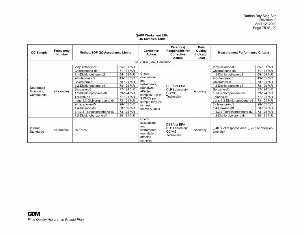
Raritan Bay Slag Site Revision: 0
April 12, 2010 Page 75 of 109
A Final Quality Assurance Project Plan
QAPP Worksheet #28a QC Samples Table
QC Sample: Frequency/ Number Method/SOP QC Acceptance Limits Corrective
Action
Person(s) Responsible for
Corrective Action
Data Quality
Indicator (DQI)
Measurement Performance Criteria
TCL VOCs (Low) Continued
Deuterated Monitoring Compounds
all samples
Vinyl chloride-d3 65-131 %R
Check calculations and instruments, reanalyze affected samples; *up to 3 DMCs per sample may fail to meet recovery limits
DESA or EPA CLP Laboratory GC/MS Technician
Accuracy
Vinyl chloride-d3 65-131 %R Chloroethane-d5 71-131 %R Chloroethane-d5 71-131 %R 1,1-Dichloroethene-d2 55-104 %R 1,1-Dichloroethene-d2 55-104 %R 2-Butanone-d5 49-155 %R 2-Butanone-d5 49-155 %R Chloroform-d 78-121 %R Chloroform-d 78-121 %R 1,2-Dichloroethane-d4 78-129 %R 1,2-Dichloroethane-d4 78-129 %R Benzene-d6 77-124 %R Benzene-d6 77-124 %R 1,2-Dichloropropane-d6 79-124 %R 1,2-Dichloropropane-d6 79-124 %R Toluene-d8 77-121 %R Toluene-d8 77-121 %R trans-1,3-Dichloropropene-d4 73-121 %R trans-1,3-Dichloropropene-d4 73-121 %R 2-Hexanone-d5 28-135 %R 2-Hexanone-d5 28-135 %R 1,4-Dioxane-d8 50-150 %R 1,4-Dioxane-d8 50-150 %R 1,1,2,2-Tetrachloroethane-d2 73-125 %R 1,1,2,2-Tetrachloroethane-d2 73-125 %R 1,2-Dichlorobenzene-d4 80-131 %R 1,2-Dichlorobenzene-d4 80-131 %R
Internal Standards all samples 60-140%
Check calculations and instruments, reanalyze affected samples
DESA or EPA CLP Laboratory GC/MS Technician
Accuracy + 40 % of response area, + 20 sec retention time shift
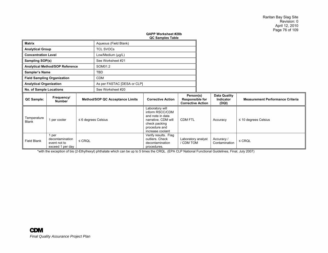
Raritan Bay Slag Site Revision: 0
April 12, 2010 Page 76 of 109
A Final Quality Assurance Project Plan
QAPP Worksheet #28b QC Samples Table
Matrix Aqueous (Field Blank)
Analytical Group TCL SVOCs
Concentration Level Low/Medium (µg/L)
Sampling SOP(s) See Worksheet #21
Analytical Method/SOP Reference SOM01.2
Sampler’s Name TBD
Field Sampling Organization CDM
Analytical Organization As per FASTAC [DESA or CLP]
No. of Sample Locations See Worksheet #20
QC Sample: Frequency/ Number Method/SOP QC Acceptance Limits Corrective Action
Person(s) Responsible for
Corrective Action
Data Quality Indicator
(DQI) Measurement Performance Criteria
Temperature Blank 1 per cooler ≤ 6 degrees Celsius
Laboratory will inform RSCC/CDM and note in data narrative. CDM will check packing procedure and increase coolant
CDM FTL Accuracy ≤ 10 degrees Celsius
Field Blank
1 per decontamination event not to exceed 1 per day
≤ CRQL
Verify results. Flag outliers. Check decontamination procedures.
Laboratory analyst / CDM TOM
Accuracy / Contamination ≤ CRQL
*with the exception of bis (2-Ethylhexyl) phthalate which can be up to 5 times the CRQL. (EPA CLP National Functional Guidelines, Final, July 2007)
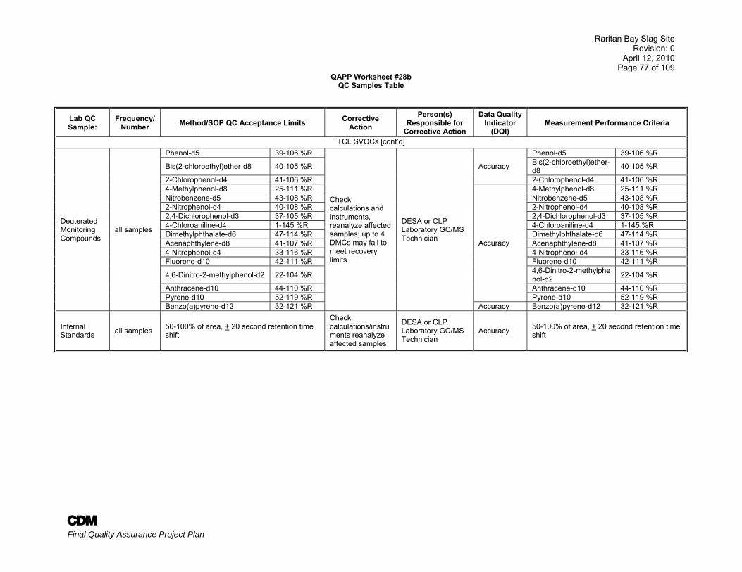
Raritan Bay Slag Site Revision: 0
April 12, 2010 Page 77 of 109
A Final Quality Assurance Project Plan
QAPP Worksheet #28b QC Samples Table
Lab QC Sample:
Frequency/ Number Method/SOP QC Acceptance Limits Corrective
Action Person(s)
Responsible for Corrective Action
Data Quality Indicator
(DQI) Measurement Performance Criteria
TCL SVOCs [cont’d]
Deuterated Monitoring Compounds
all samples
Phenol-d5 39-106 %R
Check calculations and instruments, reanalyze affected samples; up to 4 DMCs may fail to meet recovery limits
DESA or CLP Laboratory GC/MS Technician
Accuracy
Phenol-d5 39-106 %R
Bis(2-chloroethyl)ether-d8 40-105 %R Bis(2-chloroethyl)ether-d8 40-105 %R
2-Chlorophenol-d4 41-106 %R 2-Chlorophenol-d4 41-106 %R 4-Methylphenol-d8 25-111 %R
Accuracy
4-Methylphenol-d8 25-111 %R Nitrobenzene-d5 43-108 %R Nitrobenzene-d5 43-108 %R 2-Nitrophenol-d4 40-108 %R 2-Nitrophenol-d4 40-108 %R 2,4-Dichlorophenol-d3 37-105 %R 2,4-Dichlorophenol-d3 37-105 %R 4-Chloroaniline-d4 1-145 %R 4-Chloroaniline-d4 1-145 %R Dimethylphthalate-d6 47-114 %R Dimethylphthalate-d6 47-114 %R Acenaphthylene-d8 41-107 %R Acenaphthylene-d8 41-107 %R 4-Nitrophenol-d4 33-116 %R 4-Nitrophenol-d4 33-116 %R Fluorene-d10 42-111 %R Fluorene-d10 42-111 %R
4,6-Dinitro-2-methylphenol-d2 22-104 %R 4,6-Dinitro-2-methylphenol-d2 22-104 %R
Anthracene-d10 44-110 %R Anthracene-d10 44-110 %R Pyrene-d10 52-119 %R Pyrene-d10 52-119 %R Benzo(a)pyrene-d12 32-121 %R Accuracy Benzo(a)pyrene-d12 32-121 %R
Internal Standards all samples 50-100% of area, + 20 second retention time
shift
Check calculations/instruments reanalyze affected samples
DESA or CLP Laboratory GC/MS Technician
Accuracy 50-100% of area, + 20 second retention time shift
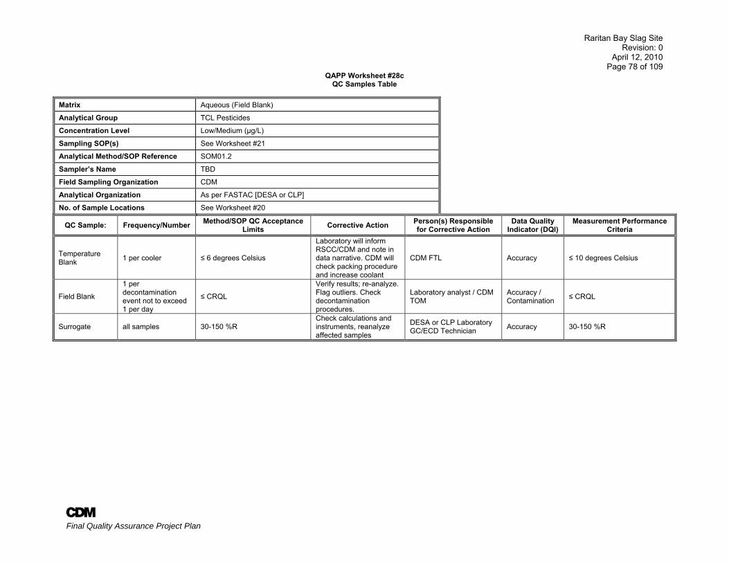
Raritan Bay Slag Site Revision: 0
April 12, 2010 Page 78 of 109
A Final Quality Assurance Project Plan
QAPP Worksheet #28c QC Samples Table
Matrix Aqueous (Field Blank)
Analytical Group TCL Pesticides
Concentration Level Low/Medium (µg/L)
Sampling SOP(s) See Worksheet #21
Analytical Method/SOP Reference SOM01.2
Sampler’s Name TBD
Field Sampling Organization CDM
Analytical Organization As per FASTAC [DESA or CLP]
No. of Sample Locations See Worksheet #20
QC Sample: Frequency/Number Method/SOP QC Acceptance Limits Corrective Action Person(s) Responsible
for Corrective Action Data Quality
Indicator (DQI) Measurement Performance
Criteria
Temperature Blank 1 per cooler ≤ 6 degrees Celsius
Laboratory will inform RSCC/CDM and note in data narrative. CDM will check packing procedure and increase coolant
CDM FTL Accuracy ≤ 10 degrees Celsius
Field Blank
1 per decontamination event not to exceed 1 per day
≤ CRQL
Verify results; re-analyze. Flag outliers. Check decontamination procedures.
Laboratory analyst / CDM TOM
Accuracy / Contamination ≤ CRQL
Surrogate all samples 30-150 %R Check calculations and instruments, reanalyze affected samples
DESA or CLP Laboratory GC/ECD Technician Accuracy 30-150 %R
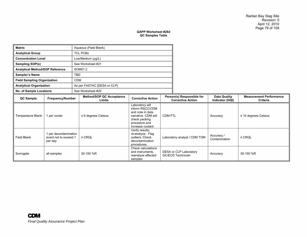
Raritan Bay Slag Site Revision: 0
April 12, 2010 Page 79 of 109
A Final Quality Assurance Project Plan
QAPP Worksheet #28d QC Samples Table
Matrix Aqueous (Field Blank)
Analytical Group TCL PCBs
Concentration Level Low/Medium (µg/L)
Sampling SOP(s) See Worksheet #21
Analytical Method/SOP Reference SOM01.2
Sampler’s Name TBD
Field Sampling Organization CDM
Analytical Organization As per FASTAC [DESA or CLP]
No. of Sample Locations See Worksheet #20
QC Sample: Frequency/Number Method/SOP QC Acceptance Limits Corrective Action Person(s) Responsible for
Corrective Action Data Quality
Indicator (DQI) Measurement Performance
Criteria
Temperature Blank 1 per cooler ≤ 6 degrees Celsius
Laboratory will inform RSCC/CDM and note in data narrative. CDM will check packing procedure and increase coolant
CDM FTL Accuracy ≤ 10 degrees Celsius
Field Blank 1 per decontamination event not to exceed 1 per day
≤ CRQL
Verify results; re-analyze. Flag outliers. Check decontamination procedures.
Laboratory analyst / CDM TOM Accuracy / Contamination ≤ CRQL
Surrogate all samples 30-150 %R
Check calculations and instruments, reanalyze affected samples
DESA or CLP Laboratory GC/ECD Technician Accuracy 30-150 %R
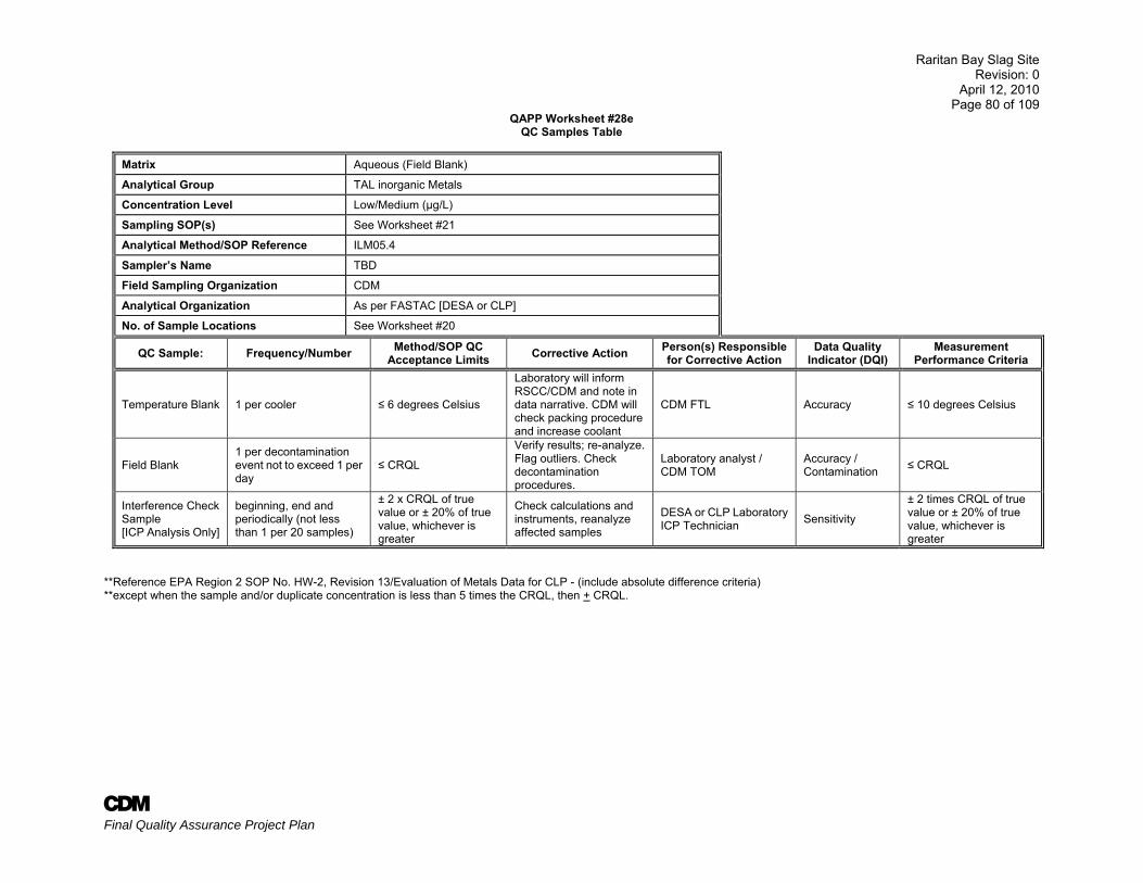
Raritan Bay Slag Site Revision: 0
April 12, 2010 Page 80 of 109
A Final Quality Assurance Project Plan
QAPP Worksheet #28e QC Samples Table
Matrix Aqueous (Field Blank)
Analytical Group TAL inorganic Metals
Concentration Level Low/Medium (µg/L)
Sampling SOP(s) See Worksheet #21
Analytical Method/SOP Reference ILM05.4
Sampler’s Name TBD
Field Sampling Organization CDM
Analytical Organization As per FASTAC [DESA or CLP]
No. of Sample Locations See Worksheet #20
QC Sample: Frequency/Number Method/SOP QC Acceptance Limits Corrective Action Person(s) Responsible
for Corrective Action Data Quality
Indicator (DQI) Measurement
Performance Criteria
Temperature Blank 1 per cooler ≤ 6 degrees Celsius
Laboratory will inform RSCC/CDM and note in data narrative. CDM will check packing procedure and increase coolant
CDM FTL Accuracy ≤ 10 degrees Celsius
Field Blank 1 per decontamination event not to exceed 1 per day
≤ CRQL
Verify results; re-analyze. Flag outliers. Check decontamination procedures.
Laboratory analyst / CDM TOM
Accuracy / Contamination ≤ CRQL
Interference Check Sample [ICP Analysis Only]
beginning, end and periodically (not less than 1 per 20 samples)
± 2 x CRQL of true value or ± 20% of true value, whichever is greater
Check calculations and instruments, reanalyze affected samples
DESA or CLP Laboratory ICP Technician Sensitivity
± 2 times CRQL of true value or ± 20% of true value, whichever is greater
**Reference EPA Region 2 SOP No. HW-2, Revision 13/Evaluation of Metals Data for CLP - (include absolute difference criteria) **except when the sample and/or duplicate concentration is less than 5 times the CRQL, then + CRQL.
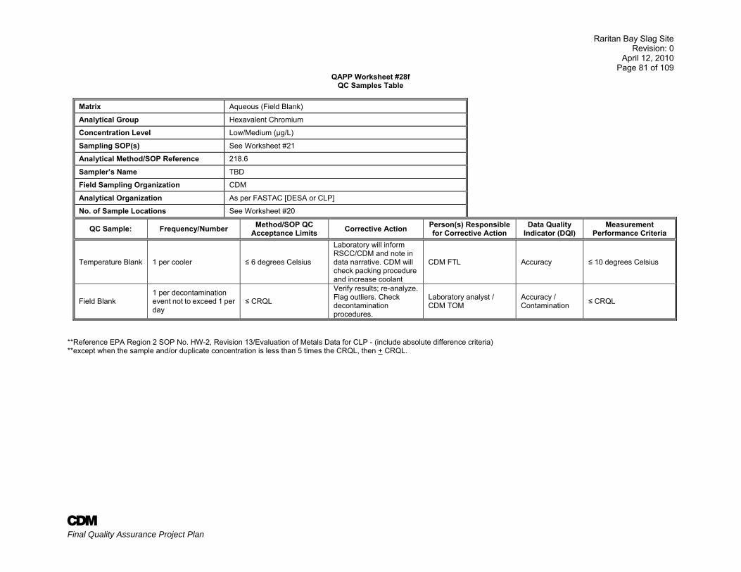
Raritan Bay Slag Site Revision: 0
April 12, 2010 Page 81 of 109
A Final Quality Assurance Project Plan
QAPP Worksheet #28f QC Samples Table
Matrix Aqueous (Field Blank)
Analytical Group Hexavalent Chromium
Concentration Level Low/Medium (µg/L)
Sampling SOP(s) See Worksheet #21
Analytical Method/SOP Reference 218.6
Sampler’s Name TBD
Field Sampling Organization CDM
Analytical Organization As per FASTAC [DESA or CLP]
No. of Sample Locations See Worksheet #20
QC Sample: Frequency/Number Method/SOP QC Acceptance Limits Corrective Action Person(s) Responsible
for Corrective Action Data Quality
Indicator (DQI) Measurement
Performance Criteria
Temperature Blank 1 per cooler ≤ 6 degrees Celsius
Laboratory will inform RSCC/CDM and note in data narrative. CDM will check packing procedure and increase coolant
CDM FTL Accuracy ≤ 10 degrees Celsius
Field Blank 1 per decontamination event not to exceed 1 per day
≤ CRQL
Verify results; re-analyze. Flag outliers. Check decontamination procedures.
Laboratory analyst / CDM TOM
Accuracy / Contamination ≤ CRQL
**Reference EPA Region 2 SOP No. HW-2, Revision 13/Evaluation of Metals Data for CLP - (include absolute difference criteria) **except when the sample and/or duplicate concentration is less than 5 times the CRQL, then + CRQL.
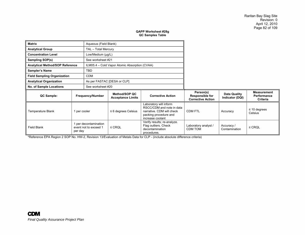
Raritan Bay Slag Site Revision: 0
April 12, 2010 Page 82 of 109
A Final Quality Assurance Project Plan
QAPP Worksheet #28g QC Samples Table
Matrix Aqueous (Field Blank)
Analytical Group TAL – Total Mercury
Concentration Level Low/Medium (µg/L)
Sampling SOP(s) See worksheet #21
Analytical Method/SOP Reference ILM05.4 – Cold Vapor Atomic Absorption (CVAA)
Sampler’s Name TBD
Field Sampling Organization CDM
Analytical Organization As per FASTAC [DESA or CLP]
No. of Sample Locations See worksheet #20
QC Sample: Frequency/Number Method/SOP QC Acceptance Limits Corrective Action
Person(s) Responsible for
Corrective Action Data Quality
Indicator (DQI) Measurement Performance
Criteria
Temperature Blank 1 per cooler ≤ 6 degrees Celsius
Laboratory will inform RSCC/CDM and note in data narrative. CDM will check packing procedure and increase coolant
CDM FTL Accuracy ≤ 10 degrees Celsius
Field Blank 1 per decontamination event not to exceed 1 per day
≤ CRQL
Verify results; re-analyze. Flag outliers. Check decontamination procedures.
Laboratory analyst / CDM TOM
Accuracy / Contamination ≤ CRQL
*Reference EPA Region 2 SOP No. HW-2, Revision 13/Evaluation of Metals Data for CLP - (include absolute difference criteria)
Raritan Bay Slag Site Revision: 0
April 12, 2010 Page 83 of 109
A Final Quality Assurance Project Plan
QAPP Worksheet #28h QC Samples Table
Matrix Aqueous (Field Blank)
Analytical Group TAL - Total Cyanide
Concentration Level Low/Medium (µg/L)
Sampling SOP(s) See worksheet #21
Analytical Method/SOP Reference ILM05.4 – Colorimeter or Spectrophotometer
Sampler’s Name TBD
Field Sampling Organization CDM
Analytical Organization As per FASTAC [DESA or CLP]
No. of Sample Locations See worksheet #20
QC Sample: Frequency/Number Method/SOP QC Acceptance Limits Corrective Action Person(s) Responsible
for Corrective Action Data Quality
Indicator (DQI) Measurement Performance
Criteria
Temperature Blank 1 per cooler ≤ 6 degrees Celsius
Laboratory will inform RSCC/CDM and note in data narrative. CDM will check packing procedure and increase coolant
CDM FTL Accuracy ≤ 10 degrees Celsius
Field Blank
1 per decontamination event not to exceed 1 per day
≤ CRQL
Verify results; re-analyze. Flag outliers. Check decontamination procedures.
Laboratory analyst / CDM TOM
Accuracy / Contamination ≤ CRQL
*Reference EPA Region 2 SOP No. HW-2, Revision 13/Evaluation of Metals Data for CLP - (include absolute difference criteria)
Raritan Bay Slag Site Revision: 0
April 12, 2010 Page 84 of 109
A Final Quality Assurance Project Plan
QAPP Worksheet #28i QC Samples Table
Matrix Soil
Analytical Group TCL VOCs
Concentration Level SIM/Low/Medium (mg/kg)
Sampling SOP(s) See Worksheet #21
Analytical Method/SOP Reference SOM01.2
Sampler’s Name TBD
Field Sampling Organization CDM
Analytical Organization As per FASTAC [DESA or CLP]
No. of Sample Locations See Worksheet #18
QC Sample: Frequency/
Number Method/SOP QC Acceptance
Limits Corrective Action Person(s)
Responsible for Corrective Action
Data Quality Indicator
(DQI) Measurement Performance
Criteria
Field Duplicate
1 per 20 samples None Notify TOM and flag
duplicate results CDM ASC and TOM Precision 75% RPD
Temperature Blank 1 per cooler ≤ 6 degrees Celsius
Laboratory will inform RSCC/CDM and note in data narrative. CDM will check packing procedure and increase coolant
Laboratory Analyst and CDM FTL Accuracy ≤ 10 degrees Celsius
Field Blank
1 per decontamination event not to exceed 1 per day
≤ CRQL
Verify results; re-analyze. Flag outliers. Check decontamination procedures.
Laboratory analyst / CDM TOM
Accuracy / Contamination ≤ CRQL
Method Blank 1 every 12 hours No analyte > CRQL* Suspend analysis unit
source recertified
DESA/ CLP Laboratory GC/MS Technician
Accuracy No analyte > CRQL*
*with the exception of methylene chloride, 2-butanone & acetone which can be up to 2 times the CRQL. (EPA CLP National Functional Guidelines, Final, July 2007)
Raritan Bay Slag Site Revision: 0
April 12, 2010 Page 85 of 109
A Final Quality Assurance Project Plan
QAPP Worksheet #28i QC Samples Table
Matrix Soil
Analytical Group TCL VOCs [cont’d]
Concentration Level Low/Medium (mg/kg)
Sampling SOP(s) See Worksheet #21
Analytical Method/SOP Reference SOM01.2
Sampler’s Name TBD
Field Sampling Organization CDM
Analytical Organization As per FASTAC [DESA or CLP]
No. of Sample Locations See Worksheet #18
QC Sample: Frequency/
Number Method/SOP QC Acceptance Limits Corrective
Action Person(s)
Responsible for Corrective Action
Data Quality Indicator (DQI) Measurement Performance Criteria
Deuterated Monitoring Compounds
all samples
Vinyl chloride-d3 68-122 %R
Check calculations and instruments, reanalyze affected samples; up to 3 DMCs per sample may fail to meet necessary limits (Section 11.3.4, Page D45 of SOM01.2)
DESA/ CLP Laboratory GC/MS Technician
Accuracy
Vinyl chloride-d3 68-122 %R Chloroethane-d5 61-130 %R Chloroethane-d5 61-130 %R 1,1-Dichloroethene-d2 45-132 %R 1,1-Dichloroethene-d2 45-132 %R 2-Butanone-d5 20-182 %R 2-Butanone-d5 20-182 %R Chloroform-d 72-123 %R Chloroform-d 72-123 %R 1,2-Dichloroethane-d4 79-122 %R 1,2-Dichloroethane-d4 79-122 %R Benzene-d6 80-121 %R Benzene-d6 80-121 %R 1,2-Dichloropropane-d6 74-124 %R 1,2-Dichloropropane-d6 74-124 %R Toluene-d8 78-121 %R Toluene-d8 78-121 %R trans-1,3-Dichloropropene-d4 72-130 %R trans-1,3-Dichloropropene-d4 72-130 %R 2-Hexanone-d5 17-184 %R 2-Hexanone-d5 17-184 %R 1,4-Dioxane-d8 50-150 %R 1,4-Dioxane-d8 50-150 %R 1,1,2,2-Tetrachloroethane-d2 56-161 %R 1,1,2,2-Tetrachloroethane-d2 56-161 %R 1,2-Dichlorobenzene-d4 70-131 %R 1,2-Dichlorobenzene-d4 70-131 %R
Internal Standards all samples 50-200% of area, + 30 second retention time shift
Check calculations/ instruments reanalyze affected samples
DESA or CLP Laboratory GC/MS Technician
Accuracy 50-100% of area, + 30 second retention time shift
Raritan Bay Slag Site Revision: 0
April 12, 2010 Page 86 of 109
A Final Quality Assurance Project Plan
QAPP Worksheet #28j
QC Samples Table Matrix Soil
Analytical Group TCL SVOCs
Concentration Level SIM/Low/Medium (mg/kg)
Sampling SOP(s) See Worksheet #21
Analytical Method/SOP Reference SOM01.2
Sampler’s Name TBD
Field Sampling Organization CDM
Analytical Organization As per FASTAC [DESA or CLP]
No. of Sample Locations See Worksheet #18
QC Sample: Frequency/ Number Method/SOP QC Acceptance Limits Corrective
Action
Person(s) Responsible for
Corrective Action
Data Quality Indicator
(DQI) Measurement Performance Criteria
Field Duplicate
1 per 20 samples None
Notify TOM and flag duplicate results
CDM ASC and TOM Precision 75% RPD
Temperature Blank 1 per cooler ≤ 6 degrees Celsius
Laboratory will inform RSCC/CDM and note in data narrative. CDM will check packing procedure and increase coolant
Laboratory Analyst and CDM FTL
Accuracy ≤ 10 degrees Celsius
Field Blank
1 per decontamination event not to exceed 1 per day
≤ CRQL
Verify results; re-analyze. Flag outliers. Check decontamination procedures.
Laboratory analyst / CDM TOM
Accuracy / Contamination ≤ CRQL
Method Blank
1 per 20 samples or batch
No analyte > CRQL*
Suspend analysis unit source recertified
DESA or CLP Laboratory GC/MS Technician
Accuracy No analyte > CRQL*
*with the exception of bis (2-Ethylhexyl) phthalate which can be up to 5 times the CRQL. (EPA CLP National Functional Guidelines, Final, July 2007)
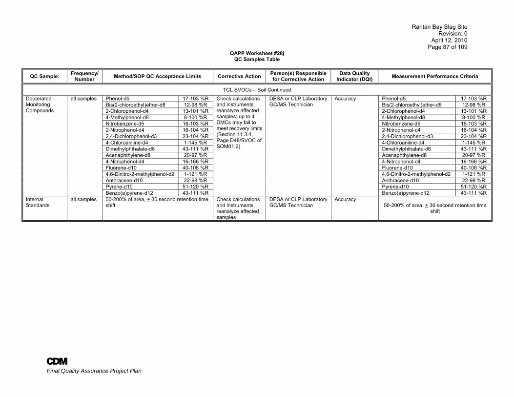
Raritan Bay Slag Site Revision: 0
April 12, 2010 Page 87 of 109
A Final Quality Assurance Project Plan
QAPP Worksheet #28j QC Samples Table
QC Sample: Frequency/Number Method/SOP QC Acceptance Limits Corrective Action Person(s) Responsible
for Corrective Action Data Quality
Indicator (DQI) Measurement Performance Criteria
TCL SVOCs – Soil Continued
Deuterated Monitoring Compounds
all samples Phenol-d5 17-103 %R Check calculations and instruments, reanalyze affected samples; up to 4 DMCs may fail to meet recovery limits (Section 11.3.4, Page D48/SVOC of SOM01.2)
DESA or CLP Laboratory GC/MS Technician
Accuracy Phenol-d5 17-103 %R Bis(2-chloroethyl)ether-d8 12-98 %R Bis(2-chloroethyl)ether-d8 12-98 %R 2-Chlorophenol-d4 13-101 %R 2-Chlorophenol-d4 13-101 %R 4-Methylphenol-d8 8-100 %R 4-Methylphenol-d8 8-100 %R Nitrobenzene-d5 16-103 %R Nitrobenzene-d5 16-103 %R 2-Nitrophenol-d4 16-104 %R 2-Nitrophenol-d4 16-104 %R 2,4-Dichlorophenol-d3 23-104 %R 2,4-Dichlorophenol-d3 23-104 %R 4-Chloroaniline-d4 1-145 %R 4-Chloroaniline-d4 1-145 %R Dimethylphthalate-d6 43-111 %R Dimethylphthalate-d6 43-111 %R Acenaphthylene-d8 20-97 %R Acenaphthylene-d8 20-97 %R 4-Nitrophenol-d4 16-166 %R 4-Nitrophenol-d4 16-166 %R Fluorene-d10 40-108 %R Fluorene-d10 40-108 %R 4,6-Dinitro-2-methylphenol-d2 1-121 %R 4,6-Dinitro-2-methylphenol-d2 1-121 %R Anthracene-d10 22-98 %R Anthracene-d10 22-98 %R Pyrene-d10 51-120 %R Pyrene-d10 51-120 %R Benzo(a)pyrene-d12 43-111 %R Benzo(a)pyrene-d12 43-111 %R
Internal Standards
all samples 50-200% of area, + 30 second retention time shift
Check calculations and instruments, reanalyze affected samples
DESA or CLP Laboratory GC/MS Technician
Accuracy 50-200% of area, + 30 second retention time
shift
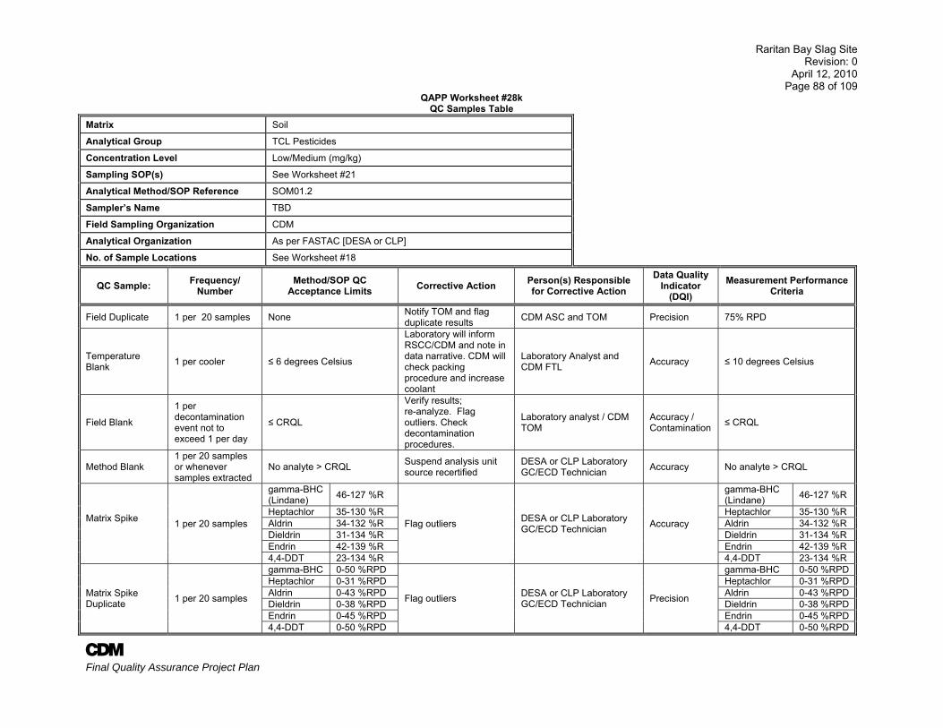
Raritan Bay Slag Site Revision: 0
April 12, 2010 Page 88 of 109
A Final Quality Assurance Project Plan
QAPP Worksheet #28k QC Samples Table
Matrix Soil
Analytical Group TCL Pesticides
Concentration Level Low/Medium (mg/kg)
Sampling SOP(s) See Worksheet #21
Analytical Method/SOP Reference SOM01.2
Sampler’s Name TBD
Field Sampling Organization CDM
Analytical Organization As per FASTAC [DESA or CLP]
No. of Sample Locations See Worksheet #18
QC Sample: Frequency/ Number
Method/SOP QC Acceptance Limits Corrective Action Person(s) Responsible
for Corrective Action Data Quality
Indicator (DQI)
Measurement Performance Criteria
Field Duplicate 1 per 20 samples None Notify TOM and flag duplicate results CDM ASC and TOM Precision 75% RPD
Temperature Blank 1 per cooler ≤ 6 degrees Celsius
Laboratory will inform RSCC/CDM and note in data narrative. CDM will check packing procedure and increase coolant
Laboratory Analyst and CDM FTL Accuracy ≤ 10 degrees Celsius
Field Blank
1 per decontamination event not to exceed 1 per day
≤ CRQL
Verify results; re-analyze. Flag outliers. Check decontamination procedures.
Laboratory analyst / CDM TOM
Accuracy / Contamination ≤ CRQL
Method Blank 1 per 20 samples or whenever samples extracted
No analyte > CRQL Suspend analysis unit source recertified
DESA or CLP Laboratory GC/ECD Technician Accuracy No analyte > CRQL
Matrix Spike 1 per 20 samples
gamma-BHC (Lindane) 46-127 %R
Flag outliers DESA or CLP Laboratory GC/ECD Technician Accuracy
gamma-BHC (Lindane) 46-127 %R
Heptachlor 35-130 %R Heptachlor 35-130 %R Aldrin 34-132 %R Aldrin 34-132 %R Dieldrin 31-134 %R Dieldrin 31-134 %R Endrin 42-139 %R Endrin 42-139 %R 4,4-DDT 23-134 %R 4,4-DDT 23-134 %R
Matrix Spike Duplicate 1 per 20 samples
gamma-BHC 0-50 %RPD
Flag outliers DESA or CLP Laboratory GC/ECD Technician Precision
gamma-BHC 0-50 %RPDHeptachlor 0-31 %RPD Heptachlor 0-31 %RPDAldrin 0-43 %RPD Aldrin 0-43 %RPDDieldrin 0-38 %RPD Dieldrin 0-38 %RPDEndrin 0-45 %RPD Endrin 0-45 %RPD4,4-DDT 0-50 %RPD 4,4-DDT 0-50 %RPD
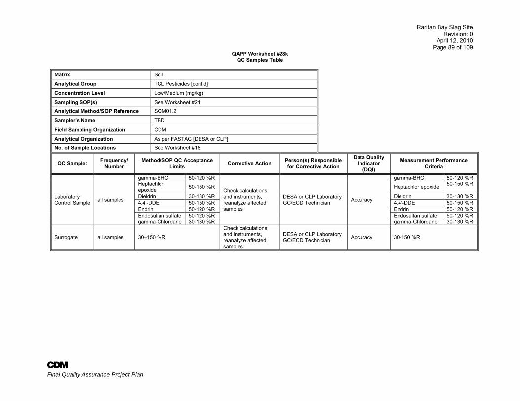
Raritan Bay Slag Site Revision: 0
April 12, 2010 Page 89 of 109
A Final Quality Assurance Project Plan
QAPP Worksheet #28k QC Samples Table
Matrix Soil
Analytical Group TCL Pesticides [cont’d]
Concentration Level Low/Medium (mg/kg)
Sampling SOP(s) See Worksheet #21
Analytical Method/SOP Reference SOM01.2
Sampler’s Name TBD
Field Sampling Organization CDM
Analytical Organization As per FASTAC [DESA or CLP]
No. of Sample Locations See Worksheet #18
QC Sample: Frequency/ Number
Method/SOP QC Acceptance Limits Corrective Action Person(s) Responsible
for Corrective Action Data Quality
Indicator (DQI)
Measurement Performance Criteria
Laboratory Control Sample all samples
gamma-BHC 50-120 %R
Check calculations and instruments, reanalyze affected samples
DESA or CLP Laboratory GC/ECD Technician Accuracy
gamma-BHC 50-120 %R Heptachlor epoxide 50-150 %R Heptachlor epoxide 50-150 %R
Dieldrin 30-130 %R Dieldrin 30-130 %R 4,4’-DDE 50-150 %R 4,4’-DDE 50-150 %R Endrin 50-120 %R Endrin 50-120 %R Endosulfan sulfate 50-120 %R Endosulfan sulfate 50-120 %R gamma-Chlordane 30-130 %R gamma-Chlordane 30-130 %R
Surrogate all samples 30–150 %R
Check calculations and instruments, reanalyze affected samples
DESA or CLP Laboratory GC/ECD Technician Accuracy 30-150 %R
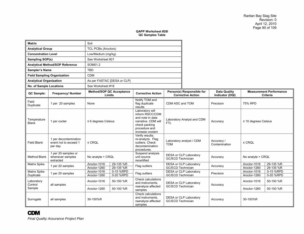
Raritan Bay Slag Site Revision: 0
April 12, 2010 Page 90 of 109
A Final Quality Assurance Project Plan
QAPP Worksheet #28l QC Samples Table
Matrix Soil
Analytical Group TCL PCBs (Aroclors)
Concentration Level Low/Medium (mg/kg)
Sampling SOP(s) See Worksheet #21
Analytical Method/SOP Reference SOM01.2
Sampler’s Name TBD
Field Sampling Organization CDM
Analytical Organization As per FASTAC [DESA or CLP]
No. of Sample Locations See Worksheet #18
QC Sample: Frequency/ Number Method/SOP QC Acceptance Limits Corrective Action Person(s) Responsible for
Corrective Action Data Quality
Indicator (DQI) Measurement Performance
Criteria
Field Duplicate 1 per 20 samples None
Notify TOM and flag duplicate results
CDM ASC and TOM Precision 75% RPD
Temperature Blank 1 per cooler ≤ 6 degrees Celsius
Laboratory will inform RSCC/CDM and note in data narrative. CDM will check packing procedure and increase coolant
Laboratory Analyst and CDM FTL Accuracy ≤ 10 degrees Celsius
Field Blank 1 per decontamination event not to exceed 1 per day
≤ CRQL
Verify results; re-analyze. Flag outliers. Check decontamination procedures.
Laboratory analyst / CDM TOM
Accuracy / Contamination ≤ CRQL
Method Blank 1 per 20 samples or whenever samples extracted
No analyte > CRQL Suspend analysis unit source recertified
DESA or CLP Laboratory GC/ECD Technician Accuracy No analyte > CRQL
Matrix Spike 1 per 20 samples Aroclor-1016 29-135 %R Flag outliers DESA or CLP Laboratory
GC/ECD Technician Accuracy Aroclor-1016 29-135 %R Aroclor-1260 29-135 %R Aroclor-1260 29-135 %R
Matrix Spike Duplicate 1 per 20 samples Aroclor-1016 0-15 %RPD Flag outliers DESA or CLP Laboratory
GC/ECD Technician Precision Aroclor-1016 0-15 %RPD Aroclor-1260 0-20 %RPD Aroclor-1260 0-20 %RPD
Laboratory Control Sample
all samples Aroclor-1016 50-150 %R Check calculations
and instruments, reanalyze affected samples
DESA or CLP Laboratory GC/ECD Technician Accuracy
Aroclor-1016 50-150 %R
Aroclor-1260 50-150 %R Aroclor-1260 50-150 %R
Surrogate all samples 30-150%R
Check calculations and instruments, reanalyze affected samples
DESA or CLP Laboratory GC/ECD Technician Accuracy 30-150%R
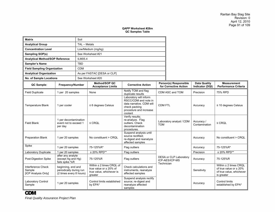
Raritan Bay Slag Site Revision: 0
April 12, 2010 Page 91 of 109
A Final Quality Assurance Project Plan
QAPP Worksheet #28m QC Samples Table
Matrix Soil
Analytical Group TAL – Metals
Concentration Level Low/Medium (mg/kg)
Sampling SOP(s) See Worksheet #21
Analytical Method/SOP Reference ILM05.4
Sampler’s Name TBD
Field Sampling Organization CDM
Analytical Organization As per FASTAC [DESA or CLP]
No. of Sample Locations See Worksheet #20
QC Sample: Frequency/Number Method/SOP QC Acceptance Limits Corrective Action Person(s) Responsible
for Corrective Action Data Quality
Indicator (DQI) Measurement
Performance Criteria
Field Duplicate 1 per 20 samples None Notify TOM and flag duplicate results CDM ASC and TOM Precision 75% RPD
Temperature Blank 1 per cooler ≤ 6 degrees Celsius
Laboratory will inform RSCC/CDM and note in data narrative. CDM will check packing procedure and increase coolant
CDM FTL Accuracy ≤ 10 degrees Celsius
Field Blank 1 per decontamination event not to exceed 1 per day
≤ CRQL
Verify results; re-analyze. Flag outliers. Check decontamination procedures.
Laboratory analyst / CDM TOM
Accuracy / Contamination ≤ CRQL
Preparation Blank 1 per 20 samples No constituent > CRQL
Suspend analysis until source rectified; re-digest and reanalyze affected samples
DESA or CLP Laboratory ICP-AES/ICP-MS Technician
Accuracy No constituent > CRQL
Spike 1 per 20 samples 75-125%R* Flag outliers Accuracy 75-125%R*
Laboratory Duplicate 1 per 20 samples ± 20% RPD** Flag outliers Precision ± 20% RPD**
Post-Digestion Spike after any analyte (except Ag and Hg) fails spike %R
75-125%R Flag outliers Accuracy 75-125%R
Interference Check Sample [ICP Analysis Only]
beginning, end and periodically during run (2 times every 8 hours)
Within ± 2 times CRQL of true value or ± 20% of true value, whichever is greater
Check calculations and instruments, reanalyze affected samples
Sensitivity
Within ± 2 times CRQL of true value or ± 20% of true value, whichever is greater
Laboratory Control Sample 1 per 20 samples Control limits established
by EPA*
Suspend analysis rectify source; re-digest and reanalyze affected samples
Accuracy Control limits established by EPA*
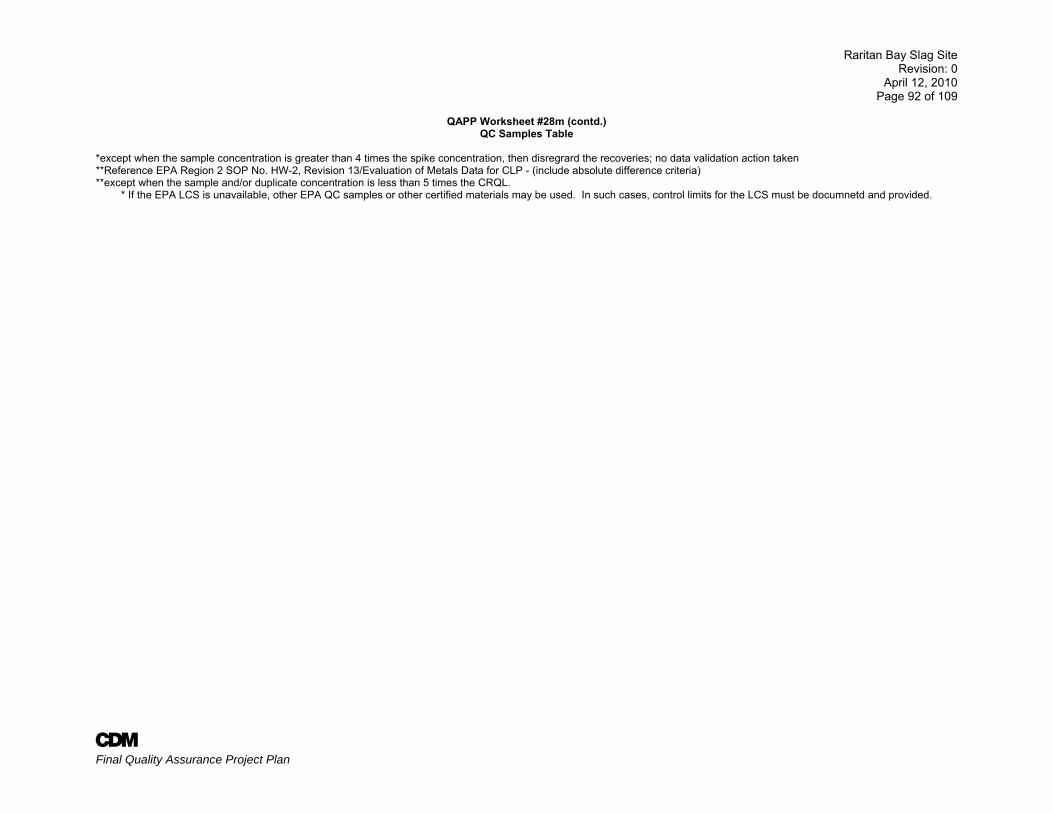
Raritan Bay Slag Site Revision: 0
April 12, 2010 Page 92 of 109
A Final Quality Assurance Project Plan
QAPP Worksheet #28m (contd.)
QC Samples Table *except when the sample concentration is greater than 4 times the spike concentration, then disregrard the recoveries; no data validation action taken **Reference EPA Region 2 SOP No. HW-2, Revision 13/Evaluation of Metals Data for CLP - (include absolute difference criteria) **except when the sample and/or duplicate concentration is less than 5 times the CRQL.
* If the EPA LCS is unavailable, other EPA QC samples or other certified materials may be used. In such cases, control limits for the LCS must be documnetd and provided.
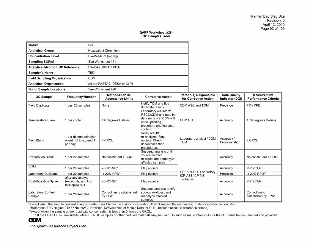
Raritan Bay Slag Site Revision: 0
April 12, 2010 Page 93 of 109
A Final Quality Assurance Project Plan
QAPP Worksheet #28n QC Samples Table
Matrix Soil
Analytical Group Hexavalent Chromium
Concentration Level Low/Medium (mg/kg)
Sampling SOP(s) See Worksheet #21
Analytical Method/SOP Reference SW-846 3060A/7196A
Sampler’s Name TBD
Field Sampling Organization CDM
Analytical Organization As per FASTAC [DESA or CLP]
No. of Sample Locations See Worksheet #20
QC Sample: Frequency/Number Method/SOP QC Acceptance Limits Corrective Action Person(s) Responsible
for Corrective Action Data Quality
Indicator (DQI) Measurement
Performance Criteria
Field Duplicate 1 per 20 samples None Notify TOM and flag duplicate results CDM ASC and TOM Precision 75% RPD
Temperature Blank 1 per cooler ≤ 6 degrees Celsius
Laboratory will inform RSCC/CDM and note in data narrative. CDM will check packing procedure and increase coolant
CDM FTL Accuracy ≤ 10 degrees Celsius
Field Blank 1 per decontamination event not to exceed 1 per day
≤ CRQL
Verify results; re-analyze. Flag outliers. Check decontamination procedures.
Laboratory analyst / CDM TOM
Accuracy / Contamination ≤ CRQL
Preparation Blank 1 per 20 samples No constituent > CRQL
Suspend analysis until source rectified; re-digest and reanalyze affected samples
DESA or CLP Laboratory ICP-AES/ICP-MS Technician
Accuracy No constituent > CRQL
Spike 1 per 20 samples 75-125%R* Flag outliers Accuracy 75-125%R*
Laboratory Duplicate 1 per 20 samples ± 20% RPD** Flag outliers Precision ± 20% RPD**
Post-Digestion Spike after any analyte (except Ag and Hg) fails spike %R
75-125%R Flag outliers Accuracy 75-125%R
Laboratory Control Sample 1 per 20 samples Control limits established
by EPA*
Suspend analysis rectify source; re-digest and reanalyze affected samples
Accuracy Control limits established by EPA*
*except when the sample concentration is greater than 4 times the spike concentration, then disregard the recoveries; no data validation action taken **Reference EPA Region 2 SOP No. HW-2, Revision 13/Evaluation of Metals Data for CLP - (include absolute difference criteria) **except when the sample and/or duplicate concentration is less than 5 times the CRQL.
* If the EPA LCS is unavailable, other EPA QC samples or other certified materials may be used. In such cases, control limits for the LCS must be documented and provided.
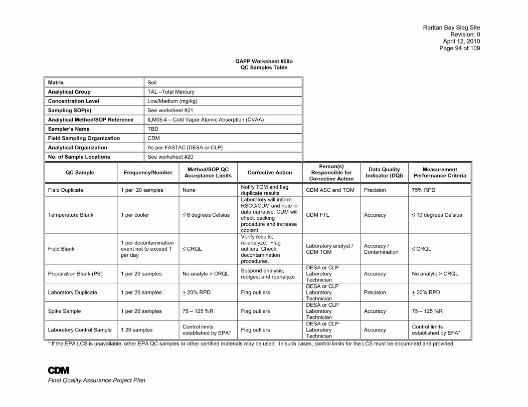
Raritan Bay Slag Site Revision: 0
April 12, 2010 Page 94 of 109
A Final Quality Assurance Project Plan
QAPP Worksheet #28o QC Samples Table
Matrix Soil
Analytical Group TAL –Total Mercury
Concentration Level Low/Medium (mg/kg)
Sampling SOP(s) See worksheet #21
Analytical Method/SOP Reference ILM05.4 – Cold Vapor Atomic Absorption (CVAA)
Sampler’s Name TBD
Field Sampling Organization CDM
Analytical Organization As per FASTAC [DESA or CLP]
No. of Sample Locations See worksheet #20
QC Sample: Frequency/Number Method/SOP QC Acceptance Limits Corrective Action
Person(s) Responsible for
Corrective Action Data Quality
Indicator (DQI) Measurement
Performance Criteria
Field Duplicate 1 per 20 samples None Notify TOM and flag duplicate results CDM ASC and TOM Precision 75% RPD
Temperature Blank 1 per cooler ≤ 6 degrees Celsius
Laboratory will inform RSCC/CDM and note in data narrative. CDM will check packing procedure and increase coolant
CDM FTL Accuracy ≤ 10 degrees Celsius
Field Blank 1 per decontamination event not to exceed 1 per day
≤ CRQL
Verify results; re-analyze. Flag outliers. Check decontamination procedures.
Laboratory analyst / CDM TOM
Accuracy / Contamination ≤ CRQL
Preparation Blank (PB) 1 per 20 samples No analyte > CRQL Suspend analysis; redigest and reanalyze
DESA or CLP Laboratory Technician
Accuracy No analyte > CRQL
Laboratory Duplicate 1 per 20 samples + 20% RPD Flag outliers DESA or CLP Laboratory Technician
Precision + 20% RPD
Spike Sample 1 per 20 samples 75 – 125 %R Flag outliers DESA or CLP Laboratory Technician
Accuracy 75 – 125 %R
Laboratory Control Sample 1 20 samples Control limits established by EPA* Flag outliers
DESA or CLP Laboratory Technician
Accuracy Control limits established by EPA*
* If the EPA LCS is unavailable, other EPA QC samples or other certified materials may be used. In such cases, control limits for the LCS must be documnetd and provided.
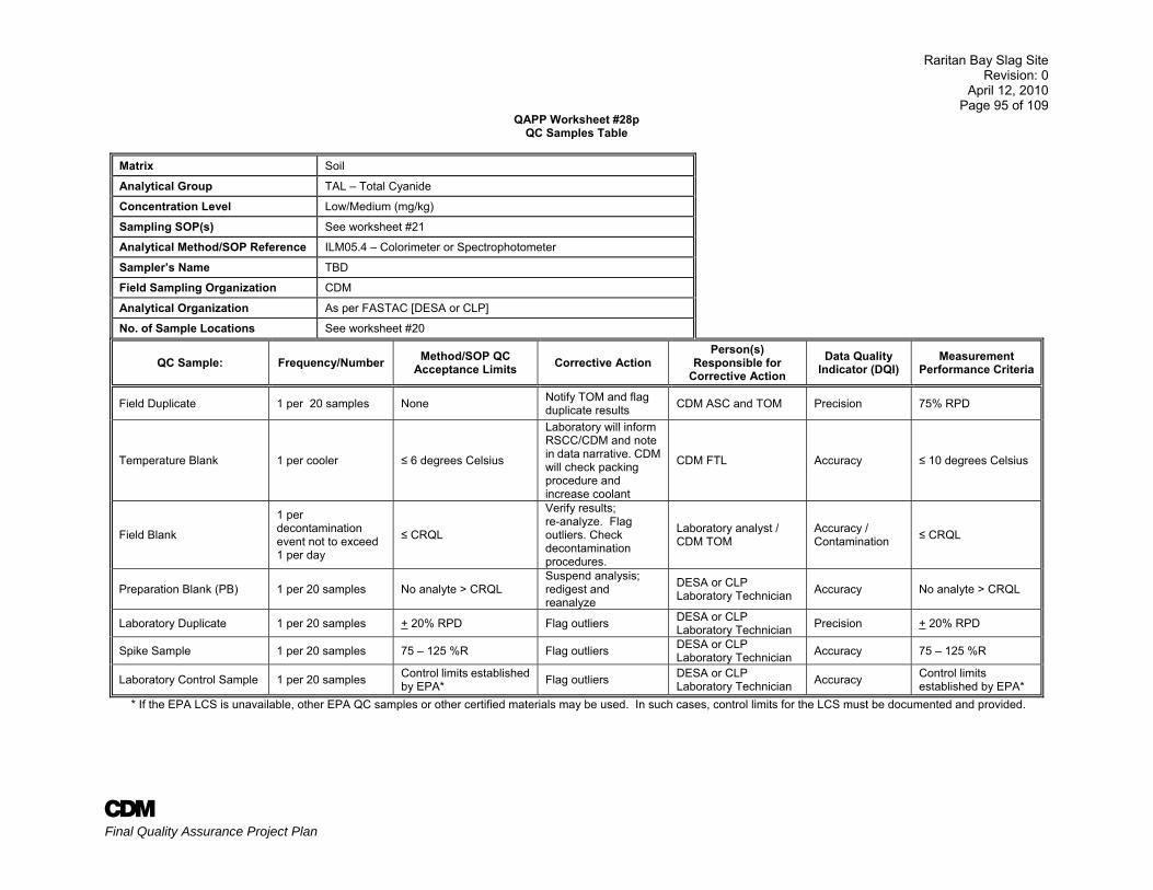
Raritan Bay Slag Site Revision: 0
April 12, 2010 Page 95 of 109
A Final Quality Assurance Project Plan
QAPP Worksheet #28p QC Samples Table
Matrix Soil
Analytical Group TAL – Total Cyanide
Concentration Level Low/Medium (mg/kg)
Sampling SOP(s) See worksheet #21
Analytical Method/SOP Reference ILM05.4 – Colorimeter or Spectrophotometer
Sampler’s Name TBD
Field Sampling Organization CDM
Analytical Organization As per FASTAC [DESA or CLP]
No. of Sample Locations See worksheet #20
QC Sample: Frequency/Number Method/SOP QC Acceptance Limits Corrective Action
Person(s) Responsible for
Corrective Action Data Quality
Indicator (DQI) Measurement
Performance Criteria
Field Duplicate 1 per 20 samples None Notify TOM and flag duplicate results CDM ASC and TOM Precision 75% RPD
Temperature Blank 1 per cooler ≤ 6 degrees Celsius
Laboratory will inform RSCC/CDM and note in data narrative. CDM will check packing procedure and increase coolant
CDM FTL Accuracy ≤ 10 degrees Celsius
Field Blank
1 per decontamination event not to exceed 1 per day
≤ CRQL
Verify results; re-analyze. Flag outliers. Check decontamination procedures.
Laboratory analyst / CDM TOM
Accuracy / Contamination ≤ CRQL
Preparation Blank (PB) 1 per 20 samples No analyte > CRQL Suspend analysis; redigest and reanalyze
DESA or CLP Laboratory Technician Accuracy No analyte > CRQL
Laboratory Duplicate 1 per 20 samples + 20% RPD Flag outliers DESA or CLP Laboratory Technician Precision + 20% RPD
Spike Sample 1 per 20 samples 75 – 125 %R Flag outliers DESA or CLP Laboratory Technician Accuracy 75 – 125 %R
Laboratory Control Sample 1 per 20 samples Control limits established by EPA* Flag outliers DESA or CLP
Laboratory Technician Accuracy Control limits established by EPA*
* If the EPA LCS is unavailable, other EPA QC samples or other certified materials may be used. In such cases, control limits for the LCS must be documented and provided.
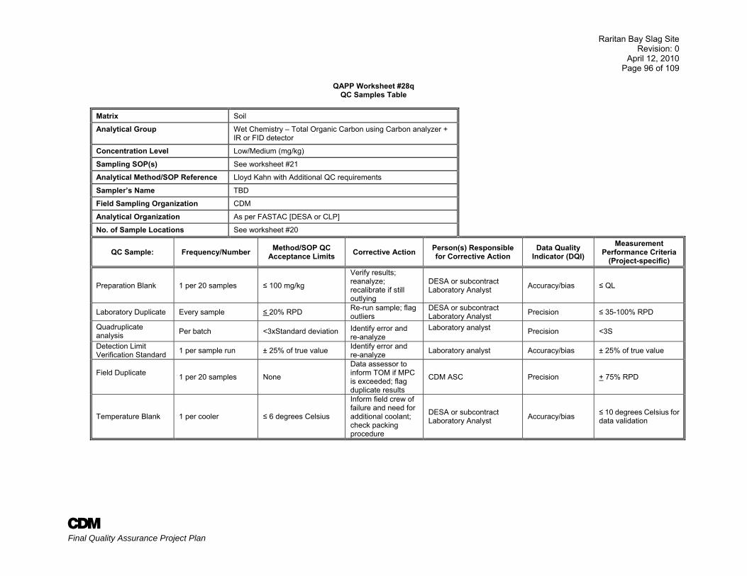
Raritan Bay Slag Site Revision: 0
April 12, 2010 Page 96 of 109
A Final Quality Assurance Project Plan
QAPP Worksheet #28q
QC Samples Table
Matrix Soil
Analytical Group Wet Chemistry – Total Organic Carbon using Carbon analyzer + IR or FID detector
Concentration Level Low/Medium (mg/kg)
Sampling SOP(s) See worksheet #21
Analytical Method/SOP Reference Lloyd Kahn with Additional QC requirements
Sampler’s Name TBD
Field Sampling Organization CDM
Analytical Organization As per FASTAC [DESA or CLP]
No. of Sample Locations See worksheet #20
QC Sample: Frequency/Number Method/SOP QC Acceptance Limits Corrective Action Person(s) Responsible
for Corrective Action Data Quality
Indicator (DQI) Measurement
Performance Criteria (Project-specific)
Preparation Blank 1 per 20 samples ≤ 100 mg/kg
Verify results; reanalyze; recalibrate if still outlying
DESA or subcontract Laboratory Analyst Accuracy/bias ≤ QL
Laboratory Duplicate Every sample ≤ 20% RPD Re-run sample; flag outliers
DESA or subcontract Laboratory Analyst Precision ≤ 35-100% RPD
Quadruplicate analysis Per batch <3xStandard deviation Identify error and
re-analyze Laboratory analyst Precision <3S
Detection Limit Verification Standard 1 per sample run ± 25% of true value Identify error and
re-analyze Laboratory analyst Accuracy/bias ± 25% of true value
Field Duplicate 1 per 20 samples None
Data assessor to inform TOM if MPC is exceeded; flag duplicate results
CDM ASC Precision + 75% RPD
Temperature Blank 1 per cooler ≤ 6 degrees Celsius
Inform field crew of failure and need for additional coolant; check packing procedure
DESA or subcontract Laboratory Analyst Accuracy/bias ≤ 10 degrees Celsius for
data validation
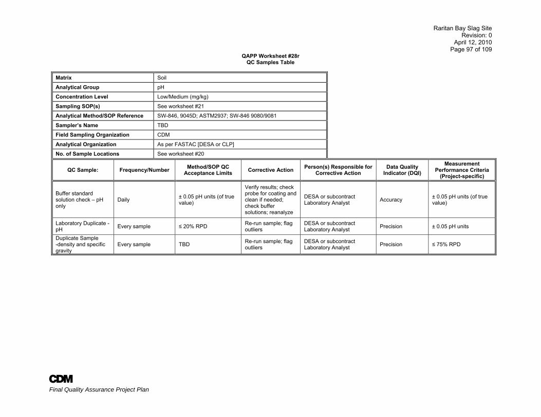
Raritan Bay Slag Site Revision: 0
April 12, 2010 Page 97 of 109
A Final Quality Assurance Project Plan
QAPP Worksheet #28r QC Samples Table
Matrix Soil
Analytical Group pH
Concentration Level Low/Medium (mg/kg)
Sampling SOP(s) See worksheet #21
Analytical Method/SOP Reference SW-846, 9045D; ASTM2937; SW-846 9080/9081
Sampler’s Name TBD
Field Sampling Organization CDM
Analytical Organization As per FASTAC [DESA or CLP]
No. of Sample Locations See worksheet #20
QC Sample: Frequency/Number Method/SOP QC Acceptance Limits Corrective Action Person(s) Responsible for
Corrective Action Data Quality
Indicator (DQI) Measurement
Performance Criteria (Project-specific)
Buffer standard solution check – pH only
Daily ± 0.05 pH units (of true value)
Verify results; check probe for coating and clean if needed; check buffer solutions; reanalyze
DESA or subcontract Laboratory Analyst Accuracy ± 0.05 pH units (of true
value)
Laboratory Duplicate - pH Every sample ≤ 20% RPD Re-run sample; flag
outliers DESA or subcontract Laboratory Analyst Precision ± 0.05 pH units
Duplicate Sample -density and specific gravity
Every sample TBD Re-run sample; flag outliers
DESA or subcontract Laboratory Analyst Precision ≤ 75% RPD
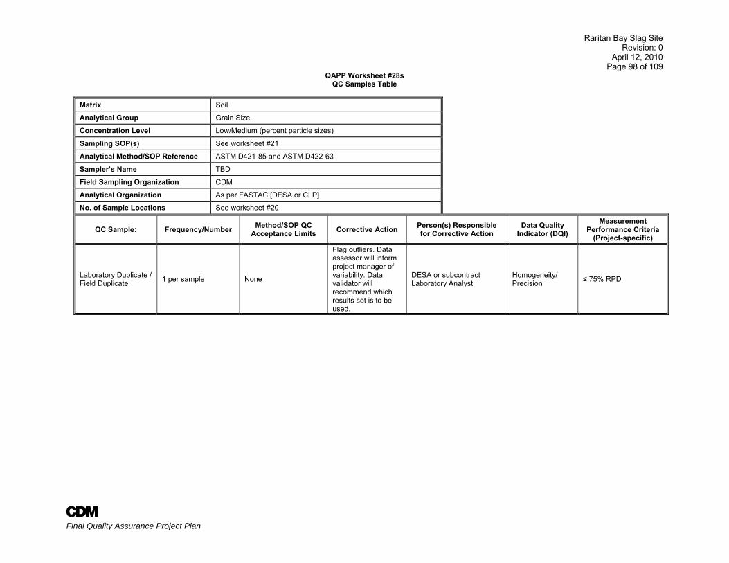
Raritan Bay Slag Site Revision: 0
April 12, 2010 Page 98 of 109
A Final Quality Assurance Project Plan
QAPP Worksheet #28s QC Samples Table
Matrix Soil
Analytical Group Grain Size
Concentration Level Low/Medium (percent particle sizes)
Sampling SOP(s) See worksheet #21
Analytical Method/SOP Reference ASTM D421-85 and ASTM D422-63
Sampler’s Name TBD
Field Sampling Organization CDM
Analytical Organization As per FASTAC [DESA or CLP]
No. of Sample Locations See worksheet #20
QC Sample: Frequency/Number Method/SOP QC Acceptance Limits Corrective Action Person(s) Responsible
for Corrective Action Data Quality
Indicator (DQI) Measurement
Performance Criteria (Project-specific)
Laboratory Duplicate / Field Duplicate 1 per sample None
Flag outliers. Data assessor will inform project manager of variability. Data validator will recommend which results set is to be used.
DESA or subcontract Laboratory Analyst
Homogeneity/ Precision ≤ 75% RPD
Raritan Bay Slag Site Revision: 0
April 12, 2010 Page 99 of 109
A Final Quality Assurance Project Plan
QAPP Worksheet #29 Project Documents and Records Table
Sample Collection Documents and Records
On-Site Analysis Documents
and Records Off-Site Analysis Documents and
Records
Data Assessment Documents
and Records
Other
FORMS II Lite Traffic Reports/ COC Records
Equipment Calibration and Maintenance Log
Sample Receipt, Custody and Tracking Logs
Field Sampling Audit Plans, Reports and Checklists
M&TE (measurement and testing equipment) Forms
Airbills Field Data Collection Logs Standards Tracking Logs Office Audit Plans, Reports and Checklist
Technical/QA Review Forms
Sample Tracking Log/Sheets PID Logs, if applicable Sample Disposal and Waste Manifests
Corrective Action Reports Purchase Requisition Forms
Field logs/logbooks Particulate Monitoring Data Logs, if applicable
Sample Preparation Logs Analytical sample results Telephone Logs
Chain of Custody Forms Photographs Corrective Action Reports Subcontract Laboratory certifications
Electronic Data Deliverables
Field Change Request Forms Inspection and maintenance records
Corrective Action Forms Subcontract Laboratory QA Plan (on file with EPA and CDM)
Non-Conformance Reports
Custody Seals Spill incident reports Data Packages (Case Narratives, Sample Results, QC Summaries and Raw Data (detailed in CLP SOPs).
QC Audit Reports Data Validation SOPs Data Validation Reports
Subcontract Documents (Contract, Scopes of Work, Bid Sheet), Subcontract Documents and Review Forms
ANSETS Forms NA Trip Reports Data Package Completeness Checklist Validated Data Reports
NA
Test Pit Logs NA Sample analysis run logs Self Assessment Checklist NA NA NA Daily Status Report to USACE-KC Data Quality Assessments NA
Raritan Bay Slag Site Revision: 0
April 12, 2010 Page 100 of 109
A Final Quality Assurance Project Plan
QAPP Worksheet #30 Analytical Services Table
Matrix Analytical
Group Concentration
Level Analytical
SOP
Data Package Turnaround
Time
Laboratory/Organization (Name and Address, Contact Person and Telephone Number)
Backup Laboratory/Organization
(Name and Address, Contact Person and Telephone Number)
Aqueous
Hexavalent Chromium
Low/Medium
SW-846 7196A 24 hr
EPA Primary contact: RSCC Adly Michael/Bob Toth 732-906-6161/6171 DESA contact: John Birri 732-906-6886
All sample analyses will be performed using EPA’s CLP and/or DESA Laboratory resources except for TOC, pH and grain size. The subcontract laboratory is TBD.
TCL VOCs SOM01.2
14 days for analysis, 14 days for data validation
SVOCs SOM01.2
PCBs SOM01.2
Pesticides SOM01.2
TAL Metals/Cyanide
ILM05.4 -ICP-AES/MS
Soil - RAS
TCL VOCs SOM01.2
TCL SVOCs SOM01.2
TCL PCBs SOM01.2
TCL Pesticides SOM01.2
TAL Total Metals ILM05.4 -ICP-AES/MS
Hexavalent Chromium SW-846 3060A/7196A
Soil– non-RAS
TOC Lloyd Kahn
CDM Subcontract laboratory - TBD
Grain size ASTM D421-85 ASTM D422-63
pH SW-846, 9045D
Raritan Bay Slag Site Revision: 0
April 12, 2010 Page 101 of 109
A Final Quality Assurance Project Plan
QAPP Worksheet #31
Planned Project Assessments Table
Assessment Type Frequency Internal or
External
Organization Performing
Assessment
Person(s) Responsiblefor Performing
Assessment (Title and Organizational
Affiliation)
Person(s) Responsible for Responding to
Assessment Findings (Title and Organizational
Affiliation)
Person(s) Responsible for Identifying and
Implementing Corrective Actions (Title and
Organizational Affiliation)
Person(s) Responsible for Monitoring Effectiveness of
Corrective Actions (Title and Organizational
Affiliation)
Sample Collection and Documentation Once External EPA TBD TOM, CDM TOM, CDM Jeniffer Oxford (RQAC) or
field auditor, CDM
Health and Safety Once if warranted
Internal/ External EPA TBD TOM, CDM TOM, CDM
Shawn Oliveira, Health & Safety Manager or designee,
SSHO, CDM
Field Audit Once Internal CDM Approved field auditor TOM, CDM CDM Project Geologist and field staff Field Auditor, CDM
Office Audit Once Internal CDM Approved CDM QA Staff TOM, CDM TOM, CDM
Jeniffer Oxford (RQAC) or designee, TOM, CDM
QAPP Annually Internal CDM Approved CDM QA Staff or QA Coordinator TOM, CDM TOM, CDM Jeniffer Oxford (RQAC),
CDM
Data Review Once Internal CDM Scott Kirchner (ASC) or designee, CDM TOM, CDM
TOM, CDM & Laboratory manager(s) (TBD)
Scott Kirchner (ASC), TOM, CDM
Raritan Bay Slag Site Revision: 0
April 12, 2010 Page 102 of 109
A Final Quality Assurance Project Plan
QAPP Worksheet #32 Assessment Findings and Corrective Action Responses
Assessment Type
Nature of Deficiencies
Documentation
Individual(s) Notified of Findings
(Name, Title, Organization)
Timeframe of Notification
Nature of Corrective Action
Response Documentation
Individual(s) Receiving Corrective
Action Response (Name, Title, Org.)
Timeframe for Response
Project Readiness Review
Checklist or logbook entry FTL Immediately to within
24 hours of review Checklist or logbook entry FTL Immediately to within 24 hours of review
Field Observations/ Deviations from Work Plan
Logbook FTL and EPA RPM Immediately to within 24 hours of deviation Logbook FTL and EPA RPM Immediately to within
24 hours of deviation
On-Site Field Inspection Written Report FTL
7 calendar days after completion of the audit
Letter/Internal Memorandum FTL and/or EPA RPM
To be identified in the cover letter of the report
Health and Safety Audit checklist TOM, CDM
Notify by phone immediately
Report 1 week after audit
Memorandum and checklist Shawn Oliveira, CDM Health and Safety Manager
Immediate CA required where possible; otherwise as specified on the CA Notice, typically 15 to 30 days from date of CA Notice
Field Audit Field Audit Report RI Task Leader, CDM
TOM, CDM
Provide summary of findings to field team on day of audit; Draft Report due within 10-15 days
Corrective Action Plan Jeniffer Oxford, CDM RQAC; Douglas Updike, CDM QA Manager
Office Audit Office Audit Report TOM, CDM
Provide summary of findings to PM on day of audit; Draft Report due within 10-15 days
Memorandum Jeniffer Oxford, CDM RQAC, Douglas Updike, CDM QA Manager
QAPP Memorandum TOM, CDM Draft Report due 30 days Memorandum and/or FCRs Jeniffer Oxford, CDM
RQAC
TBD Data Review Memorandum Scott Kirchner (ASC), CDM Notify by phone -24 hours
Memorandum TOM, CDM
Raritan Bay Slag Site Revision: 0
April 12, 2010 Page 103 of 109
A Final Quality Assurance Project Plan
QAPP Worksheet #33 QA Management Reports Table
Type of Report Frequency
(Daily, weekly, monthly, quarterly, annually, etc.)
Projected Delivery Date(s)
Person(s) Responsible for Report Preparation
(Title and Organizational Affiliation)
Report Recipient(s) (Title and Organizational
Affiliation)
EPA CLP RAS Laboratory Data (unvalidated) As performed Project-specific EPA CLP RAS Laboratory
Adly Michael, RSCC, EPA Region 2 and CDM ASC, Project Manager
EPA CLP RAS Laboratory Data (validated) As performed Up to 60 days after receipt of
unvalidated data EPA Region 2 Scott Kirchner (CDM), Field Team Leader
Laboratory Technical Systems/ Performance Audits As requested by EPA or as required TBD; within 30 days of informal
report CDM/ EPA or other Regulatory Agency
EPA RSCC, Laboratory, CDM management
Performance Evaluation Samples As requested by EPA or as required Unknown EPA or other Regulatory Agency EPA RSCC, Laboratory, CDM
management
Field Change Request As required per field change Three days after identification of need for field change FTL EPA RPM
Final Project Report Once As determined by project work plan (see project schedule) FTL EPA RPM, CDM QAC
QAPP Addendums As needed by project changes Project-specific information Project Task Leader, CDM
EPA RPM, EPA Project Officer, EPA QA Officer, CDM Contract Manager, CDM Task Order Manager
Field Audit Report Once FTL, Field Auditor, CDM
Office Audit Report Once 30 calendar days after completion of the inspection
FTL, Jeniffer Oxford, (QAC) or designee, CDM
Corrective Action Reports As required on CA request As required on CA request QA Auditor, CDM
Data Usability Assessments With each Measurement Report With final report Scott Kirchner (ASC), CDM
RI/ FS Report (Draft and Final) Once TBD TOM, CDM
Raritan Bay Slag Site Revision: 0
April 12, 2010 Page 104 of 109
A Final Quality Assurance Project Plan
QAPP Worksheet #34 Verification (Step I) Process Table
Verification Input Description Internal/ External
Responsible for Verification (Name, Organization)
Field logbooks Field notes will be prepared daily by the Field Team Leader (FTL) and will be complete, appropriate to the project tasks, and legible. The FTL will review logbooks for accuracy and completeness. Upon completion of field work, logbooks will be placed in the project files. Field reports will be verified with field log books to ensure correct reporting of information. Review will be conducted prior to completion of each report.
Internal FTL
Chains of custody COC forms will be reviewed against the samples packed in the each cooler prior to shipment. COCs will be sent with the samples to the laboratory, while copies are retained for the Sampling Trip Report and the project files. They will be internally reviewed upon completion of activities and verified against field logs, and laboratory report. Review will be conducted with completion of each data usability assessment/measurement report.
Internal FTL, ASC, data assessor
Sampling Trip Reports Sampling trip reports will be prepared for each case of field sampling for which samples are sent to a CLP laboratory. Information will be reviewed against the COC forms, and potential discrepancies will be discussed with field personnel to verify locations, dates, etc.
Internal FTL or designee; Laboratory coordinator
QAPP All planning documents will be available to reviewers to allow reconciliation with planned activities and objectives. Internal All data users
Laboratory analytical data package
Data packages will be reviewed/verified internally by the laboratory performing the work for completeness and technical accuracy prior to submittal. All laboratory data will be verified by the laboratory performing the analysis for completeness and technical accuracy prior to submittal to EPA. Data packages will be reviewed as to content and sample information upon receipt by EPA. EPA or its contractor will evaluate the data packages for completeness and compliance. Table 9 of the IDQTF UFP-QAPP shows items for compliance review.
Internal Laboratory analyst and QA officer; EPA DV contractor-data validator; CDM data validator, data assessor
Final Sample Report The project data results will be compiled in a sample report for the project. Entries will be reviewed/verified against hardcopy information. Data validation reports, QAPP, FCRs and outputs of the EQuiS database will be used to prepare the project data quality and usability assessment report. The data will be evaluated against project DQOs and measurement performance criteria, such as completeness.
Internal CDM Project task leader, data validator or FTL
Evaluate whether field sampling procedures were followed with respect to equipment and proper sampling support using audit and sampling reports, field change request forms and field logbooks.
Internal CDM data assessor
Electronic Data Deliverables (EDDs) Determine whether required fields and format were provided compatible with EQuIS. Internal CDM Data Manager
Raritan Bay Slag Site Revision: 0
April 12, 2010 Page 105 of 109
A Final Quality Assurance Project Plan
QAPP Worksheet #35 Validation (Steps IIa and IIb) Process Table
Step IIa/IIb Validation Input Description Responsible for Validation (Name, Organization)
IIa SOPs Ensure that the sampling methods/procedures outlined in QAPP were followed, and that any deviations were noted/approved. Determine potential impacts from noted/approved deviations, in regard to PQOs.
CDM RI Task Leader or ASC
IIa Chains of custody
Examine COC forms against QAPP and laboratory contract requirements (e.g., analytical methods, sample identification, etc.). Examine traceability of data from sample collection to generation of project reported data. Provides sampling dates and time; verification of sample ID; and QC sample information.
ESAT Data Validation Personnel, EPA Region 2 or CDM ASC
IIa Laboratory data package
Examine packages against QAPP and laboratory contract requirements, and against COC forms (e.g., holding times, sample handling, analytical methods, sample identification, data qualifiers, QC samples, etc.). Determine potential impacts from noted/approved deviations, in regard to PQOs.
ESAT Data Validation Personnel, EPA Region 2 or CDM ASC
IIb Laboratory data package
Used to perform data validation on 100% of all CLP data. Any subcontractor analyzed data will be validated by CDM. A report shall be prepared within 30 days of data receipt. Ensure that all analytical procedures were followed. Corrective actions will be taken and documented when applicable per specific methods. Deviations will be documented. Data will be qualified in accordance with specific methods.
ESAT Data Validation Personnel, or CDM ASC
IIb Field duplicates Compare results of field duplicate (or replicate) analyses with RPD criteria
CDM ASC, data validator
IIa Methods Records support implementation of the SOP - sampling and analysis IIb Data Narrative Determine deviations from methods and contract and the impact.
llb Audit Report Reports used to validate compliance of field sampling, handling and analysis activities with the QAPP.
IIb Project Quantitation Limit
PQLG achieved as established in the QAPP and that the laboratory successfully analyzed a standard at the QL.
IIb Field and Lab data and QC report
A summary of all QC samples and results will be verified for measurement performance criteria, completeness and 10 percent verified to field and laboratory data reports from vendors. A report on meeting the established criteria shall be prepared within 30 days of receipt.
Raritan Bay Slag Site Revision: 0
April 12, 2010 Page 106 of 109
A Final Quality Assurance Project Plan
QAPP Worksheet #36 Validation (Steps IIa and IIb) Summary Table
Step IIa/IIb Matrix Analytical Group Concentration Level
Validation Criteria
Data Validator (title and organizational
affiliation)
Organics: Data Validation SOP for SOM01.2, Region II - Data Validation Guidelines
IIa / IIb Soil / Aqueous TCL VOCs Low and Medium SOP HW-33, rev 0 ESAT DV Personnel, or EPA Region 2 - DESA
IIa / IIb Soil / Aqueous TCL SVOCs Low and Medium SOP HW-35, rev 0 ESAT DV Personnel, or EPA Region 2 - DESA
IIb Soil / Aqueous TCL Pesticides Low and Medium SOP HW-36, rev 0 ESAT DV Personnel, or EPA Region 2 - DESA
IIa / IIb Soil / Aqueous TCL Aroclors (PCBs) Low and Medium SOP HW-36, rev 0 ESAT DV Personnel, or EPA Region 2 - DESA
Inorganics: Data Validation SOP for Region II - Data Validation Guidelines
IIa / IIb Soil / Aqueous TAL Metals, and cyanide Low and Medium
Evaluation of Metals Data for the CLP Program based on SOW
ILM05.4, September 2006, SOP HW-2, rev 13
ESAT DV Personnel, or EPA Region 2 - DESA
IIb Soil TOC, pH Low and Medium DESA SOP ESAT DV Personnel, EPA Region
2 DV Personnel
DV – data validation Method requirements will also be used to evaluate the data during data validation
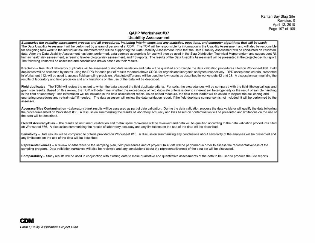
Raritan Bay Slag Site Revision: 0
April 12, 2010 Page 107 of 109
A Final Quality Assurance Project Plan
QAPP Worksheet #37 Usability Assessment
Summarize the usability assessment process and all procedures, including interim steps and any statistics, equations, and computer algorithms that will be used: The Data Usability Assessment will be performed by a team of personnel at CDM. The TOM will be responsible for information in the Usability Assessment and will also be responsible for assigning task work to the individual task members who will be supporting the Data Usability Assessment. Note that the Data Usability Assessment will be conducted on validated data. After the Data Usability Assessment has been performed, data deemed appropriate for use will then be used in the Slag Distribution Technical Memorandum and subsequent RI, human health risk assessment, screening level ecological risk assessment, and FS reports. The results of the Data Usability Assessment will be presented in the project-specific report. The following items will be assessed and conclusions drawn based on their results. Precision – Results of laboratory duplicates will be assessed during data validation and data will be qualified according to the data validation procedures cited on Worksheet #36. Field duplicates will be assessed by matrix using the RPD for each pair of results reported above CRQL for organic and inorganic analyses respectively. RPD acceptance criteria, presented in Worksheet #12, will be used to access field sampling precision. Absolute difference will be used for low results as described in worksheets 12 and 28. A discussion summarizing the results of laboratory and field precision and any limitations on the use of the data will be described. Field duplicates - The TOM will review the extent to which the data exceed the field duplicate criteria. For soils, the exceedances will be compared with the field lithological logs and grain size results. Based on this review, the TOM will determine whether the exceedance of field duplicate criteria is due to inherent soil heterogeneity or the result of sample handling in the field or laboratory. This information will be included in the data assessment report. As an added measure, the field team leader will be asked to inspect the soil coning and quartering procedures and re-train staff if needed. The data assessor will review the data validation report. If the field duplicate comparison is not included, it will be performed by the assessor. Accuracy/Bias Contamination –Laboratory blank results will be assessed as part of data validation. During the data validation process the data validator will qualify the data following the procedures listed on Worksheet #36. A discussion summarizing the results of laboratory accuracy and bias based on contamination will be presented and limitations on the use of the data will be described. Overall Accuracy/Bias – The results of instrument calibration and matrix spike recoveries will be reviewed and data will be qualified according to the data validation procedures cited on Worksheet #36. A discussion summarizing the results of laboratory accuracy and any limitations on the use of the data will be described. Sensitivity – Data results will be compared to criteria provided on Worksheet #15. A discussion summarizing any conclusions about sensitivity of the analyses will be presented and any limitations on the use of the data will be described. Representativeness – A review of adherence to the sampling plan, field procedures and of project QA audits will be performed in order to assess the representativeness of the sampling program. Data validation narratives will also be reviewed and any conclusions about the representativeness of the data set will be discussed. Comparability – Study results will be used in conjunction with existing data to make qualitative and quantitative assessments of the data to be used to produce the Site reports.
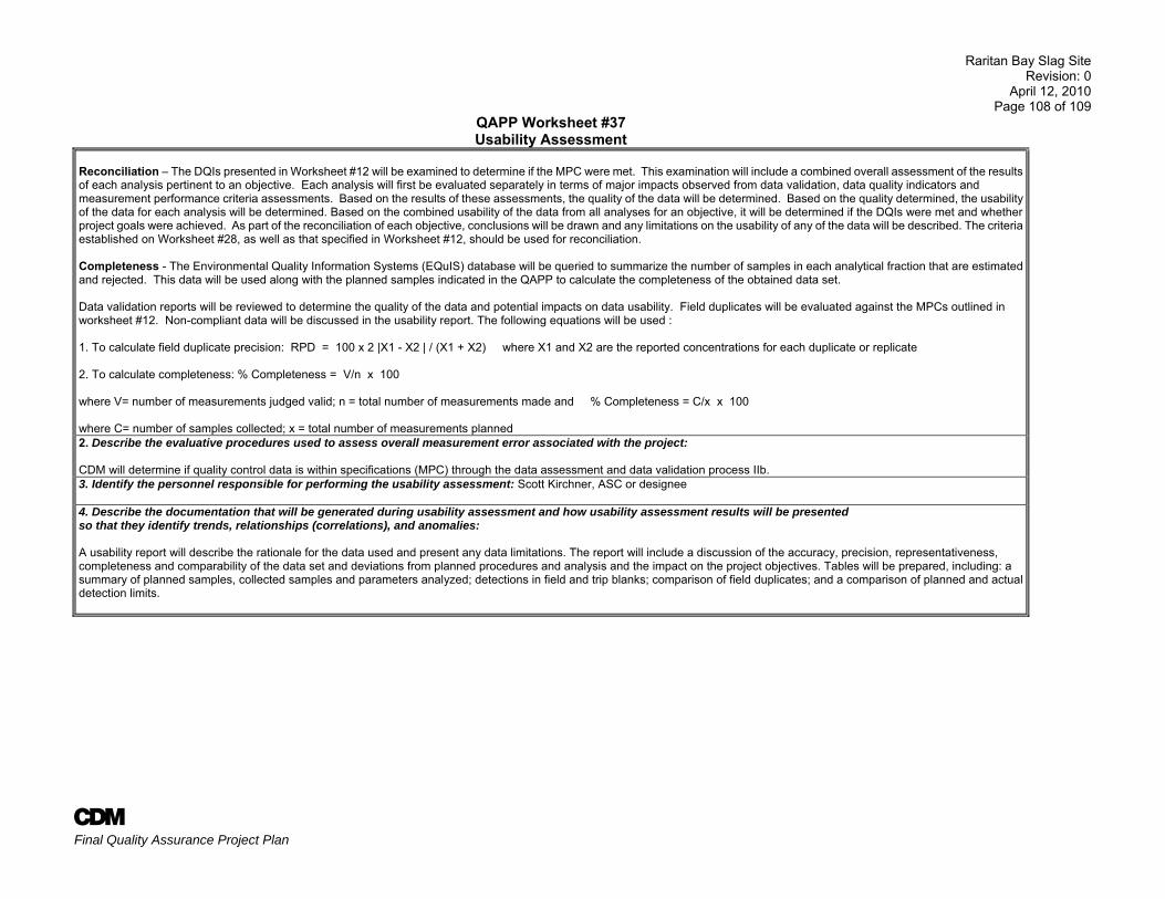
Raritan Bay Slag Site Revision: 0
April 12, 2010 Page 108 of 109
A Final Quality Assurance Project Plan
QAPP Worksheet #37 Usability Assessment
Reconciliation – The DQIs presented in Worksheet #12 will be examined to determine if the MPC were met. This examination will include a combined overall assessment of the results of each analysis pertinent to an objective. Each analysis will first be evaluated separately in terms of major impacts observed from data validation, data quality indicators and measurement performance criteria assessments. Based on the results of these assessments, the quality of the data will be determined. Based on the quality determined, the usability of the data for each analysis will be determined. Based on the combined usability of the data from all analyses for an objective, it will be determined if the DQIs were met and whether project goals were achieved. As part of the reconciliation of each objective, conclusions will be drawn and any limitations on the usability of any of the data will be described. The criteria established on Worksheet #28, as well as that specified in Worksheet #12, should be used for reconciliation. Completeness - The Environmental Quality Information Systems (EQuIS) database will be queried to summarize the number of samples in each analytical fraction that are estimated and rejected. This data will be used along with the planned samples indicated in the QAPP to calculate the completeness of the obtained data set. Data validation reports will be reviewed to determine the quality of the data and potential impacts on data usability. Field duplicates will be evaluated against the MPCs outlined in worksheet #12. Non-compliant data will be discussed in the usability report. The following equations will be used : 1. To calculate field duplicate precision: RPD = 100 x 2 |X1 - X2 | / (X1 + X2) where X1 and X2 are the reported concentrations for each duplicate or replicate 2. To calculate completeness: % Completeness = V/n x 100 where V= number of measurements judged valid; n = total number of measurements made and % Completeness = C/x x 100 where C= number of samples collected; x = total number of measurements planned 2. Describe the evaluative procedures used to assess overall measurement error associated with the project: CDM will determine if quality control data is within specifications (MPC) through the data assessment and data validation process IIb. 3. Identify the personnel responsible for performing the usability assessment: Scott Kirchner, ASC or designee 4. Describe the documentation that will be generated during usability assessment and how usability assessment results will be presented so that they identify trends, relationships (correlations), and anomalies: A usability report will describe the rationale for the data used and present any data limitations. The report will include a discussion of the accuracy, precision, representativeness, completeness and comparability of the data set and deviations from planned procedures and analysis and the impact on the project objectives. Tables will be prepared, including: a summary of planned samples, collected samples and parameters analyzed; detections in field and trip blanks; comparison of field duplicates; and a comparison of planned and actual detection limits.
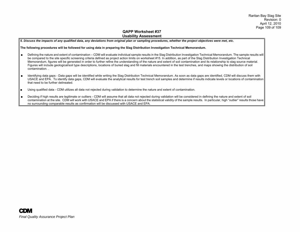
Raritan Bay Slag Site Revision: 0
April 12, 2010 Page 109 of 109
A Final Quality Assurance Project Plan
QAPP Worksheet #37 Usability Assessment
5. Discuss the impacts of any qualified data, any deviations from original plan or sampling procedures, whether the project objectives were met, etc. The following procedures will be followed for using data in preparing the Slag Distribution Investigation Technical Memorandum. ■ Defining the nature and extent of contamination – CDM will evaluate individual sample results in the Slag Distribution Investigation Technical Memorandum. The sample results will
be compared to the site specific screening criteria defined as project action limits on worksheet #15. In addition, as part of the Slag Distribution Investigation Technical Memorandum, figures will be generated in order to further refine the understanding of the nature and extent of soil contamination and its relationship to slag source material. Figures will include geological/soil type descriptions, locations of buried slag and fill materials encountered in the test trenches, and maps showing the distribution of soil contamination. .
■ Identifying data gaps - Data gaps will be identified while writing the Slag Distribution Technical Memorandum. As soon as data gaps are identified, CDM will discuss them with USACE and EPA. To identify data gaps, CDM will evaluate the analytical results for test trench soil samples and determine if results indicate levels or locations of contamination that need to be further delineated.
■ Using qualified data - CDM utilizes all data not rejected during validation to determine the nature and extent of contamination.
■ Deciding if high results are legitimate or outliers - CDM will assume that all data not rejected during validation will be considered in defining the nature and extent of soil contamination at the site. CDM will work with USACE and EPA if there is a concern about the statistical validity of the sample results. In particular, high “outlier” results those haveno surrounding comparable results as confirmation will be discussed with USACE and EPA.
Raritan Bay Slag Site Revision No.: 0
April 12, 2010 Page 1
A Final Quality Assurance Project Plan
References Lockheed Martin. 2009. Technical Memorandum, Geophysical Survey for Raritan Bay Slag Site, July. _____. 2009. Chemical Assessment Report, Characterization of Slag/Waste Material, Fate and Transport of Contaminants, and Biomonitoring of Contaminants. June. _____. 2009. Trip Report, Raritan Bay Sediment Sampling. August. Weston Solutions, Inc. 2009. Summary Letter Report, Phase II, Raritan Bay Slag, Old Bridge and Sayreville, New Jersey. June. _____. 2009. Summary Letter Report, Raritan Bay Slag, Old Bridge and Sayreville, New Jersey. January.

Figures
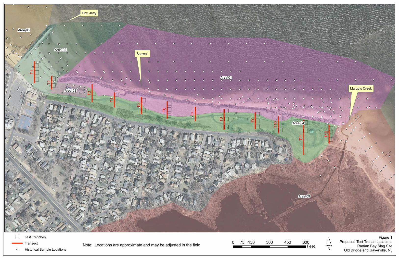
) Test Trenches
Transect
Historical Sample Locations
)
)
) )
) )
))
))
)
)
))
)
)
)
)
)
)
))
)
)
)
)
)
)
)
)T11
T1
T8
T3
T5
T6
T9
T4
T7
T2
T12
T10
Area-01
Area-09
Area-04
Area-02
Area-05
Area-03
Figure 1Proposed Test Trench Locations
Rartian Bay Slag SiteOld Bridge and Sayerville, NJ´0 150 300 450 60075
FeetNote: Locations are approximate and may be adjusted in the field
Marquis Creek
Seawall
First Jetty
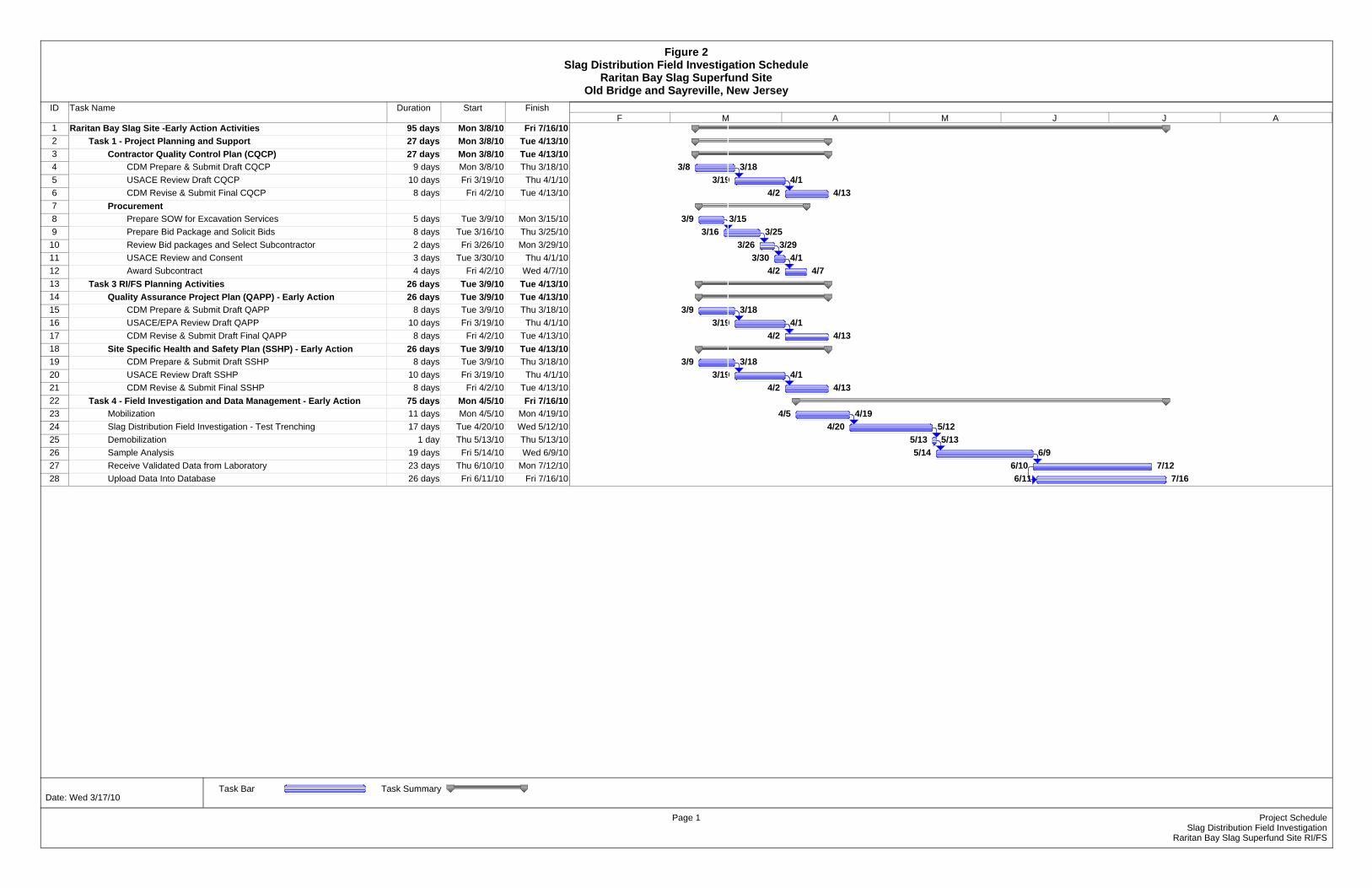
ID Task Name Duration Start Finish
1 Raritan Bay Slag Site -Early Action Activities 95 days Mon 3/8/10 Fri 7/16/102 Task 1 - Project Planning and Support 27 days Mon 3/8/10 Tue 4/13/103 Contractor Quality Control Plan (CQCP) 27 days Mon 3/8/10 Tue 4/13/104 CDM Prepare & Submit Draft CQCP 9 days Mon 3/8/10 Thu 3/18/105 USACE Review Draft CQCP 10 days Fri 3/19/10 Thu 4/1/106 CDM Revise & Submit Final CQCP 8 days Fri 4/2/10 Tue 4/13/107 Procurement 22 days Tue 3/9/10 Wed 4/7/108 Prepare SOW for Excavation Services 5 days Tue 3/9/10 Mon 3/15/109 Prepare Bid Package and Solicit Bids 8 days Tue 3/16/10 Thu 3/25/10
10 Review Bid packages and Select Subcontractor 2 days Fri 3/26/10 Mon 3/29/1011 USACE Review and Consent 3 days Tue 3/30/10 Thu 4/1/1012 Award Subcontract 4 days Fri 4/2/10 Wed 4/7/1013 Task 3 RI/FS Planning Activities 26 days Tue 3/9/10 Tue 4/13/1014 Quality Assurance Project Plan (QAPP) - Early Action 26 days Tue 3/9/10 Tue 4/13/1015 CDM Prepare & Submit Draft QAPP 8 days Tue 3/9/10 Thu 3/18/1016 USACE/EPA Review Draft QAPP 10 days Fri 3/19/10 Thu 4/1/1017 CDM Revise & Submit Draft Final QAPP 8 days Fri 4/2/10 Tue 4/13/1018 Site Specific Health and Safety Plan (SSHP) - Early Action 26 days Tue 3/9/10 Tue 4/13/1019 CDM Prepare & Submit Draft SSHP 8 days Tue 3/9/10 Thu 3/18/1020 USACE Review Draft SSHP 10 days Fri 3/19/10 Thu 4/1/1021 CDM Revise & Submit Final SSHP 8 days Fri 4/2/10 Tue 4/13/1022 Task 4 - Field Investigation and Data Management - Early Action 75 days Mon 4/5/10 Fri 7/16/1023 Mobilization 11 days Mon 4/5/10 Mon 4/19/1024 Slag Distribution Field Investigation - Test Trenching 17 days Tue 4/20/10 Wed 5/12/1025 Demobilization 1 day Thu 5/13/10 Thu 5/13/1026 Sample Analysis 19 days Fri 5/14/10 Wed 6/9/1027 Receive Validated Data from Laboratory 23 days Thu 6/10/10 Mon 7/12/1028 Upload Data Into Database 26 days Fri 6/11/10 Fri 7/16/10
3/8 3/183/19 4/1
4/2 4/13
3/9 3/153/16 3/25
3/26 3/293/30 4/1
4/2 4/7
3/9 3/183/19 4/1
4/2 4/13
3/9 3/183/19 4/1
4/2 4/13
4/5 4/194/20 5/12
5/13 5/135/14 6/9
6/10 7/126/11 7/16
F M A M J J A
Task Bar Task Summary
Figure 2Slag Distribution Field Investigation Schedule
Raritan Bay Slag Superfund SiteOld Bridge and Sayreville, New Jersey
Page 1 Project ScheduleSlag Distribution Field Investigation
Raritan Bay Slag Superfund Site RI/FS
Date: Wed 3/17/10
Appendix A
CDM TECHNICAL STANDARD OPERATING PROCEDURES (TSOPs)
1-2 Sample Custody 1-4 Subsurface Sampling 1-10 Field Measurement of Organic Vapors 2-1 Packaging and Shipping Environmental Samples 2-2 Guide to Handling of Investigation Derived Waste 3-5 Lithological Logging 4-1 Field Logbook Content and Control 4-2 Photographic Documentation of Field Activities 4-5 Field Equipment Decontamination at Nonradioactive Sites 5-1 Control of Measurement and Test Equipment
TSOP 1-2
SAMPLE CUSTODY
Sample Custody SOP 1-2 Revision: 5 Date: March 2007
Prepared: David O. Johnson Technical Review: S. Budney
QA Review: Jo Nell Mullins Approved:
E-Signed by Michael C. MalloyVERIFY authenticity with ApproveIt
Issued:
E-Signed by P. Michael SchwanVERIFY authenticity with ApproveIt
Signature/Date
Signature/Date 1.0 Objective Because of the evidentiary nature of samples collected during environmental investigations, possession must be traceable from the time the samples are collected until their derived data are introduced as evidence in legal proceedings. To maintain and document sample possession, sample custody procedures are followed. All paperwork associated with the sample custody procedures will be retained in CDM Federal Programs Corporation (CDM) files unless the client requests that it be transferred to them for use in legal proceedings or at the completion of the contract. Note: Sample custody documentation requirements vary with the specific EPA region or client. This SOP is intended to present basic sample custody requirements, along with common options. Specific sample custody requirements shall be presented in the project-specific quality assurance (QA) project plan or project-specific modification or clarification form (see Section U-1). 2.0 Background 2.1 Definitions Sample - A sample is material to be analyzed that is contained in single or multiple containers representing a unique sample identification number. Sample Custody - A sample is under custody if: 1. It is in your possession 2. It is in your view, after being in your possession 3. It was in your possession and you locked it up 4. It is in a designated secure area Chain-of-Custody Record - A chain-of-custody record is a form used to document the transfer of custody of samples from one individual to another. Custody Seal - A custody seal is a tape-like seal that is part of the chain-of-custody process and is used to detect tampering with samples after they have been packed for shipping. Sample Label - A sample label is an adhesive label placed on sample containers to designate a sample identification number and other sampling information. Sample Tag - A sample tag is attached with string to a sample container to designate a sample identification number and other sampling information. Tags may be used when it is difficult to physically place adhesive labels on the container (e.g., in the case of small air sampling tubes). 3.0 General Responsibilities Sampler - The sampler is personally responsible for the care and custody of the samples collected until they are properly transferred or dispatched. Field Team Leader - The field team leader (FTL) is responsible for ensuring that strict chain-of-custody procedures are maintained during all sampling events. The FTL is also responsible for coordinating with the subcontractor laboratory to
A Technical Standard Operating Procedures Page 1 of 6 TSOP 1-2.32207
SOP 1-2 Sample Custody Revision: 5
Date: March 2007
ensure that adequate information is recorded on custody records. The FTL determines whether proper custody procedures were followed during the fieldwork. Field Sample Custodian - The field sample custodian, when designated by the FTL, is responsible for accepting custody of samples from the sampler(s) and properly packing and shipping the samples to the laboratory assigned to do the analyses. A field sample custodian is typically designated only for large and complex field efforts. Note: Responsibilities may vary from site to site. Therefore, all field team member responsibilities shall be defined in the field plan or site/quality assurance project plan (QAPP). 4.0 Required Supplies P Chain-of-custody records (applicable client or CDM forms) P Custody seals P Sample labels and/or tags P Clear tape P EPA Field Operations Records Management System II Lite™
(FORMS II Lite™) software (if required) P Computer P Printer
P Printer paper 5.0 Procedures 5.1 Chain-of-Custody Record This procedure establishes a method for maintaining custody of samples through use of a chain-of-custody record. This procedure will be followed for all samples collected or split samples accepted. Field Custody 1. Collect only the number of samples needed to represent the media being sampled. To the extent possible, determine
the quantity and types of samples and sample locations before the actual fieldwork. As few people as possible shall handle samples.
2. Complete sample labels or tags for each sample using waterproof ink. 3. Maintain personal custody of the samples (in your possession) at all times until custody is transferred for sample
shipment or directly to the analytical laboratory. Transfer of Custody and Shipment 1. Complete a chain-of-custody record for all samples (see Figure 1 for an example of a chain-of-custody record. Similar
forms may be used when requested by the client). When transferring the possession of samples, the individuals relinquishing and receiving will sign, date, and note the time on the record. This record documents sample custody transfer from the sampler, often through another person, to the sample custodian in the appropriate laboratory.
P The date/time will be the same for both signatures when custody is transferred directly to another person. When
samples are shipped via common carrier (e.g., Federal Express), the date/time will not be the same for both signatures. Common carriers are not required to sign the chain-of-custody record.
P In all cases, it must be readily apparent that the person who received custody is the same person who
relinquished custody to the next custodian. P If samples are left unattended or a person refuses to sign, this must be documented and explained on the chain-
of-custody record. Note: If a field sample custodian has been designated, he/she may initiate the chain-of-custody record, sign, and date as the relinquisher. The individual sampler(s) must sign in the appropriate block, but does (do) not need to sign and date as a relinquisher (refer to Figure 1).
A Technical Standard Operating Procedures Page 2 of 6 TSOP 1-2.32207
SOP 1-2 Sample Custody Revision: 5
Date: March 2007
2. Package samples properly for shipment and dispatch to the appropriate laboratory for analysis. Each shipment must
be accompanied by a separate chain-of-custody record. If a shipment consists of multiple coolers, a chain-of-custody record shall be filled out for each cooler documenting only samples contained in that particular cooler.
3. The original record will accompany the shipment, and the copies will be retained by the FTL and, if applicable,
distributed to the appropriate sample coordinators. Freight bills will also be retained by the FTL as part of the permanent documentation. The shipping number from the freight bill shall be recorded on the applicable chain-of-custody record and field logbook in accordance with TSOP 4-1, Field Logbook Content and Control.
Procedure for Completing CDM Example Chain-of-Custody Record The following procedure is to be used to fill out the CDM chain-of-custody record. The record provided herein (Figure 1) is an example chain-of-custody record. If another type of custody record (i.e., provided by the EPA Contract Laboratory Program (CLP) or a subcontract laboratory or generated by FORMS II Lite™) is used to track the custody of samples, the custody record shall be filled out in its entirety. 1. Record project number. 2. Record FTL for the project (if a field sample custodian has been designated, also record this name in the “Remarks” box). 3. Record the name and address of the laboratory to which samples are being shipped. 4. Enter the project name/location or code number. 5. Record overnight courier’s airbill number. 6. Record sample location number. 7. Record sample number. 8. Note preservatives added to the sample. 9. Note media type (matrix) of the sample. 10. Note sample type (grab or composite). 11. Enter date of sample collection. 12. Enter time of sample collection in military time. 13. When required by the client, enter the names or initials of the samplers next to the sample location number of the
sample they collected. 14. List parameters for analysis and the number of containers submitted for each analysis. 15. Enter appropriate designation for laboratory quality control (e.g., matrix spike/matrix spike duplicate [MS/MSD], matrix
spike/duplicate [MS/D]), or other remarks (e.g., sample depth). 16. Sign the chain-of-custody record(s) in the space provided. All samplers must sign each record. 17. If sample tags are used, record the sample tag number in the “Remarks” column. 18. The originator checks information entered in Items 1 through 16 and then signs the top left “Relinquished by” box,
prints his/her name, and enters the current date and time (military). 19. Send the top two copies (usually white and yellow) with the samples to the laboratory; retain the third copy (usually
pink) for the project files. Retain additional copies for the project file or distribute as required to the appropriate sample coordinators.
20. The laboratory sample custodian receiving the sample shipment checks the sample label information against the chain-of-custody record. Sample condition is checked and anything unusual is noted under “Remarks” on the chain-of-custody record. The laboratory custodian receiving custody signs in the adjacent “Received by” box and keeps the copy. The white copy is returned to CDM.
5.2 Sample Labels and Tags Unless the client directs otherwise, sample labels or tags will be used for all samples collected or accepted for CDM projects. 1. Complete one label or tag with the information required by the client for each sample container collected. A typical
label or tag would be completed as follows (see Figure 2 for example of sample tag; labels are completed with the equivalent information):
P Record the project code (i.e., project or task number). P Enter the station number (sample number or EPA CLP identification number) if applicable. P Record the date to indicate the month, day, and year of sample collection. P Enter the time (military) of sample collection.
A Technical Standard Operating Procedures Page 3 of 6 TSOP 1-2.32207
SOP 1-2 Sample Custody Revision: 5
Date: March 2007
P Place a check to indicate composite or grab sample. P Record the station (sample) location. P Sign in the space provided. P Place a check next to “yes” or “no” to indicate if a preservative was added. P Place a check under “Analyses” next to the parameters for which the sample is to be analyzed. If the desired
analysis is not listed, write it in the empty slot. Note: Do not write in the box for “laboratory sample number.” P Place or write additional relevant information under “Remarks.”
2. Place adhesive labels directly on the sample containers. Place clear tape over the label to protect from moisture. 3. Securely attach sample tags to the sample bottle. On 2.27 liter (80 oz.) amber bottles, the tag string may be looped
through the ring-style handle and tied. On all other containers, it is recommended that the string be looped around the neck of the bottle, then twisted, and relooped around the neck until the slack in the string is removed.
4. Double-check that the information recorded on the sample tag is consistent with the information recorded on the
chain-of-custody record. 5.3 Custody Seals Two custody seals must be placed on opposite corners of all shipping containers (e.g., cooler) before shipment. The seals shall be signed and dated by the shipper. Custody seals may also be required to be placed on individual sample bottles. Check with the client or refer to EPA regional guidelines for direction. 5.4 Sample Shipping CDM Federal SOP 2-1, Packaging and Shipping Environmental Samples defines the requirements for packaging and shipping environmental samples. 6.0 Restrictions/Limitations Check with the EPA region or client for specific guidelines. If no specific guidelines are identified, this procedure shall be followed. For EPA CLP sampling events, combined chain-of-custody/traffic report forms generated with EPA FORMS II Lite™ or other EPA-specific records may be used. Refer to regional guidelines for completing these forms. The EPA FORMS II Lite™ software may be used to customize sample labels and custody records when directed by the client or the CDM project manager. 7.0 References U. S. Army Corps of Engineers. 2001. Requirements for the Preparation of Sampling and Analysis Plan, EM 200-1-3. Appendix F. February. U. S. Environmental Protection Agency. Revised March 1992. National Enforcement Investigations Center, Multi-Media Investigation Manual, EPA-330/9-89-003-R. p.85. __________. Region IV. 1996. Environmental Investigations Standard Operating Procedures and Quality Assurance Manual. Section 3.3. May. __________. 2002. FORMS II Lite™ User’s Guide, Version 5.1. __________. 2002. EPA Guidance for Quality Assurance Project Plans, EPA QA/G-5, EPA/240/R-02/009. Section 2.2.3. December. __________. 2004. Contract Laboratory Program (CLP), Guidance for Field Samplers, EPA-540-R-00-003. Final. Section 3.2. August.
A Technical Standard Operating Procedures Page 4 of 6 TSOP 1-2.32207
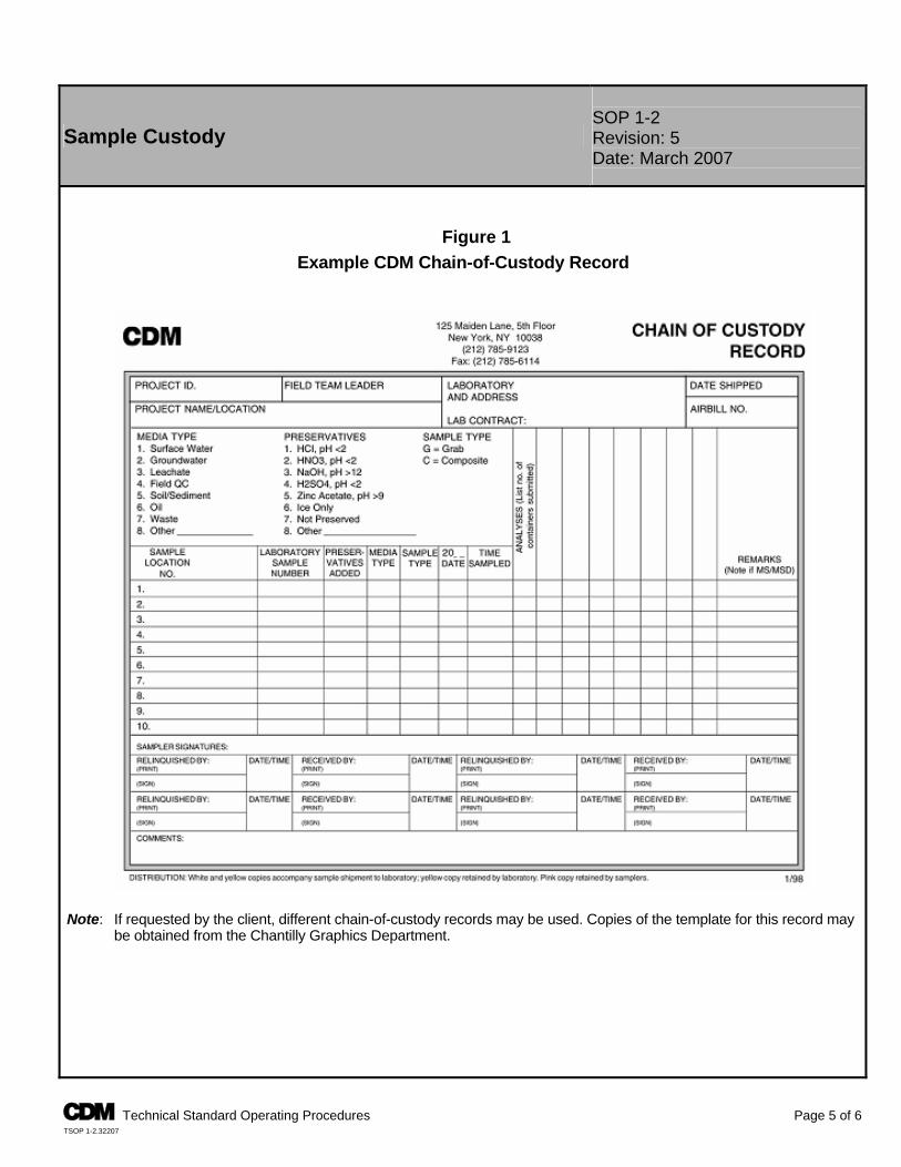
SOP 1-2 Sample Custody Revision: 5
Date: March 2007
Figure 1 Example CDM Chain-of-Custody Record
Note: If requested by the client, different chain-of-custody records may be used. Copies of the template for this record may
be obtained from the Chantilly Graphics Department.
A Technical Standard Operating Procedures Page 5 of 6 TSOP 1-2.32207
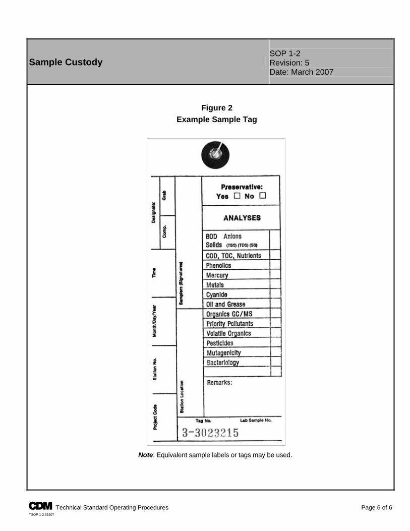
SOP 1-2 Sample Custody Revision: 5
Date: March 2007
Figure 2 Example Sample Tag
Note: Equivalent sample labels or tags may be used.
A Technical Standard Operating Procedures Page 6 of 6 TSOP 1-2.32207
TSOP 1-4
SUBSURFACE SAMPLING
Subsurface Soil Sampling SOP 1-4 Revision: 6 Date: March 2007
Prepared: Del R. Baird Technical Review: Mark Caldwell
QA Review: Jo Nell Mullins Approved:
E-Signed by Michael C. MalloyVERIFY authenticity with ApproveIt
Issued:
E-Signed by P. Michael SchwanVERIFY authenticity with ApproveIt
Signature/Date
Signature/Date 1.0 Objective The objective of this standard operating procedure (SOP) is to define the techniques and requirements for collecting soil samples from the unconsolidated zone. Techniques include use of hand augers, split-barrel samplers, Shelby tubes, direct-push rig samplers, and backhoes. 2.0 Background 2.1 Definitions Auger Flight - A steel section length attached to the auger length to extend the augers and remove additional unconsolidated material as drilling depth increases. Backhoe - An excavator whose shovel bucket is attached to a hinged boom and is drawn backward to move earth. Direct Push Rig Sampler - A sampler with a locking tip that keeps the device closed during the sampling push. The tip is released at the desired depth, and the push is continued. During the push, the soil moves into the sampler. Grab Sample - A discrete portion or aliquot taken from a specific location at a given point in time. Hand Auger - A stainless steel cylinder (bucket) approximately 7 to 10 centimeters (cm) (3 to 4 inches) in diameter and 30 cm (1 foot) in length, open at both ends with the bottom edge designed to twist into the unconsolidated material and obtain a soil core. The auger has a T-shaped handle (used for manual operation) attached to the top of the bucket by extendable stainless steel rods. Liner - A cylindrical sleeve generally made of brass, stainless steel, or Teflon® that is placed inside a split-barrel sampler, direct-push rig sampler, or hand auger bucket to collect samples for VOC analysis or prevent cross-contamination of the sample. Shelby Tube - A cylindrical sampling device, generally made of steel, that is driven into the subsurface soil through a hollow-stem auger using a drill rig. The tube, once retrieved, may be capped and the undisturbed soil sample extruded in the laboratory before analysis. Slide Hammer - A device consisting of a drive weight (hammer) and a drive weight fall guide. Split-Barrel Sampler - A cylindrical sampling device generally made of carbon steel that fits into a hollow-stem auger. The sampler is opened lengthwise, which allows the sample to be retrieved by “splitting” the barrel sampler. Also referred to as a split-spoon. Subsurface Soil - The unconsolidated material that exists deeper than approximately 30 cm (1 foot) below the ground surface. Unconsolidated Zone - A layer of nonlithified earth material (soil) that has no mineral cement or matrix binding its grains.
A Technical Standard Operating Procedures Page 1 of 11 TSOP 1-4.32707
SOP 1-4 Subsurface Soil Sampling Revision: 6
Date: March 2007
2.2 Associated Procedures P CDM Federal SOP 1-2, Sample Custody P CDM Federal SOP 2-1, Packaging and Shipping Environmental Samples P CDM Federal SOP 3-5, Lithologic Logging P CDM Federal SOP 4-1, Field Logbook Content and Control P CDM Federal SOP 4-5, Field Equipment Decontamination at Nonradioactive Sites 2.3 Discussion Shallow subsurface soil samples (to depths between 0.15 cm to 3 meters (m) [6 inches and 10 feet]) may be collected using hand augers. However, soil samples collected with a hand auger are commonly of poorer quality than those collected by split-barrel or Shelby tube samplers because the soil sample is disturbed in the augering process. Split- barrel and Shelby tube samplers are generally used during collection of soil samples using hollow-stem auger drill methods. Barrel-type samplers may also be used to collect soil samples from hand auger borings using a slide hammer device. Liners are used to minimize the loss of volatile organic compounds (VOCs) and to prevent cross-contamination from the sampler to the sample. The size and material of sampling devices shall be selected based on project and analytical objectives and defined in site-specific plans. Collecting samples using backhoes enables the collector to correlate the precise vertical and horizontal interval with adjacent materials (cross section). 3.0 General Responsibilities Site Manager - The site manager is responsible for ensuring that field personnel are trained in the use of this procedure and the required equipment, and for ensuring that subsurface soil samples are collected in accordance with this procedure and any other SOPs pertaining to specific media sampling. The site manager must also ensure that the quantity and location of subsurface soil samples collected meet the requirements of the site-specific plans. Field Team Leader - The field team leader is responsible for ensuring that field personnel collect subsurface soil samples in accordance with this SOP and other relevant procedures. Note: Responsibilities may vary from site to site. Therefore, all field team member responsibilities shall be defined in the field plan or site-/project-specific quality assurance project plan (QAPP). 4.0 Required Equipment 4.1 General P Site-specific plans P Latex or appropriate gloves P Field logbook P Plastic zip-top bags P Indelible black ink pens and markers P Clear, waterproof tape
P Personal protective clothing and equipment P Plastic sheeting
P Labels and appropriate forms/documentation for sample shipment
P Stainless steel and/or Teflon-lined spatulas and pans, trays, bowls, trowels, or spoons
P Appropriate sample containers P Decontamination supplies P Insulated cooler(s) and waterproof sealing tape P Sample chain-of-custody forms P Ice bags or “blue ice” P Custody seals Additional equipment is discussed in Section 5.2.7, Field Sampling/Preservation Methods. 4.2 Manual (Hand) Augering P T-handle P Extension rods P Hand auger: flighted-, bucket-, or tube-type auger
as required by the site-specific plans P Wrench(es), pliers
P Slide hammer with extension rods
A Technical Standard Operating Procedures Page 2 of 11 TSOP 1-4.32707
SOP 1-4 Subsurface Soil Sampling Revision: 6
Date: March 2007
4.3 Split-Barrel and Shelby Tube Sampling P Drill rig equipped with a 63-kilogram (kg) (140-lb) drop hammer and sufficient hollow-stem auger flights to drill to the
depths required by the site-specific plans. P Sufficient numbers of split-barrel samplers so that at least one is always decontaminated and available for sampling.
Three split-barrel samplers are generally the minimum necessary (Shelby tubes are used only once). P Split-barrel liners (as appropriate). P Wrench(es), hammer. 4.4 Direct Push Rig Sampling P Direct push rig with sufficient probe rods to extend to sample depths required by the site-specific plans P Sufficient number of samplers (in case of malfunction) and appropriate liners to collect adequate number of samples P Extension rods P Wrench(es), pliers, other specific tools 4.5 Backhoe Sampling P Backhoe with a sufficient length boom to extend to planned depths P Sufficient number of trowels or scoops P Extension rods P Tape, utility knife, other specific tools as needed 5.0 Procedures 5.1 Preparation 1. Review site-specific health and safety plan and project plans before initiating sampling activity. 2. Don the appropriate personal protective clothing as dictated by the site-specific health and safety plan. 3. Locate sampling location(s) in accordance with project documents (e.g., work plan) and document pertinent
information in the appropriate field logbook. When possible, reference locations back to existing site features such as buildings, roads, intersections, etc.
4. Processes for verifying depth of sampling must be specified in the site-specific plans. 5. Clear away vegetation and debris from the ground surface at the boring location. 6. Prepare an area next to the sample collection location for laying out cuttings by placing plastic sheeting on the ground
to cover the immediate area surrounding the borehole. 7. Set up a decontamination line, if decontamination is required, in accordance with CDM Federal SOP 4-5. 5.2 Collection The following general steps must be followed when collecting all subsurface soil samples: 1. Wear clean gloves during handling of all sample containers and sampling devices. 2. VOC samples or samples that may be degraded by aeration shall be collected first and with the least disturbance
possible. 3. Sampling information shall be recorded in the field logbook and on any associated forms. Describe lithology,
according to CDM Federal SOP 3-5, in the field logbook or on the lithologic log form. 4. Specific sampling devices to be used shall be identified in the site-specific plans and recorded in the field logbook.
A Technical Standard Operating Procedures Page 3 of 11 TSOP 1-4.32707
SOP 1-4 Subsurface Soil Sampling Revision: 6
Date: March 2007
5. Care must be taken to prevent cross-contamination and misidentification of samples. 6. Sample containers containing samples for VOC analysis shall be filled completely to minimize headspace. 5.2.1 Manual (Hand) Augering The following steps must be followed when collecting hand-augered samples: 1. Auger to the depth required for sampling. Place cuttings on plastic sheeting or as specified in the site-specific plans. If
possible, lay out the cuttings in stratigraphic order. 2. Throughout the augering, make detailed notes concerning the geologic features of the soil or sediments in the field
logbook. 3. Cease augering when the top of the specified sampling depth has been reached. If required, remove the auger from
the hole and decontaminate the auger or use a separate decontaminated auger, then obtain the sample. 4. Collect a grab sample for VOC analyses (or samples that may be degraded by aeration) immediately and place in
sample container. Sample bottles shall be filled completely to minimize headspace. 5. Remaining sample shall be homogenized for other analyses before placing samples in the appropriate containers.
Label containers as required. 6. Wipe containers with a clean Kimwipe or paper towel to remove residual soil from the exterior of the container(s). 7. Label the sample container with the appropriate information. Secure the label by covering it with a piece of clear tape. 8. Place the containers in zip-top plastic bags and seal the bags. Pack samples in a cooler with ice. 9. Proceed with further sampling, as required by the site-specific plans. 10. When all sampling is complete, dispose of cuttings, plastic sheeting, etc., as specified in the site-specific plans. 11. Complete the field logbook entry and other appropriate forms, being sure to record all relevant information before
leaving the site. 12. Properly package all samples for shipment and complete all necessary sample shipment documentation. Remand
custody of samples to the appropriate personnel. See CDM Federal SOPs 1-2 and 2-1 or site-specific plans. 5.2.2 Manual (Hand) Augering Using a Tube Sampler with Liner or Slide Hammer The following steps must be followed when collecting hand-augered samples using a tube sampler with liner or slide hammer: 1. Auger to the depth required for sampling. Place cuttings on the plastic sheeting as specified in the site-specific plans.
If possible, lay out the cuttings in stratigraphic order. 2. Throughout augering, make detailed notes in the field logbook concerning the geologic features of the soil or
sediments. 3. Cease augering when the top of the specified sampling depth has been reached. Remove the auger from the hole
and decontaminate. 4. Prepare a decontaminated tube sampler by installing a decontaminated liner in the auger tube.
A Technical Standard Operating Procedures Page 4 of 11 TSOP 1-4.32707
SOP 1-4 Subsurface Soil Sampling Revision: 6
Date: March 2007
5. Obtain the sample by driving the sample tube through the sample interval with the slide hammer. Remove the liner
from the tube and immediately cover the ends with Teflon tape and cap the ends of the tube. Seal the caps with waterproof tape.
6. Wipe sealed liners with a clean Kimwipe or paper towel. 7. Label the sealed liners as required in the site-specific plans. Mark the top and bottom of the sample on the outside of
the liner. 8. Place sealed liners in zip-top plastic bags and seal the bags. Pack samples in a chilled cooler. 9. Proceed with further sampling, as required by the site-specific plans. 10. When sampling is complete, dispose of cuttings, plastic sheeting, etc., as specified in the site-specific plans. 11. Decontaminate all equipment according to CDM Federal SOP 4-5 between each sample. 12. Complete the field logbook entry and other forms, being sure to record all relevant information before leaving the site. 13. Properly package all samples for shipment and complete all necessary sample shipment documentation. Remand
custody of samples to the appropriate personnel. See CDM Federal SOPs 1-2 and 2-1 or site-specific plans. 5.2.3 Split-Barrel Sampling Note: Steps 1 through 12 describe activities to be performed by a licensed drilling contractor, not CDM personnel. The following steps must be followed when collecting split-barrel samples: 1. Remove any pavement and subbase material from an area of twice the bit diameter, if necessary. 2. The drilling rig will be decontaminated at a separate location before drilling, per CDM Federal SOP 4-5 or the site-
specific decontamination procedures. 3. Attach the hollow-stem auger with the cutting head, plug, and center rod(s) to the drill rig. 4. Begin drilling and proceed to the first designated sample depth, adding auger flights as necessary. 5. Upon reaching the designated sample depth, slightly raise the auger(s) to disengage the cutting head, and rotate the
auger without advancement to clean cuttings from the bottom of the hole. 6. Remove the plug and center rods, if applicable. 7. If required by the site-specific sampling plan, install decontaminated liners in the split barrel sampler. 8. Install a decontaminated split-barrel on the center rod(s) and insert it into the hollow-stem auger. Connect the
hammer assembly and lightly tap the rods to seat the drive shoe at the top of undisturbed soil or sediment. 9. Mark the center rod in 15-cm (6-inch) increments from the top of the auger(s). 10. Drive the split-barrel using the hammer. Use a full 76-cm (30-inch) drop as specified by the American Society for
Testing and Materials (ASTM) Method D-1586. Record the number of blows required to drive the sampler through each 15-cm (6-inch) increment.
11. Cease driving when the full length of the spoon has been driven or upon refusal. Refusal occurs when little or no
progress is made for 50 blows of the hammer. ASTM D1586-99 § 7.2.1 and 7.2.2 defines “refusal” as >50 blows per 6-inch advance or a total of 100 blows.
A Technical Standard Operating Procedures Page 5 of 11 TSOP 1-4.32707
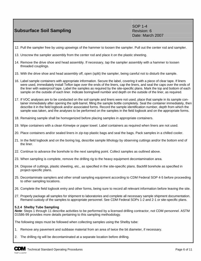
SOP 1-4 Subsurface Soil Sampling Revision: 6
Date: March 2007
12. Pull the sampler free by using upswings of the hammer to loosen the sampler. Pull out the center rod and sampler. 13. Unscrew the sampler assembly from the center rod and place it on the plastic sheeting. 14. Remove the drive shoe and head assembly. If necessary, tap the sampler assembly with a hammer to loosen
threaded couplings. 15. With the drive shoe and head assembly off, open (split) the sampler, being careful not to disturb the sample. 16. Label sample containers with appropriate information. Secure the label, covering it with a piece of clear tape. If liners
were used, immediately install Teflon tape over the ends of the liners, cap the liners, and seal the caps over the ends of the liner with waterproof tape. Label the samples as required by the site-specific plans. Mark the top and bottom of each sample on the outside of each liner. Indicate boring/well number and depth on the outside of the liner, as required.
17. If VOC analyses are to be conducted on the soil sample and liners were not used, place that sample in its sample con-
tainer immediately after opening the split-barrel, filling the sample bottle completely. Seal the container immediately, then describe it in the field logbook and/or associated forms. Record the sample identification number, depth from which the sample was taken, and the analyses to be performed on the samples in the field logbook and on the appropriate forms.
18. Remaining sample shall be homogenized before placing samples in appropriate containers. 19. Wipe containers with a clean Kimwipe or paper towel. Label containers as required when liners are not used. 20. Place containers and/or sealed liners in zip-top plastic bags and seal the bags. Pack samples in a chilled cooler. 21. In the field logbook and on the boring log, describe sample lithology by observing cuttings and/or the bottom end of
the liner. 22. Continue to advance the borehole to the next sampling point. Collect samples as outlined above. 23. When sampling is complete, remove the drilling rig to the heavy equipment decontamination area. 24. Dispose of cuttings, plastic sheeting, etc., as specified in the site-specific plans. Backfill borehole as specified in
project-specific plans. 25. Decontaminate samplers and other small sampling equipment according to CDM Federal SOP 4-5 before proceeding
to other sampling locations. 26. Complete the field logbook entry and other forms, being sure to record all relevant information before leaving the site. 27. Properly package all samples for shipment to laboratories and complete all necessary sample shipment documentation.
Remand custody of the samples to appropriate personnel. See CDM Federal SOPs 1-2 and 2-1 or site-specific plans. 5.2.4 Shelby Tube Sampling Note: Steps 1 through 11 describe activities to be performed by a licensed drilling contractor, not CDM personnel. ASTM D1586-99 provides more details pertaining to this sampling methodology. The following steps must be followed when collecting samples using the Shelby tube: 1. Remove any pavement and subbase material from an area of twice the bit diameter, if necessary. 2. The drilling rig will be decontaminated at a separate location before drilling.
A Technical Standard Operating Procedures Page 6 of 11 TSOP 1-4.32707
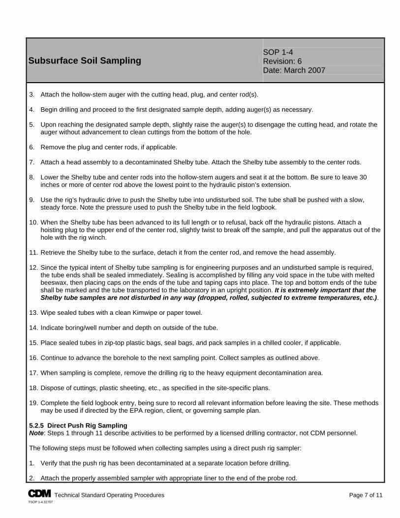
SOP 1-4 Subsurface Soil Sampling Revision: 6
Date: March 2007
3. Attach the hollow-stem auger with the cutting head, plug, and center rod(s). 4. Begin drilling and proceed to the first designated sample depth, adding auger(s) as necessary. 5. Upon reaching the designated sample depth, slightly raise the auger(s) to disengage the cutting head, and rotate the
auger without advancement to clean cuttings from the bottom of the hole. 6. Remove the plug and center rods, if applicable. 7. Attach a head assembly to a decontaminated Shelby tube. Attach the Shelby tube assembly to the center rods. 8. Lower the Shelby tube and center rods into the hollow-stem augers and seat it at the bottom. Be sure to leave 30
inches or more of center rod above the lowest point to the hydraulic piston’s extension. 9. Use the rig’s hydraulic drive to push the Shelby tube into undisturbed soil. The tube shall be pushed with a slow,
steady force. Note the pressure used to push the Shelby tube in the field logbook. 10. When the Shelby tube has been advanced to its full length or to refusal, back off the hydraulic pistons. Attach a
hoisting plug to the upper end of the center rod, slightly twist to break off the sample, and pull the apparatus out of the hole with the rig winch.
11. Retrieve the Shelby tube to the surface, detach it from the center rod, and remove the head assembly. 12. Since the typical intent of Shelby tube sampling is for engineering purposes and an undisturbed sample is required,
the tube ends shall be sealed immediately. Sealing is accomplished by filling any void space in the tube with melted beeswax, then placing caps on the ends of the tube and taping caps into place. The top and bottom ends of the tube shall be marked and the tube transported to the laboratory in an upright position. It is extremely important that the Shelby tube samples are not disturbed in any way (dropped, rolled, subjected to extreme temperatures, etc.).
13. Wipe sealed tubes with a clean Kimwipe or paper towel. 14. Indicate boring/well number and depth on outside of the tube. 15. Place sealed tubes in zip-top plastic bags, seal bags, and pack samples in a chilled cooler, if applicable. 16. Continue to advance the borehole to the next sampling point. Collect samples as outlined above. 17. When sampling is complete, remove the drilling rig to the heavy equipment decontamination area. 18. Dispose of cuttings, plastic sheeting, etc., as specified in the site-specific plans. 19. Complete the field logbook entry, being sure to record all relevant information before leaving the site. These methods
may be used if directed by the EPA region, client, or governing sample plan. 5.2.5 Direct Push Rig Sampling Note: Steps 1 through 11 describe activities to be performed by a licensed drilling contractor, not CDM personnel. The following steps must be followed when collecting samples using a direct push rig sampler: 1. Verify that the push rig has been decontaminated at a separate location before drilling. 2. Attach the properly assembled sampler with appropriate liner to the end of the probe rod.
A Technical Standard Operating Procedures Page 7 of 11 TSOP 1-4.32707
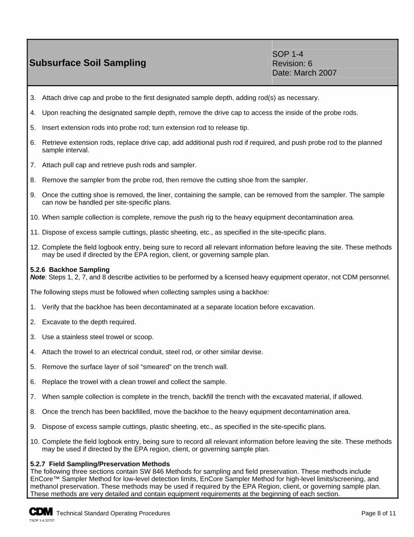
SOP 1-4 Subsurface Soil Sampling Revision: 6
Date: March 2007
3. Attach drive cap and probe to the first designated sample depth, adding rod(s) as necessary. 4. Upon reaching the designated sample depth, remove the drive cap to access the inside of the probe rods. 5. Insert extension rods into probe rod; turn extension rod to release tip. 6. Retrieve extension rods, replace drive cap, add additional push rod if required, and push probe rod to the planned
sample interval. 7. Attach pull cap and retrieve push rods and sampler. 8. Remove the sampler from the probe rod, then remove the cutting shoe from the sampler. 9. Once the cutting shoe is removed, the liner, containing the sample, can be removed from the sampler. The sample
can now be handled per site-specific plans. 10. When sample collection is complete, remove the push rig to the heavy equipment decontamination area. 11. Dispose of excess sample cuttings, plastic sheeting, etc., as specified in the site-specific plans. 12. Complete the field logbook entry, being sure to record all relevant information before leaving the site. These methods
may be used if directed by the EPA region, client, or governing sample plan. 5.2.6 Backhoe Sampling Note: Steps 1, 2, 7, and 8 describe activities to be performed by a licensed heavy equipment operator, not CDM personnel. The following steps must be followed when collecting samples using a backhoe: 1. Verify that the backhoe has been decontaminated at a separate location before excavation. 2. Excavate to the depth required. 3. Use a stainless steel trowel or scoop. 4. Attach the trowel to an electrical conduit, steel rod, or other similar devise. 5. Remove the surface layer of soil “smeared” on the trench wall. 6. Replace the trowel with a clean trowel and collect the sample. 7. When sample collection is complete in the trench, backfill the trench with the excavated material, if allowed. 8. Once the trench has been backfilled, move the backhoe to the heavy equipment decontamination area. 9. Dispose of excess sample cuttings, plastic sheeting, etc., as specified in the site-specific plans. 10. Complete the field logbook entry, being sure to record all relevant information before leaving the site. These methods
may be used if directed by the EPA region, client, or governing sample plan. 5.2.7 Field Sampling/Preservation Methods The following three sections contain SW 846 Methods for sampling and field preservation. These methods include EnCore™ Sampler Method for low-level detection limits, EnCore Sampler Method for high-level limits/screening, and methanol preservation. These methods may be used if required by the EPA Region, client, or governing sample plan. These methods are very detailed and contain equipment requirements at the beginning of each section.
A Technical Standard Operating Procedures Page 8 of 11 TSOP 1-4.32707
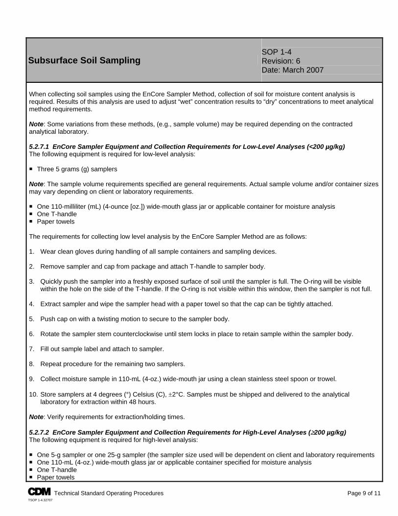
SOP 1-4 Subsurface Soil Sampling Revision: 6
Date: March 2007
When collecting soil samples using the EnCore Sampler Method, collection of soil for moisture content analysis is required. Results of this analysis are used to adjust “wet” concentration results to “dry” concentrations to meet analytical method requirements. Note: Some variations from these methods, (e.g., sample volume) may be required depending on the contracted analytical laboratory. 5.2.7.1 EnCore Sampler Equipment and Collection Requirements for Low-Level Analyses (<200 µg/kg) The following equipment is required for low-level analysis: P Three 5 grams (g) samplers Note: The sample volume requirements specified are general requirements. Actual sample volume and/or container sizes may vary depending on client or laboratory requirements. P One 110-milliliter (mL) (4-ounce [oz.]) wide-mouth glass jar or applicable container for moisture analysis P One T-handle P Paper towels The requirements for collecting low level analysis by the EnCore Sampler Method are as follows: 1. Wear clean gloves during handling of all sample containers and sampling devices. 2. Remove sampler and cap from package and attach T-handle to sampler body. 3. Quickly push the sampler into a freshly exposed surface of soil until the sampler is full. The O-ring will be visible
within the hole on the side of the T-handle. If the O-ring is not visible within this window, then the sampler is not full. 4. Extract sampler and wipe the sampler head with a paper towel so that the cap can be tightly attached. 5. Push cap on with a twisting motion to secure to the sampler body. 6. Rotate the sampler stem counterclockwise until stem locks in place to retain sample within the sampler body. 7. Fill out sample label and attach to sampler. 8. Repeat procedure for the remaining two samplers. 9. Collect moisture sample in 110-mL (4-oz.) wide-mouth jar using a clean stainless steel spoon or trowel. 10. Store samplers at 4 degrees (°) Celsius (C), ±2°C. Samples must be shipped and delivered to the analytical
laboratory for extraction within 48 hours. Note: Verify requirements for extraction/holding times. 5.2.7.2 EnCore Sampler Equipment and Collection Requirements for High-Level Analyses (≥200 µg/kg) The following equipment is required for high-level analysis: P One 5-g sampler or one 25-g sampler (the sampler size used will be dependent on client and laboratory requirements P One 110-mL (4-oz.) wide-mouth glass jar or applicable container specified for moisture analysis P One T-handle P Paper towels
A Technical Standard Operating Procedures Page 9 of 11 TSOP 1-4.32707
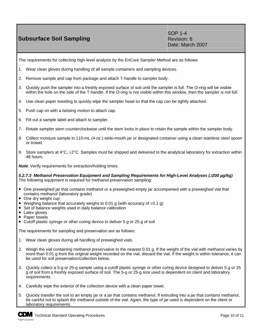
SOP 1-4 Subsurface Soil Sampling Revision: 6
Date: March 2007
The requirements for collecting high-level analysis by the EnCore Sampler Method are as follows: 1. Wear clean gloves during handling of all sample containers and sampling devices. 2. Remove sample and cap from package and attach T-handle to sampler body. 3. Quickly push the sampler into a freshly exposed surface of soil until the sampler is full. The O-ring will be visible
within the hole on the side of the T-handle. If the O-ring is not visible within this window, then the sampler is not full. 4. Use clean paper toweling to quickly wipe the sampler head so that the cap can be tightly attached. 5. Push cap on with a twisting motion to attach cap. 6. Fill out a sample label and attach to sampler. 7. Rotate sampler stem counterclockwise until the stem locks in place to retain the sample within the sampler body. 8. Collect moisture sample in 110-mL (4-oz.) wide-mouth jar or designated container using a clean stainless steel spoon
or trowel. 9. Store samplers at 4°C, ±2°C. Samples must be shipped and delivered to the analytical laboratory for extraction within
48 hours. Note: Verify requirements for extraction/holding times. 5.2.7.3 Methanol Preservation Equipment and Sampling Requirements for High-Level Analyses (≥200 µg/kg) The following equipment is required for methanol preservation sampling: P One preweighed jar that contains methanol or a preweighed empty jar accompanied with a preweighed vial that
contains methanol (laboratory grade) P One dry weight cup P Weighing balance that accurately weighs to 0.01 g (with accuracy of ±0.1 g) P Set of balance weights used in daily balance calibration P Latex gloves P Paper towels P Cutoff plastic syringe or other coring device to deliver 5 g or 25 g of soil The requirements for sampling and preservation are as follows: 1. Wear clean gloves during all handling of preweighed vials. 2. Weigh the vial containing methanol preservative to the nearest 0.01 g. If the weight of the vial with methanol varies by
more than 0.01 g from the original weight recorded on the vial, discard the vial. If the weight is within tolerance, it can be used for soil preservation/collection below.
3. Quickly collect a 5-g or 25-g sample using a cutoff plastic syringe or other coring device designed to deliver 5 g or 25
g of soil from a freshly exposed surface of soil. The 5-g or 25-g size used is dependent on client and laboratory requirements.
4. Carefully wipe the exterior of the collection device with a clean paper towel. 5. Quickly transfer the soil to an empty jar or a jar that contains methanol. If extruding into a jar that contains methanol,
be careful not to splash the methanol outside of the vial. Again, the type of jar used is dependent on the client or laboratory requirements.
A Technical Standard Operating Procedures Page 10 of 11 TSOP 1-4.32707
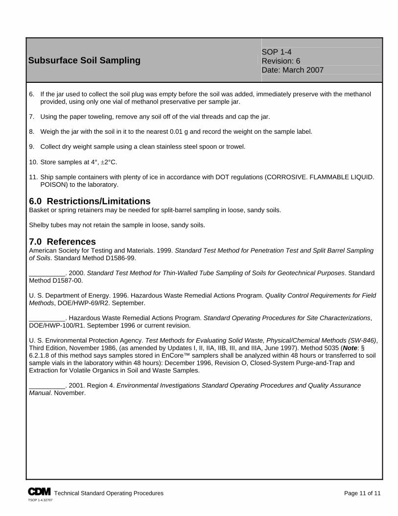
SOP 1-4 Subsurface Soil Sampling Revision: 6
Date: March 2007
6. If the jar used to collect the soil plug was empty before the soil was added, immediately preserve with the methanol
provided, using only one vial of methanol preservative per sample jar. 7. Using the paper toweling, remove any soil off of the vial threads and cap the jar. 8. Weigh the jar with the soil in it to the nearest 0.01 g and record the weight on the sample label. 9. Collect dry weight sample using a clean stainless steel spoon or trowel. 10. Store samples at 4°, ±2°C. 11. Ship sample containers with plenty of ice in accordance with DOT regulations (CORROSIVE. FLAMMABLE LIQUID.
POISON) to the laboratory. 6.0 Restrictions/Limitations Basket or spring retainers may be needed for split-barrel sampling in loose, sandy soils. Shelby tubes may not retain the sample in loose, sandy soils. 7.0 References American Society for Testing and Materials. 1999. Standard Test Method for Penetration Test and Split Barrel Sampling of Soils. Standard Method D1586-99. __________. 2000. Standard Test Method for Thin-Walled Tube Sampling of Soils for Geotechnical Purposes. Standard Method D1587-00. U. S. Department of Energy. 1996. Hazardous Waste Remedial Actions Program. Quality Control Requirements for Field Methods, DOE/HWP-69/R2. September. __________. Hazardous Waste Remedial Actions Program. Standard Operating Procedures for Site Characterizations, DOE/HWP-100/R1. September 1996 or current revision. U. S. Environmental Protection Agency. Test Methods for Evaluating Solid Waste, Physical/Chemical Methods (SW-846), Third Edition, November 1986, (as amended by Updates I, II, IIA, IIB, III, and IIIA, June 1997). Method 5035 (Note: § 6.2.1.8 of this method says samples stored in EnCore™ samplers shall be analyzed within 48 hours or transferred to soil sample vials in the laboratory within 48 hours): December 1996, Revision O, Closed-System Purge-and-Trap and Extraction for Volatile Organics in Soil and Waste Samples. __________. 2001. Region 4. Environmental Investigations Standard Operating Procedures and Quality Assurance Manual. November.
A Technical Standard Operating Procedures Page 11 of 11 TSOP 1-4.32707
TSOP 1-10
FIELD MEASUREMENT OF ORGANIC VAPORS
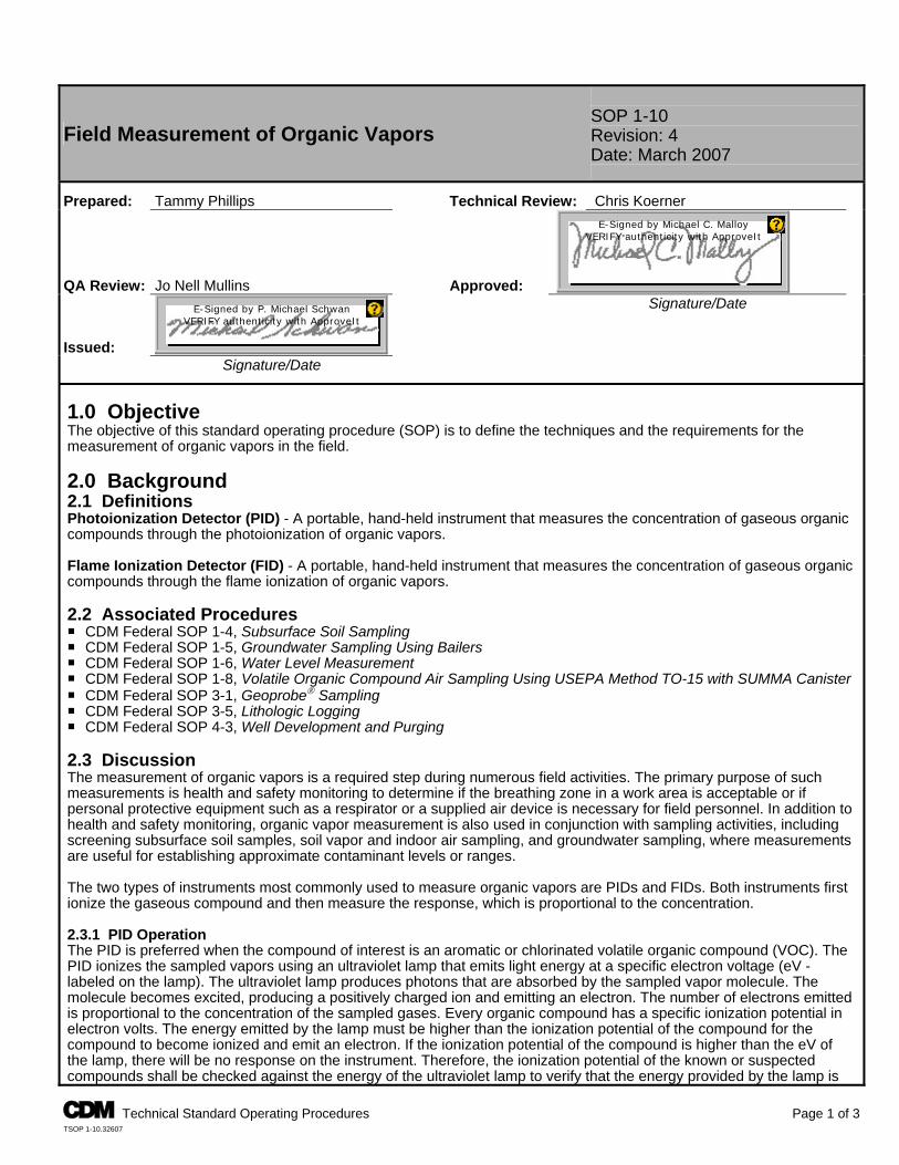
Field Measurement of Organic Vapors SOP 1-10 Revision: 4 Date: March 2007
Prepared: Tammy Phillips Technical Review: Chris Koerner
QA Review: Jo Nell Mullins Approved:
E-Signed by Michael C. MalloyVERIFY authenticity with ApproveIt
Issued:
E-Signed by P. Michael SchwanVERIFY authenticity with ApproveIt
Signature/Date
Signature/Date 1.0 Objective The objective of this standard operating procedure (SOP) is to define the techniques and the requirements for the measurement of organic vapors in the field. 2.0 Background 2.1 Definitions Photoionization Detector (PID) - A portable, hand-held instrument that measures the concentration of gaseous organic compounds through the photoionization of organic vapors. Flame Ionization Detector (FID) - A portable, hand-held instrument that measures the concentration of gaseous organic compounds through the flame ionization of organic vapors. 2.2 Associated Procedures P CDM Federal SOP 1-4, Subsurface Soil Sampling P CDM Federal SOP 1-5, Groundwater Sampling Using Bailers P CDM Federal SOP 1-6, Water Level Measurement P CDM Federal SOP 1-8, Volatile Organic Compound Air Sampling Using USEPA Method TO-15 with SUMMA Canister P CDM Federal SOP 3-1, Geoprobe® Sampling P CDM Federal SOP 3-5, Lithologic Logging P CDM Federal SOP 4-3, Well Development and Purging 2.3 Discussion The measurement of organic vapors is a required step during numerous field activities. The primary purpose of such measurements is health and safety monitoring to determine if the breathing zone in a work area is acceptable or if personal protective equipment such as a respirator or a supplied air device is necessary for field personnel. In addition to health and safety monitoring, organic vapor measurement is also used in conjunction with sampling activities, including screening subsurface soil samples, soil vapor and indoor air sampling, and groundwater sampling, where measurements are useful for establishing approximate contaminant levels or ranges. The two types of instruments most commonly used to measure organic vapors are PIDs and FIDs. Both instruments first ionize the gaseous compound and then measure the response, which is proportional to the concentration. 2.3.1 PID Operation The PID is preferred when the compound of interest is an aromatic or chlorinated volatile organic compound (VOC). The PID ionizes the sampled vapors using an ultraviolet lamp that emits light energy at a specific electron voltage (eV - labeled on the lamp). The ultraviolet lamp produces photons that are absorbed by the sampled vapor molecule. The molecule becomes excited, producing a positively charged ion and emitting an electron. The number of electrons emitted is proportional to the concentration of the sampled gases. Every organic compound has a specific ionization potential in electron volts. The energy emitted by the lamp must be higher than the ionization potential of the compound for the compound to become ionized and emit an electron. If the ionization potential of the compound is higher than the eV of the lamp, there will be no response on the instrument. Therefore, the ionization potential of the known or suspected compounds shall be checked against the energy of the ultraviolet lamp to verify that the energy provided by the lamp is
A Technical Standard Operating Procedures Page 1 of 3 TSOP 1-10.32607
A Technical Standard Operating Procedures Page 2 of 3 TSOP 1-10.32607
Field Measurement of Organic Vapors SOP 1-10 Revision: 4 Date: March 2007
greater. Additionally, manufacturer’s manuals shall be consulted to obtain the appropriate correction factors for known or suspected contaminants. Water vapor in the vapor sample can interfere with the PID detector and cause the instrument to stop responding. This can be caused by using the PID on a rainy day or when sampling headspace samples that have been in the sun. If moisture is suspected, the calibration gas shall be used to check the instrument response by inserting the gas as a check sample, not by recalibrating. If the response is lower than the gas level, then the probe and the ionization chamber shall be dried out before reusing the instrument. Note: The ultraviolet lamp in the PID is sensitive to shock, especially when using the higher eV lamps. Therefore, they shall be handled and transported carefully. The sampling probe shall not be inserted directly into soil samples or dusty areas, as the instrument vacuum will pull dirt into the ionization chamber. Under particularly dirty or dusty conditions, the lamp may become covered with a layer of dust. If dirty conditions are encountered, or if the instrument response seems to have decreased, then the lamp shall be cleaned. The instrument manual provides instructions on how to remove the instrument cover to access the lamp, and how to clean the screen in the ionization chamber and the surface of the lamp. 2.3.2 FID Operation The FID is preferred when sampling for petroleum hydrocarbons and methane (landfill gases). It responds well to aromatic hydrocarbons but is not as convenient to use as the PID. The FID allows measurement of a wide variety of compounds, but in general its sensitivity is not as high as the PID for compounds where the PID is applicable. The FID ionizes the vapor sample by burning it in a hydrogen/air flame, and measuring the response beyond what is caused by the hydrogen alone. This instrument requires a hydrogen supply, contained in a small tank in the instrument. This hydrogen, including the gas in the instrument tank, is considered a flammable gas and appropriate requirements must be adhered to when shipping. The instrument shall be emptied of hydrogen before shipping. Federal Express Hazardous Material shipping manifests must be completed when shipping the gas. The hydrogen gas in the FID combustion chamber is ignited by pressing a red button on the side of the instrument, which sends electrical current to a small resistance coil igniter in the combustion chamber. This igniter is very sensitive, and if the red button is pressed for longer than 5 seconds, the coil will burn out and the instrument will be unusable unless another igniter is available. If the instrument will not light, check the electrical connections and switches for proper settings. Check that the pump is pumping, and allow fresh air to flow through the combustion chamber for several minutes before lighting. Check to see if the exhaust port of the combustion chamber is dirty. 3.0 Responsibilities Site Manager - The site manager is responsible for ensuring that field activities are conducted in accordance with this procedure and any other SOPs pertaining to the specific activity. Field Team Leader - The field team leader is responsible for ensuring that field personnel conduct field activities in accordance with this and other relevant procedures. Note: Responsibilities may vary from site to site. Therefore, all field team member responsibilities shall be defined in the field plan or site-/project-specific quality assurance plan. 4.0 Required Equipment P Site-specific plans P Calibration gases in a range appropriate for the expected useP Field logbook P 0.5 liter (16-ounce) or “Mason” type glass jar P Waterproof black ink pen P Personal protective clothing and equipment
P Hydrogen Canister and fill valve and hose (if using FID for a period of more than 1 day)
P Photoionization detector or flame ionization detector
A Technical Standard Operating Procedures Page 3 of 3 TSOP 1-10.32607
Field Measurement of Organic Vapors SOP 1-10 Revision: 4 Date: March 2007
5.0 Procedures 5.1 Direct Reading Measurement 1. Connect the measurement probe to the instrument and make necessary operational checks (e.g., battery check, etc.)
as outlined in the manufacturer’s manual. 2. Calibrate the instrument following the applicable manufacturer’s manual 3. Make sure the instrument is reading zero and all function and range switches are set appropriately. 4. Insert the end of the probe directly into the atmosphere to be measured (e.g., breathing zone, monitoring well casing,
split spoon, etc.) and read the organic vapor concentration in parts per million (ppm) from the instrument display. Apply the appropriate correction factor if necessary. Record the highest instrument response.
5. Immediately document the reading in the field logbook or on the appropriate field form. 5.2 Headspace Measurement 1. Connect the measurement probe to the instrument and make necessary operational checks (e.g., battery check, etc.)
as outlined in the manufacturer’s manual. 2. Calibrate the instrument following the appropriate manufacturer’s manual. 3. Make sure the instrument is reading zero and all function and range switches are set appropriately. 4. Fill a clean glass jar approximately half-full of the sample to be measured. Quickly cover the top of the jar with one or
two sheets of clean aluminum foil and apply cap to seal the jar. 5. Allow headspace to develop for approximately 10 minutes. It is generally preferable to shake the sealed jar for 10 to
15 seconds at the beginning and end of headspace development. Note: When the ambient temperature is below 0°C (32°F), the headspace development and subsequent measurement shall occur within a heated vehicle or building. 6. Remove the jar cap and quickly puncture the foil and insert the instrument probe to a point approximately one-half of
the headspace depth. Do not let the probe contact the soil. If using a PID and there is condensation on the inside of the jar, only leave the probe in the jar long enough to obtain a reading. Remove the probe and allow fresh air to flow through the instrument to avoid excess water vapor to build up.
7. Read the organic vapor concentration in ppm from the instrument display. Apply the appropriate correction factor if
necessary. Record the highest instrument response. 8. Immediately record the reading in the field logbook or on the appropriate field form. 6.0 Restrictions/Limitations The two methods outlined above are the most commonly used for field measurement of organic vapors but do not apply to all circumstances. Consult project- or program-specific procedures and guidelines for deviations. Both the PID and FID provide quantitative measurement of organic vapors, but generally neither instrument is compound-specific. The typical reading range of the PID is 0 to 2,000 ppm, and the typical reading range of the FID is 0 to 1,000 ppm. The FID will measure methane while the PID will not. Note: The presence of methane will cause erratic PID measurements. In methane rich environments, toxic organic vapors shall be monitored with an FID. If desired, a charcoal filter can be placed temporarily on the FID inlet probe, which will trap all organic vapors except methane. The filtered (methane only) reading can be subtracted from unfiltered (total organic vapors) to provide an estimate of non-methane organic vapors. The reading accuracy of both instruments can be affected by ambient temperature, barometric pressure, humidity, lithology, etc. 7.0 References Martin Marietta Energy Systems, Inc. 1998. Environmental Surveillance Procedures Quality Control Program,
SH/Sub/87-21706/1. E
TSOP 2-1
PACKAGING AND SHIPPING ENVIRONMENTAL SAMPLES
Packaging and Shipping Environmental Samples SOP 2-1 Revision: 3 Date: March 2007
Prepared: Krista Lippoldt Technical Review: Chuck Myers
QA Review: Jo Nell Mullins Approved:
E-Signed by Michael C. MalloyVERIFY authenticity with ApproveIt
Issued:
E-Signed by P. Michael SchwanVERIFY authenticity with ApproveIt
Signature/Date
Signature/Date 1.0 Objective The objective of this SOP is to outline the requirements for the packaging and shipment of environmental samples. Additionally, Sections 2.0 through 7.0 outline requirements for the packaging and shipping of regulated environmental samples under the Department of Transportation (DOT) Hazardous Materials Regulations, the International Air Trans-portation Association (IATA), and International Civil Aviation Organization (ICAO) Dangerous Goods Regulations for shipment by air and applies only to domestic shipments. This SOP does not cover the requirements for packaging and shipment of equipment (including data loggers and self-contained breathing apparatus [SCBAs] or bulk chemicals that are regulated under the DOT, IATA, and ICAO. 1.1 Packaging and Shipping of All Samples This standard operating procedure (SOP) applies to the packaging and shipping of all environmental samples. If the sample is preserved or radioactive, the following sections may also be applicable.
Section 2.0 - Packaging and Shipping Samples Preserved with Methanol Section 3.0 - Packaging and Shipping Samples Preserved with Sodium Hydroxide Section 4.0 - Packaging and Shipping Samples Preserved with Hydrochloric Acid Section 5.0 - Packaging and Shipping Samples Preserved with Nitric Acid Section 6.0 - Packaging and Shipping Samples Preserved with Sulfuric Acid Section 7.0 - Packaging and Shipping Limited-Quantity Radioactive Samples
1.2 Background 1.2.1 Definitions Environmental Sample - An aliquot of air, water, plant material, sediment, or soil that represents the contaminant levels on a site. Samples of potential contaminant sources, like tanks, lagoons, or non-aqueous phase liquids are normally not “environmental” for this purpose. This procedure applies only to environmental samples that contain less than reportable quantities for any foreseeable hazardous constituents according to DOT regulations promulgated in 49 CFR - Part 172.101 Appendix A. Custody Seal - A custody seal is a narrow adhesive-backed seal that is applied to individual sample containers and/or the container (i.e., cooler) before offsite shipment. Custody seals are used to demonstrate that sample integrity has not been compromised during transportation from the field to the analytical laboratory. Inside Container - The container, normally made of glass or plastic, that actually contacts the shipped material. Its purpose is to keep the sample from mixing with the ambient environment. Outside Container - The container, normally made of metal or plastic, that the transporter contacts. Its purpose is to protect the inside container. Secondary Containment - The outside container provides secondary containment if the inside container breaks (i.e., plastic overpackaging if liquid sample is collected in glass).
A Technical Standard Operating Procedures Page 1 of 17 TSOP 2-1.32807
SOP 2-1 Packaging and Shipping Environmental Samples Revision: 3
Date: March 2007
Excepted Quantity - Excepted quantities are limits to the mass or volume of a hazardous material in the inside and outside containers below which DOT, IATA, ICAO regulations do not apply. The excepted quantity limits are very low. Most regulated shipments will be made under limited quantity. Limited Quantity - Limited quantity is the maximum amount of a hazardous material below which there are specific labeling or packaging exceptions. Performance Testing - Performance testing is the required testing of outer packaging. These tests include drop and stacking tests. Qualified Shipper - A qualified shipper is a person who has been adequately trained to perform the functions of shipping hazardous materials. 1.2.2 Associated Procedures P CDM Federal SOP 1-2, Sample Custody 1.2.3 Discussion Proper packaging and shipping is necessary to ensure the protection of the integrity of environmental samples shipped for analysis. These shipments are potentially subject to regulations published by DOT, IATA, or ICAO. Failure to abide by these rules places both CDM and the individual employee at risk of serious fines. The analytical holding times for the samples must not be exceeded. The samples shall be packed in time to be shipped for overnight delivery. Make arrangements with the laboratory before sending samples for weekend delivery. 1.3 Required Equipment P Coolers with return address of the appropriate CDM office P Bubble wrap (optional) P Heavy-duty plastic garbage bags P Ice P Plastic zip-type bags, small and large P Custody seals P Clear tape P Nylon reinforced strapping tape
P Completed chain-of-custody record or contract labora-tory program (CLP) custody records, if applicable
P Duct tape P Completed bill of lading P Vermiculite (or an equivalent nonflammable material that is
inert and absorbent)* P “This End Up” and directional arrow labels
*Check for any client-specific or laboratory requirements related to the use of absorbent packaging materials. 1.4 Packaging Environmental Samples The following steps must be followed when packing sample bottles and jars for shipment: 1. Verify the samples undergoing shipment meet the definition of “environmental sample” and are not a hazardous material
as defined by DOT. Professional judgment and/or consultation with qualified persons such as the appropriate health and safety coordinator or the health and safety manager shall be observed.
2. Select a sturdy cooler in good repair. Tape any interior opening in the cooler (drain plug) from the inside to ensure
control of interior contents. Also, tape the drain plug from the outside of the cooler. Line the cooler with a large heavy-duty plastic garbage bag.
3. Be sure the caps on all bottles are tight (will not leak); check to see that labels and chain-of-custody records are
completed properly (SOP 1-2, Sample Custody). 4. Place all bottles in separate and appropriately sized plastic zip-top bags and close the bags. Up to three VOA vials may
be packed in one bag. Binding the vials together with a rubber band on the outside of the bag, or separating them so that they do not contact each other, will reduce the risk of breakage. Bottles may be wrapped in bubble wrap. Optionally, place three to six VOA vials in a quart metal can and then fill the can with vermiculite or equivalent. Note: Trip blanks must be included in coolers containing VOA samples.
A Technical Standard Operating Procedures Page 2 of 17 TSOP 2-1.32807
SOP 2-1 Packaging and Shipping Environmental Samples Revision: 3
Date: March 2007
5. Place 2 to 4 inches of vermiculite (or equivalent) into a cooler that has been lined with a garbage bag, and then place the
bottles and cans in the bag with sufficient space to allow for the addition of packing material between the bottles and cans. It is preferable to place glass sample bottles and jars into the cooler vertically. Glass containers are less likely to break when packed vertically rather than horizontally.
6. While placing sample containers into the cooler, conduct an inventory of the contents of the shipping cooler against the
chain-of-custody record. The chain-of-custody with the cooler shall reflect only those samples within the cooler. 7. Put ice in large plastic zip-top bags (double bagging the zip-tops is preferred) and properly seal. Place the ice bags on
top of and/or between the samples. Several bags of ice are required (dependant on outdoor temperature, staging time, etc.) to maintain the cooler temperature at approximately 4° Celsius (C) if the analytical method requires cooling. Fill all remaining space between the bottles or cans with packing material. Securely fasten the top of the large garbage bag with fiber or duct tape.
8. Place the completed chain-of-custody record or the CLP traffic report form (if applicable) for the laboratory into a plastic
zip-top bag, seal the bag, tape the bag to the inner side of the cooler lid and close the cooler. 9. The cooler lid shall be secured with nylon reinforced strapping tape by wrapping each end of the cooler a minimum of
two times. Attach a completed chain-of-custody seal across the opening of the cooler on opposite sides. The custody seals shall be affixed to the cooler with half of the seal on the strapping tape so that the cooler cannot be opened without breaking the seal. Complete two more wraps around with fiber tape and place clear tape over the custody seals.
10. The shipping container lid must be marked “THIS END UP” and arrow labels that indicate the proper upward position of
the container shall be affixed to the cooler. A label containing the name and address of the shipper (CDM) shall be placed on the outside of the container. Labels used in the shipment of hazardous materials (such as Cargo Only Air Craft, Flammable Solids, etc.) are not permitted on the outside of containers used to transport environmental samples and shall not be used. The name and address of the laboratory shall be placed on the container, or when shipping by common courier, the bill of lading shall be completed and attached to the lid of the shipping container.
2.0 Packaging and Shipping Samples Preserved with Methanol 2.1 Containers P The maximum volume of methanol in a sample container is limited to 30 ml. P The sample container must not be full of methanol. 2.2 Responsibility It is the responsibility of the qualified shipper to: P Ensure that the samples undergoing shipment contain no other contaminant that meets the definition of “hazardous
material” as defined by DOT P Determine the amount of preservative in each sample so that accurate determination of quantities can be made Note: Responsibilities may vary from site to site. Therefore, all field team member responsibilities shall be defined in the field plan or site-/project-specific quality assurance project plan (QAPP). 2.3 Additional Required Equipment The following equipment is needed in addition to the required equipment listed in Section 1.3: P Inner packing may consist of glass or plastic jars P Outer packaging (for limited quantities) insulated cooler that has passed the ICAO drop test P Survey documentation (if shipping from Department of Energy [DOE] or radiological sites) P Class 3 flammable liquid labels P Orientation labels P Consignor/consignee labels
A Technical Standard Operating Procedures Page 3 of 17 TSOP 2-1.32807
SOP 2-1 Packaging and Shipping Environmental Samples Revision: 3
Date: March 2007
2.4 Packaging Samples Preserved with Methanol The following steps are to be followed when packaging limited-quantity sample shipments: P Tape any interior opening in the cooler (drain plug) from the inside to ensure control of interior contents. Also, tape the
drain plug from the outside of the cooler. P All sample containers will be properly labeled and the label protected with waterproof tape before sampling. P At a minimum the label must contain:
- Project name - Sample identification number - Project number - Collector’s initials - Date and time of sample collection - Sample location
- Preservative (note amount of preservative used in miscellaneous section of the chain-of-custody form)
P Wrap each container (40-ml VOA vials) in bubble wrap (secure with waterproof tape) to prevent breakage. P Place the bubble-wrapped container into a 2.7-mil zip-type bag, removing trapped air. P Place wrapped containers inside a polyethylene bottle filled with vermiculite; seal the bottle. (Maximum of 4 VOA vials will
fit inside a 500-ml wide-mouth polyethylene bottle.) P Total volume of methanol per shipping container must not exceed 500 ml. P Place sufficient amount of vermiculite in the bottom of the cooler to absorb any leakage that may occur. P Place a garbage bag in the cooler. P Pack the samples appropriately inside the garbage bag (bottles placed upright) to prevent movement during shipment. P Place a sufficient amount of double-bagged ice around the samples to maintain the required temperature during
shipment. P Seal the garbage bag by tieing or taping. P The maximum weight of the cooler shall not exceed 30 kg (66 lbs) for any limited-quantity shipment of dangerous goods. P Secure the chain-of-custody form (placed inside a zip-type bag) to the interior of the cooler lid. P If the shipment is from a DOE or other facility, place the results of the radiation screen and cooler/sample survey with the
chain-of-custody. P Wrap strapping tape or duct tape around both ends of the cooler and around the cooler lid. P Affix custody seals to opposite sides of the cooler lid. Cover the custody seals with clear waterproof tape. P Mark the outside of the cooler with the proper shipping name of the contents, corresponding UN number, and LTD. QTY.
(as shown below).
Methanol Mixture UN1230 LTD. QTY.
P Place a label on the front of the cooler with the company name, contact name, phone number, full street address, and
state with zip code for both shipper and recipient. P Affix a Flammable Liquid label to the outside of the cooler. P Affix package orientation labels on two opposite sides of the cooler. P Secure the marking and labels to the surface of the cooler with clear waterproof tape to prevent accidental removal during
shipment. P An example of cooler labeling/marking locations is shown in Figure 1. Note: No marking or labeling can be obscured by strapping or duct tape. Note: The inner packaging of dangerous goods must be placed into the designated cooler for shipment. Other nonregulated
environmental samples may be added to the cooler for shipment. P When shipping from a DOE facility, the cooler will be surveyed by a qualified radiation control technician to ensure that
radiation flux on exterior surfaces does not exceed 0.5 mrem/h on all sides. This survey will be documented and the results reviewed by the qualified shipper.
P Complete the Dangerous Goods and Hazardous Materials Inspection Checklist for Shipping Limited-Quantity (Appendix A). P Complete a Dangerous Goods Airbill.
A Technical Standard Operating Procedures Page 4 of 17 TSOP 2-1.32807
SOP 2-1 Packaging and Shipping Environmental Samples Revision: 3
Date: March 2007
3.0 Packaging and Shipping Samples Preserved with Sodium Hydroxide 3.1 Containers The inner packaging container (and amount of preservative) that may be used for these shipments includes:
Excepted Quantities of Sodium Hydroxide Preservatives
Preservative Desired in Final
Sample Quantity of Preservative (ml) for
Specified Container pH Conc. 40 ml 125 ml 250 ml 500 ml 1 L
NaOH 30% >12 0.08% .25 0.5 1 2 5 drops = 1 ml
3.2 Responsibility It is the responsibility of the qualified shipper to determine the amount of preservative in each sample so that accurate determination of quantities can be made. Note: Responsibilities may vary from site to site. Therefore, all field team member responsibilities shall be defined in the field plan or site-/project-specific quality assurance project plan (QAPP). 3.3 Additional Required Equipment The following equipment is needed in addition to the required equipment listed in Section 1.3: P Outer packaging (for limited quantities) insulated cooler that has passed the ICAO drop test P Inner packings may consist of glass or plastic jars no larger than 1 pint P Survey documentation (if shipping from DOE or radiological sites) P Class 8 corrosive labels P Orientation labels P Consignor/consignee labels
Figure 1 Example of Cooler Label/Marking Locations
Taped Drain
Address Label
Methanol Mixture UN1230 LTD. QTY.
To: From:
Strapping Tape
Proper Shipping Name and UN Number Orientation Labels
3 Flammable Liquid
Hazard Class Label
A Technical Standard Operating Procedures Page 5 of 17 TSOP 2-1.32807
SOP 2-1 Packaging and Shipping Environmental Samples Revision: 3
Date: March 2007
3.4 Packaging Samples Preserved with Sodium Hydroxide Samples containing NaOH as a preservative that exceed the excepted concentration of 0.08 percent (2 ml of a 30 percent NaOH solution per liter) may be shipped as a limited quantity per packing instruction Y819 of the IATA/ICAO Dangerous Goods Regulations. The following steps are to be followed when packaging limited-quantity samples shipments: P Tape any interior opening in the cooler (drain plug) from the inside to ensure control of interior contents. Also, tape the
drain plug from the outside of the cooler. P All sample containers will be properly labeled and the label protected with waterproof tape before sampling. P At a minimum the label must contain:
- Project name - Sample identification number - Project number - Collector’s initials - Date and time of sample collection - Sample location
- Preservative (note amount of preservative used in miscellaneous section of the chain-of-custody form)
P This step is optional; wrap each container in bubble wrap (secure with waterproof tape) to prevent breakage. P Place the bubble-wrapped container into a 2.7-mil zip-type bag, removing trapped air. P Place glass containers inside a polyethylene bottle filled with vermiculite; seal the bottle. P The total volume of sample in each cooler must not exceed 1 liter. P Place sufficient amount of vermiculite in the bottom of the cooler to absorb any leakage that may occur. P Place a garbage bag in the cooler. P Pack the samples appropriately inside the garbage bag (bottles placed upright) to prevent movement during shipment. P Place sufficient amount of double-bagged ice around the samples to maintain the required temperature during shipment. P Seal the garbage bag by tieing or taping. P The maximum weight of the cooler shall not exceed 30 kg (66 lbs) for any limited-quantity shipment of dangerous goods. P Secure the chain-of-custody form (placed inside a zip-type bag) to the interior of the cooler lid. P If the shipment is from a DOE or other facility, place the results of the radiation screen and cooler/sample survey with the
chain-of-custody. P Wrap strapping tape or duct tape around both ends of the cooler and around the cooler lid. P Affix custody seals to opposite sides of the cooler lid. Cover the custody seals with clear waterproof tape. P Mark the outside of the cooler with the proper shipping name of the contents, corresponding UN number, and LTD. QTY.
(as shown below).
Sodium Hydroxide Solution UN1824 LTD. QTY.
P Place a label on the front of the cooler with the company name, contact name, phone number, full street address, and
state with zip code for both shipper and recipient. P Affix a Corrosive label to the outside of the cooler. P Affix package orientation labels on two opposite sides of the cooler. P Secure the marking and labels to the surface of the cooler with clear waterproof tape to prevent accidental removal during
shipment. P An example of cooler labeling/marking locations is shown in Figure 1. Note: Samples meeting the exception concentration of 0.08 percent NaOH by weight may be shipped as nonregulated
or nonhazardous following the procedure in Section 1.4. Note: No marking or labeling can be obscured by strapping or duct tape. Note: The inner packaging of dangerous goods must be placed into the designated cooler for shipment. Other
nonregulated environmental samples may be added to the cooler for shipment.
A Technical Standard Operating Procedures Page 6 of 17 TSOP 2-1.32807
SOP 2-1 Packaging and Shipping Environmental Samples Revision: 3
Date: March 2007
P When shipping from a DOE facility, the cooler will be surveyed by a qualified radiation control technician to ensure that
radiation flux on exterior surfaces does not exceed 0.5 mrem/h on all sides. This survey will be documented and the results reviewed by the qualified shipper.
P Complete the Dangerous Goods and Hazardous Materials Inspection Checklist for Shipping Limited-Quantity (Appendix A). P Complete a Dangerous Goods Airbill. 4.0 Packaging and Shipping Samples Preserved with Hydrochloric Acid 4.1 Containers The inner packaging container (and amount of preservative) that may be used for these shipments includes:
Excepted Quantities of Hydrochloric Acid Preservatives
Preservative Desired in Final
Sample Quantity of Preservative (ml) for
Specified Container pH Conc. 40 ml 125 ml 250 ml
HCl 2N <1.96 0.04% .2 .5 1 5 drops = 1 ml
4.2 Responsibility It is the responsibility of the qualified shipper to: P Determine the samples undergoing shipment contain no other contaminant that meets the definition of hazardous
material as defined by DOT P Determine the amount of preservative in each sample so that accurate determination of quantities can be made Note: Responsibilities may vary from site to site. Therefore, all field team member responsibilities shall be defined in the field plan or site-/project-specific quality assurance project plan (QAPP). 4.3 Additional Required Equipment The following equipment is needed in addition to the required equipment listed in Section 1.3. P Inner packing may consist of glass or plastic jars no larger than 1 pint. P Outer packaging (for limited quantities) insulated cooler that has passed the ICAO drop test. P Survey documentation (if shipping from DOE or radiological sites) P Class 8 corrosive labels P Orientation labels P Consignor/consignee labels 4.4 Packaging Samples Preserved with Hydrochloric Acid The following steps are to be followed when packaging limited-quantity sample shipments: P Tape any interior opening in the cooler (drain plug) from the inside to ensure control of interior contents. Also, tape the
drain plug from the outside of the cooler. P All sample containers will be properly labeled and the label protected with waterproof tape before sampling. P At a minimum the label must contain:
- Project name - Sample identification number - Project number - Collector’s initials - Date and time of sample collection - Sample location
- Preservative (note amount of preservative used in miscellaneous section of the chain-of-custody form)
P Wrap each container (40-ml VOA vials) in bubble wrap (secure with waterproof tape) to prevent breakage. P Place the bubble-wrapped container into a 2.7-mil zip-type bag, removing trapped air. P Place wrapped containers inside a polyethylene bottle filled with vermiculite; seal the bottle. (No more than 4 VOA vials
will fit inside a 500-ml wide-mouth polyethylene bottle.)
A Technical Standard Operating Procedures Page 7 of 17 TSOP 2-1.32807
SOP 2-1 Packaging and Shipping Environmental Samples Revision: 3
Date: March 2007
P Total volume of sample inside each cooler must not exceed 1 liter. P Place sufficient amount of vermiculite in the bottom of the cooler to absorb any leakage that may occur. P Place a garbage bag in the cooler. P Pack the samples appropriately inside the garbage bag (bottles placed upright) to prevent movement during shipment. P Place sufficient amount of double-bagged ice around the samples to maintain the required temperature during shipment. P Seal the garbage bag by tieing or taping. P The maximum weight of the cooler shall not exceed 30 kg (66 lbs) for any limited-quantity shipment of dangerous goods. P Secure the chain-of-custody form (placed inside a zip-type bag) to the interior of the cooler lid. P If the shipment is from a DOE or other facility, place the results of the radiation screen and cooler/sample survey with the
chain-of-custody. P Wrap strapping tape or duct tape around both ends of the cooler and around the cooler lid. P Affix custody seals to opposite sides of the cooler lid. Cover the custody seals with clear waterproof tape. P Mark the outside of the cooler with the proper shipping name of the contents, corresponding UN number, and LTD. QTY.
(as shown below).
Hydrochloric Acid Solution UN1789 LTD. QTY.
P Place a label on the front of the cooler with the company name, contact name, phone number, full street address, and
state with zip code for both shipper and recipient. P Affix a Corrosive label to the outside of the cooler. P Affix package orientation labels on two opposite sides of the cooler. P Secure the marking and labels to the surface of the cooler with clear waterproof tape to prevent accidental removal during
shipment. P An example of cooler labeling/marking locations is shown in Figure 1.
Note: Samples containing less than the exception concentration of 0.04 percent HCl by weight will be shipped as nonregulated or nonhazardous following the procedure in Section 1.4.
Note: No marking or labeling can be obscured by strapping or duct tape. Note: The inner packaging of dangerous goods must be placed into the designated cooler for shipment. Other
nonregulated environmental samples may be added to the cooler for shipment. P When shipping from a DOE facility, the cooler will be surveyed by a qualified radiation control technician to ensure that
radiation flux on exterior surfaces does not exceed 0.5 mrem/h on all sides. This survey will be documented and the results reviewed by the qualified shipper.
P Complete the Dangerous Goods and Hazardous Materials Inspection Checklist for Shipping Limited-Quantity (Appendix A). P Complete a Dangerous Goods Airbill. 5.0 Packaging and Shipping Samples Preserved with Nitric Acid 5.1 Containers The inner packaging container (and amount of preservative) that may be used for these shipments includes:
Excepted Quantities of Nitric Acid Preservatives
Preservative Desired in Final
Sample Quantity of Preservative (ml) for
Specified Container pH Conc. 40 ml 125 ml 250 ml 500 ml 1 L
HNO3 6N <1.62 0.15% 2 4 5 8 5 drops = 1 mg/L
A Technical Standard Operating Procedures Page 8 of 17 TSOP 2-1.32807
SOP 2-1 Packaging and Shipping Environmental Samples Revision: 3
Date: March 2007
5.2 Responsibility It is the responsibility of the qualified shipper to: P Determine the samples undergoing shipment contain no other contaminant that meets the definition of hazardous
material as defined by DOT P Determine the amount of preservative in each sample so that accurate determination of quantities can be made Note: Responsibilities may vary from site to site. Therefore, all field team member responsibilities shall be defined in the field plan or site-/project-specific quality assurance project plan (QAPP). 5.3 Additional Required Equipment The following equipment is needed in addition to the required equipment listed in Section 1.3: P Inner packings may consist of glass or plastic jars no larger than 100 ml. P Outer packaging (for limited quantities) insulated cooler that has passed the ICAO drop test. P Survey documentation (if shipping from DOE or radiological sites) P Class 8 corrosive labels P Orientation labels P Consignor/consignee labels 5.4 Packaging Samples Preserved with Nitric Acid Samples containing HNO3 as a preservative that exceed the excepted concentration of 0.15 percent HNO3 will be shipped as a limited quantity per packing instruction Y807 of the IATA/ICAO Dangerous Goods Regulations. The following steps are to be followed when packaging limited-quantity sample shipments: P Tape any interior opening in the cooler (drain plug) from the inside to ensure control of interior contents. Also, tape the
drain plug from the outside of the cooler. P All sample containers will be properly labeled and the label protected with waterproof tape before sampling. P At a minimum the label must contain:
- Project name - Sample identification number - Project number - Collector’s initials - Date and time of sample collection - Sample location
- Preservative (note amount of preservative used in miscellaneous section of the chain-of-custody form)
P This step is optional; wrap each container in bubble wrap (secure with waterproof tape) to prevent breakage. P Place the bubble-wrapped container into a 2.7-mil zip-type bag, removing trapped air. P Place glass containers inside a polyethylene bottle filled with vermiculite; seal the bottle. P Place sufficient amount of vermiculite in the bottom of the cooler to absorb any leakage that may occur. P Place a garbage bag in the cooler. P Pack the samples appropriately inside the garbage bag (bottles placed upright) to prevent movement during shipment. P Place sufficient amount of double-bagged ice around the samples to maintain the required temperature during shipment. P Seal the garbage bag by tieing or taping. P The maximum volume of preserved solution in the cooler must not exceed 500 ml. P The maximum weight of the cooler shall not exceed 30 kg (66 lbs) for any limited-quantity shipment of dangerous goods. P Secure the chain-of-custody form (placed inside a zip-type bag) to the interior of the cooler lid. P If the shipment is from a DOE or other facility, place the results of the radiation screen and cooler/sample survey with the
chain-of-custody. P Wrap strapping tape or duct tape around both ends of the cooler and around the cooler lid. P Affix custody seals to opposite sides of the cooler lid. Cover the custody seals with clear waterproof tape. P Mark the outside of the cooler with the proper shipping name of the contents, corresponding UN number, and LTD. QTY.
(as shown below).
A Technical Standard Operating Procedures Page 9 of 17 TSOP 2-1.32807
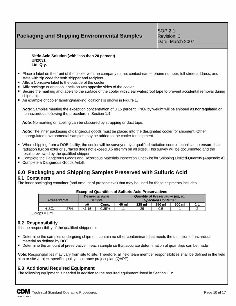
SOP 2-1 Packaging and Shipping Environmental Samples Revision: 3
Date: March 2007
Nitric Acid Solution (with less than 20 percent) UN2031 Ltd. Qty.
P Place a label on the front of the cooler with the company name, contact name, phone number, full street address, and
state with zip code for both shipper and recipient. P Affix a Corrosive label to the outside of the cooler. P Affix package orientation labels on two opposite sides of the cooler. P Secure the marking and labels to the surface of the cooler with clear waterproof tape to prevent accidental removal during
shipment. P An example of cooler labeling/marking locations is shown in Figure 1.
Note: Samples meeting the exception concentration of 0.15 percent HNO3 by weight will be shipped as nonregulated or nonhazardous following the procedure in Section 1.4. Note: No marking or labeling can be obscured by strapping or duct tape. Note: The inner packaging of dangerous goods must be placed into the designated cooler for shipment. Other nonregulated environmental samples may be added to the cooler for shipment.
P When shipping from a DOE facility, the cooler will be surveyed by a qualified radiation control technician to ensure that
radiation flux on exterior surfaces does not exceed 0.5 mrem/h on all sides. This survey will be documented and the results reviewed by the qualified shipper.
P Complete the Dangerous Goods and Hazardous Materials Inspection Checklist for Shipping Limited-Quantity (Appendix A).P Complete a Dangerous Goods Airbill. 6.0 Packaging and Shipping Samples Preserved with Sulfuric Acid 6.1 Containers The inner packaging container (and amount of preservative) that may be used for these shipments includes:
Excepted Quantities of Sulfuric Acid Preservatives
Preservative Desired in Final
Sample Quantity of Preservative (ml) for
Specified Container pH Conc. 40 ml 125 ml 250 ml 500 ml 1 L
H2SO4 37N <1.15 0.35% .1 .25 0.5 1 2 5 drops = 1 ml
6.2 Responsibility It is the responsibility of the qualified shipper to: P Determine the samples undergoing shipment contain no other contaminant that meets the definition of hazardous
material as defined by DOT P Determine the amount of preservative in each sample so that accurate determination of quantities can be made Note: Responsibilities may vary from site to site. Therefore, all field team member responsibilities shall be defined in the field plan or site-/project-specific quality assurance project plan (QAPP). 6.3 Additional Required Equipment The following equipment is needed in addition to the required equipment listed in Section 1.3:
A Technical Standard Operating Procedures Page 10 of 17 TSOP 2-1.32807
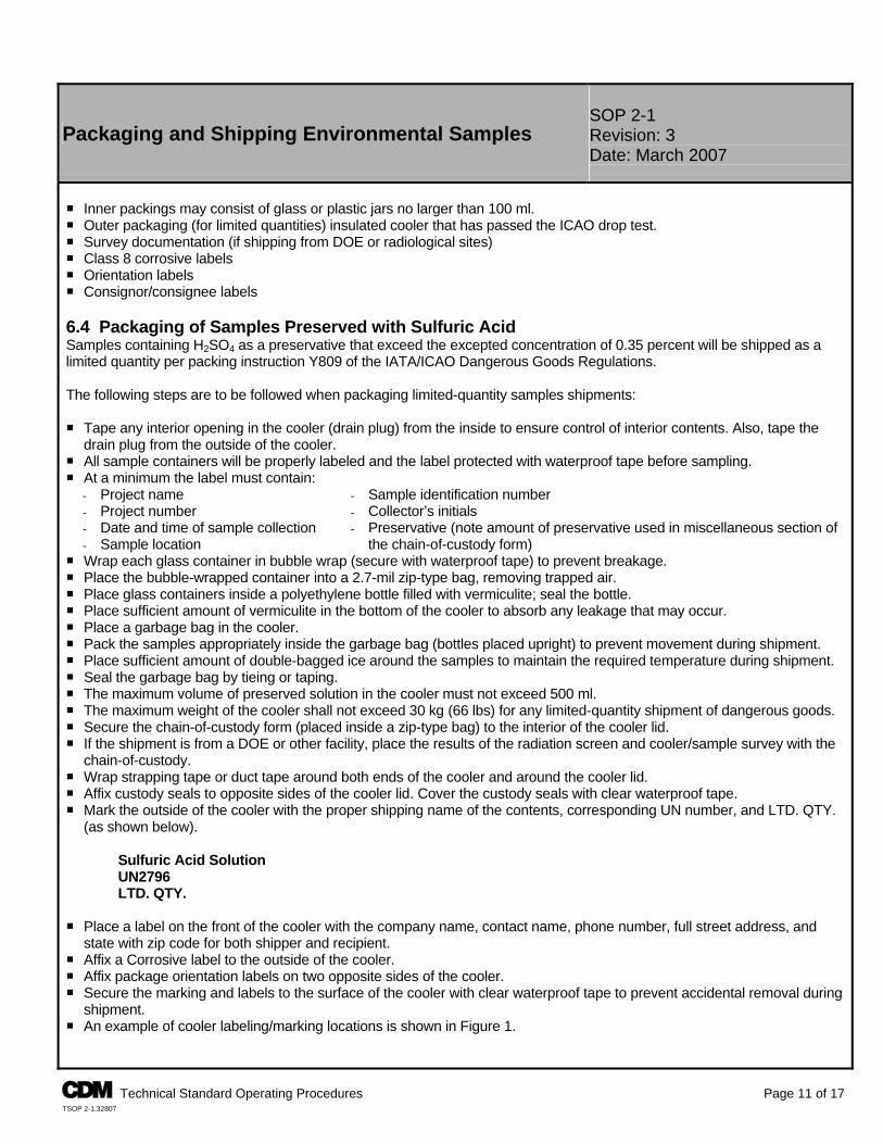
SOP 2-1 Packaging and Shipping Environmental Samples Revision: 3
Date: March 2007
P Inner packings may consist of glass or plastic jars no larger than 100 ml. P Outer packaging (for limited quantities) insulated cooler that has passed the ICAO drop test. P Survey documentation (if shipping from DOE or radiological sites) P Class 8 corrosive labels P Orientation labels P Consignor/consignee labels 6.4 Packaging of Samples Preserved with Sulfuric Acid Samples containing H2SO4 as a preservative that exceed the excepted concentration of 0.35 percent will be shipped as a limited quantity per packing instruction Y809 of the IATA/ICAO Dangerous Goods Regulations. The following steps are to be followed when packaging limited-quantity samples shipments: P Tape any interior opening in the cooler (drain plug) from the inside to ensure control of interior contents. Also, tape the
drain plug from the outside of the cooler. P All sample containers will be properly labeled and the label protected with waterproof tape before sampling. P At a minimum the label must contain:
- Project name - Sample identification number - Project number - Collector’s initials - Date and time of sample collection - Sample location
- Preservative (note amount of preservative used in miscellaneous section of the chain-of-custody form)
P Wrap each glass container in bubble wrap (secure with waterproof tape) to prevent breakage. P Place the bubble-wrapped container into a 2.7-mil zip-type bag, removing trapped air. P Place glass containers inside a polyethylene bottle filled with vermiculite; seal the bottle. P Place sufficient amount of vermiculite in the bottom of the cooler to absorb any leakage that may occur. P Place a garbage bag in the cooler. P Pack the samples appropriately inside the garbage bag (bottles placed upright) to prevent movement during shipment. P Place sufficient amount of double-bagged ice around the samples to maintain the required temperature during shipment. P Seal the garbage bag by tieing or taping. P The maximum volume of preserved solution in the cooler must not exceed 500 ml. P The maximum weight of the cooler shall not exceed 30 kg (66 lbs) for any limited-quantity shipment of dangerous goods. P Secure the chain-of-custody form (placed inside a zip-type bag) to the interior of the cooler lid. P If the shipment is from a DOE or other facility, place the results of the radiation screen and cooler/sample survey with the
chain-of-custody. P Wrap strapping tape or duct tape around both ends of the cooler and around the cooler lid. P Affix custody seals to opposite sides of the cooler lid. Cover the custody seals with clear waterproof tape. P Mark the outside of the cooler with the proper shipping name of the contents, corresponding UN number, and LTD. QTY.
(as shown below).
Sulfuric Acid Solution UN2796 LTD. QTY.
P Place a label on the front of the cooler with the company name, contact name, phone number, full street address, and
state with zip code for both shipper and recipient. P Affix a Corrosive label to the outside of the cooler. P Affix package orientation labels on two opposite sides of the cooler. P Secure the marking and labels to the surface of the cooler with clear waterproof tape to prevent accidental removal during
shipment. P An example of cooler labeling/marking locations is shown in Figure 1.
A Technical Standard Operating Procedures Page 11 of 17 TSOP 2-1.32807
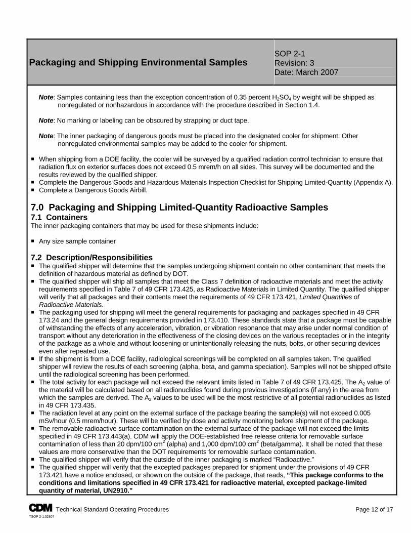
SOP 2-1 Packaging and Shipping Environmental Samples Revision: 3
Date: March 2007
Note: Samples containing less than the exception concentration of 0.35 percent H2SO4 by weight will be shipped as
nonregulated or nonhazardous in accordance with the procedure described in Section 1.4. Note: No marking or labeling can be obscured by strapping or duct tape. Note: The inner packaging of dangerous goods must be placed into the designated cooler for shipment. Other
nonregulated environmental samples may be added to the cooler for shipment. P When shipping from a DOE facility, the cooler will be surveyed by a qualified radiation control technician to ensure that
radiation flux on exterior surfaces does not exceed 0.5 mrem/h on all sides. This survey will be documented and the results reviewed by the qualified shipper.
P Complete the Dangerous Goods and Hazardous Materials Inspection Checklist for Shipping Limited-Quantity (Appendix A). P Complete a Dangerous Goods Airbill. 7.0 Packaging and Shipping Limited-Quantity Radioactive Samples 7.1 Containers The inner packaging containers that may be used for these shipments include: P Any size sample container 7.2 Description/Responsibilities P The qualified shipper will determine that the samples undergoing shipment contain no other contaminant that meets the
definition of hazardous material as defined by DOT. P The qualified shipper will ship all samples that meet the Class 7 definition of radioactive materials and meet the activity
requirements specified in Table 7 of 49 CFR 173.425, as Radioactive Materials in Limited Quantity. The qualified shipper will verify that all packages and their contents meet the requirements of 49 CFR 173.421, Limited Quantities of Radioactive Materials.
P The packaging used for shipping will meet the general requirements for packaging and packages specified in 49 CFR 173.24 and the general design requirements provided in 173.410. These standards state that a package must be capable of withstanding the effects of any acceleration, vibration, or vibration resonance that may arise under normal condition of transport without any deterioration in the effectiveness of the closing devices on the various receptacles or in the integrity of the package as a whole and without loosening or unintentionally releasing the nuts, bolts, or other securing devices even after repeated use.
P If the shipment is from a DOE facility, radiological screenings will be completed on all samples taken. The qualified shipper will review the results of each screening (alpha, beta, and gamma speciation). Samples will not be shipped offsite until the radiological screening has been performed.
P The total activity for each package will not exceed the relevant limits listed in Table 7 of 49 CFR 173.425. The A2 value of the material will be calculated based on all radionuclides found during previous investigations (if any) in the area from which the samples are derived. The A2 values to be used will be the most restrictive of all potential radionuclides as listed in 49 CFR 173.435.
P The radiation level at any point on the external surface of the package bearing the sample(s) will not exceed 0.005 mSv/hour (0.5 mrem/hour). These will be verified by dose and activity monitoring before shipment of the package.
P The removable radioactive surface contamination on the external surface of the package will not exceed the limits specified in 49 CFR 173.443(a). CDM will apply the DOE-established free release criteria for removable surface contamination of less than 20 dpm/100 cm2 (alpha) and 1,000 dpm/100 cm2 (beta/gamma). It shall be noted that these values are more conservative than the DOT requirements for removable surface contamination.
P The qualified shipper will verify that the outside of the inner packaging is marked “Radioactive.” P The qualified shipper will verify that the excepted packages prepared for shipment under the provisions of 49 CFR
173.421 have a notice enclosed, or shown on the outside of the package, that reads, “This package conforms to the conditions and limitations specified in 49 CFR 173.421 for radioactive material, excepted package-limited quantity of material, UN2910.”
A Technical Standard Operating Procedures Page 12 of 17 TSOP 2-1.32807
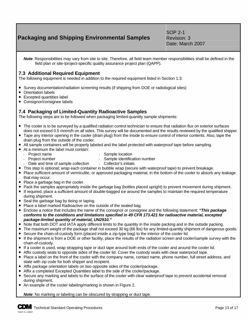
SOP 2-1 Packaging and Shipping Environmental Samples Revision: 3
Date: March 2007
Note: Responsibilities may vary from site to site. Therefore, all field team member responsibilities shall be defined in the
field plan or site-/project-specific quality assurance project plan (QAPP). 7.3 Additional Required Equipment The following equipment is needed in addition to the required equipment listed in Section 1.3: P Survey documentation/radiation screening results (if shipping from DOE or radiological sites) P Orientation labels P Excepted quantities label P Consignor/consignee labels 7.4 Packaging of Limited-Quantity Radioactive Samples The following steps are to be followed when packaging limited-quantity sample shipments: P The cooler is to be surveyed by a qualified radiation control technician to ensure that radiation flux on exterior surfaces
does not exceed 0.5 mrem/h on all sides. This survey will be documented and the results reviewed by the qualified shipper. P Tape any interior opening in the cooler (drain plug) from the inside to ensure control of interior contents. Also, tape the
drain plug from the outside of the cooler. P All sample containers will be properly labeled and the label protected with waterproof tape before sampling. P At a minimum the label must contain:
- Project name - Sample location - Project number - Sample identification number - Date and time of sample collection - Collector’s initials
P This step is optional; wrap each container in bubble wrap (secure with waterproof tape) to prevent breakage. P Place sufficient amount of vermiculite, or approved packaging material, in the bottom of the cooler to absorb any leakage
that may occur. P Place a garbage bag in the cooler. P Pack the samples appropriately inside the garbage bag (bottles placed upright) to prevent movement during shipment. P If required, place a sufficient amount of double-bagged ice around the samples to maintain the required temperature
during shipment. P Seal the garbage bag by tieing or taping. P Place a label marked Radioactive on the outside of the sealed bag. P Enclose a notice that includes the name of the consignor or consignee and the following statement: “This package
conforms to the conditions and limitations specified in 49 CFR 173.421 for radioactive material, excepted package-limited quantity of material, UN2910.”
P Note that both DOT and IATA apply different limits to the quantity in the inside packing and in the outside packing. P The maximum weight of the package shall not exceed 30 kg (66 lbs) for any limited-quantity shipment of dangerous goods. P Secure the chain-of-custody form (placed inside a zip-type bag) to the interior of the cooler lid. P If the shipment is from a DOE or other facility, place the results of the radiation screen and cooler/sample survey with the
chain-of-custody. P If a cooler is used, wrap strapping tape or duct tape around both ends of the cooler and around the cooler lid. P Affix custody seals to opposite sides of the cooler lid. Cover the custody seals with clear waterproof tape. P Place a label on the front of the cooler with the company name, contact name, phone number, full street address, and
state with zip code for both shipper and recipient. P Affix package orientation labels on two opposite sides of the cooler/package. P Affix a completed Excepted Quantities label to the side of the cooler/package. P Secure any marking and labels to the surface of the cooler with clear waterproof tape to prevent accidental removal
during shipment. P An example of the cooler labeling/marking is shown in Figure 2.
Note: No marking or labeling can be obscured by strapping or duct tape.
A Technical Standard Operating Procedures Page 13 of 17 TSOP 2-1.32807
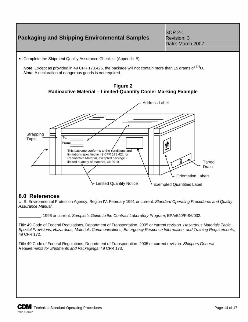
SOP 2-1 Packaging and Shipping Environmental Samples Revision: 3
Date: March 2007
P Complete the Shipment Quality Assurance Checklist (Appendix B).
Note: Except as provided in 49 CFR 173.426, the package will not contain more than 15 grams of 235U. Note: A declaration of dangerous goods is not required.
8.0 References U. S. Environmental Protection Agency. Region IV. February 1991 or current. Standard Operating Procedures and Quality Assurance Manual. __________. 1996 or current. Sampler’s Guide to the Contract Laboratory Program, EPA/540/R-96/032. Title 49 Code of Federal Regulations, Department of Transportation. 2005 or current revision. Hazardous Materials Table, Special Provisions, Hazardous, Materials Communications, Emergency Response Information, and Training Requirements, 49 CFR 172. Title 49 Code of Federal Regulations, Department of Transportation. 2005 or current revision. Shippers General Requirements for Shipments and Packagings, 49 CFR 173.
Exempted Quantities Label
Taped Drain
To: From:
Orientation Labels
Limited Quantity Notice
This package conforms to the conditions and limitations specified in 49 CFR 173.421 for Radioactive Material, excepted package - limited quantity of material, UN2910.
Strapping Tape
Address Label
Figure 2 Radioactive Material – Limited-Quantity Cooler Marking Example
A Technical Standard Operating Procedures Page 14 of 17 TSOP 2-1.32807
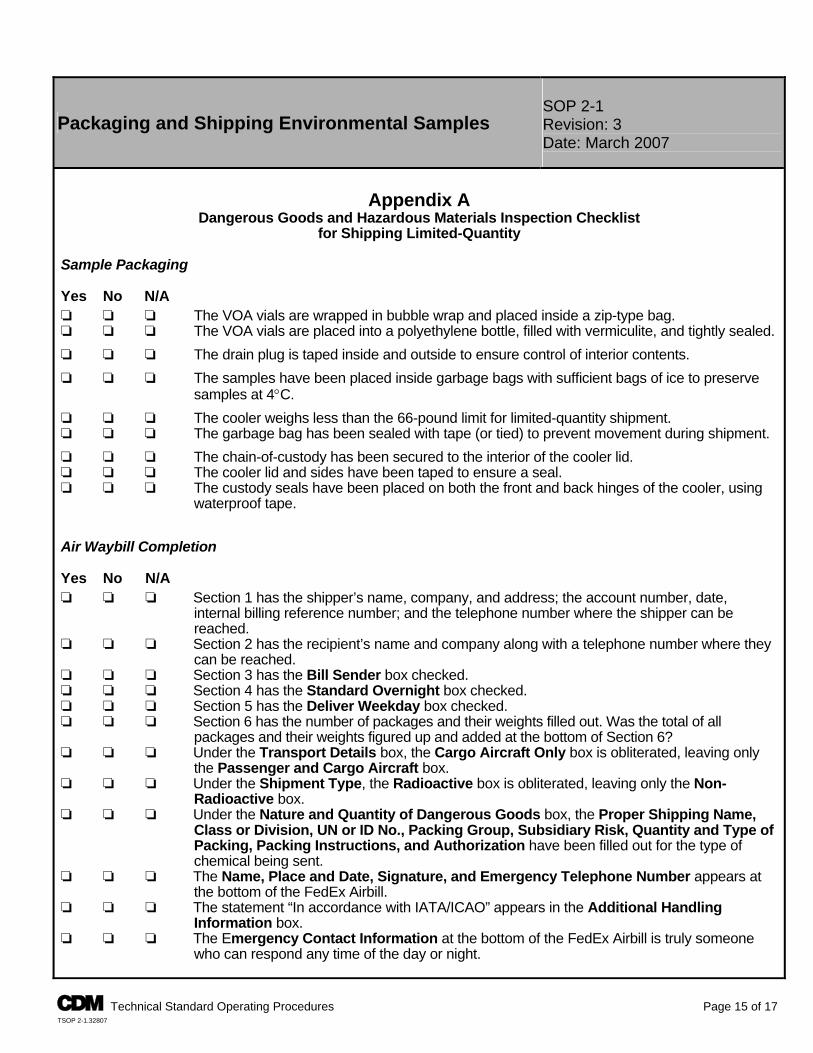
SOP 2-1 Packaging and Shipping Environmental Samples Revision: 3
Date: March 2007
Appendix A
Dangerous Goods and Hazardous Materials Inspection Checklist for Shipping Limited-Quantity
Sample Packaging
Yes No N/A ‘ ‘ ‘ The VOA vials are wrapped in bubble wrap and placed inside a zip-type bag. ‘ ‘ ‘ The VOA vials are placed into a polyethylene bottle, filled with vermiculite, and tightly sealed. ‘ ‘ ‘ The drain plug is taped inside and outside to ensure control of interior contents. ‘ ‘ ‘ The samples have been placed inside garbage bags with sufficient bags of ice to preserve
samples at 4°C. ‘ ‘ ‘ The cooler weighs less than the 66-pound limit for limited-quantity shipment. ‘ ‘ ‘ The garbage bag has been sealed with tape (or tied) to prevent movement during shipment. ‘ ‘ ‘ The chain-of-custody has been secured to the interior of the cooler lid. ‘ ‘ ‘ The cooler lid and sides have been taped to ensure a seal. ‘ ‘ ‘ The custody seals have been placed on both the front and back hinges of the cooler, using
waterproof tape.
Air Waybill Completion
Yes No N/A ‘ ‘ ‘ Section 1 has the shipper’s name, company, and address; the account number, date,
internal billing reference number; and the telephone number where the shipper can be reached.
‘ ‘ ‘ Section 2 has the recipient’s name and company along with a telephone number where they can be reached.
‘ ‘ ‘ Section 3 has the Bill Sender box checked. ‘ ‘ ‘ Section 4 has the Standard Overnight box checked. ‘ ‘ ‘ Section 5 has the Deliver Weekday box checked. ‘ ‘ ‘ Section 6 has the number of packages and their weights filled out. Was the total of all
packages and their weights figured up and added at the bottom of Section 6? ‘ ‘ ‘ Under the Transport Details box, the Cargo Aircraft Only box is obliterated, leaving only
the Passenger and Cargo Aircraft box. ‘ ‘ ‘ Under the Shipment Type, the Radioactive box is obliterated, leaving only the Non-
Radioactive box. ‘ ‘ ‘ Under the Nature and Quantity of Dangerous Goods box, the Proper Shipping Name,
Class or Division, UN or ID No., Packing Group, Subsidiary Risk, Quantity and Type of Packing, Packing Instructions, and Authorization have been filled out for the type of chemical being sent.
‘ ‘ ‘ The Name, Place and Date, Signature, and Emergency Telephone Number appears at the bottom of the FedEx Airbill.
‘ ‘ ‘ The statement “In accordance with IATA/ICAO” appears in the Additional Handling Information box.
‘ ‘ ‘ The Emergency Contact Information at the bottom of the FedEx Airbill is truly someone who can respond any time of the day or night.
A Technical Standard Operating Procedures Page 15 of 17 TSOP 2-1.32807
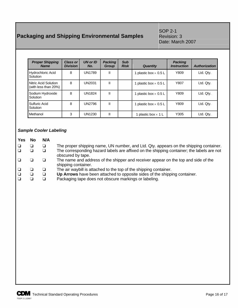
SOP 2-1 Packaging and Shipping Environmental Samples Revision: 3
Date: March 2007
Proper Shipping Class or UN or ID Packing Sub Packing Name Division No. Group Risk Quantity Instruction Authorization
Hydrochloric Acid Solution
8 UN1789 II Y809 Ltd. Qty. 1 plastic box × 0.5 L
Nitric Acid Solution (with less than 20%)
8 UN2031 II Y807 Ltd. Qty. 1 plastic box × 0.5 L
Sodium Hydroxide Solution
8 UN1824 II Y809 Ltd. Qty. 1 plastic box × 0.5 L
Sulfuric Acid Solution
8 UN2796 II Y809 Ltd. Qty. 1 plastic box × 0.5 L
Methanol 3 UN1230 II Y305 Ltd. Qty. 1 plastic box × 1 L
Sample Cooler Labeling
Yes No N/A ‘ ‘ ‘ The proper shipping name, UN number, and Ltd. Qty. appears on the shipping container. ‘ ‘ ‘ The corresponding hazard labels are affixed on the shipping container; the labels are not
obscured by tape. ‘ ‘ ‘ The name and address of the shipper and receiver appear on the top and side of the
shipping container. ‘ ‘ ‘ The air waybill is attached to the top of the shipping container. ‘ ‘ ‘ Up Arrows have been attached to opposite sides of the shipping container. ‘ ‘ ‘ Packaging tape does not obscure markings or labeling.
A Technical Standard Operating Procedures Page 16 of 17 TSOP 2-1.32807
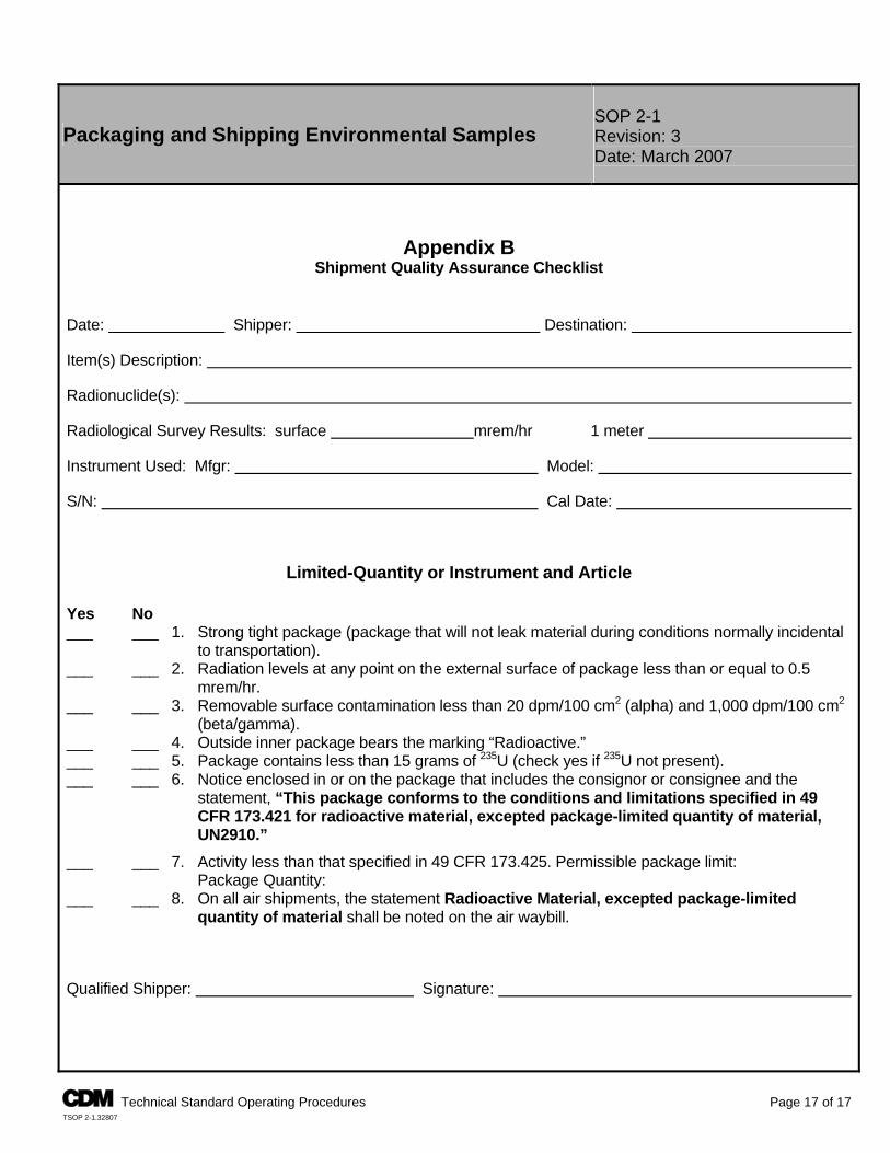
SOP 2-1 Packaging and Shipping Environmental Samples Revision: 3
Date: March 2007
Appendix B Shipment Quality Assurance Checklist
Date: Shipper: Destination: Item(s) Description: Radionuclide(s): Radiological Survey Results: surface mrem/hr 1 meter Instrument Used: Mfgr: Model: S/N: Cal Date:
Limited-Quantity or Instrument and Article Yes No ___ ___ 1. Strong tight package (package that will not leak material during conditions normally incidental
to transportation). ___ ___ 2. Radiation levels at any point on the external surface of package less than or equal to 0.5
mrem/hr. ___ ___ 3. Removable surface contamination less than 20 dpm/100 cm2 (alpha) and 1,000 dpm/100 cm2
(beta/gamma). ___ ___ 4. Outside inner package bears the marking “Radioactive.” ___ ___ 5. Package contains less than 15 grams of 235U (check yes if 235U not present). ___ ___ 6. Notice enclosed in or on the package that includes the consignor or consignee and the
statement, “This package conforms to the conditions and limitations specified in 49 CFR 173.421 for radioactive material, excepted package-limited quantity of material, UN2910.”
___ ___ 7. Activity less than that specified in 49 CFR 173.425. Permissible package limit: Package Quantity: ___ ___ 8. On all air shipments, the statement Radioactive Material, excepted package-limited
quantity of material shall be noted on the air waybill. Qualified Shipper: Signature:
A Technical Standard Operating Procedures Page 17 of 17 TSOP 2-1.32807
TSOP 2-2
GUIDE TO HANDLING OF INVESTIGATION DERIVED WASTE
Guide to Handling Investigation-Derived Waste SOP 2-2 Revision: 5 Date: March 2007
Prepared: Tim Eggert Technical Review: Matt Brookshire
QA Review: Jo Nell Mullins Approved:
E-Signed by Michael C. MalloyVERIFY authenticity with ApproveIt
Issued:
E-Signed by P. Michael SchwanVERIFY authenticity with ApproveIt
Signature/Date
Signature/Date 1.0 Objective This standard operating procedure (SOP) presents guidance for the management of investigation-derived waste (IDW). The primary objectives for managing IDW during field activities include: P Leaving the site in no worse condition than existed before field activities P Removing wastes that pose an immediate threat to human health or the environment P Proper handling of onsite wastes that do not require offsite disposal or extended aboveground containerization P Complying with federal, state, local, and facility applicable or relevant and appropriate requirements (ARARs) P Careful planning and coordination of IDW management options P Minimizing the quantity of IDW 2.0 Background 2.1 Definitions Hazardous Waste - Discarded material that is regulated listed waste, or waste that exhibits ignitability, corrosivity, reactivity, or toxicity as defined in 40 CFR 261.3 or state regulations. Investigation-Derived Wastes - Discarded materials resulting from field activities such as sampling, surveying, drilling, excavations, and decontamination processes that, in present form, possess no inherent value or additional usefulness without treatment. Wastes may be solid, sludge, liquid, gaseous, or multiphase materials that may be classified as hazardous or nonhazardous. Mixed Waste - Any material that has been classified as hazardous and radioactive. Radioactive Wastes - Discarded materials that are contaminated with radioactive constituents with specific activities in concentrations greater than the latest regulatory criteria (i.e., 10 CFR 20). Treatment, Storage, and Disposal Facility (TSDF) - Permitted facilities that accept hazardous waste shipments for further treatment, storage, and/or disposal. These facilities must be permitted by the U. S. Environmental Protection Agency (EPA) and appropriate state and local agencies. 2.2 Discussion Field investigation activities result in the generation of waste materials that may be characterized as hazardous or radioactive waste. IDWs may include drilling muds, cuttings, and purge water from test pit and well installation; purge water, soil, and other materials from collection of samples; residues from testing of treatment technologies and pump and treat systems; personal protective equipment (PPE); solutions (aqueous or otherwise) used to decontaminate nondisposable protective clothing and equipment; and other wastes or supplies used in sampling and testing potentially hazardous or radiologically contaminated material. Note: The client’s representatives may not be aware of all potential contaminants. The management of IDW must comply with applicable regulatory requirements.
A Technical Standard Operating Procedures Page 1 of 6 TSOP 2-2.32207
SOP 2-2 Guide to Handling Investigation-Derived Waste Revision: 5
Date: March 2007
3.0 General Responsibilities Site Manager - The site manager is responsible for ensuring that all IDW procedures are conducted in accordance with this SOP. The site manager is also responsible for ensuring that handling of IDW is in accordance with site-specific requirements. Project Manager - The project manager is responsible for identifying site-specific requirements for the disposal of IDW in accordance with federal, state, and/or facility requirements. Field Crew Members - Field crew members are responsible for implementing this SOP and communicating any unusual or unplanned condition to the project manager’s attention. Note: Responsibilities may vary from site to site. Therefore, all field team member responsibilities shall be defined in the field plan or site/project specific quality assurance plan. 4.0 Required Equipment Equipment required for IDW containment will vary according to site-specific/client requirements. Management decisions concerning the necessary equipment required shall consider: containment method, sampling, labeling, maneuvering, and storage (if applicable). Equipment must be onsite and inspected before commencing work. 4.1 IDW Containment Devices The appropriate containment device (drums, tanks, etc.) will depend on site- or client-specific requirements and the ultimate disposition of the IDW. Typical IDW containment devices can include: P Plastic sheeting (polyethylene) with a minimum thickness of 20 millimeters P Department of Transportation (DOT)-approved steel containers P Polyethylene or steel bulk storage tanks Containment of IDW shall be segregated by waste type (i.e., solid or liquid, corrosive or flammable, etc.) and source location. Volume of the appropriate containment device shall be site-specific. 4.2 IDW Container Labeling A “Waste Container” or “IDW Container” label or indelible marking shall be applied to each container. Labeling or marking requirements for onsite IDW not expected to be transported offsite are: P Labels and markings that contain the following information: project name, generation date, location of waste origin,
container identification number, sample number (if applicable), and contents (drill cuttings, purge water, PPE, etc.). P Each label or marking will be applied to the upper one-third of the container at least twice, on opposite sides. P Containers that are 5 gallons or less may only require one label or set of markings. P Labels or markings will be positioned on a smooth part of the container. The label must not be affixed across container
bungs, seams, ridges, or dents. P Labels must be constructed of a weather-resistive material with markings made with a permanent marker or paint pen
and capable of enduring the expected weather conditions. If markings are used, the color must be easily distinguishable from the drum color.
P Labels will be secured in a manner to ensure the label remains affixed to the container. Labeling or marking requirements for IDW expected to be transported offsite must be in accordance with the requirements of 49 CFR 172. 4.3 IDW Container Movement Staging areas for IDW containers shall be predetermined and in accordance with site-specific and/or client requirements. Arrangements shall be made before field mobilization as to the methods and personnel required to safely transport IDW containers to the staging area. Transportation offsite onto a public roadway is prohibited unless 49 CFR 172 requirements are met.
A Technical Standard Operating Procedures Page 2 of 6 TSOP 2-2.32207
SOP 2-2 Guide to Handling Investigation-Derived Waste Revision: 5
Date: March 2007
4.4 IDW Container Storage Containerized IDW shall be staged pending chemical analysis or further onsite treatment. Staging areas and bulk storage procedures are to be determined according to site-specific requirements. Containers are to be stored in such a fashion that the labels can be easily read. A secondary/spill container must be provided for liquid IDW storage and as appropriate for solid IDW storage. 5.0 Procedures The three general options for managing IDW are (1) collection and onsite disposal, (2) collection for offsite disposal, and (3) collection and interim management. Attachment 1 summarizes media-specific information on generation processes and management options. The option selected shall take into account the following factors: P Type (soil, sludge, liquid, debris), quantity, and source of IDW P Risk posed by managing the IDW onsite P Compliance with regulatory requirements P IDW minimization and consistency with the IDW remedy and the site remedy In all cases the client shall approve the plans for IDW. Formal plans for the management of IDW must be prepared as part of a work plan or separate document. 5.1 Collection and Onsite Disposal 5.1.1 Soil/Sludge/Sediment The options for handling soil/sludge/sediment IDW are as follows: 1. Return to boring, pit, or source immediately after generation as long as returning the media to these areas will not
increase site risks (e.g., the contaminated soil will not be replaced at a greater depth than where it was originally so that it will not contaminate “clean” areas).
2. Spread around boring, pit, or source within the area of contamination (AOC) as long as returning the media to these
areas will not increase site risks (e.g., direct contact with surficial contamination). 3. Consolidate in a pit within the AOC as long as returning the media to these areas will not increase site risks (e.g., the
contaminated soil will not be replaced at a greater depth than where it was originally so that it will not contaminate “clean” areas).
4. Send to onsite TSDF - may require analytical analysis before treatment/disposal. Note: These options may require client and/or regulatory approval. 5.1.2 Aqueous Liquids The options for handling aqueous liquid IDW are as follows: 1. Discharge to surface water, only when IDW is not contaminated. 2. Discharge to ground surface close to the well, only if soil contaminants will not be mobilized in the process and the
action will not contaminate clean areas. If IDW from the sampling of background upgradient wells is not a community concern or associated with soil contamination, this presumably uncontaminated IDW may be released on the ground around the well.
3. Discharge to sanitary sewer, only when IDW is not contaminated. 4. Send to onsite TSDF - may require analysis before treatment/disposal. Note: These options may require analytical results to obtain client and/or regulatory approval.
A Technical Standard Operating Procedures Page 3 of 6 TSOP 2-2.32207
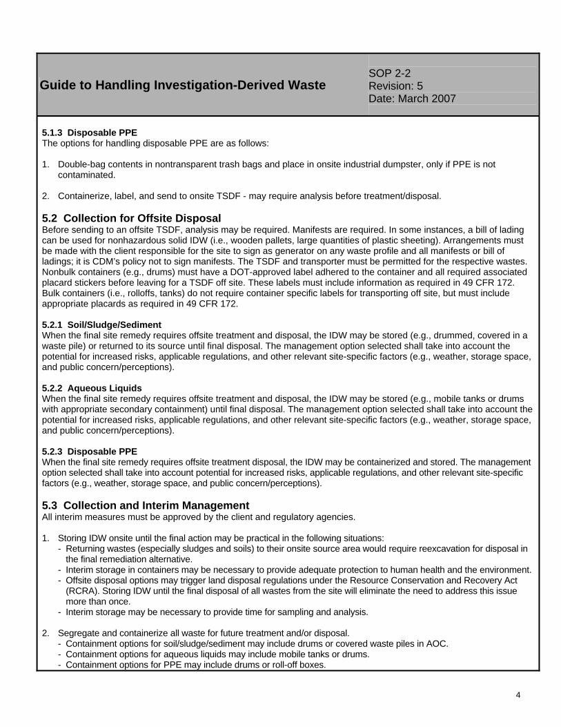
SOP 2-2 Guide to Handling Investigation-Derived Waste Revision: 5
Date: March 2007
5.1.3 Disposable PPE The options for handling disposable PPE are as follows: 1. Double-bag contents in nontransparent trash bags and place in onsite industrial dumpster, only if PPE is not
contaminated. 2. Containerize, label, and send to onsite TSDF - may require analysis before treatment/disposal. 5.2 Collection for Offsite Disposal Before sending to an offsite TSDF, analysis may be required. Manifests are required. In some instances, a bill of lading can be used for nonhazardous solid IDW (i.e., wooden pallets, large quantities of plastic sheeting). Arrangements must be made with the client responsible for the site to sign as generator on any waste profile and all manifests or bill of ladings; it is CDM’s policy not to sign manifests. The TSDF and transporter must be permitted for the respective wastes. Nonbulk containers (e.g., drums) must have a DOT-approved label adhered to the container and all required associated placard stickers before leaving for a TSDF off site. These labels must include information as required in 49 CFR 172. Bulk containers (i.e., rolloffs, tanks) do not require container specific labels for transporting off site, but must include appropriate placards as required in 49 CFR 172. 5.2.1 Soil/Sludge/Sediment When the final site remedy requires offsite treatment and disposal, the IDW may be stored (e.g., drummed, covered in a waste pile) or returned to its source until final disposal. The management option selected shall take into account the potential for increased risks, applicable regulations, and other relevant site-specific factors (e.g., weather, storage space, and public concern/perceptions). 5.2.2 Aqueous Liquids When the final site remedy requires offsite treatment and disposal, the IDW may be stored (e.g., mobile tanks or drums with appropriate secondary containment) until final disposal. The management option selected shall take into account the potential for increased risks, applicable regulations, and other relevant site-specific factors (e.g., weather, storage space, and public concern/perceptions). 5.2.3 Disposable PPE When the final site remedy requires offsite treatment disposal, the IDW may be containerized and stored. The management option selected shall take into account potential for increased risks, applicable regulations, and other relevant site-specific factors (e.g., weather, storage space, and public concern/perceptions). 5.3 Collection and Interim Management All interim measures must be approved by the client and regulatory agencies. 1. Storing IDW onsite until the final action may be practical in the following situations:
- Returning wastes (especially sludges and soils) to their onsite source area would require reexcavation for disposal in the final remediation alternative.
- Interim storage in containers may be necessary to provide adequate protection to human health and the environment. - Offsite disposal options may trigger land disposal regulations under the Resource Conservation and Recovery Act
(RCRA). Storing IDW until the final disposal of all wastes from the site will eliminate the need to address this issue more than once.
- Interim storage may be necessary to provide time for sampling and analysis. 2. Segregate and containerize all waste for future treatment and/or disposal.
- Containment options for soil/sludge/sediment may include drums or covered waste piles in AOC. - Containment options for aqueous liquids may include mobile tanks or drums. - Containment options for PPE may include drums or roll-off boxes.
A Technical Standard Operating Procedures Page 4 of 6 TSOP 2-2.32207
SOP 2-2 Guide to Handling Investigation-Derived Waste Revision: 5
Date: March 2007
6.0 Restrictions/Limitations Site Managers Shall Determine the Most Appropriate Disposal Option for Aqueous Liquids on a Site-Specific Basis. Parameters to consider, especially when determining the level of protection, include the volume of IDW, the contaminants present in the groundwater, the presence of contaminants in the soil at the site, whether the groundwater or surface water is a drinking water supply, and whether the groundwater plume is contained or moving. Special disposal/handling may be needed for drilling fluids because they may contain significant solid components. Disposable sampling materials, disposable PPE, decontamination fluids, etc. will always be managed on a site-specific basis. Under No Circumstances Shall These Types of Materials Be Brought Back to the Office or Warehouse. 7.0 References Environmental Resource Center. 1997. Hazardous Waste Management Compliance Handbook 2nd Edition. Karnofsky (Editor). Academy of Certified Hazardous Materials Manager. May 1999. Hazardous Materials Management Desk Reference. Cox. Title 49 Code of Federal Regulations, Department of Transportation. 2005 or current revision. Hazardous Materials Table, Special Provisions, Hazardous, Materials Communications, Emergency Response Information, and Training Requirements, 49 CFR 172. U. S. Environmental Protection Agency. 1987. A Compendium of Superfund Field Operations Methods, EPA/540/P-87/001.1. __________. August 1990. Low-Level Mixed Waste: A RCRA Perspective for NRC Licensees, EPA/530-SW-90-057. __________. May 1991. Management of Investigation-Derived Wastes During Site Inspections, EPA/540/G-91/009. __________. January 1992. Guide to Management of Investigation-Derived Wastes, 9345.3-03FS. __________. Region IV. November 2001. Environmental Investigations Standard Operating Procedures and Quality Assurance Manual.
A Technical Standard Operating Procedures Page 5 of 6 TSOP 2-2.32207
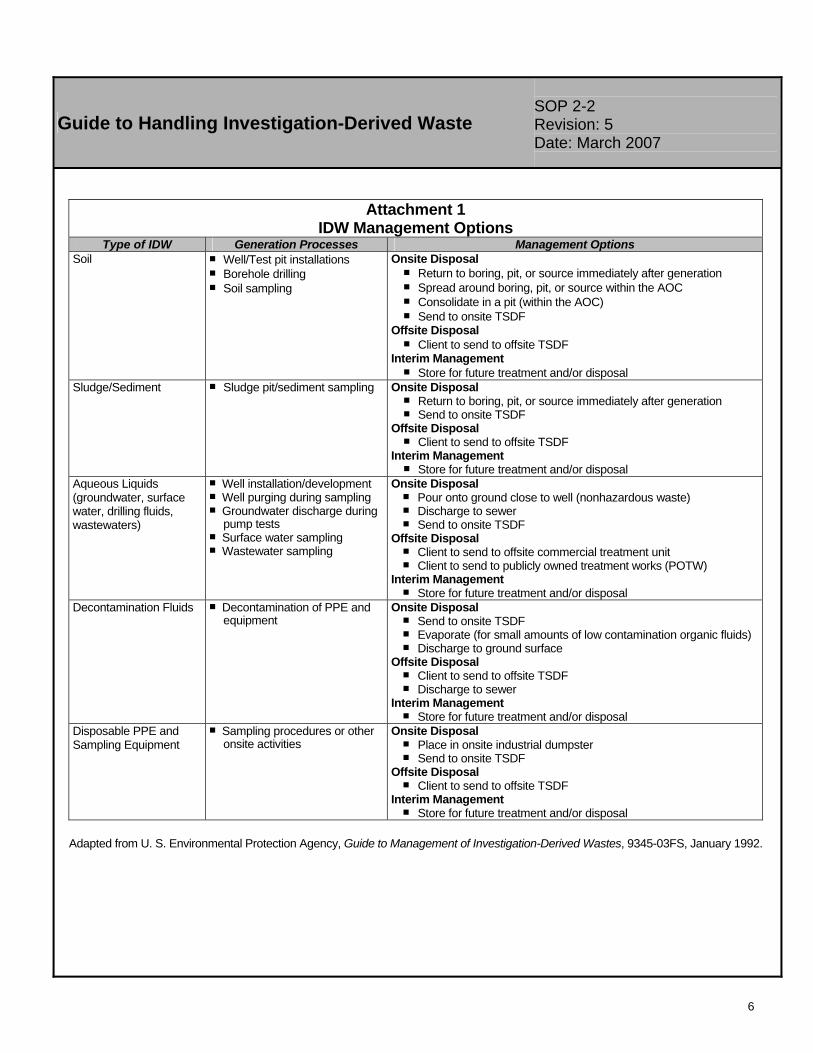
SOP 2-2 Guide to Handling Investigation-Derived Waste Revision: 5
Date: March 2007
Attachment 1 IDW Management Options
Type of IDW Generation Processes Management Options Soil P Well/Test pit installations
P Borehole drilling P Soil sampling
Onsite Disposal P Return to boring, pit, or source immediately after generation P Spread around boring, pit, or source within the AOC P Consolidate in a pit (within the AOC) P Send to onsite TSDF
Offsite Disposal P Client to send to offsite TSDF
Interim Management P Store for future treatment and/or disposal
Sludge/Sediment P Sludge pit/sediment sampling Onsite Disposal P Return to boring, pit, or source immediately after generation P Send to onsite TSDF
Offsite Disposal P Client to send to offsite TSDF
Interim Management P Store for future treatment and/or disposal
Aqueous Liquids (groundwater, surface water, drilling fluids, wastewaters)
P Well installation/development P Well purging during sampling P Groundwater discharge during
pump tests P Surface water sampling P Wastewater sampling
Onsite Disposal P Pour onto ground close to well (nonhazardous waste) P Discharge to sewer P Send to onsite TSDF
Offsite Disposal P Client to send to offsite commercial treatment unit P Client to send to publicly owned treatment works (POTW)
Interim Management P Store for future treatment and/or disposal
Decontamination Fluids P Decontamination of PPE and equipment
Onsite Disposal P Send to onsite TSDF P Evaporate (for small amounts of low contamination organic fluids) P Discharge to ground surface
Offsite Disposal P Client to send to offsite TSDF P Discharge to sewer
Interim Management P Store for future treatment and/or disposal
Disposable PPE and Sampling Equipment
P Sampling procedures or other onsite activities
Onsite Disposal P Place in onsite industrial dumpster P Send to onsite TSDF
Offsite Disposal P Client to send to offsite TSDF
Interim Management P Store for future treatment and/or disposal
Adapted from U. S. Environmental Protection Agency, Guide to Management of Investigation-Derived Wastes, 9345-03FS, January 1992.
A Technical Standard Operating Procedures Page 6 of 6 TSOP 2-2.32207
TSOP 3-5
LITHOLOGICAL LOGGING
Lithologic Logging SOP 3-5 Revision: 7 Date: March 2007
Prepared: Del R. Baird Technical Review: John Hofer
QA Review: Jo Nell Mullins Approved:
E-Signed by Michael C. MalloyVERIFY authenticity with ApproveIt
Issued:
E-Signed by P. Michael SchwanVERIFY authenticity with ApproveIt
Signature/Date
Signature/Date 1.0 Objective This standard operating procedure (SOP) governs lithologic logging of core, cuttings, split-spoon samples, and subsurface samples collected during field operations at sites where environmental investigations are performed by CDM Federal Programs Corporation (CDM). The purpose of this SOP is to present a set of descriptive protocols and standardized reporting formats to be used by all investigators in making lithologic observations. It prescribes protocols for recording basic lithologic data including, but not limited to, lithologic names, texture, composition, color, sedimentary structures, bedding, lateral and vertical contacts, and secondary features such as fractures and bioturbation. The goal of this SOP is to provide a set of instructions to produce uniform lithologic descriptions and to present a list of references to help in this task. 2.0 Background 2.1 Definitions The following list of definitions corresponds to the description sequences outlined in Section 5.2.1. They are provided to aid the geologist in what to look for when following the sequences. Example lithologic logs are given in Attachment A. Name of Sediment or Rock - In naming unconsolidated sediments, the logger shall use field equipment and reference charts to help identify the grain-size distribution and shall name the material according to the procedure in Section 5.2.1. In naming sedimentary, igneous, and metamorphic rocks, the logger shall examine the specimen for mineralogy and use the appropriate classification chart in the attachments. Texture - In examining unconsolidated sediments, the texture shall refer to the grain-size distribution, particle angularity, sorting, and packing. The logger shall provide estimates of the grain sizes present using Attachment B and C. When larger particles such as cobbles are present, determine the size of the particles and give a percentage estimate. The sediment particles shall be examined for angularity by comparing with Attachment B and the sorting shall be determined by percentage estimation. The logger shall note that the Unified Soil Classification System (USCS) uses the term grading to describe how the materials are sorted. (A poorly sorted unconsolidated material is well graded.) In examining igneous rocks, texture refers to whether the specimen is aphanitic, phaneritic, glassy, fragmental, porphyritic, or pegmatitic. Attachment D has more specific definitions of these terms. For metamorphic rocks, texture refers to whether the specimen has a foliated structure (slaty, phyllitic, schistose, or gneissic) or nonfoliated structure (granular). Color - Color may be determined using the appropriate Munsell color chart (soil or rock) and listing the Munsell number that corresponds to the color. If an unconsolidated material is mottled in color, the ranges in color shall be described. When describing core samples with several individual colors such as in phaneritic textures, individual color names shall be listed, and an overall best color name shall be given. Sedimentary Structures - This term refers primarily to unconsolidated sediments and sedimentary rocks. There are several different sedimentary structures, and the logger is referred to Compton’s Manual of Field Geology (1962) book for more details. Among the more common structures are bedding, cross-bedding, laminations, and burrows. These structures shall only be included in the description if found in the samples. Degree of Consolidation - The degree of consolidation is applicable to sedimentary rocks and unconsolidated sediments and refers to how well the material has been indurated. Unconsolidated sediments may be compacted somewhat and shall
A Technical Standard Operating Procedures Page 1 of 20 TSOP 3-5.33007
A Technical Standard Operating Procedures Page 2 of 20 TSOP 3-5.33007
Lithologic Logging SOP 3-5 Revision: 7 Date: March 2007
be described as loose, moderately compacted, or strongly compacted. In some cases they may be slightly cemented by caliche and shall be described as slightly cemented, moderately cemented, or strongly cemented. Sedimentary rocks are typically indurated but may vary in the degree of cementation. These materials shall be described as friable, moderately friable, or well indurated. When describing the cementing material, a test for reaction to hydrochloric acid (HCl) shall be done and results recorded under the description. If the logger believes he/she can identify the cementing material, then it shall be included in the description. Moisture Content - Moisture content refers to the amount of water within the sediment or the matrix. Typically sedimentary rocks and unconsolidated sediments may have water within and shall be described as dry, moist, wet (not flowing), or saturated (flowing water). Igneous and metamorphic rocks may have water within fractures and cavities. The presence of water and pertinent observations that may help in site evaluation in these rocks shall be noted. Presence of Fractures, Cavities, and Secondary Mineralization - The rock that may be encountered during drilling may have fractures or joints present within them. Should fractures be observed, they shall be noted and a description as to the density of fractures shall be given. Cavities or vugs may be present, and the density of voids, as well as size estimation, shall be given. If fractures or cavities contain evidence of secondary minerals such as zeolites, clays, or iron oxides, then a description of the mineral fill shall be added. Evidence of Contamination - The logger shall examine the core and note any obvious signs of contamination such as streaking, free product, odor, or discoloration. These observations shall be noted in the field book as shall any readings from the photoionization or flame ionization detector (PID/FID). PID/FID hits shall be recorded on the Lithologic Log Form also. Description of Contacts - The logger shall note any significant change in lithology. These changes may be gradational contacts within sediments or may be sharp contacts such as sediments over rocks. The contacts shall be noted as to whether they are erosional, gradational, or sharp, and the depth below the surface shall be noted. Composition - The composition of the rock refers to the mineralogy of the material encountered. For sedimentary rocks, it is important to note the matrix composition and use Attachment E in naming. In igneous and metamorphic rocks, the minerals that make up the rock shall be stated and an estimation of their percentage shall be noted. The classification charts listed in Attachments D and F provide a description of common compositions. 2.2 Associated Procedures P CDM Federal SOP 4-1, Field Logbook Content and Control 2.3 Discussion The installation of monitoring wells, piezometers, and boreholes is a standard practice at many sites requiring environmental investigations. The installation of these devices requires that a trained geologist, or other earth scientist under a geologist’s supervision, provide lithologic descriptions as they encounter subsurface material during auguring or drilling. In evaluating these lithologic descriptions from different boreholes, monitoring wells, or piezometers, it is sometimes possible to correlate similar units. To help in this task, it is important to provide uniform and consistent descriptions. In describing lithologies, it is helpful to have a set of references covering items such as the classification of igneous, metamorphic, and sedimentary rocks; grain-size percentage estimation; particle shape; grain-size charts; and lithologic symbols. To make lithologic descriptions produced by CDM staff as uniform and consistent as possible, this SOP provides a list of references to be used in the field. This SOP also provides a sequence for recording information on a standardized log form to make descriptions as uniform and consistent as possible. 3.0 General Responsibilities Geologist - The field person performing lithologic logging is responsible for making a consistent and uniform log and for turning in field forms and logbooks to the field team leader (FTL). Field Team Leader - The FTL is responsible for maintaining logbooks and forms and for approving techniques of lithologic logging not specifically described in this SOP. Note: Responsibilities may vary from site to site. Therefore, all field team member responsibilities shall be defined in the field plan or site/project specific quality assurance plan.
A Technical Standard Operating Procedures Page 3 of 20 TSOP 3-5.33007
Lithologic Logging SOP 3-5 Revision: 7 Date: March 2007
4.0 Required Equipment The description of subsurface lithologies requires a minor amount of field equipment for the geologist. This section provides a list of equipment to be used by the lithologic logger but does not include equipment such as drill rigs, PID/FID, sampling equipment, and personal protection equipment. The following is a general list of equipment that may be used: P Field logbook and Lithologic Log Form P Waterproof pens P Clipboard P No. 2 sieve P Dilute (10 percent) HCl P 10x magnifying hand lens P Plastic sheeting P Reference field charts P PVC sampling trays P Engineers tape measure or folding stick 5.0 Procedures 5.1 Office P Obtain field logbook and Lithologic Log Forms P Coordinate schedules/actions with FTL P Obtain necessary field equipment (i.e., hand lens, 10 percent HCl) P Obtain CDM reference field charts P Review field support documents (i.e., sampling plan, health and safety plan) P Review applicable geologic references such as U.S. Department of Agriculture (USDA) Soil Conservation Survey Soil
Surveys and/or geologic maps 5.1.1 Documentation Individuals performing lithologic logging will record their observations in a commercially available, bound field logbook (e.g., Lietz books) and/or on individual Lithologic Log Forms. Lithologic loggers will follow the general procedures for keeping a field logbook (SOP 4-1). When using a bound field logbook, record the same data required on the Lithologic Log Form. Data from the field logbook must be transcribed to the Lithologic Log Form if filling in the form in the field is not feasible. However, the data must be the same as that recorded in the field logbook. Editing of field logbook data is not allowed. In addition, if data are transcribed to the Lithologic Log Form, it shall be done within 1 day of the original data recording. All blanks in the Lithologic Log Form must be filled out. If an item is not applicable, an “NA” shall be entered. Note that the Lithologic Log may be modified based on the type of drilling (i.e., changing the blow count column to rock quality designation (RQD) for rock coring). The Lithologic Log Form shall be filled out according to the following instructions: The front page of the form contains general information: P The project name, location, and description P Borehole number P Date that the drilling activity was started and completed P Name of the person logging the well shall be recorded along with the total depth drilled P Borehole diameter(s) and drilling methods shall be recorded P Name and company of the driller and the type of drill rig and bits used A map showing the drilling location may be attached.
The continuation page(s) shall be completed according to the instructions provided within this section and according to the sequence provided in Section 5.2.1. The depth column refers to the depth below ground surface and shall be provided in feet. The tick marks can be arbitrarily set to any depth interval depending on the scale needed except where client requirements dictate the spacing. The lithology column shall contain a schematic representation of the subsurface according to the symbols found in Attachment G. Use a single X to mark the area where no core was recovered, and notes shall be recorded as to why the section was not recovered. The X shall be marked from the top to the bottom of the section so that the entire interval is marked. If the geologist can interpret the probable lithology of the missing section with reasonable confidence, they may fill in the symbols behind the X. Sharp or abrupt contacts between lithologies will be indicated by a
A Technical Standard Operating Procedures Page 4 of 20 TSOP 3-5.33007
Lithologic Logging SOP 3-5 Revision: 7 Date: March 2007
solid horizontal line. Gradational changes in lithologic composition will be shown by a gradual change of lithologic symbol in the appropriate zone. PID/FID hits shall be recorded within the PID/FID column at the appropriate depth, if applicable. Blow counts specifically refer to the number of hammer blows it takes to drive a split-spoon into the ground. Usually this is recorded as the number of blows per 6 inches but may vary. The recording of blow counts provides a relative feel for the cohesiveness of the formation. The individual recording lithologic logs shall ask the FTL whether it is required information. The description column is the most important part of the Lithologic Log Form and is where the lithology is described. In completing this section, use the applicable reference charts and complete according to the sequence in Section 5.2.1. The sample interval column is reserved for noting any samples taken and processed for the laboratory. The sample number shall be filled in at the appropriate depth. The last column refers to the percent core recovery. The individual performing lithologic logging shall determine the amount recovered and write the percentage at the appropriate depth. In addition to the information on the lithologic form, the logger shall record the appropriate information into the logbook when there is a rig shutdown, rig problems, failures to recover cores, or other issues. 5.2 General Guidelines for Using and Supplementing Lithologic Descriptive Protocols This SOP is intended to serve as a guide for recording basic lithologic information with emphasis on those sediment or rock properties that affect groundwater flow and contaminant transport. The fields of specialization of geologists using this SOP will vary. If the user has expertise in a particular field of petrology or soil science that allows for descriptions of certain geologic sections beyond the basic level required by this SOP, they may expand their descriptions. This shall be done only with approval of the FTL. The descriptive protocol presented here must be followed in making basic observations. Any further descriptions must follow a protocol that is published and generally recognized by the geologic community as a standard reference. General lithologic description will not include collecting detailed information such as can be obtained from sieve analysis or petrographic analysis. This SOP is a guide for recording visual observations of samples in the field aided by a 10x hand lens and the other simple tools. Field descriptions shall be supplemented by petrographic analysis and sieve analysis when the FTL needs data on numerical grain-size distributions, secondary porosity development, or other data that can be collected by these methods. Description detail will also be dependent on the drilling and sampling methods used. Descriptions of drill cuttings will generally be very basic verses detailed descriptions of soil split-spoon or rock core samples. This SOP includes protocols for describing igneous, metamorphic, bedrock, sedimentary rocks, and unconsolidated materials. Common abbreviations used for lithologic logging purposes are given in Attachment H. This SOP includes charts to be used for classification and naming of rocks, sediments, and soils and descriptions of texture, sedimentary structures, and percentage composition of grains. There is also a chart of lithologic symbols to be used and a list of abbreviations. For charts covering other observations or field procedures not specified by this SOP, the user is referred to the following for more information: P Compton’s Manual of Field Geology and American Geological Society (AGI) Data Sheets for Geology in the Field,
Laboratory, and Office contain other reference charts applicable to descriptions. The source of the chart used must be recorded on the Lithologic Log Form or in the field logbook.
P The Munsell soil color chart may be used for descriptions of color. P The Dictionary of Geological Terms (AGI) is to be used for definitions of geological terms. Some observations will be common to all rock and soil descriptions. All descriptions shall include as appropriate: name of sediment or rock, color, sedimentary structures, texture, moisture content, composition, fabric, significant inclusions, and degree of consolidation or induration. The description of each category shall be separated by a semicolon. Each section that discusses descriptions of a particular lithology provides a sequence for recording observations. Follow these sequences for all descriptions. All interpretive comments shall be segregated from lithologic descriptions by recording them in the remarks column. Secondary features affecting porosity and permeability such as fractures (joints or faults), cavities, and/or bioturbation shall be described if observed. Exact measurement of apparent bed thicknesses shall be made when logging core and shall supplement terminology such as “thin” or “thick.” Particular attention is to be given to recording exact locations of water tables, perched saturated zones, and description of contaminants that may be visible.
A Technical Standard Operating Procedures Page 5 of 20 TSOP 3-5.33007
Lithologic Logging SOP 3-5 Revision: 7 Date: March 2007
In some cases individuals logging may wish to describe materials such as unconsolidated sediments and soils according to different systems such as the USCS or USDA Soil Taxonomy System. These descriptions can provide additional information from what is required by this SOP. If an individual is competent in using other description methods, then they shall do so with permission from the FTL. It is often more practical to use abbreviations for often repeated terminology when recording lithologic descriptions. For the terms given in this SOP, its attachments, or the associated charts to be used for description in the field, use only the designated abbreviations. Other abbreviations are allowed; however, the abbreviation and its meaning shall be recorded on the lithologic log the first time it is used and shall be recorded at least once for every well or boring log. Loggers are cautioned to limit the use of abbreviations to avoid producing a lithologic log that is excessively cryptic. 5.2.1 Protocols for Lithologic Description of Discrete Soil or Rock Cores This section describes the protocols for completing a lithologic description based on discrete soil or rock core samples. The logger shall use the appropriate portion of this section when describing cores. In recording descriptions of sedimentary sections from a whole core, it is possible to reduce the amount of description being written by at least two strategies. One is to look at as long of a section of core as possible, looking for the “big” picture. For instance, in a 20-foot-thick zone, the dominant lithology may be siltstone that is interrupted by several thin beds of another lithology such as gravel. This section description can be simplified by writing: 35-55 below ground surface (bgs) = siltstone (with other descriptors) except as noted; 37.5-38.5 gravel zone (with descriptors); 40-42 pebble zone (with descriptors); etc. This also aids in “seeing” the thickest unit designations possible for use in modeling. Another acceptable way to describe the same interval would be: 35-37.5 siltstone; 37.5-38.5 gravel zone (with descriptors); 38-40 same as 35-37.5; 40-42 pebble zone (with descriptors); etc. Description of Unconsolidated Material Unconsolidated material comprises a significant portion of the sections of interest at CDM sites. The shallow subsurface is very important to the hydrologic investigation, as this is the portion of the geologic section where infiltration first occurs. Much of the contamination at sites being investigated is surface contamination and therefore lies on, or within, the upper portion of the surficial material. For the purpose of this SOP, soil refers to the upper biochemically weathered portion of the regolith and not the entire regolith itself. Soils are to be described as unconsolidated material and shall use the same description format. The scientist shall use the USCS classification if consistent with project objectives (Attachment K). More detailed soil descriptions shall only be made in addition to descriptions outlined below. Descriptions of unconsolidated sediments shall follow the following sequence: P Name of sediment (sand, silt, clay, etc.) P Degree of consolidation and cementation P Texture P Moisture content P Composition of larger-grained sediments P Evidence of bioturbation P Color P Description of contacts P Structure In naming unconsolidated material (refer to Attachment I - Naming of Unconsolidated Materials), the particle size with the highest percentage is the root name. When additional grains are present in excess of 15 percent, the root name is modified by adding a term in front of the root name. For instance, if a material is 80 percent sand and 20 percent gravel, then it is gravelly sand. If the subordinate grains comprise less than 15 percent but greater than 5 percent, the name is written: ____________________(dominant grain) with ________________(subordinate grain). For example, a sediment with 90 percent sand and 10 percent silt would be named a sand with silt. If a sediment contains greater than 15 percent of four particle sizes, then the name is comprised of the dominant grain size as the root name and modifiers as added before. For example, if a material is 60 percent sand, 20 percent silt, and 20 percent clay the name would be a silty clayey sand. If a material is 70 percent sand, 20 percent silt, and 10 percent clay, it would be a silty sand with clay. When large cobbles or boulders are present, their percentage shall be estimated and their mineralogy recorded. Use AGI Data Sheet 29.1 (Attachment B) for grain terms. Refer to Attachment J for an example sorting chart. Description of Bedrock Material Descriptions of rock core can vary in detail depending on the experience of the geologist and the scope of the project. However, features that shall be noted while logging rock core include depth of major fractures, mineralization in fractures and cavities, degree of weathering, hardness, and RQD. The RQD is a ratio of the total length of intact rock 4 inches in length or longer to the length of the core run. The RQD provides a numeric indication of the degree of fracturing and weathering, and thereby, and indication of conductive zones and preferential contaminant migration pathways.
A Technical Standard Operating Procedures Page 6 of 20 TSOP 3-5.33007
Lithologic Logging SOP 3-5 Revision: 7 Date: March 2007
Description of Sedimentary Rocks Sedimentary rocks consist of lithified detrital sediments such as sand and clay, chemically precipitated sediments such as limestone and gypsum, and biogenic material such as coal and coquina. The classification scheme for naming these rocks is found in Attachment E - Classification of Sedimentary Rocks. Descriptions for sedimentary rocks shall be given in the lithologic log in the following sequence: P Name of rock P Degree of composition P Texture P Presence of fractures or vugs P Color P Bioturbation P Bedding P Description of contacts P Sedimentary structures Description of Igneous and Metamorphic Rocks Igneous and metamorphic rocks are not as commonly observed at work sites, but they may be found interspersed in the sedimentary section as ash layers and as bedrock. Where they form bedrock, the development of fractures and vugs is important to their hydrologic properties. If the logger is unsure of the name of the rock because of difficulty in determining mineralogy, the name shall be accompanied by a question mark. Attachments D and F provide a classification system for these materials. Igneous and metamorphic rock descriptions shall follow the general format: P Name of rock P Composition P Texture P Presence of fractures or vugs P Color P Presence of secondary mineralization P Degree of induration for volcaniclastics P Foliation 5.2.2 Protocols for Lithologic Description from Drill Cuttings The majority of boreholes drilled in bedrock are drilled without sampling or coring. This section describes the protocols that may be used for completing lithologic logs when discrete soil samples or rock cores are not collected. Lithologic logging of boreholes drilled without sampling generally requires a higher level of experience from the geologist as interpretations need to be made based on a number of factors that are usually not taken into account when logging from discrete samples. Certain details recorded on lithologic logs based on discrete sampling will not be seen (such as sedimentary structures) and therefore cannot be recorded from drill cuttings. Below are general guidelines that shall be used while filling out boring logs based on drill cuttings: Auger Drilling The following are general guidelines that can be used to describe cuttings from auger drilling: P Collect cuttings for descriptions at least every 5 feet or if a change in the cuttings is noticed. P Keep in mind travel time for cuttings to reach the surface when estimating the depth from which the cuttings originated.P Pay attention to the reaction of the drill rig as different lithologies are encountered such as chattering versus smooth
drilling, rapid easy auger advancement versus slow hard drilling, and auger refusal. P Watch for the occurrence of water. Bedrock Rotary Drilling (including air hammer, air rotary, and mud rotary) The following are general guidelines that shall be used during rotary drilling: P Use a strainer to collect cuttings at intervals of at least 10 feet or changes in lithology. P Wash the cuttings in the strainer with potable water and examine for lithology. P Note size of rock chips. P Note changes in drill rig responses such as increasing or slowing drilling rate, sudden drop of the drill stem, increase in
chatter and record in the remarks column of the lithologic log. These are usually good indicators of changes in lithology and/or fractures.
P If drilling with air, look for changes in color and reduction or disappearance of dust as an indicator of a lithology change and/or presence of water.
P If drilling with mud/fluid rotary, watch for gain or loss of water as an indicator of conductive zones. P Record drilling rates as feet/minute, or as start and end times of each drill rod, in the remarks column of the boring log.
A Technical Standard Operating Procedures Page 7 of 20 TSOP 3-5.33007
Lithologic Logging SOP 3-5 Revision: 7 Date: March 2007
6.0 Restrictions/Limitations Only geologists, or similarly qualified persons trained in lithologic description, are qualified to perform the duties described in this SOP. The FTL for a project will have the authority to decide whether or not an individual is qualified. 7.0 References American Geological Society. 1989. American Geological Society Data Sheets for Geology in the Field, Laboratory, and Office, 3rd Ed. Compton, R.R. 1962. Manual of Field Geology, John Wiley & Sons Inc., New York, New York. Neuendorf, K.K.E, et. Al. 2005. Glossary of Geology, Fifth Edition, American Geological Institute. Soil Test Inc. 1975. Munsell Color Chart. Evanston, Illinois. U. S. Army Corp of Engineers. 1994. Rock Foundations, EM 1110-1-2908, Chapter 4. November 30. __________. 1998. Monitoring Well Design, Installation, and Documentation at Hazardous Toxic, and Radioactive Waste Sites, EM 1110-1-4000, Chapter 4. November 1. U. S. Department of Agriculture Soil Conservation Service. 1972. Soil Taxonomy, U. S. Government Printing Office, Washington, D.C. Woodward, L.A. 1988. Laboratory Manual Physical Geology, University of New Mexico Printing. Albuquerque, New Mexico. 8.0 Attachments Note: These Attachments are for informational purposes. Other equivalent charts such as USCS or logs may be used. Attachment A - CDM Federal Programs Corporation Lithologic Logs Attachment B - Grain-Size Scale; Graph determining size of sedimentary particles, particle degree of roundness charts Attachment C - Comparison Chart for Estimating Percentage Composition Attachment D - Classification of Igneous Rocks Attachment E - Classification of Sedimentary Rocks Attachment F - Classification of Metamorphic Rocks Attachment G - Lithologic Symbol Chart Attachment H - Common Abbreviations for Lithologic Logging Attachment I - Naming of Unconsolidated Materials Attachment J - Sorting Chart Attachment K - Example of Unified Soil Classification System (USCS)
A Technical Standard Operating Procedures Page 8 of 20 TSOP 3-5.33007
Lithologic Logging SOP 3-5 Revision: 7 Date: March 2007
Attachment A
CDM Federal Programs Lithologic Logs
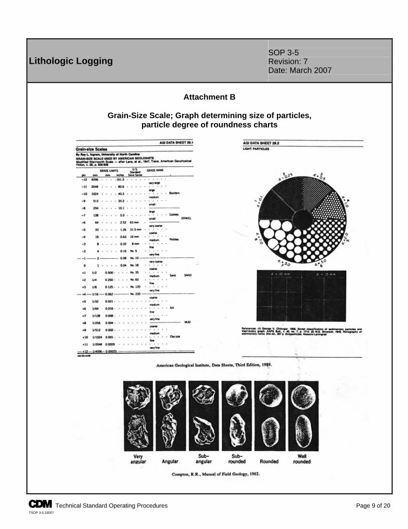
SOP 3-5 Lithologic Logging Revision: 7
Date: March 2007
Attachment B
Grain-Size Scale; Graph determining size of particles,
particle degree of roundness charts
A Technical Standard Operating Procedures Page 9 of 20 TSOP 3-5.33007
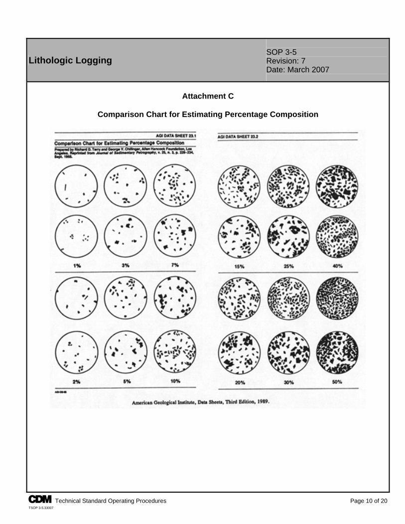
SOP 3-5 Lithologic Logging Revision: 7
Date: March 2007
Attachment C
Comparison Chart for Estimating Percentage Composition
A Technical Standard Operating Procedures Page 10 of 20 TSOP 3-5.33007
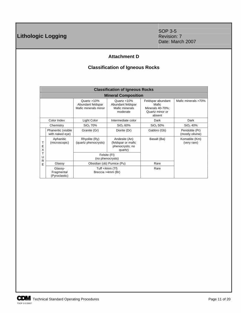
A Technical Standard Operating Procedures Page 11 of 20 TSOP 3-5.33007
Lithologic Logging SOP 3-5 Revision: 7 Date: March 2007
Attachment D
Classification of Igneous Rocks
Classification of Igneous Rocks Mineral Composition
Quartz >10% Abundant feldspar
Mafic minerals minor
Quartz <10% Abundant feldspar
Mafic minerals moderate
Feldspar abundant Mafic
Minerals 40-70%; Quartz minor or
absent
Mafic minerals >70%
Color Index Light Color Intermediate color Dark Dark Chemistry SiO2 70% SiO2 60% SiO2 50% SiO2 40%
Phaneritic (visible with naked eye)
Granite (Gr) Diorite (Dr) Gabbro (Gb) Peridotite (Pr) (mostly olivine)
Rhyolite (Ry) (quartz phenocrysts)
Andesite (An) (feldspar or mafic phenocrysts; no
quartz)
Aphanitic (microscopic)
Felsite (FI) (no phenocrysts)
Basalt (Ba)
Glassy Obsidian (ob) Pumice (Pu) Rare
T E X T U R E
Glassy-Fragmental (Pyroclastic)
Tuff <4mm (Tf) Breccia >4mm (Br)
Rare
Komatiite (Km) (very rare)
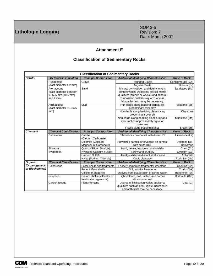
A Technical Standard Operating Procedures Page 12 of 20 TSOP 3-5.33007
Lithologic Logging SOP 3-5 Revision: 7 Date: March 2007
Attachment E
Classification of Sedimentary Rocks
Classification of Sedimentary Rocks Detrital Classification Principal Composition Additional Identifying Characteristics Name of Rock
Rounded Clasts Conglomerate (Cg)Rudaceous (clast diameter > 2 mm)
Gravel Angular Clasts Breccia (Br)
Arenaceous (clast diameter between 0.0625 mm [1/16 mm] and 2 mm)
Sand Mineral composition and detrital matrix content varies. Additional detrital matrix qualifiers (arenite or wacke) and mineral composition qualifiers (quartz, arkose, feldspathic, etc.) may be necessary.
Sandstone (Sa)
Non-fissile along bedding planes, silt predominant over clay
Siltstone (Sls)
Non-fissile along bedding planes, clay predominant over silt
Claystone
Non-fissile along bedding planes, silt and clay fraction approximately equal or
unknown
Mudstone (Ms)
Detrital
Argillaceous (clast diameter <0.0625 mm)
Mud
Fissile along bedding planes Shale (Shl)Chemical Classification Principal Composition Additional Identifying Characteristics Name of Rock
Calcite (Calcium Carbonate)
Effervesces on contact with dilute HCl Limestone (La)Calcareous
Dolomite (Calcium Magnesium Carbonate)
Pulverized sample effervesces on contact with dilute HCL
Dolomite (Dl), Dolostone
Siliceous Quartz (Silicon Dioxide) Hard, dense, fractures conchoidally Chert (Ch)Hydrated Calcium Sulfate Earthy and crumbly Gypsum (Gy)Calcium Sulfate Usually exhibits indistinct stratification Anhydrite
Chemical
Evaporites
Halite (Sodium Chloride) Cubic cleavage Rock Salt (Na)Chemical Classification Principal Composition Additional Identifying Characteristics Name of Rock
Fossil shells and fragments Loosely cemented fragmental limestone Coquina (Cq)Foraminiferal shells Soft, micritic limestone Chalk (Chk)
Calcareous
Calcite or aragonite Derived from evaporation of spring water Travertine (Tvr)Siliceous Diatom shells (saltwater or
freshwater organisms) Light-colored, soft, friable, and porous
siliceous deposit Diatomite (Dm)
Organic (Organogenetic or Biochemical)
Carbonaceous Plant Remains Degree of lithification varies-additional qualifiers such as peat, lignite, bituminous
and anthracite may be necessary.
Coal (Cl)
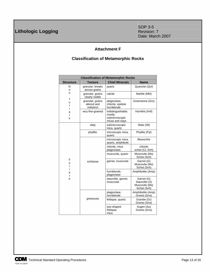
A Technical Standard Operating Procedures Page 13 of 20 TSOP 3-5.33007
Lithologic Logging SOP 3-5 Revision: 7 Date: March 2007
Attachment F
Classification of Metamorphic Rocks
Classification of Metamorphic Rocks Structure Texture Chief Minerals Name
granular; breaks across grains
quartz Quartzite (Qzt)
granular; grains clearly visible
calcite Marble (Mbl)
granular; grains altered and indistinct
plagioclase, chlorite, epidote hornblende
Greenstone (Grs)
N o n f o l i a t e
very fine-grained indistinguishable; mostly submicroscopic micas and clays
Hornfels (Hnf)
slaty submicroscopic mica, quartz
Slate (Slt)
phyllitic microscopic mica, quartz
Phyllite (Pyl)
microscopic mica, quartz, amphibole
Blueschist
chlorite, mica plagioclase
chlorite schist (CL-Sch)
muscovite, quartz Muscovite (Ms) Schist (Sch)
garnet, muscovite Garnet (G) Muscovite (Ms)
Schist (Sch) hornblende, plagioclase
Amphibolite (Amp)
schistose
staurolite, garnet, muscovite
Garnet (G) Staurolite (S)
Muscovite (Ms) Schist (Sch)
plagioclase, hornblende
Amphibolite (Amp) Gneiss (Gns)
feldspar, quartz Granitie (Gr) Gneiss (Gns)
F o l i a t e
gneissose
eye-shaped feldspar, mica
Augen (Au) Gneiss (Gns)
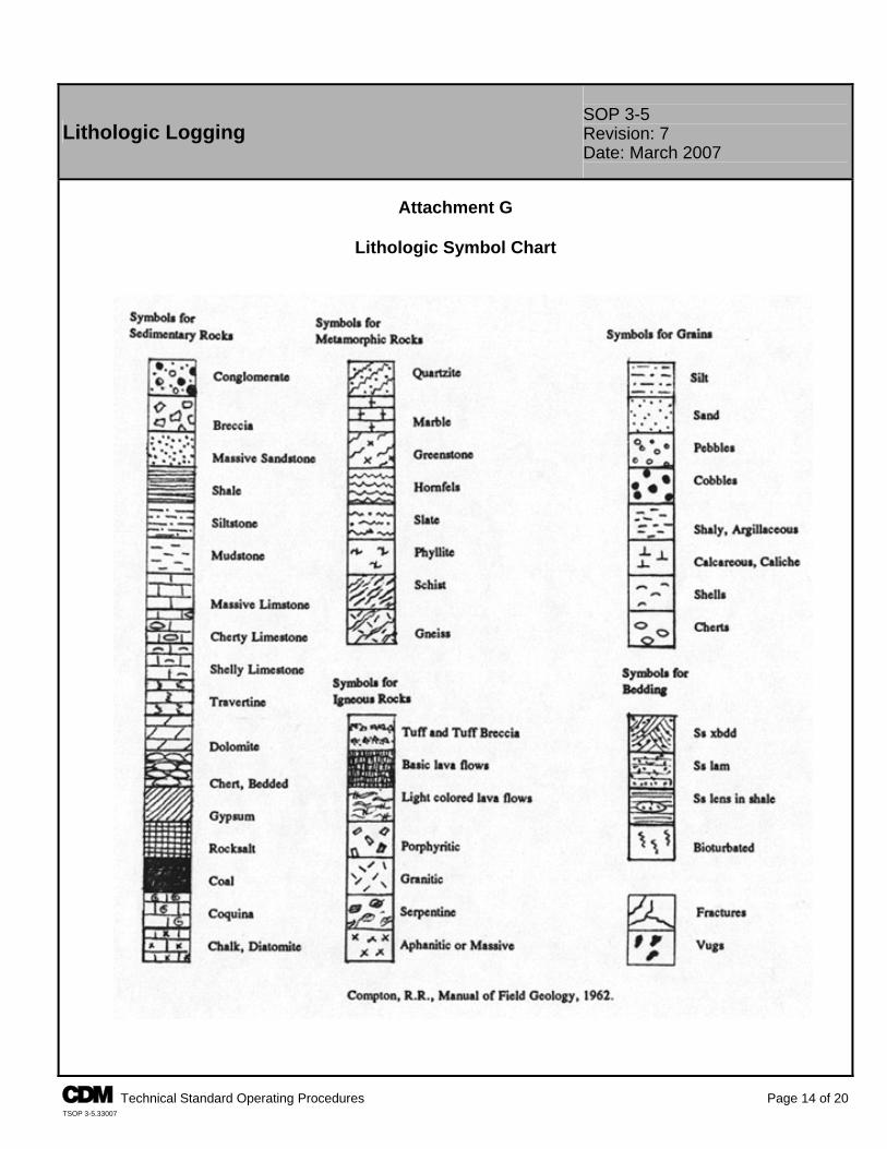
SOP 3-5 Lithologic Logging Revision: 7
Date: March 2007
Attachment G
Lithologic Symbol Chart
A Technical Standard Operating Procedures Page 14 of 20 TSOP 3-5.33007
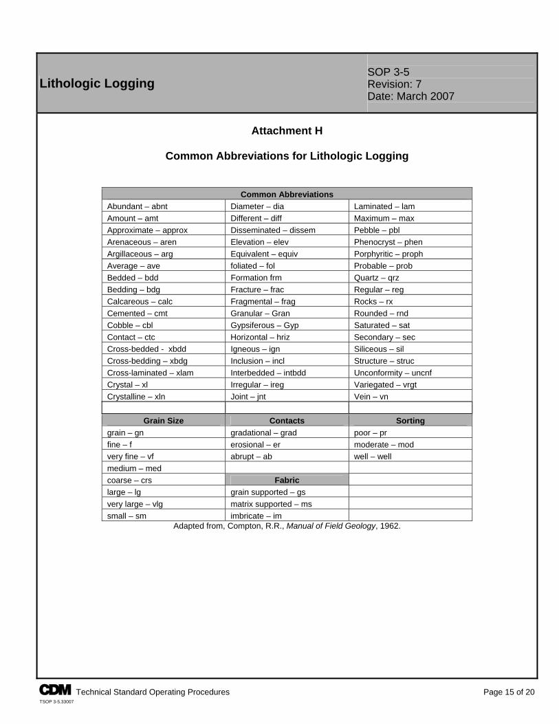
A Technical Standard Operating Procedures Page 15 of 20 TSOP 3-5.33007
Lithologic Logging SOP 3-5 Revision: 7 Date: March 2007
Attachment H
Common Abbreviations for Lithologic Logging
Common Abbreviations Abundant – abnt Diameter – dia Laminated – lam Amount – amt Different – diff Maximum – max Approximate – approx Disseminated – dissem Pebble – pbl Arenaceous – aren Elevation – elev Phenocryst – phen Argillaceous – arg Equivalent – equiv Porphyritic – proph Average – ave foliated – fol Probable – prob Bedded – bdd Formation frm Quartz – qrz Bedding – bdg Fracture – frac Regular – reg Calcareous – calc Fragmental – frag Rocks – rx Cemented – cmt Granular – Gran Rounded – rnd Cobble – cbl Gypsiferous – Gyp Saturated – sat Contact – ctc Horizontal – hriz Secondary – sec Cross-bedded - xbdd Igneous – ign Siliceous – sil Cross-bedding – xbdg Inclusion – incl Structure – struc Cross-laminated – xlam Interbedded – intbdd Unconformity – uncnf Crystal – xl Irregular – ireg Variegated – vrgt Crystalline – xln Joint – jnt Vein – vn
Grain Size Contacts Sorting grain – gn gradational – grad poor – pr fine – f erosional – er moderate – mod very fine – vf abrupt – ab well – well medium – med coarse – crs Fabric large – lg grain supported – gs very large – vlg matrix supported – ms small – sm imbricate – im
Adapted from, Compton, R.R., Manual of Field Geology, 1962.
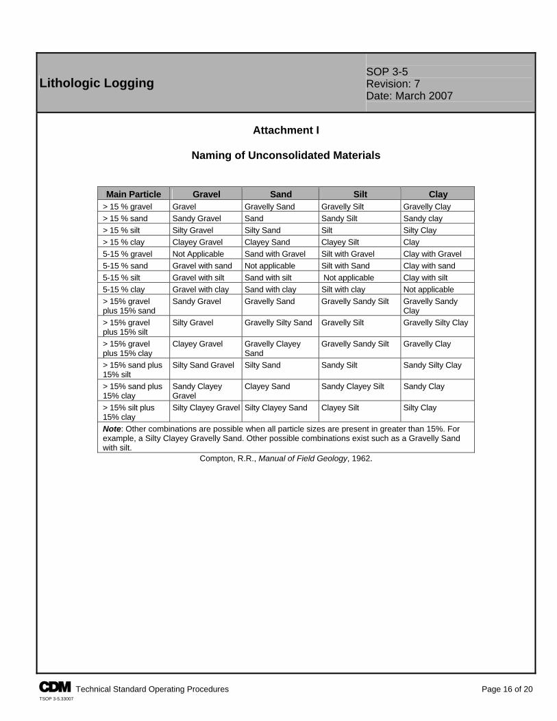
A Technical Standard Operating Procedures Page 16 of 20 TSOP 3-5.33007
Lithologic Logging SOP 3-5 Revision: 7 Date: March 2007
Attachment I
Naming of Unconsolidated Materials
Main Particle Gravel Sand Silt Clay > 15 % gravel Gravel Gravelly Sand Gravelly Silt Gravelly Clay > 15 % sand Sandy Gravel Sand Sandy Silt Sandy clay > 15 % silt Silty Gravel Silty Sand Silt Silty Clay > 15 % clay Clayey Gravel Clayey Sand Clayey Silt Clay 5-15 % gravel Not Applicable Sand with Gravel Silt with Gravel Clay with Gravel 5-15 % sand Gravel with sand Not applicable Silt with Sand Clay with sand 5-15 % silt Gravel with silt Sand with silt Not applicable Clay with silt 5-15 % clay Gravel with clay Sand with clay Silt with clay Not applicable > 15% gravel plus 15% sand
Sandy Gravel Gravelly Sand Gravelly Sandy Silt Gravelly Sandy Clay
> 15% gravel plus 15% silt
Silty Gravel Gravelly Silty Sand Gravelly Silt Gravelly Silty Clay
> 15% gravel plus 15% clay
Clayey Gravel Gravelly Clayey Sand
Gravelly Sandy Silt Gravelly Clay
> 15% sand plus 15% silt
Silty Sand Gravel Silty Sand Sandy Silt Sandy Silty Clay
> 15% sand plus 15% clay
Sandy Clayey Gravel
Clayey Sand Sandy Clayey Silt Sandy Clay
> 15% silt plus 15% clay
Silty Clayey Gravel Silty Clayey Sand Clayey Silt Silty Clay
Note: Other combinations are possible when all particle sizes are present in greater than 15%. For example, a Silty Clayey Gravelly Sand. Other possible combinations exist such as a Gravelly Sand with silt.
Compton, R.R., Manual of Field Geology, 1962.
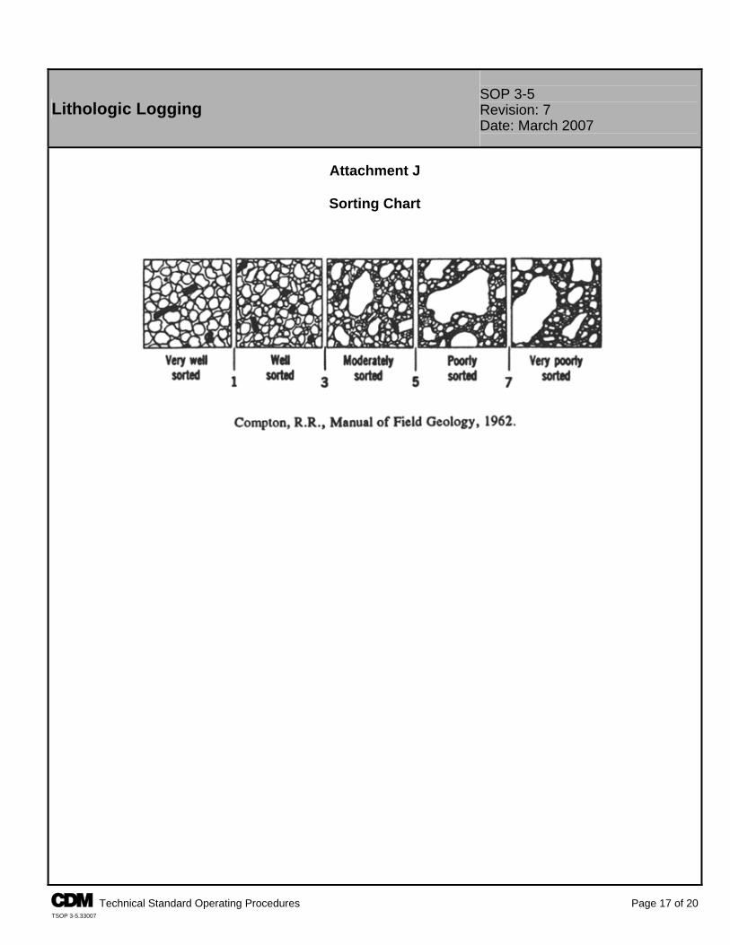
SOP 3-5 Lithologic Logging Revision: 7
Date: March 2007
Attachment J
Sorting Chart
A Technical Standard Operating Procedures Page 17 of 20 TSOP 3-5.33007
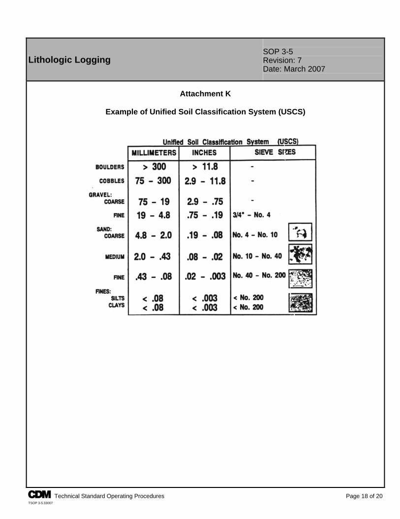
SOP 3-5 Lithologic Logging Revision: 7
Date: March 2007
Attachment K
Example of Unified Soil Classification System (USCS)
A Technical Standard Operating Procedures Page 18 of 20 TSOP 3-5.33007
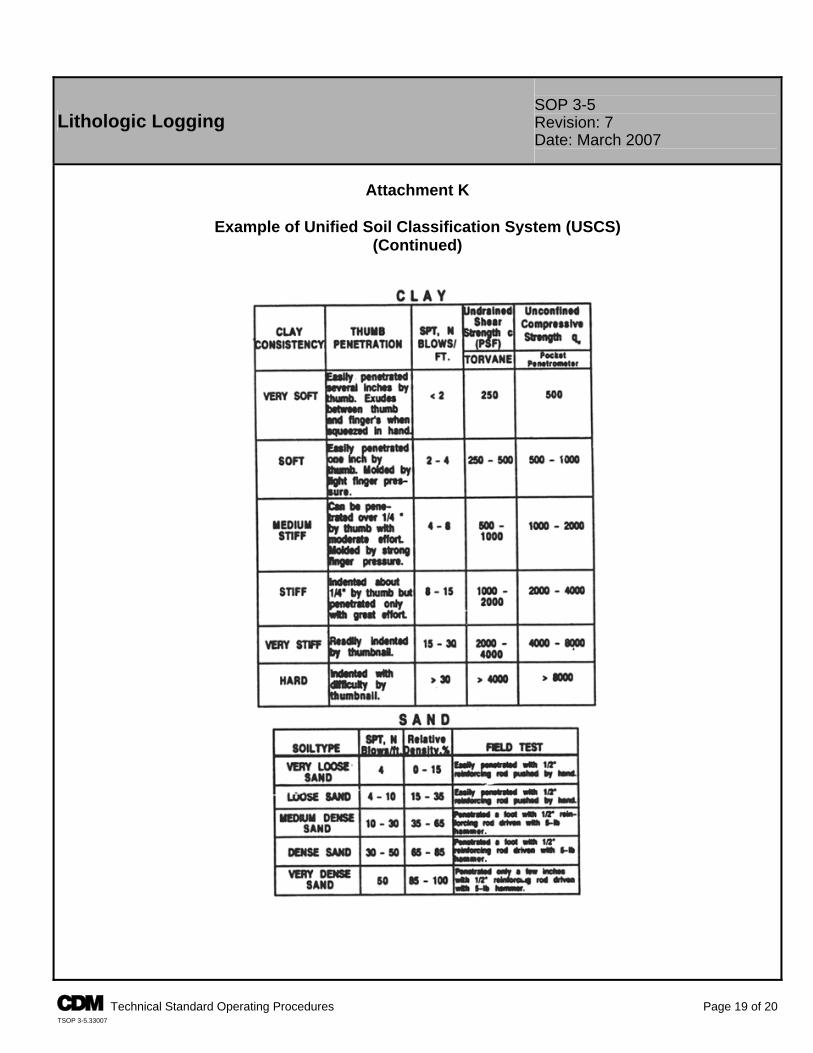
SOP 3-5 Lithologic Logging Revision: 7
Date: March 2007
Attachment K
Example of Unified Soil Classification System (USCS)
(Continued)
A Technical Standard Operating Procedures Page 19 of 20 TSOP 3-5.33007
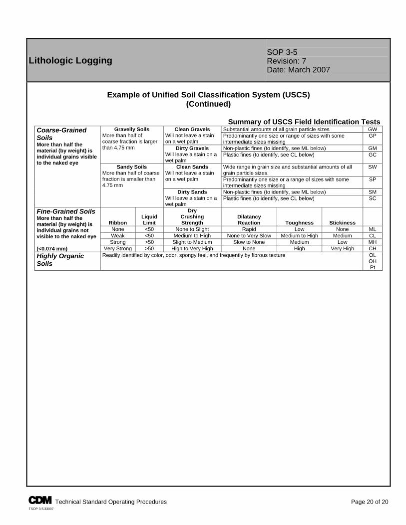
A Technical Standard Operating Procedures Page 20 of 20 TSOP 3-5.33007
Lithologic Logging SOP 3-5 Revision: 7 Date: March 2007
Example of Unified Soil Classification System (USCS)
(Continued)
Summary of USCS Field Identification TestsSubstantial amounts of all grain particle sizes GW Clean Gravels
Will not leave a stain on a wet palm
Predominantly one size or range of sizes with some intermediate sizes missing
GP
Non-plastic fines (to identify, see ML below) GM
Gravelly Soils More than half of coarse fraction is larger than 4.75 mm
Dirty Gravels Will leave a stain on a wet palm
Plastic fines (to identify, see CL below) GC
Wide range in grain size and substantial amounts of all grain particle sizes.
SW Clean Sands Will not leave a stain on a wet palm Predominantly one size or a range of sizes with some
intermediate sizes missing SP
Non-plastic fines (to identify, see ML below) SM
Coarse-Grained Soils More than half the material (by weight) is individual grains visible to the naked eye
Sandy Soils More than half of coarse fraction is smaller than 4.75 mm
Dirty Sands Will leave a stain on a wet palm
Plastic fines (to identify, see CL below) SC
Ribbon Liquid Limit
Dry Crushing Strength
Dilatancy Reaction Toughness Stickiness
None <50 None to Slight Rapid Low None ML Weak <50 Medium to High None to Very Slow Medium to High Medium CL Strong >50 Slight to Medium Slow to None Medium Low MH
Fine-Grained Soils More than half the material (by weight) is individual grains not visible to the naked eye (<0.074 mm) Very Strong >50 High to Very High None High Very High CH Highly Organic Soils
Readily identified by color, odor, spongy feel, and frequently by fibrous texture OL OH Pt

TSOP 4-1
FIELD LOGBOOK CONTENT AND CONTROL
Field Logbook Content and Control SOP 4-1 Revision: 6 Date: March 2007
Prepared: Del Baird Technical Review: Laura Splichal
QA Review: Jo Nell Mullins Approved:
E-Signed by Michael C. MalloyVERIFY authenticity with ApproveIt
Issued:
E-Signed by P. Michael SchwanVERIFY authenticity with ApproveIt
Signature/Date
Signature/Date 1.0 Objective The objective of this standard operating procedure (SOP) is to set CDM Federal (CDM) criteria for content entry and form of field logbooks. Field logbooks are an essential tool to document field activities for historical and legal purposes. 2.0 Background 2.1 Definitions Biota - The flora and fauna of a region. Magnetic Declination Corrections - Compass adjustments to correct for the angle between magnetic north and geographical meridians. 2.2 Discussion Information recorded in field logbooks includes field team names; observations; data; calculations; date/time; weather; and description of the data collection activity, methods, instruments, and results. Additionally, the logbook may contain deviations from plans and descriptions of wastes, biota, geologic material, and site features including sketches, maps, or drawings as appropriate. 3.0 General Responsibilities Field Team Leader (FTL) - The FTL is responsible for ensuring that the format and content of data entries are in accordance with this procedure. Site Personnel - All CDM employees who make entries in field logbooks during onsite activities are required to read this procedure before engaging in this activity. The FTL will assign field logbooks to site personnel who will be responsible for their care and maintenance. Site personnel will return field logbooks to the records file at the end of the assignment. Note: Responsibilities may vary from site to site. Therefore, all field team member responsibilities should be defined in the field plan or site-/project-specific quality assurance plan. 4.0 Required Equipment P Site-specific plans P Indelible black or blue ink pen P Field logbook P Ruler or similar scale 5.0 Procedures 5.1 Preparation In addition to this SOP, site personnel responsible for maintaining logbooks must be familiar with all procedures applicable to the field activity being performed. These procedures should be consulted as necessary to obtain specific information about equipment and supplies, health and safety, sample collection, packaging, decontamination, and documentation. These procedures should be located at the field office or vehicle for easy reference. Field logbooks shall be bound with lined, consecutively numbered pages. All pages must be numbered before initial use of the logbook. Before use in the field, each logbook will be marked with a specific document control number issued by
A Technical Standard Operating Procedures Page 1 of 3 TSOP 4-1.31907
SOP 4-1 Field Logbook Content and Control Revision: 6
Date: March 2007
the document control administrator, if required by the contract quality implementation plan (QIP). Not all contracts require document control numbers. The following information shall be recorded on the cover of the logbook: P Field logbook document control number (if applicable). P Start date of entries. P Activity (if the logbook is to be activity-specific), site
name, and location. P Name of CDM contact and phone number(s) (typically the project manager).
P End date of entries. P In specific cases, special logbooks may be required
(e.g., waterproof paper for stormwater monitoring).
The first few (approximately five) pages of the logbook will be reserved for a table of contents (TOC). Mark the first page with the heading and enter the following: Table of Contents Date/Description Pages (Start Date)/Reserved for TOC 1-5 The remaining pages of the table of contents will be designated as such with “TOC” written on the top center of each page. The table of contents should be completed as activities are completed and before placing the logbook in the records file. 5.2 Operation Requirements that must be followed when using a logbook: P Record work, observations, quantities of materials, calculations, drawings, and related information directly in the
logbook. If data collection forms are specified by an activity-specific plan, this information does not need to be duplicated in the logbook. However, any forms used to record site information must be referenced in the logbook.
P Do not start a new page until the previous one is full or has been marked with a single diagonal line so that additional entries cannot be made. Use both sides of each page.
P Do not erase or blot out any entry at any time. Indicate any deletion by a single line through the material to be deleted. Initial and date each deletion. Take care to not obliterate what was written previously.
P Do not remove any pages from the book. Specific requirements for field logbook entries include: P Initial and date each page. P Sign and date the final page of entries for each day. P Initial and date all changes. P Multiple authors must sign out the logbook by inserting the following: Above notes authored by: - (Sign name) - (Print name) - (Date) P A new author must sign and print his/her name before additional entries are made. P Draw a diagonal line through the remainder of the final page at the end of the day. P Record the following information on a daily basis:
- Date and time - Name of individual making entry - Names of field team and other persons onsite - Description of activity being conducted including station or location (i.e., well, boring, sampling location number) if appropriate - Weather conditions (i.e., temperature, cloud cover, precipitation, wind direction, and speed) and other pertinent data - Level of personal protection used - Serial numbers of instruments - Equipment calibration information - Serial/tracking numbers on documentation (e.g., carrier air bills)
A Technical Standard Operating Procedures Page 2 of 3 TSOP 4-1.31907
SOP 4-1 Field Logbook Content and Control Revision: 6
Date: March 2007
Entries into the field logbook shall be preceded with the time (written in military units) of the observation. The time should be recorded frequently and at the point of events or measurements that are critical to the activity being logged. All measurements made and samples collected must be recorded unless they are documented by automatic methods (e.g., data logger) or on a separate form required by an operating procedure. In these cases, the logbook must reference the automatic data record or form. At each station where a sample is collected or an observation or measurement made, a detailed description of the location of the station is required. Use a compass (include a reference to magnetic declination corrections), scale, or nearby survey markers, as appropriate. A sketch of station location may be warranted. All maps or sketches made in the logbook should have descriptions of the features shown and a direction indicator. It is preferred that maps and sketches be oriented so that north is toward the top of the page. Maps, sketches, figures, or data that will not fit on a logbook page should be referenced and attached to the logbook to prevent separation. Other events and observations that should be recorded include: P Changes in weather that impact field activities. P Deviations from procedures outlined in any governing documents. Also record the reason for any noted deviation. P Problems, downtime, or delays. P Upgrade or downgrade of personal protection equipment. P Visitors to the site. 5.3 Post-Operation To guard against loss of data as a result of damage or disappearance of logbooks, completed pages shall be periodically photocopied (weekly, at a minimum) and forwarded to the field or project office. Other field records shall be photocopied and submitted regularly and as promptly as possible to the office. When possible, electronic media such as disks and tapes should be copied and forwarded to the project office. At the conclusion of each activity or phase of site work, the individual responsible for the logbook will ensure that all entries have been appropriately signed and dated and that corrections were made properly (single lines drawn through incorrect information, then initialed and dated). The completed logbook shall be submitted to the records file. 6.0 Restrictions/Limitations Field logbooks constitute the official record of onsite technical work, investigations, and data collection activities. Their use, control, and ownership are restricted to activities pertaining to specific field operations carried out by CDM personnel and their subcontractors. They are documents that may be used in court to indicate dates, personnel, procedures, and techniques employed during site activities. Entries made in these logbooks should be factual, clear, precise, and nonsubjective. Field logbooks, and entries within, are not to be used for personal use. 7.0 References Sandia National Laboratories. 1991. Procedure for Preparing Sampling and Analysis Plan, Site-Specific Sampling Plan, and Field Operating Procedures, QA-02-03. Albuquerque Environmental Program, Department 3220, Albuquerque, New Mexico. Sandia National Laboratories. 1992. Field Operation Procedure for Field Logbook Content and Control. Environmental Restoration Department, Division 7723, Albuquerque, New Mexico.
A Technical Standard Operating Procedures Page 3 of 3 TSOP 4-1.31907
TSOP 4-2
PHOTOGRAPHIC DOCUMENTATION OF FIELD ACTIVITIES
Photographic Documentation of Field Activities SOP 4-2 Revision: 7 Date: March 2007
Prepared: David O. Johnson Technical Review: Sharon Budney
QA Review: Jo Nell Mullins Approved:
E-Signed by Michael C. MalloyVERIFY authenticity with ApproveIt
Issued:
E-Signed by P. Michael SchwanVERIFY authenticity with ApproveIt
Signature/Date
Signature/Date 1.0 Objective The purpose of this standard operating procedure (SOP) is to provide standard guidelines and methods for photographic documentation, which include still and digital photography and videotape or DVD recordings of field activities and site features (geologic formations, core sections, lithologic samples, water samples, general site layout, etc.). This document shall provide guidelines designed for use by a professional or amateur photographer. This SOP is intended for circumstances when formal photographic documentation is required. Based on project requirements, it may not be applicable for all photographic activities. 2.0 Background 2.1 Definitions Photographer - A photographer is the camera operator (professional or amateur) of still photography, including digital photography, or videotape or digital versatile discs (DVD) recording whose primary function with regard to this SOP is to produce documentary or data-oriented visual media. Identifier Component - Identifier components are visual components used within a photograph such as visual slates, reference markers, and pointers. Standard Reference Marker - A standard reference marker is a reference marker that is used to indicate a feature size in the photograph and is a standard length of measure, such as a ruler, meter stick, etc. In limited instances, if a ruled marker is not available or its use is not feasible, it can be a common object of known size placed within the visual field and used for scale. Slates - Slates are blank white index cards or paper used to present information pertaining to the subject/procedure being photographed. Letters and numbers on the slate will be bold and written with black indelible marking pens. Arrows and Pointers - Arrows and pointers are markers/pointers used to indicate and/or draw attention to a special feature within the photograph. Contrasting Backgrounds - Contrasting backgrounds are backdrops used to lay soil samples, cores, or other objects on for clearer viewing and to delineate features. Data Recording Camera Back - A data recording camera back is a camera attachment or built-in feature that will record, at the very least, frame numbers and dates directly on the film. 2.2 Associated Procedures P CDM Federal SOP 4-1, Field Logbook Content and Control 2.3 Discussion Photographs and videotape or DVD recordings made during field investigations are used as an aid in documenting and describing site features, sample collection activities, equipment used, and possible lithologic interpretation. This SOP is designed to illustrate the format and desired placement of identifier components, such as visual slates, standard
A Technical Standard Operating Procedures Page 1 of 5 TSOP 4-2.32307

SOP 4-2 Photographic Documentation of Field Activities Revision: 7
Date: March 2007
reference markers, and pointers. These items shall become an integral part of the “visual media” that, for the purpose of this document, shall encompass still photographs, digital photographs, videotape recordings (or video footage), and recordings on DVDs. The use of a photographic logbook and standardized entry procedures are also outlined. These procedures and guidelines will minimize potential ambiguities that may arise when viewing the visual media and ensure the representative nature of the photographic documentation. 3.0 General Responsibilities Field Team Leader - The field team leader (FTL) is responsible for ensuring that the format and content of photographic documentation are in accordance with this procedure. The FTL is responsible for directing the photographer to specific situations, site features, or operations that the photographer will be responsible for documenting. Photographer - The photographer shall seek direction from the FTL and regularly discuss the visual documentation requirements and schedule. The photographer is responsible for maintaining a logbook per Sections 5.1, 5.2.4, and 5.3.1 of this SOP. Responsibilities will be defined in the project sampling plan. Note: Responsibilities may vary from site to site. Therefore, all field team member responsibilities shall be defined in the field plan or site/quality assurance project plan (QAPP). 4.0 Required Equipment A general list of equipment that may be used: P 35mm camera or disposable single use camera (35mm or panoramic use)
P Standard reference markers P Slates
P Digital camera P Extra batteries for 35mm camera
P Arrows or pointers P Contrasting backgrounds
P Video camera and appropriate storage media (e.g., video tapes, DVDs)
P Medium speed, or multi purpose fine-grain, color, 35mm negative film or slide film (project dependent)
P Logbook P Data recording camera back (if available) P Indelible black or blue ink pen P Storage medium for digital camera 5.0 Procedures 5.1 Documentation A commercially available, bound logbook will be used to log and document photographic activities. Review CDM Federal SOP 4-1, Field Logbook Content and Control and prepare all supplies needed for logbook entries. Note: A separate photographic logbook is not required. A portion of the field logbook may be designated as the photographic log and documentation section. Field Health and Safety Considerations There are no hazards that an individual will be exposed to specific to photographic documentation. However, site-specific hazards may arise depending on location or operation. Personal protective equipment used in this operation will be site-specific and dictated through requirements set by the site safety officer, site health and safety plan, and/or prescribed by the CDM Federal Corporate Health and Safety Program. The photographer should contact the site safety officer for health and safety orientation before commencing field activities. The site health and safety plan must be read before entry to the site, and all individuals must sign the appropriate acknowledgement that this has been done. The photographer should be aware of any potential physical hazards while photographing the subject (e.g., traffic, low overhead hazard, edge of excavation).
A Technical Standard Operating Procedures Page 2 of 5 TSOP 4-2.32307
SOP 4-2 Photographic Documentation of Field Activities Revision: 7
Date: March 2007
5.2 Operation 5.2.1 General Photographic Activities in the Field The following sections provide general guidelines that should be followed to visually document field activities and site features using still/digital cameras and video equipment. Listed below are general suggestions that the photographer should consider when performing activities under this SOP: P The photographer should be prepared to make a variety of shots, from close-up to wide-angle. Many shots will be
repetitive in nature or format, especially close-up site feature photographs. Consideration should therefore be given to designing a system or technique that will provide a reliable repetition of performance.
P All still film photographs should be made using a medium speed, or multi purpose fine-grain, color negative film in the 35mm format unless otherwise directed by the FTL.
P It is suggested that Kodak brand “Ektapress Gold Deluxe” film or equivalent be used as the standard film for the still photography requirements of the field activities. This film is stable at room temperature after exposure and will better survive the time lag between exposure and processing. It is suggested that film speed ASA 100 should be used for outdoor photographs in bright sunlight, ASA 200 film should be used in cloudy conditions, and ASA 400 film should be used indoors or for very low-light outdoor photographs.
P No preference of videotape or DVD brand along with digital storage medium is specified and is left to the discretion of the photographer.
P The lighting for sample and feature photography should be oriented toward a flat condition with little or no shadow. If the ambient lighting conditions are inadequate, the photographer should be prepared to augment the light (perhaps with reflectors or electronic flash) to maintain the desired visual effect.
P Digital cameras have multiple photographic quality settings. A camera that obtains a higher resolution (quality) has a higher number of pixels and will store a fewer number of photographs per digital storage medium.
5.2.2 General Guidelines for Still Photography Slate Information It is recommended that each new roll of film or digital storage medium shall contain on the first usable frame (for film) a slate with consecutively assigned control numbers (a consecutive, unique number that is assigned by the photographer as in sample numbers). Caption Information All still photographs will have a full caption permanently attached to the back or permanently attached to a photo log sheet. The caption should contain the following information (digital photographs should have a caption added after the photographs are downloaded): P Film roll control number (if required) and
photograph sequence number P Description of activity/item shown (e.g., name of
facility/site, specific project name, project number) P Date and time P Direction (if applicable) P Photographer When directed by the sampling plan, a standard reference marker should be used in all documentary visual media. While the standard reference marker will be predominantly used in close-up feature documentation, inclusion in all scenes should be considered. Digital media should be downloaded at least once each day to a personal computer; the files should be in either “JPEG” or “TIFF” format. Files should be renamed at the time of download to correspond to the logbook. It is recommended the electronic files be copied to a compact disc for backup. Close-Up and Feature Photography When directed by the sampling plan, close-up photographs should include a standard reference marker of appropriate size as an indication of the feature size and contain a slate marked with the site name and any identifying label, such as a well number or core depth, that clearly communicates to the viewer the specific feature being photographed.
A Technical Standard Operating Procedures Page 3 of 5 TSOP 4-2.32307
SOP 4-2 Photographic Documentation of Field Activities Revision: 7
Date: March 2007
Feature samples, core pieces, and other lithologic media should be photographed as soon as possible after they have been removed from their in situ locations. This enables a more accurate record of their initial condition and color. When directed by the sampling plan, include a standard reference color strip (color chart such as Munsell Soil Color Chart or that available from Eastman Kodak Co.) within the scene. This is to be included for the benefit of the viewer of the photographic document and serves as a reference aid to the viewer for formal lithologic observations and interpretations. Site Photography Site photography, in general, will consist predominantly of medium- and wide-angle shots. A standard reference marker should be placed adjacent to the feature or, when this is not possible, within the same focal plane. While it is encouraged that a standard reference marker and caption/slate be included in the scene, it is understood that situations will arise that preclude their inclusion within the scene. This will be especially true of wide-angle shots. In such a case, the film/tape control number shall be entered in the photographic logbook along with the frame number and all other information pertinent to the scene. Panoramic In situations where a wide-angle lens does not provide sufficient subject detail, a single-use disposable panoramic camera is recommended. If this type of camera is not available, a panoramic series of two or three photos would be appropriate. Panoramas can provide greater detail while covering a wide subject, such as an overall shot of a site. To shoot a panoramic series using a standard 35mm or digital camera, the following procedures are recommended: P Use a stable surface or tripod to support the camera P Allow a 20- to 30-percent overlap while maintaining a uniform horizon P Complete two to three photos per series 5.2.3 General Photographic Documentation Using Video Cameras As a reminder, it is not within the scope of this document to set appropriate guidelines for presentation or “show” videotape or DVD recording. The following guidelines are set for documentary videotape or DVD recordings only and should be implemented at the discretion of the site personnel. Documentary videotape or DVD recordings of field activities may include an audio slate for all scenes. At the beginning of each video session, an announcer will recite the following information: date, time (in military units), photographer, site ID number, and site location. This oral account may include any additional information clarifying the subject matter being recorded. A standard reference marker may be used when taking close-up shots of site features with a video camera. The scene may also include a caption/slate. It should be placed adjacent and parallel to the feature being photographed. It is recommended that a standard reference marker and caption/slate be included in all scenes. The caption information is vital to the value of the documentary visual media and should be included. If it is not included within the scene, it should be placed before the scene. Original video recordings will not be edited. This will maintain the integrity of the information contained on the videotape or DVD. If editing is desired, a working copy of the original video recording can be made. A label should be placed on the videotape or DVD with the appropriate identifying information (project name, project number, date, location, etc.). 5.2.4 Photographic Documentation Photographic activities must be documented in a photographic logbook or in a section of the field logbook. The photographer will be responsible for making proper entries.
A Technical Standard Operating Procedures Page 4 of 5 TSOP 4-2.32307
SOP 4-2 Photographic Documentation of Field Activities Revision: 7
Date: March 2007
In addition to following the technical standards for logbook entry as referenced in CDM Federal SOP 4-1, the following information should be maintained in the appropriate logbook: P Photographer name. P If required, an entry shall be made for each new
roll/tape/DVD control number assigned. P Sequential tracking number for each photograph taken
(for digital cameras, the camera-generated number may be used).
P Date and time (military time).
P Location. P A description of the activity/item photographed. P If needed, a description of the general setup, including
approximate distance between the camera and the subject, may be recorded in the logbook.
P Record as much other information as possible to assist in the identification of the photographic document.
5.3 Post Operation All film will be sent for development and printing to a photographic laboratory (to be determined by the photographer). The photographer will be responsible for arranging transport of the film from the field to the photographic laboratory. The photographer shall also be responsible for arranging delivery of the negatives and photographs, digital storage medium, or videotape or DVD to the project management representative to be placed in the project files. 5.3.1 Documentation At the end of each day’s photographic session, the photographer(s) will ensure that the appropriate logbook has been completely filled out and maintained as outlined in CDM Federal SOP 4-1. 5.3.2 Archive Procedures P Photographs and the associated set of uncut negatives, digital media, and original unedited documentary video
recordings will be submitted to the project files and handled according to contract records requirements. The project manager will ensure their proper distribution.
P Completed pages of the appropriate logbook will be copied weekly and submitted to the project files. 6.0 Restrictions/Limitations This document is designed to provide a set of guidelines for the field amateur or professional photographer to ensure that an effective and standardized program of visual documentation is maintained. It is not within the scope of this document to provide instruction in photographic procedures, nor is it within the scope of this document to set guidelines for presentation or “show” photography. The procedures outlined herein are general by nature. The photographer is responsible for specific operational activity or procedure. Questions concerning specific procedures or requirements should be directed to the project manager or FTL. Note: Some sites do not permit photographic documentation. Check with the site contact for any restrictions. 7.0 References U. S. Army Corps of Engineers. 2001. Requirements for the Preparation of Sampling and Analysis Plans, EM 200-1-3. Appendix F. February. U. S. Environmental Protection Agency. 1992. National Enforcement Investigations Center. Multi-Media Investigation Manual, EPA-330/9-89-003-R. p. 85. Revised March. __________. Region IV. 2001. Environmental Investigations Standard Operating Procedures and Quality Assurance
anual. Athens, Georgia. November. M
A Technical Standard Operating Procedures Page 5 of 5 TSOP 4-2.32307
TSOP 4-5
FIELD EQIUPMENT DECONTAMINATION AT NONRADIOACTIVE SITES
Field Equipment Decontamination at Nonradioactive Sites
SOP 4-5 Revision: 7 Date: March 2007
Prepared: Steven Fundingsland Technical Review: Mike Higman
QA Review: Jo Nell Mullins Approved:
E-Signed by Michael C. MalloyVERIFY authenticity with ApproveIt
Issued:
E-Signed by P. Michael SchwanVERIFY authenticity with ApproveIt
Signature/Date
Signature/Date 1.0 Objective The objective of this standard operating procedure (SOP) is to describe the general procedures required for decontamination of field equipment at nonradioactive sites. This SOP serves as a general guide and is applicable at most sites; however, it shall be noted that site-specific conditions (i.e., type of contamination, type of media sampled), the governing agency (e.g., EPA, DOE, USACE), and site-specific work plans, sampling and analysis plans and/or quality assurance (QA) project plans may require modifications to the decontamination procedures provided in this SOP. Decontamination of field equipment is necessary to ensure acceptable quality of samples by preventing cross contamination. Further, decontamination reduces health hazards and prevents the spread of contaminants offsite. 2.0 Background 2.1 Definitions Acid Rinse - A solution of 10 percent nitric or hydrochloric acid made from reagent grade acid and analyte-free water. Analyte-Free Water - Tap water that has been treated so that the water contains no detectable heavy metals or other inorganic compounds. Analyte-free water shall be stored only in clean glass, stainless steel, or plastic containers that can be closed when not in use. Clean - Free of contamination and when decontamination has been completed in accordance with this SOP. Cross Contamination - The transfer of contaminants through equipment or personnel from the contamination source to less contaminated or noncontaminated samples or areas. Decontamination - The process of rinsing or otherwise cleaning the surfaces of equipment to rid them of contaminants and to minimize the potential for cross contamination of samples or exposure of personnel. Material Safety Data Sheets (MSDS) - These documents discuss the proper storage and physical and toxicological characteristics of a particular substance used during decontamination. These documents, generally included in site health and safety plans, shall be kept on site at all times during field operations. Organic-Free/Analyte-Free Water - Tap water that has been treated so that the water meets the analyte-free water criteria and contains no detectable organic compounds. Organic-free/analyte-free water shall be stored only in clean glass, Teflon™, or stainless steel containers that can be closed when not in use. Potable Water - Tap water may be obtained from any municipal system. Chemical analysis of the water source may be required before it is used. Sampling Equipment - Equipment that comes into direct contact with the sample media. Such equipment includes split spoon samplers, well casing and screens, and spatulas or bowls used to homogenize samples. Soap - Low-sudsing, nonphosphate detergent such as Liquinox™. Solvent Rinse - Pesticide grade, or better, isopropanol, acetone, or methanol.
A Technical Standard Operating Procedures Page 1 of 6 TSOP 4-5.31907
SOP 4-5 Field Equipment Decontamination at Revision: 7 Nonradioactive Sites Date: March 2007
2.2 Associated Procedures P CDM Federal SOP 1-1 - Surface Water Sampling P CDM Federal SOP 1-3 - Surface Soil Sampling P CDM Federal SOP 1-4 - Subsurface Soil Sampling P CDM Federal SOP 1-5 - Groundwater Sampling Using Bailers P CDM Federal SOP 1-7 - Wipe Sampling P CDM Federal SOP 1-9 - Tap Water Sampling P CDM Federal SOP 1-11 - Sediment/Sludge Sampling P CDM Federal SOP 2-2 - Guide to Handling Investigation-Derived Waste P CDM Federal SOP 3-1 - Geoprobe® Sampling 3.0 Responsibilities The project manager or designee, generally the field team leader (FTL), ensures that field personnel are trained in the performance of this procedure and that decontamination is conducted in accordance with this SOP and site-specific work plans. The FTL may also be required to collect and document rinsate samples (also known as equipment blanks) to provide quantitative verification that these procedures have been correctly implemented. Note: Responsibilities may vary from site to site. Therefore, all field team member responsibilities shall be defined in the field plan or site-/project-specific QA plan. 4.0 Required Equipment P Stiff-bristle scrub brushes P Plastic buckets and troughs P Soap P Nalgene or Teflon sprayers or wash bottles or 2- to 5-gallon, manual-pump sprayer (pump sprayer material must be
compatible with the solution used) P Plastic sheeting, plastic bags, and/or aluminum foil to keep decontaminated equipment clean between uses P Disposable wipes, rags, or paper towels P Potable water* P Analyte-free water P Organic-free/analyte-free water P Gloves, safety glasses, and other protective clothing as specified in the site-specific health and safety plan P High-pressure pump with soap dispenser or steam-spray unit (for large equipment only) P Appropriate decontamination solutions pesticide grade or better and traceable to a source (e.g., 10 percent and/or 1
percent nitric acid [HNO3], acetone, methanol, isopropanol, hexane) P Tools for equipment assembly and disassembly (as required) P 55-gallon drums or tanks for temporary storage of decontamination water (as required) P Pallets for drums or tanks holding decontamination water (as required) * Potable water may be required to be tested for contaminants before use. Check field plan for requirements. 5.0 Procedures All reusable equipment (nondedicated) used to collect, handle, or measure samples shall be decontaminated before coming into contact with any sampled media or personnel using the equipment. Decontamination of equipment shall occur either at a central decontamination station or at portable decontamination stations set up at the sampling location, drill site, or monitoring well location. The centrally located decontamination station shall include an appropriately sized bermed and lined area on which equipment decontamination shall occur and shall be equipped with a collection system and storage vessels. In certain circumstances, berming is not required when small quantities of water are being generated and for some short duration field activities (i.e., pre-remedial sampling). Equipment shall be transported to and from the decontamination station in a manner to prevent cross contamination of equipment and/or area. Precautions taken may include enclosing augers in plastic wrap while being transported on a flatbed truck.
A Technical Standard Operating Procedures Page 2 of 6 TSOP 4-5.31907
SOP 4-5 Field Equipment Decontamination at Revision: 7 Nonradioactive Sites Date: March 2007
The decontamination area shall be constructed so that contaminated water is either collected directly into appropriate containers (5-gallon buckets or steel wash tubs) or within the berms of the decontamination area that then drains into a collection system. Water from the collection system shall be transferred into 55-gallon drums or portable tanks for temporary storage. Typically, decontamination water shall be staged until sampling results or waste characterization results are obtained and evaluated and the proper disposition of the waste is determined (SOP 2-2, Guide to Handling Investigation-Derived Waste). The exact procedure for decontamination waste disposal shall be discussed in the work plan. Also, solvent and acid rinse fluids may need to be segregated from other investigation-derived wastes. All items that shall come into contact with potentially contaminated media shall be decontaminated before use and between sampling and/or drilling locations. If decontaminated items are not immediately used, they shall be covered either with clean plastic or aluminum foil depending on the size of the item. All decontamination procedures for the equipment being used are as follows: General Guidelines P Potable, analyte-free, and organic-free/analyte-free water shall be free of all contaminants of concern. Following the
field QA sampling procedure described in the work plan, analytical data from the water source may be required. P Sampling equipment that has come into contact with oil and grease shall be cleaned with methanol or other approved
alternative to remove the oily material. This may be followed by a hexane rinse and then another methanol rinse. Regulatory or client requirements regarding solvent use shall be stated in the work plan.
P All solvents and acids shall be pesticide grade or better and traceable to a source. The corresponding lot numbers
shall be recorded in the appropriate logbook.
Note: Solvents and acids are potentially hazardous materials and must be handled, stored, and transported accordingly. Solvents shall never be used in a closed building. See the site-specific health and safety plan and/or the chemical’s MSDS for specific information regarding the safe use of the chemical.
P Decontaminated equipment shall be allowed to air dry before being used. P Documentation of all cleaning and field QA sampling shall be recorded in the appropriate logbook. P Gloves, boots, safety glasses, and any other personnel protective clothing and equipment shall be used as specified in
the site-specific health and safety plan. 5.1 Heavy Equipment Decontamination Heavy equipment includes drilling rigs, well development rigs, and backhoes. Follow these steps when decontaminating this equipment: P Establish a bermed decontamination area that is large enough to fully contain the equipment to be cleaned. If
available, an existing wash pad or appropriate paved and bermed area may be used; otherwise, use one or more layers of heavy plastic sheeting to cover the ground surface and berms. All decontamination pads shall be upwind of the area under investigation.
P With the rig in place, spray areas (rear of rig or backhoe) exposed to contaminated media using a hot water high-
pressure sprayer. Be sure to spray down all surfaces, including the undercarriage. P Use brushes, soap, and potable water to remove dirt whenever necessary. P Remove equipment from the decontamination pad and allow it to air dry before returning it to the work site. P Record the equipment type, date, time, and method of decontamination in the appropriate logbook.
A Technical Standard Operating Procedures Page 3 of 6 TSOP 4-5.31907
SOP 4-5 Field Equipment Decontamination at Revision: 7 Nonradioactive Sites Date: March 2007
P After decontamination activities are completed, collect all contaminated wastewater, plastic sheeting, and disposable
gloves, boots, and clothing in separate containers or receptacles. All receptacles containing contaminated items must be properly labeled for disposal as detailed in the field plan. Liquids and solids must be drummed separately.
5.2 Downhole Equipment Decontamination Downhole equipment includes hollow-stem augers, drill pipes, rods, stems, etc. Follow these steps when decontaminating this equipment: P Set up a centralized decontamination area, if possible. This area shall be set up to collect contaminated rinse waters
and to minimize the spread of airborne spray. P Set up a “clean” area upwind of the decontamination area to receive cleaned equipment for air-drying. At a minimum,
clean plastic sheeting must be used to cover the ground, tables, or other surfaces on which decontaminated equipment is to be placed. All decontamination pads shall be upwind of any areas under investigation.
P Place the object to be cleaned on aluminum foil or plastic-covered wooden sawhorses or other supports. The objects
to be cleaned shall be at least 2 feet above the ground to avoid splashback when decontaminating. P Using soap and potable water in the hot water high-pressure sprayer (or steam unit), spray the contaminated
equipment. Aim downward to avoid spraying outside the decontamination area. Be sure to spray inside corners and gaps especially well. Use a brush, if necessary, to dislodge dirt.
P If using soapy water, rinse the equipment using clean, potable water. If using hot water, the rinse step is not necessary if
the hot water does not contain a detergent. If the hot water contains a detergent, this final clean water rinse is required. P Using a suitable sprayer, rinse the equipment thoroughly with analyte-free water. P Remove the equipment from the decontamination area and place in a clean area upwind to air dry. P Record equipment type, date, time, and method of decontamination in the appropriate logbook. P After decontamination activities are completed, collect all contaminated wastewaters, plastic sheeting, and disposable
gloves, boots, and clothing in separate containers or receptacles. All receptacles containing contaminated items must be properly labeled for disposal. Liquids and solids must be drummed separately.
5.3 Sampling Equipment Decontamination Follow these steps when decontaminating sampling equipment: P Set up a decontamination line on plastic sheeting. The decontamination line shall progress from "dirty" to "clean." A
clean area shall be established upwind of the decontamination wash/rinse activities to dry the equipment. At a minimum, clean plastic sheeting must be used to cover the ground, table, or other surfaces that the decontaminated equipment is placed for drying.
P Disassemble any items that may trap contaminants internally. Do not reassemble the items until decontamination and
air drying are complete. P Wash the items with potable water and soap using a stiff brush as necessary to remove particulate matter and surface
films. The items may be steam cleaned using soap and hot water as an alternative to brushing. Note: Polyvinyl chloride or plastic items shall not be steam cleaned. Items that have come into contact with concentrated and/or oily contaminants may need to be rinsed with a solvent such as hexane and allowed to air dry prior to this washing step.
P Thoroughly rinse the items with potable water.
A Technical Standard Operating Procedures Page 4 of 6 TSOP 4-5.31907
SOP 4-5 Field Equipment Decontamination at Revision: 7 Nonradioactive Sites Date: March 2007
P If sampling for metals, thoroughly rinse the items with an acid solution (e.g., 10 percent nitric acid) followed by a rinse
using analyte-free water. If sampling for organic compounds, thoroughly rinse the items with solvent (e.g., isopropanol) followed by a rinse using analyte-free water. The specific chemicals used for the acid rinse and solvent rinse phases shall be specified in the work plan. The acid rinsate and solvent rinsate must each be containerized separately. Acids and solvents are potentially hazardous materials and care must be exercised when using these chemicals to prevent adverse health affects (e.g., skin burns, irritation to the eyes and respiratory system). Appropriate personal protective equipment must be worn when using these chemicals. These chemicals (including spent rinsate) must be managed and stored appropriately. Special measures such as proper labels, paperwork, notification, etc. may be required when transporting or shipping these chemicals.
P Rinse the items thoroughly using organic-free/analyte-free water. P Allow the items to air dry completely. P After drying, reassemble the parts as necessary and wrap the items in clean plastic wrap or in aluminum foil. P Record equipment type, date, time, and method of decontamination in the appropriate logbook. P After decontamination activities are completed, collect all contaminated waters, used solvents and acids, plastic
sheeting, and disposable personal protective equipment. Place the contaminated items in properly labeled drums for disposal. Liquids and solids must be drummed separately. Refer to site-specific plans for labeling and waste management requirements.
5.4 Pump Decontamination Follow the manufacturer’s recommendation for specified pump decontamination procedures. At a minimum, follow these steps when decontaminating pumps: P Set up the decontamination area and separate “clean” storage area using plastic sheeting to cover the ground, tables,
and other surfaces. Set up four containers: the first container shall contain dilute (nonfoaming) soapy water, the second container shall contain potable water, the third container shall be empty to receive wastewater, and the fourth container shall contain analyte-free water.
P The pump shall be set up in the same configuration as for sampling. Submerge the pump intake (or the pump, if
submersible) and all downhole-wetted parts (tubing, piping, foot valve) in the soapy water of the first container. Place the discharge outlet in the wastewater container above the level of the wastewater. Pump soapy water through the pump assembly until it discharges to the waste container. Scrub the outside of the pump and other wetted parts with a metal brush.
P Move the pump assembly to the potable water container while leaving discharge outlet in the waste container. All
downhole-wetted parts must be immersed in the potable water rinse. Pump potable water through the pump assembly until it runs clear.
P Move the pump intake to the analyte-free water container. Pump the water through the pump assembly. Pump the
volume of water through the pump specified in the field plan. Usually, three pump-and-line-assembly volumes shall be required.
P Decontaminate the discharge outlet by hand, following the steps outlined in Section 5.3. P Remove the decontaminated pump assembly to the clean area and allow it to air dry upwind of the decontamination
area. Intake and outlet orifices shall be covered with aluminum foil to prevent the entry of airborne contaminants and particles.
P Record the equipment type, serial number, date, time, and method of decontamination in the appropriate logbook.
A Technical Standard Operating Procedures Page 5 of 6 TSOP 4-5.31907
SOP 4-5 Field Equipment Decontamination at Revision: 7 Nonradioactive Sites Date: March 2007
5.5 Instrument Probe Decontamination Instrument probes used for field measurements such as pH meters, conductivity meters, etc. shall be decontaminated between samples and after use with analyte-free, or better, water. 5.6 Waste Disposal Refer to site-specific plans and SOP 2-2 for waste disposal requirements. The following are guidelines for disposing of wastes: P All wash water, rinse water, and decontamination solutions that have come in contact with contaminated equipment
are to be handled, packaged, labeled, marked, stored, and disposed of as investigation-derived waste. P Small quantities of decontamination solutions may be allowed to evaporate to dryness. P If large quantities of used decontamination solutions shall be generated, each type of waste shall be contained in
separate containers. P Unless otherwise required, plastic sheeting and disposable protective clothing may be treated as solid, nonhazardous
waste. P Waste liquids shall be sampled, analyzed for contaminants of concern in accordance with disposal regulations, and
disposed of accordingly. 6.0 Restrictions/Limitations Nitric acid and polar solvent rinses are necessary only when sampling for metals or organics, respectively. These steps shall not be used, unless required, because of the potential for acid burns and ignitability hazards. If the field equipment is not thoroughly rinsed and allowed to completely air dry before use, volatile organic residue, which interferes with the analysis, may be detected in the samples. The occurrence of residual organic solvents is often dependent on the time of year sampling is conducted. In the summer, volatilization is rapid, and in the winter, volatilization is slow. Check with your EPA region, state, and client for approved decontamination solvents. 7.0 References American Society for Testing and Materials. 2002. Standard Practice for Decontamination of Field Equipment at Nonradioactive Waste Sites, ASTM D5088-02. January 10. Department of Energy. Hazardous Waste Remedial Actions Program. 1996. Standard Operating Procedures for Site Characterization, DOE/HWP-100/R1. September. __________. Hazardous Waste Remedial Actions Program. 1996. Quality Control Requirements for Field Methods, DOE/HWP-69/R2. September. U. S. Environmental Protection Agency. 1987. A Compendium of Superfund Field Operations Methods, EPA/540/P-87/001.1. __________. 1992. Standard Operating Safety Guidelines; Publication 9285.1-03. June. __________. Region 2. 1989. CERCLA Quality Assurance Manual, Revision 1. __________. Region 4. 2001. Engineering Support Branch Standard Operating Procedures and Quality Assurance Manual. November.
A Technical Standard Operating Procedures Page 6 of 6 TSOP 4-5.31907
TSOP 5-1
CONTROL OF MEASUREMENT AND TEST EQUIPMENT
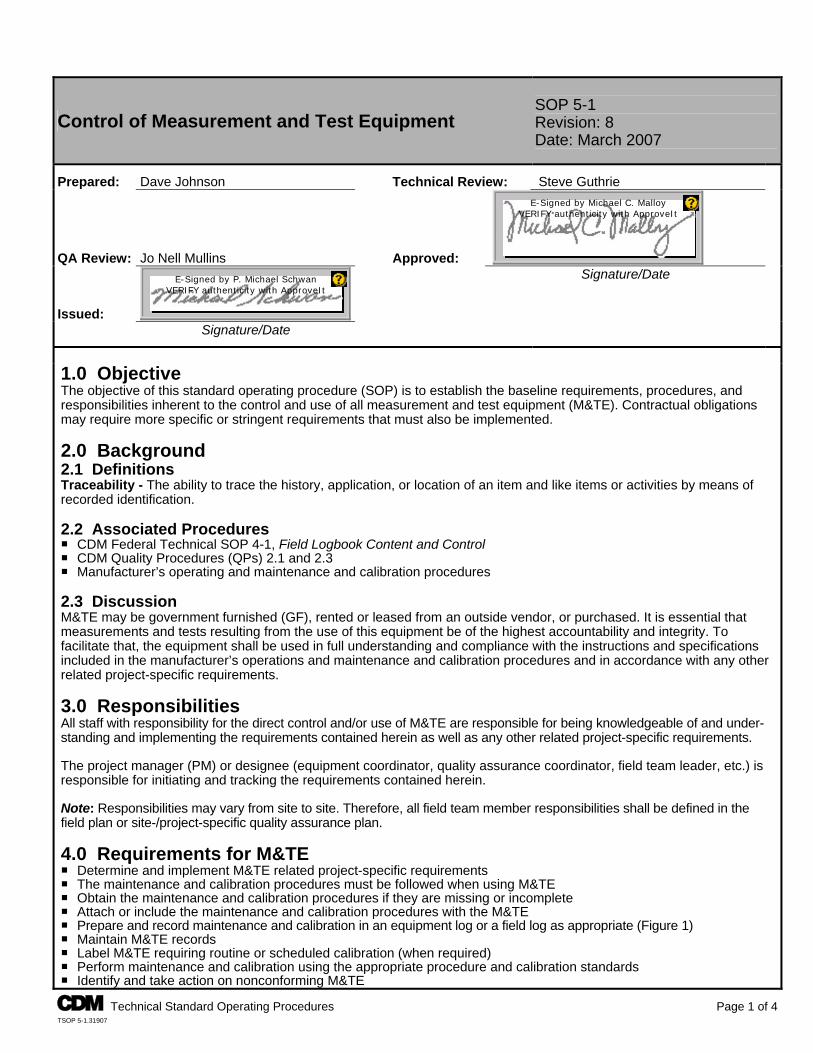
Control of Measurement and Test Equipment SOP 5-1 Revision: 8 Date: March 2007
Prepared: Dave Johnson Technical Review: Steve Guthrie
QA Review: Jo Nell Mullins Approved:
E-Signed by Michael C. MalloyVERIFY authenticity with ApproveIt
Issued:
E-Signed by P. Michael SchwanVERIFY authenticity with ApproveIt
Signature/Date
Signature/Date 1.0 Objective The objective of this standard operating procedure (SOP) is to establish the baseline requirements, procedures, and responsibilities inherent to the control and use of all measurement and test equipment (M&TE). Contractual obligations may require more specific or stringent requirements that must also be implemented. 2.0 Background 2.1 Definitions Traceability - The ability to trace the history, application, or location of an item and like items or activities by means of recorded identification. 2.2 Associated Procedures P CDM Federal Technical SOP 4-1, Field Logbook Content and Control P CDM Quality Procedures (QPs) 2.1 and 2.3 P Manufacturer’s operating and maintenance and calibration procedures 2.3 Discussion M&TE may be government furnished (GF), rented or leased from an outside vendor, or purchased. It is essential that measurements and tests resulting from the use of this equipment be of the highest accountability and integrity. To facilitate that, the equipment shall be used in full understanding and compliance with the instructions and specifications included in the manufacturer’s operations and maintenance and calibration procedures and in accordance with any other related project-specific requirements. 3.0 Responsibilities All staff with responsibility for the direct control and/or use of M&TE are responsible for being knowledgeable of and under-standing and implementing the requirements contained herein as well as any other related project-specific requirements. The project manager (PM) or designee (equipment coordinator, quality assurance coordinator, field team leader, etc.) is responsible for initiating and tracking the requirements contained herein. Note: Responsibilities may vary from site to site. Therefore, all field team member responsibilities shall be defined in the field plan or site-/project-specific quality assurance plan. 4.0 Requirements for M&TE P Determine and implement M&TE related project-specific requirements P The maintenance and calibration procedures must be followed when using M&TE P Obtain the maintenance and calibration procedures if they are missing or incomplete P Attach or include the maintenance and calibration procedures with the M&TE P Prepare and record maintenance and calibration in an equipment log or a field log as appropriate (Figure 1) P Maintain M&TE records P Label M&TE requiring routine or scheduled calibration (when required) P Perform maintenance and calibration using the appropriate procedure and calibration standards P Identify and take action on nonconforming M&TE
A Technical Standard Operating Procedures Page 1 of 4 TSOP 5-1.31907
A Technical Standard Operating Procedures Page 2 of 4 TSOP 5-1.31907
Control of Measurement and Test Equipment SOP 5-1 Revision: 8 Date: March 2007
5.0 Procedures 5.1 Determine if Other Related Project-Specific Requirements Apply For all M&TE: The PM or designee shall determine if M&TE related project-specific requirements apply. If M&TE related project-specific requirements apply, obtain a copy of them and review and implement as appropriate. 5.2 Obtain the Operating and Maintenance and Calibration Documents For GF M&TE that is to be procured: Requisitioner - Specify that the maintenance and calibration procedures be included. For GF M&TE that is acquired as a result of a property transfer: Receiver - Inspect the M&TE to determine whether maintenance and calibration procedures are included with the item. If missing or incomplete, order the appropriate documentation from the manufacturer. For M&TE that is to be rented or leased from an outside vendor: Requisitioner - Specify that the maintenance and calibration procedures, the latest calibration record, and the calibration standards certification be included. If this information is not delivered with the M&TE, ask the procurement division to request it from the vendor. 5.3 Prepare and Record Maintenance and Calibration Records For all M&TE: PM or Designee - Record all maintenance and calibration events in a field log unless other project-specific requirements apply. For GF M&TE only (does not apply to rented or leased M&TE): If an equipment log is a project specific requirement, perform the following: Receiver - Notify the PM or designee for the overall property control of the equipment upon receipt of an item of M&TE. PM or Designee and User: - Prepare a sequentially page numbered equipment log for the item using the maintenance and calibration form (or
equivalent) (Figure 1). - Record all maintenance and calibration events in an equipment log. 5.4 Label M&TE Requiring Calibration For GF M&TE only (does not apply to rented or leased M&TE): If calibration labeling is a project specific requirement, perform the following: PM or Designee: - Read the maintenance and calibration procedures to determine the frequency of calibration required. - If an M&TE item requires calibration before use, affix a label to the item stating “Calibrate Before Use.” - If an M&TE item requires calibration at other scheduled intervals, e.g., monthly, annually, etc., affix a label listing the date
of the last calibration, the date the item is next due for a calibration, the initials of the person who performed the calibration, and a space for the initials of the person who shall perform the next calibration.
5.5 Operating, Maintaining or Calibrating an M&TE Item For all M&TE: PM or Designee and User - Operate, maintain, and calibrate M&TE in accordance with the maintenance and calibration procedures. Record maintenance and calibration actions in the equipment log or field log. 5.6 Shipment For GF M&TE: Shipper - Inspect the item to ensure that the maintenance and calibration procedures are attached to the shipping case, or included, and that a copy of the most recent equipment log entry page (if required) is included with the shipment. If the maintenance and calibration procedures and/or the current equipment log page (if required) is missing or incomplete, do not ship the item. Immediately contact the PM or designee and request a replacement.
A Technical Standard Operating Procedures Page 3 of 4 TSOP 5-1.31907
Control of Measurement and Test Equipment SOP 5-1 Revision: 8 Date: March 2007
For M&TE that is rented or leased from an outside vendor: Shipper - Inspect the item to ensure that the maintenance and calibration procedures and latest calibration and standards certification records are included prior to shipment. If any documentation is missing or incomplete, do not ship the item. Immediately contact the procurement division and request that they obtain the documentation from the vendor. 5.7 Records Maintenance For GF M&TE: PM or Designee - Create a file upon the initial receipt of an item of M&TE or calibration standard. Organize the files by contract origin and by M&TE item and calibration standard. Store all files in a cabinet, file drawer, or other appropriate storage media at the pertinent warehouse or office location. Receiver - Forward the original packing slip to the procurement division and a photocopy to the PM or designee. PM or Designee and User: - Maintain all original documents in the equipment file except for the packing slip and field log. - File the photocopy of the packing slip in the M&TE file. - Record all maintenance and calibration in an equipment log or field log (as appropriate). File the completed equipment
logs in the M&TE records. Forward completed field logs to the PM for inclusion in the project files. For M&TE rented or leased from an outside vendor: Receiver - Forward the packing slip to the procurement division. User: - Forward the completed field log to the PM for inclusion in the project files. - Retain the most current maintenance and calibration record and calibration standards certifications with the M&TE item
and forward previous versions to the PM for inclusion in the project files. 5.8 Traceability of Calibration Standards For all items of M&TE: PM or Designee and User: - When ordering calibration standards, request nationally recognized standards as specified or required. Request
commercially available standards when not otherwise specified or required. Or, request standards in accordance with other related project-specific requirements.
- Require certifications for standards that clearly state the traceability. - Require Material Safety Data Sheets to be provided with standards. - Note standards that are perishable and consume or dispose of them on or before the expiration date. 5.9 M&TE That Fails Calibration For any M&TE item that cannot be calibrated or adjusted to perform accurately: PM or Designee - Immediately discontinue use and segregate the item from other equipment. Notify the appropriate PM and take
appropriate action in accordance with the CDM QP 2.3 for nonconforming items. - Review the current and previous maintenance and calibration records to determine if the validity of current or previous
measurement and test results could have been affected and notify the appropriate PM(s) of the results of the review. 6.0 Restrictions/Limitations On an item-by-item basis, exemptions from the requirements of this SOP may be granted by the Headquarters health and safety manager and/or Headquarters quality assurance director. All exemptions shall be documented by the grantor and included in the equipment records as appropriate. 7.0 References CDM Federal Programs Corporation. 2007. Quality Assurance Manual. Rev. 11. CDM Federal Programs Corporation. 2005. Government Property Manual. Rev. 3.
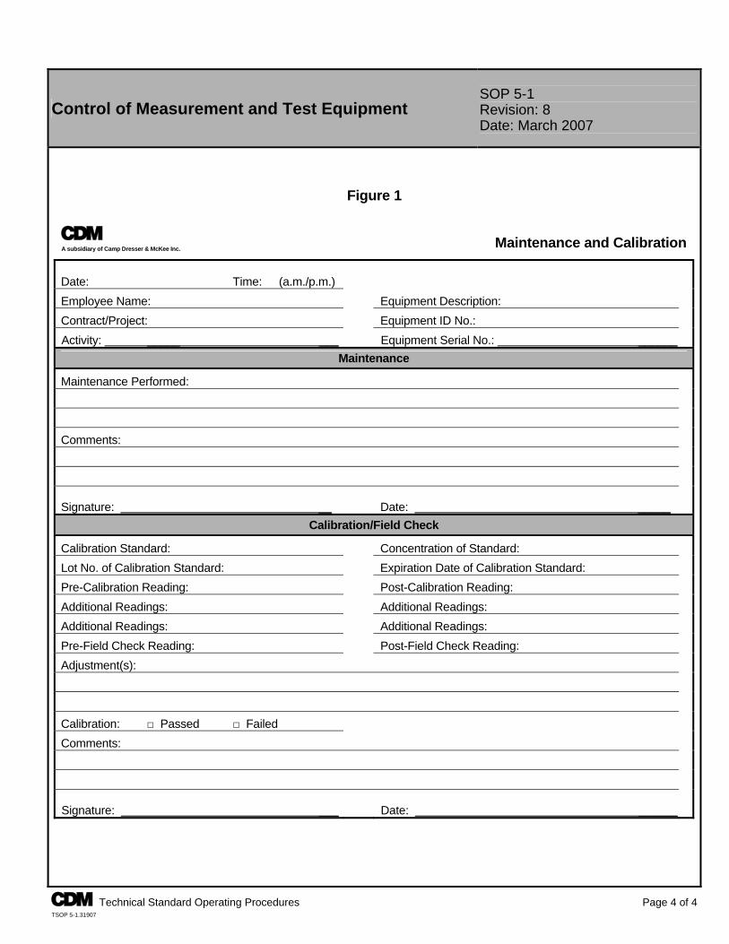
A Technical Standard Operating Procedures Page 4 of 4 TSOP 5-1.31907
Control of Measurement and Test Equipment SOP 5-1 Revision: 8 Date: March 2007
Figure 1
A A subsidiary of Camp Dresser & McKee Inc.
Maintenance and Calibration Date: Time: (a.m./p.m.)
Employee Name: Equipment Description:
Contract/Project: Equipment ID No.:
Activity: _____ ___ Equipment Serial No.: ______
Maintenance
Maintenance Performed:
Comments:
Signature: __ Date: _____
Calibration/Field Check
Calibration Standard: Concentration of Standard:
Lot No. of Calibration Standard: Expiration Date of Calibration Standard:
Pre-Calibration Reading: Post-Calibration Reading:
Additional Readings: Additional Readings:
Additional Readings: Additional Readings:
Pre-Field Check Reading: Post-Field Check Reading:
Adjustment(s):
Calibration: □ Passed □ Failed
Comments:
Signature: ___ Date: ______

Appendix B
Field Forms
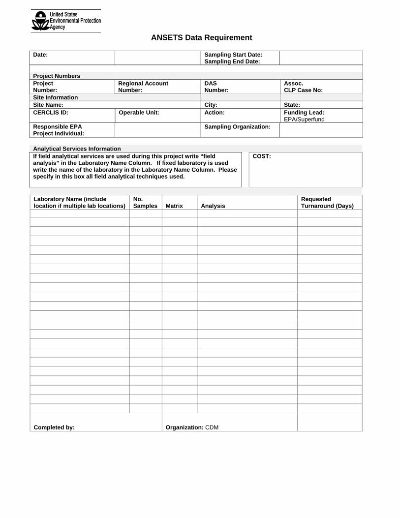
ANSETS Data Requirement
Date: Sampling Start Date: Sampling End Date:
Project Numbers Project Number:
Regional Account Number:
DAS Number:
Assoc. CLP Case No:
Site Information Site Name: City: State: CERCLIS ID:
Operable Unit:
Action:
Funding Lead: EPA/Superfund
Responsible EPA Project Individual:
Sampling Organization:
Analytical Services Information If field analytical services are used during this project write “field analysis” in the Laboratory Name Column. If fixed laboratory is used write the name of the laboratory in the Laboratory Name Column. Please specify in this box all field analytical techniques used.
COST:
Laboratory Name (include location if multiple lab locations)
No. Samples Matrix Analysis
Requested Turnaround (Days)
Completed by: Organization: CDM
Please use this FedEx airbill to return all coolers sent to your laboratory(ies) under this case number. It should be sent FedEx Express Saver (Third Business day) and addressed:
CDM Federal Warehouse 115 Newfield Ave. Edison, NJ 08837 Attn: Equipment Return
Thanks, CDM Federal Programs Corporation Please use this FedEx airbill to return all coolers sent to your laboratory(ies) under this case number. It should be sent FedEx Express Saver (Third Business day) and addressed:
CDM Federal Warehouse 115 Newfield Ave. Edison, NJ 08837 Attn: Equipment Return
Thanks, CDM Federal Programs Corporation
REV 5/01
DAILY SIGN-IN SHEET RARITAN BAY SLAG SITE
Date Print Name Signature Affiliation Time
On-Site Time
Off-Site
REV 5/01
DAILY STATUS REPORT
RARITAN BAY SLAG SITE
DATE: WEATHER:
Personnel Onsite:
Samples Collected (List locations):
Borings Completed (Include total footage drilled for each boring):
Number of Drums Generated (Names):
Miscellaneous (Equipment needs, health and safety issues, visitors onsite, etc.):
SIGNATURE:
DATE:
REV 5/01
GENERAL EQUIPMENT CALIBRATION LOG RARITAN BAY SLAG SITE
Instrument (make/model/serial #): Manufacturer: Rental Company: Upon receipt, all parts are included and this instrument is in working order: (signature/date)
Calibration Date Initial Setting
Standard/ Gas Used
(Concentration)Lot Control No. Expiration Date Adjustments Made Final Reading Comments
Pass/Fail Signature
RARITAN BAY SLAG SITE FIELD CHANGE REQUEST (FCR) FORM
USACE Contract No.: W912DQ-08-D-0018
REQUEST NO: DATE: FCR TITLE: DESCRIPTION:
REASON FOR DEVIATION:
RECOMMENDED MODIFICATION:
IMPACT ON PROJECT OBJECTIVES:
Dated Signatures:
Field Team Leader (FTL)
CDM Task Order Manager (TOM) Distribution: EPA Remedial Project Manager USACE PM CDM TOM Regional Quality Assurance Coordinator Field Team Project File
Instrument Calibration Log RAE Systems
MultiRAE + (4 gas + PID) RARITAN BAY SLAG SITE
Page 1 of 2
Calibration Completed By Date Rental Company
Rental Company Number
Instrument Serial Number
Time Instrument On1
Warm Up 5 to 10 Minutes2
Calibration Gas Manufacturer Lot No./Expiration Date Concentration(s) CO: H2S: LEL: O2: Isobutylene: Fresh Air Calibration
Carbon Monoxide (CO) Reading
VOC3 Reading (zero) H2S Reading (zero) LEL Reading (zero) Oxygen (O2)
Expected Reading4 Zero Zero Zero Zero 20.9% Actual Reading
Multiple Sensor Calibration CO Reading
H2S Reading
LEL Reading
O2 Reading
VOC Sensor Calibration VOC Reading
Expected Reading5 Expected Reading Actual Reading Actual Reading
Instrument OK? YES (Calibration Completed) NO (Problem with instrument, detail in comments) Calibration Check6 Completed (Circle one): YES NO Time: Date: Calibration Completed By:
Calibration Gas Same as Above (Circle one)? YES NO (IF NO COMPLETE INFORMATION BELOW) Manufacturer Lot No./Expiration Date Concentration(s)
CO: H2S: LEL: O2:
1 Note time instrument is turned on for initial warm up 2 While instrument is warming up, make sure inlet tubing is connected to a hydrophobic filter and fill one Tedlar bag with isobutylene and one with four gas mix 3 VOC – volatile organic compounds, H2S – hydrogen sulfide, LEL – lower explosive limit 4 Instruments should read zero after fresh air calibration is complete, write down actual readings below headings 5 Write concentration from calibration gas on this line 6 Complete at the end of the day
Instrument Calibration Log RAE Systems
MultiRAE + (4 gas + PID) RARITAN BAY SLAG SITE
Page 2 of 2
Isobutylene:
Calibration Check Readings:
CO: H2S: LEL: O2: VOC:
Comments/Corrective Action:
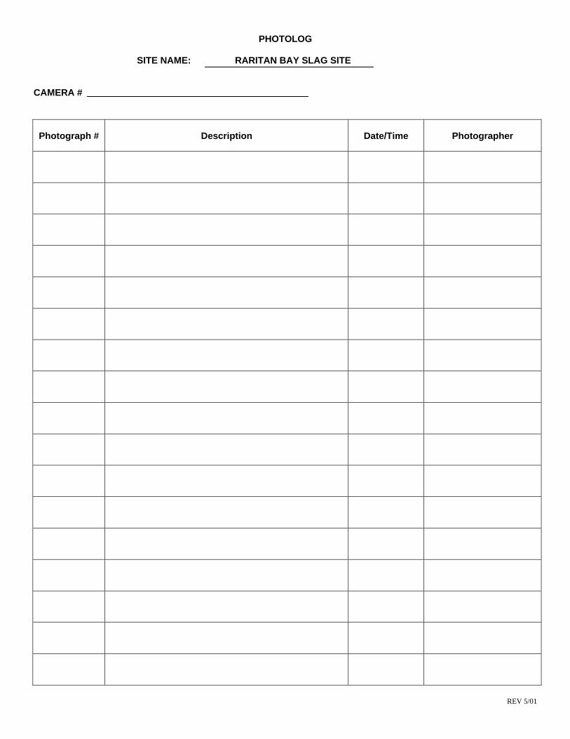
REV 5/01
PHOTOLOG
SITE NAME: RARITAN BAY SLAG SITE
CAMERA #
Photograph # Description Date/Time Photographer
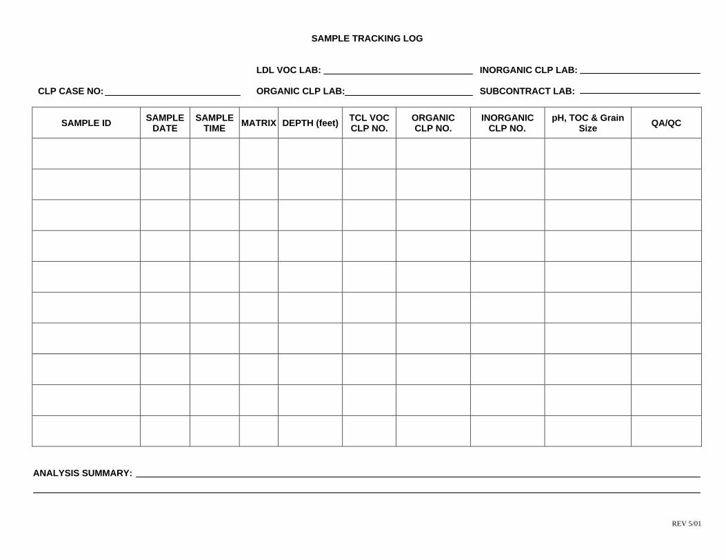
REV 5/01
SAMPLE TRACKING LOG
LDL VOC LAB: INORGANIC CLP LAB: CLP CASE NO: ORGANIC CLP LAB: SUBCONTRACT LAB:
SAMPLE ID SAMPLE DATE
SAMPLE TIME MATRIX DEPTH (feet) TCL VOC
CLP NO. ORGANIC CLP NO.
INORGANIC CLP NO.
pH, TOC & Grain Size QA/QC
ANALYSIS SUMMARY:
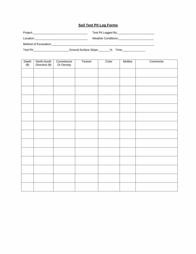
Soil Test Pit Log Forms
Project:__________________________________ Test Pit Logged By:_______________________
Location:_________________________________ Weather Conditions:______________________
Method of Excavation:________________________________________________________________
Test Pit:______________________ Ground Surface Slope:_______% Time:______________
Depth (ft)
North-South Direction (ft)
Consistence Or Density
Texture Color Mottles Comments
Appendix C
DESA QAPP Worksheets
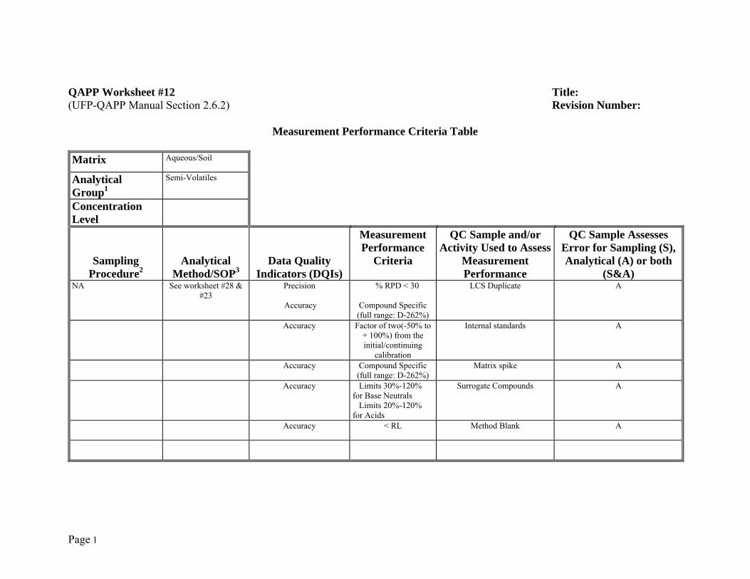
Page 1
QAPP Worksheet #12 Title: (UFP-QAPP Manual Section 2.6.2) Revision Number:
Measurement Performance Criteria Table Matrix Aqueous/Soil
Analytical Group1
Semi-Volatiles
Concentration Level
Sampling Procedure2
Analytical Method/SOP3
Data Quality Indicators (DQIs)
Measurement Performance
Criteria
QC Sample and/or Activity Used to Assess
Measurement Performance
QC Sample Assesses Error for Sampling (S), Analytical (A) or both
(S&A)NA
See worksheet #28 & #23
Precision
Accuracy
% RPD < 30
Compound Specific (full range: D-262%)
LCS Duplicate A
Accuracy Factor of two(-50% to + 100%) from the initial/continuing
calibration
Internal standards A
Accuracy Compound Specific (full range: D-262%)
Matrix spike A
Accuracy Limits 30%-120% for Base Neutrals Limits 20%-120% for Acids
Surrogate Compounds A
Accuracy < RL Method Blank A
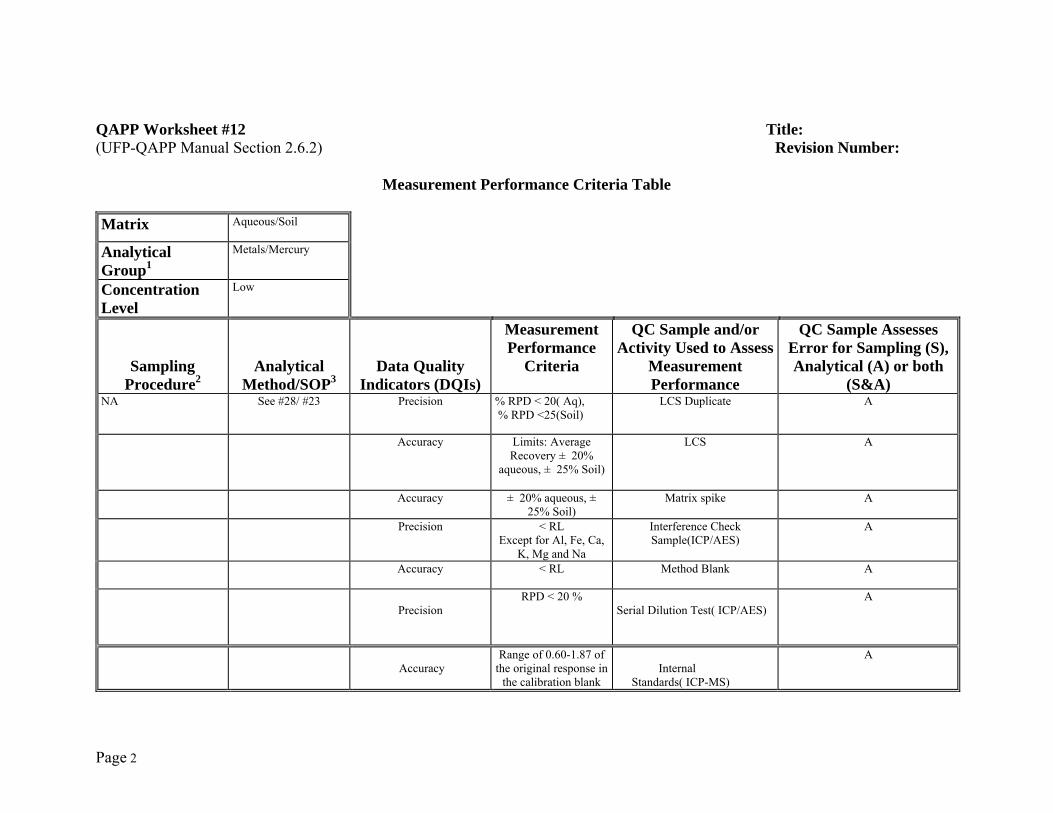
Page 2
QAPP Worksheet #12 Title: (UFP-QAPP Manual Section 2.6.2) Revision Number:
Measurement Performance Criteria Table Matrix Aqueous/Soil
Analytical Group1
Metals/Mercury
Concentration Level
Low
Sampling Procedure2
Analytical Method/SOP3
Data Quality Indicators (DQIs)
Measurement Performance
Criteria
QC Sample and/or Activity Used to Assess
Measurement Performance
QC Sample Assesses Error for Sampling (S), Analytical (A) or both
(S&A)NA
See #28/ #23 Precision % RPD < 20( Aq), % RPD <25(Soil)
LCS Duplicate A
Accuracy Limits: Average Recovery ± 20%
aqueous, ± 25% Soil)
LCS A
Accuracy ± 20% aqueous, ± 25% Soil)
Matrix spike A
Precision < RL Except for Al, Fe, Ca,
K, Mg and Na
Interference Check Sample(ICP/AES)
A
Accuracy < RL Method Blank A
Precision
RPD < 20 % Serial Dilution Test( ICP/AES)
A
Accuracy
Range of 0.60-1.87 of the original response in
the calibration blank
Internal Standards( ICP-MS)
A
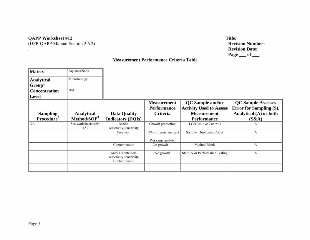
Page 3
QAPP Worksheet #12 Title: (UFP-QAPP Manual Section 2.6.2) Revision Number: . Revision Date: Page ___ of ___
Measurement Performance Criteria Table Matrix Aqueous/Soils
Analytical Group1
Microbiology
Concentration Level
N/A
Sampling Procedure2
Analytical Method/SOP3
Data Quality Indicators (DQIs)
Measurement Performance
Criteria
QC Sample and/or Activity Used to Assess
Measurement Performance
QC Sample Assesses Error for Sampling (S), Analytical (A) or both
(S&A)NA
See worksheets #28/ #23
Media selectivity,sensitivity
Growth promotion LCS(Positive Control) A
Precision 10% (different analyst)
5%( same analyst)
Sample Duplicates Count A
Contamination No growth Method Blank A
Media /containers selectivity,sensitivity
Contamination
No growth Sterility or Performance Testing A
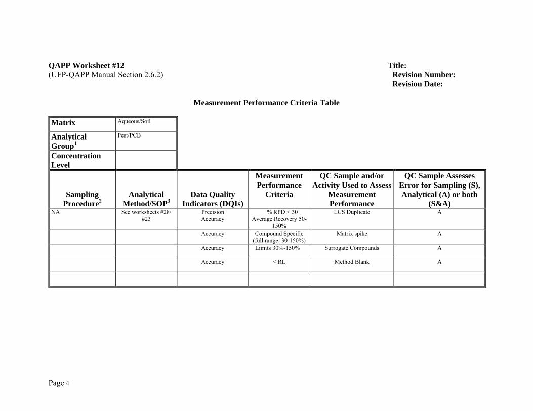
Page 4
QAPP Worksheet #12 Title: (UFP-QAPP Manual Section 2.6.2) Revision Number: Revision Date:
Measurement Performance Criteria Table Matrix Aqueous/Soil
Analytical Group1
Pest/PCB
Concentration Level
Sampling Procedure2
Analytical Method/SOP3
Data Quality Indicators (DQIs)
Measurement Performance
Criteria
QC Sample and/or Activity Used to Assess
Measurement Performance
QC Sample Assesses Error for Sampling (S), Analytical (A) or both
(S&A)NA
See worksheets #28/ #23
Precision Accuracy
% RPD < 30 Average Recovery 50-
150%
LCS Duplicate A
Accuracy Compound Specific (full range: 30-150%)
Matrix spike A
Accuracy Limits 30%-150% Surrogate Compounds A
Accuracy < RL Method Blank A
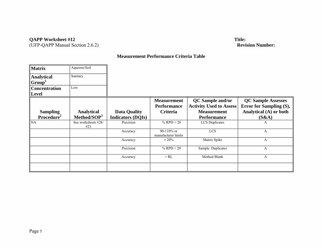
Page 5
QAPP Worksheet #12 Title: (UFP-QAPP Manual Section 2.6.2) Revision Number:
Measurement Performance Criteria Table Matrix Aqueous/Soil
Analytical Group1
Sanitary
Concentration Level
Low
Sampling Procedure2
Analytical Method/SOP3
Data Quality Indicators (DQIs)
Measurement Performance
Criteria
QC Sample and/or Activity Used to Assess
Measurement Performance
QC Sample Assesses Error for Sampling (S), Analytical (A) or both
(S&A)NA
See worksheets #28/ #23
Precision % RPD < 20 LCS Duplicates A
Accuracy 90-110% or manufacturer limits
LCS A
Accuracy ± 20% Matrix Spike A
Precision % RPD < 20 Sample Duplicates A
Accuracy < RL Method Blank A
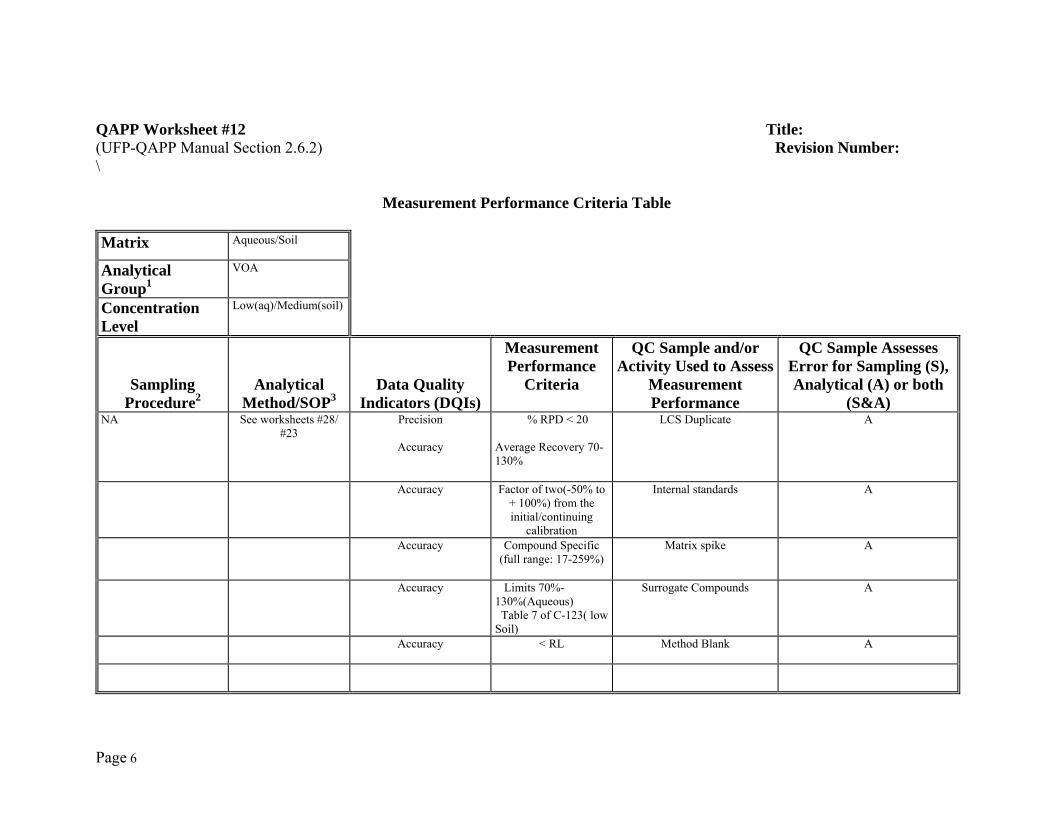
Page 6
QAPP Worksheet #12 Title: (UFP-QAPP Manual Section 2.6.2) Revision Number: \
Measurement Performance Criteria Table Matrix Aqueous/Soil
Analytical Group1
VOA
Concentration Level
Low(aq)/Medium(soil)
Sampling Procedure2
Analytical Method/SOP3
Data Quality Indicators (DQIs)
Measurement Performance
Criteria
QC Sample and/or Activity Used to Assess
Measurement Performance
QC Sample Assesses Error for Sampling (S), Analytical (A) or both
(S&A)NA
See worksheets #28/ #23
Precision
Accuracy
% RPD < 20
Average Recovery 70-130%
LCS Duplicate A
Accuracy Factor of two(-50% to + 100%) from the initial/continuing
calibration
Internal standards A
Accuracy Compound Specific (full range: 17-259%)
Matrix spike A
Accuracy Limits 70%-130%(Aqueous) Table 7 of C-123( low Soil)
Surrogate Compounds A
Accuracy < RL Method Blank A
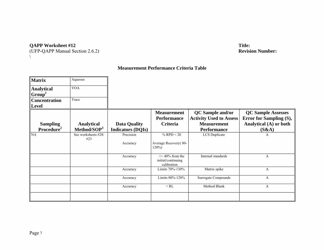
Page 7
QAPP Worksheet #12 Title: (UFP-QAPP Manual Section 2.6.2) Revision Number: \
Measurement Performance Criteria Table Matrix Aqueous
Analytical Group1
VOA
Concentration Level
Trace
Sampling Procedure2
Analytical Method/SOP3
Data Quality Indicators (DQIs)
Measurement Performance
Criteria
QC Sample and/or Activity Used to Assess
Measurement Performance
QC Sample Assesses Error for Sampling (S), Analytical (A) or both
(S&A)NA
See worksheets #28/ #23
Precision
Accuracy
% RPD < 20
Average Recovery( 80-120%)
LCS Duplicate A
Accuracy +/- 40% from the initial/continuing
calibration
Internal standards A
Accuracy Limits 70%-130% Matrix spike A
Accuracy Limits 80%-120% Surrogate Compounds A
Accuracy < RL Method Blank A

Page 8
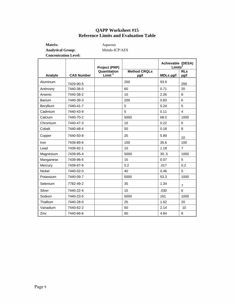
Page 9
QAPP Worksheet #15 Reference Limits and Evaluation Table
Matrix: Aqueous Analytical Group: Metals-ICP/AES Concentration Level:
Analyte CAS Number
Project (PRP) Quantitation
Limit 3
Achievable (DESA)
Limits2
Method CRQLs µg/l MDLs µg/l
RLs µg/l
Aluminum 7429-90-5 200 93.9
200 Antimony 7440-36-0 60 0.71 20 Arsenic 7440-38-2 10 2.26 8 Barium 7440-39-3 200 0.83 6 Beryllium 7440-41-7 5 0.24 5 Cadmium 7440-43-9 5 0.11 4 Calcium 7440-70-2 5000 68.0 1000 Chromium 7440-47-3 10 0.22 6 Cobalt 7440-48-4 50 0.18 8
Copper 7440-50-8 25 5.89 10
Iron 7439-89-6 100 35.6 100 Lead 7439-92-1 10 1.18 7 Magnesium 7439-95-4 5000 30..5 1000 Manganese 7439-96-5 15 0.07 5 Mercury 7439-97-6 0.2 .017 0.2 Nickel 7440-02-0 40 0.46 5 Potassium 7440-09-7 5000 53.3 1000
Selenium 7782-49-2 35 1.34 7
Silver 7440-22-4 10 .030 6 Sodium 7440-23-5 5000 161 1000 Thallium 7440-28-0 25 1.62 20 Vanadium 7440-62-2 50 2.14 10 Zinc 7440-66-6 60 4.84 8
Page 10
QAPP Worksheet #15 Reference Limits and Evaluation Table
Matrix: Aqueous Analytical Group: Metals-ICP/MS Concentration Level:
Analyte CAS Number
Project (PRP) Quantitation
Limit 3
Method CRQLs
µg/l
Achievable (DESA) Limits2
MDLs µg/l RLs µg/l
Aluminum
7429-90-5
- 1.19 10
Antimony 7440-36-0 2 0.022 2.0
Arsenic 7440-38-2 1 0.062 1.0
Barium 7440-39-3 10 0.031 1.0
Beryllium 7440-41-7 1 0.010 1.0
Cadmium 7440-43-9 1 0.009 1.0
Calcium 7440-70-2 - -
Chromium 7440-47-3 2 0.314 1.0
Cobalt 7440-48-4 1 0.015 1.0
Copper 7440-50-8 2 0.315 1.0
Iron 7439-89-6 - -
Lead 7439-92-1 1 0.011 1.0
Magnesium 7439-95-4 - -
Manganese 7439-96-5 1 0.135 1.0
Mercury 7439-97-6 - -
Nickel 7440-02-0 1 0.471 1.0
Potassium 7440-09-7 - -
Selenium 7782-49-2 5 0.183 5.0
Silver 7440-22-4 1 0.007 1.0
Sodium 7440-23-5 - -
Thallium 7440-28-0 1 0.013 1.0
Vanadium 7440-62-2 1 0.082 1.0
Zinc 7440-66-6 2 0.165 1.0
Page 11
QAPP Worksheet #15 Reference Limits and Evaluation Table
Matrix: Soil Analytical Group: Metals Concentration Level:
Analyte CAS
Number
Project (PRP)
QuantitationLimit 3
Method CRQLs mg/kg
Achievable (DESA) Limits2
MDLs - mg/kg RLs - mg/kg
Aluminum
7429-90-5
20 * 100
Antimony 7440-36-0 6 0.22 2
Arsenic 7440-38-2 1 0.35 0.8
Barium 7440-39-3 20 0.24 10
Beryllium 7440-41-7 0.5 0.02 0.3
Cadmium 7440-43-9 0.5 0.02 0.3
Calcium 7440-70-2 500 12.57 50
Chromium 7440-47-3 1 0.34 0.5
Cobalt 7440-48-4 5 0.03 2
Copper 7440-50-8 2.5 0.26 1
Iron 7439-89-6 10 * 5
Lead 7439-92-1 1 0.23 0.8
Magnesium 7439-95-4 500 5.06 50
Manganese 7439-96-5 1.5 0.33 0.5
Mercury 7439-97-6 0.1 .0043 0.05
Nickel 7440-02-0 4 0.09 2
Potassium 7440-09-7 500 12.36 50
Selenium 7782-49-2 3.5 0.22 2
Silver 7440-22-4 1 0.06 0.5
Sodium 7440-23-5 500 22.48 100
Thallium 7440-28-0 2.5 3.14 2
Vanadium 7440-62-2 5 0.40 2
Zinc 7440-66-6 6 1.57 2
* MDL study cannot be successfully performed on these analytes because of high background levels in matrix (sand).
Page 12
QAPP Worksheet #15 Reference Limits and Evaluation Table
Matrix: Soil Analytical Group: PEST/PCBs Concentration Level:
Analyte CAS
Number
Project (PRP)
QuantitationLimit 3
Method QLs µg/kg
Achievable (DESA) Limits2
MDLs µg/kg RLs µg/kg
alpha-BHC 319-89-6 1.7 2.15 2.5 gamma-BHC 58-89-9 1.7 1.89 2.5 beta-BHC 319-85-7 1.7 1.35 2.5 delta-BHC 319-86-8 1.7 1.51 2.5 Heptachlor 76-44-8 1.7 2.05 2.5 Aldrin 309-00-2 1.7 1.66 2.5 Heptachlor epoxide 1024-57-3 1.7 1.34 2.5 Gamma-chlordane 5103-74-2 1.7 0.96 2.5 alpha-chlordane 5103-71-9 1.7 1.01 2.5 Endosulfan I 1031-07-8 1.7 1.16 2.5 4,4'-DDE 72-55-9 3.3 1.92 5.0 Dieldrin 60-57-1 3.3 1.91 5.0 Endrin 72-20-8 3.3 1.84 5.0 4,4'-DDD 72-54-8 3.3 1.35 5.0 Endosulfan II 1031-078 3.3 1.27 5.0 4,4'-DDT 50-29-3 3.3 1.52 5.0 Endrin aldehyde 7421-93-4 3.3 2.24 5.0 Methoxychlor 72-43-5 17 8.00 25 Endosulfan sulfate 1031-07-8 3.3 1.24 2.5 Endrin ketone 53494-70-5 3.3 1.18 2.5 Toxaphene 8001-35-2 170 75.9 190 Technical chlordane 56.1 62 AROCLOR 1016 12674-11-2 33 31 AROCLOR 1221 11104-28-2 33 62 AROCLOR 1232 11141-16-5 33 31 AROCLOR 1242 53469-21-9 33 29.9 31 AROCLOR 1248 12672-29-6 33 31 AROCLOR 1254 11097-69-1 33 31 AROCLOR 1260 11096-82-5 33 31 AROCLOR 1262 37324-23-5 33 31 AROCLOR 1268 11100-14-4 33 31
Page 13
QAPP Worksheet #15 Reference Limits and Evaluation Table
Matrix: Aqueous Analytical Group: PEST/PCB Aroclors Concentration Level:
Analyte CAS
Number
Project (PRP)
QuantitationLimit 3
Method CRQLs µg/L
Achievable (DESA) Limits2
MDLs µg/L RLs µg/L alpha-BHC 319-89-6 0.050 0.001 0.0025 gamma-BHC 58-89-9 0.050 0.001 0.0025 beta-BHC 319-85-7 0.050 0.002 0.0025 delta-BHC 319-86-8 0.050 0.002 0.0025 Heptachlor 76-44-8 0.050 0.001 0.0025 Aldrin 309-00-2 0.050 0.001 0.0025 Heptachlor epoxide 1024-57-3 0.050 0.005 0.0025 Gamma-chlordane 5103-74-2 0.050 0.001 0.0025 Alpha-chlordane 5103-71-9 0.050 0.002 0.0025 Endosulfan I 1031-07-8 0.050 0.002 0.0025 4,4'-DDE 72-55-9 0.10 0.003 0.005 Dieldrin 60-57-1 0.10 0.004 0.005 Endrin 72-20-8 0.10 0.004 0.005 4,4'-ddd 72-54-8 0.10 0..005 0.005 Endosulfan II 1031-078 0.10 0.004 0.005 4,4'-DDT 50-29-3 0.10 0.004 0.005 Endrin aldehyde 7421-93-4 0.10 0.006 0.005 Methoxychlor 72-43-5 0.50 0.032 0.050 Endosulfan sulfate 1031-07-8 0.10 0.004 0.005 Endrin ketone 53494-70-5 0.10 0.004 0.005 Toxaphene 8001-35-2 5.0 0.049 0.1875 Technical chlordane 0.020 0.0625 AROCLOR 1016 12674-11-2 1.0 0.03125 AROCLOR 1221 11104-28-2 1.0 0.0625 AROCLOR 1232 11141-16-5 1.0 0.03125 AROCLOR 1242 53469-21-9 1.0 0.020 0.03125 AROCLOR 1248 12672-29-6 1.0 0.03125 AROCLOR 1254 11097-69-1 1.0 0.014 0.03125 AROCLOR 1260 11096-82-5 1.0 0.03125 AROCLOR 1262 37324-23-5 1.0 0.03125 AROCLOR 1268 11100-14-4 1.0 0.03125
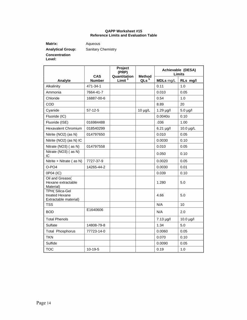
Page 14
QAPP Worksheet #15 Reference Limits and Evaluation Table
Matrix: Aqueous Analytical Group: Sanitary Chemistry Concentration Level:
Analyte CAS
Number
Project (PRP)
QuantitationLimit 3
Method QLs 5
Achievable (DESA) Limits
MDLs mg/L RLs mg/l Alkalinity 471-34-1 0.11 1.0 Ammonia 7664-41-7 0.010 0.05 Chloride 16887-00-6 0.54 1.0 COD 8.89 20 Cyanide 57-12-5 10 µg/L 1.29 µg/l 5.0 µg/l Fluoride (IC) 0.0040o 0.10 Fluoride (ISE) 016984488 .036 1.00 Hexavalent Chromium 018540299 6.21 µg/l 10.0 µg/L Nitrite (NO2) (as N) 014797650 0.010 0.05 Nitrite (NO2) (as N) IC 0.0030 0.10 Nitrate (NO3) ( as N) 014797558 0.010 0.05 Nitrate (NO3) ( as N) IC 0.050 0.10
Nitrite + Nitrate ( as N) 7727-37-9 0.0020 0.05 O-PO4 14265-44-2 0.0030 0.01 0P04 (IC) 0.039 0.10 Oil and Grease( Hexane extractable Material)
1.280 5.0
TPH( Silica-Gel treated Hexane Extractable material)
4.66 5.0
TSS N/A 10
BOD E1640606 N/A 2.0
Total Phenols 7.13 µg/l 10.0 µg/l Sulfate 14808-79-8 1.34 5.0 Total Phosphorus 77723-14-0 0.0060 0.05 TKN 0.070 0.10 Sulfide 0.0090 0.05 TOC 10-19-5 0.19 1.0

Page 15
QAPP Worksheet #15 Reference Limits and Evaluation Table
Matrix: Soil Analytical Group: Semi -Volatile Organic Compounds Concentration Level: low
Analyte CAS
Number
Project (PRP)
QuantitationLimit 3
Method QLs 5 µg/kg
Achievable (DESA) Limits2
MDLs µg/kg
RLs µg/kg
Benzaldehyde 100-52-7 170 120 Phenol 108-95-2 170 120 Bis(2-chloroethyl)ether 111-44-4 170 120 2-Chlorophenol 95-57-8 170 120 2-Methylphenol 95-48-7 170 120 Bis(2-chloroisopropyl)ether 108-60-1 170 120 Acetophenone 98-86-2 170 120 4-Methylphenol 106-44-5 170 120 N-Nitroso-di-n-propylamine 621-64-7 170 120 Hexachloroethane 67-72-1 170 120 Nitrobenzene 98-95-3 170 120 Isophorone 78-59-1 170 120 2-Nitrophenol 88-75-5 170 120 2,4-dimethylphenol 105-67-9 170 120 Bis(2-chloroethoxy)methane 111-91-1 170 120 2,4-dichlorophenol 120-83-2 170 120 Naphthalene 91-20-3 170 120 4-Chloroaniline 106-47-8 170 120 Hexachlorobutadiene 87-68-3 170 120 Caprolactam 105-60-2 170 120 4-Chloro-3-methylphenol 59-50-7 170 120 2-methyl naphthalene 91-57-6 170 120 Hexachlorocyclopentadiene 77-47-4 170 120 1,2,4,5-Tetrachlorobenzene 95-94-3 170 120 2,4,6-Trichlorophenol 88-06-2 170 120 2,4,5-Trichlorphenol 95-95-4 170 120 1,1'-Biphenyl 92-52-4 170 120 2-Chloronaphthalene 91-58-7 170 120 2-Nitroaniline 88-74-4 330 120 Dimethyl phthalate 131-11-3 170 120 Acenaphthylene 208-96-8 170 120 2,6-Dinitrotoluene 606-20-2 170 120
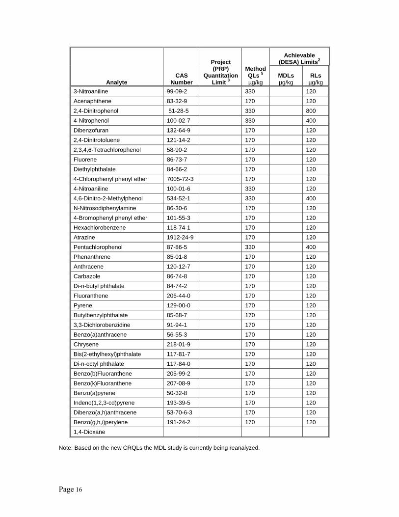
Page 16
Analyte CAS
Number
Project (PRP)
QuantitationLimit 3
Method QLs 5 µg/kg
Achievable (DESA) Limits2
MDLs µg/kg
RLs µg/kg
3-Nitroaniline 99-09-2 330 120 Acenaphthene 83-32-9 170 120 2,4-Dinitrophenol 51-28-5 330 800 4-Nitrophenol 100-02-7 330 400 Dibenzofuran 132-64-9 170 120 2,4-Dinitrotoluene 121-14-2 170 120 2,3,4,6-Tetrachlorophenol 58-90-2 170 120 Fluorene 86-73-7 170 120 Diethylphthalate 84-66-2 170 120 4-Chlorophenyl phenyl ether 7005-72-3 170 120 4-Nitroaniline 100-01-6 330 120 4,6-Dinitro-2-Methylphenol 534-52-1 330 400 N-Nitrosodiphenylamine 86-30-6 170 120 4-Bromophenyl phenyl ether 101-55-3 170 120 Hexachlorobenzene 118-74-1 170 120 Atrazine 1912-24-9 170 120 Pentachlorophenol 87-86-5 330 400 Phenanthrene 85-01-8 170 120 Anthracene 120-12-7 170 120 Carbazole 86-74-8 170 120 Di-n-butyl phthalate 84-74-2 170 120 Fluoranthene 206-44-0 170 120 Pyrene 129-00-0 170 120 Butylbenzylphthalate 85-68-7 170 120 3,3-Dichlorobenzidine 91-94-1 170 120 Benzo(a)anthracene 56-55-3 170 120 Chrysene 218-01-9 170 120 Bis(2-ethylhexyl)phthalate 117-81-7 170 120 Di-n-octyl phthalate 117-84-0 170 120 Benzo(b)Fluoranthene 205-99-2 170 120 Benzo(k)Fluoranthene 207-08-9 170 120 Benzo(a)pyrene 50-32-8 170 120 Indeno(1,2,3-cd)pyrene 193-39-5 170 120 Dibenzo(a,h)anthracene 53-70-6-3 170 120 Benzo(g,h,i)perylene 191-24-2 170 120 1,4-Dioxane
Note: Based on the new CRQLs the MDL study is currently being reanalyzed.
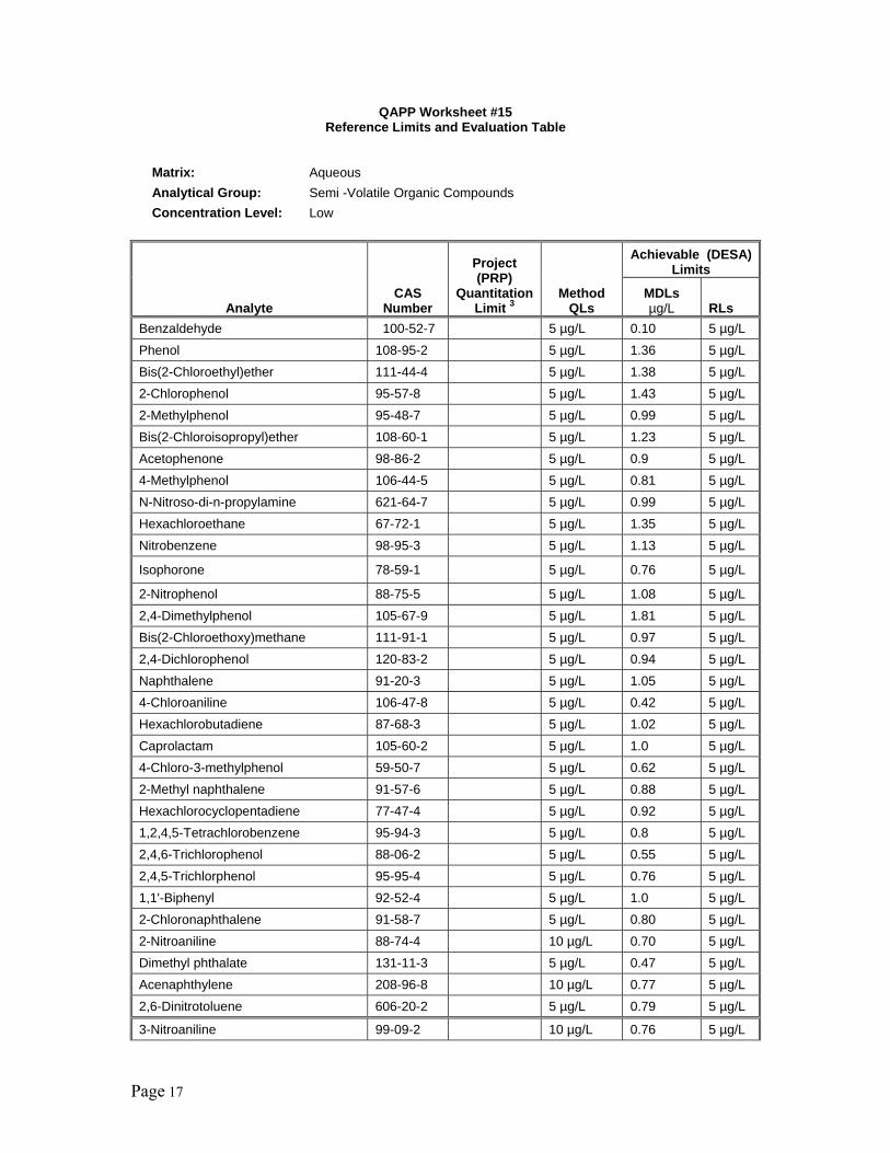
Page 17
QAPP Worksheet #15 Reference Limits and Evaluation Table
Matrix: Aqueous Analytical Group: Semi -Volatile Organic Compounds Concentration Level: Low
Analyte CAS
Number
Project (PRP)
QuantitationLimit 3
Method QLs
Achievable (DESA) Limits
MDLs µg/L RLs
Benzaldehyde 100-52-7 5 µg/L 0.10 5 µg/L Phenol 108-95-2 5 µg/L 1.36 5 µg/L Bis(2-Chloroethyl)ether 111-44-4 5 µg/L 1.38 5 µg/L 2-Chlorophenol 95-57-8 5 µg/L 1.43 5 µg/L 2-Methylphenol 95-48-7 5 µg/L 0.99 5 µg/L Bis(2-Chloroisopropyl)ether 108-60-1 5 µg/L 1.23 5 µg/L Acetophenone 98-86-2 5 µg/L 0.9 5 µg/L 4-Methylphenol 106-44-5 5 µg/L 0.81 5 µg/L N-Nitroso-di-n-propylamine 621-64-7 5 µg/L 0.99 5 µg/L Hexachloroethane 67-72-1 5 µg/L 1.35 5 µg/L Nitrobenzene 98-95-3 5 µg/L 1.13 5 µg/L
Isophorone 78-59-1 5 µg/L 0.76 5 µg/L
2-Nitrophenol 88-75-5 5 µg/L 1.08 5 µg/L 2,4-Dimethylphenol 105-67-9 5 µg/L 1.81 5 µg/L Bis(2-Chloroethoxy)methane 111-91-1 5 µg/L 0.97 5 µg/L 2,4-Dichlorophenol 120-83-2 5 µg/L 0.94 5 µg/L Naphthalene 91-20-3 5 µg/L 1.05 5 µg/L 4-Chloroaniline 106-47-8 5 µg/L 0.42 5 µg/L Hexachlorobutadiene 87-68-3 5 µg/L 1.02 5 µg/L Caprolactam 105-60-2 5 µg/L 1.0 5 µg/L 4-Chloro-3-methylphenol 59-50-7 5 µg/L 0.62 5 µg/L 2-Methyl naphthalene 91-57-6 5 µg/L 0.88 5 µg/L Hexachlorocyclopentadiene 77-47-4 5 µg/L 0.92 5 µg/L 1,2,4,5-Tetrachlorobenzene 95-94-3 5 µg/L 0.8 5 µg/L 2,4,6-Trichlorophenol 88-06-2 5 µg/L 0.55 5 µg/L 2,4,5-Trichlorphenol 95-95-4 5 µg/L 0.76 5 µg/L 1,1'-Biphenyl 92-52-4 5 µg/L 1.0 5 µg/L 2-Chloronaphthalene 91-58-7 5 µg/L 0.80 5 µg/L 2-Nitroaniline 88-74-4 10 µg/L 0.70 5 µg/L Dimethyl phthalate 131-11-3 5 µg/L 0.47 5 µg/L Acenaphthylene 208-96-8 10 µg/L 0.77 5 µg/L 2,6-Dinitrotoluene 606-20-2 5 µg/L 0.79 5 µg/L
3-Nitroaniline 99-09-2 10 µg/L 0.76 5 µg/L
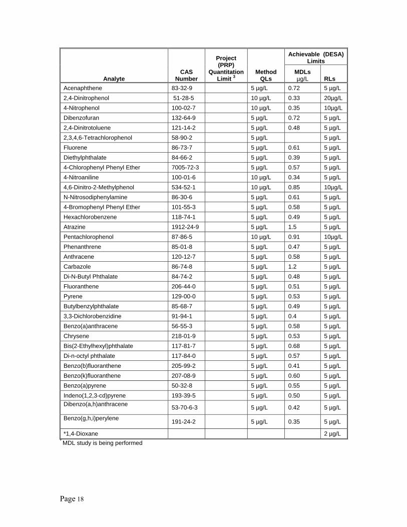
Page 18
Analyte CAS
Number
Project (PRP)
QuantitationLimit 3
Method QLs
Achievable (DESA) Limits
MDLs µg/L RLs
Acenaphthene 83-32-9 5 µg/L 0.72 5 µg/L 2,4-Dinitrophenol 51-28-5 10 µg/L 0.33 20µg/L 4-Nitrophenol 100-02-7 10 µg/L 0.35 10µg/L Dibenzofuran 132-64-9 5 µg/L 0.72 5 µg/L 2,4-Dinitrotoluene 121-14-2 5 µg/L 0.48 5 µg/L 2,3,4,6-Tetrachlorophenol 58-90-2 5 µg/L 5 µg/L Fluorene 86-73-7 5 µg/L 0.61 5 µg/L Diethylphthalate 84-66-2 5 µg/L 0.39 5 µg/L 4-Chlorophenyl Phenyl Ether 7005-72-3 5 µg/L 0.57 5 µg/L 4-Nitroaniline 100-01-6 10 µg/L 0.34 5 µg/L 4,6-Dinitro-2-Methylphenol 534-52-1 10 µg/L 0.85 10µg/L N-Nitrosodiphenylamine 86-30-6 5 µg/L 0.61 5 µg/L 4-Bromophenyl Phenyl Ether 101-55-3 5 µg/L 0.58 5 µg/L Hexachlorobenzene 118-74-1 5 µg/L 0.49 5 µg/L Atrazine 1912-24-9 5 µg/L 1.5 5 µg/L Pentachlorophenol 87-86-5 10 µg/L 0.91 10µg/L Phenanthrene 85-01-8 5 µg/L 0.47 5 µg/L Anthracene 120-12-7 5 µg/L 0.58 5 µg/L Carbazole 86-74-8 5 µg/L 1.2 5 µg/L Di-N-Butyl Phthalate 84-74-2 5 µg/L 0.48 5 µg/L Fluoranthene 206-44-0 5 µg/L 0.51 5 µg/L Pyrene 129-00-0 5 µg/L 0.53 5 µg/L Butylbenzylphthalate 85-68-7 5 µg/L 0.49 5 µg/L 3,3-Dichlorobenzidine 91-94-1 5 µg/L 0.4 5 µg/L Benzo(a)anthracene 56-55-3 5 µg/L 0.58 5 µg/L Chrysene 218-01-9 5 µg/L 0.53 5 µg/L Bis(2-Ethylhexyl)phthalate 117-81-7 5 µg/L 0.68 5 µg/L Di-n-octyl phthalate 117-84-0 5 µg/L 0.57 5 µg/L Benzo(b)fluoranthene 205-99-2 5 µg/L 0.41 5 µg/L Benzo(k)fluoranthene 207-08-9 5 µg/L 0.60 5 µg/L Benzo(a)pyrene 50-32-8 5 µg/L 0.55 5 µg/L Indeno(1,2,3-cd)pyrene 193-39-5 5 µg/L 0.50 5 µg/L Dibenzo(a,h)anthracene 53-70-6-3 5 µg/L 0.42 5 µg/L
Benzo(g,h,i)perylene 191-24-2 5 µg/L 0.35 5 µg/L
*1,4-Dioxane 2 µg/L * MDL study is being performed
Page 19
QAPP Worksheet #15 Reference Limits and Evaluation Table
Matrix: Soil Analytical Group: Volatile Organic Compounds Concentration Level: Low
Analyte CAS
Number
Project (PRP)
QuantitationLimit 3
Method QLs µg/kg
Achievable (DESA) Limits2
MDLs µg/kg RLs µg/kg
Dichlorodifluoromethane 75-71-8 5 0.7 5 Chloromethane 74-87-3 5 2.2 5 Vinyl Chloride 75-01-4 5 * 5 Bromomethane 74-83-9 5 1.3 5 Chloroethane 75-00-3 5 0.9 5 Trichlorofluoromethane 75-69-4 5 0.4 5 1,1-Dichloroethene 75-35-4 5 0.7 5 1,1,2-Trichloro-1,2,2-trifluoroethane 76-13-1 5 0.8 5
Carbon Disulfide 75-15-0 5 0.8 5 Acetone 67-64-1 10 4.0 10 Methyl Acetate 79-20-9 5 1.6 5 Methylene Chloride 75-09-2 5 0.6 5 trans-1,2-Dichloroethene 156-60-5 5 0.5 5 cis-1,2-Dichloroethene 156-59-2 5 0.6 5 Methyl tert-Butyl Ether 1634-04-4 5 0.3 5 1,1-Dichloroethane 75-34-3 5 0.7 5 2-Butanone 78-93-3 10 1.2 10 Chloroform 67-66-3 5 0.3 5 1,2-Dichloroethane 107-06-2 5 0.5 5 1,1,1-Trichloroethane 71-55-6 5 0.3 5 Cyclohexane 110-82-7 5 0.4 5 Carbon Tetrachloride 56-23-5 5 1.9 5 Benzene 71-43-2 5 0.5 5 Trichloroethene 79-01-6 5 0.6 5 Methylcyclohexane 108-87-2 5 0.8 5 1,2-Dichloropropane 78-87-5 5 0.5 5 Bromodichloromethane 75-27-4 5 0.5 5 cis-1,3-Dichloropropene 10061-01-5 5 0.6 5 trans-1,3-Dichloropropene 10061-02-6 5 0.6 5 1,1,2-Trichloroethane 79-00-5 5 0.3 5 Dibromochloromethane 124-48-1 5 0.5 5 4-Methyl-2-Pentanone 108-10-1 10 0.6 10 Toluene 108-88-3 5 1.2 5
Page 20
Analyte CAS
Number
Project (PRP)
QuantitationLimit 3
Method QLs µg/kg
Achievable (DESA) Limits2
MDLs µg/kg RLs µg/kg
1,2-Dibromoethane 106-93-4 5 0.4 5 Chlorobenzene 108-90-7 5 0.8 5 Tetrachloroethene 127-18-4 5 0.5 5 2-Hexanone 591-78-6 10 0.5 10 Ethylbenzene 100-41-4 5 0.6 5 m,p-Xylene 179601-23-1 5 1.1 5 o-Xylene 95-47-6 5 0.7 5 Styrene 100-42-5 5 0.7 5 Bromoform 75-25-2 5 0.6 5 Isopropylbenzene 98-82-8 5 0.6 5 1,1,2,2-Tetrachloroethane 79-34-5 5 0.4 5 1,3-Dichlorobenzene 541-73-1 5 1.1 5 1,4-Dichlorobenzene 106-46-7 5 1.2 5 1,2-Dichlorobenzene 95-50-1 5 1.0 5 1,2-Dibromo-3-Chloropropane 96-12-8 5 0.5 5 1,2,4-Trichlorobenzene 120-82-1 5 1.5 5 1,2,3-Trichlorobenzene 87-61-6 5 1.5 5 Bromochloromethane 74-97-5 5 0.6 5
* MDL Study will be performed
Page 21
QAPP Worksheet #15 Reference Limits and Evaluation Table
Matrix: Soil Analytical Group: Volatile Organic Compounds Concentration Level: Medium
Analyte CAS
Number
Project (PRP)
QuantitationLimit 3
Method CRQL µg/kg
Achievable (DESA) Limits2
MDLs µg/kg RLs µg/kg
Dichlorodifluoromethane 75-71-8 250 250 Chloromethane 74-87-3 250 250 Vinyl Chloride 75-01-4 250 250 Bromomethane 74-83-9 250 250 Chloroethane 75-00-3 250 250 Trichlorofluoromethane 75-69-4 250 250 1,1-Dichloroethene 75-35-4 250 250 1,1,2-Trichloro-1,2,2-trifluoroethane 76-13-1 250 250
Carbon Disulfide 75-15-0 250 250 Acetone 67-64-1 500 500 Methyl Acetate 79-20-9 250 250 Methylene Chloride 75-09-2 250 250 trans-1,2-Dichloroethene 156-60-5 250 250 cis-1,2-Dichloroethene 156-59-2 250 250 Methyl tert-butyl ether 1634-04-4 250 250 1,1-Dichloroethane 75-34-3 250 250 2-Butanone 78-93-3 500 500 Chloroform 67-66-3 250 250 1,2-Dichloroethane 107-06-2 250 250 1,1,1-Trichloroethane 71-55-6 250 250 Cyclohexane 110-82-7 250 250 Carbon Tetrachloride 56-23-5 250 250 Benzene 71-43-2 250 250 Trichloroethene 79-01-6 250 250 Methylcyclohexane 108-87-2 250 250 1,2-Dichloropropane 78-87-5 250 250 Bromodichloromethane 75-27-4 250 250 cis-1,3-Dichloropropene 10061-01-5 250 250 trans-1,3-Dichloropropene 10061-02-6 250 250 1,1,2-Trichloroethane 79-00-5 250 250 Dibromochloromethane 124-48-1 250 250 4-Methyl-2-pentanone 108-10-1 500 500 Toluene 108-88-3 250 250
Page 22
Analyte CAS
Number
Project (PRP)
QuantitationLimit 3
Method CRQL µg/kg
Achievable (DESA) Limits2
MDLs µg/kg RLs µg/kg
1,2-Dibromoethane 106-93-4 250 250 Chlorobenzene 108-90-7 250 250 Tetrachloroethene 127-18-4 250 250 2-Hexanone 591-78-6 500 500 Ethylbenzene 100-41-4 250 250 m,p-Xylene 179601-23-1 250 250 o-Xylene 95-47-6 250 250 Styrene 100-42-5 250 250 Bromoform 75-25-2 250 250 Isopropylbenzene 98-82-8 250 250 1,1,2,2-Tetrachloroethane 79-34-5 250 250 1,3-Dichlorobenzene 541-73-1 250 250 1,4-Dichlorobenzene 106-46-7 250 250 1,2-Dichlorobenzene 95-50-1 250 250 1,2-Dibromo-3-Chloropropane 96-12-8 250 250
1,2,4-Trichlorobenzene 120-82-1 250 250 1,2,3-Trichlorobenzene 87-61-6 250 250 Bromochloromethane 74-97-5 250 250
Note: Based on the new CRQLs the MDL study is currently being reanalyzed.
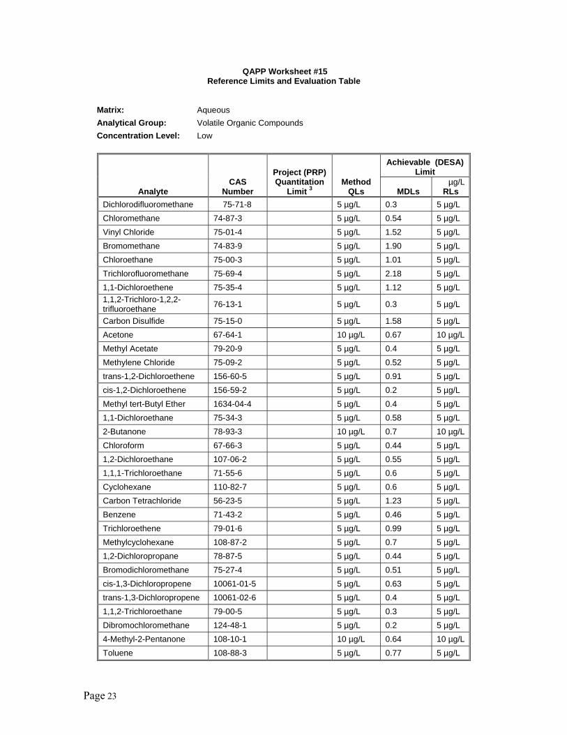
Page 23
QAPP Worksheet #15 Reference Limits and Evaluation Table
Matrix: Aqueous Analytical Group: Volatile Organic Compounds Concentration Level: Low
Analyte CAS
Number
Project (PRP) Quantitation
Limit 3 Method
QLs
Achievable (DESA) Limit
MDLs µg/L
RLs Dichlorodifluoromethane 75-71-8 5 µg/L 0.3 5 µg/L Chloromethane 74-87-3 5 µg/L 0.54 5 µg/L Vinyl Chloride 75-01-4 5 µg/L 1.52 5 µg/L Bromomethane 74-83-9 5 µg/L 1.90 5 µg/L Chloroethane 75-00-3 5 µg/L 1.01 5 µg/L Trichlorofluoromethane 75-69-4 5 µg/L 2.18 5 µg/L 1,1-Dichloroethene 75-35-4 5 µg/L 1.12 5 µg/L 1,1,2-Trichloro-1,2,2-trifluoroethane 76-13-1 5 µg/L 0.3 5 µg/L
Carbon Disulfide 75-15-0 5 µg/L 1.58 5 µg/L Acetone 67-64-1 10 µg/L 0.67 10 µg/LMethyl Acetate 79-20-9 5 µg/L 0.4 5 µg/L Methylene Chloride 75-09-2 5 µg/L 0.52 5 µg/L trans-1,2-Dichloroethene 156-60-5 5 µg/L 0.91 5 µg/L cis-1,2-Dichloroethene 156-59-2 5 µg/L 0.2 5 µg/L Methyl tert-Butyl Ether 1634-04-4 5 µg/L 0.4 5 µg/L 1,1-Dichloroethane 75-34-3 5 µg/L 0.58 5 µg/L 2-Butanone 78-93-3 10 µg/L 0.7 10 µg/LChloroform 67-66-3 5 µg/L 0.44 5 µg/L 1,2-Dichloroethane 107-06-2 5 µg/L 0.55 5 µg/L 1,1,1-Trichloroethane 71-55-6 5 µg/L 0.6 5 µg/L Cyclohexane 110-82-7 5 µg/L 0.6 5 µg/L Carbon Tetrachloride 56-23-5 5 µg/L 1.23 5 µg/L Benzene 71-43-2 5 µg/L 0.46 5 µg/L Trichloroethene 79-01-6 5 µg/L 0.99 5 µg/L Methylcyclohexane 108-87-2 5 µg/L 0.7 5 µg/L 1,2-Dichloropropane 78-87-5 5 µg/L 0.44 5 µg/L Bromodichloromethane 75-27-4 5 µg/L 0.51 5 µg/L cis-1,3-Dichloropropene 10061-01-5 5 µg/L 0.63 5 µg/L trans-1,3-Dichloropropene 10061-02-6 5 µg/L 0.4 5 µg/L 1,1,2-Trichloroethane 79-00-5 5 µg/L 0.3 5 µg/L Dibromochloromethane 124-48-1 5 µg/L 0.2 5 µg/L 4-Methyl-2-Pentanone 108-10-1 10 µg/L 0.64 10 µg/LToluene 108-88-3 5 µg/L 0.77 5 µg/L
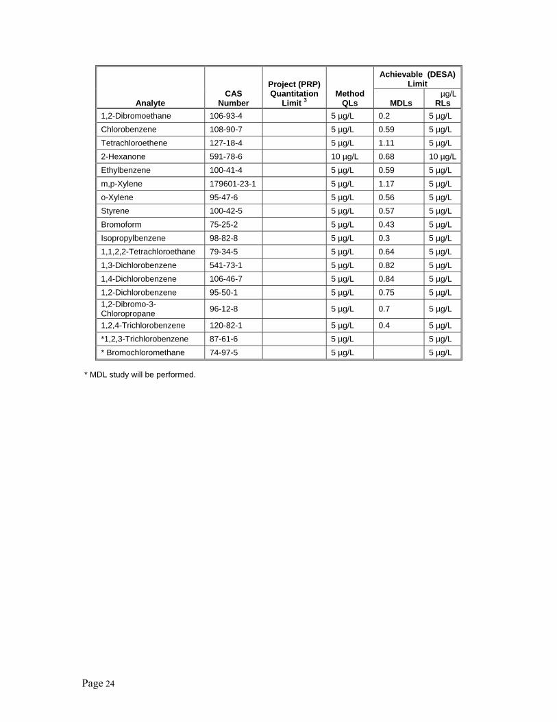
Page 24
Analyte CAS
Number
Project (PRP) Quantitation
Limit 3 Method
QLs
Achievable (DESA) Limit
MDLs µg/L
RLs 1,2-Dibromoethane 106-93-4 5 µg/L 0.2 5 µg/L Chlorobenzene 108-90-7 5 µg/L 0.59 5 µg/L Tetrachloroethene 127-18-4 5 µg/L 1.11 5 µg/L 2-Hexanone 591-78-6 10 µg/L 0.68 10 µg/LEthylbenzene 100-41-4 5 µg/L 0.59 5 µg/L m,p-Xylene 179601-23-1 5 µg/L 1.17 5 µg/L o-Xylene 95-47-6 5 µg/L 0.56 5 µg/L Styrene 100-42-5 5 µg/L 0.57 5 µg/L Bromoform 75-25-2 5 µg/L 0.43 5 µg/L Isopropylbenzene 98-82-8 5 µg/L 0.3 5 µg/L 1,1,2,2-Tetrachloroethane 79-34-5 5 µg/L 0.64 5 µg/L 1,3-Dichlorobenzene 541-73-1 5 µg/L 0.82 5 µg/L 1,4-Dichlorobenzene 106-46-7 5 µg/L 0.84 5 µg/L 1,2-Dichlorobenzene 95-50-1 5 µg/L 0.75 5 µg/L 1,2-Dibromo-3-Chloropropane 96-12-8 5 µg/L 0.7 5 µg/L
1,2,4-Trichlorobenzene 120-82-1 5 µg/L 0.4 5 µg/L *1,2,3-Trichlorobenzene 87-61-6 5 µg/L 5 µg/L * Bromochloromethane 74-97-5 5 µg/L 5 µg/L
* MDL study will be performed.
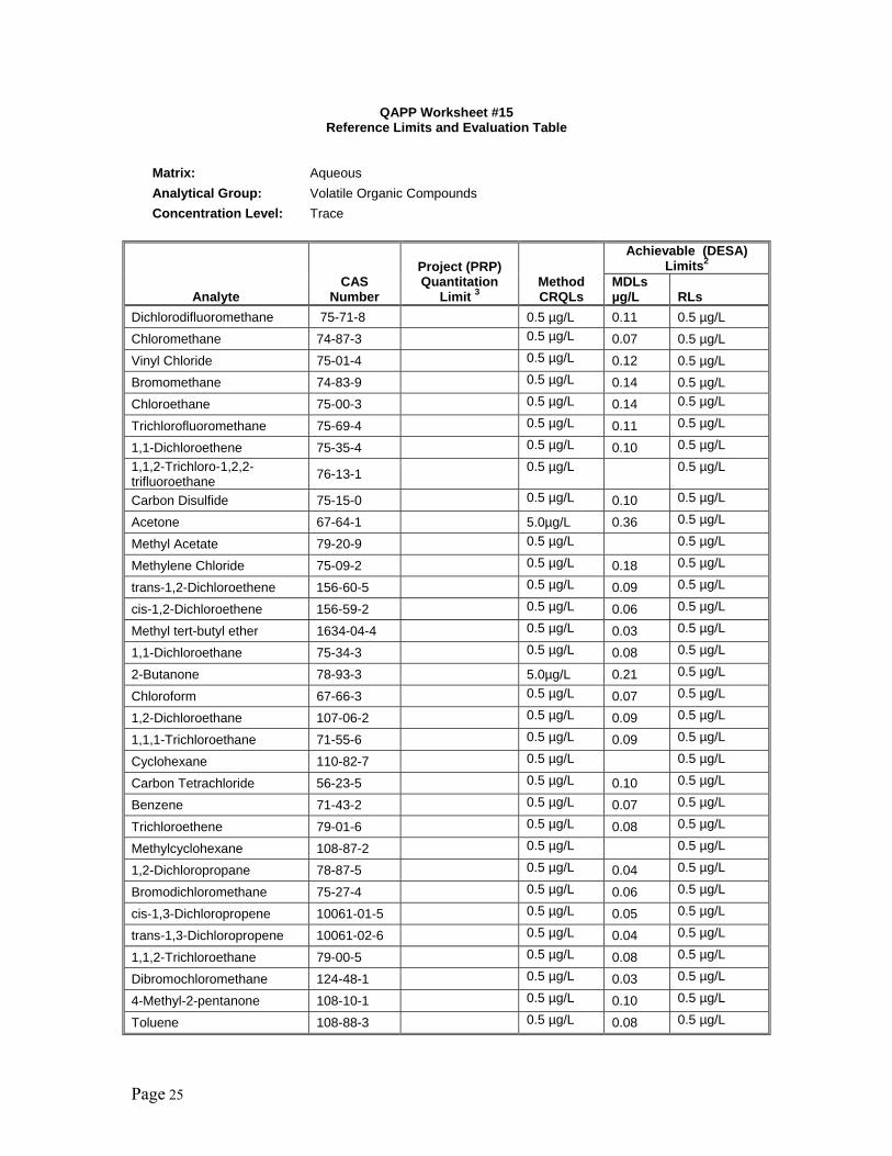
Page 25
QAPP Worksheet #15 Reference Limits and Evaluation Table
Matrix: Aqueous Analytical Group: Volatile Organic Compounds Concentration Level: Trace
Analyte CAS
Number
Project (PRP) Quantitation
Limit 3 Method CRQLs
Achievable (DESA) Limits2
MDLs µg/L RLs
Dichlorodifluoromethane 75-71-8 0.5 µg/L 0.11 0.5 µg/L Chloromethane 74-87-3 0.5 µg/L 0.07 0.5 µg/L Vinyl Chloride 75-01-4 0.5 µg/L 0.12 0.5 µg/L Bromomethane 74-83-9 0.5 µg/L 0.14 0.5 µg/L Chloroethane 75-00-3 0.5 µg/L 0.14 0.5 µg/L
Trichlorofluoromethane 75-69-4 0.5 µg/L 0.11 0.5 µg/L
1,1-Dichloroethene 75-35-4 0.5 µg/L 0.10 0.5 µg/L1,1,2-Trichloro-1,2,2-trifluoroethane 76-13-1 0.5 µg/L 0.5 µg/L
Carbon Disulfide 75-15-0 0.5 µg/L 0.10 0.5 µg/L
Acetone 67-64-1 5.0µg/L 0.36 0.5 µg/L
Methyl Acetate 79-20-9 0.5 µg/L 0.5 µg/L
Methylene Chloride 75-09-2 0.5 µg/L 0.18 0.5 µg/L
trans-1,2-Dichloroethene 156-60-5 0.5 µg/L 0.09 0.5 µg/L
cis-1,2-Dichloroethene 156-59-2 0.5 µg/L 0.06 0.5 µg/L
Methyl tert-butyl ether 1634-04-4 0.5 µg/L 0.03 0.5 µg/L
1,1-Dichloroethane 75-34-3 0.5 µg/L 0.08 0.5 µg/L
2-Butanone 78-93-3 5.0µg/L 0.21 0.5 µg/L
Chloroform 67-66-3 0.5 µg/L 0.07 0.5 µg/L
1,2-Dichloroethane 107-06-2 0.5 µg/L 0.09 0.5 µg/L
1,1,1-Trichloroethane 71-55-6 0.5 µg/L 0.09 0.5 µg/L
Cyclohexane 110-82-7 0.5 µg/L 0.5 µg/L
Carbon Tetrachloride 56-23-5 0.5 µg/L 0.10 0.5 µg/L
Benzene 71-43-2 0.5 µg/L 0.07 0.5 µg/L
Trichloroethene 79-01-6 0.5 µg/L 0.08 0.5 µg/L
Methylcyclohexane 108-87-2 0.5 µg/L 0.5 µg/L
1,2-Dichloropropane 78-87-5 0.5 µg/L 0.04 0.5 µg/L
Bromodichloromethane 75-27-4 0.5 µg/L 0.06 0.5 µg/L
cis-1,3-Dichloropropene 10061-01-5 0.5 µg/L 0.05 0.5 µg/L
trans-1,3-Dichloropropene 10061-02-6 0.5 µg/L 0.04 0.5 µg/L
1,1,2-Trichloroethane 79-00-5 0.5 µg/L 0.08 0.5 µg/L
Dibromochloromethane 124-48-1 0.5 µg/L 0.03 0.5 µg/L
4-Methyl-2-pentanone 108-10-1 0.5 µg/L 0.10 0.5 µg/L
Toluene 108-88-3 0.5 µg/L 0.08 0.5 µg/L
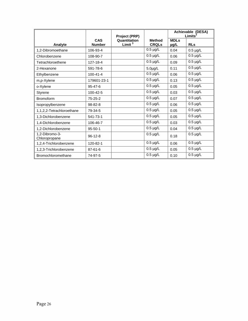
Page 26
Analyte CAS
Number
Project (PRP) Quantitation
Limit 3 Method CRQLs
Achievable (DESA) Limits2
MDLs µg/L RLs
1,2-Dibromoethane 106-93-4 0.5 µg/L 0.04 0.5 µg/L Chlorobenzene 108-90-7 0.5 µg/L 0.06 0.5 µg/L
Tetrachloroethene 127-18-4 0.5 µg/L 0.09 0.5 µg/L
2-Hexanone 591-78-6 5.0µg/L 0.11 0.5 µg/L
Ethylbenzene 100-41-4 0.5 µg/L 0.06 0.5 µg/L
m,p-Xylene 179601-23-1 0.5 µg/L 0.13 0.5 µg/L
o-Xylene 95-47-6 0.5 µg/L 0.05 0.5 µg/L
Styrene 100-42-5 0.5 µg/L 0.03 0.5 µg/L
Bromoform 75-25-2 0.5 µg/L 0.07 0.5 µg/L
Isopropylbenzene 98-82-8 0.5 µg/L 0.06 0.5 µg/L
1,1,2,2-Tetrachloroethane 79-34-5 0.5 µg/L 0.05 0.5 µg/L
1,3-Dichlorobenzene 541-73-1 0.5 µg/L 0.05 0.5 µg/L
1,4-Dichlorobenzene 106-46-7 0.5 µg/L 0.03 0.5 µg/L
1,2-Dichlorobenzene 95-50-1 0.5 µg/L 0.04 0.5 µg/L1,2-Dibromo-3-Chloropropane 96-12-8 0.5 µg/L 0.18 0.5 µg/L
1,2,4-Trichlorobenzene 120-82-1 0.5 µg/L 0.06 0.5 µg/L
1,2,3-Trichlorobenzene 87-61-6 0.5 µg/L 0.05 0.5 µg/L
Bromochloromethane 74-97-5 0.5 µg/L 0.10 0.5 µg/L

Page 27
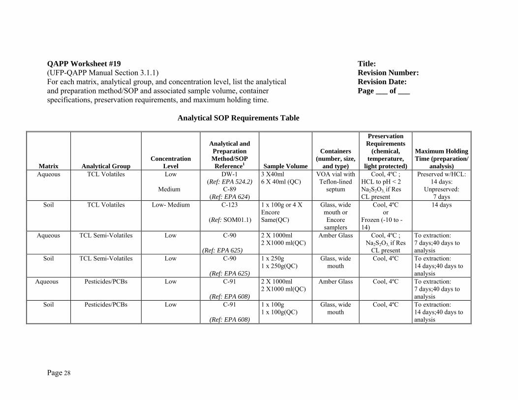
Page 28
QAPP Worksheet #19 Title: (UFP-QAPP Manual Section 3.1.1) Revision Number: For each matrix, analytical group, and concentration level, list the analytical Revision Date: and preparation method/SOP and associated sample volume, container Page ___ of ___ specifications, preservation requirements, and maximum holding time.
Analytical SOP Requirements Table
Matrix Analytical Group Concentration
Level
Analytical and Preparation Method/SOP Reference1 Sample Volume
Containers (number, size,
and type)
Preservation Requirements
(chemical, temperature,
light protected)
Maximum Holding Time (preparation/
analysis)Aqueous
TCL Volatiles Low
Medium
DW-1 (Ref: EPA 524.2)
C-89 (Ref: EPA 624)
3 X40ml 6 X 40ml (QC)
VOA vial with Teflon-lined
septum
Cool, 4ºC ; HCL to pH < 2 Na2S2O3, if Res CL present
Preserved w/HCL: 14 days:
Unpreserved: 7 days
Soil
TCL Volatiles Low- Medium C-123
(Ref: SOM01.1)
1 x 100g or 4 X Encore Same(QC)
Glass, wide mouth or Encore
samplers
Cool, 4ºC or
Frozen (-10 to -14)
14 days
Aqueous
TCL Semi-Volatiles Low
C-90
(Ref: EPA 625)
2 X 1000ml 2 X1000 ml(QC)
Amber Glass Cool, 4ºC ; Na2S2O3, if Res
CL present
To extraction: 7 days;40 days to analysis
Soil
TCL Semi-Volatiles Low
C-90
(Ref: EPA 625)
1 x 250g 1 x 250g(QC)
Glass, wide mouth
Cool, 4ºC To extraction: 14 days;40 days to analysis
Aqueous
Pesticides/PCBs Low
C-91
(Ref: EPA 608)
2 X 1000ml 2 X1000 ml(QC)
Amber Glass Cool, 4ºC To extraction: 7 days;40 days to analysis
Soil
Pesticides/PCBs Low
C-91
(Ref: EPA 608)
1 x 100g 1 x 100g(QC)
Glass, wide mouth
Cool, 4ºC To extraction: 14 days;40 days to analysis
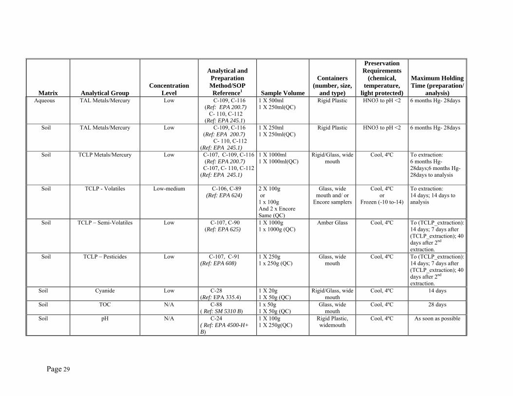
Page 29
Matrix Analytical Group Concentration
Level
Analytical and Preparation Method/SOP Reference1 Sample Volume
Containers (number, size,
and type)
Preservation Requirements
(chemical, temperature,
light protected)
Maximum Holding Time (preparation/
analysis) Aqueous
TAL Metals/Mercury Low C-109, C-116
(Ref: EPA 200.7) C- 110, C-112 (Ref: EPA 245.1)
1 X 500ml 1 X 250ml(QC)
Rigid Plastic HNO3 to pH <2 6 months Hg- 28days
Soil TAL Metals/Mercury Low C-109, C-116 (Ref: EPA 200.7) C- 110, C-112 (Ref: EPA 245.1)
1 X 250ml 1 X 250ml(QC)
Rigid Plastic HNO3 to pH <2 6 months Hg- 28days
Soil
TCLP Metals/Mercury Low C-107, C-109, C-116 (Ref: EPA 200.7) C-107, C- 110, C-112(Ref: EPA 245.1)
1 X 1000ml 1 X 1000ml(QC)
Rigid/Glass, wide mouth
Cool, 4ºC To extraction: 6 months Hg- 28days;6 months Hg- 28days to analysis
Soil
TCLP - Volatiles Low-medium C-106, C-89 (Ref: EPA 624)
2 X 100g or 1 x 100g And 2 x Encore Same (QC)
Glass, wide mouth and/ or
Encore samplers
Cool, 4ºC or
Frozen (-10 to-14)
To extraction: 14 days; 14 days to analysis
Soil
TCLP – Semi-Volatiles Low C-107, C-90 (Ref: EPA 625)
1 X 1000g 1 x 1000g (QC)
Amber Glass Cool, 4ºC To (TCLP_extraction):14 days; 7 days after (TCLP_extraction); 40 days after 2nd extraction.
Soil
TCLP – Pesticides Low C-107, C-91 (Ref: EPA 608)
1 X 250g 1 x 250g (QC)
Glass, wide mouth
Cool, 4ºC To (TCLP_extraction):14 days; 7 days after (TCLP_extraction); 40 days after 2nd extraction.
Soil
Cyanide Low C-28 (Ref: EPA 335.4)
1 X 20g 1 X 50g (QC)
Rigid/Glass, wide mouth
Cool, 4ºC 14 days
Soil
TOC N/A C-88 ( Ref: SM 5310 B)
1 x 50g 1 X 50g (QC)
Glass, wide mouth
Cool, 4ºC 28 days
Soil
pH N/A C-24 ( Ref: EPA 4500-H+ B)
1 X 100g 1 X 250g(QC)
Rigid Plastic, widemouth
Cool, 4ºC As soon as possible
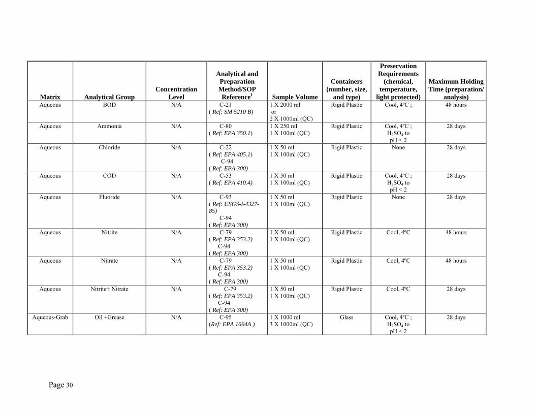
Page 30
Matrix Analytical Group Concentration
Level
Analytical and Preparation Method/SOP Reference1 Sample Volume
Containers (number, size,
and type)
Preservation Requirements
(chemical, temperature,
light protected)
Maximum Holding Time (preparation/
analysis)Aqueous
BOD
N/A C-21
( Ref: SM 5210 B) 1 X 2000 ml or 2 X 1000ml (QC)
Rigid Plastic Cool, 4ºC ;
48 hours
Aqueous
Ammonia
N/A C-80 ( Ref: EPA 350.1)
1 X 250 ml 1 X 100ml (QC)
Rigid Plastic Cool, 4ºC ; H2SO4 to pH < 2
28 days
Aqueous
Chloride
N/A C-22 ( Ref: EPA 405.1) C-94 ( Ref: EPA 300)
1 X 50 ml 1 X 100ml (QC)
Rigid Plastic None 28 days
Aqueous
COD
N/A C-53 ( Ref: EPA 410.4)
1 X 50 ml 1 X 100ml (QC)
Rigid Plastic Cool, 4ºC ; H2SO4 to pH < 2
28 days
Aqueous
Fluoride
N/A C-93 ( Ref: USGS-I-4327-85) C-94 ( Ref: EPA 300)
1 X 50 ml 1 X 100ml (QC)
Rigid Plastic None 28 days
Aqueous
Nitrite
N/A C-79 ( Ref: EPA 353.2) C-94 ( Ref: EPA 300)
1 X 50 ml 1 X 100ml (QC)
Rigid Plastic Cool, 4ºC
48 hours
Aqueous
Nitrate
N/A C-79 ( Ref: EPA 353.2) C-94 ( Ref: EPA 300)
1 X 50 ml 1 X 100ml (QC)
Rigid Plastic Cool, 4ºC
48 hours
Aqueous
Nitrite+ Nitrate
N/A C-79 ( Ref: EPA 353.2) C-94 ( Ref: EPA 300)
1 X 50 ml 1 X 100ml (QC)
Rigid Plastic Cool, 4ºC
28 days
Aqueous-Grab
Oil +Grease
N/A C-95 (Ref: EPA 1664A )
1 X 1000 ml 3 X 1000ml (QC)
Glass Cool, 4ºC ; H2SO4 to pH < 2
28 days
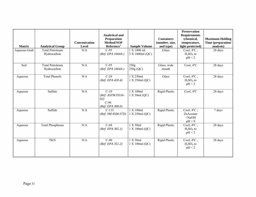
Page 31
Matrix Analytical Group Concentration
Level
Analytical and Preparation Method/SOP Reference1 Sample Volume
Containers (number, size,
and type)
Preservation Requirements
(chemical, temperature,
light protected)
Maximum Holding Time (preparation/
analysis)Aqueous-Grab
Total Petroleum Hydrocarbon
N/A C-95 (Ref: EPA 1664A )
1 X 1000 ml 3 X 1000ml (QC)
Glass Cool, 4ºC ; H2SO4 to pH < 2
28 days
Soil
Total Petroleum Hydrocarbon
N/A C-95 (Ref: EPA 1664A )
250g 250g (QC)
Glass, wide mouth
Cool, 4ºC
28 days
Aqueous
Total Phenols N/A C-29 (Ref: EPA 420.4)
1 X 250ml 1 X 250ml (QC)
Glass Cool, 4ºC ; H2SO4 to pH < 2
28 days
Aqueous
Sulfate N/A C-19 (Ref: ASTM D516-02) C-94 (Ref: EPA 300.0)
1 X 100ml 1 X 50ml (QC)
Rigid Plastic Cool, 4ºC
28 days
Aqueous
Sulfide N/A C-115 (Ref: SM 4500-S2D)
1 X 100ml 1 X 250ml (QC)
Rigid Plastic Cool, 4ºC ; ZnAcetate +NaOH pH > 9
7 days
Aqueous
Total Phosphorus N/A C-68 (Ref: EPA 365.1)
1 X 50ml 1 X 100ml (QC)
Rigid Plastic Cool, 4ºC ; H2SO4 to pH < 2
28 days
Aqueous
TKN N/A C-40 (Ref: EPA 351.2)
1 X 50ml 1 X 100ml (QC)
Rigid Plastic Cool, 4ºC ; H2SO4 to pH < 2
28 days
Page 32
Matrix Analytical Group Concentration
Level
Analytical and Preparation Method/SOP Reference1 Sample Volume
Containers (number, size,
and type)
Preservation Requirements
(chemical, temperature,
light protected)
Maximum Holding Time (preparation/
analysis) Aqueous
Turbidity N/A C-81 (Ref: EPA 351.2)
1 X 100ml 1 X 250ml (QC)
Rigid Plastic Cool, 4ºC
48 hours
Aqueous
Total Suspended Solids(TSS)/Volatile Suspended Solids(VSS)
N/A C-33 (Ref: SM 2540 D)
1 X 250ml 1 X 500ml (QC)
Rigid Plastic Cool, 4ºC
7 days
Aqueous
Total Dissolved Solids (TDS)
N/A C-37 (Ref: SM 2540 C)
1 X 250ml 1 X 500ml (QC)
Rigid Plastic Cool, 4ºC
7 days
Aqueous
Total Organic Carbon (TOC)
N/A C-83 (Ref: SM 5310 B)
1 X 50ml 1 X 100ml (QC)
Rigid Plastic Cool, 4ºC
28 days
NAPL
Ignitability N/A C-23 (Ref: SW846 Method 1010 )
1 X 250ml 1 X 250ml (QC)
Glass, wide mouth
or Metal Can
None
None
Aqueous
Specific Conductance N/A C-36 (Ref: EPA 120.1)
1 X 100ml 1 X 250ml (QC)
Rigid Plastic Cool, 4ºC
28 days
Aqueous
Hexavalent Chromium N/A C-96 (Ref: USGS-I-1230-85)
1 X 250ml 1 X 500ml (QC)
Rigid Plastic Cool, 4ºC/
Cool, 4ºC pH= 9.3-9.7 Ammonium Sulfate Buffer solution
24 hours/ 28 days
Page 33
Matrix Analytical Group Concentration
Level
Analytical and Preparation Method/SOP Reference1 Sample Volume
Containers (number, size,
and type)
Preservation Requirements
(chemical, temperature,
light protected)
Maximum Holding Time (preparation/
analysis) Aqueous
Alkalinity N/A C-18 (Ref: SM 2320 B)
1 X 100ml 1 X 250ml (QC)
Rigid Plastic Cool, 4ºC
14 days
Aqueous
Total Coliform/ Fecal Coliform
N/A B-6/B-8 (Ref: SM 9221B/9221E)
1 X 150ml 1 X 150ml (QC)
Rigid Plastic, wide mouth Cool, 4ºC ;
Na2S2O3, if Res CL present
6 hours
Sewage Sludge
Total Coliform /Fecal Coliform
N/A B-6/B-8 (Ref: SM 9221B/9221E) B-5/B-7 (Ref: SM 9222B/9222E) Colilert-18 (Ref: SM9223B)
1 X 250g 1 X 250g (QC)
Rigid Plastic, wide mouth Cool, 4ºC
24 hours
Aqueous
Heterotrophic Plate Count
N/A B-32 (Ref: EPA 9215B) B-38 (Ref: Simplate IDEX)
1X125 ml Rigid Plastic, wide mouth
Cool, 4ºC ; Na2S2O3, if Res
CL present
8 hours
Soil/Sediment
Grain (Particle) Size N/A Bio 8.3 Ref: ASTM D422-63)
1 X 16oz/500g/500ml 1 X 16oz/500g/500ml (QC)
Rigid Plastic/ Glass wide mouth
Cool, 4ºC
None
1Specify the appropriate reference letter or number from the Analytical SOP References table (Worksheet #23).
Page 34
QAPP Worksheet #23 Title: (UFP-QAPP Manual Section 3.2.1) Revision Number: Analytical SOP References Table
Reference Number
Title, Revision Date, and/or Number
Definitive or Screening Data Analytical Group Instrument
Organization Performing Analysis
Modified for Project Work? (Y/N)
Bio 8.3 Grain (Particle)Size, Rev 2.0, 3/07
Definite Grain (Particle)Size
Soil Hydrometer DESA N
B-5/B-7 Total Coliform/ Fecal Coliform, Rev 2.0, 2/07
Definite Total Coliform/ Fecal Coliform
N/A DESA N
B-6/B-8 Total Coliform/ Fecal Coliform, Rev 2.0, 2/07
Definite Total Coliform/ Fecal Coliform
N/A DESA N
C-18 Alkalinity, , Rev 2.0, 3/07
Definite Alkalinity Auto Titrator System DESA N
C-19, C-94 Sulfate, Rev 2.0, 3//07, Anions by Ion Chromatography, Rev 2.0, 3/07
Definite Sulfate Spectrophotometer, AutoAnalyzer, IC
DESA N
C-21
BOD/CBOD, Rev 2.0, 3/07
Definite BOD DO meter DESA N
C-22, C-94 Chloride, Rev 2.0, 3//07, Anions by Ion Chromatography, Rev 2.0, 3/07
Definite Chloride
Titration unit, AutoAnalyzer,, IC
DESA N
C-23 Ignitability, Rev 1.0, 1/06
Definite Ignitability Auto flash Point Test Instrument
DESA N
C-24
pH, Rev 2.0, 3/07
Definite pH pH meter DESA N
C-28
Cyanides, Total, Rev 2.0, 3/07
Definite Cyanide AutoAnalyzer DESA N
Page 35
Reference Number
Title, Revision Date, and/or Number
Definitive or Screening Data Analytical Group Instrument
Organization Performing Analysis
Modified for Project Work? (Y/N)
C-29 Total Phenols, Rev 2.0, 3/07
Definite Total Phenols AutoAnalyzer DESA N
C-33 Total Suspended Solids(TSS)/Volatile Suspended Solids(VSS), Rev 2.0, 2/07
Definite Total Dissolved Solids (TDS)
N/A DESA N
C-36 Specific Conductance, Rev 2.0, 3/07
Definite Specific Conductance
Conductivity Meter DESA N
C-37 Total Dissolved Solids (TDS) , Rev 2.0, 2/07
Definite Total Dissolved Solids (TDS)
N/A DESA N
C-40 TKN, Rev 2.0, 2/07
Definite TKN AutoAnalyzer DESA N
C-53 COD, Rev 2.0, 3/07
Definite COD
COD Reactor, Spectrophotometer
DESA N
C-68 Total Phosphorus, Rev 2.0, 12/06
Definite Total Phosphorus AutoAnalyzer DESA N
C-79, C-94 Nitrite, Nitrate, Nitrite+ Nitrate Rev 2.0, 2//07, Anions by Ion Chromatography, Rev 2.0, 12/06
Definite Nitrite
AutoAnalyzer, IC DESA N
C-80
Ammonia, Rev 2.0, 12/06
Definite Ammonia AutoAnalyzer DESA N
C-81 Turbidity, Rev 2.0, 3/07
Definite Turbidity Turbidimeter DESA N
Page 36
Reference Number
Title, Revision Date, and/or Number
Definitive or Screening Data Analytical Group Instrument
Organization Performing Analysis
Modified for Project Work? (Y/N)
C-83
Total Organics in Aqueous, Rev 2.0, 3/07
Definite Total Organics Carbon
TOC analyzer DESA N
C-88
Total Organics in Soil, Rev 1.0, 1/05
Definite Total Organics Carbon
TOC analyzer DESA N
C-89
Analysis of Volatile Organic Compounds in Aqueous, Soil/Sediment and Waste Oil/Waste Organic Solvents Samples by Purge and Trap GC/MS, Rev 2.0, 3/07
Definite TCL Volatiles( Aqueous)
GC-MS DESA L N
C-123 Analysis of Volatile Organic Compounds by Automated Closed System by Purge and Trap GC/MS, Rev 2.0, 3/07
Definite TCL Volatiles(Low Soil)
GC-MS DESA Laboratory N
DW-1
Volatile Organics in Drinking Water by Purge and Trap by GC/MS, Rev 2.0, 3/07
Definite TCL Volatiles (Trace)
GC-MS DESA Laboratory N
C-90
Analysis of Base/Neutral and Acid Compounds in Aqueous, Soil/Sediment and Waste Oil/Waste Organic Solvent Samples, Rev 2.0, 3/07
Definite TCL Semi-Volatiles
GC-MS DESA Laboratory N
C-91
Analysis of Pesticides and PCBs in Aqueous, Soil/Sediments and Waste Oil/Transformer Fluid Matrices, Rev 2.0, 3/07
Definite Pesticides/ PCBs
GC-ECD DESA Laboratory N
Page 37
Reference Number
Title, Revision Date, and/or Number
Definitive or Screening Data Analytical Group Instrument
Organization Performing Analysis
Modified for Project Work? (Y/N)
C-93, C-94 Fluoride, Rev 1.0, 1/05, Anions by Ion Chromatography, Rev 2.0, 12/06
Definite Fluoride
AutoAnalyzer, Ion Selective Electrode, IC
DESA Laboratory N
C-95 Oil +Grease, Total Petroleum Hydrocarbon Gravimetric, SPE, Rev 2.0, 03/07
Definite Oil +Grease
SPE apparatus DESA Laboratory N
C-96 Hexavalent Chromium, Rev 2.0, 3/07
Definite Hexavalent Chromium
Spectrophotometer DESA Laboratory N
C-109 Determination of Trace Elements in Aqueous Trace Metals in Aqueous, Soil/Sediment/Sludge- ICP-AES, Rev 2.0, 3/07
Definite TAL Metals ICP-AES DESA Laboratory N
C-110 Mercury Analysis in Water and Soil/Sediments By CVAAS, Rev 2.0, 3/07
Definite Mercury CVAA DESA Laboratory N
C-112 Trace Metals in Aqueous, Soil/Sediment/Sludge, Waste Oil/Organic Solvent and Biological tissue by Inductively Coupled Plasma-Mass Spectrometry, Rev 2.0, 3/07
Definite TAL Metals ICP-MS DESA Laboratory N
C-115 Sulfide, Rev 1.0, 3/07
Definite Sulfide Spectrophotometer DESA Laboratory N
Page 38
QAPP Worksheet #24 Title: (UFP-QAPP Manual Section 3.2.2) Revision Number: Identify all analytical instrumentation that requires calibration and provide Revision Date: the SOP reference number for each. In addition, document the frequency, Page ___ of ___ acceptance criteria, and corrective action requirements on the worksheet.
Analytical Instrument Calibration Table
Instrument Calibration Procedure
Frequency of Calibration Acceptance Criteria
Corrective Action (CA)
Person Responsible for CA SOP Reference1
ICP-AES See SOP C-109 See SOP C-109 See SOP C-109 See SOP C-109 Assigned Laboratory personnel SOP C-109
ICP-MS See SOP C-112 See SOP C-112 See SOP C-112 See SOP C-112 Assigned Laboratory
personnel SOP C-112
CVAAS See SOP C-110 See SOP C-110 See SOP C-110 See SOP C-110 Assigned Laboratory personnel SOP C-110
IC
See SOP C-94 See SOP C-94 See SOP C-94 See SOP C-94 Assigned Laboratory personnel SOP C-94
Spectrophotometer See SOP C-96 See SOP C-96 See SOP C-96 See SOP C-96 Assigned Laboratory personnel SOP C-96
Colorimetric/AutoAnalyzer See SOP C-28 Per manufacture’s manual
See SOP C-28 See SOP C-28 See SOP C-28 Assigned Laboratory personnel SOP C-28
GC-ECD
See SOP C-91 See SOP C-91
See SOP C-91 See SOP C-91 Assigned Laboratory personnel SOP C-91
GC-MS See SOP C- 90, C-89 See SOP C- 90, C-89 See SOP C- 90, C-89 See SOP C- 90, C-89 Assigned Laboratory
personnel SOP C- 90, C-89
TOC Analyzer
See SOP C-88, Per manufacture’s manual
See SOP C-88
See SOP C-88
See SOP C-88
Assigned Laboratory personnel
SOP C-88
pH Electrode
See SOP C-24 See SOP C-24 See SOP C-24 See SOP C-24 Assigned Laboratory personnel SOP C-24
1Specify the appropriate reference letter or number from the Analytical SOP References table (Worksheet #23). Details can be found in Equipment Calibration# SOP C-19
Page 39
QAPP Worksheet #25 Title: (UFP-QAPP Manual Section 3.2.3) Revision Number: Identify all analytical instrumentation that requires maintenance, testing, or inspection Revision Date: and provide the SOP reference number for each. In addition, document the Page ___ of ___ frequency, acceptance criteria, and corrective action requirements on the worksheet.
Analytical Instrument and Equipment Maintenance, Testing, and Inspection Table
Instrument/ Equipment Maintenance
Activity Testing ActivityInspection
Activity FrequencyAcceptance
Criteria Corrective
ActionResponsible
Person SOP Reference1
See list of Instrument given in
Worksheet #24
See LQMP, G-10, G-11, G-12, G-19
See LQMP, G-10, G-11, G-12, G-19
See LQMP, G-10, G-11, G-12, G-19
See LQMP, G-10, G-11, G-12, G-19
See LQMP, G-10, G-11, G-12, G-19
See LQMP, G-10, G-11, G-12, G-19
See LQMP, G-10, G-11, G-12, G-19
See LQMP, G-10, G-11, G-12, G-19
1Specify the appropriate reference letter or number from the Analytical SOP References table (Worksheet #23).
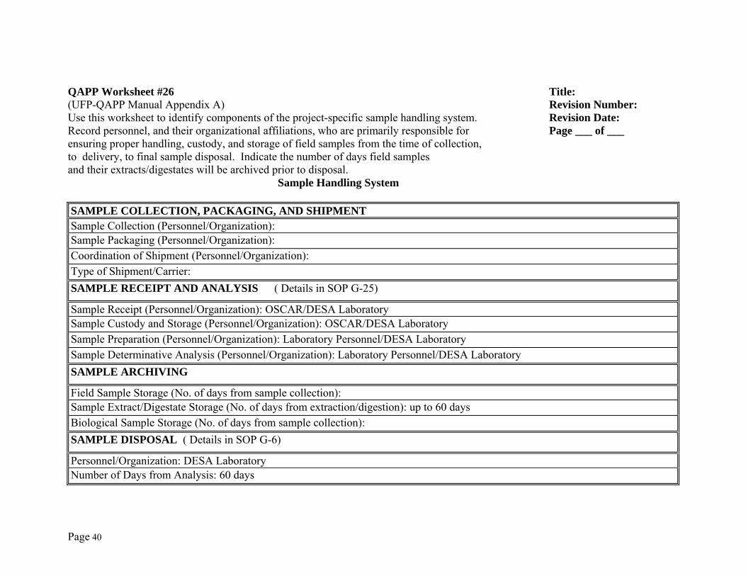
Page 40
QAPP Worksheet #26 Title: (UFP-QAPP Manual Appendix A) Revision Number: Use this worksheet to identify components of the project-specific sample handling system. Revision Date: Record personnel, and their organizational affiliations, who are primarily responsible for Page ___ of ___ ensuring proper handling, custody, and storage of field samples from the time of collection, to delivery, to final sample disposal. Indicate the number of days field samples and their extracts/digestates will be archived prior to disposal. Sample Handling System
SAMPLE COLLECTION, PACKAGING, AND SHIPMENTSample Collection (Personnel/Organization): Sample Packaging (Personnel/Organization): Coordination of Shipment (Personnel/Organization): Type of Shipment/Carrier: SAMPLE RECEIPT AND ANALYSIS ( Details in SOP G-25)
Sample Receipt (Personnel/Organization): OSCAR/DESA Laboratory Sample Custody and Storage (Personnel/Organization): OSCAR/DESA Laboratory Sample Preparation (Personnel/Organization): Laboratory Personnel/DESA Laboratory Sample Determinative Analysis (Personnel/Organization): Laboratory Personnel/DESA Laboratory SAMPLE ARCHIVING
Field Sample Storage (No. of days from sample collection): Sample Extract/Digestate Storage (No. of days from extraction/digestion): up to 60 days Biological Sample Storage (No. of days from sample collection): SAMPLE DISPOSAL ( Details in SOP G-6)
Personnel/Organization: DESA Laboratory Number of Days from Analysis: 60 days
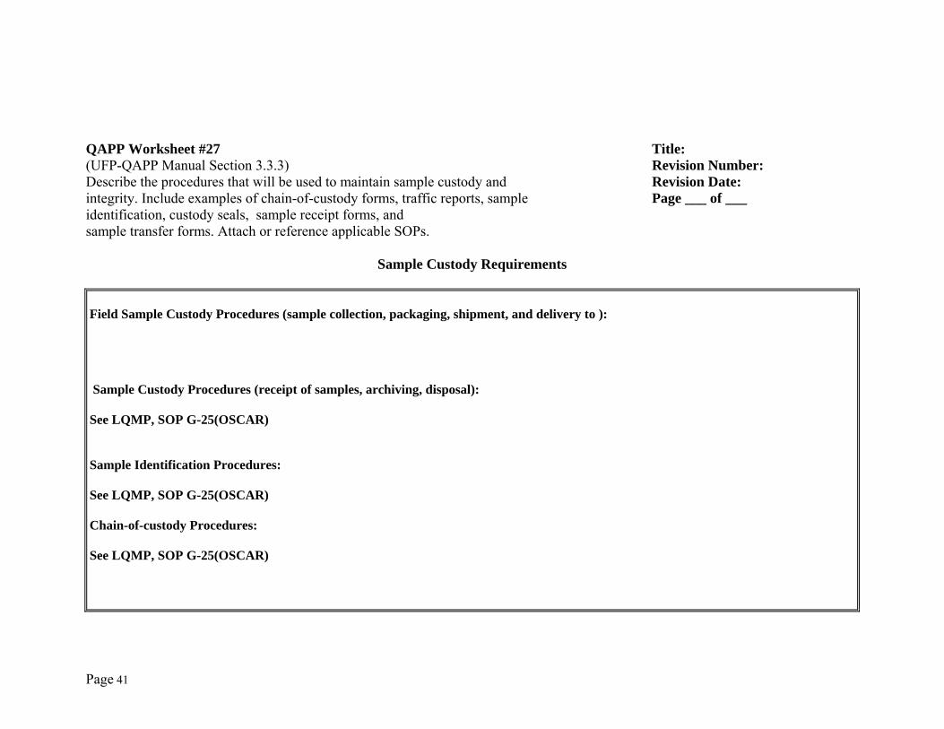
Page 41
QAPP Worksheet #27 Title: (UFP-QAPP Manual Section 3.3.3) Revision Number: Describe the procedures that will be used to maintain sample custody and Revision Date: integrity. Include examples of chain-of-custody forms, traffic reports, sample Page ___ of ___ identification, custody seals, sample receipt forms, and sample transfer forms. Attach or reference applicable SOPs.
Sample Custody Requirements
Field Sample Custody Procedures (sample collection, packaging, shipment, and delivery to ): Sample Custody Procedures (receipt of samples, archiving, disposal): See LQMP, SOP G-25(OSCAR) Sample Identification Procedures: See LQMP, SOP G-25(OSCAR) Chain-of-custody Procedures: See LQMP, SOP G-25(OSCAR)
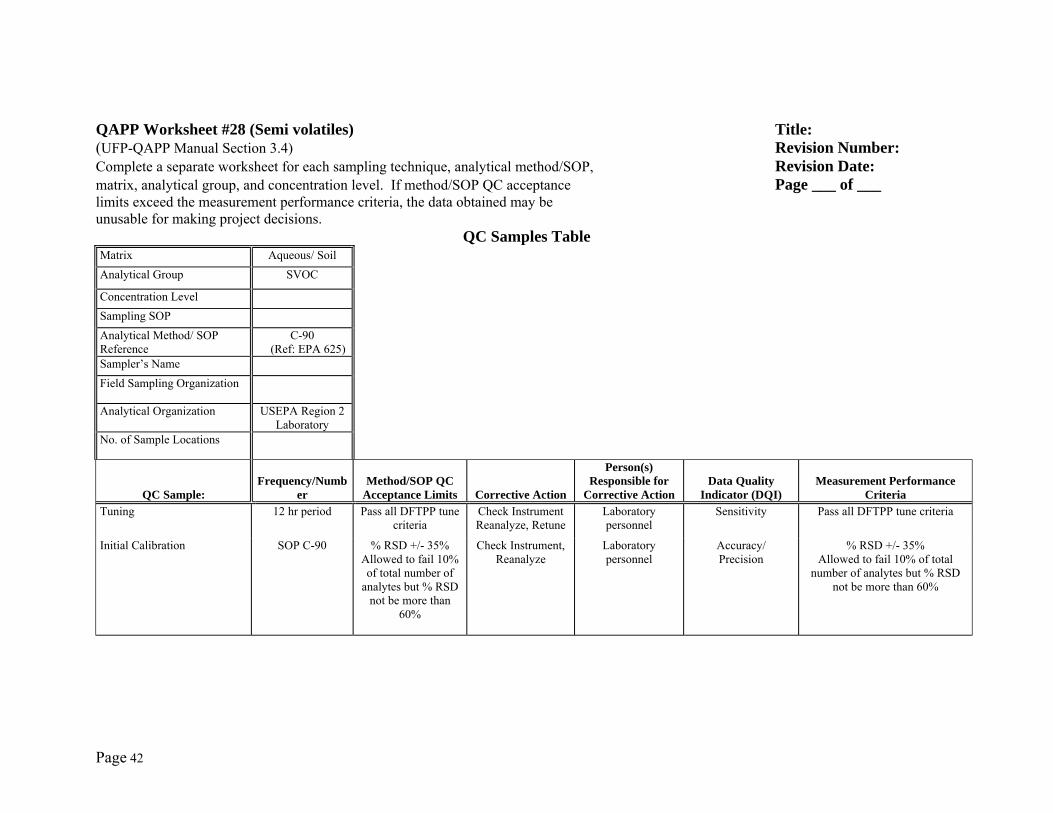
Page 42
QAPP Worksheet #28 (Semi volatiles) Title: (UFP-QAPP Manual Section 3.4) Revision Number: Complete a separate worksheet for each sampling technique, analytical method/SOP, Revision Date: matrix, analytical group, and concentration level. If method/SOP QC acceptance Page ___ of ___ limits exceed the measurement performance criteria, the data obtained may be unusable for making project decisions.
QC Samples Table Matrix Aqueous/ Soil Analytical Group SVOC Concentration Level Sampling SOP Analytical Method/ SOP Reference
C-90 (Ref: EPA 625)
Sampler’s Name Field Sampling Organization Analytical Organization USEPA Region 2
Laboratory
No. of Sample Locations
QC Sample: Frequency/Numb
er Method/SOP QC
Acceptance Limits Corrective Action
Person(s) Responsible for
Corrective ActionData Quality
Indicator (DQI)Measurement Performance
CriteriaTuning 12 hr period Pass all DFTPP tune
criteria Check Instrument Reanalyze, Retune
Laboratory personnel
Sensitivity
Pass all DFTPP tune criteria
Initial Calibration SOP C-90 % RSD +/- 35% Allowed to fail 10% of total number of
analytes but % RSD not be more than
60%
Check Instrument, Reanalyze
Laboratory personnel
Accuracy/ Precision
% RSD +/- 35% Allowed to fail 10% of total
number of analytes but % RSD not be more than 60%
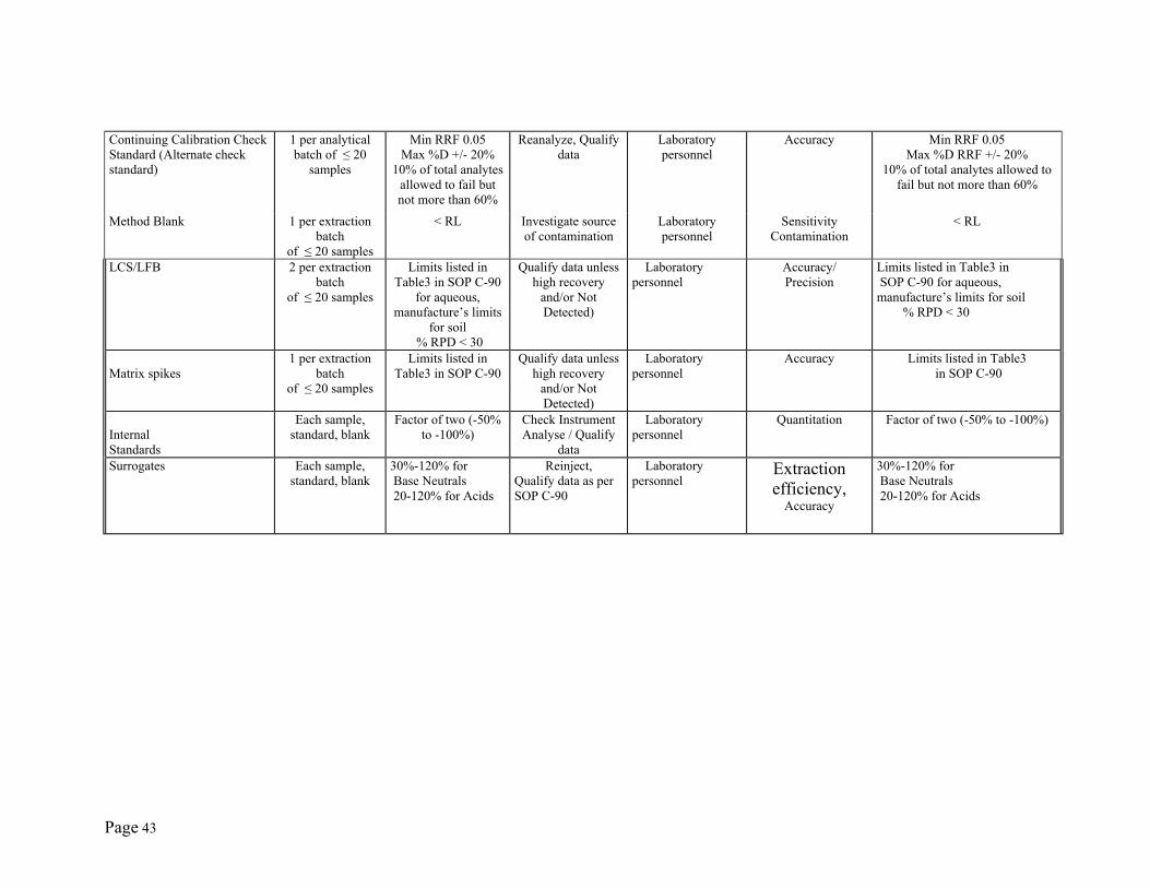
Page 43
Continuing Calibration Check Standard (Alternate check standard)
1 per analytical batch of ≤ 20
samples
Min RRF 0.05 Max %D +/- 20%
10% of total analytes allowed to fail but not more than 60%
Reanalyze, Qualify data
Laboratory personnel
Accuracy
Min RRF 0.05 Max %D RRF +/- 20%
10% of total analytes allowed to fail but not more than 60%
Method Blank 1 per extraction batch
of ≤ 20 samples
< RL Investigate source of contamination
Laboratory personnel
Sensitivity Contamination
< RL
LCS/LFB 2 per extraction batch
of ≤ 20 samples
Limits listed in Table3 in SOP C-90
for aqueous, manufacture’s limits
for soil % RPD < 30
Qualify data unless high recovery
and/or Not Detected)
Laboratory personnel
Accuracy/ Precision
Limits listed in Table3 in SOP C-90 for aqueous, manufacture’s limits for soil % RPD < 30
Matrix spikes
1 per extraction batch
of ≤ 20 samples
Limits listed in Table3 in SOP C-90
Qualify data unless high recovery
and/or Not Detected)
Laboratory personnel
Accuracy
Limits listed in Table3 in SOP C-90
Internal Standards
Each sample, standard, blank
Factor of two (-50% to -100%)
Check Instrument Analyse / Qualify
data
Laboratory personnel
Quantitation Factor of two (-50% to -100%)
Surrogates Each sample, standard, blank
30%-120% for Base Neutrals 20-120% for Acids
Reinject, Qualify data as per SOP C-90
Laboratory personnel
Extraction efficiency,
Accuracy
30%-120% for Base Neutrals 20-120% for Acids
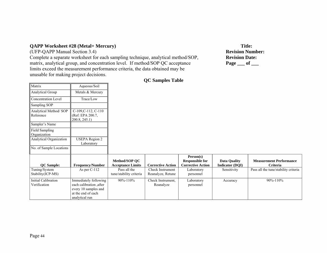
Page 44
QAPP Worksheet #28 (Metal+ Mercury) Title: (UFP-QAPP Manual Section 3.4) Revision Number: Complete a separate worksheet for each sampling technique, analytical method/SOP, Revision Date: matrix, analytical group, and concentration level. If method/SOP QC acceptance Page ___ of ___ limits exceed the measurement performance criteria, the data obtained may be unusable for making project decisions.
QC Samples Table Matrix Aqueous/Soil Analytical Group Metals & Mercury Concentration Level Trace/Low Sampling SOP Analytical Method/ SOP Reference
C-109,C-112, C-110 (Ref: EPA 200.7, 200.8, 245.1)
Sampler’s Name Field Sampling Organization
Analytical Organization USEPA Region 2
Laboratory
No. of Sample Locations
QC Sample: Frequency/NumberMethod/SOP QC
Acceptance Limits Corrective Action
Person(s) Responsible for
Corrective ActionData Quality
Indicator (DQI)Measurement Performance
CriteriaTuning/System Stability(ICP-MS)
As per C-112 Pass all the tune/stability criteria
Check Instrument Reanalyze, Retune
Laboratory personnel
Sensitivity
Pass all the tune/stability criteria
Initial Calibration Verification
Immediately following each calibration ,after every 10 samples and at the end of each analytical run
90%-110% Check Instrument, Reanalyze
Laboratory personnel
Accuracy
90%-110%
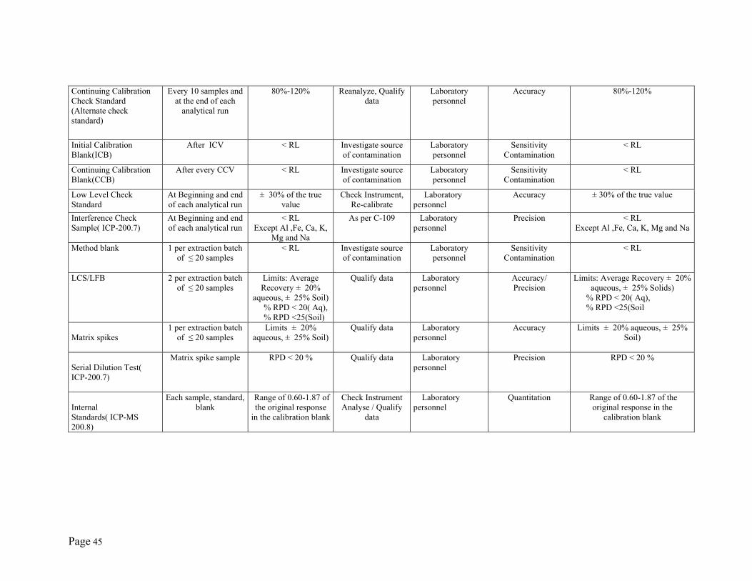
Page 45
Continuing Calibration Check Standard (Alternate check standard)
Every 10 samples and at the end of each
analytical run
80%-120% Reanalyze, Qualify data
Laboratory personnel
Accuracy
80%-120%
Initial Calibration Blank(ICB)
After ICV < RL Investigate source of contamination
Laboratory personnel
Sensitivity Contamination
< RL
Continuing Calibration Blank(CCB)
After every CCV < RL Investigate source of contamination
Laboratory personnel
Sensitivity Contamination
< RL
Low Level Check Standard
At Beginning and end of each analytical run
± 30% of the true value
Check Instrument, Re-calibrate
Laboratory personnel
Accuracy
± 30% of the true value
Interference Check Sample( ICP-200.7)
At Beginning and end of each analytical run
< RL Except Al ,Fe, Ca, K,
Mg and Na
As per C-109 Laboratory personnel
Precision
< RL Except Al ,Fe, Ca, K, Mg and Na
Method blank
1 per extraction batch of ≤ 20 samples
< RL Investigate source of contamination
Laboratory personnel
Sensitivity Contamination
< RL
LCS/LFB 2 per extraction batch of ≤ 20 samples
Limits: Average Recovery ± 20%
aqueous, ± 25% Soil) % RPD < 20( Aq), % RPD <25(Soil)
Qualify data Laboratory personnel
Accuracy/ Precision
Limits: Average Recovery ± 20% aqueous, ± 25% Solids)
% RPD < 20( Aq), % RPD <25(Soil
Matrix spikes
1 per extraction batch of ≤ 20 samples
Limits ± 20% aqueous, ± 25% Soil)
Qualify data Laboratory personnel
Accuracy
Limits ± 20% aqueous, ± 25% Soil)
Serial Dilution Test( ICP-200.7)
Matrix spike sample RPD < 20 % Qualify data Laboratory personnel
Precision
RPD < 20 %
Internal Standards( ICP-MS 200.8)
Each sample, standard, blank
Range of 0.60-1.87 of the original response
in the calibration blank
Check Instrument Analyse / Qualify
data
Laboratory personnel
Quantitation Range of 0.60-1.87 of the original response in the
calibration blank
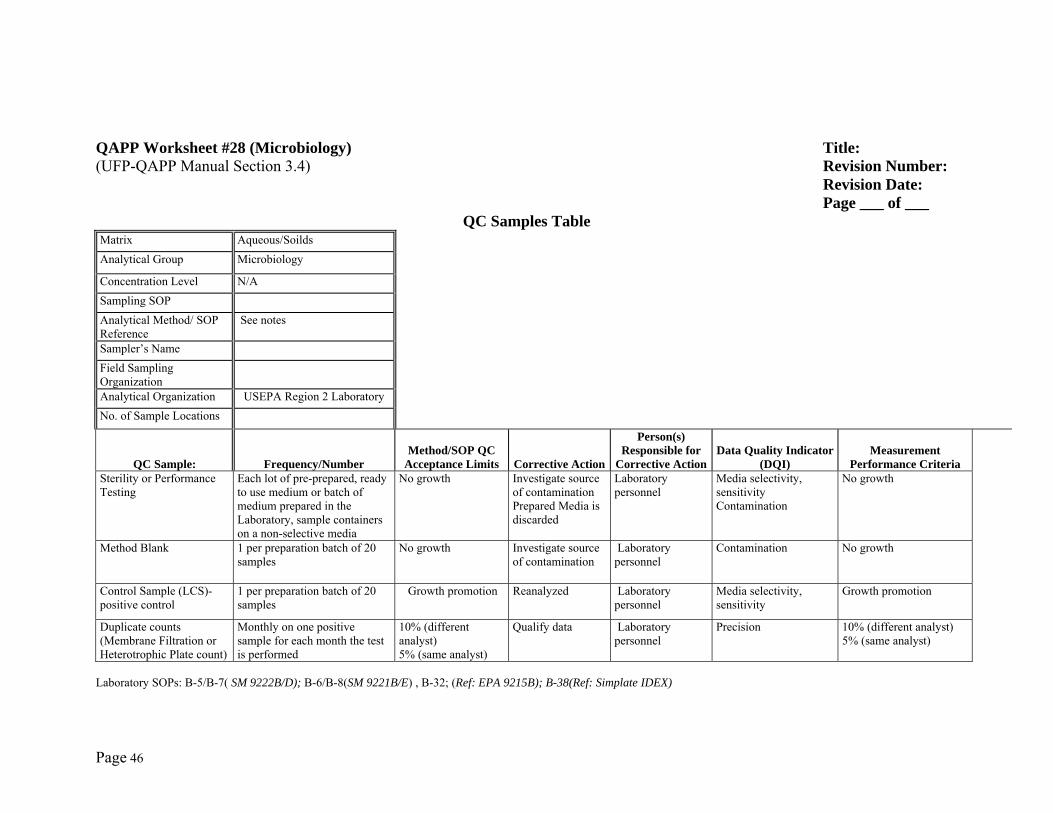
Page 46
QAPP Worksheet #28 (Microbiology) Title: (UFP-QAPP Manual Section 3.4) Revision Number: Revision Date: Page ___ of ___
QC Samples Table Matrix Aqueous/Soilds Analytical Group Microbiology Concentration Level N/A Sampling SOP Analytical Method/ SOP Reference
See notes
Sampler’s Name Field Sampling Organization
Analytical Organization USEPA Region 2 Laboratory No. of Sample Locations
QC Sample: Frequency/NumberMethod/SOP QC
Acceptance Limits Corrective Action
Person(s) Responsible for
Corrective ActionData Quality Indicator
(DQI)Measurement
Performance CriteriaSterility or Performance Testing
Each lot of pre-prepared, ready to use medium or batch of medium prepared in the Laboratory, sample containers on a non-selective media
No growth Investigate source of contamination Prepared Media is discarded
Laboratory personnel
Media selectivity, sensitivity Contamination
No growth
Method Blank 1 per preparation batch of 20 samples
No growth Investigate source of contamination
Laboratory personnel
Contamination No growth
Control Sample (LCS)- positive control
1 per preparation batch of 20 samples
Growth promotion Reanalyzed Laboratory personnel
Media selectivity, sensitivity
Growth promotion
Duplicate counts (Membrane Filtration or Heterotrophic Plate count)
Monthly on one positive sample for each month the test is performed
10% (different analyst) 5% (same analyst)
Qualify data Laboratory personnel
Precision 10% (different analyst) 5% (same analyst)
Laboratory SOPs: B-5/B-7( SM 9222B/D); B-6/B-8(SM 9221B/E) , B-32; (Ref: EPA 9215B); B-38(Ref: Simplate IDEX)
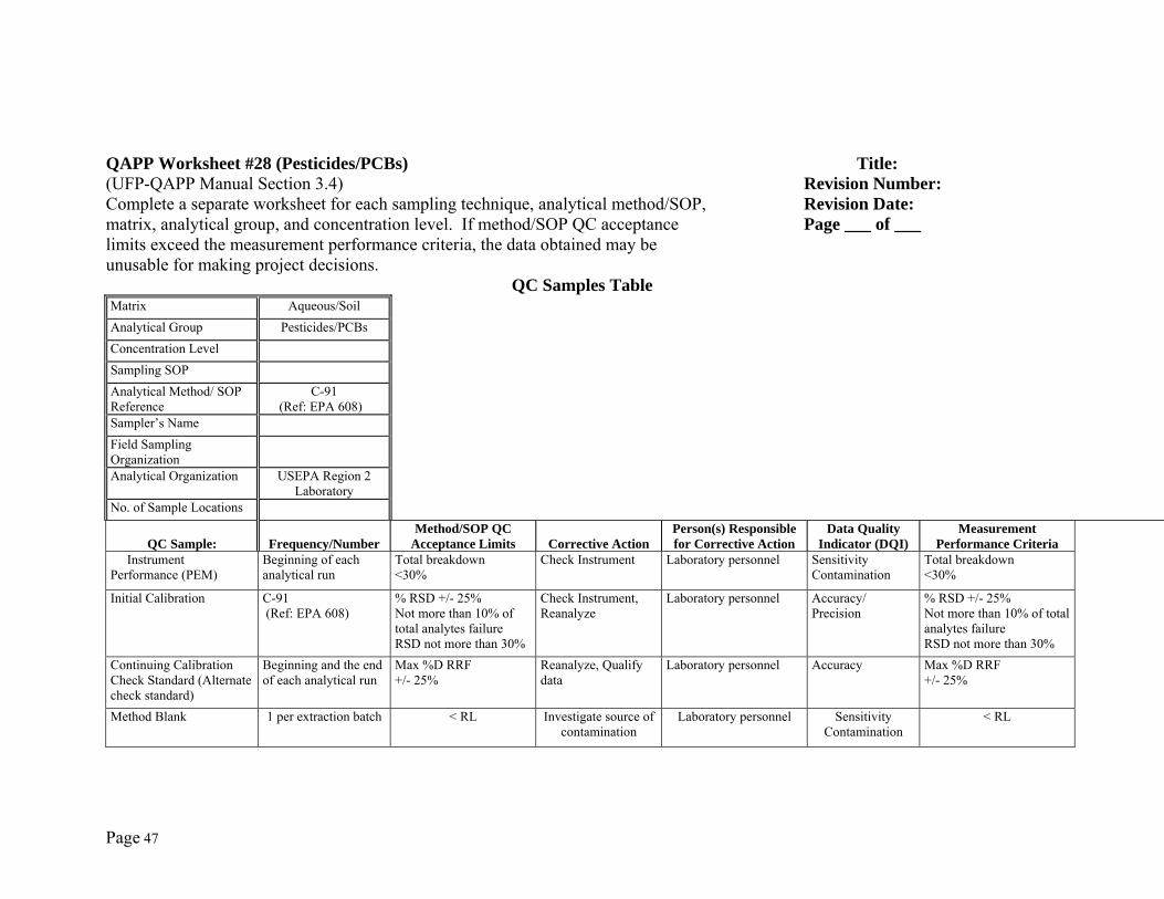
Page 47
QAPP Worksheet #28 (Pesticides/PCBs) Title: (UFP-QAPP Manual Section 3.4) Revision Number: Complete a separate worksheet for each sampling technique, analytical method/SOP, Revision Date: matrix, analytical group, and concentration level. If method/SOP QC acceptance Page ___ of ___ limits exceed the measurement performance criteria, the data obtained may be unusable for making project decisions.
QC Samples Table Matrix Aqueous/Soil Analytical Group Pesticides/PCBs Concentration Level Sampling SOP Analytical Method/ SOP Reference
C-91 (Ref: EPA 608)
Sampler’s Name Field Sampling Organization
Analytical Organization USEPA Region 2
Laboratory
No. of Sample Locations
QC Sample: Frequency/NumberMethod/SOP QC
Acceptance Limits Corrective ActionPerson(s) Responsible for Corrective Action
Data Quality Indicator (DQI)
Measurement Performance Criteria
Instrument Performance (PEM)
Beginning of each analytical run
Total breakdown <30%
Check Instrument
Laboratory personnel Sensitivity Contamination
Total breakdown <30%
Initial Calibration C-91 (Ref: EPA 608)
% RSD +/- 25% Not more than 10% of total analytes failure RSD not more than 30%
Check Instrument, Reanalyze
Laboratory personnel Accuracy/ Precision
% RSD +/- 25% Not more than 10% of total analytes failure RSD not more than 30%
Continuing Calibration Check Standard (Alternate check standard)
Beginning and the end of each analytical run
Max %D RRF +/- 25%
Reanalyze, Qualify data
Laboratory personnel Accuracy
Max %D RRF +/- 25%
Method Blank 1 per extraction batch < RL Investigate source of contamination
Laboratory personnel Sensitivity Contamination
< RL
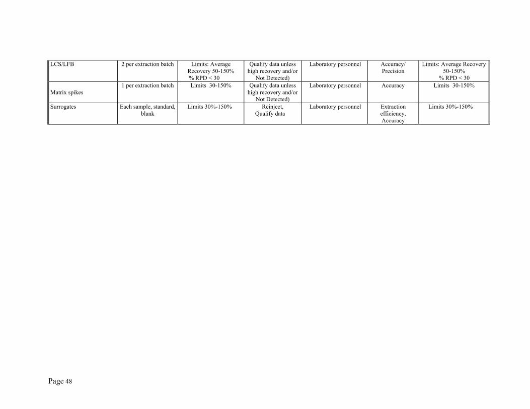
Page 48
LCS/LFB 2 per extraction batch Limits: Average Recovery 50-150%
% RPD < 30
Qualify data unless high recovery and/or
Not Detected)
Laboratory personnel Accuracy/ Precision
Limits: Average Recovery 50-150%
% RPD < 30 Matrix spikes
1 per extraction batch Limits 30-150% Qualify data unless high recovery and/or
Not Detected)
Laboratory personnel Accuracy
Limits 30-150%
Surrogates Each sample, standard, blank
Limits 30%-150% Reinject, Qualify data
Laboratory personnel Extraction efficiency, Accuracy
Limits 30%-150%
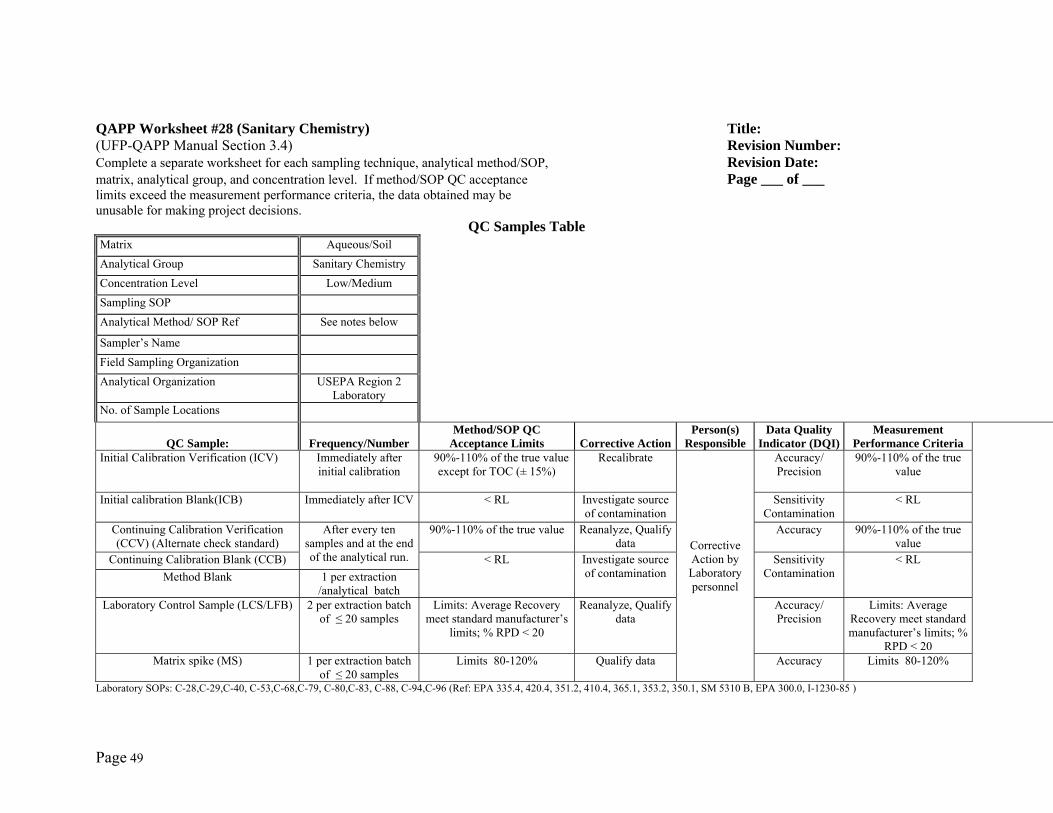
Page 49
QAPP Worksheet #28 (Sanitary Chemistry) Title: (UFP-QAPP Manual Section 3.4) Revision Number: Complete a separate worksheet for each sampling technique, analytical method/SOP, Revision Date: matrix, analytical group, and concentration level. If method/SOP QC acceptance Page ___ of ___ limits exceed the measurement performance criteria, the data obtained may be unusable for making project decisions.
QC Samples Table Matrix Aqueous/Soil Analytical Group Sanitary Chemistry Concentration Level Low/Medium Sampling SOP Analytical Method/ SOP Ref See notes below Sampler’s Name Field Sampling Organization Analytical Organization USEPA Region 2
Laboratory
No. of Sample Locations
QC Sample: Frequency/NumberMethod/SOP QC
Acceptance Limits Corrective ActionPerson(s)
ResponsibleData Quality
Indicator (DQI)Measurement
Performance CriteriaInitial Calibration Verification (ICV) Immediately after
initial calibration 90%-110% of the true value
except for TOC (± 15%) Recalibrate
Corrective Action by Laboratory personnel
Accuracy/ Precision
90%-110% of the true value
Initial calibration Blank(ICB) Immediately after ICV < RL Investigate source of contamination
Sensitivity Contamination
< RL
Continuing Calibration Verification (CCV) (Alternate check standard)
After every ten samples and at the end of the analytical run.
90%-110% of the true value Reanalyze, Qualify data
Accuracy
90%-110% of the true value
Continuing Calibration Blank (CCB) < RL Investigate source of contamination
Sensitivity Contamination
< RL Method Blank 1 per extraction
/analytical batch Laboratory Control Sample (LCS/LFB) 2 per extraction batch
of ≤ 20 samples Limits: Average Recovery
meet standard manufacturer’s limits; % RPD < 20
Reanalyze, Qualify data
Accuracy/ Precision
Limits: Average Recovery meet standard manufacturer’s limits; %
RPD < 20 Matrix spike (MS) 1 per extraction batch
of ≤ 20 samples Limits 80-120% Qualify data Accuracy
Limits 80-120%
Laboratory SOPs: C-28,C-29,C-40, C-53,C-68,C-79, C-80,C-83, C-88, C-94,C-96 (Ref: EPA 335.4, 420.4, 351.2, 410.4, 365.1, 353.2, 350.1, SM 5310 B, EPA 300.0, I-1230-85 )
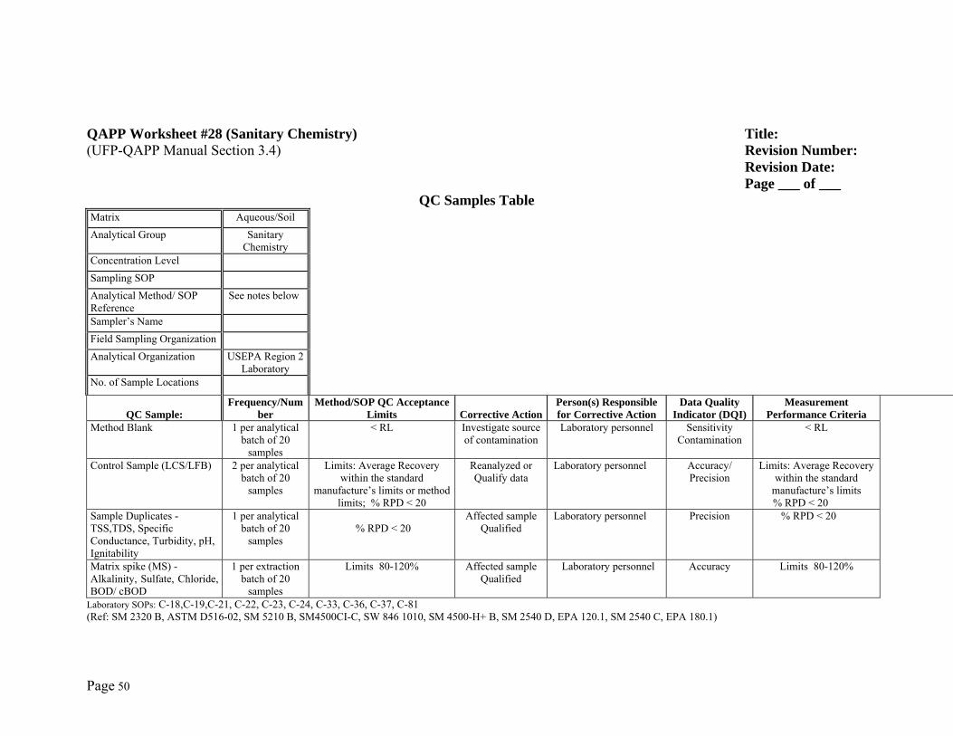
Page 50
QAPP Worksheet #28 (Sanitary Chemistry) Title: (UFP-QAPP Manual Section 3.4) Revision Number: Revision Date: Page ___ of ___
QC Samples Table Matrix Aqueous/Soil Analytical Group Sanitary
Chemistry
Concentration Level Sampling SOP Analytical Method/ SOP Reference
See notes below
Sampler’s Name Field Sampling Organization Analytical Organization USEPA Region 2
Laboratory
No. of Sample Locations
QC Sample: Frequency/Num
ber Method/SOP QC Acceptance
Limits Corrective ActionPerson(s) Responsible for Corrective Action
Data Quality Indicator (DQI)
Measurement Performance Criteria
Method Blank 1 per analytical batch of 20
samples
< RL Investigate source of contamination
Laboratory personnel Sensitivity Contamination
< RL
Control Sample (LCS/LFB) 2 per analytical batch of 20
samples
Limits: Average Recovery within the standard
manufacture’s limits or method limits; % RPD < 20
Reanalyzed or Qualify data
Laboratory personnel Accuracy/ Precision
Limits: Average Recovery within the standard
manufacture’s limits % RPD < 20
Sample Duplicates - TSS,TDS, Specific Conductance, Turbidity, pH, Ignitability
1 per analytical batch of 20
samples
% RPD < 20
Affected sample Qualified
Laboratory personnel
Precision
% RPD < 20
Matrix spike (MS) - Alkalinity, Sulfate, Chloride, BOD/ cBOD
1 per extraction batch of 20
samples
Limits 80-120% Affected sample Qualified
Laboratory personnel Accuracy
Limits 80-120%
Laboratory SOPs: C-18,C-19,C-21, C-22, C-23, C-24, C-33, C-36, C-37, C-81 (Ref: SM 2320 B, ASTM D516-02, SM 5210 B, SM4500CI-C, SW 846 1010, SM 4500-H+ B, SM 2540 D, EPA 120.1, SM 2540 C, EPA 180.1)
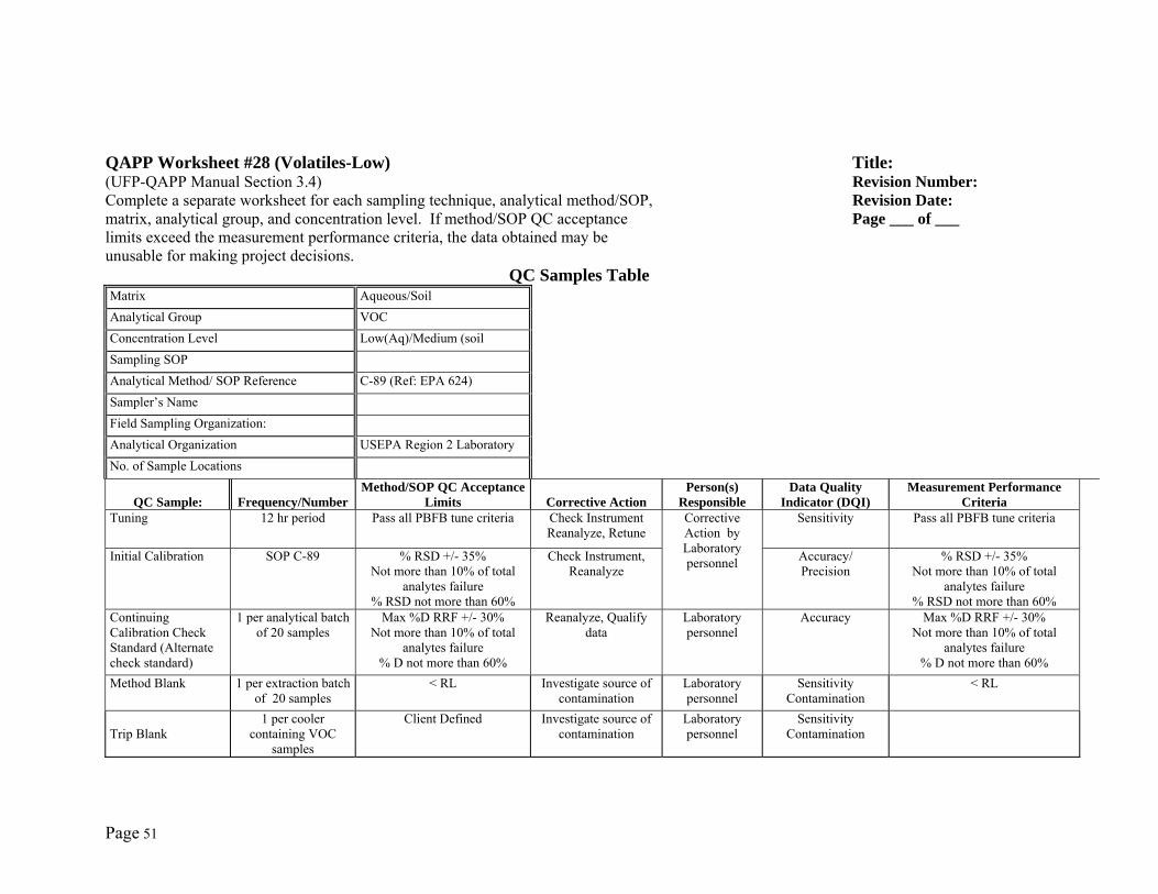
Page 51
QAPP Worksheet #28 (Volatiles-Low) Title: (UFP-QAPP Manual Section 3.4) Revision Number: Complete a separate worksheet for each sampling technique, analytical method/SOP, Revision Date: matrix, analytical group, and concentration level. If method/SOP QC acceptance Page ___ of ___ limits exceed the measurement performance criteria, the data obtained may be unusable for making project decisions.
QC Samples Table Matrix Aqueous/Soil Analytical Group VOC Concentration Level Low(Aq)/Medium (soil Sampling SOP Analytical Method/ SOP Reference C-89 (Ref: EPA 624) Sampler’s Name Field Sampling Organization: Analytical Organization USEPA Region 2 Laboratory No. of Sample Locations
QC Sample: Frequency/Number Method/SOP QC Acceptance
Limits Corrective ActionPerson(s)
Responsible Data Quality
Indicator (DQI)Measurement Performance
CriteriaTuning 12 hr period Pass all PBFB tune criteria Check Instrument
Reanalyze, Retune Corrective Action by Laboratory personnel
Sensitivity
Pass all PBFB tune criteria
Initial Calibration SOP C-89 % RSD +/- 35% Not more than 10% of total
analytes failure % RSD not more than 60%
Check Instrument, Reanalyze
Accuracy/ Precision
% RSD +/- 35% Not more than 10% of total
analytes failure % RSD not more than 60%
Continuing Calibration Check Standard (Alternate check standard)
1 per analytical batch of 20 samples
Max %D RRF +/- 30% Not more than 10% of total
analytes failure % D not more than 60%
Reanalyze, Qualify data
Laboratory personnel
Accuracy
Max %D RRF +/- 30% Not more than 10% of total
analytes failure % D not more than 60%
Method Blank 1 per extraction batch of 20 samples
< RL Investigate source of contamination
Laboratory personnel
Sensitivity Contamination
< RL
Trip Blank
1 per cooler containing VOC
samples
Client Defined Investigate source of contamination
Laboratory personnel
Sensitivity Contamination
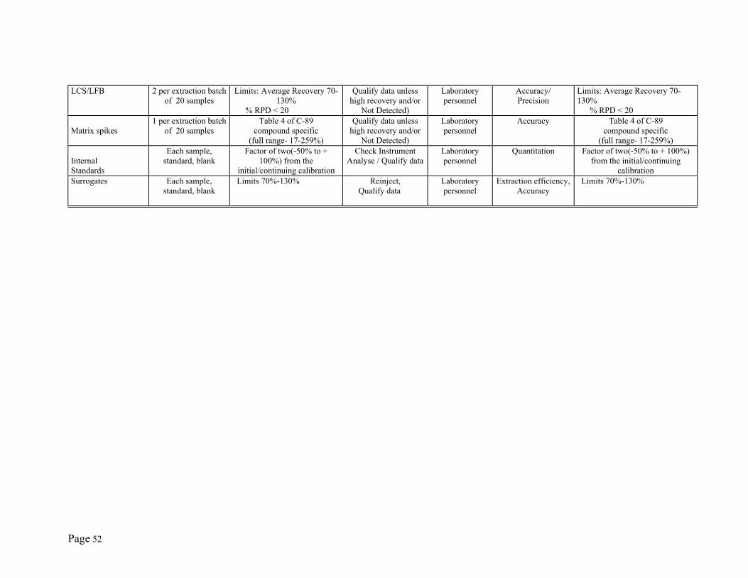
Page 52
LCS/LFB 2 per extraction batch of 20 samples
Limits: Average Recovery 70-130%
% RPD < 20
Qualify data unless high recovery and/or
Not Detected)
Laboratory personnel
Accuracy/ Precision
Limits: Average Recovery 70-130% % RPD < 20
Matrix spikes
1 per extraction batch of 20 samples
Table 4 of C-89 compound specific
(full range- 17-259%)
Qualify data unless high recovery and/or
Not Detected)
Laboratory personnel
Accuracy
Table 4 of C-89 compound specific
(full range- 17-259%) Internal Standards
Each sample, standard, blank
Factor of two(-50% to + 100%) from the
initial/continuing calibration
Check Instrument Analyse / Qualify data
Laboratory personnel
Quantitation Factor of two(-50% to + 100%) from the initial/continuing
calibration Surrogates Each sample,
standard, blank Limits 70%-130% Reinject,
Qualify data Laboratory personnel
Extraction efficiency, Accuracy
Limits 70%-130%
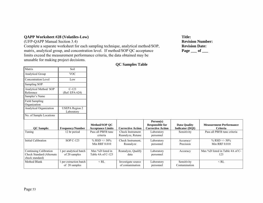
Page 53
QAPP Worksheet #28 (Volatiles-Low) Title: (UFP-QAPP Manual Section 3.4) Revision Number: Complete a separate worksheet for each sampling technique, analytical method/SOP, Revision Date: matrix, analytical group, and concentration level. If method/SOP QC acceptance Page ___ of ___ limits exceed the measurement performance criteria, the data obtained may be unusable for making project decisions.
QC Samples Table Matrix Soil Analytical Group VOC Concentration Level Low Sampling SOP Analytical Method/ SOP Reference
C-123 (Ref: EPA 624)
Sampler’s Name Field Sampling Organization
Analytical Organization USEPA Region 2
Laboratory
No. of Sample Locations
QC Sample: Frequency/NumberMethod/SOP QC
Acceptance Limits Corrective Action
Person(s) Responsible for
Corrective ActionData Quality
Indicator (DQI)Measurement Performance
CriteriaTuning 12 hr period Pass all PBFB tune
criteria Check Instrument Reanalyze, Retune
Laboratory personnel
Sensitivity
Pass all PBFB tune criteria
Initial Calibration SOP C-123 % RSD +/- 50% Min RRF 0.010
Check Instrument, Reanalyze
Laboratory personnel
Accuracy/ Precision
% RSD +/- 50% Min RRF 0.010
Continuing Calibration Check Standard (Alternate check standard)
1 per analytical batch of 20 samples
Max %D listed in Table 4A of C-123
Reanalyze, Qualify data
Laboratory personnel
Accuracy
Max %D listed in Table 4A of C-123
Method Blank 1 per extraction batch
of 20 samples < RL Investigate source
of contamination Laboratory personnel
Sensitivity Contamination
< RL
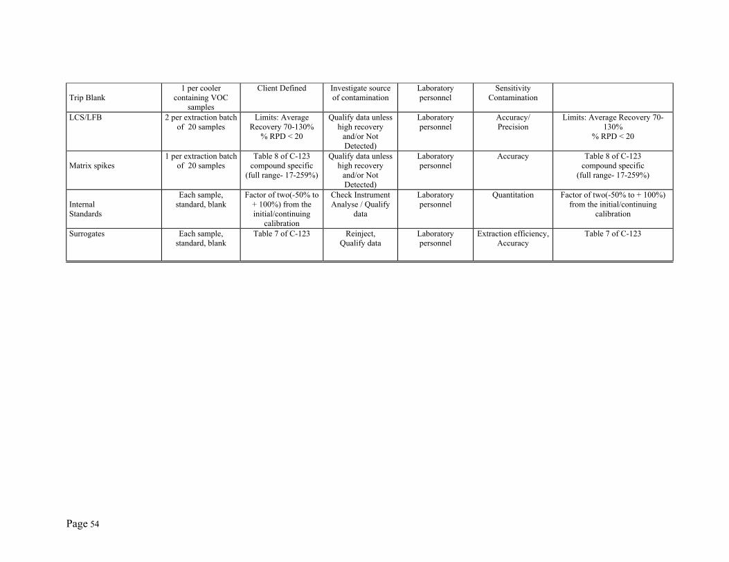
Page 54
Trip Blank
1 per cooler containing VOC
samples
Client Defined Investigate source of contamination
Laboratory personnel
Sensitivity Contamination
LCS/LFB 2 per extraction batchof 20 samples
Limits: Average Recovery 70-130%
% RPD < 20
Qualify data unless high recovery
and/or Not Detected)
Laboratory personnel
Accuracy/ Precision
Limits: Average Recovery 70-130%
% RPD < 20
Matrix spikes
1 per extraction batchof 20 samples
Table 8 of C-123 compound specific
(full range- 17-259%)
Qualify data unless high recovery
and/or Not Detected)
Laboratory personnel
Accuracy
Table 8 of C-123 compound specific
(full range- 17-259%)
Internal Standards
Each sample, standard, blank
Factor of two(-50% to + 100%) from the initial/continuing
calibration
Check Instrument Analyse / Qualify
data
Laboratory personnel
Quantitation Factor of two(-50% to + 100%) from the initial/continuing
calibration
Surrogates Each sample, standard, blank
Table 7 of C-123
Reinject, Qualify data
Laboratory personnel
Extraction efficiency, Accuracy
Table 7 of C-123
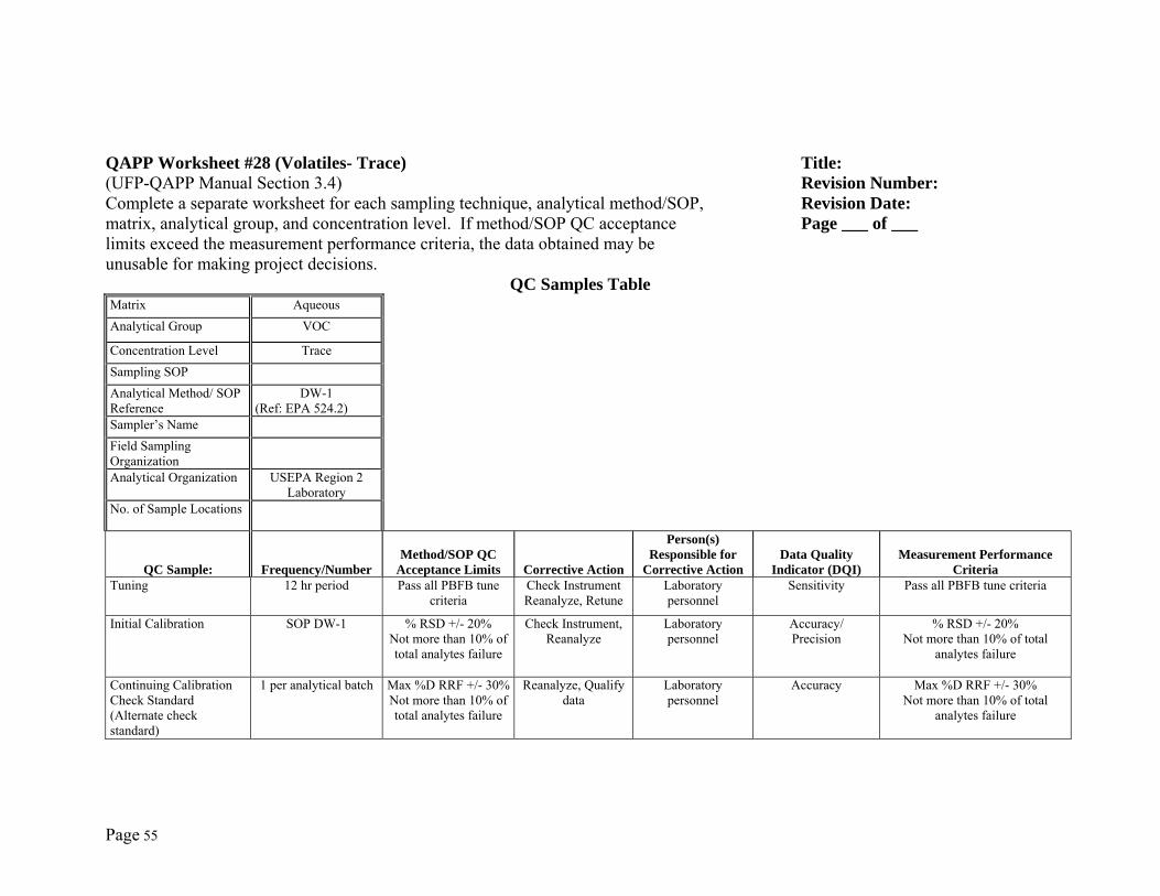
Page 55
QAPP Worksheet #28 (Volatiles- Trace) Title: (UFP-QAPP Manual Section 3.4) Revision Number: Complete a separate worksheet for each sampling technique, analytical method/SOP, Revision Date: matrix, analytical group, and concentration level. If method/SOP QC acceptance Page ___ of ___ limits exceed the measurement performance criteria, the data obtained may be unusable for making project decisions.
QC Samples Table Matrix Aqueous Analytical Group VOC Concentration Level Trace Sampling SOP Analytical Method/ SOP Reference
DW-1 (Ref: EPA 524.2)
Sampler’s Name Field Sampling Organization
Analytical Organization USEPA Region 2
Laboratory
No. of Sample Locations
QC Sample: Frequency/NumberMethod/SOP QC
Acceptance Limits Corrective Action
Person(s) Responsible for
Corrective ActionData Quality
Indicator (DQI)Measurement Performance
CriteriaTuning 12 hr period Pass all PBFB tune
criteria Check Instrument Reanalyze, Retune
Laboratory personnel
Sensitivity
Pass all PBFB tune criteria
Initial Calibration SOP DW-1 % RSD +/- 20% Not more than 10% of total analytes failure
Check Instrument, Reanalyze
Laboratory personnel
Accuracy/ Precision
% RSD +/- 20% Not more than 10% of total
analytes failure
Continuing Calibration Check Standard (Alternate check standard)
1 per analytical batch Max %D RRF +/- 30%Not more than 10% of total analytes failure
Reanalyze, Qualify data
Laboratory personnel
Accuracy
Max %D RRF +/- 30% Not more than 10% of total
analytes failure
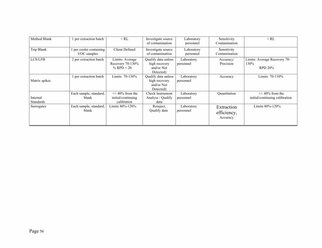
Page 56
Method Blank 1 per extraction batch < RL Investigate source of contamination
Laboratory personnel
Sensitivity Contamination
< RL
Trip Blank 1 per cooler containing VOC samples
Client Defined Investigate source of contamination
Laboratory personnel
Sensitivity Contamination
LCS/LFB 2 per extraction batch Limits: Average Recovery 70-130%
% RPD < 20
Qualify data unless high recovery
and/or Not Detected)
Laboratory personnel
Accuracy/ Precision
Limits: Average Recovery 70-130% RPD 20%
Matrix spikes
1 per extraction batch Limits 70-130% Qualify data unless high recovery
and/or Not Detected)
Laboratory personnel
Accuracy
Limits 70-130%
Internal Standards
Each sample, standard, blank
+/- 40% from the initial/continuing
calibration
Check Instrument Analyse / Qualify
data
Laboratory personnel
Quantitation +/- 40% from the initial/continuing calibration
Surrogates Each sample, standard, blank
Limits 80%-120% Reinject, Qualify data
Laboratory personnel
Extraction efficiency,
Accuracy
Limits 80%-120%
Page 57
QAPP Worksheet #29 Title: (UFP-QAPP Manual Section 3.5.1) Revision Number: Identify the documents and records that will be generated for all aspects of the Revision Date: project including, but not limited to, sample collection and field measurement, Page ___ of ___ on-site and off-site analysis, and data assessment.
Project Documents and Records Table Sample Collection
Documents and Records On-site Analysis
Documents and Records Off-site Analysis
Documents and Records Data Assessment
Documents and Records Other
Field Chains-of-Custody Internal Chains-of-Custody Sample acceptance checklist Customer Service Survey Cards
Packing Slips and Sample Tags
Sample Preparation Log
PT Sample Results Telephone Logs
Request Forms and Associated Correspondence
Standard Traceability Record Instrument Analysis Log
Training Records Procurement Request Forms
Sample Acceptance Checklist QC summary checklist with all relevant information
MDL Study Records Equipment Maintenance Logs
LIMS Sample Receipts Sample Analysis Data Initial DOC / CDOC Records Validated Computer Software Records
Automated OSCAR Logs Instrument Calibration Data Internal Audit Reports
sample identification numbers Instrument/ Computer Printouts Corrective Action Reports
Definition of Qualifiers External Assessment
Cover Letter NELAC Accreditation
Approval Form
Case Narrative
Final Report
Page 58
QAPP Worksheet #31 Title: (UFP-QAPP Manual Section 4.1.1) Revision Number: Identify the type, frequency, and responsible parties of Revision Date: planned assessment activities that will be performed for the project. Page ___ of ___
Planned Project Assessments Table
Assessment Type Frequency
Internal or
External
Organization Performing Assessment
Person(s) Responsible for Performing
Assessment (Title and Organizational
Affiliation)
Person(s) Responsible for Responding to
Assessment Findings (Title and Organizational
Affiliation)
Person(s) Responsible for Identifying and
Implementing Corrective Actions (CA) (Title and
Organizational Affiliation)
Person(s) Responsible for Monitoring
Effectiveness of CA (Title and
Organizational Affiliation)
PT
Semiannually
External
NELAC
PT provider
Laboratory Personnel
Laboratory Personnel
Laboratory QA Officer
NELAC
Every two years
External NELAC Florida DOH Laboratory QA Officer Laboratory Personnel Florida DOH
INTERNAL AUDIT
Monthly Internally DESA Laboratory
Laboratory QA Officer
Laboratory Personnel Laboratory Personnel Laboratory QA Officer
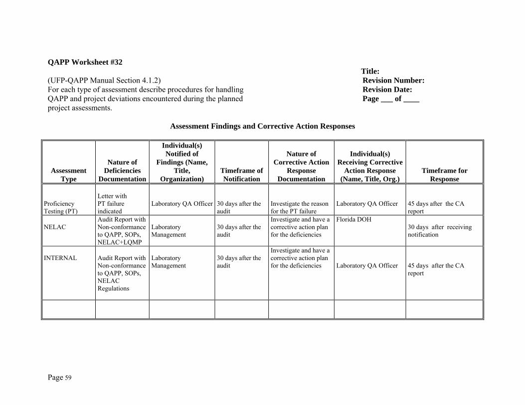
Page 59
QAPP Worksheet #32 Title: (UFP-QAPP Manual Section 4.1.2) Revision Number: For each type of assessment describe procedures for handling Revision Date: QAPP and project deviations encountered during the planned Page ___ of ____ project assessments.
Assessment Findings and Corrective Action Responses
Assessment Type
Nature of
Deficiencies Documentation
Individual(s) Notified of
Findings (Name, Title,
Organization)
Timeframe of Notification
Nature of Corrective Action
Response Documentation
Individual(s) Receiving Corrective
Action Response (Name, Title, Org.)
Timeframe for Response
Proficiency Testing (PT)
Letter with PT failure indicated
Laboratory QA Officer
30 days after the audit
Investigate the reason for the PT failure
Laboratory QA Officer
45 days after the CA report
NELAC
Audit Report with Non-conformance to QAPP, SOPs, NELAC+LQMP
Laboratory Management
30 days after the audit
Investigate and have a corrective action plan for the deficiencies
Florida DOH 30 days after receiving notification
INTERNAL
Audit Report with Non-conformance to QAPP, SOPs, NELAC Regulations
Laboratory Management
30 days after the audit
Investigate and have a corrective action plan for the deficiencies
Laboratory QA Officer
45 days after the CA report
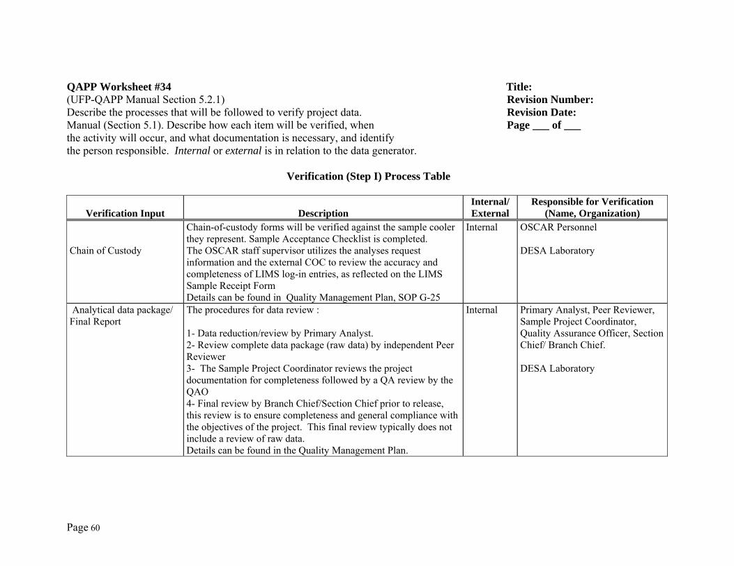
Page 60
QAPP Worksheet #34 Title: (UFP-QAPP Manual Section 5.2.1) Revision Number: Describe the processes that will be followed to verify project data. Revision Date: Manual (Section 5.1). Describe how each item will be verified, when Page ___ of ___ the activity will occur, and what documentation is necessary, and identify the person responsible. Internal or external is in relation to the data generator.
Verification (Step I) Process Table
Verification Input Description Internal/ External
Responsible for Verification (Name, Organization)
Chain of Custody
Chain-of-custody forms will be verified against the sample cooler they represent. Sample Acceptance Checklist is completed. The OSCAR staff supervisor utilizes the analyses request information and the external COC to review the accuracy and completeness of LIMS log-in entries, as reflected on the LIMS Sample Receipt Form Details can be found in Quality Management Plan, SOP G-25
Internal OSCAR Personnel DESA Laboratory
Analytical data package/ Final Report
The procedures for data review : 1- Data reduction/review by Primary Analyst. 2- Review complete data package (raw data) by independent Peer Reviewer 3- The Sample Project Coordinator reviews the project documentation for completeness followed by a QA review by the QAO 4- Final review by Branch Chief/Section Chief prior to release, this review is to ensure completeness and general compliance with the objectives of the project. This final review typically does not include a review of raw data. Details can be found in the Quality Management Plan.
Internal Primary Analyst, Peer Reviewer, Sample Project Coordinator, Quality Assurance Officer, Section Chief/ Branch Chief. DESA Laboratory
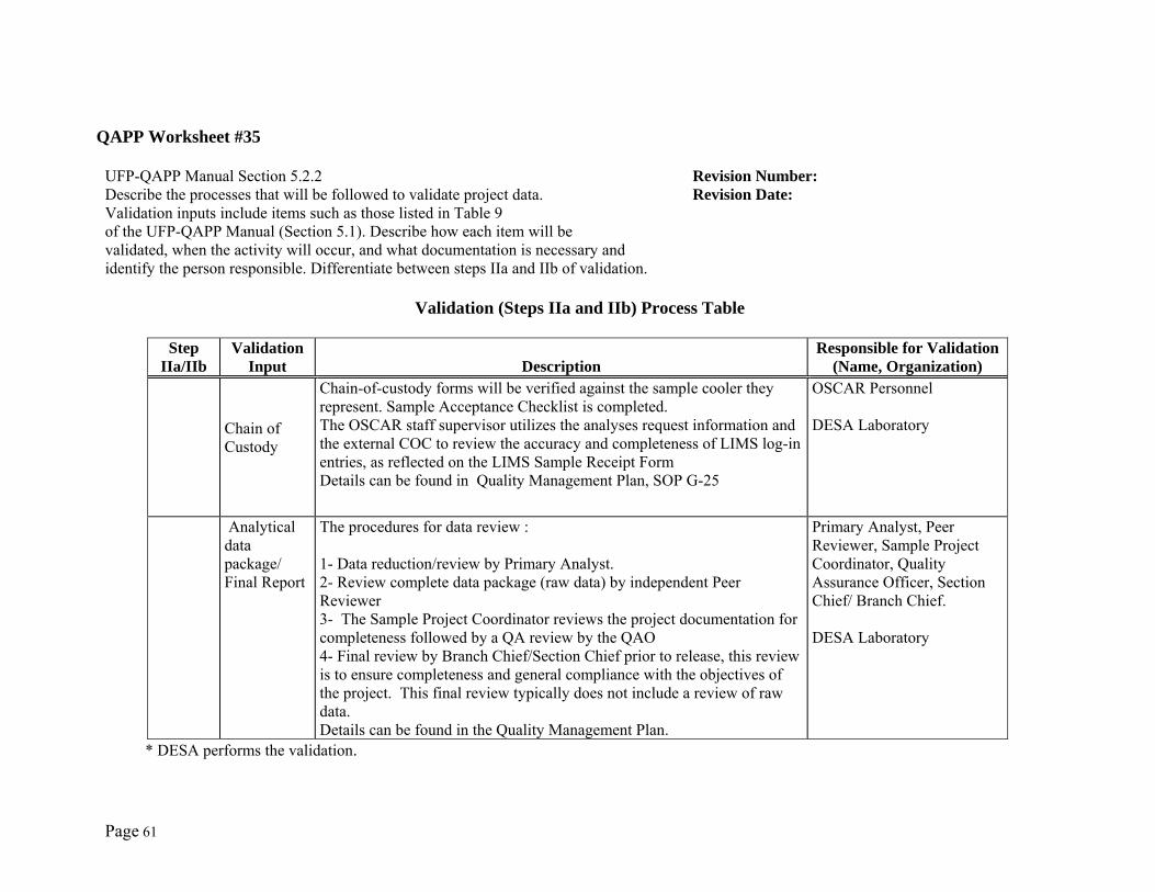
Page 61
QAPP Worksheet #35
UFP-QAPP Manual Section 5.2.2 Revision Number: Describe the processes that will be followed to validate project data. Revision Date: Validation inputs include items such as those listed in Table 9 of the UFP-QAPP Manual (Section 5.1). Describe how each item will be validated, when the activity will occur, and what documentation is necessary and identify the person responsible. Differentiate between steps IIa and IIb of validation.
Validation (Steps IIa and IIb) Process Table
Step
IIa/IIb Validation
Input DescriptionResponsible for Validation
(Name, Organization)
Chain of Custody
Chain-of-custody forms will be verified against the sample cooler they represent. Sample Acceptance Checklist is completed. The OSCAR staff supervisor utilizes the analyses request information and the external COC to review the accuracy and completeness of LIMS log-in entries, as reflected on the LIMS Sample Receipt Form Details can be found in Quality Management Plan, SOP G-25
OSCAR Personnel DESA Laboratory
Analytical data package/ Final Report
The procedures for data review : 1- Data reduction/review by Primary Analyst. 2- Review complete data package (raw data) by independent Peer Reviewer 3- The Sample Project Coordinator reviews the project documentation for completeness followed by a QA review by the QAO 4- Final review by Branch Chief/Section Chief prior to release, this review is to ensure completeness and general compliance with the objectives of the project. This final review typically does not include a review of raw data. Details can be found in the Quality Management Plan.
Primary Analyst, Peer Reviewer, Sample Project Coordinator, Quality Assurance Officer, Section Chief/ Branch Chief. DESA Laboratory
* DESA performs the validation.
Appendix D
Air Monitoring Specifications
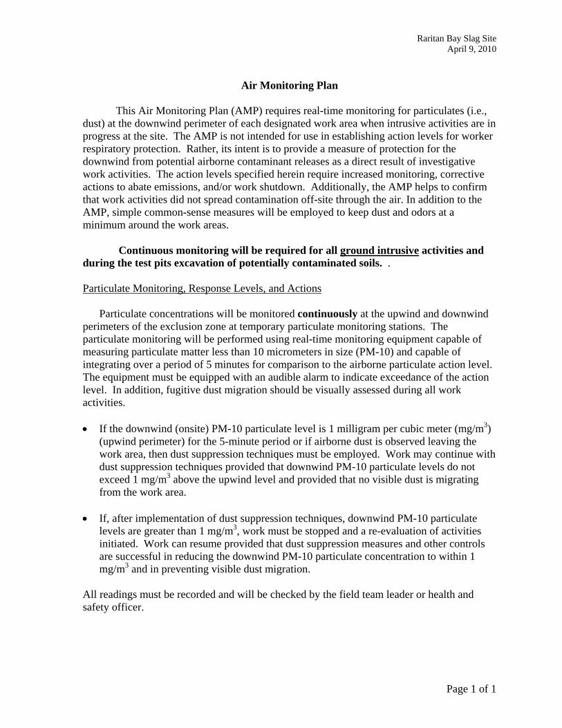
Raritan Bay Slag Site April 9, 2010
Page 1 of 1
Air Monitoring Plan
This Air Monitoring Plan (AMP) requires real-time monitoring for particulates (i.e., dust) at the downwind perimeter of each designated work area when intrusive activities are in progress at the site. The AMP is not intended for use in establishing action levels for worker respiratory protection. Rather, its intent is to provide a measure of protection for the downwind from potential airborne contaminant releases as a direct result of investigative work activities. The action levels specified herein require increased monitoring, corrective actions to abate emissions, and/or work shutdown. Additionally, the AMP helps to confirm that work activities did not spread contamination off-site through the air. In addition to the AMP, simple common-sense measures will be employed to keep dust and odors at a minimum around the work areas.
Continuous monitoring will be required for all ground intrusive activities and during the test pits excavation of potentially contaminated soils. .
Particulate Monitoring, Response Levels, and Actions
Particulate concentrations will be monitored continuously at the upwind and downwind perimeters of the exclusion zone at temporary particulate monitoring stations. The particulate monitoring will be performed using real-time monitoring equipment capable of measuring particulate matter less than 10 micrometers in size (PM-10) and capable of integrating over a period of 5 minutes for comparison to the airborne particulate action level. The equipment must be equipped with an audible alarm to indicate exceedance of the action level. In addition, fugitive dust migration should be visually assessed during all work activities. • If the downwind (onsite) PM-10 particulate level is 1 milligram per cubic meter (mg/m3)
(upwind perimeter) for the 5-minute period or if airborne dust is observed leaving the work area, then dust suppression techniques must be employed. Work may continue with dust suppression techniques provided that downwind PM-10 particulate levels do not exceed 1 mg/m3 above the upwind level and provided that no visible dust is migrating from the work area.
• If, after implementation of dust suppression techniques, downwind PM-10 particulate
levels are greater than 1 mg/m3, work must be stopped and a re-evaluation of activities initiated. Work can resume provided that dust suppression measures and other controls are successful in reducing the downwind PM-10 particulate concentration to within 1 mg/m3 and in preventing visible dust migration.
All readings must be recorded and will be checked by the field team leader or health and safety officer.
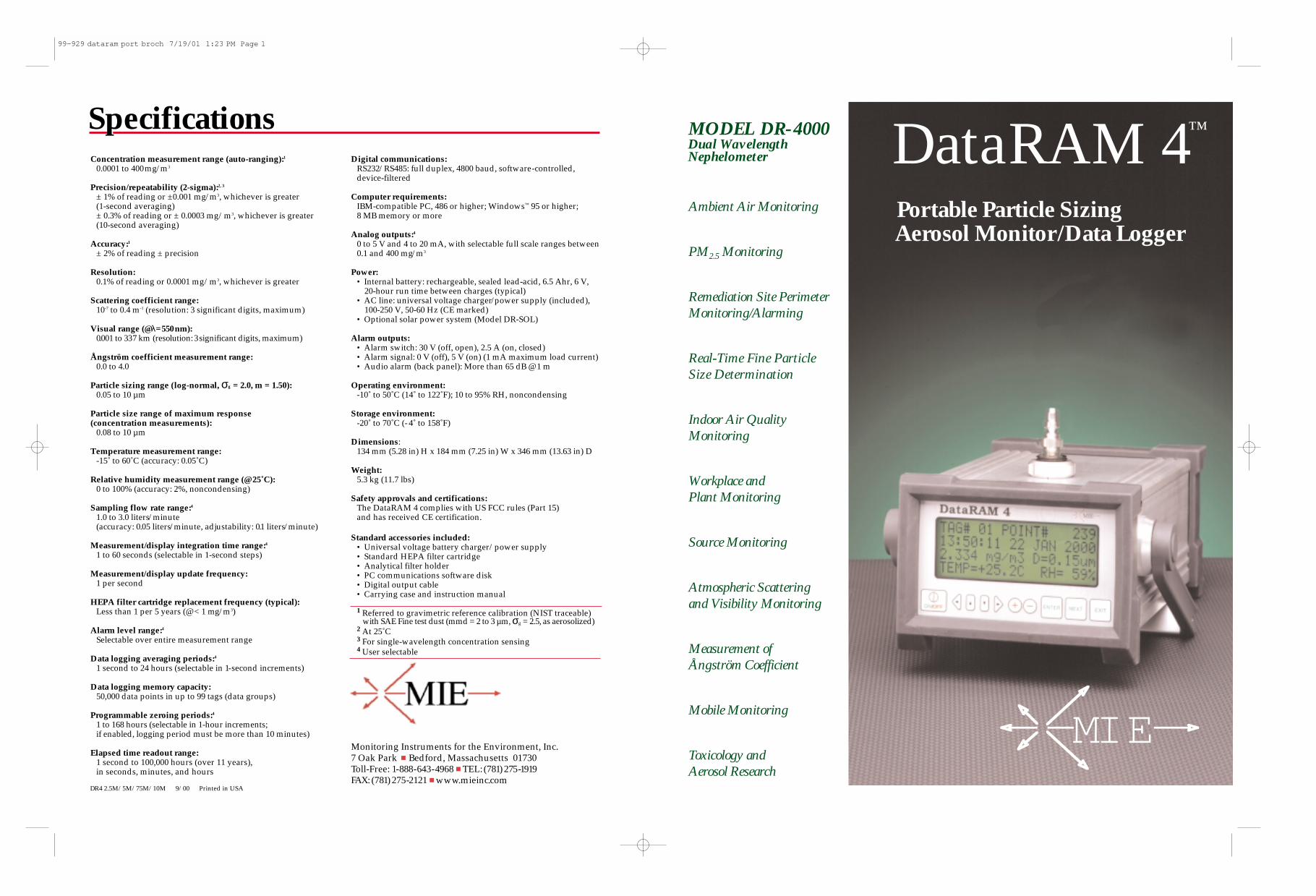
Concentration measurement range (auto-ranging):1
0.0001 to 400mg/m3
Precision/repeatability (2-sigma):2, 3
± 1% of reading or ±0.001 mg/m3, whichever is greater(1-second averaging)± 0.3% of reading or ± 0.0003 mg/m3, whichever is greater (10-second averaging)
Accuracy:1
± 2% of reading ± precision
Resolution:0.1% of reading or 0.0001 mg/m3, whichever is greater
Scattering coefficient range:10-7 to 0.4 m-1 (resolution: 3 significant digits, maximum)
Visual range (@λ=550nm):0.001 to 337 km (resolution: 3significant digits, maximum)
Ångström coefficient measurement range:0.0 to 4.0
Particle sizing range (log-normal, σg = 2.0, m = 1.50):0.05 to 10 µm
Particle size range of maximum response (concentration measurements):
0.08 to 10 µm
Temperature measurement range:-15˚ to 60˚C (accuracy: 0.05˚C)
Relative humidity measurement range (@ 25˚C):0 to 100% (accuracy: 2%, noncondensing)
Sampling flow rate range:4
1.0 to 3.0 liters/minute (accuracy: 0.05 liters/minute, adjustability: 0.1 liters/minute)
Measurement/display integration time range:4
1 to 60 seconds (selectable in 1-second steps)
Measurement/display update frequency:1 per second
HEPA filter cartridge replacement frequency (typical):Less than 1 per 5 years (@ < 1 mg/m3)
Alarm level range:4
Selectable over entire measurement range
Data logging averaging periods:4
1 second to 24 hours (selectable in 1-second increments)
Data logging memory capacity:50,000 data points in up to 99 tags (data groups)
Programmable zeroing periods:4
1 to 168 hours (selectable in 1-hour increments; if enabled, logging period must be more than 10 minutes)
Elapsed time readout range:1 second to 100,000 hours (over 11 years), in seconds, minutes, and hours
Digital communications:RS232/RS485: full duplex, 4800 baud, software-controlled, device-filtered
Computer requirements:IBM-compatible PC, 486 or higher; Windows™ 95 or higher; 8 MB memory or more
Analog outputs:4
0 to 5 V and 4 to 20 mA, with selectable full scale ranges between0.1 and 400 mg/m3
Power:• Internal battery: rechargeable, sealed lead-acid, 6.5 Ahr, 6 V,
20-hour run time between charges (typical)• AC line: universal voltage charger/power supply (included),
100-250 V, 50-60 Hz (CE marked)• Optional solar power system (Model DR-SOL)
Alarm outputs:• Alarm switch: 30 V (off, open), 2.5 A (on, closed)• Alarm signal: 0 V (off), 5 V (on) (1 mA maximum load current)• Audio alarm (back panel): More than 65 dB @ 1 m
Operating environment:-10˚ to 50˚C (14˚ to 122˚F); 10 to 95% RH, noncondensing
Storage environment:-20˚ to 70˚C (- 4˚ to 158˚F)
Dimensions:134 mm (5.28 in) H x 184 mm (7.25 in) W x 346 mm (13.63 in) D
Weight:5.3 kg (11.7 lbs)
Safety approvals and certifications:The DataRAM 4 complies with US FCC rules (Part 15) and has received CE certification.
Standard accessories included:• Universal voltage battery charger/power supply • Standard HEPA filter cartridge• Analytical filter holder• PC communications software disk• Digital output cable• Carrying case and instruction manual
1 Referred to gravimetric reference calibration (NIST traceable) with SAE Fine test dust (mmd = 2 to 3 µm, σg = 2.5, as aerosolized)
2 At 25˚C3 For single-wavelength concentration sensing4 User selectable
Monitoring Instruments for the Environment, Inc.7 Oak Park ■ Bedford, Massachusetts 01730Toll-Free: 1-888-643-4968 ■ TEL: (781) 275-1919FAX: (781) 275-2121 ■ www.mieinc.com
DR4 2.5M/5M/75M/10M 9/00 Printed in USA
Specifications DataRAM 4™
Portable Particle Sizing Aerosol Monitor/Data Logger
Ambient Air Monitoring
PM2.5 Monitoring
Remediation Site Perimeter Monitoring/Alarming
Real-Time Fine Particle Size Determination
Indoor Air Quality Monitoring
Workplace and Plant Monitoring
Source Monitoring
Atmospheric Scattering and Visibility Monitoring
Measurement of Ångström Coefficient
Mobile Monitoring
Toxicology and Aerosol Research
MIE
MODEL DR-4000Dual WavelengthNephelometer
99-929 dataram port broch 7/19/01 1:23 PM Page 1
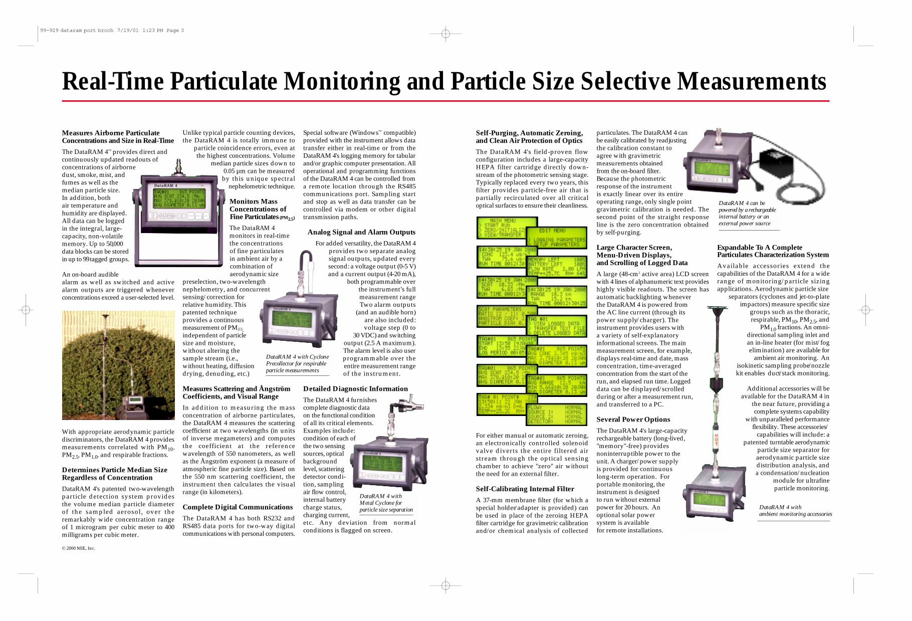
Self-Purging, Automatic Zeroing,and Clean Air Protection of Optics
The DataRAM 4's field-proven flowconfiguration includes a large-capacityHEPA filter cartridge directly down-stream of the photometric sensing stage.Typically replaced every two years, thisfilter provides particle-free air that ispartially recirculated over all criticaloptical surfaces to ensure their cleanliness.
For either manual or automatic zeroing,an electronically controlled solenoidvalve diverts the entire filtered airstream through the optical sensingchamber to achieve "zero" air withoutthe need for an external filter.
Self-Calibrating Internal Filter
A 37-mm membrane filter (for which aspecial holder/adapter is provided) canbe used in place of the zeroing HEPAfilter cartridge for gravimetric calibrationand/or chemical analysis of collected
particulates. The DataRAM 4 can be easily calibrated by readjustingthe calibration constant toagree with gravimetric measurements obtained from the on-board filter.Because the photometricresponse of the instrumentis exactly linear over its entireoperating range, only single point gravimetric calibration is needed. Thesecond point of the straight responseline is the zero concentration obtainedby self-purging.
Large Character Screen, Menu-Driven Displays,and Scrolling of Logged Data
A large (48-cm2 active area) LCD screenwith 4 lines of alphanumeric text provideshighly visible readouts. The screen has automatic backlighting wheneverthe DataRAM 4 is powered fromthe AC line current (through itspower supply/charger). The instrument provides users with a variety of self-explanatory informational screens. The main measurement screen, for example,displays real-time and date, massconcentration, time-averagedconcentration from the start of therun, and elapsed run time. Loggeddata can be displayed/scrolled during or after a measurement run,and transferred to a PC.
Several Power Options
The DataRAM 4's large-capacityrechargeable battery (long-lived,"memory"-free) providesnoninterruptible power to the unit. A charger/power supply is provided for continuous long-term operation. Forportable monitoring, theinstrument is designedto run without externalpower for 20 hours. Anoptional solar power system is available for remote installations.
Expandable To A CompleteParticulates Characterization System
Available accessories extend the capabilities of the DataRAM 4 for a widerange of monitoring/particle sizingapplications. Aerodynamic particle size
separators (cyclones and jet-to-plateimpactors) measure specific size
groups such as the thoracic, respirable, PM10, PM2.5, and
PM1.0 fractions. An omni-directional sampling inlet and an in-line heater (for mist/fog elimination) are available for
ambient air monitoring. An isokinetic sampling probe/nozzle kit enables duct/stack monitoring.
Additional accessories will be available for the DataRAM 4 in
the near future, providing a complete systems capability
with unparalleled performance flexibility. These accessories/
capabilities will include: a patented turntable aerodynamic
particle size separator for aerodynamic particle size distribution analysis, and a condensation/nucleation
module for ultrafine particle monitoring.
DataRAM 4 can bepowered by a rechargeableinternal battery or anexternal power source
Real-Time Particulate Monitoring and Particle Size Selective Measurements
© 2000 MIE, Inc.
Measures Airborne ParticulateConcentrations and Size in Real-Time
The DataRAM 4™ provides direct andcontinuously updated readouts of concentrations of airbornedust, smoke, mist, andfumes as well as themedian particle size. In addition, bothair temperature andhumidity are displayed.All data can be logged in the integral, large-capacity, non-volatilememory. Up to 50,000 data blocks can be storedin upto 99tagged groups.
An on-board audible alarm as well as switched and activealarm outputs are triggered wheneverconcentrations exceed a user-selected level.
With appropriate aerodynamic particlediscriminators, the DataRAM 4 providesmeasurements correlated with PM10,PM2.5, PM1.0, and respirable fractions.
Determines Particle Median SizeRegardless of Concentration
DataRAM 4's patented two-wavelengthparticle detection system provides the volume median particle diameterof the sampled aerosol, over theremarkably wide concentration rangeof 1 microgram per cubic meter to 400milligrams per cubic meter.
Unlike typical particle counting devices,the DataRAM 4 is totally immune to
particle coincidence errors, even atthe highest concentrations. Volume
median particle sizes down to 0.05 µm can be measuredby this unique spectral
nephelometric technique.
Monitors Mass Concentrations of Fine Particulates(PM2.5)
The DataRAM 4 monitors in real-timethe concentrations of fine particulatesin ambient air by a combination of aerodynamic size
preselection, two-wavelengthnephelometry, and concurrentsensing/correction forrelative humidity. Thispatented technique provides a continuousmeasurement of PM2.5,independent of particlesize and moisture, without altering thesample stream (i.e.,without heating, diffusiondrying, denuding, etc.)
Measures Scattering and ÅngströmCoefficients, and Visual Range
In addition to measuring the massconcentration of airborne particulates,the DataRAM 4 measures the scatteringcoefficient at two wavelengths (in unitsof inverse megameters) and computesthe coefficient at the referencewavelength of 550 nanometers, as wellas the Ångström exponent (a measure ofatmospheric fine particle size). Based onthe 550 nm scattering coefficient, theinstrument then calculates the visualrange (in kilometers).
Complete Digital Communications
The DataRAM 4 has both RS232 andRS485 data ports for two-way digitalcommunications with personal computers.
Special software (Windows™ compatible)provided with the instrument allows datatransfer either in real-time or from theDataRAM 4's logging memory for tabularand/or graphic computer presentation. Alloperational and programming functionsof the DataRAM 4 can be controlled froma remote location through the RS485 communications port. Sampling startand stop as well as data transfer can becontrolled via modem or other digitaltransmission paths.
Analog Signal and Alarm Outputs
For added versatility, the DataRAM 4provides two separate analogsignal outputs, updated everysecond: a voltage output (0-5 V)and a current output (4-20 mA),
both programmable overthe instrument’s fullmeasurement rangeTwo alarm outputs
(and an audible horn)are also included:voltage step (0 to
30 VDC) and switchingoutput (2.5 A maximum).The alarm level is also userprogrammable over theentire measurement rangeof the instrument.
Detailed Diagnostic Information
The DataRAM 4 furnishescomplete diagnostic data on the functional condition of all its critical elements.Examples include: condition of each ofthe two sensingsources, opticalbackgroundlevel, scatteringdetector condi-tion, samplingair flow control,internal batterycharge status,charging current,etc. Any deviation from normalconditions is flagged on screen.
DataRAM 4 with CyclonePrecollector for respirableparticle measurements
DataRAM 4 with Metal Cyclone for particle size separation DataRAM 4 with
ambient monitoring accessories
99-929 dataram port broch 7/19/01 1:23 PM Page 3

Product Overview
Analyze • Detect • Measure • ControlTM
personalDataRAM™ Series
Measures airborne particulate concentra-
tion in real time
• pDR-1000ANFor passive air sampling applications
• pDR-1200For active air samplingapplications
All these applications
in one small unit• Indoor air quality
monitoring
• Walk-through surveys
• Personal exposuremonitoring
• Time & motion studies
• Workplace & plantmonitoring
• Fixed-point continuous monitoring
• Remediation personalsurveillance
• Remote alarming
• Mobile monitoring invehicles & aircraft
• Toxicology & epidemiology studies
• Emergency response
• Testing air filtrationefficiency
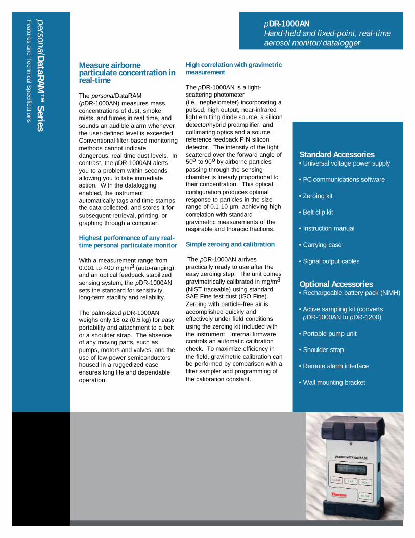
Measure airborneparticulate concentration inreal-time
The personalDataRAM(pDR-1000AN) measures massconcentrations of dust, smoke,mists, and fumes in real time, andsounds an audible alarm wheneverthe user-defined level is exceeded.Conventional filter-based monitoringmethods cannot indicatedangerous, real-time dust levels. Incontrast, the pDR-1000AN alertsyou to a problem within seconds,allowing you to take immediateaction. With the dataloggingenabled, the instrumentautomatically tags and time stampsthe data collected, and stores it forsubsequent retrieval, printing, orgraphing through a computer.
Highest performance of any real-time personal particulate monitor
With a measurement range from0.001 to 400 mg/m3 (auto-ranging),and an optical feedback stabilizedsensing system, the pDR-1000ANsets the standard for sensitivity,long-term stability and reliability.
The palm-sized pDR-1000ANweighs only 18 oz (0.5 kg) for easyportability and attachment to a beltor a shoulder strap. The absenceof any moving parts, such aspumps, motors and valves, and theuse of low-power semiconductorshoused in a ruggedized caseensures long life and dependableoperation.
High correlation with gravimetricmeasurement
The pDR-1000AN is a light-scattering photometer(i.e., nephelometer) incorporating apulsed, high output, near-infraredlight emitting diode source, a silicondetector/hybrid preamplifier, andcollimating optics and a sourcereference feedback PIN silicondetector. The intensity of the lightscattered over the forward angle of50o to 90o by airborne particlespassing through the sensingchamber is linearly proportional totheir concentration. This opticalconfiguration produces optimalresponse to particles in the sizerange of 0.1-10 µm, achieving highcorrelation with standardgravimetric measurements of therespirable and thoracic fractions.
Simple zeroing and calibration
The pDR-1000AN arrivespractically ready to use after theeasy zeroing step. The unit comesgravimetrically calibrated in mg/m3
(NIST traceable) using standardSAE Fine test dust (ISO Fine).Zeroing with particle-free air isaccomplished quickly andeffectively under field conditionsusing the zeroing kit included withthe instrument. Internal firmwarecontrols an automatic calibrationcheck. To maximize efficiency inthe field, gravimetric calibration canbe performed by comparison with afilter sampler and programming ofthe calibration constant.
personalDataRAM
™ Series
Features and T
echnical Specifications
pDR-1000ANHand-held and fixed-point, real-time aerosol monitor/datalogger
Standard Accessories• Universal voltage power supply
• PC communications software
• Zeroing kit
• Belt clip kit
• Instruction manual
• Carrying case
• Signal output cables
Optional Accessories• Rechargeable battery pack (NiMH)
• Active sampling kit (convertspDR-1000AN to pDR-1200)
• Portable pump unit
• Shoulder strap
• Remote alarm interface
• Wall mounting bracket
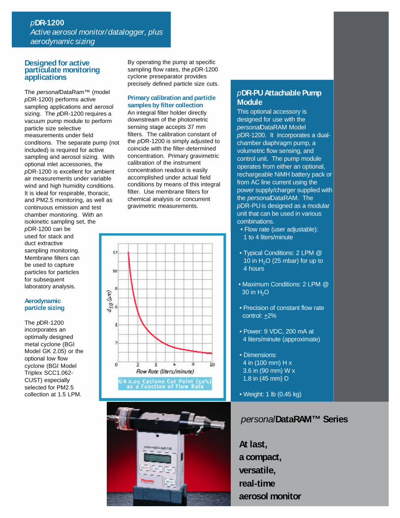
Designed for activeparticulate monitoringapplications
The personalDataRam™ (modelpDR-1200) performs activesampling applications and aerosolsizing. The pDR-1200 requires avacuum pump module to performparticle size selectivemeasurements under fieldconditions. The separate pump (notincluded) is required for activesampling and aerosol sizing. Withoptional inlet accessories, thepDR-1200 is excellent for ambientair measurements under variablewind and high humidity conditions.It is ideal for respirable, thoracic,and PM2.5 monitoring, as well ascontinuous emission and testchamber monitoring. With anisokinetic sampling set, thepDR-1200 can beused for stack andduct extractivesampling monitoring.Membrane filters canbe used to captureparticles for particlesfor subsequentlaboratory analysis.
Aerodynamicparticle sizing
The pDR-1200incorporates anoptimally designedmetal cyclone (BGIModel GK 2.05) or theoptional low flowcyclone (BGI ModelTriplex SCC1.062-CUST) especiallyselected for PM2.5collection at 1.5 LPM.
By operating the pump at specificsampling flow rates, the pDR-1200cyclone preseparator providesprecisely defined particle size cuts.
Primary calibration and particlesamples by filter collectionAn integral filter holder directlydownstream of the photometricsensing stage accepts 37 mmfilters. The calibration constant ofthe pDR-1200 is simply adjusted tocoincide with the filter-determinedconcentration. Primary gravimetriccalibration of the instrumentconcentration readout is easilyaccomplished under actual fieldconditions by means of this integralfilter. Use membrane filters forchemical analysis or concurrentgravimetric measurements.
At last,a compact,versatile,real-timeaerosol monitor
personalDataRAM™ Series
pDR-1200Active aerosol monitor/datalogger, plus aerodynamic sizing
pDR-PU Attachable Pump ModuleThis optional accessory is designed for use with thepersonalDataRAM ModelpDR-1200. It incorporates a dual-chamber diaphragm pump, avolumetric flow sensing, andcontrol unit. The pump module operates from either an optional, rechargeable NiMH battery pack orfrom AC line current using the power supply/charger supplied withthe personalDataRAM. ThepDR-PU is designed as a modular unit that can be used in variouscombinations.• Flow rate (user adjustable):1 to 4 liters/minute
• Typical Conditions: 2 LPM @10 in H2O (25 mbar) for up to4 hours
• Maximum Conditions: 2 LPM @ 30 in H2O
• Precision of constant flow rate control: +2%
• Power: 9 VDC, 200 mA at4 liters/minute (approximate)
• Dimensions:4 in (100 mm) H x 3.6 in (90 mm) W x1.8 in (45 mm) D
• Weight: 1 lb (0.45 kg)
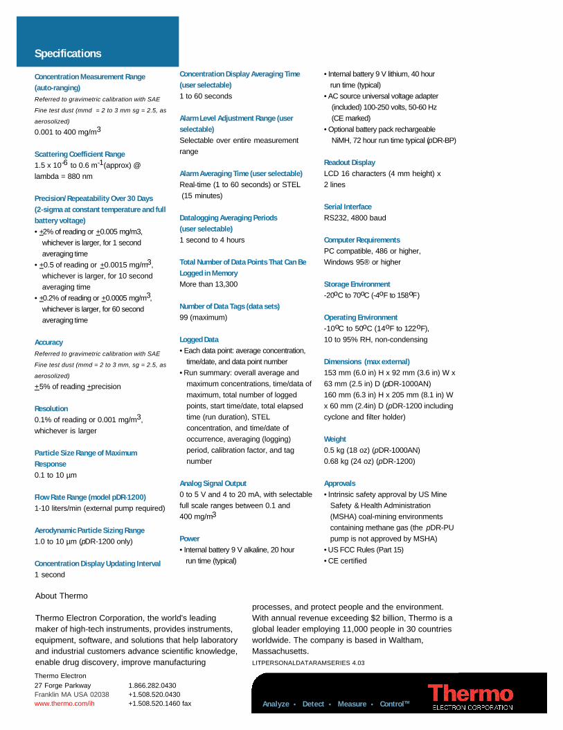
Analyze • Detect • Measure • ControlTM
Specifications
Concentration Measurement Range(auto-ranging)Referred to gravimetric calibration with SAE
Fine test dust (mmd = 2 to 3 mm sg = 2.5, as
aerosolized)
0.001 to 400 mg/m3
Scattering Coefficient Range 1.5 x 10⁻⁶ to 0.6 m-1(approx) @lambda = 880 nm
Precision/Repeatability Over 30 Days(2-sigma at constant temperature and fullbattery voltage) • +2% of reading or +0.005 mg/m3,
whichever is larger, for 1 second averaging time
• +0.5 of reading or +0.0015 mg/m3, whichever is larger, for 10 second averaging time
• +0.2% of reading or +0.0005 mg/m3, whichever is larger, for 60 second averaging time
Accuracy Referred to gravimetric calibration with SAE
Fine test dust (mmd = 2 to 3 mm, sg = 2.5, as
aerosolized)
+5% of reading +precision
Resolution 0.1% of reading or 0.001 mg/m3,whichever is larger
Particle Size Range of MaximumResponse 0.1 to 10 µm
Flow Rate Range (model pDR-1200)1-10 liters/min (external pump required)
Aerodynamic Particle Sizing Range1.0 to 10 µm (pDR-1200 only)
Concentration Display Updating Interval 1 second
Concentration Display Averaging Time(user selectable)1 to 60 seconds
Alarm Level Adjustment Range (userselectable) Selectable over entire measurementrange
Alarm Averaging Time (user selectable) Real-time (1 to 60 seconds) or STEL(15 minutes)
Datalogging Averaging Periods(user selectable) 1 second to 4 hours
Total Number of Data Points That Can BeLogged in Memory More than 13,300
Number of Data Tags (data sets) 99 (maximum)
Logged Data• Each data point: average concentration,
time/date, and data point number• Run summary: overall average and
maximum concentrations, time/data ofmaximum, total number of logged points, start time/date, total elapsed time (run duration), STELconcentration, and time/date ofoccurrence, averaging (logging)period, calibration factor, and tag number
Analog Signal Output 0 to 5 V and 4 to 20 mA, with selectablefull scale ranges between 0.1 and400 mg/m3
Power • Internal battery 9 V alkaline, 20 hour
run time (typical)
• Internal battery 9 V lithium, 40 hour run time (typical)
• AC source universal voltage adapter (included) 100-250 volts, 50-60 Hz (CE marked)
• Optional battery pack rechargeable NiMH, 72 hour run time typical (pDR-BP)
Readout Display LCD 16 characters (4 mm height) x2 lines
Serial Interface RS232, 4800 baud
Computer Requirements PC compatible, 486 or higher,Windows 95® or higher
Storage Environment-20oC to 70oC (-4oF to 158oF)
Operating Environment -10oC to 50oC (14oF to 122oF),10 to 95% RH, non-condensing
Dimensions (max external)153 mm (6.0 in) H x 92 mm (3.6 in) W x63 mm (2.5 in) D (pDR-1000AN)160 mm (6.3 in) H x 205 mm (8.1 in) Wx 60 mm (2.4in) D (pDR-1200 includingcyclone and filter holder)
Weight 0.5 kg (18 oz) (pDR-1000AN)0.68 kg (24 oz) (pDR-1200)
Approvals• Intrinsic safety approval by US Mine
Safety & Health Administration (MSHA) coal-mining environments containing methane gas (the pDR-PUpump is not approved by MSHA)
• US FCC Rules (Part 15)• CE certified
About Thermo
Thermo Electron Corporation, the world's leadingmaker of high-tech instruments, provides instruments,equipment, software, and solutions that help laboratoryand industrial customers advance scientific knowledge,enable drug discovery, improve manufacturing
processes, and protect people and the environment. With annual revenue exceeding $2 billion, Thermo is aglobal leader employing 11,000 people in 30 countriesworldwide. The company is based in Waltham,Massachusetts.LITPERSONALDATARAMSERIES 4.03
Thermo Electron27 Forge Parkway 1.866.282.0430Franklin MA USA 02038 +1.508.520.0430www.thermo.com/ih +1.508.520.1460 fax
Appendix E
Screening Level Tables
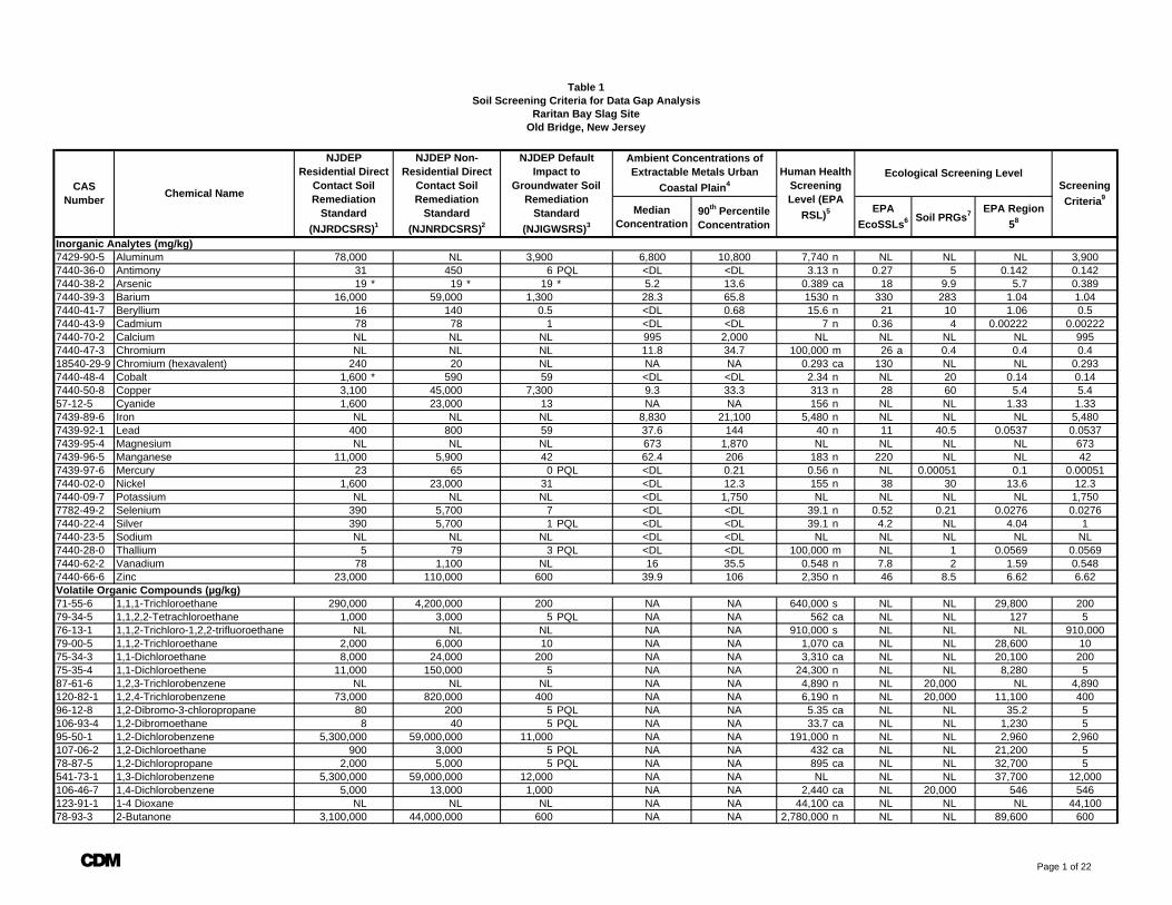
Median Concentration
90th Percentile Concentration
Inorganic Analytes (mg/kg)7429-90-5 Aluminum 78,000 NL 3,900 6,800 10,800 7,740 n NL NL NL 3,9007440-36-0 Antimony 31 450 6 PQL <DL <DL 3.13 n 0.27 5 0.142 0.1427440-38-2 Arsenic 19 * 19 * 19 * 5.2 13.6 0.389 ca 18 9.9 5.7 0.3897440-39-3 Barium 16,000 59,000 1,300 28.3 65.8 1530 n 330 283 1.04 1.047440-41-7 Beryllium 16 140 0.5 <DL 0.68 15.6 n 21 10 1.06 0.57440-43-9 Cadmium 78 78 1 <DL <DL 7 n 0.36 4 0.00222 0.002227440-70-2 Calcium NL NL NL 995 2,000 NL NL NL NL 9957440-47-3 Chromium NL NL NL 11.8 34.7 100,000 m 26 a 0.4 0.4 0.418540-29-9 Chromium (hexavalent) 240 20 NL NA NA 0.293 ca 130 NL NL 0.2937440-48-4 Cobalt 1,600 * 590 59 <DL <DL 2.34 n NL 20 0.14 0.147440-50-8 Copper 3,100 45,000 7,300 9.3 33.3 313 n 28 60 5.4 5.457-12-5 Cyanide 1,600 23,000 13 NA NA 156 n NL NL 1.33 1.337439-89-6 Iron NL NL NL 8,830 21,100 5,480 n NL NL NL 5,4807439-92-1 Lead 400 800 59 37.6 144 40 n 11 40.5 0.0537 0.05377439-95-4 Magnesium NL NL NL 673 1,870 NL NL NL NL 6737439-96-5 Manganese 11,000 5,900 42 62.4 206 183 n 220 NL NL 427439-97-6 Mercury 23 65 0 PQL <DL 0.21 0.56 n NL 0.00051 0.1 0.000517440-02-0 Nickel 1,600 23,000 31 <DL 12.3 155 n 38 30 13.6 12.37440-09-7 Potassium NL NL NL <DL 1,750 NL NL NL NL 1,7507782-49-2 Selenium 390 5,700 7 <DL <DL 39.1 n 0.52 0.21 0.0276 0.02767440-22-4 Silver 390 5,700 1 PQL <DL <DL 39.1 n 4.2 NL 4.04 17440-23-5 Sodium NL NL NL <DL <DL NL NL NL NL NL7440-28-0 Thallium 5 79 3 PQL <DL <DL 100,000 m NL 1 0.0569 0.05697440-62-2 Vanadium 78 1,100 NL 16 35.5 0.548 n 7.8 2 1.59 0.5487440-66-6 Zinc 23,000 110,000 600 39.9 106 2,350 n 46 8.5 6.62 6.62Volatile Organic Compounds (µg/kg)71-55-6 1,1,1-Trichloroethane 290,000 4,200,000 200 NA NA 640,000 s NL NL 29,800 20079-34-5 1,1,2,2-Tetrachloroethane 1,000 3,000 5 PQL NA NA 562 ca NL NL 127 576-13-1 1,1,2-Trichloro-1,2,2-trifluoroethane NL NL NL NA NA 910,000 s NL NL NL 910,00079-00-5 1,1,2-Trichloroethane 2,000 6,000 10 NA NA 1,070 ca NL NL 28,600 1075-34-3 1,1-Dichloroethane 8,000 24,000 200 NA NA 3,310 ca NL NL 20,100 20075-35-4 1,1-Dichloroethene 11,000 150,000 5 NA NA 24,300 n NL NL 8,280 587-61-6 1,2,3-Trichlorobenzene NL NL NL NA NA 4,890 n NL 20,000 NL 4,890120-82-1 1,2,4-Trichlorobenzene 73,000 820,000 400 NA NA 6,190 n NL 20,000 11,100 40096-12-8 1,2-Dibromo-3-chloropropane 80 200 5 PQL NA NA 5.35 ca NL NL 35.2 5106-93-4 1,2-Dibromoethane 8 40 5 PQL NA NA 33.7 ca NL NL 1,230 595-50-1 1,2-Dichlorobenzene 5,300,000 59,000,000 11,000 NA NA 191,000 n NL NL 2,960 2,960107-06-2 1,2-Dichloroethane 900 3,000 5 PQL NA NA 432 ca NL NL 21,200 578-87-5 1,2-Dichloropropane 2,000 5,000 5 PQL NA NA 895 ca NL NL 32,700 5541-73-1 1,3-Dichlorobenzene 5,300,000 59,000,000 12,000 NA NA NL NL NL 37,700 12,000106-46-7 1,4-Dichlorobenzene 5,000 13,000 1,000 NA NA 2,440 ca NL 20,000 546 546123-91-1 1-4 Dioxane NL NL NL NA NA 44,100 ca NL NL NL 44,10078-93-3 2-Butanone 3,100,000 44,000,000 600 NA NA 2,780,000 n NL NL 89,600 600
Table 1Soil Screening Criteria for Data Gap Analysis
Raritan Bay Slag SiteOld Bridge, New Jersey
CAS Number Chemical Name
Human Health Screening Level (EPA
RSL)5 EPA EcoSSLs6
Screening Criteria9
Soil PRGs7 EPA Region 58
Ecological Screening LevelNJDEP
Residential Direct Contact Soil Remediation
Standard (NJRDCSRS)1
NJDEP Non-Residential Direct
Contact Soil Remediation
Standard (NJNRDCSRS)2
NJDEP Default Impact to
Groundwater Soil Remediation
Standard (NJIGWSRS)3
Ambient Concentrations of Extractable Metals Urban
Coastal Plain4
A Page 1 of 22
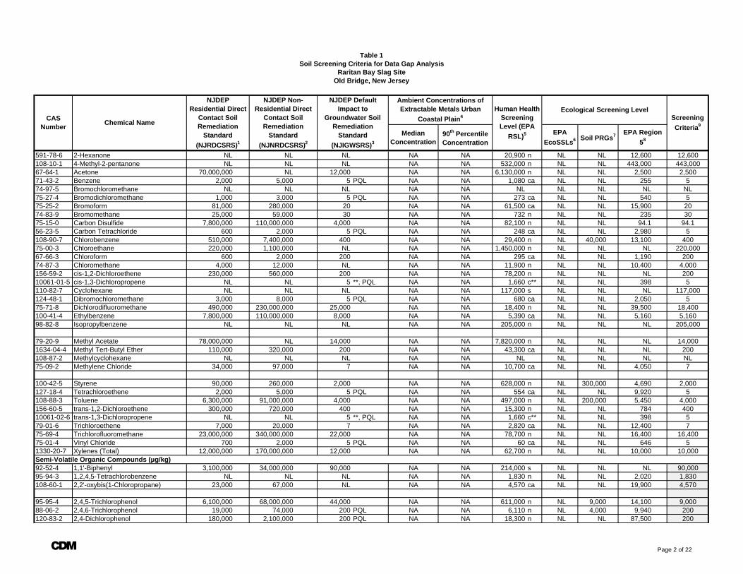
Median Concentration
90th Percentile Concentration
Table 1Soil Screening Criteria for Data Gap Analysis
Raritan Bay Slag SiteOld Bridge, New Jersey
CAS Number Chemical Name
Human Health Screening Level (EPA
RSL)5 EPA EcoSSLs6
Screening Criteria9
Soil PRGs7 EPA Region 58
Ecological Screening LevelNJDEP
Residential Direct Contact Soil Remediation
Standard (NJRDCSRS)1
NJDEP Non-Residential Direct
Contact Soil Remediation
Standard (NJNRDCSRS)2
NJDEP Default Impact to
Groundwater Soil Remediation
Standard (NJIGWSRS)3
Ambient Concentrations of Extractable Metals Urban
Coastal Plain4
591-78-6 2-Hexanone NL NL NL NA NA 20,900 n NL NL 12,600 12,600108-10-1 4-Methyl-2-pentanone NL NL NL NA NA 532,000 n NL NL 443,000 443,00067-64-1 Acetone 70,000,000 NL 12,000 NA NA 6,130,000 n NL NL 2,500 2,50071-43-2 Benzene 2,000 5,000 5 PQL NA NA 1,080 ca NL NL 255 574-97-5 Bromochloromethane NL NL NL NA NA NL NL NL NL NL75-27-4 Bromodichloromethane 1,000 3,000 5 PQL NA NA 273 ca NL NL 540 575-25-2 Bromoform 81,000 280,000 20 NA NA 61,500 ca NL NL 15,900 2074-83-9 Bromomethane 25,000 59,000 30 NA NA 732 n NL NL 235 3075-15-0 Carbon Disulfide 7,800,000 110,000,000 4,000 NA NA 82,100 n NL NL 94.1 94.156-23-5 Carbon Tetrachloride 600 2,000 5 PQL NA NA 248 ca NL NL 2,980 5108-90-7 Chlorobenzene 510,000 7,400,000 400 NA NA 29,400 n NL 40,000 13,100 40075-00-3 Chloroethane 220,000 1,100,000 NL NA NA 1,450,000 n NL NL NL 220,00067-66-3 Chloroform 600 2,000 200 NA NA 295 ca NL NL 1,190 20074-87-3 Chloromethane 4,000 12,000 NL NA NA 11,900 n NL NL 10,400 4,000156-59-2 cis-1,2-Dichloroethene 230,000 560,000 200 NA NA 78,200 n NL NL NL 20010061-01-5 cis-1,3-Dichloropropene NL NL 5 **, PQL NA NA 1,660 c** NL NL 398 5110-82-7 Cyclohexane NL NL NL NA NA 117,000 s NL NL NL 117,000124-48-1 Dibromochloromethane 3,000 8,000 5 PQL NA NA 680 ca NL NL 2,050 575-71-8 Dichlorodifluoromethane 490,000 230,000,000 25,000 NA NA 18,400 n NL NL 39,500 18,400100-41-4 Ethylbenzene 7,800,000 110,000,000 8,000 NA NA 5,390 ca NL NL 5,160 5,16098-82-8 Isopropylbenzene NL NL NL NA NA 205,000 n NL NL NL 205,000
79-20-9 Methyl Acetate 78,000,000 NL 14,000 NA NA 7,820,000 n NL NL NL 14,0001634-04-4 Methyl Tert-Butyl Ether 110,000 320,000 200 NA NA 43,300 ca NL NL NL 200108-87-2 Methylcyclohexane NL NL NL NA NA NL NL NL NL NL75-09-2 Methylene Chloride 34,000 97,000 7 NA NA 10,700 ca NL NL 4,050 7
100-42-5 Styrene 90,000 260,000 2,000 NA NA 628,000 n NL 300,000 4,690 2,000127-18-4 Tetrachloroethene 2,000 5,000 5 PQL NA NA 554 ca NL NL 9,920 5108-88-3 Toluene 6,300,000 91,000,000 4,000 NA NA 497,000 n NL 200,000 5,450 4,000156-60-5 trans-1,2-Dichloroethene 300,000 720,000 400 NA NA 15,300 n NL NL 784 40010061-02-6 trans-1,3-Dichloropropene NL NL 5 **, PQL NA NA 1,660 c** NL NL 398 579-01-6 Trichloroethene 7,000 20,000 7 NA NA 2,820 ca NL NL 12,400 775-69-4 Trichlorofluoromethane 23,000,000 340,000,000 22,000 NA NA 78,700 n NL NL 16,400 16,40075-01-4 Vinyl Chloride 700 2,000 5 PQL NA NA 60 ca NL NL 646 51330-20-7 Xylenes (Total) 12,000,000 170,000,000 12,000 NA NA 62,700 n NL NL 10,000 10,000Semi-Volatile Organic Compounds (µg/kg)92-52-4 1,1'-Biphenyl 3,100,000 34,000,000 90,000 NA NA 214,000 s NL NL NL 90,00095-94-3 1,2,4,5-Tetrachlorobenzene NL NL NL NA NA 1,830 n NL NL 2,020 1,830108-60-1 2,2'-oxybis(1-Chloropropane) 23,000 67,000 NL NA NA 4,570 ca NL NL 19,900 4,570
95-95-4 2,4,5-Trichlorophenol 6,100,000 68,000,000 44,000 NA NA 611,000 n NL 9,000 14,100 9,00088-06-2 2,4,6-Trichlorophenol 19,000 74,000 200 PQL NA NA 6,110 n NL 4,000 9,940 200120-83-2 2,4-Dichlorophenol 180,000 2,100,000 200 PQL NA NA 18,300 n NL NL 87,500 200
A Page 2 of 22
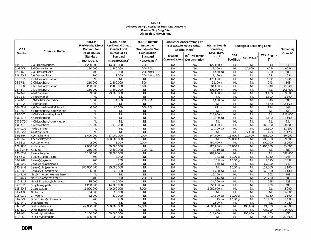
Median Concentration
90th Percentile Concentration
Table 1Soil Screening Criteria for Data Gap Analysis
Raritan Bay Slag SiteOld Bridge, New Jersey
CAS Number Chemical Name
Human Health Screening Level (EPA
RSL)5 EPA EcoSSLs6
Screening Criteria9
Soil PRGs7 EPA Region 58
Ecological Screening LevelNJDEP
Residential Direct Contact Soil Remediation
Standard (NJRDCSRS)1
NJDEP Non-Residential Direct
Contact Soil Remediation
Standard (NJNRDCSRS)2
NJDEP Default Impact to
Groundwater Soil Remediation
Standard (NJIGWSRS)3
Ambient Concentrations of Extractable Metals Urban
Coastal Plain4
105-67-9 2,4-Dimethylphenol 1,200,000 14,000,000 700 NA NA 122,000 n NL NL 10 1051-28-5 2,4-Dinitrophenol 120,000 1,400,000 300 PQL NA NA 12,200 n NL 20,000 60.9 60.9121-14-2 2,4-Dinitrotoluene 700 3,000 200 ####, PQL NA NA 1,560 ca NL NL 1280 200606-20-2 2,6-Dinitrotoluene 700 3,000 200 ####, PQL NA NA 6,120 n NL NL 32.8 32.891-58-7 2-Chloronaphthalene NL NL NL NA NA 175,000 s NL NL 12.2 12.295-57-8 2-Chlorophenol 310,000 2,200,000 500 NA NA 39100 n NL NL 243 24391-57-6 2-Methylnaphthalene 230,000 2,400,000 5,000 NA NA 31,300 n NL NL 3,240 3,24095-48-7 2-Methylphenol 310,000 3,400,000 NL NA NA 306,000 n NL NL NL 306,00088-74-4 2-Nitroaniline 39,000 23,000,000 NL NA NA 60,600 n NL NL 74,100 39,00088-75-5 2-Nitrophenol NL NL NL NA NA NL NL NL 1,600 1,60091-94-1 3,3'-Dichlorobenzidine 1,000 4,000 200 PQL NA NA 1,080 ca NL NL 646 20099-09-2 3-Nitroaniline NL NL NL NA NA NL NL NL 3,160 3,160534-52-1 4,6-Dinitro-2-methylphenol 6,000 68,000 300 PQL NA NA 611 n NL NL 144 144101-55-3 4-Bromophenyl-phenylether NL NL NL NA NA NL NL NL NL NL59-50-7 4-Chloro-3-methylphenol NL NL NL NA NA 611,000 n NL NL NL 611,000106-47-8 4-Chloroaniline NL NL NL NA NA 2,430 ca NL NL 1,100 1,1007005-72-3 4-Chlorophenyl-phenylether NL NL NL NA NA NL NL NL NL NL106-44-5 4-Methylphenol 31,000 340,000 NL NA NA 30,600 n NL NL 163,000 30,600100-01-6 4-Nitroaniline NL NL NL NA NA 24,300 ca NL NL 21,900 21,900100-02-7 4-Nitrophenol NL NL NL NA NA NL NL 7,000 5,120 5,12083-32-9 Acenaphthene 3,400,000 37,000,000 74,000 NA NA 344,000 n 29,000 f 20,000 682,000 20,000208-96-8 Acenaphthylene NL 300,000,000 NL NA NA NL 29,000 f NL 682,000 29,00098-86-2 Acetophenone 2,000 5,000 2,000 NA NA 782,000 n NL NL 300,000 2,000120-12-7 Anthracene 17,000,000 30,000,000 NL NA NA 1,720,000 n 29,000 f NL 1,480,000 29,0001912-24-9 Atrazine 210,000 2,400,000 200 PQL NA NA 2,110 ca NL NL NL 200100-52-7 Benzaldehyde 6,100,000 68,000,000 NL NA NA 782,000 n NL NL NL 782,00056-55-3 Benzo(a)anthracene 600 2,000 NL NA NA 148 ca 1,100 g NL 5,210 14850-32-8 Benzo(a)pyrene 200 200 NL NA NA 14.8 ca 1,100 g NL 1,520 14.8205-99-2 Benzo(b)fluoranthene 600 2,000 NL NA NA 148 ca NL NL 59,800 148191-24-2 Benzo(g,h,i)perylene 380,000,000 30,000,000 NL NA NA NL 1,100 g NL 119,000 1,100207-08-9 Benzo(k)fluoranthene 6,000 23,000 NL NA NA 1,480 ca NL NL 148,000 1,480111-91-1 bis(2-Chloroethoxy)methane NL NL NL NA NA 18,300 n NL NL 302 302111-44-4 bis(2-Chloroethyl)ether 400 2,000 200 PQL NA NA 214 ca NL NL 23,700 200117-81-7 bis-(2-Ethylhexyl)phthalate 35,000 140,000 NL NA NA 34,700 ca NL NL 925 92585-68-7 Butylbenzylphthalate 1,200,000 14,000,000 NL NA NA 256,000 ca NL NL 239 239105-60-2 Caprolactam 31,000,000 340,000,000 8,000 NA NA 3,060,000 n NL NL NL 8,00086-74-8 Carbazole 24,000 96,000 NL NA NA NL NL NL NL 24,000218-01-9 Chrysene 62,000 230,000 NL NA NA 14,800 ca 1,100 g NL 4,730 1,10053-70-3 Dibenzo(a,h)anthracene 200 200 NL NA NA 15 ca 1,100 g NL 18,400 14.8132-64-9 Dibenzofuran NL NL NL NA NA 7,820 n NL NL NL 7,82084-66-2 Diethylphthalate 49,000,000 550,000,000 57,000 NA NA 4,890,000 n NL 100,000 24,800 24,800131-11-3 Dimethylphthalate NL NL NL NA NA NL NL NL 734,000 734,00084-74-2 Di-n-butylphthalate 6,100,000 68,000,000 NL NA NA 611,000 n NL 200,000 150 150117-84-0 Di-n-octylphthalate 2,400,000 27,000,000 NL NA NA NL NL NL 709,000 709,000
A Page 3 of 22
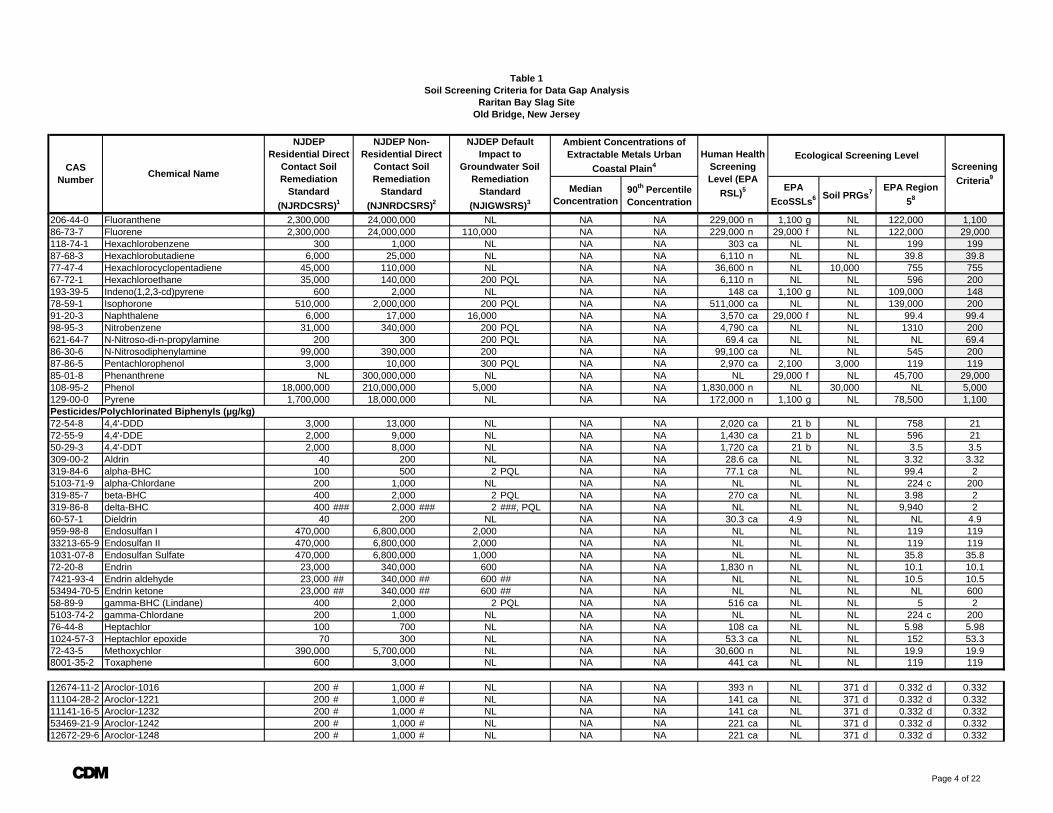
Median Concentration
90th Percentile Concentration
Table 1Soil Screening Criteria for Data Gap Analysis
Raritan Bay Slag SiteOld Bridge, New Jersey
CAS Number Chemical Name
Human Health Screening Level (EPA
RSL)5 EPA EcoSSLs6
Screening Criteria9
Soil PRGs7 EPA Region 58
Ecological Screening LevelNJDEP
Residential Direct Contact Soil Remediation
Standard (NJRDCSRS)1
NJDEP Non-Residential Direct
Contact Soil Remediation
Standard (NJNRDCSRS)2
NJDEP Default Impact to
Groundwater Soil Remediation
Standard (NJIGWSRS)3
Ambient Concentrations of Extractable Metals Urban
Coastal Plain4
206-44-0 Fluoranthene 2,300,000 24,000,000 NL NA NA 229,000 n 1,100 g NL 122,000 1,10086-73-7 Fluorene 2,300,000 24,000,000 110,000 NA NA 229,000 n 29,000 f NL 122,000 29,000118-74-1 Hexachlorobenzene 300 1,000 NL NA NA 303 ca NL NL 199 19987-68-3 Hexachlorobutadiene 6,000 25,000 NL NA NA 6,110 n NL NL 39.8 39.877-47-4 Hexachlorocyclopentadiene 45,000 110,000 NL NA NA 36,600 n NL 10,000 755 75567-72-1 Hexachloroethane 35,000 140,000 200 PQL NA NA 6,110 n NL NL 596 200193-39-5 Indeno(1,2,3-cd)pyrene 600 2,000 NL NA NA 148 ca 1,100 g NL 109,000 14878-59-1 Isophorone 510,000 2,000,000 200 PQL NA NA 511,000 ca NL NL 139,000 20091-20-3 Naphthalene 6,000 17,000 16,000 NA NA 3,570 ca 29,000 f NL 99.4 99.498-95-3 Nitrobenzene 31,000 340,000 200 PQL NA NA 4,790 ca NL NL 1310 200621-64-7 N-Nitroso-di-n-propylamine 200 300 200 PQL NA NA 69.4 ca NL NL NL 69.486-30-6 N-Nitrosodiphenylamine 99,000 390,000 200 NA NA 99,100 ca NL NL 545 20087-86-5 Pentachlorophenol 3,000 10,000 300 PQL NA NA 2,970 ca 2,100 3,000 119 11985-01-8 Phenanthrene NL 300,000,000 NL NA NA NL 29,000 f NL 45,700 29,000108-95-2 Phenol 18,000,000 210,000,000 5,000 NA NA 1,830,000 n NL 30,000 NL 5,000129-00-0 Pyrene 1,700,000 18,000,000 NL NA NA 172,000 n 1,100 g NL 78,500 1,100Pesticides/Polychlorinated Biphenyls (µg/kg)72-54-8 4,4'-DDD 3,000 13,000 NL NA NA 2,020 ca 21 b NL 758 2172-55-9 4,4'-DDE 2,000 9,000 NL NA NA 1,430 ca 21 b NL 596 2150-29-3 4,4'-DDT 2,000 8,000 NL NA NA 1,720 ca 21 b NL 3.5 3.5309-00-2 Aldrin 40 200 NL NA NA 28.6 ca NL NL 3.32 3.32319-84-6 alpha-BHC 100 500 2 PQL NA NA 77.1 ca NL NL 99.4 25103-71-9 alpha-Chlordane 200 1,000 NL NA NA NL NL NL 224 c 200319-85-7 beta-BHC 400 2,000 2 PQL NA NA 270 ca NL NL 3.98 2319-86-8 delta-BHC 400 ### 2,000 ### 2 ###, PQL NA NA NL NL NL 9,940 260-57-1 Dieldrin 40 200 NL NA NA 30.3 ca 4.9 NL NL 4.9959-98-8 Endosulfan I 470,000 6,800,000 2,000 NA NA NL NL NL 119 11933213-65-9 Endosulfan II 470,000 6,800,000 2,000 NA NA NL NL NL 119 1191031-07-8 Endosulfan Sulfate 470,000 6,800,000 1,000 NA NA NL NL NL 35.8 35.872-20-8 Endrin 23,000 340,000 600 NA NA 1,830 n NL NL 10.1 10.17421-93-4 Endrin aldehyde 23,000 ## 340,000 ## 600 ## NA NA NL NL NL 10.5 10.553494-70-5 Endrin ketone 23,000 ## 340,000 ## 600 ## NA NA NL NL NL NL 60058-89-9 gamma-BHC (Lindane) 400 2,000 2 PQL NA NA 516 ca NL NL 5 25103-74-2 gamma-Chlordane 200 1,000 NL NA NA NL NL NL 224 c 20076-44-8 Heptachlor 100 700 NL NA NA 108 ca NL NL 5.98 5.981024-57-3 Heptachlor epoxide 70 300 NL NA NA 53.3 ca NL NL 152 53.372-43-5 Methoxychlor 390,000 5,700,000 NL NA NA 30,600 n NL NL 19.9 19.98001-35-2 Toxaphene 600 3,000 NL NA NA 441 ca NL NL 119 119
12674-11-2 Aroclor-1016 200 # 1,000 # NL NA NA 393 n NL 371 d 0.332 d 0.33211104-28-2 Aroclor-1221 200 # 1,000 # NL NA NA 141 ca NL 371 d 0.332 d 0.33211141-16-5 Aroclor-1232 200 # 1,000 # NL NA NA 141 ca NL 371 d 0.332 d 0.33253469-21-9 Aroclor-1242 200 # 1,000 # NL NA NA 221 ca NL 371 d 0.332 d 0.33212672-29-6 Aroclor-1248 200 # 1,000 # NL NA NA 221 ca NL 371 d 0.332 d 0.332
A Page 4 of 22
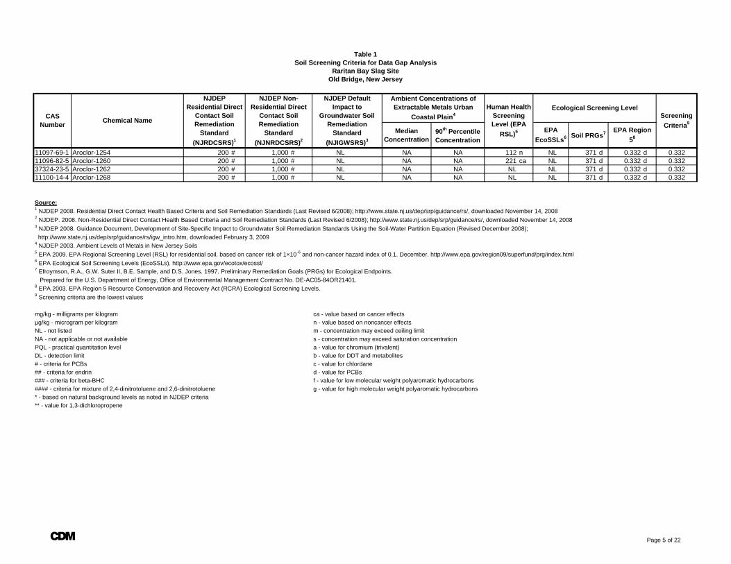
Median Concentration
90th Percentile Concentration
Table 1Soil Screening Criteria for Data Gap Analysis
Raritan Bay Slag SiteOld Bridge, New Jersey
CAS Number Chemical Name
Human Health Screening Level (EPA
RSL)5 EPA EcoSSLs6
Screening Criteria9
Soil PRGs7 EPA Region 58
Ecological Screening LevelNJDEP
Residential Direct Contact Soil Remediation
Standard (NJRDCSRS)1
NJDEP Non-Residential Direct
Contact Soil Remediation
Standard (NJNRDCSRS)2
NJDEP Default Impact to
Groundwater Soil Remediation
Standard (NJIGWSRS)3
Ambient Concentrations of Extractable Metals Urban
Coastal Plain4
11097-69-1 Aroclor-1254 200 # 1,000 # NL NA NA 112 n NL 371 d 0.332 d 0.33211096-82-5 Aroclor-1260 200 # 1,000 # NL NA NA 221 ca NL 371 d 0.332 d 0.33237324-23-5 Aroclor-1262 200 # 1,000 # NL NA NA NL NL 371 d 0.332 d 0.33211100-14-4 Aroclor-1268 200 # 1,000 # NL NA NA NL NL 371 d 0.332 d 0.332
Source:1 NJDEP 2008. Residential Direct Contact Health Based Criteria and Soil Remediation Standards (Last Revised 6/2008); http://www.state.nj.us/dep/srp/guidance/rs/, downloaded November 14, 20082 NJDEP. 2008. Non-Residential Direct Contact Health Based Criteria and Soil Remediation Standards (Last Revised 6/2008); http://www.state.nj.us/dep/srp/guidance/rs/, downloaded November 14, 20083 NJDEP 2008. Guidance Document, Development of Site-Specific Impact to Groundwater Soil Remediation Standards Using the Soil-Water Partition Equation (Revised December 2008); http://www.state.nj.us/dep/srp/guidance/rs/igw_intro.htm, downloaded February 3, 20094 NJDEP 2003. Ambient Levels of Metals in New Jersey Soils5 EPA 2009. EPA Regional Screening Level (RSL) for residential soil, based on cancer risk of 1×10⁻⁶ and non-cancer hazard index of 0.1. December. http://www.epa.gov/region09/superfund/prg/index.html6 EPA Ecological Soil Screening Levels (EcoSSLs). http://www.epa.gov/ecotox/ecossl/7 Efroymson, R.A., G.W. Suter II, B.E. Sample, and D.S. Jones. 1997. Preliminary Remediation Goals (PRGs) for Ecological Endpoints. Prepared for the U.S. Department of Energy, Office of Environmental Management Contract No. DE-AC05-84OR21401.8 EPA 2003. EPA Region 5 Resource Conservation and Recovery Act (RCRA) Ecological Screening Levels.9 Screening criteria are the lowest values
mg/kg - milligrams per kilogram ca - value based on cancer effectsµg/kg - microgram per kilogram n - value based on noncancer effectsNL - not listed m - concentration may exceed ceiling limit NA - not applicable or not available s - concentration may exceed saturation concentrationPQL - practical quantitation level a - value for chromium (trivalent)DL - detection limit b - value for DDT and metabolites# - criteria for PCBs c - value for chlordane## - criteria for endrin d - value for PCBs### - criteria for beta-BHC f - value for low molecular weight polyaromatic hydrocarbons#### - criteria for mixture of 2,4-dinitrotoluene and 2,6-dinitrotoluene g - value for high molecular weight polyaromatic hydrocarbons* - based on natural background levels as noted in NJDEP criteria** - value for 1,3-dichloropropene
A Page 5 of 22
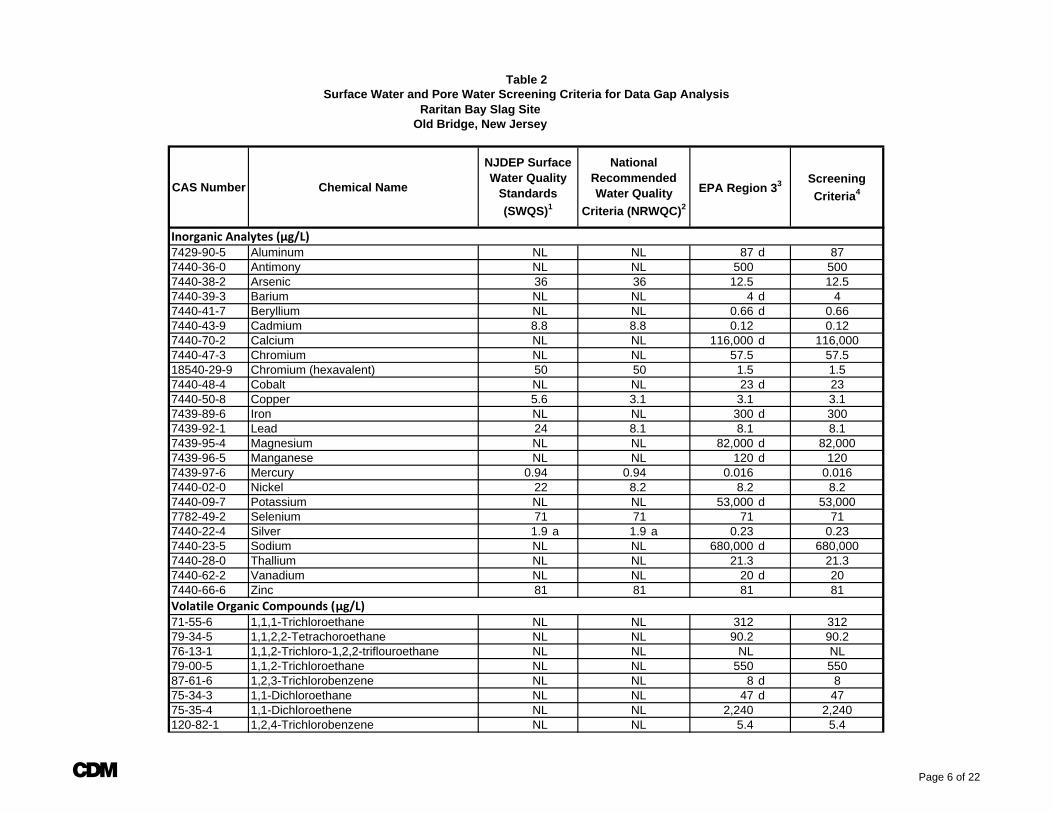
Raritan Bay Slag SiteOld Bridge, New Jersey
CAS Number Chemical NameScreening Criteria4
Inorganic Analytes (µg/L)7429-90-5 Aluminum NL NL 87 d 877440-36-0 Antimony NL NL 500 5007440-38-2 Arsenic 36 36 12.5 12.57440-39-3 Barium NL NL 4 d 47440-41-7 Beryllium NL NL 0.66 d 0.667440-43-9 Cadmium 8.8 8.8 0.12 0.127440-70-2 Calcium NL NL 116,000 d 116,0007440-47-3 Chromium NL NL 57.5 57.518540-29-9 Chromium (hexavalent) 50 50 1.5 1.57440-48-4 Cobalt NL NL 23 d 237440-50-8 Copper 5.6 3.1 3.1 3.17439-89-6 Iron NL NL 300 d 3007439-92-1 Lead 24 8.1 8.1 8.17439-95-4 Magnesium NL NL 82,000 d 82,0007439-96-5 Manganese NL NL 120 d 1207439-97-6 Mercury 0.94 0.94 0.016 0.0167440-02-0 Nickel 22 8.2 8.2 8.27440-09-7 Potassium NL NL 53,000 d 53,0007782-49-2 Selenium 71 71 71 717440-22-4 Silver 1.9 a 1.9 a 0.23 0.237440-23-5 Sodium NL NL 680,000 d 680,0007440-28-0 Thallium NL NL 21.3 21.37440-62-2 Vanadium NL NL 20 d 207440-66-6 Zinc 81 81 81 81Volatile Organic Compounds (µg/L)71-55-6 1,1,1-Trichloroethane NL NL 312 31279-34-5 1,1,2,2-Tetrachoroethane NL NL 90.2 90.276-13-1 1,1,2-Trichloro-1,2,2-triflouroethane NL NL NL NL79-00-5 1,1,2-Trichloroethane NL NL 550 55087-61-6 1,2,3-Trichlorobenzene NL NL 8 d 875-34-3 1,1-Dichloroethane NL NL 47 d 4775-35-4 1,1-Dichloroethene NL NL 2,240 2,240120-82-1 1,2,4-Trichlorobenzene NL NL 5.4 5.4
Table 2
NJDEP Surface Water Quality
Standards (SWQS)1
National Recommended Water Quality
Criteria (NRWQC)2
Surface Water and Pore Water Screening Criteria for Data Gap Analysis
EPA Region 33
A Page 6 of 22
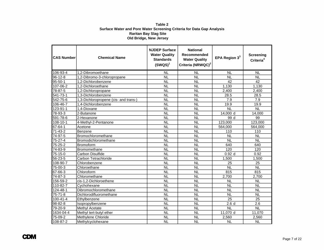
Raritan Bay Slag SiteOld Bridge, New Jersey
CAS Number Chemical NameScreening Criteria4
Table 2
NJDEP Surface Water Quality
Standards (SWQS)1
National Recommended Water Quality
Criteria (NRWQC)2
Surface Water and Pore Water Screening Criteria for Data Gap Analysis
EPA Region 33
106-93-4 1,2-Dibromoethane NL NL NL NL96-12-8 1,2-Dibromo-3-chloropropane NL NL NL NL95-50-1 1,2-Dichlorobenzene NL NL 42 42107-06-2 1,2-Dichloroethane NL NL 1,130 1,13078-87-5 1,2-Dichloropropane NL NL 2,400 2,400541-73-1 1,3-Dichlorobenzene NL NL 28.5 28.5542-75-6 1,3-Dichloropropene (cis- and trans-) NL NL 7.9 7.9106-46-7 1,4-Dichlorobenzene NL NL 19.9 19.9123-91-1 1,4-Dioxane NL NL NL NL78-93-3 2-Butanone NL NL 14,000 d 14,000591-78-6 2-Hexanone NL NL 99 d 99108-10-1 4-Methyl-2-Pentanone NL NL 123,000 123,00067-64-1 Acetone NL NL 564,000 564,00071-43-2 Benzene NL NL 110 11074-97-5 Bromochloromethane NL NL NL NL75-27-4 Bromodichloromethane NL NL NL NL75-25-2 Bromoform NL NL 640 64074-83-9 Bromomethane NL NL 120 12075-15-0 Carbon Disulfide NL NL 0.92 d 0.9256-23-5 Carbon Tetrachloride NL NL 1,500 1,500108-90-7 Chlorobenzene NL NL 25 2575-00-3 Chloroethane NL NL NL NL67-66-3 Chloroform NL NL 815 81574-87-3 Chloromethane NL NL 2,700 2,700156-59-2 cis-1,2-Dichloroethene NL NL NL NL110-82-7 Cychohexane NL NL NL NL124-48-1 Dibromochloromethane NL NL NL NL75-71-8 Dichlorodifluoromethane NL NL NL NL100-41-4 Ethylbenzene NL NL 25 2598-82-8 Isopropylbenzene NL NL 2.6 d 2.679-20-9 Methyl Acetate NL NL NL NL1634-04-4 Methyl tert-butyl ether NL NL 11,070 d 11,07075-09-2 Methylene Chloride NL NL 2,560 2,560108-87-2 Methylcyclohexane NL NL NL NL
A Page 7 of 22
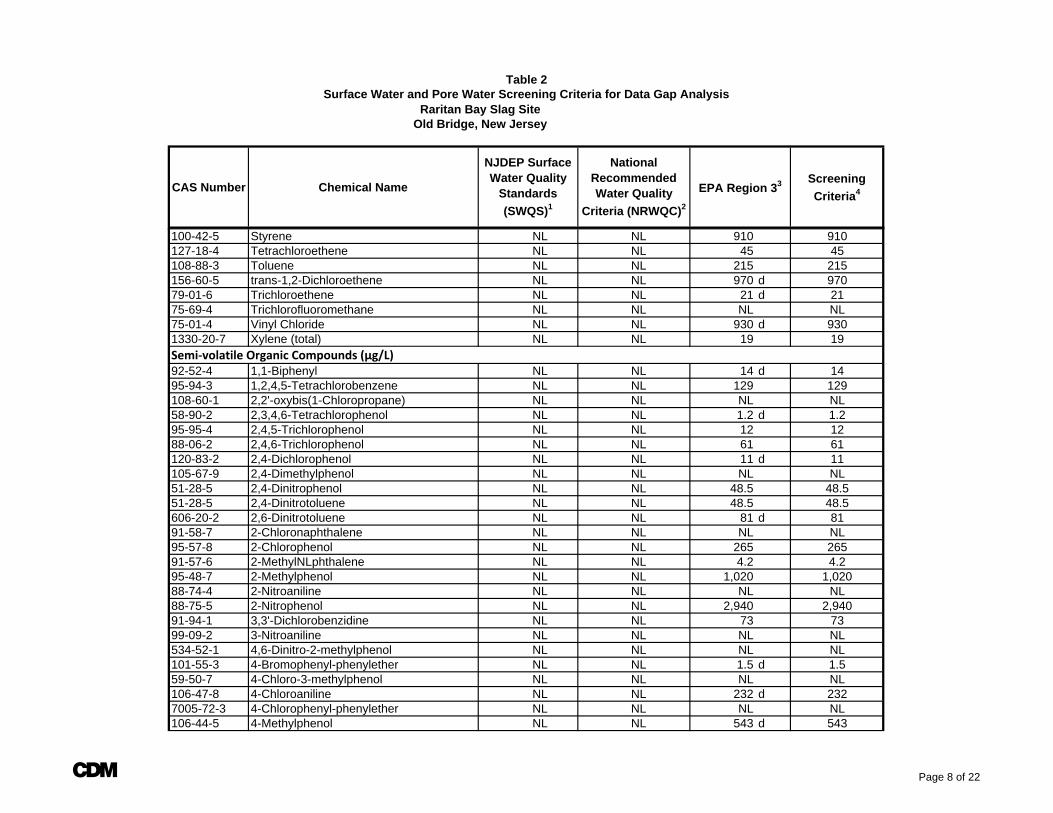
Raritan Bay Slag SiteOld Bridge, New Jersey
CAS Number Chemical NameScreening Criteria4
Table 2
NJDEP Surface Water Quality
Standards (SWQS)1
National Recommended Water Quality
Criteria (NRWQC)2
Surface Water and Pore Water Screening Criteria for Data Gap Analysis
EPA Region 33
100-42-5 Styrene NL NL 910 910127-18-4 Tetrachloroethene NL NL 45 45108-88-3 Toluene NL NL 215 215156-60-5 trans-1,2-Dichloroethene NL NL 970 d 97079-01-6 Trichloroethene NL NL 21 d 2175-69-4 Trichlorofluoromethane NL NL NL NL75-01-4 Vinyl Chloride NL NL 930 d 9301330-20-7 Xylene (total) NL NL 19 19Semi‐volatile Organic Compounds (µg/L)92-52-4 1,1-Biphenyl NL NL 14 d 1495-94-3 1,2,4,5-Tetrachlorobenzene NL NL 129 129108-60-1 2,2'-oxybis(1-Chloropropane) NL NL NL NL58-90-2 2,3,4,6-Tetrachlorophenol NL NL 1.2 d 1.295-95-4 2,4,5-Trichlorophenol NL NL 12 1288-06-2 2,4,6-Trichlorophenol NL NL 61 61120-83-2 2,4-Dichlorophenol NL NL 11 d 11105-67-9 2,4-Dimethylphenol NL NL NL NL51-28-5 2,4-Dinitrophenol NL NL 48.5 48.551-28-5 2,4-Dinitrotoluene NL NL 48.5 48.5606-20-2 2,6-Dinitrotoluene NL NL 81 d 8191-58-7 2-Chloronaphthalene NL NL NL NL95-57-8 2-Chlorophenol NL NL 265 26591-57-6 2-MethylNLphthalene NL NL 4.2 4.295-48-7 2-Methylphenol NL NL 1,020 1,02088-74-4 2-Nitroaniline NL NL NL NL88-75-5 2-Nitrophenol NL NL 2,940 2,94091-94-1 3,3'-Dichlorobenzidine NL NL 73 7399-09-2 3-Nitroaniline NL NL NL NL534-52-1 4,6-Dinitro-2-methylphenol NL NL NL NL101-55-3 4-Bromophenyl-phenylether NL NL 1.5 d 1.559-50-7 4-Chloro-3-methylphenol NL NL NL NL106-47-8 4-Chloroaniline NL NL 232 d 2327005-72-3 4-Chlorophenyl-phenylether NL NL NL NL106-44-5 4-Methylphenol NL NL 543 d 543
A Page 8 of 22
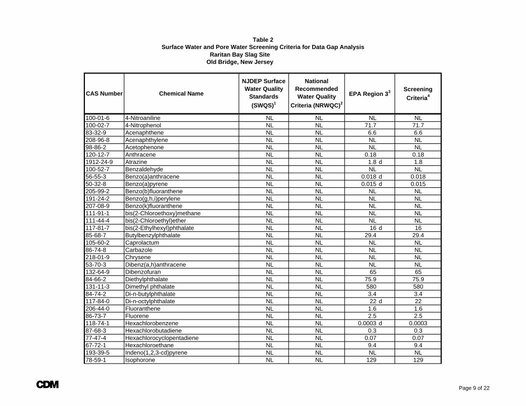
Raritan Bay Slag SiteOld Bridge, New Jersey
CAS Number Chemical NameScreening Criteria4
Table 2
NJDEP Surface Water Quality
Standards (SWQS)1
National Recommended Water Quality
Criteria (NRWQC)2
Surface Water and Pore Water Screening Criteria for Data Gap Analysis
EPA Region 33
100-01-6 4-Nitroaniline NL NL NL NL100-02-7 4-Nitrophenol NL NL 71.7 71.783-32-9 Acenaphthene NL NL 6.6 6.6208-96-8 Acenaphthylene NL NL NL NL98-86-2 Acetophenone NL NL NL NL120-12-7 Anthracene NL NL 0.18 0.181912-24-9 Atrazine NL NL 1.8 d 1.8100-52-7 Benzaldehyde NL NL NL NL56-55-3 Benzo(a)anthracene NL NL 0.018 d 0.01850-32-8 Benzo(a)pyrene NL NL 0.015 d 0.015205-99-2 Benzo(b)fluoranthene NL NL NL NL191-24-2 Benzo(g,h,i)perylene NL NL NL NL207-08-9 Benzo(k)fluoranthene NL NL NL NL111-91-1 bis(2-Chloroethoxy)methane NL NL NL NL111-44-4 bis(2-Chloroethyl)ether NL NL NL NL117-81-7 bis(2-Ethylhexyl)phthalate NL NL 16 d 1685-68-7 Butylbenzylphthalate NL NL 29.4 29.4105-60-2 Caprolactum NL NL NL NL86-74-8 Carbazole NL NL NL NL218-01-9 Chrysene NL NL NL NL53-70-3 Dibenz(a,h)anthracene NL NL NL NL132-64-9 Dibenzofuran NL NL 65 6584-66-2 Diethylphthalate NL NL 75.9 75.9131-11-3 Dimethyl phthalate NL NL 580 58084-74-2 Di-n-butylphthalate NL NL 3.4 3.4117-84-0 Di-n-octylphthalate NL NL 22 d 22206-44-0 Fluoranthene NL NL 1.6 1.686-73-7 Fluorene NL NL 2.5 2.5118-74-1 Hexachlorobenzene NL NL 0.0003 d 0.000387-68-3 Hexachlorobutadiene NL NL 0.3 0.377-47-4 Hexachlorocyclopentadiene NL NL 0.07 0.0767-72-1 Hexachloroethane NL NL 9.4 9.4193-39-5 Indeno(1,2,3-cd)pyrene NL NL NL NL78-59-1 Isophorone NL NL 129 129
A Page 9 of 22
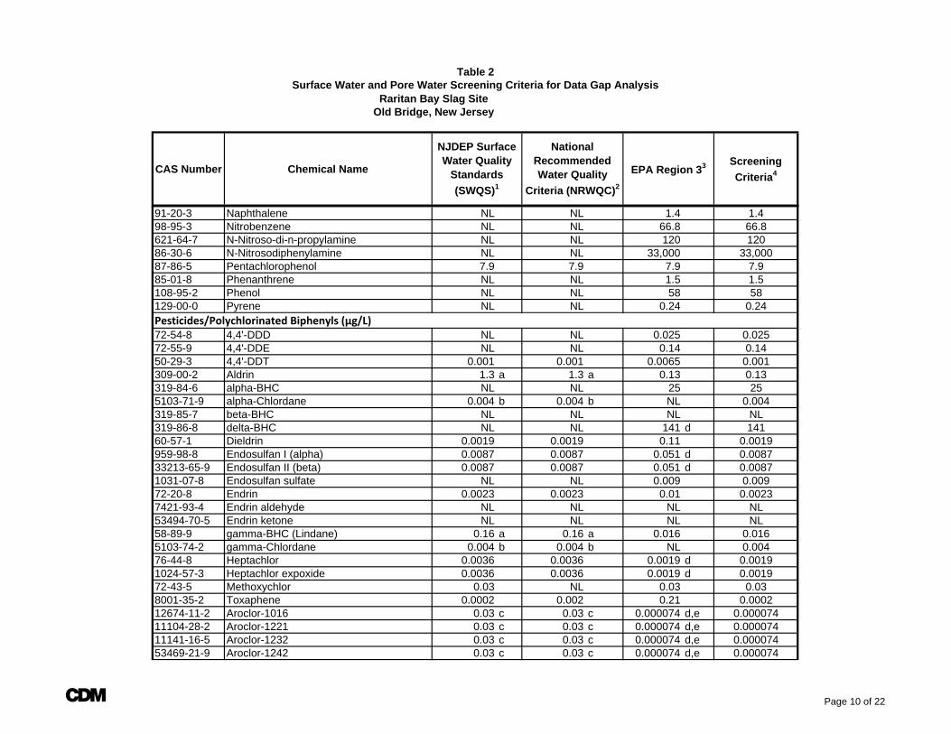
Raritan Bay Slag SiteOld Bridge, New Jersey
CAS Number Chemical NameScreening Criteria4
Table 2
NJDEP Surface Water Quality
Standards (SWQS)1
National Recommended Water Quality
Criteria (NRWQC)2
Surface Water and Pore Water Screening Criteria for Data Gap Analysis
EPA Region 33
91-20-3 Naphthalene NL NL 1.4 1.498-95-3 Nitrobenzene NL NL 66.8 66.8621-64-7 N-Nitroso-di-n-propylamine NL NL 120 12086-30-6 N-Nitrosodiphenylamine NL NL 33,000 33,00087-86-5 Pentachlorophenol 7.9 7.9 7.9 7.985-01-8 Phenanthrene NL NL 1.5 1.5108-95-2 Phenol NL NL 58 58129-00-0 Pyrene NL NL 0.24 0.24Pesticides/Polychlorinated Biphenyls (µg/L)72-54-8 4,4'-DDD NL NL 0.025 0.02572-55-9 4,4'-DDE NL NL 0.14 0.1450-29-3 4,4'-DDT 0.001 0.001 0.0065 0.001309-00-2 Aldrin 1.3 a 1.3 a 0.13 0.13319-84-6 alpha-BHC NL NL 25 255103-71-9 alpha-Chlordane 0.004 b 0.004 b NL 0.004319-85-7 beta-BHC NL NL NL NL319-86-8 delta-BHC NL NL 141 d 14160-57-1 Dieldrin 0.0019 0.0019 0.11 0.0019959-98-8 Endosulfan I (alpha) 0.0087 0.0087 0.051 d 0.008733213-65-9 Endosulfan II (beta) 0.0087 0.0087 0.051 d 0.00871031-07-8 Endosulfan sulfate NL NL 0.009 0.00972-20-8 Endrin 0.0023 0.0023 0.01 0.00237421-93-4 Endrin aldehyde NL NL NL NL53494-70-5 Endrin ketone NL NL NL NL58-89-9 gamma-BHC (Lindane) 0.16 a 0.16 a 0.016 0.0165103-74-2 gamma-Chlordane 0.004 b 0.004 b NL 0.00476-44-8 Heptachlor 0.0036 0.0036 0.0019 d 0.00191024-57-3 Heptachlor expoxide 0.0036 0.0036 0.0019 d 0.001972-43-5 Methoxychlor 0.03 NL 0.03 0.038001-35-2 Toxaphene 0.0002 0.002 0.21 0.000212674-11-2 Aroclor-1016 0.03 c 0.03 c 0.000074 d,e 0.00007411104-28-2 Aroclor-1221 0.03 c 0.03 c 0.000074 d,e 0.00007411141-16-5 Aroclor-1232 0.03 c 0.03 c 0.000074 d,e 0.00007453469-21-9 Aroclor-1242 0.03 c 0.03 c 0.000074 d,e 0.000074
A Page 10 of 22
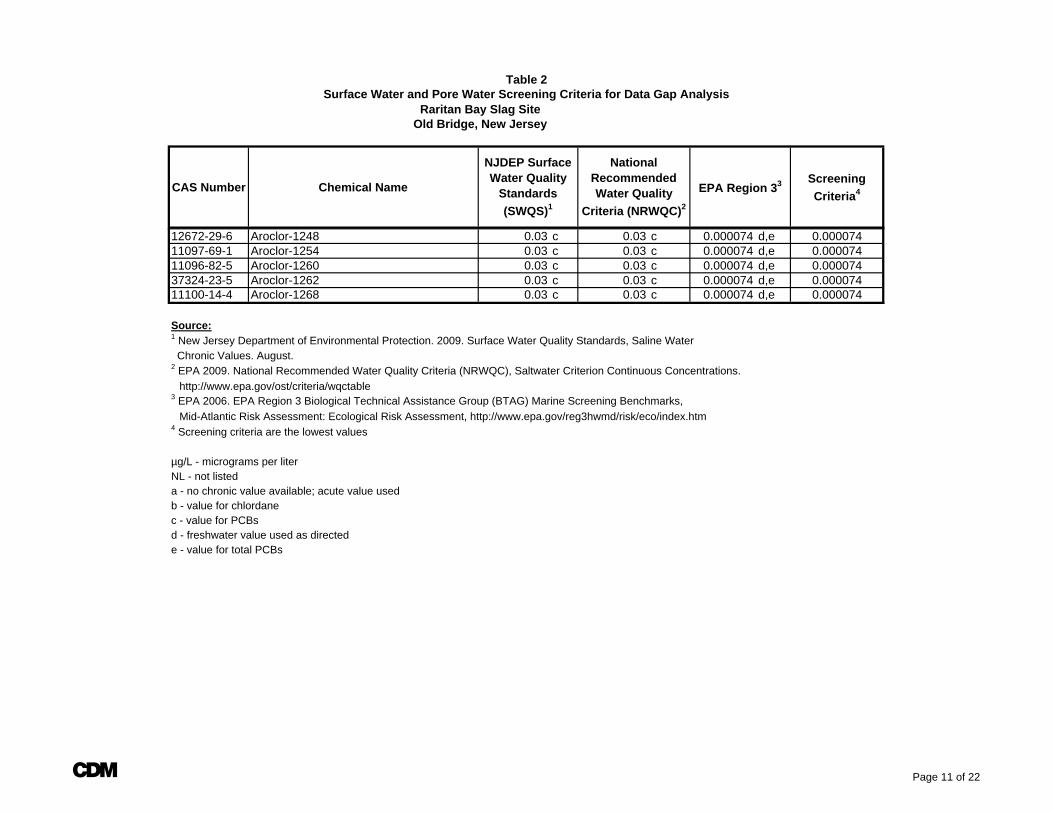
Raritan Bay Slag SiteOld Bridge, New Jersey
CAS Number Chemical NameScreening Criteria4
Table 2
NJDEP Surface Water Quality
Standards (SWQS)1
National Recommended Water Quality
Criteria (NRWQC)2
Surface Water and Pore Water Screening Criteria for Data Gap Analysis
EPA Region 33
12672-29-6 Aroclor-1248 0.03 c 0.03 c 0.000074 d,e 0.00007411097-69-1 Aroclor-1254 0.03 c 0.03 c 0.000074 d,e 0.00007411096-82-5 Aroclor-1260 0.03 c 0.03 c 0.000074 d,e 0.00007437324-23-5 Aroclor-1262 0.03 c 0.03 c 0.000074 d,e 0.00007411100-14-4 Aroclor-1268 0.03 c 0.03 c 0.000074 d,e 0.000074
Source:1 New Jersey Department of Environmental Protection. 2009. Surface Water Quality Standards, Saline Water Chronic Values. August.2 EPA 2009. National Recommended Water Quality Criteria (NRWQC), Saltwater Criterion Continuous Concentrations. http://www.epa.gov/ost/criteria/wqctable 3 EPA 2006. EPA Region 3 Biological Technical Assistance Group (BTAG) Marine Screening Benchmarks, Mid-Atlantic Risk Assessment: Ecological Risk Assessment, http://www.epa.gov/reg3hwmd/risk/eco/index.htm4 Screening criteria are the lowest values
µg/L - micrograms per literNL - not listeda - no chronic value available; acute value usedb - value for chlordanec - value for PCBsd - freshwater value used as directed e - value for total PCBs
A Page 11 of 22
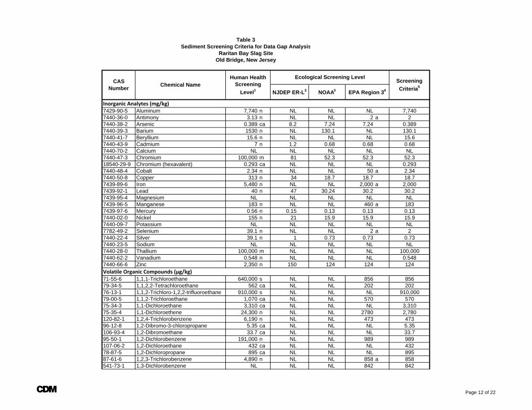
Table 3Sediment Screening Criteria for Data Gap Analysis
Raritan Bay Slag SiteOld Bridge, New Jersey
Inorganic Analytes (mg/kg)7429-90-5 Aluminum 7,740 n NL NL NL 7,7407440-36-0 Antimony 3.13 n NL NL 2 a 27440-38-2 Arsenic 0.389 ca 8.2 7.24 7.24 0.3897440-39-3 Barium 1530 n NL 130.1 NL 130.17440-41-7 Beryllium 15.6 n NL NL NL 15.67440-43-9 Cadmium 7 n 1.2 0.68 0.68 0.687440-70-2 Calcium NL NL NL NL NL7440-47-3 Chromium 100,000 m 81 52.3 52.3 52.318540-29-9 Chromium (hexavalent) 0.293 ca NL NL NL 0.2937440-48-4 Cobalt 2.34 n NL NL 50 a 2.347440-50-8 Copper 313 n 34 18.7 18.7 18.77439-89-6 Iron 5,480 n NL NL 2,000 a 2,0007439-92-1 Lead 40 n 47 30.24 30.2 30.27439-95-4 Magnesium NL NL NL NL NL7439-96-5 Manganese 183 n NL NL 460 a 1837439-97-6 Mercury 0.56 n 0.15 0.13 0.13 0.137440-02-0 Nickel 155 n 21 15.9 15.9 15.97440-09-7 Potassium NL NL NL NL NL7782-49-2 Selenium 39.1 n NL NL 2 a 27440-22-4 Silver 39.1 n 1 0.73 0.73 0.737440-23-5 Sodium NL NL NL NL NL7440-28-0 Thallium 100,000 m NL NL NL 100,0007440-62-2 Vanadium 0.548 n NL NL NL 0.5487440-66-6 Zinc 2,350 n 150 124 124 124Volatile Organic Compounds (µg/kg)71-55-6 1,1,1-Trichloroethane 640,000 s NL NL 856 85679-34-5 1,1,2,2-Tetrachloroethane 562 ca NL NL 202 20276-13-1 1,1,2-Trichloro-1,2,2-trifluoroethane 910,000 s NL NL NL 910,00079-00-5 1,1,2-Trichloroethane 1,070 ca NL NL 570 57075-34-3 1,1-Dichloroethane 3,310 ca NL NL NL 3,31075-35-4 1,1-Dichloroethene 24,300 n NL NL 2780 2,780120-82-1 1,2,4-Trichlorobenzene 6,190 n NL NL 473 47396-12-8 1,2-Dibromo-3-chloropropane 5.35 ca NL NL NL 5.35106-93-4 1,2-Dibromoethane 33.7 ca NL NL NL 33.795-50-1 1,2-Dichlorobenzene 191,000 n NL NL 989 989107-06-2 1,2-Dichloroethane 432 ca NL NL NL 43278-87-5 1,2-Dichloropropane 895 ca NL NL NL 89587-61-6 1,2,3-Trichlorobenzene 4,890 n NL NL 858 a 858541-73-1 1,3-Dichlorobenzene NL NL NL 842 842
Screening Criteria5
Ecological Screening LevelChemical NameCAS
Number
Human Health Screening
Level1 NJDEP ER-L2 NOAA3 EPA Region 34
A Page 12 of 22
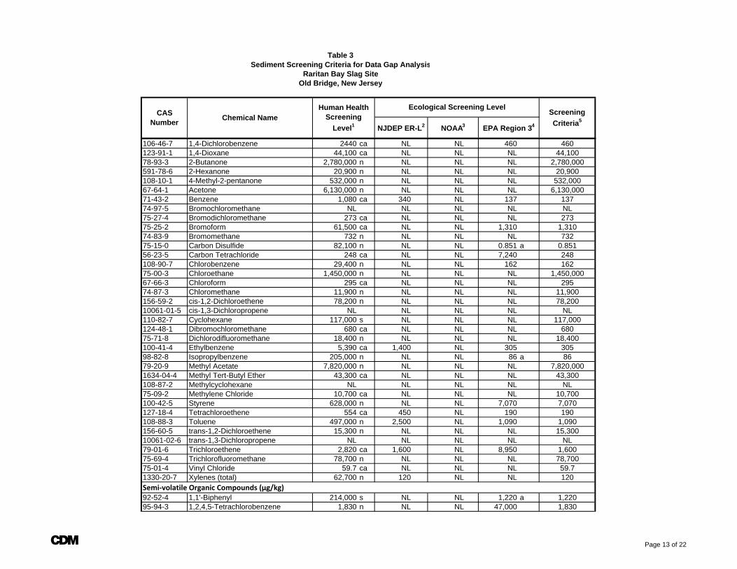
Table 3Sediment Screening Criteria for Data Gap Analysis
Raritan Bay Slag SiteOld Bridge, New Jersey
Screening Criteria5
Ecological Screening LevelChemical NameCAS
Number
Human Health Screening
Level1 NJDEP ER-L2 NOAA3 EPA Region 34
106-46-7 1,4-Dichlorobenzene 2440 ca NL NL 460 460123-91-1 1,4-Dioxane 44,100 ca NL NL NL 44,10078-93-3 2-Butanone 2,780,000 n NL NL NL 2,780,000591-78-6 2-Hexanone 20,900 n NL NL NL 20,900108-10-1 4-Methyl-2-pentanone 532,000 n NL NL NL 532,00067-64-1 Acetone 6,130,000 n NL NL NL 6,130,00071-43-2 Benzene 1,080 ca 340 NL 137 13774-97-5 Bromochloromethane NL NL NL NL NL75-27-4 Bromodichloromethane 273 ca NL NL NL 27375-25-2 Bromoform 61,500 ca NL NL 1,310 1,31074-83-9 Bromomethane 732 n NL NL NL 73275-15-0 Carbon Disulfide 82,100 n NL NL 0.851 a 0.85156-23-5 Carbon Tetrachloride 248 ca NL NL 7,240 248108-90-7 Chlorobenzene 29,400 n NL NL 162 16275-00-3 Chloroethane 1,450,000 n NL NL NL 1,450,00067-66-3 Chloroform 295 ca NL NL NL 29574-87-3 Chloromethane 11,900 n NL NL NL 11,900156-59-2 cis-1,2-Dichloroethene 78,200 n NL NL NL 78,20010061-01-5 cis-1,3-Dichloropropene NL NL NL NL NL110-82-7 Cyclohexane 117,000 s NL NL NL 117,000124-48-1 Dibromochloromethane 680 ca NL NL NL 68075-71-8 Dichlorodifluoromethane 18,400 n NL NL NL 18,400100-41-4 Ethylbenzene 5,390 ca 1,400 NL 305 30598-82-8 Isopropylbenzene 205,000 n NL NL 86 a 8679-20-9 Methyl Acetate 7,820,000 n NL NL NL 7,820,0001634-04-4 Methyl Tert-Butyl Ether 43,300 ca NL NL NL 43,300108-87-2 Methylcyclohexane NL NL NL NL NL75-09-2 Methylene Chloride 10,700 ca NL NL NL 10,700100-42-5 Styrene 628,000 n NL NL 7,070 7,070127-18-4 Tetrachloroethene 554 ca 450 NL 190 190108-88-3 Toluene 497,000 n 2,500 NL 1,090 1,090156-60-5 trans-1,2-Dichloroethene 15,300 n NL NL NL 15,30010061-02-6 trans-1,3-Dichloropropene NL NL NL NL NL79-01-6 Trichloroethene 2,820 ca 1,600 NL 8,950 1,60075-69-4 Trichlorofluoromethane 78,700 n NL NL NL 78,70075-01-4 Vinyl Chloride 59.7 ca NL NL NL 59.71330-20-7 Xylenes (total) 62,700 n 120 NL NL 120Semi‐volatile Organic Compounds (µg/kg)92-52-4 1,1'-Biphenyl 214,000 s NL NL 1,220 a 1,22095-94-3 1,2,4,5-Tetrachlorobenzene 1,830 n NL NL 47,000 1,830
A Page 13 of 22
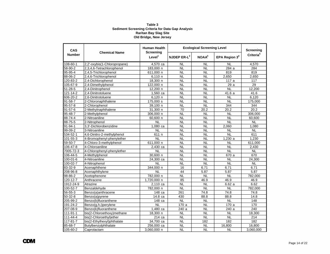
Table 3Sediment Screening Criteria for Data Gap Analysis
Raritan Bay Slag SiteOld Bridge, New Jersey
Screening Criteria5
Ecological Screening LevelChemical NameCAS
Number
Human Health Screening
Level1 NJDEP ER-L2 NOAA3 EPA Region 34
108-60-1 2,2'-oxybis(1-Chloropropane) 4,570 ca NL NL NL 4,57058-90-2 2,3,4,6-Tetrachlorophenol 183,000 n NL NL 284 a 28495-95-4 2,4,5-Trichlorophenol 611,000 n NL NL 819 81988-06-2 2,4,6-Trichlorophenol 6,110 n NL NL 2,650 2,650120-83-2 2,4-Dichlorophenol 18,300 n NL NL 117 a 117105-67-9 2,4-Dimethylphenol 122,000 n NL NL 29 a 2951-28-5 2,4-Dinitrophenol 12,200 n NL NL NL 12,200121-14-2 2,4-Dinitrotoluene 1,560 ca NL NL 41.6 a 41.6606-20-2 2,6-Dinitrotoluene 6,120 n NL NL NL 6,12091-58-7 2-Chloronaphthalene 175,000 s NL NL NL 175,00095-57-8 2-Chlorophenol 39,100 n NL NL 344 34491-57-6 2-Methylnaphthalene 31,300 n 70 20.2 20.2 20.295-48-7 2-Methylphenol 306,000 n NL NL NL 306,00088-74-4 2-Nitroaniline 60,600 n NL NL NL 60,60088-75-5 2-Nitrophenol NL NL NL NL NL91-94-1 3,3'-Dichlorobenzidine 1,080 ca NL NL 2,060 1,08099-09-2 3-Nitroaniline NL NL NL NL NL534-52-1 4,6-Dinitro-2-methylphenol 611 n NL NL NL 611101-55-3 4-Bromophenyl-phenylether NL NL NL 1,230 a 1,23059-50-7 4-Chloro-3-methylphenol 611,000 n NL NL NL 611,000106-47-8 4-Chloroaniline 2,430 ca NL NL NL 2,4307005-72-3 4-Chlorophenyl-phenylether NL NL NL NL NL106-44-5 4-Methylphenol 30,600 n NL NL 670 a 670100-01-6 4-Nitroaniline 24,300 ca NL NL NL 24,300100-02-7 4-Nitrophenol NL NL NL NL NL83-32-9 Acenaphthene 344,000 n 16 6.71 6.71 6.71208-96-8 Acenaphthylene NL 44 5.87 5.87 5.8798-86-2 Acetophenone 782,000 n NL NL NL 782,000120-12-7 Anthracene 1,720,000 n 85 46.9 46.9 46.91912-24-9 Atrazine 2,110 ca NL NL 6.62 a 6.62100-52-7 Benzaldehyde 782,000 n NL NL NL 782,00056-55-3 Benzo(a)anthracene 148 ca 261 74.8 74.8 74.850-32-8 Benzo(a)pyrene 14.8 ca 430 88.8 88.8 14.8205-99-2 Benzo(b)fluoranthene 148 ca NL NL NL 148191-24-2 Benzo(g,h,i)perylene NL 170 a NL 170 a 170207-08-9 Benzo(k)fluoranthene 1,480 ca 240 a NL 240 a 240111-91-1 bis(2-Chloroethoxy)methane 18,300 n NL NL NL 18,300111-44-4 bis(2-Chloroethyl)ether 214 ca NL NL NL 214117-81-7 bis(2-Ethylhexyl)phthalate 34,700 ca NL 182 182 18285-68-7 Butylbenzylphthalate 256,000 ca NL NL 16,800 16,800105-60-2 Caprolactam 3,060,000 n NL NL NL 3,060,000
A Page 14 of 22
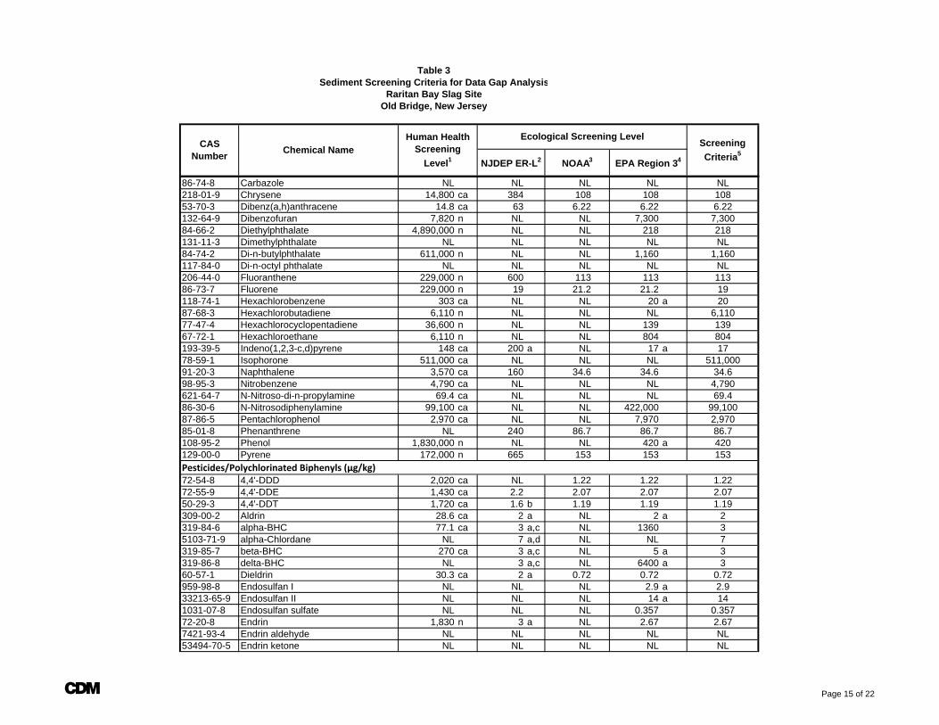
Table 3Sediment Screening Criteria for Data Gap Analysis
Raritan Bay Slag SiteOld Bridge, New Jersey
Screening Criteria5
Ecological Screening LevelChemical NameCAS
Number
Human Health Screening
Level1 NJDEP ER-L2 NOAA3 EPA Region 34
86-74-8 Carbazole NL NL NL NL NL218-01-9 Chrysene 14,800 ca 384 108 108 10853-70-3 Dibenz(a,h)anthracene 14.8 ca 63 6.22 6.22 6.22132-64-9 Dibenzofuran 7,820 n NL NL 7,300 7,30084-66-2 Diethylphthalate 4,890,000 n NL NL 218 218131-11-3 Dimethylphthalate NL NL NL NL NL84-74-2 Di-n-butylphthalate 611,000 n NL NL 1,160 1,160117-84-0 Di-n-octyl phthalate NL NL NL NL NL206-44-0 Fluoranthene 229,000 n 600 113 113 11386-73-7 Fluorene 229,000 n 19 21.2 21.2 19118-74-1 Hexachlorobenzene 303 ca NL NL 20 a 2087-68-3 Hexachlorobutadiene 6,110 n NL NL NL 6,11077-47-4 Hexachlorocyclopentadiene 36,600 n NL NL 139 13967-72-1 Hexachloroethane 6,110 n NL NL 804 804193-39-5 Indeno(1,2,3-c,d)pyrene 148 ca 200 a NL 17 a 1778-59-1 Isophorone 511,000 ca NL NL NL 511,00091-20-3 Naphthalene 3,570 ca 160 34.6 34.6 34.698-95-3 Nitrobenzene 4,790 ca NL NL NL 4,790621-64-7 N-Nitroso-di-n-propylamine 69.4 ca NL NL NL 69.486-30-6 N-Nitrosodiphenylamine 99,100 ca NL NL 422,000 99,10087-86-5 Pentachlorophenol 2,970 ca NL NL 7,970 2,97085-01-8 Phenanthrene NL 240 86.7 86.7 86.7108-95-2 Phenol 1,830,000 n NL NL 420 a 420129-00-0 Pyrene 172,000 n 665 153 153 153Pesticides/Polychlorinated Biphenyls (µg/kg)72-54-8 4,4'-DDD 2,020 ca NL 1.22 1.22 1.2272-55-9 4,4'-DDE 1,430 ca 2.2 2.07 2.07 2.0750-29-3 4,4'-DDT 1,720 ca 1.6 b 1.19 1.19 1.19309-00-2 Aldrin 28.6 ca 2 a NL 2 a 2319-84-6 alpha-BHC 77.1 ca 3 a,c NL 1360 35103-71-9 alpha-Chlordane NL 7 a,d NL NL 7319-85-7 beta-BHC 270 ca 3 a,c NL 5 a 3319-86-8 delta-BHC NL 3 a,c NL 6400 a 360-57-1 Dieldrin 30.3 ca 2 a 0.72 0.72 0.72959-98-8 Endosulfan I NL NL NL 2.9 a 2.933213-65-9 Endosulfan II NL NL NL 14 a 141031-07-8 Endosulfan sulfate NL NL NL 0.357 0.35772-20-8 Endrin 1,830 n 3 a NL 2.67 2.677421-93-4 Endrin aldehyde NL NL NL NL NL53494-70-5 Endrin ketone NL NL NL NL NL
A Page 15 of 22
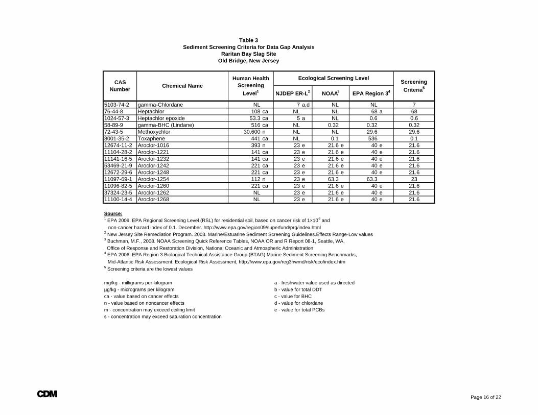
Table 3Sediment Screening Criteria for Data Gap Analysis
Raritan Bay Slag SiteOld Bridge, New Jersey
Screening Criteria5
Ecological Screening LevelChemical NameCAS
Number
Human Health Screening
Level1 NJDEP ER-L2 NOAA3 EPA Region 34
5103-74-2 gamma-Chlordane NL 7 a,d NL NL 776-44-8 Heptachlor 108 ca NL NL 68 a 681024-57-3 Heptachlor epoxide 53.3 ca 5 a NL 0.6 0.658-89-9 gamma-BHC (Lindane) 516 ca NL 0.32 0.32 0.3272-43-5 Methoxychlor 30,600 n NL NL 29.6 29.68001-35-2 Toxaphene 441 ca NL 0.1 536 0.112674-11-2 Aroclor-1016 393 n 23 e 21.6 e 40 e 21.611104-28-2 Aroclor-1221 141 ca 23 e 21.6 e 40 e 21.611141-16-5 Aroclor-1232 141 ca 23 e 21.6 e 40 e 21.653469-21-9 Aroclor-1242 221 ca 23 e 21.6 e 40 e 21.612672-29-6 Aroclor-1248 221 ca 23 e 21.6 e 40 e 21.611097-69-1 Aroclor-1254 112 n 23 e 63.3 63.3 2311096-82-5 Aroclor-1260 221 ca 23 e 21.6 e 40 e 21.637324-23-5 Aroclor-1262 NL 23 e 21.6 e 40 e 21.611100-14-4 Aroclor-1268 NL 23 e 21.6 e 40 e 21.6
Source:1 EPA 2009. EPA Regional Screening Level (RSL) for residential soil, based on cancer risk of 1×10⁻⁶ and non-cancer hazard index of 0.1. December. http://www.epa.gov/region09/superfund/prg/index.html2 New Jersey Site Remediation Program. 2003. Marine/Estuarine Sediment Screening Guidelines.Effects Range-Low values3 Buchman, M.F., 2008. NOAA Screening Quick Reference Tables, NOAA OR and R Report 08-1, Seattle, WA, Office of Response and Restoration Division, National Oceanic and Atmospheric Administration4 EPA 2006. EPA Region 3 Biological Technical Assistance Group (BTAG) Marine Sediment Screening Benchmarks, Mid-Atlantic Risk Assessment: Ecological Risk Assessment, http://www.epa.gov/reg3hwmd/risk/eco/index.htm5 Screening criteria are the lowest values
mg/kg - milligrams per kilogram a - freshwater value used as directedµg/kg - micrograms per kilogram b - value for total DDTca - value based on cancer effects c - value for BHCn - value based on noncancer effects d - value for chlordanem - concentration may exceed ceiling limit e - value for total PCBss - concentration may exceed saturation concentration
A Page 16 of 22
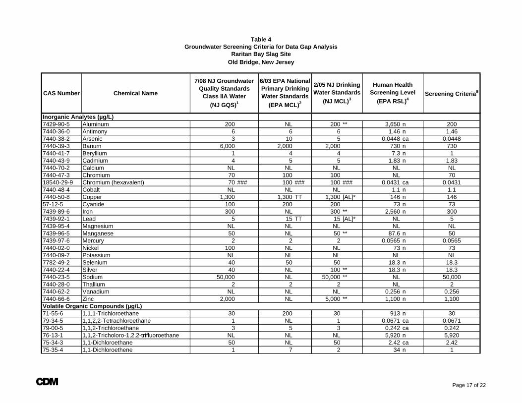
CAS Number Chemical Name Screening Criteria5
Inorganic Analytes (µg/L)7429-90-5 Aluminum 200 NL 200 ** 3,650 n 2007440-36-0 Antimony 6 6 6 1.46 n 1.467440-38-2 Arsenic 3 10 5 0.0448 ca 0.04487440-39-3 Barium 6,000 2,000 2,000 730 n 7307440-41-7 Beryllium 1 4 4 7.3 n 17440-43-9 Cadmium 4 5 5 1.83 n 1.837440-70-2 Calcium NL NL NL NL NL7440-47-3 Chromium 70 100 100 NL 7018540-29-9 Chromium (hexavalent) 70 ### 100 ### 100 ### 0.0431 ca 0.04317440-48-4 Cobalt NL NL NL 1.1 n 1.17440-50-8 Copper 1,300 1,300 TT 1,300 [AL]* 146 n 14657-12-5 Cyanide 100 200 200 73 n 737439-89-6 Iron 300 NL 300 ** 2,560 n 3007439-92-1 Lead 5 15 TT 15 [AL]* NL 57439-95-4 Magnesium NL NL NL NL NL7439-96-5 Manganese 50 NL 50 ** 87.6 n 507439-97-6 Mercury 2 2 2 0.0565 n 0.05657440-02-0 Nickel 100 NL NL 73 n 737440-09-7 Potassium NL NL NL NL NL7782-49-2 Selenium 40 50 50 18.3 n 18.37440-22-4 Silver 40 NL 100 ** 18.3 n 18.37440-23-5 Sodium 50,000 NL 50,000 ** NL 50,0007440-28-0 Thallium 2 2 2 NL 27440-62-2 Vanadium NL NL NL 0.256 n 0.2567440-66-6 Zinc 2,000 NL 5,000 ** 1,100 n 1,100Volatile Organic Compounds (µg/L)71-55-6 1,1,1-Trichloroethane 30 200 30 913 n 3079-34-5 1,1,2,2-Tetrachloroethane 1 NL 1 0.0671 ca 0.067179-00-5 1,1,2-Trichloroethane 3 5 3 0.242 ca 0.24276-13-1 1,1,2-Tricholoro-1,2,2-trifluoroethane NL NL NL 5,920 n 5,92075-34-3 1,1-Dichloroethane 50 NL 50 2.42 ca 2.4275-35-4 1,1-Dichloroethene 1 7 2 34 n 1
Table 4
7/08 NJ Groundwater Quality Standards
Class IIA Water (NJ GQS)1
Groundwater Screening Criteria for Data Gap AnalysisRaritan Bay Slag Site
Old Bridge, New Jersey
6/03 EPA National Primary Drinking Water Standards
(EPA MCL)2
2/05 NJ Drinking Water Standards
(NJ MCL)3
Human Health Screening Level
(EPA RSL)4
A Page 17 of 22
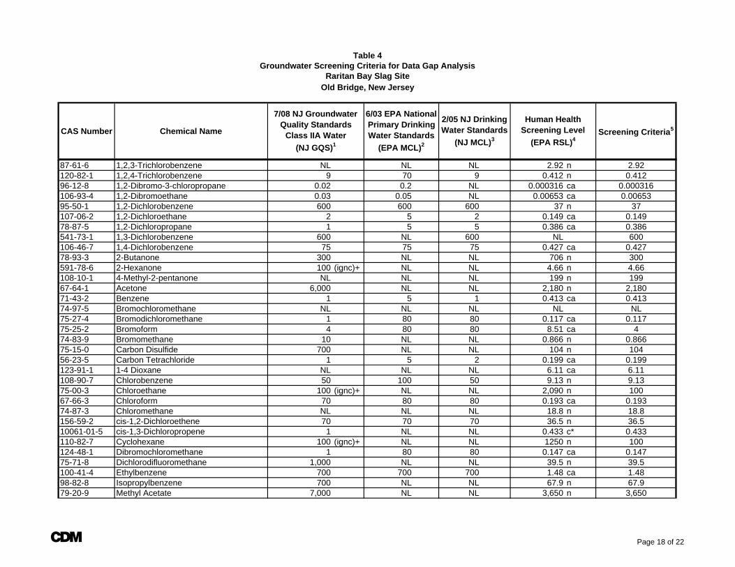
CAS Number Chemical Name Screening Criteria5
Table 4
7/08 NJ Groundwater Quality Standards
Class IIA Water (NJ GQS)1
Groundwater Screening Criteria for Data Gap AnalysisRaritan Bay Slag Site
Old Bridge, New Jersey
6/03 EPA National Primary Drinking Water Standards
(EPA MCL)2
2/05 NJ Drinking Water Standards
(NJ MCL)3
Human Health Screening Level
(EPA RSL)4
87-61-6 1,2,3-Trichlorobenzene NL NL NL 2.92 n 2.92120-82-1 1,2,4-Trichlorobenzene 9 70 9 0.412 n 0.41296-12-8 1,2-Dibromo-3-chloropropane 0.02 0.2 NL 0.000316 ca 0.000316106-93-4 1,2-Dibromoethane 0.03 0.05 NL 0.00653 ca 0.0065395-50-1 1,2-Dichlorobenzene 600 600 600 37 n 37107-06-2 1,2-Dichloroethane 2 5 2 0.149 ca 0.14978-87-5 1,2-Dichloropropane 1 5 5 0.386 ca 0.386541-73-1 1,3-Dichlorobenzene 600 NL 600 NL 600106-46-7 1,4-Dichlorobenzene 75 75 75 0.427 ca 0.42778-93-3 2-Butanone 300 NL NL 706 n 300591-78-6 2-Hexanone 100 (ignc)+ NL NL 4.66 n 4.66108-10-1 4-Methyl-2-pentanone NL NL NL 199 n 19967-64-1 Acetone 6,000 NL NL 2,180 n 2,18071-43-2 Benzene 1 5 1 0.413 ca 0.41374-97-5 Bromochloromethane NL NL NL NL NL75-27-4 Bromodichloromethane 1 80 80 0.117 ca 0.11775-25-2 Bromoform 4 80 80 8.51 ca 474-83-9 Bromomethane 10 NL NL 0.866 n 0.86675-15-0 Carbon Disulfide 700 NL NL 104 n 10456-23-5 Carbon Tetrachloride 1 5 2 0.199 ca 0.199123-91-1 1-4 Dioxane NL NL NL 6.11 ca 6.11108-90-7 Chlorobenzene 50 100 50 9.13 n 9.1375-00-3 Chloroethane 100 (ignc)+ NL NL 2,090 n 10067-66-3 Chloroform 70 80 80 0.193 ca 0.19374-87-3 Chloromethane NL NL NL 18.8 n 18.8156-59-2 cis-1,2-Dichloroethene 70 70 70 36.5 n 36.510061-01-5 cis-1,3-Dichloropropene 1 NL NL 0.433 c* 0.433110-82-7 Cyclohexane 100 (ignc)+ NL NL 1250 n 100124-48-1 Dibromochloromethane 1 80 80 0.147 ca 0.14775-71-8 Dichlorodifluoromethane 1,000 NL NL 39.5 n 39.5100-41-4 Ethylbenzene 700 700 700 1.48 ca 1.4898-82-8 Isopropylbenzene 700 NL NL 67.9 n 67.979-20-9 Methyl Acetate 7,000 NL NL 3,650 n 3,650
A Page 18 of 22
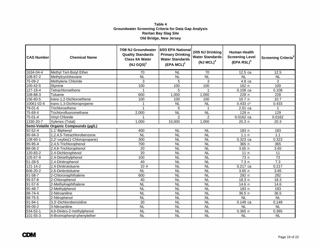
CAS Number Chemical Name Screening Criteria5
Table 4
7/08 NJ Groundwater Quality Standards
Class IIA Water (NJ GQS)1
Groundwater Screening Criteria for Data Gap AnalysisRaritan Bay Slag Site
Old Bridge, New Jersey
6/03 EPA National Primary Drinking Water Standards
(EPA MCL)2
2/05 NJ Drinking Water Standards
(NJ MCL)3
Human Health Screening Level
(EPA RSL)4
1634-04-4 Methyl Tert-Butyl Ether 70 NL 70 12.5 ca 12.5108-87-2 Methylcyclohexane NL NL NL NL NL75-09-2 Methylene Chloride 3 5 3 4.8 ca 3100-42-5 Styrene 100 100 100 162 n 100127-18-4 Tetrachloroethene 1 5 1 0.108 ca 0.108108-88-3 Toluene 600 1,000 1,000 228 n 228156-60-5 trans-1,2-Dichloroethene 100 100 100 10.7 n 10.710061-02-6 trans-1,3-Dichloropropene 1 NL NL 0.433 c* 0.43379-01-6 Trichloroethene 1 5 1 2.01 ca 175-69-4 Trichlorofluoromethane 2,000 NL NL 129 n 12975-01-4 Vinyl Chloride 1 2 2 0.0162 ca 0.01621330-20-7 Xylenes (Total) 1,000 10,000 1,000 20.3 n 20.3Semi-Volatile Organic Compounds (µg/L)92-52-4 1,1'-Biphenyl 400 NL NL 183 n 18395-94-3 1,2,4,5-Tetrachlorobenzene NL NL NL 1.1 n 1.1108-60-1 2,2'-oxybis(1-Chloropropane) 300 NL NL 0.323 ca 0.32395-95-4 2,4,5-Trichlorophenol 700 NL NL 365 n 36588-06-2 2,4,6-Trichlorophenol 20 NL NL 3.65 n 3.65120-83-2 2,4-Dichlorophenol 20 NL NL 11 n 11105-67-9 2,4-Dimethylphenol 100 NL NL 73 n 7351-28-5 2,4-Dinitrophenol 40 NL NL 7.3 n 7.3121-14-2 2,4-Dinitrotoluene 10 # NL NL 0.217 ca 0.217606-20-2 2,6-Dinitrotoluene NL NL NL 3.65 n 3.6591-58-7 2-Chloronaphthalene 600 NL NL 292 n 29295-57-8 2-Chlorophenol 40 NL NL 18.3 n 18.391-57-6 2-Methylnaphthalene NL NL NL 14.6 n 14.695-48-7 2-Methylphenol NL NL NL 183 n 18388-74-4 2-Nitroaniline NL NL NL 36.5 n 36.588-75-5 2-Nitrophenol NL NL NL NL NL91-94-1 3,3'-Dichlorobenzidine 30 NL NL 0.149 ca 0.14999-09-2 3-Nitroaniline NL NL NL NL NL534-52-1 4,6-Dinitro-2-methylphenol NL NL NL 0.365 n 0.365101-55-3 4-Bromophenyl-phenylether NL NL NL NL NL
A Page 19 of 22
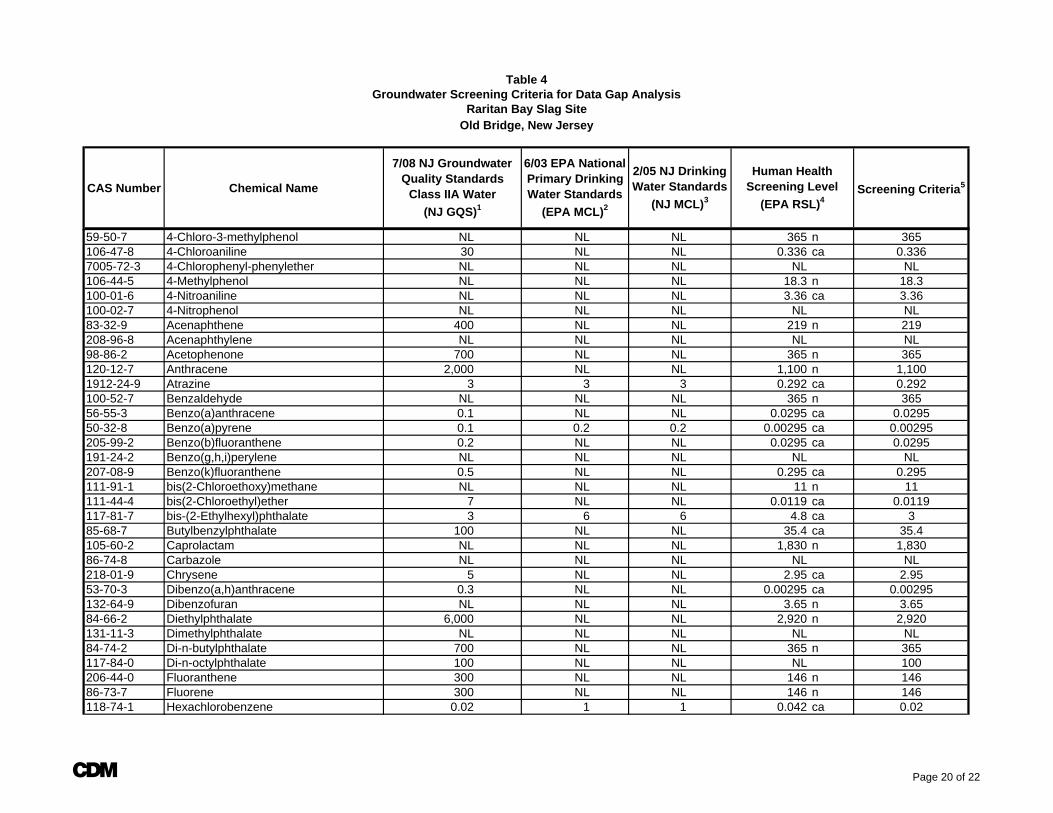
CAS Number Chemical Name Screening Criteria5
Table 4
7/08 NJ Groundwater Quality Standards
Class IIA Water (NJ GQS)1
Groundwater Screening Criteria for Data Gap AnalysisRaritan Bay Slag Site
Old Bridge, New Jersey
6/03 EPA National Primary Drinking Water Standards
(EPA MCL)2
2/05 NJ Drinking Water Standards
(NJ MCL)3
Human Health Screening Level
(EPA RSL)4
59-50-7 4-Chloro-3-methylphenol NL NL NL 365 n 365106-47-8 4-Chloroaniline 30 NL NL 0.336 ca 0.3367005-72-3 4-Chlorophenyl-phenylether NL NL NL NL NL106-44-5 4-Methylphenol NL NL NL 18.3 n 18.3100-01-6 4-Nitroaniline NL NL NL 3.36 ca 3.36100-02-7 4-Nitrophenol NL NL NL NL NL83-32-9 Acenaphthene 400 NL NL 219 n 219208-96-8 Acenaphthylene NL NL NL NL NL98-86-2 Acetophenone 700 NL NL 365 n 365120-12-7 Anthracene 2,000 NL NL 1,100 n 1,1001912-24-9 Atrazine 3 3 3 0.292 ca 0.292100-52-7 Benzaldehyde NL NL NL 365 n 36556-55-3 Benzo(a)anthracene 0.1 NL NL 0.0295 ca 0.029550-32-8 Benzo(a)pyrene 0.1 0.2 0.2 0.00295 ca 0.00295205-99-2 Benzo(b)fluoranthene 0.2 NL NL 0.0295 ca 0.0295191-24-2 Benzo(g,h,i)perylene NL NL NL NL NL207-08-9 Benzo(k)fluoranthene 0.5 NL NL 0.295 ca 0.295111-91-1 bis(2-Chloroethoxy)methane NL NL NL 11 n 11111-44-4 bis(2-Chloroethyl)ether 7 NL NL 0.0119 ca 0.0119117-81-7 bis-(2-Ethylhexyl)phthalate 3 6 6 4.8 ca 385-68-7 Butylbenzylphthalate 100 NL NL 35.4 ca 35.4105-60-2 Caprolactam NL NL NL 1,830 n 1,83086-74-8 Carbazole NL NL NL NL NL218-01-9 Chrysene 5 NL NL 2.95 ca 2.9553-70-3 Dibenzo(a,h)anthracene 0.3 NL NL 0.00295 ca 0.00295132-64-9 Dibenzofuran NL NL NL 3.65 n 3.6584-66-2 Diethylphthalate 6,000 NL NL 2,920 n 2,920131-11-3 Dimethylphthalate NL NL NL NL NL84-74-2 Di-n-butylphthalate 700 NL NL 365 n 365117-84-0 Di-n-octylphthalate 100 NL NL NL 100206-44-0 Fluoranthene 300 NL NL 146 n 14686-73-7 Fluorene 300 NL NL 146 n 146118-74-1 Hexachlorobenzene 0.02 1 1 0.042 ca 0.02
A Page 20 of 22
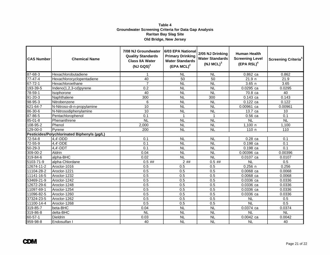
CAS Number Chemical Name Screening Criteria5
Table 4
7/08 NJ Groundwater Quality Standards
Class IIA Water (NJ GQS)1
Groundwater Screening Criteria for Data Gap AnalysisRaritan Bay Slag Site
Old Bridge, New Jersey
6/03 EPA National Primary Drinking Water Standards
(EPA MCL)2
2/05 NJ Drinking Water Standards
(NJ MCL)3
Human Health Screening Level
(EPA RSL)4
87-68-3 Hexachlorobutadiene 1 NL NL 0.862 ca 0.86277-47-4 Hexachlorocyclopentadiene 40 50 50 21.9 n 21.967-72-1 Hexachloroethane 7 NL NL 3.65 n 3.65193-39-5 Indeno(1,2,3-cd)pyrene 0.2 NL NL 0.0295 ca 0.029578-59-1 Isophorone 40 NL NL 70.8 ca 4091-20-3 Naphthalene 300 NL 300 0.143 ca 0.14398-95-3 Nitrobenzene 6 NL NL 0.122 ca 0.122621-64-7 N-Nitroso-di-n-propylamine 10 NL NL 0.00961 ca 0.0096186-30-6 N-Nitrosodiphenylamine 10 NL NL 13.7 ca 1087-86-5 Pentachlorophenol 0.1 1 1 0.56 ca 0.185-01-8 Phenanthrene NL NL NL NL NL108-95-2 Phenol 2,000 NL NL 1,100 n 1,100129-00-0 Pyrene 200 NL NL 110 n 110Pesticides/Polychlorinated Biphenyls (µg/L)72-54-8 4,4'-DDD 0.1 NL NL 0.28 ca 0.172-55-9 4,4'-DDE 0.1 NL NL 0.198 ca 0.150-29-3 4,4'-DDT 0.1 NL NL 0.198 ca 0.1309-00-2 Aldrin 0.04 NL NL 0.00396 ca 0.00396319-84-6 alpha-BHC 0.02 NL NL 0.0107 ca 0.01075103-71-9 alpha-Chlordane 0.5 ## 2 ## 0.5 ## NL 0.512674-11-2 Aroclor-1016 0.5 0.5 0.5 0.256 n 0.25611104-28-2 Aroclor-1221 0.5 0.5 0.5 0.0068 ca 0.006811141-16-5 Aroclor-1232 0.5 0.5 0.5 0.0068 ca 0.006853469-21-9 Aroclor-1242 0.5 0.5 0.5 0.0336 ca 0.033612672-29-6 Aroclor-1248 0.5 0.5 0.5 0.0336 ca 0.033611097-69-1 Aroclor-1254 0.5 0.5 0.5 0.0336 ca 0.033611096-82-5 Aroclor-1260 0.5 0.5 0.5 0.0336 ca 0.033637324-23-5 Aroclor-1262 0.5 0.5 0.5 NL 0.511100-14-4 Aroclor-1268 0.5 0.5 0.5 NL 0.5319-85-7 beta-BHC 0.04 NL NL 0.0374 ca 0.0374319-86-8 delta-BHC NL NL NL NL NL60-57-1 Dieldrin 0.03 NL NL 0.0042 ca 0.0042959-98-8 Endosulfan I 40 NL NL NL 40
A Page 21 of 22
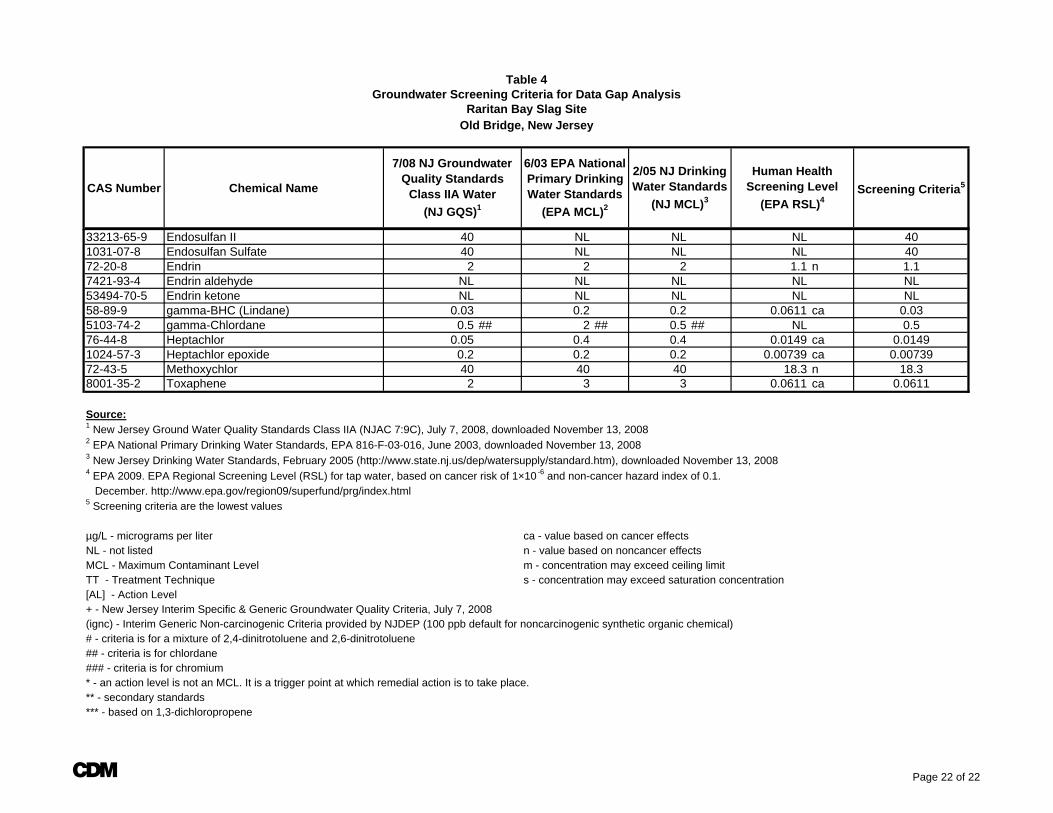
CAS Number Chemical Name Screening Criteria5
Table 4
7/08 NJ Groundwater Quality Standards
Class IIA Water (NJ GQS)1
Groundwater Screening Criteria for Data Gap AnalysisRaritan Bay Slag Site
Old Bridge, New Jersey
6/03 EPA National Primary Drinking Water Standards
(EPA MCL)2
2/05 NJ Drinking Water Standards
(NJ MCL)3
Human Health Screening Level
(EPA RSL)4
33213-65-9 Endosulfan II 40 NL NL NL 401031-07-8 Endosulfan Sulfate 40 NL NL NL 4072-20-8 Endrin 2 2 2 1.1 n 1.17421-93-4 Endrin aldehyde NL NL NL NL NL53494-70-5 Endrin ketone NL NL NL NL NL58-89-9 gamma-BHC (Lindane) 0.03 0.2 0.2 0.0611 ca 0.035103-74-2 gamma-Chlordane 0.5 ## 2 ## 0.5 ## NL 0.576-44-8 Heptachlor 0.05 0.4 0.4 0.0149 ca 0.01491024-57-3 Heptachlor epoxide 0.2 0.2 0.2 0.00739 ca 0.0073972-43-5 Methoxychlor 40 40 40 18.3 n 18.38001-35-2 Toxaphene 2 3 3 0.0611 ca 0.0611
Source:1 New Jersey Ground Water Quality Standards Class IIA (NJAC 7:9C), July 7, 2008, downloaded November 13, 20082 EPA National Primary Drinking Water Standards, EPA 816-F-03-016, June 2003, downloaded November 13, 20083 New Jersey Drinking Water Standards, February 2005 (http://www.state.nj.us/dep/watersupply/standard.htm), downloaded November 13, 20084 EPA 2009. EPA Regional Screening Level (RSL) for tap water, based on cancer risk of 1×10⁻⁶ and non-cancer hazard index of 0.1. December. http://www.epa.gov/region09/superfund/prg/index.html5 Screening criteria are the lowest values
µg/L - micrograms per liter ca - value based on cancer effectsNL - not listed n - value based on noncancer effectsMCL - Maximum Contaminant Level m - concentration may exceed ceiling limit TT - Treatment Technique s - concentration may exceed saturation concentration[AL] - Action Level+ - New Jersey Interim Specific & Generic Groundwater Quality Criteria, July 7, 2008(ignc) - Interim Generic Non-carcinogenic Criteria provided by NJDEP (100 ppb default for noncarcinogenic synthetic organic chemical)# - criteria is for a mixture of 2,4-dinitrotoluene and 2,6-dinitrotoluene## - criteria is for chlordane### - criteria is for chromium* - an action level is not an MCL. It is a trigger point at which remedial action is to take place.** - secondary standards*** - based on 1,3-dichloropropene
A Page 22 of 22